US11253000B2 - Receptacle section for an aerosol provision article - Google Patents
Receptacle section for an aerosol provision articleDownload PDFInfo
- Publication number
- US11253000B2 US11253000B2US16/333,570US201716333570AUS11253000B2US 11253000 B2US11253000 B2US 11253000B2US 201716333570 AUS201716333570 AUS 201716333570AUS 11253000 B2US11253000 B2US 11253000B2
- Authority
- US
- United States
- Prior art keywords
- receptacle section
- configuration
- aerosol
- mouth
- receptacle
- Prior art date
- Legal status (The legal status is an assumption and is not a legal conclusion. Google has not performed a legal analysis and makes no representation as to the accuracy of the status listed.)
- Active, expires
Links
Images


Classifications
- A—HUMAN NECESSITIES
- A24—TOBACCO; CIGARS; CIGARETTES; SIMULATED SMOKING DEVICES; SMOKERS' REQUISITES
- A24F—SMOKERS' REQUISITES; MATCH BOXES; SIMULATED SMOKING DEVICES
- A24F40/00—Electrically operated smoking devices; Component parts thereof; Manufacture thereof; Maintenance or testing thereof; Charging means specially adapted therefor
- A24F40/30—Devices using two or more structurally separated inhalable precursors, e.g. using two liquid precursors in two cartridges
- A—HUMAN NECESSITIES
- A24—TOBACCO; CIGARS; CIGARETTES; SIMULATED SMOKING DEVICES; SMOKERS' REQUISITES
- A24B—MANUFACTURE OR PREPARATION OF TOBACCO FOR SMOKING OR CHEWING; TOBACCO; SNUFF
- A24B15/00—Chemical features or treatment of tobacco; Tobacco substitutes, e.g. in liquid form
- A24B15/10—Chemical features of tobacco products or tobacco substitutes
- A24B15/16—Chemical features of tobacco products or tobacco substitutes of tobacco substitutes
- A24B15/167—Chemical features of tobacco products or tobacco substitutes of tobacco substitutes in liquid or vaporisable form, e.g. liquid compositions for electronic cigarettes
- A—HUMAN NECESSITIES
- A24—TOBACCO; CIGARS; CIGARETTES; SIMULATED SMOKING DEVICES; SMOKERS' REQUISITES
- A24F—SMOKERS' REQUISITES; MATCH BOXES; SIMULATED SMOKING DEVICES
- A24F40/00—Electrically operated smoking devices; Component parts thereof; Manufacture thereof; Maintenance or testing thereof; Charging means specially adapted therefor
- A24F40/10—Devices using liquid inhalable precursors
- A—HUMAN NECESSITIES
- A24—TOBACCO; CIGARS; CIGARETTES; SIMULATED SMOKING DEVICES; SMOKERS' REQUISITES
- A24F—SMOKERS' REQUISITES; MATCH BOXES; SIMULATED SMOKING DEVICES
- A24F40/00—Electrically operated smoking devices; Component parts thereof; Manufacture thereof; Maintenance or testing thereof; Charging means specially adapted therefor
- A24F40/40—Constructional details, e.g. connection of cartridges and battery parts
- A24F40/42—Cartridges or containers for inhalable precursors
- A—HUMAN NECESSITIES
- A24—TOBACCO; CIGARS; CIGARETTES; SIMULATED SMOKING DEVICES; SMOKERS' REQUISITES
- A24F—SMOKERS' REQUISITES; MATCH BOXES; SIMULATED SMOKING DEVICES
- A24F40/00—Electrically operated smoking devices; Component parts thereof; Manufacture thereof; Maintenance or testing thereof; Charging means specially adapted therefor
- A24F40/40—Constructional details, e.g. connection of cartridges and battery parts
- A24F40/46—Shape or structure of electric heating means
- A—HUMAN NECESSITIES
- A24—TOBACCO; CIGARS; CIGARETTES; SIMULATED SMOKING DEVICES; SMOKERS' REQUISITES
- A24F—SMOKERS' REQUISITES; MATCH BOXES; SIMULATED SMOKING DEVICES
- A24F47/00—Smokers' requisites not otherwise provided for
- A—HUMAN NECESSITIES
- A61—MEDICAL OR VETERINARY SCIENCE; HYGIENE
- A61M—DEVICES FOR INTRODUCING MEDIA INTO, OR ONTO, THE BODY; DEVICES FOR TRANSDUCING BODY MEDIA OR FOR TAKING MEDIA FROM THE BODY; DEVICES FOR PRODUCING OR ENDING SLEEP OR STUPOR
- A61M11/00—Sprayers or atomisers specially adapted for therapeutic purposes
- A61M11/04—Sprayers or atomisers specially adapted for therapeutic purposes operated by the vapour pressure of the liquid to be sprayed or atomised
- A61M11/041—Sprayers or atomisers specially adapted for therapeutic purposes operated by the vapour pressure of the liquid to be sprayed or atomised using heaters
- A61M11/042—Sprayers or atomisers specially adapted for therapeutic purposes operated by the vapour pressure of the liquid to be sprayed or atomised using heaters electrical
- A—HUMAN NECESSITIES
- A61—MEDICAL OR VETERINARY SCIENCE; HYGIENE
- A61M—DEVICES FOR INTRODUCING MEDIA INTO, OR ONTO, THE BODY; DEVICES FOR TRANSDUCING BODY MEDIA OR FOR TAKING MEDIA FROM THE BODY; DEVICES FOR PRODUCING OR ENDING SLEEP OR STUPOR
- A61M15/00—Inhalators
- A61M15/0028—Inhalators using prepacked dosages, one for each application, e.g. capsules to be perforated or broken-up
- A—HUMAN NECESSITIES
- A61—MEDICAL OR VETERINARY SCIENCE; HYGIENE
- A61M—DEVICES FOR INTRODUCING MEDIA INTO, OR ONTO, THE BODY; DEVICES FOR TRANSDUCING BODY MEDIA OR FOR TAKING MEDIA FROM THE BODY; DEVICES FOR PRODUCING OR ENDING SLEEP OR STUPOR
- A61M15/00—Inhalators
- A61M15/06—Inhaling appliances shaped like cigars, cigarettes or pipes
- A—HUMAN NECESSITIES
- A24—TOBACCO; CIGARS; CIGARETTES; SIMULATED SMOKING DEVICES; SMOKERS' REQUISITES
- A24F—SMOKERS' REQUISITES; MATCH BOXES; SIMULATED SMOKING DEVICES
- A24F40/00—Electrically operated smoking devices; Component parts thereof; Manufacture thereof; Maintenance or testing thereof; Charging means specially adapted therefor
- A24F40/20—Devices using solid inhalable precursors
- A—HUMAN NECESSITIES
- A61—MEDICAL OR VETERINARY SCIENCE; HYGIENE
- A61M—DEVICES FOR INTRODUCING MEDIA INTO, OR ONTO, THE BODY; DEVICES FOR TRANSDUCING BODY MEDIA OR FOR TAKING MEDIA FROM THE BODY; DEVICES FOR PRODUCING OR ENDING SLEEP OR STUPOR
- A61M2205/00—General characteristics of the apparatus
- A61M2205/36—General characteristics of the apparatus related to heating or cooling
- A61M2205/3653—General characteristics of the apparatus related to heating or cooling by Joule effect, i.e. electric resistance
- A—HUMAN NECESSITIES
- A61—MEDICAL OR VETERINARY SCIENCE; HYGIENE
- A61M—DEVICES FOR INTRODUCING MEDIA INTO, OR ONTO, THE BODY; DEVICES FOR TRANSDUCING BODY MEDIA OR FOR TAKING MEDIA FROM THE BODY; DEVICES FOR PRODUCING OR ENDING SLEEP OR STUPOR
- A61M2205/00—General characteristics of the apparatus
- A61M2205/82—Internal energy supply devices
- A61M2205/8206—Internal energy supply devices battery-operated
Definitions
- the present disclosurerelates to a receptacle section, and more particularly to a receptacle section for an aerosol provision article.
- Smoking articlessuch as cigarettes, cigars and the like burn tobacco during use to create tobacco smoke. Attempts have been made to provide alternatives to these articles that burn tobacco by creating products that release compounds without burning.
- Examples of such productsare heating devices which release compounds by heating, but not burning, the material.
- the materialmay be for example tobacco or other non-tobacco products, which may or may not contain nicotine.
- aerosol provision articlessuch as so-called e-cigarette devices. These devices typically contain a liquid which is heated to vaporize the liquid to produce an inhalable vapor or aerosol.
- the liquidmay contain nicotine and/or flavorings and/or aerosol-generating substances, such as glycerol.
- the known e-cigarette devicestypically do not contain flavorings other than those in the liquid.
- a receptacle section for an aerosol provision articlefor generating a flow of aerosol in use
- the receptacle sectionarranged for receiving therein an element for modifying a property of aerosol passing through said element received in the receptacle section in use
- the receptacle sectionbeing configurable between a first configuration and a different, second configuration, the first configuration defining a flow path for said aerosol to flow through the receptacle section via said element received in the receptacle section in use, and the second configuration allowing said element to be inserted into and/or removed from the receptacle section.
- the receptacle sectionmay comprise a first portion and a second portion moveable relative to the first portion, and a movement of the second portion relative to the first portion may change the configuration of the receptacle section between the first configuration and the second configuration.
- the movementmay comprise movement substantially parallel to a longitudinal axis of the receptacle section.
- the second portionmay be slidably mounted to the first portion thereby to allow sliding of the second portion relative to the first portion, parallel to the longitudinal axis of the receptacle section, between the first configuration and the second configuration.
- the receptacle sectionmay be arranged to allow, when in the second configuration, insertion and/or removal of said element into and/or from the receptacle section in a direction substantially parallel to the longitudinal axis of the receptacle section.
- the receptacle sectionmay be arranged to allow the insertion and/or removal of said element through an opening of the second portion, the opening being for outlet of said aerosol flowing through the receptacle section in use for inhalation by a user.
- the receptacle sectionmay comprise, at the opening, a lip portion for retaining said element in the receptacle section in use.
- Movement of the second portion towards the first portionmay cause said element when inserted in the receptacle section to protrude out of the opening.
- the receptacle sectionmay comprise, at the opening, a or the lip portion, and the lip portion may be arranged to cause said element to remain protruded out of the opening on a subsequent movement of the second portion away from the first portion.
- the receptacle sectionmay be biased to the first configuration.
- the second portionmay comprise a housing
- the first portionmay comprise a plurality of resilient members, the resilient members defining between them a receiving region for receiving said element in use, and in the first configuration the resilient members may be received in the housing and define between them a first radial dimension of the receiving region for retaining said element in the receiving section in use, and in the second configuration the resilient members may each protrude out of the housing and define between them a second, larger radial dimension of the receiving region for allowing said element to be inserted into and/or removed from the receptacle section.
- the receptacle sectionmay be arranged to allow insertion and/or removal of said element into and/or from the receptacle section in a direction substantially perpendicular to the longitudinal axis of the receptacle section.
- the second portionmay be receivable in the first portion, and a side wall of the second portion may define an opening, wherein in the second configuration the opening may be exposed for insertion and/or removal of said element into the second portion through the opening, and wherein in the first configuration the opening may be closed off by the first portion.
- the receptacle sectionmay comprise a third portion for closing off the opening, the third portion being pivotally mounted to the second portion, thereby to allow pivoting of the third portion relative to the second portion, and in the second configuration the third portion may be exposed out of the first portion thereby to allow said pivoting of the third portion, and in the first configuration the third portion may be received in the first portion.
- the first portionmay be receivable in the second portion, and a side wall of the first portion may define an opening, and in the second configuration the opening may be exposed for insertion and/or removal of said element into the first portion through the opening, and in the closed configuration the opening may be closed off by the second portion.
- the first portionmay comprise a retaining element to releasably retain the second portion relative to the first portion such that the receptacle section is in the first configuration.
- the receptacle sectionmay be biased towards the second configuration.
- the second portionmay be removable from the first portion, and the receptacle section may be in the second configuration when the second portion is removed from the first portion, and the receptacle section may be in the first configuration when the second portion is connected to the first portion.
- the first portionmay comprise a receiving portion for allowing, when the second portion is removed, insertion and/or removal of said element into and/or from the receiving portion in a direction substantially parallel to the longitudinal axis of the receptacle section.
- the receiving portionmay be arranged such that said element received in the receiving portion in use protrudes out from the receiving portion.
- the receiving portionmay comprise a plurality of resilient members extending in a direction substantially parallel to the longitudinal axis of the receptacle section, and the resilient members may define between them a receiving region for receiving said element.
- the second portionmay comprise a receiving portion for allowing, when the second portion is removed, insertion and/or removal of said element into and/or from the receiving portion in a direction substantially perpendicular to the longitudinal axis of the receptacle section.
- the receiving portionmay be receivable in the first portion.
- the receiving portionmay define an aperture into which said element can be inserted to be supported by the receiving portion.
- the first portionmay comprise a receiving portion for allowing, when the second portion is removed, insertion and/or removal of said element into and/or from the receiving portion in a direction substantially perpendicular to the longitudinal axis of the receptacle section.
- At least a portion of the second portionmay be for receipt into a user's mouth.
- the movementmay comprise rotation about a longitudinal axis of the receptacle section.
- the second portionmay be rotationally mounted with respect to the first portion, thereby to allow the second portion to rotate relative to the first portion, between the first configuration and the second configuration.
- the first portionmay define an opening and the second portion may define an opening, and in the second configuration the opening of the first portion and the opening of the second portion may be aligned with respect to one another to allow insertion and/or removal of said element into and/or from the receptacle section, through the opening of the first portion and the opening of the second portion, and in the first configuration, the opening of the first portion and the opening of the second portion may be misaligned with respect to one another.
- the second portionmay be received in the first portion, and the opening of the first portion may be in a side wall of the first portion, and the opening of the second portion may be in a side wall of the second portion, such that in the second configuration the opening of the first portion and the opening of the second portion are aligned with respect to one another to allow insertion and/or removal of said element into and/or from the first portion, through the opening of the first portion and the opening of the second portion, and such that in the first configuration the side wall of the second portion closes off the opening of the first portion.
- the movementmay comprise rotation about an axis substantially perpendicular to a longitudinal axis of the receptacle.
- the second portionmay be pivotally mounted to the first portion, thereby to allow pivoting of the second portion relative to the first portion, about an axis substantially perpendicular to the longitudinal axis of the receptacle, between the first configuration and the second configuration.
- a side wall of the first portionmay define an opening that may allow, in the second configuration, insertion and/or removal of said element into and/or from the receptacle section, through the opening, in a direction substantially perpendicular to the longitudinal axis of the receptacle section, and in the first configuration the second portion may close off the opening.
- the first portionmay comprise a retaining element to releasably retain the second portion relative to the first portion such that the receptacle section is in the first configuration.
- the retaining elementmay comprise a latch to latch the second portion relative to the first portion, and the latch may be operable by a user to release the second portion such that the receptacle section is in the second configuration.
- the first portionmay define an opening that may allow, in the open configuration, insertion and/or removal of said element into and/or from the first portion, through the opening, in a direction substantially parallel to the longitudinal axis of the receptacle section.
- the first portionmay be arranged such that said element received in the opening in use protrudes out from the opening.
- the first portionmay comprise a retaining element to releasably retain the second portion relative to the first portion such that the receptacle section is retained in the first configuration.
- the retaining elementmay be slidable, by a user, in use, along the longitudinal axis of the receptacle between a first position for obstructing said pivoting of the second portion about the first portion, and a second position for allowing said pivoting of the second portion about the first portion.
- An interface between the retaining element and the second portionmay be angled with respect to a plane parallel to the longitudinal axis of the receptacle, and may be angled with respect to a plane perpendicular to the longitudinal axis of the receptacle.
- the retaining elementmay be biased to the first position.
- At least a portion of the second portionmay be for receipt into a user's mouth in use.
- the receptacle sectionmay have the element received therein.
- the property of the aerosolmay be one or more of an organoleptic property of the aerosol, a flavor of the aerosol, and the pH of the aerosol.
- the elementmay be self-supporting and/or may be or comprise tobacco and/or may comprise a crushable flavor capsule for releasing, when crushed, a flavorant into said flow of aerosol.
- the first portionmay comprise a connecting portion for releasably connecting the receptacle section to said aerosol provision article.
- a mouthpiece for an aerosol provision articlesaid aerosol provision article being for generating a flow of aerosol in use, the mouthpiece comprising the receptacle section according to the first aspect.
- an aerosol provision articlefor generating a flow of aerosol in use, the aerosol provision article comprising the receptacle section according to the first aspect, and/or the mouthpiece according to the second aspect.
- the aerosol provision articlemay comprise: a container for holding a liquid or a material; a heater for volatilizing liquid held in the container to generate said flow of aerosol in use or for heating but not combusting the material to generate said flow of aerosol in use.
- FIG. 1shows a schematic cross section of an aerosol provision article according to an example.
- FIGS. 2 a to 2 dshow schematic cross sections of a part of an aerosol provision article comprising a first receptacle section in different configurations according to a first example.
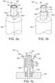
- FIGS. 3 a to 3 fshow schematic perspective views, and a schematic cross section of a part of an aerosol provision article comprising a second receptacle section in different configurations according to a second example.
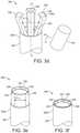
- FIGS. 4 a to 4 dshow schematic perspective views of a part of an aerosol provision article comprising a third receptacle section in different configurations according to a third example.
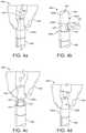
- FIGS. 5 a to 5 dshow schematic perspective views of a part of an aerosol provision article comprising a fourth receptacle section in different configurations according to a fourth example.
- FIGS. 6 a and 6 bshow schematic cross sections of a part of an aerosol provision article comprising a fifth receptacle section in different configurations according to a fifth example.
- FIG. 7shows a schematic perspective view of a part of an aerosol provision article comprising a sixth receptacle section according to a sixth example.
- FIGS. 8 a to 8 cshow schematic perspective views of a part of an aerosol provision article comprising a seventh receptacle section in different configurations according to a seventh example.
- FIG. 9shows a schematic perspective view of a part of an aerosol provision article comprising an eighth receptacle section according to an eighth example.
- FIGS. 10 a to 10 dshow schematic perspective views of a part of an aerosol provision article comprising a ninth receptacle section in different configurations according to a ninth example.
- FIGS. 11 a and 11 bshow schematic perspective views of a part of an aerosol provision article comprising a tenth receptacle section in different configurations according to a tenth example.
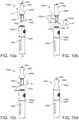
- FIGS. 12 a and 12 bshow schematic cross sections of a part of an aerosol provision article comprising an eleventh receptacle section in different configurations according to an eleventh example.
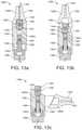
- FIGS. 13 a to 13 cshow schematic cross sections of a part of an aerosol provision article comprising a twelfth receptacle section in different configurations according to a twelfth example.
- the aerosol provision article 100is an inhalation device (i.e. a user uses it to inhale an aerosol provided by the device).
- the aerosol provision articleis hand-held.
- the article 100is an electronic cigarette device 100 .
- the device 100volatilizes a liquid to form a vapor or an aerosol which passes through an element 124 received in a mouthpiece 102 of the device 100 .
- the element 124modifies a property of the vapor or aerosol passing through the mouthpiece 102 for inhalation by a user.
- the element 124may be a flavor element 124 for modifying (imparting) a flavor of (to) vapor or aerosol passing there through.
- a vaporis a substance in the gas phase at a temperature lower than its critical temperature, which means that for example the vapor can be condensed to a liquid by increasing its pressure without reducing the temperature.
- an aerosolis a colloid of fine solid particles or liquid droplets, in air or another gas.
- a colloidis a substance in which microscopically dispersed insoluble particles are suspended throughout another substance.
- the device 100comprises an outer body 106 housing a liquid container 122 containing liquid 116 , an atomizer 108 , and a battery portion 112 .
- the atomizer 108is (electrically) connected to the battery portion 112 .
- the mouthpiece 102is, in this example, removably connected to the outer body 106 .
- the mouthpiece 102may be removed from the outer body 106 , for example to allow access to the liquid container 122 , for example to refill the liquid 116 held in the liquid container 122 .
- the mouthpiece 102has a channel 132 running there through that defines a flow path for a flow of vapor or aerosol.
- the mouthpiece 102has removably received in the channel 132 a flavor element 124 for imparting a flavor to said flow of aerosol or vapor that passes through the mouthpiece 102 in use.
- the flavor element 124may be or comprise for example tobacco, or other flavored materials that may be used to create a desired taste or aroma, or other properties, such as nicotine content.
- the device 100is arranged so that, in use, as the liquid 116 is volatilized so as to produce an aerosol of liquid droplets or sufficiently heated to produce a vapor, at least some or all or substantially all of the aerosol or vapor passes through the flavor element 124 received in the mouthpiece 102 for example so as to entrain constituents of the flavor element 134 therein. In some examples, a vapor is produced that then at least partly condenses to form on aerosol before exiting the device 100 .
- the liquid container 122is provided generally centrally of the outer body 106 .
- the liquid container 122is annular in shape and defines a channel 104 running through the length of the liquid container 122 .
- the liquid container 122may be formed of rigid, watertight and airtight materials, such as metal, suitable plastics, etc. It will be appreciated that the liquid container 122 may have a different shape, such as conical, frustoconical, or combination of these, etc.
- the atomizer 108is provided with a heater 110 and a wick (not shown) in (thermal) contact with the heater 110 .
- the orientation of the heater 110is shown schematically and for example the heater 110 may be a coil having its longitudinal axis perpendicular or parallel to the longitudinal axis of the liquid container 108 .
- the wick (not shown)is in contact with the liquid 116 . This may be achieved by for example by the wick (not shown) being inserted through a through hole (not shown) in an end wall 122 b of the liquid container 122 .
- the end wall 122 bmay be a porous member which allows liquid to pass through from the liquid container 122 , and the wick (not shown) may be in contact with the porous end wall 122 b .
- the end wall 122 bmay be for example in the form of a porous ceramic disk.
- a porous end wall 122 b of this typehelps to regulate the flow of liquid onto the wick (not shown).
- the wick (not shown)is generally absorbent and acts to draw in liquid 116 from the liquid container 122 by capillary action (shown in FIG. 1 by arrows A).
- the wickcan be non-woven and may be for example a cotton or wool material or the like, or a synthetic material, including for example polyester, nylon, viscose, polypropylene or the like, or a ceramic material.
- the atomizer 108is (electrically) connected to a battery in the battery portion 116 to enable the heater 110 to be powered.
- the heater 110is powered (which may be instigated for example by the user operating a button (not shown) of the device 100 or by a puff detector (not shown) of the overall device 100 , as is known per se, liquid 116 is drawn (shown in FIG. 1 by arrows A) in from the liquid container 122 by the wick and is heated by the heater 110 to volatilize or vaporize the liquid, so as to generate at least one of a vapor and an aerosol.
- airis drawn through an air inlet 118 .
- the liquid 116is volatized or vaporized by the heater 110 into air from the air inlet 118 thereby to produce a flow of one of a vapor and an aerosol.
- the flow vapor or aerosolis drawn through the channel 104 of the liquid container 122 , into the channel 132 of the mouthpiece 102 , through the flavor element 124 received in the mouthpiece 102 , and out from the device 100 for inhalation by a user (shown by arrow B in FIG. 1 ).
- the vapor or aerosolpicks up (entrains) flavor (and/or other constituents) from the flavor element 124 .
- One or more constituents of the flavor elementis thereby mixed with the flow of at least one of a vapor and an aerosol.
- the vapor or aerosolmay thereby also contain nicotine entrained from that solid material.
- a one way valve(not shown) may be provided, for example at or near an upper end 122 a of the liquid container 122 , so that the vapor or aerosol can only exit the channel 104 and cannot back-flow to the heater 110 or the electronics (not shown) of the device 100 .
- the flavor element 124may be or comprise material that may be used to impart a flavor (and/or one or more other constituents) to the aerosol or vapor.
- the one or more constituents of the flavor elementmay comprise constituents inherent to the material itself.
- the materialmay for example consist of or comprise tobacco. As the aerosol or vapor passes through and over the tobacco, the aerosol or vapor entrains organic and other compounds or constituents from the tobacco that lend tobacco its organoleptic properties, thus imparting the flavor to the aerosol or vapor. It will be understood however that materials other than tobacco may be used to impart different flavors (and/or one or more other constituents) to the aerosol or vapor flow.
- the flavor element 124may comprise constituents added to a material of the flavor element 124 .
- Nicotinemay be provided in the liquid 116 . Accordingly, where it is intended that the device 100 provides nicotine for the user, the nicotine may be provided in the liquid 116 , may be obtained from the flavor element 124 , or any combination of these. Likewise, flavorings may be added to the flavor element 124 (whether or not the flavor element 124 is or includes tobacco) and/or to the liquid 116 .
- a material of the flavor element 124may be a solid material, or be a mixture of solid materials, one or more of each comprising one or more constituents that can be mixed with the flow of vapor or aerosol. It will be appreciated that the flavor element 124 may comprise one or more other constituents that are not entrained into the aerosol or vapor passing there through. It will also be appreciated that the flavor element 124 may comprise a portion that does not impart any flavor and/or release any constituents into the flow of a vapor or an aerosol.
- the flavor element 124may be porous, for example so as allow vapor or aerosol to pass through it.
- the flavor element 124may be self-supporting, so as to be easily handled by a user (for example easily inserted and/or removed from the mouthpiece 102 ).
- the flavor element 124may comprise material wrapped partially or wholly in a wrapper, and/or the flavor element 124 may be supported in a resilient housing, for example a plastic housing (not shown).
- the flavor elementmay comprise, for example, a flavored carrier material, such as cellulose acetate or the like.
- the flavor element 124may be cylindrical, and/or comprise a cylindrical portion, so as to fit easily and/or tightly into a corresponding cylindrical channel 132 of the mouthpiece 102 .
- the flavor element 124comprises a crushable flavor capsule 126 for releasing, when crushed for example by a user, a liquid or a gel that flavors a flow of at least one of a vapor and an aerosol.
- the flavor element 124may comprise a crushable flavor capsule 126 wrapped or embedded in a suitable carrier material, for example cellulose acetate.
- the carrier materialmay comprise a material that allows vapor or aerosol to pass there through.
- the carrier materialmay comprise a material that holds the liquid and/or gel released from the crushable flavor capsule 126 when it is crushed. When the capsule 126 is crushed, the liquid or gel contained therein is released into the material so as to flavor vapor or aerosol passing there through.
- the various receptacle sectionsare arranged for receiving therein a flavor element for imparting a flavor to at least one of a vapor and an aerosol passing through said flavor element received in the receptacle section in use.
- the receptacle sectionsare configurable between a first configuration and a different, second configuration.
- the first configurationdefines a flow path for the at least one of a vapor and an aerosol to flow through the receptacle section via said flavor element received in the receptacle section in use, whereas the second configuration allows the flavor element to be inserted into and/or removed from the receptacle section.
- the various receptacle sectionstherefore provide a convenient way for a user to insert/and or remove a flavor element from an overall aerosol provision article (e.g. device 100 in FIG. 1 ) in/with which the receptacle section is being used.
- a usermay wish to remove and/or insert a flavor element for example, when the flavor of the flavor element deteriorates, or when a user wishes to change the taste, aroma, or other properties of the vapor or aerosol produced.
- aerosolshould be taken as encompassing an aerosol, a vapor or a mixture of an aerosol and vapor.
- FIGS. 2 a to 2 dthere is illustrated schematically cross sections of part of a device 200 that comprises an example receptacle section 202 in different configurations.
- the receptacle section 202is a mouth-end section 202 of the device 200 , that is, the receptacle section 202 is towards an end of the device 200 for receipt into a user's mouth in use.
- the receptacle section 202(or at least a portion thereof) is for receipt into a user's mouth in use, and hence is itself a mouthpiece 202 .
- FIG. 2 and the functioning thereofthat are the same or similar to those features already described with reference to FIG. 1 are given similar reference numerals to as in FIG. 1 but increased by 100, and will not be described in detail again.
- the mouth-end section 202has a first portion 202 a and a second portion 202 b moveable relative to the first portion 202 a .
- the first portion 202 ais received in the second portion 202 a .
- the first portion 202 ais removably connected to a body 206 of the overall device 200 , via a connecting means 228 .
- the connecting means 228may be, for example, a threaded connection or the like, for example the first portion 202 a may have a male thread connectable to a corresponding female thread of the body 206 .
- the second portion 202 bis for receipt into a user's mouth (not shown).
- the first portion 202 adefines a channel 204 internal thereof, and the second portion 202 b defines a channel 232 internal thereof.
- the first portion 202 a(and a portion of the channel 204 thereof) is partially received in the channel 232 of the second portion 202 b .
- the first portion 202 a and the second portion 202 bare arranged such that the channels 204 , 232 , in combination, extend from an aerosol outlet 207 of the body 206 of the overall device 200 to an opening 234 of the second portion 202 a for outlet of the aerosol for inhalation by a user.
- the channels 204 , 232thereby define, in combination, a flow path for the aerosol to flow from the outlet 207 of the body 206 of the overall device 200 to the opening 234 of the second portion 202 a for inhalation by a user.
- the second portion 202 bis slidably mounted to the first portion 202 a to enable sliding movement of the second portion 202 b relative to the first portion 202 a (and hence relative to the body 206 of the overall device 200 ) substantially parallel to a longitudinal axis P-P of the mouth-end section 202 . Movement of the second portion 202 b relative to the first portion 202 a substantially parallel to the longitudinal axis P-P of the mouth-end section 200 changes the configuration of the mouth-end section 202 between a first (closed) configuration (as shown in FIG. 2 c ) and an second (open) configuration (as shown in FIG. 2 a , FIG. 2 b , and FIG. 2 d ).
- the mouth-end section 202is arranged to allow, when in the second configuration, insertion and/or removal of a flavor element 224 into and/or from the mouth-end section 200 in a direction substantially parallel to the longitudinal axis P-P of the mouth-end section 200 .
- the flavor element 224can be inserted and/or removed from the channel 232 of the mouth-end section 202 via the opening 234 defined by the second portion 202 b.
- the first portion 202 aextends a relatively small amount into the channel 232 of the second portion 202 a (i.e. the second portion 202 a is positioned relatively away from the first portion 202 b ), such that the remaining (free) length of the channel 232 defined by the second portion 202 a is long enough to enable a flavor element 224 be fully received therein (see FIG. 2 b in particular).
- the first portion 202 aextends a relatively large amount into the channel 232 of the second portion 202 a (i.e. the second portion 202 b is position relatively towards the first portion 202 a ), such that the remaining (free) length of the channel 232 defined by the second portion is short enough so that a flavor element 224 is not fully receivable therein, and is instead forced to be exposed (protruding) out of the opening 234 of the second portion 202 b (see FIG. 2 c ).
- the flavor element 234being exposed (protruding) out of the opening 234 allows the flavor element 234 to be easily grasped (manipulated) by a user, and hence provides for convenient removal, replacement, and/or insertion of the or another flavor element 234 into the mouth-end section 202 .
- the mouth-end section 202comprises a biasing means 230 , such as a spring 230 , which, in this example, is arranged in an annular space between a part of the first portion 202 a and a part of the second portion 202 b , and which biases the second portion 202 b away from the first portion 202 a , and hence biases the mouth-end section 202 to the closed configuration.
- the mouth-end sectioncomprises a stop (not shown) to prevent the second portion 202 b from sliding entirely off the first portion 202 a.
- the second portion 202 bcomprises a first lip portion 236 , at the opening 234 , for retaining the flavor element 224 in the channel 232 .
- the first lip portion 236protrudes radially inwardly to the channel 236 around the circumference of the opening 236 .
- the first lip portion 236provides some resistance to the flavor element exiting the channel 232 of the second portion 202 b into which it is received. This resistance can be overcome when a user manipulates the mouth-end section 200 to the closed configuration, hence forcing the flavor element 224 to become exposed (protrude) out of the opening 234 of the second portion 202 b.
- the first lip portion 236abuts or opposes a rim of the top of the first portion 202 a when the mouth-end section 202 is in the closed configuration.
- the second portion 202 bfurther comprises a second lip portion 237 that is defined by an internal surface of the second portion 202 b about half way along its length and which abuts a third lip portion 239 defined by an external surface of the first portion 202 a when the mouth-end section 202 is in the closed configuration.
- a userbrings a flavor element 224 (which may comprise, for example, an already crushed crushable flavor capsule 226 ) to the opening 234 of the second portion 202 b , and pushes (arrow C) the flavor element 224 into the channel 232 of the second portion 202 b so that it is fully received into the channel 232 of the second portion 202 b (as shown in FIG. 2 b ).
- the flavor element 224is retained in the channel 232 by, at one end, the first portion 202 a received in the channel 232 of the second portion 202 b , and at the other end by the first lip portion 236 .
- a usermay wish to remove the flavor element 224 at some later point in time, for example, when the flavor element 224 has been exhausted of flavor.
- the usertherefore pushes, or pulls, or otherwise manipulates (see arrows E in FIG. 2 c ) the second portion 202 b towards the first portion 202 a .
- Thiscauses the first portion 202 a to extend further into the channel 232 of the second portion 202 b , which in turn pushes the flavor element 224 partially out of the opening 234 of the second portion 202 b (as shown in FIG. 2 c ).
- Thisalso causes the spring 230 to become compressed (as shown in FIG. 2 c ).
- the spring 230causes the second portion 202 b to return to the open configuration (see FIG. 2 d ).
- the first lip portion 236holds the flavor element 224 partially exposed out of the opening 234 , i.e. causes the flavor element 224 to remain protruded out of the opening on the subsequent movement of the second portion 202 b away from the first portion 202 a .
- the flavor element 224is therefore presented to a user so that the user can easily and controllably remove the flavor element 224 from the mouth-end section 202 .
- the mouth-end section 202In use, when the mouth-end section 202 is connected to the rest of the device (e.g. as shown schematically for device 100 in FIG. 1 ), and when the mouth-end section 202 has a flavor element 224 received therein, and when the mouth-end section 202 is in the closed configuration, when a user draws on the mouth-end section 202 , air is drawn in through an air inlet ( 120 in FIG. 1 ).
- a heater ( 110 in FIG. 1 )volatizes liquid ( 116 in FIG. 1 ) held in the liquid container ( 122 in FIG. 1 ) into the inlet air to generate a flow of aerosol.
- the flowpasses through the channel ( 104 in FIG. 1 ) in the liquid container ( 122 in FIG.
- FIGS. 3 a to 3 fthere is illustrated schematically perspective views and a schematic cross section ( FIG. 3 c ) of another example of a part of a device 300 comprising a receptacle section 302 in different configurations.
- the example receptacle section 302 in FIGS. 3 a to 3 ecan be used, for example as illustrated in the FIGS. 3 a to 3 e as the mouth-end section of the device 300 , or as some other section of the overall device 300 , for example, intermediate of the body (not illustrated) of the device 300 and the mouthpiece of the device 300 .
- FIGS. 3 a to 3 f and the functioning thereofthat are the same or similar to those features already described with reference to FIGS. 2 a to 2 d are given similar reference numerals to as in FIG. 2 but increased by 100, and will not be described in detail again.
- the mouth-end section 302 illustrated in FIGS. 3 a to 3 fis similar to the mouth-end section 202 illustrated in FIGS. 2 a to 2 d .
- the mouth-end section 302 illustrated in FIGS. 3 a to 3 fcomprises a first portion 302 a , and a second portion 302 b slidably mounted to the first portion 302 a thereby to allow sliding movement (arrow Z in FIGS. 3 a and 3 b ) of the second portion 302 b relative to the first portion 302 a substantially parallel to a longitudinal axis P-P of the mouth-end section 302 , between a closed configuration (see FIGS.
- the second portion 302 bcomprises a cylindrical housing 302 b into which the first portion 302 a is receivable.
- the first portion 302 aextends from a body 306 of the overall device 300 .
- the mouth-end section 302comprises a biasing means 330 , such as a spring 330 , to bias the housing 302 b away from the body 306 of the overall device, to bias the mouth-end section 302 towards its closed configuration (see FIG. 3 a ).
- the first portion 302 acomprises a plurality of resilient members 338 .
- the resilient members 338are generally flat and are arranged side by side around the inner wall of the housing 302 b when the mouth-end section 302 is in the closed configuration (see FIG. 3 a ).
- the resilient members 338are biased radially outwardly of the longitudinal axis P-P.
- the resilient members 338define between them a receiving region 340 for receiving a flavor element 324 .
- the first portion 302 acomprises a stem 339 extending from the body 306 of the overall device 300 .
- the resilient members 338are supported on the stem 339 .
- the resilient members 338 and the stem 339are receivable in the housing 302 b.
- the mouth-end section 302is first in the closed configuration (see FIG. 3 a ).
- the housing 302 bis located relatively away from the body 306 of the overall device 300 , and the resilient members 338 are received in the housing 302 b .
- the resilient members 338are thereby restricted from moving radially outwardly by the inner wall of the housing 302 b .
- a usermay wish to insert, remove, and/or replace a flavor element 324 into and or from the mouth-end section 302 .
- a usermay therefore push or otherwise manipulate (see arrow Z in FIG.
- each of the resilient members 338protrude (be exposed) out of an open end 334 of the housing 302 b .
- the mouth-end section 302is thereby brought into its open configuration (see FIGS. 3 b , 3 c , and 3 d ). In this open configuration, the resilient members 338 are not (fully) restricted by the inner wall of the housing 302 b , and hence move radially outwardly of each other (see FIGS. 3 c and 3 d ).
- the resilient members 338thereby define between them a radial dimension D of the receiving region 340 for allowing the flavor element 324 to be inserted into (and/or removed from) the receiving region 340 (see FIGS. 3 c and 3 d ).
- a usermay insert (see arrow G in FIG. 3 d ) a flavor element 324 into the receiving region between the resilient members 380 .
- a usermay cease pushing (or otherwise exerting a force on) the housing 302 b towards the body 306 of the device 300 , and hence the housing 302 b , under the force of the biasing means 330 , is forced to slide substantially parallel to the longitudinal axis P-P of the device 300 away from the body 306 , back over the resilient members 338 (See FIG. 3 e ).
- the housing 302 bmay be pulled or otherwise manipulated away from the body 306 and back over the resilient members 338 .
- the housing 302 bthereby slides over the resilient members 338 , which causes the resilient members 338 to be forced closer together laterally by the presence of the walls of the housing 302 b , thereby to define a smaller radial dimension D 1 of the receiving region 324 (the radial dimension D 1 in the closed configuration is smaller than the radial dimension D when in the open configuration) (see FIG. 3 e ).
- the resilient members 338thereby grip around the flavor element 324 in the receiving region 324 , thereby to retain the flavor element 324 in the mouth-end section 302 .
- the housing 302 bis slid over the resilient members 338 until the resilient members 338 are fully received in the housing 302 b (see FIG. 3 f ), and the flavor element 324 is thereby retained therein.
- the mouth-end section 302is thereby in the closed configuration (see FIGS. 3 e and 3 a ).
- One or more of the resilient members 338may comprise a lip portion 336 , at a distal end 338 a of the resilient member 338 , that extends radially inwardly of the resilient member 338 thereby to help retain the flavor element 324 in the receiving region 340 .
- the mouth-end section 302may comprise a retaining element (not shown) to retain the mouth-end section 302 in the closed configuration.
- the retaining element (not shown)is operable by a user so that, when operated, the retaining element (not shown) releases the housing 302 b so that it may be pushed (or otherwise manipulated) by a user towards the body 306 of the device 300 (i.e. pushed towards the open configuration).
- a usercan conveniently insert, remove, and/or replace a flavor element 324 into the mouth-end section 302 .
- FIGS. 4 a to 4 dthere is illustrated schematically perspective views of a part of an aerosol provision article 400 with another example receptacle section 402 in different configurations.
- the receptacle section 402is again a mouth-end section 402 of the aerosol provision article 400 although in other examples it may be a receptacle section intermediate of the mouthpiece and the body 406 of the device 400 .
- FIG. 4 and the functioning thereofthat are the same or similar to those features already described with reference to FIGS. 3 a to 3 e are given similar reference numerals to as in FIGS. 3 a to 3 e but increased by 100, and will not be described in detail again.
- the mouth-end section 402 illustrated in FIGS. 4 a to 4 dcomprises a first portion 402 a , and a second portion 402 b slidably mounted to the first portion 402 a thereby to allow sliding movement of the second portion 402 b relative to the first portion 402 a substantially parallel to a longitudinal axis P-P of the mouth-end section 402 , between a closed configuration (see FIGS. 4 a and 4 d ) and an open configuration (see FIGS. 4 b and 4 c ).
- the mouth-end section 402is arranged to allow insertion and/or removal of a flavor element 424 into and/or from the mouth-end section 402 in a direction substantially perpendicular to the longitudinal axis P-P of the mouth-end section 402 .
- the first portion 402 a and the second portion 402 bare generally elongate and are hollow.
- the first portion 402 aextends from the body portion 406 of the device 401 and connects, for example by a screw thread, to the body portion 406 .
- the second portion 402 bcomprises a first part 402 b ′ and a second part 402 b ′′ that extends from the first part 402 b ′ and has a slightly narrower diameter than does the first part 402 b ′ and which is slidably received in the first portion 402 a .
- the mouth-end section 402defines a flow channel 432 internally thereof.
- the first part 402 b ′ of the second portion 402 bis for receipt into a user's mouth.
- the first part 402 b ′ of the second portion 402 bhas an outlet 434 allowing a user to inhale aerosol from the overall device 400 via the channel 432 .
- a side wall 442 of the second part 402 b ′′ of the second portion 402 bdefines an opening 444 for insertion and/or removal of the flavor element 424 , through the opening 444 , into the channel 432 internal of the second portion 402 b.
- the first part 402 b ′ of the second portion 402 babuts against the first portion 402 a and the second part 402 b ′′ of the second portion 402 b is within the first portion 402 a such that the opening 444 in the side wall 442 is closed off by the first portion 402 a.
- the first part 402 b ′ of the second portion 402 bis relatively distal from the first portion 402 a and the second part 402 b ′′ of the second portion 402 b is exposed so that the opening 444 is exposed for insertion and/or removal of the flavor element 424 there through.
- the mouth-end section 402allows a user to easily and conveniently insert remove and or replace a flavor element 424 into the mouth-end section 402 .
- the outlet 434 of the first part 402 b ′ of the second portion 402 bcan be made small enough so as to ensure the flavor element 424 cannot be removed from, or fall out of, the outlet 434 , or indeed out of the overall device 400 , when the mouth-end section 402 is in the closed configuration. This can improve the safety of using the overall device 400 .
- the mouth-end section 402 of the overall device 400is initially in a closed configuration (see FIG. 4 a ).
- a user 440may wish to insert, remove, or replace a flavor element 424 .
- the user 440pulls on or otherwise manipulates (arrow I) the first part 402 b ′ of the second portion 402 b away from the first portion 402 a by sliding the second part 402 b ′′ of the second portion 402 b out of the first portion 402 a substantially parallel to the longitudinal axis P-P of the mouth-end section 402 so as to be in the open configuration (as in FIG. 4 b ).
- the usermay then insert (arrow J) the or another flavor element 424 , through the now exposed opening 444 in the side wall 442 into the channel 432 (see FIG. 4 b ).
- the user 440may push or otherwise manipulate (arrow K in FIG. 4 c ) the first part 402 b ′′ of the second portion 402 b back towards the first portion 402 a , so that the second part 402 b ′′ of the second portion 402 b slides substantially parallel to axis P-P of the mouth-end section 402 into the first portion 402 a so as to be in the closed configuration (as in FIG. 4 d ).
- FIGS. 5 a to 5 dthere is illustrated schematically perspective views of a part of an aerosol provision article 500 with another example receptacle section 502 in different configurations.
- the receptacle sectionis again a mouth-end section 502 although in other examples the receptacle section 502 may be intermediate of the mouthpiece and the body 506 of the device 500 .
- FIGS. 5 a to 5 d and the functioning thereofthat are the same or similar to those features already described with reference to FIGS. 4 a to 4 d are given similar reference numerals to as in FIGS. 4 a to 4 d but increased by 100, and will not be described in detail again.
- the mouth-end section 502 illustrated in FIGS. 5 a to 5 dcomprises a first portion 502 a , and a second portion 502 b slidably mounted to the first portion 502 a thereby to allow sliding movement of the second portion 502 b relative to the first portion 502 a substantially parallel to a longitudinal axis P-P of the mouth-end section 502 , between a closed configuration (see FIG. 5 d ) and an open configuration (see FIGS. 5 a to 5 c ).
- 5 a to 5 dis arranged to allow insertion and/or removal of a flavor element 524 into and/or from the mouth-end section 502 in a direction substantially perpendicular to the longitudinal axis P-P of the mouth-end section 502 , through an opening 544 in a side wall 542 of the first portion 502 a exposed in the open configuration, into a flow channel.
- the first portion 502 aextends from the body portion 506 of the device 501 and connects, for example by a screw thread, to the body portion 506 .
- the second portion 502 bcomprises a first part 502 b ′ and a second part 502 b ′′ that extends from the first part 502 b ′ and has a slightly narrower diameter than does the first part 502 b ′ and which is slidably received in the first portion 502 a .
- the first part 502 b ′ of the second portion 502 bhas an outlet 534 for allowing a user to inhale aerosol from the mouth-end section 502 .
- the mouth-end section 502further comprises a third portion 570 for closing off the opening 544 , the third portion 570 being pivotally mounted to the second part 502 b ′′ of the second portion 502 b about an axis substantially perpendicular to the longitudinal axis P-P of the mouth-end section 202 .
- the third portion 570is generally sheet like, but curved to match the curvature of the side wall 542 of the second part 502 b ′′ of the second portion 502 a . This helps the third portion 570 to effectively close off the opening 544 in the side wall 542 (which is similarly curved).
- the third portion 570is exposed allowing the third portion 570 to pivot relative to the second part 502 b ′′ of the second portion 502 b , and hence expose the opening 544 in the side wall 542 of second part 502 b ′′ of the second portion 502 a for insertion, removal or replacement of a flavor element 542 there through.
- the third portion 570covers the opening 544 and the second part 502 b ′′ of the second portion 502 b is inside of the first portion 502 a.
- the mouth-end section 502may comprise a biasing means (not shown) to bias the third portion 507 to pivot out and away from second part 502 b ′′ of the first portion 502 ba .
- the third portion 570will automatically pivot so as to expose the opening 544 in the side wall 542 of the second part 502 b ′′ of the second portion 502 b . This allows convenient insertion, removal, or replacement of a flavor element 524 into the channel 532 of the mouth-end section 502 .
- a user 540may pull or otherwise manipulate (arrow L) the second part 502 b ′′ of the second portion 502 b away from the first portion 502 a , so that the second part 502 b ′′ of the second portion 502 b slides substantially parallel to the longitudinal axis P-P of the mouth-end section 502 out of the first portion 502 a , thereby to expose the second part 502 b ′′ of the second portion 502 b and the third portion 570 (see FIG. 5 a ).
- the third portion 570may then pivot (arrow M) relative to the second part 502 b ′′ of the second portion 502 b so as to expose the opening 544 in the side wall 542 .
- the pivotingmay occur under gravity, or by manipulation by a user, under the force of a biasing means (not shown) biasing the third portion 507 away from the second part 502 b ′′ of the second portion 502 b , or by any combination of these.
- a user 540may then place (arrow N) (see FIG. 5 b ) a flavor element 524 onto an inner surface of the third portion 570 and insert the flavor element into the channel 532 by pivoting (arrow C) the third portion 570 into a closed position (see FIG. 5 b ).
- a user 540may push or otherwise manipulate (arrow O) the first part 502 b ′ of the second portion 502 b towards the first portion 502 a , thereby causing the second part 502 b ′′ of the second portion 502 b to slide substantially parallel to the longitudinal axis P-P of the mouth-end section 502 into the closed configuration ( FIG. 5 d ).
- the side wall of the first portion 502 apushes against (urges) the third portion 507 so as to cause the third portion 507 to pivot (arrow Q) so as to become flush with the side wall 542 of the second portion 502 b , and thereby to close off the opening 544 (see FIG. 5 c ).
- a usermay manually push the third portion 507 flush with the side wall 542 of the second portion 502 b prior to or while pushing the second portion 502 b towards the first portion 502 a .
- the mouthpiece 502is in the closed configuration, and is ready to use (see FIG. 5 d ).
- the mouth-end section 502may comprise a retaining element (not shown) that retains the second portion 502 b relative to the first portion 502 a so that the mouth-end section 502 is retained in the closed configuration unless a significant force (i.e. the force of a user manually pulling on the second portion 502 b ) is provided.
- FIGS. 6 a and 6 bthere is illustrated schematically cross sectional views of a part of an aerosol provision article 600 with another example receptacle section 602 in different configurations.
- the receptacle section 602is again a mouth-end section 602 .
- FIG. 6 and the functioning thereofthat are the same or similar to those features already described with reference to FIGS. 5 a to 5 d are given similar reference numerals to as in FIG. 5 but increased by 100, and will not be described in detail again.
- the mouth-end section 602 illustrated in FIGS. 6 a and 6 bcomprises a first portion 602 a , and a second portion 602 b slidably mounted within the first portion 602 a thereby to allow sliding movement of the second portion 602 b relative to the first portion 602 a substantially parallel to a longitudinal axis P-P of the mouth-end section 602 , between a closed configuration (see FIG. 6 a ) and an open configuration (see FIG. 6 b ).
- the mouth-end section 602 illustrated in FIGS. 4 a to 4 dthe mouth-end section 602 illustrated in FIGS.
- 6 a and 6 bis arranged to allow insertion and/or removal of a flavor element 624 into and/or from the mouth-end section 602 in a direction substantially perpendicular to the longitudinal axis P-P of the mouth-end section 602 , through an opening 644 in a side wall 642 of the second portion 602 b exposed in the open configuration, into a channel 632 of the second portion 602 b .
- the second portion 602 bhas an outlet 634 for allowing a user to inhale aerosol from the mouth-end section 602 .
- the second portion 602 bhas a second opening 645 in the side wall 642 of the second portion 602 b , the second opening 645 being on an opposite side of the side wall 642 to the opening 644 (now referred to with respect to FIGS. 6 a and 6 b as the ‘first’ opening 644 ).
- This second opening 645allows, when the mouth-end section 602 is in the open configuration, for a first flavor element (not shown) to be inserted into the channel 632 of the second portion 602 b (e.g. through the first opening 644 ) whilst simultaneously removing a second flavor 624 installed in the channel 632 element 624 from the channel 632 (e.g. through the second opening 645 ).
- the mouth-end section 602therefore allows rapid and convenient flavor element 624 replacement.
- the mouth-end section 602comprises a connecting means 628 to releasably connect the mouth-end section 602 to a body 606 of the overall device 600 .
- the mouth-end section 602comprises a biasing means 630 , (e.g. a spring 630 ) mounted within the first portion 602 a to bias the second portion 602 b away from and out of the first portion 602 a towards the open configuration (see FIG. 6 b ).
- the first portion 602 acomprises a retaining element 646 to releasably retain the second portion 602 b in the first portion 602 a such that the mouth-end section 602 is in the closed configuration (see FIG. 6 a ).
- the retaining element 646may comprise one or more pins for insertion into corresponding slots (not shown) in the second portion 602 b , assembled via a push fit.
- the retaining element 646may be operable by a user to manually release the second portion 602 b from within the first portion 602 a .
- the second portion 602 bonce released, may then automatically slide away from the first portion 602 a by action of the biasing means 630 such that the mouth-end section 602 is in the open configuration (see FIG. 6 b ).
- the flavor element 624may comprise a crushable flavor capsule 626 .
- FIG. 7there is illustrated schematically a perspective view of a part of an aerosol provision article 700 with another example receptacle section 702 in an open configuration.
- the receptacle section 702is again a mouth-end section 702 .
- FIG. 7 and the functioning thereofthat are the same or similar to those features already described with reference to FIGS. 6 a and 6 b are given similar reference numerals to as in FIGS. 6 a and 6 b but increased by 100, and will not be described in detail again.
- the mouth-end section 702 illustrated in FIG. 7comprises a first portion 702 a , and a second portion 702 b slidably mounted to the first portion 702 a thereby to allow sliding movement of the second portion 702 b relative to the first portion 702 a substantially parallel to a longitudinal axis P-P of the mouth-end section 702 , between a closed configuration (not shown) and an open configuration (see FIG. 7 ).
- the mouth-end section 702 illustrated in FIG. 7is arranged to allow insertion and/or removal of a flavor element 724 into and/or from the mouth-end section 702 in a direction substantially perpendicular to the longitudinal axis P-P of the mouth-end section 702 .
- the first portion 702 ais receivable in the second portion 702 b .
- the first portion 702 a and the second portion 702 bare generally cylindrical in shape.
- a side wall 742 of the first portion 702 adefines an opening 744 through which a flavor element 724 may be inserted into a channel 732 internal of the first portion 702 a and extending through the length of the first portion 702 a .
- the first portion 702 ais receivable into a channel (not shown) internal of the second portion 702 b .
- the first portion 702 acomprises a connecting means 728 , such as a screw thread, for connecting to an overall device 700 .
- the second portion 702 bis for receipt into a user's mouth, and defines an outlet (not shown) through which a user can inhale aerosol from the mouth-end section 702 .
- the second portion 702 bis positioned away from the first portion 702 a substantially parallel to the longitudinal axis P-P of the mouth-end section 702 so as to expose the opening 744 in the side wall 742 of the first portion 702 a for insertion (arrow R), removal, or replacement the flavor element 724 into the channel 732 through the opening 744 .
- a usermay slide (arrow S) the second portion 702 b back towards the first portion 702 b such that the second portion 702 b closes off (not shown) the opening 744 of the first portion 702 a .
- the mouth-end section 702is thereby in the closed configuration (not shown).
- the first portion 702 acomprises one or more seals 748 on an outer surface of the side wall 742 of the first portion 702 a , the seals 748 extending around the circumference of the side wall 742 of the first portion 702 a , above and below the opening 748 .
- the seals 738may be made of a suitable flexible material such as rubber or silicone, for example.
- the seals 738are receivable, along with the first portion 702 a , in the channel (not shown) of the second portion 702 b .
- the seals 738act to form a seal, such as an air tight seal, between the first portion 702 a and the second portion 702 b , when the mouth-end section 702 is in the closed configuration (not shown). This prevents unwanted inlet of air into the channel 732 of the first portion 702 a through the opening 744 of the first portion 702 a when the mouth-end section 702 is in the closed configuration (not shown).
- FIG. 8there is illustrated schematically perspective views of a part of an aerosol provision article 800 with another example receptacle section 802 in an open configuration ( FIGS. 8 a and 8 b ) and in a closed configuration ( FIG. 8 c ).
- the receptacle section 802is again a mouth-end section 802 .
- FIG. 8 and the functioning thereofthat are the same or similar to those features already described with reference to FIG. 7 are given similar reference numerals to as in FIG. 7 but increased by 100, and will not be described in detail again.
- the mouth-end section 802 illustrated in FIGS. 8 a to 8 ccomprises a first portion 802 a and a second portion 802 b that are generally cylindrical in shape, and the second portion 802 b is receivable in the first portion 802 a thereby to allow movement of the second portion 802 b relative to the first portion 802 a substantially parallel to a longitudinal axis P-P of the mouth-end section 802 , between a closed configuration (see FIG. 8 c ) and an open configuration (see FIGS. 8 a and 8 b ).
- the second portion 802 bis entirely removable from the first portion 802 a , the mouth-end section 802 being in the open configuration when the second portion 802 b is removed from the first portion 802 a , and the mouth-end section 802 being in the closed configuration when the second portion 802 b is not removed from the first portion 802 a (i.e. is received in the first portion 802 a ).
- the second portion 802 bis for receipt in a user's mouth and defines an outlet 834 for a user to inhale aerosol from the mouth-end section 802 .
- the first portion 802 ahas an open end 844 into which the second portion 802 b may be removably received.
- the first portion 802 acomprises a receiving portion 850 housed in the first portion 802 at the open end 844 .
- the receiving portion 850allows, when the second portion 802 b is removed, insertion, removal or replacement of a flavor element 824 into and/or from the receiving portion 850 in a direction substantially parallel to the longitudinal axis P-P of the mouth-end section 802 .
- the receiving portion 850comprises a plurality of (in this example two) resilient members 850 a , 850 b extending in a direction substantially parallel to the longitudinal axis P-P of the mouth-end section 802 .
- the resilient members 850 a , 850 bdefine between them a receiving region 852 for receiving the flavor element 824 axially therein.
- the receiving portion 850is arranged such that when a flavor element 824 is received in the receiving portion 850 , at least a portion of the flavor element 824 protrudes out of the receiving portion 824 in a direction substantially parallel to the longitudinal axis P-P of the mouth-end section 802 . This ensures that, when the second portion 802 b is removed from the first portion 802 a , and hence the mouth-end section 802 is in the open configuration, a user can easily manually remove and e.g. replace the flavor element 824 received in the receiving portion 850 .
- the second portion 802 bis removed from the first portion 802 a e.g. by a user (not shown) pulling on or otherwise manipulating the second portion 802 b away from the first portion 802 a .
- the mouth-end section 802is therefore in the open configuration (see FIG. 8 a ).
- a usermay then insert or push (arrow T) a flavor element 824 axially into the receiving region 852 of the receiving portion 850 of the first portion 802 a .
- the flavor element 824is thereby received in the first portion 802 a , but protrudes out beyond the first portion 802 a (see FIG. 8 b ).
- the usermay then push (or otherwise manipulate) the second portion 802 b into the first portion 802 a , thereby to close the open end 844 of the first portion.
- the mouth-end section 802is thereby in the closed configuration (see FIG. 8 c ).
- FIG. 9there is illustrated schematically a perspective view of an aerosol provision article 900 with another example receptacle section 902 in an open configuration.
- the receptacle section 902is again a mouth-end section 902 .
- FIG. 9 and the functioning thereofthat are the same or similar to those features already described with reference to FIG. 8 are given similar reference numerals to as in FIG. 8 but increased by 100, and will not be described in detail again.
- the mouth-end section 902 illustrated in FIG. 9comprises a first portion 902 a and a second portion 902 b removable from the first portion 902 a , which are arranged to allow movement of the second portion 902 b relative to the first portion 902 a substantially parallel to a longitudinal axis P-P of the mouth-end section 902 .
- the first portion 902 a and the second portion 902 bare both generally cylindrical in shape.
- the mouth-end section 902is in the open configuration when the second portion 902 b is removed from the first portion 902 a (see FIG.
- the first portion 902 acomprises a connecting element 928 for releasably connecting the mouth-end section 902 to a body 906 of the overall device 900 .
- the second portion 902 bis for receipt in a user's mouth and defines an outlet 934 for a user to inhale aerosol from the mouth-end section 902 .
- the first portion 902 ais receivable in the second portion 902 b , and the mouth-end section 902 is arranged to allow insertion and/or removal of a flavor element 924 into and/or from the mouth-end section 902 in a direction substantially perpendicular to the longitudinal axis P-P of the mouth-end section 402 .
- a side wall 942 of the first portion 902 adefines an opening 944 through which a flavor element 924 can be inserted into a channel 932 of the first portion 902 a .
- the opening 944extends the length of the first portion 902 a such that the first portion 902 a is open sided.
- a usermay remove the second portion 902 b from the first portion 902 a e.g. by a user (not shown) pulling on or otherwise manipulating the second portion 902 b away from the first portion 902 a .
- the mouth-end section 902is therefore in the open configuration (see FIG. 9 ).
- a usermay then insert or push a flavor element 924 in an axial or radial direction through the opening 944 and into the channel 932 of the first portion 902 a .
- the usermay then push (or otherwise manipulate) the second portion 902 b onto the first portion 902 a , thereby to return the mouth-end section 902 to the closed configuration.
- FIGS. 10 a to 10 dthere is illustrated schematically perspective views of a part of an aerosol provision article 1000 with another example receptacle section 1002 in an open configuration ( FIGS. 10 a to 10 c ) and a closed configuration ( FIG. 10 d ).
- the receptacle section 1002is again a mouth-end section 1002 .
- FIG. 10 and the functioning thereofthat are the same or similar to those features already described with reference to FIG. 9 are given similar reference numerals to as in FIG. 9 but increased by 100, and will not be described in detail again.
- the mouth-end section 1002 illustrated in FIG. 10comprises a first portion 1002 a and a second portion 1002 b removable from the first portion 1002 a and arranged to allow movement of the second portion 1002 b relative to the first portion 1002 a substantially parallel to a longitudinal axis P-P of the mouth-end section 1002 .
- the mouth-end section 1002is arranged to allow, when in the open configuration, insertion and/or removal of a flavor element 1024 into and/or from the mouth-end section 1002 in a direction substantially perpendicular to the longitudinal axis P-P of the mouth-end section 1002 .
- the mouth-end section 1002is in the open configuration when the second portion 1002 b is removed from the first portion 1002 a (see FIGS. 10 a to 10 c ), and is in the closed configuration when the second portion 1002 b is not removed from the first portion 1002 a i.e. received into the first portion 1002 a (see FIG. 10 d ).
- the first portion 1002 acomprises a connecting element 1028 for releasably connecting the mouth-end section 1002 to a body 1006 of the overall device 1000 .
- the second portion 1002 bis for receipt in a user's mouth and defines an outlet 1034 for a user to inhale aerosol from the mouth-end section 1002 .
- the second portion 1002 bcomprises a receiving portion 1050 that is receivable in the first portion 1002 a , for allowing, when the second portion 1002 b is removed, insertion and/or removal of the flavor element 1024 into and/or from the receiving portion 1050 in a direction substantially perpendicular to the longitudinal axis P-P of the mouth-end section 1002 .
- the receiving portion 1050 of the second portion 1002 bdefines an aperture 1044 into which the flavor element 1024 can be inserted to be supported by the receiving portion 1050 .
- the mouth-end section 1002 illustrated in FIGS. 10 a to 10 dallows, when the mouth-end section 1002 is in the open configuration, for a first flavor element 1024 a to be inserted into the second portion 1002 b (e.g. through a first side of the aperture 1044 ) whilst simultaneously removing a second flavor 1024 b installed in the second portion 1002 b through a second side of the aperture 1044 .
- a usermay remove the second portion 1002 b from the first portion 10002 a by pulling or otherwise manipulating (arrow U) the second portion 1002 b away from the first portion 1002 a substantially parallel to the longitudinal axis P-P of the mouth-end section 1002 ( FIG. 10 a ).
- the receiving portion 1050is thereby exposed, and the mouth-end section 1002 is in the open configuration ( FIG. 10 a ).
- a usermay then bring the first flavor element 1024 a up to the aperture 1044 , and push (arrow V) the first flavor element 1024 a laterally against the second flavor element 1024 b received in the receiving portion 1050 , thereby to displace (arrow W) the second flavor element 1024 from receiving portion 1050 out of the aperture 1044 ( FIG. 10 b ).
- the first flavor element 1024 ais thereby installed in the receiving portion 1050 ( FIG. 10 c ).
- a usermay then push or otherwise manipulate (arrow X) the second portion 1002 a so as to be received into the first portion 1002 a ( FIG. 10 c ).
- the mouth-end section 1002is thereby in the closed configuration ( FIG. 10 d ).
- the mouth-end section 1002therefore allows rapid and convenient flavor element 1024 replacement.
- FIGS. 11 a and 11 bthere is illustrated schematically perspective views of a part of an aerosol provision article 1100 with another example receptacle section 1102 in an open configuration ( FIG. 11 a ) and a closed configuration ( FIG. 11 b ).
- the receptacle section 1102is again a mouth-end section 1102 .
- FIG. 11 and the functioning thereofthat are the same or similar to those features already described with reference to FIG. 10 are given similar reference numerals to as in FIG. 10 but increased by 100, and will not be described in detail again.
- the mouth-end section 1102 illustrated in FIGS. 11 a and 11 bcomprises a first portion 1102 a and a second portion 1102 b received in the first portion 1102 a .
- the second portion 1102 bis moveable relative to the first portion 1102 a between the open configuration ( FIG. 11 a ) and the closed configuration ( FIG. 11 b ).
- the mouth-end section 1102is arranged to allow, when in the open configuration, insertion and/or removal of a flavor element 1124 into and/or from the mouth-end section 1102 in a direction substantially perpendicular to the longitudinal axis P-P of the mouth-end section 1102 .
- the first portion 1102 acomprises a connecting element 1128 for releasably connecting the mouth-end section 1102 to a body 1106 of the overall device 1100 .
- the second portion 1102 bis for receipt in a user's mouth and defines an outlet 1134 for a user to inhale aerosol from the mouth-end section 1102 .
- the movement of the second portion 1102 b relative to the first portion 1102 acomprises rotation about the longitudinal axis P-P of the mouth-end section 1102 .
- the second portion 1102 bis received in, and rotationally mounted with respect to, the first portion 1102 a , thereby to allow the second portion 1102 b to rotate about the first portion 1102 a , between the open configuration ( FIG. 11 a ) and the closed configuration ( FIG. 11 b ).
- a side wall 1160 of the first portion 1102 adefines an opening 1152 .
- a side wall 1158 of the second portion 1102 bdefines an opening 1156 .
- the opening 1152 of the first portion 1102 a and the opening 1156 of the second portion 1102 bare aligned with respect to one another. This allows insertion and/or removal of the flavor element 1124 into and/or from a channel 1132 internal of the first portion 1102 a , through the opening 1152 of the first portion 1102 a and the opening 1156 of the second portion 1102 b .
- a usermay then rotate the second portion 1102 b about the first portion 1102 a about the longitudinal axis P-P of the mouth-end section (e.g. in a counter-clockwise direction as viewed from the end of the mouth-end section 1102 defining the outlet 1134 ) thereby to misalign the opening 1152 of the first portion 1102 a and the opening 1156 of the second portion 1102 b with respect to one another such that the side wall 1158 of the second portion 1102 b closes off the opening 1152 of the first portion 1102 a .
- the mouth-end section 1102is thereby in the closed configuration ( FIG. 11 b ).
- a usermay rotate the second portion 1102 b about the first portion 1102 a about the longitudinal axis P-P of the mouth-end section (e.g. in a clockwise direction as viewed from the end of the mouth-end section 1102 defining the outlet 1134 ) thereby to align the opening 1152 of the first portion 1102 a and the opening 1156 of the second portion 1102 b with respect to one another ( FIG. 11 a ).
- a usermay then insert, remove, and/or replace a flavor element 1124 as desired.
- the second portion 1102 bis entirely received in the first portion 1102 a , and hence the mouth-end section 1102 provides a space efficient way to allow convenient manual insertion, removal and/or replacement of a flavor element 1124 .
- FIGS. 12 a and 12 bthere is illustrated schematically cross sections of a part of an aerosol provision article 1200 with another example receptacle section 1202 in an open configuration ( FIG. 12 a ) and a closed configuration ( FIG. 12 b ).
- the receptacle section 1202is again a mouth-end section 1202 .
- FIG. 12 and the functioning thereofthat are the same or similar to those features already described with reference to FIG. 11 are given similar reference numerals to as in FIG. 11 but increased by 100, and will not be described in detail again.
- the mouth-end section 1202 illustrated in FIGS. 12 a and 12 bcomprises a first portion 1202 a and a second portion 1202 b .
- the second portion 1202 bis moveable relative to the first portion 1202 a between the open configuration ( FIG. 12 a ) and the closed configuration ( FIG. 12 b ).
- the mouth-end section 1202is arranged to allow insertion and/or removal of a flavor element 1224 into and/or from the mouth-end section 1202 in a direction substantially perpendicular to the longitudinal axis P-P of the mouth-end section 1202 .
- the first portion 1202 acomprises a connecting element 1228 for releasably connecting the mouth-end section 1202 to a body 1206 of the overall device 1200 .
- the movement of the second portion 1202 b relative to the first portion 1202 acomprises rotation about an axis 1268 substantially perpendicular to the longitudinal axis P-P of the mouth-end section 1202 .
- the second portion 1202 bis pivotally mounted 1268 to the first portion 1202 a , thereby to allow pivoting of the second portion 1202 a relative to the first portion 1202 a , about an axis 1268 substantially perpendicular to the longitudinal axis P-P of the mouth-end section, between the open configuration ( FIG. 12 a ) and the closed configuration ( FIG. 12 b ).
- a portion 1202 cis for receipt in a user's mouth and defines an outlet 1234 for a user to inhale aerosol from the mouth-end section 1202 .
- the third portion 1202 cmay be connected to the first portion 1202 a , for example snap-fitted, or the third portion 1202 c and the first portion 1202 a may be a single integral part.
- a side wall 1242 of the first portion 1202 adefines an opening 1244 allowing insertion and/or removal of the flavor element 1224 into and/or from a channel 1232 internal of the first portion 1202 a through the opening 1244 .
- the first portion 1202 ais generally cylindrical, and the second portion 1202 b is generally curved to match the curvature of the side wall 1242 of the first portion 1202 a at the opening 1244 .
- the mouth-end section 1202is in the open configuration ( FIG. 12 a ) the second portion 1202 b is pivoted out and away from the first portion 1202 a , thereby exposing the opening 1244 of the first portion 1202 a .
- the pivoting of the second portion 1202 b out and away from the first portion 1202 amay be restricted to within a range of angles.
- the pivotingmay be restricted (for example by a stop (not shown)) such that the angle that a plane of the second portion 1202 b makes with respect the longitudinal axis P-P of the apparatus is restricted to between 0° and 90°, for example between 0° and 45°.
- an outer surface of the second portion 1202 bis flush with an outer surface of the side wall 1242 of the first portion 1202 a .
- the second portion 1202 bbeing generally curved to match the curvature of the side wall 1242 of the first portion 1202 a at the opening 1244 helps the second portion 1202 b to effectively close off the opening 1244 .
- the second portion 1202 bcomprises a protrusion or shelf 1290 that extends out at or near a right angle to the plane of the second portion 1202 b .
- the shelf 1290is for supporting a flavor element 1224 in the second portion 1202 b . This can be useful, for example, to support the flavor element 1224 in the second portion 1202 b when the mouth-end section 1202 is in the open configuration ( FIG. 12 a ), thereby allowing for convenient manual insertion, removal and/or replacement of the flavor element 1224 into and/or from the mouth-end section 1202 .
- the first portion 1202 acomprises a retaining element 1264 to releasably retain the second portion 1202 b in the closed configuration.
- the retaining element 1264comprises a protrusion or latch 1264 a .
- the latch 1264 ais releasably receivable in a recess or notch 1291 in the shelf 1290 of the second portion 1202 b .
- the mouth-end section 1202comprises a biasing means, such as a spring 1266 , to bias the retaining element 1264 for receipt of the latch 1264 a in the notch 1291 .
- the latch 1264is operable by a user (not shown), against the spring 1266 , to release the latch 1264 from the notch 1291 , thereby to release the second portion 1202 b to be able to pivot to the open configuration.
- a usermanually operates the retaining element 1264 to release the second portion 1202 b from the first portion 1202 a .
- the second portion 1202 bthen pivots about the axis 1268 , for example by 45°, out and away from the first portion 1202 a , under gravity, by manipulation by a user, by a biasing means (not shown) for biasing the second portion 1202 b to pivot out and away from the first portion 1202 a , or any combination of these (not shown).
- a userplaces a flavor element 1224 into the second portion 1202 b so as to rest on the shelf 1290 of the second portion 1202 b ( FIG. 12 a ).
- the flavor element 1224is inserted through the opening 1244 of the side wall 1242 of the first portion 1202 a and installed in the channel 1232 therein, and the second portion 1202 b closes off the opening 1244 .
- the latch 1264 a of the retaining element 1264engages with (protrudes into) the notch 1291 of the second portion 1202 b , and thereby retains the second portion 1202 b relative to the second portion 1202 b .
- the mouth-end section 1202is thereby in the closed configuration ( FIG. 12 b ).
- FIGS. 13 a to 13 cthere is illustrated schematically cross sections of a part of an aerosol provision article 1300 with another example receptacle section 1302 in a closed configuration ( FIG. 13 a ) and an open configuration ( FIG. 13 c ).
- the receptacle 1302is again a mouth-end section 1302 .
- FIG. 13 and the functioning thereofthat are the same or similar to those features already described with reference to FIG. 12 are given similar reference numerals to as in FIG. 12 but increased by 100, and will not be described in detail again.
- the mouth-end section 1302 illustrated in FIGS. 13 a to 12 ccomprises a first portion 1302 a and a second portion 1302 b moveable relative to the first portion 1302 a .
- the second portion 1302 bis pivotally mounted 1368 to the first portion 1302 a , thereby to allow pivoting of the second portion 1302 a relative to the first portion 1302 a , about an axis 1368 substantially perpendicular to the longitudinal axis P-P of the mouth-end section, between the closed configuration ( FIG. 13 a ) and the open configuration ( FIG. 13 c ).
- the second portion 1302 bis for receipt in a user's mouth and defines an outlet 1334 for a user to inhale aerosol from the mouth-end section 1302 .
- a first part 1364 of the first portion 1302 adefines an opening 1344 allowing, when the mouth-end section 1302 is in the open configuration, insertion and/or removal of a flavor element 1324 into and/or from a channel 1332 of the first part 1364 of the first portion 1302 a , through the opening 1344 , in a direction substantially parallel to the longitudinal axis P-P of the mouth-end section 1302 .
- the second portion 1302 bis pivoted away from the first portion 1302 a (for example so as to make an angle of for example 90° with respect to the longitudinal axis of the mouth-end section 1302 )
- the mouth-end section 1302is in the open configuration, and the opening 1344 is exposed ( FIG.
- the mouth-end section 1302is in the closed configuration, and the opening 1344 closed off by the second portion 1302 b ( FIG. 13 a ).
- the channel 1332is internal of and extends along the length of the first part 1364 of the first portion 1302 a .
- the first part 1364 of the first portion 1302 acomprises a supporting element 1395 that supports the flavor element 1324 received in the opening 1344 , and prevents the flavor element 1324 from being received entirely in the channel 1332 of the first part 1364 of the first portion 1302 a .
- the first portion 1302 ais thereby arranged such that the flavor element 1324 received in the opening 1344 in use protrudes out from the opening 1344 . This enables a user, when the mouth-end section 1302 is in the open configuration ( FIG. 13 c ), to easily manually grasp or otherwise manipulate the flavor element 1324 into and or from the mouth-end section 1302 .
- the flavor elementmay comprise a crushable flavor capsule 1326 .
- a second elongate part 1397 of the first portion 1302 ais arranged in the channel 1332 and comprises a connecting element 1328 for releasably connecting the mouth-end section 1302 to a body 1306 of the overall device 1300 .
- the first part 1364 of the first portion 1302 ais slidably mounted with respect to the second part 1397 of the first portion 1302 a to enable sliding of the first part 1364 , relative to the second part 1397 , substantially parallel to the longitudinal axis P-P of the mouth-end section 1302 .
- the first portion 1302 acomprises a biasing means, such as a spring 1366 , to bias the first part 1364 of the first portion 1302 a away from the second part 1397 substantially parallel to the longitudinal axis P-P of the mouth-end section 1302 .
- a biasing meanssuch as a spring 1366
- the second portion 1302 bis pivotally mounted, about an axis 1368 substantially perpendicular to the longitudinal axis P-P of the mouth-end section 1302 , to the second part 1397 of the first portion 1302 a .
- the mounting of the second portion 1302 b to the second part 1397 of the first portion 1302 ais via slots (not visible in the Figures) in opposing sides of the first part 1364 of the first portion 1302 a.
- the first part 1364 of the first portion 1302 aacts as a retaining element 1364 to releasably retain the second portion 1302 b in the closed configuration ( FIG. 13 a ).
- the retaining element (i.e. the first part of the first portion) 1364is slidable, by a user, in use, substantially parallel to the longitudinal axis P-P of the mouth-end section between a first position ( FIG. 13 a ) for obstructing the pivoting of the second portion 1302 b about the second part 1397 of the first portion 1302 a , and a second position ( FIG. 13 b ) for allowing pivoting of the second portion 1302 b about the second part 1397 of the first portion 1302 a.
- an interface 1399 between the retaining element (i.e. the first part of the first portion) 1364 and the second portion 1302 bis angled with respect to a plane parallel to the longitudinal axis P-P of the mouth-end section 1302 , and is angled with respect to a plane substantially perpendicular to the longitudinal axis P-P of the mouth-end section 1302 (see FIG. 13 a ).
- the anglemay be, for example, 45° with respect to both the plane parallel to the longitudinal axis P-P of the mouth-end section 1302 and the plane substantially perpendicular to the longitudinal axis P-P of the mouth-end section 1302 .
- a gap 1393is created between the second portion 1302 b and the retaining element 1364 .
- the gap 1393provides sufficient clearance of the retaining element 1364 from the second portion 1302 b such that the second portion 1302 b is free to pivot about the axis 1368 (clockwise in the sense of FIGS. 13 a to 13 c ). This exposes the opening 1344 for a user to insert, remove and/or a replace a flavor element 1324 therein.
- the mouth-end section 1302is thereby in the open configuration ( FIG. 13 c ).
- the mouth-end section 1302is first in the closed configuration ( FIG. 13 a ).
- a usermay pull or otherwise manipulate the retaining element 1364 (first part 1364 of the first portion 1302 a ) substantially parallel to the longitudinal axis P-P of the mouth-end section 1302 away from the second portion 1302 b ( FIG. 13 b ).
- a userthen rotates (clockwise in the sense of FIGS. 13 a to 13 c ) or otherwise manipulates the second portion 1302 b , relative to the first portion 1302 a , about the axis 1368 substantially perpendicular to the longitudinal axis P-P of the mouth-end section 1302 .
- the mouth-end section 1302is thereby in the open configuration, and the flavor element 1324 received in the opening 1344 is thereby exposed for a user to manually grasp and pull or otherwise manipulate out of the opening 1344 ( FIG. 13 c ). A user may then replace the flavor element 1324 into the opening 1344 . A user may then rotate (anti-clockwise in the sense of FIGS. 13 a to 13 c ) or otherwise manipulate the second portion 1302 b , relative to the first portion, about the axis 1368 substantially perpendicular to the longitudinal axis P-P of the mouth-end section 1302 . The mouth-end section 1302 is thereby returned to the closed configuration (as in FIG. 13 a ) and is ready to use.
- the element 124 , 224 , 324 etc. received in the various receptacle sections 202 , 302 , 402 etc.is a flavor element 124 , 224 , 324 etc. and is for imparting a flavor to the aerosol when the aerosol flows through the flavor element 124 , 224 , 324 etc.
- thisis not essential and instead (or in addition) the element 124 , 224 , 324 etc. may be for modifying a property of the aerosol other than (or in addition) to flavor, for example it could comprise a substance for modifying a property of the aerosol other than (or in addition) to flavor.
- the element 124 , 224 , 324 etc.may comprise a substance that modifies one or more other organoleptic properties of the aerosol (e.g. modifying the feel or smell or look of the aerosol to the user).
- the element 124 , 224 , 324 etc.may comprise a substance that modifies the PH of the aerosol by either lowering or raising the PH (e.g. modifying the acidity or the basicity of the aerosol).
- the element 124 , 224 , 324 etc.may comprise a substance that modifies (e.g. reduce) the amount of aldehydes in the aerosol.
- the element 124 , 324 , 324 etc.may comprise a substance that modifies different combinations of two or more of these or indeed other properties of the aerosol.
- the device 100 , 200 , 300 , etc.generates the aerosol by heating a liquid (the device is of type commonly referred to as an e-cig), this is not essential and in other examples, the device may generate the aerosol by heating, but not burning (combusting), a material, for example comprising a solid material, that may contain for example tobacco (e.g. a device sometimes referred to as a Tobacco Heating Product (THP) device).
- THPTobacco Heating Product
- the liquid container 122was cylindrical in shape and defined a cylindrical channel 104 running through the length of the liquid container 122 .
- the liquid containermay not be annular in shape, and/or the liquid container may comprise an outer shell that defines an annular channel between the liquid container and the outer shell through which vapor or aerosol may also, or instead, pass.
- aerosol provision articlessuch as so called e-cigarette devices (some of which not having refillable liquid containers integral to the device as such, but rather, for example, replaceable cartridges, for example comprising integral atomizers, i.e. so called “cartomizers”) and that the above examples may also be applied to these or other configurations or to other aerosol provision articles.
- Suitable liquid materials 118include materials that provide volatilized components upon heating, typically in the form of an aerosol.
- Suitable materials that the flavor element may be or compriseinclude any tobacco-containing material and may, for example, include one or more of tobacco per se, different varieties of tobacco, tobacco derivatives, pelletized tobacco, extruded tobacco, expanded tobacco, reconstituted tobacco, ground tobacco, tobacco extract, homogenized tobacco or tobacco substitutes.
- the materialmay be in the form of a rod of tobacco, a pod or plug of tobacco, loose tobacco, agglomerates, etc., and may be in relatively dry form or in relatively moist form for example.
- the tobaccomay have been modified, for example chemically modified, for example had its pH modified so as to promote the release of selected constituents of the tobacco such as nicotine.
- Suitable solid materialsmay include other, non-tobacco, products, which, depending on the product, may or may not contain nicotine.
- a tobacco rodmay be formed using a wrapping material.
- flavor and “flavorant”may refer to materials which, where local regulations permit, may be used to create a desired taste or aroma in a product for adult consumers. They may include extracts (e.g., licorice, hydrangea, Japanese white bark magnolia leaf, chamomile, fenugreek, clove, menthol, Japanese mint, aniseed, cinnamon, herb, wintergreen, cherry, berry, peach, apple, Drambuie, bourbon, scotch, whiskey, spearmint, peppermint, lavender, cardamom, celery, cascarilla, nutmeg, sandalwood, bergamot, geranium, honey essence, rose oil, vanilla, lemon oil, orange oil, cassia, caraway, cognac, jasmine, ylang-ylang, sage, fennel, pimento, ginger, anise, coriander, coffee, or a mint oil from any species of the genus Men
- Theymay be imitation, synthetic or natural ingredients or blends thereof. They may be in any suitable form, for example, oil, liquid, solid, or powder.
- a liquid, oil, or other such fluid flavorantmay be impregnated in a porous solid material so as to impart flavor and/or other properties to that porous solid material.
- the liquid or oilis a constituent of the material in which it is impregnated.
Landscapes
- Health & Medical Sciences (AREA)
- Engineering & Computer Science (AREA)
- Life Sciences & Earth Sciences (AREA)
- Animal Behavior & Ethology (AREA)
- Anesthesiology (AREA)
- Biomedical Technology (AREA)
- Heart & Thoracic Surgery (AREA)
- Hematology (AREA)
- Veterinary Medicine (AREA)
- Public Health (AREA)
- General Health & Medical Sciences (AREA)
- Pulmonology (AREA)
- Bioinformatics & Cheminformatics (AREA)
- Chemical & Material Sciences (AREA)
- Chemical Kinetics & Catalysis (AREA)
- General Chemical & Material Sciences (AREA)
- Containers And Packaging Bodies Having A Special Means To Remove Contents (AREA)
Abstract
Description


Claims (19)
Applications Claiming Priority (4)
| Application Number | Priority Date | Filing Date | Title |
|---|---|---|---|
| GBGB1615601.0AGB201615601D0 (en) | 2016-09-14 | 2016-09-14 | Receptacle section |
| GB1615601 | 2016-09-14 | ||
| GB1615601.0 | 2016-09-14 | ||
| PCT/EP2017/072811WO2018050610A1 (en) | 2016-09-14 | 2017-09-12 | Receptacle section |
Publications (2)
| Publication Number | Publication Date |
|---|---|
| US20190254346A1 US20190254346A1 (en) | 2019-08-22 |
| US11253000B2true US11253000B2 (en) | 2022-02-22 |
Family
ID=57234702
Family Applications (1)
| Application Number | Title | Priority Date | Filing Date |
|---|---|---|---|
| US16/333,570Active2038-05-23US11253000B2 (en) | 2016-09-14 | 2017-09-12 | Receptacle section for an aerosol provision article |
Country Status (8)
| Country | Link |
|---|---|
| US (1) | US11253000B2 (en) |
| EP (1) | EP3512365B1 (en) |
| JP (1) | JP6852918B2 (en) |
| KR (1) | KR102379689B1 (en) |
| CN (1) | CN109714990A (en) |
| GB (1) | GB201615601D0 (en) |
| RU (1) | RU2711347C1 (en) |
| WO (1) | WO2018050610A1 (en) |
Cited By (3)
| Publication number | Priority date | Publication date | Assignee | Title |
|---|---|---|---|---|
| US20220361590A1 (en)* | 2019-09-30 | 2022-11-17 | Philip Morris Products S.A. | Aerosol generating device with retainer |
| US11819055B2 (en) | 2017-12-15 | 2023-11-21 | Rai Strategic Holdings, Inc. | Aerosol delivery device with multiple aerosol delivery pathways |
| EP4623719A1 (en)* | 2024-03-25 | 2025-10-01 | Nicoventures Trading Limited | System for providing aerosol, device and method |
Families Citing this family (41)
| Publication number | Priority date | Publication date | Assignee | Title |
|---|---|---|---|---|
| GB201700136D0 (en) | 2017-01-05 | 2017-02-22 | British American Tobacco Investments Ltd | Aerosol generating device and article |
| GB201700620D0 (en) | 2017-01-13 | 2017-03-01 | British American Tobacco Investments Ltd | Aerosol generating device and article |
| EP4364592A3 (en)* | 2017-07-17 | 2024-07-03 | Freelander Innovations USA, LLC | Biodegradable wrapping for cartridges |
| GB201717484D0 (en) | 2017-10-24 | 2017-12-06 | Nicoventures Holdings Ltd | Electronic aerosol provision device |
| GB201717479D0 (en)* | 2017-10-24 | 2017-12-06 | Nicoventures Holdings Ltd | Hatch section for an electronic aerosol provision device |
| GB201717489D0 (en) | 2017-10-24 | 2017-12-06 | Nicoventures Holdings Ltd | Electronic aerosol provision device |
| GB201717480D0 (en)* | 2017-10-24 | 2017-12-06 | Nicoventures Holdings Ltd | Electronic aerosol provision device with seal |
| GB201717486D0 (en)* | 2017-10-24 | 2017-12-06 | Nicoventures Holdings Ltd | Mechanism for hatch of electronic aerosol provision device |
| GB201720338D0 (en) | 2017-12-06 | 2018-01-17 | British American Tobacco Investments Ltd | Component for an aerosol-generating apparatus |
| BR112020019461A2 (en)* | 2018-04-17 | 2021-01-05 | Philip Morris Products S.A. | AEROSOL GENERATOR SYSTEM |
| CN112314053A (en) | 2018-06-20 | 2021-02-02 | Jt 国际公司 | Aerosol-generating device with removable chamber |
| WO2020020950A1 (en)* | 2018-07-26 | 2020-01-30 | Philip Morris Products S.A. | Device for generating an aerosol |
| US11432581B2 (en) | 2018-09-07 | 2022-09-06 | Altria Client Services Llc | Capsule containing a matrix, device with the matrix, and method of forming the matrix |
| US11311048B2 (en) | 2018-09-07 | 2022-04-26 | Altria Client Services Llc | E-vaping device with an insert |
| CA3114380A1 (en)* | 2018-10-03 | 2020-04-09 | Jt International Sa | Vapour generating device |
| JP2022515366A (en)* | 2018-12-21 | 2022-02-18 | ジェイティー インターナショナル エス.エイ. | Electronic cigarettes and cartridges for electronic cigarettes |
| US12059033B2 (en) | 2019-01-15 | 2024-08-13 | Philip Morris Products S.A. | Aerosol-generating device with closable cavity |
| JPWO2020261540A1 (en)* | 2019-06-28 | 2020-12-30 | ||
| US12232542B2 (en)* | 2019-07-19 | 2025-02-25 | R.J. Reynolds Tobacco Company | Aerosol delivery device with sliding sleeve |
| TW202133746A (en)* | 2019-10-02 | 2021-09-16 | 瑞士商傑太日煙國際股份有限公司 | Aerosol generation device |
| CN110721331A (en)* | 2019-11-15 | 2020-01-24 | 湖南嘉业达电子有限公司 | Multifunctional portable aromatherapy machine |
| CN211932577U (en)* | 2019-12-31 | 2020-11-17 | 深圳市荣耀峰科技有限公司 | Tobacco shred heating device |
| US11278688B2 (en)* | 2020-03-12 | 2022-03-22 | Max Azevedo | Inhaling device for heavy metal salts and a method of use thereof for medical treatment |
| JP7710456B2 (en)* | 2020-03-18 | 2025-07-18 | ジェイティー インターナショナル エスエイ | Consumables for aerosol generating devices |
| US11439185B2 (en)* | 2020-04-29 | 2022-09-13 | R. J. Reynolds Tobacco Company | Aerosol delivery device with sliding and transversely rotating locking mechanism |
| US11490660B2 (en) | 2020-06-25 | 2022-11-08 | Altria Client Services Llc | Nicotine e-vaping device |
| GB202010848D0 (en)* | 2020-07-14 | 2020-08-26 | Nicoventures Trading Ltd | Article for use in an aerosol provision system |
| KR102490573B1 (en)* | 2020-07-29 | 2023-01-20 | 주식회사 케이티앤지 | Aerosol generating device |
| EP4225080A1 (en)* | 2020-10-06 | 2023-08-16 | JT International SA | Aerosol generation device |
| EP3981263B1 (en)* | 2020-10-06 | 2023-09-06 | JT International SA | Aerosol generation device with sleeve cover |
| GB202101466D0 (en)* | 2021-02-03 | 2021-03-17 | Nicoventures Trading Ltd | Non-combustible aerosol provision |
| EP4294219B1 (en)* | 2021-02-18 | 2025-04-02 | Philip Morris Products S.A. | Replaceable cartridge for aerosol-generating device with slidable sealing element |
| TW202300037A (en)* | 2021-05-06 | 2023-01-01 | 瑞士商傑太日煙國際股份有限公司 | An aerosol-generating device comprising a gripping element |
| CA3222651A1 (en)* | 2021-07-19 | 2023-01-26 | Mark Potter | Aerosol provision system |
| KR102682165B1 (en)* | 2021-11-12 | 2024-07-05 | 주식회사 이엠텍 | Atomization device having deformable mouth piece |
| KR102824247B1 (en)* | 2022-11-02 | 2025-06-24 | 주식회사 케이티앤지 | Inhaler |
| KR20250122465A (en)* | 2022-12-15 | 2025-08-13 | 필립모리스 프로덕츠 에스.에이. | Hybrid aerosol generating device with a single induction coil |
| KR102841508B1 (en)* | 2022-12-28 | 2025-08-01 | 주식회사 케이티앤지 | aerosol generating device |
| US20240277947A1 (en)* | 2023-02-17 | 2024-08-22 | Kind Distribution LLC | Adapter for vaporization attachments |
| WO2024200669A1 (en)* | 2023-03-30 | 2024-10-03 | Jt International Sa | Aerosol generating device comprising a thermal break and associated aerosol generating assembly |
| WO2025119552A1 (en)* | 2023-12-08 | 2025-06-12 | Jt International Sa | Mouthpiece for an aerosol-generating device |
Citations (81)
| Publication number | Priority date | Publication date | Assignee | Title |
|---|---|---|---|---|
| US3894544A (en) | 1972-06-02 | 1975-07-15 | Tamag Basel Ag | Process for producing tobacco structures |
| JPS5736898U (en) | 1980-08-07 | 1982-02-26 | ||
| US4338931A (en)* | 1979-04-27 | 1982-07-13 | Claudio Cavazza | Device for the quick inhalation of drugs in powder form by humans suffering from asthma |
| JPS6033891U (en) | 1983-07-18 | 1985-03-08 | テイ−ピ−エフインダストリ−株式会社 | smoking pipe |
| US4714082A (en) | 1984-09-14 | 1987-12-22 | R. J. Reynolds Tobacco Company | Smoking article |
| JPH022331A (en) | 1988-03-30 | 1990-01-08 | Kowa Display:Kk | Smokeless tobacco |
| US5099861A (en) | 1990-02-27 | 1992-03-31 | R. J. Reynolds Tobacco Company | Aerosol delivery article |
| US6382465B1 (en) | 1999-09-15 | 2002-05-07 | Ing. Ercih Pfeiffer Gmbh | Dispenser for the optionally atomized discharge of an in particular liquid medium from a container |
| US6606992B1 (en)* | 1999-06-30 | 2003-08-19 | Nektar Therapeutics | Systems and methods for aerosolizing pharmaceutical formulations |
| US6705313B2 (en) | 2002-01-16 | 2004-03-16 | Ph&T S.P.A. | Device usable in the treatment of affections of the airways |
| US6708846B1 (en) | 1999-02-14 | 2004-03-23 | Ing. Erich Pfeiffer Gmbh | Dispenser for flowable media |
| US20050000518A1 (en) | 2003-04-09 | 2005-01-06 | Nektar Therapeutics | Aerosolization apparatus with capsule puncture alignment guide |
| US20050022813A1 (en) | 2002-12-31 | 2005-02-03 | Nektar Therapeutics (Formerly Inhale Therapeutic Systems, Inc.) | Aerosolization apparatus with rotating capsule |
| US20050048003A1 (en) | 1999-12-10 | 2005-03-03 | Unisia Jecs Corporation | Inhalant medicator |
| US20050056280A1 (en) | 2002-12-31 | 2005-03-17 | Nektar Therapeutics | Receptacle for an aerosolizable pharmaceutical formulation |
| US20050081852A1 (en) | 2002-12-30 | 2005-04-21 | Nektar Therapeutics (Formely Inhale Therapeutic System Inc.) | Package for an aerosolization apparatus and pharmaceutical formulation receptacle |
| US20050150492A1 (en) | 2003-04-09 | 2005-07-14 | Nektar Therapeutics | Aerosolization apparatus with air inlet shield |
| JP2006503572A (en) | 2002-10-23 | 2006-02-02 | フィルトロナ インターナショナル リミティド | Cigarette filter |
| CN2760984Y (en) | 2004-06-22 | 2006-03-01 | 李成珠 | Substitution of tobacco smoking |
| US20070012327A1 (en) | 2005-05-03 | 2007-01-18 | Philip Morris Usa Inc. | Cigarettes and filter subassemblies with squeezable flavor capsule and methods of manufacture |
| US20080092912A1 (en) | 2006-10-18 | 2008-04-24 | R. J. Reynolds Tobacco Company | Tobacco-Containing Smoking Article |
| WO2010045671A1 (en) | 2008-10-23 | 2010-04-29 | Helmut Buchberger | Inhaler |
| JP2010536336A (en) | 2007-08-17 | 2010-12-02 | フィリップ・モーリス・プロダクツ・ソシエテ・アノニム | Multi-component filter for smoking articles |
| US20110126848A1 (en) | 2009-11-27 | 2011-06-02 | Philip Morris Usa Inc. | Electrically heated smoking system with internal or external heater |
| JP2012507287A (en) | 2008-10-31 | 2012-03-29 | アール・ジエイ・レイノルズ・タバコ・カンパニー | Chipping materials for filter cigarettes |
| WO2012156695A1 (en) | 2011-05-13 | 2012-11-22 | British American Tobacco (Investments) Limited | Support structure |
| WO2013020280A1 (en) | 2011-08-10 | 2013-02-14 | 深圳梵活生物科技有限公司 | Cigarette filter and manufacturing method thereof, cigarette and method of use thereof |
| US8377009B2 (en) | 2007-01-09 | 2013-02-19 | Mystic Pharmaceuticals, Inc. | Intranasal cartridge devices |
| US20130042865A1 (en) | 2011-08-16 | 2013-02-21 | Ploom, Inc. | Low temperature electronic vaporization device and methods |
| US20130068081A1 (en) | 2010-06-11 | 2013-03-21 | Mario Kronberg | Tool for re-cutting wiper blades |
| WO2013068081A1 (en) | 2011-11-07 | 2013-05-16 | Philip Morris Products S.A. | Smoking article with colour change segment |
| WO2013068100A1 (en) | 2011-11-07 | 2013-05-16 | Philip Morris Products S.A. | Smoking article with visible contents |
| WO2013098405A2 (en) | 2011-12-30 | 2013-07-04 | Philip Morris Products S.A. | Aerosol-generating article for use with an aerosol-generating device |
| US20130192615A1 (en) | 2012-01-31 | 2013-08-01 | Altria Client Services Inc. | Electronic cigarette |
| US8499766B1 (en)* | 2010-09-15 | 2013-08-06 | Kyle D. Newton | Electronic cigarette with function illuminator |
| WO2013121608A1 (en) | 2012-02-16 | 2013-08-22 | 株式会社カマタ | Filter containing built-in capsule, cigarette provided with filter and cigarette substitute provide with filter |
| WO2013120566A2 (en) | 2012-02-13 | 2013-08-22 | Philip Morris Products S.A. | Aerosol-generating article having biodegradeble flavour-generating component |
| WO2013138384A2 (en) | 2012-03-12 | 2013-09-19 | Uptoke Llc | Electronic vaporizing device and methods for use |
| WO2013156339A1 (en) | 2012-04-20 | 2013-10-24 | Alfred Von Schuckmann | Device for inhaling powdery substances |
| WO2013179524A1 (en) | 2012-05-30 | 2013-12-05 | 日本たばこ産業株式会社 | Cigarette and packaging members |
| KR20140070543A (en) | 2011-08-09 | 2014-06-10 | 아아르. 제이. 레날드즈 토바코 캄파니 | Smoking articles and use thereof for yielding inhalation materials |
| WO2014116974A1 (en) | 2013-01-24 | 2014-07-31 | Loec, Inc. | Method, composition and apparatus for functionalization of aerosols from non combustible smoking articles |
| GB201413019D0 (en) | 2014-02-28 | 2014-09-03 | Beyond Twenty Ltd | Beyond 1B |
| WO2014140273A2 (en) | 2013-03-15 | 2014-09-18 | Philip Morris Products S.A. | Smoking article with an airflow directing element comprising an aerosol-modifying agent |
| WO2014158051A1 (en) | 2013-03-28 | 2014-10-02 | Philip Morris Products S.A. | Smoking article with a multiple cavity filter |
| WO2014159250A1 (en) | 2013-03-12 | 2014-10-02 | R. J. Reynolds Tobacco Company | An electronic smoking article having a vapor-enhancing apparatus and associated method |
| WO2014184239A1 (en) | 2013-05-14 | 2014-11-20 | Philip Morris Products S.A. | A smoking article including a liquid delivery member and a wrapper |
| US20150027469A1 (en) | 2013-07-23 | 2015-01-29 | Altria Client Services Inc. | Electronic smoking article |
| MA20150055A1 (en) | 2013-01-14 | 2015-02-27 | Altria Client Services Inc | Improved electronic cigarette and method thereof |
| MA20150054A1 (en) | 2013-01-14 | 2015-02-27 | Altria Client Services Inc | Electronic cigarette |
| US20150083150A1 (en) | 2013-09-25 | 2015-03-26 | R.J. Reynolds Tobacco Company | Heat generation apparatus for an aerosol-generation system of a smoking article, and associated smoking article |
| MA20150169A1 (en) | 2013-01-14 | 2015-06-30 | Altria Client Services Inc | Electronic cigarette |
| JP2015518730A (en) | 2012-06-07 | 2015-07-06 | フィリップ・モーリス・プロダクツ・ソシエテ・アノニム | Smoking articles with high density tobacco |
| CN204560971U (en) | 2015-04-08 | 2015-08-19 | 华健 | A kind of device realizing increasing function of odor on electronic cigarette or tobacco smoke |
| GB2523585A (en) | 2014-02-28 | 2015-09-02 | Beyond Twenty Ltd | Portable charging case for a vapour dispenser |
| JP2015536154A (en) | 2012-12-04 | 2015-12-21 | フィリップ・モーリス・プロダクツ・ソシエテ・アノニム | Smoking articles with transparent wrappers |
| US20160007648A1 (en) | 2013-02-27 | 2016-01-14 | British American Tobacco (Investments) Limited | An inhalation device and component for an inhalation device |
| WO2016024083A1 (en) | 2014-08-13 | 2016-02-18 | Batmark Limited | Device and method |
| WO2016076178A1 (en) | 2014-11-10 | 2016-05-19 | 日本たばこ産業株式会社 | Non-combusting flavor inhaler and package |
| EP3039972A1 (en) | 2014-12-29 | 2016-07-06 | Philip Morris Products S.A. | Elongate delivery device including liquid release component |
| WO2016135342A2 (en) | 2015-02-27 | 2016-09-01 | British American Tobacco (Investments) Limited | Apparatus for generating an inhalable medium |
| US9693587B2 (en) | 2011-11-21 | 2017-07-04 | Philip Morris Products S.A. | Extractor for an aerosol-generating device |
| WO2017149152A1 (en) | 2016-03-03 | 2017-09-08 | Philip Morris Products S.A. | Methods to add materials to a cartridge and an electronic vaping device including the cartridge |
| WO2017160559A1 (en) | 2016-03-15 | 2017-09-21 | Rai Strategic Holdings, Inc. | Multi-layered micro-beads for electronic cigarettes |
| US20170347706A1 (en) | 2014-10-22 | 2017-12-07 | British American Tobacco (Investments) Limited | Inhalator and cartridge thereof |
| US20170360088A1 (en) | 2014-12-16 | 2017-12-21 | Philip Morris Products S.A. | Tobacco sachet for use in a tobacco vaporizer |
| US10015990B2 (en)* | 2014-02-10 | 2018-07-10 | Phillip Morris Products S.A. | Aerosol-generating system comprising a device and a cartridge, in which the device ensures electrical contact with the cartridge |
| US20180279678A1 (en) | 2015-10-02 | 2018-10-04 | British American Tobacco (Investments) Limited | Apparatus for generating an inhalable medium |
| US10172390B2 (en)* | 2014-01-29 | 2019-01-08 | Japan Tobacco Inc. | Non-combustion-type flavor inhaler |
| US20190098930A1 (en)* | 2016-03-30 | 2019-04-04 | British American Tobacco (Investments) Limited | Apparatus for heating aerosol generating material and a cartridge for the apparatus |
| US20190125988A1 (en)* | 2017-10-27 | 2019-05-02 | Michael Alexander Trzecieski | Method and device for vaporizing phyto material |
| US20190230990A1 (en) | 2016-09-14 | 2019-08-01 | British American Tobacco (Investments) Limited | A substance containter for an aerosol provision device |
| US10368583B2 (en)* | 2014-05-02 | 2019-08-06 | Japan Tobacco Inc. | Non-burning-type flavor inhaler |
| US20190254345A1 (en) | 2016-09-14 | 2019-08-22 | British American Tobacco (Investments) Limited | Receptacle section |
| US20190254343A1 (en) | 2016-09-14 | 2019-08-22 | British American Tobacco (Investments) Limited | A container for an aerosol provision device |
| US20190254344A1 (en) | 2016-09-14 | 2019-08-22 | British American Tobacco (Investments) Limited | Receptacle section |
| US10426199B2 (en) | 2015-02-27 | 2019-10-01 | British American Tobacco (Investments) Limited | Cartridge, components and methods for generating an inhalable medium |
| US10492526B2 (en) | 2013-02-27 | 2019-12-03 | British American Tobacco (Investments) Limited | Inhalation device and inhalant apparatus |
| US20200046026A1 (en)* | 2017-02-20 | 2020-02-13 | Philip Morris Products S.A. | Aerosol-generating device and method for using a sheet of aerosol-forming substrate in an aerosol-generating device |
| US10758686B2 (en)* | 2017-01-31 | 2020-09-01 | Altria Client Services Llc | Aerosol-generating device and aerosol-generating system |
| US20200390149A1 (en)* | 2017-10-12 | 2020-12-17 | British American Tobacco (Investments) Limited | Aerosol provision systems |
Family Cites Families (13)
| Publication number | Priority date | Publication date | Assignee | Title |
|---|---|---|---|---|
| US5249586A (en)* | 1991-03-11 | 1993-10-05 | Philip Morris Incorporated | Electrical smoking |
| DE69724559T2 (en)* | 1996-06-17 | 2004-07-15 | Japan Tobacco Inc. | FLAVORED ARTICLE |
| KR20040018585A (en)* | 2002-08-23 | 2004-03-04 | 이경목 | a Perfume Cigaret with High Pressured Perfume Containers |
| DE10321379A1 (en)* | 2003-05-12 | 2004-12-30 | Nicstic Ag | Smokeless Cigarette |
| CN1775123A (en)* | 2005-11-28 | 2006-05-24 | 杨印海 | Safety electronic atomized cigarette |
| US7766019B2 (en)* | 2006-07-21 | 2010-08-03 | Gp Technologies, Inc. | Porous plastic smoking cessation devices |
| GB0808154D0 (en)* | 2008-05-06 | 2008-06-11 | British American Tobacco Co | Aerosol dispensing device |
| CN201197360Y (en)* | 2008-05-14 | 2009-02-25 | 陈志平 | Electric cigarette |
| JP5485096B2 (en)* | 2010-09-30 | 2014-05-07 | 株式会社吉野工業所 | Cigarette holder |
| JP6974940B2 (en)* | 2013-12-20 | 2021-12-01 | フィリップ・モーリス・プロダクツ・ソシエテ・アノニム | Wax-enclosed flavor delivery system for tobacco |
| CN104223363B (en)* | 2014-08-20 | 2017-02-15 | 深圳麦克韦尔股份有限公司 | Inhalator |
| CN105054304A (en)* | 2015-08-06 | 2015-11-18 | 周瑞 | Electronic cigarette having air suction and filtration functions |
| CN105852227A (en)* | 2016-06-20 | 2016-08-17 | 云南中烟工业有限责任公司 | Smoke volume adjustable fuel heating type tobacco product |
- 2016
- 2016-09-14GBGBGB1615601.0Apatent/GB201615601D0/ennot_activeCeased
- 2017
- 2017-09-12JPJP2019513761Apatent/JP6852918B2/enactiveActive
- 2017-09-12CNCN201780056411.4Apatent/CN109714990A/enactivePending
- 2017-09-12WOPCT/EP2017/072811patent/WO2018050610A1/ennot_activeCeased
- 2017-09-12RURU2019110954Apatent/RU2711347C1/enactive
- 2017-09-12USUS16/333,570patent/US11253000B2/enactiveActive
- 2017-09-12KRKR1020197010642Apatent/KR102379689B1/enactiveActive
- 2017-09-12EPEP17780007.5Apatent/EP3512365B1/enactiveActive
Patent Citations (257)
| Publication number | Priority date | Publication date | Assignee | Title |
|---|---|---|---|---|
| US3894544A (en) | 1972-06-02 | 1975-07-15 | Tamag Basel Ag | Process for producing tobacco structures |
| US4338931A (en)* | 1979-04-27 | 1982-07-13 | Claudio Cavazza | Device for the quick inhalation of drugs in powder form by humans suffering from asthma |
| JPS5736898U (en) | 1980-08-07 | 1982-02-26 | ||
| JPS6033891U (en) | 1983-07-18 | 1985-03-08 | テイ−ピ−エフインダストリ−株式会社 | smoking pipe |
| US4714082A (en) | 1984-09-14 | 1987-12-22 | R. J. Reynolds Tobacco Company | Smoking article |
| JPH022331A (en) | 1988-03-30 | 1990-01-08 | Kowa Display:Kk | Smokeless tobacco |
| US5099861A (en) | 1990-02-27 | 1992-03-31 | R. J. Reynolds Tobacco Company | Aerosol delivery article |
| US6708846B1 (en) | 1999-02-14 | 2004-03-23 | Ing. Erich Pfeiffer Gmbh | Dispenser for flowable media |
| US6606992B1 (en)* | 1999-06-30 | 2003-08-19 | Nektar Therapeutics | Systems and methods for aerosolizing pharmaceutical formulations |
| US20050016533A1 (en) | 1999-06-30 | 2005-01-27 | Inhale Therapeutic Systems | Systems and methods for aerosolizing pharmaceutical formulations |
| US6382465B1 (en) | 1999-09-15 | 2002-05-07 | Ing. Ercih Pfeiffer Gmbh | Dispenser for the optionally atomized discharge of an in particular liquid medium from a container |
| US20050048003A1 (en) | 1999-12-10 | 2005-03-03 | Unisia Jecs Corporation | Inhalant medicator |
| US6705313B2 (en) | 2002-01-16 | 2004-03-16 | Ph&T S.P.A. | Device usable in the treatment of affections of the airways |
| JP2006503572A (en) | 2002-10-23 | 2006-02-02 | フィルトロナ インターナショナル リミティド | Cigarette filter |
| EP1555899B1 (en) | 2002-10-23 | 2006-12-20 | Filtrona International Limited | Smokers filter |
| US20050081852A1 (en) | 2002-12-30 | 2005-04-21 | Nektar Therapeutics (Formely Inhale Therapeutic System Inc.) | Package for an aerosolization apparatus and pharmaceutical formulation receptacle |
| US20050022813A1 (en) | 2002-12-31 | 2005-02-03 | Nektar Therapeutics (Formerly Inhale Therapeutic Systems, Inc.) | Aerosolization apparatus with rotating capsule |
| US20050056280A1 (en) | 2002-12-31 | 2005-03-17 | Nektar Therapeutics | Receptacle for an aerosolizable pharmaceutical formulation |
| US20050150492A1 (en) | 2003-04-09 | 2005-07-14 | Nektar Therapeutics | Aerosolization apparatus with air inlet shield |
| US20050000518A1 (en) | 2003-04-09 | 2005-01-06 | Nektar Therapeutics | Aerosolization apparatus with capsule puncture alignment guide |
| CN2760984Y (en) | 2004-06-22 | 2006-03-01 | 李成珠 | Substitution of tobacco smoking |
| US20070012327A1 (en) | 2005-05-03 | 2007-01-18 | Philip Morris Usa Inc. | Cigarettes and filter subassemblies with squeezable flavor capsule and methods of manufacture |
| JP2010506594A (en) | 2006-10-18 | 2010-03-04 | アール・ジエイ・レイノルズ・タバコ・カンパニー | Smoking articles that contain tobacco |
| US7726320B2 (en)* | 2006-10-18 | 2010-06-01 | R. J. Reynolds Tobacco Company | Tobacco-containing smoking article |
| US20080092912A1 (en) | 2006-10-18 | 2008-04-24 | R. J. Reynolds Tobacco Company | Tobacco-Containing Smoking Article |
| EP2083643A1 (en) | 2006-10-18 | 2009-08-05 | R.J.Reynolds Tobacco Company | Tobacco-containing smoking article |
| US8377009B2 (en) | 2007-01-09 | 2013-02-19 | Mystic Pharmaceuticals, Inc. | Intranasal cartridge devices |
| JP2010536336A (en) | 2007-08-17 | 2010-12-02 | フィリップ・モーリス・プロダクツ・ソシエテ・アノニム | Multi-component filter for smoking articles |
| WO2010045671A1 (en) | 2008-10-23 | 2010-04-29 | Helmut Buchberger | Inhaler |
| JP2012507287A (en) | 2008-10-31 | 2012-03-29 | アール・ジエイ・レイノルズ・タバコ・カンパニー | Chipping materials for filter cigarettes |
| US20110126848A1 (en) | 2009-11-27 | 2011-06-02 | Philip Morris Usa Inc. | Electrically heated smoking system with internal or external heater |
| US20130068081A1 (en) | 2010-06-11 | 2013-03-21 | Mario Kronberg | Tool for re-cutting wiper blades |
| US8499766B1 (en)* | 2010-09-15 | 2013-08-06 | Kyle D. Newton | Electronic cigarette with function illuminator |
| WO2012156695A1 (en) | 2011-05-13 | 2012-11-22 | British American Tobacco (Investments) Limited | Support structure |
| US20140202479A1 (en) | 2011-05-13 | 2014-07-24 | British American Tobacco (Investments) Limited | Support structure |
| KR20140070543A (en) | 2011-08-09 | 2014-06-10 | 아아르. 제이. 레날드즈 토바코 캄파니 | Smoking articles and use thereof for yielding inhalation materials |
| WO2013020280A1 (en) | 2011-08-10 | 2013-02-14 | 深圳梵活生物科技有限公司 | Cigarette filter and manufacturing method thereof, cigarette and method of use thereof |
| TW201315397A (en) | 2011-08-16 | 2013-04-16 | Ploom Inc | Low temperature electron evaporation device and method |
| EP2723429A4 (en) | 2011-08-16 | 2015-04-01 | Ploom Inc | Low temperature electronic vaporization device and methods |
| HK1198142A1 (en) | 2011-08-16 | 2015-03-13 | Pax Labs, Inc. | Low temperature electronic vaporization device and methods |
| HK1198138A1 (en) | 2011-08-16 | 2015-03-13 | Juul Labs, Inc. | Low temperature electronic vaporization device and methods |
| HK1198143A1 (en) | 2011-08-16 | 2015-03-13 | Pax Labs, Inc. | Low temperature electronic vaporization device and methods |
| CN204275207U (en) | 2011-08-16 | 2015-04-22 | Pax实验室公司 | Can the device of Inhaled Aerosol for generating |
| HK1197203A1 (en) | 2011-08-16 | 2015-01-09 | Pax Labs, Inc. | Low temperature electronic vaporization device and methods |
| EA201490448A1 (en) | 2011-08-16 | 2014-12-30 | Плум, Инк. | LOW-TEMPERATURE ELECTRONIC EVAPORATION DEVICE AND METHODS |
| JP2014524313A (en) | 2011-08-16 | 2014-09-22 | プルーム,インク. | Low temperature electron vaporization device and method |
| AR089648A1 (en) | 2011-08-16 | 2014-09-10 | Ploom Inc | LOW TEMPERATURE ELECTRONIC VAPORIZATION DEVICE AND METHODS |
| HK1200128A1 (en) | 2011-08-16 | 2015-07-31 | Pax Labs, Inc. | Low temperature electronic vaporization device and methods |
| CA2845090A1 (en) | 2011-08-16 | 2013-02-21 | Ploom, Inc. | Low temperature electronic vaporization device and methods |
| HK1200129A1 (en) | 2011-08-16 | 2015-07-31 | Pax Labs, Inc. | Low temperature electronic vaporization device and methods |
| RU157882U1 (en) | 2011-08-16 | 2015-12-20 | ПЭКС Лабз, Инк. | LOW-TEMPERATURE ELECTRONIC EVAPORATION DEVICE AND METHODS |
| SG2014013627A (en) | 2011-08-16 | 2014-07-30 | Ploom Inc | Low temperature electronic vaporization device and methods |
| WO2013025921A1 (en) | 2011-08-16 | 2013-02-21 | Ploom, Inc. | Low temperature electronic vaporization device and methods |
| EP2756860A1 (en) | 2011-08-16 | 2014-07-23 | Ploom, Inc. | Low temperature electronic vaporization device and methods |
| EP2727619A3 (en) | 2011-08-16 | 2014-07-23 | Ploom, Inc. | Low temperature electronic vaporization device and methods |
| EP2756859A1 (en) | 2011-08-16 | 2014-07-23 | Ploom, Inc. | Low temperature electronic vaporization device and methods |
| KR20140090138A (en) | 2011-08-16 | 2014-07-16 | 플룸, 인크. | Low temperature electronic vaporization device and methods |
| EP2740508A1 (en) | 2011-08-16 | 2014-06-11 | Ploom, Inc. | Low temperature electronic vaporization device and methods |
| EP2740507A1 (en) | 2011-08-16 | 2014-06-11 | Ploom, Inc. | Low temperature electronic vaporization device and methods |
| EP2740506A1 (en) | 2011-08-16 | 2014-06-11 | Ploom, Inc. | Low temperature electronic vaporization device and methods |
| US20130042865A1 (en) | 2011-08-16 | 2013-02-21 | Ploom, Inc. | Low temperature electronic vaporization device and methods |
| EP2727619A2 (en) | 2011-08-16 | 2014-05-07 | Ploom, Inc. | Low temperature electronic vaporization device and methods |
| EP2723429A1 (en) | 2011-08-16 | 2014-04-30 | Ploom, Inc. | Low temperature electronic vaporization device and methods |
| IL230930A (en) | 2011-08-16 | 2017-06-29 | Pax Labs Inc | Low temperature electronic vaporization device |
| US20130312742A1 (en) | 2011-08-16 | 2013-11-28 | Ploom, Inc. | Low temperature electronic vaporization device and methods |
| WO2013068081A1 (en) | 2011-11-07 | 2013-05-16 | Philip Morris Products S.A. | Smoking article with colour change segment |
| WO2013068100A1 (en) | 2011-11-07 | 2013-05-16 | Philip Morris Products S.A. | Smoking article with visible contents |
| JP2014532433A (en) | 2011-11-07 | 2014-12-08 | フィリップ・モーリス・プロダクツ・ソシエテ・アノニム | Smoking articles with visible contents |
| US9693587B2 (en) | 2011-11-21 | 2017-07-04 | Philip Morris Products S.A. | Extractor for an aerosol-generating device |
| WO2013098405A2 (en) | 2011-12-30 | 2013-07-04 | Philip Morris Products S.A. | Aerosol-generating article for use with an aerosol-generating device |
| JP2015503335A (en) | 2011-12-30 | 2015-02-02 | フィリップ・モーリス・プロダクツ・ソシエテ・アノニム | Aerosol-generating article for use with an aerosol generator |
| KR20140125822A (en) | 2012-01-31 | 2014-10-29 | 알트리아 클라이언트 서비시스 인코포레이티드 | Electronic cigarette |
| WO2013116568A3 (en) | 2012-01-31 | 2014-11-06 | Altria Client Services Inc. | Electronic smoking article |
| CA2867620A1 (en) | 2012-01-31 | 2013-08-08 | Altria Client Services Inc. | Electronic cigarette |
| WO2013116571A1 (en) | 2012-01-31 | 2013-08-08 | Altria Client Services Inc. | Electronic cigarette |
| CA2867624A1 (en) | 2012-01-31 | 2013-08-08 | Altria Client Services Inc. | Electronic cigarette |
| WO2013116572A1 (en) | 2012-01-31 | 2013-08-08 | Altria Client Services Inc. | Electronic cigarette |
| WO2013116558A1 (en) | 2012-01-31 | 2013-08-08 | Altria Client Services Inc. | Electronic cigarette |
| WO2013116567A1 (en) | 2012-01-31 | 2013-08-08 | Altria Client Services Inc. | Electronic cigarette |
| WO2013116565A1 (en) | 2012-01-31 | 2013-08-08 | Altria Client Services Inc. | Improved electronic cigarette and method |
| CA2862294A1 (en) | 2012-01-31 | 2013-08-08 | Altria Client Services Inc. | Electronic cigarette |
| CA2868313A1 (en) | 2012-01-31 | 2013-08-08 | Altria Client Services Inc. | Electronic smoking article |
| WO2013116568A2 (en) | 2012-01-31 | 2013-08-08 | Altria Client Services Inc. | Electronic smoking article |
| CA2862105A1 (en) | 2012-01-31 | 2013-08-08 | Altria Client Services Inc. | Electronic cigarette |
| AU2013214987A1 (en) | 2012-01-31 | 2014-08-07 | Altria Client Services Inc. | Electronic cigarette |
| AU2013214997A1 (en) | 2012-01-31 | 2014-08-07 | Altria Client Services Inc. | Electronic cigarette |
| AU2013214984A1 (en) | 2012-01-31 | 2014-08-21 | Altria Client Services Inc. | Electronic cigarette |
| AU2013214991A1 (en) | 2012-01-31 | 2014-08-21 | Altria Client Services Inc. | Improved electronic cigarette and method |
| AU2013214994A1 (en) | 2012-01-31 | 2014-08-21 | Altria Client Services Inc. | Electronic smoking article |
| KR20140125827A (en) | 2012-01-31 | 2014-10-29 | 알트리아 클라이언트 서비시스 인코포레이티드 | Electronic smoking article |
| AU2013214998A1 (en) | 2012-01-31 | 2014-08-21 | Altria Client Services Inc. | Electronic cigarette |
| NZ627439A (en) | 2012-01-31 | 2015-09-25 | Altria Client Services Inc | Electronic cigarette |
| EP2809186A4 (en) | 2012-01-31 | 2015-09-02 | Altria Client Services Inc | ELECTRONIC CIGARETTE |
| EP2809182A4 (en) | 2012-01-31 | 2015-08-12 | Altria Client Services Inc | ELECTRONIC SMOKING ARTICLE |
| EP2809183A4 (en) | 2012-01-31 | 2015-08-12 | Altria Client Services Inc | ENHANCED ELECTRONIC CIGARETTE AND ASSOCIATED METHOD |
| EP2809185A4 (en) | 2012-01-31 | 2015-08-05 | Altria Client Services Inc | ELECTRONIC CIGARETTE |
| WO2013116561A1 (en) | 2012-01-31 | 2013-08-08 | Altria Client Services Inc. | Electronic cigarette |
| US20130192616A1 (en) | 2012-01-31 | 2013-08-01 | Altria Client Services Inc. | Electronic cigarette and method |
| EP2809184A4 (en) | 2012-01-31 | 2015-07-01 | Altria Client Services Inc | ELECTRONIC CIGARETTE |
| EP2809180A4 (en) | 2012-01-31 | 2015-07-01 | Altria Client Services Inc | ELECTRONIC CIGARETTE |
| EP2809187A4 (en) | 2012-01-31 | 2015-07-01 | Altria Client Services Inc | ELECTRONIC CIGARETTE |
| MA20150153A1 (en) | 2012-01-31 | 2015-05-29 | Altria Client Services Inc | Electronic smoking article |
| US20130192621A1 (en) | 2012-01-31 | 2013-08-01 | Altria Client Services Inc. | Electronic smoking article |
| CN104661544A (en) | 2012-01-31 | 2015-05-27 | 奥驰亚客户服务公司 | Electronic cigarette |
| US20130192620A1 (en) | 2012-01-31 | 2013-08-01 | Altria Client Services Inc. | Electronic cigarette |
| JP2015513393A (en) | 2012-01-31 | 2015-05-14 | アルトリア クライアント サービシーズ インコーポレイ | Electronic cigarette |
| MX2014009397A (en) | 2012-01-31 | 2015-05-12 | Altria Client Services Inc | Electronic cigarette. |
| MX2014009394A (en) | 2012-01-31 | 2015-05-12 | Altria Client Services Inc | Improved electronic cigarette and method. |
| CA2863185A1 (en) | 2012-01-31 | 2013-08-08 | Altria Client Services Inc. | Improved electronic cigarette and method |
| KR20140125828A (en) | 2012-01-31 | 2014-10-29 | 알트리아 클라이언트 서비시스 인코포레이티드 | Electronic cigarette |
| KR20140125829A (en) | 2012-01-31 | 2014-10-29 | 알트리아 클라이언트 서비시스 인코포레이티드 | Improved electronic cigarette and method |
| AU2013214993A1 (en) | 2012-01-31 | 2014-08-21 | Altria Client Services Inc. | Electronic cigarette |
| CA2863189A1 (en) | 2012-01-31 | 2013-08-08 | Altria Client Services Inc. | Electronic cigarette |
| CN104284606A (en) | 2012-01-31 | 2015-01-14 | 奥驰亚客户服务公司 | e-cigarette |
| MX2014009393A (en) | 2012-01-31 | 2015-05-12 | Altria Client Services Inc | Electronic cigarette. |
| NZ628058A (en) | 2012-01-31 | 2016-01-29 | Altria Client Services Inc | Electronic cigarette |
| EP2809182A2 (en) | 2012-01-31 | 2014-12-10 | Altria Client Services Inc. | Electronic smoking article |
| EP2809185A1 (en) | 2012-01-31 | 2014-12-10 | Altria Client Services Inc. | Electronic cigarette |
| EP2809186A1 (en) | 2012-01-31 | 2014-12-10 | Altria Client Services Inc. | Electronic cigarette |
| EP2809184A1 (en) | 2012-01-31 | 2014-12-10 | Altria Client Services Inc. | Electronic cigarette |
| EP2809180A1 (en) | 2012-01-31 | 2014-12-10 | Altria Client Services Inc. | Electronic cigarette |
| EP2809187A1 (en) | 2012-01-31 | 2014-12-10 | Altria Client Services Inc. | Electronic cigarette |
| EP2809183A1 (en) | 2012-01-31 | 2014-12-10 | Altria Client Services Inc. | Improved electronic cigarette and method |
| CN104219973A (en) | 2012-01-31 | 2014-12-17 | 奥驰亚客户服务公司 | Electronic cigarette |
| CN104244749A (en) | 2012-01-31 | 2014-12-24 | 奥驰亚客户服务公司 | Electronic cigarette |
| CN104244750A (en) | 2012-01-31 | 2014-12-24 | 奥驰亚客户服务公司 | Improved electronic cigarette and method |
| US20130192622A1 (en) | 2012-01-31 | 2013-08-01 | Altria Client Services Inc. | Electronic cigarette |
| JP2015512617A (en) | 2012-01-31 | 2015-04-30 | アルトリア クライアント サービシーズ インコーポレイ | Electronic cigarette |
| US20130192623A1 (en) | 2012-01-31 | 2013-08-01 | Altria Client Services Inc. | Electronic cigarette |
| KR20140127288A (en) | 2012-01-31 | 2014-11-03 | 알트리아 클라이언트 서비시스 인코포레이티드 | Electronic cigarette |
| KR20150005514A (en) | 2012-01-31 | 2015-01-14 | 알트리아 클라이언트 서비시스 인코포레이티드 | Electronic cigarette |
| CN104302197A (en) | 2012-01-31 | 2015-01-21 | 奥驰亚客户服务公司 | e-cigarette |
| US20130192619A1 (en) | 2012-01-31 | 2013-08-01 | Altria Client Services Inc. | Electronic cigarette and method |
| US9004073B2 (en) | 2012-01-31 | 2015-04-14 | Altria Client Services Inc. | Electronic cigarette |
| US8997754B2 (en) | 2012-01-31 | 2015-04-07 | Altria Client Services Inc. | Electronic cigarette |
| JP2015508641A (en) | 2012-01-31 | 2015-03-23 | アルトリア クライアント サービシーズ インコーポレイ | Electronic smoking |
| MX2014009396A (en) | 2012-01-31 | 2015-02-20 | Altria Client Services Inc | Electronic smoking article. |
| MX2014009398A (en) | 2012-01-31 | 2015-02-20 | Altria Client Services Inc | Electronic cigarette. |
| JP2015505475A (en) | 2012-01-31 | 2015-02-23 | アルトリア クライアント サービシーズ インコーポレイ | Improved electronic cigarette and improved method thereof |
| JP2015505476A (en) | 2012-01-31 | 2015-02-23 | アルトリア クライアント サービシーズ インコーポレイ | Electronic cigarette |
| JP2015505474A (en) | 2012-01-31 | 2015-02-23 | アルトリア クライアント サービシーズ インコーポレイ | Electronic cigarette |
| MA20150056A1 (en) | 2012-01-31 | 2015-02-27 | Altria Client Services Inc | Electronic cigarette |
| MA20150057A1 (en) | 2012-01-31 | 2015-02-27 | Altria Client Services Inc | Electronic cigarette |
| US8997753B2 (en) | 2012-01-31 | 2015-04-07 | Altria Client Services Inc. | Electronic smoking article |
| KR20150035488A (en) | 2012-01-31 | 2015-04-06 | 알트리아 클라이언트 서비시스 인코포레이티드 | Electronic cigarette |
| MA20150058A1 (en) | 2012-01-31 | 2015-02-27 | Altria Client Services Inc | Electronic cigarette |
| JP2015506182A (en) | 2012-01-31 | 2015-03-02 | アルトリア クライアント サービシーズ インコーポレイ | Electronic cigarette |
| CN104394722A (en) | 2012-01-31 | 2015-03-04 | 奥驰亚客户服务公司 | Electronic smoking article |
| AR091949A1 (en) | 2012-01-31 | 2015-03-11 | Altria Client Services Inc | ELECTRONIC CIGARETTE |
| US20130192615A1 (en) | 2012-01-31 | 2013-08-01 | Altria Client Services Inc. | Electronic cigarette |
| US9282772B2 (en) | 2012-01-31 | 2016-03-15 | Altria Client Services Llc | Electronic vaping device |
| RU2581999C2 (en) | 2012-02-13 | 2016-04-20 | Филип Моррис Продактс С.А. | Aerosol-generating product containing biodegradable aroma-generating component |
| WO2013120566A2 (en) | 2012-02-13 | 2013-08-22 | Philip Morris Products S.A. | Aerosol-generating article having biodegradeble flavour-generating component |
| WO2013121608A1 (en) | 2012-02-16 | 2013-08-22 | 株式会社カマタ | Filter containing built-in capsule, cigarette provided with filter and cigarette substitute provide with filter |
| US20150027477A1 (en) | 2012-02-16 | 2015-01-29 | Kamata Co., Ltd. | Filter containing built-in capsule, cigarette provided with filter and cigarette substitute provided with filter |
| WO2013138384A2 (en) | 2012-03-12 | 2013-09-19 | Uptoke Llc | Electronic vaporizing device and methods for use |
| US20130298905A1 (en) | 2012-03-12 | 2013-11-14 | UpToke, LLC | Electronic vaporizing device and methods for use |
| WO2013138384A3 (en) | 2012-03-12 | 2013-10-17 | Uptoke Llc | Electronic vaporizing device and methods for use |
| WO2013156339A1 (en) | 2012-04-20 | 2013-10-24 | Alfred Von Schuckmann | Device for inhaling powdery substances |
| KR20150003845A (en) | 2012-04-20 | 2015-01-09 | 알프레드 폰 슈크만 | Device for inhaling powdery substances |
| US10010687B2 (en)* | 2012-04-20 | 2018-07-03 | Alfred Von Schuckmann | Device for inhaling powdery substances |
| WO2013179524A1 (en) | 2012-05-30 | 2013-12-05 | 日本たばこ産業株式会社 | Cigarette and packaging members |
| JP2015518730A (en) | 2012-06-07 | 2015-07-06 | フィリップ・モーリス・プロダクツ・ソシエテ・アノニム | Smoking articles with high density tobacco |
| JP2015536154A (en) | 2012-12-04 | 2015-12-21 | フィリップ・モーリス・プロダクツ・ソシエテ・アノニム | Smoking articles with transparent wrappers |
| MA20150054A1 (en) | 2013-01-14 | 2015-02-27 | Altria Client Services Inc | Electronic cigarette |
| MA20150055A1 (en) | 2013-01-14 | 2015-02-27 | Altria Client Services Inc | Improved electronic cigarette and method thereof |
| MA20150169A1 (en) | 2013-01-14 | 2015-06-30 | Altria Client Services Inc | Electronic cigarette |
| WO2014116974A1 (en) | 2013-01-24 | 2014-07-31 | Loec, Inc. | Method, composition and apparatus for functionalization of aerosols from non combustible smoking articles |
| EP2948006A1 (en) | 2013-01-24 | 2015-12-02 | LOEC, Inc. | Method, composition and apparatus for functionalization of aerosols from non combustible smoking articles |
| HK1203128A1 (en) | 2013-01-24 | 2015-10-23 | 富特姆投资有限公司 | Method, composition and apparatus for functionalization of aerosols from non combustible smoking articles |
| CN104968225A (en) | 2013-01-24 | 2015-10-07 | 洛艾克有限公司 | Methods, compositions and devices for the functionalization of aerosols for non-combustible smoking articles |
| GB2513061A (en) | 2013-01-24 | 2014-10-15 | Loec Inc | Method, composition and apparatus for functionalization of aerosols from non combustible smoking articles |
| US20150374035A1 (en) | 2013-01-24 | 2015-12-31 | Loec, Inc. | Method, composition and apparatus for functionalization of aerosols from non combustible smoking articles |
| US10470491B2 (en) | 2013-02-27 | 2019-11-12 | British American Tobacco (Investments) Limited | Inhalation device and component for an inhalation device |
| US10492526B2 (en) | 2013-02-27 | 2019-12-03 | British American Tobacco (Investments) Limited | Inhalation device and inhalant apparatus |
| US20200060333A1 (en) | 2013-02-27 | 2020-02-27 | British American Tobacco (Investments) Limited | Inhalation device and component for an inhalation device |
| US20160007648A1 (en) | 2013-02-27 | 2016-01-14 | British American Tobacco (Investments) Limited | An inhalation device and component for an inhalation device |
| WO2014159250A1 (en) | 2013-03-12 | 2014-10-02 | R. J. Reynolds Tobacco Company | An electronic smoking article having a vapor-enhancing apparatus and associated method |
| US20150313281A1 (en) | 2013-03-15 | 2015-11-05 | Philip Morris Products S.A. | Smoking article with an airflow directing element comprising an aerosol-modifying agent |
| JP2016509852A (en) | 2013-03-15 | 2016-04-04 | フィリップ・モーリス・プロダクツ・ソシエテ・アノニム | Smoking articles with airflow directing elements containing aerosol modifiers |
| WO2014140273A2 (en) | 2013-03-15 | 2014-09-18 | Philip Morris Products S.A. | Smoking article with an airflow directing element comprising an aerosol-modifying agent |
| WO2014158051A1 (en) | 2013-03-28 | 2014-10-02 | Philip Morris Products S.A. | Smoking article with a multiple cavity filter |
| WO2014184239A1 (en) | 2013-05-14 | 2014-11-20 | Philip Morris Products S.A. | A smoking article including a liquid delivery member and a wrapper |
| JP2016517701A (en) | 2013-05-14 | 2016-06-20 | フィリップ・モーリス・プロダクツ・ソシエテ・アノニム | Smoking article comprising a liquid delivery member and a wrapper |
| US20150027469A1 (en) | 2013-07-23 | 2015-01-29 | Altria Client Services Inc. | Electronic smoking article |
| WO2015013108A3 (en) | 2013-07-23 | 2015-04-16 | Altria Client Services Inc. | Electronic smoking article |
| WO2015013108A2 (en) | 2013-07-23 | 2015-01-29 | Altria Client Services Inc. | Electronic smoking article |
| US20150083150A1 (en) | 2013-09-25 | 2015-03-26 | R.J. Reynolds Tobacco Company | Heat generation apparatus for an aerosol-generation system of a smoking article, and associated smoking article |
| WO2015047954A1 (en) | 2013-09-25 | 2015-04-02 | R. J. Reynolds Tobacco Company | Heat generation apparatus for an aerosol-generation system of a smoking article, and associated smoking article |
| US10172390B2 (en)* | 2014-01-29 | 2019-01-08 | Japan Tobacco Inc. | Non-combustion-type flavor inhaler |
| US10015990B2 (en)* | 2014-02-10 | 2018-07-10 | Phillip Morris Products S.A. | Aerosol-generating system comprising a device and a cartridge, in which the device ensures electrical contact with the cartridge |
| GB2525724A (en) | 2014-02-28 | 2015-11-04 | Beyond Twenty Ltd | E-cigarette personal vaporizer |
| GB2523585A (en) | 2014-02-28 | 2015-09-02 | Beyond Twenty Ltd | Portable charging case for a vapour dispenser |
| US20150245657A1 (en) | 2014-02-28 | 2015-09-03 | Beyond Twenty Ltd. | E-cigarette personal vaporizer |
| US20150245656A1 (en) | 2014-02-28 | 2015-09-03 | Beyond Twenty Ltd. | E-cigarette personal vaporizer |
| US20150245668A1 (en) | 2014-02-28 | 2015-09-03 | Beyond Twenty Ltd. | E-cigarette personal vaporizer |
| GB2523585A8 (en) | 2014-02-28 | 2015-09-09 | Beyond Twenty Ltd | Portable charging case for a vapour dispenser |
| GB201413019D0 (en) | 2014-02-28 | 2014-09-03 | Beyond Twenty Ltd | Beyond 1B |
| US20150245665A1 (en) | 2014-02-28 | 2015-09-03 | Beyond Twenty Ltd. | E-cigarette personal vaporizer |
| GB2525080A (en) | 2014-02-28 | 2015-10-14 | Beyond Twenty Ltd | E-cigarette personal vaporizer |
| GB2525295A (en) | 2014-02-28 | 2015-10-21 | Beyond Twenty Ltd | E-cigarette personal vaporizer |
| GB2525294A (en) | 2014-02-28 | 2015-10-21 | Beyond Twenty Ltd | E-cigarette personal vaporizer |
| WO2015128665A1 (en) | 2014-02-28 | 2015-09-03 | Beyond Twenty Ltd | E-cigarette personal vaporizer |
| GB2525480A (en) | 2014-02-28 | 2015-10-28 | Beyond Twenty Ltd | E-cigarette personal vaporizer |
| US20150245667A1 (en) | 2014-02-28 | 2015-09-03 | Beyond Twenty Ltd. | E-cigarette personal vaporizer |
| GB2525726A (en) | 2014-02-28 | 2015-11-04 | Beyond Twenty Ltd | E-Cigarette personal vaporizer |
| GB2525722A (en) | 2014-02-28 | 2015-11-04 | Beyond Twenty Ltd | E-cigarette personal vaporizer |
| GB2525727A (en) | 2014-02-28 | 2015-11-04 | Beyond Twenty Ltd | E-cigarette personal vaporizer |
| GB2525725A (en) | 2014-02-28 | 2015-11-04 | Beyond Twenty Ltd | E-cigarette personal vaporizer |
| GB2525723A (en) | 2014-02-28 | 2015-11-04 | Beyond Twenty Ltd | E-cigarette personal vaporizer |
| US20150245666A1 (en) | 2014-02-28 | 2015-09-03 | Beyond Twenty Ltd. | E-cigarette personal vaporizer |
| US20150245662A1 (en) | 2014-02-28 | 2015-09-03 | Beyond Twenty Ltd. | E-cigarette personal vaporizer |
| US20150359266A1 (en) | 2014-02-28 | 2015-12-17 | Beyond Twenty Ltd. | E-cigarette personal vaporizer |
| WO2015128667A1 (en) | 2014-02-28 | 2015-09-03 | Beyond Twenty Ltd | E-cigarette personal vaporizer |
| US20150245654A1 (en) | 2014-02-28 | 2015-09-03 | Beyond Twenty Ltd. | E-cigarette personal vaporizer |
| US20150245663A1 (en) | 2014-02-28 | 2015-09-03 | Beyond Twenty Ltd. | E-cigarette personal vaporizer |
| EP2964038A1 (en) | 2014-02-28 | 2016-01-13 | Beyond Twenty Ltd. | E-cigarette personal vaporizer |
| WO2015128666A1 (en) | 2014-02-28 | 2015-09-03 | Beyond Twenty Ltd | E-cigarette personal vaporizer |
| EP2975956A1 (en) | 2014-02-28 | 2016-01-27 | Beyond Twenty Ltd. | E-cigarette personal vaporizer |
| US20150245664A1 (en) | 2014-02-28 | 2015-09-03 | Beyond Twenty Ltd. | E-cigarette personal vaporizer |
| US9247773B2 (en) | 2014-02-28 | 2016-02-02 | Beyond Twenty Ltd. | E-cigarette personal vaporizer |
| GB201413030D0 (en) | 2014-02-28 | 2014-09-03 | Beyond Twenty Ltd | Beyond 6 |
| GB2529919A (en) | 2014-02-28 | 2016-03-09 | Beyond Twenty Ltd | E-cigarette personal vaporizer |
| GB201413037D0 (en) | 2014-02-28 | 2014-09-03 | Beyond Twenty Ltd | Beyond 10 |
| US20150245655A1 (en) | 2014-02-28 | 2015-09-03 | Beyond Twenty Ltd. | E-cigarette personal vaporizer |
| GB201413021D0 (en) | 2014-02-28 | 2014-09-03 | Beyond Twenty Ltd | Beyond 2 |
| GB2531633A (en) | 2014-02-28 | 2016-04-27 | Beyond Twenty Ltd | Cartridge, method and system |
| GB201413025D0 (en) | 2014-02-28 | 2014-09-03 | Beyond Twenty Ltd | Beyond 3 |
| GB201413018D0 (en) | 2014-02-28 | 2014-09-03 | Beyond Twenty Ltd | Beyond 1A |
| GB201413036D0 (en) | 2014-02-28 | 2014-09-03 | Beyond Twenty Ltd | Beyond 9 |
| GB201413027D0 (en) | 2014-02-28 | 2014-09-03 | Beyond Twenty Ltd | Beyond 4 |
| GB201413032D0 (en) | 2014-02-28 | 2014-09-03 | Beyond Twenty Ltd | Beyond 7 |
| GB201413034D0 (en) | 2014-02-28 | 2014-09-03 | Beyond Twenty Ltd | Beyond 8 |
| GB201413028D0 (en) | 2014-02-28 | 2014-09-03 | Beyond Twenty Ltd | Beyond 5 |
| US10368583B2 (en)* | 2014-05-02 | 2019-08-06 | Japan Tobacco Inc. | Non-burning-type flavor inhaler |
| WO2016024083A1 (en) | 2014-08-13 | 2016-02-18 | Batmark Limited | Device and method |
| US20170347706A1 (en) | 2014-10-22 | 2017-12-07 | British American Tobacco (Investments) Limited | Inhalator and cartridge thereof |
| US20180360122A1 (en) | 2014-10-22 | 2018-12-20 | British American Tobacco (Investments) Limited | Inhalator and cartridge thereof |
| WO2016076178A1 (en) | 2014-11-10 | 2016-05-19 | 日本たばこ産業株式会社 | Non-combusting flavor inhaler and package |
| US20170360088A1 (en) | 2014-12-16 | 2017-12-21 | Philip Morris Products S.A. | Tobacco sachet for use in a tobacco vaporizer |
| EP3039972A1 (en) | 2014-12-29 | 2016-07-06 | Philip Morris Products S.A. | Elongate delivery device including liquid release component |
| US20180027882A1 (en) | 2015-02-27 | 2018-02-01 | British American Tobacoo (Investments) Limited | Apparatus for generating an inhalable medium |
| US10426199B2 (en) | 2015-02-27 | 2019-10-01 | British American Tobacco (Investments) Limited | Cartridge, components and methods for generating an inhalable medium |
| WO2016135342A2 (en) | 2015-02-27 | 2016-09-01 | British American Tobacco (Investments) Limited | Apparatus for generating an inhalable medium |
| CN204560971U (en) | 2015-04-08 | 2015-08-19 | 华健 | A kind of device realizing increasing function of odor on electronic cigarette or tobacco smoke |
| US20180279678A1 (en) | 2015-10-02 | 2018-10-04 | British American Tobacco (Investments) Limited | Apparatus for generating an inhalable medium |
| WO2017149152A1 (en) | 2016-03-03 | 2017-09-08 | Philip Morris Products S.A. | Methods to add materials to a cartridge and an electronic vaping device including the cartridge |
| WO2017160559A1 (en) | 2016-03-15 | 2017-09-21 | Rai Strategic Holdings, Inc. | Multi-layered micro-beads for electronic cigarettes |
| US20190098930A1 (en)* | 2016-03-30 | 2019-04-04 | British American Tobacco (Investments) Limited | Apparatus for heating aerosol generating material and a cartridge for the apparatus |
| US20190254344A1 (en) | 2016-09-14 | 2019-08-22 | British American Tobacco (Investments) Limited | Receptacle section |
| US20190254343A1 (en) | 2016-09-14 | 2019-08-22 | British American Tobacco (Investments) Limited | A container for an aerosol provision device |
| US20190254345A1 (en) | 2016-09-14 | 2019-08-22 | British American Tobacco (Investments) Limited | Receptacle section |
| US20190230990A1 (en) | 2016-09-14 | 2019-08-01 | British American Tobacco (Investments) Limited | A substance containter for an aerosol provision device |
| US10758686B2 (en)* | 2017-01-31 | 2020-09-01 | Altria Client Services Llc | Aerosol-generating device and aerosol-generating system |
| US20200046026A1 (en)* | 2017-02-20 | 2020-02-13 | Philip Morris Products S.A. | Aerosol-generating device and method for using a sheet of aerosol-forming substrate in an aerosol-generating device |
| US20200390149A1 (en)* | 2017-10-12 | 2020-12-17 | British American Tobacco (Investments) Limited | Aerosol provision systems |
| US20190125988A1 (en)* | 2017-10-27 | 2019-05-02 | Michael Alexander Trzecieski | Method and device for vaporizing phyto material |
Non-Patent Citations (27)
| Title |
|---|
| Application and File History for U.S. Appl. No. 16/333,567, filed Mar. 24, 2019, Inventor: Hepworth et al. |
| Application and File History for U.S. Appl. No. 16/333,568, filed Mar. 24, 2019, Inventor: Hepworth et al. |
| Application and File History for U.S. Appl. No. 16/333,570, filed Mar. 24, 2019, Inventor: Hepworth et al. |
| Communication pursuant to Article 94(3) EPC for Application No. 1778008.3, dated Sep. 11, 2020, 8 pages. |
| International Preliminary Report on Patentability for Application No. PCT/EP2017/072813, dated Nov. 30, 2018, 9 pages. |
| International Preliminary Report on Patentability for Application No. PCT/EP2017/072814, dated Nov. 30, 2018, 8 pages. |
| International Preliminary Report on Patentability for Application No. PCT/EP2017/073057, dated Mar. 28, 2019, 9 pages. |
| International Preliminary Report on Patentability, Application No. PCT/EP2017/072811, dated Aug. 20, 2018, 7 pages. |
| International Preliminary Reporton Patentability for Application No. PCT/EP2017/073061, dated Mar. 28, 2019, 7 pages. |
| International Search Report and Written Opinion for Application No. PCT/EP2017/072813, dated Dec. 11, 2017, 12 pages. |
| International Search Report and Written Opinion for Application No. PCT/EP2017/072814, dated Dec. 11, 2017, 12 pages. |
| International Search Report and Written Opinion for Application No. PCT/EP2017/073057, dated Feb. 7, 2018, 16 pages. |
| International Search Report and Written Opinion for Application No. PCT/EP2017/073061, dated Jan. 8, 2018, 13 pages. |
| International Search Report, Application No. PCT/EP2017/072811, dated Dec. 11, 2017, 4 pages. |
| Korean Office Action dated Oct. 26, 2020 for Korean Application No. 10-2019-7010642 27 pages. |
| Korean Office Action dated Oct. 26, 2020 for Korean Application No. 10-2019-7010644, 21 pages. |
| Notice of Reasons for Rejection for Japanese Application No. 2019-535975, dated Jul. 7, 2020, 9 pages. |
| Office Action dated Aug. 20, 2020 for Russian Application No. 2019107330, 13 pages. |
| Office Action dated Feb. 2, 2021 for Japanese Application No. JP2019-513828, 7 pages. |
| Office Action dated Jul. 21, 2020 for European Application No. 17780009.1, 7 pages. |
| Office Action dated Jul. 21, 2020 for Japanese Application No. 2019-513761, 11 pages. |
| Office Action dated Jul. 21, 2020 for Japanese Application No. 2019-513827, 9 pages. |
| Office Action dated Jul. 21, 2020 for Japanese Application No. 2019-513842, 11 pages. |
| Office Action dated Jul. 7, 2020 for Japanese Application No. JP2019-513828, 12 pages. |
| Office Action For Korean Application No. 10-2019-7010649, dated Jan. 19, 2021, 7 pages. |
| Search Report dated Mar. 2, 2018 for Great Britain Application No. GB1615609.3, 4 pages. |
| U.S. Appl. No. 16/333,563, filed Mar. 14, 2019, inventors Hepworth, et al. |
Cited By (4)
| Publication number | Priority date | Publication date | Assignee | Title |
|---|---|---|---|---|
| US11819055B2 (en) | 2017-12-15 | 2023-11-21 | Rai Strategic Holdings, Inc. | Aerosol delivery device with multiple aerosol delivery pathways |
| US20220361590A1 (en)* | 2019-09-30 | 2022-11-17 | Philip Morris Products S.A. | Aerosol generating device with retainer |
| EP4623719A1 (en)* | 2024-03-25 | 2025-10-01 | Nicoventures Trading Limited | System for providing aerosol, device and method |
| WO2025202596A1 (en)* | 2024-03-25 | 2025-10-02 | Nicoventures Trading Limited | System for providing aerosol, device and method |
Also Published As
| Publication number | Publication date |
|---|---|
| CN109714990A (en) | 2019-05-03 |
| GB201615601D0 (en) | 2016-10-26 |
| US20190254346A1 (en) | 2019-08-22 |
| WO2018050610A1 (en) | 2018-03-22 |
| KR102379689B1 (en) | 2022-03-25 |
| EP3512365A1 (en) | 2019-07-24 |
| RU2711347C1 (en) | 2020-01-16 |
| KR20190047041A (en) | 2019-05-07 |
| JP2019528714A (en) | 2019-10-17 |
| EP3512365B1 (en) | 2020-09-02 |
| JP6852918B2 (en) | 2021-03-31 |
Similar Documents
| Publication | Publication Date | Title |
|---|---|---|
| US11253000B2 (en) | Receptacle section for an aerosol provision article | |
| US11213635B2 (en) | Receptacle section | |
| US12434016B2 (en) | Receptacle section | |
| US20240123171A1 (en) | Mouthpiece |
Legal Events
| Date | Code | Title | Description |
|---|---|---|---|
| FEPP | Fee payment procedure | Free format text:ENTITY STATUS SET TO UNDISCOUNTED (ORIGINAL EVENT CODE: BIG.); ENTITY STATUS OF PATENT OWNER: LARGE ENTITY | |
| AS | Assignment | Owner name:BRITISH AMERICAN TOBACCO (INVESTMENTS) LIMITED, UNITED KINGDOM Free format text:ASSIGNMENT OF ASSIGNORS INTEREST;ASSIGNORS:HEPWORTH, RICHARD;DICKENS, COLIN;SIGNING DATES FROM 20190408 TO 20190507;REEL/FRAME:049402/0399 Owner name:BRITISH AMERICAN TOBACCO (INVESTMENTS) LIMITED, UN Free format text:ASSIGNMENT OF ASSIGNORS INTEREST;ASSIGNORS:HEPWORTH, RICHARD;DICKENS, COLIN;SIGNING DATES FROM 20190408 TO 20190507;REEL/FRAME:049402/0399 | |
| STPP | Information on status: patent application and granting procedure in general | Free format text:DOCKETED NEW CASE - READY FOR EXAMINATION | |
| STPP | Information on status: patent application and granting procedure in general | Free format text:NON FINAL ACTION MAILED | |
| AS | Assignment | Owner name:NICOVENTURES TRADING LIMITED, UNITED KINGDOM Free format text:ASSIGNMENT OF ASSIGNORS INTEREST;ASSIGNOR:BRITISH AMERICAN TOBACCO (INVESTMENTS) LIMITED;REEL/FRAME:055405/0253 Effective date:20200305 | |
| STPP | Information on status: patent application and granting procedure in general | Free format text:RESPONSE TO NON-FINAL OFFICE ACTION ENTERED AND FORWARDED TO EXAMINER | |
| STPP | Information on status: patent application and granting procedure in general | Free format text:NON FINAL ACTION MAILED | |
| STPP | Information on status: patent application and granting procedure in general | Free format text:RESPONSE TO NON-FINAL OFFICE ACTION ENTERED AND FORWARDED TO EXAMINER | |
| STPP | Information on status: patent application and granting procedure in general | Free format text:NOTICE OF ALLOWANCE MAILED -- APPLICATION RECEIVED IN OFFICE OF PUBLICATIONS | |
| STCF | Information on status: patent grant | Free format text:PATENTED CASE | |
| MAFP | Maintenance fee payment | Free format text:PAYMENT OF MAINTENANCE FEE, 4TH YEAR, LARGE ENTITY (ORIGINAL EVENT CODE: M1551); ENTITY STATUS OF PATENT OWNER: LARGE ENTITY Year of fee payment:4 |