US11252531B2 - Methods, systems, and apparatus for a geo-fence system - Google Patents
Methods, systems, and apparatus for a geo-fence systemDownload PDFInfo
- Publication number
- US11252531B2 US11252531B2US16/874,720US202016874720AUS11252531B2US 11252531 B2US11252531 B2US 11252531B2US 202016874720 AUS202016874720 AUS 202016874720AUS 11252531 B2US11252531 B2US 11252531B2
- Authority
- US
- United States
- Prior art keywords
- geo
- fence
- user
- criteria
- example embodiment
- Prior art date
- Legal status (The legal status is an assumption and is not a legal conclusion. Google has not performed a legal analysis and makes no representation as to the accuracy of the status listed.)
- Active
Links
Images


Classifications
- H—ELECTRICITY
- H04—ELECTRIC COMMUNICATION TECHNIQUE
- H04W—WIRELESS COMMUNICATION NETWORKS
- H04W4/00—Services specially adapted for wireless communication networks; Facilities therefor
- H04W4/02—Services making use of location information
- H04W4/021—Services related to particular areas, e.g. point of interest [POI] services, venue services or geofences
- G—PHYSICS
- G06—COMPUTING OR CALCULATING; COUNTING
- G06Q—INFORMATION AND COMMUNICATION TECHNOLOGY [ICT] SPECIALLY ADAPTED FOR ADMINISTRATIVE, COMMERCIAL, FINANCIAL, MANAGERIAL OR SUPERVISORY PURPOSES; SYSTEMS OR METHODS SPECIALLY ADAPTED FOR ADMINISTRATIVE, COMMERCIAL, FINANCIAL, MANAGERIAL OR SUPERVISORY PURPOSES, NOT OTHERWISE PROVIDED FOR
- G06Q30/00—Commerce
- G06Q30/02—Marketing; Price estimation or determination; Fundraising
- G06Q30/0201—Market modelling; Market analysis; Collecting market data
- G06Q30/0204—Market segmentation
- G06Q30/0205—Market segmentation based on location or geographical consideration
- G—PHYSICS
- G06—COMPUTING OR CALCULATING; COUNTING
- G06Q—INFORMATION AND COMMUNICATION TECHNOLOGY [ICT] SPECIALLY ADAPTED FOR ADMINISTRATIVE, COMMERCIAL, FINANCIAL, MANAGERIAL OR SUPERVISORY PURPOSES; SYSTEMS OR METHODS SPECIALLY ADAPTED FOR ADMINISTRATIVE, COMMERCIAL, FINANCIAL, MANAGERIAL OR SUPERVISORY PURPOSES, NOT OTHERWISE PROVIDED FOR
- G06Q30/00—Commerce
- G06Q30/02—Marketing; Price estimation or determination; Fundraising
- G06Q30/0241—Advertisements
- G06Q30/0251—Targeted advertisements
- G06Q30/0254—Targeted advertisements based on statistics
- G—PHYSICS
- G06—COMPUTING OR CALCULATING; COUNTING
- G06Q—INFORMATION AND COMMUNICATION TECHNOLOGY [ICT] SPECIALLY ADAPTED FOR ADMINISTRATIVE, COMMERCIAL, FINANCIAL, MANAGERIAL OR SUPERVISORY PURPOSES; SYSTEMS OR METHODS SPECIALLY ADAPTED FOR ADMINISTRATIVE, COMMERCIAL, FINANCIAL, MANAGERIAL OR SUPERVISORY PURPOSES, NOT OTHERWISE PROVIDED FOR
- G06Q30/00—Commerce
- G06Q30/02—Marketing; Price estimation or determination; Fundraising
- G06Q30/0241—Advertisements
- G06Q30/0251—Targeted advertisements
- G06Q30/0255—Targeted advertisements based on user history
- G—PHYSICS
- G06—COMPUTING OR CALCULATING; COUNTING
- G06Q—INFORMATION AND COMMUNICATION TECHNOLOGY [ICT] SPECIALLY ADAPTED FOR ADMINISTRATIVE, COMMERCIAL, FINANCIAL, MANAGERIAL OR SUPERVISORY PURPOSES; SYSTEMS OR METHODS SPECIALLY ADAPTED FOR ADMINISTRATIVE, COMMERCIAL, FINANCIAL, MANAGERIAL OR SUPERVISORY PURPOSES, NOT OTHERWISE PROVIDED FOR
- G06Q30/00—Commerce
- G06Q30/02—Marketing; Price estimation or determination; Fundraising
- G06Q30/0241—Advertisements
- G06Q30/0251—Targeted advertisements
- G06Q30/0259—Targeted advertisements based on store location
- G—PHYSICS
- G06—COMPUTING OR CALCULATING; COUNTING
- G06Q—INFORMATION AND COMMUNICATION TECHNOLOGY [ICT] SPECIALLY ADAPTED FOR ADMINISTRATIVE, COMMERCIAL, FINANCIAL, MANAGERIAL OR SUPERVISORY PURPOSES; SYSTEMS OR METHODS SPECIALLY ADAPTED FOR ADMINISTRATIVE, COMMERCIAL, FINANCIAL, MANAGERIAL OR SUPERVISORY PURPOSES, NOT OTHERWISE PROVIDED FOR
- G06Q30/00—Commerce
- G06Q30/02—Marketing; Price estimation or determination; Fundraising
- G06Q30/0241—Advertisements
- G06Q30/0251—Targeted advertisements
- G06Q30/0261—Targeted advertisements based on user location
- G—PHYSICS
- G06—COMPUTING OR CALCULATING; COUNTING
- G06Q—INFORMATION AND COMMUNICATION TECHNOLOGY [ICT] SPECIALLY ADAPTED FOR ADMINISTRATIVE, COMMERCIAL, FINANCIAL, MANAGERIAL OR SUPERVISORY PURPOSES; SYSTEMS OR METHODS SPECIALLY ADAPTED FOR ADMINISTRATIVE, COMMERCIAL, FINANCIAL, MANAGERIAL OR SUPERVISORY PURPOSES, NOT OTHERWISE PROVIDED FOR
- G06Q30/00—Commerce
- G06Q30/02—Marketing; Price estimation or determination; Fundraising
- G06Q30/0241—Advertisements
- G06Q30/0251—Targeted advertisements
- G06Q30/0264—Targeted advertisements based upon schedule
- H—ELECTRICITY
- H04—ELECTRIC COMMUNICATION TECHNIQUE
- H04W—WIRELESS COMMUNICATION NETWORKS
- H04W4/00—Services specially adapted for wireless communication networks; Facilities therefor
- H04W4/02—Services making use of location information
- H04W4/021—Services related to particular areas, e.g. point of interest [POI] services, venue services or geofences
- H04W4/022—Services related to particular areas, e.g. point of interest [POI] services, venue services or geofences with dynamic range variability
- H—ELECTRICITY
- H04—ELECTRIC COMMUNICATION TECHNIQUE
- H04W—WIRELESS COMMUNICATION NETWORKS
- H04W4/00—Services specially adapted for wireless communication networks; Facilities therefor
- H04W4/02—Services making use of location information
- H04W4/023—Services making use of location information using mutual or relative location information between multiple location based services [LBS] targets or of distance thresholds
- G—PHYSICS
- G06—COMPUTING OR CALCULATING; COUNTING
- G06Q—INFORMATION AND COMMUNICATION TECHNOLOGY [ICT] SPECIALLY ADAPTED FOR ADMINISTRATIVE, COMMERCIAL, FINANCIAL, MANAGERIAL OR SUPERVISORY PURPOSES; SYSTEMS OR METHODS SPECIALLY ADAPTED FOR ADMINISTRATIVE, COMMERCIAL, FINANCIAL, MANAGERIAL OR SUPERVISORY PURPOSES, NOT OTHERWISE PROVIDED FOR
- G06Q30/00—Commerce
- G06Q30/02—Marketing; Price estimation or determination; Fundraising
- G06Q30/0201—Market modelling; Market analysis; Collecting market data
- Y—GENERAL TAGGING OF NEW TECHNOLOGICAL DEVELOPMENTS; GENERAL TAGGING OF CROSS-SECTIONAL TECHNOLOGIES SPANNING OVER SEVERAL SECTIONS OF THE IPC; TECHNICAL SUBJECTS COVERED BY FORMER USPC CROSS-REFERENCE ART COLLECTIONS [XRACs] AND DIGESTS
- Y02—TECHNOLOGIES OR APPLICATIONS FOR MITIGATION OR ADAPTATION AGAINST CLIMATE CHANGE
- Y02P—CLIMATE CHANGE MITIGATION TECHNOLOGIES IN THE PRODUCTION OR PROCESSING OF GOODS
- Y02P80/00—Climate change mitigation technologies for sector-wide applications
- Y02P80/10—Efficient use of energy, e.g. using compressed air or pressurized fluid as energy carrier
- Y02P80/15—On-site combined power, heat or cool generation or distribution, e.g. combined heat and power [CHP] supply
Definitions
- the present applicationrelates generally to mobile device communications, and more specifically, in one example, to generating and detecting geo-fences.
- FIG. 1is a block diagram of an example system for defining and utilizing a geo-fence, in accordance with an example embodiment
- FIG. 3is a flowchart for an example geo-fence generator selection method, in accordance with an example embodiment
- FIG. 4is a flowchart for an example geo-fence generator method, in accordance with an example embodiment
- FIG. 5is a representation of an example user interface for defining a geo-fence, in accordance with an example embodiment
- FIG. 6is a flowchart for an example user interface method for defining a geo-fence, in accordance with an example embodiment
- FIG. 7is a block diagram of a machine within which instructions may be executed for causing the machine to perform any one or more of the methodologies discussed herein.
- a mobile devicemay only receive a communication when the mobile device enters or resides in the area encompassed by the geo-fence and/or may only process a communication when the mobile device enters and/or resides in the area encompassed by the geo-fence.
- a geo-fencemay be dynamically generated and/or modified.
- the geo-fencemay be dynamically generated and/or modified based on various criteria, such as contextual information, user behavior, user history, a density of geo-fences, a number of applications that utilize geo-fences, an amount of storage on a mobile device, and the like.
- a trigger based on the defined criteriamay initiate a generation or modification of a geo-fence.
- a geo-fence generation techniquemay comprise a geo-fence criteria, one or more triggers, and a boundary definition formula.
- Various geo-fence techniquesinclude, but are not limited to:
- a geo-fencemay be defined based on a density of the human population. For example, a restaurant located in a more densely populated area of people may define a geo-fence surrounding a smaller geographic area than a restaurant located in a less densely populated area.
- the geo-fencemay be defined by:
- a geo-fencemay be defined based on a density of similar establishments. For example, a restaurant located in a more densely populated area of restaurants may define a geo-fence surrounding a smaller geographic area than a restaurant located in a less densely populated area of restaurants.
- the geo-fencemay be defined, for example, by:
- a geo-fencemay be defined based on a value of an item. For example, an item listed for sale with a higher value may be associated with a geo-fence surrounding a larger geographic area than an item listed for sale with a higher value. A yacht valued at $700,000 may be associated with a geo-fence surrounding a larger geographic area than a sailboat valued at $3,500.
- the geo-fencemay be defined by:
- a geo-fencemay be defined based on a popularity of an item. For example, an item listed for sale that is very popular may be associated with a geo-fence surrounding a smaller geographic area than an item listed for sale that is not very popular.
- the popularity of an itemmay be measured based on one or more of a number of online searches for the item, a number of online views of an item, a number of sales of the item, and the like.
- the geo-fencemay be defined by:
- a geo-fencemay be defined based on one or more item characteristics, such as the size of an item, a weight of an item, a shipping cost for an item, and the like.
- a geo-fencemay be defined by a seller of an item based on shipping and/or delivery costs and/or based on the size and/or weight of the item.
- the geo-fencemay encompass an area served by a particular delivery company.
- the geo-fencemay be defined by:
- a geo-fencemay be defined based on the demographics of a population. For example, a geo-fence may be defined for a daycare center that encompasses an area where families are located. The geo-fence may encompass the daycare center, or the area defined by the geo-fence may exclude the location of the daycare center and simply encompass an area where families are located. The geo-fence may be defined by:
- a geo-fencemay be defined based on travel time.
- a geo-fencemay be defined encompassing an area where the travel time to a restaurant is 30 minutes or less.
- the geo-fencemay, for example, encompass major highway corridors.
- the geo-fencemay be defined by:
- a geo-fencemay be defined based on user behavior and history. For example, a geo-fence for a seller with a strong track record may be granted a larger geo-fence area than a seller with a weak track record. In one example embodiment, an area of a geo-fence for a seller with a strong track record may be expanded and/or an area of a geo-fence for a seller with a weak track record may be reduced. In one example embodiment, an area of a geo-fence for a seller with a weak track record may be defined to match a geo-fence of a seller with a strong track record.
- the geo-fencemay be defined by:
- a geo-fencemay be defined based on where a user is traveling. For example, a geo-fence may be established around an airport for a time period beginning when a traveler is expected to arrive at an airport. The geo-fence may be used, for example, to alert the traveler to accommodations and restaurants near the airport or near locations on the traveler's itinerary. The geo-fence may be relocated based on the traveler's itinerary. For example, the geo-fence may be moved and established around a hotel where the traveler has a hotel reservation.
- a geo-fence or a plurality of geo-fencesmay be activated and deactivated based on a time of day. For example, a restaurant may notice that senior customers eat at a particular time of day and may activate a geo-fence during this time period.
- the geo-fencemay be defined by:
- a plurality of techniquesmay be used to define a geo-fence.
- a restaurantmay notice that senior customers eat at a different time of day than college students and may, therefore, define a geo-fence for senior customers during a first time period and encompassing an area with a high concentration of seniors, and another geo-fence for college students during a second time period and encompassing an area with a high concentration of college students.
- the first time period and the second time periodmay overlap in time and space.
- a geo-fencemay be processed differently based on a number of applications that utilize geo-fences on a particular mobile device or on a plurality of mobile devices. For example, in order to prevent a mobile device from being overloaded with notifications, a geo-fence may be processed differently when a mobile device or a plurality of mobile devices are executing a large number of applications (that are actively utilizing geo-fences) may encompass a smaller area than a geo-fence when a mobile device or a plurality of mobile devices comprise a small number of applications (that utilize geo-fences).
- a mobile device comprising a large number of applications that are actively utilizing geo-fencesmay alter the boundaries of the geo-fence that are recognized by the mobile device. For example, when a mobile device crosses a boundary of a geo-fence, the mobile device may delay recognizing the geo-fence until the mobile device is closer to the center of the area defined by the geo-fence.
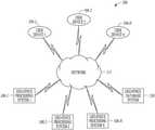
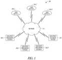
- FIG. 1is a block diagram of an example system 100 for defining and utilizing a geo-fence, in accordance with an example embodiment.
- the system 100may include one or more user devices 104 - 1 , 104 - 2 and 104 -N (known as user devices 104 hereinafter), one or more geo-fence processing systems 108 - 1 , 108 - 2 and 108 -N (known as geo-fence processing systems 108 hereinafter), a geo-fence database system 130 , and a network 115 .
- the geo-fence database system 130may maintain the definition of one or more geo-fences.
- the geo-fence database system 130may comprise information used for defining a geo-fence, such as electronic commerce item listings and historical records, client device information, demographic information, and the like.
- the network 115may be may be an ad hoc network, an intranet, an extranet, a virtual private network (VPN), a local area network (LAN), a wireless LAN (WLAN), a wide area network (WAN), a wireless WAN (WWAN), a metropolitan area network (MAN), a portion of the Internet, a portion of the Public Switched. Telephone Network (PSTN), a cellular telephone network, another type of network, a network of interconnected networks, or a combination of two or more such networks, and the like.
- VPNvirtual private network
- LANlocal area network
- WLANwireless LAN
- WANwide area network
- WWANwireless WAN
- MANmetropolitan area network
- PSTNPublic Switched. Telephone Network
- PSTNPublic Switched. Telephone Network
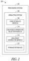
- the one or more geo-fence generator modules 214may generate and/or establish a geo-fence.
- the definition of the geo-fencemay include an indication of the boundaries of the geo-fence.
- the area encompassed by a geo-fencemay include one or more locations associated with the geo-fence, such as the location of a commercial establishment, or may exclude one or more of the locations associated with the geo-fence.
- the one or more geo-fence generator modules 214may activate a geo-fence and/or modify a geo-fence based on user commands and/or automatically based on predefined criteria.
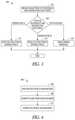
- FIG. 3is a flowchart for an example geo-fence generator selection method 300 , in accordance with an example embodiment.
- the geo-fence generator selection method 300may enable the selection of the method (i.e., geo-fence generator technique) for defining a geo-fence.
- the geo-fence generator selection method 300may be based on a user selection and/or may be automatically selected based on predefined criteria. In one example embodiment, one or more of the operations of the geo-fence generator selection method 300 may be performed by the geo-fence generator selection module 210 .
- a selection of a geo-fence generator techniquemay be obtained (operation 304 ).
- a selection of a geo-fence generator technique and associated parametersmay be obtained from a user.
- a selection of a geo-fence generator technique and associated parametersmay be obtained from a user via, for example, user device 104 - 1 , as described more fully below in conjunction with FIGS. 5 and 6 .
- a trigger(s)such as one or more of the triggers described more fully above, may occur that will invoke a geo-fence generator technique.
- one or more geo-fence generator methods corresponding to the triggermay be selected. For example, a change in demographic information may trigger the modification of a geo-fence based on a corresponding geo-fence generator method, such as the demographic generator technique and/or the time generator technique.
- a testmay be performed to determine the type of geo-fence generator method to execute (operation 308 ). For example, the selection obtained from a user may be compared to a list of available geo-fence generator techniques. If one of the available geo-fence generator techniques matches the obtained selection, then the geo-fence generator method corresponding to the selected technique may be executed (operations 312 and 316 ); otherwise, an error message may be returned indicating that the selected geo-fence generator method is not available (operation 320 ). The method may then end.
- FIG. 4is a flowchart for an example geo-fence generator method 400 , in accordance with an example embodiment.
- the geo-fence generator method 400may generate or modify a geo-fence and define, or redefine, the boundaries of the geo-fence.
- one or more of the operations of the geo-fence generator method 400may be performed by the geo-fence generator module 214 .
- one or more parameters of the geo-fence to be generatedmay be obtained (operation 404 ).
- one or more parameters of the geo-fence to be generatedmay be obtained from the user device 104 - 1 .
- one or more parameters of the geo-fence, such as the locale of the geo-fencemay be obtained, for example, from the geo-fence generator selection module 210 .
- the boundaries of the geo-fencemay be computed based on the obtained parameters (operation 408 ), as described more fully below.
- the computed geo-fencemay or may not encompass the locale.
- the boundaries of a geo-fencemay be a circle, a rectangle, an octagon, or any arbitrary shape.
- the geo-fenceis based on a volume and/or weight of an item
- the volume and/or weighte.g., 5 kilograms
- the target demographic of the geo-fencee.g., 550 college students
- the obtained parametermay be multiplied by a multiplication factor to determine the radius of the circle that defines the geo-fence.
- the geo-fenceis based on a listing density of a type of item, the listing density for the type of item may be obtained and may be multiplied by a multiplication factor.
- the number of item listings corresponding to the obtained type of listing within a one-mile radius of the obtained localemay be obtained from the geo-fence database system 130 and may be multiplied by a multiplication factor.
- the geo-fenceis based on a user's behavior and/or history
- the user's behavior and/or historye.g., percentage of listed items that are sold
- the multiplication factormay be greater than one, may be equal to one, or may be less than one.
- the boundarymay be defined using externally generated data. For example, a map identifying the demographic population of different geographical areas may be used to generate a geo-fence based on demographics.
- FIG. 5is a representation of an example user interface 500 for defining a geo-fence, in accordance with an example embodiment.
- the user interface 500may be utilized by user device 104 - 1 to enable a user to define and/or generate a geo-fence.
- an identifier of a geo-fencesuch as a geo-fence name
- a type of geo-fence generator methodmay be selected from a drop-down menu 508 .
- a parameter field area 512may be displayed that corresponds to the selected type of geo-fence generator method. For example, as illustrated in FIG.
- the parameter field area 512may comprise a locale entry field 516 for entering the latitude and longitude coordinates of the locale for the geo-fence and may comprise a geo-fence shape entry field 520 for entering the shape of the geo-fence, e.g., a circle, a rectangle, or any arbitrary shape.
- the geo-fencemay, for example, encompass a circular area centered at the coordinates defined in the locale entry field 516 .
- the selected geo-fencemay be generated and/or updated by selecting the “establish geo-fence” radio button 524 .
- FIG. 6is a flowchart for an example user interface method 600 for defining a geo-fence, in accordance with an example embodiment.
- one or more of the operations of the user interface method 600may be performed by the user interface module 206 .
- an identifier of a geo-fencesuch as a geo-fence name
- a selection of a type of geo-fence generator methodmay be obtained from the drop-down menu 508 (operation 608 ).
- a parameter field template corresponding to the obtained geo-fence generator method selectionmay be obtained (operation 612 ).
- a parameter field templatemay be obtained from a local template table and/or may be obtained from the geo-fence database system 130 .
- the obtained parameter field templatemay be displayed in the parameter field area 512 , as illustrated in FIG. 5 (operation 616 ).
- One or more parameters entered by a user in the parameter field area 512may be obtained (operation 620 ). For example, the latitude and longitude coordinates of the locale for the geo-fence may be obtained.
- a testmay be performed to determine if the “establish geo-fence” radio button 524 was selected (operation 624 ). If the “establish geo-fence” radio button 524 was selected, the obtained parameters may be passed to the geo-fence generator module 214 corresponding to the selected geo-fence generator technique (operation 628 ). The method may then end.
- Modulesmay constitute either software modules (e.g., code embodied (1) on a non-transitory machine-readable medium or (2) in a transmission signal) or hardware-implemented modules.
- a hardware-implemented moduleis a tangible unit capable of performing certain operations and may be configured or arranged in a certain manner.
- one or more computer systemse.g., a standalone, client or server computer system
- one or more processorsmay be configured by software (e.g., an application or application portion) as a hardware-implemented module that operates to perform certain operations as described herein.
- a hardware-implemented modulemay be implemented mechanically or electronically.
- a hardware-implemented modulemay include dedicated circuitry or logic that is permanently configured (e.g., as a special-purpose processor, such as a field programmable gate array (FPGA) or an application-specific integrated circuit (ASIC)) to perform certain operations.
- a hardware-implemented modulemay also include programmable logic or circuitry (e.g., as encompassed within a general-purpose processor or other programmable processor) that is temporarily configured by software to perform certain operations. It will be appreciated that the decision to implement a hardware-implemented module mechanically, in dedicated and permanently configured circuitry, or in temporarily configured circuitry (e.g., configured by software) may be driven by cost and time considerations.
- the term “hardware-implemented module”should be understood to encompass a tangible entity, be that an entity that is physically constructed, permanently configured (e.g., hardwired) or temporarily or transitorily configured (e.g., programmed) to operate in a certain manner and/or to perform certain operations described herein.
- hardware-implemented modulesare temporarily configured (e.g., programmed)
- each of the hardware-implemented modulesneed not be configured or instantiated at any one instance in time.
- the hardware-implemented modulesinclude a general-purpose processor configured using software
- the general-purpose processormay be configured as respectively different hardware-implemented modules at different times.
- Softwaremay, accordingly, configure a processor, for example, to constitute a particular hardware-implemented module at one instance of time and to constitute a different hardware-implemented module at a different instance of time.
- Hardware-implemented modulescan provide information to, and receive information from, other hardware-implemented modules. Accordingly, the described hardware-implemented modules may be regarded as being communicatively coupled. Where multiples of such hardware-implemented modules exist contemporaneously, communications may be achieved through signal transmission (e.g., over appropriate circuits and buses) that connects the hardware-implemented modules. In embodiments in which multiple hardware-implemented modules are configured or instantiated at different times, communications between such hardware-implemented modules may be achieved, for example, through the storage and retrieval of information in memory structures to which the multiple hardware-implemented modules have access. For example, one hardware-implemented module may perform an operation and store the output of that operation in a memory device to which it is communicatively coupled.
- a further hardware-implemented modulemay then, at a later time, access the memory device to retrieve and process the stored output.
- Hardware-implemented modulesmay also initiate communications with input or output devices, and can operate on a resource (e.g., a collection of information).
- processorsmay be temporarily configured (e.g., by software) or permanently configured to perform the relevant operations. Whether temporarily or permanently configured, such processors may constitute processor-implemented modules that operate to perform one or more operations or functions.
- the modules referred to hereinmay, in some example embodiments, include processor-implemented modules.
- the methods described hereinmay be at least partially processor-implemented. For example, at least some of the operations of a method may be performed by one or more processors or processor-implemented modules. The performance of certain of the operations may be distributed among the one or more processors, not only residing within a single machine, but also deployed across a number of machines. In some example embodiments, the processor or processors may be located in a single location (e.g., within a home environment, an office environment or as a server faun), while in other embodiments, the processors may be distributed across a number of locations.
- the one or more processorsmay also operate to support performance of the relevant operations in a “cloud computing” environment or as a “software as a service” (SaaS). For example, at least some of the operations may be performed by a group of computers (as examples of machines including processors), these operations being accessible via a network 115 (e.g., the Internet) and via one or more appropriate interfaces (e.g., application program interfaces (APIs).)
- a network 115e.g., the Internet
- APIsapplication program interfaces
- a computer programcan be written in any form of programming language, including compiled or interpreted languages, and it can be deployed in any form, including as a stand-alone program or as a module, subroutine, or other unit suitable for use in a computing environment.
- a computer programcan be deployed to be executed on one computer or on multiple computers, at one site or distributed across multiple sites, and interconnected by a communication network.
- the example computer system 700includes a processor 702 (e.g., a central processing unit (CPU), a graphics processing unit (GPU) or both), a main memory 704 and a static memory 706 , which communicate with each other via a bus 708 .
- the computer system 700may further include a video display unit 710 (e.g., a liquid crystal display (LCD) or a cathode ray tube (CRT)).
- the computer system 700also includes an alphanumeric input device 712 (e.g., a keyboard), a user interface (UI) navigation device (cursor control device) 714 (e.g., a mouse), a disk drive unit 716 , a signal generation device 718 (e.g., a speaker) and a network interface device 720 .
- an alphanumeric input device 712e.g., a keyboard
- UIuser interface
- cursor control devicee.g., a mouse
- disk drive unit 716e.g., a disk drive unit 716
- signal generation device 718e.g., a speaker
- network interface device 720e.g., a network interface device
- machine-readable medium 722is shown in an example embodiment to be a single medium, the term “machine-readable medium” may include a single medium or multiple media (e.g., a centralized or distributed database, and/or associated caches and servers) that store the one or more instructions or data structures 724 .
- the term “machine-readable medium”shall also be taken to include any tangible medium that is capable of storing, encoding or carrying instructions 724 for execution by the machine and that cause the machine to perform any one or more of the methodologies of the present invention, or that is capable of storing, encoding or carrying data structures utilized by or associated with such instructions 724 .
- the term “machine-readable medium”shall accordingly be taken to include, but not be limited to, solid-state memories, and optical and magnetic media.
Landscapes
- Business, Economics & Management (AREA)
- Engineering & Computer Science (AREA)
- Accounting & Taxation (AREA)
- Development Economics (AREA)
- Finance (AREA)
- Strategic Management (AREA)
- Entrepreneurship & Innovation (AREA)
- Physics & Mathematics (AREA)
- Marketing (AREA)
- Theoretical Computer Science (AREA)
- Game Theory and Decision Science (AREA)
- Economics (AREA)
- General Business, Economics & Management (AREA)
- General Physics & Mathematics (AREA)
- Computer Networks & Wireless Communication (AREA)
- Signal Processing (AREA)
- Data Mining & Analysis (AREA)
- Probability & Statistics with Applications (AREA)
- Mobile Radio Communication Systems (AREA)
- Traffic Control Systems (AREA)
- Telephonic Communication Services (AREA)
- User Interface Of Digital Computer (AREA)
- Alarm Systems (AREA)
Abstract
Description
- Criteria: human population and/or density of human population.
- Triggers: 1) a percentage change in human population exceeding a threshold; 2) the human population being within a defined population range; 3) a percentage change in the density of the human population exceeding a threshold; and 4) a density of human population being within a defined density range.
- Boundary Definition: 1) a circle with a center located at a selected locale and a radius proportional to the selected criteria.
Establishments
- Criteria: density of establishments and/or a count of establishments (may include only establishments of a similar type).
- Triggers: 1) a percentage change in a count of establishments exceeding a threshold; 2) a count of establishments being within a defined range; 3) a percentage change in a density of establishments exceeding a threshold; and 4) a density of establishments being within a defined density range.
- Boundary Definition: 1) a circle with a center located at a selected locale and a radius proportional to the selected criteria.
Density of Electronic Commerce Listings
- Criteria: density of electronic commerce listings and/or a count of electronic commerce listings (may include only electronic commerce listings of a similar type).
- Triggers: 1) a percentage change in a count of electronic commerce listings exceeding a threshold; 2) a count of electronic commerce listings being within a defined range; 3) a percentage change in a density of electronic commerce listings exceeding a threshold; and 4) a density of electronic commerce listings being within a defined density range.
- Boundary Definition: 1) a circle with a center located at a selected locale and a radius proportional to the selected criteria.
Density of Geo-Fences
- Criteria: density of geo-fences and/or a count of geo-fences.
- Triggers: 1) a percentage change in a count of geo-fences exceeding a threshold; 2) a count of geo-fences being within a defined range; 3) a percentage change in a density of geo-fences exceeding a threshold; and 4) a density geo-fences being within a defined density range.
- Boundary Definition: 1) a circle with a center located at a selected locale and a radius proportional to the selected criteria.
Item Value
- Criteria: an item value.
- Triggers: 1) an item value being within a defined range; and a percentage change in an item value exceeding a threshold.
- Boundary Definition: 1) a circle with a center located at a selected locale and a radius proportional to the selected criteria.
Item Popularity
- Criteria: a popularity of an item based on a number of online searches for the item, a number of online views of an item, and/or a number of sales of the item.
- Triggers: 1) a popularity of an item being within a defined range; and 2) a percentage change in a popularity of an item exceeding a threshold.
- Boundary Definition: 1) a circle with a center located at a selected locale and a radius proportional to the selected criteria.
Item Characteristics
- Criteria: one or more item characteristics.
- Triggers: 1) an item characteristic being within a defined range; and 2) a percentage change in an item characteristic exceeding a threshold.
- Boundary Definition: 1) a circle with a center located at a selected locale and a radius proportional to the selected criteria; 2) an area served by one or more delivery companies; and 3) an area served by one or more delivery companies that can accommodate the selected item characteristic.
Demographics
- Criteria: demographics of human population.
- Triggers: reception of new demographic information.
- Boundary Definition: 1) an area where a selected demographic exceeds a threshold value.
Travel Time
- Criteria: travel time.
- Triggers: 1) traffic congestion; 2) roadway construction; and 3) mass transit congestion.
- Boundary Definition: 1) an area where a travel time to a selected location is less than a threshold travel time.
User Characteristic
- Criteria: characteristics of a user, such as seller track record.
- Triggers: reception of revised user characteristics.
- Boundary Definition: 1) a circle with a center located at a selected locale and a radius proportional to the selected criteria.
User Travel
- Criteria: Itinerary of a user.
- Triggers: 1) reception of a new itinerary; and 2) changes to an existing itinerary.
Time of Day
- Criteria: a time of day, such as a defined time period.
- Triggers: defined time-of-day alarm.
- Boundary Definition: Defined by an associated geo-fence generator technique.
Combination of Techniques
Claims (6)
Priority Applications (1)
| Application Number | Priority Date | Filing Date | Title |
|---|---|---|---|
| US16/874,720US11252531B2 (en) | 2013-12-05 | 2020-05-15 | Methods, systems, and apparatus for a geo-fence system |
Applications Claiming Priority (4)
| Application Number | Priority Date | Filing Date | Title |
|---|---|---|---|
| US14/098,111US9307359B2 (en) | 2013-12-05 | 2013-12-05 | Methods, systems, and apparatus for a geo-fence system |
| US15/070,178US9967706B2 (en) | 2013-12-05 | 2016-03-15 | Methods, systems, and apparatus for a geo-fence system |
| US15/951,416US10694317B2 (en) | 2013-12-05 | 2018-04-12 | Methods, systems, and apparatus for a geo-fence system |
| US16/874,720US11252531B2 (en) | 2013-12-05 | 2020-05-15 | Methods, systems, and apparatus for a geo-fence system |
Related Parent Applications (1)
| Application Number | Title | Priority Date | Filing Date |
|---|---|---|---|
| US15/951,416ContinuationUS10694317B2 (en) | 2013-12-05 | 2018-04-12 | Methods, systems, and apparatus for a geo-fence system |
Publications (2)
| Publication Number | Publication Date |
|---|---|
| US20200336859A1 US20200336859A1 (en) | 2020-10-22 |
| US11252531B2true US11252531B2 (en) | 2022-02-15 |
Family
ID=53272488
Family Applications (4)
| Application Number | Title | Priority Date | Filing Date |
|---|---|---|---|
| US14/098,111Active2034-02-15US9307359B2 (en) | 2013-12-05 | 2013-12-05 | Methods, systems, and apparatus for a geo-fence system |
| US15/070,178ActiveUS9967706B2 (en) | 2013-12-05 | 2016-03-15 | Methods, systems, and apparatus for a geo-fence system |
| US15/951,416ActiveUS10694317B2 (en) | 2013-12-05 | 2018-04-12 | Methods, systems, and apparatus for a geo-fence system |
| US16/874,720ActiveUS11252531B2 (en) | 2013-12-05 | 2020-05-15 | Methods, systems, and apparatus for a geo-fence system |
Family Applications Before (3)
| Application Number | Title | Priority Date | Filing Date |
|---|---|---|---|
| US14/098,111Active2034-02-15US9307359B2 (en) | 2013-12-05 | 2013-12-05 | Methods, systems, and apparatus for a geo-fence system |
| US15/070,178ActiveUS9967706B2 (en) | 2013-12-05 | 2016-03-15 | Methods, systems, and apparatus for a geo-fence system |
| US15/951,416ActiveUS10694317B2 (en) | 2013-12-05 | 2018-04-12 | Methods, systems, and apparatus for a geo-fence system |
Country Status (7)
| Country | Link |
|---|---|
| US (4) | US9307359B2 (en) |
| EP (1) | EP3074723B1 (en) |
| KR (7) | KR101958614B1 (en) |
| CN (2) | CN107396317A (en) |
| AU (2) | AU2014360332B2 (en) |
| CA (1) | CA2931531A1 (en) |
| WO (1) | WO2015085176A1 (en) |
Families Citing this family (47)
| Publication number | Priority date | Publication date | Assignee | Title |
|---|---|---|---|---|
| US9084082B2 (en) | 2013-11-18 | 2015-07-14 | Aol Inc. | Systems and methods for optimizing message notification timing based on geographic location |
| US9307359B2 (en) | 2013-12-05 | 2016-04-05 | Ebay Inc. | Methods, systems, and apparatus for a geo-fence system |
| US9628950B1 (en) | 2014-01-12 | 2017-04-18 | Investment Asset Holdings Llc | Location-based messaging |
| US20150213496A1 (en)* | 2014-01-24 | 2015-07-30 | Aol Inc. | Methods and systems for displaying electronic content to individuals in geographic zone having inner boundary |
| US10783554B1 (en)* | 2014-02-25 | 2020-09-22 | Groupon, Inc. | Generation of promotion in an augmented reality |
| US9325654B2 (en) | 2014-02-28 | 2016-04-26 | Aol Inc. | Systems and methods for optimizing message notification timing based on electronic content consumption associated with a geographic location |
| US9584968B2 (en)* | 2014-05-21 | 2017-02-28 | Aol Inc. | Systems and methods for deploying dynamic geo-fences based on content consumption levels in a geographic location |
| US9396354B1 (en) | 2014-05-28 | 2016-07-19 | Snapchat, Inc. | Apparatus and method for automated privacy protection in distributed images |
| US11477602B2 (en) | 2014-06-10 | 2022-10-18 | Verizon Patent And Licensing Inc. | Systems and methods for optimizing and refining message notification timing |
| US10824654B2 (en) | 2014-09-18 | 2020-11-03 | Snap Inc. | Geolocation-based pictographs |
| US11216869B2 (en) | 2014-09-23 | 2022-01-04 | Snap Inc. | User interface to augment an image using geolocation |
| US10231111B2 (en)* | 2014-10-03 | 2019-03-12 | Daniel Ursitti | System and method for establishing a user connection |
| US9706519B2 (en)* | 2014-10-03 | 2017-07-11 | Daniel Ursitti | System and method for establishing a user connection |
| US9015285B1 (en) | 2014-11-12 | 2015-04-21 | Snapchat, Inc. | User interface for accessing media at a geographic location |
| US10311916B2 (en) | 2014-12-19 | 2019-06-04 | Snap Inc. | Gallery of videos set to an audio time line |
| US9385983B1 (en) | 2014-12-19 | 2016-07-05 | Snapchat, Inc. | Gallery of messages from individuals with a shared interest |
| KR102662169B1 (en) | 2015-03-18 | 2024-05-03 | 스냅 인코포레이티드 | Geo-fence authorization provisioning |
| US9571968B1 (en)* | 2015-07-21 | 2017-02-14 | International Business Machines Corporation | Geo-fence management using a cluster analysis technique |
| KR102374438B1 (en)* | 2015-08-10 | 2022-03-15 | 삼성전자주식회사 | Method for managing geo-fence and electronic device thereof |
| US10120948B2 (en)* | 2015-10-13 | 2018-11-06 | Google Llc | Providing notifications based on geofencing search results |
| US10592847B2 (en)* | 2015-12-02 | 2020-03-17 | Walmart Apollo, Llc | Method and system to support order collection using a geo-fence |
| US10354425B2 (en) | 2015-12-18 | 2019-07-16 | Snap Inc. | Method and system for providing context relevant media augmentation |
| US11900418B2 (en) | 2016-04-04 | 2024-02-13 | Snap Inc. | Mutable geo-fencing system |
| WO2018009082A1 (en)* | 2016-07-08 | 2018-01-11 | Motorola Solutions, Inc. | Method and apparatus for setting geofence boundaries |
| US9706355B1 (en) | 2016-08-12 | 2017-07-11 | Contagious Atmosphere LLC | Systems and methods for automatically generating geofences based on property information |
| EP3513320B1 (en)* | 2016-09-15 | 2021-12-01 | Oracle International Corporation | Spatial change detector in stream data |
| US10255619B2 (en)* | 2016-10-03 | 2019-04-09 | International Business Machines Corporation | Dynamic geo-fencing based on a popularity of a product |
| US10397734B2 (en)* | 2016-11-11 | 2019-08-27 | International Business Machines Corporation | System and methodology for activating geofence from selection list |
| US9922531B1 (en) | 2016-12-21 | 2018-03-20 | Tile, Inc. | Safe zones in tracking device environments |
| US10915911B2 (en)* | 2017-02-03 | 2021-02-09 | Snap Inc. | System to determine a price-schedule to distribute media content |
| US11049142B2 (en)* | 2017-02-16 | 2021-06-29 | Adobe Inc. | Smart geo-fencing using location sensitive product affinity |
| US10582277B2 (en) | 2017-03-27 | 2020-03-03 | Snap Inc. | Generating a stitched data stream |
| CN107517443A (en)* | 2017-08-24 | 2017-12-26 | 北京摩拜科技有限公司 | District management method, server, client, the management system of shared vehicle |
| US10796573B2 (en)* | 2018-01-15 | 2020-10-06 | Ford Global Technologies, Llc | Crowd-based vehicular geofencing |
| US20190313204A1 (en)* | 2018-04-09 | 2019-10-10 | Blackberry Limited | Method and system for generation of geofence shape |
| US10440509B1 (en)* | 2018-04-16 | 2019-10-08 | Walgreen Co. | Technology for managing location-based functionalities for electronic devices |
| US11157930B1 (en)* | 2018-06-26 | 2021-10-26 | Amazon Technologies, Inc. | Systems and methods for defining candidate and target locations based on items and user attributes |
| CN110674834A (en)* | 2018-07-03 | 2020-01-10 | 百度在线网络技术(北京)有限公司 | Geo-fence identification method, device, equipment and computer-readable storage medium |
| US11037450B2 (en)* | 2019-01-04 | 2021-06-15 | Ford Global Technologies, Llc | Using geofences to restrict vehicle operation |
| KR20200110050A (en)* | 2019-03-15 | 2020-09-23 | 삼성전자주식회사 | Electronic device and method for dynaminc geofencing in the electronic device |
| US10952015B2 (en) | 2019-04-10 | 2021-03-16 | Bank Of America Corporation | Interlinked geo-fencing |
| CN110599717B (en)* | 2019-07-30 | 2021-07-20 | 华为技术有限公司 | Electronic fence detection method and electronic equipment |
| CN111277952B (en)* | 2020-01-17 | 2021-11-26 | 清研讯科(北京)科技有限公司 | Electronic fence information processing method and system, positioning tag and mobile device |
| US11184365B1 (en) | 2020-06-18 | 2021-11-23 | Bank Of America Corporation | System for data authentication optimization based on real time and historical resource information |
| US11665163B2 (en) | 2020-06-18 | 2023-05-30 | Bank Of America Corporation | System for dynamic resource allocation based on real time geographic data |
| US11234098B1 (en) | 2020-07-01 | 2022-01-25 | Motorola Solutions, Inc. | Method and apparatus for setting geofence |
| CN113641284B (en)* | 2021-07-27 | 2024-02-09 | 北京中交兴路车联网科技有限公司 | Regional plotting method and device of electronic map, electronic equipment and storage medium |
Citations (38)
| Publication number | Priority date | Publication date | Assignee | Title |
|---|---|---|---|---|
| US20020077127A1 (en)* | 2000-12-19 | 2002-06-20 | Motorola, Inc. | Method for masking the location of a mobile subscriber in a cellular communications network |
| US6581546B1 (en) | 2002-02-14 | 2003-06-24 | Waters Instruments, Inc. | Animal containment system having a dynamically changing perimeter |
| US20030187803A1 (en)* | 2002-03-28 | 2003-10-02 | Pitt Lance Douglas | Location fidelity adjustment based on mobile subscriber privacy profile |
| US6665613B2 (en) | 2001-09-25 | 2003-12-16 | Lojack Corporation | Method of and apparatus for dynamically GoeFencing movable vehicle and other equipment and the like |
| US20060193280A1 (en) | 2004-12-29 | 2006-08-31 | Samsung Electronics Co., Ltd. | Relay communication method for an OFDMA-based cellular communication system |
| US20070077929A1 (en) | 2003-04-25 | 2007-04-05 | Utstarcom (China) Co., Ltd. | Method for implementing macro-diversity management by using intelligent vbs |
| US20070232311A1 (en) | 2006-03-28 | 2007-10-04 | Alcatel Lucent | Decision mechanism for handover execution in a cellular radio communications system |
| US20100003610A1 (en) | 2008-07-03 | 2010-01-07 | Jane Elece Barcelo | Electrophotographic Roller With Resistance to Nip Banding |
| US20100041419A1 (en) | 2008-08-12 | 2010-02-18 | Kota Enterprises, Llc | Customized content delivery through the use of arbitrary geographic shapes |
| US20100042940A1 (en)* | 2008-08-14 | 2010-02-18 | Caterpillar Inc. | Geofence system with integrated user interface |
| US20100064373A1 (en)* | 2008-09-05 | 2010-03-11 | Iowa State University Research Foundation, Inc. | Cloaking with footprints to provide location privacy protection in location-based services |
| WO2010077229A1 (en) | 2008-12-31 | 2010-07-08 | Tele Atlas North America, Inc. | Systems and methods for processing information related to a geographic region |
| US20100262449A1 (en) | 2009-04-09 | 2010-10-14 | Access Mobility, Inc. | Context based mobile marketing |
| US20100312842A1 (en)* | 2009-06-08 | 2010-12-09 | Ladouceur Dave J | Heterogeneous Network Delivery of Electronic Messages in Accordance with Privacy and Personalization Criteria |
| CN102089793A (en) | 2008-07-16 | 2011-06-08 | 高通股份有限公司 | Method for dynamic creation of a geofence in a wireless system |
| US8018329B2 (en) | 2008-12-12 | 2011-09-13 | Gordon * Howard Associates, Inc. | Automated geo-fence boundary configuration and activation |
| US20120172027A1 (en) | 2011-01-03 | 2012-07-05 | Mani Partheesh | Use of geofences for location-based activation and control of services |
| US20120231773A1 (en) | 1999-08-27 | 2012-09-13 | Lipovski Gerald John Jack | Cuboid-based systems and methods for safe mobile texting. |
| US20120284769A1 (en) | 2011-05-06 | 2012-11-08 | Kyle Dixon | Systems and Methods of Intelligent Policy-Based Geo-Fencing |
| US20120310527A1 (en) | 2011-05-30 | 2012-12-06 | Microsoft Corporation | Asymmetric dynamic geo-fencing |
| US8331236B2 (en) | 2006-08-30 | 2012-12-11 | Nokia Siemens Networks S.P.A. | Method to balance traffic load between nearby LTE/WiMAX cells grouped into inner and border constellations |
| US20130030391A1 (en) | 2010-04-16 | 2013-01-31 | Poly Medicure Limited | Catheter Apparatus |
| US20130030931A1 (en) | 2011-07-26 | 2013-01-31 | Mehran Moshfeghi | Method and System for Location Based Hands-Free Payment |
| CN102930107A (en) | 2011-11-09 | 2013-02-13 | 微软公司 | A geography fence based on geography mark media |
| US20130099977A1 (en) | 2011-10-20 | 2013-04-25 | Qualcomm Incorporated | Method and/or apparatus for geofence management |
| US20130212065A1 (en) | 2012-02-15 | 2013-08-15 | Flybits, Inc. | Zone Oriented Applications, Systems and Methods |
| US20130246175A1 (en) | 2011-12-05 | 2013-09-19 | Qualcomm Labs, Inc. | Selectively presenting advertisements to a customer of a service based on a place movement pattern profile |
| US20130261654A1 (en)* | 2010-10-07 | 2013-10-03 | Reshape Medical, Inc. | Materials and methods for improved intragastric balloon devices |
| US20140029468A1 (en)* | 2012-07-30 | 2014-01-30 | Qualcomm Incorporated | Adaptive Access Point Database Management |
| US20140279123A1 (en) | 2013-03-14 | 2014-09-18 | Bank Of America Corporation | Geolocation check-in system |
| US20140274151A1 (en)* | 2013-03-15 | 2014-09-18 | Nextnav, Llc | Systems and Methods for Using Three-Dimensional Location Information to improve Location Services |
| US20150095355A1 (en) | 2012-11-15 | 2015-04-02 | Banjo, Inc. | Systems and methods for dynamic event content curation |
| US20150095157A1 (en) | 2013-09-30 | 2015-04-02 | Mapquest, Inc. | Methods and systems for defining targeted geographic zones for delivering electronic content |
| WO2015085176A1 (en) | 2013-12-05 | 2015-06-11 | Ebay Inc. | A geo-fence system |
| US9137636B2 (en) | 2005-03-07 | 2015-09-15 | Telecommunication Systems, Inc. | Method and system for identifying and defining geofences |
| US9439122B2 (en) | 2011-01-28 | 2016-09-06 | Alcatel Lucent | Method for performing a handover of a mobile device |
| US20170220668A1 (en)* | 2012-10-02 | 2017-08-03 | Banjo, Inc. | Dynamic event detection system and method |
| US10091646B2 (en)* | 2014-08-29 | 2018-10-02 | Apple Inc. | Reduced resolution location determination for improved anonymity of user location |
- 2013
- 2013-12-05USUS14/098,111patent/US9307359B2/enactiveActive
- 2014
- 2014-12-05WOPCT/US2014/068803patent/WO2015085176A1/enactiveApplication Filing
- 2014-12-05CNCN201710727479.2Apatent/CN107396317A/enactivePending
- 2014-12-05KRKR1020187033261Apatent/KR101958614B1/ennot_activeExpired - Fee Related
- 2014-12-05KRKR1020187003798Apatent/KR101922390B1/enactiveActive
- 2014-12-05KRKR1020197006730Apatent/KR102082358B1/enactiveActive
- 2014-12-05KRKR1020177005770Apatent/KR101832798B1/enactiveActive
- 2014-12-05EPEP14867705.7Apatent/EP3074723B1/enactiveActive
- 2014-12-05KRKR1020207005190Apatent/KR102178193B1/enactiveActive
- 2014-12-05CNCN201480073776.4Apatent/CN105934650B/enactiveActive
- 2014-12-05KRKR1020167017866Apatent/KR101714336B1/ennot_activeExpired - Fee Related
- 2014-12-05KRKR1020207032168Apatent/KR102247768B1/enactiveActive
- 2014-12-05AUAU2014360332Apatent/AU2014360332B2/enactiveActive
- 2014-12-05CACA2931531Apatent/CA2931531A1/ennot_activeAbandoned
- 2016
- 2016-03-15USUS15/070,178patent/US9967706B2/enactiveActive
- 2016-10-14AUAU2016101804Apatent/AU2016101804A4/ennot_activeCeased
- 2018
- 2018-04-12USUS15/951,416patent/US10694317B2/enactiveActive
- 2020
- 2020-05-15USUS16/874,720patent/US11252531B2/enactiveActive
Patent Citations (47)
| Publication number | Priority date | Publication date | Assignee | Title |
|---|---|---|---|---|
| US20120231773A1 (en) | 1999-08-27 | 2012-09-13 | Lipovski Gerald John Jack | Cuboid-based systems and methods for safe mobile texting. |
| US20020077127A1 (en)* | 2000-12-19 | 2002-06-20 | Motorola, Inc. | Method for masking the location of a mobile subscriber in a cellular communications network |
| US6665613B2 (en) | 2001-09-25 | 2003-12-16 | Lojack Corporation | Method of and apparatus for dynamically GoeFencing movable vehicle and other equipment and the like |
| US6581546B1 (en) | 2002-02-14 | 2003-06-24 | Waters Instruments, Inc. | Animal containment system having a dynamically changing perimeter |
| US20030187803A1 (en)* | 2002-03-28 | 2003-10-02 | Pitt Lance Douglas | Location fidelity adjustment based on mobile subscriber privacy profile |
| US20070077929A1 (en) | 2003-04-25 | 2007-04-05 | Utstarcom (China) Co., Ltd. | Method for implementing macro-diversity management by using intelligent vbs |
| US20060193280A1 (en) | 2004-12-29 | 2006-08-31 | Samsung Electronics Co., Ltd. | Relay communication method for an OFDMA-based cellular communication system |
| US9137636B2 (en) | 2005-03-07 | 2015-09-15 | Telecommunication Systems, Inc. | Method and system for identifying and defining geofences |
| US20070232311A1 (en) | 2006-03-28 | 2007-10-04 | Alcatel Lucent | Decision mechanism for handover execution in a cellular radio communications system |
| US8331236B2 (en) | 2006-08-30 | 2012-12-11 | Nokia Siemens Networks S.P.A. | Method to balance traffic load between nearby LTE/WiMAX cells grouped into inner and border constellations |
| US20100003610A1 (en) | 2008-07-03 | 2010-01-07 | Jane Elece Barcelo | Electrophotographic Roller With Resistance to Nip Banding |
| CN102089793A (en) | 2008-07-16 | 2011-06-08 | 高通股份有限公司 | Method for dynamic creation of a geofence in a wireless system |
| CN101655959A (en) | 2008-08-12 | 2010-02-24 | 科塔企业有限责任公司 | Customized content delivery through the use of arbitrary geographic shapes |
| US20100041419A1 (en) | 2008-08-12 | 2010-02-18 | Kota Enterprises, Llc | Customized content delivery through the use of arbitrary geographic shapes |
| US20100042940A1 (en)* | 2008-08-14 | 2010-02-18 | Caterpillar Inc. | Geofence system with integrated user interface |
| US20100064373A1 (en)* | 2008-09-05 | 2010-03-11 | Iowa State University Research Foundation, Inc. | Cloaking with footprints to provide location privacy protection in location-based services |
| US8018329B2 (en) | 2008-12-12 | 2011-09-13 | Gordon * Howard Associates, Inc. | Automated geo-fence boundary configuration and activation |
| CN102272552A (en) | 2008-12-31 | 2011-12-07 | 电子地图北美公司 | Systems and methods for processing information related to a geographic region |
| WO2010077229A1 (en) | 2008-12-31 | 2010-07-08 | Tele Atlas North America, Inc. | Systems and methods for processing information related to a geographic region |
| US20100262449A1 (en) | 2009-04-09 | 2010-10-14 | Access Mobility, Inc. | Context based mobile marketing |
| US20100312842A1 (en)* | 2009-06-08 | 2010-12-09 | Ladouceur Dave J | Heterogeneous Network Delivery of Electronic Messages in Accordance with Privacy and Personalization Criteria |
| US20130030391A1 (en) | 2010-04-16 | 2013-01-31 | Poly Medicure Limited | Catheter Apparatus |
| US20130261654A1 (en)* | 2010-10-07 | 2013-10-03 | Reshape Medical, Inc. | Materials and methods for improved intragastric balloon devices |
| US20120172027A1 (en) | 2011-01-03 | 2012-07-05 | Mani Partheesh | Use of geofences for location-based activation and control of services |
| US9439122B2 (en) | 2011-01-28 | 2016-09-06 | Alcatel Lucent | Method for performing a handover of a mobile device |
| US20120284769A1 (en) | 2011-05-06 | 2012-11-08 | Kyle Dixon | Systems and Methods of Intelligent Policy-Based Geo-Fencing |
| US20120310527A1 (en) | 2011-05-30 | 2012-12-06 | Microsoft Corporation | Asymmetric dynamic geo-fencing |
| US20130030931A1 (en) | 2011-07-26 | 2013-01-31 | Mehran Moshfeghi | Method and System for Location Based Hands-Free Payment |
| US20130099977A1 (en) | 2011-10-20 | 2013-04-25 | Qualcomm Incorporated | Method and/or apparatus for geofence management |
| CN102930107A (en) | 2011-11-09 | 2013-02-13 | 微软公司 | A geography fence based on geography mark media |
| US20130246175A1 (en) | 2011-12-05 | 2013-09-19 | Qualcomm Labs, Inc. | Selectively presenting advertisements to a customer of a service based on a place movement pattern profile |
| US20130212065A1 (en) | 2012-02-15 | 2013-08-15 | Flybits, Inc. | Zone Oriented Applications, Systems and Methods |
| US20130212130A1 (en) | 2012-02-15 | 2013-08-15 | Flybits, Inc. | Zone Oriented Applications, Systems and Methods |
| US20140029468A1 (en)* | 2012-07-30 | 2014-01-30 | Qualcomm Incorporated | Adaptive Access Point Database Management |
| US20170220668A1 (en)* | 2012-10-02 | 2017-08-03 | Banjo, Inc. | Dynamic event detection system and method |
| US20150095355A1 (en) | 2012-11-15 | 2015-04-02 | Banjo, Inc. | Systems and methods for dynamic event content curation |
| US20140279123A1 (en) | 2013-03-14 | 2014-09-18 | Bank Of America Corporation | Geolocation check-in system |
| US20140274151A1 (en)* | 2013-03-15 | 2014-09-18 | Nextnav, Llc | Systems and Methods for Using Three-Dimensional Location Information to improve Location Services |
| US20150095157A1 (en) | 2013-09-30 | 2015-04-02 | Mapquest, Inc. | Methods and systems for defining targeted geographic zones for delivering electronic content |
| US9307359B2 (en) | 2013-12-05 | 2016-04-05 | Ebay Inc. | Methods, systems, and apparatus for a geo-fence system |
| US20160198298A1 (en) | 2013-12-05 | 2016-07-07 | Ebay Inc. | Methods, systems, and apparatus for a geo-fence system |
| US20150163629A1 (en) | 2013-12-05 | 2015-06-11 | Ebay Inc. | Methods, systems, and apparatus for a geo-fence system |
| WO2015085176A1 (en) | 2013-12-05 | 2015-06-11 | Ebay Inc. | A geo-fence system |
| US9967706B2 (en) | 2013-12-05 | 2018-05-08 | Ebay Inc. | Methods, systems, and apparatus for a geo-fence system |
| US20180234794A1 (en) | 2013-12-05 | 2018-08-16 | Ebay Inc. | Methods, systems, and apparatus for a geo-fence system |
| US10694317B2 (en) | 2013-12-05 | 2020-06-23 | Ebay Inc. | Methods, systems, and apparatus for a geo-fence system |
| US10091646B2 (en)* | 2014-08-29 | 2018-10-02 | Apple Inc. | Reduced resolution location determination for improved anonymity of user location |
Non-Patent Citations (82)
| Title |
|---|
| "Chinese Application Serial No. 201710727479.2, Request for Reexamination filed Feb. 25, 2021", with English amended claims, 16 pages. |
| "Korean Application Serial No. 10-2020-7032168, Notice of Preliminary Rejection dated Jan. 27, 2021", with English translation, 5 pages. |
| 312 Amendment filed for U.S. Appl. No. 14/098,111, dated Feb. 24, 2016, 6 pages. |
| Amendment filed on Jun. 4, 2019, for Korean Patent Application No. 10-2019-7006730, 20 pages (11 pages of official copy and 9 pages of English translation). |
| Amendment Under 37 CFR filed on May 12, 2020, U.S. Appl. No. 15/951,416, 7 pages. |
| Appeal Brief filed on Dec. 2, 2019, U.S. Appl. No. 15/951,416, 17 pages. |
| Appeal Brief filed on Mar. 20, 2017, for U.S. Appl. No. 15/070,178, dated Jan. 12, 2017, 27 pages. |
| Applicant Initiated Interview Summary received for U.S. Appl. No. 14/098,111, dated Jun. 12, 2015, 4 pages. |
| Applicant Initiated Interview Summary received for U.S. Appl. No. 14/098,111, dated Nov. 4, 2015, 3 pages. |
| Applicant Initiated Interview Summary received for U.S. Appl. No. 15/070,178, dated Aug. 19, 2016, 3 pages. |
| Applicant Initiated Interview Summary received for U.S. Appl. No. 15/070,178, dated Nov. 22, 2016, 3 pages. |
| Communication Pursuant to Article 94(3) EPC received for European Patent Application No. 14867705.7, dated Jan. 30, 2018, 13 pages. |
| Communication Pursuant to Article 94(3) EPC received for European Patent Application No. 14867705.7, dated Jul. 21, 2017, 17 pages. |
| Communication Pursuant to Article 94(3) EPC received for European Patent Application No. 14867705.7, dated May 31, 2018, 8 pages. |
| Decision of Reexamination received for Chinese Patent Application No. 201710727479.2 dated Apr. 6, 2021, 2 pages (1 page Concise Statement of Relevance and 1 page official copy). |
| Decision of Rejection received for Chinese Patent Application No. 201710727479.2, dated Dec. 1, 2020, 14 pages (7 pages official copy and 7 pages English translation). |
| Decision on Pre-Appeal Brief received for U.S. Appl. No. 15/951,416, dated Oct. 17, 2019, 2 pages. |
| Decision on Pre-Appeal Brief Request filed on Feb. 10, 2017, for U.S. Appl. No. 15/070,178, 2 pages. |
| Decision to Refuse received for European Patent Application No. 14867705.7, dated Apr. 17, 2019, 14 pages. |
| Extended European Search Report received for European Patent Application No. 14867705.7, dated Jul. 7, 2017, 7 pages. |
| Final Office Action received for U.S. Appl. No. 14/098,111, dated Sep. 9, 2015, 8 pages. |
| Final Office Action received for U.S. Appl. No. 15/070,178, dated Oct. 12, 2016, 9 pages. |
| Final Office Action received for U.S. Appl. No. 15/951,416, dated Jul. 15, 2019, 8 pages. |
| Final Office Action received for U.S. Appl. No. 15/951,416, dated Sep. 20, 2018, 8 pages. |
| Grounds of Appeal dated Aug. 27, 2019, for European Patent Application No. 14867705.7, dated Jun. 27, 2019, 13 pages. |
| International Preliminary Report on Patentability received for PCT Application No. PCT/US2014/068803, dated Jun. 16, 2016, 8 pages. |
| International Search Report received for PCT Patent Application No. PCT/US2014/068803, dated Mar. 10, 2015, 2 pages. |
| Non-Final Office Action received for U.S. Appl. No. 14/098,111, dated May 12, 2015, 13 pages. |
| Non-Final Office Action received for U.S. Appl. No. 15/070,178, dated Jun. 23, 2016, 7 pages. |
| Non-Final Office Action received for U.S. Appl. No. 15/951,416 dated May 14, 2018, 10 pages. |
| Non-Final Office Action received for U.S. Appl. No. 15/951,416, dated Jan. 29, 2019, 7 pages. |
| Notice of Acceptance received for Australian Patent Application No. 2014360332, dated Jun. 30, 2016, 2 pages. |
| Notice of Allowance received for U.S. Appl. No. 14/098,111, dated Nov. 24, 2015, 16 pages. |
| Notice of Allowance received for U.S. Appl. No. 15/070,178, dated Jan. 5, 2018, 8 pages. |
| Notice of Allowance received for U.S. Appl. No. 15/070,178, dated Jun. 13, 2017, 14 pages. |
| Notice of Allowance received for U.S. Appl. No. 15/951,416, dated Feb. 13, 2020, 12 pages. |
| Notice of Appeal filed for European Patent Application No. 14867705.7, dated Jun. 27, 2019, 1 page. |
| Notice of Non-Compliant Amendment received for U.S. Appl. No. 15/070,178, dated Oct. 13, 2017, 2 pages. |
| Office Action received for Canada Patent Application No. 2,931,531, dated Jun. 15, 2018, 3 pages. |
| Office Action received for Chinese Patent Application No. 201480073776.4, dated Dec. 1, 2016, 8 pages (with English Translation). |
| Office Action Received for Chinese Patent Application No. 201710727479.2 , dated Oct. 9, 2019, 19 pages (9 pages of official copy and 10 pages of English translation). |
| Office Action received for Chinese Patent Application No. 201710727479.2 dated Jun. 3, 2021, 12 pages (1 page Concise Statement of Relevance and 11 pages Official Copy only). |
| Office Action received for Chinese Patent Application No. 201710727479.2, dated May 26, 2020, 21 pages (8 pages of official copy and 13 pages of English translation). |
| Office Action received for Korean Patent Application No. 10-2019-7006730, dated Jul. 1, 2019, 8 pages (4 pages of official copy and 4 pages of English translation). |
| Office Action received for Korean Patent Application No. 10-2020-7005190, dated Apr. 1, 2020, 9 pages (5 pages of official copy and 4 pages of English translation). |
| Office Action Received for Korean Patent Application No. 10-2020-7032168, dated Nov. 16, 2020, 10 pages (5 pages of Official copy and 5 pages of English Translation). |
| Office Action received for Korean Patent Application No. 2016-7017866, dated Aug. 24, 2016, 5 pages (with English translation of claims). |
| Office Action received for Korean Patent Application No. 2017-7005770, dated Jul. 12, 2017, 13 pages (with English translation). |
| Office Action received for Korean Patent Application No. 2018-7003798, dated Mar. 14, 2018, 5 pages (2 pages of English Translation and 3 pages of official copy). |
| Partial Report received for European Patent Application No. 14867705.7, dated Apr. 18, 2017, 9 pages. |
| Pre Appeal Brief filed on Oct. 1, 2019, for U.S. Appl. No. 15/951,416, 6 pages. |
| Pre-Appeal Brief Request filed on Jan. 12, 2017, for U.S. Appl. No. 15/070,178, 5 pages. |
| Preliminary Amendment filed for U.S. Appl. No. 15/070,178, dated Mar. 31, 2016, 7 pages. |
| PTO Response to Rule 312 Amendment for U.S. Appl. No. 14/098,111, dated Mar. 3, 2016, 2 pages. |
| Response to Communication Pursuant to Article 94(3) EPC filed on Mar. 7, 2018, for European Patent Application No. 14867705.7, dated Jan. 30, 2018, 12 pages. |
| Response to Communication Pursuant to Article 94(3) EPC filed on Nov. 17, 2017, for European Patent Application No. 14867705.7, dated Jul. 21, 2017, 14 pages. |
| Response to Communication Pursuant to Article 94(3) EPC filed on Sep. 26, 2018, for European Patent Application No. 14867705.7, dated May 31, 2018, 10 pages. |
| Response to Final Office Action filed on Dec. 19, 2018, for U.S. Appl. No. 15/951,416, dated Sep. 20, 2018, 11 pages. |
| Response to Final Office Action filed on Nov. 9, 2015, for U.S. Appl. No. 14/098,111, dated Sep. 9, 2015, 11 pages. |
| Response to Korean Office Action filed on May 14, 2018, for Korean Patent Application No. 2018-7003798, dated Mar. 14, 2018, 13 pages (with English translation). |
| Response to Non-Final Office Action filed on Aug. 11, 2015, for U.S. Appl. No. 14/098,111, dated May 12, 2015, 9 pages. |
| Response to Non-Final Office Action filed on Aug. 14, 2018, for U.S. Appl. No. 15/951,416, dated May 14, 2018, 11 pages. |
| Response to Non-Final Office Action filed on May 24, 2019, for U.S. Appl. No. 15/951,416, dated Jan. 29, 2019, 12 pages. |
| Response to Non-Final Office Action filed on Sep. 8, 2016, for U.S. Appl. No. 15/070,178, dated Jun. 23, 2016, 11 pages. |
| Response to Notice of Allowance filed on Sep. 13, 2017, for U.S. Appl. No. 15/070,178, dated Jun. 13, 2017, 6 pages. |
| Response to Notice of Non-Compliant Amendment filed on Nov. 30, 2017, for U.S. Appl. No. 15/070,178, dated Oct. 13, 2017, 7 pages. |
| Response to Office Action filed on Apr. 12, 2017, for Chinese Patent Application No. 201480073776.4, dated Dec. 1, 2016, 9 pages (with English claims). |
| Response to Office Action filed on Dec. 31, 2019, for Chinese Patent application No. 201710727479.2, dated Oct. 9, 2019, 12 pages (9 pages of official copy & 3 pages of English Translation of claims). |
| Response to Office Action filed on Jun. 1, 2020, for Korean Patent Application No. 10-2020-7005190, dated Apr. 1, 2020, 17 pages (14 pages of official copy and 3 pages of English translation of claims). |
| Response to Office Action filed on Oct. 21, 2016, for Korean Patent Application No. 2016-7017866, dated Aug. 24, 2016, 11 pages (with English claims). |
| Response to Office Action filed on Sep. 10, 2020, for Chinese Patent application No. 201710727479.2, dated May 26, 2020, 14 pages (11 pages of official copy and 3 pages of English pending claims). |
| Response to Office Action Filed on Sep. 2, 2019, for Korean Patent Application No. 10-2019-7006730, dated Jul. 1, 2019, 12 pages (3 pages of English translation and 9 pages of official copy). |
| Response to Office Action filed on Sep. 8, 2017, for Korean Patent Application No. 2017-7005770, dated Jul. 12, 2017, 14 pages (with English translation). |
| Response to Rule 312 Communication received for U.S. Appl. No. 15/951,416, dated May 26, 2020, 2 pages. |
| Response to Summons to Attend Oral Proceedings filed on Feb. 21, 2019, for European Patent Application No. 14867705.7, dated Nov. 2, 2018, 12 pages. |
| Response to Summons to Attend Oral Proceedings filed on Mar. 19, 2019, for European Patent Application No. 14867705.7, dated Nov. 2, 2018, 9 pages. |
| Summons to Attend Oral Proceedings for European Patent Application No. 14867705.7, dated Nov. 2, 2018, 10 pages. |
| Summons to Attend Oral proceedings Received for European Patent Application No. 14867705.7, dated Nov. 29, 2021, 7 Pages. |
| Voluntary Amendment filed for Canada Patent Application No. 2,931,531 dated Apr. 12, 2018, 10 pages. |
| Voluntary Amendment filed for Chinese Patent Application No. 201480073776.4, dated Oct. 9, 2016, 11 pages (with English Translation). |
| Voluntary Amendment filed for Chinese Patent Application No. 201710727479.2, dated Mar. 13, 2018, 5 pages (with English translation). |
| Written Opinion received for PCT Patent Application No. PCT/US2014/068803, dated Mar. 10, 2015, 6 pages. |
Also Published As
| Publication number | Publication date |
|---|---|
| US9967706B2 (en) | 2018-05-08 |
| US20150163629A1 (en) | 2015-06-11 |
| US20160198298A1 (en) | 2016-07-07 |
| KR20200129181A (en) | 2020-11-17 |
| AU2014360332A1 (en) | 2016-06-16 |
| AU2016101804A4 (en) | 2016-11-10 |
| KR102082358B1 (en) | 2020-02-27 |
| EP3074723A4 (en) | 2017-08-09 |
| KR101832798B1 (en) | 2018-02-27 |
| WO2015085176A1 (en) | 2015-06-11 |
| KR20180126095A (en) | 2018-11-26 |
| CN105934650B (en) | 2017-09-05 |
| US9307359B2 (en) | 2016-04-05 |
| KR20180017235A (en) | 2018-02-20 |
| KR20160087909A (en) | 2016-07-22 |
| CN107396317A (en) | 2017-11-24 |
| US20200336859A1 (en) | 2020-10-22 |
| KR101958614B1 (en) | 2019-03-14 |
| US20180234794A1 (en) | 2018-08-16 |
| KR101922390B1 (en) | 2018-11-26 |
| KR20190026981A (en) | 2019-03-13 |
| CA2931531A1 (en) | 2015-06-11 |
| EP3074723A1 (en) | 2016-10-05 |
| KR20170027873A (en) | 2017-03-10 |
| US10694317B2 (en) | 2020-06-23 |
| KR101714336B1 (en) | 2017-03-08 |
| EP3074723B1 (en) | 2022-06-22 |
| KR102178193B1 (en) | 2020-11-12 |
| AU2014360332B2 (en) | 2016-07-14 |
| KR20200021562A (en) | 2020-02-28 |
| CN105934650A (en) | 2016-09-07 |
| KR102247768B1 (en) | 2021-05-04 |
Similar Documents
| Publication | Publication Date | Title |
|---|---|---|
| US11252531B2 (en) | Methods, systems, and apparatus for a geo-fence system | |
| US11687996B2 (en) | Systems and methods for prioritizing local shopping options | |
| US11317239B2 (en) | Passive dynamic geofencing for mobile devices | |
| CN108668229B (en) | System and method for configuring mobile device applications based on location |
Legal Events
| Date | Code | Title | Description |
|---|---|---|---|
| FEPP | Fee payment procedure | Free format text:ENTITY STATUS SET TO UNDISCOUNTED (ORIGINAL EVENT CODE: BIG.); ENTITY STATUS OF PATENT OWNER: LARGE ENTITY | |
| AS | Assignment | Owner name:EBAY INC., CALIFORNIA Free format text:ASSIGNMENT OF ASSIGNORS INTEREST;ASSIGNOR:CHEUNG, DENNIS;REEL/FRAME:052683/0594 Effective date:20131204 | |
| STPP | Information on status: patent application and granting procedure in general | Free format text:FINAL REJECTION MAILED | |
| STCV | Information on status: appeal procedure | Free format text:NOTICE OF APPEAL FILED | |
| STPP | Information on status: patent application and granting procedure in general | Free format text:AMENDMENT AFTER NOTICE OF APPEAL | |
| STCV | Information on status: appeal procedure | Free format text:NOTICE OF APPEAL FILED | |
| STCV | Information on status: appeal procedure | Free format text:APPEAL BRIEF (OR SUPPLEMENTAL BRIEF) ENTERED AND FORWARDED TO EXAMINER | |
| STPP | Information on status: patent application and granting procedure in general | Free format text:DOCKETED NEW CASE - READY FOR EXAMINATION | |
| STPP | Information on status: patent application and granting procedure in general | Free format text:NOTICE OF ALLOWANCE MAILED -- APPLICATION RECEIVED IN OFFICE OF PUBLICATIONS | |
| STPP | Information on status: patent application and granting procedure in general | Free format text:AWAITING TC RESP., ISSUE FEE NOT PAID | |
| STPP | Information on status: patent application and granting procedure in general | Free format text:NOTICE OF ALLOWANCE MAILED -- APPLICATION RECEIVED IN OFFICE OF PUBLICATIONS | |
| STPP | Information on status: patent application and granting procedure in general | Free format text:DOCKETED NEW CASE - READY FOR EXAMINATION | |
| STPP | Information on status: patent application and granting procedure in general | Free format text:NOTICE OF ALLOWANCE MAILED -- APPLICATION RECEIVED IN OFFICE OF PUBLICATIONS | |
| STCF | Information on status: patent grant | Free format text:PATENTED CASE | |
| MAFP | Maintenance fee payment | Free format text:PAYMENT OF MAINTENANCE FEE, 4TH YEAR, LARGE ENTITY (ORIGINAL EVENT CODE: M1551); ENTITY STATUS OF PATENT OWNER: LARGE ENTITY Year of fee payment:4 |