US11251584B2 - Tunable laser - Google Patents
Tunable laserDownload PDFInfo
- Publication number
- US11251584B2 US11251584B2US16/431,285US201916431285AUS11251584B2US 11251584 B2US11251584 B2US 11251584B2US 201916431285 AUS201916431285 AUS 201916431285AUS 11251584 B2US11251584 B2US 11251584B2
- Authority
- US
- United States
- Prior art keywords
- comb
- wavelength
- reflector
- laser
- tunable laser
- Prior art date
- Legal status (The legal status is an assumption and is not a legal conclusion. Google has not performed a legal analysis and makes no representation as to the accuracy of the status listed.)
- Active
Links
Images


Classifications
- H—ELECTRICITY
- H01—ELECTRIC ELEMENTS
- H01S—DEVICES USING THE PROCESS OF LIGHT AMPLIFICATION BY STIMULATED EMISSION OF RADIATION [LASER] TO AMPLIFY OR GENERATE LIGHT; DEVICES USING STIMULATED EMISSION OF ELECTROMAGNETIC RADIATION IN WAVE RANGES OTHER THAN OPTICAL
- H01S5/00—Semiconductor lasers
- H01S5/10—Construction or shape of the optical resonator, e.g. extended or external cavity, coupled cavities, bent-guide, varying width, thickness or composition of the active region
- H01S5/12—Construction or shape of the optical resonator, e.g. extended or external cavity, coupled cavities, bent-guide, varying width, thickness or composition of the active region the resonator having a periodic structure, e.g. in distributed feedback [DFB] lasers
- H01S5/125—Distributed Bragg reflector [DBR] lasers
- H—ELECTRICITY
- H01—ELECTRIC ELEMENTS
- H01S—DEVICES USING THE PROCESS OF LIGHT AMPLIFICATION BY STIMULATED EMISSION OF RADIATION [LASER] TO AMPLIFY OR GENERATE LIGHT; DEVICES USING STIMULATED EMISSION OF ELECTROMAGNETIC RADIATION IN WAVE RANGES OTHER THAN OPTICAL
- H01S5/00—Semiconductor lasers
- H01S5/06—Arrangements for controlling the laser output parameters, e.g. by operating on the active medium
- H01S5/062—Arrangements for controlling the laser output parameters, e.g. by operating on the active medium by varying the potential of the electrodes
- H01S5/0625—Arrangements for controlling the laser output parameters, e.g. by operating on the active medium by varying the potential of the electrodes in multi-section lasers
- H01S5/06255—Controlling the frequency of the radiation
- H—ELECTRICITY
- H01—ELECTRIC ELEMENTS
- H01S—DEVICES USING THE PROCESS OF LIGHT AMPLIFICATION BY STIMULATED EMISSION OF RADIATION [LASER] TO AMPLIFY OR GENERATE LIGHT; DEVICES USING STIMULATED EMISSION OF ELECTROMAGNETIC RADIATION IN WAVE RANGES OTHER THAN OPTICAL
- H01S5/00—Semiconductor lasers
- H01S5/005—Optical components external to the laser cavity, specially adapted therefor, e.g. for homogenisation or merging of the beams or for manipulating laser pulses, e.g. pulse shaping
- H01S5/0071—Optical components external to the laser cavity, specially adapted therefor, e.g. for homogenisation or merging of the beams or for manipulating laser pulses, e.g. pulse shaping for beam steering, e.g. using a mirror outside the cavity to change the beam direction
- H—ELECTRICITY
- H01—ELECTRIC ELEMENTS
- H01S—DEVICES USING THE PROCESS OF LIGHT AMPLIFICATION BY STIMULATED EMISSION OF RADIATION [LASER] TO AMPLIFY OR GENERATE LIGHT; DEVICES USING STIMULATED EMISSION OF ELECTROMAGNETIC RADIATION IN WAVE RANGES OTHER THAN OPTICAL
- H01S5/00—Semiconductor lasers
- H01S5/06—Arrangements for controlling the laser output parameters, e.g. by operating on the active medium
- H01S5/0607—Arrangements for controlling the laser output parameters, e.g. by operating on the active medium by varying physical parameters other than the potential of the electrodes, e.g. by an electric or magnetic field, mechanical deformation, pressure, light, temperature
- H01S5/0614—Arrangements for controlling the laser output parameters, e.g. by operating on the active medium by varying physical parameters other than the potential of the electrodes, e.g. by an electric or magnetic field, mechanical deformation, pressure, light, temperature controlled by electric field, i.e. whereby an additional electric field is used to tune the bandgap, e.g. using the Stark-effect
- H—ELECTRICITY
- H01—ELECTRIC ELEMENTS
- H01S—DEVICES USING THE PROCESS OF LIGHT AMPLIFICATION BY STIMULATED EMISSION OF RADIATION [LASER] TO AMPLIFY OR GENERATE LIGHT; DEVICES USING STIMULATED EMISSION OF ELECTROMAGNETIC RADIATION IN WAVE RANGES OTHER THAN OPTICAL
- H01S5/00—Semiconductor lasers
- H01S5/06—Arrangements for controlling the laser output parameters, e.g. by operating on the active medium
- H01S5/062—Arrangements for controlling the laser output parameters, e.g. by operating on the active medium by varying the potential of the electrodes
- H01S5/0625—Arrangements for controlling the laser output parameters, e.g. by operating on the active medium by varying the potential of the electrodes in multi-section lasers
- H01S5/06255—Controlling the frequency of the radiation
- H01S5/06256—Controlling the frequency of the radiation with DBR-structure
- H—ELECTRICITY
- H01—ELECTRIC ELEMENTS
- H01S—DEVICES USING THE PROCESS OF LIGHT AMPLIFICATION BY STIMULATED EMISSION OF RADIATION [LASER] TO AMPLIFY OR GENERATE LIGHT; DEVICES USING STIMULATED EMISSION OF ELECTROMAGNETIC RADIATION IN WAVE RANGES OTHER THAN OPTICAL
- H01S5/00—Semiconductor lasers
- H01S5/10—Construction or shape of the optical resonator, e.g. extended or external cavity, coupled cavities, bent-guide, varying width, thickness or composition of the active region
- H01S5/12—Construction or shape of the optical resonator, e.g. extended or external cavity, coupled cavities, bent-guide, varying width, thickness or composition of the active region the resonator having a periodic structure, e.g. in distributed feedback [DFB] lasers
- H01S5/1234—Actively induced grating, e.g. acoustically or electrically induced
- H—ELECTRICITY
- H01—ELECTRIC ELEMENTS
- H01S—DEVICES USING THE PROCESS OF LIGHT AMPLIFICATION BY STIMULATED EMISSION OF RADIATION [LASER] TO AMPLIFY OR GENERATE LIGHT; DEVICES USING STIMULATED EMISSION OF ELECTROMAGNETIC RADIATION IN WAVE RANGES OTHER THAN OPTICAL
- H01S5/00—Semiconductor lasers
- H01S5/20—Structure or shape of the semiconductor body to guide the optical wave ; Confining structures perpendicular to the optical axis, e.g. index or gain guiding, stripe geometry, broad area lasers, gain tailoring, transverse or lateral reflectors, special cladding structures, MQW barrier reflection layers
- H01S5/22—Structure or shape of the semiconductor body to guide the optical wave ; Confining structures perpendicular to the optical axis, e.g. index or gain guiding, stripe geometry, broad area lasers, gain tailoring, transverse or lateral reflectors, special cladding structures, MQW barrier reflection layers having a ridge or stripe structure
- H01S5/2205—Structure or shape of the semiconductor body to guide the optical wave ; Confining structures perpendicular to the optical axis, e.g. index or gain guiding, stripe geometry, broad area lasers, gain tailoring, transverse or lateral reflectors, special cladding structures, MQW barrier reflection layers having a ridge or stripe structure comprising special burying or current confinement layers
- H01S5/2222—Structure or shape of the semiconductor body to guide the optical wave ; Confining structures perpendicular to the optical axis, e.g. index or gain guiding, stripe geometry, broad area lasers, gain tailoring, transverse or lateral reflectors, special cladding structures, MQW barrier reflection layers having a ridge or stripe structure comprising special burying or current confinement layers having special electric properties
- H01S5/2227—Structure or shape of the semiconductor body to guide the optical wave ; Confining structures perpendicular to the optical axis, e.g. index or gain guiding, stripe geometry, broad area lasers, gain tailoring, transverse or lateral reflectors, special cladding structures, MQW barrier reflection layers having a ridge or stripe structure comprising special burying or current confinement layers having special electric properties special thin layer sequence
- H01S5/2228—Structure or shape of the semiconductor body to guide the optical wave ; Confining structures perpendicular to the optical axis, e.g. index or gain guiding, stripe geometry, broad area lasers, gain tailoring, transverse or lateral reflectors, special cladding structures, MQW barrier reflection layers having a ridge or stripe structure comprising special burying or current confinement layers having special electric properties special thin layer sequence quantum wells
- H—ELECTRICITY
- H01—ELECTRIC ELEMENTS
- H01S—DEVICES USING THE PROCESS OF LIGHT AMPLIFICATION BY STIMULATED EMISSION OF RADIATION [LASER] TO AMPLIFY OR GENERATE LIGHT; DEVICES USING STIMULATED EMISSION OF ELECTROMAGNETIC RADIATION IN WAVE RANGES OTHER THAN OPTICAL
- H01S5/00—Semiconductor lasers
- H01S5/30—Structure or shape of the active region; Materials used for the active region
- H01S5/34—Structure or shape of the active region; Materials used for the active region comprising quantum well or superlattice structures, e.g. single quantum well [SQW] lasers, multiple quantum well [MQW] lasers or graded index separate confinement heterostructure [GRINSCH] lasers
- H—ELECTRICITY
- H01—ELECTRIC ELEMENTS
- H01S—DEVICES USING THE PROCESS OF LIGHT AMPLIFICATION BY STIMULATED EMISSION OF RADIATION [LASER] TO AMPLIFY OR GENERATE LIGHT; DEVICES USING STIMULATED EMISSION OF ELECTROMAGNETIC RADIATION IN WAVE RANGES OTHER THAN OPTICAL
- H01S5/00—Semiconductor lasers
- H01S5/04—Processes or apparatus for excitation, e.g. pumping, e.g. by electron beams
- H01S5/042—Electrical excitation ; Circuits therefor
- H01S5/0425—Electrodes, e.g. characterised by the structure
- H01S5/04254—Electrodes, e.g. characterised by the structure characterised by the shape
- H—ELECTRICITY
- H01—ELECTRIC ELEMENTS
- H01S—DEVICES USING THE PROCESS OF LIGHT AMPLIFICATION BY STIMULATED EMISSION OF RADIATION [LASER] TO AMPLIFY OR GENERATE LIGHT; DEVICES USING STIMULATED EMISSION OF ELECTROMAGNETIC RADIATION IN WAVE RANGES OTHER THAN OPTICAL
- H01S5/00—Semiconductor lasers
- H01S5/10—Construction or shape of the optical resonator, e.g. extended or external cavity, coupled cavities, bent-guide, varying width, thickness or composition of the active region
- H01S5/12—Construction or shape of the optical resonator, e.g. extended or external cavity, coupled cavities, bent-guide, varying width, thickness or composition of the active region the resonator having a periodic structure, e.g. in distributed feedback [DFB] lasers
- H01S5/1206—Construction or shape of the optical resonator, e.g. extended or external cavity, coupled cavities, bent-guide, varying width, thickness or composition of the active region the resonator having a periodic structure, e.g. in distributed feedback [DFB] lasers having a non constant or multiplicity of periods
- H01S5/1209—Sampled grating
Definitions
- Various embodiments of this applicationrelate to the field of tunable lasers.
- Tunable lasersare widely used in telecommunications, sensing, and test and measurement applications. Semiconductor tunable lasers are particularly useful for their small size and low power consumption.
- a semiconductor tunable laseris a sampled grating distributed Bragg reflector laser (SGDBR) which uses Vernier tuning of two SGDBR (sampled grating distributed Bragg reflector) mirrors.
- the sampled grating distributed Bragg reflectorscan include a plurality of distributed Bragg reflectors which cumulatively produce a comb of reflections. The full width half maximum and reflection strength of the comb can be tailored by various design parameters including grating burst length, number of bursts, spacing between bursts coupling coefficient, etc.
- Various other embodiments of tunable lasersinclude Y branch configurations of the above, digital supermode distributed Bragg reflectors, coupled cavity designs, and tunable grating-coupler designs.
- a tunable laser described hereincomprise a laser cavity formed between a broadband mirror and a comb reflector.
- the laser cavityincludes a gain section and an optional phase section.
- Such embodiments of a tunable lasercan achieve a wide wavelength tuning range by utilizing a Vernier effect between cavity modes of the laser cavity and the modes of the comb reflector.
- a tunable laser described hereincomprise a Y-branch laser comprising a first branch comprising a first reflector, a gain section and a comb reflector and a second branch comprising a second reflector, an optional phase section and a comb reflector.
- Wavelength tuning in the Y-branchcan be achieved by using a Vernier effect between cavity modes of the laser cavity formed by the first and the second branches and the modes of the comb reflector.
- tunable lasers described hereincomprise a laser cavity formed by a comb reflector comprising an optically active material (e.g., gain material).
- the laser cavitycan comprise lenses or other optical components within the laser cavity.
- the laser cavitycan be configured as an external cavity laser.
- tunable lasers comprising a comb reflectorcan be integrated (e.g., monolithically integrated) with additional optical components and/or devices as a photonic integrated circuit.
- various embodiments of tunable lasers comprising a comb reflectorcan be monolithically integrated with a semiconductor optical amplifier and/or a modulator (e.g., an electroabsorption modulator (EAM) or a Mach-Zehnder type modulator).
- EAMelectroabsorption modulator
- Mach-Zehnder type modulatore.g., a Mach-Zehnder type modulator
- the modulatorcan be configured for direct modulation of light from the tunable laser at bit-rates greater than or equal to about 1 Gbps, greater than or equal to about 2.5 Gbps, greater than or equal to about 10 Gbps, greater than or equal to about 40 Gbps, greater than or equal to about 100 Gbps, greater than or equal to about 256 Gbps, or values in between any of these values.
- a wavelength tunable lasercomprising a gain medium; a reflective comb mirror disposed at one side of the gain medium, the reflective comb mirror having a plurality of reflection peaks; and a broadband reflector disposed at another side of the gain medium.
- the reflective comb mirror and the broadband reflectorform a laser cavity formed having a plurality of cavity modes.
- the reflective comb mirroris configured to be electrically or thermally tuned such that at least one of the plurality of reflection peaks overlaps with one of the plurality of cavity modes to generate a laser signal.
- the reflective comb mirrorcan comprise additional gain material separate from said gain medium.
- the reflective comb mirrorcan comprise one or more sections comprising additional gain material separate from said gain medium.
- the gain mediumcan comprise the reflective comb mirror.
- a wavelength tunable lasercomprising a laser cavity formed by a reflective comb mirror and a broadband reflector.
- the reflective comb mirrorhas a plurality of reflection peaks.
- the laser cavitycomprises a gain medium.
- the laser cavityhas a plurality of cavity modes.
- the laser cavitycomprises a phase section that is configured to introduce a change in optical path of an optical signal in the laser cavity.
- the phase section and/or the reflective comb mirrorare configured to be electrically or thermally tuned such that at least one of the plurality of reflection peaks of the reflective comb mirror overlaps with one of the plurality of cavity modes to produce a laser signal.
- a wavelength tunable lasercomprising a gain region comprising a gain medium; a comb mirror disposed at one side of the gain region, the comb mirror having a plurality of reflection peaks; and a broadband mirror disposed at another side of the gain region.
- a laser cavity formed by the comb mirror and the broadband mirrorhas a plurality of cavity modes.
- the comb mirroris configured to be electrically or thermally controlled such that at least one of the plurality of reflection peaks overlaps with one of the plurality of cavity modes.
- the gain region, the comb mirror and the broadband mirrorcan be disposed on a substrate comprising at least one waveguide.
- the substratecan comprise a crystalline material.
- the gain regioncan comprise a multi-quantum well semiconductor heterojunction.
- Various embodiments of the tunable lasercan be configured as a semiconductor laser.
- the comb mirrorcan comprise one or more regions comprising gain medium.
- the one or more regions comprising gain mediumcan be separate from the gain region.
- the comb mirrorcan comprise one or more regions that are devoid of the gain medium.
- the gain regioncan comprise the comb mirror.
- the tunable lasercan further comprise a phase section configured to introduce a change in optical path of an optical signal in the laser cavity.
- the phase sectioncan be configured to be electrically or thermally controlled such that at least one of the plurality of reflection peaks overlaps with one of the plurality of cavity modes.
- two or more reflection peaks of the comb mirrorcan be accommodated in a gain bandwidth of the gain region.
- a length of the laser cavitycan be configured such that a non-integer number of cavity modes are between two consecutive reflection peaks of the comb mirror.
- the broadband mirrorcan comprise a cleaved facet.
- a wavelength tunable lasercomprising a crystalline substrate; a waveguide on the crystalline substrate; a first reflector at one end of the waveguide, a second reflector at another end of the waveguide, and a gain region in a cavity formed by the first and the second reflectors.
- the first reflectorcomprises a plurality of reflective regions and has a plurality of reflection peaks in a wavelength range.
- the second reflectorhas substantially uniform reflectivity for wavelengths in the wavelength range.
- the gain regioncomprises a gain medium.
- the gain regionhas a gain peak in the wavelength range, the gain peak having a maximum gain; and a gain bandwidth equal to a width of the gain peak at 50% of the maximum gain.
- the cavity formed by the first and the second reflectorshas a plurality of cavity modes.
- a length of the cavityis configured such that a non-integer number of cavity modes are between consecutive reflection peaks of the first reflector.
- the wavelength rangecan be between about 650 nm and about 1950 nm.
- the wavelength rangecan comprise at least one of a first range from about 1250 nm and about 1360 nm, a second range from about 1500 nm and about 1580 nm, or a third range from about 1600 nm and about 1700 nm.
- the tunable lasercan further comprise one or more electrodes configured to provide electrical current or voltage to move the reflection peaks of the first reflector with respect to the cavity modes to select a desired lasing wavelength.
- two or more reflection peaks of the first reflectorcan be within the gain bandwidth.
- the first reflectorcan be a comb mirror and the second reflector can be a broadband mirror.
- Various embodiments described hereincomprise a laser cavity formed by a broadband reflector having a spectral reflectivity curve with a bandwidth between about 20 nm and about 300 nm, a comb mirror having a plurality of reflection peaks, the bandwidth of an individual reflection peak from the plurality of reflection peaks being less than about 10 nm.
- the wavelength distance between consecutive reflection peaks of the comb mirroralso referred to as free spectral range (FSR) of the comb mirror
- FSRfree spectral range
- the laser cavitycomprises a gain region between the broadband reflector and the comb mirror.
- the laser cavityhas a plurality of cavity modes.
- the optical path lengthis configured adjust the spacing between cavity modes of the laser cavity such that a non-integer number of cavity modes are present between two consecutive reflection peaks of the comb mirror.
- two or more reflection peaks of the comb mirrorcan occur within a gain bandwidth of the laser cavity.
- the laser cavitycan comprise a phase section which can be used to change a wavelength of a laser signal output from the laser cavity.
- electrical voltage and/or electrical currentcan be applied to the phase section to change the wavelength of the laser signal output from the laser cavity.
- the phase sectioncan be heated or cooled to change the wavelength of the laser signal output from the laser cavity.
- position of the plurality of reflection peaks of the comb mirrorcan be changed to change the wavelength of the laser signal output from the laser cavity.
- the position of the plurality of reflection peaks of the comb mirrorcan be changed by applying electrical current or electrical voltage to the comb mirror.
- the laser cavity comprising the gain region, the broadband reflector and the comb mirrorcan be formed on a substrate comprising a waveguide layer.
- the substratecan be a crystalline substrate.
- the laser cavity comprising the gain region, the broadband reflector and the comb mirrorcan be monolithically integrated on a substrate comprising a waveguide layer.
- the reflective comb mirrorcan comprise additional gain material separate from the gain medium in the laser cavity.
- the reflective comb mirrorcan comprise one or more sections comprising additional gain material separate from the gain medium.
- the gain medium of the laser cavitycan comprises the reflective comb mirror.
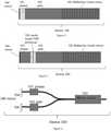
- FIG. 1schematically illustrates an embodiment of a tunable laser comprising a comb reflector.
- FIGS. 6A-6Dschematically illustrate a process of mode selection in a sampled grating distributed Bragg reflector (SGDBR) laser.
- SGDBRdistributed Bragg reflector
- FIG. 7is a wavelength map generated by simulating the operation of a tunable laser comprising a comb reflector.
- FIGS. 8A-1 and 8A-2illustrate the variation in the wavelength of light output from an embodiment of a tunable laser comprising a comb reflector for different operating conditions.
- FIG. 10is the variation in the wavelength of light output from an embodiment of a tunable laser comprising a sampled grating distributed Bragg reflector (SGDBR) laser at both ends of a laser cavity for different operating conditions.
- SGDBRsampled grating distributed Bragg reflector
- the structures, systems, and/or devices described hereinmay be embodied using a variety of techniques including techniques that may not be described herein but are known to a person having ordinary skill in the art. For purposes of comparing various embodiments, certain aspects and advantages of these embodiments are described. Not necessarily all such aspects or advantages are achieved by any particular embodiment. Thus, for example, various embodiments may be carried out in a manner that achieves or optimizes one advantage or group of advantages as taught herein without necessarily achieving other aspects or advantages as may also be taught or suggested herein. It will be understood that when an element or component is referred to herein as being “connected” or “coupled” to another element, it can be directly connected or coupled to the other element or intervening elements may be present therebetween. For clarity of description, “reflector” or “mirror” can be used interchangeably to refer to an optical element and/or a surface having a reflectivity greater than or equal to about 0.01% and less than or equal to 100% including any value in between.
- a new innovative tunable semiconductor laseris contemplated herein that offers advantages of simpler tuning mechanism as well as lower power consumption.
- Various embodiments of tunable lasers described hereincan be tuned with fewer controls (e.g., one or two controls).
- Various embodiments of the innovative tunable laser described hereincomprise a comb mirror to define a series of selectable lasing modes each of which can be continuously tuned over a short wavelength range.
- the tunable lasercan be configured to output a laser signal having a desired wavelength by selecting a lasing mode of the comb mirror that is closest to the desired wavelength and tuning the selected mode to the desired wavelength by temperature tuning and/or electrical tuning.
- the tuning range of the innovative tunable laser comprising a comb mirrorcan be greater than or equal to about 5 nm, greater than or equal to about 10 nm, greater than or equal to about 20 nm, greater than or equal to about 50 nm, greater than or equal to about 100 nm, less than or equal to about 200 nm, less than or equal to about 300 nm, less than or equal to about 500 nm, or have any value in a range or sub-range defined by any of these values.
- the lasercomprises a gain region 102 , a broadband mirror 104 disposed at one end of the gain region 102 and a comb reflector 103 disposed at another end of the gain region 102 .
- the gain region 102can comprise an optically active material.
- the gain region 102can comprise multi-quantum well heterojunctions formed in semiconductor materials, such as, for example, III-V semiconductor materials.
- the broadband mirror 104can be a cleaved facet coated with reflective coatings, cleaved facet without any coating or any other broadband reflector.
- the broadband mirror 104is disposed at one end of a gain region 102 .
- the broadband mirror 104can be configured to reflect wavelengths in a broad spectral range substantially uniformly such that the reflectivity of the broadband mirror 104 is within ⁇ 10% of an average reflectivity for wavelengths in a wide wavelength range that extends between about 20 nm and about 500 nm.
- the spectral reflectivity (e.g., reflectivity versus wavelength) curve of the broadband mirror 104can have a bandwidth (e.g., full width at half maximum (FWHM)) of about 20 nm, about 50 nm, about 100 nm, about 200 nm, about 300 nm, about 500 nm, about 1 micron, about 3 microns, about 10 microns, or any range or combination of ranges between any of these values.
- FWHMfull width at half maximum
- the broadband mirror 104is not considered to be a sampled grating distributed Bragg reflector.
- the bandwidth of the spectral reflectivity of the broadband mirror 104can be substantially greater (e.g., greater than or equal to 10 nm, greater than or equal to 20 nm, greater than or equal to 30 nm, greater than or equal to 50 nm) than bandwidth of the spectral reflectivity of a sampled grating distributed Bragg reflector.
- the comb mirror 103can be a periodically chirped reflector or a superstructure grating or mirror. In some embodiments, the comb mirror 103 can comprise a sampled grating distributed Bragg reflector. The comb mirror 103 can have a reflectivity between about 0.01% and about 99.9% for incident light having a reflective wavelength in the operating wavelength range of the tunable laser. The comb mirror 103 has a plurality of reflection peaks in the operating wavelength range of the tunable laser. Each reflection peak can have a maximum reflection at a wavelength in the operating wavelength range of the tunable laser and a bandwidth given by the spectral width of the individual reflection peak at half the maximum reflection.
- the bandwidth of an individual reflection peakcan be in a range between about 0.001 nm and about 10 nm, between about 0.01 nm and about 5 nm, between about 0.05 nm and about 4 nm, between about 0.1 nm and about 3 nm, between about 0.2 nm and about 2.5 nm, between about 0.5 nm and about 2.0 nm, between about 0.7 nm and about 1.0 nm, or any value in a range/sub-range formed by these values.
- the laser cavitycan be configured such that a non-integer number of cavity modes may fit into a single free spectral range (distance between two consecutive reflection peaks) of the comb mirror 103 .
- a non-integer number of cavity modesmay fit into a single free spectral range (distance between two consecutive reflection peaks) of the comb mirror 103 .
- different cavity modeswould overlap with different portions of consecutive reflection peaks of the comb mirror 103 .
- the innovative tunable lasercomprising a comb mirror, different cavity modes selected by consecutive reflection peaks of the comb mirror would not be able to simultaneously lase.
- the optical path length of the laser cavitycan be configured such that a non-integer number of cavity modes may fit into a single free spectral range (distance between two consecutive reflection peaks) of the comb mirror 103 .
- the comb mirror 103can be a sampled grating distributed Bragg reflector (SGDBR).
- the broadband mirror 104can be configured as a front or a back mirror of the laser device.
- the comb mirror 103can be configured as a front or a back mirror.
- the front mirrorhas a reflectivity configured to allow a portion of the laser signal to be output through the front mirror.
- the front mirrorcan have a reflectivity between about 0.1% and about 99%, between about 0.1% and about 60%, between about 1% and about 80%, between about 5% and about 70%, between about 10% and about 65%, between about 20% and about 60%, or any value in a range/sub-range defined by any of these values so as to allow output a portion of the laser signal through the front mirror. Other values outside this range are also possible.
- Various embodimentsmay make use of the laser signal from either end of the laser, or in some applications from both ends simultaneously.
- heater pads or liquid crystal with electrodes configured to apply voltage across the liquid crystalcan be associated with the comb mirror 103 and used to tune the FSR of the comb mirror 103 .
- Various embodiments of heater padsinclude disposing a resistive metallic strip over the comb mirror 103 , and applying an electric current through the resistive strip resulting in local heating which ultimately results in tuning of the comb mirror.
- Various parameterscan be adjusted such that the cavity modes are spaced wide enough apart to obtain a laser signal with a single mode having side mode suppression ratio (SMSR) greater than about 20 dB (e.g., about 30 dB, about 40 dB, about 50 dB, etc. or any range formed by any of these values).
- SMSRside mode suppression ratio
- the output signal from the lasercan have a SMSR between about 10 dB and about 150 dB, between about 30 dB and about 140 dB, between about 40 dB and about 120 dB, between about 50 dB and about 110 dB, between about 60 dB and about 100 dB, between about 70 dB and about 90 dB or any range or a combination of ranges between any of these value.
- the laser cavity formed by the broadband mirror 104 and the comb mirror 103can include an optional phase section 101 to help manipulate the cavity mode placement.
- the phase section 101can be configured to effect a change in the optical path length of the optical signal in the cavity.
- electrical current or an electrical voltagecan be applied to the phase section 101 through electrical contacts (e.g., in proximity to the phase section) to alter the optical path length of the optical signal in the laser cavity.
- the optical path length of the optical signal in the laser cavitycan be changed by effecting a temperature change in the phase section 101 .
- a temperature change in the phase section 101can be caused, for example, by applying an electric current through a resistive strip disposed with respect to the phase section 101 .
- the phase section 101can be disposed between the gain region 102 and the comb mirror 103 , and in some embodiments the phase section 101 can be within the gain region 102 . Other locations are also possible.
- the phase section 101is optional and in some embodiments, the phase section 101 can be omitted.
- cavity mode tuningcan be achieved either thermally (e.g., by applying an electrical current through a resistive heat strip) or through second order effects relating to carrier density or stress and strain in the gain region 102 .
- the comb mirror 103may be pumped to induce gain either optically or electrically.
- the gain region 102can be divided into two or more portions by providing additional reflectors (e.g., reflector 105 ) in the gain region 102 as shown in FIG. 2 .
- the reflector 105is placed in the phase section 101 .
- the reflector 105can be disposed in the gain region 102 .
- the reflectivity of the reflector 105can be in a range between about 1% and about 50% in the wavelength range of operation of the laser 200 .
- the reflector 105may advantageously increase the effective free spectral range (FSR) of dominant cavity modes.
- FSReffective free spectral range
- FIG. 3Yet another embodiment of the innovative tunable laser comprising a comb mirror incorporates Y-branch laser technology as shown in FIG. 3 .
- the embodiment of the tunable laser 300 depicted in FIG. 3can be configured as a dual output laser.
- the dual output lasercomprises a first waveguide comprising a single comb mirror 103 coupled to a second waveguide comprising the phase section 101 and a third waveguide comprising the gain section 102 .
- a broadband mirror 104is disposed at the ends of the second and the third waveguides opposite the comb mirror 103 as shown in FIG. 3 .
- the two broadband mirrors 104may or may not be HR (highly reflective).
- the two broadband mirrors 104can comprise high reflective coatings.
- the embodiment of the Y-branch laser 300 illustrated in FIG. 3can be modified in various ways.
- the second waveguideneed not comprise a phase section.
- the second waveguidecan comprise an additional gain region.
- the first and the second waveguidescan comprise additional gain regions.
- the first and/or the third waveguidescan comprise additional phase sections.
- the Y-branch lasercan comprise a broadband mirror 104 disposed at an end of the first waveguide and two comb mirrors 103 disposed at the ends of the second and third waveguides. In some such embodiments, the two comb mirrors 103 can be identical.
- both the comb mirrors 103can have the same reflectivity and/or the same FSR.
- the two comb mirrors 103need not be identical.
- the two comb mirrors 103can have different reflectivities and/or different FSRs.
- all of the first, second and third waveguidesmay include a gain region similar to the gain region ( 102 ). Many other variations are possible.
- the innovative tunable laser comprising a comb mirror described hereincan be designed to operate in wavelength ranges between about 600 nm and about 1900 nm, less than 600 nm, greater than 1900 nm where spontaneous emission and stimulated emission are available.
- Embodiments of the innovative tunable laser comprising a comb mirror discussed hereincan be fabricated from a variety of materials including but not limited to III-V semiconductor materials such as InP, GaAs, InGaAP, InAlAsP, GaN; erbium doped glasses; Silicon Germanium, and other laser materials.
- Embodiments of the innovative tunable laser comprising a comb mirror discussed hereincan also comprise hybrid combinations of materials, for example, by butt-coupling or wafer bonding gain material to other active or passive material.
- Various implementations of the innovative tunable laser comprising a comb mirror described hereincan be fabricated by monolithically integrating the gain region, the optional phase section, and the comb mirror on a substrate comprising a waveguide layer.
- the substratecan be a crystalline substrate.
- the substratecan comprise a semiconductor material.
- the radiation emitted from the gain region 102 when the tunable laser is not configured to lasecan have a peak with a maximum gain value and a bandwidth which is equal to the spectral width at which the gain is half the maximum gain value.
- the bandwidth of the gain peakcan be greater than the FSR of the comb mirror as shown in FIG. 5E .
- the bandwidth of the gain peakcan be wide enough to accommodate two or more reflection peaks of the comb mirror 103 .
- the bandwidth of the gain peakcan be wide enough to accommodate at least 3, at least 4, at least 5, at least 10 reflection peaks, at least 20 reflection peaks, at least 30 reflection peaks or any ranges between any of these values of the comb mirror 103 .
- the bandwidth of the gain peakcan be wide enough to accommodate at least 1 reflection peak of the comb mirror 103 .
- the gain region 102can extend into the comb mirror 103 .
- the comb mirror 103can be formed in the gain region 102 .
- the comb mirror 103can comprise an additional gain material different from the gain medium in the gain region 102 .
- the additional gain materialcan be distributed through the entire length of the comb mirror 103 or distributed in one or more sections.
- the one or more sections of the comb mirror 103can be separate from the gain region 102 as shown in FIG. 4A .
- the one or more sections of the comb mirror 103 comprising the additional gain materialcan be periodic as shown in FIG. 4A or non-periodic.
- the additional gain materialcan be the same as the material of the gain region 102 or different from the material of the gain region 102 .
- the gain region 102can comprise the comb mirror 103 .
- Including gain in the mirror regioncan advantageously reduce the FWHM of the reflection peaks of the comb mirror 103 which can advantageously allow higher selectivity between cavity modes. Reducing the FWHM of the reflection peaks of the comb mirror 103 can also result in the tunable laser having a larger tuning range with more comb peaks. The existence of more comb peaks can allow for individual cavity modes to be independently selected. In some such implementations of the tunable laser, thermal tuning can be used to tune the comb mirror 103 .
- one or more sections of the comb mirror 103can include gain medium and one or more other sections of the comb mirror 103 can be devoid of gain medium.
- a tunable laser comprising a comb mirrorcan comprise one or more sections having gain medium and one or more section without gain medium.
- the comb mirrorcan be provided with two or more electrical contacts, one or more electrical contacts for injecting current into the gain medium and one or more other contacts for injecting current into the portions of the comb mirror not including gain medium to accomplish wavelength tuning.
- FIG. 4Aillustrates an implementation of a laser comprising a comb mirror 103 with one or more sections comprising gain medium and one or more sections without gain medium.
- the comb mirror 103comprises a plurality of mirror bursts (or a plurality of spaced apart reflective regions) with gain sections provided between the mirror bursts.
- the gain mediumcan be distributed through the entire length of the comb mirror 103 .
- gain mediumis periodically introduced throughout the comb mirror 103 .
- the lasercan be provided with one or more electrical contact regions to provide electrical current or voltage to different portions of the laser.
- the mask layer shown in FIG. 4Bis an example of a mask layer that can be used to fabricate portions of the laser illustrated in FIG. 4A .
- the mask layer shown in FIG. 4Bcomprises a phase contact section 101 c at left configured to provide electrical current or voltage to the phase section 101 , a gain contact section 102 c configured to provide electrical current or voltage to the gain region, and a comb mirror gain contact region 103 ac configured to provide electrical current or voltage to the optically active sections of the comb mirror 103 that comprise a gain medium and a comb mirror tuning contact region 103 pc to provide electrical current or voltage to the optically passive regions of the comb mirror 103 .
- the lengths of the gain, mirror and phase sections illustrated in FIG. 4Bmay vary and be significantly different from the example shown here. Likewise, the number of mirror bursts in the comb mirror shown in FIG. 4B may vary significantly.
- one or more heaterscan be used for wavelength tuning the laser of FIG. 4A instead of or in addition to injection current.
- Wavelength tuning in various embodiments of the innovative tunable lasercomprising a comb mirror at one end and a broadband reflector at the other end as described herein can be accomplished by moving the reflection peaks of the comb mirror to select different cavity modes of the laser.
- at least one of the reflection peaks of the comb mirrorcan be moved to select one of the cavity modes.
- at least one of the reflection peaks of the comb mirroris capable of being moved by an amount greater than or equal to the distance between consecutive reflection peaks (also referred to as free spectral range (FSR)) of the comb mirror.
- FSRfree spectral range
- wavelength tuning in implementations of a sampled grating distributed Bragg reflector (SGDBR) laser comprising two sampled grating distributed Bragg reflectors (SGDBRs) at both ends of a laser cavityis accomplished by Vernier tuning of the two sampled grating distributed Bragg reflectors.
- wavelength tuningcan be accomplished by Vernier tuning of cavity modes.
- Embodiments of the innovative tunable laser comprising a comb mirror at one end and a broadband reflector at the other end as described hereincan be tuned using two tuning controls—for example, one tuning control for a phase section and a second tuning control for a mirror section instead of three tuning controls—for example, one tuning control for a phase section and two tuning controls for mirror sections that are used to achieve wavelength tuning in implementations of a SGDBR laser comprising two sampled grating distributed Bragg reflectors (SGDBRs) at both ends of a laser cavity.
- SGDBRssampled grating distributed Bragg reflectors
- FIGS. 5A-5EThe tuning operation of an embodiment of the innovative tunable laser comprising a comb mirror contemplated here is shown in FIGS. 5A-5E .
- FIG. 5Aillustrates the cavity modes of the laser cavity of the innovative tunable laser comprising a comb mirror.
- FIG. 5Billustrates the reflection peaks of the comb mirror.
- the laser cavitycan be configured such that the spacing between the cavity modes relative to the spacing between the reflection peaks of the comb mirror can be controlled to ensure that the nearest neighbors to a selected cavity mode are significantly suppressed.
- FIGS. 5A and 5Billustrate an example of a tunable laser with laser cavity and the comb mirror configured to allow approximately 6.8 cavity modes between individual reflection peaks (or FSR) of the comb mirror.
- the bandwidth of the gain peak of the gain region of the lasercan be broad relative to the FSR of the comb mirror and can accommodate 2 or more reflectance peaks of the comb mirror within the gain bandwidth of the gain region (e.g., gain region 102 ) as shown in FIG. 5D . Accordingly, the bandwidth of the gain peak does not drive the selection between adjacent competing reflection peaks of the comb mirror.
- the tuning of the mirror and phase sectioncan in some embodiments be achieved electrically or thermally, and the gain in the laser gain section can in some embodiments be achieved electrically or through optical pumping.
- the tuning operation of the innovative tunable laser comprising a comb mirror discussed hereinis significantly different from other existing lasers (e.g., the SGDBR laser).
- wavelength tuning in various embodiments of the tunable laser comprising a comb mirror discussed hereinis accomplished by a Vernier effect between the FSR of the reflection peaks and the cavity modes.
- the cavity modes in various embodiments of the innovative tunable laser comprising a combcan be tuned over a small wavelength range by the phase section.
- the comb mirrorscan be tuned over a large wavelength. Accordingly, the mirror comb can be tuned over most of the available index tuning range, minus half a cavity mode spacing.
- Continuous tuning in the innovative tunable laser comprising a comb mirrorcan be achieved using a mirror comb with FSR that is substantially close to the index tuning range.
- the comb spacingmay be denser in a SGDBR tunable laser to allow for full tuning of one mirror comb spacing plus half the width of the comb of the other mirror.
- the wavelength maps from innovative tunable laser comprising a comb mirrorshow a constant hopping between the modes of the comb mirror, before repeating back to the first mirror comb on the next available cavity mode as depicted in FIG. 7 . This operation is different from the mode selection and tuning process of a SGDBR laser.
- the design of the innovative tunable laser comprising a comb mirroris different from a conventional SGDBR laser, with different rules pertaining to the design of the mirror, and a different set of constraints on the design of the cavity length vs the design of the mirror.
- FIGS. 6A-6Ddescribes the mode selection process for tuning in an SGDBR laser comprising two SGDBRs.
- the spacing between individual reflection peaks of the first SGDBRe.g., front SGDBR
- the second SGDBRe.g., rear SGDBR
- the two SGDBRs with slightly different spacing between individual reflection peaksare tuned to achieve wavelength tuning.
- FIGS. 6C and 6Dshow two lasing modes that would be down selected by gain spectrum or mirror strength envelope. The selection process is dominated by the interplay of two comb mirrors and their relative alignment to one another.
- FIG. 7A section of a tuning map generated by simulating the operation of the innovative tunable laser comprising a comb mirror discussed herein is shown in FIG. 7 below.
- the tuning map in FIG. 7is in the wavelength range between about 1620 nm and about 1680 nm
- the innovative tunable laser comprising a comb mirrorcan be designed to operate in other wavelength ranges between about 600 nm and about 1900 nm, less than 600 nm, greater than 1900 nm or in other wavelength ranges where spontaneous emission and stimulated emission are available.
- the simulation shown in FIG. 7is obtained by using a simple model based on the tuning mechanism discussed above with reference to FIGS. 5A-5E considering the interaction between the reflection peaks of the comb mirror, the cavity modes and the gain bandwidth.
- the simulationdoes not include other physical phenomena such as four wave mixing, threshold variation affecting carrier density and cavity index, the alpha parameter etc. which can affect the wavelength tuning map.
- Some designsmay exhibit “stickiness” of modes due to four wave mixing or other nonlinear or linear effects, or hysteresis in tuning due to alpha parameter, four wave mixing or other nonlinear or linear effects. In some cases the hysteresis and mode sticking effects may be useful to the stability and predicable tuning of these devices.
- the wavelength maps of such designsmay be different from the wavelength map shown in FIG. 7 .
- the wavelength mapmay be similar to the wavelength map shown in FIG. 7 .
- the existence of hysteresismay in some cases mean that direction of tuning on the map is related to wavelength accessibility.
- the simulated wavelength map shown in FIG. 7is obtained by using only two controls—tuning the phase section to tune the cavity modes and tuning the comb mirror to tune the reflection peaks. Accordingly, the wavelength map iterates repeatedly across multiple comb modes, using different cavity modes for each iteration.
- the innovative tunable laser comprising a comb mirrorcan be continuously tuned to select any wavelength in a desired operating range using one or two controls—e.g., phase section to tune the cavity modes and tuning the comb mirror to tune the reflection peaks.
- continuous tuningrefers to the ability to configure the laser to operate at any wavelength in a wavelength range by appropriate selection of laser parameters, such as, for example, current or voltage to the gain regions, current or voltage to the phase section and current or voltage to the comb mirror.
- FIGS. 8A-1, 8A-2, 9A, 9B-1 and 9B-2Some wavelength maps from early prototypes of the innovative tunable laser comprising a comb mirror are shown in FIGS. 8A-1, 8A-2, 9A, 9B-1 and 9B-2 . These wavelength maps show multiple continuous wavelength spans selected by combination of a mirror comb peak and cavity mode on the wavelength map. The interleaving of super-modes can also occur in part as a result of second order processes including thermal and nonlinear effects. Tuning continuity in these designs is in some cases compromised by mode sticking or other second order effects. These examples are included to show the presence in some embodiments of second order effects and other non-linear processes that can lead to maps useful but different from the simulated wavelength map shown in FIG. 7 .
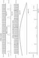
- FIG. 8A-1is a wavelength tuning map obtained by varying the electrical current to the comb mirror and the phase section.
- the FSR of the comb mirror and the cavity modeswere configured to provide approximately 20 nm of wavelength tuning as shown in the wavelength histogram shown in FIG. 8A-2 .
- FIG. 9Ashows the spectrum of light output from an embodiment of a tunable laser comprising a comb mirror for different operating conditions. As seen from the wavelength spectra 901 , 903 , 905 , 907 , 909 , 911 and 913 , a side mode suppression ratio (SMSR) greater than about 30 dB is achieved for various operating conditions of the embodiment of the innovative tunable laser comprising a comb mirror.
- SMSRside mode suppression ratio
- FIG. 9B-1illustrates the wavelength map between 1620 nm and 1650 nm for the embodiment of the innovative tunable laser comprising a comb mirror
- FIG. 9B-2is a wavelength histogram corresponding to the wavelength map of FIG. 9B-1 .
- the different color streaks in the wavelength map shown in FIG. 9B-1correspond to non-adjacent cavity modes that are tuned continuously when selected by the mirror.
- the wavelengths of light output from the innovative tunable laser comprising a comb mirrorcycle through wavelengths that are defined primarily by spacing of the mirror comb.
- One cyclemay not result in a continuous tuning range, however, the tunable laser can be configured such that this series of comb modes can be repeated for multiple adjacent cavity modes as the mirror is further tuned and cycled through the mirror peaks.
- a continuous tuning rangecan be achieved this way if desired, as shown in FIGS. 9B-1 and 9B-2 .
- the wavelength map obtained for an embodiment of a SGDBR laser illustrated in FIG. 10is different from the wavelength map shown in FIG. 9B-1 .
- a SGDBR lasertransitions through each mirror reflection peak in sequence and the combined tuning of two mirrors, allows quasi-continuous tuning across wavelength ranges that include multiple cavity mode hops along the way.
- To achieve continuous wavelength tuning in a SGDBR laserwould require tuning the phase section of the SGDBR in addition to the combined tuning of the two mirrors.
- tuning the comb mirror and the phase sectioncan achieve continuous wavelength tuning in the innovative tunable laser comprising a comb mirror.
- the difference between the tuning mechanismsis clear in that the color of the wavelength maps of FIG. 9B-1 and FIG. 10 .
- the wavelength map for an embodiment of the tunable laser comprising a comb mirror illustrated in FIG. 9B-1repeatedly cycles from left to right, gradually changing shade, whereas the wavelength map for an embodiment of a SGDBR laser illustrated in FIG. 10 , the full tuning range is accessible within a single cycle of tuning the two mirrors with respect to each other over the entire tuning range.
- the tuning map for the implementation of the SGDBR laserhops in wavelength from cavity mode to cavity mode leaving wavelength gaps.
- the innovative tunable laser comprising a comb mirrorhas the advantage of being able to display fully continuous wavelength range, without the wavelength gaps found in the wavelength map of the implementation of the SGDBR laser.
Landscapes
- Physics & Mathematics (AREA)
- Condensed Matter Physics & Semiconductors (AREA)
- General Physics & Mathematics (AREA)
- Electromagnetism (AREA)
- Optics & Photonics (AREA)
- Acoustics & Sound (AREA)
- Geometry (AREA)
- Semiconductor Lasers (AREA)
Abstract
Description
Claims (16)
Priority Applications (1)
| Application Number | Priority Date | Filing Date | Title |
|---|---|---|---|
| US16/431,285US11251584B2 (en) | 2017-03-28 | 2019-06-04 | Tunable laser |
Applications Claiming Priority (5)
| Application Number | Priority Date | Filing Date | Title |
|---|---|---|---|
| US201762477908P | 2017-03-28 | 2017-03-28 | |
| US201762489922P | 2017-04-25 | 2017-04-25 | |
| US201762596655P | 2017-12-08 | 2017-12-08 | |
| US15/938,842US10320152B2 (en) | 2017-03-28 | 2018-03-28 | Tunable laser |
| US16/431,285US11251584B2 (en) | 2017-03-28 | 2019-06-04 | Tunable laser |
Related Parent Applications (1)
| Application Number | Title | Priority Date | Filing Date |
|---|---|---|---|
| US15/938,842ContinuationUS10320152B2 (en) | 2017-03-28 | 2018-03-28 | Tunable laser |
Publications (2)
| Publication Number | Publication Date |
|---|---|
| US20190386463A1 US20190386463A1 (en) | 2019-12-19 |
| US11251584B2true US11251584B2 (en) | 2022-02-15 |
Family
ID=63671812
Family Applications (2)
| Application Number | Title | Priority Date | Filing Date |
|---|---|---|---|
| US15/938,842ActiveUS10320152B2 (en) | 2017-03-28 | 2018-03-28 | Tunable laser |
| US16/431,285ActiveUS11251584B2 (en) | 2017-03-28 | 2019-06-04 | Tunable laser |
Family Applications Before (1)
| Application Number | Title | Priority Date | Filing Date |
|---|---|---|---|
| US15/938,842ActiveUS10320152B2 (en) | 2017-03-28 | 2018-03-28 | Tunable laser |
Country Status (1)
| Country | Link |
|---|---|
| US (2) | US10320152B2 (en) |
Families Citing this family (7)
| Publication number | Priority date | Publication date | Assignee | Title |
|---|---|---|---|---|
| US10355451B2 (en) | 2017-03-28 | 2019-07-16 | Freedom Photonics Llc | Laser with sampled grating distributed bragg reflector |
| US10320152B2 (en) | 2017-03-28 | 2019-06-11 | Freedom Photonics Llc | Tunable laser |
| US11152764B1 (en) | 2018-11-20 | 2021-10-19 | Freedom Photonics Llc | Gratings for high power single mode laser |
| WO2020107315A1 (en)* | 2018-11-29 | 2020-06-04 | 华为技术有限公司 | Two-section dbr laser and monolithic integrated array light source chip |
| US11431149B1 (en) | 2019-03-22 | 2022-08-30 | Freedom Photonics Llc | Single mode laser with large optical mode size |
| US11721951B2 (en) | 2019-09-16 | 2023-08-08 | Freedom Photonics Llc | Tunable laser with active material on at least one end for monitoring performance |
| US11837838B1 (en)* | 2020-01-31 | 2023-12-05 | Freedom Photonics Llc | Laser having tapered region |
Citations (149)
| Publication number | Priority date | Publication date | Assignee | Title |
|---|---|---|---|---|
| US3752992A (en) | 1969-05-28 | 1973-08-14 | Us Navy | Optical communication system |
| US3939341A (en) | 1975-04-02 | 1976-02-17 | Hughes Aircraft Company | Phase-locked optical homodyne receiver |
| US3970838A (en) | 1975-08-29 | 1976-07-20 | Hughes Aircraft Company | Dual channel phase locked optical homodyne receiver |
| US3984835A (en) | 1974-06-03 | 1976-10-05 | Rca Corporation | Homodyne communication system |
| US4063084A (en) | 1976-07-19 | 1977-12-13 | Hughes Aircraft Company | Dual channel optical homodyne receiver |
| US4168397A (en) | 1978-05-26 | 1979-09-18 | Gte Automatic Electric Laboratories Incorporated | 8-Phase PSK modulator |
| US4596052A (en) | 1982-05-20 | 1986-06-17 | International Standard Electric Corporation | Coherent optical receiver |
| US4608697A (en) | 1983-04-11 | 1986-08-26 | At&T Bell Laboratories | Spectral control arrangement for coupled cavity laser |
| US4622672A (en) | 1984-01-20 | 1986-11-11 | At&T Bell Laboratories | Self-stabilized semiconductor lasers |
| US4719636A (en) | 1984-08-24 | 1988-01-12 | Nec Corporation | Wavelength tunable semiconductor laser device provided with control regions |
| US4870654A (en) | 1987-05-22 | 1989-09-26 | California Laboratories, Inc. | Generation of multiply folded optical paths |
| US4893352A (en) | 1987-06-30 | 1990-01-09 | Massachusetts Institute Of Technology | Optical transmitter of modulated signals |
| US4896325A (en)* | 1988-08-23 | 1990-01-23 | The Regents Of The University Of California | Multi-section tunable laser with differing multi-element mirrors |
| US4903342A (en) | 1987-10-27 | 1990-02-20 | Nec Corporation | Optical heterodyne homodyne detection apparatus |
| US4903341A (en) | 1987-12-28 | 1990-02-20 | Mcdonnell Douglas Corporation | Semiconductor optical heterodyne detector |
| US4904963A (en) | 1988-11-16 | 1990-02-27 | Mcdonnell Douglas Corporation | Staggered quadrature phase shift keyed laser modulator |
| US5003625A (en) | 1988-06-10 | 1991-03-26 | U.S. Philips Corporation | Optical heterodyne detection and integrated optical component suitable for use in such a device |
| US5007106A (en) | 1989-11-08 | 1991-04-09 | At&T Bell Laboratories | Optical Homodyne Receiver |
| JPH0391278A (en) | 1989-09-01 | 1991-04-16 | Nippon Telegr & Teleph Corp <Ntt> | Semiconductor laser diode |
| US5008957A (en) | 1988-03-03 | 1991-04-16 | Nec Corporation | Multilevel optical signal transmitter |
| US5034603A (en) | 1989-11-06 | 1991-07-23 | Wilson Keith E | Integrated optics wavelength stabilization unit |
| US5088105A (en) | 1991-03-26 | 1992-02-11 | Spectra Diode Laboratories, Inc. | Optical amplifier with folded light path and laser-amplifier combination |
| US5091916A (en) | 1990-09-28 | 1992-02-25 | At&T Bell Laboratories | Distributed reflector laser having improved side mode suppression |
| US5101450A (en) | 1991-01-23 | 1992-03-31 | Gte Laboratories Incorporated | Quadrature optical phase modulators for lightwave systems |
| US5126557A (en) | 1990-06-13 | 1992-06-30 | U.S. Philips Corp. | Device for optical heterodyne detection and optical component suitable for use in such a device |
| US5170274A (en) | 1990-03-01 | 1992-12-08 | Fujitsu Limited | Optical transmitter |
| US5181136A (en) | 1989-09-22 | 1993-01-19 | The University Of Ottawa | Optical homodyne DPSK receiver with optical amplifier |
| US5222103A (en) | 1991-01-02 | 1993-06-22 | Gte Laboratories Incorporated | Differential quadrature phase shift keying encoder for subcarrier systems |
| US5237292A (en) | 1992-07-01 | 1993-08-17 | Space Systems/Loral | Quadrature amplitude modulation system with compensation for transmission system characteristics |
| JPH0645693A (en) | 1992-04-10 | 1994-02-18 | Alcatel Nv | Tunable semiconductor laser |
| US5323258A (en) | 1990-10-05 | 1994-06-21 | Hitachi, Ltd. | Homodyne optical receiver equipment |
| US5325392A (en) | 1992-03-06 | 1994-06-28 | Nippon Telegraph And Telephone Corporation | Distributed reflector and wavelength-tunable semiconductor laser |
| US5347608A (en) | 1992-06-30 | 1994-09-13 | Ibiden Co., Ltd. | Optical waveguide and optical waveguide device |
| US5351317A (en) | 1992-08-14 | 1994-09-27 | Telefonaktiebolaget L M Ericsson | Interferometric tunable optical filter |
| US5359449A (en) | 1991-11-19 | 1994-10-25 | Fujitsu Limited | Optical modulator for an optical transmitter |
| US5398256A (en) | 1993-05-10 | 1995-03-14 | The United States Of America As Represented By The United States Department Of Energy | Interferometric ring lasers and optical devices |
| US5412226A (en) | 1989-11-20 | 1995-05-02 | British Telecommunications Public Limited Company | Semi-conductor structures |
| US5424863A (en) | 1993-09-23 | 1995-06-13 | Ael Industries, Inc. | Dual-polarization fiber optic communications link |
| WO1995022070A1 (en) | 1994-02-11 | 1995-08-17 | Philips Electronics N.V. | Optical device with phased array |
| US5452118A (en) | 1993-04-20 | 1995-09-19 | Spire Corporation | Optical heterodyne receiver for fiber optic communications system |
| US5654818A (en) | 1996-02-09 | 1997-08-05 | The United States Of America As Represented By The United States National Aeronautics And Space Administration | Polarization independent electro-optic modulator |
| US5915051A (en) | 1997-01-21 | 1999-06-22 | Massascusetts Institute Of Technology | Wavelength-selective optical add/drop switch |
| US6020963A (en) | 1996-06-04 | 2000-02-01 | Northeastern University | Optical quadrature Interferometer |
| US6078412A (en) | 1995-03-10 | 2000-06-20 | Matsushita Electric Industrial Co., Ltd. | Optical transmitter and optical transmission system using the same |
| US6205159B1 (en) | 1997-06-23 | 2001-03-20 | Newport Corporation | Discrete wavelength liquid crystal tuned external cavity diode laser |
| EP1087478A1 (en) | 1999-09-27 | 2001-03-28 | Nortel Networks Limited | Generation of short optical pulses using strongly complex coupled DFB lasers. |
| US6271950B1 (en) | 1998-08-18 | 2001-08-07 | Lucent Technologies Inc. | Optical differential phase shift keying transmission system having multiplexing, routing and add/replace capabilities |
| US6407843B1 (en) | 1998-03-05 | 2002-06-18 | Kestrel Solutions, Inc. | System and method for spectrally efficient transmission of digital data over optical fiber |
| US6407845B2 (en) | 2000-07-11 | 2002-06-18 | Fujitsu Limited | Optical transmitter and optical transmission system |
| US20020085609A1 (en) | 2001-01-02 | 2002-07-04 | Tunable Photonics Corporation | Tunable semiconductor laser having cavity with ring resonator mirror and mach-zehnder interferometer |
| US6421155B1 (en) | 1997-05-28 | 2002-07-16 | Nec Corporation | Optical data transmitting apparatus and method |
| US20020105991A1 (en) | 1999-09-02 | 2002-08-08 | Coldren Larry A. | High-power, manufacturable sampled grating distributed bragg reflector lasers |
| US6459521B1 (en) | 2000-08-28 | 2002-10-01 | Agere Systems Guardian Corp. | Electroabsorption modulator integrated distributed feedback laser transmitter |
| US20020186727A1 (en) | 2001-05-23 | 2002-12-12 | Masahiro Aoki | Optical transmitting apparatus and manufacturing method thereof |
| US20030026302A1 (en) | 2001-08-01 | 2003-02-06 | Anthon Douglas W. | Apparatus and method for phase control of tunable external cavity lasers |
| US6556327B1 (en) | 1997-11-06 | 2003-04-29 | Matsushita Electric Industrial Co., Ltd. | Signal converter, optical transmitter and optical fiber transmission system |
| US20030099425A1 (en) | 2001-11-06 | 2003-05-29 | Grubb Stephen G. | Optical communication module with one or more photonic integrated circuit (PIC) chips and an external booster optical amplifier for photonic integrated circuits (PICs) |
| US6584136B2 (en) | 2000-12-30 | 2003-06-24 | Electronics And Telecommunications Research Institute | Folded cavity laser |
| JP2003177365A (en) | 2001-12-10 | 2003-06-27 | Hitachi Ltd | Optical transmitting device, optical receiving device, and method of manufacturing optical device |
| US20030161370A1 (en)* | 2000-08-07 | 2003-08-28 | Efraim Buimovich | Characterization of multiple section semiconductor lasers |
| WO2003079508A1 (en) | 2002-03-16 | 2003-09-25 | Intense Photonics Limited | Folded integrated laser modulator |
| US6646747B2 (en) | 2001-05-17 | 2003-11-11 | Sioptical, Inc. | Interferometer apparatus and associated method |
| US6661975B1 (en) | 2000-03-10 | 2003-12-09 | Northrop Grumman Corporation | Multi-rate variable duty cycle modem for use in an optical communication system |
| US6704375B1 (en) | 1998-10-22 | 2004-03-09 | Contraves Space Ag | Device for the homodyne reception of optically phase-keyed signals |
| US20040076199A1 (en)* | 2002-08-22 | 2004-04-22 | Agility Communications, Inc. | Chirp control of integrated laser-modulators having multiple sections |
| US20040105476A1 (en)* | 2002-08-19 | 2004-06-03 | Wasserbauer John G. | Planar waveguide surface emitting laser and photonic integrated circuit |
| US6757499B1 (en) | 1999-10-28 | 2004-06-29 | Hitachi, Ltd. | Optical transmitter and optical signal transmitter |
| US6781741B2 (en) | 2002-03-04 | 2004-08-24 | Hitachi, Ltd. | Mach-Zehnder optical modulator |
| US6782205B2 (en) | 2001-06-25 | 2004-08-24 | Silicon Light Machines | Method and apparatus for dynamic equalization in wavelength division multiplexing |
| US20040179569A1 (en)* | 2003-03-12 | 2004-09-16 | Hitachi., Ltd. | Wavelength tunable DBR laser diode |
| KR20040081838A (en) | 2003-03-17 | 2004-09-23 | 엘지전자 주식회사 | Double-faced and polymer optical backplane and the fabrication method |
| US6807321B2 (en) | 2002-03-11 | 2004-10-19 | Lucent Technologies Inc. | Apparatus and method for measurement and adaptive control of polarization mode dispersion in optical fiber transmission systems |
| US20050025419A1 (en) | 2003-07-31 | 2005-02-03 | Fish Gregory A. | Tunable laser source with monolithically integrated interferometric optical modulator |
| JP2005077987A (en) | 2003-09-03 | 2005-03-24 | Sumitomo Osaka Cement Co Ltd | Optical modulator |
| US20050111852A1 (en) | 2002-11-06 | 2005-05-26 | Daniel Mahgerefteh | Method and apparatus for transmitting a signal using thermal chirp management of a directly modulated transmitter |
| US20050123017A1 (en) | 2003-11-28 | 2005-06-09 | Walsin Lihwa Corp. | External cavity tunable laser system formed MEMS corner mirror |
| US20050135733A1 (en) | 2003-12-19 | 2005-06-23 | Benoit Reid | Integrated optical loop mirror |
| US20050163186A1 (en) | 2002-03-04 | 2005-07-28 | Petersen Paul M. | High-power diode laser system |
| US20050213618A1 (en) | 2004-03-29 | 2005-09-29 | Sochava Sergei L | Semi-integrated designs for external cavity tunable lasers |
| US20050230695A1 (en) | 2004-04-06 | 2005-10-20 | Matsushita Electric Industrial Co., Ltd. | Semiconductor light-emitting element and method for manufacturing the same |
| US20050265647A1 (en) | 2002-08-02 | 2005-12-01 | Daryoosh Vakhshoori | System for amplifying optical signals |
| US6978056B2 (en) | 2003-06-04 | 2005-12-20 | Covega, Inc. | Waveguide modulators having bias control with reduced temperature dependence |
| US20060013273A1 (en)* | 2004-04-14 | 2006-01-19 | The Trustees Of Princeton University | Monolithic wavelength stabilized asymmetric laser |
| US7023601B2 (en) | 2002-12-02 | 2006-04-04 | Nortel Networks Limited | Optical E-field modulation using a Mach-Zehnder interferometer |
| US7027476B2 (en) | 2002-08-09 | 2006-04-11 | California Institute Of Technology | Tunable semiconductor lasers |
| US7035486B2 (en) | 2001-11-30 | 2006-04-25 | Bookham Technology, Plc | Photonic integrated device |
| US20060093012A1 (en) | 2004-10-29 | 2006-05-04 | Rajminder Singh | Multimode long period fiber Bragg grating machined by ultrafast laser direct writing |
| US7078981B2 (en) | 2004-07-27 | 2006-07-18 | Lucent Technologies Inc. | 16 QAM modulator and method of 16 QAM modulation |
| US20060187995A1 (en) | 2005-02-24 | 2006-08-24 | Jds Uniphase Corporation | Low loss grating for high efficiency wavelength stabilized high power lasers |
| US20060193362A1 (en) | 2003-01-28 | 2006-08-31 | High Q Laser Production Gmbh | Fold device for guiding beams in a laser |
| US7103239B2 (en) | 2001-10-09 | 2006-09-05 | Infinera Corporation | Optical transmitter |
| US7116460B2 (en) | 2001-11-30 | 2006-10-03 | Bookham Technology, Plc | Modulation control |
| US7120364B2 (en) | 2000-07-07 | 2006-10-10 | Jds Uniphase Corporation | Optical modulator and method for polarization bit interleaving |
| US7130325B2 (en) | 2003-05-02 | 2006-10-31 | Electronics And Telecommunications Research Institute | Sampled grating distributed feedback wavelength tunable semiconductor laser integrated with sampled grating distributed Bragg reflector |
| US20060251139A1 (en)* | 2005-05-09 | 2006-11-09 | Lightip Technologies Inc. | V-coupled-cavity semiconductor laser |
| US7209664B1 (en) | 2003-06-10 | 2007-04-24 | Nortel Networks Limited | Frequency agile transmitter and receiver architecture for DWDM systems |
| US7212326B2 (en) | 2003-05-30 | 2007-05-01 | Jds Uniphase Corporation | Optical external modulator |
| US20070122161A1 (en) | 2005-11-25 | 2007-05-31 | Alcatel | Fiber optical transmission system, transmitter and receiver for DQPSK modulated signals and method for stabilizing the same |
| US20070133918A1 (en) | 2003-07-02 | 2007-06-14 | Celight, Inc. | Quadrature modulator with feedback control and optical communications system using the same |
| US7245788B2 (en) | 2004-09-30 | 2007-07-17 | Sumitomo Osaka Cement Co., Ltd. | Optical modulator |
| US20070177882A1 (en) | 2006-01-31 | 2007-08-02 | Fujitsu Limited | Optical transmitter apparatus |
| US7272271B2 (en) | 2001-09-26 | 2007-09-18 | Celight, Inc. | Electro-optical integrated transmitter chip for arbitrary quadrature modulation of optical signals |
| WO2007107187A1 (en) | 2006-03-23 | 2007-09-27 | Pirelli & C. S.P.A. | Integrated laser optical source with active and passive sections formed in distinct substrates |
| US20070230617A1 (en) | 2006-03-22 | 2007-10-04 | Fujitsu Limited | Apparatus method for monitoring the I-Q phase bias in an I-Q quadrature modulation transmitter |
| US7327022B2 (en) | 2002-12-30 | 2008-02-05 | General Electric Company | Assembly, contact and coupling interconnection for optoelectronics |
| US20080056727A1 (en) | 2006-09-05 | 2008-03-06 | Fujitsu Limited | Optical transmitter and drive method of same |
| WO2008036313A1 (en) | 2006-09-21 | 2008-03-27 | Lucent Technologies Inc. | Interferometric operation of electroabsorption modulators |
| US20080080872A1 (en) | 2006-09-29 | 2008-04-03 | Fujitsu Limited | Optical transmitter |
| US7366362B2 (en) | 2005-06-27 | 2008-04-29 | Yokogawa Electric Corporation | QPSK light modulator |
| US7457496B2 (en) | 2002-10-08 | 2008-11-25 | Infinera Corporation | Receiver photonic integrated circuit (RxPIC) chip utilizing compact wavelength selective decombiners |
| US7460793B2 (en) | 2002-12-11 | 2008-12-02 | Michael George Taylor | Coherent optical detection and signal processing method and system |
| US7466882B2 (en) | 2001-10-09 | 2008-12-16 | Infinera Corporation | Monolithic transmitter/receiver photonic integrated circuit (Tx/RxPIC) transceiver chip |
| WO2009036390A1 (en) | 2007-09-14 | 2009-03-19 | Sierra Monolithics, Inc. | High-speed serializer, related components, systems and methods |
| US20090245795A1 (en) | 2008-02-14 | 2009-10-01 | Joyner Charles H | High capacity transmitter implemented on a photonic integrated circuit |
| US20090245796A1 (en) | 2008-02-22 | 2009-10-01 | Little Brent E | Optical receiver including a filter on a planar lightwave circuit |
| US20100091293A1 (en) | 2006-10-17 | 2010-04-15 | Oms Displays Ltd. | Semitransparent integrated optic mirror |
| US7751658B2 (en) | 2001-10-09 | 2010-07-06 | Infinera Corporation | Monolithic transmitter photonic integrated circuit (TxPIC) having tunable modulated sources with feedback system for source power level or wavelength tuning |
| US20100202734A1 (en) | 2009-02-12 | 2010-08-12 | The Governors Of The University Of Alberta | Tapered waveguide coupler and spectrometer |
| US20100303476A1 (en) | 2009-05-28 | 2010-12-02 | Freedom Photonics, Llc | Monolithic widely-tunable coherent receiver |
| US20110103735A1 (en) | 2008-03-31 | 2011-05-05 | Sumitomo Osaka Cement Co. Ltd | Mach-zehnder waveguide type optical modulator |
| WO2011060325A1 (en) | 2009-11-12 | 2011-05-19 | Packet Photonics, Inc. | Optical network interface module using a hardware programmable optical network interface engine |
| US20110157670A1 (en) | 2009-12-30 | 2011-06-30 | Koch Brian R | Optical modulator using a dual output laser embedded in a mach zehnder interferometer |
| US20110217002A1 (en) | 2010-03-04 | 2011-09-08 | Attila Mekis | Method and System for Waveguide Mode Filters |
| US20110243175A1 (en) | 2010-03-31 | 2011-10-06 | Evans Peter W | Segmented distributed feedback laser |
| US20110267676A1 (en) | 2009-10-13 | 2011-11-03 | Skorpios Technologies, Inc. | Method and system for hybrid integration of an opto-electronic integrated circuit |
| JP2011253930A (en) | 2010-06-02 | 2011-12-15 | Fujitsu Ltd | Semiconductor optical device |
| WO2012019290A1 (en) | 2010-08-13 | 2012-02-16 | Genia Photonics Inc. | Tunable mode-locked laser |
| US20120106984A1 (en) | 2009-02-17 | 2012-05-03 | Stephen Jones | Optical chips and devices for optical communications |
| JP2012098744A (en) | 2011-12-19 | 2012-05-24 | Sumitomo Osaka Cement Co Ltd | Optical waveguide element |
| JP2012156336A (en) | 2011-01-26 | 2012-08-16 | Nippon Telegr & Teleph Corp <Ntt> | Optical integrated circuit |
| US20120205524A1 (en) | 2008-07-09 | 2012-08-16 | Michael Mack | Method And System For A Light Source Assembly Supporting Direct Coupling To An Integrated Circuit |
| JP2012156335A (en) | 2011-01-26 | 2012-08-16 | Nippon Telegr & Teleph Corp <Ntt> | Semiconductor laser |
| US20120314277A1 (en) | 2011-06-09 | 2012-12-13 | Mitsubishi Electric Corporation | Optical modulator and optical modulation method |
| US20130016744A1 (en) | 2011-07-13 | 2013-01-17 | Oracle International Corporation | Laser source with tunable-grating-waveguide reflections |
| US20140057413A1 (en) | 2012-08-23 | 2014-02-27 | Michael Xiaoxuan Yang | Methods for fabricating devices on semiconductor substrates |
| US20140064659A1 (en) | 2012-08-28 | 2014-03-06 | Acacia Communications Inc. | Electronic and optical co-packaging of coherent transceiver |
| US20140079082A1 (en) | 2012-09-14 | 2014-03-20 | Laxense Inc. | Tunable optical system with hybrid integrated laser |
| KR20140077533A (en) | 2012-12-14 | 2014-06-24 | 삼성전기주식회사 | Method for manufacturing optical wiring board |
| US20140254978A1 (en) | 2013-03-07 | 2014-09-11 | Brian Koch | Simultaneous processing of multiple photonic device layers |
| US20140363127A1 (en) | 2011-09-13 | 2014-12-11 | Universiteit Gent | Integrated Photonics Waveguide Grating Coupler |
| US20140360013A1 (en) | 2013-06-06 | 2014-12-11 | Acacia Communications Inc. | Integration of electronic chips onto a photonic chip |
| US20150098677A1 (en) | 2013-10-07 | 2015-04-09 | Oracle International Corporation | Hybrid-integrated photonic chip package |
| WO2015064225A1 (en) | 2013-10-31 | 2015-05-07 | 日東電工株式会社 | Opto-electric hybrid substrate and method for producing same |
| US20150270684A1 (en) | 2014-03-19 | 2015-09-24 | Kabushiki Kaisha Toshiba | Semiconductor laser device |
| US20150333475A1 (en) | 2013-01-02 | 2015-11-19 | Packet Photonics, Inc. | Tunable U-Laser Transmitter With Integrated Mach-Zehnder Modulator |
| US9344196B1 (en) | 2009-05-28 | 2016-05-17 | Freedom Photonics, Llc. | Integrated interferometric optical transmitter |
| US20180287343A1 (en) | 2017-03-28 | 2018-10-04 | Freedom Photonics Llc | Laser with sampled grating distributed bragg reflector |
| US10320152B2 (en) | 2017-03-28 | 2019-06-11 | Freedom Photonics Llc | Tunable laser |
| US20200183195A1 (en) | 2018-12-07 | 2020-06-11 | Freedom Photonics Llc | Systems and methods for wavelength monitoring |
- 2018
- 2018-03-28USUS15/938,842patent/US10320152B2/enactiveActive
- 2019
- 2019-06-04USUS16/431,285patent/US11251584B2/enactiveActive
Patent Citations (172)
| Publication number | Priority date | Publication date | Assignee | Title |
|---|---|---|---|---|
| US3752992A (en) | 1969-05-28 | 1973-08-14 | Us Navy | Optical communication system |
| US3984835A (en) | 1974-06-03 | 1976-10-05 | Rca Corporation | Homodyne communication system |
| US3939341A (en) | 1975-04-02 | 1976-02-17 | Hughes Aircraft Company | Phase-locked optical homodyne receiver |
| US3970838A (en) | 1975-08-29 | 1976-07-20 | Hughes Aircraft Company | Dual channel phase locked optical homodyne receiver |
| US4063084A (en) | 1976-07-19 | 1977-12-13 | Hughes Aircraft Company | Dual channel optical homodyne receiver |
| US4168397A (en) | 1978-05-26 | 1979-09-18 | Gte Automatic Electric Laboratories Incorporated | 8-Phase PSK modulator |
| US4596052A (en) | 1982-05-20 | 1986-06-17 | International Standard Electric Corporation | Coherent optical receiver |
| US4608697A (en) | 1983-04-11 | 1986-08-26 | At&T Bell Laboratories | Spectral control arrangement for coupled cavity laser |
| US4622672A (en) | 1984-01-20 | 1986-11-11 | At&T Bell Laboratories | Self-stabilized semiconductor lasers |
| US4719636A (en) | 1984-08-24 | 1988-01-12 | Nec Corporation | Wavelength tunable semiconductor laser device provided with control regions |
| US4870654A (en) | 1987-05-22 | 1989-09-26 | California Laboratories, Inc. | Generation of multiply folded optical paths |
| US4893352A (en) | 1987-06-30 | 1990-01-09 | Massachusetts Institute Of Technology | Optical transmitter of modulated signals |
| US4903342A (en) | 1987-10-27 | 1990-02-20 | Nec Corporation | Optical heterodyne homodyne detection apparatus |
| US4903341A (en) | 1987-12-28 | 1990-02-20 | Mcdonnell Douglas Corporation | Semiconductor optical heterodyne detector |
| US5008957A (en) | 1988-03-03 | 1991-04-16 | Nec Corporation | Multilevel optical signal transmitter |
| US5003625A (en) | 1988-06-10 | 1991-03-26 | U.S. Philips Corporation | Optical heterodyne detection and integrated optical component suitable for use in such a device |
| US4896325A (en)* | 1988-08-23 | 1990-01-23 | The Regents Of The University Of California | Multi-section tunable laser with differing multi-element mirrors |
| US4904963A (en) | 1988-11-16 | 1990-02-27 | Mcdonnell Douglas Corporation | Staggered quadrature phase shift keyed laser modulator |
| JPH0391278A (en) | 1989-09-01 | 1991-04-16 | Nippon Telegr & Teleph Corp <Ntt> | Semiconductor laser diode |
| US5181136A (en) | 1989-09-22 | 1993-01-19 | The University Of Ottawa | Optical homodyne DPSK receiver with optical amplifier |
| US5034603A (en) | 1989-11-06 | 1991-07-23 | Wilson Keith E | Integrated optics wavelength stabilization unit |
| US5007106A (en) | 1989-11-08 | 1991-04-09 | At&T Bell Laboratories | Optical Homodyne Receiver |
| US5412226A (en) | 1989-11-20 | 1995-05-02 | British Telecommunications Public Limited Company | Semi-conductor structures |
| US5170274A (en) | 1990-03-01 | 1992-12-08 | Fujitsu Limited | Optical transmitter |
| US5126557A (en) | 1990-06-13 | 1992-06-30 | U.S. Philips Corp. | Device for optical heterodyne detection and optical component suitable for use in such a device |
| US5091916A (en) | 1990-09-28 | 1992-02-25 | At&T Bell Laboratories | Distributed reflector laser having improved side mode suppression |
| US5323258A (en) | 1990-10-05 | 1994-06-21 | Hitachi, Ltd. | Homodyne optical receiver equipment |
| US5222103A (en) | 1991-01-02 | 1993-06-22 | Gte Laboratories Incorporated | Differential quadrature phase shift keying encoder for subcarrier systems |
| US5101450A (en) | 1991-01-23 | 1992-03-31 | Gte Laboratories Incorporated | Quadrature optical phase modulators for lightwave systems |
| US5088105A (en) | 1991-03-26 | 1992-02-11 | Spectra Diode Laboratories, Inc. | Optical amplifier with folded light path and laser-amplifier combination |
| US5359449A (en) | 1991-11-19 | 1994-10-25 | Fujitsu Limited | Optical modulator for an optical transmitter |
| US5325392A (en) | 1992-03-06 | 1994-06-28 | Nippon Telegraph And Telephone Corporation | Distributed reflector and wavelength-tunable semiconductor laser |
| JPH0645693A (en) | 1992-04-10 | 1994-02-18 | Alcatel Nv | Tunable semiconductor laser |
| US5319667A (en) | 1992-04-10 | 1994-06-07 | Alcatel N.V. | Tunable semiconductor laser |
| US5347608A (en) | 1992-06-30 | 1994-09-13 | Ibiden Co., Ltd. | Optical waveguide and optical waveguide device |
| US5237292A (en) | 1992-07-01 | 1993-08-17 | Space Systems/Loral | Quadrature amplitude modulation system with compensation for transmission system characteristics |
| US5351317A (en) | 1992-08-14 | 1994-09-27 | Telefonaktiebolaget L M Ericsson | Interferometric tunable optical filter |
| US5452118A (en) | 1993-04-20 | 1995-09-19 | Spire Corporation | Optical heterodyne receiver for fiber optic communications system |
| US5398256A (en) | 1993-05-10 | 1995-03-14 | The United States Of America As Represented By The United States Department Of Energy | Interferometric ring lasers and optical devices |
| US5424863A (en) | 1993-09-23 | 1995-06-13 | Ael Industries, Inc. | Dual-polarization fiber optic communications link |
| WO1995022070A1 (en) | 1994-02-11 | 1995-08-17 | Philips Electronics N.V. | Optical device with phased array |
| US6078412A (en) | 1995-03-10 | 2000-06-20 | Matsushita Electric Industrial Co., Ltd. | Optical transmitter and optical transmission system using the same |
| US5654818A (en) | 1996-02-09 | 1997-08-05 | The United States Of America As Represented By The United States National Aeronautics And Space Administration | Polarization independent electro-optic modulator |
| US6020963A (en) | 1996-06-04 | 2000-02-01 | Northeastern University | Optical quadrature Interferometer |
| US5915051A (en) | 1997-01-21 | 1999-06-22 | Massascusetts Institute Of Technology | Wavelength-selective optical add/drop switch |
| US6421155B1 (en) | 1997-05-28 | 2002-07-16 | Nec Corporation | Optical data transmitting apparatus and method |
| US6205159B1 (en) | 1997-06-23 | 2001-03-20 | Newport Corporation | Discrete wavelength liquid crystal tuned external cavity diode laser |
| US6556327B1 (en) | 1997-11-06 | 2003-04-29 | Matsushita Electric Industrial Co., Ltd. | Signal converter, optical transmitter and optical fiber transmission system |
| US6407843B1 (en) | 1998-03-05 | 2002-06-18 | Kestrel Solutions, Inc. | System and method for spectrally efficient transmission of digital data over optical fiber |
| US6271950B1 (en) | 1998-08-18 | 2001-08-07 | Lucent Technologies Inc. | Optical differential phase shift keying transmission system having multiplexing, routing and add/replace capabilities |
| US6704375B1 (en) | 1998-10-22 | 2004-03-09 | Contraves Space Ag | Device for the homodyne reception of optically phase-keyed signals |
| US20020105991A1 (en) | 1999-09-02 | 2002-08-08 | Coldren Larry A. | High-power, manufacturable sampled grating distributed bragg reflector lasers |
| EP1087478A1 (en) | 1999-09-27 | 2001-03-28 | Nortel Networks Limited | Generation of short optical pulses using strongly complex coupled DFB lasers. |
| US6757499B1 (en) | 1999-10-28 | 2004-06-29 | Hitachi, Ltd. | Optical transmitter and optical signal transmitter |
| US6661975B1 (en) | 2000-03-10 | 2003-12-09 | Northrop Grumman Corporation | Multi-rate variable duty cycle modem for use in an optical communication system |
| US7120364B2 (en) | 2000-07-07 | 2006-10-10 | Jds Uniphase Corporation | Optical modulator and method for polarization bit interleaving |
| US6407845B2 (en) | 2000-07-11 | 2002-06-18 | Fujitsu Limited | Optical transmitter and optical transmission system |
| US20030161370A1 (en)* | 2000-08-07 | 2003-08-28 | Efraim Buimovich | Characterization of multiple section semiconductor lasers |
| US6459521B1 (en) | 2000-08-28 | 2002-10-01 | Agere Systems Guardian Corp. | Electroabsorption modulator integrated distributed feedback laser transmitter |
| US6584136B2 (en) | 2000-12-30 | 2003-06-24 | Electronics And Telecommunications Research Institute | Folded cavity laser |
| US20020085609A1 (en) | 2001-01-02 | 2002-07-04 | Tunable Photonics Corporation | Tunable semiconductor laser having cavity with ring resonator mirror and mach-zehnder interferometer |
| US6646747B2 (en) | 2001-05-17 | 2003-11-11 | Sioptical, Inc. | Interferometer apparatus and associated method |
| US20020186727A1 (en) | 2001-05-23 | 2002-12-12 | Masahiro Aoki | Optical transmitting apparatus and manufacturing method thereof |
| JP2003043430A (en) | 2001-05-23 | 2003-02-13 | Hitachi Ltd | Optical transmission device and method of manufacturing the same |
| US6782205B2 (en) | 2001-06-25 | 2004-08-24 | Silicon Light Machines | Method and apparatus for dynamic equalization in wavelength division multiplexing |
| US20030026302A1 (en) | 2001-08-01 | 2003-02-06 | Anthon Douglas W. | Apparatus and method for phase control of tunable external cavity lasers |
| US7272271B2 (en) | 2001-09-26 | 2007-09-18 | Celight, Inc. | Electro-optical integrated transmitter chip for arbitrary quadrature modulation of optical signals |
| US7466882B2 (en) | 2001-10-09 | 2008-12-16 | Infinera Corporation | Monolithic transmitter/receiver photonic integrated circuit (Tx/RxPIC) transceiver chip |
| US7103239B2 (en) | 2001-10-09 | 2006-09-05 | Infinera Corporation | Optical transmitter |
| US7885492B2 (en) | 2001-10-09 | 2011-02-08 | Infinera Corporation | Transmitter photonic integrated circuit (TxPIC) chips |
| US7751658B2 (en) | 2001-10-09 | 2010-07-06 | Infinera Corporation | Monolithic transmitter photonic integrated circuit (TxPIC) having tunable modulated sources with feedback system for source power level or wavelength tuning |
| US7200296B2 (en) | 2001-10-09 | 2007-04-03 | Infinera Corporation | Monolithic photonic integrated circuit (PIC) CHIP |
| US20030099425A1 (en) | 2001-11-06 | 2003-05-29 | Grubb Stephen G. | Optical communication module with one or more photonic integrated circuit (PIC) chips and an external booster optical amplifier for photonic integrated circuits (PICs) |
| US7035486B2 (en) | 2001-11-30 | 2006-04-25 | Bookham Technology, Plc | Photonic integrated device |
| US7116460B2 (en) | 2001-11-30 | 2006-10-03 | Bookham Technology, Plc | Modulation control |
| US20040207896A1 (en) | 2001-12-10 | 2004-10-21 | Hitachi, Ltd. | Optical transmitter, optical receiver, and manufacturing method of optical device |
| JP2003177365A (en) | 2001-12-10 | 2003-06-27 | Hitachi Ltd | Optical transmitting device, optical receiving device, and method of manufacturing optical device |
| US20050163186A1 (en) | 2002-03-04 | 2005-07-28 | Petersen Paul M. | High-power diode laser system |
| US6781741B2 (en) | 2002-03-04 | 2004-08-24 | Hitachi, Ltd. | Mach-Zehnder optical modulator |
| US6807321B2 (en) | 2002-03-11 | 2004-10-19 | Lucent Technologies Inc. | Apparatus and method for measurement and adaptive control of polarization mode dispersion in optical fiber transmission systems |
| WO2003079508A1 (en) | 2002-03-16 | 2003-09-25 | Intense Photonics Limited | Folded integrated laser modulator |
| US20050265647A1 (en) | 2002-08-02 | 2005-12-01 | Daryoosh Vakhshoori | System for amplifying optical signals |
| US7027476B2 (en) | 2002-08-09 | 2006-04-11 | California Institute Of Technology | Tunable semiconductor lasers |
| US20040105476A1 (en)* | 2002-08-19 | 2004-06-03 | Wasserbauer John G. | Planar waveguide surface emitting laser and photonic integrated circuit |
| US20040076199A1 (en)* | 2002-08-22 | 2004-04-22 | Agility Communications, Inc. | Chirp control of integrated laser-modulators having multiple sections |
| US7457496B2 (en) | 2002-10-08 | 2008-11-25 | Infinera Corporation | Receiver photonic integrated circuit (RxPIC) chip utilizing compact wavelength selective decombiners |
| US20050111852A1 (en) | 2002-11-06 | 2005-05-26 | Daniel Mahgerefteh | Method and apparatus for transmitting a signal using thermal chirp management of a directly modulated transmitter |
| US7023601B2 (en) | 2002-12-02 | 2006-04-04 | Nortel Networks Limited | Optical E-field modulation using a Mach-Zehnder interferometer |
| US7460793B2 (en) | 2002-12-11 | 2008-12-02 | Michael George Taylor | Coherent optical detection and signal processing method and system |
| US7327022B2 (en) | 2002-12-30 | 2008-02-05 | General Electric Company | Assembly, contact and coupling interconnection for optoelectronics |
| US20060193362A1 (en) | 2003-01-28 | 2006-08-31 | High Q Laser Production Gmbh | Fold device for guiding beams in a laser |
| US20040179569A1 (en)* | 2003-03-12 | 2004-09-16 | Hitachi., Ltd. | Wavelength tunable DBR laser diode |
| KR20040081838A (en) | 2003-03-17 | 2004-09-23 | 엘지전자 주식회사 | Double-faced and polymer optical backplane and the fabrication method |
| US7130325B2 (en) | 2003-05-02 | 2006-10-31 | Electronics And Telecommunications Research Institute | Sampled grating distributed feedback wavelength tunable semiconductor laser integrated with sampled grating distributed Bragg reflector |
| US7212326B2 (en) | 2003-05-30 | 2007-05-01 | Jds Uniphase Corporation | Optical external modulator |
| US6978056B2 (en) | 2003-06-04 | 2005-12-20 | Covega, Inc. | Waveguide modulators having bias control with reduced temperature dependence |
| US7209664B1 (en) | 2003-06-10 | 2007-04-24 | Nortel Networks Limited | Frequency agile transmitter and receiver architecture for DWDM systems |
| US20070133918A1 (en) | 2003-07-02 | 2007-06-14 | Celight, Inc. | Quadrature modulator with feedback control and optical communications system using the same |
| US7633988B2 (en) | 2003-07-31 | 2009-12-15 | Jds Uniphase Corporation | Tunable laser source with monolithically integrated interferometric optical modulator |
| US20050025419A1 (en) | 2003-07-31 | 2005-02-03 | Fish Gregory A. | Tunable laser source with monolithically integrated interferometric optical modulator |
| JP2005077987A (en) | 2003-09-03 | 2005-03-24 | Sumitomo Osaka Cement Co Ltd | Optical modulator |
| US20050123017A1 (en) | 2003-11-28 | 2005-06-09 | Walsin Lihwa Corp. | External cavity tunable laser system formed MEMS corner mirror |
| US20050135733A1 (en) | 2003-12-19 | 2005-06-23 | Benoit Reid | Integrated optical loop mirror |
| US20050213618A1 (en) | 2004-03-29 | 2005-09-29 | Sochava Sergei L | Semi-integrated designs for external cavity tunable lasers |
| US20050230695A1 (en) | 2004-04-06 | 2005-10-20 | Matsushita Electric Industrial Co., Ltd. | Semiconductor light-emitting element and method for manufacturing the same |
| US20060013273A1 (en)* | 2004-04-14 | 2006-01-19 | The Trustees Of Princeton University | Monolithic wavelength stabilized asymmetric laser |
| US7078981B2 (en) | 2004-07-27 | 2006-07-18 | Lucent Technologies Inc. | 16 QAM modulator and method of 16 QAM modulation |
| US7245788B2 (en) | 2004-09-30 | 2007-07-17 | Sumitomo Osaka Cement Co., Ltd. | Optical modulator |
| US20060093012A1 (en) | 2004-10-29 | 2006-05-04 | Rajminder Singh | Multimode long period fiber Bragg grating machined by ultrafast laser direct writing |
| US20060187995A1 (en) | 2005-02-24 | 2006-08-24 | Jds Uniphase Corporation | Low loss grating for high efficiency wavelength stabilized high power lasers |
| US20060251139A1 (en)* | 2005-05-09 | 2006-11-09 | Lightip Technologies Inc. | V-coupled-cavity semiconductor laser |
| US7366362B2 (en) | 2005-06-27 | 2008-04-29 | Yokogawa Electric Corporation | QPSK light modulator |
| US20070122161A1 (en) | 2005-11-25 | 2007-05-31 | Alcatel | Fiber optical transmission system, transmitter and receiver for DQPSK modulated signals and method for stabilizing the same |
| US20070177882A1 (en) | 2006-01-31 | 2007-08-02 | Fujitsu Limited | Optical transmitter apparatus |
| US20070230617A1 (en) | 2006-03-22 | 2007-10-04 | Fujitsu Limited | Apparatus method for monitoring the I-Q phase bias in an I-Q quadrature modulation transmitter |
| WO2007107187A1 (en) | 2006-03-23 | 2007-09-27 | Pirelli & C. S.P.A. | Integrated laser optical source with active and passive sections formed in distinct substrates |
| US20080056727A1 (en) | 2006-09-05 | 2008-03-06 | Fujitsu Limited | Optical transmitter and drive method of same |
| WO2008036313A1 (en) | 2006-09-21 | 2008-03-27 | Lucent Technologies Inc. | Interferometric operation of electroabsorption modulators |
| US20080080872A1 (en) | 2006-09-29 | 2008-04-03 | Fujitsu Limited | Optical transmitter |
| US20100091293A1 (en) | 2006-10-17 | 2010-04-15 | Oms Displays Ltd. | Semitransparent integrated optic mirror |
| WO2009036390A1 (en) | 2007-09-14 | 2009-03-19 | Sierra Monolithics, Inc. | High-speed serializer, related components, systems and methods |
| JP2010539818A (en) | 2007-09-14 | 2010-12-16 | セムテック コーポレイション | High speed serializer, related components, system, and method |
| US20090279576A1 (en) | 2008-02-14 | 2009-11-12 | Infinera Corporation | Dual output laser source |
| US20090245795A1 (en) | 2008-02-14 | 2009-10-01 | Joyner Charles H | High capacity transmitter implemented on a photonic integrated circuit |
| US20090245796A1 (en) | 2008-02-22 | 2009-10-01 | Little Brent E | Optical receiver including a filter on a planar lightwave circuit |
| US20110103735A1 (en) | 2008-03-31 | 2011-05-05 | Sumitomo Osaka Cement Co. Ltd | Mach-zehnder waveguide type optical modulator |
| US20120205524A1 (en) | 2008-07-09 | 2012-08-16 | Michael Mack | Method And System For A Light Source Assembly Supporting Direct Coupling To An Integrated Circuit |
| US20100202734A1 (en) | 2009-02-12 | 2010-08-12 | The Governors Of The University Of Alberta | Tapered waveguide coupler and spectrometer |
| US20120106984A1 (en) | 2009-02-17 | 2012-05-03 | Stephen Jones | Optical chips and devices for optical communications |
| US9887780B2 (en) | 2009-05-28 | 2018-02-06 | Freedom Photonics, Llc. | Chip-based advanced modulation format transmitter |
| US8401399B2 (en) | 2009-05-28 | 2013-03-19 | Freedom Photonics, Llc. | Chip-based advanced modulation format transmitter |
| US20100303469A1 (en) | 2009-05-28 | 2010-12-02 | Freedom Photonics, Llc | Chip-based advanced modulation format transmitter |
| US20160344480A1 (en) | 2009-05-28 | 2016-11-24 | Freedom Photonics, Llc. | Chip-based advanced modulation format transmitter |
| US20130148982A1 (en) | 2009-05-28 | 2013-06-13 | Freedom Photonics, Llc. | Chip-based advanced modulation format transmitter |
| US9344196B1 (en) | 2009-05-28 | 2016-05-17 | Freedom Photonics, Llc. | Integrated interferometric optical transmitter |
| US9270380B2 (en) | 2009-05-28 | 2016-02-23 | Freedom Photonics, Llc. | Chip-based advanced modulation format transmitter |
| US8401405B2 (en) | 2009-05-28 | 2013-03-19 | Freedom Photonics, Llc. | Monolithic widely-tunable coherent receiver |
| US9246596B2 (en) | 2009-05-28 | 2016-01-26 | Freedom Photonics, Llc. | Monolithic widely-tunable coherent receiver |
| US20140356001A1 (en) | 2009-05-28 | 2014-12-04 | Freedom Photonics, Llc. | Chip-based advanced modulation format transmitter |
| US20100303476A1 (en) | 2009-05-28 | 2010-12-02 | Freedom Photonics, Llc | Monolithic widely-tunable coherent receiver |
| US20140348516A1 (en) | 2009-05-28 | 2014-11-27 | Freedom Photonics, Llc. | Monolithic widely-tunable coherent receiver |
| US8718486B2 (en) | 2009-05-28 | 2014-05-06 | Freedom Photonics, Llc. | Chip-based advanced modulation format transmitter |
| US8712256B2 (en) | 2009-05-28 | 2014-04-29 | Freedom Photonics, Llc. | Monolithic widely-tunable coherent receiver |
| US20110267676A1 (en) | 2009-10-13 | 2011-11-03 | Skorpios Technologies, Inc. | Method and system for hybrid integration of an opto-electronic integrated circuit |
| WO2011060325A1 (en) | 2009-11-12 | 2011-05-19 | Packet Photonics, Inc. | Optical network interface module using a hardware programmable optical network interface engine |
| US20110157670A1 (en) | 2009-12-30 | 2011-06-30 | Koch Brian R | Optical modulator using a dual output laser embedded in a mach zehnder interferometer |
| US20110217002A1 (en) | 2010-03-04 | 2011-09-08 | Attila Mekis | Method and System for Waveguide Mode Filters |
| US20110243175A1 (en) | 2010-03-31 | 2011-10-06 | Evans Peter W | Segmented distributed feedback laser |
| JP2011253930A (en) | 2010-06-02 | 2011-12-15 | Fujitsu Ltd | Semiconductor optical device |
| WO2012019290A1 (en) | 2010-08-13 | 2012-02-16 | Genia Photonics Inc. | Tunable mode-locked laser |
| JP2012156336A (en) | 2011-01-26 | 2012-08-16 | Nippon Telegr & Teleph Corp <Ntt> | Optical integrated circuit |
| JP2012156335A (en) | 2011-01-26 | 2012-08-16 | Nippon Telegr & Teleph Corp <Ntt> | Semiconductor laser |
| US20120314277A1 (en) | 2011-06-09 | 2012-12-13 | Mitsubishi Electric Corporation | Optical modulator and optical modulation method |
| US20130016744A1 (en) | 2011-07-13 | 2013-01-17 | Oracle International Corporation | Laser source with tunable-grating-waveguide reflections |
| US20140363127A1 (en) | 2011-09-13 | 2014-12-11 | Universiteit Gent | Integrated Photonics Waveguide Grating Coupler |
| JP2012098744A (en) | 2011-12-19 | 2012-05-24 | Sumitomo Osaka Cement Co Ltd | Optical waveguide element |
| US20140057413A1 (en) | 2012-08-23 | 2014-02-27 | Michael Xiaoxuan Yang | Methods for fabricating devices on semiconductor substrates |
| US20140064659A1 (en) | 2012-08-28 | 2014-03-06 | Acacia Communications Inc. | Electronic and optical co-packaging of coherent transceiver |
| US20140079082A1 (en) | 2012-09-14 | 2014-03-20 | Laxense Inc. | Tunable optical system with hybrid integrated laser |
| KR20140077533A (en) | 2012-12-14 | 2014-06-24 | 삼성전기주식회사 | Method for manufacturing optical wiring board |
| US20150333475A1 (en) | 2013-01-02 | 2015-11-19 | Packet Photonics, Inc. | Tunable U-Laser Transmitter With Integrated Mach-Zehnder Modulator |
| US20140254978A1 (en) | 2013-03-07 | 2014-09-11 | Brian Koch | Simultaneous processing of multiple photonic device layers |
| US20140360013A1 (en) | 2013-06-06 | 2014-12-11 | Acacia Communications Inc. | Integration of electronic chips onto a photonic chip |
| US9941971B1 (en) | 2013-07-23 | 2018-04-10 | Freedom Photonics, Llc. | Integrated interferometric optical transmitter |
| US20150098677A1 (en) | 2013-10-07 | 2015-04-09 | Oracle International Corporation | Hybrid-integrated photonic chip package |
| WO2015064225A1 (en) | 2013-10-31 | 2015-05-07 | 日東電工株式会社 | Opto-electric hybrid substrate and method for producing same |
| US20150270684A1 (en) | 2014-03-19 | 2015-09-24 | Kabushiki Kaisha Toshiba | Semiconductor laser device |
| US20180287343A1 (en) | 2017-03-28 | 2018-10-04 | Freedom Photonics Llc | Laser with sampled grating distributed bragg reflector |
| US10320152B2 (en) | 2017-03-28 | 2019-06-11 | Freedom Photonics Llc | Tunable laser |
| US10355451B2 (en) | 2017-03-28 | 2019-07-16 | Freedom Photonics Llc | Laser with sampled grating distributed bragg reflector |
| US20190386463A1 (en) | 2017-03-28 | 2019-12-19 | Freedom Photonics Llc | Tunable laser |
| US20200183195A1 (en) | 2018-12-07 | 2020-06-11 | Freedom Photonics Llc | Systems and methods for wavelength monitoring |
Non-Patent Citations (105)
| Title |
|---|
| Adams et al. "Mach-Zehnder modulator integrated with a gain-coupled DFB laser for 10 Gbit/s, 100 km NDSF transmission at 1.55 μm," Electron. Lett., Feb. 29, 1996, vol. 32, No. 5, pp. 485-486. |
| Akulova et al., "Widely Tunable Electroabsorption-Modulated Sampled-Grating DBR Laser Transmitter", IEEE Journal of Selected Topics In Quantum Electronics, vol. 8, No. 6 , Nov.-Dec. 2002, pp. 1349-1357. |
| Amendment filed Jul. 21, 2017 in U.S. Appl. No. 15/046,969. |
| Anderson et al., "Indium Phosphide MZ chips are suited to long-reach metro", Laser Focus World, vol. 39 Issue: 3, Mar. 2003, pp. 101-104. |
| Arimoto, H. et al., "Wavelength-Tunable Short-Cavity DBR Laser Array With Active Distributed Bragg Reflector", Journal of Lightwave Technology, vol. 24(11):4436-4371, Nov. 2006. |
| Barton J. S, et al., "Tailorable chirp using Integrated Mach-Zehnder modulators with tunable Sampled Grating Distributed Bragg Reflector lasers." 2002 IEEE 18th International Semiconductor Laser Conference, Conference Digest {Cat. No.02CH37390). paper No. TuB3, Garmisch, Germany, Sept. 29-Oct. 3, 2002, pp. 49-50. |
| Barton J.S. et al., "Photonic Integrated Circuits based on Sampled-Grating Distributed-Bragg-Reflector Lasers." Photonic Integrated Systems, Proceedings of SPIE, vol. 4998, 2003, pp. 43-54. |
| Barton, J. S. et al., "Monolithic Integration of Mach-Zehnder modulators with Sampled Grating Distributed Bragg Reflector lasers," Integrated Photonics Research Conference, paper No. 1FC3-1, Vancouver, Canada, Jul. 17-19, 2002, 3 pages. |
| Barton, J. S. PhD, "The Integration of Mach-Zehnder Modulators with Sampled Grating DBR Lasers", Dissertation, Sep. 2004, 238 pages. |
| Bauters et al., "Ultra-low-loss high-aspect-ratio Si3N4 waveguides," Optics Express, vol. 19, No. 4, Feb. 14, 2011, pp. 3163-3174. |
| Beck et al., "Buried Heterostructure Quantum Cascade Lasers with a Large Optical Cavity Waveguide," IEEE Photonics Technology Letters, vol. 12, No. 11, Nov. 2000; 3 pages. Pages 1450-1452. |
| Camatel, S. et al., "Optical phase-locked loop for coherent detection optical receiver," Electronics Letters, vol. 40, No. 6, pp. 384-38518 Mar. 2004. |
| Cartledge, J. C. et al., "Comparative Performance of Lightwave Systems Using Electro-Absorption Modulators and Semiconductor Mach-Zehnder Modulators," Proc LEOS'96, Boston, MA, 1996, paper WWI, pp. 170-171. |
| Cartledge, J. C. et al., "Theoretical Performance of 10 GB/s Lightwave Systems Using a 111-V Semiconductor Mach-Zehnder Modulator", IEEE Photon. Technol. Lett., vol. 6, No. 2, pp. 282-284. |
| Cho, P., et al., "Coherent Homodyne Detection ofBPSK Signals Using Time-Gated Amplification and LiNb03 Optical 90° Hybrid," IEEE Photonics Technology Letter, vol. 16, No. 7, pp. 1727-1729, Jul. 2004. |
| Cho, P., et al., "Investigation of2-b/slHz 40 GB/s DWDM Transmission Over 4x100 km SMF-28 Fiber Using RZ-DQPSK and Polarization Multiplexing," IEEE Photonics Technology Letter, vol. 16, No. 2, pp. 656-658, Feb. 2004. |
| Cho, P., et al., "Transmission of 25-GB/s RZ-DQPSK Signals with 25-GHz Channel Spacing Over 1000 km of SMF-28 Fiber," IEEE Photonics Technology Letter, vol. 15, No. 3, pp. 473-475, Mar. 2003. |
| Cobb, K.W. et al., "Reduction of optical phase noise in semiconductor lasers," Electronics Letters, vol. 18, Issue 8, pp. 336-337, Apr. 15, 1982. |
| Corzine, S. et al., "1O-Channel x 40Gb/s per channel DQPSK Monolithically Integrated InP-based Transmitter PIC," in National Fiber Optic Engineers Conference, OSA Technical Digest (CD) (Optical Society of America, 2008), paper PDP18, Feb. 2008. |
| Delansay, Ph. et al., "InP/GalnAsP phase-shifted Mach-Zehnder modulator for wavelength-independent (1530-1560nm) performance in 10 Gbit/s transmission over dispersive fiber," Proc. Conf. Optical FiberCommun., Dallas, TX, 1997, paperTuD1. |
| Delansay, Ph., et al., "10Gbit/s transmission over 90-127 km in the wavelength range 1530-1560nm using an InP-based Mach-Zehnder modulator," Electron. Lett., vol. 32, No. 19, pp. 1820-1821, Sep. 12, 1996. |
| Delorme, F. et al., "Butt-jointed DBR laser with 15 nm tunability grown in three MOVPE steps," Electronic Letters, vol. 31, No. 15, pp. 1244-1245, Jul. 20, 1995. |
| Di, L. et al., "Single-Facet Folded-Cavity Diode Laser With Ultrasmall Bend Radius High-Index-Contrast Oxidized AlGaAs Ridge Waveguide," IEEE Photonics Technology Letters, vol. 19, No. 8, pp. 598-600, Apr. 2007. |
| Doerr, C.R., et al., "Compact High-Speed InP DQPSK Modulator," IEEE, Photonics Technology Letters, vol. 19, No. 15, pp. 1184-1186, Aug. 2007. |
| Doerr, C.R., et al., "Monolithic InP 16-QAM Modulator," in Optical Fiber Communication Conference and Exposition and The National Fiber Optic Engineers Conference. OSA Technical Digest (CD) (Optical Society of America. 2008 ), paper PDP20, Feb. 2008. |
| Donnelly et al., "AIGaAs—InGaAs Slab-Coupled Optical Waveguide Lasers," IEEE Journal of Quantum Electronics, vol. 29, No. 2, Feb. 2003; 10 pages. |
| Ferrero, V. et al., "A novel optical phase locked loop architecture based on sub-carrier modulation", in Optical Fiber Communication Conference, Technical Digest (CD) (Optical Society of America, 2004), paper FN6, Feb. 2004. |
| Glance, B., "Performance of AFC for phase noise reduction of optical sources," Electronics Letters, vol. 21, Issue 21, pp. 994-996, Oct. 10, 1985. |
| Griffin, R.A, et al. "Integrated Devices for Advanced Modulation Formats," 2004 IEEE/LEOS Workshop on Advanced Modulation Formats, pp. 39-40, Jul. 1-2, 2004. |
| Griffin, R.A, et al., "Optical Differential Quadrature Phase-Shift Key (oDQPSK) for High Capacity Optical Transmission," in Optical Fiber Communications Conference, vol. 70 of OSA Trends in Optics and Photonics (Optical Society of America, 2002), paper WX6, Mar. 2002. |
| Griffin, R.A., et al., "Integrated DQPSK Transmitter for Dispersion-Tolerant and Dispersion-Managed DWDM Transmission," in Optical Fiber Communications of Conference, (Optical Society of America, 2003), paper FP6, Mar. 2003. |
| Guillemot, C. et al., "Transparent optical packet switching: The European ACTS KEOPS project approach," J. Lightw. Technol., vol. 16, No. 12, pp. 2117-2134, Dec. 1998. |
| Hofstetter, D.et al., "Single-growth-step GaAslAlGaAs distributed Bragg reflector lasers with holographically-defined recessed gratings", Electronics Letters Oct. 27, 1994 vol. 30(22): 1858-1859. |
| Ishii et al., "Multiple-phase-shift Super Structure Grating DBR Lasers For Broad Wavelength Tuning," IEEE Photon. Technol. Lett., vol. 5, No. 6, p. 613—615, Jun. 1993. |
| Ishii, H., et al, "Quasicontinuous Wavelength Tuning in Super-Structure-Grating (SSG) DBR Lasers," IEEE Journal of Quantum Electronics, vol. 32, No. 3, pp. 433-441, Mar. 1996. |
| Jayaraman V. et al., "Theory, Design and Performance of Extended Tuning Range Semiconductor Laser with Sampled Grating", J. of Quantum Electronics, 29, pp. 1824-1834, 1993. |
| Juodawlis et al., "Continuous-wave two-photon absorption in a Watt-class semiconductor optical amplifier," Optics Express, vol. 16, No. 16, Aug. 4, 2008; 10 pages. |
| Juodawlis et al., "Gain-Power Trade-Off in Low-Confinement Semiconductor Optical Amplifiers," IEEE NUSOD 2007; CPDA3, 2 pages. |
| Juodawlis et al., "High-Power 1.5-μm InGaAsP—lnP Slab-Coupled Optical Waveguide Amplifier," IEEE Photonics Technology Letters, vol. 17, No. 2, Feb. 2005; 3 pages. |
| Juodawlis et al., "High-Power, Low-Noise 1.5-μm Slab-Coupled Optical Waveguide (SCOW) Emitters: Physics, Devices, and Applications," IEEE Journal of Selected Topics in Quantum Electronics, vol. 17, No. 6, Nov./Dec. 2011; 17 pages. |
| Juodawlis et al., "High-Power, Low-Noise Slab-Coupled Optical Waveguide (SCOW) Amplifiers and Lasers," Optical Society of America, OFC/NFOEC 2011; 3 pages. |
| Juodawlis et al., "High-Power, Ultralow-Noise Semiconductor External Cavity Lasers Based on Low-Confinement Optical Waveguide Gain Media," Proc. Of SPIE, vol. 7616; 10 pages. |
| Juodawlis et al., "Ultralow-Noise Packaged 1.55-μm Semiconductor External-Cavity Laser with 0.37-W Output Power," Optical Society of America, CLEO/IQEC 2009; 3 pages. |
| Kano, Y. et al., "Frequency control and stabilization of broadly tunable SSG-DBR lasers," in Proc. Opt. Fiber Commun. Cont., 2002, pp. 538-540. |
| Kato, M. et al., "Transmitter PIC for 10-Channel x 40Gb/s per Channel Polarization—Multiplexed RZ-DQPSK Modulation," in Optical Fiber Communication Conference, OSA Technical Digest (CD) (Optical Society of America, 2009), paper OThN2, March, 2009. |
| Kazuhiro Komori, et. al., "Single-Mode Properties of Distributed-Reflector Lasers", IEEE Journal of Quantum Electronics, vol. 25, No. 6, Jun. 1989, pp. 1235-1244. |
| Kikuchi, K. et al., "Design theory of electrically frequency-controlled narrow-linewidth semiconductor lasers for coherent optical communication systems," Journal of Lightwave Technology, vol. 5, Issue 9, pp. 1273-1276, Sep. 1987. |
| Kim et al., "Chirp Characteristics of Dual-Drive Mach-Zehnder Modulator With a Finite DC Extinction Ratio," Photonics Technology Letters, IEEE, vol. 14 Issue: 3, Mar. 2002, pp. 298-300. |
| Klamkin et al., "High-Output Saturation Power Variable Confinement Slab-Coupled Optical Waveguide Amplifier," Optical Society of America, OFC/NFOEC 2011; 3 pages. |
| Langley et al., "Packaged semiconductor laser optical phase-locked loop (OPLL) for photonic generation, processing and transmission of microwave signals," IEEE Transactions on Microwave Theory and Techniques, Vo. 47, pp. 1257-1264, Jul. 1999. |
| Lawetz et al., "Modulation Characteristics of Semiconductor Mach-Zehnder Optical Modulators", Journal of Lightwave Technology, vol. 15, No. 4, Apr. 1997, pp. 697-703. |
| Li et al., "Modeling and Design of a DFB Laser Integrated with a Mach-Zehnder Modulator," IEEE Journal of Quantum Electronics, vol. 34 Issue: 10, Oct. 1998, pp. 1807-1815. |
| Liang et al., "High-Efficiency Oxide-Confined Ridge Waveguide Laser with Nearly Symmetric Output Beam," IEEE 2006; 2 pages. |
| Liang et al., "Recent progress in lasers on silicon," Nature Photonics, No. 4, Aug. 2010, pp. 511-517. |
| Liang, D., et al., "Electrically-pumped compact hybrid silicon microring lasers for optical interconnects," Optics Express, vol. 17, No. 22, Oct. 2009, p. 20355-20364. |
| Loh et al., "Noise Figure of Watt-Class Ultralow-Confinement Semiconductor Optical Amplifiers," IEEE Journal of Quantum Electronics, vol. 47, No. 1, Jan. 2011; 10 pages. |
| Loh et al., "Packaged, High-Power, Narrow-Linewidth Slab-Coupled Optical Waveguide External Cavity Laser (SCOWECL)," IEEE Photonics Technology Letters, vol. 23, No. 14, Jul. 15, 2011; 3 pages. |
| Lovisa, S., et al., "Integrated Laser Mach-Zehnder Modulator on Indium Phosphide Free of Modulated-Feedback," IEEE Photonics Technology Letters, vol. 13, No. 12, Dec. 2001, pp. 1295-1297. |
| Madison et al., "Slab-Coupled Optical Waveguide Photodiode," Optical Society of America, CLEO/QELS 2008; 2 pages. |
| Marcatili E. A. J., "Slab-Coupled Waveguides," The Bell System Technical Journal, vol. 53, No. 4, Apr. 1974; 30 pages. |
| Mason et al., "Design of Sampled Grating DBR Lasers with Integrated Semiconductor Optical Amplifiers," IEEE Photon. Technol. Lett., vol. 12, No. 7, pp. 762-764, Jul. 2000. |
| Matsui, Y., et al. "Widely tuneable modulated grating Y-branch Chirp Managed Laser," in Optical Communication, 2009. ECOC '09. 35th European Conference on , vol. 2009-Supplement, No. pp. 1-2, 20-24 Sep. 2009. |
| Matsuo et al., "Integrated Filtered Feedback Tunable Laser using Double-Ring-Resonator-Coupled Filter," in Proc. 21st IEEE Int. Semicond. Laser Cont. (ISLC 2008), Paper WB7, pp. 155-156. |
| Matsuo et al., "Widely tunable laser using microring resonators," in Proc. 20th IEEE Int. Semicond. Laser Conf. (ISLC 2006), pp. 21-22, Paper TuB2. |
| Muller et al., "1.3-μm Continuously Tunable Distributed Feedback Laser with Constant Power Output Based on GainNAs—GaAs", Photonics Technology Letters, IEEE, vol. 15 No. 7, Jul. 2003, pp. 897-899. |
| Nicholes et al., "An 8 x 8 InP Monolithic Tunable Optical Router (MOTOR) Packet Forwarding Chip," Journal of Lightwave Technology, vol. 28, No. 4, Feb. 15. 2010, pp. 641-650. |
| Noe, R. "Phase noise-tolerant synchronous QPSK1BPSK baseband-type intradyne receiver concept with feedforward carrier recovery," Journal of Lightwave technology, vol. 23, No. 2, pp. 802-808, Feb. 2005. |
| Notice of Allowance dated Jun. 2, 2015 in U.S. Appl. No. 14/263,855. |
| Notice of Allowance dated Jun. 9, 2015 in U.S. Appl. No. 14/267,582. |
| Notice of Allowance dated Oct. 14, 2015 in U.S. Appl. No. 14/267,582. |
| Notice of Allowance dated Sep. 27, 2017 in U.S. Appl. No. 15/046,969. |
| Notice of Allowance dated Sep. 9, 2015 in U.S. Appl. No. 14/263,855. |
| Paniccia, "Integrating silicon photonics," Nature Photonics, www.nature.com/naturephotonics; vol. 4, Aug. 2010, pp. 498-499. |
| Penninckx et al., "Comparison of the Propagation Performance Over Standard Dispersive Fiber Between InP-Based TT-Phase-Shifted and Symmetrical Mach-Zehnder Modulators," IEEE Photonics Technology Letters, vol. 9, No. 9, Sep. 1997, pp. 1250-1252. |
| Pietrzak et al., "Combination of Low-Index Quantum Barrier and Super Large Optical Cavity Designs for Ultranarrow Vertical Far-Fields From High-Power Broad-Area Lasers," IEEE Journal of Selected Topics in Quantum Electronics, vol. 17, No. 6, Nov./Dec. 2011; 8 pages. |
| Raring et al., "Widely Tunable Negative-Chirp SG-DBR Laser/EA-Modulated Transmitter," Journal of Lightwave Technology., vol. 23, No. 1 ,Jan. 2005, pp. 80-86,. |
| Reid et al., "A novel broadband DBR laser for DWDM networks with simplified quasi-digital wavelength selection," Optical Fiber Communication Conference and Exhibit, Mar. 17-22, 2002, pp. 541-543. |
| Rigole et al., "Access to 20 Evenly Distributed Wavelengths Over 100 nm Using Only a Single Current Tuning in a Four-Electrode Monolithic Semiconductor Laser," IEEE Photon. Technol. Lett., vol. 7, Nov. 1995, pp. 1249-1251. |
| Rolland et al., "10 GB/s, 120km normal fiber transmission experiment using a 1.56 pm Muliple Quantum Well InP/lnGaAsP Mach-Zehnder modulator", OFC/OOC 1993, pp. 378-379. |
| Rolland et al., "10 Gbit/s, 1.56 μm Multiquantum Well InP/lnGaAsP Mach-Zehnder Optical Modulator," Electronics Letters, vol. 29, No. 5, pp. 471-472, Mar. 4, 1993. |
| Rolland, C., "InGaAsP-based Mach-Zehnder modulators for high-speed transmission systems," Optical Fiber Communication Conference and Exhibit, 1998,Technical Digest, Feb. 22-27, 1998, pp. 283-284. |
| Ru et al., "Robust slab-coupled buried-rub semiconductor laser with high fibre coupling efficiency," IEE, Sep. 27, 2004; 2 pages. |
| Ryvkin B.S. and Avrutin, E.A., "Effect of carrier loss through waveguide layer recombination of the internal quantum efficiency in large-optical-cavity laser diodes," Journal of Applied Physics 97, 113106, 2005; 6 pages. |
| Sano, H., et al., "High-speed InGaAs/InAIAs MQW Mach-Zehnder-type optical modulator", OFC/IOOC '93 Technical Digest, pp. 215-217. |
| Sasayama, K. et al., "FRONTIERNET: Frequency-Routing-Type Time-Division Interconnection network," Journal of Lightwave Technology, vol. 15, No. 3, Mar. 1997, pp. 417-429. |
| Segawa, T. et al., "Full C-Band Tuning Operation of Semiconductor Double Ring Resonator Coupled Laser With Low Turning Current," IEEE Photonics Technology Letters, vol. 19, No. 17, Sep. 2007, pp. 1322-1324. |
| Segawa, T. et al., "Tunable Double-ring-resonator-coupled Laser over Full C-band with Low Tuning Current," in Proc. 19th Indium Phosphide Related Mater. Conf. (IPRM May 2007), pp. 598-601. |
| Segawa, T. et al.,"Monolithically Integrated Filter-Free Wavelength Converter With Widely Tunable Double-Ring Resonator Coupled Laser," in Proc. 20th Indium Phosphide Related Mater. Conf. {IPRM 2008), Versailles, Fran-ce, Paper TuA 1.2, 4 pages. |
| Seimetz M. "Multi-Format Transmitters for Coherent Optical M-PSK and M-QAM Transmission," Transparent Optical Networks, 2005, Proceedings of 2005 7th International Conference, vol. 2, pp. 225-229, Jul. 2005. |
| Seimetz M. "Performance of Coherent Optical Square-16-QAM-Systems based on IQ-Transmitters and Homodyne Receivers with Digital Phase Estimation," in Optical Fiber Communication Conference and Exposition and The National Fiber Optic Engineers Conference, Technical Digest (CD) (Optical Society of America, 2006), paper NWA4, Mar. 2006. |
| Shibata, Y. et al. "Monolithically Integrated Parallel-Amplifier Structure For Filter-Free Wavelength Conversion," Jpn. J. Appl. Phys., vol. 41, Feb. 2002, pp. 1194-1198. |
| Shin, M. et al., "A novel BPSK Method using Multiple Quantum Well Electro-Absorption Modulator Integrated with MMI couplers," International Topical Meeting on Microwave photonics, MWP'99 Digest, pp. 149-152, Nov. 1999. |
| Summers, Joseph A. et al., "Concave Low-Loss Total Internal Reflection Mirrors in Indium Phosphide for High Fabrication Tolerance," Conference Paper, Conference on Lasers and Electro-Optics, Baltimore, Maryland, May 6, 2007, Integrated Optics (CTuH), 2 pages. |
| Supplemental Amendment filed Sep. 14, 2017 in U.S. Appl. No. 15/046,969. |
| Todt, R. et al., "Demonstration of Vernier effect tuning in tunable twin-guide laser diodes," Proc. Inst. Electr. Eng. Optoelectron., vol. 152, No. 2, 2005, pp. 66-71. |
| Tsukamoto, S. et al., "Coherent demodulation of optical multilevel phase-shift-keying signals using homodyne detection and digital signal processing", IEEE Photonics Technology Letters, vol. 18, No. 10, pp. 1131-1133, May 2006. |
| U.S. Appl. No. 12/789,350 and downloaded from PAIR (on Dec. 18, 2015), which is a priority application of U.S. Appl. No. 12/789,350 (Fredom.002A) which published as U.S. Publication No. 2010/0303469 on Dec. 2, 2010. |
| Walpole et al., "Slab-Coupled 1.3-μm Semiconductor Laser With Single-Spatial Large-Diameter Mode," IEEE Photonics Technology Letters, vol. 14, No. 6, Jun. 2002; 3 pages. |
| Wang, S. et al., "Analysis of ring distributed feedback lasers," Journal of Applied Physics, vol. 45, No. 9, pp. 3978-3980,Sep. 1974. |
| Wesstrom, J.O, et al, "Design of a Widely Tunable Modulated Grating Y-branch Laser using the Additive Vernier Effect for Improved Super-mode Selection," Semiconductor Laser Conference, 2002, pp. 99-100. |
| Yamashita, S. et al., "High-performance single-frequency fibre Fabry-Perot laser (FFPL) with selfinjection locking," Electronics Letters, vol. 35, No. 22, Oct. 28, 1999, pp. 1952-1954. |
| Yu, J. et al., "Phase-Engineered 111 -V MQW Mach-Zehnder Modulators," IEEE Photonics Technology Letters, vol. 8 No. 8, Aug. 1996, pp. 1018-1020. |
| Zhu, B., et al., "High Spectral Density Long-Haul40-GB/s Transmission Using CSRZ-DPSK Format," Journal of Lightwave Technology, vol. 22, No. 1, pp. 208-214, Jan. 2004. |
| Zucker, J. E., et al., "Quantum Well Interferometric Modulator Monolithically Integrated With 1.55 Full Tunable Distributed Bragg Reflector Laser," Electronics Letters, vol. 28, No. 20, Sep. 24, 1992, pp. 1888-1889. |
| Zucker, J.E., "Monolithically Integrated Laser/Mach-Zehnder Modulators Using Quantum Wells, Lasers and Electro-Optics," Society Annual Meeting, LEOS '93 Conference Proceedings. IEEE, Nov. 15-18, 1993, pp. 641-642. |
Also Published As
| Publication number | Publication date |
|---|---|
| US10320152B2 (en) | 2019-06-11 |
| US20190386463A1 (en) | 2019-12-19 |
| US20180287342A1 (en) | 2018-10-04 |
Similar Documents
| Publication | Publication Date | Title |
|---|---|---|
| US10355451B2 (en) | Laser with sampled grating distributed bragg reflector | |
| US11251584B2 (en) | Tunable laser | |
| US8559470B2 (en) | Method and system for hybrid integration of a tunable laser and a phase modulator | |
| US9209600B2 (en) | Tunable laser, a method for making, and a method for operating such a laser | |
| JP3976788B2 (en) | Q-switched semiconductor laser | |
| JP6229595B2 (en) | Modulated light source | |
| US20130235890A1 (en) | Tunable hybrid laser with carrier-induced phase control | |
| US20090290613A1 (en) | External cavity laser assembly including external chirped exit reflector for improved linearity | |
| CN104993375A (en) | Distributed feedback laser with short cavity length | |
| WO2017092094A1 (en) | Wavelength tunable semiconductor laser | |
| US5881079A (en) | Wavelength selectable laser with inherent and single-mode stability | |
| US12224554B2 (en) | Laser having tapered region | |
| CN102074891B (en) | Semiconductor laser device and method for controlling semiconductor laser | |
| JP2002299755A (en) | Fast and broadband tunable laser | |
| US12308608B2 (en) | Semiconductor optical integrated device | |
| JP5001239B2 (en) | Semiconductor tunable laser | |
| US9153930B2 (en) | Laser light source | |
| JPWO2019156226A1 (en) | Tunable laser and optical module | |
| JPH09270568A (en) | Multiple wavelength oscillation laser | |
| US20030086449A1 (en) | Generator of short light pulses | |
| JP2018011023A (en) | Variable wavelength semiconductor laser | |
| EP1769568A1 (en) | Method for designing a semiconductor laser with intracavity reflecting features, semiconductor laser and method of fabrication thereof | |
| US20250202198A1 (en) | Tunable reflector for a silicon photonic laser | |
| US20250096530A1 (en) | Laser with Tunable Reflector | |
| EP4525226A1 (en) | Laser with tunable reflector |
Legal Events
| Date | Code | Title | Description |
|---|---|---|---|
| FEPP | Fee payment procedure | Free format text:ENTITY STATUS SET TO UNDISCOUNTED (ORIGINAL EVENT CODE: BIG.); ENTITY STATUS OF PATENT OWNER: SMALL ENTITY | |
| FEPP | Fee payment procedure | Free format text:ENTITY STATUS SET TO SMALL (ORIGINAL EVENT CODE: SMAL); ENTITY STATUS OF PATENT OWNER: SMALL ENTITY | |
| STPP | Information on status: patent application and granting procedure in general | Free format text:APPLICATION DISPATCHED FROM PREEXAM, NOT YET DOCKETED | |
| AS | Assignment | Owner name:FREEDOM PHOTONICS LLC, CALIFORNIA Free format text:ASSIGNMENT OF ASSIGNORS INTEREST;ASSIGNOR:MORRISON, GORDON BARBOUR;REEL/FRAME:051190/0984 Effective date:20180328 | |
| STPP | Information on status: patent application and granting procedure in general | Free format text:DOCKETED NEW CASE - READY FOR EXAMINATION | |
| FEPP | Fee payment procedure | Free format text:PETITION RELATED TO MAINTENANCE FEES GRANTED (ORIGINAL EVENT CODE: PTGR); ENTITY STATUS OF PATENT OWNER: SMALL ENTITY | |
| STPP | Information on status: patent application and granting procedure in general | Free format text:NON FINAL ACTION MAILED | |
| STPP | Information on status: patent application and granting procedure in general | Free format text:NOTICE OF ALLOWANCE MAILED -- APPLICATION RECEIVED IN OFFICE OF PUBLICATIONS | |
| STPP | Information on status: patent application and granting procedure in general | Free format text:NOTICE OF ALLOWANCE MAILED -- APPLICATION RECEIVED IN OFFICE OF PUBLICATIONS | |
| STPP | Information on status: patent application and granting procedure in general | Free format text:DOCKETED NEW CASE - READY FOR EXAMINATION | |
| STPP | Information on status: patent application and granting procedure in general | Free format text:NON FINAL ACTION MAILED | |
| STPP | Information on status: patent application and granting procedure in general | Free format text:NOTICE OF ALLOWANCE MAILED -- APPLICATION RECEIVED IN OFFICE OF PUBLICATIONS | |
| STCF | Information on status: patent grant | Free format text:PATENTED CASE | |
| FEPP | Fee payment procedure | Free format text:ENTITY STATUS SET TO UNDISCOUNTED (ORIGINAL EVENT CODE: BIG.); ENTITY STATUS OF PATENT OWNER: LARGE ENTITY | |
| AS | Assignment | Owner name:GLAS TRUST COMPANY LLC, NEW JERSEY Free format text:SECURITY INTEREST;ASSIGNORS:LIMINAR TECHNOLOGIES, INC;LUMINAR, LLC;FREEDOM PHOTONICS LLC;REEL/FRAME:069312/0713 Effective date:20240808 Owner name:GLAS TRUST COMPANY LLC, NEW JERSEY Free format text:SECURITY INTEREST;ASSIGNORS:LUMINAR TECHNOLOGIES, INC;LUMINAR , LLC;FREEDOM PHOTONICS LLC;REEL/FRAME:069312/0669 Effective date:20240808 | |
| AS | Assignment | Owner name:GLAS TRUST COMPANY LLC, NEW JERSEY Free format text:CORRECTIVE ASSIGNMENT TO CORRECT THE THE NAME OF THE FIRST CONVEYING PARTY PREVIOUSLY RECORDED AT REEL: 69312 FRAME: 713. ASSIGNOR(S) HEREBY CONFIRMS THE ASSIGNMENT;ASSIGNORS:LUMINAR TECHNOLOGIES, INC;LUMINAR , LLC;FREEDOM PHOTONICS LLC;REEL/FRAME:069990/0772 Effective date:20240808 | |
| MAFP | Maintenance fee payment | Free format text:PAYMENT OF MAINTENANCE FEE, 4TH YEAR, LARGE ENTITY (ORIGINAL EVENT CODE: M1551); ENTITY STATUS OF PATENT OWNER: LARGE ENTITY Year of fee payment:4 |