US11248851B2 - Energy storage device - Google Patents
Energy storage deviceDownload PDFInfo
- Publication number
- US11248851B2 US11248851B2US15/979,628US201815979628AUS11248851B2US 11248851 B2US11248851 B2US 11248851B2US 201815979628 AUS201815979628 AUS 201815979628AUS 11248851 B2US11248851 B2US 11248851B2
- Authority
- US
- United States
- Prior art keywords
- heat transfer
- plates
- transfer medium
- energy storage
- storage device
- Prior art date
- Legal status (The legal status is an assumption and is not a legal conclusion. Google has not performed a legal analysis and makes no representation as to the accuracy of the status listed.)
- Active, expires
Links
Images


Classifications
- F—MECHANICAL ENGINEERING; LIGHTING; HEATING; WEAPONS; BLASTING
- F28—HEAT EXCHANGE IN GENERAL
- F28D—HEAT-EXCHANGE APPARATUS, NOT PROVIDED FOR IN ANOTHER SUBCLASS, IN WHICH THE HEAT-EXCHANGE MEDIA DO NOT COME INTO DIRECT CONTACT
- F28D20/00—Heat storage plants or apparatus in general; Regenerative heat-exchange apparatus not covered by groups F28D17/00 or F28D19/00
- F28D20/0056—Heat storage plants or apparatus in general; Regenerative heat-exchange apparatus not covered by groups F28D17/00 or F28D19/00 using solid heat storage material
- F—MECHANICAL ENGINEERING; LIGHTING; HEATING; WEAPONS; BLASTING
- F28—HEAT EXCHANGE IN GENERAL
- F28F—DETAILS OF HEAT-EXCHANGE AND HEAT-TRANSFER APPARATUS, OF GENERAL APPLICATION
- F28F21/00—Constructions of heat-exchange apparatus characterised by the selection of particular materials
- F28F21/04—Constructions of heat-exchange apparatus characterised by the selection of particular materials of ceramic; of concrete; of natural stone
- F—MECHANICAL ENGINEERING; LIGHTING; HEATING; WEAPONS; BLASTING
- F28—HEAT EXCHANGE IN GENERAL
- F28D—HEAT-EXCHANGE APPARATUS, NOT PROVIDED FOR IN ANOTHER SUBCLASS, IN WHICH THE HEAT-EXCHANGE MEDIA DO NOT COME INTO DIRECT CONTACT
- F28D20/00—Heat storage plants or apparatus in general; Regenerative heat-exchange apparatus not covered by groups F28D17/00 or F28D19/00
- F28D2020/0004—Particular heat storage apparatus
- F28D2020/0021—Particular heat storage apparatus the heat storage material being enclosed in loose or stacked elements
- F—MECHANICAL ENGINEERING; LIGHTING; HEATING; WEAPONS; BLASTING
- F28—HEAT EXCHANGE IN GENERAL
- F28D—HEAT-EXCHANGE APPARATUS, NOT PROVIDED FOR IN ANOTHER SUBCLASS, IN WHICH THE HEAT-EXCHANGE MEDIA DO NOT COME INTO DIRECT CONTACT
- F28D20/00—Heat storage plants or apparatus in general; Regenerative heat-exchange apparatus not covered by groups F28D17/00 or F28D19/00
- F28D2020/0065—Details, e.g. particular heat storage tanks, auxiliary members within tanks
- F28D2020/0069—Distributing arrangements; Fluid deflecting means
- F—MECHANICAL ENGINEERING; LIGHTING; HEATING; WEAPONS; BLASTING
- F28—HEAT EXCHANGE IN GENERAL
- F28D—HEAT-EXCHANGE APPARATUS, NOT PROVIDED FOR IN ANOTHER SUBCLASS, IN WHICH THE HEAT-EXCHANGE MEDIA DO NOT COME INTO DIRECT CONTACT
- F28D20/00—Heat storage plants or apparatus in general; Regenerative heat-exchange apparatus not covered by groups F28D17/00 or F28D19/00
- F28D2020/0065—Details, e.g. particular heat storage tanks, auxiliary members within tanks
- F28D2020/0078—Heat exchanger arrangements
- Y—GENERAL TAGGING OF NEW TECHNOLOGICAL DEVELOPMENTS; GENERAL TAGGING OF CROSS-SECTIONAL TECHNOLOGIES SPANNING OVER SEVERAL SECTIONS OF THE IPC; TECHNICAL SUBJECTS COVERED BY FORMER USPC CROSS-REFERENCE ART COLLECTIONS [XRACs] AND DIGESTS
- Y02—TECHNOLOGIES OR APPLICATIONS FOR MITIGATION OR ADAPTATION AGAINST CLIMATE CHANGE
- Y02E—REDUCTION OF GREENHOUSE GAS [GHG] EMISSIONS, RELATED TO ENERGY GENERATION, TRANSMISSION OR DISTRIBUTION
- Y02E60/00—Enabling technologies; Technologies with a potential or indirect contribution to GHG emissions mitigation
- Y02E60/14—Thermal energy storage
Definitions
- This inventionpertains generally to energy storage and, more particularly, to a modular, low cost, thermal energy storage device.
- Thermal storage in and of itselfis not new, but what has been elusive is a design that can efficiently store energy in relatively low-cost modules using common materials, rather than expensive salts or geologic formations, which may not exist everywhere. Accordingly, it is an object of this invention to provide a low-cost, modular energy storage device that is constructed from common, easily acquired materials.
- an energy storage devicecomprising: a plurality of plates comprised of a concrete-like material, supported in tandem with a flow space there between large enough to pass a heat transfer medium substantially over a face of the plates.
- An inlet plenumin fluid communication with a first end of the flow space, is configured to receive the heat transfer medium from a source and distribute the heat transfer medium through the flow space over the face of the plates.
- An outlet plenumin fluid communication with a second end of the flow space, is configured to receive the heat transfer medium from the flow space and dispense the heat transfer medium to a return destination; wherein a portion of heat in the heat transfer medium is transferred to the plates in a charging mode of operation, or a portion of the heat in the plates is transferred to the heat transfer medium in a discharging mode of operation.
- the plurality of platesare housed in a metal casing and, preferably, the plates are supported on opposite edges and extend horizontally so the heat transfer medium flows horizontally with the heat transfer medium flowing in parallel through the flow spaces between the plates.
- the heat transfer mediumis an oil or salt.
- the platesare fluted in a direction perpendicular to the direction of flow of the heat transfer medium, with the flutes spaced along the length of the plates to provide thermal breaks, slowing thermal diffusion along the length of the plates following a partial charge, i.e., transfer of heat between an area of the plate containing heat and an area of the plate which does not contain as much heat.
- the flutesare spaced six inches to four feet along the length of the plates.
- the energy storage deviceis desirably configured to operate approximately between 212° F. and 599° F. In such an embodiment the energy device is configured so the charging and discharging operation is respectively in an opposite fluid flow direction equivalent to a counter-flow heat exchanger's operation.
- the concrete-like platesmay comprise micro rebar or other similar three dimensional reinforcement.
- at least some of the flow space between the platesincludes insulation and/or sections of at least some of the plates are insulated from downstream sections of those plates to form the thermal breaks.
- the inventionalso contemplates a method of storing thermal energy comprising the step of forming a heat transfer module having a plurality of heat transfer plates comprising a concrete-like material that are spaced from each other and supported in tandem to form a flow space there between, with the heat transfer plates enclosed within a housing having an inlet plenum at one end of the flow spaces and an outlet plenum at another end of the flow spaces.
- the methoddirects a heat transfer medium through the inlet plenum and over a face of and between the plurality of heat transfer plates; transfers heat from the heat transfer medium to the heat transfer plates; and exits the heat transfer medium from the housing through the outlet plenum.
- the directing stepincludes the step of directing the heat transfer medium in parallel, horizontally over and between the plurality of heat transfer plates.
- the methodincludes the step of reinforcing the heat transfer plates with micro rebar or other similar three dimensional reinforcement.
- the methodapplies thermal breaks to the plates to retard diffusion of the heat along the length of the plates after a partial charge.
- the thermal breaksare flutes that extend in a direction perpendicular to the direction of flow of the heat transfer medium.
- the flutesare spaced six inches to four feet apart.
- the methodalso operates the heat transfer module approximately between 212° F. and 599° F.
- the methodmay also include a charging and discharging operation that is respectively in an opposite fluid flow direction equivalent to a counter-flow heat exchanger's operation.
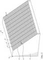
- FIG. 1is a perspective view of a portion of the housing of the energy storage device of this invention showing several of the concrete plates in position with the flow space there between;
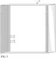
- FIG. 2shows a cutaway view of an entire module of the energy storage device of this invention including the intake plenum and all of the concrete plates that show the thermal breaks;
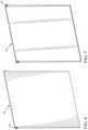
- FIG. 3is a perspective view of one of the concrete plates
- FIG. 4is a perspective view of the entire assembled energy storage device housing
- FIG. 5is a perspective view of the outer elongated shell that extends the longitudinal extent of the housing, with the plate holders shown in a position that would support the plates horizontally;
- FIG. 7is a perspective view of a second end cap that closes off the second end of the shell shown in FIG. 5 and is a mirror image of the one end cap shown in FIG. 6 .
- This inventiondescribes a method to store thermal energy in a modular way using low cost materials. It does so by aligning concrete plates 10 (shown in FIGS. 1, 2 and 3 ) of a thin cross section in close proximity to one another, forming flow channels 12 between the concrete plates. The concrete plates are then assembled in a low-cost metal module housing shell 20 with built-in guide slots 16 formed between adjacent separators 18 , which maintain the spacing between the concrete plates 10 that form the flow channels 12 . The shell 20 will be assembled and then two end caps 22 and 24 are positioned respectively at each end to the shell 20 and are affixed to the shell, such as by welding, forming a plenum 26 between the ends of the concrete plates 10 and each of the respective end caps 22 and 24 .
- each of the concrete platesis fluted, i.e., grooved in the vertical direction substantially along the entire height of the plate, at each given distance along the length of the concrete plate to reduce the effect of a heat wave moving down the plate when the heat transfer fluid is not flowing.
- the given distanceis preferably six inches to four feet, but can be longer, depending on the length of the module 100 .
- the flutes 28can be clearly observed in FIG. 2 .
- Thin strips of materialincluding but not limited to insulating materials, figuratively represented in FIG. 1 by reference character 34 , can also extend from one plenum to the other along the center of the flow channels 12 in order to tie the structure together and maintain plate spacing, while not negatively impacting performance characteristics. Insulation can also be embedded in the flutes 28 or replace the flutes altogether and tie adjacent sections of the heat transfer plates together.
- the concrete plates 10are shown extending in the horizontal direction it should be appreciated that they could be configured, alternately, to extend in the vertical direction and still be within the scope of this invention, though the horizontal flow path is preferred.
- one embodiment of this inventionemploys a concrete structure encased in metal casing 14 with a large surface to area ratio for storing thermal energy from a heat source such as a nuclear reactor.
- the concrete plates 10will include micro-rebar or other similar admixture to enhance strength, durability, and heat transfer.
- micro-rebarinclude steel, steel fibers fiberglass carbon fiber, other metals, composites and high temperature plastics. No piping need be utilized, but metal tubing or composite tubing may be employed as an alternative to the foregoing preferred channel 10 structure. All of the heat transfer medium within the module is directed by a metal casing or relatively thin concrete plates employed within the casing to store the heat.
- the concrete plates 10may be constructed from ultra-high-performance concrete, high performance concrete, high-strength concrete or high-temperature concrete. Alternatively, the plates 10 can be constructed from firebrick, ceramic, solid salt or metals.
- Flow channels for the heat transfer medium or fluidare formed between adjacent concrete plates, maximizing surface area and minimizing the thermal conductivity means and pumping power needed to drive the heat transfer medium.
- the separators 18may be thin material strips, rods or bars and may be constructed out of high temperature plastic, metal, composites or fiberglass.
- the heat transfer mediumis unpressurized and comprised of an oil or salt with suitable properties as to not negatively interact with the concrete or metal structure, which can be treated with a protective coating to deter such an interaction.
- the heat transfer mediummay be hydrocarbon based fluid such as Therminol, Duratherm H F, Calder 1, Mobiltherm, Paratherm, Dowtherm or Phillips 66, a silicone based fluid such as Duratherm S or Syltherm or a liquid salt such as Nitrate salts.
- hydrocarbon based fluidsuch as Therminol, Duratherm H F, Calder 1, Mobiltherm, Paratherm, Dowtherm or Phillips 66
- silicone based fluidsuch as Duratherm S or Syltherm
- a liquid saltsuch as Nitrate salts.
- the concrete platesare fluted along their height, i.e., perpendicular to the flow of the heat transfer medium, as to provide thermal breaks, slowing thermal diffusion between plates following a partial charge, i.e., a transfer of heat from the heat transfer medium to the concrete plates that only partially fills the capacity of the plates to store the heat.
- the thermal breaksimpede the plates from equalizing the temperature across the plates, which otherwise, after a partial charge, would prevent a high quality recovery of the heat during a discharge.
- the housing 14may be formed from plastic, coated carbon steel, stainless steel, composites or fiberglass and is preferably provided with insulation either layered within, around the inside or around the outside of the housing.
- the insulationmay be an air gap in a multi-layered shell, fiberglass, Aerogel, ceramics, mineral fiber/wool or silica.
- the energy storage device of this inventionmay be operated with the concrete plates 10 in either a horizontal or vertical orientation. Additionally, the shell 20 , end caps 22 and 24 and the concrete plates 10 may be cast at the site of use, or the fully constructed housings 14 and the concrete plates 10 may be shipped separately and assembled on site, or any combination thereof.
- Thermal energywill be loaded and unloaded from the fluted structure using a moving thermal gradient along the long axis of the concrete. Temperatures of operation will be as low as 212° F. and as high as 599° F. Charging and discharging operation will occur with opposite fluid flow direction as to resemble a counter-flow heat exchanger's operation. Micro rebar or similar admixture may be used in place of traditional concrete reinforcement, as to minimize manual labor and maximize production efficiency.
- the pressure of the incoming heat transfer mediumis at atmospheric pressure or slightly above, that is 14.5 to 21.8 psia.
- the flow rate of the heat transfer mediumdesirably, is approximately between 0-22.0 lbs/s and, preferably, about 3.9 lbs/s per module.
- the concrete platesare approximately between 0.5-3 inches thick and, more preferably, about 1.25 inches thick.
- the flow spacesare about between 0.04 inches and 0.4 inches and, more preferably, about 1/10 inch wide.
- FIG. 1shows the metal housing or casing 14 with three of the concrete plates 10 spaced by the modular guide slots 16 extending from the underside of the upper wall of the shell 20 portion of the casing 14 , to form the flow spaces or channels 12 between the plates 10 .
- the fluting 28is shown as grooves extending vertically, however, the flow of the heat transfer medium preferably extends horizontally, in parallel through the flow spaces over substantially the entire faces of the concrete plates 10 ; however, it should be appreciated that the flow may also be directed vertically with a plenum on the top and bottom of the module.
- FIG. 2shows a cutaway of a whole module 100 including all of the concrete plates 10 with a plenum 26 on either end of the elongated dimension of the concrete plates 10 , with the plenum on the left side being more visible and having an inlet or outlet nozzle 30 shown in the upper left corner of the module 100 . It does not make any difference if the plenum 26 on the right or the one on the left is the inlet plenum or outlet plenum, because the heat transfer medium, indicated by the double headed arrow 32 in FIG. 2 , will be flowing in both directions, one direction to charge the concrete plates and the opposite direction to discharge heat from the concrete plates.
- FIG. 3is a perspective view of one of the concrete plates 10 .
- FIG. 4shows a perspective view of the housing components assembled and FIGS. 5, 6 and 7 shows perspective views of the housing components disassembled.
- this inventioneliminates the need for metal piping within the module.
- the metal casingwhich is part of the functional unit, enables easy attachment of a simple plenum to each end of the flow spaces.
- the module 100utilizes the beneficial thermal properties of concrete, i.e., specific heat, durability, low-cost, ready availability, etc.
- the modulerequires only relatively low pumping power to move the heat transfer medium due to the large flow space between the concrete plates and low velocities, which increases residence time and improves heat transfer.
- the horizontal flow arrangementpermits easy inlet and outlet piping attachment and unit replacement.
- the horizontal arrangementalso permits ease of adding “thermal breaks” by simply fluting the concrete, i.e., adding vertical grooves to the concrete, in the same guide slot. This concept further eliminates the traditional use of labor intensive rebar for reinforcement.
- the heat for heating the heat transfer fluid or mediumcan be derived from a heat exchanger in heat exchange relationship with the primary or secondary loop of a nuclear reactor, coal plant, solar-thermal or other similar heat source. Alternately, the heat can be derived from a gas turbine cycle.
- this inventionprovides the most economical energy storage currently available outside of pumped hydro or compressed air into a compatible geologic formation and does not have siting restrictions.
- the inventionutilizes pre-existing equipment for a heat source, such as a nuclear power plant, inexpensive materials, and a simple design to solve a much grander challenge that has existed for some time without being practically addressed on a large commercial scale.
- the inventiondoes not require a pressurized environment and presents a reduced risk of catastrophic safety events.
Landscapes
- Engineering & Computer Science (AREA)
- Physics & Mathematics (AREA)
- Thermal Sciences (AREA)
- Mechanical Engineering (AREA)
- General Engineering & Computer Science (AREA)
- Ceramic Engineering (AREA)
- Building Environments (AREA)
- Heat-Exchange Devices With Radiators And Conduit Assemblies (AREA)
Abstract
Description
Claims (20)
Priority Applications (2)
| Application Number | Priority Date | Filing Date | Title |
|---|---|---|---|
| US15/979,628US11248851B2 (en) | 2017-06-21 | 2018-05-15 | Energy storage device |
| US16/547,950US11692778B2 (en) | 2017-06-21 | 2019-08-22 | Energy storage device |
Applications Claiming Priority (2)
| Application Number | Priority Date | Filing Date | Title |
|---|---|---|---|
| US201762522737P | 2017-06-21 | 2017-06-21 | |
| US15/979,628US11248851B2 (en) | 2017-06-21 | 2018-05-15 | Energy storage device |
Related Child Applications (1)
| Application Number | Title | Priority Date | Filing Date |
|---|---|---|---|
| US16/547,950Continuation-In-PartUS11692778B2 (en) | 2017-06-21 | 2019-08-22 | Energy storage device |
Publications (2)
| Publication Number | Publication Date |
|---|---|
| US20180372423A1 US20180372423A1 (en) | 2018-12-27 |
| US11248851B2true US11248851B2 (en) | 2022-02-15 |
Family
ID=64691554
Family Applications (1)
| Application Number | Title | Priority Date | Filing Date |
|---|---|---|---|
| US15/979,628Active2039-01-01US11248851B2 (en) | 2017-06-21 | 2018-05-15 | Energy storage device |
Country Status (5)
| Country | Link |
|---|---|
| US (1) | US11248851B2 (en) |
| EP (1) | EP3642548B1 (en) |
| JP (1) | JP7282041B2 (en) |
| KR (1) | KR102523410B1 (en) |
| WO (1) | WO2018236489A1 (en) |
Families Citing this family (3)
| Publication number | Priority date | Publication date | Assignee | Title |
|---|---|---|---|---|
| US11692778B2 (en) | 2017-06-21 | 2023-07-04 | Westinghouse Electric Company Llc | Energy storage device |
| US11248851B2 (en) | 2017-06-21 | 2022-02-15 | Westinghouse Electric Company Llc | Energy storage device |
| EP4018147A1 (en) | 2019-08-22 | 2022-06-29 | Westinghouse Electric Company Llc | Energy storage device |
Citations (42)
| Publication number | Priority date | Publication date | Assignee | Title |
|---|---|---|---|---|
| US3854186A (en) | 1973-06-14 | 1974-12-17 | Grace W R & Co | Method of preparing a heat exchanger |
| US4379109A (en) | 1978-02-02 | 1983-04-05 | W. R. Grace & Co. | Method of preparing a monolithic structure having flow channels |
| DE8630338U1 (en) | 1986-11-12 | 1987-06-19 | Vahlbrauk, Karl Heinz, 3353 Bad Gandersheim | Device for storing and/or transferring heat |
| US4993481A (en)* | 1988-10-03 | 1991-02-19 | The Agency Of Industrial Science And Technology | Thermal storage unit |
| US5184669A (en)* | 1989-02-22 | 1993-02-09 | Deutsche Forschungsanstalt Fuer Luft- Und Raumfahrt E.V. | Heat accumulator with chemical solid matter/gas storage reactions |
| US5222298A (en)* | 1990-06-29 | 1993-06-29 | Oskar Schatz | Method of producing a heat storage means |
| US5239839A (en) | 1991-06-17 | 1993-08-31 | James Timothy W | Thermal energy storage apparatus enabling use of aqueous or corrosive thermal storage media |
| US5826650A (en) | 1997-10-02 | 1998-10-27 | Keller; Leonard J. | Devices and methods for utilization of intermittently available electric energy for heating and cooling of habitable structures |
| US6079481A (en) | 1997-01-23 | 2000-06-27 | Ail Research, Inc | Thermal storage system |
| WO2002001132A2 (en) | 2000-06-23 | 2002-01-03 | Ail Research Inc | Heat exchange assembly |
| US6343485B1 (en)* | 1998-12-11 | 2002-02-05 | Behr Gmbh & Co. | Cold storage unit |
| US7144557B2 (en)* | 2002-01-11 | 2006-12-05 | Mitsubishi Chemical Corporation | Multitube reactor, vapor phase catalytic oxidation method using the multitube reactor, and start up method applied to the multitube reactor |
| US7156155B2 (en)* | 2001-09-25 | 2007-01-02 | Honda Motor Co., Ltd. | Heat storage unit and manufacturing method therefor |
| US7222659B2 (en)* | 2005-04-12 | 2007-05-29 | Alexander Levin | Heat and cold storage multistage tower with application of PCM |
| US20080105417A1 (en) | 2006-11-02 | 2008-05-08 | Thomas Deaver | Reverse flow parallel thermal transfer unit |
| US7406998B2 (en)* | 2005-02-17 | 2008-08-05 | Honda Motor Co., Ltd. | Heat storing device |
| EP2017561A2 (en) | 2007-07-18 | 2009-01-21 | Wido E. Brecht | Heat accumulator |
| US20090090109A1 (en) | 2007-06-06 | 2009-04-09 | Mills David R | Granular thermal energy storage mediums and devices for thermal energy storage systems |
| US20090294092A1 (en) | 2008-05-30 | 2009-12-03 | Bahl Carsten | Device and system for storing thermal energy |
| DE102009036550A1 (en) | 2008-11-01 | 2010-05-06 | Deutsches Zentrum für Luft- und Raumfahrt e.V. (DLR) | Device and system for temporary storage of thermal energy |
| WO2010051682A1 (en) | 2008-11-05 | 2010-05-14 | 上海神曦太阳能科技有限公司 | Solar energy heat-storage device and method making it |
| US20110016858A1 (en)* | 2009-07-24 | 2011-01-27 | J. Eberspaecher Gmbh & Co. Kg | Latent Heat Storage Device |
| WO2011079936A2 (en) | 2009-12-31 | 2011-07-07 | Ed. Züblin Ag | Device and system for the intermediate storage of thermal energy |
| US20110200156A1 (en) | 2010-02-18 | 2011-08-18 | Searete Llc, A Limited Liability Corporation Of The State Of Delaware | Method, system, and apparatus for the thermal storage of nuclear reactor generated energy |
| US20110200159A1 (en) | 2010-02-18 | 2011-08-18 | Searete Llc, A Limited Liability Corporation Of The State Of Delaware | Method, system, and apparatus for the thermal storage of energy generated by multiple nuclear reactor systems |
| US20110286724A1 (en) | 2010-05-19 | 2011-11-24 | Travis Goodman | Modular Thermal Energy Retention and Transfer System |
| US8201615B2 (en) | 2008-02-22 | 2012-06-19 | Dow Global Technologies Llc | Heat storage devices |
| US20120168111A1 (en)* | 2009-09-25 | 2012-07-05 | Dow Global Technologies Inc. | Heat transfer system utilizing thermal energy storage materials |
| WO2012140015A1 (en) | 2011-04-13 | 2012-10-18 | Sgl Carbon Se | Heat store module and heat store |
| EP2522047A1 (en) | 2010-01-08 | 2012-11-14 | Dow Global Technologies LLC | Thermal management of an electrochemical cell by a combination of heat transfer fluid and phase change material |
| US20130105106A1 (en)* | 2011-10-31 | 2013-05-02 | Dharendra Yogi Goswami | Systems And Methods For Thermal Energy Storage |
| WO2014026559A1 (en) | 2012-08-17 | 2014-02-20 | Zhu Liang | Solar heat storage device |
| US20140110080A1 (en) | 2011-06-09 | 2014-04-24 | Nest As | Thermal energy storage and plant, method and use thereof |
| US20140284021A1 (en) | 2011-11-04 | 2014-09-25 | Siemens Aktiengesellschaft | Storage and recovery of thermal energy using heat storage material being filled in a plurality of enclosures |
| US20140366536A1 (en) | 2011-11-08 | 2014-12-18 | Abengoa Solar Llc | High temperature thermal energy for grid storage and concentrated solar plant enhancement |
| US20150052931A1 (en) | 2013-08-22 | 2015-02-26 | King Fahd University Of Petroleum And Minerals | Heat exchanger |
| US20150192370A1 (en)* | 2013-04-10 | 2015-07-09 | Panasonic Intellectual Property Management Co., Ltd. | Heat storage device |
| WO2016065191A1 (en) | 2014-10-23 | 2016-04-28 | Glasspoint Solar, Inc. | Heat storage devices for solar steam generation, and associated systems and methods |
| EP3247963A1 (en) | 2014-12-19 | 2017-11-29 | Energynest As | High temperature thermal energy storage, a method of building and a method of operating said storage |
| WO2018077842A1 (en) | 2016-10-28 | 2018-05-03 | Hyperion Energy Ug (Haftungsbeschränkt) | Heat accumulator system |
| US20180372423A1 (en) | 2017-06-21 | 2018-12-27 | Westinghouse Electric Company Llc | Energy storage device |
| US10471803B2 (en) | 2016-01-27 | 2019-11-12 | Ford Global Technologies, Llc | Systems and methods for thermal battery control |
Family Cites Families (4)
| Publication number | Priority date | Publication date | Assignee | Title |
|---|---|---|---|---|
| JPS59134763U (en)* | 1983-02-27 | 1984-09-08 | ナショナル住宅産業株式会社 | heat storage device |
| JPH0424315Y2 (en)* | 1985-08-09 | 1992-06-08 | ||
| JP2011085379A (en) | 2009-10-17 | 2011-04-28 | Kenichi Yamaguchi | Heat storage body used for both air-conditioning and heating |
| US9440881B2 (en)* | 2012-12-18 | 2016-09-13 | Polytorx, Llc | Micro-rebar concrete reinforcement system |
- 2018
- 2018-05-15USUS15/979,628patent/US11248851B2/enactiveActive
- 2018-05-15KRKR1020207001633Apatent/KR102523410B1/enactiveActive
- 2018-05-15WOPCT/US2018/032685patent/WO2018236489A1/ennot_activeCeased
- 2018-05-15JPJP2019564404Apatent/JP7282041B2/enactiveActive
- 2018-05-15EPEP18820726.0Apatent/EP3642548B1/enactiveActive
Patent Citations (48)
| Publication number | Priority date | Publication date | Assignee | Title |
|---|---|---|---|---|
| US3854186A (en) | 1973-06-14 | 1974-12-17 | Grace W R & Co | Method of preparing a heat exchanger |
| US4379109A (en) | 1978-02-02 | 1983-04-05 | W. R. Grace & Co. | Method of preparing a monolithic structure having flow channels |
| DE8630338U1 (en) | 1986-11-12 | 1987-06-19 | Vahlbrauk, Karl Heinz, 3353 Bad Gandersheim | Device for storing and/or transferring heat |
| US4993481A (en)* | 1988-10-03 | 1991-02-19 | The Agency Of Industrial Science And Technology | Thermal storage unit |
| US5184669A (en)* | 1989-02-22 | 1993-02-09 | Deutsche Forschungsanstalt Fuer Luft- Und Raumfahrt E.V. | Heat accumulator with chemical solid matter/gas storage reactions |
| US5222298A (en)* | 1990-06-29 | 1993-06-29 | Oskar Schatz | Method of producing a heat storage means |
| US5239839A (en) | 1991-06-17 | 1993-08-31 | James Timothy W | Thermal energy storage apparatus enabling use of aqueous or corrosive thermal storage media |
| US6079481A (en) | 1997-01-23 | 2000-06-27 | Ail Research, Inc | Thermal storage system |
| US5826650A (en) | 1997-10-02 | 1998-10-27 | Keller; Leonard J. | Devices and methods for utilization of intermittently available electric energy for heating and cooling of habitable structures |
| US6343485B1 (en)* | 1998-12-11 | 2002-02-05 | Behr Gmbh & Co. | Cold storage unit |
| WO2002001132A2 (en) | 2000-06-23 | 2002-01-03 | Ail Research Inc | Heat exchange assembly |
| US7156155B2 (en)* | 2001-09-25 | 2007-01-02 | Honda Motor Co., Ltd. | Heat storage unit and manufacturing method therefor |
| US7144557B2 (en)* | 2002-01-11 | 2006-12-05 | Mitsubishi Chemical Corporation | Multitube reactor, vapor phase catalytic oxidation method using the multitube reactor, and start up method applied to the multitube reactor |
| US7406998B2 (en)* | 2005-02-17 | 2008-08-05 | Honda Motor Co., Ltd. | Heat storing device |
| US7222659B2 (en)* | 2005-04-12 | 2007-05-29 | Alexander Levin | Heat and cold storage multistage tower with application of PCM |
| US20080105417A1 (en) | 2006-11-02 | 2008-05-08 | Thomas Deaver | Reverse flow parallel thermal transfer unit |
| US20090090109A1 (en) | 2007-06-06 | 2009-04-09 | Mills David R | Granular thermal energy storage mediums and devices for thermal energy storage systems |
| EP2017561A2 (en) | 2007-07-18 | 2009-01-21 | Wido E. Brecht | Heat accumulator |
| US8201615B2 (en) | 2008-02-22 | 2012-06-19 | Dow Global Technologies Llc | Heat storage devices |
| US20090294092A1 (en) | 2008-05-30 | 2009-12-03 | Bahl Carsten | Device and system for storing thermal energy |
| DE102009036550A1 (en) | 2008-11-01 | 2010-05-06 | Deutsches Zentrum für Luft- und Raumfahrt e.V. (DLR) | Device and system for temporary storage of thermal energy |
| WO2010051682A1 (en) | 2008-11-05 | 2010-05-14 | 上海神曦太阳能科技有限公司 | Solar energy heat-storage device and method making it |
| US20110016858A1 (en)* | 2009-07-24 | 2011-01-27 | J. Eberspaecher Gmbh & Co. Kg | Latent Heat Storage Device |
| US20120168111A1 (en)* | 2009-09-25 | 2012-07-05 | Dow Global Technologies Inc. | Heat transfer system utilizing thermal energy storage materials |
| WO2011079936A2 (en) | 2009-12-31 | 2011-07-07 | Ed. Züblin Ag | Device and system for the intermediate storage of thermal energy |
| US20120312292A1 (en) | 2009-12-31 | 2012-12-13 | Bahl Carsten | Device and system for the intermediate storage of thermal energy |
| US9151545B2 (en)* | 2010-01-08 | 2015-10-06 | Dow Global Technologies Llc | Thermal management of an electrochemical cell by a combination of heat transfer fluid and phase change material |
| EP2522047A1 (en) | 2010-01-08 | 2012-11-14 | Dow Global Technologies LLC | Thermal management of an electrochemical cell by a combination of heat transfer fluid and phase change material |
| US20110200159A1 (en) | 2010-02-18 | 2011-08-18 | Searete Llc, A Limited Liability Corporation Of The State Of Delaware | Method, system, and apparatus for the thermal storage of energy generated by multiple nuclear reactor systems |
| US20110200156A1 (en) | 2010-02-18 | 2011-08-18 | Searete Llc, A Limited Liability Corporation Of The State Of Delaware | Method, system, and apparatus for the thermal storage of nuclear reactor generated energy |
| US20110286724A1 (en) | 2010-05-19 | 2011-11-24 | Travis Goodman | Modular Thermal Energy Retention and Transfer System |
| WO2012140015A1 (en) | 2011-04-13 | 2012-10-18 | Sgl Carbon Se | Heat store module and heat store |
| DE102011007335A1 (en) | 2011-04-13 | 2012-10-18 | Sgl Carbon Se | Heat storage module and heat storage |
| US20140110080A1 (en) | 2011-06-09 | 2014-04-24 | Nest As | Thermal energy storage and plant, method and use thereof |
| US20130105106A1 (en)* | 2011-10-31 | 2013-05-02 | Dharendra Yogi Goswami | Systems And Methods For Thermal Energy Storage |
| US20140284021A1 (en) | 2011-11-04 | 2014-09-25 | Siemens Aktiengesellschaft | Storage and recovery of thermal energy using heat storage material being filled in a plurality of enclosures |
| US20140366536A1 (en) | 2011-11-08 | 2014-12-18 | Abengoa Solar Llc | High temperature thermal energy for grid storage and concentrated solar plant enhancement |
| WO2014026559A1 (en) | 2012-08-17 | 2014-02-20 | Zhu Liang | Solar heat storage device |
| US20150192370A1 (en)* | 2013-04-10 | 2015-07-09 | Panasonic Intellectual Property Management Co., Ltd. | Heat storage device |
| US20150052931A1 (en) | 2013-08-22 | 2015-02-26 | King Fahd University Of Petroleum And Minerals | Heat exchanger |
| WO2016065191A1 (en) | 2014-10-23 | 2016-04-28 | Glasspoint Solar, Inc. | Heat storage devices for solar steam generation, and associated systems and methods |
| US20160116188A1 (en)* | 2014-10-23 | 2016-04-28 | Glasspoint Solar, Inc. | Heat storage devices for solar steam generation, and associated systems and methods |
| EP3247963A1 (en) | 2014-12-19 | 2017-11-29 | Energynest As | High temperature thermal energy storage, a method of building and a method of operating said storage |
| US10591224B2 (en) | 2014-12-19 | 2020-03-17 | Energynest As | Concrete thermal energy storage containing concrete thermal energy storage elements arranged in cassettes that are self-supporting with respect to transport and installation, method of building and methods of operating said storage |
| US10471803B2 (en) | 2016-01-27 | 2019-11-12 | Ford Global Technologies, Llc | Systems and methods for thermal battery control |
| WO2018077842A1 (en) | 2016-10-28 | 2018-05-03 | Hyperion Energy Ug (Haftungsbeschränkt) | Heat accumulator system |
| US20190249932A1 (en)* | 2016-10-28 | 2019-08-15 | Hyperion Energy UG | Thermal storage system |
| US20180372423A1 (en) | 2017-06-21 | 2018-12-27 | Westinghouse Electric Company Llc | Energy storage device |
Non-Patent Citations (7)
| Title |
|---|
| Brown, Bradley M., "Development of a Structured Concrete Thermocline Thermal Energy Storage System", Dec. 2011, 119 pp., University of Arkansas, Fayetteville, http://scholarworks.uark.edu/etd. |
| Dr. R. Panneer Selvam, "Development and Performance Evaluation of High Temperature Concrete for Thermal Energy Storage for Solar Power Generation", 32 pp., University of Arkansas, Fayetteville. |
| International Search Report and Written Opinion for International PCT Application No. PCT/US2020/040706, dated Oct. 27, 2020. |
| International Search Report and Written Opinion of the International Searching Authority dated Sep. 13, 2018 for PCT/US2018/032685 (Forms PCT/ISA/220, PCT/ISA/210, PCT/ISA/237). |
| John, Emerson Esmond, "The Development of a High Performance Concrete to Store Thermal Energy for Concentrating Solar Power Plants", Aug. 2012, 194 pp., University of Arkansas, Fayetteville, http://scholarworks.uark.edu/etd. |
| John, Emerson, "Concrete as a thermal energy storage medium for thermocline solar energy storage systems", Solar Energy, Oct. 2013, 1-2 pp., vol. 96, Published by Elsevier Ltd. |
| Supplementary European Search Report for corresponding European Patent Application No. EP1882072.6, dated Mar. 2, 2021. |
Also Published As
| Publication number | Publication date |
|---|---|
| EP3642548B1 (en) | 2023-07-05 |
| KR102523410B1 (en) | 2023-04-18 |
| KR20200010582A (en) | 2020-01-30 |
| JP2020524773A (en) | 2020-08-20 |
| EP3642548A4 (en) | 2021-04-14 |
| JP7282041B2 (en) | 2023-05-26 |
| WO2018236489A1 (en) | 2018-12-27 |
| EP3642548A1 (en) | 2020-04-29 |
| US20180372423A1 (en) | 2018-12-27 |
Similar Documents
| Publication | Publication Date | Title |
|---|---|---|
| CN111065798B (en) | Energy storage device for storing electrical energy as heat and method for this purpose | |
| US11248851B2 (en) | Energy storage device | |
| US9484121B2 (en) | System and method for storing energy in a nuclear power plant | |
| DK2758637T3 (en) | Thermal energy storage and recovery using heat storage material loaded in a plurality of enclosures | |
| US20120111006A1 (en) | Solar energy transfer and storage apparatus | |
| CN104870924B (en) | Heat storage apparatus | |
| CN113324277B (en) | Metal phase transformation heat accumulation heating device | |
| KR20250073279A (en) | Green Energy Heat Storage System | |
| US11692778B2 (en) | Energy storage device | |
| CA2917741A1 (en) | System for storing energy | |
| CN201043869Y (en) | High-temperature inclined-temperature layer mixed heat storage device in molten salt | |
| US20240247598A1 (en) | Energy recovery system and methods of use | |
| CN110242362B (en) | Supercritical carbon dioxide Brayton cycle work system | |
| WO2021034417A1 (en) | Energy storage device | |
| CN102135270B (en) | Heat accumulation and evaporation integrated device for solar thermal power generation | |
| ITMI20120809A1 (en) | THERMODYNAMIC PLANT WITH SOLAR CONCENTRATION | |
| CN115822742B (en) | Pile up bed heat-retaining power generation system | |
| JP6891338B1 (en) | A driving force generator that uses power generated by the buoyancy difference method of gravity (9.807 m / s2) as the energy source. | |
| CN108627041A (en) | A kind of spiral plate type thermochemical high temperature energy storing-releasing reaction unit | |
| CN120141194A (en) | A mobile heat storage system for steel materials on a vehicle and a heat storage and release method | |
| WO2012066314A1 (en) | Energy transfer and storage apparatus | |
| SK50402013A3 (en) | Operation method of energy-autonomous buildings and energy device |
Legal Events
| Date | Code | Title | Description |
|---|---|---|---|
| AS | Assignment | Owner name:WESTINGHOUSE ELECTRIC COMPANY LLC, PENNSYLVANIA Free format text:ASSIGNMENT OF ASSIGNORS INTEREST;ASSIGNOR:STANSBURY, CORY A.;REEL/FRAME:045803/0624 Effective date:20180508 | |
| FEPP | Fee payment procedure | Free format text:ENTITY STATUS SET TO UNDISCOUNTED (ORIGINAL EVENT CODE: BIG.); ENTITY STATUS OF PATENT OWNER: LARGE ENTITY | |
| AS | Assignment | Owner name:CREDIT SUISSE AG, CAYMAN ISLANDS BRANCH, AS COLLATERAL AGENT, NEW YORK Free format text:SECURITY INTEREST;ASSIGNORS:WESTINGHOUSE ELECTRIC COMPANY LLC;FAUSKE AND ASSOCIATES LLC;REEL/FRAME:046708/0222 Effective date:20180801 Owner name:GOLDMAN SACHS BANK USA, AS COLLATERAL AGENT, NEW YORK Free format text:SECURITY INTEREST;ASSIGNORS:WESTINGHOUSE ELECTRIC COMPANY LLC;FAUSKE AND ASSOCIATES LLC;REEL/FRAME:046708/0332 Effective date:20180801 Owner name:BANK OF MONTREAL, AS ADMINISTRATIVE AGENT, ILLINOIS Free format text:SECURITY INTEREST;ASSIGNORS:WESTINGHOUSE ELECTRIC COMPANY LLC;FAUSKE AND ASSOCIATES LLC;REEL/FRAME:046708/0639 Effective date:20180801 Owner name:CREDIT SUISSE AG, CAYMAN ISLANDS BRANCH, AS COLLAT Free format text:SECURITY INTEREST;ASSIGNORS:WESTINGHOUSE ELECTRIC COMPANY LLC;FAUSKE AND ASSOCIATES LLC;REEL/FRAME:046708/0222 Effective date:20180801 Owner name:GOLDMAN SACHS BANK USA, AS COLLATERAL AGENT, NEW Y Free format text:SECURITY INTEREST;ASSIGNORS:WESTINGHOUSE ELECTRIC COMPANY LLC;FAUSKE AND ASSOCIATES LLC;REEL/FRAME:046708/0332 Effective date:20180801 Owner name:BANK OF MONTREAL, AS ADMINISTRATIVE AGENT, ILLINOI Free format text:SECURITY INTEREST;ASSIGNORS:WESTINGHOUSE ELECTRIC COMPANY LLC;FAUSKE AND ASSOCIATES LLC;REEL/FRAME:046708/0639 Effective date:20180801 | |
| STPP | Information on status: patent application and granting procedure in general | Free format text:DOCKETED NEW CASE - READY FOR EXAMINATION | |
| AS | Assignment | Owner name:WESTINGHOUSE ELECTRIC COMPANY LLC, PENNSYLVANIA Free format text:RELEASE OF SECURITY INTEREST IN PATENTS;ASSIGNOR:GOLDMAN SACHS BANK USA, AS COLLATERAL AGENT;REEL/FRAME:049937/0032 Effective date:20190801 Owner name:FAUSKE AND ASSOCIATES LLC, ILLINOIS Free format text:RELEASE OF SECURITY INTEREST IN PATENTS;ASSIGNOR:GOLDMAN SACHS BANK USA, AS COLLATERAL AGENT;REEL/FRAME:049937/0032 Effective date:20190801 | |
| STPP | Information on status: patent application and granting procedure in general | Free format text:NON FINAL ACTION MAILED | |
| STPP | Information on status: patent application and granting procedure in general | Free format text:RESPONSE TO NON-FINAL OFFICE ACTION ENTERED AND FORWARDED TO EXAMINER | |
| STPP | Information on status: patent application and granting procedure in general | Free format text:FINAL REJECTION MAILED | |
| STPP | Information on status: patent application and granting procedure in general | Free format text:DOCKETED NEW CASE - READY FOR EXAMINATION | |
| STPP | Information on status: patent application and granting procedure in general | Free format text:NON FINAL ACTION MAILED | |
| STPP | Information on status: patent application and granting procedure in general | Free format text:RESPONSE TO NON-FINAL OFFICE ACTION ENTERED AND FORWARDED TO EXAMINER | |
| STPP | Information on status: patent application and granting procedure in general | Free format text:NOTICE OF ALLOWANCE MAILED -- APPLICATION RECEIVED IN OFFICE OF PUBLICATIONS | |
| STPP | Information on status: patent application and granting procedure in general | Free format text:PUBLICATIONS -- ISSUE FEE PAYMENT VERIFIED | |
| STCF | Information on status: patent grant | Free format text:PATENTED CASE | |
| AS | Assignment | Owner name:DEUTSCHE BANK AG NEW YORK BRANCH, AS COLLATERAL AGENT, NEW YORK Free format text:SECURITY INTEREST;ASSIGNORS:WESTINGHOUSE ELECTRIC COMPANY LLC;BHI ENERGY I SPECIALTY SERVICES LLC;STONE & WEBSTER, L.L.C. (FORMERLY STONE & WEBSTER, INC.);REEL/FRAME:066373/0604 Effective date:20240125 | |
| AS | Assignment | Owner name:FAUSKE AND ASSOCIATES LLC, ILLINOIS Free format text:RELEASE OF SECURITY INTEREST IN PATENTS;ASSIGNOR:CREDIT SUISSE AG, CAYMAN ISLANDS, AS COLLATERAL AGENT;REEL/FRAME:066380/0392 Effective date:20240125 Owner name:WESTINGHOUSE ELECTRIC COMPANY LLC, PENNSYLVANIA Free format text:RELEASE OF SECURITY INTEREST IN PATENTS;ASSIGNOR:CREDIT SUISSE AG, CAYMAN ISLANDS, AS COLLATERAL AGENT;REEL/FRAME:066380/0392 Effective date:20240125 | |
| MAFP | Maintenance fee payment | Free format text:PAYMENT OF MAINTENANCE FEE, 4TH YEAR, LARGE ENTITY (ORIGINAL EVENT CODE: M1551); ENTITY STATUS OF PATENT OWNER: LARGE ENTITY Year of fee payment:4 |