US11247918B2 - Multi-media clarification systems and methods - Google Patents
Multi-media clarification systems and methodsDownload PDFInfo
- Publication number
- US11247918B2 US11247918B2US17/170,689US202117170689AUS11247918B2US 11247918 B2US11247918 B2US 11247918B2US 202117170689 AUS202117170689 AUS 202117170689AUS 11247918 B2US11247918 B2US 11247918B2
- Authority
- US
- United States
- Prior art keywords
- media
- water
- gas
- control mechanism
- flow rate
- Prior art date
- Legal status (The legal status is an assumption and is not a legal conclusion. Google has not performed a legal analysis and makes no representation as to the accuracy of the status listed.)
- Active
Links
Images


Classifications
- C—CHEMISTRY; METALLURGY
- C02—TREATMENT OF WATER, WASTE WATER, SEWAGE, OR SLUDGE
- C02F—TREATMENT OF WATER, WASTE WATER, SEWAGE, OR SLUDGE
- C02F1/00—Treatment of water, waste water, or sewage
- C02F1/28—Treatment of water, waste water, or sewage by sorption
- C02F1/285—Treatment of water, waste water, or sewage by sorption using synthetic organic sorbents
- B—PERFORMING OPERATIONS; TRANSPORTING
- B01—PHYSICAL OR CHEMICAL PROCESSES OR APPARATUS IN GENERAL
- B01D—SEPARATION
- B01D15/00—Separating processes involving the treatment of liquids with solid sorbents; Apparatus therefor
- C—CHEMISTRY; METALLURGY
- C02—TREATMENT OF WATER, WASTE WATER, SEWAGE, OR SLUDGE
- C02F—TREATMENT OF WATER, WASTE WATER, SEWAGE, OR SLUDGE
- C02F1/00—Treatment of water, waste water, or sewage
- C02F1/001—Processes for the treatment of water whereby the filtration technique is of importance
- C02F1/004—Processes for the treatment of water whereby the filtration technique is of importance using large scale industrial sized filters
- C—CHEMISTRY; METALLURGY
- C02—TREATMENT OF WATER, WASTE WATER, SEWAGE, OR SLUDGE
- C02F—TREATMENT OF WATER, WASTE WATER, SEWAGE, OR SLUDGE
- C02F1/00—Treatment of water, waste water, or sewage
- C02F1/28—Treatment of water, waste water, or sewage by sorption
- C02F1/283—Treatment of water, waste water, or sewage by sorption using coal, charred products, or inorganic mixtures containing them
- C—CHEMISTRY; METALLURGY
- C02—TREATMENT OF WATER, WASTE WATER, SEWAGE, OR SLUDGE
- C02F—TREATMENT OF WATER, WASTE WATER, SEWAGE, OR SLUDGE
- C02F2209/00—Controlling or monitoring parameters in water treatment
- C02F2209/03—Pressure
- C—CHEMISTRY; METALLURGY
- C02—TREATMENT OF WATER, WASTE WATER, SEWAGE, OR SLUDGE
- C02F—TREATMENT OF WATER, WASTE WATER, SEWAGE, OR SLUDGE
- C02F2303/00—Specific treatment goals
- C02F2303/16—Regeneration of sorbents, filters
Definitions
- the present inventionrelates to an apparatus and method for filtering fluids. More specifically, it relates to media clarifiers.
- Media clarifiersuse media to capture particulate matter from a water or wastewater stream. Media, which adsorbs particulate matter, helps remove solids at a faster rate than traditional clarifiers, which do not use media. Consequently, media clarifiers can handle larger flows and consume less space than a traditional clarifier. Accordingly, increasing the performance of the media employed in a media clarifier is desirable.
- a media clarifiermay comprise a vessel defining a passageway for water.
- the vesselmay comprise an inlet for the passageway, an outlet for the passageway, and a screen intermediate the inlet and the outlet that is disposed within and spans the passageway.
- the vesselmay place the inlet in fluid communication with the screen and the outlet.
- the outletWhen the media clarifier is in an installed configuration, the outlet may be situated above the inlet.
- the media bedmay be disposed within the passageway intermediate the inlet and the screen.
- the media bedmay comprise both compressible media and incompressible media.
- the present inventionis adapted for use with a variety of fluid and filtering applications.
- FIG. 1is a side elevation, cross-sectional view of one embodiment of a media clarifier during normal operation.
- FIG. 2is a side elevation, cross-sectional view of one embodiment of a media clarifier during a cleaning cycle.
- FIG. 3is an enlarged view of one embodiment of a media bed.
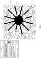
- FIG. 4is a photograph of a mixture of incompressible media interacting with compressible media.
- FIG. 5is a side elevation, cross-sectional view of one embodiment of a media clarifier with media in a stratified state.
- FIG. 6is a bar graph showing that fewer cleaning cycles are needed for a filter downstream of a media clarifier when both compressible and incompressible media are used rather than a single type of media in the media clarifier.
- FIG. 7is a bar graph showing that less water, on average, is wasted when both compressible and incompressible media are used rather than a single type of media.
- FIG. 8is a line chart showing increased efficiency when both compressible and incompressible media are used rather than a single type of media based on two sample runs.
- FIG. 9is a flow diagram illustrating one embodiment of a method for utilizing a media clarifier.
- FIG. 10is a flow diagram illustrating one embodiment of a method for cleaning a media clarifier.
- an embodimentmay refer to various configurations or embodiments of the disclosed apparatuses, systems, or methods in the singular or plural form, rather than referring to a single, particular embodiment.
- Media clarifiersmay also be referred to as media clarification systems, filter systems, media filters, upward filters, or any combination of these terms.
- Media clarifiersmay, in various embodiments, rely in whole or in part on principles of adsorption.
- Particulate mattercan be filtered from a water stream as it passes through a treatment column containing adsorbent media.
- Mediamay be comprised of many members, such as beads, sand, or synthetic fibers; the word “media” refers to both a singular and plural number of these members.
- the systemmay be used in various water applications, such as drinking water or wastewater treatment.
- the water stream provided to the systemmay be pressurized, using, for example, a pump or gravity.
- Particulate mattermay include dirt, sand, minerals, biological material, and/or other types of material, and may also include flocculated particles comprising chemicals such as flocculants and/or coagulants.
- incompressible mediadoes not flex or deform under pressures typically encountered in water filtration systems (e.g., pressures generated in 5 to 150 inches of water).
- incompressible mediacomprises small beads, which may be as small as 1 millimeter.
- the beadsmay be made of high-density polyethylene (HDPE) or other natural or synthetic materials.
- HDPEhigh-density polyethylene
- Other examples of incompressible mediainclude other plastics, such as Acrylonitrile Butadiene Styrene (ABS), low-density polyethylene (LDPE), or natural materials, such as charcoal or wood.
- Incompressible mediamay adsorb particulate matter on the media surface and within interstitial space between adjacent media beads.
- the surface of incompressible mediamay comprise a disturbed surface, such as by scarification, sanding, or other roughening applications, which makes the incompressible media more adsorbent.
- Mediamay also be compressible.
- compressible mediautilizes bundles of elongated plastic fibers.
- the bundles of elongated plastic fibersmay be tightly bound with a clip, ring, staple, crimp, or clamp at the center and fan out at the ends. These bundles, when bound, may be spherical in shape.
- the fibersmay be made from a combination of polypropylene and polyethylene terephthalate and may be approximately three (3) inches in length. In such embodiments, when the fibers are crimped or clamped together, each fibrous ball may have a diameter of approximately 1.5 to 2 inches.
- compressible mediamay flex or change size or shape under pressure.
- the compressible mediamay be more flexible than the incompressible media measured, for example, using the flexural modulus, which indicates a tendency to bend rather than break.
- Compressible mediamay capture particulate matter by any combination of adsorption on its surface or in its fibers, capture within the interstitial spaces between media, or capture by the compression and/or flexion of the media's shape.
- the media bedmay be comprised, in various embodiments, of sufficient media to span the cross-sectional area of the water column along a horizontal dimension
- the media bedmay also be thick enough to allow the water to flow over enough media surface area to capture a sufficient quantity of particulate matter to make the filter useful, which in various embodiments, may be at least six (6) inches in depth. If more than one type of media is used in the media bed, each type of media may be sufficient in number to span the cross-sectional area of the water column along a horizontal dimension of a certain depth (e.g., at least three (3) inches deep) without the other type of media. Alternatively, a combination of the types of media may be of a certain depth.
- Mediawhether compressible or incompressible, in various embodiments, may have a specific gravity of less than 1. However, various factors such as the specific gravity of the fluid, the quantity and mass of solids in the fluid, and the speed of the fluid may allow use of media that has a specific gravity of 1 or greater to rise to the filter bed.
- Compressible mediacan typically hold more particulate matter than incompressible media but generally cannot capture finer particles while it is uncompressed. For this reason, some compressible media filters employ a system to compress the media. However, while the media is compressed, it cannot adsorb as much particulate matter as it can in an uncompressed state.
- the disclosed subject mattercombines the two types of media, resulting in an unexpected synergistic effect. Compressible media may be used to capture larger particles, while incompressible media captures smaller particles. The combination of the two types of media causes the system to capture more particles. It also removes a higher percentage of particulate matter than either type of media can by itself. Additionally, it allows the filter to operate without a compression system.
- the size of the compressible mediamay be much larger than the incompressible media (e.g., five (5) to twenty (20) times larger). In various alternative embodiments, compressible and incompressible media may be more similar in size (i.e., compressible media may be less than five (5) times larger).
- the media clarifier 101may comprise a vessel 102 defining a passageway 104 for water 117 with an inlet 106 , and an outlet 108 . The outlet 108 may also be referred to as the effluent outlet 108 .
- the media clarifier 101may further comprise a screen 110 intermediate the inlet 106 and the outlet 108 .
- the screen 110may span the passageway 104 .
- the outlet 108may be a collection trough, pipe, or other mechanism for receiving effluent water 117 .
- the vessel 102may place the inlet 106 in fluid communication with the screen 110 and the outlet 108 . In the installed configuration, as illustrated in FIG. 1 , the outlet 108 may be situated above the inlet 106 .
- the media clarifier 101may include a vertical dimension 115 a , a horizontal dimension 115 b , and a transverse dimension 115 c , as illustrated on the dimensional guide 115 .
- the term “above”indicates a higher elevation along a vertical dimension 115 a .
- the term “directly above”signifies that a first element is located at a higher elevation along a vertical dimension 115 a relative to a second element with the first element and the second element at least overlapping along a horizontal dimension 115 b .
- the outlet 108may or may not be directly above the inlet 106 , but the outlet 108 may simply be above (i.e., at a higher elevation along a vertical dimension 115 a ).
- Influent water 117enters the media clarifier 101 through an inlet 106 , which may be controlled by a fluid control mechanism 113 (e.g., a pump or valve).
- the water 117may then pass through a distribution header 103 (sometimes referred to as a water distribution header 103 ) and enter into the passageway 104 , which may, in various embodiments, also be referred to or comprise a treatment column.
- Water 117flows upward through the media bed 105 , which may comprise both compressible media 109 and incompressible media 107 .
- the media bed 105may comprise and/or be referred to as a filter bed 105 .
- Solids, such as particulate matter, in the influent stream of water 117may be separated from the stream of water 117 by adsorption on to the media surfaces, by capture using the filamentous fibers or other compressible bodies, and by capture within the interstitial spaces between the media 107 , 109 .
- the media bed 105may be retained within the system by the screen 110 , which may be described as a hold-down screen system 110 or a retention screen 110 . Clarified water 117 passes through the retention screen 110 and exits via the outlet 108 (which may be located above the hold-down screen system 110 ) and then flows out of the media clarifier 101 .
- One or more of the types of media in the media bed 105may, in certain embodiments, be buoyant. In various alternative embodiments, one or more of the types of media in the media bed 105 may be non-buoyant (such that non-buoyant media resides at the bottom of the vessel 102 when the media clarifier 101 is not in use), but may be propelled upward in response to the flow of water 117 through the vessel 102 .
- a differential pressuredevelops across the media bed 105 .
- the compressible media 109is compressed, which in turn tightens the interstitial spaces to retain the particulate matter.
- the media clarifier 101may be transitioned to a cleaning cycle to remove the captured particulate matter.
- the differential pressureis regulated by constricting or expanding the volume of the media bed 105 . This can be done with a mechanical wall, a flexible housing controlled by hydrostatic pressure, or other mechanisms that can alter the volume of the media bed 105 (not illustrated in FIG. 1 ).
- the predetermined differential pressuremay be ascertained using a first and second pressure sensor 131 a - b .
- the first pressure sensor 131 amay be disposed within the passageway 104 downstream of or within the media bed 105
- a second pressure sensor 131 bmay be disposed within the passageway 104 upstream of or within the media bed 105 , as illustrated in FIG. 1 .
- only the pressure sensor 131 b upstream relative to the media bed 105is used in the media clarifier 101 based on the assumption that the pressure downstream of the media bed 105 will remain constant or at least relatively constant.
- a bottom screen positioned intermediate the inlet and the retention screenserves as a lower boundary for the media bed.
- the media clarifier 101may include a vertical dimension 115 a , a horizontal dimension 115 b , and a transverse dimension 115 c , as illustrated on the dimensional guide 115 .
- the media clarifier 101may be transitioned to a cleaning cycle using, in part, a flow direction control mechanism 121 (e.g., an actuating cylinder 121 ), which may, in various embodiments, raise a waste gate to allow the waste stream to exit the treatment vessel 102 through a wastewater opening 112 (an opening other than the outlet 108 ).
- a flow direction control mechanism 121e.g., an actuating cylinder 121
- a lower edge or lip of the wastewater opening 112is lower (along a vertical dimension 115 a ) than the lower edge or lip of the outlet 108 . Accordingly, activating a fluid direction control mechanism 121 may simply allow water 117 passing through the media bed 105 to exit through the wastewater opening 112 before it reaches the lower lip or edge of the outlet 108 .
- activating a fluid direction control mechanism 121may simply allow water 117 passing through the media bed 105 to exit through the wastewater opening 112 before it reaches the lower lip or edge of the outlet 108 .
- the flow direction control mechanism 121may comprise a pair of independently controlled gates or valves.
- a gas 123(e.g., air) may be introduced by operating a gas control mechanism 130 (e.g., by opening a valve or activating a pump).
- the introduced gas 123may flow through a distribution header 132 (sometimes referred to as a gas distribution header 132 ).
- the gas control mechanism 130 and distribution header 132may be referred to collectively as a gas or air injection mechanism assembly.
- the bulk density of the combined gas 123 and water 117is less than the bulk density of the compressible media 109 and/or the incompressible media 107 (because of the introduction of the gas 123 ) causing all or a portion of the media bed 105 to sink (not illustrated in FIG. 2 ).
- the introduced gas 123also causes collisions between the media 107 , 109 to dislodge particulate matter that has adhered to the media surface.
- the introduction of the gas 123 into the water 117which causes the media bed 105 to sink and assist with the release of captured particulate matter, may be referred to as fluidization.
- the water 117may thus pass through the fluid control mechanism 113 and distribution header 103 and travel in an upward direction through the media bed 105 to carry the released particulate matter away from the media clarifier 101 .
- the gas control mechanism 130may be closed, or, if the gas control mechanism 130 comprises a pump, the pump may be deactivated.
- Water 117may continue to pass through the vessel 102 to remove the remaining particulate matter and to assist in restoring the media bed 105 to earlier levels.
- the actuating cylinder 121may be activated to close the waste gate 120 to terminate the cleaning cycle.
- FIG. 3comprises an enlarged view of one embodiment of a media bed 105 .
- incompressible media 107is mixed with compressible media 109 to create additional interstitial gaps with which to capture solids 341 (which comprise one type of particulate matter).
- a portion of the incompressible media 107has a scarified surface to aid with adsorption.
- the incompressible media 107 that has a scarified surfacemay be referred to as scarified incompressible media 107 a.
- FIG. 4is a close-up photograph of compressible media 109 and incompressible media 107 disposed in water 117 .
- FIG. 5illustrates one embodiment of media 107 , 109 in a stratified state within a media clarifier 101 .
- the media clarifier 101may include a vertical dimension 115 a , a horizontal dimension 115 b , and a transverse dimension 115 c , as illustrated on the dimensional guide 115 .
- a layer of incompressible media 107may remain on top of a layer of compressible media 109 .
- the media clarifier 101may have: an operational state, in which water 117 flows through the vessel 102 and the clarifier is operated to remove particulate matter from the influent stream of water 117 ; a non-operational state, in which no or little water 117 flows through the media clarifier 101 ; and a cleaning state, in which the media clarifier 101 is operated to dislodge particulate matter from the media 107 , 109 and flush the dislodged particulate matter from the media clarifier 101 .
- a layer of compressible media 109may remain above a layer of incompressible media 107 (i.e., the media bed 105 is in a stratified state). This can be done by manipulating the media with streams of gas 123 and/or water 117 . As illustrated in FIG. 5 , the incompressible media 107 and compressible media 109 (which, in certain embodiments, may also be referred to as fibrous balls 109 ) may be stratified into discrete regions.
- the incompressible media 107 and compressible media 109may be stratified by adjusting the gas 123 and water 117 to segregate and stack one type of media on top of the other.
- One example of such an adjustmentis increasing the water rate and altering the gas flow rate according to the sequence identified in Table 1, which is provided below:
- FIG. 6is a bar graph illustrating the average number of cleaning cycles per day for a filter (a “downstream filter”) situated downstream of a media clarifier.
- the decreased number of cleaning cycles for the downstream filterindicates that a media clarifier with incompressible and compressible media 107 , 109 provides improved removal of particulate matter. Because the media clarifier is capturing more particulate matter, additional cleaning cycles are or may be required for the media clarifier.
- the vertical axis of FIG. 6identifies the average number of cleaning cycles per day for the downstream filter, while the horizontal axis identifies the quantity of particulate matter within the stream of water 117 received by the media clarifier, measured in NTU (Nephelometric Turbidity Units).
- FIG. 6shows that a downstream filter following a media clarifier with both types of media will have fewer cleaning cycles per day compared to a downstream filter following a media clarifier with only one type of media.
- FIG. 7is a bar graph illustrating net average percent water production.
- the vertical axis of FIG. 7identifies the net average percent of water produced, which may be defined in accordance with Equation 1.
- FIG. 7shows that a media clarifier with both types of media wastes less water 117 than a media clarifier with only one type of media.
- FIG. 8is a line graph illustrating the percentage of particulate matter removed by two sample runs.
- the vertical axis of FIG. 8identifies the percentage of particulate matter removed, measured in NTU, while the horizontal axis represents runtime in minutes.
- the line graph of FIG. 8indicates that a media clarifier with both types of media removes a higher percentage of NTU than a media clarifier using only incompressible media.
- FIG. 9is a flowchart illustrating one embodiment of a method 901 for utilizing a media clarifier.
- Step 910involves operating a fluid control mechanism 113 to cause water 117 to flow through the passageway 104 from the inlet 106 to the outlet 108 in an operational state.
- the water 117may include particulate matter at least during a portion of the time in which the water 117 is moving through the passageway 104 .
- the fluid control mechanism 113may comprise one or more of various types of valves or pumps. Accordingly, in various embodiments, a valve may control the flow of water 117 into the passageway 104 with the water 117 being propelled, for example, by the force of gravity or by a pump.
- opening a valvemay cause water 117 to flow through the passageway 104
- closing the valvemay terminate the flow of water 117 through the passageway 104 .
- a pumpis utilized as a fluid control mechanism 113 , activating the pump will cause water 117 to flow through the passageway 104 , while deactivating the pump will result in water 117 not flowing through the passageway 104 .
- step 920in a non-operational state, the fluid control mechanism 113 is operated to cause water 117 not to flow through the passageway 104 from the inlet 106 to the outlet 108 .
- step 920may involve closing a valve and/or deactivating a pump.
- step 930in a cleaning state, the fluid control mechanism 113 may be operated to cause water 117 to flow through the passageway 104 from the inlet 106 to a wastewater opening 112 and/or operating a gas control mechanism 130 to cause gas 123 to be injected into the passageway 104 .
- the cleaning state of step 930may encompass a series of stages, as discussed in connection with Table 1, or a single stage. Step 930 may also comprise inducing the media bed 105 to transition into a fluidized state and/or stratified state, as discussed above. Additional detail regarding the cleaning state will be provided in connection with FIG. 10 . It should be noted that steps 910 , 920 , 930 may be performed in any order, not necessarily in the order illustrated in FIG. 9 .
- FIG. 10is a flowchart illustrating one embodiment of a method 1001 for cleaning a media clarifier.
- a gas control mechanism 130is operated to inject gas 123 into a passageway 104 and/or a fluid control mechanism 113 is operated to inject water 117 into the passageway 104 to agitate the media bed 105 to dislodge solids captured by the media bed 105 .
- this step 1010may involve a single or a plurality of stages (see, e.g., Table 1) and may involve transitioning the media bed 105 into a fluidized and/or a stratified state.
- a fluid direction control mechanism 121may be operated to redirect a flow of water 117 passing through the media bed 105 , such that dislodged solids exit the passageway 104 through one or more openings (e.g., a wastewater opening 112 ) other than the outlet 108 .
- various types of fluid direction control mechanisms 121may be employed, such as an actuating arm coupled to a waste gate, and/or a plurality of valves or gates.
- the lower edge or lip of the wastewater opening 112may be lower than a lower edge or lip of the outlet 108 . Accordingly, in such embodiments, merely allowing the water 117 to access the wastewater opening 112 causes water 117 to flow through the wastewater opening 112 before reaching the outlet 108 .
Landscapes
- Chemical & Material Sciences (AREA)
- Analytical Chemistry (AREA)
- Chemical Kinetics & Catalysis (AREA)
- Life Sciences & Earth Sciences (AREA)
- Hydrology & Water Resources (AREA)
- Engineering & Computer Science (AREA)
- Environmental & Geological Engineering (AREA)
- Water Supply & Treatment (AREA)
- Organic Chemistry (AREA)
- Water Treatment By Sorption (AREA)
- Filtration Of Liquid (AREA)
Abstract
Description
| TABLE 1 | |||||
| Stratification | Gas (e.g., Air) | Water | Time | ||
| Steps | scfm/ft2 | gpm/ft2 | seconds | ||
| 1 | 0 | 0 | 60 | ||
| 2 | <1 | 5 | 60 | ||
| 3 | 0 | 12.5 | 60 | ||
| 4 | 3 | 12.5 | 60 | ||
Claims (20)
Priority Applications (1)
| Application Number | Priority Date | Filing Date | Title |
|---|---|---|---|
| US17/170,689US11247918B2 (en) | 2017-12-08 | 2021-02-08 | Multi-media clarification systems and methods |
Applications Claiming Priority (2)
| Application Number | Priority Date | Filing Date | Title |
|---|---|---|---|
| US15/836,628US10913667B2 (en) | 2017-12-08 | 2017-12-08 | Multi-media clarification systems and methods |
| US17/170,689US11247918B2 (en) | 2017-12-08 | 2021-02-08 | Multi-media clarification systems and methods |
Related Parent Applications (1)
| Application Number | Title | Priority Date | Filing Date |
|---|---|---|---|
| US15/836,628ContinuationUS10913667B2 (en) | 2017-12-08 | 2017-12-08 | Multi-media clarification systems and methods |
Publications (2)
| Publication Number | Publication Date |
|---|---|
| US20210155506A1 US20210155506A1 (en) | 2021-05-27 |
| US11247918B2true US11247918B2 (en) | 2022-02-15 |
Family
ID=66734566
Family Applications (2)
| Application Number | Title | Priority Date | Filing Date |
|---|---|---|---|
| US15/836,628Active2039-01-17US10913667B2 (en) | 2017-12-08 | 2017-12-08 | Multi-media clarification systems and methods |
| US17/170,689ActiveUS11247918B2 (en) | 2017-12-08 | 2021-02-08 | Multi-media clarification systems and methods |
Family Applications Before (1)
| Application Number | Title | Priority Date | Filing Date |
|---|---|---|---|
| US15/836,628Active2039-01-17US10913667B2 (en) | 2017-12-08 | 2017-12-08 | Multi-media clarification systems and methods |
Country Status (2)
| Country | Link |
|---|---|
| US (2) | US10913667B2 (en) |
| CA (1) | CA2990036C (en) |
Cited By (1)
| Publication number | Priority date | Publication date | Assignee | Title |
|---|---|---|---|---|
| US11583788B1 (en)* | 2022-01-18 | 2023-02-21 | Theodore A. Kuepper | Lightweight fibrous media (LFM) filter |
Families Citing this family (7)
| Publication number | Priority date | Publication date | Assignee | Title |
|---|---|---|---|---|
| US10744426B2 (en)* | 2015-12-31 | 2020-08-18 | Crystaphase Products, Inc. | Structured elements and methods of use |
| US10054140B2 (en) | 2016-02-12 | 2018-08-21 | Crystaphase Products, Inc. | Use of treating elements to facilitate flow in vessels |
| EP3429719B1 (en) | 2016-03-18 | 2021-10-13 | Parkson Corporation | Improved method for cleaning filtration system media |
| US10913667B2 (en) | 2017-12-08 | 2021-02-09 | Westech Engineering, Inc. | Multi-media clarification systems and methods |
| EP4076719A1 (en) | 2019-12-20 | 2022-10-26 | Crystaphase Products Inc. | Resaturation of gas into a liquid feedstream |
| EP4210865A1 (en) | 2020-09-09 | 2023-07-19 | Crystaphase Products Inc. | Process vessel entry zones |
| WO2024059460A1 (en)* | 2022-09-14 | 2024-03-21 | Specialty Minerals (Michigan) Inc. | Filtration systems and methods of operation |
Citations (184)
| Publication number | Priority date | Publication date | Assignee | Title |
|---|---|---|---|---|
| US293745A (en)* | 1884-02-19 | Filter | ||
| US515769A (en) | 1894-03-06 | Anthony harris | ||
| US620621A (en) | 1899-03-07 | Filter | ||
| US1195923A (en)* | 1916-08-22 | Schaft | ||
| US2308866A (en)* | 1938-07-30 | 1943-01-19 | Dekema Cecil John | Progressive purification of biologically impure liquids |
| US3077987A (en)* | 1958-10-22 | 1963-02-19 | Morimoto Hiroshi | Method of filtration by floating filter media |
| US3122594A (en) | 1958-07-29 | 1964-02-25 | Aluminium Lab Ltd | Apparatus and procedure for contact between fluids |
| US3219194A (en) | 1963-01-16 | 1965-11-23 | Gen Motors Corp | Filter mass of furred nodules |
| US3374896A (en)* | 1966-10-31 | 1968-03-26 | Palmer Filter Equipment Compan | Filter bed agitator |
| US3412863A (en)* | 1963-06-11 | 1968-11-26 | Fred E. Stuart Sr. | Filter bed agitator and method |
| US3424674A (en)* | 1966-05-10 | 1969-01-28 | Ritter Pfaudler Corp | Upflow filtration of fluids |
| US3471025A (en)* | 1968-12-13 | 1969-10-07 | Procter & Gamble | Filter comprising a bed of buoyant and a bed of non-bouyant sand |
| US3680701A (en) | 1971-03-29 | 1972-08-01 | Gulf Degremost Inc | R. h. dual media filter |
| US3698554A (en) | 1970-04-27 | 1972-10-17 | Isaac Paul Mail | Method for backwashing filters |
| US3721069A (en)* | 1970-08-10 | 1973-03-20 | R Walker | Air-oil separator |
| USRE27721E (en)* | 1968-08-21 | 1973-08-07 | Method and apparatus for treatingwaste-containing liquor | |
| US3826375A (en) | 1971-07-19 | 1974-07-30 | Universal Oil Prod Co | Liquid-solids contacting chamber with spherical strainer means |
| US3852193A (en)* | 1972-03-20 | 1974-12-03 | Res Filter U Patentforschungs | Liquid-purifying process and apparatus |
| US3869381A (en) | 1972-04-04 | 1975-03-04 | Dwars Ing Bureau | Process and apparatus for chemical conditioning of water |
| US3925202A (en) | 1974-04-25 | 1975-12-09 | Hydromation Filter Co | Method of and apparatus for filtering water |
| US3936281A (en)* | 1973-03-30 | 1976-02-03 | Sudoldenburger Tierfrischmehl-Anlagengesellschaft | Method and apparatus for deodorizing waste gases |
| US3996317A (en)* | 1974-11-04 | 1976-12-07 | Universal Oil Products Company | Gas-liquid scrubber with resilient flexible grids |
| US4048068A (en)* | 1974-01-09 | 1977-09-13 | Amsted Industries, Inc. | Method of and apparatus for filtering |
| US4076625A (en)* | 1976-01-16 | 1978-02-28 | General Filter Company | Baffle and wash trough assembly for granular-media filters |
| US4102786A (en)* | 1976-01-26 | 1978-07-25 | Kurita Water Industries Limited | Method for cleaning of filter device |
| US4115266A (en) | 1976-07-14 | 1978-09-19 | Katsutoshi Ohshima | Method for separating foreign substances by means of a filter forming a floating layer |
| US4122011A (en) | 1975-05-21 | 1978-10-24 | Norton Company | Trickling filter media for biological filters |
| US4125467A (en) | 1977-02-03 | 1978-11-14 | The Dow Chemical Company | Liquid-solids separator |
| US4139473A (en) | 1977-09-12 | 1979-02-13 | Alldredge Robert L | Filter |
| US4157959A (en) | 1977-08-15 | 1979-06-12 | Kansas State University Research Foundation | Method of filtration using convertible (semifluidized) beds |
| US4187175A (en)* | 1978-06-23 | 1980-02-05 | Robert Filter Manufacturing Company | Treatment facility with backwash control system |
| US4191652A (en) | 1977-12-22 | 1980-03-04 | Envirotech Corporation | Apparatus for filter backwashing |
| US4197205A (en)* | 1977-05-31 | 1980-04-08 | Gene Hirs | Deep bed filter |
| US4198301A (en) | 1978-05-19 | 1980-04-15 | Ishigaki Kiko Co., Ltd. | Filter apparatus using floating filter medium |
| US4246119A (en)* | 1979-02-12 | 1981-01-20 | Alldredge Robert L | Liquid sand filter |
| US4253947A (en) | 1979-02-12 | 1981-03-03 | Kansas State University Research Foundation | Method for wastewater treatment in fluidized bed biological reactors |
| US4290785A (en)* | 1979-02-12 | 1981-09-22 | Alldredge Robert L | Dust collector and method of operation |
| US4322296A (en) | 1980-08-12 | 1982-03-30 | Kansas State Univ. Research Foundation | Method for wastewater treatment in fluidized bed biological reactors |
| US4350590A (en) | 1981-02-25 | 1982-09-21 | Robinson Norman R | Filtration system |
| US4420403A (en) | 1982-08-02 | 1983-12-13 | Control Fluidics, Inc. | Filter module |
| US4427555A (en) | 1982-12-27 | 1984-01-24 | Control Fluidics, Inc. | Filter system |
| US4438000A (en) | 1982-08-10 | 1984-03-20 | Kansas State University Research Foundation | Method of filtration using semifluidized beds |
| US4446027A (en) | 1980-03-20 | 1984-05-01 | Environmental Elements Corp. | Buoyant media filter |
| US4487727A (en) | 1981-05-18 | 1984-12-11 | Ballato Jr Joseph F | Packing material for contacting towers |
| US4515691A (en)* | 1981-07-13 | 1985-05-07 | Unitika, Ltd. | Filtration apparatus |
| US4533367A (en)* | 1981-07-10 | 1985-08-06 | Dzemal Hadzismajlovic | Gas scrubbing method using gas liquid contact in a particulate bed |
| US4547286A (en) | 1980-07-22 | 1985-10-15 | Neptune Microfloc, Inc. | Water filtration process and apparatus having upflow filter with buoyant filter media and downflow filter with nonbuoyant filter media |
| US4582600A (en) | 1977-10-20 | 1986-04-15 | The University Of Manchester Institute Of Science And Technology | Growth of biomass |
| US4591437A (en)* | 1982-06-04 | 1986-05-27 | Leif Ernryd Ab | Apparatus for separating solid particles from a liquid |
| US4601825A (en) | 1983-03-08 | 1986-07-22 | Swed Sorb Corporation Ab | Filter for separating off liquids of high viscosity |
| US4608181A (en) | 1983-03-25 | 1986-08-26 | Neptune Microfloc, Inc. | Water filtration apparatus having upflow buoyant media filter and downflow nonbuoyant media filter |
| US4624789A (en) | 1985-03-18 | 1986-11-25 | Kansas State University Research Foundation | Mass transfer into porous granules using stratified semifluidized beds |
| US4627923A (en)* | 1984-09-20 | 1986-12-09 | International Tectonics Incorporated | Apparatus and method of filtering solids from a liquid effluent |
| US4668405A (en)* | 1985-06-19 | 1987-05-26 | Process Development, Inc. | Downflow filter with high velocity backflush |
| US4725367A (en)* | 1985-10-04 | 1988-02-16 | Ontario Research Foundation | Buoyant filter media |
| US4743382A (en) | 1980-08-06 | 1988-05-10 | The State Of Oregon Acting By And Through The State Board Of Higher Education On Behalf Of Oregon State University | Method and apparatus for separating suspended solids from liquids |
| US4744889A (en)* | 1985-04-12 | 1988-05-17 | Jan Kruyer | Separation of viscous hydrocarbons and minerals particles from aqueous mixtures by mixtures by oleophilic adhesion |
| US4776962A (en) | 1986-08-04 | 1988-10-11 | James Howden & Company Limited, A British Company | Filtering apparatus and method |
| US4793934A (en) | 1987-04-22 | 1988-12-27 | Signal Environmental Systems, Inc. | Method for enhancing the separation capacity of a multi-bed filtration system |
| US4800021A (en)* | 1986-10-01 | 1989-01-24 | Otv (Omnium De Traitements Et De Valorisation) | Process for biologically purifying sewage on a bed of granular material |
| US4810377A (en) | 1986-09-11 | 1989-03-07 | Kabushiki Kaisha Iseki Kaihatsu Koki | Clarification device |
| US4814147A (en)* | 1985-11-27 | 1989-03-21 | Laboratories Flork, S.A. | Column for physical or chemical treatment in heterogeneous phase |
| US4865734A (en) | 1988-03-25 | 1989-09-12 | Schulz Christopher R | Buoyant coarse media flocculator |
| US4885083A (en) | 1987-08-10 | 1989-12-05 | Banks James V | Single chamber filter vessel |
| US4948402A (en)* | 1988-12-09 | 1990-08-14 | Davis Water & Waste Industries, Inc. | Modular air scrubber system |
| US4963257A (en) | 1988-03-25 | 1990-10-16 | Schulz Christopher R | Buoyant coarse media flocculator |
| US5009776A (en) | 1987-09-11 | 1991-04-23 | Control Fluidics, Inc. | Filter system |
| US5030353A (en) | 1989-01-13 | 1991-07-09 | Stuth William L | Secondary sewage treatment system |
| US5059315A (en) | 1989-04-20 | 1991-10-22 | Saverio Senape | Aquarium water aeration and filtering system |
| US5080808A (en) | 1990-08-01 | 1992-01-14 | Roberts Filter Manufacturing Company | Method of washing an upflow filter and filter bed employed in said filter |
| US5087354A (en) | 1988-12-05 | 1992-02-11 | Societe Pica-Produits Industriels Et Charbons Actifs | Biological contactor for purifying water to produce drinking water |
| US5114595A (en)* | 1991-02-19 | 1992-05-19 | Coyanosa Operations Company, Inc. | Multiple screen filter and method |
| US5122287A (en)* | 1990-10-26 | 1992-06-16 | Hsiung Andrew K | Filtration system |
| US5126042A (en) | 1991-10-31 | 1992-06-30 | Malone Ronald F | Floating media biofilter |
| US5145589A (en) | 1991-04-29 | 1992-09-08 | Nishihara Environmental Sanitation Research Corporation Limited | Solid-liquid separator and process for washing the same |
| US5194231A (en)* | 1988-11-28 | 1993-03-16 | Citten Fluid Technology Limited | Packing in or for a vessel |
| US5198124A (en) | 1990-08-01 | 1993-03-30 | Roberts Filter Manufacturing Company | Upflow filter and method of washing same |
| US5200081A (en) | 1989-01-13 | 1993-04-06 | Stuth William L | Secondary sewage treatment system |
| US5202027A (en) | 1989-01-13 | 1993-04-13 | Stuth William L | Secondary sewage treatment system |
| US5217616A (en) | 1991-12-06 | 1993-06-08 | Allied-Signal Inc. | Process and apparatus for removal of organic pollutants from waste water |
| US5227051A (en) | 1990-06-13 | 1993-07-13 | Zaidan Hojin Nanyo Kyokai | System for processing organic waste liquid |
| US5229015A (en) | 1991-05-31 | 1993-07-20 | Nautus, Inc. | Liquid separator |
| US5232586A (en) | 1992-09-25 | 1993-08-03 | Malone Ronald F | Floating media hourglass biofilter |
| US5248415A (en) | 1991-10-18 | 1993-09-28 | Mitsuimiikekakouki Kabushiki Kaisha | High speed upward flow filtration apparatus |
| US5292436A (en)* | 1992-05-13 | 1994-03-08 | Kansas State University Research Foundation | Tapered bed filtration apparatus |
| US5308479A (en)* | 1989-05-26 | 1994-05-03 | Isamu Iwai | Sewage disposal apparatus employing circulating filter media |
| US5314630A (en) | 1990-08-01 | 1994-05-24 | Roberts Filter Manufacturing Company | Systems and methods for clarifying liquids |
| US5387335A (en)* | 1990-11-21 | 1995-02-07 | Iwai; Isamu | Filter circulating type sewage disposal apparatus |
| US5407574A (en) | 1987-01-09 | 1995-04-18 | Hensley Clifford J | Filter media for filter systems |
| US5413749A (en)* | 1993-06-04 | 1995-05-09 | Wheelabrator Engineered Systems Inc. | Process of making beads for a liquid purification bed |
| US5429740A (en) | 1991-07-03 | 1995-07-04 | Patent Care Bv | Device for the purification of waste water |
| US5445740A (en) | 1994-01-13 | 1995-08-29 | Malone; Ronald F. | Floating media biofilter |
| US5573663A (en) | 1994-01-10 | 1996-11-12 | Junius; John H. | Fluid filter using floating media |
| US5578200A (en)* | 1993-06-24 | 1996-11-26 | Hitachi Plant Engineering & Construction Co., Ltd. | Sewage treatment system |
| US5578202A (en) | 1995-02-17 | 1996-11-26 | Daiwa Kogyo Kabushiki Kaisha | Water processing system for highly contaminated water |
| US5616241A (en) | 1993-04-12 | 1997-04-01 | Khudenko; Boris M. | Treatment of wastewater and sludges |
| US5618431A (en) | 1994-11-16 | 1997-04-08 | Best Industries, Inc. | Method of cleaning floating filter medium for biological filtering apparatus |
| US5620607A (en)* | 1995-05-30 | 1997-04-15 | Bowie, Jr.; James E. | Filtering fluidized bed reactor |
| US5626763A (en)* | 1995-10-11 | 1997-05-06 | Mathews; Alexander P. | Tapered bed apparatus for fluid-solid mass transfer operations |
| US5723043A (en)* | 1996-06-13 | 1998-03-03 | Hawk; William D. | Filtering apparatus having positively buoyant and negatively buoyant particulate |
| US5730872A (en)* | 1996-05-10 | 1998-03-24 | Rhodes; Laurence Mark | Apparatus for separating a mixture of liquids |
| US5747311A (en) | 1995-08-22 | 1998-05-05 | Microgen Corporation | Process for chemical modification of reactants by microbes |
| US5750041A (en) | 1994-08-15 | 1998-05-12 | Hirane; Ken | Method for backwashing water processing systems |
| US5766488A (en) | 1994-05-12 | 1998-06-16 | United States Filter Corporation | Method and apparatus for water treatment |
| US5770080A (en) | 1997-04-23 | 1998-06-23 | Malone; Ronald F. | Air charged backwashing bioclarifier |
| US5800709A (en)* | 1994-03-24 | 1998-09-01 | Thames Water Utilities Limited | Biological aerated filters |
| US5804062A (en)* | 1994-10-05 | 1998-09-08 | Wyness; David K. | Water treatment plant with clarifier and peripheral filter |
| US5882531A (en)* | 1996-11-13 | 1999-03-16 | Performance Pool Products, Ltd. | Water filtration technique using granular media |
| US5932092A (en) | 1996-06-13 | 1999-08-03 | Hawk; William D. | Filtering apparatus having positively buoyant and negatively buoyant particulate |
| US5945005A (en) | 1994-01-10 | 1999-08-31 | Junius; John H. | Fluid filter using floating media |
| US5985148A (en)* | 1997-12-12 | 1999-11-16 | Liu; Kai Yuan | Water treatment filter wool balls |
| US6015497A (en) | 1997-12-17 | 2000-01-18 | Steen, Jr.; Albert Charles | Filtration system and method for removing biological wastes from aquaculture tanks |
| US6063268A (en) | 1996-04-30 | 2000-05-16 | Jowett; E. Craig | Containment of water treatment medium |
| US6100081A (en)* | 1998-06-30 | 2000-08-08 | Centre De Recherche Industrielle Du Quebec | Biofilter for purification of waste waters and method therefor |
| US6110389A (en) | 1997-10-10 | 2000-08-29 | Horowitz; Amikam | Filtration unit |
| US6171480B1 (en) | 1996-06-24 | 2001-01-09 | Board Of Regents, The University Of Texas System | Automated closed recirculating aquaculture filtration system |
| US6238556B1 (en)* | 1999-10-01 | 2001-05-29 | Fluid Art Technologies, Llc | Filtration system including a back washable pre-filtration apparatus |
| US20010002313A1 (en)* | 1998-09-11 | 2001-05-31 | W.Vantoever James | Fluidized radial flow bioreactor utilizing pellet media |
| US20010045392A1 (en) | 2000-05-24 | 2001-11-29 | Septitech, Inc. | Wastewater treatment system and method |
| US6365044B1 (en)* | 1999-05-21 | 2002-04-02 | Gregory L. Crane | Buoyant media filter with diffuser |
| US6428690B1 (en) | 2000-09-13 | 2002-08-06 | Tom Tse | Filter module with improved backwash capability |
| US6447675B1 (en)* | 2000-08-29 | 2002-09-10 | Ron James | Fish pond filter system |
| US6461525B2 (en)* | 2000-08-01 | 2002-10-08 | Tetra Process Technologies | Method for backwashing granular media filters and bioreactors |
| US6517724B1 (en) | 1998-04-16 | 2003-02-11 | Ronald F. Malone | Air charged backwashing bioclarifier |
| US20030111431A1 (en) | 1996-12-10 | 2003-06-19 | Schreiber Corporation | High rate filtration system |
| US6605216B1 (en)* | 1999-01-21 | 2003-08-12 | Sinomed Ltd. | Deep media filter |
| US6638422B1 (en)* | 1999-11-03 | 2003-10-28 | Steven H. Schwartzkopf | Liquid filtration apparatus and method embodying filtration particles having specific gravity less than liquid being filtered |
| US6666965B1 (en)* | 2002-06-14 | 2003-12-23 | Cornell Research Foundation, Inc. | Cellular microbead filter for use in water recirculating system |
| US6666436B1 (en)* | 2002-09-25 | 2003-12-23 | Beco Engineering Co. | Mixed-size packed beds |
| US6682653B2 (en) | 2001-10-30 | 2004-01-27 | Industrial Technology Research Institute | Floated biological treatment apparatus and process for purifying refractory wastewater or raw water |
| US6685826B1 (en)* | 2000-08-29 | 2004-02-03 | Ron James | Fish pond filter system |
| US20040112823A1 (en)* | 2000-09-07 | 2004-06-17 | Amine Benachenou | Polyurethane oil de-emulsification unit |
| US20040129653A1 (en)* | 2000-11-03 | 2004-07-08 | Frederick Spruce | Water treatment system |
| US6790347B2 (en) | 2001-10-24 | 2004-09-14 | Samsung Engineering Co., Ltd. | Batch style wastewater treatment apparatus using biological filtering process and wastewater treatment method using the same |
| US20040206710A1 (en)* | 2003-01-16 | 2004-10-21 | Yosuke Yamada | Filtration apparatus and filtration method |
| US20050029204A1 (en) | 2003-08-04 | 2005-02-10 | Schwartzkopf Steven H. | Liquid filtration apparatus and method embodying super-buoyant filtration particles |
| US20050211644A1 (en) | 2004-03-24 | 2005-09-29 | Aquatic Advisors, Llc | Mixed bed trickling reactor using microbeads |
| US20060151366A1 (en)* | 2005-01-10 | 2006-07-13 | Hung Hoang | See-thru self cleaning biological filter system for aqua-culture |
| US20060175262A1 (en)* | 2003-06-13 | 2006-08-10 | Martin John D | Fluid treatment and media management device |
| US20060231510A1 (en)* | 2003-04-01 | 2006-10-19 | Separatech Canada Inc. | Method and apparatus for oil water separation |
| US20070007201A1 (en) | 2005-07-11 | 2007-01-11 | Honeywell International, Inc. | Process reactor with layered packed bed |
| US7204930B2 (en)* | 2004-07-16 | 2007-04-17 | Skagit Farmers Supply | Water purification system and method |
| US7223347B2 (en) | 2003-01-29 | 2007-05-29 | Wwetco, Llc | Apparatus and method for filtering fluids |
| US20070163954A1 (en) | 2004-01-06 | 2007-07-19 | Badreddine Hassan H | Waste water treatment plant and method |
| US20070264704A1 (en)* | 2004-09-29 | 2007-11-15 | Van Toever J W | Bio-filter with low density media and toroidal media stirring configuration |
| US7329350B2 (en)* | 2005-09-12 | 2008-02-12 | Aqua Ultraviolet | Filtration system |
| US7470372B2 (en)* | 1996-05-23 | 2008-12-30 | Martin John D | Fluid treatment device |
| US7569737B2 (en) | 2005-06-30 | 2009-08-04 | Ut-Battelle, Llc | Method for excluding salt and other soluble materials from produced water |
| US20090294356A1 (en)* | 2008-05-30 | 2009-12-03 | Beggs Robert A | Backwashing unsaturated wastewater filter |
| US7670489B2 (en) | 2005-04-27 | 2010-03-02 | Institut National De Le Recherche Agronomique | Method for purifying effluent in an anaerobic reactor |
| US20100051526A1 (en) | 2005-07-06 | 2010-03-04 | Siemens Water Technologies | Phosphorous removal system and process |
| US7785479B1 (en)* | 2007-05-01 | 2010-08-31 | Michael Hays Hosford | Apparatus and method of separating |
| US8029680B2 (en)* | 2007-08-30 | 2011-10-04 | Kyushu University, National University Corporation | Filtration apparatus and filtration method |
| US8062712B2 (en)* | 2006-04-12 | 2011-11-22 | Industrie De Nora S.P.A. | Amalgam decomposer for mercury cathode cells for alkali chloride electrolysis |
| US20120006744A1 (en)* | 2008-01-28 | 2012-01-12 | Ntnu Technology Transfer As | Method and device for the treatment of waste water |
| US20120024798A1 (en)* | 2010-07-27 | 2012-02-02 | Timothy Michael Pickett | Selenium Removal Using Chemical Oxidation and Biological Reduction |
| US8110116B2 (en)* | 2008-06-19 | 2012-02-07 | Nagaoka International Corporation | Water treatment apparatus and a method for cleaning a filter layer of a water treatment apparatus |
| US20120067818A1 (en)* | 2009-06-03 | 2012-03-22 | Thorbjorn Westrum | Method and reactor for biological purification of waste water. |
| US20120211430A1 (en) | 2009-10-26 | 2012-08-23 | Jin Nak Choi | High speed filtration device using porous media, and backwash method thereof |
| US8323514B2 (en)* | 2009-03-18 | 2012-12-04 | Xylem Water Solutions Zelienople Llc | Method and system for cleaning filter media support structures |
| US20130001161A1 (en)* | 2011-06-28 | 2013-01-03 | Mark Boner | Biological Treatment and Compressed Media Filter Apparatus and Method |
| US20130126412A1 (en)* | 2011-11-18 | 2013-05-23 | Amit Kaldate | Downflow denitrification system |
| US20130220913A1 (en)* | 2012-02-23 | 2013-08-29 | Ticona Llc | Fluid filters with mechanically compacted filter beds comprising granular filter media and apparatuses and methods relating thereto |
| US8747532B2 (en)* | 2011-08-01 | 2014-06-10 | Foxconn Technology Co., Ltd. | Filter device |
| US8753511B2 (en) | 2008-09-03 | 2014-06-17 | AQ-WISE—Wise Water Technologies Ltd. | Integrated biological wastewater treatment and clarification |
| US20140291224A1 (en) | 2011-10-03 | 2014-10-02 | Ishigaki Company Limited | Indefinite form filter medium layer and filter device provided with same |
| US8864989B2 (en)* | 2010-09-28 | 2014-10-21 | Kazunori Koishi | Upward-type filtering apparatus characterized in laminating method of filtering material |
| US8925490B2 (en)* | 2012-01-13 | 2015-01-06 | JLH Consulting Inc. | Recirculating aquaculture systems and biofilters therefor |
| US20150136667A1 (en)* | 2013-11-21 | 2015-05-21 | Ronald F. Malone | Biofiltration with Enhanced Sludge Handling |
| US20150190738A1 (en) | 2012-07-16 | 2015-07-09 | Sonitec-Vortisand Technologies Inc. | Media bed filters for filtering fine particles from a raw liquid flow and method of using the same |
| US20150343336A1 (en)* | 2014-05-30 | 2015-12-03 | Ozono Polaris, S.A. de C.V. | Sanitization and regeneration of porous filter media with ozone in backwash |
| US20160250571A1 (en)* | 2013-11-12 | 2016-09-01 | William Bloomfield | Scrubbing backwash filter |
| US9440864B2 (en) | 2011-03-25 | 2016-09-13 | Doosan Heavy Industries & Construction Co., Ltd. | Dissolved air flotation-type pretreatment apparatus |
| US9802141B1 (en)* | 2014-03-04 | 2017-10-31 | IMC Consulting LLC | Cleaning system for filter beds |
| US9827512B2 (en)* | 2015-06-03 | 2017-11-28 | Ronald F. Malone | Embedded influent diffuser for floating media filter |
| US20180133624A1 (en)* | 2015-06-03 | 2018-05-17 | Ronald F. Malone | Embedded Influent Diffuser for Floating Media Filter |
| US20190039001A1 (en) | 2008-10-17 | 2019-02-07 | Bioair Solutions, Llc | Filtration Media for Filtration/Purification of a Liquid or Gas, Related Reactor Modules, Filtration Devices and Methods |
| US20190046901A1 (en) | 2016-03-18 | 2019-02-14 | Schreiber ,LLC | Improved Methods for Cleaning Filtration System Media |
| US20190177181A1 (en) | 2017-12-08 | 2019-06-13 | Westech Engineering, Inc. | Multi-media clarification systems and methods |
| US10392277B2 (en)* | 2015-03-11 | 2019-08-27 | Bl Technologies, Inc. | Backwash method for biological reactors |
| US10407317B2 (en) | 2011-02-02 | 2019-09-10 | Metawater Co., Ltd. | Floating filter media filtration system with backwash |
| US10618825B2 (en) | 2014-08-06 | 2020-04-14 | Cameron Solutions Inc. | Water treating equipment providing coalescence and flotation within a single vessel |
| US10744429B2 (en) | 2013-09-09 | 2020-08-18 | Maagan Desalination Ltd. | Sheaf-based fluid filter |
| US11052363B1 (en)* | 2019-12-20 | 2021-07-06 | Crystaphase Products, Inc. | Resaturation of gas into a liquid feedstream |
- 2017
- 2017-12-08USUS15/836,628patent/US10913667B2/enactiveActive
- 2017-12-21CACA2990036Apatent/CA2990036C/enactiveActive
- 2021
- 2021-02-08USUS17/170,689patent/US11247918B2/enactiveActive
Patent Citations (216)
| Publication number | Priority date | Publication date | Assignee | Title |
|---|---|---|---|---|
| US293745A (en)* | 1884-02-19 | Filter | ||
| US515769A (en) | 1894-03-06 | Anthony harris | ||
| US620621A (en) | 1899-03-07 | Filter | ||
| US1195923A (en)* | 1916-08-22 | Schaft | ||
| US2308866A (en)* | 1938-07-30 | 1943-01-19 | Dekema Cecil John | Progressive purification of biologically impure liquids |
| US3122594A (en) | 1958-07-29 | 1964-02-25 | Aluminium Lab Ltd | Apparatus and procedure for contact between fluids |
| US3077987A (en)* | 1958-10-22 | 1963-02-19 | Morimoto Hiroshi | Method of filtration by floating filter media |
| US3219194A (en) | 1963-01-16 | 1965-11-23 | Gen Motors Corp | Filter mass of furred nodules |
| US3412863A (en)* | 1963-06-11 | 1968-11-26 | Fred E. Stuart Sr. | Filter bed agitator and method |
| US3424674A (en)* | 1966-05-10 | 1969-01-28 | Ritter Pfaudler Corp | Upflow filtration of fluids |
| US3374896A (en)* | 1966-10-31 | 1968-03-26 | Palmer Filter Equipment Compan | Filter bed agitator |
| USRE27721E (en)* | 1968-08-21 | 1973-08-07 | Method and apparatus for treatingwaste-containing liquor | |
| US3471025A (en)* | 1968-12-13 | 1969-10-07 | Procter & Gamble | Filter comprising a bed of buoyant and a bed of non-bouyant sand |
| US3698554A (en) | 1970-04-27 | 1972-10-17 | Isaac Paul Mail | Method for backwashing filters |
| US3721069A (en)* | 1970-08-10 | 1973-03-20 | R Walker | Air-oil separator |
| US3680701A (en) | 1971-03-29 | 1972-08-01 | Gulf Degremost Inc | R. h. dual media filter |
| US3826375A (en) | 1971-07-19 | 1974-07-30 | Universal Oil Prod Co | Liquid-solids contacting chamber with spherical strainer means |
| US3852193A (en)* | 1972-03-20 | 1974-12-03 | Res Filter U Patentforschungs | Liquid-purifying process and apparatus |
| US3869381A (en) | 1972-04-04 | 1975-03-04 | Dwars Ing Bureau | Process and apparatus for chemical conditioning of water |
| US3936281A (en)* | 1973-03-30 | 1976-02-03 | Sudoldenburger Tierfrischmehl-Anlagengesellschaft | Method and apparatus for deodorizing waste gases |
| US4048068A (en)* | 1974-01-09 | 1977-09-13 | Amsted Industries, Inc. | Method of and apparatus for filtering |
| US3925202A (en) | 1974-04-25 | 1975-12-09 | Hydromation Filter Co | Method of and apparatus for filtering water |
| US3996317A (en)* | 1974-11-04 | 1976-12-07 | Universal Oil Products Company | Gas-liquid scrubber with resilient flexible grids |
| US4122011A (en) | 1975-05-21 | 1978-10-24 | Norton Company | Trickling filter media for biological filters |
| US4076625A (en)* | 1976-01-16 | 1978-02-28 | General Filter Company | Baffle and wash trough assembly for granular-media filters |
| US4102786A (en)* | 1976-01-26 | 1978-07-25 | Kurita Water Industries Limited | Method for cleaning of filter device |
| US4115266A (en) | 1976-07-14 | 1978-09-19 | Katsutoshi Ohshima | Method for separating foreign substances by means of a filter forming a floating layer |
| US4125467A (en) | 1977-02-03 | 1978-11-14 | The Dow Chemical Company | Liquid-solids separator |
| US4197205A (en)* | 1977-05-31 | 1980-04-08 | Gene Hirs | Deep bed filter |
| US4157959A (en) | 1977-08-15 | 1979-06-12 | Kansas State University Research Foundation | Method of filtration using convertible (semifluidized) beds |
| US4139473A (en) | 1977-09-12 | 1979-02-13 | Alldredge Robert L | Filter |
| US4582600A (en) | 1977-10-20 | 1986-04-15 | The University Of Manchester Institute Of Science And Technology | Growth of biomass |
| US4191652A (en) | 1977-12-22 | 1980-03-04 | Envirotech Corporation | Apparatus for filter backwashing |
| US4198301A (en) | 1978-05-19 | 1980-04-15 | Ishigaki Kiko Co., Ltd. | Filter apparatus using floating filter medium |
| US4187175A (en)* | 1978-06-23 | 1980-02-05 | Robert Filter Manufacturing Company | Treatment facility with backwash control system |
| US4253947A (en) | 1979-02-12 | 1981-03-03 | Kansas State University Research Foundation | Method for wastewater treatment in fluidized bed biological reactors |
| US4290785A (en)* | 1979-02-12 | 1981-09-22 | Alldredge Robert L | Dust collector and method of operation |
| US4246119A (en)* | 1979-02-12 | 1981-01-20 | Alldredge Robert L | Liquid sand filter |
| US4446027A (en) | 1980-03-20 | 1984-05-01 | Environmental Elements Corp. | Buoyant media filter |
| US4547286A (en) | 1980-07-22 | 1985-10-15 | Neptune Microfloc, Inc. | Water filtration process and apparatus having upflow filter with buoyant filter media and downflow filter with nonbuoyant filter media |
| US4743382A (en) | 1980-08-06 | 1988-05-10 | The State Of Oregon Acting By And Through The State Board Of Higher Education On Behalf Of Oregon State University | Method and apparatus for separating suspended solids from liquids |
| US4322296A (en) | 1980-08-12 | 1982-03-30 | Kansas State Univ. Research Foundation | Method for wastewater treatment in fluidized bed biological reactors |
| US4350590A (en) | 1981-02-25 | 1982-09-21 | Robinson Norman R | Filtration system |
| US4487727A (en) | 1981-05-18 | 1984-12-11 | Ballato Jr Joseph F | Packing material for contacting towers |
| US4533367A (en)* | 1981-07-10 | 1985-08-06 | Dzemal Hadzismajlovic | Gas scrubbing method using gas liquid contact in a particulate bed |
| US4515691A (en)* | 1981-07-13 | 1985-05-07 | Unitika, Ltd. | Filtration apparatus |
| US4591437A (en)* | 1982-06-04 | 1986-05-27 | Leif Ernryd Ab | Apparatus for separating solid particles from a liquid |
| US4420403A (en) | 1982-08-02 | 1983-12-13 | Control Fluidics, Inc. | Filter module |
| US4438000A (en) | 1982-08-10 | 1984-03-20 | Kansas State University Research Foundation | Method of filtration using semifluidized beds |
| US4427555A (en) | 1982-12-27 | 1984-01-24 | Control Fluidics, Inc. | Filter system |
| US4601825A (en) | 1983-03-08 | 1986-07-22 | Swed Sorb Corporation Ab | Filter for separating off liquids of high viscosity |
| US4608181A (en) | 1983-03-25 | 1986-08-26 | Neptune Microfloc, Inc. | Water filtration apparatus having upflow buoyant media filter and downflow nonbuoyant media filter |
| US4627923A (en)* | 1984-09-20 | 1986-12-09 | International Tectonics Incorporated | Apparatus and method of filtering solids from a liquid effluent |
| US4624789A (en) | 1985-03-18 | 1986-11-25 | Kansas State University Research Foundation | Mass transfer into porous granules using stratified semifluidized beds |
| US4744889A (en)* | 1985-04-12 | 1988-05-17 | Jan Kruyer | Separation of viscous hydrocarbons and minerals particles from aqueous mixtures by mixtures by oleophilic adhesion |
| US4668405A (en)* | 1985-06-19 | 1987-05-26 | Process Development, Inc. | Downflow filter with high velocity backflush |
| US4725367A (en)* | 1985-10-04 | 1988-02-16 | Ontario Research Foundation | Buoyant filter media |
| US4814147A (en)* | 1985-11-27 | 1989-03-21 | Laboratories Flork, S.A. | Column for physical or chemical treatment in heterogeneous phase |
| US4776962A (en) | 1986-08-04 | 1988-10-11 | James Howden & Company Limited, A British Company | Filtering apparatus and method |
| US4810377A (en) | 1986-09-11 | 1989-03-07 | Kabushiki Kaisha Iseki Kaihatsu Koki | Clarification device |
| US4800021A (en)* | 1986-10-01 | 1989-01-24 | Otv (Omnium De Traitements Et De Valorisation) | Process for biologically purifying sewage on a bed of granular material |
| US5407574A (en) | 1987-01-09 | 1995-04-18 | Hensley Clifford J | Filter media for filter systems |
| US4793934A (en) | 1987-04-22 | 1988-12-27 | Signal Environmental Systems, Inc. | Method for enhancing the separation capacity of a multi-bed filtration system |
| US4885083A (en) | 1987-08-10 | 1989-12-05 | Banks James V | Single chamber filter vessel |
| US5009776A (en) | 1987-09-11 | 1991-04-23 | Control Fluidics, Inc. | Filter system |
| US4865734A (en) | 1988-03-25 | 1989-09-12 | Schulz Christopher R | Buoyant coarse media flocculator |
| US4963257A (en) | 1988-03-25 | 1990-10-16 | Schulz Christopher R | Buoyant coarse media flocculator |
| US5194231A (en)* | 1988-11-28 | 1993-03-16 | Citten Fluid Technology Limited | Packing in or for a vessel |
| US5087354A (en) | 1988-12-05 | 1992-02-11 | Societe Pica-Produits Industriels Et Charbons Actifs | Biological contactor for purifying water to produce drinking water |
| US4948402A (en)* | 1988-12-09 | 1990-08-14 | Davis Water & Waste Industries, Inc. | Modular air scrubber system |
| USRE35234E (en)* | 1988-12-09 | 1996-05-14 | Davis Water & Waste Industries, Inc. | Modular air scrubber system |
| US5202027A (en) | 1989-01-13 | 1993-04-13 | Stuth William L | Secondary sewage treatment system |
| US5200081A (en) | 1989-01-13 | 1993-04-06 | Stuth William L | Secondary sewage treatment system |
| US5030353A (en) | 1989-01-13 | 1991-07-09 | Stuth William L | Secondary sewage treatment system |
| US5059315A (en) | 1989-04-20 | 1991-10-22 | Saverio Senape | Aquarium water aeration and filtering system |
| US5308479A (en)* | 1989-05-26 | 1994-05-03 | Isamu Iwai | Sewage disposal apparatus employing circulating filter media |
| US5227051A (en) | 1990-06-13 | 1993-07-13 | Zaidan Hojin Nanyo Kyokai | System for processing organic waste liquid |
| US5080808A (en) | 1990-08-01 | 1992-01-14 | Roberts Filter Manufacturing Company | Method of washing an upflow filter and filter bed employed in said filter |
| US5198124A (en) | 1990-08-01 | 1993-03-30 | Roberts Filter Manufacturing Company | Upflow filter and method of washing same |
| US5314630A (en) | 1990-08-01 | 1994-05-24 | Roberts Filter Manufacturing Company | Systems and methods for clarifying liquids |
| US5122287A (en)* | 1990-10-26 | 1992-06-16 | Hsiung Andrew K | Filtration system |
| US5387335A (en)* | 1990-11-21 | 1995-02-07 | Iwai; Isamu | Filter circulating type sewage disposal apparatus |
| US5114595A (en)* | 1991-02-19 | 1992-05-19 | Coyanosa Operations Company, Inc. | Multiple screen filter and method |
| US5145589A (en) | 1991-04-29 | 1992-09-08 | Nishihara Environmental Sanitation Research Corporation Limited | Solid-liquid separator and process for washing the same |
| US5229015A (en) | 1991-05-31 | 1993-07-20 | Nautus, Inc. | Liquid separator |
| US5429740A (en) | 1991-07-03 | 1995-07-04 | Patent Care Bv | Device for the purification of waste water |
| US5248415A (en) | 1991-10-18 | 1993-09-28 | Mitsuimiikekakouki Kabushiki Kaisha | High speed upward flow filtration apparatus |
| US5126042A (en) | 1991-10-31 | 1992-06-30 | Malone Ronald F | Floating media biofilter |
| US5217616A (en) | 1991-12-06 | 1993-06-08 | Allied-Signal Inc. | Process and apparatus for removal of organic pollutants from waste water |
| US5292436A (en)* | 1992-05-13 | 1994-03-08 | Kansas State University Research Foundation | Tapered bed filtration apparatus |
| US5232586A (en) | 1992-09-25 | 1993-08-03 | Malone Ronald F | Floating media hourglass biofilter |
| US5616241A (en) | 1993-04-12 | 1997-04-01 | Khudenko; Boris M. | Treatment of wastewater and sludges |
| US5413749A (en)* | 1993-06-04 | 1995-05-09 | Wheelabrator Engineered Systems Inc. | Process of making beads for a liquid purification bed |
| US6391448B1 (en)* | 1993-06-04 | 2002-05-21 | United States Filter Corporation | Liquid purification beds and beads therefor |
| US5578200A (en)* | 1993-06-24 | 1996-11-26 | Hitachi Plant Engineering & Construction Co., Ltd. | Sewage treatment system |
| US5573663A (en) | 1994-01-10 | 1996-11-12 | Junius; John H. | Fluid filter using floating media |
| US5945005A (en) | 1994-01-10 | 1999-08-31 | Junius; John H. | Fluid filter using floating media |
| US5445740A (en) | 1994-01-13 | 1995-08-29 | Malone; Ronald F. | Floating media biofilter |
| US5800709A (en)* | 1994-03-24 | 1998-09-01 | Thames Water Utilities Limited | Biological aerated filters |
| US5766488A (en) | 1994-05-12 | 1998-06-16 | United States Filter Corporation | Method and apparatus for water treatment |
| US5750041A (en) | 1994-08-15 | 1998-05-12 | Hirane; Ken | Method for backwashing water processing systems |
| US5866019A (en)* | 1994-10-05 | 1999-02-02 | Wyness; David K. | Method for backwashing filters in a water treatment plant with clarifier and peripheral filter cells |
| US5804062A (en)* | 1994-10-05 | 1998-09-08 | Wyness; David K. | Water treatment plant with clarifier and peripheral filter |
| US5618431A (en) | 1994-11-16 | 1997-04-08 | Best Industries, Inc. | Method of cleaning floating filter medium for biological filtering apparatus |
| US5578202A (en) | 1995-02-17 | 1996-11-26 | Daiwa Kogyo Kabushiki Kaisha | Water processing system for highly contaminated water |
| US5620607A (en)* | 1995-05-30 | 1997-04-15 | Bowie, Jr.; James E. | Filtering fluidized bed reactor |
| US5747311A (en) | 1995-08-22 | 1998-05-05 | Microgen Corporation | Process for chemical modification of reactants by microbes |
| US5626763A (en)* | 1995-10-11 | 1997-05-06 | Mathews; Alexander P. | Tapered bed apparatus for fluid-solid mass transfer operations |
| US6063268A (en) | 1996-04-30 | 2000-05-16 | Jowett; E. Craig | Containment of water treatment medium |
| US5730872A (en)* | 1996-05-10 | 1998-03-24 | Rhodes; Laurence Mark | Apparatus for separating a mixture of liquids |
| US7470372B2 (en)* | 1996-05-23 | 2008-12-30 | Martin John D | Fluid treatment device |
| US5723043A (en)* | 1996-06-13 | 1998-03-03 | Hawk; William D. | Filtering apparatus having positively buoyant and negatively buoyant particulate |
| US5932092A (en) | 1996-06-13 | 1999-08-03 | Hawk; William D. | Filtering apparatus having positively buoyant and negatively buoyant particulate |
| US6171480B1 (en) | 1996-06-24 | 2001-01-09 | Board Of Regents, The University Of Texas System | Automated closed recirculating aquaculture filtration system |
| US5882531A (en)* | 1996-11-13 | 1999-03-16 | Performance Pool Products, Ltd. | Water filtration technique using granular media |
| US7374676B2 (en) | 1996-12-10 | 2008-05-20 | Schreiber, Llc | High rate filtration system |
| US7572383B2 (en) | 1996-12-10 | 2009-08-11 | Schreiber, Llc | Process for filtering a fluid with a compressible filtration media |
| US20030111431A1 (en) | 1996-12-10 | 2003-06-19 | Schreiber Corporation | High rate filtration system |
| US20080257804A1 (en) | 1996-12-10 | 2008-10-23 | Schreiber, Llc | High Rate Filtration System |
| US20040140256A1 (en) | 1996-12-10 | 2004-07-22 | Schreiber Corporation | High rate filtration system |
| US20080257805A1 (en) | 1996-12-10 | 2008-10-23 | Schreiber, Llc | High Rate Filtration System |
| US20080245743A1 (en) | 1996-12-10 | 2008-10-09 | Schreiber, Llc | High Rate Filtration System |
| US5770080A (en) | 1997-04-23 | 1998-06-23 | Malone; Ronald F. | Air charged backwashing bioclarifier |
| US6110389A (en) | 1997-10-10 | 2000-08-29 | Horowitz; Amikam | Filtration unit |
| US5985148A (en)* | 1997-12-12 | 1999-11-16 | Liu; Kai Yuan | Water treatment filter wool balls |
| US6015497A (en) | 1997-12-17 | 2000-01-18 | Steen, Jr.; Albert Charles | Filtration system and method for removing biological wastes from aquaculture tanks |
| US6517724B1 (en) | 1998-04-16 | 2003-02-11 | Ronald F. Malone | Air charged backwashing bioclarifier |
| US6100081A (en)* | 1998-06-30 | 2000-08-08 | Centre De Recherche Industrielle Du Quebec | Biofilter for purification of waste waters and method therefor |
| US6326191B2 (en)* | 1998-09-11 | 2001-12-04 | Vantoever James Wayne | Fluidized radial flow bioreactor utilizing pellet media |
| US20010002313A1 (en)* | 1998-09-11 | 2001-05-31 | W.Vantoever James | Fluidized radial flow bioreactor utilizing pellet media |
| US6617155B1 (en)* | 1998-09-11 | 2003-09-09 | J. Wayne Van Toever | Fluidized radial flow bioreactor utilizing pellet media |
| US6605216B1 (en)* | 1999-01-21 | 2003-08-12 | Sinomed Ltd. | Deep media filter |
| US6365044B1 (en)* | 1999-05-21 | 2002-04-02 | Gregory L. Crane | Buoyant media filter with diffuser |
| US6238556B1 (en)* | 1999-10-01 | 2001-05-29 | Fluid Art Technologies, Llc | Filtration system including a back washable pre-filtration apparatus |
| US6638422B1 (en)* | 1999-11-03 | 2003-10-28 | Steven H. Schwartzkopf | Liquid filtration apparatus and method embodying filtration particles having specific gravity less than liquid being filtered |
| US20010045392A1 (en) | 2000-05-24 | 2001-11-29 | Septitech, Inc. | Wastewater treatment system and method |
| US6461525B2 (en)* | 2000-08-01 | 2002-10-08 | Tetra Process Technologies | Method for backwashing granular media filters and bioreactors |
| US6709574B2 (en)* | 2000-08-29 | 2004-03-23 | Ron James | Fish pond filter system |
| US6447675B1 (en)* | 2000-08-29 | 2002-09-10 | Ron James | Fish pond filter system |
| US6685826B1 (en)* | 2000-08-29 | 2004-02-03 | Ron James | Fish pond filter system |
| US20040112823A1 (en)* | 2000-09-07 | 2004-06-17 | Amine Benachenou | Polyurethane oil de-emulsification unit |
| US8721895B2 (en)* | 2000-09-07 | 2014-05-13 | Amine Benachenou | Polyurethane oil de-emulsification unit |
| US7416667B2 (en)* | 2000-09-07 | 2008-08-26 | Prosep Inc. | Polyurethane oil de-emulsification unit |
| US6428690B1 (en) | 2000-09-13 | 2002-08-06 | Tom Tse | Filter module with improved backwash capability |
| US20040129653A1 (en)* | 2000-11-03 | 2004-07-08 | Frederick Spruce | Water treatment system |
| US7029578B2 (en)* | 2000-11-03 | 2006-04-18 | Spruce International Separations | Water treatment system |
| US6790347B2 (en) | 2001-10-24 | 2004-09-14 | Samsung Engineering Co., Ltd. | Batch style wastewater treatment apparatus using biological filtering process and wastewater treatment method using the same |
| US6682653B2 (en) | 2001-10-30 | 2004-01-27 | Industrial Technology Research Institute | Floated biological treatment apparatus and process for purifying refractory wastewater or raw water |
| US6666965B1 (en)* | 2002-06-14 | 2003-12-23 | Cornell Research Foundation, Inc. | Cellular microbead filter for use in water recirculating system |
| US6666436B1 (en)* | 2002-09-25 | 2003-12-23 | Beco Engineering Co. | Mixed-size packed beds |
| US20040206710A1 (en)* | 2003-01-16 | 2004-10-21 | Yosuke Yamada | Filtration apparatus and filtration method |
| US7223347B2 (en) | 2003-01-29 | 2007-05-29 | Wwetco, Llc | Apparatus and method for filtering fluids |
| US7435351B2 (en) | 2003-01-29 | 2008-10-14 | Wwetco, Llc | Filter apparatus backwash removal device and backwash removal method |
| US20060231510A1 (en)* | 2003-04-01 | 2006-10-19 | Separatech Canada Inc. | Method and apparatus for oil water separation |
| US20060175262A1 (en)* | 2003-06-13 | 2006-08-10 | Martin John D | Fluid treatment and media management device |
| US20050029204A1 (en) | 2003-08-04 | 2005-02-10 | Schwartzkopf Steven H. | Liquid filtration apparatus and method embodying super-buoyant filtration particles |
| US7270745B2 (en) | 2003-08-04 | 2007-09-18 | Schwartzkopf Steven H | Liquid filtration apparatus embodying super-buoyant filtration particles |
| US7270755B2 (en)* | 2003-08-04 | 2007-09-18 | Schwartzkopf Steven H | Liquid filtration method embodying superbuoyant filtration particles |
| US20050127011A1 (en) | 2003-08-04 | 2005-06-16 | Schwartzkopf Steven H. | Liquid filtration apparatus and method embodying super-buoyant filtration particles |
| US7488413B2 (en) | 2004-01-06 | 2009-02-10 | Bioshaft Water Technology, Inc | Waste water treatment plant and method |
| US20070163954A1 (en) | 2004-01-06 | 2007-07-19 | Badreddine Hassan H | Waste water treatment plant and method |
| US20050211644A1 (en) | 2004-03-24 | 2005-09-29 | Aquatic Advisors, Llc | Mixed bed trickling reactor using microbeads |
| US7204930B2 (en)* | 2004-07-16 | 2007-04-17 | Skagit Farmers Supply | Water purification system and method |
| US20070264704A1 (en)* | 2004-09-29 | 2007-11-15 | Van Toever J W | Bio-filter with low density media and toroidal media stirring configuration |
| US20060151366A1 (en)* | 2005-01-10 | 2006-07-13 | Hung Hoang | See-thru self cleaning biological filter system for aqua-culture |
| US7468134B2 (en) | 2005-01-10 | 2008-12-23 | Hung Hoang | See-thru self cleaning biological filter system for aqua-culture |
| US7670489B2 (en) | 2005-04-27 | 2010-03-02 | Institut National De Le Recherche Agronomique | Method for purifying effluent in an anaerobic reactor |
| US7569737B2 (en) | 2005-06-30 | 2009-08-04 | Ut-Battelle, Llc | Method for excluding salt and other soluble materials from produced water |
| US20100051526A1 (en) | 2005-07-06 | 2010-03-04 | Siemens Water Technologies | Phosphorous removal system and process |
| US7582474B2 (en) | 2005-07-11 | 2009-09-01 | Honeywell International Inc. | Process reactor with layered packed bed |
| US20070007201A1 (en) | 2005-07-11 | 2007-01-11 | Honeywell International, Inc. | Process reactor with layered packed bed |
| US7329350B2 (en)* | 2005-09-12 | 2008-02-12 | Aqua Ultraviolet | Filtration system |
| US8062712B2 (en)* | 2006-04-12 | 2011-11-22 | Industrie De Nora S.P.A. | Amalgam decomposer for mercury cathode cells for alkali chloride electrolysis |
| US7785479B1 (en)* | 2007-05-01 | 2010-08-31 | Michael Hays Hosford | Apparatus and method of separating |
| US8029680B2 (en)* | 2007-08-30 | 2011-10-04 | Kyushu University, National University Corporation | Filtration apparatus and filtration method |
| US20120006744A1 (en)* | 2008-01-28 | 2012-01-12 | Ntnu Technology Transfer As | Method and device for the treatment of waste water |
| US20090294356A1 (en)* | 2008-05-30 | 2009-12-03 | Beggs Robert A | Backwashing unsaturated wastewater filter |
| US7914678B2 (en)* | 2008-05-30 | 2011-03-29 | Beggs Robert A | Backwashing unsaturated wastewater filter |
| US8110116B2 (en)* | 2008-06-19 | 2012-02-07 | Nagaoka International Corporation | Water treatment apparatus and a method for cleaning a filter layer of a water treatment apparatus |
| US8753511B2 (en) | 2008-09-03 | 2014-06-17 | AQ-WISE—Wise Water Technologies Ltd. | Integrated biological wastewater treatment and clarification |
| US20190039001A1 (en) | 2008-10-17 | 2019-02-07 | Bioair Solutions, Llc | Filtration Media for Filtration/Purification of a Liquid or Gas, Related Reactor Modules, Filtration Devices and Methods |
| US8323514B2 (en)* | 2009-03-18 | 2012-12-04 | Xylem Water Solutions Zelienople Llc | Method and system for cleaning filter media support structures |
| US20120067818A1 (en)* | 2009-06-03 | 2012-03-22 | Thorbjorn Westrum | Method and reactor for biological purification of waste water. |
| US9149746B2 (en) | 2009-10-26 | 2015-10-06 | Sung Pil Choi | High speed filtration device using porous media, and backwash method thereof |
| US20120211430A1 (en) | 2009-10-26 | 2012-08-23 | Jin Nak Choi | High speed filtration device using porous media, and backwash method thereof |
| US20120024798A1 (en)* | 2010-07-27 | 2012-02-02 | Timothy Michael Pickett | Selenium Removal Using Chemical Oxidation and Biological Reduction |
| US8864989B2 (en)* | 2010-09-28 | 2014-10-21 | Kazunori Koishi | Upward-type filtering apparatus characterized in laminating method of filtering material |
| US10407317B2 (en) | 2011-02-02 | 2019-09-10 | Metawater Co., Ltd. | Floating filter media filtration system with backwash |
| US9440864B2 (en) | 2011-03-25 | 2016-09-13 | Doosan Heavy Industries & Construction Co., Ltd. | Dissolved air flotation-type pretreatment apparatus |
| US20130001161A1 (en)* | 2011-06-28 | 2013-01-03 | Mark Boner | Biological Treatment and Compressed Media Filter Apparatus and Method |
| US8747532B2 (en)* | 2011-08-01 | 2014-06-10 | Foxconn Technology Co., Ltd. | Filter device |
| US20140291224A1 (en) | 2011-10-03 | 2014-10-02 | Ishigaki Company Limited | Indefinite form filter medium layer and filter device provided with same |
| US9718004B2 (en) | 2011-10-03 | 2017-08-01 | Ishigaki Company Limited | Filter medium layer and filter device provided with same |
| US9969635B2 (en)* | 2011-11-18 | 2018-05-15 | Infilco Degremont, Inc. | Downflow denitrification system |
| US20130126412A1 (en)* | 2011-11-18 | 2013-05-23 | Amit Kaldate | Downflow denitrification system |
| US8925490B2 (en)* | 2012-01-13 | 2015-01-06 | JLH Consulting Inc. | Recirculating aquaculture systems and biofilters therefor |
| US20130220913A1 (en)* | 2012-02-23 | 2013-08-29 | Ticona Llc | Fluid filters with mechanically compacted filter beds comprising granular filter media and apparatuses and methods relating thereto |
| US20150190738A1 (en) | 2012-07-16 | 2015-07-09 | Sonitec-Vortisand Technologies Inc. | Media bed filters for filtering fine particles from a raw liquid flow and method of using the same |
| US10744429B2 (en) | 2013-09-09 | 2020-08-18 | Maagan Desalination Ltd. | Sheaf-based fluid filter |
| US20160250571A1 (en)* | 2013-11-12 | 2016-09-01 | William Bloomfield | Scrubbing backwash filter |
| US10888806B2 (en)* | 2013-11-12 | 2021-01-12 | William Bloomfield | Scrubbing backwash filter |
| US20150136667A1 (en)* | 2013-11-21 | 2015-05-21 | Ronald F. Malone | Biofiltration with Enhanced Sludge Handling |
| US9802141B1 (en)* | 2014-03-04 | 2017-10-31 | IMC Consulting LLC | Cleaning system for filter beds |
| US20150343336A1 (en)* | 2014-05-30 | 2015-12-03 | Ozono Polaris, S.A. de C.V. | Sanitization and regeneration of porous filter media with ozone in backwash |
| US10618825B2 (en) | 2014-08-06 | 2020-04-14 | Cameron Solutions Inc. | Water treating equipment providing coalescence and flotation within a single vessel |
| US10392277B2 (en)* | 2015-03-11 | 2019-08-27 | Bl Technologies, Inc. | Backwash method for biological reactors |
| US10238997B2 (en) | 2015-06-03 | 2019-03-26 | Ronald F. Malone | Embedded influent diffuser for floating media filter |
| US9827512B2 (en)* | 2015-06-03 | 2017-11-28 | Ronald F. Malone | Embedded influent diffuser for floating media filter |
| US20180133624A1 (en)* | 2015-06-03 | 2018-05-17 | Ronald F. Malone | Embedded Influent Diffuser for Floating Media Filter |
| US20190046901A1 (en) | 2016-03-18 | 2019-02-14 | Schreiber ,LLC | Improved Methods for Cleaning Filtration System Media |
| US10864465B2 (en)* | 2016-03-18 | 2020-12-15 | Schreiber, Llc | Methods for cleaning filtration system media |
| US20210093986A1 (en)* | 2016-03-18 | 2021-04-01 | Schreiber, Llc | Methods for Cleaning Filtration System Media |
| US20190177181A1 (en) | 2017-12-08 | 2019-06-13 | Westech Engineering, Inc. | Multi-media clarification systems and methods |
| US10913667B2 (en)* | 2017-12-08 | 2021-02-09 | Westech Engineering, Inc. | Multi-media clarification systems and methods |
| US20210155506A1 (en)* | 2017-12-08 | 2021-05-27 | Westech Engineering, Inc. | Multi-media clarification systems and methods |
| US11052363B1 (en)* | 2019-12-20 | 2021-07-06 | Crystaphase Products, Inc. | Resaturation of gas into a liquid feedstream |
Non-Patent Citations (24)
| Title |
|---|
| Examiner-Initiated Interview Summary, U.S. Appl. No. 15/836,628, dated Jun. 1, 2020, p. 1 (shown in attachment 21). |
| Infilco Degremont, Inc., Civil Engineering Reference, webpage [online] [retrieved on Jul. 18, 2018], published on or before Dec. 7, 2016, Retrieved from the Internet: <URL: http://what-when-how.com/Tutorial/topic-84560te3/ Public-Water-Systems-898.html> pp. 1-2 (shown in attachment 17). |
| Notice of Allowance and Fee(s) Due (including a Notice of Allowability section), U.S. Appl. No. 15/836,628, dated Oct. 5, 2020, pp. 1-5 (shown in attachment 24). |
| Office Action Response, U.S. Appl. No. 15/836,628, filed Sep. 1, 2020, pp. 1-14 (shown in attachment 23). |
| Office Action, U.S. Appl. No. 15/836,628, dated Jun. 1, 2020, pp. 1-11 (shown in attachment 22). |
| Restriction Requirement Response, U.S. Appl. No. 15/836,628, filed Feb. 26, 2020, pp. 1-9 (shown in attachment 20). |
| Restriction Requirement, U.S. Appl. No. 15/836,628, dated Jan. 16, 2020, pp. 1-9 (shown in attachment 19). |
| Roberts Filter Group, Pacer II Packaged Water Treatment Plants, online brochure [retrieved on Jul. 18, 2018], published on or before Dec. 7, 2016, Retrieved from the Internet: <URL http://www.robertsfilter.com/pacer-ii- packaged-water-treatment-plants/> pp. 1-2 (shown in attachment 11). |
| Schreiber, Compressible Media Filtration, webpage [online] [retrieved on Jul. 18, 2018], published on or before Dec. 7, 2016, Retrieved from the Internet: <URL: http://www.schreiberwater.com/product/fuzzy-filter/> pp. 1-6 (shown in attachment 15). |
| Schreiber, Fuzzy Filter, online brochure [retrieved on Jul. 18, 2018], published on or before Dec. 7, 2016, Retrieved from the Internet: <URL: http://www.schreiberwater.com/wp-content/uploads/201Z/06/Fuzzy_Filter-web.pdf> pp. 1-2 (shown in attachment 16). |
| Tonka Water, ClariFlote Clarification and Filtration Two-Stage Treatment, online brochure [retrieved on Jul. 18, 2018], published on or before Dec. 7, 2016, Retrieved from the Internet: <URL: https://www.tonkawater.com/wp- content/uploads/2017/12/TonkaWater_ClariFlote_Brochure.pdf> pp. 1-2 (shown in attachment 13). |
| Tonka Water, ClariFlote, catalog drawings [online] [retrieved on Jul. 18, 2018], published on or before Dec. 7, 2016, Retrieved from the Internet: <URL: https://www.tonkawater.com/wp-content/uploads/2018/06/ TonkaWater_ClariFlote_Drawing.pdf> pp. 1-3 (shown in attachment 14). |
| Tonka Water, ClariFlote, webpage [online] [retrieved on Jul. 18, 2018], published on or before Dec. 7, 2016, Retrieved from the Internet: <URL: https://www.tonkawater.com/product/clariflote/> pp. 1-3 (shown in attachment 12). |
| WesTech Engineering, Inc., Adsorption Clarification, online brochure [retrieved on Jul. 18, 2018], published on or before Dec. 7, 2016, Retrieved from the Internet: <URL: http://www.westech-inc.com/en-usa/products/ adsorption-clarifier> pp. 1-4 (shown in attachment 4). |
| WesTech Engineering, Inc., Mixed Media Adsorption Clarifier System Increases Plant Net Production, flyer, publicly disclosed on or before Oct. 26, 2017 pp. 1-2 (shown in attachment 18). |
| WesTech Engineering, Inc., Tricon Adsorption Clarification, online brochure [retrieved on Jul. 18, 2018], published on or before Dec. 7, 2016, Retrieved from the Internet: <URL: http://www.westech-inc.com/en-usa/ products/triconandtrade-adsorption-clarification> pp. 1-4 (shown in attachment 3). |
| WesTech Engineering, Inc., Trident HS Package Water Treatment Plant, online brochure [retrieved on Aug. 10, 2018], published on or before Aug. 10, 2017, Retrieved from the Internet: <URL: https://web.archive.org/web/20170810234338/http:/www.westech-inc.com:80/en-usa/products/package-water-treatment-plant-trident-hs> pp. 1-4 (shown in attachment 6). |
| WesTech Engineering, Inc., Trident HS Package Water Treatment Plant, online brochure [retrieved on Aug. 14, 2018], published on or before Jun. 25, 2017, Retrieved from the Internet: <URL: https://web.archive.org/ web/20170625132453/http:/www.westech-inc.com/en-usa/products/package-water-treatment-plant-trident-hs> pp. 1-4 (shown in attachment 5). |
| WesTech Engineering, Inc., Trident HSC Package Water Treatment Plant, online brochure [retrieved on Jul. 18, 2018], published on or before Dec. 7, 2016, Retrieved from the Internet <URL: http://www.westech-inc.com/en- usa/products/package-water-treatment-plant-trident-hsc> pp. 1-3 (shown in attachment 7). |
| WesTech Engineering, Inc., Trident Package Water Treatment Plant, online brochure [retrieved on Jul. 18, 2018], published on or before Dec. 7, 2016, Retrieved from the Internet: <URL: http://www.westech-inc.com/en- usa/products/package-water-treatment-plant-trident> pp. 1-5 (shown in attachment 8). |
| WesTech Engineering, Inc., Trident Package Water Treatment System, product brochure, published on or before Dec. 7, 2016, pp. 1-8 (shown in attachment 1). |
| WesTech Engineering, Inc., Tri-Mite Package Water Treatment Plant, online brochure [retrieved on Jul. 18, 2018], published on or before Dec. 7, 2016, Retrieved from the Internet: <URL: http://www.westech-inc.com/en- usa/products/package-water-treatment-plant-tri-mite> pp. 1-4 (shown in attachment 2). |
| WesTech Engineering, Inc., WWETCO FlexFilter CSO and Tertiary Treatment, online brochure [retrieved on Jul. 18, 2018], published on or before Dec. 7, 2016, Retrieved from the Internet <URL: http://www.westech-inc. com/en-usa/products/combined-sewer-overflow-cso-and-tertiary-treatment-wwetco-flexfilter> pp. 1-6 (shown in attachment 10). |
| WesTech Engineering, Inc., WWETCO FlexFilter High-Rate Compressible Media Filter, brochure, published on or before Dec. 7, 2016, pp. 1-2 (shown in attachment 9). |
Cited By (1)
| Publication number | Priority date | Publication date | Assignee | Title |
|---|---|---|---|---|
| US11583788B1 (en)* | 2022-01-18 | 2023-02-21 | Theodore A. Kuepper | Lightweight fibrous media (LFM) filter |
Also Published As
| Publication number | Publication date |
|---|---|
| CA2990036A1 (en) | 2019-06-08 |
| US10913667B2 (en) | 2021-02-09 |
| CA2990036C (en) | 2024-02-20 |
| US20190177181A1 (en) | 2019-06-13 |
| US20210155506A1 (en) | 2021-05-27 |
Similar Documents
| Publication | Publication Date | Title |
|---|---|---|
| US11247918B2 (en) | Multi-media clarification systems and methods | |
| US8734641B2 (en) | Tertiary wastewater filtration using inclined filter media and internal reverse flow backwashing of filter disks | |
| KR101700931B1 (en) | apparatus for reducing non-point source contaminant having function of screen and filtering media washing | |
| CA2514929C (en) | Apparatus and method for filtering fluids | |
| US20050178704A1 (en) | Self-cleaning filter apparatus | |
| US20070108138A1 (en) | Fluid treatment device | |
| WO2004075262A3 (en) | Low pressure drop canister for fixed bed scrubber applications and method of using same | |
| WO2006102340A3 (en) | Storm water filtration system | |
| KR101412689B1 (en) | Non-point source contaminant treatment apparatus having function of filtering media washing and stagnant water discharge | |
| US7708149B2 (en) | System for feeding a liquid fluid through a filter | |
| KR101491841B1 (en) | Filter device and water filtering method using the same | |
| JP4456632B2 (en) | Density control type fiber yarn microfiltration equipment | |
| US20210206661A1 (en) | Method for Treating a Fluid by Upflow Through a Bed of Adsorbent Media and Corresponding Installation | |
| US4659462A (en) | Apparatus for pretreatment of water using a bed of granular activated carbon | |
| KR101725737B1 (en) | Continuous backwashing type non-point pollution reducing system using an air pulse | |
| KR20140121600A (en) | Up-Flow Bioball Filter System | |
| WO2002076572A1 (en) | Apparatus for filtering suspended solid in water | |
| JPS5849285B2 (en) | "Filtration" device | |
| KR102377990B1 (en) | Effective pore adjustable filter and apparatus for treatment contaminated water using the same | |
| KR102222106B1 (en) | Pollution Decontamination Unit Including Backwashing Device | |
| AU715029B2 (en) | Radial-flow fluidizable filter | |
| KR101810899B1 (en) | Spring using pore controllable multi-stage filter | |
| JP4012979B2 (en) | Oil-water separation method and oil-water separation device for drain water generated from compressed air | |
| JPH0824533A (en) | Filter | |
| KR20150077840A (en) | Liquid treatment facility |
Legal Events
| Date | Code | Title | Description |
|---|---|---|---|
| AS | Assignment | Owner name:WESTECH ENGINEERING, INC., UTAH Free format text:ASSIGNMENT OF ASSIGNORS INTEREST;ASSIGNORS:ST. GERMAIN, DARIN LYNN;FARRELL, JONATHAN BAY;PRIMROSE, BRIAN LEE;AND OTHERS;REEL/FRAME:055187/0658 Effective date:20180214 | |
| FEPP | Fee payment procedure | Free format text:ENTITY STATUS SET TO UNDISCOUNTED (ORIGINAL EVENT CODE: BIG.); ENTITY STATUS OF PATENT OWNER: LARGE ENTITY | |
| STPP | Information on status: patent application and granting procedure in general | Free format text:APPLICATION DISPATCHED FROM PREEXAM, NOT YET DOCKETED | |
| AS | Assignment | Owner name:WESTECH ENGINEERING & PROCESS EQUIPMENT LLC, UTAH Free format text:ENTITY CONVERSION FROM A CORPORATION TO A LIMITED LIABILITY COMPANY;ASSIGNOR:WESTECH ENGINEERING, INC.;REEL/FRAME:056426/0820 Effective date:20210114 | |
| AS | Assignment | Owner name:WESTECH ENGINEERING LLC, UTAH Free format text:ENTITY CONVERSION FROM A CALIFORNIA LIMITED LIABILITY COMPANY TO A UTAH LIMITED LIABILITY COMPANY;ASSIGNOR:WESTECH ENGINEERING & PROCESS EQUIPMENT LLC;REEL/FRAME:056438/0608 Effective date:20210312 | |
| AS | Assignment | Owner name:WESTECH ENGINEERING, LLC, UTAH Free format text:CHANGE OF NAME;ASSIGNOR:WESTECH ENGINEERING LLC;REEL/FRAME:056608/0995 Effective date:20210326 | |
| STPP | Information on status: patent application and granting procedure in general | Free format text:DOCKETED NEW CASE - READY FOR EXAMINATION | |
| STPP | Information on status: patent application and granting procedure in general | Free format text:NOTICE OF ALLOWANCE MAILED -- APPLICATION RECEIVED IN OFFICE OF PUBLICATIONS | |
| STPP | Information on status: patent application and granting procedure in general | Free format text:AWAITING TC RESP., ISSUE FEE NOT PAID | |
| STPP | Information on status: patent application and granting procedure in general | Free format text:NOTICE OF ALLOWANCE MAILED -- APPLICATION RECEIVED IN OFFICE OF PUBLICATIONS | |
| STPP | Information on status: patent application and granting procedure in general | Free format text:PUBLICATIONS -- ISSUE FEE PAYMENT VERIFIED | |
| STCF | Information on status: patent grant | Free format text:PATENTED CASE | |
| MAFP | Maintenance fee payment | Free format text:PAYMENT OF MAINTENANCE FEE, 4TH YEAR, LARGE ENTITY (ORIGINAL EVENT CODE: M1551); ENTITY STATUS OF PATENT OWNER: LARGE ENTITY Year of fee payment:4 |