US11247826B2 - Wrap around container - Google Patents
Wrap around containerDownload PDFInfo
- Publication number
- US11247826B2 US11247826B2US16/184,656US201816184656AUS11247826B2US 11247826 B2US11247826 B2US 11247826B2US 201816184656 AUS201816184656 AUS 201816184656AUS 11247826 B2US11247826 B2US 11247826B2
- Authority
- US
- United States
- Prior art keywords
- container
- wrap around
- foam
- receiving portion
- device receiving
- Prior art date
- Legal status (The legal status is an assumption and is not a legal conclusion. Google has not performed a legal analysis and makes no representation as to the accuracy of the status listed.)
- Active, expires
Links
Images


Classifications
- B—PERFORMING OPERATIONS; TRANSPORTING
- B65—CONVEYING; PACKING; STORING; HANDLING THIN OR FILAMENTARY MATERIAL
- B65D—CONTAINERS FOR STORAGE OR TRANSPORT OF ARTICLES OR MATERIALS, e.g. BAGS, BARRELS, BOTTLES, BOXES, CANS, CARTONS, CRATES, DRUMS, JARS, TANKS, HOPPERS, FORWARDING CONTAINERS; ACCESSORIES, CLOSURES, OR FITTINGS THEREFOR; PACKAGING ELEMENTS; PACKAGES
- B65D75/00—Packages comprising articles or materials partially or wholly enclosed in strips, sheets, blanks, tubes or webs of flexible sheet material, e.g. in folded wrappers
- B65D75/04—Articles or materials wholly enclosed in single sheets or wrapper blanks
- B65D75/14—Articles or materials wholly enclosed in single sheets or wrapper blanks in sheets or blanks folded-up around all sides of the contents from a portion on which the contents are placed
- B—PERFORMING OPERATIONS; TRANSPORTING
- B65—CONVEYING; PACKING; STORING; HANDLING THIN OR FILAMENTARY MATERIAL
- B65D—CONTAINERS FOR STORAGE OR TRANSPORT OF ARTICLES OR MATERIALS, e.g. BAGS, BARRELS, BOTTLES, BOXES, CANS, CARTONS, CRATES, DRUMS, JARS, TANKS, HOPPERS, FORWARDING CONTAINERS; ACCESSORIES, CLOSURES, OR FITTINGS THEREFOR; PACKAGING ELEMENTS; PACKAGES
- B65D81/00—Containers, packaging elements, or packages, for contents presenting particular transport or storage problems, or adapted to be used for non-packaging purposes after removal of contents
- B65D81/02—Containers, packaging elements, or packages, for contents presenting particular transport or storage problems, or adapted to be used for non-packaging purposes after removal of contents specially adapted to protect contents from mechanical damage
- B65D81/05—Containers, packaging elements, or packages, for contents presenting particular transport or storage problems, or adapted to be used for non-packaging purposes after removal of contents specially adapted to protect contents from mechanical damage maintaining contents at spaced relation from package walls, or from other contents
- B65D81/127—Containers, packaging elements, or packages, for contents presenting particular transport or storage problems, or adapted to be used for non-packaging purposes after removal of contents specially adapted to protect contents from mechanical damage maintaining contents at spaced relation from package walls, or from other contents using rigid or semi-rigid sheets of shock-absorbing material
- B65D81/1275—Containers, packaging elements, or packages, for contents presenting particular transport or storage problems, or adapted to be used for non-packaging purposes after removal of contents specially adapted to protect contents from mechanical damage maintaining contents at spaced relation from package walls, or from other contents using rigid or semi-rigid sheets of shock-absorbing material laminated or bonded to the inner wall of a container
- B—PERFORMING OPERATIONS; TRANSPORTING
- B65—CONVEYING; PACKING; STORING; HANDLING THIN OR FILAMENTARY MATERIAL
- B65D—CONTAINERS FOR STORAGE OR TRANSPORT OF ARTICLES OR MATERIALS, e.g. BAGS, BARRELS, BOTTLES, BOXES, CANS, CARTONS, CRATES, DRUMS, JARS, TANKS, HOPPERS, FORWARDING CONTAINERS; ACCESSORIES, CLOSURES, OR FITTINGS THEREFOR; PACKAGING ELEMENTS; PACKAGES
- B65D5/00—Rigid or semi-rigid containers of polygonal cross-section, e.g. boxes, cartons or trays, formed by folding or erecting one or more blanks made of paper
- B65D5/02—Rigid or semi-rigid containers of polygonal cross-section, e.g. boxes, cartons or trays, formed by folding or erecting one or more blanks made of paper by folding or erecting a single blank to form a tubular body with or without subsequent folding operations, or the addition of separate elements, to close the ends of the body
- B65D5/0245—Rigid or semi-rigid containers of polygonal cross-section, e.g. boxes, cartons or trays, formed by folding or erecting one or more blanks made of paper by folding or erecting a single blank to form a tubular body with or without subsequent folding operations, or the addition of separate elements, to close the ends of the body with end closures formed by inward folding of flaps, to form a sunken or hollow end wall, e.g. for the packaging of books
- B—PERFORMING OPERATIONS; TRANSPORTING
- B65—CONVEYING; PACKING; STORING; HANDLING THIN OR FILAMENTARY MATERIAL
- B65D—CONTAINERS FOR STORAGE OR TRANSPORT OF ARTICLES OR MATERIALS, e.g. BAGS, BARRELS, BOTTLES, BOXES, CANS, CARTONS, CRATES, DRUMS, JARS, TANKS, HOPPERS, FORWARDING CONTAINERS; ACCESSORIES, CLOSURES, OR FITTINGS THEREFOR; PACKAGING ELEMENTS; PACKAGES
- B65D5/00—Rigid or semi-rigid containers of polygonal cross-section, e.g. boxes, cartons or trays, formed by folding or erecting one or more blanks made of paper
- B65D5/02—Rigid or semi-rigid containers of polygonal cross-section, e.g. boxes, cartons or trays, formed by folding or erecting one or more blanks made of paper by folding or erecting a single blank to form a tubular body with or without subsequent folding operations, or the addition of separate elements, to close the ends of the body
- B65D5/0281—Rigid or semi-rigid containers of polygonal cross-section, e.g. boxes, cartons or trays, formed by folding or erecting one or more blanks made of paper by folding or erecting a single blank to form a tubular body with or without subsequent folding operations, or the addition of separate elements, to close the ends of the body the tubular body presenting double or multiple walls
- B—PERFORMING OPERATIONS; TRANSPORTING
- B65—CONVEYING; PACKING; STORING; HANDLING THIN OR FILAMENTARY MATERIAL
- B65D—CONTAINERS FOR STORAGE OR TRANSPORT OF ARTICLES OR MATERIALS, e.g. BAGS, BARRELS, BOTTLES, BOXES, CANS, CARTONS, CRATES, DRUMS, JARS, TANKS, HOPPERS, FORWARDING CONTAINERS; ACCESSORIES, CLOSURES, OR FITTINGS THEREFOR; PACKAGING ELEMENTS; PACKAGES
- B65D5/00—Rigid or semi-rigid containers of polygonal cross-section, e.g. boxes, cartons or trays, formed by folding or erecting one or more blanks made of paper
- B65D5/42—Details of containers or of foldable or erectable container blanks
- B65D5/4266—Folding lines, score lines, crease lines
- B—PERFORMING OPERATIONS; TRANSPORTING
- B65—CONVEYING; PACKING; STORING; HANDLING THIN OR FILAMENTARY MATERIAL
- B65D—CONTAINERS FOR STORAGE OR TRANSPORT OF ARTICLES OR MATERIALS, e.g. BAGS, BARRELS, BOTTLES, BOXES, CANS, CARTONS, CRATES, DRUMS, JARS, TANKS, HOPPERS, FORWARDING CONTAINERS; ACCESSORIES, CLOSURES, OR FITTINGS THEREFOR; PACKAGING ELEMENTS; PACKAGES
- B65D5/00—Rigid or semi-rigid containers of polygonal cross-section, e.g. boxes, cartons or trays, formed by folding or erecting one or more blanks made of paper
- B65D5/42—Details of containers or of foldable or erectable container blanks
- B65D5/44—Integral, inserted or attached portions forming internal or external fittings
- B65D5/50—Internal supporting or protecting elements for contents
- B65D5/5028—Elements formed separately from the container body
- B65D5/5088—Plastic elements
- B65D5/509—Foam plastic elements
- B—PERFORMING OPERATIONS; TRANSPORTING
- B65—CONVEYING; PACKING; STORING; HANDLING THIN OR FILAMENTARY MATERIAL
- B65D—CONTAINERS FOR STORAGE OR TRANSPORT OF ARTICLES OR MATERIALS, e.g. BAGS, BARRELS, BOTTLES, BOXES, CANS, CARTONS, CRATES, DRUMS, JARS, TANKS, HOPPERS, FORWARDING CONTAINERS; ACCESSORIES, CLOSURES, OR FITTINGS THEREFOR; PACKAGING ELEMENTS; PACKAGES
- B65D81/00—Containers, packaging elements, or packages, for contents presenting particular transport or storage problems, or adapted to be used for non-packaging purposes after removal of contents
- B65D81/02—Containers, packaging elements, or packages, for contents presenting particular transport or storage problems, or adapted to be used for non-packaging purposes after removal of contents specially adapted to protect contents from mechanical damage
- B65D81/03—Wrappers or envelopes with shock-absorbing properties, e.g. bubble films
- B—PERFORMING OPERATIONS; TRANSPORTING
- B65—CONVEYING; PACKING; STORING; HANDLING THIN OR FILAMENTARY MATERIAL
- B65D—CONTAINERS FOR STORAGE OR TRANSPORT OF ARTICLES OR MATERIALS, e.g. BAGS, BARRELS, BOTTLES, BOXES, CANS, CARTONS, CRATES, DRUMS, JARS, TANKS, HOPPERS, FORWARDING CONTAINERS; ACCESSORIES, CLOSURES, OR FITTINGS THEREFOR; PACKAGING ELEMENTS; PACKAGES
- B65D81/00—Containers, packaging elements, or packages, for contents presenting particular transport or storage problems, or adapted to be used for non-packaging purposes after removal of contents
- B65D81/02—Containers, packaging elements, or packages, for contents presenting particular transport or storage problems, or adapted to be used for non-packaging purposes after removal of contents specially adapted to protect contents from mechanical damage
- B65D81/05—Containers, packaging elements, or packages, for contents presenting particular transport or storage problems, or adapted to be used for non-packaging purposes after removal of contents specially adapted to protect contents from mechanical damage maintaining contents at spaced relation from package walls, or from other contents
- B65D81/127—Containers, packaging elements, or packages, for contents presenting particular transport or storage problems, or adapted to be used for non-packaging purposes after removal of contents specially adapted to protect contents from mechanical damage maintaining contents at spaced relation from package walls, or from other contents using rigid or semi-rigid sheets of shock-absorbing material
- B—PERFORMING OPERATIONS; TRANSPORTING
- B65—CONVEYING; PACKING; STORING; HANDLING THIN OR FILAMENTARY MATERIAL
- B65D—CONTAINERS FOR STORAGE OR TRANSPORT OF ARTICLES OR MATERIALS, e.g. BAGS, BARRELS, BOTTLES, BOXES, CANS, CARTONS, CRATES, DRUMS, JARS, TANKS, HOPPERS, FORWARDING CONTAINERS; ACCESSORIES, CLOSURES, OR FITTINGS THEREFOR; PACKAGING ELEMENTS; PACKAGES
- B65D85/00—Containers, packaging elements or packages, specially adapted for particular articles or materials
- B65D85/30—Containers, packaging elements or packages, specially adapted for particular articles or materials for articles particularly sensitive to damage by shock or pressure
- B—PERFORMING OPERATIONS; TRANSPORTING
- B65—CONVEYING; PACKING; STORING; HANDLING THIN OR FILAMENTARY MATERIAL
- B65D—CONTAINERS FOR STORAGE OR TRANSPORT OF ARTICLES OR MATERIALS, e.g. BAGS, BARRELS, BOTTLES, BOXES, CANS, CARTONS, CRATES, DRUMS, JARS, TANKS, HOPPERS, FORWARDING CONTAINERS; ACCESSORIES, CLOSURES, OR FITTINGS THEREFOR; PACKAGING ELEMENTS; PACKAGES
- B65D2585/00—Containers, packaging elements or packages specially adapted for particular articles or materials
- B65D2585/68—Containers, packaging elements or packages specially adapted for particular articles or materials for machines, engines, or vehicles in assembled or dismantled form
- B65D2585/6802—Containers, packaging elements or packages specially adapted for particular articles or materials for machines, engines, or vehicles in assembled or dismantled form specific machines, engines or vehicles
- B65D2585/6835—Containers, packaging elements or packages specially adapted for particular articles or materials for machines, engines, or vehicles in assembled or dismantled form specific machines, engines or vehicles audio-visual devices
- B65D2585/6837—Containers, packaging elements or packages specially adapted for particular articles or materials for machines, engines, or vehicles in assembled or dismantled form specific machines, engines or vehicles audio-visual devices tv or computers
Definitions
- the present inventionrelates to a wrap around container for holding an electronic device such as smart phones, hand-held tablet PCs, HDDs, optical drives and LCD screens whilst in transit, for example by mail or courier service.
- an electronic devicesuch as smart phones, hand-held tablet PCs, HDDs, optical drives and LCD screens whilst in transit, for example by mail or courier service.
- the containeris made from corrugated cardboard and comprises a base panel separated by a lateral fold line from a wrap around panel.
- the end of the wrap around panel distal from the base panelis connected to a securing flap by a tear strip.
- a pair of side wall flapsextend from opposite sides of the base panel, and each flap is arranged to be folded over an upper surface of a product placed on the base panel.
- the wrap around panelis then wrapped over the flaps and underneath the base panel, the securing flap being fixed to the underside of the base panel by adhesive.
- a problem with this wrap around containeris that it is not suitable for transporting electronic devices such as smart phones and hand-held tablet PCs as the corrugated cardboard provides insufficient protection to the device from impact to the container.
- a wrap around container for holding an electronic devicecomprising:
- the wrap around containercan more readily protect an electronic device held within by absorbing shock from say the container being dropped or being moved suddenly. Since the foam means is peelable away from the container, the foam means can be easily separated or removed enabling the rectangular panel and the flaps of the container to be recycled separately from the foam means. All of the container can thus be recycled.
- the containeris arranged to tightly wrap around the device when the container is closed so that the device cannot move around in the container.
- the Royal Mailrequires this when they are to transport lithium battery powered electronic devices.
- the wrap around container when closed around a tablet PC or smart phonewould be of a sufficiently small size so that it can be posted as a large letter.
- the wrap around containermay be used, for example, to hold a new electronic device or an electronic device that is being sent to or from repair.
- the foam meansmay be attached to the container by double sided tape.
- the foam meansmay be attached to the container by an adhesive that enables it to be peeled away. Such an adhesive is used on letters on which new credit cards are attached.
- the foam meansmay comprise a single foam member that extends over the device receiving portion and onto the surface of each flap facing the device receiving portion when in the closed position. This is suitable for transporting a smart phone.
- the foam meansmay comprise a pair of foam members wherein each foam member extends over a part of the device receiving portion and onto the surface of each flap facing the device receiving portion when in the closed position. This arrangement is suitable for transporting an electronic device such as a tablet PC.
- a gap or a second gapmay be provided between facing distal ends of the foam members on the surface of each flap facing the device receiving portion when in the closed position.
- Another gap or a first gapmay be provided between facing ends of the foam members on the device receiving portion.
- the gap and/or the another gapprovide shock dissipation.
- the foam meansmay include a foam strip that extends longitudinally over part of the surface of the wrap around portion facing the device receiving portion when folded over the flaps in the closed position, the foam strip being positioned to fit within the gap.
- the foam stripmay extend in a longitudinal plane to form a further foam barrier, the further foam barrier being between opposite sides of a device held in the container and the wrap around portion when the container is closed.
- the foam stripmay extend into said another gap. The foam strip thus provides a way of protecting opposite sides of the device which would not be protected by the foam member or members.
- the foam meanscomprises a load bearing foam which may comprise closed cell foam.
- the foam meanscomprises a load bearing foam which may comprise an olefinic polymer.
- the foam meanscomprises a load bearing foam which may comprise a polyethylene foam.
- the wrap around portionis preferably arranged to be wrapped under the device receiving portion, the fixing portion being arranged to be fixed to an outer surface of the wrap around portion above the flaps in the closed position to close the container.
- the fixing portionmay comprise a flap arranged to be fixed to the outside of the container after wrapping of the wrap around portion to close the container and a severable strip between the fixing portion flap and the wrap around portion.
- the wrap around portionmay have a protrusion for being on the outside of each flap in the closed position.
- the protrusioncan engage a side of the flap to provide additional strength to the flap in the closed position.
- the substantially rectangular panel and the flaps of the wrap around containermay comprise corrugated cardboard, the flutes of the corrugated cardboard of the panel and the flaps running laterally.
- the arrangement of panel and flaps of corrugated cardboard, and the foam meansprovide optimum cushioning for an electronic device held in the wrap around container.
- the foam means and corrugated cardboardprovides a compression aid which widely spreads the load of other containers stacked above it.
- the foam meansprovides strength for stacking as it is load bearing. The containers can be stacked securely.
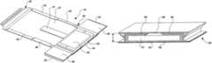
- FIG. 1is a perspective view of a wrap around container in an open state in accordance with a first embodiment of the present invention
- FIGS. 2 and 3are perspective views of the wrap around container of FIG. 1 as it is being closed;
- FIG. 4is a perspective view of part of the wrap around container of FIG. 1 when the container is closed;
- FIG. 5is a longitudinal sectional view of the wrap around container of FIG. 1 when the container is closed;
- FIG. 6is a perspective view of a blank forming part of a modified wrap around container
- FIGS. 7 and 8are perspective views of the blank of FIG. 6 in various stages of being folded
- FIG. 9is a perspective view of the modified wrap around container comprising the folded blank and foam members
- FIG. 10is a perspective view of the wrap around container of FIG. 9 with a hand held tablet PC placed on it;
- FIGS. 11 and 12are perspective views of the wrap around container of FIG. 9 in various stages of being wrapped around the tablet PC;
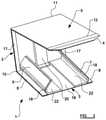
- FIG. 13is a sectional perspective view of the container of FIG. 9 wrapped around the tablet PC;
- FIG. 14is a sectional perspective view of a modified container wrapped around a smart phone.
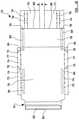
- FIG. 15is a plan view of a specific example of a blank for a wrap around container.
- a wrap around container or carton 1according to a first embodiment of the invention comprises a substantially rectangular panel 2 .
- the panel 2comprises a device receiving portion 3 at one end of the panel 2 , a fixing portion 4 at the opposite end of the panel 2 , and a wrap around portion 5 in between.
- the container 1also has a pair of flaps 6 , 7 .
- One end portion 8 (see also FIG. 2 ) of a major surface of each flap 6 , 7is fixed by adhesive to a major surface of the device receiving portion 3 adjacent to a respective longitudinal edge of the rectangular panel 2 .
- Each flap 6 , 7is bent back on itself so that a distal end of the flap extends away from the other flap.
- the wrap around portion 5has a first lateral fold line 10 with the device receiving portion 3 , a second lateral fold line 11 and a third lateral fold line 12 with a tapered part 13 of the wrap around portion 5 .
- the tapered part 13is initially of the same width as the rest of the wrap around portion 5 before it tapers to a shorter width where it is fixed to a fixing flap 14 of the fixing portion 4 by a severable strip 15 of the fixing portion 4 .
- the fixing flap 14has a self-adhesive sealing strip (not shown).
- the wrap around portion 5has a pair of longitudinal side strips 17 which are folded so as to produce double thickness edge strips and are held down by a strong adhesive. These edge strips 17 provide strengthened side impact protection.
- Each flap 6 , 7is covered by a foam member 18 and the foam member 18 extends onto the major surface of the device receiving portion 3 . There is a first gap 19 between facing ends 18 a of the foam members 18 .
- a foam strip 20extends longitudinally between the first and second lateral fold lines 10 , 11 and slightly beyond each fold line 10 , 11 , the portion 21 of the foam strip 20 which extends slightly beyond the first fold line 10 extending into the first gap 19 between the flap foam members 18 .
- Each flap foam member 18is attached to its respective flap 6 , 7 and the device receiving portion 3 , and the foam strip 20 is attached to the wrap around portion 5 . This may be done by double sided adhesive tape (not shown).
- an electronic devicesuch as a tablet PC (not shown), which is substantially cuboid in shape, is placed on the device receiving portion 3 . It rests on the end portion 22 of each foam member 18 that is adjacent the first gap 19 and spans the first gap 19 between the foam members 18 .
- the two flaps 6 , 7are folded towards each other over the electronic device and in FIG. 3 , the wrap around portion 5 is folded over the device receiving portion 3 and the flaps 6 , 7 .
- the wrap around portion 5is wrapped in a longitudinal direction. It is folded from the first fold line 10 up and over the folded flaps 6 , 7 which are now in a closed position.
- Each foam member 18thus extends over a part of the device receiving portion 3 and onto the surface of a respective flap 6 , 7 facing the device receiving portion 3 and there is a second gap 19 ′ between facing distal ends 18 b of the foam members 18 on said flap surfaces.
- Each foam member 18is also adjacent an upper surface of the electronic device placed on the device receiving portion 3 .
- the foam strip 20is on the surface of the wrap around portion 5 facing the device receiving portion 3 and fits within the second gap 19 ′ between the two foam members 18 .
- the first gap 19 provided between the foam members 18provides shock dissipation.
- the gaps 19 , 19 ′are aligned with each other.
- the wrap around portion 5is folded about the second fold line 11 and down and underneath the device receiving portion 3 .
- the wrap around portion 5is then folded about the third fold line 12 and the fixing portion 4 is over an outer surface of the wrap around portion 5 above the folded flaps 6 , 7 with the fixing flap 14 being fixed to the wrap around portion 5 by adhesive which has been exposed by removing the self-adhesive sealing strip.
- the container 1is thus secured tightly around the device and is closed.
- the foam members 18form a foam barrier between the device and the device receiving portion 3 and the flaps 6 , 7 .
- Each foam member 18has a C shape fit around the device.
- the end portion 21 of the foam strip 20protects one side of the device and extends into the first gap 19 and the opposite end portion 23 protects the other or opposite side of the device.
- the foam strip 20thus provides a further foam barrier and extends in a longitudinal plane 25 (see FIG. 4 ).
- the opposite end portion 23includes the portion 21 that extends in the first gap 19 and underneath the device.
- the foam members 18 and foam strip 20are strategically placed to protect the device in the container 1 . They act as bumpers compressing and decompressing inside a closed container 1 to protect the device inside if the container 1 is, say, dropped or subjected to sudden movement.
- each flap foam member 8is peeled away from its respective flap 6 , 7 and the device receiving portion 3 , and the foam strip 20 is peeled away from the wrap around portion 5 so that the foam and the rest of the container can be easily recycled.
- the foam used for the foam members 18 and the foam strip 20comprises an olefinic polymer such as polyethylene. This is stronger than a soft foam such as polyurethane. Also, if polyurethane foam was used it would be glued to the corrugated cardboard with a permanent adhesive and could therefore not be easily separated from the cardboard causing a problem for recycling.
- the substantially rectangular panel 2 and the flaps 6 , 7comprise corrugated cardboard, the flutes of the corrugated cardboard of the panel and the flaps running laterally as indicated by arrow 24 on FIG. 2 .
- the foamis a 28 kg/m 3 load bearing foam which is suitable for use with tablet PCs.
- the foamis preferably of a thickness of about 7 mm.
- the wrap around container 1When the wrap around container 1 is secured around a device it would have a thickness of about 30 to 38 mm, and the closed flaps 6 , 7 would be a height t (see FIG. 4 ) of about 21 mm above the device receiving portion 3 .
- a blank 30 for forming part of a modified wrap around container 31has a pair of flaps 32 , 33 at one end of the substantially rectangular panel 34 .
- the flaps 32 , 33are shown adjacent each other but they may be separated by a gap.
- the fixing portion 35is at the opposite end of the panel 34 . It includes the tapered portion 36 which is adjacent one end of the wrap around portion 37 of the rectangular panel 34 . Unlike the tapered portion 13 illustrated in FIG. 1 , there is no double thickness edge strip along the tapered portion 36 for the modified wrap around container 31 .
- the fixing portion 35also has a self-seal adhesive strip 38 , 39 on the fixing flap 40 on one side of the severable strip 41 of the fixing portion 35 and on the tapered portion 36 on the other side of the severable strip 41 .
- a longitudinal strip 42is on each longitudinal side of the wrap around portion 37 of the panel 34 and there is no longitudinal strip on each longitudinal side of the device receiving portion 43 of the panel 34 which is between the wrap around portion 37 and the flaps 32 , 33 .
- each flap 32 , 33 adjacent each respective longitudinal edge of the rectangular panel 34has a strip of glue or adhesive 44 and the end portion is the only part of the flap connected to the device receiving portion 43 of the rectangular panel 34 .
- Each longitudinal strip 42has a square of glue 45 at the end adjacent the device receiving portion 43 and a strip of glue 46 at the opposite end. In between the square of glue 45 and the strip of glue 46 , the longitudinal strip 42 is unglued and has a diagonal crease 47 extending across the width of the strip 42 from each corner of the unglued strip 48 adjacent the rectangular panel 34 .
- each longitudinal strip 42is folded onto the square of glue 45 and the strip of glue 46 , and the unglued strip is lifted up from the rectangular panel 34 to form a locking crease 48 .
- Each flap 32 , 33is folded onto the device receiving portion 43 and is held down to the device receiving portion 43 by the respective strip of glue 44 .
- Each flap 32 , 33is then folded back over its end portion having the strip of glue 44 and away from each other (see FIG. 8 ).
- Each flap 32 , 33is covered by the foam member 50 (see FIG. 9 ) which also extends onto the major surface of the device receiving portion 43 .
- Each foam member 50is attached to its respective flap and the device receiving portion 43 by double sided tape 56 shown on FIG. 8 .
- the foam strip 51is on the wrap around portion 37 of the rectangular panel 34 and extends into the first gap 52 between facing ends 50 a of the flap foam members 50 .
- the foam strip 51is attached to the wrap around portion 37 and the device receiving portion 43 by double sided tape 56 shown on FIG. 8 .
- a tablet PC 53is placed on the device receiving portion 43 (see FIG. 10 ) and rests on the end portion of each foam member 50 that is adjacent the first gap 52 .
- the two flaps 32 , 33are folded towards each other over the tablet PC 53 so that the foam member 50 for each flap is adjacent an upper surface of the tablet PC 53 (see FIG. 11 ), there being a second gap 52 ′ between facing distal ends 50 b (see FIG. 13 ) of the flaps.
- the wrap around portion 37is folded over the folded flaps 32 , 33 which are now in a closed position (see FIGS. 12 and 13 ) and there is a locking crease 48 on the outside of a side portion 54 of each folded flap 32 , 33 .
- the foam strip 51 on the surface of the wrap around portion 37 facing the device receiving portion 43fits within the second gap 52 ′ between the two foam members 50 .
- the wrap around portion 37is then folded underneath the device receiving portion 43 .
- the fixing portion 35is placed over an outer surface of the wrap around portion 37 above the folded flaps 32 , 33 with the fixing flap 40 and the tapered portion 36 being fixed to the wrap around portion 37 by adhesive which has been exposed by removing the respective self-adhesive sealing strips 38 , 39 to close the container 31 .
- the locking creases 48form protrusions on the wrap around portion 37 .
- the locking creases 48provide additional strength to the folded flaps 32 , 33 adding extra protection to the closed container 31 from side impact. Since the locking creases 48 prevent the sides 54 of the folded flaps 32 , 33 from moving outwards this prevents movement of the device inside the closed container 31 .
- Each locking crease 48may cover three quarters of the side 54 of the respective folded flap 32 , 33 .
- the locking creases 48prevent someone from trying to remove a device from a closed container without it appearing that the closed container has been tampered with.
- Known wrap around containerssuch as that described in GB 2441997, can have a side portion of a folded flap cut along one edge enabling the device inside to be removed and the cut side portion can then be pushed back to make it look like the container has not been tampered with. To do this with the closed container 31 , the locking crease 48 would need to be cut as well which would provide evidence that the closed container 31 has been tampered with.
- opposite end portions 55 (see FIG. 13 ) of the foam strip 51protect opposite sides 53 a of the tablet PC 53 and provides a foam barrier with the part of the wrap around portion 37 adjacent the opposite sides 53 a.
- FIG. 14another modified wrap around container 60 is shown wrapped around a smart phone 61 . It is similar to the wrap around container 31 illustrated in FIGS. 6 to 13 but it does not have a foam strip 51 . Also, instead of having two foam members 50 , there is a single foam member 62 that extends over the device receiving portion 63 and onto the surface of each flap 64 , 65 facing the device receiving portion 63 when in the closed position. In a specific example of a preferred embodiment, when the wrap around container 60 is secured around a device, the closed flaps 64 , 65 would be a height t of about 13 mm above the device receiving portion 63 . This height is suitable for all mobile phones. In a modification, there may be no gap 66 between the facing distal ends of the closed flaps and/or foam member.
- a specific example of a preferred embodiment of a blank 70 for forming part of a wrap around containerhas a gap w of 35 mm between the flaps 71 , 72 .
- Thisis particularly suitable for a wrap around container for a tablet PC.
- the longitudinal strips 73have an 8 bar crease 74 with the wrap around portion 75 .
- the diagonal creases 76 of each locking crease 77have an 8 bar crease 74 and opposite ends of the locking crease 77 have an 8 bar crease 74 .
- Each flap 71 , 72has an 8 bar crease 74 with the flap end portion to be glued to the device receiving portion 78 .
- each flap 71 , 72is to be folded from being beside a device to being on top of the device, this fold would have a normal crease 79 .
- each flap 71 , 72is connected to the device receiving portion 78 , the fold here would have a normal crease 79 .
- the remainder of each flap 71 , 72is perforated cut 80 from the device receiving portion 78 .
- the fixing portion 81is shown as having a single self-adhesive sealing strip 82 on the fixing flap 83 only.
- Glue or adhesive 84is shown to be on the same places as on the blank 30 illustrated in FIG. 6 except that there is glue 84 ′ on the device receiving portion 78 instead of on the end portions of the flaps.
Landscapes
- Engineering & Computer Science (AREA)
- Mechanical Engineering (AREA)
- Buffer Packaging (AREA)
- Cartons (AREA)
- Packages (AREA)
Abstract
Description
- a substantially rectangular panel including a device receiving portion at one end of the panel, a fixing portion at the opposite end of the panel, and a wrap around portion in between;
- a pair of flaps extending from opposite sides of the device receiving portion of the panel, each side being on a respective longitudinal edge of the rectangular panel, and each flap being arranged to be folded into a closed position where the flap is over at least a part of the device receiving portion and an upper surface of a device when placed on the device receiving portion, the wrap around portion being arranged to wrap at least over the flaps in the closed position and the fixing portion being arranged to be fixed to an outside of the container after wrapping of the wrap around portion to close the container; and
- foam means extending over at least part of the device receiving portion and onto the surface of each flap facing the device receiving portion when in the closed position so as to form a foam barrier between a device placed on the device receiving portion and the device receiving portion and the closed flaps, the foam means being attached to the device receiving portion and/or at least one of the two flaps, the foam means being configured to be peelable away from the container when the container is open.
Claims (12)
Applications Claiming Priority (4)
| Application Number | Priority Date | Filing Date | Title |
|---|---|---|---|
| GBGB1303009.3AGB201303009D0 (en) | 2013-02-20 | 2013-02-20 | Media wrap with load bearing foam |
| GB1303009.3 | 2013-02-20 | ||
| GB1303009 | 2013-02-20 | ||
| PCT/GB2014/050499WO2014128473A1 (en) | 2013-02-20 | 2014-02-20 | Wrap around container |
Related Parent Applications (2)
| Application Number | Title | Priority Date | Filing Date |
|---|---|---|---|
| US14/768,946DivisionUS10155616B2 (en) | 2013-02-20 | 2014-02-20 | Wrap around container |
| PCT/GB2014/050499DivisionWO2014128473A1 (en) | 2013-02-20 | 2014-02-20 | Wrap around container |
Publications (2)
| Publication Number | Publication Date |
|---|---|
| US20190077566A1 US20190077566A1 (en) | 2019-03-14 |
| US11247826B2true US11247826B2 (en) | 2022-02-15 |
Family
ID=48048706
Family Applications (2)
| Application Number | Title | Priority Date | Filing Date |
|---|---|---|---|
| US14/768,946Active2034-10-23US10155616B2 (en) | 2013-02-20 | 2014-02-20 | Wrap around container |
| US16/184,656Active2035-02-27US11247826B2 (en) | 2013-02-20 | 2018-11-08 | Wrap around container |
Family Applications Before (1)
| Application Number | Title | Priority Date | Filing Date |
|---|---|---|---|
| US14/768,946Active2034-10-23US10155616B2 (en) | 2013-02-20 | 2014-02-20 | Wrap around container |
Country Status (6)
| Country | Link |
|---|---|
| US (2) | US10155616B2 (en) |
| EP (1) | EP2958813B1 (en) |
| GB (2) | GB201303009D0 (en) |
| HU (1) | HUE031049T2 (en) |
| PL (1) | PL2958813T3 (en) |
| WO (1) | WO2014128473A1 (en) |
Families Citing this family (6)
| Publication number | Priority date | Publication date | Assignee | Title |
|---|---|---|---|---|
| GB201303009D0 (en)* | 2013-02-20 | 2013-04-03 | Packaging One Ltd | Media wrap with load bearing foam |
| US9342830B2 (en)* | 2014-07-15 | 2016-05-17 | Google Inc. | Classifying open-loop and closed-loop payment cards based on optical character recognition |
| CN108367851A (en)* | 2015-12-11 | 2018-08-03 | 凸版印刷株式会社 | packing bag |
| GB2586617A (en)* | 2019-08-29 | 2021-03-03 | Cellpak Solutions Ltd | Dual purpose packaging container |
| GB2593923B (en)* | 2020-04-09 | 2022-06-29 | Packaging One Ltd | Wrap around container |
| CN117500727A (en)* | 2022-05-31 | 2024-02-02 | 罗技欧洲公司 | Packaging for input devices |
Citations (38)
| Publication number | Priority date | Publication date | Assignee | Title |
|---|---|---|---|---|
| US607572A (en)* | 1898-07-19 | Wrapper for cuffs or like articles | ||
| US2071232A (en)* | 1935-09-03 | 1937-02-16 | Lulu W Langehennig | Wrapper for books and other merchandise |
| US2144071A (en) | 1937-04-19 | 1939-01-17 | Hinde & Dauch Paper Co | Mailing package |
| US3217868A (en) | 1964-02-28 | 1965-11-16 | Packaging Corp America | Shipper carton and package |
| US3253770A (en) | 1964-01-10 | 1966-05-31 | Bell Fibre Prod Corp | Protective carton structure |
| US3266705A (en)* | 1965-01-11 | 1966-08-16 | Republic Packaging Corp | Cushioned box |
| US3303603A (en) | 1963-07-18 | 1967-02-14 | Abeson Marion | Combination package and toy |
| US3445051A (en)* | 1968-01-04 | 1969-05-20 | Logistics Ind Corp | Container |
| US3516593A (en) | 1968-03-14 | 1970-06-23 | Donnelley & Sons Co | Protective container for books and the like |
| US3666166A (en) | 1970-05-22 | 1972-05-30 | Gen Corrugated Machinery Co In | Wrapping set and package formed therefrom |
| US4083454A (en)* | 1977-08-26 | 1978-04-11 | Merkert Enterprises Co. | Mailing and storage box |
| US4300679A (en) | 1980-08-27 | 1981-11-17 | Container Corporation Of America | Self locking folder |
| US4589552A (en)* | 1984-04-19 | 1986-05-20 | Pierre Chevalier | Package comprising a strip and side flaps |
| US4627223A (en)* | 1982-02-05 | 1986-12-09 | Janhonen Veikko Ilmari | Package blank and packaging method |
| US4773534A (en)* | 1988-03-28 | 1988-09-27 | Deheras Charles | Printed circuit board transporter |
| WO1988007476A1 (en) | 1987-03-23 | 1988-10-06 | Patrick Carr | A cuboid packing box |
| EP0377375B1 (en) | 1989-01-03 | 1992-04-15 | Pierre Chevalier | Package with folding flaps formed from an l-shaped carton strip |
| US5197260A (en) | 1988-10-31 | 1993-03-30 | L Emballage Carton Sa (Societe Anonyme) | Method for packing articles, and machine for performing the method |
| US5248034A (en)* | 1991-05-02 | 1993-09-28 | Pussikeskus Oy | Book package blank and method and machine for its fabrication |
| US5477965A (en)* | 1992-08-18 | 1995-12-26 | Herbeck; Thomas | Packaging element for stacked printed products |
| US5954202A (en)* | 1996-06-28 | 1999-09-21 | Westvaco Corporation | Paperboard blank for a self-contained, reclosable package |
| US6443309B1 (en)* | 2000-05-15 | 2002-09-03 | Victory Packaging, Inc. | Apparatus for packaging goods |
| US20020130166A1 (en)* | 2001-01-20 | 2002-09-19 | Volker Goebel | Packaging construction |
| US6471118B1 (en) | 1999-01-25 | 2002-10-29 | Pierre Andre Marc Chevalier | Cardboard container obtained by folding a strip for objects of a variable height |
| US6530480B1 (en) | 1999-10-06 | 2003-03-11 | Osram Sylvania, Inc. | Overpack carton |
| US20040004111A1 (en) | 2002-07-08 | 2004-01-08 | Cardinale Salvatore J. | Insulated water-tight container |
| US6871739B2 (en) | 2003-04-01 | 2005-03-29 | Carlos Lopez | Foldable padded case for a personal computer |
| US20070095711A1 (en) | 2005-11-01 | 2007-05-03 | Sealed Air Corporation (Us) | Protective packaging assembly |
| US20080290144A1 (en)* | 2007-05-21 | 2008-11-27 | Makofsky Marvin A | Flat-sized flexible envelope with insert |
| GB2441997B (en) | 2006-09-19 | 2009-01-28 | Ben Matthew Jarrett | A mailing container |
| US20090229936A1 (en) | 2008-03-13 | 2009-09-17 | Targus Group International, Inc. | Portable computer case |
| US7621404B2 (en)* | 1999-08-03 | 2009-11-24 | Thermafreeze Products Corporation | Insulating packaging material and related packaging system |
| WO2010025751A1 (en) | 2008-09-04 | 2010-03-11 | Amazon Europe Holding Technologies Scs | Mailing package |
| US8281970B2 (en) | 2009-04-24 | 2012-10-09 | Demskey Joan F | Backpack having a load compensating strap arrangement |
| US8322532B2 (en) | 2008-10-23 | 2012-12-04 | Tim Schafer | Packaging device and packaging system for essentially flat objects, for example lithium-ion cells |
| US20130270133A1 (en) | 2012-04-13 | 2013-10-17 | Multi Packaging Solutions, Inc | Tray cover, tray insert, and methods thereof |
| US9210976B2 (en)* | 2010-08-27 | 2015-12-15 | Samsonite Ip Holdings S.A.R.L. | Apparatus for carrying portable electronic devices of a wide range of sizes |
| US10155616B2 (en)* | 2013-02-20 | 2018-12-18 | Packaging One Limited | Wrap around container |
- 2013
- 2013-02-20GBGBGB1303009.3Apatent/GB201303009D0/ennot_activeCeased
- 2014
- 2014-02-20WOPCT/GB2014/050499patent/WO2014128473A1/enactiveApplication Filing
- 2014-02-20GBGB201403011Apatent/GB2511428B/enactiveActive
- 2014-02-20USUS14/768,946patent/US10155616B2/enactiveActive
- 2014-02-20PLPL14708320Tpatent/PL2958813T3/enunknown
- 2014-02-20HUHUE14708320Apatent/HUE031049T2/enunknown
- 2014-02-20EPEP14708320.8Apatent/EP2958813B1/enactiveActive
- 2018
- 2018-11-08USUS16/184,656patent/US11247826B2/enactiveActive
Patent Citations (40)
| Publication number | Priority date | Publication date | Assignee | Title |
|---|---|---|---|---|
| US607572A (en)* | 1898-07-19 | Wrapper for cuffs or like articles | ||
| US2071232A (en)* | 1935-09-03 | 1937-02-16 | Lulu W Langehennig | Wrapper for books and other merchandise |
| US2144071A (en) | 1937-04-19 | 1939-01-17 | Hinde & Dauch Paper Co | Mailing package |
| US3303603A (en) | 1963-07-18 | 1967-02-14 | Abeson Marion | Combination package and toy |
| US3253770A (en) | 1964-01-10 | 1966-05-31 | Bell Fibre Prod Corp | Protective carton structure |
| US3217868A (en) | 1964-02-28 | 1965-11-16 | Packaging Corp America | Shipper carton and package |
| US3266705A (en)* | 1965-01-11 | 1966-08-16 | Republic Packaging Corp | Cushioned box |
| US3445051A (en)* | 1968-01-04 | 1969-05-20 | Logistics Ind Corp | Container |
| US3516593A (en) | 1968-03-14 | 1970-06-23 | Donnelley & Sons Co | Protective container for books and the like |
| US3666166A (en) | 1970-05-22 | 1972-05-30 | Gen Corrugated Machinery Co In | Wrapping set and package formed therefrom |
| US4083454A (en)* | 1977-08-26 | 1978-04-11 | Merkert Enterprises Co. | Mailing and storage box |
| US4300679A (en) | 1980-08-27 | 1981-11-17 | Container Corporation Of America | Self locking folder |
| US4627223A (en)* | 1982-02-05 | 1986-12-09 | Janhonen Veikko Ilmari | Package blank and packaging method |
| US4589552A (en)* | 1984-04-19 | 1986-05-20 | Pierre Chevalier | Package comprising a strip and side flaps |
| WO1988007476A1 (en) | 1987-03-23 | 1988-10-06 | Patrick Carr | A cuboid packing box |
| US4773534A (en)* | 1988-03-28 | 1988-09-27 | Deheras Charles | Printed circuit board transporter |
| US5197260A (en) | 1988-10-31 | 1993-03-30 | L Emballage Carton Sa (Societe Anonyme) | Method for packing articles, and machine for performing the method |
| EP0377375B1 (en) | 1989-01-03 | 1992-04-15 | Pierre Chevalier | Package with folding flaps formed from an l-shaped carton strip |
| US5248034A (en)* | 1991-05-02 | 1993-09-28 | Pussikeskus Oy | Book package blank and method and machine for its fabrication |
| US5477965A (en)* | 1992-08-18 | 1995-12-26 | Herbeck; Thomas | Packaging element for stacked printed products |
| US5954202A (en)* | 1996-06-28 | 1999-09-21 | Westvaco Corporation | Paperboard blank for a self-contained, reclosable package |
| US6471118B1 (en) | 1999-01-25 | 2002-10-29 | Pierre Andre Marc Chevalier | Cardboard container obtained by folding a strip for objects of a variable height |
| US7621404B2 (en)* | 1999-08-03 | 2009-11-24 | Thermafreeze Products Corporation | Insulating packaging material and related packaging system |
| US6530480B1 (en) | 1999-10-06 | 2003-03-11 | Osram Sylvania, Inc. | Overpack carton |
| US20030057128A1 (en) | 1999-10-06 | 2003-03-27 | Osram Sylvania, Inc. | Overpack carton |
| US6443309B1 (en)* | 2000-05-15 | 2002-09-03 | Victory Packaging, Inc. | Apparatus for packaging goods |
| US20020130166A1 (en)* | 2001-01-20 | 2002-09-19 | Volker Goebel | Packaging construction |
| US20040004111A1 (en) | 2002-07-08 | 2004-01-08 | Cardinale Salvatore J. | Insulated water-tight container |
| US6871739B2 (en) | 2003-04-01 | 2005-03-29 | Carlos Lopez | Foldable padded case for a personal computer |
| US20070095711A1 (en) | 2005-11-01 | 2007-05-03 | Sealed Air Corporation (Us) | Protective packaging assembly |
| GB2441997B (en) | 2006-09-19 | 2009-01-28 | Ben Matthew Jarrett | A mailing container |
| US20080290144A1 (en)* | 2007-05-21 | 2008-11-27 | Makofsky Marvin A | Flat-sized flexible envelope with insert |
| US20090229936A1 (en) | 2008-03-13 | 2009-09-17 | Targus Group International, Inc. | Portable computer case |
| US8567578B2 (en) | 2008-03-13 | 2013-10-29 | Targus Group International, Inc. | Portable computer case |
| WO2010025751A1 (en) | 2008-09-04 | 2010-03-11 | Amazon Europe Holding Technologies Scs | Mailing package |
| US8322532B2 (en) | 2008-10-23 | 2012-12-04 | Tim Schafer | Packaging device and packaging system for essentially flat objects, for example lithium-ion cells |
| US8281970B2 (en) | 2009-04-24 | 2012-10-09 | Demskey Joan F | Backpack having a load compensating strap arrangement |
| US9210976B2 (en)* | 2010-08-27 | 2015-12-15 | Samsonite Ip Holdings S.A.R.L. | Apparatus for carrying portable electronic devices of a wide range of sizes |
| US20130270133A1 (en) | 2012-04-13 | 2013-10-17 | Multi Packaging Solutions, Inc | Tray cover, tray insert, and methods thereof |
| US10155616B2 (en)* | 2013-02-20 | 2018-12-18 | Packaging One Limited | Wrap around container |
Non-Patent Citations (19)
| Title |
|---|
| GB1403011.8 Search Report Under Section 17. |
| http://ad-emea.doubleclick.net/N3847/adi/ebay.uk.x.vip/_default;cat_19278;tcat_125 . . . , p. 1, Jan. 31, 2014. |
| http://fantasy.packagingdelivery.co.uk/products, cardboard-boxes-and-sheets/book-wr . . . , p. 1, Jan. 31, 2014. |
| http://priorydirect.co.uk/colompac-moduleboxes , p. 1, Feb. 4, 2014. |
| http://ukpackaging.com/cardboard-boxes/postal-boxes/cd-dvd-mailers , p. 1, Feb. 4, 2014. |
| http://ukpackaging.com/cardboard-boxes/postal-boxes/pip-large-letter-postal-box, p. 1, Feb. 4, 2014. |
| http://www.biopack.be/Lid-En/Classical_Packaging/1-1149/Foam_posta_boxes , p. 1, Jan. 31, 2014. |
| http://www.colompac.com/details.php?gr=25, pp. 1-2, Feb. 4, 2014. |
| http://www.davpack.co.uk/blog/a-moment-please-for-foam-lined-boxes-and-clear-polythene-bags, pp. 1-2, Feb. 2, 2014. |
| http://www.fotofriend.com/why-choose-us. pp. 1-3, Feb. 4, 2014. |
| http://www.packaging2buy.co.uk/postal-boxes-foam-lined-boxes.html, pp. 1-2, Feb. 4, 2014. |
| http://www.packaging2buy.co.uk/white-postal-boxes.html, pp. 1-2, Feb. 4, 2014. |
| http://www.picturemaster.co.uk/land_canvas_accessary.html, pp. 1-3, Jan. 31, 2014. |
| http://www.postpack.co.uk/acatalog/brown-foam-wrap-4.html, p. 1, Feb. 4, 2014. |
| http://www.priorydirect.co.uk/colompac-instant-bottom-boxes.html, pp. 1-2, Feb. 4, 2014. |
| http://www.rajapack.co.uk/cardboard-boxes/postal-boxes/brown-foam-postal-boxes, p. 1, Feb. 4, 2014. |
| http://www.sapphirepackaging.com/site/index.php/boxes/postal-boxes, pp. 1-2, Feb. 4, 2014. |
| http://www.staples.co.uk/search/mailing+foam+lines_box, pp. 1-2, Feb. 4, 2014. |
| PCT/GB2014/050499 International Search Report and Written Opinion. |
Also Published As
| Publication number | Publication date |
|---|---|
| GB2511428A (en) | 2014-09-03 |
| GB201403011D0 (en) | 2014-04-09 |
| EP2958813A1 (en) | 2015-12-30 |
| PL2958813T3 (en) | 2017-03-31 |
| HUE031049T2 (en) | 2017-06-28 |
| US20160001953A1 (en) | 2016-01-07 |
| WO2014128473A1 (en) | 2014-08-28 |
| EP2958813B1 (en) | 2016-08-17 |
| GB201303009D0 (en) | 2013-04-03 |
| US20190077566A1 (en) | 2019-03-14 |
| US10155616B2 (en) | 2018-12-18 |
| GB2511428B (en) | 2015-05-06 |
Similar Documents
| Publication | Publication Date | Title |
|---|---|---|
| US11247826B2 (en) | Wrap around container | |
| US10099807B2 (en) | Reversible box with tear-away strips | |
| US9714112B1 (en) | Sealing device for paper-based container | |
| CN111572888B (en) | Method for packing film packing lining | |
| US10442597B1 (en) | Retention package with article-loading aperture and method of making and using the same | |
| US7114618B2 (en) | Foldable foam packing element | |
| US3121525A (en) | Package wrapper | |
| US20060118605A1 (en) | Lidded container with tear-away opening strip and lid deflection take-up means | |
| JP6239284B2 (en) | Packaging box with cushioning sheet | |
| US8141771B2 (en) | Packaging carton box structure | |
| JP2013018518A (en) | Cardboard sandwiching packing material | |
| US12195271B2 (en) | Packaging for a record, in particular for shipping | |
| JP2008189360A (en) | Packing structure | |
| GB2427399A (en) | Blank for container with curved walls | |
| KR102553602B1 (en) | Eco-friendly box | |
| CN209467439U (en) | A modulus interspersed cushioning packing box | |
| KR102215211B1 (en) | Adhesive packing box for friendly environment | |
| CN101018719B (en) | Laminated packaging | |
| KR102566045B1 (en) | Packing box | |
| US20240190607A1 (en) | Packaging with integrated cushioning supports | |
| CN216402207U (en) | Corrugated carton convenient to close cover | |
| CN205327633U (en) | Packaging structure | |
| CN213229832U (en) | Packing box | |
| KR200210376Y1 (en) | Product packaging material | |
| EP3269659B1 (en) | Sealing device for paper-based container |
Legal Events
| Date | Code | Title | Description |
|---|---|---|---|
| AS | Assignment | Owner name:PACKAGING ONE LIMITED, GREAT BRITAIN Free format text:ASSIGNMENT OF ASSIGNORS INTEREST;ASSIGNOR:CHESWORTH, IAN NEIL;REEL/FRAME:047456/0569 Effective date:20150908 | |
| FEPP | Fee payment procedure | Free format text:ENTITY STATUS SET TO UNDISCOUNTED (ORIGINAL EVENT CODE: BIG.); ENTITY STATUS OF PATENT OWNER: SMALL ENTITY | |
| FEPP | Fee payment procedure | Free format text:ENTITY STATUS SET TO SMALL (ORIGINAL EVENT CODE: SMAL); ENTITY STATUS OF PATENT OWNER: SMALL ENTITY | |
| STPP | Information on status: patent application and granting procedure in general | Free format text:DOCKETED NEW CASE - READY FOR EXAMINATION | |
| STPP | Information on status: patent application and granting procedure in general | Free format text:RESPONSE TO NON-FINAL OFFICE ACTION ENTERED AND FORWARDED TO EXAMINER | |
| STPP | Information on status: patent application and granting procedure in general | Free format text:NON FINAL ACTION MAILED | |
| STPP | Information on status: patent application and granting procedure in general | Free format text:RESPONSE TO NON-FINAL OFFICE ACTION ENTERED AND FORWARDED TO EXAMINER | |
| STPP | Information on status: patent application and granting procedure in general | Free format text:NOTICE OF ALLOWANCE MAILED -- APPLICATION RECEIVED IN OFFICE OF PUBLICATIONS | |
| STPP | Information on status: patent application and granting procedure in general | Free format text:PUBLICATIONS -- ISSUE FEE PAYMENT VERIFIED | |
| STCF | Information on status: patent grant | Free format text:PATENTED CASE | |
| MAFP | Maintenance fee payment | Free format text:PAYMENT OF MAINTENANCE FEE, 4TH YR, SMALL ENTITY (ORIGINAL EVENT CODE: M2551); ENTITY STATUS OF PATENT OWNER: SMALL ENTITY Year of fee payment:4 |