US11247789B2 - Method of converting sheet material into a custom packaging template - Google Patents
Method of converting sheet material into a custom packaging templateDownload PDFInfo
- Publication number
- US11247789B2 US11247789B2US17/023,004US202017023004AUS11247789B2US 11247789 B2US11247789 B2US 11247789B2US 202017023004 AUS202017023004 AUS 202017023004AUS 11247789 B2US11247789 B2US 11247789B2
- Authority
- US
- United States
- Prior art keywords
- sheet material
- longitudinal
- transverse
- items
- converting
- Prior art date
- Legal status (The legal status is an assumption and is not a legal conclusion. Google has not performed a legal analysis and makes no representation as to the accuracy of the status listed.)
- Active
Links
Images


Classifications
- B—PERFORMING OPERATIONS; TRANSPORTING
- B65—CONVEYING; PACKING; STORING; HANDLING THIN OR FILAMENTARY MATERIAL
- B65B—MACHINES, APPARATUS OR DEVICES FOR, OR METHODS OF, PACKAGING ARTICLES OR MATERIALS; UNPACKING
- B65B5/00—Packaging individual articles in containers or receptacles, e.g. bags, sacks, boxes, cartons, cans, jars
- B65B5/02—Machines characterised by incorporation of means for making the containers or receptacles
- B65B5/024—Machines characterised by incorporation of means for making the containers or receptacles for making containers from preformed blanks
- B—PERFORMING OPERATIONS; TRANSPORTING
- B31—MAKING ARTICLES OF PAPER, CARDBOARD OR MATERIAL WORKED IN A MANNER ANALOGOUS TO PAPER; WORKING PAPER, CARDBOARD OR MATERIAL WORKED IN A MANNER ANALOGOUS TO PAPER
- B31B—MAKING CONTAINERS OF PAPER, CARDBOARD OR MATERIAL WORKED IN A MANNER ANALOGOUS TO PAPER
- B31B50/00—Making rigid or semi-rigid containers, e.g. boxes or cartons
- B31B50/005—Making rigid or semi-rigid containers, e.g. boxes or cartons involving a particular layout of the machinery or relative arrangement of its subunits
- B—PERFORMING OPERATIONS; TRANSPORTING
- B31—MAKING ARTICLES OF PAPER, CARDBOARD OR MATERIAL WORKED IN A MANNER ANALOGOUS TO PAPER; WORKING PAPER, CARDBOARD OR MATERIAL WORKED IN A MANNER ANALOGOUS TO PAPER
- B31B—MAKING CONTAINERS OF PAPER, CARDBOARD OR MATERIAL WORKED IN A MANNER ANALOGOUS TO PAPER
- B31B50/00—Making rigid or semi-rigid containers, e.g. boxes or cartons
- B31B50/14—Cutting, e.g. perforating, punching, slitting or trimming
- B31B50/16—Cutting webs
- B—PERFORMING OPERATIONS; TRANSPORTING
- B31—MAKING ARTICLES OF PAPER, CARDBOARD OR MATERIAL WORKED IN A MANNER ANALOGOUS TO PAPER; WORKING PAPER, CARDBOARD OR MATERIAL WORKED IN A MANNER ANALOGOUS TO PAPER
- B31B—MAKING CONTAINERS OF PAPER, CARDBOARD OR MATERIAL WORKED IN A MANNER ANALOGOUS TO PAPER
- B31B50/00—Making rigid or semi-rigid containers, e.g. boxes or cartons
- B31B50/25—Surface scoring
- B—PERFORMING OPERATIONS; TRANSPORTING
- B65—CONVEYING; PACKING; STORING; HANDLING THIN OR FILAMENTARY MATERIAL
- B65B—MACHINES, APPARATUS OR DEVICES FOR, OR METHODS OF, PACKAGING ARTICLES OR MATERIALS; UNPACKING
- B65B11/00—Wrapping, e.g. partially or wholly enclosing, articles or quantities of material, in strips, sheets or blanks, of flexible material
- B65B11/004—Wrapping, e.g. partially or wholly enclosing, articles or quantities of material, in strips, sheets or blanks, of flexible material in blanks, e.g. sheets precut and creased for folding
- B—PERFORMING OPERATIONS; TRANSPORTING
- B65—CONVEYING; PACKING; STORING; HANDLING THIN OR FILAMENTARY MATERIAL
- B65B—MACHINES, APPARATUS OR DEVICES FOR, OR METHODS OF, PACKAGING ARTICLES OR MATERIALS; UNPACKING
- B65B43/00—Forming, feeding, opening or setting-up containers or receptacles in association with packaging
- B65B43/08—Forming three-dimensional containers from sheet material
- B65B43/10—Forming three-dimensional containers from sheet material by folding the material
- B—PERFORMING OPERATIONS; TRANSPORTING
- B65—CONVEYING; PACKING; STORING; HANDLING THIN OR FILAMENTARY MATERIAL
- B65B—MACHINES, APPARATUS OR DEVICES FOR, OR METHODS OF, PACKAGING ARTICLES OR MATERIALS; UNPACKING
- B65B43/00—Forming, feeding, opening or setting-up containers or receptacles in association with packaging
- B65B43/24—Breaking creases to facilitate setting-up cartons
- B—PERFORMING OPERATIONS; TRANSPORTING
- B65—CONVEYING; PACKING; STORING; HANDLING THIN OR FILAMENTARY MATERIAL
- B65B—MACHINES, APPARATUS OR DEVICES FOR, OR METHODS OF, PACKAGING ARTICLES OR MATERIALS; UNPACKING
- B65B57/00—Automatic control, checking, warning, or safety devices
- B65B57/10—Automatic control, checking, warning, or safety devices responsive to absence, presence, abnormal feed, or misplacement of articles or materials to be packaged
- B—PERFORMING OPERATIONS; TRANSPORTING
- B65—CONVEYING; PACKING; STORING; HANDLING THIN OR FILAMENTARY MATERIAL
- B65B—MACHINES, APPARATUS OR DEVICES FOR, OR METHODS OF, PACKAGING ARTICLES OR MATERIALS; UNPACKING
- B65B59/00—Arrangements to enable machines to handle articles of different sizes, to produce packages of different sizes, to vary the contents of packages, to handle different types of packaging material, or to give access for cleaning or maintenance purposes
- B65B59/001—Arrangements to enable adjustments related to the product to be packaged
- B—PERFORMING OPERATIONS; TRANSPORTING
- B65—CONVEYING; PACKING; STORING; HANDLING THIN OR FILAMENTARY MATERIAL
- B65B—MACHINES, APPARATUS OR DEVICES FOR, OR METHODS OF, PACKAGING ARTICLES OR MATERIALS; UNPACKING
- B65B59/00—Arrangements to enable machines to handle articles of different sizes, to produce packages of different sizes, to vary the contents of packages, to handle different types of packaging material, or to give access for cleaning or maintenance purposes
- B65B59/02—Arrangements to enable adjustments to be made while the machine is running
- B—PERFORMING OPERATIONS; TRANSPORTING
- B65—CONVEYING; PACKING; STORING; HANDLING THIN OR FILAMENTARY MATERIAL
- B65B—MACHINES, APPARATUS OR DEVICES FOR, OR METHODS OF, PACKAGING ARTICLES OR MATERIALS; UNPACKING
- B65B67/00—Apparatus or devices facilitating manual packaging operations; Sack holders
- B65B67/08—Wrapping of articles
- B65B67/10—Wrapping-tables
- B—PERFORMING OPERATIONS; TRANSPORTING
- B31—MAKING ARTICLES OF PAPER, CARDBOARD OR MATERIAL WORKED IN A MANNER ANALOGOUS TO PAPER; WORKING PAPER, CARDBOARD OR MATERIAL WORKED IN A MANNER ANALOGOUS TO PAPER
- B31B—MAKING CONTAINERS OF PAPER, CARDBOARD OR MATERIAL WORKED IN A MANNER ANALOGOUS TO PAPER
- B31B2100/00—Rigid or semi-rigid containers made by folding single-piece sheets, blanks or webs
- B—PERFORMING OPERATIONS; TRANSPORTING
- B31—MAKING ARTICLES OF PAPER, CARDBOARD OR MATERIAL WORKED IN A MANNER ANALOGOUS TO PAPER; WORKING PAPER, CARDBOARD OR MATERIAL WORKED IN A MANNER ANALOGOUS TO PAPER
- B31B—MAKING CONTAINERS OF PAPER, CARDBOARD OR MATERIAL WORKED IN A MANNER ANALOGOUS TO PAPER
- B31B50/00—Making rigid or semi-rigid containers, e.g. boxes or cartons
- B31B50/14—Cutting, e.g. perforating, punching, slitting or trimming
- B31B50/16—Cutting webs
- B31B50/18—Cutting webs longitudinally
- B—PERFORMING OPERATIONS; TRANSPORTING
- B65—CONVEYING; PACKING; STORING; HANDLING THIN OR FILAMENTARY MATERIAL
- B65B—MACHINES, APPARATUS OR DEVICES FOR, OR METHODS OF, PACKAGING ARTICLES OR MATERIALS; UNPACKING
- B65B2210/00—Specific aspects of the packaging machine
- B65B2210/04—Customised on demand packaging by determining a specific characteristic, e.g. shape or height, of articles or material to be packaged and selecting, creating or adapting a packaging accordingly, e.g. making a carton starting from web material
Definitions
- This disclosurerelates to systems, methods, and apparatus for converting sheet materials. More specifically, this disclosure relates to converting machines for converting paperboard, corrugated board, cardboard, and similar sheet materials into templates for forming boxes and other packaging.
- custom sized boxesIn addition to reducing the inefficiencies associated with storing pre-made boxes of numerous sizes, creating custom sized boxes also reduces packaging and shipping costs. In the fulfillment industry it is estimated that shipped items are typically packaged in boxes that are about 65% larger than the shipped items. Boxes that are too large for a particular item are more expensive than a box that is custom sized for the item due to the cost of the excess material used to make the larger box.
- filling materiale.g., Styrofoam, foam peanuts, paper, air pillows, etc.
- pressuree.g., when boxes are taped closed or stacked.
- Customized sized boxesalso reduce the shipping costs associated with shipping items compared to shipping the items in oversized boxes.
- a shipping vehicle filled with boxes that are 65% larger than the packaged itemsis much less cost efficient to operate than a shipping vehicle filled with boxes that are custom sized to fit the packaged items.
- a shipping vehicle filled with custom sized packagescan carry a significantly larger number of packages, which can reduce the number of shipping vehicles required to ship the same number of items. Accordingly, in addition or as an alternative to calculating shipping prices based on the weight of a package, shipping prices are often affected by the size of the shipped package. Thus, reducing the size of an item's package can reduce the price of shipping the item.
- sheet material processing machines and related equipmentcan potentially alleviate the inconveniences associated with stocking standard sized shipping supplies and reduce the amount of space required for storing such shipping supplies
- previously available machines and associated equipmenthave various drawbacks. For instance, previously available machines have had a significant footprint and have occupied a lot of floor space. The floor space occupied by these large machines and equipment could be better used, for example, for storage of goods to be shipped. In addition to the large footprint, the size of the previously available machines and related equipment makes manufacturing, transportation, installation, maintenance, repair, and replacement thereof time consuming and expensive.
- previous converting machineshave been quite complex and have required access to sources of high power and compressed air. More specifically, previous converting machines have included both electrically powered components as well as pneumatic components. Including both electric and pneumatic components increases the complexity of the machines and requires the machines to have access to both electrical power and compressed air, as well as increases the size of the machines. Likewise, previous converting machines can be prohibitively expensive to purchase, operate, and maintain. The size, complexity, and cost can be deterrents to users who do not possess the space, technical knowhow, and resources required to implement previous converting machines.
- previous converting machinesoften require an intermediate measuring step prior to forming the packaging template. For instance, a user may measure the three-dimensional size of an object in order to then adjust the settings of the converting machine to produce a packaging template that forms a custom-fit box for the object. This intermediate measuring step can be time-consuming and can introduce additional human error as the measurement parameters are transferred to the converting machine.
- Embodiments of the present disclosuresolve one or more of the foregoing or other problems in the art with systems, methods, and apparatus for creating packaging templates for assembly into one or more boxes or other packaging material.
- the present disclosurerelates to systems, methods, and apparatus for processing sheet material (such as corrugated paperboard or cardboard) and converting the same into custom packaging templates.
- sheet materialsuch as corrugated paperboard or cardboard
- certain embodimentsinclude a converting machine.
- An illustrative converting machinecan include a frame, a conversion assembly, and/or means for advancing sheet material through the conversion assembly.
- the conversion assemblycan be adapted for performing one or more conversion functions on or to the sheet material (e.g., to thereby convert the sheet material into the packaging template).
- Some embodimentscan include a method of forming a packaging template (that is custom-made for packaging one or more items). For instance, in connection with a packaging system that includes a converting machine, an illustrative method can include placing the one or more items in a receiving area of the converting machine, adjusting one or more components of the converting machine according to at least one outer dimension of the one or more items, and converting sheet material into a packaging template configured for assembly into a box or packaging adapted for receiving the one or more items.
- FIG. 1illustrates a perspective view of a packaging system in accordance with an embodiment of the present disclosure
- FIG. 2illustrates a perspective view of some components of the packaging system of FIG. 1 ;
- FIG. 3illustrates a front perspective view of a converting machine useful in the packaging system of FIG. 1 ;
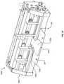
- FIG. 5illustrates a front perspective view of a frame useful in the converting machine of FIG. 3 ;
- FIG. 6illustrates a front perspective view of a portion of the frame of FIG. 5 ;
- FIG. 7illustrates a rear perspective view of the frame of FIG. 6 ;
- FIG. 10illustrates a front perspective view of an advancing mechanism in accordance with an embodiment of the present disclosure
- FIG. 12illustrates a perspective view of another packaging system in accordance with an embodiment of the present disclosure
- FIG. 13illustrates a perspective view of another packaging system in accordance with an embodiment of the present disclosure
- FIGS. 14A-14Dillustrate perspective views of some components of the packaging system of FIG. 13 in various configurations
- FIG. 15illustrates a front perspective view of a converting machine useful in the packaging system of FIG. 13 ;
- FIG. 16is a flowchart a flowchart depicting an exemplary method of forming a packaging template in accordance with an embodiment of the present disclosure.
- the words “can” and “may”are used in a permissive sense (i.e., meaning having the potential to), rather than the mandatory sense (i.e., meaning must).
- the terms “including,” “having,” “involving,” “containing,” “characterized by,” and variants thereof (e.g., “includes,” “has,” and “involves,” “contains,” etc.) as used herein, including the claims,shall be inclusive and/or open ended, shall have the same meaning as the word “comprising” and variants thereof (e.g., “comprise” and “comprises”), and does not exclude additional, un-recited elements or method steps, illustratively.
- directional and/or arbitrary termssuch as “top,” “bottom,” “left,” “right,” “up,” “down,” “upper,” “lower,” “inner,” “outer,” “proximal,” “distal” and the like can be used herein solely to indicate relative directions and/or orientations and may not otherwise be intended to limit the scope of the disclosure, invention, and/or claims to any particular orientation during use or at any other time.
- multiple instances of an element and or sub-elements of a parent elementmay each include separate letters appended to the element number.
- two instances of a particular element “ 706 ”may be labeled as “ 706 a ” and “ 706 b ”.
- the element labelmay be used without an appended letter (e.g., “ 706 ”) to generally refer to instances of the element or any one of the elements.
- Element labels including an appended lettere.g., “ 706 a ”) can be used to refer to a specific instance of the element or to distinguish or draw attention to multiple uses of the element.
- an element label with an appended lettercan be used to designate an alternative design, structure, function, implementation, and/or embodiment of an element or feature without an appended letter.
- an element “ 410 ”can have alternative designs indicated by element labels “ 410 a ” and “ 410 e .”
- an element label with an appended lettercan be used to indicate a sub-element of a parent element.
- element labels including an appended letterare not meant to be limited to the specific and/or particular embodiment(s) in which they are illustrated. In other words, reference to a specific feature in relation to one embodiment should not be construed as being limited to applications only within said embodiment.
- disclosure of an illustrative measurement or distance less than or equal to about 10 millimeters (mm) or between 0 and 10 mmincludes, illustratively, a specific disclosure of: (i) a measurement of 9 mm, 5 mm, 1 mm, or any other value between 0 and 10 mm, including 10 mm; and/or (ii) a measurement between 9 mm and 1 mm, between 8 mm and 2 mm, between 6 mm and 4 mm, and/or any other range of values between 0 and 10 mm.
- the dimensional measurements and/or distancesmay include deviations from the actual dimension (e.g., of the item or items). For instance, depending on packaging design and material thicknesses used in some embodiments, additional space (buffer) may need to be added (e.g., in order to accommodate a various number of layers of folded packaging material, or for other reasons, such as room for protective material, etc. Accordingly, such buffers are also contemplated herein.
- systems, methods, apparatus, devices, products, processes, compositions, and/or kits, etc.may include, incorporate, or otherwise comprise properties, features, components, members, and/or elements described in other embodiments disclosed and/or described herein.
- reference to a specific feature in relation to one embodimentshould not be construed as being limited to applications only within said embodiment.
- baleshall refer to a stock of sheet material that is generally rigid or semi-rigid in at least one direction, and may be used to make a packaging template.
- the balemay be formed of continuous sheet of generally rigid material or a sheet of material of any specific length, such as corrugated cardboard and paperboard sheet materials.
- the balemay have stock material that is substantially flat, folded, or wound onto a bobbin.
- the balemay comprise a “fan-folded” stack of sheet material that can be dispensed from a (terminal) end thereof.
- packaging templateshall refer to a substantially flat stock of sheet material that can be folded into a box-like shape.
- a packaging templatemay have notches, cutouts, divides, perforations, and/or creases that allow the packaging template to be bent and/or folded into a box.
- a packaging templatemay be made of any suitable material, generally known to those skilled in the art. For example, cardboard or corrugated paperboard may be used as the template sheet material.
- a suitable materialalso may have any thickness and weight that would permit it to be bent and/or folded into a box-like shape.
- cuttingcan include separating two joined portions of (sheet) material through one or more conversion functions, such as cutting, slicing, and so forth, any of which may be expressed interchangeably without necessarily departing from the scope of this disclosure.
- severingincludes cutting entirely through the thickness of at least a portion of the material.
- notchrefers to a shape created by removing material from the template or by separating portions of the template, such that a cut through the template is created.
- creasingcan include processing a portion of (sheet) material so as to compromise the (semi-rigid) integrity thereof such that the shape of the material can be altered more easily than prior to processing.
- creasingcan include compressing, compacting, folding, bending, perforated, partially cutting (e.g., without cutting entirely through the thickness of) at least a portion of the material.
- creasingdiffers from severing in that while severing includes at least partially separating two joined portions of the material (e.g., by cutting entirely through the thickness thereof), creasing retains substantial joinder of the two joined portions.
- creaseshall refer to a line along which the template may be folded.
- a creasemay be an indentation in the template material, which may aid in folding portions of the template separated by the crease, with respect to one another.
- a suitable indentationmay be created by applying sufficient pressure to reduce the thickness of the material in the desired location and/or by removing some of the material along the desired location, such as by scoring.
- the embodiments described hereingenerally relate to systems, methods, and apparatus for creating packaging templates for assembly into one or more boxes or other packaging material.
- the present disclosurerelates to systems, methods, and apparatus for processing sheet material (such as corrugated paperboard or cardboard) and converting the same into custom packaging templates.
- sheet materialsuch as corrugated paperboard or cardboard
- certain embodimentsinclude a converting machine.
- An illustrative converting machinecan include a frame, a conversion assembly, and/or means for advancing sheet material through the conversion assembly.
- the conversion assemblycan be adapted for performing one or more conversion functions on or to the sheet material (e.g., to thereby convert the sheet material into the packaging template).
- Some embodimentscan include a method of forming a packaging template (that is custom-made for packaging one or more items). For instance, in connection with a packaging system that includes a converting machine, an illustrative method can include placing the one or more items in a receiving area of the converting machine, adjusting one or more components of the converting machine according to at least one outer dimension of the one or more items, and converting sheet material into a packaging template configured for assembly into a box or packaging adapted for receiving the one or more items.
- Illustrative methods of the present disclosurecan also include advancing the sheet material to a first position, performing one or more longitudinal conversion function on at least a portion of the sheet material (e.g., while advancing the sheet material), and performing one or more transverse conversion function on at least a portion of the sheet material at the first position.
- the first position(or length of advancing thereto) can correspond to an outer dimension (e.g., height) of one or more items to be packaged.
- the methodcan include advancing the sheet material to a second position and performing one or more transverse conversion function on at least a portion of the sheet material at the second position.
- the second position(or length of advancing thereto) can likewise correspond to an outer dimension (e.g., length) of one or more items to be packaged.
- outer dimensione.g., length
- These basic stepscan be repeated as necessary to produce a custom packaging template configured to be assembled into a box that is sized according to the dimension(s) of the one or more items.
- the one or more items themselvescan provide the parameters or measurements for advancing the sheet material to the first, second, and/or subsequent positions. In other words, certain embodiments do not require separate, intermediate, and/or additional measuring of the one or more items prior to processing.
- the converting machine(or conversion assembly thereof) can include one or more longitudinal conversion elements (e.g., longheads) configured to perform the one or more longitudinal conversion functions (e.g., creasing, cutting).
- First and second (inner) longheadscan be positioned adjacent to opposing outer sides or walls of the one or more items such that the distance or separation between the longheads corresponds substantially to the width of the one or more items (e.g., with the addition of an optional buffer amount).
- the positioned longheadscan then create creases (or perform another longitudinal conversion function) on or in the sheet material at positions corresponding to the outer sides of the one or more items. Accordingly, the packaging template produced thereby can be folded along the creases (or other conversion feature) to produce a three-dimensional, custom box configured to receive the one or more items.
- transverse conversion elementse.g., crossheads
- cutsor other transverse conversion features, such as creases
- the cutscan produce flaps in the packaging template instead of separating the packaging template from the feed supply of sheet material.
- the packaging template produced therebycan be folded at the position of the cut flaps to produce structural components of a custom box, regular slotted container (RSC), or receptacle (e.g., packaging material) configured to receive the one or more items.
- the folded, cut flapscan produce one or more of the side walls, top, bottom, etc. of the box, or can comprise reinforcing, securing, or locking flaps thereof.
- the sheet materialcomprises a bale of fan-folded corrugated paperboard
- a final separating cutcan also be performed to release the packaging template from the feed supply.
- the packaging templatecan be assembled into a box in a variety of ways, methods, and/or mechanisms.
- the creased and/or cut transverse flapscan be folded to produce the side walls of a box having a hingedly-opening and/or flap-tucking upper top and/or lid.
- a first portion of the templatecan be folded and/or assembled into a receptacle having a (seamlessly connected) front wall, bottom wall, and back (rear) wall.
- Flaps extending (seamlessly) transversely outward from one or more (e.g., each) of the aforementioned wallscan be folded inward (e.g., to a 90 degree angle relative to the wall from which it extends) to (collectively) produce opposing (left and right) side walls comprising folded and/or stacked flaps.
- a second portion of the template extending (seamlessly) from the upper end of the front or rear wallcan comprise a lid or top wall.
- the top wallcan also have one or more (e.g., opposing) flaps extending transversely outward therefrom.
- the lidcan be hingedly-folded to associate with the receptacle and the flap(s) can be tucked adjacent to (e.g., outside, inside, and/or between the opposing side wall flaps of the receptacle.
- the lidcan also have a front flap extending (seamlessly) longitudinally from an opposing end (i.e., from an end opposite the front or rear wall to which the lid is connected and/or from which the lid extends.
- the front flapcan also be tucked and/or folded during assembly.
- the packaging templatecan be folded (longitudinally) into a continuous and/or circular configuration and, optionally, adhered or fastened (e.g., to produce a collapsed RSC).
- longitudinal (terminal) ends of the templatecan be fastened together to produce a tubular template having at least one seam and a plurality a template segment or body sections.
- the template segment or body sectionscan (each) have one or more transversely outwardly extending flaps, which can be folded inward (e.g., to a 90 degree angle relative to the segment from which it extends) to (collectively) produce opposing (top and bottom) portions of the box.
- top and bottomcan also (each) comprise a folded and/or stack of flaps, in some embodiments. Additional and/or alternative configurations and/or features of configurations will become apparent by or may be learned by the practice of various exemplary embodiments of the present disclosure.
- corresponding positionand similar terms can include positions adjacent to, similar to, and/or in proximity to a reference point (e.g., side wall).
- a “corresponding position”does not necessarily require the same or identical position. Accordingly, a buffer or other space can be disposed between a first and second object without necessarily negating the first object being in a position corresponding to the position of the first object.
- the methodcan be performed by means of a converting machine having a first end, a second end (e.g., opposite the first end), and a longitudinal length extending therebetween.
- the first endcan have a sheet material inlet and the second end can have a packaging template outlet.
- the converting machinecan also have a first side, a second side (e.g., opposite the first side), and a transverse width extending therebetween.
- the converting machinecan also include a (structural) frame or frame assembly configured to support a conversion assembly and/or an advancing mechanism.
- the advancing mechanismcan comprise one or more advancing members disposed about the converting machine and can be adapted for feeding and/or advancing the sheet material through the conversion assembly.
- an illustrative advancing mechanismcan comprise a plurality of wheels configured to feed the material through the conversion assembly.
- the conversion assemblycan be disposed between the first and second ends (e.g., along the longitudinal length) and/or between the first and second sides (e.g., along the transverse width).
- the conversion assemblycan be adapted for performing one or more conversion functions on or to the sheet material (e.g., to thereby convert the sheet material into the packaging template).
- the conversion assemblycan comprise one or more longitudinal conversion elements (e.g., longheads) for performing one or more longitudinal conversion functions.
- the longheadscan be selectively positionable about at least a portion of the transverse width of the converting machine or conversion assembly thereof.
- the longheadscan be connected to one or more transverse cross member(s) disposed at least partially between the first and second sides.
- the longheadscan slide along the cross member(s) to one or more positions suitable for converting the sheet material into the packaging template.
- the conversion assemblycan include a symmetrical movement apparatus connected to the longheads.
- the symmetrical movement apparatuscan coordinate symmetrical (e.g., equal and opposite) movement of the longheads about the transverse width. For instance, inward movement of a first longhead (e.g., from a first outer position on the first side of the conversion assembly) can (simultaneously) result in inward movement of a second longhead (e.g., from a second outer position on the second side of the conversion assembly).
- a similar (and/or separate) symmetrical movement apparatuscan coordinate symmetrical movement of the crosshead(s) about the transverse width.
- the conversion assemblycan include a second set (e.g., pair) of longheads or other longitudinal conversion elements.
- a second sete.g., pair
- an outer pair of longheadscan be adapted for creasing and/or cutting the sheet material at a second transverse position along the transverse width of the conversion assembly. Cutting longheads can trim the sheet material to an appropriate width for a custom packaging template.
- creasing longheadscan produce foldable flaps for reinforcing and/or securing the packaging template in a folded (e.g., box-like) configuration.
- the outer or extra longitudinal crease(s)can enable the packaging template to fold all around the item to be packaged, for example, creating a wrap-around packaging. This can be especially useful or productive with longer or “skinny” items, where a wrap-around along the longitudinal feeding axis often is easier to handle.
- the conversion assemblycan include one or more sets of crossheads configured to perform transverse conversion functions at various longitudinal positions along the length of the sheet material. Some of the crossheads can perform cuts up to (but not beyond) the (inner) longheads in some embodiments. Similar (and/or separate) symmetrical movement apparatus can also coordinate symmetrical movement of the second set of longheads and/or crossheads about the transverse width. In some embodiments, one or more longheads and/or crossheads can be released from attachment to the symmetrical movement apparatus, such that, for example, the crossheads can move independently, and even across the full width of the packaging (e.g., beyond the position of one or more of the (inner) longheads).
- FIG. 1illustrates a perspective view of a system 100 that may be used to create packaging templates.
- System 100can include at least one feed supply 102 of sheet material 104 .
- system 100includes a first feed supply 102 a of sheet material 104 a and a second feed supply 102 b of sheet material 104 b .
- sheet material 104 ahas a wider configuration than sheet material 104 b .
- system 100can be configured to accommodate and/or utilize a plurality of differently-sized sheet materials 104 .
- Feed supply 102can comprise a bale having a fanfold, rolled, or other configuration.
- Feed supply 102can also comprise one or more (pre-cut) pieces of sheet material 104 .
- Sheet material 104can comprise paperboard, corrugated board, or cardboard as known in the art and can have a substantially flat configuration.
- sheet material 104can be malleable, severable, or otherwise configurable or convertible (into a packaging template) by means of one or more conversion functions performed thereon.
- System 100can also include a feed supply base 106 .
- Base 106can comprise a mobile cart, trolley, or other device adapted for enhancing the mobility of feed supply 102 . Accordingly, system 100 can be adapted for interchangeability of various feed supplies 102 .
- item 110can be used to determine the appropriate size and/or configuration of the packaging template to be produced by the systems, methods, and/or apparatus described herein.
- the packaging templatemay be configured according to one or more (outer) dimensions of item 110 .
- the outer dimension(s) of a plurality of items 110can comprise the collective outer dimensions thereof.
- the outer dimensions of the item 110can comprise the dimensions circumscribing the one or more items 110 .
- the outer dimensions of item 110can provide a pattern for forming the packaging template (e.g., without requiring additional measuring of the dimensions (e.g., length, width, and/or height)).
- system 100can include a converting machine 200 configured to produce packaging templates from sheet material 104 .
- converting machine 200can be adjusted and/or configured to produce a custom packaging template based on the actual dimensions of the item 110 by receiving the item 110 in a receiving area.
- the outer dimensions of the item 110can then be marked or measured by adjusting and/or positioning certain components of converting machine 200 according to the outer dimensions (e.g., against the outer sides) of item 110 .
- System 100can also include a support structure 108 .
- Support structure 108can comprise a table or frame configured to rest upon a support surface, such as a floor.
- Converting machine 200can be placed and/or mounted on support structure 108 .
- One or more users 101can position themselves (e.g., stand, sit, etc.) adjacent to converting machine 200 and operate the same.
- operation of converting machine 200can include manual, electric, pneumatic, automatic, and/or responsive operation functions.
- converting machine 200can be entirely manually operated.
- converting machine 200 of system 100can be configured to receive feed supply 102 of sheet material 104 and perform the one or more conversion functions thereon in order to create one or more packaging templates 112 .
- packaging template 112may be formed into a packaging container (not shown), such as a box, configured to receive item 110 .
- the outer dimensions of item 110can be used as direct measurements or parameters for forming packaging template 112 .
- item 110can provide the model for forming packaging template 112 (e.g., with no intermediate measuring required).
- the one or more conversion functionscan alter the configuration of sheet material 104 in order to convert sheet material 104 into packaging template 112 .
- Such alterationscan include severing at least a portion of sheet material 104 .
- severingcan include separating the completed packaging template 112 from the feed stock 102 of sheet material 104 .
- Alterationscan also include creasing at least a portion of sheet material 104 .
- Sheet material 104can be advanced through converting machine 200 in a longitudinal direction. As illustrated in FIG. 2 , for instance, sheet material 104 can enter converting machine 200 at a first end 202 (e.g., rear or back end), advance through the converting machine 200 in the longitudinal direction 206 , and exit converting machine 200 at a second end 204 (e.g., front end). As will be discussed in further detail below, various conversion functions can be performed by converting machine 200 on sheet material 104 in the longitudinal direction 206 and/or transverse direction 208 .
- first end 202e.g., rear or back end
- second end 204e.g., front end
- FIGS. 3-11generally illustrate various aspects of converting machine 200 in greater detail.
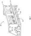
- FIG. 3for instance, illustrates a front perspective view of converting machine 200 .
- converting machine 200can include a frame 300 , a conversion assembly 400 , a feed assembly and/or advancing mechanism 500 , and/or a receiving area 600 .
- frame 300can be configured to structurally support conversion assembly 400 and/or advancing mechanism 500 .
- receiving area 600can be connected and/or disposed adjacent to conversion assembly 400 .
- front end 204 of converting machine 200can have a packaging template outlet (opening) 210 , which can be disposed in and/or (immediately) adjacent to receiving area 600 .
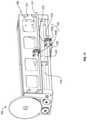
- FIG. 4illustrates a rear perspective view of converting machine 200 .
- Rear end 202 of converting machine 200can have a sheet material inlet (opening) 212 .
- Converting machine 200can also have an inlet guide 214 disposed at rear end 202 .
- inlet guide 214can ensure proper alignment of sheet material 104 upon entering converting machine 200 .
- Inlet guide 214can also continuously align feed supply 102 of sheet material 104 during processing and/or operation of converting machine 200 .
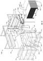
- FIG. 5illustrates an exemplary frame 300 of converting machine 200 .
- Frame 300can comprise a metal, such as aluminum, a metal alloy, a polymeric material, or any other suitable material.
- Frame 300can be configured to provide structural support for converting machine 200 and/or a skeleton on or about which various components of converting machine 200 , conversion assembly 400 , and/or advancing mechanism 500 can be attached and/or connected.
- frame 300can comprise one or more vertical frame elements 302 .
- frame 300can include vertical frame element 302 a and opposing vertical frame element 302 b .
- Frame 300can also include one or more horizontal frame elements 304 .
- Horizontal frame element 304can comprise a transverse support member or cross bar extending between vertical frame elements 302 a and 302 b .
- horizontal frame element 304can be attached and/or connected to vertical frame elements 302 a and 302 b .
- Frame 300can also include one or more rear frame elements 312 .
- Rear frame element 312can also be disposed between vertical frame elements 302 a and 302 b.
- Frame 300can also include one or more safety features.
- frame 300can have one or more upper shielding elements 306 , intermediate shielding elements 308 , and/or lower shielding elements 310 .
- Shielding elements 306 , 308 , 310can be disposed between vertical frame elements 302 a and 302 b and/or can provide a wall or barrier that substantially prevents (finger) access to components shielded thereby.
- shielding element 308can provide a back-stop and/or reference point for positioning a first end of item 110 (e.g., during processing).
- one or more conversion functionscan be performed on the sheet material in proximity to (e.g., immediately behind and/or within 2.54 cm of) shielding element 308 .
- frame 300can include one or more additional coverings (or plates) 314 .
- Covering 314can be selectively removable for quick access to a portion of converting machine 200 disposed therebehind.
- converting machine 200can comprise one or more sharpened blades or other cutting elements.
- One such cutting elementcan be disposed behind covering 314 such that access to the blade (e.g., for maintenance, repair, sharpening, or replacement thereof) can be afforded by removing covering 314 (without necessarily requiring removal of shielding element 308 , for example).
- Frame 300can also include a platform 318 .
- platform 318comprises an out-feed table for receiving a packaging template when the packaging template exits converting machine 200 via outlet 210 (see FIG. 3 ).
- platform 318can comprise a receiving table or receiving area 600 (see FIG. 3 ).
- frame 300can include one or more risers (or product shelf) 320 , including a (possibly smaller) horizontal extension 321 along the width of the machine.
- Riser 320can be configured to receive an end portion of item 110 thereon in order to lift the end portion above a pre-determined level.
- riser 320can be separated from platform 318 by a gap, space, and/or distance 322 .
- Risers 320can lift the end portion of item 110 above opening 340 of a frame 300 .
- An elevation view of opening 340is illustrated in FIG. 6 .
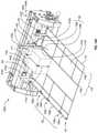
- FIG. 6illustrates a front perspective view of a frame 300 (wherein shielding elements 306 , shielding element 308 (and coverings 314 thereof), and shielding element 310 of frame 300 have been removed).
- frame 300can also have one or more (inner) support plates 330 and (inner) feed guides 338 .
- opening 340can be disposed between support plate 330 and feed guide 338 .
- support plate 330can have a guide member 332 .
- Guide member 332can comprise a lip, ledge, or other feature configured to direct the movement of sheet material 104 through converting machine 200 , and possibly also accommodate an edge or groove to support the packaging material while one or more conversion functions (e.g., transverse conversion functions) are performed. Opening 340 can be disposed between the upper feed guide 338 and guide member 332 or the lower support plate 330 . Support plate 330 and feed guide 338 can also be disposed between vertical frame elements 302 a and 302 b.
- frame 300can comprise a plurality of horizontal frame elements 304 .
- FIG. 6illustrates horizontal frame elements 304 a , 304 b , 304 c , and 304 d .
- horizontal frame elements 304 a , 304 b , 304 c , and 304 dcan serve a variety of support functions for a variety of components of converting machine 200 .
- FIG. 7illustrates a rear perspective view of frame 300 .
- frame 300can also include horizontal frame element 304 e .
- frame 300can include a rear support member 334 and/or a lower support member 336 .
- rear support member 334 and/or a lower support member 336can be connected to and/or integral with support plate 330 .
- rear frame element 312can include guide member 313 , which can be configured to direct the movement of sheet material 104 into converting machine 200 .
- Conversion assembly 400can include one or more longitudinal conversion assemblies 402 and/or one or more transverse conversion assemblies 404 .
- Longitudinal conversion assembly 402can comprise one or more longitudinal conversion elements (e.g., longheads) 410 .
- conversion assembly 400(or longitudinal conversion assembly 402 thereof) comprises longitudinal conversion elements 410 a , 410 b , 410 c , and 410 d .
- a set of longitudinal conversion elements 410can comprise a pair of longitudinal conversion elements 410 .
- conversion assembly 400can comprise two sets of longitudinal conversion elements 410 in certain embodiments.
- Longitudinal conversion elements 410can comprise a longhead. Longheads can be configured to perform one or more longitudinal conversion functions, such as creasing, cutting, etc. It will be appreciate that reference to a longhead is intended to include and/or incorporate a specific reference to other longitudinal conversion elements as known in the art and/or described herein.
- longhead 410can comprise a body portion 413 and/or one or more converting instruments 412 .
- Body portion 413can comprise a structural plate or bar.
- Converting instruments 412can comprise a creasing element and/or cutting element in certain embodiments. As illustrated in FIG. 8 , converting instruments 412 comprises a creasing wheel configured to performing a longitudinal creasing function on sheet material 104 when contacted by the same (e.g., as sheet material 104 is advanced longitudinally through converting machine 200 ).
- Longitudinal conversion elements 410can also comprise an attachment member 416 .
- Attachment member 416can be connected to (or configured to be connected to) one or more horizontal frame elements 304 .
- attachment member 416can be connected to horizontal frame elements 304 a and 304 b .
- the connection of a conversion element (or other component) to a plurality of horizontal frame elements 304can enhance stability and selective, transverse movement of the conversion element (or other component).
- conversion elements (or other component)may only be connected to one cross member without departing from the scope of this disclosure.
- Some embodimentscan also include one or more glide bearings 417 disposed between attachment member 416 and horizontal frame element 304 .
- a glide bearing 417can prevent undesirable movement of attachment member 416 (and/or the component(s) connected thereto) about horizontal frame element 304 .
- glide bearing 417can permit certain transverse movements (e.g., those resulting from a transverse and/or horizontal force applied close enough to horizontal frame element 304 ), while substantially prohibiting and/or inhibiting other transverse movements (e.g., those resulting from a transverse and/or horizontal force applied too far distant from horizontal frame element 304 ).
- Certain embodimentscan also include one or more symmetrical movement assemblies and/or apparatus (e.g., connected to frame 300 and/or disposed between vertical frame elements 302 a and 302 b thereof).
- symmetrical movement apparatus 430can comprise a pulley system or other means for coordinating symmetrical and/or simultaneous movement of a plurality of components of system 100 and/or converting machine 200 .
- Symmetrical movement apparatus 430can comprise a line 432 .
- Line 432can comprise a cable, wire, or other suitable pulley line.
- Symmetrical movement assembly 430can also comprise a multi-directional element 434 .
- multi-directional element 434can comprise a pulley wheel in some embodiments.
- symmetrical movement assembly 430 of the present disclosureis not limited to pulley systems.
- hydraulic, pneumatic, electric, mechanical, coordinated, and other suitable symmetrical movement assemblies and/or apparatusare also contemplated herein.
- symmetrical movement assembly 430can be connected to frame 300 (or vertical frame elements 302 a and/or 302 b thereof) via one or more fasteners 326 a.
- symmetrical movement assembly 430can be configured to coordinate the simultaneous and/or symmetrical (e.g., equal and opposite) movement of a pair of longitudinal conversion elements 410 .
- Longitudinal conversion elements 410can be connected to symmetrical movement assembly 430 via one or more attachment mechanism 414 .
- longitudinal conversion elements 410 a and 410 bcan be connected to and/or coordinated by a first symmetrical movement assembly 430 .
- a first attachment mechanism 414 acan attach first inner longitudinal conversion element 410 a to a first portion of symmetrical movement assembly 430 (e.g., to a first portion 433 a of line 432 ).
- Attachment mechanism 414 acan include a clamp or other fastener 418 and can be connected to body portion 413 via connector 420 .
- a second attachment mechanism 414 bcan attach second inner longitudinal conversion element 410 b to a second portion of symmetrical movement assembly 430 (e.g., to a second portion 433 b of line 432 ).
- movement of first inner longitudinal conversion element 410 a in a first directioncan cause (an equal and opposite) movement of second inner longitudinal conversion element 410 b in a second direction.
- a similar arrangementcan cause symmetric movement of first outer longitudinal conversion element 410 c and second outer longitudinal conversion element 410 d via a second symmetrical movement assembly 430 a (e.g., similarly configured and/or disposed adjacent to symmetrical movement assembly 430 ).
- components of transverse conversion assembly 404can also be coordinated via a symmetrical movement assembly 430 b.
- Transverse conversion assembly 404can include one or more transverse conversion elements 440 .
- transverse conversion element 440can comprise a crosshead.
- Such crossheadscan be configured to perform one or more transverse conversion functions, such as cutting, creasing, etc. It will be appreciated that reference to a crosshead is intended to include and/or incorporate a specific reference to other transverse conversion elements as known in the art and/or described herein.
- Crosshead 440can comprise a body portion 413 a and/or one or more converting instruments 412 a .
- Converting instrument 412 acan comprise a creasing element and/or cutting element in certain embodiments.
- converting instruments 412 acomprises a cutting wheel configured to performing one or more transverse cutting functions on sheet material 104 when contacted by the same (e.g., as converting instrument 412 a is advanced transversely across or about sheet material 104 ).
- converting instrument 412 acan be positioned and/or disposed proximal to (e.g., immediately behind and/or within 2.54 cm of) shielding element 308 .
- converting instrument 412 acan be positioned and/or disposed less than and/or about 2.54 cm, 2 cm, 1.5 cm, 1.27 cm, 1 cm, 0.75 cm, 0.5 cm, or 0.25 cm.
- At least a portion of receiving area 600can be disposed less than about 2.54 cm, 2 cm, 1.5 cm, 1.27 cm, 1 cm, 0.75 cm, 0.5 cm, or 0.25 cm from converting instrument 412 a and/or the portion of the transverse width along which the converting instrument 412 a is moveable.
- This proximity between the receiving area where the item is placed and the transverse converting instrumentscan be important in order to enable a direct visual indication for manual feeding, as described in more detail below.
- Transverse conversion element 440can also comprise an attachment member 416 a .
- Attachment member 416 acan be connected to (or configured to be connected to) one or more horizontal frame elements 304 .
- attachment member 416 acan be connected to horizontal frame element 304 d .
- Transverse conversion element 440can also comprise a second attachment member 416 b (e.g., connected to (or configured to be connected to) horizontal frame element 304 c ). In some embodiments, however, transverse conversion element 440 may only be connected to one cross member without departing from the scope of this disclosure.
- Transverse conversion element 440can also be connected to symmetrical movement assembly 430 b via one or more attachment mechanisms 414 c .
- Symmetrical movement assembly 430 bcan comprise a pulley system having a line 432 b and pulley wheels 434 a connected to frame 300 (or vertical frame elements 302 a and/or 302 b thereof) via one or more fasteners 326 a .
- transverse conversion element 440can be selectively released from symmetrical movement assembly 430 b via one or more release mechanisms 442 .
- Transverse conversion element 440can also include a handle 444 .
- Transverse conversion assembly 404can also include a second transverse conversion element 440 a .
- Transverse conversion elements 440 and 440 acan have identical, similar, or different configuration in various embodiments of the present disclosure.
- transverse conversion element 440 acan also include a body portion 413 a , a converting instrument 412 a , a first attachment member 416 a connected to horizontal frame element 304 d , a second attachment member 416 a connected to horizontal frame element 304 c , and a handle 444 .
- transverse conversion element 440 acan be connected to symmetrical movement assembly 430 b via one or more attachment mechanisms 414 d .
- transverse conversion element 440 acan lack a release mechanism 442 in some embodiments.
- movement of transverse conversion element 440can cause an equal and opposite movement of transverse conversion element 440 a when both are attached to symmetrical movement assembly 430 b .
- transverse conversion elements 440 and 440 acan move independent of one another.
- attachment mechanisms 414 ccan comprise a cone-and-socket configuration.
- attachment mechanisms 414 ccan comprise a socket 450 and an insert 452 (e.g., ball, cone, etc.).
- Socket 450can have a cavity 454 into which insert 452 can be inserted and/or disposed.
- locking mechanism 446can be engage (e.g., via one or more springs 447 or other engagement mechanism). Engaged locking mechanism 446 can inhibit and/or substantially prevent insert 452 from exiting cavity 454 of socket 450 without first disengaging locking mechanism 446 .
- a stopping mechanism 460can be provided (e.g., on longitudinal conversion element 410 or, specifically, 410 a ) by which one or more of transverse conversion elements 440 and 440 a can be substantially prevented from passing transversely.
- stopping mechanism 460can be disposed in the transverse path of transverse conversion elements 440 a (e.g., between an outer position and an inner position).
- stopping mechanism 460can be configured to substantially prevent transverse conversion element 440 a and/or converting instruments 412 a thereof from advancing inward past at least a portion of longitudinal conversion element 410 . Consequently, the transverse conversion function(s) can be limited portions of sheet material 104 flanking longitudinal conversion elements 410 .
- the transverse conversion function(s)can comprise cutting sheet material 104 (e.g., to form one or more flaps). Accordingly, limiting the range of motion of transverse conversion element 440 a can prevent transverse conversion element 440 a and/or converting instruments 412 a from cutting entirely through sheet material 104 and severing and/or separating the same from feed stock 102 .
- one or more of transverse conversion elements 440 and 440 acan be configured to avoid stopping mechanism 460 in order to perform at least one transverse conversion function beyond or past stopping mechanism 460 (e.g., across the entire width of sheet material 104 and/or conversion assembly 400 .
- transverse conversion element 440can be configured to move (freely) past stopping mechanism 460 in at least one embodiment.
- transverse conversion element 440 acan be blocked by stopping mechanism 460 such that converting instruments 412 a thereof can only advance to (but not beyond) longitudinal conversion element 410
- transverse conversion element 440can slide across the entire transverse width of conversion assembly 400 in some embodiments.
- transverse conversion element 440may need to be detached from symmetrical movement assembly 430 b in order to slide across the entire transverse width of conversion assembly 400 .
- stopping mechanism 460can also be disengaged in at least one embodiment such that transverse conversion element 440 a can pass thereby.
- FIG. 9further illustrates inlet guide 214 connected to horizontal frame element 304 e and symmetrical movement assembly 430 c .
- Inlet guide 214can be adjustably mounted to horizontal frame element 304 e such various different sizes of sheet material can be received thereby.
- inlet guide 214can comprise opposing guides 470 (e.g., each having a sloped portion 272 and/or a longitudinal portion 274 ) and horizontal frame element 304 e can comprise a crossbar.
- Opposing guides 470 a and 470 bcan be slideably mounted to the crossbar such that when opposing guides 470 a and 470 b are slid proximally or closer together (e.g., by means of symmetrical movement assembly 430 c ), inlet guide 214 can be configured to receive a sheet material having a smaller transverse width. Similarly, when opposing guides 470 a and 470 b are slid distally or further apart, inlet guide 214 can be configured to receive a sheet material having a larger transverse width. Inlet guide 214 can also include a locking mechanism (not shown) configured to prevent (transverse outward and/or inward) movement of opposing guide(s) 470 .
- inlet guide 214can also comprise outer guide walls 276 configured for aligning and/or retaining sheet material 104 .
- guide 470 acan include an outer guide wall 276 a and opposing guide 470 b can include an outer guide wall 276 b .
- Outer guide walls 276 a and 276 bcan prevent sheet material 104 from shift or sliding transversely about the width of converting machine 200 and/or from twisting or torqueing in a transverse direction, e.g. while sheet material 104 is advanced forward.
- outer guide walls 276 a and 276 bcan ensure that sheet material 104 is advanced forward in a straight line or angle.
- Advancing mechanism 500can be configured to move or advance sheet material 104 through converting machine 200 and/or conversion assembly 400 thereof.
- Advancing mechanism 500can be (entirely) manually operated, electrically operated, automatically operated, and/or any suitable combination thereof.
- sheet material 104can be fed or loaded into converting machine 200 manually by an operator 101 manually rotating (or cranking) one or more components of advancing mechanism 500 .
- one or more automatic process stepscan be initiated by the user 101 .
- one or more embodimentscan include one or more automated processing steps triggered by the completion of previously initiated (automated) processing steps. Automation can include the use of one or more sensors, circuits, series, control panels, user interfaces, CPUs, computer processors, and/or other electrical and/or mechanical components.
- crank assembly 502can comprise a crank member 504 and a translational element 506 .
- crank member 504can comprise a wheel, disk, or other rotational element.
- crank member 504can comprise a handle, bar, rod, block, ball, or any other suitable crank member.
- Crank member 504can comprise teeth or a grove 522 configured to receive translational element 506 .
- translational element 506can comprise a band, gear, toothed belt or chain, strap, or other member configured to translate movement from one component to another.
- (rotational) movement of crank member 504can be translated to one or more roller assemblies 512 by means of translational element 506 .
- translational element 506can also be connected to roller cranks 508 a and 508 b (e.g., via a grove 522 thereof).
- roller cranks 508 a and 508 bcan be connected to roller shaft 516 having one or more roller members 518 thereon.
- roller members 518can be adapted for advancing sheet material 104 through converting machine 200 (and/or conversion assembly 400 thereof) and/or through opening 340 .
- advancing mechanism 500can include one or more pressure rollers 514 configured to press sheet material 104 against roller assembly 512 a to enhance the movement induced thereby.
- pressure roller 514can comprise a roller shaft 516 a supporting a roller member 518 a configured to press sheet material 104 against roller member 518 of roller assembly 512 .
- sheet material 104can be advanced through converting machine 200 (and/or conversion assembly 400 thereof) and/or through opening 340 by means of the rolling motion of roller members 518 and 518 a.
- Roller assembly 512 bcan further enhance movement of sheet material 104 through opening 340 .
- rotation of crank member 504can cause rotational movement of roller assembly 512 b in concert with roller assembly 512 a . Accordingly, when sheet material 104 is advanced through converting machine 200 (and/or conversion assembly 400 thereof), roller assembly 512 b can promote the longitudinal movement of sheet material 104 through opening 340 .
- roller guide assembly 520 acan also include one or more roller guide assemblies 520 for enhancing the ease of insertion of the sheet material 104 into converting machine 200 (and/or conversion assembly 400 thereof).
- Roller guide assembly 520 afor example, comprises a guide wheel 524 connected to a support arm 526 via bracket 522 .
- Guide wheel 524can rotate about its axis of rotation to thereby promote the feeding of sheet material 104 toward conversion assembly 400 .
- guide wheel 524can ensure that sheet material 104 is raised or lifted to a position suitable for feeding into converting machine 200 .
- An upper guide wheel 524 of roller guide assembly 520 bcan similarly ensure that sheet material 104 is depressed or held down to a position suitable for feeding into converting machine 200 .
- roller guide assembly 520 a and 520 bcan work in concert to properly vertically position sheet material 104 for entry in converting machine 200 .
- guide member 313 of rear frame element 312can also comprise part of advancing mechanism 500 .
- FIG. 12illustrates an alternative embodiment comprising a system 100 a .
- System 100 acan include one or more feed supplies 102 of sheet material 104 .
- System 100 acan also include a converting machine 200 a .
- converting machine 200 acan be configured similar to converting machine 200 .
- converting machine 200 acan include one or more transverse conversion elements 440 b having a handle 444 a thereof disposed toward the front end of converting machine 200 a .
- rear frame element 312 acan comprise a solid (e.g., un-slotted) configuration.
- converting machine 200 acan include an advancing mechanism 500 a comprising a crank assembly 502 a having a crank member 504 a .
- Crank member 504 acan include a crank arm and ball configuration instead of a crank wheel configuration as in crank member 504 .
- converting machine 200 acan be attached, connected, and/or mounted to support structure 108 a such that platform 318 a can be planar with the surface of support structure 108 a , or even completely removed (and replaced by 108 a ). Converting machine 200 a can also be attached, connected, and/or mounted to support structure 108 a such that user 101 can stand to the side thereof (instead of in front of converting machine 200 as in system 100 ).
- handles and grips or other componentse.g., for feeding, guiding, and/or advancing sheet material 104 , positioning of longheads 410 and/or crossheads 440 , guiding, measuring, and/or marking positions, dimensions, and/or measurements, and/or other functional components or mechanisms
- the outfeed areaadjacent to receiving area 600
- the itemmight, in fact, just be slid off the riser 320 (product shelf) and automatically dropped down on the packaging that now can be closed without any lifting.
- riser 320product shelf
- FIG. 13illustrates another alternative embodiment comprising a system 100 b .
- System 100 bcan include one or more feed supplies 102 of sheet material 104 and/or one or more converting machines 200 b .
- sheet material 104 acan be fed into converting machine 200 b by user 101 and processed therein to produce packaging template 112 a .
- Converting machine 200 bcan be mounted, connected, and/or attached to a support structure 108 b .
- packaging template 112 acan exit converting machine 200 b and/or be released therefrom in planar alignment with the surface of support structure 108 b .
- Converting machine 200 bcan be mounted, connected, and/or attached to a support structure 108 b such that user 101 can stand to the side thereof (instead of in front of converting machine 200 as in system 100 ).
- Support structure 108 bcan include shelving 118 and/or suspension system 130 .
- Suspension system 130can comprise a line 132 suspended from a frame 136 .
- frame 136can include a connection element 134 slideably attached to (a first end of) line 132 and to frame 136 (e.g., along a sliding track).
- Line 132can have a support member 138 connected to an end thereof (e.g., opposite the first end).
- Other embodimentscould include a rotating or linear guided plate that can be positioned along the feeding direction in the extension of the receiving area.
- suspension system 130can at least partially lift and/or separate item 110 a from (the surface of) support structure 108 b .
- support member 138can be positioned at the end of item 110 a (opposite converting machine 200 b and/or the end of item 110 a positioned in the receiving area thereof.
- the longitudinal position of support member 138can be slidedly altered to accommodate, receive, and/or lift a variety of items 110 having any suitable longitudinal length.
- sheet material 104can more easily move beneath item 110 a when lifted and/or separated from the surface of support structure 108 b.
- System 100 bcan also include one or more carts 116 .
- Cart(s) 116can be used to hold one or more additional items 110 thereon.
- items 110 b , 110 c , and/or 110 dcan be positioned on cart(s) 116 .
- cart(s) 116can be used to hold one or more packaged items 117 .
- packaged item 117can include item 110 a disposed within a box formed and/or assembled from one or more packaging templates 112 a .
- Packaged item 117can also be covered in wrapping 120 and/or taped (closed) with tape (or other adhesive) 124 .
- converting machine 200 bcan be configured similar to converting machine 200 and/or 200 a .
- converting machine 200 bcan include a transverse conversion element 440 c having a handle 444 b thereon.
- opposing transverse conversion element 440 ddoes not include a handle thereon.
- Converting machine 200 bcan also include at least one longitudinal conversion element 410 e having an extended configuration. For instance, the height of longitudinal conversion element 410 e can exceed the height of opposing longitudinal conversion element 410 a and/or of corresponding longitudinal conversion element 410 b of converting machine 200 ).
- converting machine 200 bcan also include a measuring mechanism 700 .
- Measuring mechanism 700can comprise a ruler, (retractable) measuring tape, marking strip, lighting element (or light-generating element) or other means for measuring (e.g., the distance between two points).
- Measuring mechanism 700can be attached, connected, and/or mounted to longitudinal conversion element 410 e in some embodiments.
- measuring mechanism 700can include a ruler attached to longitudinal conversion element 410 e and/or a marking element 704 (e.g., slideably connected to longitudinal conversion element 410 e ).
- marking element 704can be adjustable along the height of longitudinal conversion element 410 e .
- marking element 704can be configured to slide (vertically) about longitudinal conversion element 410 e and slidedly abut and/or rest atop item 110 e (e.g., such that the height of item 110 e is marked and/or measured thereby).
- the (actual) height of (the physical) item 110 ecan be used to determine the position of marking element 704 .
- marking element 704can (actually) be positioned against the top surface of item 110 e . It will also be appreciated that marking element 704 can placed in a position corresponding to the top surface of item 110 e without departing from the scope of this disclosure.
- measuring mechanism 700can be configured to recapitulate and/or translate the measurement of the height of item 110 e to a longitudinal length of similar or same distance and/or amount.
- measuring mechanism 700can extend longitudinally from the front of converting machine 200 b in some embodiments.
- Measuring mechanism 700can also comprise an optional marking element 704 .
- the measurement of the height of item 110 ecan be marked and/or measured out longitudinally in certain embodiments.
- the measurement of the height of item 110 ecan be marked and/or measured out longitudinally from a converting instrument of transverse conversion element 440 c , for example.
- a measurement corresponding to the height of item 110 ecan be measured from the point and/or site of a transverse conversion function.
- measuring mechanism 700can be configured to recapitulate and/or translate the measurement of the height of item 110 e to a transverse length of similar or same distance and/or amount.
- measuring mechanism 700can extend transversely from longitudinal conversion element 410 f and/or 410 e in some embodiments.
- the measurement of the height of item 110 ecan be marked and/or measured out transversely in certain embodiments.
- the measurement of the height of item 110 ecan be marked and/or measured out transversely from converting instrument 412 a of longitudinal conversion element 410 e , for example.
- longitudinal conversion elements 410 f and 410 ecan be separated by a measurement corresponding to the height of item 110 e by deploying and/or adjusting one or more measuring mechanisms 700 to corresponding positions.
- measuring mechanism 700can comprise a lighting element 702 .
- Lighting element 702can be battery-powered, electrically powered (by a power cord), and/or otherwise operated. Lighting element 702 can produce and/or project a laser or other form (e.g., beam) of light 706 .
- lighting element 702can be configured and/or calibrated to project a first beam 706 a from measuring mechanism 700 (generally) transversely (and downward) toward packaging template 112 b .
- first beam 706 acan intersect with packaging template 112 b at a position and/or location that is separated from converting instrument 412 a of longitudinal conversion element 410 e (e.g., by a distance corresponding to (e.g., similar or equal to) the height of item 110 e ). Accordingly, first beam 706 a can mark a location for (accurately) positioning longitudinal conversion element 410 f and/or converting instrument 412 b thereof a distance from (the position of) longitudinal conversion element 410 e and/or converting instrument 412 a thereof. In at least one embodiment the distance can correspond to the height of item 110 e .
- longitudinal conversion elements 410 e and 410 fcan produce longitudinal conversion function(s) that are separated by a distance corresponding to the height of item 110 e .
- longitudinal conversion element 410 f and/or converting instrument 412 b thereofcan be accurately positioned at a location and separated from the side of item 110 e by a distance corresponding to the height of item 110 e.
- the first beam 706 acan be pointed downwards and intersect with (e.g., make a marking or visual indication on) the riser 320 or extension 321 (product shelf) rather than the packaging template.
- the frame componentsmay be more vertically stable than the packaging template 112 b (or sheet material 104 thereof), which may move up and down to the degree the guides and gap allows.
- the markingcan more easily be compared to markers (on the frame) for different sheet widths, thus indicating if a bale change is needed or appropriate.
- Lighting element 702can also be configured and/or calibrated to project a second beam 706 b from measuring mechanism 700 (generally) longitudinally (and downward) toward packaging template 112 b .
- second beam 706 bcan intersect with packaging template 112 b at a position and/or location that is separated from a converting instrument of transverse conversion element 440 c (e.g., by a distance corresponding to (e.g., similar or equal to) the height of item 110 e ).
- second beam 706 bcan mark a location for advancing packing template 112 b (or sheet material 104 thereof) during processing (e.g., in order to produce transverse conversion function(s) thereby).
- the transverse conversion function(s) produced therebycan be separated by a distance (e.g., corresponding to the height of item 110 e ).
- packaging template 112 bcan have a plurality of transverse conversions (e.g., cuts) extending from the outer side edge(s) 115 thereof (inwardly) to or toward longitudinal conversion(s) (e.g., crease(s)) 119 .
- a first transverse conversion 105 acan be separated from the front end 107 of packaging template 112 b by a first distance 109 a .
- FIGS. 14A-14Dpackaging template 112 b can have a plurality of transverse conversions (e.g., cuts) extending from the outer side edge(s) 115 thereof (inwardly) to or toward longitudinal conversion(s) (e.g., crease(s)) 119 .
- a first transverse conversion 105 acan be separated from the front end 107 of packaging template 112 b by a first distance 109
- first distance 109 acan correspond to the vertical height 111 of item 110 e .
- first distance 109 acan correspond to the longitudinal length 113 of item 110 e or another measurement.
- first distance 109 acan comprise a buffer distance (e.g., for use in the formation of a tear-away tab).
- first distance 109 acan correspond to the longitudinal length 113 of item 110 e .
- first distance 109 acan correspond to the vertical height 111 of item 110 e or another measurement.
- a third transverse conversion 105 bcan be separated from second transverse conversion 105 b by first distance 109 a (e.g., corresponding to vertical height 111 of item 110 e ) in some embodiments.
- transverse conversion element(s) 440 c(and optionally 440 d ) and/or converting instrument(s) thereof can produce transverse conversion function(s) that are separated by a distance corresponding to the height of item 110 e .
- transverse conversion element(s) 440 c(and/or 440 d ) can be accurately deployed at locations and/or positions separated by a distance corresponding to the height of item 110 e.
- the (actual) dimension(s) (e.g., longitudinal length) of item 110 ecan be used as a (direct) indication of an appropriate location and/or position to advance packaging template 112 b or one or more transverse conversions thereof.
- transverse conversion 105 ccan be aligned with the end of item 110 e (distal to transverse conversion element(s) 440 c ), thus positioning packaging template 112 b and/or sheet material 104 in a location or position where a transverse conversion function performed thereon will form a transverse conversion 105 d (see FIG. 14B ) that is separate from transverse conversion 105 c by a distance 109 b corresponding to the longitudinal length 113 of item 110 e.
- second beam 706 b of measuring mechanism 700can produce a visual indication of an appropriate position or location for advancing or feeding packaging template 112 b or sheet material 104 .
- transverse conversion 105 dcan be aligned with the visual indication of second beam 706 b , thus positioning packaging template 112 b and/or sheet material 104 in a location or position where a transverse conversion function performed thereon will form a transverse conversion (not shown) that is separate from transverse conversion 105 d by a distance 109 a corresponding to the vertical height 111 of item 110 e .
- the transverse conversion functioncan comprise cutting or severing entirely through the thickness and transverse width of sheet material 104 to release packaging template 112 b therefrom.
- adjustment of the positioning of lighting element 702can cause and/or result in a change in the position of beam(s) 706 .
- the distance of separation between longitudinal conversion element 410 e (and/or converting instrument 412 a thereof) and the point at which beam(s) 706 intersect with packaging template 112 b (or sheet material 104 thereof)can increase.
- marking element 704can be repositioned atop an item 110 of any suitable height, causing the point of intersection between beam(s) 706 and packaging template 112 b (or sheet material 104 thereof) to change accordingly.
- accurate marking of positions suitable for performing one or more conversion functionscan be indicated and/or marked.
- marking element 704can be repositioned atop an item 110 f having a vertical height 111 b that is less than vertical height 111 a of item 110 e .
- marking element 704alters the position or location of the visual indication(s) produced by beam(s) 706 .
- Longitudinal conversion elements 410 h and 410 fcan be adjusted to correspond with the new position or location of the visual indication produced by beam 706 a .
- the location of longitudinal conversion 119 b on the transverse width of packaging template 112 cis altered relative to packaging template 112 b .
- longitudinal conversion 119 bis closer to longitudinal conversion 119 a in packaging template 112 c than in packaging template 112 b.
- the distance 109 c between transverse conversions 105 b and 105 ccan also correspond to the height 111 b of item 110 f .
- the longitudinal length 113 of item 110 fis the same as the length of item 110 e
- the distance 109 b between transverse conversions 105 a and 105 bcan still correspond to the length 113 of item 110 f.
- marking element 704can be repositioned atop an item 110 g having a vertical height 111 c that is less than vertical height 111 b of item 110 f .
- the repositioning of marking element 704alters the position or location of the visual indication(s) produced by beam(s) 706 .
- Longitudinal conversion elements 410 h and 410 fcan again be adjusted to correspond with the new position or location of the visual indication produced by beam 706 a .
- the location of longitudinal conversion 119 b on the transverse width of packaging template 112 cis altered.
- longitudinal conversion 119 bis closer to longitudinal conversion 119 a in packaging template 112 d than in packaging template 112 c.
- the distance 109 d between transverse conversions 105 b and 105 ccan also correspond to the height 111 c of item 110 g .
- the longitudinal length 113 of item 110 gis the same as the length of item 110 e and item 110 f
- the distance 109 b between transverse conversions 105 a and 105 bcan still correspond to the length 113 of item 110 g.
- the angle of or in which the beams 706 are directed downwards longitudinally and/or transversely towards the packing template (or riser extension),is about 45 degrees (relative to the vertical, for example, of longitudinal conversion element 410 e ).
- a 45 degree anglecan cause the transverse and/or longitudinal position of the beam intersection point to be adjust in accordance with the vertical position of lighting element 702 .
- a defined vertical adjustment in the height of lighting element 702can result in a corresponding (e.g., equal) transverse and/or longitudinal adjustment of the beam intersection point.
- an item that is 1 cm taller (than another item)can produce and/or result in that the markers from beams 706 being moved 1 cm further out.
- inventionscan have one or more of the beams positioned or directed in another angle. For instance, an angle of about 27 degrees relative to vertical (or 63 degrees relative to horizontal) can result in a marker positioned essentially half the distance of the items' height. Accordingly, an additional height of 1 cm results in a new marker position only 0.5 cm further out. This would be suitable, for example, for making flaps that would meet in the middle (of the height). Depending on packaging design other angles can also be appropriate. At least one embodiment can have a plurality of beams indicating various, additional, or more angles (transversely and/or longitudinal), and possibly differentiated by colors.
- the position of lighting element 702 on the marking element 704may need to be adjusted depending on the distance between transverse converting instrument(s) 412 a and inner longitudinal converting elements 412 .
- Other factors that can affect the positioning of the lighting elementsare the packaging designs and material thicknesses. This is due to the need of the previously mentioned “buffer space”.
- the movement of longitudinal conversion element 410 fcan be coordinated with the movement of measuring mechanism 700 .
- a usercan (manually) position longitudinal conversion element 410 f at a location that is separated from longitudinal conversion element 410 e by a distance corresponding to the height of item 110 e and/or the distance between marking element 704 and packaging template 112 b (or sheet material 104 thereof).
- a movement coordinating mechanism(such as a pulley system or other symmetrical movement assembly) can (automatically, mechanically, electrically, hydraulically, and/or pneumatically) adjust the transverse position of longitudinal conversion element 410 f in response to a vertical repositioning of measuring mechanism 700 and/or marking element 704 thereof.
- second and/or third measuring mechanism 700 and/or marking element 704 thereofcan also be repositioned thereby.
- the item 110 ecan provide the measurement(s) and/or act as the measuring tool by providing outer dimensions suitable for positioning components of converting machine 200 b about.
- longitudinal conversion elements 410 e and 410 gcan be positioned about item 110 e (on, about, and/or at positions corresponding to (opposing) sides thereof) and measuring mechanism 700 and/or marking element 704 thereof can be positioned atop item 110 e .
- longitudinal conversion elements 410 f and 410 hcan be positioned at a distance from longitudinal conversion elements 410 e and 410 g , respectively and/or suitable position(s) for positioning longitudinal conversion elements 410 f and 410 h can be can be marked and/or indicated (e.g., by one or more (additional) measuring mechanisms 700 and/or marking elements 704 thereof).
- suitable feed location(s) and/or position(s) for performing one or more transverse conversion functionscan also be marked and/or indicated (e.g., by one or more (additional) measuring mechanisms 700 and/or marking elements 704 thereof) in response to such combination of position about item 110 e in some embodiments.
- converting machine 200 bcan comprise a receiving area 600 a (e.g., disposed at the front thereof). Converting machine 200 b can also include one or more risers 320 a .
- Riser 320 acan be elongated (relative to riser 320 of converting machine 200 , for instance) and/or can be configured to receive an end portion of item 110 e thereon (e.g., in order to lift the end portion above a pre-determined level).
- risers 320 acan be separated from platform 318 b by a gap, space, and/or distance 322 a .
- Platform 318 bcan include one or more mounting elements (e.g., holes) for attaching converting machine 200 b and/or platform 318 b thereof to a support structure.
- converting machine 200 bcan be attached to a support structure such that platform 318 b contacts and/or lays (flat) on the surface of the support structure to which it is attached.
- the surface of the support structurecan be and/or act as an extension of platform 318 b in some embodiments, or even replace it.
- platform 318 bcan have a (lower) attachment member 326 configured to secure platform 318 b to frame 300 of converting machine 200 b .
- attachment member 326can be connected to the bottom and/or underside of converting machine 200 b in some embodiments.
- the described systems and/or converting machines thereofcan be implemented in one or more method and/or process embodiments of the present disclosure.
- a method of forming a packaging templateincludes providing a sheet material and performing one or more conversion functions on at least a portion of the sheet material.
- the methodcan include performing one or more longitudinal conversion functions on at least a portion of the sheet material, performing one or more transverse conversion functions on the sheet material at a first position, and/or performing one or more transverse conversion functions on the sheet material at a second position.
- the sheet materialis converted into the packaging template by performance of the one or more transverse conversion functions and the one or more longitudinal conversion functions.
- the one or more transverse conversion functions and/or the one or more longitudinal conversion functionscan comprise creasing, bending, folding, perforating, cutting, and/or scoring the sheet material.
- Another illustrative methodcan include placing one or more to-be-packaged items in a receiving area of a converting machine, adjusting one or more components of the converting machine according to at least one outer dimension of the one or more items, and converting sheet material into a packaging template configured for assembly into a box or packaging adapted for receiving the one or more items. Accordingly, the method can include feeding the sheet material into a converting machine.
- FIG. 16is a flowchart depicting exemplary steps of an illustrative method of forming a packaging template (such as packaging template 112 ) according to an embodiment of the present disclosure. As illustrated in FIG. 16 , the method can include a step 800 of placing an item in a receiving area of a packaging machine.
- the methodcan also include a step 810 of positioning one or more components of the packaging machine about the positioned item, a step 820 of advancing a sheet material through the packaging machine, a step 830 of performing one or more longitudinal conversion functions on at least a portion of the sheet material, a step 840 of performing one or more transverse conversion functions on the sheet material at a first position, and a step 850 of performing one or more transverse conversion functions on the sheet material at a second position.
- steps 820 , 830 , 840 , and/or 850can be performed to alter the specific design of the produced packaging template 112 .
- the converting machinecan have a converting assembly configured for receiving and converting the sheet material into the packaging template, an advancing mechanism configured for advancing the sheet material through the converting assembly in a longitudinal direction, one or more transverse conversion elements configured for performing the one or more transverse conversion functions on the sheet material, one or more longitudinal conversion elements configured for performing the one or more longitudinal conversion functions on the sheet material, and/or one or more additional components as described herein.
- the methodcan include advancing the sheet material through the converting assembly (a first longitudinal distance) to a first position.
- the one or more longitudinal conversion functionsare performed on the sheet material while the sheet material is advanced through the converting assembly and at least one of the one or more transverse conversion functions are performed on the sheet material at the first position.
- the methodcan also include advancing the sheet material through the converting assembly from the first position to a second position and/or performing one or more transverse conversion functions on the sheet material at the second position.
- the methodcan further include placing the one or more to-be-packaged items in the receiving portion of the converting machine, selectively positioning a first longhead of the at least one pair of longheads at a position corresponding to a first side of the one or more to-be-packaged items, and/or selectively positioning a second longhead of the at least one pair of longheads at a position corresponding to a second side of the one or more to-be-packaged items opposite the first side.
- the first and second longheadscan perform the one or more longitudinal conversion functions on the sheet material while the sheet material is advanced through the converting assembly.
- the second longheadis selectively positioned in response to selectively positioning the first longhead by means of the symmetrical movement assembly connected to the first and second longheads.
- advancing the sheet material through the converting assembly from the first position to the second positioncan comprise advancing the sheet material a second longitudinal distance, the second longitudinal distance corresponding to a dimension (e.g. height or length) of the one or more to-be-packaged items.
- the methodcan also include selectively positioning a third longhead a first transverse distance from the positioned first longhead on the first side of the one or more to-be-packaged items and along the width of the converting machine and/or selectively positioning a fourth longhead a second transverse distance from the positioned second longhead on the second side of the one or more to-be-packaged items and along the width of the converting machine (e.g., opposite the third longhead).
- the fourth longheadcan be selectively positioned in response to selectively positioning the third longhead by means of the symmetrical movement assembly connected to the third and fourth longheads.
- the first transverse distancecan be substantially the same as the second transverse distance.
- the symmetrical movement assemblycan cause the equal and opposite movement of the fourth longhead in response to selectively moving the third longhead.
- the first transverse distance and/or second transverse distancecorresponds to the height of the one or more to-be-packaged items.
- advancing the sheet material through the converting assembly to the first positioncan comprise advancing the sheet material a first longitudinal distance, the first longitudinal distance corresponding to the first transverse distance and/or second transverse distance.
- the methodcan also include advancing the sheet material through the converting assembly from the second position to a third position and/or performing one or more transverse conversion functions on the sheet material at the third position.
- advancing the sheet material through the converting assembly from the second position to a third positioncan comprise advancing the sheet material a third longitudinal distance, the third longitudinal distance corresponding to the first transverse distance and/or second transverse distance.
- performing one or more transverse conversion functions on the sheet material at the third positioncan comprise cutting through the sheet material, thereby separating the packaging template from a remainder of the sheet material.
- performing one or more transverse conversion functions on the sheet material at the third positioncan comprise cutting partially through the sheet material (e.g., up to but not past the first and second longitudinal conversion elements), thereby retaining a connection between the packaging template and the remainder of the sheet material.
- the methodcan also include advancing the sheet material through the converting assembly from the third position to a fourth position and/or performing one or more transverse conversion functions on the sheet material at the fourth position.
- advancing the sheet material through the converting assembly from the third position to the fourth positioncan comprise advancing the sheet material a fourth longitudinal distance, the fourth longitudinal distance corresponding to the length of the one or more to-be-packaged items.
- performing one or more transverse conversion functions on the sheet material at the fourth positioncan comprise cutting through the sheet material, thereby separating the packaging template from a remainder of the sheet material.
- performing one or more transverse conversion functions on the sheet material at the fourth positioncan comprise cutting partially through the sheet material (e.g., up to but not past the first and second longitudinal conversion elements), thereby retaining a connection between the packaging template and the remainder of the sheet material.
- the methodcan also include advancing the sheet material through the converting assembly from the fourth position to a fifth position and/or performing one or more transverse conversion functions on the sheet material at the fifth position.
- advancing the sheet material through the converting assembly from the fourth position to a fifth positioncan comprise advancing the sheet material a fifth longitudinal distance, the fifth longitudinal distance corresponding to at least one of the first transverse distance and second transverse distance.
- performing one or more transverse conversion functions on the sheet material at the fifth positioncan comprise cutting through the sheet material, thereby separating the packaging template from a remainder of the sheet material.
- An exemplary methodis directed to converting sheet material into a packaging template for assembly into a box or other packaging material configured to receive one or more to-be-packaged items.
- the one or more to-be-packaged itemshave a plurality of outer dimensions including a height, a width, and a length.
- the methodcan include: (1) placing the one or more to-be-packaged items in a receiving portion of a converting machine, (2) measuring at least one dimension of the one or more to-be-packaged items in the receiving portion.
- Measuring the at least one dimensioncan include (a) selectively positioning a first of a set of longitudinal conversion elements at a position corresponding to a first side of the one or more to-be-packaged items and/or selectively positioning a second of the set of longitudinal conversion elements at a position corresponding to a second side of the one or more to-be-packaged items opposite the first side.
- the methodmay also include (3) advancing the sheet material through the converting assembly to a first position; (4) performing one or more longitudinal conversion functions on at least one portion of the sheet material with the set of longitudinal conversion elements while advancing the sheet material through the converting assembly; (5) performing one or more transverse conversion functions on the sheet material at the first position with the set of transverse conversion elements; (6) advancing the sheet material through the converting assembly from the first position to a second position; and/or (7) performing one or more transverse conversion functions on the sheet material at the second position with the set of transverse conversion elements, etc.
- Another method of forming a packaging template for assembly into a box or other packaging materialcan include: (1) feeding a supply of fanfold sheet material into a converting machine; (2) placing the one or more to-be-packaged items in the receiving portion; (3) measuring at least the width of the one or more to-be-packaged items in the receiving portion. Measuring the width may comprise selectively positioning the means for performing one or more longitudinal conversion functions about the one or more to-be-packaged items or at a position corresponding to opposing first and second sides of the one or more to-be-packaged items.
- the methodmay also include (4) advancing the sheet material through the converting assembly to a first position; (5) performing one or more longitudinal conversion functions on at least a portion of the sheet material with the means for performing one or more longitudinal conversion functions while advancing the sheet material through the converting assembly to the first position; (6) performing one or more transverse conversion functions on the sheet material at the first position with the means for performing one or more transverse conversion functions; (7) advancing the sheet material through the converting assembly from the first position to a second position; (8) performing one or more longitudinal conversion functions on at least a portion of the sheet material with the means for performing one or more longitudinal conversion functions while advancing the sheet material through the converting assembly from the first position to a second position; and/or (9) performing one or more transverse conversion functions on the sheet material at the second position with the means for performing one or more transverse conversion functions.
- each of the one or more transverse conversion functions and/or (each of) the one or more longitudinal conversion functionscan be selected from the group consisting of creasing, bending, folding, perforating, cutting, and scoring.
- the means for performing one or more longitudinal conversion functionscan comprise a plurality of longheads each having one or more converting instruments for performing the one or more longitudinal conversion functions on the sheet material, the plurality of longheads being adapted to be selectively repositionable along the width of the converting assembly to permit the one or more longitudinal conversion functions to be performed at different positions along the width of the sheet material.
- At least one of the one or more converting instruments of at least one of the one or more longheadscan be selected from the group consisting of a creasing element, a bending element, a folding element, a perforating element, and a scoring element such that at least one of the one or more longitudinal conversion functions comprises altering a configuration of a first portion of the sheet material without cutting entirely through the first portion.
- at least one of the one or more converting instruments of at least one of the one or more longheadscan be selected from the group consisting of a cutting element, a blade, a knife, and a razor such that at least one of the one or more longitudinal conversion functions comprises altering a configuration of a first portion of the sheet material by cutting entirely through the first portion.
- the means for performing one or more transverse conversion functionscan comprise a plurality of crossheads each having one or more converting instruments for performing the one or more transverse conversion functions on the sheet material, the plurality of crossheads being selectively movable relative to the sheet material and along at least a portion of the width of the converting assembly in order to perform the one or more transverse conversion functions on the sheet material. Accordingly, performing one or more transverse conversion functions on the sheet material can comprise advancing the plurality of crossheads along at least a portion of the width of the converting assembly.
- Advancing the plurality of crossheadscan include moving the plurality of crossheads from an outer position to an inner position, the inner position corresponding to the position of the means for performing one or more longitudinal conversion functions after selectively positioning the same.
- advancing the plurality of crossheadscomprises moving one or more of the plurality of crossheads transversely across an entire width of the sheet material.
- the methodcan also include retracting the one or more crossheads along at least a portion of the width.
- At least one of the one or more converting instruments of at least one of the plurality of crossheadscan be selected from the group consisting of a cutting element, a blade, a knife, and a razor such that at least one of the one or more transverse conversion functions comprises altering a configuration of a second portion of the sheet material by cutting entirely through the second portion.
- At least one of the one or more converting instruments of at least one of the plurality of crossheadscan be selected from the group consisting of a creasing element, a bending element, a folding element, a perforating element, and a scoring element such that at least one of the one or more transverse conversion functions comprises altering a configuration of a second portion of the sheet material without cutting entirely through the second portion.
- one or more of the feeding step, the advancing steps, the performing one or more longitudinal conversion functions steps, and the performing one or more transverse conversion functions stepsare conducted manually by a user.
- the feeding step, the advancing steps, the performing one or more longitudinal conversion functions step, and the performing one or more transverse conversion functions stepare all conducted manually by a user.
- one or more of the feeding step, the advancing steps, the performing one or more longitudinal conversion functions steps, and the performing one or more transverse conversion functions stepsare conducted electronically by a user initiating the one or more steps.
- one or more of the feeding step, the advancing steps, the performing one or more longitudinal conversion functions steps, and the performing one or more transverse conversion functions stepscan be conducted automatically after an initiation step.
- the methodcan also include selecting a sheet material having a width greater than the width of the one or more to-be-packaged items and/or selecting a sheet material having dimensions suitable for forming a packaging template for assembly into a box or other packaging material with dimensions suitable for receiving the one or more to-be-packaged items therein.
- the sheet materialis fed underneath at least a portion of the receiving area.
- Another method of forming a packaging template from a sheet materialcan include securing one or more longitudinal conversion elements about opposing sides of one or more items to be packaged, performing one or more longitudinal conversion functions on the sheet material at a first location, and/or performing one or more transverse conversion functions on the sheet material at a second location.
- one or more outer dimensions of the one or more itemscan be used to determine the first and second location.
- Another method of converting a sheet material into a packaging template for assembly into a box or other packaging materialcan include: (1) placing one or more to-be-packaged items in a receiving area of a converting machine, the one or more items comprising a plurality of outer dimensions including a height, a length, and a width disposed between a first outer side wall and an opposing second outer side wall; (2) positioning means for performing one or more longitudinal conversion functions adjacent to the first and second outer side walls; (3) feeding the sheet material through the converting machine; (4) performing one or more longitudinal conversion functions on the sheet material at a first location with the means for performing one or more longitudinal conversion functions; and/or (5) performing one or more transverse conversion functions on the sheet material at a second location with the means for performing one or more transverse conversion functions.
- one or more of the plurality of outer dimensionsis used to determine the first and second location.
- Various embodiment of the present disclosurerelate to systems, methods, and apparatus for forming custom packaging templates adapted for assembly into a box or other shipping container. Certain illustrative methods can be implemented using a converting machine as described herein.
- a reference itemcan be selected for which the custom-designed packaging template is desired.
- a fan-folded bale of cardboard suitable for creating the templatecan be selected. Selecting can include choosing a cardboard supply having a suitable thickness and width given the size of the item. However, exact measurement of the dimensions of the item may not be required.
- a usermay simply estimate a suitable cardboard size depending on the general size and shape of the item. The width of the cardboard may, however, need to be greater than the width of the item in certain embodiments. Suitable selection criteria will be apparent to those skilled in the art and/or may be learned by the practice of exemplary embodiments of the present disclosure.
- At least one embodimentcan include a measuring mechanism or marking element (e.g., for the outer longheads) to select appropriate material width. Comparing the mark or position with a ruler and/or markers for each available width can make the selection of material easier and/or more accurate.
- a measuring mechanism or marking elemente.g., for the outer longheads
- Comparing the mark or position with a ruler and/or markers for each available widthcan make the selection of material easier and/or more accurate.
- the usercan then place the item in a receiving area in the front of the converting machine and feed the fanfold cardboard into the back thereof.
- the cardboardcan be fed into the machine by means of a feed assembly having a plurality of rollers connected to a crank. Rotational movement of the crank in a first direction can cause rotational movement of the rollers in the same (or opposite) direction. Rotational movement of the crank in the opposite direction can cause opposite rotational movement of the rollers.
- the cardboardcan be fed into the machine by rotating the crank while inserting the cardboard to the rollers.
- Rear guides and/or rear rollerscan be used to ensure proper alignment of the cardboard as it enters the machine and/or to enhance the longitudinal movement of the cardboard into the machine.
- transverse shifting of the cardboard as it advances longitudinally through the machinecan be undesirable in some embodiments.
- One or more internal components of the machinecan also ensure proper alignment of the cardboard.
- the usercan also adjust one or more settings of the machine prior to processing the cardboard. For instance, with the item in the receiving area, the user can slide first and second, opposing, longheads from an outer position to an inner position corresponding to the sides of the item. This positioning of the longheads can essentially measure the item while simultaneously configuring the machine for creating a custom template for the item.
- the longheadscan be configured to crease the cardboard (e.g., to form a longitudinal crease) at or near the position corresponding to the sides of the item as the cardboard is cranked through the machine. Such a crease can enable folding of the custom template to form the box.
- the longheadscan also be connected to a pulley system that induces symmetrically, equal and opposite movement of the two longheads. For instance, the longheads can be connected to opposite sides of a transverse pulley line running through one or more pulley wheels. Alternatively, the longheads can move independently in some embodiments.
- the machinecan include a second set of longheads (i.e., outer longheads), which can also form one or more longitudinal creases (or make longitudinal cuts) at one or more positions along the transverse width of the machine.
- the usercan position the outer longheads at a predetermined outer position.
- the outer positioncan be separated from the inner longheads by a distance greater than, less than, equal to, and/or corresponding to the height of the item.
- the outer longheadscan be configured to trim any peripheral cardboard by cutting the cardboard longitudinally during processing.
- the outer longheadscan form longitudinal creases in the cardboard whereby the template can be folded over to reinforce the container.
- the outer longheadscan be moved to an outer-most position such that the outer longheads do not contact, crease, and/or cut the cardboard (e.g., during processing).
- the outer longheadscan also be symmetrically connected and/or connected to a positioning element.
- the positioning elementcan, for instance, automatically position the outer longheads when the user positions a positioning member atop the item (e.g., at a position corresponding to the height and/or upper wall thereof.
- Such a mechanismcan also produce a longitudinal reference point corresponding to the height of the item, the position of the positioning member, and/or the distance between the inner and outer longheads.
- the usercan then perform a first feed to advance the cardboard to a first position.
- the first positioncan correspond to the height of the item, the position of the positioning member, and/or the distance between the inner and outer longheads in some embodiments.
- the usercan then perform a first transverse cut at the first position.
- Transverse cutscan be effectuated by means of a set (e.g., pair) of crossheads.
- a single crosshead embodimentis also contemplated herein.
- the crossheadscan each have an upper handle (ease of user operation) and/or a lower cutting blade (or wheel) configured to sever through the portion of the cardboard to which it is exposed.
- the crossheadscan be positioned in an outer, resting configuration while the cardboard is advanced through the machine.
- the transverse cutcan sever or slice the cardboard transversely from the outer side edges to an inner position (e.g., corresponding to the position of the inner longheads).
- these cutscan form flaps in the template that can be arranged as a top or bottom or side walls of the box. Movement of the crossheads can also be coordinated by a symmetrical pulley system.
- One or more of the crossheadscan be blocked (e.g., inhibited, (substantially) prevented, etc.) from advancing past the (inner) longheads.
- one or more of the longheadscan have a stopper connected thereto and/or protruding therefrom. This stopper can catch the first crosshead at the appropriate transverse position.
- both crossheadscan be stopped at appropriate transverse position(s).
- the second crossheadcan move independent of the first and thereby cut across the entire width of the cardboard. Cutting across the entire cardboard can separate the finished template from the feed supply.
- the usercan perform a second feed to advance the cardboard from the first position to a second position.
- the (distance between the first position and the) second positioncan correspond to the length of the item in some embodiments.
- the usercan then perform a second transverse cut at the second position.
- the second cutcan sever the cardboard from the outer edges to the longheads or separate the template entirely from the feed supply.
- the item placed in the receiving areacan directly serve as an indication of the feeding distance corresponding to the length of the item.
- the distal endshows the position to which a previous transverse conversion mark (e.g., cut, crease, etc.) can or should be advanced in order to perform a subsequent transverse conversion function at an appropriate location (e.g., a position on the sheet material that is separated from the previous transverse conversion function by a distance corresponding to the length of the item).
- a previous transverse conversion marke.g., cut, crease, etc.
- the templatecan comprise a plurality of templates configured to be arranged and/or assembled together about the item.
- the templatecomprises a unitary custom template configured to be arranged and/or assembled into a single, three-dimensional, self-container, self-securing, and/or closeable box or other container.
- the usercan perform a third feed to advance the cardboard from the second position to a third position.
- the (distance between the second position and the) third positioncan (again) correspond to the height of the item, the position of the positioning member, and/or the distance between the inner and outer longheads in some embodiments.
- the usercan then perform a third transverse cut at the third position.
- the usercan perform a fourth feed to advance the cardboard from the third position to a fourth position.
- the (distance between the third position and the) fourth positioncan (again) correspond to the length of the item in some embodiments.
- the usercan then perform a fourth transverse cut at the fourth position.
- the usercan perform a fifth feed to advance the cardboard from the fourth position to a fifth position.
- the (distance between the fourth position and the) fifth positioncan (again) correspond to the height of the item, the position of the positioning member, and/or the distance between the inner and outer longheads in some embodiments.
- the usercan then perform a fifth transverse cut at the fifth position.
- the fifth cutcan separate the template entirely from the feed supply by advancing at least one of the crossheads (transversely) entirely across the cardboard.
- any of the aforementioned or additional cutscan sever the cardboard from the outer edges to the longheads or separate the template entirely from the feed supply.
- the usercan design the template(s) for assembly into the container.
- the methodcan comprise a manual conversion process (e.g., that does not require the use of electricity or pneumatics).
- performing feed and/or cutscan require physical exertion (e.g., instead of automated response).
- one or more of the foregoingcan be performed electrically and/or pneumatically.
- the converting machinecan also be disposed on or about the support structure such that the longitudinal outlet path of the packaging template (and/or platform) can be planar with and/or correspond to the surface of the support structure (e.g., table). Accordingly, certain methods can include using the table top as an extension of the platform.
- the usercan stand to the side of the converting machine, adjacent to the longitudinal edge of the table. In this way, the user can be positioned out of the way of the packaging template as it is produced from the converting machine.
- the usercan advance the sheet material into and/or through the converting machine and/or conversion assembly thereof by turning, cranking, and/or otherwise operating the advancing mechanism.
- the usercan also (or alternatively) operate the advancing mechanism in reverse to retract the sheet material and/or packaging template back into the converting machine and/or conversion assembly thereof.
- the usercan repeat and/or redo one or more method steps or perform one or more previously unperformed method steps.
- the usercan also use a suspension system to hoist, lift, and/or elevate the item (e.g., above the surface of the support structure) such that the sheet material and/or packaging template can more easily advance, slide, and/or move (e.g., longitudinally beneath the item).
- the suspension systemcan be configured to lift the end of the item opposite the converting machine and/or the one or more risers can lift the end of the item adjacent to the converting machine and/or the receiving area thereof.
- the usercan also position opposing inner longheads about the item. For instance, the user can slide a first longhead against a first side of the item.
- second longheadcan be positioned against a second opposing side of the item.
- a symmetrical movement assemblycan cause, create, and/or perform a corresponding, equal and opposite sliding motion of the second longhead.
- the second longheadcan also be positioned manually by the user.
- the usercan then measure the height of the item by operating a measuring mechanism. For instance, in at least one embodiment, the user can position at least one marking element atop the item.
- one or more outer longheadse.g., opposing outer longheads
- the first and second outer longheadscan be positioned in a transverse location along the conversion assembly.
- the first and second outer longheadscan be positioned about first and second inner longheads opposite and/or distal to the item.
- the outer longheadscan be separated from the inner longheads by a distance corresponding to the height of the item.
- the outer longheadscan be connected to the measuring mechanism (e.g., mechanically, electrically, hydraulically, pneumatically, etc.) such that when the user moves the measuring mechanism (vertically up or down), a corresponding transverse movement of the outer longheads occurs automatically.
- the measuring mechanisme.g., mechanically, electrically, hydraulically, pneumatically, etc.
- the positioned measuring mechanismcan cause, create, and/or perform a marking function.
- positioning of the measuring mechanismcan cause an (automatic) positioning of one or more additional measuring mechanisms.
- a marking elementcan be extended from and/or retracted towards the conversion assembly in response to positioning of the one or more measuring mechanisms.
- the position of the extended and/or retracted marking elementcan correspond to the position of the measuring mechanism.
- the marking elementcan be positioned a distance from the transverse conversion element(s) and/or converting instrument(s) thereof corresponding to the height of the item.
- the measuring mechanism(s)can comprise a lighting element (e.g., laser) that produces one or more beams.
- the beamscan intersect with the sheet material and/or template at a transverse and/or longitudinal position corresponding to the vertical height of the item and/or measuring mechanism. Accordingly, the beam can mark a suitable position for adjusting the outer longhead(s) and/or advancing the sheet material (e.g., before performing one or more transverse conversion functions).
- the positioned measuring mechanism (atop the item)can cast a beam longitudinally forward and downward to the template.
- the mark of the beam on the templatecan indicate a position to which a previous transverse conversion mark (e.g., cut, crease, etc.) can be advanced in order to perform a subsequent transverse conversion function at an appropriate location (e.g., a position on the sheet material that is separated from the previous transverse conversion function by a distance corresponding to the height of the item and/or position of the measuring mechanism).
- a previous transverse conversion marke.g., cut, crease, etc.
- the positioned measuring mechanism(atop the item) can also (or alternatively) cast a beam transversely sideways and downward to the template.
- the mark of the beam on the template and/or a frame or other elementcan indicate a position to which outer longheads can be positioned in order to perform a longitudinal conversion function and/or produce a longitudinal conversion mark at an appropriate location (e.g., a position on the sheet material that is separated from the inner longheads by a distance corresponding to the height of the item and/or position of the measuring mechanism).
- the beamcan extend from the measuring mechanism at a 45 degree angle, a 63 degree angle, or other angle relative to horizontal (or a corresponding angle (e.g., 27 degrees) relative to vertical).
- the converting machinecan include one or more sensors configured to detect the beam. In response to the detected signal, the converting machine can automatically position the outer longheads, advance the sheet material, perform one or more longitudinal conversion function, and/or other steps of one or more methods described herein. Alternatively, all steps (including manually position the longheads and advancing the sheet material to position(s) corresponding to the height of the item) can be performed manually by the user.
Landscapes
- Engineering & Computer Science (AREA)
- Mechanical Engineering (AREA)
- Making Paper Articles (AREA)
- Auxiliary Devices For And Details Of Packaging Control (AREA)
- Containers And Plastic Fillers For Packaging (AREA)
Abstract
Description
Claims (29)
Priority Applications (1)
| Application Number | Priority Date | Filing Date | Title |
|---|---|---|---|
| US17/023,004US11247789B2 (en) | 2014-12-29 | 2020-09-16 | Method of converting sheet material into a custom packaging template |
Applications Claiming Priority (4)
| Application Number | Priority Date | Filing Date | Title |
|---|---|---|---|
| US201462097455P | 2014-12-29 | 2014-12-29 | |
| US14/970,224US10093438B2 (en) | 2014-12-29 | 2015-12-15 | Converting machine |
| US16/109,261US10836516B2 (en) | 2014-12-29 | 2018-08-22 | Methods of forming packaging templates |
| US17/023,004US11247789B2 (en) | 2014-12-29 | 2020-09-16 | Method of converting sheet material into a custom packaging template |
Related Parent Applications (1)
| Application Number | Title | Priority Date | Filing Date |
|---|---|---|---|
| US16/109,261ContinuationUS10836516B2 (en) | 2014-12-29 | 2018-08-22 | Methods of forming packaging templates |
Publications (2)
| Publication Number | Publication Date |
|---|---|
| US20200407087A1 US20200407087A1 (en) | 2020-12-31 |
| US11247789B2true US11247789B2 (en) | 2022-02-15 |
Family
ID=56163349
Family Applications (3)
| Application Number | Title | Priority Date | Filing Date |
|---|---|---|---|
| US14/970,224Active2037-03-08US10093438B2 (en) | 2014-12-29 | 2015-12-15 | Converting machine |
| US16/109,261Active2036-06-21US10836516B2 (en) | 2014-12-29 | 2018-08-22 | Methods of forming packaging templates |
| US17/023,004ActiveUS11247789B2 (en) | 2014-12-29 | 2020-09-16 | Method of converting sheet material into a custom packaging template |
Family Applications Before (2)
| Application Number | Title | Priority Date | Filing Date |
|---|---|---|---|
| US14/970,224Active2037-03-08US10093438B2 (en) | 2014-12-29 | 2015-12-15 | Converting machine |
| US16/109,261Active2036-06-21US10836516B2 (en) | 2014-12-29 | 2018-08-22 | Methods of forming packaging templates |
Country Status (6)
| Country | Link |
|---|---|
| US (3) | US10093438B2 (en) |
| EP (2) | EP3240679B1 (en) |
| CN (2) | CN107614253B (en) |
| ES (1) | ES2803174T3 (en) |
| PL (1) | PL3240679T3 (en) |
| WO (1) | WO2016109337A1 (en) |
Families Citing this family (32)
| Publication number | Priority date | Publication date | Assignee | Title |
|---|---|---|---|---|
| EP2776221B1 (en) | 2011-11-10 | 2016-07-13 | Packsize LLC | Converting machine |
| GB201210170D0 (en)* | 2012-06-08 | 2012-07-25 | Linkx Systems Ltd | Container sizing method and system |
| ITBO20120463A1 (en)* | 2012-08-31 | 2014-03-01 | Ponti Group Holding S P A | METHOD FOR REALIZING CARTONS FOR PACKAGING AND EQUIPMENT THAT ACTIVATE THIS METHOD |
| US10093438B2 (en)* | 2014-12-29 | 2018-10-09 | Packsize Llc | Converting machine |
| US10759133B2 (en)* | 2015-06-15 | 2020-09-01 | International Boxes S.R.L. | Machine for automatically manufacturing customized packaging items |
| PL3426447T3 (en)* | 2016-03-11 | 2020-08-24 | Panotec Srl | Machine and method for working a material suitable to make containers |
| WO2017218296A1 (en) | 2016-06-16 | 2017-12-21 | Packsize Llc | A box template production system and method |
| US10850469B2 (en) | 2016-06-16 | 2020-12-01 | Packsize Llc | Box forming machine |
| US10647454B2 (en)* | 2016-07-22 | 2020-05-12 | Packsize Llc | Smart packaging wall |
| EP3284687B1 (en)* | 2016-08-16 | 2020-11-04 | Quadient Technologies France | System and method for automatically packaging items varying in size and number for shipment |
| US11242214B2 (en) | 2017-01-18 | 2022-02-08 | Packsize Llc | Converting machine with fold sensing mechanism |
| SE541921C2 (en)* | 2017-03-06 | 2020-01-07 | Packsize Llc | A box erecting method and system |
| SE1750727A1 (en) | 2017-06-08 | 2018-10-09 | Packsize Llc | Tool head positioning mechanism for a converting machine, and method for positioning a plurality of tool heads in a converting machine |
| US11173685B2 (en) | 2017-12-18 | 2021-11-16 | Packsize Llc | Method for erecting boxes |
| US10752387B2 (en)* | 2018-01-31 | 2020-08-25 | Quadient Technologies France | Method and system for creating custom-sized cardboard blanks for packagings and method and system for automatically packaging shipment sets in boxes |
| US11305903B2 (en) | 2018-04-05 | 2022-04-19 | Avercon BVBA | Box template folding process and mechanisms |
| US11247427B2 (en) | 2018-04-05 | 2022-02-15 | Avercon BVBA | Packaging machine infeed, separation, and creasing mechanisms |
| DE112019003075T5 (en) | 2018-06-21 | 2021-03-25 | Packsize Llc | PACKAGING DEVICE AND SYSTEMS |
| SE543046C2 (en) | 2018-09-05 | 2020-09-29 | Packsize Llc | A box erecting method and system |
| US11524474B2 (en) | 2018-11-30 | 2022-12-13 | Packsize Llc | Adjustable cutting and creasing heads for creating angled cuts and creases |
| US11292134B2 (en)* | 2018-12-19 | 2022-04-05 | Pearson Packaging Systems | Case inspection and manufacturing method |
| EP3674072A1 (en)* | 2018-12-30 | 2020-07-01 | Neopost Technologies | System and method for forming boxes from cardboard blanks |
| DE112020000348T5 (en) | 2019-01-07 | 2021-09-16 | Packsize Llc | Carton erecting machine |
| US11701854B2 (en)* | 2019-03-14 | 2023-07-18 | Packsize Llc | Packaging machine and systems |
| USD939600S1 (en)* | 2019-07-23 | 2021-12-28 | ACG PAM Pharma Technologies Pvt. Ltd. | Cartoning machine |
| US11530058B2 (en)* | 2020-01-31 | 2022-12-20 | Sparck Technologies B.V. | System and method for automatically closing boxes with cardboard lids |
| SE546315C2 (en)* | 2020-11-03 | 2024-10-01 | Optibinary Ab | Method for manufacturing of cartons and system therefor |
| CN113199433B (en)* | 2021-05-08 | 2025-05-09 | 中国船舶重工集团公司第七一三研究所 | Installation reference conversion device |
| IT202100019469A1 (en)* | 2021-07-22 | 2023-01-22 | Cmc Spa | METHOD FOR MAKING A DIE-CUT FOR BOXING ONE OR MORE ITEMS FROM A SHEET OF CARDBOARD FOR PACKAGING AND RELATED MACHINE |
| CN115214189B (en)* | 2022-05-27 | 2025-09-23 | 东莞市亚森机械有限公司 | Double independent lifting paper table loading device |
| CN114802919B (en)* | 2022-06-24 | 2022-11-15 | 江苏梵品新材料有限公司 | Environment-friendly plate packaging system |
| JP2025528463A (en)* | 2022-09-01 | 2025-08-28 | ボブスト メックス ソシエテ アノニム | Alignment Module for Irregular Edges |
Citations (384)
| Publication number | Priority date | Publication date | Assignee | Title |
|---|---|---|---|---|
| FR428967A (en) | 1910-07-04 | 1911-09-12 | Francois Joseph Charles Taupin | Rotary folding machine for paper and cardboard boxes |
| GB166622A (en) | 1920-03-05 | 1921-07-05 | Henry Jeffrey Poole | Improvements in machines for cutting paper, cardboard and the like |
| US1809853A (en) | 1927-08-29 | 1931-06-16 | Hoague Sprague Corp | Art of box making |
| SU40025A1 (en) | 1933-08-01 | 1934-12-31 | И.К. Соколов | Stitching machine |
| US2077428A (en) | 1934-12-14 | 1937-04-20 | Gilman Fanfold Corp | Strip controlling attachment |
| US2083351A (en) | 1935-07-29 | 1937-06-08 | Specialty Automatic Machine Co | Manufacture of corrugated paper cartons |
| US2181117A (en) | 1938-04-09 | 1939-11-28 | Autographic Register Co | Method of making continuous manifolding stationery |
| US2256082A (en) | 1940-02-12 | 1941-09-16 | Cons Cover Co | Paper converting machine |
| US2353419A (en) | 1942-06-11 | 1944-07-11 | Eugene S Smithson | Machine for forming box blanks |
| US2449663A (en) | 1946-09-28 | 1948-09-21 | Marcalus Nicholas | Interfolding |
| US2609736A (en) | 1948-06-03 | 1952-09-09 | Hugh E Montgomery | Machine for folding paper box blanks on a stack thereof |
| FR1020458A (en) | 1950-06-17 | 1953-02-06 | Automatic transfer machine for making one-piece cardboard boxes | |
| US2631509A (en) | 1944-07-18 | 1953-03-17 | American Viscose Corp | Method for forming tubular articles |
| US2679195A (en) | 1944-07-18 | 1954-05-25 | American Viscose Corp | Apparatus for forming tubular articles |
| US2699711A (en) | 1951-09-15 | 1955-01-18 | Bloomer Bros Co | Carton erecting machine |
| US2798582A (en) | 1948-04-15 | 1957-07-09 | Ex Cell O Corp | Web control for carton converting machine |
| US2904789A (en) | 1956-12-20 | 1959-09-22 | Victory Container Corp | Folding machine |
| DE1082227B (en) | 1957-07-19 | 1960-05-25 | Papierverarbeitungsmaschinenwe | Cutting machine for paper, cardboard or the like. |
| US3057267A (en) | 1960-06-28 | 1962-10-09 | Emhart Mfg Co | Carton opening mechanism |
| US3096692A (en) | 1962-03-16 | 1963-07-09 | Fmc Corp | Box making machine |
| US3105419A (en) | 1960-09-19 | 1963-10-01 | Bombard Leon E La | Adhesive applying apparatus and method |
| US3108515A (en) | 1962-08-01 | 1963-10-29 | Anderson Bros Mfg Co | Method and apparatus for erecting flattened cartons |
| US3153991A (en) | 1963-03-04 | 1964-10-27 | St Regis Paper Co | Apparatus for the manufacture of composite carton blanks |
| GB983946A (en) | 1962-07-18 | 1965-02-24 | Charles Edward Palmer | Synthetic plastic container and blank and method of folding same |
| DE1212854B (en) | 1963-07-30 | 1966-03-17 | Internat Machinery Corp N V | Packing machine |
| US3285145A (en) | 1963-11-18 | 1966-11-15 | Somerville Ind Ltd | Carton setting up machine |
| US3303759A (en) | 1964-05-11 | 1967-02-14 | Peters Leo | Converting machine for butter patty plate |
| US3308723A (en) | 1964-08-06 | 1967-03-14 | Jr Charles J Bergh | Apparatus for slitting and scoring carton blanks |
| US3332207A (en) | 1963-12-11 | 1967-07-25 | H G Weber And Company Inc | Carton forming, filling and sealing machine |
| US3406611A (en) | 1965-10-13 | 1968-10-22 | Nat Packaging Products | Apparatus for producing and stacking sheetlike items |
| US3418893A (en) | 1965-12-30 | 1968-12-31 | Anderson Bros Mfg Co | Carton feeding and erecting apparatus |
| US3469508A (en) | 1966-04-09 | 1969-09-30 | Eickhoff Geb | Apparatus for forming glued or coated folding box stock |
| FR1592372A (en) | 1968-11-20 | 1970-05-11 | ||
| US3511496A (en) | 1967-06-09 | 1970-05-12 | Optische Ind De Oude Delft Nv | Device for removing individual sheets from a stack |
| US3543469A (en) | 1966-04-25 | 1970-12-01 | Huntingdon Ind Inc | Packaging apparatus |
| US3555776A (en) | 1966-05-04 | 1971-01-19 | Johns Nigrelli Johns | Machine for forming a tray around a group of articles |
| US3566755A (en) | 1969-01-14 | 1971-03-02 | Weyerhaeuser Co | Apparatus for erecting cartons |
| US3611884A (en) | 1970-01-26 | 1971-10-12 | William J Hottendorf | Box making machine |
| US3618479A (en) | 1970-04-08 | 1971-11-09 | S & S Corrugated Paper Mach | Automatic positioner for hold-down means |
| US3628408A (en) | 1969-10-08 | 1971-12-21 | Xerox Corp | Stamp dispenser |
| US3646418A (en) | 1969-07-22 | 1972-02-29 | Logic Systems Inc | Positioning of multiple elements |
| US3743154A (en) | 1972-01-03 | 1973-07-03 | Minnesota Mining & Mfg | Paper guide |
| US3763750A (en) | 1972-02-01 | 1973-10-09 | Abc Packaging Machine Corp | Box forming machine |
| US3776109A (en) | 1972-04-06 | 1973-12-04 | Union Camp Corp | Folder for large box blanks |
| US3803798A (en) | 1972-09-11 | 1974-04-16 | Colgate Palmolive Co | Folded towelette guide and feed mechanism |
| US3804514A (en) | 1972-09-26 | 1974-04-16 | Xerox Corp | Dual function document stop for a caping device |
| US3807726A (en) | 1973-03-08 | 1974-04-30 | H Hope | Film receiving apparatus |
| GB1362060A (en) | 1970-11-23 | 1974-07-30 | Fmc Corp | Web handling machines |
| JPS4999239A (en) | 1973-01-25 | 1974-09-19 | ||
| US3866391A (en) | 1973-02-20 | 1975-02-18 | Emhart Corp | Wrap-around packer |
| US3882764A (en) | 1972-04-27 | 1975-05-13 | Simon Ltd Henry | Case making machinery |
| US3886833A (en) | 1974-05-01 | 1975-06-03 | Elworthy & Co Ltd | Apparatus to effect remote automatic positioning of web slitter |
| US3891203A (en) | 1973-12-27 | 1975-06-24 | Joseph Schiff | Office machine including flat article feeder |
| JPS5078616A (en) | 1973-11-15 | 1975-06-26 | ||
| US3912389A (en) | 1973-10-05 | 1975-10-14 | Canon Kk | Copy medium receiving tray |
| US3913464A (en) | 1974-11-22 | 1975-10-21 | S & S Corrugated Paper Mach | Positioning means for hold-down |
| FR2280484A1 (en) | 1974-07-29 | 1976-02-27 | Glaverbel | Glass sheet cutting appts moving at high speed - comprises cutting tool carriers moving in sequence along a support beam across the glass |
| JPS5127619A (en) | 1974-09-02 | 1976-03-08 | Mitsubishi Motors Corp | TASHIRINDANAINENKIKAN |
| US3949654A (en) | 1974-06-21 | 1976-04-13 | S. A. Martin | Assembly for use in a machine for processing sheet or similar material |
| US3986319A (en) | 1973-02-20 | 1976-10-19 | Emhart Industries, Inc. | Wrap-around packer |
| US4033217A (en) | 1976-01-13 | 1977-07-05 | S&S Corrugated Paper Machinery Co., Inc. | Slitter having carrier for selective adjustment of a plurality of heads |
| US4044658A (en) | 1976-04-01 | 1977-08-30 | Union Camp Corporation | Apparatus for folding panels of carton blank |
| US4052048A (en) | 1976-03-11 | 1977-10-04 | Paper Converting Machine Company | Longitudinally interfolding device and method |
| US4056025A (en) | 1976-04-02 | 1977-11-01 | Rubel Laurence P | Strip cutting apparatus |
| US4094451A (en) | 1976-11-04 | 1978-06-13 | Granite State Machine Co., Inc. | Lottery ticket dispenser for break-resistant web material |
| DE2700004A1 (en) | 1977-01-03 | 1978-07-06 | Sick Optik Elektronik Erwin | ELECTRO-OPTICAL FOLDING MONITORING DEVICE |
| US4121506A (en) | 1977-03-23 | 1978-10-24 | The Continental Group, Inc. | Carton forming apparatus |
| US4123966A (en) | 1976-12-08 | 1978-11-07 | Nolex Corporation | Carton forming apparatus |
| DE2819000A1 (en) | 1977-05-05 | 1978-11-16 | Meccanica V D Di Valenti Dante | MACHINE FOR THE PRODUCTION OF CORRUGATED CARDBOARD BOXES, IN PARTICULAR FOR HORTICULTURE PRODUCTS |
| GB1546789A (en) | 1976-05-28 | 1979-05-31 | Simon Container Mach Ltd | Web feeding apparatus |
| US4164171A (en) | 1977-10-25 | 1979-08-14 | American Can Company | Carton forming apparatus |
| US4173106A (en) | 1977-04-13 | 1979-11-06 | Mira-Pak Inc. | Carton forming method |
| US4191467A (en) | 1979-04-04 | 1980-03-04 | Xerox Corporation | Dual mode catch tray |
| JPS5557984A (en) | 1978-10-25 | 1980-04-30 | Hitachi Ltd | Ticket printing issusing machine |
| US4221373A (en) | 1977-03-18 | 1980-09-09 | Grapha-Holding Ag | Apparatus for folding paper sheets or the like |
| US4224847A (en) | 1977-10-20 | 1980-09-30 | Rengo Co., Ltd. | Tool positioning apparatus |
| US4252233A (en) | 1979-06-04 | 1981-02-24 | Joice Richard L | Plastic bag-wicketing pin adjustment apparatus |
| US4261239A (en) | 1978-12-13 | 1981-04-14 | Nihon Electronic Industry Co., Ltd. | Positioning head for cutting and marking apparatus |
| US4264200A (en) | 1979-09-17 | 1981-04-28 | Xerox Corporation | Platen module for computer fanfold reproduction |
| EP0030366A1 (en) | 1979-12-11 | 1981-06-17 | Ab Tetra Pak | A method and an arrangement for the feed of a material web |
| US4295841A (en) | 1979-10-19 | 1981-10-20 | The Ward Machinery Company | Box blank folding apparatus |
| US4320960A (en) | 1979-09-17 | 1982-03-23 | Xerox Corporation | Sensor controlling in computer fanfold reproduction |
| US4342562A (en) | 1978-12-21 | 1982-08-03 | Molnlycke Aktiebolag | Package and method and apparatus for manufacturing the same |
| US4368052A (en) | 1980-08-18 | 1983-01-11 | Peerless Metal Industries, Inc. | Method and apparatus for lining bulk box blanks |
| SU992220A1 (en) | 1980-12-15 | 1983-01-30 | Тбилисское Производственное Трикотажное Объединение "Бахтриони" | Machine for making box blanks from cardboard web |
| US4373412A (en) | 1980-07-10 | 1983-02-15 | Gerber Garment Technology, Inc. | Method and apparatus for cutting sheet material with a cutting wheel |
| US4375970A (en) | 1980-10-06 | 1983-03-08 | Westvaco Corporation | Converting machine gum box |
| US4401250A (en) | 1981-02-25 | 1983-08-30 | Tetra Pak International Ab | Method and an arrangement for the forward feeding of a material web in register with a crease line pattern |
| SU1054863A1 (en) | 1981-07-02 | 1983-11-15 | Новосибирский Научно-Исследовательский,Проектно-Конструкторский И Технологический Институт Комплектного Электропривода | Ac electric drive (its versions) |
| US4449349A (en) | 1980-12-03 | 1984-05-22 | Involvo Ag | Packing machine with adjustable means for weakening selected portions of cardboard blanks or the like |
| JPS59176836A (en) | 1983-03-25 | 1984-10-06 | Sanyo Electric Co Ltd | Processing system for sound input data |
| SU1121156A1 (en) | 1981-10-08 | 1984-10-30 | Челябинская Обувная Фабрика "Чпоо" | Machine for making packing boxes from cardboard web |
| JPS59198243A (en) | 1983-04-26 | 1984-11-10 | Canon Inc | Sheet separation conveying device |
| US4487596A (en) | 1981-01-16 | 1984-12-11 | Wilkinson Sword Limited | Method of, and apparatus for, manufacturing a flip-top box |
| DE3343523A1 (en) | 1983-12-01 | 1985-06-13 | ERO-Etikett GmbH, 7318 Lenningen | Station for a device processing concertina-folded continuous webs, in particular printer |
| US4563169A (en) | 1982-06-01 | 1986-01-07 | Virta Arthur W | Method and apparatus for folding container blanks |
| US4578054A (en) | 1983-11-17 | 1986-03-25 | Herrin Robert M | Carton erection and sealing apparatus |
| JPS61118720A (en) | 1984-11-15 | 1986-06-06 | Matsushita Electric Ind Co Ltd | Sukyana |
| USD286044S (en) | 1983-08-31 | 1986-10-07 | Canon Kabushiki Kaisha | Paper discharging tray for a facsimile |
| US4638696A (en) | 1984-09-17 | 1987-01-27 | Simtek Inc. | Apparatus for dispensing strip material or the like |
| JPS62172032A (en) | 1986-01-23 | 1987-07-29 | Kanegafuchi Chem Ind Co Ltd | Improved heat-resistant polyimide film |
| US4684360A (en) | 1985-02-14 | 1987-08-04 | Rengo Co., Ltd. | Tool positioning device |
| EP0234228A2 (en) | 1986-02-26 | 1987-09-02 | Robert Bosch Gmbh | Device for individualization and erecting collapsed boxes |
| US4695006A (en) | 1985-08-12 | 1987-09-22 | Minnesota Mining And Manufacturing | Paper converting machine |
| US4714946A (en) | 1985-11-27 | 1987-12-22 | International Business Machines Corporation | Continuous form feeder for a reproducing machine and process |
| US4743131A (en) | 1986-08-06 | 1988-05-10 | Atwell J Dwayne | Tractor feed continuous paper system for printers |
| US4749295A (en) | 1985-12-26 | 1988-06-07 | Bankier Companies, Inc. | Fan-fold paper catcher for a printer |
| US4773781A (en) | 1985-12-26 | 1988-09-27 | Bankier Companies, Inc. | Fan-fold paper catcher for a printer |
| JPH01133164A (en) | 1987-11-18 | 1989-05-25 | Nec Corp | Power supply circuit for memory testing device |
| US4838468A (en) | 1983-03-31 | 1989-06-13 | Ab Tetra Pak | Reel for registry of a material web provided with crease lines |
| US4844316A (en) | 1983-07-08 | 1989-07-04 | Molins Machine Company, Inc. | Web director |
| US4847632A (en) | 1988-06-03 | 1989-07-11 | Polaroid Corporation | Printer apparatus having foldable catcher assembly |
| FR2626642A1 (en) | 1988-01-29 | 1989-08-04 | Parrier Henri | Device for driving a component with a reciprocating translational movement |
| US4878521A (en) | 1988-10-28 | 1989-11-07 | Mac Engineering & Equipment Company, Inc. | Apparatus for parting and pasting battery plate grids |
| US4887412A (en) | 1987-08-07 | 1989-12-19 | Fuji Pack Systems, Ltd. | Wrapping machine |
| DE3825506A1 (en) | 1988-07-27 | 1990-02-01 | Bhs Bayerische Berg | Device for punching and, if desired, embossing, flat materials |
| EP0359005A1 (en) | 1988-09-14 | 1990-03-21 | Ab Profor | An arrangement for the intermittent forward feeding of a material web provided with transverse crease lines |
| US4923188A (en) | 1988-10-26 | 1990-05-08 | Spectra-Physics | Z-fold paper sheet carrier |
| US4932930A (en) | 1988-03-22 | 1990-06-12 | Embal-Systems | Method and machine for forming cases with polygonal section made from a sheet material and cases thus obtained |
| US4979932A (en) | 1989-03-02 | 1990-12-25 | International Paper Box Machine Co., Inc. | Apparatus and method for sealing box blanks |
| US4994008A (en) | 1989-06-01 | 1991-02-19 | Rsr Machine Builders, Inc. | Machine for producing container blanks from flat stock |
| JPH0370927A (en) | 1989-08-11 | 1991-03-26 | Toshiba Corp | Room heater and cooler |
| US5005816A (en) | 1988-06-13 | 1991-04-09 | Winkler & Dunnebier Maschinenfabrik Und Eisengiesserei Kg | Interfolder device with dynamic pressure section connected at the outlet side of the folding rollers |
| US5030192A (en) | 1990-09-07 | 1991-07-09 | Ncr Corporation | Programmable fan fold mechanism |
| US5039242A (en) | 1989-12-22 | 1991-08-13 | Spectra-Physics, Inc. | Z-fold paper retainer |
| US5046716A (en) | 1989-01-31 | 1991-09-10 | Eastman Kodak Company | Lighttight film box having a film clasping tray |
| SU1676825A1 (en) | 1989-04-05 | 1991-09-15 | Научно-производственное объединение "Легпроммеханизация" | Apparatus for making blanks of cartons |
| US5058872A (en) | 1989-08-08 | 1991-10-22 | Didde Web Press Corp. | Chain cam |
| US5072641A (en) | 1989-11-17 | 1991-12-17 | Jagenberg Aktiengesellschaft | Apparatus for positioning devices for operating upon sheets or webs |
| US5074836A (en) | 1990-08-03 | 1991-12-24 | Storage Technology Corporation | Automated stacker for previously fan folded for continuous feed print media |
| US5081487A (en) | 1991-01-25 | 1992-01-14 | Xerox Corporation | Cut sheet and computer form document output tray unit |
| US5090281A (en) | 1990-03-08 | 1992-02-25 | Marquip, Inc. | Slitting apparatus for corrugated paperboard and the like |
| US5094660A (en) | 1988-06-15 | 1992-03-10 | Fuji Photo Film Co., Ltd. | Image recording apparatus |
| SU1718783A1 (en) | 1989-10-04 | 1992-03-15 | Молдавский научно-исследовательский институт табака | Tobacco pressing device |
| US5106359A (en) | 1991-09-16 | 1992-04-21 | Lott Michael E | Carton formation system |
| US5111252A (en) | 1989-08-23 | 1992-05-05 | Sanyo Electric Co., Ltd. | Electrophotographic copying machine with paper feeding and discharge trays |
| US5118093A (en) | 1988-09-27 | 1992-06-02 | Mita Industrial Co., Ltd. | Image-forming machine |
| US5120297A (en) | 1989-06-21 | 1992-06-09 | Fosber S.R.L. | Machine for creasing and cutting endless webs of cardboard and the like |
| US5120279A (en) | 1987-07-03 | 1992-06-09 | Ina Walzlager Schaeffler Kg | Structural bearing element |
| US5123890A (en) | 1990-03-29 | 1992-06-23 | G. Fordyce Company | Apparatus and method for separating forms in a stack |
| US5123894A (en) | 1991-05-02 | 1992-06-23 | Hewlett-Packard Company | Paper guide and stacking apparatus for collecting fan fold paper for a printer or the like |
| US5137172A (en) | 1990-12-24 | 1992-08-11 | Hollymatic Corporation | Paper feed system |
| US5137174A (en) | 1991-01-30 | 1992-08-11 | Xerox Corporation | Pivoting paper tray |
| SU1756211A1 (en) | 1990-01-04 | 1992-08-23 | Проектно-Конструкторское Бюро "Пунтукас" | Method for attaching label to surface of thermoplastic container |
| US5148654A (en) | 1990-06-05 | 1992-09-22 | Kisters Maschinenbau Gmbh | Packaging system |
| US5154041A (en) | 1991-07-08 | 1992-10-13 | Schneider Packaging Equipment Co., Inc. | Wrap-around carton packing apparatus and method |
| US5157903A (en) | 1989-11-10 | 1992-10-27 | Ishida Scales Mfg. Co., Ltd. | Film-folding device for packaging apparatus |
| US5197366A (en) | 1992-07-29 | 1993-03-30 | Marquip, Inc. | Roller assembly for paperboard slitting apparatus |
| US5240243A (en) | 1990-02-28 | 1993-08-31 | Hewlett-Packard Company | Hanging bin for uniformly stacking cut sheets at the output of a plotter |
| US5241353A (en) | 1990-11-17 | 1993-08-31 | Mita Industrial Co., Ltd. | Paper-discharging tray |
| US5259255A (en) | 1989-11-17 | 1993-11-09 | Jagenberg Aktiengesellschaft | Apparatus for positioning devices for operating upon sheets or webs |
| US5263785A (en) | 1988-07-29 | 1993-11-23 | Asahi Kogaku Kogyo Kabushiki Kaisha | Sheet guide mechanism for use in an imaging device |
| USD344751S (en) | 1990-03-29 | 1994-03-01 | Artwright Marketing SDN. BHD. | Paper hopper |
| US5305993A (en) | 1991-05-27 | 1994-04-26 | Albert-Frankenthal Aktiengesellschaft | Folder and stitcher assembly with first and second stitching cylinders |
| JPH06123606A (en) | 1992-10-09 | 1994-05-06 | Kawasaki Steel Corp | Detection method for overlapping parts of strips |
| CN2164350Y (en) | 1992-12-21 | 1994-05-11 | 吴火木 | Cardboard groove forming machine |
| US5321464A (en) | 1992-08-31 | 1994-06-14 | International Business Machines Corporation | Jam-free continuous-forms printer |
| US5335777A (en) | 1993-10-15 | 1994-08-09 | Jervis B. Webb Company | Method and apparatus for belt conveyor load tracking |
| US5358345A (en) | 1994-02-16 | 1994-10-25 | Output Technology Corporation | Printer outfeed paper collector for refolding and restacking fanfold paper discharged from a continuous form printer or the like |
| US5369939A (en) | 1993-03-23 | 1994-12-06 | Moen Industries, Inc. | High speed lidder |
| US5375390A (en) | 1991-05-22 | 1994-12-27 | Technopac, Inc. | Machine for making and positioning bags made of hot-melt plastic material |
| US5397423A (en) | 1993-05-28 | 1995-03-14 | Kulicke & Soffa Industries | Multi-head die bonding system |
| US5411252A (en) | 1994-04-18 | 1995-05-02 | Pitney Bowes Inc. | Two way adjustable side guide device |
| EP0650827A2 (en) | 1993-10-27 | 1995-05-03 | Mercamer Oy | Package padding material and apparatus for forming package padding material |
| JPH07156305A (en) | 1993-12-10 | 1995-06-20 | Miyakoshi:Kk | Cardboard sheet processing equipment |
| FR2721301A1 (en) | 1994-06-17 | 1995-12-22 | Sodeme Sa | Compact folding machine with oscillating arms for sheets of cardboard |
| WO1996014773A1 (en) | 1994-11-09 | 1996-05-23 | Becher Textil- Und Stahlbau Gmbh | Shade, especially stand-up shade |
| JPH08238690A (en) | 1994-12-15 | 1996-09-17 | Griffin Automation Inc | Method and device for forming box material having slot and fold |
| DE19541061C1 (en) | 1995-11-03 | 1996-11-07 | Siemens Nixdorf Inf Syst | Electrophotographic printer with compensating device esp. ED1 printer station with web tension |
| JPH08333036A (en) | 1995-06-09 | 1996-12-17 | Toshiba Corp | Paper transport device |
| US5584633A (en) | 1994-05-10 | 1996-12-17 | General Binding Corporation | Binder element conveying mechanism |
| US5586758A (en) | 1994-03-03 | 1996-12-24 | Canon Kabushiki Kaisha | Sheet discharge apparatus and image forming apparatus having such sheet discharge apparatus |
| WO1997031773A2 (en) | 1996-02-28 | 1997-09-04 | Ranpak Corp. | Cushioning conversion machine |
| US5667468A (en) | 1994-11-10 | 1997-09-16 | Battenfeld Gloucester Engineering Co., Inc. | Screw adjustable wicket pins |
| US5671593A (en) | 1995-12-28 | 1997-09-30 | Wrap-It-Up, Inc. | Semiautomatic package wrapping machine |
| US5716313A (en) | 1991-05-16 | 1998-02-10 | Philip Morris Incorporated | Apparatus and method for folding blanks |
| US5727725A (en) | 1996-10-22 | 1998-03-17 | Genicom Corporation | Fan-fold paper stacking receptacle with angled bottom and canted back wall |
| US5767975A (en) | 1994-03-21 | 1998-06-16 | Tetra Laval Holdings And Finance | Method and device for detecting the position for a crease line of a packaging web |
| CN1191833A (en) | 1997-02-20 | 1998-09-02 | G·D·公司 | Method and device for wrapping groups of products, in particular packets of cigarettes |
| US5836498A (en) | 1996-04-10 | 1998-11-17 | Interlott Technologies, Inc. | Lottery ticket dispenser |
| EP0903219A2 (en) | 1997-08-18 | 1999-03-24 | Ranpak Corp. | Cushioning conversion system with universal output chute |
| WO1999017923A1 (en) | 1997-10-02 | 1999-04-15 | Ranpak Corp. | Packing material product and method and apparatus for making, monitoring and controlling the same |
| FR2770445A1 (en) | 1997-11-06 | 1999-05-07 | Jean Claude Serre | METHOD AND BARREL MACHINE FOR THE VOLUME OF CASES OR THE LIKE FROM A FLAT CARDBOARD CUT |
| US5902223A (en) | 1995-10-06 | 1999-05-11 | Ranpak Corp. | Cushoning conversion machine |
| US5927702A (en) | 1996-07-11 | 1999-07-27 | Canon Kabushiki Kaisha | Sheet feeder and image forming apparatus using the same |
| US5941451A (en) | 1996-05-27 | 1999-08-24 | Dexter; William P. | Contact adhesive patterns for sheet stock precluding adhesion of facing sheets in storage |
| US5964686A (en) | 1997-11-07 | 1999-10-12 | Griffin Automation, Inc. | Method for forming slotted and creased box blanks |
| US6000525A (en) | 1997-06-16 | 1999-12-14 | Sig Pack Systems Ag | Apparatus for aligning items having an approximately rectangular footprint |
| WO2000021713A1 (en) | 1998-10-09 | 2000-04-20 | Emsize Ab | Apparatus for the positioning of a tool or a tool holder in a machine designed for processing a sheet material |
| US6071223A (en) | 1997-11-13 | 2000-06-06 | Pentax Technologies Corporation | System for directing a leading edge of continuous form paper onto a stack |
| US6113525A (en) | 1997-05-16 | 2000-09-05 | Topack Verpackungstechnik Gmbh | Method of and apparatus for folding flaps on blanks of packets for rod-shaped smokers' products |
| JP2000323324A (en) | 1999-05-14 | 2000-11-24 | Yuken Kogyo Co Ltd | Electromagnetic operating device |
| US6164045A (en) | 1998-05-18 | 2000-12-26 | Focke & Co. (Gmbh & Co.) | Device for packaging groups of (Individual) packages |
| EP1065162A2 (en) | 1999-06-28 | 2001-01-03 | Engico S.r.l. | Cross-lapping machine for continuisly creasing, folding and cross-lapping corrugated board material |
| WO2001004017A1 (en) | 1999-07-09 | 2001-01-18 | Zambelli, Alberto | Box for packaging and method and equipment for producing and employing same |
| US6189933B1 (en) | 1999-06-06 | 2001-02-20 | Lyle Ely Felderman | Technique for reducing a large map into a compact paging format |
| US6245004B1 (en) | 1999-07-28 | 2001-06-12 | Michael A. Waters | Machine for performing a manufacturing operation on a sheet of material and method of operation |
| WO2001085408A2 (en) | 2000-05-12 | 2001-11-15 | Wilhelm Bilstein KG Spezialfabrik für Maschinenmesser und Kompressorventile | Method for positioning lower blades on a device for longitudinally partitioning a material web |
| FR2808722A1 (en) | 2000-05-09 | 2001-11-16 | Naturembal Sa | Cutting tool for cutting material in strip form, is made of two cutting blades slightly offset one with the other, fitted to blade holders driven by an electric motor via gearing and operates with a sawing operation |
| US6321650B1 (en) | 1999-06-17 | 2001-11-27 | Tokyo Kikai Seisakusho, Ltd. | Paper web feed unit used in a rotary press and equipped with a paper web traveling tension controller |
| US20020017754A1 (en) | 2000-08-10 | 2002-02-14 | Il-Kwon Kang | Output paper stacking device of a printing apparatus and method for completing the same |
| FR2814393A1 (en) | 2000-09-26 | 2002-03-29 | Marcel Mary | Eight-sided cardboard box is made from single cut and folded panel on machine with shaping jig |
| US6397557B1 (en) | 2000-01-17 | 2002-06-04 | Tetra Laval Holdings & Finance S.A. | Packaging machine for producing sealed packages of pourable food products |
| US20020066683A1 (en) | 1997-04-18 | 2002-06-06 | Alpha Packinging Systems | Shipping and storage container for laptop computers |
| US20020091050A1 (en) | 2001-01-11 | 2002-07-11 | Silvano Bacciottini | Machine for the creasing, perforation or circular cutting of paper and the like |
| EP1223107A1 (en) | 2001-01-12 | 2002-07-17 | CASMATIC S.p.A. | Method and device for unloading orderly groups of rolls of paper |
| US6428000B1 (en) | 1999-12-01 | 2002-08-06 | Sharp Kabushiki Kaisha | Sheet tray of image forming apparatus |
| US20020115548A1 (en) | 2001-02-16 | 2002-08-22 | Lin Chuan Sheng | Cutting apparatus with fold-mark function |
| CN1366487A (en) | 2000-04-27 | 2002-08-28 | 里弗伍德国际公司 | Paperboard cartons with laminated reinforcing ribbons and method of making same |
| US20020125712A1 (en) | 2001-03-05 | 2002-09-12 | Felderman Lyle Ely | Technique for reducing the vertical dimension of compact paging format |
| US20020139890A1 (en) | 2001-03-29 | 2002-10-03 | Zsolt Toth | Automatic roll tensioner and material dispensing system using the same |
| JP3089399U (en) | 2001-12-27 | 2002-10-25 | 株式会社坂本製作所 | Synthetic resin case and synthetic resin case manufacturing device |
| JP2003079446A (en) | 2001-09-10 | 2003-03-18 | Matsushita Electric Ind Co Ltd | Elevating cooking equipment |
| JP2003112849A (en) | 2001-10-05 | 2003-04-18 | Hokushin Ind Inc | Sheet long material feeding mechanism for elastic sheet long material cutting device |
| US6553207B2 (en) | 2000-09-29 | 2003-04-22 | Brother Kogyo Kabushiki Kaisha | Image forming apparatus capable of single-sided and double-sided printing |
| US6568865B1 (en) | 1999-10-29 | 2003-05-27 | Seiko Epson Corporation | Ejected paper receiving unit for large printer and large printer equipped with the same |
| US20030102244A1 (en) | 1997-04-18 | 2003-06-05 | Sanders C. W. | Shipping and storage container for laptop computers |
| JP2003194516A (en) | 2001-12-27 | 2003-07-09 | Nihon Tetra Pak Kk | Fold detection device |
| CN1449966A (en) | 2002-04-09 | 2003-10-22 | 富士胶片株式会社 | Method and apparatus for automatically packaging products |
| WO2003089163A2 (en) | 2002-04-22 | 2003-10-30 | Ranpak Corp. | Dunnage converter system |
| US20030217628A1 (en) | 2002-05-21 | 2003-11-27 | Michalski Wayne A. | Rotary plunge slitter with clam style slotted anvil |
| WO2003097340A1 (en) | 2002-05-20 | 2003-11-27 | L.C.R. S.N.C. Di Lorenzoni Remo & Co. | Machine for manufacturing cardboard blanks |
| US6673001B2 (en) | 2001-03-29 | 2004-01-06 | Zsolt Toth | Compact apparatus and system for creating and dispensing cushioning dunnage |
| US6690476B1 (en) | 1999-03-16 | 2004-02-10 | International Business Machines Corporation | Full form utilization feature of an image forming device |
| US20040060264A1 (en) | 2002-09-27 | 2004-04-01 | Miller Michael E. | Package wrapping method and apparatus |
| US20040082453A1 (en) | 1998-10-09 | 2004-04-29 | Emsize Ab | Apparatus for the positioning of a tool or a tool holder in a machine designed for processing a sheet material |
| US20040092374A1 (en) | 2002-11-08 | 2004-05-13 | Chiu-Fu Cheng | Processing structure for plastic film folding |
| EP1428759A2 (en) | 2002-12-09 | 2004-06-16 | Focke & Co. (GmbH & Co.) | Method and apparatus for removing flat carton blanks from a magazine and for erecting the blanks |
| US20040144555A1 (en) | 2002-11-30 | 2004-07-29 | Valere Buekers | Longitudinally activated compression sealing device for elongate members and methods for using the same |
| US20040173068A1 (en) | 2003-02-28 | 2004-09-09 | Kabushiki Kaisha Isowa | Method for cutting continuous sheet |
| US20040198577A1 (en) | 2003-01-08 | 2004-10-07 | Martin Blumle | Device and process for blank separation in a machine producing pieces of flat material cut out of a web |
| US20040214703A1 (en) | 2003-01-28 | 2004-10-28 | Berthold Berens | Punching and scoring backing plate, method for producing the backing plate, machine equipped with the backing plate and method for punching and scoring with the backing plate |
| JP2004330351A (en) | 2003-05-07 | 2004-11-25 | Isowa Corp | Slitter with circular slitter blade correction device |
| US6830328B2 (en) | 2002-11-05 | 2004-12-14 | Oki Data Americas, Inc. | Combination input and output tray assembly for a printing device |
| US20040261365A1 (en) | 2003-06-30 | 2004-12-30 | White Barton J. | Vertically oriented lateral transfer system for interfolded sheets |
| US6837135B2 (en) | 2002-05-21 | 2005-01-04 | Marquip, Llc | Plunge slitter with clam style anvil rollers |
| JP2005067019A (en) | 2003-08-25 | 2005-03-17 | Rengo Co Ltd | Device for discriminating defective blank in lengthy sheet cutting line |
| US20050079965A1 (en) | 2003-10-10 | 2005-04-14 | James Moshier | Container forming machine |
| US20050103923A1 (en) | 2003-11-14 | 2005-05-19 | Niklas Pettersson | Web guide and method |
| US6910997B1 (en) | 2004-03-26 | 2005-06-28 | Free-Flow Packaging International, Inc. | Machine and method for making paper dunnage |
| DE10355544A1 (en) | 2003-11-27 | 2005-06-30 | Sig Technology Ltd. | Transfer method e.g. for transfer of packages to processing unit, involves supplying cartons in piles and cutting transverse side of cartons open with two backs pressed into carton along top side and lower surface |
| JP2005219798A (en) | 2004-02-09 | 2005-08-18 | Teraoka Seiko Co Ltd | Packaging device |
| US20050215409A1 (en) | 2004-03-23 | 2005-09-29 | Richard Abramson | Folding machine with stacking arm |
| US20050280202A1 (en) | 2004-06-16 | 2005-12-22 | Ignasi Vila | Printer having media bin and method for operation |
| RU2004136918A (en) | 2003-12-17 | 2006-05-27 | Кхс Машинен-Унд Анлагенбау Аг (De) | DEVICE AND METHOD FOR PRODUCING PACKAGES FOR VESSELS |
| US7060016B2 (en) | 2002-01-24 | 2006-06-13 | Bobst S.A. | Device for rotary converting a web or sheet matter |
| US20060178248A1 (en) | 2005-01-28 | 2006-08-10 | Gerard Coullery | Device for maintaining side tabs of box blanks running through a folder-gluer |
| US20060180438A1 (en) | 2005-01-31 | 2006-08-17 | Muller Martini Holding Ag | Apparatus for gathering signatures along a conveying section of a circulating conveyor |
| US20060180991A1 (en) | 2004-08-24 | 2006-08-17 | Seiko Epson Corporation | Paper feeding method and paper feeder |
| US20060181008A1 (en) | 2004-11-01 | 2006-08-17 | Oce-Technologies B.V. | Sheet collecting device |
| US7115086B1 (en) | 2004-08-20 | 2006-10-03 | Automated Solutions, Llc | Queue-based bag forming system and method |
| US7121543B2 (en) | 2002-01-22 | 2006-10-17 | Seiko Epson Corporation | Recording medium receiver and recording apparatus incorporating the same |
| JP2006289914A (en) | 2005-04-14 | 2006-10-26 | Rengo Co Ltd | Crease device |
| CN1876361A (en) | 2005-06-10 | 2006-12-13 | 鲍勃斯脱股份有限公司 | Transformation station for a packaging production machine |
| US7201089B2 (en) | 2001-10-09 | 2007-04-10 | Heidelberger Druckmaschinen Ag | Feeder, gatherer-stitcher and method for index punching |
| US20070079575A1 (en) | 2005-09-28 | 2007-04-12 | Marchesini Group S.P.A. | Method for Packaging Articles in Boxes and a Machine Which Carries Out the Method |
| US7237969B2 (en) | 2005-10-05 | 2007-07-03 | Xerox Corporation | Dual output tray |
| DE102005063193A1 (en) | 2005-12-30 | 2007-07-05 | Krones Ag | Packaged goods e.g. container, grouping device, has position detecting device to detect position of part of packaged goods with respect to transport plane and to output position signal, which is characterized for detected position of goods |
| CN2925862Y (en) | 2006-07-19 | 2007-07-25 | 广州市万世德包装机械有限公司 | Linear transmitting paper-box forming machine |
| US20070227927A1 (en) | 2006-03-29 | 2007-10-04 | Andrea Coltri-Johnson | Carrier packages and methods of erecting carrier packages |
| US20070228119A1 (en) | 2006-03-29 | 2007-10-04 | Smurfit-Stone Container Enterprises, Inc. | Blank, apparatus and method for constructing container |
| US20070287623A1 (en) | 2006-06-10 | 2007-12-13 | Carlson Daniel L | Compact dunnage converter |
| US20080020916A1 (en) | 2006-07-12 | 2008-01-24 | Greg Magnell | System and method for making custom boxes for objects of random size or shape |
| US20080037273A1 (en) | 2006-08-04 | 2008-02-14 | Illumination Technologies, Inc. | Modular optical light line unit |
| US20080066632A1 (en) | 2006-09-19 | 2008-03-20 | Reinhard Raueiser | Device for cutting and/or embossing a pre-cut blank or a material web |
| US20080115641A1 (en) | 2005-07-25 | 2008-05-22 | Megaspirea Production | Device for longitudinally cutting a continuously conveyed width of material in order to form a strip with a variable longitudinal profile |
| US20080148917A1 (en) | 2005-02-25 | 2008-06-26 | Niklas Pettersson | Cutting-and Creasing-Wheel Assembly, and a Method for Cutting and Creasing a Compressible Material |
| JP2008254789A (en) | 2007-04-06 | 2008-10-23 | Ishida Co Ltd | Bag-making packaging machine |
| EP1997736A2 (en) | 2007-05-30 | 2008-12-03 | BAUMER S.r.l. | Method to form a two-piece package comprising a cover and a tray and package obtained by this method |
| US20080300120A1 (en) | 2007-05-28 | 2008-12-04 | Mitsubishi Heavy Industries, Ltd. | Creasing device for corrugated board sheet and corrugated-box making machine |
| JP2009023074A (en) | 2007-07-24 | 2009-02-05 | Toraiyaan:Kk | Cutter for plate-like member |
| RU2345893C2 (en) | 2003-05-23 | 2009-02-10 | Колгейт-Палмолив Компани | Method for packing of products |
| US7537557B2 (en) | 2006-04-10 | 2009-05-26 | Müller Martini Holding AG | Folder feeder |
| JP2009132049A (en) | 2007-11-30 | 2009-06-18 | Tomei Kogyo Kk | Processing apparatus for corrugated cardboard sheet |
| US20090178528A1 (en) | 2004-10-12 | 2009-07-16 | Fosber S.P.A. | Device for longitudinal cutting of a continuous web material, such as corrugated cardboard |
| WO2009093936A1 (en) | 2008-01-23 | 2009-07-30 | Tetra Laval Holdings & Finance S.A. | Method for controlling the register between a printed pattern and a three-dimensional pattern on a packaging material |
| US20090199527A1 (en) | 2008-02-13 | 2009-08-13 | Mary Ann Wehr | Fanfold media dust inhibitor |
| US7641190B2 (en) | 2002-07-12 | 2010-01-05 | Oki Data Corporation | Medium tray and image recording apparatus using the same |
| US7648596B2 (en) | 2002-07-25 | 2010-01-19 | Philip Morris Usa Inc. | Continuous method of rolling a powder metallurgical metallic workpiece |
| US7648451B2 (en) | 2004-06-29 | 2010-01-19 | Emmeci S.P.A. | Machine for covering packaging boxes |
| US20100012628A1 (en) | 2006-06-30 | 2010-01-21 | Mcmaster University | Abrasion assisted wire electrical discharge machining process |
| JP2010012628A (en) | 2008-07-01 | 2010-01-21 | Mitsubishi Heavy Ind Ltd | Method for making case of corrugated sheet and device therefor |
| DE102008035278A1 (en) | 2008-07-29 | 2010-02-04 | Dgr-Graphic Gmbh | Longitudinal cutter for cutting e.g. spine tape material to book block height in spine taping station of adhesive binder, has quetsch roller blade pivotable around pivoting axis and supported at holder that is movable upto height dimension |
| US20100041534A1 (en) | 2002-04-22 | 2010-02-18 | Ranpak Corp. | Dunnage converter system |
| US20100111584A1 (en) | 2008-11-05 | 2010-05-06 | Seiko Epson Corporation | Recording apparatus |
| US7735299B2 (en) | 2007-04-11 | 2010-06-15 | Meadwestvaco Packaging Systems, Llc | Packaging machine with gluing station and folding station |
| US7739856B2 (en) | 2007-04-11 | 2010-06-22 | Meadwestvaco Packaging Systems, Llc | Packaging machine with gluing station and folding station |
| WO2010091043A1 (en) | 2009-02-04 | 2010-08-12 | Packsize, Llc | Infeed system |
| US20100210439A1 (en) | 2007-10-12 | 2010-08-19 | Idemitsu Unitech Co., Ltd. | Device for cutting packing bag, device for producing packing bag and method for producing packing bag |
| US20100206582A1 (en) | 2009-02-11 | 2010-08-19 | Schlumberger Technology Corporation | Control line hybrid junction assembly |
| RU2398674C1 (en) | 2008-03-21 | 2010-09-10 | Макита Корпорейшн | Desk-top cutter |
| WO2011007237A1 (en) | 2009-07-13 | 2011-01-20 | Panotec Srl | Machine for cutting and/or pre-creasing a relatively rigid material, such as for example cardboard, a cutting and/or pre-creasing unit and the relative cutting and/or pre-creasing method |
| US20110026999A1 (en) | 2009-07-29 | 2011-02-03 | Hiroyuki Kohira | Cutter mechanism and printer with a cutter |
| US20110053746A1 (en) | 2008-02-04 | 2011-03-03 | Otor Societe Anonyme | Method and device for making boxes from a set of blanks |
| US20110099782A1 (en) | 2008-05-28 | 2011-05-05 | Winkler + Duennebier Ag | Method for converting a letter envelope production machine from set-up mode into a normal production mode |
| US20110110749A1 (en) | 2008-01-17 | 2011-05-12 | Ra Corporation Pty Ltd | Notepad Forming Method and Apparatus Therefor |
| US20110171002A1 (en) | 2008-07-03 | 2011-07-14 | Niklas Pettersson | Zero velocity stacking device |
| US7997578B2 (en) | 2009-08-03 | 2011-08-16 | Seiko Epson Corporation | Recording apparatus with removable stacker |
| WO2011100078A2 (en) | 2010-02-15 | 2011-08-18 | Ranpak Corp. | Void-fill dunnage conversion machine, stock material support, and method |
| CN201941185U (en) | 2010-12-23 | 2011-08-24 | 瑞安市百益机械有限公司 | Bottom turning and folding device of portable paper bag machine |
| US20110229191A1 (en) | 2010-03-17 | 2011-09-22 | Fuji Xerox Co., Ltd. | Cover opening/closing unit and image forming apparatus |
| CN201990294U (en) | 2011-02-17 | 2011-09-28 | 东莞市鸿铭机械有限公司 | Belt feeding mechanism of carton forming machine |
| EP2377764A1 (en) | 2010-04-15 | 2011-10-19 | MSK - Verpackungs-Systeme GmbH | Carton folding device and method for folding a carton |
| WO2011135433A1 (en) | 2010-04-27 | 2011-11-03 | Panotec Srl | Machine and method for making packing boxes |
| JP2011230385A (en) | 2010-04-28 | 2011-11-17 | Rengo Co Ltd | Identifying device of poor surface blank in blanking line |
| US20110283855A1 (en) | 2010-05-18 | 2011-11-24 | Kwarta Brian J | Slitter with translating cutting devices |
| WO2012003167A1 (en) | 2010-07-02 | 2012-01-05 | Packsize Llc | Infeed guide system |
| US20120021884A1 (en) | 2010-07-23 | 2012-01-26 | Ricoh Company, Limited | Creasing device, image forming system, and creasing method |
| CN102371705A (en) | 2011-10-13 | 2012-03-14 | 苏州华日金菱机械有限公司 | Equipment structure combination |
| US20120106963A1 (en) | 2009-03-17 | 2012-05-03 | China Mobile Communications Corporation | System, Method And Relevant Device For Signal Transmission |
| US20120122640A1 (en) | 2010-05-13 | 2012-05-17 | Douglas Machine Inc. | Continuous motion case former |
| US20120129670A1 (en) | 2008-11-13 | 2012-05-24 | Niklas Pettersson | Box gluing device |
| US20120139670A1 (en) | 2009-01-21 | 2012-06-07 | Katsutoshi Yamagata | Sealed contact device |
| US20120142512A1 (en) | 2006-11-20 | 2012-06-07 | Pack-Tiger Gmbh | Machine For The Manufacture Of Paper Cushions |
| CN202412794U (en) | 2012-01-11 | 2012-09-05 | 郑如朋 | Safety grooving machine convenient to operate |
| US20120242512A1 (en) | 2003-05-28 | 2012-09-27 | Horstemeyer Scott A | Systems and Methods for a Notification System That Enable User Changes to Stop Location for Delivery and/or Pickup of Good and/or Service |
| CN102753442A (en) | 2009-12-12 | 2012-10-24 | 派克赛斯有限责任公司 | Creating on-demand packaging based on custom arrangement of items |
| CN102791581A (en) | 2010-01-20 | 2012-11-21 | 弗朗西斯科·迪纳尔多 | Packaging machine and method for packaging products |
| US20120319920A1 (en) | 2010-02-25 | 2012-12-20 | Telefonaktiebolaget L M Ericsson (Publ) | Communication system node comprising a re-configuration network |
| FR2976561A1 (en) | 2011-06-15 | 2012-12-21 | Jean Claude Serre | Sidewall dispenser for dispensing flat package formed by packaging machine, has receiving region tilted between loading and horizontal positions, and set of sidewalls of stack of set of packages supported on stop plate |
| US20120328253A1 (en) | 2011-06-22 | 2012-12-27 | Hurley William C | Multi-fiber, fiber optic cable assemblies providing constrained optical fibers within an optical fiber sub-unit, and related fiber optic components, cables, and methods |
| CN102941592A (en) | 2012-12-03 | 2013-02-27 | 温州宁泰机械有限公司 | Cutting machine |
| US20130108227A1 (en) | 2011-10-26 | 2013-05-02 | Mark Edward Conner | Composite cable breakout assembly |
| US20130104718A1 (en) | 2010-06-23 | 2013-05-02 | Try-Yearn Co., Ltd. | Cutter for sheet-like member |
| WO2013071073A1 (en) | 2011-11-10 | 2013-05-16 | Packsize, Llc | Converting machine |
| US20130130877A1 (en) | 2011-11-18 | 2013-05-23 | Shun-Fa Su | Paper Box Forming Machine |
| US20130146355A1 (en) | 2010-09-21 | 2013-06-13 | Huber+Suhner Ag | Environmentally sealed cable breakout assemblies |
| WO2013106180A1 (en) | 2012-01-09 | 2013-07-18 | Packsize Llc | Converting machine with an upward outfeed guide |
| WO2013114057A2 (en) | 2012-02-03 | 2013-08-08 | Otor | Method and device for forming a corrugated cardboard box around a mandrel with reference edge |
| US20130294735A1 (en) | 2012-05-02 | 2013-11-07 | Donald Andrew Burris | Cable assembly |
| US20130333538A1 (en) | 2012-06-13 | 2013-12-19 | International Paper Company | Divider Fin Assembly For Die-Cut Blanks |
| US20140078635A1 (en) | 2012-09-19 | 2014-03-20 | Mark Edward Conner | Integrated surge protection for remote radio head power cable assemblies |
| WO2014048934A1 (en) | 2012-09-28 | 2014-04-03 | Kronoplus Technical Ag | Apparatus and process for applying labels to boxes |
| US20140091511A1 (en) | 2012-08-18 | 2014-04-03 | Sean Martin | Apparatus for Manipulating Substrates |
| US20140101929A1 (en) | 2011-07-01 | 2014-04-17 | Gs Nanotech Co., Ltd. | Method for packaging a thin film battery and apparatus for manufacturing a thin film battery package |
| USD703246S1 (en) | 2012-05-02 | 2014-04-22 | Packsize Llc | Converting machine |
| US20140140671A1 (en) | 2012-11-19 | 2014-05-22 | Andrew Llc | Optical fiber / electrical composite cable assembly with sealed breakout kit |
| WO2014117817A1 (en) | 2013-01-29 | 2014-08-07 | Neopost Technologies | A method and system for automatically forming packaging boxes |
| WO2014117816A1 (en) | 2013-01-29 | 2014-08-07 | Neopost Technologies | A method and system for automatically processing blanks for packaging boxes |
| US20140357463A1 (en) | 2012-05-01 | 2014-12-04 | Horizon International Inc. | Creasing and folding machine |
| US20150019387A1 (en) | 2012-01-09 | 2015-01-15 | Packsize Llc | Box-last packaging system |
| US20150053349A1 (en) | 2013-08-26 | 2015-02-26 | Kabushiki Kaisha Isowa | Corrugated sheet manufacturing apparatus |
| US8999108B2 (en) | 2011-02-08 | 2015-04-07 | Panasonic Intellectual Property Management Co., Ltd. | Tape feeder and method of mounting tape on tape feeder |
| US20150103923A1 (en) | 2013-10-14 | 2015-04-16 | Qualcomm Incorporated | Device and method for scalable coding of video information |
| US20150148210A1 (en) | 2012-06-06 | 2015-05-28 | Services De Marketing Sibthorpe Inc. | Assembly for custom box blank preparation and method |
| US20150155697A1 (en) | 2012-03-21 | 2015-06-04 | Huber+Suhner Ag | Environmentally sealed cable breakout assemblies |
| CN104812560A (en) | 2012-11-30 | 2015-07-29 | 印刷包装国际公司 | Heating Assisted Carton Forming |
| US20150224731A1 (en) | 2012-08-31 | 2015-08-13 | F.L. Auto S.R.L. | Method for realising cartons for packing and an apparatus actuating the method |
| CN104890208A (en) | 2015-05-30 | 2015-09-09 | 广东达诚机械有限公司 | Disc cutter trimming mechanism of sheet extrusion machine |
| US20150273897A1 (en) | 2014-03-28 | 2015-10-01 | Seiko Epson Corporation | Recording apparatus |
| CN104985868A (en) | 2015-06-30 | 2015-10-21 | 蚌埠市振华包装机械有限责任公司 | Corrugated paper creasing device |
| CN204773785U (en) | 2015-06-30 | 2015-11-18 | 蚌埠市振华包装机械有限责任公司 | Carton indentation cutting device |
| WO2015173745A1 (en) | 2014-05-16 | 2015-11-19 | System S.P.A. | A machine and method for making blanks for boxes to measure |
| US9199794B2 (en) | 2012-02-10 | 2015-12-01 | Mitsubishi Heavy Industries Printing & Packaging Machinery, Ltd. | Conveyor, printing device, and box making machine |
| US20150355429A1 (en) | 2014-06-04 | 2015-12-10 | Commscope Technologies Llc | Assembly for distributing hybrid cable and transitioning from trunk cable to jumper cable |
| US20150360801A1 (en) | 2013-01-29 | 2015-12-17 | Neopost Technologies | System for packaging items in a custom sized box |
| US20160001441A1 (en) | 2014-05-09 | 2016-01-07 | Packsize Llc | Outfeed table |
| US9329565B2 (en) | 2014-04-16 | 2016-05-03 | Kyocera Document Solutions Inc. | Image forming apparatus and sheet conveying device |
| US20160122044A1 (en) | 2013-05-31 | 2016-05-05 | Meurer Verpackungssysteme Gmbh | Packaging machine |
| JP2016074133A (en) | 2014-10-06 | 2016-05-12 | 三菱重工印刷紙工機械株式会社 | Pasting device and carton former having pasting device |
| US20160185065A1 (en) | 2013-01-29 | 2016-06-30 | Neopost Technologies | Method and system for automatically forming packaging boxes |
| US20160185475A1 (en) | 2014-12-29 | 2016-06-30 | Packsize Llc | Converting machine |
| US20160184142A1 (en) | 2013-12-20 | 2016-06-30 | The Proctor& Gamble Company | Dual skid absorbent article converter |
| US20160241468A1 (en) | 2013-10-04 | 2016-08-18 | Telefonaktiebolaget L M Ericsson (Publ) | A Method and Apparatus For Configuring Optical Network Nodes |
| WO2016176271A1 (en) | 2015-04-29 | 2016-11-03 | Packsize Llc | Profiling of packaging systems |
| CN106079570A (en) | 2016-07-27 | 2016-11-09 | 江苏悦达包装储运有限公司 | A kind of packing box folding forming device |
| US20160340067A1 (en) | 2014-02-03 | 2016-11-24 | Ssi Schafer Peem Gmbh | Packaging aid, packing method and packing workplace |
| US20170190134A1 (en) | 2015-12-31 | 2017-07-06 | Neopost Technologies | Folding unit for folding cardboard blanks, folding apparatus comprising such folding unit and method for folding cardboard blanks |
| EP3231594A1 (en) | 2015-01-14 | 2017-10-18 | Mitsubishi Heavy Industries Printing & Packaging Machinery, Ltd. | Slotter head, slotter apparatus, and carton manufacturing machine |
| WO2017203399A1 (en) | 2016-05-24 | 2017-11-30 | F.L. Auto S.R.L. | A folding station of a cardboard blank for packing an article rested on the cardboard blank and a machine for packaging an article internally of a cardboard box obtained from the cardboard blank |
| WO2017203401A1 (en) | 2016-05-24 | 2017-11-30 | F.L. Auto S.R.L. | A closing station for closing a cardboard box formed about an article and a machine for packing an article internally of a cardboard box obtained from a cardboard blank |
| US20170355166A1 (en) | 2016-06-09 | 2017-12-14 | Neopost Technologies | Creasing unit for creating fold lines in cardboard, blank forming apparatus comprising such creasing unit and method for creating fold lines in cardboard |
| WO2017218297A1 (en) | 2016-06-16 | 2017-12-21 | Packsize Llc | Box forming machine |
| WO2017218296A1 (en) | 2016-06-16 | 2017-12-21 | Packsize Llc | A box template production system and method |
| US9924502B2 (en) | 2011-11-11 | 2018-03-20 | Lg Electronics Inc. | Method and device for obtaining and receiving control information in wireless communication system |
| US20180201465A1 (en) | 2017-01-18 | 2018-07-19 | Packsize Llc | Converting machine with fold sensing mechanism |
| US20180265228A1 (en) | 2017-03-16 | 2018-09-20 | Lukas Hagestedt | Dunnage and packaging optimization |
| US10286621B2 (en) | 2014-05-16 | 2019-05-14 | System S.P.A. | Machine and method for making blanks for boxes to measure |
| US20190184670A1 (en) | 2017-12-18 | 2019-06-20 | Setpoint Systems, Inc. | Apparatus, system, and method for erecting boxes |
| US20190308761A1 (en) | 2018-04-05 | 2019-10-10 | Avercon BVBA | Box template folding process and mechanisms |
| US20190308383A1 (en) | 2018-04-05 | 2019-10-10 | Avercon BVBA | Packaging machine infeed, separation, and creasing mechanisms |
| US20190389611A1 (en) | 2017-03-06 | 2019-12-26 | Packsize Llc | Box erecting method and system |
| US20200101686A1 (en) | 2017-06-08 | 2020-04-02 | Packsize Llc | Tool head positioning mechanism for a converting machine, and method for positioning a plurality of tool heads in a converting machine |
| US20210261281A1 (en) | 2018-06-21 | 2021-08-26 | Packsize Llc | Packaging machine and systems |
Family Cites Families (4)
| Publication number | Priority date | Publication date | Assignee | Title |
|---|---|---|---|---|
| FR2643586B1 (en)* | 1989-02-24 | 1991-05-03 | Martin Sa | DEVICE FOR SHIFTING THE LATERAL POSITION OF A TOOL IN THE NOTCHING STATION WITHIN A MACHINE MACHINING PLATE ELEMENTS |
| US5583921A (en) | 1992-09-21 | 1996-12-10 | Casio Computer Co., Ltd. | Data transmitting/receiving apparatus and data communication system |
| EP1022123B1 (en)* | 1999-01-21 | 2005-05-04 | SCHLEICHER & Co. INTERNATIONAL AKTIENGESELLSCHAFT | Process and device for production of cushioning material and the cushioning material so produced |
| CN101628489B (en)* | 2009-08-03 | 2011-06-22 | 东莞市鸿铭机械有限公司 | Control method and positioning control system for forming, positioning and processing of paper box |
- 2015
- 2015-12-15USUS14/970,224patent/US10093438B2/enactiveActive
- 2015-12-22ESES15876050Tpatent/ES2803174T3/enactiveActive
- 2015-12-22EPEP15876050.4Apatent/EP3240679B1/enactiveActive
- 2015-12-22PLPL15876050Tpatent/PL3240679T3/enunknown
- 2015-12-22EPEP20164740.1Apatent/EP3685998A1/ennot_activeWithdrawn
- 2015-12-22CNCN201580077179.3Apatent/CN107614253B/enactiveActive
- 2015-12-22WOPCT/US2015/067375patent/WO2016109337A1/enactiveApplication Filing
- 2015-12-22CNCN202010553236.3Apatent/CN111688273B/enactiveActive
- 2018
- 2018-08-22USUS16/109,261patent/US10836516B2/enactiveActive
- 2020
- 2020-09-16USUS17/023,004patent/US11247789B2/enactiveActive
Patent Citations (445)
| Publication number | Priority date | Publication date | Assignee | Title |
|---|---|---|---|---|
| FR428967A (en) | 1910-07-04 | 1911-09-12 | Francois Joseph Charles Taupin | Rotary folding machine for paper and cardboard boxes |
| GB166622A (en) | 1920-03-05 | 1921-07-05 | Henry Jeffrey Poole | Improvements in machines for cutting paper, cardboard and the like |
| US1809853A (en) | 1927-08-29 | 1931-06-16 | Hoague Sprague Corp | Art of box making |
| SU40025A1 (en) | 1933-08-01 | 1934-12-31 | И.К. Соколов | Stitching machine |
| US2077428A (en) | 1934-12-14 | 1937-04-20 | Gilman Fanfold Corp | Strip controlling attachment |
| US2083351A (en) | 1935-07-29 | 1937-06-08 | Specialty Automatic Machine Co | Manufacture of corrugated paper cartons |
| US2181117A (en) | 1938-04-09 | 1939-11-28 | Autographic Register Co | Method of making continuous manifolding stationery |
| US2256082A (en) | 1940-02-12 | 1941-09-16 | Cons Cover Co | Paper converting machine |
| US2353419A (en) | 1942-06-11 | 1944-07-11 | Eugene S Smithson | Machine for forming box blanks |
| US2631509A (en) | 1944-07-18 | 1953-03-17 | American Viscose Corp | Method for forming tubular articles |
| US2679195A (en) | 1944-07-18 | 1954-05-25 | American Viscose Corp | Apparatus for forming tubular articles |
| US2449663A (en) | 1946-09-28 | 1948-09-21 | Marcalus Nicholas | Interfolding |
| US2798582A (en) | 1948-04-15 | 1957-07-09 | Ex Cell O Corp | Web control for carton converting machine |
| US2609736A (en) | 1948-06-03 | 1952-09-09 | Hugh E Montgomery | Machine for folding paper box blanks on a stack thereof |
| FR1020458A (en) | 1950-06-17 | 1953-02-06 | Automatic transfer machine for making one-piece cardboard boxes | |
| US2699711A (en) | 1951-09-15 | 1955-01-18 | Bloomer Bros Co | Carton erecting machine |
| US2904789A (en) | 1956-12-20 | 1959-09-22 | Victory Container Corp | Folding machine |
| DE1082227B (en) | 1957-07-19 | 1960-05-25 | Papierverarbeitungsmaschinenwe | Cutting machine for paper, cardboard or the like. |
| US3057267A (en) | 1960-06-28 | 1962-10-09 | Emhart Mfg Co | Carton opening mechanism |
| US3105419A (en) | 1960-09-19 | 1963-10-01 | Bombard Leon E La | Adhesive applying apparatus and method |
| US3096692A (en) | 1962-03-16 | 1963-07-09 | Fmc Corp | Box making machine |
| GB983946A (en) | 1962-07-18 | 1965-02-24 | Charles Edward Palmer | Synthetic plastic container and blank and method of folding same |
| US3108515A (en) | 1962-08-01 | 1963-10-29 | Anderson Bros Mfg Co | Method and apparatus for erecting flattened cartons |
| US3153991A (en) | 1963-03-04 | 1964-10-27 | St Regis Paper Co | Apparatus for the manufacture of composite carton blanks |
| DE1212854B (en) | 1963-07-30 | 1966-03-17 | Internat Machinery Corp N V | Packing machine |
| US3285145A (en) | 1963-11-18 | 1966-11-15 | Somerville Ind Ltd | Carton setting up machine |
| US3332207A (en) | 1963-12-11 | 1967-07-25 | H G Weber And Company Inc | Carton forming, filling and sealing machine |
| US3303759A (en) | 1964-05-11 | 1967-02-14 | Peters Leo | Converting machine for butter patty plate |
| US3308723A (en) | 1964-08-06 | 1967-03-14 | Jr Charles J Bergh | Apparatus for slitting and scoring carton blanks |
| US3406611A (en) | 1965-10-13 | 1968-10-22 | Nat Packaging Products | Apparatus for producing and stacking sheetlike items |
| US3418893A (en) | 1965-12-30 | 1968-12-31 | Anderson Bros Mfg Co | Carton feeding and erecting apparatus |
| US3469508A (en) | 1966-04-09 | 1969-09-30 | Eickhoff Geb | Apparatus for forming glued or coated folding box stock |
| US3543469A (en) | 1966-04-25 | 1970-12-01 | Huntingdon Ind Inc | Packaging apparatus |
| US3555776A (en) | 1966-05-04 | 1971-01-19 | Johns Nigrelli Johns | Machine for forming a tray around a group of articles |
| US3511496A (en) | 1967-06-09 | 1970-05-12 | Optische Ind De Oude Delft Nv | Device for removing individual sheets from a stack |
| FR1592372A (en) | 1968-11-20 | 1970-05-11 | ||
| US3566755A (en) | 1969-01-14 | 1971-03-02 | Weyerhaeuser Co | Apparatus for erecting cartons |
| US3646418A (en) | 1969-07-22 | 1972-02-29 | Logic Systems Inc | Positioning of multiple elements |
| US3628408A (en) | 1969-10-08 | 1971-12-21 | Xerox Corp | Stamp dispenser |
| US3611884A (en) | 1970-01-26 | 1971-10-12 | William J Hottendorf | Box making machine |
| US3618479A (en) | 1970-04-08 | 1971-11-09 | S & S Corrugated Paper Mach | Automatic positioner for hold-down means |
| GB1362060A (en) | 1970-11-23 | 1974-07-30 | Fmc Corp | Web handling machines |
| US3743154A (en) | 1972-01-03 | 1973-07-03 | Minnesota Mining & Mfg | Paper guide |
| US3763750A (en) | 1972-02-01 | 1973-10-09 | Abc Packaging Machine Corp | Box forming machine |
| US3776109A (en) | 1972-04-06 | 1973-12-04 | Union Camp Corp | Folder for large box blanks |
| US3882764A (en) | 1972-04-27 | 1975-05-13 | Simon Ltd Henry | Case making machinery |
| US3803798A (en) | 1972-09-11 | 1974-04-16 | Colgate Palmolive Co | Folded towelette guide and feed mechanism |
| US3804514A (en) | 1972-09-26 | 1974-04-16 | Xerox Corp | Dual function document stop for a caping device |
| JPS4999239A (en) | 1973-01-25 | 1974-09-19 | ||
| US3866391A (en) | 1973-02-20 | 1975-02-18 | Emhart Corp | Wrap-around packer |
| US3986319A (en) | 1973-02-20 | 1976-10-19 | Emhart Industries, Inc. | Wrap-around packer |
| US3807726A (en) | 1973-03-08 | 1974-04-30 | H Hope | Film receiving apparatus |
| US3912389A (en) | 1973-10-05 | 1975-10-14 | Canon Kk | Copy medium receiving tray |
| JPS5078616A (en) | 1973-11-15 | 1975-06-26 | ||
| US3891203A (en) | 1973-12-27 | 1975-06-24 | Joseph Schiff | Office machine including flat article feeder |
| US3886833A (en) | 1974-05-01 | 1975-06-03 | Elworthy & Co Ltd | Apparatus to effect remote automatic positioning of web slitter |
| US3949654A (en) | 1974-06-21 | 1976-04-13 | S. A. Martin | Assembly for use in a machine for processing sheet or similar material |
| FR2280484A1 (en) | 1974-07-29 | 1976-02-27 | Glaverbel | Glass sheet cutting appts moving at high speed - comprises cutting tool carriers moving in sequence along a support beam across the glass |
| JPS5127619A (en) | 1974-09-02 | 1976-03-08 | Mitsubishi Motors Corp | TASHIRINDANAINENKIKAN |
| US3913464A (en) | 1974-11-22 | 1975-10-21 | S & S Corrugated Paper Mach | Positioning means for hold-down |
| US4033217A (en) | 1976-01-13 | 1977-07-05 | S&S Corrugated Paper Machinery Co., Inc. | Slitter having carrier for selective adjustment of a plurality of heads |
| US4052048A (en) | 1976-03-11 | 1977-10-04 | Paper Converting Machine Company | Longitudinally interfolding device and method |
| US4044658A (en) | 1976-04-01 | 1977-08-30 | Union Camp Corporation | Apparatus for folding panels of carton blank |
| US4056025A (en) | 1976-04-02 | 1977-11-01 | Rubel Laurence P | Strip cutting apparatus |
| GB1546789A (en) | 1976-05-28 | 1979-05-31 | Simon Container Mach Ltd | Web feeding apparatus |
| US4094451A (en) | 1976-11-04 | 1978-06-13 | Granite State Machine Co., Inc. | Lottery ticket dispenser for break-resistant web material |
| US4123966A (en) | 1976-12-08 | 1978-11-07 | Nolex Corporation | Carton forming apparatus |
| DE2700004A1 (en) | 1977-01-03 | 1978-07-06 | Sick Optik Elektronik Erwin | ELECTRO-OPTICAL FOLDING MONITORING DEVICE |
| US4184770A (en) | 1977-01-03 | 1980-01-22 | Erwin Sick Gesellschaft Mit Beschrankter Haftung Optik-Elektronik | Monitoring systems |
| US4221373A (en) | 1977-03-18 | 1980-09-09 | Grapha-Holding Ag | Apparatus for folding paper sheets or the like |
| US4121506A (en) | 1977-03-23 | 1978-10-24 | The Continental Group, Inc. | Carton forming apparatus |
| US4173106A (en) | 1977-04-13 | 1979-11-06 | Mira-Pak Inc. | Carton forming method |
| DE2819000A1 (en) | 1977-05-05 | 1978-11-16 | Meccanica V D Di Valenti Dante | MACHINE FOR THE PRODUCTION OF CORRUGATED CARDBOARD BOXES, IN PARTICULAR FOR HORTICULTURE PRODUCTS |
| US4224847A (en) | 1977-10-20 | 1980-09-30 | Rengo Co., Ltd. | Tool positioning apparatus |
| US4164171A (en) | 1977-10-25 | 1979-08-14 | American Can Company | Carton forming apparatus |
| JPS5557984A (en) | 1978-10-25 | 1980-04-30 | Hitachi Ltd | Ticket printing issusing machine |
| US4261239A (en) | 1978-12-13 | 1981-04-14 | Nihon Electronic Industry Co., Ltd. | Positioning head for cutting and marking apparatus |
| US4342562A (en) | 1978-12-21 | 1982-08-03 | Molnlycke Aktiebolag | Package and method and apparatus for manufacturing the same |
| US4191467A (en) | 1979-04-04 | 1980-03-04 | Xerox Corporation | Dual mode catch tray |
| US4252233A (en) | 1979-06-04 | 1981-02-24 | Joice Richard L | Plastic bag-wicketing pin adjustment apparatus |
| US4264200A (en) | 1979-09-17 | 1981-04-28 | Xerox Corporation | Platen module for computer fanfold reproduction |
| US4320960A (en) | 1979-09-17 | 1982-03-23 | Xerox Corporation | Sensor controlling in computer fanfold reproduction |
| US4295841A (en) | 1979-10-19 | 1981-10-20 | The Ward Machinery Company | Box blank folding apparatus |
| EP0030366A1 (en) | 1979-12-11 | 1981-06-17 | Ab Tetra Pak | A method and an arrangement for the feed of a material web |
| JPS5689937A (en) | 1979-12-11 | 1981-07-21 | Tetra Pak Int | Method and device for feeding web material |
| US4351461A (en) | 1979-12-11 | 1982-09-28 | Tetra Pak International Ab | Method and an arrangement for the feed of a material web |
| US4373412A (en) | 1980-07-10 | 1983-02-15 | Gerber Garment Technology, Inc. | Method and apparatus for cutting sheet material with a cutting wheel |
| US4368052A (en) | 1980-08-18 | 1983-01-11 | Peerless Metal Industries, Inc. | Method and apparatus for lining bulk box blanks |
| US4375970A (en) | 1980-10-06 | 1983-03-08 | Westvaco Corporation | Converting machine gum box |
| US4449349A (en) | 1980-12-03 | 1984-05-22 | Involvo Ag | Packing machine with adjustable means for weakening selected portions of cardboard blanks or the like |
| SU992220A1 (en) | 1980-12-15 | 1983-01-30 | Тбилисское Производственное Трикотажное Объединение "Бахтриони" | Machine for making box blanks from cardboard web |
| US4487596A (en) | 1981-01-16 | 1984-12-11 | Wilkinson Sword Limited | Method of, and apparatus for, manufacturing a flip-top box |
| US4401250A (en) | 1981-02-25 | 1983-08-30 | Tetra Pak International Ab | Method and an arrangement for the forward feeding of a material web in register with a crease line pattern |
| SE450829B (en) | 1981-02-25 | 1987-08-03 | Tetra Pak Ab | SET AND DEVICE FOR PROMOTING A MATERIAL COURSE IN REGISTERED WITH A BIG LINING SAMPLE SIZE |
| SU1054863A1 (en) | 1981-07-02 | 1983-11-15 | Новосибирский Научно-Исследовательский,Проектно-Конструкторский И Технологический Институт Комплектного Электропривода | Ac electric drive (its versions) |
| SU1121156A1 (en) | 1981-10-08 | 1984-10-30 | Челябинская Обувная Фабрика "Чпоо" | Machine for making packing boxes from cardboard web |
| US4563169A (en) | 1982-06-01 | 1986-01-07 | Virta Arthur W | Method and apparatus for folding container blanks |
| JPS59176836A (en) | 1983-03-25 | 1984-10-06 | Sanyo Electric Co Ltd | Processing system for sound input data |
| US4838468A (en) | 1983-03-31 | 1989-06-13 | Ab Tetra Pak | Reel for registry of a material web provided with crease lines |
| JPS59198243A (en) | 1983-04-26 | 1984-11-10 | Canon Inc | Sheet separation conveying device |
| US4844316A (en) | 1983-07-08 | 1989-07-04 | Molins Machine Company, Inc. | Web director |
| USD286044S (en) | 1983-08-31 | 1986-10-07 | Canon Kabushiki Kaisha | Paper discharging tray for a facsimile |
| US4578054A (en) | 1983-11-17 | 1986-03-25 | Herrin Robert M | Carton erection and sealing apparatus |
| DE3343523A1 (en) | 1983-12-01 | 1985-06-13 | ERO-Etikett GmbH, 7318 Lenningen | Station for a device processing concertina-folded continuous webs, in particular printer |
| US4638696A (en) | 1984-09-17 | 1987-01-27 | Simtek Inc. | Apparatus for dispensing strip material or the like |
| JPS61118720A (en) | 1984-11-15 | 1986-06-06 | Matsushita Electric Ind Co Ltd | Sukyana |
| US4684360A (en) | 1985-02-14 | 1987-08-04 | Rengo Co., Ltd. | Tool positioning device |
| US4695006A (en) | 1985-08-12 | 1987-09-22 | Minnesota Mining And Manufacturing | Paper converting machine |
| US4714946A (en) | 1985-11-27 | 1987-12-22 | International Business Machines Corporation | Continuous form feeder for a reproducing machine and process |
| US4749295A (en) | 1985-12-26 | 1988-06-07 | Bankier Companies, Inc. | Fan-fold paper catcher for a printer |
| US4773781A (en) | 1985-12-26 | 1988-09-27 | Bankier Companies, Inc. | Fan-fold paper catcher for a printer |
| JPS62172032A (en) | 1986-01-23 | 1987-07-29 | Kanegafuchi Chem Ind Co Ltd | Improved heat-resistant polyimide film |
| EP0234228A2 (en) | 1986-02-26 | 1987-09-02 | Robert Bosch Gmbh | Device for individualization and erecting collapsed boxes |
| US4743131A (en) | 1986-08-06 | 1988-05-10 | Atwell J Dwayne | Tractor feed continuous paper system for printers |
| US5120279A (en) | 1987-07-03 | 1992-06-09 | Ina Walzlager Schaeffler Kg | Structural bearing element |
| US4887412A (en) | 1987-08-07 | 1989-12-19 | Fuji Pack Systems, Ltd. | Wrapping machine |
| JPH01133164A (en) | 1987-11-18 | 1989-05-25 | Nec Corp | Power supply circuit for memory testing device |
| FR2626642A1 (en) | 1988-01-29 | 1989-08-04 | Parrier Henri | Device for driving a component with a reciprocating translational movement |
| US4932930A (en) | 1988-03-22 | 1990-06-12 | Embal-Systems | Method and machine for forming cases with polygonal section made from a sheet material and cases thus obtained |
| US4847632A (en) | 1988-06-03 | 1989-07-11 | Polaroid Corporation | Printer apparatus having foldable catcher assembly |
| US5005816A (en) | 1988-06-13 | 1991-04-09 | Winkler & Dunnebier Maschinenfabrik Und Eisengiesserei Kg | Interfolder device with dynamic pressure section connected at the outlet side of the folding rollers |
| US5094660A (en) | 1988-06-15 | 1992-03-10 | Fuji Photo Film Co., Ltd. | Image recording apparatus |
| DE3825506A1 (en) | 1988-07-27 | 1990-02-01 | Bhs Bayerische Berg | Device for punching and, if desired, embossing, flat materials |
| US5263785A (en) | 1988-07-29 | 1993-11-23 | Asahi Kogaku Kogyo Kabushiki Kaisha | Sheet guide mechanism for use in an imaging device |
| EP0359005A1 (en) | 1988-09-14 | 1990-03-21 | Ab Profor | An arrangement for the intermittent forward feeding of a material web provided with transverse crease lines |
| US5118093A (en) | 1988-09-27 | 1992-06-02 | Mita Industrial Co., Ltd. | Image-forming machine |
| US4923188A (en) | 1988-10-26 | 1990-05-08 | Spectra-Physics | Z-fold paper sheet carrier |
| US4878521A (en) | 1988-10-28 | 1989-11-07 | Mac Engineering & Equipment Company, Inc. | Apparatus for parting and pasting battery plate grids |
| US5046716A (en) | 1989-01-31 | 1991-09-10 | Eastman Kodak Company | Lighttight film box having a film clasping tray |
| US4979932A (en) | 1989-03-02 | 1990-12-25 | International Paper Box Machine Co., Inc. | Apparatus and method for sealing box blanks |
| SU1676825A1 (en) | 1989-04-05 | 1991-09-15 | Научно-производственное объединение "Легпроммеханизация" | Apparatus for making blanks of cartons |
| US4994008A (en) | 1989-06-01 | 1991-02-19 | Rsr Machine Builders, Inc. | Machine for producing container blanks from flat stock |
| US5120297A (en) | 1989-06-21 | 1992-06-09 | Fosber S.R.L. | Machine for creasing and cutting endless webs of cardboard and the like |
| US5058872A (en) | 1989-08-08 | 1991-10-22 | Didde Web Press Corp. | Chain cam |
| JPH0370927A (en) | 1989-08-11 | 1991-03-26 | Toshiba Corp | Room heater and cooler |
| US5111252A (en) | 1989-08-23 | 1992-05-05 | Sanyo Electric Co., Ltd. | Electrophotographic copying machine with paper feeding and discharge trays |
| SU1718783A1 (en) | 1989-10-04 | 1992-03-15 | Молдавский научно-исследовательский институт табака | Tobacco pressing device |
| US5157903A (en) | 1989-11-10 | 1992-10-27 | Ishida Scales Mfg. Co., Ltd. | Film-folding device for packaging apparatus |
| US5072641A (en) | 1989-11-17 | 1991-12-17 | Jagenberg Aktiengesellschaft | Apparatus for positioning devices for operating upon sheets or webs |
| US5259255A (en) | 1989-11-17 | 1993-11-09 | Jagenberg Aktiengesellschaft | Apparatus for positioning devices for operating upon sheets or webs |
| US5039242A (en) | 1989-12-22 | 1991-08-13 | Spectra-Physics, Inc. | Z-fold paper retainer |
| SU1756211A1 (en) | 1990-01-04 | 1992-08-23 | Проектно-Конструкторское Бюро "Пунтукас" | Method for attaching label to surface of thermoplastic container |
| US5240243A (en) | 1990-02-28 | 1993-08-31 | Hewlett-Packard Company | Hanging bin for uniformly stacking cut sheets at the output of a plotter |
| US5090281A (en) | 1990-03-08 | 1992-02-25 | Marquip, Inc. | Slitting apparatus for corrugated paperboard and the like |
| US5123890A (en) | 1990-03-29 | 1992-06-23 | G. Fordyce Company | Apparatus and method for separating forms in a stack |
| USD344751S (en) | 1990-03-29 | 1994-03-01 | Artwright Marketing SDN. BHD. | Paper hopper |
| US5148654A (en) | 1990-06-05 | 1992-09-22 | Kisters Maschinenbau Gmbh | Packaging system |
| US5074836A (en) | 1990-08-03 | 1991-12-24 | Storage Technology Corporation | Automated stacker for previously fan folded for continuous feed print media |
| US5030192A (en) | 1990-09-07 | 1991-07-09 | Ncr Corporation | Programmable fan fold mechanism |
| US5241353A (en) | 1990-11-17 | 1993-08-31 | Mita Industrial Co., Ltd. | Paper-discharging tray |
| US5137172A (en) | 1990-12-24 | 1992-08-11 | Hollymatic Corporation | Paper feed system |
| US5081487A (en) | 1991-01-25 | 1992-01-14 | Xerox Corporation | Cut sheet and computer form document output tray unit |
| US5137174A (en) | 1991-01-30 | 1992-08-11 | Xerox Corporation | Pivoting paper tray |
| US5123894A (en) | 1991-05-02 | 1992-06-23 | Hewlett-Packard Company | Paper guide and stacking apparatus for collecting fan fold paper for a printer or the like |
| US5716313A (en) | 1991-05-16 | 1998-02-10 | Philip Morris Incorporated | Apparatus and method for folding blanks |
| US5375390A (en) | 1991-05-22 | 1994-12-27 | Technopac, Inc. | Machine for making and positioning bags made of hot-melt plastic material |
| US5305993A (en) | 1991-05-27 | 1994-04-26 | Albert-Frankenthal Aktiengesellschaft | Folder and stitcher assembly with first and second stitching cylinders |
| RU2015030C1 (en) | 1991-05-27 | 1994-06-30 | Альберт-Франкенталь АГ | Folding apparatus |
| US5154041A (en) | 1991-07-08 | 1992-10-13 | Schneider Packaging Equipment Co., Inc. | Wrap-around carton packing apparatus and method |
| US5106359A (en) | 1991-09-16 | 1992-04-21 | Lott Michael E | Carton formation system |
| US5197366A (en) | 1992-07-29 | 1993-03-30 | Marquip, Inc. | Roller assembly for paperboard slitting apparatus |
| US5321464A (en) | 1992-08-31 | 1994-06-14 | International Business Machines Corporation | Jam-free continuous-forms printer |
| JPH06123606A (en) | 1992-10-09 | 1994-05-06 | Kawasaki Steel Corp | Detection method for overlapping parts of strips |
| CN2164350Y (en) | 1992-12-21 | 1994-05-11 | 吴火木 | Cardboard groove forming machine |
| US5369939A (en) | 1993-03-23 | 1994-12-06 | Moen Industries, Inc. | High speed lidder |
| US5397423A (en) | 1993-05-28 | 1995-03-14 | Kulicke & Soffa Industries | Multi-head die bonding system |
| US5335777A (en) | 1993-10-15 | 1994-08-09 | Jervis B. Webb Company | Method and apparatus for belt conveyor load tracking |
| EP0650827A2 (en) | 1993-10-27 | 1995-05-03 | Mercamer Oy | Package padding material and apparatus for forming package padding material |
| JPH07156305A (en) | 1993-12-10 | 1995-06-20 | Miyakoshi:Kk | Cardboard sheet processing equipment |
| US5358345A (en) | 1994-02-16 | 1994-10-25 | Output Technology Corporation | Printer outfeed paper collector for refolding and restacking fanfold paper discharged from a continuous form printer or the like |
| US5586758A (en) | 1994-03-03 | 1996-12-24 | Canon Kabushiki Kaisha | Sheet discharge apparatus and image forming apparatus having such sheet discharge apparatus |
| US5767975A (en) | 1994-03-21 | 1998-06-16 | Tetra Laval Holdings And Finance | Method and device for detecting the position for a crease line of a packaging web |
| US5411252A (en) | 1994-04-18 | 1995-05-02 | Pitney Bowes Inc. | Two way adjustable side guide device |
| US5584633A (en) | 1994-05-10 | 1996-12-17 | General Binding Corporation | Binder element conveying mechanism |
| FR2721301A1 (en) | 1994-06-17 | 1995-12-22 | Sodeme Sa | Compact folding machine with oscillating arms for sheets of cardboard |
| WO1996014773A1 (en) | 1994-11-09 | 1996-05-23 | Becher Textil- Und Stahlbau Gmbh | Shade, especially stand-up shade |
| US5667468A (en) | 1994-11-10 | 1997-09-16 | Battenfeld Gloucester Engineering Co., Inc. | Screw adjustable wicket pins |
| JPH08238690A (en) | 1994-12-15 | 1996-09-17 | Griffin Automation Inc | Method and device for forming box material having slot and fold |
| US5624369A (en) | 1994-12-15 | 1997-04-29 | Griffin Automation, Inc. | Method and apparatus for forming slotted and creased box blanks |
| JPH08333036A (en) | 1995-06-09 | 1996-12-17 | Toshiba Corp | Paper transport device |
| US5902223A (en) | 1995-10-06 | 1999-05-11 | Ranpak Corp. | Cushoning conversion machine |
| DE19541061C1 (en) | 1995-11-03 | 1996-11-07 | Siemens Nixdorf Inf Syst | Electrophotographic printer with compensating device esp. ED1 printer station with web tension |
| US5671593A (en) | 1995-12-28 | 1997-09-30 | Wrap-It-Up, Inc. | Semiautomatic package wrapping machine |
| WO1997031773A2 (en) | 1996-02-28 | 1997-09-04 | Ranpak Corp. | Cushioning conversion machine |
| EP0889779A2 (en) | 1996-02-28 | 1999-01-13 | Ranpak Corp. | Cushioning conversion machine |
| US5836498A (en) | 1996-04-10 | 1998-11-17 | Interlott Technologies, Inc. | Lottery ticket dispenser |
| US5941451A (en) | 1996-05-27 | 1999-08-24 | Dexter; William P. | Contact adhesive patterns for sheet stock precluding adhesion of facing sheets in storage |
| US5927702A (en) | 1996-07-11 | 1999-07-27 | Canon Kabushiki Kaisha | Sheet feeder and image forming apparatus using the same |
| US5727725A (en) | 1996-10-22 | 1998-03-17 | Genicom Corporation | Fan-fold paper stacking receptacle with angled bottom and canted back wall |
| CN1191833A (en) | 1997-02-20 | 1998-09-02 | G·D·公司 | Method and device for wrapping groups of products, in particular packets of cigarettes |
| US20020066683A1 (en) | 1997-04-18 | 2002-06-06 | Alpha Packinging Systems | Shipping and storage container for laptop computers |
| US20030102244A1 (en) | 1997-04-18 | 2003-06-05 | Sanders C. W. | Shipping and storage container for laptop computers |
| US6113525A (en) | 1997-05-16 | 2000-09-05 | Topack Verpackungstechnik Gmbh | Method of and apparatus for folding flaps on blanks of packets for rod-shaped smokers' products |
| US6000525A (en) | 1997-06-16 | 1999-12-14 | Sig Pack Systems Ag | Apparatus for aligning items having an approximately rectangular footprint |
| EP0903219A2 (en) | 1997-08-18 | 1999-03-24 | Ranpak Corp. | Cushioning conversion system with universal output chute |
| WO1999017923A1 (en) | 1997-10-02 | 1999-04-15 | Ranpak Corp. | Packing material product and method and apparatus for making, monitoring and controlling the same |
| FR2770445A1 (en) | 1997-11-06 | 1999-05-07 | Jean Claude Serre | METHOD AND BARREL MACHINE FOR THE VOLUME OF CASES OR THE LIKE FROM A FLAT CARDBOARD CUT |
| US5964686A (en) | 1997-11-07 | 1999-10-12 | Griffin Automation, Inc. | Method for forming slotted and creased box blanks |
| US6071223A (en) | 1997-11-13 | 2000-06-06 | Pentax Technologies Corporation | System for directing a leading edge of continuous form paper onto a stack |
| US6164045A (en) | 1998-05-18 | 2000-12-26 | Focke & Co. (Gmbh & Co.) | Device for packaging groups of (Individual) packages |
| US20040082453A1 (en) | 1998-10-09 | 2004-04-29 | Emsize Ab | Apparatus for the positioning of a tool or a tool holder in a machine designed for processing a sheet material |
| US6840898B2 (en) | 1998-10-09 | 2005-01-11 | Emsize Ab | Apparatus for the positioning of a tool or a tool holder in a machine designed for processing a sheet material |
| SE515630C2 (en) | 1998-10-09 | 2001-09-10 | Emsize Ab | Device for positioning tool holder and device for positioning tool and tool holder |
| WO2000021713A1 (en) | 1998-10-09 | 2000-04-20 | Emsize Ab | Apparatus for the positioning of a tool or a tool holder in a machine designed for processing a sheet material |
| US6690476B1 (en) | 1999-03-16 | 2004-02-10 | International Business Machines Corporation | Full form utilization feature of an image forming device |
| US6968859B1 (en) | 1999-05-14 | 2005-11-29 | Yuken Kogyo Kabushiki Kaisha | Electromagnetic operating device |
| JP2000323324A (en) | 1999-05-14 | 2000-11-24 | Yuken Kogyo Co Ltd | Electromagnetic operating device |
| US6189933B1 (en) | 1999-06-06 | 2001-02-20 | Lyle Ely Felderman | Technique for reducing a large map into a compact paging format |
| US6321650B1 (en) | 1999-06-17 | 2001-11-27 | Tokyo Kikai Seisakusho, Ltd. | Paper web feed unit used in a rotary press and equipped with a paper web traveling tension controller |
| EP1065162A2 (en) | 1999-06-28 | 2001-01-03 | Engico S.r.l. | Cross-lapping machine for continuisly creasing, folding and cross-lapping corrugated board material |
| WO2001004017A1 (en) | 1999-07-09 | 2001-01-18 | Zambelli, Alberto | Box for packaging and method and equipment for producing and employing same |
| US6245004B1 (en) | 1999-07-28 | 2001-06-12 | Michael A. Waters | Machine for performing a manufacturing operation on a sheet of material and method of operation |
| US6568865B1 (en) | 1999-10-29 | 2003-05-27 | Seiko Epson Corporation | Ejected paper receiving unit for large printer and large printer equipped with the same |
| US6428000B1 (en) | 1999-12-01 | 2002-08-06 | Sharp Kabushiki Kaisha | Sheet tray of image forming apparatus |
| US6397557B1 (en) | 2000-01-17 | 2002-06-04 | Tetra Laval Holdings & Finance S.A. | Packaging machine for producing sealed packages of pourable food products |
| CN1366487A (en) | 2000-04-27 | 2002-08-28 | 里弗伍德国际公司 | Paperboard cartons with laminated reinforcing ribbons and method of making same |
| FR2808722A1 (en) | 2000-05-09 | 2001-11-16 | Naturembal Sa | Cutting tool for cutting material in strip form, is made of two cutting blades slightly offset one with the other, fitted to blade holders driven by an electric motor via gearing and operates with a sawing operation |
| WO2001085408A2 (en) | 2000-05-12 | 2001-11-15 | Wilhelm Bilstein KG Spezialfabrik für Maschinenmesser und Kompressorventile | Method for positioning lower blades on a device for longitudinally partitioning a material web |
| US20020017754A1 (en) | 2000-08-10 | 2002-02-14 | Il-Kwon Kang | Output paper stacking device of a printing apparatus and method for completing the same |
| FR2814393A1 (en) | 2000-09-26 | 2002-03-29 | Marcel Mary | Eight-sided cardboard box is made from single cut and folded panel on machine with shaping jig |
| US6553207B2 (en) | 2000-09-29 | 2003-04-22 | Brother Kogyo Kabushiki Kaisha | Image forming apparatus capable of single-sided and double-sided printing |
| US20020091050A1 (en) | 2001-01-11 | 2002-07-11 | Silvano Bacciottini | Machine for the creasing, perforation or circular cutting of paper and the like |
| EP1223107A1 (en) | 2001-01-12 | 2002-07-17 | CASMATIC S.p.A. | Method and device for unloading orderly groups of rolls of paper |
| US20020115548A1 (en) | 2001-02-16 | 2002-08-22 | Lin Chuan Sheng | Cutting apparatus with fold-mark function |
| US20020125712A1 (en) | 2001-03-05 | 2002-09-12 | Felderman Lyle Ely | Technique for reducing the vertical dimension of compact paging format |
| EP1373112A1 (en) | 2001-03-29 | 2004-01-02 | Zsolt Toth | Automatic roll tensioner and material dispending system using the same |
| US6471154B2 (en) | 2001-03-29 | 2002-10-29 | Zsolt Design Engineering, Inc. | Automatic roll tensioner and material dispensing system using the same |
| WO2002079062A1 (en) | 2001-03-29 | 2002-10-10 | Zsolt Toth | Automatic roll tensioner and material dispending system using the same |
| US20020139890A1 (en) | 2001-03-29 | 2002-10-03 | Zsolt Toth | Automatic roll tensioner and material dispensing system using the same |
| US6673001B2 (en) | 2001-03-29 | 2004-01-06 | Zsolt Toth | Compact apparatus and system for creating and dispensing cushioning dunnage |
| JP2003079446A (en) | 2001-09-10 | 2003-03-18 | Matsushita Electric Ind Co Ltd | Elevating cooking equipment |
| JP2003112849A (en) | 2001-10-05 | 2003-04-18 | Hokushin Ind Inc | Sheet long material feeding mechanism for elastic sheet long material cutting device |
| US7201089B2 (en) | 2001-10-09 | 2007-04-10 | Heidelberger Druckmaschinen Ag | Feeder, gatherer-stitcher and method for index punching |
| JP2003194516A (en) | 2001-12-27 | 2003-07-09 | Nihon Tetra Pak Kk | Fold detection device |
| JP3089399U (en) | 2001-12-27 | 2002-10-25 | 株式会社坂本製作所 | Synthetic resin case and synthetic resin case manufacturing device |
| US7121543B2 (en) | 2002-01-22 | 2006-10-17 | Seiko Epson Corporation | Recording medium receiver and recording apparatus incorporating the same |
| US7060016B2 (en) | 2002-01-24 | 2006-06-13 | Bobst S.A. | Device for rotary converting a web or sheet matter |
| CN1449966A (en) | 2002-04-09 | 2003-10-22 | 富士胶片株式会社 | Method and apparatus for automatically packaging products |
| WO2003089163A2 (en) | 2002-04-22 | 2003-10-30 | Ranpak Corp. | Dunnage converter system |
| EP1497049B1 (en) | 2002-04-22 | 2010-03-24 | Ranpak Corp. | Dunnage converter system |
| US20100041534A1 (en) | 2002-04-22 | 2010-02-18 | Ranpak Corp. | Dunnage converter system |
| US20110230325A1 (en) | 2002-04-22 | 2011-09-22 | Ranpak Corp. | Dunnage converter system |
| WO2003097340A1 (en) | 2002-05-20 | 2003-11-27 | L.C.R. S.N.C. Di Lorenzoni Remo & Co. | Machine for manufacturing cardboard blanks |
| US6837135B2 (en) | 2002-05-21 | 2005-01-04 | Marquip, Llc | Plunge slitter with clam style anvil rollers |
| US20030217628A1 (en) | 2002-05-21 | 2003-11-27 | Michalski Wayne A. | Rotary plunge slitter with clam style slotted anvil |
| US7641190B2 (en) | 2002-07-12 | 2010-01-05 | Oki Data Corporation | Medium tray and image recording apparatus using the same |
| US7648596B2 (en) | 2002-07-25 | 2010-01-19 | Philip Morris Usa Inc. | Continuous method of rolling a powder metallurgical metallic workpiece |
| US20070289253A1 (en) | 2002-09-27 | 2007-12-20 | Met-Tech Corp. | Package wrapping method and apparatus |
| US20040060264A1 (en) | 2002-09-27 | 2004-04-01 | Miller Michael E. | Package wrapping method and apparatus |
| US6830328B2 (en) | 2002-11-05 | 2004-12-14 | Oki Data Americas, Inc. | Combination input and output tray assembly for a printing device |
| US20040092374A1 (en) | 2002-11-08 | 2004-05-13 | Chiu-Fu Cheng | Processing structure for plastic film folding |
| US20040144555A1 (en) | 2002-11-30 | 2004-07-29 | Valere Buekers | Longitudinally activated compression sealing device for elongate members and methods for using the same |
| EP1428759A2 (en) | 2002-12-09 | 2004-06-16 | Focke & Co. (GmbH & Co.) | Method and apparatus for removing flat carton blanks from a magazine and for erecting the blanks |
| US20040198577A1 (en) | 2003-01-08 | 2004-10-07 | Martin Blumle | Device and process for blank separation in a machine producing pieces of flat material cut out of a web |
| US20040214703A1 (en) | 2003-01-28 | 2004-10-28 | Berthold Berens | Punching and scoring backing plate, method for producing the backing plate, machine equipped with the backing plate and method for punching and scoring with the backing plate |
| US20040173068A1 (en) | 2003-02-28 | 2004-09-09 | Kabushiki Kaisha Isowa | Method for cutting continuous sheet |
| JP2004330351A (en) | 2003-05-07 | 2004-11-25 | Isowa Corp | Slitter with circular slitter blade correction device |
| RU2345893C2 (en) | 2003-05-23 | 2009-02-10 | Колгейт-Палмолив Компани | Method for packing of products |
| US20120242512A1 (en) | 2003-05-28 | 2012-09-27 | Horstemeyer Scott A | Systems and Methods for a Notification System That Enable User Changes to Stop Location for Delivery and/or Pickup of Good and/or Service |
| US20040261365A1 (en) | 2003-06-30 | 2004-12-30 | White Barton J. | Vertically oriented lateral transfer system for interfolded sheets |
| JP2005067019A (en) | 2003-08-25 | 2005-03-17 | Rengo Co Ltd | Device for discriminating defective blank in lengthy sheet cutting line |
| US20050079965A1 (en) | 2003-10-10 | 2005-04-14 | James Moshier | Container forming machine |
| US7100811B2 (en) | 2003-11-14 | 2006-09-05 | Emsize Ab | Web guide and method |
| US20050103923A1 (en) | 2003-11-14 | 2005-05-19 | Niklas Pettersson | Web guide and method |
| DE10355544A1 (en) | 2003-11-27 | 2005-06-30 | Sig Technology Ltd. | Transfer method e.g. for transfer of packages to processing unit, involves supplying cartons in piles and cutting transverse side of cartons open with two backs pressed into carton along top side and lower surface |
| RU2004136918A (en) | 2003-12-17 | 2006-05-27 | Кхс Машинен-Унд Анлагенбау Аг (De) | DEVICE AND METHOD FOR PRODUCING PACKAGES FOR VESSELS |
| RU2334668C2 (en) | 2003-12-17 | 2008-09-27 | Кхс Машинен- Унд Анлагенбау Аг | Method and device for producing vessels packages |
| JP2005219798A (en) | 2004-02-09 | 2005-08-18 | Teraoka Seiko Co Ltd | Packaging device |
| US20050215409A1 (en) | 2004-03-23 | 2005-09-29 | Richard Abramson | Folding machine with stacking arm |
| US6910997B1 (en) | 2004-03-26 | 2005-06-28 | Free-Flow Packaging International, Inc. | Machine and method for making paper dunnage |
| US20050280202A1 (en) | 2004-06-16 | 2005-12-22 | Ignasi Vila | Printer having media bin and method for operation |
| US7648451B2 (en) | 2004-06-29 | 2010-01-19 | Emmeci S.P.A. | Machine for covering packaging boxes |
| US7115086B1 (en) | 2004-08-20 | 2006-10-03 | Automated Solutions, Llc | Queue-based bag forming system and method |
| US20060180991A1 (en) | 2004-08-24 | 2006-08-17 | Seiko Epson Corporation | Paper feeding method and paper feeder |
| US20090178528A1 (en) | 2004-10-12 | 2009-07-16 | Fosber S.P.A. | Device for longitudinal cutting of a continuous web material, such as corrugated cardboard |
| US20060181008A1 (en) | 2004-11-01 | 2006-08-17 | Oce-Technologies B.V. | Sheet collecting device |
| US20060178248A1 (en) | 2005-01-28 | 2006-08-10 | Gerard Coullery | Device for maintaining side tabs of box blanks running through a folder-gluer |
| US7637857B2 (en) | 2005-01-28 | 2009-12-29 | Bobst, S.A. | Device for maintaining side tabs of box blanks running through a folder-gluer |
| US20060180438A1 (en) | 2005-01-31 | 2006-08-17 | Muller Martini Holding Ag | Apparatus for gathering signatures along a conveying section of a circulating conveyor |
| US20080148917A1 (en) | 2005-02-25 | 2008-06-26 | Niklas Pettersson | Cutting-and Creasing-Wheel Assembly, and a Method for Cutting and Creasing a Compressible Material |
| JP2006289914A (en) | 2005-04-14 | 2006-10-26 | Rengo Co Ltd | Crease device |
| US20090062098A1 (en) | 2005-04-14 | 2009-03-05 | Hamada Printing Press Co., Ltd. | Creasing device |
| CN1876361A (en) | 2005-06-10 | 2006-12-13 | 鲍勃斯脱股份有限公司 | Transformation station for a packaging production machine |
| US7690099B2 (en) | 2005-06-10 | 2010-04-06 | Bobst S.A. | Transformation station for a packaging production machine |
| US20080115641A1 (en) | 2005-07-25 | 2008-05-22 | Megaspirea Production | Device for longitudinally cutting a continuously conveyed width of material in order to form a strip with a variable longitudinal profile |
| US20070079575A1 (en) | 2005-09-28 | 2007-04-12 | Marchesini Group S.P.A. | Method for Packaging Articles in Boxes and a Machine Which Carries Out the Method |
| US7237969B2 (en) | 2005-10-05 | 2007-07-03 | Xerox Corporation | Dual output tray |
| DE102005063193A1 (en) | 2005-12-30 | 2007-07-05 | Krones Ag | Packaged goods e.g. container, grouping device, has position detecting device to detect position of part of packaged goods with respect to transport plane and to output position signal, which is characterized for detected position of goods |
| US20070227927A1 (en) | 2006-03-29 | 2007-10-04 | Andrea Coltri-Johnson | Carrier packages and methods of erecting carrier packages |
| US20070228119A1 (en) | 2006-03-29 | 2007-10-04 | Smurfit-Stone Container Enterprises, Inc. | Blank, apparatus and method for constructing container |
| US7537557B2 (en) | 2006-04-10 | 2009-05-26 | Müller Martini Holding AG | Folder feeder |
| US20070287623A1 (en) | 2006-06-10 | 2007-12-13 | Carlson Daniel L | Compact dunnage converter |
| US20100012628A1 (en) | 2006-06-30 | 2010-01-21 | Mcmaster University | Abrasion assisted wire electrical discharge machining process |
| US7647752B2 (en) | 2006-07-12 | 2010-01-19 | Greg Magnell | System and method for making custom boxes for objects of random size or shape |
| US20080020916A1 (en) | 2006-07-12 | 2008-01-24 | Greg Magnell | System and method for making custom boxes for objects of random size or shape |
| CN2925862Y (en) | 2006-07-19 | 2007-07-25 | 广州市万世德包装机械有限公司 | Linear transmitting paper-box forming machine |
| US20080037273A1 (en) | 2006-08-04 | 2008-02-14 | Illumination Technologies, Inc. | Modular optical light line unit |
| US20080066632A1 (en) | 2006-09-19 | 2008-03-20 | Reinhard Raueiser | Device for cutting and/or embossing a pre-cut blank or a material web |
| US20120142512A1 (en) | 2006-11-20 | 2012-06-07 | Pack-Tiger Gmbh | Machine For The Manufacture Of Paper Cushions |
| JP2008254789A (en) | 2007-04-06 | 2008-10-23 | Ishida Co Ltd | Bag-making packaging machine |
| US7735299B2 (en) | 2007-04-11 | 2010-06-15 | Meadwestvaco Packaging Systems, Llc | Packaging machine with gluing station and folding station |
| US7739856B2 (en) | 2007-04-11 | 2010-06-22 | Meadwestvaco Packaging Systems, Llc | Packaging machine with gluing station and folding station |
| US20080300120A1 (en) | 2007-05-28 | 2008-12-04 | Mitsubishi Heavy Industries, Ltd. | Creasing device for corrugated board sheet and corrugated-box making machine |
| EP1997736A2 (en) | 2007-05-30 | 2008-12-03 | BAUMER S.r.l. | Method to form a two-piece package comprising a cover and a tray and package obtained by this method |
| JP2009023074A (en) | 2007-07-24 | 2009-02-05 | Toraiyaan:Kk | Cutter for plate-like member |
| US20100210439A1 (en) | 2007-10-12 | 2010-08-19 | Idemitsu Unitech Co., Ltd. | Device for cutting packing bag, device for producing packing bag and method for producing packing bag |
| JP2009132049A (en) | 2007-11-30 | 2009-06-18 | Tomei Kogyo Kk | Processing apparatus for corrugated cardboard sheet |
| US20110110749A1 (en) | 2008-01-17 | 2011-05-12 | Ra Corporation Pty Ltd | Notepad Forming Method and Apparatus Therefor |
| WO2009093936A1 (en) | 2008-01-23 | 2009-07-30 | Tetra Laval Holdings & Finance S.A. | Method for controlling the register between a printed pattern and a three-dimensional pattern on a packaging material |
| US20110053746A1 (en) | 2008-02-04 | 2011-03-03 | Otor Societe Anonyme | Method and device for making boxes from a set of blanks |
| US20090199527A1 (en) | 2008-02-13 | 2009-08-13 | Mary Ann Wehr | Fanfold media dust inhibitor |
| RU2398674C1 (en) | 2008-03-21 | 2010-09-10 | Макита Корпорейшн | Desk-top cutter |
| US20110099782A1 (en) | 2008-05-28 | 2011-05-05 | Winkler + Duennebier Ag | Method for converting a letter envelope production machine from set-up mode into a normal production mode |
| JP2011520674A (en) | 2008-05-28 | 2011-07-21 | ヴィンクラー ウント デュンネビアー アクチエンゲゼルシャフト | Method for shifting envelope production machine from setup operation to normal production operation |
| EP2228206A1 (en) | 2008-07-01 | 2010-09-15 | Mitsubishi Heavy Industries, Ltd. | Method and device for making box of corrugated cardboard sheet |
| US20110092351A1 (en) | 2008-07-01 | 2011-04-21 | Mitsubishi Heavy Industries, Ltd. | Method and device for producing box of corrugated board sheet |
| JP2010012628A (en) | 2008-07-01 | 2010-01-21 | Mitsubishi Heavy Ind Ltd | Method for making case of corrugated sheet and device therefor |
| US20110171002A1 (en) | 2008-07-03 | 2011-07-14 | Niklas Pettersson | Zero velocity stacking device |
| DE102008035278A1 (en) | 2008-07-29 | 2010-02-04 | Dgr-Graphic Gmbh | Longitudinal cutter for cutting e.g. spine tape material to book block height in spine taping station of adhesive binder, has quetsch roller blade pivotable around pivoting axis and supported at holder that is movable upto height dimension |
| US20100111584A1 (en) | 2008-11-05 | 2010-05-06 | Seiko Epson Corporation | Recording apparatus |
| US20120129670A1 (en) | 2008-11-13 | 2012-05-24 | Niklas Pettersson | Box gluing device |
| US20120139670A1 (en) | 2009-01-21 | 2012-06-07 | Katsutoshi Yamagata | Sealed contact device |
| US20110319242A1 (en) | 2009-02-04 | 2011-12-29 | Packsize Llc | Infeed system |
| WO2010091043A1 (en) | 2009-02-04 | 2010-08-12 | Packsize, Llc | Infeed system |
| US20100206582A1 (en) | 2009-02-11 | 2010-08-19 | Schlumberger Technology Corporation | Control line hybrid junction assembly |
| US20120106963A1 (en) | 2009-03-17 | 2012-05-03 | China Mobile Communications Corporation | System, Method And Relevant Device For Signal Transmission |
| US9120284B2 (en) | 2009-07-13 | 2015-09-01 | Panotec Srl | Machine for cutting and/or pre-creasing a relatively rigid material, such as for example cardboard, a cutting and/or pre-creasing unit and the relative cutting and/or pre-creasing method |
| WO2011007237A1 (en) | 2009-07-13 | 2011-01-20 | Panotec Srl | Machine for cutting and/or pre-creasing a relatively rigid material, such as for example cardboard, a cutting and/or pre-creasing unit and the relative cutting and/or pre-creasing method |
| US20110026999A1 (en) | 2009-07-29 | 2011-02-03 | Hiroyuki Kohira | Cutter mechanism and printer with a cutter |
| US7997578B2 (en) | 2009-08-03 | 2011-08-16 | Seiko Epson Corporation | Recording apparatus with removable stacker |
| CN102753442A (en) | 2009-12-12 | 2012-10-24 | 派克赛斯有限责任公司 | Creating on-demand packaging based on custom arrangement of items |
| US20130000252A1 (en) | 2009-12-12 | 2013-01-03 | Packsize, Llc | Creating on-demand packaging based on custom arrangement of items |
| CN102791581A (en) | 2010-01-20 | 2012-11-21 | 弗朗西斯科·迪纳尔多 | Packaging machine and method for packaging products |
| WO2011100078A2 (en) | 2010-02-15 | 2011-08-18 | Ranpak Corp. | Void-fill dunnage conversion machine, stock material support, and method |
| US20120319920A1 (en) | 2010-02-25 | 2012-12-20 | Telefonaktiebolaget L M Ericsson (Publ) | Communication system node comprising a re-configuration network |
| US20110229191A1 (en) | 2010-03-17 | 2011-09-22 | Fuji Xerox Co., Ltd. | Cover opening/closing unit and image forming apparatus |
| EP2377764A1 (en) | 2010-04-15 | 2011-10-19 | MSK - Verpackungs-Systeme GmbH | Carton folding device and method for folding a carton |
| WO2011135433A1 (en) | 2010-04-27 | 2011-11-03 | Panotec Srl | Machine and method for making packing boxes |
| US20130045847A1 (en) | 2010-04-27 | 2013-02-21 | Panotec Srl | Machine for making packing boxes |
| JP2011230385A (en) | 2010-04-28 | 2011-11-17 | Rengo Co Ltd | Identifying device of poor surface blank in blanking line |
| US20120122640A1 (en) | 2010-05-13 | 2012-05-17 | Douglas Machine Inc. | Continuous motion case former |
| US20110283855A1 (en) | 2010-05-18 | 2011-11-24 | Kwarta Brian J | Slitter with translating cutting devices |
| US20130104718A1 (en) | 2010-06-23 | 2013-05-02 | Try-Yearn Co., Ltd. | Cutter for sheet-like member |
| WO2012003167A1 (en) | 2010-07-02 | 2012-01-05 | Packsize Llc | Infeed guide system |
| US20130210597A1 (en) | 2010-07-02 | 2013-08-15 | Packsize, Llc | Infeed guide system |
| US20120021884A1 (en) | 2010-07-23 | 2012-01-26 | Ricoh Company, Limited | Creasing device, image forming system, and creasing method |
| US20150055926A1 (en) | 2010-09-21 | 2015-02-26 | Huber+Suhner Ag | Environmentally sealed cable breakout assemblies |
| US20130146355A1 (en) | 2010-09-21 | 2013-06-13 | Huber+Suhner Ag | Environmentally sealed cable breakout assemblies |
| US20160049782A1 (en) | 2010-09-21 | 2016-02-18 | Huber+Suhner Ag | Environmentally sealed cable breakout assemblies |
| CN201941185U (en) | 2010-12-23 | 2011-08-24 | 瑞安市百益机械有限公司 | Bottom turning and folding device of portable paper bag machine |
| US8999108B2 (en) | 2011-02-08 | 2015-04-07 | Panasonic Intellectual Property Management Co., Ltd. | Tape feeder and method of mounting tape on tape feeder |
| CN201990294U (en) | 2011-02-17 | 2011-09-28 | 东莞市鸿铭机械有限公司 | Belt feeding mechanism of carton forming machine |
| FR2976561A1 (en) | 2011-06-15 | 2012-12-21 | Jean Claude Serre | Sidewall dispenser for dispensing flat package formed by packaging machine, has receiving region tilted between loading and horizontal positions, and set of sidewalls of stack of set of packages supported on stop plate |
| US20120328253A1 (en) | 2011-06-22 | 2012-12-27 | Hurley William C | Multi-fiber, fiber optic cable assemblies providing constrained optical fibers within an optical fiber sub-unit, and related fiber optic components, cables, and methods |
| US20140101929A1 (en) | 2011-07-01 | 2014-04-17 | Gs Nanotech Co., Ltd. | Method for packaging a thin film battery and apparatus for manufacturing a thin film battery package |
| CN102371705A (en) | 2011-10-13 | 2012-03-14 | 苏州华日金菱机械有限公司 | Equipment structure combination |
| US20130108227A1 (en) | 2011-10-26 | 2013-05-02 | Mark Edward Conner | Composite cable breakout assembly |
| US9069151B2 (en) | 2011-10-26 | 2015-06-30 | Corning Cable Systems Llc | Composite cable breakout assembly |
| US20180178476A1 (en) | 2011-11-10 | 2018-06-28 | Packsize Llc | Converting Machine |
| CN104169073A (en) | 2011-11-10 | 2014-11-26 | 派克赛泽有限责任公司 | Elevated conversion machine with outfeed guide |
| US9969142B2 (en) | 2011-11-10 | 2018-05-15 | Packsize Llc | Converting machine |
| US20150018189A1 (en) | 2011-11-10 | 2015-01-15 | Packsize Llc | Converting machine |
| US9352526B2 (en) | 2011-11-10 | 2016-05-31 | Packsize Llc | Elevated converting machine with outfeed guide |
| WO2013071073A1 (en) | 2011-11-10 | 2013-05-16 | Packsize, Llc | Converting machine |
| WO2013071080A1 (en) | 2011-11-10 | 2013-05-16 | Packsize, Llc | Elevated converting machine with outfeed guide |
| RU2014123562A (en) | 2011-11-10 | 2015-12-20 | ПЭКСАЙЗ, ЭлЭлСи | PROCESSING MACHINE |
| RU2014123534A (en) | 2011-11-10 | 2015-12-20 | ПЭКСАЙЗ, ЭлЭлСи | VERTICAL CARTOGRAPHY INSTALLATION WITH UNLOADING GUIDE |
| JP2015502273A (en) | 2011-11-10 | 2015-01-22 | パックサイズ,エルエルシー | Conversion machine |
| US20210039347A1 (en) | 2011-11-10 | 2021-02-11 | Packsize Llc | Converting machine |
| US20140315701A1 (en) | 2011-11-10 | 2014-10-23 | Packsize Llc | Elevated converting machine with outfeed guide |
| CN104185538A (en) | 2011-11-10 | 2014-12-03 | 派克赛泽有限责任公司 | Converter |
| US9924502B2 (en) | 2011-11-11 | 2018-03-20 | Lg Electronics Inc. | Method and device for obtaining and receiving control information in wireless communication system |
| US20130130877A1 (en) | 2011-11-18 | 2013-05-23 | Shun-Fa Su | Paper Box Forming Machine |
| US20140336026A1 (en) | 2012-01-09 | 2014-11-13 | Packsize Llc | Converting machine with an upward outfeed guide |
| US20150019387A1 (en) | 2012-01-09 | 2015-01-15 | Packsize Llc | Box-last packaging system |
| WO2013106180A1 (en) | 2012-01-09 | 2013-07-18 | Packsize Llc | Converting machine with an upward outfeed guide |
| CN202412794U (en) | 2012-01-11 | 2012-09-05 | 郑如朋 | Safety grooving machine convenient to operate |
| WO2013114057A2 (en) | 2012-02-03 | 2013-08-08 | Otor | Method and device for forming a corrugated cardboard box around a mandrel with reference edge |
| US9199794B2 (en) | 2012-02-10 | 2015-12-01 | Mitsubishi Heavy Industries Printing & Packaging Machinery, Ltd. | Conveyor, printing device, and box making machine |
| US20150155697A1 (en) | 2012-03-21 | 2015-06-04 | Huber+Suhner Ag | Environmentally sealed cable breakout assemblies |
| US20140357463A1 (en) | 2012-05-01 | 2014-12-04 | Horizon International Inc. | Creasing and folding machine |
| US20130294735A1 (en) | 2012-05-02 | 2013-11-07 | Donald Andrew Burris | Cable assembly |
| USD703246S1 (en) | 2012-05-02 | 2014-04-22 | Packsize Llc | Converting machine |
| US20150148210A1 (en) | 2012-06-06 | 2015-05-28 | Services De Marketing Sibthorpe Inc. | Assembly for custom box blank preparation and method |
| US20130333538A1 (en) | 2012-06-13 | 2013-12-19 | International Paper Company | Divider Fin Assembly For Die-Cut Blanks |
| US20140091511A1 (en) | 2012-08-18 | 2014-04-03 | Sean Martin | Apparatus for Manipulating Substrates |
| US20150224731A1 (en) | 2012-08-31 | 2015-08-13 | F.L. Auto S.R.L. | Method for realising cartons for packing and an apparatus actuating the method |
| US20140078635A1 (en) | 2012-09-19 | 2014-03-20 | Mark Edward Conner | Integrated surge protection for remote radio head power cable assemblies |
| WO2014048934A1 (en) | 2012-09-28 | 2014-04-03 | Kronoplus Technical Ag | Apparatus and process for applying labels to boxes |
| US20140140671A1 (en) | 2012-11-19 | 2014-05-22 | Andrew Llc | Optical fiber / electrical composite cable assembly with sealed breakout kit |
| CN104812560A (en) | 2012-11-30 | 2015-07-29 | 印刷包装国际公司 | Heating Assisted Carton Forming |
| CN102941592A (en) | 2012-12-03 | 2013-02-27 | 温州宁泰机械有限公司 | Cutting machine |
| US20150360433A1 (en) | 2013-01-29 | 2015-12-17 | Neopost Technologies | A method and system for automatically processing blanks for packaging boxes |
| US9434496B2 (en) | 2013-01-29 | 2016-09-06 | Neopost Technologies | System for packaging items in a custom sized box |
| US20150360801A1 (en) | 2013-01-29 | 2015-12-17 | Neopost Technologies | System for packaging items in a custom sized box |
| US10155352B2 (en) | 2013-01-29 | 2018-12-18 | Neopost Technologies | Method and system for automatically forming packaging boxes |
| WO2014117817A1 (en) | 2013-01-29 | 2014-08-07 | Neopost Technologies | A method and system for automatically forming packaging boxes |
| US20160185065A1 (en) | 2013-01-29 | 2016-06-30 | Neopost Technologies | Method and system for automatically forming packaging boxes |
| US10583943B2 (en) | 2013-01-29 | 2020-03-10 | Neopost Technologies | Method and system for automatically processing blanks for packaging boxes |
| WO2014117816A1 (en) | 2013-01-29 | 2014-08-07 | Neopost Technologies | A method and system for automatically processing blanks for packaging boxes |
| US20160122044A1 (en) | 2013-05-31 | 2016-05-05 | Meurer Verpackungssysteme Gmbh | Packaging machine |
| US20150053349A1 (en) | 2013-08-26 | 2015-02-26 | Kabushiki Kaisha Isowa | Corrugated sheet manufacturing apparatus |
| US20160241468A1 (en) | 2013-10-04 | 2016-08-18 | Telefonaktiebolaget L M Ericsson (Publ) | A Method and Apparatus For Configuring Optical Network Nodes |
| US20150103923A1 (en) | 2013-10-14 | 2015-04-16 | Qualcomm Incorporated | Device and method for scalable coding of video information |
| US20160184142A1 (en) | 2013-12-20 | 2016-06-30 | The Proctor& Gamble Company | Dual skid absorbent article converter |
| US20160340067A1 (en) | 2014-02-03 | 2016-11-24 | Ssi Schafer Peem Gmbh | Packaging aid, packing method and packing workplace |
| US20150273897A1 (en) | 2014-03-28 | 2015-10-01 | Seiko Epson Corporation | Recording apparatus |
| US9329565B2 (en) | 2014-04-16 | 2016-05-03 | Kyocera Document Solutions Inc. | Image forming apparatus and sheet conveying device |
| US20160001441A1 (en) | 2014-05-09 | 2016-01-07 | Packsize Llc | Outfeed table |
| US10286621B2 (en) | 2014-05-16 | 2019-05-14 | System S.P.A. | Machine and method for making blanks for boxes to measure |
| WO2015173745A1 (en) | 2014-05-16 | 2015-11-19 | System S.P.A. | A machine and method for making blanks for boxes to measure |
| US20150355429A1 (en) | 2014-06-04 | 2015-12-10 | Commscope Technologies Llc | Assembly for distributing hybrid cable and transitioning from trunk cable to jumper cable |
| JP2016074133A (en) | 2014-10-06 | 2016-05-12 | 三菱重工印刷紙工機械株式会社 | Pasting device and carton former having pasting device |
| US10836516B2 (en)* | 2014-12-29 | 2020-11-17 | Packsize Llc | Methods of forming packaging templates |
| CN107614253A (en) | 2014-12-29 | 2018-01-19 | 派克赛泽有限责任公司 | Converter |
| US20190002137A1 (en) | 2014-12-29 | 2019-01-03 | Packsize Llc | Converting machine |
| US10093438B2 (en) | 2014-12-29 | 2018-10-09 | Packsize Llc | Converting machine |
| US20160185475A1 (en) | 2014-12-29 | 2016-06-30 | Packsize Llc | Converting machine |
| EP3231594A1 (en) | 2015-01-14 | 2017-10-18 | Mitsubishi Heavy Industries Printing & Packaging Machinery, Ltd. | Slotter head, slotter apparatus, and carton manufacturing machine |
| WO2016176271A1 (en) | 2015-04-29 | 2016-11-03 | Packsize Llc | Profiling of packaging systems |
| CN104890208A (en) | 2015-05-30 | 2015-09-09 | 广东达诚机械有限公司 | Disc cutter trimming mechanism of sheet extrusion machine |
| CN204773785U (en) | 2015-06-30 | 2015-11-18 | 蚌埠市振华包装机械有限责任公司 | Carton indentation cutting device |
| CN104985868A (en) | 2015-06-30 | 2015-10-21 | 蚌埠市振华包装机械有限责任公司 | Corrugated paper creasing device |
| US20170190134A1 (en) | 2015-12-31 | 2017-07-06 | Neopost Technologies | Folding unit for folding cardboard blanks, folding apparatus comprising such folding unit and method for folding cardboard blanks |
| US10836517B2 (en) | 2016-05-24 | 2020-11-17 | F.L. Auto S.R.L. | Closing station for closing a cardboard box formed about an article and machine for packing an article internally of a cardboard box obtained from a cardboard blank |
| US20200031506A1 (en) | 2016-05-24 | 2020-01-30 | F. L. Auto S.R.L. | A closing station for closing a cardboard box formed about an article and a machine for packing an article internally of a cardboard box obtained from a cardboard blank |
| WO2017203399A1 (en) | 2016-05-24 | 2017-11-30 | F.L. Auto S.R.L. | A folding station of a cardboard blank for packing an article rested on the cardboard blank and a machine for packaging an article internally of a cardboard box obtained from the cardboard blank |
| WO2017203401A1 (en) | 2016-05-24 | 2017-11-30 | F.L. Auto S.R.L. | A closing station for closing a cardboard box formed about an article and a machine for packing an article internally of a cardboard box obtained from a cardboard blank |
| US20170355166A1 (en) | 2016-06-09 | 2017-12-14 | Neopost Technologies | Creasing unit for creating fold lines in cardboard, blank forming apparatus comprising such creasing unit and method for creating fold lines in cardboard |
| WO2017218296A1 (en) | 2016-06-16 | 2017-12-21 | Packsize Llc | A box template production system and method |
| US20170361560A1 (en) | 2016-06-16 | 2017-12-21 | Packsize Llc | Box forming machine |
| WO2017218297A1 (en) | 2016-06-16 | 2017-12-21 | Packsize Llc | Box forming machine |
| US20210001583A1 (en) | 2016-06-16 | 2021-01-07 | Packsize Llc | Box forming machine |
| US20190329513A1 (en) | 2016-06-16 | 2019-10-31 | Packsize Llc | A box template production system and method |
| CN106079570A (en) | 2016-07-27 | 2016-11-09 | 江苏悦达包装储运有限公司 | A kind of packing box folding forming device |
| US20180201465A1 (en) | 2017-01-18 | 2018-07-19 | Packsize Llc | Converting machine with fold sensing mechanism |
| US20210371229A1 (en) | 2017-01-18 | 2021-12-02 | Packsize Llc | Converting machine with fold sensing mechanism |
| US20190389611A1 (en) | 2017-03-06 | 2019-12-26 | Packsize Llc | Box erecting method and system |
| US20180265228A1 (en) | 2017-03-16 | 2018-09-20 | Lukas Hagestedt | Dunnage and packaging optimization |
| US20200101686A1 (en) | 2017-06-08 | 2020-04-02 | Packsize Llc | Tool head positioning mechanism for a converting machine, and method for positioning a plurality of tool heads in a converting machine |
| US20190184670A1 (en) | 2017-12-18 | 2019-06-20 | Setpoint Systems, Inc. | Apparatus, system, and method for erecting boxes |
| US20190308383A1 (en) | 2018-04-05 | 2019-10-10 | Avercon BVBA | Packaging machine infeed, separation, and creasing mechanisms |
| US20190308761A1 (en) | 2018-04-05 | 2019-10-10 | Avercon BVBA | Box template folding process and mechanisms |
| US20210370633A1 (en) | 2018-04-05 | 2021-12-02 | Avercon BVBA | Packaging machine infeed, separation, and creasing mechanisms |
| US20210261281A1 (en) | 2018-06-21 | 2021-08-26 | Packsize Llc | Packaging machine and systems |
Non-Patent Citations (51)
| Title |
|---|
| Final Office Action received for U.S. Appl. No. 13/147,787, dated Apr. 17, 2015. |
| Final Office Action received for U.S. Appl. No. 13/147,787, dated Feb. 16, 2016. |
| Final Office Action received for U.S. Appl. No. 13/147,787, dated Mar. 7, 2017. |
| Final Office Action received for U.S. Appl. No. 14/357,183, dated Nov. 12, 2015. |
| Final Office Action received for U.S. Appl. No. 14/357,190, dated Aug. 1, 2017. |
| Final Office Action received for U.S. Appl. No. 14/370,729, dated Jul. 12, 2017. |
| Final Office Action received for U.S. Appl. No. 15/872,770, dated Sep. 16, 2020, 17 pages. |
| International Preliminary Report on Patentability received for PCT Patent Application No. PCT/US2019/038142, dated Dec. 30, 2020, 8 pages. |
| International Search Report and Wirtten Opinion for application No. PCT/US2012/070719 dated Feb. 25, 2013. |
| International Search Report and Written Opininon for application No. PCT/US2017/036606 dated Oct. 24, 2017. |
| International Search Report and Written Opinion for application No. PCT/US2010/022983 dated Apr. 13, 2010. |
| International Search Report and Written Opinion for application No. PCT/US2017/036603 dated Oct. 27, 2017. |
| International Search Report and Written Opinion for corresponding PCT Application No. PCT/IB2015/054179, dated Aug. 28, 2015, 13 pages. |
| International Search Report and Written Opinion for PCT/US18/14275 dated Apr. 4, 2018. |
| International Search Report and Written Opinion for PCT/US19/62696 dated Feb. 4, 2020. |
| International Search Report and Written Opinion for PCT/US2012/064414 dated Jan. 25, 2013. |
| International Search Report and Written Opinion for PCT/US2015/67375 dated Mar. 11, 2016. |
| International Search Report and Written Opinion for PCT/US2018/020928 dated Jun. 7, 2018. |
| International Search Report and Written Opinion for PCT/US2019/038142 dated Aug. 2, 2019. |
| International Search Report and Written Opinion for PCT/US2019/049102 dated Dec. 2, 2019. |
| International Search Report and Written Opinion issued in PCT/US2018/032311 dated Sep. 20, 2018. |
| International Search Report and Written Opinion PCT/IB2019/052793 dated Nov. 11, 2019. |
| International Search Report and Written Opinion PCT/IB2019/052794 dated Jun. 19, 2019. |
| International Search Report and Written Opinion received for PCT Patent Application No. PCT/US2019/049535, dated Jun. 9, 2020, 14 pages. |
| International Search Report and Written Opinion received for PCT Patent Application No. PCT/US2020/012519, dated Jun. 26, 2020, 19 pages. |
| International Search Report and Written Opinion, PCT/US2012/064403, US Search Authority, Completed Mar. 26, 2013, dated Apr. 8, 2013. |
| International Search Report for PCT/US2011/042096 dated Oct. 28, 2011. |
| Non-Final Office Action received for U.S. Appl. No. 15/872,770, dated Nov. 10, 2020, 24 pages. |
| Non-Final Office Action received for U.S. Appl. No. 16/310,406, dated Aug. 19, 2020, 22 pages. |
| Non-Final Office Action received for U.S. Appl. No. 16/375,579, dated Feb. 18, 2021, 12 pages. |
| Non-Final Office Action received for U.S. Appl. No. 16/375,588, dated Jul. 2, 2021, 15 pages. |
| Non-Final Office Action received for U.S. Appl. No. 16/619,818, dated Aug. 31, 2021, 13 pages. |
| Notification Concerning Transmittal of International Preliminary Report on Patentability for corresponding PCT Application No. PCT/IB2015/054179, dated Dec. 15, 2016, 10 pages. |
| Office Action received for U.S. Appl. No. 13/147,787, dated Aug. 27, 2014. |
| Office Action received for U.S. Appl. No. 13/147,787, dated Oct. 28, 2016. |
| Office Action received for U.S. Appl. No. 13/147,787, dated Sep. 30, 2015. |
| Office Action received for U.S. Appl. No. 13/805,602, dated Dec. 2, 2015. |
| Office Action received for U.S. Appl. No. 14/357,183, dated Jul. 16, 2015. |
| Office Action received for U.S. Appl. No. 14/357,190, dated Feb. 17, 2017. |
| Office Action received for U.S. Appl. No. 14/370,729, dated Dec. 19, 2017. |
| Office Action received for U.S. Appl. No. 14/370,729, dated Jan. 26, 2017. |
| Office Action received for U.S. Appl. No. 14/970,224, dated May 30, 2018. |
| Office Action received for U.S. Appl. No. 15/616,688, dated Mar. 19, 2020. |
| Office Action received for U.S. Appl. No. 15/872,770 dated Mar. 27, 2020. |
| Office Action received for U.S. Appl. No. 15/901,089 dated Apr. 13, 2020. |
| Office Action received for U.S. Appl. No. 16/109,261, dated Apr. 28, 2020. |
| Office Action received for U.S. Appl. No. 29/419,922, dated Aug. 6, 2013. |
| U. S. Patent Application mailed on Dec. 14, 2018, filed by Pettersson et al., U.S. Appl. No. 16/310,406. |
| U. S. Patent Application mailed on Jan. 16, 2018 filed by Osterhout, U.S. Appl. No. 15/872,770. |
| U.S. Appl. No. 16/435,252, filed Jun. 7, 2019. |
| U.S. Patent Application filed on Jan. 18, 2017, by Osterhout, U.S. Appl. No. 62/447,714. |
Also Published As
| Publication number | Publication date |
|---|---|
| US20190002137A1 (en) | 2019-01-03 |
| EP3240679B1 (en) | 2020-04-22 |
| EP3240679A4 (en) | 2018-10-17 |
| EP3240679A1 (en) | 2017-11-08 |
| US20160185475A1 (en) | 2016-06-30 |
| EP3685998A1 (en) | 2020-07-29 |
| CN111688273A (en) | 2020-09-22 |
| US10093438B2 (en) | 2018-10-09 |
| CN107614253A (en) | 2018-01-19 |
| CN107614253B (en) | 2020-07-03 |
| ES2803174T3 (en) | 2021-01-25 |
| CN111688273B (en) | 2022-07-08 |
| PL3240679T3 (en) | 2020-11-02 |
| US20200407087A1 (en) | 2020-12-31 |
| US10836516B2 (en) | 2020-11-17 |
| WO2016109337A1 (en) | 2016-07-07 |
Similar Documents
| Publication | Publication Date | Title |
|---|---|---|
| US11247789B2 (en) | Method of converting sheet material into a custom packaging template | |
| EP3050684B1 (en) | Elevated converting machine with outfeed guide | |
| US10071472B2 (en) | Outfeed table | |
| EP3778207B1 (en) | Box template production system and method | |
| US10052838B2 (en) | Converting machine with an upward outfeed guide | |
| EP2802447B1 (en) | Packaging method using a packaging system | |
| US20230015872A1 (en) | Adjustable cutting and creasing heads for creating angled cuts and creases | |
| CN216942002U (en) | Commodity circulation carton cross cutting is with processing equipment of being convenient for adjust cutter angle | |
| CN215435221U (en) | Slotting equipment for processing packaging box |
Legal Events
| Date | Code | Title | Description |
|---|---|---|---|
| AS | Assignment | Owner name:PACKSIZE LLC, UTAH Free format text:ASSIGNMENT OF ASSIGNORS INTEREST;ASSIGNOR:PETTERSSON, NIKLAS;REEL/FRAME:053793/0538 Effective date:20160118 | |
| FEPP | Fee payment procedure | Free format text:ENTITY STATUS SET TO UNDISCOUNTED (ORIGINAL EVENT CODE: BIG.); ENTITY STATUS OF PATENT OWNER: SMALL ENTITY | |
| FEPP | Fee payment procedure | Free format text:ENTITY STATUS SET TO SMALL (ORIGINAL EVENT CODE: SMAL); ENTITY STATUS OF PATENT OWNER: SMALL ENTITY | |
| STPP | Information on status: patent application and granting procedure in general | Free format text:DOCKETED NEW CASE - READY FOR EXAMINATION | |
| STPP | Information on status: patent application and granting procedure in general | Free format text:NOTICE OF ALLOWANCE MAILED -- APPLICATION RECEIVED IN OFFICE OF PUBLICATIONS | |
| STPP | Information on status: patent application and granting procedure in general | Free format text:AWAITING TC RESP., ISSUE FEE NOT PAID | |
| STPP | Information on status: patent application and granting procedure in general | Free format text:WITHDRAW FROM ISSUE AWAITING ACTION | |
| STPP | Information on status: patent application and granting procedure in general | Free format text:AWAITING TC RESP., ISSUE FEE NOT PAID | |
| STPP | Information on status: patent application and granting procedure in general | Free format text:PUBLICATIONS -- ISSUE FEE PAYMENT VERIFIED | |
| STCF | Information on status: patent grant | Free format text:PATENTED CASE | |
| FEPP | Fee payment procedure | Free format text:ENTITY STATUS SET TO UNDISCOUNTED (ORIGINAL EVENT CODE: BIG.); ENTITY STATUS OF PATENT OWNER: LARGE ENTITY | |
| AS | Assignment | Owner name:JPMORGAN CHASE BANK, N.A., ILLINOIS Free format text:SECURITY INTEREST;ASSIGNOR:PACKSIZE LLC;REEL/FRAME:068730/0393 Effective date:20240819 | |
| AS | Assignment | Owner name:JPMORGAN CHASE BANK, N.A., ILLINOIS Free format text:SECURITY INTEREST;ASSIGNOR:PACKSIZE LLC;REEL/FRAME:071282/0082 Effective date:20250515 | |
| MAFP | Maintenance fee payment | Free format text:PAYMENT OF MAINTENANCE FEE, 4TH YEAR, LARGE ENTITY (ORIGINAL EVENT CODE: M1551); ENTITY STATUS OF PATENT OWNER: LARGE ENTITY Year of fee payment:4 |