US11247433B2 - Susceptor structure - Google Patents
Susceptor structureDownload PDFInfo
- Publication number
- US11247433B2 US11247433B2US16/256,207US201916256207AUS11247433B2US 11247433 B2US11247433 B2US 11247433B2US 201916256207 AUS201916256207 AUS 201916256207AUS 11247433 B2US11247433 B2US 11247433B2
- Authority
- US
- United States
- Prior art keywords
- microwave energy
- layer
- adhesive
- energy interactive
- film
- Prior art date
- Legal status (The legal status is an assumption and is not a legal conclusion. Google has not performed a legal analysis and makes no representation as to the accuracy of the status listed.)
- Active, expires
Links
Images


Classifications
- B—PERFORMING OPERATIONS; TRANSPORTING
- B32—LAYERED PRODUCTS
- B32B—LAYERED PRODUCTS, i.e. PRODUCTS BUILT-UP OF STRATA OF FLAT OR NON-FLAT, e.g. CELLULAR OR HONEYCOMB, FORM
- B32B7/00—Layered products characterised by the relation between layers; Layered products characterised by the relative orientation of features between layers, or by the relative values of a measurable parameter between layers, i.e. products comprising layers having different physical, chemical or physicochemical properties; Layered products characterised by the interconnection of layers
- B32B7/04—Interconnection of layers
- B32B7/12—Interconnection of layers using interposed adhesives or interposed materials with bonding properties
- B—PERFORMING OPERATIONS; TRANSPORTING
- B32—LAYERED PRODUCTS
- B32B—LAYERED PRODUCTS, i.e. PRODUCTS BUILT-UP OF STRATA OF FLAT OR NON-FLAT, e.g. CELLULAR OR HONEYCOMB, FORM
- B32B27/00—Layered products comprising a layer of synthetic resin
- B32B27/06—Layered products comprising a layer of synthetic resin as the main or only constituent of a layer, which is next to another layer of the same or of a different material
- B32B27/08—Layered products comprising a layer of synthetic resin as the main or only constituent of a layer, which is next to another layer of the same or of a different material of synthetic resin
- B—PERFORMING OPERATIONS; TRANSPORTING
- B32—LAYERED PRODUCTS
- B32B—LAYERED PRODUCTS, i.e. PRODUCTS BUILT-UP OF STRATA OF FLAT OR NON-FLAT, e.g. CELLULAR OR HONEYCOMB, FORM
- B32B27/00—Layered products comprising a layer of synthetic resin
- B32B27/06—Layered products comprising a layer of synthetic resin as the main or only constituent of a layer, which is next to another layer of the same or of a different material
- B32B27/10—Layered products comprising a layer of synthetic resin as the main or only constituent of a layer, which is next to another layer of the same or of a different material of paper or cardboard
- B—PERFORMING OPERATIONS; TRANSPORTING
- B32—LAYERED PRODUCTS
- B32B—LAYERED PRODUCTS, i.e. PRODUCTS BUILT-UP OF STRATA OF FLAT OR NON-FLAT, e.g. CELLULAR OR HONEYCOMB, FORM
- B32B27/00—Layered products comprising a layer of synthetic resin
- B32B27/28—Layered products comprising a layer of synthetic resin comprising synthetic resins not wholly covered by any one of the sub-groups B32B27/30 - B32B27/42
- B32B27/281—Layered products comprising a layer of synthetic resin comprising synthetic resins not wholly covered by any one of the sub-groups B32B27/30 - B32B27/42 comprising polyimides
- B—PERFORMING OPERATIONS; TRANSPORTING
- B32—LAYERED PRODUCTS
- B32B—LAYERED PRODUCTS, i.e. PRODUCTS BUILT-UP OF STRATA OF FLAT OR NON-FLAT, e.g. CELLULAR OR HONEYCOMB, FORM
- B32B27/00—Layered products comprising a layer of synthetic resin
- B32B27/28—Layered products comprising a layer of synthetic resin comprising synthetic resins not wholly covered by any one of the sub-groups B32B27/30 - B32B27/42
- B32B27/285—Layered products comprising a layer of synthetic resin comprising synthetic resins not wholly covered by any one of the sub-groups B32B27/30 - B32B27/42 comprising polyethers
- B—PERFORMING OPERATIONS; TRANSPORTING
- B32—LAYERED PRODUCTS
- B32B—LAYERED PRODUCTS, i.e. PRODUCTS BUILT-UP OF STRATA OF FLAT OR NON-FLAT, e.g. CELLULAR OR HONEYCOMB, FORM
- B32B27/00—Layered products comprising a layer of synthetic resin
- B32B27/28—Layered products comprising a layer of synthetic resin comprising synthetic resins not wholly covered by any one of the sub-groups B32B27/30 - B32B27/42
- B32B27/286—Layered products comprising a layer of synthetic resin comprising synthetic resins not wholly covered by any one of the sub-groups B32B27/30 - B32B27/42 comprising polysulphones; polysulfides
- B—PERFORMING OPERATIONS; TRANSPORTING
- B32—LAYERED PRODUCTS
- B32B—LAYERED PRODUCTS, i.e. PRODUCTS BUILT-UP OF STRATA OF FLAT OR NON-FLAT, e.g. CELLULAR OR HONEYCOMB, FORM
- B32B27/00—Layered products comprising a layer of synthetic resin
- B32B27/32—Layered products comprising a layer of synthetic resin comprising polyolefins
- B—PERFORMING OPERATIONS; TRANSPORTING
- B32—LAYERED PRODUCTS
- B32B—LAYERED PRODUCTS, i.e. PRODUCTS BUILT-UP OF STRATA OF FLAT OR NON-FLAT, e.g. CELLULAR OR HONEYCOMB, FORM
- B32B27/00—Layered products comprising a layer of synthetic resin
- B32B27/34—Layered products comprising a layer of synthetic resin comprising polyamides
- B—PERFORMING OPERATIONS; TRANSPORTING
- B32—LAYERED PRODUCTS
- B32B—LAYERED PRODUCTS, i.e. PRODUCTS BUILT-UP OF STRATA OF FLAT OR NON-FLAT, e.g. CELLULAR OR HONEYCOMB, FORM
- B32B27/00—Layered products comprising a layer of synthetic resin
- B32B27/36—Layered products comprising a layer of synthetic resin comprising polyesters
- B—PERFORMING OPERATIONS; TRANSPORTING
- B32—LAYERED PRODUCTS
- B32B—LAYERED PRODUCTS, i.e. PRODUCTS BUILT-UP OF STRATA OF FLAT OR NON-FLAT, e.g. CELLULAR OR HONEYCOMB, FORM
- B32B29/00—Layered products comprising a layer of paper or cardboard
- B32B29/08—Corrugated paper or cardboard
- B—PERFORMING OPERATIONS; TRANSPORTING
- B32—LAYERED PRODUCTS
- B32B—LAYERED PRODUCTS, i.e. PRODUCTS BUILT-UP OF STRATA OF FLAT OR NON-FLAT, e.g. CELLULAR OR HONEYCOMB, FORM
- B32B3/00—Layered products comprising a layer with external or internal discontinuities or unevennesses, or a layer of non-planar shape; Layered products comprising a layer having particular features of form
- B32B3/26—Layered products comprising a layer with external or internal discontinuities or unevennesses, or a layer of non-planar shape; Layered products comprising a layer having particular features of form characterised by a particular shape of the outline of the cross-section of a continuous layer; characterised by a layer with cavities or internal voids ; characterised by an apertured layer
- B32B3/28—Layered products comprising a layer with external or internal discontinuities or unevennesses, or a layer of non-planar shape; Layered products comprising a layer having particular features of form characterised by a particular shape of the outline of the cross-section of a continuous layer; characterised by a layer with cavities or internal voids ; characterised by an apertured layer characterised by a layer comprising a deformed thin sheet, i.e. the layer having its entire thickness deformed out of the plane, e.g. corrugated, crumpled
- B—PERFORMING OPERATIONS; TRANSPORTING
- B32—LAYERED PRODUCTS
- B32B—LAYERED PRODUCTS, i.e. PRODUCTS BUILT-UP OF STRATA OF FLAT OR NON-FLAT, e.g. CELLULAR OR HONEYCOMB, FORM
- B32B7/00—Layered products characterised by the relation between layers; Layered products characterised by the relative orientation of features between layers, or by the relative values of a measurable parameter between layers, i.e. products comprising layers having different physical, chemical or physicochemical properties; Layered products characterised by the interconnection of layers
- B32B7/04—Interconnection of layers
- B32B7/12—Interconnection of layers using interposed adhesives or interposed materials with bonding properties
- B32B7/14—Interconnection of layers using interposed adhesives or interposed materials with bonding properties applied in spaced arrangements, e.g. in stripes
- H—ELECTRICITY
- H05—ELECTRIC TECHNIQUES NOT OTHERWISE PROVIDED FOR
- H05B—ELECTRIC HEATING; ELECTRIC LIGHT SOURCES NOT OTHERWISE PROVIDED FOR; CIRCUIT ARRANGEMENTS FOR ELECTRIC LIGHT SOURCES, IN GENERAL
- H05B6/00—Heating by electric, magnetic or electromagnetic fields
- H05B6/64—Heating using microwaves
- H05B6/647—Aspects related to microwave heating combined with other heating techniques
- H05B6/6491—Aspects related to microwave heating combined with other heating techniques combined with the use of susceptors
- H05B6/6494—Aspects related to microwave heating combined with other heating techniques combined with the use of susceptors for cooking
- B—PERFORMING OPERATIONS; TRANSPORTING
- B32—LAYERED PRODUCTS
- B32B—LAYERED PRODUCTS, i.e. PRODUCTS BUILT-UP OF STRATA OF FLAT OR NON-FLAT, e.g. CELLULAR OR HONEYCOMB, FORM
- B32B2307/00—Properties of the layers or laminate
- B32B2307/30—Properties of the layers or laminate having particular thermal properties
- B32B2307/304—Insulating
- B—PERFORMING OPERATIONS; TRANSPORTING
- B32—LAYERED PRODUCTS
- B32B—LAYERED PRODUCTS, i.e. PRODUCTS BUILT-UP OF STRATA OF FLAT OR NON-FLAT, e.g. CELLULAR OR HONEYCOMB, FORM
- B32B2307/00—Properties of the layers or laminate
- B32B2307/30—Properties of the layers or laminate having particular thermal properties
- B32B2307/306—Resistant to heat
- B—PERFORMING OPERATIONS; TRANSPORTING
- B32—LAYERED PRODUCTS
- B32B—LAYERED PRODUCTS, i.e. PRODUCTS BUILT-UP OF STRATA OF FLAT OR NON-FLAT, e.g. CELLULAR OR HONEYCOMB, FORM
- B32B2307/00—Properties of the layers or laminate
- B32B2307/40—Properties of the layers or laminate having particular optical properties
- B32B2307/402—Coloured
- B—PERFORMING OPERATIONS; TRANSPORTING
- B32—LAYERED PRODUCTS
- B32B—LAYERED PRODUCTS, i.e. PRODUCTS BUILT-UP OF STRATA OF FLAT OR NON-FLAT, e.g. CELLULAR OR HONEYCOMB, FORM
- B32B2307/00—Properties of the layers or laminate
- B32B2307/40—Properties of the layers or laminate having particular optical properties
- B32B2307/412—Transparent
- B—PERFORMING OPERATIONS; TRANSPORTING
- B32—LAYERED PRODUCTS
- B32B—LAYERED PRODUCTS, i.e. PRODUCTS BUILT-UP OF STRATA OF FLAT OR NON-FLAT, e.g. CELLULAR OR HONEYCOMB, FORM
- B32B2439/00—Containers; Receptacles
- B—PERFORMING OPERATIONS; TRANSPORTING
- B32—LAYERED PRODUCTS
- B32B—LAYERED PRODUCTS, i.e. PRODUCTS BUILT-UP OF STRATA OF FLAT OR NON-FLAT, e.g. CELLULAR OR HONEYCOMB, FORM
- B32B2439/00—Containers; Receptacles
- B32B2439/70—Food packaging
Definitions
- a susceptorgenerally comprises a thin layer of microwave energy interactive material (generally less than about 100 angstroms in thickness, for example, from about 60 to about 100 angstroms in thickness, and having an optical density of from about 0.15 to about 0.35, for example, about 0.21 to about 0.28) that tends to absorb at least a portion of impinging microwave energy and convert it to thermal energy (i.e., heat) at the interface with the food item.
- Susceptorsare typically supported on a microwave energy transparent substrate, for example, a polymer film, thereby collectively forming a “susceptor film”.
- Susceptor filmsare often joined to a dimensionally stable supporting material (or “support”), for example, paper or paperboard (“moisture-containing supports” or “fiber-based supports”), to collectively define a “supported susceptor film”.
- Supported susceptor filmsmay be used alone or in combination with numerous other materials to form various microwave heating constructs.
- the resulting structuremay tend to delaminate during heating.
- the moisture in the moisture-containing supportis released as water vapor, which exerts a pressure on the adjacent layers of the structure. With no path for the water vapor to escape, the layers of the structure tend to delaminate and loft away from one another. In some cases, this lofting or pillowing of the structure can cause the food item seated on the structure to be turned over or toppled undesirably. This phenomenon has been observed both when the supported susceptor film has been joined to another fiber-based layer and when the supported susceptor film has been joined to another polymer film layer.
- a structurecomprises a pair of susceptor films joined to opposite sides of a support layer (e.g., paper or paperboard) using continuous layers of adhesive (as is needed to stabilize the susceptor film), the structure may tend to delaminate or rupture upon heating.
- a support layere.g., paper or paperboard
- continuous layers of adhesiveas is needed to stabilize the susceptor film
- This disclosurerelates generally to various microwave energy interactive structures, various constructs formed from such structures, various methods of making and such structures and constructs, and various methods of using such structures and constructs to heat, brown, and/or crisp a food item in a microwave oven.
- the structuresgenerally comprise a supported susceptor film, which includes a susceptor layer disposed between a polymer film layer and a moisture-containing support layer (e.g., paper or paperboard), and an adjoining layer, for example, a polymer film, paper layer, or paperboard layer.
- a moisture-containing support layere.g., paper or paperboard
- the moisture-containing layeris joined to the adjoining layer using any suitable method that allows for the release of moisture from the moisture-containing layer without causing uncontrolled or undesirable lamination of the structure.
- Another exemplary structure according to the disclosuremay include a supported susceptor film joined to a microwave energy interactive insulating material using a discontinuous layer of adhesive.
- the microwave energy interactive insulating material(“insulating material”) may be any suitable material that both alters the effect of microwave energy on an adjacent food item and that provides some degree of thermal insulation from the microwave heating environment.
- the insulating materialmay include one or more susceptor layers in combination with one or more expandable insulating cells.
- the various structuresmay be used to form numerous constructs, packages, or apparatuses (collectively “constructs”) for heating, browning, and/or crisping a food item in a microwave oven.
- constructsmay include, but are not limited to, trays, platforms, sleeves, disks, cards, or pouches.
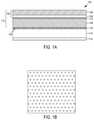
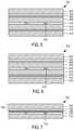
- FIG. 1Ais a schematic cross-sectional view of an exemplary microwave energy interactive structure
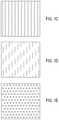
- FIGS. 1B-1Eschematically depict exemplary patterns of adhesive that may be used to form the construct of FIG. 1A ;
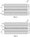
- FIG. 2is a schematic cross-sectional view of another exemplary microwave energy interactive structure
- FIG. 4Ais a schematic cross-sectional view of yet another exemplary microwave energy interactive structure
- FIG. 4Bis a schematic, partially cutaway, perspective view of a first side of a construct for heating, browning, and/or crisping a food item in a microwave oven, formed from the susceptor structure of FIG. 4A ;
- FIG. 4Cis a schematic, partially cutaway, perspective view of a second side of a construct for heating, browning, and/or crisping a food item in a microwave oven, formed from the susceptor structure of FIG. 4A ;
- FIG. 4Dis a schematic perspective view of a portion of the construct of FIGS. 4B and 4C , after sufficient exposure to microwave energy;
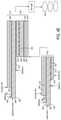
- FIG. 4Eis a diagram of an exemplary process for forming the structure and construct of FIGS. 4A-4D ;
- FIGS. 5-7are schematic cross-sectional views of exemplary microwave energy interactive insulating materials that may be used in the construct of FIGS. 4B and 4C ;
- FIG. 8Ais a schematic top plan view of an exemplary microwave heating construct including a plurality of microwave energy transparent areas.
- FIG. 8Bis a schematic cross-sectional view of a portion of the construct of FIG. 8A .
- FIG. 1Aschematically illustrates a cross-sectional view of a portion of susceptor structure 100 .
- the structure 100includes a susceptor film 102 , namely, a layer of microwave energy interactive material 104 (e.g., a first layer of microwave energy interactive material) supported on a polymer film 106 .
- the susceptor film 102is joined to a dimensionally stable, moisture-containing support layer 108 (e.g., a cellulose-based support such as paper or paperboard) using a substantially continuous layer of adhesive 110 to collectively define a supported susceptor film 112 .
- the supported susceptor film 112is joined to an adjoining layer 114 using a discontinuous layer of adhesive 116 .
- Another layer of microwave energy interactive material 118(e.g., a second layer of microwave energy interactive material) is disposed within the structure 100 on a side of the adjoining layer 114 opposite the first layer of microwave energy interactive material 104 .
- the second layer of microwave energy interactive material 118may be joined to the adjoining layer 114 as shown, or in other embodiments, one or more layers may be disposed between the second layer of microwave energy interactive material 118 and the adjoining layer 114 .
- the structure 100may include other layers, as will be discussed further below.
- the discontinuous layer of adhesive 116generally defines joined areas and unjoined areas between the moisture-containing layer 108 and the adjoining layer 114 .
- the unjoined areasmay be at least partially interconnected to define one or more passageways 120 that are in open communication with the exposed or open (e.g., unglued) peripheral edges of the adjacent layers 108 , 114 of the structure (not shown in FIG. 1A , see, e.g., FIGS. 4B and 4C ).
- the layers of microwave energy interactive material 104 , 118heat, thereby causing the moisture in the moisture-containing layer 108 to be converted into water vapor.
- the water vapormay be transported through the open areas 120 within the adhesive layer 116 (i.e., the areas not occupied by adhesive) to the exposed or unglued peripheral edges of the structure 100 , where the water vapor can be released.
- the various layers of the structure 100are able to remain laminated to one another.
- the present inventorshave found that where a continuous layer of adhesive is used, the layers tend to delaminate from one another during use.
- the discontinuous layer of adhesive 116may comprise a pattern of adhesive areas, a random (or seemingly random) arrangement of adhesive areas, or any other suitable adhesive configuration.
- the adhesive areasmay comprise discrete adhesive areas circumscribed by non-adhesive areas, which define the venting passageways 120 in the structure 100 .
- the adhesive areasmay be solid shapes, open shapes that enclose or circumscribe non-adhesive areas (e.g., an annulus), or any combination thereof.
- the adhesive areas of the discontinuous adhesive layer 116may be substantially circular in shape, such that the pattern of adhesive resembles a plurality of dots, for example, as shown in schematic top plan view in FIG. 1B .
- the adhesive “dots”may have any suitable size, spacing, and arrangement.
- the adhesivemay generally cover less than about 80% of the surface of adjoining layer 114 , and in some examples, the adhesive may cover less than about 75%, less than about 70%, less than about 65%, less than about 60%, less than about 55%, less than about 50%, less than about 45%, less than about 40%, or less than about 35% of the adjoining layer 114 .
- the adhesivemay cover from about 35% to about 80% of the adjoining layer 114 , for example, from about 45% to about 60% of the adjoining layer 114 , from about 34.9% to about 78.5% of the adjoining layer 114 .
- the degree of coverage for a particular heating applicationmay depend on numerous factors, including the level of venting needed to prevent delamination of the structure. For example, where multiple susceptor layers (e.g., layers 104 , 118 ) are used, more ventilation may be needed and the adhesive coverage area may be less than a similar structure including only one susceptor layer. Further, where the food item is to be seated on the susceptor structure, it has been determined that less adhesive may be needed where the food item has sufficient weight to assist with keeping the various layers of the susceptor structure intact.
- the adhesive dotsmay have a diameter of about 0.0625 in. (about 1.59 mm) and may be spaced about 0.0625 in. (about 1.59 mm) apart, such that the adhesive comprises about 78.5% of the total area of the structure.
- the adhesive dotsmay have a diameter of about 0.125 in. (about 3.18 mm) and may be spaced about 0.0625 in. (about 1.59 mm) apart, such that the adhesive comprises about 34.9% of the total area of the structure.
- countless other shapes, dimensions, and configurationsmay be used.
- the adjoining layer 114may be any material, for example, a polymer film, paper, or paperboard. Further, it will be understood that additional layers may be joined to the adjoining layer 114 if desired, as will be evident from the remaining discussion.
- FIGS. 2-4Aschematically depict some exemplary variations of the microwave energy interactive structure 100 of FIG. 1A .
- the various structures 200 , 300 , 400 , 800include features that are similar to structure 100 shown in FIG. 1A , except for variations noted and variations that will be understood by those of skill in the art.
- the reference numerals of similar featuresare preceded in the figures with a “2” ( FIG. 2 ), “3” ( FIG. 3 ), or “4” ( FIG. 4A ) instead of a “1”.
- the adjoining layer 214may be a moisture-containing layer, for example, paper or paperboard.
- the second layer of microwave energy interactive material 218may be joined to the adjoining layer 214 by a substantially continuous layer of adhesive 222 .
- the structure 200may include a second polymer film 224 on a side of the second layer of microwave energy interactive material 218 opposite the adhesive layer 222 to define a second susceptor film 202 ′.
- the outermost surface of the first polymer film 206 or the second polymer film 224may comprise a food-contacting surface of the respective film layer.
- Layers 214 , 218 , 222 , 224generally define a supported susceptor film 212 ′ similar to supported susceptor film 212 .
- the two supported susceptor films 212 , 212 ′are arranged with their respective moisture-containing layers 208 , 214 facing one another on opposite sides of the discontinuous layer of adhesive 216 , such that the structure 200 is generally symmetrical across the discontinuous layer of adhesive 216 .
- the water vapor from both moisture-containing layers 208 , 214may be transported from the interior of the structure 200 via the discontinuities 220 in the adhesive layer 216 .
- the adjoining layer 314may be a polymer film.
- the structure 300includes a second moisture-containing layer 322 joined to the second layer of microwave energy interactive material 318 with a substantially continuous layer of adhesive 324 .
- the outermost surface of polymer film 306may comprise a food-contacting surface of the structure 300 .
- Layers 314 , 318 , 322 , 324generally define a supported susceptor film 312 ′ similar to the supported susceptor film 312 .
- the two supported susceptor films 312 , 312 ′are in a “stacked” configuration and joined to one another by the discontinuous layer of adhesive 316 .
- FIG. 4schematically illustrates still another exemplary susceptor structure 400 .
- the structure 400includes a supported susceptor film 412 joined to a microwave energy interactive insulating material 422 using a discontinuous layer of adhesive 416 .
- the supported susceptor film 412comprises a susceptor layer 404 supported on a polymer film layer 406 to define a susceptor film 402 .
- the susceptor film 402is joined to a moisture-containing layer 408 (e.g., paperboard) with a substantially continuous layer of adhesive 410 .
- the microwave energy interactive insulating material 422includes a susceptor layer 418 supported on a first polymer film 424 , collectively forming a susceptor film 402 ′.
- the susceptor film 402 ′is joined to a moisture-containing substrate or support 426 (e.g., paper) using a substantially continuous layer of adhesive 428 , such that layers 418 , 424 , 426 , 428 define a supported susceptor film 412 ′ similar to supported susceptor film 412 .
- the microwave energy interactive insulating material 422also includes an adjoining layer 414 , in this example, a second polymer film 414 joined to the moisture-containing support 426 in a patterned configuration using an adhesive 430 or any other suitable fastening material or technique.
- the pattern of adhesive 430generally defines a plurality of non-adhesive areas surrounded by adhesive areas, such that a plurality of closed cells 432 are formed between the support 426 and the second polymer film 414 .
- the closed cells 432are operative for inflating or expanding upon sufficient exposure to microwave energy, as will be discussed further below.
- the pattern of adhesive 430may be a grid pattern, such that the closed cells 432 have a generally square shape.
- any suitable pattern of adhesion and shape of closed cells 432may be used.
- FIGS. 4B and 4Cschematically depict partial cutaway views of opposed first and second sides of an exemplary microwave energy interactive construct 434 formed (e.g., cut) from the susceptor structure 400 of FIG. 4A .
- the construct 434has a generally circular shape, and therefore may be referred to as a microwave energy interactive heating disk.
- the construct 434may be used for heating, browning, and/or crisping a generally circular food item, for example, a pizza, in a microwave oven.
- numerous other regular and irregular shapesare contemplated.
- the food item Fe.g., a pizza
- the food item Fmay be placed on a food-contacting surface 436 of the microwave energy interactive insulating material 422 (i.e., on the outermost surface of polymer film 424 , although it is contemplated that the construct 434 may be inverted and the outermost surface of polymer film 406 may comprise the food-contacting surface in other embodiments) and placed in a microwave oven. While not wishing to be bound by theory, it is believed that as the susceptor 418 (shown schematically with stippling in FIG.
- the resulting insulating material 422has a quilted or pillowed food-contacting side or surface 436 .
- the susceptor 418is urged towards the surface of the food item (e.g., the bottom surface of the food item F), to enhance browning and/or crisping, with the pillowed surface of the insulating material 422 being able to conform more closely to the contours of the food item.
- the expandable cells 432 of the insulating material 422may be brought into closer proximity with the domed area of the pizza, thereby providing enhanced browning and/or crisping as compared with a flat susceptor sheet.
- the water vapor and other gases trapped in the cells 432reduce the amount of heat transferred from the construct 434 to the microwave heating environment, thereby further enhancing heating, browning, and/or crisping of the food item F. Additional features of microwave energy interactive insulating materials are described in detail in U.S. Pat. Nos. 7,019,271, 7,351,942, and 7,923,669, each of which is incorporated by reference herein in its entirety.
- the cells 432When microwave heating has ceased, the cells 432 typically deflate and return to a somewhat flattened state having a somewhat wrinkled appearance (not shown).
- susceptor 404(shown schematically with stippling in FIG. 4C ) on the opposite side of the disk 434 converts at least a portion of the impinging microwave energy into thermal energy, which then can be transferred through the paperboard layer 408 towards the lower surface of the food item F to enhance browning and/or crisping even further. Any water vapor generated by the heating of the susceptor 404 can be released from the paperboard 408 and transported through the passageways 420 in the discontinuous adhesive layer 416 ( FIG. 4A ) to the exposed edges 438 of the construct 434 .
- a paperboard base material 408is unwound from a stock roll (not shown).
- An adhesive 410is applied to one side 440 of the paperboard 408 in a substantially continuous configuration.
- a susceptor film 402is then applied to the layer of adhesive 410 with the metal layer 404 of the susceptor film 402 facing the adhesive 410 to form the supported susceptor film 412 , which defines the second side of the construct 434 , shown in FIG. 4C .
- paper 426is unwound from a stock roll (not shown).
- a substantially continuous layer of adhesive 428is applied to a first side 442 of the paper 426 .
- a susceptor film 402 ′is then applied to the layer of adhesive 428 with the metal layer 418 of the susceptor film 402 ′ facing the adhesive 428 .
- An adhesive 430is then applied to the exposed side (i.e. the second side 444 ) of the paper 426 in a grid-like configuration.
- a polymer film 414is then applied to the adhesive 430 to define a plurality of substantially closed cells 432 between the paper 426 and the polymer film 414 . This forms the microwave energy interactive insulating material 422 on the first side of the construct ( FIG. 4B ).
- an adhesive 416is applied in a patterned configuration (e.g., a dot pattern or other pattern, such as, but not limited to, the adhesive patterns shown in FIGS. 1B-1E ) to the exposed side 446 of the paperboard 408 .
- the microwave energy interactive insulating material 422 formed previouslyis then applied to the layer of adhesive 416 to join the polymer film 414 to the paperboard 408 . This forms the first side (i.e., the food-contacting side) of the construct 434 ( FIG. 4B ).
- the webis then sent to a die cutter, where the construct 434 is cut into the desired shape, for example, a circle (e.g., FIGS. 4B and 4C ), square, oval triangle, or any other desired shape.
- a die cutterwhere the construct 434 is cut into the desired shape, for example, a circle (e.g., FIGS. 4B and 4C ), square, oval triangle, or any other desired shape.
- construct 434It will be apparent that numerous other sequences of steps may be used to form the construct 434 . It also will be apparent that numerous other microwave energy interactive insulating materials or structures may be used to form a construct in accordance with the disclosure. Any of such materials may be used alone or in combination, and in any configuration, to form the construct. Where multiple materials (or multiple layers of the same material) are used, the materials may be joined to one another partially or completely, or may remain separate from one another (i.e., unjoined).
- FIG. 5schematically illustrates another exemplary microwave energy interactive insulating material 522 that may be used instead of the microwave energy interactive insulating material 422 shown in FIGS. 4A-4D .
- the structure 522includes a polymer film layer 502 , a susceptor layer 504 , an adhesive layer 506 , and a paper layer 508 .
- the structure 500includes a second polymer film layer 510 , adhesive layer 512 , and paper layer 514 .
- the layersmay be adhered or affixed by a patterned adhesive 516 that defines a plurality of substantially closed, expandable cells 518 between the paper layers 508 , 514 .
- FIG. 6schematically illustrates yet another exemplary microwave energy interactive insulating material 622 that may be suitable for use instead of the insulating material 422 shown in FIGS. 4A-4D .
- the insulating material 622includes a pair of adjoined, symmetrical layer arrangements. If desired, the two symmetrical arrangements may be formed by folding one layer arrangement onto itself.
- the first symmetrical layer arrangementbegins at the top of the drawing, comprises a polymer film layer 602 , a susceptor layer 604 , an adhesive layer 606 , and a paper or paperboard layer 608 .
- the adhesive layer 606joins the polymer film 602 and the susceptor layer 604 to the paperboard layer 608 .
- the second symmetrical layer arrangementbeginning at the bottom of the drawing, also comprises a polymer film layer 610 , a susceptor layer 612 , an adhesive layer 614 , and a paper or paperboard layer 616 .
- a patterned adhesive layer 618is provided between the two paper layers 608 , 616 to define a plurality of closed cells 620 that are adapted to inflate when sufficiently exposed to microwave energy. While not wishing to be bound by theory, it is believed that the additional susceptor layer results in greater heating and expansion of the insulating cells, thereby providing more thermal insulation as compared with an insulating material having a single susceptor layer.
- each of the exemplary insulating materials previously describedinclude a moisture-containing layer (e.g. paper) that is believed to release at least a portion of the vapor that inflates the expandable cells.
- a moisture-containing layere.g. paper
- insulating structures without such moisture-containing layersalso may be used instead of the insulating material 422 shown in FIGS. 4A-4D to form the construct 434 (or any other construct).
- FIG. 7illustrates one example of an expandable cell insulating material 722 that inflates without the need for a moisture-containing layer, for example, paper.
- one or more reagentsare used to generate a gas that inflates the cells.
- a thin layer of microwave interactive material 702is supported on a first polymer film 704 to form a susceptor film 706 .
- One or more reagents 708lie adjacent at least a portion of the layer of microwave interactive material 702 .
- the reagent 708 coated susceptor film 706is joined to a second polymer film 710 using a patterned adhesive 712 or other material, or using thermal bonding, ultrasonic bonding, or any other suitable technique, such that closed cells 714 (shown as a void) are formed in the material 700 .
- the reagentsmay comprise sodium bicarbonate (NaHCO3) and a suitable acid. When exposed to heat, the reagents react to produce carbon dioxide.
- the reagentmay comprise a blowing agent.
- blowing agentsinclude, but are not limited to, p-p′-oxybis(benzenesulphonylhydrazide), azodicarbonamide, and p-toluenesulfonylsemicarbazide.
- blowing agentsthat may be suitable include, but are not limited to, p-p′-oxybis(benzenesulphonylhydrazide), azodicarbonamide, and p-toluenesulfonylsemicarbazide.
- numerous other reagents and released gasesare contemplated hereby.
- microwave energy interactive material 702heats upon impingement by microwave energy, water vapor or other gases are released from (or generated by) the reagent 708 , thereby exerting pressure on the susceptor film 706 on one side and the second polymer film 710 on the other side of the closed cells 714 , as discussed in connection with the various other insulating materials described above.
- the gas resulting from the reagentis sufficient both to inflate the expandable cells and to absorb any excess heat from the susceptor.
- Such materialsare described further in U.S. Pat. No. 7,868,274, which is incorporated by reference herein in its entirety.
- any of such structuresmay include one or more areas that are transparent to microwave energy.
- Such microwave energy transparent areastransmit microwave energy and, in some instances, may cause the formation of localized electric fields that enhance heating, browning, and/or crisping of an adjacent food item.
- the transparent areasmay be sized, positioned, and/or arranged to customize the heating, browning, and/or crisping of a particular area of the food item to be heated.
- FIG. 8Aschematically illustrates a top plan view of another microwave heating construct 800 (e.g., a microwave heating disk) that generally includes a susceptor 802 (shown schematically with stippling) that circumscribes a plurality of microwave energy transparent areas 804 , 806 (shown schematically in white).
- the disk 800has a substantially circular shape. However, any regular or irregular shape may be used.
- the disk 800includes a central region 808 and a peripheral region 810 .
- the microwave energy transparent areas 804are substantially circular in shape, with the concentration of microwave energy transparent areas 804 decreasing from the center of the disk 800 outwardly towards the peripheral region 810 .
- other configurationsare contemplated.
- another exemplary arrangement of microwave energy transparent areasis disclosed in U.S. Pat. Nos. 6,414,290 and 6,765,182, which are incorporated by reference herein in their entirety.
- the microwave energy transparent areas 806are substantially square in shape and arranged in rows and columns, such that the microwave energy interactive material in the peripheral region 810 has a grid-like appearance.
- the percent transparent areamay be varied as needed to achieve the desired heating, browning, and/or crisping of the food item.
- Such areasmay be formed in any suitable manner, as will be described below.
- FIG. 8Bschematically illustrates a cross-sectional view of a portion of the microwave heating disk 800 of FIG. 8A .
- the microwave heating disk 800includes a pair of microwave energy interactive elements 802 a , 802 b , for example, susceptors (or susceptor layers), supported on respective microwave energy transparent substrates 812 a , 812 b , for example, polymer film layers, to collectively define respective susceptor films or susceptor film layers 814 a , 814 b .
- Susceptor 802 acircumscribes at least one, and in some examples, a plurality, of microwave energy transparent (i.e., inactive) areas 804 (or 806 , FIG. 8A ).
- Each susceptoris joined respectively to a respective microwave energy transparent, dimensionally stable support or support layer 816 a , 816 b , for example, paper, using a respective substantially continuous adhesive layer 818 a , 818 b to define respective supported susceptor films 820 a , 820 b .
- the supported susceptor films 820 a , 820 bmay be joined to one another using a discontinuous layer of adhesive 822 (e.g., a dot pattern or other pattern, such as, but not limited to, the adhesive patterns shown in FIGS. 1B-1E ).
- support layer 816 bis joined to a double faced corrugated material 824 , which includes a plurality of flutes or corrugations 826 between facing layers 828 a , 828 b.
- the support layer 816 bis joined to the facing layer 828 a using a discontinuous layer of adhesive 830 .
- the layer of adhesive 830may be substantially continuous. While not wishing to be bound by theory, it is believed that some facing layers 828 a are somewhat textured and/or porous, which may allow water vapor to be vented from the support layer 816 b without causing delamination of the layers 816 b , 828 a.
- the support layer 816 b and discontinuous adhesive layer 830may be omitted, such that the susceptor film 814 b is joined directly to the facing layer 828 a .
- the layer of adhesive 818 b joining the susceptor film 814 b to the facing layer 828 amay be substantially continuous (as shown).
- microwave heating constructsare encompassed by the disclosure. Any of such structures or constructs may be formed from various materials, provided that the materials are substantially resistant to softening, scorching, combusting, or degrading at typical microwave oven heating temperatures, for example, at from about 250° F. to about 425° F.
- the materialsmay include microwave energy interactive materials, for example, those used to form susceptors and other microwave energy interactive elements, and microwave energy transparent or inactive materials, for example, those used to form the remainder of the construct.
- the microwave energy interactive materialmay be an electroconductive or semiconductive material, for example, a metal or a metal alloy provided as a metal foil; a vacuum deposited metal or metal alloy; or a metallic ink, an organic ink, an inorganic ink, a metallic paste, an organic paste, an inorganic paste, or any combination thereof.
- metals and metal alloysthat may be suitable include, but are not limited to, aluminum, chromium, copper, inconel alloys (nickel-chromium-molybdenum alloy with niobium), iron, magnesium, nickel, stainless steel, tin, titanium, tungsten, and any combination or alloy thereof.
- the microwave energy interactive materialmay comprise a metal oxide, for example, oxides of aluminum, iron, and tin, optionally used in conjunction with an electrically conductive material.
- a metal oxidefor example, oxides of aluminum, iron, and tin
- ITOindium tin oxide
- the microwave energy interactive materialmay comprise a suitable electroconductive, semiconductive, or non-conductive artificial dielectric or ferroelectric.
- Artificial dielectricscomprise conductive, subdivided material in a polymeric or other suitable matrix or binder, and may include flakes of an electroconductive metal, for example, aluminum.
- the constructalso may include a foil or high optical density evaporated material having a thickness sufficient to reflect a substantial portion of impinging microwave energy.
- a foil or high optical density evaporated materialhaving a thickness sufficient to reflect a substantial portion of impinging microwave energy.
- Such elementsare typically formed from a conductive, reflective metal or metal alloy, for example, aluminum, copper, or stainless steel, in the form of a solid “patch” generally having a thickness of from about 0.000285 inches to about 0.05 inches, for example, from about 0.0003 inches to about 0.03 inches.
- Other such elementsmay have a thickness of from about 0.00035 inches to about 0.020 inches, for example, 0.016 inches.
- microwave energy reflecting elementsmay be used where the food item is prone to scorching or drying out during heating and therefore, may be referred to as shielding elements. Smaller microwave energy reflecting elements may be used to diffuse or lessen the intensity of microwave energy. A plurality of smaller microwave energy reflecting elements also may be arranged to form a microwave energy directing element to direct microwave energy to specific areas of the food item. If desired, the loops may be of a length that causes microwave energy to resonate, thereby enhancing the distribution effect. Microwave energy distributing elements are described in U.S. Pat. Nos. 6,204,492, 6,433,322, 6,552,315, and 6,677,563, each of which is incorporated by reference in its entirety.
- any of the numerous microwave energy interactive elements described herein or contemplated herebymay be substantially continuous, that is, without substantial breaks or interruptions, or may be discontinuous, for example, by including one or more breaks or apertures that transmit microwave energy therethrough.
- the breaks or aperturesmay be sized and positioned to heat particular areas of the food item selectively.
- the breaks or aperturesmay extend through the entire structure, or only through one or more layers.
- the number, shape, size, and positioning of such breaks or aperturesmay vary for a particular application depending on the type of construct being formed, the food item to be heated therein or thereon, the desired degree of shielding, browning, and/or crisping, whether direct exposure to microwave energy is needed or desired to attain uniform heating of the food item, the need for regulating the change in temperature of the food item through direct heating, and whether and to what extent there is a need for venting.
- the aperturemay be a physical aperture or void in one or more layers or materials used to form the construct, or may be a non-physical “aperture” (not shown).
- a non-physical apertureis a microwave energy transparent area (e.g., microwave energy transparent areas 804 , 806 ) that allows microwave energy to pass through the structure without an actual void or hole cut through the structure.
- Such areasmay be formed by simply not applying microwave energy interactive material to the particular area, or by removing microwave energy interactive material in the particular area, or by mechanically deactivating the particular area (rendering the area electrically discontinuous).
- the areasmay be formed by chemically deactivating the microwave energy interactive material in the particular area, thereby transforming the microwave energy interactive material in the area into a substance that is transparent to microwave energy (i.e., microwave energy inactive). While both physical and non-physical apertures allow the food item to be heated directly by the microwave energy, a physical aperture also provides a venting function to allow steam or other vapors to escape from the interior of the construct.
- the arrangement of microwave energy interactive and microwave energy transparent areasmay be selected to provide various levels of heating, as needed or desired for a particular application. For example, where greater heating is desired, the total inactive (i.e., microwave energy transparent) area may be increased. In doing so, more microwave energy is transmitted to the food item. Alternatively, by decreasing the total inactive area, more microwave energy is absorbed by the microwave energy interactive areas, converted into thermal energy, and transmitted to the surface of the food item to enhance heating, browning, and/or crisping.
- Such areasmay be formed by forming these areas of the construct without a microwave energy interactive material, by removing any microwave energy interactive material that has been applied, or by deactivating the microwave energy interactive material in these areas, as discussed above.
- one or more panels, portions of panels, or portions of the constructmay be designed to be microwave energy inactive to ensure that the microwave energy is focused efficiently on the areas to be heated, browned, and/or crisped, rather than being lost to portions of the food item not intended to be browned and/or crisped or to the heating environment. This may be achieved using any suitable technique, such as those described above.
- the microwave energy interactive material(e.g., susceptors 104 , 118 , 204 , 218 , 304 , 318 , 404 , 418 , 504 , 604 , 612 , 702 , 802 a , 802 b ) may be supported on a microwave inactive or transparent substrate (e.g., polymer films 106 , 206 , 224 , 306 , 314 , 406 , 424 , 502 , 602 , 610 , 704 , 812 a , 812 b ) for ease of handling and/or to prevent contact between the microwave energy interactive material and the food item.
- a microwave inactive or transparent substratee.g., polymer films 106 , 206 , 224 , 306 , 314 , 406 , 424 , 502 , 602 , 610 , 704 , 812 a , 812 b
- the outermost surface of the polymer filmmay define at least a portion of the food-contacting surface of the package (e.g., surface 436 of polymer film 424 ).
- polymer filmsthat may be suitable include, but are not limited to, polyolefins, polyesters, polyamides, polyimides, polysulfones, polyether ketones, cellophanes, or any combination thereof.
- the polymer filmcomprises polyethylene terephthalate.
- the thickness of the filmgenerally may be from about 35 gauge to about 10 mil. In each of various examples, the thickness of the film may be from about 40 to about 80 gauge, from about 45 to about 50 gauge, about 48 gauge, or any other suitable thickness.
- Other non-conducting substrate materialssuch as paper and paper laminates, metal oxides, silicates, cellulosics, or any combination thereof, also may be used.
- the microwave energy interactive materialmay be applied to the substrate in any suitable manner, and in some instances, the microwave energy interactive material is printed on, extruded onto, sputtered onto, evaporated on, or laminated to the substrate.
- the microwave energy interactive materialmay be applied to the substrate in any pattern, and using any technique, to achieve the desired heating effect of the food item.
- the microwave energy interactive materialmay be provided as a continuous or discontinuous layer or coating including circles, loops, hexagons, islands, squares, rectangles, octagons, and so forth.
- the moisture-containing layercomprises paper having basis weight of from about 15 to about 60 lbs/ream (lb/3000 sq. ft.), for example, from about 20 to about 40 lbs/ream. In another example, the paper has a basis weight of about 25 lbs/ream. In another example, the moisture-containing layer comprises paperboard having a basis weight of from about 60 to about 330 lbs/ream, for example, from about 80 to about 140 lbs/ream.
- the paperboardgenerally may have a thickness of from about 6 to about 30 mils, for example, from about 12 to about 28 mils. In one particular example, the paperboard has a thickness of about 12 mils.
- Any suitable paperboardmay be used, for example, a solid bleached or solid unbleached sulfate board, such as SUS® board, commercially available from Graphic Packaging International.
- the packagemay be formed according to numerous processes known to those in the art, including using adhesive bonding, thermal bonding, ultrasonic bonding, mechanical stitching, or any other suitable process. Any of the various components used to form the package may be provided as a sheet of material, a roll of material, or a die cut material in the shape of the package to be formed (e.g., a blank).
- the microwave energy interactive elementmay have a grey or silver color that is visually distinguishable from the substrate or the support.
- the present disclosurecontemplates using a silver or grey toned adhesive to join the microwave energy interactive element to the support, using a silver or grey toned support to mask the presence of the silver or grey toned microwave energy interactive element, using a dark toned substrate, for example, a black toned substrate, to conceal the presence of the silver or grey toned microwave energy interactive element, overprinting the metallized side of the polymer film with a silver or grey toned ink to obscure the color variation, printing the non-metallized side of the polymer film with a silver or grey ink or other concealing color in a suitable pattern or as a solid color layer to mask or conceal the presence of the microwave energy interactive element, or any other suitable technique or combination of techniques.
- Two supported susceptor filmswere joined to one another with their respective paper support layers facing one another using a continuous layer of adhesive.
- the resulting structurewas heated without a load (i.e., without a food item) in a microwave oven for about 20 seconds.
- the layers of the structurebegan to delaminate and loft away from one another.
- the supported susceptor filmsthen were joined to one another with their respective paper support layers facing one another using a patterned adhesive.
- the patterned adhesiveconsisted of a dot pattern, where the dots had a diameter of about 0.125 in. and a spacing of about 0.0625 in.
- the resulting structurewas heated without a load (i.e., without a food item) in a microwave oven for about 20 seconds. The layers of the structure remained intact.
- a first supported susceptor film comprising a metalized polyethylene terephthalate film joined to paperboardwas pressed into a tray including a pair of elevated platforms.
- traysare described in U.S. Patent Application Publication Nos. US 2008/0164178 A1, published Jul. 10, 2008, and US 2008/0000896 A1, published Jan. 3, 2008, which are incorporated by reference herein in their entirety.
- the traywas used to heat a 10′′ Tombstone pizza in a microwave oven for about 5 minutes. The bottom crust of the pizza was browned and or crisped acceptably.
- a second traywas formed by joining a second supported susceptor film to the first supported susceptor film.
- the second supported susceptor filmincluded a metalized polyethylene terephthalate film joined to paper.
- the first and second supported susceptor filmswere joined to one another with the paperboard and paper layer facing one another using the dot adhesive pattern described in Example 1.
- the traywas used to heat a 10′′ Tombstone pizza in a microwave oven for about 5 minutes.
- the bottom crust of the pizzawas browned and or crisped exceptionally.
- the single susceptor trayproduced suitable results, the dual susceptor structure achieved superior browning and crisping of the pizza crust.
Landscapes
- Physics & Mathematics (AREA)
- Electromagnetism (AREA)
- Laminated Bodies (AREA)
- Cookers (AREA)
- Package Specialized In Special Use (AREA)
- Wrappers (AREA)
Abstract
Description
Claims (11)
Priority Applications (1)
| Application Number | Priority Date | Filing Date | Title |
|---|---|---|---|
| US16/256,207US11247433B2 (en) | 2008-11-12 | 2019-01-24 | Susceptor structure |
Applications Claiming Priority (5)
| Application Number | Priority Date | Filing Date | Title |
|---|---|---|---|
| US19898108P | 2008-11-12 | 2008-11-12 | |
| PCT/US2009/063963WO2010056696A2 (en) | 2008-11-12 | 2009-11-11 | Susceptor structure |
| US13/104,244US9162428B2 (en) | 2008-11-12 | 2011-05-10 | Susceptor structure |
| US14/843,176US10226910B2 (en) | 2008-11-12 | 2015-09-02 | Susceptor structure |
| US16/256,207US11247433B2 (en) | 2008-11-12 | 2019-01-24 | Susceptor structure |
Related Parent Applications (1)
| Application Number | Title | Priority Date | Filing Date |
|---|---|---|---|
| US14/843,176DivisionUS10226910B2 (en) | 2008-11-12 | 2015-09-02 | Susceptor structure |
Publications (2)
| Publication Number | Publication Date |
|---|---|
| US20190168483A1 US20190168483A1 (en) | 2019-06-06 |
| US11247433B2true US11247433B2 (en) | 2022-02-15 |
Family
ID=42170665
Family Applications (3)
| Application Number | Title | Priority Date | Filing Date |
|---|---|---|---|
| US13/104,244Active2032-12-18US9162428B2 (en) | 2008-11-12 | 2011-05-10 | Susceptor structure |
| US14/843,176Active2031-06-08US10226910B2 (en) | 2008-11-12 | 2015-09-02 | Susceptor structure |
| US16/256,207Active2031-05-01US11247433B2 (en) | 2008-11-12 | 2019-01-24 | Susceptor structure |
Family Applications Before (2)
| Application Number | Title | Priority Date | Filing Date |
|---|---|---|---|
| US13/104,244Active2032-12-18US9162428B2 (en) | 2008-11-12 | 2011-05-10 | Susceptor structure |
| US14/843,176Active2031-06-08US10226910B2 (en) | 2008-11-12 | 2015-09-02 | Susceptor structure |
Country Status (6)
| Country | Link |
|---|---|
| US (3) | US9162428B2 (en) |
| EP (1) | EP2346683B8 (en) |
| JP (1) | JP5302410B2 (en) |
| CA (1) | CA2741379C (en) |
| ES (1) | ES2675188T3 (en) |
| WO (1) | WO2010056696A2 (en) |
Families Citing this family (9)
| Publication number | Priority date | Publication date | Assignee | Title |
|---|---|---|---|---|
| EP2346683B8 (en) | 2008-11-12 | 2018-06-06 | Graphic Packaging International, LLC | Susceptor structure |
| EP2422137B1 (en)* | 2009-04-20 | 2018-09-19 | Graphic Packaging International, LLC | Multilayer susceptor structure |
| CA2786050C (en) | 2010-03-11 | 2015-06-16 | Graphic Packaging International, Inc. | Microwave heating package for frozen food items |
| US10251223B2 (en)* | 2015-05-20 | 2019-04-02 | Illinois Tool Works Inc. | Apparatus for providing customizable heat zones in an oven |
| WO2017117495A1 (en) | 2015-12-30 | 2017-07-06 | Graphic Packaging International, Inc. | Susceptor on a fiber reinforced film for extended functionality |
| US10464282B2 (en)* | 2016-01-21 | 2019-11-05 | GM Global Technology Operations LLC | Systems and processes for joining workpieces robustly using moguls and adhesive |
| EP3752357A4 (en)* | 2018-02-12 | 2021-12-22 | Graphic Packaging International, LLC | LAMINATE STRUCTURE, CONSTRUCTION AND PROCEDURE FOR YOUR USE |
| US20210321496A1 (en)* | 2018-08-30 | 2021-10-14 | Folia Water, Inc. | Food packaging articles including substrates with metal nanoparticles |
| USD1032377S1 (en) | 2022-08-05 | 2024-06-25 | Conagra Foods Rdm, Inc. | Microwave food pouch with tear strip vent |
Citations (85)
| Publication number | Priority date | Publication date | Assignee | Title |
|---|---|---|---|---|
| US3662139A (en) | 1970-03-04 | 1972-05-09 | Varian Associates | Cavity resonator having means for reducing leakage of r.f. energy at a covered access point |
| US4036088A (en) | 1976-08-30 | 1977-07-19 | Rolodex Corporation | Paper punch with variable spacing |
| US4398994A (en) | 1981-09-11 | 1983-08-16 | Beckett Donald E | Formation of packaging material |
| US4552614A (en) | 1984-06-18 | 1985-11-12 | Beckett Packaging Limited | Demetallizing method and apparatus |
| US4703148A (en) | 1986-10-17 | 1987-10-27 | General Mills, Inc. | Package for frozen foods for microwave heating |
| US4743488A (en) | 1986-10-31 | 1988-05-10 | Excello Specialty Company | Laminated article and method of forming the same |
| US4775771A (en) | 1987-07-30 | 1988-10-04 | James River Corporation | Sleeve for crisping and browning of foods in a microwave oven and package and method utilizing same |
| US4777053A (en) | 1986-06-02 | 1988-10-11 | General Mills, Inc. | Microwave heating package |
| US4865921A (en) | 1987-03-10 | 1989-09-12 | James Riker Corporation Of Virginia | Microwave interactive laminate |
| US4883936A (en) | 1988-09-01 | 1989-11-28 | James River Corporation | Control of microwave interactive heating by patterned deactivation |
| US4890439A (en) | 1988-11-09 | 1990-01-02 | James River Corporation | Flexible disposable material for forming a food container for microwave cooking |
| US4896009A (en) | 1988-07-11 | 1990-01-23 | James River Corporation | Gas permeable microwave reactive package |
| US4927991A (en) | 1987-11-10 | 1990-05-22 | The Pillsbury Company | Susceptor in combination with grid for microwave oven package |
| US4936935A (en) | 1988-05-20 | 1990-06-26 | Beckett Industries Inc. | Microwave heating material |
| WO1991009791A1 (en) | 1989-12-29 | 1991-07-11 | The Procter & Gamble Company | Microwave food package |
| US5038009A (en) | 1989-11-17 | 1991-08-06 | Union Camp Corporation | Printed microwave susceptor and packaging containing the susceptor |
| US5041295A (en) | 1987-07-06 | 1991-08-20 | The Pillsbury Company | Package for crisping the surface of food products in a microwave oven |
| JPH03205016A (en) | 1989-12-14 | 1991-09-06 | Meiwa Patsukusu:Kk | Exothermic material for microwave oven |
| US5053594A (en) | 1989-11-09 | 1991-10-01 | Rich-Seapak Processing Corporation | Cook and serve food package for the storing and heating by microwave energy of a food item |
| US5079397A (en) | 1987-11-18 | 1992-01-07 | Alcan International Limited | Susceptors for microwave heating and systems and methods of use |
| US5093364A (en) | 1988-08-24 | 1992-03-03 | Schering Agrochemicals Limited | 5-fluoroanthranilic fungicides |
| US5117078A (en) | 1990-02-02 | 1992-05-26 | Beckett Industries Inc. | Controlled heating of foodstuffs by microwave energy |
| US5170025A (en) | 1990-12-20 | 1992-12-08 | The Pillsbury Company | Two-sided susceptor structure |
| JPH0543705A (en) | 1991-08-13 | 1993-02-23 | Kanebo Ltd | Production of polyester solution |
| US5213902A (en) | 1991-02-19 | 1993-05-25 | Beckett Industries Inc. | Microwave oven package |
| US5220143A (en) | 1988-05-23 | 1993-06-15 | The Pillsbury Company | Susceptors having disrupted regions for differential heating in a microwave oven |
| US5221419A (en) | 1991-02-19 | 1993-06-22 | Beckett Industries Inc. | Method for forming laminate for microwave oven package |
| US5239153A (en) | 1988-11-28 | 1993-08-24 | Beckett Industries Inc. | Differential thermal heating in microwave oven packages |
| US5260537A (en) | 1991-06-17 | 1993-11-09 | Beckett Industries Inc. | Microwave heating structure |
| US5266386A (en) | 1991-02-14 | 1993-11-30 | Beckett Industries Inc. | Demetallizing procedure |
| US5278378A (en) | 1991-06-28 | 1994-01-11 | Beckett Industries Inc. | Microwave heating element with antenna structure |
| US5277954A (en) | 1992-08-13 | 1994-01-11 | W. L. Gore & Associates, Inc. | Adhesive-backed breathable layered materials |
| US5310977A (en) | 1989-02-03 | 1994-05-10 | Minnesota Mining And Manufacturing Company | Configured microwave susceptor |
| US5317120A (en) | 1991-06-28 | 1994-05-31 | The Proctor & Gamble Company | Microwave susceptor package having an apertured spacer between the susceptor and the food product |
| USRE34683E (en) | 1987-03-10 | 1994-08-02 | James River Corporation Of Virginia | Control of microwave interactive heating by patterned deactivation |
| US5334820A (en) | 1992-02-28 | 1994-08-02 | Golden Valley Microwave Foods Inc. | Microwave food heating package with accordion pleats |
| US5340436A (en) | 1991-02-14 | 1994-08-23 | Beckett Industries Inc. | Demetallizing procedure |
| US5354973A (en) | 1992-01-29 | 1994-10-11 | Beckett Industries Inc. | Microwave heating structure comprising an array of shaped elements |
| US5391864A (en) | 1991-07-16 | 1995-02-21 | Van Den Bergh Foods Company, Division Of Conopco, Inc. | Patterned susceptor for microwavable cookie dough |
| US5410135A (en) | 1988-09-01 | 1995-04-25 | James River Paper Company, Inc. | Self limiting microwave heaters |
| US5424517A (en) | 1993-10-27 | 1995-06-13 | James River Paper Company, Inc. | Microwave impedance matching film for microwave cooking |
| US5466917A (en) | 1991-06-05 | 1995-11-14 | Kabushiki Kaisha Kouransha | Microwave-absorptive heat-generating body and method for forming a heat-generating layer in a microwave-absorptive heat-generating body |
| US5519195A (en) | 1989-02-09 | 1996-05-21 | Beckett Technologies Corp. | Methods and devices used in the microwave heating of foods and other materials |
| US5527413A (en) | 1990-12-20 | 1996-06-18 | The Pillsbury Company | Temperature controlled susceptor structure |
| US5585027A (en) | 1994-06-10 | 1996-12-17 | Young; Robert C. | Microwave susceptive reheating support with perforations enabling change of size and/or shape of the substrate |
| US5628921A (en) | 1991-02-14 | 1997-05-13 | Beckett Technologies Corp. | Demetallizing procedure |
| JP3039410U (en) | 1997-01-09 | 1997-07-22 | 北越パッケージ株式会社 | Cooking aid for microwave oven |
| WO1998008752A2 (en) | 1996-08-26 | 1998-03-05 | Fort James Corporation | Microwavable package |
| US5759422A (en) | 1996-02-14 | 1998-06-02 | Fort James Corporation | Patterned metal foil laminate and method for making same |
| US5800724A (en) | 1996-02-14 | 1998-09-01 | Fort James Corporation | Patterned metal foil laminate and method for making same |
| US6114679A (en) | 1997-01-29 | 2000-09-05 | Graphic Packaging Corporation | Microwave oven heating element having broken loops |
| US6133560A (en) | 1997-02-12 | 2000-10-17 | Fort James Corporation | Patterned microwave oven susceptor |
| US6137099A (en) | 1994-11-17 | 2000-10-24 | Pak Pacific Corporation Pty., Ltd. | Food packaging for microwave cooking having a corrugated susceptor with fold lines |
| US6150646A (en) | 1996-08-26 | 2000-11-21 | Graphic Packaging Corporation | Microwavable container having active microwave energy heating elements for combined bulk and surface heating |
| US6204492B1 (en) | 1999-09-20 | 2001-03-20 | Graphic Packaging Corporation | Abuse-tolerant metallic packaging materials for microwave cooking |
| JP3079164U (en) | 2001-01-25 | 2001-08-10 | 明雄 劉 | Makeup box |
| US20010032843A1 (en) | 2000-03-10 | 2001-10-25 | Solveig Aronsson | Susceptor for heating a garnished flat dough in microwave oven |
| US6414290B1 (en) | 1998-03-19 | 2002-07-02 | Graphic Packaging Corporation | Patterned microwave susceptor |
| US6433322B2 (en) | 1999-09-20 | 2002-08-13 | Graphic Packaging Corporation | Abuse-tolerant metallic packaging materials for microwave cooking |
| US20030080119A1 (en) | 2001-10-29 | 2003-05-01 | Gary Chisholm | Semi-rigid hand-held food package |
| US6677563B2 (en) | 2001-12-14 | 2004-01-13 | Graphic Packaging Corporation | Abuse-tolerant metallic pattern arrays for microwave packaging materials |
| US20040023000A1 (en) | 2002-08-02 | 2004-02-05 | Robert C. Young | Microwave susceptor with fluid absorbent structure |
| US6717121B2 (en) | 2001-09-28 | 2004-04-06 | Graphic Packaging International, Inc. | Patterned microwave susceptor element and microwave container incorporating same |
| US20050230384A1 (en) | 2002-02-08 | 2005-10-20 | Robison Richard G | Microwave interactive flexible packaging |
| US20060049190A1 (en) | 2004-08-25 | 2006-03-09 | Middleton Scott W | Absorbent microwave interactive packaging |
| US7019271B2 (en) | 2002-02-08 | 2006-03-28 | Graphic Packaging International, Inc. | Insulating microwave interactive packaging |
| US20060157480A1 (en) | 2005-01-14 | 2006-07-20 | Lafferty Terrence P | Package for browning and crisping dough-based foods in a microwave oven |
| US20070039951A1 (en) | 2005-08-16 | 2007-02-22 | Cole Lorin R | Variable serving size insulated packaging |
| WO2007103428A2 (en) | 2006-03-09 | 2007-09-13 | Graphic Packaging International, Inc. | Susceptor with apertured support |
| US20070251943A1 (en) | 2002-02-08 | 2007-11-01 | Wnek Patrick H | Microwave energy interactive heating sheet |
| US20080000896A1 (en) | 2006-05-15 | 2008-01-03 | Lafferty Terrence P | Microwavable construct with contoured heating surface |
| US7365292B2 (en) | 2004-02-09 | 2008-04-29 | Graphic Packaging International, Inc. | Microwave cooking packages and methods of making thereof |
| US20080164178A1 (en) | 2006-05-15 | 2008-07-10 | Wnek Patrick H | Microwavable construct with contoured heating surface |
| US20080230537A1 (en) | 2007-03-23 | 2008-09-25 | Lafferty Terrence P | Susceptor with corrugated base |
| US20090032529A1 (en) | 2007-03-23 | 2009-02-05 | Lafferty Terrence P | Susceptor With Corrugated Base |
| US20090218338A1 (en) | 2006-10-16 | 2009-09-03 | Futzwater Kelly R | Elevated microwave heating construct |
| JP2009532088A (en) | 2006-03-31 | 2009-09-10 | グラフィック パッケージング インターナショナル インコーポレイテッド | Microwave components for heating, scorching, and crispy round groceries |
| JP2009532280A (en) | 2006-03-31 | 2009-09-10 | グラフィック パッケージング インターナショナル インコーポレイテッド | Structure to support food |
| WO2009114038A1 (en) | 2008-03-14 | 2009-09-17 | Graphic Packaging International, Inc. | Susceptor with corrugated base |
| US20090302032A1 (en) | 2008-06-09 | 2009-12-10 | Middleton Scott W | Microwave Energy Interactive Structure with Venting Microapertures |
| US20100012652A1 (en) | 2007-02-08 | 2010-01-21 | Cole Lorin R | Microwave Energy Interactive Insulating Sheet and System |
| US7868274B2 (en) | 2005-04-14 | 2011-01-11 | Graphic Packaging International, Inc. | Thermally activatable microwave interactive materials |
| US7982168B2 (en) | 2004-08-25 | 2011-07-19 | Graphic Packaging International, Inc. | Absorbent microwave interactive packaging |
| WO2011112770A2 (en) | 2010-03-11 | 2011-09-15 | Graphic Packaging International, Inc. | Microwave heating package for frozen food items |
| US9162428B2 (en) | 2008-11-12 | 2015-10-20 | Graphic Packaging International, Inc. | Susceptor structure |
Family Cites Families (4)
| Publication number | Priority date | Publication date | Assignee | Title |
|---|---|---|---|---|
| JPH0543705Y2 (en)* | 1987-07-03 | 1993-11-04 | ||
| JPH0339410A (en) | 1989-07-04 | 1991-02-20 | Nkk Corp | Metal refining furnace |
| JPH0379164A (en) | 1989-08-22 | 1991-04-04 | Toshiba Corp | Left and right pincushion distortion correction circuit |
| JP3039410B2 (en) | 1997-01-10 | 2000-05-08 | ダイキン工業株式会社 | Air conditioner wind direction adjustment device |
- 2009
- 2009-11-11EPEP09826640.6Apatent/EP2346683B8/enactiveActive
- 2009-11-11ESES09826640.6Tpatent/ES2675188T3/enactiveActive
- 2009-11-11JPJP2011536427Apatent/JP5302410B2/ennot_activeExpired - Fee Related
- 2009-11-11WOPCT/US2009/063963patent/WO2010056696A2/enactiveApplication Filing
- 2009-11-11CACA2741379Apatent/CA2741379C/enactiveActive
- 2011
- 2011-05-10USUS13/104,244patent/US9162428B2/enactiveActive
- 2015
- 2015-09-02USUS14/843,176patent/US10226910B2/enactiveActive
- 2019
- 2019-01-24USUS16/256,207patent/US11247433B2/enactiveActive
Patent Citations (102)
| Publication number | Priority date | Publication date | Assignee | Title |
|---|---|---|---|---|
| US3662139A (en) | 1970-03-04 | 1972-05-09 | Varian Associates | Cavity resonator having means for reducing leakage of r.f. energy at a covered access point |
| US4036088A (en) | 1976-08-30 | 1977-07-19 | Rolodex Corporation | Paper punch with variable spacing |
| US4398994A (en) | 1981-09-11 | 1983-08-16 | Beckett Donald E | Formation of packaging material |
| US4552614A (en) | 1984-06-18 | 1985-11-12 | Beckett Packaging Limited | Demetallizing method and apparatus |
| US4777053A (en) | 1986-06-02 | 1988-10-11 | General Mills, Inc. | Microwave heating package |
| US4703148A (en) | 1986-10-17 | 1987-10-27 | General Mills, Inc. | Package for frozen foods for microwave heating |
| US4743488A (en) | 1986-10-31 | 1988-05-10 | Excello Specialty Company | Laminated article and method of forming the same |
| USRE34683E (en) | 1987-03-10 | 1994-08-02 | James River Corporation Of Virginia | Control of microwave interactive heating by patterned deactivation |
| US4865921A (en) | 1987-03-10 | 1989-09-12 | James Riker Corporation Of Virginia | Microwave interactive laminate |
| US5041295A (en) | 1987-07-06 | 1991-08-20 | The Pillsbury Company | Package for crisping the surface of food products in a microwave oven |
| US4775771A (en) | 1987-07-30 | 1988-10-04 | James River Corporation | Sleeve for crisping and browning of foods in a microwave oven and package and method utilizing same |
| US4927991A (en) | 1987-11-10 | 1990-05-22 | The Pillsbury Company | Susceptor in combination with grid for microwave oven package |
| US5079397A (en) | 1987-11-18 | 1992-01-07 | Alcan International Limited | Susceptors for microwave heating and systems and methods of use |
| US4936935A (en) | 1988-05-20 | 1990-06-26 | Beckett Industries Inc. | Microwave heating material |
| US4963424A (en) | 1988-05-20 | 1990-10-16 | Beckett Industries Inc. | Microwave heating material |
| US5220143A (en) | 1988-05-23 | 1993-06-15 | The Pillsbury Company | Susceptors having disrupted regions for differential heating in a microwave oven |
| US4896009A (en) | 1988-07-11 | 1990-01-23 | James River Corporation | Gas permeable microwave reactive package |
| US5093364A (en) | 1988-08-24 | 1992-03-03 | Schering Agrochemicals Limited | 5-fluoroanthranilic fungicides |
| US4883936A (en) | 1988-09-01 | 1989-11-28 | James River Corporation | Control of microwave interactive heating by patterned deactivation |
| US5410135A (en) | 1988-09-01 | 1995-04-25 | James River Paper Company, Inc. | Self limiting microwave heaters |
| US4890439A (en) | 1988-11-09 | 1990-01-02 | James River Corporation | Flexible disposable material for forming a food container for microwave cooking |
| US5239153A (en) | 1988-11-28 | 1993-08-24 | Beckett Industries Inc. | Differential thermal heating in microwave oven packages |
| US5310977A (en) | 1989-02-03 | 1994-05-10 | Minnesota Mining And Manufacturing Company | Configured microwave susceptor |
| US5519195A (en) | 1989-02-09 | 1996-05-21 | Beckett Technologies Corp. | Methods and devices used in the microwave heating of foods and other materials |
| US5053594A (en) | 1989-11-09 | 1991-10-01 | Rich-Seapak Processing Corporation | Cook and serve food package for the storing and heating by microwave energy of a food item |
| US5038009A (en) | 1989-11-17 | 1991-08-06 | Union Camp Corporation | Printed microwave susceptor and packaging containing the susceptor |
| JPH03205016A (en) | 1989-12-14 | 1991-09-06 | Meiwa Patsukusu:Kk | Exothermic material for microwave oven |
| WO1991009791A1 (en) | 1989-12-29 | 1991-07-11 | The Procter & Gamble Company | Microwave food package |
| US5117078A (en) | 1990-02-02 | 1992-05-26 | Beckett Industries Inc. | Controlled heating of foodstuffs by microwave energy |
| US5170025A (en) | 1990-12-20 | 1992-12-08 | The Pillsbury Company | Two-sided susceptor structure |
| US5527413A (en) | 1990-12-20 | 1996-06-18 | The Pillsbury Company | Temperature controlled susceptor structure |
| US5628921A (en) | 1991-02-14 | 1997-05-13 | Beckett Technologies Corp. | Demetallizing procedure |
| US5672407A (en) | 1991-02-14 | 1997-09-30 | Beckett Technologies Corp. | Structure with etchable metal |
| US5266386A (en) | 1991-02-14 | 1993-11-30 | Beckett Industries Inc. | Demetallizing procedure |
| US5340436A (en) | 1991-02-14 | 1994-08-23 | Beckett Industries Inc. | Demetallizing procedure |
| US5221419A (en) | 1991-02-19 | 1993-06-22 | Beckett Industries Inc. | Method for forming laminate for microwave oven package |
| US5213902A (en) | 1991-02-19 | 1993-05-25 | Beckett Industries Inc. | Microwave oven package |
| US5466917A (en) | 1991-06-05 | 1995-11-14 | Kabushiki Kaisha Kouransha | Microwave-absorptive heat-generating body and method for forming a heat-generating layer in a microwave-absorptive heat-generating body |
| US5260537A (en) | 1991-06-17 | 1993-11-09 | Beckett Industries Inc. | Microwave heating structure |
| US5278378A (en) | 1991-06-28 | 1994-01-11 | Beckett Industries Inc. | Microwave heating element with antenna structure |
| US5317120A (en) | 1991-06-28 | 1994-05-31 | The Proctor & Gamble Company | Microwave susceptor package having an apertured spacer between the susceptor and the food product |
| US5391864A (en) | 1991-07-16 | 1995-02-21 | Van Den Bergh Foods Company, Division Of Conopco, Inc. | Patterned susceptor for microwavable cookie dough |
| JPH0543705A (en) | 1991-08-13 | 1993-02-23 | Kanebo Ltd | Production of polyester solution |
| US5354973A (en) | 1992-01-29 | 1994-10-11 | Beckett Industries Inc. | Microwave heating structure comprising an array of shaped elements |
| US5334820A (en) | 1992-02-28 | 1994-08-02 | Golden Valley Microwave Foods Inc. | Microwave food heating package with accordion pleats |
| US5277954A (en) | 1992-08-13 | 1994-01-11 | W. L. Gore & Associates, Inc. | Adhesive-backed breathable layered materials |
| US5424517A (en) | 1993-10-27 | 1995-06-13 | James River Paper Company, Inc. | Microwave impedance matching film for microwave cooking |
| US5585027A (en) | 1994-06-10 | 1996-12-17 | Young; Robert C. | Microwave susceptive reheating support with perforations enabling change of size and/or shape of the substrate |
| US6137099A (en) | 1994-11-17 | 2000-10-24 | Pak Pacific Corporation Pty., Ltd. | Food packaging for microwave cooking having a corrugated susceptor with fold lines |
| US5800724A (en) | 1996-02-14 | 1998-09-01 | Fort James Corporation | Patterned metal foil laminate and method for making same |
| US5759422A (en) | 1996-02-14 | 1998-06-02 | Fort James Corporation | Patterned metal foil laminate and method for making same |
| US6251451B1 (en) | 1996-08-26 | 2001-06-26 | Graphic Packaging Corporation | Microwavable package |
| WO1998008752A2 (en) | 1996-08-26 | 1998-03-05 | Fort James Corporation | Microwavable package |
| US6150646A (en) | 1996-08-26 | 2000-11-21 | Graphic Packaging Corporation | Microwavable container having active microwave energy heating elements for combined bulk and surface heating |
| US6455827B2 (en) | 1996-08-26 | 2002-09-24 | Graphic Packaging Corporation | Heating element for a microwavable package |
| JP3039410U (en) | 1997-01-09 | 1997-07-22 | 北越パッケージ株式会社 | Cooking aid for microwave oven |
| US6114679A (en) | 1997-01-29 | 2000-09-05 | Graphic Packaging Corporation | Microwave oven heating element having broken loops |
| US6133560A (en) | 1997-02-12 | 2000-10-17 | Fort James Corporation | Patterned microwave oven susceptor |
| EP0943558B1 (en) | 1998-03-19 | 2006-11-15 | Graphic Packaging International, Inc. | Patterned microwave susceptor |
| US6414290B1 (en) | 1998-03-19 | 2002-07-02 | Graphic Packaging Corporation | Patterned microwave susceptor |
| US6765182B2 (en) | 1998-03-19 | 2004-07-20 | Graphic Packaging International, Inc. | Patterned microwave susceptor |
| US6204492B1 (en) | 1999-09-20 | 2001-03-20 | Graphic Packaging Corporation | Abuse-tolerant metallic packaging materials for microwave cooking |
| US6433322B2 (en) | 1999-09-20 | 2002-08-13 | Graphic Packaging Corporation | Abuse-tolerant metallic packaging materials for microwave cooking |
| WO2001022778A1 (en) | 1999-09-20 | 2001-03-29 | Graphic Packaging Corporation | Abuse-tolerant metallic packaging materials for microwave cooking |
| US6552315B2 (en) | 1999-09-20 | 2003-04-22 | Graphic Packaging Corporation | Abuse-tolerant metallic packaging materials for microwave cooking |
| US20010032843A1 (en) | 2000-03-10 | 2001-10-25 | Solveig Aronsson | Susceptor for heating a garnished flat dough in microwave oven |
| JP3079164U (en) | 2001-01-25 | 2001-08-10 | 明雄 劉 | Makeup box |
| US6717121B2 (en) | 2001-09-28 | 2004-04-06 | Graphic Packaging International, Inc. | Patterned microwave susceptor element and microwave container incorporating same |
| US20030080119A1 (en) | 2001-10-29 | 2003-05-01 | Gary Chisholm | Semi-rigid hand-held food package |
| US6677563B2 (en) | 2001-12-14 | 2004-01-13 | Graphic Packaging Corporation | Abuse-tolerant metallic pattern arrays for microwave packaging materials |
| US8158914B2 (en) | 2002-02-08 | 2012-04-17 | Graphic Packaging International, Inc. | Microwave energy interactive heating sheet |
| US20070251943A1 (en) | 2002-02-08 | 2007-11-01 | Wnek Patrick H | Microwave energy interactive heating sheet |
| US7019271B2 (en) | 2002-02-08 | 2006-03-28 | Graphic Packaging International, Inc. | Insulating microwave interactive packaging |
| US20080087664A1 (en) | 2002-02-08 | 2008-04-17 | Robison Richard G | Microwave interactive flexible packaging |
| US7351942B2 (en) | 2002-02-08 | 2008-04-01 | Graphic Packaging International, Inc. | Insulating microwave interactive packaging |
| US7323669B2 (en) | 2002-02-08 | 2008-01-29 | Graphic Packaging International, Inc. | Microwave interactive flexible packaging |
| US20050230384A1 (en) | 2002-02-08 | 2005-10-20 | Robison Richard G | Microwave interactive flexible packaging |
| US20040023000A1 (en) | 2002-08-02 | 2004-02-05 | Robert C. Young | Microwave susceptor with fluid absorbent structure |
| US7365292B2 (en) | 2004-02-09 | 2008-04-29 | Graphic Packaging International, Inc. | Microwave cooking packages and methods of making thereof |
| US20060049190A1 (en) | 2004-08-25 | 2006-03-09 | Middleton Scott W | Absorbent microwave interactive packaging |
| US7982168B2 (en) | 2004-08-25 | 2011-07-19 | Graphic Packaging International, Inc. | Absorbent microwave interactive packaging |
| US20060157480A1 (en) | 2005-01-14 | 2006-07-20 | Lafferty Terrence P | Package for browning and crisping dough-based foods in a microwave oven |
| US7868274B2 (en) | 2005-04-14 | 2011-01-11 | Graphic Packaging International, Inc. | Thermally activatable microwave interactive materials |
| US20070039951A1 (en) | 2005-08-16 | 2007-02-22 | Cole Lorin R | Variable serving size insulated packaging |
| WO2007103428A2 (en) | 2006-03-09 | 2007-09-13 | Graphic Packaging International, Inc. | Susceptor with apertured support |
| US20070221666A1 (en) | 2006-03-09 | 2007-09-27 | Keefe Daniel J | Susceptor with apertured support |
| US7994456B2 (en) | 2006-03-31 | 2011-08-09 | Graphic Packaging International, Inc. | Construct for supporting food items |
| US8008609B2 (en) | 2006-03-31 | 2011-08-30 | Graphic Packaging International, Inc. | Microwavable construct for heating, browning, and crisping rounded food items |
| JP2009532088A (en) | 2006-03-31 | 2009-09-10 | グラフィック パッケージング インターナショナル インコーポレイテッド | Microwave components for heating, scorching, and crispy round groceries |
| JP2009532280A (en) | 2006-03-31 | 2009-09-10 | グラフィック パッケージング インターナショナル インコーポレイテッド | Structure to support food |
| US20080164178A1 (en) | 2006-05-15 | 2008-07-10 | Wnek Patrick H | Microwavable construct with contoured heating surface |
| US20080000896A1 (en) | 2006-05-15 | 2008-01-03 | Lafferty Terrence P | Microwavable construct with contoured heating surface |
| US20090218338A1 (en) | 2006-10-16 | 2009-09-03 | Futzwater Kelly R | Elevated microwave heating construct |
| US20100012652A1 (en) | 2007-02-08 | 2010-01-21 | Cole Lorin R | Microwave Energy Interactive Insulating Sheet and System |
| US20080230537A1 (en) | 2007-03-23 | 2008-09-25 | Lafferty Terrence P | Susceptor with corrugated base |
| US20090032529A1 (en) | 2007-03-23 | 2009-02-05 | Lafferty Terrence P | Susceptor With Corrugated Base |
| US8629380B2 (en) | 2007-03-23 | 2014-01-14 | Graphic Packaging International, Inc. | Susceptor with corrugated base |
| WO2009114038A1 (en) | 2008-03-14 | 2009-09-17 | Graphic Packaging International, Inc. | Susceptor with corrugated base |
| US20090302032A1 (en) | 2008-06-09 | 2009-12-10 | Middleton Scott W | Microwave Energy Interactive Structure with Venting Microapertures |
| US9162428B2 (en) | 2008-11-12 | 2015-10-20 | Graphic Packaging International, Inc. | Susceptor structure |
| WO2011112770A2 (en) | 2010-03-11 | 2011-09-15 | Graphic Packaging International, Inc. | Microwave heating package for frozen food items |
| US20110220640A1 (en) | 2010-03-11 | 2011-09-15 | Conatser Robert L | Microwave Heating Package for Frozen Food Items |
Non-Patent Citations (23)
| Title |
|---|
| Amendment A and Response to Office Action for U.S. Appl. No. 13/104,244 dated Dec. 3, 2014. |
| Amendment A and Response to Office Action for U.S. Appl. No. 14/843,176 dated Jun. 4, 2018. |
| Amendment B and Response to Final Office Action for U.S. Appl. No. 13/104,244 dated Jun. 25, 2015. |
| Amendment B and Response to Final Office Action for U.S. Appl. No. 14/843,176 dated Oct. 12, 2018. |
| Declaration of Terrence P. Lafferty dated May 10, 2011. |
| International Search Report and Written Opinion for PCT/US2008/077168 dated Apr. 22, 2009. |
| International Search Report and Written Opinion for PCT/US2011/027825 dated Nov. 30, 2011. |
| Issue Fee Transmittal Form for U.S. Appl. No. 14/843,176 dated Jan. 24, 2019. |
| Issue Notification for U.S. Appl. No. 13/104,244 dated Sep. 30, 2015. |
| Issue Notification for U.S. Appl. No. 14/843,176 dated Feb. 20, 2019. |
| Notice of Allowance and Fee(s) Due for U.S. Appl. No. 13/104,244 dated Jul. 16, 2015. |
| Notice of Allowance and Fee(s) Due for U.S. Appl. No. 14/843,176 dated Oct. 29, 2018. |
| Notification of Reason for Refusal for JP 2011-536427 dated Dec. 27, 2012, and English translation. |
| Office Action for U.S. Appl. No. 13/104,244 dated Mar. 25, 2015. |
| Office Action for U.S. Appl. No. 13/104,244 dated Mar. 7, 2014. |
| Office Action for U.S. Appl. No. 13/104,244 dated Sep. 3, 2014. |
| Office Action for U.S. Appl. No. 14/843,176 dated Apr. 25, 2018. |
| Office Action for U.S. Appl. No. 14/843,176 dated Dec. 8, 2017. |
| Office Action for U.S. Appl. No. 14/843,176 dated Jul. 31, 2018. |
| Part B Fee(s) Transmittal for U.S. Appl. No. 13/104,244 dated Sep. 15, 2015. |
| Request for Continued Examination (RCE) Transmittal for U.S. Appl. No. 14/843,176 dated Oct. 12, 2018. |
| Response to Election of Species for U.S. Appl. No. 14/843,176 dated Jan. 2, 2018. |
| Response to Election of Species Requirement for U.S. Appl. No. 13/104,244 dated May 1, 2014. |
Also Published As
| Publication number | Publication date |
|---|---|
| WO2010056696A3 (en) | 2010-07-22 |
| CA2741379A1 (en) | 2010-05-20 |
| JP5302410B2 (en) | 2013-10-02 |
| US20150375479A1 (en) | 2015-12-31 |
| US20190168483A1 (en) | 2019-06-06 |
| US20110240635A1 (en) | 2011-10-06 |
| US9162428B2 (en) | 2015-10-20 |
| EP2346683A4 (en) | 2015-03-18 |
| EP2346683A2 (en) | 2011-07-27 |
| EP2346683B1 (en) | 2018-04-25 |
| EP2346683B8 (en) | 2018-06-06 |
| WO2010056696A2 (en) | 2010-05-20 |
| ES2675188T3 (en) | 2018-07-09 |
| JP2012508660A (en) | 2012-04-12 |
| CA2741379C (en) | 2014-07-08 |
| US10226910B2 (en) | 2019-03-12 |
Similar Documents
| Publication | Publication Date | Title |
|---|---|---|
| US11247433B2 (en) | Susceptor structure | |
| US8866054B2 (en) | Microwave energy interactive heating sheet | |
| US8063344B2 (en) | Microwave energy interactive food package | |
| US8993947B2 (en) | Microwave energy interactive insulating sheet and system | |
| CA2719414C (en) | Self-venting microwave heating package | |
| US20090302032A1 (en) | Microwave Energy Interactive Structure with Venting Microapertures | |
| US20120217237A1 (en) | Multi-Compartment Microwave Heating Package | |
| US20090277899A1 (en) | Microwave energy interactive tray and wrap | |
| CA2659279A1 (en) | Construct for heating multiple food items in a microwave oven |
Legal Events
| Date | Code | Title | Description |
|---|---|---|---|
| AS | Assignment | Owner name:GRAPHIC PACKAGING INTERNATIONAL, INC., GEORGIA Free format text:ASSIGNMENT OF ASSIGNORS INTEREST;ASSIGNORS:LAFFERTY, TERRENCE P.;MIDDLETON, SCOTT W.;SIGNING DATES FROM 20110603 TO 20110606;REEL/FRAME:048122/0259 Owner name:GRAPHIC PACKAGING INTERNATIONAL, LLC, GEORGIA Free format text:CERTIFICATE OF CONVERSION;ASSIGNOR:GRAPHIC PACKAGING INTERNATIONAL, INC.;REEL/FRAME:048129/0443 Effective date:20171215 | |
| FEPP | Fee payment procedure | Free format text:ENTITY STATUS SET TO UNDISCOUNTED (ORIGINAL EVENT CODE: BIG.); ENTITY STATUS OF PATENT OWNER: LARGE ENTITY | |
| STPP | Information on status: patent application and granting procedure in general | Free format text:DOCKETED NEW CASE - READY FOR EXAMINATION | |
| AS | Assignment | Owner name:U.S. BANK NATIONAL ASSOCIATION, GEORGIA Free format text:SECURITY AGREEMENT;ASSIGNOR:GRAPHIC PACKAGING INTERNATIONAL, LLC;REEL/FRAME:055520/0204 Effective date:20210308 | |
| AS | Assignment | Owner name:BANK OF AMERICA, N.A., AS ADMINISTRATIVE AGENT, NORTH CAROLINA Free format text:SECURITY INTEREST;ASSIGNOR:GRAPHIC PACKAGING INTERNATIONAL, LLC;REEL/FRAME:055811/0676 Effective date:20210401 | |
| STPP | Information on status: patent application and granting procedure in general | Free format text:EX PARTE QUAYLE ACTION MAILED | |
| STPP | Information on status: patent application and granting procedure in general | Free format text:RESPONSE TO EX PARTE QUAYLE ACTION ENTERED AND FORWARDED TO EXAMINER | |
| STPP | Information on status: patent application and granting procedure in general | Free format text:NOTICE OF ALLOWANCE MAILED -- APPLICATION RECEIVED IN OFFICE OF PUBLICATIONS | |
| STPP | Information on status: patent application and granting procedure in general | Free format text:PUBLICATIONS -- ISSUE FEE PAYMENT VERIFIED | |
| STCF | Information on status: patent grant | Free format text:PATENTED CASE | |
| MAFP | Maintenance fee payment | Free format text:PAYMENT OF MAINTENANCE FEE, 4TH YEAR, LARGE ENTITY (ORIGINAL EVENT CODE: M1551); ENTITY STATUS OF PATENT OWNER: LARGE ENTITY Year of fee payment:4 |