US11247387B2 - Additive manufacturing system with platen having vacuum and air bearing - Google Patents
Additive manufacturing system with platen having vacuum and air bearingDownload PDFInfo
- Publication number
- US11247387B2 US11247387B2US16/557,228US201916557228AUS11247387B2US 11247387 B2US11247387 B2US 11247387B2US 201916557228 AUS201916557228 AUS 201916557228AUS 11247387 B2US11247387 B2US 11247387B2
- Authority
- US
- United States
- Prior art keywords
- platen
- holes
- vacuum
- sections
- substrate
- Prior art date
- Legal status (The legal status is an assumption and is not a legal conclusion. Google has not performed a legal analysis and makes no representation as to the accuracy of the status listed.)
- Active, expires
Links
Images


Classifications
- B—PERFORMING OPERATIONS; TRANSPORTING
- B29—WORKING OF PLASTICS; WORKING OF SUBSTANCES IN A PLASTIC STATE IN GENERAL
- B29C—SHAPING OR JOINING OF PLASTICS; SHAPING OF MATERIAL IN A PLASTIC STATE, NOT OTHERWISE PROVIDED FOR; AFTER-TREATMENT OF THE SHAPED PRODUCTS, e.g. REPAIRING
- B29C64/00—Additive manufacturing, i.e. manufacturing of three-dimensional [3D] objects by additive deposition, additive agglomeration or additive layering, e.g. by 3D printing, stereolithography or selective laser sintering
- B29C64/10—Processes of additive manufacturing
- B29C64/106—Processes of additive manufacturing using only liquids or viscous materials, e.g. depositing a continuous bead of viscous material
- B29C64/118—Processes of additive manufacturing using only liquids or viscous materials, e.g. depositing a continuous bead of viscous material using filamentary material being melted, e.g. fused deposition modelling [FDM]
- B—PERFORMING OPERATIONS; TRANSPORTING
- B29—WORKING OF PLASTICS; WORKING OF SUBSTANCES IN A PLASTIC STATE IN GENERAL
- B29C—SHAPING OR JOINING OF PLASTICS; SHAPING OF MATERIAL IN A PLASTIC STATE, NOT OTHERWISE PROVIDED FOR; AFTER-TREATMENT OF THE SHAPED PRODUCTS, e.g. REPAIRING
- B29C64/00—Additive manufacturing, i.e. manufacturing of three-dimensional [3D] objects by additive deposition, additive agglomeration or additive layering, e.g. by 3D printing, stereolithography or selective laser sintering
- B29C64/20—Apparatus for additive manufacturing; Details thereof or accessories therefor
- B29C64/205—Means for applying layers
- B29C64/209—Heads; Nozzles
- B—PERFORMING OPERATIONS; TRANSPORTING
- B29—WORKING OF PLASTICS; WORKING OF SUBSTANCES IN A PLASTIC STATE IN GENERAL
- B29C—SHAPING OR JOINING OF PLASTICS; SHAPING OF MATERIAL IN A PLASTIC STATE, NOT OTHERWISE PROVIDED FOR; AFTER-TREATMENT OF THE SHAPED PRODUCTS, e.g. REPAIRING
- B29C64/00—Additive manufacturing, i.e. manufacturing of three-dimensional [3D] objects by additive deposition, additive agglomeration or additive layering, e.g. by 3D printing, stereolithography or selective laser sintering
- B29C64/20—Apparatus for additive manufacturing; Details thereof or accessories therefor
- B29C64/227—Driving means
- B—PERFORMING OPERATIONS; TRANSPORTING
- B29—WORKING OF PLASTICS; WORKING OF SUBSTANCES IN A PLASTIC STATE IN GENERAL
- B29C—SHAPING OR JOINING OF PLASTICS; SHAPING OF MATERIAL IN A PLASTIC STATE, NOT OTHERWISE PROVIDED FOR; AFTER-TREATMENT OF THE SHAPED PRODUCTS, e.g. REPAIRING
- B29C64/00—Additive manufacturing, i.e. manufacturing of three-dimensional [3D] objects by additive deposition, additive agglomeration or additive layering, e.g. by 3D printing, stereolithography or selective laser sintering
- B29C64/20—Apparatus for additive manufacturing; Details thereof or accessories therefor
- B29C64/245—Platforms or substrates
- B—PERFORMING OPERATIONS; TRANSPORTING
- B29—WORKING OF PLASTICS; WORKING OF SUBSTANCES IN A PLASTIC STATE IN GENERAL
- B29C—SHAPING OR JOINING OF PLASTICS; SHAPING OF MATERIAL IN A PLASTIC STATE, NOT OTHERWISE PROVIDED FOR; AFTER-TREATMENT OF THE SHAPED PRODUCTS, e.g. REPAIRING
- B29C64/00—Additive manufacturing, i.e. manufacturing of three-dimensional [3D] objects by additive deposition, additive agglomeration or additive layering, e.g. by 3D printing, stereolithography or selective laser sintering
- B29C64/20—Apparatus for additive manufacturing; Details thereof or accessories therefor
- B29C64/295—Heating elements
- B—PERFORMING OPERATIONS; TRANSPORTING
- B29—WORKING OF PLASTICS; WORKING OF SUBSTANCES IN A PLASTIC STATE IN GENERAL
- B29C—SHAPING OR JOINING OF PLASTICS; SHAPING OF MATERIAL IN A PLASTIC STATE, NOT OTHERWISE PROVIDED FOR; AFTER-TREATMENT OF THE SHAPED PRODUCTS, e.g. REPAIRING
- B29C64/00—Additive manufacturing, i.e. manufacturing of three-dimensional [3D] objects by additive deposition, additive agglomeration or additive layering, e.g. by 3D printing, stereolithography or selective laser sintering
- B29C64/30—Auxiliary operations or equipment
- B29C64/364—Conditioning of environment
- B29C64/371—Conditioning of environment using an environment other than air, e.g. inert gas
- B—PERFORMING OPERATIONS; TRANSPORTING
- B29—WORKING OF PLASTICS; WORKING OF SUBSTANCES IN A PLASTIC STATE IN GENERAL
- B29C—SHAPING OR JOINING OF PLASTICS; SHAPING OF MATERIAL IN A PLASTIC STATE, NOT OTHERWISE PROVIDED FOR; AFTER-TREATMENT OF THE SHAPED PRODUCTS, e.g. REPAIRING
- B29C64/00—Additive manufacturing, i.e. manufacturing of three-dimensional [3D] objects by additive deposition, additive agglomeration or additive layering, e.g. by 3D printing, stereolithography or selective laser sintering
- B29C64/30—Auxiliary operations or equipment
- B29C64/379—Handling of additively manufactured objects, e.g. using robots
- B—PERFORMING OPERATIONS; TRANSPORTING
- B33—ADDITIVE MANUFACTURING TECHNOLOGY
- B33Y—ADDITIVE MANUFACTURING, i.e. MANUFACTURING OF THREE-DIMENSIONAL [3-D] OBJECTS BY ADDITIVE DEPOSITION, ADDITIVE AGGLOMERATION OR ADDITIVE LAYERING, e.g. BY 3-D PRINTING, STEREOLITHOGRAPHY OR SELECTIVE LASER SINTERING
- B33Y10/00—Processes of additive manufacturing
- B—PERFORMING OPERATIONS; TRANSPORTING
- B33—ADDITIVE MANUFACTURING TECHNOLOGY
- B33Y—ADDITIVE MANUFACTURING, i.e. MANUFACTURING OF THREE-DIMENSIONAL [3-D] OBJECTS BY ADDITIVE DEPOSITION, ADDITIVE AGGLOMERATION OR ADDITIVE LAYERING, e.g. BY 3-D PRINTING, STEREOLITHOGRAPHY OR SELECTIVE LASER SINTERING
- B33Y30/00—Apparatus for additive manufacturing; Details thereof or accessories therefor
- B—PERFORMING OPERATIONS; TRANSPORTING
- B33—ADDITIVE MANUFACTURING TECHNOLOGY
- B33Y—ADDITIVE MANUFACTURING, i.e. MANUFACTURING OF THREE-DIMENSIONAL [3-D] OBJECTS BY ADDITIVE DEPOSITION, ADDITIVE AGGLOMERATION OR ADDITIVE LAYERING, e.g. BY 3-D PRINTING, STEREOLITHOGRAPHY OR SELECTIVE LASER SINTERING
- B33Y40/00—Auxiliary operations or equipment, e.g. for material handling
- B33Y40/20—Post-treatment, e.g. curing, coating or polishing
- B—PERFORMING OPERATIONS; TRANSPORTING
- B33—ADDITIVE MANUFACTURING TECHNOLOGY
- B33Y—ADDITIVE MANUFACTURING, i.e. MANUFACTURING OF THREE-DIMENSIONAL [3-D] OBJECTS BY ADDITIVE DEPOSITION, ADDITIVE AGGLOMERATION OR ADDITIVE LAYERING, e.g. BY 3-D PRINTING, STEREOLITHOGRAPHY OR SELECTIVE LASER SINTERING
- B33Y40/00—Auxiliary operations or equipment, e.g. for material handling
Definitions
- the present disclosurerelates to additive manufacturing materials and techniques for printing parts.
- the present disclosurerelates to a 3D printing utilizing a platen that utilizes both vacuum to secure a substrate to the platen and an air bearing that causes the substrate to displace from the platen. All references disclosed herein are incorporated by reference.
- Additive manufacturingis generally a process in which a three-dimensional (3D) object is built by adding material to form a 3D part, rather than subtracting material as in traditional machining.
- a three-dimensional solid object of virtually any shapecan be printed from a digital model of the object by an additive manufacturing system, commonly referred to as a 3D printer.
- a typical additive manufacturing work flowincludes slicing a three-dimensional computer model into thin cross sections defining a series of layers, translating the result into two-dimensional position data, and transmitting the data to a 3D printer, which manufactures a three-dimensional structure in an additive build style.
- Additive manufacturingentails many different approaches to fabrication, including material extrusion, ink jetting, selective laser sintering, powder/binder jetting, electron-beam melting, electrophotographic imaging, and stereolithographic processes.
- Additive manufacturing technologiescan be used for prototyping (where it has been used for many years) and also for end-use production.
- end-use part productionit is desirable to print net-shape parts, or near-net shape parts (i.e., parts that match very closely to the digital image provided as a source data file, and therefore require little or no post-print processing to achieve the desired tolerances for the size and shape for the part).
- a 3D objectmay be printed from a digital representation of the printed part by extruding a viscous, flowable thermoplastic or filled thermoplastic material from a print head along tool paths at a controlled extrusion rate.
- the extruded flow of materialis deposited as a sequence of roads onto a substrate, where it fuses to previously deposited material and solidifies upon a drop in temperature.
- the print headincludes a liquefier that receives a supply of the thermoplastic material in the form of a flexible filament, and a nozzle tip for dispensing molten material.
- a filament drive mechanismengages the filament such as with a drive wheel and a bearing surface, or pair of toothed-wheels, and feeds the filament into the liquefier, where the filament is melted.
- the unmelted portion of the filamentessentially fills the diameter of the liquefier tube, providing a plug-flow type pumping action to extrude the molten filament material further downstream in the liquefier, from the tip to print a part, to form a continuous flow or tool path of resin material.
- the extrusion rateis unthrottled and is based on the feed rate of filament into the liquefier, and the filament is advanced at a feed rate calculated to achieve a targeted extrusion rate, such as is disclosed in Comb U.S. Pat. No. 6,547,995.
- the position of the print head relative to the substrateis incremented along an axis (perpendicular to the build plane) after each layer is formed, and the process is then repeated to form a printed part resembling the digital representation.
- a support structuremay be built utilizing the same deposition techniques by which the part material is deposited.
- a host computergenerates additional geometry acting as a support structure for the overhanging or free-space segments of the printed part being formed. Support material is then deposited pursuant to the generated geometry during the printing process. The support material adheres to the part material during fabrication and is removable from the completed printed part when the printing process is complete.
- a multi-axis additive manufacturing systemmay be utilized to print 3D parts using fused deposition modeling techniques.
- the multi-axis systemmay include a robotic arm movable in six degrees of freedom.
- the multi-axis systemmay also include a build platform movable in two or more degrees of freedom and independent of the movement of the robotic arm to position the 3D part being built, such as to counteract effects of gravity based upon part geometry.
- An extrudermay be mounted at an end of the robotic arm and may be configured to extrude material with a plurality of flow rates, wherein movement of the robotic arm and the build platform are synchronized with the flow rate of the extruded material to build the 3D part.
- the multiple axes of motioncan utilize complex tool paths for printing 3D parts, including single continuous 3D tool paths for up to an entire part, or multiple 3D tool paths configured to build a single part.
- Use of 3D tool pathscan reduce issues with traditional planar tool path 3D printing, such as stair-stepping (layer aliasing), seams, the requirement for supports, and the like.
- planar tool path 3D printingsuch as stair-stepping (layer aliasing), seams, the requirement for supports, and the like.
- the geometry of the partmay be used to determine the orientation of printing, as well as the routing for all toolpaths.
- materialmay be deposited in conformable 3D tool paths laid incrementally upon each other in nonplanar layers to form a printed part resembling the digital representation.
- Build surfaces and substratesare used in additive process modeling techniques to stabilize a 3D printed part as it is built and allow removal of the part when it is complete.
- a part or model under constructionbe strongly adhered to its modeling substrate, and the modeling substrate can be removable to remove the completed part from the machine.
- Strains generated within the modeling materialtend to warp the deposited structures unless the structures are supported in their correct orientation. Strong adherence to the substrate serves to prevent warpage and avoid localized shrinkage in foundation layers.
- there are external forces that act on the deposited structuressuch as pull from an extrusion nozzle, and centripetal acceleration on parts that are not stationary. Adherence of the printed part to the substrate must be sufficient to resist these forces.
- Delamination of a foundation layer from the substrate during the building of the objectcan result in a total failure in forming the object.
- the substratesince the substrate is a defining surface for the object being built, the substrate itself must be held in a well-defined configuration. Typically, it is desirable that the substrate be held in a configuration approximating a plane.
- a system for 3D printing a partincludes a platen having a platen surface including a plurality of holes therethrough and having an interior manifold in fluid communication with the plurality of holes, wherein the platen surface is configured to receive a build substrate.
- the systemincludes a vacuum source coupled to the manifold and configured to create a vacuum on the platen surface through the plurality of holes to thereby adhere a build substrate to the platen.
- the systemfurther includes a pressurized air source coupled to the manifold and configured to eject pressurized air through the plurality of holes so as to create an air bearing on the platen surface, to thereby facilitate removal of a build substrate and a printed part from the platen.
- a method for 3D printing a partincludes providing a platen having a platen surface including a plurality of holes therethrough and positioning a sheet substrate on the platen surface.
- the methodincludes pulling a vacuum through the one or more holes to secure the sheet substrate on the platen surface during part fabrication.
- the methodalso includes printing a part on the sheet substrate by moving a print head along a tool path and extruding material in the tool path.
- the methodincludes ejecting pressurized air through the one or more holes after the part is printed to create an air bearing on the platen surface beneath the substrate to facilitate removal of the printed part and sheet substrate from the platen surface.
- Directional orientationssuch as “above,” “below,” “top,” “bottom,” and the like are made with reference to a layer-printing direction of a 3D part.
- the layer-printing directionis the upward direction along the vertical z-axis.
- the terms “above,” “below,” “top,” “bottom,” and the likeare based on the vertical z-axis.
- the terms “above,” “below,” “top,” “bottom,” and the likeare relative to the given axis.
- providingsuch as for “providing a material,” when recited in the claims, is not intended to require any particular delivery or receipt of the provided item. Rather, the term “providing” is merely used to recite items that will be referred to in subsequent elements of the claim(s), for purposes of clarity and ease of readability.
- temperatures referred to hereinare based on atmospheric pressure (i.e. one atmosphere).
- near-net partrefers to a part that is printed so that it is very close to its final shape after the initial printing.
- a near-net partmatches closely to the digital image provided as a source data file, and therefore requires little or no post-print processing to achieve the desired tolerances for the size and shape for the part.
- outside ovenrefers to a build environment that is not enclosed within a temperature controlled environmental chamber, but is used and operated outside the confines of an environmental chamber.
- FIG. 1is a front view of an exemplary additive manufacturing system configured to print 3D parts on a build platen.
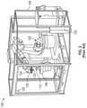
- FIG. 2is a perspective view of another exemplary additive manufacturing system configured to print 3D parts on a build platen.
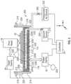
- FIG. 3is a simplified diagram of portions of an exemplary platen assembly configured for use as build platform in a 3D printing system.
- FIG. 4is a partial perspective view of an exemplary platen, showing one pivot bracket.
- FIG. 5is a partial top perspective view of an exemplary modular platen.
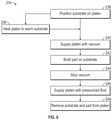
- FIG. 6is a diagram showing steps in an exemplary method of use of the disclosed platen system.
- the present disclosureis directed to an exemplary platen assembly configured for use as build platform in a 3D printing system, such as the hold and release platen system shown in FIG. 1 or 2 , for example.
- a vacuum systemis used to apply vacuum suction to a platen in order to secure a flexible substrate sheet in place during a 3D build.
- the flexible substrateis removable after the construction of the part is completed.
- the present disclosureovercomes these difficulties by presenting a platen system that includes both a vacuum source for securing a building substrate onto the platen surface and also a pressurized fluid source, such as pressurized air, for creating a fluid or air bearing that facilitates removal of the part and substrate from the platen surface.
- a pressurized fluid sourcesuch as pressurized air
- the presently described platen systemcan be used as platen 14 in the additive manufacturing system 10 of FIG. 1 or in place of the build platform in the multi-axis robotic build system 100 of FIG. 2 , for example.
- teachings of the described platen assemblycan also be incorporated into other build platforms, such as trunnion tables, rocking cradles, rail or gantry mounted motion platforms, and the like.
- FIG. 1is a schematic front view of an exemplary additive manufacturing system 10 .
- system 10is an extrusion-based additive manufacturing system for 3D printing or otherwise building parts and support structures using a layer-based, additive manufacturing technique, where the part can be printed from part material and support structures can be printed from support material.
- Suitable extrusion-based additive manufacturing systems for system 10include fused deposition modeling systems developed by Stratasys, Inc., Eden Prairie, Minn. under the trademark “FDM”.
- system 10includes chamber 12 , platen 14 , platen gantry 16 , print head 18 , head gantry 20 , and consumable assemblies 22 and 24 .
- Chamber 12is an enclosed environment that contains platen 14 and any printed objects 30 , 32 .
- Chamber 12can be heated (e.g., with circulating heated air) to reduce the rate at which the part and support materials solidify after being extruded and deposited.
- chamber 12can be omitted and/or replaced with different types of build environments. For example, parts can be built in a build environment that is open to ambient conditions or may be enclosed with alternative structures (e.g., flexible curtains).
- Platen 14is a platform on which printed parts 30 and support structures 32 are printed in a layer-by-layer manner.
- platen 14may also include a flexible polymeric film or liner on which the printed parts and support structures are printed, to allow for easy part separation from the platen.
- print head 18is a dual-tip extrusion head configured to receive consumable filaments from consumable assemblies 22 and 24 (e.g., via feed tube assemblies 26 and 28 ) for printing 3D part 30 and support structure 32 on platen 14 .
- Consumable assembly 22may contain a supply of a part material, such as a high-performance part material, for printing printed part 30 from the part material.
- Consumable assembly 24may contain a supply of a support material for printing support structure 32 from the given support material.
- Platen 14is supported by platen gantry 16 , which is a gantry assembly configured to move platen 14 along (or substantially along) a vertical z-axis.
- print head 18is supported by head gantry 20 , which is a gantry assembly configured to move print head 18 in (or substantially in) a horizontal x-y plane above chamber 12 .
- platen 14may be configured to move in the horizontal x-y plane within chamber 12 and print head 18 may be configured to move along the z-axis.
- Other similar arrangementsmay also be used such that one or both of platen 14 and print head 18 are moveable relative to each other over a desired number of degrees of freedom.
- Platen 14 and print head 18may also be oriented along different axes. For example, platen 14 may be oriented vertically and print head 18 may print printed part 30 and support structure 32 along the x-axis or the y-axis.
- the print head 18can have any suitable configuration.
- suitable devices for print head 18and the connections between print head 18 and head gantry 20 include those disclosed in Crump et al., U.S. Pat. No. 5,503,785; Swanson et al., U.S. Pat. No. 6,004,124; LaBoissiere, et al., U.S. Pat. Nos. 7,384,255 and 7,604,470; Leavitt, U.S. Pat. No. 7,625,200; Batchelder et al., U.S. Pat. No. 7,896,209; Comb et al., U.S. Pat. No. 8,153,182; Leavitt, U.S. Pat. No. 7,625,200; and Swanson et al., U.S. Pat. Nos. 8,419,996 and 8,647,102.
- System 10also includes controller 34 , which can include one or more control circuits configured to monitor and operate the components of system 10 .
- controller 34can communicate over communication line 36 with chamber 12 (e.g., with a heating unit for chamber 12 ), print head 18 , and various sensors, calibration devices, display devices, and/or user input devices.
- System 12 and/or controller 34can also communicate with computer 38 , which can include one or more discrete computer-based systems that communicate with system 12 and/or controller 34 , and may be separate from system 12 , or alternatively may be an internal component of system 12 .
- Computer 38includes computer-based hardware, such as data storage devices, processors, memory modules, and the like for generating and storing tool path and related printing instructions. Computer 38 may transmit these instructions to system 10 (e.g., to controller 34 ) to perform printing operations.
- a digital model representative of a 3D part to be printedcan be created, such as by scanning an existing 3D object to create a digital image file, or such as by creating a 3D model using a computer-aided design (CAD) program.
- the digital model and/or instructions for printing the modelcan be loaded into computer 38 .
- the computer 38can communicate with controller 34 , which serves to direct the system 10 to 3D print the part 30 and optionally, a support structure 32 .
- Part materialis deposited in layers along tool paths that build upon one another to form the part 30 .
- FIG. 2is a perspective view of a multi-axis robotic build system 100 that may be used for building three-dimensional (3D) parts utilizing two-dimensional tool paths, three-dimensional tool paths and combinations thereof.
- System 100includes in one embodiment a robotic arm 102 capable of movement along six axes.
- An exemplary robotic armis an industrial robot manufactured by KUKA Robotics of Augsburg, Germany. While six axes of motion are discussed for the robotic arm 102 from a stationary base, it should be understood that additional axes or other movements are also amenable to use with the embodiments of the present disclosure, without departing therefrom.
- the robotic arm 102could be mounted to move on a rail or a gantry to provide additional degrees of freedom.
- the robotic arm 102carries a print head 104 , such as, by way of example only and not by way of limitation, a print head similar to print head 18 described above, for printing parts from a filament feedstock.
- a build platform 106is provided, which in one embodiment is movable along two axes of rotation, rotation about the z-axis, and tilting (rotation) about the x-axis.
- a controller 108contains software and hardware for controlling the motion of the robotic arm 102 and the build platform 106 , as well as the printing operation of the print head 104 .
- a generated tool pathis utilized to control motion of the robotic arm 102 .
- control of the extrusion headis also used to accurately deposit material along the generated tool path.
- one embodiment of the present disclosuresynchronizes timing of the motion of the robotic arm 102 with print head 104 to extrusion from the print head 104 .
- Embodiments of the present disclosureprovide for speed up or slowdown of printing, changing the extrusion rate in conjunction with robotic movements, tip cleaning, tip changing, and other actions of the print head 104 based on the generated tool path and motion of the robotic arm 102 .
- extrusion from the print head 104may be synchronized with motion of the robotic arm 102 in manners taught by Comb et al. U.S. Pat. No. 6,054,077; and Comb U.S. Pat. Nos. 6,814,907, 6,547,995, and 6,814,907.
- the partmay be fabricated on a polymeric sheet substrate releasably adhered to a build platen.
- the polymeric sheet substrateacts as a foundation or base on which to begin extrusion of material.
- vacuum pressuremay be applied between the polymeric sheet substrate and the build platen to secure the sheet to the platen. After the part is formed, the vacuum pressure may be released.
- the size and/or weight of the formed part on the substratemay hinder removal of the substrate and part from the platen surface, and from the machine.
- the present disclosureis directed to a retention and release platen system 200 for use in an extrusion-based additive manufacturing system, such as exemplary systems 10 or 100 , to print or form 3D parts.
- a retention and release platen system 200for use in an extrusion-based additive manufacturing system, such as exemplary systems 10 or 100 , to print or form 3D parts.
- the system 10can be configured to build upon the disclosed platen of system 200 rather than platen 14 .
- the system 100can be configured to build upon the disclosed platen of system 200 rather than the illustrated build platform 106 .
- the platen system 200improves alignment and retention of a sheet substrate 208 to a build platen onto which a part 30 and if needed, associated support structures 32 , are built. After the printing process is complete, the system 200 allows for application of an air bearing to facilitate removal of the printed part 30 on the sheet substrate 208 from the build platen.
- FIG. 3is an exemplary embodiment of retention and release platen system 200 , shown in use with print head 18 and head gantry 20 driven by one or more x-y motors 204 .
- System 200is shown schematically as including a platen 114 , controller 34 , vacuum source 210 having a vacuum valve 250 , pressurized air source 222 having a pressurized fluid valve 252 , and an optional platen gantry 16 driven by a z-axis motor 202 .
- FIG. 3illustrates the printing of an exemplary part 30 on sheet substrate 208 , which is supported on platen 114 of retention and release platen system 200 .
- Sheet substrate 208is a flexible sheet formed of a polymeric material, such as nylon or acrylic, for example, as is described above.
- a non-limiting, exemplary sheet substrate 208is in the form an acrylic sheet having a thickness of about 0.06 inch.
- platen 114 of system 200has an outward-facing surface 212 configured as a build platform or a build table for retaining and supporting sheet substrate 208 .
- Platen 114further comprises an interior manifold 116 located beneath platen surface 212 .
- Manifold 116is coupled to vacuum source 210 , controlled by vacuum valve 250 (which can be activated to create a vacuum in response to signals from controller 34 ) and pressurized air source 222 , controlled by pressurized fluid valve 252 (which can be activated to produce an air bearing in response to signals from controller 34 ).
- Platen surface 212includes a plurality of holes 214 that expose sheet substrate 208 to the vacuum produced by vacuum source 210 and to the pressurized air supplied by pressurized air source 222 , which are alternately applied under control of the controller 34 .
- the vacuum source 210When the vacuum source 210 is activated, the sheet substrate adheres to the surface 212 under vacuum.
- the holesare sized to be small enough to enable the vacuum source to provide adequate suction to the corners of the substrate 208 , holding it in place.
- the pressurized air source 222is activated, an air bearing is created beneath the sheet substrate.
- each of holes 214is connected to a plurality of grooves 215 , and grooves 215 are arranged in a grid configuration that includes holes 214 .
- the vacuum and the pressurized airare applied at different times through the same network of grooves, holes and supply tubing.
- the vacuum and the pressurized airmay communicate through holes 214 to be distributed in the channels of grooves 215 under any object (such as sheet substrate 208 ), placed on platen surface 212 .
- separate sets of holes, grooves and/or supply tubingmay be used to supply the vacuum and the pressurized air.
- the vacuum produced by vacuum source 210assists in securing sheet substrate 208 to support surface 212 of platen 114 during printing or forming of the part 30 .
- controller 34will signal the vacuum source 210 to deactivate the vacuum, thereby releasing the vacuum hold-down force on substrate 208 , and the vacuum source can be isolated from the platen area via valving.
- platen 114also serves as an air-bearing platen through the introduction of pressurized air jets through the same holes 214 , but this time from pressurized air source 222 .
- the pressurized air source 222supplies a plurality of air jets via manifold 116 through holes 214 of platen surface 212 to create an air bearing between surface 212 of the platen 114 and the substrate 208 .
- An air bearingis a bearing that uses a thin film of pressurized gas to provide a low friction load-bearing interface between surfaces.
- the air bearing of the present inventionapplies a lifting force to the sheet substrate 208 to lessen the force required to oppose the frictional drag of moving a heavy part across the platen, such as in removing part 30 (and its sheet substrate 208 ) from the platen 114 after it is built.
- the plurality of air jetsare activated to thereby enable removal of the part 30 (and sheet substrate 208 ) from the platen 114 by an operator or robot (such as by sliding), using lesser force than would otherwise be required on an unpressurized platen.
- Such removal by air conveyancecan be further facilitated by tilting surface 212 to a non-horizontal position (such as is further described below), thereby allowing the sheet substrate 208 , assisted by the air bearing provided through holes 214 and pressurized air source 222 , to slide at an inclined angle off platen 114 , further assisting with the otherwise burdensome and manual removal of the large and/or bulky printed part.
- Provision of the air jets through holes 214reduces sliding friction between sheet substrate 208 and platen surface 212 .
- the velocity and/or pressure of air ejected through holes 214can be adjusted by controller 34 , taking into account factors such as the weight of part 30 .
- Provision of pressurized air from pressurized air source 222 to holes 214 in platen 114can be facilitated by suitable blowers of any configuration (not shown).
- the number and size of apertures 214 in platen surface 212 , and the spacing between the apertures 214may be selected to produce the both the desired vacuum suction, as well as the desired air pressure, on a bottom surface of sheet substrate 208 .
- platen 114is modular, in that it is formed from several platen sections 224 .
- the number and orientation of an assembly of such multiple platen sections 224can be selected based on the needs of a particular facility or a particular part build.
- each platen section 224is about two feet wide and about four feet deep.
- four such platen sections 224 a , 224 b , 224 c and 224 dare shown, with adjacent platen sections 224 being separated at joints 226 .
- the provision of modular platen sectionsallows for customization of the platen size for a particular part size being built. The allowance of a custom platen size enables optimization of the vacuum source requirement, providing for increased vacuum suction supply, minimized vacuum system sizing, increased air bearing pressure supply, and minimized air pressure supply requirements.
- each of the platen sections 224can be secured to a rail 228 via fasteners 230 in surface 212 .
- platen 114is formed of an aluminum alloy that evenly expands and contracts with the application of heat. Accordingly, in exemplary embodiments, securement of the platen sections 224 to rails 228 is configured to accommodate slight dimensional changes in the platen sections 224 and joints 226 .
- fasteners 230are set screws that are not overly tightened, in order to prevent buckling or warping.
- each platen section 224is provided with a plurality of holes 214 through surface 212 .
- a vacuummay be pulled downward through holes 214 by vacuum source 210 to secure any sheet substrate 208 or part 30 positioned above the platen 114 to the platen surface 212 .
- air jetsmay be expelled from the same holes 214 via pressurized air source 222 to assist in floating the bulk part 30 and sheet substrate 208 to facilitate their removal from platen surface 212 .
- the vacuum and pressurized airare provided through the same holes 214 in a platen surface 212 , and the vacuum system isolated from pressurized air system via valving.
- the platen sections 224are divided from each other by divider walls 232 (phantom lines) at joints 226 .
- each of the sections 224can be isolated from each of the other sections 224 .
- controller 34can be selected to control the application of a vacuum source 210 or pressurized air source 222 to only selected platen sections 224 for use in building a smaller part.
- platen 114further includes an optional platen heater 206 configured to heat a top surface 212 of platen 114 . This can soften a sheet substrate 208 to allow it to conform to the platen surface 212 more quickly and easily when a vacuum is pulled through the surface 212 .
- heater 206is modular and includes a plurality of heater sections. In one embodiment, the plurality of heater sections corresponds to the plurality of platen sections 224 in number and arrangement. Sections of heater 206 corresponding to the respective platen sections 224 can be turned on and off, and a temperature of each section 224 can be controlled independently of the other sections 224 .
- platen 114is not heated to more than 150 C.
- a gasket or seal 270(not shown) beneath the sheet substrate 208 to surround the top perimeter of the platen 114 or any portion thereof to temper the air flow as it leaves the air pipe/channel and better contact the substrate 208 .
- the platen 114may include a groove or grooves for receiving the gasket 270 .
- the gasket materialmay be elastomeric or rubbery, and would allow for better contact with the substrate material 208 after it is laid down on the platen 114 , and either air or vacuum is turned on. When an air flow is used, if hole sizes or air flow is too large or too high, the air may blow some portions of the substrate 208 more than others.
- the holes and air floware sized together to allow for good distribution of air flow underneath the substrate 208 , in order to float the substrate 208 and part 30 more easily across the platen surface 212 .
- the platenis configured to allow tilting to an inclined position, either automatically or manually, during unloading of a printed part.
- platen 114is configured as a cradle that is configured to tilt about the x axis, and the platen gantry is powered (additionally or alternatively) by a motor configured move the platen 114 about a pivot axis of the platen gantry.
- system 200further includes pivot brackets 216 , pivot pins 218 , and drive mechanisms 220 .
- Platen 114is mounted on pivot brackets 216 , which are configured to tilt platen surface 212 about pivot pins 218 .
- the surface 212 of platen 114is placed in an inclined position by tilting platen 114 about pivot pins 218 . Such tilting may be directed by controller 34 through drive mechanisms 220 . If desired, the use of a tilting platen mechanism, in combination with an air bearing, allows for easier sliding movement and removal of a heavy part from the machine onto a cart or conveyor system, after fabrication.
- Controller 34represents one or more control circuits comprising one or more processors that are configured to monitor and operate the components of system 200 to perform one or more functions or method steps described herein.
- one or more of the control functions performed by controller 34can be implemented in hardware, software, firmware, and the like, or a combination thereof.
- Controller 34may communicate over communication line with print head 18 , chamber 12 (e.g., with a heating unit for chamber 12 ), motors 202 and 204 , and various sensors, calibration devices, display devices, user input devices, and/or other components of the system 200 .
- Controller 34may also communicate with one or more of platen 114 , platen gantry 16 , head gantry 20 , and any other suitable component of system 200 , 10 or 100 . Descriptions pertaining to controller 34 also refer to controller 108 of FIG. 2 .
- the communication linemay include one or more electrical, optical, and/or wireless signal lines, allowing controller 34 to communicate with various components of system 200 .
- System 200 and/or controller 34may also communicate with one or more computer-based systems (not shown), which may include computer-based hardware, such as data storage devices, processors, memory modules, and the like for generating, storing, and transmitting tool path and related printing instructions to system 200 , 10 and/or 100 .
- controller 34may direct z-axis motor 202 and platen gantry 16 to move platen 114 to a predetermined height and/or tilted orientation. Controller 34 may then direct motors 204 and head gantry 20 to move print head 18 around in the horizontal x-y plane. Controller 34 may also direct devices in print head 18 to selectively draw successive segments of the consumable material from consumable assemblies.
- FIG. 6is a diagram showing steps in an exemplary method for use of the retention and release platen system 200 .
- Method 234begins with step 236 , which includes positioning sheet substrate 208 on surface 212 of platen 114 .
- Sheet substrate 208need not be a single sheet; rather, it can be provided in modular sections, such as those corresponding in size to platen sections 224 , for example, as long as vacuum and air pressure supply holes are positioned under each individual sheet.
- the number and arrangement of sheet substrate sectionscan be selected based on the shape and position of part 30 to be built thereon.
- sheet substrate sectionsneed not be positioned exactly over correspondingly sized platen sections 224 , as long as the substrate sections fully cover the portion of the platen sections 224 being used.
- Step 238is optional and includes heating platen 114 with platen heater 206 to warm the sheet substrate 208 , allowing it to better and/or more quickly conform to the platen surface 212 during the next step 240 .
- platen heater 206is in the form of a mica heater.
- a vacuumis pulled through holes 214 by vacuum source 210 .
- a 3D printing systemsuch as system 10 of FIG. 1 or system 100 of FIG. 2 is used to build a part 30 (and support structure 32 , if any) on sheet substrate 208 .
- each print head 18melts the successive segments of received consumable filament. The molten material is extruded and deposited onto platen 114 for 3D printing part 30 (and optionally, support structure 32 ) in a layer-by-layer manner.
- step 244after part completion, the vacuum from source 210 is turned off, and vacuum valve 250 is closed.
- valve 252 for pressurized air source 222is turned on to supply air pressure to platen surface 212 through holes 214 to form an air bearing under sheet substrate 208 .
- step 248with this air bearing assist, the completed part and sheet substrate are then slidably removed from platen 114 (by a user or using robotic automation).
- the pressurized air source 222can then be turned off and valve 252 closed.
- Part 30 and support structure 32may then be removed from substrate 208 , and support structure 32 removed from part 30 .
- the part 30may then undergo one or more additional post-processing steps.
- print head 18While this description sometimes mentions a single print head 18 , it is to be understood that multiple print heads 18 can be used in a single build.
- Suitable devices and techniques for print heads 18 and for retaining print heads 18are known, and include those disclosed in Swanson et al., U.S. Pat. Nos. 8,403,658 and 8,647,102. Descriptions pertaining to print head 18 and head gantry 20 also refer to print head 104 and robotic arm 102 of FIG. 2 . Examples of other suitable gantry assemblies for head gantry 20 include those disclosed in Comb et al., U.S. Pat. No. 9,108,360.
- platen 114may be configured to move in the horizontal x-y plane, and print head 18 may be configured to move along the z-axis, such as build system 10 of FIG. 1 .
- Other arrangementsmay also be used such that one or both of platen 114 and print head 18 are moveable relative to each other.
- the platenmay not need to move during the build operation (thus platen gantry 16 may be eliminated).
- Platen 114 and print head 18may also be oriented along different axes than as illustrated. For example, platen 114 may be oriented vertically during a print operation in a horizontal build configuration.
- multi-axis robotic build system 100is used to build a five foot long canoe out of FDM® Nylon 12CFTM, available from Stratasys, Inc. of Eden Prairie, Minn.
- a platen 114was made of eight configurable two foot by two foot platen sections 224 .
- a single axis rotation movement about pivot pins 218was set up to allow tilting of platen 114 .
- the platen 114was heated with platen heater 206 to a temperature of 70 C.
- a sheet substrate 208is made of Solvay Radel® polyphenylsulfone (PPSU).
- PPSUSolvay Radel® polyphenylsulfone
- a vacuum of 25 inches of mercury (Hg)was applied to the substrate 208 through holes 214 .
- the vacuum from vacuum source 210caused the substrate sheet 208 to seal into place on platen surface 212 .
- the canoe 30was printed and upon completion weighed about 150 pounds.
- the vacuum source 210 and platen heater 206were turned off.
- the canoe 30was allowed to cool completely, and valving 252 to an air pressure supply 222 was turned on manually, to an extent at which the canoe 30 was slightly cushioned from the surface 212 .
- the platen 114was rotated at a slight incline about pivot pins 218 , and the canoe was manually and easily slid off of the platen surface 212 and onto a portable cart.
Landscapes
- Engineering & Computer Science (AREA)
- Chemical & Material Sciences (AREA)
- Materials Engineering (AREA)
- Manufacturing & Machinery (AREA)
- Physics & Mathematics (AREA)
- Mechanical Engineering (AREA)
- Optics & Photonics (AREA)
- Health & Medical Sciences (AREA)
- Toxicology (AREA)
- Robotics (AREA)
- Environmental & Geological Engineering (AREA)
Abstract
Description
Claims (18)
Priority Applications (1)
| Application Number | Priority Date | Filing Date | Title |
|---|---|---|---|
| US16/557,228US11247387B2 (en) | 2018-08-30 | 2019-08-30 | Additive manufacturing system with platen having vacuum and air bearing |
Applications Claiming Priority (2)
| Application Number | Priority Date | Filing Date | Title |
|---|---|---|---|
| US201862725031P | 2018-08-30 | 2018-08-30 | |
| US16/557,228US11247387B2 (en) | 2018-08-30 | 2019-08-30 | Additive manufacturing system with platen having vacuum and air bearing |
Publications (2)
| Publication Number | Publication Date |
|---|---|
| US20200070405A1 US20200070405A1 (en) | 2020-03-05 |
| US11247387B2true US11247387B2 (en) | 2022-02-15 |
Family
ID=69642248
Family Applications (1)
| Application Number | Title | Priority Date | Filing Date |
|---|---|---|---|
| US16/557,228Active2039-11-27US11247387B2 (en) | 2018-08-30 | 2019-08-30 | Additive manufacturing system with platen having vacuum and air bearing |
Country Status (1)
| Country | Link |
|---|---|
| US (1) | US11247387B2 (en) |
Cited By (1)
| Publication number | Priority date | Publication date | Assignee | Title |
|---|---|---|---|---|
| US11718028B2 (en)* | 2019-10-23 | 2023-08-08 | Ivoclar Vivadent Ag | Stereolithography method |
Families Citing this family (14)
| Publication number | Priority date | Publication date | Assignee | Title |
|---|---|---|---|---|
| CA3136003A1 (en)* | 2019-04-04 | 2020-10-08 | Pektech Holdings Inc. | Automated part removal for additive manufacturing |
| ES2961161T3 (en)* | 2020-03-09 | 2024-03-08 | Airbus Operations Slu | One-piece manufacturing method |
| CN112793163A (en)* | 2020-12-15 | 2021-05-14 | 深圳市中汇强科技有限公司 | Material separation type plastic hot-melting type 3D printer material bearing table capable of turning materials up and down |
| US11485079B2 (en)* | 2020-12-22 | 2022-11-01 | Stratasys, Inc. | System for leveling heated platen in 3D printer |
| CN112817209B (en)* | 2020-12-28 | 2024-09-10 | 山东大学 | Stamping equipment capable of realizing special-shaped curved surface stamping and using method |
| CN113733555A (en)* | 2021-08-28 | 2021-12-03 | 西安交通大学 | A low-pressure 3D printing method and device for a high-performance polymer and its composite material |
| JP7014480B1 (en) | 2021-10-05 | 2022-02-01 | 株式会社写真化学 | Manufacturing method of stereolithography equipment and 3D modeling |
| JP7023555B1 (en)* | 2021-10-05 | 2022-02-22 | 株式会社写真化学 | Manufacturing method of stereolithography equipment and 3D modeling |
| CN113894529B (en)* | 2021-11-29 | 2022-09-13 | 深圳市合力士机电设备有限公司 | Press plate bearing press and operation method thereof |
| CN114103118B (en)* | 2021-11-30 | 2023-05-23 | 浙江机电职业技术学院 | Consumable pretreatment device for 3D printer |
| CN114209460A (en)* | 2021-12-31 | 2022-03-22 | 成都贝施美生物科技有限公司 | Processing method and device of personalized base station |
| CN114734627B (en)* | 2022-03-29 | 2024-06-14 | 南京焕型智剂医药科技有限公司 | Additive manufacturing equipment and supporting device thereof |
| CN116394512B (en)* | 2023-03-14 | 2024-10-25 | 重庆交通大学 | A 3D printing molding device and molding method |
| NL2037180B1 (en) | 2024-03-05 | 2025-09-15 | Demcon Newco 9 B V | Three dimensional (3d) printing system and method |
Citations (94)
| Publication number | Priority date | Publication date | Assignee | Title |
|---|---|---|---|---|
| GB816016A (en) | 1955-12-08 | 1959-07-08 | Hercules Powder Co Ltd | Improvements in or relating to melt spinning process and apparatus |
| US4567489A (en) | 1983-01-04 | 1986-01-28 | Obstfelder Guenther | Thermal printhead for thermographic printer |
| US4728392A (en) | 1984-04-20 | 1988-03-01 | Matsushita Electric Industrial Co., Ltd. | Ink jet printer and method for fabricating a nozzle member |
| US5121329A (en) | 1989-10-30 | 1992-06-09 | Stratasys, Inc. | Apparatus and method for creating three-dimensional objects |
| US5169081A (en) | 1989-02-04 | 1992-12-08 | Draftex Industries Limited | Strip handling apparatus and method |
| US5303141A (en) | 1991-01-03 | 1994-04-12 | International Business Machines Corporation | Model generation system having closed-loop extrusion nozzle positioning |
| US5312224A (en) | 1993-03-12 | 1994-05-17 | International Business Machines Corporation | Conical logarithmic spiral viscosity pump |
| US5370467A (en) | 1991-01-31 | 1994-12-06 | Citizen Watch Co., Ltd. | Print head for dot matrix printer |
| US5503785A (en) | 1994-06-02 | 1996-04-02 | Stratasys, Inc. | Process of support removal for fused deposition modeling |
| US5738817A (en) | 1996-02-08 | 1998-04-14 | Rutgers, The State University | Solid freeform fabrication methods |
| US5764521A (en) | 1995-11-13 | 1998-06-09 | Stratasys Inc. | Method and apparatus for solid prototyping |
| US5866058A (en) | 1997-05-29 | 1999-02-02 | Stratasys Inc. | Method for rapid prototyping of solid models |
| US5939008A (en) | 1998-01-26 | 1999-08-17 | Stratasys, Inc. | Rapid prototyping apparatus |
| US5968561A (en) | 1998-01-26 | 1999-10-19 | Stratasys, Inc. | High performance rapid prototyping system |
| US6004124A (en) | 1998-01-26 | 1999-12-21 | Stratasys, Inc. | Thin-wall tube liquifier |
| US6022207A (en) | 1998-01-26 | 2000-02-08 | Stratasys, Inc. | Rapid prototyping system with filament supply spool monitoring |
| US6054077A (en) | 1999-01-11 | 2000-04-25 | Stratasys, Inc. | Velocity profiling in an extrusion apparatus |
| US6067480A (en) | 1997-04-02 | 2000-05-23 | Stratasys, Inc. | Method and apparatus for in-situ formation of three-dimensional solid objects by extrusion of polymeric materials |
| US6070107A (en) | 1997-04-02 | 2000-05-30 | Stratasys, Inc. | Water soluble rapid prototyping support and mold material |
| US6085957A (en) | 1996-04-08 | 2000-07-11 | Stratasys, Inc. | Volumetric feed control for flexible filament |
| US6129872A (en) | 1998-08-29 | 2000-10-10 | Jang; Justin | Process and apparatus for creating a colorful three-dimensional object |
| US6193923B1 (en) | 1995-09-27 | 2001-02-27 | 3D Systems, Inc. | Selective deposition modeling method and apparatus for forming three-dimensional objects and supports |
| US6228923B1 (en) | 1997-04-02 | 2001-05-08 | Stratasys, Inc. | Water soluble rapid prototyping support and mold material |
| US6257517B1 (en) | 1999-08-10 | 2001-07-10 | Sandvik Steel Co. | Method and apparatus for feeding welding wire |
| US6547995B1 (en) | 2001-09-21 | 2003-04-15 | Stratasys, Inc. | Melt flow compensation in an extrusion apparatus |
| US6644703B1 (en)* | 1999-08-25 | 2003-11-11 | Core Flow Ltd. | Self-adaptive vacuum gripping system |
| US6645412B2 (en) | 1999-04-20 | 2003-11-11 | Stratasys, Inc. | Process of making a three-dimensional object |
| US6685866B2 (en) | 1999-06-23 | 2004-02-03 | Stratasys, Inc. | Method and apparatus for three-dimensional modeling |
| US6722872B1 (en) | 1999-06-23 | 2004-04-20 | Stratasys, Inc. | High temperature modeling apparatus |
| US6730252B1 (en) | 2000-09-20 | 2004-05-04 | Swee Hin Teoh | Methods for fabricating a filament for use in tissue engineering |
| US20040084814A1 (en)* | 2002-10-31 | 2004-05-06 | Boyd Melissa D. | Powder removal system for three-dimensional object fabricator |
| US6749414B1 (en) | 2001-04-30 | 2004-06-15 | Stratasys, Inc. | Extrusion apparatus for three-dimensional modeling |
| US6790403B1 (en) | 1999-04-20 | 2004-09-14 | Stratasys, Inc. | Soluble material and process for three-dimensional modeling |
| US6814907B1 (en) | 2001-12-18 | 2004-11-09 | Stratasys, Inc. | Liquifier pump control in an extrusion apparatus |
| US6869559B2 (en) | 2003-05-05 | 2005-03-22 | Stratasys, Inc. | Material and method for three-dimensional modeling |
| US20050129941A1 (en) | 2001-09-21 | 2005-06-16 | Stratasys, Inc. | High-precision modeling filament |
| US20050142846A1 (en)* | 2003-12-31 | 2005-06-30 | Microfabrica Inc. | Method and apparatus for maintaining parallelism of layers and/or achieving desired thicknesses of layers during the electrochemical fabrication of structures |
| US20070003656A1 (en) | 2005-07-01 | 2007-01-04 | Stratasys, Inc. | Rapid prototyping system with controlled material feedstock |
| JP2007098948A (en) | 2005-09-30 | 2007-04-19 | Three D Syst Inc | Rapid prototyping and manufacturing system and method |
| US7236166B2 (en) | 2005-01-18 | 2007-06-26 | Stratasys, Inc. | High-resolution rapid manufacturing |
| US20070228590A1 (en) | 2006-04-03 | 2007-10-04 | Stratasys, Inc. | Single-motor extrusion head having multiple extrusion lines |
| US20080121172A1 (en) | 2002-12-03 | 2008-05-29 | Kritchman Eliahu M | System and method for printing of three-dimensional objects |
| US20080169585A1 (en) | 2007-01-12 | 2008-07-17 | Stratasys, Inc. | Surface-treatment method for rapid-manufactured three-dimensional objects |
| US20080213419A1 (en) | 2007-02-12 | 2008-09-04 | Stratasys, Inc. | Viscosity pump for extrusion-based deposition systems |
| US20090020901A1 (en) | 2007-07-04 | 2009-01-22 | Envisiontec Gmbh | Process and device for producing a three-dimensional object |
| US20090035405A1 (en) | 2007-07-31 | 2009-02-05 | Stratasys, Inc. | Extrusion head for use in extrusion-based layered deposition modeling |
| US20090101278A1 (en) | 2007-10-17 | 2009-04-23 | Louis Laberge-Lebel | Methods for preparing freeform three-dimensional structures |
| US20090263582A1 (en) | 2008-04-18 | 2009-10-22 | Stratasys, Inc. | Digital manufacturing with amorphous metallic alloys |
| US20090273122A1 (en) | 2008-04-30 | 2009-11-05 | Stratasys, Inc. | Liquefier assembly for use in extrusion-based digital manufacturing systems |
| US20090274540A1 (en) | 2008-04-30 | 2009-11-05 | Stratasys, Inc. | Filament drive mechanism for use in extrusion-based digital manufacturing systems |
| US20100005987A1 (en) | 2008-07-09 | 2010-01-14 | Matan Digital Printers Ltd. | Reversible printing table |
| JP2010510100A (en) | 2006-11-22 | 2010-04-02 | イーオーエス ゲゼルシャフト ミット ベシュレンクテル ハフツング イレクトロ オプティカル システムズ | Apparatus and method for layered manufacturing of three-dimensional objects |
| US20100100224A1 (en) | 2008-10-21 | 2010-04-22 | Stratasys, Inc. | Adjustable head mount for digital manufacturing system |
| US20100096485A1 (en) | 2008-10-22 | 2010-04-22 | Stratasys, Inc. | Filament guide mechanism for filament spool container |
| US20100096489A1 (en) | 2008-10-22 | 2010-04-22 | Stratasys, Inc. | Filament spool |
| US20100096072A1 (en) | 2008-10-17 | 2010-04-22 | Stratasys, Inc. | Support material for digital manufacturing systems |
| US20100161105A1 (en) | 2008-12-22 | 2010-06-24 | Stratasys, Inc. | Combined process for building three-dimensional models |
| US20100283172A1 (en) | 2008-01-08 | 2010-11-11 | Stratasys, Inc. | Consumable assembly for use in extrusion-based layered deposition systems |
| US20100327479A1 (en) | 2009-06-23 | 2010-12-30 | Stratasys, Inc. | Consumable materials having customized characteristics |
| US20110054663A1 (en) | 2009-09-02 | 2011-03-03 | Sony Corporation | Three-dimensional modeling apparatus, method of producing a three-dimensional object, and three-dimensional object |
| US20110076496A1 (en) | 2009-09-30 | 2011-03-31 | Stratasys, Inc. | Non-cylindrical filaments for use in extrusion-based digital manufacturing systems |
| US20110076495A1 (en) | 2009-09-30 | 2011-03-31 | Stratasys, Inc. | Consumable materials having topographical surface patterns for use in extrusion-based digital manufacturing systems |
| US20110074065A1 (en) | 2009-09-30 | 2011-03-31 | Stratasys, Inc. | Ribbon liquefier for use in extrusion-based digital manufacturing systems |
| US7936351B2 (en) | 2006-12-14 | 2011-05-03 | Institute For Information Industry | Apparatus, method, and computer readable medium thereof capable of pre-storing data for generating self-shadow of a 3D object |
| US20110117268A1 (en) | 2009-11-19 | 2011-05-19 | Stratasys, Inc. | Consumable materials having encoded markings for use with direct digital manufacturing systems |
| US20110121476A1 (en) | 2009-11-19 | 2011-05-26 | Stratasys, Inc. | Encoded consumable materials and sensor assemblies for use in additive manufacturing systems |
| US8033811B2 (en) | 2008-07-25 | 2011-10-11 | Stratasys, Inc. | Pantograph assembly for digital manufacturing system |
| DE102010015451A1 (en) | 2010-04-17 | 2011-10-20 | Voxeljet Technology Gmbh | Method and device for producing three-dimensional objects |
| US8075300B2 (en) | 2008-06-30 | 2011-12-13 | Stratasys, Inc. | Vapor smoothing surface finishing system |
| US20120046779A1 (en) | 2010-08-18 | 2012-02-23 | Charles Pax | Automated 3d build processes |
| US8123999B2 (en) | 2002-04-17 | 2012-02-28 | Stratasys, Inc. | Smoothing method for layered deposition modeling |
| US20120068378A1 (en) | 2010-09-22 | 2012-03-22 | Stratasys, Inc. | Method for building three-dimensional models with extrusion-based additive manufacturing systems |
| US20120067501A1 (en) | 2010-09-21 | 2012-03-22 | The Boeing Company | Continuous Linear Production in a Selective Laser Sintering System |
| WO2012037329A2 (en) | 2010-09-17 | 2012-03-22 | Stratasys, Inc. | Semi-crystalline consumable materials for use in extrusion-based additive manufacturing systems |
| US20120070523A1 (en) | 2010-09-22 | 2012-03-22 | Stratasys, Inc. | Liquefier assembly for use in extrusion-based additive manufacturing systems |
| US20120105903A1 (en) | 2010-08-18 | 2012-05-03 | Pettis Nathaniel B | Networked three-dimensional printing |
| US20120164256A1 (en) | 2010-12-22 | 2012-06-28 | Stratasys, Inc. | Print head assembly and print head for use in fused deposition modeling system |
| US20120164330A1 (en) | 2010-12-22 | 2012-06-28 | Stratasys, Inc. | Method of using print head assembly in fused deposition modeling system |
| US20120162314A1 (en) | 2010-12-22 | 2012-06-28 | Stratasys, Inc. | Print head assembly for use in fused deposition modeling system |
| WO2012100297A1 (en) | 2011-01-26 | 2012-08-02 | Zydex Pty Ltd | A device for making an object |
| US8459280B2 (en) | 2011-09-23 | 2013-06-11 | Stratasys, Inc. | Support structure removal system |
| US20130269731A1 (en) | 2012-04-17 | 2013-10-17 | Illinois Tool Works Inc. | Method for cleaning a nozzle of a material deposition system |
| US20130323415A1 (en)* | 2012-05-31 | 2013-12-05 | Douglas Edward Brackley | Methods of applying a layer of material to a non-planar glass sheet |
| US20140048980A1 (en) | 2012-08-16 | 2014-02-20 | Stratasys, Inc. | Additive manufacturing system with extended printing volume, and methods of use thereof |
| US8985497B2 (en) | 2011-12-22 | 2015-03-24 | Stratasys, Inc. | Consumable assembly with payout tube for additive manufacturing system |
| US9073263B2 (en) | 2011-12-22 | 2015-07-07 | Stratasys, Inc. | Spool assembly for additive manufacturing system, and methods of manufacture and use thereof |
| US9108360B2 (en) | 2011-09-23 | 2015-08-18 | Stratasys, Inc. | Gantry assembly for use in additive manufacturing system |
| US20160375491A1 (en)* | 2015-06-29 | 2016-12-29 | Applied Materials, Inc. | Temperature controlled additive manufacturing |
| US9633889B2 (en)* | 2013-03-06 | 2017-04-25 | Applied Materials, Inc. | Substrate support with integrated vacuum and edge purge conduits |
| US9636868B2 (en) | 2012-08-16 | 2017-05-02 | Stratasys, Inc. | Additive manufacturing system with extended printing volume, and methods of use thereof |
| US20170297320A1 (en) | 2016-04-18 | 2017-10-19 | Stratasys, Inc. | Sheet substrate retention device for securing a sheet substrate to a vacuum platen in an additive manufacturing system |
| US20180065186A1 (en)* | 2016-04-01 | 2018-03-08 | Board Of Regents, The University Of Texas System | Micro-selective sintering laser systems and methods thereof |
| US20180141273A1 (en)* | 2012-08-16 | 2018-05-24 | Stratasys, Inc. | Additive manufacturing system with extended printing volume, and methods of use thereof |
| US20190255612A1 (en)* | 2018-02-18 | 2019-08-22 | Markforged, Inc. | Sintering furnace |
- 2019
- 2019-08-30USUS16/557,228patent/US11247387B2/enactiveActive
Patent Citations (120)
| Publication number | Priority date | Publication date | Assignee | Title |
|---|---|---|---|---|
| GB816016A (en) | 1955-12-08 | 1959-07-08 | Hercules Powder Co Ltd | Improvements in or relating to melt spinning process and apparatus |
| US4567489A (en) | 1983-01-04 | 1986-01-28 | Obstfelder Guenther | Thermal printhead for thermographic printer |
| US4728392A (en) | 1984-04-20 | 1988-03-01 | Matsushita Electric Industrial Co., Ltd. | Ink jet printer and method for fabricating a nozzle member |
| US5169081A (en) | 1989-02-04 | 1992-12-08 | Draftex Industries Limited | Strip handling apparatus and method |
| US5121329A (en) | 1989-10-30 | 1992-06-09 | Stratasys, Inc. | Apparatus and method for creating three-dimensional objects |
| US5340433A (en) | 1989-10-30 | 1994-08-23 | Stratasys, Inc. | Modeling apparatus for three-dimensional objects |
| US5303141A (en) | 1991-01-03 | 1994-04-12 | International Business Machines Corporation | Model generation system having closed-loop extrusion nozzle positioning |
| US5370467A (en) | 1991-01-31 | 1994-12-06 | Citizen Watch Co., Ltd. | Print head for dot matrix printer |
| US5312224A (en) | 1993-03-12 | 1994-05-17 | International Business Machines Corporation | Conical logarithmic spiral viscosity pump |
| US5503785A (en) | 1994-06-02 | 1996-04-02 | Stratasys, Inc. | Process of support removal for fused deposition modeling |
| US6193923B1 (en) | 1995-09-27 | 2001-02-27 | 3D Systems, Inc. | Selective deposition modeling method and apparatus for forming three-dimensional objects and supports |
| US5764521A (en) | 1995-11-13 | 1998-06-09 | Stratasys Inc. | Method and apparatus for solid prototyping |
| US5738817A (en) | 1996-02-08 | 1998-04-14 | Rutgers, The State University | Solid freeform fabrication methods |
| US5900207A (en) | 1996-02-08 | 1999-05-04 | Rutgers, The State University Old Queens | Solid freeform fabrication methods |
| US6085957A (en) | 1996-04-08 | 2000-07-11 | Stratasys, Inc. | Volumetric feed control for flexible filament |
| US6228923B1 (en) | 1997-04-02 | 2001-05-08 | Stratasys, Inc. | Water soluble rapid prototyping support and mold material |
| US6067480A (en) | 1997-04-02 | 2000-05-23 | Stratasys, Inc. | Method and apparatus for in-situ formation of three-dimensional solid objects by extrusion of polymeric materials |
| US6070107A (en) | 1997-04-02 | 2000-05-30 | Stratasys, Inc. | Water soluble rapid prototyping support and mold material |
| US5866058A (en) | 1997-05-29 | 1999-02-02 | Stratasys Inc. | Method for rapid prototyping of solid models |
| US6022207A (en) | 1998-01-26 | 2000-02-08 | Stratasys, Inc. | Rapid prototyping system with filament supply spool monitoring |
| US5968561A (en) | 1998-01-26 | 1999-10-19 | Stratasys, Inc. | High performance rapid prototyping system |
| US5939008A (en) | 1998-01-26 | 1999-08-17 | Stratasys, Inc. | Rapid prototyping apparatus |
| US6004124A (en) | 1998-01-26 | 1999-12-21 | Stratasys, Inc. | Thin-wall tube liquifier |
| US6129872A (en) | 1998-08-29 | 2000-10-10 | Jang; Justin | Process and apparatus for creating a colorful three-dimensional object |
| US6054077A (en) | 1999-01-11 | 2000-04-25 | Stratasys, Inc. | Velocity profiling in an extrusion apparatus |
| US6790403B1 (en) | 1999-04-20 | 2004-09-14 | Stratasys, Inc. | Soluble material and process for three-dimensional modeling |
| US6645412B2 (en) | 1999-04-20 | 2003-11-11 | Stratasys, Inc. | Process of making a three-dimensional object |
| US6685866B2 (en) | 1999-06-23 | 2004-02-03 | Stratasys, Inc. | Method and apparatus for three-dimensional modeling |
| US6722872B1 (en) | 1999-06-23 | 2004-04-20 | Stratasys, Inc. | High temperature modeling apparatus |
| US7172715B2 (en) | 1999-06-23 | 2007-02-06 | Stratasys, Inc. | Filament spool auto-change in a modeling machine |
| US6923634B2 (en) | 1999-06-23 | 2005-08-02 | Stratasys, Inc. | Filament loading system in an extrusion apparatus |
| US6257517B1 (en) | 1999-08-10 | 2001-07-10 | Sandvik Steel Co. | Method and apparatus for feeding welding wire |
| US6644703B1 (en)* | 1999-08-25 | 2003-11-11 | Core Flow Ltd. | Self-adaptive vacuum gripping system |
| US6730252B1 (en) | 2000-09-20 | 2004-05-04 | Swee Hin Teoh | Methods for fabricating a filament for use in tissue engineering |
| US6749414B1 (en) | 2001-04-30 | 2004-06-15 | Stratasys, Inc. | Extrusion apparatus for three-dimensional modeling |
| US6998087B1 (en)* | 2001-04-30 | 2006-02-14 | Stratasys, Inc. | Extrusion method for three dimensional modeling |
| US7122246B2 (en) | 2001-09-21 | 2006-10-17 | Stratasys, Inc. | High-precision modeling filament |
| US20050129941A1 (en) | 2001-09-21 | 2005-06-16 | Stratasys, Inc. | High-precision modeling filament |
| US6547995B1 (en) | 2001-09-21 | 2003-04-15 | Stratasys, Inc. | Melt flow compensation in an extrusion apparatus |
| US6814907B1 (en) | 2001-12-18 | 2004-11-09 | Stratasys, Inc. | Liquifier pump control in an extrusion apparatus |
| US8123999B2 (en) | 2002-04-17 | 2012-02-28 | Stratasys, Inc. | Smoothing method for layered deposition modeling |
| US20040084814A1 (en)* | 2002-10-31 | 2004-05-06 | Boyd Melissa D. | Powder removal system for three-dimensional object fabricator |
| US20080121172A1 (en) | 2002-12-03 | 2008-05-29 | Kritchman Eliahu M | System and method for printing of three-dimensional objects |
| US6869559B2 (en) | 2003-05-05 | 2005-03-22 | Stratasys, Inc. | Material and method for three-dimensional modeling |
| US20050142846A1 (en)* | 2003-12-31 | 2005-06-30 | Microfabrica Inc. | Method and apparatus for maintaining parallelism of layers and/or achieving desired thicknesses of layers during the electrochemical fabrication of structures |
| US7236166B2 (en) | 2005-01-18 | 2007-06-26 | Stratasys, Inc. | High-resolution rapid manufacturing |
| US20070003656A1 (en) | 2005-07-01 | 2007-01-04 | Stratasys, Inc. | Rapid prototyping system with controlled material feedstock |
| US7384255B2 (en) | 2005-07-01 | 2008-06-10 | Stratasys, Inc. | Rapid prototyping system with controlled material feedstock |
| JP2007098948A (en) | 2005-09-30 | 2007-04-19 | Three D Syst Inc | Rapid prototyping and manufacturing system and method |
| US7604470B2 (en) | 2006-04-03 | 2009-10-20 | Stratasys, Inc. | Single-motor extrusion head having multiple extrusion lines |
| US20070228590A1 (en) | 2006-04-03 | 2007-10-04 | Stratasys, Inc. | Single-motor extrusion head having multiple extrusion lines |
| JP2010510100A (en) | 2006-11-22 | 2010-04-02 | イーオーエス ゲゼルシャフト ミット ベシュレンクテル ハフツング イレクトロ オプティカル システムズ | Apparatus and method for layered manufacturing of three-dimensional objects |
| US7936351B2 (en) | 2006-12-14 | 2011-05-03 | Institute For Information Industry | Apparatus, method, and computer readable medium thereof capable of pre-storing data for generating self-shadow of a 3D object |
| US20080169585A1 (en) | 2007-01-12 | 2008-07-17 | Stratasys, Inc. | Surface-treatment method for rapid-manufactured three-dimensional objects |
| US20080213419A1 (en) | 2007-02-12 | 2008-09-04 | Stratasys, Inc. | Viscosity pump for extrusion-based deposition systems |
| JP2010517830A (en) | 2007-02-12 | 2010-05-27 | ストラタシス,インコーポレイテッド | Viscous pump for extrusion deposition systems. |
| US7891964B2 (en) | 2007-02-12 | 2011-02-22 | Stratasys, Inc. | Viscosity pump for extrusion-based deposition systems |
| US20090020901A1 (en) | 2007-07-04 | 2009-01-22 | Envisiontec Gmbh | Process and device for producing a three-dimensional object |
| US7625200B2 (en) | 2007-07-31 | 2009-12-01 | Stratasys, Inc. | Extrusion head for use in extrusion-based layered deposition modeling |
| US20090035405A1 (en) | 2007-07-31 | 2009-02-05 | Stratasys, Inc. | Extrusion head for use in extrusion-based layered deposition modeling |
| US20090101278A1 (en) | 2007-10-17 | 2009-04-23 | Louis Laberge-Lebel | Methods for preparing freeform three-dimensional structures |
| US8403658B2 (en) | 2008-01-08 | 2013-03-26 | Stratasys, Inc. | Consumable assembly for use in extrusion-based layered deposition systems |
| US20100283172A1 (en) | 2008-01-08 | 2010-11-11 | Stratasys, Inc. | Consumable assembly for use in extrusion-based layered deposition systems |
| US8215371B2 (en) | 2008-04-18 | 2012-07-10 | Stratasys, Inc. | Digital manufacturing with amorphous metallic alloys |
| US20090263582A1 (en) | 2008-04-18 | 2009-10-22 | Stratasys, Inc. | Digital manufacturing with amorphous metallic alloys |
| US20090274540A1 (en) | 2008-04-30 | 2009-11-05 | Stratasys, Inc. | Filament drive mechanism for use in extrusion-based digital manufacturing systems |
| US20090273122A1 (en) | 2008-04-30 | 2009-11-05 | Stratasys, Inc. | Liquefier assembly for use in extrusion-based digital manufacturing systems |
| US7896209B2 (en) | 2008-04-30 | 2011-03-01 | Stratasys, Inc. | Filament drive mechanism for use in extrusion-based digital manufacturing systems |
| US8075300B2 (en) | 2008-06-30 | 2011-12-13 | Stratasys, Inc. | Vapor smoothing surface finishing system |
| US20100005987A1 (en) | 2008-07-09 | 2010-01-14 | Matan Digital Printers Ltd. | Reversible printing table |
| US8033811B2 (en) | 2008-07-25 | 2011-10-11 | Stratasys, Inc. | Pantograph assembly for digital manufacturing system |
| US8246888B2 (en) | 2008-10-17 | 2012-08-21 | Stratasys, Inc. | Support material for digital manufacturing systems |
| US20100096072A1 (en) | 2008-10-17 | 2010-04-22 | Stratasys, Inc. | Support material for digital manufacturing systems |
| US8153182B2 (en) | 2008-10-21 | 2012-04-10 | Stratasys, Inc. | Adjustable head mount for digital manufacturing system |
| US20100100224A1 (en) | 2008-10-21 | 2010-04-22 | Stratasys, Inc. | Adjustable head mount for digital manufacturing system |
| US7938351B2 (en) | 2008-10-22 | 2011-05-10 | Stratasys, Inc. | Filament guide mechanism for filament spool container |
| US7938356B2 (en) | 2008-10-22 | 2011-05-10 | Stratasys, Inc. | Filament spool |
| US20100096485A1 (en) | 2008-10-22 | 2010-04-22 | Stratasys, Inc. | Filament guide mechanism for filament spool container |
| US20100096489A1 (en) | 2008-10-22 | 2010-04-22 | Stratasys, Inc. | Filament spool |
| US20100161105A1 (en) | 2008-12-22 | 2010-06-24 | Stratasys, Inc. | Combined process for building three-dimensional models |
| US20100327479A1 (en) | 2009-06-23 | 2010-12-30 | Stratasys, Inc. | Consumable materials having customized characteristics |
| US20110054663A1 (en) | 2009-09-02 | 2011-03-03 | Sony Corporation | Three-dimensional modeling apparatus, method of producing a three-dimensional object, and three-dimensional object |
| US8236227B2 (en) | 2009-09-30 | 2012-08-07 | Stratasys, Inc. | Method for building three-dimensional models in extrusion-based digital manufacturing systems using tracked filaments |
| US8221669B2 (en) | 2009-09-30 | 2012-07-17 | Stratasys, Inc. | Method for building three-dimensional models in extrusion-based digital manufacturing systems using ribbon filaments |
| US20110074065A1 (en) | 2009-09-30 | 2011-03-31 | Stratasys, Inc. | Ribbon liquefier for use in extrusion-based digital manufacturing systems |
| US20110076495A1 (en) | 2009-09-30 | 2011-03-31 | Stratasys, Inc. | Consumable materials having topographical surface patterns for use in extrusion-based digital manufacturing systems |
| US20110076496A1 (en) | 2009-09-30 | 2011-03-31 | Stratasys, Inc. | Non-cylindrical filaments for use in extrusion-based digital manufacturing systems |
| US20110233804A1 (en) | 2009-11-19 | 2011-09-29 | Stratasys, Inc. | Encoded consumable materials and sensor assemblies for use in additive manufacturing systems |
| US8658250B2 (en) | 2009-11-19 | 2014-02-25 | Stratasys, Inc. | Encoded consumable materials and sensor assemblies for use in additive manufacturing systems |
| US20110121476A1 (en) | 2009-11-19 | 2011-05-26 | Stratasys, Inc. | Encoded consumable materials and sensor assemblies for use in additive manufacturing systems |
| US20110117268A1 (en) | 2009-11-19 | 2011-05-19 | Stratasys, Inc. | Consumable materials having encoded markings for use with direct digital manufacturing systems |
| WO2011127897A2 (en) | 2010-04-17 | 2011-10-20 | Voxeljet Technology Gmbh | Method and device for producing three-dimensional models |
| DE102010015451A1 (en) | 2010-04-17 | 2011-10-20 | Voxeljet Technology Gmbh | Method and device for producing three-dimensional objects |
| US20130026680A1 (en) | 2010-04-17 | 2013-01-31 | Voxeljet Technology Gmbh | Method and device for producing three-dimensional models |
| US20120105903A1 (en) | 2010-08-18 | 2012-05-03 | Pettis Nathaniel B | Networked three-dimensional printing |
| US20120046779A1 (en) | 2010-08-18 | 2012-02-23 | Charles Pax | Automated 3d build processes |
| WO2012037329A2 (en) | 2010-09-17 | 2012-03-22 | Stratasys, Inc. | Semi-crystalline consumable materials for use in extrusion-based additive manufacturing systems |
| US20120067501A1 (en) | 2010-09-21 | 2012-03-22 | The Boeing Company | Continuous Linear Production in a Selective Laser Sintering System |
| US20120070523A1 (en) | 2010-09-22 | 2012-03-22 | Stratasys, Inc. | Liquefier assembly for use in extrusion-based additive manufacturing systems |
| US20120068378A1 (en) | 2010-09-22 | 2012-03-22 | Stratasys, Inc. | Method for building three-dimensional models with extrusion-based additive manufacturing systems |
| US20120164330A1 (en) | 2010-12-22 | 2012-06-28 | Stratasys, Inc. | Method of using print head assembly in fused deposition modeling system |
| US20120162314A1 (en) | 2010-12-22 | 2012-06-28 | Stratasys, Inc. | Print head assembly for use in fused deposition modeling system |
| US8647102B2 (en) | 2010-12-22 | 2014-02-11 | Stratasys, Inc. | Print head assembly and print head for use in fused deposition modeling system |
| US20120164256A1 (en) | 2010-12-22 | 2012-06-28 | Stratasys, Inc. | Print head assembly and print head for use in fused deposition modeling system |
| WO2012100297A1 (en) | 2011-01-26 | 2012-08-02 | Zydex Pty Ltd | A device for making an object |
| US8459280B2 (en) | 2011-09-23 | 2013-06-11 | Stratasys, Inc. | Support structure removal system |
| US9108360B2 (en) | 2011-09-23 | 2015-08-18 | Stratasys, Inc. | Gantry assembly for use in additive manufacturing system |
| US9073263B2 (en) | 2011-12-22 | 2015-07-07 | Stratasys, Inc. | Spool assembly for additive manufacturing system, and methods of manufacture and use thereof |
| US8985497B2 (en) | 2011-12-22 | 2015-03-24 | Stratasys, Inc. | Consumable assembly with payout tube for additive manufacturing system |
| US20130269731A1 (en) | 2012-04-17 | 2013-10-17 | Illinois Tool Works Inc. | Method for cleaning a nozzle of a material deposition system |
| US20130323415A1 (en)* | 2012-05-31 | 2013-12-05 | Douglas Edward Brackley | Methods of applying a layer of material to a non-planar glass sheet |
| US20140048980A1 (en) | 2012-08-16 | 2014-02-20 | Stratasys, Inc. | Additive manufacturing system with extended printing volume, and methods of use thereof |
| US9168697B2 (en) | 2012-08-16 | 2015-10-27 | Stratasys, Inc. | Additive manufacturing system with extended printing volume, and methods of use thereof |
| US9636868B2 (en) | 2012-08-16 | 2017-05-02 | Stratasys, Inc. | Additive manufacturing system with extended printing volume, and methods of use thereof |
| US20180141273A1 (en)* | 2012-08-16 | 2018-05-24 | Stratasys, Inc. | Additive manufacturing system with extended printing volume, and methods of use thereof |
| US9633889B2 (en)* | 2013-03-06 | 2017-04-25 | Applied Materials, Inc. | Substrate support with integrated vacuum and edge purge conduits |
| US20160375491A1 (en)* | 2015-06-29 | 2016-12-29 | Applied Materials, Inc. | Temperature controlled additive manufacturing |
| US20180065186A1 (en)* | 2016-04-01 | 2018-03-08 | Board Of Regents, The University Of Texas System | Micro-selective sintering laser systems and methods thereof |
| US20170297320A1 (en) | 2016-04-18 | 2017-10-19 | Stratasys, Inc. | Sheet substrate retention device for securing a sheet substrate to a vacuum platen in an additive manufacturing system |
| US20190255612A1 (en)* | 2018-02-18 | 2019-08-22 | Markforged, Inc. | Sintering furnace |
Non-Patent Citations (12)
| Title |
|---|
| Australian Examination Report dated Oct. 8, 2015 for corresponding Australian Patent Application No. 2013302496, filed Feb. 11, 2015. |
| Canadian Examiner's Reported dated Jun. 2, 2016, for corresponding Canadian Application No. 2,880,307 filed Jan. 26, 2015. |
| Canadian Office Action dated Aug. 11, 2017 for corresponding Canadian Application No. 2,880,307, filed Feb. 20, 2014. |
| Canadian Office Action dated Mar. 26, 2018 for corresponding Canadian Application No. 2880307, filed Jan. 26, 2015. |
| Chinese Office Action dated Feb. 29, 2016 for corresponding Chinese Application No. 201380043692.1, filed Feb. 13, 2015. |
| Chinese Office Action dated Jan. 16, 2017 for corresponding Chinese Application No. 201380043692.1, filed Feb. 13, 2015. |
| Chinese Office Action dated Oct. 10, 2016 for corresponding Chinese Application No. 201380043692.1, filed Feb. 13, 2015. |
| Extended European search report for European application No. 19150008.1, dated May 17, 2019, 9 pages. |
| International Search Report and Written Opinion dated Oct. 22, 2013, from International Application No. PCT/US2013/055311. |
| Korean Office Action dated Apr. 11, 2016 for corresponding Korean Application No. 10-2015-7006115, filed Mar. 9, 2015. |
| Supplementary European Search Report dated Mar. 1, 2016 for corresponding European Patent Application No. 13829416.0, filed Feb. 3, 2015. |
| www.envisiontec.com, "3D-Bioplotter", Datasheet, Mar. 2011. |
Cited By (1)
| Publication number | Priority date | Publication date | Assignee | Title |
|---|---|---|---|---|
| US11718028B2 (en)* | 2019-10-23 | 2023-08-08 | Ivoclar Vivadent Ag | Stereolithography method |
Also Published As
| Publication number | Publication date |
|---|---|
| US20200070405A1 (en) | 2020-03-05 |
Similar Documents
| Publication | Publication Date | Title |
|---|---|---|
| US11247387B2 (en) | Additive manufacturing system with platen having vacuum and air bearing | |
| US11642851B2 (en) | Multiple axis robotic additive manufacturing system and methods | |
| US11485079B2 (en) | System for leveling heated platen in 3D printer | |
| US10513104B2 (en) | 3D printer with coupling for attaching print head to head carriage | |
| US11161336B2 (en) | Heated air system for 3D printer | |
| US10549517B2 (en) | Additive manufacturing system with extended printing volume, and methods of use thereof | |
| US8033811B2 (en) | Pantograph assembly for digital manufacturing system | |
| US10562289B2 (en) | Print foundation positioning and printing methods for additive manufacturing system | |
| US20180333781A1 (en) | Method and device for producing three-dimensional models | |
| EP3504047B1 (en) | Baffle doors for additive manufacturing system | |
| US20180056608A1 (en) | 3d printer with coupling for attaching print head and additional equipment to head carriage | |
| US10494219B2 (en) | Filament loading drive in a 3D printer | |
| US11020899B2 (en) | Additive manufacturing system with extended printing volume, and methods of use thereof | |
| US10513107B2 (en) | Lever tray release | |
| Dine et al. | On the development of a robot-operated 3D-printer | |
| US10889068B1 (en) | Rotational position error compensation of print heads in a 3D printer and methods thereof | |
| US11904542B2 (en) | Platen with grid assembly for 3D printing | |
| CN209869406U (en) | Additive manufacturing system with extended print volume | |
| RU2719528C1 (en) | 3d printer for parallel printing | |
| US20250214304A1 (en) | Method of concurrently 3d printing extruded parts having dissimilar slice heights | |
| HK1208646B (en) | Additive manufacturing system with extended printing volume, and methods of use thereof |
Legal Events
| Date | Code | Title | Description |
|---|---|---|---|
| FEPP | Fee payment procedure | Free format text:ENTITY STATUS SET TO UNDISCOUNTED (ORIGINAL EVENT CODE: BIG.); ENTITY STATUS OF PATENT OWNER: LARGE ENTITY | |
| AS | Assignment | Owner name:STRATASYS, INC., MINNESOTA Free format text:ASSIGNMENT OF ASSIGNORS INTEREST;ASSIGNORS:BARCLAY, AARON;WATTERSON, ADAM;SIGNING DATES FROM 20191113 TO 20191114;REEL/FRAME:051016/0892 | |
| STPP | Information on status: patent application and granting procedure in general | Free format text:DOCKETED NEW CASE - READY FOR EXAMINATION | |
| STPP | Information on status: patent application and granting procedure in general | Free format text:NON FINAL ACTION MAILED | |
| STPP | Information on status: patent application and granting procedure in general | Free format text:RESPONSE TO NON-FINAL OFFICE ACTION ENTERED AND FORWARDED TO EXAMINER | |
| STPP | Information on status: patent application and granting procedure in general | Free format text:NOTICE OF ALLOWANCE MAILED -- APPLICATION RECEIVED IN OFFICE OF PUBLICATIONS | |
| STPP | Information on status: patent application and granting procedure in general | Free format text:PUBLICATIONS -- ISSUE FEE PAYMENT VERIFIED | |
| STPP | Information on status: patent application and granting procedure in general | Free format text:AWAITING TC RESP, ISSUE FEE PAYMENT VERIFIED | |
| STCF | Information on status: patent grant | Free format text:PATENTED CASE | |
| MAFP | Maintenance fee payment | Free format text:PAYMENT OF MAINTENANCE FEE, 4TH YEAR, LARGE ENTITY (ORIGINAL EVENT CODE: M1551); ENTITY STATUS OF PATENT OWNER: LARGE ENTITY Year of fee payment:4 |