US11247058B2 - Network-accessible data about patient with wearable cardiac defibrillator system - Google Patents
Network-accessible data about patient with wearable cardiac defibrillator systemDownload PDFInfo
- Publication number
- US11247058B2 US11247058B2US16/593,898US201916593898AUS11247058B2US 11247058 B2US11247058 B2US 11247058B2US 201916593898 AUS201916593898 AUS 201916593898AUS 11247058 B2US11247058 B2US 11247058B2
- Authority
- US
- United States
- Prior art keywords
- compliance
- patient
- motion
- event data
- wcd system
- Prior art date
- Legal status (The legal status is an assumption and is not a legal conclusion. Google has not performed a legal analysis and makes no representation as to the accuracy of the status listed.)
- Active
Links
Images


Classifications
- A—HUMAN NECESSITIES
- A61—MEDICAL OR VETERINARY SCIENCE; HYGIENE
- A61N—ELECTROTHERAPY; MAGNETOTHERAPY; RADIATION THERAPY; ULTRASOUND THERAPY
- A61N1/00—Electrotherapy; Circuits therefor
- A61N1/18—Applying electric currents by contact electrodes
- A61N1/32—Applying electric currents by contact electrodes alternating or intermittent currents
- A61N1/36—Applying electric currents by contact electrodes alternating or intermittent currents for stimulation
- A61N1/372—Arrangements in connection with the implantation of stimulators
- A61N1/37211—Means for communicating with stimulators
- A—HUMAN NECESSITIES
- A61—MEDICAL OR VETERINARY SCIENCE; HYGIENE
- A61N—ELECTROTHERAPY; MAGNETOTHERAPY; RADIATION THERAPY; ULTRASOUND THERAPY
- A61N1/00—Electrotherapy; Circuits therefor
- A61N1/18—Applying electric currents by contact electrodes
- A61N1/32—Applying electric currents by contact electrodes alternating or intermittent currents
- A61N1/38—Applying electric currents by contact electrodes alternating or intermittent currents for producing shock effects
- A61N1/39—Heart defibrillators
- A61N1/3925—Monitoring; Protecting
- A61N1/3937—Monitoring output parameters
- A—HUMAN NECESSITIES
- A61—MEDICAL OR VETERINARY SCIENCE; HYGIENE
- A61N—ELECTROTHERAPY; MAGNETOTHERAPY; RADIATION THERAPY; ULTRASOUND THERAPY
- A61N1/00—Electrotherapy; Circuits therefor
- A61N1/18—Applying electric currents by contact electrodes
- A61N1/32—Applying electric currents by contact electrodes alternating or intermittent currents
- A61N1/38—Applying electric currents by contact electrodes alternating or intermittent currents for producing shock effects
- A61N1/39—Heart defibrillators
- A61N1/3993—User interfaces for automatic external defibrillators
- G—PHYSICS
- G16—INFORMATION AND COMMUNICATION TECHNOLOGY [ICT] SPECIALLY ADAPTED FOR SPECIFIC APPLICATION FIELDS
- G16H—HEALTHCARE INFORMATICS, i.e. INFORMATION AND COMMUNICATION TECHNOLOGY [ICT] SPECIALLY ADAPTED FOR THE HANDLING OR PROCESSING OF MEDICAL OR HEALTHCARE DATA
- G16H10/00—ICT specially adapted for the handling or processing of patient-related medical or healthcare data
- G16H10/60—ICT specially adapted for the handling or processing of patient-related medical or healthcare data for patient-specific data, e.g. for electronic patient records
- G—PHYSICS
- G16—INFORMATION AND COMMUNICATION TECHNOLOGY [ICT] SPECIALLY ADAPTED FOR SPECIFIC APPLICATION FIELDS
- G16H—HEALTHCARE INFORMATICS, i.e. INFORMATION AND COMMUNICATION TECHNOLOGY [ICT] SPECIALLY ADAPTED FOR THE HANDLING OR PROCESSING OF MEDICAL OR HEALTHCARE DATA
- G16H20/00—ICT specially adapted for therapies or health-improving plans, e.g. for handling prescriptions, for steering therapy or for monitoring patient compliance
- G16H20/30—ICT specially adapted for therapies or health-improving plans, e.g. for handling prescriptions, for steering therapy or for monitoring patient compliance relating to physical therapies or activities, e.g. physiotherapy, acupressure or exercising
- G—PHYSICS
- G16—INFORMATION AND COMMUNICATION TECHNOLOGY [ICT] SPECIALLY ADAPTED FOR SPECIFIC APPLICATION FIELDS
- G16H—HEALTHCARE INFORMATICS, i.e. INFORMATION AND COMMUNICATION TECHNOLOGY [ICT] SPECIALLY ADAPTED FOR THE HANDLING OR PROCESSING OF MEDICAL OR HEALTHCARE DATA
- G16H20/00—ICT specially adapted for therapies or health-improving plans, e.g. for handling prescriptions, for steering therapy or for monitoring patient compliance
- G16H20/40—ICT specially adapted for therapies or health-improving plans, e.g. for handling prescriptions, for steering therapy or for monitoring patient compliance relating to mechanical, radiation or invasive therapies, e.g. surgery, laser therapy, dialysis or acupuncture
- G—PHYSICS
- G16—INFORMATION AND COMMUNICATION TECHNOLOGY [ICT] SPECIALLY ADAPTED FOR SPECIFIC APPLICATION FIELDS
- G16H—HEALTHCARE INFORMATICS, i.e. INFORMATION AND COMMUNICATION TECHNOLOGY [ICT] SPECIALLY ADAPTED FOR THE HANDLING OR PROCESSING OF MEDICAL OR HEALTHCARE DATA
- G16H40/00—ICT specially adapted for the management or administration of healthcare resources or facilities; ICT specially adapted for the management or operation of medical equipment or devices
- G16H40/60—ICT specially adapted for the management or administration of healthcare resources or facilities; ICT specially adapted for the management or operation of medical equipment or devices for the operation of medical equipment or devices
- G16H40/63—ICT specially adapted for the management or administration of healthcare resources or facilities; ICT specially adapted for the management or operation of medical equipment or devices for the operation of medical equipment or devices for local operation
- G—PHYSICS
- G16—INFORMATION AND COMMUNICATION TECHNOLOGY [ICT] SPECIALLY ADAPTED FOR SPECIFIC APPLICATION FIELDS
- G16H—HEALTHCARE INFORMATICS, i.e. INFORMATION AND COMMUNICATION TECHNOLOGY [ICT] SPECIALLY ADAPTED FOR THE HANDLING OR PROCESSING OF MEDICAL OR HEALTHCARE DATA
- G16H40/00—ICT specially adapted for the management or administration of healthcare resources or facilities; ICT specially adapted for the management or operation of medical equipment or devices
- G16H40/60—ICT specially adapted for the management or administration of healthcare resources or facilities; ICT specially adapted for the management or operation of medical equipment or devices for the operation of medical equipment or devices
- G16H40/67—ICT specially adapted for the management or administration of healthcare resources or facilities; ICT specially adapted for the management or operation of medical equipment or devices for the operation of medical equipment or devices for remote operation
- G—PHYSICS
- G16—INFORMATION AND COMMUNICATION TECHNOLOGY [ICT] SPECIALLY ADAPTED FOR SPECIFIC APPLICATION FIELDS
- G16H—HEALTHCARE INFORMATICS, i.e. INFORMATION AND COMMUNICATION TECHNOLOGY [ICT] SPECIALLY ADAPTED FOR THE HANDLING OR PROCESSING OF MEDICAL OR HEALTHCARE DATA
- G16H15/00—ICT specially adapted for medical reports, e.g. generation or transmission thereof
Definitions
- SCASudden Cardiac Arrest
- ICDImplantable Cardioverter Defibrillator
- a WCD systemtypically includes a harness, vest, or other garment for wearing by the patient.
- the systemincludes a defibrillator and external electrodes, which are attached on the inside of the harness, vest, or other garment.
- the external electrodesmay then make good electrical contact with the patient's skin, and therefore can help monitor the patient's ECG. If a shockable heart arrhythmia is detected, then the defibrillator of the WCD system delivers the appropriate electric shock through the patient's body, and thus through the heart.
- the present descriptiongives instances of devices, systems, software and methods, the use of which may help a patient with his or her compliance about wearing a wearable cardiac defibrillator (WCD) system that has been assigned to them.
- WCDcardiac defibrillator
- a data file systemincludes one or more files about a patient wearing a wearable cardiac defibrillator (WCD) system that has been assigned to them.
- the one or more filesmay contain at least one patient identifier of the patient, compliance data about a history of the patient's wearing the WCD system, and possibly other data.
- the data file systemcan be accessed through a communication network when the patient uses a communication device. When so accessed, some of the contents can be viewed on a screen of the device, for example in the form of a website.
- the health care provider and friends and familycan view such data and even enter inputs, which may create a situation that motivates the patient to comply better.
- a wearable cardiac defibrillator (WCD) systemthat has been assigned to a patient for wearing may include a motion sensor that generates motion event data.
- a processormay determine, as a proxy for patient generated motion, whether a compliance statistic about the motion event data is larger than a compliance threshold about the patient wearing the WCD system. If not, a compliance alert can be caused to be generated. Accordingly, problems or impediments in the patient's compliance can be detected and be hopefully rectified.
- a wearable cardiac defibrillator (WCD) systemthat has been assigned to a patient for wearing may include a motion sensor that generates motion event data. Inert periods may be determined from a motion statistic of the motion event data. The WCD system may also include a timer, for determining durations of these inert periods. An output device may output an alert if the duration of the inert period exceeds an inert threshold, which may warn about non-use, i.e. non-wearing of the WCD system. In optional embodiments, a snooze feature may be implemented regarding outputting the alert, which may be further disabled.
- FIG. 1is a composite diagram of a sample embodiments and arrangements according to embodiments.
- FIG. 2is a diagram showing a detail of FIG. 1 , where a patient wears a sample wearable cardiac defibrillator (WCD) system according to embodiments.
- WCDcardiac defibrillator
- FIG. 3is a diagram showing components of an external defibrillator, such as the one shown in FIG. 2 , and which is made according to embodiments.
- FIG. 4is a diagram showing sample components of a communication device that could be the device of FIG. 1 , and which is made according to embodiments.
- FIG. 5is a diagram showing a sample image that can be displayed by the screen of a communication device, such as that of FIG. 1 , according to embodiments.
- FIG. 6shows sample images of displays by a communication device, such as that of FIG. 1 , according to embodiments.
- FIG. 7is a diagram showing a sample image that can be displayed by a communication device, such as that of FIG. 1 , according to embodiments.
- FIG. 8is a diagram of a sample computer and a sample associated wearable cardiac defibrillator (WCD) system according to embodiments.
- WCDwearable cardiac defibrillator
- FIG. 9is a flowchart for illustrating methods according to embodiments.
- FIG. 10shows a possible dialogue, verbal or by text messages, between a patient and an attendant who is monitoring the patient's compliance, and which may result from embodiments.
- FIG. 11shows sample timing diagrams for describing an alerting feature according to embodiments.
- FIG. 12is a flowchart for illustrating methods according to embodiments.
- WCDcardiac defibrillator
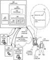
- FIG. 1shows a patient 182 wearing a sample wearable cardiac defibrillator (WCD) system 101 made according to embodiments.
- WCDcardiac defibrillator
- Communication device 110can be either a part of the WCD system, or a commercially available mobile communication device that has one or more suitable applications (“apps”) loaded onto it.
- appssuitable applications
- communication device 110forms a wireless local communication link (“comlink”) 171 with the WCD system.
- the local comlinkcan be wired.
- FIG. 1patient 182 is using communication device 110 , while wearing WCD system 101 .
- WCD system 101 and communication device 110are now considered in more detail.
- FIG. 2shows a detail of a portion of FIG. 1 that shows patient 182 wearing wearable cardiac defibrillator (WCD) system 101 and using communication device 110 .
- WCDwearable cardiac defibrillator
- WCD system 101includes a support structure 270 that is configured to be worn by patient 182 .
- Patient 182is using communication device 110 , while wearing support structure 270 .
- WCD system 101also includes an external defibrillator 200 that is coupled to support structure 270 .
- Defibrillator 200is configured to defibrillate patient 182 while patient 182 wears support structure 270 .
- Support structure 270can be any structure suitable for wearing, such as a harness, a vest, another garment, and so on.
- the support structurecan be implemented in a single component, or multiple components.
- a support structuremay have a top component resting on the shoulders, for ensuring that the defibrillation electrodes will be in the right place for defibrillating, and a bottom component resting on the hips, for carrying the bulk of the weight of the defibrillator.
- a single component embodimentcould be with a belt around the torso, or a harness around the shoulders.
- Other embodimentscould use an adhesive structure or another way for attaching to the patient, with or without encircling any part of the body. There can be other examples.
- a generic support structure 270is shown relative to the body of patient 182 , and thus also relative to his or her heart 285 .
- Structure 270could be a harness, vest, garment, as per the above; it could be implemented in a single component, or multiple components, and so on.
- Structure 270is configured to be wearable by patient 182 , but the manner of wearing it is not depicted, as structure 270 is depicted only generically in FIG. 2 .
- FIG. 2shows an example of defibrillation electrodes 204 , 208 , which are coupled to an external defibrillator 200 via electrode leads 205 .
- defibrillator 200can administer, via electrodes 204 , 208 , a brief, strong electric pulse 211 through the body.
- Pulse 211also known as a defibrillation shock, goes also through heart 285 , in an attempt to restart it, for saving the life of patient 182 .
- Defibrillator 200 and defibrillation electrodes 204 , 208are coupled to support structure 270 . As such, all components of defibrillator 200 are therefore coupled to support structure 270 .
- Patient 182is shown holding communication device 110 .
- Device 110is shown as having established local comlink 171 with one of the components of WCD system 101 .
- local comlink 171is shown as established specifically with defibrillator 200 , on behalf of the entire WCD system 101 .
- This embodimentis advantageous when, as here, defibrillator 200 is collocated with a communication module, but that is not necessary. Indeed, the local comlink can become established with a different component of the WCD system, and particularly the one that includes a wireless communication module on behalf of the entire WCD system.
- a prior art defibrillatortypically decides whether to defibrillate or not based on an electrocardiogram (“ECG”) of the patient.
- ECGelectrocardiogram
- defibrillator 200can defibrillate or not also based additionally on other inputs and received communication, as will be seen later.
- the use, readiness and maintenance of defibrillator 200can be improved based on the communication enabled by the invention.
- WCD system 101may also optionally include a monitoring device 280 , which can also be called an outside monitoring device.
- Monitoring device 280is configured to monitor at least one local parameter.
- a local parameteris a parameter of patient 182 , or a parameter of the wearable defibrillation system, or a parameter of the environment, as will be described later.
- monitoring device 280is physically coupled to the support structure.
- monitoring device 280is communicatively coupled with other components coupled to the support structure, such as a communication module, as will be deemed necessary by a person skilled in the art in view of this disclosure.
- FIG. 3is a diagram showing components of an external defibrillator 300 made according to embodiments. These components can be, for example, in external defibrillator 200 of FIG. 2 .
- the components shown in FIG. 3can be provided in a housing 301 , which is also known as casing 301 .
- External defibrillator 300is intended for a patient who would be wearing it, such as patient 182 of FIG. 1 and FIG. 2 .
- Defibrillator 300further includes a user interface (UI) 370 for a user 382 .
- User 382can be wearer 182 , if conscious. Or user 382 can be a local rescuer at the scene, such as a bystander who might offer assistance, or a trained person. According to FIG. 1 , user 382 might be in remote communication with a remote rescuer, such as a trained person within Health Care entity 191 , according to embodiments.
- Defibrillator 300may include monitoring device 380 within housing 301 , and can also be called an inside monitoring device.
- Monitoring device 380can monitor patient parameters, system parameters and/or environmental parameters.
- inside monitoring device 380can be the same, or complementary to outside monitoring device 280 of FIG. 2 , and can be provided in addition to it, or instead of it. Allocating which of the whole system parameters are monitored by which monitoring device can be determined according to design considerations.
- a motion sensorcan be within housing 301 , as part of inside monitoring device 380 , for system economy based on ease of implementation and communicating its results.
- a sensor that monitors the patient's blood pressuremay be at the external location of device 280 .
- Defibrillator 300typically includes a defibrillation port 310 , such as a socket in housing 301 .
- Defibrillation port 310includes nodes 314 , 318 .
- Defibrillation electrodes 304 , 308can be plugged in defibrillation port 310 . Plugging can be from their leads, such as leads 205 of FIG. 2 , so as to make electrical contact with nodes 314 , 318 , respectively.
- the defibrillation electrodescan be connected continuously to defibrillation port 310 , instead. Either way, defibrillation port 310 can be used for guiding, via electrodes, to the wearer the electrical charge that has been stored in energy storage module 350 .
- Defibrillator 300may optionally also have an ECG port 319 in housing 301 , for plugging in ECG electrodes 309 , which are also known as ECG leads. It is also possible that ECG electrodes can be connected continuously to ECG port 319 , instead. ECG electrodes 309 can help sense an ECG signal, e.g. a 12-lead signal, or a signal from a different number of leads, as long as they make good electrical contact with the body of the patient. ECG electrodes 309 can be attached to the inside of support structure 270 for making contact with the patient, similarly as the defibrillation electrodes.
- ECG electrodes 309can be attached to the inside of support structure 270 for making contact with the patient, similarly as the defibrillation electrodes.
- Defibrillator 300also includes a measurement circuit 320 .
- Measurement circuit 320receives physiological signals from ECG port 319 , if provided. Even if defibrillator 300 lacks ECG port 319 , measurement circuit 320 can obtain physiological signals through nodes 314 , 318 instead, when defibrillation electrodes 304 , 308 are attached to the patient. In these cases, a patient's ECG signal can be sensed as a voltage difference between electrodes 304 , 308 . Plus, impedance between electrodes 304 , 308 can be sensed. Sensing the impedance can be useful for detecting, among other things, whether these electrodes 304 , 308 are not making good electrical contact with the patient's body. These physiological signals can be sensed, and information about them can be rendered by circuit 320 as data, or other signals, etc.
- Defibrillator 300also includes a processor 330 .
- Processor 330may be implemented in any number of ways. Such ways include, by way of example and not of limitation, digital and/or analog processors such as microprocessors and digital-signal processors (DSPs); controllers such as microcontrollers; software running in a machine; programmable circuits such as Field Programmable Gate Arrays (FPGAs), Field-Programmable Analog Arrays (FPAAs), Programmable Logic Devices (PLDs), Application Specific Integrated Circuits (ASICs), any combination of one or more of these, and so on.
- DSPsdigital-signal processors
- controllerssuch as microcontrollers
- software running in a machineprogrammable circuits such as Field Programmable Gate Arrays (FPGAs), Field-Programmable Analog Arrays (FPAAs), Programmable Logic Devices (PLDs), Application Specific Integrated Circuits (ASICs), any combination of one or more of these, and so on.
- Processor 330can be considered to have a number of modules.
- One such modulecan be a detection module 332 .
- Processor 330running detection module 332 , is a sample embodiment of a logic device configured to determine whether the above-described monitored parameter has reached a specific threshold.
- the monitoring parametercan be input from monitoring device 380 , if provided.
- detection module 332can include a ventricular fibrillation (“VF”) detector.
- the patient's sensed ECG from measurement circuit 320can be used by the VF detector to determine whether the patient is experiencing VF. Detecting VF is useful, because VF is a precursor to SCA.
- Another such module in processor 330can be an advice module 334 , which arrives at advice of what to do.
- the advicecan be based on outputs of detection module 332 .
- a Shock Advisory Algorithmcan render the advice to shock, as opposed to not shock the patient. Such can be, for example, when the patient's condition has reached or exceeded an advised defibrillation threshold. Shocking can be for defibrillation, pacing, and so on.
- adviceis to shock, some external defibrillator embodiments proceed with shocking, or may advise a remote attendant to do it, and so on.
- the advicecan be to administer CPR, and defibrillator 300 may further issue prompts for it, and so on.
- Processor 330can include additional modules, such as other module 336 , for other functions.
- monitoring device 380may be operated in part by processor 330 , etc.
- Defibrillator 300optionally further includes a memory 338 , which can be a non-transitory computer-readable storage medium.
- Memory 338may be able to work together with processor 330 .
- Memory 338may be implemented in any number of ways. Such ways include, by way of example and not of limitation, nonvolatile memories (NVM), read-only memories (ROM), random access memories (RAM), any combination of these, and so on.
- NVMnonvolatile memories
- ROMread-only memories
- RAMrandom access memories
- Memory 338if provided, can include programs for processor 330 , and so on. The programs can be operational for the inherent needs of processor 330 , and can also include protocols and ways that decisions can be made by advice module 334 .
- memory 338can store prompts for user 382 , if they are a local rescuer.
- memory 338can store data.
- the datacan include patient data, system data and environmental data, for example as learned by monitoring device 380 and monitoring device 280 .
- the datacan be stored before it is transmitted out of defibrillator 300 , or stored after it is received by it.
- Defibrillator 300may also include a power source 340 .
- power source 340typically includes a battery. Such a battery is typically implemented as a battery pack, which can be rechargeable or not. Sometimes, a combination is used, of rechargeable and non-rechargeable battery packs.
- Other embodiments of power source 340can include AC power override, for where AC power will be available, and so on.
- power source 340is controlled by processor 330 .
- Defibrillator 300additionally includes an energy storage module 350 , which can thus be coupled to the support structure of the wearable system.
- Module 350is where some electrical energy is stored, when preparing it for sudden discharge to administer a shock.
- Module 350can be charged from power source 340 to the right amount of energy, as controlled by processor 330 .
- module 350includes a capacitor 352 , which can be a single capacitor or a system of capacitors, and so on. As described above, capacitor 352 can store the charge for delivering to the patient.
- Defibrillator 300moreover includes a discharge circuit 355 .
- Circuit 355can be controlled to permit the energy stored in module 350 to be discharged to nodes 314 , 318 , and thus also to defibrillation electrodes 304 , 308 .
- Circuit 355can include one or more switches 357 . Those can be made in a number of ways, such as by an H-bridge, and so on.
- User interface 370can be made in any number of ways.
- interface 370may include a screen, to display what is detected and measured, provide visual feedback to the rescuer for their resuscitation attempts, and so on.
- Interface 370may also include a speaker, to issue voice prompts, etc. Sounds, images, vibrations, and anything that can be experienced by user 382 can also be called human perceptible indications.
- Interface 370may additionally include various controls, such as pushbuttons, keyboards, touchscreens, a microphone, and so on.
- discharge circuit 355can be controlled by processor 330 , or directly by user 382 via user interface 370 , and so on.
- Defibrillator 300can optionally include a communication module 390 , for establishing one or more wireless comlinks, such as local comlink 171 .
- the communication modulemay also include an antenna, portions of a processor, and other sub-components as may be deemed necessary by a person skilled in the art. This way, data and commands can be communicated, such as patient data, episode information, therapy attempted, CPR performance, system data, environmental data, and so on.
- Communication module 390may also establish a bypass comlink, as described elsewhere in this document.
- Defibrillator 300can optionally include other components.
- communication device 110can be a wireless telephone, a smartphone, a Personal Digital Assistant (PDA), a personal electronic device, a pager, a laptop computer, a tablet, an e-reader, and so on.
- PDAPersonal Digital Assistant
- Such communication devicesare increasingly becoming more than just wireless voice communication devices.
- some communication devicesare essentially portable computing devices that can support a variety of applications such as email, web browsing, text processing applications, contact applications, scheduling applications, games, and so on.
- Patient 182typically carries communication device 110 , and is intended to be its primary user.
- Patient 182may carry device 110 in a pocket, in a special holder, or even wear it on their wrist. It should be further remembered that, given the particular dynamics of SCA, where the patient may be an unconscious victim, a rescuer may actually use the patient's communication device 110 . And, in some embodiments, a rescuer may instead use their own communication device, instead of the one carried by the patient.
- FIG. 4is a diagram showing possible sample components of a communication device 410 made according to embodiments.
- Device 410could be the same as device 110 that is depicted in FIG. 1 .
- Communication device 410is typically provided with a housing 412 , and its components are typically within housing 412 .
- Device 410is typically powered by a battery 414 that can be rechargeable. Battery 414 enables device 410 to be portable, mobile.
- Communication device 410includes one or more antennas 416 for wireless communication.
- Device 410also includes RF (radio frequency) circuitry 418 .
- RF circuitry 418cooperates with antenna(s) 416 to receive and send RF signals.
- RF circuitry 418converts RF signals to/from wired electrical signals.
- RF circuitry 418may include well-known circuitry for performing these functions, including but not limited to an RF transceiver, one or more amplifiers, a tuner, one or more oscillators, a digital signal processor, a CODEC chipset, a subscriber identity module (SIM) card, a memory, and so forth.
- the one or more antennas 416 , plus RF circuitry 418can establish wireless communication links (“comlinks”) as per the above, when cooperating with one of the communication modules of communication device 410 that are described below.
- Controller 422can be one or more processors, implemented as a Central Processing Unit (CPU), a digital signal processor, a microprocessor, a microcontroller, an application-specific integrated circuit (ASIC), a programmable logic device (PLD), or other implementation. Controller 422 can be optionally combined in a single chip with a memory controller and a peripherals interface.
- CPUCentral Processing Unit
- ASICapplication-specific integrated circuit
- PLDprogrammable logic device
- Device 410also includes a memory 424 , which can be a non-transitory computer-readable storage medium.
- Memory 424can include both persistent/non-volatile and non-persistent/volatile memory components.
- Memory 424can be implemented in any technology for memory for such devices, volatile memory, non-volatile memory (NVM), for example RAM, ROM, EEPROM, flash memory, and so on.
- NVMnon-volatile memory
- RAMvolatile memory
- ROMread-only memory
- EEPROMelectrically erasable programmable read-only memory
- flash memoryelectrically erasable programmable read-only memory
- Additional memory componentsmay be plugged in from a device external to housing 412 , such as a thumb drive, in some embodiments.
- Memory 424can store programs 426 and data 427 .
- Programs 426can include instructions that can be executed by controller 422 .
- Programs 426may include an operating system, such as, for example, Android, iOS, Windows
- App(s) 429can be stored in memory 424 , as mentioned above. App(s) 429 can also include instructions that can be executed by controller 422 . Common app(s) 429 can be provided for a contacts module, an email client module, a calendar module, a camera module, a maps module, and so on.
- communication device 410can be performed by communication device 410 due to one or more special app(s) 429 , which are provided in addition to common apps. Even if communication device 410 is initially provided in a more generic form without special app(s) 429 , the latter may be downloaded later.
- Communication device 410further includes a user interface 430 , for use by a user, such as patient 182 .
- User interface 430includes individual devices for receiving inputs by the user, output devices for generating outputs for the user, or both.
- the outputs for the usercan be human-perceptible indications, such as sounds, vibrations, lights, images, and so on. Examples of such individual devices include a screen that could be a touch screen, a physical keypad, an optical finger interface, one or more speakers, one or more microphones, one or more accelerometers, and so on.
- Such devicescan be included within housing 412 , or can be added by a separate plugin, such as a keypad, a keyboard, a display, and a speaker.
- Communication device 410moreover includes a communication module 432 .
- Module 432can conduct communication using any one of a variety of standards, protocols and technologies. Examples of the latter are Global System for Mobile Communications (GSM), Enhanced Data GSM Environment (EDGE), high-speed downlink packet access (HSDPA), wideband code division multiple access (W-CDMA), code division multiple access (CDMA), time division multiple access (TDMA), Bluetooth, Wireless Fidelity (Wi-Fi) (e.g., IEEE 802.11a, IEEE 802.11b, IEEE 802.11g and/or IEEE 802.11n), voice over Internet Protocol (VoIP), Wi-MAX, a protocol for email (e.g., Internet message access protocol (IMAP) and/or post office protocol (POP)), instant messaging (e.g., extensible messaging and presence protocol (XMPP), Session Initiation Protocol for Instant Messaging and Presence Leveraging Extensions (SIMPLE), Instant Messaging and Presence Service (IMPS), and/or Short Message Service (SMS
- communication device 410can include a contactless communication I/O module 434 .
- Module 434can be used for short range detection and communication, such as Near-Field Communications (NFC), Radio Frequency Identification (RFID), and so on.
- NFCNear-Field Communications
- RFIDRadio Frequency Identification
- Communication device 410can also include a location detection system 436 , which can be implemented with GPS.
- Device 410can further include one or more sensor mechanisms 438 .
- Mechanisms 438can include one or more accelerometers, a proximity sensor, a magnetometer, optical sensors, an image sensor, and so on. Data captured by location detection system 436 and sensor mechanisms 438 can be stored as data 427 .
- Programs 426can advantageously coordinate their use with components of device 410 .
- antenna(s) 416may be used to detect electromagnetic fields (EMF), and a microphone of user interface 430 may be used to detect sound.
- EMFelectromagnetic fields
- Many of the components of a communication deviceare well known in the field, and therefore and are not described further.
- communication device 110has a screen 111 .
- Screen 111can be part of user interface 430 .
- a sample view 146 of what can be displayed on screen 111is shown in a balloon. The contents of view 146 may depend on the communication arrangements, which are now described in more detail.
- a communication network 180can be the internet.
- Communication device 110can communicate via communication network 180 , for example according to shown arrows.
- Communication device 110may exchange data via a remote comlink 172 , local comlink 171 , or bypass comlinks, for example as described in U.S. Pat. No. 8,838,235 B2, which is incorporated herein by reference.
- FIG. 1additionally shows a computer 120 made according to embodiments.
- Computer 120is remote with respect to patient 182 ; in fact, computer 120 may be accessed via communication network 180 by patient 182 using communication device 110 . Access can be via remote comlink 172 , which is different from local comlink 171 .
- Comlink 171may also be through a network, but is it across a smaller distance than comlink 172 .
- Computer 120may include a processor 122 .
- Processor 122may be programmable for a general purpose, or dedicated, such as a microcontroller, a microprocessor, a Digital Signal Processor (DSP), etc.
- DSPDigital Signal Processor
- Computer 120may also include non-transitory computer-readable storage media, such as at least one memory 123 .
- Memory 123can be of different types, including but not limited to volatile memory, non-volatile memory (NVM), read only memory (ROM); random access memory (RAM); magnetic disk storage media; optical storage media; smart cards, flash memory devices, etc.
- These storage mediamay store at least one program 125 that processor 122 may be able to read, and execute. More particularly, program 125 can contain instructions in the form of code, which processor 122 may be able to execute upon reading. Executing is performed by physical manipulations of physical quantities, and may result in functions, processes, actions and/or methods to be performed according to embodiments, and/or processor 122 to cause other devices or components or blocks to perform such functions, processes, actions and/or methods. Often, for the sake of convenience only, it is preferred to implement and describe a program as various interconnected distinct software modules or features. These, along with data are individually and also collectively known as software. In some instances, software is combined with hardware, in a mix called firmware.
- memory 123may store a data file system 126 .
- Data file system 126is thus stored in connection with patient 182 having been assigned WCD system 101 .
- Data file system 126may include one or more files. These one or more files may contain at least one patient identifier P.I. 127 of the patient, and compliance data C.D. 128 about a history of patient 182 wearing the support structure of WCD system 101 .
- Data file system 126can be configured to be accessed via communication network 180 by a person using a communication device, such as patient 182 using communication device 110 . Data file system 126 can be accessed this way if computer 120 is a server accessible from the internet, etc.
- patient identifier 127 and compliance data 128can be configured to be downloaded via communication network 180 to communication device 110 .
- screen 111can be configured to display viewable data about the downloaded patient identifier 127 and about the downloaded compliance data 128 .
- sample view 146includes viewable data 147 about the downloaded patient identifier 127 , which are the patient's name.
- the viewable datamay be displayed in a number of ways.
- communication device 110may have a browser application, and the viewable data can be displayed via the browser application.
- one or more of the files of data system 126are provided in html, which makes it easy to display in a browser application.
- Data file system 126may contain additional information. Some of it may be downloadable, and some of that may be further viewable on screen 111 .
- the one or more filesoptionally further contain at least one WCD identifier 129 of WCD system 101 .
- the viewable dataincludes data about WCD identifier 129 .
- access to data file system 126is protected.
- using the communication devicemay include entering an access code.
- the downloadingcan be performed responsive to entering the access code.
- the entered codehas to be validated as correct, and so on. Different parties that may access data file system 126 may have different codes, and so on.
- the access codeis legible on the WCD system, having been written on it in advance. In the example of FIG. 1 , a request is shown within view 146 to enter an access code.
- view 546is shown, which could be the image displayed by communication device 110 .
- View 546could be, for instance, the view after a correct access code has been entered responsive to view 146 of FIG. 1 .
- view 546includes viewable data 547 , which can be the full name of patient 182 .
- viewable datacan be displayed about the downloaded compliance data 128 .
- viewable data 548is compliance data about the compliance of patient 182 actually wearing WCD system 101 .
- the term “diligence”may be used to discuss what is, from the clinical point of view, their compliance.
- viewable data 548is a percentage score. This score could be, for example, the wear time over the total time over a period spanning back 7 days. It is possible that patient 182 would have to remove WCD system 101 for bathing, which could prevent this percentage score from being maintained at 100.0%.
- compliance data 128may be generated in a number of ways.
- WCD system 101may further include a motion sensor.
- the motion sensorcan be configured to generate motion event data.
- the patient's compliancemay be inferred from the motion event data, among other factors. For instance, it could be that the motion event data indicates no motion events, and that could be due to the fact that patient 182 is not wearing system 101 , and so on.
- Another factor for the patient compliancecan be the time, for example expecting different motion patterns during the night, accounting for vibrations that can be ruled out as not being patient generated, and so on. As such, the time itself might help interpret the motion event data.
- One more factorcan be as to whether the ECG is received, which speaks to compliance as to wearing system 101 properly or not, and so on.
- the motion event datamay be communicated in any number of ways.
- WCD system 101may include the previously mentioned communications module, which can be configured to communicate the motion event data.
- communication device 110can be configured to communicate the motion event data.
- the compliance datacan become updated compliance data, responsive to the communicated motion event data.
- compliance data 128may become updated compliance data by adding data, computing updated averages, and so on.
- view 546can further include viewable data 551 , which can be about relevant recent events. It will be understood that, in such embodiments, the files of the data system can contain such events; when downloaded, these can become viewable data 551 .
- defibrillation event datacan be communicated, whether to computer 120 or to another functionality.
- the WCD systemfurther includes a communications module configured to communicate the defibrillation event data.
- the communication deviceis configured to communicate the defibrillation event data.
- the one or more files of the data file systemcan become updated in response to it. This can be performed in a number of ways. For example, the one or more files can become updated so that they contain the defibrillation event data itself. In some embodiments, then, viewable data 551 further includes the defibrillation event data.
- alertscan be included, for example alerts, thresholds, and statistics, any of which can be contained in the one or more files. Examples are now described.
- WCD system 101further includes an energy storage module that stores an electrical charge.
- the one or more files of data file system 126may further contain a battery alert, if an amount of the stored charge is less than a threshold charge.
- the battery alertmay be generated by WCD system 101 and be communicated to data file system 126 .
- the amount of chargemay be communicated to data file system 126 , and the battery alert may be generated within computer 120 .
- the viewable datafurther includes the battery alert.
- a compliance statisticis computed about the updated compliance data, as is also described later with reference to FIG. 8 .
- a compliance alertmay be generated if the compliance statistic is not larger than a compliance threshold.
- the one or more filesmay further contain the compliance alert. This alert may also be communicated to an attendant, such as with a Health Care entity 191 .
- Other included datacan be records of such alerts, statistics about such alerts, statistics about compliance history, etc.
- View 546can further include buttons, or equivalent ways to see other views, for example by linking to other webpages or places in network 180 .
- Such a buttoncan be actuated by touching, if the screen is a touchscreen. Examples of such buttons are now described.
- a button 591can be for calling a doctor. Actuating it may call Health Care entity 191 , seen in FIG. 1 .
- Health Care entity 191may be able to also download data file system 126 , have the same views as patient 182 has with device 110 , and so on.
- a button 592can be for adding a friend or a family member to the website. Actuating it may enable a family members and friends 192 , seen in FIG. 1 , to also have access to data file system 126 , or selected parts of it, such as the compliance score. The engagement and participating of family members and friends 192 and friends can motivate patient 182 , to improve compliance. In embodiments, family members and friends 192 may even enter inputs, such as encouraging notes. Of course, such access to others is preferably granted after patient 182 has voluntarily agreed to waive their confidentiality as to these others, which sometimes can be performed in exchange for signing Non-Disclosure Agreements.
- a customer service button 593can be displayed on the screen.
- the one or more files of data file system 126may further contain a customer service network address of a customer service location 193 in communication network 180 .
- actuating the customer service buttoncan accesses the customer service network address.
- a stats button 594can be displayed on the screen.
- Button 594can be for the patient's information, such as activity information, physiological information, health goals, and related statistics. There can be a number of such types of information. Examples are now described.
- FIG. 6shows sample views 646 A, 646 B, 646 C with viewable data of the patient.
- the viewable datais activity monitoring in terms of steps walked.
- the viewable datais metabolic monitoring, in terms of calories burned.
- the viewable datais heart rate monitoring.
- these viewsare shown with reference to health goals. In some embodiments the health goals can be adjusted, as is now described.
- FIG. 7shows a sample view 746 , which can be reached in a number of ways.
- One such wayis from a button of views 646 A, 646 B.
- View 746permits changing the health goals.
- these settingsare not stored only on communication device 110 , but the one or more files of data files system 126 further contain at least one health goal of patient 182 .
- the viewable dataincludes data about the health goal, for example showing the goal as a graph, a statistic, etc., for example as seen in the views 646 A, 646 B, 646 C of FIG. 6 . This data may have thus been downloaded.
- View 746further permits changing settings of the optional non-use alert and snooze features that are described later in this document. Again, in some of these embodiments, these settings are not stored only on the communication device 110 , but the one or more files of data files system 126 further contain at least one snooze setting such as the inert threshold. In some of those embodiments, the viewable data includes data about the inert threshold, for example showing its value, as it may have been downloaded.
- a Done button 799can take the viewer back to the previous view that they came from.
- the viewable data that generate views 646 A, 646 B, 646 Ccan be stored also in data file system 126 . In such embodiments, others can also see it, such as Health Care entity 191 and family and friends 192 . It will be understood that, in such embodiments, the files of data file system 126 can contain the patient information which, when downloaded, becomes the viewable data of views 646 A, 646 B, 646 C.
- WCD system 101can further include a measurement circuit configured to generate patient physiological data from a patient physiological signal. In such instances, the patient physiological data can be communicated, whether to computer 120 or to another functionality.
- the WCD systemfurther includes a communications module configured to communicate the patient physiological data.
- the communication deviceis configured to communicate the patient physiological data.
- the one or more files of the data file systemcan become updated in response to it, etc.
- the viewable datafurther includes the patient physiological data.
- an education button 595can be displayed on the screen.
- Education button 595can be labeled as shown, and show information about WCD system 101 , access system settings, and so on.
- an information location in a communication networkmay include information about WCD system 101 . This information location can be a help website set up by the manufacturer, etc.
- the one or more files of data file system 126further contain an information network address of the information location in network 180 . Actuating the education button may access the information network address.
- Embodiments of the inventionare also intended to facilitate monitoring compliance of a patient wearing a wearable cardiac defibrillator (WCD) system that has been assigned to him. These embodiments are now described in more detail.
- WCDwearable cardiac defibrillator
- FIG. 8is a diagram of a computer 820 and an associated WCD system 801 according to embodiments.
- WCD system 801includes a support structure which is configured to be worn by a patient such as patient 182 .
- WCD system 801also includes an external defibrillator coupled to the support structure.
- WCD system 801may include a motion sensor coupled to the support structure and configured to generate motion event data.
- WCD system 801may include a communication module and/or the patient wearing WCD system 801 may use a communication device.
- Computer 820includes a processor 822 , which can be made as was described for processor 122 .
- Computer 820also includes a non-transitory storage medium 823 , which is also known as memory 823 and can be as memory 123 .
- Memory 823can be coupled with processor 822 , and store one or more programs 825 and data 826 .
- computer 820is associated with WCD system 801 in the sense that the one or more programs 825 are stored in connection with a patient having been assigned to wear WCD system 801 .
- Thismay be performed in a number of ways.
- computer 820is remote from WCD system 801 , for example as computer 120 is with respect to WCD system 101 .
- computer 820can be called a remote computer, even though a remote comlink between them can be over a short physical distance, such as using Bluetooth.
- computer 820is actually part of system 801 . Common aspects of both types of embodiments are described first.
- FIG. 9shows a flowchart 900 for describing methods according to embodiments. The methods of flowchart 900 may also be practiced by embodiments described above.
- a compliance statisticis computed.
- the compliance statisticcan be about motion event data generated by the motion detector of WCD system 801 .
- a compliance thresholdcan be about the patient wearing the support structure, for example for how long a time. If the answer is yes, the execution can return to operation 910 . Moreover, additional motion event data may be received, operation 910 can yield an updated compliance statistic, and so on.
- a compliance alertcan be caused to be generated. This may be received by an attendant, who may communicate with the patient. Their dialogue can be, for example, as shown in FIG. 10 .
- operation 910is not performed by the processor. Rather, WCD system 801 may compute the compliance statistic, which can then be communicated to the remote processor.
- operation 910is performed by the processor.
- WCD system 801can communicate the motion event data via a communication network to the remote processor. Then the compliance statistic can be computed from the motion event data.
- the remote computerfurther includes a timer, which is configured to generate a time signal. In such instances, the compliance statistic can be computed also from the time signal.
- the remote computerfurther includes an output device, which can be part of a user interface.
- an output devicewhich can be part of a user interface.
- the programswhen executed by the processor, they can cause the compliance alert to be communicated via the output device.
- the output devicemay produce a visual or auditory signal, so as to attract the attention of the attendant.
- the compliance thresholdcan be adjusted. Adjustment can be by any of the parties involved, although it is advisable to restrict access to perhaps only the attendant. In some such instances, therefore, in addition to the operations of flowchart 900 , an adjustment input can be received. Then, when the programs are executed by the remote processor, they may further result in adjusting the compliance threshold, responsive to the received adjustment input.
- processor 822can be as processor 330 , i.e. within the external defibrillator. When the programs are executed by the processor, they may thus further result in defibrillating the patient while the support structure is worn by the patient.
- WCD system 801further includes a communication module. Different elements can be caused to be communicated by the communication module. In some of these embodiments, the motion event data is caused to be communicated by the communication module.
- the compliance statisticis computed from the motion event data, as per operation 910 . Then the compliance statistic can be caused to be communicated by the communication module.
- WCD system 801further includes a timer, which is configured to generate a time signal. In such instances, the compliance statistic can be computed also from the time signal.
- the generated alertis communicated by the communication module.
- a method for WCD system 801may include the operations of flowchart 900 , plus defibrillating the patient while the support structure is worn by the patient.
- WCD system 801further includes a communication module, different elements can be caused to be communicated by it as described above.
- Embodiments of the inventionfurther include alerting for non-use of a wearable cardiac defibrillator system.
- a wearable cardiac defibrillator (WCD) systemcould be such as WCD system 101 , which includes support structure 270 and external defibrillator 200 .
- WCD systemcan additionally include a motion sensor coupled to the support structure and configured to generate motion event data.
- WCD systemcan further include a timer coupled to the support structure, and configured to determine a duration of an inert period.
- the inert periodcan be a period during which a motion statistic of the motion event data is less than a motion threshold. If the duration of the inert period exceeds an inert threshold, then an output device can be configured to output a human-perceptible alert for non-use.
- the output devicecan be part of a user interface, and so on. Particulars are now described.
- FIG. 11shows sample timing diagrams 1101 , 1102 , 1103 according to embodiments.
- Diagram 1101depicts motion events 1110 as stars plotted along a time axis. Each star may have variables additional to their moment of occurrence, or to the moment of starting.
- instantaneous motion events 1110are shown, although that does not need to be the case. For example, they are not instantaneous if the patient is rising from a chair, or walking.
- Motion event datamay be extracted from motion events 1110 .
- the motion event datamay recognize and classify aspects of patient motion. For one example, aspects may be classified as patient-generated or not, depending on a magnitude of force, or acceleration. For another example, aspects may be classified as to whether they match typical motion patterns of means of transportation, such as periodicity and other statistics about frequency of motion, etc. For one more example, such aspects may be classified depending on the time of day, and according to previous patterns of the patient.
- a motion statistic of the motion event datacan thus be extracted for selected times along the time axis, for determining an amount of patient motion characterized as generated by the patient.
- the motion statisticmay be intended for the amount of patient-generated motion.
- an inert periodcan be a duration during which the motion statistic is less than a motion threshold. It should be noted that inert periods for these purposes could be periods of patient motion which, however, are not characterized as being patient-generated. Examples of inert periods are now described.
- Diagram 1102can be used for depicting such inert periods. Its horizontal axis is a time axis parallel and coincident to the time axis of diagram 1101 . Its vertical axis is also a time axis, which is of the same scale as the horizontal axis. The inert periods occur between the times of motion events 1110 . In diagram 1102 ramps are also shown, as the durations of the inert periods could be measured by the aforementioned timer along the vertical axis. Accordingly, these durations can be shown on the vertical axis. The ramps are inclined at 45°, because the vertical axis is of the same scale as the horizontal axis.
- Diagram 1103can be used for depicting actions of the output device. Its horizontal axis is a time axis parallel and coincident to the time axis of diagrams 1101 and 1102 .
- the alertis output between TX and T 3 , i.e. for the entire time during which the duration exceeds the inert threshold. This is not necessary, however, and a different alerting pattern may be initiated in response to the inert threshold being exceeded at time TX.
- the output devicemay be implemented in a number of ways, locally and/or remotely.
- the WCD systemmay include the output device itself, for example as part of user interface 370 .
- the human-perceptible alertcan be an audible alert.
- the output deviceis a component of a communication device, such as communication device 110 .
- the communication deviceis a standalone device, and in other embodiments the WCD system includes the communication device.
- the output devicecan be collocated with the recipient, and alert the recipient. Examples of recipients are shown in FIG. 1 : Health Care entity 191 and friends and family 192 .
- the WCD systemmay further include a communications module, which is configured to communicate to a recipient alert event data about the duration of the inert period exceeding the inert threshold. Communicating may be as described above, either through a backup comlink, or through a local comlink that continues by a remote comlink through a network, to computer 120 , and from there to the recipient, etc.
- the alert event datamay include information that generated the alert, such as one or more of the motion statistic, the duration of the inert period, and the event that the duration of the inert period exceeds the inert threshold.
- a value for the inert thresholdis downloaded from a communication network. This value may have been set by Health Care entity 191 .
- an inert threshold adjust inputis received by the WCD system.
- the inert thresholdmay become adjusted to a new value responsive to the received inert threshold adjust input.
- the inert threshold adjust inputis received via a communication device for example as seen in FIG. 7 .
- the WCD systemfurther includes a user interface, such as UI 370 , which is configured to receive the inert threshold adjust input; the inert threshold adjust input is then received via the user interface.
- the new valueis communicated to a recipient through a network, for example via a communications module configured to communicate this new value through the network.
- a snooze featureis implemented for the alert about non-use.
- the duration of the inert periodcan be determined as starting from a first moment. More particularly at diagram 1102 , in the previously described inert period, the first moment was T 1 and the inert period ended at T 3 when there was another isolated motion event 1110 —perhaps the user tapped the WCD system. At the time T 3 , the duration of the inert period was reset to zero, and resumed increasing from zero. At a subsequent time T 4 , the threshold is crossed again, and the alert is restarted as seen in diagram 1103 .
- a snooze inputis received, and the first moment becomes reset to a new value responsive to the received snooze input.
- the new valueis zero, although other values are possible. Resetting happened without a motion event from diagram 1101 .
- the alert of diagram 1103is thus turned off due to the received snooze input, at least temporarily.
- the snooze inputmay be received via a communication device such as communication device 110 .
- the WCD systemfurther includes a user interface, such as UI 370 , which is configured to receive the snooze input, and the snooze input is received via the user interface.
- the snooze inputcan be received as a result of a user actuating a Snooze button in the appropriate interface.
- the alertis turned off, this may be only temporary. In effect, a new inert period can be started and, when the threshold is crossed again, the alert can restart. It should be noted that, in the example of FIG. FIG. 7 , the duration of the inert threshold (2 min) is the same regardless of whether the inert period was started from the end of the last motion event or actuating the snooze button. This need not be the case, however, and different inert thresholds may be implemented.
- the snooze featurecan be disabled. For example, a Snooze-OFF input may be received, and the output device then does not output the human-perceptible alert responsive to the received Snooze-OFF input, even if the duration of the inert period exceeds the inert threshold.
- the Snooze-OFF inputmay be received.
- the Snooze-OFF inputis received via a communication device such as communication device 110 .
- the Snooze-OFF inputis received via a network, for example being set this way by Health Care entity 191 .
- the WCD systemfurther includes a user interface, such as UI 370 , which is configured to receive the Snooze-OFF input, and the Snooze-OFF input is received via the user interface.
- the Snooze-OFF inputcan be received as a result of a user actuating a Snooze-OFF button in the appropriate interface, for example as seen in FIG. 7 .
- FIG. 12shows a flowchart 1200 for describing methods according to embodiments for a wearable cardiac defibrillator (WCD) system to work with an output device, whether the latter is part of the WCD system or not.
- WCDwearable cardiac defibrillator
- a patientmay be defibrillated while wearing a support structure of the WCD system.
- a valuemay be downloaded for an inert threshold.
- the valuemay be downloaded from a communication network.
- motion event datamay be generated, for example by a motion sensor of the WCD system.
- the duration of an inert periodmay be determined.
- the inert periodcan be a time interval during which the previously mentioned motion statistic of the motion event data is less than the previously mentioned motion threshold. Its duration may be determined in a number of ways, for example by counting time from its first moment until the present.
- Embodimentsmay proceed in terms of an inert threshold.
- a value for itmay be stored in a system memory.
- an inert threshold adjust inputmay be received, and the inert threshold may be adjusted to a new value in responsive thereto.
- the inert threshold adjust inputmay be received in a number of ways, such as via a communication device, a user interface of the WCD system, etc.
- the inert threshold adjust inputmay be received locally, for example as shown in FIG. 7 ; in such cases, the new value can be communicated to a recipient through a network, for example via a communications module of the WCD system.
- the duration of the inert periodexceeds this inert threshold.
- the inert thresholdmay be a value downloaded during operation 1220 , or a pre-stored value, etc. If not, then execution may return to operation 1240 so as to determine the updated duration, and so on.
- the output devicemay be caused to output a human-perceptible alert.
- the output deviceis located near the WCD system, and can even be part of it.
- the output deviceis located remotely, in which case alert event data may be communicated to a recipient through a network, for example via a communications module of the WCD system.
- the alert event datamay be about the duration of the inert period exceeding the inert threshold. In such cases the output device may alerts the recipient, in an auditory way, or visually by presenting alerts, records, etc.
- optional operation 1270it is inquired whether a snooze input has been received.
- the snooze inputmay be received in a number of ways, such as via a communication device, a user interface of the WCD system, etc. If at operation 1270 a snooze input has not been received, then execution may return to operation 1260 . If at operation 1270 a snooze input has been received, then according to another, optional operation 1280 , the first moment of the duration of the inert period may be reset to a new value, and execution may return to operation 1240 .
- the snooze featuremay be disabled.
- a Snooze-OFF inputmay be received.
- the output devicemight not be caused to output the human-perceptible alert responsive to the received Snooze-OFF input, even if the duration of the inert period exceeds the inert threshold.
- the Snooze-OFF inputmay be received in a number of ways, such as through a network, via a communication device, a user interface of the WCD system, etc.
- each operationcan be performed as an affirmative step of doing, or causing to happen, what is written that can take place. Such doing or causing to happen can be by the whole system or device, or just one or more components of it.
- the order of operationsis not constrained to what is shown, and different orders may be possible according to different embodiments.
- new operationsmay be added, or individual operations may be modified or deleted. The added operations can be, for example, from what is mentioned while primarily describing a different system, apparatus, device or method.
- phrases “constructed to” and/or “configured to”denote one or more actual states of construction and/or configuration that is fundamentally tied to physical characteristics of the element or feature preceding these phrases and, as such, reach well beyond merely describing an intended use. Any such elements or features can be implemented in any number of ways, as will be apparent to a person skilled in the art after reviewing the present disclosure, beyond any examples shown in this document.
Landscapes
- Health & Medical Sciences (AREA)
- Engineering & Computer Science (AREA)
- Public Health (AREA)
- General Health & Medical Sciences (AREA)
- Biomedical Technology (AREA)
- Medical Informatics (AREA)
- Primary Health Care (AREA)
- Epidemiology (AREA)
- Life Sciences & Earth Sciences (AREA)
- Nuclear Medicine, Radiotherapy & Molecular Imaging (AREA)
- Veterinary Medicine (AREA)
- Animal Behavior & Ethology (AREA)
- Radiology & Medical Imaging (AREA)
- Business, Economics & Management (AREA)
- General Business, Economics & Management (AREA)
- Cardiology (AREA)
- Heart & Thoracic Surgery (AREA)
- Biophysics (AREA)
- Physical Education & Sports Medicine (AREA)
- Human Computer Interaction (AREA)
- Urology & Nephrology (AREA)
- Surgery (AREA)
- Electrotherapy Devices (AREA)
Abstract
Description
Claims (26)
Priority Applications (3)
| Application Number | Priority Date | Filing Date | Title |
|---|---|---|---|
| US16/593,898US11247058B2 (en) | 2014-05-13 | 2019-10-04 | Network-accessible data about patient with wearable cardiac defibrillator system |
| US17/590,620US11896829B2 (en) | 2014-05-13 | 2022-02-01 | Network-accessible data about patient with wearable cardiac defibrillator system |
| US18/398,619US20240139524A1 (en) | 2014-05-13 | 2023-12-28 | Network-accessible data about patient with wearable cardiac defibrillator system |
Applications Claiming Priority (3)
| Application Number | Priority Date | Filing Date | Title |
|---|---|---|---|
| US201461992850P | 2014-05-13 | 2014-05-13 | |
| US14/580,183US10449370B2 (en) | 2014-05-13 | 2014-12-22 | Network-accessible data about patient with wearable cardiac defibrillator system |
| US16/593,898US11247058B2 (en) | 2014-05-13 | 2019-10-04 | Network-accessible data about patient with wearable cardiac defibrillator system |
Related Parent Applications (1)
| Application Number | Title | Priority Date | Filing Date |
|---|---|---|---|
| US14/580,183ContinuationUS10449370B2 (en) | 2014-05-13 | 2014-12-22 | Network-accessible data about patient with wearable cardiac defibrillator system |
Related Child Applications (1)
| Application Number | Title | Priority Date | Filing Date |
|---|---|---|---|
| US17/590,620ContinuationUS11896829B2 (en) | 2014-05-13 | 2022-02-01 | Network-accessible data about patient with wearable cardiac defibrillator system |
Publications (2)
| Publication Number | Publication Date |
|---|---|
| US20200030616A1 US20200030616A1 (en) | 2020-01-30 |
| US11247058B2true US11247058B2 (en) | 2022-02-15 |
Family
ID=54538721
Family Applications (4)
| Application Number | Title | Priority Date | Filing Date |
|---|---|---|---|
| US14/580,183Active2038-01-21US10449370B2 (en) | 2014-05-13 | 2014-12-22 | Network-accessible data about patient with wearable cardiac defibrillator system |
| US16/593,898ActiveUS11247058B2 (en) | 2014-05-13 | 2019-10-04 | Network-accessible data about patient with wearable cardiac defibrillator system |
| US17/590,620Active2035-01-31US11896829B2 (en) | 2014-05-13 | 2022-02-01 | Network-accessible data about patient with wearable cardiac defibrillator system |
| US18/398,619PendingUS20240139524A1 (en) | 2014-05-13 | 2023-12-28 | Network-accessible data about patient with wearable cardiac defibrillator system |
Family Applications Before (1)
| Application Number | Title | Priority Date | Filing Date |
|---|---|---|---|
| US14/580,183Active2038-01-21US10449370B2 (en) | 2014-05-13 | 2014-12-22 | Network-accessible data about patient with wearable cardiac defibrillator system |
Family Applications After (2)
| Application Number | Title | Priority Date | Filing Date |
|---|---|---|---|
| US17/590,620Active2035-01-31US11896829B2 (en) | 2014-05-13 | 2022-02-01 | Network-accessible data about patient with wearable cardiac defibrillator system |
| US18/398,619PendingUS20240139524A1 (en) | 2014-05-13 | 2023-12-28 | Network-accessible data about patient with wearable cardiac defibrillator system |
Country Status (1)
| Country | Link |
|---|---|
| US (4) | US10449370B2 (en) |
Families Citing this family (12)
| Publication number | Priority date | Publication date | Assignee | Title |
|---|---|---|---|---|
| US20220409896A1 (en)* | 2013-11-27 | 2022-12-29 | Ebt Medical, Inc. | System for display of neurostimulation usage and compliance |
| US9839356B2 (en)* | 2015-07-07 | 2017-12-12 | Zoll Medical Corporation | Systems and methods for communicating data |
| US10179246B2 (en) | 2015-12-04 | 2019-01-15 | West Affum Holdings Corp. | Wearable cardioverter defibrillator (WCD) system using security NFC tag for uploading configuration data |
| US20180151047A1 (en)* | 2016-07-11 | 2018-05-31 | Rei, Inc. | Method and system for wearable personnel monitoring |
| CN108969888B (en)* | 2017-06-02 | 2022-03-15 | 西艾丰控股公司 | Wearable cardioverter-defibrillator system using secure tags to upload configuration data |
| WO2019166359A1 (en)* | 2018-02-27 | 2019-09-06 | Robert Bosch Gmbh | Wearable health device system with automatic referencing of seismocardiography signals |
| US11040214B2 (en) | 2018-03-01 | 2021-06-22 | West Affum Holdings Corp. | Wearable cardioverter defibrillator (WCD) system having main UI that conveys message and peripheral device that amplifies the message |
| US11298556B2 (en) | 2018-04-25 | 2022-04-12 | West Affum Holdings Corp. | WCD user interface response to a change in device orientation |
| US11534615B2 (en)* | 2018-04-26 | 2022-12-27 | West Affum Holdings Dac | Wearable Cardioverter Defibrillator (WCD) system logging events and broadcasting state changes and system status information to external clients |
| US11865350B2 (en)* | 2020-11-18 | 2024-01-09 | Zoll Medical Corporation | Systems and methods of monitoring wear compliance of a patient wearing an ambulatory medical device |
| US12362065B2 (en) | 2021-09-23 | 2025-07-15 | West Affum Holdings Dac | Health data management and display |
| US20230138882A1 (en)* | 2021-10-29 | 2023-05-04 | West Affum Holdings Corp. | Integrative wearable health monitoring |
Citations (136)
| Publication number | Priority date | Publication date | Assignee | Title |
|---|---|---|---|---|
| US3724355A (en) | 1970-06-12 | 1973-04-03 | K Schranz | Apparatus for processing exposed photographic film or the like |
| JPS5963767A (en) | 1982-10-04 | 1984-04-11 | Oki Electric Ind Co Ltd | Semiconductor device |
| US4583524A (en) | 1984-11-21 | 1986-04-22 | Hutchins Donald C | Cardiopulmonary resuscitation prompting |
| US4619265A (en) | 1984-03-08 | 1986-10-28 | Physio-Control Corporation | Interactive portable defibrillator including ECG detection circuit |
| US4666432A (en) | 1985-09-13 | 1987-05-19 | Mcneish Kenneth | Catheter retaining means and method |
| US4698848A (en) | 1986-09-26 | 1987-10-13 | Buckley Mary C | Blouse for cardiac patients |
| US4928690A (en) | 1988-04-25 | 1990-05-29 | Lifecor, Inc. | Portable device for sensing cardiac function and automatically delivering electrical therapy |
| US4955381A (en) | 1988-08-26 | 1990-09-11 | Cardiotronics, Inc. | Multi-pad, multi-function electrode |
| US5078134A (en) | 1988-04-25 | 1992-01-07 | Lifecor, Inc. | Portable device for sensing cardiac function and automatically delivering electrical therapy |
| JPH04320257A (en) | 1991-04-19 | 1992-11-11 | Oji Paper Co Ltd | Support for photographic paper |
| US5228449A (en) | 1991-01-22 | 1993-07-20 | Athanasios G. Christ | System and method for detecting out-of-hospital cardiac emergencies and summoning emergency assistance |
| US5348008A (en) | 1991-11-25 | 1994-09-20 | Somnus Corporation | Cardiorespiratory alert system |
| US5394892A (en) | 1990-04-02 | 1995-03-07 | K J Mellet Nominees Pty Ltd | CPR prompting apparatus |
| US5405362A (en) | 1991-04-29 | 1995-04-11 | The Board Of Regents For The University Of Texas System | Interactive external defibrillation and drug injection system |
| US5429593A (en) | 1993-12-23 | 1995-07-04 | Matory; Yvedt L. | Post-surgical, drainage accommodating, compression dressing |
| US5474574A (en) | 1992-06-24 | 1995-12-12 | Cardiac Science, Inc. | Automatic external cardioverter/defibrillator |
| US5618208A (en) | 1994-06-03 | 1997-04-08 | Siemens Medical Systems, Inc. | Fully insulated, fully shielded electrical connector arrangement |
| US5662690A (en) | 1994-12-08 | 1997-09-02 | Heartstream, Inc. | Defibrillator with training features and pause actuator |
| US5708978A (en) | 1994-08-17 | 1998-01-20 | Johnsrud; Anna C. | Medical vest |
| US5741306A (en) | 1996-05-23 | 1998-04-21 | Lifecor, Inc. | Patient-worn energy delivery apparatus |
| US5782878A (en) | 1994-12-07 | 1998-07-21 | Heartstream, Inc. | External defibrillator with communications network link |
| US5792204A (en) | 1996-05-08 | 1998-08-11 | Pacesetter, Inc. | Methods and apparatus for controlling an implantable device programmer using voice commands |
| WO1998039061A2 (en) | 1997-03-07 | 1998-09-11 | Cadent Medical Corporation | Wearable defibrillation system |
| US5902249A (en) | 1995-03-03 | 1999-05-11 | Heartstream, Inc. | Method and apparatus for detecting artifacts using common-mode signals in differential signal detectors |
| US5913685A (en) | 1996-06-24 | 1999-06-22 | Hutchins; Donald C. | CPR computer aiding |
| US5944669A (en) | 1997-11-20 | 1999-08-31 | Lifecor, Inc. | Apparatus and method for sensing cardiac function |
| US6047203A (en) | 1997-03-17 | 2000-04-04 | Nims, Inc. | Physiologic signs feedback system |
| US6065154A (en) | 1998-04-07 | 2000-05-23 | Lifecor, Inc. | Support garments for patient-worn energy delivery apparatus |
| US6108197A (en) | 1992-05-15 | 2000-08-22 | Via, Inc. | Flexible wearable computer |
| US6201992B1 (en) | 1999-04-01 | 2001-03-13 | Agilent Technologies, Inc. | Defibrillator interface capable of generating video images |
| US6263238B1 (en) | 1998-04-16 | 2001-07-17 | Survivalink Corporation | Automatic external defibrillator having a ventricular fibrillation detector |
| US6280461B1 (en) | 1996-05-23 | 2001-08-28 | Lifecor, Inc. | Patient-worn energy delivery apparatus |
| US6287328B1 (en) | 1999-04-08 | 2001-09-11 | Agilent Technologies, Inc. | Multivariable artifact assessment |
| US6319011B1 (en) | 1995-04-06 | 2001-11-20 | Michael J. Motti | Automatic training defibrillator simulator and method |
| US6334070B1 (en) | 1998-11-20 | 2001-12-25 | Medtronic Physio-Control Manufacturing Corp. | Visual and aural user interface for an automated external defibrillator |
| US6356785B1 (en) | 1997-11-06 | 2002-03-12 | Cecily Anne Snyder | External defibrillator with CPR prompts and ACLS prompts and methods of use |
| US6437083B1 (en) | 2001-12-06 | 2002-08-20 | General Electric Company | Process for preparing branched aromatic polycarbonates |
| US6450942B1 (en) | 1999-08-20 | 2002-09-17 | Cardiorest International Ltd. | Method for reducing heart loads in mammals |
| US20020181680A1 (en) | 1999-10-05 | 2002-12-05 | Marshal Linder | Data collection and system management for patient-worn medical devices |
| US6529875B1 (en) | 1996-07-11 | 2003-03-04 | Sega Enterprises Ltd. | Voice recognizer, voice recognizing method and game machine using them |
| US20030158593A1 (en) | 2002-02-19 | 2003-08-21 | Heilman Marlin S. | Cardiac garment |
| US6762917B1 (en) | 2001-06-12 | 2004-07-13 | Novx Corporation | Method of monitoring ESC levels and protective devices utilizing the method |
| US20050107833A1 (en) | 2003-11-13 | 2005-05-19 | Freeman Gary A. | Multi-path transthoracic defibrillation and cardioversion |
| US7065401B2 (en) | 2002-05-08 | 2006-06-20 | Michael Worden | Method of applying electrical signals to a patient and automatic wearable external defibrillator |
| US20060173499A1 (en) | 2005-01-31 | 2006-08-03 | Medtronic Emergency Response Systems, Inc. | System and method for using diagnostic pulses in connection with defibrillation therapy |
| DE102005060985A1 (en) | 2005-12-20 | 2007-06-28 | Oestreich, Wolfgang, Dr.med. | System for mobile monitoring of heart functions has electrodes which are connected to central administrative unit through electrical conductors and these conductors are arranged in clothing |
| US20080312709A1 (en) | 2007-06-13 | 2008-12-18 | Volpe Shane S | Wearable medical treatment device with motion/position detection |
| US20090005827A1 (en) | 2007-06-26 | 2009-01-01 | David Weintraub | Wearable defibrillator |
| US7559902B2 (en) | 2003-08-22 | 2009-07-14 | Foster-Miller, Inc. | Physiological monitoring garment |
| US20100007413A1 (en) | 2006-11-10 | 2010-01-14 | Koninklijke Philips Electronics N.V. | Ecg electrode contact quality measurement system |
| US7753759B2 (en) | 2007-10-22 | 2010-07-13 | Tammy Pintor | Article of apparel for concealing objects |
| US20100298899A1 (en) | 2007-06-13 | 2010-11-25 | Donnelly Edward J | Wearable medical treatment device |
| US7865238B2 (en) | 2004-09-29 | 2011-01-04 | Koninklijke Philips Electronics N.V. | High-voltage module for an external defibrillator |
| US7870761B2 (en) | 2002-05-14 | 2011-01-18 | Koninklijke Philips Electronics N.V. | Garment and method for producing the same |
| WO2011146448A1 (en) | 2010-05-18 | 2011-11-24 | Zoll Medical Corporation | Wearable therapeutic device |
| US20110288605A1 (en) | 2010-05-18 | 2011-11-24 | Zoll Medical Corporation | Wearable ambulatory medical device with multiple sensing electrodes |
| US8135462B2 (en) | 2002-08-26 | 2012-03-13 | Physio-Control, Inc. | Pulse detection using patient physiological signals |
| US20120112903A1 (en) | 2010-11-08 | 2012-05-10 | Zoll Medical Corporation | Remote medical device alarm |
| US20120150008A1 (en) | 2010-12-09 | 2012-06-14 | Kaib Thomas E | Electrode with redundant impedance reduction |
| US20120144551A1 (en) | 2010-12-09 | 2012-06-14 | Eric Guldalian | Conductive Garment |
| US20120158075A1 (en) | 2010-12-16 | 2012-06-21 | Kaib Thomas E | Water resistant wearable medical device |
| US20120191476A1 (en) | 2011-01-20 | 2012-07-26 | Reid C Shane | Systems and methods for collection, organization and display of ems information |
| US20120265265A1 (en) | 2011-04-13 | 2012-10-18 | Mehdi Razavi | Automated External Defibrillator Pad System |
| WO2012151160A1 (en) | 2011-05-02 | 2012-11-08 | Zoll Medical Corporation | Patient-worn energy delivery apparatus and techniques for sizing same |
| US20120293323A1 (en) | 2011-03-25 | 2012-11-22 | Zoll Medical Corporation | System and method for adapting alarms in a wearable medical device |
| US20120302860A1 (en) | 2011-03-25 | 2012-11-29 | Zoll Medical Corporation | Selection of optimal channel for rate determination |
| US20120310315A1 (en) | 2009-03-17 | 2012-12-06 | Savage Walter T | Device and method for reducing patient transthoracic impedance for the purpose of delivering a therapeutic current |
| US8369944B2 (en) | 2007-06-06 | 2013-02-05 | Zoll Medical Corporation | Wearable defibrillator with audio input/output |
| US20130085538A1 (en) | 2011-09-01 | 2013-04-04 | Zoll Medical Corporation | Wearable monitoring and treatment device |
| US8527028B2 (en) | 2007-05-16 | 2013-09-03 | Medicomp, Inc. | Harness with sensors |
| US20130231711A1 (en) | 2012-03-02 | 2013-09-05 | Thomas E. Kaib | Systems and methods for configuring a wearable medical monitoring and/or treatment device |
| US20130245388A1 (en) | 2011-09-01 | 2013-09-19 | Mc10, Inc. | Electronics for detection of a condition of tissue |
| US8548557B2 (en) | 2010-08-12 | 2013-10-01 | Covidien Lp | Medical electrodes |
| US8560044B2 (en) | 2007-05-16 | 2013-10-15 | Medicomp, Inc. | Garment accessory with electrocardiogram sensors |
| US20130274565A1 (en) | 2012-04-13 | 2013-10-17 | Alois Antonin Langer | Outpatient health emergency warning system |
| US20130317852A1 (en) | 2012-05-22 | 2013-11-28 | Geneva Healthcare, LLC | Medical device information portal |
| US20130325078A1 (en) | 2012-05-31 | 2013-12-05 | Zoll Medical Corporation | Medical monitoring and treatment device with external pacing |
| US8615295B2 (en) | 2009-03-17 | 2013-12-24 | Cardiothrive, Inc. | External defibrillator |
| US20140012144A1 (en) | 2012-07-09 | 2014-01-09 | William E. Crone | Perfusion detection system |
| US20140025131A1 (en) | 2012-07-20 | 2014-01-23 | Physio-Control, Inc. | Wearable defibrillator with voice prompts and voice recognition |
| US20140046391A1 (en) | 2012-08-10 | 2014-02-13 | Physio-Control, Inc. | Wearable defibrillator system communicating via mobile communication device |
| US20140070957A1 (en) | 2012-09-11 | 2014-03-13 | Gianluigi LONGINOTTI-BUITONI | Wearable communication platform |
| US8706255B2 (en) | 2006-04-28 | 2014-04-22 | Medtronic, Inc. | Holster for charging pectorally implanted medical devices |
| US8742349B2 (en) | 2011-09-21 | 2014-06-03 | Carestream Health, Inc. | Portable radiographic detector exterior battery latch and methods for using the same |
| US20140163663A1 (en) | 2012-12-11 | 2014-06-12 | Piyush Poddar | Method and system for switching shock vectors and decreasing transthoracic impedance for cardioversion and defibrillation |
| US20140296931A1 (en)* | 2013-04-02 | 2014-10-02 | Physio-Control, Inc. | Wearable defibrillator with no long-term ecg monitoring |
| US8904214B2 (en) | 2010-07-09 | 2014-12-02 | Zoll Medical Corporation | System and method for conserving power in a medical device |
| US20140378812A1 (en) | 2011-12-20 | 2014-12-25 | Sensible Medical Innovatons | Thoracic garment of positioning electromagnetic (em) transducers and methods of using such thoracic garment |
| US20150039053A1 (en) | 2013-06-28 | 2015-02-05 | Zoll Medical Corporation | Systems and methods of delivering therapy using an ambulatory medical device |
| US20150057964A1 (en)* | 2013-08-26 | 2015-02-26 | EveryFit, Inc. | Systems and methods for a power efficient method for detecting wear and non-wear of a sensor |
| WO2015056262A1 (en) | 2013-10-18 | 2015-04-23 | Healthwatch Ltd. | Independent wearable health monitoring system, adapted to interface with a treatment device |
| US20150161554A1 (en) | 2013-12-11 | 2015-06-11 | Uber Technologies, Inc. | Intelligent dispatch system for selecting service providers |
| US9084583B2 (en) | 2007-09-14 | 2015-07-21 | Medtronic Monitoring, Inc. | Medical device with automatic start-up upon contact to patient tissue |
| US9089685B2 (en) | 2013-02-25 | 2015-07-28 | West Affum Holdings Corp. | Wearable defibrillator with a multivector shock waveform |
| US9119547B2 (en) | 2005-12-20 | 2015-09-01 | Cardiac Pacemakers, Inc. | Arrhythmia discrimination based on determination of rate dependency |
| US9132267B2 (en) | 2013-03-04 | 2015-09-15 | Zoll Medical Corporation | Flexible therapy electrode system |
| US20150297135A1 (en) | 2012-11-24 | 2015-10-22 | Healthwatch Ltd. | Float loop textile electrodes and methods of knitting thereof |
| US20150328472A1 (en) | 2014-05-13 | 2015-11-19 | Physio-Control, Inc. | Wearable cardioverter defibrillator components discarding ecg signals prior to making shock/no shock determination |
| US20160004831A1 (en) | 2014-07-07 | 2016-01-07 | Zoll Medical Corporation | Medical device with natural language processor |
| US9265432B2 (en) | 2008-05-07 | 2016-02-23 | Cameron Health, Inc. | Methods and devices for accurately classifying cardiac activity |
| US20160076176A1 (en) | 2014-09-17 | 2016-03-17 | Myant Capital Partners Inc. | Seamless silhouette with engineered insulation property |
| US20160076175A1 (en) | 2014-09-11 | 2016-03-17 | Myant Capital Partners Inc. | Compression fabrics with tailored comfort |
| US20160082277A1 (en) | 2013-02-25 | 2016-03-24 | West Affum Holdings Corp. | Wearable cardioverter defibrillator (wcd) system informing patient that it is validating just-detected cardiac arrhythmia |
| US20160113581A1 (en) | 2013-06-07 | 2016-04-28 | Healthwatch Ltd. | Docking station for smart garments |
| US9345898B2 (en) | 2013-01-23 | 2016-05-24 | West Affum Holdings Corp. | Wearable cardiac defibrillator system controlling conductive fluid deployment |
| US9445719B2 (en) | 2008-12-15 | 2016-09-20 | Medtronic Monitoring, Inc. | Patient monitoring systems and methods |
| US20160283900A1 (en) | 2015-03-24 | 2016-09-29 | Zoll Medical Corporation | Low-power signaling for medical devices and medical device personnel |
| US20170014073A1 (en) | 2014-03-09 | 2017-01-19 | Healthwatch Ltd. | Elastic conductive stripe and methods of utilizing thereof |
| US20170027469A1 (en) | 2014-04-17 | 2017-02-02 | Healthwatch Ltd. | Devices and methods for obtaining workable ecg signals using dry knitted electrodes |
| US20170040758A1 (en) | 2014-04-18 | 2017-02-09 | Healthwatch Ltd | Connector and cable assembly for smart garments |
| US20170036066A1 (en) | 2015-08-05 | 2017-02-09 | Tony CHAHINE | Garment with stretch sensors |
| US9579020B2 (en) | 2007-09-14 | 2017-02-28 | Medtronic Monitoring, Inc. | Adherent cardiac monitor with advanced sensing capabilities |
| US9592403B2 (en) | 2013-02-25 | 2017-03-14 | West Affum Holdings Corp. | Wearable cardioverter defibrillator (WCD) system making shock/no shock determinations from multiple patient parameters |
| US9598799B2 (en) | 2013-02-13 | 2017-03-21 | Healthwatch Ltd. | Methods for stabilizing physical dimensions and positioning of knitted electrodes of a knitted garment |
| US20170162840A1 (en) | 2011-04-28 | 2017-06-08 | Zoll Circulation, Inc. | Latch mechanism for battery retention |
| US20170319862A1 (en) | 2013-02-25 | 2017-11-09 | West Affum Holdings Corp. | Wcd system validating detected cardiac arrhythmias thoroughly so as to not sound loudly due to some quickly self-terminating cardiac arrhythmias |
| US20170367591A1 (en) | 2014-12-18 | 2017-12-28 | Koninklijke Philips N.V. | Wearable cardioverter defibrillator (wcd) apparatus and method for improved comfort and longer wear |
| US9895105B2 (en) | 2011-06-20 | 2018-02-20 | Healthwatch Ltd. | Independent non-interfering wearable health monitoring and alert system |
| US9901741B2 (en) | 2015-05-11 | 2018-02-27 | Physio-Control, Inc. | Wearable cardioverter defibrillator (WCD) system using sensor modules with reassurance code for confirmation before shock |
| US20180117299A1 (en) | 2016-11-03 | 2018-05-03 | West Affum Holdings Corp. | Wearable cardioverter defibrillator (wcd) system measuring patient's respiration |
| US20180116537A1 (en) | 2014-07-07 | 2018-05-03 | Zoll Medical Corporation | System and Method for Distinguishing a Cardiac Event From Noise in an Electrocardiogram (ECG) Signal |
| USRE46926E1 (en) | 2007-09-14 | 2018-07-03 | Medtronic Monitoring, Inc. | Adherent device with multiple physiological sensors |
| US20180184933A1 (en) | 2017-01-05 | 2018-07-05 | West Affum Holdings Corp. | Wearable cardioverter defibrillator having reduced noise prompts |
| US20180185662A1 (en) | 2017-01-05 | 2018-07-05 | West Affum Holdings Corp. | Wearable cardioverter defibrillator having adjustable alarm time |
| US10016613B2 (en) | 2013-04-02 | 2018-07-10 | West Affum Holdings Corp. | Wearable cardiac defibrillator system long-term monitoring alternating patient parameters other than ECG |
| US20180243578A1 (en) | 2017-02-27 | 2018-08-30 | Zoll Medical Corporation | Ambulatory medical device interaction |
| US10076656B2 (en) | 2005-11-16 | 2018-09-18 | Bioness Neuromodulation Ltd. | Gait modulation system and method |
| US20180361165A1 (en) | 2007-09-20 | 2018-12-20 | Boston Scientific Neuromodulation Corporation | Apparatus and Methods for Charging an Implanted Medical Device Power Source |
| US10192387B2 (en) | 2016-10-12 | 2019-01-29 | Uber Technologies, Inc. | Facilitating direct rider driver pairing for mass egress areas |
| US20190030352A1 (en) | 2017-07-28 | 2019-01-31 | West Affum Holdings Corp. | Wearable cardioverter defibrillator (wcd) system reacting to high-amplitude ecg noise |
| US20190076666A1 (en) | 2017-09-12 | 2019-03-14 | West Affum Holdings Corp. | Wearable cardioverter defibrillator (wcd) system warning ambulatory patient by weak alerting shock |
| US20190116896A1 (en) | 2013-10-25 | 2019-04-25 | Armour Technologies, Inc. | Apparatus, system, and method for reducing head or neck trauma |
| US10307133B2 (en) | 2013-06-26 | 2019-06-04 | Zoll Medical Corporation | Therapeutic device including acoustic sensor |
| US20190321650A1 (en) | 2013-06-14 | 2019-10-24 | Cardiothrive, Inc. | Wearable multiphasic cardioverter defibrillator system and method |
| US10589110B2 (en) | 2010-12-10 | 2020-03-17 | Zoll Medical Corporation | Wearable therapeutic device |
| US10599814B2 (en) | 2007-09-14 | 2020-03-24 | Medtronic Monitoring, Inc. | Dynamic pairing of patients to data collection gateways |
Family Cites Families (5)
| Publication number | Priority date | Publication date | Assignee | Title |
|---|---|---|---|---|
| US3724455A (en) | 1970-06-02 | 1973-04-03 | P Unger | Cardiac warning device |
| US20070179349A1 (en)* | 2006-01-19 | 2007-08-02 | Hoyme Kenneth P | System and method for providing goal-oriented patient management based upon comparative population data analysis |
| CN104428034A (en)* | 2012-05-31 | 2015-03-18 | 佐尔医药公司 | Systems and methods for detecting health disorders |
| US9314159B2 (en)* | 2012-09-24 | 2016-04-19 | Physio-Control, Inc. | Patient monitoring device with remote alert |
| US9642529B1 (en)* | 2013-03-17 | 2017-05-09 | eMobileCare Corporation | Proactive and preventive health care system using remote monitoring and notifications |
- 2014
- 2014-12-22USUS14/580,183patent/US10449370B2/enactiveActive
- 2019
- 2019-10-04USUS16/593,898patent/US11247058B2/enactiveActive
- 2022
- 2022-02-01USUS17/590,620patent/US11896829B2/enactiveActive
- 2023
- 2023-12-28USUS18/398,619patent/US20240139524A1/enactivePending
Patent Citations (168)
| Publication number | Priority date | Publication date | Assignee | Title |
|---|---|---|---|---|
| US3724355A (en) | 1970-06-12 | 1973-04-03 | K Schranz | Apparatus for processing exposed photographic film or the like |
| JPS5963767A (en) | 1982-10-04 | 1984-04-11 | Oki Electric Ind Co Ltd | Semiconductor device |
| US4619265A (en) | 1984-03-08 | 1986-10-28 | Physio-Control Corporation | Interactive portable defibrillator including ECG detection circuit |
| US4583524A (en) | 1984-11-21 | 1986-04-22 | Hutchins Donald C | Cardiopulmonary resuscitation prompting |
| USRE34800E (en) | 1984-11-21 | 1994-11-29 | Hutchins; Donald C. | Cardiopulmonary resuscitation prompting |
| US4666432A (en) | 1985-09-13 | 1987-05-19 | Mcneish Kenneth | Catheter retaining means and method |
| US4698848A (en) | 1986-09-26 | 1987-10-13 | Buckley Mary C | Blouse for cardiac patients |
| US5078134A (en) | 1988-04-25 | 1992-01-07 | Lifecor, Inc. | Portable device for sensing cardiac function and automatically delivering electrical therapy |
| US4928690A (en) | 1988-04-25 | 1990-05-29 | Lifecor, Inc. | Portable device for sensing cardiac function and automatically delivering electrical therapy |
| US4955381A (en) | 1988-08-26 | 1990-09-11 | Cardiotronics, Inc. | Multi-pad, multi-function electrode |
| US5394892A (en) | 1990-04-02 | 1995-03-07 | K J Mellet Nominees Pty Ltd | CPR prompting apparatus |
| US5228449A (en) | 1991-01-22 | 1993-07-20 | Athanasios G. Christ | System and method for detecting out-of-hospital cardiac emergencies and summoning emergency assistance |
| JPH04320257A (en) | 1991-04-19 | 1992-11-11 | Oji Paper Co Ltd | Support for photographic paper |
| US5405362A (en) | 1991-04-29 | 1995-04-11 | The Board Of Regents For The University Of Texas System | Interactive external defibrillation and drug injection system |
| US5348008A (en) | 1991-11-25 | 1994-09-20 | Somnus Corporation | Cardiorespiratory alert system |
| US5353793A (en) | 1991-11-25 | 1994-10-11 | Oishi-Kogyo Company | Sensor apparatus |
| US6108197A (en) | 1992-05-15 | 2000-08-22 | Via, Inc. | Flexible wearable computer |
| US5474574A (en) | 1992-06-24 | 1995-12-12 | Cardiac Science, Inc. | Automatic external cardioverter/defibrillator |
| US5429593A (en) | 1993-12-23 | 1995-07-04 | Matory; Yvedt L. | Post-surgical, drainage accommodating, compression dressing |
| US5618208A (en) | 1994-06-03 | 1997-04-08 | Siemens Medical Systems, Inc. | Fully insulated, fully shielded electrical connector arrangement |
| US5708978A (en) | 1994-08-17 | 1998-01-20 | Johnsrud; Anna C. | Medical vest |
| US5782878A (en) | 1994-12-07 | 1998-07-21 | Heartstream, Inc. | External defibrillator with communications network link |
| US5662690A (en) | 1994-12-08 | 1997-09-02 | Heartstream, Inc. | Defibrillator with training features and pause actuator |
| US5902249A (en) | 1995-03-03 | 1999-05-11 | Heartstream, Inc. | Method and apparatus for detecting artifacts using common-mode signals in differential signal detectors |
| US6319011B1 (en) | 1995-04-06 | 2001-11-20 | Michael J. Motti | Automatic training defibrillator simulator and method |
| US5792204A (en) | 1996-05-08 | 1998-08-11 | Pacesetter, Inc. | Methods and apparatus for controlling an implantable device programmer using voice commands |
| US6280461B1 (en) | 1996-05-23 | 2001-08-28 | Lifecor, Inc. | Patient-worn energy delivery apparatus |
| US5741306A (en) | 1996-05-23 | 1998-04-21 | Lifecor, Inc. | Patient-worn energy delivery apparatus |
| US5913685A (en) | 1996-06-24 | 1999-06-22 | Hutchins; Donald C. | CPR computer aiding |
| US6529875B1 (en) | 1996-07-11 | 2003-03-04 | Sega Enterprises Ltd. | Voice recognizer, voice recognizing method and game machine using them |
| US20110022105A9 (en) | 1997-03-07 | 2011-01-27 | Owen James M | Defibrillation system |
| US6148233A (en) | 1997-03-07 | 2000-11-14 | Cardiac Science, Inc. | Defibrillation system having segmented electrodes |
| US6304780B1 (en) | 1997-03-07 | 2001-10-16 | Cardiac Science Inc. | External defibrillator system with diagnostic module |
| WO1998039061A2 (en) | 1997-03-07 | 1998-09-11 | Cadent Medical Corporation | Wearable defibrillation system |
| US6671545B2 (en) | 1997-03-07 | 2003-12-30 | Cardiac Science, Inc. | Defibrillator with controller operating in a low power mode |
| US6427083B1 (en) | 1997-03-07 | 2002-07-30 | Cardiac Science, Inc. | Defibrillation system |
| US6546285B1 (en) | 1997-03-07 | 2003-04-08 | Cardiac Science, Inc. | Long term wear electrode for defibrillation system |
| EP2305110A1 (en) | 1997-03-17 | 2011-04-06 | Adidas AG | Physiologic signs feedback system |
| US6047203A (en) | 1997-03-17 | 2000-04-04 | Nims, Inc. | Physiologic signs feedback system |
| US6356785B1 (en) | 1997-11-06 | 2002-03-12 | Cecily Anne Snyder | External defibrillator with CPR prompts and ACLS prompts and methods of use |
| US5944669A (en) | 1997-11-20 | 1999-08-31 | Lifecor, Inc. | Apparatus and method for sensing cardiac function |
| US6065154A (en) | 1998-04-07 | 2000-05-23 | Lifecor, Inc. | Support garments for patient-worn energy delivery apparatus |
| US6263238B1 (en) | 1998-04-16 | 2001-07-17 | Survivalink Corporation | Automatic external defibrillator having a ventricular fibrillation detector |
| US6334070B1 (en) | 1998-11-20 | 2001-12-25 | Medtronic Physio-Control Manufacturing Corp. | Visual and aural user interface for an automated external defibrillator |
| US6201992B1 (en) | 1999-04-01 | 2001-03-13 | Agilent Technologies, Inc. | Defibrillator interface capable of generating video images |
| US6287328B1 (en) | 1999-04-08 | 2001-09-11 | Agilent Technologies, Inc. | Multivariable artifact assessment |
| US6450942B1 (en) | 1999-08-20 | 2002-09-17 | Cardiorest International Ltd. | Method for reducing heart loads in mammals |
| US20020181680A1 (en) | 1999-10-05 | 2002-12-05 | Marshal Linder | Data collection and system management for patient-worn medical devices |
| US6681003B2 (en) | 1999-10-05 | 2004-01-20 | Lifecor, Inc. | Data collection and system management for patient-worn medical devices |
| US6762917B1 (en) | 2001-06-12 | 2004-07-13 | Novx Corporation | Method of monitoring ESC levels and protective devices utilizing the method |
| US6437083B1 (en) | 2001-12-06 | 2002-08-20 | General Electric Company | Process for preparing branched aromatic polycarbonates |
| US20030158593A1 (en) | 2002-02-19 | 2003-08-21 | Heilman Marlin S. | Cardiac garment |
| US7065401B2 (en) | 2002-05-08 | 2006-06-20 | Michael Worden | Method of applying electrical signals to a patient and automatic wearable external defibrillator |
| US7870761B2 (en) | 2002-05-14 | 2011-01-18 | Koninklijke Philips Electronics N.V. | Garment and method for producing the same |
| US8135462B2 (en) | 2002-08-26 | 2012-03-13 | Physio-Control, Inc. | Pulse detection using patient physiological signals |
| US7559902B2 (en) | 2003-08-22 | 2009-07-14 | Foster-Miller, Inc. | Physiological monitoring garment |
| US20050107834A1 (en) | 2003-11-13 | 2005-05-19 | Freeman Gary A. | Multi-path transthoracic defibrillation and cardioversion |
| US20050107833A1 (en) | 2003-11-13 | 2005-05-19 | Freeman Gary A. | Multi-path transthoracic defibrillation and cardioversion |
| US7865238B2 (en) | 2004-09-29 | 2011-01-04 | Koninklijke Philips Electronics N.V. | High-voltage module for an external defibrillator |
| US20060173499A1 (en) | 2005-01-31 | 2006-08-03 | Medtronic Emergency Response Systems, Inc. | System and method for using diagnostic pulses in connection with defibrillation therapy |
| US10076656B2 (en) | 2005-11-16 | 2018-09-18 | Bioness Neuromodulation Ltd. | Gait modulation system and method |
| US9119547B2 (en) | 2005-12-20 | 2015-09-01 | Cardiac Pacemakers, Inc. | Arrhythmia discrimination based on determination of rate dependency |
| DE102005060985A1 (en) | 2005-12-20 | 2007-06-28 | Oestreich, Wolfgang, Dr.med. | System for mobile monitoring of heart functions has electrodes which are connected to central administrative unit through electrical conductors and these conductors are arranged in clothing |
| US8706255B2 (en) | 2006-04-28 | 2014-04-22 | Medtronic, Inc. | Holster for charging pectorally implanted medical devices |
| US20100007413A1 (en) | 2006-11-10 | 2010-01-14 | Koninklijke Philips Electronics N.V. | Ecg electrode contact quality measurement system |
| US8560044B2 (en) | 2007-05-16 | 2013-10-15 | Medicomp, Inc. | Garment accessory with electrocardiogram sensors |
| US8527028B2 (en) | 2007-05-16 | 2013-09-03 | Medicomp, Inc. | Harness with sensors |
| US20130144355A1 (en) | 2007-06-06 | 2013-06-06 | Zoll Medical Corporation | Wearable defibrillator with audio input/output |
| US8965500B2 (en) | 2007-06-06 | 2015-02-24 | Zoll Medical Corporation | Wearable defibrillator with audio input/output |
| US8369944B2 (en) | 2007-06-06 | 2013-02-05 | Zoll Medical Corporation | Wearable defibrillator with audio input/output |
| US20140324112A1 (en) | 2007-06-06 | 2014-10-30 | Zoll Medical Corporation | Wearable defibrillator with audio input/output |
| US20080312709A1 (en) | 2007-06-13 | 2008-12-18 | Volpe Shane S | Wearable medical treatment device with motion/position detection |
| US8140154B2 (en) | 2007-06-13 | 2012-03-20 | Zoll Medical Corporation | Wearable medical treatment device |
| US20100298899A1 (en) | 2007-06-13 | 2010-11-25 | Donnelly Edward J | Wearable medical treatment device |
| US7974689B2 (en) | 2007-06-13 | 2011-07-05 | Zoll Medical Corporation | Wearable medical treatment device with motion/position detection |
| US8676313B2 (en) | 2007-06-13 | 2014-03-18 | Zoll Medical Corporation | Wearable medical treatment device with motion/position detection |
| US20140163334A1 (en)* | 2007-06-13 | 2014-06-12 | Zoll Medical Corporation | Wearable medical treatment device with motion/position detection |
| US20090005827A1 (en) | 2007-06-26 | 2009-01-01 | David Weintraub | Wearable defibrillator |
| US9579020B2 (en) | 2007-09-14 | 2017-02-28 | Medtronic Monitoring, Inc. | Adherent cardiac monitor with advanced sensing capabilities |
| US9084583B2 (en) | 2007-09-14 | 2015-07-21 | Medtronic Monitoring, Inc. | Medical device with automatic start-up upon contact to patient tissue |
| US10599814B2 (en) | 2007-09-14 | 2020-03-24 | Medtronic Monitoring, Inc. | Dynamic pairing of patients to data collection gateways |
| USRE46926E1 (en) | 2007-09-14 | 2018-07-03 | Medtronic Monitoring, Inc. | Adherent device with multiple physiological sensors |
| US20180361165A1 (en) | 2007-09-20 | 2018-12-20 | Boston Scientific Neuromodulation Corporation | Apparatus and Methods for Charging an Implanted Medical Device Power Source |
| US7753759B2 (en) | 2007-10-22 | 2010-07-13 | Tammy Pintor | Article of apparel for concealing objects |
| US9265432B2 (en) | 2008-05-07 | 2016-02-23 | Cameron Health, Inc. | Methods and devices for accurately classifying cardiac activity |
| US9445719B2 (en) | 2008-12-15 | 2016-09-20 | Medtronic Monitoring, Inc. | Patient monitoring systems and methods |
| US20120310315A1 (en) | 2009-03-17 | 2012-12-06 | Savage Walter T | Device and method for reducing patient transthoracic impedance for the purpose of delivering a therapeutic current |
| US8615295B2 (en) | 2009-03-17 | 2013-12-24 | Cardiothrive, Inc. | External defibrillator |
| US20110288605A1 (en) | 2010-05-18 | 2011-11-24 | Zoll Medical Corporation | Wearable ambulatory medical device with multiple sensing electrodes |
| US9008801B2 (en) | 2010-05-18 | 2015-04-14 | Zoll Medical Corporation | Wearable therapeutic device |
| WO2011146448A1 (en) | 2010-05-18 | 2011-11-24 | Zoll Medical Corporation | Wearable therapeutic device |
| US20110288604A1 (en) | 2010-05-18 | 2011-11-24 | Kaib Thomas E | Wearable therapeutic device |
| US8904214B2 (en) | 2010-07-09 | 2014-12-02 | Zoll Medical Corporation | System and method for conserving power in a medical device |
| US9454219B2 (en) | 2010-07-09 | 2016-09-27 | Zoll Medical Corporation | System and method for conserving power in a medical device |
| US8548557B2 (en) | 2010-08-12 | 2013-10-01 | Covidien Lp | Medical electrodes |
| US20120112903A1 (en) | 2010-11-08 | 2012-05-10 | Zoll Medical Corporation | Remote medical device alarm |
| WO2012064604A1 (en) | 2010-11-08 | 2012-05-18 | Zoll Medical Corporation | Remote medical device alarm |
| US20120144551A1 (en) | 2010-12-09 | 2012-06-14 | Eric Guldalian | Conductive Garment |
| US20120150008A1 (en) | 2010-12-09 | 2012-06-14 | Kaib Thomas E | Electrode with redundant impedance reduction |
| US10589110B2 (en) | 2010-12-10 | 2020-03-17 | Zoll Medical Corporation | Wearable therapeutic device |
| US20120158075A1 (en) | 2010-12-16 | 2012-06-21 | Kaib Thomas E | Water resistant wearable medical device |
| US10463867B2 (en) | 2010-12-16 | 2019-11-05 | Zoll Medical Corporation | Water resistant wearable medical device |
| US20120191476A1 (en) | 2011-01-20 | 2012-07-26 | Reid C Shane | Systems and methods for collection, organization and display of ems information |
| US20120293323A1 (en) | 2011-03-25 | 2012-11-22 | Zoll Medical Corporation | System and method for adapting alarms in a wearable medical device |
| US20120302860A1 (en) | 2011-03-25 | 2012-11-29 | Zoll Medical Corporation | Selection of optimal channel for rate determination |
| US9408548B2 (en) | 2011-03-25 | 2016-08-09 | Zoll Medical Corporation | Selection of optimal channel for rate determination |
| US8897860B2 (en) | 2011-03-25 | 2014-11-25 | Zoll Medical Corporation | Selection of optimal channel for rate determination |
| US20120265265A1 (en) | 2011-04-13 | 2012-10-18 | Mehdi Razavi | Automated External Defibrillator Pad System |
| US20170162840A1 (en) | 2011-04-28 | 2017-06-08 | Zoll Circulation, Inc. | Latch mechanism for battery retention |
| US20120283794A1 (en) | 2011-05-02 | 2012-11-08 | Kaib Thomas E | Patient-worn energy delivery apparatus and techniques for sizing same |
| WO2012151160A1 (en) | 2011-05-02 | 2012-11-08 | Zoll Medical Corporation | Patient-worn energy delivery apparatus and techniques for sizing same |
| US9895105B2 (en) | 2011-06-20 | 2018-02-20 | Healthwatch Ltd. | Independent non-interfering wearable health monitoring and alert system |
| JP2014526282A (en) | 2011-09-01 | 2014-10-06 | ゾール メディカル コーポレイション | Wearable monitoring and treatment device |
| US9131901B2 (en) | 2011-09-01 | 2015-09-15 | Zoll Medical Corporation | Wearable monitoring and treatment device |
| US20130245388A1 (en) | 2011-09-01 | 2013-09-19 | Mc10, Inc. | Electronics for detection of a condition of tissue |
| US20130085538A1 (en) | 2011-09-01 | 2013-04-04 | Zoll Medical Corporation | Wearable monitoring and treatment device |
| US8644925B2 (en) | 2011-09-01 | 2014-02-04 | Zoll Medical Corporation | Wearable monitoring and treatment device |
| US8742349B2 (en) | 2011-09-21 | 2014-06-03 | Carestream Health, Inc. | Portable radiographic detector exterior battery latch and methods for using the same |
| US20140378812A1 (en) | 2011-12-20 | 2014-12-25 | Sensible Medical Innovatons | Thoracic garment of positioning electromagnetic (em) transducers and methods of using such thoracic garment |
| US20130231711A1 (en) | 2012-03-02 | 2013-09-05 | Thomas E. Kaib | Systems and methods for configuring a wearable medical monitoring and/or treatment device |
| US9878171B2 (en) | 2012-03-02 | 2018-01-30 | Zoll Medical Corporation | Systems and methods for configuring a wearable medical monitoring and/or treatment device |
| US20130274565A1 (en) | 2012-04-13 | 2013-10-17 | Alois Antonin Langer | Outpatient health emergency warning system |
| US20130317852A1 (en) | 2012-05-22 | 2013-11-28 | Geneva Healthcare, LLC | Medical device information portal |
| US20130325078A1 (en) | 2012-05-31 | 2013-12-05 | Zoll Medical Corporation | Medical monitoring and treatment device with external pacing |
| US9675804B2 (en) | 2012-05-31 | 2017-06-13 | Zoll Medical Corporation | Medical monitoring and treatment device with external pacing |
| US20140012144A1 (en) | 2012-07-09 | 2014-01-09 | William E. Crone | Perfusion detection system |
| US20140025131A1 (en) | 2012-07-20 | 2014-01-23 | Physio-Control, Inc. | Wearable defibrillator with voice prompts and voice recognition |
| US20140046391A1 (en) | 2012-08-10 | 2014-02-13 | Physio-Control, Inc. | Wearable defibrillator system communicating via mobile communication device |
| US20140070957A1 (en) | 2012-09-11 | 2014-03-13 | Gianluigi LONGINOTTI-BUITONI | Wearable communication platform |
| US20150297135A1 (en) | 2012-11-24 | 2015-10-22 | Healthwatch Ltd. | Float loop textile electrodes and methods of knitting thereof |
| US20140163663A1 (en) | 2012-12-11 | 2014-06-12 | Piyush Poddar | Method and system for switching shock vectors and decreasing transthoracic impedance for cardioversion and defibrillation |
| US9345898B2 (en) | 2013-01-23 | 2016-05-24 | West Affum Holdings Corp. | Wearable cardiac defibrillator system controlling conductive fluid deployment |
| US9598799B2 (en) | 2013-02-13 | 2017-03-21 | Healthwatch Ltd. | Methods for stabilizing physical dimensions and positioning of knitted electrodes of a knitted garment |
| US9089685B2 (en) | 2013-02-25 | 2015-07-28 | West Affum Holdings Corp. | Wearable defibrillator with a multivector shock waveform |
| US20170319862A1 (en) | 2013-02-25 | 2017-11-09 | West Affum Holdings Corp. | Wcd system validating detected cardiac arrhythmias thoroughly so as to not sound loudly due to some quickly self-terminating cardiac arrhythmias |
| US9592403B2 (en) | 2013-02-25 | 2017-03-14 | West Affum Holdings Corp. | Wearable cardioverter defibrillator (WCD) system making shock/no shock determinations from multiple patient parameters |
| US20160082277A1 (en) | 2013-02-25 | 2016-03-24 | West Affum Holdings Corp. | Wearable cardioverter defibrillator (wcd) system informing patient that it is validating just-detected cardiac arrhythmia |
| US9132267B2 (en) | 2013-03-04 | 2015-09-15 | Zoll Medical Corporation | Flexible therapy electrode system |
| US20140296931A1 (en)* | 2013-04-02 | 2014-10-02 | Physio-Control, Inc. | Wearable defibrillator with no long-term ecg monitoring |
| US10016613B2 (en) | 2013-04-02 | 2018-07-10 | West Affum Holdings Corp. | Wearable cardiac defibrillator system long-term monitoring alternating patient parameters other than ECG |
| US20160113581A1 (en) | 2013-06-07 | 2016-04-28 | Healthwatch Ltd. | Docking station for smart garments |
| US20190321650A1 (en) | 2013-06-14 | 2019-10-24 | Cardiothrive, Inc. | Wearable multiphasic cardioverter defibrillator system and method |
| US10307133B2 (en) | 2013-06-26 | 2019-06-04 | Zoll Medical Corporation | Therapeutic device including acoustic sensor |
| US20150039053A1 (en) | 2013-06-28 | 2015-02-05 | Zoll Medical Corporation | Systems and methods of delivering therapy using an ambulatory medical device |
| US20150057964A1 (en)* | 2013-08-26 | 2015-02-26 | EveryFit, Inc. | Systems and methods for a power efficient method for detecting wear and non-wear of a sensor |
| WO2015056262A1 (en) | 2013-10-18 | 2015-04-23 | Healthwatch Ltd. | Independent wearable health monitoring system, adapted to interface with a treatment device |
| US20160256104A1 (en) | 2013-10-18 | 2016-09-08 | Healthwatch Ltd. | Independent wearable health monitoring system, adapted to interface with a treatment device |
| US20190116896A1 (en) | 2013-10-25 | 2019-04-25 | Armour Technologies, Inc. | Apparatus, system, and method for reducing head or neck trauma |
| US20150161554A1 (en) | 2013-12-11 | 2015-06-11 | Uber Technologies, Inc. | Intelligent dispatch system for selecting service providers |
| US20170014073A1 (en) | 2014-03-09 | 2017-01-19 | Healthwatch Ltd. | Elastic conductive stripe and methods of utilizing thereof |
| US20170027469A1 (en) | 2014-04-17 | 2017-02-02 | Healthwatch Ltd. | Devices and methods for obtaining workable ecg signals using dry knitted electrodes |
| US20170040758A1 (en) | 2014-04-18 | 2017-02-09 | Healthwatch Ltd | Connector and cable assembly for smart garments |
| US20150328472A1 (en) | 2014-05-13 | 2015-11-19 | Physio-Control, Inc. | Wearable cardioverter defibrillator components discarding ecg signals prior to making shock/no shock determination |
| US20180116537A1 (en) | 2014-07-07 | 2018-05-03 | Zoll Medical Corporation | System and Method for Distinguishing a Cardiac Event From Noise in an Electrocardiogram (ECG) Signal |
| US20160004831A1 (en) | 2014-07-07 | 2016-01-07 | Zoll Medical Corporation | Medical device with natural language processor |
| US20160076175A1 (en) | 2014-09-11 | 2016-03-17 | Myant Capital Partners Inc. | Compression fabrics with tailored comfort |
| US20160076176A1 (en) | 2014-09-17 | 2016-03-17 | Myant Capital Partners Inc. | Seamless silhouette with engineered insulation property |
| US20170367591A1 (en) | 2014-12-18 | 2017-12-28 | Koninklijke Philips N.V. | Wearable cardioverter defibrillator (wcd) apparatus and method for improved comfort and longer wear |
| US20160283900A1 (en) | 2015-03-24 | 2016-09-29 | Zoll Medical Corporation | Low-power signaling for medical devices and medical device personnel |
| US9901741B2 (en) | 2015-05-11 | 2018-02-27 | Physio-Control, Inc. | Wearable cardioverter defibrillator (WCD) system using sensor modules with reassurance code for confirmation before shock |
| US20170036066A1 (en) | 2015-08-05 | 2017-02-09 | Tony CHAHINE | Garment with stretch sensors |
| US10192387B2 (en) | 2016-10-12 | 2019-01-29 | Uber Technologies, Inc. | Facilitating direct rider driver pairing for mass egress areas |
| US20180117299A1 (en) | 2016-11-03 | 2018-05-03 | West Affum Holdings Corp. | Wearable cardioverter defibrillator (wcd) system measuring patient's respiration |
| US20180184933A1 (en) | 2017-01-05 | 2018-07-05 | West Affum Holdings Corp. | Wearable cardioverter defibrillator having reduced noise prompts |
| US20180185662A1 (en) | 2017-01-05 | 2018-07-05 | West Affum Holdings Corp. | Wearable cardioverter defibrillator having adjustable alarm time |
| US20180243578A1 (en) | 2017-02-27 | 2018-08-30 | Zoll Medical Corporation | Ambulatory medical device interaction |
| US20190030352A1 (en) | 2017-07-28 | 2019-01-31 | West Affum Holdings Corp. | Wearable cardioverter defibrillator (wcd) system reacting to high-amplitude ecg noise |
| US20190076666A1 (en) | 2017-09-12 | 2019-03-14 | West Affum Holdings Corp. | Wearable cardioverter defibrillator (wcd) system warning ambulatory patient by weak alerting shock |
Non-Patent Citations (12)
| Title |
|---|
| Heartstart MRx and XL AED Algorithm—Application Note, Jul. 2001, Edition 2 Philips Healthcare, USA. |
| Heartstart MRx and XL AED Algorithm—Application Note, Jul. 2001, Edition 2 Phillips Healthcare, USA. |
| International Search Report and Written Opinion for PCT Application No. PCT/US2015/051726, dated May 20, 2016, European Patent Office, Rijswijk, 11 pages. |
| Klein, H. U., Goldenberg I., & Moss, A. J., Risk Stratification for Implantable Cardioverter Defibrillator Therapy: The Role of the Wearable Cardioverter-Defibrillator, Clinical update, European Heart Jounal, May 31, 2013, pp. 1-14, doi:10.1093/eurheartj/eht167, European Society of Cardiology. |
| Klein, H. U., Goldenberg, I., and Moss, A. J., "Risk Stratification for Implantable Cardioverter Defibrillator Therapy: The Role of the Wearable Cardioverter-Defibrillator, Clinical update," European Heart Journal, May 31, 2013, pp. 1-14, doi:10.1093/eurheartj/eht167, European Society of Cardiology. |
| Lifecor LifeVest System Model WCD 3100 Operator's Manual, 2006, PN 20B0040 Rev FI, Zoll Lifecor Corporation, Pittsburgh, PA. |
| LifeVest Model 4000 Patient Manual, Zoll, 2009, PN 20B0047 Rev B. |
| Pagan-Carlo, et al., "Encircling Overlapping Multipulse Shock Waveforms for Transthoracic Defibrillation," JACC Journals, Dec. 1998, vol. 32 Issue 7, p. 2065-2071. |
| The LifeVest Network/Patient Data Management System, Zoll, 2015, 2000503 Rev A. |
| Zoll LifeVest Model 4000 Patient Manual PN 20B0047 Rev B, (C) 2009-2012. |
| Zoll LifeVest® Wear Time Report (2012). |
| Zoll, LifeVest, Proven protection from Sudden Cardiac Death, issued Mar. 27, 2018, 4 pages. Pittsburgh PA, USA. |
Also Published As
| Publication number | Publication date |
|---|---|
| US11896829B2 (en) | 2024-02-13 |
| US20150331996A1 (en) | 2015-11-19 |
| US20200030616A1 (en) | 2020-01-30 |
| US20240139524A1 (en) | 2024-05-02 |
| US20220152403A1 (en) | 2022-05-19 |
| US10449370B2 (en) | 2019-10-22 |
Similar Documents
| Publication | Publication Date | Title |
|---|---|---|
| US11896829B2 (en) | Network-accessible data about patient with wearable cardiac defibrillator system | |
| US12226625B2 (en) | Wearable cardiac defibrillator systems and methods and software for contacting non-witnessing responders | |
| US9079045B2 (en) | Wearable defibrillator system communicating via mobile communication device | |
| US11794005B2 (en) | Controlling functions of wearable cardiac defibrillation system | |
| US10946208B2 (en) | Wearable cardioverter defibrillator (WCD) system using security NFC tag for requests of data from memory | |
| US12226646B2 (en) | Wearable cardioverter defibrillator (WCD) system having main UI that conveys message and peripheral device that amplifies the message | |
| US20250161702A1 (en) | Wearable defibrillator system forwarding patient information based on recipient profile and/or event type | |
| US20160136446A1 (en) | Wearable cardiac defibrillator system delivering prompts to patient | |
| US12121737B2 (en) | Wearable cardioverter defibrillator system with remote alerts based on proximity | |
| US20250262445A1 (en) | Wearable medical device implementing low power communication | |
| US20250017529A1 (en) | Survey-based variable user interface and patient engagement features for mobile communication device included in wearable medical device system | |
| EP3329963A1 (en) | Wearable cardioverter defibrillator (wcd) system |
Legal Events
| Date | Code | Title | Description |
|---|---|---|---|
| FEPP | Fee payment procedure | Free format text:ENTITY STATUS SET TO UNDISCOUNTED (ORIGINAL EVENT CODE: BIG.); ENTITY STATUS OF PATENT OWNER: LARGE ENTITY | |
| STPP | Information on status: patent application and granting procedure in general | Free format text:APPLICATION DISPATCHED FROM PREEXAM, NOT YET DOCKETED | |
| AS | Assignment | Owner name:KENNEDY LEWIS MANAGEMENT LP, AS AGENT, NEW YORK Free format text:INTELLECTUAL PROPERTY SECURITY AGREEMENT;ASSIGNOR:WEST AFFUM HOLDINGS CORP.;REEL/FRAME:053910/0783 Effective date:20200924 | |
| STPP | Information on status: patent application and granting procedure in general | Free format text:NON FINAL ACTION MAILED | |
| STPP | Information on status: patent application and granting procedure in general | Free format text:RESPONSE TO NON-FINAL OFFICE ACTION ENTERED AND FORWARDED TO EXAMINER | |
| STPP | Information on status: patent application and granting procedure in general | Free format text:FINAL REJECTION MAILED | |
| STPP | Information on status: patent application and granting procedure in general | Free format text:ADVISORY ACTION MAILED | |
| STPP | Information on status: patent application and granting procedure in general | Free format text:DOCKETED NEW CASE - READY FOR EXAMINATION | |
| STPP | Information on status: patent application and granting procedure in general | Free format text:NOTICE OF ALLOWANCE MAILED -- APPLICATION RECEIVED IN OFFICE OF PUBLICATIONS | |
| AS | Assignment | Owner name:WEST AFFUM HOLDINGS CORP, CAYMAN ISLANDS Free format text:ASSIGNMENT OF ASSIGNORS INTEREST;ASSIGNOR:PHYSIO-CONTROL INC.;REEL/FRAME:057735/0989 Effective date:20150702 Owner name:PHYSIO-CONTROL, INC., WASHINGTON Free format text:ASSIGNMENT OF ASSIGNORS INTEREST;ASSIGNORS:GUSTAVSON, LAURA M.;FINCH, DAVID PETER;ROANE, ERICK MICHAEL;AND OTHERS;SIGNING DATES FROM 20150702 TO 20150724;REEL/FRAME:057735/0566 | |
| STPP | Information on status: patent application and granting procedure in general | Free format text:PUBLICATIONS -- ISSUE FEE PAYMENT VERIFIED | |
| STCF | Information on status: patent grant | Free format text:PATENTED CASE | |
| AS | Assignment | Owner name:WEST AFFUM HOLDINGS DAC, IRELAND Free format text:ASSIGNMENT OF ASSIGNORS INTEREST;ASSIGNOR:WEST AFFUM HOLDINGS CORP.;REEL/FRAME:060389/0694 Effective date:20220427 | |
| AS | Assignment | Owner name:WEST AFFUM HOLDINGS CORP., CAYMAN ISLANDS Free format text:RELEASE BY SECURED PARTY;ASSIGNOR:KENNEDY LEWIS MANAGEMENT LP.;REEL/FRAME:065107/0149 Effective date:20230929 | |
| AS | Assignment | Owner name:PERCEPTIVE CREDIT HOLDINGS IV, LP, NEW YORK Free format text:SECURITY AGREEMENT;ASSIGNOR:WEST AFFUM HOLDINGS DESIGNATED ACTIVITY COMPANY;REEL/FRAME:065116/0049 Effective date:20230929 | |
| MAFP | Maintenance fee payment | Free format text:PAYMENT OF MAINTENANCE FEE, 4TH YEAR, LARGE ENTITY (ORIGINAL EVENT CODE: M1551); ENTITY STATUS OF PATENT OWNER: LARGE ENTITY Year of fee payment:4 |