US11247015B2 - Ventilator with integrated oxygen production - Google Patents
Ventilator with integrated oxygen productionDownload PDFInfo
- Publication number
- US11247015B2 US11247015B2US16/413,440US201916413440AUS11247015B2US 11247015 B2US11247015 B2US 11247015B2US 201916413440 AUS201916413440 AUS 201916413440AUS 11247015 B2US11247015 B2US 11247015B2
- Authority
- US
- United States
- Prior art keywords
- oxygen
- patient
- ventilator
- pressure
- control system
- Prior art date
- Legal status (The legal status is an assumption and is not a legal conclusion. Google has not performed a legal analysis and makes no representation as to the accuracy of the status listed.)
- Active, expires
Links
Images


Classifications
- A—HUMAN NECESSITIES
- A61—MEDICAL OR VETERINARY SCIENCE; HYGIENE
- A61M—DEVICES FOR INTRODUCING MEDIA INTO, OR ONTO, THE BODY; DEVICES FOR TRANSDUCING BODY MEDIA OR FOR TAKING MEDIA FROM THE BODY; DEVICES FOR PRODUCING OR ENDING SLEEP OR STUPOR
- A61M16/00—Devices for influencing the respiratory system of patients by gas treatment, e.g. ventilators; Tracheal tubes
- A61M16/10—Preparation of respiratory gases or vapours
- A61M16/1005—Preparation of respiratory gases or vapours with O2 features or with parameter measurement
- A61M16/101—Preparation of respiratory gases or vapours with O2 features or with parameter measurement using an oxygen concentrator
- A—HUMAN NECESSITIES
- A61—MEDICAL OR VETERINARY SCIENCE; HYGIENE
- A61M—DEVICES FOR INTRODUCING MEDIA INTO, OR ONTO, THE BODY; DEVICES FOR TRANSDUCING BODY MEDIA OR FOR TAKING MEDIA FROM THE BODY; DEVICES FOR PRODUCING OR ENDING SLEEP OR STUPOR
- A61M16/00—Devices for influencing the respiratory system of patients by gas treatment, e.g. ventilators; Tracheal tubes
- A61M16/0003—Accessories therefor, e.g. sensors, vibrators, negative pressure
- A61M16/0009—Accessories therefor, e.g. sensors, vibrators, negative pressure with sub-atmospheric pressure, e.g. during expiration
- A—HUMAN NECESSITIES
- A61—MEDICAL OR VETERINARY SCIENCE; HYGIENE
- A61M—DEVICES FOR INTRODUCING MEDIA INTO, OR ONTO, THE BODY; DEVICES FOR TRANSDUCING BODY MEDIA OR FOR TAKING MEDIA FROM THE BODY; DEVICES FOR PRODUCING OR ENDING SLEEP OR STUPOR
- A61M16/00—Devices for influencing the respiratory system of patients by gas treatment, e.g. ventilators; Tracheal tubes
- A61M16/0051—Devices for influencing the respiratory system of patients by gas treatment, e.g. ventilators; Tracheal tubes with alarm devices
- A—HUMAN NECESSITIES
- A61—MEDICAL OR VETERINARY SCIENCE; HYGIENE
- A61M—DEVICES FOR INTRODUCING MEDIA INTO, OR ONTO, THE BODY; DEVICES FOR TRANSDUCING BODY MEDIA OR FOR TAKING MEDIA FROM THE BODY; DEVICES FOR PRODUCING OR ENDING SLEEP OR STUPOR
- A61M16/00—Devices for influencing the respiratory system of patients by gas treatment, e.g. ventilators; Tracheal tubes
- A61M16/0057—Pumps therefor
- A61M16/0063—Compressors
- A—HUMAN NECESSITIES
- A61—MEDICAL OR VETERINARY SCIENCE; HYGIENE
- A61M—DEVICES FOR INTRODUCING MEDIA INTO, OR ONTO, THE BODY; DEVICES FOR TRANSDUCING BODY MEDIA OR FOR TAKING MEDIA FROM THE BODY; DEVICES FOR PRODUCING OR ENDING SLEEP OR STUPOR
- A61M16/00—Devices for influencing the respiratory system of patients by gas treatment, e.g. ventilators; Tracheal tubes
- A61M16/0057—Pumps therefor
- A61M16/0066—Blowers or centrifugal pumps
- A61M16/0069—Blowers or centrifugal pumps the speed thereof being controlled by respiratory parameters, e.g. by inhalation
- A—HUMAN NECESSITIES
- A61—MEDICAL OR VETERINARY SCIENCE; HYGIENE
- A61M—DEVICES FOR INTRODUCING MEDIA INTO, OR ONTO, THE BODY; DEVICES FOR TRANSDUCING BODY MEDIA OR FOR TAKING MEDIA FROM THE BODY; DEVICES FOR PRODUCING OR ENDING SLEEP OR STUPOR
- A61M16/00—Devices for influencing the respiratory system of patients by gas treatment, e.g. ventilators; Tracheal tubes
- A61M16/021—Devices for influencing the respiratory system of patients by gas treatment, e.g. ventilators; Tracheal tubes operated by electrical means
- A61M16/022—Control means therefor
- A61M16/024—Control means therefor including calculation means, e.g. using a processor
- A—HUMAN NECESSITIES
- A61—MEDICAL OR VETERINARY SCIENCE; HYGIENE
- A61M—DEVICES FOR INTRODUCING MEDIA INTO, OR ONTO, THE BODY; DEVICES FOR TRANSDUCING BODY MEDIA OR FOR TAKING MEDIA FROM THE BODY; DEVICES FOR PRODUCING OR ENDING SLEEP OR STUPOR
- A61M16/00—Devices for influencing the respiratory system of patients by gas treatment, e.g. ventilators; Tracheal tubes
- A61M16/08—Bellows; Connecting tubes ; Water traps; Patient circuits
- A61M16/0808—Condensation traps
- A—HUMAN NECESSITIES
- A61—MEDICAL OR VETERINARY SCIENCE; HYGIENE
- A61M—DEVICES FOR INTRODUCING MEDIA INTO, OR ONTO, THE BODY; DEVICES FOR TRANSDUCING BODY MEDIA OR FOR TAKING MEDIA FROM THE BODY; DEVICES FOR PRODUCING OR ENDING SLEEP OR STUPOR
- A61M16/00—Devices for influencing the respiratory system of patients by gas treatment, e.g. ventilators; Tracheal tubes
- A61M16/08—Bellows; Connecting tubes ; Water traps; Patient circuits
- A61M16/0816—Joints or connectors
- A61M16/0841—Joints or connectors for sampling
- A61M16/0858—Pressure sampling ports
- A—HUMAN NECESSITIES
- A61—MEDICAL OR VETERINARY SCIENCE; HYGIENE
- A61M—DEVICES FOR INTRODUCING MEDIA INTO, OR ONTO, THE BODY; DEVICES FOR TRANSDUCING BODY MEDIA OR FOR TAKING MEDIA FROM THE BODY; DEVICES FOR PRODUCING OR ENDING SLEEP OR STUPOR
- A61M16/00—Devices for influencing the respiratory system of patients by gas treatment, e.g. ventilators; Tracheal tubes
- A61M16/08—Bellows; Connecting tubes ; Water traps; Patient circuits
- A61M16/0875—Connecting tubes
- A—HUMAN NECESSITIES
- A61—MEDICAL OR VETERINARY SCIENCE; HYGIENE
- A61M—DEVICES FOR INTRODUCING MEDIA INTO, OR ONTO, THE BODY; DEVICES FOR TRANSDUCING BODY MEDIA OR FOR TAKING MEDIA FROM THE BODY; DEVICES FOR PRODUCING OR ENDING SLEEP OR STUPOR
- A61M16/00—Devices for influencing the respiratory system of patients by gas treatment, e.g. ventilators; Tracheal tubes
- A61M16/08—Bellows; Connecting tubes ; Water traps; Patient circuits
- A61M16/0883—Circuit type
- A—HUMAN NECESSITIES
- A61—MEDICAL OR VETERINARY SCIENCE; HYGIENE
- A61M—DEVICES FOR INTRODUCING MEDIA INTO, OR ONTO, THE BODY; DEVICES FOR TRANSDUCING BODY MEDIA OR FOR TAKING MEDIA FROM THE BODY; DEVICES FOR PRODUCING OR ENDING SLEEP OR STUPOR
- A61M16/00—Devices for influencing the respiratory system of patients by gas treatment, e.g. ventilators; Tracheal tubes
- A61M16/10—Preparation of respiratory gases or vapours
- A—HUMAN NECESSITIES
- A61—MEDICAL OR VETERINARY SCIENCE; HYGIENE
- A61M—DEVICES FOR INTRODUCING MEDIA INTO, OR ONTO, THE BODY; DEVICES FOR TRANSDUCING BODY MEDIA OR FOR TAKING MEDIA FROM THE BODY; DEVICES FOR PRODUCING OR ENDING SLEEP OR STUPOR
- A61M16/00—Devices for influencing the respiratory system of patients by gas treatment, e.g. ventilators; Tracheal tubes
- A61M16/20—Valves specially adapted to medical respiratory devices
- A61M16/201—Controlled valves
- A61M16/202—Controlled valves electrically actuated
- A—HUMAN NECESSITIES
- A61—MEDICAL OR VETERINARY SCIENCE; HYGIENE
- A61M—DEVICES FOR INTRODUCING MEDIA INTO, OR ONTO, THE BODY; DEVICES FOR TRANSDUCING BODY MEDIA OR FOR TAKING MEDIA FROM THE BODY; DEVICES FOR PRODUCING OR ENDING SLEEP OR STUPOR
- A61M16/00—Devices for influencing the respiratory system of patients by gas treatment, e.g. ventilators; Tracheal tubes
- A61M16/20—Valves specially adapted to medical respiratory devices
- A61M16/201—Controlled valves
- A61M16/207—Membrane valves with pneumatic amplification stage, i.e. having master and slave membranes
- A—HUMAN NECESSITIES
- A61—MEDICAL OR VETERINARY SCIENCE; HYGIENE
- A61M—DEVICES FOR INTRODUCING MEDIA INTO, OR ONTO, THE BODY; DEVICES FOR TRANSDUCING BODY MEDIA OR FOR TAKING MEDIA FROM THE BODY; DEVICES FOR PRODUCING OR ENDING SLEEP OR STUPOR
- A61M16/00—Devices for influencing the respiratory system of patients by gas treatment, e.g. ventilators; Tracheal tubes
- A61M16/20—Valves specially adapted to medical respiratory devices
- A61M16/208—Non-controlled one-way valves, e.g. exhalation, check, pop-off non-rebreathing valves
- A—HUMAN NECESSITIES
- A61—MEDICAL OR VETERINARY SCIENCE; HYGIENE
- A61M—DEVICES FOR INTRODUCING MEDIA INTO, OR ONTO, THE BODY; DEVICES FOR TRANSDUCING BODY MEDIA OR FOR TAKING MEDIA FROM THE BODY; DEVICES FOR PRODUCING OR ENDING SLEEP OR STUPOR
- A61M16/00—Devices for influencing the respiratory system of patients by gas treatment, e.g. ventilators; Tracheal tubes
- A61M16/10—Preparation of respiratory gases or vapours
- A61M16/105—Filters
- A61M16/1055—Filters bacterial
- A—HUMAN NECESSITIES
- A61—MEDICAL OR VETERINARY SCIENCE; HYGIENE
- A61M—DEVICES FOR INTRODUCING MEDIA INTO, OR ONTO, THE BODY; DEVICES FOR TRANSDUCING BODY MEDIA OR FOR TAKING MEDIA FROM THE BODY; DEVICES FOR PRODUCING OR ENDING SLEEP OR STUPOR
- A61M16/00—Devices for influencing the respiratory system of patients by gas treatment, e.g. ventilators; Tracheal tubes
- A61M16/10—Preparation of respiratory gases or vapours
- A61M16/105—Filters
- A61M16/106—Filters in a path
- A61M16/107—Filters in a path in the inspiratory path
- A—HUMAN NECESSITIES
- A61—MEDICAL OR VETERINARY SCIENCE; HYGIENE
- A61M—DEVICES FOR INTRODUCING MEDIA INTO, OR ONTO, THE BODY; DEVICES FOR TRANSDUCING BODY MEDIA OR FOR TAKING MEDIA FROM THE BODY; DEVICES FOR PRODUCING OR ENDING SLEEP OR STUPOR
- A61M16/00—Devices for influencing the respiratory system of patients by gas treatment, e.g. ventilators; Tracheal tubes
- A61M16/20—Valves specially adapted to medical respiratory devices
- A—HUMAN NECESSITIES
- A61—MEDICAL OR VETERINARY SCIENCE; HYGIENE
- A61M—DEVICES FOR INTRODUCING MEDIA INTO, OR ONTO, THE BODY; DEVICES FOR TRANSDUCING BODY MEDIA OR FOR TAKING MEDIA FROM THE BODY; DEVICES FOR PRODUCING OR ENDING SLEEP OR STUPOR
- A61M16/00—Devices for influencing the respiratory system of patients by gas treatment, e.g. ventilators; Tracheal tubes
- A61M16/0003—Accessories therefor, e.g. sensors, vibrators, negative pressure
- A61M2016/0027—Accessories therefor, e.g. sensors, vibrators, negative pressure pressure meter
- A—HUMAN NECESSITIES
- A61—MEDICAL OR VETERINARY SCIENCE; HYGIENE
- A61M—DEVICES FOR INTRODUCING MEDIA INTO, OR ONTO, THE BODY; DEVICES FOR TRANSDUCING BODY MEDIA OR FOR TAKING MEDIA FROM THE BODY; DEVICES FOR PRODUCING OR ENDING SLEEP OR STUPOR
- A61M16/00—Devices for influencing the respiratory system of patients by gas treatment, e.g. ventilators; Tracheal tubes
- A61M16/0003—Accessories therefor, e.g. sensors, vibrators, negative pressure
- A61M2016/003—Accessories therefor, e.g. sensors, vibrators, negative pressure with a flowmeter
- A61M2016/0033—Accessories therefor, e.g. sensors, vibrators, negative pressure with a flowmeter electrical
- A61M2016/0036—Accessories therefor, e.g. sensors, vibrators, negative pressure with a flowmeter electrical in the breathing tube and used in both inspiratory and expiratory phase
- A—HUMAN NECESSITIES
- A61—MEDICAL OR VETERINARY SCIENCE; HYGIENE
- A61M—DEVICES FOR INTRODUCING MEDIA INTO, OR ONTO, THE BODY; DEVICES FOR TRANSDUCING BODY MEDIA OR FOR TAKING MEDIA FROM THE BODY; DEVICES FOR PRODUCING OR ENDING SLEEP OR STUPOR
- A61M16/00—Devices for influencing the respiratory system of patients by gas treatment, e.g. ventilators; Tracheal tubes
- A61M16/0003—Accessories therefor, e.g. sensors, vibrators, negative pressure
- A61M2016/003—Accessories therefor, e.g. sensors, vibrators, negative pressure with a flowmeter
- A61M2016/0033—Accessories therefor, e.g. sensors, vibrators, negative pressure with a flowmeter electrical
- A61M2016/0039—Accessories therefor, e.g. sensors, vibrators, negative pressure with a flowmeter electrical in the inspiratory circuit
- A—HUMAN NECESSITIES
- A61—MEDICAL OR VETERINARY SCIENCE; HYGIENE
- A61M—DEVICES FOR INTRODUCING MEDIA INTO, OR ONTO, THE BODY; DEVICES FOR TRANSDUCING BODY MEDIA OR FOR TAKING MEDIA FROM THE BODY; DEVICES FOR PRODUCING OR ENDING SLEEP OR STUPOR
- A61M16/00—Devices for influencing the respiratory system of patients by gas treatment, e.g. ventilators; Tracheal tubes
- A61M16/10—Preparation of respiratory gases or vapours
- A61M16/1005—Preparation of respiratory gases or vapours with O2 features or with parameter measurement
- A61M2016/102—Measuring a parameter of the content of the delivered gas
- A61M2016/1025—Measuring a parameter of the content of the delivered gas the O2 concentration
- A—HUMAN NECESSITIES
- A61—MEDICAL OR VETERINARY SCIENCE; HYGIENE
- A61M—DEVICES FOR INTRODUCING MEDIA INTO, OR ONTO, THE BODY; DEVICES FOR TRANSDUCING BODY MEDIA OR FOR TAKING MEDIA FROM THE BODY; DEVICES FOR PRODUCING OR ENDING SLEEP OR STUPOR
- A61M2202/00—Special media to be introduced, removed or treated
- A61M2202/0007—Special media to be introduced, removed or treated introduced into the body
- A—HUMAN NECESSITIES
- A61—MEDICAL OR VETERINARY SCIENCE; HYGIENE
- A61M—DEVICES FOR INTRODUCING MEDIA INTO, OR ONTO, THE BODY; DEVICES FOR TRANSDUCING BODY MEDIA OR FOR TAKING MEDIA FROM THE BODY; DEVICES FOR PRODUCING OR ENDING SLEEP OR STUPOR
- A61M2202/00—Special media to be introduced, removed or treated
- A61M2202/02—Gases
- A61M2202/0208—Oxygen
- A—HUMAN NECESSITIES
- A61—MEDICAL OR VETERINARY SCIENCE; HYGIENE
- A61M—DEVICES FOR INTRODUCING MEDIA INTO, OR ONTO, THE BODY; DEVICES FOR TRANSDUCING BODY MEDIA OR FOR TAKING MEDIA FROM THE BODY; DEVICES FOR PRODUCING OR ENDING SLEEP OR STUPOR
- A61M2205/00—General characteristics of the apparatus
- A61M2205/02—General characteristics of the apparatus characterised by a particular materials
- A61M2205/0272—Electro-active or magneto-active materials
- A—HUMAN NECESSITIES
- A61—MEDICAL OR VETERINARY SCIENCE; HYGIENE
- A61M—DEVICES FOR INTRODUCING MEDIA INTO, OR ONTO, THE BODY; DEVICES FOR TRANSDUCING BODY MEDIA OR FOR TAKING MEDIA FROM THE BODY; DEVICES FOR PRODUCING OR ENDING SLEEP OR STUPOR
- A61M2205/00—General characteristics of the apparatus
- A61M2205/33—Controlling, regulating or measuring
- A61M2205/3331—Pressure; Flow
- A61M2205/3334—Measuring or controlling the flow rate
- A—HUMAN NECESSITIES
- A61—MEDICAL OR VETERINARY SCIENCE; HYGIENE
- A61M—DEVICES FOR INTRODUCING MEDIA INTO, OR ONTO, THE BODY; DEVICES FOR TRANSDUCING BODY MEDIA OR FOR TAKING MEDIA FROM THE BODY; DEVICES FOR PRODUCING OR ENDING SLEEP OR STUPOR
- A61M2205/00—General characteristics of the apparatus
- A61M2205/33—Controlling, regulating or measuring
- A61M2205/3331—Pressure; Flow
- A61M2205/3358—Measuring barometric pressure, e.g. for compensation
- A—HUMAN NECESSITIES
- A61—MEDICAL OR VETERINARY SCIENCE; HYGIENE
- A61M—DEVICES FOR INTRODUCING MEDIA INTO, OR ONTO, THE BODY; DEVICES FOR TRANSDUCING BODY MEDIA OR FOR TAKING MEDIA FROM THE BODY; DEVICES FOR PRODUCING OR ENDING SLEEP OR STUPOR
- A61M2205/00—General characteristics of the apparatus
- A61M2205/42—Reducing noise
- A—HUMAN NECESSITIES
- A61—MEDICAL OR VETERINARY SCIENCE; HYGIENE
- A61M—DEVICES FOR INTRODUCING MEDIA INTO, OR ONTO, THE BODY; DEVICES FOR TRANSDUCING BODY MEDIA OR FOR TAKING MEDIA FROM THE BODY; DEVICES FOR PRODUCING OR ENDING SLEEP OR STUPOR
- A61M2205/00—General characteristics of the apparatus
- A61M2205/50—General characteristics of the apparatus with microprocessors or computers
- A61M2205/502—User interfaces, e.g. screens or keyboards
- A—HUMAN NECESSITIES
- A61—MEDICAL OR VETERINARY SCIENCE; HYGIENE
- A61M—DEVICES FOR INTRODUCING MEDIA INTO, OR ONTO, THE BODY; DEVICES FOR TRANSDUCING BODY MEDIA OR FOR TAKING MEDIA FROM THE BODY; DEVICES FOR PRODUCING OR ENDING SLEEP OR STUPOR
- A61M2205/00—General characteristics of the apparatus
- A61M2205/50—General characteristics of the apparatus with microprocessors or computers
- A61M2205/52—General characteristics of the apparatus with microprocessors or computers with memories providing a history of measured variating parameters of apparatus or patient
- B—PERFORMING OPERATIONS; TRANSPORTING
- B01—PHYSICAL OR CHEMICAL PROCESSES OR APPARATUS IN GENERAL
- B01D—SEPARATION
- B01D2256/00—Main component in the product gas stream after treatment
- B01D2256/12—Oxygen
- B—PERFORMING OPERATIONS; TRANSPORTING
- B01—PHYSICAL OR CHEMICAL PROCESSES OR APPARATUS IN GENERAL
- B01D—SEPARATION
- B01D2257/00—Components to be removed
- B01D2257/10—Single element gases other than halogens
- B01D2257/102—Nitrogen
- B—PERFORMING OPERATIONS; TRANSPORTING
- B01—PHYSICAL OR CHEMICAL PROCESSES OR APPARATUS IN GENERAL
- B01D—SEPARATION
- B01D2259/00—Type of treatment
- B01D2259/40—Further details for adsorption processes and devices
- B01D2259/40007—Controlling pressure or temperature swing adsorption
- B01D2259/40009—Controlling pressure or temperature swing adsorption using sensors or gas analysers
- B—PERFORMING OPERATIONS; TRANSPORTING
- B01—PHYSICAL OR CHEMICAL PROCESSES OR APPARATUS IN GENERAL
- B01D—SEPARATION
- B01D2259/00—Type of treatment
- B01D2259/40—Further details for adsorption processes and devices
- B01D2259/401—Further details for adsorption processes and devices using a single bed
- B—PERFORMING OPERATIONS; TRANSPORTING
- B01—PHYSICAL OR CHEMICAL PROCESSES OR APPARATUS IN GENERAL
- B01D—SEPARATION
- B01D2259/00—Type of treatment
- B01D2259/45—Gas separation or purification devices adapted for specific applications
- B01D2259/4533—Gas separation or purification devices adapted for specific applications for medical purposes
- B—PERFORMING OPERATIONS; TRANSPORTING
- B01—PHYSICAL OR CHEMICAL PROCESSES OR APPARATUS IN GENERAL
- B01D—SEPARATION
- B01D53/00—Separation of gases or vapours; Recovering vapours of volatile solvents from gases; Chemical or biological purification of waste gases, e.g. engine exhaust gases, smoke, fumes, flue gases, aerosols
- B01D53/02—Separation of gases or vapours; Recovering vapours of volatile solvents from gases; Chemical or biological purification of waste gases, e.g. engine exhaust gases, smoke, fumes, flue gases, aerosols by adsorption, e.g. preparative gas chromatography
- B01D53/04—Separation of gases or vapours; Recovering vapours of volatile solvents from gases; Chemical or biological purification of waste gases, e.g. engine exhaust gases, smoke, fumes, flue gases, aerosols by adsorption, e.g. preparative gas chromatography with stationary adsorbents
- B01D53/047—Pressure swing adsorption
- B01D53/0476—Vacuum pressure swing adsorption
- B—PERFORMING OPERATIONS; TRANSPORTING
- B01—PHYSICAL OR CHEMICAL PROCESSES OR APPARATUS IN GENERAL
- B01D—SEPARATION
- B01D53/00—Separation of gases or vapours; Recovering vapours of volatile solvents from gases; Chemical or biological purification of waste gases, e.g. engine exhaust gases, smoke, fumes, flue gases, aerosols
- B01D53/02—Separation of gases or vapours; Recovering vapours of volatile solvents from gases; Chemical or biological purification of waste gases, e.g. engine exhaust gases, smoke, fumes, flue gases, aerosols by adsorption, e.g. preparative gas chromatography
- B01D53/04—Separation of gases or vapours; Recovering vapours of volatile solvents from gases; Chemical or biological purification of waste gases, e.g. engine exhaust gases, smoke, fumes, flue gases, aerosols by adsorption, e.g. preparative gas chromatography with stationary adsorbents
- B01D53/047—Pressure swing adsorption
- B01D53/053—Pressure swing adsorption with storage or buffer vessel
Definitions
- the present inventionis directed generally to ventilators used to assist human patients with breathing.
- Respirationmay be characterized as including both an inspiratory phase and an exhalation phase.
- inspiratory phaseinspiratory gases are drawn into the lungs, and during the exhalation phase, exhalation gases are expelled from the lungs.
- An embodimentincludes a method of providing a breath to a human patient.
- the patienthas a patient connection connected by a patient circuit to a ventilator having a first ventilator connection and a different second ventilator connection.
- Each of the first and second ventilator connectionsis in fluid communication with the patient circuit.
- the methodincludes identifying, with the ventilator, initiation of an inspiratory phase of the breath, delivering a bolus of oxygen to the first ventilator connection before or during the inspiratory phase, and delivering breathing gases including air to the second ventilator connection during the inspiratory phase.
- the ventilatorisolates the bolus of oxygen delivered to the first ventilator connection from the breathing gases delivered to the second ventilator connection.
- the ventilatormay deliver the bolus of oxygen at the initiation of the inspiratory phase of the breath.
- the ventilatormay determine a volume of the bolus of oxygen delivered for the breath.
- the methodmay further include identifying, with the ventilator, an end of the inspiratory phase of the breath, and terminating the delivery of the bolus of oxygen before the end of the inspiratory phase.
- the breathing gasesmay be delivered after the delivery of the bolus of oxygen has been terminated.
- the methodmay be used with a user specified total tidal volume.
- the breathing gases delivered for the breathhave a first volume
- the bolus of oxygen delivered for the breathhas a second volume
- combined the first and second volumesare substantially equal to the user specified total tidal volume.
- the methodmay be used with a user specified peak inspiratory pressure value.
- a combined pressure of the breathing gases and the bolus of oxygen delivered for the breathdoes not exceed the user specified peak inspiratory pressure value.
- An embodimentincludes a ventilator device for use with a human patient having a patient connection couplable to a patient circuit.
- the ventilator deviceincludes a ventilator connection couplable to the patient circuit, one or more first flow conduits in fluid communication with the ventilator connection, and a compressor configured to deliver breathing gases to the one or more first flow conduits.
- the one or more first flow conduitsdeliver the breathing gases to the ventilator connection.
- the ventilator devicealso includes a patient oxygen outlet couplable to the patient circuit, one or more second flow conduits in fluid communication with the patient oxygen outlet, and an oxygen source configured to deliver oxygen to the one or more second flow conduits.
- the one or more second flow conduitsdeliver the oxygen to the patient oxygen outlet.
- the patient oxygen outlet and the one or more second flow conduitsisolate the oxygen from the breathing gases delivered to the one or more first flow conduits and the ventilator connection.
- the one or more second flow conduitsinclude a first conduit and a second conduit
- the ventilator devicefurther includes a valve.
- the first conduitis in fluid communication with the valve to deliver oxygen from the oxygen source to the valve.
- the second conduitis in fluid communication with the valve to deliver oxygen from the valve to the patient oxygen outlet. Opening the valve allows the oxygen to flow from the oxygen source to the patient oxygen outlet through the first and second conduits. On the other hand, closing the valve prevents the oxygen from flowing from the oxygen source to the patient oxygen outlet through the first and second conduits.
- the ventilator deviceincludes a control system configured to: (a) open the valve at or before a beginning of an inspiratory phase of a breath to thereby allow the oxygen to flow from the oxygen source to the patient oxygen outlet; (b) close the valve before an end of the inspiratory phase of the breath to thereby prevent the oxygen from flowing from the oxygen source to the patient oxygen outlet; and (c) instruct the compressor to deliver the breathing gases before the end of the inspiratory phase of the breath.
- the control systemmay be configured to instruct the compressor to deliver the breathing gases after the valve has been closed.
- the ventilator deviceincludes an input configured to receive a user specified total tidal volume.
- the breathing gases delivered for the breathhave a first volume
- the oxygen allowed to flow for the breathhas a second volume
- combined the first and second volumesare substantially equal to the user specified total tidal volume.
- the ventilator deviceincludes an input configured to receive a user specified peak inspiratory pressure value.
- a combined pressure of the breathing gases delivered and the oxygen allowed to flow for the breathdoes not exceed the user specified peak inspiratory pressure value.
- the ventilator deviceincludes a user input configured to receive a user selected parameter value.
- the control systemis configured to leave the valve open until a volume of oxygen determined based at least in part on the user selected parameter value has flowed through the valve.
- the oxygen sourcemay be configured to store oxygen.
- the ventilator devicemay optionally include an oxygen generator in fluid communication with the oxygen source, and a sensor configured to provide a signal to the control system.
- the signalencodes at least one of a concentration of oxygen stored by the oxygen source and a pressure of the oxygen stored by the oxygen source.
- the control systemis configured to use the signal to determine whether an amount of oxygen stored by the oxygen source is less than a threshold value, and to operate the oxygen generator to deliver oxygen to the oxygen source when the control system determines the amount of oxygen stored by the oxygen source is less than the threshold value.
- the patient circuitmay have a sensor configured to detect a flow rate within the patient circuit and send a signal encoding the flow rate.
- the control systemmay be configured to receive the signal from the sensor and use the signal to detect when the patient has initiated the beginning of the inspiratory phase.
- the ventilator deviceincludes a sensor configured to detect a flow rate within one of the one or more first flow conduits and send a signal to the control system encoding the flow rate.
- the control systemis configured to use the signal to detect when the patient has initiated the beginning of the inspiratory phase.
- the ventilator deviceincludes an accumulator configured to deliver at least a portion of the breathing gases to the compressor via at least one of the one or more first flow conduits, and a sensor configured to (a) detect a flow rate inside the at least one of the one or more first flow conduits and (b) send a signal to the control system encoding the flow rate.
- the control systemis configured to use the signal to detect when the patient has initiated the beginning of the inspiratory phase.
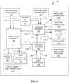
- FIG. 1is a block diagram illustrating an exemplary system that includes a ventilator for use by a human patient.
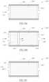
- FIG. 2Ais an illustration of a first embodiment of a passive patient circuit for use with the ventilator of FIG. 1 .
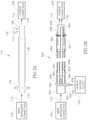
- FIG. 2Bis a cross-sectional view of a second embodiment of a passive patient circuit for use with the ventilator of FIG. 1 .
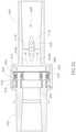
- FIG. 2Cis an enlarged cross-sectional view of a valve assembly of the passive patient circuit of FIG. 2B illustrated in a closed configuration.
- FIG. 2Dis an enlarged cross-sectional view of the valve assembly of the passive patient circuit of FIG. 2B illustrated in an open configuration.
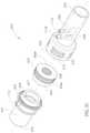
- FIG. 2Eis an exploded view of a valve assembly of the passive patient circuit of FIG. 2B .
- FIG. 3Ais a cross-sectional view of an embodiment of an active patient circuit for use with the ventilator of FIG. 1 .
- FIG. 3Bis an exploded view of a multi-lumen tube assembly of the active patient circuit of FIG. 3A .
- FIG. 3Cis an exploded view of an active exhalation valve assembly of the active patient circuit of FIG. 3A .
- FIG. 3Dis an enlarged perspective view of a double bellows member of the active exhalation valve assembly of FIG. 3C .
- FIG. 3Eis an enlarged cross-sectional view of the active patient circuit of FIG. 3A illustrated with the double bellows member of the active exhalation valve assembly in a closed position.
- FIG. 3Fis a first enlarged cross-sectional view of the active patient circuit of FIG. 3A illustrated with the double bellows member of the active exhalation valve assembly in an open position.
- FIG. 3Gis a second enlarged cross-sectional view of the active patient circuit of FIG. 3A illustrated with the double bellows member of the active exhalation valve assembly in the open position.
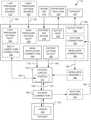
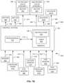
- FIG. 4is block diagram illustrating some exemplary components of the ventilator of FIG. 1 .
- FIG. 5Ais a schematic diagram illustrating some exemplary components of a ventilator assembly of the ventilator of FIG. 1 .
- FIG. 5Bis block diagram illustrating exemplary components of a control system of the ventilator, control signals sent by the control system to exemplary components of the ventilation assembly, and the data signals received by the control system from exemplary components of the ventilation assembly.
- FIG. 6is block diagram illustrating some exemplary components of a user interface of the ventilator of FIG. 1 .
- FIG. 7Ais a schematic diagram illustrating some exemplary components of an oxygen assembly of the ventilator of FIG. 1 .
- FIG. 7Bis block diagram illustrating exemplary control signals sent by the control system to exemplary components of the oxygen assembly, and the data signals received by the control system from exemplary components of the oxygen assembly.
- FIG. 8Ais a block diagram illustrating an adsorption bed of the oxygen assembly during a first phase of a vacuum pressure swing absorption (“VPSA”) process.
- VPSAvacuum pressure swing absorption
- FIG. 8Bis a block diagram illustrating the adsorption bed of the oxygen assembly during a second phase of the VPSA process.
- FIG. 8Cis a block diagram illustrating the adsorption bed of the oxygen assembly during a third phase of the VPSA process.
- FIG. 8Dis a block diagram illustrating the adsorption bed of the oxygen assembly during a fourth phase of the VPSA process.
- FIG. 9is an illustration of a metering valve of the oxygen assembly.
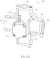
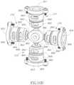
- FIG. 10Ais a perspective view of a first side of a first rotary valve assembly of the oxygen assembly.
- FIG. 10Bis a perspective view of a second side of the first rotary valve assembly.
- FIG. 10Cis a perspective view of the first side of the first rotary valve assembly including a shaft of a motor assembly and omitting other parts of the motor assembly.
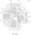
- FIG. 10Dis a perspective view of the second side of the first rotary valve assembly with its outer housing and printed circuit board removed.
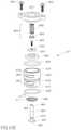
- FIG. 10Eis an exploded perspective view of one of four poppet valves of the first rotary valve assembly illustrated with an end cap and fasteners.
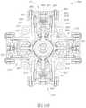
- FIG. 10Fis a cross-sectional view of the first rotary valve assembly with its second and fourth poppet valves open.
- FIG. 10Gis a cross-sectional view of the first rotary valve assembly with its first and third poppet valves open.
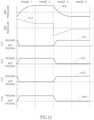
- FIG. 11is a graph showing pressure and feed flow experienced by a bed of nitrogen adsorbent material of the oxygen generator during the four phases of the VPSA process.
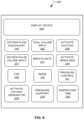
- FIG. 12is a flow diagram of a method performed by the control system of the ventilator of FIG. 1 .
- FIG. 13Ais an illustration of an optional second rotary valve assembly of the oxygen assembly depicted with a first one of its four poppet valves open.
- FIG. 13Bis an illustration of the optional second rotary valve assembly of the oxygen assembly depicted with a second one of its four poppet valves open.
- FIG. 13Cis an illustration of the optional second rotary valve assembly of the oxygen assembly depicted with a third one of its four poppet valves open.
- FIG. 13Dis an illustration of the optional second rotary valve assembly of the oxygen assembly depicted with a fourth one of its four poppet valves open.
- FIG. 14Ais a graph showing patient airway flow using a prior art ventilator during both inspiratory and expiratory phases.
- FIG. 14Bis a graph showing patient airway pressure using the prior art ventilator during both the inspiratory and expiratory phases.
- FIG. 15Ais a graph showing patient airway flow using the ventilator of FIG. 1 during both inspiratory and expiratory phases.
- FIG. 15Bis a graph showing patient airway pressure using the ventilator of FIG. 1 during both the inspiratory and expiratory phases.
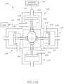
- FIG. 16is a block diagram illustrating an exemplary suction assembly for use with the ventilator of FIG. 1 .
- FIG. 1is a block diagram illustrating an exemplary system 10 that includes a ventilator 100 for use by a patient 102 .
- the ventilator 100may be configured to provide both traditional volume controlled ventilation and pressure controlled ventilation.
- the ventilator 100has an optional multi-lumen tube connection 103 , a main ventilator connection 104 , and an patient oxygen outlet 105 .
- the patient 102has a patient connection 106 (e.g., a tracheal tube, a nasal mask, a mouthpiece, and the like) that is connectable to the main ventilator connection 104 and/or the patient oxygen outlet 105 by a patient circuit 110 .
- a patient connection 106e.g., a tracheal tube, a nasal mask, a mouthpiece, and the like
- the patient circuit 110may be implemented as an active patient circuit or a passive patient circuit.
- the patient circuit 110may include one or more ports 111 configured to be connected to the optional multi-lumen tube connection 103 .
- the port(s) 111allow one or more pressure signals 109 to flow between the optional multi-lumen tube connection 103 and the patient circuit 110 .
- a pressure signalmay be characterized as gas(es) obtained from a fluid (and/or gas) source for which a pressure is to be measured.
- the gas(es) obtainedare at the same pressure as the fluid (and/or gas) source.
- the main ventilator connection 104is configured to provide gases 112 that include room air 114 optionally mixed with oxygen. While identified as being “room air,” those of ordinary skill in the art appreciate that the room air 114 may include air obtained from any source external to the ventilator 100 .
- the air 114is received by the ventilator 100 via a patient air intake 116 .
- the oxygen that is optionally mixed with the air 114may be generated internally by the ventilator 100 and/or received from an optional low pressure oxygen source 118 (e.g., an oxygen concentrator), and/or an optional high pressure oxygen source 120 .
- the ventilator 100may output exhaust gases (e.g., nitrogen-rich gas 122 ) via an outlet vent 124 .
- the ventilator 100may include a low pressure oxygen inlet 126 configured to be coupled to the optional low pressure oxygen source 118 and receive optional low pressure oxygen 128 therefrom.
- the ventilator 100may include an optional high pressure oxygen inlet 130 configured to be coupled to the optional high pressure oxygen source 120 and receive optional high pressure oxygen 132 therefrom.
- the patient oxygen outlet 105is configured to provide doses or pulses of oxygen 140 to the patient connection 106 (via the patient circuit 110 ) that are synchronized with the patient's breathing. Unlike the gases 112 provided by the main ventilator connection 104 , the pulses of oxygen 140 do not include the air 114 .
- the gases 112 and/or the pulses of oxygen 140 delivered to the patient circuit 110are conducted thereby as inspiratory gases 108 to the patient connection 106 , which at least in part conducts those gases into the patient's lung(s) 142 .
- exhaled gases 107enter the patient circuit 110 via the patient connection 106 .
- the patient circuit 110may contain one or more of the following gases: the gases 112 provided by the ventilator 100 , the pulses of oxygen 140 , and the exhaled gases 107 .
- the gases inside the patient circuit 110will be referred to hereafter as “patient gases.”
- the ventilator 100includes a suction connection 150 configured to be coupled to an optional suction assembly 152 .
- the ventilator 100may provide suction 154 to the optional suction assembly 152 via the optional suction connection 150 .
- the suction assembly 152may be configured to be connected to the patient connection 106 and/or a suction catheter 812 (see FIG. 16 ) positionable inside the patient connection 106 .
- the ventilator 100includes a nebulizer connection 160 configured to be coupled to an optional nebulizer assembly 162 .
- the ventilator 100may provide gases 164 (e.g., the air 114 ) to the optional nebulizer assembly 162 via the optional nebulizer connection 160 .
- the optional nebulizer assembly 162may be configured to be connected to the patient circuit 110 . However, this is not a requirement.
- the ventilator 100may include an outlet port 166 through which exhaust 167 may exit from the ventilator 100 .
- the ventilator 100may be configured to be portable and powered by an internal battery (not shown) and/or an external power source (not shown) such as a conventional wall outlet.
- FIG. 2Ais an illustration of a first embodiment of a passive patient circuit 170 that may be used to implement the patient circuit 110 .
- the passive patient circuit 170has a first end portion 172 opposite a second end portion 174 .
- the first end portion 172is configured to be connected or coupled (e.g., directly or using a hose, flow line, conduit, or tube) to the main ventilator connection 104 .
- the second end portion 174is configured to be connected or coupled to the patient connection 106 (e.g., directly or using a hose, flow line, conduit, or tube).
- the passive patient circuit 170conducts the gases 112 (that include the air 114 optionally mixed with oxygen) from the main ventilator connection 104 into the patient connection 106 .
- the passive patient circuit 170includes an optional bacterial filter 176 , a leak valve 177 , and a flexible tube segment 178 .
- the optional bacterial filter 176may be positioned between the first end portion 172 and the flexible tube segment 178 .
- the gases 112may flow through the optional bacterial filter 176 and on to the patient connection 106 .
- the bacterial filter 176helps prevent bacteria (e.g., received from the patient connection 106 ) from entering the ventilator 100 (via the main ventilator connection 104 ).
- the leak valve 177is coupled to the flexible tube segment 178 near the second end portion 174 .
- the leak valve 177is configured to allow gases to flow out of the passive patient circuit 170 and into the environment outside the passive patient circuit 170 .
- the leak valve 177may be implemented as a conventional fixed leak valve configured to allow at most a threshold amount of pressure inside the passive patient circuit 170 during both the inspiratory and exhalation phases.
- the leak valve 177may be implemented as a positive pressure valve that allows a portion of the patient gases to flow out of the passive patient circuit 170 and into the environment outside the passive patient circuit 170 whenever the pressure inside the passive patient circuit 170 is above the threshold amount (e.g., environmental pressure).
- the leak valve 177includes a flexible member or flap 179 that covers and seals an outlet opening 180 when the pressure inside the passive patient circuit 170 is below the threshold amount. Thus, the leak valve 177 is closed when the pressure inside the passive patient circuit 170 is below the threshold amount.
- the flap 179is configured to be pushed outwardly and away from the outlet opening 180 when the pressure inside the passive patient circuit 170 exceeds the threshold amount (e.g., environmental pressure).
- the threshold amounte.g., environmental pressure
- the leak valve 177is open when the pressure inside the passive patient circuit 170 is above the threshold amount.
- the leak valve 177is open during both the inspiratory and exhalation phases. This means a portion of the patient gases inside the passive patient circuit 170 flow out of the passive patient circuit 170 through the outlet opening 180 and into the environment outside the passive patient circuit 170 during both the inspiratory and exhalation phases.
- FIG. 2Bis an illustration of a second embodiment of a passive patient circuit 440 that may be used to implement the patient circuit 110 .
- the passive patient circuit 440includes a connector 442 , a flexible tube segment 444 , an open-ended oxygen pulse delivery tube 446 , and a valve assembly 448 .
- the flexible tube segment 444may be implemented using a conventional corrugated or expanding ventilation hose or tubing (e.g., circuit tubing).
- the flexible tube segment 444has a first end portion 450 opposite a second end portion 451 .
- the first end portion 450is configured to be connected or coupled to the connector 442 .
- the second end portion 451is configured to be connected or coupled to the valve assembly 448 .
- the connector 442has a generally tube-shaped connector housing 452 with a first end portion 454 configured to be connected to the main ventilator connection 104 (e.g., directly or using a hose, flow line, conduit, or tube) and to receive the gases 112 (that include the air 114 optionally mixed with oxygen) from the main ventilator connection 104 .
- the bacterial filter 176may be positioned between the connector 442 and the main ventilator connection 104 . In such embodiments, the gases 112 flow through the bacterial filter 176 on their way to the connector 442 .
- the bacterial filter 176helps prevent bacteria (e.g., received from the patient connection 106 ) from entering the ventilator 100 (via the main ventilator connection 104 ).
- the connector housing 452has a second end portion 456 configured to be coupled to the first end portion 450 of the flexible tube segment 444 and to provide the gases 112 received by the first end portion 454 to the flexible tube segment 444 .
- the flexible tube segment 444conducts the gases 112 to the valve assembly 448 .
- the connector 442includes a hollow tube section 458 that extends outwardly from the connector housing 452 .
- the tube section 458is substantially transverse to the connector housing 452 .
- the tube section 458has an open free end portion 459 configured to be connected to the patient oxygen outlet 105 (e.g., directly or using a hose, flow line, conduit, or tube) and to receive the pulses of oxygen 140 therefrom.
- the tube section 458is connected to the oxygen pulse delivery tube 446 and provides the pulses of oxygen 140 thereto.
- the tube section 458is connected to or includes a branch tube 460 that extends longitudinally inside the connector housing 452 .
- the branch tube 460has an open free end 462 configured to be coupled to the oxygen pulse delivery tube 446 and provide the pulses of oxygen 140 thereto. While the tube section 458 extends into the connector housing 452 , the tube section 458 only partially obstructs the flow of the gases 112 through the connector housing 452 . In other words, the gases 112 pass by or alongside the tube section 458 and the branch tube 460 , if present.
- the oxygen pulse delivery tube 446extends through the flexible tube segment 444 and at least part way into the valve assembly 448 .
- the oxygen pulse delivery tube 446isolates the pulses of oxygen 140 from the gases in the flexible tube segment 444 along a majority portion of the passive patient circuit 440 .
- the oxygen pulse delivery tube 446has a first end portion 464 configured to be coupled to the branch tube 460 .
- the oxygen pulse delivery tube 446has a second end portion 465 that terminates at or near the patient connection 106 .
- the second end portion 465may terminate within about two centimeters of the patient connection 106 .
- the oxygen pulse delivery tube 446conducts the pulses of oxygen 140 from the branch tube 460 to the patient connection 106 .
- the passive patient circuit 440conducts the gases 112 (that include the air 114 optionally mixed with oxygen) from the main ventilator connection 104 into the patient connection 106 .
- the oxygen pulse delivery tube 446may be connected to the patient oxygen outlet 105 (e.g., directly or using a hose, flow line, conduit, or tube) to receive the pulses of oxygen 140 from the patient oxygen outlet 105 .
- the oxygen pulse delivery tube 446may extend along the outside of the flexible tube segment 444 .
- the second end portion 465 of the oxygen pulse delivery tube 446may be connected to a portion of the passive patient circuit 440 at or near the patient connection 106 to provide the pulses of oxygen 140 from the branch tube 460 to the patient connection 106 .
- FIGS. 2C-2Eillustrate exemplary components of the valve assembly 448 .
- the valve assembly 448includes a first valve housing 468 , a second valve housing 469 , and a flexible ring-shaped leaf 470 .
- the first valve housing 468is configured to be coupled to the patient connection 106 (see FIG. 2A ) and the second valve housing 469 is configured to be coupled to the second end portion 451 of the flexible tube segment 444 .
- the first and second valve housings 468 and 469are configured to be coupled together with the ring-shaped leaf 470 positioned therebetween.
- a peripheral portion 473 of the leaf 470is positioned within a ring-shaped chamber 474 defined by the first and second valve housings 468 and 469 .
- One or more openings 476are formed in the second valve housing 469 and connect the chamber 474 with the environment outside the passive patient circuit 440 (see FIG. 2A ).
- one or more openings 478are formed in the second valve housing 469 and connect the patient gases inside the passive patient circuit 440 (see FIG. 2A ) with the chamber 474 .
- the peripheral portion 473 of the leaf 470is configured to transition or deflect from a closed position (see FIG. 2C ) and an open position (see FIG. 2D ) when the pressure inside the passive patient circuit 440 (see FIG. 2A ) exceeds the threshold amount (e.g., environmental pressure).
- the threshold amounte.g., environmental pressure.
- the leaf 470blocks off the one or more openings 478 and isolates the chamber 474 from the environment inside the passive patient circuit 440 (see FIG. 2A ).
- the peripheral portion 473 of the leaf 470is in the open position depicted in FIG.
- the leaf 470no longer blocks off the one or more openings 478 and allows the chamber 474 to communicate with the patient gases inside and outside the passive patient circuit 440 (see FIG. 2A ).
- gasesmay exit the interior of the passive patient circuit 440 (see FIG. 2A ) through the opening(s) 478 , the chamber 474 , and the opening(s) 476 .
- the ventilator 100adjusts the pressure inside the passive patient circuit 440 to achieve a preset inspiratory pressure, which places or maintains the leaf 470 in the open position. Some of the patient gases flow to the patient 102 (see FIG. 1 ), and some of the patent gases flow out through the openings 476 .
- the ventilator 100adjusts the pressure inside the passive patient circuit 440 to achieve a baseline or positive end-expiratory pressure (“PEEP”), which places or maintains the leaf 470 in the open position.
- PEEPpositive end-expiratory pressure
- Some of the exhaled gases 107 (see FIG. 1 ) from the patient 102flow out through the openings 476 , and some of the exhaled gases 107 flow into the passive patient circuit 440 (e.g., into the flexible tube segment 444 ).
- the breath 102may pause between the end of the exhalation phase and the beginning of the inspiratory phase. This pause may be characterized as a dead time that occurs between the phases.
- the ventilator 100adjusts the pressure inside the passive patient circuit 440 to PEEP, which places or maintains the leaf 470 in the open position, and causes the flow of the gases 112 from the ventilator 100 to flow out of the passive patient circuit 440 through the openings 476 .
- at least a portion of the exhaled gases 107 that flowed into the passive patient circuit 440 during the exhalation phaseis “purged” out through the openings 476 by the forward moving flow of the gases 112 from the ventilator 100 .
- the combined areas of the openings 476may be characterized as providing a fixed orifice.
- the valve assembly 448may be characterized as being a one-way valve with a fixed orifice. If the combined areas of the openings 476 is too large, most of the inspiratory flow will leak out through the openings 476 , leaving little for the patient 102 . Conversely, if the combined areas of the openings 476 is too small, the exhaled gases 107 will not be fully purged from the passive patient circuit 440 during the exhalation phase and the pause between the inspiratory and exhalation phases.
- the valve assembly 448may be configured to leak about 20-50 liters per minute (“LPM”) when the pressure inside the passive patient circuit 440 is about 10 centimeters of water (“cmH20”).
- FIG. 3Adepicts an active patient circuit 600 that may be used to implement the patient circuit 110 (see FIG. 1 ).
- the active patient circuit 600includes the connector 442 , the flexible tube segment 444 , the oxygen pulse delivery tube 446 , a multi-lumen tube assembly 602 , and an active exhalation valve assembly 604 .
- the connector 442is coupled to both the first end portion 450 of the flexible tube segment 444 and the oxygen pulse delivery tube 446 .
- the connector 442receives the gases 112 and provides them to the flexible tube segment 444 .
- the connector 442receives the pulses of oxygen 140 and provides them to the oxygen pulse delivery tube 446 .
- the pulses of oxygen 140exit the oxygen pulse delivery tube 446 at or near the patient connection 106 .
- the pulses of oxygen 140may exit the oxygen pulse delivery tube 446 within about centimeters of the patient connection 106 .
- the pulses of oxygen 140exit the oxygen pulse delivery tube 446 at or near the active exhalation valve assembly 604 .
- the bacterial filter 176may be positioned between the connector 442 and the main ventilator connection 104 .
- the gases 112flow through the bacterial filter 176 on their way to the connector 442 .
- the bacterial filter 176helps prevent bacteria (e.g., received from the patient connection 106 ) from entering the ventilator 100 (via the main ventilator connection 104 ).
- the second end portion 451 of the flexible tube segment 444is configured to be coupled to the active exhalation valve assembly 604 .
- the patient circuit 110may include one or more ports 111 configured to allow the one or more pressure signals 109 to flow between the optional multi-lumen tube connection 103 and the patient circuit 110 .
- the ports 111(see FIG. 1 ) include ports 111 A- 111 C spaced apart from one another longitudinally.
- the ports 111 A- 111 Care each formed in the active exhalation valve assembly 604 .
- the port 111 Cis referred to hereafter as the pilot port 111 C.
- FIG. 3Bis exploded perspective view of the multi-lumen tube assembly 602 .
- the multi-lumen tube assembly 602includes a coupler 608 , an elongated tube segment 610 , and a connector member 612 .
- the coupler 608is configured to couple a first end portion 620 of the tube segment 610 to the optional multi-lumen tube connection 103 (see FIG. 3A ).
- the tube segment 610has a second end portion 622 opposite the first end portion 620 .
- the second end portion 622is connected to the connector member 612 .
- Three separate and continuous open-ended channels 626 A- 626 Cextend longitudinally through the tube segment 610 .
- the connector member 612has three connectors 630 A- 630 C configured to connected to the ports 111 A- 111 C (see FIG. 3C ), respectively.
- the connectors 630 A and 630 Breceive pressure signals 109 A and 109 B (see FIG. 5A ), respectively, from the ports 111 A and 111 B, respectively.
- the connector 630 Cconducts a pressure signal 109 C (see FIG. 5A ) to and from the pilot port 111 C.
- Continuous channels 632 A- 632 Cextend from the connectors 630 A- 630 C, respectively, to an end portion 634 of the connector member 612 .
- the continuous channels 626 A- 626 C of the tube segment 610are aligned and communicate with the continuous channels 632 A- 632 C, respectively.
- the multi-lumen tube assembly 602may be used to conduct the separate pressure signals 109 A and 109 B, respectively, from the ports 111 A and 111 B, respectively, to the optional multi-lumen tube connection 103 . Further, the multi-lumen tube assembly 602 may be used to conduct the pressure signal 109 C to the pilot port 111 C from the optional multi-lumen tube connection 103 and vice versa.
- the active exhalation valve assembly 604includes a first valve housing member 640 , a double bellows member 644 , and a second valve housing member 642 .
- the ports 111 A and 111 Bare formed in the first valve housing member 640 and extend laterally outwardly therefrom.
- the pilot port 111 Cis formed in the second valve housing member 642 and extends laterally outwardly therefrom.
- FIGS. 3E and 3Fare enlarged longitudinal cross sectional views that each show a portion of the active patient circuit 600 that includes the active exhalation valve assembly 604 .
- the oxygen pulse delivery tube 446has been omitted from FIGS. 3E and 3F .
- the first valve housing member 640includes an internal obstruction 646 positioned between the ports 111 A and 111 B and configured to partially restrict flow through the first valve housing member 640 .
- the interior of the first valve housing member 640includes a first narrowed portion 647 A that is adjacent to the obstruction 646 and the port 111 A, and a second narrowed portion 647 B that is adjacent to the obstruction 646 and the port 111 B.
- first and second narrowed portions 647 A and 647 Bare positioned opposite one another longitudinally with respect to the obstruction 646 with the first narrowed portion 647 A being nearer to the patient connection 106 (see FIG. 3A ) than the second narrowed portion 647 B.
- the ports 111 A and 111 Bopen into the first and second narrowed portions 647 A and 647 B, respectively.
- the obstruction 646 , the first and second narrowed portions 647 A and 647 B, and the ports 111 A and 111 Bdefine an airway flow transducer 648 (e.g., a fixed orifice differential pressure type flow meter) inside the interior of the first valve housing member 640 .
- the gases 112may flow around the obstruction 646 along flow paths identified by curved arrows 649 A and 649 B.
- the exhaled gases 107may flow around the obstruction 646 along flow paths opposite those identified by the curved arrows 649 A and 649 B.
- the first valve housing member 640has a first end portion 650 configured to be coupled to the patient connection 106 (see FIG. 3A ) and a second end portion 652 configured to be coupled to the second valve housing member 642 .
- the second valve housing member 642has a first end portion 654 configured to be coupled to the second end portion 652 of the first valve housing member 640 , and a second end portion 656 configured to be coupled to the second end portion 451 of the flexible tube segment 444 .
- the first end portion 654 of the second valve housing member 642has a generally cylindrical shaped bellows connector portion 657 .
- An opening 658 of the pilot port 111 Cis formed in the bellows connector portion 657 of the second valve housing member 642 .
- the double bellows member 644has a generally ring-like outer shape with a centrally located through-channel 660 .
- the double bellows member 644has a hollow interior 662 with a ring-shaped open end 664 opposite a ring-shaped closed end 666 (see FIG. 3C ).
- the double bellows member 644has concertinaed inner and outer sidewalls 668 and 669 .
- the inner sidewall 668extends between the open end 664 and the closed end 666 along the centrally located through-channel 660 .
- the outer sidewall 669extends between the open end 664 and the closed end 666 and is spaced radially outwardly from the inner sidewall 668 .
- the hollow interior 662is defined between the inner and outer sidewalls 668 and 669 .
- Each of the inner and outer sidewalls 668 and 669have bellows portions 668 A and 669 A (see FIG. 3C ), respectively, which each have an undulating longitudinal cross-sectional shape.
- the inner and outer sidewalls 668 and 669may include different numbers of convolutions that define a single convolute or more than two convolutes.
- the open end 664is configured to fit over the bellows connector portion 657 of the second valve housing member 642 like a sleeve.
- the bellows portions 668 A and 669 A(see FIG. 3C ) of the inner and outer sidewalls 668 and 669 , respectively, are positioned adjacent to the bellows connector portion 657 of the second valve housing member 642 .
- the opening 658 of the pilot port 111 Cis in communication with a portion of the hollow interior 662 positioned between the bellows portions 668 A and 669 A (see FIG. 3C ) of the inner and outer sidewalls 668 and 669 , respectively.
- the opening 658 of the pilot port 111 Cmay provide the pressure signal 109 C to the interior of the double bellows member 644 .
- the second end portion 652 of the first valve housing member 640is configured to be coupled to the first end portion 654 of the second valve housing member 642 .
- a ring-shaped chamber 670is defined between the second end portion 652 of the first valve housing member 640 and the first end portion 654 of the second valve housing member 642 .
- One or more openings 672are formed in the first valve housing member 640 and connect the chamber 670 with the environment outside the active patient circuit 600 (see FIG. 3A ).
- the bellows portion 668 A and 669 A (see FIG. 3C ) of the outer sidewall 669 and a peripheral portion 674 of the closed end 666is positioned within the chamber 670 .
- the double bellows member 644is constructed from a flexible material (e.g., silicone rubber and the like).
- the bellows portions 668 A and 669 A (see FIG. 3C ) of the inner and outer sidewalls 668 and 669 , respectively,are configured to compress to transition the closed end 666 from a closed position (see FIG. 3E ) to an open position (see FIG. 3F ).
- the bellows portions 668 A and 669 Aare not compressed, the closed end 666 is in the closed position depicted in FIG. 3E .
- the closed end 666 of the double bellows member 644abuts a ring-shaped seat 680 formed in the first valve housing member 640 and defining a portion of the chamber 670 . This seals the chamber 670 from the interior of the active patient circuit 600 .
- the bellows portions 668 A and 669 Aare compressed toward the second valve housing member 642 , the closed end 666 is in the open position depicted in FIG. 3F .
- the closed end 666is spaced away from the seat 680 .
- This opens the chamber 670by connecting the chamber 670 with the inside of the active patient circuit 600 .
- patient gases inside the active patient circuit 600may exit therefrom through the chamber 670 and the opening(s) 672 (see FIG. 3C ).
- the closed end 666 of the double bellows member 644is selectively moved between the open and closed positions by controlling the pressure inside the double bellows member 644 using the pilot port 111 C.
- the closed end 666 of the double bellows member 644may be placed in the closed position (see FIG. 3E ) during the inspiratory phase, and in the open position during the expiratory phase.
- the pilot port 111 Cprovides a flow of gases (as the pressure signal 109 C) having the same pressure as the gases 112 (provided to the active patient circuit 600 ) to the hollow interior 662 of the double bellows member 644 .
- An area of the double bellows member 644 exposed to a pressure provided by the patient 102 (see FIG. 1 ) via the patient connection 106is less than an area exposed to the pressure of the pressure signal 109 C, so that even if the two pressures are equal, the closed end 666 of the double bellows member 644 will move to or remain in the closed position against the seat 680 .
- the pilot port 111 Cprovides a flow of gases (as the pressure signal 109 C) having a pilot pressure to the hollow interior 662 of the double bellows member 644 .
- the pilot pressureis less than the pressure provided by the patient 102 (see FIG.
- the pressure inside the hollow interior 662 of the double bellows member 644may be alternated between a closed pressure that is the same pressure as the gases 112 (provided to the active patient circuit 600 ), and an open pressure that is equal to the pilot pressure. If desired, the pressure inside the hollow interior 662 of the double bellows member 644 may be adjusted by allowing the flow of gases (in the pressure signal 109 C) to flow from the hollow interior 662 to the pilot port 111 C.
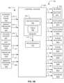
- FIG. 4is a block diagram illustrating some exemplary components of the ventilator 100 .
- the ventilator 100includes a ventilation assembly 190 , a user interface 200 , an oxygen assembly 210 , a control system 220 , and conventional monitoring and alarm systems 221 . Because those of ordinary skill in the art are familiar with conventional monitoring and alarm systems 221 , they will not be described in detail herein.
- the control system 220receives input information 196 (e.g., settings, parameter values, and the like) from the user interface 200 , and provides output information 198 (e.g., performance information, status information, and the like) to the user interface 200 .
- the user interface 200is configured to receive input from a user (e.g., a caregiver, a clinician, and the like associated with the patient 102 depicted in FIG. 1 ) and provide that input to the control system 220 in the input information 196 .
- the user interface 200is also configured to display the output information 198 to the user.
- the patient circuit 110may include the optional port(s) 111 configured to allow one or more pressure signals 109 to flow between the optional multi-lumen tube connection 103 and the patient circuit 110 .
- the optional multi-lumen tube connection 103is configured to provide the pressure signal(s) 109 to the ventilation assembly 190 .
- the ventilation assembly 190may receive one or more control signals 192 from the control system 220 , and the ventilation assembly 190 may provide one or more data signals 194 to the control system 220 .
- the oxygen assembly 210may receive one or more control signals 260 from the control system 220 , and the oxygen assembly 210 may provide one or more data signals 262 to the control system 220 .
- the control signals 192 and 260 and the data signals 194 and 262may be used by the control system 220 to monitor and/or control internal operations of the ventilator 100 .
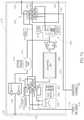
- FIG. 5Ais a schematic diagram illustrating some exemplary components of the ventilation assembly 190 .
- FIG. 5Bis a block diagram illustrating exemplary components of the control system 220 , the control signal(s) 192 sent by the control system 220 to exemplary components of the ventilation assembly 190 , and the data signals 194 received by the control system 220 from exemplary components of the ventilation assembly 190 .
- the ventilation assembly 190includes an accumulator 202 , an internal flow transducer 212 , a blower 222 , an airway pressure transducer 224 , an airway flow transducer module 225 , an exhalation control assembly 226 , an oxygen sensor 227 , an ambient pressure transducer 228 , an inlet silencer 229 , and an internal bacteria filter 230 .
- the air 114may be drawn into the ventilator 100 (see FIGS. 1 and 4 ) through the patient air intake 116 , which may be configured to filter dust and/or other types of particles from the air.
- At least a portion of the air 114flows into the accumulator 202 where the air 114 may optionally be mixed with oxygen 250 received from the oxygen assembly 210 , the low pressure oxygen 128 (received from the low-pressure external oxygen source 118 depicted in FIG. 1 ), combinations and/or sub-combinations thereof, and the like.
- the high pressure oxygen 132(received from the high-pressure external oxygen source 120 depicted in FIG. 1 ) flows into the oxygen assembly 210 and may be delivered to the accumulator 202 (see FIG. 5A ) as the oxygen 250 .
- the accumulator 202may also serve as a muffler for the patient air intake 116 .
- the inlet silencer 229helps muffle sounds created by the oxygen assembly 210 (e.g., by a compressor 302 illustrated in FIG. 7A ).
- the oxygen sensor 227is connected to the accumulator 202 and measures an oxygen concentration value of the gas(es) inside the accumulator 202 . This value approximates the oxygen concentration value of a gas 252 that exits the accumulator 202 .
- the oxygen sensor 227provides an oxygen concentration signal 276 encoding the oxygen concentration value to the control system 220 .
- the control system 220processes the oxygen concentration signal 276 to obtain a measure of how much oxygen is in the gas 252 (e.g., expressed as a percentage).
- the output information 198 sent by the control system 220 to the user interface 200may include the measure of how much oxygen is in the gas 252 .
- the user interface 200may display this measure to the user (e.g., the patient 102 depicted in FIG. 1 ).
- the accumulator 202includes or is connected to the low-pressure oxygen inlet 126 .
- the control system 220may not control the resulting oxygen concentration flowing to the patient 102 .
- the low-pressure oxygen 128may simply flow into the accumulator 202 , be mixed with the air 114 , and pushed into the patient circuit 110 (see FIG. 1 ) by the blower 222 .
- the ventilator 100does not control the oxygen concentration delivered to the patient 102 in the inspiratory gases 108 (see FIG. 1 ), but does control the delivery of the inspiratory gases 108 during the inspiratory phase of each breath.
- the gas 252 exiting the accumulator 202includes the air 114 and optionally one or more of the oxygen 250 and the oxygen 128 .
- the gas 252may be conducted via a conduit or flow line 214 to the internal flow transducer 212 .
- a portion of the flow line 214 between the accumulator 202 and the internal flow transducer 212has been omitted from FIG. 5A .
- the gas 252flows through the internal flow transducer 212 , which measures a flow rate of the gas 252 and provides a flow signal 270 (see FIG. 5B ) encoding the flow rate to the control system 220 (see FIG. 5B ).
- the flow signal 270may be implemented as an analog electric signal. Referring to FIG.
- the control system 220uses the flow signal 270 to control the blower 222 .
- the internal flow transducer 212may be implemented using a flow transducer having a fixed orifice differential pressure configuration.
- the internal flow transducer 212may be used to detect when the patient 102 (see FIG. 1 ) has initiated a breath.
- the internal flow transducer 212may be used in this manner when the patient circuit 110 (see FIG. 1 ) is implemented as a passive patient circuit (e.g., the passive patient circuit 170 , the passive patient circuit 440 , and the like).
- the flow of gases through the flow line 214is not determined entirely by the blower 222 . Instead, the patient's breathing efforts may cause a change in the flow rate through the flow line 214 .
- the control system 220may identify that the patient 102 has initiated a breath by identifying a change in the flow rate (encoded in the flow signal 270 ) through the flow line 214 .
- the internal flow transducer 212may include or be connected to an auto zero solenoid valve SV 5 configured to be selectively activated and deactivated by a control signal 285 (see FIG. 5B ) sent by the control system 220 .
- the internal flow transducer 212may drift over time, causing flow rate measuring errors. To compensate for this error, occasionally (e.g., periodically) the control system 220 energizes (or activates) the auto zero solenoid valve SV 5 (using the control signal 285 ) and determines an offset value for the internal flow transducer 212 . After determining the offset value, the control system 220 uses the offset value to compensate future readings (based on the flow signal 270 ) accordingly.
- the blower 222may be implemented as a radial blower driven by a motor 272 .
- the motor 272may be implemented as a brushless direct current motor.
- the blower 222may be implemented as a compressor, a pump, and the like.
- the motor 272has an operating speed that is controlled by the control system 220 .
- the control system 220may continuously control the operating speed of the motor 272 .
- the gas 252flows out of the blower 222 and into a conduit or flow line 273 .
- the flow line 273may include one or more ports (e.g., a blower port 275 A and a port 275 B) configured to provide access to the flow of the gas 252 in the flow line 273 .
- the flow line 273conducts the flow of the gas 252 from the blower 222 to the internal bacteria filter 230 .
- a portion of the flow line 273 between the ports 275 A and 275 Bhas been omitted from FIG. 5A .
- the airway pressure transducer 224measures airway pressure of the gas 252 flowing out of the blower 222 and toward the main ventilator connection 104 .
- the airway pressure transducer 224provides an electrical pressure signal 274 encoding these pressure values to the control system 220 .
- the electrical pressure signal 274is used to control patient pressure during the inspiratory and exhalation phases.
- the electrical pressure signal 274is also used by the monitoring and alarm systems 221 (see FIG. 4 ).
- the ventilator 100may include one or more redundant airway pressure transducers (not shown) like the airway pressure transducer 224 to provide a failsafe backup for the airway pressure transducer 224 .
- the airway pressure transducer 224may be used by the control system 220 to detect a pressure change and in response to detecting a pressure change, instruct the blower 222 to increase or decrease its speed to adjust the pressure inside the flow line 273 .
- the control system 220may use the electrical pressure signal 274 to deliver pressure ventilation and/or help ensure the pressure inside the flow line 273 does not exceed an user supplied peak inspiratory pressure value (e.g., entered via the pressure control input 237 depicted in FIG. 6 ).
- the airway flow transducer module 225includes a differential pressure transducer PT 4 , auto zero solenoid valves SV 1 and SV 2 , and purge solenoid valves SV 3 and SV 4 .
- the control system 220may selectively activate or deactivate the solenoid valves SV 1 -SV 4 using control signals 281 - 284 , respectively.
- the patient circuit 110may include the one or more optional ports 111 .
- FIG. 5Aillustrates an implementation of the ventilation assembly 190 configured for use with the patient circuit 110 implemented as an active patient circuit (e.g., the active patient circuit 600 depicted in FIG. 3A , and the like).
- the ports 275 A and 275 B, the airway flow transducer module 225 , and the exhalation control assembly 226may be omitted from the ventilation assembly 190 .
- the airway flow transducer module 225 , and the exhalation control assembly 226 illustrated in FIG. 5Aare configured for use with an active patient circuit (e.g., the active patient circuit 600 depicted in FIG. 3A ) that includes the airway flow transducer 648 (see FIG. 3G ).
- an active patient circuite.g., the active patient circuit 600 depicted in FIG. 3A
- the first and second ports 111 A and 111 Bsend first and second pressure signals 109 A and 109 B, respectively, (e.g., via separate lines or channels) to the differential pressure transducer PT 4 .
- the differential pressure transducer PT 4has input ports PA and PB configured to receive the first and second pressure signals 109 A and 109 B, respectively.
- the differential pressure transducer PT 4determines a differential pressure based on the first and second pressure signals 109 A and 109 B, converts the differential pressure to a signal 277 (see FIG. 5B ), and (as illustrated in FIG. 56 ) transmits the signal 277 to the control system 220 for further processing thereby.
- the signal 277may be an analog signal.
- the signal 277may be used to detect when the patient 102 (see FIG. 1 ) has initiated a breath.
- the flow of gases through the active patient circuit 600(see FIG. 3A ) is not determined entirely by the blower 222 . Instead, the patient's breathing efforts may cause a change in the flow rate through the active patient circuit 600 .
- the control system 220may identify that the patient 102 has initiated a breath by identifying a change in the flow rate (encoded in the signal 277 ) through the active patient circuit 600 .
- the auto zero solenoid valves SV 1 and SV 2are connected to the input ports PA and PB, respectively, of the differential pressure transducer PT 4 . Further, each of the auto zero solenoid valves SV 1 and SV 2 is connected to ambient pressure.
- the differential pressure transducer PT 4can drift over time causing flow measuring errors. To compensate for this error, occasionally (e.g., periodically) the control system 220 energizes (or activates) the auto zero solenoid valves SV 1 and SV 2 (using the control signals 281 and 282 , respectively) and determines an offset value for the differential pressure transducer PT 4 .
- control system 220deactivates the auto zero solenoid valves SV 1 and SV 2 (using the control signals 281 and 282 , respectively). After determining the offset value, the control system 220 uses the offset value to compensate future readings (based on the signal 277 ) accordingly.
- the purge solenoid valves SV 3 and SV 4are connected to the blower port 275 A.
- the control system 220occasionally (e.g., periodically) energizes (or activates) the purge solenoid valves SV 3 and SV 4 (using the control signals 283 and 284 , respectively), which allows dry gas from the line 273 (see FIG.
- the lines, ports, and/or channelse.g., the optional multi-lumen tube connection 103 , the channels 626 A and 626 B, the channels 632 A and 632 B, the ports 111 A and 111 B, and the like
- conducting the pressure signals 109 A and 109 Bto purge those structures of any moisture that may have condensed from the humid patient breathing gas.
- the exhalation control assembly 226includes an accumulator A 2 , a pressure transducer PT 8 , and solenoid valves SV 6 -SV 8 .
- the accumulator A 2has three ports 267 - 269 and an internal pressure (referred as the “pilot pressure”).
- the pressure transducer PT 8is connected to the accumulator A 2 , measures the internal pressure inside the accumulator A 2 , and transmits this value to the control system 220 in an electrical pressure signal 271 (see FIG. 5B ).
- the solenoid valves SV 6 -SV 8are configured to be selectively activated and deactivated by control signals 286 - 288 , respectively, sent by the control system 220 to the solenoid valves SV 6 -SV 8 , respectively.
- the solenoid valve SV 6is connected to the first port 267 of the accumulator A 2 , the port 275 B, and the pilot port 111 C (see FIG. 3C ) of the active patient circuit 600 (see FIG. 3A ).
- the solenoid valve SV 7is connected to the second port 268 of the accumulator A 2 and the port 275 B.
- the solenoid valve SV 8is connected between the third port 269 of the accumulator A 2 and the outlet port 166 .
- the exhalation control assembly 226provides the pilot pressure (from the accumulator A 2 ) to the pilot port 111 C (see FIG. 3C ) of the active patient circuit 600 (see FIG. 3A ), which as described above, controls the active exhalation valve assembly 604 .
- the control system 220activates the solenoid valve SV 6 (using the control signal 286 ), which connects the pressure of the gases 252 (via the port 275 B) to the pilot port 111 C. This closes the active exhalation valve assembly 604 .
- the control system 220deactivates the solenoid valve SV 6 (using the control signal 286 ), which connects the internal pressure of the accumulator A 2 (or the pilot pressure) to the active exhalation valve assembly 604 , which opens the active exhalation valve assembly 604 .
- the control system 220uses the solenoid valves SV 7 and SV 8 to control the pilot pressure inside the accumulator A 2 using feedback provided by the pressure transducer PT 8 (via the electrical pressure signal 271 depicted in FIG. 5B ) to set a pilot pressure for the exhalation phase that will achieve the desired PEEP. For example, the control system 220 may lower the pilot pressure inside the accumulator A 2 by activating the solenoid valve SV 8 (using the control signal 288 ) to vent some of the gases inside the accumulator A 2 via the outlet port 166 as the exhaust 167 .
- control system 220may increase the pilot pressure by activating the solenoid valve SV 7 (using the control signal 287 ) to add some of the gases 252 (obtained via the port 275 B) to the inside of the accumulator A 2 .
- the control system 220uses the electrical pressure signal 274 (received from the airway pressure transducer 224 ) to help control the blower 222 .
- the control system 220sends a control signal 278 to the motor 272 , which directs the blower 222 to provide a desired flow rate and/or a desired amount of pressure to the patient 102 .
- the flow signal 270is used to help control the flow rate of the gas 252 during the inspiratory and exhalation phases.
- the electrical pressure signal 274is used to control the patient pressure during the inspiratory and exhalation phases.
- the ventilator 100adjusts the pressure inside the patient circuit 110 (e.g., the passive patient circuit 440 illustrated in FIG. 2B ) to achieve the preset inspiratory pressure during the inspiratory phase, the baseline pressure or PEEP during the exhalation phase, and PEEP during the pause between the inspiratory and exhalation phases. These adjustments are made by the control system 220 , which monitors the electrical pressure signal 274 , and uses the control signal 278 to increase or decrease the speed of the motor 272 to achieve the desired pressure inside the patient circuit 110 .
- the control system 220monitors the electrical pressure signal 274 , and uses the control signal 278 to increase or decrease the speed of the motor 272 to achieve the desired pressure inside the patient circuit 110 .
- the ambient pressure transducer 228measures an atmospheric pressure value.
- the ambient pressure transducer 228provides an ambient electrical pressure signal 280 encoding the atmospheric pressure value to the control system 220 .
- the control system 220uses the ambient electrical pressure signal 280 to correct the flow rate values (received via the flow signal 270 ), and/or the exhaled tidal volume value (calculated by the control system 220 ) to desired standard conditions.
- the flow line 273conducts the flow of the gas 252 from the blower 222 to the internal bacteria filter 230 .
- the gas 252passes through the internal bacteria filter 230 , they exit the internal bacteria filter 230 as the gases 112 and enter the patient circuit 110 (see FIG. 1 ) via the main ventilator connection 104 .
- the internal bacteria filter 230helps prevent bacteria in the patient circuit 110 from contaminating the ventilator 100 .
- FIG. 6is a block diagram illustrating some exemplary components of the user interface 200 .
- FIG. 4illustrates the output information 198 sent by the control system 220 to exemplary components of the user interface 200 , and the input information 196 received by the control system 220 from exemplary components of the user interface 200 .
- the user interface 200is configured to receive operating parameter values from a user (e.g., a clinician) and to display information to the user.
- the user interface 200may include a display device 240 (e.g., a liquid crystal display), a mode input 235 , an inspiratory time input 236 , a pressure control input 237 , a pressure support input 238 , an activate oxygen generator input 239 for activating oxygen generation (described below), a tidal volume input 242 , an oxygen flow equivalent 244 , a fraction of inspired oxygen (“FI02”) input 246 , a breath rate input 247 , an oxygen pulse volume input 251 , an activate suction input 248 for activing the suction assembly 152 (see FIG. 1 ), and an activate nebulizer input 249 for activing the nebulizer assembly 162 (see FIG. 1 ).
- a display device 240e.g., a liquid crystal display
- mode input 235e.g., an inspiratory
- the mode input 235is configured to receive an indication as to whether the ventilator 100 determines when each breath is initiated or the patient 102 determines when each breath is initiated.
- the breath rate input 247is configured to receive a rate (e.g., breaths per minute) at which breaths are to be delivered. If the user has indicated (using the mode input 235 ) that the ventilator 100 determines when each breath is initiated, the ventilator 100 will deliver breaths in accordance with the rate received by the breath rate input 247 (e.g., at regularly timed intervals).
- the ventilator 100will automatically deliver breaths as needed to ensure the patient 102 receives breaths at least as frequently as indicated by the rate received by the breath rate input 247 .
- the ventilator 100may identify the end of the inspiratory phase using time or a rate of flow of the gases 112 to the patient 102 . In the latter case, the patient 102 determines when the inspiratory phase ends.
- the inspiratory time input 236is configured to receive a value indicating a duration T i from the initiation of each breath to the end of the inspiratory phase.
- the ventilator 100may use the value (indicating the duration T i ) to identify the end of the inspiratory phase.
- the pressure support input 238receives an indication that the user would like to use the rate of flow of the gases 112 to the patient 102 (instead of the value indicating the duration T i ) to end the inspiratory phase.
- the ventilator 100may end the inspiratory phase of a breath when the flow rate of the gases 112 is only about 25% of a peak flow rate that occurred during the breath.
- the ventilator 100is configured to deliver the gases 112 alone, or a combination of the gases 112 and the pulses of oxygen 140 .
- the ventilator 100may be configured to provide both traditional volume controlled ventilation and pressure controlled ventilation.
- the usermay use the pressure control input 237 to enter a peak inspiratory pressure value.
- the ventilator 100uses the peak inspiratory pressure value to configure the gases 112 alone, or the combination of the gases 112 and the pulses of oxygen 140 such that the pressure during the inspiratory phases is at most the peak inspiratory pressure value.
- the FI02 input 246is configured to receive an oxygen concentration value.
- the ventilator 100uses the oxygen concentration value to configure the gases 112 to have an oxygen concentration equal to or approximating the oxygen concentration value.
- the oxygen pulse volume input 251is configured to receive an oxygen pulse volume value (e.g., expressed in milliliters, or a value within a predefined range, such as from 1 to 10, and the like).
- the ventilator 100uses the oxygen pulse volume value to configure each of the pulses of oxygen 140 to have a volume equal to or approximating the oxygen pulse volume value.
- the tidal volume input 242is configured to receive a desired total tidal volume value.
- the ventilator 100uses the desired total tidal volume value to output a volume of the gases 112 (illustrated by area 586 and described below) and one of the pulses of oxygen 140 (illustrated by area 584 and described below) during each breath.
- the total tidal volume deliveredis the combined volumes of gases 112 and the pulse of oxygen 140 delivered during the breath.
- the oxygen flow equivalent 244is configured to receive a desired oxygen delivery rate (expressed in liters per minute) that identifies a rate at which a hypothetical continuous oxygen flow may be bled into a conventional ventilator or the patient circuit 110 (see FIG. 1 ) from an external source (e.g., a stand-alone oxygen concentrator).
- the ventilator 100uses this value to configure each of the pulses of oxygen 140 (see FIG. 1 ) to deliver an amount of oxygen that would provide equivalent oxygenation to the patient 102 (see FIG. 1 ) as the hypothetical continuous oxygen flow.
- FIG. 7Ais a schematic diagram illustrating some exemplary components of the oxygen assembly 210 .
- FIG. 7Billustrates the control signals 260 sent by the control system 220 to exemplary components of the oxygen assembly 210 , and the data signals 262 received by the control system 220 from exemplary components of the oxygen assembly 210 .
- the oxygen assembly 210is configured to receive the high-pressure oxygen 132 and/or generate oxygen 346 (see FIG. 8B ) and provide the oxygen 250 to the accumulator 202 (see FIG. 5A ) of the ventilation assembly 190 and/or provide the pulses of oxygen 140 to the patient oxygen outlet 105 .
- the oxygen assembly 210may be configured to provide up to about two liters per minute (“LPM”) of approximately 90% pure oxygen.
- the oxygen assembly 210includes an adsorption bed 300 , the compressor 302 , a first rotary valve assembly 306 , two pressure transducers PT 2 and PT 3 , two pressure regulators R 1 and R 2 , an outlet silencer 311 , optional solenoid valves SV 9 and SV 10 , an oxygen tank 312 , an oxygen sensor 314 , a metering valve 320 , and an optional second rotary valve assembly 330 .
- the compressor 302 , the first rotary valve assembly 306 , the adsorption bed 300 , and the pressure regulators R 1 and R 2may be characterized as being an oxygen generator or oxygen concentrator.
- the oxygen generator illustrated in the figures and described belowimplements a vacuum pressure swing absorption (“VPSA”) process.
- the ventilator 100may include an oxygen generator that implements at least one of a polymer membrane separation process, an ion transport separation process, a cryogenic process, and the like.
- the VPSA process described belowis a subset of Pressure Swing Adsorption (PSA) and the oxygen generator may be configured to implement a PSA process other than the VPSA process described below.
- PSAPressure Swing Adsorption
- the adsorption bed 300is configured to harvest oxygen from the air 114 received via the patient air intake 116 .
- the adsorption bed 300may be configured to at least partially implement a VPSA process that includes a cycle with four phases (described below).
- the cyclealternately generates the oxygen 346 (see FIG. 8B ) and the nitrogen-rich gas 122 .
- the ventilator 100operates, the cycle is repeated until enough oxygen has been generated to fill the oxygen tank 312 .
- the oxygen tank 312is full, the cycles are halted or slowed until a sufficient amount of the oxygen in the oxygen tank 312 has been removed. Then, the cycles are resumed again or sped up as appropriate.
- the nitrogen-rich gas 122 generated by each cycleis exhausted to the outside environment via the outlet vent 124 .
- FIGS. 8A-8Dare block diagrams illustrating some exemplary components of the adsorption bed 300 .
- the adsorption bed 300includes at least one housing 340 having a first end 341 opposite a second end 343 .
- the housing 340contains a bed of nitrogen adsorbent material 344 (such as zeolite) between its first and second ends 341 and 343 .
- the bed of nitrogen adsorbent material 344preferentially absorbs nitrogen.
- the adsorption bed 300will be described as including a single housing containing a single bed of nitrogen adsorbent material.
- the adsorption bed 300may include two or more beds like the bed of nitrogen adsorbent material 344 that are each housed inside separate housings like the housing 340 .
- FIG. 8Aillustrates the adsorption bed 300 during a first phase.
- the air 114is pumped into the housing 340 by the compressor 302 (see FIG. 7A ).
- the housing 340is pressurized with the air 114 (by the compressor 302 )
- nitrogen in the airis preferentially adsorbed by the bed of nitrogen adsorbent material 344 , which leaves behind unadsorbed oxygen.
- the bed of nitrogen adsorbent material 344may include interstitial spaces in which the unadsorbed oxygen is held or trapped.
- FIG. 8Billustrates the adsorption bed 300 during a second phase of a cycle of the VPSA process.
- the oxygen 346is pumped from the housing 340 .
- the oxygen 346flows from the interstitial spaces and into the oxygen tank 312 (see FIG. 7A ).
- FIG. 8Cillustrates the adsorption bed 300 during a third phase of a cycle of the VPSA process.
- the nitrogen-rich gas 122is pulled from the bed of nitrogen adsorbent material 344 in the housing 340 (by the compressor 302 illustrated in FIG. 7A ) and vented to the outside environment via the outlet vent 124 (see FIG. 7A ).
- FIG. 8Dillustrates the adsorption bed 300 during a fourth phase of a cycle of the VPSA process.
- a flow of “purge” oxygen 348e.g., from the oxygen tank 312 illustrated in FIG. 7A ) may be used to help draw out the nitrogen-rich gas 122 and regenerate the bed of nitrogen adsorbent material 344 .
- the oxygen 346 (see FIG. 8B ) removed from the adsorption bed 300flows through the pressure regulator R 2 , and into the oxygen tank 312 where the oxygen 346 is stored. While this is occurring, the metering valve 320 may be closed, and the pressure regulator R 1 may be closed to prevent flow back into the adsorption bed 300 . Alternatively, the metering valve 320 may be at least partially open to allow some of the oxygen 346 to flow to the optional second rotary valve assembly 330 .
- the compressor 302is configured to alternately push the air 114 into the adsorption bed 300 (through the first rotary valve assembly 306 ) and pull the nitrogen-rich gas 122 out of the adsorption bed 300 (through the first rotary valve assembly 306 ).
- the compressor 302may be driven by a motor 350 and may include a sensor 352 (e.g., an encoder) configured to provide a signal 354 encoding the direction and speed of rotation of the motor 350 to the control system 220 .
- the motor 350is configured to receive instructions from the control system 220 encoded in a control signal 356 .
- the instructions in the control signal 356instruct the motor 350 to switch on or off and/or indicate in which direction the motor 350 is to rotate when switched on. Further, the control signal 356 may instruct the motor 350 at which speed to run. Referring to FIG. 7A , when the motor 350 runs in a first direction, the compressor 302 pushes air into the adsorption bed 300 . On the other hand, when the motor 350 runs in a second direction, the compressor 302 pulls the nitrogen-rich gas 122 (see FIGS. 8C and 8D ) from the adsorption bed 300 .
- the motor 350may be implemented as a brushless direct current motor.
- FIG. 9is an illustration of the metering valve 320 .
- the pressure transducer PT 3is connected across the metering valve 320 .
- the pressure transducer PT 3may determine a pressure differential value across the metering valve 320 .
- the pressure transducer PT 3provides a pressure differential signal 358 encoding the pressure differential value to the control system 220 .
- the metering valve 320may be driven by a stepper motor 322 configured to receive a control signal 360 from the control system 220 encoding a stepper position value.
- the stepper motor 322is configured to move to the stepper position value encoded in the control signal 360 .
- the metering valve 320is a stepper driven proportioning valve characterized by three variables: (1) valve position, (2) differential pressure across the valve (as measured by the pressure transducer PT 3 ), and (3) flow rate. When a particular flow rate is desired (e.g., entered by the user via the flow rate input 248 depicted in FIG.
- the control system 220uses the pressure differential signal 358 (encoding the pressure differential value) and the particular flow rate to “look up” a corresponding stepper position value in a characterization table 362 .
- the characterization table 362stores stepper position values each associated with a flow rate value and a pressure differential value.
- a particular pressure differential value and a particular flow rate valuemay be used by the control system 220 to determine a stepper position value.
- the control system 220encodes the stepper position value in the control signal 360 and sends it to the stepper motor 322 . This process may be repeated occasionally (e.g., every few milliseconds) to provide an instantaneously desired oxygen flow rate.
- a position sensor 368may be operatively coupled to the metering valve 320 and used to determine a home position.
- the position sensor 368provides a position signal 370 to the control system 220 that encodes whether the metering valve 320 is in the home position (e.g., true or “on”) or at a position other than the home position (e.g., false or “off”).
- the pressure regulator R 2may be characterized as being a back pressure regulator.
- the pressure regulator R 2may be configured to prevent the pressure inside the adsorption bed 300 from exceeding a first threshold pressure value (e.g., approximately 10 pounds per square inch (“PSIG”)).
- PSIGpounds per square inch
- the pressure regulator R 2may be configured to allow oxygen to flow automatically from the adsorption bed 300 when the pressure inside the adsorption bed 300 reaches the first threshold value.
- the pressure regulator R 2may also be configured to prevent gases from flowing into the adsorption bed 300 . This allows the pressure regulator R 2 to control the pressure during the first phase (see FIG. 8A ) and the second phase (see FIG. 8B ).
- the pressure regulator R 1may be characterized as being a vacuum regulator.
- the pressure regulator R 1may be configured to prevent the pressure inside the adsorption bed 300 from falling below a second threshold pressure value (e.g., approximately ⁇ 7 PSIG).
- a second threshold pressure valuee.g., approximately ⁇ 7 PSIG
- the pressure regulator R 1regulates the pressure in the adsorption bed 300 to the second threshold pressure during the third phase (see FIG. 8C ) and the fourth phase (see FIG. 8D ).
- the pressure regulator R 1may be configured to allow oxygen to flow automatically into the adsorption bed 300 (e.g., from the oxygen tank 312 ) when the pressure inside the adsorption bed 300 falls below the second threshold value.
- the pressure regulator R 1may also be configured to prevent gases inside the adsorption bed 300 from flowing out of the adsorption bed 300 toward the metering valve 320 (see FIG. 1 ).
- the optional solenoid valves SV 9 and SV 10may be configured to maintain the pressure inside the oxygen tank 312 between a minimum threshold pressure value (e.g., approximately 4 PSIG) and a maximum threshold pressure value (e.g., approximately 10 PSIG).
- the solenoid valves SV 9 and SV 10are connected in a parallel arrangement to a conduit or flow line (not shown) that conducts the high-pressure oxygen 132 (e.g., from the high-pressure oxygen source 120 illustrated in FIG. 1 ) to the oxygen tank 312 .
- the control system 220selectively activates and deactivates the solenoid valves SV 9 and SV 10 using control signals 380 and 382 (see FIG. 7B ), respectively, to maintain the pressure in oxygen tank 312 between the minimum and maximum threshold pressure values.
- control system 220 and the solenoid valves SV 9 and SV 10perform the functions of a digital (on/off) regulator.
- the control system 220may automatically stop the oxygen assembly 210 from performing the VPSA process when the high-pressure external oxygen source 120 is connected. For example, the control system 220 may slow or shut down the VPSA process when pressure in the oxygen tank 312 exceeds an upper threshold (e.g., 10 PSIG). In this manner, the control system 220 may slow or shut down the VPSA process when the adsorption bed 300 is operating or the high-pressure external oxygen source 120 is connected. On the other hand, when the pressure inside the oxygen tank 312 falls below a lower pressure threshold (e.g., 4 PSIG), the control system 220 may restart or accelerate the VPSA process.
- an upper thresholde.g. 10 PSIG
- the oxygen tank 312may be implemented as a rigid chamber configured to store a predetermined amount of oxygen (e.g., about 56 cubic inches of oxygen).
- the outlet silencer 311helps muffle sounds created by the compressor 302 .
- the oxygen sensor 314measures oxygen concentration in the oxygen tank 312 , and encodes an oxygen concentration value in an oxygen concentration signal 378 provided to the control system 220 .
- the control system 220may use the oxygen concentration signal 378 to monitor the oxygen assembly 210 to ensure it is working properly. If the oxygen concentration signal 378 indicates the oxygen concentration is too low, the control system 220 may conclude that the oxygen assembly 210 is not functioning properly.
- the pressure transducer PT 2monitors the pressure between the first and second rotary valve assemblies 306 and 330 (which may be characterized as being a pump pressure supplied to the second rotary valve assembly 330 ). Referring to FIG. 7B , the pressure transducer PT 2 provides an electrical pressure signal 374 encoding that pressure value to the control system 220 .
- FIG. 10Ais a perspective view of a first side of an exemplary embodiment of the first rotary valve assembly 306 .
- FIG. 10Bis a perspective view of a second side of the first rotary valve assembly 306 opposite the first side.
- the first rotary valve assembly 306includes a motor assembly 830 mounted to an outer housing 832 .
- the motor assembly 830includes a stepper motor 833 (see FIG. 7B ) and a shaft 836 (see FIGS. 10B and 10C ).
- the stepper motor 833is configured to rotate the shaft 836 .
- a position sensor 834may be mounted on a printed circuit board (“PCB”) 837 fastened to the outer housing 832 opposite the motor assembly 830 .
- the PCB 837may include an opening through which an end of the shaft 836 opposite the motor assembly 830 may pass.
- FIG. 10Cdepicts the first side of the first rotary valve assembly 306 and the shaft 836 of the motor assembly 830 .
- Other parts of the motor assembly 830have been omitted in FIG. 10C .
- the outer housing 832has an outer shape that is generally cross or cruciform-shaped.
- the outer housing 832has four arms 841 - 844 that extend outwardly from a central region 845 of the outer housing 832 .
- the motor assembly 830(see FIG. 10A ) is mounted to the central region 845 .
- FIG. 10Ddepicts the second side of the first rotary valve assembly 306 with the outer housing 832 and the PCB 837 removed.
- the arms 841 - 844house poppet valves CV 1 -CV 4 , respectively.
- the poppet valves CV 1 and CV 3are positioned opposite one another, and the poppet valves CV 2 and CV 4 are positioned opposite one another.
- the first rotary valve assembly 306includes a cam 850 mounted on the shaft 836 (see FIGS. 10B and 10C ) and configured to selectively actuate the poppet valves CV 1 -CV 4 .
- the cam 850rotates with the shaft 836 as the motor assembly 830 (see FIG. 10A ) rotates the shaft 836 .
- the position sensor 834provides a position signal 835 to the control system 220 that encodes whether the cam 850 , the stepper motor 833 (see FIGS. 10A and 10B ), and/or the shaft 836 (see FIGS. 10B and 10C ) is in a home position (e.g., true or “on”) or at a position other than the home position (e.g., false or “off”).
- each of the arms 841 - 844is open at its distal end 846 .
- the open distal ends 846 of the arms 841 - 844are closed by end caps 851 - 854 , respectively.
- the end caps 851 - 854may be fastened to the outer housing 832 by fasteners 855 .
- the arms 841 - 844include inlet openings 856 A- 856 D, respectively, configured to receive a gas or mixture of gases, and outlet openings 858 A- 858 D, respectively, through which a gas or mixture of gases may exit.
- each of the poppet valves CV 1 -CV 4includes an open ended housing 860 with a lateral inlet 862 and a lateral outlet 864 .
- the lateral inlets 862 of the poppet valves CV 1 -CV 4are aligned and in fluid communication with the inlet openings 856 A- 856 D, respectively, of the outer housing 832 .
- the lateral outlets 864 of the poppet valves CV 1 -CV 4are aligned and in fluid communication with the outlet openings 858 A- 858 D, respectively, of the outer housing 832 .
- One or more seals 866 and 868may be positioned between the outer housing 832 and the housing 860 .
- the seal 868may be positioned between the lateral inlet 862 and the lateral outlet 864 .
- one of the seals 866may be positioned between each of the open distal ends 846 of the arms 841 - 844 and the end caps 851 - 854 , respectively.
- FIG. 10Eis an exploded perspective view of the poppet valve CV 1 , the end cap 851 , and the fasteners 855 .
- the housing 860has an open proximal end portion 870 opposite an open distal end portion 872 .
- the open distal end portion 872is closed by the end cap 851 when the end cap 851 is fastened to the outer housing 832 .
- the housings 860 of the poppet valves CV 2 -CV 4are closed at their open distal end portions 872 by the end caps 852 - 853 , respectively, when the end caps 852 - 854 are fastened to the outer housing 832
- FIG. 10Fis a cross sectional view of the first rotary valve assembly 306 with the cam 850 positioned to open the poppet valves CV 2 and CV 4 .
- FIG. 10Gis a cross sectional view of the first rotary valve assembly 306 with the cam 850 positioned to open the poppet valves CV 1 and CV 3 .
- a generally cylindrically shaped guide portion 876extends inwardly from the open proximal end portion 870 (see FIG. 10E ) of the housing 860 .
- An open-ended channel 877is formed in the guide portion 876 .
- a shoulder 878is formed on the inside the housing 860 between the lateral inlet and outlet 862 and 864 .
- the poppet valve CV 1has a pushrod 880 biased away from the end cap 851 by a biasing assembly 884 .
- the pushrod 880extends through the channel 877 and exits the housing 860 though the open proximal end portion 870 (see FIG. 10E ).
- the pushrod 880may have a circumferential recess 879 form near its proximal end portion 881 .
- a ring-shaped diaphragm 886may extend around the pushrod 880 near the proximal end portion 881 .
- the diaphragm 886is positioned inside the recess 879 .
- the diaphragm 886may close and seal the open proximal end portion 870 .
- the diaphragm 886may flex or stretch longitudinally to allow the pushrod 880 to move longitudinally with respect to the housing 860 .
- the diaphragm 886is positioned between the open proximal end portion 870 of the housing 860 and the outer housing 832 .
- the diaphragm 886has a circular outer peripheral portion P 1 connected to a circular central portion P 2 by a curved or contoured intermediate portion P 3 .
- the intermediate portion P 3may be characterized as being a convolute and a circle positioned midway between the outer peripheral portion P 1 and the central portion P 2 may be characterized as being located at a center of the convolute.
- the diaphragm 886has an effective area which extends from the circle at the center of the convolute to the central portion P 2 .
- the pushrod 880has a distal end portion 882 opposite the proximal end portion 881 .
- the proximal end portion 881has a cam follower 883 (see FIGS. 10C and 10E ) formed therein.
- the proximal end portion 881may taper outwardly and be generally cone-shaped.
- the cam follower 883(see FIG. 10C ) may be implemented as a planar or contoured lower surface of the proximal end portion 881 .
- a ring-shaped seat 896is fixedly attached to the shoulder 878 formed on the inside the housing 860 .
- the seat 896has a central through-hole 897 through which the pushrod 880 extends unobstructed.
- the distal end portion 882 of the pushrod 880has a longitudinally extending channel 885 formed therein.
- the channel 885is open at the distal end portion 882 of the pushrod 880 .
- a disc-shaped poppet member 892is fastened to the distal end portion 882 of the pushrod 880 by a fastener 894 (e.g., a bolt, screw, and the like) that extends into the open end of the channel 885 .
- the fastener 894couples the poppet member 892 to the distal end portion 882 of the pushrod 880 , which moves therewith as a unit when the pushrod 880 moves inside the housing 860 .
- the poppet member 892when the poppet member 892 is pressed against the seat 896 , the poppet member 892 closes the central through-hole 897 and divides the interior of the housing 860 into a proximal chamber 900 and a distal chamber 902 .
- the poppet member 892may seal the proximal and distal chambers 900 and 902 from one another.
- the lateral inlet 862is in communication with the proximal chamber 900
- the lateral outlet 864is in communication with the proximal chamber 900 .
- the distal end portion 882 of the pushrod 880is adjacent the biasing assembly 884 .
- the biasing assembly 884includes a biasing member 888 (e.g., a coil spring), and an end cap 890 .
- the biasing member 888applies an inwardly directed force on the pushrod 880 , which helps insure the pushrod 880 maintains contact with the cam 850 .
- the end cap 890rests upon the fastener 894 and is positioned between the disc-shaped poppet member 892 and the end cap 851 .
- the biasing member 888extends between the end cap 890 and the end cap 851 and applies the biasing force to the end cap 890 , which translates that force to the fastener 894 and/or the poppet member 892 . In turn, the fastener 894 and/or the poppet member 892 translates the biasing force to the pushrod 880 .
- the cam 850may be characterized as having two lobes or high points 910 and 912 opposite one another.
- the high point 910 or 912pushes the pushrod 880 outwardly toward the end cap 851 .
- Thispushes the disc-shaped poppet member 892 away from the seat 896 (as illustrated in FIG. 10G ) and opens the central through-hole 897 .
- Thisopens the poppet valve CV 1 and allows a gas or mixture of gases to flow though the poppet valve CV 1 .
- FIG. 10Gthe cam follower 883
- each of the poppet valves CV 1 -CV 4may have a “balanced” valve configuration. Whenever one of the poppet valves CV 1 -CV 4 is closed, pressure inside the proximal chamber 900 acts upon both the effective area of the diaphragm 886 and a portion of the poppet member 892 covering (or closing) the central through-hole 897 of the seat 896 .
- the area of the portion of the poppet member 892 covering (or closing) the central through-hole 897 of the seat 896is approximately equal to the effective area of the diaphragm 886 .
- an inwardly (or proximally) directed forceacts upon the effective area of the diaphragm 886 .
- an inwardly (or proximally) directed forceacts on the portion of the poppet member 892 covering the central through-hole 897 of the seat 896 .
- an outwardly (or distally) directed forceacts upon the effective area of the diaphragm 886 and an outwardly (or distally) directed force acts on the portion of the poppet member 892 covering the central through-hole 897 of the seat 896 .
- forces directed in opposite directionsact upon the effective area of the diaphragm 886 and the area of the portion of the poppet member 892 covering (or closing) the central through-hole 897 of the seat 896 .
- each of the poppet valves CV 1 -CV 4is biased into a closed position by its biasing assembly 884 .
- Each of the poppet valves CV 1 -CV 4includes the cam follower 883 (see FIGS. 10C and 10E ) that abuts the cam 850 . As the cam 850 rotates, it pushes opposing ones of the poppet valves CV 1 -CV 4 outwardly opening them. If the poppet valves CV 1 and CV 3 are in open positions, the poppet valves CV 2 and CV 4 are in closed positions and vice versa. Referring to FIG.
- the first rotary valve assembly 306(e.g., the stepper motor 833 ) is configured to receive a control signal 376 from the control system 220 encoding a cam position.
- the first rotary valve assembly 306(e.g., the stepper motor 833 ) is also configured to rotate the cam 850 to the position encoded in the control signal 376 .
- the poppet valve CV 3(see FIG. 10G ) is connected to the compressor 302 and the adsorption bed 300 .
- the control system 220makes the pressure inside the distal chamber 902 of the poppet valve CV 3 less than the pressure inside the proximal chamber 900 of the poppet valve CV 3 by configuring the compressor 302 to provide suction to the distal chamber 902 .
- the poppet valve CV 1( FIG. 10G ) is connected to the compressor 302 and the outlet vent 124 .
- the control system 220makes the pressure inside the distal chamber 902 of the poppet valve CV 1 less than the pressure inside the proximal chamber 900 of the poppet valve CV 1 by configuring the compressor 302 to push the nitrogen-rich gas 122 (see FIGS. 8C and 8D ) into the proximal chamber 900 .
- the poppet valve CV 3receives the nitrogen-rich gas 122 (see FIGS. 8C and 8D ) from the adsorption bed 300 and provides it to the compressor 302 .
- the poppet valve CV 1allows the nitrogen-rich gas 122 pumped from the adsorption bed 300 (via the poppet valve CV 3 ) by the compressor 302 to flow out of the compressor 302 and exit the ventilator 100 via the outlet vent 124 .
- the poppet valve CV 3may be connected to the second rotary valve assembly 330 .
- the compressor 302may provide the suction 154 to the suction assembly 152 via the second rotary valve assembly 330 .
- the poppet valve CV 4(see FIG. 10F ) is connected to the compressor 302 and the patient air intake 116 .
- the control system 220makes the pressure inside the distal chamber 902 of the poppet valve CV 4 less than the pressure inside the proximal chamber 900 of the poppet valve CV 4 by configuring the compressor 302 to provide suction to the distal chamber 902 .
- the poppet valve CV 2(see FIG. 10F ) is connected to the compressor 302 and the adsorption bed 300 .
- the control system 220makes the pressure inside the distal chamber 902 of the poppet valve CV 2 less than the pressure inside the proximal chamber 900 of the poppet valve CV 2 by configuring the compressor 302 to provide the air 114 pumped by the compressor 302 to the proximal chamber 900 .
- the poppet valve CV 4allows the air 114 to be pumped via the patient air intake 116 into the compressor 302 .
- the poppet valve CV 2provides the air 114 from the compressor 302 to the adsorption bed 300 .
- the poppet valve CV 2may be connected to the second rotary valve assembly 330 .
- the gases 164 provided to the second rotary valve assembly 330may be used to implement the nebulizer assembly 162 .
- the oxygen assembly 210generates the oxygen 364 (see FIG. 8B ) using the VPSA process, which may have four phases that are labeled “PHASE 1,” “PHASE 2,” “PHASE 3,” and “PHASE 4” across the top of FIG. 11 .
- an upper line 400depicts pressure experienced by the bed of nitrogen adsorbent material 344 (see FIGS. 8A-8D ) during the four phases of the VPSA process.
- the line 400may be determined by the control system 220 based on the electrical pressure signal 374 (see FIG. 7B ) provided by the pressure transducer PT 2 .
- a lower line 410depicts feed flow rate through the bed of nitrogen adsorbent material 344 (see FIGS. 8A-8D ) during the four-phases of the VPSA process.
- Lines 421 and 423show that the poppet valves CV 1 and CV 3 , respectively, are transitioned from open (“passing”) to closed (“not passing”) at the beginning of the first phase and then the poppet valves CV 1 and CV 3 are transitioned from closed (‘not passing’) to open (“passing”) at the beginning of third phase.
- the poppet valves CV 1 and CV 3are closed during most of the first phase and all of the second phase.
- the poppet valves CV 1 and CV 3are open during most of the third phase and all of the fourth phase.
- lines 422 and 424show that the poppet valves CV 2 and CV 4 , respectively, are transitioned from closed (“not passing”) to open (“passing”) at the beginning of the first phase and then the poppet valves CV 2 and CV 4 are transitioned from open (“passing”) to closed (“not passing”) at the beginning of third phase.
- the poppet valves CV 2 and CV 4are open during most of the first phase and all of the second phase.
- the poppet valves CV 2 and CV 4are closed during most of the third phase and all of the fourth phase.
- FIG. 12is a flow diagram of a method 500 performed by the control system 220 .
- the method 500at least partially implements the VPSA process.
- the pressure transducer PT 2(see FIGS. 7A and 7B ) occasionally obtains pressure values for the adsorption bed 300 and sends the electrical pressure signal 374 to the control system 220 .
- first block 502the control system 220 begins the first phase of the VPSA process by opening the poppet valves CV 2 and CV 4 , and closing the poppet valves CV 1 and CV 3 . At this point, the pressure regulator R 2 is closed.
- the control system 220instructs the motor 350 of the compressor 302 to pump the air 114 from the patient air intake 116 into the adsorption bed 300 .
- the motor 350 of the compressor 302may run at a relatively high speed while drawing the air 114 from the patient air intake 116 .
- the control system 220determines that the pressure inside the adsorption bed 300 has reached the first threshold pressure value (e.g., approximately 10 PSIG).
- the first threshold pressure valuee.g., approximately 10 PSIG.
- the pressure regulator R 2automatically opens. At this point, the first phase ends and the second phase begins.
- nitrogenis adsorbed by the adsorption bed 300 from the air 114 and referring to FIG. 8B , the oxygen 346 (e.g., 90% pure oxygen) flows out of the adsorption bed 300 through the pressure regulator R 2 .
- the oxygen that passes through the pressure regulator R 2 during the second phaseis stored in the oxygen tank 312 .
- a mass transfer zone 430moves away from the first end 341 (in a direction identified by an arrow “D 1 ”) through to the second end 343 .
- Gas on a first side 432 of the mass transfer zone 430 near the first end 341is air, and gas on a second side 434 of the mass transfer zone 430 near the second end 343 is about 90% oxygen.
- the compressor 302may run relatively slowly during the second phase to facilitate effective nitrogen adsorption.
- the control system 220detects the end of the second phase, which ends when the mass transfer zone 430 reaches the second end 343 .
- the control system 220may determine the second phase has ended after a predetermined amount of time (e.g., about one second) has elapsed.
- the control system 220may also use a secondary means (e.g., pressure) to help determine when the second phase has ended.
- a secondary meanse.g., pressure
- control system 220opens the poppet valves CV 1 and CV 3 , and closes the poppet valves CV 2 and CV 4 . At this point, the pressure regulator R 1 is closed.
- the control system 220instructs the motor 350 of the compressor 302 to pump the nitrogen-rich gas 122 from the adsorption bed 300 and into the external environment through the outlet vent 124 .
- the compressor 302may run at a relatively high speed as it draws the nitrogen-rich gas 122 out of the adsorption bed 300 .
- the control system 220determines that the pressure inside the adsorption bed 300 has reached the second threshold pressure value (e.g., approximately ⁇ 7 PSIG). At this point, the third phase ends and the fourth phase begins.
- the second threshold pressure valuee.g., approximately ⁇ 7 PSIG
- control system 220may reduce the speed of the motor 350 to a relatively slow speed.
- the control system 220purges the adsorption bed 300 with oxygen from the oxygen tank 312 .
- the pressure regulator R 1opens automatically to allow the flow of “purge” oxygen 348 (see FIG. 8D ) from the oxygen tank 312 to flow through the adsorption bed 300 (e.g., in a direction identified by an arrow “D 2 ”).
- the mass transfer zone 430also moves away from the second end 343 (in a direction identified by an arrow “D 3 ”) through to the first end 341 .
- the low pressure inside the adsorption bed 300 combined with the flow of purge oxygen 348draws the nitrogen out and regenerates the adsorption bed 300 .
- the fourth phaseends, which completes one four-phase cycle, and the method 500 terminates.
- the control system 220may begin another cycle by returning to block 502 of the method 500 .
- FIGS. 13A-13Dare schematic diagrams of the second rotary valve assembly 330 .
- the second rotary valve assembly 330may be substantially similar to the first rotary valve assembly 306 (see FIGS. 10A and 10B ).
- the second rotary valve assembly 330includes a cam 530 with a single lobe or high point 532 , which is unlike the cam 850 of the first rotary valve assembly 306 , which has two high points 910 and 912 (see FIG. 10F ) opposite one another.
- the cam 530 of the second rotary valve assembly 330is configured to selectively actuate four poppet valves CV 5 -CV 8 one at a time.
- Each of the poppet valves CV 5 -CV 8may be substantially similar to the poppet valve CV 1 illustrated in FIG. 10E .
- the poppet valves CV 5 and CV 7are positioned opposite one another.
- the poppet valves CV 6 and CV 8are positioned opposite one another.
- the poppet valves CV 5 -CV 8are biased into a closed position.
- Each of the poppet valves CV 5 -CV 8has a pushrod 538 (substantially similar to the pushrod 880 depicted in FIG. 10E ) with a cam follower 540 (substantially similar to the cam follower 883 depicted in FIG. 10C ) that abuts the cam 530 .
- the cam 530rotates, it pushes only one of the pushrods 538 of the poppet valves CV 5 -CV 8 at a time outwardly and into an open position.
- each of the poppet valves CV 5 -CV 8may include a poppet member (substantially identical to the poppet member 892 ) configured to move with respect to a seat (substantially identical to the seat 896 ) to selectively connect a proximal chamber (like the proximal chamber 900 ) with a distal chamber (like the distal chamber 902 ).
- a proximal chamberlike the proximal chamber 900
- a distal chamberlike the distal chamber 902
- the second rotary valve assembly 330includes a stepper motor 542 and a position sensor 544 substantially similar to the stepper motor 833 and the position sensor 834 of the first rotary valve assembly 306 .
- the second rotary valve assembly 330e.g., the stepper motor 542
- the second rotary valve assembly 330is configured to receive a control signal 546 from the control system 220 encoding a cam position.
- the second rotary valve assembly 330(e.g., the stepper motor 542 ) is also configured to rotate the cam 530 to the position encoded in the control signal 546 .
- the position sensor 544provides a position signal 548 to the control system 220 that encodes whether the stepper motor 542 and/or the cam 530 is in a home position (e.g., true or “on”) or at a position other than the home position (e.g., false or “off”).
- the poppet valve CV 5has an inlet 550 connected to the suction connection 150 and an outlet 552 connected to the poppet valve CV 3 (see FIGS. 100D, 10F, and 10G ).
- the poppet valve CV 5may be opened (as shown in FIG. 13A ) to receive the suction 154 from the compressor 302 and provide the suction 154 to the suction connection 150 .
- Any gases received from the suction assembly 152 (see FIG. 1 ) via the suction connection 150may be pumped by the compressor 302 out the outlet vent 124 via the poppet valve CV 1 .
- the nitrogen-rich gas 122may be pumped by the compressor 302 at the same time the suction 154 is provided.
- the poppet valve CV 6has an inlet 554 connected to the nebulizer assembly 162 and an outlet 556 connected to the poppet valve CV 2 .
- the poppet valve CV 6may be opened (as shown in FIG. 13B ) to provide the gases 164 to the nebulizer connection 160 instead of providing the air 114 to the adsorption bed 300 .
- the compressor 302may power the nebulizer assembly 162 (see FIG. 1 ).
- the poppet valve CV 7has an inlet 558 connected to the metering valve 320 and an outlet 560 connected to the accumulator 202 .
- oxygen output from the metering valve 320is provided to the accumulator 202 .
- the poppet valve CV 8has an inlet 562 connected to the metering valve 320 and an outlet 564 connected to the patient circuit 110 .
- the oxygen 364from the adsorption bed 300
- the oxygen from the oxygen tank 312is provided directly to the patient circuit 110 .
- the control system 220includes a memory 700 connected to one or more processors 710 .
- the memorystores the table 362 and instructions 720 executable by the processor(s) 710 .
- the processor(s) 710may be implemented by one or more microprocessors, microcontrollers, application-specific integrated circuits (“ASIC”), digital signal processors (“DSP”), combinations or sub-combinations thereof, or the like.
- the processor(s) 710may be integrated into an electrical circuit, such as a conventional circuit board, that supplies power to the processor(s) 710 .
- the processor(s) 710may include internal memory and/or the memory 700 may be coupled thereto. The present invention is not limited by the specific hardware component(s) used to implement the processor(s) 710 and/or the memory 700 .
- the memory 700is a computer readable medium that includes instructions or computer executable components that are executed by the processor(s) 710 .
- the memory 700may be implemented using transitory and/or non-transitory memory components.
- the memory 700may be coupled to the processor(s) 710 by an internal bus 715 .
- the memory 700may include random access memory (“RAM”) and read-only memory (“ROM”).
- RAMrandom access memory
- ROMread-only memory
- the memory 700contains instructions and data that control the operation of the processor(s) 710 .
- the memory 700may also include a basic input/output system (“BIOS”), which contains the basic routines that help transfer information between elements within the ventilator 100 .
- BIOSbasic input/output system
- the memory 700may include internal and/or external memory devices such as hard disk drives, floppy disk drives, and optical storage devices (e.g., CD-ROM, R/W CD-ROM, DVD, and the like).
- the ventilator 100may also include one or more I/O interfaces (not shown) such as a serial interface (e.g., RS-232, RS-432, and the like), an IEEE-488 interface, a universal serial bus (“USB”) interface, a parallel interface, and the like, for the communication with removable memory devices such as flash memory drives, external floppy disk drives, and the like.
- the processor(s) 710is configured to execute software implementing the VPSA process (which may include performing the method 500 illustrated in FIG. 12 ) and/or delivering oxygen in accordance with oxygen delivery methods described below. Such software may be implemented by the instructions 720 stored in memory 700 .
- the ventilator 100delivers the inspiratory gases 108 directly to the patient connection 106 (via the patient circuit 110 ).
- Oxygenmay be delivered to the patient 102 in one of two ways: (1) as pulses of oxygen 140 delivered directly to the patient connection 106 , or (2) in the gases 112 that contain the air 114 optionally blended with the oxygen 250 and/or the low pressure oxygen 128 in the accumulator 202 .
- FIGS. 14A and 14Bare graphs illustrating traditional delivery of oxygen by a conventional portable ventilator connected to an external low pressure continuous flow source, such as a stand-alone oxygen concentrator.
- the conventional portable ventilatoris using traditional volume controlled ventilation to deliver breaths.
- the x-axisis time.
- the inspiratory phaseoccurs during the duration T i .
- the exhalation phaseoccurs during a duration T E .
- the pauseoccurs during a duration T P .
- the y-axisis flow rate within the patient's airway.
- a dashed line 570illustrates a continuous flow of oxygen delivered during both the inspiratory and expiratory phases.
- a solid line 572illustrates a flow of air provided by the conventional portable ventilator during both the inspiratory and expiratory phases. The solid line 572 is determined by a set of desired ventilator settings.
- An area 574illustrates an inspiratory volume of air received by the patient, and an area 575 illustrates an expiratory volume of air expelled by the patient.
- the area 574represents the desired total tidal volume selected by the user.
- a shaded area 576illustrates a volume of effective oxygen provided to the patient during the inspiratory phase.
- An area 578illustrates a volume of oxygen that is delivered by the conventional portable ventilator during the inspiratory phase but is unusable (e.g., trapped in one or more anatomical dead spaces). Together the areas 576 and 578 form a volume of gases that exceed the desired ventilator settings (e.g., a desired total tidal volume). Specifically, together the areas 574 , 576 , and 578 form a total inspiratory volume (of oxygen and air) delivered by the conventional portable ventilator that exceeds the desired total tidal volume.
- An area 580illustrates a volume of oxygen delivered by the conventional portable ventilator during the exhalation phase that is wasted by the conventional portable ventilator.
- the conventional portable ventilatoris using traditional pressure controlled ventilation to deliver breaths.
- the y-axisis pressure within the patient's airway.
- a pressure value “PIP”identifies the peak inspiratory pressure input or desired by the user.
- a solid line 581illustrates patient airway pressure during both the inspiratory and expiratory phases.
- the continuous flow of oxygenillustrated in FIG. 14A by the dashed line 570 ) causes the pressure within the patient's airway to exceed the peak inspiratory pressure input by the user (the pressure value “PIP”).
- the conventional portable ventilatoris inefficient.
- the conventional portable ventilatorwastes all of the continuous flow of oxygen (illustrated in FIG. 14A by the dashed line 570 ) delivered during non-inspiratory time.
- the continuous flow of oxygen delivered to the patientis not controlled (e.g., by ventilator volume or inspiratory pressure settings), only a portion of the oxygen (illustrated by the shaded area 576 ) delivered is actually effective.
- the continuous flow of oxygencauses the peak inspiratory pressure input by the user to be exceeded when pressure controlled ventilation is used.
- One reason for this problemis that the conventional ventilator does not know how much oxygen (e.g., volume or rate) is being delivered to the patient.
- FIGS. 14A and 14Bdepict the conventional portable ventilator using traditional volume controlled ventilation and traditional pressure controlled ventilation, respectively, to deliver breaths
- a similar resultoccurs when the conventional portable ventilator uses other types of ventilation because the ventilator does not know how much oxygen (e.g., volume or rate) is being delivered to the patient.
- the ventilatorcannot accurately configure the breaths delivered (e.g., to achieve either a desired flow rate or pressure in the patient's airway).
- FIGS. 15A and 15Bare graphs illustrating oxygen delivery provided by the ventilator 100 illustrated in FIGS. 1 and 4 .
- the ventilator 100is using volume controlled ventilation to deliver breaths.
- the x-axisis time.
- the inspiratory phaseoccurs during the duration T i .
- the exhalation phaseoccurs during the duration T E .
- the pauseoccurs during the duration T P .
- a solid line 582illustrates a flow of air provided by the ventilator 100 during both the inspiratory and expiratory phases.
- the solid line 582is determined by a set of desired ventilator settings (e.g., values entered via the user interface 200 illustrated in FIG. 6 ).
- a shaded area 584illustrates a volume of effective oxygen provided to the patient 102 at the beginning of the inspiratory phase.
- An area 586illustrates a volume of air provided to the patient 102 during the inspiratory phase. Together the areas 584 and 586 form a total inspiratory volume (of oxygen and air) delivered by the ventilator 100 . As mentioned above, this volume is also referred to as the total tidal volume.
- An area 588illustrates an expiratory volume of air expelled by the patient 102 .
- FIG. 15Aillustrates delivering one of the pulses of oxygen 140 (see FIG. 1 ) at the start of the inspiration phase before the gases 112 (see FIG. 1 ) are provided.
- the ventilator 100may wait until after the pulse of oxygen has been delivered before delivering the gases 112 .
- the patient 102at the start of each inspiration phase of each breath, the patient 102 (see FIG. 1 ) may be receiving only the pulse (or bolus) of oxygen from the ventilator 100 .
- the flow of the gases 112may begin before the delivery of the bolus of oxygen has completed. In any event, the flow of the gases 112 are started before the end of the inspiration phase.
- the ventilator 100is using pressure controlled ventilation to deliver breaths.
- the y-axisis pressure within the patient's airway.
- a solid line 589illustrates patient airway pressure during both the inspiratory and expiratory phases.
- the pressure within the patient's airwaydoes not exceed the peak inspiratory pressure value input by the user (the pressure value “PIP”) using the pressure control input 237 (see FIG. 6 ).
- the ventilator 100is more efficient than the conventional portable ventilator.
- the ventilator 100does not provide a continuous flow of oxygen and therefore, avoids wasting oxygen during non-inspiratory times.
- the total inspiratory volumeis in accordance with (and does not exceed) the desired ventilator settings.
- the oxygenis delivered in the first part of the breath where the oxygen provides better oxygenation, as opposed to during the last part of the breath when the oxygen becomes trapped in the anatomical dead spaces.
- the ventilator 100may configure the breaths not to exceed a user supplied peak inspiratory pressure value (e.g., when pressure ventilation is used).
- the ventilator 100could configure the ventilator 100 to deliver any desired type of ventilation in which oxygen is delivered in the first part of the breath. Further, the delivery of the pulses of oxygen 140 (see FIG. 1 ) may begin before the initiation of each breath.
- the control system 220instructs the second rotary valve assembly 330 (via the control signal 546 depicted in FIG. 7B ) to rotate the cam 530 to open the poppet valve CV 8 .
- the inspiratory phasemay be initiated by either the control system 220 or the patient 102 .
- the control system 220instructs the stepper motor 322 of the metering valve 320 to deliver a desired dose or pulse of oxygen to the patient circuit 110 , referred to as a “bolus.”
- the ventilator 100is configured to synchronize a bolus of oxygen with the patient's breathing.
- the ventilator 100may be configured to provide the volume (or bolus) of oxygen depicted by the area 584 of FIG. 15A .
- the user interface 200may be used to determine parameter values for the bolus. For example, if the oxygen flow equivalent input 244 (see FIG. 6 ) allows the user to select a numerical value (e.g., from 1 to 10), each successive number may represent an amount of “equivalent oxygenation” relative to a continuous flow of oxygen. For example, the number “2” may provide a bolus of oxygen at the beginning of a breath that would provide oxygenation equivalent to a bleed-in flow of oxygen at two liters per minute from an external source (e.g., the low pressure oxygen source 118 depicted in FIG. 1 ). By way of another non-limiting example, the user may select a numerical value within a predetermined range that represents from about 0.2 liters per minute to about 9 liters per minute in increments of about 0.1 liters per minute.
- control system 220is configured to deliver an amount of oxygen in the bolus that is less than an amount of oxygen that would be delivered by the continuous flow of oxygen during the inspiration phase.
- the usermay enter a pulse volume value using the oxygen pulse volume input 251 (see FIG. 6 ) that specifies the size of the bolus.
- the pulse volume valuemay be expressed in milliliters or a dimensionless value within a predetermined numerical range (e.g., from 1 to 10). In such embodiments, each successive number may represent a greater amount of oxygen.
- the control system 220adjusts the delivery of the breath to account for the bolus, and ensures that the breath is delivered in accordance with the user setting of tidal volume (entered via the tidal volume input 242 depicted in FIG. 6 ) or the peak inspiratory pressure value (e.g., entered via the pressure control input 237 depicted in FIG. 6 ).
- the control system 220may configure the bolus to have a volume that is less than about 75% of the total tidal volume delivered.
- the control system 220may configure the bolus to have a volume that is between about 50% and about 75% of the total tidal volume delivered.
- the ventilator 100is configured to adjust the parameter values (e.g., volume, pressure, etc.) of the inspiratory gases 108 to assure the inspiratory gases 108 are delivered correctly.
- the usere.g., a clinician
- the tidal volume input 242see FIG. 6
- the oxygen pulse volume input 251see FIG. 6
- the control system 220may deliver a user-set bolus of oxygen (e.g., in the gases 112 and/or the pulses of oxygen 140 ) to the patient connection 106 .
- the size of the bolusis controlled by the metering valve 320 .
- the control system 220reduces the flow of the gases 252 (see FIG. 5A ) as measured by the internal flow transducer 212 (and encoded in the flow signal 270 illustrated in FIG. 5B ) to satisfy a user set tidal volume value (when volume ventilation is used) or a user set peak inspiratory pressure value (when pressure ventilation is used).
- the total inspiratory flow rate and volume of the gases 112may be determined using the flow signal 270 (see FIG. 5B ), and the pulse volume may be determined using the signal 358 (see FIG. 7B ) and the stepper position value (described above) of the metering valve 320 .
- the control system 220controls the pulse (or bolus) volume using the control signal 360 (see FIG. 7B ) sent to the stepper motor 322 (see FIG. 7B ) of the metering valve 320 .
- the control system 220sets the air delivery from the accumulator 202 using the control signal 278 (see FIG. 5B ) sent to the motor 272 of the blower 222 .
- the cam 530 of the second rotary valve assembly 330is positioned so that the poppet valve CV 7 is in the open position.
- the control system 220determines the oxygen flow required at a given time to achieve a FI02 input by the user (e.g., via the FI02 input 246 depicted in FIG. 6 ).
- the FI02may be expressed within a range (e.g., about 21% to about 100%).
- the control system 220may use the control signal 360 (see FIG. 7B ) to position the metering valve 320 to achieve the desired oxygen flow.
- the control system 220may use the oxygen concentration signal 276 (see FIG. 5B ) from the oxygen sensor 227 to monitor the gases 252 that pass through the internal bacterial filter 230 and emerge as the gases 112 .
- the suction assembly 152may include a filter 800 , a conventional suction canister 810 , a conventional suction catheter 812 , and tubing 820 configured to be connected to the suction catheter 812 .
- the suction catheter 812may be configured to be inserted inside the patient connection 106 .
- the suction assembly 152provides a means to use the suction 154 provided by the ventilator 100 to “vacuum” secretions from the patient's airway.
- the control system 220positions the cam 850 of the first rotary valve assembly 306 to open the poppet valves CV 1 and CV 3 , and, referring to FIG. 13A , the control system 220 positions the cam 530 of the second rotary valve assembly 330 to open the poppet valve CV 5 .
- the compressor 302pulls gas and secretions from the suction catheter 812 (see FIG. 16 ), through the tubing 820 and into the suction canister 810 (see FIG. 16 ) where the liquid secretions are trapped.
- the filter 800(e.g., a hydrophobic filter) may be used to further prevent patient secretions from entering the ventilator 100 through the suction connection 150 .
- gas pulled into the ventilator 100continues through the first and second rotary valve assemblies 306 and 330 , and enters the compressor 302 .
- the control system 220controls the speed of the motor 350 of the compressor 302 to achieve the user set suction pressure, as measured by the pressure transducer PT 2 .
- the nebulizer assembly 162provides a means to use the gases 164 provided by the ventilator 100 for delivering aerosolized medications to the patient's lung(s) 142 .
- the control system 220positions the cam 850 of the first rotary valve assembly 306 to open the poppet valves CV 2 and CV 4 , and, referring to FIG. 13B , the control system 220 positions the cam 530 of the second rotary valve assembly 330 to open the poppet valve CV 6 .
- gasflows from the compressor 302 , through the first and second rotary valve assemblies 306 and 330 , and on to the nebulizer assembly 162 .
- the control system 220controls the speed of the motor 350 of the compressor 302 to maintain a desired pressure (e.g., about 12 PSIG) as measured by the pressure transducer PT 2 .
- the first rotary valve assembly 306may be cycled to synchronize medication delivery with the inspiratory phase as desired. In a manner similar to that used for pulse dose oxygen delivery, the control system 220 may compensate (or adjust) the breaths delivered to account for the additional volume delivered by the nebulizer assembly 162 .
- any two components herein combined to achieve a particular functionalitycan be seen as “associated with” each other such that the desired functionality is achieved, irrespective of architectures or intermedial components.
- any two components so associatedcan also be viewed as being “operably connected,” or “operably coupled,” to each other to achieve the desired functionality.
Landscapes
- Health & Medical Sciences (AREA)
- Emergency Medicine (AREA)
- Pulmonology (AREA)
- Engineering & Computer Science (AREA)
- Anesthesiology (AREA)
- Biomedical Technology (AREA)
- Heart & Thoracic Surgery (AREA)
- Hematology (AREA)
- Life Sciences & Earth Sciences (AREA)
- Animal Behavior & Ethology (AREA)
- General Health & Medical Sciences (AREA)
- Public Health (AREA)
- Veterinary Medicine (AREA)
- Measurement Of The Respiration, Hearing Ability, Form, And Blood Characteristics Of Living Organisms (AREA)
Abstract
Description
Claims (11)
Priority Applications (1)
| Application Number | Priority Date | Filing Date | Title |
|---|---|---|---|
| US16/413,440US11247015B2 (en) | 2015-03-24 | 2019-05-15 | Ventilator with integrated oxygen production |
Applications Claiming Priority (2)
| Application Number | Priority Date | Filing Date | Title |
|---|---|---|---|
| US14/667,480US10315002B2 (en) | 2015-03-24 | 2015-03-24 | Ventilator with integrated oxygen production |
| US16/413,440US11247015B2 (en) | 2015-03-24 | 2019-05-15 | Ventilator with integrated oxygen production |
Related Parent Applications (1)
| Application Number | Title | Priority Date | Filing Date |
|---|---|---|---|
| US14/667,480DivisionUS10315002B2 (en) | 2015-03-24 | 2015-03-24 | Ventilator with integrated oxygen production |
Publications (2)
| Publication Number | Publication Date |
|---|---|
| US20190262572A1 US20190262572A1 (en) | 2019-08-29 |
| US11247015B2true US11247015B2 (en) | 2022-02-15 |
Family
ID=80214265
Family Applications (1)
| Application Number | Title | Priority Date | Filing Date |
|---|---|---|---|
| US16/413,440Active2036-03-13US11247015B2 (en) | 2015-03-24 | 2019-05-15 | Ventilator with integrated oxygen production |
Country Status (1)
| Country | Link |
|---|---|
| US (1) | US11247015B2 (en) |
Cited By (3)
| Publication number | Priority date | Publication date | Assignee | Title |
|---|---|---|---|---|
| US11446455B2 (en)* | 2019-07-05 | 2022-09-20 | Air Liquide Medical Systems | Medical ventilator with internal casing including a motorized micro-blower and gas circuits |
| US11992585B2 (en) | 2020-03-13 | 2024-05-28 | Julian HENLEY | Electro-ionic devices for improved protection from airborne biopathogens |
| US12017232B2 (en) | 2020-03-13 | 2024-06-25 | Julian HENLEY | Electro-ionic mask devices for improved protection from airborne biopathogens |
Families Citing this family (6)
| Publication number | Priority date | Publication date | Assignee | Title |
|---|---|---|---|---|
| CN114450053A (en) | 2019-09-10 | 2022-05-06 | 费雪派克医疗保健有限公司 | Methods and systems for controlling oxygen delivery in flow therapy devices |
| WO2021231363A1 (en)* | 2020-05-11 | 2021-11-18 | The United States Of America As Represented By The Secretary Of The Navy | Medical ventilator and method of use |
| CN116847897A (en)* | 2020-12-21 | 2023-10-03 | 万泰生命系统公司 | Ventilator systems with integrated oxygen delivery, and related devices and methods |
| US12290636B2 (en)* | 2021-06-16 | 2025-05-06 | Northman Ip Holdco Limited | Respiratory devices |
| USD1097081S1 (en)* | 2021-10-05 | 2025-10-07 | Reliance Worldwide Corporation (UK) Limited | Connector |
| CN117547702B (en)* | 2023-12-14 | 2024-10-22 | 深圳融昕医疗科技有限公司 | Shunt tube, breathing pipeline and breathing machine capable of preventing condensation water of breathing machine from flowing back |
Citations (499)
| Publication number | Priority date | Publication date | Assignee | Title |
|---|---|---|---|---|
| US3191596A (en) | 1960-09-19 | 1965-06-29 | Forrest M Bird | Respirator |
| US3234932A (en) | 1960-09-19 | 1966-02-15 | Forrest M Bird | Respirator |
| US3789837A (en) | 1970-12-11 | 1974-02-05 | J Liddall | Automatic therapeutic ventilator |
| US3875626A (en) | 1972-12-12 | 1975-04-08 | Jungner Instrument Ab | Device for measuring the tidal gas volume in a lung ventilator |
| US4280399A (en) | 1980-05-29 | 1981-07-28 | Bird & Son, Inc. | Roof ridge ventilator |
| US4331455A (en) | 1979-05-11 | 1982-05-25 | Osaka Oxygen Industries, Ltd. | Method of producing oxygen rich gas utilizing an oxygen concentrator having good start-up characteristics |
| US4357936A (en) | 1979-03-05 | 1982-11-09 | Bear Medical Systems, Inc. | Directional thermistor assist sensing |
| US4367767A (en) | 1980-12-04 | 1983-01-11 | Bear Medical Systems, Inc. | Servo-controlled gas pressure relief valve |
| US4386945A (en) | 1982-02-01 | 1983-06-07 | Litton Systems, Inc. | Process and compound bed means for evolving a first component enriched gas |
| US4401116A (en) | 1980-12-04 | 1983-08-30 | Bear Medical Systems, Inc. | Gas flow rate control device for medical ventilator |
| US4417573A (en) | 1981-07-02 | 1983-11-29 | Bear Medical Systems, Inc. | Patient adaptor for medical ventilator |
| US4425914A (en) | 1981-02-10 | 1984-01-17 | Memorial Hospital For Cancer And Allied Diseases | Humidifier-injector for jet ventilator |
| US4449990A (en) | 1982-09-10 | 1984-05-22 | Invacare Respiratory Corp. | Method and apparatus for fractioning oxygen |
| US4450838A (en) | 1981-02-10 | 1984-05-29 | Memorial Hospital For Cancer And Allied Diseases | Jet ventilator control system |
| US4459982A (en) | 1982-09-13 | 1984-07-17 | Bear Medical Systems, Inc. | Servo-controlled demand regulator for respiratory ventilator |
| US4502481A (en) | 1983-02-15 | 1985-03-05 | Christian Pamela H | Device for manually ventilating a patient |
| US4502873A (en) | 1982-07-27 | 1985-03-05 | Proto-Med, Inc. | Method and apparatus for concentrating oxygen |
| US4516424A (en) | 1982-07-09 | 1985-05-14 | Hudson Oxygen Therapy Sales Company | Oxygen concentrator monitor and regulation assembly |
| US4527557A (en) | 1984-11-01 | 1985-07-09 | Bear Medical Systems, Inc. | Medical ventilator system |
| US4545790A (en) | 1983-08-11 | 1985-10-08 | Bio-Care, Incorporated | Oxygen concentrator |
| US4576616A (en) | 1982-07-27 | 1986-03-18 | Proto-Med. Inc. | Method and apparatus for concentrating oxygen |
| GB2164568A (en) | 1984-09-21 | 1986-03-26 | Figgie Int Inc | Self-contained portable single patient ventilator/resuscitator |
| US4602653A (en) | 1984-11-01 | 1986-07-29 | Bear Medical Systems, Inc. | Electronically-controlled gas blending system |
| US4621632A (en) | 1984-11-01 | 1986-11-11 | Bear Medical Systems, Inc. | Humidifier system |
| US4627860A (en) | 1982-07-09 | 1986-12-09 | Hudson Oxygen Therapy Sales Company | Oxygen concentrator and test apparatus |
| US4637386A (en) | 1984-06-14 | 1987-01-20 | Dragerwerk Ag | Ventilation system having true valve control for controlling ventilation pressures |
| US4648395A (en) | 1982-07-07 | 1987-03-10 | Sanyo Densihkogyo Co. Ltd. | Synchronized feed type oxygen concentrator for use in an open breathing system |
| US4648888A (en) | 1982-07-09 | 1987-03-10 | Hudson Oxygen Therapy Sales Co. | Oxygen concentrator |
| US4681099A (en) | 1984-11-30 | 1987-07-21 | Tottori University | Breath-synchronized concentrated-oxygen supplier |
| US4682591A (en) | 1985-05-02 | 1987-07-28 | Pneupac Limited | Resuscitator/ventilator |
| US4702240A (en) | 1986-07-22 | 1987-10-27 | Bear Medical Systems, Inc. | Demand-responsive gas blending system for medical ventilator |
| US4794922A (en) | 1986-11-04 | 1989-01-03 | Bird Products Corporation | Ventilator manifold |
| US4807616A (en) | 1987-07-09 | 1989-02-28 | Carmeli Adahan | Portable ventilator apparatus |
| US4813979A (en) | 1988-02-02 | 1989-03-21 | The United States Of America As Represented By The Secretary Of The Air Force | Secondary oxygen purifier for molecular sieve oxygen concentrator |
| US4869733A (en) | 1986-05-22 | 1989-09-26 | Vbm Corporation | Super-enriched oxygen generator |
| US4880443A (en) | 1988-12-22 | 1989-11-14 | The United States Of America As Represented By The Secretary Of The Air Force | Molecular sieve oxygen concentrator with secondary oxygen purifier |
| US4905685A (en) | 1987-04-14 | 1990-03-06 | Siemens Aktiengesellschaft | Inhalation anaesthesia equipment |
| US4936297A (en) | 1988-05-30 | 1990-06-26 | Dragerwerk Ag | Device for the enrichment of respiratory air with oxygen |
| US4941469A (en) | 1987-11-12 | 1990-07-17 | Carmeli Adahan | Portable ventilator apparatus |
| US4971609A (en) | 1990-02-05 | 1990-11-20 | Pawlos Robert A | Portable oxygen concentrator |
| US4983190A (en) | 1985-05-21 | 1991-01-08 | Pall Corporation | Pressure-swing adsorption system and method for NBC collective protection |
| US4993269A (en) | 1988-12-16 | 1991-02-19 | Bird Products Corporation | Variable orifice flow sensing apparatus |
| US5002591A (en) | 1988-10-14 | 1991-03-26 | Vbm Corporation | High efficiency PSA gas concentrator |
| US5014694A (en) | 1990-10-15 | 1991-05-14 | Bird Products Corporation | Ambient pressure air/oxygen blender |
| US5021137A (en) | 1986-07-25 | 1991-06-04 | Ceramatec, Inc. | Ceramic solid electrolyte based electrochemical oxygen concentrator cell |
| US5024219A (en) | 1987-01-12 | 1991-06-18 | Dietz Henry G | Apparatus for inhalation therapy using triggered dose oxygenator employing an optoelectronic inhalation sensor |
| US5034023A (en) | 1989-12-21 | 1991-07-23 | Corning Incorporated | Ceramic honeycomb structures as oxygen separators or concentrators |
| US5071453A (en) | 1989-09-28 | 1991-12-10 | Litton Systems, Inc. | Oxygen concentrator with pressure booster and oxygen concentration monitoring |
| US5072729A (en) | 1986-11-04 | 1991-12-17 | Bird Products Corporation | Ventilator exhalation valve |
| US5101656A (en) | 1990-06-27 | 1992-04-07 | The United States Of America As Represented By The Secretary Of The Air Force | Method and apparatus for oxygen concentration analysis |
| US5107831A (en) | 1989-06-19 | 1992-04-28 | Bear Medical Systems, Inc. | Ventilator control system using sensed inspiratory flow rate |
| US5127400A (en) | 1990-03-23 | 1992-07-07 | Bird Products Corp. | Ventilator exhalation valve |
| US5129924A (en) | 1989-12-29 | 1992-07-14 | Jerald Schultz | Supplemental oxygen ventilator |
| US5134329A (en) | 1989-01-26 | 1992-07-28 | Siemens Aktiengesellschaft | Self-ventilated electrical machine with arrangement to facilitate assembly and dismantling of the ventilator disk |
| US5161525A (en) | 1990-05-11 | 1992-11-10 | Puritan-Bennett Corporation | System and method for flow triggering of pressure supported ventilation |
| US5166563A (en) | 1990-03-02 | 1992-11-24 | Stuart Bassine | Magnetically actuated linear displacement compressor |
| US5169506A (en) | 1990-12-31 | 1992-12-08 | Invacare Corporation | Oxygen concentration system utilizing pressurized air |
| US5186793A (en) | 1990-12-31 | 1993-02-16 | Invacare Corporation | Oxygen concentrator utilizing electrochemical cell |
| US5265594A (en) | 1990-10-30 | 1993-11-30 | Siemens Aktiengesellschaft | Apparatus for regulating the flow-through amount of a flowing medium |
| US5273031A (en) | 1990-10-31 | 1993-12-28 | Siemens Aktiengesellschaft | Ventilator |
| US5275642A (en) | 1989-05-17 | 1994-01-04 | Stuart Bassine | Molecular sieve for oxygen concentrator |
| US5296110A (en) | 1991-01-07 | 1994-03-22 | University Of Central Florida | Apparatus and method for separating oxygen from air |
| US5331995A (en) | 1992-07-17 | 1994-07-26 | Bear Medical Systems, Inc. | Flow control system for medical ventilator |
| US5335426A (en) | 1992-09-22 | 1994-08-09 | Foothills Medical Equipment, Inc. | Method and apparatus for thermal regeneration of molecular sieve material used in oxygen concentrators |
| US5354361A (en) | 1993-05-28 | 1994-10-11 | Litton Industries, Inc. | Energy recovering pressure balance scheme for a combination pressure swing absorber with a boost compressor |
| US5370112A (en) | 1993-07-01 | 1994-12-06 | Devilbiss Health Care, Inc. | Method and means for powering portable oxygen supply systems |
| US5378345A (en) | 1986-07-25 | 1995-01-03 | Ceramatec, Inc. | Ceramic solid electrolyte-based electrochemical oxygen concentrator cell |
| US5400777A (en) | 1990-10-31 | 1995-03-28 | Siemens Aktiengesellschaft | Ventilator |
| US5469372A (en) | 1994-08-29 | 1995-11-21 | Raymond A. McBrearty | Oxygen concentrator remote monitoring apparatus |
| US5474595A (en) | 1994-04-25 | 1995-12-12 | Airsep Corporation | Capacity control system for pressure swing adsorption apparatus and associated method |
| US5474062A (en) | 1987-11-04 | 1995-12-12 | Bird Products Corporation | Medical ventilator |
| US5494028A (en) | 1986-11-04 | 1996-02-27 | Bird Products Corporation | Medical ventilator |
| US5497767A (en) | 1993-02-05 | 1996-03-12 | Siemens Elema Ab | Method and apparatus for supplying fresh gas to a patient during manual ventilation |
| US5501212A (en) | 1991-09-25 | 1996-03-26 | Siemens Aktiengesellschaft | In-line dehumidifying device exposed to the ambient environment |
| US5540233A (en) | 1993-10-22 | 1996-07-30 | Siemens-Elema Ab | Method for determining the functional residual capacity of lungs and a ventilator for practicing said method |
| US5540220A (en) | 1994-12-08 | 1996-07-30 | Bear Medical Systems, Inc. | Pressure-limited, time-cycled pulmonary ventilation with volume-cycle override |
| US5575283A (en) | 1994-02-14 | 1996-11-19 | Siemens-Elema Ab | Device for determining an opening pressure in the lungs |
| US5578115A (en) | 1995-07-24 | 1996-11-26 | Devilbiss Health Care, Inc. | Molecular sieve container for oxygen concentrator |
| US5676133A (en) | 1995-06-14 | 1997-10-14 | Apotheus Laboratories, Inc. | Expiratory scavenging method and apparatus and oxygen control system for post anesthesia care patients |
| US5694926A (en) | 1994-10-14 | 1997-12-09 | Bird Products Corporation | Portable drag compressor powered mechanical ventilator |
| US5694924A (en) | 1995-10-19 | 1997-12-09 | Siemens-Elema Ab | Anesthetic administration system with active regulation of the volume of the gas reservoir during a breathing cycle |
| US5701883A (en) | 1996-09-03 | 1997-12-30 | Respironics, Inc. | Oxygen mixing in a blower-based ventilator |
| US5706801A (en) | 1995-07-28 | 1998-01-13 | Caire Inc. | Sensing and communications system for use with oxygen delivery apparatus |
| US5720277A (en) | 1995-02-27 | 1998-02-24 | Siemens Elema Ab | Ventilator/Anaesthetic system with juxtaposed CO2 meter and expired gas flow meter |
| US5740796A (en) | 1995-12-01 | 1998-04-21 | Siemens Elema Ab | Ventilator system and method for operating same |
| US5743253A (en) | 1995-01-26 | 1998-04-28 | Siemens-Eleman Ab | Method and apparatus for maintaining a defined respiratory gas flow pattern to a subject by identifying a transfer function of the connection system |
| US5746806A (en) | 1996-08-15 | 1998-05-05 | Nellcor Puritan Bennett Incorporated | Apparatus and method for controlling output of an oxygen concentrator |
| WO1998022172A1 (en) | 1996-11-18 | 1998-05-28 | Medlis Corp. | Artificial ventilation system and methods of controlling carbon dioxide rebreathing |
| US5765557A (en) | 1995-03-17 | 1998-06-16 | Board Of Regents, The University Of Texas System | Method and apparatus for directing air flow within an intubated patient |
| US5766310A (en) | 1996-07-19 | 1998-06-16 | Litton Systems Incorporated | Single stage secondary high purity oxygen concentrator |
| US5765558A (en) | 1995-10-13 | 1998-06-16 | Siemens Elema Ab | Tracheal tube and ventilator system permitting endogenously-produced NO to be combined with respiratory gas |
| WO1998026830A1 (en) | 1996-12-16 | 1998-06-25 | Resmed Limited | Non return slider valve used in respiration systems |
| US5810324A (en) | 1996-08-30 | 1998-09-22 | Siemens-Elema Ab | Flow regulator with two solenoids |
| US5827358A (en) | 1996-11-08 | 1998-10-27 | Impact Mst, Incorporation | Rapid cycle pressure swing adsorption oxygen concentration method and apparatus |
| US5845633A (en) | 1995-12-01 | 1998-12-08 | Siemens Elema A.B. | Dosing device for adding a controlled amount of a gas to a fluid |
| US5849219A (en) | 1994-04-13 | 1998-12-15 | U.S. Philips Corporation | Aqueous dispersion of particles |
| US5858063A (en) | 1997-06-03 | 1999-01-12 | Litton Systems, Inc. | Oxygen concentrator with beds' duty cycle control and self-test |
| US5858062A (en) | 1997-02-10 | 1999-01-12 | Litton Systems, Inc. | Oxygen concentrator |
| US5862802A (en) | 1981-04-03 | 1999-01-26 | Forrest M. Bird | Ventilator having an oscillatory inspiratory phase and method |
| US5871564A (en) | 1997-06-16 | 1999-02-16 | Airsep Corp | Pressure swing adsorption apparatus |
| WO1999008738A1 (en) | 1997-08-14 | 1999-02-25 | Resmed Limited | An apparatus and method for supplying on-demand additional breathable gas |
| US5875777A (en) | 1996-04-26 | 1999-03-02 | Siemens Elema Ab | Ventilator and method for controlling same to reproduce a manually generated breathing pattern |
| US5878744A (en) | 1996-08-02 | 1999-03-09 | Siemens Elema Ab | Ventilator system and method of operating a ventilating system |
| US5893944A (en) | 1997-09-30 | 1999-04-13 | Dong; Jung Hyi | Portable PSA oxygen generator |
| US5896857A (en) | 1996-12-20 | 1999-04-27 | Resmed Limited | Valve for use in a gas delivery system |
| US5906672A (en) | 1996-06-14 | 1999-05-25 | Invacare Corporation | Closed-loop feedback control for oxygen concentrator |
| US5917135A (en) | 1996-06-14 | 1999-06-29 | Invacare Corporation | Gas concentration sensor and control for oxygen concentrator utilizing gas concentration sensor |
| JPH11192410A (en) | 1997-10-28 | 1999-07-21 | Ngk Spark Plug Co Ltd | Oxygen concentrating device |
| US5931162A (en) | 1996-06-03 | 1999-08-03 | Siemens Aktiengesellschaft | Ventilator which allows spontaneous inhalation and expiration within a controlled breathing mode |
| JPH11210927A (en) | 1997-10-20 | 1999-08-06 | Siemens Elema Ab | Valve |
| US5937853A (en) | 1995-11-16 | 1999-08-17 | Siemens Elema Ab | Ventilator for respiratory treatment |
| US5948142A (en) | 1994-11-11 | 1999-09-07 | The Secretary Of State For Defense In Her Britannic Majesty's Government Of The United Kingdom Of Great Britain And Northern Ireland | Pressure and temperature swing adsorption and temperature swing adsorption |
| US5957130A (en) | 1996-09-06 | 1999-09-28 | Siemens Elema Ab | Device for compensating for flow resistance in a ventilator/respirator |
| US5968236A (en) | 1998-02-20 | 1999-10-19 | Bassine; Stuart | Valve free oxygen concentrator |
| US5988165A (en) | 1997-10-01 | 1999-11-23 | Invacare Corporation | Apparatus and method for forming oxygen-enriched gas and compression thereof for high-pressure mobile storage utilization |
| US5997617A (en) | 1997-01-31 | 1999-12-07 | Healthdyne Technologies, Inc. | Pressure swing absorption system with multi-chamber canister |
| US6010555A (en) | 1997-11-04 | 2000-01-04 | Praxair Technology, Inc. | Vacuum pressure swing adsorption system and method |
| JP2000024110A (en) | 1998-07-16 | 2000-01-25 | Teijin Ltd | Respiration synchronizing-type gas supply device |
| US6035851A (en) | 1996-10-03 | 2000-03-14 | Siemens-Elema Ab | Method and device for monitoring the condition of a filter in a ventilator |
| US6062218A (en) | 1996-09-12 | 2000-05-16 | Siemens-Elema Ab | Flow regulator |
| US6073630A (en) | 1994-02-28 | 2000-06-13 | Flight Medical Ltd. | Exhalation valve assembly |
| WO2000038772A1 (en) | 1998-12-24 | 2000-07-06 | Resmed Limited | An anti-asphyxia valve |
| US6095139A (en) | 1997-09-11 | 2000-08-01 | Siemens Elema Ab | Ventilator suitable for miniaturization |
| US6102038A (en) | 1998-05-15 | 2000-08-15 | Pulmonetic Systems, Inc. | Exhalation valve for mechanical ventilator |
| US6113673A (en) | 1998-09-16 | 2000-09-05 | Materials And Electrochemical Research (Mer) Corporation | Gas storage using fullerene based adsorbents |
| US6112744A (en) | 1996-12-20 | 2000-09-05 | Siemens Elema Ab | Therapeutic system for respiratory care with a liquid and gas with an oscillator device for promoting exchange between the gas and liquid |
| JP2000300673A (en) | 1999-04-26 | 2000-10-31 | Teijin Ltd | Gas feeding device of breath synchronizing type |
| US6152134A (en) | 1996-10-18 | 2000-11-28 | Invacare Corporation | Oxygen conserving device |
| US6152135A (en) | 1998-10-23 | 2000-11-28 | Pulmonetic Systems, Inc. | Ventilator system |
| US6152132A (en)* | 1997-09-11 | 2000-11-28 | Siemens Elema Ab | Inspiratory tube for a ventilator |
| US6156100A (en) | 1999-02-01 | 2000-12-05 | Fantom Technologies, Inc. | Method and apparatus for concentrating a gas using a single stage adsorption zone |
| US6155252A (en) | 1995-03-17 | 2000-12-05 | Board Of Regents, The University Of Texas System | Method and apparatus for directing air flow within an intubated patient |
| US6158430A (en) | 1997-12-15 | 2000-12-12 | Siemens-Elema Ab | Ventilator system for one or more treatment patients |
| US6162283A (en) | 1999-02-01 | 2000-12-19 | Fantom Technologies Inc. | Method and apparatus for concentrating a gas using a single stage adsorption zone |
| US6176897B1 (en) | 1996-12-31 | 2001-01-23 | Questor Industries Inc. | High frequency pressure swing adsorption |
| US6186142B1 (en) | 1997-07-25 | 2001-02-13 | Minnesota Innovative Technologies & Instruments Corporation (Miti) | Control of respiratory oxygen delivery |
| US6192885B1 (en) | 1998-06-15 | 2001-02-27 | Siemens-Elema Ab | Method for controlling an expiratory valve in a ventilator |
| US6217635B1 (en) | 1998-11-09 | 2001-04-17 | Fantom Technologies Inc. | Method and apparatus for concentrating a gas using a single stage adsorption chamber |
| US6234170B1 (en) | 1997-11-20 | 2001-05-22 | Siemens Elema Ab | Gas pressure generator |
| US6253767B1 (en) | 1998-12-10 | 2001-07-03 | Robert F. Mantz | Gas concentrator |
| US6263873B1 (en) | 1998-02-25 | 2001-07-24 | Siemens-Elema Ab | Bellows arrangement for a ventilator/anesthesia system |
| US6269811B1 (en)* | 1998-11-13 | 2001-08-07 | Respironics, Inc. | Pressure support system with a primary and a secondary gas flow and a method of using same |
| US6298848B1 (en) | 1998-10-27 | 2001-10-09 | Siemens-Elema Ab | Device for flushing a deadspace in mechanical ventilation |
| US6344069B2 (en) | 1997-01-30 | 2002-02-05 | Praxair Technology, Inc. | System for energy recovery in a vacuum pressure swing adsorption apparatus |
| US6346139B1 (en) | 1999-05-12 | 2002-02-12 | Respironics, Inc. | Total delivery oxygen concentration system |
| US6348082B1 (en) | 1999-05-14 | 2002-02-19 | Respironics, Inc. | Gas fractionalization system and associated method |
| US6360740B1 (en) | 1998-10-14 | 2002-03-26 | Siemens Elema Ab | Method and apparatus for assisted breathing |
| US6386235B1 (en) | 2001-01-02 | 2002-05-14 | Chad Therapeutics | Ambulatory cylinder recharging and dispensing valve |
| JP2002136598A (en) | 2000-11-02 | 2002-05-14 | Kawasaki Safety Service Industries Ltd | Expiratory valve device for artificial respirator |
| US6394089B1 (en) | 2000-01-18 | 2002-05-28 | Northrop Grumman Corporation | Patient ventilator oxygen concentration system |
| US6395065B1 (en) | 1999-05-14 | 2002-05-28 | Respironics, Inc. | Air flow control in a gas fractionalization system and associated method |
| US6393802B1 (en) | 1999-12-22 | 2002-05-28 | Sunrise Medical Hhg, Inc. | Cylinder filler for use with an oxygen concentrator |
| US6412483B1 (en) | 1998-01-15 | 2002-07-02 | Nellcor Puritan Bennett | Oxygen blending in a piston ventilator |
| US20020092420A1 (en) | 2001-01-12 | 2002-07-18 | Advanced Respiratory, Inc. | Pressure swing adsorption gas separation method and apparatus |
| US20020121278A1 (en) | 1998-12-22 | 2002-09-05 | Respironics, Inc. | Insufflation system, attachment and method |
| US6446630B1 (en) | 1999-02-11 | 2002-09-10 | Sunrise Medical Hhg Inc | Cylinder filling medical oxygen concentrator |
| US6471744B1 (en) | 2001-08-16 | 2002-10-29 | Sequal Technologies, Inc. | Vacuum-pressure swing absorption fractionator and method of using the same |
| US6478850B2 (en) | 2000-08-02 | 2002-11-12 | Wearair Oxygen Inc. | Miniaturized wearable oxygen concentrator |
| US20030000531A1 (en) | 2001-06-27 | 2003-01-02 | Tuck Winton Charles | Nasal mask |
| WO2003008017A2 (en) | 2001-07-20 | 2003-01-30 | The Research Foundation Of State University Of New York | Device and method of isolating bias flow |
| US6514318B2 (en) | 1999-06-10 | 2003-02-04 | Questair Technologies Inc. | Multistage system for separating gas by adsorption |
| US6514319B2 (en) | 1999-12-09 | 2003-02-04 | Questair Technologies Inc. | Life support oxygen concentrator |
| US20030024766A1 (en) | 2001-08-06 | 2003-02-06 | Loren Briscoe | Sound moderator for oxygen concentrator |
| US6516798B1 (en) | 2000-03-07 | 2003-02-11 | Timothy A. Davies | Method of breathing tracheally |
| US6520176B1 (en) | 2000-05-25 | 2003-02-18 | L'air Liquide, Societe Anonyme A Directoire Et Conseil De Surveillance Pour L'etude Et L'exploitation Des Procedes Georges Claude | Portable oxygen concentrator |
| US6524370B2 (en) | 2000-07-28 | 2003-02-25 | The Boc Group, Inc. | Oxygen production |
| US6532956B2 (en) | 2000-03-30 | 2003-03-18 | Respironics, Inc. | Parameter variation for proportional assist ventilation or proportional positive airway pressure support devices |
| US20030051729A1 (en) | 2001-09-16 | 2003-03-20 | Eliezer Be'eri | Inexsufflator |
| US6547851B2 (en) | 2000-08-02 | 2003-04-15 | Wearair Oxygen Inc. | Miniaturized wearable oxygen concentrator |
| US6551384B1 (en) | 2001-07-05 | 2003-04-22 | Praxair Technology, Inc. | Medical oxygen concentrator |
| US6553992B1 (en) | 2000-03-03 | 2003-04-29 | Resmed Ltd. | Adjustment of ventilator pressure-time profile to balance comfort and effectiveness |
| US6558451B2 (en) | 2000-05-10 | 2003-05-06 | Airsep Corporation | Multiple bed pressure swing adsorption method and apparatus |
| US6564798B1 (en) | 1999-07-15 | 2003-05-20 | Siemens Elema Ab | Method and computer software product for controlling an expiratory valve in a ventilator |
| US6565635B2 (en) | 2000-09-25 | 2003-05-20 | Questair Technologies, Inc. | Layered manifold pressure swing adsorption device and method |
| JP2003156174A (en) | 2001-11-19 | 2003-05-30 | Ckd Corp | Rotary mechanism driven switching valve |
| US20030111077A1 (en) | 2001-12-17 | 2003-06-19 | Hooser Theron Van | Patient humidification systems |
| US20030131848A1 (en) | 1999-11-24 | 2003-07-17 | Alex Stenzler | Method and apparatus for delivery of inhaled nitric oxide to spontaneous-breathing and mechanically-ventilated patients |
| US6595213B2 (en) | 2000-01-25 | 2003-07-22 | Siemens Elema Ab | High-frequency oscillator ventilator |
| US6601583B2 (en) | 2000-01-25 | 2003-08-05 | Siemens Elema Ab | Ventilator wherein operation is modifiable dependent on patient sounds |
| EP0937478B1 (en) | 1998-02-19 | 2003-08-27 | Microflow Engineering SA | Device and apparatus for intracavitary drug delivery during video-assisted surgery or other endoscopic procedures |
| US6622726B1 (en) | 2000-10-17 | 2003-09-23 | Newport Medical Instruments, Inc. | Breathing apparatus and method |
| US6626175B2 (en) | 2000-10-06 | 2003-09-30 | Respironics, Inc. | Medical ventilator triggering and cycling method and mechanism |
| US6629525B2 (en) | 2000-08-03 | 2003-10-07 | Sequal Technologies, Inc. | Portable oxygen concentration system and method of using the same |
| US20030200865A1 (en) | 2002-04-24 | 2003-10-30 | Mccombs Norman R. | Reduced noise oxygen concentrator |
| US6641645B1 (en) | 2002-06-13 | 2003-11-04 | Air Products And Chemicals, Inc. | Vacuum swing adsorption process with controlled waste gas withdrawal |
| US6640807B2 (en) | 2000-03-09 | 2003-11-04 | Siemens Elema Ab | High frequency oscillation ventilator |
| US6644312B2 (en) | 2000-03-07 | 2003-11-11 | Resmed Limited | Determining suitable ventilator settings for patients with alveolar hypoventilation during sleep |
| US6651692B2 (en) | 2001-07-14 | 2003-11-25 | DRäGER AEROSPACE GMBH | Modular oxygen supply system |
| US6651652B1 (en) | 1998-06-30 | 2003-11-25 | Siemens-Elema Ab | Method for identifying respiration attempts by analyzing neuroelectrical signals, and respiration detector and respiratory aid system operating according to the method |
| US6660065B2 (en) | 2002-05-06 | 2003-12-09 | Litton Systems, Inc. | Pressure swing adsorption dryer for pneumatically driven pressure intensifiers |
| US20030230308A1 (en) | 2002-06-18 | 2003-12-18 | Siemens Elema Ab | Medical ventilator with a graphics interface allowing designation of target values |
| US6668828B1 (en) | 2000-10-16 | 2003-12-30 | Pulmonox Technologies Corporations | System and elements for managing therapeutic gas administration to a spontaneously breathing non-ventilated patient |
| US6679258B1 (en) | 1998-08-25 | 2004-01-20 | Siemens Elema Ab | Ventilator operable in a compensated volume support mode |
| US20040021108A1 (en) | 2002-07-30 | 2004-02-05 | Siemens-Elema Ab | Valve assembly |
| US6691702B2 (en) | 2000-08-03 | 2004-02-17 | Sequal Technologies, Inc. | Portable oxygen concentration system and method of using the same |
| US6694978B1 (en) | 1999-12-02 | 2004-02-24 | Siemens-Elema Ab | High-frequency oscillation patient ventillator system |
| US6702880B2 (en) | 2002-05-17 | 2004-03-09 | Porous Media Corporation | Inlet silencer/filter for an oxygen concentrator |
| US6712877B2 (en) | 2002-08-27 | 2004-03-30 | Litton Systems, Inc. | Oxygen concentrator system |
| US6712876B2 (en) | 2002-08-27 | 2004-03-30 | Litton Systems, Inc. | Oxygen concentrator system with altitude compensation |
| US6740146B2 (en) | 2002-09-12 | 2004-05-25 | Edward L. Simonds | Oxygen concentrator |
| US6739334B2 (en) | 2001-03-07 | 2004-05-25 | Maquet Critical Care Ab | Expiration cassette that is removably insertable in the expiration section of a ventilation |
| US6758216B1 (en) | 1999-09-15 | 2004-07-06 | Resmed Limited | Ventilatory assistance using an external effort sensor |
| US6761166B2 (en) | 2002-01-17 | 2004-07-13 | Maquet Critical Care Ab | Device for reducing dead space in a ventilator system |
| US6764534B2 (en) | 2002-01-31 | 2004-07-20 | Airsep Corporation | Portable oxygen concentrator |
| US6782888B1 (en) | 1999-04-07 | 2004-08-31 | Event Medical Ltd. | Breathing apparatus |
| US6793719B2 (en) | 2001-10-22 | 2004-09-21 | Oxus Co., Ltd. | Concentrating chamber in oxygen concentrating apparatus |
| US6811590B2 (en) | 2002-04-12 | 2004-11-02 | Oxus Co., Ltd. | Gas concentrating method and apparatus using pressure swing adsorption |
| US20040231913A1 (en) | 2003-05-21 | 2004-11-25 | Mccombs Norman R. | Noise muffler for oxygen concentrator |
| US6837244B2 (en) | 2000-09-21 | 2005-01-04 | Ngk Spark Plug Co., Ltd. | Oxygen enriching apparatus, controller for the oxygen enriching apparatus, and recording medium for the controller |
| US20050012657A1 (en) | 2003-06-16 | 2005-01-20 | Paul Mohan | Method and apparatus for remotely deriving the velocity vector of an in-flight ballistic projectile |
| US6860858B2 (en) | 2001-05-23 | 2005-03-01 | Resmed Limited | Ventilator patient synchronization |
| US20050045040A1 (en) | 2003-09-02 | 2005-03-03 | Airsep Corporation | Sound enclosure for portable oxygen concentrators |
| US6863068B2 (en) | 2002-07-25 | 2005-03-08 | Draeger Medical, Inc. | Ventilation sound detection system |
| US6866700B2 (en) | 2002-08-27 | 2005-03-15 | Ag Industries | Filter housing assembly for use in oxygen concentrators and other compressors |
| US20050072426A1 (en) | 2003-10-07 | 2005-04-07 | Deane Geoffrey Frank | Portable gas fractionalization system |
| US20050072298A1 (en) | 2003-10-07 | 2005-04-07 | Deane Geoffrey Frank | Portable gas fractionalization system |
| US20050072306A1 (en) | 2003-10-07 | 2005-04-07 | Deane Geoffrey Frank | Portable gas fractionalization system |
| US20050072423A1 (en) | 2003-10-07 | 2005-04-07 | Deane Geoffrey Frank | Portable gas fractionalization system |
| US6889726B2 (en) | 2002-10-25 | 2005-05-10 | Invacare Corporation | Method and apparatus for filling portable high pressure cylinders with respiratory oxygen |
| US20050103341A1 (en) | 2003-10-07 | 2005-05-19 | Deane Geoffrey F. | Portable gas fractionalization system |
| US6896721B1 (en) | 2001-10-03 | 2005-05-24 | Thomas Industries Inc. | Motor start-up unloading in an oxygen concentrator |
| US20050112013A1 (en) | 2003-08-04 | 2005-05-26 | Pulmonetic Systems, Inc. | Method and apparatus for reducing noise in a roots-type blower |
| US6910480B1 (en) | 1999-09-15 | 2005-06-28 | Resmed Ltd. | Patient-ventilator synchronization using dual phase sensors |
| US20050217481A1 (en) | 2004-03-31 | 2005-10-06 | Dunne Stephen R | Rotary adsorbent contactors for drying, purification and separation of gases |
| US20050257686A1 (en) | 2004-05-21 | 2005-11-24 | Occhialini James M | Weight-optimized portable oxygen concentrator |
| US20050274815A1 (en) | 2001-06-21 | 2005-12-15 | Lars Bergholtz | Device for drinks and the sue of a material for such a device |
| US20050274381A1 (en) | 2004-06-04 | 2005-12-15 | Deane Geoffrey F | Systems and methods for delivering therapeutic gas to patients |
| US20060011065A1 (en) | 2004-07-19 | 2006-01-19 | Hastings John M | Inlet nozzle for oxygen concentrator |
| US7000610B2 (en) | 1999-12-17 | 2006-02-21 | Maquet Critcal Care Ab | High frequency oscillator ventilator |
| US20060042631A1 (en) | 2004-08-31 | 2006-03-02 | Martin James F | Apparatus to deliver oxygen to a patient |
| US20060064802A1 (en) | 2003-04-14 | 2006-03-30 | Bsh Bosch Und Siemens Hausgerate Gmbh | Waste collecting apparatus having a ventilating device and method of operating a waste collecting system |
| US7032592B2 (en) | 2002-06-18 | 2006-04-25 | Maquet Critical Care Ab | Gas dosing device |
| US20060086251A1 (en) | 2004-10-25 | 2006-04-27 | Invacare Corporation | Apparatus and method of providing concentrated product gas |
| US7040318B2 (en) | 2001-07-30 | 2006-05-09 | Imt Medical Ag | Ventilator |
| US20060102181A1 (en) | 2004-10-12 | 2006-05-18 | Airsep Corporation | Oxygen concentrator with variable temperature and pressure sensing control means |
| US20060107947A1 (en) | 2002-08-19 | 2006-05-25 | Max Rist | Device for influencing gas flows |
| US20060117957A1 (en) | 2004-10-12 | 2006-06-08 | Airsep Corporation | Mini-portable oxygen concentrator |
| US20060137522A1 (en) | 2003-02-14 | 2006-06-29 | Kenshi Nishimura | Oxygen concentrator for medical treatment |
| US7077133B2 (en) | 2000-09-21 | 2006-07-18 | Ngk Spark Plug Co., Ltd. | Oxygen enriching apparatus, controller, and recording medium |
| US7081745B2 (en) | 2002-03-22 | 2006-07-25 | Ge Healthcare Finland Oy | Paramagnetic oxygen sensing apparatus and method |
| US20060174875A1 (en) | 2005-02-09 | 2006-08-10 | Vbox, Incorporated | Ambulatory oxygen concentrator containing a power pack |
| US20060174871A1 (en) | 2005-02-09 | 2006-08-10 | Vbox, Incorporated | Ambulatory oxygen concentrator with high efficiency adsorbent |
| US20060174877A1 (en) | 2005-02-09 | 2006-08-10 | Vbox, Incorporated | Portable oxygen concentrator with a docking station |
| US7094275B2 (en) | 1997-12-01 | 2006-08-22 | Questair Technologies, Inc. | Modular pressure swing adsorption apparatus |
| US7105038B2 (en) | 2003-02-18 | 2006-09-12 | Jej Co., Ltd. | Gas concentration method and its apparatus |
| US7121276B2 (en) | 2005-02-09 | 2006-10-17 | Vbox, Incorporated | Personal oxygen concentrator |
| US7121277B2 (en) | 2000-08-08 | 2006-10-17 | Maquet Critical Care Ab | Ventilator |
| US20060230931A1 (en) | 2005-04-05 | 2006-10-19 | Bliss Peter L | Portable oxygen concentrator |
| US20060230929A1 (en) | 2005-04-05 | 2006-10-19 | Bliss Peter L | Portable oxygen concentrator |
| US20060230924A1 (en) | 2005-02-23 | 2006-10-19 | Deane Geoffrey F | Systems and methods of monitoring and controlling the performance of a gas fractionalization apparatus |
| US20060230939A1 (en) | 2005-04-05 | 2006-10-19 | Bliss Peter L | Portable oxygen concentrator |
| WO2006121980A2 (en) | 2005-05-06 | 2006-11-16 | Anecare Laboratories, Inc. | Apparatus and techniques for reducing the effects of general anesthetics |
| US20060283325A1 (en) | 2003-09-09 | 2006-12-21 | Masato Sugano | Oxygen concentrating apparatus and rotary valve |
| US7171963B2 (en) | 2005-02-09 | 2007-02-06 | Vbox, Incorporated | Product pump for an oxygen concentrator |
| US20070031302A1 (en) | 2005-08-08 | 2007-02-08 | Carsten Wittrup | Method and apparatus for purifying a gas |
| US7179326B2 (en) | 2002-03-05 | 2007-02-20 | Teijin Limited | Oxygen concentration apparatus |
| US7188621B2 (en) | 2003-08-04 | 2007-03-13 | Pulmonetic Systems, Inc. | Portable ventilator system |
| US20070084349A1 (en) | 2005-10-03 | 2007-04-19 | Calkins Wade F | Exhaust conduit and adapter mounting for portable oxygen concentrator |
| US20070084342A1 (en) | 2005-10-19 | 2007-04-19 | Sunrise Medical Hhg Inc. | Cylinder Filling Oxygen Concentrator |
| US7213468B2 (en) | 2003-04-21 | 2007-05-08 | Teijin Pharma Limited | Ultrasonic apparatus and method for measuring the concentration and flow rate of gas |
| US20070101999A1 (en) | 2005-11-08 | 2007-05-10 | Viasys Manufacturing, Inc. | High frequency oscillator ventilator |
| JP2007117273A (en) | 2005-10-26 | 2007-05-17 | Tokunaga Soki Kenkyusho:Kk | Intra-tracheal sputum aspirating apparatus |
| US20070135757A1 (en) | 2005-12-12 | 2007-06-14 | Acker Jaron M | Multiple lumen monitored drug delivery nasal cannula system |
| US20070148016A1 (en) | 2005-12-22 | 2007-06-28 | Newport Medical Instruments, Inc. | Reciprocating drive apparatus and method |
| US20070169623A1 (en) | 2006-01-26 | 2007-07-26 | Oxus Co., Ltd. | Apparatus of oxygen concentration system and method thereof |
| US7250073B2 (en) | 1999-12-09 | 2007-07-31 | Questair Technologies, Inc. | Life support oxygen concentrator |
| US7255103B2 (en) | 2003-03-07 | 2007-08-14 | Resmed Limited | Methods and apparatus for varying the back-up rate for a ventilator |
| US20070199566A1 (en) | 2006-02-02 | 2007-08-30 | Be Eri Eliezer | Respiratory apparatus |
| US20070214955A1 (en) | 2006-03-16 | 2007-09-20 | Acoba, L.L.C. | Method and system of coordinating an intensifier and sieve beds |
| US20070227360A1 (en) | 2006-04-03 | 2007-10-04 | Atlas Charles R | Portable oxygen concentrator |
| US20070227540A1 (en) | 2004-04-05 | 2007-10-04 | Breas Medical Ab | Control Valve for a Ventilator |
| US20070272243A1 (en)* | 2006-05-16 | 2007-11-29 | Impact Instrumentation, Inc. | Ventilator circuit for oxygen generating system |
| US20080000477A1 (en) | 2006-03-15 | 2008-01-03 | Huster Keith A | High frequency chest wall oscillation system |
| US20080004566A1 (en) | 2006-06-30 | 2008-01-03 | Dale Sloan | Gastrointestinal insufflation device and method |
| US20080028933A1 (en) | 2006-08-07 | 2008-02-07 | Ross David A | Radial sieve module |
| US20080034975A1 (en) | 2006-08-08 | 2008-02-14 | Invacare Corporation | Oxygen concentrator having structural sieve beds |
| US20080053441A1 (en)* | 2006-09-01 | 2008-03-06 | Nellcor Puritan Bennett Incorporated | Method and system of detecting faults in a breathing assistance device |
| US20080066741A1 (en) | 2006-09-20 | 2008-03-20 | Lemahieu Edward | Methods and systems of delivering medication via inhalation |
| US20080066616A1 (en) | 2006-09-18 | 2008-03-20 | Thomas Sprinkle | Apparatus and method of providing concentrated product gas |
| US7347207B2 (en) | 2002-11-20 | 2008-03-25 | Maquet Critical Care Ab | Anesthesia apparatus with remote control during operation in a manual ventilation mode |
| US7350521B2 (en) | 2004-01-22 | 2008-04-01 | Air Products And Chemicals, Inc. | Simplified dual mode medical oxygen concentrator |
| US20080092892A1 (en) | 2003-08-04 | 2008-04-24 | Pulmonetic Systems, Inc. | Compressor Control System for a Portable Ventilator |
| US20080110338A1 (en) | 2006-10-10 | 2008-05-15 | Inogen Corporation | Adsorbent bed pressure balancing for a gas concentrator |
| US20080110461A1 (en) | 2004-10-20 | 2008-05-15 | Resmed Limited | Method and Apparatus For Detecting Ineffective Inspiratory Efforts and Improving Patient-Ventilator Interaction |
| US20080135044A1 (en) | 2003-06-18 | 2008-06-12 | Breathe Technologies | Methods and devices for minimally invasive respiratory support |
| USRE40402E1 (en) | 1999-01-29 | 2008-06-24 | Maquet Critical Care Ab | Non-invasive method for optimizing the respiration of atelectatic lungs |
| US7406966B2 (en) | 2003-08-18 | 2008-08-05 | Menlo Lifesciences, Llc | Method and device for non-invasive ventilation with nasal interface |
| US20080185544A1 (en) | 2007-02-01 | 2008-08-07 | Cheng-Kang Yeh | Structure for air control valve of oxygen concentrator |
| US20080202337A1 (en) | 2006-11-28 | 2008-08-28 | Brenton Taylor | Gas concentrator with improved water rejection capability |
| US20080202508A1 (en) | 2007-02-27 | 2008-08-28 | Mcclain Michael S | Oxygen concentrator system |
| US7427315B2 (en) | 2004-09-07 | 2008-09-23 | Ric Investments, Llc | High output concentrator |
| US7428902B2 (en) | 2004-12-15 | 2008-09-30 | Newport Medical Instruments, Inc. | Humidifier system for artificial respiration |
| US7431032B2 (en) | 2005-02-09 | 2008-10-07 | Vbox Incorporated | Low power ambulatory oxygen concentrator |
| US20080251071A1 (en) | 2007-04-13 | 2008-10-16 | Resmed Limited | Method and system for motor failure detection |
| US20080257145A1 (en) | 2007-04-20 | 2008-10-23 | Invacare Corporation | Product gas concentrator and method associated therewith |
| US20080257349A1 (en) | 2004-05-10 | 2008-10-23 | Breas Medical Ab | Multilevel Ventilator |
| US7445663B1 (en) | 2004-10-21 | 2008-11-04 | Sunrise Medical Hhg Inc. | Energy efficient oxygen concentrator |
| US7445546B2 (en) | 2002-12-19 | 2008-11-04 | Bsh Bosch Und Slemens Hausgeraete Gmbh | Housing for an extractor hood and ventilator housing |
| JP2008539841A (en) | 2005-05-02 | 2008-11-20 | エス・ア・イ・エム・エ | Respiratory assistance device with gas regulating valve and respiratory assistance method |
| US20080295839A1 (en) | 2007-06-01 | 2008-12-04 | Habashi Nader M | Ventilator Apparatus and System of Ventilation |
| US20080302363A1 (en) | 2007-06-05 | 2008-12-11 | Allied Healthcare Products, Inc. | Ventilator apparatus |
| US20080302362A1 (en) | 2004-08-10 | 2008-12-11 | Resmed Limited | Method and Apparatus For Humidification of Breathable Gas With Profiled Delivery |
| US20080315441A1 (en) | 2007-06-19 | 2008-12-25 | Oxus Co., Ltd. (Status: Corporation) | Oxygen Generator |
| US20080314385A1 (en) | 2006-01-30 | 2008-12-25 | Hamilton Medical Ag | O2 - Controller |
| US20090007912A1 (en) | 2004-04-05 | 2009-01-08 | Breas Medical Ab | Ventilator for Supplying Breathable Gas to a Patient, and a Noise Reduction Method for Said Ventilator |
| US20090025564A1 (en) | 2005-05-06 | 2009-01-29 | Teijin Pharma Limited | Silencer and oxygen concentrator having silencer |
| US20090025560A1 (en) | 2005-04-15 | 2009-01-29 | Teijin Pharma Limited | Oxygen Concentrator |
| US7491261B2 (en) | 2005-06-27 | 2009-02-17 | Wearair Oxygen, Inc. | Process and apparatus for generating and delivering an enriched gas fraction |
| US20090044698A1 (en) | 2005-11-04 | 2009-02-19 | Meacham Company | Vacuum pressure swing absorption system and method |
| US7497215B1 (en) | 2002-12-20 | 2009-03-03 | Koninklijke Philips Electronics N.V. | Medical ventilator with compressor heated exhalation filter |
| US20090065007A1 (en) | 2007-09-06 | 2009-03-12 | Wilkinson William R | Oxygen concentrator apparatus and method |
| US20090071333A1 (en) | 2006-10-04 | 2009-03-19 | Air Products And Chemicals, Inc. | Performance Stability in Shallow Beds in Pressure Swing Adsorption Systems |
| US20090078251A1 (en) | 2007-09-24 | 2009-03-26 | Covidien Ag | System and method of conditioning respiratory gases |
| US7510601B2 (en) | 2005-12-20 | 2009-03-31 | Air Products And Chemicals, Inc. | Portable medical oxygen concentrator |
| US7517385B2 (en) | 2004-04-30 | 2009-04-14 | Sequal Technologies, Inc. | Gas separation device and method of use |
| US20090101147A1 (en) | 2005-09-12 | 2009-04-23 | Mergenet Medical, Inc. | High Flow Therapy Artificial Airway Interfaces and Related Methods |
| US7524365B2 (en) | 2006-06-27 | 2009-04-28 | Taiwan An I Co., Ltd. | Airflow channel module for oxygen concentrator |
| US20090107500A1 (en) | 2007-10-25 | 2009-04-30 | Sequal Technologies, Inc. | Portable Oxygen Concentrator System and Method Including Concentrated Oxygen Flow Delivery |
| US7527053B2 (en) | 2003-08-04 | 2009-05-05 | Cardinal Health 203, Inc. | Method and apparatus for attenuating compressor noise |
| US20090133368A1 (en) | 2005-10-03 | 2009-05-28 | Wade Frank Calkins | Exhaust conduit and adapter mounting for portable oxygen concentrator |
| US20090133694A1 (en) | 2007-11-28 | 2009-05-28 | Covidien Ag | Device for detecting a dangerous resistance to flow in a flow of gas through a filter equipped, in case, with an hme |
| US20090145428A1 (en) | 2007-12-05 | 2009-06-11 | Sequal Technologies, Inc. | System and Method for Controlling Supply of Oxygen Based on Breathing Rate |
| US7550036B2 (en) | 2003-08-12 | 2009-06-23 | Sunbio2 Co. Ltd. | Gas concentrator |
| US20090167698A1 (en) | 2006-04-03 | 2009-07-02 | Altas Charles R | User interface for a portable oxygen concentrator |
| US7559326B2 (en) | 2003-06-18 | 2009-07-14 | Resmed Limited | Vent and/or diverter assembly for use in breathing apparatus |
| US20090188502A1 (en) | 2006-06-30 | 2009-07-30 | Breas Medical Ab | Energy relief control in a mechanical ventilator |
| US20090211448A1 (en) | 2008-02-21 | 2009-08-27 | Mcclain Michael S | Oxygen concentrator water separating system |
| US7590551B2 (en) | 2000-11-17 | 2009-09-15 | Draeger Medical Systems, Inc. | System and method for processing patient information |
| US20090250059A1 (en) | 2008-04-08 | 2009-10-08 | Pulmonetic Systems, Inc. | Flow sensor |
| US7604005B2 (en) | 2005-02-09 | 2009-10-20 | Vbox Incorporated | Adsorbent cartridge for oxygen concentrator |
| US20090301477A1 (en) | 2008-06-05 | 2009-12-10 | Brian William Pierro | Heat and moisture exchange unit with check valve |
| US20090308396A1 (en) | 2008-06-13 | 2009-12-17 | Delphi Technologies | Wearable Oxygen Concentrator System |
| US7637989B2 (en) | 2003-12-31 | 2009-12-29 | Merits Health Products Co., Ltd. | Rapid cycle pressure swing adsorption oxygen concentration method and mechanical valve for the same |
| US7655063B2 (en) | 2007-06-08 | 2010-02-02 | Treatyou Medical Technology Corporation | Can-filter structure of oxygen concentrator |
| US7655059B2 (en) | 2007-06-22 | 2010-02-02 | Treatyou Medical Technology Corporation | Quickly assemblable structure of molecular sieves and can filters in oxygen concentrator |
| US20100024819A1 (en) | 2005-06-21 | 2010-02-04 | Breas Medical Ab | Apparatus, method, system and computer program for leakage compensation for a ventilator |
| US20100051030A1 (en) | 2008-09-04 | 2010-03-04 | Sequal Technologies, Inc. | System and Method for Controlling Bolus Pulse Duration Based on Inspiratory Time in an Oxygen Concentration System |
| US20100052293A1 (en) | 2008-08-29 | 2010-03-04 | Brooks Vincent L | Mobile modular cart/case system for oxygen concentrators and infusion pump systems |
| US7682428B2 (en) | 2003-08-26 | 2010-03-23 | Teijin Pharma Limited | Oxygen concentration apparatus |
| US20100071693A1 (en) | 2008-08-22 | 2010-03-25 | Breathe Technologies | Methods and devices for providing mechanical ventilation with an open airway interface |
| US7686870B1 (en) | 2005-12-29 | 2010-03-30 | Inogen, Inc. | Expandable product rate portable gas fractionalization system |
| US20100078018A1 (en)* | 2008-09-26 | 2010-04-01 | Erkki Paavo Heinonen | Method and arrangement for detecting a leak in anesthesia system |
| US20100095841A1 (en) | 2008-10-20 | 2010-04-22 | Pacific Consolidated Industries, Inc. | VSA gas concentrator using a reversing blower |
| US7708818B2 (en) | 2006-10-11 | 2010-05-04 | Fenix Medical, Llc. | Air filtering assembly for use with oxygen concentrating equipment |
| US7708802B1 (en) | 2005-05-23 | 2010-05-04 | Inogen, Inc. | Gas fractionalization apparatus with built-in administrative and self-diagnostic functions |
| US20100116270A1 (en) | 2008-11-10 | 2010-05-13 | Edwards Paul L | Medical Ventilator System and Method Using Oxygen Concentrators |
| US7717981B2 (en) | 2006-10-04 | 2010-05-18 | Air Products And Chemicals, Inc. | Performance stability in shallow beds in pressure swing adsorption systems |
| US20100122699A1 (en) | 2008-11-17 | 2010-05-20 | The Metrohealth System | Combination lung ventilation and mucus clearance apparatus and method |
| US20100126249A1 (en) | 2007-05-31 | 2010-05-27 | Teijin Pharma Limited | Ultrasonic apparatus and method for measuring the concentration of gas |
| US20100154797A1 (en) | 2008-10-10 | 2010-06-24 | Mergenet Medical, Inc. | Respiratory secretion rentention device, system and method |
| US7763103B2 (en) | 2006-08-28 | 2010-07-27 | Ric Investments, Llc | Oxygen concentration system |
| US7766010B2 (en) | 2005-02-09 | 2010-08-03 | Vbox, Incorporated | Method of controlling the rate of oxygen produced by an oxygen concentrator |
| US20100229867A1 (en) | 2007-11-05 | 2010-09-16 | Resmed Limited | Ventilation system and control thereof |
| US20100275921A1 (en) | 2009-04-29 | 2010-11-04 | Resmed Limited | Methods and apparatus for detecting and treating respiratory insufficiency |
| US7828878B2 (en) | 2006-12-15 | 2010-11-09 | Praxair Technology, Inc. | High frequency PSA process for gas separation |
| US20100288279A1 (en) | 2008-01-11 | 2010-11-18 | Koninklijke Philips Electronics N.V. | Patient control of ventilation properties |
| JP2010535078A (en) | 2007-07-31 | 2010-11-18 | アールアイシー・インベストメンツ・エルエルシー | Pressure reducing valve with flexible cuff |
| WO2010141983A1 (en) | 2009-06-09 | 2010-12-16 | Resmed Paris Sas | Breathing assistance device with linear actuated gas regulating valve |
| US7861716B2 (en) | 2006-03-15 | 2011-01-04 | Carefusion 207, Inc. | Closed loop control system for a high frequency oscillation ventilator |
| US20110000489A1 (en) | 2007-12-20 | 2011-01-06 | Maquet Critical Care Ab | Control unit, method and computer-readable medium for operating a ventilator |
| US7866315B2 (en) | 2005-02-09 | 2011-01-11 | Vbox, Incorporated | Method and apparatus for controlling the purity of oxygen produced by an oxygen concentrator |
| US7874290B2 (en) | 2003-07-04 | 2011-01-25 | Resmed Paris | Breathing assistance device |
| US7892322B2 (en) | 2005-04-19 | 2011-02-22 | Japan Atomic Energy Agency | Apparatus and method for separating gas |
| US20110057651A1 (en) | 2008-05-14 | 2011-03-10 | Koninklijke Philips Electronics N.V. | Oxygen concentration measurement with gmr |
| US7909034B2 (en) | 2003-10-23 | 2011-03-22 | Maquet Critical Care Ab | Combined positive and negative pressure assist ventilation |
| US20110067699A1 (en) | 2008-10-10 | 2011-03-24 | Mergenet Medical, Inc. | Respiratory secretion retention device, system and method |
| US20110073115A1 (en) | 2009-09-30 | 2011-03-31 | Nellcor Puritan Bennett Llc | Tracheal cuff for providing seal with reduced pressure on the tracheal walls |
| US20110073107A1 (en) | 2009-09-28 | 2011-03-31 | Sequal Technologies Inc. | Controlling and communicatng with respiratory care devices |
| US7934499B2 (en) | 1999-09-15 | 2011-05-03 | Resmed Limited | Patient-ventilator synchronization using dual phase sensors |
| US7954493B2 (en) | 2002-12-17 | 2011-06-07 | Teijin Pharma Limited | Oxygen supplying apparatus |
| US20110154986A1 (en) | 2009-12-29 | 2011-06-30 | Oxus Co., Ltd | High efficiency gas concentrating apparatus and method of controlling high efficiency gas concentrating apparatus |
| US20110192122A1 (en) | 2010-02-09 | 2011-08-11 | Invacare Corporation | Breathing gas supply system |
| US20110197882A1 (en) | 2008-10-17 | 2011-08-18 | Koninklijke Philips Electronics N.V. | Power control in a medical ventilator |
| US20110197889A1 (en)* | 2010-02-16 | 2011-08-18 | Ninna Lahde | Arrangement and method for supplying breathing gas for respiration |
| US20110197883A1 (en) | 2008-10-17 | 2011-08-18 | Koninklijke Philips Electronics N.V. | Porting block for a medical ventilator |
| US20110197884A1 (en) | 2008-10-17 | 2011-08-18 | Koninklijke Philips Electronics N.V. | Volume control in a medical ventilator |
| US20110197887A1 (en) | 2008-10-16 | 2011-08-18 | Koninklijke Philips Electronics N.V. | Accessory connection and data synchronication in a ventilator |
| US8006692B2 (en) | 2005-12-02 | 2011-08-30 | Carefusion 2200, Inc. | Gas blender with auxiliary mixed gas outlet |
| US20110209706A1 (en) | 2008-10-16 | 2011-09-01 | Koninklijke Philips Electronics N.V. | Ventilator with limp mode |
| US20110209707A1 (en) | 2010-02-26 | 2011-09-01 | Nellcor Puritan Bennett Llc | Method And Apparatus For Oxygen Reprocessing Of Expiratory Gases In Mechanical Ventilation |
| US8016918B2 (en) | 2006-10-04 | 2011-09-13 | Air Products And Chemicals, Inc. | Performance stability in rapid cycle pressure swing adsorption systems |
| US8016916B2 (en) | 2007-07-12 | 2011-09-13 | Japan Atomic Energy Agency | Apparatus and method for separating gas |
| US20110220107A1 (en) | 2008-11-19 | 2011-09-15 | Koninklijke Philips Electronics N.V. | Insufflating-exsufflating system |
| US8020553B2 (en) | 2005-02-09 | 2011-09-20 | Vbox, Incorporated | Ambulatory oxygen concentrator containing a three phase vacuum separation system |
| US20110232645A1 (en) | 2008-12-16 | 2011-09-29 | Koninklijke Philips Electronics, N.V. | Interface apparatus identification system and method and differentiating feature therefor |
| US20110232483A1 (en) | 2008-12-22 | 2011-09-29 | Koninklijke Philips Electronics, N.V. | Portable and stationary oxygen concentrator system |
| US20110247622A1 (en) | 2010-04-07 | 2011-10-13 | Chart Sequal Technologies Inc. | Portable Oxygen Delivery Device |
| US20110247616A1 (en) | 2008-12-30 | 2011-10-13 | Koninklijke Philips Electronics, N.V. | System and method for dispensing medicament into a ventilator circuit |
| US20110259334A1 (en) | 2008-10-17 | 2011-10-27 | Koninklijke Philips Electronics N.V. | Inlet airflow assembly in a medical ventilator |
| US8062003B2 (en) | 2005-09-21 | 2011-11-22 | Invacare Corporation | System and method for providing oxygen |
| US8070922B2 (en) | 2006-08-07 | 2011-12-06 | Oxus America, Inc. | Monolithic supported oxygen generator |
| US8070864B2 (en) | 2006-09-22 | 2011-12-06 | Teijin Pharma Limited | Oxygen concentrator |
| US20110297153A1 (en) | 2009-02-26 | 2011-12-08 | Grimsey Marine Technology Limited | Breathing Apparatus |
| US8075676B2 (en) | 2008-02-22 | 2011-12-13 | Oxus America, Inc. | Damping apparatus for scroll compressors for oxygen-generating systems |
| US20110303223A1 (en) | 2009-02-25 | 2011-12-15 | Koninklijke Philips Electronics N.V. | Pressure support system with machine delivered breaths |
| US20110315140A1 (en) | 2010-06-29 | 2011-12-29 | Precision Medical, Inc. | Portable oxygen concentrator |
| US20120006326A1 (en) | 2009-03-23 | 2012-01-12 | Koninklijke Philips Electronics N.V. | Gas mixing control apparatus and method |
| US20120006199A1 (en) | 2010-07-08 | 2012-01-12 | Mccombs Norman R | Sieve bed |
| US8100125B2 (en) | 2005-09-30 | 2012-01-24 | Carefusion 207, Inc. | Venturi geometry design for flow-generator patient circuit |
| US20120017909A1 (en)* | 2008-09-23 | 2012-01-26 | Porges Charles E | Systems and methods for conserving oxygen in a breathing assistance device |
| US20120027628A1 (en) | 2010-07-30 | 2012-02-02 | Ikiken Co., Ltd. | Compressor and oxygen concentrator |
| US20120037159A1 (en) | 2009-04-22 | 2012-02-16 | Resmed Ltd | Detection of asynchrony |
| US8118024B2 (en) | 2003-08-04 | 2012-02-21 | Carefusion 203, Inc. | Mechanical ventilation system utilizing bias valve |
| US20120055477A1 (en) | 2010-09-07 | 2012-03-08 | Wilkinson William R | Oxygen concentrator apparatus configured for high altitude use |
| US20120055482A1 (en) | 2010-09-07 | 2012-03-08 | Wilkinson William R | Oxygen concentrator heat management system and method |
| US20120055340A1 (en) | 2010-09-07 | 2012-03-08 | Wilkinson William R | Power management systems and methods for use in an oxygen concentrator |
| US20120055483A1 (en) | 2010-09-07 | 2012-03-08 | Wilkinson William R | Shutdown system and method for an oxygen concentrator |
| US20120055480A1 (en) | 2010-09-07 | 2012-03-08 | Wilkinson William R | Ventilator systems and methods |
| US20120060840A1 (en) | 2010-09-15 | 2012-03-15 | Allied Healthcare Products, Inc. | Ventilation system |
| US8156937B2 (en) | 2003-08-04 | 2012-04-17 | Carefusion 203, Inc. | Portable ventilator system |
| WO2012052903A1 (en) | 2010-10-21 | 2012-04-26 | Koninklijke Philips Electronics N.V. | Humidifier bypass valve |
| GB2485417A (en) | 2010-11-15 | 2012-05-16 | Frede Oellgaard Jensen | Reversible proportional four-way valve |
| US20120125337A1 (en) | 2009-08-13 | 2012-05-24 | Teijin Pharma Limited | Device for calculating respiratory waveform information and medical instrument using respiratory waveform information |
| US8210205B2 (en) | 2006-03-09 | 2012-07-03 | Michaels Gregory A | Rotary valve assembly |
| US20120167886A1 (en) | 2010-12-30 | 2012-07-05 | Brenton Taylor | Advanced portable oxygen concentrator |
| US20120174926A1 (en)* | 2011-01-10 | 2012-07-12 | General Electric Company | System and Method of Preventing the Delivery of Hypoxic Gases to a Patient |
| US20120177546A1 (en) | 2009-09-30 | 2012-07-12 | Koninklijke Philips Electronics N.V. | Gas concentration arrangement |
| US8226745B2 (en) | 2009-04-28 | 2012-07-24 | Lehigh University | Miniature oxygen concentrators and methods |
| US8225789B2 (en) | 2001-07-19 | 2012-07-24 | Resmed Limited | Pressure support ventilation of patients |
| US20120192862A1 (en) | 2011-01-31 | 2012-08-02 | Carefusion 303, Inc. | Patient-controlled aerosol administration |
| US20120192867A1 (en) | 2011-01-31 | 2012-08-02 | Carefusion 303, Inc. | Patient-controlled ventilation |
| US20120192864A1 (en) | 2009-10-05 | 2012-08-02 | Separation Design Group Llc | Ultra Rapid Cycle Portable Oxygen Concentrator |
| US8236095B1 (en) | 2008-10-17 | 2012-08-07 | O2 Concepts, LLC | Vacuum-pressure swing absorption concentrator |
| US8256419B2 (en) | 2004-02-18 | 2012-09-04 | Maquet Critical Care Ab | Method and device using myoelectrical activity for optimizing a patient's ventilatory assist |
| US8280498B2 (en) | 2008-11-13 | 2012-10-02 | Maquet Critical Care Ab | Method, ventilator and control unit for determining a position of an esophageal catheter |
| US20120247329A1 (en) | 2009-12-17 | 2012-10-04 | Koninklijke Philips Electronics N.V. | Oxygen separation method and system with a plasma pump and a membrane |
| US20120266883A1 (en) | 2011-04-22 | 2012-10-25 | Inogen, Inc. | Gas concentrator with removable cartridge adsorbent beds |
| US20120285460A1 (en) | 2011-05-13 | 2012-11-15 | Lung Assist, Inc. | Mechanical Insufflation/Exsufflation Airway Clearance Apparatus |
| US20120291884A1 (en) | 2010-01-12 | 2012-11-22 | Teijin Pharma Limited | Oxygen concentrator |
| US20120308779A1 (en) | 2010-02-03 | 2012-12-06 | Koninklijke Philips Electronics N.V. | Membrane for oxygen generation |
| US20120304867A1 (en) | 2009-12-18 | 2012-12-06 | Ikiken Co. Ltd | Oxygen concentrator |
| US20120318145A1 (en) | 2010-03-05 | 2012-12-20 | Koninklijke Philips Electronics N.V. | Oxygen separation membrane |
| US8337599B2 (en) | 2007-05-07 | 2012-12-25 | Teijin Pharma Limited | Oxygen concentrator |
| US8343259B2 (en) | 2010-03-29 | 2013-01-01 | Wearair Oxygen, Inc. | Moisture mitigation in PSA air fractionation |
| US20130008444A1 (en) | 2010-03-25 | 2013-01-10 | Resmed Paris Sas | Breathable gas inlet control device for respiratory treatment apparatus |
| US20130008438A1 (en) | 2010-01-15 | 2013-01-10 | Ikiken Co., Ltd. | Oxygen concentrator |
| US20130025591A1 (en) | 2011-06-03 | 2013-01-31 | Wyngate Medical Technologies, Inc. | Ventilator with Integral Oxygen Generator |
| US20130032148A1 (en) | 2011-08-04 | 2013-02-07 | Neely Travis Ray | Oxygen delivery apparatus, system, and method |
| US8371298B2 (en) | 2005-12-06 | 2013-02-12 | Maquet Critical Care Ab | Method and apparatus for lung volume estimation |
| US8375944B2 (en) | 2003-09-25 | 2013-02-19 | Resmed Limited | CPAP mask and system |
| US8377180B2 (en) | 2007-11-15 | 2013-02-19 | Teijin Pharma Limited | Oxygen concentrator |
| US8388745B1 (en) | 2009-11-09 | 2013-03-05 | Oxus America, Inc. | Replaceable sieve bed for portable oxygen concentrator |
| WO2013033589A1 (en) | 2011-09-02 | 2013-03-07 | University Of Medicine And Dentistry Of New Jersey | Manual insufflator-exsufflator |
| US8400290B2 (en) | 2010-01-19 | 2013-03-19 | Covidien Lp | Nuisance alarm reduction method for therapeutic parameters |
| US20130081617A1 (en) | 2011-10-03 | 2013-04-04 | Sabrina B. Cavendish | Combination MDI and nebulizer adapter for a ventilator system |
| US20130087145A1 (en) | 2010-04-29 | 2013-04-11 | Maquet Vertrieb Und Service Deutschland Gmbh | Method and device for supplying at least one medical gas to a patient receiving artificial respiration with the aid of a ventilator |
| US20130087146A1 (en) | 2009-11-11 | 2013-04-11 | Matthew John Callaghan | Ventilation systems and methods |
| US8418692B2 (en) | 2009-12-04 | 2013-04-16 | Covidien Lp | Ventilation system with removable primary display |
| US8418691B2 (en) | 2009-03-20 | 2013-04-16 | Covidien Lp | Leak-compensated pressure regulated volume control ventilation |
| US8424520B2 (en) | 2008-09-23 | 2013-04-23 | Covidien Lp | Safe standby mode for ventilator |
| US8424521B2 (en) | 2009-02-27 | 2013-04-23 | Covidien Lp | Leak-compensated respiratory mechanics estimation in medical ventilators |
| US8428672B2 (en) | 2009-01-29 | 2013-04-23 | Impact Instrumentation, Inc. | Medical ventilator with autonomous control of oxygenation |
| CN103071215A (en) | 2013-01-11 | 2013-05-01 | 北京航空航天大学 | Breathing machine with sputum excretion function |
| US8435013B2 (en) | 2007-02-09 | 2013-05-07 | Daikin Industries, Ltd. | Reciprocating compressor and oxygen concentrator |
| US8434480B2 (en) | 2008-03-31 | 2013-05-07 | Covidien Lp | Ventilator leak compensation |
| US8434488B2 (en) | 2009-06-08 | 2013-05-07 | Covidien Lp | Endotracheal tube with dedicated evacuation port |
| US8443294B2 (en) | 2009-12-18 | 2013-05-14 | Covidien Lp | Visual indication of alarms on a ventilator graphical user interface |
| US20130125891A1 (en) | 2011-11-17 | 2013-05-23 | Patrick E. Eddy | System and method for dynamic regulation of oxygen flow responsive to an oximeter |
| US8448641B2 (en) | 2009-03-20 | 2013-05-28 | Covidien Lp | Leak-compensated proportional assist ventilation |
| US8469026B2 (en) | 2005-06-09 | 2013-06-25 | Maquet Critical Care Ab | Ventilator operable in a bioelectric signal-dependent mode, with automatic switching to another mode upon dropout of the bioelectric signal |
| US20130167843A1 (en) | 2011-12-31 | 2013-07-04 | Nellcor Puritan Bennett Llc | Piezoelectric blower piloted valve |
| US20130199520A1 (en) | 2012-01-23 | 2013-08-08 | Aeon Research and Technology, LLC | Modular pulmonary treatment system |
| US20130220325A1 (en) | 2010-09-28 | 2013-08-29 | Noel Martin Davis | Treatment device and method of use |
| WO2013140321A1 (en) | 2012-03-21 | 2013-09-26 | Koninklijke Philips N.V. | Bi-directional flow generation in an in-exsufflation system |
| US20130255689A1 (en) | 2012-03-27 | 2013-10-03 | Seoil Pacific Corp. | Direction switching valve unit and cough assisting device using the same |
| US20130272905A1 (en) | 2010-09-29 | 2013-10-17 | Dattatraya Rajaram Shelke | Device for transferring energy between two fluids |
| US20130276789A1 (en) | 2010-12-21 | 2013-10-24 | Koninklijke Philips Electronics N.V. | Ventilator with integrated blower to provide negative or positive pressure in a ventilator system |
| WO2013164733A1 (en) | 2012-05-01 | 2013-11-07 | Koninklijke Philips N.V. | System and method for controlling flow during exhalation in a respiratory support system |
| US20130312757A1 (en) | 2012-04-13 | 2013-11-28 | Fresca Medical, Inc. | Sleep apnea device |
| US20140007878A1 (en) | 2011-03-23 | 2014-01-09 | Resmed Limited | Detection of ventilation sufficiency |
| JP2014018030A (en) | 2012-07-11 | 2014-01-30 | Fujitsu Semiconductor Ltd | Control circuit for power supply, power supply device, and method for controlling power supply |
| WO2014059405A1 (en) | 2012-10-12 | 2014-04-17 | Inova Labs, Inc. | Method and systems for the delivery of oxygen enriched gas |
| US20140116441A1 (en) | 2011-06-29 | 2014-05-01 | Koninklijke Philips N.V. | Method and apparatus for assisting airway clearance |
| US20140150792A1 (en) | 2007-01-26 | 2014-06-05 | Cs Medical, Inc. | System for providing flow-targeted ventilation synchronized to a patient's breathing cycle |
| US20140150791A1 (en) | 2012-12-03 | 2014-06-05 | Hill-Rom Services Pte. Ltd. | Combination respiratory therapy device, system, and method |
| US20140150789A1 (en) | 2012-12-04 | 2014-06-05 | Ino Therapeutics Llc | Cannula For Minimizing Dilution Of Dosing During Nitric Oxide Delivery |
| US20140166009A1 (en) | 2012-12-04 | 2014-06-19 | Ino Therapeutics Llc | Cannula For Minimizing Dilution Of Dosing During Nitric Oxide Delivery |
| US8770191B2 (en) | 2011-01-07 | 2014-07-08 | General Electric Company | System and method for providing mechanical ventilation support to a patient |
| US20140216446A1 (en) | 2013-02-02 | 2014-08-07 | Dräger Medical GmbH | Device and method for providing a breathing gas stream |
| US20140318535A1 (en) | 2013-04-24 | 2014-10-30 | Science Medical, LLC | Breathing devices and related systems and methods |
| US20140373835A1 (en) | 2013-06-25 | 2014-12-25 | Breathe Technologies, Inc. | Delivery adaptor for ventilation system |
| US20150000654A1 (en) | 2013-06-28 | 2015-01-01 | American Air Liquide, Inc. | Breathing assistance apparatus for delivery of nitric oxide to a patient by means of a nasal cannula assembly with flow control passage |
| US20150000660A1 (en) | 2013-06-28 | 2015-01-01 | American Air Liquide, Inc. | Nasal cannula assembly with flow control passage communicating with a deformable reservoir |
| US20150101610A1 (en) | 2012-04-16 | 2015-04-16 | Metran Co., Ltd. | Opening and closing device and respiratory assistance device |
| US20150224278A1 (en) | 2014-02-10 | 2015-08-13 | Pneumoflex Systems, Llc | Nebulized ventilation system |
| WO2015126853A1 (en) | 2014-02-18 | 2015-08-27 | Baylor College Of Medicine | Negative pressure ex vivo lung ventilation and perfusion system |
| US20150283352A1 (en) | 2012-09-13 | 2015-10-08 | Hapella Oy | Device for the care of respiratory diseases and for the improvement of pulmonary function |
| US20150320962A1 (en)* | 2012-12-17 | 2015-11-12 | Konlnklijke Philips N.V. | Rotary fluid coupler |
| US20160095997A1 (en) | 2009-04-02 | 2016-04-07 | Breathe Technologies, Inc. | Methods, Systems and Devices for Non-Invasive Open Ventilation for Treating Airway Obstructions |
| WO2016067147A1 (en) | 2014-10-31 | 2016-05-06 | Koninklijke Philips N.V. | Controlling pressure during enhanced cough flow |
| US20160243330A1 (en) | 2011-11-18 | 2016-08-25 | Capnia, Inc. | Respiratory Ventilation System with Gas Sparing Valve Having Optional CPAP Mode and Mask for Use with Same |
| US20160279369A1 (en) | 2015-03-24 | 2016-09-29 | Ventec Life Systems, Inc. | Secretion trap |
| US20160339202A1 (en)* | 2014-02-06 | 2016-11-24 | Smiths Medical International Limited | Ventilators and ventilator systems |
| US20170000968A1 (en) | 2014-03-13 | 2017-01-05 | Resmed Limited | A humidifier for a respiratory therapy device |
| WO2017149532A1 (en) | 2016-02-29 | 2017-09-08 | Inovytec Medical Solutions Ltd | Portable light-weight ventilator system |
| US20170361058A1 (en) | 2016-06-21 | 2017-12-21 | Ventec Life Systems, Inc. | Cough-assist systems with humidifier bypass |
| US20180085541A1 (en) | 2015-04-02 | 2018-03-29 | Hill-Rom Services Pte. Ltd. | Manifold for respiratory device |
| US10350377B2 (en) | 2014-01-23 | 2019-07-16 | Smart Rs Inc. | Bypass system and method for respiratory therapy and anesthesia |
| US20210252243A1 (en) | 2018-06-26 | 2021-08-19 | ResMed Pty Ltd | Headgear tubing for a patient interface |
- 2019
- 2019-05-15USUS16/413,440patent/US11247015B2/enactiveActive
Patent Citations (654)
| Publication number | Priority date | Publication date | Assignee | Title |
|---|---|---|---|---|
| US3191596A (en) | 1960-09-19 | 1965-06-29 | Forrest M Bird | Respirator |
| US3234932A (en) | 1960-09-19 | 1966-02-15 | Forrest M Bird | Respirator |
| US3789837A (en) | 1970-12-11 | 1974-02-05 | J Liddall | Automatic therapeutic ventilator |
| US3875626A (en) | 1972-12-12 | 1975-04-08 | Jungner Instrument Ab | Device for measuring the tidal gas volume in a lung ventilator |
| US4357936A (en) | 1979-03-05 | 1982-11-09 | Bear Medical Systems, Inc. | Directional thermistor assist sensing |
| US4331455A (en) | 1979-05-11 | 1982-05-25 | Osaka Oxygen Industries, Ltd. | Method of producing oxygen rich gas utilizing an oxygen concentrator having good start-up characteristics |
| US4280399A (en) | 1980-05-29 | 1981-07-28 | Bird & Son, Inc. | Roof ridge ventilator |
| US4367767A (en) | 1980-12-04 | 1983-01-11 | Bear Medical Systems, Inc. | Servo-controlled gas pressure relief valve |
| US4401116A (en) | 1980-12-04 | 1983-08-30 | Bear Medical Systems, Inc. | Gas flow rate control device for medical ventilator |
| US4425914A (en) | 1981-02-10 | 1984-01-17 | Memorial Hospital For Cancer And Allied Diseases | Humidifier-injector for jet ventilator |
| US4450838A (en) | 1981-02-10 | 1984-05-29 | Memorial Hospital For Cancer And Allied Diseases | Jet ventilator control system |
| US5862802A (en) | 1981-04-03 | 1999-01-26 | Forrest M. Bird | Ventilator having an oscillatory inspiratory phase and method |
| US4417573A (en) | 1981-07-02 | 1983-11-29 | Bear Medical Systems, Inc. | Patient adaptor for medical ventilator |
| US4386945A (en) | 1982-02-01 | 1983-06-07 | Litton Systems, Inc. | Process and compound bed means for evolving a first component enriched gas |
| US4648395A (en) | 1982-07-07 | 1987-03-10 | Sanyo Densihkogyo Co. Ltd. | Synchronized feed type oxygen concentrator for use in an open breathing system |
| US4561287A (en) | 1982-07-09 | 1985-12-31 | Hudson Oxygen Therapy Sales Company | Oxygen concentrator |
| US4516424A (en) | 1982-07-09 | 1985-05-14 | Hudson Oxygen Therapy Sales Company | Oxygen concentrator monitor and regulation assembly |
| US4648888A (en) | 1982-07-09 | 1987-03-10 | Hudson Oxygen Therapy Sales Co. | Oxygen concentrator |
| US4627860A (en) | 1982-07-09 | 1986-12-09 | Hudson Oxygen Therapy Sales Company | Oxygen concentrator and test apparatus |
| US4576616A (en) | 1982-07-27 | 1986-03-18 | Proto-Med. Inc. | Method and apparatus for concentrating oxygen |
| US4502873A (en) | 1982-07-27 | 1985-03-05 | Proto-Med, Inc. | Method and apparatus for concentrating oxygen |
| US4449990A (en) | 1982-09-10 | 1984-05-22 | Invacare Respiratory Corp. | Method and apparatus for fractioning oxygen |
| US4459982A (en) | 1982-09-13 | 1984-07-17 | Bear Medical Systems, Inc. | Servo-controlled demand regulator for respiratory ventilator |
| US4502481A (en) | 1983-02-15 | 1985-03-05 | Christian Pamela H | Device for manually ventilating a patient |
| US4545790A (en) | 1983-08-11 | 1985-10-08 | Bio-Care, Incorporated | Oxygen concentrator |
| US4637386A (en) | 1984-06-14 | 1987-01-20 | Dragerwerk Ag | Ventilation system having true valve control for controlling ventilation pressures |
| GB2164568A (en) | 1984-09-21 | 1986-03-26 | Figgie Int Inc | Self-contained portable single patient ventilator/resuscitator |
| US4602653A (en) | 1984-11-01 | 1986-07-29 | Bear Medical Systems, Inc. | Electronically-controlled gas blending system |
| US4527557A (en) | 1984-11-01 | 1985-07-09 | Bear Medical Systems, Inc. | Medical ventilator system |
| US4621632A (en) | 1984-11-01 | 1986-11-11 | Bear Medical Systems, Inc. | Humidifier system |
| US4681099A (en) | 1984-11-30 | 1987-07-21 | Tottori University | Breath-synchronized concentrated-oxygen supplier |
| US4682591A (en) | 1985-05-02 | 1987-07-28 | Pneupac Limited | Resuscitator/ventilator |
| US4983190A (en) | 1985-05-21 | 1991-01-08 | Pall Corporation | Pressure-swing adsorption system and method for NBC collective protection |
| US4869733A (en) | 1986-05-22 | 1989-09-26 | Vbm Corporation | Super-enriched oxygen generator |
| US4702240A (en) | 1986-07-22 | 1987-10-27 | Bear Medical Systems, Inc. | Demand-responsive gas blending system for medical ventilator |
| US5021137A (en) | 1986-07-25 | 1991-06-04 | Ceramatec, Inc. | Ceramic solid electrolyte based electrochemical oxygen concentrator cell |
| US5378345A (en) | 1986-07-25 | 1995-01-03 | Ceramatec, Inc. | Ceramic solid electrolyte-based electrochemical oxygen concentrator cell |
| US5494028A (en) | 1986-11-04 | 1996-02-27 | Bird Products Corporation | Medical ventilator |
| US5072729A (en) | 1986-11-04 | 1991-12-17 | Bird Products Corporation | Ventilator exhalation valve |
| US4794922A (en) | 1986-11-04 | 1989-01-03 | Bird Products Corporation | Ventilator manifold |
| US5024219A (en) | 1987-01-12 | 1991-06-18 | Dietz Henry G | Apparatus for inhalation therapy using triggered dose oxygenator employing an optoelectronic inhalation sensor |
| US4905685A (en) | 1987-04-14 | 1990-03-06 | Siemens Aktiengesellschaft | Inhalation anaesthesia equipment |
| US4807616A (en) | 1987-07-09 | 1989-02-28 | Carmeli Adahan | Portable ventilator apparatus |
| US5474062A (en) | 1987-11-04 | 1995-12-12 | Bird Products Corporation | Medical ventilator |
| US4941469A (en) | 1987-11-12 | 1990-07-17 | Carmeli Adahan | Portable ventilator apparatus |
| US4813979A (en) | 1988-02-02 | 1989-03-21 | The United States Of America As Represented By The Secretary Of The Air Force | Secondary oxygen purifier for molecular sieve oxygen concentrator |
| US4936297A (en) | 1988-05-30 | 1990-06-26 | Dragerwerk Ag | Device for the enrichment of respiratory air with oxygen |
| US5002591A (en) | 1988-10-14 | 1991-03-26 | Vbm Corporation | High efficiency PSA gas concentrator |
| US4993269A (en) | 1988-12-16 | 1991-02-19 | Bird Products Corporation | Variable orifice flow sensing apparatus |
| US4880443A (en) | 1988-12-22 | 1989-11-14 | The United States Of America As Represented By The Secretary Of The Air Force | Molecular sieve oxygen concentrator with secondary oxygen purifier |
| US5134329A (en) | 1989-01-26 | 1992-07-28 | Siemens Aktiengesellschaft | Self-ventilated electrical machine with arrangement to facilitate assembly and dismantling of the ventilator disk |
| US5275642A (en) | 1989-05-17 | 1994-01-04 | Stuart Bassine | Molecular sieve for oxygen concentrator |
| US5107831A (en) | 1989-06-19 | 1992-04-28 | Bear Medical Systems, Inc. | Ventilator control system using sensed inspiratory flow rate |
| US5071453A (en) | 1989-09-28 | 1991-12-10 | Litton Systems, Inc. | Oxygen concentrator with pressure booster and oxygen concentration monitoring |
| US5034023A (en) | 1989-12-21 | 1991-07-23 | Corning Incorporated | Ceramic honeycomb structures as oxygen separators or concentrators |
| US5129924A (en) | 1989-12-29 | 1992-07-14 | Jerald Schultz | Supplemental oxygen ventilator |
| US4971609A (en) | 1990-02-05 | 1990-11-20 | Pawlos Robert A | Portable oxygen concentrator |
| US5166563A (en) | 1990-03-02 | 1992-11-24 | Stuart Bassine | Magnetically actuated linear displacement compressor |
| US5127400A (en) | 1990-03-23 | 1992-07-07 | Bird Products Corp. | Ventilator exhalation valve |
| US5161525A (en) | 1990-05-11 | 1992-11-10 | Puritan-Bennett Corporation | System and method for flow triggering of pressure supported ventilation |
| US5101656A (en) | 1990-06-27 | 1992-04-07 | The United States Of America As Represented By The Secretary Of The Air Force | Method and apparatus for oxygen concentration analysis |
| US5014694A (en) | 1990-10-15 | 1991-05-14 | Bird Products Corporation | Ambient pressure air/oxygen blender |
| US5265594A (en) | 1990-10-30 | 1993-11-30 | Siemens Aktiengesellschaft | Apparatus for regulating the flow-through amount of a flowing medium |
| US5273031A (en) | 1990-10-31 | 1993-12-28 | Siemens Aktiengesellschaft | Ventilator |
| US5400777A (en) | 1990-10-31 | 1995-03-28 | Siemens Aktiengesellschaft | Ventilator |
| US5186793A (en) | 1990-12-31 | 1993-02-16 | Invacare Corporation | Oxygen concentrator utilizing electrochemical cell |
| US5169506A (en) | 1990-12-31 | 1992-12-08 | Invacare Corporation | Oxygen concentration system utilizing pressurized air |
| US5397443A (en) | 1990-12-31 | 1995-03-14 | Invacare Corporation | Method of assembling tubular electrochemical oxygen generators |
| US5296110A (en) | 1991-01-07 | 1994-03-22 | University Of Central Florida | Apparatus and method for separating oxygen from air |
| US5501212A (en) | 1991-09-25 | 1996-03-26 | Siemens Aktiengesellschaft | In-line dehumidifying device exposed to the ambient environment |
| US5331995A (en) | 1992-07-17 | 1994-07-26 | Bear Medical Systems, Inc. | Flow control system for medical ventilator |
| US5335426A (en) | 1992-09-22 | 1994-08-09 | Foothills Medical Equipment, Inc. | Method and apparatus for thermal regeneration of molecular sieve material used in oxygen concentrators |
| US5497767A (en) | 1993-02-05 | 1996-03-12 | Siemens Elema Ab | Method and apparatus for supplying fresh gas to a patient during manual ventilation |
| US5354361A (en) | 1993-05-28 | 1994-10-11 | Litton Industries, Inc. | Energy recovering pressure balance scheme for a combination pressure swing absorber with a boost compressor |
| US5370112A (en) | 1993-07-01 | 1994-12-06 | Devilbiss Health Care, Inc. | Method and means for powering portable oxygen supply systems |
| US5540233A (en) | 1993-10-22 | 1996-07-30 | Siemens-Elema Ab | Method for determining the functional residual capacity of lungs and a ventilator for practicing said method |
| US5575283A (en) | 1994-02-14 | 1996-11-19 | Siemens-Elema Ab | Device for determining an opening pressure in the lungs |
| US6073630A (en) | 1994-02-28 | 2000-06-13 | Flight Medical Ltd. | Exhalation valve assembly |
| US5849219A (en) | 1994-04-13 | 1998-12-15 | U.S. Philips Corporation | Aqueous dispersion of particles |
| US5474595A (en) | 1994-04-25 | 1995-12-12 | Airsep Corporation | Capacity control system for pressure swing adsorption apparatus and associated method |
| US5469372A (en) | 1994-08-29 | 1995-11-21 | Raymond A. McBrearty | Oxygen concentrator remote monitoring apparatus |
| US6877511B2 (en) | 1994-10-14 | 2005-04-12 | Bird Products Corporation | Portable drag compressor powered mechanical ventilator |
| US20090084381A1 (en) | 1994-10-14 | 2009-04-02 | Bird Products Corporation | Portable drag compressor powered mechanical ventilator |
| US20070144521A1 (en) | 1994-10-14 | 2007-06-28 | Bird Products Corporation | Portable drag compressor powered mechanical ventilator |
| US5694926A (en) | 1994-10-14 | 1997-12-09 | Bird Products Corporation | Portable drag compressor powered mechanical ventilator |
| US5881722A (en) | 1994-10-14 | 1999-03-16 | Bird Products Corporation | Portable drag compressor powered mechanical ventilator |
| US6526970B2 (en) | 1994-10-14 | 2003-03-04 | Devries Douglas F. | Portable drag compressor powered mechanical ventilator |
| US7222623B2 (en) | 1994-10-14 | 2007-05-29 | Birds Products Corporation | Portable drag compressor powered mechanical ventilator |
| US7849854B2 (en) | 1994-10-14 | 2010-12-14 | Bird Products Corporation | Portable drag compressor powered mechanical ventilator |
| US5868133A (en) | 1994-10-14 | 1999-02-09 | Bird Products Corporation | Portable drag compressor powered mechanical ventilator |
| US20020005197A1 (en) | 1994-10-14 | 2002-01-17 | Devries Douglas F. | Portable drag compressor powered mechanical ventilator |
| US5948142A (en) | 1994-11-11 | 1999-09-07 | The Secretary Of State For Defense In Her Britannic Majesty's Government Of The United Kingdom Of Great Britain And Northern Ireland | Pressure and temperature swing adsorption and temperature swing adsorption |
| US5540220A (en) | 1994-12-08 | 1996-07-30 | Bear Medical Systems, Inc. | Pressure-limited, time-cycled pulmonary ventilation with volume-cycle override |
| US5743253A (en) | 1995-01-26 | 1998-04-28 | Siemens-Eleman Ab | Method and apparatus for maintaining a defined respiratory gas flow pattern to a subject by identifying a transfer function of the connection system |
| US5720277A (en) | 1995-02-27 | 1998-02-24 | Siemens Elema Ab | Ventilator/Anaesthetic system with juxtaposed CO2 meter and expired gas flow meter |
| US5765557A (en) | 1995-03-17 | 1998-06-16 | Board Of Regents, The University Of Texas System | Method and apparatus for directing air flow within an intubated patient |
| US6155252A (en) | 1995-03-17 | 2000-12-05 | Board Of Regents, The University Of Texas System | Method and apparatus for directing air flow within an intubated patient |
| US5676133A (en) | 1995-06-14 | 1997-10-14 | Apotheus Laboratories, Inc. | Expiratory scavenging method and apparatus and oxygen control system for post anesthesia care patients |
| US5578115A (en) | 1995-07-24 | 1996-11-26 | Devilbiss Health Care, Inc. | Molecular sieve container for oxygen concentrator |
| US5706801A (en) | 1995-07-28 | 1998-01-13 | Caire Inc. | Sensing and communications system for use with oxygen delivery apparatus |
| US5765558A (en) | 1995-10-13 | 1998-06-16 | Siemens Elema Ab | Tracheal tube and ventilator system permitting endogenously-produced NO to be combined with respiratory gas |
| US5694924A (en) | 1995-10-19 | 1997-12-09 | Siemens-Elema Ab | Anesthetic administration system with active regulation of the volume of the gas reservoir during a breathing cycle |
| US5937853A (en) | 1995-11-16 | 1999-08-17 | Siemens Elema Ab | Ventilator for respiratory treatment |
| US5740796A (en) | 1995-12-01 | 1998-04-21 | Siemens Elema Ab | Ventilator system and method for operating same |
| US5845633A (en) | 1995-12-01 | 1998-12-08 | Siemens Elema A.B. | Dosing device for adding a controlled amount of a gas to a fluid |
| US5875777A (en) | 1996-04-26 | 1999-03-02 | Siemens Elema Ab | Ventilator and method for controlling same to reproduce a manually generated breathing pattern |
| US5931162A (en) | 1996-06-03 | 1999-08-03 | Siemens Aktiengesellschaft | Ventilator which allows spontaneous inhalation and expiration within a controlled breathing mode |
| US5906672A (en) | 1996-06-14 | 1999-05-25 | Invacare Corporation | Closed-loop feedback control for oxygen concentrator |
| US5917135A (en) | 1996-06-14 | 1999-06-29 | Invacare Corporation | Gas concentration sensor and control for oxygen concentrator utilizing gas concentration sensor |
| US5766310A (en) | 1996-07-19 | 1998-06-16 | Litton Systems Incorporated | Single stage secondary high purity oxygen concentrator |
| US5878744A (en) | 1996-08-02 | 1999-03-09 | Siemens Elema Ab | Ventilator system and method of operating a ventilating system |
| US5746806A (en) | 1996-08-15 | 1998-05-05 | Nellcor Puritan Bennett Incorporated | Apparatus and method for controlling output of an oxygen concentrator |
| US5810324A (en) | 1996-08-30 | 1998-09-22 | Siemens-Elema Ab | Flow regulator with two solenoids |
| US6123074A (en) | 1996-09-03 | 2000-09-26 | Respironics, Inc. | Oxygen mixing in a blower-based ventilator |
| US5701883A (en) | 1996-09-03 | 1997-12-30 | Respironics, Inc. | Oxygen mixing in a blower-based ventilator |
| US5957130A (en) | 1996-09-06 | 1999-09-28 | Siemens Elema Ab | Device for compensating for flow resistance in a ventilator/respirator |
| US6062218A (en) | 1996-09-12 | 2000-05-16 | Siemens-Elema Ab | Flow regulator |
| US6035851A (en) | 1996-10-03 | 2000-03-14 | Siemens-Elema Ab | Method and device for monitoring the condition of a filter in a ventilator |
| US6152134A (en) | 1996-10-18 | 2000-11-28 | Invacare Corporation | Oxygen conserving device |
| US6068680A (en) | 1996-11-08 | 2000-05-30 | Impact Mst, Incorporated | Rapid cycle pressure swing adsorption oxygen concentration method and apparatus |
| US5827358A (en) | 1996-11-08 | 1998-10-27 | Impact Mst, Incorporation | Rapid cycle pressure swing adsorption oxygen concentration method and apparatus |
| WO1998022172A1 (en) | 1996-11-18 | 1998-05-28 | Medlis Corp. | Artificial ventilation system and methods of controlling carbon dioxide rebreathing |
| WO1998026830A1 (en) | 1996-12-16 | 1998-06-25 | Resmed Limited | Non return slider valve used in respiration systems |
| US6189532B1 (en) | 1996-12-16 | 2001-02-20 | Resmed Limited | Valve for use in a gas delivery system |
| US5896857A (en) | 1996-12-20 | 1999-04-27 | Resmed Limited | Valve for use in a gas delivery system |
| US6112744A (en) | 1996-12-20 | 2000-09-05 | Siemens Elema Ab | Therapeutic system for respiratory care with a liquid and gas with an oscillator device for promoting exchange between the gas and liquid |
| JP2001507982A (en) | 1996-12-31 | 2001-06-19 | ボーイ ゴードン キーファー | Adsorption by high frequency pressure fluctuation |
| US6176897B1 (en) | 1996-12-31 | 2001-01-23 | Questor Industries Inc. | High frequency pressure swing adsorption |
| US6344069B2 (en) | 1997-01-30 | 2002-02-05 | Praxair Technology, Inc. | System for energy recovery in a vacuum pressure swing adsorption apparatus |
| US6190441B1 (en) | 1997-01-31 | 2001-02-20 | Respironics Georgia, Inc. | Pressure swing absorption system with multi-chamber canister |
| US5997617A (en) | 1997-01-31 | 1999-12-07 | Healthdyne Technologies, Inc. | Pressure swing absorption system with multi-chamber canister |
| US5858062A (en) | 1997-02-10 | 1999-01-12 | Litton Systems, Inc. | Oxygen concentrator |
| US5858063A (en) | 1997-06-03 | 1999-01-12 | Litton Systems, Inc. | Oxygen concentrator with beds' duty cycle control and self-test |
| US5871564A (en) | 1997-06-16 | 1999-02-16 | Airsep Corp | Pressure swing adsorption apparatus |
| US6186142B1 (en) | 1997-07-25 | 2001-02-13 | Minnesota Innovative Technologies & Instruments Corporation (Miti) | Control of respiratory oxygen delivery |
| WO1999008738A1 (en) | 1997-08-14 | 1999-02-25 | Resmed Limited | An apparatus and method for supplying on-demand additional breathable gas |
| US6095139A (en) | 1997-09-11 | 2000-08-01 | Siemens Elema Ab | Ventilator suitable for miniaturization |
| US6152132A (en)* | 1997-09-11 | 2000-11-28 | Siemens Elema Ab | Inspiratory tube for a ventilator |
| US5893944A (en) | 1997-09-30 | 1999-04-13 | Dong; Jung Hyi | Portable PSA oxygen generator |
| US8123497B2 (en) | 1997-10-01 | 2012-02-28 | Invacare Corporation | Apparatus for compressing and storing oxygen enriched gas |
| US6302107B1 (en) | 1997-10-01 | 2001-10-16 | Invacare Corporation | Apparatus and method for forming oxygen-enriched gas and compression thereof for high-pressure mobile storage utilization |
| US20120152248A1 (en) | 1997-10-01 | 2012-06-21 | Invacare Corporation | Apparatus for compressing and storing oxygen enriched gas |
| US6923180B2 (en) | 1997-10-01 | 2005-08-02 | Invacare Corporation | Oxygen conserving device utilizing a radial multi-stage compressor for high-pressure mobile storage |
| US6805122B2 (en) | 1997-10-01 | 2004-10-19 | Invacare Corporation | Oxygen conserving device utilizing a radial multi-stage compressor for high-pressure mobile storage |
| US7294170B2 (en) | 1997-10-01 | 2007-11-13 | Invacare Corporation | Apparatus for compressing and storing oxygen enriched gas |
| US5988165A (en) | 1997-10-01 | 1999-11-23 | Invacare Corporation | Apparatus and method for forming oxygen-enriched gas and compression thereof for high-pressure mobile storage utilization |
| JPH11210927A (en) | 1997-10-20 | 1999-08-06 | Siemens Elema Ab | Valve |
| JPH11192410A (en) | 1997-10-28 | 1999-07-21 | Ngk Spark Plug Co Ltd | Oxygen concentrating device |
| US6010555A (en) | 1997-11-04 | 2000-01-04 | Praxair Technology, Inc. | Vacuum pressure swing adsorption system and method |
| US6234170B1 (en) | 1997-11-20 | 2001-05-22 | Siemens Elema Ab | Gas pressure generator |
| US7094275B2 (en) | 1997-12-01 | 2006-08-22 | Questair Technologies, Inc. | Modular pressure swing adsorption apparatus |
| US6158430A (en) | 1997-12-15 | 2000-12-12 | Siemens-Elema Ab | Ventilator system for one or more treatment patients |
| US6412483B1 (en) | 1998-01-15 | 2002-07-02 | Nellcor Puritan Bennett | Oxygen blending in a piston ventilator |
| EP0937478B1 (en) | 1998-02-19 | 2003-08-27 | Microflow Engineering SA | Device and apparatus for intracavitary drug delivery during video-assisted surgery or other endoscopic procedures |
| US5968236A (en) | 1998-02-20 | 1999-10-19 | Bassine; Stuart | Valve free oxygen concentrator |
| US6263873B1 (en) | 1998-02-25 | 2001-07-24 | Siemens-Elema Ab | Bellows arrangement for a ventilator/anesthesia system |
| US6102038A (en) | 1998-05-15 | 2000-08-15 | Pulmonetic Systems, Inc. | Exhalation valve for mechanical ventilator |
| US6192885B1 (en) | 1998-06-15 | 2001-02-27 | Siemens-Elema Ab | Method for controlling an expiratory valve in a ventilator |
| US6651652B1 (en) | 1998-06-30 | 2003-11-25 | Siemens-Elema Ab | Method for identifying respiration attempts by analyzing neuroelectrical signals, and respiration detector and respiratory aid system operating according to the method |
| JP2000024110A (en) | 1998-07-16 | 2000-01-25 | Teijin Ltd | Respiration synchronizing-type gas supply device |
| US6679258B1 (en) | 1998-08-25 | 2004-01-20 | Siemens Elema Ab | Ventilator operable in a compensated volume support mode |
| US6113673A (en) | 1998-09-16 | 2000-09-05 | Materials And Electrochemical Research (Mer) Corporation | Gas storage using fullerene based adsorbents |
| US6360740B1 (en) | 1998-10-14 | 2002-03-26 | Siemens Elema Ab | Method and apparatus for assisted breathing |
| US6152135A (en) | 1998-10-23 | 2000-11-28 | Pulmonetic Systems, Inc. | Ventilator system |
| US6298848B1 (en) | 1998-10-27 | 2001-10-09 | Siemens-Elema Ab | Device for flushing a deadspace in mechanical ventilation |
| US6217635B1 (en) | 1998-11-09 | 2001-04-17 | Fantom Technologies Inc. | Method and apparatus for concentrating a gas using a single stage adsorption chamber |
| US6269811B1 (en)* | 1998-11-13 | 2001-08-07 | Respironics, Inc. | Pressure support system with a primary and a secondary gas flow and a method of using same |
| US6253767B1 (en) | 1998-12-10 | 2001-07-03 | Robert F. Mantz | Gas concentrator |
| US20020121278A1 (en) | 1998-12-22 | 2002-09-05 | Respironics, Inc. | Insufflation system, attachment and method |
| WO2000038772A1 (en) | 1998-12-24 | 2000-07-06 | Resmed Limited | An anti-asphyxia valve |
| USRE40402E1 (en) | 1999-01-29 | 2008-06-24 | Maquet Critical Care Ab | Non-invasive method for optimizing the respiration of atelectatic lungs |
| US6156100A (en) | 1999-02-01 | 2000-12-05 | Fantom Technologies, Inc. | Method and apparatus for concentrating a gas using a single stage adsorption zone |
| US6162283A (en) | 1999-02-01 | 2000-12-19 | Fantom Technologies Inc. | Method and apparatus for concentrating a gas using a single stage adsorption zone |
| US6446630B1 (en) | 1999-02-11 | 2002-09-10 | Sunrise Medical Hhg Inc | Cylinder filling medical oxygen concentrator |
| US7219666B2 (en) | 1999-04-07 | 2007-05-22 | Event Medical Limited | Ventilator |
| US6782888B1 (en) | 1999-04-07 | 2004-08-31 | Event Medical Ltd. | Breathing apparatus |
| JP2000300673A (en) | 1999-04-26 | 2000-10-31 | Teijin Ltd | Gas feeding device of breath synchronizing type |
| US6478857B2 (en) | 1999-05-12 | 2002-11-12 | Respironics, Inc. | Total delivery oxygen concentration system |
| US6346139B1 (en) | 1999-05-12 | 2002-02-12 | Respironics, Inc. | Total delivery oxygen concentration system |
| US20020053286A1 (en) | 1999-05-12 | 2002-05-09 | Respironics, Inc. | Total delivery oxygen concentration system |
| US6497755B2 (en) | 1999-05-14 | 2002-12-24 | Respironics, Inc. | Air flow control in a gas fractionalization system and associated method |
| US6395065B1 (en) | 1999-05-14 | 2002-05-28 | Respironics, Inc. | Air flow control in a gas fractionalization system and associated method |
| US6348082B1 (en) | 1999-05-14 | 2002-02-19 | Respironics, Inc. | Gas fractionalization system and associated method |
| US6514318B2 (en) | 1999-06-10 | 2003-02-04 | Questair Technologies Inc. | Multistage system for separating gas by adsorption |
| US6564798B1 (en) | 1999-07-15 | 2003-05-20 | Siemens Elema Ab | Method and computer software product for controlling an expiratory valve in a ventilator |
| US6910480B1 (en) | 1999-09-15 | 2005-06-28 | Resmed Ltd. | Patient-ventilator synchronization using dual phase sensors |
| US7055522B2 (en) | 1999-09-15 | 2006-06-06 | Resmed Ltd. | Patient-ventilator synchronization using dual phase sensors |
| US7100609B2 (en) | 1999-09-15 | 2006-09-05 | Resmed Limited | Ventilatory assistance using an external effort sensor |
| US6758216B1 (en) | 1999-09-15 | 2004-07-06 | Resmed Limited | Ventilatory assistance using an external effort sensor |
| US7934499B2 (en) | 1999-09-15 | 2011-05-03 | Resmed Limited | Patient-ventilator synchronization using dual phase sensors |
| US20030131848A1 (en) | 1999-11-24 | 2003-07-17 | Alex Stenzler | Method and apparatus for delivery of inhaled nitric oxide to spontaneous-breathing and mechanically-ventilated patients |
| US6694978B1 (en) | 1999-12-02 | 2004-02-24 | Siemens-Elema Ab | High-frequency oscillation patient ventillator system |
| US6514319B2 (en) | 1999-12-09 | 2003-02-04 | Questair Technologies Inc. | Life support oxygen concentrator |
| US7250073B2 (en) | 1999-12-09 | 2007-07-31 | Questair Technologies, Inc. | Life support oxygen concentrator |
| US20030196550A1 (en) | 1999-12-09 | 2003-10-23 | Questair Technologies Inc. | Life support oxygen concentrator |
| US7000610B2 (en) | 1999-12-17 | 2006-02-21 | Maquet Critcal Care Ab | High frequency oscillator ventilator |
| US6393802B1 (en) | 1999-12-22 | 2002-05-28 | Sunrise Medical Hhg, Inc. | Cylinder filler for use with an oxygen concentrator |
| US6394089B1 (en) | 2000-01-18 | 2002-05-28 | Northrop Grumman Corporation | Patient ventilator oxygen concentration system |
| US6601583B2 (en) | 2000-01-25 | 2003-08-05 | Siemens Elema Ab | Ventilator wherein operation is modifiable dependent on patient sounds |
| US6595213B2 (en) | 2000-01-25 | 2003-07-22 | Siemens Elema Ab | High-frequency oscillator ventilator |
| US6553992B1 (en) | 2000-03-03 | 2003-04-29 | Resmed Ltd. | Adjustment of ventilator pressure-time profile to balance comfort and effectiveness |
| US7367337B2 (en) | 2000-03-03 | 2008-05-06 | Resmed Limited | Adjustment of ventilator pressure-time profile to balance comfort and effectiveness |
| US20120125336A1 (en) | 2000-03-03 | 2012-05-24 | Resmed Limited | Adjustment of ventilator pressure-time profile to balance comfort and effectiveness |
| US8122885B2 (en) | 2000-03-03 | 2012-02-28 | Resmed Limited | Adjustment of ventilator pressure-time profile to balance comfort and effectiveness |
| US6755193B2 (en) | 2000-03-03 | 2004-06-29 | Resmed Limited | Adjustment of ventilator pressure-time profile to balance comfort and effectiveness |
| US6644312B2 (en) | 2000-03-07 | 2003-11-11 | Resmed Limited | Determining suitable ventilator settings for patients with alveolar hypoventilation during sleep |
| US6845773B2 (en) | 2000-03-07 | 2005-01-25 | Resmed Limited | Determining suitable ventilator settings for patients with alveolar hypoventilation during sleep |
| US6516798B1 (en) | 2000-03-07 | 2003-02-11 | Timothy A. Davies | Method of breathing tracheally |
| US7089937B2 (en) | 2000-03-07 | 2006-08-15 | Resmed Limited | Determining suitable ventilator settings for patients with alveolar hypoventilation during sleep |
| US6640807B2 (en) | 2000-03-09 | 2003-11-04 | Siemens Elema Ab | High frequency oscillation ventilator |
| US6532956B2 (en) | 2000-03-30 | 2003-03-18 | Respironics, Inc. | Parameter variation for proportional assist ventilation or proportional positive airway pressure support devices |
| US6558451B2 (en) | 2000-05-10 | 2003-05-06 | Airsep Corporation | Multiple bed pressure swing adsorption method and apparatus |
| US6520176B1 (en) | 2000-05-25 | 2003-02-18 | L'air Liquide, Societe Anonyme A Directoire Et Conseil De Surveillance Pour L'etude Et L'exploitation Des Procedes Georges Claude | Portable oxygen concentrator |
| US6524370B2 (en) | 2000-07-28 | 2003-02-25 | The Boc Group, Inc. | Oxygen production |
| US6547851B2 (en) | 2000-08-02 | 2003-04-15 | Wearair Oxygen Inc. | Miniaturized wearable oxygen concentrator |
| US6478850B2 (en) | 2000-08-02 | 2002-11-12 | Wearair Oxygen Inc. | Miniaturized wearable oxygen concentrator |
| US6691702B2 (en) | 2000-08-03 | 2004-02-17 | Sequal Technologies, Inc. | Portable oxygen concentration system and method of using the same |
| US6629525B2 (en) | 2000-08-03 | 2003-10-07 | Sequal Technologies, Inc. | Portable oxygen concentration system and method of using the same |
| US6651658B1 (en) | 2000-08-03 | 2003-11-25 | Sequal Technologies, Inc. | Portable oxygen concentration system and method of using the same |
| US7121277B2 (en) | 2000-08-08 | 2006-10-17 | Maquet Critical Care Ab | Ventilator |
| US6837244B2 (en) | 2000-09-21 | 2005-01-04 | Ngk Spark Plug Co., Ltd. | Oxygen enriching apparatus, controller for the oxygen enriching apparatus, and recording medium for the controller |
| US7077133B2 (en) | 2000-09-21 | 2006-07-18 | Ngk Spark Plug Co., Ltd. | Oxygen enriching apparatus, controller, and recording medium |
| US6565635B2 (en) | 2000-09-25 | 2003-05-20 | Questair Technologies, Inc. | Layered manifold pressure swing adsorption device and method |
| US6626175B2 (en) | 2000-10-06 | 2003-09-30 | Respironics, Inc. | Medical ventilator triggering and cycling method and mechanism |
| US6668828B1 (en) | 2000-10-16 | 2003-12-30 | Pulmonox Technologies Corporations | System and elements for managing therapeutic gas administration to a spontaneously breathing non-ventilated patient |
| US6622726B1 (en) | 2000-10-17 | 2003-09-23 | Newport Medical Instruments, Inc. | Breathing apparatus and method |
| JP2002136598A (en) | 2000-11-02 | 2002-05-14 | Kawasaki Safety Service Industries Ltd | Expiratory valve device for artificial respirator |
| US7590551B2 (en) | 2000-11-17 | 2009-09-15 | Draeger Medical Systems, Inc. | System and method for processing patient information |
| US6386235B1 (en) | 2001-01-02 | 2002-05-14 | Chad Therapeutics | Ambulatory cylinder recharging and dispensing valve |
| US6641644B2 (en) | 2001-01-12 | 2003-11-04 | Vbox, Incorporated | Pressure swing adsorption gas separation method and apparatus |
| US20030010208A1 (en) | 2001-01-12 | 2003-01-16 | Vbox, Incorporated | Pressure swing adsorption gas separation method and apparatus |
| US20020092420A1 (en) | 2001-01-12 | 2002-07-18 | Advanced Respiratory, Inc. | Pressure swing adsorption gas separation method and apparatus |
| US6739334B2 (en) | 2001-03-07 | 2004-05-25 | Maquet Critical Care Ab | Expiration cassette that is removably insertable in the expiration section of a ventilation |
| US6860858B2 (en) | 2001-05-23 | 2005-03-01 | Resmed Limited | Ventilator patient synchronization |
| US8388548B2 (en) | 2001-05-23 | 2013-03-05 | Resmed Limited | Ventilator patient synchronization |
| US6997881B2 (en) | 2001-05-23 | 2006-02-14 | Resmed Limited | Ventilator patient synchronization |
| US7914459B2 (en) | 2001-05-23 | 2011-03-29 | Resmed Limited | Ventilator patient synchronization |
| US7727160B2 (en) | 2001-05-23 | 2010-06-01 | Resmed Limited | Ventilator patient synchronization |
| US20050274815A1 (en) | 2001-06-21 | 2005-12-15 | Lars Bergholtz | Device for drinks and the sue of a material for such a device |
| US20030000531A1 (en) | 2001-06-27 | 2003-01-02 | Tuck Winton Charles | Nasal mask |
| US6551384B1 (en) | 2001-07-05 | 2003-04-22 | Praxair Technology, Inc. | Medical oxygen concentrator |
| US6651692B2 (en) | 2001-07-14 | 2003-11-25 | DRäGER AEROSPACE GMBH | Modular oxygen supply system |
| US20130104898A1 (en) | 2001-07-19 | 2013-05-02 | Resmed Limited | Pressure support ventilation of patients |
| US8225789B2 (en) | 2001-07-19 | 2012-07-24 | Resmed Limited | Pressure support ventilation of patients |
| WO2003008017A2 (en) | 2001-07-20 | 2003-01-30 | The Research Foundation Of State University Of New York | Device and method of isolating bias flow |
| US7040318B2 (en) | 2001-07-30 | 2006-05-09 | Imt Medical Ag | Ventilator |
| US20030024766A1 (en) | 2001-08-06 | 2003-02-06 | Loren Briscoe | Sound moderator for oxygen concentrator |
| US6471744B1 (en) | 2001-08-16 | 2002-10-29 | Sequal Technologies, Inc. | Vacuum-pressure swing absorption fractionator and method of using the same |
| US7096866B2 (en) | 2001-09-16 | 2006-08-29 | Alyn Woldenberg Family Hospital | Inexsufflator |
| WO2003045486A1 (en) | 2001-09-16 | 2003-06-05 | Alyn Woldenberg Family Hospital | Inexsufflator |
| US20030051729A1 (en) | 2001-09-16 | 2003-03-20 | Eliezer Be'eri | Inexsufflator |
| US6896721B1 (en) | 2001-10-03 | 2005-05-24 | Thomas Industries Inc. | Motor start-up unloading in an oxygen concentrator |
| US6793719B2 (en) | 2001-10-22 | 2004-09-21 | Oxus Co., Ltd. | Concentrating chamber in oxygen concentrating apparatus |
| JP2003156174A (en) | 2001-11-19 | 2003-05-30 | Ckd Corp | Rotary mechanism driven switching valve |
| US20030111077A1 (en) | 2001-12-17 | 2003-06-19 | Hooser Theron Van | Patient humidification systems |
| US6761166B2 (en) | 2002-01-17 | 2004-07-13 | Maquet Critical Care Ab | Device for reducing dead space in a ventilator system |
| US6949133B2 (en) | 2002-01-31 | 2005-09-27 | Airsep Corporation | Portable oxygen concentrator |
| US6764534B2 (en) | 2002-01-31 | 2004-07-20 | Airsep Corporation | Portable oxygen concentrator |
| US7179326B2 (en) | 2002-03-05 | 2007-02-20 | Teijin Limited | Oxygen concentration apparatus |
| US7081745B2 (en) | 2002-03-22 | 2006-07-25 | Ge Healthcare Finland Oy | Paramagnetic oxygen sensing apparatus and method |
| US6811590B2 (en) | 2002-04-12 | 2004-11-02 | Oxus Co., Ltd. | Gas concentrating method and apparatus using pressure swing adsorption |
| US20030200865A1 (en) | 2002-04-24 | 2003-10-30 | Mccombs Norman R. | Reduced noise oxygen concentrator |
| US6908503B2 (en) | 2002-04-24 | 2005-06-21 | Airsep Corporation | Reduced noise oxygen concentrator |
| US6660065B2 (en) | 2002-05-06 | 2003-12-09 | Litton Systems, Inc. | Pressure swing adsorption dryer for pneumatically driven pressure intensifiers |
| US6702880B2 (en) | 2002-05-17 | 2004-03-09 | Porous Media Corporation | Inlet silencer/filter for an oxygen concentrator |
| US6641645B1 (en) | 2002-06-13 | 2003-11-04 | Air Products And Chemicals, Inc. | Vacuum swing adsorption process with controlled waste gas withdrawal |
| US7032592B2 (en) | 2002-06-18 | 2006-04-25 | Maquet Critical Care Ab | Gas dosing device |
| US20030230308A1 (en) | 2002-06-18 | 2003-12-18 | Siemens Elema Ab | Medical ventilator with a graphics interface allowing designation of target values |
| US6863068B2 (en) | 2002-07-25 | 2005-03-08 | Draeger Medical, Inc. | Ventilation sound detection system |
| US20040021108A1 (en) | 2002-07-30 | 2004-02-05 | Siemens-Elema Ab | Valve assembly |
| US20060107947A1 (en) | 2002-08-19 | 2006-05-25 | Max Rist | Device for influencing gas flows |
| US6712876B2 (en) | 2002-08-27 | 2004-03-30 | Litton Systems, Inc. | Oxygen concentrator system with altitude compensation |
| US6866700B2 (en) | 2002-08-27 | 2005-03-15 | Ag Industries | Filter housing assembly for use in oxygen concentrators and other compressors |
| US6712877B2 (en) | 2002-08-27 | 2004-03-30 | Litton Systems, Inc. | Oxygen concentrator system |
| US6740146B2 (en) | 2002-09-12 | 2004-05-25 | Edward L. Simonds | Oxygen concentrator |
| US6889726B2 (en) | 2002-10-25 | 2005-05-10 | Invacare Corporation | Method and apparatus for filling portable high pressure cylinders with respiratory oxygen |
| US7347207B2 (en) | 2002-11-20 | 2008-03-25 | Maquet Critical Care Ab | Anesthesia apparatus with remote control during operation in a manual ventilation mode |
| US7954493B2 (en) | 2002-12-17 | 2011-06-07 | Teijin Pharma Limited | Oxygen supplying apparatus |
| US7445546B2 (en) | 2002-12-19 | 2008-11-04 | Bsh Bosch Und Slemens Hausgeraete Gmbh | Housing for an extractor hood and ventilator housing |
| US7497215B1 (en) | 2002-12-20 | 2009-03-03 | Koninklijke Philips Electronics N.V. | Medical ventilator with compressor heated exhalation filter |
| US20060137522A1 (en) | 2003-02-14 | 2006-06-29 | Kenshi Nishimura | Oxygen concentrator for medical treatment |
| US7105038B2 (en) | 2003-02-18 | 2006-09-12 | Jej Co., Ltd. | Gas concentration method and its apparatus |
| US7628151B2 (en) | 2003-03-07 | 2009-12-08 | Resmed Limited | Methods and apparatus for varying the back-up rate for a ventilator |
| US7255103B2 (en) | 2003-03-07 | 2007-08-14 | Resmed Limited | Methods and apparatus for varying the back-up rate for a ventilator |
| US8051852B2 (en) | 2003-03-07 | 2011-11-08 | Resmed Limited | Methods and apparatus for varying the back-up rate for a ventilator |
| US8448640B2 (en) | 2003-03-07 | 2013-05-28 | Resmed Limited | Methods and apparatus for varying the back-up rate for a ventilator |
| US20060064802A1 (en) | 2003-04-14 | 2006-03-30 | Bsh Bosch Und Siemens Hausgerate Gmbh | Waste collecting apparatus having a ventilating device and method of operating a waste collecting system |
| US7213468B2 (en) | 2003-04-21 | 2007-05-08 | Teijin Pharma Limited | Ultrasonic apparatus and method for measuring the concentration and flow rate of gas |
| US20040231913A1 (en) | 2003-05-21 | 2004-11-25 | Mccombs Norman R. | Noise muffler for oxygen concentrator |
| US6935460B2 (en) | 2003-05-21 | 2005-08-30 | Airsep Corporation | Noise muffler for oxygen concentrator |
| US20050012657A1 (en) | 2003-06-16 | 2005-01-20 | Paul Mohan | Method and apparatus for remotely deriving the velocity vector of an in-flight ballistic projectile |
| US20080135044A1 (en) | 2003-06-18 | 2008-06-12 | Breathe Technologies | Methods and devices for minimally invasive respiratory support |
| US7559326B2 (en) | 2003-06-18 | 2009-07-14 | Resmed Limited | Vent and/or diverter assembly for use in breathing apparatus |
| US8146596B2 (en) | 2003-06-18 | 2012-04-03 | Resmed Limited | Vent and/or diverter assembly for use in breathing apparatus |
| US7874290B2 (en) | 2003-07-04 | 2011-01-25 | Resmed Paris | Breathing assistance device |
| US20120012109A1 (en) | 2003-07-04 | 2012-01-19 | Resmed Paris | Breathing assistance device |
| US8156937B2 (en) | 2003-08-04 | 2012-04-17 | Carefusion 203, Inc. | Portable ventilator system |
| US20080092892A1 (en) | 2003-08-04 | 2008-04-24 | Pulmonetic Systems, Inc. | Compressor Control System for a Portable Ventilator |
| US20080092893A1 (en) | 2003-08-04 | 2008-04-24 | Pulmonetic Systems, Inc. | Compressor control system for a portable ventilator |
| US8118024B2 (en) | 2003-08-04 | 2012-02-21 | Carefusion 203, Inc. | Mechanical ventilation system utilizing bias valve |
| US8297279B2 (en) | 2003-08-04 | 2012-10-30 | Carefusion 203, Inc. | Portable ventilator system |
| US7527053B2 (en) | 2003-08-04 | 2009-05-05 | Cardinal Health 203, Inc. | Method and apparatus for attenuating compressor noise |
| US20050112013A1 (en) | 2003-08-04 | 2005-05-26 | Pulmonetic Systems, Inc. | Method and apparatus for reducing noise in a roots-type blower |
| US9126002B2 (en) | 2003-08-04 | 2015-09-08 | Carefusion 203, Inc. | Mechanical ventilation system utilizing bias valve |
| US7188621B2 (en) | 2003-08-04 | 2007-03-13 | Pulmonetic Systems, Inc. | Portable ventilator system |
| US8522780B2 (en) | 2003-08-04 | 2013-09-03 | Carefusion 203, Inc. | Portable ventilator system |
| US8627819B2 (en) | 2003-08-04 | 2014-01-14 | Carefusion 203, Inc. | Portable ventilator system |
| US8683997B2 (en) | 2003-08-04 | 2014-04-01 | Carefusion 203, Inc. | Portable ventilator system |
| US7550036B2 (en) | 2003-08-12 | 2009-06-23 | Sunbio2 Co. Ltd. | Gas concentrator |
| US7406966B2 (en) | 2003-08-18 | 2008-08-05 | Menlo Lifesciences, Llc | Method and device for non-invasive ventilation with nasal interface |
| US7682428B2 (en) | 2003-08-26 | 2010-03-23 | Teijin Pharma Limited | Oxygen concentration apparatus |
| US7156903B2 (en) | 2003-09-02 | 2007-01-02 | Airsep Corporation | Sound enclosure for portable oxygen concentrators |
| US20050045040A1 (en) | 2003-09-02 | 2005-03-03 | Airsep Corporation | Sound enclosure for portable oxygen concentrators |
| US20060283325A1 (en) | 2003-09-09 | 2006-12-21 | Masato Sugano | Oxygen concentrating apparatus and rotary valve |
| US8375944B2 (en) | 2003-09-25 | 2013-02-19 | Resmed Limited | CPAP mask and system |
| US20050072306A1 (en) | 2003-10-07 | 2005-04-07 | Deane Geoffrey Frank | Portable gas fractionalization system |
| US7135059B2 (en) | 2003-10-07 | 2006-11-14 | Inogen, Inc. | Portable gas fractionalization system |
| US20050103341A1 (en) | 2003-10-07 | 2005-05-19 | Deane Geoffrey F. | Portable gas fractionalization system |
| US20050072423A1 (en) | 2003-10-07 | 2005-04-07 | Deane Geoffrey Frank | Portable gas fractionalization system |
| US20080087170A1 (en) | 2003-10-07 | 2008-04-17 | Deane Geoffrey F | Portable gas fractionalization system |
| US7438745B2 (en) | 2003-10-07 | 2008-10-21 | Inogen, Inc. | Portable gas fractionalization system |
| US7730887B2 (en) | 2003-10-07 | 2010-06-08 | Inogen, Inc. | Portable gas fractionalization system |
| US20050072298A1 (en) | 2003-10-07 | 2005-04-07 | Deane Geoffrey Frank | Portable gas fractionalization system |
| US7922789B1 (en) | 2003-10-07 | 2011-04-12 | Inogen, Inc. | Portable gas fractionalization system |
| US20050072426A1 (en) | 2003-10-07 | 2005-04-07 | Deane Geoffrey Frank | Portable gas fractionalization system |
| US7066985B2 (en) | 2003-10-07 | 2006-06-27 | Inogen, Inc. | Portable gas fractionalization system |
| US7753996B1 (en) | 2003-10-07 | 2010-07-13 | Inogen, Inc. | Portable gas fractionalization system |
| US7909034B2 (en) | 2003-10-23 | 2011-03-22 | Maquet Critical Care Ab | Combined positive and negative pressure assist ventilation |
| US7637989B2 (en) | 2003-12-31 | 2009-12-29 | Merits Health Products Co., Ltd. | Rapid cycle pressure swing adsorption oxygen concentration method and mechanical valve for the same |
| US7350521B2 (en) | 2004-01-22 | 2008-04-01 | Air Products And Chemicals, Inc. | Simplified dual mode medical oxygen concentrator |
| US8256419B2 (en) | 2004-02-18 | 2012-09-04 | Maquet Critical Care Ab | Method and device using myoelectrical activity for optimizing a patient's ventilatory assist |
| US20050217481A1 (en) | 2004-03-31 | 2005-10-06 | Dunne Stephen R | Rotary adsorbent contactors for drying, purification and separation of gases |
| US20090007912A1 (en) | 2004-04-05 | 2009-01-08 | Breas Medical Ab | Ventilator for Supplying Breathable Gas to a Patient, and a Noise Reduction Method for Said Ventilator |
| US20070227540A1 (en) | 2004-04-05 | 2007-10-04 | Breas Medical Ab | Control Valve for a Ventilator |
| US7517385B2 (en) | 2004-04-30 | 2009-04-14 | Sequal Technologies, Inc. | Gas separation device and method of use |
| US20080257349A1 (en) | 2004-05-10 | 2008-10-23 | Breas Medical Ab | Multilevel Ventilator |
| US20050257686A1 (en) | 2004-05-21 | 2005-11-24 | Occhialini James M | Weight-optimized portable oxygen concentrator |
| US20070289446A1 (en) | 2004-05-21 | 2007-12-20 | Air Products And Chemicals, Inc. | Weight-Optimized Portable Oxygen Concentrator |
| US7473299B2 (en) | 2004-05-21 | 2009-01-06 | Air Products And Chemicals, Inc. | Weight-optimized portable oxygen concentrator |
| US7279029B2 (en) | 2004-05-21 | 2007-10-09 | Air Products And Chemicals, Inc. | Weight-optimized portable oxygen concentrator |
| US7841343B2 (en) | 2004-06-04 | 2010-11-30 | Inogen, Inc. | Systems and methods for delivering therapeutic gas to patients |
| JP2008501445A (en) | 2004-06-04 | 2008-01-24 | アイノゲン、インコーポレイテッド | System and method for delivering therapeutic gas to a patient |
| US20050274381A1 (en) | 2004-06-04 | 2005-12-15 | Deane Geoffrey F | Systems and methods for delivering therapeutic gas to patients |
| US20060011065A1 (en) | 2004-07-19 | 2006-01-19 | Hastings John M | Inlet nozzle for oxygen concentrator |
| US20080302362A1 (en) | 2004-08-10 | 2008-12-11 | Resmed Limited | Method and Apparatus For Humidification of Breathable Gas With Profiled Delivery |
| US20060042631A1 (en) | 2004-08-31 | 2006-03-02 | Martin James F | Apparatus to deliver oxygen to a patient |
| US8167988B2 (en) | 2004-09-07 | 2012-05-01 | Ric Investments, Llc | High output concentrator |
| US7429289B2 (en) | 2004-09-07 | 2008-09-30 | Ric Investments, Llc | High output concentrator |
| US7427315B2 (en) | 2004-09-07 | 2008-09-23 | Ric Investments, Llc | High output concentrator |
| US7918925B2 (en) | 2004-09-07 | 2011-04-05 | Ric Investments, Llc | High output concentrator |
| US7780769B2 (en) | 2004-09-07 | 2010-08-24 | Ric Investments, Llc | High output concentrator |
| US7682429B2 (en) | 2004-09-07 | 2010-03-23 | Ric Investments, Llc | High output concentrator |
| US8016925B2 (en) | 2004-10-12 | 2011-09-13 | Mccombs Norman R | Mini-portable oxygen concentrator |
| US20060102181A1 (en) | 2004-10-12 | 2006-05-18 | Airsep Corporation | Oxygen concentrator with variable temperature and pressure sensing control means |
| US20060117957A1 (en) | 2004-10-12 | 2006-06-08 | Airsep Corporation | Mini-portable oxygen concentrator |
| US20060266357A1 (en) | 2004-10-12 | 2006-11-30 | Airsep Corporation | Oxygen concentrator with variable ambient pressure sensing control means |
| US20080110461A1 (en) | 2004-10-20 | 2008-05-15 | Resmed Limited | Method and Apparatus For Detecting Ineffective Inspiratory Efforts and Improving Patient-Ventilator Interaction |
| US7445663B1 (en) | 2004-10-21 | 2008-11-04 | Sunrise Medical Hhg Inc. | Energy efficient oxygen concentrator |
| US7455717B2 (en) | 2004-10-25 | 2008-11-25 | Invacare Corporation | Apparatus and method of providing concentrated product gas |
| US8070853B2 (en) | 2004-10-25 | 2011-12-06 | Invacare Corporation | Apparatus and method of providing concentrated product gas |
| US20090065526A1 (en) | 2004-10-25 | 2009-03-12 | Sprinkle Thomas B | Apparatus and Method of Providing Concentrated Product Gas |
| US20060086251A1 (en) | 2004-10-25 | 2006-04-27 | Invacare Corporation | Apparatus and method of providing concentrated product gas |
| US7428902B2 (en) | 2004-12-15 | 2008-09-30 | Newport Medical Instruments, Inc. | Humidifier system for artificial respiration |
| US20070056584A1 (en) | 2005-02-09 | 2007-03-15 | Vbox, Incorporated | Oxygen concentrator with a product pump |
| US7604004B2 (en) | 2005-02-09 | 2009-10-20 | Vbox Incorporated | Personal oxygen concentrator |
| US7866315B2 (en) | 2005-02-09 | 2011-01-11 | Vbox, Incorporated | Method and apparatus for controlling the purity of oxygen produced by an oxygen concentrator |
| US8020553B2 (en) | 2005-02-09 | 2011-09-20 | Vbox, Incorporated | Ambulatory oxygen concentrator containing a three phase vacuum separation system |
| US20060174877A1 (en) | 2005-02-09 | 2006-08-10 | Vbox, Incorporated | Portable oxygen concentrator with a docking station |
| US7431032B2 (en) | 2005-02-09 | 2008-10-07 | Vbox Incorporated | Low power ambulatory oxygen concentrator |
| US20060174875A1 (en) | 2005-02-09 | 2006-08-10 | Vbox, Incorporated | Ambulatory oxygen concentrator containing a power pack |
| US7766010B2 (en) | 2005-02-09 | 2010-08-03 | Vbox, Incorporated | Method of controlling the rate of oxygen produced by an oxygen concentrator |
| US7171963B2 (en) | 2005-02-09 | 2007-02-06 | Vbox, Incorporated | Product pump for an oxygen concentrator |
| US7604005B2 (en) | 2005-02-09 | 2009-10-20 | Vbox Incorporated | Adsorbent cartridge for oxygen concentrator |
| US20070056583A1 (en) | 2005-02-09 | 2007-03-15 | Vbox, Incorporated | Product pump for an oxygen concentrator |
| US7121276B2 (en) | 2005-02-09 | 2006-10-17 | Vbox, Incorporated | Personal oxygen concentrator |
| US20060174871A1 (en) | 2005-02-09 | 2006-08-10 | Vbox, Incorporated | Ambulatory oxygen concentrator with high efficiency adsorbent |
| US7585351B2 (en) | 2005-02-23 | 2009-09-08 | Inogen, Inc. | Systems and methods of monitoring and controlling the performance of a gas fractionalization apparatus |
| US20060230924A1 (en) | 2005-02-23 | 2006-10-19 | Deane Geoffrey F | Systems and methods of monitoring and controlling the performance of a gas fractionalization apparatus |
| US7794522B2 (en) | 2005-04-05 | 2010-09-14 | Respironics, Inc. | Portable oxygen concentrator |
| US7329304B2 (en) | 2005-04-05 | 2008-02-12 | Respironics Oxytec, Inc. | Portable oxygen concentrator |
| US7402193B2 (en) | 2005-04-05 | 2008-07-22 | Respironics Oxytec, Inc. | Portable oxygen concentrator |
| US7368005B2 (en) | 2005-04-05 | 2008-05-06 | Respironics Oxytec, Inc. | Portable oxygen concentrator |
| US20060230929A1 (en) | 2005-04-05 | 2006-10-19 | Bliss Peter L | Portable oxygen concentrator |
| US20080282880A1 (en) | 2005-04-05 | 2008-11-20 | Respironics Oxytec, Inc. | Portable Oxygen Concentrator |
| US20080196580A1 (en) | 2005-04-05 | 2008-08-21 | Respironics Oxytec, Inc. | Portable Oxygen Concentrator |
| US20060230931A1 (en) | 2005-04-05 | 2006-10-19 | Bliss Peter L | Portable oxygen concentrator |
| US20060230939A1 (en) | 2005-04-05 | 2006-10-19 | Bliss Peter L | Portable oxygen concentrator |
| US7837761B2 (en) | 2005-04-05 | 2010-11-23 | Ric Investments, Llc | Portable oxygen concentrator |
| US20090025560A1 (en) | 2005-04-15 | 2009-01-29 | Teijin Pharma Limited | Oxygen Concentrator |
| US7892322B2 (en) | 2005-04-19 | 2011-02-22 | Japan Atomic Energy Agency | Apparatus and method for separating gas |
| JP2008539841A (en) | 2005-05-02 | 2008-11-20 | エス・ア・イ・エム・エ | Respiratory assistance device with gas regulating valve and respiratory assistance method |
| US20090025564A1 (en) | 2005-05-06 | 2009-01-29 | Teijin Pharma Limited | Silencer and oxygen concentrator having silencer |
| WO2006121980A2 (en) | 2005-05-06 | 2006-11-16 | Anecare Laboratories, Inc. | Apparatus and techniques for reducing the effects of general anesthetics |
| US7708802B1 (en) | 2005-05-23 | 2010-05-04 | Inogen, Inc. | Gas fractionalization apparatus with built-in administrative and self-diagnostic functions |
| US8469026B2 (en) | 2005-06-09 | 2013-06-25 | Maquet Critical Care Ab | Ventilator operable in a bioelectric signal-dependent mode, with automatic switching to another mode upon dropout of the bioelectric signal |
| US20100024819A1 (en) | 2005-06-21 | 2010-02-04 | Breas Medical Ab | Apparatus, method, system and computer program for leakage compensation for a ventilator |
| US20090229459A1 (en) | 2005-06-27 | 2009-09-17 | John Lee Warren | Process and Apparatus for Generating and Delivering an Enriched Gas Fraction |
| US7704304B2 (en) | 2005-06-27 | 2010-04-27 | Wearair Oxygen, Inc. | Process and apparatus for generating and delivering an enriched gas fraction |
| US7491261B2 (en) | 2005-06-27 | 2009-02-17 | Wearair Oxygen, Inc. | Process and apparatus for generating and delivering an enriched gas fraction |
| US20070031302A1 (en) | 2005-08-08 | 2007-02-08 | Carsten Wittrup | Method and apparatus for purifying a gas |
| US20090101147A1 (en) | 2005-09-12 | 2009-04-23 | Mergenet Medical, Inc. | High Flow Therapy Artificial Airway Interfaces and Related Methods |
| US8062003B2 (en) | 2005-09-21 | 2011-11-22 | Invacare Corporation | System and method for providing oxygen |
| US8100125B2 (en) | 2005-09-30 | 2012-01-24 | Carefusion 207, Inc. | Venturi geometry design for flow-generator patient circuit |
| US20070084349A1 (en) | 2005-10-03 | 2007-04-19 | Calkins Wade F | Exhaust conduit and adapter mounting for portable oxygen concentrator |
| US20090133368A1 (en) | 2005-10-03 | 2009-05-28 | Wade Frank Calkins | Exhaust conduit and adapter mounting for portable oxygen concentrator |
| US7550031B2 (en) | 2005-10-19 | 2009-06-23 | Sunrise Medical Hhg Inc. | Cylinder filling oxygen concentrator |
| US20070084342A1 (en) | 2005-10-19 | 2007-04-19 | Sunrise Medical Hhg Inc. | Cylinder Filling Oxygen Concentrator |
| JP2007117273A (en) | 2005-10-26 | 2007-05-17 | Tokunaga Soki Kenkyusho:Kk | Intra-tracheal sputum aspirating apparatus |
| US20090044698A1 (en) | 2005-11-04 | 2009-02-19 | Meacham Company | Vacuum pressure swing absorption system and method |
| US20070101999A1 (en) | 2005-11-08 | 2007-05-10 | Viasys Manufacturing, Inc. | High frequency oscillator ventilator |
| US8006692B2 (en) | 2005-12-02 | 2011-08-30 | Carefusion 2200, Inc. | Gas blender with auxiliary mixed gas outlet |
| US8371298B2 (en) | 2005-12-06 | 2013-02-12 | Maquet Critical Care Ab | Method and apparatus for lung volume estimation |
| US20070135757A1 (en) | 2005-12-12 | 2007-06-14 | Acker Jaron M | Multiple lumen monitored drug delivery nasal cannula system |
| US7510601B2 (en) | 2005-12-20 | 2009-03-31 | Air Products And Chemicals, Inc. | Portable medical oxygen concentrator |
| US20070148016A1 (en) | 2005-12-22 | 2007-06-28 | Newport Medical Instruments, Inc. | Reciprocating drive apparatus and method |
| US7686870B1 (en) | 2005-12-29 | 2010-03-30 | Inogen, Inc. | Expandable product rate portable gas fractionalization system |
| US7758672B2 (en) | 2006-01-26 | 2010-07-20 | Oxus Co., Ltd. | Apparatus of oxygen concentration system and method thereof |
| US20070169623A1 (en) | 2006-01-26 | 2007-07-26 | Oxus Co., Ltd. | Apparatus of oxygen concentration system and method thereof |
| US20080314385A1 (en) | 2006-01-30 | 2008-12-25 | Hamilton Medical Ag | O2 - Controller |
| US20070199566A1 (en) | 2006-02-02 | 2007-08-30 | Be Eri Eliezer | Respiratory apparatus |
| US20120285543A1 (en) | 2006-03-09 | 2012-11-15 | Michaels Gregory A | Rotary Valve Assembly |
| US8210205B2 (en) | 2006-03-09 | 2012-07-03 | Michaels Gregory A | Rotary valve assembly |
| US8434482B2 (en) | 2006-03-15 | 2013-05-07 | Carefusion 207, Inc. | Closed loop control system for a high frequency oscillation ventilator |
| US20080000477A1 (en) | 2006-03-15 | 2008-01-03 | Huster Keith A | High frequency chest wall oscillation system |
| US7861716B2 (en) | 2006-03-15 | 2011-01-04 | Carefusion 207, Inc. | Closed loop control system for a high frequency oscillation ventilator |
| US20070214955A1 (en) | 2006-03-16 | 2007-09-20 | Acoba, L.L.C. | Method and system of coordinating an intensifier and sieve beds |
| US7556670B2 (en) | 2006-03-16 | 2009-07-07 | Aylsworth Alonzo C | Method and system of coordinating an intensifier and sieve beds |
| US20070227360A1 (en) | 2006-04-03 | 2007-10-04 | Atlas Charles R | Portable oxygen concentrator |
| US20090167698A1 (en) | 2006-04-03 | 2009-07-02 | Altas Charles R | User interface for a portable oxygen concentrator |
| US20070272243A1 (en)* | 2006-05-16 | 2007-11-29 | Impact Instrumentation, Inc. | Ventilator circuit for oxygen generating system |
| US7524365B2 (en) | 2006-06-27 | 2009-04-28 | Taiwan An I Co., Ltd. | Airflow channel module for oxygen concentrator |
| US20080004566A1 (en) | 2006-06-30 | 2008-01-03 | Dale Sloan | Gastrointestinal insufflation device and method |
| US20090188502A1 (en) | 2006-06-30 | 2009-07-30 | Breas Medical Ab | Energy relief control in a mechanical ventilator |
| US20080028933A1 (en) | 2006-08-07 | 2008-02-07 | Ross David A | Radial sieve module |
| US8070922B2 (en) | 2006-08-07 | 2011-12-06 | Oxus America, Inc. | Monolithic supported oxygen generator |
| US8282717B2 (en) | 2006-08-08 | 2012-10-09 | Invacare Corporation | Oxygen concentrator having structural sieve beds |
| US7875105B2 (en) | 2006-08-08 | 2011-01-25 | Invacare Corporation | Oxygen concentrator having structural sieve beds |
| US20080034975A1 (en) | 2006-08-08 | 2008-02-14 | Invacare Corporation | Oxygen concentrator having structural sieve beds |
| US20130031784A1 (en) | 2006-08-08 | 2013-02-07 | Invacare Corporation | Oxygen Concentrator Having Structural Sieve Beds |
| US20110113964A1 (en) | 2006-08-08 | 2011-05-19 | Chambers William M | Oxygen concentrator having structural sieve beds |
| US7771511B2 (en) | 2006-08-28 | 2010-08-10 | Ric Investments, Llc | Oxygen concentration system and method |
| US7763103B2 (en) | 2006-08-28 | 2010-07-27 | Ric Investments, Llc | Oxygen concentration system |
| US20100294127A1 (en) | 2006-08-28 | 2010-11-25 | Ric Investments, Llc | Oxygen concentration system and method |
| US8147597B2 (en) | 2006-08-28 | 2012-04-03 | Ric Investments, Llc | Oxygen concentration system |
| US20080053441A1 (en)* | 2006-09-01 | 2008-03-06 | Nellcor Puritan Bennett Incorporated | Method and system of detecting faults in a breathing assistance device |
| US7722700B2 (en) | 2006-09-18 | 2010-05-25 | Invacare Corporation | Apparatus and method of providing concentrated product gas |
| US20080066616A1 (en) | 2006-09-18 | 2008-03-20 | Thomas Sprinkle | Apparatus and method of providing concentrated product gas |
| US20080066741A1 (en) | 2006-09-20 | 2008-03-20 | Lemahieu Edward | Methods and systems of delivering medication via inhalation |
| US8070864B2 (en) | 2006-09-22 | 2011-12-06 | Teijin Pharma Limited | Oxygen concentrator |
| US20090071333A1 (en) | 2006-10-04 | 2009-03-19 | Air Products And Chemicals, Inc. | Performance Stability in Shallow Beds in Pressure Swing Adsorption Systems |
| US8016918B2 (en) | 2006-10-04 | 2011-09-13 | Air Products And Chemicals, Inc. | Performance stability in rapid cycle pressure swing adsorption systems |
| US7717981B2 (en) | 2006-10-04 | 2010-05-18 | Air Products And Chemicals, Inc. | Performance stability in shallow beds in pressure swing adsorption systems |
| US8142544B2 (en) | 2006-10-10 | 2012-03-27 | Inogen, Inc. | Adsorbent bed pressure balancing for a gas concentrator |
| US7857894B2 (en) | 2006-10-10 | 2010-12-28 | Inogen, Inc. | Adsorbent bed pressure balancing for a gas concentrator |
| US20080110338A1 (en) | 2006-10-10 | 2008-05-15 | Inogen Corporation | Adsorbent bed pressure balancing for a gas concentrator |
| US7708818B2 (en) | 2006-10-11 | 2010-05-04 | Fenix Medical, Llc. | Air filtering assembly for use with oxygen concentrating equipment |
| US20080202337A1 (en) | 2006-11-28 | 2008-08-28 | Brenton Taylor | Gas concentrator with improved water rejection capability |
| US7780768B2 (en) | 2006-11-28 | 2010-08-24 | Inogen, Inc. | Gas concentrator with improved water rejection capability |
| US20100282084A1 (en) | 2006-11-28 | 2010-11-11 | Brenton Taylor | Gas concentrator with improved water rejection capability |
| US8192526B2 (en) | 2006-12-15 | 2012-06-05 | Praxair Technology, Inc. | High frequency PSA process for gas separation |
| US7828878B2 (en) | 2006-12-15 | 2010-11-09 | Praxair Technology, Inc. | High frequency PSA process for gas separation |
| US20140150792A1 (en) | 2007-01-26 | 2014-06-05 | Cs Medical, Inc. | System for providing flow-targeted ventilation synchronized to a patient's breathing cycle |
| US20080185544A1 (en) | 2007-02-01 | 2008-08-07 | Cheng-Kang Yeh | Structure for air control valve of oxygen concentrator |
| US8435013B2 (en) | 2007-02-09 | 2013-05-07 | Daikin Industries, Ltd. | Reciprocating compressor and oxygen concentrator |
| US20080202508A1 (en) | 2007-02-27 | 2008-08-28 | Mcclain Michael S | Oxygen concentrator system |
| US20080251071A1 (en) | 2007-04-13 | 2008-10-16 | Resmed Limited | Method and system for motor failure detection |
| US20080257145A1 (en) | 2007-04-20 | 2008-10-23 | Invacare Corporation | Product gas concentrator and method associated therewith |
| US8337599B2 (en) | 2007-05-07 | 2012-12-25 | Teijin Pharma Limited | Oxygen concentrator |
| US20100126249A1 (en) | 2007-05-31 | 2010-05-27 | Teijin Pharma Limited | Ultrasonic apparatus and method for measuring the concentration of gas |
| US20080295839A1 (en) | 2007-06-01 | 2008-12-04 | Habashi Nader M | Ventilator Apparatus and System of Ventilation |
| US20080302363A1 (en) | 2007-06-05 | 2008-12-11 | Allied Healthcare Products, Inc. | Ventilator apparatus |
| US7655063B2 (en) | 2007-06-08 | 2010-02-02 | Treatyou Medical Technology Corporation | Can-filter structure of oxygen concentrator |
| US7533872B2 (en) | 2007-06-19 | 2009-05-19 | Oxus Co., Ltd. | Oxygen generator |
| US20080315441A1 (en) | 2007-06-19 | 2008-12-25 | Oxus Co., Ltd. (Status: Corporation) | Oxygen Generator |
| US7655059B2 (en) | 2007-06-22 | 2010-02-02 | Treatyou Medical Technology Corporation | Quickly assemblable structure of molecular sieves and can filters in oxygen concentrator |
| US8016916B2 (en) | 2007-07-12 | 2011-09-13 | Japan Atomic Energy Agency | Apparatus and method for separating gas |
| JP2010535078A (en) | 2007-07-31 | 2010-11-18 | アールアイシー・インベストメンツ・エルエルシー | Pressure reducing valve with flexible cuff |
| US20110030684A1 (en) | 2007-09-06 | 2011-02-10 | Inova Labs, Inc. | Oxygen concentrator apparatus and method having flow restricted coupling of the canisters |
| US20090065007A1 (en) | 2007-09-06 | 2009-03-12 | Wilkinson William R | Oxygen concentrator apparatus and method |
| US20110030685A1 (en) | 2007-09-06 | 2011-02-10 | Wilkinson William R | Oxygen concentrator apparatus and method of delivering pulses of oxygen |
| US20110030689A1 (en) | 2007-09-06 | 2011-02-10 | Inova Labs, Inc. | Oxygen concentrator apparatus and method having an ultrasonic detector |
| US20110030687A1 (en) | 2007-09-06 | 2011-02-10 | Inova Labs, Inc. | Oxygen concentrator apparatus and method with an oxygen assisted venting system |
| US20110030686A1 (en) | 2007-09-06 | 2011-02-10 | Inova Labs, Inc. | Oxygen concentrator apparatus and method having variable operation modes |
| US20090078251A1 (en) | 2007-09-24 | 2009-03-26 | Covidien Ag | System and method of conditioning respiratory gases |
| US20090107500A1 (en) | 2007-10-25 | 2009-04-30 | Sequal Technologies, Inc. | Portable Oxygen Concentrator System and Method Including Concentrated Oxygen Flow Delivery |
| US20100229867A1 (en) | 2007-11-05 | 2010-09-16 | Resmed Limited | Ventilation system and control thereof |
| US8377180B2 (en) | 2007-11-15 | 2013-02-19 | Teijin Pharma Limited | Oxygen concentrator |
| US20090133694A1 (en) | 2007-11-28 | 2009-05-28 | Covidien Ag | Device for detecting a dangerous resistance to flow in a flow of gas through a filter equipped, in case, with an hme |
| US20090145428A1 (en) | 2007-12-05 | 2009-06-11 | Sequal Technologies, Inc. | System and Method for Controlling Supply of Oxygen Based on Breathing Rate |
| US20110000489A1 (en) | 2007-12-20 | 2011-01-06 | Maquet Critical Care Ab | Control unit, method and computer-readable medium for operating a ventilator |
| US20100288279A1 (en) | 2008-01-11 | 2010-11-18 | Koninklijke Philips Electronics N.V. | Patient control of ventilation properties |
| US20090211448A1 (en) | 2008-02-21 | 2009-08-27 | Mcclain Michael S | Oxygen concentrator water separating system |
| US8075676B2 (en) | 2008-02-22 | 2011-12-13 | Oxus America, Inc. | Damping apparatus for scroll compressors for oxygen-generating systems |
| US8434480B2 (en) | 2008-03-31 | 2013-05-07 | Covidien Lp | Ventilator leak compensation |
| US20130186400A1 (en) | 2008-03-31 | 2013-07-25 | Covidien Lp | Ventilator leak compensation |
| US20090250059A1 (en) | 2008-04-08 | 2009-10-08 | Pulmonetic Systems, Inc. | Flow sensor |
| US20110057651A1 (en) | 2008-05-14 | 2011-03-10 | Koninklijke Philips Electronics N.V. | Oxygen concentration measurement with gmr |
| US20090301477A1 (en) | 2008-06-05 | 2009-12-10 | Brian William Pierro | Heat and moisture exchange unit with check valve |
| US20090308396A1 (en) | 2008-06-13 | 2009-12-17 | Delphi Technologies | Wearable Oxygen Concentrator System |
| US20100071693A1 (en) | 2008-08-22 | 2010-03-25 | Breathe Technologies | Methods and devices for providing mechanical ventilation with an open airway interface |
| US20100052293A1 (en) | 2008-08-29 | 2010-03-04 | Brooks Vincent L | Mobile modular cart/case system for oxygen concentrators and infusion pump systems |
| US20100051030A1 (en) | 2008-09-04 | 2010-03-04 | Sequal Technologies, Inc. | System and Method for Controlling Bolus Pulse Duration Based on Inspiratory Time in an Oxygen Concentration System |
| US8424520B2 (en) | 2008-09-23 | 2013-04-23 | Covidien Lp | Safe standby mode for ventilator |
| US20120017909A1 (en)* | 2008-09-23 | 2012-01-26 | Porges Charles E | Systems and methods for conserving oxygen in a breathing assistance device |
| US20100078018A1 (en)* | 2008-09-26 | 2010-04-01 | Erkki Paavo Heinonen | Method and arrangement for detecting a leak in anesthesia system |
| US20110067699A1 (en) | 2008-10-10 | 2011-03-24 | Mergenet Medical, Inc. | Respiratory secretion retention device, system and method |
| US20100154797A1 (en) | 2008-10-10 | 2010-06-24 | Mergenet Medical, Inc. | Respiratory secretion rentention device, system and method |
| US20110197887A1 (en) | 2008-10-16 | 2011-08-18 | Koninklijke Philips Electronics N.V. | Accessory connection and data synchronication in a ventilator |
| US20110209706A1 (en) | 2008-10-16 | 2011-09-01 | Koninklijke Philips Electronics N.V. | Ventilator with limp mode |
| US8236095B1 (en) | 2008-10-17 | 2012-08-07 | O2 Concepts, LLC | Vacuum-pressure swing absorption concentrator |
| US8361204B1 (en) | 2008-10-17 | 2013-01-29 | O2 Concepts, LLC | Vacuum-pressure swing absorption concentrator |
| US20110197882A1 (en) | 2008-10-17 | 2011-08-18 | Koninklijke Philips Electronics N.V. | Power control in a medical ventilator |
| US20110197883A1 (en) | 2008-10-17 | 2011-08-18 | Koninklijke Philips Electronics N.V. | Porting block for a medical ventilator |
| US20110197884A1 (en) | 2008-10-17 | 2011-08-18 | Koninklijke Philips Electronics N.V. | Volume control in a medical ventilator |
| US20110259334A1 (en) | 2008-10-17 | 2011-10-27 | Koninklijke Philips Electronics N.V. | Inlet airflow assembly in a medical ventilator |
| US20100095841A1 (en) | 2008-10-20 | 2010-04-22 | Pacific Consolidated Industries, Inc. | VSA gas concentrator using a reversing blower |
| JP2012508074A (en) | 2008-11-10 | 2012-04-05 | チャート・シークワル・テクノロジーズ・インコーポレイテッド | Medical ventilator system and method using an oxygen concentrator |
| US20100116270A1 (en) | 2008-11-10 | 2010-05-13 | Edwards Paul L | Medical Ventilator System and Method Using Oxygen Concentrators |
| US8280498B2 (en) | 2008-11-13 | 2012-10-02 | Maquet Critical Care Ab | Method, ventilator and control unit for determining a position of an esophageal catheter |
| US8844530B2 (en) | 2008-11-17 | 2014-09-30 | Hill-Rom Services Pte. Ltd. | Combination lung ventilation and mucus clearance apparatus and method |
| US20100122699A1 (en) | 2008-11-17 | 2010-05-20 | The Metrohealth System | Combination lung ventilation and mucus clearance apparatus and method |
| US20110220107A1 (en) | 2008-11-19 | 2011-09-15 | Koninklijke Philips Electronics N.V. | Insufflating-exsufflating system |
| US20110232645A1 (en) | 2008-12-16 | 2011-09-29 | Koninklijke Philips Electronics, N.V. | Interface apparatus identification system and method and differentiating feature therefor |
| US20110232483A1 (en) | 2008-12-22 | 2011-09-29 | Koninklijke Philips Electronics, N.V. | Portable and stationary oxygen concentrator system |
| US20110247616A1 (en) | 2008-12-30 | 2011-10-13 | Koninklijke Philips Electronics, N.V. | System and method for dispensing medicament into a ventilator circuit |
| US8428672B2 (en) | 2009-01-29 | 2013-04-23 | Impact Instrumentation, Inc. | Medical ventilator with autonomous control of oxygenation |
| US20110303223A1 (en) | 2009-02-25 | 2011-12-15 | Koninklijke Philips Electronics N.V. | Pressure support system with machine delivered breaths |
| US20110297153A1 (en) | 2009-02-26 | 2011-12-08 | Grimsey Marine Technology Limited | Breathing Apparatus |
| US8424521B2 (en) | 2009-02-27 | 2013-04-23 | Covidien Lp | Leak-compensated respiratory mechanics estimation in medical ventilators |
| US8448641B2 (en) | 2009-03-20 | 2013-05-28 | Covidien Lp | Leak-compensated proportional assist ventilation |
| US20130186401A1 (en) | 2009-03-20 | 2013-07-25 | Covidien Lp | Leak-compensated pressure regulated volume control ventilation |
| US8418691B2 (en) | 2009-03-20 | 2013-04-16 | Covidien Lp | Leak-compensated pressure regulated volume control ventilation |
| US20120006326A1 (en) | 2009-03-23 | 2012-01-12 | Koninklijke Philips Electronics N.V. | Gas mixing control apparatus and method |
| US20160095997A1 (en) | 2009-04-02 | 2016-04-07 | Breathe Technologies, Inc. | Methods, Systems and Devices for Non-Invasive Open Ventilation for Treating Airway Obstructions |
| US20120037159A1 (en) | 2009-04-22 | 2012-02-16 | Resmed Ltd | Detection of asynchrony |
| US8226745B2 (en) | 2009-04-28 | 2012-07-24 | Lehigh University | Miniature oxygen concentrators and methods |
| US20100275921A1 (en) | 2009-04-29 | 2010-11-04 | Resmed Limited | Methods and apparatus for detecting and treating respiratory insufficiency |
| US8434488B2 (en) | 2009-06-08 | 2013-05-07 | Covidien Lp | Endotracheal tube with dedicated evacuation port |
| WO2010141983A1 (en) | 2009-06-09 | 2010-12-16 | Resmed Paris Sas | Breathing assistance device with linear actuated gas regulating valve |
| US20120125337A1 (en) | 2009-08-13 | 2012-05-24 | Teijin Pharma Limited | Device for calculating respiratory waveform information and medical instrument using respiratory waveform information |
| US20110073107A1 (en) | 2009-09-28 | 2011-03-31 | Sequal Technologies Inc. | Controlling and communicatng with respiratory care devices |
| US20110073115A1 (en) | 2009-09-30 | 2011-03-31 | Nellcor Puritan Bennett Llc | Tracheal cuff for providing seal with reduced pressure on the tracheal walls |
| US20120177546A1 (en) | 2009-09-30 | 2012-07-12 | Koninklijke Philips Electronics N.V. | Gas concentration arrangement |
| US20120192864A1 (en) | 2009-10-05 | 2012-08-02 | Separation Design Group Llc | Ultra Rapid Cycle Portable Oxygen Concentrator |
| US8388745B1 (en) | 2009-11-09 | 2013-03-05 | Oxus America, Inc. | Replaceable sieve bed for portable oxygen concentrator |
| US20130087146A1 (en) | 2009-11-11 | 2013-04-11 | Matthew John Callaghan | Ventilation systems and methods |
| US8418692B2 (en) | 2009-12-04 | 2013-04-16 | Covidien Lp | Ventilation system with removable primary display |
| US20120247329A1 (en) | 2009-12-17 | 2012-10-04 | Koninklijke Philips Electronics N.V. | Oxygen separation method and system with a plasma pump and a membrane |
| US20120304867A1 (en) | 2009-12-18 | 2012-12-06 | Ikiken Co. Ltd | Oxygen concentrator |
| US8443294B2 (en) | 2009-12-18 | 2013-05-14 | Covidien Lp | Visual indication of alarms on a ventilator graphical user interface |
| US20110154986A1 (en) | 2009-12-29 | 2011-06-30 | Oxus Co., Ltd | High efficiency gas concentrating apparatus and method of controlling high efficiency gas concentrating apparatus |
| US8349053B2 (en) | 2009-12-29 | 2013-01-08 | Oxus Co., Ltd. | High efficiency gas concentrating apparatus and method of controlling high efficiency gas concentrating apparatus |
| US20120291884A1 (en) | 2010-01-12 | 2012-11-22 | Teijin Pharma Limited | Oxygen concentrator |
| US20130008438A1 (en) | 2010-01-15 | 2013-01-10 | Ikiken Co., Ltd. | Oxygen concentrator |
| US8400290B2 (en) | 2010-01-19 | 2013-03-19 | Covidien Lp | Nuisance alarm reduction method for therapeutic parameters |
| US20120308779A1 (en) | 2010-02-03 | 2012-12-06 | Koninklijke Philips Electronics N.V. | Membrane for oxygen generation |
| US20110192122A1 (en) | 2010-02-09 | 2011-08-11 | Invacare Corporation | Breathing gas supply system |
| US20110197889A1 (en)* | 2010-02-16 | 2011-08-18 | Ninna Lahde | Arrangement and method for supplying breathing gas for respiration |
| US20110209707A1 (en) | 2010-02-26 | 2011-09-01 | Nellcor Puritan Bennett Llc | Method And Apparatus For Oxygen Reprocessing Of Expiratory Gases In Mechanical Ventilation |
| US20120318145A1 (en) | 2010-03-05 | 2012-12-20 | Koninklijke Philips Electronics N.V. | Oxygen separation membrane |
| US20130008444A1 (en) | 2010-03-25 | 2013-01-10 | Resmed Paris Sas | Breathable gas inlet control device for respiratory treatment apparatus |
| US8343259B2 (en) | 2010-03-29 | 2013-01-01 | Wearair Oxygen, Inc. | Moisture mitigation in PSA air fractionation |
| US20110247620A1 (en) | 2010-04-07 | 2011-10-13 | Chart Sequal Technologies Inc. | Portable Oxygen Delivery Device |
| US20120000462A1 (en) | 2010-04-07 | 2012-01-05 | Chart Sequal Technologies Inc. | Portable Oxygen Delivery Device |
| US20110247621A1 (en) | 2010-04-07 | 2011-10-13 | Chart Sequal Technologies Inc. | Portable Oxygen Delivery Device |
| US20110247622A1 (en) | 2010-04-07 | 2011-10-13 | Chart Sequal Technologies Inc. | Portable Oxygen Delivery Device |
| US20130098361A1 (en) | 2010-04-29 | 2013-04-25 | Maquet Vertrieb Und Service Deutschland Gmbh | Method and Device for Supplying at Least One Medical Gas to a Patient Receiving Artificial Respiration with the Aid of a Ventilator |
| US20130087145A1 (en) | 2010-04-29 | 2013-04-11 | Maquet Vertrieb Und Service Deutschland Gmbh | Method and device for supplying at least one medical gas to a patient receiving artificial respiration with the aid of a ventilator |
| US20130092159A1 (en) | 2010-04-29 | 2013-04-18 | Maquet Vertrieb Und Service Deutschland Gmbh | Method and device for supplying at least one medical gas to a patient receiving artificial respiration with the aid of a ventilator |
| US20110315140A1 (en) | 2010-06-29 | 2011-12-29 | Precision Medical, Inc. | Portable oxygen concentrator |
| US20120006199A1 (en) | 2010-07-08 | 2012-01-12 | Mccombs Norman R | Sieve bed |
| US8257473B2 (en) | 2010-07-08 | 2012-09-04 | Airsep Corporation | Sieve bed |
| US20120027628A1 (en) | 2010-07-30 | 2012-02-02 | Ikiken Co., Ltd. | Compressor and oxygen concentrator |
| US20120055475A1 (en) | 2010-09-07 | 2012-03-08 | Wilkinson William R | Oxygen concentrator system and methods for oral delivery of oxygen enriched gas |
| US20120055474A1 (en) | 2010-09-07 | 2012-03-08 | Wilkinson William R | Methods and systems for providing oxygen enriched gas |
| US20120055482A1 (en) | 2010-09-07 | 2012-03-08 | Wilkinson William R | Oxygen concentrator heat management system and method |
| US20120055477A1 (en) | 2010-09-07 | 2012-03-08 | Wilkinson William R | Oxygen concentrator apparatus configured for high altitude use |
| US20120055340A1 (en) | 2010-09-07 | 2012-03-08 | Wilkinson William R | Power management systems and methods for use in an oxygen concentrator |
| US20120055483A1 (en) | 2010-09-07 | 2012-03-08 | Wilkinson William R | Shutdown system and method for an oxygen concentrator |
| US20120055480A1 (en) | 2010-09-07 | 2012-03-08 | Wilkinson William R | Ventilator systems and methods |
| US20120060840A1 (en) | 2010-09-15 | 2012-03-15 | Allied Healthcare Products, Inc. | Ventilation system |
| US20130220325A1 (en) | 2010-09-28 | 2013-08-29 | Noel Martin Davis | Treatment device and method of use |
| US20130272905A1 (en) | 2010-09-29 | 2013-10-17 | Dattatraya Rajaram Shelke | Device for transferring energy between two fluids |
| WO2012052903A1 (en) | 2010-10-21 | 2012-04-26 | Koninklijke Philips Electronics N.V. | Humidifier bypass valve |
| US9504799B2 (en) | 2010-10-21 | 2016-11-29 | Koninklijke Philips N.V. | Humidifier bypass valve |
| GB2485417A (en) | 2010-11-15 | 2012-05-16 | Frede Oellgaard Jensen | Reversible proportional four-way valve |
| US20130276789A1 (en) | 2010-12-21 | 2013-10-24 | Koninklijke Philips Electronics N.V. | Ventilator with integrated blower to provide negative or positive pressure in a ventilator system |
| US8366815B2 (en) | 2010-12-30 | 2013-02-05 | Inogen, Inc. | Advanced portable oxygen concentrator |
| US8440004B2 (en) | 2010-12-30 | 2013-05-14 | Inogen, Inc. | Advanced portable oxygen concentrator |
| US20120167887A1 (en) | 2010-12-30 | 2012-07-05 | Brenton Taylor | Advanced portable oxygen concentrator |
| US20120167888A1 (en) | 2010-12-30 | 2012-07-05 | Brenton Taylor | Advanced portable oxygen concentrator |
| US20120167883A1 (en) | 2010-12-30 | 2012-07-05 | Brenton Taylor | Advanced portable oxygen concentrator |
| US8377181B2 (en) | 2010-12-30 | 2013-02-19 | Inogen, Inc. | Advanced portable oxygen concentrator |
| US20120167886A1 (en) | 2010-12-30 | 2012-07-05 | Brenton Taylor | Advanced portable oxygen concentrator |
| US8770191B2 (en) | 2011-01-07 | 2014-07-08 | General Electric Company | System and method for providing mechanical ventilation support to a patient |
| US20120174926A1 (en)* | 2011-01-10 | 2012-07-12 | General Electric Company | System and Method of Preventing the Delivery of Hypoxic Gases to a Patient |
| US20120192862A1 (en) | 2011-01-31 | 2012-08-02 | Carefusion 303, Inc. | Patient-controlled aerosol administration |
| US20120192867A1 (en) | 2011-01-31 | 2012-08-02 | Carefusion 303, Inc. | Patient-controlled ventilation |
| US20140007878A1 (en) | 2011-03-23 | 2014-01-09 | Resmed Limited | Detection of ventilation sufficiency |
| US20120266883A1 (en) | 2011-04-22 | 2012-10-25 | Inogen, Inc. | Gas concentrator with removable cartridge adsorbent beds |
| US8539952B2 (en) | 2011-05-13 | 2013-09-24 | Hill-Rom Services Pte. Ltd. | Mechanical insufflation/exsufflation airway clearance apparatus |
| US20120285460A1 (en) | 2011-05-13 | 2012-11-15 | Lung Assist, Inc. | Mechanical Insufflation/Exsufflation Airway Clearance Apparatus |
| US20130025591A1 (en) | 2011-06-03 | 2013-01-31 | Wyngate Medical Technologies, Inc. | Ventilator with Integral Oxygen Generator |
| US20140116441A1 (en) | 2011-06-29 | 2014-05-01 | Koninklijke Philips N.V. | Method and apparatus for assisting airway clearance |
| US20130032148A1 (en) | 2011-08-04 | 2013-02-07 | Neely Travis Ray | Oxygen delivery apparatus, system, and method |
| WO2013033589A1 (en) | 2011-09-02 | 2013-03-07 | University Of Medicine And Dentistry Of New Jersey | Manual insufflator-exsufflator |
| US20130081617A1 (en) | 2011-10-03 | 2013-04-04 | Sabrina B. Cavendish | Combination MDI and nebulizer adapter for a ventilator system |
| US20130125891A1 (en) | 2011-11-17 | 2013-05-23 | Patrick E. Eddy | System and method for dynamic regulation of oxygen flow responsive to an oximeter |
| US20160243330A1 (en) | 2011-11-18 | 2016-08-25 | Capnia, Inc. | Respiratory Ventilation System with Gas Sparing Valve Having Optional CPAP Mode and Mask for Use with Same |
| US20130167843A1 (en) | 2011-12-31 | 2013-07-04 | Nellcor Puritan Bennett Llc | Piezoelectric blower piloted valve |
| US20130199520A1 (en) | 2012-01-23 | 2013-08-08 | Aeon Research and Technology, LLC | Modular pulmonary treatment system |
| US20150027444A1 (en) | 2012-03-21 | 2015-01-29 | Koninklijke Philips N.V. | Bi-directional flow generation in an in-exsufflation system |
| WO2013140321A1 (en) | 2012-03-21 | 2013-09-26 | Koninklijke Philips N.V. | Bi-directional flow generation in an in-exsufflation system |
| US20130255689A1 (en) | 2012-03-27 | 2013-10-03 | Seoil Pacific Corp. | Direction switching valve unit and cough assisting device using the same |
| US9345851B2 (en) | 2012-03-27 | 2016-05-24 | Seoil Pacific Corp | Direction switching valve unit and cough assisting device using the same |
| US20130312757A1 (en) | 2012-04-13 | 2013-11-28 | Fresca Medical, Inc. | Sleep apnea device |
| US20150101610A1 (en) | 2012-04-16 | 2015-04-16 | Metran Co., Ltd. | Opening and closing device and respiratory assistance device |
| WO2013164733A1 (en) | 2012-05-01 | 2013-11-07 | Koninklijke Philips N.V. | System and method for controlling flow during exhalation in a respiratory support system |
| JP2014018030A (en) | 2012-07-11 | 2014-01-30 | Fujitsu Semiconductor Ltd | Control circuit for power supply, power supply device, and method for controlling power supply |
| US20150283352A1 (en) | 2012-09-13 | 2015-10-08 | Hapella Oy | Device for the care of respiratory diseases and for the improvement of pulmonary function |
| WO2014059405A1 (en) | 2012-10-12 | 2014-04-17 | Inova Labs, Inc. | Method and systems for the delivery of oxygen enriched gas |
| US20140150791A1 (en) | 2012-12-03 | 2014-06-05 | Hill-Rom Services Pte. Ltd. | Combination respiratory therapy device, system, and method |
| US20140166009A1 (en) | 2012-12-04 | 2014-06-19 | Ino Therapeutics Llc | Cannula For Minimizing Dilution Of Dosing During Nitric Oxide Delivery |
| US20140150789A1 (en) | 2012-12-04 | 2014-06-05 | Ino Therapeutics Llc | Cannula For Minimizing Dilution Of Dosing During Nitric Oxide Delivery |
| US20150320962A1 (en)* | 2012-12-17 | 2015-11-12 | Konlnklijke Philips N.V. | Rotary fluid coupler |
| CN103071215A (en) | 2013-01-11 | 2013-05-01 | 北京航空航天大学 | Breathing machine with sputum excretion function |
| US20140216446A1 (en) | 2013-02-02 | 2014-08-07 | Dräger Medical GmbH | Device and method for providing a breathing gas stream |
| WO2014176454A1 (en) | 2013-04-24 | 2014-10-30 | Science Medical, LLC | Breathing devices and related systems and methods |
| US20140318535A1 (en) | 2013-04-24 | 2014-10-30 | Science Medical, LLC | Breathing devices and related systems and methods |
| US20140373835A1 (en) | 2013-06-25 | 2014-12-25 | Breathe Technologies, Inc. | Delivery adaptor for ventilation system |
| US9522248B2 (en) | 2013-06-28 | 2016-12-20 | L'Air Liquide, Société Anonyme pour l'Etude et l'Exploitation des Procédés Georges Claude | Breathing assistance apparatus for delivery of nitric oxide to a patient by means of a nasal cannula assembly with flow control passage |
| US20150000660A1 (en) | 2013-06-28 | 2015-01-01 | American Air Liquide, Inc. | Nasal cannula assembly with flow control passage communicating with a deformable reservoir |
| US20150000654A1 (en) | 2013-06-28 | 2015-01-01 | American Air Liquide, Inc. | Breathing assistance apparatus for delivery of nitric oxide to a patient by means of a nasal cannula assembly with flow control passage |
| US10350377B2 (en) | 2014-01-23 | 2019-07-16 | Smart Rs Inc. | Bypass system and method for respiratory therapy and anesthesia |
| US20160339202A1 (en)* | 2014-02-06 | 2016-11-24 | Smiths Medical International Limited | Ventilators and ventilator systems |
| US20150224278A1 (en) | 2014-02-10 | 2015-08-13 | Pneumoflex Systems, Llc | Nebulized ventilation system |
| WO2015126853A1 (en) | 2014-02-18 | 2015-08-27 | Baylor College Of Medicine | Negative pressure ex vivo lung ventilation and perfusion system |
| US20170000968A1 (en) | 2014-03-13 | 2017-01-05 | Resmed Limited | A humidifier for a respiratory therapy device |
| WO2016067147A1 (en) | 2014-10-31 | 2016-05-06 | Koninklijke Philips N.V. | Controlling pressure during enhanced cough flow |
| US10245406B2 (en)* | 2015-03-24 | 2019-04-02 | Ventec Life Systems, Inc. | Ventilator with integrated oxygen production |
| US20160279369A1 (en) | 2015-03-24 | 2016-09-29 | Ventec Life Systems, Inc. | Secretion trap |
| US10758699B2 (en) | 2015-03-24 | 2020-09-01 | Ventec Life Systems, Inc. | Secretion trap |
| US10518059B2 (en) | 2015-03-24 | 2019-12-31 | Ventec Life Systems, Inc. | Passive leak valve |
| US20160279363A1 (en) | 2015-03-24 | 2016-09-29 | Ventec Life Systems, Inc. | Ventilator with integrated oxygen production |
| US9956371B2 (en) | 2015-03-24 | 2018-05-01 | Ventec Life Systems, Inc. | Ventilator with integrated cough-assist |
| US10046134B2 (en) | 2015-03-24 | 2018-08-14 | Ventec Life Systems, Inc. | Pressure swing adsorption oxygen generator |
| US10105509B2 (en) | 2015-03-24 | 2018-10-23 | Ventec Life Systems, Inc. | Active exhalation valve |
| US20190054268A1 (en) | 2015-03-24 | 2019-02-21 | Ventec Life Systems, lnc. | Active exhalation valve |
| US20160279378A1 (en) | 2015-03-24 | 2016-09-29 | Ventec Life Systems, Inc. | Passive leak valve |
| US20180085541A1 (en) | 2015-04-02 | 2018-03-29 | Hill-Rom Services Pte. Ltd. | Manifold for respiratory device |
| WO2017149532A1 (en) | 2016-02-29 | 2017-09-08 | Inovytec Medical Solutions Ltd | Portable light-weight ventilator system |
| US20170361058A1 (en) | 2016-06-21 | 2017-12-21 | Ventec Life Systems, Inc. | Cough-assist systems with humidifier bypass |
| US10773049B2 (en) | 2016-06-21 | 2020-09-15 | Ventec Life Systems, Inc. | Cough-assist systems with humidifier bypass |
| US20210252243A1 (en) | 2018-06-26 | 2021-08-19 | ResMed Pty Ltd | Headgear tubing for a patient interface |
Non-Patent Citations (13)
| Title |
|---|
| Branson, D R. et al., Branson, D. Richard et al., "Maximizing Oxygen Delivery During Mechanical Ventilation with a Portable Oxygen Concentrator," The Journal of TRAUMA® Injury, Infection, and Critical Care, vol. 69, No. 1, July Supplement 2010, 7 pages., Jul. 2010, 7 pages. |
| Chinese Office Action with English translation dated Apr. 13, 2020 in Chinese Patent Application No. 201680030445.1, 27 pages. |
| Extended European Search Report dated Sep. 24, 2018 in European Patent Application No. 16769634.3, 7 pages. |
| Gandidine et al., "System Design Verification for Closed Loop Control of Oxygenation With Concentrator Integration," Military Medicine, 2016, vol. 181(5):177-183. |
| Gustafson, et al., Gustafson et al., "Pulse Dose Delivery of Oxygen in Mechanically Ventilated Pigs with Acute Lung Injury," The Journal of Trauma and Acute Care Surgery, 75(5), Nov. 2013, pp. 775-779., 5 pages. |
| International Search Report and Written Opinion dated Jun. 10, 2016 in International Patent Application No. PCT/US2016/023828, 11 pages. |
| International Search Report and Written Opinion dated Sep. 6, 2017 in International Patent Application No. PCT/US2017/037738, 8 pages. |
| Japanese Office Action dated Dec. 24, 2019 in Japanese Patent Application No. 2017-550238, 10 pages. |
| Japanese Office Action with translation dated Aug. 31, 2021 in Japanese Patent Application No. 2021-005078, 5 pages. |
| Japanese Office Action with translation dated Aug. 31, 2021 in Japanese Patent Application No. 2021-005079, 9 pages. |
| Japanese Office Action with translation dated Sep. 1, 2021 in Japanese Patent Application No. 2020-161786, 17 pages. |
| Japanese Office Action with translation dated Sep. 7, 2021 in Japanese Patent Application No. 2020-161787, 8 pages. |
| US 8,012,240, 11/2008, Sprinkle (withdrawn) |
Cited By (4)
| Publication number | Priority date | Publication date | Assignee | Title |
|---|---|---|---|---|
| US11446455B2 (en)* | 2019-07-05 | 2022-09-20 | Air Liquide Medical Systems | Medical ventilator with internal casing including a motorized micro-blower and gas circuits |
| US11992585B2 (en) | 2020-03-13 | 2024-05-28 | Julian HENLEY | Electro-ionic devices for improved protection from airborne biopathogens |
| US12017232B2 (en) | 2020-03-13 | 2024-06-25 | Julian HENLEY | Electro-ionic mask devices for improved protection from airborne biopathogens |
| US12208183B2 (en) | 2020-03-13 | 2025-01-28 | Julian HENLEY | Electro-ionic devices for improved protection from airborne biopathogens |
Also Published As
| Publication number | Publication date |
|---|---|
| US20190262572A1 (en) | 2019-08-29 |
Similar Documents
| Publication | Publication Date | Title |
|---|---|---|
| US10245406B2 (en) | Ventilator with integrated oxygen production | |
| US11247015B2 (en) | Ventilator with integrated oxygen production |
Legal Events
| Date | Code | Title | Description |
|---|---|---|---|
| FEPP | Fee payment procedure | Free format text:ENTITY STATUS SET TO UNDISCOUNTED (ORIGINAL EVENT CODE: BIG.); ENTITY STATUS OF PATENT OWNER: SMALL ENTITY | |
| AS | Assignment | Owner name:VENTEC LIFE SYSTEMS, INC., WASHINGTON Free format text:ASSIGNMENT OF ASSIGNORS INTEREST;ASSIGNORS:DEVRIES, DOUGLAS F.;GOOD, DAVID M.;GAW, SHAN E.;AND OTHERS;REEL/FRAME:049198/0736 Effective date:20150427 | |
| FEPP | Fee payment procedure | Free format text:ENTITY STATUS SET TO SMALL (ORIGINAL EVENT CODE: SMAL); ENTITY STATUS OF PATENT OWNER: SMALL ENTITY | |
| STPP | Information on status: patent application and granting procedure in general | Free format text:NOTICE OF ALLOWANCE MAILED -- APPLICATION RECEIVED IN OFFICE OF PUBLICATIONS | |
| STPP | Information on status: patent application and granting procedure in general | Free format text:DOCKETED NEW CASE - READY FOR EXAMINATION | |
| STPP | Information on status: patent application and granting procedure in general | Free format text:NOTICE OF ALLOWANCE MAILED -- APPLICATION RECEIVED IN OFFICE OF PUBLICATIONS | |
| STPP | Information on status: patent application and granting procedure in general | Free format text:AWAITING TC RESP., ISSUE FEE NOT PAID | |
| STPP | Information on status: patent application and granting procedure in general | Free format text:PUBLICATIONS -- ISSUE FEE PAYMENT RECEIVED | |
| STPP | Information on status: patent application and granting procedure in general | Free format text:PUBLICATIONS -- ISSUE FEE PAYMENT VERIFIED | |
| STCF | Information on status: patent grant | Free format text:PATENTED CASE | |
| AS | Assignment | Owner name:TRUIST BANK, FLORIDA Free format text:NOTICE OF GRANT OF SECURITY INTEREST IN PATENTS;ASSIGNOR:VENTEC LIFE SYSTEMS, INC.;REEL/FRAME:062781/0470 Effective date:20220713 | |
| MAFP | Maintenance fee payment | Free format text:PAYMENT OF MAINTENANCE FEE, 4TH YR, SMALL ENTITY (ORIGINAL EVENT CODE: M2551); ENTITY STATUS OF PATENT OWNER: SMALL ENTITY Year of fee payment:4 |