US11246975B2 - Low acuity dressing with integral pump - Google Patents
Low acuity dressing with integral pumpDownload PDFInfo
- Publication number
- US11246975B2 US11246975B2US15/571,238US201615571238AUS11246975B2US 11246975 B2US11246975 B2US 11246975B2US 201615571238 AUS201615571238 AUS 201615571238AUS 11246975 B2US11246975 B2US 11246975B2
- Authority
- US
- United States
- Prior art keywords
- layer
- foam block
- absorbent
- blister
- pressure
- Prior art date
- Legal status (The legal status is an assumption and is not a legal conclusion. Google has not performed a legal analysis and makes no representation as to the accuracy of the status listed.)
- Active, expires
Links
Images


Classifications
- A—HUMAN NECESSITIES
- A61—MEDICAL OR VETERINARY SCIENCE; HYGIENE
- A61M—DEVICES FOR INTRODUCING MEDIA INTO, OR ONTO, THE BODY; DEVICES FOR TRANSDUCING BODY MEDIA OR FOR TAKING MEDIA FROM THE BODY; DEVICES FOR PRODUCING OR ENDING SLEEP OR STUPOR
- A61M1/00—Suction or pumping devices for medical purposes; Devices for carrying-off, for treatment of, or for carrying-over, body-liquids; Drainage systems
- A61M1/64—Containers with integrated suction means
- A61M1/68—Containers incorporating a flexible member creating suction
- A—HUMAN NECESSITIES
- A61—MEDICAL OR VETERINARY SCIENCE; HYGIENE
- A61M—DEVICES FOR INTRODUCING MEDIA INTO, OR ONTO, THE BODY; DEVICES FOR TRANSDUCING BODY MEDIA OR FOR TAKING MEDIA FROM THE BODY; DEVICES FOR PRODUCING OR ENDING SLEEP OR STUPOR
- A61M1/00—Suction or pumping devices for medical purposes; Devices for carrying-off, for treatment of, or for carrying-over, body-liquids; Drainage systems
- A61M1/90—Negative pressure wound therapy devices, i.e. devices for applying suction to a wound to promote healing, e.g. including a vacuum dressing
- A61F13/00068—
- A—HUMAN NECESSITIES
- A61—MEDICAL OR VETERINARY SCIENCE; HYGIENE
- A61F—FILTERS IMPLANTABLE INTO BLOOD VESSELS; PROSTHESES; DEVICES PROVIDING PATENCY TO, OR PREVENTING COLLAPSING OF, TUBULAR STRUCTURES OF THE BODY, e.g. STENTS; ORTHOPAEDIC, NURSING OR CONTRACEPTIVE DEVICES; FOMENTATION; TREATMENT OR PROTECTION OF EYES OR EARS; BANDAGES, DRESSINGS OR ABSORBENT PADS; FIRST-AID KITS
- A61F13/00—Bandages or dressings; Absorbent pads
- A61F13/02—Adhesive bandages or dressings
- A61F13/0203—Adhesive bandages or dressings with fluid retention members
- A61F13/0206—Adhesive bandages or dressings with fluid retention members with absorbent fibrous layers, e.g. woven or non-woven absorbent pads or island dressings
- A61F13/0216—
- A—HUMAN NECESSITIES
- A61—MEDICAL OR VETERINARY SCIENCE; HYGIENE
- A61F—FILTERS IMPLANTABLE INTO BLOOD VESSELS; PROSTHESES; DEVICES PROVIDING PATENCY TO, OR PREVENTING COLLAPSING OF, TUBULAR STRUCTURES OF THE BODY, e.g. STENTS; ORTHOPAEDIC, NURSING OR CONTRACEPTIVE DEVICES; FOMENTATION; TREATMENT OR PROTECTION OF EYES OR EARS; BANDAGES, DRESSINGS OR ABSORBENT PADS; FIRST-AID KITS
- A61F13/00—Bandages or dressings; Absorbent pads
- A61F13/05—Bandages or dressings; Absorbent pads specially adapted for use with sub-pressure or over-pressure therapy, wound drainage or wound irrigation, e.g. for use with negative-pressure wound therapy [NPWT]
- A—HUMAN NECESSITIES
- A61—MEDICAL OR VETERINARY SCIENCE; HYGIENE
- A61M—DEVICES FOR INTRODUCING MEDIA INTO, OR ONTO, THE BODY; DEVICES FOR TRANSDUCING BODY MEDIA OR FOR TAKING MEDIA FROM THE BODY; DEVICES FOR PRODUCING OR ENDING SLEEP OR STUPOR
- A61M1/00—Suction or pumping devices for medical purposes; Devices for carrying-off, for treatment of, or for carrying-over, body-liquids; Drainage systems
- A61M1/71—Suction drainage systems
- A61M1/74—Suction control
- A61M1/743—Suction control by changing the cross-section of the line, e.g. flow regulating valves
- A—HUMAN NECESSITIES
- A61—MEDICAL OR VETERINARY SCIENCE; HYGIENE
- A61M—DEVICES FOR INTRODUCING MEDIA INTO, OR ONTO, THE BODY; DEVICES FOR TRANSDUCING BODY MEDIA OR FOR TAKING MEDIA FROM THE BODY; DEVICES FOR PRODUCING OR ENDING SLEEP OR STUPOR
- A61M1/00—Suction or pumping devices for medical purposes; Devices for carrying-off, for treatment of, or for carrying-over, body-liquids; Drainage systems
- A61M1/71—Suction drainage systems
- A61M1/78—Means for preventing overflow or contamination of the pumping systems
- A61M1/784—Means for preventing overflow or contamination of the pumping systems by filtering, sterilising or disinfecting the exhaust air, e.g. swellable filter valves
- A—HUMAN NECESSITIES
- A61—MEDICAL OR VETERINARY SCIENCE; HYGIENE
- A61M—DEVICES FOR INTRODUCING MEDIA INTO, OR ONTO, THE BODY; DEVICES FOR TRANSDUCING BODY MEDIA OR FOR TAKING MEDIA FROM THE BODY; DEVICES FOR PRODUCING OR ENDING SLEEP OR STUPOR
- A61M1/00—Suction or pumping devices for medical purposes; Devices for carrying-off, for treatment of, or for carrying-over, body-liquids; Drainage systems
- A61M1/90—Negative pressure wound therapy devices, i.e. devices for applying suction to a wound to promote healing, e.g. including a vacuum dressing
- A61M1/91—Suction aspects of the dressing
- A61M1/912—Connectors between dressing and drainage tube
- A61M1/913—Connectors between dressing and drainage tube having a bridging element for transferring the reduced pressure from the connector to the dressing
- A—HUMAN NECESSITIES
- A61—MEDICAL OR VETERINARY SCIENCE; HYGIENE
- A61M—DEVICES FOR INTRODUCING MEDIA INTO, OR ONTO, THE BODY; DEVICES FOR TRANSDUCING BODY MEDIA OR FOR TAKING MEDIA FROM THE BODY; DEVICES FOR PRODUCING OR ENDING SLEEP OR STUPOR
- A61M1/00—Suction or pumping devices for medical purposes; Devices for carrying-off, for treatment of, or for carrying-over, body-liquids; Drainage systems
- A61M1/90—Negative pressure wound therapy devices, i.e. devices for applying suction to a wound to promote healing, e.g. including a vacuum dressing
- A61M1/96—Suction control thereof
- A61M1/962—Suction control thereof having pumping means on the suction site, e.g. miniature pump on dressing or dressing capable of exerting suction
- A—HUMAN NECESSITIES
- A61—MEDICAL OR VETERINARY SCIENCE; HYGIENE
- A61M—DEVICES FOR INTRODUCING MEDIA INTO, OR ONTO, THE BODY; DEVICES FOR TRANSDUCING BODY MEDIA OR FOR TAKING MEDIA FROM THE BODY; DEVICES FOR PRODUCING OR ENDING SLEEP OR STUPOR
- A61M1/00—Suction or pumping devices for medical purposes; Devices for carrying-off, for treatment of, or for carrying-over, body-liquids; Drainage systems
- A61M1/90—Negative pressure wound therapy devices, i.e. devices for applying suction to a wound to promote healing, e.g. including a vacuum dressing
- A61M1/98—Containers specifically adapted for negative pressure wound therapy
- A61M1/984—Containers specifically adapted for negative pressure wound therapy portable on the body
- A61M1/985—Containers specifically adapted for negative pressure wound therapy portable on the body the dressing itself forming the collection container
- A—HUMAN NECESSITIES
- A61—MEDICAL OR VETERINARY SCIENCE; HYGIENE
- A61F—FILTERS IMPLANTABLE INTO BLOOD VESSELS; PROSTHESES; DEVICES PROVIDING PATENCY TO, OR PREVENTING COLLAPSING OF, TUBULAR STRUCTURES OF THE BODY, e.g. STENTS; ORTHOPAEDIC, NURSING OR CONTRACEPTIVE DEVICES; FOMENTATION; TREATMENT OR PROTECTION OF EYES OR EARS; BANDAGES, DRESSINGS OR ABSORBENT PADS; FIRST-AID KITS
- A61F13/00—Bandages or dressings; Absorbent pads
- A61F2013/00089—Wound bandages
- A61F2013/00119—Wound bandages elastic
- A—HUMAN NECESSITIES
- A61—MEDICAL OR VETERINARY SCIENCE; HYGIENE
- A61F—FILTERS IMPLANTABLE INTO BLOOD VESSELS; PROSTHESES; DEVICES PROVIDING PATENCY TO, OR PREVENTING COLLAPSING OF, TUBULAR STRUCTURES OF THE BODY, e.g. STENTS; ORTHOPAEDIC, NURSING OR CONTRACEPTIVE DEVICES; FOMENTATION; TREATMENT OR PROTECTION OF EYES OR EARS; BANDAGES, DRESSINGS OR ABSORBENT PADS; FIRST-AID KITS
- A61F13/00—Bandages or dressings; Absorbent pads
- A61F2013/00089—Wound bandages
- A61F2013/0028—Wound bandages applying of mechanical pressure; passive massage
- A61M1/0003—
- A—HUMAN NECESSITIES
- A61—MEDICAL OR VETERINARY SCIENCE; HYGIENE
- A61M—DEVICES FOR INTRODUCING MEDIA INTO, OR ONTO, THE BODY; DEVICES FOR TRANSDUCING BODY MEDIA OR FOR TAKING MEDIA FROM THE BODY; DEVICES FOR PRODUCING OR ENDING SLEEP OR STUPOR
- A61M1/00—Suction or pumping devices for medical purposes; Devices for carrying-off, for treatment of, or for carrying-over, body-liquids; Drainage systems
- A61M1/60—Containers for suction drainage, adapted to be used with an external suction source
- A—HUMAN NECESSITIES
- A61—MEDICAL OR VETERINARY SCIENCE; HYGIENE
- A61M—DEVICES FOR INTRODUCING MEDIA INTO, OR ONTO, THE BODY; DEVICES FOR TRANSDUCING BODY MEDIA OR FOR TAKING MEDIA FROM THE BODY; DEVICES FOR PRODUCING OR ENDING SLEEP OR STUPOR
- A61M2205/00—General characteristics of the apparatus
- A61M2205/02—General characteristics of the apparatus characterised by a particular materials
- A61M2205/0216—Materials providing elastic properties, e.g. for facilitating deformation and avoid breaking
- A—HUMAN NECESSITIES
- A61—MEDICAL OR VETERINARY SCIENCE; HYGIENE
- A61M—DEVICES FOR INTRODUCING MEDIA INTO, OR ONTO, THE BODY; DEVICES FOR TRANSDUCING BODY MEDIA OR FOR TAKING MEDIA FROM THE BODY; DEVICES FOR PRODUCING OR ENDING SLEEP OR STUPOR
- A61M2205/00—General characteristics of the apparatus
- A61M2205/75—General characteristics of the apparatus with filters
- A61M2205/7536—General characteristics of the apparatus with filters allowing gas passage, but preventing liquid passage, e.g. liquophobic, hydrophobic, water-repellent membranes
- A—HUMAN NECESSITIES
- A61—MEDICAL OR VETERINARY SCIENCE; HYGIENE
- A61M—DEVICES FOR INTRODUCING MEDIA INTO, OR ONTO, THE BODY; DEVICES FOR TRANSDUCING BODY MEDIA OR FOR TAKING MEDIA FROM THE BODY; DEVICES FOR PRODUCING OR ENDING SLEEP OR STUPOR
- A61M2205/00—General characteristics of the apparatus
- A61M2205/75—General characteristics of the apparatus with filters
- A61M2205/7545—General characteristics of the apparatus with filters for solid matter, e.g. microaggregates
- A—HUMAN NECESSITIES
- A61—MEDICAL OR VETERINARY SCIENCE; HYGIENE
- A61M—DEVICES FOR INTRODUCING MEDIA INTO, OR ONTO, THE BODY; DEVICES FOR TRANSDUCING BODY MEDIA OR FOR TAKING MEDIA FROM THE BODY; DEVICES FOR PRODUCING OR ENDING SLEEP OR STUPOR
- A61M2207/00—Methods of manufacture, assembly or production
Definitions
- the invention set forth in the appended claimsrelates generally to tissue treatment systems and more particularly, but without limitation, to a dressing having an integral pump for low-acuity tissue sites.
- Negative-pressure therapymay provide a number of benefits, including migration of epithelial and subcutaneous tissues, improved blood flow, and micro-deformation of tissue at a wound site. Together, these benefits can increase development of granulation tissue and reduce healing times.
- a system for providing negative-pressure therapy to a tissue sitecan include an absorbent and a sealing layer configured to cover the absorbent.
- the systemcan also include a blister fluidly coupled to the absorbent.
- the blistermay have a collapsed position and an expanded position.
- a first check valvemay be fluidly coupled to the absorbent and the blister and configured to prevent fluid flow from the blister into the absorbent if the blister is moved from the expanded position to the collapsed position.
- a second check valvemay be fluidly coupled to the blister and the ambient environment and configured to prevent fluid flow from the ambient environment into the blister if the blister is moved from the collapsed position to the expanded position.
- the dressing assemblycan include a pouch and a cover configured to cover the pouch.
- a negative-pressure sourcemay be fluidly coupled to the pouch.
- the negative-pressure sourcemay have a first position and a second position.
- a first check valvemay be fluidly coupled to the pouch and the negative-pressure source and operable to prevent fluid flow from the negative-pressure source into the pouch if the negative-pressure source is moved from the second position to the first position.
- a second check valvemay be fluidly coupled to the negative-pressure source and the ambient environment and configured to prevent fluid flow from the ambient environment into the negative-pressure source if the negative-pressure source is moved from the first position to the second position.
- a dressing assemblymay be positioned adjacent to the tissue site.
- the dressing assemblymay have an absorbent; a sealing layer configured to cover the absorbent; and a blister fluidly coupled to the absorbent.
- the blistermay have a collapsed position and an expanded position.
- a first check valvemay be fluidly coupled to the absorbent and the blister and configured to prevent fluid flow from the blister into the absorbent if the blister is moved from the expanded position to the collapsed position.
- a second check valvemay be fluidly coupled to the blister and the ambient environment and configured to prevent fluid flow from the ambient environment into the blister if the blister is moved from the collapsed position to the expanded position.
- the blistermay be compressed from the expanded position to the collapsed position to evacuate the blister.
- the blistermay expand from the collapsed position to the expanded position to draw fluid from the absorbent.
- FIG. 1is a sectional view of an example embodiment of a negative-pressure therapy system that can provide negative-pressure therapy in accordance with this specification;
- FIG. 2is a top perspective view illustrating additional details that may be associated with an example embodiment of the negative-pressure therapy system of FIG. 1 in a first position;
- FIG. 3is a top perspective view illustrating additional details that may be associated with an example embodiment of the negative-pressure therapy system of FIG. 1 in a second position;
- FIG. 4is a sectional view of an example embodiment of another negative-pressure therapy system that can provide negative-pressure therapy in accordance with this specification;
- FIG. 5is a sectional view of an example embodiment of another negative-pressure therapy system that can provide negative-pressure therapy in accordance with this specification;
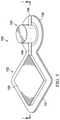
- FIG. 6is a top perspective view illustrating additional details that may be associated with an example embodiment of the negative-pressure therapy system of FIG. 5 in a first position;
- FIG. 7is a top perspective view illustrating additional details that may be associated with an example embodiment of the negative-pressure therapy system of FIG. 5 in a second position;
- FIG. 8is a sectional view of an example embodiment of another negative-pressure therapy system that can provide negative-pressure therapy in accordance with this specification.
- FIG. 9is a top perspective view illustrating additional details that may be associated with an example embodiment of the negative-pressure therapy system of FIG. 8 .
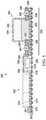
- FIG. 1is a sectional view of an example embodiment of a negative-pressure therapy system 100 that can provide negative-pressure therapy in accordance with this specification.
- the negative-pressure therapy system 100may include a dressing assembly and a tissue interface.
- a tissue interface 108may be placed in a tissue site and a dressing assembly 102 may be placed over the tissue site and the tissue interface 108 .
- the dressing assembly 102may include a cover 103 and a pouch 105 which may be fluidly coupled to a negative-pressure source 104 .
- components of the negative-pressure therapy system 100may be coupled directly or indirectly.
- the negative-pressure source 104may be directly coupled to the pouch 105 and indirectly coupled to the tissue site through the pouch 105 .
- Componentsmay be fluidly coupled to each other to provide a path for transferring fluids (i.e., liquid and/or gas) between the components.
- componentsmay be fluidly coupled through a tube, such as a tube 140 or a tube 146 .
- a tubeis an elongated, cylindrical structure with some flexibility, but the geometry and rigidity may vary.
- componentsmay additionally or alternatively be coupled by virtue of physical proximity, being integral to a single structure, or being formed from the same piece of material. Coupling may also include mechanical, thermal, electrical, or chemical coupling (such as a chemical bond) in some contexts.
- the tissue interface 108may be placed within, over, on, or otherwise proximate to a tissue site.
- the cover 103may be placed over the tissue interface 108 and sealed to tissue near the tissue site.
- the cover 103may be sealed to undamaged epidermis peripheral to a tissue site.
- the dressing assembly 102can provide a sealed therapeutic environment proximate to a tissue site, substantially isolated from the external environment, and the negative-pressure source 104 can reduce the pressure in the sealed therapeutic environment.
- the sealed therapeutic environmentmay be formed in the space occupied by the tissue interface 108 and the pouch 105 . If the tissue interface 108 is not used, the sealed therapeutic environment may be formed in the space occupied by the pouch 105 and the tissue site. Negative pressure applied across the tissue site in the sealed therapeutic environment can induce macrostrain and microstrain in the tissue site, as well as remove exudates and other fluids from the tissue site, which can be collected in the pouch 105 and disposed of properly.
- the fluid mechanics of using a negative-pressure source to reduce pressure in another component or location, such as within a sealed therapeutic environment,can be mathematically complex.
- the basic principles of fluid mechanics applicable to negative-pressure therapyare generally well-known to those skilled in the art, and the process of reducing pressure may be described illustratively herein as “delivering,” “distributing,” or “generating” negative pressure, for example.
- downstreamtypically implies a position in a fluid path relatively closer to a negative-pressure source
- upstreamimplies a position relatively further away from a negative-pressure source.
- fluid inletor “outlet” in such a frame of reference. This orientation is generally presumed for purposes of describing various features and components of negative-pressure therapy systems herein.
- the fluid pathmay also be reversed in some applications (such as by substituting a positive-pressure source for a negative-pressure source) and this descriptive convention should not be construed as a limiting convention.
- tissue sitein this context broadly refers to a wound or defect located on or within tissue, including but not limited to, bone tissue, adipose tissue, muscle tissue, neural tissue, dermal tissue, vascular tissue, connective tissue, cartilage, tendons, or ligaments.
- a woundmay include chronic, acute, traumatic, subacute, and dehisced wounds, partial-thickness burns, ulcers (such as diabetic, pressure, or venous insufficiency ulcers), flaps, and grafts, for example.
- tissue sitemay also refer to areas of any tissue that are not necessarily wounded or defective, but are instead areas in which it may be desirable to add or promote the growth of additional tissue. For example, negative pressure may be used in certain tissue areas to grow additional tissue that may be harvested and transplanted to another tissue location.
- Negative pressuregenerally refers to a pressure less than a local ambient pressure, such as the ambient pressure in a local environment external to a sealed therapeutic environment provided by the dressing assembly 102 .
- the local ambient pressuremay also be the atmospheric pressure at which a tissue site is located.
- the pressuremay be less than a hydrostatic pressure associated with tissue at the tissue site. Unless otherwise indicated, values of pressure stated herein are gauge pressures.
- references to increases in negative pressuretypically refer to a decrease in absolute pressure, while decreases in negative pressure typically refer to an increase in absolute pressure.
- the tissue interface 108can be generally adapted to contact a tissue site.
- the tissue interface 108may be partially or fully in contact with the tissue site. If the tissue site is a wound, for example, the tissue interface 108 may partially or completely fill the wound, or may be placed over the wound.
- the tissue interface 108may take many forms, and may have many sizes, shapes, or thicknesses depending on a variety of factors, such as the type of treatment being implemented or the nature and size of a tissue site. For example, the size and shape of the tissue interface 108 may be adapted to the contours of deep and irregular shaped tissue sites.
- the tissue interface 108may be a manifold.
- a “manifold” in this contextgenerally includes any substance or structure providing a plurality of pathways adapted to collect or distribute fluid across a tissue site under negative pressure.
- a manifoldmay be adapted to receive negative pressure from a source and distribute the negative pressure through multiple apertures across a tissue site, which may have the effect of collecting fluid from across a tissue site and drawing the fluid toward the source.
- the fluid pathmay be reversed or a secondary fluid path may be provided to facilitate delivering fluid across a tissue site.
- the pathways of a manifoldmay be channels that are interconnected to improve distribution or collection of fluids across a tissue site.
- cellular foam, open-cell foam, reticulated foam, porous tissue collections, and other porous materialsuch as gauze or felted mat generally include pores, edges, and/or walls adapted to form interconnected fluid pathways.
- Liquids, gels, and other foamsmay also include or be cured to include apertures and flow channels.
- a manifoldmay be a porous foam material having interconnected cells or pores adapted to uniformly (or quasi-uniformly) distribute negative pressure to a tissue site.
- the foam materialmay be either hydrophobic or hydrophilic.
- a manifoldmay be an open-cell, reticulated polyurethane foam such as GranuFoam® dressing available from Kinetic Concepts, Inc. of San Antonio, Tex.
- the tissue interface 108may also wick fluid away from a tissue site, while continuing to distribute negative pressure to the tissue site.
- the wicking properties of the tissue interface 108may draw fluid away from a tissue site by capillary flow or other wicking mechanisms.
- An example of a hydrophilic foamis a polyvinyl alcohol, open-cell foam such as V.A.C. WhiteFoam® dressing available from Kinetic Concepts, Inc. of San Antonio, Tex.
- Other hydrophilic foamsmay include those made from polyether.
- Other foams that may exhibit hydrophilic characteristicsinclude hydrophobic foams that have been treated or coated to provide hydrophilicity.
- the tissue interface 108may further promote granulation at a tissue site when pressure within the sealed therapeutic environment is reduced.
- any or all of the surfaces of the tissue interface 108may have an uneven, coarse, or jagged profile that can induce microstrains and stresses at a tissue site if negative pressure is applied through the tissue interface 108 .
- the tissue interface 108may be constructed from bioresorbable materials. Suitable bioresorbable materials may include, without limitation, a polymeric blend of polylactic acid (PLA) and polyglycolic acid (PGA). The polymeric blend may also include without limitation polycarbonates, polyfumarates, and capralactones.
- the tissue interface 108may further serve as a scaffold for new cell-growth, or a scaffold material may be used in conjunction with the tissue interface 108 to promote cell-growth.
- a scaffoldis generally a substance or structure used to enhance or promote the growth of cells or formation of tissue, such as a three-dimensional porous structure that provides a template for cell growth.
- scaffold materialsinclude calcium phosphate, collagen, PLA/PGA, coral hydroxy apatites, carbonates, or processed allograft materials.
- tissue interface 108may be combined with hemostat material and anti-microbial materials to treat tissue sites that may have a significant depth.
- the cover 103may be a sealing layer and provide a bacterial barrier and protection from physical trauma.
- the cover 103may also be constructed from a material that can reduce evaporative losses and provide a fluid seal between two components or two environments, such as between a therapeutic environment and a local external environment.
- the cover 103may be, for example, an elastomeric film or membrane that can provide a seal adequate to maintain a negative pressure at a tissue site for a given negative-pressure source.
- the cover 103may be a polymer drape, such as a polyurethane film, that is permeable to water vapor but impermeable to liquid. Such drapes typically have a thickness in the range of 25-50 microns. For permeable materials, the permeability generally should be low enough that a desired negative pressure may be maintained.
- An attachment devicemay be used to attach the cover 103 to an attachment surface, such as undamaged epidermis, a gasket, or another cover.
- the attachment devicemay take many forms.
- an attachment devicemay be a medically-acceptable, pressure-sensitive adhesive that extends about a periphery, a portion, or an entire sealing member.
- some or all of the cover 103may be coated with an acrylic adhesive having a coating weight between 25-65 g.s.m. Thicker adhesives, or combinations of adhesives, may be applied in some embodiments, to improve the seal and reduce leaks.
- Other example embodiments of an attachment devicemay include a double-sided tape, paste, hydrocolloid, hydrogel, silicone gel, or organogel.
- patients having low-acuity tissue sitesmay be mobile and may not require confinement to a care facility during the duration of the treatment of the tissue site. Consequently, a dedicated negative-pressure therapy system that requires a continuous supply of electrical current to provide negative-pressure therapy may not be preferable for use as a treatment device.
- Ambulatory patientsmay receive beneficial negative-pressure therapy by using the negative-pressure therapy system 100 described herein, which provides a peel-and-place dressing and negative-pressure source that allows the patient to easily see the status of the negative-pressure therapy and to reapply negative-pressure therapy without the intervention of a clinician.
- the negative-pressure therapy system 100can include the tissue interface 108 and the dressing assembly 102 having the cover 103 , the pouch 105 , and the negative-pressure source 104 .
- the cover 103 , the pouch 105 , and the negative-pressure source 104may be coupled to each other and collectively placed over the tissue interface 108 and undamaged epidermis.
- the pouch 105may include an absorbent 124 , a first outer layer, such as an upstream layer 126 , and a second outer layer, such as a downstream layer 128 .
- the upstream layer 126 and the downstream layer 128may envelop or enclose the absorbent 124 .
- the absorbent 124may hold, stabilize, and/or solidify fluids collected from the tissue site.
- the absorbent 124may be formed from materials referred to as “hydrogels,” “super-absorbents,” or “hydrocolloids.” If disposed within the dressing assembly 102 , the absorbent 124 may be formed into fibers or spheres to manifold negative pressure until the absorbent 124 becomes saturated.
- the absorbent 124may be Texsus FP2325 having a material density of about 800 grams per square meter (gsm).
- the absorbent materialmay be BASF 402C, Technical Absorbents 2317 available from Technical Absorbents (www.techabsorbents.com), sodium polyacrylate super absorbers, cellulosics (carboxy methyl cellulose and salts such as sodium CMC), or alginates.
- the absorbent 124may be formed of granular absorbent components that may be scatter coated onto a paper substrate. Scatter coating involves spreading a granular absorbent powder uniformly onto a textile substrate, such as paper. The substrate, having the granular absorbent powder disposed thereon, may be passed through an oven to cure the powder and cause the powder to adhere to the paper substrate. The cured granular absorbent powder and substrate may be passed through a calender machine to provide a smooth uniform surface to the absorbent material.
- the upstream layer 126 and the downstream layer 128have perimeter dimensions that may be larger than the perimeter dimensions of the absorbent 124 so that, if the absorbent 124 is positioned between the upstream layer 126 and the downstream layer 128 and the center portions of the absorbent 124 , the upstream layer 126 , and the downstream layer 128 are aligned, the upstream layer 126 and the downstream layer 128 may extend beyond the perimeter of the absorbent 124 .
- the upstream layer 126 and the downstream layer 128surround the absorbent 124 . Peripheral portions of the upstream layer 126 and the downstream layer 128 may be coupled so that the upstream layer 126 and the downstream layer 128 enclose the absorbent 124 .
- the upstream layer 126 and the downstream layer 128may be coupled by high frequency welding, ultrasonic welding, heat welding, or impulse welding, for example. In other exemplary embodiments, the upstream layer 126 and the downstream layer 128 may be coupled by bonding or folding, for example.
- the upstream layer 126may be formed of non-woven material in some embodiments.
- the upstream layer 126may have a polyester fibrous porous structure.
- the upstream layer 126may be porous, but preferably the upstream layer 126 is not perforated.
- the upstream layer 126may have a material density between about 80 gsm and about 150 gsm. In other exemplary embodiments, the material density may be lower or greater depending on the particular application of the pouch 105 .
- the upstream layer 126may be a plurality of layers of non-woven material.
- the upstream layer 126may be formed of Libeltex TDL2, for example. In other embodiments, the upstream layer 126 may also be formed of Libeltex TL4.
- the downstream layer 128may also be formed of a non-woven material in some embodiments.
- the downstream layer 128may have a polyester fibrous porous structure.
- the downstream layer 128may be porous, but the downstream layer 128 preferably is not perforated.
- the downstream layer 128may have a material density between about 80 gsm and about 150 gsm. In other exemplary embodiments, the material density may be lower or greater depending on the particular application of the pouch 105 .
- the material density of the downstream layer 128may be greater or less than the material density of the upstream layer 126 . In some embodiments, a thickness of the downstream layer 128 may be greater than a thickness of the upstream layer 126 .
- the thickness of the downstream layer 128may be less than the thickness of the upstream layer 126 .
- the downstream layer 128may be a plurality of layers of non-woven material.
- the downstream layer 128may be formed of Libeltex TL4. In other exemplary embodiments, the downstream layer 128 may be formed of Libeltex TDL2.
- the upstream layer 126 and the downstream layer 128may be manifolding layers configured to facilitate fluid movement through the pouch 105 .
- the upstream layer 126 and the downstream layer 128may each have a hydrophobic side and a hydrophilic side.
- the hydrophobic sidemay also be referred to as a wicking side, wicking surface, distribution surface, distribution side, or fluid distribution surface.
- the hydrophobic sidemay be a smooth distribution surface configured to move fluid along a grain of the upstream layer 126 and the downstream layer 128 , distributing fluid throughout the upstream layer 126 and the downstream layer 128 .
- the hydrophilic sidemay be configured to acquire bodily fluid from the hydrophobic side to aid in bodily fluid movement into the absorbent 124 .
- the hydrophilic sidemay also be referred to as a fluid acquisition surface, fluid acquisition side, hydrophilic acquisition surface, or hydrophilic acquisition side.
- the hydrophilic sidemay be a fibrous surface and be configured to draw fluid into the upstream layer 126 and the downstream layer 128 .
- the hydrophilic side of the upstream layer 126 and the downstream layer 128may be positioned adjacent to the absorbent 124 .
- the hydrophobic side of the upstream layer 126 and the downstream layer 128may be positioned adjacent to the absorbent 124 .
- the hydrophilic side of one of the upstream layer 126 or the downstream layer 128may be positioned adjacent to the absorbent 124
- the hydrophobic side of the other of the upstream layer 126 or the downstream layer 128may be positioned adjacent to the absorbent 124 .
- the cover 103may include or may be a hybrid drape having a barrier layer 110 , a bonding adhesive layer 112 , and a sealing adhesive layer 114 .
- the barrier layer 110may be formed from a range of medically approved films ranging in thickness from about 15 microns ( ⁇ m) to about 50 microns ( ⁇ m).
- the barrier layer 110may comprise a suitable material or materials, such as the following: hydrophilic polyurethane (PU), cellulosics, hydrophilic polyamides, polyvinyl alcohol, polyvinyl pyrrolidone, hydrophilic acrylics, hydrophilic silicone elastomers, and copolymers of these.
- the barrier layer 110may be formed from a breathable cast matt polyurethane film sold by Expopack Advanced Coatings of Wrexham, United Kingdom, under the name INSPIRE 2301 .
- the barrier layer 110may have a high moisture vapor transmission rate (MVTR).
- the MVTR of the barrier layer 110allows vapor to egress and inhibits liquids from exiting.
- the MVTR of the barrier layer 110may be greater than or equal to 300 g/m 2 /24 hours. In other embodiments, the MVTR of the barrier layer 110 may be greater than or equal to 1,000 g/m 2 /24 hours.
- the illustrative INSPIRE 2301 filmmay have an MVTR (inverted cup technique) of 14,400 g/m 2 /24 hours and may be approximately 30 microns thick. In other embodiments, a drape having a low MVTR or that allows no vapor transfer might be used.
- the barrier layer 110can also function as a barrier to liquids and microorganisms.
- the barrier layer 110may be adapted to form a bulge on a first side of the barrier layer and a cavity 111 on an opposite side of the barrier layer from the bulge.
- the barrier layer 110may be placed on a mold and stretched to plastically deform a portion of the barrier layer 110 , forming the cavity 111 .
- a periphery of the barrier layer 110 that is not stretched by the formation of the cavity 111may form a flange surrounding the cavity 111 .
- the cavity 111may be positioned so that a portion of the flange may be larger on a first side of the cavity 111 than on a second side of the cavity 111 .
- the disparity in sizes of the flangemay form a foundational flange 130 and a sealing flange 131 .
- the pouch 105may be disposed in the cavity 111 .
- the cavity 111may also be a portion of the barrier layer 110 that is free of adhesive.
- a portion of the barrier layer 110may be left without the bonding adhesive layer 112 ; the area of the barrier layer 110 without the bonding adhesive layer 112 may be equal to a surface area of the pouch 105 to be covered by the barrier layer 110 .
- the foundational flange 130may extend away from the cavity 111 .
- the foundational flange 130may have a length and a width sufficient to permit other objects to be coupled to the dressing assembly 102 .
- the foundational flange 130may support the negative-pressure source 104 , as illustrated in FIG. 1 .
- the bonding adhesive layer 112may be coupled to the barrier layer 110 on a side of the barrier layer 110 having an opening of the cavity 111 .
- the bonding adhesive layer 112may include an aperture 116 .
- the aperture 116may be coextensive with the opening of the cavity 111 .
- the bonding adhesive layer 112may cover the barrier layer 110 at the foundational flange 130 and the sealing flange 131 , leaving the portion of the barrier layer 110 forming the cavity 111 free of the bonding adhesive layer 112 .
- the bonding adhesive layer 112may comprise an acrylic adhesive, rubber adhesive, high-tack silicone adhesive, polyurethane, or other substance.
- the bonding adhesive layer 112comprises an acrylic adhesive with coating weight of 15 grams/m 2 (gsm) to 70 grams/m 2 (gsm).
- the bonding adhesive layer 112may be a continuous layer of material or may be a layer with apertures (not shown). The apertures may be formed after application of the bonding adhesive layer 112 or may be formed by coating the bonding adhesive layer 112 in patterns on a carrier layer.
- the bond strength of the bonding adhesivemay have a peel adhesion or resistance to being peeled from a stainless steel material between about 6N/25 mm to about 10N/25 mm on stainless steel substrate at 23° C. at 50% relative humidity based on the American Society for Testing and Materials (“ASTM”) standard ASTM D3330.
- the bonding adhesive layer 112may be about 30 microns to about 60 microns in thickness.
- the sealing adhesive layer 114may be coupled to the bonding adhesive layer 112 and the pouch 105 .
- the sealing adhesive layer 114may cover the sealing flange 131 , the pouch 105 , and the foundational flange 130 .
- the sealing adhesive layer 114may be formed with the plurality of apertures 118 .
- the apertures 118may be numerous shapes, for example, circles, squares, stars, ovals, polygons, slits, complex curves, rectilinear shapes, triangles, or other shapes.
- Each aperture 118 of the plurality of apertures 118may have an effective diameter, which is the diameter of a circular area having the same surface area as the aperture 118 .
- each aperture 118may typically be in the range of about 6 mm to about 50 mm.
- the plurality of apertures 118may have a uniform pattern or may be randomly distributed in the sealing adhesive layer 114 . Generally, the apertures 118 may be disposed across a length and width of the sealing adhesive layer 114 .
- the sealing adhesive layer 114may comprise a silicone gel (or soft silicone), hydrocolloid, hydrogel, polyurethane gel, polyolefin gel, hydrogenated styrenic copolymer gels, or foamed gels with compositions as listed, or soft closed cell foams (polyurethanes, polyolefins) coated with an adhesive (e.g., 30 gsm-70 gsm acrylic), polyurethane, polyolefin, or hydrogenated styrenic copolymers.
- the sealing adhesive layer 114may have a thickness in the range of about 100 microns ( ⁇ m) to about 1,000 microns ( ⁇ m).
- the sealing adhesive layer 114may have stiffness between about 5 Shore OO and about 80 Shore OO.
- the sealing adhesive layer 114may be hydrophobic or hydrophilic.
- the sealing adhesive of the sealing adhesive layer 114may be an adhesive having a low to medium tackiness, for example, a silicone polymer, polyurethane, or an additional acrylic adhesive.
- the bond strength of the sealing adhesivemay have a peel adhesion or resistance to being peeled from a stainless steel material between about 0.5N/25 mm to about 1.5N/25 mm on stainless steel substrate at 23° C. at 50% relative humidity based on ASTM D3330.
- the sealing adhesivemay have a tackiness such that the sealing adhesive may achieve the bond strength above after a contact time of less than about 60 seconds. Tackiness may be considered a bond strength of an adhesive after a very low contact time between the adhesive and a substrate.
- the sealing adhesive layer 114may have a tackiness that may be about 30% to about 50% of the tackiness of the bonding adhesive of the bonding adhesive layer 112 .
- the bonding adhesive layer 112may be coupled to the barrier layer 110 .
- the sealing adhesive layer 114may be coupled to the bonding adhesive layer 112 at the sealing flange 131 and the foundational flange 130 and to the pouch 105 at the cavity 111 .
- a scrim layermay be disposed in the sealing adhesive layer 114 .
- the scrim layermay provide additional mechanical support for the sealing adhesive layer 114 .
- the sealing adhesive layer 114may be treated on a portion and a side of the sealing adhesive layer 114 adjacent to the pouch 105 . The treated portion of the sealing adhesive layer 114 may reduce the tackiness of the sealing adhesive layer 114 so that the sealing adhesive layer 114 may not readily adhere to the pouch 105 .
- the initial tackiness of the sealing adhesive layer 114is preferably sufficient to initially couple the sealing adhesive layer 114 to the epidermis by forming sealing couplings.
- a forcecan be applied to the barrier layer 110 of the cover 103 .
- the usermay rub the foundational flange 130 and the sealing flange 131 .
- This actioncan cause at least a portion of the bonding adhesive layer 112 to be forced into the plurality of apertures 118 and into contact with the epidermis to form bonding couplings.
- the bonding couplingsprovide secure, releasable mechanical fixation to the epidermis.
- the average effective diameter of the plurality of apertures 118 for the sealing adhesive layer 114may be varied as one control of the tackiness or adhesion strength of the cover 103 .
- the more bonding adhesive of the bonding adhesive layer 112 that extends through the apertures 118the stronger the bond of the bonding coupling.
- the thinner the sealing adhesive layer 114the more bonding adhesive of the bonding adhesive layer 112 generally extends through the apertures 118 and the greater the bond of the bonding coupling.
- the average effective diameter of the plurality of apertures 118may be relatively smaller than if the bonding adhesive layer 112 is less tacky and the sealing adhesive layer 114 is thicker.
- the thickness of the sealing adhesive layer 114may be approximately 200 microns
- the thickness of the bonding adhesive layer 112may be approximately 30 microns with a tackiness of 2000 g/25 cm wide strip
- the average effective diameter of each aperture 118may be approximately 6 mm.
- the negative-pressure source 104may be coupled to the barrier layer 110 of the foundational flange 130 .
- the negative-pressure source 104may include a barrier layer and a biasing member, for example, a film layer 132 and a foam block 134 .
- the film layer 132may form a source flange 136 and a source cavity 138 .
- the source cavity 138may be a portion of the film layer 132 that is plastically deformed, such as by vacuum forming, thermoforming, micro-thermoforming, injection molding, or blow molding, for example.
- the source cavity 138may form walls of the negative-pressure source 104 that may be resilient or flexible.
- the source flange 136may be a portion of the film layer 132 adjacent to and surrounding an opening of the source cavity 138 .
- the foam block 134may be disposed in the source cavity 138 .
- the source flange 136may be coupled to the barrier layer 110 of the foundational flange 130 to seal the foam block 134 in the source cavity 138 .
- the source flange 136may be coupled to the barrier layer 110 by high frequency welding, ultrasonic welding, heat welding, or impulse welding, for example.
- the source flange 136may be coupled to the barrier layer 110 by bonding or folding, for example.
- the source cavity 138may be fluidly isolated from the ambient environment and the pouch 105 .
- the film layer 132may be constructed from a material that can provide a fluid seal between two components or two environments, such as between the source cavity 138 and a local external environment, while allowing for repeated elastic deformation of the film layer 132 .
- the film layer 132may be, for example, an elastomeric film or membrane that can provide a seal between the source cavity 138 and the ambient environment.
- the film layer 132may be a polymer drape, such as a polyurethane film, that is permeable to water vapor but impermeable to liquid. Such drapes typically have a thickness in the range of 25-50 microns. For permeable materials, the permeability generally should be low enough that a desired negative pressure may be maintained.
- the film layer 132may be a polyurethane having a thickness between about 50 microns and about 250 microns and preferably about 100 microns.
- the foam block 134may be a foam having a plurality of interconnected flow channels.
- cellular foam, open-cell foam, reticulated foam, porous tissue collections, and other porous materialthat generally include pores, edges, and/or walls adapted to form interconnected fluid pathways.
- Liquids, gels, and other foamsmay also include or be cured to include apertures and flow channels.
- the foam block 134may be a porous foam material having interconnected cells or pores adapted to uniformly (or quasi-uniformly) distribute fluid throughout the foam block 134 .
- the foam materialmay be either hydrophobic or hydrophilic.
- the foam block 134may be an open-cell, reticulated polyurethane foam such as GranuFoam® dressing available from Kinetic Concepts, Inc. of San Antonio, Tex. Another exemplary embodiment of the foam block 134 may be Z48AA foam from FXI®.
- the foam block 134may include an indicator, such as a color change dye. The indicator may change colors if contacted by a liquid. Consequently, if the foam block 134 changes colors, a user may know that the dressing assembly 102 is saturated.
- Foam materialsmay have an elastic modulus, which may also be referred to as a foam modulus.
- the elastic modulus of a materialmay measure the resistance of the material to elastic deformation under a load.
- the elastic modulus of a materialmay be defined as the slope of a stress-strain curve in the elastic deformation region of the curve.
- the elastic deformation region of a stress-strain curverepresents that portion of the curve where a deformation of a material due to an applied load is elastic, that is, not permanent. If the load is removed, the material may return to its pre-loaded state.
- Stiffer materialsmay have a higher elastic modulus, and more compliant materials may have a lower elastic modulus.
- references to the elastic modulus of a materialrefers to a material under tension.
- the elastic moduluscan be compared between materials by comparing the compression force deflection (CFD) of the materials.
- CFDcompression force deflection
- CFDis determined experimentally by compressing a sample of a material until the sample is reduced to about 25% of its uncompressed size. The load applied to reach the 25% compression of the sample is then divided by the area of the sample over which the load is applied to arrive at the CFD.
- the CFDcan also be measured by compressing a sample of a material to about 50% of the sample's uncompressed size.
- the CFD of a foam materialcan be a function of compression level, polymer stiffness, cell structure, foam density, and cell pore size.
- the foam block 134may have a CFD that is greater than a CFD of the tissue interface 108 .
- the tissue interface 108may have a 25% CFD of about 2 kPa.
- the tissue interface 108may compress to about 25% of its uncompressed size if a load of about 2 kPa is applied to the tissue interface 108 .
- the foam block 134may have a CFD of about 4 kPA.
- the foam block 134may compress to about 25% of its uncompressed size if a load of about 4 kPa is applied to the foam block 134 .
- the foam block 134is more resistant to deformation than the tissue interface 108 .
- CFDcan represent the tendency of a foam to return to its uncompressed state if a load is applied to compress the foam.
- a foam having a CFD of about 4 kPamay exert about 4 kPa in reaction to 25% compression.
- the CFD of the foam block 134may represent the ability of the foam block 134 to bias the film layer 132 toward an expanded position. For example, if the foam block 134 is compressed to 25% of its original size, the foam block 134 may exert a spring force that opposes the applied force over the area of the foam block 134 to which the force is applied. The reactive force may be proportional to the amount the foam block 134 is compressed.
- the foam block 134may have a free volume.
- the free volume of the foam block 134may be the volume of free space of the foam block 134 , for example, the volume of the plurality of channels of the foam block 134 .
- the free volume of the foam block 134may be greater than the free volume of the sealed therapeutic environment.
- the free volume of the foam block 134may be greater than the free volume of the pouch 105 .
- the tissue interface 108is used with the dressing assembly 102
- the free volume of the foam block 134may be greater than the combined free volume of the pouch 105 and the tissue interface 108 .
- the free volume of the foam block 134may be greater than about 20 cm 3 .
- the negative-pressure source 104may be fluidly coupled to the cavity 111 through a fluid inlet, such as the tube 140 .
- the tube 140may be representative of a fluid communication path between the negative-pressure source 104 and the cavity 111 .
- the tube 140may be a sealed channel or other fluid pathway.
- the tube 140may include a lumen 142 fluidly coupled to the source cavity 138 and the pouch 105 .
- a valvesuch as a check valve 144 , may be fluidly coupled to the lumen 142 .
- Exemplary check valves 144may include ball check valves, diaphragm check valves, swing check valves, stop-check valves, duckbill valves, or pneumatic non-return valves.
- the check valve 144may permit fluid communication from the pouch 105 to the source cavity 138 and prevent fluid communication from the source cavity 138 to the pouch 105 . For example, if a pressure in the pouch 105 is greater than a pressure in the source cavity 138 , the check valve 144 may open, and if the pressure in the source cavity 138 is greater than the pressure in the pouch 105 , the check valve 144 may close.
- a filtermay be disposed on an end of the tube 140 .
- the filtermay be a hydrophobic porous polymer filter having gel blocking properties.
- the filtermay be a non-gel blocking filter, such as a Gore MMT314 material having a polytetrafluoroethylene (PTFE) layer.
- the PTFE layermay face the manifolding structure to prevent fluid communication across the PTFE layer.
- the filtermay be on an end of the tube 140 proximate to the dressing assembly 102 . In other embodiments, the filter may be on an end of the tube 140 proximate to the negative-pressure source 104 .
- the source cavity 138may also be fluidly coupled to the ambient environment through a fluid outlet, such as the tube 146 .
- a fluid outletsuch as the tube 146 .
- the tube 146 having a lumen 148may fluidly couple the source cavity 138 to the ambient environment.
- the tube 146may be representative of a fluid communication path between the ambient environment and the source cavity 138 .
- a valvesuch as a check valve 150 , may be fluidly coupled to the lumen 148 to control fluid communication through the lumen 148 .
- Exemplary check valves 150may include ball check valves, diaphragm check valves, swing check valves, stop-check valves, duckbill valves, or pneumatic non-return valves.
- the check valve 150may permit fluid communication from the source cavity 138 to the ambient environment and prevent fluid communication from the ambient environment to the source cavity 138 . For example, if a pressure in the source cavity 138 is greater than a pressure in the ambient environment, the check valve 150 may open, and if the pressure in the ambient environment is greater than the pressure in the source cavity 138 , the check valve 150 may close.
- a filtermay be disposed on an end of the tube 146 .
- the filtermay be a hydrophobic porous polymer filter having gel blocking properties.
- the filtermay be a non-gel blocking filter, such as a Gore MMT314 material having a polytetrafluoroethylene (PTFE) layer.
- the PTFE layermay face the manifolding structure to prevent fluid communication across the PTFE layer.
- the filtermay be on an end of the tube 146 proximate to the negative-pressure source 104 . In other embodiments, the filter may be on an end of the tube 140 proximate to the ambient environment.
- the tissue interface 108may be disposed adjacent to a tissue site. If the tissue interface 108 is used, the thickness of the tissue interface 108 may preferably be less than about 10 mm.
- the dressing assembly 102may be disposed over the tissue interface 108 to create the sealed therapeutic environment.
- the pouch 105 of the dressing assembly 102may be positioned over the tissue interface 108 and the negative-pressure source 104 may be positioned over undamaged tissue proximate the tissue interface 108 .
- a forcesuch as hand pressure, may be applied to the sealing flange 131 and the foundational flange 130 , urging the bonding adhesive of the bonding adhesive layer 112 through the apertures 118 of the sealing adhesive layer 114 to form bonding couplings and securing the negative-pressure therapy system 100 to the tissue site.
- FIG. 2is a perspective view illustrating additional details of the negative-pressure source 104 in a first position, such as a collapsed position
- FIG. 3is a perspective view illustrating additional details of the negative-pressure source 104 is a second position, such as an expanded position.
- the negative-pressure source 104may be operated to generate a negative pressure in the pouch 105 .
- a force 152such as hand pressure, may be applied to the film layer 132 over the foam block 134 to compress the foam block 134 to the first position and decrease the volume of the source cavity 138 . If the foam block 134 and the source cavity 138 are fluidly isolated from the ambient environment, compression of the foam block 134 may increase the pressure in the source cavity 138 .
- An increase of pressure in the source cavity 138may create a pressure differential across the check valve 144 that urges the check valve 144 to close.
- an increase of pressure in the source cavity 138may create a pressure differential across the check valve 150 that urges the check valve 150 to open, allowing fluid from the source cavity 138 to flow through the tube 146 to the ambient environment. If the force 152 is removed, the foam block 134 may expand, increasing the volume of the source cavity 138 and decreasing the pressure in the source cavity 138 .
- the decrease in pressure in the source cavity 138may create a pressure differential across the check valve 150 that urges the check valve 150 to close, preventing fluid from flowing from the ambient environment to the source cavity 138 .
- the decrease in pressure in the source cavity 138may also create a pressure differential across the check valve 144 that urges the check valve 144 to open, permitting fluid flow from the pouch 105 to the source cavity 138 .
- Fluidmay flow from the pouch 105 to the source cavity 138 until the source cavity 138 and the foam block 134 reach their respective uncompressed positions as shown in FIG. 3 . In this manner, a portion of the total volume of fluid in the sealed therapeutic environment may be removed. In response to the removal of a portion of the fluid, a smaller volume of fluid occupies the sealed therapeutic environment, decreasing the pressure in the sealed therapeutic environment.
- additional fluidmay be removed from the sealed therapeutic environment, further decreasing the pressure.
- Decreasing the pressure in the sealed therapeutic environmentmay create a pressure differential across the dressing assembly 102 . If the pressure in the sealed therapeutic environment reaches the therapy pressure for negative-pressure therapy, the CFD of the foam block 134 may be insufficient to cause the foam block 134 to expand following compression of the foam block 134 from the second position of FIG. 3 to the first position of FIG. 2 .
- the therapy pressuremay be the pressure at which negative-pressure therapy may be performed. In some embodiments, the therapy pressure provided by the foam block 134 may be about 70 mm Hg of negative pressure. In other embodiments, the therapy pressure provided by the foam block 134 may be between about 50 mm Hg and 150 mm Hg of negative pressure. If the foam block 134 remains compressed as shown in FIG.
- a patient or clinicianmay have an indication that the therapy pressure has been reached.
- the compressed foam block 134may also act as a pressure reservoir.
- negative-pressure therapythere may be a natural leakage or decline of negative pressure at the tissue site.
- the pressure differential across the dressing assembly 102may decrease and the foam block 134 may gradually expand, reapplying negative pressure at the tissue site.
- the negative-pressure source 104 having the foam block 134may maintain a therapeutic negative pressure for about 8 hours or more.
- FIG. 4is a sectional view of an example embodiment of a negative-pressure therapy system 200 that can provide negative-pressure therapy in accordance with this specification.
- the negative-pressure therapy system 200may be similar to and operate as described above with respect to the negative-pressure therapy system 100 . Similar elements have similar reference numbers indexed to 200.
- the negative-pressure therapy system 200can include a dressing assembly 202 having a cover 203 , a pouch 205 , and a negative-pressure source 204 .
- the cover 203 , the pouch 205 , and the negative-pressure source 204may be coupled to each other.
- the negative-pressure therapy system 200can also include the tissue interface 108 .
- the pouch 205may include an absorbent 224 , a first outer layer, such as an upstream layer 226 , and a second outer layer, such as a downstream layer 228 .
- the upstream layer 226 and the downstream layer 228may envelop or enclose the absorbent 224 .
- the absorbent 224may hold, stabilize, and/or solidify fluids that may be collected from the tissue site.
- the absorbent 224may be of the type referred to as “hydrogels,” “super-absorbents,” or “hydrocolloids.” If disposed within the dressing assembly 202 , the absorbent 224 may be formed into fibers or spheres to manifold negative pressure until the absorbent 224 becomes saturated.
- the absorbent 224may be Texsus FP2325 having a material density of about 800 grams per square meter (gsm).
- the absorbent materialmay be BASF 402C, Technical Absorbents 2317 available from Technical Absorbents (www.techabsorbents.com), sodium polyacrylate super absorbers, cellulosics (carboxy methyl cellulose and salts such as sodium CMC), or alginates.
- the absorbent 224may be formed of granular absorbent components that may be scatter coated onto a paper substrate. Scatter coating involves spreading a granular absorbent powder uniformly onto a textile substrate, such as paper. The substrate, having the granular absorbent powder disposed thereon, may be passed through an oven to cure the powder and cause the powder to adhere to the paper substrate. The cured granular absorbent powder and substrate may be passed through a calender machine to provide a smooth uniform surface to the absorbent material.
- the upstream layer 226 and the downstream layer 228have perimeter dimensions that may be larger than the perimeter dimensions of the absorbent 224 so that, if the absorbent 224 is positioned between the upstream layer 226 and the downstream layer 228 and the center portions of the absorbent 224 , the upstream layer 226 , and the downstream layer 228 are aligned, the upstream layer 226 and the downstream layer 228 may extend beyond the perimeter of the absorbent 224 .
- the upstream layer 226 and the downstream layer 228surround the absorbent 224 . Peripheral portions of the upstream layer 226 and the downstream layer 228 may be coupled so that the upstream layer 226 and the downstream layer 228 enclose the absorbent 224 .
- the upstream layer 226 and the downstream layer 228may be coupled by high frequency welding, ultrasonic welding, heat welding, or impulse welding, for example. In other exemplary embodiments, the upstream layer 226 and the downstream layer 228 may be coupled by bonding or folding, for example.
- the upstream layer 226may be formed of non-woven material in some embodiments.
- the upstream layer 226may have a polyester fibrous porous structure.
- the upstream layer 226may be porous, but preferably the upstream layer 226 is not perforated.
- the upstream layer 226may have a material density between about 80 gsm and about 150 gsm. In other exemplary embodiments, the material density may be lower or greater depending on the particular application of the pouch 205 .
- the upstream layer 226may a plurality of layers of, for example, non-woven material.
- the upstream layer 226may be formed of Libeltex TDL2, for example. In other embodiments, the upstream layer 226 may also be formed of Libeltex TL4.
- the upstream layer 226may have a hydrophilic side and a hydrophobic side.
- the downstream layer 228may also be formed of a non-woven material in some embodiments.
- the downstream layer 228may have a polyester fibrous porous structure.
- the downstream layer 228may be porous, but the downstream layer 228 preferably is not perforated.
- the downstream layer 228may have a material density between about 80 gsm and about 150 gsm. In other exemplary embodiments, the material density may be lower or greater depending on the particular application of the pouch 205 .
- the material density of the downstream layer 228may be greater or less than the material density of the upstream layer 226 . In some embodiments, a thickness of the downstream layer 228 may be greater than a thickness of the upstream layer 226 .
- the thickness of the downstream layer 228may be less than the thickness of the upstream layer 226 .
- the downstream layer 228may a plurality of layers of, for example, non-woven material.
- the downstream layer 228may be formed of Libeltex TL4. In other exemplary embodiments, the downstream layer 228 may be formed of Libeltex TDL2.
- the upstream layer 226 and the downstream layer 228may be manifolding layers configured to facilitate fluid movement through the pouch 205 .
- the upstream layer 226 and the downstream layer 228may each have a hydrophobic side and a hydrophilic side.
- the hydrophobic sidemay also be referred to as a wicking side, wicking surface, distribution surface, distribution side, or fluid distribution surface.
- the hydrophobic sidemay be a smooth distribution surface configured to move fluid along a grain of the upstream layer 226 and the downstream layer 228 , distributing fluid throughout the upstream layer 226 and the downstream layer 228 .
- the hydrophilic sidemay be configured to acquire bodily fluid from the hydrophobic side to aid in bodily fluid movement into the absorbent 224 .
- the hydrophilic sidemay also be referred to as a fluid acquisition surface, fluid acquisition side, hydrophilic acquisition surface, or hydrophilic acquisition side.
- the hydrophilic sidemay be a fibrous surface and be configured to draw fluid into the upstream layer 226 and the downstream layer 228 .
- the hydrophilic side of the upstream layer 226 and the downstream layer 228may be positioned adjacent to the absorbent 224 .
- the hydrophobic side of the upstream layer 226 and the downstream layer 228may be positioned adjacent to the absorbent 224 .
- the hydrophilic side of one of the upstream layer 226 or the downstream layer 228may be positioned adjacent to the absorbent 224
- the hydrophobic side of the other of the upstream layer 226 or the downstream layer 228may be positioned adjacent to the absorbent 224 .
- the cover 203may include a barrier layer 210 and an adhesive layer 213 having a bonding adhesive 212 and a sealing adhesive 214 .
- the barrier layer 210may be formed from a range of medically approved films ranging in thickness from about 15 microns ( ⁇ m) to about 50 microns ( ⁇ m).
- the barrier layer 210may comprise a suitable material or materials, such as the following: hydrophilic polyurethane (PU), cellulosics, hydrophilic polyamides, polyvinyl alcohol, polyvinyl pyrrolidone, hydrophilic acrylics, hydrophilic silicone elastomers, and copolymers of these.
- the barrier layer 210may be formed from a breathable cast matt polyurethane film sold by Expopack Advanced Coatings of Wrexham, United Kingdom, under the name INSPIRE 2301 .
- the barrier layer 210may have a high moisture vapor transmission rate (MVTR).
- the MVTR of the barrier layer 210allows vapor to egress and inhibits liquids from exiting.
- the MVTR of the barrier layer 210may be greater than or equal to 300 g/m 2 /24 hours.
- the MVTR of the barrier layer 210may be greater than or equal to 1000 g/m 2 /24 hours.
- the illustrative INSPIRE 2301 filmmay have an MVTR (inverted cup technique) of 14400 g/m 2 /24 hours and may be approximately 30 microns thick. In other embodiments, a drape having a low MVTR or that allows no vapor transfer might be used.
- the barrier layer 210can also function as a barrier to liquids and microorganisms.
- the barrier layer 210may be adapted to form a cavity 211 .
- the barrier layer 210may be placed on a mold and stretched to plastically deform a portion of the barrier layer 210 , forming the cavity 211 .
- a periphery of the barrier layer 210 that is not stretched by the formation of the cavity 211may form a flange surrounding the cavity 211 .
- the cavity 211may be positioned so that a portion of the flange may be larger on a first side of the cavity 211 than on a second side of the cavity 211 .
- the disparity in sizes of the flangemay form a foundational flange 230 and a sealing flange 231 .
- the pouch 205may be disposed in the cavity 211 .
- the cavity 211may also be a portion of the barrier layer 210 that is free of the adhesive layer 213 .
- a portion of the barrier layer 210may be left without the adhesive layer 213 ; the area of the barrier layer 210 without the adhesive layer 213 may be equal to a surface area of the pouch 205 to be covered by the barrier layer 210 .
- the foundational flange 230may extend away from the cavity 211 . In some embodiments, the foundational flange 230 may have a length sufficient to permit other objects to be coupled to the dressing assembly 202 . In some embodiments, the foundational flange 230 may support the negative-pressure source 204 , as illustrated in FIG. 4 .
- the adhesive layer 213may be coupled to the barrier layer 210 on a side of the barrier layer 210 having an opening of the cavity 211 .
- the adhesive layer 213may include an aperture 216 .
- the aperture 216may be coextensive with the opening of the cavity 211 .
- the adhesive layer 213may cover the barrier layer 210 at the foundational flange 230 and the sealing flange 231 , leaving the portion of the barrier layer 210 forming the cavity 211 free of the adhesive layer 213 .
- the bonding adhesive 212may be deposited onto the barrier layer 210 in a pattern.
- the bonding adhesive 212may be applied to the barrier layer 210 on a side of the barrier layer 210 having the opening of the cavity 211 so that the bonding adhesive 212 forms a checkerboard pattern.
- the barrier layer 210may have portions having the bonding adhesive 212 deposited thereon and portions that may be free of the bonding adhesive 212 .
- the sealing adhesive 214may also be deposited onto the barrier layer 210 in a pattern.
- the sealing adhesive 214may be applied to the barrier layer 210 on the side of the barrier layer 210 having the opening of the cavity 211 so that the sealing adhesive 214 forms a checkerboard pattern.
- the barrier layer 210may have portions having the sealing adhesive 214 deposited thereon and portions that may be free of the sealing adhesive 214 .
- the pattern of the bonding adhesive 212 and the pattern of the sealing adhesive 214may be registered. Registration of the bonding adhesive 212 and the sealing adhesive 214 generally refers to the alignment of the two adhesives relative to one another. In particular, registration of the bonding adhesive 212 and the sealing adhesive 214 may refer to the coordination of adhesive placement on the barrier layer 210 to achieve a desired effect. For example, a certain percentage of overlap of one adhesive over the other adhesive, minimal overlap of one adhesive over the other adhesive so that the adhesives are offset from one another, or complete overlap of one adhesive over the other adhesive are all adhesive placements that may be considered registered.
- the bonding adhesive 212 and the sealing adhesive 214may be registered by being disposed on the barrier layer 210 so that the bonding adhesive 212 and the sealing adhesive 214 each substantially couple to the barrier layer 210 .
- the bonding adhesive 212 and the sealing adhesive 214 of the examplemay be aligned relative to one another to have minimal overlap of one adhesive over the other adhesive.
- the sealing adhesive 214may be offset from the bonding adhesive 212 , with both adhesives being coupled to the barrier layer 210 .
- Registering the bonding adhesive 212 and the sealing adhesive 214provides for easier manufacturing and use of the cover 203 . Registering of the bonding adhesive 212 and the sealing adhesive 214 may also enhance desired properties of the cover 203 .
- the bonding adhesive 212may comprise an acrylic adhesive, rubber adhesive, high-tack silicone adhesive, polyurethane, or other substance.
- the bonding adhesive 212comprises an acrylic adhesive with coating weight of 15 grams/m 2 (gsm) to 70 grams/m 2 (gsm).
- the bond strength of the bonding adhesivemay have a peel adhesion or resistance to being peeled from a stainless steel material between about 6N/25 mm to about 10N/25 mm on stainless steel substrate at 23° C. at 50% relative humidity based on the American Society for Testing and Materials (“ASTM”) standard ASTM D3330.
- the bonding adhesive 212may be about 30 microns to about 60 microns in thickness.
- the sealing adhesive 214may comprise a silicone gel (or soft silicone), hydrocolloid, hydrogel, polyurethane gel, polyolefin gel, hydrogenated styrenic copolymer gels, or foamed gels with compositions as listed, or soft closed cell foams (polyurethanes, polyolefins) coated with an adhesive (e.g., 30 gsm-70 gsm acrylic), polyurethane, polyolefin, or hydrogenated styrenic copolymers.
- the sealing adhesive 214may have a thickness in the range of about 100 microns ( ⁇ m) to about 1000 microns ( ⁇ m). In some embodiments, the sealing adhesive 214 may have stiffness between about 5 Shore OO and about 80 Shore OO.
- the sealing adhesive 214may be hydrophobic or hydrophilic.
- the sealing adhesive 214may be an adhesive having a low to medium tackiness, for example, a silicone polymer, polyurethane, or an additional acrylic adhesive.
- the bond strength of the sealing adhesivemay have a peel adhesion or resistance to being peeled from a stainless steel material between about 0.5N/25 mm to about 1.5N/25 mm on stainless steel substrate at 23° C. at 50% relative humidity based on ASTM D3330.
- the sealing adhesive 214may have a tackiness such that the sealing adhesive 214 may achieve the bond strength above after a contact time of less than 60 seconds. Tackiness may be considered a bond strength of an adhesive after a very low contact time between the adhesive and a substrate.
- the sealing adhesive 214may have a tackiness that may be about 30% to about 50% of the tackiness of the bonding adhesive of the bonding adhesive 212 .
- the adhesive layer 213may be coupled to the sealing flange 231 and the foundational flange 230 .
- the thickness of the bonding adhesive 212may be less than the thickness of the sealing adhesive 214 so that the adhesive layer 213 may have a varying thickness. If the adhesive layer 213 is placed proximate to or in contact with the epidermis of the patient, the sealing adhesive 214 may be in contact with the epidermis to form sealing couplings. In some embodiments, the thickness of the bonding adhesive 212 may be less than the thickness of the sealing adhesive 214 , forming a gap between the bonding adhesive 212 and the epidermis.
- the initial tackiness of the sealing adhesive 214is preferably sufficient to initially couple the sealing adhesive 214 to the epidermis by forming sealing couplings.
- a forcecan be applied to the barrier layer 210 of the cover 203 .
- the usermay rub the foundational flange 230 and the sealing flange 231 . This action can cause at least a portion of the bonding adhesive 212 to be forced into the plurality of apertures 218 and into contact with the epidermis to form bonding couplings.
- the bonding couplingsprovide secure, releasable mechanical fixation to the epidermis.
- the negative-pressure source 204may be coupled to the barrier layer 210 of the foundational flange 230 .
- the negative-pressure source 204may be an enclosure formed by a film layer 232 and having a foam block 234 disposed therein.
- the film layer 232may form a source flange 236 and a source cavity 238 .
- the source cavity 238may be a portion of the film layer 232 this is plastically stretched, such as by vacuum forming, thermoforming, micro-thermoforming, injection molding, or blow molding, for example.
- the source cavity 238may form walls of the negative-pressure source 204 that may be resilient or flexible.
- the source flange 236may be a portion of the film layer 232 adjacent to and surrounding an opening of the source cavity 238 .
- the foam block 234may be disposed in the source cavity 238 .
- the source flange 236may be coupled to the barrier layer 210 of the foundational flange 230 to seal the foam block 234 in the source cavity 238 .
- the source flange 236may be coupled to the barrier layer 210 by high frequency welding, ultrasonic welding, heat welding, or impulse welding, for example.
- the source flange 236may be coupled to the barrier layer 210 by bonding or folding, for example.
- the source cavity 238may be fluidly isolated from the ambient environment and the pouch 205 .
- the film layer 232may be constructed from a material that can provide a fluid seal between two components or two environments, such as between the source cavity 238 and a local external environment, while allowing for repeated elastic deformation of the film layer 232 .
- the film layer 232may be, for example, an elastomeric film or membrane that can provide a seal between the source cavity 238 and the ambient environment.
- the film layer 232may be a polymer drape, such as a polyurethane film, that is permeable to water vapor but impermeable to liquid. Such drapes typically have a thickness in the range of 25-50 microns. For permeable materials, the permeability generally should be low enough that a desired negative pressure may be maintained.
- the film layer 232may be a polyurethane having a thickness between about 50 microns and about 250 microns and preferably about 100 microns.
- the foam block 234may be a foam having a plurality of interconnected flow channels.
- cellular foam, open-cell foam, reticulated foam, porous tissue collections, and other porous materialthat generally include pores, edges, and/or walls adapted to form interconnected fluid pathways.
- Liquids, gels, and other foamsmay also include or be cured to include apertures and flow channels.
- the foam block 234may be a porous foam material having interconnected cells or pores adapted to uniformly (or quasi-uniformly) distribute fluid throughout the foam block 234 .
- the foam materialmay be either hydrophobic or hydrophilic.
- the foam block 234may be an open-cell, reticulated polyurethane foam such as GranuFoam® dressing available from Kinetic Concepts, Inc. of San Antonio, Tex.
- Another exemplary embodiment of the foam block 234may be Z48AA foam from FXI®.
- Foam materialsmay have an elastic modulus, which may also be referred to as a foam modulus.
- the elastic modulus of a materialmay measure the resistance of the material to elastic deformation under a load.
- the elastic modulus of a materialmay be defined as the slope of a stress-strain curve in the elastic deformation region of the curve.
- the elastic deformation region of a stress-strain curverepresents that portion of the curve where a deformation of a material due to an applied load is elastic, that is, not permanent. If the load is removed, the material may return to its pre-loaded state.
- Stiffer materialsmay have a higher elastic modulus, and more compliant materials may have a lower elastic modulus.
- references to the elastic modulus of a materialrefers to a material under tension.
- the elastic moduluscan be compared between materials by comparing the compression force deflection (CFD) of the materials.
- CFDcompression force deflection
- CFDis determined experimentally by compressing a sample of a material until the sample is reduced to about 25% of its uncompressed size. The load applied to reach the 25% compression of the sample is then divided by the area of the sample over which the load is applied to arrive at the CFD.
- the CFDcan also be measured by compressing a sample of a material to about 50% of the sample's uncompressed size.
- the CFD of a foam materialcan be a function of compression level, polymer stiffness, cell structure, foam density, and cell pore size.
- the foam block 234may have a CFD of about 4 kPA. The foam block 234 may compress to about 25% of its uncompressed size if a load of about 4 kPa is applied to the foam block 234 .
- CFDcan represent the tendency of a foam to return to its uncompressed state if a load is applied to compress the foam.
- a foam having a CFD of about 4 kPamay exert about 4 kPa in reaction to 25% compression.
- the CFD of the foam block 234may represent the ability of the foam block 234 to bias the film layer 232 toward an expanded position. For example, if the foam block 234 is compressed to 25% of its original size, the foam block 234 may exert a spring force that opposes the applied force over the area of the foam block 234 to which the force is applied. The reactive force may be proportional to the amount the foam block 234 is compressed.
- the foam block 234may have a free volume.
- the free volume of the foam block 234may be the volume of free space of the foam block 234 , for example, the volume of the plurality of channels of the foam block 234 .
- the free volume of the foam block 234may be greater than the free volume of the sealed therapeutic environment.
- the free volume of the foam block 234may be greater than the free volume of the pouch 205 . If the free volume of the pouch 205 is about 10 cm 3 , then the free volume of the foam block 234 may be greater than about 10 cm 3 .
- the negative-pressure source 204may be fluidly coupled to the cavity 211 through a fluid inlet, such as a tube 240 .
- the tube 240may be representative of a fluid communication path between the negative-pressure source 204 and the cavity 211 .
- the tube 240may be a sealed channel or other fluid pathway.
- the tube 240may include a lumen 242 fluidly coupled to the source cavity 238 and the pouch 205 .
- a valvesuch as a check valve 244 , may be fluidly coupled to the lumen 242 .
- Exemplary check valves 244may include ball check valves, diaphragm check valves, swing check valves, stop-check valves, duckbill valves, or pneumatic non-return valves.
- the check valve 244may permit fluid communication from the pouch 205 to the source cavity 238 and prevent fluid communication from the source cavity 238 to the pouch 205 . For example, if a pressure in the pouch 205 is greater than a pressure in the source cavity 238 , the check valve 244 may open, and if the pressure in the source cavity 238 is greater than the pressure in the pouch 205 , the check valve 244 may close.
- a filtermay be disposed on an end of the tube 240 .
- the filtermay be a hydrophobic porous polymer filter having gel blocking properties.
- the source cavity 238may also be fluidly coupled to the ambient environment through a fluid outlet, such as a tube 246 .
- the tube 246may be representative of a fluid communication path between the ambient environment and the source cavity 238 .
- the tube 246 having a lumen 248may fluidly couple the source cavity 238 to the ambient environment.
- a valve, such as a check valve 250may be fluidly coupled to the lumen 248 to control fluid communication through the lumen 248 .
- Exemplary check valves 250may include ball check valves, diaphragm check valves, swing check valves, stop-check valves, duckbill valves, or pneumatic non-return valves.
- the check valve 250may permit fluid communication from the source cavity 238 to the ambient environment and prevent fluid communication from the ambient environment to the source cavity 238 . For example, if a pressure in the source cavity 238 is greater than a pressure in the ambient environment, the check valve 250 may open, and if the pressure in the ambient environment is greater than the pressure in the source cavity 238 , the check valve 250 may close.
- a filtermay be disposed on an end of the tube 246 . The filter may be a hydrophobic porous polymer filter having gel blocking properties.
- FIG. 5is a sectional view of an example embodiment of a negative-pressure therapy system 300 that can provide negative-pressure therapy in accordance with this specification.
- the negative-pressure therapy system 300may be similar to and operate as described above with respect to the negative-pressure therapy system 100 . Similar elements have similar reference numbers indexed to 300.
- the negative-pressure therapy system 300can include a dressing assembly 302 having a cover 303 , a pouch 305 , and a negative-pressure source 304 .
- the cover 303 , the pouch 305 , and the negative-pressure source 304may be coupled to each other.
- the negative-pressure therapy system 300can also include the tissue interface 108 .
- the pouch 305may include an absorbent 324 , a first outer layer, such as an upstream layer 326 , and a second outer layer, such as a downstream layer 328 .
- the upstream layer 326 and the downstream layer 328may envelop or enclose the absorbent 324 .
- the absorbent 324may hold, stabilize, and/or solidify fluids that may be collected from the tissue site.
- the absorbent 324may be formed from materials referred to as “hydrogels,” “super-absorbents,” or “hydrocolloids.” If disposed within the dressing assembly 302 , the absorbent 324 may be formed into fibers or spheres to manifold negative pressure until the absorbent 324 becomes saturated.
- the absorbent 324may be Texsus FP2325 having a material density of about 800 grams per square meter (gsm).
- the absorbent materialmay be BASF 402C, Technical Absorbents 2317 available from Technical Absorbents (www.techabsorbents.com), sodium polyacrylate super absorbers, cellulosics (carboxy methyl cellulose and salts such as sodium CMC), or alginates.
- the absorbent 324may be formed of granular absorbent components that may be scatter coated onto a paper substrate. Scatter coating involves spreading a granular absorbent powder uniformly onto a textile substrate, such as paper. The substrate, having the granular absorbent powder disposed thereon, may be passed through an oven to cure the powder and cause the powder to adhere to the paper substrate. The cured granular absorbent powder and substrate may be passed through a calender machine to provide a smooth uniform surface to the absorbent material.
- the upstream layer 326 and the downstream layer 328have perimeter dimensions that may be larger than the perimeter dimensions of the absorbent 324 so that, if the absorbent 324 is positioned between the upstream layer 326 and the downstream layer 328 and the center portions of the absorbent 324 , the upstream layer 326 , and the downstream layer 328 are aligned, the upstream layer 326 and the downstream layer 328 may extend beyond the perimeter of the absorbent 324 .
- the upstream layer 326 and the downstream layer 328surround the absorbent 324 . Peripheral portions of the upstream layer 326 and the downstream layer 328 may be coupled so that the upstream layer 326 and the downstream layer 328 enclose the absorbent 324 .
- the upstream layer 326 and the downstream layer 328may be coupled by high frequency welding, ultrasonic welding, heat welding, or impulse welding, for example. In other exemplary embodiments, the upstream layer 326 and the downstream layer 328 may be coupled by bonding or folding, for example.
- the upstream layer 326may be formed of non-woven material in some embodiments.
- the upstream layer 326may have a polyester fibrous porous structure.
- the upstream layer 326may be porous, but preferably the upstream layer 326 is not perforated.
- the upstream layer 326may have a material density between about 80 gsm and about 150 gsm. In other exemplary embodiments, the material density may be lower or greater depending on the particular application of the pouch 305 .
- the upstream layer 326may a plurality of layers of, for example, non-woven material.
- the upstream layer 326may be formed of Libeltex TDL2, for example. In other embodiments, the upstream layer 326 may also be formed of Libeltex TL4.
- the upstream layer 326may have a hydrophilic side and a hydrophobic side.
- the downstream layer 328may also be formed of a non-woven material in some embodiments.
- the downstream layer 328may have a polyester fibrous porous structure.
- the downstream layer 328may be porous, but the downstream layer 328 preferably is not perforated.
- the downstream layer 328may have a material density between about 80 gsm and about 150 gsm. In other exemplary embodiments, the material density may be lower or greater depending on the particular application of the pouch 305 .
- the material density of the downstream layer 328may be greater or less than the material density of the upstream layer 326 . In some embodiments, a thickness of the downstream layer 328 may be greater than a thickness of the upstream layer 326 .
- the thickness of the downstream layer 328may be less than the thickness of the upstream layer 326 .
- the downstream layer 328may a plurality of layers of, for example, non-woven material.
- the downstream layer 328may be formed of Libeltex TL4. In other exemplary embodiments, the downstream layer 328 may be formed of Libeltex TDL2.
- the upstream layer 326 and the downstream layer 328may be manifolding layers configured to facilitate fluid movement through the pouch 305 .
- the upstream layer 326 and the downstream layer 328may each have a hydrophobic side and a hydrophilic side.
- the hydrophobic sidemay also be referred to as a wicking side, wicking surface, distribution surface, distribution side, or fluid distribution surface.
- the hydrophobic sidemay be a smooth distribution surface configured to move fluid along a grain of the upstream layer 326 and the downstream layer 328 , distributing fluid throughout the upstream layer 326 and the downstream layer 328 .
- the hydrophilic sidemay be configured to acquire bodily fluid from the hydrophobic side to aid in bodily fluid movement into the absorbent 324 .
- the hydrophilic sidemay also be referred to as a fluid acquisition surface, fluid acquisition side, hydrophilic acquisition surface, or hydrophilic acquisition side.
- the hydrophilic sidemay be a fibrous surface and be configured to draw fluid into the upstream layer 326 and the downstream layer 328 .
- the hydrophilic side of the upstream layer 326 and the downstream layer 328may be positioned adjacent to the absorbent 324 .
- the hydrophobic side of the upstream layer 326 and the downstream layer 328may be positioned adjacent to the absorbent 324 .
- the hydrophilic side of one of the upstream layer 326 or the downstream layer 328may be positioned adjacent to the absorbent 324
- the hydrophobic side of the other of the upstream layer 326 or the downstream layer 328may be positioned adjacent to the absorbent 324 .
- the cover 303may include or may be a hybrid drape that includes a barrier layer 310 , a bonding adhesive layer 312 , and a sealing adhesive layer 314 .
- the barrier layer 310may be formed from a range of medically approved films ranging in thickness from about 15 microns ( ⁇ m) to about 50 microns ( ⁇ m).
- the barrier layer 310may comprise a suitable material or materials, such as the following: hydrophilic polyurethane (PU), cellulosics, hydrophilic polyamides, polyvinyl alcohol, polyvinyl pyrrolidone, hydrophilic acrylics, hydrophilic silicone elastomers, and copolymers of these.
- the barrier layer 310may be formed from a breathable cast matt polyurethane film sold by Expopack Advanced Coatings of Wrexham, United Kingdom, under the name INSPIRE 2301 .
- the barrier layer 310may have a high moisture vapor transmission rate (MVTR).
- the MVTR of the barrier layer 310allows vapor to egress and inhibits liquids from exiting.
- the MVTR of the barrier layer 310may be greater than or equal to 300 g/m 2 /24 hours.
- the MVTR of the barrier layer 310may be greater than or equal to 1000 g/m 2 /24 hours.
- the illustrative INSPIRE 2301 filmmay have an MVTR (inverted cup technique) of 14400 g/m 2 /24 hours and may be approximately 30 microns thick.
- a drape having a low MVTR or that allows no vapor transfermight be used.
- the barrier layer 310can also function as a barrier to liquids and microorganisms.
- the barrier layer 310may be adapted to form a bulge on a first side of the barrier layer 310 and a cavity 311 on an opposite side of the barrier layer 310 .
- the barrier layer 310may be placed on a mold and stretched to plastically deform a portion of the barrier layer 310 , forming the cavity 311 .
- a periphery of the barrier layer 310 that is not stretched by the formation of the cavity 311may form a flange surrounding the cavity 311 .
- the cavity 311may be positioned so that a portion of the flange may be larger on a first side of the cavity 311 than on a second side of the cavity 311 .
- the disparity in sizes of the flangemay form a foundational flange 330 and a sealing flange 331 .
- the pouch 305may be disposed in the cavity 311 .
- the cavity 311may also be a portion of the barrier layer 310 that is free of the bonding adhesive layer 312 .
- a portion of the barrier layer 310may be left without the bonding adhesive layer 312 ; the area of the barrier layer 310 without the bonding adhesive layer 312 may be equal to a surface area of the pouch 305 to be covered by the barrier layer 310 .
- the foundational flange 330may extend away from the cavity 311 .
- the foundational flange 330may have a length and a width sufficient to permit other objects to be coupled to the dressing assembly 302 .
- the foundational flange 330may support the negative-pressure source 304 , as illustrated in FIG. 5 .
- the bonding adhesive layer 312may be coupled to the barrier layer 310 on a side of the barrier layer 310 having an opening of the cavity 311 .
- the bonding adhesive layer 312may include an aperture 316 .
- the aperture 316may be coextensive with the opening of the cavity 311 .
- the bonding adhesive layer 312may cover the barrier layer 310 at the foundational flange 330 and the sealing flange 331 , leaving the portion of the barrier layer 310 forming the cavity 311 free of bonding adhesive.
- the bonding adhesive layer 312may comprise an acrylic adhesive, rubber adhesive, high-tack silicone adhesive, polyurethane, or other substance.
- the bonding adhesive layer 312comprises an acrylic adhesive with coating weight of 15 grams/m 2 (gsm) to 70 grams/m 2 (gsm).
- the bonding adhesive layer 312may be a continuous layer of material or may be a layer with apertures (not shown). The apertures may be formed after application of the bonding adhesive layer 312 or may be formed by coating the bonding adhesive layer 312 in patterns on a carrier layer.
- the bond strength of the bonding adhesivemay have a peel adhesion or resistance to being peeled from a stainless steel material between about 6N/25 mm to about 10N/25 mm on stainless steel substrate at 23° C. at 50% relative humidity based on the American Society for Testing and Materials (“ASTM”) standard ASTM D3330.
- the bonding adhesive layer 312may be about 30 microns to about 60 microns in thickness.
- the sealing adhesive layer 314may be coupled to the bonding adhesive layer 312 and the pouch 305 .
- the sealing adhesive layer 314may cover the sealing flange 331 , the pouch 305 , and the foundational flange 330 .
- the sealing adhesive layer 314may be formed with the plurality of apertures 318 .
- the apertures 318may be numerous shapes, for example, circles, squares, stars, ovals, polygons, slits, complex curves, rectilinear shapes, triangles, or other shapes.
- Each aperture 318 of the plurality of apertures 318may have an effective diameter, which is the diameter of a circular area having the same surface area as the aperture 318 .
- each aperture 318may typically be in the range of about 6 mm to about 50 mm.
- the plurality of apertures 318may have a uniform pattern or may be randomly distributed in the sealing adhesive layer 314 . Generally, the apertures 318 may be disposed across a length and width of the sealing adhesive layer 314 .
- the sealing adhesive layer 314may comprise a silicone gel (or soft silicone), hydrocolloid, hydrogel, polyurethane gel, polyolefin gel, hydrogenated styrenic copolymer gels, or foamed gels with compositions as listed, or soft closed cell foams (polyurethanes, polyolefins) coated with an adhesive (e.g., 30 gsm-70 gsm acrylic), polyurethane, polyolefin, or hydrogenated styrenic copolymers.
- the sealing adhesive layer 314may have a thickness in the range of about 100 microns ( ⁇ m) to about 1000 microns ( ⁇ m).
- the sealing adhesive layer 314may have stiffness between about 5 Shore OO and about 80 Shore OO.
- the sealing adhesive layer 314may be hydrophobic or hydrophilic.
- the sealing adhesive of the sealing adhesive layer 314may be an adhesive having a low to medium tackiness, for example, a silicone polymer, polyurethane, or an additional acrylic adhesive.
- the bond strength of the sealing adhesivemay have a peel adhesion or resistance to being peeled from a stainless steel material between about 0.5N/25 mm to about 1.5N/25 mm on stainless steel substrate at 23° C. at 50% relative humidity based on ASTM D3330.
- the sealing adhesive of the sealing adhesive layer 314may have a tackiness such that the sealing adhesive may achieve the bond strength above after a contact time of less than 60 seconds. Tackiness may be considered a bond strength of an adhesive after a very low contact time between the adhesive and a substrate. In some embodiments, the sealing adhesive layer 314 may have a tackiness that may be about 30% to about 50% of the tackiness of the bonding adhesive of the bonding adhesive layer 312 .
- the bonding adhesive layer 312may be coupled to the barrier layer 310 .
- the sealing adhesive layer 314may be coupled to the bonding adhesive layer 312 at the sealing flange 331 and the foundational flange 330 and to the pouch 305 at the cavity 311 .
- a scrim layermay be disposed in the sealing adhesive layer 314 .
- the scrim layermay provide additional mechanical support for the sealing adhesive layer 314 .
- the sealing adhesive layer 314may be treated on a portion and a side of the sealing adhesive layer 314 adjacent to the pouch 305 . The treated portion of the sealing adhesive layer 314 may reduce the tackiness of the sealing adhesive layer 314 so that the sealing adhesive layer 314 may not readily adhere to the pouch 305 .
- the initial tackiness of the sealing adhesive layer 314is preferably sufficient to initially couple the sealing adhesive layer 314 to the epidermis by forming sealing couplings.
- a forcecan be applied to the barrier layer 310 of the cover 303 .
- the usermay rub the foundational flange 330 and the sealing flange 331 . This action can cause at least a portion of the bonding adhesive layer 312 to be forced into the plurality of apertures 318 and into contact with the epidermis to form bonding couplings.
- the bonding couplingsprovide secure, releasable mechanical fixation to the epidermis.
- the average effective diameter of the plurality of apertures 318 for the sealing adhesive layer 314may be varied as one control of the tackiness or adhesion strength of the cover 303 .
- the more bonding adhesive of the bonding adhesive layer 312 that extends through the apertures 318the stronger the bond of the bonding coupling.
- the thinner the sealing adhesive layer 314the more bonding adhesive of the bonding adhesive layer 312 generally extends through the apertures 318 and the greater the bond of the bonding coupling.
- the average effective diameter of the plurality of apertures 318may be relatively smaller than apertures 318 in a thicker sealing adhesive layer 314 and less tacky bonding adhesive layer 312 .
- the thickness of the sealing adhesive layer 314may be approximately 200 microns
- the thickness of the bonding adhesive layer 312is approximately 30 microns with a tackiness of 2000 g/25 cm wide strip
- the average effective diameter of each aperture 318is approximately about 6 mm.
- the negative-pressure source 304may be coupled to the barrier layer 310 of the foundational flange 330 .
- the negative-pressure source 304may include a barrier layer and a biasing member, for example, a film layer 332 , a first foam block 334 , and a second foam block 335 .
- the film layer 332may form a source flange 336 and a source cavity 338 .
- the source cavity 338may be a portion of the film layer 332 that is plastically deformed, such as by vacuum forming, thermoforming, micro-thermoforming, injection molding, or blow molding, for example.
- the source cavity 338may form walls of the negative-pressure source 304 that may be resilient or flexible.
- the source flange 336may be a portion of the film layer 332 adjacent to and surrounding an opening of the source cavity 338 .
- the first foam block 334 and the second foam block 335may be disposed in the source cavity 338 .
- the first foam block 334 and the second foam block 335may be stacked over one another and positioned within the source cavity 338 .
- the source flange 336may be coupled to the barrier layer 310 of the foundational flange 330 to seal the first foam block 334 and the second foam block 335 in the source cavity 338 .
- the source flange 336may be coupled to the barrier layer 310 by high frequency welding, ultrasonic welding, heat welding, or impulse welding, for example. In other exemplary embodiments, the source flange 336 may be coupled to the barrier layer 310 by bonding or folding, for example. In some embodiments, if the source flange 336 is coupled to the barrier layer 310 of the foundational flange 330 , the source cavity 338 may be fluidly isolated from the ambient environment and the pouch 305 .
- the film layer 332may be constructed from a material that can provide a fluid seal between two components or two environments, such as between the source cavity 238 and a local external environment, while allowing for repeated elastic deformation of the film layer 332 .
- the film layer 332may be, for example, an elastomeric film or membrane that can provide a seal between the source cavity 338 and the ambient environment.
- the film layer 332may be a polymer drape, such as a polyurethane film, that is permeable to water vapor but impermeable to liquid. Such drapes typically have a thickness in the range of 25-50 microns. For permeable materials, the permeability generally should be low enough that a desired negative pressure may be maintained.
- the film layer 332may be a polyurethane having a thickness between about 50 microns and about 250 microns and preferably about 100 microns.
- the first foam block 334 and the second foam block 335may have similar dimensions. For example, if the first foam block 334 and the second foam block 335 are cylindrical, the first foam block 334 and the second foam block 335 may have similar diameters.
- the first foam block 334 and the second foam block 335may be a foam having a plurality of interconnected flow channels. For example, cellular foam, open-cell foam, reticulated foam, porous tissue collections, and other porous material that generally include pores, edges, and/or walls adapted to form interconnected fluid pathways. Liquids, gels, and other foams may also include or be cured to include apertures and flow channels.
- the first foam block 334 and the second foam block 335may be a porous foam material having interconnected cells or pores adapted to uniformly (or quasi-uniformly) distribute fluid throughout the first foam block 334 and the second foam block 335 .
- the foam materialmay be either hydrophobic or hydrophilic.
- the first foam block 334 and the second foam block 335may be an open-cell, reticulated polyurethane foam such as GranuFoam® dressing available from Kinetic Concepts, Inc. of San Antonio, Tex.
- Another exemplary embodiment of the first foam block 334 and the second foam block 335may be Z48AA foam from FXI.
- Foam materialsmay have an elastic modulus, which may also be referred to as a foam modulus.
- the elastic modulus of a materialmay measure the resistance of the material to elastic deformation under a load.
- the elastic modulus of a materialmay be defined as the slope of a stress-strain curve in the elastic deformation region of the curve.
- the elastic deformation region of a stress-strain curverepresents that portion of the curve where the deformation of the material due to the applied load is elastic, that is, not permanent. If the load is removed, the material may return to its pre-loaded state.
- Stiffer materialsmay have a higher elastic modulus, and more compliant materials may have a lower elastic modulus.
- references to the elastic modulus of a materialrefers to a material under tension.
- the elastic moduluscan compared between materials by comparing the compression force deflection (CFD) of the materials.
- CFDcompression force deflection
- CFDis determined experimentally by compressing a sample of a material until the sample is reduced to about 25% of its uncompressed size. The load applied to reach the 25% compression of the sample is then divided by the area of the sample over which the load is applied to arrive at the CFD.
- the CFDcan also be measured by compressing a sample of a material to about 50% of the sample's uncompressed size.
- the CFD of a foam materialcan be a function of compression level, polymer stiffness, cell structure, foam density, and cell pore size.
- the first foam block 334 and the second foam block 335may have a CFD that is greater than a CFD of the tissue interface 108 .
- the tissue interface 108may have a 25% CFD of about 2 kPa.
- the tissue interface 108may compress to about 25% of its uncompressed size if a load of about 2 kPa is applied to the tissue interface 108 .
- the first foam block 334 and the second foam block 335may have a CFD of about 4 kPA.
- the first foam block 334 and the second foam block 335may compress to about 25% of its uncompressed size if a load of about 4 kPa is applied to the first foam block 334 and the second foam block 335 .
- the first foam block 334 and the second foam block 335is more resistant to deformation than the tissue interface 108 .
- CFDcan represent the tendency of a foam to return to its uncompressed state if a load is applied to compress the foam.
- a foam having a CFD of about 4 kPamay exert about 4 kPa in reaction to 25% compression.
- the CFD of the first foam block 334 and the second foam block 335may represent the ability of the first foam block 334 and the second foam block 335 to bias the film layer 332 toward an expanded position.
- the first foam block 334 and the second foam block 335may exert a spring force that opposes the applied force over the area of the first foam block 334 and the second foam block 335 to which the force is applied.
- the reactive forcemay be proportional to the amount the first foam block 334 and the second foam block 335 is compressed.
- the first foam block 334 and the second foam block 335may have different foam moduli.
- the first foam block 334may have a first CFD so that the first foam block 334 may exert a first force when in the compressed state that decreases as the first foam block 334 extends to the uncompressed state.
- the second foam block 335may have a second CFD so that the second foam block 335 may exert a second force when in the compressed state that decreases as the second foam block 335 extends to the uncompressed state. If the first foam block 334 and the second foam block 335 are stacked, the first force and the second force may be combined to reach a total desired spring force.
- the CFD of the first foam block 334 and the CFD of the second foam block 335may be selected so that the total desired spring force for the combined first foam block 334 and the second foam block 335 is generally the same approaching the extended state as in the compressed state.
- the first foam block 334 and the second foam block 335may be selected so that the collective blocks exert the same upward force over the entire extension of both the first foam block 334 and the second foam block 335 .
- the foam material of the first foam block 334 and the second foam block 335may be selected based on an expected volume of the pouch 305 and the tissue interface 108 (if used).
- the volume of the pouch 305may define a volume of fluid to be withdrawn from the pouch 305 to achieve a therapy pressure. For example, if the pouch 305 has a volume of about 50 cubic centimeters, and no tissue interface 108 is used, removing about 10 cubic centimeters of fluid from the pouch 305 may generate a negative pressure of about 125 mm Hg. To generate 125 mm Hg with a single compression of a single foam block having a volume of 10 cm 3 the CFD of the single foam block may be around 17 kPa.
- the moduli of the first foam block 334 and the second foam block 335may be selected to have a combined foam modulus of about 17 kPa. Having the first foam block 334 and the second foam block 335 may allow for selection of two foams having lower than 17 kPa moduli, which may each be more easily compressed than a single foam having the 17 kPa modulus.
- the first foam block 334 and the second foam block 335may have a free volume.
- the free volume of first foam block 334 and the second foam block 335may be the volume of free space of the first foam block 334 and the second foam block 335 , for example, the volume of the plurality of channels of the first foam block 334 and the second foam block 335 .
- the free volume of the first foam block 334 and the second foam block 335may be greater than the free volume of the pouch 305 . For example, if the free volume of the pouch 305 is 10 cm 3 , then the free volume of the first foam block 334 and the second foam block 335 may be greater than about 20 cm 3 .
- the negative-pressure source 304may be fluidly coupled to the cavity 311 through a fluid inlet, such as a tube 340 .
- the tube 340may be representative of a fluid communication path between the negative-pressure source 304 and the cavity 311 .
- the tube 340may be a sealed channel or other fluid pathway.
- the tube 340may include a lumen 342 fluidly coupled to the source cavity 338 and the pouch 305 .
- a valvesuch as a check valve 344 , may be fluidly coupled to the lumen 342 .
- Exemplary check valves 344may include ball check valves, diaphragm check valves, swing check valves, stop-check valves, duckbill valves, or pneumatic non-return valves.
- the check valve 344may permit fluid communication from the pouch 305 to the source cavity 338 and prevent fluid communication from the source cavity 338 to the pouch 305 . For example, if a pressure in the pouch 305 is greater than a pressure in the source cavity 338 , the check valve 344 may open, and if the pressure in the source cavity 338 is greater than the pressure in the pouch 305 , the check valve 344 may close.
- a filtermay be disposed on an end of the tube 340 .
- the filtermay be a hydrophobic porous polymer filter having gel blocking properties.
- the source cavity 338may also be fluidly coupled to the ambient environment through a fluid outlet, such as a tube 346 .
- a fluid outletsuch as a tube 346 .
- the tube 346 having a lumen 348may fluidly couple the source cavity 338 to the ambient environment.
- the tube 346may be representative of a fluid communication path between the ambient environment and the source cavity 338 .
- a valvesuch as a check valve 350 , may be fluidly coupled to the lumen 348 to control fluid communication through the lumen 348 .
- Exemplary check valves 350may include ball check valves, diaphragm check valves, swing check valves, stop-check valves, duckbill valves, or pneumatic non-return valves.
- the check valve 350may permit fluid communication from the source cavity 338 to the ambient environment and prevent fluid communication from the ambient environment to the source cavity 338 . For example, if a pressure in the source cavity 338 is greater than a pressure in the ambient environment, the check valve 350 may open, and if the pressure in the ambient environment is greater than the pressure in the source cavity 338 , the check valve 350 may close.
- a filtermay be disposed on an end of the tube 346 . The filter may be a hydrophobic porous polymer filter having gel blocking properties.
- the dressing assembly 302may be disposed over the tissue site to form the sealed therapeutic environment.
- the pouch 305 of the dressing assembly 302may be positioned over the tissue site and the negative-pressure source 304 may be positioned over undamaged tissue proximate the tissue interface 108 .
- a forcesuch as hand pressure, may be applied to the sealing flange 331 and the foundational flange 330 , urging the bonding adhesive of the bonding adhesive layer 312 through the apertures 318 of the sealing adhesive layer 314 to form bonding couplings and securing the negative-pressure therapy system 300 to the tissue site.
- FIG. 6is a perspective view illustrating additional details of the negative-pressure source 304 in a first position
- FIG. 7is a perspective view illustrating additional details of the negative-pressure source 304 is a second position.
- the negative-pressure source 304may be operated to generate a negative pressure in the pouch 305 .
- a force 352such as hand pressure, may be applied to the film layer 332 over the first foam block 334 to compress the first foam block 334 to the first position and decrease the volume of the source cavity 338 . If the first foam block 334 and the source cavity 338 are fluidly isolated from the ambient environment, compression of the first foam block 334 may increase the pressure in the source cavity 338 .
- An increase of pressure in the source cavity 338may create a pressure differential across the check valve 344 that urges the check valve 344 to close.
- an increase of pressure in the source cavity 338may create a pressure differential across the check valve 350 that urges the check valve 350 to open, allowing fluid from the source cavity 338 to flow through the tube 346 to the ambient environment. If the force 352 is removed, the first foam block 334 may expand, increasing the volume of the source cavity 338 and decreasing the pressure in the source cavity 338 .
- the decrease in pressure in the source cavity 338may create a pressure differential across the check valve 350 that urges the check valve 350 to close, preventing fluid from flowing from the ambient environment to the source cavity 338 .
- the decrease in pressure in the source cavity 338may also create a pressure differential across the check valve 344 that urges the check valve 344 to open, permitting fluid flow from the pouch 305 to the source cavity 338 .
- Fluidmay flow from the pouch 305 to the source cavity 338 until the source cavity 338 and the first foam block 334 reach their respective uncompressed positions as shown in FIG. 7 . In this manner, a portion of the total volume of fluid in the sealed therapeutic environment may be removed. In response to the removal of a portion of the fluid, a smaller volume of fluid occupies the sealed therapeutic environment, decreasing the pressure.
- additional fluidmay be removed from the sealed therapeutic environment, further decreasing the pressure.
- Decreasing the pressure in the source cavity 338 , the cavity 311 , and the cavity between the pouch 305 and the tissue sitemay create a pressure differential across the dressing assembly 302 . If the pressure in the source cavity 338 , the cavity 311 , and the cavity between the pouch 305 and the tissue site reaches the therapy pressure for negative-pressure therapy, the CFD of the first foam block 334 may be insufficient to cause the first foam block 334 to expand following compression of the first foam block 334 from the second position of FIG. 7 to the first position of FIG. 6 .
- the therapy pressuremay be the pressure at which negative-pressure therapy may be performed. In some embodiments, the therapy pressure provided by the first foam block 334 may be about 70 mm Hg of negative pressure.
- the therapy pressure provided by the first foam block 334may be between about 50 mm Hg and 150 mm Hg of negative pressure. If the first foam block 334 remains compressed as shown in FIG. 6 , a patient or clinician may have an indication that the therapy pressure has been reached.
- the compressed first foam block 334may also act as a pressure reservoir. As negative-pressure therapy is provided, there may be a natural leakage or decline of negative pressure at the tissue site. As the negative pressure decreases in the cavity 311 , the source cavity 338 , and the cavity between the pouch 305 and the tissue site, the pressure differential across the dressing assembly 302 may decrease and the first foam block 334 may gradually expand, reapplying negative pressure at the tissue site.
- the negative-pressure source 304 having the first foam block 334may maintain a therapeutic negative pressure for about 8 hours or more.
- FIG. 8is a sectional view of an example embodiment of a negative-pressure therapy system 400 that can provide negative-pressure therapy in accordance with this specification.
- the negative-pressure therapy system 400may be similar to and operate as described above with respect to the negative-pressure therapy system 100 . Similar elements have similar reference numbers indexed to 400.
- the negative-pressure therapy system 400can include a dressing assembly 402 having a cover 403 , a pouch 405 , and a negative-pressure source 404 .
- the cover 403 , the pouch 405 , and the negative-pressure source 404may be coupled to each other.
- the negative-pressure therapy system 400can also include the tissue interface 108 .
- the pouch 405may include an absorbent 424 , a first outer layer, such as an upstream layer 426 , and a second outer layer, such as a downstream layer 428 .
- the upstream layer 426 and the downstream layer 428may envelop or enclose the absorbent 424 .
- the absorbent 424may hold, stabilize, and/or solidify fluids that may be collected from the tissue site.
- the absorbent 424may be formed from materials referred to as “hydrogels,” “super-absorbents,” or “hydrocolloids.” If disposed within the dressing assembly 402 , the absorbent 424 may be formed into fibers or spheres to manifold negative pressure until the absorbent 424 becomes saturated.
- the absorbent 424may be Texsus FP2325 having a material density of about 800 grams per square meter (gsm).
- the absorbent materialmay be BASF 402C, Technical Absorbents 2317 available from Technical Absorbents (www.techabsorbents.com), sodium polyacrylate super absorbers, cellulosics (carboxy methyl cellulose and salts such as sodium CMC), or alginates.
- the absorbent 424may be formed of granular absorbent components that may be scatter coated onto a paper substrate. Scatter coating involves spreading a granular absorbent powder uniformly onto a textile substrate, such as paper. The substrate, having the granular absorbent powder disposed thereon, may be passed through an oven to cure the powder and cause the powder to adhere to the paper substrate. The cured granular absorbent powder and substrate may be passed through a calender machine to provide a smooth uniform surface to the absorbent material.
- the upstream layer 426 and the downstream layer 428have perimeter dimensions that may be larger than the perimeter dimensions of the absorbent 424 so that, if the absorbent 424 is positioned between the upstream layer 426 and the downstream layer 428 and the center portions of the absorbent 424 , the upstream layer 426 , and the downstream layer 428 are aligned, the upstream layer 426 and the downstream layer 428 may extend beyond the perimeter of the absorbent 424 .
- the upstream layer 426 and the downstream layer 428may surround the absorbent 424 . Peripheral portions of the upstream layer 426 and the downstream layer 428 may be coupled so that the upstream layer 426 and the downstream layer 428 enclose the absorbent 424 .
- the upstream layer 426 and the downstream layer 428may be coupled by high frequency welding, ultrasonic welding, heat welding, or impulse welding, for example. In other exemplary embodiments, the upstream layer 426 and the downstream layer 428 may be coupled by bonding or folding, for example.
- the upstream layer 426may be formed of non-woven material in some embodiments.
- the upstream layer 426may have a polyester fibrous porous structure.
- the upstream layer 426may be porous, but preferably the upstream layer 426 is not perforated.
- the upstream layer 426may have a material density between about 80 gsm and about 150 gsm. In other exemplary embodiments, the material density may be lower or greater depending on the particular application of the pouch 405 .
- the upstream layer 426may be formed of Libeltex TDL2, for example. In other embodiments, the upstream layer 426 may be formed of Libeltex TL4.
- the upstream layer 426may have a hydrophilic side and a hydrophobic side.
- the downstream layer 428may also be formed of a non-woven material in some embodiments.
- the downstream layer 428may have a polyester fibrous porous structure.
- the downstream layer 428may be porous, but the downstream layer 428 preferably is not perforated.
- the downstream layer 428may have a material density between about 80 gsm and about 150 gsm. In other exemplary embodiments, the material density may be lower or greater depending on the particular application of the pouch 405 .
- the material density of the downstream layer 428may be greater or less than the material density of the upstream layer 426 . In some embodiments, a thickness of the downstream layer 428 may be greater than a thickness of the upstream layer 426 .
- the thickness of the downstream layer 428may be less than the thickness of the upstream layer 426 .
- the downstream layer 428may be formed of Libeltex TL4. In other exemplary embodiments, the downstream layer 428 may be formed of Libeltex TDL2.
- the upstream layer 426 and the downstream layer 428may be manifolding layers configured to facilitate fluid movement through the pouch 405 .
- the upstream layer 426 and the downstream layer 428may each have a hydrophobic side and a hydrophilic side.
- the hydrophobic sidemay also be referred to as a wicking side, wicking surface, distribution surface, distribution side, or fluid distribution surface.
- the hydrophobic sidemay be a smooth distribution surface configured to move fluid along a grain of the upstream layer 426 and the downstream layer 428 , distributing fluid throughout the upstream layer 426 and the downstream layer 428 .
- the hydrophilic sidemay be configured to acquire bodily fluid from the hydrophobic side to aid in bodily fluid movement into the absorbent 424 .
- the hydrophilic sidemay also be referred to as a fluid acquisition surface, fluid acquisition side, hydrophilic acquisition surface, or hydrophilic acquisition side.
- the hydrophilic sidemay be a fibrous surface and be configured to draw fluid into the upstream layer 426 and the downstream layer 428 .
- the hydrophilic side of the upstream layer 426 and the downstream layer 428may be positioned adjacent to the absorbent 424 .
- the hydrophobic side of the upstream layer 426 and the downstream layer 428may be positioned adjacent to the absorbent 424 .
- the hydrophilic side of one of the upstream layer 426 or the downstream layer 428may be positioned adjacent to the absorbent 424
- the hydrophobic side of the other of the upstream layer 426 or the downstream layer 428may be positioned adjacent to the absorbent 424 .
- the cover 403may include or may be a hybrid drape that includes a barrier layer 410 , a bonding adhesive layer 412 , and a sealing adhesive layer 414 .
- the barrier layer 410may be formed from a range of medically approved films ranging in thickness from about 15 microns ( ⁇ m) to about 50 microns ( ⁇ m).
- the barrier layer 410may comprise a suitable material or materials, such as the following: hydrophilic polyurethane (PU), cellulosics, hydrophilic polyamides, polyvinyl alcohol, polyvinyl pyrrolidone, hydrophilic acrylics, hydrophilic silicone elastomers, and copolymers of these.
- the barrier layer 410may be formed from a breathable cast matt polyurethane film sold by Expopack Advanced Coatings of Wrexham, United Kingdom, under the name INSPIRE 2301 .
- the barrier layer 410may have a high moisture vapor transmission rate (MVTR).
- the MVTR of the barrier layer 410allows vapor to egress and inhibits liquids from exiting.
- the MVTR of the barrier layer 410may be greater than or equal to 300 g/m 2 /24 hours.
- the MVTR of the barrier layer 410may be greater than or equal to 1000 g/m 2 /24 hours.
- the illustrative INSPIRE 2301 filmmay have an MVTR (inverted cup technique) of 14400 g/m 2 /24 hours and may be approximately 30 microns thick.
- a drape having a low MVTR or that allows no vapor transfermight be used.
- the barrier layer 410can also function as a barrier to liquids and microorganisms.
- the barrier layer 410may be adapted to form a bulge on a first side of the barrier layer 410 and a cavity 411 on an opposite side of the barrier layer 410 .
- the barrier layer 410may be placed on a mold and stretched to plastically deform a portion of the barrier layer 410 , forming the cavity 411 .
- a periphery of the barrier layer 410 that is not stretched by the formation of the cavity 411may form a flange surrounding the cavity 411 .
- the cavity 411may be positioned so that a portion of the flange may be larger on a first side of the cavity 411 than on a second side of the cavity 411 .
- the disparity in sizes of the flangemay form a foundational flange 430 and a sealing flange 431 .
- the pouch 405may be disposed in the cavity 411 .
- the cavity 411may also be a portion of the barrier layer 410 that is free of the bonding adhesive layer 412 .
- a portion of the barrier layer 410may be left without the bonding adhesive layer 412 ; the area of the barrier layer 410 without the bonding adhesive layer 412 may be equal to a surface area of the pouch 405 to be covered by the barrier layer 410 .
- the foundational flange 430may extend away from the cavity 411 .
- the foundational flange 430may have a length and a width sufficient to permit other objects to be coupled to the dressing assembly 402 .
- the foundational flange 430may support the negative-pressure source 404 , as illustrated in FIG. 8 .
- the bonding adhesive layer 412may be coupled to the barrier layer 410 on a side of the barrier layer 410 having an opening of the cavity 411 .
- the bonding adhesive layer 412may include an aperture 416 .
- the aperture 416may be coextensive with the opening of the cavity 411 .
- the bonding adhesive layer 412may cover the barrier layer 410 at the foundational flange 430 and the sealing flange 431 , leaving the portion of the barrier layer 410 forming the cavity 411 free of the bonding adhesive layer 412 .
- the bonding adhesive layer 412may comprise an acrylic adhesive, rubber adhesive, high-tack silicone adhesive, polyurethane, or other substance.
- the bonding adhesive layer 412comprises an acrylic adhesive with coating weight of 15 grams/m 2 (gsm) to 70 grams/m 2 (gsm).
- the bonding adhesive layer 412may be a continuous layer of material or may be a layer with apertures (not shown). The apertures may be formed after application of the bonding adhesive layer 412 or may be formed by coating the bonding adhesive layer 412 in patterns on a carrier layer.
- the bond strength of the bonding adhesivemay have a peel adhesion or resistance to being peeled from a stainless steel material between about 6N/25 mm to about 40N/25 mm on stainless steel substrate at 23° C. at 50% relative humidity based on the American Society for Testing and Materials (“ASTM”) standard ASTM D3330.
- the bonding adhesive layer 412may be about 30 microns to about 60 microns in thickness.
- the sealing adhesive layer 414may be coupled to the bonding adhesive layer 412 and the pouch 405 .
- the sealing adhesive layer 414may cover the sealing flange 431 , the pouch 405 , and the foundational flange 430 .
- the sealing adhesive layer 414may be formed with the plurality of apertures 418 .
- the apertures 418may be numerous shapes, for example, circles, squares, stars, ovals, polygons, slits, complex curves, rectilinear shapes, triangles, or other shapes.
- Each aperture 418 of the plurality of apertures 418may have an effective diameter, which is the diameter of a circular area having the same surface area as the aperture 418 .
- each aperture 418may typically be in the range of about 6 mm to about 50 mm.
- the plurality of apertures 418may have a uniform pattern or may be randomly distributed in the sealing adhesive layer 414 . Generally, the apertures 418 may be disposed across a length and width of the sealing adhesive layer 414 .
- the sealing adhesive layer 414may comprise a silicone gel (or soft silicone), hydrocolloid, hydrogel, polyurethane gel, polyolefin gel, hydrogenated styrenic copolymer gels, or foamed gels with compositions as listed, or soft closed cell foams (polyurethanes, polyolefins) coated with an adhesive (e.g., 40 gsm-70 gsm acrylic), polyurethane, polyolefin, or hydrogenated styrenic copolymers.
- the sealing adhesive layer 414may have a thickness in the range of about 100 microns ( ⁇ m) to about 1000 microns ( ⁇ m).
- the sealing adhesive layer 414may have stiffness between about 5 Shore OO and about 80 Shore OO.
- the sealing adhesive layer 414may be hydrophobic or hydrophilic.
- the sealing adhesive of the sealing adhesive layer 414may be an adhesive having a low to medium tackiness, for example, a silicone polymer, polyurethane, or an additional acrylic adhesive.
- the bond strength of the sealing adhesivemay have a peel adhesion or resistance to being peeled from a stainless steel material between about 0.5N/25 mm to about 4.5N/25 mm on stainless steel substrate at 23° C. at 50% relative humidity based on ASTM D3330.
- the sealing adhesivemay have a tackiness such that the sealing adhesive may achieve the bond strength above after a contact time of less than 60 seconds. Tackiness may be considered a bond strength of an adhesive after a very low contact time between the adhesive and a substrate.
- the sealing adhesive layer 414may have a tackiness that may be about 40% to about 50% of the tackiness of the bonding adhesive of the bonding adhesive layer 412 .
- the bonding adhesive layer 412may be coupled to the barrier layer 410 .
- the sealing adhesive layer 414may be coupled to the bonding adhesive layer 412 at the sealing flange 431 and the foundational flange 430 and to the pouch 405 at the cavity 411 .
- a scrim layermay be disposed in the sealing adhesive layer 414 .
- the scrim layermay provide additional mechanical support for the sealing adhesive layer 414 .
- the sealing adhesive layer 414may be treated on a portion and a side of the sealing adhesive layer 414 adjacent to the pouch 405 . The treated portion of the sealing adhesive layer 414 may reduce the tackiness of the sealing adhesive layer 414 so that the sealing adhesive layer 414 may not readily adhere to the pouch 405 .
- the initial tackiness of the sealing adhesive layer 414is preferably sufficient to initially couple the sealing adhesive layer 414 to the epidermis by forming sealing couplings.
- a forcecan be applied to the barrier layer 410 of the cover 403 .
- the usermay rub the foundational flange 430 and the sealing flange 431 . This action can cause at least a portion of the bonding adhesive layer 412 to be forced into the plurality of apertures 418 and into contact with the epidermis to form bonding couplings.
- the bonding couplingsprovide secure, releasable mechanical fixation to the epidermis.
- the average effective diameter of the plurality of apertures 418 for the sealing adhesive layer 414may be varied as one control of the tackiness or adhesion strength of the cover 403 .
- the more bonding adhesive of the bonding adhesive layer 412 that extends through the apertures 418the stronger the bond of the bonding coupling.
- the thinner the sealing adhesive layer 414the more bonding adhesive of the bonding adhesive layer 412 generally extends through the apertures 418 and the greater the bond of the bonding coupling.
- the average effective diameter of the plurality of apertures 418may be relatively smaller than apertures 418 in a thicker sealing adhesive layer 414 and a less tacky bonding adhesive layer 412 .
- the thickness of the sealing adhesive layer 414may be approximately 200 microns
- the thickness of the bonding adhesive layer 412is approximately 30 microns with a tackiness of 2000 g/25 cm wide strip
- the average effective diameter of each aperture 418is approximately about 6 mm.
- the negative-pressure source 404may be coupled to the barrier layer 410 of the foundational flange 430 .
- the negative-pressure source 404may include a barrier layer and a biasing member, for example, a film layer 432 , a first foam block 434 , a second foam block 435 , and a third foam block 437 .
- the film layer 432may form a source flange 436 and a source cavity 438 .
- the source cavity 438may be a portion of the film layer 432 that is plastically deformed, such as by vacuum forming, thermoforming, micro-thermoforming, injection molding, or blow molding, for example.
- the source cavity 438may form walls of the negative-pressure source 404 that may be resilient or flexible.
- the source flange 436may be a portion of the film layer 432 adjacent to and surrounding an opening of the source cavity 438 .
- the first foam block 434 , the second foam block 435 , and the third foam block 437may be disposed in the source cavity 438 .
- the first foam block 434 , the second foam block 435 , and the third foam block 437may be stacked over one another and positioned within the source cavity 438 .
- the source flange 436may be coupled to the barrier layer 410 of the foundational flange 430 to seal the first foam block 434 , the second foam block 435 , and the third foam block 437 in the source cavity 438 .
- the source flange 436may be coupled to the barrier layer 410 by high frequency welding, ultrasonic welding, heat welding, or impulse welding, for example.
- the source flange 436may be coupled to the barrier layer 410 by bonding or folding, for example.
- the source cavity 438may be fluidly isolated from the ambient environment and the pouch 405 .
- the film layer 432may be constructed from a material that can provide a fluid seal between two components or two environments, such as between the source cavity 438 and a local external environment, while allowing for repeated elastic deformation of the film layer 432 .
- the film layer 432may be, for example, an elastomeric film or membrane that can provide a seal between the source cavity 438 and the ambient environment.
- the film layer 432may be a polymer drape, such as a polyurethane film, that is permeable to water vapor but impermeable to liquid. Such drapes typically have a thickness in the range of 25-50 microns. For permeable materials, the permeability generally should be low enough that a desired negative pressure may be maintained.
- the film layer 432may be a polyurethane having a thickness between about 50 microns and about 250 microns and preferably about 100 microns.
- the first foam block 434 , the second foam block 435 , and the third foam block 437may have similar dimensions. For example, if the first foam block 434 , the second foam block 435 , and the third foam block 437 are cylindrical, the first foam block 434 , the second foam block 435 , and the third foam block 437 may have similar diameters.
- the first foam block 434 , the second foam block 435 , and the third foam block 437may be a foam having a plurality of interconnected flow channels. For example, cellular foam, open-cell foam, reticulated foam, porous tissue collections, and other porous material that generally include pores, edges, and/or walls adapted to form interconnected fluid pathways.
- Liquids, gels, and other foamsmay also include or be cured to include apertures and flow channels.
- the first foam block 434 , the second foam block 435 , and the third foam block 437may be a porous foam material having interconnected cells or pores adapted to uniformly (or quasi-uniformly) distribute fluid throughout the first foam block 434 , the second foam block 435 , and the third foam block 437 .
- the foam materialmay be either hydrophobic or hydrophilic.
- the first foam block 434 , the second foam block 435 , and the third foam block 437may be an open-cell, reticulated polyurethane foam such as GranuFoam® dressing available from Kinetic Concepts, Inc. of San Antonio, Tex.
- Another exemplary embodiment of the first foam block 434 , the second foam block 435 , and the third foam block 437may be Z48AA foam from FXI.
- Foam materialsmay have an elastic modulus, which may also be referred to as a foam modulus.
- the elastic modulus of a materialmay measure the resistance of the material to elastic deformation under a load.
- the elastic modulus of a materialmay be defined as the slope of a stress-strain curve in the elastic deformation region of the curve.
- the elastic deformation region of a stress-strain curverepresents that portion of the curve where the deformation of the material due to the applied load is elastic, that is, not permanent. If the load is removed, the material may return to its pre-loaded state.
- Stiffer materialsmay have a higher elastic modulus, and more compliant materials may have a lower elastic modulus.
- references to the elastic modulus of a materialrefers to a material under tension.
- the elastic moduluscan compared between materials by comparing the compression force deflection (CFD) of the materials.
- CFDcompression force deflection
- CFDis determined experimentally by compressing a sample of a material until the sample is reduced to about 25% of its uncompressed size. The load applied to reach the 25% compression of the sample is then divided by the area of the sample over which the load is applied to arrive at the CFD.
- the CFDcan also be measured by compressing a sample of a material to about 50% of the sample's uncompressed size.
- the CFD of a foam materialcan be a function of compression level, polymer stiffness, cell structure, foam density, and cell pore size.
- the first foam block 434 , the second foam block 435 , and the third foam block 437may collectively have a CFD of about 4 kPA.
- the first foam block 434 , the second foam block 435 , and the third foam block 437may compress to about 25% of its uncompressed size if a load of about 4 kPa is applied to the first foam block 434 , the second foam block 435 , and the third foam block 437 .
- the first foam block 434 , the second foam block 435 , and the third foam block 437is more resistant to deformation than the tissue interface 108 .
- CFDcan represent the tendency of a foam to return to its uncompressed state if a load is applied to compress the foam.
- a foam having a CFD of about 4 kPamay exert about 4 kPa in reaction to 25% compression.
- the collective CFD of the first foam block 434 , the second foam block 435 , and the third foam block 437may represent the ability of the first foam block 434 , the second foam block 435 , and the third foam block 437 to bias the film layer 432 toward an expanded position.
- the first foam block 434 , the second foam block 435 , and the third foam block 437may collectively exert a spring force that opposes the applied force over the area of the first foam block 434 , the second foam block 435 , and the third foam block 437 to which the force is applied.
- the reactive forcemay be proportional to the amount the first foam block 434 , the second foam block 435 , and the third foam block 437 are compressed.
- the first foam block 434 , the second foam block 435 , and the third foam block 437may have different foam moduli.
- the first foam block 434may have a first CFD so that the first foam block 434 may exert a first force when in the compressed state that decreases as the first foam block 434 extends to the uncompressed state.
- the second foam block 435may have a second CFD so that the second foam block 435 may exert a second force when in the compressed state that decreases as the second foam block 435 extends to the uncompressed state.
- the third foam block 437may have a third CFD so that the third foam block 437 may exert a third force when in the compressed state that decreases as the third foam block 437 extends to the uncompressed state. If the first foam block 434 , the second foam block 435 , and the third foam block 437 are stacked, the first force, the second force, and the third may be combined to reach a total desired spring force. In some embodiments, the CFD of the first foam block 434 , the CFD of the second foam block 435 , and the CFD of the third foam block 437 may be selected so that the total desired spring force for the combined first foam block 434 , the second foam block 435 , and the third foam block 437 is generally the same approaching the extended state as in the compressed state.
- first foam block 434 , the second foam block 435 , and the third foam block 437may be selected so that the collective blocks exert the same upward force over the entire extension of both the first foam block 434 , the second foam block 435 , and the third foam block 437 .
- the foam material of the first foam block 434 , the second foam block 435 , and the third foam block 437may be selected based on an expected volume of the pouch 405 and the tissue interface 108 (if used).
- the volume of the pouch 405may define a volume of fluid to be withdrawn from the pouch 405 to achieve a therapy pressure. For example, if the pouch 405 has a volume of about 50 cubic centimeters, and no tissue interface 108 is used, removing about 10 cubic centimeters of fluid from the pouch 405 may generate a negative pressure of about 125 mm Hg. To generate 125 mm Hg with a single compression of a single foam block having a volume of 10 cm 3 the CFD of the single foam block may be around 17 kPa.
- the moduli of the first foam block 434 , the second foam block 435 , and the third foam block 437may be selected to have a combined foam modulus of about 17 kPa. Having the first foam block 434 , the second foam block 435 , and the third foam block 437 may allow for selection of two foams having lower than 17 kPa moduli, which may each be more easily compressed than a single foam having the 17 kPa modulus.
- the first foam block 434 , the second foam block 435 , and the third foam block 437may have a free volume.
- the free volume of first foam block 434 , the second foam block 435 , and the third foam block 437may be the volume of free space of the first foam block 434 , the second foam block 435 , and the third foam block 437 , for example, the volume of the plurality of channels of the first foam block 434 , the second foam block 435 , and the third foam block 437 .
- the free volume of the first foam block 434 , the second foam block 435 , and the third foam block 437may be greater than the free volume of the pouch 405 . For example, if the free volume of the pouch 405 is 10 cm 3 , then the free volume of the first foam block 434 , the second foam block 435 , and the third foam block 437 may be greater than about 20 cm 3 .
- the negative-pressure source 404may be fluidly coupled to the to the cavity 411 through a fluid inlet, such as a tube 440 .
- the tube 440may be representative of a fluid communication path between the negative-pressure source 404 and the cavity 411 .
- the tube 440may be a sealed channel or other fluid pathway.
- the tube 440may include a lumen 442 fluidly coupled to the source cavity 438 and the pouch 405 .
- a valvesuch as a check valve 444 , may be fluidly coupled to the lumen 442 .
- Exemplary check valves 444may include ball check valves, diaphragm check valves, swing check valves, stop-check valves, duckbill valves, or pneumatic non-return valves.
- the check valve 444may permit fluid communication from the pouch 405 to the source cavity 438 and prevent fluid communication from the source cavity 438 to the pouch 405 . For example, if a pressure in the pouch 405 is greater than a pressure in the source cavity 438 , the check valve 444 may open, and if the pressure in the source cavity 438 is greater than the pressure in the pouch 405 , the check valve 444 may close.
- a filtermay be disposed on an end of the tube 440 .
- the filtermay be a hydrophobic porous polymer filter having gel blocking properties.
- the source cavity 438may also be fluidly coupled to the ambient environment through a fluid outlet, such as a tube 446 .
- a fluid outletsuch as a tube 446 .
- the tube 446 having a lumen 448may fluidly couple the source cavity 438 to the ambient environment.
- the tube 446may be representative of a fluid communication path between the ambient environment and the source cavity 438 .
- a valvesuch as a check valve 450 , may be fluidly coupled to the lumen 448 to control fluid communication through the lumen 448 .
- Exemplary check valves 450may include ball check valves, diaphragm check valves, swing check valves, stop-check valves, duckbill valves, or pneumatic non-return valves.
- the check valve 450may permit fluid communication from the source cavity 438 to the ambient environment and prevent fluid communication from the ambient environment to the source cavity 438 . For example, if a pressure in the source cavity 438 is greater than a pressure in the ambient environment, the check valve 450 may open, and if the pressure in the ambient environment is greater than the pressure in the source cavity 438 , the check valve 450 may close.
- a filtermay be disposed on an end of the tube 446 . The filter may be a hydrophobic porous polymer filter having gel blocking properties.
- the dressing assembly 402may be disposed over the tissue site to form the sealed therapeutic environment.
- the pouch 405 of the dressing assembly 402may be positioned over the tissue site and the negative-pressure source 404 may be positioned over undamaged tissue proximate the tissue site.
- a forcesuch as hand pressure, may be applied to the sealing flange 431 and the foundational flange 430 , urging the bonding adhesive of the bonding adhesive layer 412 through the apertures 418 of the sealing adhesive layer 414 to form bonding couplings and securing the dressing assembly 402 to the tissue site.
- FIG. 9is a perspective view illustrating additional details of the negative-pressure source 404 .
- the negative-pressure source 404may be operated to generate a negative pressure in the pouch 405 .
- a forcesuch as hand pressure, may be applied to the film layer 432 over the first foam block 434 , the second foam block 435 , and the third foam block 437 to compress the first foam block 434 , the second foam block 435 , and the third foam block 437 to decrease the volume of the source cavity 438 .
- first foam block 434 , the second foam block 435 , and the third foam block 437 and the source cavity 438are fluidly isolated from the ambient environment, compression of the first foam block 434 , the second foam block 435 , and the third foam block 437 may increase the pressure in the source cavity 438 .
- An increase of pressure in the source cavity 438may create a pressure differential across the check valve 444 that urges the check valve 444 to close.
- an increase of pressure in the source cavity 438may create a pressure differential across the check valve 450 that urges the check valve 450 to open, allowing fluid from the source cavity 438 to flow through the tube 446 to the ambient environment.
- the first foam block 434 , the second foam block 435 , and the third foam block 437may expand, increasing the volume of the source cavity 438 and decreasing the pressure in the source cavity 438 .
- the decrease in pressure in the source cavity 438may create a pressure differential across the check valve 450 that urges the check valve 450 to close, preventing fluid from flowing from the ambient environment to the source cavity 438 .
- the decrease in pressure in the source cavity 438may also create a pressure differential across the check valve 444 that urges the check valve 444 to open, permitting fluid flow from the pouch 405 to the source cavity 438 .
- Fluidmay flow from the pouch 405 to the source cavity 438 until the source cavity 438 and the first foam block 434 , the second foam block 435 , and the third foam block 437 reach their respective uncompressed positions. In this manner, a portion of the total volume of fluid in the sealed therapeutic environment may be removed. In response to the removal of a portion of the fluid, a smaller volume of fluid occupies the sealed therapeutic environment, decreasing the pressure. Each time the first foam block 434 , the second foam block 435 , and the third foam block 437 are compressed and allowed to rebound, additional fluid may be removed from the sealed therapeutic environment, further decreasing the pressure.
- Decreasing the pressure in the sealed therapeutic environmentmay create a pressure differential across the dressing assembly 402 . If the pressure in the sealed therapeutic environment reaches the therapy pressure for negative-pressure therapy, the CFD of the first foam block 434 , the second foam block 435 , and the third foam block 437 may be insufficient to cause the first foam block 434 , the second foam block 435 , and the third foam block 437 to expand following compression of the first foam block 434 , the second foam block 435 , and the third foam block 437 .
- the therapy pressuremay be the pressure at which negative-pressure therapy may be performed. In some embodiments, the therapy pressure provided by the first foam block 434 , the second foam block 435 , and the third foam block 437 may be about 70 mm Hg of negative pressure.
- the therapy pressure provided by the first foam block 434 , the second foam block 435 , and the third foam block 437may be between about 50 mm Hg and 150 mm Hg of negative pressure. If the first foam block 434 , the second foam block 435 , and the third foam block 437 remains compressed, a patient or clinician may have an indication that the therapy pressure has been reached. The compressed first foam block 434 , the second foam block 435 , and the third foam block 437 may also act as a pressure reservoir. As negative-pressure therapy is provided, there may be a natural leakage or decline of negative pressure at the tissue site.
- the pressure differential across the dressing assembly 402may decrease and the first foam block 434 , the second foam block 435 , and the third foam block 437 may gradually expand, reapplying negative pressure at the tissue site.
- the negative-pressure source 404 having the first foam block 434 , the second foam block 435 , and the third foam block 437may maintain a therapeutic negative pressure for about 8 hours or more.
- the fluid container and dressing assemblymay be shaped to accommodate differently shaped tissue sites.
- the pouch 105 and the dressing assembly 102 of FIGS. 1-3 and the pouch 205 and the dressing assembly 202 of FIG. 4may have a square shape and a large area to accommodate a tissue site having a large area.
- the pouch 305 and the dressing assembly 302 of FIG. 5 , FIG. 6 , and FIG. 7may have a curved shape to accommodate wounds having a significant curvature or that may be located on or near an articulating joint.
- the pouch 405 and the dressing assembly 402 of FIG. 8 and FIG. 9may have a rectangular shape to accommodate a tissue site, such as a linear wound, that has a high length to width ratio.
- the foam block 134 , 234 , 334 , 335 , 434 , 435 , 437may be replaced with other types of elastic elements, such a polymer coil spring formed of polyurethane or acrylonitrile butadiene styrene (ABS).
- the negative-pressure source 104 , 204 , 304 , and 404may comprise or may be a blow-molded bellows that is coupled to the foundational flange 130 , 230 , 330 , or 430 .
Landscapes
- Health & Medical Sciences (AREA)
- Heart & Thoracic Surgery (AREA)
- Animal Behavior & Ethology (AREA)
- Biomedical Technology (AREA)
- Vascular Medicine (AREA)
- Life Sciences & Earth Sciences (AREA)
- Engineering & Computer Science (AREA)
- General Health & Medical Sciences (AREA)
- Public Health (AREA)
- Veterinary Medicine (AREA)
- Anesthesiology (AREA)
- Hematology (AREA)
- Media Introduction/Drainage Providing Device (AREA)
- External Artificial Organs (AREA)
Abstract
Description
Claims (17)
Priority Applications (1)
| Application Number | Priority Date | Filing Date | Title |
|---|---|---|---|
| US15/571,238US11246975B2 (en) | 2015-05-08 | 2016-05-08 | Low acuity dressing with integral pump |
Applications Claiming Priority (3)
| Application Number | Priority Date | Filing Date | Title |
|---|---|---|---|
| US201562159110P | 2015-05-08 | 2015-05-08 | |
| PCT/US2016/031397WO2016182977A1 (en) | 2015-05-08 | 2016-05-08 | Low acuity dressing with integral pump |
| US15/571,238US11246975B2 (en) | 2015-05-08 | 2016-05-08 | Low acuity dressing with integral pump |
Related Parent Applications (1)
| Application Number | Title | Priority Date | Filing Date |
|---|---|---|---|
| PCT/US2016/031397A-371-Of-InternationalWO2016182977A1 (en) | 2015-05-08 | 2016-05-08 | Low acuity dressing with integral pump |
Related Child Applications (2)
| Application Number | Title | Priority Date | Filing Date |
|---|---|---|---|
| US16/380,647Continuation-In-PartUS20190298580A1 (en) | 2015-05-08 | 2019-04-10 | Low-acuity dressing with integral pump |
| US17/534,139DivisionUS20220080102A1 (en) | 2015-05-08 | 2021-11-23 | Low Acuity Dressing With Integral Pump |
Publications (2)
| Publication Number | Publication Date |
|---|---|
| US20180272052A1 US20180272052A1 (en) | 2018-09-27 |
| US11246975B2true US11246975B2 (en) | 2022-02-15 |
Family
ID=57249383
Family Applications (2)
| Application Number | Title | Priority Date | Filing Date |
|---|---|---|---|
| US15/571,238Active2037-08-09US11246975B2 (en) | 2015-05-08 | 2016-05-08 | Low acuity dressing with integral pump |
| US17/534,139PendingUS20220080102A1 (en) | 2015-05-08 | 2021-11-23 | Low Acuity Dressing With Integral Pump |
Family Applications After (1)
| Application Number | Title | Priority Date | Filing Date |
|---|---|---|---|
| US17/534,139PendingUS20220080102A1 (en) | 2015-05-08 | 2021-11-23 | Low Acuity Dressing With Integral Pump |
Country Status (3)
| Country | Link |
|---|---|
| US (2) | US11246975B2 (en) |
| EP (2) | EP3574877B1 (en) |
| WO (1) | WO2016182977A1 (en) |
Cited By (2)
| Publication number | Priority date | Publication date | Assignee | Title |
|---|---|---|---|---|
| US11839527B2 (en) | 2017-12-06 | 2023-12-12 | Cornell University | Manually-operated negative pressure wound therapy (NPWT) bandage with improved pump efficiency, automatic pressure indicator and automatic pressure limiter |
| US12161792B2 (en) | 2017-11-16 | 2024-12-10 | Convatec Limited | Fluid collection apparatus |
Families Citing this family (54)
| Publication number | Priority date | Publication date | Assignee | Title |
|---|---|---|---|---|
| EP2214612B1 (en) | 2007-11-21 | 2019-05-01 | Smith & Nephew PLC | Wound dressing |
| GB0808376D0 (en) | 2008-05-08 | 2008-06-18 | Bristol Myers Squibb Co | Wound dressing |
| GB0817796D0 (en) | 2008-09-29 | 2008-11-05 | Convatec Inc | wound dressing |
| GB201020236D0 (en) | 2010-11-30 | 2011-01-12 | Convatec Technologies Inc | A composition for detecting biofilms on viable tissues |
| WO2012078724A1 (en) | 2010-12-08 | 2012-06-14 | Convatec Technologies Inc. | Apparatus and method for applying pressure to a wound site |
| US10207031B2 (en) | 2010-12-08 | 2019-02-19 | Convatec Technologies Inc. | Integrated system for assessing wound exudates |
| ES2748519T3 (en) | 2010-12-08 | 2020-03-17 | Convatec Technologies Inc | Wound exudate system accessory |
| WO2013066426A2 (en) | 2011-06-24 | 2013-05-10 | Kci Licensing, Inc. | Reduced-pressure dressings employing tissue-fixation elements |
| GB201115182D0 (en) | 2011-09-02 | 2011-10-19 | Trio Healthcare Ltd | Skin contact material |
| GB2497406A (en) | 2011-11-29 | 2013-06-12 | Webtec Converting Llc | Dressing with a perforated binder layer |
| JP2016507663A (en) | 2012-12-20 | 2016-03-10 | コンバテック・テクノロジーズ・インコーポレイテッドConvatec Technologies Inc | Processing of chemically modified cellulosic fibers |
| DK3288508T3 (en) | 2015-04-27 | 2020-03-09 | Smith & Nephew | REDUCED PRESSURE DEVICES |
| JP2018519884A (en)* | 2015-05-26 | 2018-07-26 | スミス アンド ネフュー ピーエルシーSmith & Nephew Public Limited Company | Compressible negative pressure source and method of use |
| GB2543544A (en) | 2015-10-21 | 2017-04-26 | Brightwake Ltd | Wound dressing |
| EP3426206B1 (en) | 2016-03-07 | 2023-05-10 | Smith & Nephew plc | Wound treatment apparatuses and methods with negative pressure source integrated into wound dressing |
| AU2017243601A1 (en) | 2016-03-30 | 2018-11-22 | Acib Gmbh | Detecting microbial infection in wounds |
| PL3435941T3 (en) | 2016-03-30 | 2022-05-09 | Convatec Technologies Inc. | Detecting microbial infections in wounds |
| CA3022184A1 (en) | 2016-04-26 | 2017-11-02 | Smith & Nephew Plc | Wound dressings and methods of use with integrated negative pressure source having a fluid ingress inhibition component |
| CA3038206A1 (en) | 2016-05-03 | 2017-11-09 | Smith & Nephew Plc | Optimizing power transfer to negative pressure sources in negative pressure therapy systems |
| US11096831B2 (en) | 2016-05-03 | 2021-08-24 | Smith & Nephew Plc | Negative pressure wound therapy device activation and control |
| WO2017191158A1 (en) | 2016-05-03 | 2017-11-09 | Smith & Nephew Plc | Systems and methods for driving negative pressure sources in negative pressure therapy systems |
| DK3481349T3 (en) | 2016-07-08 | 2021-07-12 | Convatec Technologies Inc | Flexible vacuum system |
| MX2019000232A (en) | 2016-07-08 | 2019-11-12 | Convatec Technologies Inc | Fluid flow sensing. |
| EP3481348A4 (en) | 2016-07-08 | 2020-02-26 | ConvaTec Technologies Inc. | Fluid collection apparatus |
| WO2018037075A1 (en) | 2016-08-25 | 2018-03-01 | Smith & Nephew Plc | Absorbent negative pressure wound therapy dressing |
| EP3519001B1 (en) | 2016-09-30 | 2025-05-21 | Smith & Nephew plc | Negative pressure wound treatment apparatuses and methods with integrated electronics |
| EP3551244A1 (en) | 2016-12-12 | 2019-10-16 | Smith & Nephew PLC | Pressure wound therapy status indication via external device |
| JP7231227B2 (en) | 2017-02-22 | 2023-03-01 | コーネル ユニヴァーシティー | Mechanical vacuum dressing for mechanical management, protection and aspiration of small incisions |
| EP3592312B1 (en) | 2017-03-08 | 2024-01-10 | Smith & Nephew plc | Negative pressure wound therapy device control in presence of fault condition |
| JP7121050B2 (en) | 2017-05-09 | 2022-08-17 | スミス アンド ネフュー ピーエルシー | Redundant control of negative pressure wound therapy systems |
| US20210121333A1 (en)* | 2017-06-07 | 2021-04-29 | Kci Licensing, Inc. | Tissue interface incorporating multiple layers |
| GB201718070D0 (en) | 2017-11-01 | 2017-12-13 | Smith & Nephew | Negative pressure wound treatment apparatuses and methods with integrated electronics |
| CA3074780A1 (en) | 2017-09-13 | 2019-03-21 | Smith & Nephew Plc | Negative pressure wound treatment apparatuses and methods with integrated electronics |
| RU2020113361A (en)* | 2017-09-20 | 2021-10-20 | Колопласт А/С | WOUND CARE DEVICE TO REMOVE DEAD TISSUE OF WOUNDS |
| US11497653B2 (en) | 2017-11-01 | 2022-11-15 | Smith & Nephew Plc | Negative pressure wound treatment apparatuses and methods with integrated electronics |
| GB201718072D0 (en) | 2017-11-01 | 2017-12-13 | Smith & Nephew | Negative pressure wound treatment apparatuses and methods with integrated electronics |
| GB201718054D0 (en) | 2017-11-01 | 2017-12-13 | Smith & Nephew | Sterilization of integrated negative pressure wound treatment apparatuses and sterilization methods |
| US20230049136A1 (en)* | 2017-12-06 | 2023-02-16 | Guard Medical Sas | Negative pressure wound therapy (npwt) bandage |
| US20220378623A1 (en)* | 2017-12-06 | 2022-12-01 | Guard Medical Sas | Negative pressure wound therapy (npwt) bandage |
| EP3829515A1 (en) | 2018-08-01 | 2021-06-09 | KCI Licensing, Inc. | Soft-tissue treatment with negative pressure |
| USD898925S1 (en) | 2018-09-13 | 2020-10-13 | Smith & Nephew Plc | Medical dressing |
| US20220001096A1 (en)* | 2018-10-03 | 2022-01-06 | Kci Licensing, Inc. | Low-profile fluid conductors with treatment indicators |
| GB201903774D0 (en) | 2019-03-20 | 2019-05-01 | Smith & Nephew | Negative pressure wound treatment apparatuses and methods with integrated electronics |
| WO2020205449A1 (en) | 2019-03-29 | 2020-10-08 | Kci Licensing, Inc. | Negative-pressure treatment with area stabilization |
| WO2020205445A1 (en)* | 2019-03-29 | 2020-10-08 | Kci Licensing, Inc. | Negative-pressure treatment with area stabilization |
| EP3946502A1 (en)* | 2019-03-29 | 2022-02-09 | KCI Licensing, Inc. | Dressing with integrated pump and releasably coupled pump actuator |
| GB201907716D0 (en) | 2019-05-31 | 2019-07-17 | Smith & Nephew | Systems and methods for extending operational time of negative pressure wound treatment apparatuses |
| EP4295869A3 (en) | 2019-06-03 | 2024-03-20 | Convatec Limited | Methods and devices to disrupt and contain pathogens |
| CN114786636A (en)* | 2019-10-22 | 2022-07-22 | 护医简易股份有限公司 | Negative Pressure Wound Therapy (NPWT) Bandages |
| US11771819B2 (en) | 2019-12-27 | 2023-10-03 | Convatec Limited | Low profile filter devices suitable for use in negative pressure wound therapy systems |
| US11331221B2 (en) | 2019-12-27 | 2022-05-17 | Convatec Limited | Negative pressure wound dressing |
| CA3171933A1 (en) | 2020-02-20 | 2021-08-26 | Convatec Limited | A wound dressing and a wound therapy apparatus |
| EP4237027A1 (en)* | 2020-12-07 | 2023-09-06 | KCI Manufacturing Unlimited Company | Systems, methods, and apparatuses to overcome pump-induced pressure excursions and control aliasing with reduced volume, absorbent negative-pressure therapy systems |
| US20240277916A1 (en)* | 2021-09-30 | 2024-08-22 | Kci Manufacturing Unlimited Company | Wearable compressed foam generated negative pressure therapy devices, systems, and methods |
Citations (512)
| Publication number | Priority date | Publication date | Assignee | Title |
|---|---|---|---|---|
| US1355846A (en) | 1920-02-06 | 1920-10-19 | David A Rannells | Medical appliance |
| US1944834A (en) | 1932-01-16 | 1934-01-23 | Johnson & Johnson | Adhesive tape or plaster |
| US2547758A (en) | 1949-01-05 | 1951-04-03 | Wilmer B Keeling | Instrument for treating the male urethra |
| US2552664A (en) | 1947-04-24 | 1951-05-15 | Bertha W Burdine | Adhesive material |
| US2632443A (en) | 1949-04-18 | 1953-03-24 | Eleanor P Lesher | Surgical dressing |
| GB692578A (en) | 1949-09-13 | 1953-06-10 | Minnesota Mining & Mfg | Improvements in or relating to drape sheets for surgical use |
| US2682873A (en) | 1952-07-30 | 1954-07-06 | Johnson & Johnson | General purpose protective dressing |
| US2860081A (en) | 1954-11-22 | 1958-11-11 | Bert M Eiken | Trouser cuff tack |
| US2910763A (en) | 1955-08-17 | 1959-11-03 | Du Pont | Felt-like products |
| US2969057A (en) | 1957-11-04 | 1961-01-24 | Brady Co W H | Nematodic swab |
| US3066672A (en) | 1960-09-27 | 1962-12-04 | Jr William H Crosby | Method and apparatus for serial sampling of intestinal juice |
| US3172808A (en) | 1965-03-09 | Method of treating wounds | ||
| US3183116A (en) | 1960-03-14 | 1965-05-11 | Kendall & Co | Method of making perforated adhesive tapes |
| US3367332A (en) | 1965-08-27 | 1968-02-06 | Gen Electric | Product and process for establishing a sterile area of skin |
| US3376868A (en) | 1964-06-04 | 1968-04-09 | Howe Sound Co | Surgical evacuator device |
| US3520300A (en) | 1967-03-15 | 1970-07-14 | Amp Inc | Surgical sponge and suction device |
| US3568675A (en) | 1968-08-30 | 1971-03-09 | Clyde B Harvey | Fistula and penetrating wound dressing |
| US3648692A (en) | 1970-12-07 | 1972-03-14 | Parke Davis & Co | Medical-surgical dressing for burns and the like |
| US3682180A (en) | 1970-06-08 | 1972-08-08 | Coilform Co Inc | Drain clip for surgical drain |
| US3742952A (en) | 1971-04-28 | 1973-07-03 | Alpha Ind Inc | Surgical suction pump assembly |
| US3774611A (en) | 1972-06-08 | 1973-11-27 | J Tussey | Stabilized contamination free surgical evacuator |
| US3777016A (en) | 1967-10-31 | 1973-12-04 | J Gilbert | Composition and method for the treat-ment of damaged skin |
| US3779243A (en) | 1971-10-15 | 1973-12-18 | J Tussey | Contamination free surgical evacuator |
| US3826254A (en) | 1973-02-26 | 1974-07-30 | Verco Ind | Needle or catheter retaining appliance |
| US3852823A (en) | 1972-03-08 | 1974-12-10 | J Jones | Method of sealing a bathing or shower cap to the head of the wearer |
| GB1386800A (en) | 1971-10-27 | 1975-03-12 | Johnson & Johnson | Self-adhesive disposable surgical drape |
| US3903882A (en) | 1974-04-19 | 1975-09-09 | American Cyanamid Co | Composite dressing |
| US3967624A (en) | 1975-04-04 | 1976-07-06 | Johnson & Johnson | Disposable diaper with tab fasteners having a perforated cover strip |
| US3983297A (en) | 1972-06-14 | 1976-09-28 | Teijin Limited | Pressure-sensitive adhesive tape or drape |
| US4060081A (en) | 1975-07-15 | 1977-11-29 | Massachusetts Institute Of Technology | Multilayer membrane useful as synthetic skin |
| DE2640413A1 (en) | 1976-09-08 | 1978-03-09 | Wolf Gmbh Richard | CATHETER MONITORING DEVICE |
| US4080970A (en) | 1976-11-17 | 1978-03-28 | Miller Thomas J | Post-operative combination dressing and internal drain tube with external shield and tube connector |
| US4096853A (en) | 1975-06-21 | 1978-06-27 | Hoechst Aktiengesellschaft | Device for the introduction of contrast medium into an anus praeter |
| US4139004A (en) | 1977-02-17 | 1979-02-13 | Gonzalez Jr Harry | Bandage apparatus for treating burns |
| US4141361A (en) | 1970-02-09 | 1979-02-27 | Snyder Manufacturing Co., Incorporated | Evacuator |
| US4163822A (en) | 1975-07-29 | 1979-08-07 | Smith & Nephew Research Limited | Pressure sensitive adhesive material and method of preparation |
| US4165748A (en) | 1977-11-07 | 1979-08-28 | Johnson Melissa C | Catheter tube holder |
| US4174664A (en) | 1978-05-08 | 1979-11-20 | Milliken Research Corporation | Cylindrical screen having aperatures with geometric centers defined by arrays of equilateral triangles |
| US4184510A (en) | 1977-03-15 | 1980-01-22 | Fibra-Sonics, Inc. | Valued device for controlling vacuum in surgery |
| WO1980002182A1 (en) | 1979-04-06 | 1980-10-16 | J Moss | Portable suction device for collecting fluids from a closed wound |
| US4233969A (en) | 1976-11-11 | 1980-11-18 | Lock Peter M | Wound dressing materials |
| US4245630A (en) | 1976-10-08 | 1981-01-20 | T. J. Smith & Nephew, Ltd. | Tearable composite strip of materials |
| US4256109A (en) | 1978-07-10 | 1981-03-17 | Nichols Robert L | Shut off valve for medical suction apparatus |
| US4261363A (en) | 1979-11-09 | 1981-04-14 | C. R. Bard, Inc. | Retention clips for body fluid drains |
| US4275721A (en) | 1978-11-28 | 1981-06-30 | Landstingens Inkopscentral Lic, Ekonomisk Forening | Vein catheter bandage |
| US4284079A (en) | 1979-06-28 | 1981-08-18 | Adair Edwin Lloyd | Method for applying a male incontinence device |
| US4297995A (en) | 1980-06-03 | 1981-11-03 | Key Pharmaceuticals, Inc. | Bandage containing attachment post |
| US4323069A (en) | 1980-05-12 | 1982-04-06 | The Procter & Gamble Company | Disposable absorbent article having an intermediate layer interposed between the topsheet and the absorbent core |
| US4333468A (en) | 1980-08-18 | 1982-06-08 | Geist Robert W | Mesentery tube holder apparatus |
| US4343848A (en) | 1980-12-15 | 1982-08-10 | Ethyl Corporation | Embossed thermoplastic material |
| US4360015A (en) | 1981-05-14 | 1982-11-23 | Hartford Corporation | Multilayer absorbent structure |
| US4373519A (en) | 1981-06-26 | 1983-02-15 | Minnesota Mining And Manufacturing Company | Composite wound dressing |
| US4382441A (en) | 1978-12-06 | 1983-05-10 | Svedman Paul | Device for treating tissues, for example skin |
| US4392853A (en) | 1981-03-16 | 1983-07-12 | Rudolph Muto | Sterile assembly for protecting and fastening an indwelling device |
| US4392858A (en) | 1981-07-16 | 1983-07-12 | Sherwood Medical Company | Wound drainage device |
| US4414970A (en) | 1980-07-30 | 1983-11-15 | Smith And Nephew Associated Companies Limited | Elastic bandages |
| US4419097A (en) | 1981-07-31 | 1983-12-06 | Rexar Industries, Inc. | Attachment for catheter tube |
| EP0097517A1 (en) | 1982-06-22 | 1984-01-04 | Smith and Nephew Associated Companies p.l.c. | Wound dressing, manufacture and use |
| EP0100148A1 (en) | 1982-07-06 | 1984-02-08 | Dow Corning Limited | Medical-surgical dressing and a process for the production thereof |
| US4465485A (en) | 1981-03-06 | 1984-08-14 | Becton, Dickinson And Company | Suction canister with unitary shut-off valve and filter features |
| EP0117632A2 (en) | 1983-01-27 | 1984-09-05 | Johnson & Johnson Products Inc. | Adhesive film dressing |
| US4475909A (en) | 1982-05-06 | 1984-10-09 | Eisenberg Melvin I | Male urinary device and method for applying the device |
| US4480638A (en) | 1980-03-11 | 1984-11-06 | Eduard Schmid | Cushion for holding an element of grafted skin |
| US4525166A (en) | 1981-11-21 | 1985-06-25 | Intermedicat Gmbh | Rolled flexible medical suction drainage device |
| US4525374A (en) | 1984-02-27 | 1985-06-25 | Manresa, Inc. | Treating hydrophobic filters to render them hydrophilic |
| US4529402A (en) | 1980-07-08 | 1985-07-16 | Snyder Laboratories, Inc. | Closed wound suction evacuator with rotary valve |
| US4540412A (en) | 1983-07-14 | 1985-09-10 | The Kendall Company | Device for moist heat therapy |
| US4543100A (en) | 1983-11-01 | 1985-09-24 | Brodsky Stuart A | Catheter and drain tube retainer |
| US4548202A (en) | 1983-06-20 | 1985-10-22 | Ethicon, Inc. | Mesh tissue fasteners |
| US4551139A (en) | 1982-02-08 | 1985-11-05 | Marion Laboratories, Inc. | Method and apparatus for burn wound treatment |
| EP0161865A2 (en) | 1984-05-03 | 1985-11-21 | Smith and Nephew Associated Companies p.l.c. | Adhesive wound dressing |
| US4569348A (en) | 1980-02-22 | 1986-02-11 | Velcro Usa Inc. | Catheter tube holder strap |
| AU550575B2 (en) | 1981-08-07 | 1986-03-27 | Richard Christian Wright | Wound drainage device |
| US4600146A (en) | 1981-03-24 | 1986-07-15 | Shin-Etsu Chemical Co., Ltd. | Sustainedly vapor-releasing body having excellent shape-retainability |
| US4605399A (en) | 1984-12-04 | 1986-08-12 | Complex, Inc. | Transdermal infusion device |
| US4608041A (en) | 1981-10-14 | 1986-08-26 | Frese Nielsen | Device for treatment of wounds in body tissue of patients by exposure to jets of gas |
| US4617021A (en) | 1983-11-09 | 1986-10-14 | Rauscher & Co. Verbandstoff- Und Wattefabriken | Absorbent surgical dressing, and process for manufacturing same |
| US4640688A (en) | 1985-08-23 | 1987-02-03 | Mentor Corporation | Urine collection catheter |
| US4655754A (en) | 1984-11-09 | 1987-04-07 | Stryker Corporation | Vacuum wound drainage system and lipids baffle therefor |
| US4664652A (en) | 1985-02-07 | 1987-05-12 | Snyder Laboratories, Inc. | Wound evacuator |
| US4664662A (en) | 1984-08-02 | 1987-05-12 | Smith And Nephew Associated Companies Plc | Wound dressing |
| WO1987004626A1 (en) | 1986-01-31 | 1987-08-13 | Osmond, Roger, L., W. | Suction system for wound and gastro-intestinal drainage |
| JPS62139523U (en) | 1986-02-14 | 1987-09-03 | ||
| US4705543A (en) | 1986-09-19 | 1987-11-10 | Perma Pure Products, Inc. | Fluid drying tube |
| JPS62275456A (en) | 1986-05-22 | 1987-11-30 | 帝三製薬株式会社 | Wound protective material |
| US4710165A (en) | 1985-09-16 | 1987-12-01 | Mcneil Charles B | Wearable, variable rate suction/collection device |
| WO1987007164A1 (en) | 1986-05-28 | 1987-12-03 | Lohmann Gmbh & Co. Kg. | Fixing system for securing catheters, cannulas or similar to the surface of the skin, and process for the sterile securing thereof |
| US4715857A (en) | 1985-04-18 | 1987-12-29 | Charcoal Cloth Ltd. | Wound dressings |
| EP0251810A2 (en) | 1986-07-04 | 1988-01-07 | JOHNSON & JOHNSON | Wound dressing |
| US4733659A (en) | 1986-01-17 | 1988-03-29 | Seton Company | Foam bandage |
| GB2195255A (en) | 1986-09-30 | 1988-04-07 | Vacutec Uk Limited | Method and apparatus for vacuum treatment of an epidermal surface |
| US4743232A (en) | 1986-10-06 | 1988-05-10 | The Clinipad Corporation | Package assembly for plastic film bandage |
| GB2197789A (en) | 1986-11-28 | 1988-06-02 | Smiths Industries Plc | Anti-foaming disinfectants used in surgical suction apparatus |
| US4753230A (en) | 1985-06-12 | 1988-06-28 | J. R. Crompton P.L.C. | Wound dressing |
| US4758220A (en) | 1985-09-26 | 1988-07-19 | Alcon Laboratories, Inc. | Surgical cassette proximity sensing and latching apparatus |
| EP0275353A2 (en) | 1987-01-20 | 1988-07-27 | The B.F. Goodrich Company | Perforated elastomeric soft film and wound dressing made therewith |
| CN87101823A (en) | 1987-03-12 | 1988-08-31 | 铁汉 | Medical dressing materials without adhesion |
| US4773408A (en) | 1985-01-04 | 1988-09-27 | E. R. Squibb & Sons, Inc. | Wound dressing |
| US4787888A (en) | 1987-06-01 | 1988-11-29 | University Of Connecticut | Disposable piezoelectric polymer bandage for percutaneous delivery of drugs and method for such percutaneous delivery (a) |
| US4826494A (en) | 1984-11-09 | 1989-05-02 | Stryker Corporation | Vacuum wound drainage system |
| US4832008A (en) | 1988-02-09 | 1989-05-23 | The Kendall Company | Wound dressing with release sheets strip |
| US4838883A (en) | 1986-03-07 | 1989-06-13 | Nissho Corporation | Urine-collecting device |
| US4840187A (en) | 1986-09-11 | 1989-06-20 | Bard Limited | Sheath applicator |
| US4842594A (en) | 1983-08-24 | 1989-06-27 | Chicopee | Absorbent article with internal wicking means |
| US4848364A (en) | 1986-10-23 | 1989-07-18 | Patentico Ltd. | Covering sheet which can be made form-retaining |
| US4863449A (en) | 1987-07-06 | 1989-09-05 | Hollister Incorporated | Adhesive-lined elastic condom cathether |
| US4871611A (en) | 1985-11-15 | 1989-10-03 | Mead Release Products, Inc. | Breathable backing or release liner and process for forming the same |
| US4872450A (en) | 1984-08-17 | 1989-10-10 | Austad Eric D | Wound dressing and method of forming same |
| US4878901A (en) | 1986-10-10 | 1989-11-07 | Sachse Hans Ernst | Condom catheter, a urethral catheter for the prevention of ascending infections |
| GB2220357A (en) | 1988-05-28 | 1990-01-10 | Smiths Industries Plc | Medico-surgical containers |
| US4897081A (en) | 1984-05-25 | 1990-01-30 | Thermedics Inc. | Percutaneous access device |
| US4906240A (en) | 1988-02-01 | 1990-03-06 | Matrix Medica, Inc. | Adhesive-faced porous absorbent sheet and method of making same |
| US4906233A (en) | 1986-05-29 | 1990-03-06 | Terumo Kabushiki Kaisha | Method of securing a catheter body to a human skin surface |
| US4919654A (en) | 1988-08-03 | 1990-04-24 | Kalt Medical Corporation | IV clamp with membrane |
| US4930997A (en) | 1987-08-19 | 1990-06-05 | Bennett Alan N | Portable medical suction device |
| CA2005436A1 (en) | 1988-12-13 | 1990-06-13 | Glenda G. Kalt | Transparent tracheostomy tube dressing |
| US4941882A (en) | 1987-03-14 | 1990-07-17 | Smith And Nephew Associated Companies, P.L.C. | Adhesive dressing for retaining a cannula on the skin |
| US4953565A (en) | 1986-11-26 | 1990-09-04 | Shunro Tachibana | Endermic application kits for external medicines |
| WO1990010424A1 (en) | 1989-03-16 | 1990-09-20 | Smith & Nephew Plc | Absorbent devices and precursors therefor |
| US4961493A (en) | 1988-12-27 | 1990-10-09 | Nisshinbo Industries, Inc. | Aromatic package |
| US4969880A (en) | 1989-04-03 | 1990-11-13 | Zamierowski David S | Wound dressing and treatment method |
| US4981474A (en) | 1988-02-16 | 1991-01-01 | Baxter Travenol Laboratories, Inc. | Body fluid drainage device |
| US4985019A (en) | 1988-03-11 | 1991-01-15 | Michelson Gary K | X-ray marker |
| US4996128A (en) | 1990-03-12 | 1991-02-26 | Nova Manufacturing, Inc. | Rechargeable battery |
| US4995382A (en) | 1981-02-13 | 1991-02-26 | Smith And Nephew Associated Companies Limited | Wound dressing, manufacture and use |
| GB2235877A (en) | 1989-09-18 | 1991-03-20 | Antonio Talluri | Closed wound suction apparatus |
| US5010883A (en) | 1983-12-24 | 1991-04-30 | Smith & Nephew Associated Companies Plc | Surgical dressing |
| US5018515A (en) | 1987-12-14 | 1991-05-28 | The Kendall Company | See through absorbent dressing |
| US5025783A (en) | 1986-09-02 | 1991-06-25 | Sparta Surgical Corp. | Method of applying a medical dressing device |
| US5028597A (en) | 1986-04-07 | 1991-07-02 | Agency Of Industrial Science And Technology | Antithrombogenic materials |
| US5037397A (en) | 1985-05-03 | 1991-08-06 | Medical Distributors, Inc. | Universal clamp |
| US5042500A (en) | 1990-06-18 | 1991-08-27 | Medical Graphics Corporation | Drying sample line |
| US5086170A (en) | 1989-01-16 | 1992-02-04 | Roussel Uclaf | Process for the preparation of azabicyclo compounds |
| US5092323A (en) | 1990-06-29 | 1992-03-03 | Hollister Incorporated | Moisture-absorbing, site-revealing adhesive dressing |
| US5092858A (en) | 1990-03-20 | 1992-03-03 | Becton, Dickinson And Company | Liquid gelling agent distributor device |
| US5100396A (en) | 1989-04-03 | 1992-03-31 | Zamierowski David S | Fluidic connection system and method |
| US5112323A (en) | 1990-02-08 | 1992-05-12 | Snyder Laboratories, Inc. | Wound evacuator |
| US5127601A (en) | 1989-01-23 | 1992-07-07 | Lightning Diversion Systems | Conformal lightning shield and method of making |
| US5134994A (en) | 1990-02-12 | 1992-08-04 | Say Sam L | Field aspirator in a soft pack with externally mounted container |
| US5149331A (en) | 1991-05-03 | 1992-09-22 | Ariel Ferdman | Method and device for wound closure |
| US5151314A (en) | 1991-01-31 | 1992-09-29 | Johnson & Johnson Medical, Inc. | Three-layer laminated panel |
| US5152757A (en) | 1989-12-14 | 1992-10-06 | Brigham And Women's Hospital | System for diagnosis and treatment of wounds |
| US5167613A (en) | 1992-03-23 | 1992-12-01 | The Kendall Company | Composite vented wound dressing |
| US5176663A (en) | 1987-12-02 | 1993-01-05 | Pal Svedman | Dressing having pad with compressibility limiting elements |
| US5180375A (en) | 1991-05-02 | 1993-01-19 | Feibus Miriam H | Woven surgical drain and woven surgical sponge |
| EP0538917A1 (en) | 1991-07-29 | 1993-04-28 | The Kendall Company | Vented wound dressing |
| WO1993009727A1 (en) | 1991-11-14 | 1993-05-27 | Wake Forest University | Method and apparatus for treating tissue damage |
| US5215522A (en) | 1984-07-23 | 1993-06-01 | Ballard Medical Products | Single use medical aspirating device and method |
| US5232453A (en) | 1989-07-14 | 1993-08-03 | E. R. Squibb & Sons, Inc. | Catheter holder |
| US5244457A (en) | 1992-03-23 | 1993-09-14 | The Kendall Company | Vented wound dressing |
| US5246775A (en) | 1992-01-03 | 1993-09-21 | Loscuito Salvatore M | Self-sticking drywall tape |
| US5261893A (en) | 1989-04-03 | 1993-11-16 | Zamierowski David S | Fastening system and method |
| US5266372A (en) | 1989-04-24 | 1993-11-30 | Nitto Denko Corporation | Fixing tape |
| US5270358A (en) | 1989-12-28 | 1993-12-14 | Minnesota Mining And Manufacturing Company | Composite of a disperesed gel in an adhesive matrix |
| US5271987A (en) | 1989-04-17 | 1993-12-21 | Weyerhaeuser Company | Unitary absorbent structure |
| US5278100A (en) | 1991-11-08 | 1994-01-11 | Micron Technology, Inc. | Chemical vapor deposition technique for depositing titanium silicide on semiconductor wafers |
| US5279550A (en) | 1991-12-19 | 1994-01-18 | Gish Biomedical, Inc. | Orthopedic autotransfusion system |
| US5298015A (en) | 1989-07-11 | 1994-03-29 | Nippon Zeon Co., Ltd. | Wound dressing having a porous structure |
| US5342376A (en) | 1993-05-03 | 1994-08-30 | Dermagraphics, Inc. | Inserting device for a barbed tissue connector |
| US5342329A (en) | 1991-10-11 | 1994-08-30 | Inmed Ltda. | Portable disposable device for post-surgical suction |
| US5344415A (en) | 1993-06-15 | 1994-09-06 | Deroyal Industries, Inc. | Sterile system for dressing vascular access site |
| DE4306478A1 (en) | 1993-03-02 | 1994-09-08 | Wolfgang Dr Wagner | Drainage device, in particular pleural drainage device, and drainage method |
| WO1994020041A1 (en) | 1993-03-09 | 1994-09-15 | Wake Forest University | Wound treatment employing reduced pressure |
| US5356386A (en) | 1987-06-05 | 1994-10-18 | Uresil Corporation | Apparatus for locating body cavities |
| US5358494A (en) | 1989-07-11 | 1994-10-25 | Svedman Paul | Irrigation dressing |
| EP0630629A1 (en) | 1993-05-27 | 1994-12-28 | Paul Hartmann Aktiengesellschaft | Hydrogel wound dressing product |
| US5384174A (en) | 1988-05-21 | 1995-01-24 | Smith & Nephew Plc | Adhesive sheet |
| US5387207A (en) | 1991-08-12 | 1995-02-07 | The Procter & Gamble Company | Thin-unit-wet absorbent foam materials for aqueous body fluids and process for making same |
| US5419769A (en) | 1992-10-23 | 1995-05-30 | Smiths Industries Medical Systems, Inc. | Suction systems |
| US5423778A (en) | 1989-12-14 | 1995-06-13 | Elof Eriksson | System and method for transplantation of cells |
| EP0659390A2 (en) | 1993-12-20 | 1995-06-28 | Paul Hartmann Aktiengesellschaft | External fixation dressing |
| US5429590A (en) | 1992-12-01 | 1995-07-04 | Nitto Denko Corporation | Medical water-absorptive polymer and dressing for wound and medical bandage using the same |
| US5437622A (en) | 1992-04-29 | 1995-08-01 | Laboratoire Hydrex (Sa) | Transparent adhesive dressing with reinforced starter cuts |
| US5437651A (en) | 1993-09-01 | 1995-08-01 | Research Medical, Inc. | Medical suction apparatus |
| US5445604A (en) | 1980-05-22 | 1995-08-29 | Smith & Nephew Associated Companies, Ltd. | Wound dressing with conformable elastomeric wound contact layer |
| DE29504378U1 (en) | 1995-03-15 | 1995-09-14 | MTG Medizinisch, technische Gerätebau GmbH, 66299 Friedrichsthal | Electronically controlled low-vacuum pump for chest and wound drainage |
| US5458938A (en) | 1993-08-03 | 1995-10-17 | Minnesota Mining And Manufacturing Company | Mounting laminate having recessed adhesive areas |
| WO1996005873A1 (en) | 1994-08-22 | 1996-02-29 | Kinetic Concepts Inc. | Wound drainage equipment |
| US5501212A (en) | 1991-09-25 | 1996-03-26 | Siemens Aktiengesellschaft | In-line dehumidifying device exposed to the ambient environment |
| US5522808A (en) | 1992-03-16 | 1996-06-04 | Envirosurgical, Inc. | Surgery plume filter device and method of filtering |
| US5527293A (en) | 1989-04-03 | 1996-06-18 | Kinetic Concepts, Inc. | Fastening system and method |
| WO1996022753A1 (en) | 1995-01-26 | 1996-08-01 | Innovative Technologies Limited | Wound dressing |
| US5549585A (en) | 1993-07-01 | 1996-08-27 | Abbott Laboratories | Gelling treatment for suction drainage system |
| US5549584A (en)* | 1994-02-14 | 1996-08-27 | The Kendall Company | Apparatus for removing fluid from a wound |
| US5556375A (en) | 1994-06-16 | 1996-09-17 | Hercules Incorporated | Wound dressing having a fenestrated base layer |
| EP0633758B1 (en) | 1992-03-30 | 1996-10-30 | Mölnlycke AB | An absorbent wound dressing |
| US5585178A (en) | 1991-12-31 | 1996-12-17 | Minnesota Mining & Manufacturing Company | Composite adhesive tape |
| US5599292A (en) | 1990-07-24 | 1997-02-04 | Yoon; Inbae | Multifunctional devices for use in endoscopic surgical procedures and methods therefor |
| US5607388A (en) | 1994-06-16 | 1997-03-04 | Hercules Incorporated | Multi-purpose wound dressing |
| US5611373A (en) | 1995-04-27 | 1997-03-18 | Handy & Harman Automotive Group, Inc. | Laminated fuel line and connector |
| WO1997018007A1 (en) | 1995-11-14 | 1997-05-22 | Kci Medical Limited | Portable wound treatment apparatus |
| US5634893A (en) | 1995-04-24 | 1997-06-03 | Haemonetics Corporation | Autotransfusion apparatus |
| US5641506A (en) | 1993-03-18 | 1997-06-24 | Lohmann Gmbh & Co., Kg | Medical patch material and a process for its production |
| US5653224A (en) | 1991-06-10 | 1997-08-05 | Creative Integration & Design, Inc. | Nasal dilator with areas of adhesive engagement of varying strength |
| US5678564A (en) | 1992-08-07 | 1997-10-21 | Bristol Myers Squibb | Liquid removal system |
| US5710233A (en) | 1994-02-25 | 1998-01-20 | Rhein Chemie Rheinau Gmbh | Polyurethane elastomers with reduced gas permeability |
| US5714225A (en) | 1993-01-15 | 1998-02-03 | Coloplast A/S | Skin plate product |
| US5736470A (en) | 1996-06-25 | 1998-04-07 | Omega Research, Inc. | Pressure sensitive adhesive article and method of making |
| US5759570A (en) | 1992-11-23 | 1998-06-02 | Johnson & Johnson Medical, Inc. | Multi-layer wound dressing |
| US5776119A (en) | 1996-09-30 | 1998-07-07 | Bilbo; Sharon C. | Portable suction unit |
| US5807295A (en) | 1994-03-30 | 1998-09-15 | Smith & Nephew Plc | Medical articles |
| US5830201A (en) | 1994-01-14 | 1998-11-03 | Frederick W. George | Flushable diaper and method |
| US5878971A (en) | 1997-05-22 | 1999-03-09 | Minnesota Mining And Manufacturing Company | Perforated tab and tabbed tape rolls |
| GB2329127A (en) | 1997-09-12 | 1999-03-17 | Kci Medical Ltd | Suction head and drape wound treatment assembly |
| US5902439A (en) | 1994-03-30 | 1999-05-11 | De La Rue International Limited | Self-adhesive stamps |
| US5919476A (en) | 1997-09-29 | 1999-07-06 | Pmt Corporation | Reinforced gel sheeting for scar treatment |
| US5941863A (en) | 1994-12-30 | 1999-08-24 | Sca Molnlycke Ab | Absorbent articles having improved properties |
| US5964252A (en) | 1997-12-18 | 1999-10-12 | Morgan Adhesives Company | Adhesive closure system with an abridged release liner |
| US5981822A (en) | 1997-05-02 | 1999-11-09 | Johnson & Johnson Medical, Inc. | Absorbent wound dressings |
| US5998561A (en) | 1997-03-11 | 1999-12-07 | Jeneric/Pentron Incorporated | Catalyst and composition for silicone dental impression materials |
| WO1999065542A1 (en) | 1998-06-18 | 1999-12-23 | 3M Innovative Properties Company | Microchanneled active fluid transport devices |
| EP1002846A1 (en) | 1998-11-19 | 2000-05-24 | Minnesota Mining And Manufacturing Company | Adhesive tape for a diaper closure system |
| US6071267A (en) | 1998-02-06 | 2000-06-06 | Kinetic Concepts, Inc. | Medical patient fluid management interface system and method |
| US6083616A (en) | 1997-09-19 | 2000-07-04 | Seal Products, Inc. | Nontack pressure activated adhesive |
| US6086995A (en) | 1994-05-13 | 2000-07-11 | Decora North America | Self-wound self-adhesive surface covering material |
| US6135116A (en) | 1997-07-28 | 2000-10-24 | Kci Licensing, Inc. | Therapeutic method for treating ulcers |
| US6174306B1 (en) | 1995-05-13 | 2001-01-16 | Wim Fleischmann | Device for vacuum-sealing an injury |
| US6191335B1 (en) | 1997-01-21 | 2001-02-20 | Smith & Nephew Plc | Dressings |
| US6201164B1 (en) | 1996-07-11 | 2001-03-13 | Coloplast A/S | Hydrocolloid wound gel |
| US6228485B1 (en) | 1999-04-30 | 2001-05-08 | Flexipak Distributin, Llc | Venting tape |
| WO2001036188A1 (en) | 1999-11-16 | 2001-05-25 | Allegiance Corporation | Intermittently bonded nonwoven disposable surgical laminates |
| US6238762B1 (en) | 1999-09-03 | 2001-05-29 | Kittrich Corpn | Selectively tearable covering sheet |
| US6241747B1 (en) | 1993-05-03 | 2001-06-05 | Quill Medical, Inc. | Barbed Bodily tissue connector |
| US6262329B1 (en) | 1991-02-28 | 2001-07-17 | National Starch & Chemical Company Investment Holding Corporation | Water vapor permeable, pressure sensitive adhesive composition |
| WO2001060296A1 (en) | 2000-02-15 | 2001-08-23 | 3M Innovative Properties Company | Textured absorbent article for wound dressing |
| US6287316B1 (en) | 1999-03-26 | 2001-09-11 | Ethicon, Inc. | Knitted surgical mesh |
| WO2001068021A1 (en) | 2000-03-10 | 2001-09-20 | 3M Innovative Properties Company | Medical dressings with multiple adhesives and methods of manufacturing |
| US20010030304A1 (en) | 2000-02-14 | 2001-10-18 | Katsuhiro Kohda | Radiation image acquisition method and apparatus |
| WO2001085248A1 (en) | 2000-05-09 | 2001-11-15 | Kci Licensing, Inc. | Abdominal wound dressing |
| WO2001090465A2 (en) | 2000-05-19 | 2001-11-29 | Kimberly-Clark Worldwide, Inc. | Topsheet and transfer layer for an absorbent article |
| US20020009568A1 (en) | 1997-12-12 | 2002-01-24 | Bries James L. | Removable adhesive tape laminate and separable fastener |
| US20020016346A1 (en) | 1994-12-09 | 2002-02-07 | The Regents University Of California, A California Corporation | Method for enhancing outflow of aqueous humor in treatment of glaucoma |
| US20020065494A1 (en) | 2000-11-29 | 2002-05-30 | Lockwood Jeffrey S. | Vacuum therapy and cleansing dressing for wounds |
| WO2002043743A1 (en) | 2000-11-29 | 2002-06-06 | Bristol-Myers Squibb Company | Light stabilized antimicrobial materials |
| US20020077661A1 (en) | 2000-12-20 | 2002-06-20 | Vahid Saadat | Multi-barbed device for retaining tissue in apposition and methods of use |
| US20020090496A1 (en) | 2000-11-01 | 2002-07-11 | Sang-Hoon Kim | Adhesive tapes and adhesive note pads featuring non-adhesive sections |
| WO2002062403A1 (en) | 2001-02-08 | 2002-08-15 | Coloplast A/S | A medical dressing comprising an antimicrobial silver compound |
| US20020115951A1 (en) | 2001-02-22 | 2002-08-22 | Core Products International, Inc. | Ankle brace providing upper and lower ankle adjustment |
| US20020119292A1 (en) | 2000-12-22 | 2002-08-29 | Sriram Venkatasanthanam | Three-dimensional flexible adhesive film structures |
| US20020120185A1 (en)* | 2000-05-26 | 2002-08-29 | Kci Licensing, Inc. | System for combined transcutaneous blood gas monitoring and vacuum assisted wound closure |
| US20020130064A1 (en) | 1998-10-30 | 2002-09-19 | Adams Thomas C. | Glued screens for shale shakers |
| US6457200B1 (en) | 1996-08-02 | 2002-10-01 | Nitto Denko Corpration | Pressure-sensitive cleaning sheet, image-forming material having cleaning part, and method of cleaning image-forming apparatus |
| US6458109B1 (en) | 1998-08-07 | 2002-10-01 | Hill-Rom Services, Inc. | Wound treatment apparatus |
| US20020143286A1 (en) | 2001-03-05 | 2002-10-03 | Kci Licensing, Inc. | Vacuum assisted wound treatment apparatus and infection identification system and method |
| US20020150720A1 (en) | 2001-04-16 | 2002-10-17 | Howard Pamela A. | Wound dressing system |
| US20020150270A1 (en) | 2001-03-07 | 2002-10-17 | Harman International Industries Incorporated | Sound system having a HF horn coaxially aligned in the mouth of a midrange horn |
| US20020161346A1 (en) | 2000-11-29 | 2002-10-31 | Lockwood Jeffrey S. | Vacuum therapy and cleansing dressing for wounds |
| US20020164346A1 (en) | 2001-02-14 | 2002-11-07 | Nicolette Charles A. | Altered peptide ligands |
| US6488643B1 (en)* | 1998-10-08 | 2002-12-03 | Kci Licensing, Inc. | Wound healing foot wrap |
| US20020183702A1 (en) | 1999-11-29 | 2002-12-05 | Henley Alan Wayne | Wound treatment apparatus |
| US6493568B1 (en) | 1994-07-19 | 2002-12-10 | Kci Licensing, Inc. | Patient interface system |
| AU755496B2 (en) | 1997-09-12 | 2002-12-12 | Kci Licensing, Inc. | Surgical drape and suction head for wound treatment |
| US6495229B1 (en) | 1999-09-17 | 2002-12-17 | Avery Dennison Corporation | Pattern coated adhesive article |
| US20020198504A1 (en) | 2000-11-29 | 2002-12-26 | Risk James R. | Wound treatment apparatus |
| US6503855B1 (en) | 1998-10-02 | 2003-01-07 | 3M Innovative Properties Company | Laminated composites |
| US20030014022A1 (en) | 2001-07-12 | 2003-01-16 | Lockwood Jeffrey S. | Control of vacuum level rate of change |
| GB2377939A (en) | 2001-07-26 | 2003-01-29 | Johnson & Johnson Medical Ltd | Apertured-sheet material |
| US6529532B2 (en) | 2000-04-14 | 2003-03-04 | Lpkf Laser & Electronics Ag | Apparatus for frequency conversion of a laser |
| WO2003018098A2 (en) | 2001-08-24 | 2003-03-06 | Kci Licensing, Inc. | Vacuum assisted tissue treatment system |
| US6548727B1 (en) | 2000-02-17 | 2003-04-15 | 3M Innovative Properties Company | Foam/film composite medical articles |
| US20030070680A1 (en) | 2001-10-16 | 2003-04-17 | Smith T. Paul | Method and apparatus for treating breathing gases |
| US6566577B1 (en) | 1999-03-24 | 2003-05-20 | Johnson & Johnson Medical Limited | Wound dressings having low adherency |
| WO2003045294A1 (en) | 2001-11-23 | 2003-06-05 | Johnson & Johnson Medical Limited | Absorbent wound dressing containing a hydrogel layer |
| US20030109855A1 (en) | 2001-09-28 | 2003-06-12 | Solem Jan Otto | Method, a device, and a system for organ reconditioning and a device for preserving an internal body organ |
| WO2003053484A1 (en) | 2001-12-20 | 2003-07-03 | Noble Fiber Technologies | Wound dressings comprising metallic silver |
| US20030158577A1 (en) | 2002-02-21 | 2003-08-21 | Integrated Vascular Systems, Inc. | Plunger apparatus and methods for delivering a closure device |
| US6626891B2 (en) | 1997-07-03 | 2003-09-30 | Polymedics N.V. | Drainage system to be used with an open wound, an element which is used thereby for placing a drainage tube or hose, and a method of using said drainage system |
| US6627215B1 (en) | 1998-12-30 | 2003-09-30 | Oligos Etc. Inc. | Devices for improved wound management |
| US20030208175A1 (en) | 2000-06-12 | 2003-11-06 | Gross James R. | Absorbent products with improved vertical wicking and rewet capability |
| US20030212357A1 (en) | 2002-05-10 | 2003-11-13 | Pace Edgar Alan | Method and apparatus for treating wounds with oxygen and reduced pressure |
| US6648862B2 (en) | 2001-11-20 | 2003-11-18 | Spheric Products, Ltd. | Personally portable vacuum desiccator |
| US20030225347A1 (en) | 2002-06-03 | 2003-12-04 | Argenta Louis C. | Directed tissue growth employing reduced pressure |
| US20030225355A1 (en) | 1998-10-01 | 2003-12-04 | Butler Charles E. | Composite material for wound repair |
| US20040002676A1 (en) | 2002-06-28 | 2004-01-01 | Siegwart Kathleen Ann | Adhesive bandage having a selectively placed layer |
| US6680113B1 (en) | 1989-12-29 | 2004-01-20 | 3M Innovative Properties Company | Multi-layered dressing |
| US6693180B2 (en) | 2002-04-04 | 2004-02-17 | China Textile Institute | Composite sponge wound dressing made of β-Chitin and Chitosan and method for producing the same |
| US6695823B1 (en) | 1999-04-09 | 2004-02-24 | Kci Licensing, Inc. | Wound therapy device |
| GB2392836A (en) | 2002-09-11 | 2004-03-17 | Johnson & Johnson Medical Ltd | Wound dressings for the treatment of wound infection |
| WO2004024197A1 (en) | 2002-09-11 | 2004-03-25 | Johnson & Johnson Medical Limited | Wound dressing materials comprising complexes of anionic polysaccharides with silver |
| US20040064132A1 (en) | 2002-09-16 | 2004-04-01 | Boehringer John R. | Device for treating a wound |
| GB2393655A (en) | 2002-09-27 | 2004-04-07 | Johnson & Johnson Medical Ltd | Wound treatment device |
| US20040077984A1 (en) | 2002-10-22 | 2004-04-22 | George Worthley | Dressing and a method for making and applying a dressing |
| US20040082925A1 (en) | 2002-10-23 | 2004-04-29 | Patel Harish A. | Medical dressing containing antimicrobial agent |
| WO2004037334A1 (en) | 2002-10-28 | 2004-05-06 | Smith & Nephew Plc | Apparatus for aspirating, irrigating and cleansing wounds |
| US20040099268A1 (en) | 2000-05-10 | 2004-05-27 | Fisher & Paykel Healthcare Limited | Expiratory limb for a breathing circuit |
| US20040118401A1 (en) | 2000-06-21 | 2004-06-24 | Smith Daniel John | Conduit with heated wick |
| US20040127836A1 (en) | 2002-12-31 | 2004-07-01 | Sigurjonsson Gudmundur Fertram | Wound dressing |
| US20040127862A1 (en) | 2002-12-31 | 2004-07-01 | Bubb Stephen K. | Tissue closure treatment system and method with externally-applied patient interface |
| US20040133143A1 (en) | 2002-12-19 | 2004-07-08 | 3M Innovative Properties Company | Absorbent medical articles |
| US20040163278A1 (en) | 2002-11-01 | 2004-08-26 | Caspers Carl A. | Vacuum-suspended shoe |
| US6787682B2 (en) | 2001-11-05 | 2004-09-07 | Hollister Incorporated | Absorbent foam wound dressing |
| US20040186239A1 (en) | 2000-03-21 | 2004-09-23 | Jian Qin | Permanently wettable superabsorbents |
| US20040219337A1 (en) | 2002-11-25 | 2004-11-04 | Kappler, Inc. | Breathable blood and viral barrier fabric |
| US20040230179A1 (en) | 2003-02-07 | 2004-11-18 | Alfred E. Mann Institute For Biomedical Engineering | Surgical drain with sensors for monitoring fluid lumen |
| WO2004112852A1 (en) | 2003-06-23 | 2004-12-29 | Beiersdorf Ag | Antimicrobial wounddressing |
| WO2005002483A2 (en) | 2003-06-25 | 2005-01-13 | Andover Coated Products, Inc. | Pressure-sensitive adhesive tapes |
| US20050034731A1 (en) | 2003-08-13 | 2005-02-17 | Rousseau Robert A. | Surgical wound closure device |
| US20050054998A1 (en) | 2003-09-05 | 2005-03-10 | Poccia John F. | Absorbent article |
| US20050059918A1 (en) | 2003-09-17 | 2005-03-17 | Sigurjonsson Gudmundur Fertram | Wound dressing and method for manufacturing the same |
| US20050065484A1 (en) | 2003-09-10 | 2005-03-24 | Watson Richard L. | Wound healing apparatus with bioabsorbable material and suction tubes |
| US20050070858A1 (en) | 2002-04-10 | 2005-03-31 | Lockwood Jeffrey S | Access openings in vacuum bandage |
| US20050101940A1 (en) | 2003-08-28 | 2005-05-12 | Radl Christopher L. | Device for treating a wound |
| US20050113732A1 (en) | 2001-04-19 | 2005-05-26 | Roger Lawry | Scar tissue treatment bandage and method |
| US20050124925A1 (en) | 2003-05-23 | 2005-06-09 | Yvette Scherpenborg | Thermal compressive aerating bandage and methods of use relating to same |
| US20050137539A1 (en) | 2002-09-13 | 2005-06-23 | Biggie John J. | Closed wound drainage system |
| US20050143694A1 (en) | 2002-02-15 | 2005-06-30 | Schmidt Nicolai M. | Wound care device |
| DE202004018245U1 (en) | 2004-11-24 | 2005-07-07 | Riesinger, Birgit | Drainage device for treating wounds using reduced pressure has absorption body with layer(s) of textile section enriched with super-absorbents enclosed by liquid transmissive sleeve; absorbed wound secretions remain in absorption body |
| WO2005062896A2 (en) | 2003-12-23 | 2005-07-14 | Hemcon, Inc. | Tissue dressing assemblies, systems, and methods formed from hydrophilic polymer sponge structures such as chistosan |
| US20050159695A1 (en) | 2001-12-06 | 2005-07-21 | Cullen Breda M. | Controlled release therapeutic wound dressings |
| US20050158442A1 (en) | 2003-12-19 | 2005-07-21 | Werner Westermann | Wax-coated cheese |
| US20050163978A1 (en) | 2004-01-27 | 2005-07-28 | Esben Strobech | Article having a surface showing adhesive properties |
| US20050161042A1 (en) | 2004-01-23 | 2005-07-28 | Ric Investments, Llc. | Liquid absorbing filter assembly and system using same |
| JP2005205120A (en) | 2003-12-25 | 2005-08-04 | Uni Charm Corp | Panty liner |
| US20050214376A1 (en) | 2003-10-21 | 2005-09-29 | Marie-Pierre Faure | Hydrogel-containing medical articles and methods of using and making the same |
| US20050233072A1 (en) | 2002-07-04 | 2005-10-20 | Basf Aktiengesellschaft A German Corporation | Method for producing coatings sticking discrete patterns on a substrate |
| WO2005105176A1 (en) | 2004-04-27 | 2005-11-10 | Smith & Nephew, Plc | Wound cleansing apparatus with flowstress |
| US20050261643A1 (en) | 2002-09-13 | 2005-11-24 | Farhad Bybordi | Closed wound drainage system |
| US20050261642A1 (en)* | 2004-05-21 | 2005-11-24 | Weston Richard S | Flexible reduced pressure treatment appliance |
| US20050277860A1 (en) | 2004-06-14 | 2005-12-15 | Jentec, Inc. | Extended stay-on wound dressing |
| WO2005123170A1 (en) | 2004-06-21 | 2005-12-29 | Ethicon, Inc. | Wound dressings for vacuum therapy |
| US20060014030A1 (en) | 2002-10-25 | 2006-01-19 | Paul Hartmann Ag | Anti-adhesive coating for treating bandages |
| US20060020235A1 (en) | 2004-07-16 | 2006-01-26 | Polyremedy, Inc. | Wound dressing and apparatus for forming same |
| US20060079852A1 (en) | 2002-12-31 | 2006-04-13 | Bubb Stephen K | Externally-applied patient interface system and method |
| US20060083776A1 (en) | 2003-10-27 | 2006-04-20 | Bott Richard R | Preparations for topical application and methods of delivering an active agent to a substrate |
| US7070584B2 (en) | 2001-02-20 | 2006-07-04 | Kci Licensing, Inc. | Biocompatible wound dressing |
| US20060154546A1 (en) | 2003-06-25 | 2006-07-13 | Andover Coated Products, Inc. | Air permeable pressure-sensitive adhesive tapes |
| US20060241542A1 (en) | 2005-01-28 | 2006-10-26 | Gudnason Palmar I | Wound dressing and method for manufacturing the same |
| US20060236979A1 (en) | 2005-03-24 | 2006-10-26 | Ems-Chemie Ag | Line system for fluids having volatile components |
| GB2425487A (en) | 2005-04-26 | 2006-11-01 | Dow Corning | Wound dressing and method of preparation |
| US20060271020A1 (en) | 2005-05-24 | 2006-11-30 | Huang Joseph Z | Portable drug delivery device including a detachable and replaceble administration or dosing element |
| US20070027414A1 (en) | 2005-07-28 | 2007-02-01 | Integra Lifesciences Corporation | Laminar construction negative pressure wound dressing including bioabsorbable material |
| US20070028526A1 (en) | 2005-08-05 | 2007-02-08 | 3M Innovative Properties Company | Abrasive article and methods of making same |
| WO2007030601A2 (en) | 2005-09-06 | 2007-03-15 | Tyco Healthcare Group Lp | Self contained wound dressing with micropump |
| WO2007070269A1 (en) | 2005-12-09 | 2007-06-21 | 3M Innovative Properties Company | Release agent composition for skin adhesives |
| US20070161937A1 (en) | 2005-12-15 | 2007-07-12 | Adel Aali | Wound shield for exudate management |
| WO2007085396A1 (en) | 2006-01-25 | 2007-08-02 | Birgit Riesinger | Prefabricated wound dressing with superabsorber |
| US20070185426A1 (en) | 2001-02-16 | 2007-08-09 | Kci Licensing, Inc. | Biocompatible wound dressing |
| WO2007087811A1 (en) | 2006-02-02 | 2007-08-09 | Coloplast A/S | A suction system |
| US20070190281A1 (en) | 2006-02-09 | 2007-08-16 | Hooft Johannes W G | Tape and method of a manufacturing the same |
| JP2007254515A (en) | 2006-03-22 | 2007-10-04 | Lintec Corp | Pressure-sensitive adhesive sheet for application to skin |
| WO2007113597A2 (en) | 2006-04-03 | 2007-10-11 | Brightwake Limited | Adhesive laminates and applications thereof |
| US20070265585A1 (en)* | 2006-05-11 | 2007-11-15 | Joshi Ashok V | Device and method for wound therapy |
| US20070265586A1 (en) | 2006-05-11 | 2007-11-15 | Joshi Ashok V | Device and method for wound therapy |
| US20070283962A1 (en) | 2006-06-07 | 2007-12-13 | Ventus Medical, Inc. | Layered nasal devices |
| US20080009812A1 (en) | 2004-11-02 | 2008-01-10 | Birgit Riesinger | Device for the Treatment of Wounds Using a Vacuum |
| US20080027366A1 (en) | 2006-05-03 | 2008-01-31 | Da Silva Macedo Carlos Jr | Adhesive bandage |
| WO2008026117A1 (en) | 2006-08-31 | 2008-03-06 | Kimberly-Clark Worldwide, Inc. | Conductive porous materials |
| JP2008080137A (en) | 2006-09-28 | 2008-04-10 | Tyco Healthcare Group Lp | Portable wound treatment system |
| WO2008041926A1 (en) | 2006-10-03 | 2008-04-10 | Mölnlycke Health Care Ab | Wound dressing having pressure-distributing tube inlet |
| US20080090085A1 (en) | 2002-06-24 | 2008-04-17 | 3M Innovative Properties Company | Heat curable adhesive composition, article, semiconductor apparatus and method |
| WO2008048527A2 (en) | 2006-10-13 | 2008-04-24 | Kci Licensing Inc. | Reduced pressure delivery system having a manually-activated pump for providing treatment to low-severity wounds |
| WO2008054312A1 (en) | 2006-11-01 | 2008-05-08 | Mölnlycke Health Care Ab | Surgical drape having highly flexible edge and a stiffening edge layer |
| US20080138591A1 (en) | 2006-12-08 | 2008-06-12 | 3M Innovative Properties Company | Adhesive articles with discontinuities and methods of making the same |
| US20080149104A1 (en) | 2006-12-06 | 2008-06-26 | Weinmann Gerate Fur Medizin Gmbh & Co. Kg | Ventilator mask with a filler and method of production |
| WO2008082444A2 (en) | 2006-10-03 | 2008-07-10 | Arsenal Medical, Inc. | Articles and methods for tissue repair |
| US20080173389A1 (en) | 2007-01-22 | 2008-07-24 | Vinay Mehta | Peel and stick stretch wrap |
| JP4129536B2 (en) | 2000-02-24 | 2008-08-06 | ヴェネテック インターナショナル,インコーポレイテッド | Highly compatible catheter anchoring system |
| US20080195017A1 (en)* | 2007-02-09 | 2008-08-14 | Timothy Mark Robinson | Breathable interface system for topical reduced pressure |
| WO2008100440A1 (en) | 2007-02-09 | 2008-08-21 | Kci Licensing Inc. | System and method for managing reduced pressure at a tissue site |
| WO2008104609A1 (en) | 2007-03-01 | 2008-09-04 | Coloplast A/S | Pressure-distributing elements for use with negative pressure therapy |
| US20080225663A1 (en) | 2003-06-16 | 2008-09-18 | Fraudhalt Limited | Method and apparatus for determining if an optical disk originated from a valid source |
| US20080269657A1 (en) | 2007-04-26 | 2008-10-30 | Isense Corporation | Adhesive overbandage |
| US20080271804A1 (en) | 2007-03-20 | 2008-11-06 | Neogen Technologies, Inc. | Flat-hose assembly for wound drainage system |
| WO2008131895A1 (en) | 2007-04-29 | 2008-11-06 | Iskia Gmbh & Co. Kg | Flat drainage system for wound treatment |
| WO2008149107A1 (en) | 2007-06-06 | 2008-12-11 | Bristol-Myers Squibb Company | A wound dressing |
| US20080306456A1 (en)* | 2005-12-14 | 2008-12-11 | Birgit Riesinger | Wound Treatment Device with Elastically Deformable Vacuum-Generating Element |
| WO2009002260A1 (en) | 2007-06-27 | 2008-12-31 | Mölnlycke Health Care Ab | A device for treatment of wounds with reduced pressure |
| US20090025724A1 (en) | 2007-07-16 | 2009-01-29 | Herron Jr Roy Howard | System for removal of water from a hose and the hygroscopic hose utilized |
| GB2452720A (en) | 2007-09-11 | 2009-03-18 | Ethicon Inc | Wound dressing with an antimicrobial absorbent layer and an apertured cover sheet |
| US20090088719A1 (en) | 2007-09-27 | 2009-04-02 | Tyco Healthcare Retail Service Ag | Absorbent article having integral stretch panels and methods for making the same |
| US20090093779A1 (en) | 2006-04-12 | 2009-04-09 | Birgit Riesinger | Primary Dressing |
| US20090124988A1 (en) | 2007-02-09 | 2009-05-14 | Richard Daniel John Coulthard | Delivery tube, system, and method for storing liquid from a tissue site |
| WO2009066106A1 (en) | 2007-11-21 | 2009-05-28 | Smith & Nephew Plc | Wound dressing |
| WO2009066105A1 (en) | 2007-11-21 | 2009-05-28 | Smith & Nephew Plc | Wound dressing |
| WO2009081134A1 (en) | 2007-12-24 | 2009-07-02 | Systagenix Wound Management Ip Co. B.V. | Reinforced adhesive backing sheet |
| US20090177172A1 (en) | 2008-01-03 | 2009-07-09 | Robert Peyton Wilkes | Low-profile reduced pressure treatment system |
| WO2009089016A1 (en) | 2008-01-08 | 2009-07-16 | Southeastern Medical Technologies, Llc | A methods and apparatuses for the treatment of wounds with pressures altered from atmospheric |
| US20090216204A1 (en) | 2008-02-27 | 2009-08-27 | Sai Bhavaraju | Auto-replenishing, wound-dressing apparatus and method |
| US20090216168A1 (en) | 2006-11-07 | 2009-08-27 | Paul Hartmann Ag | Multi-layer absorbent wound dressing with a hydrophilic wound contact layer |
| US20090216170A1 (en) | 2008-02-27 | 2009-08-27 | Timothy Mark Robinson | System and method for healing a wound at a tissue site |
| US20090227969A1 (en) | 2008-03-05 | 2009-09-10 | Jonathan Paul Jaeb | Dressing and method for applying reduced pressure to and collecting and storing fluid from a tissue site |
| US20090234307A1 (en) | 2008-03-13 | 2009-09-17 | Tyco Healthcare Group Lp | Vacuum Port for Vacuum Wound Therapy |
| US20090234306A1 (en) | 2008-03-13 | 2009-09-17 | Tyco Healthcare Group Lp | Vacuum wound therapy wound dressing with variable performance zones |
| WO2009124100A1 (en) | 2008-04-04 | 2009-10-08 | 3M Innovative Properties Company | Wound dressing with micropump |
| WO2009126103A1 (en) | 2008-04-09 | 2009-10-15 | Mölnlycke Health Care Ab | A device for treatment of wound using reduced pressure |
| US20090292264A1 (en) | 2008-05-21 | 2009-11-26 | Tyco Healthcare Group, Lp | Wound therapy system with housing and canister support |
| US20090312662A1 (en) | 2005-08-16 | 2009-12-17 | Joshua Lewis Colman | Breath Sampling Device and Method for Using Same |
| US20090326487A1 (en) | 2008-06-30 | 2009-12-31 | Tyco Healthcare Group Lp | Apparatus for Enhancing Wound Healing |
| US20090326488A1 (en) | 2006-07-24 | 2009-12-31 | Klaus Budig | Canister, Suction Device and System For Vacuum Treatment Securing a Fixed Treatment Pressure |
| US7645269B2 (en)* | 2001-04-30 | 2010-01-12 | Kci Licensing, Inc. | Gradient wound treatment system and method |
| WO2010011148A1 (en) | 2008-07-24 | 2010-01-28 | Frederick George | Negative pressure wound therapy system |
| US20100028390A1 (en) | 2004-03-24 | 2010-02-04 | Cleary Gary W | Transdermal Delivery Device |
| US20100030170A1 (en) | 2008-08-01 | 2010-02-04 | Keith Alan Keller | Absorptive Pad |
| WO2010016791A1 (en) | 2008-08-05 | 2010-02-11 | Mölnlycke Health Care Ab | Component for securing attachment of a medical device to skin |
| US20100063467A1 (en) | 2006-07-13 | 2010-03-11 | Deborah Addison | Hydrogel Wound Dressings Exhibiting Reduced Fiber Losses in Use |
| US20100069863A1 (en) | 2008-09-18 | 2010-03-18 | Jonathan Scott Olson | Multi-layer dressings, systems, and methods for applying reduced pressure at a tissue site |
| WO2010032728A1 (en) | 2008-09-16 | 2010-03-25 | 株式会社朝日ラバー | Bonded object of three-dimensional silicone rubber |
| US20100106106A1 (en) | 2008-10-29 | 2010-04-29 | Keith Patrick Heaton | Reduced-pressure, wound-closure and treatment systems and methods |
| US20100106118A1 (en) | 2006-02-06 | 2010-04-29 | Keith Patrick Heaton | Systems and methods for improved connection to wound dressings in conjunction with reduced pressure wound treatment systems |
| WO2010056977A2 (en) | 2008-11-14 | 2010-05-20 | Kci Licensing, Inc. | Fluid pouch, system, and method for storing fluid from a tissue site |
| US20100125259A1 (en) | 2008-11-19 | 2010-05-20 | Jonathan Scott Olson | Dynamic, reduced-pressure treatment systems and methods |
| US20100168633A1 (en) | 2007-06-04 | 2010-07-01 | Chaabane Bougherara | Method for manufacturing two different patterned adhesive layers simultaneously |
| US20100168635A1 (en) | 2007-06-04 | 2010-07-01 | Markus Freiding | Method for manufacturing a net patterned adhesive layer |
| US20100185163A1 (en) | 2009-01-20 | 2010-07-22 | Tyco Healthcare Group Lp | Method and Apparatus for Bridging From a Dressing in Negative Pressure Wound Therapy |
| US20100212768A1 (en) | 2009-02-20 | 2010-08-26 | Illinois Tool Works Inc. | Air hose delivery assembly with inner liner |
| US20100226824A1 (en) | 2009-03-03 | 2010-09-09 | Amos Ophir | Drying substances, preparation and use thereof |
| US20100262090A1 (en) | 2006-10-02 | 2010-10-14 | Birgit Riesinger | Wound care article for extraction and control of wound fluids |
| US20100268144A1 (en) | 2009-04-21 | 2010-10-21 | Yu-Ping Lu | Scar treatment silicone dressing |
| US20100267302A1 (en) | 2009-04-17 | 2010-10-21 | 3M Innovative Properties Company | Silicone gel adhesive construction |
| US20100286582A1 (en) | 2007-07-13 | 2010-11-11 | Simpson John T | Superhydrophobic, diatomaceous earth comprising bandages and method of making the same |
| WO2010129299A2 (en) | 2009-04-27 | 2010-11-11 | Avery Dennison Corporation | Systems, methods and materials for delivery and debonding on demand |
| US20100305524A1 (en) | 2009-06-01 | 2010-12-02 | Tyco Healthcare Group Lp | System for Providing Continual Drainage in Negative Pressure Wound Therapy |
| US20100305490A1 (en) | 2008-03-05 | 2010-12-02 | Richard Daniel John Coulthard | Dressing and method for applying reduced pressure to and collecting and storing fluid from a tissue site |
| US7846141B2 (en) | 2002-09-03 | 2010-12-07 | Bluesky Medical Group Incorporated | Reduced pressure treatment system |
| US20100312159A1 (en) | 2005-04-16 | 2010-12-09 | Adel Aali | Secondary Wound Dressings for Securing Primary Dressings and Managing Fluid from Wounds, and Methods of Using Same |
| US20100318072A1 (en) | 1997-08-01 | 2010-12-16 | 3M Innovative Properties Company | Medical article having fluid control film |
| US20100324516A1 (en) | 2009-06-18 | 2010-12-23 | Tyco Healthcare Group Lp | Apparatus for Vacuum Bridging and/or Exudate Collection |
| WO2011008497A2 (en) | 2009-07-15 | 2011-01-20 | Kci Licensing, Inc. | Reduced-pressure dressings, systems, and methods employing desolidifying barrier layers |
| US20110054423A1 (en) | 2003-10-28 | 2011-03-03 | Smith & Nephew Plc | Wound cleansing apparatus in-situ |
| WO2011043786A1 (en) | 2009-09-17 | 2011-04-14 | Zipline Medical, Inc. | Rapid closing surgical closure device |
| WO2011049562A1 (en) | 2009-10-20 | 2011-04-28 | Kci Licensing, Inc. | Dressing reduced-pressure indicators, systems, and methods |
| US20110118683A1 (en) | 2004-04-05 | 2011-05-19 | Richard Scott Weston | Reduced pressure treatment system |
| US20110160686A1 (en) | 2009-04-24 | 2011-06-30 | Alcare Co., Ltd. | Wound dressing and method for producing it |
| US20110201984A1 (en) | 2003-04-17 | 2011-08-18 | Nanosys, Inc. | Medical Device Applications of Nanostructured Surfaces |
| US20110224631A1 (en) | 2010-03-11 | 2011-09-15 | Tyler Simmons | Dressings, systems, and methods for treating a tissue site |
| US20110229688A1 (en) | 2008-11-28 | 2011-09-22 | Brightwake Limited | Perforation of laminated materials, laminate comprising a perforated layer of hydrophobic gel and an imperforate substrate, wound dressing |
| WO2011115908A1 (en) | 2010-03-16 | 2011-09-22 | Kci Licensing, Inc. | Delivery-and-fluid-storage bridges for use with reduced-pressure systems |
| US20110237969A1 (en) | 2008-09-15 | 2011-09-29 | Anders Eckerbom | Gas sampling line |
| US20110244010A1 (en) | 2010-04-03 | 2011-10-06 | Praful Doshi | Medical devices including medicaments and methods of making and using same |
| WO2011121127A1 (en) | 2010-04-03 | 2011-10-06 | Birgit Riesinger | Wound care article adapted to different through-flow speeds of the wound exudate |
| US20110257612A1 (en) | 2010-04-16 | 2011-10-20 | Kci Licensing, Inc. | Reduced-pressure sources, systems, and methods employing a polymeric, porous, hydrophobic material |
| US20110257617A1 (en) | 2010-04-02 | 2011-10-20 | Franklin Amie B | Therapeutic Diffusion Hydrocolloid Wound Dressings |
| US20110282309A1 (en) | 2010-04-27 | 2011-11-17 | Smith & Nephew Plc | Wound dressing and method of use |
| US20110281084A1 (en) | 2010-05-14 | 2011-11-17 | Tim Ashwell | Variable bond strength adhesive tape |
| WO2011162862A1 (en) | 2010-06-23 | 2011-12-29 | Convatec Technologies Inc. | Wound dressing |
| US20120016322A1 (en) | 2010-07-19 | 2012-01-19 | Kci Licensing, Inc. | Systems and methods for electrically detecting the presence of exudate in dressings |
| US20120019031A1 (en) | 2010-07-21 | 2012-01-26 | Gregory Robert Bessert | Wheelchair Cover |
| US20120040131A1 (en) | 2010-08-10 | 2012-02-16 | Speer Dwaine D | Composite Panel Having Perforated Foam Core |
| US20120036733A1 (en) | 2008-12-19 | 2012-02-16 | Iqtex Patentverwaltung Ug | Super absorber polymer felt and method for the production thereof |
| US20120059339A1 (en) | 2009-03-03 | 2012-03-08 | Padtech As | Pad with fluid barrier |
| JP2012050274A (en) | 2010-08-28 | 2012-03-08 | Mitsubishi Electric Corp | Rotor of synchronous motor |
| US20120095380A1 (en) | 2009-06-15 | 2012-04-19 | Molnlycke Health Care Ab | Wound dressing with high liquid handling capacity |
| US20120109034A1 (en) | 2010-10-27 | 2012-05-03 | Kci Licensing, Inc. | Interactive, wireless reduced-pressure dressings, methods, and systems |
| US20120123359A1 (en) | 2010-11-11 | 2012-05-17 | Michael Clark Reed | Wound Leakage Vacuum Collection Device |
| US8216198B2 (en) | 2009-01-09 | 2012-07-10 | Tyco Healthcare Group Lp | Canister for receiving wound exudate in a negative pressure therapy system |
| WO2012104584A1 (en) | 2011-01-31 | 2012-08-09 | Systagenix Wound Management Ip Co. B.V. | Silicone wound dressing laminate and method for making the same |
| WO2012112204A1 (en) | 2011-02-14 | 2012-08-23 | Kci Licensing, Inc. | Reduced-pressure dressings, systems, and methods for use with linear wounds |
| US8251979B2 (en) | 2009-05-11 | 2012-08-28 | Tyco Healthcare Group Lp | Orientation independent canister for a negative pressure wound therapy device |
| US8257327B2 (en) | 2003-10-28 | 2012-09-04 | Smith & Nephew Plc | Wound cleansing apparatus with actives |
| US20120237722A1 (en) | 2008-11-10 | 2012-09-20 | Tredegar Film Products Corporation | Transfer Layer for Absorbent Article |
| US20120258271A1 (en) | 2011-04-08 | 2012-10-11 | Pointil Systems Inc. | Methods for reducing tack of pressure-sensitive adhesive |
| WO2012140378A1 (en) | 2011-04-15 | 2012-10-18 | Laboratoires Urgo | Very absorbent, thin adhesive dressing, and uses thereof for the treatment of chronic wounds |
| WO2012143665A1 (en) | 2011-04-21 | 2012-10-26 | Smith & Nephew Plc | Blockage management |
| US8298197B2 (en) | 2005-06-29 | 2012-10-30 | Elof Eriksson | Wound chamber for limb |
| US20120310186A1 (en) | 2011-06-06 | 2012-12-06 | Tyco Healthcare Group Lp | Dressings and Related Methods Therefor |
| WO2013009239A1 (en) | 2011-07-08 | 2013-01-17 | Mölnlycke Health Care Ab | Self-adhesive wound care product |
| US20130030394A1 (en) | 2011-07-26 | 2013-01-31 | Christopher Brian Locke | Systems and methods for treating a tissue site with reduced pressure involving a reduced-pressure interface having a cutting element |
| US20130053746A1 (en) | 2011-08-23 | 2013-02-28 | Zodiac Automotive Division | Central-opening knitting |
| US20130066285A1 (en) | 2011-09-14 | 2013-03-14 | Christopher Brian Locke | Reduced-pressure systems and methods employing a leak-detection member |
| EP2578193A1 (en) | 2010-06-01 | 2013-04-10 | Zuiko Corporation | Surface sheet for wound dressing and wound dressing |
| US20130096518A1 (en) | 2007-12-06 | 2013-04-18 | Smith & Nephew Plc | Wound filling apparatuses and methods |
| US20130098360A1 (en) | 2009-12-22 | 2013-04-25 | Fisher & Paykel Healthcare Ltd | Components for medical circuits |
| GB2496310A (en) | 2011-11-01 | 2013-05-08 | Brightwake Ltd | Yarn and textile material for wound dressings |
| US20130116661A1 (en) | 2008-03-13 | 2013-05-09 | Kci Licensing, Inc. | System and method for reduced pressure charging |
| WO2013066426A2 (en) | 2011-06-24 | 2013-05-10 | Kci Licensing, Inc. | Reduced-pressure dressings employing tissue-fixation elements |
| US8449509B2 (en) | 2004-04-05 | 2013-05-28 | Bluesky Medical Group Incorporated | Flexible reduced pressure treatment appliance |
| US20130150763A1 (en) | 2011-12-07 | 2013-06-13 | Esmaeil Mirzaei | Electro spun nanofibrous wound dressing and a method of synthesizing the same |
| US20130152945A1 (en) | 2011-12-16 | 2013-06-20 | Kci Licensing, Inc. | Sealing systems and methods employing a switchable drape |
| WO2013090810A1 (en) | 2011-12-16 | 2013-06-20 | Kci Licensing, Inc. | Releasable medical drapes |
| US20130165887A1 (en) | 2011-12-21 | 2013-06-27 | The Procter & Gamble Company | Package comprising peelable overlabel |
| US20130189339A1 (en) | 2006-01-31 | 2013-07-25 | David J. Vachon | Medical Devices, Wound Dressings, and Methods for Dressing Wounds |
| US8529548B2 (en) | 2004-04-27 | 2013-09-10 | Smith & Nephew Plc | Wound treatment apparatus and method |
| US20130261585A1 (en) | 2012-03-30 | 2013-10-03 | Kimberly-Clark Worldwide, Inc. | Absorbent Articles with Decolorizing Structures |
| US8551060B2 (en) | 2008-07-17 | 2013-10-08 | Smith & Nephew, Inc. | Subatmospheric pressure mechanism for wound therapy system and related methods therefor |
| US20130304007A1 (en) | 2010-12-08 | 2013-11-14 | Convatec Technologies Inc. | Method and system for removing exudates from a wound site |
| US20130330486A1 (en) | 2012-06-07 | 2013-12-12 | Mind Flow Llc | One-Way Graphics Materials and Methods |
| US8632523B2 (en) | 2007-05-24 | 2014-01-21 | Applied Tissue Technologies, Llc | Wound treatment device employing negative pressure |
| US20140039424A1 (en) | 2012-08-03 | 2014-02-06 | Kci Licensing, Inc. | Interfaces, systems, and methods for use in reduced pressure tissue treatment |
| WO2014022400A1 (en) | 2012-07-30 | 2014-02-06 | Kci Licensing, Inc. | Reduced-pressure absorbent dressing, system for treating a tissue site, and method of manufacturing the dressing |
| WO2014039557A1 (en) | 2012-09-04 | 2014-03-13 | Integrated Healing Technologies | Wound dressing |
| US20140107561A1 (en) | 2012-10-11 | 2014-04-17 | Anubis LLC | Compressive oxygen diffusive wound dressings |
| US20140107562A1 (en) | 2012-10-11 | 2014-04-17 | Anubis LLC | Oxygen diffusive wound dressings and methods of manufacturing and use |
| US20140141197A1 (en) | 2011-07-08 | 2014-05-22 | Contra Vision Ltd. | Open perforated material and method of imaging to form a vision control panel |
| WO2014078518A1 (en) | 2012-11-16 | 2014-05-22 | Kci Licensing, Inc. | Medical drape with pattern adhesive layers and method of manufacturing same |
| US20140171851A1 (en) | 2011-04-15 | 2014-06-19 | Deborah Addison | Patterned silicone coating |
| US20140200533A1 (en)* | 2013-01-16 | 2014-07-17 | Kci Licensing, Inc. | Dressing with asymmetric absorbent core for negative pressure wound therapy |
| WO2014143488A1 (en) | 2013-03-14 | 2014-09-18 | Kci Licensing, Inc. | Absorbent dressing with hybrid drape |
| WO2014140608A1 (en) | 2013-03-15 | 2014-09-18 | Smith & Nephew Plc | Wound dressing sealant and use thereof |
| US20140336557A1 (en) | 2013-05-10 | 2014-11-13 | Biovation Ii, Llc | Biopolymer multi-layer multi-functional medical dressing and method of making same |
| US20140350494A1 (en) | 2011-05-17 | 2014-11-27 | Smith & Nephew Plc | Tissue healing |
| US20140352073A1 (en) | 2013-06-04 | 2014-12-04 | Welspun India Limited | Semi-absorbent, semi-resistant, breathable fabric |
| US8920830B2 (en) | 2008-07-07 | 2014-12-30 | Laboratoire Medidom S.A. | Temperature reducing, healing wound dressing |
| US8926592B2 (en) | 2003-10-28 | 2015-01-06 | Smith & Nephew Plc | Wound cleansing apparatus with heat |
| US20150030848A1 (en) | 2012-03-12 | 2015-01-29 | Bostik Sa | Breathable self-adhesive articles |
| DE202014100383U1 (en) | 2014-01-29 | 2015-02-02 | Birgit Riesinger | Wound care article comprising a material with high restoring force |
| US20150045752A1 (en) | 2012-03-05 | 2015-02-12 | Lohmann & Rauscher Gmbh | Wound care arrangement and covering unit therefor |
| US20150057625A1 (en) | 2012-03-28 | 2015-02-26 | Kci Licensing, Inc. | Reduced-pressure systems, dressings, and methods facilitating separation of electronic and clinical component parts |
| US20150080815A1 (en) | 2013-09-19 | 2015-03-19 | Medline Industries, Inc. | Wound dressing containing polysaccharide and collagen |
| US9017302B2 (en) | 2008-07-21 | 2015-04-28 | Smith & Nephew, Inc. | Thin film wound dressing |
| US20150119830A1 (en) | 2013-10-30 | 2015-04-30 | Kci Licensing, Inc. | Absorbent conduit and system |
| US20150119833A1 (en) | 2013-10-30 | 2015-04-30 | Kci Licensing, Inc. | Dressing with differentially sized perforations |
| US20150119834A1 (en) | 2013-10-28 | 2015-04-30 | Kci Licensing, Inc. | Hybrid sealing tape |
| US20150141941A1 (en) | 2012-05-23 | 2015-05-21 | Smith & Nephew Plc | Apparatuses and methods for negative pressure wound therapy |
| US20150190286A1 (en) | 2012-08-01 | 2015-07-09 | Smith & Nephew Plc | Wound dressing and method of treatment |
| WO2015130471A1 (en) | 2014-02-28 | 2015-09-03 | Kci Licensing, Inc. | Hybrid drape having a gel-coated perforated mesh |
| US20150290041A1 (en) | 2012-03-05 | 2015-10-15 | Polyremedy, Inc. | Wound Dressing Inhibiting Lateral Diffusion of Absorbed Exudate |
| US20160000610A1 (en) | 2013-01-09 | 2016-01-07 | Bsn Medical Gmbh | Liquid-permeable primary dressing with a silicone coating |
| US20160067107A1 (en) | 2013-04-08 | 2016-03-10 | Brightwake Limited | Absorbent wound dressings |
| US20160144084A1 (en) | 2013-03-15 | 2016-05-26 | Smith & Nephew Plc | Wound dressing and method of treatment |
| WO2017048866A1 (en) | 2015-09-17 | 2017-03-23 | Kci Licensing, Inc. | Hybrid silicone and acrylic adhesive cover for use with wound treatment |
| US9877873B2 (en) | 2011-04-12 | 2018-01-30 | Kci Licensing, Inc. | Evaporative fluid pouch and systems for use with body fluids |
| US9956120B2 (en) | 2013-10-30 | 2018-05-01 | Kci Licensing, Inc. | Dressing with sealing and retention interface |
- 2016
- 2016-05-08EPEP19186600.3Apatent/EP3574877B1/enactiveActive
- 2016-05-08USUS15/571,238patent/US11246975B2/enactiveActive
- 2016-05-08EPEP16793298.7Apatent/EP3294245B1/enactiveActive
- 2016-05-08WOPCT/US2016/031397patent/WO2016182977A1/ennot_activeCeased
- 2021
- 2021-11-23USUS17/534,139patent/US20220080102A1/enactivePending
Patent Citations (577)
| Publication number | Priority date | Publication date | Assignee | Title |
|---|---|---|---|---|
| US3172808A (en) | 1965-03-09 | Method of treating wounds | ||
| US1355846A (en) | 1920-02-06 | 1920-10-19 | David A Rannells | Medical appliance |
| US1944834A (en) | 1932-01-16 | 1934-01-23 | Johnson & Johnson | Adhesive tape or plaster |
| US2552664A (en) | 1947-04-24 | 1951-05-15 | Bertha W Burdine | Adhesive material |
| US2547758A (en) | 1949-01-05 | 1951-04-03 | Wilmer B Keeling | Instrument for treating the male urethra |
| US2632443A (en) | 1949-04-18 | 1953-03-24 | Eleanor P Lesher | Surgical dressing |
| GB692578A (en) | 1949-09-13 | 1953-06-10 | Minnesota Mining & Mfg | Improvements in or relating to drape sheets for surgical use |
| US2682873A (en) | 1952-07-30 | 1954-07-06 | Johnson & Johnson | General purpose protective dressing |
| US2860081A (en) | 1954-11-22 | 1958-11-11 | Bert M Eiken | Trouser cuff tack |
| US2910763A (en) | 1955-08-17 | 1959-11-03 | Du Pont | Felt-like products |
| US2969057A (en) | 1957-11-04 | 1961-01-24 | Brady Co W H | Nematodic swab |
| US3183116A (en) | 1960-03-14 | 1965-05-11 | Kendall & Co | Method of making perforated adhesive tapes |
| US3066672A (en) | 1960-09-27 | 1962-12-04 | Jr William H Crosby | Method and apparatus for serial sampling of intestinal juice |
| US3376868A (en) | 1964-06-04 | 1968-04-09 | Howe Sound Co | Surgical evacuator device |
| US3367332A (en) | 1965-08-27 | 1968-02-06 | Gen Electric | Product and process for establishing a sterile area of skin |
| US3520300A (en) | 1967-03-15 | 1970-07-14 | Amp Inc | Surgical sponge and suction device |
| US3777016A (en) | 1967-10-31 | 1973-12-04 | J Gilbert | Composition and method for the treat-ment of damaged skin |
| US3568675A (en) | 1968-08-30 | 1971-03-09 | Clyde B Harvey | Fistula and penetrating wound dressing |
| US4141361A (en) | 1970-02-09 | 1979-02-27 | Snyder Manufacturing Co., Incorporated | Evacuator |
| US3682180A (en) | 1970-06-08 | 1972-08-08 | Coilform Co Inc | Drain clip for surgical drain |
| US3648692A (en) | 1970-12-07 | 1972-03-14 | Parke Davis & Co | Medical-surgical dressing for burns and the like |
| US3742952A (en) | 1971-04-28 | 1973-07-03 | Alpha Ind Inc | Surgical suction pump assembly |
| US3779243A (en) | 1971-10-15 | 1973-12-18 | J Tussey | Contamination free surgical evacuator |
| GB1386800A (en) | 1971-10-27 | 1975-03-12 | Johnson & Johnson | Self-adhesive disposable surgical drape |
| US3852823A (en) | 1972-03-08 | 1974-12-10 | J Jones | Method of sealing a bathing or shower cap to the head of the wearer |
| US3774611A (en) | 1972-06-08 | 1973-11-27 | J Tussey | Stabilized contamination free surgical evacuator |
| US3983297A (en) | 1972-06-14 | 1976-09-28 | Teijin Limited | Pressure-sensitive adhesive tape or drape |
| US3826254A (en) | 1973-02-26 | 1974-07-30 | Verco Ind | Needle or catheter retaining appliance |
| US3903882A (en) | 1974-04-19 | 1975-09-09 | American Cyanamid Co | Composite dressing |
| US3967624A (en) | 1975-04-04 | 1976-07-06 | Johnson & Johnson | Disposable diaper with tab fasteners having a perforated cover strip |
| US4096853A (en) | 1975-06-21 | 1978-06-27 | Hoechst Aktiengesellschaft | Device for the introduction of contrast medium into an anus praeter |
| US4060081A (en) | 1975-07-15 | 1977-11-29 | Massachusetts Institute Of Technology | Multilayer membrane useful as synthetic skin |
| US4163822A (en) | 1975-07-29 | 1979-08-07 | Smith & Nephew Research Limited | Pressure sensitive adhesive material and method of preparation |
| DE2640413A1 (en) | 1976-09-08 | 1978-03-09 | Wolf Gmbh Richard | CATHETER MONITORING DEVICE |
| US4245630A (en) | 1976-10-08 | 1981-01-20 | T. J. Smith & Nephew, Ltd. | Tearable composite strip of materials |
| US4233969A (en) | 1976-11-11 | 1980-11-18 | Lock Peter M | Wound dressing materials |
| US4080970A (en) | 1976-11-17 | 1978-03-28 | Miller Thomas J | Post-operative combination dressing and internal drain tube with external shield and tube connector |
| US4139004A (en) | 1977-02-17 | 1979-02-13 | Gonzalez Jr Harry | Bandage apparatus for treating burns |
| US4184510A (en) | 1977-03-15 | 1980-01-22 | Fibra-Sonics, Inc. | Valued device for controlling vacuum in surgery |
| US4165748A (en) | 1977-11-07 | 1979-08-28 | Johnson Melissa C | Catheter tube holder |
| US4174664A (en) | 1978-05-08 | 1979-11-20 | Milliken Research Corporation | Cylindrical screen having aperatures with geometric centers defined by arrays of equilateral triangles |
| US4256109A (en) | 1978-07-10 | 1981-03-17 | Nichols Robert L | Shut off valve for medical suction apparatus |
| US4275721A (en) | 1978-11-28 | 1981-06-30 | Landstingens Inkopscentral Lic, Ekonomisk Forening | Vein catheter bandage |
| US4382441A (en) | 1978-12-06 | 1983-05-10 | Svedman Paul | Device for treating tissues, for example skin |
| WO1980002182A1 (en) | 1979-04-06 | 1980-10-16 | J Moss | Portable suction device for collecting fluids from a closed wound |
| US4284079A (en) | 1979-06-28 | 1981-08-18 | Adair Edwin Lloyd | Method for applying a male incontinence device |
| US4261363A (en) | 1979-11-09 | 1981-04-14 | C. R. Bard, Inc. | Retention clips for body fluid drains |
| US4569348A (en) | 1980-02-22 | 1986-02-11 | Velcro Usa Inc. | Catheter tube holder strap |
| US4480638A (en) | 1980-03-11 | 1984-11-06 | Eduard Schmid | Cushion for holding an element of grafted skin |
| US4323069A (en) | 1980-05-12 | 1982-04-06 | The Procter & Gamble Company | Disposable absorbent article having an intermediate layer interposed between the topsheet and the absorbent core |
| US5445604A (en) | 1980-05-22 | 1995-08-29 | Smith & Nephew Associated Companies, Ltd. | Wound dressing with conformable elastomeric wound contact layer |
| US4297995A (en) | 1980-06-03 | 1981-11-03 | Key Pharmaceuticals, Inc. | Bandage containing attachment post |
| US4529402A (en) | 1980-07-08 | 1985-07-16 | Snyder Laboratories, Inc. | Closed wound suction evacuator with rotary valve |
| US4414970A (en) | 1980-07-30 | 1983-11-15 | Smith And Nephew Associated Companies Limited | Elastic bandages |
| US4333468A (en) | 1980-08-18 | 1982-06-08 | Geist Robert W | Mesentery tube holder apparatus |
| US4343848A (en) | 1980-12-15 | 1982-08-10 | Ethyl Corporation | Embossed thermoplastic material |
| US4995382A (en) | 1981-02-13 | 1991-02-26 | Smith And Nephew Associated Companies Limited | Wound dressing, manufacture and use |
| US4465485A (en) | 1981-03-06 | 1984-08-14 | Becton, Dickinson And Company | Suction canister with unitary shut-off valve and filter features |
| US4392853A (en) | 1981-03-16 | 1983-07-12 | Rudolph Muto | Sterile assembly for protecting and fastening an indwelling device |
| US4600146A (en) | 1981-03-24 | 1986-07-15 | Shin-Etsu Chemical Co., Ltd. | Sustainedly vapor-releasing body having excellent shape-retainability |
| US4360015A (en) | 1981-05-14 | 1982-11-23 | Hartford Corporation | Multilayer absorbent structure |
| US4373519A (en) | 1981-06-26 | 1983-02-15 | Minnesota Mining And Manufacturing Company | Composite wound dressing |
| US4392858A (en) | 1981-07-16 | 1983-07-12 | Sherwood Medical Company | Wound drainage device |
| US4419097A (en) | 1981-07-31 | 1983-12-06 | Rexar Industries, Inc. | Attachment for catheter tube |
| AU550575B2 (en) | 1981-08-07 | 1986-03-27 | Richard Christian Wright | Wound drainage device |
| US4608041A (en) | 1981-10-14 | 1986-08-26 | Frese Nielsen | Device for treatment of wounds in body tissue of patients by exposure to jets of gas |
| US4525166A (en) | 1981-11-21 | 1985-06-25 | Intermedicat Gmbh | Rolled flexible medical suction drainage device |
| US4551139A (en) | 1982-02-08 | 1985-11-05 | Marion Laboratories, Inc. | Method and apparatus for burn wound treatment |
| US4475909A (en) | 1982-05-06 | 1984-10-09 | Eisenberg Melvin I | Male urinary device and method for applying the device |
| EP0097517A1 (en) | 1982-06-22 | 1984-01-04 | Smith and Nephew Associated Companies p.l.c. | Wound dressing, manufacture and use |
| EP0100148A1 (en) | 1982-07-06 | 1984-02-08 | Dow Corning Limited | Medical-surgical dressing and a process for the production thereof |
| EP0117632A2 (en) | 1983-01-27 | 1984-09-05 | Johnson & Johnson Products Inc. | Adhesive film dressing |
| US4548202A (en) | 1983-06-20 | 1985-10-22 | Ethicon, Inc. | Mesh tissue fasteners |
| US4540412A (en) | 1983-07-14 | 1985-09-10 | The Kendall Company | Device for moist heat therapy |
| US4842594A (en) | 1983-08-24 | 1989-06-27 | Chicopee | Absorbent article with internal wicking means |
| US4543100A (en) | 1983-11-01 | 1985-09-24 | Brodsky Stuart A | Catheter and drain tube retainer |
| US4617021A (en) | 1983-11-09 | 1986-10-14 | Rauscher & Co. Verbandstoff- Und Wattefabriken | Absorbent surgical dressing, and process for manufacturing same |
| US5010883A (en) | 1983-12-24 | 1991-04-30 | Smith & Nephew Associated Companies Plc | Surgical dressing |
| US4525374A (en) | 1984-02-27 | 1985-06-25 | Manresa, Inc. | Treating hydrophobic filters to render them hydrophilic |
| EP0161865A2 (en) | 1984-05-03 | 1985-11-21 | Smith and Nephew Associated Companies p.l.c. | Adhesive wound dressing |
| US4897081A (en) | 1984-05-25 | 1990-01-30 | Thermedics Inc. | Percutaneous access device |
| US5215522A (en) | 1984-07-23 | 1993-06-01 | Ballard Medical Products | Single use medical aspirating device and method |
| US4664662A (en) | 1984-08-02 | 1987-05-12 | Smith And Nephew Associated Companies Plc | Wound dressing |
| US4872450A (en) | 1984-08-17 | 1989-10-10 | Austad Eric D | Wound dressing and method of forming same |
| US4655754A (en) | 1984-11-09 | 1987-04-07 | Stryker Corporation | Vacuum wound drainage system and lipids baffle therefor |
| US4826494A (en) | 1984-11-09 | 1989-05-02 | Stryker Corporation | Vacuum wound drainage system |
| US4605399A (en) | 1984-12-04 | 1986-08-12 | Complex, Inc. | Transdermal infusion device |
| US4773408A (en) | 1985-01-04 | 1988-09-27 | E. R. Squibb & Sons, Inc. | Wound dressing |
| US4664652A (en) | 1985-02-07 | 1987-05-12 | Snyder Laboratories, Inc. | Wound evacuator |
| US4715857A (en) | 1985-04-18 | 1987-12-29 | Charcoal Cloth Ltd. | Wound dressings |
| US5037397A (en) | 1985-05-03 | 1991-08-06 | Medical Distributors, Inc. | Universal clamp |
| US4753230A (en) | 1985-06-12 | 1988-06-28 | J. R. Crompton P.L.C. | Wound dressing |
| US4640688A (en) | 1985-08-23 | 1987-02-03 | Mentor Corporation | Urine collection catheter |
| US4710165A (en) | 1985-09-16 | 1987-12-01 | Mcneil Charles B | Wearable, variable rate suction/collection device |
| US4758220A (en) | 1985-09-26 | 1988-07-19 | Alcon Laboratories, Inc. | Surgical cassette proximity sensing and latching apparatus |
| US4871611A (en) | 1985-11-15 | 1989-10-03 | Mead Release Products, Inc. | Breathable backing or release liner and process for forming the same |
| US4733659A (en) | 1986-01-17 | 1988-03-29 | Seton Company | Foam bandage |
| WO1987004626A1 (en) | 1986-01-31 | 1987-08-13 | Osmond, Roger, L., W. | Suction system for wound and gastro-intestinal drainage |
| JPS62139523U (en) | 1986-02-14 | 1987-09-03 | ||
| US4838883A (en) | 1986-03-07 | 1989-06-13 | Nissho Corporation | Urine-collecting device |
| US5028597A (en) | 1986-04-07 | 1991-07-02 | Agency Of Industrial Science And Technology | Antithrombogenic materials |
| JPS62275456A (en) | 1986-05-22 | 1987-11-30 | 帝三製薬株式会社 | Wound protective material |
| WO1987007164A1 (en) | 1986-05-28 | 1987-12-03 | Lohmann Gmbh & Co. Kg. | Fixing system for securing catheters, cannulas or similar to the surface of the skin, and process for the sterile securing thereof |
| US4906233A (en) | 1986-05-29 | 1990-03-06 | Terumo Kabushiki Kaisha | Method of securing a catheter body to a human skin surface |
| EP0251810A2 (en) | 1986-07-04 | 1988-01-07 | JOHNSON & JOHNSON | Wound dressing |
| US5025783A (en) | 1986-09-02 | 1991-06-25 | Sparta Surgical Corp. | Method of applying a medical dressing device |
| US4840187A (en) | 1986-09-11 | 1989-06-20 | Bard Limited | Sheath applicator |
| US4705543A (en) | 1986-09-19 | 1987-11-10 | Perma Pure Products, Inc. | Fluid drying tube |
| GB2195255A (en) | 1986-09-30 | 1988-04-07 | Vacutec Uk Limited | Method and apparatus for vacuum treatment of an epidermal surface |
| US4743232A (en) | 1986-10-06 | 1988-05-10 | The Clinipad Corporation | Package assembly for plastic film bandage |
| US4878901A (en) | 1986-10-10 | 1989-11-07 | Sachse Hans Ernst | Condom catheter, a urethral catheter for the prevention of ascending infections |
| US4848364A (en) | 1986-10-23 | 1989-07-18 | Patentico Ltd. | Covering sheet which can be made form-retaining |
| US4953565A (en) | 1986-11-26 | 1990-09-04 | Shunro Tachibana | Endermic application kits for external medicines |
| GB2197789A (en) | 1986-11-28 | 1988-06-02 | Smiths Industries Plc | Anti-foaming disinfectants used in surgical suction apparatus |
| EP0275353A2 (en) | 1987-01-20 | 1988-07-27 | The B.F. Goodrich Company | Perforated elastomeric soft film and wound dressing made therewith |
| CN87101823A (en) | 1987-03-12 | 1988-08-31 | 铁汉 | Medical dressing materials without adhesion |
| US4941882A (en) | 1987-03-14 | 1990-07-17 | Smith And Nephew Associated Companies, P.L.C. | Adhesive dressing for retaining a cannula on the skin |
| US4787888A (en) | 1987-06-01 | 1988-11-29 | University Of Connecticut | Disposable piezoelectric polymer bandage for percutaneous delivery of drugs and method for such percutaneous delivery (a) |
| US5356386A (en) | 1987-06-05 | 1994-10-18 | Uresil Corporation | Apparatus for locating body cavities |
| US4863449A (en) | 1987-07-06 | 1989-09-05 | Hollister Incorporated | Adhesive-lined elastic condom cathether |
| US4930997A (en) | 1987-08-19 | 1990-06-05 | Bennett Alan N | Portable medical suction device |
| US5176663A (en) | 1987-12-02 | 1993-01-05 | Pal Svedman | Dressing having pad with compressibility limiting elements |
| US5018515A (en) | 1987-12-14 | 1991-05-28 | The Kendall Company | See through absorbent dressing |
| US4906240A (en) | 1988-02-01 | 1990-03-06 | Matrix Medica, Inc. | Adhesive-faced porous absorbent sheet and method of making same |
| US4832008A (en) | 1988-02-09 | 1989-05-23 | The Kendall Company | Wound dressing with release sheets strip |
| US4981474A (en) | 1988-02-16 | 1991-01-01 | Baxter Travenol Laboratories, Inc. | Body fluid drainage device |
| US4985019A (en) | 1988-03-11 | 1991-01-15 | Michelson Gary K | X-ray marker |
| US5384174A (en) | 1988-05-21 | 1995-01-24 | Smith & Nephew Plc | Adhesive sheet |
| EP0358302A2 (en) | 1988-05-28 | 1990-03-14 | Smiths Industries Public Limited Company | Medico-surgical suction container |
| GB2220357A (en) | 1988-05-28 | 1990-01-10 | Smiths Industries Plc | Medico-surgical containers |
| US4919654A (en) | 1988-08-03 | 1990-04-24 | Kalt Medical Corporation | IV clamp with membrane |
| CA2005436A1 (en) | 1988-12-13 | 1990-06-13 | Glenda G. Kalt | Transparent tracheostomy tube dressing |
| US4961493A (en) | 1988-12-27 | 1990-10-09 | Nisshinbo Industries, Inc. | Aromatic package |
| US5086170A (en) | 1989-01-16 | 1992-02-04 | Roussel Uclaf | Process for the preparation of azabicyclo compounds |
| US5127601A (en) | 1989-01-23 | 1992-07-07 | Lightning Diversion Systems | Conformal lightning shield and method of making |
| WO1990010424A1 (en) | 1989-03-16 | 1990-09-20 | Smith & Nephew Plc | Absorbent devices and precursors therefor |
| US5100396A (en) | 1989-04-03 | 1992-03-31 | Zamierowski David S | Fluidic connection system and method |
| US4969880A (en) | 1989-04-03 | 1990-11-13 | Zamierowski David S | Wound dressing and treatment method |
| US5527293A (en) | 1989-04-03 | 1996-06-18 | Kinetic Concepts, Inc. | Fastening system and method |
| US5261893A (en) | 1989-04-03 | 1993-11-16 | Zamierowski David S | Fastening system and method |
| US5271987A (en) | 1989-04-17 | 1993-12-21 | Weyerhaeuser Company | Unitary absorbent structure |
| US5266372A (en) | 1989-04-24 | 1993-11-30 | Nitto Denko Corporation | Fixing tape |
| US5298015A (en) | 1989-07-11 | 1994-03-29 | Nippon Zeon Co., Ltd. | Wound dressing having a porous structure |
| US5358494A (en) | 1989-07-11 | 1994-10-25 | Svedman Paul | Irrigation dressing |
| US5232453A (en) | 1989-07-14 | 1993-08-03 | E. R. Squibb & Sons, Inc. | Catheter holder |
| GB2235877A (en) | 1989-09-18 | 1991-03-20 | Antonio Talluri | Closed wound suction apparatus |
| US5152757A (en) | 1989-12-14 | 1992-10-06 | Brigham And Women's Hospital | System for diagnosis and treatment of wounds |
| US5423778A (en) | 1989-12-14 | 1995-06-13 | Elof Eriksson | System and method for transplantation of cells |
| US5270358A (en) | 1989-12-28 | 1993-12-14 | Minnesota Mining And Manufacturing Company | Composite of a disperesed gel in an adhesive matrix |
| US6680113B1 (en) | 1989-12-29 | 2004-01-20 | 3M Innovative Properties Company | Multi-layered dressing |
| US5112323A (en) | 1990-02-08 | 1992-05-12 | Snyder Laboratories, Inc. | Wound evacuator |
| US5134994A (en) | 1990-02-12 | 1992-08-04 | Say Sam L | Field aspirator in a soft pack with externally mounted container |
| US4996128A (en) | 1990-03-12 | 1991-02-26 | Nova Manufacturing, Inc. | Rechargeable battery |
| US5092858A (en) | 1990-03-20 | 1992-03-03 | Becton, Dickinson And Company | Liquid gelling agent distributor device |
| US5042500A (en) | 1990-06-18 | 1991-08-27 | Medical Graphics Corporation | Drying sample line |
| US5092323A (en) | 1990-06-29 | 1992-03-03 | Hollister Incorporated | Moisture-absorbing, site-revealing adhesive dressing |
| US5599292A (en) | 1990-07-24 | 1997-02-04 | Yoon; Inbae | Multifunctional devices for use in endoscopic surgical procedures and methods therefor |
| US5151314A (en) | 1991-01-31 | 1992-09-29 | Johnson & Johnson Medical, Inc. | Three-layer laminated panel |
| US6262329B1 (en) | 1991-02-28 | 2001-07-17 | National Starch & Chemical Company Investment Holding Corporation | Water vapor permeable, pressure sensitive adhesive composition |
| US5180375A (en) | 1991-05-02 | 1993-01-19 | Feibus Miriam H | Woven surgical drain and woven surgical sponge |
| US5149331A (en) | 1991-05-03 | 1992-09-22 | Ariel Ferdman | Method and device for wound closure |
| US5653224A (en) | 1991-06-10 | 1997-08-05 | Creative Integration & Design, Inc. | Nasal dilator with areas of adhesive engagement of varying strength |
| EP0538917A1 (en) | 1991-07-29 | 1993-04-28 | The Kendall Company | Vented wound dressing |
| US5387207A (en) | 1991-08-12 | 1995-02-07 | The Procter & Gamble Company | Thin-unit-wet absorbent foam materials for aqueous body fluids and process for making same |
| US5501212A (en) | 1991-09-25 | 1996-03-26 | Siemens Aktiengesellschaft | In-line dehumidifying device exposed to the ambient environment |
| US5342329A (en) | 1991-10-11 | 1994-08-30 | Inmed Ltda. | Portable disposable device for post-surgical suction |
| US5278100A (en) | 1991-11-08 | 1994-01-11 | Micron Technology, Inc. | Chemical vapor deposition technique for depositing titanium silicide on semiconductor wafers |
| WO1993009727A1 (en) | 1991-11-14 | 1993-05-27 | Wake Forest University | Method and apparatus for treating tissue damage |
| US5636643A (en) | 1991-11-14 | 1997-06-10 | Wake Forest University | Wound treatment employing reduced pressure |
| US5645081A (en) | 1991-11-14 | 1997-07-08 | Wake Forest University | Method of treating tissue damage and apparatus for same |
| US5279550A (en) | 1991-12-19 | 1994-01-18 | Gish Biomedical, Inc. | Orthopedic autotransfusion system |
| US5585178A (en) | 1991-12-31 | 1996-12-17 | Minnesota Mining & Manufacturing Company | Composite adhesive tape |
| US5246775A (en) | 1992-01-03 | 1993-09-21 | Loscuito Salvatore M | Self-sticking drywall tape |
| US5522808A (en) | 1992-03-16 | 1996-06-04 | Envirosurgical, Inc. | Surgery plume filter device and method of filtering |
| US5167613A (en) | 1992-03-23 | 1992-12-01 | The Kendall Company | Composite vented wound dressing |
| US5244457A (en) | 1992-03-23 | 1993-09-14 | The Kendall Company | Vented wound dressing |
| EP0633758B1 (en) | 1992-03-30 | 1996-10-30 | Mölnlycke AB | An absorbent wound dressing |
| US5437622A (en) | 1992-04-29 | 1995-08-01 | Laboratoire Hydrex (Sa) | Transparent adhesive dressing with reinforced starter cuts |
| US5678564A (en) | 1992-08-07 | 1997-10-21 | Bristol Myers Squibb | Liquid removal system |
| US5419769A (en) | 1992-10-23 | 1995-05-30 | Smiths Industries Medical Systems, Inc. | Suction systems |
| US5759570A (en) | 1992-11-23 | 1998-06-02 | Johnson & Johnson Medical, Inc. | Multi-layer wound dressing |
| US5429590A (en) | 1992-12-01 | 1995-07-04 | Nitto Denko Corporation | Medical water-absorptive polymer and dressing for wound and medical bandage using the same |
| US5714225A (en) | 1993-01-15 | 1998-02-03 | Coloplast A/S | Skin plate product |
| DE4306478A1 (en) | 1993-03-02 | 1994-09-08 | Wolfgang Dr Wagner | Drainage device, in particular pleural drainage device, and drainage method |
| WO1994020041A1 (en) | 1993-03-09 | 1994-09-15 | Wake Forest University | Wound treatment employing reduced pressure |
| US5641506A (en) | 1993-03-18 | 1997-06-24 | Lohmann Gmbh & Co., Kg | Medical patch material and a process for its production |
| US6241747B1 (en) | 1993-05-03 | 2001-06-05 | Quill Medical, Inc. | Barbed Bodily tissue connector |
| US5342376A (en) | 1993-05-03 | 1994-08-30 | Dermagraphics, Inc. | Inserting device for a barbed tissue connector |
| EP0630629A1 (en) | 1993-05-27 | 1994-12-28 | Paul Hartmann Aktiengesellschaft | Hydrogel wound dressing product |
| US5344415A (en) | 1993-06-15 | 1994-09-06 | Deroyal Industries, Inc. | Sterile system for dressing vascular access site |
| US5549585A (en) | 1993-07-01 | 1996-08-27 | Abbott Laboratories | Gelling treatment for suction drainage system |
| US5458938A (en) | 1993-08-03 | 1995-10-17 | Minnesota Mining And Manufacturing Company | Mounting laminate having recessed adhesive areas |
| US5437651A (en) | 1993-09-01 | 1995-08-01 | Research Medical, Inc. | Medical suction apparatus |
| US5447492A (en)* | 1993-12-20 | 1995-09-05 | New Dimensions In Medicine, Inc. | External fixation dressing for accommodating a retaining pin |
| EP0659390A2 (en) | 1993-12-20 | 1995-06-28 | Paul Hartmann Aktiengesellschaft | External fixation dressing |
| US5830201A (en) | 1994-01-14 | 1998-11-03 | Frederick W. George | Flushable diaper and method |
| US5549584A (en)* | 1994-02-14 | 1996-08-27 | The Kendall Company | Apparatus for removing fluid from a wound |
| US5710233A (en) | 1994-02-25 | 1998-01-20 | Rhein Chemie Rheinau Gmbh | Polyurethane elastomers with reduced gas permeability |
| US5902439A (en) | 1994-03-30 | 1999-05-11 | De La Rue International Limited | Self-adhesive stamps |
| US5807295A (en) | 1994-03-30 | 1998-09-15 | Smith & Nephew Plc | Medical articles |
| US6086995A (en) | 1994-05-13 | 2000-07-11 | Decora North America | Self-wound self-adhesive surface covering material |
| US5607388A (en) | 1994-06-16 | 1997-03-04 | Hercules Incorporated | Multi-purpose wound dressing |
| US5556375A (en) | 1994-06-16 | 1996-09-17 | Hercules Incorporated | Wound dressing having a fenestrated base layer |
| US6493568B1 (en) | 1994-07-19 | 2002-12-10 | Kci Licensing, Inc. | Patient interface system |
| WO1996005873A1 (en) | 1994-08-22 | 1996-02-29 | Kinetic Concepts Inc. | Wound drainage equipment |
| US20020016346A1 (en) | 1994-12-09 | 2002-02-07 | The Regents University Of California, A California Corporation | Method for enhancing outflow of aqueous humor in treatment of glaucoma |
| US5941863A (en) | 1994-12-30 | 1999-08-24 | Sca Molnlycke Ab | Absorbent articles having improved properties |
| WO1996022753A1 (en) | 1995-01-26 | 1996-08-01 | Innovative Technologies Limited | Wound dressing |
| DE29504378U1 (en) | 1995-03-15 | 1995-09-14 | MTG Medizinisch, technische Gerätebau GmbH, 66299 Friedrichsthal | Electronically controlled low-vacuum pump for chest and wound drainage |
| US5634893A (en) | 1995-04-24 | 1997-06-03 | Haemonetics Corporation | Autotransfusion apparatus |
| US5611373A (en) | 1995-04-27 | 1997-03-18 | Handy & Harman Automotive Group, Inc. | Laminated fuel line and connector |
| US6174306B1 (en) | 1995-05-13 | 2001-01-16 | Wim Fleischmann | Device for vacuum-sealing an injury |
| WO1997018007A1 (en) | 1995-11-14 | 1997-05-22 | Kci Medical Limited | Portable wound treatment apparatus |
| US5736470A (en) | 1996-06-25 | 1998-04-07 | Omega Research, Inc. | Pressure sensitive adhesive article and method of making |
| US6201164B1 (en) | 1996-07-11 | 2001-03-13 | Coloplast A/S | Hydrocolloid wound gel |
| US6457200B1 (en) | 1996-08-02 | 2002-10-01 | Nitto Denko Corpration | Pressure-sensitive cleaning sheet, image-forming material having cleaning part, and method of cleaning image-forming apparatus |
| US5776119A (en) | 1996-09-30 | 1998-07-07 | Bilbo; Sharon C. | Portable suction unit |
| US6191335B1 (en) | 1997-01-21 | 2001-02-20 | Smith & Nephew Plc | Dressings |
| US5998561A (en) | 1997-03-11 | 1999-12-07 | Jeneric/Pentron Incorporated | Catalyst and composition for silicone dental impression materials |
| US5981822A (en) | 1997-05-02 | 1999-11-09 | Johnson & Johnson Medical, Inc. | Absorbent wound dressings |
| US5878971A (en) | 1997-05-22 | 1999-03-09 | Minnesota Mining And Manufacturing Company | Perforated tab and tabbed tape rolls |
| US6626891B2 (en) | 1997-07-03 | 2003-09-30 | Polymedics N.V. | Drainage system to be used with an open wound, an element which is used thereby for placing a drainage tube or hose, and a method of using said drainage system |
| US6135116A (en) | 1997-07-28 | 2000-10-24 | Kci Licensing, Inc. | Therapeutic method for treating ulcers |
| US20100318072A1 (en) | 1997-08-01 | 2010-12-16 | 3M Innovative Properties Company | Medical article having fluid control film |
| US6345623B1 (en) | 1997-09-12 | 2002-02-12 | Keith Patrick Heaton | Surgical drape and suction head for wound treatment |
| US6814079B2 (en) | 1997-09-12 | 2004-11-09 | Kci Licensing, Inc. | Surgical drape and suction head for wound treatment |
| AU755496B2 (en) | 1997-09-12 | 2002-12-12 | Kci Licensing, Inc. | Surgical drape and suction head for wound treatment |
| EP1018967A1 (en) | 1997-09-12 | 2000-07-19 | KCI Medical Ltd. | Surgical drape and suction head for wound treatment |
| US6553998B2 (en) | 1997-09-12 | 2003-04-29 | Kci Licensing, Inc. | Surgical drape and suction head for wound treatment |
| AU745271B2 (en) | 1997-09-12 | 2002-03-14 | Kci Licensing, Inc. | Surgical drape and suction head for wound treatment |
| GB2333965A (en) | 1997-09-12 | 1999-08-11 | Kci Medical Ltd | Surgical drape |
| WO1999013793A1 (en) | 1997-09-12 | 1999-03-25 | Kci Medical Limited | Surgical drape and suction head for wound treatment |
| GB2329127A (en) | 1997-09-12 | 1999-03-17 | Kci Medical Ltd | Suction head and drape wound treatment assembly |
| US6083616A (en) | 1997-09-19 | 2000-07-04 | Seal Products, Inc. | Nontack pressure activated adhesive |
| US5919476A (en) | 1997-09-29 | 1999-07-06 | Pmt Corporation | Reinforced gel sheeting for scar treatment |
| US20020009568A1 (en) | 1997-12-12 | 2002-01-24 | Bries James L. | Removable adhesive tape laminate and separable fastener |
| US5964252A (en) | 1997-12-18 | 1999-10-12 | Morgan Adhesives Company | Adhesive closure system with an abridged release liner |
| US6071267A (en) | 1998-02-06 | 2000-06-06 | Kinetic Concepts, Inc. | Medical patient fluid management interface system and method |
| WO1999065542A1 (en) | 1998-06-18 | 1999-12-23 | 3M Innovative Properties Company | Microchanneled active fluid transport devices |
| US6458109B1 (en) | 1998-08-07 | 2002-10-01 | Hill-Rom Services, Inc. | Wound treatment apparatus |
| US20030225355A1 (en) | 1998-10-01 | 2003-12-04 | Butler Charles E. | Composite material for wound repair |
| US6503855B1 (en) | 1998-10-02 | 2003-01-07 | 3M Innovative Properties Company | Laminated composites |
| US6488643B1 (en)* | 1998-10-08 | 2002-12-03 | Kci Licensing, Inc. | Wound healing foot wrap |
| US20020130064A1 (en) | 1998-10-30 | 2002-09-19 | Adams Thomas C. | Glued screens for shale shakers |
| EP1002846A1 (en) | 1998-11-19 | 2000-05-24 | Minnesota Mining And Manufacturing Company | Adhesive tape for a diaper closure system |
| US6627215B1 (en) | 1998-12-30 | 2003-09-30 | Oligos Etc. Inc. | Devices for improved wound management |
| US6566577B1 (en) | 1999-03-24 | 2003-05-20 | Johnson & Johnson Medical Limited | Wound dressings having low adherency |
| US6287316B1 (en) | 1999-03-26 | 2001-09-11 | Ethicon, Inc. | Knitted surgical mesh |
| US6695823B1 (en) | 1999-04-09 | 2004-02-24 | Kci Licensing, Inc. | Wound therapy device |
| US6228485B1 (en) | 1999-04-30 | 2001-05-08 | Flexipak Distributin, Llc | Venting tape |
| US6238762B1 (en) | 1999-09-03 | 2001-05-29 | Kittrich Corpn | Selectively tearable covering sheet |
| US6495229B1 (en) | 1999-09-17 | 2002-12-17 | Avery Dennison Corporation | Pattern coated adhesive article |
| WO2001036188A1 (en) | 1999-11-16 | 2001-05-25 | Allegiance Corporation | Intermittently bonded nonwoven disposable surgical laminates |
| US20020183702A1 (en) | 1999-11-29 | 2002-12-05 | Henley Alan Wayne | Wound treatment apparatus |
| US20010030304A1 (en) | 2000-02-14 | 2001-10-18 | Katsuhiro Kohda | Radiation image acquisition method and apparatus |
| WO2001060296A1 (en) | 2000-02-15 | 2001-08-23 | 3M Innovative Properties Company | Textured absorbent article for wound dressing |
| US6566575B1 (en) | 2000-02-15 | 2003-05-20 | 3M Innovative Properties Company | Patterned absorbent article for wound dressing |
| US6548727B1 (en) | 2000-02-17 | 2003-04-15 | 3M Innovative Properties Company | Foam/film composite medical articles |
| JP4129536B2 (en) | 2000-02-24 | 2008-08-06 | ヴェネテック インターナショナル,インコーポレイテッド | Highly compatible catheter anchoring system |
| WO2001068021A1 (en) | 2000-03-10 | 2001-09-20 | 3M Innovative Properties Company | Medical dressings with multiple adhesives and methods of manufacturing |
| US20010051178A1 (en) | 2000-03-10 | 2001-12-13 | 3M Innovative Properties Company | Medical dressings with multiple adhesives and methods of manufacturing |
| US20040186239A1 (en) | 2000-03-21 | 2004-09-23 | Jian Qin | Permanently wettable superabsorbents |
| US6529532B2 (en) | 2000-04-14 | 2003-03-04 | Lpkf Laser & Electronics Ag | Apparatus for frequency conversion of a laser |
| US20040030304A1 (en) | 2000-05-09 | 2004-02-12 | Kenneth Hunt | Abdominal wound dressing |
| US20080243044A1 (en) | 2000-05-09 | 2008-10-02 | Kenneth Hunt | Abdominal wound dressing |
| WO2001085248A1 (en) | 2000-05-09 | 2001-11-15 | Kci Licensing, Inc. | Abdominal wound dressing |
| US20040099268A1 (en) | 2000-05-10 | 2004-05-27 | Fisher & Paykel Healthcare Limited | Expiratory limb for a breathing circuit |
| WO2001090465A2 (en) | 2000-05-19 | 2001-11-29 | Kimberly-Clark Worldwide, Inc. | Topsheet and transfer layer for an absorbent article |
| US20020120185A1 (en)* | 2000-05-26 | 2002-08-29 | Kci Licensing, Inc. | System for combined transcutaneous blood gas monitoring and vacuum assisted wound closure |
| US6856821B2 (en) | 2000-05-26 | 2005-02-15 | Kci Licensing, Inc. | System for combined transcutaneous blood gas monitoring and vacuum assisted wound closure |
| US20030208175A1 (en) | 2000-06-12 | 2003-11-06 | Gross James R. | Absorbent products with improved vertical wicking and rewet capability |
| US20040118401A1 (en) | 2000-06-21 | 2004-06-24 | Smith Daniel John | Conduit with heated wick |
| US20020090496A1 (en) | 2000-11-01 | 2002-07-11 | Sang-Hoon Kim | Adhesive tapes and adhesive note pads featuring non-adhesive sections |
| US6685681B2 (en) | 2000-11-29 | 2004-02-03 | Hill-Rom Services, Inc. | Vacuum therapy and cleansing dressing for wounds |
| US20020065494A1 (en) | 2000-11-29 | 2002-05-30 | Lockwood Jeffrey S. | Vacuum therapy and cleansing dressing for wounds |
| WO2002043743A1 (en) | 2000-11-29 | 2002-06-06 | Bristol-Myers Squibb Company | Light stabilized antimicrobial materials |
| US6752794B2 (en) | 2000-11-29 | 2004-06-22 | Hill-Rom Services, Inc. | Vacuum therapy and cleansing dressing for wounds |
| US20020198504A1 (en) | 2000-11-29 | 2002-12-26 | Risk James R. | Wound treatment apparatus |
| US20020161346A1 (en) | 2000-11-29 | 2002-10-31 | Lockwood Jeffrey S. | Vacuum therapy and cleansing dressing for wounds |
| US6855135B2 (en) | 2000-11-29 | 2005-02-15 | Hill-Rom Services, Inc. | Vacuum therapy and cleansing dressing for wounds |
| US20050131327A1 (en) | 2000-11-29 | 2005-06-16 | Lockwood Jeffrey S. | Vacuum therapy and cleansing dressing for wounds |
| US20020077661A1 (en) | 2000-12-20 | 2002-06-20 | Vahid Saadat | Multi-barbed device for retaining tissue in apposition and methods of use |
| US20020119292A1 (en) | 2000-12-22 | 2002-08-29 | Sriram Venkatasanthanam | Three-dimensional flexible adhesive film structures |
| WO2002062403A1 (en) | 2001-02-08 | 2002-08-15 | Coloplast A/S | A medical dressing comprising an antimicrobial silver compound |
| US20020164346A1 (en) | 2001-02-14 | 2002-11-07 | Nicolette Charles A. | Altered peptide ligands |
| US20070185426A1 (en) | 2001-02-16 | 2007-08-09 | Kci Licensing, Inc. | Biocompatible wound dressing |
| US7070584B2 (en) | 2001-02-20 | 2006-07-04 | Kci Licensing, Inc. | Biocompatible wound dressing |
| US20020115951A1 (en) | 2001-02-22 | 2002-08-22 | Core Products International, Inc. | Ankle brace providing upper and lower ankle adjustment |
| US20020143286A1 (en) | 2001-03-05 | 2002-10-03 | Kci Licensing, Inc. | Vacuum assisted wound treatment apparatus and infection identification system and method |
| US20020150270A1 (en) | 2001-03-07 | 2002-10-17 | Harman International Industries Incorporated | Sound system having a HF horn coaxially aligned in the mouth of a midrange horn |
| US20020150720A1 (en) | 2001-04-16 | 2002-10-17 | Howard Pamela A. | Wound dressing system |
| US20050113732A1 (en) | 2001-04-19 | 2005-05-26 | Roger Lawry | Scar tissue treatment bandage and method |
| US7645269B2 (en)* | 2001-04-30 | 2010-01-12 | Kci Licensing, Inc. | Gradient wound treatment system and method |
| US20030014022A1 (en) | 2001-07-12 | 2003-01-16 | Lockwood Jeffrey S. | Control of vacuum level rate of change |
| GB2377939A (en) | 2001-07-26 | 2003-01-29 | Johnson & Johnson Medical Ltd | Apertured-sheet material |
| WO2003018098A2 (en) | 2001-08-24 | 2003-03-06 | Kci Licensing, Inc. | Vacuum assisted tissue treatment system |
| US20030109855A1 (en) | 2001-09-28 | 2003-06-12 | Solem Jan Otto | Method, a device, and a system for organ reconditioning and a device for preserving an internal body organ |
| US20030070680A1 (en) | 2001-10-16 | 2003-04-17 | Smith T. Paul | Method and apparatus for treating breathing gases |
| US6787682B2 (en) | 2001-11-05 | 2004-09-07 | Hollister Incorporated | Absorbent foam wound dressing |
| US6648862B2 (en) | 2001-11-20 | 2003-11-18 | Spheric Products, Ltd. | Personally portable vacuum desiccator |
| WO2003045294A1 (en) | 2001-11-23 | 2003-06-05 | Johnson & Johnson Medical Limited | Absorbent wound dressing containing a hydrogel layer |
| US20050256437A1 (en) | 2001-11-23 | 2005-11-17 | Derek Silcock | Absorbent wound dressing containing a hydrogel layer |
| WO2003045492A1 (en) | 2001-11-27 | 2003-06-05 | Hill-Rom Services, Inc. | Vacuum therapy and cleansing dressing for wounds |
| US20050159695A1 (en) | 2001-12-06 | 2005-07-21 | Cullen Breda M. | Controlled release therapeutic wound dressings |
| WO2003053484A1 (en) | 2001-12-20 | 2003-07-03 | Noble Fiber Technologies | Wound dressings comprising metallic silver |
| US20050143694A1 (en) | 2002-02-15 | 2005-06-30 | Schmidt Nicolai M. | Wound care device |
| US20030158577A1 (en) | 2002-02-21 | 2003-08-21 | Integrated Vascular Systems, Inc. | Plunger apparatus and methods for delivering a closure device |
| US6693180B2 (en) | 2002-04-04 | 2004-02-17 | China Textile Institute | Composite sponge wound dressing made of β-Chitin and Chitosan and method for producing the same |
| US20050070858A1 (en) | 2002-04-10 | 2005-03-31 | Lockwood Jeffrey S | Access openings in vacuum bandage |
| US20030212357A1 (en) | 2002-05-10 | 2003-11-13 | Pace Edgar Alan | Method and apparatus for treating wounds with oxygen and reduced pressure |
| US20030225347A1 (en) | 2002-06-03 | 2003-12-04 | Argenta Louis C. | Directed tissue growth employing reduced pressure |
| US20080090085A1 (en) | 2002-06-24 | 2008-04-17 | 3M Innovative Properties Company | Heat curable adhesive composition, article, semiconductor apparatus and method |
| US20040002676A1 (en) | 2002-06-28 | 2004-01-01 | Siegwart Kathleen Ann | Adhesive bandage having a selectively placed layer |
| US20050233072A1 (en) | 2002-07-04 | 2005-10-20 | Basf Aktiengesellschaft A German Corporation | Method for producing coatings sticking discrete patterns on a substrate |
| US9211365B2 (en) | 2002-09-03 | 2015-12-15 | Bluesky Medical Group, Inc. | Reduced pressure treatment system |
| US7846141B2 (en) | 2002-09-03 | 2010-12-07 | Bluesky Medical Group Incorporated | Reduced pressure treatment system |
| US20110046585A1 (en)* | 2002-09-03 | 2011-02-24 | Bluesky Medical Group, Inc. | Reduced pressure treatment system |
| US8062273B2 (en) | 2002-09-03 | 2011-11-22 | Bluesky Medical Group Incorporated | Reduced pressure treatment system |
| GB2392836A (en) | 2002-09-11 | 2004-03-17 | Johnson & Johnson Medical Ltd | Wound dressings for the treatment of wound infection |
| WO2004024197A1 (en) | 2002-09-11 | 2004-03-25 | Johnson & Johnson Medical Limited | Wound dressing materials comprising complexes of anionic polysaccharides with silver |
| US6979324B2 (en) | 2002-09-13 | 2005-12-27 | Neogen Technologies, Inc. | Closed wound drainage system |
| US20050261643A1 (en) | 2002-09-13 | 2005-11-24 | Farhad Bybordi | Closed wound drainage system |
| US20050137539A1 (en) | 2002-09-13 | 2005-06-23 | Biggie John J. | Closed wound drainage system |
| US20040064132A1 (en) | 2002-09-16 | 2004-04-01 | Boehringer John R. | Device for treating a wound |
| GB2393655A (en) | 2002-09-27 | 2004-04-07 | Johnson & Johnson Medical Ltd | Wound treatment device |
| US20040077984A1 (en) | 2002-10-22 | 2004-04-22 | George Worthley | Dressing and a method for making and applying a dressing |
| US20140178564A1 (en) | 2002-10-23 | 2014-06-26 | Covidien Lp | Methods for preparation of medical dressing containing antimicrobial agent |
| US20040082925A1 (en) | 2002-10-23 | 2004-04-29 | Patel Harish A. | Medical dressing containing antimicrobial agent |
| US20060014030A1 (en) | 2002-10-25 | 2006-01-19 | Paul Hartmann Ag | Anti-adhesive coating for treating bandages |
| US8398614B2 (en) | 2002-10-28 | 2013-03-19 | Smith & Nephew Plc | Apparatus for aspirating, irrigating and cleansing wounds |
| WO2004037334A1 (en) | 2002-10-28 | 2004-05-06 | Smith & Nephew Plc | Apparatus for aspirating, irrigating and cleansing wounds |
| US8535296B2 (en) | 2002-10-28 | 2013-09-17 | Smith & Nephew Plc | Apparatus for aspirating, irrigating and cleansing wounds |
| US8834451B2 (en) | 2002-10-28 | 2014-09-16 | Smith & Nephew Plc | In-situ wound cleansing apparatus |
| US20040163278A1 (en) | 2002-11-01 | 2004-08-26 | Caspers Carl A. | Vacuum-suspended shoe |
| US20040219337A1 (en) | 2002-11-25 | 2004-11-04 | Kappler, Inc. | Breathable blood and viral barrier fabric |
| US20040133143A1 (en) | 2002-12-19 | 2004-07-08 | 3M Innovative Properties Company | Absorbent medical articles |
| US20060079852A1 (en) | 2002-12-31 | 2006-04-13 | Bubb Stephen K | Externally-applied patient interface system and method |
| US20040127836A1 (en) | 2002-12-31 | 2004-07-01 | Sigurjonsson Gudmundur Fertram | Wound dressing |
| US7402721B2 (en) | 2002-12-31 | 2008-07-22 | Ossur Hf | Wound dressing |
| US20040127862A1 (en) | 2002-12-31 | 2004-07-01 | Bubb Stephen K. | Tissue closure treatment system and method with externally-applied patient interface |
| US7154017B2 (en) | 2002-12-31 | 2006-12-26 | Ossur Hf | Method for producing a wound dressing |
| US20040230179A1 (en) | 2003-02-07 | 2004-11-18 | Alfred E. Mann Institute For Biomedical Engineering | Surgical drain with sensors for monitoring fluid lumen |
| US20110201984A1 (en) | 2003-04-17 | 2011-08-18 | Nanosys, Inc. | Medical Device Applications of Nanostructured Surfaces |
| US20050124925A1 (en) | 2003-05-23 | 2005-06-09 | Yvette Scherpenborg | Thermal compressive aerating bandage and methods of use relating to same |
| US20080225663A1 (en) | 2003-06-16 | 2008-09-18 | Fraudhalt Limited | Method and apparatus for determining if an optical disk originated from a valid source |
| WO2004112852A1 (en) | 2003-06-23 | 2004-12-29 | Beiersdorf Ag | Antimicrobial wounddressing |
| US20060154546A1 (en) | 2003-06-25 | 2006-07-13 | Andover Coated Products, Inc. | Air permeable pressure-sensitive adhesive tapes |
| WO2005002483A2 (en) | 2003-06-25 | 2005-01-13 | Andover Coated Products, Inc. | Pressure-sensitive adhesive tapes |
| US20050034731A1 (en) | 2003-08-13 | 2005-02-17 | Rousseau Robert A. | Surgical wound closure device |
| US7942866B2 (en)* | 2003-08-28 | 2011-05-17 | Boehringer Technologies, L.P. | Device for treating a wound |
| US20050101940A1 (en) | 2003-08-28 | 2005-05-12 | Radl Christopher L. | Device for treating a wound |
| US20050054998A1 (en) | 2003-09-05 | 2005-03-10 | Poccia John F. | Absorbent article |
| US20050065484A1 (en) | 2003-09-10 | 2005-03-24 | Watson Richard L. | Wound healing apparatus with bioabsorbable material and suction tubes |
| US20050059918A1 (en) | 2003-09-17 | 2005-03-17 | Sigurjonsson Gudmundur Fertram | Wound dressing and method for manufacturing the same |
| US20050214376A1 (en) | 2003-10-21 | 2005-09-29 | Marie-Pierre Faure | Hydrogel-containing medical articles and methods of using and making the same |
| US20060083776A1 (en) | 2003-10-27 | 2006-04-20 | Bott Richard R | Preparations for topical application and methods of delivering an active agent to a substrate |
| US8257327B2 (en) | 2003-10-28 | 2012-09-04 | Smith & Nephew Plc | Wound cleansing apparatus with actives |
| US8926592B2 (en) | 2003-10-28 | 2015-01-06 | Smith & Nephew Plc | Wound cleansing apparatus with heat |
| US9289542B2 (en) | 2003-10-28 | 2016-03-22 | Smith & Nephew Plc | Wound cleansing apparatus |
| US20110054423A1 (en) | 2003-10-28 | 2011-03-03 | Smith & Nephew Plc | Wound cleansing apparatus in-situ |
| US20050158442A1 (en) | 2003-12-19 | 2005-07-21 | Werner Westermann | Wax-coated cheese |
| WO2005062896A2 (en) | 2003-12-23 | 2005-07-14 | Hemcon, Inc. | Tissue dressing assemblies, systems, and methods formed from hydrophilic polymer sponge structures such as chistosan |
| JP2005205120A (en) | 2003-12-25 | 2005-08-04 | Uni Charm Corp | Panty liner |
| US20050161042A1 (en) | 2004-01-23 | 2005-07-28 | Ric Investments, Llc. | Liquid absorbing filter assembly and system using same |
| US20050163978A1 (en) | 2004-01-27 | 2005-07-28 | Esben Strobech | Article having a surface showing adhesive properties |
| US20100028390A1 (en) | 2004-03-24 | 2010-02-04 | Cleary Gary W | Transdermal Delivery Device |
| US9198801B2 (en) | 2004-04-05 | 2015-12-01 | Bluesky Medical Group, Inc. | Flexible reduced pressure treatment appliance |
| US8449509B2 (en) | 2004-04-05 | 2013-05-28 | Bluesky Medical Group Incorporated | Flexible reduced pressure treatment appliance |
| US20110118683A1 (en) | 2004-04-05 | 2011-05-19 | Richard Scott Weston | Reduced pressure treatment system |
| US8529548B2 (en) | 2004-04-27 | 2013-09-10 | Smith & Nephew Plc | Wound treatment apparatus and method |
| US20150080788A1 (en) | 2004-04-27 | 2015-03-19 | Smith & Nephew Plc | Wound treatment apparatus and method |
| WO2005105176A1 (en) | 2004-04-27 | 2005-11-10 | Smith & Nephew, Plc | Wound cleansing apparatus with flowstress |
| US20050261642A1 (en)* | 2004-05-21 | 2005-11-24 | Weston Richard S | Flexible reduced pressure treatment appliance |
| US20050277860A1 (en) | 2004-06-14 | 2005-12-15 | Jentec, Inc. | Extended stay-on wound dressing |
| US20070225663A1 (en) | 2004-06-21 | 2007-09-27 | Watt Paul W | Wound dressings for vacuum therapy |
| WO2005123170A1 (en) | 2004-06-21 | 2005-12-29 | Ethicon, Inc. | Wound dressings for vacuum therapy |
| US20060020235A1 (en) | 2004-07-16 | 2006-01-26 | Polyremedy, Inc. | Wound dressing and apparatus for forming same |
| US20080009812A1 (en) | 2004-11-02 | 2008-01-10 | Birgit Riesinger | Device for the Treatment of Wounds Using a Vacuum |
| US20120143157A1 (en) | 2004-11-02 | 2012-06-07 | Birgit Riesinger | Multi-component dressing for wound treatment on the human or animal body with application of reduced pressure |
| DE202004018245U1 (en) | 2004-11-24 | 2005-07-07 | Riesinger, Birgit | Drainage device for treating wounds using reduced pressure has absorption body with layer(s) of textile section enriched with super-absorbents enclosed by liquid transmissive sleeve; absorbed wound secretions remain in absorption body |
| US20080119802A1 (en) | 2004-11-24 | 2008-05-22 | Birgit Riesinger | Drainage Device for the Treating Wounds Using a Reduced Pressure |
| US20110172617A1 (en) | 2004-11-24 | 2011-07-14 | Birgit Riesinger | Drainage device for treating wounds using a reduced pressure |
| US20060241542A1 (en) | 2005-01-28 | 2006-10-26 | Gudnason Palmar I | Wound dressing and method for manufacturing the same |
| US20060236979A1 (en) | 2005-03-24 | 2006-10-26 | Ems-Chemie Ag | Line system for fluids having volatile components |
| US20100312159A1 (en) | 2005-04-16 | 2010-12-09 | Adel Aali | Secondary Wound Dressings for Securing Primary Dressings and Managing Fluid from Wounds, and Methods of Using Same |
| GB2425487A (en) | 2005-04-26 | 2006-11-01 | Dow Corning | Wound dressing and method of preparation |
| US20060271020A1 (en) | 2005-05-24 | 2006-11-30 | Huang Joseph Z | Portable drug delivery device including a detachable and replaceble administration or dosing element |
| US8298197B2 (en) | 2005-06-29 | 2012-10-30 | Elof Eriksson | Wound chamber for limb |
| US20070027414A1 (en) | 2005-07-28 | 2007-02-01 | Integra Lifesciences Corporation | Laminar construction negative pressure wound dressing including bioabsorbable material |
| US20070028526A1 (en) | 2005-08-05 | 2007-02-08 | 3M Innovative Properties Company | Abrasive article and methods of making same |
| US20090312662A1 (en) | 2005-08-16 | 2009-12-17 | Joshua Lewis Colman | Breath Sampling Device and Method for Using Same |
| WO2007022097A2 (en) | 2005-08-16 | 2007-02-22 | Andover Healthcare, Inc. | Air permeable pressure-sensitive adhesive tapes |
| WO2007030601A2 (en) | 2005-09-06 | 2007-03-15 | Tyco Healthcare Group Lp | Self contained wound dressing with micropump |
| US7569742B2 (en) | 2005-09-07 | 2009-08-04 | Tyco Healthcare Group Lp | Self contained wound dressing with micropump |
| US20090264807A1 (en) | 2005-09-07 | 2009-10-22 | Tyco Healthcare Group Lp | Self contained wound dressing with micropump |
| US20070078366A1 (en)* | 2005-09-07 | 2007-04-05 | Kurt Haggstrom | Self contained wound dressing with micropump |
| WO2007070269A1 (en) | 2005-12-09 | 2007-06-21 | 3M Innovative Properties Company | Release agent composition for skin adhesives |
| US20080306456A1 (en)* | 2005-12-14 | 2008-12-11 | Birgit Riesinger | Wound Treatment Device with Elastically Deformable Vacuum-Generating Element |
| US20140039423A1 (en) | 2005-12-14 | 2014-02-06 | Birgit Riesinger | Wound treatment device with elastically deformable vacuum producing element |
| US20070161937A1 (en) | 2005-12-15 | 2007-07-12 | Adel Aali | Wound shield for exudate management |
| WO2007085396A1 (en) | 2006-01-25 | 2007-08-02 | Birgit Riesinger | Prefabricated wound dressing with superabsorber |
| US20130189339A1 (en) | 2006-01-31 | 2013-07-25 | David J. Vachon | Medical Devices, Wound Dressings, and Methods for Dressing Wounds |
| WO2007087811A1 (en) | 2006-02-02 | 2007-08-09 | Coloplast A/S | A suction system |
| US20100106118A1 (en) | 2006-02-06 | 2010-04-29 | Keith Patrick Heaton | Systems and methods for improved connection to wound dressings in conjunction with reduced pressure wound treatment systems |
| US20070190281A1 (en) | 2006-02-09 | 2007-08-16 | Hooft Johannes W G | Tape and method of a manufacturing the same |
| JP2007254515A (en) | 2006-03-22 | 2007-10-04 | Lintec Corp | Pressure-sensitive adhesive sheet for application to skin |
| US20100159192A1 (en) | 2006-04-03 | 2010-06-24 | Brightwake Limited | Adhesive laminates and applications thereof |
| WO2007113597A2 (en) | 2006-04-03 | 2007-10-11 | Brightwake Limited | Adhesive laminates and applications thereof |
| US20090093779A1 (en) | 2006-04-12 | 2009-04-09 | Birgit Riesinger | Primary Dressing |
| US20080027366A1 (en) | 2006-05-03 | 2008-01-31 | Da Silva Macedo Carlos Jr | Adhesive bandage |
| US20070265586A1 (en) | 2006-05-11 | 2007-11-15 | Joshi Ashok V | Device and method for wound therapy |
| US20070265585A1 (en)* | 2006-05-11 | 2007-11-15 | Joshi Ashok V | Device and method for wound therapy |
| WO2007133618A2 (en) | 2006-05-11 | 2007-11-22 | Iasis Medical, Llc | Device and method for wound therapy |
| US20070283962A1 (en) | 2006-06-07 | 2007-12-13 | Ventus Medical, Inc. | Layered nasal devices |
| US20100063467A1 (en) | 2006-07-13 | 2010-03-11 | Deborah Addison | Hydrogel Wound Dressings Exhibiting Reduced Fiber Losses in Use |
| US20090326488A1 (en) | 2006-07-24 | 2009-12-31 | Klaus Budig | Canister, Suction Device and System For Vacuum Treatment Securing a Fixed Treatment Pressure |
| WO2008026117A1 (en) | 2006-08-31 | 2008-03-06 | Kimberly-Clark Worldwide, Inc. | Conductive porous materials |
| JP2008080137A (en) | 2006-09-28 | 2008-04-10 | Tyco Healthcare Group Lp | Portable wound treatment system |
| US20100262090A1 (en) | 2006-10-02 | 2010-10-14 | Birgit Riesinger | Wound care article for extraction and control of wound fluids |
| WO2008041926A1 (en) | 2006-10-03 | 2008-04-10 | Mölnlycke Health Care Ab | Wound dressing having pressure-distributing tube inlet |
| WO2008082444A2 (en) | 2006-10-03 | 2008-07-10 | Arsenal Medical, Inc. | Articles and methods for tissue repair |
| US20140155849A1 (en)* | 2006-10-13 | 2014-06-05 | Kci Licensing, Inc. | Reduced pressure delivery system having a manually-activated pump for providing treatment to low-severity wounds |
| WO2008048527A2 (en) | 2006-10-13 | 2008-04-24 | Kci Licensing Inc. | Reduced pressure delivery system having a manually-activated pump for providing treatment to low-severity wounds |
| WO2008054312A1 (en) | 2006-11-01 | 2008-05-08 | Mölnlycke Health Care Ab | Surgical drape having highly flexible edge and a stiffening edge layer |
| US20090216168A1 (en) | 2006-11-07 | 2009-08-27 | Paul Hartmann Ag | Multi-layer absorbent wound dressing with a hydrophilic wound contact layer |
| US20080149104A1 (en) | 2006-12-06 | 2008-06-26 | Weinmann Gerate Fur Medizin Gmbh & Co. Kg | Ventilator mask with a filler and method of production |
| US20080138591A1 (en) | 2006-12-08 | 2008-06-12 | 3M Innovative Properties Company | Adhesive articles with discontinuities and methods of making the same |
| US20080173389A1 (en) | 2007-01-22 | 2008-07-24 | Vinay Mehta | Peel and stick stretch wrap |
| US20080195017A1 (en)* | 2007-02-09 | 2008-08-14 | Timothy Mark Robinson | Breathable interface system for topical reduced pressure |
| WO2008100440A1 (en) | 2007-02-09 | 2008-08-21 | Kci Licensing Inc. | System and method for managing reduced pressure at a tissue site |
| US20090124988A1 (en) | 2007-02-09 | 2009-05-14 | Richard Daniel John Coulthard | Delivery tube, system, and method for storing liquid from a tissue site |
| US7880050B2 (en)* | 2007-02-09 | 2011-02-01 | Kci Licensing, Inc. | Breathable interface system for topical reduced pressure |
| WO2008104609A1 (en) | 2007-03-01 | 2008-09-04 | Coloplast A/S | Pressure-distributing elements for use with negative pressure therapy |
| US20080271804A1 (en) | 2007-03-20 | 2008-11-06 | Neogen Technologies, Inc. | Flat-hose assembly for wound drainage system |
| US20080269657A1 (en) | 2007-04-26 | 2008-10-30 | Isense Corporation | Adhesive overbandage |
| WO2008131895A1 (en) | 2007-04-29 | 2008-11-06 | Iskia Gmbh & Co. Kg | Flat drainage system for wound treatment |
| US8632523B2 (en) | 2007-05-24 | 2014-01-21 | Applied Tissue Technologies, Llc | Wound treatment device employing negative pressure |
| US20100168635A1 (en) | 2007-06-04 | 2010-07-01 | Markus Freiding | Method for manufacturing a net patterned adhesive layer |
| US20100168633A1 (en) | 2007-06-04 | 2010-07-01 | Chaabane Bougherara | Method for manufacturing two different patterned adhesive layers simultaneously |
| WO2008149107A1 (en) | 2007-06-06 | 2008-12-11 | Bristol-Myers Squibb Company | A wound dressing |
| WO2009002260A1 (en) | 2007-06-27 | 2008-12-31 | Mölnlycke Health Care Ab | A device for treatment of wounds with reduced pressure |
| US20100286582A1 (en) | 2007-07-13 | 2010-11-11 | Simpson John T | Superhydrophobic, diatomaceous earth comprising bandages and method of making the same |
| US20090025724A1 (en) | 2007-07-16 | 2009-01-29 | Herron Jr Roy Howard | System for removal of water from a hose and the hygroscopic hose utilized |
| GB2452720A (en) | 2007-09-11 | 2009-03-18 | Ethicon Inc | Wound dressing with an antimicrobial absorbent layer and an apertured cover sheet |
| US20090088719A1 (en) | 2007-09-27 | 2009-04-02 | Tyco Healthcare Retail Service Ag | Absorbent article having integral stretch panels and methods for making the same |
| WO2009066106A1 (en) | 2007-11-21 | 2009-05-28 | Smith & Nephew Plc | Wound dressing |
| US8764732B2 (en) | 2007-11-21 | 2014-07-01 | Smith & Nephew Plc | Wound dressing |
| WO2009066105A1 (en) | 2007-11-21 | 2009-05-28 | Smith & Nephew Plc | Wound dressing |
| US20130096518A1 (en) | 2007-12-06 | 2013-04-18 | Smith & Nephew Plc | Wound filling apparatuses and methods |
| WO2009081134A1 (en) | 2007-12-24 | 2009-07-02 | Systagenix Wound Management Ip Co. B.V. | Reinforced adhesive backing sheet |
| US20090177172A1 (en) | 2008-01-03 | 2009-07-09 | Robert Peyton Wilkes | Low-profile reduced pressure treatment system |
| WO2009089016A1 (en) | 2008-01-08 | 2009-07-16 | Southeastern Medical Technologies, Llc | A methods and apparatuses for the treatment of wounds with pressures altered from atmospheric |
| US20090216170A1 (en) | 2008-02-27 | 2009-08-27 | Timothy Mark Robinson | System and method for healing a wound at a tissue site |
| US20090216204A1 (en) | 2008-02-27 | 2009-08-27 | Sai Bhavaraju | Auto-replenishing, wound-dressing apparatus and method |
| US20100305490A1 (en) | 2008-03-05 | 2010-12-02 | Richard Daniel John Coulthard | Dressing and method for applying reduced pressure to and collecting and storing fluid from a tissue site |
| US20090227969A1 (en) | 2008-03-05 | 2009-09-10 | Jonathan Paul Jaeb | Dressing and method for applying reduced pressure to and collecting and storing fluid from a tissue site |
| US20090234307A1 (en) | 2008-03-13 | 2009-09-17 | Tyco Healthcare Group Lp | Vacuum Port for Vacuum Wound Therapy |
| AU2009200608A1 (en) | 2008-03-13 | 2009-10-01 | Smith & Nephew Inc. | Vacuum wound therapy wound dressing with variable performance zones |
| US20130116661A1 (en) | 2008-03-13 | 2013-05-09 | Kci Licensing, Inc. | System and method for reduced pressure charging |
| US20090234306A1 (en) | 2008-03-13 | 2009-09-17 | Tyco Healthcare Group Lp | Vacuum wound therapy wound dressing with variable performance zones |
| WO2009124100A1 (en) | 2008-04-04 | 2009-10-08 | 3M Innovative Properties Company | Wound dressing with micropump |
| WO2009126103A1 (en) | 2008-04-09 | 2009-10-15 | Mölnlycke Health Care Ab | A device for treatment of wound using reduced pressure |
| US20090292264A1 (en) | 2008-05-21 | 2009-11-26 | Tyco Healthcare Group, Lp | Wound therapy system with housing and canister support |
| US20090326487A1 (en) | 2008-06-30 | 2009-12-31 | Tyco Healthcare Group Lp | Apparatus for Enhancing Wound Healing |
| US8920830B2 (en) | 2008-07-07 | 2014-12-30 | Laboratoire Medidom S.A. | Temperature reducing, healing wound dressing |
| US8551060B2 (en) | 2008-07-17 | 2013-10-08 | Smith & Nephew, Inc. | Subatmospheric pressure mechanism for wound therapy system and related methods therefor |
| US20140163491A1 (en) | 2008-07-17 | 2014-06-12 | Smith & Nephew, Inc. | Subatmospheric pressure mechanism for wound therapy system and related methods therefor |
| US9017302B2 (en) | 2008-07-21 | 2015-04-28 | Smith & Nephew, Inc. | Thin film wound dressing |
| WO2010011148A1 (en) | 2008-07-24 | 2010-01-28 | Frederick George | Negative pressure wound therapy system |
| US20100030170A1 (en) | 2008-08-01 | 2010-02-04 | Keith Alan Keller | Absorptive Pad |
| US20110137271A1 (en)* | 2008-08-05 | 2011-06-09 | Angelica Andresen | Component for securing attachment of a medical device to skin |
| WO2010016791A1 (en) | 2008-08-05 | 2010-02-11 | Mölnlycke Health Care Ab | Component for securing attachment of a medical device to skin |
| US20110237969A1 (en) | 2008-09-15 | 2011-09-29 | Anders Eckerbom | Gas sampling line |
| US20110171480A1 (en) | 2008-09-16 | 2011-07-14 | Asahi Rubber Inc. | Three-dimensional silicone-rubber bonded object |
| WO2010032728A1 (en) | 2008-09-16 | 2010-03-25 | 株式会社朝日ラバー | Bonded object of three-dimensional silicone rubber |
| US20100069863A1 (en) | 2008-09-18 | 2010-03-18 | Jonathan Scott Olson | Multi-layer dressings, systems, and methods for applying reduced pressure at a tissue site |
| US20100106106A1 (en) | 2008-10-29 | 2010-04-29 | Keith Patrick Heaton | Reduced-pressure, wound-closure and treatment systems and methods |
| US20120237722A1 (en) | 2008-11-10 | 2012-09-20 | Tredegar Film Products Corporation | Transfer Layer for Absorbent Article |
| WO2010056977A2 (en) | 2008-11-14 | 2010-05-20 | Kci Licensing, Inc. | Fluid pouch, system, and method for storing fluid from a tissue site |
| US20100125259A1 (en) | 2008-11-19 | 2010-05-20 | Jonathan Scott Olson | Dynamic, reduced-pressure treatment systems and methods |
| US20110229688A1 (en) | 2008-11-28 | 2011-09-22 | Brightwake Limited | Perforation of laminated materials, laminate comprising a perforated layer of hydrophobic gel and an imperforate substrate, wound dressing |
| US20120036733A1 (en) | 2008-12-19 | 2012-02-16 | Iqtex Patentverwaltung Ug | Super absorber polymer felt and method for the production thereof |
| US8679081B2 (en) | 2009-01-09 | 2014-03-25 | Smith & Nephew, Inc. | Canister for receiving wound exudate in a negative pressure therapy system |
| US8216198B2 (en) | 2009-01-09 | 2012-07-10 | Tyco Healthcare Group Lp | Canister for receiving wound exudate in a negative pressure therapy system |
| US20100185163A1 (en) | 2009-01-20 | 2010-07-22 | Tyco Healthcare Group Lp | Method and Apparatus for Bridging From a Dressing in Negative Pressure Wound Therapy |
| US20100212768A1 (en) | 2009-02-20 | 2010-08-26 | Illinois Tool Works Inc. | Air hose delivery assembly with inner liner |
| US20120059339A1 (en) | 2009-03-03 | 2012-03-08 | Padtech As | Pad with fluid barrier |
| US20100226824A1 (en) | 2009-03-03 | 2010-09-09 | Amos Ophir | Drying substances, preparation and use thereof |
| US20100267302A1 (en) | 2009-04-17 | 2010-10-21 | 3M Innovative Properties Company | Silicone gel adhesive construction |
| US20100268144A1 (en) | 2009-04-21 | 2010-10-21 | Yu-Ping Lu | Scar treatment silicone dressing |
| US20110160686A1 (en) | 2009-04-24 | 2011-06-30 | Alcare Co., Ltd. | Wound dressing and method for producing it |
| WO2010129299A2 (en) | 2009-04-27 | 2010-11-11 | Avery Dennison Corporation | Systems, methods and materials for delivery and debonding on demand |
| US8251979B2 (en) | 2009-05-11 | 2012-08-28 | Tyco Healthcare Group Lp | Orientation independent canister for a negative pressure wound therapy device |
| US8568386B2 (en) | 2009-05-11 | 2013-10-29 | Smith & Nephew, Inc. | Orientation independent canister for a negative pressure wound therapy device |
| US20100305524A1 (en) | 2009-06-01 | 2010-12-02 | Tyco Healthcare Group Lp | System for Providing Continual Drainage in Negative Pressure Wound Therapy |
| US20120095380A1 (en) | 2009-06-15 | 2012-04-19 | Molnlycke Health Care Ab | Wound dressing with high liquid handling capacity |
| US20100324516A1 (en) | 2009-06-18 | 2010-12-23 | Tyco Healthcare Group Lp | Apparatus for Vacuum Bridging and/or Exudate Collection |
| WO2011008497A2 (en) | 2009-07-15 | 2011-01-20 | Kci Licensing, Inc. | Reduced-pressure dressings, systems, and methods employing desolidifying barrier layers |
| WO2011043786A1 (en) | 2009-09-17 | 2011-04-14 | Zipline Medical, Inc. | Rapid closing surgical closure device |
| WO2011049562A1 (en) | 2009-10-20 | 2011-04-28 | Kci Licensing, Inc. | Dressing reduced-pressure indicators, systems, and methods |
| US20130098360A1 (en) | 2009-12-22 | 2013-04-25 | Fisher & Paykel Healthcare Ltd | Components for medical circuits |
| US20110224631A1 (en) | 2010-03-11 | 2011-09-15 | Tyler Simmons | Dressings, systems, and methods for treating a tissue site |
| WO2011115908A1 (en) | 2010-03-16 | 2011-09-22 | Kci Licensing, Inc. | Delivery-and-fluid-storage bridges for use with reduced-pressure systems |
| US20110257617A1 (en) | 2010-04-02 | 2011-10-20 | Franklin Amie B | Therapeutic Diffusion Hydrocolloid Wound Dressings |
| US20110244010A1 (en) | 2010-04-03 | 2011-10-06 | Praful Doshi | Medical devices including medicaments and methods of making and using same |
| WO2011121127A1 (en) | 2010-04-03 | 2011-10-06 | Birgit Riesinger | Wound care article adapted to different through-flow speeds of the wound exudate |
| US20110257612A1 (en) | 2010-04-16 | 2011-10-20 | Kci Licensing, Inc. | Reduced-pressure sources, systems, and methods employing a polymeric, porous, hydrophobic material |
| WO2011130570A1 (en) | 2010-04-16 | 2011-10-20 | Kci Licensing, Inc. | Dressings and methods for treating a tissue site on a patient |
| US20110282309A1 (en) | 2010-04-27 | 2011-11-17 | Smith & Nephew Plc | Wound dressing and method of use |
| US20110281084A1 (en) | 2010-05-14 | 2011-11-17 | Tim Ashwell | Variable bond strength adhesive tape |
| EP2578193A1 (en) | 2010-06-01 | 2013-04-10 | Zuiko Corporation | Surface sheet for wound dressing and wound dressing |
| US20130172843A1 (en) | 2010-06-01 | 2013-07-04 | Zuiko Corporation | Surface sheet for wound dressing and wound dressing |
| WO2011162862A1 (en) | 2010-06-23 | 2011-12-29 | Convatec Technologies Inc. | Wound dressing |
| US20120016322A1 (en) | 2010-07-19 | 2012-01-19 | Kci Licensing, Inc. | Systems and methods for electrically detecting the presence of exudate in dressings |
| US20120019031A1 (en) | 2010-07-21 | 2012-01-26 | Gregory Robert Bessert | Wheelchair Cover |
| US20120040131A1 (en) | 2010-08-10 | 2012-02-16 | Speer Dwaine D | Composite Panel Having Perforated Foam Core |
| JP2012050274A (en) | 2010-08-28 | 2012-03-08 | Mitsubishi Electric Corp | Rotor of synchronous motor |
| US20120109034A1 (en) | 2010-10-27 | 2012-05-03 | Kci Licensing, Inc. | Interactive, wireless reduced-pressure dressings, methods, and systems |
| US20120123359A1 (en) | 2010-11-11 | 2012-05-17 | Michael Clark Reed | Wound Leakage Vacuum Collection Device |
| US20130304007A1 (en) | 2010-12-08 | 2013-11-14 | Convatec Technologies Inc. | Method and system for removing exudates from a wound site |
| WO2012104584A1 (en) | 2011-01-31 | 2012-08-09 | Systagenix Wound Management Ip Co. B.V. | Silicone wound dressing laminate and method for making the same |
| US20140058309A1 (en) | 2011-01-31 | 2014-02-27 | Deborah Addison | Silicone wound dressing laminate and method for making the same |
| WO2012112204A1 (en) | 2011-02-14 | 2012-08-23 | Kci Licensing, Inc. | Reduced-pressure dressings, systems, and methods for use with linear wounds |
| US20120258271A1 (en) | 2011-04-08 | 2012-10-11 | Pointil Systems Inc. | Methods for reducing tack of pressure-sensitive adhesive |
| US9877873B2 (en) | 2011-04-12 | 2018-01-30 | Kci Licensing, Inc. | Evaporative fluid pouch and systems for use with body fluids |
| WO2012140378A1 (en) | 2011-04-15 | 2012-10-18 | Laboratoires Urgo | Very absorbent, thin adhesive dressing, and uses thereof for the treatment of chronic wounds |
| US20140171851A1 (en) | 2011-04-15 | 2014-06-19 | Deborah Addison | Patterned silicone coating |
| WO2012143665A1 (en) | 2011-04-21 | 2012-10-26 | Smith & Nephew Plc | Blockage management |
| US20140350494A1 (en) | 2011-05-17 | 2014-11-27 | Smith & Nephew Plc | Tissue healing |
| US20120310186A1 (en) | 2011-06-06 | 2012-12-06 | Tyco Healthcare Group Lp | Dressings and Related Methods Therefor |
| WO2013066426A2 (en) | 2011-06-24 | 2013-05-10 | Kci Licensing, Inc. | Reduced-pressure dressings employing tissue-fixation elements |
| US20140141197A1 (en) | 2011-07-08 | 2014-05-22 | Contra Vision Ltd. | Open perforated material and method of imaging to form a vision control panel |
| WO2013009239A1 (en) | 2011-07-08 | 2013-01-17 | Mölnlycke Health Care Ab | Self-adhesive wound care product |
| US20130030394A1 (en) | 2011-07-26 | 2013-01-31 | Christopher Brian Locke | Systems and methods for treating a tissue site with reduced pressure involving a reduced-pressure interface having a cutting element |
| US20130053746A1 (en) | 2011-08-23 | 2013-02-28 | Zodiac Automotive Division | Central-opening knitting |
| US20130066285A1 (en) | 2011-09-14 | 2013-03-14 | Christopher Brian Locke | Reduced-pressure systems and methods employing a leak-detection member |
| US20140309574A1 (en) | 2011-11-01 | 2014-10-16 | Brightwake Limited | Wound dressings, and yarn useful therein |
| GB2496310A (en) | 2011-11-01 | 2013-05-08 | Brightwake Ltd | Yarn and textile material for wound dressings |
| US20130150763A1 (en) | 2011-12-07 | 2013-06-13 | Esmaeil Mirzaei | Electro spun nanofibrous wound dressing and a method of synthesizing the same |
| US9192444B2 (en) | 2011-12-16 | 2015-11-24 | Kci Licensing, Inc. | Sealing systems and methods employing a switchable drape |
| US20130152945A1 (en) | 2011-12-16 | 2013-06-20 | Kci Licensing, Inc. | Sealing systems and methods employing a switchable drape |
| WO2013090810A1 (en) | 2011-12-16 | 2013-06-20 | Kci Licensing, Inc. | Releasable medical drapes |
| US20140012213A1 (en)* | 2011-12-16 | 2014-01-09 | Kci Licensing, Inc. | Releasable medical drapes |
| US20130165887A1 (en) | 2011-12-21 | 2013-06-27 | The Procter & Gamble Company | Package comprising peelable overlabel |
| US20150045752A1 (en) | 2012-03-05 | 2015-02-12 | Lohmann & Rauscher Gmbh | Wound care arrangement and covering unit therefor |
| US20150290041A1 (en) | 2012-03-05 | 2015-10-15 | Polyremedy, Inc. | Wound Dressing Inhibiting Lateral Diffusion of Absorbed Exudate |
| US20150030848A1 (en) | 2012-03-12 | 2015-01-29 | Bostik Sa | Breathable self-adhesive articles |
| US20150057625A1 (en) | 2012-03-28 | 2015-02-26 | Kci Licensing, Inc. | Reduced-pressure systems, dressings, and methods facilitating separation of electronic and clinical component parts |
| US20130261585A1 (en) | 2012-03-30 | 2013-10-03 | Kimberly-Clark Worldwide, Inc. | Absorbent Articles with Decolorizing Structures |
| US20150141941A1 (en) | 2012-05-23 | 2015-05-21 | Smith & Nephew Plc | Apparatuses and methods for negative pressure wound therapy |
| US20130330486A1 (en) | 2012-06-07 | 2013-12-12 | Mind Flow Llc | One-Way Graphics Materials and Methods |
| WO2014022400A1 (en) | 2012-07-30 | 2014-02-06 | Kci Licensing, Inc. | Reduced-pressure absorbent dressing, system for treating a tissue site, and method of manufacturing the dressing |
| US20150190286A1 (en) | 2012-08-01 | 2015-07-09 | Smith & Nephew Plc | Wound dressing and method of treatment |
| US20140039424A1 (en) | 2012-08-03 | 2014-02-06 | Kci Licensing, Inc. | Interfaces, systems, and methods for use in reduced pressure tissue treatment |
| WO2014039557A1 (en) | 2012-09-04 | 2014-03-13 | Integrated Healing Technologies | Wound dressing |
| US20140107561A1 (en) | 2012-10-11 | 2014-04-17 | Anubis LLC | Compressive oxygen diffusive wound dressings |
| US20140107562A1 (en) | 2012-10-11 | 2014-04-17 | Anubis LLC | Oxygen diffusive wound dressings and methods of manufacturing and use |
| WO2014078518A1 (en) | 2012-11-16 | 2014-05-22 | Kci Licensing, Inc. | Medical drape with pattern adhesive layers and method of manufacturing same |
| US20160000610A1 (en) | 2013-01-09 | 2016-01-07 | Bsn Medical Gmbh | Liquid-permeable primary dressing with a silicone coating |
| US20140200533A1 (en)* | 2013-01-16 | 2014-07-17 | Kci Licensing, Inc. | Dressing with asymmetric absorbent core for negative pressure wound therapy |
| WO2014113253A1 (en) | 2013-01-16 | 2014-07-24 | Kci Licensing, Inc. | Dressing with asymmetric absorbent core for negative pressure wound therapy |
| US20140276490A1 (en) | 2013-03-14 | 2014-09-18 | Kci Licensing, Inc. | Absorbent dressing with hybrid drape |
| WO2014143488A1 (en) | 2013-03-14 | 2014-09-18 | Kci Licensing, Inc. | Absorbent dressing with hybrid drape |
| WO2014140608A1 (en) | 2013-03-15 | 2014-09-18 | Smith & Nephew Plc | Wound dressing sealant and use thereof |
| US20160144084A1 (en) | 2013-03-15 | 2016-05-26 | Smith & Nephew Plc | Wound dressing and method of treatment |
| US20160067107A1 (en) | 2013-04-08 | 2016-03-10 | Brightwake Limited | Absorbent wound dressings |
| US20140336557A1 (en) | 2013-05-10 | 2014-11-13 | Biovation Ii, Llc | Biopolymer multi-layer multi-functional medical dressing and method of making same |
| US20140352073A1 (en) | 2013-06-04 | 2014-12-04 | Welspun India Limited | Semi-absorbent, semi-resistant, breathable fabric |
| US20150080815A1 (en) | 2013-09-19 | 2015-03-19 | Medline Industries, Inc. | Wound dressing containing polysaccharide and collagen |
| US20150119834A1 (en) | 2013-10-28 | 2015-04-30 | Kci Licensing, Inc. | Hybrid sealing tape |
| US20150119833A1 (en) | 2013-10-30 | 2015-04-30 | Kci Licensing, Inc. | Dressing with differentially sized perforations |
| WO2015065615A1 (en) | 2013-10-30 | 2015-05-07 | Kci Licensing, Inc. | Absorbent conduit and system |
| US20150119830A1 (en) | 2013-10-30 | 2015-04-30 | Kci Licensing, Inc. | Absorbent conduit and system |
| US9956120B2 (en) | 2013-10-30 | 2018-05-01 | Kci Licensing, Inc. | Dressing with sealing and retention interface |
| DE202014100383U1 (en) | 2014-01-29 | 2015-02-02 | Birgit Riesinger | Wound care article comprising a material with high restoring force |
| WO2015130471A1 (en) | 2014-02-28 | 2015-09-03 | Kci Licensing, Inc. | Hybrid drape having a gel-coated perforated mesh |
| WO2017048866A1 (en) | 2015-09-17 | 2017-03-23 | Kci Licensing, Inc. | Hybrid silicone and acrylic adhesive cover for use with wound treatment |
Non-Patent Citations (113)
| Title |
|---|
| "D.E. Tribble, An Improved Sump Drain-Irrigation Device of Simple Construction," Archives of Surgery 105 (1972) pp. 511-513. |
| A.A. Safronov, Dissertation Abstract, Vacuum Therapy of Trophic Ulcers of the Lower Leg with Simultaneous Autoplasty of the Skin (Central Scientific Research Institute of Traumatology and Orthopedics, Moscow, U.S.S.R. 1967) (copy and certified translation). |
| Advisory Action for related U.S. Appl. No. 15/793,044, dated Dec. 9, 2020. |
| Arnljots, Bjöm et al.: "Irrigation Treatment in Split-Thickness Skin Grafting of Intractable Leg Ulcers", Scand J. Plast Reconstr. Surg., No. 19, 1985, pp. 211-213. |
| Australian Office Action for related application 2013344686, dated Nov. 28, 2017. |
| Australian Office Action for related application 2018278874, dated Feb. 12, 2020. |
| C.E. Tennants, "The Use of Hypermia in the Postoperative Treatment of Lesions of the Extremities and Thorax," Journal of the American Medical Association 64 (1915), pp. 1548-1549. |
| Chariker, Mark E., M.D., et al; "Effective Management of incisional and cutaneous fistulae with closed suction wound drainage"; Contemporary Surgery, vol. 34, Jun. 1989, pp. 59-63. |
| Chinn, Steven D. et al.: "Closed Wound Suction Drainage", The Journal of Foot Surgery, vol. 24, No. 1, 1985, pp. 76-81. |
| Dattilo, Philip P., Jr., et al; "Medical Textiles: Application of an Absorbable Barbed Bi-directional Surgical Suture"; Journal of Textile and Apparel, Technology and Management, vol. 2, Issue 2, Spring 2002, pp. 1-5. |
| Davydov, Yu. A., et al; "Vacuum Therapy in the Treatment of Purulent Lactation Mastitis"; Vestnik Khirurgi, May 14, 1986, pp. 66-70, and 9 page English translation thereof. |
| Davydov, Yu.A., et al; "Bacteriological and Cytological Assessment of Vacuum Therapy for Purulent Wounds"; Vestnik Khirugi, Oct. 1988, pp. 48-52, and 8 page English translation thereof. |
| Davydov, Yu.A., et al; "Concepts for the Clinical-Biological Management of the Wound Process in the Treatment of Purulent Wounds by Means of Vacuum Therapy"; Vestnik Khirurgi, Jul. 7, 1980, pp. 132-136, and 8 page English translation thereof. |
| Egnell Minor, Instruction Book, First Edition, 300 7502, Feb. 1975, pp. 24. |
| Egnell Minor: Addition to the Users Manual Concerning Overflow Protection—Concerns all Egnell Pumps, Feb. 3, 1983, pp. 2. |
| EP Examination Report for corresponding application 12705381.7, dated May 22, 2014. |
| EP Informal Search Report for related application 19186600.3. |
| European Examination Report dated Jun. 29, 2016, corresponding to EP Application No. 16173614.5. |
| European Search Report for corresponding application 17164033.7, dated Oct. 13, 2017. |
| European Search Report for corresponding application 17167872.5, dated Aug. 14, 2017. |
| European Search Report for corresponding application 17183683.6, dated Sep. 18, 2017. |
| European Search Report for corresponding Application No. 15192606.0 dated Feb. 24, 2016. |
| European Search Report for corresponding EP Application 171572787 dated Jun. 6, 2017. |
| European Search Report for corresponding EPSN 15157408.4 published on Sep. 30, 2015. |
| European Search Report for EP 11714148.1, dated May 2, 2014. |
| Extended European Search Report for corresponding application 17191970.7, dated Oct. 26, 2017. |
| Extended European Search Report for corresponding Application No. 15194949.2, dated Mar. 11, 2016. |
| Extended European Search Report for related application 16793298.7, dated Mar. 27, 2018. |
| Extended European Search Report for related application 17177013.4, dated Mar. 19, 2018. |
| Extended European Search Report for related application 18193559.4, dated Dec. 17, 2018. |
| Extended European Search Report for related application 20185730.7, dated Oct. 9, 2020. |
| F.E. Johnson, "An Improved Technique for Skin Graft Placement Using a Suction Drain," Surgery, Gynecology, and Obstetrics 159 (1984), pp. 584-585. |
| G. {hacek over (Z)}ivadinovi?, V. ?uki?, {hacek over (Z)}. Maksimovi?, ?. Radak, and P. Pe{hacek over (s)}ka, "Vacuum Therapy in the Treatment of Peripheral Blood Vessels," Timok Medical Journal 11 (1986), pp. 161-164 (copy and certified translation). |
| George V. Letsou, MD., et al; "Stimulation of Adenylate Cyclase Activity in Cultured Endothelial Cells Subjected to Cyclic Stretch"; Journal of Cardiovascular Surgery, 31, 1990, pp. 634-639. |
| International Search Report and Written Opinion dated Oct. 19, 2010; PCT International Application No. PCT/US2009/036217. |
| International Search Report and Written Opinion for corresponding PCT application PCT/US2016/051768 dated Dec. 15, 2016. |
| International Search Report and Written Opinion for corresponding PCT/US2014/010704 dated Mar. 25, 2014. |
| International Search Report and Written Opinion for corresponding PCT/US2014/048081 dated Nov. 14, 2014. |
| International Search Report and Written opinion for PCT Application PCT/US2009/036222, dated Dec. 15, 2009. |
| International Search Report and Written Opinion for PCT International Application No. PCT/US2011/028344, dated Jan. 6, 2011. |
| International Search Report and Written Opinion for PCT/GB2008/003075 dated Mar. 11, 2010. |
| International Search Report and Written Opinion for PCT/GB2008/004216 dated Jul. 2, 2009. |
| International Search Report and Written Opinion for PCT/GB2012/000099 dated May 2, 2012. |
| International Search Report and Written Opinion for PCT/GB2012/050822 dated Aug. 8, 2012. |
| International Search Report and Written Opinion for PCT/IB2013/060862 dated Jun. 26, 2014. |
| International Search Report and Written Opinion for PCT/US2012/069893 dated Apr. 8, 2013. |
| International Search Report and Written Opinion for PCT/US2013/070070 dated Jan. 29, 2014. |
| International Search Report and Written Opinion for PCT/US2014/016320 dated Apr. 15, 2014. |
| International Search Report and Written Opinion for PCT/US2014/056508 dated Dec. 9, 2014. |
| International Search Report and Written Opinion for PCT/US2014/056524 dated Dec. 11, 2014. |
| International Search Report and Written Opinion for PCT/US2014/056566 dated Dec. 5, 2014. |
| International Search Report and Written Opinion for PCT/US2014/056594 dated Dec. 2, 2014. |
| International Search Report and Written Opinion for PCT/US2014/061251 dated May 8, 2015. |
| International Search Report and Written Opinion for PCT/US2015/015493 dated May 4, 2015. |
| International Search Report and Written Opinion for PCT/US2015/029037 dated Sep. 4, 2015. |
| International Search Report and Written Opinion for PCT/US2015/034289 dated Aug. 21, 2015. |
| International Search Report and Written Opinion for PCT/US2015/065135 dated Apr. 4, 2016. |
| International Search Report and Written Opinion for related application PCT/US2016/047351, dated Nov. 2, 2016. |
| International Search Report and Written Opinion for related application PCT/US2017/058209, dated Jan. 10, 2018. |
| International Search Report for PCT International Application PCT/GB95/01983; dated Nov. 23, 1995. |
| ISR for corresponding PCT/US2016/031397 dated Aug. 8, 2016. |
| James H. Blackburn II, MD et al.: Negative-Pressure Dressings as a Bolster for Skin Grafts; Annals of Plastic Surgery, vol. 40, No. 5, May 1998, pp. 453-457; Lippincott Williams & Wilkins, Inc., Philidelphia, PA, USA. |
| Japanese Notice of Rejection for related application 2016-570333, dated Feb. 26, 2019. |
| Japanese office action for related application 2015-547246, dated Sep. 5, 2017. |
| Japanese Office Action for related application 2019-235427, dated Jan. 5, 2021. |
| John Masters; "Reliable, Inexpensive and Simple Suction Dressings"; Letter to the Editor, British Journal of Plastic Surgery, 1998, vol. 51 (3), p. 267; Elsevier Science/The British Association of Plastic Surgeons, UK. |
| K.F. Jeter, T.E. Tintle, and M. Chariker, "Managing Draining Wounds and Fistulae: New and Established Methods," Chronic Wound Care, edited by D. Krasner (Health Management Publications, Inc., King of Prussia, PA 1990), pp. 240-246. |
| Kostyuchenok, B.M., et al; "Vacuum Treatment in the Surgical Management of Purulent Wounds"; Vestnik Khirurgi, Sep. 1986, pp. 18-21 and 6 page English translation thereof. |
| Louis C. Argenta, MD and Michael J. Morykwas, PHD; Vacuum-Assisted Closure: A New Method for Wound Control and Treatment: Clinical Experience; Annals of Plastic Surgery; vol. 38, No. 6, Jun. 1997; pp. 563-576. |
| M. Schein, R. Saadia, J.R. Jamieson, and G.A.G. Decker, "The ‘Sandwich Technique’ in the Management of the Open Abdomen," British Journal of Surgery 73 (1986), pp. 369-370. |
| M. Waring et al., "Cell attachment to adhesive dressing: qualitative and quantitative analysis", Wounds, UK, (2008), vol. 4, No. 3, pp. 35-47. |
| M.J. Morykwas, L.C. Argenta, E.I. Shelton-Brown, and W. McGuirt, "Vacuum-Assisted Closure: A New Method for Wound Control and Treatment: Animal Studies and Basic Foundation," Annals of Plastic Surgery 38 (1997), pp. 553-562 (Morykwas I). |
| N.A. Bagautdinov, "Variant of External Vacuum Aspiration in the Treatment of Purulent Diseases of Soft Tissues," Current Problems in Modern Clinical Surgery: Interdepartmental Collection, edited by V. Ye Volkov et al. (Chuvashia State University, Cheboksary, U.S.S.R. 1986); pp. 94-96 (copy and certified translation). |
| NPD 1000 Negative Pressure Would Therapy System, Kalypto Medical, pp. 1-4, dated Sep. 2008. |
| Office Action for related U.S. Appl. No. 13/982,650, dated Dec. 14, 2017. |
| Office Action for related U.S. Appl. No. 14/080,348, dated Apr. 12, 2019. |
| Office Action for related U.S. Appl. No. 14/490,898, dated Jan. 4, 2018. |
| Office Action for related U.S. Appl. No. 14/517,521, dated Dec. 12, 2017. |
| Office Action for related U.S. Appl. No. 14/619,714, dated Dec. 3, 2018. |
| Office Action for related U.S. Appl. No. 14/630,290, dated Apr. 30, 2020. |
| Office Action for related U.S. Appl. No. 14/630,290, dated Jan. 11, 2019. |
| Office Action for related U.S. Appl. No. 14/965,675, dated Aug. 9, 2018. |
| Office Action for related U.S. Appl. No. 14/965,675, dated Dec. 12, 2018. |
| Office Action for related U.S. Appl. No. 14/965,675, dated Jan. 31, 2018. |
| Office Action for related U.S. Appl. No. 15/265,718, dated Feb. 7, 2019. |
| Office Action for related U.S. Appl. No. 15/307,472, dated Oct. 18, 2018. |
| Office Action for related U.S. Appl. No. 15/314,426, dated Aug. 29, 2019. |
| Office Action for related U.S. Appl. No. 15/410,991, dated May 2, 2019. |
| Office Action for related U.S. Appl. No. 15/600,451, dated Nov. 27, 2019. |
| Office Action for related U.S. Appl. No. 15/793,044, dated May 13, 2020. |
| Office Action for related U.S. Appl. No. 15/793,044, dated Sep. 24, 2020. |
| Office Action for related U.S. Appl. No. 15/884,198, dated May 19, 2020. |
| Office Action for related U.S. Appl. No. 15/937,485, dated Aug. 4, 2020. |
| Office Action for related U.S. Appl. No. 16/007,060, dated Aug. 18, 2020. |
| Office Action for related U.S. Appl. No. 16/151,005, dated Apr. 13, 2021. |
| Office Action for related U.S. Appl. No. 16/287,862, dated Nov. 2, 2021. |
| Orringer, Jay, et al; "Management of Wounds in Patients with Complex Enterocutaneous Fistulas"; Surgery, Gynecology & Obstetrics, Jul. 1987, vol. 165, pp. 79-80. |
| PCT International Examination and Search Report, PCT International Application PCT/GB96/02802; dated Jan. 15, 1998 & Apr. 29, 1997. |
| PCT International Search Report for PCT International Application PCT/GB98/02713; dated Jan. 8, 1999. |
| PCT Written Opinion, PCT International Application PCT/GB96/02802; dated Sep. 3, 1997. |
| PCT Written Opinion; PCT International Application PCT/GB98/02713; dated Jun. 8, 1999. |
| R. White, "Evidence for atraumatic soft silicone wound dressing use". Wound, UK (2005), vol. 3, pp. 104-108, Mepilex Border docs, (2001). |
| S.E. Greer, et al. "The Use of Subatmospheric Pressure Dressing Therapy to Close Lymphocutaneous Fistulas of the Groin" British Journal of Plastic Surgery (2000), 53, pp. 484-487. |
| Selections from W. Meyer and V. Schmieden, Bier's Hyperemic Treatment in Surgery, Medicine, and the Specialties: A Manual of Its Practical Application, (W.B. Saunders Co., Philadelphia, PA 1909), pp. 17-25, 44-64, 90-96, 167-170, and 210-211. |
| Susan Mendez-Eatmen, RN; "When wounds Won't Heal" RN Jan. 1998, vol. 61 (1); Medical Economics Company, Inc., Montvale, NJ, USA; pp. 20-24. |
| Svedman, P. et al: "A Dressing System Providing Fluid Supply and Suction Drainage Used for Continuous of Intermittent Irrigation", Annals of Plastic Surgery, vol. 17, No. 2, Aug. 1986, pp. 125-133. |
| Svedman, P.: "A Dressing Allowing Continuous Treatment of a Biosurface", IRCS Medical Science: Biomedical Technology, Clinical Medicine, Surgery and Transplantation, vol. 7, 1979, p. 221. |
| Svedman, P.: "Irrigation Treatment of Leg Ulcers", The Lancet, Sep. 3, 1983, pp. 532-534. |
| V.A. Kuznetsov & N.a. Bagautdinov, "Vacuum and Vacuum-Sorption Treatment of Open Septic Wounds," in II All-Union Conference on Wounds and Wound Infections: Presentation Abstracts, edited by B.M. Kostyuchenok et al. (Moscow, U.S.S.R. Oct. 28-29, 1986) pp. 91-92 ("Bagautdinov II"). |
| V.A. Solovev et al., Guidelines, The Method of Treatment of Immature External Fistulas in the Upper Gastrointestinal Tract, editor-in-chief Prov. V.I. Parahonyak (S.M. Kirov Gorky State Medical Institute, Gorky, U.S.S.R. 1987) ("Solovev Guidelines"). |
| V.A. Solovev, Dissertation Abstract, Treatment and Prevention of Suture Failures after Gastric Resection (S.M. Kirov Gorky State Medical Institute, Gorky, U.S.S.R. 1988) ("Solovev Abstract"). |
| V.A.C.® Therapy Clinical Guidelines: A Reference Source for Clinicians; Jul. 2007. |
| Yusupov. Yu.N., et al; "Active Wound Drainage", Vestnki Khirurgi, vol. 138, Issue 4, 1987, and 7 page English translation thereof. |
Cited By (2)
| Publication number | Priority date | Publication date | Assignee | Title |
|---|---|---|---|---|
| US12161792B2 (en) | 2017-11-16 | 2024-12-10 | Convatec Limited | Fluid collection apparatus |
| US11839527B2 (en) | 2017-12-06 | 2023-12-12 | Cornell University | Manually-operated negative pressure wound therapy (NPWT) bandage with improved pump efficiency, automatic pressure indicator and automatic pressure limiter |
Also Published As
| Publication number | Publication date |
|---|---|
| EP3294245B1 (en) | 2019-09-04 |
| EP3574877A1 (en) | 2019-12-04 |
| EP3574877B1 (en) | 2022-08-17 |
| US20220080102A1 (en) | 2022-03-17 |
| US20180272052A1 (en) | 2018-09-27 |
| WO2016182977A1 (en) | 2016-11-17 |
| EP3294245A1 (en) | 2018-03-21 |
| EP3574877A3 (en) | 2020-07-01 |
| EP3294245A4 (en) | 2018-04-25 |
Similar Documents
| Publication | Publication Date | Title |
|---|---|---|
| US20220080102A1 (en) | Low Acuity Dressing With Integral Pump | |
| US20190298580A1 (en) | Low-acuity dressing with integral pump | |
| US20230201042A1 (en) | Hybrid drape having a gel-coated perforated mesh | |
| US12220302B2 (en) | Dressing with increased apposition force | |
| US11576821B2 (en) | Methods for manufacturing and assembling dual material tissue interface for negative-pressure therapy | |
| JP7000419B2 (en) | Medical systems and dressings used under pressure | |
| US20190192750A1 (en) | Hybrid Sealing Tape | |
| US20180353334A1 (en) | Tissue Contact Interface | |
| JP2020523073A (en) | Peel-off dressing for negative pressure treatment | |
| US20220409801A1 (en) | Conformable dressing for negative-pressure treatment of large areas | |
| EP4426252B1 (en) | Negative pressure wound therapy dressing with isolated super absorbent |
Legal Events
| Date | Code | Title | Description |
|---|---|---|---|
| FEPP | Fee payment procedure | Free format text:ENTITY STATUS SET TO UNDISCOUNTED (ORIGINAL EVENT CODE: BIG.); ENTITY STATUS OF PATENT OWNER: LARGE ENTITY | |
| STPP | Information on status: patent application and granting procedure in general | Free format text:DOCKETED NEW CASE - READY FOR EXAMINATION | |
| STPP | Information on status: patent application and granting procedure in general | Free format text:NON FINAL ACTION MAILED | |
| STPP | Information on status: patent application and granting procedure in general | Free format text:RESPONSE TO NON-FINAL OFFICE ACTION ENTERED AND FORWARDED TO EXAMINER | |
| STPP | Information on status: patent application and granting procedure in general | Free format text:FINAL REJECTION MAILED | |
| STPP | Information on status: patent application and granting procedure in general | Free format text:ADVISORY ACTION MAILED | |
| STPP | Information on status: patent application and granting procedure in general | Free format text:DOCKETED NEW CASE - READY FOR EXAMINATION | |
| STPP | Information on status: patent application and granting procedure in general | Free format text:RESPONSE TO NON-FINAL OFFICE ACTION ENTERED AND FORWARDED TO EXAMINER | |
| STPP | Information on status: patent application and granting procedure in general | Free format text:FINAL REJECTION MAILED | |
| STPP | Information on status: patent application and granting procedure in general | Free format text:RESPONSE AFTER FINAL ACTION FORWARDED TO EXAMINER | |
| STPP | Information on status: patent application and granting procedure in general | Free format text:DOCKETED NEW CASE - READY FOR EXAMINATION | |
| STPP | Information on status: patent application and granting procedure in general | Free format text:NOTICE OF ALLOWANCE MAILED -- APPLICATION RECEIVED IN OFFICE OF PUBLICATIONS | |
| STPP | Information on status: patent application and granting procedure in general | Free format text:PUBLICATIONS -- ISSUE FEE PAYMENT VERIFIED | |
| STCF | Information on status: patent grant | Free format text:PATENTED CASE | |
| STPP | Information on status: patent application and granting procedure in general | Free format text:WITHDRAW FROM ISSUE AWAITING ACTION | |
| STPP | Information on status: patent application and granting procedure in general | Free format text:AWAITING TC RESP., ISSUE FEE NOT PAID | |
| STPP | Information on status: patent application and granting procedure in general | Free format text:NOTICE OF ALLOWANCE MAILED -- APPLICATION RECEIVED IN OFFICE OF PUBLICATIONS | |
| STCF | Information on status: patent grant | Free format text:PATENTED CASE | |
| AS | Assignment | Owner name:KCI LICENSING, INC., TEXAS Free format text:ASSIGNMENT OF ASSIGNORS INTEREST;ASSIGNORS:LOCKE, CHRISTOPHER BRIAN;ROBINSON, TIMOTHY MARK;SIGNING DATES FROM 20230709 TO 20231020;REEL/FRAME:065293/0843 | |
| AS | Assignment | Owner name:3M INNOVATIVE PROPERTIES COMPANY, MINNESOTA Free format text:ASSIGNMENT OF ASSIGNORS INTEREST;ASSIGNOR:KCI LICENSING, INC.;REEL/FRAME:066064/0128 Effective date:20240108 | |
| AS | Assignment | Owner name:SOLVENTUM INTELLECTUAL PROPERTIES COMPANY, MINNESOTA Free format text:ASSIGNMENT OF ASSIGNORS INTEREST;ASSIGNOR:3M INNOVATIVE PROPERTIES COMPANY;REEL/FRAME:066443/0513 Effective date:20240201 | |
| MAFP | Maintenance fee payment | Free format text:PAYMENT OF MAINTENANCE FEE, 4TH YEAR, LARGE ENTITY (ORIGINAL EVENT CODE: M1551); ENTITY STATUS OF PATENT OWNER: LARGE ENTITY Year of fee payment:4 |