US11246658B2 - Ablation catheter tip - Google Patents
Ablation catheter tipDownload PDFInfo
- Publication number
- US11246658B2 US11246658B2US16/337,828US201716337828AUS11246658B2US 11246658 B2US11246658 B2US 11246658B2US 201716337828 AUS201716337828 AUS 201716337828AUS 11246658 B2US11246658 B2US 11246658B2
- Authority
- US
- United States
- Prior art keywords
- tip
- extending
- longitudinally
- thermal
- ablation
- Prior art date
- Legal status (The legal status is an assumption and is not a legal conclusion. Google has not performed a legal analysis and makes no representation as to the accuracy of the status listed.)
- Active, expires
Links
Images


Classifications
- A—HUMAN NECESSITIES
- A61—MEDICAL OR VETERINARY SCIENCE; HYGIENE
- A61B—DIAGNOSIS; SURGERY; IDENTIFICATION
- A61B18/00—Surgical instruments, devices or methods for transferring non-mechanical forms of energy to or from the body
- A61B18/04—Surgical instruments, devices or methods for transferring non-mechanical forms of energy to or from the body by heating
- A61B18/12—Surgical instruments, devices or methods for transferring non-mechanical forms of energy to or from the body by heating by passing a current through the tissue to be heated, e.g. high-frequency current
- A61B18/14—Probes or electrodes therefor
- A61B18/1492—Probes or electrodes therefor having a flexible, catheter-like structure, e.g. for heart ablation
- A—HUMAN NECESSITIES
- A61—MEDICAL OR VETERINARY SCIENCE; HYGIENE
- A61B—DIAGNOSIS; SURGERY; IDENTIFICATION
- A61B18/00—Surgical instruments, devices or methods for transferring non-mechanical forms of energy to or from the body
- A61B2018/00005—Cooling or heating of the probe or tissue immediately surrounding the probe
- A61B2018/00011—Cooling or heating of the probe or tissue immediately surrounding the probe with fluids
- A61B2018/00029—Cooling or heating of the probe or tissue immediately surrounding the probe with fluids open
- A—HUMAN NECESSITIES
- A61—MEDICAL OR VETERINARY SCIENCE; HYGIENE
- A61B—DIAGNOSIS; SURGERY; IDENTIFICATION
- A61B18/00—Surgical instruments, devices or methods for transferring non-mechanical forms of energy to or from the body
- A61B2018/00053—Mechanical features of the instrument of device
- A61B2018/00059—Material properties
- A61B2018/00071—Electrical conductivity
- A61B2018/00077—Electrical conductivity high, i.e. electrically conducting
- A—HUMAN NECESSITIES
- A61—MEDICAL OR VETERINARY SCIENCE; HYGIENE
- A61B—DIAGNOSIS; SURGERY; IDENTIFICATION
- A61B18/00—Surgical instruments, devices or methods for transferring non-mechanical forms of energy to or from the body
- A61B2018/00053—Mechanical features of the instrument of device
- A61B2018/00059—Material properties
- A61B2018/00089—Thermal conductivity
- A61B2018/00095—Thermal conductivity high, i.e. heat conducting
- A—HUMAN NECESSITIES
- A61—MEDICAL OR VETERINARY SCIENCE; HYGIENE
- A61B—DIAGNOSIS; SURGERY; IDENTIFICATION
- A61B18/00—Surgical instruments, devices or methods for transferring non-mechanical forms of energy to or from the body
- A61B2018/00053—Mechanical features of the instrument of device
- A61B2018/00059—Material properties
- A61B2018/00089—Thermal conductivity
- A61B2018/00101—Thermal conductivity low, i.e. thermally insulating
- A—HUMAN NECESSITIES
- A61—MEDICAL OR VETERINARY SCIENCE; HYGIENE
- A61B—DIAGNOSIS; SURGERY; IDENTIFICATION
- A61B18/00—Surgical instruments, devices or methods for transferring non-mechanical forms of energy to or from the body
- A61B2018/00571—Surgical instruments, devices or methods for transferring non-mechanical forms of energy to or from the body for achieving a particular surgical effect
- A61B2018/00577—Ablation
- A—HUMAN NECESSITIES
- A61—MEDICAL OR VETERINARY SCIENCE; HYGIENE
- A61B—DIAGNOSIS; SURGERY; IDENTIFICATION
- A61B18/00—Surgical instruments, devices or methods for transferring non-mechanical forms of energy to or from the body
- A61B2018/00636—Sensing and controlling the application of energy
- A61B2018/00642—Sensing and controlling the application of energy with feedback, i.e. closed loop control
- A—HUMAN NECESSITIES
- A61—MEDICAL OR VETERINARY SCIENCE; HYGIENE
- A61B—DIAGNOSIS; SURGERY; IDENTIFICATION
- A61B18/00—Surgical instruments, devices or methods for transferring non-mechanical forms of energy to or from the body
- A61B2018/00636—Sensing and controlling the application of energy
- A61B2018/00666—Sensing and controlling the application of energy using a threshold value
- A—HUMAN NECESSITIES
- A61—MEDICAL OR VETERINARY SCIENCE; HYGIENE
- A61B—DIAGNOSIS; SURGERY; IDENTIFICATION
- A61B18/00—Surgical instruments, devices or methods for transferring non-mechanical forms of energy to or from the body
- A61B2018/00636—Sensing and controlling the application of energy
- A61B2018/00696—Controlled or regulated parameters
- A61B2018/00702—Power or energy
- A—HUMAN NECESSITIES
- A61—MEDICAL OR VETERINARY SCIENCE; HYGIENE
- A61B—DIAGNOSIS; SURGERY; IDENTIFICATION
- A61B18/00—Surgical instruments, devices or methods for transferring non-mechanical forms of energy to or from the body
- A61B2018/00636—Sensing and controlling the application of energy
- A61B2018/00773—Sensed parameters
- A61B2018/00791—Temperature
- A61B2018/00797—Temperature measured by multiple temperature sensors
- A—HUMAN NECESSITIES
- A61—MEDICAL OR VETERINARY SCIENCE; HYGIENE
- A61B—DIAGNOSIS; SURGERY; IDENTIFICATION
- A61B18/00—Surgical instruments, devices or methods for transferring non-mechanical forms of energy to or from the body
- A61B2018/00636—Sensing and controlling the application of energy
- A61B2018/00773—Sensed parameters
- A61B2018/00791—Temperature
- A61B2018/00815—Temperature measured by a thermistor
- A—HUMAN NECESSITIES
- A61—MEDICAL OR VETERINARY SCIENCE; HYGIENE
- A61B—DIAGNOSIS; SURGERY; IDENTIFICATION
- A61B18/00—Surgical instruments, devices or methods for transferring non-mechanical forms of energy to or from the body
- A61B2018/00636—Sensing and controlling the application of energy
- A61B2018/00773—Sensed parameters
- A61B2018/00791—Temperature
- A61B2018/00821—Temperature measured by a thermocouple
- A—HUMAN NECESSITIES
- A61—MEDICAL OR VETERINARY SCIENCE; HYGIENE
- A61B—DIAGNOSIS; SURGERY; IDENTIFICATION
- A61B2218/00—Details of surgical instruments, devices or methods for transferring non-mechanical forms of energy to or from the body
- A61B2218/001—Details of surgical instruments, devices or methods for transferring non-mechanical forms of energy to or from the body having means for irrigation and/or aspiration of substances to and/or from the surgical site
- A61B2218/002—Irrigation
Definitions
- the present disclosurerelates to low thermal mass ablation catheter tips (also known as high-thermal-sensitivity catheter tips) and to systems for controlling the delivery of RF energy to such catheters during ablation procedures.
- RF generators used during catheter ablation proceduresare often set in a “temperature control” mode, and the power is initially set to a value that is sufficiently high (for example, 35 Watts) to create lesions in tissue and the tip temperature is set to, for example, 40° C. As soon as the tip reaches 40° C., the power is titrated down to a lower power setting such as, for example, 15 Watts to maintain the 40° C. target temperature. This can, however, create problems in that such lower power settings (e.g., 15 Watts) may be too low to create lesions that are deep enough to be effective for treating abnormal heart rhythms.
- a lower power settingsuch as, for example, 15 Watts
- the ablation catheter tipincluding an electrically-conductive housing, a thermally-insulative tip insert, a plurality of thermal sensors, and a wired or wireless communication pathway.
- the electrically-conductive housingincludes a conductive shell that surrounds at least a portion of the tip insert, and the thermally-insulative tip insert includes a plurality of longitudinally-extending sensor channels and a radially-extending sensor channel.
- the plurality of thermal sensorsare in thermal communication with the conductive shell and provide directional temperature feedback. Each of the thermal sensors are circumferentially distributed around the tip insert in the plurality of longitudinally extending sensor channels and the radially-extending sensor channel.
- the wired or wireless communication pathwayis communicatively connected to the plurality of thermal sensors and reports the directional temperature feedback to an ablation control system.
- the thermal sensors that are circumferentially distributed around the tip insert in the plurality of longitudinally extending sensor channelsare radially offset relative to the thermal sensors that are circumferentially distributed around the tip insert in the radially-extending sensor channel.
- the ablation tipincludes a thermally and electrically conductive housing, a thermally-insulative tip insert, and a plurality of thermal sensors.
- the thermally and electrically conductive housingincludes a conductive shell that comprises an inner surface, and surrounds at least a portion of the tip insert.
- the thermally-insulative tip insertincludes a plurality of longitudinally-extending sensor channels and a plurality of longitudinally-extending lead wire channels positioned between the plurality of longitudinally-extending sensor channels.
- the plurality of thermal sensorsare circumferentially distributed around the tip insert in the plurality of longitudinally extending sensor channels and in thermally-transmissive contact with the inner surface of the conductive shell.
- Each of the plurality of thermal sensorsreceive and report temperature feedback received through the conductive shell via the wired or wireless communication pathway which is communicatively connected to the plurality of thermal sensors and an ablation control system.
- the ablation catheter tipincludes a thermally-insulative ablation tip insert, a conductive shell, and a shank.
- the thermally-insulative ablation tip insertincludes a first portion and a second portion, where the first portion of the tip insert includes a plurality of longitudinally-extending sensor channels and a radially-extending sensor channel.
- the insertsupports a plurality of temperature sensors circumferentially distributed around the tip insert in the plurality of longitudinally extending sensor channels and the radially-extending sensor channel. The temperature sensors form proximal and distal circumferential rings.
- the conductive shellincludes a shell distal end portion and a shell proximal end portion, where the conductive shell is adapted to fit around the first portion of the insert in thermally-conductive contact with the plurality of temperature sensors in the proximal and distal circumferential rings.
- the shankis adapted to cover the second portion of the insert, whereby the conductive shell and the shank are conductively connected and together effectively encase the ablation tip insert.
- FIG. 1is a highly-schematic representation of one embodiment of a system for delivering pulsed RF energy during catheter ablation, showing possible communication pathways between primary components in this embodiment.
- FIG. 2is similar to FIG. 1 , but depicts the components arranged in a slightly different configuration in an alternative embodiment of a system for delivering pulsed RF energy during catheter ablation.
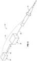
- FIG. 3is similar to FIGS. 1 and 2 , but depicts a system with a dedicated central processing unit interfacing with the components also depicted in FIGS. 1 and 2 .
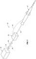
- FIG. 4schematically depicts a catheter in use in a patient and connected to a generator comprising a pulsed RF control system according to the present disclosure.
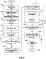
- FIG. 5depicts one possible control flowchart, including various optional steps, for delivering pulsed RF energy to an ablation catheter.
- FIG. 6depicts six representative controller responses, showing how a measured process variable may approach a set point depending on how the controller is configured.
- FIG. 7depicts a representative controller response and depicts how a measured process variable (PV) at a first set point (“initial steady state value of PV”) may be driven to a second set point (“final steady state value of PV”).
- PVprocess variable
- FIG. 8is a fragmentary, isometric view of various components comprising the distal end of an ablation catheter that could be used with the pulsed RF control systems disclosed herein.
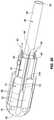
- FIG. 9is similar to FIG. 8 , but depicts components of the distal end of a non-irrigated catheter that could be used in combination with the pulsed RF control systems disclosed herein.
- FIG. 10is an exploded, isometric view of the catheter tip depicted in FIG. 8 , showing additional components and features.
- FIG. 11is a side view of the conductive shell depicted in, for example, FIGS. 8 and 10 .
- FIG. 12is an isometric view of the conductive shell depicted, for example, in FIGS. 10 and 11 .
- FIG. 13is a cross-sectional view showing the interior of the conductive shell depicted in, for example, FIGS. 10-12 .
- FIG. 14is an enlarged isometric view of the shank also depicted in, for example, FIGS. 8-10 .
- FIG. 15is an isometric, cross-sectional view of the various catheter tip components also depicted in FIG. 8 .
- FIG. 16is similar to FIG. 15 , but is a cross-sectional view taken at an angular orientation that bisects two of the lateral irrigation channels.
- FIG. 17is an enlarged, fragmentary, cross-sectional view showing a possible interconnection between the shell cylindrical body, the shank, and an RF lead wire.
- FIG. 18is a fragmentary, isometric, cross-sectional view of a prior art, solid platinum (or solid platinum iridium) irrigated catheter tip with a polymer irrigation tube mounted in its proximal end.
- FIG. 19is similar to FIGS. 15 and 16 , and depicts another fragmentary, isometric, cross-sectional view, but this time taken from an angular orientation that clearly shows a distal-most thermal sensor.
- FIG. 20is an isometric view of components of the tip also depicted in, for example, FIGS. 8, 10, 15, 16, and 19 .
- FIG. 21is similar to FIG. 20 , but shows the catheter tip components in a different orientation, revealing the distal-most thermal sensor; and this view also includes the shank, which is not present in FIG. 20 .
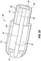
- FIG. 22is an isometric view of the thermally-insulative ablation tip insert also depicted in FIG. 21 .
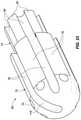
- FIG. 23depicts the tip insert of FIG. 22 in a slightly different angular orientation, revealing an arc-shaped channel or ditch that extends toward the distal end of the catheter tip to position the distal-most thermal sensor at that location.
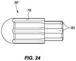
- FIG. 24depicts a thermally-insulative ablation tip insert for a non-irrigated embodiment of a catheter tip, such as the embodiment depicted in FIG. 9 .
- FIG. 25is most similar to FIG. 8 , but depicts an alternative embodiment comprising one or more isolated temperature-sensing islands.
- FIG. 26is most similar to FIG. 12 , but depicts a multilayer embodiment of the conductive shell.
- FIG. 27Aschematically depicts magnetic flux lines reacting to a diamagnetic sub stance.
- FIG. 27Bschematically depicts magnetic flux lines reacting to a paramagnetic sub stance.
- FIG. 27Cschematically depicts magnetic flux lines reacting to a ferromagnetic sub stance.
- FIG. 28Ais most similar to FIG. 20 , but depicts an embodiment of the tip insert on which both distal and proximal temperature sensors are mounted.
- FIG. 28Bis an isometric view of a conductive shell for assembly over the tip insert of FIG. 28A , consistent with various aspects of the present disclosure.
- FIG. 29is an isometric view of a thermally-insulative ablation tip insert including a radially extending channel or ditch, consistent with various aspects of the present disclosure.
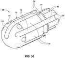
- FIG. 30depicts the tip insert of FIG. 29 in a slightly different angular orientation, revealing an arc-shaped channel or ditch that extends toward a distal end of the catheter tip to position a distal-most thermal sensor at that location, consistent with various aspects of the present disclosure.
- FIG. 31depicts an embodiment of a tip insert, as shown in FIGS. 29, and 30 , on which both distal and proximal temperature sensors are mounted, consistent with various aspects of the present disclosure.
- FIG. 32depicts a front view of the tip insert of FIG. 31 , revealing the distal-most thermal sensor, consistent with various aspects of the present disclosure.
- FIG. 33is a side view of one exemplary configuration of a tip insert including various catheter tip components, consistent with various aspects of the present disclosure.
- FIG. 34is a side view of another exemplary configuration of a tip insert including various catheter tip components, consistent with various aspects of the present disclosure.
- FIG. 35depicts an embodiment of a tip insert including a plurality of longitudinally-extending channels or ditches, and two longitudinally offset, radially extending channels or ditches on which both distal, proximal, and intermediate temperature sensors are mounted, consistent with various aspects of the present disclosure.
- FIG. 1is a highly-schematic representation of one embodiment of a system 10 for delivering pulsed RF energy to an ablation catheter 12 during catheter ablation, showing possible communication pathways 14 , 16 , 18 between primary components in this embodiment.
- This figuredepicts a generator 20 operatively connected to a pulse control box 22 , which is operatively connected to the ablation catheter 12 .
- a number of possible wired and/or wireless communication pathwaysare shown.
- a dashed line 14represents temperature feedback from the catheter to the pulse control box 22 of readings from at least one temperature sensor mounted in the tip of the catheter 12 .
- the cathetermay comprise multiple thermal sensors (for example, thermocouples or thermistors), as described further below.
- the feedback shown in FIG. 1 from the catheter to the pulse control boxmay be, for example, the highest reading from among all of the individual temperature sensor readings, or it may be, for example, an average of all of the individual readings from all of the temperature sensors.
- FIG. 1two communication options, represented by double-headed arrow 24 and single-headed arrow 26 , are shown for delivering information to the generator 20 or exchanging information between the pulse control box 22 and the generator 20 .
- the communication pathway 18 between the generator 20 and the pulse control box 22could comprise, for example, multiple, separate electrical connection (not separately shown) between the generator 20 and the pulse control box 22 .
- One of these communication linescould be, for example, a separate (possibly dedicated) line for communicating to the generator the highest temperature measured by any of a plurality of temperature sensors mounted in the catheter tip. This could be used to trigger a temperature-based shutdown feature in the generator for patient safety.
- the temperature reading or readings from the cathetermay be sent to the pulse control box, which may then feed the highest temperature reading to the generator so that the generator can engage its safety features and shut down if the temperature reading appears to be getting undesirably or unsafely high.
- the generator 20“thinks” it is delivering RF energy to the catheter, but that energy is being delivered instead to the pulse control box 22 .
- the pulse control boxdetermines, based upon the temperature feedback that it receives from the catheter, whether to drive the catheter at the power level coming from the generator or, alternatively, to pulse the delivery of RF energy to the catheter tip.
- the generatormay be blind to the fact that the pulse control box 22 is determining whether to send power to the catheter tip or to momentarily suspend delivery of energy to the catheter tip as a means of effectively controlling tissue temperature by monitoring and controlling catheter tip temperature.
- FIG. 2is similar to FIG. 1 , but depicts the components arranged in a slightly different configuration in an alternative embodiment of a system 10 ′ for delivering pulsed RF energy during catheter ablation.
- the pulse control box 22is again receiving temperature feedback from the catheter 12 along communication pathway 14 .
- the pulse control box 22is “telling” the generator (e.g., along communication pathway 18 ′) to switch “off” and “on” based on the sensed temperature from the catheter 12 .
- the generator 20then delivers pulsed RF energy to the catheter 12 via communication pathway 28 .
- this system 10 ′ for delivering pulsed RF energyas in the system 10 depicted in FIG.
- the powercan remain at a desired power level (e.g., 50 or 60 Watts) rather than being reduced to an ineffective level when excessive temperature is sensed by the catheter tip.
- a desired power levele.g., 50 or 60 Watts
- the poweris delivered in a pulsed manner; and it is the control of the energy pulses, including control of the length of the time gaps between pulses, that is used to control the tip temperature as a surrogate for controlling the tissue temperature.
- the generator 20may receive temperature feedback via communication pathway 28 and then pass temperature feedback information to the pulse control box 22 , which would then control the generator 20 as described above.
- FIG. 3is similar to FIGS. 1 and 2 , but depicts a system 10 ′′ with a dedicated central processing unit (CPU) 30 interfacing with the components 12 , 20 , 22 also depicted in FIGS. 1 and 2 .
- a dedicated CPUis among the components in the system 10 ′′ for delivering pulsed RF energy during ablation.
- This figurealso shows a number of potential communication pathways between and among the various components, including, for example, a temperature feedback pathway 32 between the catheter and the CPU, the temperature feedback pathway 14 between the catheter and the pulse control box 22 , a communication pathway 34 between the generator 20 and the CPU 30 , a communication pathway 18 ′′ between the generator and the pulse control box, the communication pathway 28 between the generator 20 and the catheter 12 , and a communication pathway 36 between the CPU and the pulse control box.
- a temperature feedback pathway 32 between the catheter and the CPUthe temperature feedback pathway 14 between the catheter and the pulse control box 22
- a communication pathway 34between the generator 20 and the CPU 30
- a communication pathway 18 ′′between the generator and the pulse control box
- the communication pathway 28between the generator 20 and the catheter 12
- a communication pathway 36between the CPU and the pulse control box
- the generator 20may directly receive temperature feedback from the catheter 12 along, for example, communication pathway 28 .
- the generator 20could then share that temperature feedback information with the dedicated CPU 30 and/or the pulse control box 22 via one or more of the communication pathways 18 ′′, 34 , 36 .
- Yet another possible alternative to the system 10 ′′ depicted in FIG. 3would be to switch the locations of the pulse control box 22 and the generator 20 , similar to the configuration depicted in FIG. 1 , but also include the dedicated CPU 30 depicted in FIG. 3 .
- FIG. 4schematically depicts a catheter 12 in use in a patient 38 and connected to a generator 40 comprising a pulsed RF control system according to the present disclosure.
- This figuredepicts a portion of a human torso of the patient 38 , a heart, a representative catheter tip located in the heart, a representative catheter handle, and the RF generator.
- the catheteris assumed to be connected to the RF generator 40 .
- the pulse control hardware, software, and/or firmwareis built into the generator itself.
- FIG. 5is a flowchart depicting one possible control flow, including various optional steps, for delivering pulsed RF energy to an ablation catheter.
- the processcommences at block 502 .
- the generatoris placed in a “power-control” mode.
- the generator poweris set to a desired power level for a desired initial time.
- that initial power levelis shown as 50 Watts and the initial time is shown as 60 seconds; however, both of these are merely sample values.
- the pulse controlmay be set to set point 1. If, for example, the pulse control box 22 (see, for example, FIG. 1 ) is a PID controller (also known as a proportional-integral-derivative controller or a three-term controller), set point 1 may relate to the measured process variable (PV). That measured process variable may be the temperature feedback coming from the catheter tip during the ablation cycle.
- a PID controlleralso known as a proportional-integral-derivative controller or a three-term controller
- set point 1may relate to the measured process variable (PV). That measured process variable may be the temperature feedback coming from the catheter tip during the ablation cycle.
- a PID controllercalculates an error value as the difference between a measured process variable—e.g., measured tip temperature—and a desired set point—e.g., a desired tip temperature. The controller then attempts to minimize the error by adjusting the process through use of a manipulated variable (MV)—e.g., the time that a selected power is actively delivered to an ablation tip.
- MVmanipulated variable
- the controllercalculates a weighted sum of P, I, and D, and then uses that value to adjust the process—here by adjusting the time when RF power is delivered to the ablation tip (e.g., by pulsing the delivery of RF energy to the tip).
- a useris allowed to “tune” the three values, namely the P, I, and D values.
- the controllermay be a separate controller as discussed herein and shown in FIGS.
- RF poweris turned “on” and “off” based on the temperature feedback as it is interpreted and analyzed by the pulse control box.
- the ablation cyclebegins.
- the control systemmonitors the catheter tip temperature. As noted above, this would be the “PV” value in a PID controller. As represented by block 514 and its loop back to block 512 , as long as the tip temperature is not close to set point 1, the system continues to permit the delivery of full RF power to the ablation tip and continues to monitor catheter tip temperature at block 512 . Once the measured tip temperature is approximately at the value of set point 1 (e.g., 40° C. in one example), the pulse control box (e.g., the PID controller) would begin to pulse the RF energy being delivered to the catheter tip (see block 516 ) in an effort to keep the tip temperature approximately at set point 1.
- set point 1e.g. 40° C. in one example
- the temperature setting on the pulse control box 22is changed to set point 2, which may be, for example, a higher value than set point 1.
- set point 2is 55° C.
- the full RF powermay be delivered to the catheter tip (see block 520 ).
- the systemmay stop delivering pulsed RF energy to the ablation tip as the system tries to drive the tip temperature from the set point 1 temperature to the set point 2 temperature.
- the systemmonitors the tip temperature.
- decision block 524the system compares the temperature at the ablation tip to set point 2. If the tip temperature is not yet approximately equal to the value of set point 2, the system repeatedly returns to block 522 and continues to monitor the tip temperature being reported to the pulse control box. Once the tip temperature is approximately equal to the value of set point 2, control transfers from block 524 to block 526 in FIG. 5 .
- Block 526is similar to block 516 and, at this point, the control system begins again to pulse the delivery of RF energy in an effort to keep the tip temperature approximately at set point 2 without overheating the tissue.
- decision block 528the system next attempts to determine whether the ablation is complete (e.g., a physician may stop calling for the delivery of ablation energy). Once it is determined that the ablation is complete (e.g., when, a physician determines that sufficient RF energy has been delivered to the tissue), control transfers to block 530 ; and all delivery of RF energy to the ablation tip is stopped.
- the PID controllerreceives values for set point 1 and set point 2, which may be entered by a user.
- the PID controlleralso receives the measured temperature (or multiple measured temperatures if multiple temperature sensors are present) from the catheter tip.
- the controllerdetermines when to permit delivery of full power RF energy or pulsed RF energy to the ablation tip, including, in the latter case, the length of the pulses (i.e., the time periods when RF energy is being delivered to the catheter tip) and the length of the time periods when no RF energy is being delivered to the catheter tip.
- the length of the pulses and the length of the non-pulse time periodsmay vary continuously.
- the PID controllerdetermines algorithmically when to turn the RF power “on” and “off” as it receives real-time (or near-real-time) tip temperature feedback from the ablation catheter.
- FIG. 6depicts six representative controller response curves, showing how a measured process variable (which may be the measured tip temperature in the control systems disclosed herein) may approach a set point (which may be the desired tip temperature in the control systems disclosed herein), depending on how the controller is configured.
- the controller response curve labeled “Long Integral Action Time” in FIG. 6may be a desirable controller response as the tip temperature is driven from its starting temperature to the desired ablation temperature.
- this curvewhich is located in the middle of the left three curves in FIG. 6 , the temperature would never exceed the set point temperature (e.g., set point 1 or set point 2 in FIG. 5 ), but would reach the set point temperature in a timely and efficient manner.
- FIG. 7depicts a representative controller response curve and depicts how a measured process variable (PV) at a first set point (“initial steady state value of PV”) may be driven to a second set point (“final steady state value of PV”).
- PVprocess variable
- This ‘dual set point’ configurationis represented in the full flowchart of FIG. 5 , which is described above. It should be noted, however, that such a dual set point control scheme is not required. In other words, an effective controller could drive the catheter tip temperature directly to the set point ultimately desired, without driving to a first value (e.g., set point 1) and then driving to a second value (e.g., set point 2).
- blocks 518 - 526are labeled “optional” in FIG. 5 .
- set point 1could be an initial temperature that is somewhere between the starting temperature of the ablation tip and the ultimate desired temperature for the ablation tip. If the system is able to reach the set point 1 value effectively and while remaining under control, that would provide the user with confidence that the tip is in contact with the tissue and that the controller is working properly before the tip temperature reaches a potentially dangerously-high temperature.
- set point 1i.e., where control transitions from block 514 to block 516 in FIG. 5
- the userwill have confidence that the controller is functioning properly and could then, at block 518 of FIG. 5 , input a higher (ultimately desired) working temperature for creating lesions.
- an ablation tip having a relatively low thermal massalso known as ablation tip having high thermal sensitivity. If the ablation tip has a relatively low thermal mass, it more rapidly heats (i.e., it comes to temperature quickly) and cools (i.e., it does not remain hot for long after power is removed), enabling tighter control of the tip temperature and less “coasting” of the tip temperature past a desired set point as well as more rapid reduction in tip temperature when RF power is removed from the tip. In fact, such a tip may cool down at the same rate as the tissue, which would inform the user whether the tip became dislodged during ablation. Remaining FIGS.
- FIG. 8is a fragmentary, isometric view of various components comprising an embodiment of a tip 42 at the distal end of an ablation catheter that could be used with the pulsed RF control systems disclosed herein.
- a conductive shell 44e.g., a platinum shell, a platinum iridium shell, or a gold shell
- the conductive shell 44(which may weigh, for example, 0.027 g) includes a shell distal end portion 48 and a shell proximal end portion 50 , which may comprise one or more parts or components.
- the shell 44includes six irrigation holes 46 , two of which are visible in this isometric view.
- FIG. 8Also visible in FIG. 8 is an optional shank 52 comprising an annular or washer-shaped brim 54 and a cylindrical open crown 56 , which together define the top-hat-shaped shank.
- the conductive shell 44 and the shank 52effectively encase an ablation tip insert 58 (see, for example, FIG. 10 ), the proximal surface 60 of which is partially visible in FIG. 8 .
- An electrical lead wire 62is shown connected (e.g., by soldering or welding) to the shank 52 .
- the electrical lead wire 62may be directly connected to the conductive shell 44 .
- a number of lead wire pairs 64 for the temperature sensors comprising part of the tipmay be seen extending rearwardly or proximally in FIG. 8 .
- FIG. 8also shows two components of an irrigation tube assembly 66 extending proximally in FIG. 8 (i.e., rightwardly in this figure).
- the conductive shell 44 depicted in the figuresincludes six irrigation holes 46 , more or fewer holes may be used, and the size of the holes may be larger, or smaller, or a mix of larger and smaller holes.
- FIG. 9is similar to FIG. 8 , but the conductive shell 44 ′ depicted in FIG. 9 does not include any irrigation ports or holes through it (compare element 46 in FIG. 8 ). Thus, this is a non-irrigated catheter tip 42 ′ that could be used in combination with the pulsed RF control systems described herein.
- Most of the discussion belowfocuses on the irrigated catheter tip embodiment 42 of FIG. 8 , but much of what is said below regarding the embodiment 42 depicted in FIG. 8 applies equally well to the non-irrigated catheter tip embodiment 42 ′ depicted in FIG. 9 , with the exception of the discussion of the irrigation features.
- the irrigation tube assembly 66(shown in FIG. 8 ) is not necessary in the non-irrigated catheter tip embodiment 42 ′ depicted in FIG. 9 (and, thus, is not shown in FIG. 9 ), the irrigation tube assembly 66 could be present on the non-irrigated catheter tip embodiment.
- the proximal surface 60 of the ablation tip insert of the non-irrigated embodiment 42 ′may be slightly different from the proximal surface 60 ( FIG. 8 ) of the ablation tip insert 58 (see also FIG. 10 ) of the irrigated embodiment 42 ( FIG. 8 ).
- the proximal surface 60may not include the main channel 84 , which is discussed further below in connection with FIG. 10 .
- the non-irrigated embodiment of FIG. 9could, however, just as easily use the same ablation tip insert 58 and the irrigation tube assembly 66 shown in the irrigated catheter tip embodiment 42 of FIG. 8 , which would make it possible, for example, to manufacture both irrigated and non-irrigated embodiments on a single assembly line, and would likely result in the two embodiments exhibiting more similar structural integrity during use.
- FIG. 10which is an exploded, isometric view of the catheter tip 42 depicted in FIG. 8 , is described next, starting with the elements shown in the upper left-hand portion of that figure and working toward the lower right-hand portion of the figure.
- FIG. 10again depicts the conductive shell 44 , but this time exploded away from the other components of the tip shown in FIGS. 8 and 9 thereby revealing additional features and components.
- To the right of the conductive shell in FIG. 10is an assembly of an ablation tip insert 58 and one temperature sensor 68 (e.g., a thermocouple). As may be seen in FIG.
- the tip insert 58includes a plurality of lateral irrigation channels 70 that are sized and arranged to align with complementary irrigation holes 46 through the conductive shell 44 .
- the diameter of the lateral irrigation channels 70 in the tip insert 58may be smaller than the complementary holes 46 through the conductive shell 44 .
- the tip insertwhich may be a unitary piece, includes a main body 72 and a stem 74 .
- the tip insert 58can be constructed from, for example, plastic (such as PEEK, which is polyether ether ketone) or thermally-insulative ceramic.
- the main body portion 72includes a plurality of optional, longitudinally-extending sensor channels or ditches 76 .
- a thermal sensor 68is shown mounted in one of these ditches 76 .
- Each of the sensor ditchesis separated from the next adjacent sensor ditch by a longitudinally-extending shell seat 78 .
- the plurality of shell seats between the sensor ditchesare configured to ride against, or very near to, the inner surface of the conductive shell 44 .
- the stem 74 of the tip insert 58defines a plurality of longitudinally-extending wire channels or ditches 80 separated by a plurality of longitudinally-extending shank seats 82 .
- the ditches 76 , 80are configured to carry temperature sensor lead wires on their path to the proximal end of the catheter.
- the shank seats 82are sized and configured to ride against, or very near to, the inner surface of the cylindrical open crown portion 56 of the shank 52 .
- the tip insert 58includes a main channel 84 having a circular cross-section that, as shown in the figures and as described further below, may include more than one inner diameter.
- the irrigation tube assemblycomprises, in this embodiment, a central irrigation tube 86 and an optional seating sleeve 88 .
- the central irrigation tube 86has a distal end 90 and a proximal end 92 and may be constructed from a polymer, such as polyimide. This central irrigation tube may extend proximally toward a catheter handle, or may extend proximally all the way to the catheter handle.
- the optional seating sleeve 88as shown in the embodiment depicted in FIG. 10 , may include a cylindrical portion and a frustoconical boss.
- the seating sleevemay be positioned at a desired longitudinal location along the outer surface of the central irrigation tube 86 and then may be fixed in place (for example, by an adhesive or sonic welding or via some other technique).
- the irrigation tube assemblywould then be mounted in the tip insert by, for example, adhesive. If the optional seating sleeve is not included (e.g., to simplify tip construction and manufacturing), the central irrigation tube 86 could be adhered directly to the tip insert 58 .
- To the right of the irrigation tube assembly in FIG. 10is the optional shank 52 . Details of the shank are described further below in connection with, for example, FIG. 14 . To the right of the shank are five additional temperature sensors 68 .
- six temperature sensorsare radially disposed symmetrically about the catheter longitudinal axis 94 (see, for example, FIG. 8 ). Since one of those six thermal sensors is depicted already in position on the tip insert 58 in FIG. 10 , the remaining five temperature sensors are shown in the lower right-hand portion of FIG. 10 , oriented and arranged so as to slip into the remaining five complementary sensor ditches 76 formed in the tip insert.
- FIGS. 11-13are additional views of the conductive shell 44 depicted in, for example, FIGS. 8 and 10 .
- the conductive shellmay comprise a hemispherical or nearly-hemispherical domed distal end 48 and a cylindrical body 50 .
- a ‘seam’ 96is shown between the domed distal end 48 and the cylindrical body 50 . This may be merely a circumferential transition line between the cylindrical body and the domed distal end of a unitary component; or, alternatively, it may be the location where the cylindrical body is connected to the domed distal end by, for example, welding.
- the wall thickness 98 of the shellis 0.002 inches, but alternative wall thicknesses also work.
- the conductive shellcould be formed or manufactured by, for example, forging, machining, drawing, spinning, or coining. Also, the conductive shell could be constructed from molded ceramic that has, for example, sputtered platinum on its external surface. In another alternative embodiment, the conductive shell could be constructed from conductive ceramic material.
- FIG. 14is an enlarged, isometric view of the shank 52 also depicted in, for example, FIGS. 8-10 .
- the brim 54may include a circumferential outward edge 100 that, as described below, may be connected by welding or soldering to a surface (e.g., the inner surface) of the cylindrical body 50 of the conductive shell.
- the shankincludes a cylindrical open crown 56 that also defines an inner surface. As described above, the inner surface of the cylindrical open crown is sized and configured to slide over the shank seats 82 defined on the stem of the tip insert 58 .
- the cylindrical open crown of the shankalso defines a proximal end or edge 102 .
- FIG. 15is an isometric, cross-sectional view of various components of the catheter tip 42 also depicted in FIG. 8 and clearly shows two temperature sensors 68 mounted in their respective temperature sensor ditches 76 .
- the sensor ditchesmay include a wire ramp 104 that allows the thermal sensor lead wires 64 to transition from the sensor ditches 76 (formed in the main body of the tip insert) to the wire ditches 80 (formed in the stem of the tip insert).
- the circumferential outer edge 100(as shown in FIG. 14 ) of the brim 54 of the shank 52 is shown riding against the inner surface of the cylindrical body of the conductive shell 50 .
- the shankmay be welded or soldered to the conductive shell at this interface to ensure good electrical contact between the shank and the shell.
- the tip electrode lead wire 62may be electrically connected to the cylindrical open crown 56 of the shank 52 in this embodiment, the shank must be conductively connected to the conductive shell 44 in a manner that permits transfer of energy from the tip electrode lead wire 62 to the shank 52 and then to the conductive shell 44 .
- the irrigation tube assembly 66 shown in FIG. 15it is possible to see that the distal end 90 of the central irrigation tube 86 rides against an inner annular ledge 106 formed as part of the tip insert 58 . Further, the frustoconical boss defines a distally-facing ledge or lip that rides against the distal end of the stem 74 of the tip insert 58 . Thus, the irrigation tube assembly seats against both the proximal surface 60 of the tip insert 58 as well as the inner annular ledge 106 defined along the longitudinal irrigation channel 84 extending through most of the tip insert 58 .
- any voids in the assembled tipmay be filled with potting material, providing a durable assembled set of components.
- the outer surface of the temperature sensorsare mounted so as to at least be in close proximity to, and preferably so as to be in physical contact with, the inner surface of the conductive shell 44 .
- “in close proximity to”means, for example, within 0.0002 to 0.0010 inches, particularly if a conductive adhesive or other bonding technique is used to bond the temperature sensors to the inner surface of the shell.
- the distal end portions of the sensor ditches 76may be shallower than the proximal end portions of the sensor ditches. In this manner, when a temperature sensor 68 is mounted in its respective sensor ditch, the distal most portion of the temperature sensor is “lifted” toward and possibly against the inner surface of the cylindrical body of the conductive shell 44 . This helps to establish good thermal conductivity between the conductive shell and the thermal sensor or sensors mounted inside of the shell.
- FIG. 16is similar to FIG. 15 , but is a cross-sectional view taken at a slightly different angular orientation from that shown in FIG. 15 , to thereby reveal two of the lateral irrigation channels 70 configured to deliver irrigant 108 outside of the tip 42 . Since the conductive shell is very thin in these embodiments, and since the tip insert is constructed from an insulative material, the irrigant, when used, has very little ability or opportunity to influence the temperature of the conductive shell 44 . As shown to good advantage in FIG. 16 , the irrigant exiting the lateral irrigation channels touches the inner edges of the holes 46 through the conductive shell before exiting to the surrounding blood. This may be contrasted to what is shown in FIG.
- FIG. 18depicts a prior art catheter tip 42 ′′.
- FIG. 18depicts a solid platinum (or platinum iridium) tip 110 with a polymer irrigation tube 86 mounted in it.
- the irrigant 108flows through and directly contacts a portion of the platinum tip before reaching the lateral irrigation channels 70 ′ and then exiting the tip.
- the cool irrigantrides directly against the platinum comprising the conductive tip.
- the irriganthas a much greater opportunity to influence the temperature of the tip than does the irrigant in the embodiment depicted in, for example, FIG. 16 .
- the temperature of the conductive shell in the immediate vicinity of the tissue-tip interfaceheats up quickly, and the sensor 68 closest to that portion of the conductive shell rapidly senses and reports a temperature rise in the immediate vicinity of the tissue-tip interface. It is not necessary for the entire tip to heat up before the sensor can report a temperature rise in the tissue, the blood flowing around the entire tip thus has less of an opportunity to distort the sensed tip temperature, and fewer temperature averaging issues come into play.
- FIG. 17is an enlarged, fragmentary, cross-sectional view showing one possible interconnection between the cylindrical body 50 of the conductive shell 44 , the shank 52 , and the RF lead wire 62 .
- a proximal edge 112 of the cylindrical body 50 of the conductive shellis bent around the circumferential outward edge 100 of the shank brim 54 .
- the shank brim and the shell bodyare then connected by welding or soldering, for example.
- energy coming from the RF lead wire 62can be delivered to the shank crown 56 , conducted to the shank brim 54 , and then delivered to the cylindrical body 50 of the conductive shell.
- FIG. 19is similar to FIGS. 15 and 16 , and depicts another fragmentary, isometric, cross-sectional view, but this time taken from an angular orientation that clearly shows a distal-most thermal sensor 114 .
- this figureclearly depicts an arc-shaped channel extension 116 extending from one of the sensor ditches 76 .
- the distal-most thermal sensori.e., a seventh thermal sensor in this embodiment
- This distal-most thermal sensoris shown having a spherical shape in FIG. 19 and being placed ahead of (i.e., distally of) one of the radially-disposed thermal sensors 68 .
- FIG. 20is an isometric view of components of the tip also depicted in, for example, FIGS. 8, 10, 15, 16, and 19 .
- all six of the radially-disposed thermal sensors 68are in place in their respective sensor ditches 76 .
- the seventh, distal-most thermal sensormay also be in place, but is not shown in this particular figure.
- This figurealso clearly shows the frustoconical boss comprising part of the optional seating sleeve 88 with its distally-facing surface or tip resting against the proximally-facing surface 60 of the tip insert 58 .
- FIG. 21is similar to FIG. 20 , but shows components of the catheter tip from a different view, wherein the distal-most thermal sensor 114 (i.e., the seventh thermal sensor in this embodiment) is visible, and this view also includes the shank 52 , which is not present in FIG. 20 .
- the shankis in place over the stem of the tip insert, which helps clarify the benefit of the wire ramps 104 connecting the sensor ditches 76 to the wire ditches, both of which are formed in the tip insert.
- FIG. 22is an isometric view of just the thermally-insulative ablation tip insert 58 also depicted in FIG. 21 , but without any other tip components.
- All of the ablation tip inserts described hereinare preferably constructed from thermally-insulative material. They could be constructed from, for example, ULTEM, plastic (such as PEEK, which is polyether ether ketone) or thermally-insulative ceramic.
- the tip insertincludes six laterally-extending irrigation channels 70 , each of which has a longitudinal axis arranged substantially perpendicular to the longitudinal axis of the tube channel that is itself arranged substantially parallel to the catheter longitudinal axis 94 .
- the laterally-extending irrigation channelsconnect a distal end of the tube channel 84 to an outer surface of the tip insert.
- the laterally-extending irrigation channelscould be arranged at a different angle (i.e., different from 90°) relative to the tube channel longitudinal axis.
- more or fewer than six laterally-extending irrigation channelsmay be present in the tip insert.
- the outer surface of the tip insertmay define a plurality of sensor ditches 76 , and these ditches may be separated by a plurality of shell seats 78 . These sensor ditches may be, for example, 0.010 inches deep.
- the shell seats, as described above,may be configured to ride against, or very near to, the inner surface of the conductive shell. A few of the sensor wire ramps are also clearly visible in FIG. 22 .
- the stem 74 of the tip insertmay define a plurality of wire ditches 80 separated by a plurality of shank seats 82 as shown in FIG. 22 .
- FIG. 23depicts the tip insert 58 of FIG. 22 in a slightly different orientation, revealing the arc-shaped channel 116 (or sensor ditch extension) that extends toward the distal-most end of the catheter tip to position the distal-most thermal sensor 114 (see, for example, FIG. 21 ) at that location.
- this arc-shaped channel extensionneed not be present. It has been determined, however, that a number of advantages may be realized by positioning a thermal sensor as far distally on the catheter tip as possible. For example, in view of the rapid heat dissipation experienced by these catheter tips, it can be extremely helpful to sense temperature at this distal location since it may be in the best location for most accurately determining the temperature of the surrounding tissue during certain procedures.
- FIG. 24depicts an alternative thermally-insulative ablation tip insert 58 ′.
- This tip insertcould be used in a non-irrigated embodiment of the catheter tip 42 ′, such as the embodiment depicted in FIG. 9 .
- the control systems for delivering pulsed RF to ablation catheters described hereinmay completely eliminate the need for the use of irrigation.
- FIG. 24depicts one possible configuration for a tip insert for use in a non-irrigated ablation catheter. This embodiment of the tip insert still includes sensor ditches 76 and sensor wire ditches 80 as described above.
- the thermally-insulative ablation tip insertthere may be more or fewer sensor ditches 76 .
- the sensor ditchesmay facilitate placement of the sensors 68 on the insert (e.g., during catheter assembly), the outer surface of the main body of the tip insert may be smooth (or at least ditchless). In such an embodiment, the sensors may be aligned on the smooth outer surface of the tip insert (and, possibly, held in place by, for example, adhesive).
- the gaps or voids between the inner surface of the conductive shell and the outer surface of the tip insertmay be filled with material (e.g., potting material or adhesive).
- materiale.g., potting material or adhesive.
- the sensorsmay be put in place before or after the conductive shell is placed over the tip insert. For instance, the sensors may be mounted on (e.g., adhered to) the smooth outer surface of the tip insert forming a tip-insert-sensor subassembly.
- the conductive shellmay be placed over that tip-insert-sensor subassembly before the remaining voids between the tip-insert-sensor subassembly and the conductive shell are filled.
- the conductive shellmay be held in place over the tip insert while one or more sensors are slid into the gap between the outer surface of the tip insert and the inner surface of the conductive shell. Subsequently, the voids could again be filled.
- FIG. 25is most similar to FIG. 8 , but depicts one form of an alternative embodiment of a catheter tip 42 ′′′ comprising one or more isolated temperature-sensing islands 118 which, in this embodiment, reside partially on the domed distal end 48 ′ of the conductive shell 44 ′′ and partially on the cylindrical body 50 ′ of the conductive shell 44 ′′.
- Each of these temperature-sensing islands 118is outlined or circumscribed by a strip of insulative material 120 placed to reduce or eliminate any potential influence from irrigant flowing through the nearby holes 46 ′ in the conductive shell.
- a single-layer conductive shell 44(see, e.g., FIGS. 10-13 and 15 ) constructed from a thin layer of gold, for example, may perform in an magnetic resonance (MR) environment without causing undesirable or unmanageable MR artifacts
- a conductive shellcomprising an outer layer of a paramagnetic material such as platinum or platinum iridium, for example, may benefit from a multilayer construction as discussed below.
- FIG. 26is most similar to FIG. 12 , but depicts a multilayer conductive shell 44 ′′′.
- a multilayer conductive shellmay have just a multilayer cylindrical body portion, just a multilayer domed distal end portion, or both a multilayer domed distal end portion and a multilayer cylindrical body.
- both the domed distal end portion 48 ′′′ and the cylindrical body 50 ′′′have a multilayer construction.
- the domed distal end portion 48 ′′′comprises an inner layer 122 and an outer layer 124
- the cylindrical body 50 ′′′similarly comprises an inner layer 126 and an outer layer 128 .
- the domed distal end portion and the cylindrical bodymust both be constructed with the same number of layers or with the same thickness of layers.
- the walls of the conductive shell 44 ′′′may, for example, be of a total thickness that is the same as, or nearly the same as, the thickness 98 (see FIG. 12 ) of the single-layer conductive shell 44 described above.
- the conductive shellcould be formed or manufactured per, for example, the techniques already described herein.
- FIGS. 27A, 27B, and 27Cschematically depict various materials or substances in a magnetic field (e.g., in an MR environment).
- FIG. 27Aschematically depicts magnetic flux lines reacting to a diamagnetic substance (the lines of force tend to avoid the substance when placed in a magnetic field)
- FIG. 27Bschematically depicts magnetic flux lines reacting to a paramagnetic substance (the lines of force prefer to pass through the substance rather than air)
- FIG. 27Cschematically depicts magnetic flux lines reacting to a ferromagnetic substance (the lines of force tend to crowd into the substance).
- Platinum iridium(a paramagnetic material) is commonly used for constructing catheter tips.
- a thin conductive shelle.g., conductive shell 44 depicted in FIG. 12
- a thin conductive shellconstructed entirely from platinum or platinum iridium (or some other paramagnetic material) may induce MR artifacts.
- a more MR compatible catheter tipmay comprise, for example, a single layer conductive shell 44 constructed entirely from a diamagnetic material (e.g., a thin gold conductive shell) or a multilayer conductive shell 44 ′′′.
- the conductive shell 44 ′′′comprises a shell distal end portion (shown as domed distal end 48 ′′′ in FIG. 26 ) and a shell proximal end portion (shown as cylindrical body 50 ′′′ in FIG. 26 ).
- the conductive shell 44 ′′′may comprise a platinum iridium outer layer (or skin) 124 , 128 and an inner layer (or liner or core) 122 , 126 constructed from a diamagnetic material (e.g., gold or copper).
- a diamagnetic materiale.g., gold or copper
- the paramagnetic outer layer 124 , 128 and the diamagnetic inner layer 122 , 126‘cooperate’ in a manner that minimizes or mitigates against the generation of undesirable MR artifacts.
- the multilayer conductive shell 44 ′′′ of the MR compatible catheter tipmay have an outer layer constructed from a diamagnetic material (such as bismuth or gold) and an inner layer constructed from a paramagnetic material (such as platinum or platinum iridium).
- a diamagnetic materialsuch as bismuth or gold
- a paramagnetic materialsuch as platinum or platinum iridium
- a multilayer conductive shellmay comprise more than two layers.
- the conductive shellmay comprise three layers, including a very thin outer layer of a paramagnetic material, a somewhat thicker or much thicker intermediate layer of a diamagnetic material, and an oversized internal layer of a non-precious metal (or plastic or other material) sized to ensure that the finished geometry of the overall ablation tip is of a desired size for effective tissue ablation.
- one example multilayer shell configurationcould comprise a platinum outer layer (or skin) and an inner layer (or liner or core) of gold or silver with a thickness ratio (e.g., platinum-to-gold thickness ratio) of at least 1/10 (i.e., the platinum layer being one-tenth as thick as the gold layer).
- a thickness ratioe.g., platinum-to-gold thickness ratio
- a multilayer conductive shell configuration 44 ′′′could comprise a platinum outer layer and a bismuth inner layer with a thickness ratio (e.g., platinum-to-bismuth thickness ratio) of at least 1 ⁇ 2 (i.e., the platinum outer layer being one-half as think as the bismuth inner layer) since bismuth has a permeability that is about one-half the permeability of platinum.
- the layersmay also be constructed from alloys, which may be used, for example, when a pure element material might otherwise be disqualified from use in the construction of a catheter tip.
- FIG. 28Ais most similar to FIG. 20 , but depicts an embodiment having both distal temperature or thermal sensors 68 and proximal temperature or thermal sensors 68 ′ mounted on a tip insert.
- a plurality of temperature sensors 68 ′may be deployed around or near the proximal end of the tip 42 .
- These temperature sensors 68 ′could be mounted, for example, on the ablation tip insert as already described above.
- FIG. 28Adepicts an ablation tip insert 58 for an irrigated tip 42
- the proximal temperature sensors 68 ′may also be used in non-irrigated embodiments such as the tip 42 ′ depicted in FIG. 9 .
- the proximal thermal sensors 68 ′may be deployed, for example, in an angularly-spaced configuration similar to the configuration of the six radially-disposed distal temperature sensors 68 shown in, for example, FIGS. 15, 19, 20, and 21 (but located near the proximal end of the main body 72 of the ablation tip insert 58 rather than its distal end).
- the temperature sensor configuration depicted in FIG. 28Awould provide a higher-resolution ‘picture’ of the thermal profile of the tip and, therefore, a better understanding of tissue temperature near the catheter tip during ablation. This is particularly beneficial when such a tip construction is used with the pulsed RF control systems disclosed herein.
- a catheter tip consistent with the present disclosuremay have one or more irrigant channels distributed along a length and around a circumference of the catheter tip.
- Various design factors including quantity, location, size, and nozzling effect (if any) of the irrigant channelsmay depend upon specific applications.
- six distal irrigation channels 70are circumferentially distributed about a distal end of the ablation tip insert 58 , with both distal thermocouples 68 and proximal thermocouples 68 ′ located proximal thereof.
- six proximal irrigation channels 70 ′are circumferentially distributed on a main body 72 of the ablation tip insert 58 near the intersection of the main body and stem 74 .
- the proximal irrigation channels 70 ′are proximal of both distal thermocouples 68 and proximal thermocouples 68 ′.
- FIG. 28Bis an isometric view of a conductive shell 44 for assembly over the tip insert 58 of FIG. 28A , consistent with various aspects of the present disclosure.
- the conductive shellmay comprise a hemispherical or nearly-hemispherical domed distal end 48 and a cylindrical body 50 .
- a ‘seam’ 96is shown between the domed distal end 48 and the cylindrical body 50 . This may be merely a circumferential transition line between the cylindrical body and the domed distal end of a unitary component; or, alternatively, it may be the location where the cylindrical body is connected to the domed distal end by, for example, welding.
- the wall thickness 98 of the shellis 0.002 inches, but alternative wall thicknesses are also readily envisioned.
- the conductive shell 44may be formed or manufactured by, for example, forging, machining, drawing, spinning, or coining.
- the shell 44includes 12 irrigation holes 46 and 46 ′, six of which are visible in this isometric view.
- the irrigation holesform two circumferentially extending rings about the conductive shell.
- the 12 irrigation holes 46 and 46 ′align with the 12 irrigation channels 70 and 70 ′ on the tip insert 58 (as shown in FIG. 28A ).
- the conductive shell 44 depicted in the figuresincludes 12 irrigation holes 46 and 46 ′, more or fewer holes may be used, and the size of the holes may be larger, or smaller, or a mix of larger and smaller holes.
- FIG. 29is an isometric view of a thermally-insulative ablation tip insert 58 including a plurality of longitudinally-extending channels or ditches 76 , and a radially extending channel or ditch 76 ′, consistent with various aspects of the present disclosure.
- the tip insert 58which may be a unitary piece, includes a main body 72 and a stem 74 .
- the thermally-insulative ablation tip insert 58 of FIG. 29is shown without any other tip components.
- Various embodiments of the present disclosureare directed to the ablation tip insert 58 including (exclusively) thermally-insulative material, for example, ULTEM, plastic (such as PEEK, which is polyether ether ketone) or thermally-insulative ceramic.
- the tip insert 58includes six radially-extending irrigation channels 70 , each of the irrigation channels 70 extending substantially perpendicular to the longitudinal axis of a tube channel 84 (see, for example, FIG. 19 ) that is itself arranged substantially parallel to a longitudinal axis 94 (see, for example, FIG. 8 ).
- the laterally-extending irrigation channels 70connect a distal end of the tube channel 84 to an outer surface of the tip insert.
- the laterally-extending irrigation channels 70can be arranged at a variety of angles relative to the longitudinal axis 94 of the catheter (i.e., different from 90°).
- various embodimentsmay include more or fewer than six laterally-extending irrigation channels 70 in the tip insert 58 .
- an outer surface of tip insert 58defines a plurality of longitudinally-extending sensor ditches 76 (relative to a longitudinal axis 94 of a catheter, as shown in FIG. 8 ) separated by a plurality of shell seats 78 , and a radially-extending sensor ditch 76 ′ near a proximal end of the main body 72 .
- These sensor ditchesmay be, for example, 0.010 inches deep and house thermal sensors 68 and 68 ′ therein (see, for example, FIG. 31 ).
- the shell seats 78may be configured to ride against, or very near to, the inner surface of the conductive shell 44 (see, for example, FIG. 12 ). Accordingly, when the assembled tip insert 58 , including thermocouples 68 and 68 ′, is inserted into the conductive shell 44 , the thermocouples are in close proximity or in direct contact with the conductive shell facilitating improved thermal response of the system.
- a stem 74 of tip insert 58may define a plurality of wire ditches 80 separated by a plurality of shank seats 82 .
- wire leads extending from thermocouples coupled to the tip insert 58may be routed back to a proximal end of a catheter shaft.
- proximal thermal sensorsmay be fixed within a distal portion of longitudinally-extending sensor ditches 76 , while distal thermal sensors may be radially offset from the proximal thermal sensors, and fixed within radially-extending sensor ditch 76 ′.
- This radial offset of the proximal and distal thermal sensorsfacilitates wire leads being run along a length of sensor ditch 76 without interfering with physical placement of the proximal thermal sensors therein—which may otherwise affect the relative contact of the proximal thermal sensors to the conductive shell 44 in final assembly.
- an increased radial distance between the thermal sensors 68 ′ within the radially-extending ditch 76 ′ and a tube channel 84 , that carries irrigant fluid to irrigation channels 70helps to mitigate thermal sink there between that may impact the accuracy, and thermal response of the thermal sensors 68 ′.
- FIG. 30depicts the tip insert of FIG. 29 in a slightly different angular orientation, revealing an arc-shaped channel or ditch 116 that extends from one of the longitudinally-extending sensor ditches 76 toward a distal end of the catheter tip to position a distal-most thermal sensor 114 (see, for example, FIG. 21 ) at that location, consistent with various aspects of the present disclosure. While some embodiments of the present disclosure need not include such an arc-shaped channel extension 116 , a number of advantages may be realized by positioning a thermal sensor as far distally on the catheter tip as possible.
- a thermal sensor at the distal tipmay provide the most accurate temperature reading of tissue surrounding the distal tip of the catheter during certain procedures.
- the distal tip of the cathetermay be in contact with target tissue.
- FIG. 31depicts an embodiment of a tip insert 58 , as shown in FIGS. 29, and 30 , on which both distal and proximal temperature sensors ( 68 and 68 ′, respectively) are mounted, consistent with various aspects of the present disclosure.
- all six of the radially-disposed thermal sensors 68are positioned in their respective longitudinally-extending sensor ditches 76 .
- the seventh, distal-most thermal sensormay be positioned within arc-shaped channel extension 116 (see, for example, FIG. 30 ), but is not shown in this particular figure.
- FIG. 31also depicts a frustoconical boss comprising part of the optional seating sleeve 88 with its distally-facing surface or tip resting against the proximally-facing surface 60 of tip insert 58 .
- FIG. 31depicts an embodiment having both distal temperature sensors 68 and proximal temperature sensors 68 ′ mounted on tip insert 58 .
- the plurality of proximal temperature sensors 68 ′may be deployed around or near the proximal end of the tip 42 .
- These proximal temperature sensors 68 ′may be mounted, for example, within radially-extending sensor ditch 76 ′ near a proximal end of the ablation tip insert 58 .
- the radially-extending sensor ditch 76 ′may house one or more proximal temperature sensors 68 ′.
- These temperature sensors 68 ′may either be longitudinally aligned with the respective sensor ditches 76 (and distal temperature sensors 68 ), or radially offset relative to the sensor ditches 76 .
- lead wire pairs 64 from each of the proximal and distal temperature sensorsmay be run in such a way as to prevent the lead wire pairs and another temperature sensor from coming into contact or otherwise affecting the other temperature sensor (e.g., electromagnetic interference).
- a lead wire pair 64 extending from distal temperature sensor 68extends through longitudinally-extending sensor ditch 76 , and through wire ditch 80 to a proximal end of the catheter shaft.
- the lead wire pair 64 extending from the distal temperature sensor 68does not physically or electrically interact with the proximal temperature sensor 68 ′.
- a lead wire pair 64 extending from proximal temperature sensor 68 ′extends through a short portion of the radially-extending sensor ditch 76 ′ before running along the longitudinally-extending sensor ditch 76 , and through the wire ditch 80 to the proximal end of the catheter shaft.
- FIG. 31depicts an ablation tip insert 58 for an irrigated tip 42
- a configuration including proximal temperature sensors 68 ′ in a radially-extending sensor ditch 76 ′may also be used in non-irrigated embodiments such as the tip 42 ′ depicted in FIG. 9 .
- the temperature sensor configuration depicted in FIG. 31would provide a higher-resolution ‘picture’ of the thermal profile of the tip and, therefore, a better understanding of tissue temperature near the catheter tip during an ablation therapy. This is particularly beneficial when such a tip construction is used with a pulsed RF control system as disclosed herein.
- FIG. 32depicts a front view of a tip insert 58 of FIG. 31 , revealing the distal-most thermal sensor 114 which extends to the distal end of the tip insert within an arc-shaped channel extension 116 , consistent with various aspects of the present disclosure.
- the present viewalso further exemplifies the radially offset nature of distal temperature sensors 68 relative to proximal temperature sensors 68 ′. Not only does the proximal and distal thermal sensors' locations along the length and circumference of the longitudinal axis of the tip insert facilitate enhanced temperature resolution across a length of the tip insert, but also an enhanced radial temperature resolution around the circumference of the tip insert.
- the present embodimentdisplays enhanced temperature resolution and sensitivity that enables the ablation catheter to contact and ablate tissue anywhere along conductive shell 44 (as shown in FIG. 16 , for example), but also to accurately control the ablation based on one or more of the temperature sensors—such as the temperature sensor in closest proximity to the tissue being ablated.
- a temperature sensor configurationincluding proximal and distal temperature sensors ( 68 ′ and 68 , respectively) also facilitates identification of a contact zone between the conductive shell 44 and tissue.
- the warmest temperature reading of the temperature sensormay be indicative of contact with tissue as the remaining sensors (and the portion of the conductive shell 44 in contact therewith) experience significant thermal sync from the blood pool.
- FIG. 33is a side view of one exemplary configuration of a tip insert including various catheter tip components, consistent with various aspects of the present disclosure.
- a thermal sensor configurationis depicted that facilitates longitudinal alignment of distal thermal sensors 68 and proximal thermal sensors 68 ′ while mitigating interaction between lead wire pair 64 1 (extending from the distal thermal sensors 68 ) and proximal thermal sensors 68 ′.
- running the lead wire pair 64 1 along the same longitudinally-extending sensor ditch 76 that a proximal thermal sensor 68 ′ is placed withinmay affect the thermal coupling between the proximal thermal sensor 68 ′ and a conductive shell 44 (as shown in FIG. 16 , for example).
- the lead wire pairs 64may emit electromagnetic interference that inhibits the accuracy (or other desirable characteristic) of the proximal thermal sensors 68 ′, or vice versa.
- the present embodimentfurther includes a longitudinally-extending lead wire ditch 76 ′′ that extends between adjacent longitudinally-extending sensor ditches 76 .
- the lead wire pairs 64 1 that extend from distal thermal sensors 68are diverted from the longitudinally-extending sensor ditches 76 to the longitudinally-extending lead wire ditches 76 ′′ prior to reaching the proximal thermal sensors 68 ′.
- lead wire pairs 64 2 that extend from the proximal thermal sensors 68 ′may similarly be diverted into the longitudinally-extending lead wire ditches 76 ′′, whereby both sets of lead wire pairs 64 1-2 then extend to the proximal end of the catheter shaft.
- FIG. 34is a side view of another exemplary configuration of a tip insert including various catheter tip components, consistent with various aspects of the present disclosure.
- a thermal sensor configurationis depicted that facilitates longitudinal alignment of distal thermal sensors 68 and proximal thermal sensors 68 ′ within the same longitudinally-extending sensor ditch 76 , while mitigating interaction between lead wire pair 64 1 (extending from the distal thermal sensors 68 ) and proximal thermal sensors 68 ′.
- the present embodimentfurther includes a longitudinally-extending lead wire ditch 76 ′′ that extends between adjacent longitudinally-extending sensor ditches 76 .
- Lead wire pairs 64 1extend from distal thermal sensors 68 and are diverted from the longitudinally-extending sensor ditches 76 to the longitudinally-extending lead wire ditches 76 ′′, via a distal radially-extending ditch 76 ′ prior to reaching the proximal thermal sensors 68 ′.
- lead wire pairs 64 2extend from the proximal thermal sensors 68 ′ and may be diverted into the longitudinally-extending lead wire ditches 76 ′′ via a proximal radially-extending ditch 76 ′. Both sets of lead wire pairs 64 1-2 then extend together to the proximal end of the catheter shaft. In other embodiments, the lead wire pairs 64 2 may extend from the proximal thermal sensors 68 ′ to the proximal end of the catheter shaft along the longitudinally-extending sensor ditch 76 , independent of the lead wire pairs 64 1 .
- FIG. 35depicts an embodiment of a tip insert 58 including two longitudinally offset, radially-extending channels or ditches ( 76 ′ and 76 ′′) on which both proximal, and intermediate thermal sensors ( 68 ′ and 68 ′′, respectively) are mounted, consistent with various aspects of the present disclosure.
- thermal sensors 68are positioned in their respective sensor ditches 76 .
- Another, distal-most thermal sensor 114may be positioned within arc-shaped channel extension 114 (see, for example, FIG. 21 ), but is not shown in this particular figure.
- FIG. 35also depicts a frustoconical boss comprising part of the optional seating sleeve 88 with its distally-facing surface or tip resting against the proximally-facing surface 60 of tip insert 58 .
- FIG. 35further depicts an embodiment having both distal thermal sensors 68 , proximal thermal sensors 68 ′, and intermediate thermal sensors 68 ′′ mounted on tip insert 58 .
- a plurality of proximal thermal sensors 68 ′may be deployed around or near the proximal end of the tip insert 58 .
- the proximal thermal sensors 68 ′may be mounted, for example, within a first radially-extending sensor ditch 76 ′ on the ablation tip insert 58 .
- the first radially-extending sensor ditch 76 ′may house one or more proximal thermal sensors 68 ′, these thermal sensors 68 ′ may either be radially aligned with the respective sensor ditches 76 , or radially offset relative to the sensor ditches 76 .
- proximal thermal sensors 68 ′are radially offset from the distal thermal sensors 68 , as shown in FIG. 35 , lead wire pairs 64 from each of the proximal and distal thermal sensors may be run in such a way as to prevent the lead wire pairs from another thermal sensor from coming into contact or otherwise affecting (e.g., electromagnetic interference) another thermal sensor.
- a lead wire pair 64 extending from distal thermal sensor 68extends through longitudinally-extending sensor ditch 76 , and through wire ditch 80 to a proximal end of the catheter shaft.
- the lead wire pairs 64 extending from the distal thermal sensors 68do not physically or electro-magnetically interact with the proximal thermal sensors 68 ′.
- a lead wire pair 64 extending from proximal thermal sensors 68 ′extend through a short portion of the first radially-extending sensor ditch 76 ′ before running along the longitudinally-extending sensor ditch 76 (proximal of distal thermal sensor 68 ), and through the wire ditch 80 to the proximal end of the catheter shaft.
- the embodiment of FIG. 35further includes a second radially-extending sensor ditch 76 ′′ distal of a first radially-extending sensor ditch 76 ′.
- the second radially-extending sensor ditch 76 ′′may house one or more intermediate thermal sensors 68 ′′. These intermediate thermal sensors 68 ′′ may either be axially aligned with the respective sensor ditches 76 , or radially offset relative to the sensor ditches.
- lead wire pairs 64 from each of the proximal, distal, and intermediate thermal sensorsmay be run in such a way as to prevent the lead wire pairs from coming in close proximity to the other thermal sensors.
- contact between lead wire pairs and thermal sensorsmay impact the thermal coupling between the thermal sensors and a conductive shell 44 (as shown in FIG. 16 , for example) which encompasses the tip insert 58 .
- contact between lead wire pairs and thermal sensorsmay result in electro-magnetic interference across the thermal sensor signals potentially corrupting signal data.
- the thermal sensors 68 , 68 ′, and 68 ′′may be precisely positioned in contact with (or in close proximity to) a conductive shell once assembled. This precise positioning of the thermal sensors facilitates a comparable thermal response across all of the thermal sensors which is desirable for consistent control inputs during an ablation therapy, for example.
- FIG. 35depicts an ablation tip insert 58 for an irrigated tip 42
- a configuration including proximal thermal sensors 68 ′ in a radially-extending sensor ditch 76 ′may also be used in non-irrigated embodiments, such as the tip 42 ′ depicted in FIG. 9 .
- a higher-resolution ‘picture’ of the thermal profile of the tipmay be achieved. This may be particularly beneficial when such a tip construction is used with a pulsed RF control system as disclosed herein.
- catheter tips having a variety of thermometry configurationscould be deployed successfully with the pulsed RF control systems described herein.
- the representative catheter tips described hereininclude six or twelve radially-disposed thermal sensors and one distal thermal sensor placed close to the distal end of the catheter tip, the invention is not limited to such seven-sensor and thirteen-sensor configurations.
- catheterscomprising various segmented tip designs may work to good advantage with the control systems described above.
- Some such tip configurationsare disclosed in U.S. patent application No. 61/896,304, filed 28 Oct. 2013, and in related international patent application no. PCT/US2014/062562, filed 28 Oct. 2014 and published 7 May 2015 in English as international publication no. WO 2015/065966 A2, both of which are hereby incorporated by reference as though fully set forth herein.
- control systems described hereinmay use a “rolling thermocouple,” which would, for example, measure the temperature output from each of a plurality of thermocouples every 20 msec (for example) and report the highest of these temperatures to the pulse control box and, potentially, directly to the generator (at least for safety shutdown reasons).
- the controlleris always working with the most accurate representation of the actual tissue temperature.
- any temperature sensors facing away from the tissue during use of the catheter in an ablation procedurewould cool rapidly and their readings could be ignored or discounted, whereas the temperature sensor or sensors closest to the portion of the catheter tip that is in contact with tissue would heat rapidly and would, therefore, provide a temperature reading that is closest to the actual temperature of the tissue being ablated.
- the systemis able to rapidly adjust for the widely varying readings being received from the thermal sensors as the catheter tip is rotated or pushed into tissue during actual use.
- proximal and distalmay be used throughout the specification with reference to a clinician manipulating one end of an instrument used to treat a patient.
- proximalrefers to the portion of the instrument closest to the clinician and the term “distal” refers to the portion located furthest from the clinician.
- distalrefers to the portion located furthest from the clinician.
- spatial termssuch as “vertical,” “horizontal,” “up,” and “down” may be used herein with respect to the illustrated embodiments.
- surgical instrumentsmay be used in many orientations and positions, and these terms are not intended to be limiting and absolute.
Landscapes
- Health & Medical Sciences (AREA)
- Life Sciences & Earth Sciences (AREA)
- Surgery (AREA)
- Engineering & Computer Science (AREA)
- Plasma & Fusion (AREA)
- Medical Informatics (AREA)
- Otolaryngology (AREA)
- Physics & Mathematics (AREA)
- Cardiology (AREA)
- Biomedical Technology (AREA)
- Heart & Thoracic Surgery (AREA)
- Nuclear Medicine, Radiotherapy & Molecular Imaging (AREA)
- Molecular Biology (AREA)
- Animal Behavior & Ethology (AREA)
- General Health & Medical Sciences (AREA)
- Public Health (AREA)
- Veterinary Medicine (AREA)
- Surgical Instruments (AREA)
- Media Introduction/Drainage Providing Device (AREA)
Abstract
Description
- A.14,18″,28,32,34,36 (all)
- B.14,28,34,36
- C.14,34,36
- D.14,18″,36
- E.32,34,36
- F.18″,32,36
- G.18″,32,34
- H.14,18″,34
Claims (20)
Priority Applications (1)
| Application Number | Priority Date | Filing Date | Title |
|---|---|---|---|
| US16/337,828US11246658B2 (en) | 2016-10-04 | 2017-08-30 | Ablation catheter tip |
Applications Claiming Priority (3)
| Application Number | Priority Date | Filing Date | Title |
|---|---|---|---|
| US201662404013P | 2016-10-04 | 2016-10-04 | |
| US16/337,828US11246658B2 (en) | 2016-10-04 | 2017-08-30 | Ablation catheter tip |
| PCT/US2017/049264WO2018067248A1 (en) | 2016-10-04 | 2017-08-30 | Ablation catheter tip |
Publications (2)
| Publication Number | Publication Date |
|---|---|
| US20200038100A1 US20200038100A1 (en) | 2020-02-06 |
| US11246658B2true US11246658B2 (en) | 2022-02-15 |
Family
ID=61831226
Family Applications (1)
| Application Number | Title | Priority Date | Filing Date |
|---|---|---|---|
| US16/337,828Active2038-09-10US11246658B2 (en) | 2016-10-04 | 2017-08-30 | Ablation catheter tip |
Country Status (5)
| Country | Link |
|---|---|
| US (1) | US11246658B2 (en) |
| EP (1) | EP3522809B1 (en) |
| JP (1) | JP6718557B2 (en) |
| CN (1) | CN109788982B (en) |
| WO (1) | WO2018067248A1 (en) |
Families Citing this family (5)
| Publication number | Priority date | Publication date | Assignee | Title |
|---|---|---|---|---|
| US11103304B2 (en)* | 2017-06-13 | 2021-08-31 | Biosense Webster (Israel) Ltd. | Catheter with composite insert support member |
| WO2019003346A1 (en)* | 2017-06-28 | 2019-01-03 | オリンパス株式会社 | Method of manufacturing handpiece of operation system, method of setting handpiece characteristics of operation system, handpiece of operation system, and operation system |
| EP4243578A3 (en) | 2019-03-27 | 2023-10-25 | St. Jude Medical, Cardiology Division, Inc. | Ablation catheter tip with flexible electronic circuitry |
| US11497551B2 (en) | 2019-11-26 | 2022-11-15 | RELIGN Corporation | Arthroscopic devices and methods |
| CN113456986B (en)* | 2021-05-30 | 2023-04-28 | 为泰医疗器械(深圳)有限公司 | Double-cavity microcatheter for coronary intervention |
Citations (158)
| Publication number | Priority date | Publication date | Assignee | Title |
|---|---|---|---|---|
| US3674014A (en) | 1969-10-28 | 1972-07-04 | Astra Meditec Ab | Magnetically guidable catheter-tip and method |
| US3935766A (en) | 1973-10-09 | 1976-02-03 | Masters Christopher F | Method and apparatus for machining cylindrical tubes |
| US4809713A (en) | 1987-10-28 | 1989-03-07 | Joseph Grayzel | Catheter with magnetic fixation |
| US4945912A (en) | 1988-11-25 | 1990-08-07 | Sensor Electronics, Inc. | Catheter with radiofrequency heating applicator |
| US5056517A (en) | 1989-07-24 | 1991-10-15 | Consiglio Nazionale Delle Ricerche | Biomagnetically localizable multipurpose catheter and method for magnetocardiographic guided intracardiac mapping, biopsy and ablation of cardiac arrhythmias |
| US5057105A (en) | 1989-08-28 | 1991-10-15 | The University Of Kansas Med Center | Hot tip catheter assembly |
| US5176144A (en) | 1989-09-14 | 1993-01-05 | Terumo Kabushiki Kaisha | Cardiac output measuring catheter |
| US5279299A (en) | 1991-02-15 | 1994-01-18 | Cardiac Pathways Corporation | Endocardial mapping and ablation system and catheter probe |
| US5363861A (en) | 1991-11-08 | 1994-11-15 | Ep Technologies, Inc. | Electrode tip assembly with variable resistance to bending |
| US5378230A (en) | 1993-11-01 | 1995-01-03 | Mahurkar; Sakharam D. | Triple-lumen critical care catheter |
| US5542938A (en) | 1992-07-28 | 1996-08-06 | Cordis Corporation | Magnetic guidewire coupling for catheter exchange |
| US5545200A (en) | 1993-07-20 | 1996-08-13 | Medtronic Cardiorhythm | Steerable electrophysiology catheter |
| US5662647A (en) | 1991-07-22 | 1997-09-02 | Transamerican Technologies International | Electrode assembly for electrosurgical instrument |
| US5681280A (en) | 1995-05-02 | 1997-10-28 | Heart Rhythm Technologies, Inc. | Catheter control system |
| US5688267A (en) | 1995-05-01 | 1997-11-18 | Ep Technologies, Inc. | Systems and methods for sensing multiple temperature conditions during tissue ablation |
| US5706827A (en) | 1994-09-21 | 1998-01-13 | Scimed Life Systems, Inc. | Magnetic lumen catheter |
| US5755790A (en) | 1995-04-14 | 1998-05-26 | B. Braun Celsa | Intraluminal medical device |
| US5769847A (en) | 1994-06-27 | 1998-06-23 | Ep Technologies, Inc. | Systems and methods for controlling tissue ablation using multiple temperature sensing elements |
| US5782810A (en) | 1995-11-22 | 1998-07-21 | O'donnell; Miles C. | Multipart radiopaque and/or magnetically detectable tube catheter and method of fabrication thereof |
| US5788713A (en) | 1994-07-22 | 1998-08-04 | University Of Washington | Method and apparatus for stereotactic implantation |
| US5810804A (en) | 1995-08-15 | 1998-09-22 | Rita Medical Systems | Multiple antenna ablation apparatus and method with cooling element |
| US5849028A (en) | 1997-05-16 | 1998-12-15 | Irvine Biomedical, Inc. | Catheter and method for radiofrequency ablation of cardiac tissue |
| US5893885A (en) | 1996-11-01 | 1999-04-13 | Cordis Webster, Inc. | Multi-electrode ablation catheter |
| US5911720A (en) | 1996-11-26 | 1999-06-15 | Ep Technologies, Inc. | Ablation catheter with segmented tip |
| US5951471A (en) | 1998-03-09 | 1999-09-14 | Irvine Biomedical, Inc. | Catheter-based coronary sinus mapping and ablation |
| US5957961A (en) | 1996-03-11 | 1999-09-28 | Medtronic, Inc. | Multiple sensor, temperature controlled R-F ablation system |
| US5979180A (en) | 1996-12-19 | 1999-11-09 | Institut Francais Du Petrole | Process and device for treating a gas by refrigeration and contact with a solvent |
| US6001095A (en) | 1997-06-23 | 1999-12-14 | Irvine Biomedical, Inc. | Catheter system having closely spaced distal bipolar electrodes |
| US6015414A (en) | 1997-08-29 | 2000-01-18 | Stereotaxis, Inc. | Method and apparatus for magnetically controlling motion direction of a mechanically pushed catheter |
| US6045550A (en) | 1998-05-05 | 2000-04-04 | Cardiac Peacemakers, Inc. | Electrode having non-joined thermocouple for providing multiple temperature-sensitive junctions |
| US6068641A (en) | 1998-08-25 | 2000-05-30 | Linvatec Corporation | Irrigated burr |
| US6113591A (en) | 1994-06-27 | 2000-09-05 | Ep Technologies, Inc. | Systems and methods for sensing sub-surface temperatures in body tissue |
| US6123702A (en) | 1998-09-10 | 2000-09-26 | Scimed Life Systems, Inc. | Systems and methods for controlling power in an electrosurgical probe |
| US6126647A (en) | 1999-05-17 | 2000-10-03 | Hermetic Switch, Inc. | Magnetically guided catheter with sensor |
| US6162184A (en) | 1994-06-27 | 2000-12-19 | Ep Technologies, Inc. | Systems and methods for sensing temperature within the body |
| US6171275B1 (en) | 1998-12-03 | 2001-01-09 | Cordis Webster, Inc. | Irrigated split tip electrode catheter |
| US6185448B1 (en) | 1998-09-29 | 2001-02-06 | Simcha Borovsky | Apparatus and method for locating and mapping a catheter in intracardiac operations |
| US6190180B1 (en) | 1996-04-18 | 2001-02-20 | Kim Purington | Swiveling electrical connector |
| US6197021B1 (en) | 1994-08-08 | 2001-03-06 | Ep Technologies, Inc. | Systems and methods for controlling tissue ablation using multiple temperature sensing elements |
| US6208881B1 (en) | 1998-10-20 | 2001-03-27 | Micropure Medical, Inc. | Catheter with thin film electrodes and method for making same |
| US6217573B1 (en) | 1998-12-03 | 2001-04-17 | Cordis Webster | System and method for measuring surface temperature of tissue during ablation |
| US6233479B1 (en) | 1998-09-15 | 2001-05-15 | The Regents Of The University Of California | Microwave hematoma detector |
| US6235024B1 (en) | 1999-06-21 | 2001-05-22 | Hosheng Tu | Catheters system having dual ablation capability |
| US6245061B1 (en) | 1995-06-07 | 2001-06-12 | Ep Technologies, Inc. | Tissue heating and ablation systems and methods using self-heated electrodes |
| US6251134B1 (en) | 1999-02-28 | 2001-06-26 | Inflow Dynamics Inc. | Stent with high longitudinal flexibility |
| US20010012956A1 (en) | 1998-07-28 | 2001-08-09 | Behl Robert S. | Apparatus and method for treating tumors near the surface of an organ |
| US6273876B1 (en) | 1997-12-05 | 2001-08-14 | Intratherapeutics, Inc. | Catheter segments having circumferential supports with axial projection |
| US6292678B1 (en) | 1999-05-13 | 2001-09-18 | Stereotaxis, Inc. | Method of magnetically navigating medical devices with magnetic fields and gradients, and medical devices adapted therefor |
| US6322584B2 (en) | 1998-07-31 | 2001-11-27 | Surx, Inc. | Temperature sensing devices and methods to shrink tissues |
| US20020022834A1 (en) | 1998-05-05 | 2002-02-21 | Simpson John A. | RF ablation catheter tip electrode with multiple thermal sensors |
| US6385472B1 (en) | 1999-09-10 | 2002-05-07 | Stereotaxis, Inc. | Magnetically navigable telescoping catheter and method of navigating telescoping catheter |
| US20020058866A1 (en) | 2000-11-15 | 2002-05-16 | Segner Garland L. | Electrophysiology catheter |
| US6405067B1 (en) | 2000-07-07 | 2002-06-11 | Biosense Webster, Inc. | Catheter with tip electrode having a recessed ring electrode mounted thereon |
| US6425894B1 (en) | 2000-07-12 | 2002-07-30 | Biosense Webster, Inc. | Ablation catheter with electrode temperature monitoring |
| US6464632B1 (en) | 1999-02-13 | 2002-10-15 | James M. Taylor | Flexible inner liner for the working channel of an endoscope |
| US6477396B1 (en) | 2000-07-07 | 2002-11-05 | Biosense Webster, Inc. | Mapping and ablation catheter |
| US6493590B1 (en) | 2000-02-09 | 2002-12-10 | Micronet Medical, Inc. | Flexible band electrodes for medical leads |
| US6498944B1 (en) | 1996-02-01 | 2002-12-24 | Biosense, Inc. | Intrabody measurement |
| US6524303B1 (en) | 2000-09-08 | 2003-02-25 | Stereotaxis, Inc. | Variable stiffness magnetic catheter |
| US6544270B1 (en) | 2000-09-14 | 2003-04-08 | Cardiac Pacemakers, Inc. | Multi-lumen cardiac catheter and system |
| US6592580B1 (en) | 1997-08-08 | 2003-07-15 | Stockert Gmbh | Apparatus for the high-frequency treatment of body tissue |
| US6605087B2 (en) | 1997-07-21 | 2003-08-12 | St. Jude Medical, Daig Division | Ablation catheter |
| US6611699B2 (en) | 2001-06-28 | 2003-08-26 | Scimed Life Systems, Inc. | Catheter with an irrigated composite tip electrode |
| US20030176766A1 (en) | 2002-03-15 | 2003-09-18 | Long Gary L. | Apparatus for guiding an instrument used with an endoscope |
| US20030216639A1 (en) | 1998-08-02 | 2003-11-20 | Pinhas Gilboa | Intrabody navigation system for medical applications |
| US6669692B1 (en) | 2000-08-21 | 2003-12-30 | Biosense Webster, Inc. | Ablation catheter with cooled linear electrode |
| US20040015215A1 (en) | 2000-09-07 | 2004-01-22 | Raymond Fredricks | Apparatus and method for treatment of an intervertebral disc |
| US20040019447A1 (en) | 2002-07-16 | 2004-01-29 | Yehoshua Shachar | Apparatus and method for catheter guidance control and imaging |
| US6690963B2 (en) | 1995-01-24 | 2004-02-10 | Biosense, Inc. | System for determining the location and orientation of an invasive medical instrument |
| US6730082B2 (en) | 2001-07-09 | 2004-05-04 | Scimed Life Systems, Inc. | Two-piece distal catheter assembly |
| US6733497B2 (en) | 2001-07-09 | 2004-05-11 | Scimed Life Systems, Inc. | Clamshell distal catheter assembly |
| US6740083B2 (en) | 2001-07-09 | 2004-05-25 | Scimed Life Systems, Inc. | Distal catheter assembly with proximal mounting member |
| US6755816B2 (en) | 1999-10-04 | 2004-06-29 | Stereotaxis, Inc. | Method for safely and efficiently navigating magnetic devices in the body |
| US6780183B2 (en) | 2002-09-16 | 2004-08-24 | Biosense Webster, Inc. | Ablation catheter having shape-changing balloon |
| US20040204671A1 (en) | 2003-04-08 | 2004-10-14 | Stubbs Jack B. | Continuous gas flow trocar assembly |
| US20040231683A1 (en) | 2003-05-21 | 2004-11-25 | Michael Eng | Electrophysiology catheter |
| US20040242995A1 (en) | 2003-03-21 | 2004-12-02 | Michael Maschke | Catheter for magnetic navigation |
| US20040243143A1 (en) | 2003-05-27 | 2004-12-02 | Corcoran Michael P. | Flexible delivery device |
| US20040267106A1 (en) | 2001-01-29 | 2004-12-30 | Segner Garland L | Electrophysiology catheter |
| US20050004563A1 (en) | 2003-07-01 | 2005-01-06 | Racz N. Sandor | Apparatus and methods for sensing and cooling during application of thermal energy for treating degenerative spinal discs |
| US20050054989A1 (en) | 2001-01-09 | 2005-03-10 | Rex Medical, L.P. | Dialysis catheter |
| US20050070894A1 (en) | 2001-12-12 | 2005-03-31 | Tissuelink Medical, Inc | Fluid-assisted medical devices, systems and methods |
| US20050096589A1 (en) | 2003-10-20 | 2005-05-05 | Yehoshua Shachar | System and method for radar-assisted catheter guidance and control |
| US20050174004A1 (en) | 2002-10-01 | 2005-08-11 | Isamu Takehara | Permanent magnet for motor, motor and magnetizing method |
| US20050197633A1 (en) | 2001-04-13 | 2005-09-08 | Schwartz Robert S. | Syringe system |
| US20050222560A1 (en) | 2004-03-12 | 2005-10-06 | Kenichi Kimura | Operative instrument |
| US20050245846A1 (en) | 2004-05-03 | 2005-11-03 | Casey Don E | Vibrating, magnetically guidable catheter with magnetic powder commingled with resin, extruded as an integral part the catheter |
| US20050272975A1 (en) | 2004-03-23 | 2005-12-08 | Mcweeney John O | In-vivo visualization system |
| US20060064123A1 (en) | 1998-02-06 | 2006-03-23 | Possis Medical, Inc. | Rapid exchange fluid jet thrombectomy device and method |
| US20060149192A1 (en) | 1999-07-19 | 2006-07-06 | Deniega Jose C | Catheter for uniform delivery of medication |
| US20060200191A1 (en) | 1996-05-20 | 2006-09-07 | Gholam-Reza Zadno-Azizi | Method and apparatuses for treating an intravascular occlusion |
| US7137395B2 (en) | 2000-02-29 | 2006-11-21 | The Johns Hopkins University | Circumferential pulmonary vein ablation using a laser and fiberoptic balloon catheter |
| US20060287650A1 (en) | 2005-06-21 | 2006-12-21 | Hong Cao | Ablation catheter with fluid distribution structures |
| US20070016131A1 (en) | 2005-07-12 | 2007-01-18 | Munger Gareth T | Flexible magnets for navigable medical devices |
| US20070016006A1 (en) | 2005-05-27 | 2007-01-18 | Yehoshua Shachar | Apparatus and method for shaped magnetic field control for catheter, guidance, control, and imaging |
| US20070066878A1 (en) | 2005-09-16 | 2007-03-22 | Worley Seth J | Catheter with flexible pre-shaped tip section |
| US7197354B2 (en) | 2004-06-21 | 2007-03-27 | Mediguide Ltd. | System for determining the position and orientation of a catheter |
| US20070073268A1 (en) | 2002-08-12 | 2007-03-29 | Goble E M | Integrated Infusion and Aspiration System and Method |
| US7207989B2 (en) | 2003-10-27 | 2007-04-24 | Biosense Webster, Inc. | Method for ablating with needle electrode |
| US20070197891A1 (en) | 2006-02-23 | 2007-08-23 | Yehoshua Shachar | Apparatus for magnetically deployable catheter with MOSFET sensor and method for mapping and ablation |
| US7263397B2 (en) | 1998-06-30 | 2007-08-28 | St. Jude Medical, Atrial Fibrillation Division, Inc. | Method and apparatus for catheter navigation and location and mapping in the heart |
| US7276044B2 (en) | 2001-05-06 | 2007-10-02 | Stereotaxis, Inc. | System and methods for advancing a catheter |
| US20070270791A1 (en) | 2006-05-16 | 2007-11-22 | Huisun Wang | Ablation electrode assembly and methods for improved control of temperature and minimization of coagulation and tissue damage |
| US20080039705A1 (en) | 2006-05-03 | 2008-02-14 | Viswanathan Raju R | Map based intuitive device control and sensing to navigate a medical device |
| US20080045943A1 (en) | 2003-10-29 | 2008-02-21 | Frederik Henricus Wittkampf | Catheter and Method, in Particular for Ablation and Like Technique |
| US7341063B2 (en) | 2000-02-16 | 2008-03-11 | Stereotaxis, Inc. | Magnetic medical devices with changeable magnetic moments and method of navigating magnetic medical devices with changeable magnetic moments |
| US20080091193A1 (en) | 2005-05-16 | 2008-04-17 | James Kauphusman | Irrigated ablation catheter having magnetic tip for magnetic field control and guidance |
| US7386339B2 (en) | 1999-05-18 | 2008-06-10 | Mediguide Ltd. | Medical imaging and navigation system |
| US20080161797A1 (en) | 2006-12-29 | 2008-07-03 | Huisun Wang | Ablation catheter electrode having multiple thermal sensors and method of use |
| US20080249395A1 (en) | 2007-04-06 | 2008-10-09 | Yehoshua Shachar | Method and apparatus for controlling catheter positioning and orientation |
| US20080255642A1 (en) | 2006-06-28 | 2008-10-16 | Ardian, Inc. | Methods and systems for thermally-induced renal neuromodulation |
| US20080297287A1 (en) | 2007-05-30 | 2008-12-04 | Magnetecs, Inc. | Magnetic linear actuator for deployable catheter tools |
| US20080319418A1 (en) | 2004-03-30 | 2008-12-25 | Cathrx Pty Ltd | Catheter Steering Device |
| US7536218B2 (en) | 2005-07-15 | 2009-05-19 | Biosense Webster, Inc. | Hybrid magnetic-based and impedance-based position sensing |
| US20090163916A1 (en) | 2007-12-21 | 2009-06-25 | Saurav Paul | Flexible Conductive Polymer Electrode and Method for Ablation |
| US20090171272A1 (en) | 2007-12-29 | 2009-07-02 | Tegg Troy T | Deflectable sheath and catheter assembly |
| US20090171348A1 (en) | 2007-12-28 | 2009-07-02 | Xiaoping Guo | Deflectable catheter with distal deflectable segment |
| US20090234347A1 (en) | 1997-03-05 | 2009-09-17 | The Trustees Of Columbia University In The City Of New York | Electrothermal instrument for sealing and joining or cutting tissue |
| US7594913B2 (en) | 1998-12-14 | 2009-09-29 | Medwaves, Inc. | Radio-frequency based catheter system and method for ablating biological tissues |
| US20090259222A1 (en) | 2006-10-10 | 2009-10-15 | Huisun Wang | Ablation electrode assembly with insulated distal outlet |
| US20090306655A1 (en) | 2008-06-09 | 2009-12-10 | Stangenes Todd R | Catheter assembly with front-loaded tip and multi-contact connector |
| US20090306653A1 (en) | 2006-03-16 | 2009-12-10 | Cathrx Ltd. | Electrode sheath for a catheter |
| US7655003B2 (en) | 2005-06-22 | 2010-02-02 | Smith & Nephew, Inc. | Electrosurgical power control |
| US7742795B2 (en)* | 2005-03-28 | 2010-06-22 | Minnow Medical, Inc. | Tuned RF energy for selective treatment of atheroma and other target tissues and/or structures |
| US20100174177A1 (en) | 2007-07-03 | 2010-07-08 | Kirk Wu | Magnetically guided catheter |
| US7766907B2 (en) | 2006-12-28 | 2010-08-03 | St. Jude Medical, Atrial Fibrillation Division, Inc. | Ablation catheter with sensor array and discrimination circuit to minimize variation in power density |
| US20110160726A1 (en)* | 2009-12-30 | 2011-06-30 | Frank Ingle | Apparatus and methods for fluid cooled electrophysiology procedures |
| US20110224667A1 (en)* | 2010-03-15 | 2011-09-15 | Josef Koblish | Ablation catheter with isolated temperature sensing tip |
| US20110264089A1 (en) | 2010-04-26 | 2011-10-27 | Michael Olen Zirkle | Irrigated catheter with internal position sensor |
| US20120157991A1 (en) | 2010-12-17 | 2012-06-21 | Christian Steven C | Irrigant distribution system for flexible electrodes |
| US20120165812A1 (en) | 2010-12-28 | 2012-06-28 | Christian Steven C | Multi-rate fluid flow and variable power deliverty for ablation electrode assemblies used in catheter ablation procedures |
| US20120245576A1 (en) | 2011-03-23 | 2012-09-27 | Halt Medical Inc. | Merged image user interface and navigational tool for remote control of surgical devices |
| US20120310080A1 (en) | 2009-12-22 | 2012-12-06 | Cunningham Charles H | Interventional Instrument Tracking Device Imageable with Magnetic Resonance Imaging and Method for Use Thereof |
| US8348937B2 (en) | 2008-12-31 | 2013-01-08 | St. Jude Medical, Atrial Fibrillation Division, Inc. | Irrigated ablation catheter |
| CN202776541U (en) | 2012-07-18 | 2013-03-13 | 深圳市惠泰医疗器械有限公司 | Controllable renal artery radiofrequency ablation electrode conduit |
| US8414579B2 (en) | 2009-06-30 | 2013-04-09 | Boston Scientific Scimed, Inc. | Map and ablate open irrigated hybrid catheter |
| US20130237977A1 (en) | 2012-03-12 | 2013-09-12 | John McCarthy | Systems and methods for temperature-controlled ablation using radiometric feedback in an interface module-based system |
| CN103690237A (en) | 2013-08-22 | 2014-04-02 | 安隽医疗科技(南京)有限公司 | Electrosurgery scalpel based on temperature and power control |
| US20140171936A1 (en)* | 2012-12-17 | 2014-06-19 | Biosense Webster (Israel) Ltd. | Irrigated catheter tip with temperature sensor and optic fiber arrays |
| US20140171821A1 (en) | 2012-12-17 | 2014-06-19 | Biosense Webster (Israel), Ltd. | Irrigated catheter tip with temperature sensor array |
| US20140187893A1 (en) | 2012-12-28 | 2014-07-03 | Biosense Webster (Israel), Ltd. | Catheter with improved safety line for distal tip and related method |
| US20140276052A1 (en) | 2013-03-15 | 2014-09-18 | Philips Koninklijke Electronics N.V. | Ablation catheter with ultrasonic lesion monitoring capability |
| US20150025526A1 (en) | 2012-03-23 | 2015-01-22 | Synaptic Medical (Beijing) Co. Ltd. | Ablation electrode and perfused electrode catheter using the electrode |
| US20150066003A1 (en) | 2005-07-01 | 2015-03-05 | Halt Medical Inc. | Anchored RF Ablation Device for The Destruction of Tissue Masses |
| US20150105701A1 (en) | 2013-08-22 | 2015-04-16 | Energize Medical Llc | Therapeutic energy systems |
| US20150289932A1 (en) | 2010-08-04 | 2015-10-15 | St. Jude Medical, Atrial Fibrillation Division, Inc. | Magnetically guided catheters |
| US20150297292A1 (en)* | 2014-04-17 | 2015-10-22 | Boston Scientific Scimed, Inc. | Devices and methods for therapeutic heat treatment |
| US20160128765A1 (en) | 2014-11-11 | 2016-05-12 | Biosense Webster (Israel) Ltd. | Irrigated ablation catheter with sensor array |
| WO2016081650A1 (en) | 2014-11-19 | 2016-05-26 | Advanced Cardiac Therapeutics, Inc. | Ablation devices, systems and methods of using a high-resolution electrode assembly |
| US20160143690A1 (en) | 2014-11-24 | 2016-05-26 | Biosense Webster (Israel) Ltd. | Irrigated ablation catheter with multiple sensors |
| US20160192982A1 (en) | 2013-10-28 | 2016-07-07 | St. Jude Medical, Cardiology Division, Inc. | Ablation catheter designs and methods with enhanced diagnostic capabilities |
| US20160276739A1 (en)* | 2015-03-16 | 2016-09-22 | St. Jude Medical, Cardiology Division, Inc. | Field concentrating antennas for magnetic position sensors |
| US20160287312A1 (en) | 2015-03-31 | 2016-10-06 | St. Jude Medical, Cardiology Division, Inc. | Methods and devices for delivering pulsed RF energy during catheter ablation |
| US9532828B2 (en) | 2010-11-29 | 2017-01-03 | Medtronic Ablation Frontiers Llc | System and method for adaptive RF ablation |
| US20170042449A1 (en) | 2014-02-25 | 2017-02-16 | St. Jude Medical, Cardiology Division, Inc. | System and method for local electrophysiological characterization of cardiac substrate using multi-electrode catheters |
| US9788891B2 (en) | 2010-12-28 | 2017-10-17 | St. Jude Medical, Atrial Fibrillation Division, Inc. | Ablation electrode assemblies and methods for using same |
| US20180092688A1 (en) | 2016-10-04 | 2018-04-05 | St. Jude Medical, Cardiology Division, Inc. | Ablation catheter tip with flexible electronic circuitry |
| US20180092689A1 (en) | 2016-10-04 | 2018-04-05 | St. Jude Medical, Cardiology Division, Inc. | Methods and devices for estimating tip-tissue coupling of an ablation catheter tip |
Family Cites Families (3)
| Publication number | Priority date | Publication date | Assignee | Title |
|---|---|---|---|---|
| ES2864589T3 (en)* | 2011-04-12 | 2021-10-14 | Thermedical Inc | Devices for conformal therapy in fluid-enhanced ablation |
| JP5731668B2 (en)* | 2011-06-16 | 2015-06-10 | セント・ジュード・メディカル・エイトリアル・フィブリレーション・ディヴィジョン・インコーポレーテッド | Irrigation solution dispersion system for flexible electrodes |
| CN105310766B (en)* | 2014-07-17 | 2018-11-30 | 四川锦江电子科技有限公司 | Ablation catheter end electrodes with perfusion liquid functional |
- 2017
- 2017-08-30JPJP2019518079Apatent/JP6718557B2/enactiveActive
- 2017-08-30WOPCT/US2017/049264patent/WO2018067248A1/ennot_activeCeased
- 2017-08-30CNCN201780059756.5Apatent/CN109788982B/enactiveActive
- 2017-08-30USUS16/337,828patent/US11246658B2/enactiveActive
- 2017-08-30EPEP17858862.0Apatent/EP3522809B1/enactiveActive
Patent Citations (178)
| Publication number | Priority date | Publication date | Assignee | Title |
|---|---|---|---|---|
| US3674014A (en) | 1969-10-28 | 1972-07-04 | Astra Meditec Ab | Magnetically guidable catheter-tip and method |
| US3935766A (en) | 1973-10-09 | 1976-02-03 | Masters Christopher F | Method and apparatus for machining cylindrical tubes |
| US4809713A (en) | 1987-10-28 | 1989-03-07 | Joseph Grayzel | Catheter with magnetic fixation |
| US4945912A (en) | 1988-11-25 | 1990-08-07 | Sensor Electronics, Inc. | Catheter with radiofrequency heating applicator |
| US5056517A (en) | 1989-07-24 | 1991-10-15 | Consiglio Nazionale Delle Ricerche | Biomagnetically localizable multipurpose catheter and method for magnetocardiographic guided intracardiac mapping, biopsy and ablation of cardiac arrhythmias |
| US5057105A (en) | 1989-08-28 | 1991-10-15 | The University Of Kansas Med Center | Hot tip catheter assembly |
| US5176144A (en) | 1989-09-14 | 1993-01-05 | Terumo Kabushiki Kaisha | Cardiac output measuring catheter |
| US5279299A (en) | 1991-02-15 | 1994-01-18 | Cardiac Pathways Corporation | Endocardial mapping and ablation system and catheter probe |
| US5662647A (en) | 1991-07-22 | 1997-09-02 | Transamerican Technologies International | Electrode assembly for electrosurgical instrument |
| US5363861A (en) | 1991-11-08 | 1994-11-15 | Ep Technologies, Inc. | Electrode tip assembly with variable resistance to bending |
| US5542938A (en) | 1992-07-28 | 1996-08-06 | Cordis Corporation | Magnetic guidewire coupling for catheter exchange |
| US5545200A (en) | 1993-07-20 | 1996-08-13 | Medtronic Cardiorhythm | Steerable electrophysiology catheter |
| US5378230A (en) | 1993-11-01 | 1995-01-03 | Mahurkar; Sakharam D. | Triple-lumen critical care catheter |
| US5769847A (en) | 1994-06-27 | 1998-06-23 | Ep Technologies, Inc. | Systems and methods for controlling tissue ablation using multiple temperature sensing elements |
| US6113591A (en) | 1994-06-27 | 2000-09-05 | Ep Technologies, Inc. | Systems and methods for sensing sub-surface temperatures in body tissue |
| US6162184A (en) | 1994-06-27 | 2000-12-19 | Ep Technologies, Inc. | Systems and methods for sensing temperature within the body |
| US5788713A (en) | 1994-07-22 | 1998-08-04 | University Of Washington | Method and apparatus for stereotactic implantation |
| US6500172B1 (en) | 1994-08-08 | 2002-12-31 | Ep Technologies, Inc. | Systems and methods for controlling tissue ablation using multiple temperature sensing elements |
| US6197021B1 (en) | 1994-08-08 | 2001-03-06 | Ep Technologies, Inc. | Systems and methods for controlling tissue ablation using multiple temperature sensing elements |
| US5706827A (en) | 1994-09-21 | 1998-01-13 | Scimed Life Systems, Inc. | Magnetic lumen catheter |
| US6690963B2 (en) | 1995-01-24 | 2004-02-10 | Biosense, Inc. | System for determining the location and orientation of an invasive medical instrument |
| US5755790A (en) | 1995-04-14 | 1998-05-26 | B. Braun Celsa | Intraluminal medical device |
| US5688267A (en) | 1995-05-01 | 1997-11-18 | Ep Technologies, Inc. | Systems and methods for sensing multiple temperature conditions during tissue ablation |
| US5681280A (en) | 1995-05-02 | 1997-10-28 | Heart Rhythm Technologies, Inc. | Catheter control system |
| US6245061B1 (en) | 1995-06-07 | 2001-06-12 | Ep Technologies, Inc. | Tissue heating and ablation systems and methods using self-heated electrodes |
| US5810804A (en) | 1995-08-15 | 1998-09-22 | Rita Medical Systems | Multiple antenna ablation apparatus and method with cooling element |
| US5782810A (en) | 1995-11-22 | 1998-07-21 | O'donnell; Miles C. | Multipart radiopaque and/or magnetically detectable tube catheter and method of fabrication thereof |
| US6498944B1 (en) | 1996-02-01 | 2002-12-24 | Biosense, Inc. | Intrabody measurement |
| US6356790B1 (en) | 1996-03-11 | 2002-03-12 | Medtronic, Inc. | Apparatus for R-F ablation |
| US5957961A (en) | 1996-03-11 | 1999-09-28 | Medtronic, Inc. | Multiple sensor, temperature controlled R-F ablation system |
| US6190180B1 (en) | 1996-04-18 | 2001-02-20 | Kim Purington | Swiveling electrical connector |
| US20060200191A1 (en) | 1996-05-20 | 2006-09-07 | Gholam-Reza Zadno-Azizi | Method and apparatuses for treating an intravascular occlusion |
| US5893885A (en) | 1996-11-01 | 1999-04-13 | Cordis Webster, Inc. | Multi-electrode ablation catheter |
| US5911720A (en) | 1996-11-26 | 1999-06-15 | Ep Technologies, Inc. | Ablation catheter with segmented tip |
| US5979180A (en) | 1996-12-19 | 1999-11-09 | Institut Francais Du Petrole | Process and device for treating a gas by refrigeration and contact with a solvent |
| US20090234347A1 (en) | 1997-03-05 | 2009-09-17 | The Trustees Of Columbia University In The City Of New York | Electrothermal instrument for sealing and joining or cutting tissue |
| US6788967B2 (en) | 1997-05-14 | 2004-09-07 | Biosense, Inc. | Medical diagnosis, treatment and imaging systems |
| US5849028A (en) | 1997-05-16 | 1998-12-15 | Irvine Biomedical, Inc. | Catheter and method for radiofrequency ablation of cardiac tissue |
| US6001095A (en) | 1997-06-23 | 1999-12-14 | Irvine Biomedical, Inc. | Catheter system having closely spaced distal bipolar electrodes |
| US6605087B2 (en) | 1997-07-21 | 2003-08-12 | St. Jude Medical, Daig Division | Ablation catheter |
| US6592580B1 (en) | 1997-08-08 | 2003-07-15 | Stockert Gmbh | Apparatus for the high-frequency treatment of body tissue |
| US6475223B1 (en) | 1997-08-29 | 2002-11-05 | Stereotaxis, Inc. | Method and apparatus for magnetically controlling motion direction of a mechanically pushed catheter |
| US20030125752A1 (en) | 1997-08-29 | 2003-07-03 | Werp Peter R. | Method and apparatus for magnetically controlling motion direction of a mechanically pushed catheter |
| US6015414A (en) | 1997-08-29 | 2000-01-18 | Stereotaxis, Inc. | Method and apparatus for magnetically controlling motion direction of a mechanically pushed catheter |
| US6273876B1 (en) | 1997-12-05 | 2001-08-14 | Intratherapeutics, Inc. | Catheter segments having circumferential supports with axial projection |
| US20060064123A1 (en) | 1998-02-06 | 2006-03-23 | Possis Medical, Inc. | Rapid exchange fluid jet thrombectomy device and method |
| US5951471A (en) | 1998-03-09 | 1999-09-14 | Irvine Biomedical, Inc. | Catheter-based coronary sinus mapping and ablation |
| US6045550A (en) | 1998-05-05 | 2000-04-04 | Cardiac Peacemakers, Inc. | Electrode having non-joined thermocouple for providing multiple temperature-sensitive junctions |
| US20020022834A1 (en) | 1998-05-05 | 2002-02-21 | Simpson John A. | RF ablation catheter tip electrode with multiple thermal sensors |
| US7263397B2 (en) | 1998-06-30 | 2007-08-28 | St. Jude Medical, Atrial Fibrillation Division, Inc. | Method and apparatus for catheter navigation and location and mapping in the heart |
| US20010012956A1 (en) | 1998-07-28 | 2001-08-09 | Behl Robert S. | Apparatus and method for treating tumors near the surface of an organ |
| US6322584B2 (en) | 1998-07-31 | 2001-11-27 | Surx, Inc. | Temperature sensing devices and methods to shrink tissues |
| US20030216639A1 (en) | 1998-08-02 | 2003-11-20 | Pinhas Gilboa | Intrabody navigation system for medical applications |
| US6068641A (en) | 1998-08-25 | 2000-05-30 | Linvatec Corporation | Irrigated burr |
| US6123702A (en) | 1998-09-10 | 2000-09-26 | Scimed Life Systems, Inc. | Systems and methods for controlling power in an electrosurgical probe |
| US7211082B2 (en) | 1998-09-11 | 2007-05-01 | Stereotaxis, Inc. | Magnetically navigable telescoping catheter and method of navigating telescoping catheter |
| US20020072662A1 (en) | 1998-09-11 | 2002-06-13 | Hall Andrew F. | Magnetically navigable telescoping catheter and method of navigating telescoping catheter |
| US20040158142A1 (en) | 1998-09-11 | 2004-08-12 | Hall Andrew F. | Magnetically navigable telescoping catheter and method of navigating telescoping catheter |
| US6233479B1 (en) | 1998-09-15 | 2001-05-15 | The Regents Of The University Of California | Microwave hematoma detector |
| US6185448B1 (en) | 1998-09-29 | 2001-02-06 | Simcha Borovsky | Apparatus and method for locating and mapping a catheter in intracardiac operations |
| US6208881B1 (en) | 1998-10-20 | 2001-03-27 | Micropure Medical, Inc. | Catheter with thin film electrodes and method for making same |
| US6217573B1 (en) | 1998-12-03 | 2001-04-17 | Cordis Webster | System and method for measuring surface temperature of tissue during ablation |
| US6171275B1 (en) | 1998-12-03 | 2001-01-09 | Cordis Webster, Inc. | Irrigated split tip electrode catheter |
| US7594913B2 (en) | 1998-12-14 | 2009-09-29 | Medwaves, Inc. | Radio-frequency based catheter system and method for ablating biological tissues |
| US6464632B1 (en) | 1999-02-13 | 2002-10-15 | James M. Taylor | Flexible inner liner for the working channel of an endoscope |
| US6251134B1 (en) | 1999-02-28 | 2001-06-26 | Inflow Dynamics Inc. | Stent with high longitudinal flexibility |
| US20010047129A1 (en) | 1999-05-13 | 2001-11-29 | Hall Andrew F. | Medical devices adapted for magnetic navigation with magnetic fields and gradients |
| US6292678B1 (en) | 1999-05-13 | 2001-09-18 | Stereotaxis, Inc. | Method of magnetically navigating medical devices with magnetic fields and gradients, and medical devices adapted therefor |
| US6126647A (en) | 1999-05-17 | 2000-10-03 | Hermetic Switch, Inc. | Magnetically guided catheter with sensor |
| US7386339B2 (en) | 1999-05-18 | 2008-06-10 | Mediguide Ltd. | Medical imaging and navigation system |
| US6235024B1 (en) | 1999-06-21 | 2001-05-22 | Hosheng Tu | Catheters system having dual ablation capability |
| US20060149192A1 (en) | 1999-07-19 | 2006-07-06 | Deniega Jose C | Catheter for uniform delivery of medication |
| US6385472B1 (en) | 1999-09-10 | 2002-05-07 | Stereotaxis, Inc. | Magnetically navigable telescoping catheter and method of navigating telescoping catheter |
| US6755816B2 (en) | 1999-10-04 | 2004-06-29 | Stereotaxis, Inc. | Method for safely and efficiently navigating magnetic devices in the body |
| US6493590B1 (en) | 2000-02-09 | 2002-12-10 | Micronet Medical, Inc. | Flexible band electrodes for medical leads |
| US7341063B2 (en) | 2000-02-16 | 2008-03-11 | Stereotaxis, Inc. | Magnetic medical devices with changeable magnetic moments and method of navigating magnetic medical devices with changeable magnetic moments |
| US7137395B2 (en) | 2000-02-29 | 2006-11-21 | The Johns Hopkins University | Circumferential pulmonary vein ablation using a laser and fiberoptic balloon catheter |
| US6405067B1 (en) | 2000-07-07 | 2002-06-11 | Biosense Webster, Inc. | Catheter with tip electrode having a recessed ring electrode mounted thereon |
| US6477396B1 (en) | 2000-07-07 | 2002-11-05 | Biosense Webster, Inc. | Mapping and ablation catheter |
| US6425894B1 (en) | 2000-07-12 | 2002-07-30 | Biosense Webster, Inc. | Ablation catheter with electrode temperature monitoring |
| US6669692B1 (en) | 2000-08-21 | 2003-12-30 | Biosense Webster, Inc. | Ablation catheter with cooled linear electrode |
| US20040015215A1 (en) | 2000-09-07 | 2004-01-22 | Raymond Fredricks | Apparatus and method for treatment of an intervertebral disc |
| US6524303B1 (en) | 2000-09-08 | 2003-02-25 | Stereotaxis, Inc. | Variable stiffness magnetic catheter |
| US6544270B1 (en) | 2000-09-14 | 2003-04-08 | Cardiac Pacemakers, Inc. | Multi-lumen cardiac catheter and system |
| US6662034B2 (en) | 2000-11-15 | 2003-12-09 | Stereotaxis, Inc. | Magnetically guidable electrophysiology catheter |
| US20020058866A1 (en) | 2000-11-15 | 2002-05-16 | Segner Garland L. | Electrophysiology catheter |
| US20050054989A1 (en) | 2001-01-09 | 2005-03-10 | Rex Medical, L.P. | Dialysis catheter |
| US20040267106A1 (en) | 2001-01-29 | 2004-12-30 | Segner Garland L | Electrophysiology catheter |
| US20050197633A1 (en) | 2001-04-13 | 2005-09-08 | Schwartz Robert S. | Syringe system |
| US7276044B2 (en) | 2001-05-06 | 2007-10-02 | Stereotaxis, Inc. | System and methods for advancing a catheter |
| US6611699B2 (en) | 2001-06-28 | 2003-08-26 | Scimed Life Systems, Inc. | Catheter with an irrigated composite tip electrode |
| US6740083B2 (en) | 2001-07-09 | 2004-05-25 | Scimed Life Systems, Inc. | Distal catheter assembly with proximal mounting member |
| US6730082B2 (en) | 2001-07-09 | 2004-05-04 | Scimed Life Systems, Inc. | Two-piece distal catheter assembly |
| US6733497B2 (en) | 2001-07-09 | 2004-05-11 | Scimed Life Systems, Inc. | Clamshell distal catheter assembly |
| US20050070894A1 (en) | 2001-12-12 | 2005-03-31 | Tissuelink Medical, Inc | Fluid-assisted medical devices, systems and methods |
| US20080097429A1 (en) | 2001-12-12 | 2008-04-24 | Tissuelink Medical, Inc. | Fluid-assisted medical devices, systems and methods |
| US20030176766A1 (en) | 2002-03-15 | 2003-09-18 | Long Gary L. | Apparatus for guiding an instrument used with an endoscope |
| US20060114088A1 (en) | 2002-07-16 | 2006-06-01 | Yehoshua Shachar | Apparatus and method for generating a magnetic field |
| US20060116634A1 (en) | 2002-07-16 | 2006-06-01 | Yehoshua Shachar | System and method for controlling movement of a surgical tool |
| US20060116633A1 (en) | 2002-07-16 | 2006-06-01 | Yehoshua Shachar | System and method for a magnetic catheter tip |
| US20040019447A1 (en) | 2002-07-16 | 2004-01-29 | Yehoshua Shachar | Apparatus and method for catheter guidance control and imaging |
| US20070073268A1 (en) | 2002-08-12 | 2007-03-29 | Goble E M | Integrated Infusion and Aspiration System and Method |
| US6780183B2 (en) | 2002-09-16 | 2004-08-24 | Biosense Webster, Inc. | Ablation catheter having shape-changing balloon |
| US20050174004A1 (en) | 2002-10-01 | 2005-08-11 | Isamu Takehara | Permanent magnet for motor, motor and magnetizing method |
| US20040242995A1 (en) | 2003-03-21 | 2004-12-02 | Michael Maschke | Catheter for magnetic navigation |
| US20040204671A1 (en) | 2003-04-08 | 2004-10-14 | Stubbs Jack B. | Continuous gas flow trocar assembly |
| US6980843B2 (en) | 2003-05-21 | 2005-12-27 | Stereotaxis, Inc. | Electrophysiology catheter |
| US20040231683A1 (en) | 2003-05-21 | 2004-11-25 | Michael Eng | Electrophysiology catheter |
| US20040243143A1 (en) | 2003-05-27 | 2004-12-02 | Corcoran Michael P. | Flexible delivery device |
| US20050004563A1 (en) | 2003-07-01 | 2005-01-06 | Racz N. Sandor | Apparatus and methods for sensing and cooling during application of thermal energy for treating degenerative spinal discs |
| US20050096589A1 (en) | 2003-10-20 | 2005-05-05 | Yehoshua Shachar | System and method for radar-assisted catheter guidance and control |
| US7280863B2 (en) | 2003-10-20 | 2007-10-09 | Magnetecs, Inc. | System and method for radar-assisted catheter guidance and control |
| US20080027313A1 (en) | 2003-10-20 | 2008-01-31 | Magnetecs, Inc. | System and method for radar-assisted catheter guidance and control |
| US7207989B2 (en) | 2003-10-27 | 2007-04-24 | Biosense Webster, Inc. | Method for ablating with needle electrode |
| US20080045943A1 (en) | 2003-10-29 | 2008-02-21 | Frederik Henricus Wittkampf | Catheter and Method, in Particular for Ablation and Like Technique |
| US7998141B2 (en) | 2003-10-29 | 2011-08-16 | University Medical Center Utrecht | Irrigated catheter and method, in particular for ablation and like techniques |
| US20050222560A1 (en) | 2004-03-12 | 2005-10-06 | Kenichi Kimura | Operative instrument |
| US20050272975A1 (en) | 2004-03-23 | 2005-12-08 | Mcweeney John O | In-vivo visualization system |
| US20080319418A1 (en) | 2004-03-30 | 2008-12-25 | Cathrx Pty Ltd | Catheter Steering Device |
| US20050245846A1 (en) | 2004-05-03 | 2005-11-03 | Casey Don E | Vibrating, magnetically guidable catheter with magnetic powder commingled with resin, extruded as an integral part the catheter |
| US7197354B2 (en) | 2004-06-21 | 2007-03-27 | Mediguide Ltd. | System for determining the position and orientation of a catheter |
| US7742795B2 (en)* | 2005-03-28 | 2010-06-22 | Minnow Medical, Inc. | Tuned RF energy for selective treatment of atheroma and other target tissues and/or structures |
| US20080091193A1 (en) | 2005-05-16 | 2008-04-17 | James Kauphusman | Irrigated ablation catheter having magnetic tip for magnetic field control and guidance |
| US20070016006A1 (en) | 2005-05-27 | 2007-01-18 | Yehoshua Shachar | Apparatus and method for shaped magnetic field control for catheter, guidance, control, and imaging |
| US20060287650A1 (en) | 2005-06-21 | 2006-12-21 | Hong Cao | Ablation catheter with fluid distribution structures |
| US7655003B2 (en) | 2005-06-22 | 2010-02-02 | Smith & Nephew, Inc. | Electrosurgical power control |
| US20150066003A1 (en) | 2005-07-01 | 2015-03-05 | Halt Medical Inc. | Anchored RF Ablation Device for The Destruction of Tissue Masses |
| US20070016131A1 (en) | 2005-07-12 | 2007-01-18 | Munger Gareth T | Flexible magnets for navigable medical devices |
| US7536218B2 (en) | 2005-07-15 | 2009-05-19 | Biosense Webster, Inc. | Hybrid magnetic-based and impedance-based position sensing |
| US20070066878A1 (en) | 2005-09-16 | 2007-03-22 | Worley Seth J | Catheter with flexible pre-shaped tip section |
| US20070197891A1 (en) | 2006-02-23 | 2007-08-23 | Yehoshua Shachar | Apparatus for magnetically deployable catheter with MOSFET sensor and method for mapping and ablation |
| US20090306653A1 (en) | 2006-03-16 | 2009-12-10 | Cathrx Ltd. | Electrode sheath for a catheter |
| US20080039705A1 (en) | 2006-05-03 | 2008-02-14 | Viswanathan Raju R | Map based intuitive device control and sensing to navigate a medical device |
| US20070270791A1 (en) | 2006-05-16 | 2007-11-22 | Huisun Wang | Ablation electrode assembly and methods for improved control of temperature and minimization of coagulation and tissue damage |
| US20080255642A1 (en) | 2006-06-28 | 2008-10-16 | Ardian, Inc. | Methods and systems for thermally-induced renal neuromodulation |
| US20090259222A1 (en) | 2006-10-10 | 2009-10-15 | Huisun Wang | Ablation electrode assembly with insulated distal outlet |
| US7766907B2 (en) | 2006-12-28 | 2010-08-03 | St. Jude Medical, Atrial Fibrillation Division, Inc. | Ablation catheter with sensor array and discrimination circuit to minimize variation in power density |
| US20080161797A1 (en) | 2006-12-29 | 2008-07-03 | Huisun Wang | Ablation catheter electrode having multiple thermal sensors and method of use |
| US8845633B2 (en) | 2006-12-29 | 2014-09-30 | St. Jude Medical, Atrial Fibrillation Division, Inc. | Ablation catheter electrode having multiple thermal sensors and method of use |
| US20080249395A1 (en) | 2007-04-06 | 2008-10-09 | Yehoshua Shachar | Method and apparatus for controlling catheter positioning and orientation |
| US20080297287A1 (en) | 2007-05-30 | 2008-12-04 | Magnetecs, Inc. | Magnetic linear actuator for deployable catheter tools |
| US20100174177A1 (en) | 2007-07-03 | 2010-07-08 | Kirk Wu | Magnetically guided catheter |
| US20090163916A1 (en) | 2007-12-21 | 2009-06-25 | Saurav Paul | Flexible Conductive Polymer Electrode and Method for Ablation |
| US20090171348A1 (en) | 2007-12-28 | 2009-07-02 | Xiaoping Guo | Deflectable catheter with distal deflectable segment |
| US20090171272A1 (en) | 2007-12-29 | 2009-07-02 | Tegg Troy T | Deflectable sheath and catheter assembly |
| US20090306655A1 (en) | 2008-06-09 | 2009-12-10 | Stangenes Todd R | Catheter assembly with front-loaded tip and multi-contact connector |
| US8348937B2 (en) | 2008-12-31 | 2013-01-08 | St. Jude Medical, Atrial Fibrillation Division, Inc. | Irrigated ablation catheter |
| US8414579B2 (en) | 2009-06-30 | 2013-04-09 | Boston Scientific Scimed, Inc. | Map and ablate open irrigated hybrid catheter |
| US20120310080A1 (en) | 2009-12-22 | 2012-12-06 | Cunningham Charles H | Interventional Instrument Tracking Device Imageable with Magnetic Resonance Imaging and Method for Use Thereof |
| US20110160726A1 (en)* | 2009-12-30 | 2011-06-30 | Frank Ingle | Apparatus and methods for fluid cooled electrophysiology procedures |
| US20110224667A1 (en)* | 2010-03-15 | 2011-09-15 | Josef Koblish | Ablation catheter with isolated temperature sensing tip |
| US20110264089A1 (en) | 2010-04-26 | 2011-10-27 | Michael Olen Zirkle | Irrigated catheter with internal position sensor |
| US20150289932A1 (en) | 2010-08-04 | 2015-10-15 | St. Jude Medical, Atrial Fibrillation Division, Inc. | Magnetically guided catheters |
| US9532828B2 (en) | 2010-11-29 | 2017-01-03 | Medtronic Ablation Frontiers Llc | System and method for adaptive RF ablation |
| US20120157991A1 (en) | 2010-12-17 | 2012-06-21 | Christian Steven C | Irrigant distribution system for flexible electrodes |
| US9788891B2 (en) | 2010-12-28 | 2017-10-17 | St. Jude Medical, Atrial Fibrillation Division, Inc. | Ablation electrode assemblies and methods for using same |
| US20120165812A1 (en) | 2010-12-28 | 2012-06-28 | Christian Steven C | Multi-rate fluid flow and variable power deliverty for ablation electrode assemblies used in catheter ablation procedures |
| US20120245576A1 (en) | 2011-03-23 | 2012-09-27 | Halt Medical Inc. | Merged image user interface and navigational tool for remote control of surgical devices |
| US20130237977A1 (en) | 2012-03-12 | 2013-09-12 | John McCarthy | Systems and methods for temperature-controlled ablation using radiometric feedback in an interface module-based system |
| US20150025526A1 (en) | 2012-03-23 | 2015-01-22 | Synaptic Medical (Beijing) Co. Ltd. | Ablation electrode and perfused electrode catheter using the electrode |
| CN202776541U (en) | 2012-07-18 | 2013-03-13 | 深圳市惠泰医疗器械有限公司 | Controllable renal artery radiofrequency ablation electrode conduit |
| US20140171821A1 (en) | 2012-12-17 | 2014-06-19 | Biosense Webster (Israel), Ltd. | Irrigated catheter tip with temperature sensor array |
| US20140171936A1 (en)* | 2012-12-17 | 2014-06-19 | Biosense Webster (Israel) Ltd. | Irrigated catheter tip with temperature sensor and optic fiber arrays |
| US20140187893A1 (en) | 2012-12-28 | 2014-07-03 | Biosense Webster (Israel), Ltd. | Catheter with improved safety line for distal tip and related method |
| US20140276052A1 (en) | 2013-03-15 | 2014-09-18 | Philips Koninklijke Electronics N.V. | Ablation catheter with ultrasonic lesion monitoring capability |
| US20150105701A1 (en) | 2013-08-22 | 2015-04-16 | Energize Medical Llc | Therapeutic energy systems |
| CN103690237A (en) | 2013-08-22 | 2014-04-02 | 安隽医疗科技(南京)有限公司 | Electrosurgery scalpel based on temperature and power control |
| US20160192982A1 (en) | 2013-10-28 | 2016-07-07 | St. Jude Medical, Cardiology Division, Inc. | Ablation catheter designs and methods with enhanced diagnostic capabilities |
| US20170042449A1 (en) | 2014-02-25 | 2017-02-16 | St. Jude Medical, Cardiology Division, Inc. | System and method for local electrophysiological characterization of cardiac substrate using multi-electrode catheters |
| US20150297292A1 (en)* | 2014-04-17 | 2015-10-22 | Boston Scientific Scimed, Inc. | Devices and methods for therapeutic heat treatment |
| US20160128765A1 (en) | 2014-11-11 | 2016-05-12 | Biosense Webster (Israel) Ltd. | Irrigated ablation catheter with sensor array |
| WO2016081650A1 (en) | 2014-11-19 | 2016-05-26 | Advanced Cardiac Therapeutics, Inc. | Ablation devices, systems and methods of using a high-resolution electrode assembly |
| US20160143690A1 (en) | 2014-11-24 | 2016-05-26 | Biosense Webster (Israel) Ltd. | Irrigated ablation catheter with multiple sensors |
| US20160276739A1 (en)* | 2015-03-16 | 2016-09-22 | St. Jude Medical, Cardiology Division, Inc. | Field concentrating antennas for magnetic position sensors |
| US20160287312A1 (en) | 2015-03-31 | 2016-10-06 | St. Jude Medical, Cardiology Division, Inc. | Methods and devices for delivering pulsed RF energy during catheter ablation |
| US20160287326A1 (en) | 2015-03-31 | 2016-10-06 | St. Jude Medical, Cardiology Division, Inc. | Methods and devices for delivering pulsed RF energy during catheter ablation |
| US20180092688A1 (en) | 2016-10-04 | 2018-04-05 | St. Jude Medical, Cardiology Division, Inc. | Ablation catheter tip with flexible electronic circuitry |
| US20180092689A1 (en) | 2016-10-04 | 2018-04-05 | St. Jude Medical, Cardiology Division, Inc. | Methods and devices for estimating tip-tissue coupling of an ablation catheter tip |
Non-Patent Citations (2)
| Title |
|---|
| Mass Device, Advanced Cardiac Thereapeutics touts 1st-in-human trial for RF ablation tech, Jan. 28, 2016; pp. 1-2. |
| Rozen, Guy et al., "Real Time Radiofrequeny Ablation Lesion Assessment with a Novel Technology Using Contact Force Sensing and Elaborate Catheter-Tissue Interface Temperature Measurement," HRS Presentation May 14, 2015. |
Also Published As
| Publication number | Publication date |
|---|---|
| CN109788982B (en) | 2021-11-02 |
| EP3522809A1 (en) | 2019-08-14 |
| JP6718557B2 (en) | 2020-07-08 |
| CN109788982A (en) | 2019-05-21 |
| US20200038100A1 (en) | 2020-02-06 |
| JP2019534746A (en) | 2019-12-05 |
| WO2018067248A1 (en) | 2018-04-12 |
| EP3522809A4 (en) | 2020-06-17 |
| EP3522809B1 (en) | 2021-11-24 |
Similar Documents
| Publication | Publication Date | Title |
|---|---|---|
| US11350986B2 (en) | High-thermal-sensitivity ablation catheters and catheter tips | |
| US20240090943A1 (en) | Ablation catheter tip with flexible electronic circuitry | |
| US11246658B2 (en) | Ablation catheter tip | |
| US20250143782A1 (en) | Ablation catheter tip with flexible electronic circuitry | |
| EP3496642B1 (en) | Devices for estimating tip-tissue coupling of an ablation catheter tip | |
| JP2019533499A5 (en) |
Legal Events
| Date | Code | Title | Description |
|---|---|---|---|
| FEPP | Fee payment procedure | Free format text:ENTITY STATUS SET TO UNDISCOUNTED (ORIGINAL EVENT CODE: BIG.); ENTITY STATUS OF PATENT OWNER: LARGE ENTITY | |
| AS | Assignment | Owner name:ST. JUDE MEDICAL, CARDIOLOGY DIVISION, INC., MINNESOTA Free format text:ASSIGNMENT OF ASSIGNORS INTEREST;ASSIGNORS:HILLUKKA, BRETT A.;TEGG, TROY T.;SIGNING DATES FROM 20190308 TO 20190318;REEL/FRAME:049363/0258 | |
| STPP | Information on status: patent application and granting procedure in general | Free format text:DOCKETED NEW CASE - READY FOR EXAMINATION | |
| STPP | Information on status: patent application and granting procedure in general | Free format text:NON FINAL ACTION MAILED | |
| STPP | Information on status: patent application and granting procedure in general | Free format text:RESPONSE TO NON-FINAL OFFICE ACTION ENTERED AND FORWARDED TO EXAMINER | |
| STPP | Information on status: patent application and granting procedure in general | Free format text:NOTICE OF ALLOWANCE MAILED -- APPLICATION RECEIVED IN OFFICE OF PUBLICATIONS | |
| STPP | Information on status: patent application and granting procedure in general | Free format text:AWAITING TC RESP., ISSUE FEE NOT PAID | |
| STPP | Information on status: patent application and granting procedure in general | Free format text:NOTICE OF ALLOWANCE MAILED -- APPLICATION RECEIVED IN OFFICE OF PUBLICATIONS | |
| STPP | Information on status: patent application and granting procedure in general | Free format text:PUBLICATIONS -- ISSUE FEE PAYMENT VERIFIED | |
| STCF | Information on status: patent grant | Free format text:PATENTED CASE | |
| MAFP | Maintenance fee payment | Free format text:PAYMENT OF MAINTENANCE FEE, 4TH YEAR, LARGE ENTITY (ORIGINAL EVENT CODE: M1551); ENTITY STATUS OF PATENT OWNER: LARGE ENTITY Year of fee payment:4 |