US11246586B2 - Instrument to manipulate and pass suture - Google Patents
Instrument to manipulate and pass sutureDownload PDFInfo
- Publication number
- US11246586B2 US11246586B2US16/898,246US202016898246AUS11246586B2US 11246586 B2US11246586 B2US 11246586B2US 202016898246 AUS202016898246 AUS 202016898246AUS 11246586 B2US11246586 B2US 11246586B2
- Authority
- US
- United States
- Prior art keywords
- finger
- hooked
- slide
- configuration
- fingers
- Prior art date
- Legal status (The legal status is an assumption and is not a legal conclusion. Google has not performed a legal analysis and makes no representation as to the accuracy of the status listed.)
- Active
Links
Images


Classifications
- A—HUMAN NECESSITIES
- A61—MEDICAL OR VETERINARY SCIENCE; HYGIENE
- A61B—DIAGNOSIS; SURGERY; IDENTIFICATION
- A61B17/00—Surgical instruments, devices or methods
- A61B17/04—Surgical instruments, devices or methods for suturing wounds; Holders or packages for needles or suture materials
- A61B17/0469—Suturing instruments for use in minimally invasive surgery, e.g. endoscopic surgery
- A—HUMAN NECESSITIES
- A61—MEDICAL OR VETERINARY SCIENCE; HYGIENE
- A61B—DIAGNOSIS; SURGERY; IDENTIFICATION
- A61B17/00—Surgical instruments, devices or methods
- A61B17/04—Surgical instruments, devices or methods for suturing wounds; Holders or packages for needles or suture materials
- A61B17/0482—Needle or suture guides
- A—HUMAN NECESSITIES
- A61—MEDICAL OR VETERINARY SCIENCE; HYGIENE
- A61B—DIAGNOSIS; SURGERY; IDENTIFICATION
- A61B17/00—Surgical instruments, devices or methods
- A61B17/04—Surgical instruments, devices or methods for suturing wounds; Holders or packages for needles or suture materials
- A61B17/06—Needles ; Sutures; Needle-suture combinations; Holders or packages for needles or suture materials
- A61B17/06066—Needles, e.g. needle tip configurations
- A61B17/06109—Big needles, either gripped by hand or connectable to a handle
- A—HUMAN NECESSITIES
- A61—MEDICAL OR VETERINARY SCIENCE; HYGIENE
- A61B—DIAGNOSIS; SURGERY; IDENTIFICATION
- A61B17/00—Surgical instruments, devices or methods
- A61B17/00234—Surgical instruments, devices or methods for minimally invasive surgery
- A61B2017/00349—Needle-like instruments having hook or barb-like gripping means, e.g. for grasping suture or tissue
Definitions
- Embodiments of the inventionrelate generally to surgical instruments. More particularly, embodiments of the invention relate to surgical instruments that can manipulate and pass suture through tissue.
- a mechanismmust be housed that allows easy passing and retrieving of suture by the doctor in an arthroscopic atmosphere.
- the mechanismcan grab suture and hold it fixed but there are certain surgical techniques that require the suture to be captured and allowed to slide within the mechanism.
- Embodiments of the present inventionprovide a medical instrument comprising a handle; a hollow shaft extending from the handle; a set of fingers including a first finger and a second finger; and a slide disposed on the handle, the slide operably connected to the set of fingers to cause the set of fingers to extend from the hollow shaft, in a deployed configuration, and retract into the hollow shaft, in a retracted configuration, upon movement of the slide along the handle, wherein the first finger and the second finger separating from each other, resulting in an open configuration, as the set of fingers move from the retracted configuration to the deployed configuration; and the first finger and the second finger coming together, resulting in a closed configuration, at a joint as the set of fingers move from the deployed configuration to the retracted configuration.
- Embodiments of the present inventionfurther provide a medical instrument comprising a handle; a hollow shaft extending from the handle, the hollow shaft having a distal end with a sharpened tip; a set of fingers including a short finger and a hooked finger having a hook at a hooked finger distal end thereof, a hook distal end surface of the hook facing the handle, a short finger distal end surface facing the hook distal end surface; and a slide disposed on the handle, the slide operably connected to the set of fingers to cause the set of fingers to extend from the hollow shaft, in a deployed configuration, and retract into the hollow shaft, in a retracted configuration, upon movement of the slide along the handle, wherein the short finger and the hooked finger separating from each other, resulting in an open configuration, as the set of fingers move from the retracted configuration to the deployed configuration; the first finger and the second finger coming together, resulting in a closed configuration, at a joint as the set of fingers move from the deployed configuration to the retracted configuration; and a slot is formed between the
- Embodiments of the present inventionalso provide a method for capturing a suture comprising inserting a tip of a medical instrument through tissue having the suture thereunder, the medical instrument comprising a handle; a hollow shaft extending from the handle; a set of fingers including a first finger and a second finger; and a slide disposed on the handle, the slide operably connected to the set of fingers to cause the set of fingers to extend from the hollow shaft, in a deployed configuration, and retract into the hollow shaft, in a retracted configuration, upon movement of the slide along the handle, wherein the first finger and the second finger separating from each other, resulting in an open configuration, as the set of fingers move from the retracted configuration to the deployed configuration; and the first finger and the second finger coming together, resulting in a closed configuration, at a joint as the set of fingers move from the deployed configuration to the retracted configuration; moving the slide to move the set of fingers into the open configuration and deployed configuration; capturing the suture in the slot; moving the slide to move the set of fingers into
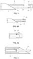
- FIG. 1illustrates a perspective view of an instrument according to an exemplary embodiment of the present invention
- FIG. 2illustrates a detailed perspective view of a distal end of the instrument of FIG. 1 in an open configuration
- FIG. 3illustrates a detailed side view of the distal end of FIG. 2 ;
- FIG. 4Aillustrates a detailed side view of the distal end of FIG. 2 in a closed configuration
- FIG. 4Billustrates a detailed side view of an alternate configuration of the distal end
- FIG. 5illustrates a cross-sectional detailed side view of a suture captured in the formed slot of the instrument of FIG. 1 ;
- FIG. 6illustrates a cross-sectional top view of the suture captured as shown in FIG. 5 ;
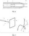
- FIG. 7illustrates a step in the use of the instrument of FIG. 1 in retrieving suture end extending from an anchor
- FIG. 8illustrates the instrument of FIG. 1 passing through tissue
- FIG. 9illustrates the distal end of the instrument of FIG. 1 in an open configuration to retrieve suture in the slot formed therein;
- FIG. 10illustrates closure of the slot in the distal end of the instrument of FIG. 1 ;
- FIG. 11illustrates the distal end of the slot and the suture being withdrawn into the distal end tip of the instrument of FIG. 1 ;
- FIG. 12illustrates the instrument of FIG. 1 and the suture being pulled through the tissue
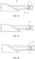
- FIG. 13illustrates a detailed side view of a distal end of an instrument according to an embodiment of the present invention
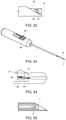
- FIG. 14illustrates a detailed side view of a distal end of an instrument according to an embodiment of the present invention
- FIG. 15illustrates a detailed side view of a distal end of an instrument according to an embodiment of the present invention
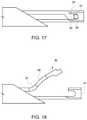
- FIG. 16illustrates a detailed side view of a distal end of an instrument with a suture capturing ram according to an embodiment of the present invention
- FIG. 17illustrates a detailed side view of a distal end of an instrument with the suture capturing ram of FIG. 16 pressing to hold the suture according to an embodiment of the present invention
- FIG. 18illustrates a detailed side view of a distal end of an instrument with a bend in the short finger according to an embodiment of the present invention
- FIG. 19illustrates a detailed side view of a distal end of an instrument with a suture captured in a slot under the short finger according to an embodiment of the present invention
- FIG. 20illustrates the instrument of FIG. 19 in a closed configuration
- FIG. 21illustrates the instrument of FIG. 19 in a fully retracted configuration
- FIG. 22illustrates the instrument of FIG. 19 with the suture captured between the end of the short finger and the end of the long finger;
- FIG. 23illustrates an instrument with dual controls according to an exemplary embodiment of the present invention
- FIG. 24illustrates a connection mechanism for the slide controls
- FIG. 25illustrates a cross-sectional view of an end of the instrument according to an embodiment of the present invention
- FIGS. 26 through 29illustrate methods for connecting the slide controls with the fingers of the instrument
- FIGS. 30 through 32illustrate various structures for the interaction between the short and long fingers of the instrument, with the short finger being the upper finger;
- FIG. 33illustrates a structure for the interaction between the short and long fingers where both fingers are approximately the same length
- FIGS. 34 and 35illustrate a structure for the interaction between the short and long fingers of the instrument, with the long finger being the upper finger.
- a commercial implementation in accordance with the spirit and teachings of the present inventionmay be configured according to the needs of the particular application, whereby any aspect(s), feature(s), function(s), result(s), component(s), approach(es), or step(s) of the teachings related to any described embodiment of the present invention may be suitably omitted, included, adapted, mixed and matched, or improved and/or optimized by those skilled in the art, using their average skills and known techniques, to achieve the desired implementation that addresses the needs of the particular application.
- embodiments of the present inventionprovide a surgical instrument that can manipulate and pass suture through tissue.
- the devicecan easily pass suture through tissue with the suture fixed to the mechanism or where the suture is captured by the mechanism and allowed to slide.
- This ability to control suture in one of two waysis a feature to provide a large amount of suture on the other side of the tissue that will be relatively easy for the surgeon to grab and pull out of the arthroscopic portal.
- the deviceincludes a handle with a hollow shaft extending therefrom and a set of fingers movable into and out of the shaft. The fingers can be designed to capture suture, permit the suture to slide while captured, and optionally hold the suture in the device.
- a device 1also referred to as instrument 1 , includes a handle 2 attached to a shaft 4 with a distal working end 5 .
- a slide 3is disposed within the handle 2 with a portion of the slide 3 accessible from an exterior of the handle. The slide 3 can be used to control a set of fingers 17 that can be used to manipulate suture.
- the shaft 4can be formed as a hollow cannula similar to a needle. While the Figures show a generally linear hollow cannula, it should be understood that the shaft 4 may include one or more bends therealong, including near its distal working end 5 , depending on the particular application. A sharpened tip 6 of the shaft 4 can enhance the ability of the shaft 4 to pierce or slide around tissue.
- the set of fingers 17shown in FIG. 2 in a deployed, open configuration, can extend into and out of the shaft 4 .
- the set of fingers 17can include a short finger 8 and a hooked finger 7 . These can be positioned relative to each other with a gap 43 as shown in FIG. 2 or can be pushed together with the aid of an active (e.g., secondary slide in handle) or passive (e.g., spring) actuation mechanism.
- a slot 15can be produced when the short finger 8 and the hooked finger 7 are brought together as shown in FIG. 4A .
- the connectioncan be a butt joint or can have added features, as illustrated, to lock the two fingers together.
- a distal end 11 of the short finger 8has a tooth 22 that meshes with a chamfer 23 of a proximal portion 12 of the hooked finger 7 .
- the joint 14is created.
- the tooth 22 in this exampleis held from moving radially outward by the hooked finger's chamfer 23 and vice versa.
- FIG. 4Bis similar except the connection scheme is reversed with features tooth 22 and chamfer 23 being replaced with short finger feature 26 and hooked finger feature 25 respectively to form a joint 24 .
- the formed slot 15can be sized such that if a suture 16 is captured it has ample room to allow the suture 16 to slide while being retained within the slot 15 .
- An anchor 20also referred to as an implant 20
- a strand of suture 21can be attached to the anchor 20 .
- the suture 21can be loosely attached to the anchor 20 (allowed to slide), in this case the suture 21 is fixed to the anchor 20 .
- the goal for this exampleis to pull one of the strands of the suture 21 through the tissue 18 .
- Thiscan be done by piercing the distal working end 5 through the tissue 18 with the set of fingers 17 in a retracted configuration, inside the shaft 4 , so that the sharpened tip 6 can aid in the penetration of the tissue 18 .
- the short finger 8 and the hooked finger 7can then be deployed out of the shaft 4 , as illustrated in FIG. 9 , to the point that a gap 43 is opened between the short finger 8 and the hooked finger 7 .
- the suture 21can be guided into the gap 43 and the distal end 11 of the short finger and the proximal portion 12 of the hooked finger 7 can be brought together such that the suture 21 is now captured within the slot 15 .
- the short finger 8 and the hooked finger 7 , along with the captured suture 21can be pulled slightly into the needle 6 , as shown in FIG. 11 .
- the leg of the suture 21 attached to the anchor 20can be held fixed so the suture 21 can slide through the slot 15 in order to allow device 1 to pull away from the implant 20 .
- the short finger 8 and the hooked finger 7can be deployed again and the suture 21 is released from the slot 15 via the gap 43 .
- FIGS. 13 through 15variations of the mating scheme between the short finger 8 and the hooked finger 7 are illustrated.
- a simple butt joint 27is shown in FIG. 13 with the created slot 15 .
- the suture 21is shown in a distal position as if the device is being removed from the tissue and the suture 21 is permitted to slide in slot 15 .
- the short finger 8 and the hooked finger 7are unable to separate outward because the inside diameter of the shaft 4 contains them.
- a ram 29is added to the short finger 8 in order to mate more closely with the hooked finger 7 and make the construct more stable.
- the size of the slot 28is also minimized, adding axial control of the suture 21 while still allowing the suture 21 to slide in the slot 28 .
- FIG. 15shows a design combining the features of FIGS. 14 and 4A , where a ram 29 extends partially into the slot 28 (not labelled in FIG. 15 but shown in FIG. 14 ).
- the ram 29may extend into the slot 28 to secure the suture in a non-sliding position at the end of the ram 29 .
- a tapered lead-inmay be provided on the ram 29 to meet with a mating taper of the hooked finger 7 , thus guiding the short finger 8 and the hooked finger 7 together in a secure position.
- FIGS. 16 and 17a design with additional features is shown. With the fingers positioned relative to each other, with a space 31 between the short finger 8 and the hooked finger 7 , as shown in FIG. 16 , a slot 32 is created such that the suture 21 is allowed to slide. If holding the suture 21 fixed between the fingers is desired, then the fingers can be brought closer together, resulting in a smaller space 34 , as shown in FIG. 17 , thus allowing ram 35 to pinch the suture 21 against wall 36 of the hooked finger 7 .
- FIG. 18presents a variation of the short finger 39 by adding one or more bends, such as proximate bend 37 and distal bend 38 , for example.
- the bendsallows a larger opening and movable finger for easier suture capturing. Bends can also be imparted on the hooked finger 41 in unison or alone.
- FIG. 19illustrates the fingers have been retracted enough that the short finger 39 and the hooked finger 41 have captured the suture 21 in slot 40 .
- the fingers 39 , 41are brought even closer such that a short finger ledge 42 goes under a hooked finger ledge 43 to create a connection between the two fingers 39 , 41 .
- the suture 21is able to slide even if pulled into the shaft 4 a bit as shown in FIG. 21 . If the fingers 39 , 41 are retracted far enough into the shaft 4 , friction may restrict the sliding motion of the suture 21 and act as a non-sliding hold.
- FIG. 22A resultant variation of this method when, combined with the description of FIGS. 16 and 17 , is shown on FIG. 22 .
- Slide 45can be attached to the short finger 8 and a second slide 46 can be attached to the hooked finger 7 or vice versa. This allows the two fingers 8 , 7 to be controlled independently.
- FIGS. 24 through 29show one method of attaching a finger to a slide using an L-bend 51 and a cross hole 49 in the slide.
- both fingers 7 and 8are attached to a single slide 47 .
- the hooked finger 7can be fixed to the slide using an L-bend 51 while the short finger 8 can be allowed to travel axially within the slide 47 through an L-block 50 .
- the fingersare biased together or closed (see FIG. 25 ) using spring 48 and stop 52 in the slide.
- the slide assemblyis actuated distally, the L-block 50 hits stop 52 in the handle 2 and prevents the short finger 8 from advancing relative to the hooked finger 7 .
- the slide 47continues advancing along with the hooked finger 7 , creating an opening 43 between the fingers as shown in FIG. 29 .
- a third methodcould use a spring and stop on each finger so that, in the relaxed state, the fingers are configured as in FIG. 2 . However, with one slide the user can retract the hooked finger 7 until it comes in contact with the short finger 8 then both are retracted together.
- FIGS. 30 through 32show variations with the short finger 8 positioned as the upper finger.
- FIG. 30shows one potential variation without a hook.
- the short finger 8 and long finger 53join together using simple butt joint 54 forming a slot 15 to capture suture 21 .
- FIG. 31shows a configuration with a hook 56 on the short finger 8 .
- the long finger 53includes locking tooth 57 which temporarily locks the two fingers together.
- FIG. 32shows a configuration with a hook 56 on the short finger 8 , but in this case the two fingers are held together using a simple butt joint.
- FIG. 33shows a variation in which the two fingers are of nearly equal length.
- An upper finger 58includes a head 56 while the lower finger 59 can be a simple straight wire or ribbon.
- the two fingers 58 , 56can come together to form slot 15 which is used to contain the suture 21 .
- FIGS. 34 and 35show variations with the short finger positioned as the lower finger.
- a simple butt joint 54 between the upper finger 58 and lower finger 59form a slot 15 to capture suture 21 as shown in FIG. 34 .
- the two fingerscan be temporarily held together using a tooth 61 on the upper finger 58 as shown in FIG. 35 .
- FIGS. 30-35Any combination of the features noted in FIGS. 30-35 can be interchanged to create other finger designs.
Landscapes
- Health & Medical Sciences (AREA)
- Life Sciences & Earth Sciences (AREA)
- Surgery (AREA)
- Heart & Thoracic Surgery (AREA)
- Engineering & Computer Science (AREA)
- Biomedical Technology (AREA)
- Nuclear Medicine, Radiotherapy & Molecular Imaging (AREA)
- Medical Informatics (AREA)
- Molecular Biology (AREA)
- Animal Behavior & Ethology (AREA)
- General Health & Medical Sciences (AREA)
- Public Health (AREA)
- Veterinary Medicine (AREA)
- Surgical Instruments (AREA)
Abstract
Description
Claims (21)
Priority Applications (4)
| Application Number | Priority Date | Filing Date | Title |
|---|---|---|---|
| US16/898,246US11246586B2 (en) | 2019-08-20 | 2020-06-10 | Instrument to manipulate and pass suture |
| PCT/US2020/045998WO2021034577A1 (en) | 2019-08-20 | 2020-08-12 | Instrument to manipulate and pass suture |
| EP20855051.7AEP4017380A1 (en) | 2019-08-20 | 2020-08-12 | Instrument to manipulate and pass suture |
| US17/451,129US20220031304A1 (en) | 2019-08-20 | 2021-10-15 | Instrument to manipulate and pass suture |
Applications Claiming Priority (2)
| Application Number | Priority Date | Filing Date | Title |
|---|---|---|---|
| US201962889492P | 2019-08-20 | 2019-08-20 | |
| US16/898,246US11246586B2 (en) | 2019-08-20 | 2020-06-10 | Instrument to manipulate and pass suture |
Related Child Applications (1)
| Application Number | Title | Priority Date | Filing Date |
|---|---|---|---|
| US17/451,129ContinuationUS20220031304A1 (en) | 2019-08-20 | 2021-10-15 | Instrument to manipulate and pass suture |
Publications (2)
| Publication Number | Publication Date |
|---|---|
| US20210052268A1 US20210052268A1 (en) | 2021-02-25 |
| US11246586B2true US11246586B2 (en) | 2022-02-15 |
Family
ID=74646999
Family Applications (2)
| Application Number | Title | Priority Date | Filing Date |
|---|---|---|---|
| US16/898,246ActiveUS11246586B2 (en) | 2019-08-20 | 2020-06-10 | Instrument to manipulate and pass suture |
| US17/451,129AbandonedUS20220031304A1 (en) | 2019-08-20 | 2021-10-15 | Instrument to manipulate and pass suture |
Family Applications After (1)
| Application Number | Title | Priority Date | Filing Date |
|---|---|---|---|
| US17/451,129AbandonedUS20220031304A1 (en) | 2019-08-20 | 2021-10-15 | Instrument to manipulate and pass suture |
Country Status (3)
| Country | Link |
|---|---|
| US (2) | US11246586B2 (en) |
| EP (1) | EP4017380A1 (en) |
| WO (1) | WO2021034577A1 (en) |
Cited By (2)
| Publication number | Priority date | Publication date | Assignee | Title |
|---|---|---|---|---|
| US20220265265A1 (en)* | 2021-02-23 | 2022-08-25 | José Alencar MARQUES JUNIOR | Meniscus suture device |
| USD1000921S1 (en)* | 2021-12-14 | 2023-10-10 | Ecolab Usa Inc. | Roll threader tool |
Families Citing this family (1)
| Publication number | Priority date | Publication date | Assignee | Title |
|---|---|---|---|---|
| KR102597762B1 (en) | 2017-12-14 | 2023-11-03 | 콘메드 코포레이션 | Suture passing device |
Citations (62)
| Publication number | Priority date | Publication date | Assignee | Title |
|---|---|---|---|---|
| US2850803A (en) | 1957-11-20 | 1958-09-09 | Briskman | Shears with arcuate profiled teeth |
| US3879813A (en) | 1973-02-08 | 1975-04-29 | Ici Ltd | Clamp |
| US5059201A (en)* | 1989-11-03 | 1991-10-22 | Asnis Stanley E | Suture threading, stitching and wrapping device for use in open and closed surgical procedures |
| US5222977A (en)* | 1992-02-21 | 1993-06-29 | Esser Rene D | Surgical needle with an adjustable eye |
| US5250053A (en) | 1992-05-29 | 1993-10-05 | Linvatec Corporation | Suture shuttle device |
| US5261917A (en) | 1992-02-19 | 1993-11-16 | Hasson Harrith M | Suture tying forceps with a plurality of suture holders and method of tying a suture |
| US5312432A (en) | 1992-05-01 | 1994-05-17 | Vance Products Inc. | Percutaneously insertable, needle-sized tissue retractor and system |
| US5318589A (en) | 1992-04-15 | 1994-06-07 | Microsurge, Inc. | Surgical instrument for endoscopic surgery |
| US5342389A (en) | 1992-04-28 | 1994-08-30 | Habley Medical Technology Corporation | Tissue manipulator |
| US5454822A (en) | 1992-12-31 | 1995-10-03 | K. Widmann Ag | Apparatus for clamping and cutting viscera |
| US5499991A (en) | 1994-12-19 | 1996-03-19 | Linvatec Corporation | Endoscopic needle with suture retriever |
| US5632751A (en) | 1995-07-28 | 1997-05-27 | Piraka; Hadi A. | Surgical suturing device |
| US5653716A (en) | 1994-12-29 | 1997-08-05 | Acufex Microsurgical, Inc. | Suture manipulating instrument with grasping members |
| US5782747A (en) | 1996-04-22 | 1998-07-21 | Zimmon Science Corporation | Spring based multi-purpose medical instrument |
| US5797958A (en) | 1989-12-05 | 1998-08-25 | Yoon; Inbae | Endoscopic grasping instrument with scissors |
| US5817111A (en)* | 1996-03-28 | 1998-10-06 | Riza; Erol D. | Open loop suture snare |
| US5910148A (en) | 1997-08-06 | 1999-06-08 | Mitek Surgical Products, Inc. | Suture retrograder |
| US5984938A (en) | 1989-12-05 | 1999-11-16 | Yoon; Inbae | Surgical instrument with jaws and movable internal scissors and method for use thereof |
| US5993466A (en) | 1997-06-17 | 1999-11-30 | Yoon; Inbae | Suturing instrument with multiple rotatably mounted spreadable needle holders |
| US20020183785A1 (en) | 1998-07-27 | 2002-12-05 | Howell Thomas A. | Surgical clamp pad with interdigitatin teeth |
| US6616683B1 (en) | 2000-05-02 | 2003-09-09 | Duke University | Method of making miniaturized surgical forceps |
| US20040055608A1 (en) | 1993-02-22 | 2004-03-25 | Ethicon, Inc. | Minimally-invasive devices and methods for treatment of congestive heart failure |
| US20040087967A1 (en) | 2002-11-06 | 2004-05-06 | Israel Schur | Device and method for withdrawing a tubular body part |
| US20040172057A1 (en) | 2003-02-27 | 2004-09-02 | Guillebon Henri De | Super atraumatic grasper apparatus |
| US20040249393A1 (en) | 2003-03-18 | 2004-12-09 | Thomas Weisel | Expandable needle suture apparatus and associated handle assembly |
| WO2006023975A2 (en) | 2004-08-24 | 2006-03-02 | Depuy Mitek, Inc. | Expandable needle suture apparatus and associated handle assembly with rotational suture manipulation system |
| US7169156B2 (en) | 1993-07-26 | 2007-01-30 | Innovasive Devices, Inc. | Suture grasping device |
| US7261725B2 (en) | 2005-01-13 | 2007-08-28 | Binmoeller Kenneth F | Endoscopic device with independently actuated legs |
| US20070213767A1 (en) | 2006-03-13 | 2007-09-13 | Sundaram Ravikumar | Minimally invasive surgical assembly and methods |
| US20070250112A1 (en) | 2006-03-13 | 2007-10-25 | Sundaram Ravikumar | Minimally Invasive Surgical Assembly and Methods |
| US20090062819A1 (en)* | 2007-08-27 | 2009-03-05 | Burkhart Stephen S | In-line suture passer and method of passing suture |
| US7766937B2 (en) | 2006-03-13 | 2010-08-03 | Mini-Lap Technologies, Inc. | Minimally invasive surgical assembly and methods |
| US20100262181A1 (en) | 2009-04-08 | 2010-10-14 | Seung Wook Choi | Endo psi and cabinet therefor |
| US20110071550A1 (en) | 2001-02-26 | 2011-03-24 | Diduch David R | Suture Passing Devices and Methods |
| US20120123448A1 (en)* | 2010-09-10 | 2012-05-17 | James Flom | Method and apparatus for passing suture through tissue |
| US20120143222A1 (en) | 2010-12-02 | 2012-06-07 | Coloplast A/S | Suture system and assembly |
| WO2012093094A1 (en) | 2011-01-07 | 2012-07-12 | Z-Medical Gmbh & Co. Kg | Thread gripper |
| US20130030450A1 (en) | 2001-05-21 | 2013-01-31 | Peter Dreyfuss | Suture passer |
| US20130030462A1 (en) | 2009-12-22 | 2013-01-31 | Neosurgical Limited | Laparoscopic surgical device |
| US20130116709A1 (en) | 2011-11-07 | 2013-05-09 | C.R. Bard, Inc. | Instruments for delivering transfascial sutures and methods of transfascial suturing |
| US20130144315A1 (en) | 2010-08-02 | 2013-06-06 | University Of South Florida | Universal laparoscopic suturing device |
| US20130190782A1 (en) | 2008-10-22 | 2013-07-25 | Cayenne Medical, Inc. | Arthroscopic suture passing devices and methods |
| US8496656B2 (en) | 2003-05-15 | 2013-07-30 | Covidien Ag | Tissue sealer with non-conductive variable stop members and method of sealing tissue |
| US20130218175A1 (en) | 2012-02-16 | 2013-08-22 | Coopersurgical, Inc. | Suture Passers and Related Methods |
| US8585714B2 (en) | 2003-03-18 | 2013-11-19 | Depuy Mitek, Llc | Expandable needle suture apparatus and associated handle assembly with rotational suture manipulation system |
| US20130324803A1 (en) | 2009-01-23 | 2013-12-05 | Reza S. Mohajer | Veress needle with illuminated guidance and suturing capability |
| US20140012292A1 (en) | 2010-09-10 | 2014-01-09 | Pivot Medical, Inc. | Method and apparatus for passing suture through tissue |
| US20140222033A1 (en)* | 2012-02-07 | 2014-08-07 | Arthrocare Corporation | Surgical instrument for manipulating and passing suture |
| US20150094739A1 (en)* | 2013-09-30 | 2015-04-02 | Biomet Sports Medicine, Llc | Suture Passer Device Including a Blunt Tip and a Sharp Tip |
| US20150112368A1 (en) | 2010-09-10 | 2015-04-23 | Pivot Medical, Inc. | Method and apparatus for passing suture through tissue |
| US20150272603A1 (en) | 2014-03-31 | 2015-10-01 | Ethicon Endo-Surgery, Inc. | Surgical devices with articulating end effectors and methods of using surgical devices with articulating end effectors |
| US20160000423A1 (en) | 2013-03-15 | 2016-01-07 | Novasurg Innovations, Llc | Needle driver |
| US20160022488A1 (en) | 2013-03-08 | 2016-01-28 | Optic Logik Llc | Intraocular lens fixation correction methods and devices |
| US20160166248A1 (en) | 2012-07-10 | 2016-06-16 | Edwards Lifesciences Corporation | Multiple-firing securing device and methods for using and manufacturing same |
| US20160278801A1 (en) | 2015-03-26 | 2016-09-29 | United States Endoscopy Group, Inc. | Endoscopic grasping device |
| US20170042533A1 (en)* | 2014-04-24 | 2017-02-16 | Smith & Nephew, Inc. | Suture passer |
| US20170367693A1 (en) | 2013-07-16 | 2017-12-28 | Suture Ease, Inc. | Suture apparatus, system and method |
| US9936943B1 (en) | 2014-08-07 | 2018-04-10 | Nicholas MANCINI | Suture passing surgical device with atraumatic grasper preventing accidental perforations |
| US20180116652A1 (en) | 2016-10-31 | 2018-05-03 | Smith & Nephew, Inc. | Suture passer and grasper instrument and method |
| US20190125384A1 (en) | 2017-10-30 | 2019-05-02 | Ethicon Llc | Surgical instrument with rotary drive selectively actuating multiple end effector functions |
| US10420574B2 (en) | 2016-09-19 | 2019-09-24 | Richard Devere Thrasher, III | Double forceps |
| US20190336124A1 (en) | 2018-05-04 | 2019-11-07 | Arch Day Design, Llc | Suture passing device |
Family Cites Families (1)
| Publication number | Priority date | Publication date | Assignee | Title |
|---|---|---|---|---|
| US9326766B2 (en)* | 2013-03-15 | 2016-05-03 | Novasurg Innovations, Llc | Needle driver |
- 2020
- 2020-06-10USUS16/898,246patent/US11246586B2/enactiveActive
- 2020-08-12WOPCT/US2020/045998patent/WO2021034577A1/ennot_activeCeased
- 2020-08-12EPEP20855051.7Apatent/EP4017380A1/ennot_activeWithdrawn
- 2021
- 2021-10-15USUS17/451,129patent/US20220031304A1/ennot_activeAbandoned
Patent Citations (69)
| Publication number | Priority date | Publication date | Assignee | Title |
|---|---|---|---|---|
| US2850803A (en) | 1957-11-20 | 1958-09-09 | Briskman | Shears with arcuate profiled teeth |
| US3879813A (en) | 1973-02-08 | 1975-04-29 | Ici Ltd | Clamp |
| US5059201A (en)* | 1989-11-03 | 1991-10-22 | Asnis Stanley E | Suture threading, stitching and wrapping device for use in open and closed surgical procedures |
| US5984938A (en) | 1989-12-05 | 1999-11-16 | Yoon; Inbae | Surgical instrument with jaws and movable internal scissors and method for use thereof |
| US5797958A (en) | 1989-12-05 | 1998-08-25 | Yoon; Inbae | Endoscopic grasping instrument with scissors |
| US5261917A (en) | 1992-02-19 | 1993-11-16 | Hasson Harrith M | Suture tying forceps with a plurality of suture holders and method of tying a suture |
| US5222977A (en)* | 1992-02-21 | 1993-06-29 | Esser Rene D | Surgical needle with an adjustable eye |
| US5318589A (en) | 1992-04-15 | 1994-06-07 | Microsurge, Inc. | Surgical instrument for endoscopic surgery |
| US5342389A (en) | 1992-04-28 | 1994-08-30 | Habley Medical Technology Corporation | Tissue manipulator |
| US5312432A (en) | 1992-05-01 | 1994-05-17 | Vance Products Inc. | Percutaneously insertable, needle-sized tissue retractor and system |
| US5250053A (en) | 1992-05-29 | 1993-10-05 | Linvatec Corporation | Suture shuttle device |
| US5279311A (en) | 1992-05-29 | 1994-01-18 | Linvatec Corporation | Suture shuttle device |
| US5454822A (en) | 1992-12-31 | 1995-10-03 | K. Widmann Ag | Apparatus for clamping and cutting viscera |
| US20040055608A1 (en) | 1993-02-22 | 2004-03-25 | Ethicon, Inc. | Minimally-invasive devices and methods for treatment of congestive heart failure |
| US7169156B2 (en) | 1993-07-26 | 2007-01-30 | Innovasive Devices, Inc. | Suture grasping device |
| US5499991A (en) | 1994-12-19 | 1996-03-19 | Linvatec Corporation | Endoscopic needle with suture retriever |
| US5653716A (en) | 1994-12-29 | 1997-08-05 | Acufex Microsurgical, Inc. | Suture manipulating instrument with grasping members |
| US5632751A (en) | 1995-07-28 | 1997-05-27 | Piraka; Hadi A. | Surgical suturing device |
| US5817111A (en)* | 1996-03-28 | 1998-10-06 | Riza; Erol D. | Open loop suture snare |
| US5782747A (en) | 1996-04-22 | 1998-07-21 | Zimmon Science Corporation | Spring based multi-purpose medical instrument |
| US5993466A (en) | 1997-06-17 | 1999-11-30 | Yoon; Inbae | Suturing instrument with multiple rotatably mounted spreadable needle holders |
| US6022360A (en) | 1997-08-06 | 2000-02-08 | Ethicon, Inc. | Suture retrograder |
| US5910148A (en) | 1997-08-06 | 1999-06-08 | Mitek Surgical Products, Inc. | Suture retrograder |
| US20020183785A1 (en) | 1998-07-27 | 2002-12-05 | Howell Thomas A. | Surgical clamp pad with interdigitatin teeth |
| US6616683B1 (en) | 2000-05-02 | 2003-09-09 | Duke University | Method of making miniaturized surgical forceps |
| US20110071550A1 (en) | 2001-02-26 | 2011-03-24 | Diduch David R | Suture Passing Devices and Methods |
| US20130030450A1 (en) | 2001-05-21 | 2013-01-31 | Peter Dreyfuss | Suture passer |
| US20040087967A1 (en) | 2002-11-06 | 2004-05-06 | Israel Schur | Device and method for withdrawing a tubular body part |
| US20040172057A1 (en) | 2003-02-27 | 2004-09-02 | Guillebon Henri De | Super atraumatic grasper apparatus |
| US20040249393A1 (en) | 2003-03-18 | 2004-12-09 | Thomas Weisel | Expandable needle suture apparatus and associated handle assembly |
| US8066718B2 (en) | 2003-03-18 | 2011-11-29 | Depuy Mitek, Inc. | Expandable needle suture apparatus and associated handle assembly |
| US8585714B2 (en) | 2003-03-18 | 2013-11-19 | Depuy Mitek, Llc | Expandable needle suture apparatus and associated handle assembly with rotational suture manipulation system |
| US8496656B2 (en) | 2003-05-15 | 2013-07-30 | Covidien Ag | Tissue sealer with non-conductive variable stop members and method of sealing tissue |
| WO2006023975A2 (en) | 2004-08-24 | 2006-03-02 | Depuy Mitek, Inc. | Expandable needle suture apparatus and associated handle assembly with rotational suture manipulation system |
| US7261725B2 (en) | 2005-01-13 | 2007-08-28 | Binmoeller Kenneth F | Endoscopic device with independently actuated legs |
| US7766937B2 (en) | 2006-03-13 | 2010-08-03 | Mini-Lap Technologies, Inc. | Minimally invasive surgical assembly and methods |
| US8133255B2 (en) | 2006-03-13 | 2012-03-13 | Mini-Lap Technologies, Inc. | Minimally invasive surgical assembly and methods |
| US20170049465A1 (en) | 2006-03-13 | 2017-02-23 | Teleflex Medical Incorporated | Minimally invasive surgical assembly and methods |
| US20070213767A1 (en) | 2006-03-13 | 2007-09-13 | Sundaram Ravikumar | Minimally invasive surgical assembly and methods |
| US20070250112A1 (en) | 2006-03-13 | 2007-10-25 | Sundaram Ravikumar | Minimally Invasive Surgical Assembly and Methods |
| US20090062819A1 (en)* | 2007-08-27 | 2009-03-05 | Burkhart Stephen S | In-line suture passer and method of passing suture |
| US20130190782A1 (en) | 2008-10-22 | 2013-07-25 | Cayenne Medical, Inc. | Arthroscopic suture passing devices and methods |
| US20130324803A1 (en) | 2009-01-23 | 2013-12-05 | Reza S. Mohajer | Veress needle with illuminated guidance and suturing capability |
| US20100262181A1 (en) | 2009-04-08 | 2010-10-14 | Seung Wook Choi | Endo psi and cabinet therefor |
| US20130030462A1 (en) | 2009-12-22 | 2013-01-31 | Neosurgical Limited | Laparoscopic surgical device |
| US20130144315A1 (en) | 2010-08-02 | 2013-06-06 | University Of South Florida | Universal laparoscopic suturing device |
| US20140012292A1 (en) | 2010-09-10 | 2014-01-09 | Pivot Medical, Inc. | Method and apparatus for passing suture through tissue |
| US20150112368A1 (en) | 2010-09-10 | 2015-04-23 | Pivot Medical, Inc. | Method and apparatus for passing suture through tissue |
| US9931114B2 (en) | 2010-09-10 | 2018-04-03 | Pivot Medical, Inc. | Method and apparatus for passing suture through tissue |
| US20120123448A1 (en)* | 2010-09-10 | 2012-05-17 | James Flom | Method and apparatus for passing suture through tissue |
| US20120143222A1 (en) | 2010-12-02 | 2012-06-07 | Coloplast A/S | Suture system and assembly |
| WO2012093094A1 (en) | 2011-01-07 | 2012-07-12 | Z-Medical Gmbh & Co. Kg | Thread gripper |
| US20130116709A1 (en) | 2011-11-07 | 2013-05-09 | C.R. Bard, Inc. | Instruments for delivering transfascial sutures and methods of transfascial suturing |
| US20140222033A1 (en)* | 2012-02-07 | 2014-08-07 | Arthrocare Corporation | Surgical instrument for manipulating and passing suture |
| US11096682B2 (en) | 2012-02-07 | 2021-08-24 | Arthrocare Corporation | Surgical instrument for manipulating and passing suture |
| US20130218175A1 (en) | 2012-02-16 | 2013-08-22 | Coopersurgical, Inc. | Suture Passers and Related Methods |
| US20160166248A1 (en) | 2012-07-10 | 2016-06-16 | Edwards Lifesciences Corporation | Multiple-firing securing device and methods for using and manufacturing same |
| US20160022488A1 (en) | 2013-03-08 | 2016-01-28 | Optic Logik Llc | Intraocular lens fixation correction methods and devices |
| US20160000423A1 (en) | 2013-03-15 | 2016-01-07 | Novasurg Innovations, Llc | Needle driver |
| US20170367693A1 (en) | 2013-07-16 | 2017-12-28 | Suture Ease, Inc. | Suture apparatus, system and method |
| US20150094739A1 (en)* | 2013-09-30 | 2015-04-02 | Biomet Sports Medicine, Llc | Suture Passer Device Including a Blunt Tip and a Sharp Tip |
| US20150272603A1 (en) | 2014-03-31 | 2015-10-01 | Ethicon Endo-Surgery, Inc. | Surgical devices with articulating end effectors and methods of using surgical devices with articulating end effectors |
| US20170042533A1 (en)* | 2014-04-24 | 2017-02-16 | Smith & Nephew, Inc. | Suture passer |
| US9936943B1 (en) | 2014-08-07 | 2018-04-10 | Nicholas MANCINI | Suture passing surgical device with atraumatic grasper preventing accidental perforations |
| US20160278801A1 (en) | 2015-03-26 | 2016-09-29 | United States Endoscopy Group, Inc. | Endoscopic grasping device |
| US10420574B2 (en) | 2016-09-19 | 2019-09-24 | Richard Devere Thrasher, III | Double forceps |
| US20180116652A1 (en) | 2016-10-31 | 2018-05-03 | Smith & Nephew, Inc. | Suture passer and grasper instrument and method |
| US20190125384A1 (en) | 2017-10-30 | 2019-05-02 | Ethicon Llc | Surgical instrument with rotary drive selectively actuating multiple end effector functions |
| US20190336124A1 (en) | 2018-05-04 | 2019-11-07 | Arch Day Design, Llc | Suture passing device |
Non-Patent Citations (9)
| Title |
|---|
| Arthroscopic TAG Suture Anchors—1998 Smith and Nephew product catalog. |
| Blitz Suture Retriever, Linvatec, 1995 product catalog. |
| International Preliminary Report on Patentability (Chapter II) dated Feb. 2, 2021 from PCT Application No. PCT/US2020/070307. |
| International Preliminary Report on Patentability dated Mar. 2, 2021 from PCT Application No. PCT/US2020/045998. |
| International Search Report & Written Opinion dated Dec. 14, 2021 from PCT Application No. PCT/US21/49936. |
| International Search Report & Written Opinion dated Nov. 23, 2020 from PCT Application No. PCT/US20/45998. |
| International Search Report & Written Opinion dated Oct. 9, 2020 from PCT Application No. PCT/US2020/070307. |
| International Search Report dated Jul. 10, 2019 from PCT Application No. PCT/US2019/030221. |
| SutureLasso—2003 Arthrex catalog, Shoulder Arthroscopy & Mini-Open Repairs, 10-21. |
Cited By (2)
| Publication number | Priority date | Publication date | Assignee | Title |
|---|---|---|---|---|
| US20220265265A1 (en)* | 2021-02-23 | 2022-08-25 | José Alencar MARQUES JUNIOR | Meniscus suture device |
| USD1000921S1 (en)* | 2021-12-14 | 2023-10-10 | Ecolab Usa Inc. | Roll threader tool |
Also Published As
| Publication number | Publication date |
|---|---|
| EP4017380A1 (en) | 2022-06-29 |
| WO2021034577A1 (en) | 2021-02-25 |
| US20220031304A1 (en) | 2022-02-03 |
| US20210052268A1 (en) | 2021-02-25 |
Similar Documents
| Publication | Publication Date | Title |
|---|---|---|
| US20220031304A1 (en) | Instrument to manipulate and pass suture | |
| US11229427B2 (en) | Dual insufflation and wound closure devices and methods | |
| US10194920B2 (en) | Circular bone tunneling device employing a stabilizing element | |
| CN106659494B (en) | Systems and methods for suture delivery | |
| DE69334017T2 (en) | Apparatus for suturing a puncture site in a blood vessel | |
| JP5119205B2 (en) | Expandable needle suturing device and associated handle assembly | |
| DE602004013351T2 (en) | Sewing device with cutting blade | |
| EP0834281A1 (en) | System for suture anchor placement | |
| KR101880423B1 (en) | Method and apparatus for guiding a suture thread | |
| EP3222220B1 (en) | Suture thread for laparoscopic port site closing apparatus | |
| WO1994021178A1 (en) | Verres needle suturing device | |
| US20090082787A1 (en) | Suturing Device | |
| AU2014232723A1 (en) | Surgical suturing device with transverse engagement | |
| CN104487004A (en) | Multi-suture knotless anchor for attaching tissue to bone and related method | |
| US8512358B2 (en) | Suturing assembly | |
| US20140207188A1 (en) | Surgical suture retrieving and passing system | |
| CN208573778U (en) | Knotting device in a kind of laparoscope puncture incision | |
| AU2022100011A4 (en) | Instrument to manipulate and pass suture | |
| US20180235603A1 (en) | Access and suture apparatus, system, and method of closing tissue | |
| US10595857B2 (en) | Needle and guide apparatus for passing suture | |
| US11801045B2 (en) | Suture passing device and methods of use thereof | |
| US10292688B2 (en) | Removable bone penetrating device and methods | |
| KR20200099169A (en) | Suture passing device | |
| US9820734B2 (en) | Device for cutting suture from a distance | |
| US20170055977A1 (en) | Multiple-needle suturing assembly |
Legal Events
| Date | Code | Title | Description |
|---|---|---|---|
| AS | Assignment | Owner name:ARCH DAY DESIGN, LLC, CALIFORNIA Free format text:ASSIGNMENT OF ASSIGNORS INTEREST;ASSIGNORS:PISARNWONGS, ROGER;WEISEL, THOMAS;SIGNING DATES FROM 20190820 TO 20190821;REEL/FRAME:052900/0641 | |
| FEPP | Fee payment procedure | Free format text:ENTITY STATUS SET TO UNDISCOUNTED (ORIGINAL EVENT CODE: BIG.); ENTITY STATUS OF PATENT OWNER: SMALL ENTITY | |
| FEPP | Fee payment procedure | Free format text:ENTITY STATUS SET TO SMALL (ORIGINAL EVENT CODE: SMAL); ENTITY STATUS OF PATENT OWNER: SMALL ENTITY | |
| STPP | Information on status: patent application and granting procedure in general | Free format text:APPLICATION DISPATCHED FROM PREEXAM, NOT YET DOCKETED | |
| STPP | Information on status: patent application and granting procedure in general | Free format text:DOCKETED NEW CASE - READY FOR EXAMINATION | |
| STPP | Information on status: patent application and granting procedure in general | Free format text:NON FINAL ACTION MAILED | |
| STPP | Information on status: patent application and granting procedure in general | Free format text:RESPONSE TO NON-FINAL OFFICE ACTION ENTERED AND FORWARDED TO EXAMINER | |
| STPP | Information on status: patent application and granting procedure in general | Free format text:NOTICE OF ALLOWANCE MAILED -- APPLICATION RECEIVED IN OFFICE OF PUBLICATIONS | |
| STPP | Information on status: patent application and granting procedure in general | Free format text:PUBLICATIONS -- ISSUE FEE PAYMENT VERIFIED | |
| STPP | Information on status: patent application and granting procedure in general | Free format text:WITHDRAW FROM ISSUE AWAITING ACTION | |
| STPP | Information on status: patent application and granting procedure in general | Free format text:AWAITING TC RESP., ISSUE FEE NOT PAID | |
| STPP | Information on status: patent application and granting procedure in general | Free format text:NOTICE OF ALLOWANCE MAILED -- APPLICATION RECEIVED IN OFFICE OF PUBLICATIONS | |
| STPP | Information on status: patent application and granting procedure in general | Free format text:PUBLICATIONS -- ISSUE FEE PAYMENT VERIFIED | |
| STCF | Information on status: patent grant | Free format text:PATENTED CASE | |
| FEPP | Fee payment procedure | Free format text:MAINTENANCE FEE REMINDER MAILED (ORIGINAL EVENT CODE: REM.); ENTITY STATUS OF PATENT OWNER: SMALL ENTITY |