US11246585B2 - Method and apparatus for attaching tissue to bone, including the provision and use of a novel knotless suture anchor system - Google Patents
Method and apparatus for attaching tissue to bone, including the provision and use of a novel knotless suture anchor systemDownload PDFInfo
- Publication number
- US11246585B2 US11246585B2US16/364,337US201916364337AUS11246585B2US 11246585 B2US11246585 B2US 11246585B2US 201916364337 AUS201916364337 AUS 201916364337AUS 11246585 B2US11246585 B2US 11246585B2
- Authority
- US
- United States
- Prior art keywords
- movable element
- anchor
- bone
- suture anchor
- inserter
- Prior art date
- Legal status (The legal status is an assumption and is not a legal conclusion. Google has not performed a legal analysis and makes no representation as to the accuracy of the status listed.)
- Active, expires
Links
Images


Classifications
- A—HUMAN NECESSITIES
- A61—MEDICAL OR VETERINARY SCIENCE; HYGIENE
- A61B—DIAGNOSIS; SURGERY; IDENTIFICATION
- A61B17/00—Surgical instruments, devices or methods
- A61B17/04—Surgical instruments, devices or methods for suturing wounds; Holders or packages for needles or suture materials
- A61B17/0401—Suture anchors, buttons or pledgets, i.e. means for attaching sutures to bone, cartilage or soft tissue; Instruments for applying or removing suture anchors
- A—HUMAN NECESSITIES
- A61—MEDICAL OR VETERINARY SCIENCE; HYGIENE
- A61B—DIAGNOSIS; SURGERY; IDENTIFICATION
- A61B17/00—Surgical instruments, devices or methods
- A61B17/04—Surgical instruments, devices or methods for suturing wounds; Holders or packages for needles or suture materials
- A61B17/0485—Devices or means, e.g. loops, for capturing the suture thread and threading it through an opening of a suturing instrument or needle eyelet
- A—HUMAN NECESSITIES
- A61—MEDICAL OR VETERINARY SCIENCE; HYGIENE
- A61B—DIAGNOSIS; SURGERY; IDENTIFICATION
- A61B90/00—Instruments, implements or accessories specially adapted for surgery or diagnosis and not covered by any of the groups A61B1/00 - A61B50/00, e.g. for luxation treatment or for protecting wound edges
- A61B90/08—Accessories or related features not otherwise provided for
- A—HUMAN NECESSITIES
- A61—MEDICAL OR VETERINARY SCIENCE; HYGIENE
- A61B—DIAGNOSIS; SURGERY; IDENTIFICATION
- A61B90/00—Instruments, implements or accessories specially adapted for surgery or diagnosis and not covered by any of the groups A61B1/00 - A61B50/00, e.g. for luxation treatment or for protecting wound edges
- A61B90/50—Supports for surgical instruments, e.g. articulated arms
- A61B90/57—Accessory clamps
- A—HUMAN NECESSITIES
- A61—MEDICAL OR VETERINARY SCIENCE; HYGIENE
- A61B—DIAGNOSIS; SURGERY; IDENTIFICATION
- A61B17/00—Surgical instruments, devices or methods
- A61B17/00234—Surgical instruments, devices or methods for minimally invasive surgery
- A61B2017/00292—Surgical instruments, devices or methods for minimally invasive surgery mounted on or guided by flexible, e.g. catheter-like, means
- A61B2017/00296—Surgical instruments, devices or methods for minimally invasive surgery mounted on or guided by flexible, e.g. catheter-like, means mounted on an endoscope
- A—HUMAN NECESSITIES
- A61—MEDICAL OR VETERINARY SCIENCE; HYGIENE
- A61B—DIAGNOSIS; SURGERY; IDENTIFICATION
- A61B17/00—Surgical instruments, devices or methods
- A61B17/00234—Surgical instruments, devices or methods for minimally invasive surgery
- A61B2017/00292—Surgical instruments, devices or methods for minimally invasive surgery mounted on or guided by flexible, e.g. catheter-like, means
- A61B2017/003—Steerable
- A61B2017/00305—Constructional details of the flexible means
- A61B2017/00309—Cut-outs or slits
- A—HUMAN NECESSITIES
- A61—MEDICAL OR VETERINARY SCIENCE; HYGIENE
- A61B—DIAGNOSIS; SURGERY; IDENTIFICATION
- A61B17/00—Surgical instruments, devices or methods
- A61B17/04—Surgical instruments, devices or methods for suturing wounds; Holders or packages for needles or suture materials
- A61B17/0401—Suture anchors, buttons or pledgets, i.e. means for attaching sutures to bone, cartilage or soft tissue; Instruments for applying or removing suture anchors
- A61B2017/0409—Instruments for applying suture anchors
- A—HUMAN NECESSITIES
- A61—MEDICAL OR VETERINARY SCIENCE; HYGIENE
- A61B—DIAGNOSIS; SURGERY; IDENTIFICATION
- A61B17/00—Surgical instruments, devices or methods
- A61B17/04—Surgical instruments, devices or methods for suturing wounds; Holders or packages for needles or suture materials
- A61B17/0401—Suture anchors, buttons or pledgets, i.e. means for attaching sutures to bone, cartilage or soft tissue; Instruments for applying or removing suture anchors
- A61B2017/0412—Suture anchors, buttons or pledgets, i.e. means for attaching sutures to bone, cartilage or soft tissue; Instruments for applying or removing suture anchors having anchoring barbs or pins extending outwardly from suture anchor body
- A—HUMAN NECESSITIES
- A61—MEDICAL OR VETERINARY SCIENCE; HYGIENE
- A61B—DIAGNOSIS; SURGERY; IDENTIFICATION
- A61B17/00—Surgical instruments, devices or methods
- A61B17/04—Surgical instruments, devices or methods for suturing wounds; Holders or packages for needles or suture materials
- A61B17/0401—Suture anchors, buttons or pledgets, i.e. means for attaching sutures to bone, cartilage or soft tissue; Instruments for applying or removing suture anchors
- A61B2017/0414—Suture anchors, buttons or pledgets, i.e. means for attaching sutures to bone, cartilage or soft tissue; Instruments for applying or removing suture anchors having a suture-receiving opening, e.g. lateral opening
- A—HUMAN NECESSITIES
- A61—MEDICAL OR VETERINARY SCIENCE; HYGIENE
- A61B—DIAGNOSIS; SURGERY; IDENTIFICATION
- A61B17/00—Surgical instruments, devices or methods
- A61B17/04—Surgical instruments, devices or methods for suturing wounds; Holders or packages for needles or suture materials
- A61B17/0401—Suture anchors, buttons or pledgets, i.e. means for attaching sutures to bone, cartilage or soft tissue; Instruments for applying or removing suture anchors
- A61B2017/042—Suture anchors, buttons or pledgets, i.e. means for attaching sutures to bone, cartilage or soft tissue; Instruments for applying or removing suture anchors plastically deformed during insertion
- A61B2017/0422—Suture anchors, buttons or pledgets, i.e. means for attaching sutures to bone, cartilage or soft tissue; Instruments for applying or removing suture anchors plastically deformed during insertion by insertion of a separate member into the body of the anchor
- A61B2017/0424—Suture anchors, buttons or pledgets, i.e. means for attaching sutures to bone, cartilage or soft tissue; Instruments for applying or removing suture anchors plastically deformed during insertion by insertion of a separate member into the body of the anchor the separate member staying in the anchor after placement
- A—HUMAN NECESSITIES
- A61—MEDICAL OR VETERINARY SCIENCE; HYGIENE
- A61B—DIAGNOSIS; SURGERY; IDENTIFICATION
- A61B17/00—Surgical instruments, devices or methods
- A61B17/04—Surgical instruments, devices or methods for suturing wounds; Holders or packages for needles or suture materials
- A61B17/0401—Suture anchors, buttons or pledgets, i.e. means for attaching sutures to bone, cartilage or soft tissue; Instruments for applying or removing suture anchors
- A61B2017/042—Suture anchors, buttons or pledgets, i.e. means for attaching sutures to bone, cartilage or soft tissue; Instruments for applying or removing suture anchors plastically deformed during insertion
- A61B2017/0422—Suture anchors, buttons or pledgets, i.e. means for attaching sutures to bone, cartilage or soft tissue; Instruments for applying or removing suture anchors plastically deformed during insertion by insertion of a separate member into the body of the anchor
- A61B2017/0425—Suture anchors, buttons or pledgets, i.e. means for attaching sutures to bone, cartilage or soft tissue; Instruments for applying or removing suture anchors plastically deformed during insertion by insertion of a separate member into the body of the anchor the anchor or the separate member comprising threads, e.g. a set screw in the anchor
- A—HUMAN NECESSITIES
- A61—MEDICAL OR VETERINARY SCIENCE; HYGIENE
- A61B—DIAGNOSIS; SURGERY; IDENTIFICATION
- A61B17/00—Surgical instruments, devices or methods
- A61B17/04—Surgical instruments, devices or methods for suturing wounds; Holders or packages for needles or suture materials
- A61B17/0401—Suture anchors, buttons or pledgets, i.e. means for attaching sutures to bone, cartilage or soft tissue; Instruments for applying or removing suture anchors
- A61B2017/0445—Suture anchors, buttons or pledgets, i.e. means for attaching sutures to bone, cartilage or soft tissue; Instruments for applying or removing suture anchors cannulated, e.g. with a longitudinal through-hole for passage of an instrument
- A—HUMAN NECESSITIES
- A61—MEDICAL OR VETERINARY SCIENCE; HYGIENE
- A61B—DIAGNOSIS; SURGERY; IDENTIFICATION
- A61B17/00—Surgical instruments, devices or methods
- A61B17/04—Surgical instruments, devices or methods for suturing wounds; Holders or packages for needles or suture materials
- A61B17/0401—Suture anchors, buttons or pledgets, i.e. means for attaching sutures to bone, cartilage or soft tissue; Instruments for applying or removing suture anchors
- A61B2017/0446—Means for attaching and blocking the suture in the suture anchor
- A61B2017/0448—Additional elements on or within the anchor
- A61B2017/045—Additional elements on or within the anchor snug fit within the anchor
- A—HUMAN NECESSITIES
- A61—MEDICAL OR VETERINARY SCIENCE; HYGIENE
- A61B—DIAGNOSIS; SURGERY; IDENTIFICATION
- A61B17/00—Surgical instruments, devices or methods
- A61B17/04—Surgical instruments, devices or methods for suturing wounds; Holders or packages for needles or suture materials
- A61B17/0401—Suture anchors, buttons or pledgets, i.e. means for attaching sutures to bone, cartilage or soft tissue; Instruments for applying or removing suture anchors
- A61B2017/0446—Means for attaching and blocking the suture in the suture anchor
- A61B2017/0448—Additional elements on or within the anchor
- A61B2017/0453—Additional elements on or within the anchor threaded elements, e.g. set screws
- A—HUMAN NECESSITIES
- A61—MEDICAL OR VETERINARY SCIENCE; HYGIENE
- A61B—DIAGNOSIS; SURGERY; IDENTIFICATION
- A61B17/00—Surgical instruments, devices or methods
- A61B17/04—Surgical instruments, devices or methods for suturing wounds; Holders or packages for needles or suture materials
- A61B17/0401—Suture anchors, buttons or pledgets, i.e. means for attaching sutures to bone, cartilage or soft tissue; Instruments for applying or removing suture anchors
- A61B2017/0446—Means for attaching and blocking the suture in the suture anchor
- A61B2017/0458—Longitudinal through hole, e.g. suture blocked by a distal suture knot
- A—HUMAN NECESSITIES
- A61—MEDICAL OR VETERINARY SCIENCE; HYGIENE
- A61B—DIAGNOSIS; SURGERY; IDENTIFICATION
- A61B90/00—Instruments, implements or accessories specially adapted for surgery or diagnosis and not covered by any of the groups A61B1/00 - A61B50/00, e.g. for luxation treatment or for protecting wound edges
- A61B90/08—Accessories or related features not otherwise provided for
- A61B2090/0807—Indication means
- A61B2090/0811—Indication means for the position of a particular part of an instrument with respect to the rest of the instrument, e.g. position of the anvil of a stapling instrument
Definitions
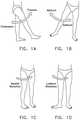
- This inventionrelates to surgical methods and apparatus in general, and more particularly to surgical methods and apparatus for treating a hip joint and other anatomy.
- the hip jointis a ball-and-socket joint which movably connects the leg to the torso.
- the hip jointis capable of a wide range of different motions, e.g., flexion and extension, abduction and adduction, medial and lateral rotation, etc. See FIGS. 1A, 1B, 1C and 1D .
- the hip jointis perhaps the most mobile joint in the body.
- the hip jointcarries substantial weight loads during most of the day, in both static (e.g., standing and sitting) and dynamic (e.g., walking and running) conditions.
- the hip jointis susceptible to a number of different pathologies. These pathologies can have both congenital and injury-related origins. In some cases, the pathology can be substantial at the outset. In other cases, the pathology may be minor at the outset but, if left untreated, may worsen over time. More particularly, in many cases, an existing pathology may be exacerbated by the dynamic nature of the hip joint and the substantial weight loads imposed on the hip joint.
- the pathologymay, either initially or thereafter, significantly interfere with patient comfort and lifestyle. In some cases, the pathology can be so severe as to require partial or total hip replacement. A number of procedures have been developed for treating hip pathologies short of partial or total hip replacement, but these procedures are generally limited in scope due to the significant difficulties associated with treating the hip joint.
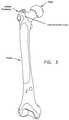
- the hip jointis formed at the junction of the leg and the torso. More particularly, and looking now at FIG. 2 , the head of the femur is received in the acetabular cup of the hip, with a plurality of ligaments and other soft tissue serving to hold the bones in articulating relation.
- the femuris generally characterized by an elongated body terminating, at its top end, in an angled neck which supports a hemispherical head (also sometimes referred to as “the ball”).
- a large projection known as the greater trochanterprotrudes laterally and posteriorly from the elongated body adjacent to the neck of the femur.
- a second, somewhat smaller projection known as the lesser trochanterprotrudes medially and posteriorly from the elongated body adjacent to the neck.
- An intertrochanteric crest( FIGS. 3 and 4 ) extends along the periphery of the femur, between the greater trochanter and the lesser trochanter.
- the hip socketis made up of three constituent bones: the ilium, the ischium and the pubis. These three bones cooperate with one another (they typically ossify into a single “hip bone” structure by the age of 25 or so) in order to collectively form the acetabular cup.
- the acetabular cupreceives the head of the femur.
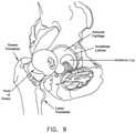
- Both the head of the femur and the acetabular cupare covered with a layer of articular cartilage which protects the underlying bone and facilitates motion. See FIG. 6 .
- ligaments and soft tissueserve to hold the ball of the femur in place within the acetabular cup. More particularly, and looking now at FIGS. 7 and 8 , the ligamentum teres extends between the ball of the femur and the base of the acetabular cup. As seen in FIGS. 8 and 9 , a labrum is disposed about the perimeter of the acetabular cup. The labrum serves to increase the depth of the acetabular cup and effectively establishes a suction seal between the ball of the femur and the rim of the acetabular cup, thereby helping to hold the head of the femur in the acetabular cup. In addition to the foregoing, and looking now at FIG.
- a fibrous capsuleextends between the neck of the femur and the rim of the acetabular cup, effectively sealing off the ball-and-socket members of the hip joint from the remainder of the body.
- the foregoing structuresi.e., the ligamentum teres, the labrum and the fibrous capsule
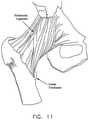
- a set of three main ligamentsi.e., the iliofemoral ligament, the ischiofemoral ligament and the pubofemoral ligament
- FIGS. 11 and 12show the iliofemoral ligament, with FIG. 11 being an anterior view and FIG. 12 being a posterior view.
- the hip jointis susceptible to a number of different pathologies. These pathologies can have both congenital and injury-related origins.
- one important type of congenital pathology of the hip jointinvolves impingement between the neck of the femur and the rim of the acetabular cup.
- this impingementcan occur due to irregularities in the geometry of the femur.
- This type of impingementis sometimes referred to as cam-type femoroacetabular impingement (i.e., cam-type FAI).
- the impingementcan occur due to irregularities in the geometry of the acetabular cup.
- This latter type of impingementis sometimes referred to as pincer-type femoroacetabular impingement (i.e., pincer-type FAI). Impingement can result in a reduced range of motion, substantial pain and, in some cases, significant deterioration of the hip joint.
- another important type of congenital pathology of the hip jointinvolves defects in the articular surface of the ball and/or the articular surface of the acetabular cup. Defects of this type sometimes start out fairly small but often increase in size over time, generally due to the dynamic nature of the hip joint and also due to the weight-bearing nature of the hip joint. Articular defects can result in substantial pain, induce and/or exacerbate arthritic conditions and, in some cases, cause significant deterioration of the hip joint.
- one important type of injury-related pathology of the hip jointinvolves trauma to the labrum. More particularly, in many cases, an accident or sports-related injury can result in the labrum being torn away from the rim of the acetabular cup, typically with a tear running through the body of the labrum. See FIG. 15 . These types of labral injuries can be very painful for the patient and, if left untreated, can lead to substantial deterioration of the hip joint.
- the hip jointis generally considered to be a “tight” joint, in the sense that there is relatively little room to maneuver within the confines of the joint itself. This is in marked contrast to the shoulder joint and the knee joint, which are generally considered to be relatively “spacious” joints (at least when compared to the hip joint). As a result, it is relatively difficult for surgeons to perform minimally-invasive procedures on the hip joint.
- the pathways for entering the interior of the hip jointi.e., the natural pathways which exist between adjacent bones and/or delicate neurovascular structures
- the pathways for entering the interior of the hip jointare generally much more constraining for the hip joint than for the shoulder joint or the knee joint. This limited access further complicates effectively performing minimally-invasive procedures on the hip joint.
- the nature and location of the pathologies of the hip jointalso complicate performing minimally-invasive procedures on the hip joint.
- the angle of approachwhich is offset from the angle at which the instrument addresses the tissue. This makes drilling into bone, for example, significantly more complicated than where the angle of approach is effectively aligned with the angle at which the instrument addresses the tissue, such as is frequently the case in the shoulder joint.
- the working space within the hip jointis typically extremely limited, further complicating repairs where the angle of approach is not aligned with the angle at which the instrument addresses the tissue.
- hip arthroscopyis becoming increasingly more common in the diagnosis and treatment of various hip pathologies.
- hip arthroscopyis currently practical for only selected pathologies and, even then, hip arthroscopy has generally met with limited success.
- One procedure which is sometimes attempted arthroscopicallyrelates to the repair of a torn and/or detached labrum.
- This proceduremay be attempted when the labrum has been damaged but is still sufficiently healthy and capable of repair.
- the repaircan occur with a labrum which is still attached to the acetabulum or after the labrum has been deliberately detached from the acetabulum (e.g., so as to allow for acetabular rim trimming to treat a pathology such as a pincer-type FAI) and needs to be subsequently re-attached.
- FIG. 16shows a normal labrum which has its base securely attached to the acetabulum
- FIG. 16shows a normal labrum which has its base securely attached to the acetabulum
- the present inventionis intended to improve upon the current approaches for labrum repair.
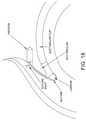
- one such approachutilizes a screw-type anchor, with two lengths of suture extending therefrom, and involves deploying the anchor in the acetabulum above the labrum re-attachment site. After the anchor has been deployed, one length of suture is passed either through the detached labrum or, alternatively, around the detached labrum. Then that length of suture is tied to the other length of suture so as to secure the labrum against the acetabular rim. See FIG. 18 .
- suture anchors of the sort described aboveare traditionally used for re-attaching ligaments to bone and, as a result, tend to be relatively large, since they must carry the substantial pull-out forces normally associated with ligament reconstruction.
- this large anchor sizeis generally unnecessary for labrum re-attachment, since the labrum is not subjected to substantial forces, and the large anchor size typically causes unnecessary trauma to the patient.
- the large size of traditional suture anchorscan be problematic when the anchors are used for labrum re-attachment, since the suture anchors generally require a substantial bone mass for secure anchoring, and such a large bone mass is generally available only a substantial distance up the acetabular shelf.
- the large size of the suture anchorsgenerally makes it necessary to set the suture anchor a substantial distance up the acetabular shelf, in order to ensure that the distal tip of the suture anchor does not inadvertently break through the acetabular shelf and contact the articulating surfaces of the joint.
- labral re-attachment utilizing a suture anchor set high up into the acetabular shelfcreates a suture path, and hence a labral draw force, which is not directly aligned with the portion of the acetabular rim where the labrum is to be re-attached.
- an “indirect” draw forcealso known as “eversion”
- the labrumis drawn around the rim of the acetabulum rather than directly into the acetabulum. See FIG. 18 .
- suture anchors of a smaller sizeallows the suture anchor to be set closer to the rim of the acetabulum, which can help reduce this effect. See FIG. 18A .
- suture anchors of the sort described aboverequire that a knot be tied at the surgical site in order to secure the labrum to the acetabulum.
- the suture anchortypically has a suture connected thereto so that two lengths of suture extend from the suture anchor and are available to secure the labrum to the acetabulum (which receives the suture anchor).
- One or both of the two lengths of sutureare passed through or around the labrum and then knotted to one another so as to secure the labrum to the acetabulum.
- itcan be time-consuming and inconvenient to form the knot at the surgical site, given the limited access to the surgical site and the restricted work space at the surgical site.
- the present inventionprovides a novel method and apparatus for re-attaching the labrum to the acetabulum.
- the present inventionprovides a novel knotless suture anchor system which may be used to re-attach the labrum to the acetabulum, and/or to attach other tissue to bone.
- a knotless suture anchorwherein a loop of suture is passed through the labrum (or other tissue) and its two free ends are slidably connected (e.g., slidably threaded through) the knotless suture anchor.
- the knotless suture anchoris advanced into the acetabulum (or other bone) and the loop of suture is tensioned so as to hold the labrum (or other tissue) in place against the acetabulum (or other bone)
- the knotless suture anchoris reconfigured so as to lock the loop of suture to the knotless suture anchor and hence secure the labrum (or other tissue) to the acetabulum (or other bone).
- apparatus for securing a first object to a second objectcomprising:
- an elongated bodyhaving a distal end, a proximal end, and a lumen extending between the distal end and the proximal end, the lumen comprising a distal section and a proximal section, the distal section of the lumen having a wider diameter than the proximal section of the lumen;
- a windowextending through the side wall of the elongated body and communicating with the lumen, the window being disposed in the vicinity of the intersection between the distal section of the lumen and the proximal section of the lumen and being sized to receive a first object therein;
- an elongated elementextending through the lumen of the elongated body, the elongated element comprising a proximal end and a distal end;
- a locking elementmounted to the distal end of the elongated element and disposed in the distal section of the lumen;
- apparatus for securing a first object to a second objectcomprising:
- an elongated bodyhaving a distal end, a proximal end, and a lumen extending between the distal end and the proximal end;
- a windowextending through the side wall of the elongated body and communicating with the lumen, the window being sized to receive a first object therein;
- the locking elementdisposed in the lumen, the locking element having a larger proximal end and a smaller distal end;
- a method for securing a first object to a second objectcomprising:
- providing apparatuscomprising:
- a method for securing a first object to a second objectcomprising:
- providing apparatuscomprising:
- apparatus for securing an object to bonecomprising:
- an anchorcomprising:
- an inserter for deploying said anchor in bonecomprising:
- apparatus for securing an object to bonecomprising:
- an anchorcomprising:
- an inserter for deploying said anchor in bonecomprising:
- apparatus for securing an object to bonecomprising:
- an anchorcomprising:
- an inserter for deploying said anchor in bonecomprising:
- a method for securing an object to bonecomprising:
- providing apparatuscomprising:
- a method for securing an object to bonecomprising:
- providing apparatuscomprising:
- a method for securing an object to bonecomprising:
- providing apparatuscomprising:
- apparatus for securing an object to bonecomprising:
- an anchorcomprising:
- an inserter for deploying said anchor in bonecomprising:
- a method for securing an object to bonecomprising:
- providing apparatuscomprising:
- apparatus for securing an object to bonecomprising:
- an anchorcomprising:
- an inserter for deploying said anchor in bonecomprising:
- a method for securing an object to bonecomprising:
- providing apparatuscomprising:
- FIGS. 1A-1Dare schematic views showing various aspects of hip motion
- FIG. 2is a schematic view showing bone structures in the region of the hip joint
- FIG. 3is a schematic anterior view of the femur
- FIG. 4is a schematic posterior view of the top end of the femur
- FIG. 5is a schematic view of the pelvis
- FIGS. 6-12are schematic views showing bone and soft tissue structures in the region of the hip joint
- FIG. 13is a schematic view showing cam-type femoroacetabular impingement (i.e., cam-type FAI);
- FIG. 14is a schematic view showing pincer-type femoroacetabular impingement (i.e., pincer-type FAI);
- FIG. 15is a schematic view showing a labral tear
- FIG. 16is a schematic view showing a normal labrum which has its base securely attached to the acetabulum;
- FIG. 17is a schematic view showing a portion of the labrum detached from the acetabulum
- FIG. 18is a schematic view showing a suture anchor being used to re-attach the labrum to the acetabulum;
- FIG. 18Ais a schematic view showing another suture anchor being used to re-attach the labrum to the acetabulum;
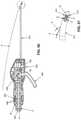
- FIGS. 19 and 20are schematic views showing a novel knotless suture anchor system formed in accordance with the present invention.
- FIGS. 21-25are schematic views showing the knotless suture anchor of the knotless suture anchor system shown in FIGS. 19 and 20 , and the distal end of the inserter of the knotless suture anchor system shown in FIGS. 19 and 20 ;
- FIGS. 26 and 27are schematic views showing the handle of the inserter of the knotless suture anchor system shown in FIGS. 19 and 20 ;
- FIG. 28shows portions of the knotless suture anchor system (i.e., the suture anchor, inserter and suture threader) shown in FIGS. 19 and 20 ;
- FIGS. 28A, 29 and 30show a suture loaded into the knotless suture anchor system shown in FIGS. 19 and 20 , wherein FIG. 30 is a cutaway view of FIG. 29 ;
- FIGS. 31-36are schematic views showing the knotless suture anchor of the knotless suture anchor system shown in FIGS. 19 and 20 securing a suture to bone, wherein FIG. 36 is a cutaway view of FIG. 35 ;
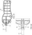
- FIGS. 37-48are schematic views showing an alternative form of knotless suture anchor system formed in accordance with the present invention, wherein FIGS. 37, 38, 41, 42, 43, 44, 47 and 48 comprise side views, and FIGS. 39, 40, 45 and 46 comprise top views;
- FIGS. 49-52are schematic views showing the knotless suture anchor system of FIGS. 37-48 securing a suture to bone (whereby to secure a labrum to bone);
- FIGS. 53-56are schematic views showing the knotless suture anchor system of FIGS. 37-48 , wherein the shaft carrying the knotless suture anchor is formed with a flexible construction (note that suture S is omitted from FIGS. 53-55 for the sake of clarity);
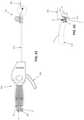
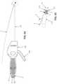
- FIGS. 57-71are schematic views showing another form of knotless suture anchor system formed in accordance with the present invention, wherein the shaft is carried by a slidable inner carriage (note that in FIGS. 66, 68 and 70 , the outer shell of the inserter handle is removed in order to expose internal elements of the inserter handle); and
- FIGS. 72-75are schematic views showing the knotless suture anchor system of FIGS. 57-71 deploying a knotless suture anchor in bone.
- Knotless suture anchor system 5generally comprises a knotless suture anchor 10 , an inserter 15 for inserting knotless suture anchor 10 in bone, and a suture threader 20 for threading a suture through knotless suture anchor 10 (and inserter 15 ) before the knotless suture anchor is deployed in bone.
- knotless suture anchor 10generally comprises a body 25 , a locking element 30 for radially expanding the body and securing a suture (not shown in FIGS. 21-25 ) to the body, and a pull rod 35 for moving locking element 30 proximally relative to body 25 , whereby to simultaneously (i) radially expand the body so as to secure knotless suture anchor 10 to bone, and (ii) secure a suture to the body so as to secure that suture to knotless suture anchor 10 (and hence to the bone within which the knotless suture anchor is secured).
- body 25comprises a distal end 40 terminating in a distal end surface 45 , a proximal end 50 terminating in a proximal end surface 55 , and a stepped bore 60 extending from distal end surface 45 to proximal end surface 55 .
- Stepped bore 60comprises a distal section 65 having a wider diameter, and a proximal section 70 having a narrower diameter.
- Distal section 65preferably has a relatively smooth interior wall, and proximal section 70 preferably has a textured interior wall, e.g., threads 72 .
- a shoulder 75is formed at the intersection of distal section 65 and proximal section 70 .
- Body 25 of knotless suture anchor 10has a generally cylindrical outer surface 80 which may include ribs (or other bone-engaging elements) 85 . Ribs (or other bone-engaging elements) 85 may have various configurations, either identical to or varied from one another, and/or may be regularly or irregularly spaced, as will hereinafter be discussed.
- Body 25also includes a side opening 90 which extends radially through the side wall of body 25 so as to connect stepped bore 60 with the region outside of the body 25 of knotless suture anchor 10 .
- Side opening 90is preferably located in the vicinity of shoulder 75 . In one preferred form of the invention, side opening 90 extends from a region distal to shoulder 75 to a region approximately even with, or proximal to, shoulder 75 .
- a portion of generally cylindrical outer surface 80is recessed as shown at 95 (i.e., to accommodate a suture extending alongside the outer surface of the body), and the proximal end 50 of body 25 is reduced in diameter as shown at 100 so as to form an annular shoulder 105 .
- the axis of stepped bore 60is off-center from the axis of outer surface 80 ( FIG. 25 ) so as to strengthen the side wall of body 25 at 95 while still minimizing anchor diameter.
- locking element 30comprises an elongated body 110 having an enlarged distal end 115 which includes a thin flange 120 and terminates in a distal end surface 125 , a proximal end 130 which terminates in a proximal end surface 135 , and a stepped bore 140 which extends from distal end surface 125 to proximal end surface 135 .
- thing flange 120has a larger diameter than enlarged distal end 115
- enlarged distal end 115has a larger diameter than the portion of locking element 30 which is proximal to enlarged distal end 115 .
- Proximal end 130 of locking element 30is preferably tapered, e.g., in the manner shown in FIGS. 22 and 24 , whereby to facilitate advancement of locking element 30 into proximal section 70 of stepped bore 60 of body 25 , as will hereinafter be discussed.
- proximal end 130 of locking element 30includes a weakened section 132 , preferably formed by a circumferential groove 133 , whereby to allow the proximalmost portion of locking element 30 to separate from the remainder of locking element 30 , as will hereinafter be discussed.
- Stepped bore 140comprises a distal section 145 and a proximal section 150 , with distal section 145 having a larger diameter than the diameter of proximal section 150 , and with proximal section 150 having a smaller diameter than the diameter of distal section 145 .
- a shoulder 155is formed at the intersection of distal section 145 and proximal section 150 .
- Locking element 30has a generally cylindrical outer surface 160 which may include ribs (or other surface profile elements) 165 . Ribs (or other surface profile elements) 165 may have various configurations, either identical to or varied from one another, and/or may be regularly or irregularly spaced, as will hereinafter be discussed.
- Locking element 30is sized so that (i) the diameter of its generally cylindrical outer surface 160 is less than the diameter of distal section 65 of stepped bore 60 of body 25 , and (ii) the diameter of its flange 120 at the distal end of the locking element is larger than the diameter of distal section 65 of stepped bore 60 of body 25 , such that cylindrical outer surface 160 of locking element 30 can be received in distal section 65 of stepped bore 60 of body 25 , but flange 120 at the distal end of locking element 30 cannot normally be received in distal section 65 of stepped bore 60 of body 25 .
- locking element 30is sized so that when its flange 120 is seated against end surface 45 of body 25 , proximal end surface 135 of locking element 30 is disposed distal to at least the proximalmost portion of side opening 90 in body 25 and, preferably, distal to the entire side opening 90 in body 25 .
- the diameter of generally cylindrical outer surface 160 of locking element 30is approximately equal to, or somewhat larger than, the diameter of proximal section 70 of stepped bore 60 of body 25 .
- proximal movement of locking element 30 into proximal section 70 of stepped bore 60 of body 25simultaneously causes (i) the creation of an interference fit between the generally cylindrical outer surface 160 of locking element 30 , the one or more sutures extending through proximal section 70 of stepped bore 60 and the inner wall of proximal section 70 of stepped bore 60 , and (ii) radial expansion of body 25 .
- proximal movement of locking element 30 into proximal section 70 of stepped bore 60 of body 25causes radial expansion of the body so as to secure knotless suture anchor 10 to a surrounding bone, and captures the suture within the proximal section 70 of stepped bore 60 , whereby to secure the suture to the knotless suture anchor 10 (and hence to the bone within which the knotless suture anchor 10 is secured).
- distal end 115 of locking element 30has a diameter which is smaller than distal section 65 of stepped bore 60 , but distal end 115 of locking element 30 has a diameter which is larger than proximal section 70 of stepped bore 60 .
- distal end 115 of locking element 30will stop proximal movement of locking element 30 when distal end 115 abuts shoulder 75 of body 25 .
- thin flange 120located at the distal end of locking element 30 ) will engage distal end surface 45 of body 25 and thereafter collapse (or bend) so that thin flange 120 is able to enter distal section 65 of stepped bore 60 .
- thin flange 120helps to prevent the unintentional actuation of knotless suture anchor 10 by requiring the application of a force to pull rod 35 above a pre-determined threshold force (i.e., the pre-determined force at which thin flange 120 collapses, or bends) in order to permit movement of locking element 30 proximally (whereby to actuate knotless suture anchor 10 ).
- a pre-determined threshold forcei.e., the pre-determined force at which thin flange 120 collapses, or bends
- thin flange 120also helps secure knotless suture anchor 10 on inserter 15 during delivery of the knotless suture anchor to the surgical site.
- knotless suture anchorsare typically delivered without the benefit of such mechanical support and hence are subjected to more forces which can dislodge the knotless suture anchor from the inserter during delivery to the bone site and into the bone hole.
- pull rod 35comprises an elongated body 170 having a distal end 175 terminating in an enlarged head 180 , and a proximal end 185 terminating within the handle 190 of inserter 15 , as will hereinafter be discussed in further detail.
- Elongated body 170 of pull rod 35is sized to pass through proximal section 150 of bore 140 of locking element 30
- enlarged head 180 of pull rod 35is sized to seat in distal portion 145 of bore 140 of locking element 30 , such that pulling proximally on elongated body 170 of pull rod 35 will cause locking element 30 to move proximally.
- enlarged head 180 of pull rod 35comprises a proximal surface 191 which extends circumferentially around the distal end of pull rod 35 at the junction of (or transition between) elongated body 170 and enlarged head 180 .
- Proximal surface 191 of enlarged head 180may comprise a fillet or chamfer, such that when a sufficient proximal force (i.e., a proximal force above a set threshold force) is applied to pull rod 35 , enlarged head 180 can move proximally into bore 140 of locking element 30 , as will hereinafter be discussed.
- inserter 15generally comprises a shaft 195 having a distal end 200 terminating in distal end surface 205 , a proximal end 210 terminating in a proximal end surface 215 , and a bore 220 extending therebetween.
- Distal end 200 of shaft 195comprises a counterbore 225 which is sized so as to receive the proximal end 50 of body 25 of knotless suture anchor 10 , in a male/female connection, with distal end surface 205 of shaft 195 being seated against annular shoulder 105 of body 25 .
- the proximal end 50 of body 25 of knotless suture anchor 10is not round ( FIG.
- a side opening 227extends radially through the side wall of shaft 195 so as to connect bore 220 with the region outside the shaft. Preferably side opening 227 in shaft 195 is aligned with side opening 90 in knotless suture anchor 10 .
- Handle 190comprises a lever 230 which is rotatably mounted to handle 190 via a pivot pin 235 .
- the proximal end 185 of pull rod 35is secured to lever 230 such that when lever 230 is activated (i.e. squeezed towards handle 190 ), pull rod 35 is moved proximally, whereby to move locking element 30 proximally, as will hereinafter be discussed.
- a finger-to-finger engagementis provided at 232 , 233 so as to prevent accidental activation of lever 230 .
- Preferably pull rod 35is set with a small amount of tension (that is below the threshold force that is required to retract locking element 30 ) so as to help hold suture anchor 10 on the distal end of inserter 15 .
- suture threader 20is provided for threading a suture through knotless suture anchor 10 (and inserter 15 ) before the knotless suture anchor is deployed in bone.
- suture threader 20is pre-mounted to shaft 195 of inserter 15 , with the suture threader having a portion threaded through inserter 15 and knotless suture anchor 10 so as to facilitate threading a suture (or multiple sutures) through the knotless suture anchor 10 and through inserter 15 ; see FIGS. 19 and 28 .
- suture threader 20preferably comprises a body 240 having clamping arms 245 extending therefrom.
- Clamping arms 245are configured to releasably secure body 240 of suture threader 20 to shaft 195 of inserter 15 .
- a wire shaft 250extends distally from body 240 , and a collapsible, diamond-shaped capture element 255 is secured to the distal end of wire shaft 250 .
- the wire shaft 250 and diamond-shaped capture element 255are formed out of a single, thin Nitinol wire having its two terminal ends secured to body 240 .
- suture threader 20Prior to use, suture threader 20 has its diamond-shaped capture element 255 collapsed radially inwardly, and it is passed through side opening 227 of shaft 195 , along bore 220 of shaft 195 of inserter 15 , along proximal portion 70 of stepped bore 60 of body 25 of knotless suture anchor 10 , and out side opening 90 of body 25 of knotless suture anchor 10 , whereupon diamond-shaped capture element 255 re-expands to its erected shape, e.g., in the manner shown in FIGS. 19 and 28 .
- the suture which is to be secured to a bone by means of knotless suture anchor 10is first passed through the tissue which is to be secured to the bone, next the suture is passed through diamond-shaped capture element 255 of suture threader 20 , and then suture threader 20 is pulled rearwardly on shaft 195 of inserter 15 , towing the suture with it, until the suture has been pulled through side opening 90 of knotless suture anchor 10 , along proximal portion 70 of stepped bore 60 of body 25 of knotless suture anchor 10 , along bore 220 of shaft 195 of inserter 15 , and out side opening 227 in shaft 195 of inserter 15 . See FIGS.
- inserter 15is used to advance knotless suture anchor 10 and suture S into a hole H ( FIGS. 29 and 30 ) formed in a bone B.
- Suture Smay then be tensioned so as to adjust the position of the tissue relative to the bone. This can be accomplished by pulling on the free ends of the suture S, either independently or together. Sufficient tension will overcome any friction in the suture path and reduce the distance from the tissue to the knotless suture anchor 10 (and hence to the bone).
- the lever 230is moved toward handle 190 , whereby to force pull rod 35 proximally. This action causes locking element 30 to move proximally ( FIGS.
- enlarged head 180needs to be larger in diameter than the diameter of proximal section 150 of bore 140 but not so large that it cannot be pulled through the bore 140 when sufficient proximal force is applied.
- an enlarged head 180 having a diameter of approximately 0.0250 incheswill provide adequate “interference” between enlarged head 180 and shoulder 155 so as to provide sufficient resistance to entering bore 140 when a proximal force less than the maximum proximal force (i.e., partial activation force) is applied ( FIG. 32 ).
- a proximal force less than the maximum proximal forcei.e., partial activation force
- such a configurationpermits the enlarged head 180 to enter bore 140 ( FIG. 33 ) when a sufficient proximal force (i.e., full activation force) is applied to pull rod 35 (and hence to enlarged head 180 ).
- the force required to pull locking element 30 proximally so as to lock suture S to the suture anchor, and so as to expand the body of the suture anchoris less than the force required to draw pull rod 35 through locking element 30 so as to disengage pull rod 35 from locking element 30 —this ensures that pull rod 35 is not disengaged from locking element 30 until locking element 30 has locked suture S to the suture anchor and expanded the body of the suture anchor.
- the force required to draw pull rod 35 through locking element 30 so as to disengage pull rod 35 from locking element 30is less than the force required to pull locking element 30 through the proximal end of body 25 of the knotless suture anchor 10 (due to the fact that distal end 115 of locking element 30 is sufficiently larger than proximal section 150 of bore 140 )—this ensures that pull rod 35 disengages from locking element 30 and locking element 30 is never pulled through the proximal end of body 25 of the knotless suture anchor 10 .
- the force required to pull locking element 30 through proximal end of body 25is greater than the force required to draw pull rod 35 through locking element so as to disengage pull rod 35 from locking element 30 (i.e., the full activation force).
- proximal surface 191 of enlarged head 180 of pull rod 35also influences the proximal force at which enlarged head 180 will enter into, and begin moving through, bore 140 in locking element 30 .
- proximal surface 146 of enlarged head 180comprises a fillet of approximately 0.005 inches (or a chamfer of approximately 45 degrees).
- pull rod 35Further proximal movement of pull rod 35 (i.e., by way of moving lever 230 even further towards handle 190 ) causes pull rod 35 to completely pull enlarged head 180 through bore 140 and out of the proximal end of locking element 30 ( FIG. 34 ).
- locking element 30comprises a weakened section 132 located at the proximal end of locking element 30 .
- the weakened sectionwill separate from locking element 30 , allowing a proximal portion of locking element 30 to detach from the locking element and be removed from the anchor by pull rod 35 ( FIG. 34 ).
- inserter 15can be removed from the hole H in bone B (see FIGS. 35 and 36 ), leaving the knotless suture anchor 10 secured in the hole H in the bone B, and with the suture S secured to the knotless suture anchor and emanating from the bone hole H, whereby to secure the suture (and hence the tissue which the suture S has been passed through) to the bone B.
- the suture anchormay be subjected to transverse forces as it is advanced towards, and/or inserted into, the bone hole. This is particularly true where the suture anchor must be advanced through a tight corridor (e.g., such as in arthroscopic surgery), or along a tortuous path (e.g., such as when being advanced to a labral repair site within the hip), since in these situations the suture anchor may accidentally bump into intervening structures and/or the suture anchor may need to turn along a curved sheath during insertion. When this occurs, the suture anchor may be damaged and/or moved out of alignment with its inserter, etc., which can result in ineffective anchor placement in the bone.
- a tight corridore.g., such as in arthroscopic surgery
- a tortuous pathe.g., such as when being advanced to a labral repair site within the hip
- inserter 15comprises a retractable sheath 310 which is co-axial with, and external to, the aforementioned inserter shaft 195 .
- Inserter 15also comprises an overtube 315 .
- shaft 195is secured to handle 190 ( FIG.
- retractable sheath 310is coaxially mounted about shaft 195 and spring-biased in a distal direction by a compression spring 320
- overtube 315is coaxially mounted about retractable sheath 310 and secured to handle 190 .
- the distal end surface 325 of retractable sheath 310is disposed proximal to the distal end of knotless suture anchor 10 , but distal to the proximal end of knotless suture anchor 10 (see FIGS. 38 and 40 ).
- retractable sheath 310is located between the midpoint of knotless suture anchor 10 and the distal end of knotless suture anchor 10 .
- retractable sheath 310can cover, and hence protect, the major length of knotless suture anchor 10 as the knotless suture anchor is advanced to the surgical site, but still expose the distal end of knotless suture anchor 10 so as to facilitate insertion of the knotless suture anchor into a bone hole. See FIGS. 37-42 .
- retractable sheath 310is forced proximally, against the power of compression spring 320 , knotless suture anchor 10 is completely exposed. See FIGS. 43-48 .
- retractable sheath 310 and overtube 315have distal markings 326 and 327 , respectively, which provide indication of anchor depth. For example, when markings 326 and 327 align, the anchor is at the preferred depth.
- retractable sheath 310preferably has a slot 311 extending from its distal end (see FIGS. 40 and 46 ) to allow suture to pass from within retractable sheath 310 (i.e., from knotless suture anchor 10 and/or shaft 195 ) to outside retractable sheath 310 .
- Slot 311is preferably rotationally aligned with side opening 90 in knotless suture anchor 10 and opening 227 in the side wall of shaft 195 .
- retractable sheath 310is initially disposed in its distal position, i.e., compression spring 320 actively pushes the proximal end of retractable sheath 310 away from handle 190 , so that retractable sheath 310 covers the majority of the length of knotless suture anchor 10 , but leaves the distal tip of the knotless suture anchor 10 exposed for easy locating into a bone hole H. Thereafter, when knotless suture anchor 10 is to be deployed into the bone hole H, the knotless suture anchor 10 is advanced (e.g., through an arthroscopic cannula) to the surgical site, with retractable sheath 310 covering, and protecting, the knotless suture anchor 10 during such advancement.
- compression spring 320actively pushes the proximal end of retractable sheath 310 away from handle 190 , so that retractable sheath 310 covers the majority of the length of knotless suture anchor 10 , but leaves the distal tip of the knotless suture anchor 10 exposed for easy locating into a
- Overtube 315prevents retractable sheath 310 from prematurely retracting while the knotless suture anchor 10 is being delivered to the bone site.
- the knotless suture anchor 10may be passed through a cannula with an elastomeric septum; the septum, being grip-like in nature, will tend to grip the retractable sheath 310 and, consequently, retract the retractable sheath, thus removing some or all of the protection it was providing to the knotless suture anchor 10 .
- Overtube 315provides protection against this occurrence as the septum will bear against the overtube 315 (it being the outermost surface) instead of retractable sheath 310 . Then the exposed distal tip of knotless suture anchor 10 is placed into bone hole H ( FIGS.
- retractable sheath 310contacts the outer surface of the bone B about the perimeter of the bone hole H and provides additional mechanical support against any transverse forces that may be applied to the knotless suture anchor 10 from the inserter 15 , for example, if there is a misalignment between the arthroscopic portal and the axis of the bone hole H.
- the knotless suture anchor 10is then advanced into the bone hole H. This is done by moving inserter 15 distally.
- shaft 195advances the knotless suture anchor 10 into the bone hole H while the engagement of retractable sheath 310 with the outer surface of the bone B causes the retractable sheath 310 to remain stationary relative to the bone B. See FIGS. 51 and 52 .
- the power of compression spring 320is overcome and the advancing handle 190 moves shaft 195 distally within retractable sheath 310 .
- pushing handle 190 distallymoves shaft 195 distally, while compression spring 320 allows retractable sheath 310 to remain seated on the outer surface of the bone B and retract into the advancing handle 190 .
- retractable sheath 310During advancement of knotless suture anchor 10 into the bone hole H, retractable sheath 310 continues to provide mechanical support to the knotless suture anchor 10 as the knotless suture anchor 10 is pressed further into the bone hole. In this manner, retractable sheath 310 protects and supports knotless suture anchor 10 during delivery into the bone hole H.
- retractable sheath 310 and overtube 315are formed out of biocompatible materials such as stainless steel.
- retractable sheath 310is formed out of a transparent polymer.
- a distal marking 328 ( FIG. 44 ) on the shaft 195can be visualized through the transparent retractable sheath 310 to provide visual indication of anchor depth.
- the spring 320may be sufficiently strong so as to overcome inadvertent retraction of retractable sheath 310 during delivery; hence, in this form of the invention, overtube 315 may be omitted.
- shaft 195with a flexible construction.
- inserter 15may sometimes approach the bone hole at an angle to the longitudinal axis of the bone hole. Where this occurs, and where shaft 195 is rigid, the rigid nature of shaft 195 can cause knotless suture anchor 10 to resist tracking the orientation of the bone hole during insertion of the knotless suture anchor into the bone hole. This can put additional stress on knotless suture anchor 10 , and/or on the connection between knotless suture anchor 10 and shaft 195 , and/or on other components of knotless suture anchor system 5 (e.g., it can put additional stress on pull rod 35 ).
- shaft 195may be formed so as to be flexible, so that if inserter 15 approaches bone hole H at an angle to the longitudinal axis of the bone hole ( FIG. 53 ), shaft 195 can flex so as to allow knotless suture anchor 10 to track the orientation of the bone hole during insertion of the knotless suture anchor into the bone hole ( FIGS. 54 and 55 ).
- Various approachesmay be used to form shaft 195 so that it is flexible, e.g., shaft 195 may be formed out of a flexible material (e.g., a superelastic material such as Nitinol) and/or shaft 195 may be provided with a series of laser cuts 400 ( FIG. 55 ) so as to render the shaft flexible.
- pull rod 35is also formed so as to be flexible.
- knotless suture anchor 10may be formed with a flexible construction, such that where inserter 15 approaches the bone hole at an angle to the longitudinal axis of the bone hole, the knotless suture anchor can still track to the orientation of the bone hole during insertion of the knotless suture anchor into the bone hole.
- knotless suture anchor 10is flexible along its longitudinal axis (i.e., in bending).
- shaft 195 of inserter 15is preferably also formed flexible so as to enhance tracking of the bone hole by shaft 195 of inserter 15 during insertion of the knotless suture anchor into the bone hole (although shaft 195 of inserter 15 may also be formed rigid if desired).
- pull rod 35is preferably also formed flexible so that pull rod 35 can follow a curved path where inserter 15 approaches the bone hole at an angle relative to the longitudinal axis of the bone hole.
- pull rod 35may comprise a flexible shaft (e.g., Nitinol) or pull rod 35 may comprise a flexible cable, suture, etc.
- knotless suture anchore.g., knotless suture anchor 10
- the knotless suture anchor 10may be subjected to transverse forces as the knotless suture anchor is advanced towards, and/or inserted into, bone hole H.
- knotless suture anchor 10must be advanced through a tight corridor (e.g., such as during arthroscopic surgery), and/or along a tortuous path (e.g., such as when the knotless suture anchor is being advanced to a labral repair site within the hip joint), since in these situations (as well as in others) knotless suture anchor 10 may accidentally bump into intervening structures, and/or knotless suture anchor 10 may need to pass through a curved sheath during advancement to the insertion site.
- a tight corridore.g., such as during arthroscopic surgery
- a tortuous pathe.g., such as when the knotless suture anchor is being advanced to a labral repair site within the hip joint
- knotless suture anchor 10may be damaged, and/or moved out of alignment with its inserter, etc., either of which can result in ineffective anchor placement in the bone. This is particularly true where the size of knotless suture anchor 10 and its associated inserter are quite small (e.g., where knotless suture anchor 10 is approximately 2.8 mm in diameter).
- inserter 15includes the aforementioned retractable sheath 310 which is coaxial with, and external to, the inserter shaft 195 .
- This retractable sheath 310is coaxially mounted about shaft 195 and is spring-biased in a distal direction by the compression spring 320 .
- retractable sheath 310covers at least a portion of knotless suture anchor 10 as the knotless suture anchor is advanced to the insertion site, however, when handle 190 is thereafter used to push the knotless suture anchor into the bone, engagement of retractable sheath 310 with the outer surface of the bone causes the retractable sheath 310 to retract into handle 190 .
- retractable sheath 310protects and supports the knotless suture anchor 10 during delivery to the bone hole, but does not interfere with insertion of the knotless suture anchor 10 into the bone hole.
- overtube 315is coaxially mounted about retractable sheath 310 and inserter shaft 195 .
- Overtube 315prevents retractable sheath 310 from prematurely retracting while the knotless suture anchor 10 is being delivered to the insertion site.
- the knotless suture anchor 10may be passed through a cannula having an elastomeric septum; if the retractable sheath 310 were not protected by overtube 315 , the septum, being grip-like in nature, could tend to grip retractable sheath 310 and, consequently, prematurely retract the retractable sheath 310 , thus removing some or all of the protection the retractable sheath 310 provides to the knotless suture anchor 10 during advancement to the insertion site.
- Overtube 315provides protection against this occurrence as the septum will bear against overtube 315 (since it provides the outermost surface of the assembly) instead of bearing against retractable sheath 310 .
- FIGS. 37-48essentially provides an inserter comprising the handle 190 , the inserter shaft 195 fixed to handle 190 , the spring-biased retractable sheath 310 slidably mounted to handle 190 , and the overtube 315 fixedly mounted to handle 190 .
- FIGS. 57-71show an alternative construction for supporting and protecting knotless suture anchor 10 during approach and insertion into bone. More particularly, with the construction shown in FIGS. 57-71 , there is provided an inserter handle 405 having an overtube 315 fixedly mounted thereto and extending distally therefrom. Overtube 315 is preferably curved (as shown in FIGS. 57 and 62-71 ) so as to enable curved (angled) delivery of knotless suture anchor 10 . This can be beneficial when the desired angle of the bone hole differs from the access angle through the intervening tissue to the bone site. For example, in repairing the hip labrum, it is desirable to create a bone hole (and subsequently deliver an anchor) at an angle which tilts away from the acetabular cup. This angulation of the bone hole reduces the chance that the bone hole (and the subsequent anchor delivery) will penetrate into the acetabular cup surface.
- Overtube 315preferably comprises at least one tooth 410 at its distal end for engaging bone.
- retractable sheath 310While the retractable sheath 310 discussed above supports anchor delivery to the bone hole, retractable sheath 310 does not engage the bone in such a way as to withstand transverse loads that may be imparted to knotless suture anchor 10 and/or to inserter shaft 195 during delivery of the knotless suture anchor into the bone hole, i.e., retractable sheath 310 is spring biased and, as such, cannot be, for example, pressed into the bone to securely engage the bone.
- knotless suture anchor 310 and/or inserter shaft 195can be subjected to transverse forces during anchor insertion when the angle of the bone hole differs from the access angle through the intervening tissue to the site of the bone hole; this may result in ineffective anchor delivery and/or damage to the anchor and/or inserter shaft.
- the overtube 315with at least one tooth 410 at its distal end for securely engaging bone, can withstand transverse forces that may be imparted during anchor delivery. This may occur when the angle of the bone hole differs from the access angle through the intervening tissue to the site of the bone hole (as previously discussed). This may also occur when overtube 315 is curved; in this construction (and as shown in FIGS.
- an impact force applied to driver head 425 of inserter 15 for delivery of anchor 10 into the bone holecauses flexible inserter shaft 195 to contact the inside surface of overtube 315 and impart distal- and transverse-directed forces to overtube 315 .
- the overtube 315may impart distal- and transverse-forces against the bone surface; the at least one tooth 410 at the distal end of overtube 315 acts to securely engage overtube 315 , and hence inserter 15 , with the bone such that the forces imparted by overtube 315 against the bone surface will not cause the distal end of overtube 315 to shift on the bone surface, which could lead to ineffective placement of knotless suture anchor 10 and/or damage to knotless suture anchor 10 and/or inserter shaft 195 .
- Overtube 315also comprises a distal slot 415 ( FIG. 58 ) so as to enable passage of suture S from knotless suture anchor 10 through overtube 315 .
- Distal slot 415extends to the distal end of overtube 315 so as to enable suture S to freely slide out of overtube 315 when the knotless suture anchor 10 is disengaged from inserter shaft 195 .
- Inserter shaft 195is slidably disposed within overtube 315 .
- Inserter shaft 195is preferably flexible at its distal end (i.e., along the length extending along the curve of overtube 315 ). This can be accomplished by forming inserter shaft 195 out of a flexible material (e.g., a superelastic metal such as Nitinol) or by forming a series of laser cuts 400 in inserter shaft 195 (as can be seen in FIG. 69 ) so as to render inserter shaft 195 flexible.
- the distal end of inserter shaft 195releasably carries knotless suture anchor 10 in the manner previously described.
- inserter shaft 195is fixedly attached to a slidable inner carriage 420 ( FIGS. 66, 68 and 70 ) which is movably mounted within inserter handle 405 .
- Slidable inner carriage 420is moved relative to inserter handle 405 by applying force to a driver head 425 which is exposed at the proximal end of inserter handle 405 .
- driver head 425distally (e.g., by striking driver head 425 with a mallet)
- slidable inner carriage 420is moved distally, whereby to move inserter shaft 195 (and hence knotless suture anchor 10 ) distally.
- a removable stop 427is releasably secured to driver head 425 .
- Removable stop 427prevents driver head 425 from being inadvertently driven distally, and hence prevents slidable inner carriage 420 , inserter shaft 195 and knotless suture anchor 10 from being inadvertently driven distally.
- the driver headand hence slidable driver carriage 420 , inserter shaft 195 and suture anchor 10
- the driver headmay be moved distally (e.g., by striking driver head 425 with a mallet).
- slidable inner carriage 420comprises one or more projections 428
- inserter handle 405comprises one or more resilient fingers 429 , whereby to permit slidable inner carriage 420 to move distally within inserter handle 405 but prevent slidable inner carriage 420 from moving proximally within inserter handle 405 .
- projections 428 and resilient fingers 429form a ratchet-type mechanism for ensuring substantially one-way movement of slidable inner carriage 420 relative to inserter handle 405 .
- projections 428 and resilient fingers 429cooperate to prevent slidable inner carriage 420 from thereafter returning substantially proximally.
- the one or more projections 428encounter the one or more fingers 429 , there is resistance against slidable inner carriage 420 moving distally within inserter handle 405 .
- a threshold forceis required to flex resilient finger(s) 429 sufficiently for projection(s) 428 to pass under resilient finger(s) 429 and thus allow slidable inner carriage 420 to move distally within inserter handle 405 .
- a resilient finger 429is adjacent to a projection 428 so as to create a force which must be overcome before slidable inner carriage 420 advances distally.
- This featurecan be advantageous, for example, so that as the inserter 15 is advanced to the bone site, any inadvertent distal pressure or force on the driver head 425 and/or actuation lever 430 will not advance the slidable inner carriage 420 (and hence advance knotless suture anchor 10 further out of the overtube 315 ).
- Slidable inner carriage 420includes an actuation lever 430 which is pivotally connected to slidable inner carriage 420 . More particularly, actuation lever 430 is pivotally mounted to slidable inner carriage 420 and moves distally when slidable inner carriage 420 moves distally. Actuation lever 430 is connected to the proximal end of pull rod 35 for actuating knotless suture anchor 10 (i.e., by moving pull rod 35 proximally) once the knotless suture anchor is inside bone hole H, whereby to bind suture S to knotless suture anchor 10 and secure the knotless suture anchor to the bone. It will be appreciated that pull rod 35 extends through inserter shaft 195 for connection to actuation lever 430 . Note that, if desired, lever 430 may be replaced by a different form of actuator, e.g., a rotatable knob, etc., for selectively moving pull rod 35 proximally.
- a bone hole(e.g., a bone hole H) is created in the bone.
- Bone hole His preferably created by passing a drill bit or punch through a curved guide and into the bone. The drill bit or punch and the curved guide are then removed from the surgical site.
- suture Sis passed through the tissue that is to be secured to the bone. Then suture S is threaded through knotless suture anchor 10 . More particularly, the inserter and knotless suture anchor are initially in the position shown in FIGS.
- Distal end of anchor 10may be used to help locate bone hole H. Inserter 15 is then rotated to the desired direction of curved delivery; for example, for hip labral repair, the curvature of inserter 15 would typically be directed away from the acetabular cup. The exposed distal end of the anchor 10 is placed into bone hole H by manual manipulation of inserter handle 405 . Anchor 10 is inserted into bone hole H until the distal end of overtube 315 contacts bone. Tooth 410 on the distal end of overtube 315 is then engaged with bone. See FIG. 72 .
- driver head 425With overtube 315 sufficiently engaged with bone, driver head 425 is moved distally (e.g., by striking the driver head 425 with a mallet), whereby to move slidable inner carriage 420 distally, whereby to move flexible inserter shaft 195 distally, whereby to advance knotless suture anchor 10 out of overtube 315 and into bone hole H ( FIGS. 68, 69 and 73 ). Suture S is then tensioned to adjust the position and/or tension of the tissue relative to knotless suture anchor 10 (and hence the bone).
- lever 430is activated, whereby to move pull rod 35 proximally and hence to move locking element 30 proximally within knotless suture anchor 10 , whereby to bind suture S to knotless suture anchor 10 and secure the tissue to the bone ( FIGS. 70, 71 and 74 ).
- inserter 15is withdrawn from the insertion site by withdrawing inserter handle 405 proximally, leaving knotless suture anchor 10 deployed in bone hole H. See FIG. 75 .
- overtube 315is fixed to inserter handle 405 , and the driver head 425 is used to move slidable inner carriage 420 distally, whereby to advance flexible inserter shaft 195 distally out of overtube 315 , whereby to insert knotless suture anchor 10 into bone hole H.
- overtube 315protects and supports knotless suture anchor 10 during advancement to the insertion site and, by engaging the bone surface, resists transverse forces that otherwise would be subjected onto the knotless suture anchor 10 and/or inserter shaft 195 .
- driver head 425is moved distally relative to inserter handle 405 , e.g., by striking driver head 425 with a mallet, so as to move slidable inner carriage 420 distally relative to inserter handle 405 , whereby to move flexible inserter shaft 195 distally relative to overtube 315 , whereby to advance knotless suture anchor 10 out of overtube 315 and into bone hole H
- inserter handle 405be kept stationary while driver head 425 is moved distally during insertion of knotless suture anchor 10 in bone hole H.
- inserter handle 405is inadvertently driven distally (e.g., by inadvertently striking inserter handle 405 with the mallet which is used to strike driver head 425 ), the distal tip of overtube 315 could be driven into the bone, which could interfere with proper anchor placement and/or cause undesirable trauma to the bone.
- the distal tip of overtube 315could skip along the bone due to the fact that the distal end of the overtube 315 curves away from the longitudinal axis of overtube 315 , which could cause knotless suture anchor 10 to move out of bone hole H and/or cause damage to knotless suture anchor 10 and/or damage to the bone.
- driver head 425 and inserter handle 405are configured so that driver head 425 stands proud of inserter handle 405 at both the start and finish of the anchor-insertion process, so as to minimize the possibility that the mallet might inadvertently strike inserter handle 405 (rather than driver head 425 ) during insertion of knotless suture anchor 10 in bone hole H.
- driver head 425when driver head 425 is in its “proximal” position (i.e., so that knotless suture anchor 10 is largely sheathed within overtube 315 , as seen in the corresponding FIGS. 62, 65 and 67 ), the proximal surface A of driver head 425 is displaced proximally from the proximal surface B of inserter handle 405 ; and as seen in FIGS. 68 and 70 , when driver head 425 is in its “distal” position (i.e., so that knotless suture anchor 10 is extended out of overtube 315 for insertion into bone hole H, as seen in the corresponding FIGS.
- proximal surface A of driver head 425is still displaced proximally from proximal surface B of inserter handle 405 , albeit by a shorter distance (i.e., by the distance that flexible inserter shaft 195 is to advance knotless suture anchor 10 distally into bone hole H).
- driver head 425is preferably provided with a visual marker C, with driver head 425 being advanced an appropriate distance relative to inserter handle 405 when visual marker C is aligned with proximal surface B of inserter handle 405 (see FIGS. 68 and 70 ).
- visual marker Cmay comprise a circumferential groove, which may or may not be visually enhanced with coloration, or an O-ring disposed in the circumferential groove, where the O-ring may itself be visually enhanced with coloration, etc.
- proximal surface A of driver head 425will still stand well proud of proximal surface B of inserter handle 425 , whereby to minimize the possibility that a mallet might inadvertently strike proximal surface B of inserter handle 425 , which could adversely affect anchor insertion into bone hole H (e.g., due to overtube 315 being driving into the bone, or due to overtube 315 skipping along the surface of the bone).
- visual marker Chelps the user know when driver head 425 has been driven far enough to properly insert knotless suture anchor 10 into bone hole H while still keeping proximal surface A of driver head 425 sufficiently proud above proximal surface B of inserter handle 405 to minimize the risk of a mallet blow inadvertently striking inserter handle 405 .
- providing visual marker C on driver head 425provides the user with an additional advantage beyond ensuring adequate anchor insertion while minimizing the risk of a mallet blow inadvertently striking inserter handle 425 . More particularly, by providing visual marker C to guide the extent to which driver head 425 moves distally relative to inserter handle 425 , the user is also provided with a visual guide to prevent over-inserting knotless suture anchor 10 into bone hole H. In this respect it should be appreciated that if knotless suture anchor 10 were to be advanced too far into bone hole H, knotless suture anchor 10 could “bottom out” in bone hole H.
- bone hole His drilled sufficiently deep so as to allow a clearance between the distal end of the knotless suture anchor 10 and the bottom of bone hole H when visual marker C on driver head 425 is aligned with proximal surface B of inserter handle 405 (i.e., knotless suture anchor 10 does not bottom out in bone hole H when visual marker C on driver head 425 is aligned with proximal surface B of inserter handle 405 ).
- a visual marker De.g., a line
- visual marker Ee.g., a line
- window Fopens on the distal end surface of overtube 315 , e.g., as seen in FIGS. 62-74 .
- window Fis spaced proximally from the distal end surface of overtube 315 .
- driver head 425 and flexible inserter shaft 195are to be advanced, regardless of whether the user is looking at the proximal end of the device (e.g., inserter handle 405 and driver head 425 , by direct visualization) or the distal end of the device (e.g., overtube 315 and knotless suture anchor 10 , by endoscopic visualization).
- overtube 315is formed in a straight configuration.
- inserter shaft 195may be flexible or may be substantially rigid (i.e., it can omit features such as laser cuts 400 that provide flexibility to inserter shaft 195 ).
- a transmission elemente.g., pull rod 35
- a locking elemente.g., locking element 30
- an interference fite.g., a pinch fit
- a filamente.g., suture S
- the knotless suture anchoris mounted to a flexible inserter shaft (e.g., flexible inserter shaft 195 ), and the flexible inserter shaft is mounted to a slidable carriage (e.g., slidable inner carriage 420 ) which is mounted to a handle, such that movement of the slidable carriage will result in movement of the knotless suture anchor relative to the handle.
- a flexible inserter shafte.g., flexible inserter shaft 195
- a slidable carriagee.g., slidable inner carriage 420
- a transmission elemente.g., a shaft, cable, etc.
- a locking elemente.g., a locking element
- an interference fite.g., a pinch fit
- a filamente.g., a suture
- a transmission elemente.g., a shaft, cable, etc.
- a locking elementcan be moved distally so as to move a locking element distally so as to make an interference fit (e.g., a pinch fit) with a filament (e.g., a suture), whereby to bind the filament to a knotless suture anchor.
- an interference fite.g., a pinch fit
- a filamente.g., a suture
- a transmission elemente.g., a rod, shaft, cable, etc.
- a locking elemente.g., proximally, rotationally, distally
- an interference fite.g., a pinch fit
- a filamente.g., a suture
- the knotless suture anchormay be mounted to a flexible inserter shaft (e.g., flexible inserter shaft 195 ), and the flexible inserter shaft may be mounted to a slidable carriage (e.g., slidable inner carriage 420 ) which is mounted to a handle, such that movement of the slidable carriage will result in movement of the knotless suture anchor relative to the handle.
- a flexible inserter shafte.g., flexible inserter shaft 195
- a slidable carriagee.g., slidable inner carriage 420
- the locking elementis rotated in order to secure the suture to the body of the knotless suture anchor.
- a rotation rodi.e., the transmission element
- This rotation rod which rotates the transmission elementis constructed so as to be flexible, so that it can curve with the shaft (i.e., flexible inserter shaft 195 ) which carries the knotless suture anchor in the angled outer tube (i.e., overtube 315 ).
- the slidable carriagepreferably comprises an actuator which is coupled to rotation rod. This actuator can take the form of a rotatable knob which the user can rotate.
- the locking elementis pushed in order to secure the suture to the body of the knotless suture anchor.
- a push rodi.e., the transmission element
- This push rod which pushes the transmission elementis constructed so as to be flexible so that it can curve with shaft in the angled outer tube (i.e., overtube 315 ).
- the slidable carriagecomprises an actuator coupled to the push rod.
- This actuatorcan take the form of a lever, cam, screw mechanism, etc. which the user actuates to advance the push rod, and hence the locking element, distally so as to secure the suture to the body of the knotless suture anchor.
- knotless suture anchor 10does not require actuation to lock suture S to the knotless suture anchor.
- suture Smay be locked by being squeezed or pressed between the body 25 of knotless suture anchor 10 and the side of bone hole H.
- the act of pressing knotless suture anchor 10 into bone hole Hlocks suture S to body 25 of knotless suture anchor 10 .
- knotless suture anchor system 5may also be used for re-attaching other soft tissue of the hip joint, or for re-attaching tissue of other joints, or for re-attaching tissue elsewhere in the body. In this respect it should be appreciated that knotless suture anchor system 5 may be used to attach soft tissue to bone or soft tissue to other soft tissue, or for attaching objects (e.g., prostheses) to bone or other tissue.
- objectse.g., prostheses
Landscapes
- Health & Medical Sciences (AREA)
- Surgery (AREA)
- Life Sciences & Earth Sciences (AREA)
- Medical Informatics (AREA)
- Animal Behavior & Ethology (AREA)
- Engineering & Computer Science (AREA)
- Biomedical Technology (AREA)
- Heart & Thoracic Surgery (AREA)
- Veterinary Medicine (AREA)
- Molecular Biology (AREA)
- Nuclear Medicine, Radiotherapy & Molecular Imaging (AREA)
- General Health & Medical Sciences (AREA)
- Public Health (AREA)
- Oral & Maxillofacial Surgery (AREA)
- Pathology (AREA)
- Rheumatology (AREA)
- Prostheses (AREA)
Abstract
Description
- (A) is a continuation-in-part of prior U.S. patent application Ser. No. 13/830,501, filed Mar. 14, 2013 by Pivot Medical, Inc. and Jeremy Graul et al. for METHOD AND APPARATUS FOR ATTACHING TISSUE TO BONE, INCLUDING THE PROVISION AND USE OF A NOVEL KNOTLESS SUTURE ANCHOR SYSTEM, which patent application in turn:
- (i) is a continuation-in-part of prior U.S. patent application Ser. No. 13/642,168, filed Dec. 26, 2012 by Chris Pamichev et al. for METHOD AND APPARATUS FOR RE-ATTACHING THE LABRUM TO THE ACETABULUM, INCLUDING THE PROVISION AND USE OF A NOVEL SUTURE ANCHOR SYSTEM, which patent application in turn claims benefit of:
- (a) prior International (PCT) Patent Application No. PCT/US2011/021173, filed Jan. 13, 2011 by Pivot Medical, Inc. and Chris Pamichev et al. for METHOD AND APPARATUS FOR RE-ATTACHING THE LABRUM TO THE ACETABULUM, INCLUDING THE PROVISION AND USE OF A NOVEL SUTURE ANCHOR SYSTEM which in turn claims benefit of:
- (1) prior U.S. Provisional Patent Application Ser. No. 61/326,709, filed Apr. 22, 2010 by Chris Pamichev et al. for METHOD AND APPARATUS FOR RE-SECURING THE LABRUM TO THE ACETABULUM, INCLUDING THE PROVISION AND USE OF A NOVEL SUTURE ANCHOR SYSTEM; and
- (2) prior U.S. patent application Ser. No. 12/839,246, filed Jul. 19, 2010 by Chris Pamichev et al. for METHOD AND APPARATUS FOR RE-ATTACHING THE LABRUM TO THE ACETABULUM, INCLUDING THE PROVISION AND USE OF A NOVEL SUTURE ANCHOR SYSTEM, which in turn claims benefit of:
- (A) prior U.S. Provisional Patent Application Ser. No. 61/271,205, filed Jul. 17, 2009 by Chris Pamichev et al. for METHOD AND APPARATUS FOR RE-SECURING THE LABRUM TO THE ACETABULUM, INCLUDING THE PROVISION AND USE OF A NOVEL NANO TACK SYSTEM; and
- (B) prior U.S. Provisional Patent Application Ser. No. 61/326,709, filed Apr. 22, 2010 by Chris Pamichev et al. for METHOD AND APPARATUS FOR RE-SECURING THE LABRUM TO THE ACETABULUM, INCLUDING THE PROVISION AND USE OF A NOVEL SUTURE ANCHOR SYSTEM;
- (a) prior International (PCT) Patent Application No. PCT/US2011/021173, filed Jan. 13, 2011 by Pivot Medical, Inc. and Chris Pamichev et al. for METHOD AND APPARATUS FOR RE-ATTACHING THE LABRUM TO THE ACETABULUM, INCLUDING THE PROVISION AND USE OF A NOVEL SUTURE ANCHOR SYSTEM which in turn claims benefit of:
- (ii) is a continuation-in-part of prior U.S. patent application Ser. No. 13/538,378, filed Jun. 29, 2012 by Andrew Lantz et al. for METHOD AND APPARATUS FOR RE-ATTACHING THE LABRUM TO THE ACETABULUM, INCLUDING THE PROVISION AND USE OF A NOVEL SUTURE ANCHOR SYSTEM, which patent application in turn claims benefit of prior U.S. Provisional Patent Application Ser. No. 61/502,621, filed Jun. 29, 2011 by Andrew Lantz et al. for FORCE-LIMITING (FORCE-CONTROLLING) DELIVERY MECHANISMS FOR THE CONTROLLED DELIVERY OF THE SUTURE ANCHOR;
- (iii) claims benefit of prior U.S. Provisional Patent Application Ser. No. 61/644,129, filed May 8, 2012 by Jeremy Graul et al. for METHOD AND APPARATUS FOR RE-ATTACHING THE LABRUM TO THE ACETABULUM, INCLUDING THE PROVISION AND USE OF A NOVEL SUTURE ANCHOR SYSTEM; and
- (iv) claims benefit of prior U.S. Provisional Patent Application Ser. No. 61/718,997, filed Oct. 26, 2012 by Pivot Medical, Inc. and Jeremy Graul et al. for METHOD AND APPARATUS FOR RE-ATTACHING THE LABRUM TO THE ACETABULUM, INCLUDING THE PROVISION AND USE OF A NOVEL SUTURE ANCHOR SYSTEM; and
- (i) is a continuation-in-part of prior U.S. patent application Ser. No. 13/642,168, filed Dec. 26, 2012 by Chris Pamichev et al. for METHOD AND APPARATUS FOR RE-ATTACHING THE LABRUM TO THE ACETABULUM, INCLUDING THE PROVISION AND USE OF A NOVEL SUTURE ANCHOR SYSTEM, which patent application in turn claims benefit of:
- (B) claims benefit of prior U.S. Provisional Patent Application Ser. No. 61/915,004, filed Dec. 12, 2013 by Pivot Medical, Inc. and Jeremy Graul for METHOD AND APPARATUS FOR ATTACHING TISSUE TO BONE, INCLUDING THE PROVISION AND USE OF A NOVEL KNOTLESS SUTURE ANCHOR SYSTEM; and
- (A) is a continuation-in-part of prior U.S. patent application Ser. No. 13/830,501, filed Mar. 14, 2013 by Pivot Medical, Inc. and Jeremy Graul et al. for METHOD AND APPARATUS FOR ATTACHING TISSUE TO BONE, INCLUDING THE PROVISION AND USE OF A NOVEL KNOTLESS SUTURE ANCHOR SYSTEM, which patent application in turn:
- an elongated body having a distal end, a proximal end, and a lumen extending between the distal end and the proximal end, the lumen comprising a distal section and a proximal section, the distal section of the lumen having a wider diameter than the proximal section of the lumen;
- a window extending through the side wall of the elongated body and communicating with the lumen, the window being disposed in the vicinity of the intersection between the distal section of the lumen and the proximal section of the lumen and being sized to receive a first object therein;
- an elongated element extending through the lumen of the elongated body, the elongated element comprising a proximal end and a distal end; and
- a locking element mounted to the distal end of the elongated element and disposed in the distal section of the lumen;
- an elongated body having a distal end, a proximal end, and a lumen extending between the distal end and the proximal end;
- a window extending through the side wall of the elongated body and communicating with the lumen, the window being sized to receive a first object therein;
- a locking element mounted to the distal end of the elongated element and disposed in the lumen, the locking element having a larger proximal end and a smaller distal end;
- a body comprising an opening for receiving a filament therein; and
- a locking element movably mounted to said body for selectively locking said filament to said body; and
- a handle;
- an overtube extending distally from said handle;
- a shaft movably mounted within said overtube and releasably connected to said body of said anchor, said shaft being hollow; and
- a rod movably mounted within said shaft and connected to said locking element;
- a body comprising an opening for receiving a filament therein; and
- a locking element movably mounted to said body for selectively locking said filament to said body; and
- a handle;
- an overtube extending distally from said handle;
- a carriage movably mounted to said handle;
- a shaft movably mounted within said overtube and connected to said carriage and releasably connected to said body of said anchor, said shaft being hollow; and
- a rod movably mounted within said shaft and connected to said locking element.
- a body comprising an opening for receiving a filament therein; and
- a handle;
- an overtube extending distally from said handle, wherein the distal end of said overtube is curved;
- a carriage movably mounted to said handle; and
- a shaft movably mounted within said overtube and connected to said carriage and releasably connected to said body of said anchor, said shaft being hollow and at least a portion of said shaft being flexible.
- an anchor, said anchor comprising:
- a body comprising an opening for receiving a filament therein; and
- a locking element movably mounted to said body for selectively locking said filament to said body; and
- an inserter for deploying said anchor in bone, said inserter comprising:
- a handle;
- an overtube extending distally from said handle;
- a shaft movably mounted within said overtube and releasably connected to said body of said anchor, said shaft being hollow; and
- a rod movably mounted within said shaft and connected to said locking element;
- wherein at least a portion of said shaft is flexible;
- an anchor, said anchor comprising:
- an anchor, said anchor comprising:
- a body comprising an opening for receiving a filament therein; and
- a locking element movably mounted to said body for selectively locking said filament to said body; and
- an inserter for deploying said anchor in bone, said inserter comprising:
- a handle;
- an overtube extending distally from said handle;
- a carriage movably mounted to said handle;
- a shaft movably mounted within said overtube and connected to said carriage and releasably connected to said body of said anchor, said shaft being hollow; and
- a rod movably mounted within said shaft and connected to said locking element;
- an anchor, said anchor comprising:
- an anchor, said anchor comprising:
- a body comprising an opening for receiving a filament therein; and
- an inserter for deploying said anchor in bone, said inserter comprising:
- a handle;
- an overtube extending distally from said handle, wherein the distal end of said overtube is curved;
- a carriage movably mounted to said handle; and
- a shaft movably mounted within said overtube and connected to said carriage and releasably connected to said body of said anchor, said shaft being hollow and at least a portion of said shaft being flexible;
- an anchor, said anchor comprising:
- a body comprising an opening for receiving a filament therein; and
- a locking element movably mounted to said body for selectively locking said filament to said body; and
- a handle having a distal end and a proximal end;
- an overtube having a distal end and a proximal end, said proximal end of said overtube being mounted to said distal end of said handle;
- a slidable carriage movably mounted to said handle for movement between a proximal position and a distal position;
- a hollow shaft movably mounted within said overtube, said hollow shaft having a distal end and a proximal end, said proximal end of said hollow shaft being mounted to said slidable carriage and said distal end of said hollow shaft being releasably connected to said body of said anchor;
- said slidable carriage comprising a drive head extending out of said proximal end of said handle, such that applying a distal force to said drive head moves said slidable carriage from said proximal position toward said distal position;
- a transmission element movably mounted within said hollow shaft, said transmission element having a distal end and a proximal end, said proximal end of said transmission element being mounted to said slidable carriage and said distal end of said transmission element being connected to said locking element of said anchor; and
- an actuator mounted to said slidable carriage, said proximal end of said transmission element being mounted to said actuator such that said actuator may selectively move said transmission element whereby to move said locking element.
- an anchor, said anchor comprising:
- a body comprising an opening for receiving a filament therein; and
- a locking element movably mounted to said body for selectively locking said filament to said body; and
- an inserter for deploying said anchor in bone, said inserter comprising:
- a handle having a distal end and a proximal end;
- an overtube having a distal end and a proximal end, said proximal end of said overtube being mounted to said distal end of said handle;
- a slidable carriage movably mounted to said handle for movement between a proximal position and a distal position;
- a hollow shaft movably mounted within said overtube, said hollow shaft having a distal end and a proximal end, said proximal end of said hollow shaft being mounted to said slidable carriage and said distal end of said hollow shaft being releasably connected to said body of said anchor;
- said slidable carriage comprising a drive head extending out of said proximal end of said handle, such that applying a distal force to said drive head moves said slidable carriage from said proximal position toward said distal position;
- a transmission element movably mounted within said hollow shaft, said transmission element having a distal end and a proximal end, said proximal end of said transmission element being mounted to said slidable carriage and said distal end of said transmission element being connected to said locking element of said anchor; and
- an actuator mounted to said slidable carriage, said proximal end of said transmission element being mounted to said actuator such that said actuator may selectively move said transmission element whereby to move said locking element;
- an anchor, said anchor comprising:
- a body comprising an opening for receiving a filament therein; and
- a locking element movably mounted to said body for selectively locking said filament to said body; and
- a handle having a distal end and a proximal end;
- an overtube having a distal end and a proximal end, said proximal end of said overtube being mounted to said distal end of said handle;
- a slidable carriage movably mounted to said handle for movement between a proximal position and a distal position;
- a hollow shaft movably mounted within said overtube, said hollow shaft having a distal end and a proximal end, said proximal end of said hollow shaft being mounted to said slidable carriage and said distal end of said hollow shaft being releasably connected to said body of said anchor;
- a transmission element movably mounted within said hollow shaft, said transmission element having a distal end and a proximal end, said proximal end of said transmission element being mounted to said slidable carriage and said distal end of said transmission element being connected to said locking element of said anchor; and
- an actuator mounted to said slidable carriage, said proximal end of said transmission element being mounted to said actuator such that said actuator may selectively move said transmission element whereby to move said locking element.
- an anchor, said anchor comprising:
- a body comprising an opening for receiving a filament therein; and
- a locking element movably mounted to said body for selectively locking said filament to said body; and
- an inserter for deploying said anchor in bone, said inserter comprising:
- a handle having a distal end and a proximal end;
- an overtube having a distal end and a proximal end, said proximal end of said overtube being mounted to said distal end of said handle;
- a slidable carriage movably mounted to said handle for movement between a proximal position and a distal position;
- a hollow shaft movably mounted within said overtube, said hollow shaft having a distal end and a proximal end, said proximal end of said hollow shaft being mounted to said slidable carriage and said distal end of said hollow shaft being releasably connected to said body of said anchor;
- a transmission element movably mounted within said hollow shaft, said transmission element having a distal end and a proximal end, said proximal end of said transmission element being mounted to said slidable carriage and said distal end of said transmission element being connected to said locking element of said anchor; and
- an actuator mounted to said slidable carriage, said proximal end of said transmission element being mounted to said actuator such that said actuator may selectively move said transmission element whereby to move said locking element;
- an anchor, said anchor comprising:
Claims (23)
Priority Applications (3)
| Application Number | Priority Date | Filing Date | Title |
|---|---|---|---|
| US16/364,337US11246585B2 (en) | 2009-07-17 | 2019-03-26 | Method and apparatus for attaching tissue to bone, including the provision and use of a novel knotless suture anchor system |
| US17/671,919US12232718B2 (en) | 2009-07-17 | 2022-02-15 | Method and apparatus for attaching tissue to bone, including the provision and use of a novel knotless suture anchor system |
| US19/027,697US20250295405A1 (en) | 2009-07-17 | 2025-01-17 | Method and apparatus for attaching tissue to bone, including the provision and use of a novel knotless suture anchor system |
Applications Claiming Priority (14)
| Application Number | Priority Date | Filing Date | Title |
|---|---|---|---|
| US27120509P | 2009-07-17 | 2009-07-17 | |
| US32670910P | 2010-04-22 | 2010-04-22 | |
| US12/839,246US9179905B2 (en) | 2009-07-17 | 2010-07-19 | Method and apparatus for re-attaching the labrum to the acetabulum, including the provision and use of a novel suture anchor system |
| PCT/US2011/021173WO2011133233A1 (en) | 2010-04-22 | 2011-01-13 | Method and apparatus for re-attaching the labrum to the acetabulum, including the provision and use of a novel suture anchor system |
| US201161502621P | 2011-06-29 | 2011-06-29 | |
| US201261644129P | 2012-05-08 | 2012-05-08 | |
| US13/538,378US9101355B2 (en) | 2009-07-17 | 2012-06-29 | Method and apparatus for re-attaching the labrum to the acetabulum, including the provision and use of a novel suture anchor system |
| US201261718997P | 2012-10-26 | 2012-10-26 | |
| US13/830,501US9149268B2 (en) | 2009-07-17 | 2013-03-14 | Method and apparatus for attaching tissue to bone, including the provision and use of a novel knotless suture anchor system |
| US201361915004P | 2013-12-12 | 2013-12-12 | |
| US14/568,805US9826973B2 (en) | 2009-07-17 | 2014-12-12 | Method and apparatus for attaching tissue to bone, including the provision and use of a novel knotless suture anchor system |
| US201562201627P | 2015-08-06 | 2015-08-06 | |
| US15/231,227US10238379B2 (en) | 2009-07-17 | 2016-08-08 | Method and apparatus for attaching tissue to bone, including the provision and use of a novel knotless suture anchor system |
| US16/364,337US11246585B2 (en) | 2009-07-17 | 2019-03-26 | Method and apparatus for attaching tissue to bone, including the provision and use of a novel knotless suture anchor system |
Related Parent Applications (1)
| Application Number | Title | Priority Date | Filing Date |
|---|---|---|---|
| US15/231,227ContinuationUS10238379B2 (en) | 2009-07-17 | 2016-08-08 | Method and apparatus for attaching tissue to bone, including the provision and use of a novel knotless suture anchor system |
Related Child Applications (1)
| Application Number | Title | Priority Date | Filing Date |
|---|---|---|---|
| US17/671,919ContinuationUS12232718B2 (en) | 2009-07-17 | 2022-02-15 | Method and apparatus for attaching tissue to bone, including the provision and use of a novel knotless suture anchor system |
Publications (2)
| Publication Number | Publication Date |
|---|---|
| US20190282224A1 US20190282224A1 (en) | 2019-09-19 |
| US11246585B2true US11246585B2 (en) | 2022-02-15 |
Family
ID=80214258
Family Applications (1)
| Application Number | Title | Priority Date | Filing Date |
|---|---|---|---|
| US16/364,337Active2031-02-16US11246585B2 (en) | 2009-07-17 | 2019-03-26 | Method and apparatus for attaching tissue to bone, including the provision and use of a novel knotless suture anchor system |
Country Status (1)
| Country | Link |
|---|---|
| US (1) | US11246585B2 (en) |
Cited By (1)
| Publication number | Priority date | Publication date | Assignee | Title |
|---|---|---|---|---|
| US20220175367A1 (en)* | 2009-07-17 | 2022-06-09 | Stryker Puerto Rico Limited | Method and apparatus for attaching tissue to bone, including the provision and use of a novel knotless suture anchor system |
Families Citing this family (1)
| Publication number | Priority date | Publication date | Assignee | Title |
|---|---|---|---|---|
| WO2022144644A1 (en) | 2020-12-28 | 2022-07-07 | DePuy Synthes Products, Inc. | Suture threader for bone plate |
Citations (282)
| Publication number | Priority date | Publication date | Assignee | Title |
|---|---|---|---|---|
| US919138A (en) | 1909-03-16 | 1909-04-20 | Clarence A Drake | Surgical needle. |
| US2416260A (en) | 1943-04-23 | 1947-02-18 | Singer Mfg Co | Needle threader and loop lifter for use with surgical stitching instruments |
| US2579192A (en) | 1950-08-15 | 1951-12-18 | George H Sciaroni | Suturing instrument |
| US2808055A (en) | 1953-06-25 | 1957-10-01 | Robert W Thayer | Surgical stitching instruments |
| US3566739A (en) | 1969-02-07 | 1971-03-02 | Charles S Lebar | Anchoring device |
| US3708883A (en) | 1971-01-04 | 1973-01-09 | S Flander | Dental implant and method for using the same |
| US4408938A (en) | 1981-08-24 | 1983-10-11 | Maguire James V | Expansion sleeve |
| US4484570A (en) | 1980-05-28 | 1984-11-27 | Synthes Ltd. | Device comprising an implant and screws for fastening said implant to a bone, and a device for connecting two separated pieces of bone |
| US4492226A (en) | 1979-10-10 | 1985-01-08 | Vsesojuzny Nauchno-Issledovatelsky I Ispytatelny Institut Meditsinskoi Tekhniki | Device for uniting bone fragments |
| US4590928A (en) | 1980-09-25 | 1986-05-27 | South African Invention Development Corporation | Surgical implant |
| US4605414A (en) | 1984-06-06 | 1986-08-12 | John Czajka | Reconstruction of a cruciate ligament |
| US4632100A (en) | 1985-08-29 | 1986-12-30 | Marlowe E. Goble | Suture anchor assembly |
| EP0232049A1 (en) | 1986-01-24 | 1987-08-12 | Pfizer Hospital Products Group, Inc. | Fixation device for a ligament or tendon prosthesis |
| EP0241240A2 (en) | 1986-04-07 | 1987-10-14 | E. Marlowe Goble | Suture anchor apparatus |
| EP0251583A2 (en) | 1986-06-23 | 1988-01-07 | Howmedica Inc. | Modular femoral fixation system |
| US4741330A (en) | 1983-05-19 | 1988-05-03 | Hayhurst John O | Method and apparatus for anchoring and manipulating cartilage |
| EP0270704A1 (en) | 1986-12-12 | 1988-06-15 | Aesculap Ag | Anchoring element for fastening an osteosynthesis plate to a bone |
| US4779616A (en) | 1986-02-04 | 1988-10-25 | Johnson Lanny L | Surgical suture-snagging method |
| EP0318426A1 (en) | 1987-11-23 | 1989-05-31 | HILTI Aktiengesellschaft | Expansion dowel with an expansion sleeve and a retractable expanding cone |
| US4870957A (en) | 1988-12-27 | 1989-10-03 | Marlowe Goble E | Ligament anchor system |
| US4871289A (en) | 1988-11-25 | 1989-10-03 | Olympic Manufacturing Group, Inc. | Expansion fastener |
| US4927421A (en) | 1989-05-15 | 1990-05-22 | Marlowe Goble E | Process of endosteal fixation of a ligament |
| US5037422A (en) | 1990-07-02 | 1991-08-06 | Acufex Microsurgical, Inc. | Bone anchor and method of anchoring a suture to a bone |
| US5046513A (en) | 1987-05-18 | 1991-09-10 | Mitek Surgical Products, Inc. | Method for anchoring suture to bone |
| WO1992004874A1 (en) | 1990-09-25 | 1992-04-02 | Nicholson Associates, Inc. | Bone fastener |
| US5176682A (en) | 1992-06-01 | 1993-01-05 | Chow James C Y | Surgical implement |
| US5207679A (en) | 1991-09-26 | 1993-05-04 | Mitek Surgical Products, Inc. | Suture anchor and installation tool |
| US5209753A (en) | 1989-11-03 | 1993-05-11 | Lutz Biedermann | Bone screw |
| US5224946A (en) | 1990-07-02 | 1993-07-06 | American Cyanamid Company | Bone anchor and method of anchoring a suture to a bone |
| US5226426A (en) | 1990-12-18 | 1993-07-13 | Inbae Yoon | Safety penetrating instrument |
| US5236445A (en) | 1990-07-02 | 1993-08-17 | American Cyanamid Company | Expandable bone anchor and method of anchoring a suture to a bone |
| EP0574707A1 (en) | 1992-06-15 | 1993-12-22 | United States Surgical Corporation | Suture anchoring device and method |
| US5324308A (en) | 1993-10-28 | 1994-06-28 | Javin Pierce | Suture anchor |
| US5330442A (en) | 1992-10-09 | 1994-07-19 | United States Surgical Corporation | Suture retaining clip |
| US5336240A (en) | 1991-03-04 | 1994-08-09 | Liebscherkunststofftechnik | Bone-dowel assembly for anchoring a suture |
| US5354298A (en) | 1991-03-22 | 1994-10-11 | United States Surgical Corporation | Suture anchor installation system |
| US5364407A (en) | 1994-03-21 | 1994-11-15 | Poll Wayne L | Laparoscopic suturing system |
| US5383905A (en) | 1992-10-09 | 1995-01-24 | United States Surgical Corporation | Suture loop locking device |
| US5405352A (en) | 1991-04-09 | 1995-04-11 | Weston; Peter V. | Suture knot, method for its formation and use, and knot forming apparatus |
| US5411523A (en) | 1994-04-11 | 1995-05-02 | Mitek Surgical Products, Inc. | Suture anchor and driver combination |
| US5417712A (en) | 1994-02-17 | 1995-05-23 | Mitek Surgical Products, Inc. | Bone anchor |
| US5423860A (en) | 1993-05-28 | 1995-06-13 | American Cyanamid Company | Protective carrier for suture anchor |
| WO1995015726A1 (en) | 1993-12-06 | 1995-06-15 | Innovasive Devices, Inc. | Bone fastener |
| EP0673624A2 (en) | 1994-03-24 | 1995-09-27 | Ethicon, Inc. | Two-piece suture anchor with barbs |
| US5464427A (en) | 1994-10-04 | 1995-11-07 | Synthes (U.S.A.) | Expanding suture anchor |
| US5472452A (en) | 1994-08-30 | 1995-12-05 | Linvatec Corporation | Rectilinear anchor for soft tissue fixation |
| US5480403A (en) | 1991-03-22 | 1996-01-02 | United States Surgical Corporation | Suture anchoring device and method |
| US5489210A (en) | 1994-05-13 | 1996-02-06 | Hanosh; Frederick N. | Expanding dental implant and method for its use |
| US5499991A (en) | 1994-12-19 | 1996-03-19 | Linvatec Corporation | Endoscopic needle with suture retriever |
| US5501692A (en) | 1994-01-28 | 1996-03-26 | Riza; Erol D. | Laparoscopic suture snare |
| US5501683A (en) | 1993-06-18 | 1996-03-26 | Linvatec Corporation | Suture anchor for soft tissue fixation |
| US5501695A (en) | 1992-05-27 | 1996-03-26 | The Anspach Effort, Inc. | Fastener for attaching objects to bones |
| US5514159A (en) | 1994-09-13 | 1996-05-07 | United States Surgical Corporation | Guillotine suture clip |
| US5522844A (en) | 1993-06-22 | 1996-06-04 | Johnson; Lanny L. | Suture anchor, suture anchor installation device and method for attaching a suture to a bone |
| US5522845A (en) | 1994-09-27 | 1996-06-04 | Mitek Surgical Products, Inc. | Bone anchor and bone anchor installation |
| US5534012A (en) | 1993-05-14 | 1996-07-09 | Bonutti; Peter M. | Method and apparatus for anchoring a suture |
| US5545180A (en) | 1993-12-13 | 1996-08-13 | Ethicon, Inc. | Umbrella-shaped suture anchor device with actuating ring member |
| US5562687A (en) | 1993-07-12 | 1996-10-08 | Mitek Surgical Products, Inc. | Surgical repair kit and its method of use |
| US5569306A (en) | 1995-06-06 | 1996-10-29 | Thal; Raymond | Knotless suture anchor assembly |
| US5571139A (en) | 1995-05-19 | 1996-11-05 | Jenkins, Jr.; Joseph R. | Bidirectional suture anchor |
| US5584835A (en) | 1993-10-18 | 1996-12-17 | Greenfield; Jon B. | Soft tissue to bone fixation device and method |
| WO1997003615A1 (en) | 1995-07-20 | 1997-02-06 | Applied Medical Resources Corporation | Surgical ligating device and method for using same |
| US5601558A (en) | 1993-02-17 | 1997-02-11 | Smith & Nephew Endoscopy, Inc. | Soft tissue anchors and systems for implantation |
| US5601557A (en) | 1982-05-20 | 1997-02-11 | Hayhurst; John O. | Anchoring and manipulating tissue |
| US5611515A (en) | 1991-12-03 | 1997-03-18 | Boston Scientic Corporation | Bladder neck suspension procedure |
| US5630824A (en) | 1994-06-01 | 1997-05-20 | Innovasive Devices, Inc. | Suture attachment device |
| US5632748A (en) | 1993-06-14 | 1997-05-27 | Linvatec Corporation | Endosteal anchoring device for urging a ligament against a bone surface |
| US5643321A (en) | 1994-11-10 | 1997-07-01 | Innovasive Devices | Suture anchor assembly and methods |
| US5643292A (en) | 1995-01-10 | 1997-07-01 | Applied Medical Resources Corporation | Percutaneous suturing device |
| US5645589A (en) | 1994-08-22 | 1997-07-08 | Li Medical Technologies, Inc. | Anchor and method for securement into a bore |
| US5649963A (en) | 1994-11-10 | 1997-07-22 | Innovasive Devices, Inc. | Suture anchor assembly and methods |
| WO1997030649A1 (en) | 1996-02-20 | 1997-08-28 | Medicinelodge, Inc. | Ligament bone anchor and method for its use |
| US5662658A (en) | 1996-01-19 | 1997-09-02 | Mitek Surgical Products, Inc. | Bone anchor inserter, method for loading same, method for holding and delivering a bone anchor, and method for inserting a bone anchor in a bone |
| US5681320A (en) | 1991-12-13 | 1997-10-28 | Mcguire; David A. | Bone-cutting guide |
| US5681333A (en) | 1995-11-08 | 1997-10-28 | Arthrex, Inc. | Method and apparatus for arthroscopic rotator cuff repair utilizing bone tunnels for suture attachment |
| US5690649A (en) | 1995-12-05 | 1997-11-25 | Li Medical Technologies, Inc. | Anchor and anchor installation tool and method |
| US5702215A (en) | 1995-06-05 | 1997-12-30 | Li Medical Technologies, Inc. | Retractable fixation device |
| US5702422A (en) | 1995-12-06 | 1997-12-30 | Stone; Kevin R. | Anterior cruciate ligament repair method |
| US5707395A (en) | 1997-01-16 | 1998-01-13 | Li Medical Technologies, Inc. | Surgical fastener and method and apparatus for ligament repair |
| US5709708A (en) | 1997-01-31 | 1998-01-20 | Thal; Raymond | Captured-loop knotless suture anchor assembly |
| US5713903A (en) | 1991-03-22 | 1998-02-03 | United States Surgical Corporation | Orthopedic fastener |
| US5716368A (en) | 1993-06-02 | 1998-02-10 | General Surgical Innovations, Inc. | Knotmaker with curved elongate member used in tying a ligature |
| US5725541A (en) | 1996-01-22 | 1998-03-10 | The Anspach Effort, Inc. | Soft tissue fastener device |
| EP0834281A1 (en) | 1996-10-03 | 1998-04-08 | United States Surgical Corporation | System for suture anchor placement |
| US5741300A (en) | 1996-09-10 | 1998-04-21 | Li Medical Technologies, Inc. | Surgical anchor and package and cartridge for surgical anchor |
| US5746752A (en) | 1995-11-08 | 1998-05-05 | Arthrex, Inc. | Double-diameter knot pusher |
| US5746753A (en) | 1996-05-13 | 1998-05-05 | Boston Scientific Corporation | Needle grasping apparatus |
| US5755728A (en) | 1996-03-07 | 1998-05-26 | Maki; Neil J. | Suture apparatus with loop end portions |
| US5782862A (en) | 1996-07-01 | 1998-07-21 | Bonutti; Peter M. | Suture anchor inserter assembly and method |
| US5782863A (en) | 1993-09-20 | 1998-07-21 | Bartlett; Edwin C. | Apparatus and method for anchoring sutures |
| US5782864A (en) | 1997-04-03 | 1998-07-21 | Mitek Surgical Products, Inc. | Knotless suture system and method |
| US5791899A (en) | 1994-03-07 | 1998-08-11 | Memory Medical Systems, Inc. | Bone anchoring apparatus and method |
| WO1998038938A1 (en) | 1997-03-07 | 1998-09-11 | Innovasive Devices, Inc. | Methods and apparatus for anchoring objects to bone |
| US5814073A (en) | 1996-12-13 | 1998-09-29 | Bonutti; Peter M. | Method and apparatus for positioning a suture anchor |
| US5814071A (en) | 1994-11-10 | 1998-09-29 | Innovasive Devices, Inc. | Suture anchor assembly and methods |
| US5814072A (en) | 1996-11-15 | 1998-09-29 | Bonutti; Peter M. | Method and apparatus for use in anchoring a suture |
| US5843127A (en) | 1994-08-22 | 1998-12-01 | Le Medical Technologies, Inc. | Fixation device and method for installing same |
| US5845645A (en) | 1993-05-14 | 1998-12-08 | Bonutti; Peter M. | Method of anchoring a suture |
| US5849004A (en) | 1996-07-17 | 1998-12-15 | Bramlet; Dale G. | Surgical anchor |
| US5906624A (en) | 1997-01-03 | 1999-05-25 | Mitek Surgical Products, Inc. | Suture threader assembly, suture anchor assembly, and method for threading suture |
| US5910148A (en) | 1997-08-06 | 1999-06-08 | Mitek Surgical Products, Inc. | Suture retrograder |
| US5928244A (en) | 1996-10-04 | 1999-07-27 | United States Surgical Corporation | Tissue fastener implantation apparatus and method |
| US5935149A (en) | 1995-06-07 | 1999-08-10 | Smith & Nephew Inc. | Suturing tissue |
| US5935134A (en) | 1997-09-22 | 1999-08-10 | Ethicon, Inc. | System and method for anchoring a cord-like element to a workpiece |
| US5948001A (en) | 1996-10-03 | 1999-09-07 | United States Surgical Corporation | System for suture anchor placement |
| US5957953A (en) | 1996-02-16 | 1999-09-28 | Smith & Nephew, Inc. | Expandable suture anchor |
| US5980559A (en) | 1996-08-19 | 1999-11-09 | Bonutti; Peter M. | Suture anchor |
| US5980558A (en) | 1997-09-30 | 1999-11-09 | Biomet Inc. | Suture anchor system |
| US5993459A (en) | 1996-10-04 | 1999-11-30 | Larsen; Scott | Suture anchor installation system with insertion tool |
| US6010514A (en) | 1998-03-17 | 2000-01-04 | Burney; Bryan T. | Suturing assembly and method of use |
| US6045574A (en) | 1999-04-01 | 2000-04-04 | Thal; Raymond | Sleeve and loop knotless suture anchor assembly |
| US6045573A (en) | 1999-01-21 | 2000-04-04 | Ethicon, Inc. | Suture anchor having multiple sutures |
| US6077277A (en) | 1999-04-05 | 2000-06-20 | Starion Instruments, Inc. | Suture welding device |
| EP1016377A2 (en) | 1998-12-30 | 2000-07-05 | Depuy Orthopaedics, Inc. | Suture locking device |
| US6086608A (en) | 1996-02-22 | 2000-07-11 | Smith & Nephew, Inc. | Suture collet |
| US6099547A (en) | 1997-02-13 | 2000-08-08 | Scimed Life Systems, Inc. | Method and apparatus for minimally invasive pelvic surgery |
| US6099538A (en) | 1999-02-02 | 2000-08-08 | T.A.G. Medical Products | Set of surgical tools and surgical method for connecting soft bone parts to one another or to connective tissue |
| US6117144A (en) | 1995-08-24 | 2000-09-12 | Sutura, Inc. | Suturing device and method for sealing an opening in a blood vessel or other biological structure |
| US6143017A (en) | 1999-03-17 | 2000-11-07 | Thal; Raymond | Free loop knotless suture anchor assembly |
| US6149669A (en) | 1997-10-30 | 2000-11-21 | Li Medical Technologies, Inc. | Surgical fastener assembly method of use |
| US6159234A (en) | 1997-08-01 | 2000-12-12 | Peter M. Bonutti | Method and apparatus for securing a suture |
| US6200329B1 (en) | 1998-08-31 | 2001-03-13 | Smith & Nephew, Inc. | Suture collet |
| US6221107B1 (en) | 1998-08-03 | 2001-04-24 | Mark E. Steiner | Ligament fixation device and method |
| US6231592B1 (en) | 1997-08-01 | 2001-05-15 | Peter M. Bonutti | Method and apparatus for securing a suture |
| US20010002436A1 (en) | 1998-01-09 | 2001-05-31 | Bowman Steven M. | Suture buttress |
| US6241732B1 (en) | 1998-11-03 | 2001-06-05 | David W. Overaker | Biocompatible absorbable rivets and pins for use in surgical procedures |
| US6312448B1 (en) | 1996-11-15 | 2001-11-06 | Peter M. Bonutti | Apparatus and method for use in positioning an anchor |
| US6319252B1 (en) | 1999-07-23 | 2001-11-20 | Mcdevitt Dennis | System and method for attaching soft tissue to bone |
| US20010049529A1 (en) | 1996-11-12 | 2001-12-06 | Cachia Victor V. | Bone fixation system |
| US20020040241A1 (en) | 2000-06-14 | 2002-04-04 | Teppo Jarvinen | Fixation anchor |
| US20020147456A1 (en) | 2001-02-26 | 2002-10-10 | Diduch David R. | Superelastic suture passing devices and methods |
| US6475230B1 (en) | 1997-08-01 | 2002-11-05 | Peter M. Bonutti | Method and apparatus for securing a suture |
| US20030004545A1 (en) | 2001-05-25 | 2003-01-02 | Burkhart Stephen S. | Interference fit knotless suture anchor fixation |
| USRE37963E1 (en) | 1995-06-06 | 2003-01-07 | Raymond Thal | Knotless suture anchor assembly |
| US6506190B1 (en) | 1998-05-21 | 2003-01-14 | Christopher J. Walshe | Tissue anchor system |
| US6517579B1 (en) | 2000-09-06 | 2003-02-11 | Lonnie E. Paulos | Method and apparatus for securing a soft tissue graft to bone during an ACL reconstruction |
| US6520980B1 (en) | 2000-11-02 | 2003-02-18 | Opus Medical, Inc. | Method and apparatus for attaching connective tissues to bone using a self-locking knotless suture anchoring device |
| US6527794B1 (en) | 1999-08-10 | 2003-03-04 | Ethicon, Inc. | Self-locking suture anchor |
| US6527795B1 (en) | 2000-10-18 | 2003-03-04 | Ethicon, Inc. | Knotless suture anchor system and method of use |
| US20030065361A1 (en) | 2001-10-02 | 2003-04-03 | Dreyfuss Peter J. | Suture anchor with internal suture loop |
| US6544281B2 (en) | 2000-06-22 | 2003-04-08 | Arthrex, Inc. | Graft fixation using a screw or plug against suture or tissue |
| US6547807B2 (en) | 1999-12-03 | 2003-04-15 | Kwan-Ho Chan | Suture relay for surgery |
| US6547800B2 (en) | 2001-06-06 | 2003-04-15 | Opus Medical, Inc. | Method and apparatus for attaching connective tissues to bone using a cortical bone anchoring device |
| US6575976B2 (en) | 2000-06-12 | 2003-06-10 | Arthrex, Inc. | Expandable tissue anchor |
| US6582453B1 (en) | 2000-07-14 | 2003-06-24 | Opus Medical, Inc. | Method and apparatus for attaching connective tissues to bone using a suture anchoring device |
| US6585730B1 (en) | 2000-08-30 | 2003-07-01 | Opus Medical, Inc. | Method and apparatus for attaching connective tissues to bone using a knotless suture anchoring device |
| US20030139752A1 (en) | 2001-11-26 | 2003-07-24 | Olympus Optical Co., Ltd. | System comprising endoscope and endoscopic instruments |
| US6620166B1 (en) | 1998-01-09 | 2003-09-16 | Ethicon, Inc. | Suture buttress system |
| US6629984B1 (en) | 1998-07-07 | 2003-10-07 | Kwan-Ho Chan | Surgical repair kit and its method of use |
| US6641596B1 (en) | 2000-10-18 | 2003-11-04 | Ethicon, Inc. | Knotless bioabsorbable suture anchor system and method |
| US6660008B1 (en) | 2001-06-07 | 2003-12-09 | Opus Medical, Inc. | Method and apparatus for attaching connective tissues to bone using a suture anchoring device |
| US6673094B1 (en) | 2000-02-23 | 2004-01-06 | Ethicon, Inc. | System and method for attaching soft tissue to bone |
| US6692516B2 (en) | 2000-11-28 | 2004-02-17 | Linvatec Corporation | Knotless suture anchor and method for knotlessly securing tissue |
| US6733506B1 (en) | 2000-11-16 | 2004-05-11 | Ethicon, Inc. | Apparatus and method for attaching soft tissue to bone |
| US20040093031A1 (en) | 2000-06-22 | 2004-05-13 | Burkhart Stephen S. | Graft fixation using a plug against suture |
| US6746457B2 (en) | 2001-12-07 | 2004-06-08 | Abbott Laboratories | Snared suture trimmer |
| US6752814B2 (en) | 1997-02-13 | 2004-06-22 | Scimed Life Systems, Inc. | Devices for minimally invasive pelvic surgery |
| US20040138706A1 (en) | 2003-01-09 | 2004-07-15 | Jeffrey Abrams | Knotless suture anchor |
| US6770076B2 (en) | 2001-02-12 | 2004-08-03 | Opus Medical, Inc. | Method and apparatus for attaching connective tissues to bone using a knotless suture anchoring device |
| US6780198B1 (en) | 2001-12-06 | 2004-08-24 | Opus Medical, Inc. | Bone anchor insertion device |
| US20040249393A1 (en) | 2003-03-18 | 2004-12-09 | Thomas Weisel | Expandable needle suture apparatus and associated handle assembly |
| US20050004644A1 (en) | 2003-05-06 | 2005-01-06 | Enpath Medical, Inc. | Rotatable lead introducer |
| US6855157B2 (en) | 2002-02-04 | 2005-02-15 | Arthrocare Corporation | Method and apparatus for attaching connective tissues to bone using a knotless suture anchoring device |
| US20050049592A1 (en) | 2000-04-04 | 2005-03-03 | Keith Peter T. | Devices and methods for annular repair of intervertebral discs |
| US6887259B2 (en) | 2000-10-18 | 2005-05-03 | Depuy Mitek, Inc. | Suture anchor system and method of use |
| US6932834B2 (en) | 2002-06-27 | 2005-08-23 | Ethicon, Inc. | Suture anchor |
| EP1568327A1 (en) | 2004-02-26 | 2005-08-31 | DePuy Mitek, Inc. | Devices for repairing triangular fibrocartilage complex tears |
| US6942666B2 (en) | 2002-03-29 | 2005-09-13 | Ethicon, Inc. | Expandable cable anchor |
| US20050245932A1 (en) | 2004-04-16 | 2005-11-03 | Fanton Gary S | Apparatus and methods for securing tissue to bone |
| US20050277986A1 (en) | 2001-02-12 | 2005-12-15 | Arthrocare Corporation | Knotless suture lock apparatus and method for securing tissue |
| US20050283171A1 (en) | 2004-06-18 | 2005-12-22 | Bellafiore Mark A | Hollow suture needle with handle |
| US6986781B2 (en) | 2001-11-08 | 2006-01-17 | Smith & Nephew, Inc. | Tissue repair system |
| US6991636B2 (en) | 2002-08-26 | 2006-01-31 | Arthrex, Inc. | Nitinol loop suture passer |
| US20060052788A1 (en) | 2003-02-04 | 2006-03-09 | Thelen Sarah L | Expandable fixation devices for minimally invasive surgery |
| US20060079904A1 (en) | 2004-10-13 | 2006-04-13 | Raymond Thal | Multirow knotless suture anchor assembly |
| US20060081553A1 (en) | 2004-09-14 | 2006-04-20 | Wright Medical Technology | Snap-off surgical screw |
| US7037324B2 (en) | 2000-09-15 | 2006-05-02 | United States Surgical Corporation | Knotless tissue anchor |
| US7041120B2 (en) | 1999-11-11 | 2006-05-09 | Linvatec Corporation | Toggle anchor and tool for insertion thereof |
| US20060106423A1 (en) | 2004-09-28 | 2006-05-18 | Thomas Weisel | Suture anchor |
| US7074203B1 (en) | 1990-09-25 | 2006-07-11 | Depuy Mitek, Inc. | Bone anchor and deployment device therefor |
| US7090690B2 (en) | 2002-11-19 | 2006-08-15 | Arthrocare Corporation | Devices and methods for repairing soft tissue |
| US20060217762A1 (en) | 2004-06-09 | 2006-09-28 | Usgi Medical, Inc. | Compressible tissue anchor assemblies |
| US20060235413A1 (en) | 2004-12-07 | 2006-10-19 | Arthrotek, Inc. | Expanding suture anchor having an actuator pin |
| US20060265010A1 (en) | 2003-09-15 | 2006-11-23 | Abbott Laboratories | Suture locking device and methods |
| US7144415B2 (en) | 2004-11-16 | 2006-12-05 | The Anspach Effort, Inc. | Anchor/suture used for medical procedures |
| US20060282081A1 (en) | 2004-04-16 | 2006-12-14 | Fanton Gary S | Apparatus and method for securing tissue to bone with a suture |
| US20070005068A1 (en) | 2005-02-07 | 2007-01-04 | Sklar Joseph H | Knotless suture anchor |
| US7160314B2 (en) | 2000-11-24 | 2007-01-09 | Sofradim Production | Fastener for fixing a prosthesis, and device for delivering this fastener |
| EP1762187A1 (en) | 2005-09-13 | 2007-03-14 | Arthrex, Inc. | Fully-threaded bioabsorbable suture anchor |
| US20070093858A1 (en) | 2000-03-03 | 2007-04-26 | C. R. Bard, Inc. | Suture clips, delivery devices and methods |
| US7226469B2 (en) | 1999-02-02 | 2007-06-05 | Arthrex, Inc. | Insert molded suture anchor |
| US20070142835A1 (en) | 2004-06-02 | 2007-06-21 | Green Michael L | Suture anchor |
| US20070166149A1 (en) | 2003-12-29 | 2007-07-19 | Remo Tacconelli | Vane system equipped with a guiding mechanism for centrifugal compressor |
| EP1825817A1 (en) | 2006-02-27 | 2007-08-29 | Karl Storz GmbH & Co. KG | Anchor element for knotless attachment of tissue to a bone |
| US20070219557A1 (en) | 2006-03-17 | 2007-09-20 | Bourque Bernard J | Soft tissue fixation |
| US20070255317A1 (en) | 2006-03-22 | 2007-11-01 | Fanton Gary S | Suture passer devices and uses thereof |
| US20070270907A1 (en) | 2006-05-19 | 2007-11-22 | Stokes Michael J | Suture locking device |
| US20070270889A1 (en) | 2006-05-19 | 2007-11-22 | Conlon Sean P | Combination knotting element and suture anchor applicator |
| US20070288027A1 (en) | 1999-02-02 | 2007-12-13 | Grafton R D | Bioabsorbable tissue tack with oval-shaped head and method of tissue fixation using the same |
| US20080033460A1 (en) | 2006-08-04 | 2008-02-07 | Depuy Mitek, Inc. | Suture Anchor System With Tension Relief Mechanism |
| US20080086138A1 (en) | 2006-10-06 | 2008-04-10 | Arthrotek, Inc. | Rotational securing of a suture |
| WO2008063915A2 (en) | 2006-11-13 | 2008-05-29 | Kfx Medical Corporation | System and method for attaching soft tissue to bone |
| US20080275469A1 (en) | 2007-03-05 | 2008-11-06 | Fanton Gary S | Tack anchor systems, bone anchor systems, and methods of use |
| US20080294177A1 (en) | 2002-06-13 | 2008-11-27 | Guided Delivery Systems Inc. | Methods and devices for termination |
| US20080306510A1 (en) | 2007-06-05 | 2008-12-11 | Stchur Robert P | Fixation suture device and method |
| US20090018554A1 (en) | 2007-07-12 | 2009-01-15 | Marc Thorne | Suture passing and retrieval device |
| US7507200B2 (en) | 2003-01-31 | 2009-03-24 | Olympus Corporation | Diathermic snare, medical instrument system using the snare, and method of assembling the medical instrument system |
| US20090082807A1 (en) | 2007-09-24 | 2009-03-26 | Miller M Todd | Suture anchor having a suture engaging structure and inserter arrangement |
| US20090112214A1 (en) | 2007-10-30 | 2009-04-30 | Hipco, Inc. | Device and Method for Hip Distention and Access |
| US20090192545A1 (en) | 2008-01-30 | 2009-07-30 | William Buchanan Workman | Curved suture anchor guide and method of use |
| US20090248068A1 (en) | 2008-03-25 | 2009-10-01 | Linvatec Corporation | Non-metallic knotless suture anchor |
| US20090292321A1 (en) | 2006-06-23 | 2009-11-26 | Michel Collette | Bone anchoring device |
| US20090299386A1 (en) | 2004-12-07 | 2009-12-03 | Biomet Sports Medicine, Llc | Soft Tissue Rivet and Method of Use |
| US20090306711A1 (en) | 2006-02-03 | 2009-12-10 | Biomet Sports Medicine, Llc | Method for Tissue Fixation |
| US20090312794A1 (en) | 2008-06-16 | 2009-12-17 | Cayenne Medical, Inc. | Anchors and methods for securing suture to bone |
| US20100004683A1 (en) | 2007-12-31 | 2010-01-07 | Cayenne Medical, Inc. | Anchors and method for securing suture to bone |
| US20100049213A1 (en) | 2007-10-19 | 2010-02-25 | Guided Delivery Systems Inc. | Devices and methods for termination |
| US20100063542A1 (en) | 2008-09-08 | 2010-03-11 | Van Der Burg Erik | Knotless suture anchor for soft tissue repair and method of use |
| US20100069925A1 (en) | 2006-09-21 | 2010-03-18 | Mayo Foundation For Medical Education And Research | Devices and methods for ligating anatomical structures |
| US7682374B2 (en) | 2003-10-21 | 2010-03-23 | Arthrocare Corporation | Knotless suture lock and bone anchor implant method |
| US20100094314A1 (en) | 2008-10-10 | 2010-04-15 | Hernlund Jonathan D | Tether tensioning devices and related methods |
| US20100094355A1 (en) | 2008-10-13 | 2010-04-15 | Rockford Orthopaedic Sports Medicine Services, Llc | Variable tension post fixation |
| US20100094425A1 (en) | 2008-10-14 | 2010-04-15 | Anulex Technologies, Inc. | Method and apparatus for the treatment of the intervertebral disc annulus |
| US20100114162A1 (en) | 1999-12-02 | 2010-05-06 | Smith & Nephew, Inc. | Methods for Tissue Repair |
| US7713286B2 (en) | 2002-11-15 | 2010-05-11 | Linvatec Corporation | Knotless suture anchor |
| US20100121348A1 (en) | 2008-11-12 | 2010-05-13 | Ross Creek Medical | Insertion tool for knotless suture anchor for soft tissue repair and method of use |
| US20100121349A1 (en) | 2008-10-10 | 2010-05-13 | Meier Stephen C | Termination devices and related methods |
| US20100191283A1 (en) | 2001-02-12 | 2010-07-29 | Arthrocare Corporation | Knotless suture anchoring device having deforming section to accommodate sutures of various diameters |
| US20100198258A1 (en) | 2009-01-30 | 2010-08-05 | Kfx Medical Corporation | System and method for attaching soft tissue to bone |
| US7780701B1 (en) | 2003-08-13 | 2010-08-24 | Biomet Sports Medicine, Llc | Suture anchor |
| US20100222812A1 (en) | 2003-07-02 | 2010-09-02 | Biomet Sports Medicine, Llc | Method and Apparatus for Suture Anchors With a Vertical Eyelet |
| US7794484B2 (en) | 2007-05-07 | 2010-09-14 | Biomet Sports Medicine, Llc | Fixation device for delivery of biological material between soft tissue and bone |
| US20100251861A1 (en) | 2009-04-07 | 2010-10-07 | Sixto Jr Robert | Torque-Limiting Fastener Driver |
| US7828820B2 (en) | 2006-03-21 | 2010-11-09 | Biomet Sports Medicine, Llc | Method and apparatuses for securing suture |
| US20100292731A1 (en) | 2009-05-12 | 2010-11-18 | Foundry Newco Xl, Inc. | Methods and devices to treat diseased or injured musculoskeletal tissue |
| US7837710B2 (en) | 2003-09-10 | 2010-11-23 | Linvatec Corporation | Knotless suture anchor |
| US20100305576A1 (en) | 2009-05-29 | 2010-12-02 | Wright Medical Technology, Inc. | Suture anchoring instrument |
| US7846167B2 (en) | 2005-11-07 | 2010-12-07 | Biomet Microfixation, Llc | Driver assembly and fastener apparatus |
| US20110015674A1 (en) | 2009-07-16 | 2011-01-20 | Howmedica Osteonics Corp. | Suture anchor implantation instrumentation system |
| US20110046682A1 (en) | 2009-07-06 | 2011-02-24 | Synthes Gmbh Or Synthes Usa, Llc | Expandable fixation assemblies |
| US20110071549A1 (en) | 2008-04-02 | 2011-03-24 | David Caborn | Method and apparatus for meniscal repair |
| US20110071545A1 (en) | 2009-07-17 | 2011-03-24 | Chris Pamichev | Method and apparatus for re-attaching the labrum to the acetabulum, including the provision and use of a novel suture anchor system |
| WO2011060022A2 (en) | 2009-11-10 | 2011-05-19 | Smith & Nephew, Inc. | Locking suture anchor assembly |
| US7963972B2 (en) | 2007-09-12 | 2011-06-21 | Arthrocare Corporation | Implant and delivery system for soft tissue repair |
| EP2335603A1 (en) | 2009-10-30 | 2011-06-22 | DePuy Mitek, Inc. | Knotless suture anchor |
| US7976565B1 (en) | 2004-12-07 | 2011-07-12 | Biomet Sports Medicine, Llc | Expanding suture anchor having an actuator pin |
| US7993369B2 (en) | 2000-06-22 | 2011-08-09 | Arthrex, Inc. | Graft fixation using a plug against suture |
| US20110224726A1 (en) | 2010-03-12 | 2011-09-15 | Linvatec Corporation | Suture anchor |
| US20110295279A1 (en) | 2010-05-25 | 2011-12-01 | Biomet Sports Medicine, Llc | Method and Apparatus for Passing a Suture |
| US20110301621A1 (en) | 2009-02-17 | 2011-12-08 | Depuy Mitek Inc. | Side-loaded medical implement particularly useful in arthroscopic surgery |
| US20110301622A1 (en) | 2009-02-17 | 2011-12-08 | T.A.G. Medical Devices Agriculture Cooperative Ltd. | Medical implement for manipulating sutures particularly useful in arthroscopic surgery |
| US8075572B2 (en) | 2007-04-26 | 2011-12-13 | Ethicon Endo-Surgery, Inc. | Surgical suturing apparatus |
| USRE43143E1 (en) | 1982-05-20 | 2012-01-24 | Hayhurst John O | Tissue manipulation |
| US8100942B1 (en) | 2004-06-02 | 2012-01-24 | Kfx Medical Corporation | System and method for attaching soft tissue to bone |
| US20120041485A1 (en) | 2006-02-03 | 2012-02-16 | Biomet Sports Medicine, Llc | Method and Apparatus for Coupling Soft Tissue to a Bone |
| US20120053629A1 (en) | 2010-08-30 | 2012-03-01 | DePuy Mikek, Inc. | Knotless suture anchor with unthreaded nose |
| US8128641B2 (en) | 2002-03-11 | 2012-03-06 | Wardle John L | Surgical coils and methods of deploying |
| US20120059417A1 (en) | 2006-02-03 | 2012-03-08 | Biomet Sports Medicine, Llc | Method and Apparatus for Coupling Soft Tissue to a Bone |
| US8133258B2 (en) | 2006-08-03 | 2012-03-13 | Arthrocare Corporation | Method and apparatus for attaching connective tissues to bone using a knotless suture anchoring device |
| WO2012034131A2 (en) | 2010-09-10 | 2012-03-15 | Pivot Medical, Inc. | Method and apparatus for passing suture through tissue |
| US8137381B2 (en) | 2007-04-25 | 2012-03-20 | Arthrocare Corporation | Knotless suture anchor having discrete polymer components and related methods |
| US20120150223A1 (en) | 2010-04-27 | 2012-06-14 | Jamie Manos | Stitch lock for attaching two or more structures |
| US8298291B2 (en) | 2005-05-26 | 2012-10-30 | Usgi Medical, Inc. | Methods and apparatus for securing and deploying tissue anchors |
| US20130006276A1 (en) | 2009-07-17 | 2013-01-03 | Andrew Lantz | Method and apparatus for re-attaching the labrum to the acetabulum, including the provision and use of a novel suture anchor system |
| US8409252B2 (en) | 2008-03-25 | 2013-04-02 | Linvatec Corporation | Knotless suture anchor |
| US20130096611A1 (en) | 2011-09-22 | 2013-04-18 | Derek C. Sullivan | Tensionable knotless anchors with splice and methods of tissue repair |
| US20130103083A1 (en) | 2011-10-03 | 2013-04-25 | Cayenne Medical, Inc. | Suture anchors and methods of use |
| US8435264B2 (en) | 2010-08-30 | 2013-05-07 | Depuy Mitek, Llc | Knotless suture anchor and driver |
| US8444674B2 (en) | 2006-07-20 | 2013-05-21 | Lee D. Kaplan | Surgical instruments |
| US8454704B2 (en) | 2007-04-20 | 2013-06-04 | Pivot Medical, Inc. | Method and apparatus for re-attaching the labrum of a hip joint |
| US20130144338A1 (en) | 2011-11-10 | 2013-06-06 | Biomet Sports Medicine, Llc | Apparatus for Coupling Soft Tissue to a Bone |
| US20130144334A1 (en) | 2011-06-23 | 2013-06-06 | Nicolas Bouduban | Suture anchor system and method |
| US8469998B2 (en) | 2010-08-30 | 2013-06-25 | Depuy Mitek, Llc | Knotless suture anchor |
| US20130204298A1 (en) | 2009-07-17 | 2013-08-08 | Pivot Medical, Inc. | Method and apparatus for attaching tissue to bone, including the provision and use of a novel knotless suture anchor system |
| US8545535B2 (en) | 2009-05-12 | 2013-10-01 | Foundry Newco Xi, Inc. | Suture anchors with one-way cinching mechanisms |
| US8545536B2 (en) | 2010-09-24 | 2013-10-01 | Sportwelding Gmbh | Device and method for fixating a suture anchor in hard tissue |
| US20130267998A1 (en) | 2012-04-06 | 2013-10-10 | Arthrocare Corporation | Multi-suture knotless anchor for attaching tissue to bone and related method |
| US20130296931A1 (en) | 2012-05-07 | 2013-11-07 | Depuy Mitek, Inc. | Systems, Devices, and Methods for Securing Tissue |
| US20140249579A1 (en) | 2011-10-04 | 2014-09-04 | Kfx Medical Corporation | Dual expansion anchor |
| US20140257382A1 (en) | 2013-03-11 | 2014-09-11 | Howmedica Osteonics Corp. | Filamentary fixation device and assembly and method of assembly, manufacture and use |
| US20140316460A1 (en) | 2013-04-22 | 2014-10-23 | Pivot Medical, Inc. | Method and apparatus for attaching tissue to bone |
| US20150100087A1 (en) | 2009-07-17 | 2015-04-09 | Pivot Medical, Inc. | Method and apparatus for attaching tissue to bone, including the provision and use of a novel knotless suture anchor system |
- 2019
- 2019-03-26USUS16/364,337patent/US11246585B2/enactiveActive
Patent Citations (373)
| Publication number | Priority date | Publication date | Assignee | Title |
|---|---|---|---|---|
| US919138A (en) | 1909-03-16 | 1909-04-20 | Clarence A Drake | Surgical needle. |
| US2416260A (en) | 1943-04-23 | 1947-02-18 | Singer Mfg Co | Needle threader and loop lifter for use with surgical stitching instruments |
| US2579192A (en) | 1950-08-15 | 1951-12-18 | George H Sciaroni | Suturing instrument |
| US2808055A (en) | 1953-06-25 | 1957-10-01 | Robert W Thayer | Surgical stitching instruments |
| US3566739A (en) | 1969-02-07 | 1971-03-02 | Charles S Lebar | Anchoring device |
| US3708883A (en) | 1971-01-04 | 1973-01-09 | S Flander | Dental implant and method for using the same |
| US4492226A (en) | 1979-10-10 | 1985-01-08 | Vsesojuzny Nauchno-Issledovatelsky I Ispytatelny Institut Meditsinskoi Tekhniki | Device for uniting bone fragments |
| US4484570A (en) | 1980-05-28 | 1984-11-27 | Synthes Ltd. | Device comprising an implant and screws for fastening said implant to a bone, and a device for connecting two separated pieces of bone |
| US4778468A (en) | 1980-09-25 | 1988-10-18 | South African Invention Development Corporation | Surgical implant |
| US4590928A (en) | 1980-09-25 | 1986-05-27 | South African Invention Development Corporation | Surgical implant |
| US4408938A (en) | 1981-08-24 | 1983-10-11 | Maguire James V | Expansion sleeve |
| USRE43143E1 (en) | 1982-05-20 | 2012-01-24 | Hayhurst John O | Tissue manipulation |
| US5647874A (en) | 1982-05-20 | 1997-07-15 | John O. Hayhurst | Anchoring and manipulating tissue |
| US5601557A (en) | 1982-05-20 | 1997-02-11 | Hayhurst; John O. | Anchoring and manipulating tissue |
| US4741330A (en) | 1983-05-19 | 1988-05-03 | Hayhurst John O | Method and apparatus for anchoring and manipulating cartilage |
| US4605414A (en) | 1984-06-06 | 1986-08-12 | John Czajka | Reconstruction of a cruciate ligament |
| US4632100A (en) | 1985-08-29 | 1986-12-30 | Marlowe E. Goble | Suture anchor assembly |
| US4708132A (en) | 1986-01-24 | 1987-11-24 | Pfizer-Hospital Products Group, Inc. | Fixation device for a ligament or tendon prosthesis |
| EP0232049A1 (en) | 1986-01-24 | 1987-08-12 | Pfizer Hospital Products Group, Inc. | Fixation device for a ligament or tendon prosthesis |
| US4779616A (en) | 1986-02-04 | 1988-10-25 | Johnson Lanny L | Surgical suture-snagging method |
| EP0241240A2 (en) | 1986-04-07 | 1987-10-14 | E. Marlowe Goble | Suture anchor apparatus |
| EP0251583A2 (en) | 1986-06-23 | 1988-01-07 | Howmedica Inc. | Modular femoral fixation system |
| EP0270704A1 (en) | 1986-12-12 | 1988-06-15 | Aesculap Ag | Anchoring element for fastening an osteosynthesis plate to a bone |
| US5046513A (en) | 1987-05-18 | 1991-09-10 | Mitek Surgical Products, Inc. | Method for anchoring suture to bone |
| EP0318426A1 (en) | 1987-11-23 | 1989-05-31 | HILTI Aktiengesellschaft | Expansion dowel with an expansion sleeve and a retractable expanding cone |
| US4871289A (en) | 1988-11-25 | 1989-10-03 | Olympic Manufacturing Group, Inc. | Expansion fastener |
| US4870957A (en) | 1988-12-27 | 1989-10-03 | Marlowe Goble E | Ligament anchor system |
| US4927421A (en) | 1989-05-15 | 1990-05-22 | Marlowe Goble E | Process of endosteal fixation of a ligament |
| US5209753A (en) | 1989-11-03 | 1993-05-11 | Lutz Biedermann | Bone screw |
| US5224946A (en) | 1990-07-02 | 1993-07-06 | American Cyanamid Company | Bone anchor and method of anchoring a suture to a bone |
| US5236445A (en) | 1990-07-02 | 1993-08-17 | American Cyanamid Company | Expandable bone anchor and method of anchoring a suture to a bone |
| US5037422A (en) | 1990-07-02 | 1991-08-06 | Acufex Microsurgical, Inc. | Bone anchor and method of anchoring a suture to a bone |
| US6524316B1 (en) | 1990-09-25 | 2003-02-25 | Ethicon, Inc. | Bone fastener |
| US5268001A (en) | 1990-09-25 | 1993-12-07 | Innovasive Devices, Inc. | Bone fastener |
| US5968044A (en) | 1990-09-25 | 1999-10-19 | Innovasive Devices, Inc. | Bone fastener |
| US5911721A (en) | 1990-09-25 | 1999-06-15 | Innovasive Devices, Inc. | Bone fastener |
| WO1992004874A1 (en) | 1990-09-25 | 1992-04-02 | Nicholson Associates, Inc. | Bone fastener |
| US7074203B1 (en) | 1990-09-25 | 2006-07-11 | Depuy Mitek, Inc. | Bone anchor and deployment device therefor |
| US5725529A (en) | 1990-09-25 | 1998-03-10 | Innovasive Devices, Inc. | Bone fastener |
| US5226426A (en) | 1990-12-18 | 1993-07-13 | Inbae Yoon | Safety penetrating instrument |
| US5336240A (en) | 1991-03-04 | 1994-08-09 | Liebscherkunststofftechnik | Bone-dowel assembly for anchoring a suture |
| US5480403A (en) | 1991-03-22 | 1996-01-02 | United States Surgical Corporation | Suture anchoring device and method |
| US5354298A (en) | 1991-03-22 | 1994-10-11 | United States Surgical Corporation | Suture anchor installation system |
| US5713903A (en) | 1991-03-22 | 1998-02-03 | United States Surgical Corporation | Orthopedic fastener |
| US5405352A (en) | 1991-04-09 | 1995-04-11 | Weston; Peter V. | Suture knot, method for its formation and use, and knot forming apparatus |
| US5207679A (en) | 1991-09-26 | 1993-05-04 | Mitek Surgical Products, Inc. | Suture anchor and installation tool |
| US5611515A (en) | 1991-12-03 | 1997-03-18 | Boston Scientic Corporation | Bladder neck suspension procedure |
| US5681320A (en) | 1991-12-13 | 1997-10-28 | Mcguire; David A. | Bone-cutting guide |
| US5501695A (en) | 1992-05-27 | 1996-03-26 | The Anspach Effort, Inc. | Fastener for attaching objects to bones |
| US5176682A (en) | 1992-06-01 | 1993-01-05 | Chow James C Y | Surgical implement |
| EP0574707A1 (en) | 1992-06-15 | 1993-12-22 | United States Surgical Corporation | Suture anchoring device and method |
| US5383905A (en) | 1992-10-09 | 1995-01-24 | United States Surgical Corporation | Suture loop locking device |
| US5330442A (en) | 1992-10-09 | 1994-07-19 | United States Surgical Corporation | Suture retaining clip |
| US6056772A (en) | 1993-02-04 | 2000-05-02 | Bonutti; Peter M. | Method and apparatus for positioning a suture anchor |
| US5601558A (en) | 1993-02-17 | 1997-02-11 | Smith & Nephew Endoscopy, Inc. | Soft tissue anchors and systems for implantation |
| US5845645A (en) | 1993-05-14 | 1998-12-08 | Bonutti; Peter M. | Method of anchoring a suture |
| US5534012A (en) | 1993-05-14 | 1996-07-09 | Bonutti; Peter M. | Method and apparatus for anchoring a suture |
| US5423860A (en) | 1993-05-28 | 1995-06-13 | American Cyanamid Company | Protective carrier for suture anchor |
| US5716368A (en) | 1993-06-02 | 1998-02-10 | General Surgical Innovations, Inc. | Knotmaker with curved elongate member used in tying a ligature |
| US5632748A (en) | 1993-06-14 | 1997-05-27 | Linvatec Corporation | Endosteal anchoring device for urging a ligament against a bone surface |
| US5501683A (en) | 1993-06-18 | 1996-03-26 | Linvatec Corporation | Suture anchor for soft tissue fixation |
| US5522844A (en) | 1993-06-22 | 1996-06-04 | Johnson; Lanny L. | Suture anchor, suture anchor installation device and method for attaching a suture to a bone |
| US5562683A (en) | 1993-07-12 | 1996-10-08 | Mitek Surgical Products, Inc. | Surgical repair kit and its method of use |
| US5562687A (en) | 1993-07-12 | 1996-10-08 | Mitek Surgical Products, Inc. | Surgical repair kit and its method of use |
| US5782863A (en) | 1993-09-20 | 1998-07-21 | Bartlett; Edwin C. | Apparatus and method for anchoring sutures |
| US5584835A (en) | 1993-10-18 | 1996-12-17 | Greenfield; Jon B. | Soft tissue to bone fixation device and method |
| US5324308A (en) | 1993-10-28 | 1994-06-28 | Javin Pierce | Suture anchor |
| WO1995015726A1 (en) | 1993-12-06 | 1995-06-15 | Innovasive Devices, Inc. | Bone fastener |
| US5545180A (en) | 1993-12-13 | 1996-08-13 | Ethicon, Inc. | Umbrella-shaped suture anchor device with actuating ring member |
| US5501692A (en) | 1994-01-28 | 1996-03-26 | Riza; Erol D. | Laparoscopic suture snare |
| US5417712A (en) | 1994-02-17 | 1995-05-23 | Mitek Surgical Products, Inc. | Bone anchor |
| US5791899A (en) | 1994-03-07 | 1998-08-11 | Memory Medical Systems, Inc. | Bone anchoring apparatus and method |
| US5364407A (en) | 1994-03-21 | 1994-11-15 | Poll Wayne L | Laparoscopic suturing system |
| EP0673624A2 (en) | 1994-03-24 | 1995-09-27 | Ethicon, Inc. | Two-piece suture anchor with barbs |
| US5486197A (en) | 1994-03-24 | 1996-01-23 | Ethicon, Inc. | Two-piece suture anchor with barbs |
| US5411523A (en) | 1994-04-11 | 1995-05-02 | Mitek Surgical Products, Inc. | Suture anchor and driver combination |
| US5489210A (en) | 1994-05-13 | 1996-02-06 | Hanosh; Frederick N. | Expanding dental implant and method for its use |
| US5630824A (en) | 1994-06-01 | 1997-05-20 | Innovasive Devices, Inc. | Suture attachment device |
| US5843127A (en) | 1994-08-22 | 1998-12-01 | Le Medical Technologies, Inc. | Fixation device and method for installing same |
| US5645589A (en) | 1994-08-22 | 1997-07-08 | Li Medical Technologies, Inc. | Anchor and method for securement into a bore |
| US5472452A (en) | 1994-08-30 | 1995-12-05 | Linvatec Corporation | Rectilinear anchor for soft tissue fixation |
| US5514159A (en) | 1994-09-13 | 1996-05-07 | United States Surgical Corporation | Guillotine suture clip |
| US5522845A (en) | 1994-09-27 | 1996-06-04 | Mitek Surgical Products, Inc. | Bone anchor and bone anchor installation |
| US5464427A (en) | 1994-10-04 | 1995-11-07 | Synthes (U.S.A.) | Expanding suture anchor |
| US5797963A (en) | 1994-11-10 | 1998-08-25 | Innovasive Devices, Inc. | Suture anchor assembly and methods |
| US5643321A (en) | 1994-11-10 | 1997-07-01 | Innovasive Devices | Suture anchor assembly and methods |
| US5649963A (en) | 1994-11-10 | 1997-07-22 | Innovasive Devices, Inc. | Suture anchor assembly and methods |
| US5814071A (en) | 1994-11-10 | 1998-09-29 | Innovasive Devices, Inc. | Suture anchor assembly and methods |
| US5499991A (en) | 1994-12-19 | 1996-03-19 | Linvatec Corporation | Endoscopic needle with suture retriever |
| US5643292A (en) | 1995-01-10 | 1997-07-01 | Applied Medical Resources Corporation | Percutaneous suturing device |
| US6319269B1 (en) | 1995-04-21 | 2001-11-20 | Lehmann K. Li | Fixation device and method for installing same |
| US5571139A (en) | 1995-05-19 | 1996-11-05 | Jenkins, Jr.; Joseph R. | Bidirectional suture anchor |
| US5702215A (en) | 1995-06-05 | 1997-12-30 | Li Medical Technologies, Inc. | Retractable fixation device |
| US5683419A (en) | 1995-06-06 | 1997-11-04 | Thal; Raymond | Knotless suture anchor assembly |
| US5728136A (en) | 1995-06-06 | 1998-03-17 | Thal; Raymond | Knotless suture anchor assembly |
| US5569306A (en) | 1995-06-06 | 1996-10-29 | Thal; Raymond | Knotless suture anchor assembly |
| USRE37963E1 (en) | 1995-06-06 | 2003-01-07 | Raymond Thal | Knotless suture anchor assembly |
| US5720765A (en) | 1995-06-06 | 1998-02-24 | Thal; Raymond | Knotless suture anchor assembly |
| US5665112A (en) | 1995-06-06 | 1997-09-09 | Thal; Raymond | Knotless suture anchor assembly |
| US5658313A (en) | 1995-06-06 | 1997-08-19 | Thal; Raymond | Knotless suture anchor assembly |
| US5935149A (en) | 1995-06-07 | 1999-08-10 | Smith & Nephew Inc. | Suturing tissue |
| WO1997003615A1 (en) | 1995-07-20 | 1997-02-06 | Applied Medical Resources Corporation | Surgical ligating device and method for using same |
| US6117144A (en) | 1995-08-24 | 2000-09-12 | Sutura, Inc. | Suturing device and method for sealing an opening in a blood vessel or other biological structure |
| US5746752A (en) | 1995-11-08 | 1998-05-05 | Arthrex, Inc. | Double-diameter knot pusher |
| US5681333A (en) | 1995-11-08 | 1997-10-28 | Arthrex, Inc. | Method and apparatus for arthroscopic rotator cuff repair utilizing bone tunnels for suture attachment |
| US5690649A (en) | 1995-12-05 | 1997-11-25 | Li Medical Technologies, Inc. | Anchor and anchor installation tool and method |
| US5702422A (en) | 1995-12-06 | 1997-12-30 | Stone; Kevin R. | Anterior cruciate ligament repair method |
| US5662658A (en) | 1996-01-19 | 1997-09-02 | Mitek Surgical Products, Inc. | Bone anchor inserter, method for loading same, method for holding and delivering a bone anchor, and method for inserting a bone anchor in a bone |
| US5725541A (en) | 1996-01-22 | 1998-03-10 | The Anspach Effort, Inc. | Soft tissue fastener device |
| US5957953A (en) | 1996-02-16 | 1999-09-28 | Smith & Nephew, Inc. | Expandable suture anchor |
| US5702397A (en) | 1996-02-20 | 1997-12-30 | Medicinelodge, Inc. | Ligament bone anchor and method for its use |
| WO1997030649A1 (en) | 1996-02-20 | 1997-08-28 | Medicinelodge, Inc. | Ligament bone anchor and method for its use |
| US6086608A (en) | 1996-02-22 | 2000-07-11 | Smith & Nephew, Inc. | Suture collet |
| US5755728A (en) | 1996-03-07 | 1998-05-26 | Maki; Neil J. | Suture apparatus with loop end portions |
| US5746753A (en) | 1996-05-13 | 1998-05-05 | Boston Scientific Corporation | Needle grasping apparatus |
| US5782862A (en) | 1996-07-01 | 1998-07-21 | Bonutti; Peter M. | Suture anchor inserter assembly and method |
| US5849004A (en) | 1996-07-17 | 1998-12-15 | Bramlet; Dale G. | Surgical anchor |
| US5980559A (en) | 1996-08-19 | 1999-11-09 | Bonutti; Peter M. | Suture anchor |
| US5741300A (en) | 1996-09-10 | 1998-04-21 | Li Medical Technologies, Inc. | Surgical anchor and package and cartridge for surgical anchor |
| EP0834281A1 (en) | 1996-10-03 | 1998-04-08 | United States Surgical Corporation | System for suture anchor placement |
| US5948001A (en) | 1996-10-03 | 1999-09-07 | United States Surgical Corporation | System for suture anchor placement |
| US5948000A (en) | 1996-10-03 | 1999-09-07 | United States Surgical Corporation | System for suture anchor placement |
| US5928244A (en) | 1996-10-04 | 1999-07-27 | United States Surgical Corporation | Tissue fastener implantation apparatus and method |
| US5993459A (en) | 1996-10-04 | 1999-11-30 | Larsen; Scott | Suture anchor installation system with insertion tool |
| US20010049529A1 (en) | 1996-11-12 | 2001-12-06 | Cachia Victor V. | Bone fixation system |
| US6312448B1 (en) | 1996-11-15 | 2001-11-06 | Peter M. Bonutti | Apparatus and method for use in positioning an anchor |
| US5814072A (en) | 1996-11-15 | 1998-09-29 | Bonutti; Peter M. | Method and apparatus for use in anchoring a suture |
| US5814073A (en) | 1996-12-13 | 1998-09-29 | Bonutti; Peter M. | Method and apparatus for positioning a suture anchor |
| US5906624A (en) | 1997-01-03 | 1999-05-25 | Mitek Surgical Products, Inc. | Suture threader assembly, suture anchor assembly, and method for threading suture |
| US5707395A (en) | 1997-01-16 | 1998-01-13 | Li Medical Technologies, Inc. | Surgical fastener and method and apparatus for ligament repair |
| US5891168A (en) | 1997-01-31 | 1999-04-06 | Thal; Raymond | Process for attaching tissue to bone using a captured-loop knotless suture anchor assembly |
| US5709708A (en) | 1997-01-31 | 1998-01-20 | Thal; Raymond | Captured-loop knotless suture anchor assembly |
| US6575987B2 (en) | 1997-02-13 | 2003-06-10 | Scimed Life Systems, Inc. | Quick connect bone suture fastener |
| US6752814B2 (en) | 1997-02-13 | 2004-06-22 | Scimed Life Systems, Inc. | Devices for minimally invasive pelvic surgery |
| US6099547A (en) | 1997-02-13 | 2000-08-08 | Scimed Life Systems, Inc. | Method and apparatus for minimally invasive pelvic surgery |
| US6245082B1 (en) | 1997-02-13 | 2001-06-12 | Scimed Life Systems, Inc. | System for attaching a urethral sling to a suture |
| WO1998038938A1 (en) | 1997-03-07 | 1998-09-11 | Innovasive Devices, Inc. | Methods and apparatus for anchoring objects to bone |
| US5935129A (en) | 1997-03-07 | 1999-08-10 | Innovasive Devices, Inc. | Methods and apparatus for anchoring objects to bone |
| US5782864A (en) | 1997-04-03 | 1998-07-21 | Mitek Surgical Products, Inc. | Knotless suture system and method |
| US6475230B1 (en) | 1997-08-01 | 2002-11-05 | Peter M. Bonutti | Method and apparatus for securing a suture |
| US6159234A (en) | 1997-08-01 | 2000-12-12 | Peter M. Bonutti | Method and apparatus for securing a suture |
| US7048755B2 (en) | 1997-08-01 | 2006-05-23 | Bonutti Peter M | Method and apparatus for securing a suture |
| US6231592B1 (en) | 1997-08-01 | 2001-05-15 | Peter M. Bonutti | Method and apparatus for securing a suture |
| US5910148A (en) | 1997-08-06 | 1999-06-08 | Mitek Surgical Products, Inc. | Suture retrograder |
| US6022360A (en) | 1997-08-06 | 2000-02-08 | Ethicon, Inc. | Suture retrograder |
| US5935134A (en) | 1997-09-22 | 1999-08-10 | Ethicon, Inc. | System and method for anchoring a cord-like element to a workpiece |
| US6041485A (en) | 1997-09-22 | 2000-03-28 | Pedlick; Jack S. | System and method for anchoring a cord-like element to a workpiece |
| US5980558A (en) | 1997-09-30 | 1999-11-09 | Biomet Inc. | Suture anchor system |
| US6149669A (en) | 1997-10-30 | 2000-11-21 | Li Medical Technologies, Inc. | Surgical fastener assembly method of use |
| US20010002436A1 (en) | 1998-01-09 | 2001-05-31 | Bowman Steven M. | Suture buttress |
| US6245081B1 (en) | 1998-01-09 | 2001-06-12 | Steven M. Bowman | Suture buttress |
| US6620166B1 (en) | 1998-01-09 | 2003-09-16 | Ethicon, Inc. | Suture buttress system |
| US6814741B2 (en) | 1998-01-09 | 2004-11-09 | Ethicon, Inc. | Suture buttress |
| US6010514A (en) | 1998-03-17 | 2000-01-04 | Burney; Bryan T. | Suturing assembly and method of use |
| US6506190B1 (en) | 1998-05-21 | 2003-01-14 | Christopher J. Walshe | Tissue anchor system |
| US6629984B1 (en) | 1998-07-07 | 2003-10-07 | Kwan-Ho Chan | Surgical repair kit and its method of use |
| US6221107B1 (en) | 1998-08-03 | 2001-04-24 | Mark E. Steiner | Ligament fixation device and method |
| US6200329B1 (en) | 1998-08-31 | 2001-03-13 | Smith & Nephew, Inc. | Suture collet |
| US6241732B1 (en) | 1998-11-03 | 2001-06-05 | David W. Overaker | Biocompatible absorbable rivets and pins for use in surgical procedures |
| EP1016377A2 (en) | 1998-12-30 | 2000-07-05 | Depuy Orthopaedics, Inc. | Suture locking device |
| US7033380B2 (en) | 1998-12-30 | 2006-04-25 | Ethicon, Inc. | Suture locking device |
| US6045573A (en) | 1999-01-21 | 2000-04-04 | Ethicon, Inc. | Suture anchor having multiple sutures |
| US20070288027A1 (en) | 1999-02-02 | 2007-12-13 | Grafton R D | Bioabsorbable tissue tack with oval-shaped head and method of tissue fixation using the same |
| US6099538A (en) | 1999-02-02 | 2000-08-08 | T.A.G. Medical Products | Set of surgical tools and surgical method for connecting soft bone parts to one another or to connective tissue |
| US7226469B2 (en) | 1999-02-02 | 2007-06-05 | Arthrex, Inc. | Insert molded suture anchor |
| US6143017A (en) | 1999-03-17 | 2000-11-07 | Thal; Raymond | Free loop knotless suture anchor assembly |
| US6045574A (en) | 1999-04-01 | 2000-04-04 | Thal; Raymond | Sleeve and loop knotless suture anchor assembly |
| US6077277A (en) | 1999-04-05 | 2000-06-20 | Starion Instruments, Inc. | Suture welding device |
| US6319252B1 (en) | 1999-07-23 | 2001-11-20 | Mcdevitt Dennis | System and method for attaching soft tissue to bone |
| US20110152929A1 (en) | 1999-07-23 | 2011-06-23 | Depuy Mitek, Inc. | System and method for attaching soft tissue to bone |
| US20040220573A1 (en) | 1999-07-23 | 2004-11-04 | Ethicon, Inc. | System and method for attaching soft tissue to bone |
| US6770073B2 (en) | 1999-07-23 | 2004-08-03 | Depuy Mitek, Inc. | System and method for attaching soft tissue to bone |
| US7896907B2 (en) | 1999-07-23 | 2011-03-01 | Ethicon, Inc. | System and method for attaching soft tissue to bone |
| US8491600B2 (en) | 1999-07-23 | 2013-07-23 | Depuy Mitek, Llc | System and method for attaching soft tissue to bone |
| US20020115999A1 (en) | 1999-07-23 | 2002-08-22 | Mcdevitt Dennis | System and method for attaching soft tissue to bone |
| US7081126B2 (en) | 1999-08-10 | 2006-07-25 | Ethicon, Inc. | Self-locking suture anchor |
| US6660023B2 (en) | 1999-08-10 | 2003-12-09 | Ethicon, Inc. | Self-locking suture anchor |
| US20050149122A1 (en) | 1999-08-10 | 2005-07-07 | Mcdevitt Dennis | Self-locking suture anchor |
| US6527794B1 (en) | 1999-08-10 | 2003-03-04 | Ethicon, Inc. | Self-locking suture anchor |
| US20090099598A1 (en) | 1999-08-10 | 2009-04-16 | Depuy Mitek, Inc. | Self-locking suture anchor |
| US7041120B2 (en) | 1999-11-11 | 2006-05-09 | Linvatec Corporation | Toggle anchor and tool for insertion thereof |
| US20100114162A1 (en) | 1999-12-02 | 2010-05-06 | Smith & Nephew, Inc. | Methods for Tissue Repair |
| US6547807B2 (en) | 1999-12-03 | 2003-04-15 | Kwan-Ho Chan | Suture relay for surgery |
| US6673094B1 (en) | 2000-02-23 | 2004-01-06 | Ethicon, Inc. | System and method for attaching soft tissue to bone |
| US20070093858A1 (en) | 2000-03-03 | 2007-04-26 | C. R. Bard, Inc. | Suture clips, delivery devices and methods |
| US20050049592A1 (en) | 2000-04-04 | 2005-03-03 | Keith Peter T. | Devices and methods for annular repair of intervertebral discs |
| US6575976B2 (en) | 2000-06-12 | 2003-06-10 | Arthrex, Inc. | Expandable tissue anchor |
| US20020040241A1 (en) | 2000-06-14 | 2002-04-04 | Teppo Jarvinen | Fixation anchor |
| US6562071B2 (en) | 2000-06-14 | 2003-05-13 | Jaervinen Teppo | Fixation anchor |
| US7329272B2 (en) | 2000-06-22 | 2008-02-12 | Arthrex, Inc. | Graft fixation using a plug against suture |
| US20040093031A1 (en) | 2000-06-22 | 2004-05-13 | Burkhart Stephen S. | Graft fixation using a plug against suture |
| US6544281B2 (en) | 2000-06-22 | 2003-04-08 | Arthrex, Inc. | Graft fixation using a screw or plug against suture or tissue |
| US7993369B2 (en) | 2000-06-22 | 2011-08-09 | Arthrex, Inc. | Graft fixation using a plug against suture |
| US6582453B1 (en) | 2000-07-14 | 2003-06-24 | Opus Medical, Inc. | Method and apparatus for attaching connective tissues to bone using a suture anchoring device |
| US20030195564A1 (en) | 2000-07-14 | 2003-10-16 | Opus Medical, Inc. | Method and apparatus for attaching connective tissues to bone using a suture anchoring device |
| US6585730B1 (en) | 2000-08-30 | 2003-07-01 | Opus Medical, Inc. | Method and apparatus for attaching connective tissues to bone using a knotless suture anchoring device |
| US20030195563A1 (en) | 2000-08-30 | 2003-10-16 | Opus Medical, Inc. | Method and apparatus for attaching connective tissues to bone using a knotless suture anchoring device |
| US6517579B1 (en) | 2000-09-06 | 2003-02-11 | Lonnie E. Paulos | Method and apparatus for securing a soft tissue graft to bone during an ACL reconstruction |
| US7235100B2 (en) | 2000-09-15 | 2007-06-26 | Tyco Healthcare Group Lp | Knotless tissue anchor |
| US7309346B2 (en) | 2000-09-15 | 2007-12-18 | United States Surgical Corporation | Knotless tissue anchor |
| US7037324B2 (en) | 2000-09-15 | 2006-05-02 | United States Surgical Corporation | Knotless tissue anchor |
| US6641596B1 (en) | 2000-10-18 | 2003-11-04 | Ethicon, Inc. | Knotless bioabsorbable suture anchor system and method |
| US6527795B1 (en) | 2000-10-18 | 2003-03-04 | Ethicon, Inc. | Knotless suture anchor system and method of use |
| US6887259B2 (en) | 2000-10-18 | 2005-05-03 | Depuy Mitek, Inc. | Suture anchor system and method of use |
| US20050075668A1 (en) | 2000-10-18 | 2005-04-07 | Lizardi Jose E. | Knotless bioabsorbable suture anchor system and method |
| US7381213B2 (en) | 2000-10-18 | 2008-06-03 | Depuy Mitek, Inc. | Knotless bioabsorbable suture anchor system and method |
| US6520980B1 (en) | 2000-11-02 | 2003-02-18 | Opus Medical, Inc. | Method and apparatus for attaching connective tissues to bone using a self-locking knotless suture anchoring device |
| US6733506B1 (en) | 2000-11-16 | 2004-05-11 | Ethicon, Inc. | Apparatus and method for attaching soft tissue to bone |
| US20110098728A1 (en) | 2000-11-16 | 2011-04-28 | Depuy Mitek, Inc. | Apparatus and method for attaching soft tissue to bone |
| US7867264B2 (en) | 2000-11-16 | 2011-01-11 | Ethicon, Inc. | Apparatus and method for attaching soft tissue to bone |
| US8834543B2 (en) | 2000-11-16 | 2014-09-16 | Depuy Mitek, Llc | Apparatus and method for attaching soft tissue to bone |
| US7160314B2 (en) | 2000-11-24 | 2007-01-09 | Sofradim Production | Fastener for fixing a prosthesis, and device for delivering this fastener |
| US8029537B2 (en) | 2000-11-28 | 2011-10-04 | Linvatec Corporation | Knotless suture anchor and method for knotlessly securing tissues |
| US6692516B2 (en) | 2000-11-28 | 2004-02-17 | Linvatec Corporation | Knotless suture anchor and method for knotlessly securing tissue |
| US8137383B2 (en) | 2000-11-28 | 2012-03-20 | Linvatec Corporation | Knotless suture anchor and method for knotlessly securing tissues |
| US7662171B2 (en) | 2000-11-28 | 2010-02-16 | Linvatec Corporation | Knotless suture anchor and method for knotlessly securing tissues |
| US7556640B2 (en) | 2001-02-12 | 2009-07-07 | Arthrocare Corporation | Bone anchor device having toggle member for attaching connective tissues to bone |
| US7695494B2 (en) | 2001-02-12 | 2010-04-13 | Arthrocare Corporation | Method and apparatus for attaching connective tissues to bone using a knotless suture anchoring device |
| US6770076B2 (en) | 2001-02-12 | 2004-08-03 | Opus Medical, Inc. | Method and apparatus for attaching connective tissues to bone using a knotless suture anchoring device |
| US20050277986A1 (en) | 2001-02-12 | 2005-12-15 | Arthrocare Corporation | Knotless suture lock apparatus and method for securing tissue |
| US20090222041A1 (en) | 2001-02-12 | 2009-09-03 | Arthrocare Corporation | Methods and devices for attaching connective tissues to bone using a knotless suture anchoring device |
| US7083638B2 (en) | 2001-02-12 | 2006-08-01 | Arthrocare Corporation | Method and apparatus for attaching connective tissues to bone using a knotless suture anchoring device |
| US8444672B2 (en) | 2001-02-12 | 2013-05-21 | Arthrocare Corporation | Methods and devices for attaching connective tissues to bone using a knotless suture anchoring device |
| US20100191283A1 (en) | 2001-02-12 | 2010-07-29 | Arthrocare Corporation | Knotless suture anchoring device having deforming section to accommodate sutures of various diameters |
| US20020147456A1 (en) | 2001-02-26 | 2002-10-10 | Diduch David R. | Superelastic suture passing devices and methods |
| US7842050B2 (en) | 2001-02-26 | 2010-11-30 | Diduch David R | Suture passing devices |
| US6641597B2 (en) | 2001-05-25 | 2003-11-04 | Arthrex, Inc. | Interference fit knotless suture anchor fixation |
| US20030004545A1 (en) | 2001-05-25 | 2003-01-02 | Burkhart Stephen S. | Interference fit knotless suture anchor fixation |
| US7674274B2 (en) | 2001-06-06 | 2010-03-09 | Arthrocare Corporation | Method and apparatus for attaching connective tissues to bone using a cortical bone anchoring device |
| US6547800B2 (en) | 2001-06-06 | 2003-04-15 | Opus Medical, Inc. | Method and apparatus for attaching connective tissues to bone using a cortical bone anchoring device |
| US6660008B1 (en) | 2001-06-07 | 2003-12-09 | Opus Medical, Inc. | Method and apparatus for attaching connective tissues to bone using a suture anchoring device |
| US20030065361A1 (en) | 2001-10-02 | 2003-04-03 | Dreyfuss Peter J. | Suture anchor with internal suture loop |
| US6986781B2 (en) | 2001-11-08 | 2006-01-17 | Smith & Nephew, Inc. | Tissue repair system |
| US20030139752A1 (en) | 2001-11-26 | 2003-07-24 | Olympus Optical Co., Ltd. | System comprising endoscope and endoscopic instruments |
| US6780198B1 (en) | 2001-12-06 | 2004-08-24 | Opus Medical, Inc. | Bone anchor insertion device |
| US6746457B2 (en) | 2001-12-07 | 2004-06-08 | Abbott Laboratories | Snared suture trimmer |
| US6855157B2 (en) | 2002-02-04 | 2005-02-15 | Arthrocare Corporation | Method and apparatus for attaching connective tissues to bone using a knotless suture anchoring device |
| US7637926B2 (en) | 2002-02-04 | 2009-12-29 | Arthrocare Corporation | Method and apparatus for attaching connective tissues to bone using a knotless suture anchoring device |
| US8128641B2 (en) | 2002-03-11 | 2012-03-06 | Wardle John L | Surgical coils and methods of deploying |
| US6942666B2 (en) | 2002-03-29 | 2005-09-13 | Ethicon, Inc. | Expandable cable anchor |
| US20080294177A1 (en) | 2002-06-13 | 2008-11-27 | Guided Delivery Systems Inc. | Methods and devices for termination |
| US6932834B2 (en) | 2002-06-27 | 2005-08-23 | Ethicon, Inc. | Suture anchor |
| US6991636B2 (en) | 2002-08-26 | 2006-01-31 | Arthrex, Inc. | Nitinol loop suture passer |
| US7713286B2 (en) | 2002-11-15 | 2010-05-11 | Linvatec Corporation | Knotless suture anchor |
| US7090690B2 (en) | 2002-11-19 | 2006-08-15 | Arthrocare Corporation | Devices and methods for repairing soft tissue |
| US20040138706A1 (en) | 2003-01-09 | 2004-07-15 | Jeffrey Abrams | Knotless suture anchor |
| US7517357B2 (en) | 2003-01-09 | 2009-04-14 | Linvatec Biomaterials | Knotless suture anchor |
| US7507200B2 (en) | 2003-01-31 | 2009-03-24 | Olympus Corporation | Diathermic snare, medical instrument system using the snare, and method of assembling the medical instrument system |
| US20060052788A1 (en) | 2003-02-04 | 2006-03-09 | Thelen Sarah L | Expandable fixation devices for minimally invasive surgery |
| US20120143221A1 (en) | 2003-03-18 | 2012-06-07 | Depuy Mitek, Inc. | Expandable Needle Suture Apparatus And Associated Handle Assembly |
| US20040249393A1 (en) | 2003-03-18 | 2004-12-09 | Thomas Weisel | Expandable needle suture apparatus and associated handle assembly |
| US8066718B2 (en) | 2003-03-18 | 2011-11-29 | Depuy Mitek, Inc. | Expandable needle suture apparatus and associated handle assembly |
| US20050004644A1 (en) | 2003-05-06 | 2005-01-06 | Enpath Medical, Inc. | Rotatable lead introducer |
| US20100222812A1 (en) | 2003-07-02 | 2010-09-02 | Biomet Sports Medicine, Llc | Method and Apparatus for Suture Anchors With a Vertical Eyelet |
| US7780701B1 (en) | 2003-08-13 | 2010-08-24 | Biomet Sports Medicine, Llc | Suture anchor |
| US7837710B2 (en) | 2003-09-10 | 2010-11-23 | Linvatec Corporation | Knotless suture anchor |
| US20060265010A1 (en) | 2003-09-15 | 2006-11-23 | Abbott Laboratories | Suture locking device and methods |
| US7682374B2 (en) | 2003-10-21 | 2010-03-23 | Arthrocare Corporation | Knotless suture lock and bone anchor implant method |
| US20070166149A1 (en) | 2003-12-29 | 2007-07-19 | Remo Tacconelli | Vane system equipped with a guiding mechanism for centrifugal compressor |
| EP1568327A1 (en) | 2004-02-26 | 2005-08-31 | DePuy Mitek, Inc. | Devices for repairing triangular fibrocartilage complex tears |
| US20060282082A1 (en) | 2004-04-16 | 2006-12-14 | Fanton Gary S | Apparatus and method for securing tissue to bone with a suture |
| US20050245932A1 (en) | 2004-04-16 | 2005-11-03 | Fanton Gary S | Apparatus and methods for securing tissue to bone |
| US20060282083A1 (en) | 2004-04-16 | 2006-12-14 | Fanton Gary S | Apparatus and method for securing tissue to bone with a suture |
| US20060282081A1 (en) | 2004-04-16 | 2006-12-14 | Fanton Gary S | Apparatus and method for securing tissue to bone with a suture |
| US8109969B1 (en) | 2004-06-02 | 2012-02-07 | Kfx Medical Corporation | System and method for attaching soft tissue to bone |
| US20070142835A1 (en) | 2004-06-02 | 2007-06-21 | Green Michael L | Suture anchor |
| US8100942B1 (en) | 2004-06-02 | 2012-01-24 | Kfx Medical Corporation | System and method for attaching soft tissue to bone |
| US20060217762A1 (en) | 2004-06-09 | 2006-09-28 | Usgi Medical, Inc. | Compressible tissue anchor assemblies |
| US20050283171A1 (en) | 2004-06-18 | 2005-12-22 | Bellafiore Mark A | Hollow suture needle with handle |
| US7704262B2 (en) | 2004-06-18 | 2010-04-27 | Linvatec Corporation | Hollow suture needle with handle |
| US20060081553A1 (en) | 2004-09-14 | 2006-04-20 | Wright Medical Technology | Snap-off surgical screw |
| US20060106423A1 (en) | 2004-09-28 | 2006-05-18 | Thomas Weisel | Suture anchor |
| US8118835B2 (en) | 2004-09-28 | 2012-02-21 | Surgical Solutions, Llc | Suture anchor |
| US20060079904A1 (en) | 2004-10-13 | 2006-04-13 | Raymond Thal | Multirow knotless suture anchor assembly |
| US7144415B2 (en) | 2004-11-16 | 2006-12-05 | The Anspach Effort, Inc. | Anchor/suture used for medical procedures |
| US20060235413A1 (en) | 2004-12-07 | 2006-10-19 | Arthrotek, Inc. | Expanding suture anchor having an actuator pin |
| US20090299386A1 (en) | 2004-12-07 | 2009-12-03 | Biomet Sports Medicine, Llc | Soft Tissue Rivet and Method of Use |
| US8057524B2 (en) | 2004-12-07 | 2011-11-15 | Biomet Sports Medicine, Llc | Soft tissue rivet and method of use |
| US8986345B2 (en) | 2004-12-07 | 2015-03-24 | Biomet Sports Medicine, Llc | Expanding suture anchor having an actuator pin |
| US7976565B1 (en) | 2004-12-07 | 2011-07-12 | Biomet Sports Medicine, Llc | Expanding suture anchor having an actuator pin |
| US20070005068A1 (en) | 2005-02-07 | 2007-01-04 | Sklar Joseph H | Knotless suture anchor |
| US8298291B2 (en) | 2005-05-26 | 2012-10-30 | Usgi Medical, Inc. | Methods and apparatus for securing and deploying tissue anchors |
| US20070060922A1 (en) | 2005-09-13 | 2007-03-15 | Arthrex, Inc. | Fully-threaded bioabsorbable suture anchor |
| EP1762187A1 (en) | 2005-09-13 | 2007-03-14 | Arthrex, Inc. | Fully-threaded bioabsorbable suture anchor |
| US7846167B2 (en) | 2005-11-07 | 2010-12-07 | Biomet Microfixation, Llc | Driver assembly and fastener apparatus |
| US20070156150A1 (en) | 2006-01-04 | 2007-07-05 | Fanton Gary S | Ring cinch assembly to attach bone to tissue |
| US20110238113A1 (en) | 2006-01-04 | 2011-09-29 | Tornier, Inc. | Ring cinch assembly to attach bone to tissue |
| US20070156176A1 (en) | 2006-01-04 | 2007-07-05 | Fanton Gary S | Ring cinch assembly to attach bone to tissue |
| US7938847B2 (en) | 2006-01-04 | 2011-05-10 | Tornier, Inc. | Ring cinch assembly to attach bone to tissue |
| US20120041485A1 (en) | 2006-02-03 | 2012-02-16 | Biomet Sports Medicine, Llc | Method and Apparatus for Coupling Soft Tissue to a Bone |
| US20120059417A1 (en) | 2006-02-03 | 2012-03-08 | Biomet Sports Medicine, Llc | Method and Apparatus for Coupling Soft Tissue to a Bone |
| US20090306711A1 (en) | 2006-02-03 | 2009-12-10 | Biomet Sports Medicine, Llc | Method for Tissue Fixation |
| US20130023930A1 (en) | 2006-02-03 | 2013-01-24 | Biomet Sports Medicine, Llc | Method for Tissue Fixation |
| EP1825817A1 (en) | 2006-02-27 | 2007-08-29 | Karl Storz GmbH & Co. KG | Anchor element for knotless attachment of tissue to a bone |
| US20070203498A1 (en) | 2006-02-27 | 2007-08-30 | Christian Gerber | Anchor Element For Knotless Fixing Of Tissue To A Bone |
| US20070219557A1 (en) | 2006-03-17 | 2007-09-20 | Bourque Bernard J | Soft tissue fixation |
| US7828820B2 (en) | 2006-03-21 | 2010-11-09 | Biomet Sports Medicine, Llc | Method and apparatuses for securing suture |
| US20070260259A1 (en) | 2006-03-22 | 2007-11-08 | Fanton Gary S | Bone anchor installer and method of use |
| US20070255317A1 (en) | 2006-03-22 | 2007-11-01 | Fanton Gary S | Suture passer devices and uses thereof |
| US20070270907A1 (en) | 2006-05-19 | 2007-11-22 | Stokes Michael J | Suture locking device |
| US20070270889A1 (en) | 2006-05-19 | 2007-11-22 | Conlon Sean P | Combination knotting element and suture anchor applicator |
| US20090292321A1 (en) | 2006-06-23 | 2009-11-26 | Michel Collette | Bone anchoring device |
| US8444674B2 (en) | 2006-07-20 | 2013-05-21 | Lee D. Kaplan | Surgical instruments |
| US8133258B2 (en) | 2006-08-03 | 2012-03-13 | Arthrocare Corporation | Method and apparatus for attaching connective tissues to bone using a knotless suture anchoring device |
| US20080033460A1 (en) | 2006-08-04 | 2008-02-07 | Depuy Mitek, Inc. | Suture Anchor System With Tension Relief Mechanism |
| US20100069925A1 (en) | 2006-09-21 | 2010-03-18 | Mayo Foundation For Medical Education And Research | Devices and methods for ligating anatomical structures |
| US20080086138A1 (en) | 2006-10-06 | 2008-04-10 | Arthrotek, Inc. | Rotational securing of a suture |
| US7674276B2 (en) | 2006-10-06 | 2010-03-09 | Biomet Sports Medicine, Llc | Rotational securing of a suture |
| WO2008063915A2 (en) | 2006-11-13 | 2008-05-29 | Kfx Medical Corporation | System and method for attaching soft tissue to bone |
| US20080275469A1 (en) | 2007-03-05 | 2008-11-06 | Fanton Gary S | Tack anchor systems, bone anchor systems, and methods of use |
| US8454704B2 (en) | 2007-04-20 | 2013-06-04 | Pivot Medical, Inc. | Method and apparatus for re-attaching the labrum of a hip joint |
| US8137381B2 (en) | 2007-04-25 | 2012-03-20 | Arthrocare Corporation | Knotless suture anchor having discrete polymer components and related methods |
| US8075572B2 (en) | 2007-04-26 | 2011-12-13 | Ethicon Endo-Surgery, Inc. | Surgical suturing apparatus |
| US7794484B2 (en) | 2007-05-07 | 2010-09-14 | Biomet Sports Medicine, Llc | Fixation device for delivery of biological material between soft tissue and bone |
| US20080306510A1 (en) | 2007-06-05 | 2008-12-11 | Stchur Robert P | Fixation suture device and method |
| US20090018554A1 (en) | 2007-07-12 | 2009-01-15 | Marc Thorne | Suture passing and retrieval device |
| US7963972B2 (en) | 2007-09-12 | 2011-06-21 | Arthrocare Corporation | Implant and delivery system for soft tissue repair |
| US8632568B2 (en) | 2007-09-24 | 2014-01-21 | Stryker Corporation | Suture anchor having a suture engaging structure and inserter arrangement |
| US20090082807A1 (en) | 2007-09-24 | 2009-03-26 | Miller M Todd | Suture anchor having a suture engaging structure and inserter arrangement |
| US20100049213A1 (en) | 2007-10-19 | 2010-02-25 | Guided Delivery Systems Inc. | Devices and methods for termination |
| US20090112214A1 (en) | 2007-10-30 | 2009-04-30 | Hipco, Inc. | Device and Method for Hip Distention and Access |
| US20100004683A1 (en) | 2007-12-31 | 2010-01-07 | Cayenne Medical, Inc. | Anchors and method for securing suture to bone |
| US20090192545A1 (en) | 2008-01-30 | 2009-07-30 | William Buchanan Workman | Curved suture anchor guide and method of use |
| US8409252B2 (en) | 2008-03-25 | 2013-04-02 | Linvatec Corporation | Knotless suture anchor |
| US20090248068A1 (en) | 2008-03-25 | 2009-10-01 | Linvatec Corporation | Non-metallic knotless suture anchor |
| US8162978B2 (en) | 2008-03-25 | 2012-04-24 | Linvatec Corporation | Non-metallic knotless suture anchor |
| US20110071549A1 (en) | 2008-04-02 | 2011-03-24 | David Caborn | Method and apparatus for meniscal repair |
| US20090312794A1 (en) | 2008-06-16 | 2009-12-17 | Cayenne Medical, Inc. | Anchors and methods for securing suture to bone |
| US20100063542A1 (en) | 2008-09-08 | 2010-03-11 | Van Der Burg Erik | Knotless suture anchor for soft tissue repair and method of use |
| US20100121349A1 (en) | 2008-10-10 | 2010-05-13 | Meier Stephen C | Termination devices and related methods |
| US20100094314A1 (en) | 2008-10-10 | 2010-04-15 | Hernlund Jonathan D | Tether tensioning devices and related methods |
| US20100094355A1 (en) | 2008-10-13 | 2010-04-15 | Rockford Orthopaedic Sports Medicine Services, Llc | Variable tension post fixation |
| US20100100127A1 (en) | 2008-10-13 | 2010-04-22 | Rockford Orthopaedic Sports Medicine Services, Llc | Variable tension post fixation |
| US20100094425A1 (en) | 2008-10-14 | 2010-04-15 | Anulex Technologies, Inc. | Method and apparatus for the treatment of the intervertebral disc annulus |
| US20100121348A1 (en) | 2008-11-12 | 2010-05-13 | Ross Creek Medical | Insertion tool for knotless suture anchor for soft tissue repair and method of use |
| US8523902B2 (en) | 2009-01-30 | 2013-09-03 | Kfx Medical Corporation | System and method for attaching soft tissue to bone |
| US20100198258A1 (en) | 2009-01-30 | 2010-08-05 | Kfx Medical Corporation | System and method for attaching soft tissue to bone |
| US20110301622A1 (en) | 2009-02-17 | 2011-12-08 | T.A.G. Medical Devices Agriculture Cooperative Ltd. | Medical implement for manipulating sutures particularly useful in arthroscopic surgery |
| US20110301621A1 (en) | 2009-02-17 | 2011-12-08 | Depuy Mitek Inc. | Side-loaded medical implement particularly useful in arthroscopic surgery |
| US20100251861A1 (en) | 2009-04-07 | 2010-10-07 | Sixto Jr Robert | Torque-Limiting Fastener Driver |
| US20100292731A1 (en) | 2009-05-12 | 2010-11-18 | Foundry Newco Xl, Inc. | Methods and devices to treat diseased or injured musculoskeletal tissue |
| US8545535B2 (en) | 2009-05-12 | 2013-10-01 | Foundry Newco Xi, Inc. | Suture anchors with one-way cinching mechanisms |
| US20100305576A1 (en) | 2009-05-29 | 2010-12-02 | Wright Medical Technology, Inc. | Suture anchoring instrument |
| US20110046682A1 (en) | 2009-07-06 | 2011-02-24 | Synthes Gmbh Or Synthes Usa, Llc | Expandable fixation assemblies |
| US20110015674A1 (en) | 2009-07-16 | 2011-01-20 | Howmedica Osteonics Corp. | Suture anchor implantation instrumentation system |
| US9149268B2 (en)* | 2009-07-17 | 2015-10-06 | Pivot Medical, Inc. | Method and apparatus for attaching tissue to bone, including the provision and use of a novel knotless suture anchor system |
| US20130006276A1 (en) | 2009-07-17 | 2013-01-03 | Andrew Lantz | Method and apparatus for re-attaching the labrum to the acetabulum, including the provision and use of a novel suture anchor system |
| US20150100087A1 (en) | 2009-07-17 | 2015-04-09 | Pivot Medical, Inc. | Method and apparatus for attaching tissue to bone, including the provision and use of a novel knotless suture anchor system |
| US20110071545A1 (en) | 2009-07-17 | 2011-03-24 | Chris Pamichev | Method and apparatus for re-attaching the labrum to the acetabulum, including the provision and use of a novel suture anchor system |
| US20130204298A1 (en) | 2009-07-17 | 2013-08-08 | Pivot Medical, Inc. | Method and apparatus for attaching tissue to bone, including the provision and use of a novel knotless suture anchor system |
| US20110264140A1 (en) | 2009-10-30 | 2011-10-27 | Depuy Mitek, Inc. | Knotless suture anchor |
| US8613756B2 (en) | 2009-10-30 | 2013-12-24 | Depuy Mitek, Llc | Knotless suture anchor |
| EP2335603A1 (en) | 2009-10-30 | 2011-06-22 | DePuy Mitek, Inc. | Knotless suture anchor |
| WO2011060022A2 (en) | 2009-11-10 | 2011-05-19 | Smith & Nephew, Inc. | Locking suture anchor assembly |
| US20110224726A1 (en) | 2010-03-12 | 2011-09-15 | Linvatec Corporation | Suture anchor |
| US20120150223A1 (en) | 2010-04-27 | 2012-06-14 | Jamie Manos | Stitch lock for attaching two or more structures |
| US20110295279A1 (en) | 2010-05-25 | 2011-12-01 | Biomet Sports Medicine, Llc | Method and Apparatus for Passing a Suture |
| US8460340B2 (en) | 2010-08-30 | 2013-06-11 | Depuy Mitek, Llc | Knotless suture anchor |
| US8469998B2 (en) | 2010-08-30 | 2013-06-25 | Depuy Mitek, Llc | Knotless suture anchor |
| US20130184748A1 (en) | 2010-08-30 | 2013-07-18 | Depuy Mitek, Llc | Knotless suture anchor |
| US20120053629A1 (en) | 2010-08-30 | 2012-03-01 | DePuy Mikek, Inc. | Knotless suture anchor with unthreaded nose |
| US8435264B2 (en) | 2010-08-30 | 2013-05-07 | Depuy Mitek, Llc | Knotless suture anchor and driver |
| WO2012034131A2 (en) | 2010-09-10 | 2012-03-15 | Pivot Medical, Inc. | Method and apparatus for passing suture through tissue |
| US8545536B2 (en) | 2010-09-24 | 2013-10-01 | Sportwelding Gmbh | Device and method for fixating a suture anchor in hard tissue |
| US20130144334A1 (en) | 2011-06-23 | 2013-06-06 | Nicolas Bouduban | Suture anchor system and method |
| US20130096611A1 (en) | 2011-09-22 | 2013-04-18 | Derek C. Sullivan | Tensionable knotless anchors with splice and methods of tissue repair |
| US20130103083A1 (en) | 2011-10-03 | 2013-04-25 | Cayenne Medical, Inc. | Suture anchors and methods of use |
| US20140249579A1 (en) | 2011-10-04 | 2014-09-04 | Kfx Medical Corporation | Dual expansion anchor |
| US20130144338A1 (en) | 2011-11-10 | 2013-06-06 | Biomet Sports Medicine, Llc | Apparatus for Coupling Soft Tissue to a Bone |
| US20130267998A1 (en) | 2012-04-06 | 2013-10-10 | Arthrocare Corporation | Multi-suture knotless anchor for attaching tissue to bone and related method |
| US20130296931A1 (en) | 2012-05-07 | 2013-11-07 | Depuy Mitek, Inc. | Systems, Devices, and Methods for Securing Tissue |
| US20140257382A1 (en) | 2013-03-11 | 2014-09-11 | Howmedica Osteonics Corp. | Filamentary fixation device and assembly and method of assembly, manufacture and use |
| US20140316460A1 (en) | 2013-04-22 | 2014-10-23 | Pivot Medical, Inc. | Method and apparatus for attaching tissue to bone |
Cited By (1)
| Publication number | Priority date | Publication date | Assignee | Title |
|---|---|---|---|---|
| US20220175367A1 (en)* | 2009-07-17 | 2022-06-09 | Stryker Puerto Rico Limited | Method and apparatus for attaching tissue to bone, including the provision and use of a novel knotless suture anchor system |
Also Published As
| Publication number | Publication date |
|---|---|
| US20190282224A1 (en) | 2019-09-19 |
Similar Documents
| Publication | Publication Date | Title |
|---|---|---|
| US9826973B2 (en) | Method and apparatus for attaching tissue to bone, including the provision and use of a novel knotless suture anchor system | |
| US10092285B2 (en) | Method and apparatus for attaching tissue to bone, including the provision and use of a novel knotless suture anchor system | |
| US10136884B2 (en) | Method and apparatus for attaching tissue to bone, including the provision and use of a novel knotless suture anchor system, including a retractable sheath | |
| US11517300B2 (en) | Method and apparatus for re-attaching the labrum to the acetabulum, including the provision and use of a novel suture anchor system | |
| US10238379B2 (en) | Method and apparatus for attaching tissue to bone, including the provision and use of a novel knotless suture anchor system | |
| EP2560558B1 (en) | Apparatus for re-attaching the labrum to the acetabulum | |
| US10058319B2 (en) | Method and apparatus for attaching tissue to bone, including the provision and use of a novel knotless suture anchor system, including a novel locking element | |
| US20250295405A1 (en) | Method and apparatus for attaching tissue to bone, including the provision and use of a novel knotless suture anchor system | |
| US11246585B2 (en) | Method and apparatus for attaching tissue to bone, including the provision and use of a novel knotless suture anchor system | |
| US20220175367A1 (en) | Method and apparatus for attaching tissue to bone, including the provision and use of a novel knotless suture anchor system | |
| US11197663B2 (en) | Method and apparatus for attaching tissue to bone, including the provision and use of a novel knotless suture anchor system | |
| US20230099495A1 (en) | Method and apparatus for reattaching the labrum to the acetabulum, including the provision and use of a novel suture anchor system |
Legal Events
| Date | Code | Title | Description |
|---|---|---|---|
| FEPP | Fee payment procedure | Free format text:ENTITY STATUS SET TO UNDISCOUNTED (ORIGINAL EVENT CODE: BIG.); ENTITY STATUS OF PATENT OWNER: LARGE ENTITY | |
| AS | Assignment | Owner name:PIVOT MEDICAL, INC., CALIFORNIA Free format text:ASSIGNMENT OF ASSIGNORS INTEREST;ASSIGNOR:GRAUL, JEREMY;REEL/FRAME:049449/0159 Effective date:20171121 Owner name:PIVOT MEDICAL, INC., CALIFORNIA Free format text:ASSIGNMENT OF ASSIGNORS INTEREST;ASSIGNOR:BURLEY, J. BROOK;REEL/FRAME:049449/0047 Effective date:20171110 | |
| AS | Assignment | Owner name:STRYKER PUERTO RICO LIMITED, PUERTO RICO Free format text:NUNC PRO TUNC ASSIGNMENT;ASSIGNOR:PIVOT MEDICAL, INC.;REEL/FRAME:050297/0044 Effective date:20190904 | |
| STPP | Information on status: patent application and granting procedure in general | Free format text:NON FINAL ACTION MAILED | |
| STPP | Information on status: patent application and granting procedure in general | Free format text:RESPONSE TO NON-FINAL OFFICE ACTION ENTERED AND FORWARDED TO EXAMINER | |
| STPP | Information on status: patent application and granting procedure in general | Free format text:FINAL REJECTION MAILED | |
| STPP | Information on status: patent application and granting procedure in general | Free format text:DOCKETED NEW CASE - READY FOR EXAMINATION | |
| STPP | Information on status: patent application and granting procedure in general | Free format text:NOTICE OF ALLOWANCE MAILED -- APPLICATION RECEIVED IN OFFICE OF PUBLICATIONS | |
| STPP | Information on status: patent application and granting procedure in general | Free format text:PUBLICATIONS -- ISSUE FEE PAYMENT VERIFIED | |
| STCF | Information on status: patent grant | Free format text:PATENTED CASE | |
| AS | Assignment | Owner name:STRYKER PUERTO RICO, LLC, PUERTO RICO Free format text:CONFIRMATORY ASSIGNMENT;ASSIGNOR:STRYKER PUERTO RICO HOLDINGS B.V.;REEL/FRAME:061002/0129 Effective date:20201218 Owner name:STRYKER PUERTO RICO HOLDINGS B.V., NETHERLANDS Free format text:MERGER;ASSIGNOR:STRYKER PUERTO RICO LIMITED;REEL/FRAME:060659/0582 Effective date:20201230 | |
| MAFP | Maintenance fee payment | Free format text:PAYMENT OF MAINTENANCE FEE, 4TH YEAR, LARGE ENTITY (ORIGINAL EVENT CODE: M1551); ENTITY STATUS OF PATENT OWNER: LARGE ENTITY Year of fee payment:4 |