US11246566B2 - US imaging probe with an instrument channel - Google Patents
US imaging probe with an instrument channelDownload PDFInfo
- Publication number
- US11246566B2 US11246566B2US15/739,295US201515739295AUS11246566B2US 11246566 B2US11246566 B2US 11246566B2US 201515739295 AUS201515739295 AUS 201515739295AUS 11246566 B2US11246566 B2US 11246566B2
- Authority
- US
- United States
- Prior art keywords
- tubing
- handle
- probe
- recess
- ultrasound imaging
- Prior art date
- Legal status (The legal status is an assumption and is not a legal conclusion. Google has not performed a legal analysis and makes no representation as to the accuracy of the status listed.)
- Active, expires
Links
Images


Classifications
- A—HUMAN NECESSITIES
- A61—MEDICAL OR VETERINARY SCIENCE; HYGIENE
- A61B—DIAGNOSIS; SURGERY; IDENTIFICATION
- A61B8/00—Diagnosis using ultrasonic, sonic or infrasonic waves
- A61B8/44—Constructional features of the ultrasonic, sonic or infrasonic diagnostic device
- A61B8/4444—Constructional features of the ultrasonic, sonic or infrasonic diagnostic device related to the probe
- A61B8/445—Details of catheter construction
- A—HUMAN NECESSITIES
- A61—MEDICAL OR VETERINARY SCIENCE; HYGIENE
- A61B—DIAGNOSIS; SURGERY; IDENTIFICATION
- A61B1/00—Instruments for performing medical examinations of the interior of cavities or tubes of the body by visual or photographical inspection, e.g. endoscopes; Illuminating arrangements therefor
- A61B1/00064—Constructional details of the endoscope body
- A61B1/00071—Insertion part of the endoscope body
- A61B1/00073—Insertion part of the endoscope body with externally grooved shaft
- A—HUMAN NECESSITIES
- A61—MEDICAL OR VETERINARY SCIENCE; HYGIENE
- A61B—DIAGNOSIS; SURGERY; IDENTIFICATION
- A61B1/00—Instruments for performing medical examinations of the interior of cavities or tubes of the body by visual or photographical inspection, e.g. endoscopes; Illuminating arrangements therefor
- A61B1/31—Instruments for performing medical examinations of the interior of cavities or tubes of the body by visual or photographical inspection, e.g. endoscopes; Illuminating arrangements therefor for the rectum, e.g. proctoscopes, sigmoidoscopes, colonoscopes
- A—HUMAN NECESSITIES
- A61—MEDICAL OR VETERINARY SCIENCE; HYGIENE
- A61B—DIAGNOSIS; SURGERY; IDENTIFICATION
- A61B8/00—Diagnosis using ultrasonic, sonic or infrasonic waves
- A61B8/12—Diagnosis using ultrasonic, sonic or infrasonic waves in body cavities or body tracts, e.g. by using catheters
- A—HUMAN NECESSITIES
- A61—MEDICAL OR VETERINARY SCIENCE; HYGIENE
- A61B—DIAGNOSIS; SURGERY; IDENTIFICATION
- A61B8/00—Diagnosis using ultrasonic, sonic or infrasonic waves
- A61B8/42—Details of probe positioning or probe attachment to the patient
- A61B8/4272—Details of probe positioning or probe attachment to the patient involving the acoustic interface between the transducer and the tissue
- A61B8/4281—Details of probe positioning or probe attachment to the patient involving the acoustic interface between the transducer and the tissue characterised by sound-transmitting media or devices for coupling the transducer to the tissue
- A—HUMAN NECESSITIES
- A61—MEDICAL OR VETERINARY SCIENCE; HYGIENE
- A61B—DIAGNOSIS; SURGERY; IDENTIFICATION
- A61B8/00—Diagnosis using ultrasonic, sonic or infrasonic waves
- A61B8/44—Constructional features of the ultrasonic, sonic or infrasonic diagnostic device
- A61B8/4483—Constructional features of the ultrasonic, sonic or infrasonic diagnostic device characterised by features of the ultrasound transducer
- A61B8/4494—Constructional features of the ultrasonic, sonic or infrasonic diagnostic device characterised by features of the ultrasound transducer characterised by the arrangement of the transducer elements
- A—HUMAN NECESSITIES
- A61—MEDICAL OR VETERINARY SCIENCE; HYGIENE
- A61B—DIAGNOSIS; SURGERY; IDENTIFICATION
- A61B1/00—Instruments for performing medical examinations of the interior of cavities or tubes of the body by visual or photographical inspection, e.g. endoscopes; Illuminating arrangements therefor
- A61B1/12—Instruments for performing medical examinations of the interior of cavities or tubes of the body by visual or photographical inspection, e.g. endoscopes; Illuminating arrangements therefor with cooling or rinsing arrangements
- A61B1/126—Instruments for performing medical examinations of the interior of cavities or tubes of the body by visual or photographical inspection, e.g. endoscopes; Illuminating arrangements therefor with cooling or rinsing arrangements provided with means for cleaning in-use
Definitions
- the followinggenerally relates to an ultrasound imaging probe and more particularly to an ultrasound imaging probe with a channel, which is located in at least a shaft of a housing, that is configured to support an external instrument such as tubing for routing an acoustic fluid from outside a cavity to inside of the cavity where the shaft has been inserted.
- Ultrasound (US) imaginghas provided useful information about the interior characteristics (e.g., organ tissue, blood flow, other flow, etc.) of a subject or object under examination.
- An US imaging systemhas included an ultrasound probe and a console.
- the ultrasound probehouses a transducer array, and the console includes a user interface, processing and control circuitry, and either a display or an interface to a display.
- the transducer arraytransmits an ultrasound signal into a field of view and receives echoes produced in response to the signal interacting with structure therein.
- the echoesare processed, producing an image of the scanned structure, which is visually presented through the display monitor.
- a gelhas been applied between the transducer array and the contact area of the subject to improve image quality, as air generally is not a good conductor of ultrasound signals.
- a suitable gelhas acoustic properties well-suited to conduct ultrasound signals between the transducer array and the contact area.
- For procedures within cavitiese.g., a colorectal procedure, water has been used as the acoustic medium between the transducer array and the contact area.
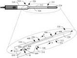
- FIGS. 1 and 2show an example probe 102 configured for using water as an acoustic medium.
- the probe 102includes an elongate shaft 104 extending from a handle region 106 .
- a port 108 located at the handle region 106interfaces with a hollow path 110 that runs inside of the probe 102 through elongate shaft 104 to an opening 112 at a tip region 114 of the shaft 104 .
- a connector 202 at the end of a tube 204is connected to the port 108 .
- the other end of the tube 204is connected, through a valve 206 , to a syringe 208 .
- an expandable sheath 210(balloon/water standoff) is placed over the elongate shaft 104 and, in this example, part of the handle 103 .
- An elastic band 212secures the sheath 210 to the probe 102 .
- the elongate shaft 104is then inserted into the cavity.
- the valve 206is opened, and the syringe 208 is used to pump water into the sheath 210 via water from the syringe 208 and egressing through the opening 112 .
- the valve 206is closed. The examination is performed with water as the acoustic medium.
- the probe 102Before using the probe 102 for such an examination, the probe 102 is cleaned, disinfected, sterilized or the like. Any debris (e.g., fecal matter from a colorectal examination) on the probe, e.g., in the hollow path 110 , can contaminate the hollow path 110 and/or the tip region 114 .
- the wateris removed from the cavity by disconnecting the syringe 208 and opening the valve 206 , letting the water egress from the cavity out of the tube 204 .
- the hollow path 110is entirely inside of the probe 102 , with exception of the end at the port 108 and the opening 112 .
- the majority of the hollow path 110is not readily accessible and/or may be difficult to clean, disinfect, sterilize, etc. for subsequent use for another examination.
- a protective covercannot be placed over the hallow path 110 because it would prevent ingress of the water into the sheath 210 .
- any debrise.g., fecal matter from a colorectal examination
- any debrise.g., fecal matter from a colorectal examination
- contamination of the hollow path 110 and/or the tip region 114can transfer to the cavity of a subsequent patient, which may lead to infection. At least in view of the foregoing, there is an unresolved need for another approach.
- a systemin one aspect, includes an ultrasound imaging probe with an elongate shaft including an outer perimeter housing, two ends and a long axis.
- the systemfurther includes a channel that extends along the direction of the long axis, is part of the outer perimeter housing, and is configured as a recess of the outer perimeter housing.
- the systemfurther includes a handle affixed to one of the ends of the elongate shaft.
- the systemfurther includes a transducer array disposed at another of the ends of the elongate shaft.
- the transducer arrayincludes one or more transducer elements.
- a methodin another aspect, includes receiving an acoustic fluid at one end of tubing installed in a recessed channel of an outer surface of an end of an elongate ultrasound imaging probe inserted into a cavity of a subject. The method further includes routing the acoustic fluid through the shaft via the tubing. The method further includes expelling the fluid routed through the shaft into the cavity.
- an ultrasound imaging probein another aspect, includes a tubular section with a long axis and a recess extending along the long axis.
- the recesshas a depth and a width.
- the ultrasound imaging probefurther includes a first end portion affixed to a first end of the tubular section.
- the ultrasound imaging probefurther includes a second end portion affixed to a second opposing end of the tubular section.
- the ultrasound imaging probefurther includes one or more transducer elements disposed at one of the first or second end portions.
- FIGS. 1 and 2illustrate a prior art ultrasound probe with an internal hollow path for routing an acoustic medium from outside of a cavity of a patient to inside of the cavity between the transducer array and the contact area of the cavity;
- FIG. 3schematically illustrates an example ultrasound imaging system with a recess in the housing for holding tubing for routing an acoustic medium from outside of a cavity of a patient to inside of the cavity between the transducer array and the contact area of the cavity;
- FIG. 4illustrate a perspective view of an example of the probe of FIG. 3 ;
- FIG. 5illustrate a side view of the probe of FIG. 4 ;
- FIG. 6illustrate a top down view of the probe of FIG. 4 , showing the recess
- FIG. 7describes an example method in accordance with an embodiment described herein
- FIG. 8schematically illustrates a sub-portion of the probe showing the recess without tubing installed therein;
- FIG. 9schematically illustrates the sub-portion of the probe of FIG. 8 showing the tubing being installed in the recess;
- FIG. 10schematically illustrates the sub-portion of the probe of FIG. 8 showing the tubing being installed in the recess over a sheath;
- FIG. 11shows further tubing removable connected to the tubing of FIG. 10 ;
- FIGS. 12A, 12B and 12Cschematically illustrate example geometry of the recess and installation of tubing therein;
- FIGS. 13A, 13B and 13Cschematically illustrate another example of geometry of the recess and installation of tubing therein;
- FIGS. 14A, 14B and 14Cschematically illustrate yet another example of geometry of the recess and installation of tubing therein.
- FIG. 15illustrates an example of the ultrasound imaging system.
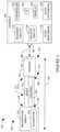
- FIG. 3schematically illustrates an imaging system 302 such as ultrasound imaging system.
- the imaging system 302includes an ultrasound imaging probe 304 and a console 306 .
- the ultrasound imaging probe 304 and the console 306include complementary communication interfaces 303 and 305 , which are configured for wireless and/or wired communication between the ultrasound imaging probe 304 and the console 306 over a communication path 308 .
- the probe 304in one instance, is configured as a natural orifice probe, which includes probes configured for insertion into a cavity of the body by way of a natural orifice of the body (e.g., anus, vagina, esophagus, eye, ear, nasal cavity, etc.). Additionally or alternatively, the probe 304 is configured for insertion through a non-natural orifice of the body (e.g., an incision, etc.).
- An example probeis the Type 2052 and the Type 8838, both products of BK-Medical ApS, Herlev, DK, which is a wholly owned subsidiary of Analogic Corporation, MA, USA.
- the ultrasound imaging probe 304includes a handle region 310 and an elongate shaft 312 .
- a first side 314 of the handle region 310includes the communication interface 303 .
- a second side 314 of the handle region 310is affixed to the elongate shaft 312 .
- the elongate shaft 312includes a first end region 316 affixed to the handle region 310 and a second end or tip region 318 , located opposite the first end region 314 along a long axis 320 of the probe 304 and the elongate shaft 312 .
- a transducer array 322with a one-dimensional (1-D) or two-dimensional (2-D) array of transducer elements 324 , is disposed at the second end or tip region 318 and can be considered as part of a tip of the shaft 312 .
- the transducer array 322includes one or more transducer elements 324 .
- the transducer elements 324are configured to transmit ultrasound signals and receive echo signals. Suitable configurations include, but are not limited to, single element, linear array, curved array, phased array, etc.
- the transducer array 322can be fully populated or sparse, square, circular, irregular, etc.
- the probe 304further includes a channel 326 with first and second end regions 328 and 330 .
- the channel 326is part of an outer perimeter housing 331 of the probe 304 and is configured as a recess in at least the outer perimeter housing 331 .
- the channel 326extends to also be part of at least the handle end 310 of the probe 304 .
- the channel 326is an open recess (e.g., open to the ambient environment) and not enclosed inside of the shaft 312 or other parts of the probe 304 .
- Such a configurationrenders the channel 326 easier to clean, disinfect, and/or sterilize, relative to a configuration in which the channel is enclosed inside the probe 304 . It is also possible to use a cover as the tube is on the outside.
- the channel 326is geometrically configured to receive an instrument such as tubing configured to route a fluid, such as water, from outside of a cavity of a subject or object, into which the shaft 312 is inserted, to inside of the cavity.
- a fluidsuch as water
- Such fluidcan be used to fill and expand an elastic expandable container such as a balloon, standoff, etc. installed over the shaft 312 in the cavity or is applied directly in the cavity, e.g., in connection with a live water injection procedure.
- the fluidprovides an acoustic medium for ultrasound signals between the transducer elements 324 of the transducer array 322 and the tissue inside of the cavity.
- Other instrumentsare also contemplated herein.
- the console 306includes transmit circuitry 332 configured to generate a set of radio frequency (RF) pulses that are conveyed to the transducer array 322 .
- the set of pulsesactuates a corresponding set of the transducer elements 324 , causing one or more sets of the elements 324 to transmit ultrasound signals into an examination or scan field of view.
- RFradio frequency
- the console 306further includes receive circuitry 334 configured to receive echoes (RF signals) generated in response to the transmitted ultrasound signals from the transducer array 322 .
- the echoesgenerally, are a result of the interaction between the emitted ultrasound signals and the structure (e.g., flowing blood cells, organ cells, etc.) in the scan field of view.
- the console 306further includes an echo processor 336 that processes received echoes. Such processing may include applying time delays, weighting on the channels, summing, and/or otherwise beamforming received echoes. Other processing may lower speckle, improve specular reflector delineation, and/or includes FIR filtering, IIR filtering, etc.
- the echo processor 336For B-mode, the echo processor 336 generates a sequence of focused, coherent echo samples along focused scanlines of a scanplane.
- the console 306further includes a scan converter 338 that scan converts the frames of data to generate data for display, for example, by converting the data to the coordinate system of a display 340 , which may be integrated with the console (as shown) or a separate device therefrom.
- the scan converter 338can use analog and/or digital scan converting techniques.
- the console 306further includes a user interface (UI) 342 with one or more input devices (e.g., a button, a knob, a touchscreen, etc.) and/or one or more output devices (e.g., the display 340 , communication ports, etc.), which allows for interaction with the system 302 .
- UIuser interface
- input devicese.g., a button, a knob, a touchscreen, etc.
- output devicese.g., the display 340 , communication ports, etc.
- the console 306further includes a controller 344 that controls at least one of transducer array 322 , the element(s) 324 , the transmit circuit 332 , the receive circuit 334 , the echo processor 336 , the scan converter 338 , the display 340 or the user interface 342 .
- At least one of the components of the console 306can be implemented by a processor (e.g., a microprocessor, a central processing unit, etc.) executing computer readable instructions encoded, embedded, stored, etc. on non-transitory computer readable storage medium such as physical memory.
- the at least one of the componentsis implemented by the processor executing computer readable instructions carried by a signal, carrier medium and/or other transitory computer readable storage medium.
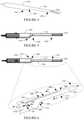
- FIGS. 4, 5 and 6show an example of the probe 304 .
- FIG. 4shows a perspective view of the probe 304 .
- FIG. 5shows a side view of the probe 304 .
- FIG. 6shows a top down view of the probe 304 , including a magnified sub-portion of the probe 304 , showing an example of the channel 326 of the probe 304 in a perspective view.
- the channel 326extends along the long axis 320 from the 314 / 328 interface toward the end region 318 .
- the channelincludes a floor 602 and side walls 604 .
- the floor 602is concave shaped and the side walls 604 are planar. In other embodiments, the floor 602 and/or the side walls 604 are otherwise shaped.
- FIGS. 12A, 12B and 12Ca cross sectional view along line A-A showing a concave floor 602 and planar side walls 604 is illustrated.
- a depth “D” and a width “W” of the channel 326is the same (within a predetermined tolerance) from the 314 / 328 interface up to a region 606 .
- D and/or Wcan vary along this extent.
- the depthdecreases as the floor 602 in the channel 326 rises or inclines up to a surface 608 of the out perimeter housing 331 where there is no longer a recess in the outer perimeter housing 331 .
- the rise in the floor 602can be linear and/or non-linear, continuous and/or stepped, abrupt and/or gradual, etc. In a variation, this portion of the floor 602 does not rise.
- the channel 326also extends from the 314 / 328 interface through the handle 310 to an opening 609 at a side 610 of the handle 310 .
- the channel 326ends at the 314 / 328 interface or elsewhere.
- this portion of the channel 326first extends linearly through the handle 310 and then curves to the side 610 of the handle 310 .
- D and Ware the same through the shaft 312 and the handle 310 .
- the geometry of the channel 326 in the handle 310can be different, e.g., non-linear portion, an irregular portion, different D and/or W, etc.
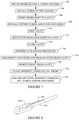
- FIG. 7illustrates a method for employing the probe 304 in connection with a colorectal procedural.
- FIGS. 8, 9, 10 and 11are referenced for graphical illustration.
- FIG. 8shows an example of a sub-portion of the probe 304 , showing the handle 310 , the shaft 312 , and the channel 326 .
- tubingis installed in the channel 326 .
- FIG. 9shows an example in which tubing 902 , which includes a valve 904 and a connector 906 , is installed directly into the channel 326 .
- FIG. 10shows an example in which a sheath 1002 is first installed over the shaft 312 and then the tubing 902 is installed in the channel 326 over the sheath 1002 .
- a sheathballoon, water standoff, etc.
- the probe shaft 312is inserted into the rectum.
- FIG. 10shows the shaft 312 inserted into a cavity 1102 inside of a human being (e.g., the rectum).
- FIG. 11shows further tubing 1104 removably connected to the port 906 and a depressible container 1106 holding a fluid 1108 .
- the probe 304 , the tubings 902 and 1104 , and the container 1106are referred to herein as system 1100 .
- FIG. 10shows the rotational movement of the valve 9004 to open the valve 904 .
- the depressible container 1106is actuated which pushes the fluid 1108 through the tubings 1104 and 902 to the cavity 1102 .
- FIG. 11shows a user squeezing the depressible container 1106 to push the fluid 1108 .
- valve 904is closed.
- an ultrasound procedureis performed.
- the container 1106(and/or further tubing 1104 ) is then disconnected from the port 906 and the valve 904 is opened, allowing the fluid 1108 in the cavity 1102 to egress out of the tubing 902 .
- the probe shaft 312is removed from the cavity 1102 .
- the probe 304including the channel 326 , is cleaned, disinfected, sterilized, etc. for another the procedure.
- tubings 902 and 1104 , sheath 1002 , and/or the container 1105are discarded or cleaned, disinfected, sterilized, etc.
- FIG. 12Ashows the cross section of the shaft 312 along line A-A of FIG. 6 without the tubing 902 installed in the channel 326 and with the cover 1002 over the channel 326 .
- FIG. 12Bshows the cross section with the tubing 902 partially installed in the channel 326 . In this example, installing the tubing 902 in the channel 326 pushes the cover into the channel 326 .
- FIG. 12Cshows the cross section with the tubing 902 installed in the channel 326 . In FIG. 12C , the tubing rests against the floor 602 and the side walls 604 with the cover 1002 therebetween.
- Dis greater than a diameter of the tubing 902 and W is the same or slightly larger (e.g., 0-100 microns) than the diameter of the tubing 902 .
- FIGS. 13A, 13B and 13Cshow a variation in which the side walls 604 include an arc portion 1302 .
- a distance 1304 between ends of the arc portion 1302is less than the diameter of the tubing 902 .
- the tubing 902is deformed (e.g., compressed) as the tubing 902 passes the ends of the arc portion 1302 when being installed in the channel 326 , although it still pushes the cover 1002 into the channel 326 .
- Installing the tubing 902is this example requires the user to urge (e.g., push) the tubing 902 passed the ends of the arc portion 1302 .
- Once inside the channel 326as shown in FIG.
- the tubing shapereturns and the ends of the arc portion 1302 inhibit the tubing 902 from coming out of the channel 326 on its own.
- the userurges (e.g., but this time pulls) the tubing 902 passed the ends of the arc portion 1302 .
- FIGS. 14A, 14B and 14Cshow another variation.
- the side walls 604are planar as shown in FIGS. 6, 12A -C and 13 A-C, and the floor 602 is also planar, and not arc shaped.
- This variationfurther includes features such as nubs 1402 along the side walls 604 .
- the illustrated location, size, number, etc. of nubs 1402is for illustrative purposes. That is in other variations other locations, above and below the illustrated location along the depth, large or smaller nubs 1402 , only a single nub 1402 on one side or multiple on both sides, etc. are contemplated.
- a distance 1403 between the nubs 1402is less than the diameter of the tubing 902 . As such, as shown in FIG.
- the tubing 902is deformed as the tubing 902 passes the nubs 1402 when being installed in the channel 326 , e.g., when pushed into the channel 326 .
- the nubs 1402secure the tubing 902 in place with the cover 1002 between the tubing 902 and the nubs 1402 .
- the useragain urges (e.g., but this time pulls) the tubing 902 passed the nubs 1402 .
- FIGS. 14A-Ccould have the side walls 604 that are convex in place of or in addition to the nubs 1402 , where the minimum distance between the side walls 604 is less than the diameter of the tubing 902 .
- Other features besides nubsare also contemplated herein.
- another featureis a tacky surface of the floor 602 and/or walls 604 .
- Another featureis a set screw or the like.
- Another featureis an elastic band.
- Another featureis a mechanical door that opens and closes.
- Another featureis the tubing 902 itself, which expands when filed with the fluid 1108 to make the diameter of the tubing 902 large than the opening and/or width of the channel 326 . Still other combinations, variations and/or other features are contemplated herein.
- FIG. 15illustrates an example of the ultrasound imaging system 302 with the probe 304 with the channel 326 in the shaft 312 .
- the display 340 and the console 306are separate devices attached to a mobile cart 1502 , which includes a base 1504 with movers 1506 such as wheels, casters, etc.
- a portable energy source 1508such as a rechargeable and/or non-rechargeable battery pack and/or other source supplies power for the system 302 .
- a probe support 1510is affixed to the cart 1502 and supports at least the probe 304 .
- a cable 1514extends from the handle 310 to a probe interface 1516 of the console 306 .
- the ultrasound imaging system 302rests on a table, desk, etc., and does not include movers and is not attached to a cart.
Landscapes
- Health & Medical Sciences (AREA)
- Life Sciences & Earth Sciences (AREA)
- Surgery (AREA)
- Physics & Mathematics (AREA)
- General Health & Medical Sciences (AREA)
- Molecular Biology (AREA)
- Pathology (AREA)
- Radiology & Medical Imaging (AREA)
- Nuclear Medicine, Radiotherapy & Molecular Imaging (AREA)
- Engineering & Computer Science (AREA)
- Biomedical Technology (AREA)
- Heart & Thoracic Surgery (AREA)
- Medical Informatics (AREA)
- Veterinary Medicine (AREA)
- Animal Behavior & Ethology (AREA)
- Biophysics (AREA)
- Public Health (AREA)
- Optics & Photonics (AREA)
- Acoustics & Sound (AREA)
- Gynecology & Obstetrics (AREA)
- Ultra Sonic Daignosis Equipment (AREA)
Abstract
Description
Claims (23)
Applications Claiming Priority (1)
| Application Number | Priority Date | Filing Date | Title |
|---|---|---|---|
| PCT/IB2015/054836WO2016207701A1 (en) | 2015-06-26 | 2015-06-26 | Ultrasound imaging probe with an instrument channel |
Publications (2)
| Publication Number | Publication Date |
|---|---|
| US20180185007A1 US20180185007A1 (en) | 2018-07-05 |
| US11246566B2true US11246566B2 (en) | 2022-02-15 |
Family
ID=53762236
Family Applications (1)
| Application Number | Title | Priority Date | Filing Date |
|---|---|---|---|
| US15/739,295Active2037-08-17US11246566B2 (en) | 2015-06-26 | 2015-06-26 | US imaging probe with an instrument channel |
Country Status (2)
| Country | Link |
|---|---|
| US (1) | US11246566B2 (en) |
| WO (1) | WO2016207701A1 (en) |
Families Citing this family (5)
| Publication number | Priority date | Publication date | Assignee | Title |
|---|---|---|---|---|
| US11246566B2 (en)* | 2015-06-26 | 2022-02-15 | B-K Medical Aps | US imaging probe with an instrument channel |
| US20240008855A1 (en)* | 2015-09-08 | 2024-01-11 | Advanced Tactile Imaging Inc. | Tactile ultrasound method and probe for predicting spontaneous preterm birth |
| US12220116B2 (en)* | 2018-12-19 | 2025-02-11 | Teikyo University | Blood vessel harvesting system |
| DE102019105438A1 (en)* | 2019-03-04 | 2020-09-10 | Jürgen Kress | Endoscope with quick-change tubing |
| WO2020183226A1 (en)* | 2019-03-12 | 2020-09-17 | B-K Medical Aps | Ultrasound-guided transperineal and/or transrectal biopsy |
Citations (52)
| Publication number | Priority date | Publication date | Assignee | Title |
|---|---|---|---|---|
| US3760810A (en)* | 1970-12-11 | 1973-09-25 | Hoorn M Van | Surgical ligating instrument of the endoscope type |
| US4327738A (en)* | 1979-10-19 | 1982-05-04 | Green Philip S | Endoscopic method & apparatus including ultrasonic B-scan imaging |
| US4646722A (en)* | 1984-12-10 | 1987-03-03 | Opielab, Inc. | Protective endoscope sheath and method of installing same |
| US4815470A (en)* | 1987-11-13 | 1989-03-28 | Advanced Diagnostic Medical Systems, Inc. | Inflatable sheath for ultrasound probe |
| US4823812A (en)* | 1986-05-12 | 1989-04-25 | Biodan Medical Systems Ltd. | Applicator for insertion into a body opening for medical purposes |
| US4877033A (en)* | 1988-05-04 | 1989-10-31 | Seitz Jr H Michael | Disposable needle guide and examination sheath for transvaginal ultrasound procedures |
| US4944287A (en)* | 1988-03-29 | 1990-07-31 | Asahi Kogaku Kogyo K.K. | Flexible tube of endoscope |
| US4974590A (en)* | 1988-05-18 | 1990-12-04 | Olympus Optical Co., Ltd. | Ultrasonic probe for use in ultrasonic endoscope |
| USRE34110E (en)* | 1988-04-22 | 1992-10-27 | Opielab, Inc. | Endoscope for use with a disposable sheath |
| US5193525A (en)* | 1990-11-30 | 1993-03-16 | Vision Sciences | Antiglare tip in a sheath for an endoscope |
| US5207213A (en)* | 1991-02-01 | 1993-05-04 | Circon Corporation | Laparoscope having means for removing image impeding material from a distal lens |
| US5349941A (en)* | 1993-03-26 | 1994-09-27 | Oktas | Cleanable endoscope |
| US5471988A (en)* | 1993-12-24 | 1995-12-05 | Olympus Optical Co., Ltd. | Ultrasonic diagnosis and therapy system in which focusing point of therapeutic ultrasonic wave is locked at predetermined position within observation ultrasonic scanning range |
| US5830127A (en)* | 1996-08-05 | 1998-11-03 | Cybersonics, Inc. | Method and apparatus for cleaning endoscopes and the like |
| US5944654A (en)* | 1996-11-14 | 1999-08-31 | Vista Medical Technologies, Inc. | Endoscope with replaceable irrigation tube |
| US6036649A (en)* | 1997-06-17 | 2000-03-14 | Kabushiki Kaisha Toshiba | Ultrasound probe |
| US6053934A (en)* | 1997-06-02 | 2000-04-25 | Cook Urological, Incorporated | Replaceable, medical device handle |
| US6126607A (en)* | 1997-11-03 | 2000-10-03 | Barzell-Whitmore Maroon Bells, Inc. | Ultrasound interface control system |
| US6261234B1 (en)* | 1998-05-07 | 2001-07-17 | Diasonics Ultrasound, Inc. | Method and apparatus for ultrasound imaging with biplane instrument guidance |
| US6340344B1 (en)* | 2000-07-18 | 2002-01-22 | Evergreen Medical Incorporated | Endoscope with a removable suction tube |
| US6443902B1 (en)* | 1998-01-07 | 2002-09-03 | B-K Medical A/S | Ultrasound probe with a detachable needle guide, for collecting tissue samples |
| US6511427B1 (en)* | 2000-03-10 | 2003-01-28 | Acuson Corporation | System and method for assessing body-tissue properties using a medical ultrasound transducer probe with a body-tissue parameter measurement mechanism |
| US20030036681A1 (en)* | 2001-06-29 | 2003-02-20 | Aviv Jonathan E. | Optical transesophageal echocardiography probe |
| US6533720B1 (en)* | 2001-01-17 | 2003-03-18 | Avtar S. Dhindsa | Modular endoscope valve assembly and method |
| US20030171678A1 (en)* | 2002-03-11 | 2003-09-11 | Batten Bobby G. | System for examining, mapping, diagnosing and treating diseases of the prostate |
| US6626855B1 (en)* | 1999-11-26 | 2003-09-30 | Therus Corpoation | Controlled high efficiency lesion formation using high intensity ultrasound |
| US20040084070A1 (en)* | 2002-09-13 | 2004-05-06 | Katsumi Sasaki | Cleaning device for medical instrument |
| US20040234924A1 (en)* | 2002-11-15 | 2004-11-25 | Teresa Hickok | Waterguide design and method and tube assembly for use therewith |
| US20050027165A1 (en)* | 2003-04-07 | 2005-02-03 | Jean Rovegno | Removable operating device for a flexible endoscopic probe for medical purposes |
| US20050085803A1 (en)* | 2003-10-17 | 2005-04-21 | Olympus Corporation | Ultrasonic-treatment handpiece with heat/vibration blocking structure and ultrasonic treatment apparatus using the handpiece |
| US20060258908A1 (en)* | 2005-05-13 | 2006-11-16 | David Stefanchik | Sheath for use with an endoscope |
| US20070066990A1 (en)* | 2005-09-19 | 2007-03-22 | Andrew Marsella | Device for forming a fluid tight seal during a procedure within a hollow organ |
| US20080064962A1 (en) | 2006-09-07 | 2008-03-13 | Kabushiki Kaisha Toshiba | Puncture adapter and an ultrasonic probe, and the method of using the same |
| US20080249416A1 (en)* | 2007-04-05 | 2008-10-09 | Olympus Medical Systems Corp. | Treatment instrument system |
| US20090036773A1 (en)* | 2007-07-31 | 2009-02-05 | Mirabilis Medica Inc. | Methods and apparatus for engagement and coupling of an intracavitory imaging and high intensity focused ultrasound probe |
| US20090118729A1 (en)* | 2007-11-07 | 2009-05-07 | Mirabilis Medica Inc. | Hemostatic spark erosion tissue tunnel generator with integral treatment providing variable volumetric necrotization of tissue |
| US7615005B2 (en)* | 2003-05-16 | 2009-11-10 | Ethicon Endo-Surgery, Inc. | Medical apparatus for use with an endoscope |
| US20100179416A1 (en)* | 2009-01-14 | 2010-07-15 | Michael Hoey | Medical Systems and Methods |
| US7762949B2 (en)* | 2003-10-16 | 2010-07-27 | Granit Medical Innovation, Llc | Endoscope with open channels |
| US7811265B2 (en)* | 2000-11-24 | 2010-10-12 | Innovacell Biotechnologie Gmbh | Ultrasonic probe with positioning device for examination devices and operation devices |
| US7815565B2 (en)* | 2003-05-16 | 2010-10-19 | Ethicon Endo-Surgery, Inc. | Endcap for use with an endoscope |
| US20110160514A1 (en)* | 2009-12-31 | 2011-06-30 | Ethicon Endo-Surgery, Inc. | Electrical ablation devices |
| US8007432B2 (en)* | 2007-01-26 | 2011-08-30 | Ethicon Endo-Surgery, Inc. | Endoscopic accessory control mechanism |
| US8100882B2 (en)* | 2004-05-14 | 2012-01-24 | Ethicon Endo-Surgery, Inc. | Guidewire structure |
| US20120116222A1 (en)* | 2010-06-17 | 2012-05-10 | Olympus Medical Systems Corp. | Ultrasound treatment system and method of actuating the ultrasound treatment system |
| US20120209114A1 (en)* | 2009-04-22 | 2012-08-16 | Region Nordjylland, Aalborg Sygehus | Device for holding an imaging probe and use of such device |
| US20130006236A1 (en)* | 2009-04-24 | 2013-01-03 | Greep Darcy W | Electrosurgical instrument with adjustable utility conduit |
| US20150057646A1 (en)* | 2009-03-06 | 2015-02-26 | Procept Biorobotics Corporation | Automated image-guided tissue resection and treatment |
| US9861336B2 (en)* | 2012-09-07 | 2018-01-09 | Gynesonics, Inc. | Methods and systems for controlled deployment of needle structures in tissue |
| US20180116495A1 (en)* | 2016-10-31 | 2018-05-03 | Cook Medical Technologies Llc | High-pressure endoscope cleaning device |
| US9999430B2 (en)* | 2012-01-19 | 2018-06-19 | Stryker European Holdings I, Llc | Guide sleeve for suprapatellar surgery |
| US20180185007A1 (en)* | 2015-06-26 | 2018-07-05 | B-K Medical Aps | Us imaging probe with an instrument channel |
- 2015
- 2015-06-26USUS15/739,295patent/US11246566B2/enactiveActive
- 2015-06-26WOPCT/IB2015/054836patent/WO2016207701A1/ennot_activeCeased
Patent Citations (55)
| Publication number | Priority date | Publication date | Assignee | Title |
|---|---|---|---|---|
| US3760810A (en)* | 1970-12-11 | 1973-09-25 | Hoorn M Van | Surgical ligating instrument of the endoscope type |
| US4327738A (en)* | 1979-10-19 | 1982-05-04 | Green Philip S | Endoscopic method & apparatus including ultrasonic B-scan imaging |
| US4646722A (en)* | 1984-12-10 | 1987-03-03 | Opielab, Inc. | Protective endoscope sheath and method of installing same |
| US4823812A (en)* | 1986-05-12 | 1989-04-25 | Biodan Medical Systems Ltd. | Applicator for insertion into a body opening for medical purposes |
| US4815470A (en)* | 1987-11-13 | 1989-03-28 | Advanced Diagnostic Medical Systems, Inc. | Inflatable sheath for ultrasound probe |
| US4944287A (en)* | 1988-03-29 | 1990-07-31 | Asahi Kogaku Kogyo K.K. | Flexible tube of endoscope |
| USRE34110E (en)* | 1988-04-22 | 1992-10-27 | Opielab, Inc. | Endoscope for use with a disposable sheath |
| US4877033A (en)* | 1988-05-04 | 1989-10-31 | Seitz Jr H Michael | Disposable needle guide and examination sheath for transvaginal ultrasound procedures |
| US4974590A (en)* | 1988-05-18 | 1990-12-04 | Olympus Optical Co., Ltd. | Ultrasonic probe for use in ultrasonic endoscope |
| US5193525A (en)* | 1990-11-30 | 1993-03-16 | Vision Sciences | Antiglare tip in a sheath for an endoscope |
| US5207213A (en)* | 1991-02-01 | 1993-05-04 | Circon Corporation | Laparoscope having means for removing image impeding material from a distal lens |
| US5349941A (en)* | 1993-03-26 | 1994-09-27 | Oktas | Cleanable endoscope |
| US5471988A (en)* | 1993-12-24 | 1995-12-05 | Olympus Optical Co., Ltd. | Ultrasonic diagnosis and therapy system in which focusing point of therapeutic ultrasonic wave is locked at predetermined position within observation ultrasonic scanning range |
| US5830127A (en)* | 1996-08-05 | 1998-11-03 | Cybersonics, Inc. | Method and apparatus for cleaning endoscopes and the like |
| US5944654A (en)* | 1996-11-14 | 1999-08-31 | Vista Medical Technologies, Inc. | Endoscope with replaceable irrigation tube |
| US6053934A (en)* | 1997-06-02 | 2000-04-25 | Cook Urological, Incorporated | Replaceable, medical device handle |
| US6036649A (en)* | 1997-06-17 | 2000-03-14 | Kabushiki Kaisha Toshiba | Ultrasound probe |
| US6126607A (en)* | 1997-11-03 | 2000-10-03 | Barzell-Whitmore Maroon Bells, Inc. | Ultrasound interface control system |
| US6443902B1 (en)* | 1998-01-07 | 2002-09-03 | B-K Medical A/S | Ultrasound probe with a detachable needle guide, for collecting tissue samples |
| US6261234B1 (en)* | 1998-05-07 | 2001-07-17 | Diasonics Ultrasound, Inc. | Method and apparatus for ultrasound imaging with biplane instrument guidance |
| US6626855B1 (en)* | 1999-11-26 | 2003-09-30 | Therus Corpoation | Controlled high efficiency lesion formation using high intensity ultrasound |
| US6511427B1 (en)* | 2000-03-10 | 2003-01-28 | Acuson Corporation | System and method for assessing body-tissue properties using a medical ultrasound transducer probe with a body-tissue parameter measurement mechanism |
| US6340344B1 (en)* | 2000-07-18 | 2002-01-22 | Evergreen Medical Incorporated | Endoscope with a removable suction tube |
| US6585642B2 (en)* | 2000-07-18 | 2003-07-01 | Evergreen Medical Incorporated | Endoscope with a removable suction tube |
| US7811265B2 (en)* | 2000-11-24 | 2010-10-12 | Innovacell Biotechnologie Gmbh | Ultrasonic probe with positioning device for examination devices and operation devices |
| US6533720B1 (en)* | 2001-01-17 | 2003-03-18 | Avtar S. Dhindsa | Modular endoscope valve assembly and method |
| US20030036681A1 (en)* | 2001-06-29 | 2003-02-20 | Aviv Jonathan E. | Optical transesophageal echocardiography probe |
| US20030171678A1 (en)* | 2002-03-11 | 2003-09-11 | Batten Bobby G. | System for examining, mapping, diagnosing and treating diseases of the prostate |
| US20040084070A1 (en)* | 2002-09-13 | 2004-05-06 | Katsumi Sasaki | Cleaning device for medical instrument |
| US20040234924A1 (en)* | 2002-11-15 | 2004-11-25 | Teresa Hickok | Waterguide design and method and tube assembly for use therewith |
| US20050027165A1 (en)* | 2003-04-07 | 2005-02-03 | Jean Rovegno | Removable operating device for a flexible endoscopic probe for medical purposes |
| US7615005B2 (en)* | 2003-05-16 | 2009-11-10 | Ethicon Endo-Surgery, Inc. | Medical apparatus for use with an endoscope |
| US7815565B2 (en)* | 2003-05-16 | 2010-10-19 | Ethicon Endo-Surgery, Inc. | Endcap for use with an endoscope |
| US7762949B2 (en)* | 2003-10-16 | 2010-07-27 | Granit Medical Innovation, Llc | Endoscope with open channels |
| US20050085803A1 (en)* | 2003-10-17 | 2005-04-21 | Olympus Corporation | Ultrasonic-treatment handpiece with heat/vibration blocking structure and ultrasonic treatment apparatus using the handpiece |
| US8100882B2 (en)* | 2004-05-14 | 2012-01-24 | Ethicon Endo-Surgery, Inc. | Guidewire structure |
| US20060258908A1 (en)* | 2005-05-13 | 2006-11-16 | David Stefanchik | Sheath for use with an endoscope |
| US7905830B2 (en)* | 2005-05-13 | 2011-03-15 | Ethicon Endo-Surgery, Inc. | Sheath for use with an endoscope |
| US20070066990A1 (en)* | 2005-09-19 | 2007-03-22 | Andrew Marsella | Device for forming a fluid tight seal during a procedure within a hollow organ |
| US20080064962A1 (en) | 2006-09-07 | 2008-03-13 | Kabushiki Kaisha Toshiba | Puncture adapter and an ultrasonic probe, and the method of using the same |
| US8007432B2 (en)* | 2007-01-26 | 2011-08-30 | Ethicon Endo-Surgery, Inc. | Endoscopic accessory control mechanism |
| US20080249416A1 (en)* | 2007-04-05 | 2008-10-09 | Olympus Medical Systems Corp. | Treatment instrument system |
| US20090036773A1 (en)* | 2007-07-31 | 2009-02-05 | Mirabilis Medica Inc. | Methods and apparatus for engagement and coupling of an intracavitory imaging and high intensity focused ultrasound probe |
| US8052604B2 (en)* | 2007-07-31 | 2011-11-08 | Mirabilis Medica Inc. | Methods and apparatus for engagement and coupling of an intracavitory imaging and high intensity focused ultrasound probe |
| US20090118729A1 (en)* | 2007-11-07 | 2009-05-07 | Mirabilis Medica Inc. | Hemostatic spark erosion tissue tunnel generator with integral treatment providing variable volumetric necrotization of tissue |
| US20100179416A1 (en)* | 2009-01-14 | 2010-07-15 | Michael Hoey | Medical Systems and Methods |
| US20150057646A1 (en)* | 2009-03-06 | 2015-02-26 | Procept Biorobotics Corporation | Automated image-guided tissue resection and treatment |
| US20120209114A1 (en)* | 2009-04-22 | 2012-08-16 | Region Nordjylland, Aalborg Sygehus | Device for holding an imaging probe and use of such device |
| US20130006236A1 (en)* | 2009-04-24 | 2013-01-03 | Greep Darcy W | Electrosurgical instrument with adjustable utility conduit |
| US20110160514A1 (en)* | 2009-12-31 | 2011-06-30 | Ethicon Endo-Surgery, Inc. | Electrical ablation devices |
| US20120116222A1 (en)* | 2010-06-17 | 2012-05-10 | Olympus Medical Systems Corp. | Ultrasound treatment system and method of actuating the ultrasound treatment system |
| US9999430B2 (en)* | 2012-01-19 | 2018-06-19 | Stryker European Holdings I, Llc | Guide sleeve for suprapatellar surgery |
| US9861336B2 (en)* | 2012-09-07 | 2018-01-09 | Gynesonics, Inc. | Methods and systems for controlled deployment of needle structures in tissue |
| US20180185007A1 (en)* | 2015-06-26 | 2018-07-05 | B-K Medical Aps | Us imaging probe with an instrument channel |
| US20180116495A1 (en)* | 2016-10-31 | 2018-05-03 | Cook Medical Technologies Llc | High-pressure endoscope cleaning device |
Non-Patent Citations (1)
| Title |
|---|
| International Search Report for PCT/IB2015/054836 published as WO2016/207701A1 dated Dec. 29, 2016. |
Also Published As
| Publication number | Publication date |
|---|---|
| US20180185007A1 (en) | 2018-07-05 |
| WO2016207701A1 (en) | 2016-12-29 |
Similar Documents
| Publication | Publication Date | Title |
|---|---|---|
| US11246566B2 (en) | US imaging probe with an instrument channel | |
| JP7351972B2 (en) | Wireless intraluminal imaging devices and systems | |
| JP6661372B2 (en) | Reciprocating internal ultrasonic transducer assembly | |
| EP2164399B1 (en) | Wireless ultrasound probe cable | |
| JP7304344B2 (en) | Wireless Digital Patient Interface Module with Wireless Charging | |
| JP6069529B2 (en) | Diaphragm, head assembly and ultrasonic device | |
| US11583251B2 (en) | US imaging probe with an US transducer array and an integrated optical imaging sub-system | |
| EP1742580A1 (en) | Ultrasonic intracavity probe for 3d imaging | |
| KR20150012144A (en) | Acoustic probe, System including the same and Method of operationg thereof | |
| US20180214130A1 (en) | Compact fingertip-manipulated ultrasound imaging | |
| EP3589209B1 (en) | Intravascular ultrasound imaging | |
| US11883234B2 (en) | Probe cable support | |
| CN109310882B (en) | Ultrasound probe, ultrasound system and method for producing ultrasound images | |
| KR102704205B1 (en) | Ultrasound Probe, Ultrasound imaging apparatus including the same, and control method for the same | |
| CN113939233A (en) | Acoustic window with composite shape for ultrasound probe | |
| WO2008146207A2 (en) | Wireless ultrasound probe with heads-up display | |
| KR20150090636A (en) | Ultrasonci probe and ultrasonic diagnostic apparatus including the same | |
| EP3167807B1 (en) | Portable ultrasonic diagnostic device and method of improving power efficiency of such a device | |
| KR101893640B1 (en) | Cross-shaped or t-shaped ultrasonic probe and ultrasound diagnosis device thereof | |
| US10321847B2 (en) | Integrated tracking system for endocavity imaging | |
| CN203970418U (en) | Ultrasonic probe separation sleeve and ultrasonic testing system | |
| US20160235389A1 (en) | Us imaging apparatus with an antibacterial and/or an antimicrobial embedded in or on a surface thereof | |
| CN206836900U (en) | Has the Ultrasonic-B probe device of sterilizing function | |
| US20170209223A1 (en) | Instrument Annular Location Sensor | |
| CN118177922A (en) | Ultrasonic visual needle knife |
Legal Events
| Date | Code | Title | Description |
|---|---|---|---|
| AS | Assignment | Owner name:B-K MEDICAL APS, DENMARK Free format text:ASSIGNMENT OF ASSIGNORS INTEREST;ASSIGNORS:ANDERSEN, MARIANNE;JENSEN, HENRIK;PAEDE, JOHANNES;SIGNING DATES FROM 20150608 TO 20150615;REEL/FRAME:044470/0084 | |
| FEPP | Fee payment procedure | Free format text:ENTITY STATUS SET TO UNDISCOUNTED (ORIGINAL EVENT CODE: BIG.); ENTITY STATUS OF PATENT OWNER: LARGE ENTITY | |
| STPP | Information on status: patent application and granting procedure in general | Free format text:DOCKETED NEW CASE - READY FOR EXAMINATION | |
| STPP | Information on status: patent application and granting procedure in general | Free format text:RESPONSE TO NON-FINAL OFFICE ACTION ENTERED AND FORWARDED TO EXAMINER | |
| STPP | Information on status: patent application and granting procedure in general | Free format text:FINAL REJECTION MAILED | |
| STPP | Information on status: patent application and granting procedure in general | Free format text:ADVISORY ACTION MAILED | |
| STCV | Information on status: appeal procedure | Free format text:NOTICE OF APPEAL FILED | |
| STPP | Information on status: patent application and granting procedure in general | Free format text:NON FINAL ACTION MAILED | |
| STPP | Information on status: patent application and granting procedure in general | Free format text:NOTICE OF ALLOWANCE MAILED -- APPLICATION RECEIVED IN OFFICE OF PUBLICATIONS | |
| STPP | Information on status: patent application and granting procedure in general | Free format text:PUBLICATIONS -- ISSUE FEE PAYMENT RECEIVED | |
| STPP | Information on status: patent application and granting procedure in general | Free format text:PUBLICATIONS -- ISSUE FEE PAYMENT VERIFIED | |
| STCF | Information on status: patent grant | Free format text:PATENTED CASE | |
| MAFP | Maintenance fee payment | Free format text:PAYMENT OF MAINTENANCE FEE, 4TH YEAR, LARGE ENTITY (ORIGINAL EVENT CODE: M1551); ENTITY STATUS OF PATENT OWNER: LARGE ENTITY Year of fee payment:4 |