US11246479B2 - Integrated endoscope cleansing system - Google Patents
Integrated endoscope cleansing systemDownload PDFInfo
- Publication number
- US11246479B2 US11246479B2US17/267,508US201917267508AUS11246479B2US 11246479 B2US11246479 B2US 11246479B2US 201917267508 AUS201917267508 AUS 201917267508AUS 11246479 B2US11246479 B2US 11246479B2
- Authority
- US
- United States
- Prior art keywords
- ics
- ecs
- iecs
- endoscope
- iws
- Prior art date
- Legal status (The legal status is an assumption and is not a legal conclusion. Google has not performed a legal analysis and makes no representation as to the accuracy of the status listed.)
- Active
Links
Images


Classifications
- A—HUMAN NECESSITIES
- A61—MEDICAL OR VETERINARY SCIENCE; HYGIENE
- A61B—DIAGNOSIS; SURGERY; IDENTIFICATION
- A61B1/00—Instruments for performing medical examinations of the interior of cavities or tubes of the body by visual or photographical inspection, e.g. endoscopes; Illuminating arrangements therefor
- A61B1/012—Instruments for performing medical examinations of the interior of cavities or tubes of the body by visual or photographical inspection, e.g. endoscopes; Illuminating arrangements therefor characterised by internal passages or accessories therefor
- A61B1/015—Control of fluid supply or evacuation
- A—HUMAN NECESSITIES
- A61—MEDICAL OR VETERINARY SCIENCE; HYGIENE
- A61B—DIAGNOSIS; SURGERY; IDENTIFICATION
- A61B1/00—Instruments for performing medical examinations of the interior of cavities or tubes of the body by visual or photographical inspection, e.g. endoscopes; Illuminating arrangements therefor
- A61B1/00112—Connection or coupling means
- A61B1/00114—Electrical cables in or with an endoscope
- A—HUMAN NECESSITIES
- A61—MEDICAL OR VETERINARY SCIENCE; HYGIENE
- A61B—DIAGNOSIS; SURGERY; IDENTIFICATION
- A61B1/00—Instruments for performing medical examinations of the interior of cavities or tubes of the body by visual or photographical inspection, e.g. endoscopes; Illuminating arrangements therefor
- A61B1/00112—Connection or coupling means
- A61B1/00121—Connectors, fasteners and adapters, e.g. on the endoscope handle
- A61B1/00124—Connectors, fasteners and adapters, e.g. on the endoscope handle electrical, e.g. electrical plug-and-socket connection
- A—HUMAN NECESSITIES
- A61—MEDICAL OR VETERINARY SCIENCE; HYGIENE
- A61B—DIAGNOSIS; SURGERY; IDENTIFICATION
- A61B1/00—Instruments for performing medical examinations of the interior of cavities or tubes of the body by visual or photographical inspection, e.g. endoscopes; Illuminating arrangements therefor
- A61B1/00112—Connection or coupling means
- A61B1/00121—Connectors, fasteners and adapters, e.g. on the endoscope handle
- A61B1/00128—Connectors, fasteners and adapters, e.g. on the endoscope handle mechanical, e.g. for tubes or pipes
- A—HUMAN NECESSITIES
- A61—MEDICAL OR VETERINARY SCIENCE; HYGIENE
- A61B—DIAGNOSIS; SURGERY; IDENTIFICATION
- A61B1/00—Instruments for performing medical examinations of the interior of cavities or tubes of the body by visual or photographical inspection, e.g. endoscopes; Illuminating arrangements therefor
- A61B1/005—Flexible endoscopes
- A61B1/0051—Flexible endoscopes with controlled bending of insertion part
- A61B1/0052—Constructional details of control elements, e.g. handles
- A—HUMAN NECESSITIES
- A61—MEDICAL OR VETERINARY SCIENCE; HYGIENE
- A61B—DIAGNOSIS; SURGERY; IDENTIFICATION
- A61B1/00—Instruments for performing medical examinations of the interior of cavities or tubes of the body by visual or photographical inspection, e.g. endoscopes; Illuminating arrangements therefor
- A61B1/012—Instruments for performing medical examinations of the interior of cavities or tubes of the body by visual or photographical inspection, e.g. endoscopes; Illuminating arrangements therefor characterised by internal passages or accessories therefor
- A61B1/018—Instruments for performing medical examinations of the interior of cavities or tubes of the body by visual or photographical inspection, e.g. endoscopes; Illuminating arrangements therefor characterised by internal passages or accessories therefor for receiving instruments
- A—HUMAN NECESSITIES
- A61—MEDICAL OR VETERINARY SCIENCE; HYGIENE
- A61B—DIAGNOSIS; SURGERY; IDENTIFICATION
- A61B1/00—Instruments for performing medical examinations of the interior of cavities or tubes of the body by visual or photographical inspection, e.g. endoscopes; Illuminating arrangements therefor
- A61B1/04—Instruments for performing medical examinations of the interior of cavities or tubes of the body by visual or photographical inspection, e.g. endoscopes; Illuminating arrangements therefor combined with photographic or television appliances
- A61B1/05—Instruments for performing medical examinations of the interior of cavities or tubes of the body by visual or photographical inspection, e.g. endoscopes; Illuminating arrangements therefor combined with photographic or television appliances characterised by the image sensor, e.g. camera, being in the distal end portion
- A—HUMAN NECESSITIES
- A61—MEDICAL OR VETERINARY SCIENCE; HYGIENE
- A61B—DIAGNOSIS; SURGERY; IDENTIFICATION
- A61B1/00—Instruments for performing medical examinations of the interior of cavities or tubes of the body by visual or photographical inspection, e.g. endoscopes; Illuminating arrangements therefor
- A61B1/12—Instruments for performing medical examinations of the interior of cavities or tubes of the body by visual or photographical inspection, e.g. endoscopes; Illuminating arrangements therefor with cooling or rinsing arrangements
- A61B1/126—Instruments for performing medical examinations of the interior of cavities or tubes of the body by visual or photographical inspection, e.g. endoscopes; Illuminating arrangements therefor with cooling or rinsing arrangements provided with means for cleaning in-use
- A—HUMAN NECESSITIES
- A61—MEDICAL OR VETERINARY SCIENCE; HYGIENE
- A61B—DIAGNOSIS; SURGERY; IDENTIFICATION
- A61B1/00—Instruments for performing medical examinations of the interior of cavities or tubes of the body by visual or photographical inspection, e.g. endoscopes; Illuminating arrangements therefor
- A61B1/31—Instruments for performing medical examinations of the interior of cavities or tubes of the body by visual or photographical inspection, e.g. endoscopes; Illuminating arrangements therefor for the rectum, e.g. proctoscopes, sigmoidoscopes, colonoscopes
Definitions
- the present inventionin some embodiments thereof, relates to a body organ lumen cleaning system, and, more particularly, but not exclusively, to an integrated endoscope body organ lumen cleansing system (IECS).
- IECSintegrated endoscope body organ lumen cleansing system
- gastrointestinal processingalso adds new structure; for example, by aggregating digested particles, and by controlling stool water content.
- stoolis classified of a scale from 7 (completely liquid) to 1 (small hard lumps).
- Variables affecting the state of fecal aggregation and fluid content, as well as completeness of food digestion,include the frequency of defecation (normally ranging from five times a day to twice a week), and the speed at which food passes through the gastrointestinal tract (10 hours to 4 days is normal).
- Gut flora and secretions of the digestive tractalso become part of the stool.
- a colonoscopeprovides means for optically and/or electronically imaging the colon and its contents, for example, to look for cancerous and/or pre-cancerous polyps.
- a common practice before colonoscopyis to clear as much of a colon's contents as possible, sometimes by aggressive changes to diet and/or by administration of purgatives.
- imagingoccurs while flushing or washing a portion of the colon with an irrigating fluid. Irrigating fluid, fecal matter and/or other colon contents are drawn out of the colon by suction and/or other methods for transporting matter out of the body.
- the following patent applicationsrelate to the field of endeavor of the current application: U.S. Patent Application 2010/0185056 by Tal Gordon et al.; U.S. Patent Application 2011/0105845 by Tal Gordon et al.; and U.S. Patent Application 2012/0101336 by Yoav Hirsch et al.
- an integrated endoscope cleansing systemcomprising: an endoscope having: at least one insertion tube in communication with an endoscope working station (EWS), and at least one working channel functionally coupled to at least one endoscope cleaning system (ECS) vacuum source, wherein the EWS is configured to control the ECS vacuum source; and an independent cleansing system (ICS) having: an independent cleansing system working station (IWS), and having at least one ICS evacuation conduit located within at least the insertion tube and functionally coupled to an ICS vacuum source; wherein the IWS is configured to control the ICS vacuum source.
- EWSendoscope working station
- ICSindependent cleansing system having: an independent cleansing system working station (IWS), and having at least one ICS evacuation conduit located within at least the insertion tube and functionally coupled to an ICS vacuum source; wherein the IWS is configured to control the ICS vacuum source.
- the evacuation conduit and the working channel togethercomprise a single channel within the insert tube.
- the evacuation conduit and the working channeltogether comprise a single tube within the insert tube to which both the ICS vacuum source and the ECS vacuum source are functionally coupled.
- the IECScomprises at least one mode of operation consisting of at least one of: (a) ICS/ECS Master/Slave mode of operation; (b) ICS/ECS “Smart” Master/Slave mode of operation; and (c) ECS/ICS Master/Slave mode of operation.
- the IECScomprises at least one mode of operation toggle switch configured to toggle between at least two of the modes of operation.
- the IECSis configured for manual activation of at least one of the ECS and ICS.
- the IECSin the manual mode of operation, is configured to manually activate each of the ECS and ICS individually, sequentially or concurrently.
- the ICSin the ICS/ECS Master/Slave mode of operation, is activated and configured to automatically activate the ECS.
- At least one of the IWS and EWScomprises at least processor and at least one sensor configured to communicate at least one operating parameter to the processor.
- the at least one operating parametercomprises at least one of lumen pressure and flow of matter in a lumen of at least one of the working channel and evacuation conduit.
- the IWS processoris configured to receive and process the at least one operating parameter received from the EWS processor and automatically activate the ECS based on the received parameters.
- the EWS processorin the ECS/ICS Master/Slave mode of operation, is configured to receive and process the at least one operating parameter from the sensor and to automatically activate the ICS based on the received parameter.
- the endoscopecomprises a colonoscope.
- the insertion tubeis configured to receive IECS components associated with at least one operating function group.
- the at least one operating function groupcomprises at least one of: (a) an endoscope operating function group; (b) an ECS operating function group; and (c) an ICS operating function group.
- the endoscope operating function groupcomprises at least one of an endoscope angulation control navigation cable, light wiring and circuitry, power circuitry, image acquisition camera and circuitry and sensors and associated circuitry.
- the ECS operating function groupcomprises at least one suction/working channel and at least one irrigation and/or air/water supply tube.
- the ICS operating function groupcomprises at least one irrigation and/or air/water supply tube and at least one evacuation conduit.
- the IECScomprises an interface.
- the interfaceis configured to couple an umbilical cable originating from the IWS to the insertion tube.
- the umbilical cablecomprises at least one irrigation tube and at least one evacuation conduit.
- the umbilical cablecomprises sensor circuitry.
- the umbilical cableis disposable.
- the insertion tubecomprises at least one bendable portion.
- the bendable portioncomprises a resilient, braided and/or ribbed wall.
- tubes housed within the bendable portionare bendable in accordance with the bending of the bendable portion.
- the insertion tubecomprises a distal tip having at least one opening.
- the at least one openingcomprises at least one fluid jet nozzle.
- a method for a colonoscopy procedurecomprising providing an integrated endoscope cleansing system (IECS) comprising: an endoscope having: at least one mode of operation toggle switch and at least one insertion tube in communication with an endoscope working station (EWS), and at least one working channel functionally coupled to at least one endoscope cleaning system (ECS) vacuum source, wherein the EWS configured to control the ECS vacuum source; and an independent cleansing system (ICS) having: an independent cleansing system working station (IWS), and at least one ICS evacuation conduit located within at least the insertion tube and functionally coupled to an ICS vacuum source, wherein the IWS configured to control the ICS vacuum source; introducing the IECS insertion tube into a colon; and performing the colonoscopy procedure; wherein performing the colonoscopy procedure comprises adjusting the mode of operation toggle switch between a first and a second mode of operation during the colonoscopy procedure, and wherein the first and second modes differ in configuration of a source of
- the first and second modes of operationsare selected from among the group consisting of: (a) a manual mode of operation; (b) ICS/ECS Master/Slave mode of operation; (c) ICS/ECS “Smart” Master/Slave mode of operation; and (d) ECS/ICS Master/Slave mode of operation.
- the IECSin the manual mode of operation is configured for manual activation of at least one of the ECS and ICS.
- the ICSin the ICS/ECS Master/Slave mode of operation the ICS is activated and configured to automatically activate the ECS.
- At least one of the IWS and EWScomprises at least processor and at least one sensor configured to communicate at least one operating parameter to the processor.
- the at least one operating parametercomprises at least one of lumen pressure and flow of matter in a lumen of at least one of the working channel and evacuation conduit.
- the IWS processoris configured to receive and process the at least one operating parameter received from the EWS processor and automatically activate the ECS based on the received parameters.
- the EWS processorin the ECS/ICS Master/Slave mode of operation is configured to receive and process the at least one operating parameter from the sensor and to automatically activate the ICS based on the received parameter.
- adjusting the mode of operation toggle switchcomprises selecting the ICS/ECS Master/Slave mode of operation.
- the methodfurther comprises: activating the ICS; advancing the IECS through the colon up to a cecum while concurrently cleansing the colon with the ICS; and automatically activating the ECS by the ICS when needed throughout the advancement.
- the IECScomprises at least one image acquisition camera and circuitry and the method further comprising: upon reaching the cecum, adjusting the mode of operation toggle switch and selecting ECS/ICS Master/Slave mode of operation; activating image acquisition camera and circuitry; gradually retracting the IECS from the cecum; activating the ECS when needed; automatically activating ICS by ECS when needed; and removing the IECS from colon.
- some embodiments of the present inventionmay be embodied as a system, method or computer program product. Accordingly, some embodiments of the present invention may take the form of an entirely hardware embodiment, an entirely software embodiment (including firmware, resident software, micro-code, etc.) or an embodiment combining software and hardware aspects that may all generally be referred to herein as a “circuit,” “module” or “system.” Furthermore, some embodiments of the present invention may take the form of a computer program product embodied in one or more computer readable medium(s) having computer readable program code embodied thereon. Implementation of the method and/or system of some embodiments of the invention can involve performing and/or completing selected tasks manually, automatically, or a combination thereof. Moreover, according to actual instrumentation and equipment of some embodiments of the method and/or system of the invention, several selected tasks could be implemented by hardware, by software or by firmware and/or by a combination thereof, e.g., using an operating system.
- a data processorsuch as a computing platform for executing a plurality of instructions.
- the data processorincludes a volatile memory for storing instructions and/or data and/or a non-volatile storage, for example, a magnetic hard-disk and/or removable media, for storing instructions and/or data.
- a network connectionis provided as well.
- a display and/or a user input devicesuch as a keyboard or mouse are optionally provided as well.
- the computer readable mediummay be a computer readable signal medium or a computer readable storage medium.
- a computer readable storage mediummay be, for example, but not limited to, an electronic, magnetic, optical, electromagnetic, infrared, or semiconductor system, apparatus, or device, or any suitable combination of the foregoing.
- a computer readable storage mediummay be any tangible medium that can contain, or store a program for use by or in connection with an instruction execution system, apparatus, or device.
- a computer readable signal mediummay include a propagated data signal with computer readable program code embodied therein, for example, in baseband or as part of a carrier wave. Such a propagated signal may take any of a variety of forms, including, but not limited to, electro-magnetic, optical, or any suitable combination thereof.
- a computer readable signal mediummay be any computer readable medium that is not a computer readable storage medium and that can communicate, propagate, or transport a program for use by or in connection with an instruction execution system, apparatus, or device.
- Program code embodied on a computer readable medium and/or data used therebymay be transmitted using any appropriate medium, including but not limited to wireless, wireline, optical fiber cable, RF, etc., or any suitable combination of the foregoing.
- Computer program code for carrying out operations for some embodiments of the present inventionmay be written in any combination of one or more programming languages, including an object oriented programming language such as Java, Smalltalk, C++ or the like and conventional procedural programming languages, such as the “C” programming language or similar programming languages.
- the program codemay execute entirely on the user's computer, partly on the user's computer, as a stand-alone software package, partly on the user's computer and partly on a remote computer or entirely on the remote computer or server.
- the remote computermay be connected to the user's computer through any type of network, including a local area network (LAN) or a wide area network (WAN), or the connection may be made to an external computer (for example, through the Internet using an Internet Service Provider).
- LANlocal area network
- WANwide area network
- Internet Service Providerfor example, AT&T, MCI, Sprint, EarthLink, MSN, GTE, etc.
- These computer program instructionsmay also be stored in a computer readable medium that can direct a computer, other programmable data processing apparatus, or other devices to function in a particular manner, such that the instructions stored in the computer readable medium produce an article of manufacture including instructions which implement the function/act specified in the flowchart and/or block diagram block or blocks.
- the computer program instructionsmay also be loaded onto a computer, other programmable data processing apparatus, or other devices to cause a series of operational steps to be performed on the computer, other programmable apparatus or other devices to produce a computer implemented process such that the instructions which execute on the computer or other programmable apparatus provide processes for implementing the functions/acts specified in the flowchart and/or block diagram block or blocks.
- Some of the methods described hereinare generally designed only for use by a computer, and may not be feasible or practical for performing purely manually, by a human expert.
- a human expert who wanted to manually perform similar tasks, such as monitor fluid input and output, waste matter suction and similar,might be expected to use completely different methods, e.g., making use of expert knowledge and/or the pattern recognition capabilities of the human brain, which would be vastly more efficient than manually going through the steps of the methods described herein.
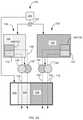
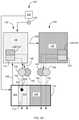
- FIG. 1is a plan view and simplified block diagram illustration of an integrated endoscope and cleaning system (IECS) in accordance with some embodiments of the invention
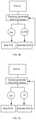
- FIGS. 2A-2Bare a simplified block diagrams of a mode of operation of IECS in accordance with some embodiments of the invention.
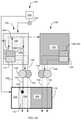
- FIGS. 3A, 3B and 3Care simplified block diagrams of a mode of operation of IECS in accordance with some embodiments of the invention.
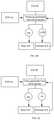
- FIGS. 4A, 4B and 4Care simplified block diagrams of a mode of operation of IECS in accordance with some embodiments of the invention.
- FIGS. 5A, 5B and 5Care simplified block diagrams of a mode of operation of IECS in accordance with some embodiments of the invention.
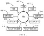
- FIG. 6is a simplified block diagram of an IECS mode of operation toggle switch in accordance with some embodiments of the invention.
- FIGS. 7A and 7Bare a simplified flow chart of implementation of IECS in a colonoscopy procedure in accordance with some embodiments of the invention.
- FIGS. 8A and 8Bare part block diagram, cross-section view, simplified illustrations of an IECS interface in accordance with some embodiments of the invention.
- FIG. 9is a cross-section view simplified illustration of IECS insertion tube in accordance with some embodiments of the invention.
- FIG. 10is a perspective view simplified illustration of an IECS endoscope insertion tube bendable portion in accordance with some embodiments of the invention.
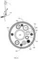
- FIG. 11is a perspective view simplified illustration of an IECS distal tip in accordance with some embodiments of the current invention.
- the present inventionin some embodiments thereof, relates to a body organ lumen cleaning system, and, more particularly, but not exclusively, to an integrated endoscope body organ lumen cleaning system (IECS).
- IECSintegrated endoscope body organ lumen cleaning system
- Proximalmeans close to a user and/or away from the body being treated.
- distalmeans away from the user and/or close to the body being treated.
- an aspect of some embodiments of the inventionrelates to an integrated endoscope cleaning system (IECS).
- the IECSis configured to operate in one or more modes of operation.
- the IECScomprises one or more modes of operation toggle switches configured to toggle the IECS between one or more modes of operations.
- the term “toggle switch”is used (particularly in the phrasing “mode of operation toggle switch”) to refer to any switching mechanism, (e.g., mechanical and/or electronic, operating by means of software and/or hardware, and optionally comprising one or a plurality of separately switched selections) which allows selecting from among two, three, four, five, or more modes of operation.
- a single switchtoggles between two or more modes of operation; in some embodiments, two or more switches are functionally combined as a toggle switch configured to select from among two or more modes of operation.
- the IECScomprises one or more lumen cleaning systems.
- the IECScomprises an endoscope cleaning system (ECS).
- the IECScomprises an independent cleaning system (ICS).
- the IECScomprises at least one an endoscope cleaning system (ECS) and at least one independent cleaning system (ICS).
- the endoscope cleaning system (ECS) and the independent cleaning system (ICS)are housed together at least within an endoscope insertion tube.
- one or more modes of operationcomprise a manual mode of operation.
- the IECSin the manual mode of operation is configured for manual activation to enable a user to activate at least one of the endoscope cleaning system (ECS) and the independent cleaning system (ICS).
- the manual mode of operation the IECSis configured to activate both the endoscope cleaning system (ECS) and the independent cleaning system (ICS) concurrently.
- one or more modes of operationcomprise an ICS/ECS Master/Slave mode of operation.
- the ICS/ECS Master/Slave mode of operation the IECSis configured to activate the independent cleaning system (ICS).
- the independent cleaning system (ICS)is configured to automatically activate the endoscope cleaning system (ECS) as needed.
- At least one of the ICS and ECScomprises one or more corresponding Independent system Working Station (IWS) and Endoscope Working Station (EWS).
- IWSIndependent system Working Station
- EWSEndoscope Working Station
- at least one of the IWS and EWScomprises at least one processor configured to at least one of process imager signals, process sensor signals, control one or more of the pumps and/or valves, and communicate processed information to a monitor.
- one or more modes of operationcomprise an ICS/ECS “Smart” Master/Slave mode of operation.
- the IECSin the ICS/ECS “Smart” Master/Slave mode of operation the IECS is configured to activate the endoscope cleaning system (ECS).
- an independent cleaning system (ICS) processoris configured to receive and process operating parameters received from an Endoscope Working Station (EWS) processor and automatically activate the ICS based on the received parameters.
- EWSEndoscope Working Station
- one or more modes of operationcomprises ECS/ICS Master/Slave mode of operation.
- the ECS/ICS Master/Slave mode of operation the IECSis configured to activate the endoscope cleaning system (ECS).
- the endoscope cleaning system (ECS) EWS processoris configured to receive and process operating parameters and to automatically activate the ICS as needed based on the received parameters.
- an aspect of some embodiments of the inventionrelates to an IECS.
- the interfacecouples an umbilical cable originating from the IWS to the IECS insertion tube.
- the umbilical cableaccommodates at least one ICS evacuation conduit.
- the umbilical cableaccommodates at least one ICS irrigation tube.
- the umbilical cableaccommodates at least one sensor circuitry in communication with the IWS processor.
- the umbilical cableis disposable.
- the interfacecomprises a flexible joint configured to allow flexion and extension of a branch of the interface.
- the interfacecomprises conduits that communicate with corresponding conduits permanently accommodated within the insertion tube.
- An aspect of some embodiments of the inventionrelates to an endoscope insertion tube bendable portion.
- the bendable portionis configured to be driven by one or more endoscope navigation cables.
- the bendable portionis configured to bend radially at least up to 180 degrees in vertical (up and down) directions and at least up to 160 degrees in horizontal (left and right) directions.
- An aspect of some embodiments of the inventionrelates to an IECS insertion tube distal tip comprises one or more openings.
- a first end of one or more conduitsopens to one or more openings at the tip of the insertion tube.
- a second end of the one or more conduitsopens to one or more ports in the tube.
- the portsare located between the colonoscope handle end and the one or more openings at the tip of the insertion tube.
- the one or more of the conduitsare permanently accommodated within the tube.
- the one or more openingscomprise fluid jet nozzles that eject fluid jets.
- one or more fluid/air aperturesare angled to aim fluid/air at a lens of a camera received inside the distal tip.
- an IECS 100comprises an endoscope 101 having an endoscope handle 102 , an interface portion 116 and endoscope insertion tube 118 including a distal end tip 130 and a bendable portion 132 .
- endoscope 101comprises a colonoscope.
- IECS 100comprises one or more lumen cleaning systems: an endoscope cleaning system (ECS) 150 and an independent cleaning system (ICS) 155 .
- ECS 150comprises an endoscope handle 102 in fluid and data communication with an Endoscope Working Station (EWS) 106 via at least one umbilical cable 104 carrying at least one or more air and/or water supply tubes in fluid communication with respective EWS 106 air 108 and/or water 110 sources communicating with respective air 178 and/or water 170 supply tubes and one or more suction tubes in fluid communication with an EWS source of vacuum 112 .
- EWS 106comprises a waste reservoir 111 .
- EWS 106comprises a processor 114 having a database.
- handle 102is in data communication with an EWS 106 processor 114 .
- EWS 106 processor 124is configured to receive data from and control one or more fluid pumps, light and power sources (not shown).
- integrated endoscope and cleaning system (IECS) 100 independent cleaning systemincludes at least one ICS Working Station (IWS) 126 in fluid and data communication with endoscope insertion tube body 118 via at least one umbilical cable 136 carrying at least one or more air and/or water supply tubes (not shown) in fluid communication with respective IWS 126 air 128 and/or water 120 sources via one or more control valves 144 and one or more suction tubes in fluid communication with an CSWS source of vacuum 122 and controlled by one or more valves 146 .
- IWS 126comprises at least one evacuation reservoir 121 and at least one processor 124 having a database and receiving data from and controlling one or more fluid pumps, light, image acquisition and power sources (not shown).
- IWS 126 processor 124is in data communication with handle 102 as indicated in FIG. 1 by an arrow designated reference numeral 145 .
- ICS 155comprises one or more fluid jet nozzles (not shown) configured eject fluid jets to agitate and break up matter in an examined lumen e.g., fecal matter in the colon.
- the jet nozzleseject directional fluid jets directed by IWS 126 .
- the jet nozzlesare located adjacent a camera head and are directed to clean a camera lens from debris.
- endoscope handle 102comprises at least one suction control valve 138 and at least one air/water control valve 140 .
- suction control valve 138 and air/water control valve 140are configured to be activated manually by a user.
- suction control valve 138 and air/water control valve 140are in data communication with IWS 126 processor 114 .
- suction control valve 138 and air/water control valve 140are controlled by at least one of manually and IWS 126 processor 114 .
- endoscope handle 102comprises at least one IECS mode of operation toggle switch 142 .
- mode of operation toggle switch 142is configured to select between one or more modes of operation of IECS 100 .
- endoscope insertion tube 118comprises at least one working channel 134 optionally functionally coupled to at least one EWS 106 vacuum source 112 as indicated by broken line arrow 147 and at least one fluid supply tube 148 comprising at least one of air 178 and/or water 170 supply tube in fluid communication with at least one of EWS 106 air 108 and/or water 110 sources.
- endoscope insertion tube 118comprises at least one evacuation tube 152 functionally coupled to at least one IWS 126 vacuum source 122 and/or at least one fluid supply tube 154 comprising at least one of air and or water supply tubes in fluid communication with at least one of IWS 126 air 128 and/or water 120 sources.
- tube/channel/conduit elementsare presented as separate elements in some examples, and in particular are described as being separately assigned to EWS 106 and IWS 126 (e.g., via function groups 204 and 206 ). However, it should be understood that these elements are optionally shared by being in a fluid interconnection, with control by the EWS 106 , IWS 126 , or a combination thereof. Control is conferred, shared, and/or transferred, e.g., by the use of control valves 138 , 140 , 144 , 146 .
- evacuation tube 152joins to (and optionally comprises) working channel 134 , with working channel 134 being joined (e.g., by means of a Y-tube connection) to both the EWS 106 (e.g., via control valve 138 ) and to the IWS 126 (e.g., via control valve 146 ).
- evacuation tube 152 and working channel 134together comprise a single channel within the insertion tube, for example as a single tube shared between EWS 106 and IWS 126 , or as a plurality of tubes shared between EWS 106 and IWS 126 .
- IWS 126directly provides a high throughput alternative and/or additional mode of operation to the same working channel used for evacuation by EWS 106 (e.g., by application of a higher level of suction).
- one of EWS 106 and IWS 126provides capability for modulation of evacuation pressure, while the other provides a constant or merely on/off source of evacuation pressure.
- the modulationis sensor-driven. For example, upon the sensed occurrence of blockage and/or the beginning of obstruction, one of EWS 106 and IWS 126 operates to clear the block by reversing pressure, while vacuum pressure from the other is optionally switched off, or alternatively left on but modulated by pressure changes driven by the other.
- Sharing a tubeallows the blockage clearance and/or other sensor driven capabilities of one station to assist the evacuation capabilities (perhaps more basic) of the other station.
- there are a limited number of conduits availableand it is preferred to concentrate evacuation to, e.g., just one of them, so that another is available as a working channel for a tools.
- one of EWS 106 and IWS 126is more aggressive in applying suction, and it is preferred to have this aggressive suction active only at selected times—for example, during cleaning under the active guidance of an operator. This potentially increases safety of the device at other times, improves handling, makes control of insufflation level easier, and/or reduces pump noise or other evacuation-related side effects.
- the deviceis configured to switch between using one tube for evacuation and two (that is, switch between using a lesser and greater number of tubes), allowing reconfiguration of evacuation capacity (e.g., in the midst of a procedure) to suit the changing demands of different phases of the procedure.
- fluid supply tube 154joins to (and optionally comprises) fluid supply tube 148 , with fluid supply tube 148 being joined (e.g., by means of a Y-tube connection) to both the EWS 106 (e.g., via control valve 140 ) and the IWS 126 (e.g., via control valve 144 ).
- fluid supply tube 154 and fluid supply tube 148together comprise a single channel within the insertion tube; for example as a single tube shared between EWS 106 and IWS 126 , or as a plurality of tubes shared between EWS 106 and IWS 126 . As for evacuation, sharing a single tube potentially frees up another tube for other uses in some embodiments.
- IWS 126may be configured to supply a different fluid or mix of fluids (e.g., an air/liquid mix for producing jets) than EWS 106 .
- the deviceis configured to switch between using one tube for fluid supply and two (that is, switch between using a lesser and greater number of tubes), allowing reconfiguration of irrigation capacity (e.g., in the midst of a procedure) to suit the changing demands of different phases of the procedure.
- IECS 100is configured to operate in one or more optional modes of operation including at least:
- FIG. 2A-Bare a simplified block diagrams of a mode of operation of IECS 100 in accordance with some embodiments of the invention.
- IECS 100comprises at least three function groups:
- An endoscope operating function group 202controlled by an operator 250 and optionally by EWS 106 and comprising at least one or more endoscope angulation controls and navigation cables, light wiring and circuitry, power circuitry, image acquisition camera and circuitry and sensors and associated circuitry;
- ECS 150 function group 204controlled by EWS 106 and comprising one or more suction/working channels 134 and one or more irrigation and/or air 178 /water 170 supply tubes coupled to air 108 and/or water 110 sources via one or more valves 140 .
- one or more suction/working channels 134are functionally coupled to vacuum source 112 via one or more suction control valves 138 .
- suction/working channels 134 and one or more irrigation and/or air 178 /water 170 supply tubesare one or more irrigation and/or air/water supply tubes disposed at least in part through endoscope 101 insertion tube 118 .
- ECS 150 function group 204comprises sensors and their associated circuitry in communication with EWS 106 processor 114 .
- one or more evacuation conduits 152 and/or one or more air/water supply tubes 154are disposed at least in part through endoscope 101 insertion tube 118 .
- ICS 155 function group 206comprises sensors and their associated circuitry in communication with IWS 126 processor 124 .
- an operator 250toggles manually between operation of ECS 150 alone, ICS 155 alone or joint manual activation of ECS 150 and ICS 155 .
- ICS 155comprises fluid jet nozzles (not shown) configured to agitate and break up matter in the examined lumen e.g., fecal matter in the colon.
- the manual mode of operationprovides for local imaging and cleaning of a portion of a colon employing ECS 150 when needed and activation of ICS 155 under conditions in which the ability of ECS cleaning operation is insufficient and requires supplementary cleaning and/or agitation and break up of matter in the examined lumen.
- one or more directional jet nozzlesare located on a camera head and directed by IWS 126 .
- ECS function group 204 and/or ICS function group 206enter endoscope 101 via interface portion 116 and are accommodated within endoscope 101 insertion tube 118 ( FIG. 1 ).
- ECS 150 group 204 and optionally endoscope operating group 202are controlled and supplied from air 108 /water 110 and or vacuum 112 sources by EWS 106 .
- ICS 155 group 206is independently controlled and supplied from air 128 /water 120 and or vacuum 122 sources in IWS 126 .
- IECS 100comprises one or more mode of operation toggle switches 142 .
- mode of operation toggle switch 142is configured to be adjusted manually by an operator 250 or, alternatively and optionally, by an IECS 100 computer (not shown) and set at a desired mode of operation.
- mode of operation toggle switch 142is optionally set to operate ECS 150 .
- EWS 106is configured to activate and operate at least air 108 /water 110 and/or vacuum 112 sources as well as air/water control valve 140 and suction control valve 138 respectively corresponding to the setting of mode of operation toggle switch 142 .
- EWS 150controls one or more suction control valves 138 and one or more air/water supply valves 140 .
- mode of operation toggle switch 142is optionally set to operate ICS 155 .
- IWS 126is configured to activate and operate at least air 128 /water 120 and/or vacuum 122 sources as well as air/water control valve 144 and suction control valve 146 respectively corresponding to the setting mode of operation toggle switch 142 .
- CSWS 155controls one or more suction control valves 146 and one or more air/water supply valves 144 .
- irrigation tubes 154 and 148are merged (e.g., at Y-connector 171 ) and continue as a single tube through insertion tube 118 .
- evacuation conduit 152 and working channel 134are merged (e.g., at Y-connector 172 ) and continue as a single tube through insertion tube 118 .
- the mergingis four-way; e.g. irrigation tubes 154 and 148 are merged at a four-way connector to connect to both of control valves 140 , 144 , and/or evacuation conduit 152 and working channel 134 are merged at a four-way connector to connect to both of control valves 138 , 146 .
- function group 206 and function group 204share one or more tubes (e.g., by 3-way and/or 4-way connections) for example as just described in relation to FIG. 2B , and/or as described in relation to FIG. 9 and/or FIG. 1 , herein.
- FIGS. 3A, 3B and 3Care simplified block diagrams of a mode of operation of IECS 100 in accordance with some embodiments of the invention.
- mode of operation toggle switch 142is optionally set to operate ICS 155 and ECS 150 in a respectively Master/Slave mode of operation.
- ICS 155is configured to control IWS 155 valves 144 / 146 as well as EWS 150 valves 138 / 140 as indicated by an arrow 350 .
- ICS 155is configured to operate independently and automatically activate ECS 150 when needed.
- IECS 100is introduced into the colon and advanced along the colon up to the cecum.
- ICS 155is activated e.g., to cleanse the colon in preparation for an imaging portion of the procedure. The cleansing process is carried out concurrently with the advancement of IECS 100 in the colon.
- ICS 155 evacuation conduit 152comprises one or more sensors 302 that communicate operating parameters e.g., lumen pressure and flow of matter in evacuation conduit 152 lumen to IWS 126 processor 124 .
- operating parameterse.g., lumen pressure and flow of matter in evacuation conduit 152 lumen
- IWS 126 processor 124communicates operating parameters e.g., lumen pressure and flow of matter in evacuation conduit 152 lumen to IWS 126 processor 124 .
- IWS 126is configured to automatically activate ICS 155 based on the received parameters to supplement cleansing operation of ICS 155 .
- IWS 155additionally and optionally is configured to activate EWS 150 one or more valves 138 and/or 140 as needed.
- ICSis activated and receives information regarding operating parameters of the ICS from one or more ICS sensors.
- the datais received in a continuous or intermittent manner.
- the operating parametercomprises a pressure parameter indicating e.g., pressure inside ICS evacuation conduit 152 .
- a fall in pressuremay indicate partial or complete blockage of the evacuation conduit 152 bringing ICS 155 IWS 126 to activate ECS 150 to evacuate matter e.g., from a colon.
- ICSis activated and receives information regarding operating parameters of the ICS from one or more ICS sensors.
- the datais received in a continuous or intermittent manner.
- the operating parametercomprises a matter volume parameter indicating e.g., high volume of matter inside ICS evacuation conduit 152 .
- Hi volume indication(a “HI” indication) may indicate e.g., too high a volume of matter in a colon for ICS 155 evacuation conduit 152 to evacuate alone bringing ICS 155 IWS 126 to activate ECS 150 to evacuate excessive matter from the colon.
- ICS 155 group 206 and ECS 150 group 204share one or more tubes, for example as described in relation to FIG. 2B , FIG. 9 and/or FIG. 1 , herein.
- mode of operation toggle switch 142is optionally set to operate ECS 150 and ICS 155 in a respectively Master/Slave mode of operation.
- mode of operation toggle switch 142is optionally set to operate ICS 155 and ECS 150 in a respectively Master/Slave mode of operation.
- a lumen of at least one of ECS 150 working channel 134 and ICS 155 evacuation conduit 152comprises one or more sensors disposed in one or more corresponding ECS 150 and ICS 155 components being in data communication with corresponding EWS 106 and IWS 126 .
- the one or more sensorscomprise at least one of a pressure sensor, contact sensor and flowmeter.
- a sensor 402is disposed in a lumen of working channel 134 providing EWS 106 processor 114 data regarding working channel 134 operating parameters e.g., lumen pressure and flow of matter in working channel 134 lumen.
- sensor 402is configured to alert EWS 106 processor 114 when lumen of working channel 134 is blocked e.g., by a tool.
- the operating parametersinclude parameters originating from function group 202 e.g., image acquisition data as indicated in FIGS. 4A-C by an arrow 456 .
- ECS 150is activated and operating parameters described elsewhere herein are communicated e.g., from sensor 402 and/or valves 138 / 140 to EWS 106 processor 114 as indicated by arrow 450 and from EWS 106 processor 114 to IWS 126 processor 124 indicated by arrow 454 .
- operating parameterse.g., rate of flow, fluid level, fluid weight and fluid pressure are communicated from ECS 150 components e.g., from EWS 106 air 108 and/or water 110 sources to EWS 106 processor 114 as indicated by arrow 452 and from EWS 106 processor 114 to IWS 126 processor 124 indicated by arrow 454 .
- operating parameterse.g., image information
- ECS 150 function group 202 componentse.g., camera (not shown) to EWS 106 processor 114 indicated by arrow 456 and from EWS 106 processor 114 to IWS 126 processor 124 indicated by arrow 454 .
- IWS 126 processor 124is configured to process the operating parameters received from EWS 106 processor 114 as explained elsewhere herein and automatically activate ICS 155 based on the received parameters.
- ICS 155is activated e.g., to cleanse the colon in areas in which a field of view is blocked by colon lumen matter e.g., fecal matter.
- IWS 126receives operating parameters, e.g., image information, communicated from ECS 150 function group 202 components e.g., camera (not shown) via EWS 106 processor 114 .
- IWS 126is configured to automatically activate ICS 155 based on the received operating parameters e.g., image information to supplement cleansing operation of ECS 150 .
- working channel 134is clogged or blocked by matter suctioned from lumen of a colon.
- a fall in pressure in a lumen of working channel 134is sensed by a sensor e.g., sensor 402 , and communicated to IWS 126 via EWS 150 .
- IWS 126is configured to automatically activate ICS 155 based on the received parameters to supplement cleansing operation of ECS 150 . Once parameters return to acceptable levels e.g., working channel 134 lumen pressure is normal, indicating that supplemental cleansing is no longer needed, IWS 126 is configured to automatically stop ICS 155 activity based on the received operating parameters.
- ECS 150is activated and ICS 155 receives information regarding operating parameters of ECS from one or more ECS sensors.
- the datais received in a continuous or intermittent manner.
- the operating parametercomprises a pressure parameter indicating e.g., pressure inside ECS working channel 134 .
- a fall in pressuremay indicate partial or complete blockage of the working channel 134 bringing ICS 155 IWS 126 to activate ICS 155 to evacuate matter via ICS evacuation conduit 152 ; e.g., from a colon.
- ECS 150is activated and ICS 155 receives information regarding operating parameters of ECS 150 from one or more ECS sensors.
- the datais received in a continuous or intermittent manner.
- the operating parametercomprises a matter volume parameter indicating, e.g., a high volume of matter inside ECS working channel 134 .
- Hi volume indication(a “HI” indication) may indicate e.g., too high a volume of matter in a colon for ECS 150 working channel 134 to evacuate alone bringing ICS 155 IWS 126 to activate ICS 150 evacuation channel 152 to evacuate excessive matter from the colon.
- ICS 155 group 206 and ECS 150 group 204share one or more tubes, for example as described in relation to FIG. 2B , FIG. 9 and/or FIG. 1 , herein.
- mode of operation toggle switch 142is optionally set to operate ECS 150 and ICS 155 in a respectively Master/Slave mode of operation.
- mode of operation toggle switch 142is set to operate ICS 155 and ECS 150 in a respectively Master/Slave mode of operation.
- one or more sensors 402comprising at least one of a pressure sensor, contact sensor and flowmeter are disposed in a lumen of working channel 134 .
- one or more sensors 402are configured to provide EWS 106 processor 114 with operating parameters regarding working channel 134 ; e.g., lumen pressure and flow of matter in working channel 134 lumen.
- the operating parametersinclude parameters originating from function group 202 ; e.g., image acquisition data as indicated in FIGS. 5A-C by an arrow 456 .
- ECS 150is activated and operating parameters described elsewhere herein are communicated e.g., from sensor 402 and/or valves 138 / 140 to EWS 106 processor 114 as indicated by arrow 550 . Additionally and optionally, operating parameters, e.g., rate of flow, fluid level, fluid weight and fluid pressure are communicated from ECS 150 EWS 106 components e.g., air 108 and/or water 110 sources, to EWS 106 processor 114 . Additionally and optionally, operating parameters, e.g., image information, are communicated from ECS 150 function group 202 components e.g., camera (not shown) to EWS 106 processor 114 indicated by arrow 456 .
- ECS 150 function group 202 componentse.g., camera (not shown)
- EWS 106 processor 114is configured to process the received operating parameters and activate ICS 155 based on the received operating parameters. For example and in some embodiments, in a colonoscopy procedure, following introduction and advancement of IECS 100 into the colon, a user 250 employs function group 202 to image the colon as IECS 100 is gradually retracted from the cecum and gradually out of the colon. In some instances, ICS 155 is activated e.g., to cleanse the colon in areas in which a field of view is blocked by colon lumen matter e.g., fecal matter.
- EWS 106is configured to automatically activate ICS 155 as indicated by arrow 552 based on the received operating parameters to supplement cleansing operation of ECS 150 .
- working channel 134is clogged or blocked by matter suctioned from lumen of a colon.
- a fall in pressure in a lumen of working channel 134is sensed by a sensor e.g., sensor 402 , and communicated to EWS 150 .
- EWS 106is configured to automatically activate ICS 155 as indicated by arrow 552 based on the received operating parameters to supplement cleansing operation of ECS 150 .
- At least one of ECS/ICS/EWS/IWS designated as a Master operating systemis operative to activate at least one of corresponding ECS/ICS/EWS/IWS designated as a Slave operating system continuously or intermittently and/or inactivate at least one of corresponding ECS/ICS/EWS/IWS designated as a Slave operating system when received operating parameters as described elsewhere herein indicate that operation of a Slave operating system is no longer required.
- ECS 150is activated and receives information regarding operating parameters of ECS from one or more ECS sensors.
- the datais received in a continuous or intermittent manner.
- the operating parametercomprises a pressure parameter indicating e.g., pressure inside ECS working channel 134 .
- a fall in pressuremay indicate partial or complete blockage of the working channel 134 bringing ECS 150 EWS 116 to activate ICS 155 to evacuate matter via ICS evacuation conduit 152 ; e.g., from a colon.
- ECS 150is activated and receives information regarding operating parameters of ECS 150 from one or more ECS sensors.
- the datais received in a continuous or intermittent manner.
- the operating parametercomprises a matter volume parameter indicating, e.g., a high volume of matter inside ECS working channel 134 .
- Hi volume indication(a “HI” indication) may indicate e.g., too high a volume of matter in a colon for ECS 150 working channel 134 to evacuate alone bringing ECS 150 EWS 116 to activate ICS 150 evacuation channel 152 to evacuate excessive matter from the colon.
- toggle switch 142is configured to select between one or more modes of operation including: (a) Off mode 602 in which IECS 100 is turned off. (b) ECS mode 604 —in which only ECS 150 is activated (c) ICS mode 606 —in which only ICS 155 is activated. (d) ICS/ECS I Master/Slave mode 608 —in which ICS 155 is activated and is configured to automatically optionally continuously or intermittently activate ECS 150 valves 138 / 140 as explained elsewhere herein.
- ECS/ICS I Master/Slave mode 610in which ECS 150 is activated and is configured to automatically optionally continuously or intermittently activate ICS 155 valves 144 / 146 as explained elsewhere herein.
- ICS/ECS II Master/Slave mode 612in which ICS 155 is activated and is configured to automatically optionally continuously or intermittently activate ECS 150 .
- ECS/ICS II Master/Slave mode 614in which ECS 150 is activated and is configured to automatically optionally continuously or intermittently activate ICS 155 .
- ICS 155 group 206 and ECS 150 group 204share one or more tubes, for example as described in relation to FIG. 2B , FIG. 9 and/or FIG. 1 , herein.
- FIGS. 7A and 7Bare a simplified flow chart of implementation of IECS 100 in a colonoscopy procedure in accordance with some embodiments of the invention.
- a colonoscopy procedurecommonly requires preparation to cleanse out the content of the colon and to allow proper imaging of the colon wall. However, in some instances, preparation is incomplete, insufficient or has not been done at all.
- a colonoscopycomprises at least two phases: a cleansing phase that is carried out concurrently with the introduction of the colonoscope into the colon and an imaging phase that follows the cleansing phase and is commonly carried out during the colonoscope withdrawal from the colon.
- IECS 100comprises an ICS 155 configured to agitate and break down colon lumen fecal matter so to enable effective evacuation of the matter out of the colon.
- an exemplary and optional method of implementing IECS 100 in a colonoscopy procedurecomprises at 702 introducing IECS 100 into a colon and adjusting at 704 IECS mode of operation toggle switch 142 to ICS/ECS Master/Slave mode of operation 606 / 612 and activating ICS 155 at 706 .
- the methodfurther comprises at 708 guiding IECS 100 through the colon while concurrently cleansing the colon with ICS 155 .
- At 710optionally activating or inactivating ECS 150 optionally automatically as needed throughout the advancement of IECS 100 to supplement the cleansing operation of ICS 155 and reaching the cecum at 712 .
- the imaging phase of the methodbegins at 714 in adjusting IECS mode of operation toggle switch 142 to ECS/ICS Master/Slave mode of operation 610 / 614 and at 716 starting image acquisition while gradually retracting IECS 100 in the colon away from the cecum.
- activating ECS 150 and optionally at 720 activating or inactivating ICS 155optionally automatically as needed throughout the retraction of IECS 100 along and out of the colon to supplement the cleansing operation of ECS 150 until fully removing IECS 100 from the colon at 722 .
- IECS. 8A and 8Bare part block diagram, cross-section view, simplified illustrations of an IECS interface in accordance with some embodiments of the invention.
- IECS 100comprises at least three function groups: Endoscope operating function group 202 , ECS 150 function group 204 and ICS 155 function group 206 .
- ICS 155 function group 206including one or more irrigation fluid supply tubes 154 ; e.g., air and/or water supply tubes, coupled to air 128 and/or water 120 sources, one or more evacuation conduits 152 in fluid communication with vacuum source 122 and optionally a sensor (e.g., sensor 302 ) associated circuitry 1008 in communication with IWS 126 processor 124 enter IECS 100 insertion tube 118 via IECS interface 116 via at least one umbilical cable 136 between ICS Working Station (IWS) 126 and IECS 100 interface 116 .
- irrigation fluid supply tubes 154e.g., air and/or water supply tubes, coupled to air 128 and/or water 120 sources
- evacuation conduits 152in fluid communication with vacuum source 122 and optionally a sensor (e.g., sensor 302 ) associated circuitry 1008 in communication with IWS 126 processor 124 enter IECS 100 insertion tube 118 via IECS interface 116 via at least one umbilical cable 136 between ICS Working Station
- Umbilical cable 136terminates at the IECS 100 end at a quick release coupling 802 configured to couple to an entry port 804 of interface 116 .
- umbilical cable 136is disposable.
- interface 116comprises a flexible joint 806 configured to allow flexion and extension of interface 116 branch 808 and increase comfort of coupling interface 116 and umbilical cable 136 .
- FIG. 9is a cross-section view simplified illustration of IECS insertion tube in accordance with some embodiments of the invention.
- insertion tube 118comprises endoscope operating function group 202 comprising at least one or more endoscope navigation cables 902 , light bundle 1004 and image acquisition camera cable 906 .
- insertion tube 118comprises endoscope operating function group 204 comprising at least one or more suction/working channels 134 and one or more irrigation and/or air 178 /water 170 supply tubes coupled to air 108 and/or water 110 sources.
- insertion tube 118comprises ICS 155 function group 206 including one or more irrigation or fluid supply tubes 154 ; e.g., air and/or water supply tubes, one or more evacuation conduits 152 in fluid communication with vacuum source 122 and optionally a sensor (e.g., sensor 302 ) and sensor 302 associated circuitry 908 .
- irrigation or fluid supply tubes 154e.g., air and/or water supply tubes
- evacuation conduits 152in fluid communication with vacuum source 122 and optionally a sensor (e.g., sensor 302 ) and sensor 302 associated circuitry 908 .
- ICS 155 function group 206 and endoscope operating function group 204are configured to at least partially overlap in the tubes belonging to each, and share control of evacuation and/or fluid supply.
- evacuation tube 152joins to (and optionally comprises or is identical to) working channel 134 , with one or both of working channel 134 and evacuation tube 152 being joined (e.g., by means of a Y-tube connection) to both the EWS 106 (e.g., via control valve 138 ) and to the IWS 126 (e.g., via control valve 146 ).
- fluid supply tube 154joins to (and optionally comprises or is identical to) fluid supply tube 148 , with one or both of fluid supply tube 148 and fluid supply tube 154 being joined (e.g., by means of a Y-tube connection) to the EWS 106 (e.g., via control valve 140 ) and to the IWS 126 (e.g., via control valve 144 ).
- a diameter of insertion tube 118is between 17 and 22 mm, between 18 and 20 mm, less than 17 mm, more than 22 mm or any diameter in between. In some embodiments, a diameter of insertion tube 118 is equal to 19 mm. In some embodiments, a diameter of insertion tube 118 is less than 19 mm. In some embodiments, one or more evacuation conduits 152 comprises a diameter in the range between 2 and 10 mm, 4 and 8 mm or 5-6 mm, less than 2 mm or more than 10 mm and any diameter in between. In some embodiments, the diameter of evacuation conduits 152 is between 5.4 mm and 6.0 mm. In FIG.
- the components of insertion tube 118are depicted distanced from one another for clarity of explanation. In some embodiments, the components of insertion tube 118 are positioned in close proximity to reduce the diameter of insertion tube 118 as much as possible e.g., less than 20 mm.
- bendable portion 132is configured to be driven by one or more endoscope navigation cables 902 and bend radially at least up to 180 degrees in vertical (up and down) directions and at least up to 160 degrees in horizontal (left and right) directions to aim distal end tip 130 in a desired direction.
- bendable portion 132comprises a braided or ribbed wall 1002 made of a resilient material e.g., rubber. In some embodiments, bendable portion 132 comprises a spiral form wall.
- all tubes housed within insertion tube 118 and bendable portion 132 represented in FIG. 10 by tubes 1004are made of resilient materials and are bendable in accordance with the bending of bendable portion 132 .
- FIG. 11is a perspective view simplified illustration of an IECS distal tip 130 in accordance with some embodiments of the current invention, viewed from aspect of the back surface depicting attachment ports of bendable portion 132 components.
- an IECS distal tip 130is configured to attach to a distal tip of bendable portion 132 and comprises one or more light bundle 904 receiving ports 1104 , one or more camera receiving ports 906 , one or more working channels 134 receiving port 1134 , one or more ports 1148 for receiving fluid supply tubes 148 comprising air 178 and/or water 170 supply tubes, one or more evacuation tubes 152 receiving port 1152 , one or more sensor 302 circuitry 908 receiving port 1108 and one or more air 128 and/or water 120 supply/irrigation tubes receiving ports and/or fluid jet nozzles 1102 .
- compositions, method or structuremay include additional ingredients, steps and/or parts, but only if the additional ingredients, steps and/or parts do not materially alter the basic and novel characteristics of the claimed composition, method or structure.
- range formatis merely for convenience and brevity and should not be construed as an inflexible limitation on the scope of the invention. Accordingly, the description of a range should be considered to have specifically disclosed all the possible subranges as well as individual numerical values within that range. For example, description of a range such as “from 1 to 6” should be considered to have specifically disclosed subranges such as “from 1 to 3”, “from 1 to 4”, “from 1 to 5”, “from 2 to 4”, “from 2 to 6”, “from 3 to 6”, etc.; as well as individual numbers within that range, for example, 1, 2, 3, 4, 5, and 6. This applies regardless of the breadth of the range.
- methodrefers to manners, means, techniques and procedures for accomplishing a given task including, but not limited to, those manners, means, techniques and procedures either known to, or readily developed from known manners, means, techniques and procedures by practitioners of the medical arts.
- treatingincludes abrogating, substantially inhibiting, slowing or reversing the progression of a condition, substantially ameliorating clinical or aesthetical symptoms of a condition or substantially preventing the appearance of clinical or aesthetical symptoms of a condition.
Landscapes
- Health & Medical Sciences (AREA)
- Life Sciences & Earth Sciences (AREA)
- Surgery (AREA)
- Engineering & Computer Science (AREA)
- Biomedical Technology (AREA)
- Molecular Biology (AREA)
- Pathology (AREA)
- Radiology & Medical Imaging (AREA)
- Nuclear Medicine, Radiotherapy & Molecular Imaging (AREA)
- Biophysics (AREA)
- Physics & Mathematics (AREA)
- Heart & Thoracic Surgery (AREA)
- Medical Informatics (AREA)
- Optics & Photonics (AREA)
- Animal Behavior & Ethology (AREA)
- General Health & Medical Sciences (AREA)
- Public Health (AREA)
- Veterinary Medicine (AREA)
- Mechanical Engineering (AREA)
- Endoscopes (AREA)
- Instruments For Viewing The Inside Of Hollow Bodies (AREA)
Abstract
Description
Claims (23)
Priority Applications (1)
| Application Number | Priority Date | Filing Date | Title |
|---|---|---|---|
| US17/267,508US11246479B2 (en) | 2018-08-16 | 2019-08-16 | Integrated endoscope cleansing system |
Applications Claiming Priority (3)
| Application Number | Priority Date | Filing Date | Title |
|---|---|---|---|
| US201862764779P | 2018-08-16 | 2018-08-16 | |
| US17/267,508US11246479B2 (en) | 2018-08-16 | 2019-08-16 | Integrated endoscope cleansing system |
| PCT/IL2019/050919WO2020035868A1 (en) | 2018-08-16 | 2019-08-16 | Integrated endoscope cleansing system |
Related Parent Applications (1)
| Application Number | Title | Priority Date | Filing Date |
|---|---|---|---|
| PCT/IL2019/050919A-371-Of-InternationalWO2020035868A1 (en) | 2018-08-16 | 2019-08-16 | Integrated endoscope cleansing system |
Related Child Applications (1)
| Application Number | Title | Priority Date | Filing Date |
|---|---|---|---|
| US17/569,558ContinuationUS20220125289A1 (en) | 2018-08-16 | 2022-01-06 | Integrated endoscope cleansing system |
Publications (2)
| Publication Number | Publication Date |
|---|---|
| US20210244267A1 US20210244267A1 (en) | 2021-08-12 |
| US11246479B2true US11246479B2 (en) | 2022-02-15 |
Family
ID=69525251
Family Applications (2)
| Application Number | Title | Priority Date | Filing Date |
|---|---|---|---|
| US17/267,508ActiveUS11246479B2 (en) | 2018-08-16 | 2019-08-16 | Integrated endoscope cleansing system |
| US17/569,558AbandonedUS20220125289A1 (en) | 2018-08-16 | 2022-01-06 | Integrated endoscope cleansing system |
Family Applications After (1)
| Application Number | Title | Priority Date | Filing Date |
|---|---|---|---|
| US17/569,558AbandonedUS20220125289A1 (en) | 2018-08-16 | 2022-01-06 | Integrated endoscope cleansing system |
Country Status (5)
| Country | Link |
|---|---|
| US (2) | US11246479B2 (en) |
| EP (1) | EP3836982B1 (en) |
| JP (1) | JP2021533895A (en) |
| CN (1) | CN112888464B (en) |
| WO (1) | WO2020035868A1 (en) |
Families Citing this family (9)
| Publication number | Priority date | Publication date | Assignee | Title |
|---|---|---|---|---|
| WO2015029039A1 (en) | 2013-08-29 | 2015-03-05 | Motus Gi Medical Technologies Ltd. | Colon cleaning system with automatic self-purging features |
| US9949618B2 (en) | 2013-11-21 | 2018-04-24 | Motus Gi Medical Technologies Ltd. | Apparatus and method for coupling between a colonoscope and add-on tubes |
| EP3071090A1 (en) | 2013-11-21 | 2016-09-28 | Motus Gi Medical Technologies Ltd. | Distal front end for coordinated positioning of an endoscope with a suction device |
| ES2841350T3 (en) | 2014-04-09 | 2021-07-08 | Motus Gi Medical Tech Ltd | Stool evacuation channel |
| BR112020016159A2 (en)* | 2018-02-09 | 2021-01-19 | GYRUS ACMI, INC (também comercializando como OLYMPUS SURGICAL TECHNOLOGIES AMERICA) | MEDICAL LASER APPLIANCE, ENDOSCOPE CONTROLLER AND MEDICAL SYSTEM |
| CN112888464B (en) | 2018-08-16 | 2022-06-21 | 莫图斯吉医疗科技有限公司 | Integrated endoscope cleaning system |
| WO2022125550A1 (en)* | 2020-12-07 | 2022-06-16 | Adaptivendo Llc | Endoscope systems and assemblies |
| US11963665B2 (en)* | 2021-10-27 | 2024-04-23 | Olympus Medical Systems Corp. | Endoscope and endoscope system |
| WO2024228877A2 (en)* | 2023-05-02 | 2024-11-07 | Evoendo, Inc. | Endoscopy device having enhanced electrical control system |
Citations (104)
| Publication number | Priority date | Publication date | Assignee | Title |
|---|---|---|---|---|
| JPS5081088A (en) | 1973-11-16 | 1975-07-01 | ||
| US4270525A (en) | 1978-04-17 | 1981-06-02 | Olympus Optical Co., Ltd. | Suction control device for an endoscope |
| JPS59183202A (en) | 1983-04-04 | 1984-10-18 | Hitachi Ltd | Low nox burner |
| US4526622A (en) | 1983-04-15 | 1985-07-02 | Olympus Optical Co., Ltd. | Method of cleaning endoscope channels |
| DE3624428A1 (en) | 1986-07-18 | 1988-01-28 | Frimberger Erintrud | Hollow probe for irrigation of the digestive tract of the human or animal body, especially for irrigation of the stomach |
| US5011471A (en) | 1987-12-24 | 1991-04-30 | Sumitomo Bakelite Company Limited | Excretions treating apparatus |
| US5096385A (en) | 1989-11-08 | 1992-03-17 | Ivac Corporation | Method and system for upstream occlusion detection |
| WO1992017219A2 (en) | 1991-04-08 | 1992-10-15 | Clinical Product Development Limited | Surgical device |
| US5201908A (en) | 1991-06-10 | 1993-04-13 | Endomedical Technologies, Inc. | Sheath for protecting endoscope from contamination |
| JPH05161711A (en) | 1991-12-12 | 1993-06-29 | Gijutsu Kenkyu Kumiai Iryo Fukushi Kiki Kenkyusho | Excretion device with pressure sensor |
| US5279542A (en) | 1992-07-23 | 1994-01-18 | Wilk Peter J | Colon irrigation method |
| JPH0611741A (en) | 1992-06-26 | 1994-01-21 | Sharp Corp | Optical device |
| JPH0666605A (en) | 1992-08-21 | 1994-03-11 | Kodo Tsushin Syst Kenkyusho:Kk | Interconnection test sequence generating system |
| JPH06237887A (en) | 1993-02-18 | 1994-08-30 | Fuji Photo Optical Co Ltd | Structure of air-and water supplying nozzle for endoscope |
| JPH07136103A (en) | 1993-11-18 | 1995-05-30 | Asahi Optical Co Ltd | End of endoscope |
| JPH07155283A (en) | 1993-12-02 | 1995-06-20 | Olympus Optical Co Ltd | Cover-type endoscope |
| JPH07178040A (en) | 1993-12-22 | 1995-07-18 | Olympus Optical Co Ltd | Cover system endoscope |
| US5545121A (en) | 1993-02-02 | 1996-08-13 | Olympus Optical Co., Ltd. | Cover-type endoscope apparatus |
| US5554098A (en) | 1993-02-26 | 1996-09-10 | Olympus Optical Co., Ltd. | Endoscope system including endoscope and disposable protection cover |
| US5630795A (en) | 1991-08-02 | 1997-05-20 | Olympus Optical Co., Ltd. | Cleaning tube apparatus for endoscope |
| US5674182A (en) | 1993-02-26 | 1997-10-07 | Olympus Optical Co., Ltd. | Endoscope system including endoscope and protection cover |
| US5679110A (en) | 1994-05-26 | 1997-10-21 | Olympus Optical Co., Ltd. | Endoscope cover attaching apparatus |
| US5725477A (en) | 1993-11-18 | 1998-03-10 | Asahi Kogaku Kogyo Kabushiki Kaisha | Front end structure of endoscope |
| US5788650A (en) | 1997-08-08 | 1998-08-04 | Dotolo Research Corporation | Colon hydrotherapy apparatus |
| JPH11216104A (en) | 1998-02-03 | 1999-08-10 | Fuji Photo Optical Co Ltd | Suction device for endoscope |
| WO1999060934A1 (en) | 1998-05-22 | 1999-12-02 | Ensurg, Inc. | Medical device for the transportation and dissolution of fluid and matter from within the human body |
| JPH11335405A (en) | 1998-05-28 | 1999-12-07 | Sekisui Chem Co Ltd | Resin production apparatus |
| JP2000014767A (en) | 1998-06-30 | 2000-01-18 | Shigenobu Takane | Defecation device |
| WO2000054653A1 (en) | 1999-03-12 | 2000-09-21 | Boston Scientific Limited | Controllable endoscopic sheath |
| WO2001012102A1 (en) | 1999-08-13 | 2001-02-22 | Enteric Medical Technologies, Inc. | Apparatus for forming implants in gastrointestinal tract and kit for use therewith |
| JP2001061760A (en) | 1999-08-25 | 2001-03-13 | Olympus Optical Co Ltd | Cover sheath type rigid endoscope |
| US6309346B1 (en) | 2000-06-29 | 2001-10-30 | Ashkan Farhadi | Creeping colonoscope |
| US20010053909A1 (en) | 2000-05-26 | 2001-12-20 | Olympus Optical Co., Ltd. | Endoscope hood for mucous membrane resection |
| US6409657B1 (en) | 1999-03-31 | 2002-06-25 | Fuji Photo Optical. Co., Ltd. | Cleaning device for cleaning view window of endoscope |
| EP1284120A1 (en) | 2001-08-09 | 2003-02-19 | Ingo F. Prof. Dr. Herrmann | Disposable endoscope sheath |
| JP2003265595A (en) | 2002-03-13 | 2003-09-24 | Takane Shigenobu | Excretory device |
| US6641553B1 (en) | 1999-06-02 | 2003-11-04 | Boston Scientific Corporation | Devices and methods for delivering a drug |
| JP2004008822A (en) | 1994-05-26 | 2004-01-15 | Olympus Corp | Attachment device for endoscope cover |
| JP2004129951A (en) | 2002-10-11 | 2004-04-30 | Olympus Corp | Tip hood part member for endoscope |
| US20040127891A1 (en) | 2002-10-17 | 2004-07-01 | Humble Robin Charles | System and method for removing a protective cover from a medical instrument |
| US6786864B2 (en) | 2001-02-06 | 2004-09-07 | Olympus Corporation | Endoscopic system and method for positioning an indwelling tube |
| JP2004357846A (en) | 2003-06-03 | 2004-12-24 | Japan Vilene Co Ltd | Enema catheter |
| US20050033264A1 (en) | 2003-08-04 | 2005-02-10 | Peter Redinger | Catheter device |
| EP1508294A1 (en) | 2003-08-21 | 2005-02-23 | Olympus Corporation | Endoscope hood |
| US20050085694A1 (en)* | 2003-10-16 | 2005-04-21 | Nakao Naomi L. | Endoscope with open channels |
| JP2005137423A (en) | 2003-11-04 | 2005-06-02 | Olympus Corp | External channel for endoscope and branch member for external channel |
| US20050154262A1 (en) | 2003-04-01 | 2005-07-14 | Banik Michael S. | Imaging system for video endoscope |
| US20050256464A1 (en) | 2002-04-11 | 2005-11-17 | Gilbert Pallas | Apparatus for washing the colon |
| WO2005110580A2 (en) | 2004-05-06 | 2005-11-24 | Carrier Corporation | Technique for detecting and predicting air filter condition |
| WO2005117685A1 (en) | 2004-04-28 | 2005-12-15 | Ucl Biomedica Plc | Endoscope, for example a colonoscope, and a cleaning method for use therewith |
| US20060025729A1 (en) | 2004-07-30 | 2006-02-02 | Leiboff Arnold R | Transanal colorectal irrigators |
| US20060069304A1 (en) | 2004-09-24 | 2006-03-30 | Olympus Corporation | Endoscopic treatment instrument, endoscopic treatment system and supporting adaptor |
| US20060079861A1 (en) | 2002-06-21 | 2006-04-13 | Sergey Matasov | Disposable intestinal intubator with drain and irrigator |
| WO2006039511A2 (en) | 2004-09-30 | 2006-04-13 | Boston Scientific Scimed, Inc. | System and method of obstruction removal |
| WO2006101908A2 (en) | 2005-03-21 | 2006-09-28 | Advanced Medical Optics, Inc. | The application of vacuum as a method and mechanism for controlling eye chamber stability |
| US20060235458A1 (en) | 2005-04-15 | 2006-10-19 | Amir Belson | Instruments having an external working channel |
| US20060270906A1 (en) | 2003-11-26 | 2006-11-30 | Olympus Corporation | Cap for endoscope |
| JP2006325816A (en) | 2005-05-25 | 2006-12-07 | Fujinon Corp | Hood for endoscope |
| US20070015965A1 (en) | 2005-07-13 | 2007-01-18 | Usgi Medical Inc. | Methods and apparatus for colonic cleaning |
| USD536449S1 (en) | 2004-07-15 | 2007-02-06 | Olympus Corporation | Treatment apparatus for endoscope |
| US20070234716A1 (en) | 2006-04-07 | 2007-10-11 | Toyota Jidosha Kabushiki Kaisha | Vehicular ejector system and controller and control method for vehicular ejector system |
| CN101065051A (en) | 2004-09-03 | 2007-10-31 | 斯特赖克Gi有限公司 | Control system for supplying fluid medium to endoscope |
| US20080188715A1 (en) | 2006-10-11 | 2008-08-07 | Olympus Medical Systems Corp. | Endoscope cleaning sheath, and endoscope apparatus and endoscope comprising the cleaning sheath |
| WO2008093288A2 (en) | 2007-01-31 | 2008-08-07 | Jetprep Ltd. | Colonic cleansing device |
| JP2008206559A (en) | 2007-02-23 | 2008-09-11 | Hoya Corp | Tip part of endoscope |
| CN101301191A (en) | 2007-05-08 | 2008-11-12 | 富士能株式会社 | Insertion assisted tool |
| WO2008155776A1 (en) | 2007-06-21 | 2008-12-24 | Easyglide Ltd. | System for advancing in a body lumen |
| WO2009040744A2 (en) | 2007-09-24 | 2009-04-02 | Jetprep Ltd. | Virtual channel enabling device for use in endoscopic instrument insertion and body cavity cleansing |
| US20090143722A1 (en) | 2007-12-04 | 2009-06-04 | Jae-Hwang Kim | Apparatus and method for controlling fecal diverting device |
| WO2009095915A1 (en) | 2008-01-29 | 2009-08-06 | Jetprep Ltd. | Distal Head Units for Endoscopes |
| US20090198212A1 (en) | 2007-05-16 | 2009-08-06 | Tyler Timberlake | Endoscopic injection needle assembly inluding an endoscopic hood |
| WO2009125387A2 (en) | 2008-04-08 | 2009-10-15 | Jetprep Ltd. | Body passage cleansing device |
| US20090292172A1 (en) | 2008-05-21 | 2009-11-26 | Boston Scientific Scimed, Inc. | Expandable Delivery Devices and Methods of Use |
| WO2009143201A1 (en) | 2008-05-20 | 2009-11-26 | Easyglide Ltd. | Endoscopic device with fluid cleaning |
| US20100025644A1 (en) | 2008-08-01 | 2010-02-04 | The Boeing Company | Wire bundle pull tool |
| US20100063358A1 (en) | 2006-07-07 | 2010-03-11 | Fred Kessler | Channeled flexible sleeve for medical articles |
| US20100076420A1 (en) | 2008-09-25 | 2010-03-25 | Chek-Med Systems, Inc. | Evacuation chamber |
| US20100185150A1 (en) | 2007-06-19 | 2010-07-22 | Jaime Zacharias | Post-Occlusion Chamber Collapse Canceling System For A Surgical Apparatus and Method of Use |
| WO2010138521A2 (en) | 2009-05-27 | 2010-12-02 | Easyglide Ltd. | Endoscopic system with fluid cleaning |
| US20110034865A1 (en) | 2009-07-16 | 2011-02-10 | Mayo Foundation For Medical Education And Research | Colonic Lavage Catheter |
| US20110092892A1 (en) | 2008-04-08 | 2011-04-21 | Jetprep Ltd. | Body passage cleansing device |
| JP2011083329A (en) | 2009-10-13 | 2011-04-28 | Hoya Corp | Endoscope cover |
| CN102046064A (en) | 2008-03-31 | 2011-05-04 | 智能医疗系统有限公司 | Components Used With Endoscopes |
| CN102076271A (en) | 2008-05-05 | 2011-05-25 | 尼蒂外科设备有限公司 | Endoscopic compression clip and system and method for use thereof |
| WO2011083451A2 (en) | 2010-01-11 | 2011-07-14 | Motus Gi Medical Technologies Ltd. | Systems and methods for cleaning body cavities |
| CN102137615A (en) | 2008-09-01 | 2011-07-27 | 阿克塞斯视觉技术公司 | Instrument for an endoscope |
| WO2011158232A2 (en) | 2010-06-13 | 2011-12-22 | Motus Gi Medical Technologies Ltd. | Systems and methods for cleaning body cavities |
| EP2417896A1 (en) | 2009-04-10 | 2012-02-15 | Sumitomo Bakelite Co., Ltd. | Endoscope hood and endoscope having same mounted thereon |
| CN102711590A (en) | 2009-09-04 | 2012-10-03 | 新加坡科技研究局 | An improved anorectal probe assembly and method |
| WO2012141261A1 (en) | 2011-04-13 | 2012-10-18 | オリンパスメディカルシステムズ株式会社 | Endoscope |
| US20130046138A1 (en) | 2011-08-19 | 2013-02-21 | Cook Medical Technologies Llc | Cap for Attachment to an Endoscope |
| US20130303852A1 (en)* | 2011-12-28 | 2013-11-14 | Olympus Medical Systems Corp. | Device for regulating pressure inside body cavity and endoscope system |
| US20130331855A1 (en) | 2012-06-12 | 2013-12-12 | Boston Scientific Scimed, Inc. | Tissue resection device and related methods of use |
| JP2014018563A (en) | 2012-07-23 | 2014-02-03 | Olympus Corp | Guide tube for endoscope |
| WO2015029039A1 (en) | 2013-08-29 | 2015-03-05 | Motus Gi Medical Technologies Ltd. | Colon cleaning system with automatic self-purging features |
| WO2015075721A1 (en) | 2013-11-21 | 2015-05-28 | Motus Gi Medical Technologies Ltd. | Distal front end for coordinated positioning of an endoscope with a suction device |
| WO2015155776A2 (en) | 2014-04-09 | 2015-10-15 | Motus Gi Medical Technologies Ltd. | Cleaning method for prepless colonoscopy |
| WO2015193896A1 (en) | 2014-06-17 | 2015-12-23 | Motus Gi Medical Technologies Ltd. | Apparatus and method for coupling between a colonoscope and add-on tubes |
| US20160317000A1 (en)* | 2013-12-24 | 2016-11-03 | Motus Gi Medical Technologies Ltd. | Ancillary vacuum module usable with an endoscope |
| US20160324412A1 (en) | 2013-11-21 | 2016-11-10 | Motus Gi Medical Technologies Ltd. | Apparatus and method for coupling between a colonoscope and add-on tubes |
| WO2016189533A1 (en) | 2015-05-27 | 2016-12-01 | Motus Gi Medical Technologies Ltd. | Distal front end for coordinated positioning of an endoscope with a suction device |
| US20170087284A1 (en)* | 2013-12-22 | 2017-03-30 | Motus Gi Medical Technologies Ltd. | Colon cleaning devices and methods |
| US20180020905A1 (en) | 2016-07-22 | 2018-01-25 | Steris Inc. | Apparatus for decontaminating equipment having internal channels (lumens) |
| WO2020035868A1 (en) | 2018-08-16 | 2020-02-20 | Motus Gi Medical Technologies Ltd. | Integrated endoscope cleansing system |
Family Cites Families (4)
| Publication number | Priority date | Publication date | Assignee | Title |
|---|---|---|---|---|
| US5386817A (en)* | 1991-06-10 | 1995-02-07 | Endomedical Technologies, Inc. | Endoscope sheath and valve system |
| JP2002125916A (en)* | 2000-10-27 | 2002-05-08 | Olympus Optical Co Ltd | Endoscope |
| DE10310614B4 (en)* | 2002-03-25 | 2007-10-11 | Richard Wolf Gmbh | resectoscope |
| US20190142453A1 (en)* | 2017-11-15 | 2019-05-16 | Pavel V. Efremkin | Devices and methods for intrabody surgery |
- 2019
- 2019-08-16CNCN201980067734.2Apatent/CN112888464B/enactiveActive
- 2019-08-16EPEP19850154.6Apatent/EP3836982B1/enactiveActive
- 2019-08-16USUS17/267,508patent/US11246479B2/enactiveActive
- 2019-08-16JPJP2021507735Apatent/JP2021533895A/enactivePending
- 2019-08-16WOPCT/IL2019/050919patent/WO2020035868A1/ennot_activeCeased
- 2022
- 2022-01-06USUS17/569,558patent/US20220125289A1/ennot_activeAbandoned
Patent Citations (134)
| Publication number | Priority date | Publication date | Assignee | Title |
|---|---|---|---|---|
| JPS5081088A (en) | 1973-11-16 | 1975-07-01 | ||
| US4270525A (en) | 1978-04-17 | 1981-06-02 | Olympus Optical Co., Ltd. | Suction control device for an endoscope |
| JPS59183202A (en) | 1983-04-04 | 1984-10-18 | Hitachi Ltd | Low nox burner |
| US4526622A (en) | 1983-04-15 | 1985-07-02 | Olympus Optical Co., Ltd. | Method of cleaning endoscope channels |
| DE3624428A1 (en) | 1986-07-18 | 1988-01-28 | Frimberger Erintrud | Hollow probe for irrigation of the digestive tract of the human or animal body, especially for irrigation of the stomach |
| US5011471A (en) | 1987-12-24 | 1991-04-30 | Sumitomo Bakelite Company Limited | Excretions treating apparatus |
| US5096385A (en) | 1989-11-08 | 1992-03-17 | Ivac Corporation | Method and system for upstream occlusion detection |
| WO1992017219A2 (en) | 1991-04-08 | 1992-10-15 | Clinical Product Development Limited | Surgical device |
| US5201908A (en) | 1991-06-10 | 1993-04-13 | Endomedical Technologies, Inc. | Sheath for protecting endoscope from contamination |
| US5630795A (en) | 1991-08-02 | 1997-05-20 | Olympus Optical Co., Ltd. | Cleaning tube apparatus for endoscope |
| JPH05161711A (en) | 1991-12-12 | 1993-06-29 | Gijutsu Kenkyu Kumiai Iryo Fukushi Kiki Kenkyusho | Excretion device with pressure sensor |
| JPH0611741A (en) | 1992-06-26 | 1994-01-21 | Sharp Corp | Optical device |
| US5279542A (en) | 1992-07-23 | 1994-01-18 | Wilk Peter J | Colon irrigation method |
| JPH0666605A (en) | 1992-08-21 | 1994-03-11 | Kodo Tsushin Syst Kenkyusho:Kk | Interconnection test sequence generating system |
| US5545121A (en) | 1993-02-02 | 1996-08-13 | Olympus Optical Co., Ltd. | Cover-type endoscope apparatus |
| JPH06237887A (en) | 1993-02-18 | 1994-08-30 | Fuji Photo Optical Co Ltd | Structure of air-and water supplying nozzle for endoscope |
| US5924977A (en) | 1993-02-26 | 1999-07-20 | Olympus Optical Co., Ltd. | Endoscope system including endoscope and disposable protection cover |
| US5674182A (en) | 1993-02-26 | 1997-10-07 | Olympus Optical Co., Ltd. | Endoscope system including endoscope and protection cover |
| US5554098A (en) | 1993-02-26 | 1996-09-10 | Olympus Optical Co., Ltd. | Endoscope system including endoscope and disposable protection cover |
| JPH07136103A (en) | 1993-11-18 | 1995-05-30 | Asahi Optical Co Ltd | End of endoscope |
| US5725477A (en) | 1993-11-18 | 1998-03-10 | Asahi Kogaku Kogyo Kabushiki Kaisha | Front end structure of endoscope |
| US5725476A (en) | 1993-11-18 | 1998-03-10 | Asahi Kogaku Kogyo Kabushiki Kaisha | Front end structure of endoscope |
| JPH07155283A (en) | 1993-12-02 | 1995-06-20 | Olympus Optical Co Ltd | Cover-type endoscope |
| JPH07178040A (en) | 1993-12-22 | 1995-07-18 | Olympus Optical Co Ltd | Cover system endoscope |
| US5679110A (en) | 1994-05-26 | 1997-10-21 | Olympus Optical Co., Ltd. | Endoscope cover attaching apparatus |
| JP2004008822A (en) | 1994-05-26 | 2004-01-15 | Olympus Corp | Attachment device for endoscope cover |
| US5788650A (en) | 1997-08-08 | 1998-08-04 | Dotolo Research Corporation | Colon hydrotherapy apparatus |
| JPH11216104A (en) | 1998-02-03 | 1999-08-10 | Fuji Photo Optical Co Ltd | Suction device for endoscope |
| WO1999060934A1 (en) | 1998-05-22 | 1999-12-02 | Ensurg, Inc. | Medical device for the transportation and dissolution of fluid and matter from within the human body |
| JPH11335405A (en) | 1998-05-28 | 1999-12-07 | Sekisui Chem Co Ltd | Resin production apparatus |
| JP2000014767A (en) | 1998-06-30 | 2000-01-18 | Shigenobu Takane | Defecation device |
| WO2000054653A1 (en) | 1999-03-12 | 2000-09-21 | Boston Scientific Limited | Controllable endoscopic sheath |
| US6409657B1 (en) | 1999-03-31 | 2002-06-25 | Fuji Photo Optical. Co., Ltd. | Cleaning device for cleaning view window of endoscope |
| US6641553B1 (en) | 1999-06-02 | 2003-11-04 | Boston Scientific Corporation | Devices and methods for delivering a drug |
| WO2001012102A1 (en) | 1999-08-13 | 2001-02-22 | Enteric Medical Technologies, Inc. | Apparatus for forming implants in gastrointestinal tract and kit for use therewith |
| JP2001061760A (en) | 1999-08-25 | 2001-03-13 | Olympus Optical Co Ltd | Cover sheath type rigid endoscope |
| US20010053909A1 (en) | 2000-05-26 | 2001-12-20 | Olympus Optical Co., Ltd. | Endoscope hood for mucous membrane resection |
| US6309346B1 (en) | 2000-06-29 | 2001-10-30 | Ashkan Farhadi | Creeping colonoscope |
| US6786864B2 (en) | 2001-02-06 | 2004-09-07 | Olympus Corporation | Endoscopic system and method for positioning an indwelling tube |
| EP1284120A1 (en) | 2001-08-09 | 2003-02-19 | Ingo F. Prof. Dr. Herrmann | Disposable endoscope sheath |
| JP2003265595A (en) | 2002-03-13 | 2003-09-24 | Takane Shigenobu | Excretory device |
| US20050256464A1 (en) | 2002-04-11 | 2005-11-17 | Gilbert Pallas | Apparatus for washing the colon |
| US20060079861A1 (en) | 2002-06-21 | 2006-04-13 | Sergey Matasov | Disposable intestinal intubator with drain and irrigator |
| JP2004129951A (en) | 2002-10-11 | 2004-04-30 | Olympus Corp | Tip hood part member for endoscope |
| US20040127891A1 (en) | 2002-10-17 | 2004-07-01 | Humble Robin Charles | System and method for removing a protective cover from a medical instrument |
| US20050154262A1 (en) | 2003-04-01 | 2005-07-14 | Banik Michael S. | Imaging system for video endoscope |
| JP2004357846A (en) | 2003-06-03 | 2004-12-24 | Japan Vilene Co Ltd | Enema catheter |
| US20050033264A1 (en) | 2003-08-04 | 2005-02-10 | Peter Redinger | Catheter device |
| JP2005095582A (en) | 2003-08-21 | 2005-04-14 | Olympus Corp | Hood for endoscope |
| EP1508294A1 (en) | 2003-08-21 | 2005-02-23 | Olympus Corporation | Endoscope hood |
| US20050085694A1 (en)* | 2003-10-16 | 2005-04-21 | Nakao Naomi L. | Endoscope with open channels |
| JP2005137423A (en) | 2003-11-04 | 2005-06-02 | Olympus Corp | External channel for endoscope and branch member for external channel |
| US20060270906A1 (en) | 2003-11-26 | 2006-11-30 | Olympus Corporation | Cap for endoscope |
| WO2005117685A1 (en) | 2004-04-28 | 2005-12-15 | Ucl Biomedica Plc | Endoscope, for example a colonoscope, and a cleaning method for use therewith |
| WO2005110580A2 (en) | 2004-05-06 | 2005-11-24 | Carrier Corporation | Technique for detecting and predicting air filter condition |
| JP2007536073A (en) | 2004-05-06 | 2007-12-13 | キャリア コーポレイション | Air filter condition detection and prediction technology |
| USD536449S1 (en) | 2004-07-15 | 2007-02-06 | Olympus Corporation | Treatment apparatus for endoscope |
| US20060025729A1 (en) | 2004-07-30 | 2006-02-02 | Leiboff Arnold R | Transanal colorectal irrigators |
| CN101065051A (en) | 2004-09-03 | 2007-10-31 | 斯特赖克Gi有限公司 | Control system for supplying fluid medium to endoscope |
| US20060069304A1 (en) | 2004-09-24 | 2006-03-30 | Olympus Corporation | Endoscopic treatment instrument, endoscopic treatment system and supporting adaptor |
| WO2006039511A2 (en) | 2004-09-30 | 2006-04-13 | Boston Scientific Scimed, Inc. | System and method of obstruction removal |
| JP2008532727A (en) | 2005-03-21 | 2008-08-21 | アドバンスト メディカル オプティクス, インコーポレーテッド | Using degree of vacuum as a method and mechanism to control the stability of the chamber |
| WO2006101908A2 (en) | 2005-03-21 | 2006-09-28 | Advanced Medical Optics, Inc. | The application of vacuum as a method and mechanism for controlling eye chamber stability |
| US20060235458A1 (en) | 2005-04-15 | 2006-10-19 | Amir Belson | Instruments having an external working channel |
| JP2006325816A (en) | 2005-05-25 | 2006-12-07 | Fujinon Corp | Hood for endoscope |
| US20070015965A1 (en) | 2005-07-13 | 2007-01-18 | Usgi Medical Inc. | Methods and apparatus for colonic cleaning |
| US20070234716A1 (en) | 2006-04-07 | 2007-10-11 | Toyota Jidosha Kabushiki Kaisha | Vehicular ejector system and controller and control method for vehicular ejector system |
| JP2007278191A (en) | 2006-04-07 | 2007-10-25 | Toyota Motor Corp | Ejector system for vehicle and control device |
| US20100063358A1 (en) | 2006-07-07 | 2010-03-11 | Fred Kessler | Channeled flexible sleeve for medical articles |
| US20080188715A1 (en) | 2006-10-11 | 2008-08-07 | Olympus Medical Systems Corp. | Endoscope cleaning sheath, and endoscope apparatus and endoscope comprising the cleaning sheath |
| US20100298773A1 (en) | 2007-01-31 | 2010-11-25 | David Nitsan | Colonic cleaning device |
| WO2008093288A2 (en) | 2007-01-31 | 2008-08-07 | Jetprep Ltd. | Colonic cleansing device |
| JP2008206559A (en) | 2007-02-23 | 2008-09-11 | Hoya Corp | Tip part of endoscope |
| CN101301191A (en) | 2007-05-08 | 2008-11-12 | 富士能株式会社 | Insertion assisted tool |
| US20090198212A1 (en) | 2007-05-16 | 2009-08-06 | Tyler Timberlake | Endoscopic injection needle assembly inluding an endoscopic hood |
| US20100185150A1 (en) | 2007-06-19 | 2010-07-22 | Jaime Zacharias | Post-Occlusion Chamber Collapse Canceling System For A Surgical Apparatus and Method of Use |
| WO2008155776A1 (en) | 2007-06-21 | 2008-12-24 | Easyglide Ltd. | System for advancing in a body lumen |
| US20100185056A1 (en) | 2007-06-21 | 2010-07-22 | Tal Gordon | System for advancing in a body lumen |
| WO2009040744A2 (en) | 2007-09-24 | 2009-04-02 | Jetprep Ltd. | Virtual channel enabling device for use in endoscopic instrument insertion and body cavity cleansing |
| US20100256447A1 (en) | 2007-09-24 | 2010-10-07 | Shay Dubi | Virtual channel enabling device for use in endoscopic instrument insertion and body cavity cleansing |
| US20090143722A1 (en) | 2007-12-04 | 2009-06-04 | Jae-Hwang Kim | Apparatus and method for controlling fecal diverting device |
| WO2009095915A1 (en) | 2008-01-29 | 2009-08-06 | Jetprep Ltd. | Distal Head Units for Endoscopes |
| CN102046064A (en) | 2008-03-31 | 2011-05-04 | 智能医疗系统有限公司 | Components Used With Endoscopes |
| JP2011518584A (en) | 2008-04-08 | 2011-06-30 | ジエツトプレツプ・リミテツド | Body passage cleaning device |
| WO2009125387A2 (en) | 2008-04-08 | 2009-10-15 | Jetprep Ltd. | Body passage cleansing device |
| US20110092892A1 (en) | 2008-04-08 | 2011-04-21 | Jetprep Ltd. | Body passage cleansing device |
| CN102076271A (en) | 2008-05-05 | 2011-05-25 | 尼蒂外科设备有限公司 | Endoscopic compression clip and system and method for use thereof |
| CN102083356A (en) | 2008-05-20 | 2011-06-01 | 易斯格里德有限公司 | Endoscopic device with fluid cleaning |
| US20110105845A1 (en) | 2008-05-20 | 2011-05-05 | Tal Gordon | Endoscopic device with fluid cleaning |
| JP2011520567A (en) | 2008-05-20 | 2011-07-21 | イージーグライド・リミテッド | Endoscopic device with fluid cleaning function |
| WO2009143201A1 (en) | 2008-05-20 | 2009-11-26 | Easyglide Ltd. | Endoscopic device with fluid cleaning |
| US20090292172A1 (en) | 2008-05-21 | 2009-11-26 | Boston Scientific Scimed, Inc. | Expandable Delivery Devices and Methods of Use |
| US20100025644A1 (en) | 2008-08-01 | 2010-02-04 | The Boeing Company | Wire bundle pull tool |
| CN102137615A (en) | 2008-09-01 | 2011-07-27 | 阿克塞斯视觉技术公司 | Instrument for an endoscope |
| US20100076420A1 (en) | 2008-09-25 | 2010-03-25 | Chek-Med Systems, Inc. | Evacuation chamber |
| EP2417896A1 (en) | 2009-04-10 | 2012-02-15 | Sumitomo Bakelite Co., Ltd. | Endoscope hood and endoscope having same mounted thereon |
| WO2010138521A2 (en) | 2009-05-27 | 2010-12-02 | Easyglide Ltd. | Endoscopic system with fluid cleaning |
| US20120101336A1 (en) | 2009-05-27 | 2012-04-26 | Yoav Hirsch | Endoscopic system with fluid cleaning |
| US20110034865A1 (en) | 2009-07-16 | 2011-02-10 | Mayo Foundation For Medical Education And Research | Colonic Lavage Catheter |
| CN102711590A (en) | 2009-09-04 | 2012-10-03 | 新加坡科技研究局 | An improved anorectal probe assembly and method |
| JP2011083329A (en) | 2009-10-13 | 2011-04-28 | Hoya Corp | Endoscope cover |
| WO2011083450A2 (en) | 2010-01-11 | 2011-07-14 | Motus Gi Medical Technologies Ltd. | Systems and methods for cleaning body cavities and for endoscopic steering |
| WO2011083451A2 (en) | 2010-01-11 | 2011-07-14 | Motus Gi Medical Technologies Ltd. | Systems and methods for cleaning body cavities |
| US20130296771A1 (en) | 2010-01-11 | 2013-11-07 | Motus Gi Medical Technologies Ltd. | Systems and methods for cleaning body cavities |
| US20120289910A1 (en) | 2010-01-11 | 2012-11-15 | Motus Gi Medical Technologies Ltd. | Systems and methods for cleaning body cavities |
| CN102892445A (en) | 2010-01-11 | 2013-01-23 | 模托斯Gi医疗技术有限公司 | Systems and methods for cleaning body cavities |
| JP2013516300A (en) | 2010-01-11 | 2013-05-13 | モータス ジーアイ メディカル テクノロジーズ リミテッド | System and method for purifying body cavities |
| WO2011158232A2 (en) | 2010-06-13 | 2011-12-22 | Motus Gi Medical Technologies Ltd. | Systems and methods for cleaning body cavities |
| JP2013532023A (en) | 2010-06-13 | 2013-08-15 | モータス ジーアイ メディカル テクノロジーズ リミテッド | System and method for cleaning a body cavity |
| US20130085442A1 (en) | 2010-06-13 | 2013-04-04 | Motus Gi Medical Technologies Ltd. | Systems and methods for cleaning body cavities |
| US20130131453A1 (en) | 2011-04-13 | 2013-05-23 | Olympus Medical Systems Corp. | Endoscope |
| WO2012141261A1 (en) | 2011-04-13 | 2012-10-18 | オリンパスメディカルシステムズ株式会社 | Endoscope |
| JPWO2012141261A1 (en) | 2011-04-13 | 2014-07-28 | オリンパスメディカルシステムズ株式会社 | Endoscope |
| US20130046138A1 (en) | 2011-08-19 | 2013-02-21 | Cook Medical Technologies Llc | Cap for Attachment to an Endoscope |
| US20130303852A1 (en)* | 2011-12-28 | 2013-11-14 | Olympus Medical Systems Corp. | Device for regulating pressure inside body cavity and endoscope system |
| US20130331855A1 (en) | 2012-06-12 | 2013-12-12 | Boston Scientific Scimed, Inc. | Tissue resection device and related methods of use |
| JP2014018563A (en) | 2012-07-23 | 2014-02-03 | Olympus Corp | Guide tube for endoscope |
| WO2015029039A1 (en) | 2013-08-29 | 2015-03-05 | Motus Gi Medical Technologies Ltd. | Colon cleaning system with automatic self-purging features |
| US20190247566A1 (en) | 2013-08-29 | 2019-08-15 | Motus GI Medical Technlogies Ltd. | Colon cleaning system with automatic self-purging features |
| US20160206805A1 (en)* | 2013-08-29 | 2016-07-21 | Motus Gi Medical Technologies Ltd. | Colon cleaning system with automatic self-purging features |
| WO2015075721A1 (en) | 2013-11-21 | 2015-05-28 | Motus Gi Medical Technologies Ltd. | Distal front end for coordinated positioning of an endoscope with a suction device |
| US20150257633A1 (en) | 2013-11-21 | 2015-09-17 | Motus Gi Medical Technologies Ltd. | Distal front end for coordinated positioning of an endoscope with a suction device |
| US20210076906A1 (en) | 2013-11-21 | 2021-03-18 | Motus Gi Medical Technologies Ltd. | Distal front end for coordinated positioning of an endoscope with a suction device |
| US20180235448A1 (en) | 2013-11-21 | 2018-08-23 | Motus Gi Medical Technologies Ltd. | Apparatus and method for coupling between a colonoscope and add-on tubes |
| US20160324412A1 (en) | 2013-11-21 | 2016-11-10 | Motus Gi Medical Technologies Ltd. | Apparatus and method for coupling between a colonoscope and add-on tubes |
| US20170087284A1 (en)* | 2013-12-22 | 2017-03-30 | Motus Gi Medical Technologies Ltd. | Colon cleaning devices and methods |
| US20160317000A1 (en)* | 2013-12-24 | 2016-11-03 | Motus Gi Medical Technologies Ltd. | Ancillary vacuum module usable with an endoscope |
| US20170173256A1 (en) | 2014-04-09 | 2017-06-22 | Motus Gi Medical Technologies Ltd. | Cleaning method for prepless colonoscopy |
| US20190298910A1 (en) | 2014-04-09 | 2019-10-03 | Motus Gi Medical Technologies Ltd. | Cleaning method for prepless colonoscopy |
| WO2015155776A2 (en) | 2014-04-09 | 2015-10-15 | Motus Gi Medical Technologies Ltd. | Cleaning method for prepless colonoscopy |
| WO2015193896A1 (en) | 2014-06-17 | 2015-12-23 | Motus Gi Medical Technologies Ltd. | Apparatus and method for coupling between a colonoscope and add-on tubes |
| WO2016189533A1 (en) | 2015-05-27 | 2016-12-01 | Motus Gi Medical Technologies Ltd. | Distal front end for coordinated positioning of an endoscope with a suction device |
| US20180020905A1 (en) | 2016-07-22 | 2018-01-25 | Steris Inc. | Apparatus for decontaminating equipment having internal channels (lumens) |
| WO2020035868A1 (en) | 2018-08-16 | 2020-02-20 | Motus Gi Medical Technologies Ltd. | Integrated endoscope cleansing system |
Non-Patent Citations (84)
| Title |
|---|
| Ambrose et al. "Physiological Consequences of Orthograde Lavage Bowel Preparation For Elective Colorectal Surgery: A Review", Journal of the Royal Society of Medicine,76(9): 767-771, Sep. 1983. p. 768, 2nd Paragraph. |
| Applicant-Initiated Interview Summary dated Apr. 10, 2019 From the US Patent and Trademark Office Re. U.S. Appl. No. 15/959,397. (3 pages). |
| Applicant-Initiated Interview Summary dated Aug. 4, 2017 From the US Patent and Trademark Office Re. U.S. Appl. No. 14/722,400. (3 Pages). |
| Applicant-Initiated Interview Summary dated Sep. 14, 2017 From the US Patent and Trademark Office Re. U.S. Appl. No. 15/108,601. (3 pages). |
| Communication Pursuant to Article 94(3) EPC dated Apr. 30, 2021 From the European Patent Office Re. Application No. 16799477.1. (10 Pages). |
| Communication Pursuant to Article 94(3) EPC dated Apr. 4, 2018 From the European Patent Office Re. Application No. 14816424.7. (5 Pages). |
| Communication Pursuant to Article 94(3) EPC dated Jan. 3, 2017 From the European Patent Office Re. Application No. 15735746.8. (4 Pages). |
| Communication Pursuant to Article 94(3) EPC dated Jun. 5, 2020 From the European Patent Office Re. Application No. 17196947.0. (5 Pages). |
| Communication Pursuant to Article 94(3) EPC dated May 8, 2020 From the European Patent Office Re. Application No. 14816424.7. (4 Pages). |
| Communication Pursuant to Article 94(3) EPC dated Nov. 11, 2019 From the European Patent Office Re. Application No. 14771962.9. (5 Pages). |
| Communication Pursuant to Article 94(3) EPC dated Sep. 22, 2021 From the European Patent Office Re. Application No. 19850154.6. (6 Pages). |
| Communication Relating to the Results of the Partial International Search dated Feb. 24, 2015 From the International Searching Authority Re. Application No. PCT/IL2014/051014. |
| Decision of Refusal dated Sep. 1, 2020 From the Japan Patent Office Re. Application No. 2016-537600 and Its Translation Into English. (10 Pages). |
| Decision to Grant dated Jan. 6, 2020 From the Japan Patent Office Re. Application No. 2016-559518. (3 Pages). |
| Decision to Grant Patent dated Jul. 16, 2019 From the Japan Patent Office Re. Application No. 2017-227752 and Its Translation Into English. (6 Pages). |
| European Search Report and the European Search Opinion dated Mar. 23, 2018 From the European Patent Office Re. Application No. 17196947.0. (7 Pages). |
| International Preliminary Report on Patentability dated Dec. 29, 2016 From the International Bureau of WIPO Re. Application No. PCT/IL2015/050615. (8 Pages). |
| International Preliminary Report on Patentability dated Dec. 7, 2017 From the International Bureau of WIPO Re. Application No. PCT/IL2016/050544. (8 Pages). |
| International Preliminary Report on Patentability dated Feb. 25, 2021 From the International Bureau of WIPO Re. Application No. PCT/IL2019/050919. (6 Pages). |
| International Preliminary Report on Patentability dated Jun. 2, 2016 From the International Bureau of WIPO Re. Application No. PCT/IL2014/051014. |
| International Preliminary Report on Patentability dated Mar. 10, 2016 From the International Bureau of WIPO Re. Application No. PCT/IL2014/050778. |
| International Preliminary Report on Patentability dated Oct. 20, 2016 From the International Bureau of WIPO Re. Application No. PCT/IL2015/050379. (9 Pages). |
| International Search Report and the Written Opinion dated Dec. 26, 2019 From the International Searching Authority Re. Application No. PCT/IL2019/050919. (12 Pages). |
| International Search Report and the Written Opinion dated Dec. 8, 2014 From the International Searching Authority Re. Application No. PCT/IL2014/050778. |
| International Search Report and the Written Opinion dated Feb. 16, 2016 From the International Searching Authority Re. Application No. PCT/IL2015/050379. |
| International Search Report and the Written Opinion dated May 6, 2015 From the International Searching Authority Re. Application No. PCT/IL2014/051014. |
| International Search Report and the Written Opinion dated Oct. 13, 2015 From the International Searching Authority Re. Application No. PCT/IL2015/050615. |
| International Search Report and the Written Opinion dated Oct. 16, 2015 From the International Searching Authority Re. Application No. PCT/IL2015/050379. |
| International Search Report and the Written Opinion dated Sep. 11, 2016 From the International Searching Authority Re. Application No. PCT/IL2016/050544. |
| Invitation to Pay Additional Fees dated Aug. 12, 2015 From the International Searching Authority Re. Application No. PCT/IL2015/050379. |
| Notice Of Allowance dated Dec. 5, 2018 From the US Patent and Trademark Office Re. U.S. Appl. No. 14/915,266. (18 pages). |
| Notice Of Allowance dated Feb. 1, 2019 From the US Patent and Trademark Office Re. U.S. Appl. No. 15/301,968. (18 pages). |
| Notice Of Allowance dated Feb. 23, 2018 From the US Patent and Trademark Office Re. U.S. Appl. No. 15/108,601. (8 pages). |
| Notice of Allowance dated Jul. 21, 2021from the US Patent and Trademark Office Re. U.S. Appl. No. 16/389,955. (13 pages). |
| Notice of Allowance dated Nov. 13, 2020 from the US Patent and Trademark Office Re. U.S. Appl. No. 15/959,397. (15 pages). |
| Notice of Allowance dated Oct. 1, 2020 from the US Patent and Trademark Office Re. U.S. Appl. No. 14/722,400. (26 pages). |
| Notice of Grounds of Rejection dated Jan. 31, 2017 From the Japan Patent Office Re. Application No. 2016-553662. (3 Pages). |
| Notice of Grounds of Rejection dated Jun. 27, 2017 From the Japan Patent Office Re. Application No. 2016-553662. (3 Pages). |
| Notice of Grounds of Rejection dated Nov. 6, 2018 From the Japan Patent Office Re. Application No. 2017-227752. (2 Pages). |
| Notice of Grounds of Rejection dated Sep. 5, 2018 From the Japan Patent Office Re. Application No. 2016-528831. (6 Pages). |
| Notice of Reason(s) for Rejection dated Aug. 10, 2021 From the Japan Patent Office Re. Application No. 2016-537600. (1 Page). |
| Notice of Reason(s) for Rejection dated Aug. 17, 2021 From the Japan Patent Office Re. Application No. 2016-537600. ( 1 Page). |
| Notice of Reasons for Rejection dated Feb. 6, 2019 From the Japan Patent Office Re. Application No. 2016-559518 and Its Translation Into English. (12 Pages). |
| Notice of Reasons for Rejection dated Jul. 10, 2018 From the Japan Patent Office Re. Application No. 2016-537600 and Its Summary in English. (9 Pages). |
| Notice of Reasons for Rejection dated Jun. 16, 2020 From the Japan Patent Office Re. Application No. 2017-559659 and Its Translation Into English. (9 Pages). |
| Notice of Reasons for Rejection dated Mar. 2, 2021 From the Japan Patent Office Re. Application No. 2020-016683 and Its Translation Into English. (9 Pages). |
| Notification of Office Action and Search Report dated Apr. 1, 2019 From the State Intellectual Property Office of the People's Republic of China Re. Application No. 201680002365.5 and Its Summary in English. (9 Pages). |
| Notification of Office Action and Search Report dated Apr. 16, 2020 From the State Intellectual Property Office of the People's Republic of China Re. Application No. 201810576718.3 and Its Translation of Office Action Into English. (14 Pages). |
| Notification of Office Action and Search Report dated Jul. 8, 2021 From the State Intellectual Property Office of the People's Republic of China Re. Application No. 201980067734.2 and Its Translation of Office Action Into English. (6 Pages). |
| Notification of Office Action and Search Report dated Jun. 3, 2020 From the State Intellectual Property Office of the People's Republic of China Re. Application No. 201680002365.5 and Its Summary in English. (7 Pages). |
| Notification of Office Action and Search Report dated Nov. 16, 2017 From the State Intellectual Property Office of the People's Republic of China Re. Application No. 201580037467.6. (9 Pages). |
| Notification of Office Action and Search Report dated Sep. 23, 2020 From the State Intellectual Property Office of the People's Republic of China Re. Application No. 201810576718.3 and Its Translation of Office Action Into English. (8 Pages). |
| Notification of Office Action dated Dec. 16, 2019 From the State Intellectual Property Office of the People's Republic of China Re. Application No. 201680002365.5. (4 Pages). |
| Notification of Reason for Refusal dated May 19, 2020 From the Japan Patent Office Re. Application No. 2016-537600 and Its Translation Into English. (10 Pages). |
| Notification of Reasons for Refusal dated Jun. 25, 2019 From the Japan Patent Office Re. Application No. 2016-537600 and Its Summary in English. (8 Pages). |
| Official Action dated Apr. 26, 2021 From the US Patent and Trademark Office Re. U.S. Appl. No. 16/389,955. (57 Pages). |
| Official Action dated Apr. 5, 2018 From the US Patent and Trademark Office Re. U.S. Appl. No. 14/915,266. (62 pages). |
| Official Action dated Apr. 6, 2018 From the US Patent and Trademark Office Re. U.S. Appl. No. 15/301,968. (52 pages). |
| Official Action dated Feb. 1, 2019 From the US Patent and Trademark Office Re. U.S. Appl. No. 15/959,397. (31 pages). |
| Official Action dated Jul. 1, 2020 from the US Patent and Trademark Office Re. U.S. Appl. No. 15/959,397. (37 pages). |
| Official Action dated Jul. 31, 2019 From the US Patent and Trademark Office Re. U.S. Appl. No. 15/959,397. (25 pages). |
| Official Action dated Jun. 6, 2017 from the US Patent and Trademark Office Re. U.S. Appl. No. 14/722,400. (51 pages). |
| Official Action dated Mar. 15, 2019 From the US Patent and Trademark Office Re. U.S. Appl. No. 14/722,400. (41 pages). |
| Official Action dated May 31, 2017 From the US Patent and Trademark Office Re. U.S. Appl. No. 15/108,601. (46 Pages). |
| Official Action dated Nov. 8, 2017 From the US Patent and Trademark Office Re. U.S. Appl. No. 14/722,400. (23 pages). |
| Official Action dated Oct. 19, 2017 From the US Patent and Trademark Office Re. U.S. Appl. No. 15/108,601. (38 pages). |
| Official Action dated Oct. 2, 2019 From the US Patent and Trademark Office Re. U.S. Appl. No. 14/722,400. (28 pages). |
| Restriction Official Action dated Feb. 28, 2017 From the US Patent and Trademark Office Re. U.S. Appl. No. 14/722,400. (11 pages. |
| Restriction Official Action dated Jan. 16, 2018 From the US Patent and Trademark Office Re. U.S. Appl. No. 14/915,266. (8 pages). |
| Restriction Official Action dated Mar. 29, 2017 From the US Patent and Trademark Office Re. U.S. Appl. No. 15/108,601. (10 Pages). |
| Restriction Official Action dated Nov. 16, 2016 From the US Patent and Trademark Office Re. U.S. Appl. No. 14/722,400. (11 pages). |
| Restriction Official Action dated Oct. 4, 2018 From the US Patent and Trademark Office Re. U.S. Appl. No. 15/959,397. (10 pages). |
| Supplementary European Search Report and the European Search Opinion dated Dec. 1, 2017 From the European Patent Office Re. Application No. 15776016.6. (10 Pages). |
| Supplementary European Search Report and the European Search Opinion dated Mar. 21, 2019 From the European Patent Office Re. Application No. 16799477.1. (10 Pages). |
| Translation Dated Apr. 9, 2019 of Notification of Office Action dated Apr. 1, 2019 From the State Intellectual Property Office of the People's Republic of China Re. Application No. 201680002365.5. (5 Pages). |
| Translation Dated Dec. 30, 2019 of Notification of Office Action dated Dec. 16, 2019 From the State Intellectual Property Office of the People's Republic of China Re. Application No. 201680002365.5. (2 Pages). |
| Translation Dated Jul. 18, 2019 of Notification of Reasons for Refusal dated Jun. 25, 2019 From the Japan Patent Office Re. Application No. 2016-537600. (7 Pages). |
| Translation Dated Jul. 24, 2018 of Notice of Reasons for Rejection dated Jul. 10, 2018 From the Japan Patent Office Re. Application No. 2016-537600 and Its Summary in English. (9 Pages). |
| Translation Dated Jun. 9, 2020 of Notification of Office Action dated Jun. 3, 2020 From the State Intellectual Property Office of the People's Republic of China Re. Application No. 201680002365.5. (2 Pages). |
| Translation Dated Nov. 14, 2018 of Notice of Grounds of Rejection dated Nov. 6, 2018 From the Japan Patent Office Re. Application No. 2017-227752. (2 Pages). |
| Translation Dated Sep. 20, 2018 of Notice of Grounds of Rejection dated Sep. 5, 2018 From the Japan Patent Office Re. Application No. 2016-528831. (7 Pages). |
| Translation of Notice of Grounds of Rejection dated Jan. 31, 2017 From the Japan Patent Office Re. Application No. 2016-553662. (4 Pages). |
| Translation of Notice of Grounds of Rejection dated Jun. 27, 2017 From the Japan Patent Office Re. Application No. 2016-553662. (3 Pages). |
| Translation of Notification of Office Action dated Nov. 16, 2017 From the State Intellectual Property Office of the People's Republic of China Re. Application No. 201580037467.6. (2 Pages). |
Also Published As
| Publication number | Publication date |
|---|---|
| WO2020035868A1 (en) | 2020-02-20 |
| CN112888464B (en) | 2022-06-21 |
| EP3836982A4 (en) | 2021-10-06 |
| EP3836982A1 (en) | 2021-06-23 |
| CN112888464A (en) | 2021-06-01 |
| EP3836982B1 (en) | 2024-01-17 |
| US20220125289A1 (en) | 2022-04-28 |
| US20210244267A1 (en) | 2021-08-12 |
| JP2021533895A (en) | 2021-12-09 |
| EP3836982C0 (en) | 2024-01-17 |
Similar Documents
| Publication | Publication Date | Title |
|---|---|---|
| US11246479B2 (en) | Integrated endoscope cleansing system | |
| JP7025118B2 (en) | Colon cleaning system with self-cleaning properties | |
| US10588493B2 (en) | Sheath and hub for imaging endoscope | |
| EP1804642B1 (en) | Automated control of irrigation and aspiration in a single-use endoscope | |
| US5855549A (en) | Method of using an optical female urethroscope | |
| US20240122459A1 (en) | Ancillary vacuum module usable with an endoscope | |
| EP3197335B1 (en) | Medical devices | |
| WO1997036536A9 (en) | Optical female urethroscope | |
| CN105377116A (en) | Rigid head for a body passage device | |
| CN101703415B (en) | Hard ultrasonic gallbladder endoscope system | |
| EP2534998B1 (en) | Insertion assisting tool for endoscope | |
| EP3174448B1 (en) | Elongate tubular member having a crossover port | |
| JP2015029764A (en) | Endoscope | |
| CN102100521A (en) | Multi-channel hard intraoperative choledochoscope | |
| JP5390150B2 (en) | Auxiliary tool and endoscope system | |
| JP4131009B2 (en) | Endoscope with auxiliary water inlet | |
| JP2602822B2 (en) | Endoscope air / liquid supply device | |
| CN117771470B (en) | Liquid injection device | |
| US20240415376A1 (en) | Techniques for supplying fluid to an endoscope | |
| JP2014000480A (en) | Assist device and endoscope system | |
| JPH10113331A (en) | Endoscope device |
Legal Events
| Date | Code | Title | Description |
|---|---|---|---|
| FEPP | Fee payment procedure | Free format text:ENTITY STATUS SET TO UNDISCOUNTED (ORIGINAL EVENT CODE: BIG.); ENTITY STATUS OF PATENT OWNER: SMALL ENTITY | |
| FEPP | Fee payment procedure | Free format text:ENTITY STATUS SET TO SMALL (ORIGINAL EVENT CODE: SMAL); ENTITY STATUS OF PATENT OWNER: SMALL ENTITY | |
| AS | Assignment | Owner name:MOTUS GI MEDICAL TECHNOLOGIES LTD., ISRAEL Free format text:ASSIGNMENT OF ASSIGNORS INTEREST;ASSIGNORS:SHTUL, BORIS;LULEKO, KOBY;POMERANZ, MARK;SIGNING DATES FROM 20190722 TO 20190804;REEL/FRAME:055452/0247 | |
| STPP | Information on status: patent application and granting procedure in general | Free format text:NON FINAL ACTION MAILED | |
| AS | Assignment | Owner name:KREOS CAPITAL VI (EXPERT FUND) L.P., JERSEY Free format text:SECURITY INTEREST;ASSIGNOR:MOTUS GI MEDICAL TECHNOLOGIES LTD.;REEL/FRAME:056940/0110 Effective date:20210716 | |
| STPP | Information on status: patent application and granting procedure in general | Free format text:RESPONSE TO NON-FINAL OFFICE ACTION ENTERED AND FORWARDED TO EXAMINER | |
| STPP | Information on status: patent application and granting procedure in general | Free format text:NOTICE OF ALLOWANCE MAILED -- APPLICATION RECEIVED IN OFFICE OF PUBLICATIONS | |
| STPP | Information on status: patent application and granting procedure in general | Free format text:AWAITING TC RESP., ISSUE FEE NOT PAID | |
| STPP | Information on status: patent application and granting procedure in general | Free format text:PUBLICATIONS -- ISSUE FEE PAYMENT RECEIVED | |
| STPP | Information on status: patent application and granting procedure in general | Free format text:PUBLICATIONS -- ISSUE FEE PAYMENT VERIFIED | |
| STCF | Information on status: patent grant | Free format text:PATENTED CASE | |
| AS | Assignment | Owner name:HERCULES CAPITAL, INC., CALIFORNIA Free format text:SECURITY INTEREST;ASSIGNORS:MOTUS GI, LLC;MOTUS GI MEDICAL TECHNOLOGIES LTD.;REEL/FRAME:069708/0960 Effective date:20241230 | |
| MAFP | Maintenance fee payment | Free format text:PAYMENT OF MAINTENANCE FEE, 4TH YR, SMALL ENTITY (ORIGINAL EVENT CODE: M2551); ENTITY STATUS OF PATENT OWNER: SMALL ENTITY Year of fee payment:4 |