US11246476B2 - Method for visualizing tissue with an ICG dye composition during ablation procedures - Google Patents
Method for visualizing tissue with an ICG dye composition during ablation proceduresDownload PDFInfo
- Publication number
- US11246476B2 US11246476B2US16/259,483US201916259483AUS11246476B2US 11246476 B2US11246476 B2US 11246476B2US 201916259483 AUS201916259483 AUS 201916259483AUS 11246476 B2US11246476 B2US 11246476B2
- Authority
- US
- United States
- Prior art keywords
- lesion
- tissue
- icg
- image
- fluorescence
- Prior art date
- Legal status (The legal status is an assumption and is not a legal conclusion. Google has not performed a legal analysis and makes no representation as to the accuracy of the status listed.)
- Active, expires
Links
- BDBMLMBYCXNVMC-UHFFFAOYSA-NCC1(C)C2=C(/C=C\C3=CC=CC=C32)[N+](CCCCS(=O)(=O)O)=C1/C=C/C=C/C=C/C=C1\N(CCCCS(=O)(=O)[O-])C2=C(C3=C(C=CC=C3)C=C2)C1(C)C.[Na+]Chemical compoundCC1(C)C2=C(/C=C\C3=CC=CC=C32)[N+](CCCCS(=O)(=O)O)=C1/C=C/C=C/C=C/C=C1\N(CCCCS(=O)(=O)[O-])C2=C(C3=C(C=CC=C3)C=C2)C1(C)C.[Na+]BDBMLMBYCXNVMC-UHFFFAOYSA-N0.000description1
Images


Classifications
- A—HUMAN NECESSITIES
- A61—MEDICAL OR VETERINARY SCIENCE; HYGIENE
- A61B—DIAGNOSIS; SURGERY; IDENTIFICATION
- A61B1/00—Instruments for performing medical examinations of the interior of cavities or tubes of the body by visual or photographical inspection, e.g. endoscopes; Illuminating arrangements therefor
- A61B1/04—Instruments for performing medical examinations of the interior of cavities or tubes of the body by visual or photographical inspection, e.g. endoscopes; Illuminating arrangements therefor combined with photographic or television appliances
- A61B1/043—Instruments for performing medical examinations of the interior of cavities or tubes of the body by visual or photographical inspection, e.g. endoscopes; Illuminating arrangements therefor combined with photographic or television appliances for fluorescence imaging
- A—HUMAN NECESSITIES
- A61—MEDICAL OR VETERINARY SCIENCE; HYGIENE
- A61B—DIAGNOSIS; SURGERY; IDENTIFICATION
- A61B1/00—Instruments for performing medical examinations of the interior of cavities or tubes of the body by visual or photographical inspection, e.g. endoscopes; Illuminating arrangements therefor
- A61B1/06—Instruments for performing medical examinations of the interior of cavities or tubes of the body by visual or photographical inspection, e.g. endoscopes; Illuminating arrangements therefor with illuminating arrangements
- A61B1/0638—Instruments for performing medical examinations of the interior of cavities or tubes of the body by visual or photographical inspection, e.g. endoscopes; Illuminating arrangements therefor with illuminating arrangements providing two or more wavelengths
- A—HUMAN NECESSITIES
- A61—MEDICAL OR VETERINARY SCIENCE; HYGIENE
- A61B—DIAGNOSIS; SURGERY; IDENTIFICATION
- A61B18/00—Surgical instruments, devices or methods for transferring non-mechanical forms of energy to or from the body
- A61B18/18—Surgical instruments, devices or methods for transferring non-mechanical forms of energy to or from the body by applying electromagnetic radiation, e.g. microwaves
- A61B18/20—Surgical instruments, devices or methods for transferring non-mechanical forms of energy to or from the body by applying electromagnetic radiation, e.g. microwaves using laser
- A—HUMAN NECESSITIES
- A61—MEDICAL OR VETERINARY SCIENCE; HYGIENE
- A61B—DIAGNOSIS; SURGERY; IDENTIFICATION
- A61B5/00—Measuring for diagnostic purposes; Identification of persons
- A61B5/0033—Features or image-related aspects of imaging apparatus, e.g. for MRI, optical tomography or impedance tomography apparatus; Arrangements of imaging apparatus in a room
- A61B5/0036—Features or image-related aspects of imaging apparatus, e.g. for MRI, optical tomography or impedance tomography apparatus; Arrangements of imaging apparatus in a room including treatment, e.g., using an implantable medical device, ablating, ventilating
- A—HUMAN NECESSITIES
- A61—MEDICAL OR VETERINARY SCIENCE; HYGIENE
- A61B—DIAGNOSIS; SURGERY; IDENTIFICATION
- A61B5/00—Measuring for diagnostic purposes; Identification of persons
- A61B5/0059—Measuring for diagnostic purposes; Identification of persons using light, e.g. diagnosis by transillumination, diascopy, fluorescence
- A61B5/0071—Measuring for diagnostic purposes; Identification of persons using light, e.g. diagnosis by transillumination, diascopy, fluorescence by measuring fluorescence emission
- A—HUMAN NECESSITIES
- A61—MEDICAL OR VETERINARY SCIENCE; HYGIENE
- A61B—DIAGNOSIS; SURGERY; IDENTIFICATION
- A61B5/00—Measuring for diagnostic purposes; Identification of persons
- A61B5/0059—Measuring for diagnostic purposes; Identification of persons using light, e.g. diagnosis by transillumination, diascopy, fluorescence
- A61B5/0082—Measuring for diagnostic purposes; Identification of persons using light, e.g. diagnosis by transillumination, diascopy, fluorescence adapted for particular medical purposes
- A61B5/0084—Measuring for diagnostic purposes; Identification of persons using light, e.g. diagnosis by transillumination, diascopy, fluorescence adapted for particular medical purposes for introduction into the body, e.g. by catheters
- A—HUMAN NECESSITIES
- A61—MEDICAL OR VETERINARY SCIENCE; HYGIENE
- A61B—DIAGNOSIS; SURGERY; IDENTIFICATION
- A61B1/00—Instruments for performing medical examinations of the interior of cavities or tubes of the body by visual or photographical inspection, e.g. endoscopes; Illuminating arrangements therefor
- A61B1/00002—Operational features of endoscopes
- A61B1/00043—Operational features of endoscopes provided with output arrangements
- A61B1/00045—Display arrangement
- A61B1/0005—Display arrangement combining images e.g. side-by-side, superimposed or tiled
- A—HUMAN NECESSITIES
- A61—MEDICAL OR VETERINARY SCIENCE; HYGIENE
- A61B—DIAGNOSIS; SURGERY; IDENTIFICATION
- A61B17/00—Surgical instruments, devices or methods
- A61B2017/00017—Electrical control of surgical instruments
- A61B2017/00022—Sensing or detecting at the treatment site
- A61B2017/00057—Light
- A61B2017/00061—Light spectrum
- A—HUMAN NECESSITIES
- A61—MEDICAL OR VETERINARY SCIENCE; HYGIENE
- A61B—DIAGNOSIS; SURGERY; IDENTIFICATION
- A61B18/00—Surgical instruments, devices or methods for transferring non-mechanical forms of energy to or from the body
- A61B2018/00571—Surgical instruments, devices or methods for transferring non-mechanical forms of energy to or from the body for achieving a particular surgical effect
- A61B2018/00577—Ablation
- A—HUMAN NECESSITIES
- A61—MEDICAL OR VETERINARY SCIENCE; HYGIENE
- A61B—DIAGNOSIS; SURGERY; IDENTIFICATION
- A61B18/00—Surgical instruments, devices or methods for transferring non-mechanical forms of energy to or from the body
- A61B2018/00982—Surgical instruments, devices or methods for transferring non-mechanical forms of energy to or from the body combined with or comprising means for visual or photographic inspections inside the body, e.g. endoscopes
- A—HUMAN NECESSITIES
- A61—MEDICAL OR VETERINARY SCIENCE; HYGIENE
- A61B—DIAGNOSIS; SURGERY; IDENTIFICATION
- A61B90/00—Instruments, implements or accessories specially adapted for surgery or diagnosis and not covered by any of the groups A61B1/00 - A61B50/00, e.g. for luxation treatment or for protecting wound edges
- A61B90/36—Image-producing devices or illumination devices not otherwise provided for
- A61B90/37—Surgical systems with images on a monitor during operation
- A61B2090/373—Surgical systems with images on a monitor during operation using light, e.g. by using optical scanners
- A—HUMAN NECESSITIES
- A61—MEDICAL OR VETERINARY SCIENCE; HYGIENE
- A61B—DIAGNOSIS; SURGERY; IDENTIFICATION
- A61B90/00—Instruments, implements or accessories specially adapted for surgery or diagnosis and not covered by any of the groups A61B1/00 - A61B50/00, e.g. for luxation treatment or for protecting wound edges
- A61B90/36—Image-producing devices or illumination devices not otherwise provided for
- A61B90/37—Surgical systems with images on a monitor during operation
- A61B2090/376—Surgical systems with images on a monitor during operation using X-rays, e.g. fluoroscopy
- A—HUMAN NECESSITIES
- A61—MEDICAL OR VETERINARY SCIENCE; HYGIENE
- A61B—DIAGNOSIS; SURGERY; IDENTIFICATION
- A61B90/00—Instruments, implements or accessories specially adapted for surgery or diagnosis and not covered by any of the groups A61B1/00 - A61B50/00, e.g. for luxation treatment or for protecting wound edges
- A61B90/39—Markers, e.g. radio-opaque or breast lesions markers
- A61B2090/3937—Visible markers
- A61B2090/3941—Photoluminescent markers
- A—HUMAN NECESSITIES
- A61—MEDICAL OR VETERINARY SCIENCE; HYGIENE
- A61B—DIAGNOSIS; SURGERY; IDENTIFICATION
- A61B90/00—Instruments, implements or accessories specially adapted for surgery or diagnosis and not covered by any of the groups A61B1/00 - A61B50/00, e.g. for luxation treatment or for protecting wound edges
- A61B90/30—Devices for illuminating a surgical field, the devices having an interrelation with other surgical devices or with a surgical procedure
- A—HUMAN NECESSITIES
- A61—MEDICAL OR VETERINARY SCIENCE; HYGIENE
- A61B—DIAGNOSIS; SURGERY; IDENTIFICATION
- A61B90/00—Instruments, implements or accessories specially adapted for surgery or diagnosis and not covered by any of the groups A61B1/00 - A61B50/00, e.g. for luxation treatment or for protecting wound edges
- A61B90/36—Image-producing devices or illumination devices not otherwise provided for
- A61B90/361—Image-producing devices, e.g. surgical cameras
Definitions
- the present disclosurerelates to ablation instruments and methods of use thereof, in particular to ablation catheters and methods for visualizing tissue using an ICG dye composition to identify and distinguish ablative tissue from de novo tissue.
- Cardiac arrhythmiasare irregularities in the normal beating pattern of the heart and can manifest themselves in either the atria or the ventricles of the heart.
- atrial fibrillationis a form of arrhythmia characterized by rapid randomized contractions of atrial myocardium, causing an irregular, often rapid ventricular rate.
- the regular pumping function of the atriais replaced by a disorganized, ineffective quivering as a result of chaotic conduction of electrical signals through the upper chambers of the heart.
- Atrial fibrillationis often associated with other forms of cardiovascular disease, including congestive heart failure, rheumatic heart disease, coronary artery disease, left ventricular hypertrophy, cardiomyopathy, or hypertension.
- Atrial fibrillationparoxysmal and persistent
- ectopic focitissue that are located in one or more of the four pulmonary veins, which attach to the rear of the left atrium. It has been found that atrial fibrillation may be cured by electrically isolating the pulmonary veins from the rest of the atrium.
- circumferential ablation of tissue at the junction of the pulmonary veins and the left atriumhas been practiced to treat atrial fibrillation.
- electrical conductivity from one segment to anothercan be blocked and the resulting segments become too small to sustain the fibrillatory process on their own.
- ablation deviceshave recently been proposed for creating lesions to treat cardiac arrhythmias.
- Many of the recently proposed ablation instrumentsare percutaneous devices that are designed to create such lesions from within the heart.
- Such devicesare positioned in the heart by catheterization of the patient, e.g., by passing the ablation instrument into the heart via a blood vessel, such as the femoral vein.
- percutaneous devicesare positioned with the assistance of a guide catheter and guide wire, which are first advanced into heart.
- a guide catheter or similar guide deviceis advanced through the vasculature and into the left atrium of the heart.
- a guide wireis then advanced toward a pulmonary vein.
- a catheter instrument with an expandable elementis then advanced through the guide catheter and over the guide wire and into the pulmonary vein where the expandable element (e.g., a balloon) is inflated.
- the balloonincludes a circumferential ablation element, e.g., an energy emitting device, such as a laser, disposed in the inner surface of the balloon, which performs the ablation procedure.
- ablation near or within the pulmonary veincan result in complications. Overtreatment deep within a vein can result in stenosis (closure of the vein itself), necrosis or other structural damage, any of which can necessitate immediate open chest surgery. Conversely, undertreatment in which scar tissue formed is not continuous and/or insufficient to replace the cardiac muscles sought to be electrically isolated from the atrium will cause the surgical ablation procedure to be unsuccessful. Thus, repeating of the surgical ablation procedure is then required which is almost always undesirable.
- the lesionsare not visible for various reasons.
- the ablation energy in these procedurestypically penetrates deeply into the atrial tissue to create the lesion while leaving the endocardial surface relatively undamaged.
- color video camerasare often not sensitive enough to discriminate the subtle color changes that distinguish treated and untreated tissue.
- the light levels delivered to the siteare limited since they typically travel to the treatment site via a small optical fiber thereby further hindering the ability of video cameras to visualize these distinctions.
- the present inventionis directed to the use of an indocyanine green (ICG dye) composition as part of an imaging system for distinguishing lesions from de novo tissue.
- a tissue ablation system for identification of a lesion formed by directed energy emission at a surgical site of a patientincludes a source of an indocyanine green (ICG dye) composition for delivery into a body of the patient including to the surgical site.
- the systemfurther includes a tissue ablation instrument for use at the surgical site.
- the instrumentincludes a movable directed first energy emitter configured to emit a variable amount of directed energy for ablating tissue and forming a lesion at the surgical site.
- a second energy emitteris provided for applying energy of a type and in an amount sufficient to cause the ICG composition to fluoresce.
- the systemfurther includes an imaging device that is configured to obtain an image of the surgical site while the ICG fluoresces with the lesion being visually identifiable relative to de-novo tissue based on a lack of observable fluorescence at locations of the lesion, while the de-novo tissue is characterized by areas of fluorescence.
- a displaysuch as a computer monitor, displays the image in real time.
- the formed lesionis immediately and readily visually distinguishable from the de novo tissue and blood due to the bright fluorescence of the de novo tissue and blood versus the formed lesion being characterized by a lack of fluorescence, the user (surgeon) can detect deficiencies in the lesion, such as gaps or breaks in the lesion, and take immediate corrective measures.
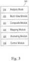
- FIG. 3is a block diagram of the processor modules used in the cardiac ablation instrument.
- FIG. 4illustrates a user interface in the form of a splint-screen arrangement for displaying information
- FIG. 8is a screen shot of the display of FIG. 1 depicting visual warning signals indicative of insufficient lesions
- FIG. 9is a block diagram of a computer system configured to employ one ablation method of the present invention.
- FIG. 10is a representative view of a treatment site from along a longitudinal axis of a catheter.
- a visualization system/methodthat uses ICG dye for distinguishing ablated tissue from de novo tissue.
- ICGIndocyanine green
- ICG dyehas the following formula:
- ICG dyeis traditionally used for determining cardiac output, hepatic function, and liver blood flow, and for ophthalmic angiography. It has a peak spectral absorption at about 800 nm. These infrared frequencies penetrate retinal layers and other tissue allowing ICG angiography to image deeper patterns of circulation than fluorescein angiography. ICG binds tightly to plasma proteins and becomes confined to the vascular system. ICG has a half-life of 150 to 180 seconds and is removed from circulation exclusively by the liver to bile juice.
- ICGis a fluorescent dye which is used in medicine as an indicator substance (e.g. for photometric hepatic function diagnostics and fluorescence angiography) in cardiac, circulatory, hepatic and ophthalmic conditions. ICG is typically administered intravenously and, depending on liver performance, is eliminated from the body with a half-life of approximately 3-4 minutes. ICG sodium salt is normally available in powder form and can be dissolved in various solvents; 5% ( ⁇ 5% depending on batch) sodium iodide is usually added to ensure better solubility. The sterile lyophilisate of a water-ICG solution is approved in many European countries and the United States under the names ICG-Pulsion and IC-Green as a diagnostic for intravenous use.
- the absorption and fluorescence spectrum of ICGis in the near infrared region. Both depend to some degree on the solvent used and the concentration. ICG absorbs mainly between 600 nm and 900 nm and emits fluorescence between 750 nm and 950 nm. The large overlapping of the absorption and fluorescence spectra leads to a marked reabsorption of the fluorescence by ICG itself.
- the fluorescence spectrumis very wide. Its maximum values are approximately 810 nm in water and approximately 830 nm in blood. For medical applications based on absorption, the maximum absorption at approximately 800 nm (in blood plasma at low concentrations) is important.
- lasers with a wavelength of around 780 to 815 nmare used. At this wavelength, ICG still absorbs very well and yet it is still technically possible to suppress the excitation light in order to detect the fluorescence.
- FIG. 1is a schematic block diagram illustrating an ablator/endoscopic system in accordance with the invention, designated generally by reference numeral 10 .
- Ablator system 10preferably includes a surgical ablation instrument 100 preferably including an endoscope and ablation instrument as discussed below.
- the surgical ablation instrument 100can be any number of different ablation instruments that are commercially available including those disclosed by Applicant in previous U.S. patents and patent applications (e.g., U.S. patent application publication Nos. 2009/0326320 and 2011/0082451, each of which is hereby incorporated by reference in its entirety).
- the ablation instrument 100is of a type that emits ablation energy sufficient to cause formation of an ablation at a tissue target site.
- the ablator system 10further preferably includes an aiming light source 20 and an illumination light source 24 .
- a processor 12designed to accept input and output data from the connected instruments, display and controller and process that data into visual information.
- an excitation light source YYthat emits light in the wavelength range adequate to excite the ICG dye fluorescence.
- the illumination light source 24may be identical to the excitation source YY.
- the illumination light source 24may provide a broadband white light illumination for normal endoscopic imaging and then be converted to an excitation light source by using an optical filter to remove wavelengths away from the absorption peak of ICG.
- an endoscopeis preferably provided in ablation instrument 100 and has the capability of capturing both live images and recording still images.
- An illumination lightis used to provide operating light to the surgical site.
- the illumination lightis of a frequency that allows the user to differentiate between different tissues present at the operating site.
- An aiming light source 20is used to visualize the location where energy will be delivered by the ablation instrument 100 to tissue. It is envisioned that the aiming light will be of a wavelength that can be recorded by an image capture device and visible on a display.
- the processor 12is designed to process live visual data as well as data from the ablation instrument controllers and display.
- the processoris configured execute a series of software and/or hardware modules configured to interpret, manipulate and record visual information received from the surgical site.
- the processor 12is further configured to manipulate and provide illustrative and graphical overlays and composite or hybrid visual data to the display device.
- the system 10further includes a controller 16 , an energy source 18 , aiming light source 20 and a user interface 22 .
- Controller 16is preferably configured to control the output of the energy source 18 and the illumination and excitation sources 24 and 25 of an energy transmitter as well as determine the distance and movement of an energy transmitter relative to tissue at an ablation surgical site (as discussed further below).
- an endoscopeis preferably supported by the ablation instrument 100 and captures images that can be processed by the processor 12 to determine whether sufficient ablative energy deliveries have been directed to a specific area of a surgical site. Data obtained from the endoscope includes real-time video or still images of the surgical site as seen from the ablation instrument.
- the aiming light source 20is used to visualize the surgical site location 120 where energy will be delivered by the ablation instrument 100 to tissue 130 .
- the aiming light source 20outputs light in a visible region of the electromagnetic spectrum.
- the controller 16transmits radiant energy, via energy source 18 , from the ablation instrument 100 to a target tissue site 120 to effect ablation by lesions.
- radiant energyas used herein is intended to encompass energy sources that do not rely primarily on conductive or convective heat transfer. Such sources include, but are not limited to, acoustic, laser and electromagnetic radiation sources and, more specifically, include microwave, x-ray, gamma-ray, ultrasonic and radiant light sources.
- the term “light” as used hereinis intended to encompass electromagnetic radiation including, but not limited to, visible light, infrared and ultraviolet radiation.
- the illumination light source 24is a light source used to provide proper illumination to the surgical site.
- the illuminateis configured so that natural biological tones and hues can be easily identifiable by an operator.
- the controller 16can provide the user with the ability to control the function of the aiming light source, the user input devices, and the ablation instrument.
- the controllerserves as the primary control interface for the ablation system. Through the controller, the user can turn on and off both the aiming and illumination lights. Furthermore the controller possesses the ability to change the illumination and aiming light intensity. The ability to switch user interfaces or display devices is also envisioned. Additionally, the controller gives access to the ablation instrument, including control over the intensity of the discharge, duration and location of ablative energy discharges.
- the controller 16can further provide a safety shutoff to the system in the event that a clear transmission pathway between the radiant energy source and the target tissue is lost during energy delivery (e.g., see commonly owned U.S. patent application Ser. No. 12/896,010, filed Oct. 1, 2010, which is hereby incorporated by reference in its entirety.
- the controllercan be separate microprocessor based control interface hardware or it can be a portion of a configured as a module operating through a processor based computer system configured to accept and control inputs from various physical devices.
- a set of modulescooperate with one another to provide the information presented through the interface of the system of FIG. 1 .
- an analysis module 218there is an analysis module 218 , a multiple view module 220 , a composite module 222 , a mapping module 224 , an illustrating module 226 , and a control interface module 228 .
- Each of these modulescan comprise hardware, code executing in a processor, or both, that configures a machines such as a workstation to implement the functionality described herein.
- the analysis module 218includes instructions for analyzing a lesion and determining if it is sufficient for the desired treatment.
- the analysis moduleis configured to inspect the image data captured by the image capture device and a lesion of sufficient dimensions and quality has been formed.
- the analysis module 218can be implemented as discrete sub-modules to provide functions such as receiving data on the duration and intensity of an ablative emission.
- An additional sub moduleis capable of evaluating the duration of the energy emission and comparing it to a look up table of sufficient duration and intensity values suitable to form a proper lesion.
- the multiple view module 220includes instructions for configuring the processor 12 to provide multiple images to the display.
- the multiple view moduleconfigures the display to depict at least two image depiction areas. In a first image depiction area, the live video stream of the surgical site is displayed to the user. In a second image depiction area, a still image, highlighting the last target of ablative energy is depicted.
- the composite module 222includes instructions for combining a series of still images and producing a composite image that depicts the target location of the ablative emission in each still image.
- the compositing module 222can be implemented as discrete sub-modules to provide functions such as altering the transparency of each still image layer of the composite image so that a time based map of ablation locations can be produced. Another function implemented by the submodules is construction of a video or slideshow from a sequence of still images.
- the mapping module 224includes instructions for overlaying proposed treatment paths on the live image.
- the mapping moduleis configured to show showing colored markers indicating acceptable levels of ablative energy depositing.
- the mapping moduleis capable of generating a green colored visual marker and superposing it over the live image to indicate areas that have yet to receive levels of ablative energy necessary for treatment.
- the mapping module 224is also capable of simultaneously generating a red colored (or other color) visual marker and superimposing it over the live image to indicate areas that have received sufficient quantities of ablative energy suitable lesions.
- the mapping module 224can be implemented as discrete sub-modules to provide functions such as receiving data on the duration and intensity of an ablative emission and correlating that specific instance to a specific stored image.
- the illustrating module 226includes instructions for providing an image to the display, wherein the image is an illustration or graphical representation of the surgical site.
- the illustrating module 226is configured to allow annotation of the illustrated image as well as comparison between the live image and the illustrated image. For example, and as shown in FIG. 8 , display 14 provides a first screen portion 610 depicting the actual surgical site 152 as viewed from endoscope 176 .
- Display 14also illustrates a second screen portion 620 illustrating a graphical depiction of the surgical site 152 indicating the actual path of the energy transmitter 140 on the tissue at the surgical site wherein the path consists of a trace indicating the sufficiency of the formed lesions in which a solid trace 630 indicates sufficient lesions and a hashed trace 640 indicates insufficient lesions.
- the control module 220includes instruction for orientating and accessing the functions of each of the other modules, as well as communicating with the controller and inputting information or manipulating the parameters of the data being displayed during operation.
- the manipulation and controlling functionscan be implemented as discrete sub-modules with instructions for selecting operation modes, control interfaces, display orientation, recording modes, storage device location and data entry.
- the userrefers to the live video feed from the image capture device to determine where to direct a radiant energy transmission.
- a live video image and a still image of the surgical siteare depicted on the display.
- the processor 12outputs to the display 14 at least two separately defined image depiction areas 204 , 206 .
- One image depiction area 204is reserved for displaying live video transmitted from the surgical site 152 .
- At least one other image depiction area 206is used to depict an image or a composite image comprised of several still images representing specific moments in time during the surgical procedure.
- the live video shown to the userwill allow the user to see the reflection of the aiming light 218 and hence direct ablative energy.
- the first still image 210 depictedwill be a still image captured at a point in time prior to the initiation of the first radiant energy emission. For instance, at a point in time prior to the emission of radiant energy, the image capture device records an image 210 of the surgical site 152 that depicts the surgical site 152 without the aiming light. By taking a still image 210 of the site, the user can record a baseline image of the surgical site before any treatment has been commenced. Furthermore, through the functions of the illustrative module, an illustration of the untouched 152 can be generated.
- a still image 210is taken of the surgical site 152 .
- the characteristics of the ablative evente.g. information regarding the duration and intensity of the radiant of the energy emission
- the reflection the aiming lightwill be visible in the still image, providing a location indicator as to where the energy was directed.
- a series of these still imagescan be combined by using the composite module.
- the composite imageis composed a series of individual images representing a specific period of time during the procedure, a time based map of the entire operation can also be produced in real time or for subsequent review.
- the inventionis not to be understood to be limited to the two image depiction areas discussed above with reference to FIG. 3 or 4 , but rather may encompass any number of image depiction areas in which the images and representations of the surgical site 152 can be reviewed.
- the images shown by the display 14can be manipulated by the modules to illustrate the presence of sufficient or insufficient lesion formation.
- the display 14may illustrate the image of the surgical site 152 viewed from the endoscope 176 wherein varying shades of grey and white depict tissue and lesions and in the event insufficient lesions are determined to be formed, or a red marker can be superimposed on the image of the surgical site 152 at the location where the insufficient lesion was determined.
- an audio signalmay also be emitted from ablator system 10 causing further warning to the user.
- the modules of the systempermit the surgeon to view all treatment segments forming the entire ablation arc to see if a continuous, uninterrupted ablation has been formed (or see if the ablation has the intended, desired shape). If there are visible gaps or other imperfections with the formed ablation, the surgeon can move the energy transmitter 140 to the proper location for retreatment of these areas until the desired ablation is formed. The process can then be repeated to determine and confirm that the gap was eliminated.
- mapping, analyzing and illustrating functions performed by the ablation system of the present inventionovercome the disadvantages associated with prior ablation surgical procedures and results in increased ablation success rates due to a more optimal and more accurate viewing and quality determination of the spot lesions created to form the continuous ablation at the tissue location for the surgical site 152 .
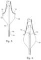
- FIG. 5provides a schematic, cross-sectional view of an ablation instrument 100 , including an elongate body 114 , a central lumen tubing 116 and a compliant balloon 126 inflatable via one or more ports 122 in the central tubing 116 .
- the central tubing 116can also house an energy emitter that is capable of both axial movement and rotation within a lumen formed in the elongate body 114 .
- the energy emitteris also described herein as being an energy transmitter, an energy emitter (or lesion generator), a radiant energy emitter and a radiant energy transmitter (ablation element).
- the catheter body 114also referred to herein as the catheter body
- the catheter body 114also provides lumens 118 A and 118 B for extraction (or circulation) of an inflation fluid, an endoscope 176 and illumination and excitation fibers 128 A and 128 B.
- the ablation instrument 100is preferably designed such that upon disposition within the heart (e.g., proximal to a pulmonary vein), the balloon 126 can be inflated such that a shoulder portion 150 of the balloon 126 will be urged into close proximity with a target region 152 of cardiac tissue.
- the energy emitter (or “lesion generator”) 140can be positioned to delivery ablative energy to the target region 152 to form a continuous lesion.
- continuousin the context of a lesion is intended to mean a lesion that substantially blocks electrical conduction between tissue segments on opposite sides of the lesion.
- the radiant energy emitter 140is shown in FIG. 2 disposed within the balloon 126 remotely from the target tissue (e.g., within a central lumen 116 of the catheter body 114 or otherwise disposed within the balloon).
- the radiant energy transmitter (ablation element) 140includes at least one optical fiber coupled to a distal light projecting, optical element, which cooperate to project a spot of ablative light energy through the instrument 100 to the target site 152 (in FIG. 6 ).
- the catheter body 114 , projection balloon 126 and inflation/ablation fluidsare all preferably substantially transparent to the radiant energy at the selected wavelength of the energy source as well as to the absorption and emission wavelengths of ICG dye to provide a low-loss transmission pathway from the radiant energy transmitter 140 to the target site 152 .
- balloonencompasses deformable hollow shapes which can be inflated into various configurations including spherical, obloid, tear drop, etc., shapes dependent upon the requirements of the body cavity.
- Such balloon elementscan be elastic or simply capable of unfolding or unwrapping into an expanded state.
- the ballooncan further encompass multiple chamber configurations.
- a reflectance sensorpreferably an endoscope 176 capable of capturing an image of the target site 152 and/or the instrument position.
- the endoscope 176is typically an optical fiber bundle with a lens or other optical coupler at its distal end to receive light.
- the reflectance sensor/endoscopecan also include an illumination source, such one or more optical fibers coupled to a light source or sources. Alternatively illumination and excitation light may be delivered though separate optical fibers as indicated by 128 A in FIG. 2 . Endoscopes are available commercially from various sources.
- the endoscopecan further include an optical head assembly, as detailed in more detail below, to increase the field of view.
- ablation element 140 and endoscope 176are adapted for independent axial movement within the catheter body 14 .
- endoscopeas used herein is intended to encompass optical imaging devices, generally, including but not limited to endoscopes, fiberscopes, cardioscopes, angioscopes and other optical fiber-based imaging devices. More generally, “endoscope” encompasses any light-guiding (or waveguide) structure capable of transmitting an “image” of an object to a location for viewing, such as display 14 .
- spot lesionsare formed at the target site 152 by applying radiant energy from the energy transmitter 140 to target tissue.
- the applied radiant energymay be applied in an energy range from about 50 Joules/cm 2 to about 1000 Joules/cm 2 , or preferably from about 75 Joules/cm 2 to about 750 Joules/cm 2 .
- the power levels applied by the energy emittercan range from about 10 Watts/cm 2 to about 150 Watts/cm 2 and the duration of energy delivery can range from about 1 second to about 1 minute, preferably from about 5 seconds to about 45 seconds, or more preferably from about 10 to about 30 seconds. For example, for power levels between 10 and 75 Watts/cm 2 it can be advantageous to apply the radiant energy for about 30 seconds.
- the ablation instrument 100includes an aiming light preferably having a pulsed operating mode in which visible light from the aiming light unit is delivered in pulses to cause intermittent illumination of the tissue at the target site 152 . This gives the aiming light an appearance of being a blinking light.
- the surgeonis able to directly observe the tissue that is being treated at the target site 152 , using an endoscope, between the aiming light pulses.
- the endoscope 176is used to determine the extent of tissue ablation by sensing the change in color of the tissue as it is ablated and at a time when the aiming beam is in an off cycle via the display 14 .
- the surgeoncan observe the treated tissue to determine how the treatment is progressing since the endoscope 176 is used to determine the extent of tissue ablation by sensing the change in color of the tissue as it is ablated and at a time when the aiming beam is in an off cycle.
- the processor 12 of ablator system 10obviates this problem by determining the quality of the lesion formed on the tissue at the target site 152 which may be viewed on monitor 14 and/or indicated to a surgeon visual overlay or audio cues.
- the method of operation for determining the quality of spot lesions at an ablation surgical site 152will now be discussed.
- the processor 12then preferably uses algorithmic techniques to determine whether a sufficient spot lesion has just recently been formed on the tissue at the surgical site (step 320 ).
- algorithmic techniquesto determine whether a sufficient spot lesion has just recently been formed on the tissue at the surgical site (step 320 ).
- the rate of movement of the energy transmitter 140 relative to the tissue at the surgical site 152e.g., the amount of time that energy is applied to the tissue at a given location
- a determinationis made as to whether a sufficient spot lesion has been formed on the tissue at a location which the energy transmitter is applying ablation energy thereto.
- a lookup table or other similar meansmay also be used by processor 12 for determining the aforesaid lesion quality.
- a spot lesionis to be understood as being sufficient when it comprises enough scar tissue effective to block the transmission of electrical signals therethrough.
- the processor 12is preferably further operative and configured to provide a signal to the surgeon indicative of whether a sufficient spot lesion has been formed (step 330 ).
- This indicative signalmay be provided in the event an insufficient or no spot lesion was formed on the tissue at the surgical site 152 that was subject to the energy transmitter 140 dispersing energy thereto.
- This indicative signalmay be an audio and/or visual signal.
- the audio signalmay consist of a warning tone and the visual signal may consist of a marker (e.g., color red) superimposed on the display 14 illustrating the surgical site 152 (provided via endoscope 176 ) at the location at which the insufficient spot lesion was determined.
- the aforesaid warning signalis promptly provided to the surgeon enabling the surgeon to revisit the tissue having the insufficient lesion and make proper adjustments with the energy transmitter 140 (e.g., apply more energy, close the distance between energy transmitter 140 and the surgical site and/or slow the movement of energy transmitter 140 relative to the surgical site) so as to now form sufficient lesions.
- FIG. 9is a block diagram of one computer system 300 configured for employment of method 100 .
- System 300includes a user interface 305 , a processor 310 , and a memory 315 .
- System 300may be implemented on a general purpose microcomputer, such as one of the members of the Sun® Microsystems family of computer systems, one of the members of the IBM® Personal Computer family, one of the members of the Apple® Computer family, or a myriad other conventional workstations.
- system 300is represented herein as a standalone system, it is not limited to such, but instead can be coupled to other computer systems via a network (not shown).
- Memory 315is a memory for storing data and instructions suitable for controlling the operation of processor 310 .
- An implementation of memory 315would include a random access memory (RAM), a hard drive and a read only memory (ROM).
- RAMrandom access memory
- ROMread only memory
- One of the components stored in memory 315is a program 320 .
- Program 320includes instructions for controlling processor 310 to execute method 100 .
- Program 320may be implemented as a single module or as a plurality of modules that operate in cooperation with one another.
- Program 320is contemplated as representing a software embodiment of the method described hereinabove.
- User interface 305includes an input device, such as a keyboard, touch screen, tablet, or speech recognition subsystem, for enabling a user to communicate information and command selections to processor 310 .
- User interface 305also includes an output device such as a display or a printer. In the case of a touch screen, the input and output functions are provided by the same structure.
- a cursor controlsuch as a mouse, track-ball, or joy stick, allows the user to manipulate a cursor on the display for communicating additional information and command selections to processor 310 .
- Storage media 325can be any conventional storage media such as a magnetic tape, an optical storage media, a compact disc, or a floppy disc. Alternatively, storage media 325 can be a random access memory, or other type of electronic storage, located on a remote storage system.
- an ICG dye compositionis used for visualizing ablated tissue and allowing the ablated tissue to be visually distinguished from de-novo tissue.
- a suitable and biologically sufficient amount of ICG dyeis delivered to the patient either immediately prior to performing the ablation procedure; during the ablative procedure or immediately after the ablation procedure.
- the timing and time period for delivering the ICG dyeis sufficient to allow the ICG dye to travel through the bloodstream to the ablation tissue site where the ICG dye binds to plasma proteins and permit visualization of the ablated tissue since the ablated tissue (a lesion) is visually distinguishable from de novo tissue (non-ablated tissue) as a result of the binding properties of the ICG dye.
- ablated tissueis tissue which has undergone coagulative necrosis due to energy being applied to the tissue. Unlike, the surrounding de-novo tissue, the ablated tissue does not have blood flowing therein and therefore, the ICG dye bound to blood plasma protein is carried into the ablated tissue to a far lesser extent than it is carried into de novo tissue. The result is that the ablated tissue does not absorb the ICG dye and is thus marked by a lack of fluorescence.
- FIG. 10is a representative endoscopic view of a treatment site from along a longitudinal axis of the catheter.
- This viewis preferably displayed on a display, such as a monitor and the ablated tissue is displayed in a visually distinguished manner relative to the de-novo (untreated) tissue.
- a displaysuch as a monitor
- the ablated tissueis displayed in a visually distinguished manner relative to the de-novo (untreated) tissue.
- areas that contain bloodsuch as blood in the pulmonary vein lumen and blood in the atrium, etc.
- the area of the ablated tissuehas a darker appearance due to a lack of ICG dye.
- the ablated tissueis easily distinguishable from the surrounding blood rich areas since the areas of ablated tissue lack the fluorescence that is exhibited in the blood rich areas.
- the ablation system 10 described hereinis modified by the inclusion of an excitation light that emits light at the proper excitation wavelength (e.g., about 805 nm) instead of the use of a white light that is used in other ablation procedures.
- the devicealso includes an imaging device, such as a camera or the like, which includes appropriate filters and is constructed to be able to detect and record near IR light near the peak of the ICG emission spectra (i.e., about 835 nm) on out to the limit of the ICG dye fluorescence spectrum (i.e. 880 nm) while filtering out all of the excitation light to allow the emitted fluorescence to be visible as shown in FIG. 10 ).
- an imaging devicesuch as a camera or the like, which includes appropriate filters and is constructed to be able to detect and record near IR light near the peak of the ICG emission spectra (i.e., about 835 nm) on out to the limit of the ICG dye fluorescence spectrum (i.e. 880
- the principle of fluorescence imaging using ICG dyeinvolves the following steps.
- the tissue of interestis illuminated at a selected excitation wavelength (about 750 nm to about 805 nm) while observing it at longer emission wavelengths (e.g., over 815 nm in the case of 805 nm excitation).
- Filtersare preferably used as part of the imaging device to prevent mixing of the excitation (strong) and fluorescing (weak) rays to sum at a sensor or the like that is part of the overall imaging system. Even if the fluorescene is only a small fraction of the excitation intensity, a surprisingly good signal to noise ratio (SNR) is attached.
- SNRsignal to noise ratio
- the exact shape of the observed spectracan depend somewhat on the chemical environment and physical conditions of the ICG molecules like temperature and ICG concentration as well as the absorption spectra of the tissue through which some of the emitted light must pass.
- ICGinterleukin-1 kinase
- ⁇ -lipoproteinlipids of lipoprotein complexes
- binding to protein proteinsalso shifts, slowly, taking several minutes, the absorption peak, at 780 nm, toward longer wavelengths, to 805 nm. It has been reported that absorption peak maximum was observed at 810 nm in the epidermal cell cultures, and at 805-810 nm in the human skin in vivo. The emission peak is also shifted similarly.
- the imaging system in accordance with the present inventionincludes an appropriate imaging device that is configured to monitor, in real time, the condition of the tissue at the surgical site and in particular, allow the physician to readily distinguish between ablated tissue and de novo tissue that has not been ablated.
- the imaging systemallows the observed image to be displayed in real-time on a display and/or recorded and stored in memory.
- An endoscopecan be used to obtain an image of the ablated tissue as described herein.
- the endoscopeis inserted into the body and positioned adjacent the area of interest.
- An instrumentis then used in combination with the endoscope to provide energy at an appropriate wavelength to cause the ICG dye within the subject tissue to fluoresce so that the image can be obtained.
- a second instrumentcan be used with the endoscope that permits the image of the fluorescing ICG dye within the tissue to be obtained.
- an optical deviceis connected to a CCD camera can be used in conjunction with the endoscopic procedures of the present invention. The optical device and the CCD camera permits the physician to view the target tissue in the heart.
- the deviceWhen the imaging device is in the form of a CCD camera, the device includes software and equipment that effectively filters light (reflected light) of certain wavelength(s) and in particular, the imaging device can include one or more video chips and corresponding bandpass filters and/or other filter arrangements that allow the fluorescence emission of the ICG dye to be filtered out and then further processed.
- a traditional filtere.g., a bandpass filter
- fluorescence imagingcan be done so that both visible or excitation and fluorescence images are displayed together as one image.
- the fluorescence imagealong may contain only a few details so that the visible image greatly helps to locate the fluorescing parts with the help of landmarks seen in the visible image.
- the fluorescence channelis shown, rendered, in colors like vivid green, having a striking color contrast to the visible image of tissues.
- the type of visualizationis especially important in intraoperational use, where the fluorescing parts, like blood veins and healthy de novo tissue, should be recognized easily and immediately.
- Image registration softwarecan then be used to combine the two images in proper alignment.
- the present inventionthus allows the surgeon to view the formed ablation(s) (lesion) in real-time and to evaluate the quality of the formed ablation(s) to allow the surgeon to decide whether additional ablation treatment is needed. For example, if the surgeon views the display and notices that the formed ablation(s) includes a defect, such as a void (gap or break) along its length, or is otherwise not acceptable, then the surgeon can take corrective action.
- a defectsuch as a void (gap or break) along its length, or is otherwise not acceptable
- a gap formed along the length of the lesionis readily recognizable since the area of the gap will exhibit fluorescence, while the other sections of the lesion lack fluorescence and appear dark.
- a gap (break) Ais present in the lesion and is readily and immediately discoverable by the surgeon when viewing the display due to the fact that the area A (the gap area) fluoresces, while the lesion has a dark color on the display.
- holes/gaps located along the lesionare easily seen due to these areas appearing as fluorescent “hot spots” relative to the adjacent dark areas which represent the formed lesion(s).
- the surgeoncan then further ablate the tissue to close off the gap or otherwise correct the formed ablation such that a complete ablation is formed as desired.
- the surgeoncan then check the video display after performing such additional ablation to make sure that the lesion is complete as represented by a continuous dark segment (lack of fluorescence) on the video display. In other words, once corrective action is taken and these fluorescent “hot spots” are eliminated by ablating the tissue at such location, the “hot spots” will disappear.
- the vivid fluorescent colors that indicate the lack of ablated tissue and instead show areas of blood flow and de-novo tissueallow the surgeon in real-time to see deficiencies in the formed lesion (ablation) and take immediate corrective action, thereby ensuring that the lesion (ablation) is fully formed and will act to block electrical signals as desired.
- U.S. patent application publication No. 2009/0326320discloses other details of exemplary imaging systems and is hereby incorporated by reference in its entirety. It will be understood that one or more of the features disclosed in that document can be implemented in the imaging system of the present invention in that the imaging system can include more than one means for visualizing the surgical site and providing the user (surgeon) with helpful feedback and information concerning the quality of the lesion (i.e., whether the lesion is a continuous, uninterrupted structure, etc.).
Landscapes
- Health & Medical Sciences (AREA)
- Life Sciences & Earth Sciences (AREA)
- Surgery (AREA)
- Physics & Mathematics (AREA)
- Engineering & Computer Science (AREA)
- Animal Behavior & Ethology (AREA)
- General Health & Medical Sciences (AREA)
- Public Health (AREA)
- Biomedical Technology (AREA)
- Heart & Thoracic Surgery (AREA)
- Medical Informatics (AREA)
- Molecular Biology (AREA)
- Veterinary Medicine (AREA)
- Pathology (AREA)
- Biophysics (AREA)
- Nuclear Medicine, Radiotherapy & Molecular Imaging (AREA)
- Optics & Photonics (AREA)
- Radiology & Medical Imaging (AREA)
- Otolaryngology (AREA)
- Electromagnetism (AREA)
- Surgical Instruments (AREA)
- Endoscopes (AREA)
- Cardiology (AREA)
- Plasma & Fusion (AREA)
- Laser Surgery Devices (AREA)
Abstract
Description

Claims (10)
Priority Applications (1)
| Application Number | Priority Date | Filing Date | Title |
|---|---|---|---|
| US16/259,483US11246476B2 (en) | 2014-04-28 | 2019-01-28 | Method for visualizing tissue with an ICG dye composition during ablation procedures |
Applications Claiming Priority (3)
| Application Number | Priority Date | Filing Date | Title |
|---|---|---|---|
| US201461985142P | 2014-04-28 | 2014-04-28 | |
| US14/697,065US20150305604A1 (en) | 2014-04-28 | 2015-04-27 | System and method for visualizing tissue with an icg dye composition during ablation procedures |
| US16/259,483US11246476B2 (en) | 2014-04-28 | 2019-01-28 | Method for visualizing tissue with an ICG dye composition during ablation procedures |
Related Parent Applications (1)
| Application Number | Title | Priority Date | Filing Date |
|---|---|---|---|
| US14/697,065DivisionUS20150305604A1 (en) | 2014-04-28 | 2015-04-27 | System and method for visualizing tissue with an icg dye composition during ablation procedures |
Publications (2)
| Publication Number | Publication Date |
|---|---|
| US20190150718A1 US20190150718A1 (en) | 2019-05-23 |
| US11246476B2true US11246476B2 (en) | 2022-02-15 |
Family
ID=54333618
Family Applications (2)
| Application Number | Title | Priority Date | Filing Date |
|---|---|---|---|
| US14/697,065AbandonedUS20150305604A1 (en) | 2014-04-28 | 2015-04-27 | System and method for visualizing tissue with an icg dye composition during ablation procedures |
| US16/259,483Active2036-01-12US11246476B2 (en) | 2014-04-28 | 2019-01-28 | Method for visualizing tissue with an ICG dye composition during ablation procedures |
Family Applications Before (1)
| Application Number | Title | Priority Date | Filing Date |
|---|---|---|---|
| US14/697,065AbandonedUS20150305604A1 (en) | 2014-04-28 | 2015-04-27 | System and method for visualizing tissue with an icg dye composition during ablation procedures |
Country Status (4)
| Country | Link |
|---|---|
| US (2) | US20150305604A1 (en) |
| EP (1) | EP3137007A4 (en) |
| JP (1) | JP2017513645A (en) |
| WO (1) | WO2015167929A1 (en) |
Cited By (1)
| Publication number | Priority date | Publication date | Assignee | Title |
|---|---|---|---|---|
| US20220287551A1 (en)* | 2019-08-28 | 2022-09-15 | Sony Olympus Medical Solutions Inc. | Medical image processing apparatus and medical observation system |
Families Citing this family (68)
| Publication number | Priority date | Publication date | Assignee | Title |
|---|---|---|---|---|
| US10448861B2 (en)* | 2013-09-06 | 2019-10-22 | Covidien Lp | System and method for light based lung visualization |
| EP3137007A4 (en)* | 2014-04-28 | 2017-09-27 | Cardiofocus, Inc. | System and method for visualizing tissue with an icg dye composition during ablation procedures |
| US11344365B2 (en) | 2016-01-05 | 2022-05-31 | Cardiofocus, Inc. | Ablation system with automated sweeping ablation energy element |
| EP3206061A1 (en)* | 2016-02-15 | 2017-08-16 | Leica Instruments (Singapore) Pte. Ltd. | Illumination filter system and observation system for a multispectral fluorescence microscope |
| US10929959B2 (en)* | 2016-04-04 | 2021-02-23 | Sony Corporation | Image processing apparatus, imaging apparatus, and image processing method |
| ES2923898T3 (en)* | 2017-02-18 | 2022-10-03 | Univ Rochester | Medical Imaging and Surgical Visualization Devices Using Near Infrared Fluorescent Polymers |
| USD851245S1 (en) | 2017-04-14 | 2019-06-11 | Cardiofocus, Inc. | Compliant balloon |
| JP6920931B2 (en)* | 2017-09-01 | 2021-08-18 | 富士フイルム株式会社 | Medical image processing equipment, endoscopy equipment, diagnostic support equipment, and medical business support equipment |
| BR112020012744A2 (en) | 2017-12-27 | 2020-12-01 | Ethicon Llc | fluorescence imaging in a light-deficient environment |
| EP3740147B1 (en) | 2018-01-15 | 2024-03-27 | Cardiofocus, Inc. | Ablation system with automated ablation energy element |
| JP2020168208A (en)* | 2019-04-03 | 2020-10-15 | オリンパス株式会社 | Endoscope system |
| US11716543B2 (en) | 2019-06-20 | 2023-08-01 | Cilag Gmbh International | Wide dynamic range using a monochrome image sensor for fluorescence imaging |
| US11432706B2 (en) | 2019-06-20 | 2022-09-06 | Cilag Gmbh International | Hyperspectral imaging with minimal area monolithic image sensor |
| US11892403B2 (en) | 2019-06-20 | 2024-02-06 | Cilag Gmbh International | Image synchronization without input clock and data transmission clock in a pulsed fluorescence imaging system |
| US11898909B2 (en) | 2019-06-20 | 2024-02-13 | Cilag Gmbh International | Noise aware edge enhancement in a pulsed fluorescence imaging system |
| US11412152B2 (en) | 2019-06-20 | 2022-08-09 | Cilag Gmbh International | Speckle removal in a pulsed hyperspectral imaging system |
| US11624830B2 (en) | 2019-06-20 | 2023-04-11 | Cilag Gmbh International | Wide dynamic range using a monochrome image sensor for laser mapping imaging |
| US12181412B2 (en) | 2019-06-20 | 2024-12-31 | Cilag Gmbh International | Minimizing image sensor input/output in a pulsed hyperspectral, fluorescence, and laser mapping imaging system |
| US11457154B2 (en) | 2019-06-20 | 2022-09-27 | Cilag Gmbh International | Speckle removal in a pulsed hyperspectral, fluorescence, and laser mapping imaging system |
| US10952619B2 (en) | 2019-06-20 | 2021-03-23 | Ethicon Llc | Hyperspectral and fluorescence imaging and topology laser mapping with minimal area monolithic image sensor |
| US11252326B2 (en) | 2019-06-20 | 2022-02-15 | Cilag Gmbh International | Pulsed illumination in a laser mapping imaging system |
| US11540696B2 (en) | 2019-06-20 | 2023-01-03 | Cilag Gmbh International | Noise aware edge enhancement in a pulsed fluorescence imaging system |
| US11389066B2 (en) | 2019-06-20 | 2022-07-19 | Cilag Gmbh International | Noise aware edge enhancement in a pulsed hyperspectral, fluorescence, and laser mapping imaging system |
| US10841504B1 (en) | 2019-06-20 | 2020-11-17 | Ethicon Llc | Fluorescence imaging with minimal area monolithic image sensor |
| US12013496B2 (en) | 2019-06-20 | 2024-06-18 | Cilag Gmbh International | Noise aware edge enhancement in a pulsed laser mapping imaging system |
| US11276148B2 (en) | 2019-06-20 | 2022-03-15 | Cilag Gmbh International | Super resolution and color motion artifact correction in a pulsed fluorescence imaging system |
| US11412920B2 (en)* | 2019-06-20 | 2022-08-16 | Cilag Gmbh International | Speckle removal in a pulsed fluorescence imaging system |
| US11925328B2 (en) | 2019-06-20 | 2024-03-12 | Cilag Gmbh International | Noise aware edge enhancement in a pulsed hyperspectral imaging system |
| US11360028B2 (en) | 2019-06-20 | 2022-06-14 | Cilag Gmbh International | Super resolution and color motion artifact correction in a pulsed hyperspectral, fluorescence, and laser mapping imaging system |
| US11622094B2 (en) | 2019-06-20 | 2023-04-04 | Cilag Gmbh International | Wide dynamic range using a monochrome image sensor for fluorescence imaging |
| US11700995B2 (en) | 2019-06-20 | 2023-07-18 | Cilag Gmbh International | Speckle removal in a pulsed fluorescence imaging system |
| US11589819B2 (en) | 2019-06-20 | 2023-02-28 | Cilag Gmbh International | Offset illumination of a scene using multiple emitters in a laser mapping imaging system |
| US11533417B2 (en) | 2019-06-20 | 2022-12-20 | Cilag Gmbh International | Laser scanning and tool tracking imaging in a light deficient environment |
| US11895397B2 (en) | 2019-06-20 | 2024-02-06 | Cilag Gmbh International | Image synchronization without input clock and data transmission clock in a pulsed fluorescence imaging system |
| US12126887B2 (en) | 2019-06-20 | 2024-10-22 | Cilag Gmbh International | Hyperspectral and fluorescence imaging with topology laser scanning in a light deficient environment |
| US11288772B2 (en) | 2019-06-20 | 2022-03-29 | Cilag Gmbh International | Super resolution and color motion artifact correction in a pulsed fluorescence imaging system |
| US11237270B2 (en) | 2019-06-20 | 2022-02-01 | Cilag Gmbh International | Hyperspectral, fluorescence, and laser mapping imaging with fixed pattern noise cancellation |
| US11903563B2 (en) | 2019-06-20 | 2024-02-20 | Cilag Gmbh International | Offset illumination of a scene using multiple emitters in a fluorescence imaging system |
| US11758256B2 (en) | 2019-06-20 | 2023-09-12 | Cilag Gmbh International | Fluorescence imaging in a light deficient environment |
| US11986160B2 (en) | 2019-06-20 | 2024-05-21 | Cllag GmbH International | Image synchronization without input clock and data transmission clock in a pulsed hyperspectral imaging system |
| US11516387B2 (en) | 2019-06-20 | 2022-11-29 | Cilag Gmbh International | Image synchronization without input clock and data transmission clock in a pulsed hyperspectral, fluorescence, and laser mapping imaging system |
| US11311183B2 (en) | 2019-06-20 | 2022-04-26 | Cilag Gmbh International | Controlling integral energy of a laser pulse in a fluorescence imaging system |
| US11793399B2 (en) | 2019-06-20 | 2023-10-24 | Cilag Gmbh International | Super resolution and color motion artifact correction in a pulsed hyperspectral imaging system |
| US11187658B2 (en) | 2019-06-20 | 2021-11-30 | Cilag Gmbh International | Fluorescence imaging with fixed pattern noise cancellation |
| US11471055B2 (en) | 2019-06-20 | 2022-10-18 | Cilag Gmbh International | Noise aware edge enhancement in a pulsed fluorescence imaging system |
| US12007550B2 (en) | 2019-06-20 | 2024-06-11 | Cilag Gmbh International | Driving light emissions according to a jitter specification in a spectral imaging system |
| US11671691B2 (en) | 2019-06-20 | 2023-06-06 | Cilag Gmbh International | Image rotation in an endoscopic laser mapping imaging system |
| US11633089B2 (en) | 2019-06-20 | 2023-04-25 | Cilag Gmbh International | Fluorescence imaging with minimal area monolithic image sensor |
| US11877065B2 (en) | 2019-06-20 | 2024-01-16 | Cilag Gmbh International | Image rotation in an endoscopic hyperspectral imaging system |
| US11550057B2 (en) | 2019-06-20 | 2023-01-10 | Cilag Gmbh International | Offset illumination of a scene using multiple emitters in a fluorescence imaging system |
| US11674848B2 (en) | 2019-06-20 | 2023-06-13 | Cilag Gmbh International | Wide dynamic range using a monochrome image sensor for hyperspectral imaging |
| US11012599B2 (en) | 2019-06-20 | 2021-05-18 | Ethicon Llc | Hyperspectral imaging in a light deficient environment |
| US11213194B2 (en) | 2019-06-20 | 2022-01-04 | Cilag Gmbh International | Optical fiber waveguide in an endoscopic system for hyperspectral, fluorescence, and laser mapping imaging |
| US11937784B2 (en) | 2019-06-20 | 2024-03-26 | Cilag Gmbh International | Fluorescence imaging in a light deficient environment |
| US11398011B2 (en) | 2019-06-20 | 2022-07-26 | Cilag Gmbh International | Super resolution and color motion artifact correction in a pulsed laser mapping imaging system |
| US11944273B2 (en) | 2019-06-20 | 2024-04-02 | Cilag Gmbh International | Fluorescence videostroboscopy of vocal cords |
| US11134832B2 (en) | 2019-06-20 | 2021-10-05 | Cilag Gmbh International | Image rotation in an endoscopic hyperspectral, fluorescence, and laser mapping imaging system |
| US11931009B2 (en) | 2019-06-20 | 2024-03-19 | Cilag Gmbh International | Offset illumination of a scene using multiple emitters in a hyperspectral imaging system |
| CN110510147B (en)* | 2019-08-02 | 2022-11-22 | 西安飞机工业(集团)有限责任公司 | Airplane structure crack detection method |
| KR102095794B1 (en)* | 2019-10-28 | 2020-04-02 | 오리오스메디칼 주식회사 | Method and apparatus for scanning blood vessels |
| US12121211B2 (en) | 2019-11-22 | 2024-10-22 | Lake Region Manufacturing, Inc. | Guidewire and catheter system for in-vivo forward viewing of the vasculature |
| US20220039744A1 (en)* | 2020-08-06 | 2022-02-10 | Medtronic Navigation, Inc. | Tumor ablation planning using interstitial optical mapping |
| US20220079600A1 (en)* | 2020-09-15 | 2022-03-17 | Baylis Medical Company Inc. | Medical guidewire assembly |
| JP7434591B2 (en) | 2020-09-29 | 2024-02-20 | オリンパス株式会社 | Support devices, endoscope systems, support methods and programs |
| WO2022070275A1 (en)* | 2020-09-29 | 2022-04-07 | オリンパス株式会社 | Support device, endoscopic system, support method, and program |
| EP4243671A4 (en)* | 2020-11-12 | 2024-09-11 | Cardiofocus, Inc. | Ablation catheters with multiple endoscopes and imaging chip endoscopes and system for altering an orientation of an endoscopic image |
| US20220323143A1 (en)* | 2021-04-01 | 2022-10-13 | Cardiofocus, Inc. | Deployable structures to provide electrodes on the surface of an endoscopically guided laser ablation catheter for use in ablation and electrophysiological mapping |
| CN120641021A (en)* | 2023-02-09 | 2025-09-12 | 奥林巴斯医疗株式会社 | Medical device, medical system, learning device, operating method and program of medical device |
Citations (256)
| Publication number | Priority date | Publication date | Assignee | Title |
|---|---|---|---|---|
| US3417745A (en) | 1963-08-23 | 1968-12-24 | Sheldon Edward Emanuel | Fiber endoscope provided with focusing means and electroluminescent means |
| US3821510A (en) | 1973-02-22 | 1974-06-28 | H Muncheryan | Hand held laser instrumentation device |
| US4224929A (en) | 1977-11-08 | 1980-09-30 | Olympus Optical Co., Ltd. | Endoscope with expansible cuff member and operation section |
| US4233493A (en) | 1974-05-21 | 1980-11-11 | Nath Guenther | Apparatus for applying intense light radiation to a limited area |
| US4273109A (en) | 1976-07-06 | 1981-06-16 | Cavitron Corporation | Fiber optic light delivery apparatus and medical instrument utilizing same |
| US4336809A (en)* | 1980-03-17 | 1982-06-29 | Burleigh Instruments, Inc. | Human and animal tissue photoradiation system and method |
| US4445892A (en) | 1982-05-06 | 1984-05-01 | Laserscope, Inc. | Dual balloon catheter device |
| US4585298A (en) | 1982-08-26 | 1986-04-29 | Kei Mori | Photoradiator for radiating light |
| US4625724A (en) | 1984-07-25 | 1986-12-02 | Fuji Photo Optical Co., Ltd. | Laser vascular anastomosis apparatus |
| EP0214712A1 (en) | 1985-07-31 | 1987-03-18 | C.R. Bard, Inc. | Infrared laser catheter apparatus |
| US4660925A (en) | 1985-04-29 | 1987-04-28 | Laser Therapeutics, Inc. | Apparatus for producing a cylindrical pattern of light and method of manufacture |
| US4701166A (en) | 1983-05-03 | 1987-10-20 | Catheter Technology Corp. | Valved two-way catheter |
| US4718417A (en) | 1985-03-22 | 1988-01-12 | Massachusetts Institute Of Technology | Visible fluorescence spectral diagnostic for laser angiosurgery |
| US4770653A (en) | 1987-06-25 | 1988-09-13 | Medilase, Inc. | Laser angioplasty |
| US4781681A (en) | 1987-09-15 | 1988-11-01 | Gv Medical, Inc. | Inflatable tip for laser catheterization |
| EP0292621A1 (en) | 1987-05-26 | 1988-11-30 | Surgical Laser Technologies, Inc. | Contact or insertion laser probe having wide angle radiation |
| EP0292695A2 (en) | 1987-05-25 | 1988-11-30 | Deutsche Aerospace AG | Device for circumferential irradiation of objects |
| EP0299448A2 (en) | 1987-07-17 | 1989-01-18 | Consiglio Nazionale Delle Ricerche | Fibre optic device for the transmission and lateral irradiation of laser energy, particularly for angioplasty |
| US4819632A (en) | 1986-05-19 | 1989-04-11 | Davies David H | Retrolasing catheter and method |
| EP0311458A2 (en) | 1987-10-08 | 1989-04-12 | The Beth Israel Hospital Association | Laser balloon catheter |
| US4852567A (en) | 1988-01-21 | 1989-08-01 | C. R. Bard, Inc. | Laser tipped catheter |
| US4860743A (en) | 1986-10-27 | 1989-08-29 | University Of Florida | Laser method and apparatus for the recanalization of vessels and the treatment of other cardiac conditions |
| US4862886A (en) | 1985-05-08 | 1989-09-05 | Summit Technology Inc. | Laser angioplasty |
| US4913142A (en) | 1985-03-22 | 1990-04-03 | Massachusetts Institute Of Technology | Catheter for laser angiosurgery |
| US4961738A (en) | 1987-01-28 | 1990-10-09 | Mackin Robert A | Angioplasty catheter with illumination and visualization within angioplasty balloon |
| US5026367A (en) | 1988-03-18 | 1991-06-25 | Cardiovascular Laser Systems, Inc. | Laser angioplasty catheter and a method for use thereof |
| US5030201A (en) | 1989-11-24 | 1991-07-09 | Aubrey Palestrant | Expandable atherectomy catheter device |
| EP0437183A1 (en) | 1990-01-09 | 1991-07-17 | Ciba-Geigy Ag | Light diffuser for a photodynamic therapy of tumours in the oesophagus of a patient |
| EP0437181A1 (en) | 1990-01-09 | 1991-07-17 | Ciba-Geigy Ag | Apparatus for irradiating the bronchia of a patient for a photodynamic therapy |
| EP0439629A1 (en) | 1989-08-24 | 1991-08-07 | S.L.T. Japan Co, Ltd. | Device for irradiating laser beams |
| US5053033A (en) | 1990-10-10 | 1991-10-01 | Boston Advanced Technologies, Inc. | Inhibition of restenosis by ultraviolet radiation |
| US5071417A (en) | 1990-06-15 | 1991-12-10 | Rare Earth Medical Lasers, Inc. | Laser fusion of biological materials |
| US5078681A (en) | 1989-10-23 | 1992-01-07 | Olympus Optical Co., Ltd. | Balloon catheter apparatus with releasable distal seal and method of operation |
| US5090959A (en) | 1987-04-30 | 1992-02-25 | Advanced Cardiovascular Systems, Inc. | Imaging balloon dilatation catheter |
| US5109859A (en) | 1989-10-04 | 1992-05-05 | Beth Israel Hospital Association | Ultrasound guided laser angioplasty |
| US5125925A (en) | 1988-08-03 | 1992-06-30 | Photoradiation Systems | Intracavity laser catheter with sensing fiber |
| US5133709A (en) | 1990-02-23 | 1992-07-28 | Prince Martin R | Optical fiber with atraumatic rounded end for use in laser angioplasty |
| US5140987A (en) | 1989-03-17 | 1992-08-25 | Wayne State University | Method for transvenous ablation of cardiac electrically conductive tissue by laser photocoagulation |
| US5151097A (en) | 1989-09-01 | 1992-09-29 | S.L.T. Japan Co., Ltd. | Laser light emitter |
| US5151096A (en) | 1991-03-28 | 1992-09-29 | Angiolaz, Incorporated | Laser catheter diffuser |
| WO1992017243A2 (en) | 1991-04-05 | 1992-10-15 | Indigo Medical, Incorporated | Apparatus using a laser lucent needle |
| US5163935A (en) | 1991-02-20 | 1992-11-17 | Reliant Laser Corporation | Surgical laser endoscopic focusing guide with an optical fiber link |
| US5169395A (en) | 1991-04-26 | 1992-12-08 | Pdt Cardiovascular, Inc. | Laser delivery system |
| US5188632A (en) | 1984-12-07 | 1993-02-23 | Advanced Interventional Systems, Inc. | Guidance and delivery system for high-energy pulsed laser light |
| US5188634A (en) | 1990-07-13 | 1993-02-23 | Trimedyne, Inc. | Rotatable laser probe with beveled tip |
| US5190538A (en) | 1991-04-22 | 1993-03-02 | Trimedyne, Inc. | Method and apparatus for subjecting a body site to a movable beam of laterally directed laser radiation |
| US5196005A (en) | 1991-11-26 | 1993-03-23 | Pdt Systems, Inc. | Continuous gradient cylindrical diffusion tip for optical fibers and method for making |
| WO1993006888A1 (en) | 1991-10-03 | 1993-04-15 | Deutsch Alan S | Device for laser surgery in narrow passages |
| US5207699A (en) | 1989-10-30 | 1993-05-04 | Coe Frederick L | Lancet handling and disposal assembly |
| US5242438A (en) | 1991-04-22 | 1993-09-07 | Trimedyne, Inc. | Method and apparatus for treating a body site with laterally directed laser radiation |
| WO1993019680A1 (en) | 1992-04-06 | 1993-10-14 | Laser-Medizin-Zentrum Gmbh Berlin | Working shaft for photo-thermal therapy |
| US5261904A (en) | 1990-01-30 | 1993-11-16 | C. R. Bard, Inc. | Laser catheter having diffraction grating for beam shaping |
| US5269777A (en) | 1990-11-01 | 1993-12-14 | Pdt Systems, Inc. | Diffusion tip for optical fibers |
| WO1993025155A1 (en) | 1992-06-12 | 1993-12-23 | Pdt Systems | Cylindrical diffusion tips for optical fibers and method for making |
| USRE34544E (en) | 1982-11-23 | 1994-02-15 | The Beth Israel Hospital Association | Method of treatment of artherosclerosis and balloon catheter the same |
| EP0598984A1 (en) | 1992-07-06 | 1994-06-01 | CeramOptec GmbH | Radial medical laser delivery device |
| US5318024A (en) | 1985-03-22 | 1994-06-07 | Massachusetts Institute Of Technology | Laser endoscope for spectroscopic imaging |
| WO1994017434A1 (en) | 1993-01-21 | 1994-08-04 | Fiberguide Industries, Inc. | Fiber optic cylindrical diffuser |
| US5344419A (en) | 1993-04-23 | 1994-09-06 | Wayne State University | Apparatus and method for making a diffusing tip in a balloon catheter system |
| US5350375A (en) | 1993-03-15 | 1994-09-27 | Yale University | Methods for laser induced fluorescence intensity feedback control during laser angioplasty |
| US5363458A (en) | 1994-02-28 | 1994-11-08 | Fiber Guide Industries | Fiber optic light diffuser |
| DE9411754U1 (en) | 1994-07-20 | 1994-11-10 | Göbel, Dieter, Dr., 80333 München | Laser awl for the treatment of osteochondritis deformans |
| WO1994026184A1 (en) | 1993-05-14 | 1994-11-24 | Laser-Medizin-Zentrum Gmbh, Berlin | Process and device for thermally obliterating biological tissues |
| US5368564A (en) | 1992-12-23 | 1994-11-29 | Angeion Corporation | Steerable catheter |
| US5374953A (en) | 1991-02-01 | 1994-12-20 | Olympus Optical Co., Ltd. | Electronic endoscope apparatus with signal validity monitor |
| US5380317A (en) | 1988-06-10 | 1995-01-10 | Trimedyne Laser Systems, Inc. | Medical device applying localized high intensity light and heat, particularly for destruction of the endometrium |
| US5380316A (en) | 1990-12-18 | 1995-01-10 | Advanced Cardiovascular Systems, Inc. | Method for intra-operative myocardial device revascularization |
| US5395362A (en) | 1992-01-14 | 1995-03-07 | Summit Technology | Methods and apparatus for distributing laser radiation |
| US5401270A (en) | 1990-12-19 | 1995-03-28 | Carl-Zeiss-Stiftung | Applicator device for laser radiation |
| US5409483A (en) | 1993-01-22 | 1995-04-25 | Jeffrey H. Reese | Direct visualization surgical probe |
| US5417653A (en) | 1993-01-21 | 1995-05-23 | Sahota; Harvinder | Method for minimizing restenosis |
| US5418649A (en) | 1992-04-28 | 1995-05-23 | Olympus Optical Co., Ltd. | Objective lens system for endoscopes |
| US5423805A (en) | 1992-02-05 | 1995-06-13 | Angeion Corporation | Laser catheter with moveable integral fixation wires |
| US5427119A (en) | 1993-11-03 | 1995-06-27 | Daig Corporation | Guiding introducer for right atrium |
| US5431647A (en) | 1994-07-13 | 1995-07-11 | Pioneer Optics Company | Fiberoptic cylindrical diffuser |
| US5437660A (en) | 1991-12-30 | 1995-08-01 | Trimedyne, Inc. | Tissue ablation and a lateral-lasing fiber optic device therefor |
| US5441497A (en) | 1994-07-14 | 1995-08-15 | Pdt Cardiovascular, Inc. | Light diffusing guidewire |
| US5445608A (en) | 1993-08-16 | 1995-08-29 | James C. Chen | Method and apparatus for providing light-activated therapy |
| US5464404A (en) | 1993-09-20 | 1995-11-07 | Abela Laser Systems, Inc. | Cardiac ablation catheters and method |
| US5482037A (en) | 1993-01-18 | 1996-01-09 | X-Trode S.R.L. | Electrode catheter for mapping and operating on cardiac cavities |
| US5496305A (en) | 1985-03-22 | 1996-03-05 | Massachusetts Institue Of Technology | Catheter for laser angiosurgery |
| US5497774A (en) | 1993-11-03 | 1996-03-12 | Daig Corporation | Guiding introducer for left atrium |
| WO1996007451A2 (en) | 1994-09-09 | 1996-03-14 | Rare Earth Medical, Inc. | Phototherapeutic apparatus |
| US5531664A (en) | 1990-12-26 | 1996-07-02 | Olympus Optical Co., Ltd. | Bending actuator having a coil sheath with a fixed distal end and a free proximal end |
| US5536265A (en) | 1994-03-25 | 1996-07-16 | Ciba-Geigy Corporation | Light diffuser and process for the manufacturing of a light diffuser |
| WO1996034646A1 (en) | 1995-05-01 | 1996-11-07 | Medtronic Cardiorhythm | Dual curve ablation catheter and method |
| US5575766A (en) | 1993-11-03 | 1996-11-19 | Daig Corporation | Process for the nonsurgical mapping and treatment of atrial arrhythmia using catheters guided by shaped guiding introducers |
| WO1996040342A1 (en) | 1995-06-07 | 1996-12-19 | Cardima, Inc. | Guiding catheter for coronary sinus |
| US5605162A (en) | 1991-10-15 | 1997-02-25 | Advanced Cardiovascular Systems, Inc. | Method for using a variable stiffness guidewire |
| US5613965A (en) | 1994-12-08 | 1997-03-25 | Summit Technology Inc. | Corneal reprofiling using an annular beam of ablative radiation |
| US5630837A (en) | 1993-07-01 | 1997-05-20 | Boston Scientific Corporation | Acoustic ablation |
| US5643253A (en) | 1995-06-06 | 1997-07-01 | Rare Earth Medical, Inc. | Phototherapy apparatus with integral stopper device |
| US5649923A (en) | 1988-10-24 | 1997-07-22 | The General Hospital Corporation | Catheter devices for delivering laser energy |
| US5662712A (en) | 1993-04-28 | 1997-09-02 | Focal, Inc. | Apparatus for intraluminal photothermoforming |
| WO1997037714A1 (en) | 1996-04-05 | 1997-10-16 | Medtronic, Inc. | Catheter with autoinflating, autoregulating balloon |
| US5678550A (en) | 1995-08-11 | 1997-10-21 | The United States Of America As Represented By The Secretary Of The Department Of Health And Human Services | Apparatus and method for in situ detection of areas of cardiac electrical activity |
| US5680860A (en) | 1994-07-07 | 1997-10-28 | Cardiac Pathways Corporation | Mapping and/or ablation catheter with coilable distal extremity and method for using same |
| US5690611A (en) | 1994-07-08 | 1997-11-25 | Daig Corporation | Process for the treatment of atrial arrhythima using a catheter guided by shaped giding introducers |
| US5693043A (en) | 1985-03-22 | 1997-12-02 | Massachusetts Institute Of Technology | Catheter for laser angiosurgery |
| US5700243A (en) | 1992-10-30 | 1997-12-23 | Pdt Systems, Inc. | Balloon perfusion catheter |
| US5702438A (en) | 1995-06-08 | 1997-12-30 | Avitall; Boaz | Expandable recording and ablation catheter system |
| US5722401A (en) | 1994-10-19 | 1998-03-03 | Cardiac Pathways Corporation | Endocardial mapping and/or ablation catheter probe |
| US5725522A (en) | 1990-06-15 | 1998-03-10 | Rare Earth Medical, Inc. | Laser suturing of biological materials |
| US5741249A (en) | 1996-10-16 | 1998-04-21 | Fidus Medical Technology Corporation | Anchoring tip assembly for microwave ablation catheter |
| US5759619A (en) | 1995-12-29 | 1998-06-02 | Lg Electronics Inc. | Method of manufacturing second harmonic generation device |
| US5769843A (en) | 1996-02-20 | 1998-06-23 | Cormedica | Percutaneous endomyocardial revascularization |
| US5773835A (en)* | 1996-06-07 | 1998-06-30 | Rare Earth Medical, Inc. | Fiber optic spectroscopy |
| US5772590A (en) | 1992-06-30 | 1998-06-30 | Cordis Webster, Inc. | Cardiovascular catheter with laterally stable basket-shaped electrode array with puller wire |
| US5779646A (en) | 1995-02-28 | 1998-07-14 | E.P. Technologies Inc. | Deflectable biopsy catheter |
| US5782899A (en) | 1992-06-05 | 1998-07-21 | Cardiac Pathways Corporation | Endocardial mapping and ablation system utilizing a separately controlled ablation catheter and method |
| US5782239A (en) | 1992-06-30 | 1998-07-21 | Cordis Webster, Inc. | Unique electrode configurations for cardiovascular electrode catheter with built-in deflection method and central puller wire |
| US5800482A (en) | 1996-03-06 | 1998-09-01 | Cardiac Pathways Corporation | Apparatus and method for linear lesion ablation |
| US5807395A (en) | 1993-08-27 | 1998-09-15 | Medtronic, Inc. | Method and apparatus for RF ablation and hyperthermia |
| US5823955A (en) | 1995-11-20 | 1998-10-20 | Medtronic Cardiorhythm | Atrioventricular valve tissue ablation catheter and method |
| US5824005A (en) | 1995-08-22 | 1998-10-20 | Board Of Regents, The University Of Texas System | Maneuverable electrophysiology catheter for percutaneous or intraoperative ablation of cardiac arrhythmias |
| US5830209A (en) | 1992-02-05 | 1998-11-03 | Angeion Corporation | Multi-fiber laser catheter |
| US5833682A (en) | 1996-08-26 | 1998-11-10 | Illumenex Corporation | Light delivery system with blood flushing capability |
| US5845646A (en)* | 1996-11-05 | 1998-12-08 | Lemelson; Jerome | System and method for treating select tissue in a living being |
| US5860974A (en) | 1993-07-01 | 1999-01-19 | Boston Scientific Corporation | Heart ablation catheter with expandable electrode and method of coupling energy to an electrode on a catheter shaft |
| US5885278A (en) | 1994-10-07 | 1999-03-23 | E.P. Technologies, Inc. | Structures for deploying movable electrode elements |
| US5891134A (en) | 1996-09-24 | 1999-04-06 | Goble; Colin | System and method for applying thermal energy to tissue |
| US5891133A (en) | 1996-03-29 | 1999-04-06 | Eclipse Surgical Technologies, Inc. | Apparatus for laser-assisted intra-coronary transmyocardial revascularization and other applications |
| US5904651A (en) | 1996-10-28 | 1999-05-18 | Ep Technologies, Inc. | Systems and methods for visualizing tissue during diagnostic or therapeutic procedures |
| US5908448A (en) | 1993-09-30 | 1999-06-01 | Boston Scientific Corporation | Controlled deployment of a medical device |
| US5908415A (en) | 1994-09-09 | 1999-06-01 | Rare Earth Medical, Inc. | Phototherapy methods and apparatus |
| US5931834A (en) | 1996-10-15 | 1999-08-03 | Eclipse Surgical Technologies, Inc. | Method for non-synchronous laser-assisted myocardial revascularization |
| US5938660A (en) | 1997-06-27 | 1999-08-17 | Daig Corporation | Process and device for the treatment of atrial arrhythmia |
| US5947959A (en) | 1994-09-09 | 1999-09-07 | Rare Earth Medical, Inc. | Phototherapeutic apparatus with diffusive tip assembly |
| US5967984A (en) | 1995-06-30 | 1999-10-19 | Boston Scientific Corporation | Ultrasound imaging catheter with a cutting element |
| US5971983A (en) | 1997-05-09 | 1999-10-26 | The Regents Of The University Of California | Tissue ablation device and method of use |
| US5995875A (en) | 1997-10-01 | 1999-11-30 | United States Surgical | Apparatus for thermal treatment of tissue |
| US6004269A (en) | 1993-07-01 | 1999-12-21 | Boston Scientific Corporation | Catheters for imaging, sensing electrical potentials, and ablating tissue |
| US6012457A (en) | 1997-07-08 | 2000-01-11 | The Regents Of The University Of California | Device and method for forming a circumferential conduction block in a pulmonary vein |
| US6024740A (en) | 1997-07-08 | 2000-02-15 | The Regents Of The University Of California | Circumferential ablation device assembly |
| US6056744A (en) | 1994-06-24 | 2000-05-02 | Conway Stuart Medical, Inc. | Sphincter treatment apparatus |
| US6064902A (en) | 1998-04-16 | 2000-05-16 | C.R. Bard, Inc. | Pulmonary vein ablation catheter |
| US6071281A (en) | 1998-05-05 | 2000-06-06 | Ep Technologies, Inc. | Surgical method and apparatus for positioning a diagnostic or therapeutic element within the body and remote power control unit for use with same |
| US6071302A (en) | 1997-12-31 | 2000-06-06 | Cardiofocus, Inc. | Phototherapeutic apparatus for wide-angle diffusion |
| US6071279A (en) | 1996-12-19 | 2000-06-06 | Ep Technologies, Inc. | Branched structures for supporting multiple electrode elements |
| US6086581A (en) | 1992-09-29 | 2000-07-11 | Ep Technologies, Inc. | Large surface cardiac ablation catheter that assumes a low profile during introduction into the heart |
| US6090084A (en) | 1994-07-08 | 2000-07-18 | Daig Corporation | Shaped guiding introducers for use with a catheter for the treatment of atrial arrhythmia |
| US6099514A (en) | 1996-08-13 | 2000-08-08 | Oratec Interventions, Inc. | Method and apparatus for delivering or removing material from the interior of an intervertebral disc |
| US6102905A (en) | 1994-09-09 | 2000-08-15 | Cardiofocus, Inc. | Phototherapy device including housing for an optical element and method of making |
| US6117071A (en) | 1997-07-29 | 2000-09-12 | Asahi Kogaku Kogyo Kabushiki Kaisha | Endoscope with movable imaging unit for zooming or focusing |
| US6117101A (en) | 1997-07-08 | 2000-09-12 | The Regents Of The University Of California | Circumferential ablation device assembly |
| US6120496A (en) | 1998-05-05 | 2000-09-19 | Scimed Life Systems, Inc. | Surgical method and apparatus for positioning a diagnostic or therapeutic element within the body and coupling device for use with same |
| US6146379A (en) | 1993-10-15 | 2000-11-14 | Ep Technologies, Inc. | Systems and methods for creating curvilinear lesions in body tissue |
| WO2000067656A1 (en) | 1999-05-11 | 2000-11-16 | Atrionix, Inc. | Tissue ablation device assembly and method for electrically isolating a pulmonary vein ostium from an atrial wall |
| WO2000067832A2 (en) | 1999-05-11 | 2000-11-16 | Atrionix, Inc. | Balloon anchor wire |
| US6159203A (en) | 1985-07-31 | 2000-12-12 | Cardiofocus, Inc. | Infrared laser catheter system |
| US6161543A (en)* | 1993-02-22 | 2000-12-19 | Epicor, Inc. | Methods of epicardial ablation for creating a lesion around the pulmonary veins |
| US6164283A (en)* | 1997-07-08 | 2000-12-26 | The Regents Of The University Of California | Device and method for forming a circumferential conduction block in a pulmonary vein |
| WO2001003599A2 (en) | 1999-07-14 | 2001-01-18 | Cardiofocus, Inc. | Photoablation system |
| US6179835B1 (en) | 1996-01-19 | 2001-01-30 | Ep Technologies, Inc. | Expandable-collapsible electrode structures made of electrically conductive material |
| EP1072231A1 (en) | 1999-07-30 | 2001-01-31 | Terumo Kabushiki Kaisha | Laser irradiation apparatus |
| WO2001013812A1 (en) | 1999-08-25 | 2001-03-01 | Cardiofocus, Inc. | Maneuverable optical fiber device for cardiac photoablation |
| FR2798371A1 (en) | 1999-09-10 | 2001-03-16 | Acemo | Transfer device for use in manufacturing animal feed has Archimedes screw in housing with normally closed valve at outlet and has inlet at lower air pressure than outlet |
| US6217510B1 (en) | 1997-10-02 | 2001-04-17 | Olympus Optical Co., Ltd. | Endoscopes and endoscope devices which image regular observation images and fluorescent images as well as which provide easier operation of treatment tools |
| US6237605B1 (en) | 1996-10-22 | 2001-05-29 | Epicor, Inc. | Methods of epicardial ablation |
| US6240231B1 (en) | 1997-12-22 | 2001-05-29 | Micrus Corporation | Variable stiffness fiber optic shaft |
| US6245064B1 (en)* | 1997-07-08 | 2001-06-12 | Atrionix, Inc. | Circumferential ablation device assembly |
| US6251109B1 (en) | 1997-06-27 | 2001-06-26 | Daig Corporation | Process and device for the treatment of atrial arrhythmia |
| US6251092B1 (en) | 1997-12-30 | 2001-06-26 | Medtronic, Inc. | Deflectable guiding catheter |
| US6270492B1 (en) | 1994-09-09 | 2001-08-07 | Cardiofocus, Inc. | Phototherapeutic apparatus with diffusive tip assembly |
| WO2001064123A2 (en) | 2000-02-29 | 2001-09-07 | Johns Hopkins University | Circumferential pulmonary vein ablation using a laser and fiberoptic balloon catheter |
| US20010030107A1 (en) | 2000-01-03 | 2001-10-18 | Peter Simpson | Auger lock |
| US6312427B1 (en) | 1998-10-23 | 2001-11-06 | Afx, Inc. | Directional reflector shield assembly for a microwave ablation instrument |
| US6314962B1 (en) | 1996-10-22 | 2001-11-13 | Epicor, Inc. | Method of ablating tissue around the pulmonary veins |
| US6325797B1 (en) | 1999-04-05 | 2001-12-04 | Medtronic, Inc. | Ablation catheter and method for isolating a pulmonary vein |
| US20020019627A1 (en) | 2000-06-13 | 2002-02-14 | Maguire Mark A. | Surgical ablation probe for forming a circumferential lesion |
| US6352531B1 (en) | 1999-03-24 | 2002-03-05 | Micrus Corporation | Variable stiffness optical fiber shaft |
| US20020029062A1 (en)* | 2000-09-07 | 2002-03-07 | Shutaro Satake | Balloon catheter for pulmonary vein isolation |
| US6375654B1 (en) | 2000-05-19 | 2002-04-23 | Cardiofocus, Inc. | Catheter system with working portion radially expandable upon rotation |
| US6394949B1 (en) | 1998-10-05 | 2002-05-28 | Scimed Life Systems, Inc. | Large area thermal ablation |
| US20020065512A1 (en) | 2000-07-13 | 2002-05-30 | Todd Fjield | Thermal treatment methods and apparatus with focused energy application |
| US20020091383A1 (en) | 2000-04-27 | 2002-07-11 | Hooven Michael D. | Combination ablation and visualization apparatus for ablating cardiac tissue |
| US6423055B1 (en) | 1999-07-14 | 2002-07-23 | Cardiofocus, Inc. | Phototherapeutic wave guide apparatus |
| US6423058B1 (en) | 1998-02-19 | 2002-07-23 | Curon Medical, Inc. | Assemblies to visualize and treat sphincters and adjoining tissue regions |
| US20020107511A1 (en) | 2000-05-03 | 2002-08-08 | Collins Russell F. | Apparatus and methods for mapping and ablation in electrophysiology procedures |
| US20020173785A1 (en)* | 2000-03-31 | 2002-11-21 | Medtronic, Inc. | System and method for positioning implantable medical devices within coronary veins |
| US6485485B1 (en) | 1998-08-13 | 2002-11-26 | Intraluminal Therapeutics, Inc. | Expandable laser catheter |
| US20020183739A1 (en) | 2001-03-30 | 2002-12-05 | Long Gary L. | Endoscopic ablation system with sealed sheath |
| WO2002096479A2 (en) | 2001-05-31 | 2002-12-05 | Infraredx, Inc. | Balloon catheter |
| US6500174B1 (en) | 1997-07-08 | 2002-12-31 | Atrionix, Inc. | Circumferential ablation device assembly and methods of use and manufacture providing an ablative circumferential band along an expandable member |
| US6514249B1 (en) | 1997-07-08 | 2003-02-04 | Atrionix, Inc. | Positioning system and method for orienting an ablation element within a pulmonary vein ostium |
| US6522933B2 (en) | 2001-03-30 | 2003-02-18 | Biosense, Webster, Inc. | Steerable catheter with a control handle having a pulley mechanism |
| US20030069620A1 (en)* | 2001-10-09 | 2003-04-10 | Hong Li | Balloon catheters for non-continuous lesions |
| US6554794B1 (en) | 1997-09-24 | 2003-04-29 | Richard L. Mueller | Non-deforming deflectable multi-lumen catheter |
| US6558375B1 (en) | 2000-07-14 | 2003-05-06 | Cardiofocus, Inc. | Cardiac ablation instrument |
| US6562020B1 (en) | 1998-07-15 | 2003-05-13 | Corazon Technologies, Inc. | Kits for use in the treatment of vascular calcified lesions |
| US6579285B2 (en) | 1994-09-09 | 2003-06-17 | Cardiofocus, Inc. | Photoablation with infrared radiation |
| US6579278B1 (en) | 2000-05-05 | 2003-06-17 | Scimed Life Systems, Inc. | Bi-directional steerable catheter with asymmetric fulcrum |
| US6582536B2 (en) | 2000-04-24 | 2003-06-24 | Biotran Corporation Inc. | Process for producing steerable sheath catheters |
| US20030120270A1 (en) | 2001-04-23 | 2003-06-26 | Transurgical, Inc. | Ablation therapy |
| JP2003210028A (en) | 2002-01-23 | 2003-07-29 | Iseki & Co Ltd | Spiral spiral of zoom auger |
| US20030144657A1 (en) | 2002-01-28 | 2003-07-31 | Cardiac Pacemakers, Inc. | Inner and outer telescoping catheter delivery system |
| EP1331893A2 (en) | 2000-11-10 | 2003-08-06 | Boston Scientific Limited | Steerable loop structures for supporting diagnostic and therapeutic elements in contact with body tissue |
| US6605084B2 (en) | 2000-03-24 | 2003-08-12 | Transurgical, Inc. | Apparatus and methods for intrabody thermal treatment |
| US6605055B1 (en) | 2000-09-13 | 2003-08-12 | Cardiofocus, Inc. | Balloon catheter with irrigation sheath |
| US20030158550A1 (en) | 1999-11-16 | 2003-08-21 | Ganz Robert A. | Method of treating abnormal tissue in the human esophagus |
| US6648875B2 (en) | 2001-05-04 | 2003-11-18 | Cardiac Pacemakers, Inc. | Means for maintaining tension on a steering tendon in a steerable catheter |
| US6669655B1 (en) | 1999-10-20 | 2003-12-30 | Transurgical, Inc. | Sonic element and catheter incorporating same |
| US20040006333A1 (en) | 1994-09-09 | 2004-01-08 | Cardiofocus, Inc. | Coaxial catheter instruments for ablation with radiant energy |
| US6676656B2 (en) | 1994-09-09 | 2004-01-13 | Cardiofocus, Inc. | Surgical ablation with radiant energy |
| US6679873B2 (en) | 1999-09-24 | 2004-01-20 | Omnisonics Medical Technologies, Inc. | Method for using a steerable catheter device |
| JP2004065076A (en) | 2002-08-05 | 2004-03-04 | Iseki & Co Ltd | Conveyor spiral of zoom auger |
| US6702780B1 (en) | 1999-09-08 | 2004-03-09 | Super Dimension Ltd. | Steering configuration for catheter with rigid distal device |
| US20040054360A1 (en) | 2002-09-17 | 2004-03-18 | Yitzhack Schwartz | Laser pulmonary vein isolation |
| US20040122290A1 (en) | 2001-03-30 | 2004-06-24 | Irion Klaus M. | Endoscopic visualization apparatus with different imaging systems |
| US6771996B2 (en) | 2001-05-24 | 2004-08-03 | Cardiac Pacemakers, Inc. | Ablation and high-resolution mapping catheter system for pulmonary vein foci elimination |
| US20040186351A1 (en)* | 1996-11-20 | 2004-09-23 | Olympus Optical Co., Ltd. (Now Olympus Corporation) | Fluorescent endoscope system enabling simultaneous achievement of normal light observation based on reflected light and fluorescence observation based on light with wavelengths in infrared spectrum |
| US6796972B1 (en) | 2000-07-14 | 2004-09-28 | Edwards Lifesciences Llc | Catheter anchoring balloon structure with irrigation |
| WO2004110258A2 (en) | 2003-06-10 | 2004-12-23 | Cardiofocus, Inc. | Guided cardiac ablation catheters |
| US20050065504A1 (en)* | 1999-07-14 | 2005-03-24 | Gerald Melsky | Guided cardiac ablation catheters |
| US6896673B2 (en) | 2000-04-27 | 2005-05-24 | Atricure, Inc. | Method for transmural ablation |
| US6907298B2 (en) | 2002-01-09 | 2005-06-14 | Medtronic, Inc. | Method and apparatus for imparting curves in implantable elongated medical instruments |
| US6932809B2 (en) | 2002-05-14 | 2005-08-23 | Cardiofocus, Inc. | Safety shut-off device for laser surgical instruments employing blackbody emitters |
| US20050222558A1 (en) | 1999-07-14 | 2005-10-06 | Cardiofocus, Inc. | Methods of cardiac ablation employing a deflectable sheath catheter |
| US20050234436A1 (en) | 1999-07-14 | 2005-10-20 | Cardiofocus, Inc. | Methods of cardiac ablation in the vicinity of the right inferior pulmonary vein |
| US20050288654A1 (en) | 2004-06-07 | 2005-12-29 | Tim Nieman | Methods and devices for delivering ablative energy |
| US20060268402A1 (en)* | 2005-03-18 | 2006-11-30 | Norbert Eustergerling | Image sensor for a fluorescence scanner |
| US20070087445A1 (en)* | 2005-10-14 | 2007-04-19 | The General Hospital Corporation | Arrangements and methods for facilitating photoluminescence imaging |
| US20080039746A1 (en) | 2006-05-25 | 2008-02-14 | Medtronic, Inc. | Methods of using high intensity focused ultrasound to form an ablated tissue area containing a plurality of lesions |
| US20080108870A1 (en) | 2006-11-06 | 2008-05-08 | Wiita Bruce E | Apparatus and method for stabilizing an image from an endoscopic camera |
| US20080306337A1 (en)* | 2007-06-11 | 2008-12-11 | Board Of Regents, The University Of Texas System | Characterization of a Near-Infrared Laparoscopic Hyperspectral Imaging System for Minimally Invasive Surgery |
| US20090093728A1 (en)* | 2007-10-05 | 2009-04-09 | Searete Llc, A Limited Liability Corporation Of The State Of Delaware | Vasculature and lymphatic system imaging and ablation associated with a reservoir |
| US20090093807A1 (en)* | 2007-10-03 | 2009-04-09 | Searete Llc, A Limited Liability Corporation Of The State Of Delaware | Vasculature and lymphatic system imaging and ablation |
| US20090177272A1 (en)* | 2007-12-18 | 2009-07-09 | Abbate Anthony J | Self-expanding devices and methods therefor |
| US20090275934A1 (en) | 1999-07-14 | 2009-11-05 | Cardiofocus, Inc. | Ablation instrument having deflectable sheath catheters with out-of plane bent tip |
| US20090299354A1 (en)* | 1999-07-14 | 2009-12-03 | Cardiofocus, Inc. | Cardiac ablation catheters for forming overlapping lesions |
| US20090326320A1 (en)* | 1999-07-14 | 2009-12-31 | Cardiofocus, Inc. | System and method for visualizing tissue during ablation procedures |
| US20100247436A1 (en) | 2009-01-23 | 2010-09-30 | The Penn State Research Foundation | In vivo photodynamic therapy of cancer via a near infrared agent encapsulated in calcium phosphate nanoparticles |
| US20100280504A1 (en) | 2007-12-28 | 2010-11-04 | Koninklijke Philips Electronics N.V. | Tissue ablation device with photoacoustic lesion formation feedback |
| US20110082450A1 (en)* | 2009-10-02 | 2011-04-07 | Cardiofocus, Inc. | Cardiac ablation system with inflatable member having multiple inflation settings |
| US20110082452A1 (en)* | 2009-10-02 | 2011-04-07 | Cardiofocus, Inc. | Cardiac ablation system with automatic safety shut-off feature |
| US20110082451A1 (en)* | 2009-10-06 | 2011-04-07 | Cardiofocus, Inc. | Cardiac ablation image analysis system and process |
| US20110082449A1 (en)* | 2009-10-02 | 2011-04-07 | Cardiofocus, Inc. | Cardiac ablation system with pulsed aiming light |
| US7935108B2 (en) | 1999-07-14 | 2011-05-03 | Cardiofocus, Inc. | Deflectable sheath catheters |
| US20110158914A1 (en)* | 2009-12-25 | 2011-06-30 | Fujifilm Corporation | Fluorescence image capturing method and apparatus |
| US20120150046A1 (en) | 2010-10-22 | 2012-06-14 | Voyage Medical, Inc. | Tissue contrast imaging systems |
| US20120226166A1 (en) | 2005-02-02 | 2012-09-06 | Voyage Medical, Inc. | Delivery of biological compounds to ischemic and/or infarcted tissue |
| US20120271299A1 (en) | 2009-01-09 | 2012-10-25 | Ncontact Surgical, Inc. | Method and devices for coagulation of tissue |
| US20130102862A1 (en) | 2011-09-22 | 2013-04-25 | The George Washington University | Systems and Methods for Visualizing Ablated Tissue |
| US20130190741A1 (en) | 2006-08-03 | 2013-07-25 | Hansen Medical, Inc. | Systems and methods for performing minimally invasive procedures |
| US20130190747A1 (en)* | 2012-01-10 | 2013-07-25 | Josef V. Koblish | Electrophysiology system and methods |
| US20130324797A1 (en)* | 2012-03-30 | 2013-12-05 | Olympus Corporation | Endoscope apparatus |
| US8647119B1 (en) | 2006-04-18 | 2014-02-11 | President And Fellows Of Harvard College | Methods and kits with fluorescent probes for caries detection |
| US20140350534A1 (en)* | 2013-02-20 | 2014-11-27 | Sloan-Kettering Institute For Cancer Research | Raman based ablation/resection systems and methods |
| US20150018807A1 (en)* | 2013-02-20 | 2015-01-15 | Memorial Sloan Kettering Cancer Center | Raman-triggered ablation/resection systems and methods |
| US20150182118A1 (en)* | 2013-12-31 | 2015-07-02 | Memorial Sloan Kettering Cancer Center | Systems, methods, and apparatus for multichannel imaging of fluorescent sources in real time |
| US20150305604A1 (en)* | 2014-04-28 | 2015-10-29 | Cardiofocus, Inc. | System and method for visualizing tissue with an icg dye composition during ablation procedures |
| US20160030022A1 (en)* | 2014-07-31 | 2016-02-04 | The General Hospital Corporation | Optical Biopsy Needle and Endoscope System |
| US20160038027A1 (en)* | 2006-10-06 | 2016-02-11 | Novadaq Technologies Inc. | Methods, software and systems for imaging |
| US10219742B2 (en)* | 2008-04-14 | 2019-03-05 | Novadaq Technologies ULC | Locating and analyzing perforator flaps for plastic and reconstructive surgery |
| US20190099211A1 (en)* | 2017-09-29 | 2019-04-04 | Biosense Webster (Israel) Ltd. | Highlighting region for re-ablation |
| US10258285B2 (en)* | 2004-05-28 | 2019-04-16 | St. Jude Medical, Atrial Fibrillation Division, Inc. | Robotic surgical system and method for automated creation of ablation lesions |
- 2015
- 2015-04-23EPEP15785530.5Apatent/EP3137007A4/ennot_activeWithdrawn
- 2015-04-23WOPCT/US2015/027314patent/WO2015167929A1/enactiveApplication Filing
- 2015-04-23JPJP2016564561Apatent/JP2017513645A/enactivePending
- 2015-04-27USUS14/697,065patent/US20150305604A1/ennot_activeAbandoned
- 2019
- 2019-01-28USUS16/259,483patent/US11246476B2/enactiveActive
Patent Citations (311)
| Publication number | Priority date | Publication date | Assignee | Title |
|---|---|---|---|---|
| US3417745A (en) | 1963-08-23 | 1968-12-24 | Sheldon Edward Emanuel | Fiber endoscope provided with focusing means and electroluminescent means |
| US3821510A (en) | 1973-02-22 | 1974-06-28 | H Muncheryan | Hand held laser instrumentation device |
| US4233493A (en) | 1974-05-21 | 1980-11-11 | Nath Guenther | Apparatus for applying intense light radiation to a limited area |
| US4273109A (en) | 1976-07-06 | 1981-06-16 | Cavitron Corporation | Fiber optic light delivery apparatus and medical instrument utilizing same |
| US4224929A (en) | 1977-11-08 | 1980-09-30 | Olympus Optical Co., Ltd. | Endoscope with expansible cuff member and operation section |
| US4336809A (en)* | 1980-03-17 | 1982-06-29 | Burleigh Instruments, Inc. | Human and animal tissue photoradiation system and method |
| US4445892A (en) | 1982-05-06 | 1984-05-01 | Laserscope, Inc. | Dual balloon catheter device |
| US4585298A (en) | 1982-08-26 | 1986-04-29 | Kei Mori | Photoradiator for radiating light |
| USRE34544E (en) | 1982-11-23 | 1994-02-15 | The Beth Israel Hospital Association | Method of treatment of artherosclerosis and balloon catheter the same |
| US4701166A (en) | 1983-05-03 | 1987-10-20 | Catheter Technology Corp. | Valved two-way catheter |
| US4625724A (en) | 1984-07-25 | 1986-12-02 | Fuji Photo Optical Co., Ltd. | Laser vascular anastomosis apparatus |
| US5188632A (en) | 1984-12-07 | 1993-02-23 | Advanced Interventional Systems, Inc. | Guidance and delivery system for high-energy pulsed laser light |
| US5693043A (en) | 1985-03-22 | 1997-12-02 | Massachusetts Institute Of Technology | Catheter for laser angiosurgery |
| US5318024A (en) | 1985-03-22 | 1994-06-07 | Massachusetts Institute Of Technology | Laser endoscope for spectroscopic imaging |
| US4718417A (en) | 1985-03-22 | 1988-01-12 | Massachusetts Institute Of Technology | Visible fluorescence spectral diagnostic for laser angiosurgery |
| US5496305A (en) | 1985-03-22 | 1996-03-05 | Massachusetts Institue Of Technology | Catheter for laser angiosurgery |
| US4913142A (en) | 1985-03-22 | 1990-04-03 | Massachusetts Institute Of Technology | Catheter for laser angiosurgery |
| US4660925A (en) | 1985-04-29 | 1987-04-28 | Laser Therapeutics, Inc. | Apparatus for producing a cylindrical pattern of light and method of manufacture |
| US4862886A (en) | 1985-05-08 | 1989-09-05 | Summit Technology Inc. | Laser angioplasty |
| US6159203A (en) | 1985-07-31 | 2000-12-12 | Cardiofocus, Inc. | Infrared laser catheter system |
| US6547780B1 (en) | 1985-07-31 | 2003-04-15 | Cardiofocus, Inc. | Infrared laser catheter system |
| US5843073A (en) | 1985-07-31 | 1998-12-01 | Rare Earth Medical, Inc. | Infrared laser catheter system |
| EP0214712A1 (en) | 1985-07-31 | 1987-03-18 | C.R. Bard, Inc. | Infrared laser catheter apparatus |
| US4819632A (en) | 1986-05-19 | 1989-04-11 | Davies David H | Retrolasing catheter and method |
| US4860743A (en) | 1986-10-27 | 1989-08-29 | University Of Florida | Laser method and apparatus for the recanalization of vessels and the treatment of other cardiac conditions |
| US4961738A (en) | 1987-01-28 | 1990-10-09 | Mackin Robert A | Angioplasty catheter with illumination and visualization within angioplasty balloon |
| US5090959A (en) | 1987-04-30 | 1992-02-25 | Advanced Cardiovascular Systems, Inc. | Imaging balloon dilatation catheter |
| US4878725A (en) | 1987-05-25 | 1989-11-07 | Messerschmitt-Bolkow-Blohm Gmbh | Apparatus for the circumferential irradiation of objects |
| EP0292695A2 (en) | 1987-05-25 | 1988-11-30 | Deutsche Aerospace AG | Device for circumferential irradiation of objects |
| EP0292621A1 (en) | 1987-05-26 | 1988-11-30 | Surgical Laser Technologies, Inc. | Contact or insertion laser probe having wide angle radiation |
| US4770653A (en) | 1987-06-25 | 1988-09-13 | Medilase, Inc. | Laser angioplasty |
| US4842390A (en) | 1987-07-17 | 1989-06-27 | Consiglio Nazionale Delle Ricerche | Fiber optic device for angioplasty |
| EP0299448A2 (en) | 1987-07-17 | 1989-01-18 | Consiglio Nazionale Delle Ricerche | Fibre optic device for the transmission and lateral irradiation of laser energy, particularly for angioplasty |
| US4781681A (en) | 1987-09-15 | 1988-11-01 | Gv Medical, Inc. | Inflatable tip for laser catheterization |
| US4878492A (en) | 1987-10-08 | 1989-11-07 | C. R. Bard, Inc. | Laser balloon catheter |
| EP0311458A2 (en) | 1987-10-08 | 1989-04-12 | The Beth Israel Hospital Association | Laser balloon catheter |
| US4852567A (en) | 1988-01-21 | 1989-08-01 | C. R. Bard, Inc. | Laser tipped catheter |
| US5026367A (en) | 1988-03-18 | 1991-06-25 | Cardiovascular Laser Systems, Inc. | Laser angioplasty catheter and a method for use thereof |
| US5380317A (en) | 1988-06-10 | 1995-01-10 | Trimedyne Laser Systems, Inc. | Medical device applying localized high intensity light and heat, particularly for destruction of the endometrium |
| US5125925A (en) | 1988-08-03 | 1992-06-30 | Photoradiation Systems | Intracavity laser catheter with sensing fiber |
| US5649923A (en) | 1988-10-24 | 1997-07-22 | The General Hospital Corporation | Catheter devices for delivering laser energy |
| US5140987A (en) | 1989-03-17 | 1992-08-25 | Wayne State University | Method for transvenous ablation of cardiac electrically conductive tissue by laser photocoagulation |
| EP0439629A1 (en) | 1989-08-24 | 1991-08-07 | S.L.T. Japan Co, Ltd. | Device for irradiating laser beams |
| US5209748A (en) | 1989-08-24 | 1993-05-11 | S.L.T. Japan Co., Ltd. | Laser light irradiation apparatus |
| US5151097A (en) | 1989-09-01 | 1992-09-29 | S.L.T. Japan Co., Ltd. | Laser light emitter |
| US5109859A (en) | 1989-10-04 | 1992-05-05 | Beth Israel Hospital Association | Ultrasound guided laser angioplasty |
| US5078681A (en) | 1989-10-23 | 1992-01-07 | Olympus Optical Co., Ltd. | Balloon catheter apparatus with releasable distal seal and method of operation |
| US5207699A (en) | 1989-10-30 | 1993-05-04 | Coe Frederick L | Lancet handling and disposal assembly |
| US5030201A (en) | 1989-11-24 | 1991-07-09 | Aubrey Palestrant | Expandable atherectomy catheter device |
| EP0437181A1 (en) | 1990-01-09 | 1991-07-17 | Ciba-Geigy Ag | Apparatus for irradiating the bronchia of a patient for a photodynamic therapy |
| EP0437183A1 (en) | 1990-01-09 | 1991-07-17 | Ciba-Geigy Ag | Light diffuser for a photodynamic therapy of tumours in the oesophagus of a patient |
| US5219346A (en) | 1990-01-09 | 1993-06-15 | Ciba-Geigy Corporation | Light diffuser for the photodynamic therapy of tumors in the oesophagus of a patient |
| US5261904A (en) | 1990-01-30 | 1993-11-16 | C. R. Bard, Inc. | Laser catheter having diffraction grating for beam shaping |
| US5133709A (en) | 1990-02-23 | 1992-07-28 | Prince Martin R | Optical fiber with atraumatic rounded end for use in laser angioplasty |
| US5725522A (en) | 1990-06-15 | 1998-03-10 | Rare Earth Medical, Inc. | Laser suturing of biological materials |
| US5071417A (en) | 1990-06-15 | 1991-12-10 | Rare Earth Medical Lasers, Inc. | Laser fusion of biological materials |
| US5188634A (en) | 1990-07-13 | 1993-02-23 | Trimedyne, Inc. | Rotatable laser probe with beveled tip |
| US5053033A (en) | 1990-10-10 | 1991-10-01 | Boston Advanced Technologies, Inc. | Inhibition of restenosis by ultraviolet radiation |
| US5269777A (en) | 1990-11-01 | 1993-12-14 | Pdt Systems, Inc. | Diffusion tip for optical fibers |
| US5380316A (en) | 1990-12-18 | 1995-01-10 | Advanced Cardiovascular Systems, Inc. | Method for intra-operative myocardial device revascularization |
| US5401270A (en) | 1990-12-19 | 1995-03-28 | Carl-Zeiss-Stiftung | Applicator device for laser radiation |
| US5531664A (en) | 1990-12-26 | 1996-07-02 | Olympus Optical Co., Ltd. | Bending actuator having a coil sheath with a fixed distal end and a free proximal end |
| US5374953A (en) | 1991-02-01 | 1994-12-20 | Olympus Optical Co., Ltd. | Electronic endoscope apparatus with signal validity monitor |
| US5163935A (en) | 1991-02-20 | 1992-11-17 | Reliant Laser Corporation | Surgical laser endoscopic focusing guide with an optical fiber link |
| US5151096A (en) | 1991-03-28 | 1992-09-29 | Angiolaz, Incorporated | Laser catheter diffuser |
| WO1992017243A2 (en) | 1991-04-05 | 1992-10-15 | Indigo Medical, Incorporated | Apparatus using a laser lucent needle |
| EP0792664A2 (en) | 1991-04-05 | 1997-09-03 | Indigo Medical, Inc. | Apparatus using a laser lucent needle |
| US5242438A (en) | 1991-04-22 | 1993-09-07 | Trimedyne, Inc. | Method and apparatus for treating a body site with laterally directed laser radiation |
| US5190538A (en) | 1991-04-22 | 1993-03-02 | Trimedyne, Inc. | Method and apparatus for subjecting a body site to a movable beam of laterally directed laser radiation |
| US5169395A (en) | 1991-04-26 | 1992-12-08 | Pdt Cardiovascular, Inc. | Laser delivery system |
| WO1993006888A1 (en) | 1991-10-03 | 1993-04-15 | Deutsch Alan S | Device for laser surgery in narrow passages |
| US5605162A (en) | 1991-10-15 | 1997-02-25 | Advanced Cardiovascular Systems, Inc. | Method for using a variable stiffness guidewire |
| US5330465A (en) | 1991-11-26 | 1994-07-19 | Laser Therapeutics, Inc. | Continuous gradient cylindrical diffusion tip for optical fibers and method for using |
| US5196005A (en) | 1991-11-26 | 1993-03-23 | Pdt Systems, Inc. | Continuous gradient cylindrical diffusion tip for optical fibers and method for making |
| US5437660A (en) | 1991-12-30 | 1995-08-01 | Trimedyne, Inc. | Tissue ablation and a lateral-lasing fiber optic device therefor |
| US5395362A (en) | 1992-01-14 | 1995-03-07 | Summit Technology | Methods and apparatus for distributing laser radiation |
| US5830209A (en) | 1992-02-05 | 1998-11-03 | Angeion Corporation | Multi-fiber laser catheter |
| US5423805A (en) | 1992-02-05 | 1995-06-13 | Angeion Corporation | Laser catheter with moveable integral fixation wires |
| WO1993019680A1 (en) | 1992-04-06 | 1993-10-14 | Laser-Medizin-Zentrum Gmbh Berlin | Working shaft for photo-thermal therapy |
| US5418649A (en) | 1992-04-28 | 1995-05-23 | Olympus Optical Co., Ltd. | Objective lens system for endoscopes |
| US5782899A (en) | 1992-06-05 | 1998-07-21 | Cardiac Pathways Corporation | Endocardial mapping and ablation system utilizing a separately controlled ablation catheter and method |
| WO1993025155A1 (en) | 1992-06-12 | 1993-12-23 | Pdt Systems | Cylindrical diffusion tips for optical fibers and method for making |
| US5782239A (en) | 1992-06-30 | 1998-07-21 | Cordis Webster, Inc. | Unique electrode configurations for cardiovascular electrode catheter with built-in deflection method and central puller wire |
| US5772590A (en) | 1992-06-30 | 1998-06-30 | Cordis Webster, Inc. | Cardiovascular catheter with laterally stable basket-shaped electrode array with puller wire |
| EP0598984A1 (en) | 1992-07-06 | 1994-06-01 | CeramOptec GmbH | Radial medical laser delivery device |
| US6086581A (en) | 1992-09-29 | 2000-07-11 | Ep Technologies, Inc. | Large surface cardiac ablation catheter that assumes a low profile during introduction into the heart |
| US5700243A (en) | 1992-10-30 | 1997-12-23 | Pdt Systems, Inc. | Balloon perfusion catheter |
| US5507725A (en) | 1992-12-23 | 1996-04-16 | Angeion Corporation | Steerable catheter |
| US5368564A (en) | 1992-12-23 | 1994-11-29 | Angeion Corporation | Steerable catheter |
| US5482037A (en) | 1993-01-18 | 1996-01-09 | X-Trode S.R.L. | Electrode catheter for mapping and operating on cardiac cavities |
| US5337381A (en) | 1993-01-21 | 1994-08-09 | Fiberguide Industries | Fiber optic cylindrical diffuser |
| WO1994017434A1 (en) | 1993-01-21 | 1994-08-04 | Fiberguide Industries, Inc. | Fiber optic cylindrical diffuser |
| US5417653A (en) | 1993-01-21 | 1995-05-23 | Sahota; Harvinder | Method for minimizing restenosis |
| US5409483A (en) | 1993-01-22 | 1995-04-25 | Jeffrey H. Reese | Direct visualization surgical probe |
| US6161543A (en)* | 1993-02-22 | 2000-12-19 | Epicor, Inc. | Methods of epicardial ablation for creating a lesion around the pulmonary veins |
| US5350375A (en) | 1993-03-15 | 1994-09-27 | Yale University | Methods for laser induced fluorescence intensity feedback control during laser angioplasty |
| US5344419A (en) | 1993-04-23 | 1994-09-06 | Wayne State University | Apparatus and method for making a diffusing tip in a balloon catheter system |
| US5662712A (en) | 1993-04-28 | 1997-09-02 | Focal, Inc. | Apparatus for intraluminal photothermoforming |
| WO1994026184A1 (en) | 1993-05-14 | 1994-11-24 | Laser-Medizin-Zentrum Gmbh, Berlin | Process and device for thermally obliterating biological tissues |
| US5630837A (en) | 1993-07-01 | 1997-05-20 | Boston Scientific Corporation | Acoustic ablation |
| US6004269A (en) | 1993-07-01 | 1999-12-21 | Boston Scientific Corporation | Catheters for imaging, sensing electrical potentials, and ablating tissue |
| US5860974A (en) | 1993-07-01 | 1999-01-19 | Boston Scientific Corporation | Heart ablation catheter with expandable electrode and method of coupling energy to an electrode on a catheter shaft |
| US5445608A (en) | 1993-08-16 | 1995-08-29 | James C. Chen | Method and apparatus for providing light-activated therapy |
| US5807395A (en) | 1993-08-27 | 1998-09-15 | Medtronic, Inc. | Method and apparatus for RF ablation and hyperthermia |
| US5464404A (en) | 1993-09-20 | 1995-11-07 | Abela Laser Systems, Inc. | Cardiac ablation catheters and method |
| US5908448A (en) | 1993-09-30 | 1999-06-01 | Boston Scientific Corporation | Controlled deployment of a medical device |
| US6146379A (en) | 1993-10-15 | 2000-11-14 | Ep Technologies, Inc. | Systems and methods for creating curvilinear lesions in body tissue |
| US5497774A (en) | 1993-11-03 | 1996-03-12 | Daig Corporation | Guiding introducer for left atrium |
| US5427119A (en) | 1993-11-03 | 1995-06-27 | Daig Corporation | Guiding introducer for right atrium |
| US5575766A (en) | 1993-11-03 | 1996-11-19 | Daig Corporation | Process for the nonsurgical mapping and treatment of atrial arrhythmia using catheters guided by shaped guiding introducers |
| US5363458A (en) | 1994-02-28 | 1994-11-08 | Fiber Guide Industries | Fiber optic light diffuser |
| US5536265A (en) | 1994-03-25 | 1996-07-16 | Ciba-Geigy Corporation | Light diffuser and process for the manufacturing of a light diffuser |
| US6056744A (en) | 1994-06-24 | 2000-05-02 | Conway Stuart Medical, Inc. | Sphincter treatment apparatus |
| US5680860A (en) | 1994-07-07 | 1997-10-28 | Cardiac Pathways Corporation | Mapping and/or ablation catheter with coilable distal extremity and method for using same |
| US6090084A (en) | 1994-07-08 | 2000-07-18 | Daig Corporation | Shaped guiding introducers for use with a catheter for the treatment of atrial arrhythmia |
| US5690611A (en) | 1994-07-08 | 1997-11-25 | Daig Corporation | Process for the treatment of atrial arrhythima using a catheter guided by shaped giding introducers |
| US5431647A (en) | 1994-07-13 | 1995-07-11 | Pioneer Optics Company | Fiberoptic cylindrical diffuser |
| US5441497A (en) | 1994-07-14 | 1995-08-15 | Pdt Cardiovascular, Inc. | Light diffusing guidewire |
| DE9411754U1 (en) | 1994-07-20 | 1994-11-10 | Göbel, Dieter, Dr., 80333 München | Laser awl for the treatment of osteochondritis deformans |
| US6676656B2 (en) | 1994-09-09 | 2004-01-13 | Cardiofocus, Inc. | Surgical ablation with radiant energy |
| US6270492B1 (en) | 1994-09-09 | 2001-08-07 | Cardiofocus, Inc. | Phototherapeutic apparatus with diffusive tip assembly |
| WO1996007451A2 (en) | 1994-09-09 | 1996-03-14 | Rare Earth Medical, Inc. | Phototherapeutic apparatus |
| US6102905A (en) | 1994-09-09 | 2000-08-15 | Cardiofocus, Inc. | Phototherapy device including housing for an optical element and method of making |
| US6579285B2 (en) | 1994-09-09 | 2003-06-17 | Cardiofocus, Inc. | Photoablation with infrared radiation |
| US20040006333A1 (en) | 1994-09-09 | 2004-01-08 | Cardiofocus, Inc. | Coaxial catheter instruments for ablation with radiant energy |
| US5947959A (en) | 1994-09-09 | 1999-09-07 | Rare Earth Medical, Inc. | Phototherapeutic apparatus with diffusive tip assembly |
| US8025661B2 (en) | 1994-09-09 | 2011-09-27 | Cardiofocus, Inc. | Coaxial catheter instruments for ablation with radiant energy |
| US20050038419A9 (en) | 1994-09-09 | 2005-02-17 | Cardiofocus, Inc. | Coaxial catheter instruments for ablation with radiant energy |
| US20090221997A1 (en) | 1994-09-09 | 2009-09-03 | Cardiofocus, Inc. | Coaxial catheter instruments for ablation with radiant energy |
| US5908415A (en) | 1994-09-09 | 1999-06-01 | Rare Earth Medical, Inc. | Phototherapy methods and apparatus |
| US8444639B2 (en) | 1994-09-09 | 2013-05-21 | Cardiofocus, Inc. | Coaxial catheter instruments for ablation with radiant energy |
| US20070078451A1 (en) | 1994-09-09 | 2007-04-05 | Cardiofocus, Inc. | Treatment of atrial fibrillation by overlapping curvilinear lesions |
| US20060253113A1 (en) | 1994-09-09 | 2006-11-09 | Cardiofocus, Inc. | Methods for ablation with radiant energy |
| US6071282A (en) | 1994-10-07 | 2000-06-06 | Ep Technologies, Inc. | Structures for deploying electrode elements |
| US5885278A (en) | 1994-10-07 | 1999-03-23 | E.P. Technologies, Inc. | Structures for deploying movable electrode elements |
| US6544262B2 (en) | 1994-10-07 | 2003-04-08 | Ep Technologies, Inc. | Structures and methods for deploying electrode elements |
| US20030171746A1 (en) | 1994-10-07 | 2003-09-11 | Fleischman Sidney D. | Structures and methods for deploying electrode elements |
| US6214002B1 (en) | 1994-10-07 | 2001-04-10 | Ep Technologies, Inc. | Structures and methods for deploying electrode elements |
| US5722401A (en) | 1994-10-19 | 1998-03-03 | Cardiac Pathways Corporation | Endocardial mapping and/or ablation catheter probe |
| US5613965A (en) | 1994-12-08 | 1997-03-25 | Summit Technology Inc. | Corneal reprofiling using an annular beam of ablative radiation |
| US5779646A (en) | 1995-02-28 | 1998-07-14 | E.P. Technologies Inc. | Deflectable biopsy catheter |
| WO1996034646A1 (en) | 1995-05-01 | 1996-11-07 | Medtronic Cardiorhythm | Dual curve ablation catheter and method |
| US5643253A (en) | 1995-06-06 | 1997-07-01 | Rare Earth Medical, Inc. | Phototherapy apparatus with integral stopper device |
| US5775327A (en)* | 1995-06-07 | 1998-07-07 | Cardima, Inc. | Guiding catheter for the coronary sinus |
| WO1996040342A1 (en) | 1995-06-07 | 1996-12-19 | Cardima, Inc. | Guiding catheter for coronary sinus |
| US5702438A (en) | 1995-06-08 | 1997-12-30 | Avitall; Boaz | Expandable recording and ablation catheter system |
| US5967984A (en) | 1995-06-30 | 1999-10-19 | Boston Scientific Corporation | Ultrasound imaging catheter with a cutting element |
| US5678550A (en) | 1995-08-11 | 1997-10-21 | The United States Of America As Represented By The Secretary Of The Department Of Health And Human Services | Apparatus and method for in situ detection of areas of cardiac electrical activity |
| US5824005A (en) | 1995-08-22 | 1998-10-20 | Board Of Regents, The University Of Texas System | Maneuverable electrophysiology catheter for percutaneous or intraoperative ablation of cardiac arrhythmias |
| US5823955A (en) | 1995-11-20 | 1998-10-20 | Medtronic Cardiorhythm | Atrioventricular valve tissue ablation catheter and method |
| US5759619A (en) | 1995-12-29 | 1998-06-02 | Lg Electronics Inc. | Method of manufacturing second harmonic generation device |
| US6179835B1 (en) | 1996-01-19 | 2001-01-30 | Ep Technologies, Inc. | Expandable-collapsible electrode structures made of electrically conductive material |
| US5769843A (en) | 1996-02-20 | 1998-06-23 | Cormedica | Percutaneous endomyocardial revascularization |
| US5800482A (en) | 1996-03-06 | 1998-09-01 | Cardiac Pathways Corporation | Apparatus and method for linear lesion ablation |
| US5891133A (en) | 1996-03-29 | 1999-04-06 | Eclipse Surgical Technologies, Inc. | Apparatus for laser-assisted intra-coronary transmyocardial revascularization and other applications |
| WO1997037714A1 (en) | 1996-04-05 | 1997-10-16 | Medtronic, Inc. | Catheter with autoinflating, autoregulating balloon |
| US5773835A (en)* | 1996-06-07 | 1998-06-30 | Rare Earth Medical, Inc. | Fiber optic spectroscopy |
| US6099514A (en) | 1996-08-13 | 2000-08-08 | Oratec Interventions, Inc. | Method and apparatus for delivering or removing material from the interior of an intervertebral disc |
| US5833682A (en) | 1996-08-26 | 1998-11-10 | Illumenex Corporation | Light delivery system with blood flushing capability |
| US5891134A (en) | 1996-09-24 | 1999-04-06 | Goble; Colin | System and method for applying thermal energy to tissue |
| US5931834A (en) | 1996-10-15 | 1999-08-03 | Eclipse Surgical Technologies, Inc. | Method for non-synchronous laser-assisted myocardial revascularization |
| US5741249A (en) | 1996-10-16 | 1998-04-21 | Fidus Medical Technology Corporation | Anchoring tip assembly for microwave ablation catheter |
| US6314962B1 (en) | 1996-10-22 | 2001-11-13 | Epicor, Inc. | Method of ablating tissue around the pulmonary veins |
| US6237605B1 (en) | 1996-10-22 | 2001-05-29 | Epicor, Inc. | Methods of epicardial ablation |
| US5904651A (en) | 1996-10-28 | 1999-05-18 | Ep Technologies, Inc. | Systems and methods for visualizing tissue during diagnostic or therapeutic procedures |
| US5845646A (en)* | 1996-11-05 | 1998-12-08 | Lemelson; Jerome | System and method for treating select tissue in a living being |
| US20040186351A1 (en)* | 1996-11-20 | 2004-09-23 | Olympus Optical Co., Ltd. (Now Olympus Corporation) | Fluorescent endoscope system enabling simultaneous achievement of normal light observation based on reflected light and fluorescence observation based on light with wavelengths in infrared spectrum |
| US6071279A (en) | 1996-12-19 | 2000-06-06 | Ep Technologies, Inc. | Branched structures for supporting multiple electrode elements |
| US6471697B1 (en) | 1997-05-09 | 2002-10-29 | The Regents Of The University Of California | Tissue ablation device and method |
| US6416511B1 (en) | 1997-05-09 | 2002-07-09 | The Regents Of The University Of California | Circumferential ablation device assembly |
| US20090221996A1 (en) | 1997-05-09 | 2009-09-03 | The Regents Of The University Of California | Circumferential ablation device assembly |
| US5971983A (en) | 1997-05-09 | 1999-10-26 | The Regents Of The University Of California | Tissue ablation device and method of use |
| US20020115995A1 (en) | 1997-05-09 | 2002-08-22 | The Regents Of The University Of California | Circumferential ablation device assembly |
| US20030065307A1 (en) | 1997-05-09 | 2003-04-03 | Lesh Michael D. | Device and method for forming a circumferential conduction block in a pulmonary vein |
| US6254599B1 (en) | 1997-05-09 | 2001-07-03 | Atrionix, Inc. | Circumferential ablation device assembly |
| US20030111085A1 (en) | 1997-05-09 | 2003-06-19 | Lesh Michael D. | Device and method for forming a circumferential conduction block in a pulmonary vein |
| US6235025B1 (en) | 1997-06-27 | 2001-05-22 | Daig Corporation | Process and device for the treatment of atrial arrhythmia |
| US6503247B2 (en) | 1997-06-27 | 2003-01-07 | Daig Corporation | Process and device for the treatment of atrial arrhythmia |
| US6251109B1 (en) | 1997-06-27 | 2001-06-26 | Daig Corporation | Process and device for the treatment of atrial arrhythmia |
| US5938660A (en) | 1997-06-27 | 1999-08-17 | Daig Corporation | Process and device for the treatment of atrial arrhythmia |
| US6500174B1 (en) | 1997-07-08 | 2002-12-31 | Atrionix, Inc. | Circumferential ablation device assembly and methods of use and manufacture providing an ablative circumferential band along an expandable member |
| US6117101A (en) | 1997-07-08 | 2000-09-12 | The Regents Of The University Of California | Circumferential ablation device assembly |
| US6012457A (en) | 1997-07-08 | 2000-01-11 | The Regents Of The University Of California | Device and method for forming a circumferential conduction block in a pulmonary vein |
| US6245064B1 (en)* | 1997-07-08 | 2001-06-12 | Atrionix, Inc. | Circumferential ablation device assembly |
| US6502576B1 (en) | 1997-07-08 | 2003-01-07 | The Regents Of The University Of California | Device and method for forming a circumferential conduction block in a pulmonary vein |
| US6024740A (en) | 1997-07-08 | 2000-02-15 | The Regents Of The University Of California | Circumferential ablation device assembly |
| US6514249B1 (en) | 1997-07-08 | 2003-02-04 | Atrionix, Inc. | Positioning system and method for orienting an ablation element within a pulmonary vein ostium |
| US6964660B2 (en) | 1997-07-08 | 2005-11-15 | Atrionix, Inc. | Tissue ablation device assembly and method of electrically isolating a pulmonary vein ostium from an atrial wall |
| US6164283A (en)* | 1997-07-08 | 2000-12-26 | The Regents Of The University Of California | Device and method for forming a circumferential conduction block in a pulmonary vein |
| US6383151B1 (en)* | 1997-07-08 | 2002-05-07 | Chris J. Diederich | Circumferential ablation device assembly |
| US6305378B1 (en) | 1997-07-08 | 2001-10-23 | The Regents Of The University Of California | Device and method for forming a circumferential conduction block in a pulmonary vein |
| US6117071A (en) | 1997-07-29 | 2000-09-12 | Asahi Kogaku Kogyo Kabushiki Kaisha | Endoscope with movable imaging unit for zooming or focusing |
| US6554794B1 (en) | 1997-09-24 | 2003-04-29 | Richard L. Mueller | Non-deforming deflectable multi-lumen catheter |
| US5995875A (en) | 1997-10-01 | 1999-11-30 | United States Surgical | Apparatus for thermal treatment of tissue |
| US6217510B1 (en) | 1997-10-02 | 2001-04-17 | Olympus Optical Co., Ltd. | Endoscopes and endoscope devices which image regular observation images and fluorescent images as well as which provide easier operation of treatment tools |
| US6240231B1 (en) | 1997-12-22 | 2001-05-29 | Micrus Corporation | Variable stiffness fiber optic shaft |
| US6251092B1 (en) | 1997-12-30 | 2001-06-26 | Medtronic, Inc. | Deflectable guiding catheter |
| US6071302A (en) | 1997-12-31 | 2000-06-06 | Cardiofocus, Inc. | Phototherapeutic apparatus for wide-angle diffusion |
| US6423058B1 (en) | 1998-02-19 | 2002-07-23 | Curon Medical, Inc. | Assemblies to visualize and treat sphincters and adjoining tissue regions |
| US6064902A (en) | 1998-04-16 | 2000-05-16 | C.R. Bard, Inc. | Pulmonary vein ablation catheter |
| US6071281A (en) | 1998-05-05 | 2000-06-06 | Ep Technologies, Inc. | Surgical method and apparatus for positioning a diagnostic or therapeutic element within the body and remote power control unit for use with same |
| US6120496A (en) | 1998-05-05 | 2000-09-19 | Scimed Life Systems, Inc. | Surgical method and apparatus for positioning a diagnostic or therapeutic element within the body and coupling device for use with same |
| US6562020B1 (en) | 1998-07-15 | 2003-05-13 | Corazon Technologies, Inc. | Kits for use in the treatment of vascular calcified lesions |
| US6485485B1 (en) | 1998-08-13 | 2002-11-26 | Intraluminal Therapeutics, Inc. | Expandable laser catheter |
| US20020120264A1 (en) | 1998-10-05 | 2002-08-29 | Crowley Robert J. | Large area thermal ablation |
| US6394949B1 (en) | 1998-10-05 | 2002-05-28 | Scimed Life Systems, Inc. | Large area thermal ablation |
| US6312427B1 (en) | 1998-10-23 | 2001-11-06 | Afx, Inc. | Directional reflector shield assembly for a microwave ablation instrument |
| US6352531B1 (en) | 1999-03-24 | 2002-03-05 | Micrus Corporation | Variable stiffness optical fiber shaft |
| US6325797B1 (en) | 1999-04-05 | 2001-12-04 | Medtronic, Inc. | Ablation catheter and method for isolating a pulmonary vein |
| WO2000067832A2 (en) | 1999-05-11 | 2000-11-16 | Atrionix, Inc. | Balloon anchor wire |
| WO2000067656A1 (en) | 1999-05-11 | 2000-11-16 | Atrionix, Inc. | Tissue ablation device assembly and method for electrically isolating a pulmonary vein ostium from an atrial wall |
| WO2001003599A2 (en) | 1999-07-14 | 2001-01-18 | Cardiofocus, Inc. | Photoablation system |
| US20090275934A1 (en) | 1999-07-14 | 2009-11-05 | Cardiofocus, Inc. | Ablation instrument having deflectable sheath catheters with out-of plane bent tip |
| US20110245822A1 (en) | 1999-07-14 | 2011-10-06 | Cardiofocus, Inc. | Deflectable sheath catheters |
| US7357796B2 (en) | 1999-07-14 | 2008-04-15 | Cardiofocus Corporation | Phototherapeutic wave guide apparatus |
| US20020183729A1 (en) | 1999-07-14 | 2002-12-05 | Farr Norman E. | Phototherapeutic wave guide apparatus |
| US20050234436A1 (en) | 1999-07-14 | 2005-10-20 | Cardiofocus, Inc. | Methods of cardiac ablation in the vicinity of the right inferior pulmonary vein |
| US6423055B1 (en) | 1999-07-14 | 2002-07-23 | Cardiofocus, Inc. | Phototherapeutic wave guide apparatus |
| US6572609B1 (en) | 1999-07-14 | 2003-06-03 | Cardiofocus, Inc. | Phototherapeutic waveguide apparatus |
| US6953457B2 (en) | 1999-07-14 | 2005-10-11 | Cardiofocus, Inc. | Phototherapeutic wave guide apparatus |
| US20050222558A1 (en) | 1999-07-14 | 2005-10-06 | Cardiofocus, Inc. | Methods of cardiac ablation employing a deflectable sheath catheter |
| US6942657B2 (en) | 1999-07-14 | 2005-09-13 | Cardiofocus, Inc. | Intralumenal contact sensor |
| US20050065504A1 (en)* | 1999-07-14 | 2005-03-24 | Gerald Melsky | Guided cardiac ablation catheters |
| US7207984B2 (en) | 1999-07-14 | 2007-04-24 | Cardiofocus, Inc. | Methods for projection of energy |
| US20090326320A1 (en)* | 1999-07-14 | 2009-12-31 | Cardiofocus, Inc. | System and method for visualizing tissue during ablation procedures |
| US20080195088A1 (en) | 1999-07-14 | 2008-08-14 | Cardiofocus, Inc. | Method and device for cardiac tissue ablation |
| US20110245828A1 (en) | 1999-07-14 | 2011-10-06 | Cardiofocus, Inc. | Deflectable sheath catheters |
| US20090299354A1 (en)* | 1999-07-14 | 2009-12-03 | Cardiofocus, Inc. | Cardiac ablation catheters for forming overlapping lesions |
| US7935108B2 (en) | 1999-07-14 | 2011-05-03 | Cardiofocus, Inc. | Deflectable sheath catheters |
| US20040059397A1 (en) | 1999-07-14 | 2004-03-25 | Sinofsky Edward L. | Intralumenal contact sensor |
| US6626900B1 (en) | 1999-07-14 | 2003-09-30 | Cardiofocus, Inc. | Intralumenal contact sensor |
| EP1072231A1 (en) | 1999-07-30 | 2001-01-31 | Terumo Kabushiki Kaisha | Laser irradiation apparatus |
| WO2001013812A1 (en) | 1999-08-25 | 2001-03-01 | Cardiofocus, Inc. | Maneuverable optical fiber device for cardiac photoablation |
| US6702780B1 (en) | 1999-09-08 | 2004-03-09 | Super Dimension Ltd. | Steering configuration for catheter with rigid distal device |
| FR2798371A1 (en) | 1999-09-10 | 2001-03-16 | Acemo | Transfer device for use in manufacturing animal feed has Archimedes screw in housing with normally closed valve at outlet and has inlet at lower air pressure than outlet |
| US6679873B2 (en) | 1999-09-24 | 2004-01-20 | Omnisonics Medical Technologies, Inc. | Method for using a steerable catheter device |
| US6669655B1 (en) | 1999-10-20 | 2003-12-30 | Transurgical, Inc. | Sonic element and catheter incorporating same |
| US20030158550A1 (en) | 1999-11-16 | 2003-08-21 | Ganz Robert A. | Method of treating abnormal tissue in the human esophagus |
| US20010030107A1 (en) | 2000-01-03 | 2001-10-18 | Peter Simpson | Auger lock |
| US7137395B2 (en) | 2000-02-29 | 2006-11-21 | The Johns Hopkins University | Circumferential pulmonary vein ablation using a laser and fiberoptic balloon catheter |
| WO2001064123A2 (en) | 2000-02-29 | 2001-09-07 | Johns Hopkins University | Circumferential pulmonary vein ablation using a laser and fiberoptic balloon catheter |
| US6605084B2 (en) | 2000-03-24 | 2003-08-12 | Transurgical, Inc. | Apparatus and methods for intrabody thermal treatment |
| US20020173785A1 (en)* | 2000-03-31 | 2002-11-21 | Medtronic, Inc. | System and method for positioning implantable medical devices within coronary veins |
| US6582536B2 (en) | 2000-04-24 | 2003-06-24 | Biotran Corporation Inc. | Process for producing steerable sheath catheters |
| US20020091383A1 (en) | 2000-04-27 | 2002-07-11 | Hooven Michael D. | Combination ablation and visualization apparatus for ablating cardiac tissue |
| US6896673B2 (en) | 2000-04-27 | 2005-05-24 | Atricure, Inc. | Method for transmural ablation |
| US20020107511A1 (en) | 2000-05-03 | 2002-08-08 | Collins Russell F. | Apparatus and methods for mapping and ablation in electrophysiology procedures |
| US6579278B1 (en) | 2000-05-05 | 2003-06-17 | Scimed Life Systems, Inc. | Bi-directional steerable catheter with asymmetric fulcrum |
| US6375654B1 (en) | 2000-05-19 | 2002-04-23 | Cardiofocus, Inc. | Catheter system with working portion radially expandable upon rotation |
| US20020019627A1 (en) | 2000-06-13 | 2002-02-14 | Maguire Mark A. | Surgical ablation probe for forming a circumferential lesion |
| US20030050632A1 (en) | 2000-07-13 | 2003-03-13 | Transurgical, Inc. | Thermal treatment methods and apparatus with focused energy application |
| US6635054B2 (en) | 2000-07-13 | 2003-10-21 | Transurgical, Inc. | Thermal treatment methods and apparatus with focused energy application |
| US20020065512A1 (en) | 2000-07-13 | 2002-05-30 | Todd Fjield | Thermal treatment methods and apparatus with focused energy application |
| US6796972B1 (en) | 2000-07-14 | 2004-09-28 | Edwards Lifesciences Llc | Catheter anchoring balloon structure with irrigation |
| US6558375B1 (en) | 2000-07-14 | 2003-05-06 | Cardiofocus, Inc. | Cardiac ablation instrument |
| US20020029062A1 (en)* | 2000-09-07 | 2002-03-07 | Shutaro Satake | Balloon catheter for pulmonary vein isolation |
| US6605055B1 (en) | 2000-09-13 | 2003-08-12 | Cardiofocus, Inc. | Balloon catheter with irrigation sheath |
| US6916306B1 (en) | 2000-11-10 | 2005-07-12 | Boston Scientific Scimed, Inc. | Steerable loop structures for supporting diagnostic and therapeutic elements in contact with body tissue |
| EP1331893A2 (en) | 2000-11-10 | 2003-08-06 | Boston Scientific Limited | Steerable loop structures for supporting diagnostic and therapeutic elements in contact with body tissue |
| US20020183739A1 (en) | 2001-03-30 | 2002-12-05 | Long Gary L. | Endoscopic ablation system with sealed sheath |
| US20040122290A1 (en) | 2001-03-30 | 2004-06-24 | Irion Klaus M. | Endoscopic visualization apparatus with different imaging systems |
| US6522933B2 (en) | 2001-03-30 | 2003-02-18 | Biosense, Webster, Inc. | Steerable catheter with a control handle having a pulley mechanism |
| US20030120270A1 (en) | 2001-04-23 | 2003-06-26 | Transurgical, Inc. | Ablation therapy |
| US6648875B2 (en) | 2001-05-04 | 2003-11-18 | Cardiac Pacemakers, Inc. | Means for maintaining tension on a steering tendon in a steerable catheter |
| US6771996B2 (en) | 2001-05-24 | 2004-08-03 | Cardiac Pacemakers, Inc. | Ablation and high-resolution mapping catheter system for pulmonary vein foci elimination |
| WO2002096479A2 (en) | 2001-05-31 | 2002-12-05 | Infraredx, Inc. | Balloon catheter |
| US20030069620A1 (en)* | 2001-10-09 | 2003-04-10 | Hong Li | Balloon catheters for non-continuous lesions |
| US6907298B2 (en) | 2002-01-09 | 2005-06-14 | Medtronic, Inc. | Method and apparatus for imparting curves in implantable elongated medical instruments |
| JP2003210028A (en) | 2002-01-23 | 2003-07-29 | Iseki & Co Ltd | Spiral spiral of zoom auger |
| US20030144657A1 (en) | 2002-01-28 | 2003-07-31 | Cardiac Pacemakers, Inc. | Inner and outer telescoping catheter delivery system |
| WO2003090835A1 (en) | 2002-04-25 | 2003-11-06 | Medtronic, Inc. | Improved system and method for positioning implantable medical devices within coronary veins |
| US6932809B2 (en) | 2002-05-14 | 2005-08-23 | Cardiofocus, Inc. | Safety shut-off device for laser surgical instruments employing blackbody emitters |
| JP2004065076A (en) | 2002-08-05 | 2004-03-04 | Iseki & Co Ltd | Conveyor spiral of zoom auger |
| US20040054360A1 (en) | 2002-09-17 | 2004-03-18 | Yitzhack Schwartz | Laser pulmonary vein isolation |
| US6997924B2 (en) | 2002-09-17 | 2006-02-14 | Biosense Inc. | Laser pulmonary vein isolation |
| WO2004110258A2 (en) | 2003-06-10 | 2004-12-23 | Cardiofocus, Inc. | Guided cardiac ablation catheters |
| US10258285B2 (en)* | 2004-05-28 | 2019-04-16 | St. Jude Medical, Atrial Fibrillation Division, Inc. | Robotic surgical system and method for automated creation of ablation lesions |
| US20050288654A1 (en) | 2004-06-07 | 2005-12-29 | Tim Nieman | Methods and devices for delivering ablative energy |
| US20120226166A1 (en) | 2005-02-02 | 2012-09-06 | Voyage Medical, Inc. | Delivery of biological compounds to ischemic and/or infarcted tissue |
| US20060268402A1 (en)* | 2005-03-18 | 2006-11-30 | Norbert Eustergerling | Image sensor for a fluorescence scanner |
| US20070087445A1 (en)* | 2005-10-14 | 2007-04-19 | The General Hospital Corporation | Arrangements and methods for facilitating photoluminescence imaging |
| US8647119B1 (en) | 2006-04-18 | 2014-02-11 | President And Fellows Of Harvard College | Methods and kits with fluorescent probes for caries detection |
| US20080039746A1 (en) | 2006-05-25 | 2008-02-14 | Medtronic, Inc. | Methods of using high intensity focused ultrasound to form an ablated tissue area containing a plurality of lesions |
| US20130190741A1 (en) | 2006-08-03 | 2013-07-25 | Hansen Medical, Inc. | Systems and methods for performing minimally invasive procedures |
| US20160038027A1 (en)* | 2006-10-06 | 2016-02-11 | Novadaq Technologies Inc. | Methods, software and systems for imaging |
| US20080108870A1 (en) | 2006-11-06 | 2008-05-08 | Wiita Bruce E | Apparatus and method for stabilizing an image from an endoscopic camera |
| US20080306337A1 (en)* | 2007-06-11 | 2008-12-11 | Board Of Regents, The University Of Texas System | Characterization of a Near-Infrared Laparoscopic Hyperspectral Imaging System for Minimally Invasive Surgery |
| US20090093807A1 (en)* | 2007-10-03 | 2009-04-09 | Searete Llc, A Limited Liability Corporation Of The State Of Delaware | Vasculature and lymphatic system imaging and ablation |
| US20090093728A1 (en)* | 2007-10-05 | 2009-04-09 | Searete Llc, A Limited Liability Corporation Of The State Of Delaware | Vasculature and lymphatic system imaging and ablation associated with a reservoir |
| US20090177272A1 (en)* | 2007-12-18 | 2009-07-09 | Abbate Anthony J | Self-expanding devices and methods therefor |
| US20100280504A1 (en) | 2007-12-28 | 2010-11-04 | Koninklijke Philips Electronics N.V. | Tissue ablation device with photoacoustic lesion formation feedback |
| US10219742B2 (en)* | 2008-04-14 | 2019-03-05 | Novadaq Technologies ULC | Locating and analyzing perforator flaps for plastic and reconstructive surgery |
| US20120271299A1 (en) | 2009-01-09 | 2012-10-25 | Ncontact Surgical, Inc. | Method and devices for coagulation of tissue |
| US20100247436A1 (en) | 2009-01-23 | 2010-09-30 | The Penn State Research Foundation | In vivo photodynamic therapy of cancer via a near infrared agent encapsulated in calcium phosphate nanoparticles |
| US20110082449A1 (en)* | 2009-10-02 | 2011-04-07 | Cardiofocus, Inc. | Cardiac ablation system with pulsed aiming light |
| US20110082452A1 (en)* | 2009-10-02 | 2011-04-07 | Cardiofocus, Inc. | Cardiac ablation system with automatic safety shut-off feature |
| US20110082450A1 (en)* | 2009-10-02 | 2011-04-07 | Cardiofocus, Inc. | Cardiac ablation system with inflatable member having multiple inflation settings |
| US8702688B2 (en)* | 2009-10-06 | 2014-04-22 | Cardiofocus, Inc. | Cardiac ablation image analysis system and process |
| US20110082451A1 (en)* | 2009-10-06 | 2011-04-07 | Cardiofocus, Inc. | Cardiac ablation image analysis system and process |
| US20110158914A1 (en)* | 2009-12-25 | 2011-06-30 | Fujifilm Corporation | Fluorescence image capturing method and apparatus |
| US20120150046A1 (en) | 2010-10-22 | 2012-06-14 | Voyage Medical, Inc. | Tissue contrast imaging systems |
| US20130102862A1 (en) | 2011-09-22 | 2013-04-25 | The George Washington University | Systems and Methods for Visualizing Ablated Tissue |
| US20130190747A1 (en)* | 2012-01-10 | 2013-07-25 | Josef V. Koblish | Electrophysiology system and methods |
| US20130324797A1 (en)* | 2012-03-30 | 2013-12-05 | Olympus Corporation | Endoscope apparatus |
| US9775497B2 (en)* | 2012-03-30 | 2017-10-03 | Olympus Corporation | Endoscope apparatus for outputting signals corresponding to first and second narrowband wavelength bands |
| US20140350534A1 (en)* | 2013-02-20 | 2014-11-27 | Sloan-Kettering Institute For Cancer Research | Raman based ablation/resection systems and methods |
| US20150018807A1 (en)* | 2013-02-20 | 2015-01-15 | Memorial Sloan Kettering Cancer Center | Raman-triggered ablation/resection systems and methods |
| US20150182118A1 (en)* | 2013-12-31 | 2015-07-02 | Memorial Sloan Kettering Cancer Center | Systems, methods, and apparatus for multichannel imaging of fluorescent sources in real time |
| US20150305604A1 (en)* | 2014-04-28 | 2015-10-29 | Cardiofocus, Inc. | System and method for visualizing tissue with an icg dye composition during ablation procedures |
| US20160030022A1 (en)* | 2014-07-31 | 2016-02-04 | The General Hospital Corporation | Optical Biopsy Needle and Endoscope System |
| US20190099211A1 (en)* | 2017-09-29 | 2019-04-04 | Biosense Webster (Israel) Ltd. | Highlighting region for re-ablation |
Non-Patent Citations (21)
Cited By (2)
| Publication number | Priority date | Publication date | Assignee | Title |
|---|---|---|---|---|
| US20220287551A1 (en)* | 2019-08-28 | 2022-09-15 | Sony Olympus Medical Solutions Inc. | Medical image processing apparatus and medical observation system |
| US12295553B2 (en)* | 2019-08-28 | 2025-05-13 | Sony Olympus Medical Solutions Inc. | Medical image processing apparatus and medical observation system |
Also Published As
| Publication number | Publication date |
|---|---|
| EP3137007A4 (en) | 2017-09-27 |
| WO2015167929A1 (en) | 2015-11-05 |
| EP3137007A1 (en) | 2017-03-08 |
| US20150305604A1 (en) | 2015-10-29 |
| US20190150718A1 (en) | 2019-05-23 |
| JP2017513645A (en) | 2017-06-01 |
Similar Documents
| Publication | Publication Date | Title |
|---|---|---|
| US11246476B2 (en) | Method for visualizing tissue with an ICG dye composition during ablation procedures | |
| EP2485671B1 (en) | Cardiac ablation image analysis system | |
| US10154888B2 (en) | System and method for visual confirmation of pulmonary vein isolation during abalation procedures | |
| JP4418234B2 (en) | Endoscope system | |
| US11457817B2 (en) | Systems and methods for hyperspectral analysis of cardiac tissue | |
| US9254090B2 (en) | Tissue contrast imaging systems | |
| JP5926806B2 (en) | System and method for visualizing ablated tissue | |
| AU782257B2 (en) | Method and apparatus for performing intra-operative angiography | |
| US11382515B2 (en) | Renal denervation using nerve fluorescing dye | |
| US5762609A (en) | Device and method for analysis of surgical tissue interventions | |
| US11832878B2 (en) | Ablation system with automated ablation energy element | |
| US20210369118A1 (en) | Lesion visualization using dual wavelength approach |
Legal Events
| Date | Code | Title | Description |
|---|---|---|---|
| FEPP | Fee payment procedure | Free format text:ENTITY STATUS SET TO UNDISCOUNTED (ORIGINAL EVENT CODE: BIG.); ENTITY STATUS OF PATENT OWNER: SMALL ENTITY | |
| FEPP | Fee payment procedure | Free format text:ENTITY STATUS SET TO SMALL (ORIGINAL EVENT CODE: SMAL); ENTITY STATUS OF PATENT OWNER: SMALL ENTITY | |
| STPP | Information on status: patent application and granting procedure in general | Free format text:DOCKETED NEW CASE - READY FOR EXAMINATION | |
| STPP | Information on status: patent application and granting procedure in general | Free format text:NON FINAL ACTION MAILED | |
| AS | Assignment | Owner name:CARDIOFOCUS, INC., MASSACHUSETTS Free format text:ASSIGNMENT OF ASSIGNORS INTEREST;ASSIGNOR:MELSKY, GERALD;REEL/FRAME:056274/0843 Effective date:20210518 | |
| STPP | Information on status: patent application and granting procedure in general | Free format text:RESPONSE TO NON-FINAL OFFICE ACTION ENTERED AND FORWARDED TO EXAMINER | |
| STPP | Information on status: patent application and granting procedure in general | Free format text:NOTICE OF ALLOWANCE MAILED -- APPLICATION RECEIVED IN OFFICE OF PUBLICATIONS | |
| STPP | Information on status: patent application and granting procedure in general | Free format text:AWAITING TC RESP., ISSUE FEE NOT PAID | |
| STPP | Information on status: patent application and granting procedure in general | Free format text:NOTICE OF ALLOWANCE MAILED -- APPLICATION RECEIVED IN OFFICE OF PUBLICATIONS | |
| STPP | Information on status: patent application and granting procedure in general | Free format text:PUBLICATIONS -- ISSUE FEE PAYMENT VERIFIED | |
| STCF | Information on status: patent grant | Free format text:PATENTED CASE | |
| MAFP | Maintenance fee payment | Free format text:PAYMENT OF MAINTENANCE FEE, 4TH YR, SMALL ENTITY (ORIGINAL EVENT CODE: M2551); ENTITY STATUS OF PATENT OWNER: SMALL ENTITY Year of fee payment:4 |