US11245300B2 - Electric machine - Google Patents
Electric machineDownload PDFInfo
- Publication number
- US11245300B2 US11245300B2US16/648,298US201816648298AUS11245300B2US 11245300 B2US11245300 B2US 11245300B2US 201816648298 AUS201816648298 AUS 201816648298AUS 11245300 B2US11245300 B2US 11245300B2
- Authority
- US
- United States
- Prior art keywords
- stator
- stator segment
- electric machine
- winding
- segment
- Prior art date
- Legal status (The legal status is an assumption and is not a legal conclusion. Google has not performed a legal analysis and makes no representation as to the accuracy of the status listed.)
- Active, expires
Links
Images


Classifications
- H—ELECTRICITY
- H02—GENERATION; CONVERSION OR DISTRIBUTION OF ELECTRIC POWER
- H02K—DYNAMO-ELECTRIC MACHINES
- H02K3/00—Details of windings
- H02K3/04—Windings characterised by the conductor shape, form or construction, e.g. with bar conductors
- H02K3/28—Layout of windings or of connections between windings
- H—ELECTRICITY
- H02—GENERATION; CONVERSION OR DISTRIBUTION OF ELECTRIC POWER
- H02K—DYNAMO-ELECTRIC MACHINES
- H02K7/00—Arrangements for handling mechanical energy structurally associated with dynamo-electric machines, e.g. structural association with mechanical driving motors or auxiliary dynamo-electric machines
- H02K7/14—Structural association with mechanical loads, e.g. with hand-held machine tools or fans
- H—ELECTRICITY
- H02—GENERATION; CONVERSION OR DISTRIBUTION OF ELECTRIC POWER
- H02K—DYNAMO-ELECTRIC MACHINES
- H02K1/00—Details of the magnetic circuit
- H02K1/06—Details of the magnetic circuit characterised by the shape, form or construction
- H02K1/12—Stationary parts of the magnetic circuit
- H—ELECTRICITY
- H02—GENERATION; CONVERSION OR DISTRIBUTION OF ELECTRIC POWER
- H02K—DYNAMO-ELECTRIC MACHINES
- H02K1/00—Details of the magnetic circuit
- H02K1/06—Details of the magnetic circuit characterised by the shape, form or construction
- H02K1/12—Stationary parts of the magnetic circuit
- H02K1/16—Stator cores with slots for windings
- H—ELECTRICITY
- H02—GENERATION; CONVERSION OR DISTRIBUTION OF ELECTRIC POWER
- H02K—DYNAMO-ELECTRIC MACHINES
- H02K21/00—Synchronous motors having permanent magnets; Synchronous generators having permanent magnets
- H02K21/12—Synchronous motors having permanent magnets; Synchronous generators having permanent magnets with stationary armatures and rotating magnets
- H—ELECTRICITY
- H02—GENERATION; CONVERSION OR DISTRIBUTION OF ELECTRIC POWER
- H02K—DYNAMO-ELECTRIC MACHINES
- H02K3/00—Details of windings
- H02K3/04—Windings characterised by the conductor shape, form or construction, e.g. with bar conductors
- H—ELECTRICITY
- H02—GENERATION; CONVERSION OR DISTRIBUTION OF ELECTRIC POWER
- H02K—DYNAMO-ELECTRIC MACHINES
- H02K3/00—Details of windings
- H02K3/46—Fastening of windings on the stator or rotor structure
- H—ELECTRICITY
- H02—GENERATION; CONVERSION OR DISTRIBUTION OF ELECTRIC POWER
- H02K—DYNAMO-ELECTRIC MACHINES
- H02K3/00—Details of windings
- H02K3/46—Fastening of windings on the stator or rotor structure
- H02K3/52—Fastening salient pole windings or connections thereto
- H02K3/521—Fastening salient pole windings or connections thereto applicable to stators only
- H02K3/522—Fastening salient pole windings or connections thereto applicable to stators only for generally annular cores with salient poles
- H—ELECTRICITY
- H02—GENERATION; CONVERSION OR DISTRIBUTION OF ELECTRIC POWER
- H02K—DYNAMO-ELECTRIC MACHINES
- H02K1/00—Details of the magnetic circuit
- H02K1/06—Details of the magnetic circuit characterised by the shape, form or construction
- H02K1/12—Stationary parts of the magnetic circuit
- H02K1/14—Stator cores with salient poles
- H—ELECTRICITY
- H02—GENERATION; CONVERSION OR DISTRIBUTION OF ELECTRIC POWER
- H02K—DYNAMO-ELECTRIC MACHINES
- H02K1/00—Details of the magnetic circuit
- H02K1/06—Details of the magnetic circuit characterised by the shape, form or construction
- H02K1/12—Stationary parts of the magnetic circuit
- H02K1/18—Means for mounting or fastening magnetic stationary parts on to, or to, the stator structures
- H—ELECTRICITY
- H02—GENERATION; CONVERSION OR DISTRIBUTION OF ELECTRIC POWER
- H02K—DYNAMO-ELECTRIC MACHINES
- H02K21/00—Synchronous motors having permanent magnets; Synchronous generators having permanent magnets
- H02K21/12—Synchronous motors having permanent magnets; Synchronous generators having permanent magnets with stationary armatures and rotating magnets
- H02K21/14—Synchronous motors having permanent magnets; Synchronous generators having permanent magnets with stationary armatures and rotating magnets with magnets rotating within the armatures
- H02K21/16—Synchronous motors having permanent magnets; Synchronous generators having permanent magnets with stationary armatures and rotating magnets with magnets rotating within the armatures having annular armature cores with salient poles
- H—ELECTRICITY
- H02—GENERATION; CONVERSION OR DISTRIBUTION OF ELECTRIC POWER
- H02K—DYNAMO-ELECTRIC MACHINES
- H02K3/00—Details of windings
- H02K3/04—Windings characterised by the conductor shape, form or construction, e.g. with bar conductors
- H02K3/12—Windings characterised by the conductor shape, form or construction, e.g. with bar conductors arranged in slots
- H—ELECTRICITY
- H02—GENERATION; CONVERSION OR DISTRIBUTION OF ELECTRIC POWER
- H02K—DYNAMO-ELECTRIC MACHINES
- H02K3/00—Details of windings
- H02K3/04—Windings characterised by the conductor shape, form or construction, e.g. with bar conductors
- H02K3/18—Windings for salient poles
Definitions
- the inventionrelates to an electric machine which has an annular stator and a rotor arranged within the stator.
- Such an electric machineis used for example in an electric compressor of a turbocharger of an internal combustion engine.
- a compressor which is provided for the supercharging of the internal combustion enginemust be operated at very high rotational speeds owing to the efficiency of the aerodynamics. These lie in a range from approximately 70 000 revolutions per minute to 150 000 revolutions per minute.
- stator winding of an electric machineAs a concentrated winding, in the case of which the coils are each wound around a stator tooth. This makes a compact design possible, but generates a stator magnetic field with a high spatial harmonic content. This in turn causes high ohmic losses in the rotor of the electric machine owing to eddy currents.
- stator winding of an electric machineit is also already known to realize the stator winding of an electric machine as a distributed winding. Such a distributed winding replicates a sine wave more effectively than a concentrated winding. If the stator winding is realized as a distributed winding, the eddy currents are significantly reduced. However, distributed windings are usually produced using the pull-in technique or plugged together from individual conductors using the so-called hairpin technique and subsequently welded. In both of the above cases, a comparatively large amount of space is required for the end windings, since the conductors have to be guided past one another during the winding construction process.
- DE 10 2013 207 469 A1has disclosed an electric machine which has an annular stator and a rotor arranged within the stator.
- the statorhas a stator iron. This in turn has a stator yoke and stator teeth. Furthermore, the stator has a stator winding which runs in toroidal fashion around the stator yoke, wherein the stator yoke has an inner groove provided on the inner circumference of the stator yoke, and an outer groove provided on the outer circumference of the stator yoke, for receiving the stator winding.
- pottingis provided on the stator winding in such a way that the stator winding is thermally connected to the stator iron by the potting.
- An electric machinehas an annular stator and a rotor arranged within the stator, wherein the stator has a multiplicity of stator segments in a circumferential direction, wherein each of the stator segments has one or more inner grooves, arranged in the region of the inner circumference of the stator segment, and a winding window which is arranged in the region of the outer circumference of the stator segment, wherein a stator winding is wound in toroidal fashion around the stator segment, and wherein the winding window is partially surrounded at its radial outer side by stator segment outer arms such that a radially directed outer gap extending from the winding window to the outer circumference of the stator segment is formed in the region between the stator segment outer arms.
- the advantages of the inventionconsist in particular in that the winding inductance that is coupled to the rotor of the electric machine can be kept small, such that the rotor is exposed to only relatively small harmonic amplitudes of the stator magnetic field in relation to the prior art.
- the return conductors of the stator winding running outside the statorare used to provide an additional inductance, the B field of which is independent of the rotor, that is to say follows a path which does not lead along the rotor and also does not lead through the latter.
- the desired inductancecan advantageously be set through suitable selection of the length and the width of the outer gap according to the invention, which is provided between the two stator segment outer arms and extends in the radial direction.
- FIG. 1shows a diagram for illustrating a first exemplary embodiment of an electric machine according to the invention
- FIG. 2shows a diagram for illustrating a second exemplary embodiment of an electric machine according to the invention
- FIG. 3shows a diagram for illustrating a third exemplary embodiment of an electric machine according to the invention
- FIG. 4shows a diagram for illustrating an embodiment of the invention
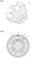
- FIG. 5shows a diagram for illustrating another embodiment of the invention.
- FIG. 1shows a diagram for illustrating a first exemplary embodiment of an electric machine according to the invention.
- the electric machine 1 shown in FIG. 1has an annular stator 2 and a rotor 3 arranged within the stator.
- the stator 2has a multiplicity of stator segments 4 in the circumferential direction.
- Each of these stator segments 4is assigned to one of the phases U, V or W of the alternating-current system. Consequently, the stator segments are designated by the letters U, V or W in FIG. 1 .
- each of these stator segments 4has two inner grooves 7 which are arranged in the region of the inner circumference 5 of the respective stator segment and which each extend in a radial direction.
- each of the stator segments 4has, in the region of its outer circumference 6 , a winding window 8 whose longitudinal direction extends in the circumferential direction of the stator.
- the inner grooves 7 and the winding window 8 of each stator segment 4serve for receiving the stator winding 9 , which is wound toroidally around the respective stator segment.
- each stator segment 4is partially surrounded at its radial outer side by stator segment outer arms 10 such that a radially directed outer gap 11 extending from the winding window 8 to the outer circumference 6 of the respective stator segment 4 is formed between the stator segment outer arms 10 .
- this outer gap 11are selected such that an additional magnetic circuit is formed in the region outside the stator, which additional magnetic circuit has a predefined inductance determined by the length and the width of the outer gap 11 . Consequently, a magnetic field of desired size can be built up outside the stator through suitable selection of the length and the width of the outer gap 11 .
- This magnetic field formed outside the statorhas no influence on the rotor 3 , arranged inside the stator 2 , of the electric machine, so that the B field or the associated harmonic amplitudes of the additional magnetic field have no undesired effects on the rotor.
- the outer gap 11extends radially outward from the central region, in the circumferential direction, of the winding window 8 to the outer circumference 6 of the respective stator segment 4 . Consequently, in this exemplary embodiment, the stator segment outer arms 10 have the same length in the circumferential direction of the respective stator segment 4 .
- the electric machine 1 illustrated in FIG. 1is a four-pole machine, for which a stator 2 is used which has a total of 24 inner grooves 7 on its inner circumference 5 .
- This statorhas a total of 12 stator segments 4 .
- Four of these stator segmentsare assigned to the phase U, four more of the stator segments are assigned to the phase V and the four remaining stator segments are assigned to the phase W.
- Each stator segment 4has two inner grooves 7 and a winding window 8 , wherein the stator winding associated with the respective stator segment is wound in toroidal fashion around the stator segment, wherein the winding window is dimensioned such that it can accommodate twice the number of conductors compared to the two inner grooves of the stator segment.
- stator magnetic field which is formed within the stator and which is coupled to the rotor of the electric machinecan be kept small, such that the influence of the harmonic amplitudes from the magnetic field formed within the stator on the rotor is kept low.
- FIG. 2shows a diagram for illustrating a second exemplary embodiment of an electric machine according to the invention.
- the statorhas a multiplicity of stator segments in the circumferential direction.
- each of these stator segmentsis assigned only one inner groove 7 arranged in the region of the inner circumference of the stator segment.
- each stator segmenthas a winding window 8 .
- the stator winding associated with the respective stator segmentis wound toroidally around the stator segment.
- the winding window 8is partially surrounded at its radial outer side by stator segment outer arms 10 such that a radially directed outer gap 11 extending from the winding window 8 to the outer circumference 6 of the respective stator segment is formed between the stator segment outer arms.
- the second exemplary embodimentdiffers from the first exemplary embodiment shown in FIG. 1 also in that the inner grooves 7 of the respective stator segment 4 do not end directly at the inner circumference 5 of the respective stator segment 4 , but are spaced apart from this inner circumference 5 .
- these inner groovesare partially surrounded at their radial inner side by stator segment inner arms 13 in such a way that a radially directed inner gap 14 extending from the inner groove 7 to the inner circumference 5 of the respective stator segment 4 is formed between the stator segment inner arms 13 .
- the advantage of this embodimentis that only small reluctance differences arise at the inner circumference of the stator in the circumferential direction. This results in lower losses in the rotor.
- the inner gap 14is widened in the circumferential direction in its transition region to the inner groove 7 of the respective stator segment.
- FIG. 3shows a diagram for illustrating a third exemplary embodiment of an electric machine according to the invention.
- This third exemplary embodimentdiffers from the second exemplary embodiment shown in FIG. 2 only in that the outer gap 11 is widened in the circumferential direction in its transition region to the outer circumference 6 of the stator segment 4 .
- This widening in the circumferential directionhas the advantage that the flow through the electrically conductive housing material surrounding the stator is reduced. This also reduces the eddy current losses.
- FIG. 4shows a diagram for explaining an embodiment of the invention.
- each stator segmenthas two inner grooves 7 arranged in the region of the inner circumference of the stator segment and has a winding window 8 arranged in the region of the outer circumference of the stator segment.
- the winding window 8is partially surrounded at its radial outer side by stator segment outer arms 10 such that a radially directed outer gap extending from the winding window 8 to the outer circumference 6 of the respective stator segment is formed between the stator segment outer arms.
- FIG. 4by contrast to the first exemplary embodiment shown in FIG.
- the stator segment outer arms 10are designed such that they can be folded over, wherein the stator segment outer arms 10 are shown in a first end position in FIG. 4 .
- This first end positionis the folded-open position of the stator segment outer arms.
- the winding window 8is opened up, such that the winding process of the stator winding is simplified.
- the stator segment outer arms 10are in their folded-closed position. In this folded-closed end position of the stator segment outer arms 10 , the outer gap 11 extending radially outward from the winding window 8 is kept free.
- stator segment outer armssuch that they can be folded over may also be used in electric machines according to the invention which have a different number of inner grooves per stator segment.
- FIG. 5shows a diagram of another embodiment of the invention.
- each stator segmenthas two inner grooves 7 arranged in the region of the inner circumference of the stator segment and has a winding window 8 arranged in the region of the outer circumference of the stator segment.
- the winding window 8is partially surrounded at its radial outer side by stator segment outer arms such that a radially directed outer gap extending from the winding window to the outer circumference of the respective stator segment is formed between the stator segment outer arms.
- bridges 12are mounted onto the stator outer arms. These bridges 12 are designed such that the outer gap extending from the winding window to the outer circumference of the respective stator segment is kept free.
- the bridges 12are preferably composed of iron powder or MPP core material.
- stator segmentshave an iron powder or MPP core in the region between the inner grooves 7 and the winding window 8 . This reduces the losses of the electric machine.
- An advantageous embodiment of the inventionconsists in equipping the electric machine with an additional winding, which serves as a sensor winding, in the region of the inner circumference of the stator segments.
- This additional windingis preferably a distributed winding composed of a very thin wire.
- the stator windingmay be a coil wound as one strand.
- the stator windingmay also be a coil that is not wound as one strand.
- stator windingmay be realized in the form of a delta connection or a star connection.
- the electric machinemay be a four-pole or a two-pole electric machine.
- the segments of the statormay be connected to one another using the dovetail technique. Alternatively, it is also possible to weld the segments of the stator together. A further alternative is to connect the segments of the stator to one another by means of plastics injection molding. Alternatively, instead of a dovetail connection, any other “puzzle geometry” may also be used to connect the stator segments.
- the complete statormay advantageously be enclosed by a potting composed of a thermally conductive material for the purposes of better heat dissipation.
- one insulation layermay be introduced between adjacent stator segments in order to prevent an occurrence of short circuits between adjacent lamination layers and an occurrence of eddy currents.
Landscapes
- Engineering & Computer Science (AREA)
- Power Engineering (AREA)
- Iron Core Of Rotating Electric Machines (AREA)
Abstract
Description
Claims (13)
Applications Claiming Priority (4)
| Application Number | Priority Date | Filing Date | Title |
|---|---|---|---|
| DE102017216631.2 | 2017-09-20 | ||
| DE102017216631.2ADE102017216631A1 (en) | 2017-09-20 | 2017-09-20 | Electric machine |
| DE102017216631 | 2017-09-20 | ||
| PCT/EP2018/071397WO2019057383A1 (en) | 2017-09-20 | 2018-08-07 | ELECTRICAL MACHINE |
Publications (2)
| Publication Number | Publication Date |
|---|---|
| US20200287435A1 US20200287435A1 (en) | 2020-09-10 |
| US11245300B2true US11245300B2 (en) | 2022-02-08 |
Family
ID=63143150
Family Applications (1)
| Application Number | Title | Priority Date | Filing Date |
|---|---|---|---|
| US16/648,298Active2038-12-06US11245300B2 (en) | 2017-09-20 | 2018-08-07 | Electric machine |
Country Status (4)
| Country | Link |
|---|---|
| US (1) | US11245300B2 (en) |
| CN (1) | CN111226382B (en) |
| DE (1) | DE102017216631A1 (en) |
| WO (1) | WO2019057383A1 (en) |
Families Citing this family (3)
| Publication number | Priority date | Publication date | Assignee | Title |
|---|---|---|---|---|
| DE102017216631A1 (en)* | 2017-09-20 | 2019-03-21 | Continental Automotive Gmbh | Electric machine |
| DE112022001002T5 (en)* | 2021-04-13 | 2023-12-07 | Hitachi Astemo, Ltd. | ROTATING ELECTRIC MACHINE |
| CN114785005A (en)* | 2022-05-12 | 2022-07-22 | 哈尔滨理工大学 | A permanent magnet fault-tolerant motor with double-slot structure |
Citations (38)
| Publication number | Priority date | Publication date | Assignee | Title |
|---|---|---|---|---|
| US3588888A (en)* | 1969-07-02 | 1971-06-28 | Bowmar Instrument Corp | Electromagnetic indicating apparatus |
| US3956651A (en)* | 1974-11-05 | 1976-05-11 | General Electric Company | Wire stator structure |
| US4103197A (en)* | 1975-03-19 | 1978-07-25 | Sony Corporation | Cylindrical core with toroidal windings at angularly spaced locations on the core |
| JPS5970155A (en) | 1982-10-14 | 1984-04-20 | Matsushita Electric Ind Co Ltd | Small-sized motor |
| US4547713A (en) | 1982-11-05 | 1985-10-15 | Kollmorgen Technologies Corporation | Toroidally wound brushless DC motor |
| US4563606A (en)* | 1982-07-14 | 1986-01-07 | Hitachi, Ltd. | Electric rotary machine with toroidal windings on an annular stator core |
| US5044897A (en)* | 1989-07-10 | 1991-09-03 | Regents Of The University Of Minnesota | Radial drive for implantable centrifugal cardiac assist pump |
| US5334899A (en)* | 1991-09-30 | 1994-08-02 | Dymytro Skybyk | Polyphase brushless DC and AC synchronous machines |
| US6177746B1 (en)* | 1999-10-21 | 2001-01-23 | Christopher N. Tupper | Low inductance electrical machine |
| US6211595B1 (en)* | 1997-07-18 | 2001-04-03 | Sankyo Seiki Mfg. Co., Ltd. | Armature structure of toroidal winding type rotating electric machine |
| JP2001103688A (en) | 1999-09-27 | 2001-04-13 | Ebara Corp | Bearingless rotating machine |
| US6236135B1 (en)* | 1998-12-10 | 2001-05-22 | Minebea Co., Ltd. | Toroidal core type actuator with phase separator |
| US6700271B2 (en)* | 2000-01-14 | 2004-03-02 | Harmonic Drive Systems, Inc. | Hybrid synchronous motor equipped with toroidal winding |
| US6924574B2 (en) | 2003-05-30 | 2005-08-02 | Wisconsin Alumni Research Foundation | Dual-rotor, radial-flux, toroidally-wound, permanent-magnet machine |
| US20050236920A1 (en) | 2001-11-27 | 2005-10-27 | Denso Corporation | Brushless rotary electric machine having tandem rotary cores |
| US7145280B2 (en)* | 2000-04-19 | 2006-12-05 | Wellington Drive Technologies Limited | Stator for a dynamoelectric machine having a split ferromagnetic core |
| WO2007043506A1 (en) | 2005-10-13 | 2007-04-19 | Matsushita Electric Industrial Co., Ltd. | Motor with two rotors |
| US7701101B2 (en)* | 2003-09-02 | 2010-04-20 | Cummins Generator Technologies Limited | Alternator assembly |
| US7768157B2 (en)* | 2006-10-30 | 2010-08-03 | Seiko Epson Corporation | Brushless motor |
| US7932650B2 (en)* | 2006-06-01 | 2011-04-26 | Panasonic Corporation | Motor stator and molded motor |
| US7965014B2 (en) | 2008-09-12 | 2011-06-21 | Honda Motor Co., Ltd. | Stator for electrical rotating machine |
| US20120161361A1 (en)* | 2009-04-22 | 2012-06-28 | Ansaldo Energia S.P.A | Method for pouring resin in a stator of an electric machine, in particular an axial flux electric machine |
| US8253299B1 (en)* | 2007-03-30 | 2012-08-28 | Rittenhouse Norman P | Wound magnetic flux channel transverse wound stator permanent magnet motor |
| US8258665B2 (en)* | 1993-01-22 | 2012-09-04 | Borealis Technical Limited | Motor winding |
| FR3005219A1 (en) | 2013-04-24 | 2014-10-31 | Bosch Gmbh Robert | AXIALLY SHORT ELECTRIC MACHINE WITH LITTLE NUMBER OF POLES |
| WO2015002453A1 (en) | 2013-07-03 | 2015-01-08 | 주식회사 아모텍 | Motor having divisional core stator and manufacturing method therefor |
| US20150180298A1 (en) | 2012-08-01 | 2015-06-25 | Nidec Motor Corporation | Motor stator with reduced coil configuration |
| US9171692B2 (en)* | 2011-08-19 | 2015-10-27 | Siemens Aktiengesellschaft | Drive for rotary anode with stator with yoke winding |
| US20160168775A1 (en) | 2013-07-19 | 2016-06-16 | Amotech Co., Ltd. | Washing machine motor and washing machine comprising same |
| US20160226322A1 (en) | 2015-01-30 | 2016-08-04 | Johnson Electric S.A. | Motor Armature |
| US9673675B2 (en)* | 2012-12-20 | 2017-06-06 | Lucchi R. Elettromeccanica S.R.L. | Stator of an axial flow electric machine and the process for making it |
| US9698648B2 (en)* | 2012-06-14 | 2017-07-04 | Panasonic Intellectual Property Management Co., Ltd. | Motor |
| US20180041083A1 (en)* | 2014-12-18 | 2018-02-08 | Siemens Aktiengesellschaft | Stator for an electrical machine |
| US9912203B2 (en)* | 2014-06-20 | 2018-03-06 | Lucchi R. Elettromeccanica Srl | Axial-flux electric machine with winding rotor and method for the production thereof |
| US10044250B2 (en)* | 2013-10-22 | 2018-08-07 | Denso Corporation | Armature, method for winding armature coil, and DC motor |
| US20200144875A1 (en)* | 2017-05-11 | 2020-05-07 | Mitsubishi Electric Corporation | Armature core of rotary electric machine |
| US20200287427A1 (en)* | 2017-09-20 | 2020-09-10 | Vitesco Technologies GmbH | Electric machine |
| US20200287435A1 (en)* | 2017-09-20 | 2020-09-10 | Vitesco Technologies GmbH | Electric machine |
Family Cites Families (2)
| Publication number | Priority date | Publication date | Assignee | Title |
|---|---|---|---|---|
| JP2006296035A (en)* | 2005-04-07 | 2006-10-26 | Mitsubishi Electric Corp | Toroidal winding motor and elevator hoisting machine using the same |
| CN102315746B (en)* | 2011-04-20 | 2014-07-02 | 华南理工大学 | Mixed excitation short-magnetic-circuit variable-reluctance motor |
- 2017
- 2017-09-20DEDE102017216631.2Apatent/DE102017216631A1/enactivePending
- 2018
- 2018-08-07CNCN201880061346.9Apatent/CN111226382B/enactiveActive
- 2018-08-07USUS16/648,298patent/US11245300B2/enactiveActive
- 2018-08-07WOPCT/EP2018/071397patent/WO2019057383A1/ennot_activeCeased
Patent Citations (42)
| Publication number | Priority date | Publication date | Assignee | Title |
|---|---|---|---|---|
| US3588888A (en)* | 1969-07-02 | 1971-06-28 | Bowmar Instrument Corp | Electromagnetic indicating apparatus |
| US3956651A (en)* | 1974-11-05 | 1976-05-11 | General Electric Company | Wire stator structure |
| US4103197A (en)* | 1975-03-19 | 1978-07-25 | Sony Corporation | Cylindrical core with toroidal windings at angularly spaced locations on the core |
| US4563606A (en)* | 1982-07-14 | 1986-01-07 | Hitachi, Ltd. | Electric rotary machine with toroidal windings on an annular stator core |
| JPS5970155A (en) | 1982-10-14 | 1984-04-20 | Matsushita Electric Ind Co Ltd | Small-sized motor |
| US4547713A (en) | 1982-11-05 | 1985-10-15 | Kollmorgen Technologies Corporation | Toroidally wound brushless DC motor |
| US5044897A (en)* | 1989-07-10 | 1991-09-03 | Regents Of The University Of Minnesota | Radial drive for implantable centrifugal cardiac assist pump |
| US5334899A (en)* | 1991-09-30 | 1994-08-02 | Dymytro Skybyk | Polyphase brushless DC and AC synchronous machines |
| US8258665B2 (en)* | 1993-01-22 | 2012-09-04 | Borealis Technical Limited | Motor winding |
| US6211595B1 (en)* | 1997-07-18 | 2001-04-03 | Sankyo Seiki Mfg. Co., Ltd. | Armature structure of toroidal winding type rotating electric machine |
| US6236135B1 (en)* | 1998-12-10 | 2001-05-22 | Minebea Co., Ltd. | Toroidal core type actuator with phase separator |
| JP2001103688A (en) | 1999-09-27 | 2001-04-13 | Ebara Corp | Bearingless rotating machine |
| US6177746B1 (en)* | 1999-10-21 | 2001-01-23 | Christopher N. Tupper | Low inductance electrical machine |
| US6700271B2 (en)* | 2000-01-14 | 2004-03-02 | Harmonic Drive Systems, Inc. | Hybrid synchronous motor equipped with toroidal winding |
| US7145280B2 (en)* | 2000-04-19 | 2006-12-05 | Wellington Drive Technologies Limited | Stator for a dynamoelectric machine having a split ferromagnetic core |
| US20050236920A1 (en) | 2001-11-27 | 2005-10-27 | Denso Corporation | Brushless rotary electric machine having tandem rotary cores |
| US7023121B2 (en)* | 2001-11-27 | 2006-04-04 | Denso Corporation | Brushless rotary electric machine having tandem rotary cores |
| US6924574B2 (en) | 2003-05-30 | 2005-08-02 | Wisconsin Alumni Research Foundation | Dual-rotor, radial-flux, toroidally-wound, permanent-magnet machine |
| US7701101B2 (en)* | 2003-09-02 | 2010-04-20 | Cummins Generator Technologies Limited | Alternator assembly |
| WO2007043506A1 (en) | 2005-10-13 | 2007-04-19 | Matsushita Electric Industrial Co., Ltd. | Motor with two rotors |
| US20090091204A1 (en) | 2005-10-13 | 2009-04-09 | Matsushita Electric Industrial Co., Ltd. | Motor having twin-rotor |
| US8035265B2 (en) | 2006-06-01 | 2011-10-11 | Panasonic Corporation | Motor stator and molded motor |
| US7932650B2 (en)* | 2006-06-01 | 2011-04-26 | Panasonic Corporation | Motor stator and molded motor |
| US7768157B2 (en)* | 2006-10-30 | 2010-08-03 | Seiko Epson Corporation | Brushless motor |
| US8253299B1 (en)* | 2007-03-30 | 2012-08-28 | Rittenhouse Norman P | Wound magnetic flux channel transverse wound stator permanent magnet motor |
| US7965014B2 (en) | 2008-09-12 | 2011-06-21 | Honda Motor Co., Ltd. | Stator for electrical rotating machine |
| US20120161361A1 (en)* | 2009-04-22 | 2012-06-28 | Ansaldo Energia S.P.A | Method for pouring resin in a stator of an electric machine, in particular an axial flux electric machine |
| US9171692B2 (en)* | 2011-08-19 | 2015-10-27 | Siemens Aktiengesellschaft | Drive for rotary anode with stator with yoke winding |
| US9698648B2 (en)* | 2012-06-14 | 2017-07-04 | Panasonic Intellectual Property Management Co., Ltd. | Motor |
| US20150180298A1 (en) | 2012-08-01 | 2015-06-25 | Nidec Motor Corporation | Motor stator with reduced coil configuration |
| US9673675B2 (en)* | 2012-12-20 | 2017-06-06 | Lucchi R. Elettromeccanica S.R.L. | Stator of an axial flow electric machine and the process for making it |
| FR3005219A1 (en) | 2013-04-24 | 2014-10-31 | Bosch Gmbh Robert | AXIALLY SHORT ELECTRIC MACHINE WITH LITTLE NUMBER OF POLES |
| DE102013207469A1 (en) | 2013-04-24 | 2014-11-13 | Robert Bosch Gmbh | Stator winding for axially short electrical machines of small number of poles |
| WO2015002453A1 (en) | 2013-07-03 | 2015-01-08 | 주식회사 아모텍 | Motor having divisional core stator and manufacturing method therefor |
| US20160168775A1 (en) | 2013-07-19 | 2016-06-16 | Amotech Co., Ltd. | Washing machine motor and washing machine comprising same |
| US10044250B2 (en)* | 2013-10-22 | 2018-08-07 | Denso Corporation | Armature, method for winding armature coil, and DC motor |
| US9912203B2 (en)* | 2014-06-20 | 2018-03-06 | Lucchi R. Elettromeccanica Srl | Axial-flux electric machine with winding rotor and method for the production thereof |
| US20180041083A1 (en)* | 2014-12-18 | 2018-02-08 | Siemens Aktiengesellschaft | Stator for an electrical machine |
| US20160226322A1 (en) | 2015-01-30 | 2016-08-04 | Johnson Electric S.A. | Motor Armature |
| US20200144875A1 (en)* | 2017-05-11 | 2020-05-07 | Mitsubishi Electric Corporation | Armature core of rotary electric machine |
| US20200287427A1 (en)* | 2017-09-20 | 2020-09-10 | Vitesco Technologies GmbH | Electric machine |
| US20200287435A1 (en)* | 2017-09-20 | 2020-09-10 | Vitesco Technologies GmbH | Electric machine |
Also Published As
| Publication number | Publication date |
|---|---|
| CN111226382B (en) | 2022-11-18 |
| US20200287435A1 (en) | 2020-09-10 |
| WO2019057383A1 (en) | 2019-03-28 |
| CN111226382A (en) | 2020-06-02 |
| DE102017216631A1 (en) | 2019-03-21 |
Similar Documents
| Publication | Publication Date | Title |
|---|---|---|
| JP5354302B2 (en) | Rotating electric machine stator | |
| CN103548242B (en) | For the manufacture of the method for the stator winding of the motor of alternating current generator especially | |
| US11245300B2 (en) | Electric machine | |
| KR101514122B1 (en) | Rotary electric machine | |
| US11626784B2 (en) | Stator structure and resolver | |
| US20120086288A1 (en) | Electric rotating machine | |
| US9660495B2 (en) | Stator for a high-temperature electric motor and electric motor | |
| US20170366075A1 (en) | Synchronous Reluctance Motor | |
| CN107078582B (en) | Stator for electric machine | |
| JP2019193471A (en) | Rotary electric machine stator | |
| CN104380576A (en) | Stator of rotary electric machine | |
| US10454348B2 (en) | Stator for rotating electrical machine | |
| US10236735B2 (en) | Electric conductor for coil and rotating electric machine | |
| US20220263371A1 (en) | Stator of a brushless electric motor | |
| CN110164672A (en) | The stator structure and rotary transformer of rotary transformer | |
| US11437872B2 (en) | Electric machine with stator segments and winding supports | |
| US20120001516A1 (en) | Stator for electric rotating machine and method of manufacturing the same | |
| KR20160026779A (en) | Winding arrangement and method for producing a winding arrangement | |
| TW202101858A (en) | Armature structure of three-phase motor | |
| JP2015226395A (en) | Stator of rotary electric machine | |
| US20230034199A1 (en) | Method for winding a stator of a brushless direct current motor | |
| US20230223829A1 (en) | Stator structure and resolver | |
| US20180278111A1 (en) | Rotating electric machine | |
| US2788458A (en) | High starting torque induction motor rotor | |
| US20060250042A1 (en) | Dynamoelectric machine with ring type rotor and stator windings |
Legal Events
| Date | Code | Title | Description |
|---|---|---|---|
| FEPP | Fee payment procedure | Free format text:ENTITY STATUS SET TO UNDISCOUNTED (ORIGINAL EVENT CODE: BIG.); ENTITY STATUS OF PATENT OWNER: LARGE ENTITY | |
| AS | Assignment | Owner name:VITESCO TECHNOLOGIES GMBH, GERMANY Free format text:ASSIGNMENT OF ASSIGNORS INTEREST;ASSIGNORS:STAUDER, PETER;LUEDDECKE, BERNHARDT, DR.;VORNWEG, LARS;AND OTHERS;SIGNING DATES FROM 20200212 TO 20200218;REEL/FRAME:052289/0935 | |
| STPP | Information on status: patent application and granting procedure in general | Free format text:APPLICATION DISPATCHED FROM PREEXAM, NOT YET DOCKETED | |
| STPP | Information on status: patent application and granting procedure in general | Free format text:DOCKETED NEW CASE - READY FOR EXAMINATION | |
| STPP | Information on status: patent application and granting procedure in general | Free format text:NOTICE OF ALLOWANCE MAILED -- APPLICATION RECEIVED IN OFFICE OF PUBLICATIONS | |
| STPP | Information on status: patent application and granting procedure in general | Free format text:PUBLICATIONS -- ISSUE FEE PAYMENT RECEIVED | |
| STPP | Information on status: patent application and granting procedure in general | Free format text:PUBLICATIONS -- ISSUE FEE PAYMENT VERIFIED | |
| STCF | Information on status: patent grant | Free format text:PATENTED CASE | |
| MAFP | Maintenance fee payment | Free format text:PAYMENT OF MAINTENANCE FEE, 4TH YEAR, LARGE ENTITY (ORIGINAL EVENT CODE: M1551); ENTITY STATUS OF PATENT OWNER: LARGE ENTITY Year of fee payment:4 |