US11243450B2 - Saw modulator having optical power component for extended angular redirection of light - Google Patents
Saw modulator having optical power component for extended angular redirection of lightDownload PDFInfo
- Publication number
- US11243450B2 US11243450B2US16/150,929US201816150929AUS11243450B2US 11243450 B2US11243450 B2US 11243450B2US 201816150929 AUS201816150929 AUS 201816150929AUS 11243450 B2US11243450 B2US 11243450B2
- Authority
- US
- United States
- Prior art keywords
- modulator
- optical power
- power component
- saw
- substrate
- Prior art date
- Legal status (The legal status is an assumption and is not a legal conclusion. Google has not performed a legal analysis and makes no representation as to the accuracy of the status listed.)
- Active, expires
Links
Images


Classifications
- G—PHYSICS
- G02—OPTICS
- G02F—OPTICAL DEVICES OR ARRANGEMENTS FOR THE CONTROL OF LIGHT BY MODIFICATION OF THE OPTICAL PROPERTIES OF THE MEDIA OF THE ELEMENTS INVOLVED THEREIN; NON-LINEAR OPTICS; FREQUENCY-CHANGING OF LIGHT; OPTICAL LOGIC ELEMENTS; OPTICAL ANALOGUE/DIGITAL CONVERTERS
- G02F1/00—Devices or arrangements for the control of the intensity, colour, phase, polarisation or direction of light arriving from an independent light source, e.g. switching, gating or modulating; Non-linear optics
- G02F1/29—Devices or arrangements for the control of the intensity, colour, phase, polarisation or direction of light arriving from an independent light source, e.g. switching, gating or modulating; Non-linear optics for the control of the position or the direction of light beams, i.e. deflection
- G02F1/33—Acousto-optical deflection devices
- G02F1/335—Acousto-optical deflection devices having an optical waveguide structure
- G—PHYSICS
- G02—OPTICS
- G02F—OPTICAL DEVICES OR ARRANGEMENTS FOR THE CONTROL OF LIGHT BY MODIFICATION OF THE OPTICAL PROPERTIES OF THE MEDIA OF THE ELEMENTS INVOLVED THEREIN; NON-LINEAR OPTICS; FREQUENCY-CHANGING OF LIGHT; OPTICAL LOGIC ELEMENTS; OPTICAL ANALOGUE/DIGITAL CONVERTERS
- G02F2201/00—Constructional arrangements not provided for in groups G02F1/00 - G02F7/00
- G02F2201/30—Constructional arrangements not provided for in groups G02F1/00 - G02F7/00 grating
- G02F2201/305—Constructional arrangements not provided for in groups G02F1/00 - G02F7/00 grating diffraction grating
- G—PHYSICS
- G02—OPTICS
- G02F—OPTICAL DEVICES OR ARRANGEMENTS FOR THE CONTROL OF LIGHT BY MODIFICATION OF THE OPTICAL PROPERTIES OF THE MEDIA OF THE ELEMENTS INVOLVED THEREIN; NON-LINEAR OPTICS; FREQUENCY-CHANGING OF LIGHT; OPTICAL LOGIC ELEMENTS; OPTICAL ANALOGUE/DIGITAL CONVERTERS
- G02F2201/00—Constructional arrangements not provided for in groups G02F1/00 - G02F7/00
- G02F2201/34—Constructional arrangements not provided for in groups G02F1/00 - G02F7/00 reflector
Definitions
- ROMsAcousto-optic modulators
- SAWsurface acoustic wave
- SAW modulatoris the guided-to-leaky-mode device fabricated using lithium niobate as described, for example, in Hinkov et al., Collinear Acoustooptical TM - TE Mode Conversion in Proton Exchanged Ti:LiNbO 3 Waveguide Structures , J. Lightwave Tech., vol. 6(6), pp. 900-08 (1988), Smalley et al., Anisotropic leaky-mode modulator for holographic video displays, Nature, vol. 498, pp. 313-317 (2013); McLaughlin et al., Optimized guided - to - leaky - mode device for graphics processing unit controlled frequency division of color , Appl. Opt., vol.
- SAWssurface acoustic waves diffract light propagating in the modulators' waveguides and cause at least some of the light to change from guided modes to leaky modes that exit the waveguides at angles dictated in part by the frequency of the light and the frequency of the SAWs.
- SAW-based light field generatorscan be designed to project light of various intensities as a function of angle, even simultaneously, for each emissive region. This is different than the majority of 3-D display technologies, such as lenticular and integral photography displays, which use spatial multiplexing: each display pixel is divided into subpixels with different emission directions, disadvantageously trading off spatial resolution and direction resolution.
- SAW modulator-based light field generator systemshave limitations.
- One approachmight be to increase the bandwidth of radio frequency (RF) drive signals applied to SAW modulators. This correspondingly creates Surface Acoustic Waves (SAWs) of an increasingly broader spectral range within the SAW modulators, which diffract the light at a wider range of angles to create wider fields of view.
- RF bandwidthtypically provides only nominal increases.
- SAW modulatorsare arranged in pairs to double the field of view as compared to unitary configurations of SAW modulators. However, twice as many SAW modulators are required to produce the desired range of emitted light, which increases cost, and limits the compactness of displays.
- additional interconnections and control signaling between the pairs of SAW modulatorsare required, which increases complexity.
- the present inventionconcerns AOMs and more specifically SAW modulators and the light steering and field generator systems including these devices.
- the systems and/or the modulatorsemploy at least one optical element acting with optical power.
- a power optical elementis said to “act with optical power” when it is constructed to have a non-zero diopter rating.
- the optical power componentis a curved mirror or has volume features including reflective, refractive, or diffractive optical structures. Examples include volume diffraction gratings and volume holographic optical elements.
- the optical power componentis incorporated within the system by either embedding the optical power component within the substrate of the modulator, or by placing/mounting/forming the optical power component upon a surface of the modulator, in examples.
- Modulators that incorporate optical power componentshave advantages.
- the optical power componentscan broaden the otherwise limited native optical redirection capability compared with current modulators.
- the optical power componentscan further beneficially redirect the outgoing light so that it is within the SAW modulator's total internal reflection (TIR) exit cone.
- TIRtotal internal reflection
- the inventionfeatures a SAW modulator, which includes at least one optical power component.
- the optical power componentmight be embedded within a substrate of the SAW modulator or is placed upon, mounted to, and/or fabricated in a surface of the SAW modulator.
- optical power componentmight have the function of a concave mirror or convex mirror or refractive lens.
- the optical power componentmight be a volume grating, volume holographic optical element, reflective surface grating, or a mirror coated curved surface of the modulator's substrate.
- the optical power componentcan be used to direct light out of a distal face or a proximal face of the modulator.
- the optical power componenthas a power in the range of +/ ⁇ 100 to +/ ⁇ 10,000 diopters.
- the inventionfeatures a SAW modulator light field generator system. It comprises a substrate, series of optical modulators integrated side-by-side in the substrate; and at least one optical power component for directing light from optical modulators.
- Each optical power componentmight extend across all of the modulators in the substrate. Moreover, there might be two or more optical power components located along the length of the optical modulators.
- the inventionfeatures a method for generating a light field.
- the methodcomprises generating radio frequency drive signals, diffracting light from waveguides of optical modulators integrated in a substrate by generating surface acoustic waves from the radio frequency drive signals; and expanding a range of exit angles of light from the substrate with at least one optical power component.
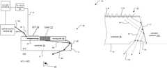
- FIG. 1is a schematic side view of a leaky-mode SAW modulator that illustrates several limitations associated with the devices;
- FIG. 2Ais a schematic side view of a leaky-mode SAW modulator including a concave optical power component that is embedded within a substrate of the SAW modulator, showing a ray path of light incident upon a distal portion optical power component and exiting out the distal face of the modulator;
- FIG. 2Bis a schematic side view of a leaky-mode SAW modulator including a concave optical power component that is embedded within a substrate of the SAW modulator, showing a ray path of light incident upon the optical power component and exiting out the proximal face of the modulator;
- FIG. 3is a schematic side view of a SAW modulator including the embedded concave optical power component, showing a ray path of light incident upon a proximal portion of the optical power component;
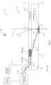
- FIGS. 4A and 4Bare schematic side views of SAW modulators including embedded convex optical power components, showing how varying the spatial frequency of the SAW affects the output optical signals through the distal or proximal faces, respectively;
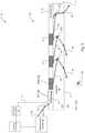
- FIG. 5is a schematic side view of a SAW modulator including three concave optical power components distributed along the length of the waveguide, showing a ray path of light incident upon the components;
- FIG. 6Ais a schematic side view of a SAW modulator including a concave optical power component that is formed on a mirror-coated curved end face of the modulator's substrate;
- FIGS. 6B and 6Cshow schematic side views of portions of other SAW modulators that include powered refractive optical components, such as concave and convex lenses, to increase the deflection angle, and convex optics;
- powered refractive optical componentssuch as concave and convex lenses
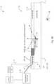
- FIG. 7is a schematic side view of a SAW modulator including an embedded convex optical power component, illustrating operation of the light field generator system when changing the frequency of the SAW;
- FIG. 8is a schematic side view of a SAW modulator including an embedded concave optical power component along with a spacer layer placed adjacent to a SAW modulator substrate, which carries a refractive lens optical power component;
- FIG. 9is a schematic side view of a SAW modulator including an embedded concave optical power component along with a diffractive optical power component on a distal/exit face of the substrate;
- FIG. 10is a schematic block diagram of a Red/Green/Blue (RGB) light field generator system utilizing the previously disclosed SAW modulators.
- RGBRed/Green/Blue
- the term “and/or”includes any and all combinations of one or more of the associated listed items. Further, the singular forms of the articles “a”, “an” and “the” are intended to include the plural forms as well; unless expressly stated otherwise. It will be further understood that the terms: includes, comprises, including and/or comprising, when used in this specification, specify the presence of stated features, integers, steps, operations, elements, and/or components, but do not preclude the presence or addition of one or more other features, integers, steps, operations, elements, components, and/or groups thereof. Further, it will be understood that when an element, including component or subsystem, is referred to and/or shown as being connected or coupled to another element, it can be directly connected or coupled to the other element or intervening elements may be present.
- FIG. 1shows a side view of a leaky-mode SAW modulator 32 within a light steering system 10 . It illustrates the general construction and operation of the SAW modulator, and why solely varying the RF drive signal frequency might not be the best approach to changing the angle at which the light is emitted from the modulator 32 .
- the SAW modulator 32is formed from a substrate 36 that is preferably made of a piezoelectric material such as lithium niobate, in one example.
- the substrate 36can be manufactured entirely of the piezoelectric material, or the piezoelectric material can be deposited upon or bonded to a different secondary substrate material, in examples.
- the substrate 36includes an array of SAW modulators, arrayed next to each other, side-by-side, extending into the plane of the figure.
- the illustrated SAW modulator 32includes an interdigital transducer (IDT) 24 and at least one waveguide 48 .
- the IDT 24is typically patterned upon the proximal surface 19 of the substrate 36 .
- the waveguides 48are typically formed within the substrate, such as by proton-exchanged ion channel or laser micromachined region.
- Each waveguidecan transmit one, several, or a continuum of wavelengths.
- the multiple waveguides formed within the substrate 36might be configured for different wavelengths of light, such as red, green and blue for a visual display system, such as a holographic display.
- the three configurationsare: light exiting from a surface ( 16 or 19 ) that is principally parallel to the waveguide (face-fire), light exiting from a surface ( 17 ) that is perpendicular to the waveguide (edge-fire), and intermediate cases.
- the SAW modulator 32also preferably includes a reflective diffraction grating 50 .
- the reflective diffraction grating 50is bonded to, patterned into or formed upon the face of the substrate 36 that is opposite the waveguide 48 . This placement of the reflective diffraction grating 50 enables light that exits the waveguide 48 to be reflected out of the system 10 at face 19 , which is proximal to the waveguide 48 .
- a source of illuminationsuch as an optical source module 40 provides light signals 26 to the SAW modulator 32 .
- An in-coupling prism 18is placed upon the surface 19 of the SAW modulator 32 and couples the light signals 26 into the optical waveguide 48 .
- Other coupling mechanismscan be used, however.
- a short listincludes butt-coupled fibers, in-coupling gratings and in-coupling of free space propagating light.
- the optical source module 40is often a laser such that the light signals 26 are of the same or narrow range of wavelengths.
- an RF signal generator 25connects to the IDT 24 .
- An RE drive signal 15 generated by the RF signal generator 25is applied to the IDT 24 through intervening RE feedlines. Due to the piezoelectric properties of the substrate 36 , the RF drive signal 15 causes the IDT 24 to induce a surface acoustic wave (SAW) 22 traveling chiefly through the waveguide 48 .
- SAWsurface acoustic wave
- the light signals 26interact with the SAW 22 .
- the diffraction of the waveguide light 26 by the SAW 22converts part of the light to transverse magnetic (TM) polarization.
- TMtransverse magnetic
- the TM polarized light signalsare in leaky mode(s) of the waveguide 48 .
- Light of the leaky modesenters the bulk substrate 36 as diffracted light 46 at diffraction angle ⁇ , relative to grazing 77 .
- These light signals 46propagate within the substrate 36 generally in a direction indicated by reference A.
- the light signals 46can typically then be transmitted out of the SAW modulator 32 according to any of paths B, C, or D.
- paths B, C, or Dthere are different design challenges associated with getting the light signals 46 to traverse the different paths B, C, or D.
- the diffracted light signals 46leave the waveguide 48 at an angle of, for example, approximately 20° from the waveguide axis, grazing 77 .
- the light signals 46then approach the distal face 16 at angle ⁇ , which is approximately 70° from normal 78 .
- the light signals 46are directed along paths C and D, respectively.
- reflective diffraction grating 50is employed to redirect the light signals 46 back through the substrate 36 and towards the proximal surface 19 .
- the reflective diffraction grating 50redirects the light signals 46 at an angle that is normal (or nearly normal) to the proximal surface 19 , thus enabling transmission of the signals 46 out of the SAW modulator 32 via proximal surface 19 at exit angle ⁇ after some refraction at the face 19 .
- a transmissive diffraction grating 50is constructed to redirect the light signals 46 at an angle that is normal (or nearly normal) to the distal surface 16 for transmission along path C.
- the optical redirection capabilityis still largely dictated by the bandwidth of the RF signal generator 25 and the refractive index mismatch between the ambient environment and the substrate 36 .
- FIG. 2Ashows a SAW modulator 32 that incorporates an optical power component 29 that is embedded within the substrate 36 , which can be used to effectively amplify the optical redirection capability.
- the illustrated optical componenthas a concave curvature to provide a positive dioptric power.
- the substrate 36includes an array of SAW modulators, arrayed next to each other, side-by-side, extending into the plane of the figure. In the typical substrate, there would be more than 3-5 modulators. At higher levels of integration, possibly 10, 20, or 50 or more modulators are formed in the substrate 36 .
- the optical power component 29is a reflective embedded concave surface such as: 1) a mirrored surface embedded in the substrate 36 , 2) a volume grating fabricated in the substrate 36 , or 3) a volume holographic element having the function of a concave mirrored surface in the substrate 36 .
- the optical power component 29takes the form of a curved surface such as a paraboloid cylindrical or hyperbolic surface. The surface extends into the plane of the page so that one element functions as a powered element of each of the side-by-side modulators integrated into the common substrate 36 .
- the profile of the optical powered element 29varies in a direction perpendicular to the plane of the page, e.g. with a twist.
- the optical powered element 29provides a different, orthogonal axis of beam steering for the different modulators in the substrate 36 . This is useful as a full-parallax display rather than a horizontal-parallax-only display.
- the volume grating or the volume holographic elementare typically fabricated by femtosecond laser writing or by holographic methods (for example, if the substrate or a portion of the substrate 36 is photorefractive), in examples. As such, the volume grating and the volume holographic element might in fact occupy a rectangular volume within the substrate.
- volume grating and the volume holographic elementmight in fact occupy a rectangular volume within the substrate.
- one of the original articles on the theory behind volume gratingsis authored by Kogelnik, H, and entitled “Coupled Wave Theory for Thick Hologram Gratings.” Bell System Technical Journal, 48(9), 2909-2947, November 1969.
- a more recent paper describing a useful computational method to design diffractive optical power componentsis authored by Zhou, G., Chen, Y., Wang, Z., &.
- the optical power component 29redirects rays of the diffracted light signals 46 that are incident upon the surface of the optical power component 29 with a greater angular extent than the planar reflective diffractive grating discussed earlier.
- the optical power component 29can redirect the light signals 46 to be aligned either normal to or nearly normal to an exit face, such as the distal surface 16 . This enables direct transmission of the signals 46 out of the distal surface 16 and to the observer 99 , thus eliminating or reducing the need for additional optical structures (such as a transmissive diffractive grating 50 in FIG. 1 ) to provide the same function.
- the optical power component 29is preferably designed to have a shape and optical power to change the optical path of the light signals 46 and thus the exit angle ⁇ with relatively small changes in the spatial frequency of the SAW 22 /frequency of the RF drive signal 15 and thus diffraction angle ⁇ .
- the rays of the light signals 46are incident upon a bottom portion of the optical power component 29 .
- the optical power component 29directs the light signals 46 downward and rearward towards the bottom surface 16 .
- the exit light angle ⁇varies over a range of greater than 45 degrees and possibly by more than 90 degrees with the frequency changes in the RF drive signal 15 .
- the optical power component 29redirects the light signals 46 at an angle that is closer to normal or nearly normal to the distal surface 16 in many cases. This eliminates the need for the diffraction grating 50 shown in FIG. 1 to ensure that light is coupled out of the substrate 36 .
- Each optical power component 29 embedded within and/or placed upon each SAW modulator 32forms a notional pixel of a display device, in one example.
- FIG. 2Bshows another SAW modulator 32 that incorporates an optical power component 29 that is embedded within the substrate 36 .
- the optical power componentis oriented to reflect the diffracted light 46 out of the proximal face 19 .
- FIG. 3shows the path of the diffracted light signals 46 within and from the substrate 36 when a ray is incident on the “top” of the reflective concave optical power component 29 .
- the light signals 46 incident upon the top of the optical power component 29are reflected at a greater angle by the optical power component 29 than in FIG. 2 , As a result, the direction of the light signals 46 upon exiting the SAW modulator 32 is different than in FIG. 2 .
- This large change in the direction ( ⁇ ranging from obtuse to acute) between FIGS. 2A and 3can be achieved with a modest change in the SAW/RF drive signal frequency, which is generally a desirable characteristic.
- FIG. 4Ashows a SAW modulator 32 that incorporates an embedded optical power component 29 that has a convex curvature to provide a negative dioptric power and shows how the exit light angle varies with changes in the frequency of the RF drive signals 15 .
- the controller module 60By modulating the frequency of the RF drive signals 15 , the diffraction angle of the light signals 46 transmitted out of the SAW modulator 32 varies between ⁇ 1 to ⁇ 2 to ⁇ 3 , which is a relatively small angular range.
- the illumination profile, or a fan of light formed by the diffracted light signals 46is dictated by the properties of the induced SAW 22 and can thus be regulated to produce the desired output light field.
- the controller module 60generates the RF drive signals 15 with three frequencies such as low, medium, and high frequency values of the RF drive signals 15 , as shown. These frequencies might be generated serially in time or as different frequency components of a single drive signal.
- the resulting three different spatial frequencies for the SAW 22are then produced within the waveguide 48 for each of the three frequencies of the RF drive signals 15 .
- the change in spatial frequency of the SAW 22correspondingly changes the locations at which the diffracted light signals 46 are incident upon the optical power component 29 , assuming that the SAWs interact with the light signals 26 at the same position along the waveguide 48 .
- the different locationsare indicated by where the different light signals 46 - 1 , 46 - 2 , and 46 - 3 impinge on the optical power component 29 .
- the light signals 46are then reflected by the optical power component 29 .
- Each of the light signals 46 - 1 , 46 - 2 , and 46 - 3are transmitted out of the SAW modulator 32 in different directions, as shown.
- Each of the signals 46 - 1 / 42 - 2 / 46 - 2are transmitted in different directions, as a function of the local spatial frequency components of the SAW 22 that contributed to the formation of the light signals 46 - 1 , 46 - 2 , and 46 - 3 .
- modulation of the RF drive signals 15can “steer” the light signals 46 transmitted out of the SAW modulator 32 in different directions and over a wide range of ⁇ .
- the SAW 22 created within the waveguide 48might have a continuously varying frequency, such as a frequency ramp. This can broaden the footprint of light signals 46 emerging with the same angle. This can also provide a continuous, rather than a discrete collection, and optionally amplitude-modulated, fan of exit light.
- the embedded optical power component 29has the convex curvature that provides a negative dioptric power. As a result, an even wider angular extent of light signals emitted from the SAW modulator is achieved.
- the optical power component 99typically has a paraboloid, cylindrical, or hyperbolic surface profile, which extends into the plane of the page.
- the same optical power componentreflects the light from the different modulators.
- FIG. 4Bshows a related embodiment in which the optical power component 99 is rotated, relative to FIG. 4A , to direct the optical signals to exit the proximal face 19 .
- FIG. 5shows another embodiment of a SAW modulator 32 .
- the system 10incorporates multiple optical power components 29 - 1 , 29 - 2 , and 29 - 3 .
- the optical power components 29are embedded within the substrate 36 at different locations along the length of the SAW modulator 32 . While the example shows concave optical components 29 - 1 , 29 - 2 , and 29 - 3 with positive dioptric power, convex optical components 29 - 1 , 29 - 2 , and 29 - 3 with negative dioptric power would be used in other examples.
- Another examplehas combinations of convex and concave optical components such that optical components 29 - 1 , and 29 - 3 are convex and optical component 29 - 2 is concave, or vice versa. And in still further combinations, the optical components 29 - 1 , 29 - 2 , and 29 - 3 are rotated from their illustrated orientations in still other embodiments to direct the light to exit out the proximal face 19 .
- an optical designercan “tile” or pixelate the entire length of an exit face of the SAW modulator 32 .
- the controller module 60coordinates the instantaneous locations of the SAWs 22 as they travel along the length of the waveguide 48 with the locations of and spacing between the optical power components 29 - 1 , 29 - 2 , and 29 - 3 .
- an exit facesuch as the distal surface 16 of the SAW modulator can effectively be partitioned into notional pixels.
- FIG. 6Ashows yet another embodiment of a SAW modulator 32 , Unlike the embodiments described thus far, the system 10 incorporates an optical power component 29 that is formed on an optically curved surface.
- the surfaceis fabricated into the substrate 36 , and possibly coated with a metal or dielectric mirror layer.
- the curved surfaceis fabricated into an end face 17 of the modulator's substrate 36 .
- the optical power componentmight be placed/mounted on a surface of the SAW modulator 32 such as the distal face 16 .
- Such surface optical featuresmay be created by sawing, lithography, embossing, or other methods.
- the optical power component 29is a diffractive element.
- a transmissive optical power component 29is a surface formed by removing material from the lithium niobate substrate 36 at the distal face 16 as an exit face to create a concave optical power component.
- the curved optical surfaceprovides diverging optical power, thereby broadening the angular extent of the diffracted light 46 .
- optical elements that provide the optical powermight be placed upon an exit face, patterned flat on a surface such as an exit face, and included as part of a later optical train.
- FIG. 6Cis another example of a transmissive optical power component 29 ,
- the component 29is formed by adding material to the lithium niobate substrate 36 at the distal face 16 as an exit face to create a convex optical surface.
- FIG. 7shows another embodiment of a SAW modulator 32 .
- This modulatorhas an embedded optical power component 29 that is convex. The effect of varying the frequency of the RF drive signals 15 applied to the system 10 is also shown.
- RF drive signals 15 of three different frequenciesare applied to the IDT 24 of the SAW modulator 32 , either sequentially or simultaneously.
- light signals 46 - 1 , 46 - 2 , and 46 - 3are emitted from the SAW modulator 32 at similar directions but displaced along the distal face 16 .
- the “footprint” for a given anglecan be broader at exit.
- FIG. 8shows another embodiment of a SAW modulator 32 .
- This modulatorincorporates two optical power components.
- the second optical power component 29 Sis formed on, attached to, or fabricated in a spacer layer 38 .
- the second optical power component 29 Sis placed adjacent to proximal surface 19 S of the spacer layer 38 .
- the spacer layeris epoxy bonded to the substrate 36 using a low refractive index epoxy.
- spacer layer 38is aligned to be parallel with the axis of waveguide 48 , and is placed below the distal surface 16 of the SAW modulator 32 .
- the spacer layeris preferably formed from a transmissive material such as glass.
- the first optical power component 29 - 1is a concave mirror, embedded within the substrate 36 of the SAW modulator 32 .
- the second optical power component 29 Sis a refractive microlens that is placed upon a proximal surface 19 S of the spacer layer 38 .
- the first and second optical power componentsform a notional “telescope array” for increasing the angular extent of the light signals 46 emitted from the SAW modulator 32 , as disclosed in U.S. Provisional application Ser. No. 16/041,040, filed on Jul. 20, 2018, entitled “Telescope Arrays and Superimposed Volume Gratings for Light Field Generation.”
- the optical power components 29 discussed in the previous embodimentscan cover a wide range of power.
- the components 29typically have a power of +/ ⁇ 1000 diopters, but the power is conceivably in the range +/ ⁇ 100 to +/ ⁇ 10,000 diopters, or much less than 100 diopters if the image depth is centered at a plane much different than the plane of the device.
- FIG. 9shows another embodiment of a SAW modulator 32 with two optical power components 29 - 1 , 29 - 2 .
- the first optical power component 29 - 1is embedded within the substrate of the SAW modulator 32 .
- the second optical power component 29 - 2is a diffractive lens that is placed upon, mounted to, or fabricated in the distal surface 16 .
- the first optical power component 29 - 1by itself may not be able to align the light signals 46 with sufficient accuracy.
- the inclusion of the second optical power component 29 - 2can simplify the design of and tolerance for other optical components.
- diffracted light signals 46 that are incident upon extreme proximal/distal edges of the first optical power component 29 - 1are reflected at a lesser angular extent than signals that strike near the center of the first optical power component 29 - 1 .
- the first optical power component 29 - 1still provides some redirection of the light signals 46 .
- any additional optical structures, such as the second optical component 29 - 2will typically require less resolving power, as compared to similar optical structures mounted near exit faces of SAW modulators 32 that lack optical power components.
- FIG. 10shows how the previously-described SAW modulators might be utilized in an RGB light field generator system 12 and integrated side-by-side in a common substrate 36 .
- the RGB light field generator system 12includes the controller module 60 , the optical source module 40 , the RF signal generator 25 , an optional splitter/switch 49 , and the substrate 36 as might be used as a component of a display system.
- the optical source module 40includes three sources 9 - 1 , 9 - 2 , and 9 - 3 , respectively providing red, green, and blue light according to one primary color pallet.
- the optical source module 40 and the splitter/switch 49are under control of the controller module 60 .
- the substrate 36includes waveguides 48 that are fabricated to accept and transmit light signals 26 of either red ( 26 - 1 ), green ( 26 - 2 ), or blue ( 26 - 3 ) wavelengths.
- waveguides 48are arranged in waveguide banks 58 - 1 . . . 58 -N.
- waveguide bank 58 - 1includes three waveguides 48 R- 1 , 48 G- 1 , and 48 B- 1 .
- Waveguides 48 R- 1 , 48 G- 1 , and 48 B- 1are respectively fabricated for red light signals 26 - 1 , green light signals 26 - 2 , and blue light signals 26 - 3 .
- the waveguides 48are formed within SAW modulators 32 and are constructed and operated in accordance with the previously disclosed embodiments.
- optical power components 29 - 1 to 29 - 4extend across the array of waveguides.
- the light field generator system 12generally operates as follows. Light signals 26 from the optical source module 40 enter the splitter/switch 49 .
- the splitter/switch 49splits, switches, and/or combines the light signals 26 such that the light signals 26 enter the waveguides 48 within the waveguide banks 58 .
- the splitter/switch 49typically connects to the waveguides via fiber connections 103 .
- the splitter/switch 49then routes the light signals 26 to the waveguides 48 within each of the waveguide banks 58 , based on the wavelengths of the light signals 26 .
- the splitter/switch 49routes red light signals 26 - 1 to waveguide 48 R- 1 in waveguide bank 58 - 1 , 48 R- 2 in waveguide bank 58 - 2 , and to 48 R-N in waveguide bank 58 -N.
- the RF signal generatorsupplies RF drive signals to the IDTs (not shown) for each of the waveguides 48 .
Landscapes
- Physics & Mathematics (AREA)
- Nonlinear Science (AREA)
- General Physics & Mathematics (AREA)
- Optics & Photonics (AREA)
- Optical Modulation, Optical Deflection, Nonlinear Optics, Optical Demodulation, Optical Logic Elements (AREA)
Abstract
Description
Claims (17)
Priority Applications (1)
| Application Number | Priority Date | Filing Date | Title |
|---|---|---|---|
| US16/150,929US11243450B2 (en) | 2017-01-30 | 2018-10-03 | Saw modulator having optical power component for extended angular redirection of light |
Applications Claiming Priority (6)
| Application Number | Priority Date | Filing Date | Title |
|---|---|---|---|
| US201762452281P | 2017-01-30 | 2017-01-30 | |
| US201762453041P | 2017-02-01 | 2017-02-01 | |
| US201762468455P | 2017-03-08 | 2017-03-08 | |
| US201762567451P | 2017-10-03 | 2017-10-03 | |
| US15/883,811US20180217414A1 (en) | 2017-01-30 | 2018-01-30 | Electro-Holographic Light Field Generators and Displays |
| US16/150,929US11243450B2 (en) | 2017-01-30 | 2018-10-03 | Saw modulator having optical power component for extended angular redirection of light |
Related Parent Applications (1)
| Application Number | Title | Priority Date | Filing Date |
|---|---|---|---|
| US15/883,811Continuation-In-PartUS20180217414A1 (en) | 2017-01-30 | 2018-01-30 | Electro-Holographic Light Field Generators and Displays |
Publications (2)
| Publication Number | Publication Date |
|---|---|
| US20190033684A1 US20190033684A1 (en) | 2019-01-31 |
| US11243450B2true US11243450B2 (en) | 2022-02-08 |
Family
ID=65138278
Family Applications (1)
| Application Number | Title | Priority Date | Filing Date |
|---|---|---|---|
| US16/150,929Active2038-05-31US11243450B2 (en) | 2017-01-30 | 2018-10-03 | Saw modulator having optical power component for extended angular redirection of light |
Country Status (1)
| Country | Link |
|---|---|
| US (1) | US11243450B2 (en) |
Families Citing this family (18)
| Publication number | Priority date | Publication date | Assignee | Title |
|---|---|---|---|---|
| CN112925100B (en)* | 2014-09-29 | 2023-10-31 | 奇跃公司 | Optical system |
| NZ773836A (en) | 2015-03-16 | 2022-07-01 | Magic Leap Inc | Methods and systems for diagnosing and treating health ailments |
| EP3308220B1 (en) | 2015-06-15 | 2020-11-18 | Magic Leap, Inc. | Display system with optical elements for in-coupling multiplexed light streams |
| JP6923552B2 (en) | 2016-04-08 | 2021-08-18 | マジック リープ, インコーポレイテッドMagic Leap,Inc. | Augmented reality systems and methods with varifocal lens elements |
| AU2017264780B2 (en) | 2016-05-12 | 2022-05-12 | Magic Leap, Inc. | Distributed light manipulation over imaging waveguide |
| CN115469458B (en) | 2016-11-18 | 2025-06-03 | 奇跃公司 | Spatially variable liquid crystal diffraction grating |
| US11067860B2 (en) | 2016-11-18 | 2021-07-20 | Magic Leap, Inc. | Liquid crystal diffractive devices with nano-scale pattern and methods of manufacturing the same |
| EP3542213B1 (en) | 2016-11-18 | 2025-10-08 | Magic Leap, Inc. | Waveguide light multiplexer using crossed gratings |
| CN116107101A (en) | 2016-12-08 | 2023-05-12 | 奇跃公司 | Diffraction device based on cholesteric liquid crystal |
| US10895784B2 (en) | 2016-12-14 | 2021-01-19 | Magic Leap, Inc. | Patterning of liquid crystals using soft-imprint replication of surface alignment patterns |
| EP4250242A3 (en) | 2017-01-23 | 2023-11-29 | Magic Leap, Inc. | Eyepiece for virtual, augmented, or mixed reality systems |
| IL311431A (en) | 2017-02-23 | 2024-05-01 | Magic Leap Inc | Display system with variable power reflector |
| EP3602175A4 (en) | 2017-03-21 | 2021-04-21 | Magic Leap, Inc. | EYE IMAGING DEVICE USING OPTICAL DIFFRACTION ELEMENTS |
| EP3685215B1 (en) | 2017-09-21 | 2024-01-03 | Magic Leap, Inc. | Augmented reality display with waveguide configured to capture images of eye and/or environment |
| US10852547B2 (en) | 2017-12-15 | 2020-12-01 | Magic Leap, Inc. | Eyepieces for augmented reality display system |
| EP3884337A4 (en) | 2018-11-20 | 2022-08-17 | Magic Leap, Inc. | Eyepieces for augmented reality display system |
| US11650423B2 (en) | 2019-06-20 | 2023-05-16 | Magic Leap, Inc. | Eyepieces for augmented reality display system |
| US20240094568A1 (en)* | 2022-09-20 | 2024-03-21 | Meta Platforms Technologies, Llc | Optical modulator and image projector based on leaky-mode waveguide with spatial multiplexing |
Citations (37)
| Publication number | Priority date | Publication date | Assignee | Title |
|---|---|---|---|---|
| US3874782A (en)* | 1973-10-01 | 1975-04-01 | Bell Telephone Labor Inc | Light-guiding switch, modulator and deflector employing antisotropic substrate |
| US4067641A (en)* | 1974-01-18 | 1978-01-10 | Texas Instruments Incorporated | Waveguide for integrated optical circuits |
| US4084130A (en)* | 1974-01-18 | 1978-04-11 | Texas Instruments Incorporated | Laser for integrated optical circuits |
| US4443696A (en)* | 1981-08-28 | 1984-04-17 | John Taboada | Optical beam intensity control system |
| US4946253A (en)* | 1989-10-16 | 1990-08-07 | Arizona Board Of Regents For And On Behalf Of The University Of Arizona | Reconfigurable substrate-mode holographic interconnect apparatus and method |
| US5131060A (en)* | 1990-07-09 | 1992-07-14 | Canon Kabushiki Kaisha | Optical waveguide modulator communications device and method of modulating light using same |
| US5504772A (en)* | 1994-09-09 | 1996-04-02 | Deacon Research | Laser with electrically-controlled grating reflector |
| US5717510A (en)* | 1994-08-02 | 1998-02-10 | Fujitsu Limited | Optimized optical transmission system for high capacity transmission |
| US6167169A (en)* | 1994-09-09 | 2000-12-26 | Gemfire Corporation | Scanning method and architecture for display |
| US20020141039A1 (en)* | 2001-04-02 | 2002-10-03 | Michael Mermelstein | Spatial light modulation |
| US20030026512A1 (en)* | 2001-05-17 | 2003-02-06 | Optronx, Inc. | Optical modulator apparatus and associated method |
| US20050238277A1 (en)* | 2004-03-01 | 2005-10-27 | Wei-Chih Wang | Polymer based electro-optic scanner for image acquisition and display |
| US20060028727A1 (en)* | 2002-08-20 | 2006-02-09 | Moon John A | Method and apparatus for drug product tracking using encoded optical identification elements |
| US7058261B2 (en)* | 2003-09-04 | 2006-06-06 | Sioptical, Inc. | Interfacing multiple wavelength sources to thin optical waveguides utilizing evanescent coupling |
| US20080138013A1 (en)* | 2004-04-23 | 2008-06-12 | Parriaux Olivier M | High Efficiency Optical Diffraction Device |
| US20080239420A1 (en)* | 2007-04-02 | 2008-10-02 | Vuzix Corporation | Agile holographic optical phased array device and applications |
| US20080278722A1 (en)* | 2007-05-07 | 2008-11-13 | The Board Of Trustees Of The University Of Illinois | Fluorescence detection enhancement using photonic crystal extraction |
| US20130050788A1 (en)* | 2011-08-24 | 2013-02-28 | Samsung Electronics Co., Ltd. | Acousto-optic device having nanostructure, and optical scanner, optical modulator, and display apparatus using the acousto-optic device |
| US20130320190A1 (en)* | 2012-05-30 | 2013-12-05 | Industrial Technology Research Institute | Light source device |
| US20140055692A1 (en)* | 2009-06-23 | 2014-02-27 | Seereal Technologies S.A. | Light modulation device for a display for representing two- and/or three-dimensional image content |
| US20140104665A1 (en)* | 2012-04-25 | 2014-04-17 | Milan Momcilo Popovich | Holographic wide angle display |
| US20140300695A1 (en)* | 2007-08-11 | 2014-10-09 | Massachusetts Institute Of Technology | Full-Parallax Acousto-Optic/Electro-Optic Holographic Video Display |
| US20140300694A1 (en) | 2007-08-11 | 2014-10-09 | Massachusetts Institute Of Technology | Anisotropic Leaky-Mode Modulator for Holographic Video Displays |
| US8873131B2 (en)* | 2011-06-28 | 2014-10-28 | Samsung Electronics Co., Ltd. | Acousto-optic device having multi-layer nanostructure, optical scanner, optical modulator, and display apparatus using the acousto-optic device |
| US20160223988A1 (en)* | 2007-08-11 | 2016-08-04 | Massachusetts Institute Of Technology | Transparent Flat-Panel Holographic Display |
| US20160286204A1 (en)* | 2014-12-29 | 2016-09-29 | Magic Leap, Inc. | Light projector using an acousto-optical control device |
| US9508377B2 (en)* | 2013-04-05 | 2016-11-29 | Hitachi Consumer Electronics Co., Ltd. | Hologram recording and reproducing device, and angular multiplexing recording and reproducing method |
| US9613886B2 (en)* | 2013-08-29 | 2017-04-04 | Industrial Technology Research Institute | Optical coupling module |
| US20180074457A1 (en)* | 2016-07-22 | 2018-03-15 | Massachusetts Institute Of Technology | Near-to-Eye and See-Through Holographic Displays |
| US10149958B1 (en)* | 2015-07-17 | 2018-12-11 | Bao Tran | Systems and methods for computer assisted operation |
| US10156725B2 (en)* | 2014-09-29 | 2018-12-18 | Magic Leap, Inc. | Architectures and methods for outputting different wavelength light out of waveguides |
| US20180364482A1 (en)* | 2017-06-15 | 2018-12-20 | Microsoft Technology Licensing, Llc | Holographic display system |
| US20190025666A1 (en)* | 2017-07-20 | 2019-01-24 | The Charles Stark Draper Laboratory, Inc. | Systems and Methods for Light Field Generation |
| US20190025667A1 (en)* | 2017-07-21 | 2019-01-24 | The Charles Stark Draper Laboratory, Inc. | Telescope Arrays and Superimposed Volume Gratings for Light Field Generation |
| US10365434B2 (en)* | 2015-06-12 | 2019-07-30 | Pacific Biosciences Of California, Inc. | Integrated target waveguide devices and systems for optical coupling |
| US20190302569A1 (en)* | 2018-03-29 | 2019-10-03 | The Charles Stark Draper Laboratory, Inc. | Multi-mode illumination of surface acoustic wave modulator |
| US20210003968A1 (en)* | 2007-08-11 | 2021-01-07 | Massachusetts Institute Of Technology | Transparent Flat-Panel Holographic Display |
- 2018
- 2018-10-03USUS16/150,929patent/US11243450B2/enactiveActive
Patent Citations (37)
| Publication number | Priority date | Publication date | Assignee | Title |
|---|---|---|---|---|
| US3874782A (en)* | 1973-10-01 | 1975-04-01 | Bell Telephone Labor Inc | Light-guiding switch, modulator and deflector employing antisotropic substrate |
| US4067641A (en)* | 1974-01-18 | 1978-01-10 | Texas Instruments Incorporated | Waveguide for integrated optical circuits |
| US4084130A (en)* | 1974-01-18 | 1978-04-11 | Texas Instruments Incorporated | Laser for integrated optical circuits |
| US4443696A (en)* | 1981-08-28 | 1984-04-17 | John Taboada | Optical beam intensity control system |
| US4946253A (en)* | 1989-10-16 | 1990-08-07 | Arizona Board Of Regents For And On Behalf Of The University Of Arizona | Reconfigurable substrate-mode holographic interconnect apparatus and method |
| US5131060A (en)* | 1990-07-09 | 1992-07-14 | Canon Kabushiki Kaisha | Optical waveguide modulator communications device and method of modulating light using same |
| US5717510A (en)* | 1994-08-02 | 1998-02-10 | Fujitsu Limited | Optimized optical transmission system for high capacity transmission |
| US5504772A (en)* | 1994-09-09 | 1996-04-02 | Deacon Research | Laser with electrically-controlled grating reflector |
| US6167169A (en)* | 1994-09-09 | 2000-12-26 | Gemfire Corporation | Scanning method and architecture for display |
| US20020141039A1 (en)* | 2001-04-02 | 2002-10-03 | Michael Mermelstein | Spatial light modulation |
| US20030026512A1 (en)* | 2001-05-17 | 2003-02-06 | Optronx, Inc. | Optical modulator apparatus and associated method |
| US20060028727A1 (en)* | 2002-08-20 | 2006-02-09 | Moon John A | Method and apparatus for drug product tracking using encoded optical identification elements |
| US7058261B2 (en)* | 2003-09-04 | 2006-06-06 | Sioptical, Inc. | Interfacing multiple wavelength sources to thin optical waveguides utilizing evanescent coupling |
| US20050238277A1 (en)* | 2004-03-01 | 2005-10-27 | Wei-Chih Wang | Polymer based electro-optic scanner for image acquisition and display |
| US20080138013A1 (en)* | 2004-04-23 | 2008-06-12 | Parriaux Olivier M | High Efficiency Optical Diffraction Device |
| US20080239420A1 (en)* | 2007-04-02 | 2008-10-02 | Vuzix Corporation | Agile holographic optical phased array device and applications |
| US20080278722A1 (en)* | 2007-05-07 | 2008-11-13 | The Board Of Trustees Of The University Of Illinois | Fluorescence detection enhancement using photonic crystal extraction |
| US20210003968A1 (en)* | 2007-08-11 | 2021-01-07 | Massachusetts Institute Of Technology | Transparent Flat-Panel Holographic Display |
| US20140300695A1 (en)* | 2007-08-11 | 2014-10-09 | Massachusetts Institute Of Technology | Full-Parallax Acousto-Optic/Electro-Optic Holographic Video Display |
| US20140300694A1 (en) | 2007-08-11 | 2014-10-09 | Massachusetts Institute Of Technology | Anisotropic Leaky-Mode Modulator for Holographic Video Displays |
| US20160223988A1 (en)* | 2007-08-11 | 2016-08-04 | Massachusetts Institute Of Technology | Transparent Flat-Panel Holographic Display |
| US20140055692A1 (en)* | 2009-06-23 | 2014-02-27 | Seereal Technologies S.A. | Light modulation device for a display for representing two- and/or three-dimensional image content |
| US8873131B2 (en)* | 2011-06-28 | 2014-10-28 | Samsung Electronics Co., Ltd. | Acousto-optic device having multi-layer nanostructure, optical scanner, optical modulator, and display apparatus using the acousto-optic device |
| US20130050788A1 (en)* | 2011-08-24 | 2013-02-28 | Samsung Electronics Co., Ltd. | Acousto-optic device having nanostructure, and optical scanner, optical modulator, and display apparatus using the acousto-optic device |
| US20140104665A1 (en)* | 2012-04-25 | 2014-04-17 | Milan Momcilo Popovich | Holographic wide angle display |
| US20130320190A1 (en)* | 2012-05-30 | 2013-12-05 | Industrial Technology Research Institute | Light source device |
| US9508377B2 (en)* | 2013-04-05 | 2016-11-29 | Hitachi Consumer Electronics Co., Ltd. | Hologram recording and reproducing device, and angular multiplexing recording and reproducing method |
| US9613886B2 (en)* | 2013-08-29 | 2017-04-04 | Industrial Technology Research Institute | Optical coupling module |
| US10156725B2 (en)* | 2014-09-29 | 2018-12-18 | Magic Leap, Inc. | Architectures and methods for outputting different wavelength light out of waveguides |
| US20160286204A1 (en)* | 2014-12-29 | 2016-09-29 | Magic Leap, Inc. | Light projector using an acousto-optical control device |
| US10365434B2 (en)* | 2015-06-12 | 2019-07-30 | Pacific Biosciences Of California, Inc. | Integrated target waveguide devices and systems for optical coupling |
| US10149958B1 (en)* | 2015-07-17 | 2018-12-11 | Bao Tran | Systems and methods for computer assisted operation |
| US20180074457A1 (en)* | 2016-07-22 | 2018-03-15 | Massachusetts Institute Of Technology | Near-to-Eye and See-Through Holographic Displays |
| US20180364482A1 (en)* | 2017-06-15 | 2018-12-20 | Microsoft Technology Licensing, Llc | Holographic display system |
| US20190025666A1 (en)* | 2017-07-20 | 2019-01-24 | The Charles Stark Draper Laboratory, Inc. | Systems and Methods for Light Field Generation |
| US20190025667A1 (en)* | 2017-07-21 | 2019-01-24 | The Charles Stark Draper Laboratory, Inc. | Telescope Arrays and Superimposed Volume Gratings for Light Field Generation |
| US20190302569A1 (en)* | 2018-03-29 | 2019-10-03 | The Charles Stark Draper Laboratory, Inc. | Multi-mode illumination of surface acoustic wave modulator |
Non-Patent Citations (39)
| Title |
|---|
| "Allied High Tech—Grinding Equipment System," https://www.alliedhightech.com/equipment/grinding-polishing, 1-2 (2017/2019). |
| "Anti-Reflective Coating," https://en.wikipedia.org/wiki/Anti-reflective_coating; 1-9 (2017/2019). |
| Aieta, F., et al., "Multiwavelength achromatic metasurfaces by dispersive phase compensation," Science, 347 (6228): 1342-1345 (2015). |
| Byrnes,S., et al., "Designing large, high-efficiency, high-numerical-aperture, transmissive meta-lenses for visible light." Opt. Exp. 24 (5): 5110-5124 (2016). |
| Davis, S.R., et al., "Analog, Non-Mechanical Beam-Steerer with 80 Degree Field of Regard," Proc. of SPIE, 6971, 69710G-1-69710G-11, (2008). |
| Fattal, D. et al., "A multi-directional backlight for a wide-angle, glasses-free three-dimensional display," Nature, 495: 348-351 (2013). |
| Geng, J., "Three-Dimensional Display Technologies," Advances in Optics and Photonics, 5: 456-535 (2013). |
| Hinkov, V.P., et al., "Collinear Acoustoopitcal TM-TE Mode Conversion in Proton Exchanged Ti: LiNbO3 Waveguide Structures," J. Lighwave Tech., 6(6): 903-908 (1988). |
| International Search Report and Written Opinion of the International Searching Authority, dated Apr. 12, 2018, from International Application No. PCT/US2018/015928, filed on Jan. 30, 2018. 15 pages. |
| International Search Report and Written Opinion of the International Searching Authority, dated June 6, 2018, from International Application No. PCT/US2018/015930, filed on Jan. 30, 2018. 21 pages. |
| Jolly, S., et al., "Computation of Fresnel holograms and diffraction-specific coherent panoramagrams for full-color holographic displays based on leaky-mode modulators," Proc. SPIE Practical Holography XXIX, 9386, 93860A (2016). |
| Jolly, S., et al., "Near-to-eye electroholography via guided-wave acousto-optics for augmented reality," Proc. of SPIE vol. 10127 (2017). |
| Jolly, S., et al., "Progress in Transplant Flat-Panel Holographic Displays Enabled by Guided-Wave Acousto-Optics," Proc. of SPIE, 10558: 105580L-1-105580L-7 (2018). |
| Kihm, H., et al., "Nonparaxial Fresnel Diffraction from Oblique End Facets of Optical Fibers," Proc. Of SPIE, 5688: 517-524 (2004). |
| Kogelnik, H., "Coupled Wave Theory for Thick Hologram Gratings," Bell System Technical Journal, 48(9), 2909-2947 (1969). |
| Kulick, J.H., et al., Partial pixels: A Three-Dimensional Diffractive Display Architecture,' Josa A, 12(1), 73-83 (1995). |
| Lin, A., et al., "Optimization of random diffraction gratings in thin-film solar cells using genetic algorithms," Solar Energy Materials and Solar Cells, 92(12): 1689-1696 (2008). |
| Lucente, M., "Computational Holographic Bandwidth Compression," IBM Systems Journal, 35(3&4): 349-365 (1996). |
| Maines, J.D., et al., "Surface-Acoustic-Wave Devices for Signal Processing Applications," Proceedings of the IEEE, 64(5): 639-652 (1976). |
| Matteo, A.M., et al., "Collinear Guided Wave to Leaky Wave Acoustooptic Interactions in Proton-Exchanged LiNbO3 Waveguides," IEEE Trans. Ultrasonics, Ferroelectrics, and Frequency Control, 47(1): 16-28 (2000). |
| McLaughlin, S., et al., "Optimized Guided-to-Leaky-Mode Device for Graphics Processing Unit Controlled Frequency Division of Color," Applied Optics, 54(12): 3732-3736 (2015). |
| Onural, L., et al., "New High-Resolution Display Device for Holographic Three-Dimenstional Video: Principles and Simulations," Optical Engineering, 33(3): 835-844 (1994). |
| Pan, Y., et al., "A Review of Dynamic Holographic Three-Dimensional Display: Algorithms, Devices, and Systems," IEEE Trans. Industrial Informatics, 12(4): 1599-1610 (2016). |
| Plesniak, W., et al., "Reconfigurable image projection holograms," Optical Engineering 45(11): 115801-1-115801-15 (2006). |
| Qaderi, K., et al., "Leaky-Mode Waveguide Modulators with High Deflection Angle for Use in Holographic Video Displays," Optic Express, 24(18): 20831-20841 (2016). |
| Qing, L., et al., "Crowding clustering genetic algorithm for multimodal function optimization," Appl. Soft Computing, 8(1): 88-95 (2008). |
| Ryu, G., et al., "Development of Acoustic-Optic (AO) SLM Applicable to 3D Holographic Display," Transducers, 1979-1982 (2017). |
| Savidis, N., et al., "Progress in fabrication of waveguide spatial light modulators via femtosecond laser micromachining," Proc. of SPIE vol. 10115 (2017). |
| Shokooh-Saremi, M., et al., "Particle Swarm Optimization and Its Application to the Design of Diffraction Grating Filters," Opt. Lett., 32(8): 894-896 (2007). |
| Smalley, D.E., et al., "Anisotropic Leaky-Mode Modulator for Holographic Video Displays," Nature, 498: 313-318 (2013). |
| Smithwick, Q., et al., "Interactive holographic stereograms with accommodation cues," Practical Holography XXIV: Materials and Applications, ed. Hans I. Bjelkhagen and Raymond K. Kostuk, SPIE (2010). |
| St. Hilaire, P., "Scalable Optical Architecture for Electronic Holography," Optical Engineering, 34(10): 2900-2911 (1995). |
| Stone, T., et al., "Hybrid Diffractive-Refractive Lenses and Achromats," Applied Optics, 27(14): 2960-2971 (1988). |
| Taillaert, D., et al., "Grating Couplers for Coupling between Optical Fibers and Nanophotonic Waveguides," Japanese Journal of Applied Physics, 45(8A): 6071-6077 (2006). |
| Tsai, C.S., et al., "Guided-Wave Two-Dimensional Acousto-Optic Scanner Using Proton-Exchanged Lithium Niobate Waveguide," Fiber and Integrated Optics, 17: 157-166 (1998). |
| Wilson, M.G.F., et al., "Theory of curved diffraction gratings," IEEE Proceedings, 127(3): 127-132 (1980). |
| Yamaguchi, M., "Light-Field and Holographic Three-Dimensional Displays [Invited]," J. Optical Society of America, 33(12): 2348-2364 (2016). |
| Zhou, G., et al. "Genetic Local Search Algorithm for Optimization Design of Diffractive Optical power components," Applied Optics, 38(20): 4281-4290 (1999). |
| Zicker, W., et al., "Antialiasing for Automultiscopic 3D Displays," Eurographic Symposium on Rendering (2006). |
Also Published As
| Publication number | Publication date |
|---|---|
| US20190033684A1 (en) | 2019-01-31 |
Similar Documents
| Publication | Publication Date | Title |
|---|---|---|
| US11243450B2 (en) | Saw modulator having optical power component for extended angular redirection of light | |
| US11340513B2 (en) | SAW modulators and light steering methods | |
| EP1292857B1 (en) | Dynamically variable diffractive optical devices | |
| KR102745805B1 (en) | Method for manufacturing optical waveguide | |
| US11460628B2 (en) | Projector integrated with a scanning mirror | |
| US6539132B2 (en) | Acousto-optical switch for fiber optic lines | |
| KR100951213B1 (en) | Image display | |
| US8731403B2 (en) | Multicast optical switch | |
| EP4215254B1 (en) | Dynamic incoupling gratings in imaging systems | |
| US10416468B2 (en) | Light field generator devices with series output couplers | |
| JP2000056146A (en) | Light self-guide optical circuit | |
| JP2001228420A (en) | Device for performing dynamic control of luminous flux direction within wide visual field | |
| JPH11504444A (en) | Multiple reflection type multiplexer device and demultiplexer device | |
| JP2005525604A (en) | Method and device for variable optical attenuator | |
| US12135435B2 (en) | Method and system for fiber scanning projector with angled eyepiece | |
| US11119383B2 (en) | Telescope arrays and superimposed volume gratings for light field generation | |
| CN120577920A (en) | Diffraction waveguide and display system | |
| Lo et al. | Lens design issues for the optical structure of a holographic free space optical switch | |
| Saitoh et al. | Coupling efficiency of an optical star coupler with a holographic branching device |
Legal Events
| Date | Code | Title | Description |
|---|---|---|---|
| FEPP | Fee payment procedure | Free format text:ENTITY STATUS SET TO UNDISCOUNTED (ORIGINAL EVENT CODE: BIG.); ENTITY STATUS OF PATENT OWNER: SMALL ENTITY | |
| FEPP | Fee payment procedure | Free format text:ENTITY STATUS SET TO SMALL (ORIGINAL EVENT CODE: SMAL); ENTITY STATUS OF PATENT OWNER: SMALL ENTITY | |
| STPP | Information on status: patent application and granting procedure in general | Free format text:APPLICATION DISPATCHED FROM PREEXAM, NOT YET DOCKETED | |
| STPP | Information on status: patent application and granting procedure in general | Free format text:DOCKETED NEW CASE - READY FOR EXAMINATION | |
| STPP | Information on status: patent application and granting procedure in general | Free format text:NON FINAL ACTION MAILED | |
| STPP | Information on status: patent application and granting procedure in general | Free format text:NON FINAL ACTION MAILED | |
| STPP | Information on status: patent application and granting procedure in general | Free format text:RESPONSE TO NON-FINAL OFFICE ACTION ENTERED AND FORWARDED TO EXAMINER | |
| STPP | Information on status: patent application and granting procedure in general | Free format text:FINAL REJECTION MAILED | |
| STPP | Information on status: patent application and granting procedure in general | Free format text:RESPONSE AFTER FINAL ACTION FORWARDED TO EXAMINER | |
| STPP | Information on status: patent application and granting procedure in general | Free format text:NOTICE OF ALLOWANCE MAILED -- APPLICATION RECEIVED IN OFFICE OF PUBLICATIONS | |
| AS | Assignment | Owner name:THE CHARLES STARK DRAPER LABORATORY, INC., MASSACHUSETTS Free format text:ASSIGNMENT OF ASSIGNORS INTEREST;ASSIGNORS:FAVALORA, GREGG E.;MOEBIUS, MICHAEL G.;BYRNES, STEVEN J.;SIGNING DATES FROM 20211207 TO 20211208;REEL/FRAME:058539/0908 | |
| STPP | Information on status: patent application and granting procedure in general | Free format text:PUBLICATIONS -- ISSUE FEE PAYMENT VERIFIED | |
| STCF | Information on status: patent grant | Free format text:PATENTED CASE | |
| MAFP | Maintenance fee payment | Free format text:PAYMENT OF MAINTENANCE FEE, 4TH YR, SMALL ENTITY (ORIGINAL EVENT CODE: M2551); ENTITY STATUS OF PATENT OWNER: SMALL ENTITY Year of fee payment:4 |