US11242805B2 - Turbine section of high bypass turbofan - Google Patents
Turbine section of high bypass turbofanDownload PDFInfo
- Publication number
- US11242805B2 US11242805B2US16/025,022US201816025022AUS11242805B2US 11242805 B2US11242805 B2US 11242805B2US 201816025022 AUS201816025022 AUS 201816025022AUS 11242805 B2US11242805 B2US 11242805B2
- Authority
- US
- United States
- Prior art keywords
- fan
- turbine
- section
- compressor
- engine
- Prior art date
- Legal status (The legal status is an assumption and is not a legal conclusion. Google has not performed a legal analysis and makes no representation as to the accuracy of the status listed.)
- Active, expires
Links
Images


Classifications
- F—MECHANICAL ENGINEERING; LIGHTING; HEATING; WEAPONS; BLASTING
- F02—COMBUSTION ENGINES; HOT-GAS OR COMBUSTION-PRODUCT ENGINE PLANTS
- F02C—GAS-TURBINE PLANTS; AIR INTAKES FOR JET-PROPULSION PLANTS; CONTROLLING FUEL SUPPLY IN AIR-BREATHING JET-PROPULSION PLANTS
- F02C7/00—Features, components parts, details or accessories, not provided for in, or of interest apart form groups F02C1/00 - F02C6/00; Air intakes for jet-propulsion plants
- F02C7/36—Power transmission arrangements between the different shafts of the gas turbine plant, or between the gas-turbine plant and the power user
- F—MECHANICAL ENGINEERING; LIGHTING; HEATING; WEAPONS; BLASTING
- F01—MACHINES OR ENGINES IN GENERAL; ENGINE PLANTS IN GENERAL; STEAM ENGINES
- F01D—NON-POSITIVE DISPLACEMENT MACHINES OR ENGINES, e.g. STEAM TURBINES
- F01D11/00—Preventing or minimising internal leakage of working-fluid, e.g. between stages
- F01D11/08—Preventing or minimising internal leakage of working-fluid, e.g. between stages for sealing space between rotor blade tips and stator
- F01D11/12—Preventing or minimising internal leakage of working-fluid, e.g. between stages for sealing space between rotor blade tips and stator using a rubstrip, e.g. erodible. deformable or resiliently-biased part
- F01D11/122—Preventing or minimising internal leakage of working-fluid, e.g. between stages for sealing space between rotor blade tips and stator using a rubstrip, e.g. erodible. deformable or resiliently-biased part with erodable or abradable material
- F—MECHANICAL ENGINEERING; LIGHTING; HEATING; WEAPONS; BLASTING
- F01—MACHINES OR ENGINES IN GENERAL; ENGINE PLANTS IN GENERAL; STEAM ENGINES
- F01D—NON-POSITIVE DISPLACEMENT MACHINES OR ENGINES, e.g. STEAM TURBINES
- F01D25/00—Component parts, details, or accessories, not provided for in, or of interest apart from, other groups
- F01D25/24—Casings; Casing parts, e.g. diaphragms, casing fastenings
- F—MECHANICAL ENGINEERING; LIGHTING; HEATING; WEAPONS; BLASTING
- F01—MACHINES OR ENGINES IN GENERAL; ENGINE PLANTS IN GENERAL; STEAM ENGINES
- F01D—NON-POSITIVE DISPLACEMENT MACHINES OR ENGINES, e.g. STEAM TURBINES
- F01D5/00—Blades; Blade-carrying members; Heating, heat-insulating, cooling or antivibration means on the blades or the members
- F01D5/02—Blade-carrying members, e.g. rotors
- F01D5/06—Rotors for more than one axial stage, e.g. of drum or multiple disc type; Details thereof, e.g. shafts, shaft connections
- F—MECHANICAL ENGINEERING; LIGHTING; HEATING; WEAPONS; BLASTING
- F01—MACHINES OR ENGINES IN GENERAL; ENGINE PLANTS IN GENERAL; STEAM ENGINES
- F01D—NON-POSITIVE DISPLACEMENT MACHINES OR ENGINES, e.g. STEAM TURBINES
- F01D7/00—Rotors with blades adjustable in operation; Control thereof
- F—MECHANICAL ENGINEERING; LIGHTING; HEATING; WEAPONS; BLASTING
- F02—COMBUSTION ENGINES; HOT-GAS OR COMBUSTION-PRODUCT ENGINE PLANTS
- F02C—GAS-TURBINE PLANTS; AIR INTAKES FOR JET-PROPULSION PLANTS; CONTROLLING FUEL SUPPLY IN AIR-BREATHING JET-PROPULSION PLANTS
- F02C3/00—Gas-turbine plants characterised by the use of combustion products as the working fluid
- F02C3/04—Gas-turbine plants characterised by the use of combustion products as the working fluid having a turbine driving a compressor
- F02C3/107—Gas-turbine plants characterised by the use of combustion products as the working fluid having a turbine driving a compressor with two or more rotors connected by power transmission
- F—MECHANICAL ENGINEERING; LIGHTING; HEATING; WEAPONS; BLASTING
- F02—COMBUSTION ENGINES; HOT-GAS OR COMBUSTION-PRODUCT ENGINE PLANTS
- F02C—GAS-TURBINE PLANTS; AIR INTAKES FOR JET-PROPULSION PLANTS; CONTROLLING FUEL SUPPLY IN AIR-BREATHING JET-PROPULSION PLANTS
- F02C7/00—Features, components parts, details or accessories, not provided for in, or of interest apart form groups F02C1/00 - F02C6/00; Air intakes for jet-propulsion plants
- F02C7/20—Mounting or supporting of plant; Accommodating heat expansion or creep
- F—MECHANICAL ENGINEERING; LIGHTING; HEATING; WEAPONS; BLASTING
- F02—COMBUSTION ENGINES; HOT-GAS OR COMBUSTION-PRODUCT ENGINE PLANTS
- F02C—GAS-TURBINE PLANTS; AIR INTAKES FOR JET-PROPULSION PLANTS; CONTROLLING FUEL SUPPLY IN AIR-BREATHING JET-PROPULSION PLANTS
- F02C9/00—Controlling gas-turbine plants; Controlling fuel supply in air- breathing jet-propulsion plants
- F02C9/16—Control of working fluid flow
- F02C9/18—Control of working fluid flow by bleeding, bypassing or acting on variable working fluid interconnections between turbines or compressors or their stages
- F—MECHANICAL ENGINEERING; LIGHTING; HEATING; WEAPONS; BLASTING
- F02—COMBUSTION ENGINES; HOT-GAS OR COMBUSTION-PRODUCT ENGINE PLANTS
- F02K—JET-PROPULSION PLANTS
- F02K3/00—Plants including a gas turbine driving a compressor or a ducted fan
- F02K3/02—Plants including a gas turbine driving a compressor or a ducted fan in which part of the working fluid by-passes the turbine and combustion chamber
- F02K3/04—Plants including a gas turbine driving a compressor or a ducted fan in which part of the working fluid by-passes the turbine and combustion chamber the plant including ducted fans, i.e. fans with high volume, low pressure outputs, for augmenting the jet thrust, e.g. of double-flow type
- F02K3/06—Plants including a gas turbine driving a compressor or a ducted fan in which part of the working fluid by-passes the turbine and combustion chamber the plant including ducted fans, i.e. fans with high volume, low pressure outputs, for augmenting the jet thrust, e.g. of double-flow type with front fan
- F—MECHANICAL ENGINEERING; LIGHTING; HEATING; WEAPONS; BLASTING
- F02—COMBUSTION ENGINES; HOT-GAS OR COMBUSTION-PRODUCT ENGINE PLANTS
- F02K—JET-PROPULSION PLANTS
- F02K3/00—Plants including a gas turbine driving a compressor or a ducted fan
- F02K3/02—Plants including a gas turbine driving a compressor or a ducted fan in which part of the working fluid by-passes the turbine and combustion chamber
- F02K3/04—Plants including a gas turbine driving a compressor or a ducted fan in which part of the working fluid by-passes the turbine and combustion chamber the plant including ducted fans, i.e. fans with high volume, low pressure outputs, for augmenting the jet thrust, e.g. of double-flow type
- F02K3/075—Plants including a gas turbine driving a compressor or a ducted fan in which part of the working fluid by-passes the turbine and combustion chamber the plant including ducted fans, i.e. fans with high volume, low pressure outputs, for augmenting the jet thrust, e.g. of double-flow type controlling flow ratio between flows
- F—MECHANICAL ENGINEERING; LIGHTING; HEATING; WEAPONS; BLASTING
- F04—POSITIVE - DISPLACEMENT MACHINES FOR LIQUIDS; PUMPS FOR LIQUIDS OR ELASTIC FLUIDS
- F04D—NON-POSITIVE-DISPLACEMENT PUMPS
- F04D19/00—Axial-flow pumps
- F04D19/02—Multi-stage pumps
- F—MECHANICAL ENGINEERING; LIGHTING; HEATING; WEAPONS; BLASTING
- F04—POSITIVE - DISPLACEMENT MACHINES FOR LIQUIDS; PUMPS FOR LIQUIDS OR ELASTIC FLUIDS
- F04D—NON-POSITIVE-DISPLACEMENT PUMPS
- F04D29/00—Details, component parts, or accessories
- F04D29/26—Rotors specially for elastic fluids
- F04D29/32—Rotors specially for elastic fluids for axial flow pumps
- F04D29/321—Rotors specially for elastic fluids for axial flow pumps for axial flow compressors
- F04D29/324—Blades
- F—MECHANICAL ENGINEERING; LIGHTING; HEATING; WEAPONS; BLASTING
- F05—INDEXING SCHEMES RELATING TO ENGINES OR PUMPS IN VARIOUS SUBCLASSES OF CLASSES F01-F04
- F05B—INDEXING SCHEME RELATING TO WIND, SPRING, WEIGHT, INERTIA OR LIKE MOTORS, TO MACHINES OR ENGINES FOR LIQUIDS COVERED BY SUBCLASSES F03B, F03D AND F03G
- F05B2250/00—Geometry
- F05B2250/20—Geometry three-dimensional
- F05B2250/28—Geometry three-dimensional patterned
- F05B2250/283—Honeycomb
- F—MECHANICAL ENGINEERING; LIGHTING; HEATING; WEAPONS; BLASTING
- F05—INDEXING SCHEMES RELATING TO ENGINES OR PUMPS IN VARIOUS SUBCLASSES OF CLASSES F01-F04
- F05D—INDEXING SCHEME FOR ASPECTS RELATING TO NON-POSITIVE-DISPLACEMENT MACHINES OR ENGINES, GAS-TURBINES OR JET-PROPULSION PLANTS
- F05D2220/00—Application
- F05D2220/30—Application in turbines
- F05D2220/32—Application in turbines in gas turbines
- F05D2220/323—Application in turbines in gas turbines for aircraft propulsion, e.g. jet engines
- F—MECHANICAL ENGINEERING; LIGHTING; HEATING; WEAPONS; BLASTING
- F05—INDEXING SCHEMES RELATING TO ENGINES OR PUMPS IN VARIOUS SUBCLASSES OF CLASSES F01-F04
- F05D—INDEXING SCHEME FOR ASPECTS RELATING TO NON-POSITIVE-DISPLACEMENT MACHINES OR ENGINES, GAS-TURBINES OR JET-PROPULSION PLANTS
- F05D2220/00—Application
- F05D2220/30—Application in turbines
- F05D2220/36—Application in turbines specially adapted for the fan of turbofan engines
- F—MECHANICAL ENGINEERING; LIGHTING; HEATING; WEAPONS; BLASTING
- F05—INDEXING SCHEMES RELATING TO ENGINES OR PUMPS IN VARIOUS SUBCLASSES OF CLASSES F01-F04
- F05D—INDEXING SCHEME FOR ASPECTS RELATING TO NON-POSITIVE-DISPLACEMENT MACHINES OR ENGINES, GAS-TURBINES OR JET-PROPULSION PLANTS
- F05D2240/00—Components
- F05D2240/35—Combustors or associated equipment
- F—MECHANICAL ENGINEERING; LIGHTING; HEATING; WEAPONS; BLASTING
- F05—INDEXING SCHEMES RELATING TO ENGINES OR PUMPS IN VARIOUS SUBCLASSES OF CLASSES F01-F04
- F05D—INDEXING SCHEME FOR ASPECTS RELATING TO NON-POSITIVE-DISPLACEMENT MACHINES OR ENGINES, GAS-TURBINES OR JET-PROPULSION PLANTS
- F05D2240/00—Components
- F05D2240/60—Shafts
- F—MECHANICAL ENGINEERING; LIGHTING; HEATING; WEAPONS; BLASTING
- F05—INDEXING SCHEMES RELATING TO ENGINES OR PUMPS IN VARIOUS SUBCLASSES OF CLASSES F01-F04
- F05D—INDEXING SCHEME FOR ASPECTS RELATING TO NON-POSITIVE-DISPLACEMENT MACHINES OR ENGINES, GAS-TURBINES OR JET-PROPULSION PLANTS
- F05D2250/00—Geometry
- F05D2250/80—Size or power range of the machines
- F—MECHANICAL ENGINEERING; LIGHTING; HEATING; WEAPONS; BLASTING
- F05—INDEXING SCHEMES RELATING TO ENGINES OR PUMPS IN VARIOUS SUBCLASSES OF CLASSES F01-F04
- F05D—INDEXING SCHEME FOR ASPECTS RELATING TO NON-POSITIVE-DISPLACEMENT MACHINES OR ENGINES, GAS-TURBINES OR JET-PROPULSION PLANTS
- F05D2260/00—Function
- F05D2260/40—Transmission of power
- F05D2260/403—Transmission of power through the shape of the drive components
- F05D2260/4031—Transmission of power through the shape of the drive components as in toothed gearing
- F05D2260/40311—Transmission of power through the shape of the drive components as in toothed gearing of the epicyclical, planetary or differential type
- Y—GENERAL TAGGING OF NEW TECHNOLOGICAL DEVELOPMENTS; GENERAL TAGGING OF CROSS-SECTIONAL TECHNOLOGIES SPANNING OVER SEVERAL SECTIONS OF THE IPC; TECHNICAL SUBJECTS COVERED BY FORMER USPC CROSS-REFERENCE ART COLLECTIONS [XRACs] AND DIGESTS
- Y02—TECHNOLOGIES OR APPLICATIONS FOR MITIGATION OR ADAPTATION AGAINST CLIMATE CHANGE
- Y02T—CLIMATE CHANGE MITIGATION TECHNOLOGIES RELATED TO TRANSPORTATION
- Y02T50/00—Aeronautics or air transport
- Y02T50/60—Efficient propulsion technologies, e.g. for aircraft
Definitions
- the second turbine sectionhas blades and vanes, and a second turbine airfoil count defined as the numerical count of all of the blades and vanes in the second turbine section.
- a ratio of the second turbine airfoil count to the bypass area ratiois between 100 and 150.
- the second turbine sectiondefines a maximum gas path radius and the fan blades define a maximum radius, and a ratio of the maximum gas path radius to the maximum radius of the fan blades is less than 0.6.
- a hub-to-tip ratio (Ri:Ro) of the second turbine sectionis greater than 0.5, measured at the maximum Ro axial location in the second turbine section.
- the fanis a single fan, and the array of fan blades have a fixed stagger angle.
- the engine forward mount locationengages with an intermediate case.
- the engine aft mount locationengages with a mid-turbine frame.
- the first turbine sectionis a two-stage turbine.
- the second turbine sectionis a three-stage to six-stage turbine.
- the second turbineincludes an inlet, an outlet, and a pressure ratio of greater than 5. The pressure ratio is pressure measured prior to the inlet as related to pressure at the outlet prior to any exhaust nozzle.
- the hub-to-tip ratio (Ri:Ro)is less than or equal to 0.7, measured at the maximum Ro axial location in the second turbine section.
- the array of fan bladeshave a fixed stagger angle.
- the gearboxis located aft of the first compressor section.
- a further embodiment of any of the foregoing embodimentsincludes a fan nacelle and a core nacelle.
- the fan nacelleat least partially surrounds the core nacelle.
- a variable area fan nozzleis in communication with the fan duct, and defines a fan nozzle exit area between the fan nacelle and the core nacelle. The variable area fan nozzle is moveable to change the fan nozzle exit area.
- the fan nacelledefines an engine inlet
- the variable area fan nozzledefines a bypass outlet
- a pressure ratio defined by the engine inlet and the bypass outletbeing less than or equal to 1.4.
- the second turbine sectionis a three-stage or a four-stage turbine
- the hub-to-tip ratio (Ri:Ro)is between 0.55 and 0.65, measured at the maximum Ro axial location in the second turbine section
- the second turbine airfoil countis below 1000 airfoils.
- the array of fan bladescomprise a composite material.
- a turbofan engineincludes a fan that has a circumferential array of fan blades, and a compressor in fluid communication with the fan.
- the compressorhas a first compressor section and a second compressor section.
- the second compressor sectionhas a second compressor section inlet with a compressor inlet annulus area.
- a fan ducthas a fan duct annulus area outboard of the second compressor section inlet. The ratio of the fan duct annulus area to the compressor inlet annulus area defines a bypass area ratio.
- a turbinehas a first turbine section driving the first compressor section, and a second turbine section driving the fan through an epicyclic gearbox.
- the second turbine sectionhas blades and vanes, and a second turbine airfoil count is defined as the numerical count of all of the blades and vanes in the second turbine section.
- a ratio of the second turbine airfoil count to the bypass area ratiois greater than 100 and is less than 170.
- the second turbine sectionthat has a maximum gas path radius and the fan blades that has a maximum radius, and a ratio of the maximum gas path radius to the maximum radius of the fan blades is equal to or greater than 0.35, and is less than 0.6.
- a hub-to-tip ratio (Ri:Ro) of the second turbine sectionis greater than 0.5, and is less than or equal to 0.7, measured at the maximum Ro axial location in the second turbine section.
- the first compressor sectionis a nine-stage compressor
- the second compressor sectionis a four-stage compressor
- a further embodiment of any of the foregoing embodimentsincludes an engine intermediate case, an engine forward mount location proximate to the gearbox and supporting an engine mount when the engine is mounted, and an engine thrust case including an engine aft mount location supporting an engine mount and to react at least a thrust load when the engine is mounted.
- the ratio of the maximum gas path radius to the maximum radius of the fan bladesis less than or equal to 0.55, and the hub-to-tip ratio (Ri:Ro) is between 0.55 and 0.65.
- the gearboxis located aft of the first compressor section.
- a turbofan engineincludes a fan that has a circumferential array of fan blades, and a compressor in fluid communication with the fan.
- the compressorhas a first compressor section and a second compressor section that have three stages.
- the second compressor sectionhas a second compressor section inlet with a compressor inlet annulus area, and a fan duct that has a fan duct annulus area outboard of the second compressor section inlet.
- a ratio of the fan duct annulus area to the compressor inlet annulus areadefines a bypass area ratio.
- a turbinehas a two-stage first turbine section driving the first compressor section, and a second turbine section driving the fan through an epicyclic gearbox.
- the second turbine sectionhas blades and vanes, and a second turbine airfoil count defined as the numerical count of all of the blades and vanes in the second turbine section.
- a ratio of the second turbine airfoil count to the bypass area ratiois between 100 and 150.
- the second turbine sectionhas a maximum gas path radius and the fan blades include a maximum radius, and a ratio of the maximum gas path radius to the maximum radius of the fan blades is equal to or greater than 0.35, and is less than 0.6.
- the bypass area ratiois between 8.0 and 20.0.
- the second turbine sectionis a three-stage to six-stage turbine.
- the array of fan bladeshave a fixed stagger angle.
- the ratio of the maximum gas path radius to the maximum radius of the fan bladesis between 0.35 and 0.50.
- the ratio of the second turbine airfoil count to the bypass area ratiois between 120 and 140.
- a turbofan enginehaving an engine case and a gaspath through the engine case.
- a fanhas a circumferential array of fan blades.
- the enginefurther has a compressor in fluid communication with the fan, a combustor in fluid communication with the compressor, a turbine in fluid communication with the combustor, wherein the turbine includes a low pressure turbine section having 3 to 6 blade stages.
- a speed reduction mechanismcouples the low pressure turbine section to the fan.
- a bypass area ratiois greater than about 6.0.
- a ratio of the total number of airfoils in the low pressure turbine section divided by the bypass area ratiois less than about 170, said low pressure turbine section airfoil count being the total number of blade airfoils and vane airfoils of the low pressure turbine section.
- the bypass area ratiomay be greater than about 8.0 or may be between about 8.0 and about 20.0.
- a fan casemay encircle the fan blades radially outboard of the engine case.
- the compressormay comprise a low pressure compressor section and a high pressure compressor section.
- the blades of the low pressure compressor section and low pressure turbine sectionmay share a low shaft.
- the high pressure compressor section and a high pressure turbine section of the turbinemay share a high shaft.
- the speed reduction mechanismmay comprise an epicyclic transmission coupling the low speed shaft to a fan shaft to drive the fan with a speed reduction.
- the low pressure turbine sectionmay have an exemplary 2 to 6 blade stages or 2 to 3 blade stages.
- a hub-to-tip ratio (Ri:Ro) of the low pressure turbine sectionmay be between about 0.4 and about 0.5 measured at the maximum Ro axial location in the low pressure turbine section.
- a ratio of maximum gaspath radius along the low pressure turbine section to maximum radius of the fanmay be less than about 0.55, or less than about 0.50, or between about 0.35 and about 0.50.
- the ratio of low pressure turbine section airfoil count to bypass area ratiomay be between about 10 and about 150.
- the airfoil count of the low pressure turbine sectionmay be below about 1600.
- the enginemay be in combination with a mounting arrangement (e.g., of an engine pylon) wherein an aft mount reacts at least a thrust load.
- a mounting arrangemente.g., of an engine pylon
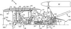
- FIG. 1Ais an axial sectional view of a turbofan engine.
- FIG. 1Bis a cross-sectional view of a portion of a fan case.
- FIG. 1Cis a cross-sectional view of a fan blade taken along line 1 C- 1 C of FIG. 1A .
- FIG. 2Ais an axial sectional view of a low pressure turbine section of the engine of FIG. 1A .
- FIG. 2Bis a cross-sectional view of a portion of a turbine blade of FIG. 2A having a directionally solidified microstructure.
- FIG. 3is transverse sectional view of transmission of the engine of FIG. 1A .
- FIG. 4Ais a partial cross-sectional view of a fan.
- FIG. 4Bis a cross-sectional view of a fan blade along line 4 B- 4 B of FIG. 4A .
- FIG. 5Ais a sectional side view of a variable area fan nozzle in a closed position.
- FIG. 5Bis a sectional side view of the variable area fan nozzle of FIG. 5A in an open position.
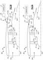
- FIG. 6shows another embodiment.
- FIG. 7shows yet another embodiment.
- FIG. 1Ashows a turbofan engine 20 having a main housing (engine case) 22 containing a rotor shaft assembly 23 .
- An exemplary engineis a high-bypass turbofan.
- a high pressure turbine section (gas generating turbine) 26 and a low pressure turbine section 27respectively drive a high pressure compressor section 28 and a low pressure compressor section 30 .
- the high pressure turbine sectionexperiences higher pressures that the low pressure turbine section.
- a low pressure turbine sectionis a section that powers a fan 42 .
- an intermediate spoolcomprises an intermediate pressure compressor between the low fan and high pressure compressor section and an intermediate pressure turbine between the high pressure turbine section and low pressure turbine section.
- the engineextends along a longitudinal axis 500 from a fore end to an aft end. Adjacent the fore end, a shroud (fan case) 40 encircles the fan 42 and is supported by fan exit guide vanes 44 . An aerodynamic nacelle around the fan case 40 is shown and an aerodynamic nacelle 45 around the engine case is shown.
- a shroud (fan case) 40Adjacent the fore end, a shroud (fan case) 40 encircles the fan 42 and is supported by fan exit guide vanes 44 .
- An aerodynamic nacelle around the fan case 40is shown and an aerodynamic nacelle 45 around the engine case is shown.
- the fan case 40can be made of an organic matrix composite, for example.
- the compositecan include a matrix material 47 and reinforcement fibers 49 distributed through the matrix material 47 .
- the reinforcement fibers 49may be discontinuous or continuous, depending upon the desired properties of the composite, for example.
- the matrix material 47may be a thermoset polymer or a thermoplastic polymer.
- the reinforcement fibers 49may include organic materials such as carbon, for example, and can be selected based on rigidity goals or other criteria. Given this description, one of ordinary skill in the art will recognize that other types of matrix materials and reinforcement fibers may be used.
- the low shaft portion 25 of the rotor shaft assembly 23drives the fan 42 through a speed reduction mechanism 46 .
- An exemplary speed reduction mechanismis an epicyclic transmission, namely a star or planetary gear system.
- the nacelle 45defines an engine inlet 50 and a bypass outlet 51 .
- an inlet airflow 520 entering the nacelle 45 through engine inlet 50is divided into a portion 522 passing along a core flowpath 524 and a bypass portion 526 passing along a bypass flowpath 528 .
- the bypass portion 526 of airflowexits the bypass outlet 51 to produce thrust.
- flow along the core flowpathsequentially passes through the low pressure compressor section, high pressure compressor section, a combustor 48 , the high pressure turbine section, and the low pressure turbine section before exiting from an outlet 530 .
- FIG. 3schematically shows details of the transmission 46 .
- a forward end of the low shaft 25is coupled to a sun gear 52 (or other high speed input to the speed reduction mechanism).
- the externally-toothed sun gear 52is encircled by a number of externally-toothed star gears 56 and an internally-toothed ring gear 54 .
- the exemplary ring gearis coupled to the fan to rotate with the fan as a unit.
- the star gears 56are positioned between and enmeshed with the sun gear and ring gear.
- a cage or star carrier assembly 60carries the star gears via associated journals 62 .
- the exemplary star carrieris substantially irrotatably mounted relative via fingers 404 to the case 22 .
- Another transmission/gearbox combinationhas the star carrier connected to the fan and the ring is fixed to the fixed structure (case) is possible and such is commonly referred to as a planetary gearbox.
- the speed reduction ratiois determined by the ratio of diameters within the gearbox.
- An exemplary reductionis between about 2:1 and about 13:1.
- the exemplary fan( FIG. 1A ) comprises a circumferential array of fan blades 70 .
- Each blade 70comprises an airfoil 72 having a leading edge 74 and a trailing edge 76 and extending from an inboard end 78 at a platform to an outboard end 80 (i.e., a free tip).
- the outboard end 80is in close facing proximity to a rub strip 82 along an interior surface 84 of the nacelle and fan case.
- the fan blades 70have a fixed pitch or stagger angle relative to the longitudinal axis 500 .
- a pylon 94is mounted to the fan case and/or to the other engine cases.
- the exemplary pylon 94may be as disclosed in U.S. patent application Ser. No. 11/832,107 (US2009/0056343A1).
- the pyloncomprises a forward mount 100 and an aft/rear mount 102 .
- the forward mountmay engage the engine intermediate case (IMC) 93 aft of the fan case 40
- the aft mountmay engage the engine thrust case 95 .
- the engine thrust casecan extend aft of the high pressure compressor section 28 and forward of the low pressure turbine section 27 .
- the aft mountreacts at least a thrust load of the engine.
- the aft mount 102is attachable to a mid-turbine frame 29 of the engine static structure.
- the mid-turbine frame 29is arranged generally between the high pressure turbine section 26 and the low pressure turbine section 27 . Attaching the aft mount 102 to the mid-turbine frame 29 can increase ground clearance by locating portions of the engine 20 relatively closer to the aircraft wing.
- the aft mount 102 ′is attachable to the engine case 22 at turbine exhaust case 22 c which is aft of the turbine section 27 (shown in dashed line in FIG. 2A ).
- the mid-turbine frame 29further supports one or more bearings 31 , which support high 24 and/or low 25 shaft portions of the shaft assembly 23 .
- the mid-turbine frame 57includes airfoils 33 (one shown) which are distributed circumferentially about the axis 500 and in the core airflow path 524 .
- the fan case 40is a hardwall containment case configured to contain, and absorb the impact of, a fan blade 70 separating from a fan hub 41 or a fragment thereof.
- the hardwall containment casecan be a hard ballistic liner applied to the nacelle 45 .
- the hard ballistic linercan include a rigid material such as a resin impregnated fiber structure, metallic structures, or ceramic structures, for example.
- FIG. 2Ashows the low pressure turbine section 27 as comprising an exemplary three blade stages 200 , 202 , 204 .
- An exemplary blade stage countis 2-6, more narrowly, 2-4, or 2-3, 3-5, or 3-4. Interspersed between the blade stages are vane stages 206 and 208 .
- Each exemplary blade stagecomprises a disk 210 , 212 , and 214 , respectively.
- a circumferential array of bladesextends from peripheries of each of the disks.
- Each exemplary bladecomprises an airfoil 220 extending from an inner diameter (ID) platform 222 to an outer diameter (OD) shroud 224 (shown integral with the airfoil).
- IDinner diameter
- ODouter diameter
- An alternativemay be an unshrouded blade with a rotational gap between the tip of the blade and a stationary blade outer air seal (BOAS).
- Each exemplary shroud 224has outboard sealing ridges which seal with abradable seals (e.g., honeycomb) fixed to the case.
- the exemplary vanes in stages 206 and 208include airfoils 230 extending from ID platforms 232 to OD shrouds 234 .
- the exemplary OD shrouds 234are directly mounted to the case.
- the exemplary platforms 232carry seals for sealing with inter-disk knife edges protruding outwardly from inter-disk spacers which may be separate from the adjacent disks or unitarily formed with one of the adjacent disks.
- Each exemplary disk 210 , 212 , 214comprises an enlarged central annular protuberance or “bore” 240 , 242 , 244 and a thinner radial web 246 , 248 , 250 extending radially outboard from the bore.
- the boreimparts structural strength allowing the disk to withstand centrifugal loading which the disk would otherwise be unable to withstand.
- Each turbine blade 220 and/or vane 221can be made of a directionally solidified material (shown schematically in FIG. 2B ) or a single-crystal material.
- Directionally solidified materialsinclude a microstructure having a plurality of elongated grains 266 that are parallel to the major stress axes of the component as is known in the art. Each of the elongated grains 266 can extend radially the along the airfoil.
- Single crystal materialsare formed as a single, homogenous crystal of material that includes no grain boundaries in the material, or rather, consist of only one grain.
- Single crystal materialscan include nickel-based super alloys such as Nickel aluminide (NiAl).
- each turbine bladecan be made of a composite material, such a ceramic matrix composite (CMC) material, including at least the first rotor stage 200 of the low pressure turbine section 27 .
- CMCceramic matrix composite
- Incorporating of one or more of these features, in the low pressure turbine section 27 , including the exemplary stage counts, materials and/or seal and disk arrangements,can enable or otherwise assist in redistribution of power extraction from the high pressure turbine section 26 to the low pressure turbine section 27 , which can further result in a reduction of the number of stage counts in the high pressure compressor section 28 and a more compact engine arrangement.
- a turbofan engineis characterized by its bypass ratio (mass flow ratio of air bypassing the core to air passing through the core) and the geometric bypass area ratio (ratio of fan duct annulus area outside/outboard of the low pressure compressor section inlet (i.e., at location 260 in FIG. 1A ) to low pressure compressor section inlet annulus area (i.e., at location 262 in FIG. 2A ).
- High bypass enginestypically have bypass area ratio of at least four. There has been a correlation between increased bypass area ratio and increased low pressure turbine section radius and low pressure turbine section airfoil count. As is discussed below, this correlation may be broken by having an engine with relatively high bypass area ratio and relatively low turbine size.
- the engine 20has a bypass area ratio greater than about 6.0, or more narrowly greater than about 8.0. In some embodiments, the engine 20 has a bypass area ratio between about 8.0 and about 20.0.
- the engine 20 bypass ratiois greater than or equal to about six (6), with an example embodiment being greater than or equal to about ten (10), the speed reduction mechanism 46 defines a gear reduction ratio of greater than about 2.3 and the low pressure turbine section 27 has a pressure ratio that is greater than about five. In one further non-limiting embodiment, the low pressure turbine section 27 has a pressure ratio that is greater than about five and less than about ten. In one disclosed embodiment, the engine 20 bypass ratio is greater than about ten (10:1), the fan diameter is significantly larger than that of the low pressure compressor section 30 , and the low pressure turbine section 27 has a pressure ratio that is greater than about five 5:1.
- Low pressure turbine section 27 pressure ratiois pressure measured prior to inlet of low pressure turbine section 27 as related to the pressure at the outlet of the low pressure turbine section 27 prior to an exhaust nozzle.
- the low pressure turbine section 27can have a pressure ratio that is less than or equal to about 20.0, such as between about 10.0 and about 15.0.
- the engine 20has a bypass ratio less than or equal to about 25.0, such as between about 15.0 and about 20.0, or between about 15.0 and 18.0.
- the gear reduction ratiocan be less than about 5.0, or less than about 4.0, for example, or between about 4.0 and 5.0.
- the term “about”is to be determined based on the number of significant digits of the corresponding quantity unless otherwise stated.
- the fan 42is designed for a particular flight condition—typically cruise at about 0.8 Mach and about 35,000 feet.
- TSFCThrust Specific Fuel Consumption
- Low fan pressure ratiois the pressure ratio across the fan blade alone, without a Fan Exit Guide Vane (“FEGV”) system.
- the low fan pressure ratio as disclosed herein according to one non-limiting embodimentis less than about 1.50, or more narrowly less than about 1.45, or between about 1.3 and 1.45, or between about 1.30 and 1.38.
- Low corrected fan tip speedis the actual fan tip speed in ft/sec divided by an industry standard temperature correction of [(Tram ° R)/(518.7° R] 0.5 .
- the “Low corrected fan tip speed” as disclosed herein according to one non-limiting embodimentis less than about 1150 ft/second. Further, low corrected fan tip speed according to one non-limiting embodiment is greater than about 1000 ft/second.
- a speed reduction mechanisme.g., a transmission
- the exemplary transmissionis an epicyclic transmission such as a star or planetary gear system.
- Alternative transmissionsinclude composite belt transmissions, metal chain belt transmissions, fluidic transmissions, and electric means (e.g., a motor/generator set where the turbine turns a generator providing electricity to an electric motor which drives the fan).
- the core gaspathextends from an inboard boundary (e.g., at blade hubs or outboard surfaces of platforms of associated blades and vanes) to an outboard boundary (e.g., at blade tips and inboard surfaces of blade outer air seals for unshrouded blade tips and at inboard surfaces of OD shrouds of shrouded blade tips and at inboard surfaces of OD shrouds of the vanes).
- inboard boundarye.g., at blade hubs or outboard surfaces of platforms of associated blades and vanes
- an outboard boundarye.g., at blade tips and inboard surfaces of blade outer air seals for unshrouded blade tips and at inboard surfaces of OD shrouds of shrouded blade tips and at inboard surfaces of OD shrouds of the vanes.
- the exemplary compact low pressure turbine sectionhas a hub-to-tip ratio close to about 0.5 (e.g., about 0.4-0.5 or about 0.42-0.48, with an exemplary about 0.46).
- the hub-to-tip ratiois above 0.5, and can be less than or equal to about 0.7, or more narrowly less than about 0.55.
- the hub-to-tip ratiocan be between about 0.55 and about 0.65, such as about 0.6.
- An exemplary fan size measurementis the maximum tip radius R Tmax of the fan blades.
- An exemplary ratiois the maximum R O along the low pressure turbine section to R Tmax of the fan blades. Exemplary values for this ratio are less than or equal to about 0.6, or more narrowly, less than or equal to about 0.55 (e.g., about 0.35-0.55), less than about 0.50, or about 0.35-0.50.
- the designermay balance multiple physical phenomena to arrive at a system solution as defined by the low pressure turbine hub-to-tip ratio, the fan maximum tip radius to low pressure turbine maximum Ro ratio, the bypass area ratio, and the bypass area ratio to low pressure turbine airfoil count ratio.
- These concernsinclude, but are not limited to: a) aerodynamics within the low pressure turbine, b) low pressure turbine blade structural design, c) low pressure turbine disk structural design, and d) the shaft connecting the low pressure turbine to the low pressure compressor and speed reduction device between the low pressure compressor and fan.
- the designercan choose to make low pressure turbine section disk bores much thicker relative to prior art turbine bores and the bores may be at a much smaller radius R B . This increases the amount of mass at less than a “self-sustaining radius”.
- Another meansis to choose disk materials of greater strength than prior art such as the use of wrought powdered metal disks to allow for extremely high centrifugal blade pulls associated with the compactness.
- AN 2is the annulus area of the exit of the low pressure turbine divided by the low pressure turbine rpm squared at its redline or maximum speed.
- AN 2is the annulus area of the exit of the low pressure turbine divided by the low pressure turbine rpm squared at its redline or maximum speed.
- low pressure turbine section sizeAnother characteristic of low pressure turbine section size is airfoil count (numerical count of all of the blades and vanes in the low pressure turbine). Airfoil metal angles can be selected such that airfoil count is low or extremely low relative to a direct drive turbine. In known prior art engines having bypass area ratio above 6.0 (e.g. 8.0-20), low pressure turbine sections involve ratios of airfoil count to bypass area ratio above 190.
- the ratio of airfoil count to bypass area ratiomay be below about 170 to as low as 10 (e.g., equal to or below about 150 or an exemplary about 10-170, more narrowly about 10-150).
- the ratio of airfoil count to bypass area ratiois greater than or equal to about 100, such as between about 120 to 140, and the low pressure turbine section 27 has between three and four stages.
- the ratio of airfoil count to bypass area ratiois less than 100, such as between about 15 and 80, and the low pressure turbine section 27 has between three and four stages.
- the airfoil countmay be below about 1700, or below about 1600 or below about 1000, such as about 300-800 airfoils, or more narrowly between about 350-750 airfoils.
- FIG. 4Aillustrates a partial cross-sectional view of fan 42 ′ including a pitch change mechanism 71 for varying a pitch of one or more fan blades 70 ′.
- Each of the fan blades 70 ′(one shown for illustrative purposes) is rotatably attached to a fan rotor 43 via the pitch change mechanism 71 , with fan rotor 43 driven by speed reduction mechanism 46 ′.
- the fan blade 70 ′includes an airfoil body extending between leading edge L/E and trailing edge T/E, in a thickness direction T between pressure and suction sides P, S, and along fan blade axis E in a spanwise or radial direction R between tip 70 a and platform 70 b adjacent to conical hub 39 , with the radial direction R being perpendicular to chordwise direction X and the thickness direction T.
- a root 70 d of the fan blade 70 ′extends inward from platform 70 b .
- the fan blade axis Ecan be perpendicular, or otherwise transverse to, the longitudinal axis 500 .
- the pitch change mechanism 71is configured to cause one or more of the fan blades 70 ′ to rotate about a corresponding fan blade axis E between a first position P 1 and a second position P 2 (depicted in dashed lines in FIG. 4B ).
- the pitch change mechanism 71includes an actuator 73 coupled to a control device 75 to cause the fan blade 70 ′ to rotate to a desired pitch or angle of incidence.
- Example actuators and control devicescan include a hydraulic pump coupled to a hydraulic source, an electrical motor coupled to a dedicated controller or engine controller, or another suitable device.
- the nacelle 45can be provided with a variable area fan nozzle (VAFN) 53 .
- VAFN 53changes the physical area and geometry of the bypass flow path 528 during particular flight conditions, such as takeoff, landing and cruise.
- the VAFN 53is operated to effectively vary a fan nozzle exit area 55 to adjust fan bypass air flow 526 through bypass flowpath 528 during various operating conditions.
- the VAFN 53generally includes a first fan nacelle section 57 a and a second fan nacelle section 57 b movably mounted relative to the first fan nacelle section 57 a to establish an auxiliary port 61 ( FIG. 5B ).
- the auxiliary port 61is closed by positioning the second fan nacelle section 57 b to abut the first fan nacelle section 57 a ( FIG. 5A ).
- the bypass flow 526is effectively altered by sliding of the second fan nacelle section 57 b along the engine axis 500 relative to the first fan nacelle section 57 a between a closed position ( FIG. 5A ) and an open position ( FIG. 5B ).
- Movement of the VAFN 53effectively changes the effective area of the fan nozzle exit area 55 , including flow through first and second portions 55 a , 55 b when the VAFN 53 is deployed ( FIG. 5B ).
- First portion 55 ais defined between the second fan nacelle section 57 b and a core cowling 58
- second portion 55 bis defined by auxiliary port 61 .
- Walls of the second fan nacelle section 57 b and the core cowling 58can be contoured to vary the fan nozzle exit area 55 in response to relative movement along the engine axis 500 .
- the second fan nacelle section 57 bis moveable in response to an actuator 59 .
- the VAFN 53communicates with controller C operatively coupled to actuator 59 to cause the fan nozzle exit area 55 to be adjusted.
- Controller Ccan be a standalone system, or can be provided by another system of the engine 20 or aircraft, such as a full authority digital engine controller (FADEC).
- FADECfull authority digital engine controller
- the controller Ccan be programmed with logic to translate the VAFN 53 between open and closed positions.
- the engine 20has a pressure ratio defined between the engine inlet 50 and the bypass outlet 51 , and can be taken with respect to the relative to the stagnation pressures at a cruise condition, for example.
- the pressure ratiomay be defined with the VAFN 53 in a fully open position or a fully closed position.
- the pressure ratiois less than or equal to about 1.4, and can be greater than or equal to about 1.1.
- the pressure ratiois between about 1.2 and about 1.3.
- FIG. 6shows an embodiment 600 , wherein there is a fan drive turbine 608 driving a shaft 606 to in turn drive a fan rotor 602 .
- a gear reduction 604may be positioned between the fan drive turbine 608 and the fan rotor 602 , or alternatively between an aft portion of the shaft 606 and the fan drive turbine 608 at location 604 ′ aft of a second stage compressor rotor 614 or a combustor section 618 (shown in dashed lines).
- This gear reduction 604 , 604 ′may be structured and operate like the gear reduction disclosed above.
- a compressor rotor 610is driven by an intermediate pressure turbine 612
- the second stage compressor rotor 614is driven by a turbine rotor 216 .
- the combustion section 618is positioned intermediate the compressor rotor 614 and the turbine section 616 .
Landscapes
- Engineering & Computer Science (AREA)
- Mechanical Engineering (AREA)
- General Engineering & Computer Science (AREA)
- Chemical & Material Sciences (AREA)
- Combustion & Propulsion (AREA)
- Physics & Mathematics (AREA)
- Fluid Mechanics (AREA)
- Structures Of Non-Positive Displacement Pumps (AREA)
Abstract
Description
Claims (31)
Priority Applications (3)
| Application Number | Priority Date | Filing Date | Title |
|---|---|---|---|
| US16/025,022US11242805B2 (en) | 2007-08-01 | 2018-07-02 | Turbine section of high bypass turbofan |
| EP19184027.1AEP3591191A1 (en) | 2018-07-02 | 2019-07-02 | Turbine section of high bypass turbofan |
| US17/230,326US11486311B2 (en) | 2007-08-01 | 2021-04-14 | Turbine section of high bypass turbofan |
Applications Claiming Priority (9)
| Application Number | Priority Date | Filing Date | Title |
|---|---|---|---|
| US11/832,107US8256707B2 (en) | 2007-08-01 | 2007-08-01 | Engine mounting configuration for a turbofan gas turbine engine |
| US201161498516P | 2011-06-17 | 2011-06-17 | |
| US201261593190P | 2012-01-31 | 2012-01-31 | |
| US13/475,252US8844265B2 (en) | 2007-08-01 | 2012-05-18 | Turbine section of high bypass turbofan |
| US13/599,175US9010085B2 (en) | 2007-08-01 | 2012-08-30 | Turbine section of high bypass turbofan |
| US14/692,090US10662880B2 (en) | 2007-08-01 | 2015-04-21 | Turbine section of high bypass turbofan |
| US14/793,785US20150377123A1 (en) | 2007-08-01 | 2015-07-08 | Turbine section of high bypass turbofan |
| US15/292,472US10060357B2 (en) | 2007-08-01 | 2016-10-13 | Turbine section of high bypass turbofan |
| US16/025,022US11242805B2 (en) | 2007-08-01 | 2018-07-02 | Turbine section of high bypass turbofan |
Related Parent Applications (1)
| Application Number | Title | Priority Date | Filing Date |
|---|---|---|---|
| US15/292,472Continuation-In-PartUS10060357B2 (en) | 2007-08-01 | 2016-10-13 | Turbine section of high bypass turbofan |
Related Child Applications (1)
| Application Number | Title | Priority Date | Filing Date |
|---|---|---|---|
| US17/230,326ContinuationUS11486311B2 (en) | 2007-08-01 | 2021-04-14 | Turbine section of high bypass turbofan |
Publications (2)
| Publication Number | Publication Date |
|---|---|
| US20190017445A1 US20190017445A1 (en) | 2019-01-17 |
| US11242805B2true US11242805B2 (en) | 2022-02-08 |
Family
ID=80080820
Family Applications (1)
| Application Number | Title | Priority Date | Filing Date |
|---|---|---|---|
| US16/025,022Active2029-05-20US11242805B2 (en) | 2007-08-01 | 2018-07-02 | Turbine section of high bypass turbofan |
Country Status (1)
| Country | Link |
|---|---|
| US (1) | US11242805B2 (en) |
Cited By (3)
| Publication number | Priority date | Publication date | Assignee | Title |
|---|---|---|---|---|
| US20220074352A1 (en)* | 2007-08-01 | 2022-03-10 | Raytheon Technologies Corporation | Turbine section of gas turbine engine |
| US11459957B2 (en)* | 2017-01-03 | 2022-10-04 | Raytheon Technologies Corporation | Gas turbine engine with non-epicyclic gear reduction system |
| US20230028982A1 (en)* | 2020-01-10 | 2023-01-26 | Safran Aircraft Engines | Assembly between an aircraft pylon and a turbomachine |
Families Citing this family (8)
| Publication number | Priority date | Publication date | Assignee | Title |
|---|---|---|---|---|
| US11346289B2 (en) | 2007-08-01 | 2022-05-31 | Raytheon Technologies Corporation | Turbine section of high bypass turbofan |
| US11486311B2 (en)* | 2007-08-01 | 2022-11-01 | Raytheon Technologies Corporation | Turbine section of high bypass turbofan |
| US11149650B2 (en)* | 2007-08-01 | 2021-10-19 | Raytheon Technologies Corporation | Turbine section of high bypass turbofan |
| US10844721B2 (en)* | 2019-03-13 | 2020-11-24 | Rolls-Royce Plc | Gas turbine engine for an aircraft |
| US11149584B2 (en) | 2019-10-07 | 2021-10-19 | General Electric Company | Containment case having ceramic coated fibers |
| US11286779B2 (en)* | 2020-06-03 | 2022-03-29 | Honeywell International Inc. | Characteristic distribution for rotor blade of booster rotor |
| US11724813B2 (en)* | 2021-05-24 | 2023-08-15 | General Electric Company | Midshaft rating for turbomachine engines |
| US12071978B2 (en) | 2021-05-24 | 2024-08-27 | General Electric Company | Midshaft rating for turbomachine engines |
Citations (151)
| Publication number | Priority date | Publication date | Assignee | Title |
|---|---|---|---|---|
| US2258792A (en) | 1941-04-12 | 1941-10-14 | Westinghouse Electric & Mfg Co | Turbine blading |
| US2936655A (en) | 1955-11-04 | 1960-05-17 | Gen Motors Corp | Self-aligning planetary gearing |
| US3021731A (en) | 1951-11-10 | 1962-02-20 | Wilhelm G Stoeckicht | Planetary gear transmission |
| US3194487A (en) | 1963-06-04 | 1965-07-13 | United Aircraft Corp | Noise abatement method and apparatus |
| US3287906A (en) | 1965-07-20 | 1966-11-29 | Gen Motors Corp | Cooled gas turbine vanes |
| US3327971A (en) | 1964-06-23 | 1967-06-27 | Rolls Royce | Mounting arrangement for lift engines |
| US3352178A (en) | 1965-11-15 | 1967-11-14 | Gen Motors Corp | Planetary gearing |
| US3412560A (en) | 1966-08-03 | 1968-11-26 | Gen Motors Corp | Jet propulsion engine with cooled combustion chamber, fuel heater, and induced air-flow |
| US3664612A (en) | 1969-12-22 | 1972-05-23 | Boeing Co | Aircraft engine variable highlight inlet |
| US3747343A (en) | 1972-02-10 | 1973-07-24 | United Aircraft Corp | Low noise prop-fan |
| US3754484A (en) | 1971-01-08 | 1973-08-28 | Secr Defence | Gearing |
| US3814549A (en) | 1972-11-14 | 1974-06-04 | Avco Corp | Gas turbine engine with power shaft damper |
| US3820719A (en) | 1972-05-09 | 1974-06-28 | Rolls Royce 1971 Ltd | Gas turbine engines |
| US3892358A (en) | 1971-03-17 | 1975-07-01 | Gen Electric | Nozzle seal |
| US3932058A (en) | 1974-06-07 | 1976-01-13 | United Technologies Corporation | Control system for variable pitch fan propulsor |
| US3935558A (en) | 1974-12-11 | 1976-01-27 | United Technologies Corporation | Surge detector for turbine engines |
| US3988889A (en) | 1974-02-25 | 1976-11-02 | General Electric Company | Cowling arrangement for a turbofan engine |
| US4037809A (en) | 1974-11-13 | 1977-07-26 | Societe Nationale D'etude Et De Construction De Moteurs D'aviation | Device for mounting a turboreactor on an aeroplane |
| US4044973A (en) | 1975-12-29 | 1977-08-30 | The Boeing Company | Nacelle assembly and mounting structures for a turbofan jet propulsion engine |
| GB1516041A (en) | 1977-02-14 | 1978-06-28 | Secr Defence | Multistage axial flow compressor stators |
| US4130872A (en) | 1975-10-10 | 1978-12-19 | The United States Of America As Represented By The Secretary Of The Air Force | Method and system of controlling a jet engine for avoiding engine surge |
| GB2010969A (en) | 1977-12-22 | 1979-07-04 | Rolls Royce | Mounting for Gas Turbine Jet Propulsion Engine |
| GB2041090A (en) | 1979-01-31 | 1980-09-03 | Rolls Royce | By-pass gas turbine engines |
| US4266741A (en) | 1978-05-22 | 1981-05-12 | The Boeing Company | Mounting apparatus for fan jet engine having mixed flow nozzle installation |
| US4284174A (en) | 1979-04-18 | 1981-08-18 | Avco Corporation | Emergency oil/mist system |
| US4289360A (en) | 1979-08-23 | 1981-09-15 | General Electric Company | Bearing damper system |
| US4313711A (en)* | 1977-08-24 | 1982-02-02 | The English Electric Company Limited | Turbine and like rotary machines |
| US4478551A (en) | 1981-12-08 | 1984-10-23 | United Technologies Corporation | Turbine exhaust case design |
| US4595340A (en) | 1984-07-30 | 1986-06-17 | General Electric Company | Gas turbine bladed disk assembly |
| US4649114A (en) | 1979-10-05 | 1987-03-10 | Intermedicat Gmbh | Oxygen permeable membrane in fermenter for oxygen enrichment of broth |
| US4696156A (en) | 1986-06-03 | 1987-09-29 | United Technologies Corporation | Fuel and oil heat management system for a gas turbine engine |
| US4966338A (en) | 1987-08-05 | 1990-10-30 | General Electric Company | Aircraft pylon |
| US4969325A (en) | 1989-01-03 | 1990-11-13 | General Electric Company | Turbofan engine having a counterrotating partially geared fan drive turbine |
| US4979362A (en) | 1989-05-17 | 1990-12-25 | Sundstrand Corporation | Aircraft engine starting and emergency power generating system |
| US5102379A (en) | 1991-03-25 | 1992-04-07 | United Technologies Corporation | Journal bearing arrangement |
| US5136839A (en) | 1988-09-28 | 1992-08-11 | Short Brothers Plc | Ducted fan turbine engine |
| US5141400A (en) | 1991-01-25 | 1992-08-25 | General Electric Company | Wide chord fan blade |
| US5174525A (en) | 1991-09-26 | 1992-12-29 | General Electric Company | Structure for eliminating lift load bending in engine core of turbofan |
| US5273393A (en) | 1992-03-26 | 1993-12-28 | Rolls-Royce Plc | Gas turbine engine casing |
| US5275357A (en) | 1992-01-16 | 1994-01-04 | General Electric Company | Aircraft engine mount |
| US5277382A (en) | 1992-10-13 | 1994-01-11 | General Electric Company | Aircraft engine forward mount |
| US5317877A (en) | 1992-08-03 | 1994-06-07 | General Electric Company | Intercooled turbine blade cooling air feed system |
| US5320307A (en) | 1992-03-25 | 1994-06-14 | General Electric Company | Aircraft engine thrust mount |
| US5361580A (en) | 1993-06-18 | 1994-11-08 | General Electric Company | Gas turbine engine rotor support system |
| US5372338A (en) | 1992-04-15 | 1994-12-13 | Rolls-Royce Plc | Mounting arrangement for a gas turbine engine |
| US5409184A (en) | 1993-02-20 | 1995-04-25 | Rolls-Royce Plc | Mounting for coupling a turbofan gas turbine engine to an aircraft structure |
| US5433674A (en) | 1994-04-12 | 1995-07-18 | United Technologies Corporation | Coupling system for a planetary gear train |
| US5443229A (en) | 1993-12-13 | 1995-08-22 | General Electric Company | Aircraft gas turbine engine sideways mount |
| US5447411A (en) | 1993-06-10 | 1995-09-05 | Martin Marietta Corporation | Light weight fan blade containment system |
| US5452575A (en) | 1993-09-07 | 1995-09-26 | General Electric Company | Aircraft gas turbine engine thrust mount |
| US5466198A (en) | 1993-06-11 | 1995-11-14 | United Technologies Corporation | Geared drive system for a bladed propulsor |
| US5474258A (en) | 1991-11-25 | 1995-12-12 | Rolls-Royce Plc | Mounting arrangement for a gas turbine engine |
| US5497961A (en) | 1991-08-07 | 1996-03-12 | Rolls-Royce Plc | Gas turbine engine nacelle assembly |
| US5524847A (en) | 1993-09-07 | 1996-06-11 | United Technologies Corporation | Nacelle and mounting arrangement for an aircraft engine |
| EP0791383A1 (en) | 1996-02-26 | 1997-08-27 | Japan Gore-Tex, Inc. | An assembly for deaeration of liquids |
| US5677060A (en) | 1994-03-10 | 1997-10-14 | Societe Europeenne De Propulsion | Method for protecting products made of a refractory material against oxidation, and resulting protected products |
| US5746391A (en) | 1995-04-13 | 1998-05-05 | Rolls-Royce Plc | Mounting for coupling a turbofan gas turbine engine to an aircraft structure |
| US5778659A (en) | 1994-10-20 | 1998-07-14 | United Technologies Corporation | Variable area fan exhaust nozzle having mechanically separate sleeve and thrust reverser actuation systems |
| US5810287A (en) | 1996-05-24 | 1998-09-22 | The Boeing Company | Aircraft support pylon |
| US5857836A (en) | 1996-09-10 | 1999-01-12 | Aerodyne Research, Inc. | Evaporatively cooled rotor for a gas turbine engine |
| US5860276A (en) | 1996-04-18 | 1999-01-19 | Rolls-Royce Plc | Ducted fan gas turbine engine mounting |
| US5871176A (en) | 1996-11-21 | 1999-02-16 | Societe Nationale D'etude Et De Construction De Moteurs D'aviation "Snecma" | Redundant front suspension system for a turboshaft engine |
| US5871177A (en) | 1996-11-21 | 1999-02-16 | Societe Nationale D'etude Et De Construction De Moteurs D'aviation "Snecma" | Redundant front suspension system for a turboshaft engine |
| US5871175A (en) | 1996-11-21 | 1999-02-16 | Societe Nationale D'etude Et De Construction De Moteurs D'aviation | Redundant front suspension system for a turboshaft engine |
| US5915917A (en) | 1994-12-14 | 1999-06-29 | United Technologies Corporation | Compressor stall and surge control using airflow asymmetry measurement |
| US5921500A (en) | 1997-10-08 | 1999-07-13 | General Electric Company | Integrated failsafe engine mount |
| US5927644A (en) | 1997-10-08 | 1999-07-27 | General Electric Company | Double failsafe engine mount |
| US5975841A (en) | 1997-10-03 | 1999-11-02 | Thermal Corp. | Heat pipe cooling for turbine stators |
| US5985470A (en) | 1998-03-16 | 1999-11-16 | General Electric Company | Thermal/environmental barrier coating system for silicon-based materials |
| US6106233A (en) | 1997-12-19 | 2000-08-22 | United Technologies Corporation | Method for linear friction welding and product made by such method |
| US6126110A (en) | 1997-12-22 | 2000-10-03 | Mcdonnell Douglas Corporation | Horizontally opposed trunnion forward engine mount system supported beneath a wing pylon |
| US6138949A (en) | 1998-10-30 | 2000-10-31 | Sikorsky Aircraft Corporation | Main rotor pylon support structure |
| US6189830B1 (en) | 1999-02-26 | 2001-02-20 | The Boeing Company | Tuned engine mounting system for jet aircraft |
| US6223616B1 (en) | 1999-12-22 | 2001-05-01 | United Technologies Corporation | Star gear system with lubrication circuit and lubrication method therefor |
| US20010010798A1 (en) | 2000-02-02 | 2001-08-02 | Dailey Geoffrey M. | Rotary apparatus for a gas turbine engine |
| EP1142850A1 (en) | 2000-04-06 | 2001-10-10 | General Electric Company | Thermal/environmental barrier coating for silicon-containing materials |
| US6315815B1 (en) | 1999-12-16 | 2001-11-13 | United Technologies Corporation | Membrane based fuel deoxygenator |
| US6318070B1 (en) | 2000-03-03 | 2001-11-20 | United Technologies Corporation | Variable area nozzle for gas turbine engines driven by shape memory alloy actuators |
| US6387456B1 (en) | 1999-04-15 | 2002-05-14 | General Electric Company | Silicon based substrate with environmental/thermal barrier layer |
| US6474597B1 (en) | 1999-11-20 | 2002-11-05 | Rolls-Royce Plc | Gas turbine engine mounting arrangement |
| US6478545B2 (en) | 2001-03-07 | 2002-11-12 | General Electric Company | Fluted blisk |
| US20020172593A1 (en)* | 2001-05-19 | 2002-11-21 | Udall Kenneth F. | Mounting arrangement for a gas turbine engine |
| US6517027B1 (en) | 2001-12-03 | 2003-02-11 | Pratt & Whitney Canada Corp. | Flexible/fixed support for engine cowl |
| US6517341B1 (en) | 1999-02-26 | 2003-02-11 | General Electric Company | Method to prevent recession loss of silica and silicon-containing materials in combustion gas environments |
| US6524072B1 (en) | 1997-06-25 | 2003-02-25 | Rolls Royce Plc | Disk for a blisk rotary stage of a gas turbine engine |
| US6607165B1 (en) | 2002-06-28 | 2003-08-19 | General Electric Company | Aircraft engine mount with single thrust link |
| US20030163984A1 (en)* | 2002-03-01 | 2003-09-04 | Seda Jorge F. | Aircraft engine with inter-turbine engine frame supported counter rotating low pressure turbine rotors |
| US6652222B1 (en) | 2002-09-03 | 2003-11-25 | Pratt & Whitney Canada Corp. | Fan case design with metal foam between Kevlar |
| US6709492B1 (en) | 2003-04-04 | 2004-03-23 | United Technologies Corporation | Planar membrane deoxygenator |
| US6814541B2 (en) | 2002-10-07 | 2004-11-09 | General Electric Company | Jet aircraft fan case containment design |
| US6899518B2 (en) | 2002-12-23 | 2005-05-31 | Pratt & Whitney Canada Corp. | Turbine shroud segment apparatus for reusing cooling air |
| EP1617044A1 (en) | 2004-07-13 | 2006-01-18 | General Electric Company | Selectively thinned turbine blade |
| US7021585B2 (en) | 2003-06-30 | 2006-04-04 | Snecma Moteurs | Aircraft engine rear mount with thrust links and boomerang-shaped lever |
| US7021042B2 (en) | 2002-12-13 | 2006-04-04 | United Technologies Corporation | Geartrain coupling for a turbofan engine |
| US20060090448A1 (en) | 2004-10-29 | 2006-05-04 | Henry John L | Gas turbine engine and method of assembling same |
| US7055330B2 (en) | 2004-02-25 | 2006-06-06 | United Technologies Corp | Apparatus for driving an accessory gearbox in a gas turbine engine |
| US20060228206A1 (en) | 2005-04-07 | 2006-10-12 | General Electric Company | Low solidity turbofan |
| US20060248900A1 (en) | 2005-05-05 | 2006-11-09 | Gabriel Suciu | Accessory gearbox |
| US7134286B2 (en) | 2004-08-24 | 2006-11-14 | Pratt & Whitney Canada Corp. | Gas turbine floating collar arrangement |
| GB2426792A (en) | 2005-04-01 | 2006-12-06 | David Richard Hopkins | Fan with conical hub |
| WO2007038674A1 (en) | 2005-09-28 | 2007-04-05 | Entrotech Composites, Llc | Braid-reinforced composites and processes for their preparation |
| US20080003096A1 (en) | 2006-06-29 | 2008-01-03 | United Technologies Corporation | High coverage cooling hole shape |
| GB2440345A (en) | 2006-07-26 | 2008-01-30 | Rolls Royce Plc | Integrally bladed rotor having blades made of metallic and non-metallic materials |
| US7328580B2 (en) | 2004-06-23 | 2008-02-12 | General Electric Company | Chevron film cooled wall |
| US20080098718A1 (en) | 2006-10-31 | 2008-05-01 | John Leslie Henry | Turbofan engine assembly and method of assembling same |
| US20080116009A1 (en) | 2006-11-22 | 2008-05-22 | United Technologies Corporation | Lubrication system with extended emergency operability |
| US7445433B2 (en) | 2004-02-24 | 2008-11-04 | Rolls-Royce Plc | Fan or compressor blisk |
| US20080317588A1 (en) | 2007-06-25 | 2008-12-25 | Grabowski Zbigniew M | Managing spool bearing load using variable area flow nozzle |
| EP2025898A2 (en) | 2007-08-01 | 2009-02-18 | United Technologies Corporation | Engine mounting configuration for a turbofan gas turbine engine |
| US20090092487A1 (en) | 2007-10-09 | 2009-04-09 | United Technologies Corp. | Systems and Methods Involving Multiple Torque Paths for Gas Turbine Engines |
| US20090185908A1 (en) | 2008-01-21 | 2009-07-23 | Honeywell International, Inc. | Linear friction welded blisk and method of fabrication |
| US7591754B2 (en) | 2006-03-22 | 2009-09-22 | United Technologies Corporation | Epicyclic gear train integral sun gear coupling design |
| US20090304473A1 (en) | 2008-04-16 | 2009-12-10 | Liane Holze | Method for the milling of blisks |
| US20090304518A1 (en) | 2006-07-04 | 2009-12-10 | Ihi Corporation | Turbofan engine |
| US20090314881A1 (en) | 2008-06-02 | 2009-12-24 | Suciu Gabriel L | Engine mount system for a turbofan gas turbine engine |
| US7654075B2 (en) | 2005-10-14 | 2010-02-02 | Rolls-Royce Plc | Fan static structure |
| US7662059B2 (en) | 2006-10-18 | 2010-02-16 | United Technologies Corporation | Lubrication of windmilling journal bearings |
| US7677493B2 (en) | 2005-06-28 | 2010-03-16 | Airbus France | Engine assembly for aircraft comprising an engine and a mounting device for such an engine |
| US7694505B2 (en) | 2006-07-31 | 2010-04-13 | General Electric Company | Gas turbine engine assembly and method of assembling same |
| US20100105516A1 (en) | 2006-07-05 | 2010-04-29 | United Technologies Corporation | Coupling system for a star gear train in a gas turbine engine |
| US20100148396A1 (en) | 2007-04-17 | 2010-06-17 | General Electric Company | Methods of making articles having toughened and untoughened regions |
| US20100212281A1 (en) | 2009-02-26 | 2010-08-26 | United Technologies Corporation | Auxiliary pump system for fan drive gear system |
| US20100218483A1 (en) | 2009-02-27 | 2010-09-02 | United Technologies Corporation | Controlled fan stream flow bypass |
| US7806651B2 (en) | 2004-04-02 | 2010-10-05 | Mtu Aero Engines Gmbh | Method for designing a low-pressure turbine of an aircraft engine, and low-pressure turbine |
| US20100259013A1 (en) | 2009-04-09 | 2010-10-14 | Rolls-Royce Deutschland Ltd & Co Kg | Abradable labyrinth seal for a fluid-flow machine |
| US7828682B2 (en) | 2006-05-11 | 2010-11-09 | Hansen Transmissions International N.V. | Gearbox for a wind turbine |
| US7841165B2 (en)* | 2006-10-31 | 2010-11-30 | General Electric Company | Gas turbine engine assembly and methods of assembling same |
| US20100331139A1 (en) | 2009-06-25 | 2010-12-30 | United Technologies Corporation | Epicyclic gear system with superfinished journal bearing |
| US20110056183A1 (en) | 2009-09-09 | 2011-03-10 | Sankrithi Mithra M K V | Ultra-efficient propulsor with an augmentor fan circumscribing a turbofan |
| US7926260B2 (en) | 2006-07-05 | 2011-04-19 | United Technologies Corporation | Flexible shaft for gas turbine engine |
| US20110123326A1 (en) | 2009-11-20 | 2011-05-26 | United Technologies Corporation | Bellows preload and centering spring for a fan drive gear system |
| US20110159797A1 (en) | 2009-12-31 | 2011-06-30 | Willem Beltman | Quiet System Cooling Using Coupled Optimization Between Integrated Micro Porous Absorbers And Rotors |
| US7997868B1 (en) | 2008-11-18 | 2011-08-16 | Florida Turbine Technologies, Inc. | Film cooling hole for turbine airfoil |
| EP2359975A1 (en) | 2010-02-19 | 2011-08-24 | General Electric Company | Welding process and component formed thereby |
| US20110293423A1 (en) | 2010-05-28 | 2011-12-01 | General Electric Company | Articles which include chevron film cooling holes, and related processes |
| US20110302907A1 (en)* | 2010-06-11 | 2011-12-15 | Murphy Michael J | Variable area fan nozzle |
| US20120124964A1 (en) | 2007-07-27 | 2012-05-24 | Hasel Karl L | Gas turbine engine with improved fuel efficiency |
| US8205432B2 (en) | 2007-10-03 | 2012-06-26 | United Technologies Corporation | Epicyclic gear train for turbo fan engine |
| US20120251306A1 (en) | 2009-11-20 | 2012-10-04 | United Technologies Corporation | Fan Rotor Support |
| US20120291449A1 (en) | 2007-08-01 | 2012-11-22 | United Technologies Corporation | Turbine Section of High Bypass Turbofan |
| US20130186058A1 (en) | 2012-01-24 | 2013-07-25 | William G. Sheridan | Geared turbomachine fan and compressor rotation |
| US20130224003A1 (en) | 2012-02-28 | 2013-08-29 | Daniel Bernard Kupratis | Gas turbine engine with fan-tied inducer section |
| US20130255219A1 (en)* | 2012-04-02 | 2013-10-03 | Frederick M. Schwarz | Geared turbofan with three co-rotating turbines |
| US20140174056A1 (en) | 2008-06-02 | 2014-06-26 | United Technologies Corporation | Gas turbine engine with low stage count low pressure turbine |
| US8834099B1 (en) | 2012-09-28 | 2014-09-16 | United Technoloiies Corporation | Low noise compressor rotor for geared turbofan engine |
| WO2014152101A1 (en) | 2013-03-15 | 2014-09-25 | United Technologies Corporation | Turbofan engine bearing and gearbox arrangement |
| US8869504B1 (en) | 2013-11-22 | 2014-10-28 | United Technologies Corporation | Geared turbofan engine gearbox arrangement |
| US20150089958A1 (en) | 2012-01-31 | 2015-04-02 | United Technologies Corporation | Gas turbine engine with high speed low pressure turbine section |
| US20150233303A1 (en) | 2012-09-27 | 2015-08-20 | United Technologies Corporation | Method for setting a gear ratio of a fan drive gear system of a gas turbine engine |
| US20150377122A1 (en) | 2007-08-01 | 2015-12-31 | United Technologies Corporation | Turbine section of high bypass turbofan |
| EP3115576A1 (en) | 2015-07-08 | 2017-01-11 | United Technologies Corporation | Turbine section of high bypass turbofan |
- 2018
- 2018-07-02USUS16/025,022patent/US11242805B2/enactiveActive
Patent Citations (158)
| Publication number | Priority date | Publication date | Assignee | Title |
|---|---|---|---|---|
| US2258792A (en) | 1941-04-12 | 1941-10-14 | Westinghouse Electric & Mfg Co | Turbine blading |
| US3021731A (en) | 1951-11-10 | 1962-02-20 | Wilhelm G Stoeckicht | Planetary gear transmission |
| US2936655A (en) | 1955-11-04 | 1960-05-17 | Gen Motors Corp | Self-aligning planetary gearing |
| US3194487A (en) | 1963-06-04 | 1965-07-13 | United Aircraft Corp | Noise abatement method and apparatus |
| US3327971A (en) | 1964-06-23 | 1967-06-27 | Rolls Royce | Mounting arrangement for lift engines |
| US3287906A (en) | 1965-07-20 | 1966-11-29 | Gen Motors Corp | Cooled gas turbine vanes |
| US3352178A (en) | 1965-11-15 | 1967-11-14 | Gen Motors Corp | Planetary gearing |
| US3412560A (en) | 1966-08-03 | 1968-11-26 | Gen Motors Corp | Jet propulsion engine with cooled combustion chamber, fuel heater, and induced air-flow |
| US3664612A (en) | 1969-12-22 | 1972-05-23 | Boeing Co | Aircraft engine variable highlight inlet |
| US3754484A (en) | 1971-01-08 | 1973-08-28 | Secr Defence | Gearing |
| US3892358A (en) | 1971-03-17 | 1975-07-01 | Gen Electric | Nozzle seal |
| US3747343A (en) | 1972-02-10 | 1973-07-24 | United Aircraft Corp | Low noise prop-fan |
| US3820719A (en) | 1972-05-09 | 1974-06-28 | Rolls Royce 1971 Ltd | Gas turbine engines |
| US3814549A (en) | 1972-11-14 | 1974-06-04 | Avco Corp | Gas turbine engine with power shaft damper |
| US3988889A (en) | 1974-02-25 | 1976-11-02 | General Electric Company | Cowling arrangement for a turbofan engine |
| US3932058A (en) | 1974-06-07 | 1976-01-13 | United Technologies Corporation | Control system for variable pitch fan propulsor |
| US4037809A (en) | 1974-11-13 | 1977-07-26 | Societe Nationale D'etude Et De Construction De Moteurs D'aviation | Device for mounting a turboreactor on an aeroplane |
| US3935558A (en) | 1974-12-11 | 1976-01-27 | United Technologies Corporation | Surge detector for turbine engines |
| US4130872A (en) | 1975-10-10 | 1978-12-19 | The United States Of America As Represented By The Secretary Of The Air Force | Method and system of controlling a jet engine for avoiding engine surge |
| US4044973A (en) | 1975-12-29 | 1977-08-30 | The Boeing Company | Nacelle assembly and mounting structures for a turbofan jet propulsion engine |
| GB1516041A (en) | 1977-02-14 | 1978-06-28 | Secr Defence | Multistage axial flow compressor stators |
| US4313711A (en)* | 1977-08-24 | 1982-02-02 | The English Electric Company Limited | Turbine and like rotary machines |
| GB2010969A (en) | 1977-12-22 | 1979-07-04 | Rolls Royce | Mounting for Gas Turbine Jet Propulsion Engine |
| US4266741A (en) | 1978-05-22 | 1981-05-12 | The Boeing Company | Mounting apparatus for fan jet engine having mixed flow nozzle installation |
| GB2041090A (en) | 1979-01-31 | 1980-09-03 | Rolls Royce | By-pass gas turbine engines |
| US4284174A (en) | 1979-04-18 | 1981-08-18 | Avco Corporation | Emergency oil/mist system |
| US4289360A (en) | 1979-08-23 | 1981-09-15 | General Electric Company | Bearing damper system |
| US4649114A (en) | 1979-10-05 | 1987-03-10 | Intermedicat Gmbh | Oxygen permeable membrane in fermenter for oxygen enrichment of broth |
| US4478551A (en) | 1981-12-08 | 1984-10-23 | United Technologies Corporation | Turbine exhaust case design |
| US4595340A (en) | 1984-07-30 | 1986-06-17 | General Electric Company | Gas turbine bladed disk assembly |
| US4696156A (en) | 1986-06-03 | 1987-09-29 | United Technologies Corporation | Fuel and oil heat management system for a gas turbine engine |
| US4966338A (en) | 1987-08-05 | 1990-10-30 | General Electric Company | Aircraft pylon |
| US5136839A (en) | 1988-09-28 | 1992-08-11 | Short Brothers Plc | Ducted fan turbine engine |
| US4969325A (en) | 1989-01-03 | 1990-11-13 | General Electric Company | Turbofan engine having a counterrotating partially geared fan drive turbine |
| US4979362A (en) | 1989-05-17 | 1990-12-25 | Sundstrand Corporation | Aircraft engine starting and emergency power generating system |
| US5141400A (en) | 1991-01-25 | 1992-08-25 | General Electric Company | Wide chord fan blade |
| US5102379A (en) | 1991-03-25 | 1992-04-07 | United Technologies Corporation | Journal bearing arrangement |
| US5497961A (en) | 1991-08-07 | 1996-03-12 | Rolls-Royce Plc | Gas turbine engine nacelle assembly |
| US5174525A (en) | 1991-09-26 | 1992-12-29 | General Electric Company | Structure for eliminating lift load bending in engine core of turbofan |
| US5474258A (en) | 1991-11-25 | 1995-12-12 | Rolls-Royce Plc | Mounting arrangement for a gas turbine engine |
| US5275357A (en) | 1992-01-16 | 1994-01-04 | General Electric Company | Aircraft engine mount |
| US5320307A (en) | 1992-03-25 | 1994-06-14 | General Electric Company | Aircraft engine thrust mount |
| US5273393A (en) | 1992-03-26 | 1993-12-28 | Rolls-Royce Plc | Gas turbine engine casing |
| US5372338A (en) | 1992-04-15 | 1994-12-13 | Rolls-Royce Plc | Mounting arrangement for a gas turbine engine |
| US5317877A (en) | 1992-08-03 | 1994-06-07 | General Electric Company | Intercooled turbine blade cooling air feed system |
| US5277382A (en) | 1992-10-13 | 1994-01-11 | General Electric Company | Aircraft engine forward mount |
| US5409184A (en) | 1993-02-20 | 1995-04-25 | Rolls-Royce Plc | Mounting for coupling a turbofan gas turbine engine to an aircraft structure |
| US5447411A (en) | 1993-06-10 | 1995-09-05 | Martin Marietta Corporation | Light weight fan blade containment system |
| US5466198A (en) | 1993-06-11 | 1995-11-14 | United Technologies Corporation | Geared drive system for a bladed propulsor |
| US5361580A (en) | 1993-06-18 | 1994-11-08 | General Electric Company | Gas turbine engine rotor support system |
| US5452575A (en) | 1993-09-07 | 1995-09-26 | General Electric Company | Aircraft gas turbine engine thrust mount |
| US5524847A (en) | 1993-09-07 | 1996-06-11 | United Technologies Corporation | Nacelle and mounting arrangement for an aircraft engine |
| US5443229A (en) | 1993-12-13 | 1995-08-22 | General Electric Company | Aircraft gas turbine engine sideways mount |
| US5677060A (en) | 1994-03-10 | 1997-10-14 | Societe Europeenne De Propulsion | Method for protecting products made of a refractory material against oxidation, and resulting protected products |
| US5433674A (en) | 1994-04-12 | 1995-07-18 | United Technologies Corporation | Coupling system for a planetary gear train |
| US5778659A (en) | 1994-10-20 | 1998-07-14 | United Technologies Corporation | Variable area fan exhaust nozzle having mechanically separate sleeve and thrust reverser actuation systems |
| US5915917A (en) | 1994-12-14 | 1999-06-29 | United Technologies Corporation | Compressor stall and surge control using airflow asymmetry measurement |
| US5746391A (en) | 1995-04-13 | 1998-05-05 | Rolls-Royce Plc | Mounting for coupling a turbofan gas turbine engine to an aircraft structure |
| EP0791383A1 (en) | 1996-02-26 | 1997-08-27 | Japan Gore-Tex, Inc. | An assembly for deaeration of liquids |
| US5860276A (en) | 1996-04-18 | 1999-01-19 | Rolls-Royce Plc | Ducted fan gas turbine engine mounting |
| US5810287A (en) | 1996-05-24 | 1998-09-22 | The Boeing Company | Aircraft support pylon |
| US5857836A (en) | 1996-09-10 | 1999-01-12 | Aerodyne Research, Inc. | Evaporatively cooled rotor for a gas turbine engine |
| US5871176A (en) | 1996-11-21 | 1999-02-16 | Societe Nationale D'etude Et De Construction De Moteurs D'aviation "Snecma" | Redundant front suspension system for a turboshaft engine |
| US5871177A (en) | 1996-11-21 | 1999-02-16 | Societe Nationale D'etude Et De Construction De Moteurs D'aviation "Snecma" | Redundant front suspension system for a turboshaft engine |
| US5871175A (en) | 1996-11-21 | 1999-02-16 | Societe Nationale D'etude Et De Construction De Moteurs D'aviation | Redundant front suspension system for a turboshaft engine |
| US6524072B1 (en) | 1997-06-25 | 2003-02-25 | Rolls Royce Plc | Disk for a blisk rotary stage of a gas turbine engine |
| US5975841A (en) | 1997-10-03 | 1999-11-02 | Thermal Corp. | Heat pipe cooling for turbine stators |
| US5927644A (en) | 1997-10-08 | 1999-07-27 | General Electric Company | Double failsafe engine mount |
| US5921500A (en) | 1997-10-08 | 1999-07-13 | General Electric Company | Integrated failsafe engine mount |
| US6106233A (en) | 1997-12-19 | 2000-08-22 | United Technologies Corporation | Method for linear friction welding and product made by such method |
| US6126110A (en) | 1997-12-22 | 2000-10-03 | Mcdonnell Douglas Corporation | Horizontally opposed trunnion forward engine mount system supported beneath a wing pylon |
| US5985470A (en) | 1998-03-16 | 1999-11-16 | General Electric Company | Thermal/environmental barrier coating system for silicon-based materials |
| US6138949A (en) | 1998-10-30 | 2000-10-31 | Sikorsky Aircraft Corporation | Main rotor pylon support structure |
| US6189830B1 (en) | 1999-02-26 | 2001-02-20 | The Boeing Company | Tuned engine mounting system for jet aircraft |
| US6517341B1 (en) | 1999-02-26 | 2003-02-11 | General Electric Company | Method to prevent recession loss of silica and silicon-containing materials in combustion gas environments |
| US6387456B1 (en) | 1999-04-15 | 2002-05-14 | General Electric Company | Silicon based substrate with environmental/thermal barrier layer |
| US6474597B1 (en) | 1999-11-20 | 2002-11-05 | Rolls-Royce Plc | Gas turbine engine mounting arrangement |
| US6315815B1 (en) | 1999-12-16 | 2001-11-13 | United Technologies Corporation | Membrane based fuel deoxygenator |
| US6223616B1 (en) | 1999-12-22 | 2001-05-01 | United Technologies Corporation | Star gear system with lubrication circuit and lubrication method therefor |
| US20010010798A1 (en) | 2000-02-02 | 2001-08-02 | Dailey Geoffrey M. | Rotary apparatus for a gas turbine engine |
| US6318070B1 (en) | 2000-03-03 | 2001-11-20 | United Technologies Corporation | Variable area nozzle for gas turbine engines driven by shape memory alloy actuators |
| EP1142850A1 (en) | 2000-04-06 | 2001-10-10 | General Electric Company | Thermal/environmental barrier coating for silicon-containing materials |
| US6478545B2 (en) | 2001-03-07 | 2002-11-12 | General Electric Company | Fluted blisk |
| US6708925B2 (en) | 2001-05-19 | 2004-03-23 | Rolls-Royce Plc | Mounting arrangement for a gas turbine engine |
| US20020172593A1 (en)* | 2001-05-19 | 2002-11-21 | Udall Kenneth F. | Mounting arrangement for a gas turbine engine |
| US6935591B2 (en) | 2001-05-19 | 2005-08-30 | Rolls-Royce Plc | Mounting arrangement for a gas turbine engine |
| US6517027B1 (en) | 2001-12-03 | 2003-02-11 | Pratt & Whitney Canada Corp. | Flexible/fixed support for engine cowl |
| US20030163984A1 (en)* | 2002-03-01 | 2003-09-04 | Seda Jorge F. | Aircraft engine with inter-turbine engine frame supported counter rotating low pressure turbine rotors |
| US6619030B1 (en) | 2002-03-01 | 2003-09-16 | General Electric Company | Aircraft engine with inter-turbine engine frame supported counter rotating low pressure turbine rotors |
| US6607165B1 (en) | 2002-06-28 | 2003-08-19 | General Electric Company | Aircraft engine mount with single thrust link |
| US6652222B1 (en) | 2002-09-03 | 2003-11-25 | Pratt & Whitney Canada Corp. | Fan case design with metal foam between Kevlar |
| US6814541B2 (en) | 2002-10-07 | 2004-11-09 | General Electric Company | Jet aircraft fan case containment design |
| US7021042B2 (en) | 2002-12-13 | 2006-04-04 | United Technologies Corporation | Geartrain coupling for a turbofan engine |
| US6899518B2 (en) | 2002-12-23 | 2005-05-31 | Pratt & Whitney Canada Corp. | Turbine shroud segment apparatus for reusing cooling air |
| US6709492B1 (en) | 2003-04-04 | 2004-03-23 | United Technologies Corporation | Planar membrane deoxygenator |
| US7021585B2 (en) | 2003-06-30 | 2006-04-04 | Snecma Moteurs | Aircraft engine rear mount with thrust links and boomerang-shaped lever |
| US7445433B2 (en) | 2004-02-24 | 2008-11-04 | Rolls-Royce Plc | Fan or compressor blisk |
| US7055330B2 (en) | 2004-02-25 | 2006-06-06 | United Technologies Corp | Apparatus for driving an accessory gearbox in a gas turbine engine |
| US7806651B2 (en) | 2004-04-02 | 2010-10-05 | Mtu Aero Engines Gmbh | Method for designing a low-pressure turbine of an aircraft engine, and low-pressure turbine |
| US7328580B2 (en) | 2004-06-23 | 2008-02-12 | General Electric Company | Chevron film cooled wall |
| EP1617044A1 (en) | 2004-07-13 | 2006-01-18 | General Electric Company | Selectively thinned turbine blade |
| US7134286B2 (en) | 2004-08-24 | 2006-11-14 | Pratt & Whitney Canada Corp. | Gas turbine floating collar arrangement |
| US20060090448A1 (en) | 2004-10-29 | 2006-05-04 | Henry John L | Gas turbine engine and method of assembling same |
| GB2426792A (en) | 2005-04-01 | 2006-12-06 | David Richard Hopkins | Fan with conical hub |
| US20060228206A1 (en) | 2005-04-07 | 2006-10-12 | General Electric Company | Low solidity turbofan |
| US7374403B2 (en) | 2005-04-07 | 2008-05-20 | General Electric Company | Low solidity turbofan |
| US20060248900A1 (en) | 2005-05-05 | 2006-11-09 | Gabriel Suciu | Accessory gearbox |
| US7677493B2 (en) | 2005-06-28 | 2010-03-16 | Airbus France | Engine assembly for aircraft comprising an engine and a mounting device for such an engine |
| WO2007038674A1 (en) | 2005-09-28 | 2007-04-05 | Entrotech Composites, Llc | Braid-reinforced composites and processes for their preparation |
| US7654075B2 (en) | 2005-10-14 | 2010-02-02 | Rolls-Royce Plc | Fan static structure |
| US7824305B2 (en) | 2006-03-22 | 2010-11-02 | United Technologies Corporation | Integral sun gear coupling |
| US7591754B2 (en) | 2006-03-22 | 2009-09-22 | United Technologies Corporation | Epicyclic gear train integral sun gear coupling design |
| US7828682B2 (en) | 2006-05-11 | 2010-11-09 | Hansen Transmissions International N.V. | Gearbox for a wind turbine |
| US20080003096A1 (en) | 2006-06-29 | 2008-01-03 | United Technologies Corporation | High coverage cooling hole shape |
| US20090304518A1 (en) | 2006-07-04 | 2009-12-10 | Ihi Corporation | Turbofan engine |
| US7926260B2 (en) | 2006-07-05 | 2011-04-19 | United Technologies Corporation | Flexible shaft for gas turbine engine |
| US20100105516A1 (en) | 2006-07-05 | 2010-04-29 | United Technologies Corporation | Coupling system for a star gear train in a gas turbine engine |
| GB2440345A (en) | 2006-07-26 | 2008-01-30 | Rolls Royce Plc | Integrally bladed rotor having blades made of metallic and non-metallic materials |
| US7694505B2 (en) | 2006-07-31 | 2010-04-13 | General Electric Company | Gas turbine engine assembly and method of assembling same |
| US7662059B2 (en) | 2006-10-18 | 2010-02-16 | United Technologies Corporation | Lubrication of windmilling journal bearings |
| US7841165B2 (en)* | 2006-10-31 | 2010-11-30 | General Electric Company | Gas turbine engine assembly and methods of assembling same |
| US20080098718A1 (en) | 2006-10-31 | 2008-05-01 | John Leslie Henry | Turbofan engine assembly and method of assembling same |
| US20080116009A1 (en) | 2006-11-22 | 2008-05-22 | United Technologies Corporation | Lubrication system with extended emergency operability |
| US20100148396A1 (en) | 2007-04-17 | 2010-06-17 | General Electric Company | Methods of making articles having toughened and untoughened regions |
| US20080317588A1 (en) | 2007-06-25 | 2008-12-25 | Grabowski Zbigniew M | Managing spool bearing load using variable area flow nozzle |
| US20120124964A1 (en) | 2007-07-27 | 2012-05-24 | Hasel Karl L | Gas turbine engine with improved fuel efficiency |
| US20120291449A1 (en) | 2007-08-01 | 2012-11-22 | United Technologies Corporation | Turbine Section of High Bypass Turbofan |
| EP2025898A2 (en) | 2007-08-01 | 2009-02-18 | United Technologies Corporation | Engine mounting configuration for a turbofan gas turbine engine |
| US20090056343A1 (en) | 2007-08-01 | 2009-03-05 | Suciu Gabriel L | Engine mounting configuration for a turbofan gas turbine engine |
| US20150377122A1 (en) | 2007-08-01 | 2015-12-31 | United Technologies Corporation | Turbine section of high bypass turbofan |
| US8205432B2 (en) | 2007-10-03 | 2012-06-26 | United Technologies Corporation | Epicyclic gear train for turbo fan engine |
| US20090092487A1 (en) | 2007-10-09 | 2009-04-09 | United Technologies Corp. | Systems and Methods Involving Multiple Torque Paths for Gas Turbine Engines |
| US20090185908A1 (en) | 2008-01-21 | 2009-07-23 | Honeywell International, Inc. | Linear friction welded blisk and method of fabrication |
| US20090304473A1 (en) | 2008-04-16 | 2009-12-10 | Liane Holze | Method for the milling of blisks |
| US20090314881A1 (en) | 2008-06-02 | 2009-12-24 | Suciu Gabriel L | Engine mount system for a turbofan gas turbine engine |
| US20140174056A1 (en) | 2008-06-02 | 2014-06-26 | United Technologies Corporation | Gas turbine engine with low stage count low pressure turbine |
| US7997868B1 (en) | 2008-11-18 | 2011-08-16 | Florida Turbine Technologies, Inc. | Film cooling hole for turbine airfoil |
| US20100212281A1 (en) | 2009-02-26 | 2010-08-26 | United Technologies Corporation | Auxiliary pump system for fan drive gear system |
| US20100218483A1 (en) | 2009-02-27 | 2010-09-02 | United Technologies Corporation | Controlled fan stream flow bypass |
| US20100259013A1 (en) | 2009-04-09 | 2010-10-14 | Rolls-Royce Deutschland Ltd & Co Kg | Abradable labyrinth seal for a fluid-flow machine |
| US20100331139A1 (en) | 2009-06-25 | 2010-12-30 | United Technologies Corporation | Epicyclic gear system with superfinished journal bearing |
| US20110056183A1 (en) | 2009-09-09 | 2011-03-10 | Sankrithi Mithra M K V | Ultra-efficient propulsor with an augmentor fan circumscribing a turbofan |
| US20120251306A1 (en) | 2009-11-20 | 2012-10-04 | United Technologies Corporation | Fan Rotor Support |
| US20110123326A1 (en) | 2009-11-20 | 2011-05-26 | United Technologies Corporation | Bellows preload and centering spring for a fan drive gear system |
| US20110159797A1 (en) | 2009-12-31 | 2011-06-30 | Willem Beltman | Quiet System Cooling Using Coupled Optimization Between Integrated Micro Porous Absorbers And Rotors |
| EP2359975A1 (en) | 2010-02-19 | 2011-08-24 | General Electric Company | Welding process and component formed thereby |
| US20110293423A1 (en) | 2010-05-28 | 2011-12-01 | General Electric Company | Articles which include chevron film cooling holes, and related processes |
| US20110302907A1 (en)* | 2010-06-11 | 2011-12-15 | Murphy Michael J | Variable area fan nozzle |
| EP2535548A2 (en) | 2011-06-17 | 2012-12-19 | United Technologies Corporation | Turbine section of high bypass turbofan |
| US20130186058A1 (en) | 2012-01-24 | 2013-07-25 | William G. Sheridan | Geared turbomachine fan and compressor rotation |
| US20150089958A1 (en) | 2012-01-31 | 2015-04-02 | United Technologies Corporation | Gas turbine engine with high speed low pressure turbine section |
| US20130224003A1 (en) | 2012-02-28 | 2013-08-29 | Daniel Bernard Kupratis | Gas turbine engine with fan-tied inducer section |
| US20130255219A1 (en)* | 2012-04-02 | 2013-10-03 | Frederick M. Schwarz | Geared turbofan with three co-rotating turbines |
| US20150233303A1 (en) | 2012-09-27 | 2015-08-20 | United Technologies Corporation | Method for setting a gear ratio of a fan drive gear system of a gas turbine engine |
| US8834099B1 (en) | 2012-09-28 | 2014-09-16 | United Technoloiies Corporation | Low noise compressor rotor for geared turbofan engine |
| WO2014152101A1 (en) | 2013-03-15 | 2014-09-25 | United Technologies Corporation | Turbofan engine bearing and gearbox arrangement |
| US8869504B1 (en) | 2013-11-22 | 2014-10-28 | United Technologies Corporation | Geared turbofan engine gearbox arrangement |
| EP3115576A1 (en) | 2015-07-08 | 2017-01-11 | United Technologies Corporation | Turbine section of high bypass turbofan |
Non-Patent Citations (226)
| Title |
|---|
| "Civil Turbojet/Turbofan Specifications", Jet Engine Specification Database (Apr. 3, 2005). |
| "Press release. The GE90 engine. Retreived from: https://www.geaviation.com/commercial/engines/ge90-engine; https://www.geaviation.com/press-release/ge90-engine-family/ge90-115b-fan-completing-blade-testing-schedule-first-engine-test; and https://www.geaviation.com/press-release/ge90-engine-family/ge'scomposite-fan-blade-revolution-turns-20-years-old". |
| Agarwal, B.D and Broutman, L.J. (1990). Analysis and performance of fiber composites, 2nd Edition. John Wiley & Sons, Inc. New York: New York. pp. 1-30, 50-51, 56-58, 60-61, 64-71, 87-89, 324-329, 436-437. |
| Ahmad, F. and Mizramoghadam, A.V. (1999). Single v. two stage high pressure turbine design of modern aero engines. ASME. Prestend at the International Gast Turbine & Aeroengine Congress & Exhibition. Indianapolis, Indiana. Jun. 7-10, 1999. pp. 1-9. |
| Anderson, N.E., Loewenthal, S.H., and Black, J.D. (1984). An analytical method to predict efficiency of aircraft gearboxes. NASA Technical Memorandum prepared for the Twentieth Joint Propulsion Conference. Cincinnati, OH. Jun. 11-13, 1984. pp. 1-25. |
| Angston, L. and Faghri, A. Heat pipe turbine vane cooling. Prepared for Advanced Turbine Systems Annual Program Review. Morgantown, West Virginia. Oct. 17-19, 1995. pp. 3-9. |
| Applicant-Admitted Prior Art: Diagram "GE 90 Engine Airflow" http://ctr-sgi1.stanford.edu/CITS/ge90.html downloaded Jun. 15, 2012. |
| Applicant-Admitted Prior Art: Flight International, Avco Lycoming ALF502F-2 Cutaway, 2007, http://www.flightglobal.com/airspace/media/aeroenginesjetcutaways/avco-lycoming-alf502r-2-cutaway-5582.aspx. |
| Applicant-Admitted Prior Art: Flight International, Avco Lycoming LF507F Cutaway, 2007, http://www.flightglobal.com/airspace/media/aeroenginesjetcutaways/avco-lycoming-alf502r-2-cutaway-5582.aspx. |
| Applicant-Admitted Prior Art: Flight International, Avco Lycoming TFE531 Cutaway, 2007, http://www.flightglobal.com/airspace/media/aeroenginesjetcutaways/avco-lycoming-alf502r-2-cutaway-5582.aspx. |
| Applicant-admitted prior art: Garrett TFE 731-3 sectional view from http://perso.ovh.net/˜caeaxtke/fr/coll/falcon50_5.html downloaded Jun. 15, 2012. |
| Applicant-Admitted Prior Art: Rolls Royce Trent 800, cutaway view, http://www.epower-propulsion.com/epower/gallery/ABP-RR%20Trent%20800%20cutaway.htm downloaded Jun. 15, 2012. |
| Applicant-admitted prior art: Rolls-Royce Trent 1000 cutaway view from http://hackedgadgets.com/2011/08/02/how-to-build-a-rolls-royce-trent-1000-jet-engine-used-in-the-boeing-787/ downloaded Jun. 15, 2012. |
| Applicant-Admitted Prior Art: Rolls-Royce Trent cutaway view from http://web.mit.edu/aeroastro/labs/gtl/early_GT_history.html downloaded Jun. 15, 2012. |
| Applicant-admitted prior art: Rolls-Royce Trent cutaway view from http://www.warandtactics.com/smf/planet-earth-the-serious-stuff-non-mil-news/a-380-emergency-landing!/ downloaded Jun. 15, 2012. |
| Applicant-Admitted Prior Art: TFE 731-20 PR Sheet, http://design.ae.utexas.edu/subject/work/TFE731_4.jpg downloaded Jun. 15, 2012. |
| Applicant-Admitted Prior Art: V2500 Fact Sheet, International Aero Engines, http://i-a-e.com/wp-content/uploads/2012/03/facts.pdf Jun. 15, 2012. |
| Avco Lycoming Divison. ALF 502L Maintenance Manual. Apr. 1981. pp. 1-118. |
| Aviadvigatel D-110. Jane's Aero-engines, Aero-engines—Turbofan. Jun. 1, 2010. |
| Aviadvigatel D-110. Jane's Aero-Engines. Jane's by IHS Markit. Jun. 1, 2010. |
| Baker, R.W. (2000). Membrane technology and applications. New York, NY: McGraw-Hill. pp. 87-151. |
| Bessarabov, D.G., Jacobs, E.P., Sanderson, R.D., and Beckman, I.N. (1996). Use of nonporous polymeric flat-sheet gas-separation membranes in a membrane-liquid contactor: experimental studies. Journal of Membrane Sciences, vol. 113. 1996. pp. 275-284. |
| Bornstein, N. (1993). Oxidation of advanced intermetallic compounds. Journal de Physique IV, 1993, 03 (C9), pp. C9-367-C9-373. |
| Brennan, P.J. and Kroliczek, E.J. (1979). Heat pipe design handbook. Prepared for National Aeronautics and Space Administration by B & K Engineering, Inc. Jun. 1979. pp. 1-348. |
| Brines, G.L. (1990). The turbofan of tomorrow. Mechanical Engineering: The Journal of the American Society of Mechanical Engineers, 108(8), 65-67. |
| Bucknell, R.L. (1973). Influence of fuels and lubricants on turbine engine design and performance, fuel and lubricant analyses. Final Technical Report, Mar. 1971-Mar. 1973. pp. 1-252. |
| Bunker, R.S. (2005). A review of shaped hole turbine film-cooling technology. Journal of Heat Transfer vol. 127. Apr. 2005. pp. 441-453. |
| Carney, K., Pereira, M. Revilock, and Matheny, P. (2003). Jet engine fan blade containment using two alternate geometries. 4th European LS-DYNA Users Conference. pp. 1-10. |
| Cheryan, M. (1998). Ultrafiltration and microfiltration handbook. Lancaster, PA: Tecnomic Publishing Company, Inc. pp. 171-236. |
| Clarke, D.R. and Levi, C.G. (2003). Materials design for the next generation thermal barrier coatings. Annual. Rev. Mater. Res. vol. 33. 2003. pp. 383-417. |
| Collar, L.P. and Springer, G.S. (2003). Mechanics of composite structures. Cambridge, UK: Cambridge University Press. p. 465. |
| Cramoisi, G. Ed. (2012). Death in the Potomac: The crash of Air Florida Flight 90. Air Crash Investigations. Accident Report NTSB/AAR-82-8. p. 45-47. |
| Cusick, M. (1981). Avco Lycoming's ALF 502 high bypass fan engine. Society of Automotive Engineers, inc. Business Aircraft Meeting & Exposition. Wichita, Kansas. Apr. 7-10, 1981. pp. 1-9. |
| Daly, M. Ed. (2010). Jane's Aero-Engine. Issue Twenty-seven. Mar. 2010. p. 633-636. |
| Darrah, S. (1987). Jet fuel deoxygenation. Interim Report for Period Mar. 1987-Jul. 1988. pp. 1-22. |
| Dassault Falcon 900EX Easy Systems Summary. Retrieved from: http://www.smartcockpit.com/docs/F900EX-Engines.pdf pp. 1-31. |
| Datasheet. CF6-80C2 high-bypass turbofan engines. Retreived from https://geaviation.com/sites/default/files/datasheet-CF6-80C2.pdf. |
| Datasheet. CFM56-5B for the Airbus A320ceo family and CFM56-7B for the Boeing 737 family. https://www.cfmaeroengines.com/. |
| Datasheet. Genx™ high bypass turbofan engines. Retreived from: https://www.geaviation.com/sites/default/files/datasheet-genx.pdf. |
| Davies, D. and Miller, D.C. (1971). A variable pitch fan for an ultra quiet demonstrator engine. 1976 Spring Convention: Seeds for Success in Civil Aircraft Design in the Next Two Decades. pp. 1-18. |
| Decision for Inter Partes Review of U.S. Pat. No. 8,844,265. Claims 1, 2, 6-16, and 20. General Electric Company, Petitioner v. United Technologies Corporation, Patent Owner. Entered Date of Jan. 3, 2017. |
| Decker, S. and Clough, R. (2016). GE wins shot at voiding pratt patent in jet-engine clash. Bloomberg Technology. Retrieved from: https://www.bloomberg.com/news/articles/2016-06-30/ge-wins-shot-to-invalidate-pratt-airplane-engine-patent-in-u-s. |
| Declaration of Dr. Magdy Attia. In re U.S. Pat. No. 8,313,280. Executed Oct. 21, 2016. pp. 1-88. |
| Declaration of Dr. Magdy Attia. In re U.S. Pat. No. 8,517,668. Executed Dec. 8, 2016. pp. 1-81. |
| Declaration of John Eaton, Ph.D. In re U.S. Pat. No. 8,869,568. Executed Mar. 28, 2016. pp. 1-87. |
| Declaration of Reza Abhari, Ph.D. In re U.S. Pat. No. 8,844,265. Executed Jun. 28, 2016. pp. 1-91. |
| Declaration of Reza Abhari. In re U.S. Pat. No. 8,448,895. Executed Nov. 28. pp. 1-81. |
| Declaration of Reza Abhari. In re U.S. Pat. No. 8,695,920, claims 1-4, 7-14, 17 and 19. Executed Nov. 29. pp. 1-102. |
| Declaration of Reza Abhari. In re U.S. Pat. No. 8,695,920. Executed Nov. 30. pp. 1-67. |
| Dickey, T.A. and Dobak, E.R. (1972). The evolution and development status of ALF 502 turbofan engine. National Aerospace Engineering and Manufacturing Meeting. San Diego, California. Oct. 2-5, 1972. pp. 1-12. |
| Drago, R.J. (1974). Heavy-lift helicopter brings up drive ideas. Power Transmission Design. Mar. 1987. pp. 1-15. |
| Drago, R.J. and Margasahayam, R.N. (1987). Stress analysis of planet gears with integral bearings; 3D finite-element model development and test validation. 1987 MSC NASTRAN World Users Conference. Los Angeles, CA. Mar. 1987. pp. 1-14. |
| Dudley, D.W., Ed. (1962). Gear handbook. New York, NY: McGraw-Hill. pp. 14-17 (TOC, Preface, and Index). |
| Dudley, D.W., Ed. (1962). Gear handbook. New York, NY: McGraw-Hill. pp. 3.14-3.18 and 12.7-12.21. |
| Dudley, D.W., Ed. (1962). Handbook of practical gear design. Lancaster, PA: Technomic Publishing Company, Inc. pp. 3.96-3.102 and 8.12-8.18. |
| Dudley, D.W., Ed. (1994). Practical gear design. New York, NY: McGraw-Hill. pp. 119-124. |
| Edkins, D.P., Hirschkron, R., and Lee, R. (1972). TF34 turbofan quiet engine study. Final Report prepared for NASA. NASA-CR-120914. Jan. 1, 1972. pp. 1-99. |
| Edwards, T. and Zabarnick, S. (1993). Supercritical fuel deposition mechanisms. Ind. Eng. Chem. Res. vol. 32. 1993. pp. 3117-3122. |
| El-Sayad, A.F. (2008). Aircraft propulsion and gas turbine engines. Boca Raton, FL: CRC Press. pp. 215-219 and 855-860. |
| Engine Alliance GP7200. Jane's Aero-Engines. Jane's by IHS Markit. Jul. 12, 2010. |
| European Search Report for European Application No. 16178668.6 dated Nov. 22, 2016. |
| European Search Report for European Application No. 16178679.3 dated Dec. 1, 2016. |
| European Search Report for European Application No. 16178691.8 dated Dec. 7, 2016. |
| European Search Report for European Patent Application No. 19184028.9 completed Oct. 10, 2019. |
| Faghri, A. (1995). Heat pipe and science technology. Washington, D.C.: Taylor & Francis. pp. 1-60. |
| Falchetti, F., Quiniou, H., and Verdier, L. (1994). Aerodynamic design and 3D Navier-Stokes analysis of a high specific flow fan. ASME. Presented at the International Gas Turbine and Aeroengine Congress and Exposition. The Hague, Netherlands. Jun. 13-16, 1994. pp. 1-10. |
| File History for U.S. Appl. No. 12/131,876. |
| Fledderjohn, K.R. (1983). The TFE731-5: Evolution of a decade of business jet service. SAE Technical Paper Series. Business Aircraft Meeting & Exposition. Wichita, Kansas. Apr. 12-15, 1983. pp. 1-12. |
| Frankenfeld, J.W. and Taylor, W.F. (1980). Deposit fromation from deoxygenated hydrocarbons. 4. Studies in Sure compound systems. Ind. Eng. Chem., Prod. Res. Dev., vol. 19(1). 1978. pp. 65-70. |
| Garret TFE731 Turbofan Engine (CAT C). Chapter 79: Lubrciation System. TTFE731 Issue 2. 2010. pp. 1-24. |
| Gates, D. Bombardier flies at higher market. Seattle Times. Jul. 13, 2008. pp. C6. |
| General Electric F101. Janes's Aero-Engines. Jane's by IHS Markit. Oct. 11, 2012. |
| General Electric F101. Scramble—The Aviation Magazine. Oct. 24, 2011. Retrieved May 17, 2013 from: http://wiki.scramble.nl/index.php?title=General_Electric_F101#F101-GE-100. |
| Gibala, R., Ghosh, A.K., Van Aken, D.C., Srolovitz, D.J., Basu, A., Chang, H., . . . Yang, W. (1992). Mechanical behavior and interface design of MoSi2-based alloys and composites. Materials Science and Engineering, A155, 1992. pp. 147-158. |
| Gliebe, P.R. and Janardan, B.A. (2003). Ultra-high bypass engine aeroacoustic study. NASA/CR-2003-21252. GE Aircraft Engines, Cincinnati, Ohio. Oct. 2003. pp. 1-103. |
| Grady, J.E., Weir, D.S., Lamoureux, M.C., and Martinez, M.M. (2007). Engine noise research in NASA's quiet aircraft technology project. Papers from the International Symposium on Air Breathing Engines (ISABE). 2007. |
| Gray, D.E. (1978). Energy efficient engine preliminary design and integration studies. Prepared for NASA. NASA CR-135396. Nov. 1978. pp. 1-366. |
| Gray, D.E. and Gardner, W.B. (1983). Energy efficient engine program technology benefit/cost study—vol. 2. NASA CR-174766. Oct. 1983. pp. 1-118. |
| Griffiths, B. (2005). Composite fan blade containment case. Modern Machine Shop. Retrieved from: http://www.mmsonline.com/articles/composite-fan-blade-containment-case pp. 1-4. |
| Gunston, B. (Ed.) (2000). Jane's aero-engines, Issue seven. Coulsdon, Surrey, UK: Jane's Information Group Limited. pp. 510-512. |
| Guynn, M. D., Berton, J.J., Fisher, K. L., Haller, W.J., Tong, M. T., and Thurman, D.R. (2011). Refined exploration of turbofan design options for an advanced single-aisle transport. NASA/TM-2011-216883. pp. 1-27. |
| Hall, C.A. and Crichton, D. (2007). Engine design studies for a silent aircraft. Journal of Turbomachinery, 129, 479-487. |
| Han, J., Dutta, S., and Ekkad, S.V. (2000). Gas turbine heat transfer and cooling technology. New York, NY: Taylor & Francis. pp. 1-25, 129-157, and 160-249. |
| Haque, A. and Shamsuzzoha, M., Hussain, F., and Dean, D. (2003). S20-glass/epoxy polymer nanocomposites: Manufacturing, structures, thermal and mechanical properties. Journal of Composite Materials, 37(20), 1821-1837. |
| Hazlett, R.N. (1991). Thermal oxidation stability of aviation turbine fuels. Philadelphia, PA: ASTM. pp. 1-163. |
| Heingartner, P., Mba, D., Brown, D. (2003). Determining power losses in the helical gear mesh; Case Study. ASME 2003 Design Engineering Technical Conferences. Chicago, IL. Sep. 2-6, 2003. pp. 1-7. |
| Hemighaus, G., Boval, T., Bacha, J., Barnes, F., Franklin, M., Gibbs, L., . . . Morris, J. (2007). Aviation fuels: Techincal review. Chevron Products Company. pp. 1-94. Retrieved from: https://www.cgabusinessdesk.com/document/aviation_tech_review.pdf. |
| Hendricks, E.S. and Tong, M.T. (2012). Performance and weight estimates for an advanced open rotor engine. NASA/TM-2012-217710. pp. 1-13. |
| Hess, C. (1998). Pratt & Whitney develops geared turbofan. Flug Revue 43(7). Oct. 1998. |
| Honeywell Learjet 31 and 35/36 TFE731-2 to 2C Engine Upgrade Program. Sep. 2005. pp. 1-4. |
| Honeywell LF502. Jane's Aero-engines, Aero-engines—Turbofan. Aug. 17, 2016. |
| Honeywell LF502. Jane's Aero-engines, Aero-engines—Turbofan. Feb. 9, 2012. |
| Honeywell LF502. Jane's Aero-Engines. Jane's by IHS Markit. Feb. 9, 2012. |
| Honeywell LF507. Jane's Aero-engines, Aero-engines—Turbofan. Feb. 9, 2012. |
| Honeywell LF507. Jane's Aero-Engines. Jane's by IHS Markit. Feb. 9, 2012. |
| Honeywell Sabreliner 65 TFE731-3 to -3D Engine Upgrade Program. Oct. 2005. pp. 1-4. |
| Honeywell TFE731 Pilot Tips. pp. 1-143. |
| Honeywell TFE731. Jane's Aero-engines, Aero-engines—Turbofan. Jul. 18, 2012. |
| Honeywell TFE731. Jane's Aero-Engines. Jane's by IHS Markit. Jul. 18, 2012. |
| Honeywell TFE731-5AR to -5BR Engine Conversion Program. Sep. 2005. pp. 1-4. |
| Horikoshi, S. and Serpone, N. (2013). Introduction to nanoparticles. Microwaves in nanoparticle synthesis. Wiley-VCH Verlag GmbH & Co. KGaA. pp. 1-24. |
| Huang, H., Sobel, D.R., and Spadaccini, L.J. (2002). Endothermic heat-sink of hydrocarbon fuels for scramjet cooling. AIAA/ASME/SAE/ASEE, Jul. 2002. pp. 1-7. |
| Hughes, C. (2002). Aerodynamic performance of scale-model turbofan outlet guide vanes designed for low noise. Prepared for the 40th Aerospace Sciences Meeting and Exhibit. Reno, NV. NASA/TM-2001-211352. Jan. 14-17, 2002. pp. 1-38. |
| Hughes, C. (2010). Geared turbofan technology. NASA Environmentally Responsible Aviation Project. Green Aviation Summit. NASA Ames Research Center. Sep. 8-9, 2010. pp. 1-8. |
| Ivchenko—Progress AI-727M. Jane's Aero-engines, Aero-engines—Turbofan. Nov. 27, 2011. |
| Ivchenko—Progress AI-727M. Jane's Aero-Engines. Jane's by IHS Markit. Nov. 11, 2017. |
| Ivchenko—Progress D-436. Jane's Aero-engines, Aero-engines—Turbofan. Feb. 8, 2012. |
| Ivchenko—Progress D-436. Jane's Aero-Engines. Jane's by IHS Markit. Feb. 8, 2012. |
| Ivchenko—Progress D-727. Jane's Aero-engines, Aero-engines—Turbofan. Feb. 7, 2007. |
| Ivchenko—Progress D-727. Jane's Aero-Engines. Jane's by IHS Markit. Feb. 7, 2007. |
| Jacobson, N.S. (1993). Corrosion of silicon-based ceramics in combustion environments. J. Am. Ceram. Soc. 76(1). pp. 3-28. |
| Jeng, Y.-L., Lavernia, E.J. (1994). Processing of molybdenum disilicide. J. of Mat. Sci. vol. 29. 1994. pp. 2557-2571. |
| Jorgensen, P.J., Wadsworth, M.E., and Cutler, I.B. (1961). Effects of water vapor on oxidation of silicon carbide. J. Am. Ceram. Soc. 44(6). pp. 248-261. |
| Kahn, H., Tayebi, N., Ballarini, R., Mullen, R.L., Heuer, A.H. (2000). Fracture toughness of polysilicon MEMS devices. Sensors and Actuators vol. 82. 2000. pp. 274-280. |
| Kandebo, S.W. (1993). Geared-turbofan engine design targets cost, complexity. Aviation Week & Space Technology, 148(8). Start p. 32. |
| Kaplan, B., Nicke, E., Voss, C. (2006), Design of a highly efficient low-noise fan for ultra-high bypass engines. Proceedings of GT2006 for ASME Turbo Expo 2006: Power for Land, Sea and Air. Barcelona, SP. May 8-11, 2006. pp. 1-10. |
| Kerrebrock, J.L. (1977). Aircraft engines and gas turbines. Cambridge, MA: The MIT Press. p. 11. |
| Knip, Jr., G. (1987). Analysis of an advanced technology subsonic turbofan incorporating revolutionary materials. NASA Technical Memorandum. May 1987. pp. 1-23. |
| Koff , B.L. (2003). Gas turbine technology evolution—A designers perspective. AIAA/ICAS International Air and Space Symposium and Exposition. Jul. 14-16, 2003. AIAA 2003-2722. pp. 1-15. |
| Kojima, Y., Usuki, A. Kawasumi, M., Okada, A., Fukushim, Y., Kurauchi, T., and Kamigaito, O. (1992). Mechanical properties of nylon 6-clay hybrid. Journal of Materials Research, 8(5), 1185-1189. |
| Krantz, T.L. (1990). Experimental and analytical evaluation of efficiency of helicopter planetary stage. NASA Technical Paper. Nov. 1990. pp. 1-19. |
| Krenkel, W., Naslain, R., and Schneider, H. Eds. (2001). High temperature ceramic matrix composites pp. 224-229. Weinheim, DE: Wiley-VCH Verlag GmbH. |
| Kurzke, J. (2008). Preliminary Design, Aero-engine design: From state of the art turbofans towards innovative architectures. pp. 1-72. |
| Kurzke, J. (2009). Fundamental differences between conventional and geared turbofans. Proceedings of ASME Turbo Expo: Power for Land, Sea, and Air. 2009, Orlando, Florida. pp. 145-151. |
| Kurzke, J. (2012). GasTurb 12: Design and off-design performance of gas turbines. Retrieved from: https://www.scribd.com/document/153900429/GasTurb-12. |
| Lau K., Gu, C., and Hui, D. (2005). A critical review on nanotube and nanotube/nanoclay related polymer composite materials. Composites: Part B 37(2006) 425-436. |
| Leckie, F.A. and Dal Bello, D.J. (2009). Strength and stiffness of engineering systems. Mechanical Engineering Series. Springer. pp. 1-3. |
| Lee, K.N. (2000). Current status of environmental barrier coatings for Si-Based ceramics. Surface and Coatings Technology 133-134, 2000. pp. 1-7. |
| Lewicki, D.G., Black, J.D., Savage, M., and Coy, J.J. (1985). Fatigue life analysis of a turboprop reduction gearbox. NASA Technical Memorandum. Prepared for the Design Technical Conference (ASME). Sep. 11-13, 1985. pp. 1-26. |
| Lord, W.K., MacMartin, D.G., and Tillman, T.G. (2000). Flow control opportunities in gas turbine engines. American Institute of Aeronautics and Astronautics. pp. 1-15. |
| Lynwander, P. (1983). Gear drive systems: Design and application. New York, New York: Marcel Dekker, Inc. pp. 145, 355-358. |
| Mancuso, J.R. and Corcoran, J.P. (2003). What are the differences in high performance flexible couplings for turbomachinery? Proceedings of the Thirty-Second Turbomachinery Symposium. 2003. pp. 189-207. |
| Matsumoto, T., Toshiro, U., Kishida, A., Tsutomu, F., Maruyama, I., and Akashi, M. (1996). Novel functional polymers: Poly (dimethylsiloxane)-polyamide multiblock copolymer. VII. Oxygen permeability of aramid-silicone membranes in a gas-membrane-liquid system. Journal of Applied Polymer Science, vol. 64(6). May 9, 1997. pp. 1153-1159. |
| Mattingly, J.D. (1996). Elements of gas turbine propulsion. New York, New York: McGraw-Hill, Inc. pp. 1-18, 60-62, 85-87, 95-104, 121-123, 223-234, 242-245, 278-280, 303-309, 323-326, 462-479, 517-520, 563-565, 673-675, 682-685, 697-699, 703-705, 802-805, 862-864, and 923-925. |
| Mattingly, J.D. (1996). Elements of gas turbine propulsion. New York, New York: McGraw-Hill, Inc. pp. 1-18, 60-62, 85-87, 95-104, 121-123, 223-234, 242-245, 278-285, 303-309, 323-326, 462-479, 517-520, 563-565, 630-632, 668-670, 673-675, 682-685, 697-705, 726-727, 731-732, 802-805, 828-830 and appendices. |
| Mattingly, J.D. (1996). Elements of gas turbine propulsion. New York, New York: McGraw-Hill, Inc. pp. 1-18, 60-62, 85-87, 95-104, 121-123, 223-234, 242-245, 278-285, 303-309, 323-326, 462-479, 517-520, 563-565, 630-632, 673-675, 682-685, 697-699, 703-705, 802-805, 862-864, and 923-925. |
| Mattingly, J.D. (1996). Elements of gas turbine propulsion. New York, New York: McGraw-Hill, Inc. pp. 8-15. |
| McArdle, J.G. (1979). Static test-stand performance of the YF-102 turbofan engine with several exhaust configurations for the quiet short-haul research aircraft (QSRA). NASA Technical Paper. Nov. 1979. pp. 1-68. |
| McArdle, J.G. and Moore, A.S. (1979). Static test-stand performance of the YF-102 turobfan engine with several exhaust configurations for the Quiet Short-Haul Research Aircraft (QSRA). Prepared for NASA. NASA-TP-1556. Nov. 1979. pp. 1-68. |
| McCune, M.E. (1993). Initial test results of 40,000 horsepower fan drive gear system for advanced ducted propulsion systems. AIAA 29th Joint Conference and Exhibit. Jun. 28-30, 1993. pp. 1-10. |
| McMillian, A. (2008) Material development for fan blade containment casing. Abstract. p. 1. Conference on Engineering and Physics: Synergy for Success 2006. Journal of Physics: Conference Series vol. 105. London, UK. Oct. 5, 2006. |
| Merriam-Webster's collegiate dictionary, 10th Ed. (2001). p. 1125-1126. |
| Merriam-Webster's collegiate dictionary, 11th Ed. (2009). p. 824. |
| Meyer, A.G. (1988). Transmission development of Textron Lycoming's geared fan engine. Technical Paper. Oct. 1988. pp. 1-12. |
| Middleton, P. (1971). 614: VFW's jet feederliner. Flight International, Nov. 4, 1971. p. 725, 729-732. |
| Moxon, J. How to save fuel in tomorrow's engines. Flight International. Jul. 30, 1983. 3873(124). pp. 272-273. |
| Muhlstein, C.L., Stach, E.A., and Ritchie, R.O. (2002). A reaction-layer mechanism for the delayed failure of micron-scale polycrystalline silicon structural films subjected to high-cycle fatigue loading. Acta Materialia vol. 50. 2002. pp. 3579-3595. |
| Munt, R. (1981). Aircraft technology assessment: Progress in low emissions engine. Technical Report. May 1981. pp. 1-171. |
| Nanocor Technical Data for Epoxy Nanocomposites using Nanomer 1.30E Nanoclay. Nnacor, Inc. Oct. 2004. |
| NASA Conference Publication. Quiet, powered-lift propulsion. Cleveland, Ohio. Nov. 14-15, 1978. pp. 1-420. |
| Newsletter. PurePower PW1000G Engine News. vol. 3(3). Dec. 2010. |
| Norton, M. and Karczub, D. (2003). Fundamentals of noise and vibration analysis for engineers. Press Syndicate of the University of Cambridge. New York: New York. p. 524. |
| Notice of Allowance and allowed claims for U.S. Appl. No. 13/475,252 dated May 27, 2014. |
| Notice of Allowance and allowed claims for U.S. Appl. No. 14/102,764 dated May 30, 2014. |
| Notice of Opposition for European Patent No. 2535548 (13813216.2) mailed Apr. 29, 2019 by Safran Aircraft Engines. |
| Oates, G.C. (Ed). (1989). Aircraft propulsion systems and technology and design. Washington, D.C.: American Institute of Aeronautics, Inc. pp. 341-344. |
| Office Action for U.S. Appl. No. 14/102,764 dated Feb. 21, 2014. |
| Orbit Search Results. "bypass area ratio". Retrieved Feb. 21, 2019. |
| Parker, R.G. and Lin, J. (2001). Modeling, modal properties, and mesh stiffness variation instabilities of planetary gears. Prepared for NASA. NASA/CR-2001-210939. May 2001. pp. 1-111. |
| Petition for Inter Partes Review of U.S. Pat. No. 9,709,070. General Electric Company, Petitioner, v. United Technologies Corporation, Patent Owner. IPR2020-00083. Oct. 23, 2019. |
| Petrovic, J.J., Castro, R.G., Vaidya, R.U., Peters, M.I., Mendoza, D., Hoover, R.C., and Gallegos, D.E. (2001). Molybdenum disilicide materials for glass melting sensor sheaths. Ceramic Engineering and Science Proceedings. vol. 22(3). 2001. pp. 59-64. |
| Product Brochure. Garrett TFE731. Allied Signal. Copyright 1987. pp. 1-24. |
| Product Brochure. The ALF 502R turbofan: technology, ecology, economy. Avco Lycoming TEXTRON. |
| Pyrograf-III Carbon Nanofiber. Product guide. Retrieved Dec. 1, 2015 from: http://pyrografproducts.com/Merchant5/merchant_mvc?Screen=cp_nanofiber. |
| Ramsden, J.M. (Ed). (1978). The new European airliner. Flight International, 113(3590). Jan. 7, 1978. pp. 39-43. |
| Ratna, D. (2009). Handbook of thermoset resins. Shawbury, UK: iSmithers. pp. 187-216. |
| Rauch, D. (1972). Design study of an air pump and integral lift engine ALF-504 using the Lycoming 502 core. Prepare for NASA. Jul. 1972. pp. 1-182. |
| Reshotko, M., Karchmer, A., Penko, P.F. (1977). Core noise measurements on a YF-102 turbofan engine. NASA TM X-73587. Prepared for Aerospace Sciences Meeting sponsored by the American Institute of Aeronautics and Astronautics. Jan. 24-26, 2977. |
| Reuters. (2014). GE exec says avoided geared design in jet engine battle with Pratt. Retrieved from: https://www.reuters.com/article/us-general-electric-united-tech-engine/ge-exec-says-avoided-geared-design-in-jet-engine-battle-with-pratt-idUSKBN0HA2H620140915. |
| Reynolds, C.N. (1985). Advanced prop-fan engine technology (APET) single- and counter-rotation gearbox/pitch change mechanism. Prepared for NASA. NASA CR-168114 (vol. I). Jul. 1985. pp. 1-295. |
| Riegler, C., and Bichlmaier, C. (2007). The geared turbofan technology—Opportunities, challenges and readiness status. Porceedings CEAS. Sep. 10-13, 2007. Berlin, Germany. pp. 1-12. |
| Rolls-Royce M45H. Jane's Aero-engines, Aero-engines—Turbofan. Feb. 24, 2010. |
| Rolls-Royce M45H. Jane's Aero-Engines. Jane's by IHS Markit. Feb. 24, 2010. |
| Rolly-Royce RB211. Jane's Aero-Engines. Jane's by IHS Markit. Feb. 24, 2010. |
| Roux, E. (2007). Turbofan and turbojet engines database handbook. Editions Elodie Roux. Blagnac: France. pp. 1-595. |
| Sabnis, J. (2010). The PW1000G PurePower new engine concept and its impact on MRO. Av Week Engine MRO Forum. Dec. 1, 2010. pp. 1-45. |
| Salemme, C.T. and Murphy, G.C. (1979). Metal spar/superhybrid shell composite fan blades. Prepared for NASA. NASA-CR-159594. Aug. 1979. pp. 1-127. |
| Savelle, S.A. and Garrard, G.D. (1996). Application of transient and dynamic simulations to the U.S. Army T55-L-712 helicopter engine. The American Society of Mechanical Engineers. Presented Jun. 10-13, 1996. pp. 1-8. |
| Schaefer, J.W., Sagerser, D.R., and Stakolich, E.G. (1977). Dynamics of high-bypass-engine thrust reversal using a variable-pitch fan. Technical Report prepare for NASA. NASA-TM-X-3524. May 1, 1977. pp. 1-31. |
| Schairer, E.T. (1977). Recent conceptual design studies of single turbofan engine aircraft. Society of Automotive Engineers. Business Aircraft Meeting. Mar. 29-Apr. 1, 1977. pp. 1-17, Table 1 and Figures 1-15. |
| Seader, J.D. and Henley, E.J. (1998). Separation process principles. New York, NY: John Wiley & Sons, Inc. pp. 722-726 and 764-771. |
| Shah, D.M. (1992). MoSi2 and other silicides as high temperature structural materials. Superalloys 1992. The Minerals, Metals, & Materials Society. pp. 409-422. |
| Shorter Oxford English dictionary, 6th Edition. (2007). vol. 2, N-Z. p. 1888. |
| Silverstein, C.C., Gottschlich, J.M., and Meininger, M. The feasibility of heat pipe turbine vane cooling. Presented at the International Gas Turbine and Aeroengine Congress and Exposition, The Hague, Netherlands. Jun. 13-16, 1994.pp. 1-7. |
| Spadaccini, L.J., and Huang, H. (2002). On-line fuel deoxygenation for coke suppression. ASME, Jun. 2002. pp. 1-7. |
| Spadaccini, L.J., Sobel, D.R., and Huang, H. (2001). Deposit formation and mitigation in aircraft fuels. Journal of Eng. For Gas Turbine and Power, vol. 123. Oct. 2001. pp. 741-746. |
| Summons to Attend Oral Proceedings for EP Application No. 16178679.3 dated Sep. 17, 2019. |
| Sundaram, S.K., Hsu, J-Y., Speyer, R.F. (1994). Molten glass corrosion resistance of immersed combustion-heating tube materials in soda-lime-silicate glass. J. Am. Ceram. Soc. 77(6). pp. 1613-1623. |
| Sundaram, S.K., Hsu, J-Y., Speyer, R.F. (1995). Molten glass corrosion resistance of immersed combustion-heating tube materials in e-glass. J. Am. Ceram. Soc. 78(7). pp. 1940-1946. |
| Suzuki, Y., Morgan, P.E.D., and Niihara, K. (1998). Improvement in mechanical properties of powder-processed MoSi2 by the addition of Sc2O3 and Y2O3. J. Am. Ceram. Soci. 81(12). pp. 3141-3149. |
| Sweetman, B. and Sutton, O. (1998). Pratt & Whitney's surprise leap. Interavia Business & Technology, 53.621, p. 25. |
| Tapken, U., Raitor, T., and Enghardt, L. (2009). Tonal noise radiation from an UHBR fan-optimized in-duct radial mode analysis. AIAA/CEAS Aeroacoustics Conference. May 11-13, 2009. AIAA 2009-3288. pp. 1-15. |
| Taylor, W.F. (1974). Deposit formation from deoxygenated hydrocarbons. I. General features. Ind. Eng. Chem., Prod. Res. Develop., vol. 13(2). 1974. pp. 133-138. |
| Taylor, W.F. (1974). Deposit formation from deoxygenated hydrocarbons. II. Effect of trace sulfur compounds. Ind. Eng. Chem., Prod. Res. Dev., vol. 15(1). 1974. pp. 64-68. |
| Taylor, W.F. and Frankenfeld, J.W. (1978). Deposit fromation from deoxygenated hydrocarbons. 3. Effects of trace nitrogen and oxygen compounds. Ind. Eng. Chem., Prod. Res. Dev., vol. 17(1). 1978. pp. 86-90. |
| Technical Data. Teflon. WS Hampshire Inc. Retrieved from: http://catalog.wshampshire.com/Asset/psg_teflon_ptfe.pdf. |
| The European Search Report for EP Application No. 19184027.1, dated Nov. 25, 2019. |
| Third Party Observation submitted by Rolls-Royce Plc for European Patent Application No. 18184558.7 (EP3409935) dated Dec. 17, 2019. |
| Thulin, R.D., Howe, D.C., and Singer, I.D. (1982). Energy efficient engine: High pressure turbine detailed design report. Prepared for NASA. NASA CR-165608. pp. 1-178. |
| Treager, I.E. (1995). Aircraft gas turbine engine technology, 3rd Edition. Glencoe Aviation Technology Series. McGraw-Hill. p. 445. |
| Trembley, Jr., H.F. (1977). Determination of effects of ambient conditions on aircraft engine emissions. ALF 502 combustor rig testing and engine verification test. Prepared for Environmental Protection Agency. Sep. 1977. pp. 1-256. |
| Trembley, Jr., H.F. (1977). Determination of effects of ambient conditions on aircraft engine emissions. Prepared for Environmental Protection Agency. Ann Arbor, Michigan. Sep. 1977 pp. 1-256. |
| Tsirlin, M., Pronin, Y.E., Florina, E.K., Mukhametov, S. Kh., Khatsernov, M.A., Yun, H.M., . . . Kroke, E. (2001). Experimental investigation of multifunctional interphase coatings on SiC fibers for non-oxide high temperature resistant CMCs. High Temperature Ceramic Matrix Composites. 4th Int'l Conf. on High Temp. Ceramic Matrix Composites. Oct. 1-3, 2001. pp. 149-156. |
| Turbomeca Aubisque. Jane's Aero-engines, Aero-engines—Turbofan. Nov. 2, 2009. |
| Turbomeca Aubisque. Jane's Aero-Engines. Jane's by IHS Markit. Nov. 2, 2009. |
| Type Certificate Data Sheet No. E6NE. Department of Transportation Federal Aviation Administration. Jun. 7, 2002. pp. 1-10. |
| U.S. Department of Transportation: Federal Aviation Administration Advisory Circular. Runway overrun prevention. Dated: Nov. 6, 2007. p. 1-8 and Appendix 1 p. 1-15, Appendix 2 p. 1-6, Appendix 3 p. 1-3, and Appendix 4 p. 1-5. |
| U.S. Department of Transportation: Federal Aviation Administration Advisory Circular. Standard operating procedures for flight deck crewmembers. Dated: Feb. 27, 2003 . . . p. 1-6 and Appendices. |
| U.S. Department of Transportation: Federal Aviation Administration Type Certificate Data Sheet No. E6WE. Dated: May 9, 2000. p. 1. |
| Vasudevan, A.K. and Petrovic, J.J. (1992). A comparative overview of molybedenum disilicide composites. Materials Science and Engineering, A155, 1992. pp. 1-17. |
| Walsh, P.P. and Fletcher, P. (2004). Gas turbine performance, 2nd Edition. Oxford, UK: Blackwell Science. pp. 1-658. |
| Walsh, P.P. and Fletcher, P. (2004). Gas turbine performance, 2nd Edition. Oxford, UK: Blackwell Science. pp. 186-191. |
| Warwick, G. (2007). Civil engines: Pratt & Whitney gears up for the future with GTF. Flight International, Nov. 2007. Retrieved Jun. 14, 2016 from: https://www.flightglobal.com/news/articles/civil-engines-pratt-amp-whitney-gears-up-for-the-future-with-219989/. |
| Waters, M.N. and Schairer, E.T. (1977). Analysis of turbofan propulsion system weight and dimensions. NASA Technical Memorandum. Jan. 1977. pp. 1-65. |
| Webster, J.D., Westwood, M.E., Hayes, F.H., Day, R.J., Taylor, R., Duran, A., . . . Vogel, W.D. (1998). Oxidation protection coatings for C/SiC based on yttrium silicate. Journal of European Ceramic Society vol. 18. 1998. pp. 2345-2350. |
| Wendus, B.E., Stark, D.F., Holler, R.P., and Funkhouser, M.E. (2003). Follow-on technology requirement study for advanced subsonic transport NASA/CR-2003-212467. pp. 1-37. |
| Whitaker, R. (1982). ALF 502: plugging the turbofan gap. Flight International, p. 237-241, Jan. 30, 1982. |
| Wilfert, G. (2008). Geared fan. Aero-Engine Design: From State of the Art Turbofans Towards Innovative Architectures, von Karman Institute for Fluid Dynamics, Belgium, Mar. 3-7, 2008. pp. 1-26. |
| Willis, W.S. (1979). Quiet clean short-haul experimental engine (QCSEE) final report NASA/CR-159473 pp. 1-289. |
| Winn, A. (Ed). (1990). Wide Chord Fan Club. Flight International, 4217(137). May 23-29, 1990. pp. 34-38. |
| Wright, G.H. and Russell, J.G. (1990). The M.45SD-02 variable pitch geared fan engine demonstrator test and evaluation experience. Aeronautical Journal., vol. 84(836). Sep. 1980. pp. 268-277. |
| Xie, M. (2008). Intelligent engine systems: Smart case system. NASA/CR-2008-215233. pp. 1-31. |
| Xu, Y., Cheng, L., Zhang, L., Ying, H., and Zhou, W. (1999). Oxidation behavior and mechanical properties of C/SiC composites with Si—MoSi2 oxidation protection coating. J. of Mat. Sci. vol. 34. 1999. pp. 6009-6014. |
| Zalud, T. (1998). Gears put a new spin on turbofan performance. Machine Design, 70(20), p. 104. |
| Zamboni, G. and Xu, L. (2009). Fan root aerodynamics for large bypass gas turbine engines: Influence on the engine performance and 3D design. Proceedings of ASME Turbo Expo 2009: Power for Land, Sea and Air. Jun. 8-12, 2009, Orlando, Florida, USA. pp. 1-12. |
| Zhao, J.C. and Westbrook, J.H. (2003). Ultrahigh-temperature materials for jet engines. MRS Bulletin. vol. 28(9). Sep. 2003. pp. 622-630. |
Cited By (5)
| Publication number | Priority date | Publication date | Assignee | Title |
|---|---|---|---|---|
| US20220074352A1 (en)* | 2007-08-01 | 2022-03-10 | Raytheon Technologies Corporation | Turbine section of gas turbine engine |
| US11614036B2 (en)* | 2007-08-01 | 2023-03-28 | Raytheon Technologies Corporation | Turbine section of gas turbine engine |
| US11459957B2 (en)* | 2017-01-03 | 2022-10-04 | Raytheon Technologies Corporation | Gas turbine engine with non-epicyclic gear reduction system |
| US20230028982A1 (en)* | 2020-01-10 | 2023-01-26 | Safran Aircraft Engines | Assembly between an aircraft pylon and a turbomachine |
| US11970280B2 (en)* | 2020-01-10 | 2024-04-30 | Safran Aircraft Engines | Assembly between an aircraft pylon and a turbomachine |
Also Published As
| Publication number | Publication date |
|---|---|
| US20190017445A1 (en) | 2019-01-17 |
Similar Documents
| Publication | Publication Date | Title |
|---|---|---|
| US11614036B2 (en) | Turbine section of gas turbine engine | |
| US11242805B2 (en) | Turbine section of high bypass turbofan | |
| EP3591191A1 (en) | Turbine section of high bypass turbofan | |
| US11480108B2 (en) | Turbine section of high bypass turbofan | |
| EP3409935B1 (en) | Turbine section of high bypass turbofan | |
| US11486311B2 (en) | Turbine section of high bypass turbofan | |
| CA2933432C (en) | Geared turbofan gas turbine engine architecture | |
| CA2951916C (en) | Geared turbofan gas turbine engine architecture | |
| US20150377122A1 (en) | Turbine section of high bypass turbofan | |
| EP3115576A1 (en) | Turbine section of high bypass turbofan | |
| CA2856912A1 (en) | Geared turbofan gas turbine engine architecture | |
| EP3115590A1 (en) | Turbine section of high bypass turbofan | |
| US20150377124A1 (en) | Turbine section of high bypass turbofan | |
| US11346289B2 (en) | Turbine section of high bypass turbofan | |
| US20230323836A1 (en) | Turbine section of a gas turbine engine | |
| EP3591192A1 (en) | Turbofan engine with an epicyclic transmission | |
| EP3115589A1 (en) | Turbine section of high bypass turbofan |
Legal Events
| Date | Code | Title | Description |
|---|---|---|---|
| FEPP | Fee payment procedure | Free format text:ENTITY STATUS SET TO UNDISCOUNTED (ORIGINAL EVENT CODE: BIG.); ENTITY STATUS OF PATENT OWNER: LARGE ENTITY | |
| STPP | Information on status: patent application and granting procedure in general | Free format text:DOCKETED NEW CASE - READY FOR EXAMINATION | |
| STPP | Information on status: patent application and granting procedure in general | Free format text:NON FINAL ACTION MAILED | |
| AS | Assignment | Owner name:RAYTHEON TECHNOLOGIES CORPORATION, MASSACHUSETTS Free format text:CHANGE OF NAME;ASSIGNOR:UNITED TECHNOLOGIES CORPORATION;REEL/FRAME:054062/0001 Effective date:20200403 | |
| STPP | Information on status: patent application and granting procedure in general | Free format text:NOTICE OF ALLOWANCE MAILED -- APPLICATION RECEIVED IN OFFICE OF PUBLICATIONS | |
| AS | Assignment | Owner name:RAYTHEON TECHNOLOGIES CORPORATION, CONNECTICUT Free format text:CORRECTIVE ASSIGNMENT TO CORRECT THE AND REMOVE PATENT APPLICATION NUMBER 11886281 AND ADD PATENT APPLICATION NUMBER 14846874. TO CORRECT THE RECEIVING PARTY ADDRESS PREVIOUSLY RECORDED AT REEL: 054062 FRAME: 0001. ASSIGNOR(S) HEREBY CONFIRMS THE CHANGE OF ADDRESS;ASSIGNOR:UNITED TECHNOLOGIES CORPORATION;REEL/FRAME:055659/0001 Effective date:20200403 | |
| AS | Assignment | Owner name:UNITED TECHNOLOGIES CORPORATION, CONNECTICUT Free format text:ASSIGNMENT OF ASSIGNORS INTEREST;ASSIGNOR:ADAMS, PAUL R.;REEL/FRAME:055915/0830 Effective date:20150616 Owner name:RAYTHEON TECHNOLOGIES CORPORATION, CONNECTICUT Free format text:ASSIGNMENT OF ASSIGNORS INTEREST;ASSIGNORS:MAGGE, SHANKAR S.;STAUBACH, JOSEPH B.;LORD, WESLEY K.;AND OTHERS;SIGNING DATES FROM 20210208 TO 20210413;REEL/FRAME:055915/0891 | |
| STPP | Information on status: patent application and granting procedure in general | Free format text:PUBLICATIONS -- ISSUE FEE PAYMENT RECEIVED | |
| STPP | Information on status: patent application and granting procedure in general | Free format text:PUBLICATIONS -- ISSUE FEE PAYMENT VERIFIED | |
| STCF | Information on status: patent grant | Free format text:PATENTED CASE | |
| AS | Assignment | Owner name:RTX CORPORATION, CONNECTICUT Free format text:CHANGE OF NAME;ASSIGNOR:RAYTHEON TECHNOLOGIES CORPORATION;REEL/FRAME:064714/0001 Effective date:20230714 | |
| MAFP | Maintenance fee payment | Free format text:PAYMENT OF MAINTENANCE FEE, 4TH YEAR, LARGE ENTITY (ORIGINAL EVENT CODE: M1551); ENTITY STATUS OF PATENT OWNER: LARGE ENTITY Year of fee payment:4 |