US11241889B2 - Coating device and associated coating method - Google Patents
Coating device and associated coating methodDownload PDFInfo
- Publication number
- US11241889B2 US11241889B2US16/214,646US201816214646AUS11241889B2US 11241889 B2US11241889 B2US 11241889B2US 201816214646 AUS201816214646 AUS 201816214646AUS 11241889 B2US11241889 B2US 11241889B2
- Authority
- US
- United States
- Prior art keywords
- coating agent
- coating
- colour
- print head
- paint
- Prior art date
- Legal status (The legal status is an assumption and is not a legal conclusion. Google has not performed a legal analysis and makes no representation as to the accuracy of the status listed.)
- Active, expires
Links
Images


Classifications
- B—PERFORMING OPERATIONS; TRANSPORTING
- B05—SPRAYING OR ATOMISING IN GENERAL; APPLYING FLUENT MATERIALS TO SURFACES, IN GENERAL
- B05B—SPRAYING APPARATUS; ATOMISING APPARATUS; NOZZLES
- B05B13/00—Machines or plants for applying liquids or other fluent materials to surfaces of objects or other work by spraying, not covered by groups B05B1/00 - B05B11/00
- B05B13/02—Means for supporting work; Arrangement or mounting of spray heads; Adaptation or arrangement of means for feeding work
- B05B13/04—Means for supporting work; Arrangement or mounting of spray heads; Adaptation or arrangement of means for feeding work the spray heads being moved during spraying operation
- B—PERFORMING OPERATIONS; TRANSPORTING
- B41—PRINTING; LINING MACHINES; TYPEWRITERS; STAMPS
- B41J—TYPEWRITERS; SELECTIVE PRINTING MECHANISMS, i.e. MECHANISMS PRINTING OTHERWISE THAN FROM A FORME; CORRECTION OF TYPOGRAPHICAL ERRORS
- B41J3/00—Typewriters or selective printing or marking mechanisms characterised by the purpose for which they are constructed
- B41J3/407—Typewriters or selective printing or marking mechanisms characterised by the purpose for which they are constructed for marking on special material
- B41J3/4073—Printing on three-dimensional objects not being in sheet or web form, e.g. spherical or cubic objects
- B—PERFORMING OPERATIONS; TRANSPORTING
- B05—SPRAYING OR ATOMISING IN GENERAL; APPLYING FLUENT MATERIALS TO SURFACES, IN GENERAL
- B05B—SPRAYING APPARATUS; ATOMISING APPARATUS; NOZZLES
- B05B1/00—Nozzles, spray heads or other outlets, with or without auxiliary devices such as valves, heating means
- B05B1/14—Nozzles, spray heads or other outlets, with or without auxiliary devices such as valves, heating means with multiple outlet openings; with strainers in or outside the outlet opening
- B—PERFORMING OPERATIONS; TRANSPORTING
- B05—SPRAYING OR ATOMISING IN GENERAL; APPLYING FLUENT MATERIALS TO SURFACES, IN GENERAL
- B05C—APPARATUS FOR APPLYING FLUENT MATERIALS TO SURFACES, IN GENERAL
- B05C11/00—Component parts, details or accessories not specifically provided for in groups B05C1/00 - B05C9/00
- B05C11/10—Storage, supply or control of liquid or other fluent material; Recovery of excess liquid or other fluent material
- B05C11/1002—Means for controlling supply, i.e. flow or pressure, of liquid or other fluent material to the applying apparatus, e.g. valves
- B05C11/1005—Means for controlling supply, i.e. flow or pressure, of liquid or other fluent material to the applying apparatus, e.g. valves responsive to condition of liquid or other fluent material already applied to the surface, e.g. coating thickness, weight or pattern
- B—PERFORMING OPERATIONS; TRANSPORTING
- B05—SPRAYING OR ATOMISING IN GENERAL; APPLYING FLUENT MATERIALS TO SURFACES, IN GENERAL
- B05C—APPARATUS FOR APPLYING FLUENT MATERIALS TO SURFACES, IN GENERAL
- B05C11/00—Component parts, details or accessories not specifically provided for in groups B05C1/00 - B05C9/00
- B05C11/10—Storage, supply or control of liquid or other fluent material; Recovery of excess liquid or other fluent material
- B05C11/1002—Means for controlling supply, i.e. flow or pressure, of liquid or other fluent material to the applying apparatus, e.g. valves
- B05C11/1015—Means for controlling supply, i.e. flow or pressure, of liquid or other fluent material to the applying apparatus, e.g. valves responsive to a conditions of ambient medium or target, e.g. humidity, temperature ; responsive to position or movement of the coating head relative to the target
- B05C11/1018—Means for controlling supply, i.e. flow or pressure, of liquid or other fluent material to the applying apparatus, e.g. valves responsive to a conditions of ambient medium or target, e.g. humidity, temperature ; responsive to position or movement of the coating head relative to the target responsive to distance of target
- B—PERFORMING OPERATIONS; TRANSPORTING
- B05—SPRAYING OR ATOMISING IN GENERAL; APPLYING FLUENT MATERIALS TO SURFACES, IN GENERAL
- B05C—APPARATUS FOR APPLYING FLUENT MATERIALS TO SURFACES, IN GENERAL
- B05C11/00—Component parts, details or accessories not specifically provided for in groups B05C1/00 - B05C9/00
- B05C11/10—Storage, supply or control of liquid or other fluent material; Recovery of excess liquid or other fluent material
- B05C11/1036—Means for supplying a selected one of a plurality of liquids or other fluent materials, or several in selected proportions, to the applying apparatus
- B—PERFORMING OPERATIONS; TRANSPORTING
- B05—SPRAYING OR ATOMISING IN GENERAL; APPLYING FLUENT MATERIALS TO SURFACES, IN GENERAL
- B05C—APPARATUS FOR APPLYING FLUENT MATERIALS TO SURFACES, IN GENERAL
- B05C11/00—Component parts, details or accessories not specifically provided for in groups B05C1/00 - B05C9/00
- B05C11/10—Storage, supply or control of liquid or other fluent material; Recovery of excess liquid or other fluent material
- B05C11/1044—Apparatus or installations for supplying liquid or other fluent material to several applying apparatus or several dispensing outlets, e.g. to several extrusion nozzles
- B—PERFORMING OPERATIONS; TRANSPORTING
- B05—SPRAYING OR ATOMISING IN GENERAL; APPLYING FLUENT MATERIALS TO SURFACES, IN GENERAL
- B05C—APPARATUS FOR APPLYING FLUENT MATERIALS TO SURFACES, IN GENERAL
- B05C5/00—Apparatus in which liquid or other fluent material is projected, poured or allowed to flow on to the surface of the work
- B05C5/02—Apparatus in which liquid or other fluent material is projected, poured or allowed to flow on to the surface of the work the liquid or other fluent material being discharged through an outlet orifice by pressure, e.g. from an outlet device in contact or almost in contact, with the work
- B05C5/027—Coating heads with several outlets, e.g. aligned transversally to the moving direction of a web to be coated
- B—PERFORMING OPERATIONS; TRANSPORTING
- B41—PRINTING; LINING MACHINES; TYPEWRITERS; STAMPS
- B41J—TYPEWRITERS; SELECTIVE PRINTING MECHANISMS, i.e. MECHANISMS PRINTING OTHERWISE THAN FROM A FORME; CORRECTION OF TYPOGRAPHICAL ERRORS
- B41J3/00—Typewriters or selective printing or marking mechanisms characterised by the purpose for which they are constructed
- B41J3/407—Typewriters or selective printing or marking mechanisms characterised by the purpose for which they are constructed for marking on special material
- B—PERFORMING OPERATIONS; TRANSPORTING
- B05—SPRAYING OR ATOMISING IN GENERAL; APPLYING FLUENT MATERIALS TO SURFACES, IN GENERAL
- B05B—SPRAYING APPARATUS; ATOMISING APPARATUS; NOZZLES
- B05B12/00—Arrangements for controlling delivery; Arrangements for controlling the spray area
- B05B12/08—Arrangements for controlling delivery; Arrangements for controlling the spray area responsive to condition of liquid or other fluent material to be discharged, of ambient medium or of target ; responsive to condition of spray devices or of supply means, e.g. pipes, pumps or their drive means
- B05B12/12—Arrangements for controlling delivery; Arrangements for controlling the spray area responsive to condition of liquid or other fluent material to be discharged, of ambient medium or of target ; responsive to condition of spray devices or of supply means, e.g. pipes, pumps or their drive means responsive to conditions of ambient medium or target, e.g. humidity, temperature position or movement of the target relative to the spray apparatus
- B05B12/122—Arrangements for controlling delivery; Arrangements for controlling the spray area responsive to condition of liquid or other fluent material to be discharged, of ambient medium or of target ; responsive to condition of spray devices or of supply means, e.g. pipes, pumps or their drive means responsive to conditions of ambient medium or target, e.g. humidity, temperature position or movement of the target relative to the spray apparatus responsive to presence or shape of target
- B—PERFORMING OPERATIONS; TRANSPORTING
- B05—SPRAYING OR ATOMISING IN GENERAL; APPLYING FLUENT MATERIALS TO SURFACES, IN GENERAL
- B05B—SPRAYING APPARATUS; ATOMISING APPARATUS; NOZZLES
- B05B13/00—Machines or plants for applying liquids or other fluent materials to surfaces of objects or other work by spraying, not covered by groups B05B1/00 - B05B11/00
- B05B13/02—Means for supporting work; Arrangement or mounting of spray heads; Adaptation or arrangement of means for feeding work
- B05B13/04—Means for supporting work; Arrangement or mounting of spray heads; Adaptation or arrangement of means for feeding work the spray heads being moved during spraying operation
- B05B13/0431—Means for supporting work; Arrangement or mounting of spray heads; Adaptation or arrangement of means for feeding work the spray heads being moved during spraying operation with spray heads moved by robots or articulated arms, e.g. for applying liquid or other fluent material to three-dimensional [3D] surfaces
- B—PERFORMING OPERATIONS; TRANSPORTING
- B05—SPRAYING OR ATOMISING IN GENERAL; APPLYING FLUENT MATERIALS TO SURFACES, IN GENERAL
- B05B—SPRAYING APPARATUS; ATOMISING APPARATUS; NOZZLES
- B05B13/00—Machines or plants for applying liquids or other fluent materials to surfaces of objects or other work by spraying, not covered by groups B05B1/00 - B05B11/00
- B05B13/02—Means for supporting work; Arrangement or mounting of spray heads; Adaptation or arrangement of means for feeding work
- B05B13/04—Means for supporting work; Arrangement or mounting of spray heads; Adaptation or arrangement of means for feeding work the spray heads being moved during spraying operation
- B05B13/0447—Installation or apparatus for applying liquid or other fluent material to conveyed separate articles
- B05B13/0452—Installation or apparatus for applying liquid or other fluent material to conveyed separate articles the objects being vehicle components, e.g. vehicle bodies
- B—PERFORMING OPERATIONS; TRANSPORTING
- B05—SPRAYING OR ATOMISING IN GENERAL; APPLYING FLUENT MATERIALS TO SURFACES, IN GENERAL
- B05B—SPRAYING APPARATUS; ATOMISING APPARATUS; NOZZLES
- B05B14/00—Arrangements for collecting, re-using or eliminating excess spraying material
- B05B14/40—Arrangements for collecting, re-using or eliminating excess spraying material for use in spray booths
- B05B14/43—Arrangements for collecting, re-using or eliminating excess spraying material for use in spray booths by filtering the air charged with excess material
- B—PERFORMING OPERATIONS; TRANSPORTING
- B05—SPRAYING OR ATOMISING IN GENERAL; APPLYING FLUENT MATERIALS TO SURFACES, IN GENERAL
- B05D—PROCESSES FOR APPLYING FLUENT MATERIALS TO SURFACES, IN GENERAL
- B05D5/00—Processes for applying liquids or other fluent materials to surfaces to obtain special surface effects, finishes or structures
- B05D5/06—Processes for applying liquids or other fluent materials to surfaces to obtain special surface effects, finishes or structures to obtain multicolour or other optical effects
- B—PERFORMING OPERATIONS; TRANSPORTING
- B05—SPRAYING OR ATOMISING IN GENERAL; APPLYING FLUENT MATERIALS TO SURFACES, IN GENERAL
- B05D—PROCESSES FOR APPLYING FLUENT MATERIALS TO SURFACES, IN GENERAL
- B05D7/00—Processes, other than flocking, specially adapted for applying liquids or other fluent materials to particular surfaces or for applying particular liquids or other fluent materials
- B05D7/14—Processes, other than flocking, specially adapted for applying liquids or other fluent materials to particular surfaces or for applying particular liquids or other fluent materials to metal, e.g. car bodies
Definitions
- the present disclosurerelates to a coating device for coating components with a coating agent, more particularly for painting motor vehicle body parts with a paint. Further, the present disclosure relates to a corresponding coating method.
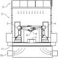
- FIG. 1shows a cross-section view through a conventional painting installation for painting motor vehicle body parts.
- the motor vehicle body parts to be paintedare transported on a conveyor 1 at right angles to the drawing plane through a painting cabin 2 , in which the motor vehicle body parts are then painted in the conventional manner by painting robots 3 , 4 .
- the painting robots 3 , 4have several swivelling robot arms each of which carry, via a multi-axis robot hand axis, an application device, such as, for example a rotary atomiser, an air atomiser or a so-called airless device.
- the air downdraft speed in the painting cabin 2must be in the range of approx. 0.3-0.5 m/s at least in order to rapidly remove the overspray occurring during painting from the painting cabin 2 .
- the known application devicesare associated with high operating costs through the paint losses and the costs of disposing of the overspray.
- the aim of the present disclosureis therefore to bring about an appropriate improvement.
- FIG. 1shows a cross-section view of a conventional painting installation for painting motor vehicle body parts.
- FIG. 2shows a cross-section view of an exemplary painting installation for painting motor vehicle body parts with print heads as application devices.
- FIG. 3Ashows a nozzle of an exemplary print head with a colour changer and the associated coating agent supply.
- FIG. 3Bshows a nozzle row of an exemplary print head with several coating agent nozzles each with individually allocated colour changers.
- FIG. 4Ashows a nozzle row with several coating agent nozzles and an allocated colour changer.
- FIG. 4Bshows a modification of FIG. 4A , where on the input side the colour changer only has one single special colour supply.
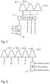
- FIG. 5shows a modification of FIG. 4A , where on the input side the colour changer is connected to a colour mixer which is supplied with the primary colours of a colour system.
- FIG. 6shows a nozzle row of an exemplary print head with several coating agent nozzles where four of the coating agent nozzles are each supplied with one primary colour of a CMYK colour system, while the fifth coating agent nozzle is supplied with an effect paint.
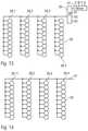
- FIG. 7shows several nozzle rows of an exemplary print head, to each of which one primary colour of a CMYK colour system is allocated.
- FIG. 8shows several nozzle rows of an exemplary print head, to each of which a colour changer and one of the primary colours of a CMYK colour system is allocated.
- FIG. 9shows several nozzle rows of an exemplary print head, to each of which a primary colour of a CMYK colour system and a colour changer is allocated, whereby the nozzle rows can alternatively be supplied with an effect paint via another colour changer.
- FIG. 10shows a nozzle row of an exemplary print head whereby four adjacent coating agent nozzles are supplied with a mixed colour shade via a colour mixer, while the fifth coating agent nozzle is supplied with an effect paint via a colour changer.
- FIG. 11shows several nozzle rows of an exemplary print head, which are jointly supplied with a mixed colour shade via a colour mixer.
- FIG. 12show several nozzle rows of an exemplary print head each with one colour changer, whereby the colour changers of the individual rows are supplied with a mixed colour shade via a colour mixer.
- FIG. 13shows several nozzle rows of an exemplary print head which are jointly supplied with the coating agent to be applied via a colour changer and a colour mixer.
- FIG. 14shows several nozzle rows of an exemplary print head which are jointly supplied via a single coating agent supply line.
- FIG. 15shows several nozzle rows of an exemplary print head, whereby the individual nozzles within the nozzle row are alternately connected to a first coating agent supply line and a second coating agent supply line.
- FIG. 16shows an exemplary nozzle arrangement in a print head.
- FIG. 17shows an alternative exemplary nozzle arrangement in the print head with smaller coating agent nozzles.
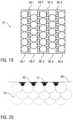
- FIG. 18shows an exemplary alternative arrangement of the coating agent nozzles in the print head, whereby the coating agent nozzles have different nozzle sizes.
- FIG. 19shows a modification of FIG. 18 , wherein the nozzle rows with the larger coating agent nozzles are arranged offset with regard to each other.
- FIG. 20shows a diagram for clarifying the painting of a sharp edge with the print head, according to one exemplary illustration.
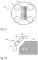
- FIG. 21shows a rotating print head
- FIG. 22shows a print head arrangement with several swivelling print heads for adaptation to curved component surfaces.
- FIG. 23shows a layered pixel with several layers in the primary colours of a colour system and an uppermost layer of a metallic paint.
- FIG. 24shows a schematic view of an exemplary coating device with a multiple axis robot which controls a print head and sensor in order to position the print head.
- FIG. 25shows a schematic view of an exemplary coating device in which several components are mixed to form a mixture, whereby the print head then applies the mixture.
- FIG. 26shows a schematic view of a print head which applies several components independently of each other, whereby mixing takes place on the component surface, according to one exemplary illustration.
- FIG. 27shows a schematic view of an exemplary print head with a sheath flow nozzle.
- FIG. 28shows a schematic view of an exemplary print head in which the coating agent droplets are pneumatically discharged and accelerated.
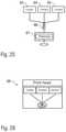
- FIG. 29shows a schematic view of a print head which generates a trapezoidal layer thickness distribution.
- FIG. 30shows a schematic view of an exemplary coating device in which numerous print heads are mounted on a portal.
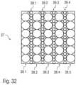
- FIGS. 31 and 32show modifications of FIGS. 18 and 19 with a maximum packing density of the individual nozzles.
- the exemplary illustrationscomprise the general technical teaching of using an application device with such a degree of application efficiency that a wash-out in which the overspray is conventionally removed from the cabin air can be dispensed with.
- an advantage of the exemplary coating deviceis the fact that a separate wash-out can be dispensed with.
- the exemplary illustrationsare not limited to painting installations which do not have a wash-out. Rather, through the use of application devices with a higher degree of application efficiency, it is possible to reduce the dimensions of the wash-out, in the event that it cannot be fully dispensed with.
- the application devicemay be, according to one exemplary illustration, a print head, for example as used in a similar form in inkjet printers. It could, for example, be a bubble jet print head or a piezo print head. However, with regard to the technical principle of the print head used, the exemplary illustrations are not restricted to bubble jet print heads and piezo print heads, but can in general be implemented with other discharging mechanisms.
- the print headcan discharge the coating agent pneumatically.
- the individual coating agent dropscan be discharged by means of brief air pulses which accelerate the coating agent drops in the direction of the component to be coated, whereby the painting distances can be increased.
- the print headcan optionally discharge the coating agent as individual coating agent droplets or continuously. Furthermore, within the context of the exemplary illustrations it is possible for some of the coating agent nozzles of the print head to discharge the coating agent continuously while some of the coating agent nozzles of the print head discharge coating agent in the form of individual coating agent droplets.
- the print headis positioned by a multi-axis robot, whereby the robot may have several swivelling robot arms and a multi-axis robot hand axis on which the print head is mounted.
- the print headcan be attached to a machine which moveably positions the print head relative to the component to be coated.
- a machinecan be a conventional roof machine or a side machine, which are in themselves known from the prior art and do not therefore need to be described in more detail
- the print head in the exemplary coating devicemay advantageously exhibit a considerably greater surface coating output, which may be, for example, greater than 1 m 2 /min, 2 m 2 /min, 3 m 2 per minute or 4 m 2 /min.
- the print head in the coating devicemust be able to apply fluid paints containing solid paint components, such as, for example, pigments and so-called metallic flakes (micas).
- solid paint componentssuch as, for example, pigments and so-called metallic flakes (micas).
- the individual coating agent nozzles of the print headtherefore may be adapted in terms of their size to the solid paint components, so that the print head can also apply paints with the solid paint components.
- an atomiserinstead of a print head, an atomiser can be used which discharges the coating agent from at least one coating agent nozzle.
- the application devicemay be arranged in a painting cabin in which the components are coated with the coating agent.
- painting cabinsare known from the prior art and do not therefore need to be described in more detail.
- the print heads used as application devices within the context of the exemplary illustrationsmay generally exhibit a much greater application efficiency than conventional application devices, such as rotary atomisers.
- the wash-out located under the painting cabincan therefore be considerably smaller in dimension than in conventional painting installations with rotary atomisers as application devices.
- the high application efficiency of the print heads used as application deviceseven allows washing out or any other laborious filtering measures, e.g. dry separation or the like below the painting cabin, to be completely dispensed with. In this case simple filters suffice which can be replaced or cleaned cyclically (e.g. weekly, monthly, every six months or annually).
- the high application efficiency of the print heads used as application devices within the context of the exemplary illustrationsallows explosion protection measures in accordance with the relevant statutory ATEX guidelines to be dispensed with, as less overspray is produced and therefore no atmosphere at risk of explosion occurs during operation. In one exemplary illustration, no explosion protection is therefore provided in the painting cabin.
- an air extraction systemmay be provided which extracts the air from the painting cabin, for example with the extraction taking place downwards.
- the cabin airmay be extracted through a filter which filters the overspray from the cabin air, whereby the air filter can be designed for example as a filter ceiling arranged on the base of the painting cabin, so that the cabin air is extracted downwards through the filter ceiling from the painting cabin.
- the downdraft speed in the painting cabincan be lower than in conventional painting installations which use rotary atomisers as application devices for example.
- the downdraft speed in the painting cabincan therefore be less than, merely as examples, 0.5 m/s, 0.4 m/s, 0.3 m/s, 0.2 m/s or 0.1 m/s.
- At least one colour changeris assigned to the print head which is connected to the print head on the output side and is provided with various coating agents on the input side so that the colour changer selects one of the coating agents and supplies the print head with the selected coating agent.
- Various coating agents in the primary colours of a colour systeme.g. the CMYK colour system
- the colour changercan be supplied with various effect paints, such as, for example, special paints, metallic paints or mica paints.
- the colour changeronly supplies one single coating agent nozzle of the print head with the selected coating agent.
- a separate colour changeris therefore assigned to each coating agent nozzle of the print head, so that the coating agent to be applied can be individually selected for the individual coating agent nozzles.
- the individual colour changerscan be controlled individually and independently of each other in order to select the required coating agent for the relevant coating agent nozzles.
- the colour changersupplies a group of several coating agent nozzles with the same coating agent, whereby the coating agent nozzles can be arranged in a row for example, for instance in a line or column.
- a colour mixermay be arranged upstream of the colour changer on the input side which on the input side is supplied with variously coloured coating agents in the primary colours of a colour system (e.g. CMYK colour system).
- the colour mixermixes a desired colour shade from the various primary colours and supplies this to the colour changer for selection.
- the colour changermay be supplied with at least one effect paint, for example a mica paint, a metallic paint and/or a special paint. The colour changer can then either select the colour shade mixed by the colour mixer or fall back on one of the effect paints.
- a group of adjacent coating agent nozzlesis each supplied with a primary colour of a colour system.
- four adjacent coating agent nozzlesare supplied with the primary colours cyan, magenta, yellow or black.
- a further adjacent coating agent nozzlemay then be supplied with one of several effect paints by a colour changer.
- the coating agent nozzles for the primary colours and for the effect paintare spatially arranged so closely adjacent to each other in the print head that the discharged coating agents mix on the component to be coated to form the desired colour shade with a desired effect paint. In this exemplary illustration, colour mixing may therefore take place on the component to be coated.
- the coating agent nozzles in the print headcan be arranged in rows, for example in lines and columns.
- the coating agent nozzlesmay be arranged in matrix form in the print head.
- one primary coloure.g. cyan, magenta, yellow, black
- one primary coloure.g. cyan, magenta, yellow, black
- the coating agent nozzles within a row of nozzlesto be alternately supplied with the respective primary colour (e.g. cyan, magenta, yellow, black) and with an effect paint.
- the individual nozzle rowscan each be supplied by one colour changer with the coating agent to be applied, whereby the colour changers in each row of nozzles are supplied with a particular primary colour and an effect paint.
- the colour changer of one row of nozzlescan be supplied with a coating agent of the colour cyan and a special paint, while the colour changer of the next row of nozzles is supplied with a coating agent of the colour magenta and the special paint.
- the colour changers in the next rows of nozzlesare then supplied accordingly with the colours yellow and black respectively and with the special paint.
- the colour changers of the individual rows of nozzlescan be jointly connected on the input side with a further colour changer which selects one of several effect paints.
- the colour changers in the individual nozzle rowscan then either select the directly supplied primary colour or indirectly utilise the supplied special paints via the further colour changer.
- a group of coating agent nozzlesis jointly supplied with a particular colour shade mixed together by the colour mixer from the primary colours of a colour system.
- an adjacent additional coating agent nozzleis supplied by another colour changer which selects from several effect paints.
- mixing of the selected effect paint with the previously mixed colour shadetakes place on the component to be coated.
- one portion of the coating agent nozzles of the print headare connected to a colour mixer, which on the input side is supplied with the primary colours of a colour system.
- another portion of the coating agent nozzles of the print headis connected to a special paint supply.
- the coating agent nozzles in the print headmay be arranged in a matrix form in lines and columns. It is possible for the coating agent nozzles in the individual nozzle rows (lines or columns) to be alternately connected to the colour mixer and special paint supply.
- one portion of the coating agent nozzles of the print headmay be connected to a first coating agent supply line, whereas a second portion of the coating agent nozzles of the print head is connected to a second coating agent supply line so that the print head can supply two different coating agents.
- the coating agent nozzles in the individual nozzle rowsmay alternately be connected with the one coating agent supply line or with the other coating agent supply line.
- the print headhas at least one separate coating agent nozzle which only applies special paint containing effect particles.
- the print headalso has at least one further coating agent nozzle which applies normal paint containing no effect particles. The various coating agent nozzles can then be adapted accordingly.
- the effect particlese.g. metallic, mica etc.
- the effect particlesare applied to the object with a separate coating agent nozzle.
- the effectscan be applied to the object very specifically and with local differences.
- effectscan be achieved which are not conceivable at all today.
- With the new inkjet technologyit is possible to place the effect particles only on the upper surface of the layer for example.
- the coating agent nozzles in the print headmay be arranged in a matrix form in several lines and columns.
- the individual coating agent nozzles of the print headare essentially of equal size.
- the adjacent nozzle rowscan be offset with regard to each other in the longitudinal direction, more particularly by half the width of a nozzle, which allows a maximum packing density of the coating agent nozzles in the nozzle head.
- the individual nozzle rowsmay be arranged transversely, more particularly perpendicularly to the direction of advance of the nozzle head.
- the print headhas nozzle openings of different sizes.
- rows of nozzles with large coating agent nozzles and rows of nozzles with small coating agent nozzlescan be arranged alternately.
- rows of nozzles comprising the larger coating agent nozzlesmay be offset with regard to each other, more particularly by half the width of a nozzle.
- the print headis rotatably mounted and rotates during coating.
- the print headcan have coating agent nozzles of various sizes, whereby the smaller coating agent nozzles may be arranged closer to the rotational axis of the print head than the larger coating agent nozzles.
- print headsare provided which are jointly guided by one device (e.g. a multiple axis robot) and can be swivelled with regard to each other, which allows adaptation to curved component surfaces.
- one devicee.g. a multiple axis robot
- various primary colours of a colour systemcan be mixed in order to obtain a desired colour shade, whereby the colour mixing can take place either in a colour mixer or on the component surface to be coated.
- the colour systemcan optionally be the CMYK colour system or the RGB colour system, to name but a few examples.
- the exemplary illustrationsare not limited to the specifically aforementioned examples.
- the surface areas of the print heade.g. leads
- a wear-reducing coatingsuch as, for example, a Diamond-Like Carbon (DLC) coating, a diamond coating, a hard metal or a material combination of a hard and a soft material.
- the surface areas of the print head coming into contact with the coating agentcan be coated with titanium nitride, titanium oxide or chemical nickel, or with another layer produced by way of a Physical Vapour Deposition (PVC) process, Chemical Vapour Deposition (CVD) process, or an Electrolytic Oxidation of Aluminium (Eloxal) process, or be provided with an “easy-to-clean” coating.
- PVCPhysical Vapour Deposition
- CVDChemical Vapour Deposition
- EloxalElectrolytic Oxidation of Aluminium
- electrostatic coating agent charging and/or compressed air supportcan be provided.
- a further possibilityconsists in position detection which detects the spatial position of the print head and/or the component surface to be coated and controls/regulates the positioning of the print head accordingly.
- the “mixing room”can be a mixing chamber, a hose section or a mixing system (e.g. Keenix mixer).
- a mixing systeme.g. Keenix mixer.
- the problemis the very precise dosing of the individual components in order to achieve the correct colour shade.
- a colour sensor for regulating the dosing unitcan therefore be useful.
- the inkjet technologycan also be used as dosing technique.
- the required quantity of individual dropletswhich are dependent on the opening time of the nozzle and the pressure, can be produced.
- These inkjet nozzlesagain mix the colour shade in a mixing room.
- the senoris attached to the print head or to the robot, but in principle other designs are also possible.
- the sensorcan detect the previous paint path so that the current paint path can be applied at a position relative to the previous paint path.
- the current paint pathmay be applied a certain distance parallel to the previous paint path, which is possible through the above-described sensor detection.
- the senoris an optical sensor, but in principle other types of sensors are also possible.
- the aforementioned guide pathcan also be a separate guide path which is only applied for guiding purposes and can, for example, comprise a normally invisible colour that is only visible to the sensor when illuminated with ultraviolet (UV) or infra-red (IR) light.
- UVultraviolet
- IRinfra-red
- Such a laser measuring systemcan also detect the distance to the surface of the component to be coated and keep it constant as part of a regulation system.
- a robot controlleris provided which on the input side is connected to the sensor and on the output side to the robot, whereby the robot controller positions the print head as a function of the course of the guide path.
- the print headhas a sheath flow nozzle with emits a sheath flow of air or another gas, whereby the sheath flow encompasses the coating agent flow emitted by the coating agent nozzle in order to atomise and/or delimit the coating agent droplets.
- this sheath flow in the form of an air curtaincan direct the resulting overspray onto the component surface, thereby improving the application efficiency.
- the print headhas several coating agent nozzles which are arranged next to each other in relation to the direction of the path, whereby the outer coating agent nozzles emit less coating agent than the inner coating agent nozzles, which leads to an corresponding layer thickness of the distribution transversely to the path direction.
- Nozzlesdo not necessarily have to be arranged in a row.
- the paint quantitycan be controlled for each nozzle and each pixel. Through different quantities of paint the colour shade intensity, for example, is controlled.
- the layer thickness distributionit is possible for the layer thickness distribution to be a Gaussian normal distribution.
- the coating agent quantity emitted by the individual coating agent nozzlesto be selected so that the layer thickness distribution is a trapezoidal distribution.
- Such a trapezoidal layer thickness distributionis advantageous as the adjacent coating agent paths can overlap each other in such a way that the superimposition of the trapezoidal layer thickness distributions of the adjacent coating agent paths results in a constant layer thickness.
- the components to be coatedare carried along a conveyor path, as known in painting installations from the prior art and therefore does not need to be described in more detail.
- a portalspans the conveyor path, whereby numerous print heads are mounted on the portal which are directed at the components on the conveyor path and coat the components.
- the coating agentmay be applied to the component in the form of pixels, whereby the individual pixels each consist of several primary colours of a colour system in order, through colour mixing, to achieve a desired colour of the pixel.
- the colour mixingcan, for example be subtractive colour mixing, but in principle it is also possible to achieve the desired colour through additive colour mixing.
- the various primary colours (e.g. red, green, blue) of the relevant colour systeme.g. RGB colour system
- the upper layer of a pixelit is possible for the upper layer of a pixel to have an effect paint and be semi-transparent so that the uppermost layer achieves the desired effect and at the same time lets through the desired colour produced by the underlying layers.
- the technology according to the various exemplary illustrationscan also be used for the specific coating of cut edges of previously coated metal sheets, punched boards or for the efficient sealing of seams and edges.
- FIG. 2shows an exemplary painting installation.
- Motor vehicle body parts to be paintedmay be transported on a conveyor 1 at right angles to the drawing plane through a painting cabin 2 , in which the motor vehicle body parts are then painted in the conventional manner by painting robots 3 , 4 .
- Above the painting cabin 2there may be a plenum 5 from which air is introduced through a ceiling 6 of the painting cabin 2 downwards in the direction of the arrow into the painting cabin 2 .
- a special feature of the exemplary painting installationinitially consists in the fact that the painting robots 3 , 4 do not have rotary atomisers as application devices, but print heads 8 , 9 , which have a much greater application efficiency of more than 95% and therefore produce much less overspray.
- wash-oute.g., wash-out 7 present in the conventional painting installation in accordance with FIG. 1 , can be dispensed with.
- the exemplary painting installation shown in FIG. 2has an air extractor 10 under the painting cabin 2 which extracts the cabin air downwards from the painting cabin 2 through a filter ceiling 11 .
- the filter ceiling 11filters the small amount of overspray out of the cabin air without any wash-out being required, e.g., wash-out 7 as in the conventional painting installation.
- the print heads 8 , 9operate on the piezo principle like conventional print heads, but the surface coating performance of the print heads 8 , 9 is much greater than conventional print heads so that the motor vehicle body parts can be painted at a satisfactory working speed.
- FIG. 3Ashows a coating agent nozzle 12 , which in each of the print heads 8 , 9 may be arranged in addition to numerous other coating agent nozzles, whereby the coating agent nozzle 12 is supplied with the coating agent to be applied by a colour changer 13 .
- the colour changer 13On the input side the colour changer 13 is connected to a total of seven coating agent supply lines from which the colour changer 13 can select one for supplying coating agent to coating agent nozzle 12 .
- the other three coating agent supply lines of the colour changer 13are for supplying a metallic paint, a mica paint and a special paint.
- the desired colour shade of the coating agentis mixed on the motor vehicle body component to be coated, whereby time-based or local mixing is optionally possible.
- coating agent droplets in the primary colours C, M, Y and Kare, for example, consecutively applied in the required colour ratio so that the coating agent droplets then mix on the motor vehicle body component to be coated.
- coating agent droplets of a particular primary colour C, M, Y or Kare applied from the coating agent nozzle 12 , which then mix on the motor vehicle body parts with other coating agent droplets applied by another coating agent nozzle, which is not shown in FIG. 3A .
- FIG. 3Bshows a modification of the exemplary illustration of FIG. 3A in which a nozzle row with four coating agent nozzles 14 . 1 - 14 . 4 and four colour mixers 15 . 1 - 15 . 4 is shown.
- the colour changers 15 . 1 - 15 . 4are jointly connected to five coating agent supply lines via which the colour changers 15 . 1 - 15 . 4 are supplied with the four primary colours C, M, Y, K of the CMYK colour system and also with a special paint S.
- FIG. 4Ashows a group of coating agent nozzles 16 . 1 - 16 . 5 , which are jointly connected to the outlet of a colour changer 17 and therefore apply the same coating agent in operation.
- the colour changer 17On the input side the colour changer 17 is connected to seven coating agent supply lines of which four coating agent supply lines supply the primary colours C, M, Y, K of the CMYK colour system, while the other three coating agent pipelines supply a metallic paint, a mica paint and a special paint respectively.
- FIG. 4Blargely corresponds with the exemplary illustration previously described and shown in FIG. 4A , so that in order to avoid repetition, reference is made to the above description with the same reference numbers being used for corresponding details.
- a special feature of this exampleis that on the output side the colour changer 17 is connected to a total of six coating agent nozzles 16 . 1 - 16 . 6 which therefore apply the same coating agent.
- Another special feature of this exemplary illustrationis that on the input side the colour changer 17 is only connected to five coating agent supply lines, of which four of the coating agent supply lines supply the primary colours of C, M, Y, K of the CMYK colour system while the fifth coating agent supply line supplies a special paint.
- FIG. 5partially corresponds with the exemplary illustration in FIG. 4A , so that to avoid repetition reference is made to the above description with the same reference numbers being used for corresponding details.
- a special feature of this exampleis that on the input side the colour changer 17 is connected to a colour mixer 18 , whereby on its input side the colour mixer 18 is connected to four coating agent supply lines which supply the four primary colours C, M, Y, K of the CMYK colour system.
- the colour mixer 18can therefore mix any colour shade from the primary colours C, M, Y, K and supply it to the colour changer 17 .
- the colour changer 17can optionally only supply the coating agent nozzle 16 . 1 with the coating agent to be applied or also coating agent nozzles 16 . 2 , 16 . 3 and, as required, other coating agent nozzles, which are not shown in the drawing.
- FIG. 6again partially corresponds with the above-described exemplary illustrations, so that to avoid repetition reference is made to the above description with the same reference numbers being used for corresponding details.
- a special feature of this illustrationis that the adjacent coating agent nozzles 16 . 1 - 16 . 4 are each directly connected to a coating agent supply line via each of which one of the primary colours C, M, Y, K of the CMYK colour system is supplied.
- the adjacent coating agent nozzle 16 . 5is connected via the colour changer 17 to three further coating agent supply lines which supply a metallic paint, a mica paint and a special paint.
- the colour changerthen may select a desired effect paint (metallic paint, mica paint or special paint) and apply the desired effect paint via the coating agent nozzle 16 . 5 .
- a desired effect paintmetallic paint, mica paint or special paint
- the four primary colours C, M, Y and K of the CMYK colour systemare applied in the desired ratio via the coating agent nozzles 16 . 1 - 16 . 4 .
- the primary colours C, M, Y, Kthen mix with the selected effect paint on the component to be coated.
- FIG. 7shows several nozzle rows 19 . 1 - 19 . 4 with numerous coating agent nozzles 20 , whereby one of the four primary colours C, M, Y, K of the CMYK colour system is assigned to the individual nozzle rows 19 . 1 - 19 . 4 .
- the coating agent nozzles 20 of coating agent row 19 . 1apply the primary colour C (cyan), while coating agent row 19 . 2 applies the primary colour M (magenta).
- the nozzle rows 19 . 1 - 19 . 4can also apply a special paint S.
- every second coating agent nozzle 20is therefore connected to a special paint supply line.
- the individual coating agent nozzles 20can therefore alternately apply the special paint S and one of the four primary colours C, M, Y, K.
- FIG. 8also shows four nozzle rows 21 . 1 - 21 . 4 , which each comprise numerous coating agent nozzles 22 .
- colour changers 23 . 1 - 23 . 4are provided which each provide all the coating agent nozzles 22 of one of the four nozzle rows 21 . 1 - 21 . 4 with a coating agent.
- colour changer 23 . 1supplies all the coating agent nozzles 22 of nozzle row 21 . 1
- colour changer 23 . 2supplies all the coating agent nozzles 22 of nozzle row 21 . 2
- colour changer 23 . 3supplies all the coating agent nozzles 22 of nozzle row 21 . 3
- colour changer 23 . 4supplies all the coating agent nozzles 20 of nozzle row 21 . 4 with the coating agent to be applied.
- the colour changers 23 . 1 - 23 . 4are each supplied with a primary colour C, M, Y, K so that each of the primary colours C, M, Y, K is assigned to one of the four nozzle rows 21 . 1 - 21 . 4 .
- the colour changers 23 . 1 - 23 . 4are also connected to several special colour supply lines via which the special colours, metallic paints or suchlike can be supplied.
- FIG. 9corresponds partially with the exemplary illustration described above and shown in FIG. 8 so that to avoid repetition reference is made to the above description with the same reference numbers being used for corresponding details.
- a special feature of this exampleis that on the input side the colour changers 23 . 1 - 23 . 4 are connected to a further colour changer 24 , whereby on its input side colour changer 24 is supplied with three different effect paints S 1 , S 2 , S 3 .
- the colour changer 24thus selects one of the effect paints S 1 , S 2 or S 3 and makes the selected effect paint available for the other colour changers 23 . 1 - 23 . 4 to select.
- the colour changers 23 . 1 - 23 . 4can therefore optionally select the relevant primary colour C, M, Y or K or the effect paint made available by the colour changer 24 .
- FIG. 10partially corresponds with the exemplary illustration described above and shown in FIG. 6 , so that to avoid repetition reference is made to the above description with the same reference numbers being used for corresponding details.
- a special feature of this exampleis that the coating agent nozzles 16 . 1 - 16 . 4 are not supplied separately with one of the primary colours C, M, Y or K each. Rather, the coating agent nozzles 16 . 1 - 16 . 4 are jointly supplied with the coating agent to be applied by a colour mixer 25 , whereby on its input side the colour mixer 25 is supplied with the primary colours C, M, Y, K of the CMYK colour system and is controlled to mix a desired colour shade which is then applied by coating agent nozzles 16 . 1 - 16 . 4 .
- FIG. 11corresponds partially with the exemplary illustration described above and shown in FIG. 7 so that to avoid repetition reference is made to the above description with the same reference numbers being used for corresponding details.
- a special feature of this illustrationis that the individual nozzle rows 19 . 1 - 19 . 4 are not supplied with the various primary colours but with a mixed together coating agent, which is mixed by a colour mixer 26 from the primary colours C, M, Y and K.
- FIG. 12corresponds partially with the exemplary illustration described above and shown in FIG. 8 so that to avoid repetition reference is made to the above description with the same reference numbers being used for corresponding details.
- a special feature of this exampleis that the individual colour changers 23 . 1 - 23 . 4 are jointly supplied with a colour mixture which is supplied by a colour mixer 27 , whereby on the input side the colour mixer 27 is supplied with the primary colours C, M, Y and K.
- FIG. 13shows a further exemplary illustration of a nozzle arrangement in the print heads 8 , 9 , whereby four nozzle rows 28 . 1 - 28 . 4 are shown here which each have numerous coating agent nozzles 29 .
- all the coating agent nozzles 29 and all the coating agent rows 28 . 1 - 28 . 4are jointly supplied with the coating agent from a colour changer 30 .
- the colour changer 30On the input side the colour changer 30 is connected to three special colour supply lines via which the three special paints S 1 , S 2 , S 3 are supplied.
- the colour changer 30is connected to a colour mixer 31 which from the primary colours, C, M, Y, K mixes a desired colour shade and makes it available to the colour changer 30 for selection.
- FIG. 14corresponds partially with the exemplary illustration which is described above and shown in FIG. 13 , so that to avoid repetition reference is made to the above description with the same reference numbers being used for corresponding details.
- a special feature of this exemplary illustrationis that all the coating agent nozzles 29 in all the nozzle rows 28 . 1 - 28 . 4 are connected to a joint coating agent supply line 31 via which the same coating agent is supplied.
- FIG. 15corresponds partially with the example of FIG. 11 , so that to avoid repetition reference is made to the above description.
- a special feature of this exemplary illustrationis that the coating agent nozzles 20 in the individual nozzle rows 19 . 1 - 19 . 4 are alternately connected to a first coating agent supply line 32 and a second coating agent supply line 33 .
- FIG. 16shows a nozzle arrangement 34 for the print heads 8 , 9 of the painting installation according to one exemplary illustration, whereby the arrow indicates the direction of advance of the print heads 8 , 9 , i.e. the direction of the pressure.
- the nozzle arrangement 34has several nozzle rows 35 . 1 - 35 . 7 each of which comprise several coating agent nozzles 36 .
- the coating agent nozzles 36have a nozzle opening of uniform size.
- the adjacent nozzle rows 35 . 1 - 35 . 7are offset with regard to each other in the longitudinal direction by half the width of a nozzle, which allows a maximum packing density of the coating agent nozzles 36 within the nozzle arrangement 34 .
- FIG. 17shows a modification of a nozzle arrangement 34 which largely corresponds with the nozzle arrangement described above and shown in FIG. 16 , so that to avoid repetition reference is made to the above description.
- a special feature of this exemplary illustrationis that the individual nozzles 36 have a much smaller nozzle size.
- a further special feature of this exemplary illustrationis that the adjacent nozzle rows are not offset with regard to each other.
- FIG. 18shows a further exemplary illustration of a nozzle arrangement 37 with five parallel nozzle rows 38 . 1 - 38 . 5 with relative large nozzle openings and four nozzle rows 39 . 1 - 39 . 4 with relatively small nozzle openings.
- FIG. 19The exemplary illustration in accordance with FIG. 19 largely corresponds with the example shown in FIG. 18 and described above, so that to avoid repetition reference is made to the above description with the same reference numbers being used for corresponding details.
- a special feature of this exemplary illustrationis that the nozzle rows 38 . 1 - 38 . 5 with the larger nozzle openings are offset with regard to each other in the longitudinal direction by half the width of a nozzle.
- FIG. 20shows a diagram for painting a sharp edge 39 . It can be seen that the edge 39 is composed of variously large coating agent surfaces 40 , 41 , 42 whereby the differently sized coating agent surfaces 40 - 42 are produced by differently sized coating agent nozzles.
- FIG. 21schematically shows a rotatable print head 43 with four large coating agent nozzles 44 and numerous smaller coating agent nozzles 45 , whereby the larger coating agent nozzles 44 are arranged on the outside with regard to the axis of rotation of the print head 43 while the smaller coating agent nozzles 45 are located on the inside with regard to the axis of rotation of the print head 43 .
- FIG. 22shows a print head arrangement 46 with a total of four print heads 47 - 50 which can be swivelled with regard to each other in order to allow better adaptation to the surface of a curved component 51 .
- FIG. 23shows a pixel 52 , which can be applied to a component 53 with the exemplary coating methods by means of a print head, whereby for the sake of simplicity a single pixel 52 is shown in the drawing. However, in practice numerous pixels 52 are applied.
- the pixel 52comprises several layers 54 - 57 arranged on top of each other.
- the three lower layers 55 - 57are of the primary colours red, green and blue of the RGB colour system.
- the lower layerscan be in the primary colours of a different colour system, such as the CMYK colour system.
- FIG. 24shows a coating device according to one exemplary illustration with a multiple axis robot 58 which moves a print head 59 along predefined coating agent paths over a component surface 60 , whereby the robot is 58 is operated by a robot controller 61 .
- the robot controller 61controls the robot 58 in such a way that the print head 59 is guided along predefined coating agent paths over the component surface 60 whereby the coating agent paths lie adjacent to each other in a meandering pattern.
- a special featureis that an optical sensor 62 is also attached to the print head 59 which during operation detects the position and course of the previous coating agent paths so that the current coating agent path can be exactly aligned with regard to the previous coating agent path.
- FIG. 25shows in a very simplified form a variant of an exemplary coating device with three separate coating agent supply lines 63 - 65 , which each supply one component of the coating agent to be applied.
- the coating agent supply lines 63 - 65are connected to a mixer 66 which mixes the individual components into a coating agent mixture which is then supplied to a print head 67 . Mixing of the various components of the coating agent thus takes place before application by the print head 67 .
- FIG. 26shows in simplified form a print head 68 which applies three different components of a coating agent separately onto the vehicle component surface, whereby mixing of the individual components only takes place on the vehicle component surface.
- FIG. 27schematically shows a print head 69 for applying coating agent droplets 70 onto a vehicle component surface 71 .
- the print head 69has a coating agent nozzle 72 from which the individual coating agent droplets 70 are discharged pneumatically or in another manner.
- the print head 69has a sheath flow nozzle 73 which annularly surrounds the coating agent nozzle 72 and emits a circular sheath flow which surrounds the individual coating agent droplets 70 .
- sheath flow emitted from the sheath flow nozzle 73directs any overspray in the direction of the component surface 71 and thereby improves the application efficiency.
- FIG. 28shows, also in a very simplified form, an exemplary print head 69 which partially corresponds with the print head 69 according to FIG. 27 so that to avoid repetition, reference is made to the above description with the same reference numbers being used for corresponding details.
- a special feature of this exemplary illustrationis that the individual coating agent droplets 70 are pneumatically discharged from the coating agent nozzle 72 whereby the coating agent droplets 70 are pneumatically accelerated as a result of which the maximum possible painting distance is increased, as the individual coating agent droplets 70 have a greater kinetic energy due to the pneumatic acceleration.
- FIG. 29shows a print head 74 during the application of two adjacent paint paths, whereby the position of the print head 74 in the current paint path is shown without an apostrophe, while the position of the print head 74 ′ in the previous painting path is shown with an apostrophe.
- the print head 74has coating agent nozzles 75 arranged transversely to the path direction, whereby the outer coating agent nozzles 75 emit less coating agent than the inner coating agent nozzles 75 .
- the print head 74achieves a trapezoidal layer thickness distribution 76 on the component surface. This is advantageous as the trapezoidal layer thickness distribution 76 is then superimposed on the also trapezoidal layer thickness distribution 76 ′ of the previous paint path which leads to a constant layer thickness.
- FIG. 30shows a coating device according to one exemplary illustration in which the components 77 to be coated are transported along linear conveyor path 78 through a painting cabin, which is in itself known from the prior art and does not therefore need to be described in more detail.
- a portal 79spans the conveyor path 78 whereby attached to the portal are numerous print heads 80 which are directed at the components 77 on the conveyor path 78 and coat these with a coating agent.
- FIG. 31shows a modification of FIG. 19 , so that to avoid repetition reference is made to the above description with the same reference numbers being used for corresponding details.
- a special feature of this exemplary illustrationis the much greater packing density of the individual coating agent nozzles.
- FIG. 32shows a modification of FIG. 18 , so that to avoid repetition reference is made to the above description with the same reference numbers being used for corresponding details.
- the special featureis that the packing density of the individual coating agent nozzles is much greater.
Landscapes
- Engineering & Computer Science (AREA)
- Manufacturing & Machinery (AREA)
- Coating Apparatus (AREA)
- Spray Control Apparatus (AREA)
- Application Of Or Painting With Fluid Materials (AREA)
- Details Or Accessories Of Spraying Plant Or Apparatus (AREA)
- Manipulator (AREA)
- Ink Jet (AREA)
- Electrostatic Spraying Apparatus (AREA)
- Organic Low-Molecular-Weight Compounds And Preparation Thereof (AREA)
Abstract
Description
- 1 Conveyor
- 2 Painting cabin
- 3 Painting robot
- 4 Painting robot
- 5 Plenum
- 6 Ceiling
- 7 Wash-out
- 8 Print head
- 9 Print head
- 10 Air extractor
- 11 Filter ceiling
- 12 Coating agent nozzle
- 13 Colour changer
- 14.1-14.4 Coating agent nozzles
- 15.1-15.4 Colour changer
- 16.1-16.6 Coating agent nozzles
- 17 Colour changer
- 18 Colour mixer
- 19.1-19.4 Nozzle rows
- 20 Coating agent nozzles
- 21.1-21.4 Nozzle rows
- 22 Nozzle rows
- 23.1-23.4 Colour changer
- 24 Colour changer
- 25 Colour mixer
- 26 Colour mixer
- 27 Colour mixer
- 28.1-28.4 Nozzle rows
- 29 Coating agent nozzle
- 30 Colour changer
- 31 Coating agent supply line
- 32 Coating agent supply line
- 33 Coating agent supply line
- 34 Nozzle arrangement
- 35.1-35.7 Nozzle rows
- 36 Coating agent nozzles
- 37 Nozzle arrangement
- 38.1-38.5 Nozzle rows
- 39 Edge
- 40-42 Coating agent surfaces
- 43 Print head
- 44 Coating agent nozzles
- 45 Coating agent nozzles
- 46 Print head arrangement
- 47-50 Print heads
- 51 Component
- 52 Pixel
- 53 Component
- 54-57 Layers
- 58 Robot
- 59 Print head
- 60 Component surface
- 61 Robot controller
- 62 Sensor
- 63 Coating agent supply
- 66 Mixer
- 67 Print head
- 68 Print head
- 69 Print head
- 70 Coating agent droplet
- 71 Component surface
- 72 Coating agent nozzle
- 73 Sheath flow nozzle
- 74,74′ Print head
- 75,75′ Coating agent nozzles
- 76,76′ Layer thickness distribution
- 77 Components
- 78 Conveyor
- 79 Portal
- 80 Print heads
Claims (14)
Priority Applications (1)
| Application Number | Priority Date | Filing Date | Title |
|---|---|---|---|
| US16/214,646US11241889B2 (en) | 2008-10-24 | 2018-12-10 | Coating device and associated coating method |
Applications Claiming Priority (5)
| Application Number | Priority Date | Filing Date | Title |
|---|---|---|---|
| DE102008053178.2 | 2008-10-24 | ||
| DE102008053178ADE102008053178A1 (en) | 2008-10-24 | 2008-10-24 | Coating device and associated coating method |
| PCT/EP2009/007448WO2010046064A1 (en) | 2008-10-24 | 2009-10-16 | Coating device and associated coating method |
| US15/911,580US10814643B2 (en) | 2008-10-24 | 2018-03-05 | Coating device and associated coating method |
| US16/214,646US11241889B2 (en) | 2008-10-24 | 2018-12-10 | Coating device and associated coating method |
Related Parent Applications (1)
| Application Number | Title | Priority Date | Filing Date |
|---|---|---|---|
| US15/911,580ContinuationUS10814643B2 (en) | 2008-10-24 | 2018-03-05 | Coating device and associated coating method |
Publications (2)
| Publication Number | Publication Date |
|---|---|
| US20190193421A1 US20190193421A1 (en) | 2019-06-27 |
| US11241889B2true US11241889B2 (en) | 2022-02-08 |
Family
ID=41527840
Family Applications (3)
| Application Number | Title | Priority Date | Filing Date |
|---|---|---|---|
| US13/125,854Active2031-10-28US10150304B2 (en) | 2008-10-24 | 2009-10-16 | Coating device and associated coating method |
| US15/911,580ActiveUS10814643B2 (en) | 2008-10-24 | 2018-03-05 | Coating device and associated coating method |
| US16/214,646Active2029-10-17US11241889B2 (en) | 2008-10-24 | 2018-12-10 | Coating device and associated coating method |
Family Applications Before (2)
| Application Number | Title | Priority Date | Filing Date |
|---|---|---|---|
| US13/125,854Active2031-10-28US10150304B2 (en) | 2008-10-24 | 2009-10-16 | Coating device and associated coating method |
| US15/911,580ActiveUS10814643B2 (en) | 2008-10-24 | 2018-03-05 | Coating device and associated coating method |
Country Status (9)
| Country | Link |
|---|---|
| US (3) | US10150304B2 (en) |
| EP (5) | EP2337688B2 (en) |
| JP (5) | JP5976320B2 (en) |
| CN (4) | CN106000730B (en) |
| DE (1) | DE102008053178A1 (en) |
| ES (5) | ES2717502T3 (en) |
| HU (4) | HUE043677T2 (en) |
| PL (2) | PL3112177T3 (en) |
| WO (1) | WO2010046064A1 (en) |
Cited By (1)
| Publication number | Priority date | Publication date | Assignee | Title |
|---|---|---|---|---|
| US11731158B2 (en) | 2019-04-19 | 2023-08-22 | Exel Industries | Coating product applicator, application installation comprising such an applicator and application method using such an applicator |
Families Citing this family (97)
| Publication number | Priority date | Publication date | Assignee | Title |
|---|---|---|---|---|
| JP3268134B2 (en) | 1994-07-28 | 2002-03-25 | 株式会社河合楽器製作所 | Keyboard switch for electronic musical instrument |
| DE102008053178A1 (en) | 2008-10-24 | 2010-05-12 | Dürr Systems GmbH | Coating device and associated coating method |
| DE102008063984A1 (en) | 2008-12-19 | 2010-07-01 | Dürr Systems GmbH | Method and device for applying a paint film as a liquid film |
| CN101954327A (en)* | 2009-07-14 | 2011-01-26 | 鸿富锦精密工业(深圳)有限公司 | Three-dimensional inkjet head |
| EP2319630A1 (en) | 2009-11-05 | 2011-05-11 | Heidelberger Druckmaschinen AG | Method for multi-colour permanent varnishing of a product |
| DE102010019612A1 (en) | 2010-05-06 | 2011-11-10 | Dürr Systems GmbH | Coating device, in particular with an application device, and associated coating method that emits a droplets of coating agent droplet |
| DE102011002880A1 (en)* | 2011-01-19 | 2012-07-19 | Wiwa Wilhelm Wagner Gmbh & Co. Kg | Nozzle device for applying viscous adhesive mass on window during manufacturing e.g. window, has window plane moving relative to window and nozzle element that applies adhesive masses on nozzle orifices |
| DE102012005087A1 (en) | 2011-03-28 | 2012-10-04 | Heidelberger Druckmaschinen Aktiengesellschaft | Device for printing surfaces with multiple, movable print heads |
| FR2973281B1 (en)* | 2011-03-31 | 2013-04-26 | Arkema France | METHOD FOR OBTAINING AN OBJECT HAVING A PRINTED THREE-DIMENSIONAL SURFACE |
| DE102012007372A1 (en) | 2011-05-03 | 2012-11-08 | Heidelberger Druckmaschinen Ag | Method for multi-color, semi-permanent coating of product, involves defining area and location on surface of product, where separation layer is acted upon at location with electromagnetic radiation |
| DE102012006371A1 (en)* | 2012-03-29 | 2012-07-05 | Heidelberger Druckmaschinen Aktiengesellschaft | Method for printing image on body i.e. tank of e.g. passenger car, involves generating three or higher-dimension raster matrix data to control inkjet printhead, and printing image with inkjet printhead using raster data |
| ITPI20120062A1 (en)* | 2012-05-21 | 2013-11-22 | Cmo Di Sodini Dino & C S N C | METHOD FOR THE PAINTING OF OBJECTS AND EQUIPMENT CARRYING OUT THIS METHOD |
| DE102012017538A1 (en)* | 2012-09-05 | 2014-03-06 | Heidelberger Druckmaschinen Ag | Process for imaging and / or varnishing the surface of objects |
| JP2016501136A (en)* | 2012-11-09 | 2016-01-18 | エボニック インダストリーズ アクチエンゲゼルシャフトEvonik Industries AG | Multicolor extrusion 3D printing |
| DE102013002412A1 (en) | 2013-02-11 | 2014-08-14 | Dürr Systems GmbH | Application method and application system |
| DE102013002433A1 (en)* | 2013-02-11 | 2014-08-14 | Dürr Systems GmbH | Painting process and painting plant for decorative stripes |
| DE102014006991A1 (en) | 2013-06-06 | 2014-12-11 | Heidelberger Druckmaschinen Ag | Apparatus for printing with an ink jet printhead on a curved surface of an obiect |
| US20160185128A1 (en)* | 2013-09-12 | 2016-06-30 | Agfa Graphics Nv | Large cuboid shaped object inkjet printing |
| WO2015047832A1 (en)* | 2013-09-26 | 2015-04-02 | Veeco Ald Inc. | Printing of colored pattern using atommic layer deposition |
| CN103895346B (en)* | 2014-04-04 | 2016-03-30 | 深圳市华星光电技术有限公司 | A kind of ink-jet coating apparatus and spraying method |
| CN105751492B (en)* | 2014-12-15 | 2018-05-18 | 广州光宝移动电子部件有限公司 | Three-dimensional object and method for manufacturing same |
| JP6532052B2 (en)* | 2015-01-16 | 2019-06-19 | 国立大学法人山形大学 | Ink jet device |
| DE102015000585A1 (en)* | 2015-01-16 | 2016-07-21 | Eisenmann Se | Method for operating a surface treatment plant |
| JP6482914B2 (en)* | 2015-03-17 | 2019-03-13 | 国立大学法人山形大学 | Printing device |
| EP3297766B1 (en) | 2015-05-22 | 2020-05-06 | Dürr Systems AG | Coating unit and its working process |
| DE102015006666A1 (en)* | 2015-05-22 | 2016-11-24 | Dürr Systems Ag | Coating system and associated operating method |
| MX368235B (en)* | 2015-07-01 | 2019-09-25 | Volkswagen De Mexico S A De C V | Digital printing process of a vehicle body. |
| DE102015008844A1 (en)* | 2015-07-13 | 2017-01-19 | Eisenmann Se | Device for separating overspray and surface treatment plant |
| US10556249B2 (en)* | 2015-10-16 | 2020-02-11 | The Boeing Company | Robotic end effector and method for maskless painting |
| EP3167957B1 (en) | 2015-11-10 | 2020-12-30 | Magna Exteriors GmbH | Modular coating unit and method for coating plastic components |
| DE102016000356A1 (en) | 2016-01-14 | 2017-07-20 | Dürr Systems Ag | Perforated plate with reduced diameter in one or both edge regions of a row of nozzles |
| DE102016000390A1 (en) | 2016-01-14 | 2017-07-20 | Dürr Systems Ag | Perforated plate with increased hole spacing in one or both edge regions of a row of nozzles |
| CN105772295A (en)* | 2016-05-24 | 2016-07-20 | 李富平 | Automobile spraying equipment capable of inducing spraying distance |
| CN105964440A (en)* | 2016-07-14 | 2016-09-28 | 青岛金光鸿智能机械电子有限公司 | Quick color changing and spraying device and method |
| CN105944864A (en)* | 2016-07-14 | 2016-09-21 | 青岛金光鸿智能机械电子有限公司 | Digital camouflage spray coating device and method |
| CN105944885A (en)* | 2016-07-14 | 2016-09-21 | 青岛金光鸿智能机械电子有限公司 | Automatic camouflage spraying device and method |
| CN106238256B (en)* | 2016-09-30 | 2018-06-15 | 中国地质大学(北京) | For the automatic ink-jet toning system and painting methods of 3D printing model post processing |
| DE102016014952A1 (en) | 2016-12-14 | 2018-06-14 | Dürr Systems Ag | Coating device for coating components |
| DE102016014919A1 (en) | 2016-12-14 | 2018-06-14 | Dürr Systems Ag | Application device and method for applying a coating agent |
| DE102016014944A1 (en) | 2016-12-14 | 2018-06-14 | Dürr Systems Ag | Coating method and corresponding coating device |
| DE102016014946A1 (en) | 2016-12-14 | 2018-06-14 | Dürr Systems Ag | Printhead for applying a coating agent to a component |
| DE102016014920A1 (en) | 2016-12-14 | 2018-06-14 | Dürr Systems Ag | Printhead with sliding and / or rotating mechanism for at least one row of nozzles |
| DE102016014947A1 (en) | 2016-12-14 | 2018-06-14 | Dürr Systems Ag | Printhead for applying a coating agent |
| DE102016014953A1 (en) | 2016-12-14 | 2018-06-14 | Dürr Systems Ag | Painting plant and corresponding painting process |
| DE102016014956A1 (en)* | 2016-12-14 | 2018-06-14 | Dürr Systems Ag | Coating device and associated operating method |
| DE102016014955A1 (en) | 2016-12-14 | 2018-06-14 | Dürr Systems Ag | Coating device and corresponding coating method |
| DE102016014948A1 (en) | 2016-12-14 | 2018-06-14 | Dürr Systems Ag | Printhead and related operating procedures |
| DE102016014943A1 (en) | 2016-12-14 | 2018-06-14 | Dürr Systems Ag | Printhead with tempering device |
| DE102016014951A1 (en) | 2016-12-14 | 2018-06-14 | Dürr Systems Ag | Coating device and associated operating method |
| DE102017101937A1 (en) | 2017-02-01 | 2018-08-02 | Abb Schweiz Ag | Application system for coating components and coating equipment |
| DE102017001780B3 (en)* | 2017-02-24 | 2018-04-12 | Dürr Systems Ag | Applicator and application method |
| RU2719973C1 (en)* | 2017-03-30 | 2020-04-23 | Мазда Мотор Корпорейшн | Coating application device and coating application method |
| US11179890B2 (en) | 2017-05-16 | 2021-11-23 | Toshiba Kikai Kabushiki Kaisha | Additive manufacturing device and additive manufacturing method |
| DE102017122495A1 (en) | 2017-09-27 | 2019-03-28 | Dürr Systems Ag | Applicator with a small nozzle spacing |
| DE102017122492A1 (en)* | 2017-09-27 | 2019-03-28 | Dürr Systems Ag | Applicator with an integrated control circuit |
| CN109551914A (en)* | 2017-09-27 | 2019-04-02 | 福州高意光学有限公司 | A kind of femtosecond laser generation color image method |
| DE102017122493A1 (en) | 2017-09-27 | 2019-03-28 | Dürr Systems Ag | Applicator with small nozzle spacing |
| DE102017009542B3 (en)* | 2017-10-13 | 2019-01-03 | Marco Systemanalyse Und Entwicklung Gmbh | positioning |
| WO2019108965A1 (en) | 2017-11-30 | 2019-06-06 | Moore John R | Systems for applying coating compositions utilizing a high transfer efficiency applicator and corresponding methods |
| DE102019102232A1 (en)* | 2018-01-30 | 2019-08-01 | Ford Motor Company | ULTRASONIC TRANSMITTER WITH ACOUSTIC FOCUSING DEVICE |
| US11872580B2 (en)* | 2018-01-30 | 2024-01-16 | Ford Motor Company | Composite ultrasonic material applicators with embedded shaping gas micro-applicators and methods of use thereof |
| DE102018103034A1 (en)* | 2018-02-12 | 2019-08-14 | Dr. Ing. H.C. F. Porsche Aktiengesellschaft | Print on a vehicle |
| DE112019002283T5 (en) | 2018-05-03 | 2021-02-04 | Fanuc America Corporation | ROBOT-CONTROLLED DEVICE FOR A COMPACT PAINT BOOTH |
| CN108787202A (en)* | 2018-07-09 | 2018-11-13 | 宁波高新区斯汀环保科技有限公司 | A kind of sheet fabrication spray-painting plant |
| FR3094899B1 (en)* | 2019-04-15 | 2022-10-07 | Exel Ind | Installation for applying coating product and method for cleaning such an installation |
| DE102019110564A1 (en)* | 2019-04-24 | 2020-10-29 | Dr. Ing. H.C. F. Porsche Aktiengesellschaft | Method and device for printing on a body |
| DE102019112113A1 (en)* | 2019-05-09 | 2020-11-12 | Dürr Systems Ag | Coating process and corresponding coating system |
| JP7070503B2 (en)* | 2019-05-21 | 2022-05-18 | 株式会社ダイフク | Coating robot |
| CN112437698A (en) | 2019-06-26 | 2021-03-02 | Abb瑞士股份有限公司 | Coating machine and coating method |
| DE102019118684A1 (en)* | 2019-07-10 | 2021-01-14 | Novem Car Interior Design Gmbh | Method for producing a molded part |
| DE102019119730A1 (en)* | 2019-07-22 | 2021-01-28 | Dr. Ing. H.C. F. Porsche Aktiengesellschaft | Pattern printing applicator and methods therefor |
| JP7204925B2 (en)* | 2019-07-31 | 2023-01-16 | 京セラ株式会社 | Coating equipment and coating method |
| CN113260462B (en) | 2019-08-09 | 2023-01-10 | Abb瑞士股份有限公司 | Coating machine |
| WO2021040028A1 (en)* | 2019-08-30 | 2021-03-04 | 京セラ株式会社 | Painting device, painted film, and painting method |
| JP6783366B1 (en)* | 2019-09-26 | 2020-11-11 | 株式会社大気社 | Painting machine, painting system, and painting machine control method |
| CN110653111B (en)* | 2019-10-14 | 2020-11-20 | 昆山德瑞泰自动设备有限公司 | Automatic spraying room with waste gas recovery system |
| WO2021168551A1 (en)* | 2020-02-24 | 2021-09-02 | Laboratoire Cir Inc. | Method of coating a carbon surface |
| US11845270B2 (en) | 2020-04-07 | 2023-12-19 | Abb Schweiz Ag | Ink-jet type vehicle coating machine and vehicle coating method |
| US12122932B2 (en) | 2020-05-29 | 2024-10-22 | Axalta Coating Systems Ip Co., Llc | Coating compositions for application utilizing a high transfer efficiency applicator and methods and systems thereof |
| US20230100988A1 (en)* | 2020-06-18 | 2023-03-30 | Abb Schweiz Ag | Painting robot and painting method using painting robot |
| DE102020117012A1 (en)* | 2020-06-29 | 2021-12-30 | Lts Lohmann Therapie-Systeme Ag | Dosing device and method for dosing therapeutic liquids |
| US11701678B1 (en) | 2020-06-29 | 2023-07-18 | Abb Schweiz Ag | Painting robot |
| CA3186305A1 (en) | 2020-07-01 | 2022-01-06 | Heliosonic Gmbh | Laser printing on curved surfaces |
| CN112317220A (en)* | 2020-10-28 | 2021-02-05 | 安徽淮星车体装备有限公司 | Paint spraying equipment for machining automobile parts and spraying method thereof |
| CN112827704B (en)* | 2020-12-31 | 2021-11-30 | 合肥右一传媒科技有限公司 | Paint spraying processing equipment for automobile front cover plate |
| JP7450571B2 (en)* | 2021-03-10 | 2024-03-15 | 株式会社日立製作所 | Droplet applicator |
| US11826768B2 (en)* | 2021-03-11 | 2023-11-28 | Ford Global Technologies, Llc | Method and apparatus for adaptive control and real-time edge tracking of adhesive and sealer dispensing |
| JP6948482B1 (en) | 2021-03-25 | 2021-10-13 | アーベーベー・シュバイツ・アーゲーABB Schweiz AG | Painting robot system and painting method |
| EP4094847A1 (en) | 2021-05-27 | 2022-11-30 | Axalta Coating Systems GmbH | Coating compositions and methods for application |
| JP7691860B2 (en)* | 2021-06-15 | 2025-06-12 | 株式会社大気社 | Painting System |
| JP7628060B2 (en)* | 2021-06-15 | 2025-02-07 | 株式会社大気社 | Painting System |
| DE102021124196A1 (en) | 2021-09-20 | 2023-03-23 | Dürr Systems Ag | Application method for coating an object, preferably one or more motor vehicle body parts |
| US12420296B2 (en)* | 2021-10-06 | 2025-09-23 | Ford Motor Company | Ultrasonic atomizer for applying a coating to a substrate with electrostatic charge to prevent droplet coalescence during atomization |
| DE102021133410A1 (en) | 2021-12-16 | 2023-06-22 | Dürr Systems Ag | Coating equipment and related operating procedure |
| JP7169476B1 (en) | 2022-03-28 | 2022-11-10 | アーベーベー・シュバイツ・アーゲー | painting robot |
| CN115155882B (en)* | 2022-06-13 | 2023-05-09 | 福建闽威科技股份有限公司 | Printing equipment of chromatic aberration management and control technology |
| CN119525043B (en)* | 2025-01-23 | 2025-04-25 | 浙江昌明新材料科技股份有限公司 | A fluorocarbon powder coating uniform coating device |
Citations (125)
| Publication number | Priority date | Publication date | Assignee | Title |
|---|---|---|---|---|
| DE1887910U (en) | 1964-02-20 | Bersch a Fratscher GmbH Seligenstadt (Hess) | I uf t channel | |
| US3708798A (en) | 1971-12-23 | 1973-01-02 | Ibm | Ink distribution for non-impact printing recorder |
| JPS50139138A (en)* | 1974-04-25 | 1975-11-06 | ||
| JPS53126930A (en) | 1977-04-13 | 1978-11-06 | Hitachi Ltd | Ink jet recorder |
| JPS5625465A (en) | 1979-08-09 | 1981-03-11 | Ricoh Co Ltd | Air stream paralleling device structured unitedly with charging electrode |
| EP0026359A2 (en) | 1979-09-26 | 1981-04-08 | OMIA S.A. Société dite | Painting booth for painting diverse artifacts, such as, especially, vehicles or such |
| DE3140486A1 (en) | 1981-10-12 | 1982-05-06 | Jagenberg-Werke AG, 4000 Düsseldorf | DEVICE FOR COATING OBJECTS, LIKE GLASS BOTTLES, WITH PLASTIC |
| DE3130096A1 (en) | 1980-08-04 | 1982-05-19 | Ransburg Japan, Ltd., Tokyo | DEVICE FOR ELECTRIC COATING AND METHOD FOR CHANGING COLORS IN SUCH A DEVICE |
| JPS6028844A (en) | 1983-07-28 | 1985-02-14 | Toyota Motor Corp | Painting booth for automatic painting machine |
| EP0206452A2 (en) | 1985-04-08 | 1986-12-30 | Tektronix, Inc. | Print head for ink jet printer |
| GB2177946A (en) | 1985-07-02 | 1987-02-04 | Honda Motor Co Ltd | Painting apparatus for vehicle bodies |
| WO1988008755A1 (en) | 1987-05-04 | 1988-11-17 | Ideal-Line A/S | After-filter for a powder paint spraying installation |
| US4792817A (en) | 1983-08-29 | 1988-12-20 | Diagraph Corporation | Ink jet printing systems |
| DE3927880A1 (en) | 1989-08-23 | 1991-01-03 | Behr Industrieanlagen | Coating system using different paints - has different paint tanks selectively connected to spray device |
| US4993353A (en) | 1987-08-18 | 1991-02-19 | Mazda Motor Corporation | Automatic color change paint spray system |
| JPH03151073A (en) | 1989-11-06 | 1991-06-27 | Nishikawa Kasei Kk | painting equipment |
| US5090361A (en) | 1988-05-26 | 1992-02-25 | Honda Giken Kogyo Kabushiki Kaisha | Coating apparatus |
| JPH0463163A (en) | 1990-06-28 | 1992-02-28 | Trinity Ind Corp | Automatic coating device |
| EP0538147A2 (en) | 1991-10-17 | 1993-04-21 | Sony Corporation | Ink-jet print head and ink-jet printer |
| DE4204704A1 (en) | 1992-02-17 | 1993-08-19 | Jan Slomianny | Applying rust protection coating to tear line area of a steel pull-ring top - using a matrix printer with at least one applicator head and means of moving the can top relative to the head |
| WO1994007698A1 (en) | 1992-04-25 | 1994-04-14 | Printing Press Services (Hydrosystems) Ltd | Improvements in or relating to printing machines |
| JPH06121944A (en) | 1992-10-09 | 1994-05-06 | Nissan Motor Co Ltd | Coating equipment |
| JPH06134393A (en) | 1992-10-30 | 1994-05-17 | Aisin Chem Co Ltd | Laminated coating film |
| DE4238378A1 (en) | 1992-11-13 | 1994-05-19 | Merck Patent Gmbh | Coating substrate with system giving good opacity and high lustre - by applying two coats of pigmented lacquer contg metal oxide-coated mica flakes, using finer flakes in first than second, and opt clear cost |
| JPH0679506U (en) | 1993-04-20 | 1994-11-08 | 株式会社日本製鋼所 | Paint film peeling device |
| US5521477A (en) | 1993-08-25 | 1996-05-28 | Mazda Motor Corporation | Evaluation method of coating sag and coating control system utilizing said method |
| WO1996032282A1 (en) | 1995-04-12 | 1996-10-17 | Eastman Kodak Company | A high speed digital fabric printer |
| DE29614871U1 (en) | 1996-08-27 | 1996-12-05 | polytronic Großbildkommunikation Know How, Technik und Service GmbH, 15345 Altlandsberg | Computer-controlled, mobile, large color system |
| US5602572A (en) | 1994-08-25 | 1997-02-11 | Minnesota Mining And Manufacturing Company | Thinned halftone dot patterns for inkjet printing |
| JPH0994527A (en) | 1995-07-26 | 1997-04-08 | Kansai Paint Co Ltd | Method for manufacturing automobile body having patterned coating film |
| JPH09164706A (en) | 1995-12-15 | 1997-06-24 | Ricoh Co Ltd | Inkjet head |
| US5699491A (en) | 1995-06-15 | 1997-12-16 | Canon Information Systems, Inc. | Printer driver having gamut-mapped colors |
| JPH1043675A (en) | 1996-08-02 | 1998-02-17 | Toyota Motor Corp | Method of forming patterned coating film having metallic feeling |
| WO1998028088A2 (en) | 1996-12-20 | 1998-07-02 | Waelti Ag Geb | Spraying booth and circulation system for a working chamber |
| JPH10197967A (en) | 1997-01-09 | 1998-07-31 | Fuji Photo Film Co Ltd | Image forming device |
| US5818477A (en) | 1994-04-29 | 1998-10-06 | Fullmer; Timothy S. | Image forming system and process using more than four color processing |
| US5820456A (en) | 1996-10-24 | 1998-10-13 | Sandy J. Pangle | Paint spray booth |
| DE19731829A1 (en) | 1997-07-24 | 1999-01-28 | Tietz Patrick | Colour mixing and dosing unit for enamels, paints etc.using paint delivery unit atomising paint |
| CN1209363A (en) | 1997-08-22 | 1999-03-03 | 本田技研工业株式会社 | Method and apparatus for applying powder coatings |
| JPH1176889A (en) | 1997-09-02 | 1999-03-23 | Nikon Corp | Painting equipment |
| EP0970811A1 (en) | 1998-07-06 | 2000-01-12 | L.A.C. Corporation | Automatic painting device |
| JP2000135459A (en) | 1998-08-27 | 2000-05-16 | Tomen System Kk | Color change coating method and coating equipment for automobile body with multicolor paint |
| DE19852079A1 (en) | 1998-11-11 | 2000-05-18 | Thomas Kovarovsky | Image generating painting arrangement has controller with device that reacts to image information by actuating robot arm, dosing device to reproduce image on painted surface |
| US6106107A (en) | 1996-10-21 | 2000-08-22 | Jemtex Ink Jet Printing Ltd. | Apparatus and method for multi-jet generation of high viscosity fluid and channel construction particularly useful therein |
| JP2000238254A (en) | 1999-02-25 | 2000-09-05 | Tenryu Ind Co Ltd | Method and machine for forming pattern on surface of article |
| JP2000288442A (en) | 1999-04-08 | 2000-10-17 | Comfort:Kk | Ionized air supply device for painting booth |
| US6136449A (en) | 1995-12-19 | 2000-10-24 | Basf Coatings Ag | Method for forming a paint film, and a painted object |
| DE29724351U1 (en) | 1997-07-24 | 2000-12-07 | Tietz, Patrick, 13503 Berlin | Device for controlled color mixing and dosing of paints and colors |
| US6162270A (en)* | 1997-06-07 | 2000-12-19 | N.S.Technologies Inc. | Downdraft paint booth and filters therefor |
| EP1065055A1 (en) | 1999-07-01 | 2001-01-03 | SARL A I M Société à responsabilité limitée | Device for decorating voluminous objects |
| WO2001015812A1 (en) | 1999-09-01 | 2001-03-08 | Gerold Fleissner | Nozzle body for producing superfine liquid jet streams on water needling devices and a jet needling method |
| EP1095707A2 (en) | 1999-10-29 | 2001-05-02 | Dürr Systems GmbH | Colour change valve assembly and method for flushing a colour changer |
| US6296706B1 (en)* | 1999-11-15 | 2001-10-02 | Ppg Industries Ohio, Inc. | Method and apparatus for dynamically coating a substrate |
| US6302523B1 (en) | 1999-07-19 | 2001-10-16 | Xerox Corporation | Ink jet printheads |
| US6331326B1 (en) | 1998-04-15 | 2001-12-18 | Basf Nof Coatings Co., Ltd. | Method for forming coating film and coating composition |
| US6375319B1 (en) | 1996-12-19 | 2002-04-23 | Toshiba Tec Kabushiki Kaisha | Ink-jet printer |
| US6428132B1 (en) | 1999-11-26 | 2002-08-06 | Francotyp-Postalia Ag & Co. | Method for determining the number of normal imprints implementable with a remaining ink quantity and arrangement for the implementation of the method |
| US20020175962A1 (en) | 2001-05-23 | 2002-11-28 | Seiko Epson Corporation | Printing by switching sub-scan feeding between monochromatic and color areas |
| EP1277579A2 (en) | 2001-06-27 | 2003-01-22 | Eastman Kodak Company | A continuous ink jet printing apparatus with nozzles having different diameters |
| US6517187B1 (en) | 2001-09-14 | 2003-02-11 | Xerox Corporation | Method and apparatus for cleaning residual ink from printhead nozzle faces |
| US20030029379A1 (en) | 2001-07-11 | 2003-02-13 | Fuji Photo Film Co., Ltd. | Electrostatic coating device and electrostatic coating method |
| US20030048314A1 (en) | 1998-09-30 | 2003-03-13 | Optomec Design Company | Direct write TM system |
| JP2003144991A (en) | 2001-11-14 | 2003-05-20 | Kanto Auto Works Ltd | Apparatus for supplying small amount of coating color |
| US6592203B1 (en) | 2002-02-11 | 2003-07-15 | Lexmark International, Inc. | Subcovered printing mode for a printhead with multiple sized ejectors |
| US20030159651A1 (en) | 2002-02-22 | 2003-08-28 | Seiko Epson Corporation | Thin film structure, device and method for manufacturing the same |
| US20030186613A1 (en) | 2002-03-06 | 2003-10-02 | Seiko Epson Corporation | Liquid material ejecting method, liquid material ejecting apparatus, color filter manufacturing method, color filter, liquid crystal device, electroluminescence device manufacturing method, electroluminescence device, plasma display panel manufacturing method, and plasma display panel |
| US20030202215A1 (en) | 2002-04-30 | 2003-10-30 | Mary Ellen Biddle | Shingle masks that reduce banding effect on ink jet printers |
| JP2003329828A (en) | 2002-03-06 | 2003-11-19 | Seiko Epson Corp | Liquid material discharging method, liquid material discharging device, color filter manufacturing method and color filter, liquid crystal display device, electroluminescent device manufacturing method and electroluminescent device, and plasma display panel manufacturing method and plasma display |
| JP2004066081A (en) | 2002-08-05 | 2004-03-04 | Lac:Kk | Oil applicator |
| US20040081770A1 (en) | 1999-11-15 | 2004-04-29 | Dattilo Vincent P. | Method and apparatus for coating a substrate |
| EP1449667A1 (en) | 2003-02-21 | 2004-08-25 | Agfa-Gevaert | Method and device for printing grey scale images |
| JP2004284121A (en) | 2003-03-20 | 2004-10-14 | Fuji Xerox Co Ltd | Inkjet recording head |
| US20050048897A1 (en) | 2003-08-01 | 2005-03-03 | Ford Motor Company | System for dynamic airflow control in a paint booth using multiple air supply plenums |
| JP2005088548A (en) | 2003-09-19 | 2005-04-07 | Nichiha Corp | Construction plate printer |
| JP2005103446A (en) | 2003-09-30 | 2005-04-21 | Toyota Motor Corp | Coating method and coating apparatus |
| JP2005125273A (en) | 2003-10-27 | 2005-05-19 | Nippon Paint Co Ltd | Treating method and device of over-spray coating |
| FR2862563A1 (en) | 2003-11-24 | 2005-05-27 | Centre Nat Rech Scient | Digital printing robot for printing patterns on vehicle e.g. lorry, has carrier and wrist with three and two degrees of freedom in movement and rotation, for permitting positioning and orientation of printing set, respectively |
| US20050156960A1 (en) | 2004-01-16 | 2005-07-21 | Courian Kenneth J. | Printmode selection systems and methods |
| CN1651898A (en) | 2005-02-25 | 2005-08-10 | 天津大学 | Flow imaging particle measuring device and its measuring method |
| US20050179724A1 (en) | 2002-01-16 | 2005-08-18 | Salt Bryan D. | Droplet deposition apparatus |
| CN1668386A (en) | 2002-05-29 | 2005-09-14 | 施密德吕纳股份公司 | Method of coating the surface |
| CN2741670Y (en) | 2004-11-17 | 2005-11-23 | 青岛市李沧区房产经营公司振华路管修所 | Automatic spray coating machine with gradually changing colour |
| CN1723126A (en) | 2002-11-23 | 2006-01-18 | 西尔弗布鲁克研究有限公司 | Inkjet printhead with conformally coated heater |
| US20060044376A1 (en) | 2004-08-26 | 2006-03-02 | Baird Richard W | Apparatus and methods for applying images to a surface |
| US20060068109A1 (en) | 2004-09-15 | 2006-03-30 | Airbus Deutschland Gmbh | Painting device, painting arrangement, method for painting a curved surface of an object, and use of an inkjet device for painting an aircraft |
| DE102004044655A1 (en) | 2004-09-15 | 2006-03-30 | Airbus Deutschland Gmbh | Aircraft painting apparatus, controls movement of paint ejecting device along guide to emit predetermined amount of paint over curved surface |
| CN1755405A (en) | 2004-10-01 | 2006-04-05 | 精工爱普生株式会社 | Droplet ejection device, method of manufacturing panel from substrate, image display device, and electronic device |
| CN1767904A (en) | 2003-03-27 | 2006-05-03 | 本田技研工业株式会社 | Coating method and system for forming protective layer |
| US20060103691A1 (en) | 2004-11-18 | 2006-05-18 | Eastman Kodak Company | Fluid ejection device nozzle array configuration |
| US20060171250A1 (en) | 2004-12-23 | 2006-08-03 | Frosztega Chris B | Color coatings blender apparatus |
| US20060197723A1 (en) | 2005-03-01 | 2006-09-07 | Sikora Robert M | Reflective fluidics matrix display particularly suited for large format applications |
| JP2006289239A (en) | 2005-04-08 | 2006-10-26 | Shibaura Mechatronics Corp | Solution coating apparatus and coating method |
| CN1874848A (en) | 2003-10-31 | 2006-12-06 | 日本油漆株式会社 | Spraying device and spraying method |
| WO2007002660A1 (en) | 2005-06-27 | 2007-01-04 | Applied Materials, Inc. | System and methods for inkjet printing for flat panel displays |
| US20070034715A1 (en) | 2005-08-09 | 2007-02-15 | Fanuc Robotics America, Inc. | Apparatus and method for a rotary atomizer with improved pattern control |
| US20070035554A1 (en) | 2005-08-09 | 2007-02-15 | Basf Corporation | Method of visualizing a color deviation |
| US7182815B2 (en) | 2001-01-15 | 2007-02-27 | Seiko Epson Corporation | Apparatus and method for producing color filters by discharging material |
| US20070076069A1 (en) | 2005-09-12 | 2007-04-05 | Jetrion Llc | Metallic ink jet printing system for graphics applications |
| US20070097176A1 (en) | 2005-10-31 | 2007-05-03 | Kenneth Hickey | Orifice plate coated with palladium nickel alloy |
| CN1960809A (en) | 2004-06-03 | 2007-05-09 | 诺信公司 | Color change for powder coating material application system |
| JP2007154431A (en) | 2005-11-30 | 2007-06-21 | Kubota Matsushitadenko Exterior Works Ltd | Decorative building board |
| US20070175175A1 (en) | 2005-12-29 | 2007-08-02 | Robert Schwenke | Apparatus and method of dispensing conductive material with active Z-axis control |
| DE102006005341A1 (en) | 2006-02-07 | 2007-08-09 | Volkswagen Ag | Painting device e.g. for painting device, has robot and moveable arm and a at movable arm application part is provided for color which can be applied |
| JP2007216220A (en) | 2006-01-23 | 2007-08-30 | Kansai Paint Co Ltd | Dual layer pattern coating forming method |
| CN101048289A (en) | 2004-09-15 | 2007-10-03 | 麦森尼特公司 | Method and apparatus for creating an image on an article, and article resulting therefrom |
| JP2007276165A (en) | 2006-04-03 | 2007-10-25 | Fuji Xerox Co Ltd | Liquid droplet discharging apparatus |
| WO2007131636A1 (en) | 2006-05-15 | 2007-11-22 | Dürr Systems GmbH | Coating device and associated operating method |
| DE102006032804A1 (en) | 2006-07-14 | 2008-01-17 | Dürr Systems GmbH | Painting plant and associated operating method |
| EP1884365A1 (en) | 2006-07-28 | 2008-02-06 | Abb Research Ltd. | Paint applicator and coating method |
| US20080047486A1 (en) | 2005-10-21 | 2008-02-28 | Durr System, Inc. | Coating Zone And Coating Plant |
| DE102006047382A1 (en) | 2006-10-06 | 2008-04-10 | Venjakob Maschinenbau Gmbh & Co. Kg | Apparatus for painting workpieces |
| JP2008126599A (en) | 2006-11-23 | 2008-06-05 | Kansai Paint Co Ltd | INKJET PRINTED PRODUCTION METHOD AND INKJET PRINTED MATERIAL |
| DE102006060398A1 (en) | 2006-12-20 | 2008-06-26 | Mankiewicz Gebr. & Co (Gmbh & Co Kg) | Fluid coating e.g. finish paint, applying device for surface of body of e.g. passenger car, has nozzle applying fluid on surface by air flow, and unit producing air flow, which deflects fluid between nozzle and surface |
| JP2008173942A (en) | 2007-01-22 | 2008-07-31 | Kyocera Mita Corp | Image forming device and image forming method |
| JP2008174866A (en) | 2007-01-18 | 2008-07-31 | Seiren Co Ltd | Method of inkjet-printing |
| CN101235252A (en) | 2008-01-15 | 2008-08-06 | 大连美宸特环保节能产品有限公司 | Multifunctional liquid rubber spray coating, preparation method, use method and special equipment |
| US20080236484A1 (en) | 2005-10-21 | 2008-10-02 | Durr Systems, Inc. | Automatically Steered Coating Machine Also A Container for The Coating Material |
| JP2008246713A (en) | 2007-03-29 | 2008-10-16 | Konica Minolta Medical & Graphic Inc | Recording head, head unit and ink jet recorder |
| US20080252671A1 (en) | 2003-06-03 | 2008-10-16 | Dreamscape Interiors, Inc. | Computerized Apparatus and Method for Applying Graphics to Surfaces |
| WO2008125967A2 (en) | 2007-04-17 | 2008-10-23 | Gruppo Barbieri & Tarozzi S.P.A. | Decoration method and system for decorating ceramic products |
| US20080311836A1 (en) | 2007-06-13 | 2008-12-18 | Honda Motor Co., Ltd. | Intelligent air conditioning system for a paint booth |
| WO2010046064A1 (en) | 2008-10-24 | 2010-04-29 | Dürr Systems GmbH | Coating device and associated coating method |
| EP2208541A2 (en) | 2009-01-16 | 2010-07-21 | Jörg R. Bauer | Method for coating, particularly varnishing, a surface and digital coating system |
| WO2010146473A1 (en) | 2009-06-19 | 2010-12-23 | Epainters Gbr | Multichannel - printhead or dosing head |
| US8567909B2 (en) | 2011-09-09 | 2013-10-29 | Eastman Kodak Company | Printhead for inkjet printing device |
Family Cites Families (11)
| Publication number | Priority date | Publication date | Assignee | Title |
|---|---|---|---|---|
| DE1204704C2 (en) | 1961-09-04 | 1973-09-20 | PROCESS AND EQUIPMENT FOR REDUCING THE INFLUENCE OF INTERFERENCE SIGNALS OVERLAYING A BROADBAND MESSAGE SIGNAL DURING A TRANSMISSION OR A RECORDING AND REPRODUCTION PROCESS | |
| LU88129A1 (en) | 1992-06-10 | 1994-03-01 | Wurth Paul Sa | UNIVERSAL CHUCK FOR A DRILLING MACHINE FOR A TAP HOLE OF A TANK OVEN |
| US6062056A (en) | 1998-02-18 | 2000-05-16 | Tippins Incorporated | Method and apparatus for cooling a steel strip |
| US6247657B1 (en) | 1999-05-28 | 2001-06-19 | Delphi Technologies, Inc. | Power gun spray nozzle and method |
| FR2810539B1 (en)* | 2000-06-26 | 2004-05-07 | Oreal | PROCESS AND DEVICE FOR TREATING, PARTICULARLY MAKEUP, COLORING OR COSMETIC CARE, OF PARTS OR THE WHOLE OF THE HUMAN OR ANIMAL BODY |
| US7253218B2 (en) | 2004-03-01 | 2007-08-07 | H.B. Fuller Company | Sound damping compositions and methods for applying and baking same onto substrates |
| JP4182123B2 (en) | 2006-06-12 | 2008-11-19 | キヤノン株式会社 | Inkjet recording head and inkjet recording apparatus |
| US7434909B2 (en) | 2006-12-28 | 2008-10-14 | Toshiba Tec Kabushiki Kaisha | Ink-jet head and head unit |
| JP2010208120A (en) | 2009-03-10 | 2010-09-24 | Seiko Epson Corp | Liquid jetting apparatus |
| JP5974543B2 (en) | 2012-02-29 | 2016-08-23 | ブラザー工業株式会社 | Droplet discharge device and droplet discharge adjustment method thereof |
| EP2880298A1 (en) | 2012-08-01 | 2015-06-10 | 3M Innovative Properties Company | Fuel injectors with non-coined three-dimensional nozzle inlet face |
- 2008
- 2008-10-24DEDE102008053178Apatent/DE102008053178A1/ennot_activeWithdrawn
- 2009
- 2009-10-16HUHUE16001688Apatent/HUE043677T2/enunknown
- 2009-10-16JPJP2011532528Apatent/JP5976320B2/enactiveActive
- 2009-10-16ESES16001688Tpatent/ES2717502T3/enactiveActive
- 2009-10-16ESES16001687Tpatent/ES2820650T3/enactiveActive
- 2009-10-16CNCN201610445628.1Apatent/CN106000730B/enactiveActive
- 2009-10-16HUHUE16001687Apatent/HUE052081T2/enunknown
- 2009-10-16ESES16001689Tpatent/ES2971867T3/enactiveActive
- 2009-10-16ESES18151709Tpatent/ES2837857T3/enactiveActive
- 2009-10-16EPEP09737368.2Apatent/EP2337688B2/enactiveActive
- 2009-10-16CNCN200980147030.2Apatent/CN102224012B/enactiveActive
- 2009-10-16WOPCT/EP2009/007448patent/WO2010046064A1/enactiveApplication Filing
- 2009-10-16HUHUE09737368Apatent/HUE032462T2/enunknown
- 2009-10-16HUHUE18151709Apatent/HUE051586T2/enunknown
- 2009-10-16EPEP16001688.7Apatent/EP3112177B1/enactiveActive
- 2009-10-16EPEP18151709.5Apatent/EP3332979B1/enactiveActive
- 2009-10-16EPEP16001689.5Apatent/EP3115216B1/enactiveActive
- 2009-10-16USUS13/125,854patent/US10150304B2/enactiveActive
- 2009-10-16ESES09737368Tpatent/ES2606508T5/enactiveActive
- 2009-10-16CNCN201610445627.7Apatent/CN106079913B/enactiveActive
- 2009-10-16PLPL16001688Tpatent/PL3112177T3/enunknown
- 2009-10-16CNCN201610445626.2Apatent/CN106079912B/enactiveActive
- 2009-10-16EPEP16001687.9Apatent/EP3112176B1/enactiveActive
- 2009-10-16PLPL09737368.2Tpatent/PL2337688T5/enunknown
- 2016
- 2016-03-29JPJP2016065551Apatent/JP6130950B2/enactiveActive
- 2016-09-12JPJP2016177617Apatent/JP6335991B2/enactiveActive
- 2016-09-12JPJP2016177618Apatent/JP6335992B2/enactiveActive
- 2016-09-12JPJP2016177619Apatent/JP6335993B2/enactiveActive
- 2018
- 2018-03-05USUS15/911,580patent/US10814643B2/enactiveActive
- 2018-12-10USUS16/214,646patent/US11241889B2/enactiveActive
Patent Citations (149)
| Publication number | Priority date | Publication date | Assignee | Title |
|---|---|---|---|---|
| DE1887910U (en) | 1964-02-20 | Bersch a Fratscher GmbH Seligenstadt (Hess) | I uf t channel | |
| US3708798A (en) | 1971-12-23 | 1973-01-02 | Ibm | Ink distribution for non-impact printing recorder |
| JPS50139138A (en)* | 1974-04-25 | 1975-11-06 | ||
| JPS53126930A (en) | 1977-04-13 | 1978-11-06 | Hitachi Ltd | Ink jet recorder |
| JPS5625465A (en) | 1979-08-09 | 1981-03-11 | Ricoh Co Ltd | Air stream paralleling device structured unitedly with charging electrode |
| EP0026359A2 (en) | 1979-09-26 | 1981-04-08 | OMIA S.A. Société dite | Painting booth for painting diverse artifacts, such as, especially, vehicles or such |
| US4508266A (en) | 1980-08-04 | 1985-04-02 | Ransburg Japan, Ltd. | Method of changing color of paints for an electrostatic coating machine |
| DE3130096A1 (en) | 1980-08-04 | 1982-05-19 | Ransburg Japan, Ltd., Tokyo | DEVICE FOR ELECTRIC COATING AND METHOD FOR CHANGING COLORS IN SUCH A DEVICE |
| DE3140486A1 (en) | 1981-10-12 | 1982-05-06 | Jagenberg-Werke AG, 4000 Düsseldorf | DEVICE FOR COATING OBJECTS, LIKE GLASS BOTTLES, WITH PLASTIC |
| FR2514267A1 (en) | 1981-10-12 | 1983-04-15 | Jagenberg Werke Ag | DEVICE FOR COATING PLASTIC MATERIALS WITH OBJECTS SUCH AS GLASS BOTTLES |
| GB2107614A (en) | 1981-10-12 | 1983-05-05 | Jagenberg Werke Ag | Coating bottles |
| JPS6028844A (en) | 1983-07-28 | 1985-02-14 | Toyota Motor Corp | Painting booth for automatic painting machine |
| US4792817A (en) | 1983-08-29 | 1988-12-20 | Diagraph Corporation | Ink jet printing systems |
| EP0206452A2 (en) | 1985-04-08 | 1986-12-30 | Tektronix, Inc. | Print head for ink jet printer |
| GB2177946A (en) | 1985-07-02 | 1987-02-04 | Honda Motor Co Ltd | Painting apparatus for vehicle bodies |
| WO1988008755A1 (en) | 1987-05-04 | 1988-11-17 | Ideal-Line A/S | After-filter for a powder paint spraying installation |
| US4993353A (en) | 1987-08-18 | 1991-02-19 | Mazda Motor Corporation | Automatic color change paint spray system |
| US5090361A (en) | 1988-05-26 | 1992-02-25 | Honda Giken Kogyo Kabushiki Kaisha | Coating apparatus |
| DE3927880A1 (en) | 1989-08-23 | 1991-01-03 | Behr Industrieanlagen | Coating system using different paints - has different paint tanks selectively connected to spray device |
| JPH03151073A (en) | 1989-11-06 | 1991-06-27 | Nishikawa Kasei Kk | painting equipment |
| JPH0463163A (en) | 1990-06-28 | 1992-02-28 | Trinity Ind Corp | Automatic coating device |
| EP0538147A2 (en) | 1991-10-17 | 1993-04-21 | Sony Corporation | Ink-jet print head and ink-jet printer |
| DE4204704A1 (en) | 1992-02-17 | 1993-08-19 | Jan Slomianny | Applying rust protection coating to tear line area of a steel pull-ring top - using a matrix printer with at least one applicator head and means of moving the can top relative to the head |
| WO1994007698A1 (en) | 1992-04-25 | 1994-04-14 | Printing Press Services (Hydrosystems) Ltd | Improvements in or relating to printing machines |
| JPH06121944A (en) | 1992-10-09 | 1994-05-06 | Nissan Motor Co Ltd | Coating equipment |
| JPH06134393A (en) | 1992-10-30 | 1994-05-17 | Aisin Chem Co Ltd | Laminated coating film |
| DE4238378A1 (en) | 1992-11-13 | 1994-05-19 | Merck Patent Gmbh | Coating substrate with system giving good opacity and high lustre - by applying two coats of pigmented lacquer contg metal oxide-coated mica flakes, using finer flakes in first than second, and opt clear cost |
| JPH06206041A (en) | 1992-11-13 | 1994-07-26 | Merck Patent Gmbh | Coating |
| JPH0679506U (en) | 1993-04-20 | 1994-11-08 | 株式会社日本製鋼所 | Paint film peeling device |
| US5521477A (en) | 1993-08-25 | 1996-05-28 | Mazda Motor Corporation | Evaluation method of coating sag and coating control system utilizing said method |
| US5818477A (en) | 1994-04-29 | 1998-10-06 | Fullmer; Timothy S. | Image forming system and process using more than four color processing |
| US5602572A (en) | 1994-08-25 | 1997-02-11 | Minnesota Mining And Manufacturing Company | Thinned halftone dot patterns for inkjet printing |
| WO1996032282A1 (en) | 1995-04-12 | 1996-10-17 | Eastman Kodak Company | A high speed digital fabric printer |
| US5699491A (en) | 1995-06-15 | 1997-12-16 | Canon Information Systems, Inc. | Printer driver having gamut-mapped colors |
| JPH0994527A (en) | 1995-07-26 | 1997-04-08 | Kansai Paint Co Ltd | Method for manufacturing automobile body having patterned coating film |
| JPH09164706A (en) | 1995-12-15 | 1997-06-24 | Ricoh Co Ltd | Inkjet head |
| US6136449A (en) | 1995-12-19 | 2000-10-24 | Basf Coatings Ag | Method for forming a paint film, and a painted object |
| JPH1043675A (en) | 1996-08-02 | 1998-02-17 | Toyota Motor Corp | Method of forming patterned coating film having metallic feeling |
| DE29614871U1 (en) | 1996-08-27 | 1996-12-05 | polytronic Großbildkommunikation Know How, Technik und Service GmbH, 15345 Altlandsberg | Computer-controlled, mobile, large color system |
| US6106107A (en) | 1996-10-21 | 2000-08-22 | Jemtex Ink Jet Printing Ltd. | Apparatus and method for multi-jet generation of high viscosity fluid and channel construction particularly useful therein |
| US5820456A (en) | 1996-10-24 | 1998-10-13 | Sandy J. Pangle | Paint spray booth |
| US6375319B1 (en) | 1996-12-19 | 2002-04-23 | Toshiba Tec Kabushiki Kaisha | Ink-jet printer |
| WO1998028088A2 (en) | 1996-12-20 | 1998-07-02 | Waelti Ag Geb | Spraying booth and circulation system for a working chamber |
| US6264547B1 (en) | 1996-12-20 | 2001-07-24 | WäLTI ROBERT | Spraying booth and circulation system for a working chamber |
| JPH10197967A (en) | 1997-01-09 | 1998-07-31 | Fuji Photo Film Co Ltd | Image forming device |
| US6162270A (en)* | 1997-06-07 | 2000-12-19 | N.S.Technologies Inc. | Downdraft paint booth and filters therefor |
| DE29724351U1 (en) | 1997-07-24 | 2000-12-07 | Tietz, Patrick, 13503 Berlin | Device for controlled color mixing and dosing of paints and colors |
| DE19731829A1 (en) | 1997-07-24 | 1999-01-28 | Tietz Patrick | Colour mixing and dosing unit for enamels, paints etc.using paint delivery unit atomising paint |
| CN1209363A (en) | 1997-08-22 | 1999-03-03 | 本田技研工业株式会社 | Method and apparatus for applying powder coatings |
| JPH1176889A (en) | 1997-09-02 | 1999-03-23 | Nikon Corp | Painting equipment |
| US6331326B1 (en) | 1998-04-15 | 2001-12-18 | Basf Nof Coatings Co., Ltd. | Method for forming coating film and coating composition |
| CN1242262A (en) | 1998-07-06 | 2000-01-26 | 爱而爱喜股份有限公司 | Automatic painting device |
| US6096132A (en) | 1998-07-06 | 2000-08-01 | L.A.C. Corporation | Automatic painting device |
| EP0970811A1 (en) | 1998-07-06 | 2000-01-12 | L.A.C. Corporation | Automatic painting device |
| JP2000135459A (en) | 1998-08-27 | 2000-05-16 | Tomen System Kk | Color change coating method and coating equipment for automobile body with multicolor paint |
| US20030048314A1 (en) | 1998-09-30 | 2003-03-13 | Optomec Design Company | Direct write TM system |
| DE19852079A1 (en) | 1998-11-11 | 2000-05-18 | Thomas Kovarovsky | Image generating painting arrangement has controller with device that reacts to image information by actuating robot arm, dosing device to reproduce image on painted surface |
| JP2000238254A (en) | 1999-02-25 | 2000-09-05 | Tenryu Ind Co Ltd | Method and machine for forming pattern on surface of article |
| JP2000288442A (en) | 1999-04-08 | 2000-10-17 | Comfort:Kk | Ionized air supply device for painting booth |
| EP1065055A1 (en) | 1999-07-01 | 2001-01-03 | SARL A I M Société à responsabilité limitée | Device for decorating voluminous objects |
| US6302523B1 (en) | 1999-07-19 | 2001-10-16 | Xerox Corporation | Ink jet printheads |
| WO2001015812A1 (en) | 1999-09-01 | 2001-03-08 | Gerold Fleissner | Nozzle body for producing superfine liquid jet streams on water needling devices and a jet needling method |
| EP1095707A2 (en) | 1999-10-29 | 2001-05-02 | Dürr Systems GmbH | Colour change valve assembly and method for flushing a colour changer |
| US6296706B1 (en)* | 1999-11-15 | 2001-10-02 | Ppg Industries Ohio, Inc. | Method and apparatus for dynamically coating a substrate |
| US20040081770A1 (en) | 1999-11-15 | 2004-04-29 | Dattilo Vincent P. | Method and apparatus for coating a substrate |
| US6428132B1 (en) | 1999-11-26 | 2002-08-06 | Francotyp-Postalia Ag & Co. | Method for determining the number of normal imprints implementable with a remaining ink quantity and arrangement for the implementation of the method |
| US7182815B2 (en) | 2001-01-15 | 2007-02-27 | Seiko Epson Corporation | Apparatus and method for producing color filters by discharging material |
| DE60218929T2 (en) | 2001-05-23 | 2007-12-06 | Seiko Epson Corp. | Printing using sub-scan feed switching between monochrome and multicolor areas |
| US20020175962A1 (en) | 2001-05-23 | 2002-11-28 | Seiko Epson Corporation | Printing by switching sub-scan feeding between monochromatic and color areas |
| EP1277579A2 (en) | 2001-06-27 | 2003-01-22 | Eastman Kodak Company | A continuous ink jet printing apparatus with nozzles having different diameters |
| US20030029379A1 (en) | 2001-07-11 | 2003-02-13 | Fuji Photo Film Co., Ltd. | Electrostatic coating device and electrostatic coating method |
| JP2003103791A (en) | 2001-09-14 | 2003-04-09 | Xerox Corp | Method for cleaning residual ink of printing head nozzle face and apparatus therefor |
| US6517187B1 (en) | 2001-09-14 | 2003-02-11 | Xerox Corporation | Method and apparatus for cleaning residual ink from printhead nozzle faces |
| JP2003144991A (en) | 2001-11-14 | 2003-05-20 | Kanto Auto Works Ltd | Apparatus for supplying small amount of coating color |
| US20050179724A1 (en) | 2002-01-16 | 2005-08-18 | Salt Bryan D. | Droplet deposition apparatus |
| US6592203B1 (en) | 2002-02-11 | 2003-07-15 | Lexmark International, Inc. | Subcovered printing mode for a printhead with multiple sized ejectors |
| US20030159651A1 (en) | 2002-02-22 | 2003-08-28 | Seiko Epson Corporation | Thin film structure, device and method for manufacturing the same |
| JP2003329828A (en) | 2002-03-06 | 2003-11-19 | Seiko Epson Corp | Liquid material discharging method, liquid material discharging device, color filter manufacturing method and color filter, liquid crystal display device, electroluminescent device manufacturing method and electroluminescent device, and plasma display panel manufacturing method and plasma display |
| US20030186613A1 (en) | 2002-03-06 | 2003-10-02 | Seiko Epson Corporation | Liquid material ejecting method, liquid material ejecting apparatus, color filter manufacturing method, color filter, liquid crystal device, electroluminescence device manufacturing method, electroluminescence device, plasma display panel manufacturing method, and plasma display panel |
| US20030202215A1 (en) | 2002-04-30 | 2003-10-30 | Mary Ellen Biddle | Shingle masks that reduce banding effect on ink jet printers |
| US6764162B2 (en) | 2002-04-30 | 2004-07-20 | Lexmark International, Inc. | Shingle masks that reduce banding effect on ink jet printers |
| CN1668386A (en) | 2002-05-29 | 2005-09-14 | 施密德吕纳股份公司 | Method of coating the surface |
| JP2004066081A (en) | 2002-08-05 | 2004-03-04 | Lac:Kk | Oil applicator |
| CN1723126A (en) | 2002-11-23 | 2006-01-18 | 西尔弗布鲁克研究有限公司 | Inkjet printhead with conformally coated heater |
| EP1449667A1 (en) | 2003-02-21 | 2004-08-25 | Agfa-Gevaert | Method and device for printing grey scale images |
| US20040165021A1 (en) | 2003-02-21 | 2004-08-26 | Guido Desie | Method and device for printing grey scale images at high printing speed and image quality |
| JP2004284121A (en) | 2003-03-20 | 2004-10-14 | Fuji Xerox Co Ltd | Inkjet recording head |
| CN1767904A (en) | 2003-03-27 | 2006-05-03 | 本田技研工业株式会社 | Coating method and system for forming protective layer |
| US20080252671A1 (en) | 2003-06-03 | 2008-10-16 | Dreamscape Interiors, Inc. | Computerized Apparatus and Method for Applying Graphics to Surfaces |
| US20050048897A1 (en) | 2003-08-01 | 2005-03-03 | Ford Motor Company | System for dynamic airflow control in a paint booth using multiple air supply plenums |
| JP4108026B2 (en) | 2003-09-19 | 2008-06-25 | ニチハ株式会社 | Building board printer |
| JP2005088548A (en) | 2003-09-19 | 2005-04-07 | Nichiha Corp | Construction plate printer |
| JP2005103446A (en) | 2003-09-30 | 2005-04-21 | Toyota Motor Corp | Coating method and coating apparatus |
| JP2005125273A (en) | 2003-10-27 | 2005-05-19 | Nippon Paint Co Ltd | Treating method and device of over-spray coating |
| CN1874848A (en) | 2003-10-31 | 2006-12-06 | 日本油漆株式会社 | Spraying device and spraying method |
| US20070062383A1 (en) | 2003-11-24 | 2007-03-22 | Universite De Poitiers | Robot for large-format, three dimensional digital printing on a fixed surface and printing method involving at least one such robot |
| FR2862563A1 (en) | 2003-11-24 | 2005-05-27 | Centre Nat Rech Scient | Digital printing robot for printing patterns on vehicle e.g. lorry, has carrier and wrist with three and two degrees of freedom in movement and rotation, for permitting positioning and orientation of printing set, respectively |
| US20050156960A1 (en) | 2004-01-16 | 2005-07-21 | Courian Kenneth J. | Printmode selection systems and methods |
| CN1960809A (en) | 2004-06-03 | 2007-05-09 | 诺信公司 | Color change for powder coating material application system |
| US20060044376A1 (en) | 2004-08-26 | 2006-03-02 | Baird Richard W | Apparatus and methods for applying images to a surface |
| CN101048289A (en) | 2004-09-15 | 2007-10-03 | 麦森尼特公司 | Method and apparatus for creating an image on an article, and article resulting therefrom |
| US20060068109A1 (en) | 2004-09-15 | 2006-03-30 | Airbus Deutschland Gmbh | Painting device, painting arrangement, method for painting a curved surface of an object, and use of an inkjet device for painting an aircraft |
| DE102004044655A1 (en) | 2004-09-15 | 2006-03-30 | Airbus Deutschland Gmbh | Aircraft painting apparatus, controls movement of paint ejecting device along guide to emit predetermined amount of paint over curved surface |
| CN1755405A (en) | 2004-10-01 | 2006-04-05 | 精工爱普生株式会社 | Droplet ejection device, method of manufacturing panel from substrate, image display device, and electronic device |
| CN2741670Y (en) | 2004-11-17 | 2005-11-23 | 青岛市李沧区房产经营公司振华路管修所 | Automatic spray coating machine with gradually changing colour |
| US20060103691A1 (en) | 2004-11-18 | 2006-05-18 | Eastman Kodak Company | Fluid ejection device nozzle array configuration |
| US20060171250A1 (en) | 2004-12-23 | 2006-08-03 | Frosztega Chris B | Color coatings blender apparatus |
| CN1651898A (en) | 2005-02-25 | 2005-08-10 | 天津大学 | Flow imaging particle measuring device and its measuring method |
| US20060197723A1 (en) | 2005-03-01 | 2006-09-07 | Sikora Robert M | Reflective fluidics matrix display particularly suited for large format applications |
| JP2006289239A (en) | 2005-04-08 | 2006-10-26 | Shibaura Mechatronics Corp | Solution coating apparatus and coating method |
| WO2007002660A1 (en) | 2005-06-27 | 2007-01-04 | Applied Materials, Inc. | System and methods for inkjet printing for flat panel displays |
| US20070035554A1 (en) | 2005-08-09 | 2007-02-15 | Basf Corporation | Method of visualizing a color deviation |
| US20070034715A1 (en) | 2005-08-09 | 2007-02-15 | Fanuc Robotics America, Inc. | Apparatus and method for a rotary atomizer with improved pattern control |
| CN101356245A (en) | 2005-09-12 | 2009-01-28 | 电子影像公司 | Metallic Inkjet Printing Systems for Graphics Applications |
| US20070076069A1 (en) | 2005-09-12 | 2007-04-05 | Jetrion Llc | Metallic ink jet printing system for graphics applications |
| CN101356245B (en) | 2005-09-12 | 2013-02-13 | 电子影像公司 | Metallic ink jet printing system for graphics applications |
| US20080236484A1 (en) | 2005-10-21 | 2008-10-02 | Durr Systems, Inc. | Automatically Steered Coating Machine Also A Container for The Coating Material |
| US20080047486A1 (en) | 2005-10-21 | 2008-02-28 | Durr System, Inc. | Coating Zone And Coating Plant |
| CN101351341A (en) | 2005-10-31 | 2009-01-21 | 惠普开发有限公司 | Orifice plate coated with palladium nickel alloy |
| US20070097176A1 (en) | 2005-10-31 | 2007-05-03 | Kenneth Hickey | Orifice plate coated with palladium nickel alloy |
| JP2007154431A (en) | 2005-11-30 | 2007-06-21 | Kubota Matsushitadenko Exterior Works Ltd | Decorative building board |
| US20070175175A1 (en) | 2005-12-29 | 2007-08-02 | Robert Schwenke | Apparatus and method of dispensing conductive material with active Z-axis control |
| JP2007216220A (en) | 2006-01-23 | 2007-08-30 | Kansai Paint Co Ltd | Dual layer pattern coating forming method |
| DE102006005341A1 (en) | 2006-02-07 | 2007-08-09 | Volkswagen Ag | Painting device e.g. for painting device, has robot and moveable arm and a at movable arm application part is provided for color which can be applied |
| JP2007276165A (en) | 2006-04-03 | 2007-10-25 | Fuji Xerox Co Ltd | Liquid droplet discharging apparatus |
| WO2007131636A1 (en) | 2006-05-15 | 2007-11-22 | Dürr Systems GmbH | Coating device and associated operating method |
| DE102006032804A1 (en) | 2006-07-14 | 2008-01-17 | Dürr Systems GmbH | Painting plant and associated operating method |
| US20100047465A1 (en) | 2006-07-14 | 2010-02-25 | Helmut Ansorge | Paint shop and corresponding method of operation |
| EP1884365A1 (en) | 2006-07-28 | 2008-02-06 | Abb Research Ltd. | Paint applicator and coating method |
| DE102006047382A1 (en) | 2006-10-06 | 2008-04-10 | Venjakob Maschinenbau Gmbh & Co. Kg | Apparatus for painting workpieces |
| JP2008126599A (en) | 2006-11-23 | 2008-06-05 | Kansai Paint Co Ltd | INKJET PRINTED PRODUCTION METHOD AND INKJET PRINTED MATERIAL |
| DE102006060398A1 (en) | 2006-12-20 | 2008-06-26 | Mankiewicz Gebr. & Co (Gmbh & Co Kg) | Fluid coating e.g. finish paint, applying device for surface of body of e.g. passenger car, has nozzle applying fluid on surface by air flow, and unit producing air flow, which deflects fluid between nozzle and surface |
| JP2008174866A (en) | 2007-01-18 | 2008-07-31 | Seiren Co Ltd | Method of inkjet-printing |
| JP2008173942A (en) | 2007-01-22 | 2008-07-31 | Kyocera Mita Corp | Image forming device and image forming method |
| JP2008246713A (en) | 2007-03-29 | 2008-10-16 | Konica Minolta Medical & Graphic Inc | Recording head, head unit and ink jet recorder |
| WO2008128019A1 (en) | 2007-04-13 | 2008-10-23 | Dreamscape Interiors, Inc. | Computerized apparatus and method for applying graphics to surfaces |
| WO2008125967A2 (en) | 2007-04-17 | 2008-10-23 | Gruppo Barbieri & Tarozzi S.P.A. | Decoration method and system for decorating ceramic products |
| US20080311836A1 (en) | 2007-06-13 | 2008-12-18 | Honda Motor Co., Ltd. | Intelligent air conditioning system for a paint booth |
| CN101235252A (en) | 2008-01-15 | 2008-08-06 | 大连美宸特环保节能产品有限公司 | Multifunctional liquid rubber spray coating, preparation method, use method and special equipment |
| CN102224012A (en) | 2008-10-24 | 2011-10-19 | 杜尔系统有限责任公司 | Coating device and related coating method |
| US20110262622A1 (en) | 2008-10-24 | 2011-10-27 | Frank Herre | Coating device and associated coating method |
| WO2010046064A1 (en) | 2008-10-24 | 2010-04-29 | Dürr Systems GmbH | Coating device and associated coating method |
| CN102224012B (en) | 2008-10-24 | 2016-08-03 | 杜尔系统有限责任公司 | Coating device and related coating method |
| JP5976320B2 (en) | 2008-10-24 | 2016-08-23 | デュール システムズ ゲゼルシャフト ミット ベシュレンクテル ハフツング | Painting equipment and painting method |
| JP2016175077A (en) | 2008-10-24 | 2016-10-06 | デュール システムズ ゲゼルシャフト ミット ベシュレンクテル ハフツング | Coating equipment and coating method |
| JP6130950B2 (en) | 2008-10-24 | 2017-05-17 | デュール システムズ アーゲーDurr Systems AG | Painting equipment and painting method |
| EP2208541A2 (en) | 2009-01-16 | 2010-07-21 | Jörg R. Bauer | Method for coating, particularly varnishing, a surface and digital coating system |
| WO2010146473A1 (en) | 2009-06-19 | 2010-12-23 | Epainters Gbr | Multichannel - printhead or dosing head |
| US8567909B2 (en) | 2011-09-09 | 2013-10-29 | Eastman Kodak Company | Printhead for inkjet printing device |
Non-Patent Citations (12)
| Title |
|---|
| "Control Method for Robot Arms"; Journal of the Society of Instrument and Control Engineers, vol. 25, No. 1 (with English summary). |
| "Types of Residential Plumbing Systems". Oct. 8, 1999. Web. Sep. 2, 2014; <<http://www.chilipperapp.com/os.htm>>. |
| Article: New Sprayers Make Car Body Painting More Economical, 2004; 4 pages (inlcuding abstract). |
| Boeres, Yvan; Generationswechsel—iP1500/2000/3000/4000 bilden neue Canon PIXMA-Druckerfamilie (www.digitalkamera.de); https://www.digitalkamera.de/Meldung/iP1500_2000_3000_4000_bilden_neue_canon_PIXMA_druckerfamilie; Aug. 2, 2004; accessed Apr. 26, 2018 (with English machine translation). |
| English Translation of JP50-139138 published Nov. 1975.* |
| EPO Office Action dated Feb. 7, 2018 for Application No. EP16 001 687.9 (4 pages). |
| https://www.jstage/jst.gojp/article/sicejl1962/25/1/25_1_37/_pdf (17 pages; with English machine translation). |
| International Search Report for PCT/EP2009/007448, dated Jan. 29, 2010. |
| JPO Office Action dated Jul. 30, 2021 for Patent No. JP 5976320 ( 304 pages; with English machine translation). |
| OBST, Manfred "Lackierereien planen und optimieren", Modeme Lackiertechnik, p. 41, 2002, ISBN: 3878707371. |
| SIPO Office Action dated Dec. 14, 2017 for Application No. 201610445627.7 (6 pages; with English translation). |
| SIPO Office Action dated Feb. 1, 2018 for Application No. CN20161044566.2 (7 pages; with English translation). |
Cited By (1)
| Publication number | Priority date | Publication date | Assignee | Title |
|---|---|---|---|---|
| US11731158B2 (en) | 2019-04-19 | 2023-08-22 | Exel Industries | Coating product applicator, application installation comprising such an applicator and application method using such an applicator |
Also Published As
Similar Documents
| Publication | Publication Date | Title |
|---|---|---|
| US11241889B2 (en) | Coating device and associated coating method | |
| JP6991218B2 (en) | Coating device and method of applying the coating composition | |
| US20200078814A1 (en) | Coating installation and corresponding coating method | |
| US20180008997A1 (en) | Skirt for a rotary projector of coating product comprising at least three distinct series of air ejecting nozzles | |
| JP7609564B2 (en) | Equipment for applying coating agents and method for cleaning the equipment | |
| SU1351689A1 (en) | Spray gun | |
| JP2001157857A (en) | Color mixture coating method and color mixture coating device | |
| JP2001162218A (en) | Color change coating method |
Legal Events
| Date | Code | Title | Description |
|---|---|---|---|
| AS | Assignment | Owner name:DUERR SYSTEMS, GMBH, GERMANY Free format text:ASSIGNMENT OF ASSIGNORS INTEREST;ASSIGNORS:HERRE, FRANK;FRITZ, HANS-GEORG;WESSELKY, STEFFEN;SIGNING DATES FROM 20110413 TO 20110528;REEL/FRAME:047727/0652 | |
| FEPP | Fee payment procedure | Free format text:ENTITY STATUS SET TO UNDISCOUNTED (ORIGINAL EVENT CODE: BIG.); ENTITY STATUS OF PATENT OWNER: LARGE ENTITY | |
| STPP | Information on status: patent application and granting procedure in general | Free format text:RESPONSE TO NON-FINAL OFFICE ACTION ENTERED AND FORWARDED TO EXAMINER | |
| STPP | Information on status: patent application and granting procedure in general | Free format text:ADVISORY ACTION MAILED | |
| STPP | Information on status: patent application and granting procedure in general | Free format text:DOCKETED NEW CASE - READY FOR EXAMINATION | |
| STPP | Information on status: patent application and granting procedure in general | Free format text:NON FINAL ACTION MAILED | |
| STPP | Information on status: patent application and granting procedure in general | Free format text:RESPONSE TO NON-FINAL OFFICE ACTION ENTERED AND FORWARDED TO EXAMINER | |
| STPP | Information on status: patent application and granting procedure in general | Free format text:FINAL REJECTION MAILED | |
| STPP | Information on status: patent application and granting procedure in general | Free format text:RESPONSE AFTER FINAL ACTION FORWARDED TO EXAMINER | |
| STPP | Information on status: patent application and granting procedure in general | Free format text:NOTICE OF ALLOWANCE MAILED -- APPLICATION RECEIVED IN OFFICE OF PUBLICATIONS | |
| AS | Assignment | Owner name:DUERR SYSTEMS AG, GERMANY Free format text:CHANGE OF NAME;ASSIGNOR:DUERR SYSTEMS GMBH;REEL/FRAME:057684/0453 Effective date:20160810 | |
| STPP | Information on status: patent application and granting procedure in general | Free format text:AWAITING TC RESP., ISSUE FEE NOT PAID Free format text:NOTICE OF ALLOWANCE MAILED -- APPLICATION RECEIVED IN OFFICE OF PUBLICATIONS | |
| STPP | Information on status: patent application and granting procedure in general | Free format text:PUBLICATIONS -- ISSUE FEE PAYMENT VERIFIED | |
| STCF | Information on status: patent grant | Free format text:PATENTED CASE | |
| MAFP | Maintenance fee payment | Free format text:PAYMENT OF MAINTENANCE FEE, 4TH YEAR, LARGE ENTITY (ORIGINAL EVENT CODE: M1551); ENTITY STATUS OF PATENT OWNER: LARGE ENTITY Year of fee payment:4 |