US11241304B2 - Method for fluid flow through body passages - Google Patents
Method for fluid flow through body passagesDownload PDFInfo
- Publication number
- US11241304B2 US11241304B2US16/532,809US201916532809AUS11241304B2US 11241304 B2US11241304 B2US 11241304B2US 201916532809 AUS201916532809 AUS 201916532809AUS 11241304 B2US11241304 B2US 11241304B2
- Authority
- US
- United States
- Prior art keywords
- end portion
- intermediate portion
- passage
- diameter
- inches
- Prior art date
- Legal status (The legal status is an assumption and is not a legal conclusion. Google has not performed a legal analysis and makes no representation as to the accuracy of the status listed.)
- Active, expires
Links
Images


Classifications
- A—HUMAN NECESSITIES
- A61—MEDICAL OR VETERINARY SCIENCE; HYGIENE
- A61F—FILTERS IMPLANTABLE INTO BLOOD VESSELS; PROSTHESES; DEVICES PROVIDING PATENCY TO, OR PREVENTING COLLAPSING OF, TUBULAR STRUCTURES OF THE BODY, e.g. STENTS; ORTHOPAEDIC, NURSING OR CONTRACEPTIVE DEVICES; FOMENTATION; TREATMENT OR PROTECTION OF EYES OR EARS; BANDAGES, DRESSINGS OR ABSORBENT PADS; FIRST-AID KITS
- A61F2/00—Filters implantable into blood vessels; Prostheses, i.e. artificial substitutes or replacements for parts of the body; Appliances for connecting them with the body; Devices providing patency to, or preventing collapsing of, tubular structures of the body, e.g. stents
- A61F2/02—Prostheses implantable into the body
- A61F2/04—Hollow or tubular parts of organs, e.g. bladders, tracheae, bronchi or bile ducts
- A61F2/06—Blood vessels
- A61F2/07—Stent-grafts
- A—HUMAN NECESSITIES
- A61—MEDICAL OR VETERINARY SCIENCE; HYGIENE
- A61B—DIAGNOSIS; SURGERY; IDENTIFICATION
- A61B17/00—Surgical instruments, devices or methods
- A61B17/34—Trocars; Puncturing needles
- A61B17/3468—Trocars; Puncturing needles for implanting or removing devices, e.g. prostheses, implants, seeds, wires
- A—HUMAN NECESSITIES
- A61—MEDICAL OR VETERINARY SCIENCE; HYGIENE
- A61F—FILTERS IMPLANTABLE INTO BLOOD VESSELS; PROSTHESES; DEVICES PROVIDING PATENCY TO, OR PREVENTING COLLAPSING OF, TUBULAR STRUCTURES OF THE BODY, e.g. STENTS; ORTHOPAEDIC, NURSING OR CONTRACEPTIVE DEVICES; FOMENTATION; TREATMENT OR PROTECTION OF EYES OR EARS; BANDAGES, DRESSINGS OR ABSORBENT PADS; FIRST-AID KITS
- A61F2/00—Filters implantable into blood vessels; Prostheses, i.e. artificial substitutes or replacements for parts of the body; Appliances for connecting them with the body; Devices providing patency to, or preventing collapsing of, tubular structures of the body, e.g. stents
- A61F2/02—Prostheses implantable into the body
- A61F2/04—Hollow or tubular parts of organs, e.g. bladders, tracheae, bronchi or bile ducts
- A61F2/06—Blood vessels
- A61F2/064—Blood vessels with special features to facilitate anastomotic coupling
- A—HUMAN NECESSITIES
- A61—MEDICAL OR VETERINARY SCIENCE; HYGIENE
- A61M—DEVICES FOR INTRODUCING MEDIA INTO, OR ONTO, THE BODY; DEVICES FOR TRANSDUCING BODY MEDIA OR FOR TAKING MEDIA FROM THE BODY; DEVICES FOR PRODUCING OR ENDING SLEEP OR STUPOR
- A61M1/00—Suction or pumping devices for medical purposes; Devices for carrying-off, for treatment of, or for carrying-over, body-liquids; Drainage systems
- A61M1/36—Other treatment of blood in a by-pass of the natural circulatory system, e.g. temperature adaptation, irradiation ; Extra-corporeal blood circuits
- A61M1/3613—Reperfusion, e.g. of the coronary vessels, e.g. retroperfusion
- A—HUMAN NECESSITIES
- A61—MEDICAL OR VETERINARY SCIENCE; HYGIENE
- A61M—DEVICES FOR INTRODUCING MEDIA INTO, OR ONTO, THE BODY; DEVICES FOR TRANSDUCING BODY MEDIA OR FOR TAKING MEDIA FROM THE BODY; DEVICES FOR PRODUCING OR ENDING SLEEP OR STUPOR
- A61M1/00—Suction or pumping devices for medical purposes; Devices for carrying-off, for treatment of, or for carrying-over, body-liquids; Drainage systems
- A61M1/36—Other treatment of blood in a by-pass of the natural circulatory system, e.g. temperature adaptation, irradiation ; Extra-corporeal blood circuits
- A61M1/3621—Extra-corporeal blood circuits
- A61M1/3653—Interfaces between patient blood circulation and extra-corporal blood circuit
- A61M1/3655—Arterio-venous shunts or fistulae
- A—HUMAN NECESSITIES
- A61—MEDICAL OR VETERINARY SCIENCE; HYGIENE
- A61M—DEVICES FOR INTRODUCING MEDIA INTO, OR ONTO, THE BODY; DEVICES FOR TRANSDUCING BODY MEDIA OR FOR TAKING MEDIA FROM THE BODY; DEVICES FOR PRODUCING OR ENDING SLEEP OR STUPOR
- A61M27/00—Drainage appliance for wounds or the like, i.e. wound drains, implanted drains
- A61M27/002—Implant devices for drainage of body fluids from one part of the body to another
- A—HUMAN NECESSITIES
- A61—MEDICAL OR VETERINARY SCIENCE; HYGIENE
- A61B—DIAGNOSIS; SURGERY; IDENTIFICATION
- A61B17/00—Surgical instruments, devices or methods
- A61B17/00234—Surgical instruments, devices or methods for minimally invasive surgery
- A61B2017/00238—Type of minimally invasive operation
- A61B2017/00243—Type of minimally invasive operation cardiac
- A61B2017/00247—Making holes in the wall of the heart, e.g. laser Myocardial revascularization
- A61B2017/00252—Making holes in the wall of the heart, e.g. laser Myocardial revascularization for by-pass connections, i.e. connections from heart chamber to blood vessel or from blood vessel to blood vessel
- A—HUMAN NECESSITIES
- A61—MEDICAL OR VETERINARY SCIENCE; HYGIENE
- A61F—FILTERS IMPLANTABLE INTO BLOOD VESSELS; PROSTHESES; DEVICES PROVIDING PATENCY TO, OR PREVENTING COLLAPSING OF, TUBULAR STRUCTURES OF THE BODY, e.g. STENTS; ORTHOPAEDIC, NURSING OR CONTRACEPTIVE DEVICES; FOMENTATION; TREATMENT OR PROTECTION OF EYES OR EARS; BANDAGES, DRESSINGS OR ABSORBENT PADS; FIRST-AID KITS
- A61F2/00—Filters implantable into blood vessels; Prostheses, i.e. artificial substitutes or replacements for parts of the body; Appliances for connecting them with the body; Devices providing patency to, or preventing collapsing of, tubular structures of the body, e.g. stents
- A61F2/02—Prostheses implantable into the body
- A61F2/04—Hollow or tubular parts of organs, e.g. bladders, tracheae, bronchi or bile ducts
- A61F2/06—Blood vessels
- A61F2/07—Stent-grafts
- A61F2002/072—Encapsulated stents, e.g. wire or whole stent embedded in lining
- A—HUMAN NECESSITIES
- A61—MEDICAL OR VETERINARY SCIENCE; HYGIENE
- A61F—FILTERS IMPLANTABLE INTO BLOOD VESSELS; PROSTHESES; DEVICES PROVIDING PATENCY TO, OR PREVENTING COLLAPSING OF, TUBULAR STRUCTURES OF THE BODY, e.g. STENTS; ORTHOPAEDIC, NURSING OR CONTRACEPTIVE DEVICES; FOMENTATION; TREATMENT OR PROTECTION OF EYES OR EARS; BANDAGES, DRESSINGS OR ABSORBENT PADS; FIRST-AID KITS
- A61F2230/00—Geometry of prostheses classified in groups A61F2/00 - A61F2/26 or A61F2/82 or A61F9/00 or A61F11/00 or subgroups thereof
- A61F2230/0063—Three-dimensional shapes
- A61F2230/0067—Three-dimensional shapes conical
- A—HUMAN NECESSITIES
- A61—MEDICAL OR VETERINARY SCIENCE; HYGIENE
- A61F—FILTERS IMPLANTABLE INTO BLOOD VESSELS; PROSTHESES; DEVICES PROVIDING PATENCY TO, OR PREVENTING COLLAPSING OF, TUBULAR STRUCTURES OF THE BODY, e.g. STENTS; ORTHOPAEDIC, NURSING OR CONTRACEPTIVE DEVICES; FOMENTATION; TREATMENT OR PROTECTION OF EYES OR EARS; BANDAGES, DRESSINGS OR ABSORBENT PADS; FIRST-AID KITS
- A61F2250/00—Special features of prostheses classified in groups A61F2/00 - A61F2/26 or A61F2/82 or A61F9/00 or A61F11/00 or subgroups thereof
- A61F2250/0004—Special features of prostheses classified in groups A61F2/00 - A61F2/26 or A61F2/82 or A61F9/00 or A61F11/00 or subgroups thereof adjustable
- A61F2250/001—Special features of prostheses classified in groups A61F2/00 - A61F2/26 or A61F2/82 or A61F9/00 or A61F11/00 or subgroups thereof adjustable for adjusting a diameter
- A—HUMAN NECESSITIES
- A61—MEDICAL OR VETERINARY SCIENCE; HYGIENE
- A61F—FILTERS IMPLANTABLE INTO BLOOD VESSELS; PROSTHESES; DEVICES PROVIDING PATENCY TO, OR PREVENTING COLLAPSING OF, TUBULAR STRUCTURES OF THE BODY, e.g. STENTS; ORTHOPAEDIC, NURSING OR CONTRACEPTIVE DEVICES; FOMENTATION; TREATMENT OR PROTECTION OF EYES OR EARS; BANDAGES, DRESSINGS OR ABSORBENT PADS; FIRST-AID KITS
- A61F2250/00—Special features of prostheses classified in groups A61F2/00 - A61F2/26 or A61F2/82 or A61F9/00 or A61F11/00 or subgroups thereof
- A61F2250/0014—Special features of prostheses classified in groups A61F2/00 - A61F2/26 or A61F2/82 or A61F9/00 or A61F11/00 or subgroups thereof having different values of a given property or geometrical feature, e.g. mechanical property or material property, at different locations within the same prosthesis
- A61F2250/0015—Special features of prostheses classified in groups A61F2/00 - A61F2/26 or A61F2/82 or A61F9/00 or A61F11/00 or subgroups thereof having different values of a given property or geometrical feature, e.g. mechanical property or material property, at different locations within the same prosthesis differing in density or specific weight
- A61F2250/0017—Special features of prostheses classified in groups A61F2/00 - A61F2/26 or A61F2/82 or A61F9/00 or A61F11/00 or subgroups thereof having different values of a given property or geometrical feature, e.g. mechanical property or material property, at different locations within the same prosthesis differing in density or specific weight differing in yarn density
- A—HUMAN NECESSITIES
- A61—MEDICAL OR VETERINARY SCIENCE; HYGIENE
- A61F—FILTERS IMPLANTABLE INTO BLOOD VESSELS; PROSTHESES; DEVICES PROVIDING PATENCY TO, OR PREVENTING COLLAPSING OF, TUBULAR STRUCTURES OF THE BODY, e.g. STENTS; ORTHOPAEDIC, NURSING OR CONTRACEPTIVE DEVICES; FOMENTATION; TREATMENT OR PROTECTION OF EYES OR EARS; BANDAGES, DRESSINGS OR ABSORBENT PADS; FIRST-AID KITS
- A61F2250/00—Special features of prostheses classified in groups A61F2/00 - A61F2/26 or A61F2/82 or A61F9/00 or A61F11/00 or subgroups thereof
- A61F2250/0014—Special features of prostheses classified in groups A61F2/00 - A61F2/26 or A61F2/82 or A61F9/00 or A61F11/00 or subgroups thereof having different values of a given property or geometrical feature, e.g. mechanical property or material property, at different locations within the same prosthesis
- A61F2250/0029—Special features of prostheses classified in groups A61F2/00 - A61F2/26 or A61F2/82 or A61F9/00 or A61F11/00 or subgroups thereof having different values of a given property or geometrical feature, e.g. mechanical property or material property, at different locations within the same prosthesis differing in bending or flexure capacity
- A—HUMAN NECESSITIES
- A61—MEDICAL OR VETERINARY SCIENCE; HYGIENE
- A61F—FILTERS IMPLANTABLE INTO BLOOD VESSELS; PROSTHESES; DEVICES PROVIDING PATENCY TO, OR PREVENTING COLLAPSING OF, TUBULAR STRUCTURES OF THE BODY, e.g. STENTS; ORTHOPAEDIC, NURSING OR CONTRACEPTIVE DEVICES; FOMENTATION; TREATMENT OR PROTECTION OF EYES OR EARS; BANDAGES, DRESSINGS OR ABSORBENT PADS; FIRST-AID KITS
- A61F2250/00—Special features of prostheses classified in groups A61F2/00 - A61F2/26 or A61F2/82 or A61F9/00 or A61F11/00 or subgroups thereof
- A61F2250/0014—Special features of prostheses classified in groups A61F2/00 - A61F2/26 or A61F2/82 or A61F9/00 or A61F11/00 or subgroups thereof having different values of a given property or geometrical feature, e.g. mechanical property or material property, at different locations within the same prosthesis
- A61F2250/003—Special features of prostheses classified in groups A61F2/00 - A61F2/26 or A61F2/82 or A61F9/00 or A61F11/00 or subgroups thereof having different values of a given property or geometrical feature, e.g. mechanical property or material property, at different locations within the same prosthesis differing in adsorbability or resorbability, i.e. in adsorption or resorption time
- A61F2250/0031—Special features of prostheses classified in groups A61F2/00 - A61F2/26 or A61F2/82 or A61F9/00 or A61F11/00 or subgroups thereof having different values of a given property or geometrical feature, e.g. mechanical property or material property, at different locations within the same prosthesis differing in adsorbability or resorbability, i.e. in adsorption or resorption time made from both resorbable and non-resorbable prosthetic parts, e.g. adjacent parts
- A—HUMAN NECESSITIES
- A61—MEDICAL OR VETERINARY SCIENCE; HYGIENE
- A61F—FILTERS IMPLANTABLE INTO BLOOD VESSELS; PROSTHESES; DEVICES PROVIDING PATENCY TO, OR PREVENTING COLLAPSING OF, TUBULAR STRUCTURES OF THE BODY, e.g. STENTS; ORTHOPAEDIC, NURSING OR CONTRACEPTIVE DEVICES; FOMENTATION; TREATMENT OR PROTECTION OF EYES OR EARS; BANDAGES, DRESSINGS OR ABSORBENT PADS; FIRST-AID KITS
- A61F2250/00—Special features of prostheses classified in groups A61F2/00 - A61F2/26 or A61F2/82 or A61F9/00 or A61F11/00 or subgroups thereof
- A61F2250/0014—Special features of prostheses classified in groups A61F2/00 - A61F2/26 or A61F2/82 or A61F9/00 or A61F11/00 or subgroups thereof having different values of a given property or geometrical feature, e.g. mechanical property or material property, at different locations within the same prosthesis
- A61F2250/0039—Special features of prostheses classified in groups A61F2/00 - A61F2/26 or A61F2/82 or A61F9/00 or A61F11/00 or subgroups thereof having different values of a given property or geometrical feature, e.g. mechanical property or material property, at different locations within the same prosthesis differing in diameter
Definitions
- the present applicationrelates to devices and methods and for use in percutaneous interventional surgery.
- the present applicationrelates to devices and methods for providing or maintaining fluid flow through passages such as heart cavities and blood vessels.
- Key-hole surgeryis a well-known surgical technique wherein surgical devices are inserted into a patient's body through a small aperture cut.
- key-hole surgeryit is often preferable to use key-hole surgery in cardiovascular procedures, so as to avoid the substantial discomfort, need for general anesthesia, trauma, high risk of infection, and long recovery time typically associated with conventional surgery.
- a coronary arteryis partially occluded by a blockage such as an atheroma.
- a balloon catheter including a flexible, hollow tubeis inserted into an artery, usually near the patient's groin, and is guided through the body to the patient's heart.
- the heart and the cardiac arteriesmay be visualised using X-ray fluoroscopy, and the tip of the catheter may be fluorescent so that its position can be determined.
- the cathetercarries an inflatable balloon near its distal tip. The balloon is positioned in or near to the blockage, and then the balloon is inflated so as to widen or dilate the occluded blood vessel to restore blood flow through the coronary artery to the cardiac tissue.
- a tubular supporting devicee.g., stent
- the stentmay be deployed at the site of the blockage to prevent future occlusion (restenosis) or collapse of the blood vessel.
- the stentmay, for example, be an expandable metal mesh tube which is carried on the balloon of the balloon catheter. While on the catheter, the tube has a relatively small diameter in comparison to the diameter of the blood vessel.
- the stentexpands when the balloon is inflated, so that the stent pushes against the wall of the blood vessel.
- the stentis arranged to retain its expanded shape when it reaches its expanded position, for example by plastic deformation or by means of a mechanical locking mechanism, so as to form a resilient scaffold or support in the blood vessel.
- the support structure(e.g., stent) supports and dilates the wall of the blood vessel to maintain a pathway for blood to flow through the vessel.
- Self-expanding stentsare also available, which are held in a collapsed state by a suitably adapted catheter for transport through the artery and which adopt an expanded state when deployed at the site of the blockage.
- the cathetermay, for example, include a retaining sleeve which retains the stent in a compressed or unexpanded state. Upon removal or withdrawal of the sleeve from the stent, the stent expands to support and dilate the wall of the blood vessel.
- bypass surgeryis an open-chest or open-heart procedure, and typically involves grafting a piece of healthy blood vessel onto the coronary artery so as to bypass the blockage and restore blood flow to the coronary tissue.
- the healthy blood vesselis usually a vein harvested from the patient's leg or arm during the course of the bypass operation.
- the patient's heartmust be exposed by opening the chest, separating the breastbone, and cutting the pericardium surrounding the heart, resulting in significant surgical trauma.
- Certain patientsare unsuitable as candidates for conventional coronary bypass surgery, due low expectation of recovery or high risk from the significant trauma due to surgery, high risk of infection, absence of healthy vessels to use as bypass grafts, significant co-morbidities, and expected long and complicated recovery time associated with open-chest surgery.
- factorssuch as diabetes, age, obesity, and smoking may exclude patients who are in need of treatment.
- Certain embodiments described hereincan provide fluid flow in passages such as coronary and/or peripheral blood vessels by creating a bypass using minimally invasive surgical techniques.
- a method of diverting fluid flow from a first passage to a second passagecomprises deploying a device in a third passage between the first passage and the second passage.
- the devicecomprises a first end portion, a second portion, an intermediate portion, and a graft material.
- the first end portionhas a first end diameter.
- the second end portionhas a second end diameter larger than the first end diameter.
- the intermediate portionis between the first end portion and the second end portion.
- the intermediate portiontapers between the first end portion and the second end portion.
- the graft materialis coupled to at least the intermediate portion.
- the methodfurther comprises expanding the first end portion against sidewalls of the first passage and expanding the second end portion against sidewalls of the second passage.
- the first passagemay be an artery and the second passage may be a vein.
- the first passagemay be a coronary artery and the second passage may be a coronary vein.
- the methodmay further comprise dilating the third passage.
- the first passagemay be a peripheral artery and the second passage may be a peripheral vein.
- the methodmay further comprise dilating the third passage.
- Dilating the third passagemay comprise expanding the intermediate portion.
- the first passagemay be substantially parallel to the second passage.
- Expanding one of the first end portion and the second end portionmay comprise allowing self-expansion of the one of the first end portion and the second end portion and expanding the other of the first end portion and the second end portion may comprise balloon expanding the other of the first end portion and the second end portion.
- the methodmay further comprise expanding the intermediate portion.
- a devicecomprises a first end portion, a second end portion, an intermediate portion, and a graft material.
- the first end portionhas a first end diameter.
- the second end portionhas a second end diameter smaller than the first end diameter.
- the intermediate portionis between the first end portion and the second end portion.
- the intermediate portiontapers between the first end portion and the second end portion.
- the graft materialis coupled to at least the intermediate portion.
- At least one of the first end portion and the second end portionmay be substantially cylindrical.
- the first end portionmay be substantially cylindrical and the second end portion may be substantially cylindrical.
- the first end portionmay taper between the first end diameter and the intermediate portion or the second end portion may taper between the second end diameter and the intermediate portion.
- the first end portionmay taper between the first end diameter and the intermediate portion and the second end portion may taper between the second end diameter and the intermediate portion.
- the first end portionmay comprise a first type of material
- the second end portionmay comprise a second type of material
- the intermediate portionmay comprise a third type of material.
- the first type of materialmay comprise a first cut material
- the second type of materialmay comprise a second cut material
- the third type of materialmay comprise filaments.
- the first cut materialmay comprise a chromium cobalt alloy
- the second cut materialmay comprise nitinol
- the filamentsmay comprise nitinol.
- the first type of materialmay comprise a cut material
- the second type of materialmay comprise the cut material
- the third type of materialmay comprise filaments.
- the cut materialmay comprise nitinol and the filaments may comprise nitinol.
- At least one of the first end portion, the second end portion, the intermediate portion, and the graft materialmay comprise a bioabsorbable material. At least some of the graft material may be outside the intermediate portion. At least some of the graft material may be inside the intermediate portion. At least some of the graft material may be embedded within the intermediate portion.
- the devicemay be capable of maintaining fluid flow between a first passage in which the first end portion is anchored and a second passage in which the second end portion is anchored.
- the first passagemay be substantially parallel to the second passage.
- the intermediate portionmay be conformable to an “S” shape.
- a devicecomprises a first end portion, a second end portion, an intermediate portion, and a graft material.
- the first end portioncomprises a first material.
- the second end portioncomprises a second material different than the first material.
- the intermediate portionis between the first end portion and the second end portion.
- the graft materialis coupled to at least the intermediate portion.
- the first materialmay comprise nitinol and the second material may comprise chromium cobalt.
- the first materialmay comprise nitinol and the second material may comprise stainless steel.
- the first end portionmay comprise cut struts and the second end portion may comprise filaments.
- the first end portionmay comprise cut struts and the second end portion may comprise cut struts.
- the first materialmay comprise an alloy and the first end portion may comprise struts or filaments having a first thickness, and the second material may comprise the alloy and the second end portion may comprise struts or filaments having a second thickness different than the first thickness.
- the intermediate portionmay comprise a third material.
- the third materialmay comprise nitinol.
- the intermediate portionmay comprise filaments.
- the intermediate portionmay comprise cut struts.
- At least one of the first end portion and the second end portionmay be substantially cylindrical. At least one of the first end portion, the second end portion, the intermediate portion, and the graft material may comprise a bioabsorbable material. At least some of the graft material may be outside the intermediate portion. At least some of the graft material may be inside the intermediate portion. At least some of the graft material may be embedded within the intermediate portion. The graft material may be coupled to at least one of the first end portion and the second end portion.
- the devicemay be capable of maintaining fluid flow between a first passage in which the first end portion is anchored and a second passage in which the second end portion is anchored. The first passage may be substantially parallel to the second passage.
- the intermediate portionmay be conformable to an “S” shape.
- a devicecomprises a support structure and a graft material.
- the support structurecomprises a first end portion, a second end portion, and an intermediate portion between the first end portion and the second end portion. At least one of the first end portion, the second end portion, and the intermediate portion comprise cut struts and at least one of the first end portion, the second end portion, and the intermediate portion comprise filaments.
- the graft materialis coupled to at least the intermediate portion.
- the first end portion and the second end portioncomprise cut struts and the intermediate portion may comprise filaments. At least some of the graft material may be outside the intermediate portion. At least some of the graft material may be inside the intermediate portion. At least some of the graft material may be embedded within the intermediate portion. The graft material may be coupled to at least one of the first end portion and the second end portion.
- the devicemay be capable of maintaining fluid flow between a first passage in which the first end portion is anchored and a second passage in which the second end portion is anchored.
- the first passagemay be substantially parallel to the second passage.
- the intermediate portionmay be conformable to an “S” shape.
- the devicemay have a diameter between about 1 mm and about 12 mm (e.g., between 2 mm and 6 mm).
- the devicemay have a diameter between about 1 mm and about 10 mm (e.g., between 4 mm and 8 mm).
- the devicemay have a diameter between about 6 mm and about 25 mm (e.g., between 12 mm and 15 mm).
- the devicemay have a diameter between about 20 mm and about 50 mm (e.g., between 35 mm and 40 mm).
- the devicemay have a length between about 25 mm and about 150 mm (e.g., between 70 mm and 110 mm).
- the devicemay include filaments having a diameter between about 0.001 inches and about 0.01 inches (e.g., between 0.003 inches and 0.006 inches).
- the devicemay include struts having a diameter between about 0.001 inches and about 0.01 inches (e.g., between 0.003 inches and 0.006 inches).
- a device for providing or maintaining fluid flow through at least one passage in a human or animal bodyincludes two end portions for anchoring the device in position and an intermediate portion that allows movement of the end portions relative to each another.
- the end portions and the intermediate portiontogether define a pathway for fluid flow through the device.
- the devicecan respond to movement of the passage or passages in which the device is used.
- the intermediate portionmay be flexible to allow relative movement of the end portions.
- the devicehas varying or differential flexibility along the length of the device or along a length of a portion of the device. Device flexibility can reduce the likelihood of device failure due to fatigue, for example because the magnitude of stresses within the intermediate portion may be relatively low in comparison to stresses on a support structure (e.g., stent) with uniform flexibility along its entire length.
- the devicemay be configured to provide or maintain fluid flow through a single passageway, for example an occluded blood vessel.
- the intermediate portionmay be capable of maintaining fluid flow between proximal and distal portions of the occluded blood vessel.
- the intermediate portioncan pass through a further passage, for example outside the blood vessel, extending between the proximal and distal portions of the blood vessel.
- the devicemay be configured for use as a bypass between proximal and distal portions of a single blood vessel, for example an artery or a vein.
- the devicemay be configured to provide fluid flow from an occluded blood passage to another passage.
- the passagescan be interconnected by the intermediate portion passing through a further passage extending between the two passages.
- the devicemay be configured for use as a shunt between two passages, for example between an artery and a vein.
- the devicemay be suitable for use in applications where the end portions are anchored in separate passages that move relative to one another.
- a pathway for fluid communication to be maintained through the device irrespective of the relative movement of the end portions, and the likelihood of fatigue failure of the device due to cyclic movement of the end portionsmay be low in comparison to a support structure (e.g., stent) lacking such an intermediate portion.
- One or both of the end portionsmay be diametrically expandable to anchor the device in position.
- An expanded end portionmay, for example, be expandable to meet with and press against the inner sidewalls of a passage to inhibit or prevent substantial sliding or rotation of the end portion within the passage, and/or to dilate the passage.
- the intermediate portionmay be diametrically expandable, for example to dilate the fluid flow pathway.
- the devicemay be in the form of a tube defining a lumen configured to act as a fluid flow pathway.
- the tubemay be fluid-tight, so as to confine the fluid flow within the lumen of the tube.
- the tubemay include, but is not limited to, a polymeric material, for example a biocompatible polymer such as polytetrafluoroethylene (PTFE) or polyurethane such as polycarbonate aromatic biodurable thermoplastic polyurethane elastomer (e.g., ChronoFlex C® 80A and 55D medical grade, available from AdvanSource Biomaterials of Wilmington, Mass.).
- PTFEpolytetrafluoroethylene
- polyurethanesuch as polycarbonate aromatic biodurable thermoplastic polyurethane elastomer
- the devicemay include a supporting structure that supports the end portions.
- the supporting structuremay support the intermediate portion, in which case the supporting structure may be flexible within the intermediate portion to allow movement of the end portions relative to each other.
- the supporting structure or a portion thereofmay be embedded within a wall of the tube.
- the structure or a portion of the structuremay be located on the outside of the tube or within the lumen of the tube.
- the supporting structuremay include at least one mesh.
- a single meshmay extend along the entire length of the device.
- each end of the deviceincludes a mesh, in which case the meshes may stop short of the intermediate portion or may extend into the intermediate portion.
- the meshmay have a higher density or smaller window size (e.g., a smaller spacing between filaments and/or struts of the mesh) in the end portions than in the intermediate portion so that the device is relatively more flexible in the intermediate portion than in the end portions.
- the devicemay be relatively more flexible in the intermediate portion than in the end portions by way of absence of a mesh, or even when including a mesh with substantially uniform or uniform density or window size (e.g., due to factors other than mesh density or window size), or by including a mesh having a non-uniform density.
- At least one meshmay include biocompatible metal wire.
- the metal wiremay be stainless steel.
- at least one meshmay include a shape memory material, for example nitinol and/or chromium cobalt. When a shape memory material is used, at least a portion of the device may be self-expanding.
- One or both end portionsmay include anchoring protuberances or barbs capable of and/or configured to dig into or grasp the inside sidewalls of a passage, for example to prevent or reduce slippage or other movement of the or each end portion relative to the passage.
- the two end portionsmay have different diameters, so that the device can be made to fit securely within a passage having variable diameter, or with one end portion in a first passage and the other end portion in a second passage, when the passages have different diameters.
- the devicecan be configured for a particular application and/or for a particular patient.
- a method of diverting fluid flow from a first passage to a second passageincludes forming a third passage between the first and second passages, providing a device having two end portions and an intermediate portion, deforming the intermediate portion of the device to permit insertion of the device in the passages, and expanding the end portions against the walls of the first and second passages so as to anchor the device in the passages.
- the intermediate portion of the devicemay be flexed to permit insertion of the device in the passages.
- the two end portions and the intermediate portionmay be configured to maintain or provide fluid flow through the device.
- One or more end portions of the devicemay be expanded by a balloon catheter.
- at least one end portionmay be self-expanding, in which case the method may include providing the device in a retaining sleeve, and removing the retaining sleeve to enable the at least one end portion to expand.
- the methodmay further include expanding the intermediate portion to dilate the third passage, thereby forming a larger pathway for fluid flow from the first passage to the second passage.
- the methods described hereinmay be used in many surgical procedures, and can be performed by minimally invasive (key-hole) techniques.
- the methodsmay be particularly suitable for the treatment of coronary heart disease, for example by providing a shunt or bypass to divert arterial blood from an occluded coronary artery to a coronary vein (e.g., adjacent to the coronary artery) and/or by traversing an occlusion in a coronary artery by exiting the artery proximal to the occlusion, extending through subintimal tissue, external tissue, and/or a portion of a proximate vessel, and reentering the coronary artery distal to the occlusion, for peripheral vascular disease such as critical limb ischemia, for example by providing a shunt or bypass to divert arterial blood from an occluded peripheral artery to a peripheral vein and/or by traversing an occlusion in a peripheral vessel by exiting the vessel proximal to the occlusion, extending through subin
- a method of treating coronary heart diseaseincludes diverting arterial blood from a coronary artery to a coronary vein by the methods described herein.
- a method of treating critical limb ischemiaincludes diverting arterial blood from a peripheral artery to a peripheral vein by the methods described herein.
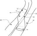
- FIG. 1is a side perspective view of an example embodiment of a device for providing fluid flow
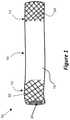
- FIG. 2shows the device of FIG. 1 in use as a shunt between two blood vessels
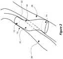
- FIG. 3is a side perspective view of another example embodiment of a device for providing fluid flow.
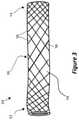
- FIG. 4is a side perspective view of still another example embodiment of a device for providing fluid flow.
- FIG. 5is a side perspective view of yet another example embodiment of a device for providing fluid flow.
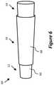
- FIG. 6is a side perspective view of yet still another example embodiment of a device for providing fluid flow.
- the present applicationdescribes devices and methods usable in minimally invasive surgical procedures, which can reduce performance of conventional surgery to treat conditions such as coronary heart disease and critical limb ischemia. For example, patients who might otherwise be unable to receive surgery such as coronary bypass surgery or peripheral arterial bypass surgery can be treated, and the amount of surgical trauma, the risk of infection, and/or the time to recovery may be reduced or significantly reduced in comparison to conventional surgery.
- Fluid such as bloodmay be diverted from the first passage into the second passage by way of the interconnecting third passage.
- the arterial bloodcan perfuse into tissue in a retrograde manner (retroperfusion).
- the interconnecting passage between the first and second passagescan be created by, for example, deploying a needle outwards from a first catheter located within the first passage, so that the needle traverses the interstitial tissue or septum between the first and second passages.
- a second cathetermay be located in the second passage, so as to provide a target device which receives a signal, for example an ultrasound signal, transmitted from the first catheter.
- a signalfor example an ultrasound signal
- a structure including a lumenmay be inserted in the passage to support the interstitial tissue and/or to inhibit or prevent the passage from closing.
- the tubemay, for example, include a stent expanded in the channel using a balloon catheter or self-expansion, as described herein.
- a catheter to deliver the structurefor example a balloon catheter or catheter that allows self-expansion, may be guided to the channel by a guide wire deployed in the passage by the first catheter.
- Passages such as arteries, veins, and heart chamberscan pulsate as the heart beats, for example due to movement of heart walls, peripheral limbs, and/or fluctuations in pressure within the passages themselves. This pulsation can cause movement of the passages relative to each another, which can impose stress on a structure within an interconnecting passage therebetween. This stress may be large in comparison to stress experienced by a structure within a single passage. Stress can lead to premature failure of the structure, for example by fatigue failure of the stent struts. Failure of the structure may result in injury to the interstitial tissue and/or occlusion of the interconnecting passage, which could lead to significant complications or complete failure of the therapy.
- FIG. 1illustrates a device or implant or prosthetic 10 for providing or maintaining fluid flow through at least one passage.
- the device 10includes a first or proximal end portion 12 , a second or distal end portion 14 , and an intermediate portion 16 between the proximal end portion 12 and the distal end portion 14 .
- the deviceincludes a bore or lumen 20 for passage of fluid through the device 10 .
- the device 10for example at least the intermediate portion 16 of the device 10 , includes a flexible polymer tube 18 .
- the flexible polymer tube 18may at least partially define the lumen 20 .
- the device 10includes a support structure (e.g., at least one stent) including a mesh 22 and a mesh 24 .
- a support structuree.g., at least one stent
- the mesh 22is embedded in the outside wall of the tube 18 proximate to the proximal end portion 12 of the device 10 .
- at least a portion of the mesh 24is embedded in the outside wall of the tube 18 proximate to the distal end portion 14 of the device 10 .
- the meshes 22 , 24may include biocompatible metal such as stainless steel and/or shape memory material such as nitinol or chromium cobalt.
- the wire meshes 22 , 24can stiffen the end portions 12 , 14 , respectively.
- the intermediate portion 16may be relatively flexible in comparison to the end portions 12 , 14 , and/or the end portions 12 , 14 may have a relatively high radial stiffness.
- the end portions 12 , 14 of the device 10are diametrically expandable.
- the wire meshes 22 , 24may have a smaller diameter after formation or manufacture than the passages, for example blood vessels, into which the device 10 will be deployed.
- the end portions 12 , 14can be expanded or deformed outwardly so that the respective diameters of the end portions 12 , 14 increase, for example to abut the interior sidewalls of the passages.
- the end portions 12 , 14are configured to maintain the expanded diameter indefinitely, for example by plastic deformation of the material (e.g., wires, struts) of the meshes 22 , 24 and/or by provision of a locking mechanism arranged to mechanically lock the meshes 22 , 24 in the expanded position.
- the intermediate portion 16 of the device 10may be diametrically expandable, for example by way of plastic deformation of the tube 18 .
- FIG. 2shows the device 10 of FIG. 1 deployed to provide a fluid flow path between a first passage 26 and a second passage 28 .
- the passages 26 , 28may include coronary blood vessels, for example a coronary artery 26 and a coronary vein 28 , or vice versa.
- the passages 26 , 28may include peripheral blood vessels (e.g., blood vessels in limbs), for example a femoral or other peripheral artery 26 and a femoral or other peripheral vein 28 , or vice versa.
- the end portions 12 , 14 and the intermediate portion 16 of the device 10have been expanded to meet with and push against the inner walls of the passages 26 , 28 .
- the distal end portion 14 of the device 10is located within the second passage 28
- the proximal end portion 12 of the device 10is located within the first passage 26 .
- the intermediate portion 16extends through an opening or interconnecting passage 30 surgically formed between the passages 26 , 28 .
- the expanded end portions 12 , 14 of the device 10are resilient, and impart an outward radial force on the inner walls of the passages 26 , 28 .
- the end portions 12 , 14 of the device 10are held or anchored in place within the respective passages 26 , 28 . Slippage of the device 10 within the passages 26 , 28 is thereby prevented or reduced.
- the end portions 12 , 14 of the device 10can anchor or fix the device 10 in position, in use, while providing or maintaining fluid flow through the lumen 20 of the tube 18 ( FIG. 1 ). In this way, the device 10 can act as a shunt between the first passage 26 and the second passage 28 .
- the intermediate portion 16 of the device 10may be flexible, for example allowing the intermediate portion 16 to form an ‘S’ shape formed by the combination of the first passage 26 , the second passage 28 , and the interconnecting passage 30 ( FIG. 2 ).
- the flexible intermediate portion 16can allow the end portions 12 , 14 of the device 10 to move with respect to one another in response to relative movement of the passages 26 , 28 .
- the intermediate portion 16may not be susceptible to damage due to mesh fatigue, for example upon cyclic or other stress imparted by relative movement of the passages 26 , 28 .
- the intermediate portion 16 of the device 10has sufficient resilience to maintain dilatation of the interconnecting passage 30 , so that the interconnecting passage 30 remains open to provide or maintain a path for blood flow from the artery 26 to the vein 28 by way of the lumen 20 of the tube 18 ( FIG. 1 ). Blood flow from the artery 26 to the vein 28 , by way of the interconnecting passage 30 , may thereby be provided or maintained through the lumen 20 of the tube 18 .
- the device 10at least partially supports the artery 26 , the vein 28 , and the interconnecting passage 30 to provide a pathway for fluid communication through the device 10 .
- the proximal end portion 12 and the distal end portion 14 of the device 10are arranged so that, when the device 10 is deployed with the distal end portion 14 in a vein 28 and the proximal end portion 12 in an artery 26 , for example as shown in FIG. 2 , the diameter of the expanded distal end portion 14 is sufficient to hold the distal end portion 14 within the vein 28 , and the diameter of the expanded proximal end portion 12 is sufficient to hold the proximal end portion 12 within the artery 26 .
- the diameter of the proximal end portion 12may therefore differ from the diameter of the distal end portion 14 .
- the device 10can be tailored to a certain anatomy and/or the anatomy of an individual patient.
- FIG. 2An example procedure for positioning the device 10 of FIG. 1 to provide a shunt between an occluded artery 26 and a vein 28 (e.g., a coronary artery 26 and a coronary vein 28 , or a peripheral artery 26 and a peripheral vein 28 ) to achieve retroperfusion of arterial blood, for example as shown in FIG. 2 , will now be described.
- a vein 28e.g., a coronary artery 26 and a coronary vein 28 , or a peripheral artery 26 and a peripheral vein 28
- a cathetermay be inserted into the patient's arterial system by way of a small aperture cut, usually in the patient's groin area.
- the catheteris fed to the artery 26 and guided to a position upstream of the site of the occlusion, for example at a site proximate and parallel or substantially parallel to a vein 28 .
- a hollow needleis deployed from the catheter, through the wall of the artery 26 , through the interstitial tissue 32 that separates the artery 26 and vein 28 , and through the wall of the vein 28 .
- the path of the needlecreates an interconnecting passage or opening 30 , which allows blood to flow between the artery 26 and the vein 28 .
- Deployment of the needlemay be guided by a transmitter (e.g., a directional ultrasound transmitter) coupled to a catheter in the artery 26 and a receiver (e.g., an omnidirectional ultrasound receiver) coupled to a catheter in the vein 28 , or vice versa, for example as described in International Patent Application No. PCT/GB05/003480.
- a transmittere.g., a directional ultrasound transmitter
- a receivere.g., an omnidirectional ultrasound receiver
- Other methods of forming the opening 30are also possible (e.g., with or without guidance, from vein to artery, etc.).
- a guide wireis inserted through the hollow needle and into the vein 28 .
- the needleis then retracted, leaving the guide wire in place in the artery 26 , the passage 30 , and the vein 28 .
- the catheter carrying the needlecan then be withdrawn from the patient's body.
- the guide wirecan be used to guide further catheters to the interconnecting passage 30 between the artery 26 and the vein 28 .
- a catheter carrying the device 10 in a non-expanded stateis advanced towards the interconnecting passage 30 , guided by the guide wire, for example by a rapid exchange lumen or through the lumen 20 .
- the cathetermay include, for example, a balloon catheter configured to expand at least a portion of the device 10 and/or a catheter configured to allow self-expansion of at least a portion of the device 10 .
- the distal end portion 14 of the device 10is passed through the interconnecting passage 30 and into the vein 28 , leaving the proximal end portion 12 in the artery 26 .
- the intermediate portion 16 of the device 10is at least partially in the passage 30 , and is at least partially within the artery 26 and the vein 28 .
- the intermediate portion 16flexes to adopt a curved or “S”-shaped formation, depending on the anatomy of the site. Adoption of such curvature may conform the shape of an intermediate portion 16 extending through the interconnecting passage 30 , and optionally into at least one of the passages 26 , 28 , to the shape of at least the interconnecting passage 30 .
- the distal end portion 14 of the device 10is expanded, for example upon inflation of a balloon or by self-expansion, so as to increase the diameter of the distal end portion 14 and anchor the distal end portion 14 against the inner wall of the vein 28 .
- the cathetermay be adapted to expand the intermediate portion 16 of the device 10 , for example by inflation of a balloon, so that the interconnecting passage 30 can be widened or dilated to obtain blood flow (e.g., sufficient blood flow) from the artery 26 to the vein 28 .
- the proximal end portion 12 of the device 10is expanded, for example upon inflation of a balloon or by self-expansion, so as to increase the diameter of the proximal end portion 12 and anchor the proximal end portion 12 against the inner wall of the artery 26 .
- the catheter and the guide wireare withdrawn from the patient's body.
- the device 10is anchored or fixed in position within the vein 28 , the artery 26 , and the interconnecting passage 30 as shown in FIG. 2 .
- the cathetermay be adapted to selectively expand the proximal end portion 12 , the distal end portion 14 , and/or the intermediate portion 16 of the device 10 individually or in combination, for example by the provision of two or more separately inflatable balloons or balloon portions, a single balloon configured to expand all of the portions of the device 10 simultaneously, or a single balloon configured to expand one or more selected portions of the device 10 .
- the end portions 12 , 14may be self-expanding, and the intermediate portion 16 may be expanded by a balloon to dilate the passage 30 .
- all or selected parts of the device 10may be expanded, for example, simultaneously by a balloon across the entire length of the device 10 or by a plurality of balloons longitudinally spaced to selectively inflate selected parts of the device 10 , and/or sequentially by a balloon or plurality of balloons.
- all or selected parts of the device 10may be expanded, for example, by proximal retraction of a sheath over or around the device 10 , which can lead to deployment of the device 10 from distal to proximal as the sheath is proximally retracted. Deployment of the device 10 proximal to distal and deployment of the device 10 intermediate first then the ends are also possible.
- a balloon cathetermay be guided to the interconnecting passage 30 and positioned so that an inflatable balloon portion of the catheter lies in the interconnecting passage 30 .
- the balloonpushes against the walls of the interconnecting passage 30 to widen or dilate the interconnecting passage 30 to ease subsequent insertion of the device 10 .
- FIG. 3illustrates another device 34 for providing fluid flow through at least one passage.
- the device 34includes a mesh 36 and a polymer tube 18 .
- the mesh 36is shown as being on the outside of the polymer tube 18 , but as described herein could also or alternatively be on an inside of the polymer tube and/or within the polymer tube 18 .
- the device 34includes a proximal end portion 12 , a distal end portion 14 , and an intermediate portion 16 .
- the mesh 36extends along the entire length of the device 34 , including along the intermediate portion 16 .
- the spacing of filaments or struts of the mesh 36varies along the length of the device 34 .
- winding density of a woven or layered filamentary meshmay be varied and/or a window size pattern of a cut mesh may be varied.
- the spacingmay be relatively small in the proximal end portion 12 and the distal end portions 14 , and the spacing may be relatively large in the intermediate portion 16 .
- the density or window size of the mesh 36may be relatively low in the intermediate portion 16
- the density or window size of the mesh 36may be relatively high in the end portions 12 , 14 .
- the intermediate portion 16may be flexible in comparison to the end portions 12 , 14 .
- the relatively rigid end portions 12 , 14may engage and anchor in passages.
- the mesh 36 in the intermediate portion 16may be subject to stress such as cyclic stress, in use, the relatively high flexibility of the intermediate portion 16 due to the low density or window size allows the impact of the stress to be low because the intermediate portion 16 can flex in response to the stress.
- the risk of fatigue failure of the device 34 , and particularly the filaments or struts 38 of the mesh 36may therefore be reduced in comparison to a device having uniform flexibility along its entire length.
- the spacingmay be relatively large in the proximal end portion 12 and the distal end portions 14 , and the spacing may be relatively small in the intermediate portion 16 .
- the density of the mesh 36may be relatively high (or the window size of the mesh 36 may be relatively low) in the intermediate portion 16 , and the density of the mesh 36 may be relatively low (or the window size of the mesh 36 may be relatively high) in the end portions 12 , 14 .
- the intermediate portion 16may have radial strength sufficient to inhibit or prevent collapse of the passage 30 , yet still, flexible enough to flex in response to stress such as cyclic stress.
- the end portions 12 , 14may engage and anchor in passages.
- FIG. 4illustrates another device or implant or prosthetic 40 for providing fluid flow through at least one passage.
- the device 40includes a proximal end portion 12 , a distal end portion 14 , and an intermediate portion 16 .
- the device 40includes a polymer tube 18 and a support structure including a first mesh 42 and a second mesh 44 .
- the first mesh 42extends from the proximal end portion 12 toward (e.g., into) the intermediate portion 16 and optionally into the distal end portion 14 .
- the second mesh 44extends from the distal end portion 14 toward (e.g., into) the intermediate portion 16 and optionally into the proximal end portion 12 .
- Both meshes 42 , 44thereby overlap each other at least in the intermediate portion 16 .
- Both meshes 42 , 44may be on the outside of the tube 18 , on the inside of the tube 18 , or embedded within the tube 18 , or one mesh may be on the outside of the tube 18 , on the inside of the tube 18 , or embedded within the tube 18 while the other mesh is differently on the outside of the tube 18 , on the inside of the tube 18 , or embedded within the tube 18 (e.g., one mesh inside the tube 18 and one mesh outside the tube 18 ).
- the meshes 42 , 44may be formed, for example, by winding wire in a lattice configuration around or inside the polymer tube 18 , by placing a cut tube around or inside the polymer tube 18 , by being embedded in the polymer tube 18 , combinations thereof, and the like.
- the density of the meshes 42 , 44is relatively high (or the window size of the meshes 42 , 44 is relatively low) in their respective end portions 12 , 14 and decreases in density (or increases in window size) towards the intermediate portion 16 .
- the total winding densitye.g., the winding density of both meshes 42 , 44 , taken together
- the total window sizee.g., the window size of both meshes 42 , 44 , taken together
- the intermediate portion 16is relatively flexible in comparison to the end portions 12 , 14 .
- the meshes 42 , 44do not extend into the intermediate portion, and absence of a mesh could cause the intermediate portion 16 to be relatively flexible in comparison to the end portions 12 , 14 .
- the densitydecreases, the mesh coverage decreases, and/or the porosity increases because the width of the struts and/or filaments remains substantially constant or constant or does not increase in the same proportion as the window size, which could provide a change in flexibility along a longitudinal length.
- the first and second meshes 42 , 44may include different materials, which can allow optimization of the properties of each of the respective distal and proximal end portions 12 , 14 of the device 40 for a particular application of the device 40 .
- the second mesh 44 at the distal end portion 14 of the device 40may include a relatively flexible metallic alloy for ease of insertion through an interconnecting passage between two blood vessels, while the first mesh 42 at the proximal end portion 12 of the device 40 may include a relatively inelastic metallic alloy to provide a high degree of resilience at the proximal end portion 14 to anchor the device 40 firmly in position.
- the first and second meshes 42 , 44could include the same material composition (e.g., both including nitinol) but different wire diameters (gauge) or strut thicknesses.
- FIG. 5illustrates another device or implant or prosthetic 50 for providing fluid flow through at least one passage.
- the device 50includes a support structure (e.g., stent) 56 and a graft 58 .
- the device 50includes a proximal end portion 12 , a distal end portion 14 , and an intermediate portion 16 .
- the proximal end portion 12includes a cylindrical or substantially cylindrical portion and the distal end portion 14 includes a cylindrical or substantially cylindrical portion.
- the diameter of the proximal end portion 12is smaller than the diameter of the distal end portion 14 . In some embodiments, the diameter of the proximal end portion 12 is larger than the diameter of the distal end portion 14 .
- the intermediate portion 16has a tapered or frustoconical shape between the proximal end portion 12 and the distal end portion 14 .
- the stent 56may include filaments (e.g., woven, layered), a cut tube or sheet, and/or combinations thereof.
- Parameters of the stent 56may be uniform or substantially uniform across a portion and/or across multiple portions, or may vary within a portion and/or across multiple portions.
- the stent 56 at the proximal end portion 12may include a cut tube or sheet
- the stent 56 at the distal end portion 12may include a cut tube or sheet
- the stent 56 at the intermediate portion 16may include filaments (e.g., woven or layered). Certain such embodiments may provide good anchoring by the proximal end portion 12 and the distal end portion 14 and good flexibility (e.g., adaptability to third passage sizes and dynamic stresses) of the intermediate portion 16 .
- the stent 56may include different materials in different portions.
- the stent 56 at the proximal end portion 12may include chromium cobalt and/or tantalum
- the stent 56 at the distal end portion 14may include nitinol
- the stent 56 at the intermediate portion 16may include nitinol.
- Certain such embodimentsmay provide good anchoring and/or wall apposition by the device 50 in each deployment areas (e.g., the proximal end portion 12 engaging sidewalls of an artery, the distal end portion 14 engaging sidewalls of a vein, and the intermediate portion 16 engaging sidewalls of the passage between the artery and the vein).
- the stent 56 at the proximal portionmay include a cut tube or sheet including chromium cobalt and/or tantalum
- the stent 56 at the distal end portion 14may include a cut tube or sheet including nitinol
- the stent 56 at the intermediate portion 16may include filaments including nitinol.
- the cut patternmay be the same.
- the cut patternmay be the same in the proximal end portion 12 and the distal end portion 14 , but proportional to the change in diameter.
- the window size or strut densityis uniform or substantially uniform within a portion 12 , 14 , 16 , within two or more of the portions 12 , 14 , 16 , and/or from one end of the stent 56 to the other end of the stent 56 .
- the windingmay be the same.
- the windingmay be the same in the proximal end portion 12 and the distal end portion 14 , but changed due to the change in diameter.
- the winding density or porosityis uniform or substantially uniform within a portion 12 , 14 , 16 , within two or more of the portions 12 , 14 , 16 , and/or from one end of the stent 56 to the other end of the stent 56 .
- the stent 56includes at least one portion including a cut tube or sheet and at least one portion including filaments
- the cut pattern and windingmay be configured to result in a uniform or substantially uniform density. Non-uniformity is also possible, for example as described herein.
- the graft 58may include materials and attachment to the stent 56 as described with respect to the tube 18 .
- the graft 58generally forms a fluid-tight passage for at least a portion of the device 50 . Although illustrated as only being around the intermediate portion 16 , the graft 58 may extend the entire length of the device 50 , or may partially overlap into at least one of the cylindrical end portions 12 , 14 .
- FIG. 6illustrates another device 60 for providing fluid flow through at least one passage.
- the device 60includes a support structure (e.g., stent) and a graft 68 .
- the device 60includes a proximal end portion 12 , a distal end portion 14 , and an intermediate portion 16 .
- the proximal end portion 12includes a tapered or frustoconical portion and the distal end portion 14 includes a tapered or frustoconical portion.
- the diameter of the proximal end of the proximal end portion 12is smaller than the diameter of the distal end of the distal end portion 14 .
- the diameter of the proximal end of the proximal end portion 12is larger than the diameter of the distal end of the distal end portion 14 .
- the intermediate portion 16has a tapered or frustoconical shape between the proximal end portion 12 and the distal end portion 14 .
- the angle of inclination of the portions 12 , 14 , 16is the same or substantially the same (e.g., as illustrated in FIG. 6 ). In some embodiments, the angle of inclination of at least one portion is sharper or narrower than at least one other portion.
- the frustoconical proximal end portion 12 and distal end portion 14may allow better anchoring in a body passage, for example because arteries tend to taper with distance from the heart and veins tend to taper with distance towards the heart, and the end portions 12 , 14 can be configured to at least partially correspond to such anatomical taper.
- the support structure 66may include filaments (e.g., woven, layered), a cut tube or sheet, the same materials, different materials, and combinations thereof.
- the graft 68may include materials and attachment to the stent 66 as described with respect to the tube 18 .
- the graft 68generally forms a fluid-tight passage for at least a portion of the device 60 . Although illustrated as only being around the intermediate portion 16 , the graft 68 may extend the entire length of the device 60 , or may partially overlap into at least one of the frustoconical end portions 12 , 14 .
- the proximal end portion 12can be cylindrical or substantially cylindrical (e.g., as in the device 50 ), the distal end portion 14 can be tapered or frustoconical (e.g., as in the device 60 ), with the proximal end portion 12 having a larger diameter than the distal end of the distal end portion 14 .
- the proximal end portion 12can be tapered or frustoconical (e.g., as in the device 60 ), the distal end portion 14 can be cylindrical or substantially cylindrical (e.g., as in the device 50 ), with the proximal end of the proximal end portion 12 having a larger diameter than the distal end portion 14 .
- the intermediate portion 16can have a tapered or frustoconical shape between the proximal end portion 12 and the distal end portion 14 .
- the devicegenerally includes a handle at the proximal end with a trigger actuatable by a user and a combination of tubular member at the distal end configured to be pushed and/or pulled upon actuation of the trigger to release the device.
- Other delivery devicesare also possible.
- the delivery devicemay include a portion slidable over a guide wire (e.g., a guide wire that has been navigated between the artery and the vein via a tissue traversing needle) and/or may be trackable through a lumen of a catheter.
- a guide wiree.g., a guide wire that has been navigated between the artery and the vein via a tissue traversing needle
- the devicefor example a stent of the device, a mesh of the device, a support structure of the device, etc., may be self-expanding.
- a meshmay include a shape-memory material, such as nitinol, which is capable of returning to a pre-set shape after undergoing deformation.
- the stentmay be manufactured to a shape that is desired in the expanded configuration, and is compressible to fit inside a sleeve for transport on a catheter to a vascular site.
- the sleeveis drawn back from the stent to allow the shape memory material to return to the pre-set shape, which can anchor the stent in the passages, and which may dilate the passages if the stent has sufficient radial strength.
- the use of a balloon catheteris not required to expand a fully self-expanding stent, but may be used, for example, to improve or optimize the deployment.
- a devicemay include one or more self-expanding portions, and one or more portions which are expandable by deformation, for example using a balloon catheter.
- the first mesh 42may include stainless steel expandable by a balloon catheter
- the second mesh 44may include nitinol for self-expansion upon deployment.
- the polymer tube 18may include any suitable compliant or flexible polymer, such as PTFE, silicone, polyethylene terephthalate (PET), polyurethane such as polycarbonate aromatic biodurable thermoplastic polyurethane elastomer (e.g., ChronoFlex C® 80A and 55D medical grade, available from AdvanSource Biomaterials of Wilmington, Mass.), combinations thereof, and the like.
- PTFEpolyethylene terephthalate
- PETpolyurethane
- polycarbonate aromatic biodurable thermoplastic polyurethane elastomere.g., ChronoFlex C® 80A and 55D medical grade, available from AdvanSource Biomaterials of Wilmington, Mass.
- the polymer tube 18may include biodegradable, bioabsorbable, or biocompatible polymer (e.g., polylactic acid (PLA), polyglycolic acid (PGA), polyglycolic-lactic acid (PLGA), polycaprolactone (PCL), polyorthoesters, polyanhydrides, combinations thereof, etc.
- the polymermay be in tube form before interaction with a support structure (e.g., stent), or may be formed on, in, and/or around a support structure (e.g., stent).
- the polymermay include spun fibers, a dip-coating, combinations thereof, and the like.
- the devicemay omit the tube.
- the intermediate portion of the stentmay include a mesh with a low winding density or high window size, while the end portions of the stent include a mesh with a higher winding density or lower window size, the mesh being generally tubular to define a pathway for fluid flow through the center of the mesh.
- the polymer tube 18includes a lip (e.g., comprising the same or different material), which can help form a fluid-tight seal between the polymer tube 18 and the body passages. The seal may be angled, for example to account for angled positioning of the polymer tube 18 between body passages.
- the polymer tube 18may extend longitudinally beyond the support structure in at least one direction, and the part extending beyond is not supported by the support structure.
- the meshmay include any suitable material, such as nickel, titanium, chromium, cobalt, tantalum, platinum, tungsten, iron, manganese, molybdenum, combinations thereof (e.g., nitinol, chromium cobalt, stainless steel), and the like.
- the meshmay include biodegradable, bioabsorbable, or biocompatible polymer (e.g., polylactic acid (PLA), polyglycolic acid (PGA), polyglycolic-lactic acid (PLGA), polycaprolactone (PCL), polyorthoesters, polyanhydrides, combinations thereof, etc.) and/or glass, and may lack metal. Different materials may be used for portions of the mesh or within the same mesh, for example as previously described with reference to FIG.
- the mesh 24 at the distal end portion 14 and the mesh 22 at the proximal end portion 12 of the device 10may include different materials.
- the mesh 22 , and/or the mesh 24may include a metallic alloy (e.g., comprising cobalt, chromium, nickel, titanium, combinations thereof, and the like) in combination with a different type of metallic alloy (e.g., a shape memory alloy in combination with a non-shape memory alloy, a first shape memory alloy in combination with a second shape memory alloy different than the first shape memory alloy, a clad material (e.g., comprising a core including a radiopaque material such as titanium, tantalum, rhenium, bismuth, silver, gold, platinum, iridium, tungsten, etc.)) and/or a non-metallic material such as a polymer (e.g., polyester fiber), carbon, and/or bioabsorbable glass fiber.
- a metallic alloye.g., comprising cobalt,
- At least one mesh 22 , 24comprises nitinol and stainless steel.
- the nitinolmay allow some self-expansion (e.g., partial and/or full self-expansion), and the mesh could then be further expanded, for example using a balloon.
- any other structure that can provide the desired degree of resiliencemay be used.
- layers of filaments wound in opposite directionsmay be fused at the filament ends to provide an expandable structure.
- a metal sheetmay be cut (e.g., laser cut, chemically etched, plasma cut, etc.) to form perforations and then heat set in a tubular formation or a metal tube (e.g., hypotube) may be cut (e.g., laser cut, chemically etched, plasma cut, etc.) to form perforations.
- a cut tubeincluding a cut sheet rolled into a tube) may be heat set to impart an expanded configuration.
- Filaments or wires or ribbons that may be woven or braided, or layered or otherwise arranged,are generally elongate and have a circular, oval, square, rectangular, etc. transverse cross-section.
- Example non-woven filamentscan include a first layer of filaments wound in a first direction and a second layer of filaments wound in a second direction, at least some of the filament ends being coupled together (e.g., by being coupled to an expandable ring).
- Example braid patternsinclude one-over-one-under-one, a one-over-two-under-two, a two-over-two-under-two, and/or combinations thereof, although other braid patterns are also possible.
- filamentsmay be helically wrapped, cross in sliding relation, and/or combinations thereof.
- Filamentsmay be loose (e.g., held together by the weave) and/or include welds, coupling elements such as sleeves, and/or combinations thereof.
- Ends of filamentscan be bent back, crimped (e.g., end crimp with a radiopaque material such as titanium, tantalum, rhenium, bismuth, silver, gold, platinum, iridium, tungsten, etc. that can also act as a radiopaque marker), twisted, ball welded, coupled to a ring, combinations thereof, and the like.
- a radiopaque materialsuch as titanium, tantalum, rhenium, bismuth, silver, gold, platinum, iridium, tungsten, etc. that can also act as a radiopaque marker
- Weave endsmay include filament ends and/or bent-back filaments, and may include open cells, fixed or unfixed filaments, welds, adhesives, or other means of fusion, radiopaque markers, combinations thereof, and the like. Parameters of the filaments may be uniform or substantially uniform across a portion and/or across multiple portions, or may vary within a portion and/or across multiple portions.
- the proximal end portion 12may include a first parameter and the distal end portion 14 may include a second parameter different than the first braid pattern.
- the proximal end portion 12 and the distal end portion 14may each include a first parameter and the intermediate portion 16 may include a second parameter different than the parameter.
- At least one of the proximal end portion 12 , the distal end portion 14 , and the intermediate portion 16may include both a first parameter and a second parameter different than the first parameter.
- Filament parametersmay include, for example, filament type, filament thickness, filament material, quantity of filaments, weave pattern, layering, wind direction, pitch, angle, crossing type, filament coupling or lack thereof, filament end treatment, weave end treatment, layering end treatment, quantity of layers, presence or absence of welds, radiopacity, braid pattern, density, porosity, filament angle, braid diameter, winding diameter, and shape setting.
- Tubes or sheetsmay be cut to form strut or cell patterns, struts being the parts of the tube or sheet left after cutting and cells or perforations or windows being the parts cut away.
- a tubee.g., hypotube
- the tube or sheetmay be shape set before or after cutting.
- the tube or sheetmay be welded or otherwise coupled to itself, to another tube or sheet, to filaments, to a graft material, etc.
- Cuttingmay be by laser, chemical etchant, plasma, combinations thereof, and the like.
- Example cut patternsinclude helical spiral, weave-like, coil, individual rings, sequential rings, open cell, closed cell, combinations thereof, and the like.
- the ringsmay be coupled using flex connectors, non-flex connectors, and/or combinations thereof.
- the rings connectorse.g., flex, non-flex, and/or combinations thereof
- the tube or sheet or sections thereofmay be ground and/or polished before or after cutting. Interior ridges may be formed, for example to assist with fluid flow.
- Parameters of the cut tube or sheetmay be uniform or substantially uniform across a portion and/or across multiple portions, or may vary within a portion and/or across multiple portions.
- the proximal end portion 12may include a first parameter and the distal end portion 14 may include a second parameter different than the first parameter.
- the proximal end portion 12 and the distal end portion 14may each include a first parameter and the intermediate portion 16 may include a second parameter different than the parameter.
- at least one of the proximal end portion 12 , the distal end portion 14 , and the intermediate portion 16may include both a first parameter and a second parameter different than the first parameter.
- Cut tube or sheet parametersmay include, for example, radial strut thickness, circumferential strut width, strut shape, cell shape, cut pattern, cut type, material, density, porosity, tube diameter, and shape setting.
- the perforationsmay provide the mesh with a relatively flexible intermediate portion and relatively stiff end portions.
- the supporting structuremay instead be an open-cell foam disposed within the tube.
- Filaments of a stent, stent-graft, or a portion thereof, and/or struts of a cut stent, stent-graft, or a portion thereof,may be surface modified, for example to carry medications such as thrombosis modifiers, fluid flow modifiers, antibiotics, etc.
- Filaments of a stent, stent-graft, or a portion thereof, and/or struts of a cut stent, stent-graft, or a portion thereof,may be at least partially covered with a coating including medications such as thrombosis modifiers, fluid flow modifiers, antibiotics, etc., for example embedded within a polymer layer or a series of polymer layers, which may be the same as or different than the polymer tube 18 .
- medicationssuch as thrombosis modifiers, fluid flow modifiers, antibiotics, etc.
- Thickness (e.g., diameter) of filaments of a stent, stent-graft, or a portion thereof, and/or struts of a cut stent, stent-graft, or a portion thereofmay be between about 0.0005 inches and about 0.02 inches, between about 0.0005 inches and about 0.015 inches, between about 0.0005 inches and about 0.01 inches, between about 0.0005 inches and about 0.008 inches, between about 0.0005 inches and about 0.007 inches, between about 0.0005 inches and about 0.006 inches, between about 0.0005 inches and about 0.005 inches, between about 0.0005 inches and about 0.004 inches, between about 0.0005 inches and about 0.003 inches, between about 0.0005 inches and about 0.002 inches, between about 0.0005 inches and about 0.001 inches, between about 0.001 inches and about 0.02 inches, between about 0.001 inches and about 0.015 inches, between about 0.001 inches and about 0.01 inches, between about 0.001 inches and about 0.008 inches,
- Filaments and/or strutscomprising certain materials (e.g., biodegradable material, materials with less restoring force, etc.) may be thicker than the identified thicknesses.
- Thicknesses of filaments and/or strutsmay be based, for example, on at least one of device or device portion size (e.g., diameter and/or length), porosity, radial strength, material, quantity of filaments and/or struts, cut pattern, weave pattern, layering pattern, and the like.
- larger filament and/or strut thicknessesmay be useful for large devices or device portions used to treat large vessels such as coronary vessels
- mid-sized filament and/or strut thicknessese.g., between about 0.003 inches and about 0.006 inches
- small filament and/or strut thicknessese.g., less than about 0.003 inches
- small devices or device portionsused to treat small vessels such as veins and neurological vessels.
- the internal or external diameter of a stent, a stent-graft, or a first end portion, second end portion, intermediate portion, or subportion thereof, for example taking into account filament or strut thicknessmay be between about 1 mm and about 12 mm, between about 1 mm and about 10 mm, between about 1 mm and about 8 mm, between about 1 mm and about 6 mm, between about 1 mm and about 4 mm, between about 1 mm and about 2 mm, between about 2 mm and about 12 mm, between about 2 mm and about 10 mm, between about 2 mm and about 8 mm, between about 2 mm and about 6 mm, between about 2 mm and about 4 mm, between about 4 mm and about 12 mm, between about 4 mm and about 10 mm, between about 4 mm and about 8 mm, between about 4 mm and about 6 mm, between about 6 mm and about 12 mm, between about 6 mm and about 12 mm, between about 6 mm and about 10 mm, between about 4
- the internal or external diameter of a stent, a stent-graft, or a portion thereof, for example taking into account filament or strut thicknessmay be between about 1 mm and about 10 mm, between about 1 mm and about 8 mm, between about 1 mm and about 6 mm, between about 1 mm and about 4 mm, between about 1 mm and about 2 mm, between about 2 mm and about 10 mm, between about 2 mm and about 8 mm, between about 2 mm and about 6 mm, between about 2 mm and about 4 mm, between about 4 mm and about 10 mm, between about 4 mm and about 8 mm, between about 4 mm and about 6 mm, between about 6 mm and about 10 mm, between about 6 mm and about 8 mm, or between about 8 mm and about 10 mm.
- the internal or external diameter of a stent, a stent-graft, or a portion thereof, for example taking into account filament or strut thicknessmay be between about 6 mm and about 25 mm, between about 6 mm and about 20 mm, between about 6 mm and about 15 mm, between about 6 mm and about 12 mm, between about 6 mm and about 9 mm, between about 9 mm and about 25 mm, between about 9 mm and about 20 mm, between about 9 mm and about 15 mm, between about 9 mm and about 12 mm, between about 12 mm and about 25 mm, between about 12 mm and about 20 mm, between about 12 mm and about 15 mm, between about 15 mm and about 25 mm, between about 15 mm and about 20 mm, or between about 20 mm and about 25 mm.
- Certain such diametersmay be suitable for treating, for example, peripheral vessels.
- the internal or external diameter of a stent, a stent-graft, or a portion thereof, for example taking into account filament or strut thicknessmay be between about 20 mm and about 50 mm, between about 20 mm and about 40 mm, between about 20 mm and about 35 mm, between about 20 mm and about 30 mm, between about 30 mm and about 50 mm, between about 30 mm and about 40 mm, between about 30 mm and about 35 mm, between about 35 mm and about 50 mm, between about 35 mm and about 40 mm, or between about 40 mm and about 50 mm.
- Certain such diametersmay be suitable for treating, for example, aortic vessels.
- the diameter of the devicemay refer to the diameter of the first end portion, the second end portion, or the intermediate portion, each of which may be in expanded or unexpanded form.
- the diameter of the devicemay refer to the average diameter of the device when all of the portions of the device are in either expanded or unexpanded form.
- the length of a stent, a stent-graft, or a first end portion, second end portion, intermediate portion, or subportion thereofmay be between about 5 mm and about 150 mm, between about 5 mm and about 110 mm, between about 5 mm and about 70 mm, between about 5 mm and about 50 mm, between about 5 mm and about 25 mm, between about 5 mm and about 20 mm, between about 5 mm and about 10 mm, between about 10 mm and about 150 mm, between about 10 mm and about 110 mm, between about 10 mm and about 70 mm, between about 10 mm and about 50 mm, between about 10 mm and about 25 mm, between about 10 mm and about 20 mm, between about 20 mm and about 150 mm, between about 20 mm and about 110 mm, between about 20 mm and about 70 mm, between about 20 mm and about 50 mm, between about 20 mm and about 25 mm, between about 25 mm and about 150 mm, between about 10 mm and about
- the porosity of a stent, a stent-graft, or a first end portion, second end portion, intermediate portion, or subportion thereofmay be between about 5% and about 95%, between about 5% and about 50%, between about 5% and about 25%, between about 5% and about 10%, between about 10% and about 50%, between about 10% and about 25%, between about 25% and about 50%, between about 50% and about 95%, between about 50% and about 75%, between about 50% and about 60%, between about 60% and about 95%, between about 75% and about 90%, between about 60% and about 75%, and combinations thereof.
- the density of a stentmay be inverse to the porosity of that stent.
- the porosity of a portion of a stent covered by a graftmay be about 0%.
- the porositymay vary by objectives for certain portions of the stent.
- the intermediate portionmay have a low porosity to increase fluid flow through the device, while end portions may have lower porosity to increase flexibility and wall apposition.
- the radial strength or compression resistance of a stent, a stent-graft, or a first end portion, second end portion, intermediate portion, or subportion thereofmay be between about 0.1 N/mm and about 0.5 N/mm, between about 0.2 N/mm and about 0.5 N/mm, between about 0.3 N/mm and about 0.5 N/mm, between about 0.1 N/mm and about 0.3 N/mm, between about 0.1 N/mm and about 0.2 N/mm, between about 0.2 N/mm and about 0.5 N/mm, between about 0.2 N/mm and about 0.3 N/mm, or between about 0.3 N/mm and about 0.5 N/mm.
- a ratio of a thickness of a strut or filament to a diameter of a device portion comprising that strut or filamentmay be between about 1:10 and about 1:250, between about 1:25 and about 1:175, or between about 1:50 and about 1:100.
- a ratio of a length of a device or portion thereof to a diameter of a device or a portion thereofmay be between about 1:1 and about 50:1, between about 5:1 and about 25:1, or between about 10:1 and about 20:1.
- Portions of the devicemay include radiopaque material.
- filaments and/or struts a stent, a stent-graft, or a first end portion, second end portion, intermediate portion, or subportion thereofmay comprise (e.g., be at least partially made from) titanium, tantalum, rhenium, bismuth, silver, gold, platinum, iridium, tungsten, combinations thereof, and the like.
- filaments and/or struts of a stent, stent-graft, or a portion thereofmay comprise (e.g., be at least partially made from) a material having a density greater than about 9 grams per cubic centimeter.
- Separate radiopaque markersmay be attached to certain parts of the device.
- radiopaque markerscan be added to the proximal end of the device or parts thereof (e.g., a proximal part of the intermediate portion, a proximal part of the distal portion), the distal end of the device or parts thereof (e.g., a distal part of the intermediate portion, a distal part of the proximal portion), and/or other parts.
- a radiopaque marker between ends of a devicemay be useful, for example, to demarcate transitions between materials, portions, etc. Radiopacity may vary across the length of the device.
- the proximal portioncould have a first radiopacity (e.g., due to distal portion material and/or separate markers) and the distal portion could have a second radiopacity (e.g., due to distal portion material and/or separate markers) different than the first radiopacity.
- first radiopacitye.g., due to distal portion material and/or separate markers
- second radiopacitye.g., due to distal portion material and/or separate markers
- the deviceincludes a polymer tube, and no supporting structure is provided.
- the intermediate portion of such a devicemay be relatively more flexible than the end portions by, for example, decreasing the wall thickness of the polymer tube within the intermediate portion.
- the supporting structuremay be located around the outside of the tube, in the inner bore of the tube, or embedded within a wall of the tube. More than one supporting structure may be provided, in which case each supporting structure may have a different location with respect to the tube.
- One or both of the end portions of the devicemay include anchoring elements such as hooks, protuberances, or barbs configured to grasp or grip inner sidewalls of a blood vessel.
- anchoring elementssuch as hooks, protuberances, or barbs configured to grasp or grip inner sidewalls of a blood vessel.
- the radial force of the end portions after expansionmay be sufficient to grasp or grip inner sidewalls of a blood vessel without anchoring elements.
- mesh type, material, wall thickness, flexibility, etc.may gradually change from an end portion toward an intermediate portion or from an intermediate portion toward an end portion.
- the flexibility of the devicemay increase gradually when moving from an end portion towards the intermediate portion, for example as described with respect to the devices 34 , 40 .
- the change in flexibilitymay be due to change in mesh density (e.g., winding density, window size), tube thickness, or other factors.
- the flexibility of the devicemay be uniform or substantially uniform along the entire length of the support structure (e.g., stent), or along certain portions of the support structure (e.g., along an entire end portion, along the entire intermediate portion, along one end portion and the intermediate portion but not the other end portion, etc.).
- the devices described hereinmay be particularly suitable for use as a transvascular shunt in percutaneous surgery, the devices could be used in many other medical applications.
- the devicescould be used in angioplasty for the treatment of occluded blood vessels with tortuous or kinked paths, or where the vessels may be subject to deflection or deformation at or near the position of the stent.
- the stentcould also be used for the repair of damaged blood vessels, for example in aortic grafting procedures or after perforation during a percutaneous procedure.
- the intermediate portion of the devicecan allow the device to conform to the shape of the blood vessel and to deform in response to movement of the vessel with reduced risk of fatigue failure while remaining fixed or anchored in position by the end portions.
- the devicescould be used to form a shunt between a healthy artery and a healthy vein for dialysis access and/or access for administration of medications (e.g., intermittent injection of cancer therapy, which can damage vessels).
- the devices described hereinmay be used in applications in which the fluid that flows through the device is a liquid such as blood, the devices could be used in applications such as tracheal or bronchial surgery where the fluid is a gas, such as air.
- the fluidmay contain solid matter, for example emboli or, in gastric surgery where the fluid includes food particles.
- a method of diverting fluid flow from a first passage to a second passagecomprising:
- a devicecomprising:
- first end portioncomprises a first type of material
- second end portioncomprises a second type of material
- intermediate portioncomprises a third type of material
- the first type of materialcomprises a first cut material
- the second type of materialcomprises a second cut material
- the third type of materialcomprises filaments.
- a devicecomprising:
- a devicecomprising:
Landscapes
- Health & Medical Sciences (AREA)
- Heart & Thoracic Surgery (AREA)
- Life Sciences & Earth Sciences (AREA)
- Vascular Medicine (AREA)
- Veterinary Medicine (AREA)
- Public Health (AREA)
- Biomedical Technology (AREA)
- Engineering & Computer Science (AREA)
- Animal Behavior & Ethology (AREA)
- General Health & Medical Sciences (AREA)
- Cardiology (AREA)
- Oral & Maxillofacial Surgery (AREA)
- Gastroenterology & Hepatology (AREA)
- Pulmonology (AREA)
- Transplantation (AREA)
- Hematology (AREA)
- Anesthesiology (AREA)
- Surgery (AREA)
- Otolaryngology (AREA)
- Ophthalmology & Optometry (AREA)
- Pathology (AREA)
- Nuclear Medicine, Radiotherapy & Molecular Imaging (AREA)
- Medical Informatics (AREA)
- Molecular Biology (AREA)
- Prostheses (AREA)
- Media Introduction/Drainage Providing Device (AREA)
Abstract
Description
- deploying a device in a third passage between the first passage and the second passage, the device comprising;
- a first end portion having a first end diameter;
- a second end portion having a second end diameter larger than the first end diameter;
- an intermediate portion between the first end portion and the second end portion, the intermediate portion tapering between the first end portion and the second end portion; and
- a graft material coupled to at least the intermediate portion; expanding the first end portion against sidewalls of the first passage; and expanding the second end portion against sidewalls of the second passage.
- deploying a device in a third passage between the first passage and the second passage, the device comprising;
- a first end portion having a first end diameter;
- a second end portion having a second end diameter smaller than the first end diameter;
- an intermediate portion between the first end portion and the second end portion, the intermediate portion tapering between the first end portion and the second end portion; and
- a graft material coupled to at least the intermediate portion.
- a first end portion comprising a first material;
- a second end portion comprising a second material different than the first material;
- an intermediate portion between the first end portion and the second end portion; and
- a graft material coupled to at least the intermediate portion.
- a support structure comprising
- a first end portion;
- a second end portion;
- an intermediate portion between the first end portion and the second end portion, at least one of the first end portion, the second end portion, and the intermediate portion being comprising cut struts and at least one of the first end portion, the second end portion, and the intermediate portion comprising filaments; and
- a graft material coupled to at least the intermediate portion.
- a support structure comprising
Claims (20)
Priority Applications (2)
| Application Number | Priority Date | Filing Date | Title |
|---|---|---|---|
| US16/532,809US11241304B2 (en) | 2006-04-20 | 2019-08-06 | Method for fluid flow through body passages |
| US17/573,028US20220125572A1 (en) | 2006-04-20 | 2022-01-11 | Apparatus and method for fluid flow through body passages |
Applications Claiming Priority (10)
| Application Number | Priority Date | Filing Date | Title |
|---|---|---|---|
| GBGB0607761.4AGB0607761D0 (en) | 2006-04-20 | 2006-04-20 | Variable density stent |
| GB0607761 | 2006-04-20 | ||
| GB0607761.4 | 2006-04-20 | ||
| PCT/GB2007/001430WO2007122396A1 (en) | 2006-04-20 | 2007-04-20 | Apparatus and method for maintaining fluid flow throug body passages |
| US13/791,185US20130190676A1 (en) | 2006-04-20 | 2013-03-08 | Devices and methods for fluid flow through body passages |
| US14/592,163US9108018B2 (en) | 2006-04-20 | 2015-01-08 | Methods for fluid flow through body passages |
| US14/718,477US9326792B2 (en) | 2006-04-20 | 2015-05-21 | Methods for fluid flow through body passages |
| US15/143,864US9782201B2 (en) | 2006-04-20 | 2016-05-02 | Methods for fluid flow through body passages |
| US15/701,060US10390933B2 (en) | 2006-04-20 | 2017-09-11 | Devices for fluid flow through body vessels |
| US16/532,809US11241304B2 (en) | 2006-04-20 | 2019-08-06 | Method for fluid flow through body passages |
Related Parent Applications (1)
| Application Number | Title | Priority Date | Filing Date |
|---|---|---|---|
| US15/701,060ContinuationUS10390933B2 (en) | 2006-04-20 | 2017-09-11 | Devices for fluid flow through body vessels |
Related Child Applications (1)
| Application Number | Title | Priority Date | Filing Date |
|---|---|---|---|
| US17/573,028ContinuationUS20220125572A1 (en) | 2006-04-20 | 2022-01-11 | Apparatus and method for fluid flow through body passages |
Publications (2)
| Publication Number | Publication Date |
|---|---|
| US20190358020A1 US20190358020A1 (en) | 2019-11-28 |
| US11241304B2true US11241304B2 (en) | 2022-02-08 |
Family
ID=48797801
Family Applications (9)
| Application Number | Title | Priority Date | Filing Date |
|---|---|---|---|
| US13/791,185AbandonedUS20130190676A1 (en) | 2006-04-20 | 2013-03-08 | Devices and methods for fluid flow through body passages |
| US14/592,163ActiveUS9108018B2 (en) | 2006-04-20 | 2015-01-08 | Methods for fluid flow through body passages |
| US14/592,128ActiveUS9532803B2 (en) | 2006-04-20 | 2015-01-08 | Devices for fluid flow through body passages |
| US14/718,477ActiveUS9326792B2 (en) | 2006-04-20 | 2015-05-21 | Methods for fluid flow through body passages |
| US15/143,864ActiveUS9782201B2 (en) | 2006-04-20 | 2016-05-02 | Methods for fluid flow through body passages |
| US15/390,925ActiveUS10136987B2 (en) | 2006-04-20 | 2016-12-27 | Devices for fluid flow through body passages |
| US15/701,060Active2027-04-28US10390933B2 (en) | 2006-04-20 | 2017-09-11 | Devices for fluid flow through body vessels |
| US16/532,809Active2027-09-01US11241304B2 (en) | 2006-04-20 | 2019-08-06 | Method for fluid flow through body passages |
| US17/573,028PendingUS20220125572A1 (en) | 2006-04-20 | 2022-01-11 | Apparatus and method for fluid flow through body passages |
Family Applications Before (7)
| Application Number | Title | Priority Date | Filing Date |
|---|---|---|---|
| US13/791,185AbandonedUS20130190676A1 (en) | 2006-04-20 | 2013-03-08 | Devices and methods for fluid flow through body passages |
| US14/592,163ActiveUS9108018B2 (en) | 2006-04-20 | 2015-01-08 | Methods for fluid flow through body passages |
| US14/592,128ActiveUS9532803B2 (en) | 2006-04-20 | 2015-01-08 | Devices for fluid flow through body passages |
| US14/718,477ActiveUS9326792B2 (en) | 2006-04-20 | 2015-05-21 | Methods for fluid flow through body passages |
| US15/143,864ActiveUS9782201B2 (en) | 2006-04-20 | 2016-05-02 | Methods for fluid flow through body passages |
| US15/390,925ActiveUS10136987B2 (en) | 2006-04-20 | 2016-12-27 | Devices for fluid flow through body passages |
| US15/701,060Active2027-04-28US10390933B2 (en) | 2006-04-20 | 2017-09-11 | Devices for fluid flow through body vessels |
Family Applications After (1)
| Application Number | Title | Priority Date | Filing Date |
|---|---|---|---|
| US17/573,028PendingUS20220125572A1 (en) | 2006-04-20 | 2022-01-11 | Apparatus and method for fluid flow through body passages |
Country Status (1)
| Country | Link |
|---|---|
| US (9) | US20130190676A1 (en) |
Cited By (6)
| Publication number | Priority date | Publication date | Assignee | Title |
|---|---|---|---|---|
| US11311700B2 (en) | 2018-10-09 | 2022-04-26 | Limflow Gmbh | Methods for accessing pedal veins |
| US11446170B2 (en) | 2004-09-08 | 2022-09-20 | Limflow Gmbh | Minimally invasive surgical apparatus and methods |
| US11471262B2 (en) | 2013-03-08 | 2022-10-18 | Limflow Gmbh | Methods for targeting a body passage to effect fluid flow |
| US11612397B2 (en) | 2019-11-01 | 2023-03-28 | Limflow Gmbh | Devices and methods for increasing blood perfusion to a distal extremity |
| US11826504B2 (en) | 2017-04-10 | 2023-11-28 | Limflow Gmbh | Methods for routing a guidewire from a first vessel and through a second vessel in lower extremity vasculature |
| US12285182B2 (en) | 2018-10-10 | 2025-04-29 | Innova Vascular, Inc. | Devices and methods for removing an embolus |
Families Citing this family (37)
| Publication number | Priority date | Publication date | Assignee | Title |
|---|---|---|---|---|
| US20130190676A1 (en) | 2006-04-20 | 2013-07-25 | Limflow Gmbh | Devices and methods for fluid flow through body passages |
| US8814930B2 (en) | 2007-01-19 | 2014-08-26 | Elixir Medical Corporation | Biodegradable endoprosthesis and methods for their fabrication |
| EP4032486A1 (en) | 2010-11-16 | 2022-07-27 | TVA Medical, Inc. | Devices for forming a fistula |
| CN104379207A (en) | 2011-12-28 | 2015-02-25 | 克里尔医疗有限公司 | System and method for blood filtering and/or treatment |
| US20150094744A1 (en)* | 2012-05-25 | 2015-04-02 | H. Lee Moffitt Cancer Center And Research Institute, Inc. | Vascular anastomosis stent |
| US9486276B2 (en) | 2012-10-11 | 2016-11-08 | Tva Medical, Inc. | Devices and methods for fistula formation |
| US10835367B2 (en) | 2013-03-08 | 2020-11-17 | Limflow Gmbh | Devices for fluid flow through body passages |
| CN105228683B (en) | 2013-03-14 | 2022-06-10 | Tva医疗公司 | Fistula-forming device and method for forming fistula |
| EP3030201B1 (en)* | 2013-08-09 | 2017-06-28 | Boston Scientific Scimed, Inc. | Atraumatic stents including radiopaque connectors and methods |
| WO2015048224A1 (en) | 2013-09-25 | 2015-04-02 | Johnson Jed K | Fiber scaffolds for use creating implantable structures |
| WO2015112915A1 (en)* | 2014-01-24 | 2015-07-30 | Elixir Medical Corporation | Biodegradable endoprostheses and methods for their fabrication |
| US10695534B2 (en) | 2014-03-14 | 2020-06-30 | Tva Medical, Inc. | Fistula formation devices and methods therefor |
| JP6356262B2 (en)* | 2014-04-08 | 2018-07-11 | ボストン サイエンティフィック サイムド,インコーポレイテッドBoston Scientific Scimed,Inc. | Stent |
| US9545263B2 (en)* | 2014-06-19 | 2017-01-17 | Limflow Gmbh | Devices and methods for treating lower extremity vasculature |
| US9855156B2 (en)* | 2014-08-15 | 2018-01-02 | Elixir Medical Corporation | Biodegradable endoprostheses and methods of their fabrication |
| US9730819B2 (en) | 2014-08-15 | 2017-08-15 | Elixir Medical Corporation | Biodegradable endoprostheses and methods of their fabrication |
| US9259339B1 (en) | 2014-08-15 | 2016-02-16 | Elixir Medical Corporation | Biodegradable endoprostheses and methods of their fabrication |
| US9480588B2 (en) | 2014-08-15 | 2016-11-01 | Elixir Medical Corporation | Biodegradable endoprostheses and methods of their fabrication |
| CN107427377B (en) | 2015-01-12 | 2019-09-03 | 微仙美国有限公司 | bracket |
| US10603040B1 (en) | 2015-02-09 | 2020-03-31 | Tva Medical, Inc. | Methods for treating hypertension and reducing blood pressure with formation of fistula |
| JP7219090B2 (en) | 2016-01-15 | 2023-02-07 | ティーブイエー メディカル, インコーポレイテッド | Systems and methods for gluing vessels |
| CN114042224B (en) | 2016-01-15 | 2024-09-17 | Tva医疗公司 | Device and method for advancing a wire |
| US10874422B2 (en) | 2016-01-15 | 2020-12-29 | Tva Medical, Inc. | Systems and methods for increasing blood flow |
| WO2017124062A1 (en) | 2016-01-15 | 2017-07-20 | Tva Medical, Inc. | Devices and methods for forming a fistula |
| JP7222881B2 (en)* | 2016-04-25 | 2023-02-15 | ソリナス メディカル インコーポレイテッド | Self-sealing tubular grafts, patches, methods of making and using same |
| US11622872B2 (en) | 2016-05-16 | 2023-04-11 | Elixir Medical Corporation | Uncaging stent |
| JP6963566B2 (en) | 2016-05-16 | 2021-11-10 | エリクシアー メディカル コーポレイション | Uncaging stent |
| US20190263068A1 (en)* | 2016-06-10 | 2019-08-29 | Neograft Technologies, Inc. | System for producing a graft device with a three-dimensional covering |
| CN109982652B (en) | 2016-09-25 | 2022-08-05 | Tva医疗公司 | Vascular stent device and method |
| DE102017123461A1 (en) | 2017-10-10 | 2019-04-11 | Jotec Gmbh | Expandable vascular implant |
| US20190117369A1 (en)* | 2017-10-25 | 2019-04-25 | Cook Medical Technologies Llc | Layered cover material and method of use thereof |
| US11103252B2 (en)* | 2018-01-23 | 2021-08-31 | Swaminathan Jayaraman | Device to treat vascular defect and method of making the same |
| US12042152B2 (en) | 2019-08-21 | 2024-07-23 | Lakshmikumar Pillai | Systems and methods for retrograde perfusion and clearance of emboli |
| US10835258B1 (en) | 2019-08-21 | 2020-11-17 | Lakshmikumar Pillai | Systems and methods for retrograde perfusion and clearance of emboli |
| AU2021375762A1 (en) | 2020-11-09 | 2023-06-15 | Venova Medical, Inc. | Endovascular implants and devices and methods for accurate placement |
| WO2023030494A1 (en)* | 2021-09-02 | 2023-03-09 | 晨兴(南通)医疗器械有限公司 | Atrial shunt device and manufacturing method, and atrial shunt system using shunt device |
| WO2024155720A1 (en)* | 2023-01-18 | 2024-07-25 | Aveera Medical, Inc. | Medical system |
Citations (310)
| Publication number | Priority date | Publication date | Assignee | Title |
|---|---|---|---|---|
| US4249539A (en) | 1979-02-09 | 1981-02-10 | Technicare Corporation | Ultrasound needle tip localization system |
| US4560374A (en) | 1983-10-17 | 1985-12-24 | Hammerslag Julius G | Method for repairing stenotic vessels |
| US4586919A (en) | 1984-04-06 | 1986-05-06 | Taheri Syde A | External shunt and method for procuring and preserving the endothelium of a vein used in arterial bypass |
| US4655746A (en) | 1985-12-02 | 1987-04-07 | Target Therapeutics | Catheter device |
| JPS62298347A (en) | 1986-06-06 | 1987-12-25 | イントラメド・ラボラトリーズ・インク | Vein valve cutter and vein valve cutting method |
| US4757821A (en) | 1986-11-12 | 1988-07-19 | Corazonix Corporation | Omnidirectional ultrasonic probe |
| US4768508A (en) | 1986-06-06 | 1988-09-06 | Thomas J. Fogarty | Vein valve cutting method |
| US4952215A (en) | 1988-02-29 | 1990-08-28 | Boisurge, Inc. | Valvulotome with leaflet disruption heads and fluid supply |
| WO1991001689A1 (en) | 1989-07-28 | 1991-02-21 | Jacob Segalowitz | Valvulotome catheter |
| US5047041A (en) | 1989-08-22 | 1991-09-10 | Samuels Peter B | Surgical apparatus for the excision of vein valves in situ |
| EP0467516A1 (en) | 1990-07-20 | 1992-01-22 | Cabot Technology Corporation | Hemostatic stent |
| EP0515322A1 (en) | 1991-05-16 | 1992-11-25 | MERLONI TERMOSANITARI S.p.A. | Flowrate adjuster for hydromassage installations |
| US5203777A (en) | 1992-03-19 | 1993-04-20 | Lee Peter Y | Radiopaque marker system for a tubular device |
| US5234450A (en) | 1989-07-28 | 1993-08-10 | Jacob Segalowitz | Valvulotome catheter |
| US5284478A (en) | 1992-06-08 | 1994-02-08 | Nobles Anthony A | Detachable tip optical valvulotome |
| US5304189A (en) | 1992-04-09 | 1994-04-19 | Lafeber Company | Venous valve cutter for in situ incision of venous valve leaflets |
| US5591226A (en) | 1995-01-23 | 1997-01-07 | Schneider (Usa) Inc. | Percutaneous stent-graft and method for delivery thereof |
| WO1997013471A1 (en) | 1995-10-13 | 1997-04-17 | Transvascular, Inc. | A device, system and method for interstitial transvascular intervention |
| US5639278A (en) | 1993-10-21 | 1997-06-17 | Corvita Corporation | Expandable supportive bifurcated endoluminal grafts |
| US5720776A (en) | 1991-10-25 | 1998-02-24 | Cook Incorporated | Barb and expandable transluminal graft prosthesis for repair of aneurysm |
| JPH10502567A (en) | 1995-04-26 | 1998-03-10 | バスキューテック, インク. | Automatic centering barbarotome |
| US5759174A (en) | 1997-01-29 | 1998-06-02 | Cathco, Inc. | Angioplasty balloon with an expandable external radiopaque marker band |
| US5782904A (en) | 1993-09-30 | 1998-07-21 | Endogad Research Pty Limited | Intraluminal graft |
| US5792056A (en) | 1993-06-07 | 1998-08-11 | Prince; Martin R. | Method and apparatus for magnetic resonance imaging of arteries using a magnetic resonance contrast agent |
| US5800522A (en) | 1995-07-07 | 1998-09-01 | W. L. Gore & Associates, Inc. | Interior liner for tubes, pipes and blood conduits |
| US5843171A (en) | 1996-01-29 | 1998-12-01 | W. L. Gore & Associates, Inc. | Method of insitu bypass to hold open venous valves |
| CN1204244A (en) | 1995-10-13 | 1999-01-06 | 血管转换公司 | Device. system and method for interstitial transvascular |
| US5897495A (en) | 1993-03-10 | 1999-04-27 | Kabushiki Kaisha Toshiba | Ultrasonic wave medical treatment apparatus suitable for use under guidance of magnetic resonance imaging |
| US5916264A (en) | 1997-05-14 | 1999-06-29 | Jomed Implantate Gmbh | Stent graft |
| US5951599A (en) | 1997-07-09 | 1999-09-14 | Scimed Life Systems, Inc. | Occlusion system for endovascular treatment of an aneurysm |
| WO2000009041A1 (en) | 1998-08-14 | 2000-02-24 | Boston Scientific Scimed, Inc. | Stent-graft-membrane and method of making same |
| WO2000033770A2 (en) | 1998-12-09 | 2000-06-15 | Gore Enterprise Holdings, Inc. | Multi-stage expandable stent-graft |
| US6081738A (en) | 1998-01-15 | 2000-06-27 | Lumend, Inc. | Method and apparatus for the guided bypass of coronary occlusions |
| US6099559A (en) | 1998-05-28 | 2000-08-08 | Medtronic Ave, Inc. | Endoluminal support assembly with capped ends |
| WO2000045886A2 (en) | 1999-02-03 | 2000-08-10 | Scimed Life Systems, Inc. | Percutaneous bypass apparatus and method |
| US6102884A (en) | 1997-02-07 | 2000-08-15 | Squitieri; Rafael | Squitieri hemodialysis and vascular access systems |
| US6165185A (en) | 1999-07-28 | 2000-12-26 | Vasconnect, Inc. | Method for interconnecting vessels in a patient |
| US6190379B1 (en) | 1995-06-06 | 2001-02-20 | Sun Star Technology, Inc. | Hot tip catheter |
| US6190353B1 (en) | 1995-10-13 | 2001-02-20 | Transvascular, Inc. | Methods and apparatus for bypassing arterial obstructions and/or performing other transvascular procedures |
| US6193745B1 (en) | 1995-10-03 | 2001-02-27 | Medtronic, Inc. | Modular intraluminal prosteheses construction and methods |
| US6193763B1 (en) | 1998-12-17 | 2001-02-27 | Robert A. Mackin | Apparatus and method for contemporaneous treatment and fluoroscopic mapping of body tissue |
| US6254610B1 (en) | 1999-05-24 | 2001-07-03 | Impulse Dynamics N.V. | Device and method for dragging and positioning a member within a duct in a body |
| EP1117458A1 (en) | 1998-10-02 | 2001-07-25 | Endogad Research PTY Limited | Guidewire capture device |
| US6287336B1 (en) | 1995-10-16 | 2001-09-11 | Medtronic, Inc. | Variable flexibility stent |
| US6302875B1 (en) | 1996-10-11 | 2001-10-16 | Transvascular, Inc. | Catheters and related devices for forming passageways between blood vessels or other anatomical structures |
| WO2002002163A2 (en) | 2000-07-05 | 2002-01-10 | Heuser Richard R | Catheter apparatus and method for arterializing a vein |
| US6364900B1 (en) | 1999-07-14 | 2002-04-02 | Richard R. Heuser | Embolism prevention device |
| US20020048310A1 (en) | 2000-03-07 | 2002-04-25 | Heuser Richard R. | Catheter for thermal and ultrasound evaluation of arteriosclerotic plaque |
| US20020052644A1 (en) | 1998-12-11 | 2002-05-02 | Shaolian Samuel M. | Implantable vascular graft |
| US20020068869A1 (en) | 2000-06-27 | 2002-06-06 | Axel Brisken | Drug delivery catheter with internal ultrasound receiver |
| JP2002516704A (en) | 1998-06-02 | 2002-06-11 | トランスバスキュラー インコーポレイテッド | Deformable multicellular support stent |
| US20020089262A1 (en) | 2000-05-09 | 2002-07-11 | Minoru Topa | Cylindrical transducer apparatus |
| US6464681B1 (en) | 1999-09-17 | 2002-10-15 | Richard R. Heuser | Methods and apparatus for treating body tissues and bodily fluid vessels |
| US6475170B1 (en) | 1997-12-30 | 2002-11-05 | Remon Medical Technologies Ltd | Acoustic biosensor for monitoring physiological conditions in a body implantation site |
| US20020173784A1 (en) | 1996-10-22 | 2002-11-21 | Epicor, Inc. | Methods and devices for ablation |
| US6536949B1 (en) | 2000-03-07 | 2003-03-25 | Richard R. Heuser | Catheter for thermal evaluation of arteriosclerotic plaque |
| US6554842B2 (en) | 2000-03-10 | 2003-04-29 | Radius Medical Technologies, Inc. | Small diameter snare |
| EP1307163A2 (en) | 2000-08-10 | 2003-05-07 | Dialysis Access Solutions Inc. | Distally narrowed vascular grafts and methods of using same for making artery-to-vein and artery-to-artery connections |
| US20030092667A1 (en) | 1995-03-05 | 2003-05-15 | Katsuro Tachibana | Delivery of therapeutic compositions using ultrasound |
| US6569193B1 (en) | 1999-07-22 | 2003-05-27 | Advanced Cardiovascular Systems, Inc. | Tapered self-expanding stent |
| US20030100916A1 (en) | 1999-12-21 | 2003-05-29 | Lee Jeong S. | Angioplasty catheter system with adjustable balloon length |
| US6585650B1 (en) | 2000-03-20 | 2003-07-01 | Jomed N.V. | Method and system for bypassing an artery block |
| US20030125799A1 (en) | 2001-12-28 | 2003-07-03 | Limon Timothy A. | Intravascular stent and method of use |
| US20030139802A1 (en) | 2001-12-06 | 2003-07-24 | Wulfman Edward I. | Medical device |
| US20030153969A1 (en) | 1998-09-30 | 2003-08-14 | Mark Dehdashtian | Methods and apparatus for intraluminal placement of a bifurcated intraluminal graft |
| US6685671B1 (en) | 1998-01-14 | 2004-02-03 | Sumitomo Bakeleite Co., Ltd. | Balloon catheter for puncturing, medical tube introduction device using the catheter and method for use thereof |
| US6699280B2 (en) | 1999-04-15 | 2004-03-02 | Mayo Foundation For Medical Education And Research | Multi-section stent |
| US20040064081A1 (en) | 2000-08-10 | 2004-04-01 | Paul Stanish | Arteriovenous grafts and methods of implanting the same |
| US20040073282A1 (en) | 2001-08-06 | 2004-04-15 | Paul Stanish | Distally-narrowed vascular grafts and methods of using same for making artery-to-vein and artery-to-artery connections |
| US6726677B1 (en) | 1995-10-13 | 2004-04-27 | Transvascular, Inc. | Stabilized tissue penetrating catheters |
| US6730116B1 (en) | 1999-04-16 | 2004-05-04 | Medtronic, Inc. | Medical device for intraluminal endovascular stenting |
| US20040122508A1 (en) | 1993-09-30 | 2004-06-24 | White Geoffrey H. | Intraluminal graft |
| US20040148005A1 (en) | 2002-10-17 | 2004-07-29 | Heuser Richard R. | Stent with covering and differential dilation |
| US20040199243A1 (en) | 2001-07-09 | 2004-10-07 | Ofer Yodfat | Filtering device and method for a venous furcation |
| US20040230289A1 (en) | 2003-05-15 | 2004-11-18 | Scimed Life Systems, Inc. | Sealable attachment of endovascular stent to graft |
| US20040249335A1 (en) | 2003-04-08 | 2004-12-09 | Faul John L. | Implantable arteriovenous shunt device |
| US20050004648A1 (en) | 2000-05-04 | 2005-01-06 | Percardia, Inc. | Methods and devices for delivering a ventricular stent |
| US20050021124A1 (en) | 2003-07-22 | 2005-01-27 | Brendan Cunniffe | Stents and stent delivery system |
| US6858038B2 (en) | 2002-06-21 | 2005-02-22 | Richard R. Heuser | Stent system |
| US20050113798A1 (en) | 2000-07-21 | 2005-05-26 | Slater Charles R. | Methods and apparatus for treating the interior of a blood vessel |
| WO2005065579A1 (en) | 2003-12-22 | 2005-07-21 | Boston Scientific Limited | Variable density braid stent |
| US20050165469A1 (en) | 2002-12-24 | 2005-07-28 | Michael Hogendijk | Vascular prosthesis including torsional stabilizer and methods of use |
| US20050192606A1 (en) | 2004-02-27 | 2005-09-01 | Paul Ram H.Jr. | Valvulotome with a cutting edge |
| US20050203549A1 (en) | 2004-03-09 | 2005-09-15 | Fidel Realyvasquez | Methods and apparatus for off pump aortic valve replacement with a valve prosthesis |
| US20050209617A1 (en) | 2004-03-05 | 2005-09-22 | Paul Koven | Valvulotome |
| CN2728440Y (en) | 2004-07-30 | 2005-09-28 | 北京有色金属研究总院 | Aorta tectorial membrane stent |
| US20050234288A1 (en) | 1998-05-15 | 2005-10-20 | A-Med Systems, Inc. | Pulmonary and circulatory blood flow support devices and methods for heart surgery procedures |
| US7018401B1 (en) | 1999-02-01 | 2006-03-28 | Board Of Regents, The University Of Texas System | Woven intravascular devices and methods for making the same and apparatus for delivery of the same |
| US20060111770A1 (en) | 1999-06-02 | 2006-05-25 | Dusan Pavcnik | Implantable vascular device comprising a bioabsorbable frame |
| US20060116713A1 (en) | 2004-11-26 | 2006-06-01 | Ivan Sepetka | Aneurysm treatment devices and methods |
| US20060116700A1 (en) | 2004-11-29 | 2006-06-01 | Crow Loren M | Aortic stenosis cutting balloon blade |
| US20060122554A1 (en) | 1998-01-30 | 2006-06-08 | Wilk Peter J | Left ventricular conduits to coronary arteries and methods for coronary bypass |
| US20060173475A1 (en) | 2005-02-01 | 2006-08-03 | Boston Scientific Scimed, Inc. | Vascular catheter, system, and method |
| US20060195172A1 (en) | 2004-08-17 | 2006-08-31 | Microport Medical Co., Ltd. | Multi-unit stent-graft |
| CN2843384Y (en) | 2005-07-12 | 2006-12-06 | 北京有色金属研究总院 | A kind of aortic blood pipe holder |
| US20060287709A1 (en) | 2002-11-13 | 2006-12-21 | Advanced Cardiovascular Systems, Inc. | Drug-eluting stent and methods of making the same |
| US7166088B2 (en) | 2003-01-27 | 2007-01-23 | Heuser Richard R | Catheter introducer system |
| US20070051681A1 (en) | 2003-04-18 | 2007-03-08 | Nardo Bruno P F | Device and machine for regenerating a human liver |
| US7195637B2 (en) | 2000-04-18 | 2007-03-27 | Impulse Dynamics N.V. | Method and device for inserting leads into coronary veins |
| US20070179590A1 (en) | 2005-12-29 | 2007-08-02 | Wenfeng Lu | Hybrid intraluminal device with varying expansion force |
| US20070185513A1 (en) | 2001-06-29 | 2007-08-09 | Woolfson Steven B | Method and apparatus for resecting and replacing an aortic valve |
| US20070203515A1 (en) | 2006-01-25 | 2007-08-30 | Heuser Richard R | Catheter system for connecting adjacent blood vessels |
| US20070265563A1 (en) | 2006-05-11 | 2007-11-15 | Heuser Richard R | Device for treating chronic total occlusion |
| US20070270902A1 (en) | 2004-09-17 | 2007-11-22 | Slazas Robert R | Thin Film Metallic Devices for Plugging Aneurysms or Vessels |
| US20070276468A1 (en) | 2005-05-24 | 2007-11-29 | Inspiremd Ltd. | Bifurcated stent assemblies |
| US20080009936A1 (en) | 2006-05-05 | 2008-01-10 | Eidosmed, Llc | Stent device for anastomoses of blood vessels and other tubular organs |
| US20080154153A1 (en) | 2004-08-25 | 2008-06-26 | Heuser Richard R | Multiple-wire systems and methods for ablation of occlusions within blood vessels |
| US20080161901A1 (en) | 2006-01-25 | 2008-07-03 | Heuser Richard R | Catheter system with stent apparatus for connecting adjacent blood vessels |
| US20080161904A1 (en) | 2006-01-25 | 2008-07-03 | Heuser Richard R | Connection of adjacent blood vessels |
| US7402141B2 (en) | 2003-08-27 | 2008-07-22 | Heuser Richard R | Catheter guidewire system using concentric wires |
| US20080177249A1 (en) | 2007-01-22 | 2008-07-24 | Heuser Richard R | Catheter introducer system |
| US20080194939A1 (en) | 2004-09-08 | 2008-08-14 | Advotek Medical Devices Ltd. | Minimally Invasive Surgical Appartus and Methods |
| US20080228209A1 (en) | 2004-03-08 | 2008-09-18 | Demello Richard M | System and method for removal of material from a blood vessel using a small diameter catheter |
| US20080234813A1 (en) | 2007-03-20 | 2008-09-25 | Heuser Richard R | Percutaneous Interventional Cardiology System for Treating Valvular Disease |
| US20080255595A1 (en) | 2005-03-04 | 2008-10-16 | Dale Buchbinder | Valvulotome |
| US20090012429A1 (en) | 2004-08-25 | 2009-01-08 | Heuser Richard R | Catheter guidewire system using concentric wires |
| US20090093791A1 (en) | 1999-09-17 | 2009-04-09 | Heuser Richard R | Devices and methods for treating chronic total occlusion |
| EP2063823A2 (en) | 2006-09-01 | 2009-06-03 | Rainer J. Zotz | Devices, system, kit and method for epicardial access |
| US20090192485A1 (en) | 2008-01-28 | 2009-07-30 | Heuser Richard R | Snare device |
| US7582108B2 (en) | 2003-10-28 | 2009-09-01 | Deutsche Institute für Textil-und Faserforschung Stuttgart Stiftung des Oeffentlichen Rechts | Tubular implant |
| WO2009107142A2 (en) | 2008-02-28 | 2009-09-03 | Fistulink Ltd. | Apparatus and method for creating arteriovenous fistulas |
| US7621902B2 (en) | 2002-08-26 | 2009-11-24 | Flowcardia, Inc. | Ultrasound catheter for disrupting blood vessel obstructions |
| WO2009150099A1 (en) | 2008-06-10 | 2009-12-17 | Bavaria Medizin Technologie Gmbh | Scoring catheter for treating diseased heart valves |
| US7670329B2 (en) | 1995-10-13 | 2010-03-02 | Medtronic Vascular, Inc. | Systems and methods for delivering drugs to selected locations within the body |
| US20100082058A1 (en) | 2007-01-23 | 2010-04-01 | Kassab Ghassan S | Devices, systems and methods for controlling local blood pressure |
| US20100094391A1 (en) | 2008-10-10 | 2010-04-15 | Kevin Heraty | Stent suitable for deployment in a blood vessel |
| US20100131000A1 (en) | 2008-11-21 | 2010-05-27 | Radius Medical Technologies, Inc. | System and method for removal of material from a blood vessel |
| US20100198056A1 (en) | 2009-01-20 | 2010-08-05 | Mariel Fabro | Diagnostic catheters, guide catheters, visualization devices and chord manipulation devices, and related kits and methods |
| US7780719B2 (en) | 1998-03-04 | 2010-08-24 | Boston Scientific Scimed, Inc. | Stent having variable properties and method of its use |
| US20100241214A1 (en) | 2006-11-22 | 2010-09-23 | Inspiremd Ltd. | Optimized stent jacket |
| JP2010269161A (en) | 2002-06-28 | 2010-12-02 | Cook Inc | Thoracic aortic aneurysm stent graft |
| US7849860B2 (en) | 1996-10-11 | 2010-12-14 | Medtronic Vascular, Inc. | Methods and apparatus for transmyocardial direct coronary revascularization |
| US20110054589A1 (en) | 2009-08-27 | 2011-03-03 | Boston Scientific Scimed, Inc. | Stent with variable cross section braiding filament and method for making same |
| US20110082490A1 (en) | 2009-05-15 | 2011-04-07 | Lemaitre Vascular, Inc. | Non-Occlusive Dilation Devices |
| US7966057B2 (en) | 2001-02-06 | 2011-06-21 | Medtronic Vascular, Inc. | Methods and apparatus for guided transluminal interventions using vessel wall penetrating catheters and other apparatus |
| US7967769B2 (en) | 2003-04-08 | 2011-06-28 | Rox Medical Inc. | Implantable arterio-venous shunt devices and methods for their use |
| US20110208109A1 (en) | 2008-12-19 | 2011-08-25 | Cvdevices, Llc | Autoretroperfusion devices and systems |
| WO2011107249A1 (en) | 2010-03-01 | 2011-09-09 | Andramed Gmbh | Valvulotome guided by a guide wire/catheter |
| US20110251482A1 (en) | 2009-10-29 | 2011-10-13 | Rox Medical, Inc. | Devices, systems and methods for enhanced visualization of the anatomy of a patient |
| US20110264104A1 (en) | 2009-08-03 | 2011-10-27 | The Methodist Hospital Research Institute | Hemodialysis grafts and methods for localizing and identifying the placement of same |
| US8066674B2 (en) | 2003-01-27 | 2011-11-29 | Heuser Richard R | Catheter introducer system |
| WO2011163322A1 (en) | 2010-06-22 | 2011-12-29 | Lemaitre Vascular, Inc. | Over-the-wire valvulotomes |
| US20110319902A1 (en) | 2010-06-26 | 2011-12-29 | Scott Epstein | Catheter delivery system |
| US20120046730A1 (en) | 2010-04-14 | 2012-02-23 | Abbott Vascular | Methods of treating a condition of a vessel in a patient |
| JP2012040394A (en) | 2010-08-21 | 2012-03-01 | Cook Medical Technologies Llc | Prosthesis having pivoting fenestration |
| US8142387B2 (en) | 2006-08-02 | 2012-03-27 | Michael Heise | Tubular vascular transplant |
| US20120095500A1 (en) | 2010-10-14 | 2012-04-19 | Heuser Richard R | Concentric wire embolism protection device |
| US8172861B2 (en) | 2007-12-20 | 2012-05-08 | Tautona Group, L.P. | Compositions and methods for joining non-conjoined lumens |
| US20120116354A1 (en) | 2010-11-08 | 2012-05-10 | Heuser Richard R | Devices and methods for small vessel access |
| US20120123512A1 (en) | 2010-11-11 | 2012-05-17 | Wilson T. Asfora | Sutureless vascular anastomosis connection |
| US8197499B2 (en) | 2006-06-21 | 2012-06-12 | The Board Of Trustees Of The Leland Stanford Junior University | Compositions and methods for joining non-conjoined lumens |
| US20120150092A1 (en) | 2009-03-17 | 2012-06-14 | Cytograft Tissue Engineering, Inc. | Guided percutaneous bypass |
| US8216259B2 (en) | 2006-06-21 | 2012-07-10 | The Board Of Trustees Of The Leland Stanford Jr. University | Compositions and methods for joining non-conjoined lumens |
| US20120179238A1 (en) | 2011-01-10 | 2012-07-12 | Peritec Biosciences, Ltd. | Stent having variable stiffness |
| US8226592B2 (en) | 2004-12-15 | 2012-07-24 | Rox Medical, Inc. | Method of treating COPD with artificial arterio-venous fistula and flow mediating systems |
| US8231646B2 (en) | 2005-07-29 | 2012-07-31 | Cvdevices, Llc | Device and methods for controlling blood perfusion pressure using a retrograde cannula |
| US8235916B2 (en) | 2006-02-03 | 2012-08-07 | Pacesetter, Inc. | System and method for manipulating insertion pathways for accessing target sites |
| US20120203329A1 (en) | 2011-02-07 | 2012-08-09 | Heuser Richard R | Bifurcated stent and method of use |
| US8251943B1 (en) | 2010-01-06 | 2012-08-28 | The United States Of America As Represented By The Secretary Of The Air Force | Vascular shunt |
| US20120239137A1 (en) | 2011-03-17 | 2012-09-20 | Pq Bypass, Inc. | Defferential dilation stent and method of use |
| US8282591B2 (en) | 2004-03-29 | 2012-10-09 | Iftikhar Khan | Hybrid arteriovenous shunt |
| US20120271396A1 (en) | 2007-01-19 | 2012-10-25 | Elixir Medical Corporation | Biodegradable endoprostheses and methods for their fabrication |
| US20120271400A1 (en) | 2011-04-21 | 2012-10-25 | Lyons Drew P | Introducer for a vascular repair prosthesis |
| US20120277774A1 (en) | 2009-11-13 | 2012-11-01 | The Brigham And Women's Hospital, Inc. | Method and Apparatus for Vascular Anastomosis |
| US20120296406A1 (en) | 2011-05-17 | 2012-11-22 | The University Of Kentucky Research Foundation | Graft within a graft endoluminal graft |
| US20120310319A1 (en) | 2010-12-21 | 2012-12-06 | Tieu Tai D | Stent |
| US8343089B2 (en) | 2003-11-21 | 2013-01-01 | Silk Road Medical, Inc. | Method and apparatus for treating a carotid artery |
| US8343087B2 (en) | 2008-02-28 | 2013-01-01 | Vascular Office (Sarl) | Prosthetic device for creating a vascular bypass, without clamping, from a blood vessel |
| US20130023813A1 (en) | 2011-07-19 | 2013-01-24 | Abbott Cardiovascular Systems, Inc. | Drug Delivery Device and Method |
| US8361101B2 (en) | 2004-11-26 | 2013-01-29 | Dtherapeutics, Llc | Devices, systems and methods for controlling local blood pressure |
| US20130030461A1 (en) | 2011-07-26 | 2013-01-31 | Marks Michael P | Intravascular thromboembolectomy device and method using the same |
| US20130041305A1 (en) | 2011-08-10 | 2013-02-14 | Henry Samuel Tarlian, JR. | Arterial shunt |
| US20130053732A1 (en) | 2011-08-24 | 2013-02-28 | Richard R. Heuser | Devices and methods for treating hypertension with energy |
| WO2013033215A1 (en) | 2011-08-30 | 2013-03-07 | Kamat Suraj Govind | Deployment of stents within bifurcated vessels |
| US20130060323A1 (en) | 2011-09-01 | 2013-03-07 | Cook Medical Technologies Llc | Braided helical wire stent |
| US20130079697A1 (en) | 2011-08-11 | 2013-03-28 | David Martin Kaye | Systems and methods for limb treatment |
| AU2012258395B1 (en) | 2012-11-27 | 2013-03-28 | Cook Medical Technologies Llc | Assembly of stent grafts with diameter reducing ties |
| EP2582306A1 (en) | 2010-06-15 | 2013-04-24 | Caymus Medical, Inc. | Systems and methods for creating arteriovenous (av) fistulas |
| US20130103137A1 (en) | 2010-07-07 | 2013-04-25 | Nikkiso Co., Ltd. | Artificial blood vessel |
| US20130116715A1 (en) | 2011-11-09 | 2013-05-09 | Boston Scientific Scimed, Inc. | Medical cutting devices and methods of use |
| US8439963B2 (en) | 2006-04-20 | 2013-05-14 | Limflow Gmbh | Apparatus and method for maintaining fluid flow through body passages |
| US20130138139A1 (en) | 2011-11-30 | 2013-05-30 | Cook Medical Technologies Llc | Hemodialysis graft |
| US20130144373A1 (en) | 2011-12-06 | 2013-06-06 | Aortic Innovations Llc | Device for endovascular aortic repair and method of using the same |
| JP2013528112A (en) | 2010-06-08 | 2013-07-08 | ベニティ・インコーポレイテッド | Bidirectional stent delivery system |
| US20130190676A1 (en) | 2006-04-20 | 2013-07-25 | Limflow Gmbh | Devices and methods for fluid flow through body passages |
| US20130197621A1 (en) | 2010-08-12 | 2013-08-01 | Silk Road Medical, Inc. | Systems and methods for treating a carotid artery |
| US20130204176A1 (en) | 2012-02-03 | 2013-08-08 | Medtronic Vascular, Inc. | Arteriovenous Shunt Having a Moveable Valve |
| WO2013113704A1 (en) | 2012-01-31 | 2013-08-08 | Jotec Gmbh | Modular stent graft |
| US8506516B2 (en) | 2007-05-29 | 2013-08-13 | Cvdevices, Llc | Devices, systems, and methods for achieving magnetic gastric bypass |
| US20130226067A1 (en) | 2012-02-24 | 2013-08-29 | Medtronic Vascular, Inc. | Arteriovenous Shunt Having Eccentric Anchor Stent |
| US20130226285A1 (en) | 2010-11-12 | 2013-08-29 | Gera Strommer | Percutaneous heart bypass graft surgery apparatus and method |
| US8540668B2 (en) | 2004-12-09 | 2013-09-24 | Boston Scientific Scimed, Inc. | Catheter including a compliant balloon |
| EP2640280A1 (en) | 2010-11-16 | 2013-09-25 | TVA Medical, Inc. | Devices and methods for forming a fistula |
| US8545418B2 (en) | 2004-08-25 | 2013-10-01 | Richard R. Heuser | Systems and methods for ablation of occlusions within blood vessels |
| US20130261531A1 (en) | 2012-03-30 | 2013-10-03 | Medtronic Vascular, Inc. | Arteriovenous Shunt Having a Flow Control Mechanism |
| US20130324901A1 (en) | 2012-05-30 | 2013-12-05 | Lakshmikumar Pillai | Transvascular Access Methods |
| US20130331762A1 (en) | 2008-12-19 | 2013-12-12 | Ghassan S. Kassab | Systems, devices, and methods for organ retroperfusion along with regional mild hypothermia |
| US8636791B1 (en) | 2006-11-21 | 2014-01-28 | Seshadri Raju | Venous stent |
| US8652084B2 (en) | 2007-08-09 | 2014-02-18 | Indiana University Research And Technology Corporation | Arteriovenous shunt with integrated surveillance system |
| US20140052170A1 (en) | 2012-08-17 | 2014-02-20 | Richard R. Heuser | Embolism protection device |
| US20140088681A1 (en) | 2010-01-27 | 2014-03-27 | Sriram Iyer | Device and method for preventing stenosis at an anastomosis site |
| US20140088685A1 (en) | 2011-06-15 | 2014-03-27 | Phraxis, Inc. | Anastomotic connector and system for delivery |
| US20140088623A1 (en) | 2011-06-15 | 2014-03-27 | Phraxis, Inc. | Arterial venous spool anchor |
| US20140100508A1 (en) | 2004-03-29 | 2014-04-10 | Nazir A. Khan | Hybrid arteriovenous shunt |
| US8727988B2 (en) | 1995-10-13 | 2014-05-20 | Medtronic Vascular, Inc. | Tissue penetrating catheters having integral imaging transducers and their methods of use |
| US20140142677A1 (en) | 2012-04-23 | 2014-05-22 | Pq Bypass, Inc. | Methods and systems for bypassing occlusions in a femoral artery |
| US20140142679A1 (en) | 2012-11-20 | 2014-05-22 | Indiana University Research And Technology Corporation | Intravascular shunt for traumatized arteries |
| US20140148751A1 (en) | 2008-12-19 | 2014-05-29 | Ghassan S. Kassab | Peripheral arterialization devices and methods of using the same |
| US8747345B2 (en) | 2010-04-29 | 2014-06-10 | Vanderbilt University | Percutaneous collateral bypass |
| US8771305B2 (en) | 2008-11-11 | 2014-07-08 | Edgar Louis Shriver | Lateral intravascular excision/incision devices |
| US20140194910A1 (en) | 2011-08-01 | 2014-07-10 | Eyal Orion | Vessel shaping devices and methods |
| US8784474B2 (en) | 2011-04-21 | 2014-07-22 | Cook Medical Technologies Llc | Emergency vascular repair system and method |
| US8808358B2 (en) | 2005-02-17 | 2014-08-19 | Khoury Medical Devices, Llc | Vascular endograft |
| WO2014137830A1 (en) | 2013-03-08 | 2014-09-12 | Robert Julian Dickinson | Methods and systems for providing or maintaining fluid flow through body passages |
| WO2014145021A1 (en) | 2013-03-15 | 2014-09-18 | Orange County Glaucoma, Pc | Enhancement of aqueous flow |
| US20140270067A1 (en) | 2013-03-14 | 2014-09-18 | Stephen Knecht Clark | Radiographic marker |
| US20140276335A1 (en) | 2013-03-14 | 2014-09-18 | Tva Medical, Inc. | Fistula formulation devices and methods therefor |
| WO2014162067A1 (en) | 2013-04-02 | 2014-10-09 | Xavier Renard | System for joining two blood vessels |
| US8858490B2 (en) | 2007-07-18 | 2014-10-14 | Silk Road Medical, Inc. | Systems and methods for treating a carotid artery |
| US8858579B2 (en) | 2004-03-09 | 2014-10-14 | Innovative International Technologies, B.V. | Method for performing a vascular anastomosis |
| US20140324155A1 (en) | 2010-08-03 | 2014-10-30 | Cook Medical Technologies Llc | Blood perfusion device delivery system |
| WO2014176458A2 (en) | 2013-04-24 | 2014-10-30 | Trustees Of Tufts College | Bioresorbable biopolymer anastomosis devices |
| US8888733B2 (en) | 2008-12-19 | 2014-11-18 | Cvdevices, Llc | Devices, systems, and methods for autoretroperfusion |
| US20140343582A1 (en) | 2010-11-11 | 2014-11-20 | Wilson T. Asfora | Deployment tool for sutureless vascular anastomosis connection |
| US20140350593A1 (en) | 2012-01-13 | 2014-11-27 | Gilbert Laroya | Retrieval snare device and method |
| US8900115B2 (en) | 1997-10-09 | 2014-12-02 | Thoratec Corporation | Implantable heart assist system and method of applying same |
| US20140358221A1 (en) | 2011-10-10 | 2014-12-04 | National University Of Singapore | Membrane for Covering a Peripheral Surface of a Stent |
| US20140358064A1 (en) | 2006-08-30 | 2014-12-04 | C.R. Bard, Inc. | Arteriovenous fistula |
| US8905962B2 (en) | 2010-07-02 | 2014-12-09 | Nikkiso Co., Ltd. | Artificial blood vessel and access port of artificial blood vessel |
| US20140364882A1 (en) | 2012-01-12 | 2014-12-11 | Amj B.V. | Blood vessel connectors and methods for blood vessel connection |
| US20140371653A1 (en) | 2007-07-18 | 2014-12-18 | Silk Road Medical, Inc. | Methods and Systems for Establishing Retrograde Carotid Arterial Blood Flow |
| US8915934B2 (en) | 2003-11-24 | 2014-12-23 | Cardica, Inc. | Anastomosis system with anvil entry hole sealer |
| US20150005872A1 (en) | 2011-05-12 | 2015-01-01 | Cook Medical Technologies Llc | Emergency vascular repair prosthesis |
| US8926545B2 (en) | 2004-08-27 | 2015-01-06 | Rox Medical, Inc. | Device and method for establishing an artificial arterio-venous fistula |
| US20150011925A1 (en) | 2013-07-08 | 2015-01-08 | Robert F. Buckman, Jr. | Method and device for temporary emergency vessel anastomoses |
| US8945039B2 (en) | 2008-12-19 | 2015-02-03 | Cvdevices, Llc | Devices, systems, and methods for organ retroperfusion |
| WO2015017714A2 (en) | 2013-07-31 | 2015-02-05 | Cvdevices, Llc | Unitary body systems and devices and methods to use the same for retroperfusion |
| US8968230B2 (en) | 2011-08-30 | 2015-03-03 | Cvdevices, Llc | Coil occlusion devices and systems and methods of using the same |
| US20150174379A1 (en) | 2012-08-30 | 2015-06-25 | Celso Bagaoisan | Devices and methods for the treatment of vascular disease |
| WO2015108984A1 (en) | 2014-01-14 | 2015-07-23 | Volcano Corporation | Catheter assembly for vascular access site creation |
| US20150209526A1 (en) | 2014-01-14 | 2015-07-30 | Volcano Corporation | Devices and methods for forming vascular access |
| US20150223817A1 (en) | 2007-08-02 | 2015-08-13 | Bioconnect Systems, Inc. | Implantable flow connector |
| US20150258308A1 (en) | 2014-03-14 | 2015-09-17 | Tva Medical, Inc. | Fistula formation devices and methods therefor |
| US9179916B2 (en) | 2005-06-30 | 2015-11-10 | Rox Medical Inc. | Devices, systems and methods for creation of a peripherally located fistula |
| WO2015195668A1 (en) | 2014-06-19 | 2015-12-23 | Timothy Lenihan | Devices and methods for treating lower extremity vasculature |
| US20160058956A1 (en) | 2014-08-27 | 2016-03-03 | Tva Medical, Inc. | Cryolipolysis devices and methods therefor |
| US20160066933A1 (en) | 2014-09-10 | 2016-03-10 | Vascular Solutions, Inc. | Guidewire Capture |
| US20160096008A1 (en) | 2012-04-15 | 2016-04-07 | Bioconnect Systems, Inc. | Implantable flow connector |
| US20160175569A1 (en) | 2014-12-22 | 2016-06-23 | Richard R. Heuser | Device for treating vascular occlusion |
| US20160199626A1 (en) | 2012-04-15 | 2016-07-14 | Bioconnect Systems, Inc. | Delivery system for implantable flow connector |
| US20160213462A1 (en) | 2015-01-22 | 2016-07-28 | Annamaria Szabolcs | Methods and devices for minimally invasive transcatheter coronary artery bypass grafting |
| GB2536362A (en) | 2015-03-10 | 2016-09-14 | Stent Tek Ltd | Surgical system, device and methods of use thereof for the percutaneous creation of an arteriovenous fistula (AVF) |
| US9486276B2 (en) | 2012-10-11 | 2016-11-08 | Tva Medical, Inc. | Devices and methods for fistula formation |
| EP3099372A1 (en) | 2014-01-30 | 2016-12-07 | Singapore Health Services Pte Ltd | Arterial sheath which allows distal perfusion within a cannulated vessel |
| US9539124B1 (en) | 2006-11-21 | 2017-01-10 | Seshadri Raju | Venous stent |
| WO2017011402A1 (en) | 2015-07-10 | 2017-01-19 | Rox Medical, Inc. | Methods, systems and devices for creating a blood flow pathway to treat a patient |
| US9649157B1 (en) | 2011-04-29 | 2017-05-16 | Avenu Medical, Inc. | Systems and methods for creating arteriovenous (AV) fistulas |
| US20170202616A1 (en) | 2016-01-15 | 2017-07-20 | Tva Medical, Inc. | Devices and methods for forming a fistula |
| US20170202603A1 (en) | 2016-01-15 | 2017-07-20 | Tva Medical, Inc. | Systems and methods for increasing blood flow |
| US20170216032A1 (en) | 2016-01-29 | 2017-08-03 | Bioventrix, Inc. | Percutaneous arterial access to position trans-myocardial implant devices and methods |
| US20170239035A1 (en) | 2014-05-30 | 2017-08-24 | Endologix, Inc. | Modular stent graft systems and methods with inflatable fill structures |
| US9757542B2 (en) | 2012-05-17 | 2017-09-12 | Lake Region Manufacturing, Inc. | Capture device |
| EP2613822B1 (en) | 2010-09-10 | 2017-11-01 | W.L. Gore & Associates, Inc. | Anastomotic devices and methods |
| US9872693B2 (en) | 2014-02-04 | 2018-01-23 | Takatoshi Furuya | Venous valve incising blades, manufacturing method of the same and artery revascularization treatment using the same |
| US20180071120A1 (en) | 2016-09-09 | 2018-03-15 | Micro Medical Solutions, Inc. | Method and apparatus for treating critical limb ischemia |
| WO2018057095A1 (en) | 2016-09-25 | 2018-03-29 | Tva Medical, Inc. | Vascular stent devices and methods |
| US9931164B2 (en) | 2010-06-15 | 2018-04-03 | Avenu Medical, Inc. | Intravascular arterial to venous anastomosis and tissue welding catheter |
| EP3302231A1 (en) | 2015-05-29 | 2018-04-11 | CIS Forschungsinstitut für Mikrosensorik und Photovoltaik GmbH | Method and device for ascertaining a blood pressure curve |
| US20180098869A1 (en) | 2016-10-07 | 2018-04-12 | Pq Bypass, Inc. | Systems and methods for delivering stent grafts |
| US20180116522A1 (en) | 2015-07-10 | 2018-05-03 | Rox Medical, Inc. | Methods, systems and devices for creating a blood flow pathway to treat a patient |
| EP3322470A1 (en) | 2015-07-13 | 2018-05-23 | CTI Vascular AG | Mechanically actuated and functionally integratable catheter system for treating vascular and non-vascular diseases |
| EP3322471A1 (en) | 2015-07-13 | 2018-05-23 | CTI Vascular AG | Hydraulically actuated and functionally integratable catheter system for treating vascular and non-vascular diseases |
| US20180185563A1 (en) | 2016-12-30 | 2018-07-05 | Vascular Access Technologies, Inc. | Methods and devices for percutaneous implantation of arterio-venous grafts |
| US20180243115A1 (en) | 2014-12-04 | 2018-08-30 | Trivascular, Inc. | Internal iliac preservation devices and methods |
| WO2018164766A1 (en) | 2017-03-06 | 2018-09-13 | Ram Medical Innovations Llc | Apparatus and method for improved access of procedural catheter in tortuous vessels |
| US20180271637A1 (en) | 2017-03-24 | 2018-09-27 | Merit Medical Systems, Inc. | Subcutaneous vascular assemblies for improving blood flow and related devices and methods |
| US10092427B2 (en) | 2009-11-04 | 2018-10-09 | Confluent Medical Technologies, Inc. | Alternating circumferential bridge stent design and methods for use thereof |
| WO2018189593A2 (en) | 2017-04-10 | 2018-10-18 | Limflow Gmbh | Devices and methods for treating lower extremity vasculature |
| EP3402426A1 (en) | 2016-01-15 | 2018-11-21 | TVA Medical, Inc. | Systems and methods for adhering vessels |
| EP3402561A1 (en) | 2016-01-15 | 2018-11-21 | TVA Medical, Inc. | Devices and methods for advancing a wire |
| US20180333283A1 (en) | 2012-12-21 | 2018-11-22 | CARDINAL HEALTH SWITZERLAND 515 GmbH | Cannulation guiding device for bifurcated stent and method of use |
| US10159822B2 (en) | 2011-06-02 | 2018-12-25 | Cook Medical Technologies Llc | Catheter and treatment methods for lower leg ischemia |
| US10231771B2 (en) | 2012-02-08 | 2019-03-19 | Avenu Medical, Inc. | Intravascular arterial to venous anastomosis and tissue welding catheter |
| US20190083228A1 (en) | 2013-03-08 | 2019-03-21 | Limflow Gmbh | Devices for fluid flow through body passages |
| US20190126017A1 (en) | 2017-10-31 | 2019-05-02 | Merit Medical Systems, Inc. | Subcutaneous vascular assemblies for improving blood flow and related devices and methods |
| US10314591B2 (en) | 2015-08-04 | 2019-06-11 | Cook Medical Technologies Llc | Medical device and corresponding method of use for arteriovenous fistula creation |
| US20190246631A1 (en) | 2014-02-04 | 2019-08-15 | University Of Pittsburgh - Of The Commonwealth System Of Higher Education | Endovascular apparatus for perfusing organs in a body |
| US20190254846A1 (en) | 2016-09-19 | 2019-08-22 | Cti Vascular Ag | Catheter system for treating vascular and non-vascular diseases |
| US20190262118A1 (en) | 2017-03-03 | 2019-08-29 | V-Wave Ltd. | Asymmetric shunt for redistributing atrial blood volume |
| US20190269888A1 (en) | 2014-01-30 | 2019-09-05 | Tar Toong Victor Chao | Arterial sheath which allows distal perfusion within a cannulated vessel |
| US20190290828A1 (en) | 2013-03-15 | 2019-09-26 | Tomislav Deur | Controlled arterial/venous access |
| WO2019202339A1 (en) | 2018-04-20 | 2019-10-24 | Stent Tek Limited | Apparatus for orientation display and alignment in percutaneous devices |
| US10492936B2 (en) | 2015-10-30 | 2019-12-03 | Ram Medical Innovations, Llc | Apparatus and method for improved access of procedural catheter in tortuous vessels |
| WO2019236900A1 (en) | 2018-06-08 | 2019-12-12 | Efemoral Medical Llc. | Absorbable intravascular devices that shorten upon expansion creating space for vascular movement |
| US10603040B1 (en) | 2015-02-09 | 2020-03-31 | Tva Medical, Inc. | Methods for treating hypertension and reducing blood pressure with formation of fistula |
| WO2020072717A1 (en) | 2018-10-05 | 2020-04-09 | Board Of Regents Of The University Of Nebraska | Bypass graft |
| WO2020076833A1 (en) | 2018-10-09 | 2020-04-16 | Limflow Gmbh | Devices and methods for catheter alignment |
| US20200121845A1 (en) | 2018-10-19 | 2020-04-23 | Stan Batiste | AV Flow Restrictors |
| US20200171282A1 (en) | 2018-12-04 | 2020-06-04 | Micro Medical Solutions, Inc. | System and method for treatment of the claudification of the superficial femoral and proximal popliteal artery |
| US20200187879A1 (en) | 2018-12-12 | 2020-06-18 | NeuroTronik IP Holding (Jersey) Limited | Fluorscopic markers for single view positioning |
| US10695065B1 (en) | 2013-08-01 | 2020-06-30 | Avenu Medical, Inc. | Percutaneous arterial to venous anastomosis clip application catheter system and methods |
| US20200246531A1 (en) | 2019-02-04 | 2020-08-06 | Contract Medical International Gmbh | Systems and methods for diverting blood flow in blood vessels |
| US20200305951A1 (en) | 2012-11-14 | 2020-10-01 | Avenu Medical, Inc. | Intravascular arterial to venous anastomosis and tissue welding catheter |
| US20200368047A1 (en) | 2019-05-20 | 2020-11-26 | Wei Cheong Steven KUM | Extravascular bypass systems and methods |
| WO2020242491A1 (en) | 2019-05-31 | 2020-12-03 | Tva Medical, Inc. | Systems, methods, and catheters for endovascular treatment of a blood vessel |
| EP3064171B1 (en) | 2013-10-31 | 2021-01-06 | Shanghai Microport Endovascular Medtech Co., Ltd. | Coated stent graft |
| US10926068B2 (en) | 2018-10-15 | 2021-02-23 | MagPAD, LLC | Magnetic puncture access and delivery systems and methods |
| WO2021087294A1 (en) | 2019-11-01 | 2021-05-06 | Limflow Gmbh | Devices and methods for increasing blood perfusion to a distal extremity |
| US11007075B2 (en) | 2018-02-18 | 2021-05-18 | Ram Medical Innovations, Inc. | Vascular access devices and methods for lower limb interventions |
| WO2021137851A1 (en) | 2019-12-30 | 2021-07-08 | Tva Medical, Inc. | Systems for forming a fistula |
Family Cites Families (1)
| Publication number | Priority date | Publication date | Assignee | Title |
|---|---|---|---|---|
| EP3424463A1 (en)* | 2003-11-08 | 2019-01-09 | Cook Medical Technologies LLC | Aorta and branch vessel stent grafts and system |
- 2013
- 2013-03-08USUS13/791,185patent/US20130190676A1/ennot_activeAbandoned
- 2015
- 2015-01-08USUS14/592,163patent/US9108018B2/enactiveActive
- 2015-01-08USUS14/592,128patent/US9532803B2/enactiveActive
- 2015-05-21USUS14/718,477patent/US9326792B2/enactiveActive
- 2016
- 2016-05-02USUS15/143,864patent/US9782201B2/enactiveActive
- 2016-12-27USUS15/390,925patent/US10136987B2/enactiveActive
- 2017
- 2017-09-11USUS15/701,060patent/US10390933B2/enactiveActive
- 2019
- 2019-08-06USUS16/532,809patent/US11241304B2/enactiveActive
- 2022
- 2022-01-11USUS17/573,028patent/US20220125572A1/enactivePending
Patent Citations (447)
| Publication number | Priority date | Publication date | Assignee | Title |
|---|---|---|---|---|
| US4249539A (en) | 1979-02-09 | 1981-02-10 | Technicare Corporation | Ultrasound needle tip localization system |
| US4560374A (en) | 1983-10-17 | 1985-12-24 | Hammerslag Julius G | Method for repairing stenotic vessels |
| US4586919A (en) | 1984-04-06 | 1986-05-06 | Taheri Syde A | External shunt and method for procuring and preserving the endothelium of a vein used in arterial bypass |
| US4655746A (en) | 1985-12-02 | 1987-04-07 | Target Therapeutics | Catheter device |
| EP0248761B1 (en) | 1986-06-06 | 1992-04-29 | FOGARTY, Thomas J. | Vein valve cutter |
| JPS62298347A (en) | 1986-06-06 | 1987-12-25 | イントラメド・ラボラトリーズ・インク | Vein valve cutter and vein valve cutting method |
| US4739760A (en) | 1986-06-06 | 1988-04-26 | Thomas J. Fogarty | Vein valve cutter apparatus |
| US4768508A (en) | 1986-06-06 | 1988-09-06 | Thomas J. Fogarty | Vein valve cutting method |
| US4757821A (en) | 1986-11-12 | 1988-07-19 | Corazonix Corporation | Omnidirectional ultrasonic probe |
| US4952215A (en) | 1988-02-29 | 1990-08-28 | Boisurge, Inc. | Valvulotome with leaflet disruption heads and fluid supply |
| US5092872A (en) | 1989-07-28 | 1992-03-03 | Jacob Segalowitz | Valvulotome catheter |
| US5234450A (en) | 1989-07-28 | 1993-08-10 | Jacob Segalowitz | Valvulotome catheter |
| WO1991001689A1 (en) | 1989-07-28 | 1991-02-21 | Jacob Segalowitz | Valvulotome catheter |
| US5047041A (en) | 1989-08-22 | 1991-09-10 | Samuels Peter B | Surgical apparatus for the excision of vein valves in situ |
| EP0467516A1 (en) | 1990-07-20 | 1992-01-22 | Cabot Technology Corporation | Hemostatic stent |
| EP0515322A1 (en) | 1991-05-16 | 1992-11-25 | MERLONI TERMOSANITARI S.p.A. | Flowrate adjuster for hydromassage installations |
| US5720776A (en) | 1991-10-25 | 1998-02-24 | Cook Incorporated | Barb and expandable transluminal graft prosthesis for repair of aneurysm |
| US5203777A (en) | 1992-03-19 | 1993-04-20 | Lee Peter Y | Radiopaque marker system for a tubular device |
| US5304189A (en) | 1992-04-09 | 1994-04-19 | Lafeber Company | Venous valve cutter for in situ incision of venous valve leaflets |
| US5601580A (en) | 1992-04-09 | 1997-02-11 | Uresil Corporation | Venous valve cutter |
| US5284478A (en) | 1992-06-08 | 1994-02-08 | Nobles Anthony A | Detachable tip optical valvulotome |
| US5352232A (en) | 1992-06-08 | 1994-10-04 | Endovascular, Inc. | Method for using detachable tip valvulotome |
| US5897495A (en) | 1993-03-10 | 1999-04-27 | Kabushiki Kaisha Toshiba | Ultrasonic wave medical treatment apparatus suitable for use under guidance of magnetic resonance imaging |
| US5792056A (en) | 1993-06-07 | 1998-08-11 | Prince; Martin R. | Method and apparatus for magnetic resonance imaging of arteries using a magnetic resonance contrast agent |
| US5782904A (en) | 1993-09-30 | 1998-07-21 | Endogad Research Pty Limited | Intraluminal graft |
| US20040122508A1 (en) | 1993-09-30 | 2004-06-24 | White Geoffrey H. | Intraluminal graft |
| US5639278A (en) | 1993-10-21 | 1997-06-17 | Corvita Corporation | Expandable supportive bifurcated endoluminal grafts |
| US5591226A (en) | 1995-01-23 | 1997-01-07 | Schneider (Usa) Inc. | Percutaneous stent-graft and method for delivery thereof |
| US20030092667A1 (en) | 1995-03-05 | 2003-05-15 | Katsuro Tachibana | Delivery of therapeutic compositions using ultrasound |
| JPH10502567A (en) | 1995-04-26 | 1998-03-10 | バスキューテック, インク. | Automatic centering barbarotome |
| US6190379B1 (en) | 1995-06-06 | 2001-02-20 | Sun Star Technology, Inc. | Hot tip catheter |
| US5800522A (en) | 1995-07-07 | 1998-09-01 | W. L. Gore & Associates, Inc. | Interior liner for tubes, pipes and blood conduits |
| US6193745B1 (en) | 1995-10-03 | 2001-02-27 | Medtronic, Inc. | Modular intraluminal prosteheses construction and methods |
| US7670329B2 (en) | 1995-10-13 | 2010-03-02 | Medtronic Vascular, Inc. | Systems and methods for delivering drugs to selected locations within the body |
| US20090182360A1 (en) | 1995-10-13 | 2009-07-16 | Medtronic Vascular, Inc. | Device, System and Method for Interstitial Transvascular Intervention |
| WO1997013471A1 (en) | 1995-10-13 | 1997-04-17 | Transvascular, Inc. | A device, system and method for interstitial transvascular intervention |
| US8753366B2 (en) | 1995-10-13 | 2014-06-17 | Medtronic Vascular, Inc. | Catheters and related devices for forming passageways between blood vessels or other anatomical structures |
| US8727988B2 (en) | 1995-10-13 | 2014-05-20 | Medtronic Vascular, Inc. | Tissue penetrating catheters having integral imaging transducers and their methods of use |
| US6726677B1 (en) | 1995-10-13 | 2004-04-27 | Transvascular, Inc. | Stabilized tissue penetrating catheters |
| CN1204244A (en) | 1995-10-13 | 1999-01-06 | 血管转换公司 | Device. system and method for interstitial transvascular |
| US6190353B1 (en) | 1995-10-13 | 2001-02-20 | Transvascular, Inc. | Methods and apparatus for bypassing arterial obstructions and/or performing other transvascular procedures |
| US20010041930A1 (en) | 1995-10-16 | 2001-11-15 | Medtronic, Inc. | Variable flexibility stent |
| US6287336B1 (en) | 1995-10-16 | 2001-09-11 | Medtronic, Inc. | Variable flexibility stent |
| US5843171A (en) | 1996-01-29 | 1998-12-01 | W. L. Gore & Associates, Inc. | Method of insitu bypass to hold open venous valves |
| US6302875B1 (en) | 1996-10-11 | 2001-10-16 | Transvascular, Inc. | Catheters and related devices for forming passageways between blood vessels or other anatomical structures |
| US7849860B2 (en) | 1996-10-11 | 2010-12-14 | Medtronic Vascular, Inc. | Methods and apparatus for transmyocardial direct coronary revascularization |
| US20020173784A1 (en) | 1996-10-22 | 2002-11-21 | Epicor, Inc. | Methods and devices for ablation |
| US5759174A (en) | 1997-01-29 | 1998-06-02 | Cathco, Inc. | Angioplasty balloon with an expandable external radiopaque marker band |
| US6102884A (en) | 1997-02-07 | 2000-08-15 | Squitieri; Rafael | Squitieri hemodialysis and vascular access systems |
| USRE41448E1 (en) | 1997-02-07 | 2010-07-20 | Hemosphere, Inc. | Squitieri hemodialysis and vascular access systems |
| US20070123811A1 (en) | 1997-02-07 | 2007-05-31 | Squitieri Rafael P | Squitieri hemodialysis and vascular access systems |
| US6582409B1 (en) | 1997-02-07 | 2003-06-24 | Graftcath, Inc. | Hemodialysis and vascular access systems |
| EP0973577B1 (en) | 1997-02-07 | 2005-03-23 | Rafael P. Squitieri | Vascular access systems for hemodialysis |
| EP1550479B1 (en) | 1997-02-07 | 2015-09-16 | Hemosphere, Inc. | Vascular access systems for hemodialysis |
| USRE44639E1 (en) | 1997-02-07 | 2013-12-10 | Hemosphere, Inc. | Hemodialysis and vascular access system |
| US5916264A (en) | 1997-05-14 | 1999-06-29 | Jomed Implantate Gmbh | Stent graft |
| US5951599A (en) | 1997-07-09 | 1999-09-14 | Scimed Life Systems, Inc. | Occlusion system for endovascular treatment of an aneurysm |
| US8900115B2 (en) | 1997-10-09 | 2014-12-02 | Thoratec Corporation | Implantable heart assist system and method of applying same |
| US6863684B2 (en) | 1997-11-14 | 2005-03-08 | Medtronic Vascular, Inc. | Deformable scaffolding multicellular stent |
| US6475170B1 (en) | 1997-12-30 | 2002-11-05 | Remon Medical Technologies Ltd | Acoustic biosensor for monitoring physiological conditions in a body implantation site |
| US6685671B1 (en) | 1998-01-14 | 2004-02-03 | Sumitomo Bakeleite Co., Ltd. | Balloon catheter for puncturing, medical tube introduction device using the catheter and method for use thereof |
| US6081738A (en) | 1998-01-15 | 2000-06-27 | Lumend, Inc. | Method and apparatus for the guided bypass of coronary occlusions |
| US20060122554A1 (en) | 1998-01-30 | 2006-06-08 | Wilk Peter J | Left ventricular conduits to coronary arteries and methods for coronary bypass |
| US7780719B2 (en) | 1998-03-04 | 2010-08-24 | Boston Scientific Scimed, Inc. | Stent having variable properties and method of its use |
| US20050234288A1 (en) | 1998-05-15 | 2005-10-20 | A-Med Systems, Inc. | Pulmonary and circulatory blood flow support devices and methods for heart surgery procedures |
| US6099559A (en) | 1998-05-28 | 2000-08-08 | Medtronic Ave, Inc. | Endoluminal support assembly with capped ends |
| JP2002516704A (en) | 1998-06-02 | 2002-06-11 | トランスバスキュラー インコーポレイテッド | Deformable multicellular support stent |
| WO2000009041A1 (en) | 1998-08-14 | 2000-02-24 | Boston Scientific Scimed, Inc. | Stent-graft-membrane and method of making same |
| US20030153969A1 (en) | 1998-09-30 | 2003-08-14 | Mark Dehdashtian | Methods and apparatus for intraluminal placement of a bifurcated intraluminal graft |
| EP1117458A1 (en) | 1998-10-02 | 2001-07-25 | Endogad Research PTY Limited | Guidewire capture device |
| WO2000033770A2 (en) | 1998-12-09 | 2000-06-15 | Gore Enterprise Holdings, Inc. | Multi-stage expandable stent-graft |
| US20020052644A1 (en) | 1998-12-11 | 2002-05-02 | Shaolian Samuel M. | Implantable vascular graft |
| US6193763B1 (en) | 1998-12-17 | 2001-02-27 | Robert A. Mackin | Apparatus and method for contemporaneous treatment and fluoroscopic mapping of body tissue |
| US7018401B1 (en) | 1999-02-01 | 2006-03-28 | Board Of Regents, The University Of Texas System | Woven intravascular devices and methods for making the same and apparatus for delivery of the same |
| US6475226B1 (en) | 1999-02-03 | 2002-11-05 | Scimed Life Systems, Inc. | Percutaneous bypass apparatus and method |
| WO2000045886A2 (en) | 1999-02-03 | 2000-08-10 | Scimed Life Systems, Inc. | Percutaneous bypass apparatus and method |
| US6699280B2 (en) | 1999-04-15 | 2004-03-02 | Mayo Foundation For Medical Education And Research | Multi-section stent |
| US6730116B1 (en) | 1999-04-16 | 2004-05-04 | Medtronic, Inc. | Medical device for intraluminal endovascular stenting |
| US6254610B1 (en) | 1999-05-24 | 2001-07-03 | Impulse Dynamics N.V. | Device and method for dragging and positioning a member within a duct in a body |
| US20060111770A1 (en) | 1999-06-02 | 2006-05-25 | Dusan Pavcnik | Implantable vascular device comprising a bioabsorbable frame |
| US6364900B1 (en) | 1999-07-14 | 2002-04-02 | Richard R. Heuser | Embolism prevention device |
| US6569193B1 (en) | 1999-07-22 | 2003-05-27 | Advanced Cardiovascular Systems, Inc. | Tapered self-expanding stent |
| US6165185A (en) | 1999-07-28 | 2000-12-26 | Vasconnect, Inc. | Method for interconnecting vessels in a patient |
| US6464681B1 (en) | 1999-09-17 | 2002-10-15 | Richard R. Heuser | Methods and apparatus for treating body tissues and bodily fluid vessels |
| US20150045728A1 (en) | 1999-09-17 | 2015-02-12 | Richard R. Heuser | Device for treating chronic total occlusion |
| US7179250B2 (en) | 1999-09-17 | 2007-02-20 | Heuser Richard R | Methods and apparatus for treating body tissues and bodily fluid vessels |
| US20150032095A1 (en) | 1999-09-17 | 2015-01-29 | Richard R. Heuser | Devices and methods for treating chronic total occlusion |
| US20090093791A1 (en) | 1999-09-17 | 2009-04-09 | Heuser Richard R | Devices and methods for treating chronic total occlusion |
| US20030100916A1 (en) | 1999-12-21 | 2003-05-29 | Lee Jeong S. | Angioplasty catheter system with adjustable balloon length |
| US6536949B1 (en) | 2000-03-07 | 2003-03-25 | Richard R. Heuser | Catheter for thermal evaluation of arteriosclerotic plaque |
| US20020048310A1 (en) | 2000-03-07 | 2002-04-25 | Heuser Richard R. | Catheter for thermal and ultrasound evaluation of arteriosclerotic plaque |
| US6554842B2 (en) | 2000-03-10 | 2003-04-29 | Radius Medical Technologies, Inc. | Small diameter snare |
| US6585650B1 (en) | 2000-03-20 | 2003-07-01 | Jomed N.V. | Method and system for bypassing an artery block |
| US7195637B2 (en) | 2000-04-18 | 2007-03-27 | Impulse Dynamics N.V. | Method and device for inserting leads into coronary veins |
| US20050004648A1 (en) | 2000-05-04 | 2005-01-06 | Percardia, Inc. | Methods and devices for delivering a ventricular stent |
| US20020089262A1 (en) | 2000-05-09 | 2002-07-11 | Minoru Topa | Cylindrical transducer apparatus |
| US20020068869A1 (en) | 2000-06-27 | 2002-06-06 | Axel Brisken | Drug delivery catheter with internal ultrasound receiver |
| WO2002002163A2 (en) | 2000-07-05 | 2002-01-10 | Heuser Richard R | Catheter apparatus and method for arterializing a vein |
| EP1299145B1 (en) | 2000-07-05 | 2007-09-12 | Richard R. Heuser | Catheter apparatus for arterializing a vein |
| JP2004501720A (en) | 2000-07-05 | 2004-01-22 | リチャード・アール・ホイザー | Catheter device and method for arterializing a vein |
| CN1460029A (en) | 2000-07-05 | 2003-12-03 | 理查德·R·休瑟 | Catheter device and method for turning veins into arteries |
| US6464665B1 (en) | 2000-07-05 | 2002-10-15 | Richard R. Heuser | Catheter apparatus and method for arterializing a vein |
| US20050113798A1 (en) | 2000-07-21 | 2005-05-26 | Slater Charles R. | Methods and apparatus for treating the interior of a blood vessel |
| US20040064081A1 (en) | 2000-08-10 | 2004-04-01 | Paul Stanish | Arteriovenous grafts and methods of implanting the same |
| EP1307163A2 (en) | 2000-08-10 | 2003-05-07 | Dialysis Access Solutions Inc. | Distally narrowed vascular grafts and methods of using same for making artery-to-vein and artery-to-artery connections |
| US7966057B2 (en) | 2001-02-06 | 2011-06-21 | Medtronic Vascular, Inc. | Methods and apparatus for guided transluminal interventions using vessel wall penetrating catheters and other apparatus |
| US20070185513A1 (en) | 2001-06-29 | 2007-08-09 | Woolfson Steven B | Method and apparatus for resecting and replacing an aortic valve |
| US20040199243A1 (en) | 2001-07-09 | 2004-10-07 | Ofer Yodfat | Filtering device and method for a venous furcation |
| US20040073282A1 (en) | 2001-08-06 | 2004-04-15 | Paul Stanish | Distally-narrowed vascular grafts and methods of using same for making artery-to-vein and artery-to-artery connections |
| US20030139802A1 (en) | 2001-12-06 | 2003-07-24 | Wulfman Edward I. | Medical device |
| US20030125799A1 (en) | 2001-12-28 | 2003-07-03 | Limon Timothy A. | Intravascular stent and method of use |
| US6858038B2 (en) | 2002-06-21 | 2005-02-22 | Richard R. Heuser | Stent system |
| JP2010269161A (en) | 2002-06-28 | 2010-12-02 | Cook Inc | Thoracic aortic aneurysm stent graft |
| US7621902B2 (en) | 2002-08-26 | 2009-11-24 | Flowcardia, Inc. | Ultrasound catheter for disrupting blood vessel obstructions |
| US20040148005A1 (en) | 2002-10-17 | 2004-07-29 | Heuser Richard R. | Stent with covering and differential dilation |
| US7300459B2 (en) | 2002-10-17 | 2007-11-27 | Heuser Richard R | Stent with covering and differential dilation |
| US20060287709A1 (en) | 2002-11-13 | 2006-12-21 | Advanced Cardiovascular Systems, Inc. | Drug-eluting stent and methods of making the same |
| US20050165469A1 (en) | 2002-12-24 | 2005-07-28 | Michael Hogendijk | Vascular prosthesis including torsional stabilizer and methods of use |
| US7914492B2 (en) | 2003-01-27 | 2011-03-29 | Heuser Richard R | Catheter introducer system |
| US7166088B2 (en) | 2003-01-27 | 2007-01-23 | Heuser Richard R | Catheter introducer system |
| US8066674B2 (en) | 2003-01-27 | 2011-11-29 | Heuser Richard R | Catheter introducer system |
| US8574185B2 (en) | 2003-04-08 | 2013-11-05 | The Board Trustees Of The Leland Stanford Junior University | Implantable arterio-venous shunt devices and methods for their use |
| US20120010556A1 (en) | 2003-04-08 | 2012-01-12 | Stanford University | Long-Term Implantable Arterio-Venous Shunt Device |
| US8551032B2 (en) | 2003-04-08 | 2013-10-08 | The Board Of Trustees Of The Leland Stanford Junior University | Therapeutic method for treatment of hypertension |
| US20040249335A1 (en) | 2003-04-08 | 2004-12-09 | Faul John L. | Implantable arteriovenous shunt device |
| US20130041306A1 (en) | 2003-04-08 | 2013-02-14 | John Faul | Therapeutic method for treatment of hypertension |
| US7967769B2 (en) | 2003-04-08 | 2011-06-28 | Rox Medical Inc. | Implantable arterio-venous shunt devices and methods for their use |
| EP1613373A1 (en) | 2003-04-08 | 2006-01-11 | The Board of Trustees of The Leland Stanford Junior University | Implantable arteriovenous shunt device |
| US8048016B2 (en) | 2003-04-08 | 2011-11-01 | The Board Of Trustees Of The Leland Stanford Junior University | Arterio-venous shunt devices |
| US7628768B2 (en) | 2003-04-08 | 2009-12-08 | Rox Medical, Inc. | Implantable arterio-venous shunt devices and methods for their use |
| US20070051681A1 (en) | 2003-04-18 | 2007-03-08 | Nardo Bruno P F | Device and machine for regenerating a human liver |
| US20040230289A1 (en) | 2003-05-15 | 2004-11-18 | Scimed Life Systems, Inc. | Sealable attachment of endovascular stent to graft |
| US20050021124A1 (en) | 2003-07-22 | 2005-01-27 | Brendan Cunniffe | Stents and stent delivery system |
| US7402141B2 (en) | 2003-08-27 | 2008-07-22 | Heuser Richard R | Catheter guidewire system using concentric wires |
| US7582108B2 (en) | 2003-10-28 | 2009-09-01 | Deutsche Institute für Textil-und Faserforschung Stuttgart Stiftung des Oeffentlichen Rechts | Tubular implant |
| US8343089B2 (en) | 2003-11-21 | 2013-01-01 | Silk Road Medical, Inc. | Method and apparatus for treating a carotid artery |
| US8414516B2 (en) | 2003-11-21 | 2013-04-09 | Silk Road Medical, Inc. | Method and apparatus for treating a carotid artery |
| US8870805B2 (en) | 2003-11-21 | 2014-10-28 | Silk Road Medical, Inc. | Method and apparatus for treating a carotid artery |
| US20150025616A1 (en) | 2003-11-21 | 2015-01-22 | Silk Road Medical, Inc. | Method And Apparatus For Treating A Carotid Artery |
| US8915934B2 (en) | 2003-11-24 | 2014-12-23 | Cardica, Inc. | Anastomosis system with anvil entry hole sealer |
| WO2005065579A1 (en) | 2003-12-22 | 2005-07-21 | Boston Scientific Limited | Variable density braid stent |
| US20050192606A1 (en) | 2004-02-27 | 2005-09-01 | Paul Ram H.Jr. | Valvulotome with a cutting edge |
| US20050209617A1 (en) | 2004-03-05 | 2005-09-22 | Paul Koven | Valvulotome |
| US20080228209A1 (en) | 2004-03-08 | 2008-09-18 | Demello Richard M | System and method for removal of material from a blood vessel using a small diameter catheter |
| US8858579B2 (en) | 2004-03-09 | 2014-10-14 | Innovative International Technologies, B.V. | Method for performing a vascular anastomosis |
| US20050203549A1 (en) | 2004-03-09 | 2005-09-15 | Fidel Realyvasquez | Methods and apparatus for off pump aortic valve replacement with a valve prosthesis |
| US8282591B2 (en) | 2004-03-29 | 2012-10-09 | Iftikhar Khan | Hybrid arteriovenous shunt |
| US8747344B2 (en) | 2004-03-29 | 2014-06-10 | Nazir A. Khan | Hybrid arteriovenous shunt |
| US20140100508A1 (en) | 2004-03-29 | 2014-04-10 | Nazir A. Khan | Hybrid arteriovenous shunt |
| CN2728440Y (en) | 2004-07-30 | 2005-09-28 | 北京有色金属研究总院 | Aorta tectorial membrane stent |
| US20060195172A1 (en) | 2004-08-17 | 2006-08-31 | Microport Medical Co., Ltd. | Multi-unit stent-graft |
| EP1779809B1 (en) | 2004-08-17 | 2010-08-11 | Microport Medical (Shanghai) Co., Ltd. | Combined film-coated stent which can bend in any direction |
| US8545418B2 (en) | 2004-08-25 | 2013-10-01 | Richard R. Heuser | Systems and methods for ablation of occlusions within blood vessels |
| US20090012429A1 (en) | 2004-08-25 | 2009-01-08 | Heuser Richard R | Catheter guidewire system using concentric wires |
| US20080154153A1 (en) | 2004-08-25 | 2008-06-26 | Heuser Richard R | Multiple-wire systems and methods for ablation of occlusions within blood vessels |
| US8926545B2 (en) | 2004-08-27 | 2015-01-06 | Rox Medical, Inc. | Device and method for establishing an artificial arterio-venous fistula |
| US20080194939A1 (en) | 2004-09-08 | 2008-08-14 | Advotek Medical Devices Ltd. | Minimally Invasive Surgical Appartus and Methods |
| US10398580B2 (en) | 2004-09-08 | 2019-09-03 | Limflow Gmbh | Minimally invasive surgical apparatus and methods |
| US20200054469A1 (en) | 2004-09-08 | 2020-02-20 | Limflow Gmbh | Minimally invasive surgical apparatus and methods |
| US20070270902A1 (en) | 2004-09-17 | 2007-11-22 | Slazas Robert R | Thin Film Metallic Devices for Plugging Aneurysms or Vessels |
| US20060116713A1 (en) | 2004-11-26 | 2006-06-01 | Ivan Sepetka | Aneurysm treatment devices and methods |
| US8361101B2 (en) | 2004-11-26 | 2013-01-29 | Dtherapeutics, Llc | Devices, systems and methods for controlling local blood pressure |
| US8894681B2 (en) | 2004-11-26 | 2014-11-25 | Dtherapeutics, Llc | Devices, systems and methods for controlling local blood pressure |
| US20060116700A1 (en) | 2004-11-29 | 2006-06-01 | Crow Loren M | Aortic stenosis cutting balloon blade |
| US8540668B2 (en) | 2004-12-09 | 2013-09-24 | Boston Scientific Scimed, Inc. | Catheter including a compliant balloon |
| US8226592B2 (en) | 2004-12-15 | 2012-07-24 | Rox Medical, Inc. | Method of treating COPD with artificial arterio-venous fistula and flow mediating systems |
| US20060173475A1 (en) | 2005-02-01 | 2006-08-03 | Boston Scientific Scimed, Inc. | Vascular catheter, system, and method |
| US8808358B2 (en) | 2005-02-17 | 2014-08-19 | Khoury Medical Devices, Llc | Vascular endograft |
| US20080255595A1 (en) | 2005-03-04 | 2008-10-16 | Dale Buchbinder | Valvulotome |
| US20070276468A1 (en) | 2005-05-24 | 2007-11-29 | Inspiremd Ltd. | Bifurcated stent assemblies |
| US9179916B2 (en) | 2005-06-30 | 2015-11-10 | Rox Medical Inc. | Devices, systems and methods for creation of a peripherally located fistula |
| US9955970B2 (en) | 2005-06-30 | 2018-05-01 | Rox Medical, Inc. | Devices, systems and methods for creation of peripherally located fistula |
| CN2843384Y (en) | 2005-07-12 | 2006-12-06 | 北京有色金属研究总院 | A kind of aortic blood pipe holder |
| US8231646B2 (en) | 2005-07-29 | 2012-07-31 | Cvdevices, Llc | Device and methods for controlling blood perfusion pressure using a retrograde cannula |
| US20120296368A1 (en) | 2005-07-29 | 2012-11-22 | Cvdevices, Llc | Devices and methods for controlling blood perfusion pressure |
| US20140039538A1 (en) | 2005-07-29 | 2014-02-06 | Ghassan S. Kassab | Methods and devices for controlling blood perfusion pressure along with regional mild hypothermia |
| US20070179590A1 (en) | 2005-12-29 | 2007-08-02 | Wenfeng Lu | Hybrid intraluminal device with varying expansion force |
| US20080161901A1 (en) | 2006-01-25 | 2008-07-03 | Heuser Richard R | Catheter system with stent apparatus for connecting adjacent blood vessels |
| US20070203515A1 (en) | 2006-01-25 | 2007-08-30 | Heuser Richard R | Catheter system for connecting adjacent blood vessels |
| US20080161904A1 (en) | 2006-01-25 | 2008-07-03 | Heuser Richard R | Connection of adjacent blood vessels |
| US8235916B2 (en) | 2006-02-03 | 2012-08-07 | Pacesetter, Inc. | System and method for manipulating insertion pathways for accessing target sites |
| US9108018B2 (en) | 2006-04-20 | 2015-08-18 | Limflow Gmbh | Methods for fluid flow through body passages |
| US10390933B2 (en) | 2006-04-20 | 2019-08-27 | Limflow Gmbh | Devices for fluid flow through body vessels |
| US8439963B2 (en) | 2006-04-20 | 2013-05-14 | Limflow Gmbh | Apparatus and method for maintaining fluid flow through body passages |
| US9782201B2 (en) | 2006-04-20 | 2017-10-10 | Limflow Gmbh | Methods for fluid flow through body passages |
| US9326792B2 (en) | 2006-04-20 | 2016-05-03 | Limflow Gmbh | Methods for fluid flow through body passages |
| US20130190676A1 (en) | 2006-04-20 | 2013-07-25 | Limflow Gmbh | Devices and methods for fluid flow through body passages |
| US10136987B2 (en) | 2006-04-20 | 2018-11-27 | Limflow Gmbh | Devices for fluid flow through body passages |
| US9532803B2 (en) | 2006-04-20 | 2017-01-03 | Limflow Gmbh | Devices for fluid flow through body passages |
| US20080009936A1 (en) | 2006-05-05 | 2008-01-10 | Eidosmed, Llc | Stent device for anastomoses of blood vessels and other tubular organs |
| US20070265563A1 (en) | 2006-05-11 | 2007-11-15 | Heuser Richard R | Device for treating chronic total occlusion |
| US8197499B2 (en) | 2006-06-21 | 2012-06-12 | The Board Of Trustees Of The Leland Stanford Junior University | Compositions and methods for joining non-conjoined lumens |
| US8216259B2 (en) | 2006-06-21 | 2012-07-10 | The Board Of Trustees Of The Leland Stanford Jr. University | Compositions and methods for joining non-conjoined lumens |
| US8142387B2 (en) | 2006-08-02 | 2012-03-27 | Michael Heise | Tubular vascular transplant |
| US20140358064A1 (en) | 2006-08-30 | 2014-12-04 | C.R. Bard, Inc. | Arteriovenous fistula |
| EP2063823A2 (en) | 2006-09-01 | 2009-06-03 | Rainer J. Zotz | Devices, system, kit and method for epicardial access |
| US9192491B1 (en) | 2006-11-21 | 2015-11-24 | Seshadri Raju | Venous stent |
| US9539124B1 (en) | 2006-11-21 | 2017-01-10 | Seshadri Raju | Venous stent |
| US8636791B1 (en) | 2006-11-21 | 2014-01-28 | Seshadri Raju | Venous stent |
| US20100241214A1 (en) | 2006-11-22 | 2010-09-23 | Inspiremd Ltd. | Optimized stent jacket |
| US20120271396A1 (en) | 2007-01-19 | 2012-10-25 | Elixir Medical Corporation | Biodegradable endoprostheses and methods for their fabrication |
| US20080177249A1 (en) | 2007-01-22 | 2008-07-24 | Heuser Richard R | Catheter introducer system |
| US20100082058A1 (en) | 2007-01-23 | 2010-04-01 | Kassab Ghassan S | Devices, systems and methods for controlling local blood pressure |
| US20110197900A1 (en) | 2007-03-20 | 2011-08-18 | Heuser Richard R | Percutaneous interventional cardiology system for treating valvular disease |
| US20080234813A1 (en) | 2007-03-20 | 2008-09-25 | Heuser Richard R | Percutaneous Interventional Cardiology System for Treating Valvular Disease |
| US8506516B2 (en) | 2007-05-29 | 2013-08-13 | Cvdevices, Llc | Devices, systems, and methods for achieving magnetic gastric bypass |
| US8858490B2 (en) | 2007-07-18 | 2014-10-14 | Silk Road Medical, Inc. | Systems and methods for treating a carotid artery |
| US20140371653A1 (en) | 2007-07-18 | 2014-12-18 | Silk Road Medical, Inc. | Methods and Systems for Establishing Retrograde Carotid Arterial Blood Flow |
| US10987106B2 (en) | 2007-08-02 | 2021-04-27 | Tva Medical, Inc. | Implantable flow connector |
| US20150223817A1 (en) | 2007-08-02 | 2015-08-13 | Bioconnect Systems, Inc. | Implantable flow connector |
| US20210177420A1 (en) | 2007-08-02 | 2021-06-17 | Tva Medical, Inc. | Implantable flow connector |
| US20160151066A1 (en) | 2007-08-02 | 2016-06-02 | Bioconnect Systems, Inc. | Implantable flow connector |
| US8652084B2 (en) | 2007-08-09 | 2014-02-18 | Indiana University Research And Technology Corporation | Arteriovenous shunt with integrated surveillance system |
| US8172861B2 (en) | 2007-12-20 | 2012-05-08 | Tautona Group, L.P. | Compositions and methods for joining non-conjoined lumens |
| US20090192485A1 (en) | 2008-01-28 | 2009-07-30 | Heuser Richard R | Snare device |
| US20110077680A1 (en) | 2008-01-28 | 2011-03-31 | Heuser Richard R | Large mouth snare device |
| US20110046720A1 (en) | 2008-02-28 | 2011-02-24 | Alon Shalev | Apparatus and Method for Creating Arteriovenous Fistulas |
| US8343087B2 (en) | 2008-02-28 | 2013-01-01 | Vascular Office (Sarl) | Prosthetic device for creating a vascular bypass, without clamping, from a blood vessel |
| WO2009107142A2 (en) | 2008-02-28 | 2009-09-03 | Fistulink Ltd. | Apparatus and method for creating arteriovenous fistulas |
| CN102083376A (en) | 2008-06-10 | 2011-06-01 | 巴伐利亚医药技术股份有限公司 | Scoring catheter for treating diseased heart valves |
| WO2009150099A1 (en) | 2008-06-10 | 2009-12-17 | Bavaria Medizin Technologie Gmbh | Scoring catheter for treating diseased heart valves |
| US20100094391A1 (en) | 2008-10-10 | 2010-04-15 | Kevin Heraty | Stent suitable for deployment in a blood vessel |
| US20110251671A1 (en) | 2008-10-10 | 2011-10-13 | Kevin Heraty | Stent suitable for deployment in a blood vessel |
| US8771305B2 (en) | 2008-11-11 | 2014-07-08 | Edgar Louis Shriver | Lateral intravascular excision/incision devices |
| US20100131000A1 (en) | 2008-11-21 | 2010-05-27 | Radius Medical Technologies, Inc. | System and method for removal of material from a blood vessel |
| US9724214B2 (en) | 2008-12-19 | 2017-08-08 | Cvdevices, Llc | Retroperfusion systems, devices, and methods |
| US8888733B2 (en) | 2008-12-19 | 2014-11-18 | Cvdevices, Llc | Devices, systems, and methods for autoretroperfusion |
| EP2379130B1 (en) | 2008-12-19 | 2018-02-28 | CVDevices, LLC | Autoretroperfusion devices and systems |
| US9504781B2 (en) | 2008-12-19 | 2016-11-29 | Cvdevices, Llc | Peripheral arterialization devices and methods of using the same |
| US8945039B2 (en) | 2008-12-19 | 2015-02-03 | Cvdevices, Llc | Devices, systems, and methods for organ retroperfusion |
| US20170071721A1 (en) | 2008-12-19 | 2017-03-16 | Cvdevices, Llc | Peripheral arterialization devices and methods of using the same |
| US10736729B2 (en) | 2008-12-19 | 2020-08-11 | Cvdevices, Llc | Peripheral arterialization devices and methods of using the same |
| US20140148751A1 (en) | 2008-12-19 | 2014-05-29 | Ghassan S. Kassab | Peripheral arterialization devices and methods of using the same |
| US8979786B2 (en) | 2008-12-19 | 2015-03-17 | Cvdevices, Llc | Autoretroperfusion devices and systems |
| US20130331762A1 (en) | 2008-12-19 | 2013-12-12 | Ghassan S. Kassab | Systems, devices, and methods for organ retroperfusion along with regional mild hypothermia |
| US20110208109A1 (en) | 2008-12-19 | 2011-08-25 | Cvdevices, Llc | Autoretroperfusion devices and systems |
| US20100198056A1 (en) | 2009-01-20 | 2010-08-05 | Mariel Fabro | Diagnostic catheters, guide catheters, visualization devices and chord manipulation devices, and related kits and methods |
| US20120150092A1 (en) | 2009-03-17 | 2012-06-14 | Cytograft Tissue Engineering, Inc. | Guided percutaneous bypass |
| US20110082490A1 (en) | 2009-05-15 | 2011-04-07 | Lemaitre Vascular, Inc. | Non-Occlusive Dilation Devices |
| US20110264104A1 (en) | 2009-08-03 | 2011-10-27 | The Methodist Hospital Research Institute | Hemodialysis grafts and methods for localizing and identifying the placement of same |
| US20110054589A1 (en) | 2009-08-27 | 2011-03-03 | Boston Scientific Scimed, Inc. | Stent with variable cross section braiding filament and method for making same |
| US20110251482A1 (en) | 2009-10-29 | 2011-10-13 | Rox Medical, Inc. | Devices, systems and methods for enhanced visualization of the anatomy of a patient |
| US10092427B2 (en) | 2009-11-04 | 2018-10-09 | Confluent Medical Technologies, Inc. | Alternating circumferential bridge stent design and methods for use thereof |
| US20120277774A1 (en) | 2009-11-13 | 2012-11-01 | The Brigham And Women's Hospital, Inc. | Method and Apparatus for Vascular Anastomosis |
| US8251943B1 (en) | 2010-01-06 | 2012-08-28 | The United States Of America As Represented By The Secretary Of The Air Force | Vascular shunt |
| US20140088681A1 (en) | 2010-01-27 | 2014-03-27 | Sriram Iyer | Device and method for preventing stenosis at an anastomosis site |
| US20130116500A1 (en) | 2010-03-01 | 2013-05-09 | Andramed Gmbh | Valvulotome guided by a guide wire/catheter |
| WO2011107249A1 (en) | 2010-03-01 | 2011-09-09 | Andramed Gmbh | Valvulotome guided by a guide wire/catheter |
| US20120046730A1 (en) | 2010-04-14 | 2012-02-23 | Abbott Vascular | Methods of treating a condition of a vessel in a patient |
| US8747345B2 (en) | 2010-04-29 | 2014-06-10 | Vanderbilt University | Percutaneous collateral bypass |
| JP2013528112A (en) | 2010-06-08 | 2013-07-08 | ベニティ・インコーポレイテッド | Bidirectional stent delivery system |
| US20200353153A1 (en) | 2010-06-15 | 2020-11-12 | Avenu Medical, Inc. | Systems and methods for creating arteriovenous (av) fistulas |
| EP2582306A1 (en) | 2010-06-15 | 2013-04-24 | Caymus Medical, Inc. | Systems and methods for creating arteriovenous (av) fistulas |
| US9931164B2 (en) | 2010-06-15 | 2018-04-03 | Avenu Medical, Inc. | Intravascular arterial to venous anastomosis and tissue welding catheter |
| US10751461B2 (en) | 2010-06-15 | 2020-08-25 | Avenu Medical, Inc. | Systems and methods for creating arteriovenous (AV) fistulas |
| US20120046678A1 (en) | 2010-06-22 | 2012-02-23 | Lemaitre Vascular, Inc. | Over-the-Wire Valvulotomes |
| WO2011163322A1 (en) | 2010-06-22 | 2011-12-29 | Lemaitre Vascular, Inc. | Over-the-wire valvulotomes |
| US20160100855A1 (en) | 2010-06-22 | 2016-04-14 | Lemaitre Vascular, Inc. | Over-the-Wire-Valvulotomes |
| US20110319902A1 (en) | 2010-06-26 | 2011-12-29 | Scott Epstein | Catheter delivery system |
| US8905962B2 (en) | 2010-07-02 | 2014-12-09 | Nikkiso Co., Ltd. | Artificial blood vessel and access port of artificial blood vessel |
| US20130103137A1 (en) | 2010-07-07 | 2013-04-25 | Nikkiso Co., Ltd. | Artificial blood vessel |
| US20140324155A1 (en) | 2010-08-03 | 2014-10-30 | Cook Medical Technologies Llc | Blood perfusion device delivery system |
| US20130197621A1 (en) | 2010-08-12 | 2013-08-01 | Silk Road Medical, Inc. | Systems and methods for treating a carotid artery |
| JP2012040394A (en) | 2010-08-21 | 2012-03-01 | Cook Medical Technologies Llc | Prosthesis having pivoting fenestration |
| EP2613822B1 (en) | 2010-09-10 | 2017-11-01 | W.L. Gore & Associates, Inc. | Anastomotic devices and methods |
| US20190298909A1 (en) | 2010-09-10 | 2019-10-03 | W. L. Gore & Associates, Inc. | Anastomotic devices and methods |
| US20120095500A1 (en) | 2010-10-14 | 2012-04-19 | Heuser Richard R | Concentric wire embolism protection device |
| US20120116354A1 (en) | 2010-11-08 | 2012-05-10 | Heuser Richard R | Devices and methods for small vessel access |
| US20120123512A1 (en) | 2010-11-11 | 2012-05-17 | Wilson T. Asfora | Sutureless vascular anastomosis connection |
| US20140343582A1 (en) | 2010-11-11 | 2014-11-20 | Wilson T. Asfora | Deployment tool for sutureless vascular anastomosis connection |
| US20130226285A1 (en) | 2010-11-12 | 2013-08-29 | Gera Strommer | Percutaneous heart bypass graft surgery apparatus and method |
| US20150313668A1 (en) | 2010-11-16 | 2015-11-05 | Tva Medical, Inc. | Devices and methods for forming a fistula |
| US9017323B2 (en) | 2010-11-16 | 2015-04-28 | Tva Medical, Inc. | Devices and methods for forming a fistula |
| US11051880B2 (en) | 2010-11-16 | 2021-07-06 | Tva Medical, Inc. | Devices and methods for forming a fistula |
| US20180344396A1 (en) | 2010-11-16 | 2018-12-06 | Tva Medical, Inc. | Devices and methods for forming a fistula |
| US9039702B2 (en) | 2010-11-16 | 2015-05-26 | Tva Medical, Inc. | Devices and methods for forming a fistula |
| EP2640280A1 (en) | 2010-11-16 | 2013-09-25 | TVA Medical, Inc. | Devices and methods for forming a fistula |
| US20120310319A1 (en) | 2010-12-21 | 2012-12-06 | Tieu Tai D | Stent |
| US20120179238A1 (en) | 2011-01-10 | 2012-07-12 | Peritec Biosciences, Ltd. | Stent having variable stiffness |
| US20120203329A1 (en) | 2011-02-07 | 2012-08-09 | Heuser Richard R | Bifurcated stent and method of use |
| US20120239137A1 (en) | 2011-03-17 | 2012-09-20 | Pq Bypass, Inc. | Defferential dilation stent and method of use |
| US20160175087A1 (en) | 2011-03-17 | 2016-06-23 | Pq Bypass, Inc. | Differential dilation stent and method of use |
| US9301830B2 (en) | 2011-03-17 | 2016-04-05 | Pq Bypass, Inc. | Differential dilation stent and method of use |
| US8784474B2 (en) | 2011-04-21 | 2014-07-22 | Cook Medical Technologies Llc | Emergency vascular repair system and method |
| US20120271400A1 (en) | 2011-04-21 | 2012-10-25 | Lyons Drew P | Introducer for a vascular repair prosthesis |
| US9649157B1 (en) | 2011-04-29 | 2017-05-16 | Avenu Medical, Inc. | Systems and methods for creating arteriovenous (AV) fistulas |
| US9955972B1 (en) | 2011-04-29 | 2018-05-01 | Avenu Medical, Inc. | Systems and methods for creating arteriovenous (AV) fistulas |
| US20150005872A1 (en) | 2011-05-12 | 2015-01-01 | Cook Medical Technologies Llc | Emergency vascular repair prosthesis |
| US20120296406A1 (en) | 2011-05-17 | 2012-11-22 | The University Of Kentucky Research Foundation | Graft within a graft endoluminal graft |
| US10159822B2 (en) | 2011-06-02 | 2018-12-25 | Cook Medical Technologies Llc | Catheter and treatment methods for lower leg ischemia |
| US20140100510A1 (en) | 2011-06-15 | 2014-04-10 | Phraxis, Inc. | Anastomotic connector |
| US20140088623A1 (en) | 2011-06-15 | 2014-03-27 | Phraxis, Inc. | Arterial venous spool anchor |
| US20140088685A1 (en) | 2011-06-15 | 2014-03-27 | Phraxis, Inc. | Anastomotic connector and system for delivery |
| US8815278B2 (en) | 2011-07-19 | 2014-08-26 | Abbott Cardiovascular Systems Inc. | Drug delivery device and method |
| US20130023813A1 (en) | 2011-07-19 | 2013-01-24 | Abbott Cardiovascular Systems, Inc. | Drug Delivery Device and Method |
| US20140330194A1 (en) | 2011-07-19 | 2014-11-06 | Abbott Cardiovascular Systems, Inc. | Drug delivery device and method |
| US20130030461A1 (en) | 2011-07-26 | 2013-01-31 | Marks Michael P | Intravascular thromboembolectomy device and method using the same |
| US20140194910A1 (en) | 2011-08-01 | 2014-07-10 | Eyal Orion | Vessel shaping devices and methods |
| US8951222B2 (en) | 2011-08-10 | 2015-02-10 | Western Vascular Institute | Arterial shunt |
| US20130041305A1 (en) | 2011-08-10 | 2013-02-14 | Henry Samuel Tarlian, JR. | Arterial shunt |
| US20130079697A1 (en) | 2011-08-11 | 2013-03-28 | David Martin Kaye | Systems and methods for limb treatment |
| US20130053732A1 (en) | 2011-08-24 | 2013-02-28 | Richard R. Heuser | Devices and methods for treating hypertension with energy |
| WO2013033215A1 (en) | 2011-08-30 | 2013-03-07 | Kamat Suraj Govind | Deployment of stents within bifurcated vessels |
| US8968230B2 (en) | 2011-08-30 | 2015-03-03 | Cvdevices, Llc | Coil occlusion devices and systems and methods of using the same |
| US20130060323A1 (en) | 2011-09-01 | 2013-03-07 | Cook Medical Technologies Llc | Braided helical wire stent |
| US20140358221A1 (en) | 2011-10-10 | 2014-12-04 | National University Of Singapore | Membrane for Covering a Peripheral Surface of a Stent |
| US20130116715A1 (en) | 2011-11-09 | 2013-05-09 | Boston Scientific Scimed, Inc. | Medical cutting devices and methods of use |
| US20130138139A1 (en) | 2011-11-30 | 2013-05-30 | Cook Medical Technologies Llc | Hemodialysis graft |
| US20130144373A1 (en) | 2011-12-06 | 2013-06-06 | Aortic Innovations Llc | Device for endovascular aortic repair and method of using the same |
| US20140364882A1 (en) | 2012-01-12 | 2014-12-11 | Amj B.V. | Blood vessel connectors and methods for blood vessel connection |
| US20140350593A1 (en) | 2012-01-13 | 2014-11-27 | Gilbert Laroya | Retrieval snare device and method |
| WO2013113704A1 (en) | 2012-01-31 | 2013-08-08 | Jotec Gmbh | Modular stent graft |
| US20140336746A1 (en) | 2012-01-31 | 2014-11-13 | Jotec Gmbh | Modular stent graft |
| US20130204176A1 (en) | 2012-02-03 | 2013-08-08 | Medtronic Vascular, Inc. | Arteriovenous Shunt Having a Moveable Valve |
| US10231771B2 (en) | 2012-02-08 | 2019-03-19 | Avenu Medical, Inc. | Intravascular arterial to venous anastomosis and tissue welding catheter |
| EP2812063B1 (en) | 2012-02-08 | 2020-03-25 | Avenu Medical, Inc. | Intravascular arterial to venous anastomosis and tissue welding catheter |
| US20130226067A1 (en) | 2012-02-24 | 2013-08-29 | Medtronic Vascular, Inc. | Arteriovenous Shunt Having Eccentric Anchor Stent |
| US20130261531A1 (en) | 2012-03-30 | 2013-10-03 | Medtronic Vascular, Inc. | Arteriovenous Shunt Having a Flow Control Mechanism |
| US10434293B2 (en) | 2012-04-15 | 2019-10-08 | Tva Medical, Inc. | Implantable flow connector |
| US20200086094A1 (en) | 2012-04-15 | 2020-03-19 | Tva Medical, Inc. | Delivery system for implantable flow connector |
| US10632293B2 (en) | 2012-04-15 | 2020-04-28 | Tva Medical, Inc. | Delivery system for implantable flow connector |
| US20160199626A1 (en) | 2012-04-15 | 2016-07-14 | Bioconnect Systems, Inc. | Delivery system for implantable flow connector |
| US20190366062A1 (en) | 2012-04-15 | 2019-12-05 | Tva Medical, Inc. | Implantable flow connector |
| US20160096008A1 (en) | 2012-04-15 | 2016-04-07 | Bioconnect Systems, Inc. | Implantable flow connector |
| EP2841027B1 (en) | 2012-04-23 | 2018-08-15 | PQ Bypass, Inc. | System for bypassing occlusions in a femoral artery |
| US9259340B2 (en) | 2012-04-23 | 2016-02-16 | Pq Bypass, Inc. | Methods and systems for bypassing occlusions in a femoral artery |
| US20160128855A1 (en) | 2012-04-23 | 2016-05-12 | Pq Bypass, Inc. | Methods and systems for bypassing occlusions in a femoral artery |
| US10265206B2 (en) | 2012-04-23 | 2019-04-23 | Pq Bypass, Inc. | Methods and systems for bypassing occlusions in a femoral artery |
| US20140142677A1 (en) | 2012-04-23 | 2014-05-22 | Pq Bypass, Inc. | Methods and systems for bypassing occlusions in a femoral artery |
| US9757542B2 (en) | 2012-05-17 | 2017-09-12 | Lake Region Manufacturing, Inc. | Capture device |
| US20130324901A1 (en) | 2012-05-30 | 2013-12-05 | Lakshmikumar Pillai | Transvascular Access Methods |
| US20140052170A1 (en) | 2012-08-17 | 2014-02-20 | Richard R. Heuser | Embolism protection device |
| US20150174379A1 (en) | 2012-08-30 | 2015-06-25 | Celso Bagaoisan | Devices and methods for the treatment of vascular disease |
| US20210128228A1 (en) | 2012-10-11 | 2021-05-06 | Tva Medical, Inc. | Devices and methods for fistula formulation |
| US10869717B2 (en) | 2012-10-11 | 2020-12-22 | Tva Medical, Inc. | Devices and methods for fistula formation |
| US9486276B2 (en) | 2012-10-11 | 2016-11-08 | Tva Medical, Inc. | Devices and methods for fistula formation |
| US20170119464A1 (en) | 2012-10-11 | 2017-05-04 | Tva Medical, Inc. | Devices and methods for fistula formation |
| US20200305951A1 (en) | 2012-11-14 | 2020-10-01 | Avenu Medical, Inc. | Intravascular arterial to venous anastomosis and tissue welding catheter |
| US20140142679A1 (en) | 2012-11-20 | 2014-05-22 | Indiana University Research And Technology Corporation | Intravascular shunt for traumatized arteries |
| AU2012258395B1 (en) | 2012-11-27 | 2013-03-28 | Cook Medical Technologies Llc | Assembly of stent grafts with diameter reducing ties |
| US20180333283A1 (en) | 2012-12-21 | 2018-11-22 | CARDINAL HEALTH SWITZERLAND 515 GmbH | Cannulation guiding device for bifurcated stent and method of use |
| US20200214827A1 (en) | 2013-03-08 | 2020-07-09 | Limflow Gmbh | Methods for targeting a body passage to effect fluid flow |
| US9314329B2 (en) | 2013-03-08 | 2016-04-19 | Limflow Gmbh | Methods and systems for providing or maintaining fluid flow through body passages |
| US20190083228A1 (en) | 2013-03-08 | 2019-03-21 | Limflow Gmbh | Devices for fluid flow through body passages |
| WO2014137830A1 (en) | 2013-03-08 | 2014-09-12 | Robert Julian Dickinson | Methods and systems for providing or maintaining fluid flow through body passages |
| US10835367B2 (en) | 2013-03-08 | 2020-11-17 | Limflow Gmbh | Devices for fluid flow through body passages |
| US10405967B1 (en) | 2013-03-08 | 2019-09-10 | Limflow Gmbh | Methods for puncturing an expandable member to confirm advancement into a body passage |
| US10524894B1 (en) | 2013-03-08 | 2020-01-07 | Limflow Gmbh | Methods for effecting retroperfusion in a body passage |
| US9706998B2 (en) | 2013-03-08 | 2017-07-18 | Limflow Gmbh | Methods for targeting body passages |
| US10285800B2 (en) | 2013-03-08 | 2019-05-14 | Limflow Gmbh | Systems for providing or maintaining fluid flow through body passages |
| EP2968852A1 (en) | 2013-03-14 | 2016-01-20 | TVA Medical, Inc. | Fistula formulation devices and methods therefor |
| US10821217B2 (en) | 2013-03-14 | 2020-11-03 | Tva Medical, Inc. | Fistula formation devices and methods therefor |
| US20140276335A1 (en) | 2013-03-14 | 2014-09-18 | Tva Medical, Inc. | Fistula formulation devices and methods therefor |
| US20140270067A1 (en) | 2013-03-14 | 2014-09-18 | Stephen Knecht Clark | Radiographic marker |
| US20190290828A1 (en) | 2013-03-15 | 2019-09-26 | Tomislav Deur | Controlled arterial/venous access |
| WO2014145021A1 (en) | 2013-03-15 | 2014-09-18 | Orange County Glaucoma, Pc | Enhancement of aqueous flow |
| WO2014162067A1 (en) | 2013-04-02 | 2014-10-09 | Xavier Renard | System for joining two blood vessels |
| WO2014176458A2 (en) | 2013-04-24 | 2014-10-30 | Trustees Of Tufts College | Bioresorbable biopolymer anastomosis devices |
| US20150011925A1 (en) | 2013-07-08 | 2015-01-08 | Robert F. Buckman, Jr. | Method and device for temporary emergency vessel anastomoses |
| US10363354B2 (en) | 2013-07-31 | 2019-07-30 | Cvdevices, Llc | Unitary body systems and devices and methods to use the same for retroperfusion |
| WO2015017714A2 (en) | 2013-07-31 | 2015-02-05 | Cvdevices, Llc | Unitary body systems and devices and methods to use the same for retroperfusion |
| US20160166754A1 (en) | 2013-07-31 | 2016-06-16 | Hyo Won Choi | Unitary body systems and devices and methods to use the same for retroperfusion |
| US10695065B1 (en) | 2013-08-01 | 2020-06-30 | Avenu Medical, Inc. | Percutaneous arterial to venous anastomosis clip application catheter system and methods |
| EP3064171B1 (en) | 2013-10-31 | 2021-01-06 | Shanghai Microport Endovascular Medtech Co., Ltd. | Coated stent graft |
| US20190083717A1 (en) | 2014-01-14 | 2019-03-21 | Koninklijke Philips N.V. | Devices and methods for forming vascular access |
| WO2015108984A1 (en) | 2014-01-14 | 2015-07-23 | Volcano Corporation | Catheter assembly for vascular access site creation |
| US20150297259A1 (en) | 2014-01-14 | 2015-10-22 | Volcano Corporation | Catheter assembly for vascular access site creation |
| US20150209526A1 (en) | 2014-01-14 | 2015-07-30 | Volcano Corporation | Devices and methods for forming vascular access |
| US20190269888A1 (en) | 2014-01-30 | 2019-09-05 | Tar Toong Victor Chao | Arterial sheath which allows distal perfusion within a cannulated vessel |
| EP3099372A1 (en) | 2014-01-30 | 2016-12-07 | Singapore Health Services Pte Ltd | Arterial sheath which allows distal perfusion within a cannulated vessel |
| US10799259B2 (en) | 2014-02-04 | 2020-10-13 | Takatoshi FURUYA | Venous valve incising blades, manufacturing method of the same and artery revascularization treatment using the same |
| US20190246631A1 (en) | 2014-02-04 | 2019-08-15 | University Of Pittsburgh - Of The Commonwealth System Of Higher Education | Endovascular apparatus for perfusing organs in a body |
| US9872693B2 (en) | 2014-02-04 | 2018-01-23 | Takatoshi Furuya | Venous valve incising blades, manufacturing method of the same and artery revascularization treatment using the same |
| US20150258308A1 (en) | 2014-03-14 | 2015-09-17 | Tva Medical, Inc. | Fistula formation devices and methods therefor |
| US10695534B2 (en) | 2014-03-14 | 2020-06-30 | Tva Medical, Inc. | Fistula formation devices and methods therefor |
| US20200061338A1 (en) | 2014-03-14 | 2020-02-27 | Tva Medical, Inc. | Fistula formation devices and methods therefor |
| US20170239035A1 (en) | 2014-05-30 | 2017-08-24 | Endologix, Inc. | Modular stent graft systems and methods with inflatable fill structures |
| US9545263B2 (en) | 2014-06-19 | 2017-01-17 | Limflow Gmbh | Devices and methods for treating lower extremity vasculature |
| US10596356B2 (en) | 2014-06-19 | 2020-03-24 | Limflow Gmbh | Methods for placing a stent-graft to cover collateral vessels in lower extremity vasculature |
| US20170128704A1 (en) | 2014-06-19 | 2017-05-11 | Limflow Gmbh | Devices and methods for treating lower extremity vasculature |
| WO2015195668A1 (en) | 2014-06-19 | 2015-12-23 | Timothy Lenihan | Devices and methods for treating lower extremity vasculature |
| US20160058956A1 (en) | 2014-08-27 | 2016-03-03 | Tva Medical, Inc. | Cryolipolysis devices and methods therefor |
| US20160066933A1 (en) | 2014-09-10 | 2016-03-10 | Vascular Solutions, Inc. | Guidewire Capture |
| US20180243115A1 (en) | 2014-12-04 | 2018-08-30 | Trivascular, Inc. | Internal iliac preservation devices and methods |
| US20160175569A1 (en) | 2014-12-22 | 2016-06-23 | Richard R. Heuser | Device for treating vascular occlusion |
| US20160213462A1 (en) | 2015-01-22 | 2016-07-28 | Annamaria Szabolcs | Methods and devices for minimally invasive transcatheter coronary artery bypass grafting |
| US10603040B1 (en) | 2015-02-09 | 2020-03-31 | Tva Medical, Inc. | Methods for treating hypertension and reducing blood pressure with formation of fistula |
| EP3267951A1 (en) | 2015-03-10 | 2018-01-17 | Stent Tek Limited | Surgical system, device and methods of use thereof for the percutaneous creation of an arteriovenous fistula (avf) |
| GB2536362A (en) | 2015-03-10 | 2016-09-14 | Stent Tek Ltd | Surgical system, device and methods of use thereof for the percutaneous creation of an arteriovenous fistula (AVF) |
| US10517637B2 (en) | 2015-03-10 | 2019-12-31 | Stent Tek Limited | Surgical system for the percutaneous creation of an arteriovenous fistula (AVF) |
| US20170354416A1 (en) | 2015-03-10 | 2017-12-14 | Stent Tek Limited | Surgical system for the percutaneous creation of an arteriovenous fistula (avf) |
| US20180000512A1 (en) | 2015-03-10 | 2018-01-04 | Stent Tek Limited | Method for the percutaneous creation of an arteriovenous fistula (avf) |
| US10881429B2 (en) | 2015-03-10 | 2021-01-05 | Stenk Tek Limited | Method for the percutaneous creation of an arteriovenous fistula (AVF) |
| WO2016145202A1 (en) | 2015-03-10 | 2016-09-15 | Stent Tek Limited | Surgical system, device and methods of use thereof for the percutaneous creation of an arteriovenous fistula (avf) |
| EP3302231A1 (en) | 2015-05-29 | 2018-04-11 | CIS Forschungsinstitut für Mikrosensorik und Photovoltaik GmbH | Method and device for ascertaining a blood pressure curve |
| WO2017011402A1 (en) | 2015-07-10 | 2017-01-19 | Rox Medical, Inc. | Methods, systems and devices for creating a blood flow pathway to treat a patient |
| US20180116522A1 (en) | 2015-07-10 | 2018-05-03 | Rox Medical, Inc. | Methods, systems and devices for creating a blood flow pathway to treat a patient |
| EP3322470A1 (en) | 2015-07-13 | 2018-05-23 | CTI Vascular AG | Mechanically actuated and functionally integratable catheter system for treating vascular and non-vascular diseases |
| EP3322471A1 (en) | 2015-07-13 | 2018-05-23 | CTI Vascular AG | Hydraulically actuated and functionally integratable catheter system for treating vascular and non-vascular diseases |
| US10314591B2 (en) | 2015-08-04 | 2019-06-11 | Cook Medical Technologies Llc | Medical device and corresponding method of use for arteriovenous fistula creation |
| US10492936B2 (en) | 2015-10-30 | 2019-12-03 | Ram Medical Innovations, Llc | Apparatus and method for improved access of procedural catheter in tortuous vessels |
| US20190133678A1 (en) | 2016-01-15 | 2019-05-09 | Tva Medical, Inc. | Systems and methods for adhering vessels |
| US20190134349A1 (en) | 2016-01-15 | 2019-05-09 | Tva Medical, Inc. | Devices and methods for advancing a wire |
| US20170202616A1 (en) | 2016-01-15 | 2017-07-20 | Tva Medical, Inc. | Devices and methods for forming a fistula |
| US20170202603A1 (en) | 2016-01-15 | 2017-07-20 | Tva Medical, Inc. | Systems and methods for increasing blood flow |
| US11026743B2 (en) | 2016-01-15 | 2021-06-08 | Tva Medical, Inc. | Devices and methods for forming a fistula |
| US10874422B2 (en) | 2016-01-15 | 2020-12-29 | Tva Medical, Inc. | Systems and methods for increasing blood flow |
| EP3402426A1 (en) | 2016-01-15 | 2018-11-21 | TVA Medical, Inc. | Systems and methods for adhering vessels |
| US20200289149A1 (en) | 2016-01-15 | 2020-09-17 | Tva Medical, Inc. | Systems and methods for increasing blood flow |
| EP3402561A1 (en) | 2016-01-15 | 2018-11-21 | TVA Medical, Inc. | Devices and methods for advancing a wire |
| EP3402432A1 (en) | 2016-01-15 | 2018-11-21 | TVA Medical, Inc. | Devices and methods for forming a fistula |
| US20170216032A1 (en) | 2016-01-29 | 2017-08-03 | Bioventrix, Inc. | Percutaneous arterial access to position trans-myocardial implant devices and methods |
| US20180071120A1 (en) | 2016-09-09 | 2018-03-15 | Micro Medical Solutions, Inc. | Method and apparatus for treating critical limb ischemia |
| US20190254846A1 (en) | 2016-09-19 | 2019-08-22 | Cti Vascular Ag | Catheter system for treating vascular and non-vascular diseases |
| US10632005B2 (en) | 2016-09-19 | 2020-04-28 | Cti Vascular Ag | Catheter system for treating vascular and non-vascular diseases |
| US20190274855A1 (en) | 2016-09-25 | 2019-09-12 | Tva Medical, Inc. | Vascular stent devices and methods |
| WO2018057095A1 (en) | 2016-09-25 | 2018-03-29 | Tva Medical, Inc. | Vascular stent devices and methods |
| US20200022829A1 (en) | 2016-10-07 | 2020-01-23 | Pq Bypass, Inc. | Systems and methods for delivering stent grafts |
| US10278851B2 (en) | 2016-10-07 | 2019-05-07 | Pq Bypass, Inc. | Systems and methods for delivering stent grafts |
| US20180098869A1 (en) | 2016-10-07 | 2018-04-12 | Pq Bypass, Inc. | Systems and methods for delivering stent grafts |
| US20180185563A1 (en) | 2016-12-30 | 2018-07-05 | Vascular Access Technologies, Inc. | Methods and devices for percutaneous implantation of arterio-venous grafts |
| US20190262118A1 (en) | 2017-03-03 | 2019-08-29 | V-Wave Ltd. | Asymmetric shunt for redistributing atrial blood volume |
| WO2018164766A1 (en) | 2017-03-06 | 2018-09-13 | Ram Medical Innovations Llc | Apparatus and method for improved access of procedural catheter in tortuous vessels |
| US20180271638A1 (en) | 2017-03-24 | 2018-09-27 | Merit Medical Systems, Inc. | Subcutaneous vascular assemblies for improving blood flow and related devices and methods |
| US20180271637A1 (en) | 2017-03-24 | 2018-09-27 | Merit Medical Systems, Inc. | Subcutaneous vascular assemblies for improving blood flow and related devices and methods |
| US10925710B2 (en) | 2017-03-24 | 2021-02-23 | Merit Medical Systems, Inc. | Subcutaneous vascular assemblies for improving blood flow and related devices and methods |
| US20210166950A9 (en) | 2017-04-10 | 2021-06-03 | Limflow Gmbh | Methods for routing a guidewire from a first vessel and through a second vessel in lower extremity vasculature |
| US20200161144A1 (en) | 2017-04-10 | 2020-05-21 | Limflow Gmbh | Methods for routing a guidewire from a first vessel and through a second vessel in lower extremity vasculature |
| US10543308B2 (en) | 2017-04-10 | 2020-01-28 | Limflow Gmbh | Methods for routing a guidewire from a first vessel and through a second vessel in lower extremity vasculature |
| WO2018189593A2 (en) | 2017-04-10 | 2018-10-18 | Limflow Gmbh | Devices and methods for treating lower extremity vasculature |
| US20190275293A1 (en) | 2017-04-10 | 2019-09-12 | Limflow Gmbh | Devices and methods for treating lower extremity vasculature |
| US20190126017A1 (en) | 2017-10-31 | 2019-05-02 | Merit Medical Systems, Inc. | Subcutaneous vascular assemblies for improving blood flow and related devices and methods |
| US11007075B2 (en) | 2018-02-18 | 2021-05-18 | Ram Medical Innovations, Inc. | Vascular access devices and methods for lower limb interventions |
| WO2019202339A1 (en) | 2018-04-20 | 2019-10-24 | Stent Tek Limited | Apparatus for orientation display and alignment in percutaneous devices |
| WO2019236900A1 (en) | 2018-06-08 | 2019-12-12 | Efemoral Medical Llc. | Absorbable intravascular devices that shorten upon expansion creating space for vascular movement |
| WO2020072717A1 (en) | 2018-10-05 | 2020-04-09 | Board Of Regents Of The University Of Nebraska | Bypass graft |
| WO2020076833A1 (en) | 2018-10-09 | 2020-04-16 | Limflow Gmbh | Devices and methods for catheter alignment |
| US20210220623A1 (en) | 2018-10-09 | 2021-07-22 | Limflow Gmbh | Devices and methods for catheter alignment |
| US10926068B2 (en) | 2018-10-15 | 2021-02-23 | MagPAD, LLC | Magnetic puncture access and delivery systems and methods |
| US20200121845A1 (en) | 2018-10-19 | 2020-04-23 | Stan Batiste | AV Flow Restrictors |
| US20200171282A1 (en) | 2018-12-04 | 2020-06-04 | Micro Medical Solutions, Inc. | System and method for treatment of the claudification of the superficial femoral and proximal popliteal artery |
| US20200187879A1 (en) | 2018-12-12 | 2020-06-18 | NeuroTronik IP Holding (Jersey) Limited | Fluorscopic markers for single view positioning |
| US20200246531A1 (en) | 2019-02-04 | 2020-08-06 | Contract Medical International Gmbh | Systems and methods for diverting blood flow in blood vessels |
| US20200368047A1 (en) | 2019-05-20 | 2020-11-26 | Wei Cheong Steven KUM | Extravascular bypass systems and methods |
| WO2020242491A1 (en) | 2019-05-31 | 2020-12-03 | Tva Medical, Inc. | Systems, methods, and catheters for endovascular treatment of a blood vessel |
| WO2021087294A1 (en) | 2019-11-01 | 2021-05-06 | Limflow Gmbh | Devices and methods for increasing blood perfusion to a distal extremity |
| WO2021137851A1 (en) | 2019-12-30 | 2021-07-08 | Tva Medical, Inc. | Systems for forming a fistula |
Non-Patent Citations (87)
| Title |
|---|
| Alexandrescu et al., "Deep calf veins arterialization for inferior limb preservation in diabetic patients with extended ischaemic wounds, unfit for direct arterial reconstruction: preliminary results according to an angiosome model of perfusion", Cardiovasc. Revasc. Med., Jan.-Feb. 2011, vol. 12, pp. 10-19. |
| Apparatus and Method for Maintaining Fluid Flow Through Body Passages, U.S. Appl. No. 12/297,498 (U.S. Pat. No. 8,439,963), filed Apr. 20, 2007 (May 14, 2013). |
| Augsburger et al., "Effect of Flow Diverter Porosity on Intraaneurysmal Blood Flow", Clinincal Neuroradiology, 2009, No. 3, pp. 204-214. |
| Busato et al., "The great saphenous vein in situ for the arterialization of the venous arch of the foot", J. Casc. Bras., 2010, vol. 9, No. 3, pp. 119-123. |
| Devices and Methods for Catheter Alignment, U.S. Appl. No. 17/225,380, filed Apr. 8, 2021. |
| Devices and Methods for Treating Lower Extremity Vasculature, U.S. Appl. No. 14/718,427 (U.S. Pat. No. 9,545,263), filed May 21, 2015 (Jan. 17, 2017). |
| Devices and Methods for Treating Lower Extremity Vasculature, U.S. Appl. No. 15/405,707, filed Jan. 13, 2017. |
| Devices for Fluid Flow Through Body Passages, U.S. Appl. No. 13/791,185, filed Apr. 8, 2014. |
| Devices for Fluid Flow Through Body Passages, U.S. Appl. No. 15/390,925 (U.S. Pat. No. 10,136,987), filed Dec. 27, 2016 (Nov. 27, 2018). |
| Devices for Fluid Flow Through Body Passages, U.S. Appl. No. 16/191,769 (U.S. Pat. No. 10,835,367), filed Nov. 15, 2018 (Nov. 17, 2020). |
| Devices for Fluid Flow Through Body Vessels, U.S. Appl. No. 15/701,060 (U.S. Pat. No. 10,390,933), filed Sep. 11, 2017 (Aug. 27, 2019). |
| Djoric et al., "Distal Venous Arterialization and Reperfusion Injury: Focus on Oxidative Status", Eur. Surg. Res., 2012, vol. 48, pp. 200-207. |
| Djoric, "Early individual experience with distal venous arterialization as a lower limb salvage procedure", Am. Surg., Jun. 2011, vol. 77, No. 6, pp. 726-730 (Abstract Only). |
| Engelke et al., "Distal Venous Arterialization for Lower Limb Salvage: Angiographic Appearances and Interventional Procedures", Radiographics, Sep.-Oct. 2001, vol. 21, No. 5, pp. 1239-1248. |
| Gasparis et al., "Distal venous arterialization for limb salvage—a case report", Vasc. Endovascular Surg., Nov.-Dec. 2002, vol. 36, No. 6, pp. 469-472 (Abstract Only). |
| Gavrilenko et al., "Long-term results of venous blood flow arterialization of the leg and foot in patients with critical lower limb ischemia", Angiol. Sosud. Khir., 2007, vol. 13, No. 2, pp. 95-103 (Abstract Only). |
| Houlind et al., "Early results from an angiosome-directed open surgical technique for venous arterialization in patients with critical limb ischemia", Diabet. Foot Ankle, Dec. 2013, vol. 17, No. 4. |
| Jacob et al., "Vascular surgical society of great britain and Ireland: distal venous arterialization for non-reconstructable arterial disease", Br. J. Surg., May 1999, vol. 86, No. 5, p. 694 (Abstract Only). |
| Kassab et al., "Coronary venous retroperfusion: an old concept, a new approach", J. Appl. Physiol., Feb. 2008., vol. 104, pp. 1266-1272. |
| Keshelava et al., "Foot venous system arterialization for salvage of nonreconstructable acute ischemic limb: a case report", J. Vasc. Nurs., Mar. 2009., vol. 27, No. 1, pp. 13-16 (Abstract Only). |
| Kopelman et al., "Prevention of limb loss in critical ischaemia by arterialization of the superficial venous system: an experimental study in dogs", Cardiovasc. Surg., Aug. 1998., vol. 6, No. 4, pp. 384-388 (Abstract Only). |
| Lengua et al., "Arterialization of the distal veins of the foot for limb salvage in arteritis—Techniques and results", Ann. Chir., Sep. 2001., vol. 126, No. 7, pp. 629-638 (Abstract Only). |
| Lu et al., "Meta-analysis of the Clinical Effectiveness of Venous Arterialization for Salvage of Critically Ischaemic Limbs", Eur. J. Vasc. Endovasc. Surg., May 2006, vol. 31, pp. 493-499. |
| Matarrese et al., "Revascularization of the ischemic hand with arterialization of the venous system", J. Hand. Surg. Am., Dec. 2011., vol. 36, No. 12, pp. 2047-2051 (Abstract Only). |
| Methods and Systems for Providing or Maintaining Fluid Flow Through Body Passages, U.S. Appl. No. 14/834,813 (U.S. Pat. No. 9,314,329), filed Aug. 25, 2015 (Apr. 19, 2016). |
| Methods for Accessing Pedal Veins, U.S. Appl. No. 17/225,365, filed Apr. 8, 2021. |
| Methods for Accessing Pedal Veins, U.S. Appl. No. 17/361,752, filed Jun. 29, 2021. |
| Methods for Fluid Flow Through Body Passages, U.S. Appl. No. 14/592,128 (U.S. Pat. No. 9,532,803), filed Jan. 8, 2015 (Jan. 3, 2017). |
| Methods for Fluid Flow Through Body Passages, U.S. Appl. No. 14/592,163 (U.S. Pat. No. 9,108,018), filed Jan. 8, 2015 (Aug. 18, 2015). |
| Methods for Fluid Flow Through Body Passages, U.S. Appl. No. 14/718,477 (U.S. Pat. No. 9,326,792), filed May 21, 2015 (May 3, 2016). |
| Methods for Fluid Flow Through Body Passages, U.S. Appl. No. 15/143,864 (U.S. Pat. No. 9,782,201), filed May 2, 2016 (Oct. 10, 2017). |
| Methods for Placing a Stent-Graft to Cover Collateral Vessels in Lower Extremity Vasculature, U.S. Appl. No. 16/426,280 (U.S. Pat. No. 10,596,356), filed May 30, 2019 (Mar. 24, 2020). |
| Methods for Puncturing an Expandable Member to Confirm Advancement Into a Body Passage, U.S. Appl. No. 16/410,932 (U.S. Pat. No. 10,405,967), filed May 13, 2019 (Sep. 10, 2019). |
| Methods for Routing a Guidewire From a First Vessel and Through a Second Vessel in Lower Extremity Vasculature, U.S. Appl. No. 16/426,375 (U.S. Pat. No. 10,543,308), filed May 30, 2019 (Jan. 28, 2020). |
| Methods for Routing a Guidewire From a First Vessel and Through a Second Vessel in Lower Extremity Vasculature, U.S. Appl. No. 16/747,825, filed Jan. 21, 2020. |
| Methods for Targeting a Body Passage to Effect Fluid Flow, U.S. Appl. No. 16/552,241 (U.S. Pat. No. 10,524,894), filed Aug. 27, 2019 (Jan. 7, 2020). |
| Methods for Targeting a Body Passage to Effect Fluid Flow, U.S. Appl. No. 16/717,164, filed Dec. 17, 2019. |
| Methods for Targeting Body Passages, U.S. Appl. No. 15/084,999 (U.S. Pat. No. 9,706,998), filed Mar. 30, 2016 (Jul. 18, 2017). |
| Miasnik et al., "Scintigraphic evaluation of the efficacy of nonstandard methods of treating critical ischemia of the lower limbs", Khirurgiia (Mosk), 2002, vol. 6, pp. 48-51 (Abstract Only). |
| Minimally Invasive Surgical Apparatus and Methods, U.S. Appl. No. 11/662,128, filed Sep. 8, 2005. |
| Minimally Invasive Surgical Apparatus and Methods, U.S. Appl. No. 14/141,913 (U.S. Pat. No. 10,398,580), filed Dec. 27, 2013 (Sep. 3, 2019). |
| Minimally Invasive Surgical Apparatus and Methods, U.S. Appl. No. 16/552,168, filed Aug. 27, 2019. |
| Mutirangura et al., "Pedal bypass with deep venous arterialization: the therapeutic option in critical limb ischemia and unreconstructable distal arteries", Vascular, Dec. 2011., vol. 19, No. 6, pp. 313-319. |
| Nguyen et al., "Treatment of hand ischemia with arterialization of the venous system of the hand: report of three cases", Ann. Chir. Plast. Esthet., Jun. 2011., vol. 56, No. 3, pp. 200-206 (Abstract Only). |
| Pederson, "Revascularization of the chronically ischemic hand", Hand Clin, Nov. 1999., vol. 15, No. 4, pp. 629-642 (Abstract Only). |
| Pokrovsky et al., "Arterialization of the hand venous system in patients with critical ischemia and thrombangiitis obliterans", Angiol. Sosud. Khir., 2007, vol. 13, No. 2, pp. 105-111 (Abstract Only). |
| Rowe et al., "Initial experience with dorsal venous arch arterialization for limb salvage", Ann. Vasc. Surg., Feb.-Mar. 2002, vol. 16, No. 2, pp. 187-192 (Abstract Only). |
| Sangiorgi et al, "The Cutaneous Microvascular Architecture of Human Diabetic Toe Studied by Corrosion Casting and Scanning Electron Microscopy Analysis", Anat. Rec., Oct. 2010., vol. 293, pp. 1639-1645. |
| Sasajima et al., "Combined distal venous arterialization and free flap for patients with extensive tissue loss", Ann. Vasc. Surg., Apr. 2010., vol. 24, No. 3, pp. 373-381 (Abstract Only). |
| Schreve et al., "Comparative study of venous arterialization and pedal bypass in a patient cohort with critical limb ischemia", Ann. Vasc. Surg., Jul. 2014.; vol. 28, No. 5, pp. 1123-1127 (Abstract Only). |
| Sheil, "Treatment of critical ischaemia of the lower limb by venous arterialization : an interim report", Br. J. Surg., Mar. 1977., vol. 64, No. 3, pp. 197-199 (Abstract Only). |
| Systems for Providing or Maintaining Fluid Flow Through Body Passages, U.S. Appl. No. 15/648,695 (U.S. Pat. No. 10,285,800), filed Jul. 13, 2017 (May 14, 2019). |
| Tang et al., "The effects of stent porosity on the endovascular treatment of intracranial aneurysms located near a bifurcation", J. Biomedical Science and Engineering, 2013, vol. 6, pp. 812-822. |
| U.S. Appl. No. (U.S. Pat. No. 9,314,329), Methods and Systems for Providing or Maintaining Fluid Flow Through Body Passages, filed Aug. 25, 2015 (Apr. 19, 2016). |
| U.S. Appl. No. 11/662,128, Minimally Invasive Surgical Apparatus and Methods, filed Sep. 8, 2005. |
| U.S. Appl. No. 12/297,498 (U.S. Pat. No. 8,439,963), Apparatus and Method for Maintaining Fluid Flow Through Body Passages, filed Apr. 20, 2007 (May 14, 2013. |
| U.S. Appl. No. 13/791,185, Devices for Fluid Flow Through Body Passages, filed Apr. 8, 2014. |
| U.S. Appl. No. 14/141,913 (U.S. Pat. No. 10,398,580), Minimally Invasive Surgical Apparatus and Methods, filed Dec. 27, 2013 (Sep. 3, 2019). |
| U.S. Appl. No. 14/592,128 (U.S. Pat. No. 9,532,803), Devices for Fluid Flow Through Body Passages, filed Jan. 8, 2015 (Jan. 3, 2017). |
| U.S. Appl. No. 14/592,128 (U.S. Pat. No. 9,532,803), Methods for Fluid Flow Through Body Passages, filed Jan. 8, 2015 (Jan. 3, 2017). |
| U.S. Appl. No. 14/592,163 (U.S. Pat. No. 9,108,018), Methods for Fluid Flow Through Body Passages, filed Jan. 8, 2015 (Aug. 18, 2015). |
| U.S. Appl. No. 14/718,427 (U.S. Pat. No. 9,545,263), Devices and Methods for Treating Lower Extremity Vasculature, filed May 21, 2015 (Jan. 17, 2017). |
| U.S. Appl. No. 14/718,477 (U.S. Pat. No. 9,326,792), Methods for Fluid Flow Through Body Passages, filed May 21, 2015 (May 03, 2016). |
| U.S. Appl. No. 14/718,477 (U.S. Pat. No. 9,326,792), Methods for Fluid Flow Through Body Passages, filed May 21, 2015 (May 3, 2016). |
| U.S. Appl. No. 14/834,813 (U.S. Pat. No. 9,314,329), Methods and Systems for Providing or Maintaining Fluid Flow Through Body Passages, filed Aug. 25, 2015 (Apr. 19, 2016). |
| U.S. Appl. No. 15/084,999 (U.S. Pat. No. 9,706,998), Methods for Targeting Body Passages, filed Mar. 30, 2016 (Jul. 18, 2017). |
| U.S. Appl. No. 15/084,999 (U.S. Pat. No. 9,706,998), Passages for Targeting Body Passages, filed Mar. 30, 2016 (Jul. 18, 2017). |
| U.S. Appl. No. 15/143,864 (U.S. Pat. No. 9,782,201), Methods for Fluid Flow Through Body Passages, filed May 2, 2016 (Oct. 10, 2017). |
| U.S. Appl. No. 15/390,925 (U.S. Pat. No. 10,136,987), Devices for Fluid Flow Through Body Passages, filed Dec. 27, 2016 (Nov. 27, 2018). |
| U.S. Appl. No. 15/405,707, Devices and Methods for Treating Lower Extremity Vasculature, filed Jan. 13, 2017. |
| U.S. Appl. No. 15/648,695 (U.S. Pat. No. 10,285,800), Systems for Providing or Maintaining Fluid Flow Through Body Passages, filed Jul. 13, 2017 (May 14, 2019). |
| U.S. Appl. No. 15/648,695 (U.S. Pat. No. 10,285,800), Systems for Providng or Maintaining Fluid Flow Through Body Passages, filed Jul. 13, 2017 (May 14, 2019). |
| U.S. Appl. No. 15/701,060 (U.S. Pat. No. 10,390,933), Devices for Fluid Flow Through Body Vessels, filed Sep. 11, 2017 (Aug. 27, 2019). |
| U.S. Appl. No. 16/191,769 (U.S. Pat. No. 10,835,367), Devices for Fluid Flow Through Body Passages, filed Nov. 15, 2018 (Nov. 17, 2020). |
| U.S. Appl. No. 16/191,769, Devices for Fluid Flow Through Body Passages, filed Nov. 15, 2018. |
| U.S. Appl. No. 16/191,769, Devices for Fluid Flow Through Body Vessels, filed Nov. 15, 2018. |
| U.S. Appl. No. 16/410,932 (U.S. Pat. No. 10,405,967), Methods for Puncturing an Expandable Member to Confirm Advancement Into a Body Passage, filed May 13, 2019 (Sep. 10, 2019). |
| U.S. Appl. No. 16/426,280 (U.S. Pat. No. 10,596,356), Methods for Placing a Stent-Graft to Cover Collateral Vessels in Lower Extremity Vasculature, filed May 30, 2019 (Mar. 24, 2020). |
| U.S. Appl. No. 16/426,280, Methods for Placing a Stent-Graft to Cover Collateral Vessels in Lower Extremity Vasculature, filed May 30, 2019. |
| U.S. Appl. No. 16/426,375 (U.S. Pat. No. 10,543,308), Methods for Routing a Guidewire from a First Vessel and Through a Second Vessel in Lower Extremity Vasculature, filed May 30, 2019 (Jan. 28, 2020). |
| U.S. Appl. No. 16/426,375 (U.S. Pat. No. 10,543,308), Methods for Routing a Guidwire From a First Vessel and Through a Second Vessel in Lower Extremity Vasculature, filed May 30, 2019 (Jan. 28, 2020). |
| U.S. Appl. No. 16/426,375, Methods for Routing a Guidewire From a First Vessel and Through a Second Vessel in Lower Extremity Vasculature, filed May 30, 2019. |
| U.S. Appl. No. 16/552,168, Minimally Invasive Surgical Apparatus and Methods, filed Aug. 27, 2019. |
| U.S. Appl. No. 16/552,241 (U.S. Pat. No. 10,524,894), Methods for Effecting Retroperfusion in a Body Passage, filed Aug. 27, 2019 (Jan. 7, 2020). |
| U.S. Appl. No. 16/552,241, Methods for Effecting Retroperfusion in a Body Passage, filed Aug. 27, 2019. |
| U.S. Appl. No. 16/717,164, Methods for Targeting a Body Passage to Effect Fluid Flow, filed Dec. 17, 2019. |
| U.S. Appl. No. 16/747,825, Methods for Routing a Guidewire From a First Vessel and Through a Second Vessel in Lower Extremity Vasculature, filed Jan. 21, 2020. |
Cited By (9)
| Publication number | Priority date | Publication date | Assignee | Title |
|---|---|---|---|---|
| US11446170B2 (en) | 2004-09-08 | 2022-09-20 | Limflow Gmbh | Minimally invasive surgical apparatus and methods |
| US11471262B2 (en) | 2013-03-08 | 2022-10-18 | Limflow Gmbh | Methods for targeting a body passage to effect fluid flow |
| US11826504B2 (en) | 2017-04-10 | 2023-11-28 | Limflow Gmbh | Methods for routing a guidewire from a first vessel and through a second vessel in lower extremity vasculature |
| US11311700B2 (en) | 2018-10-09 | 2022-04-26 | Limflow Gmbh | Methods for accessing pedal veins |
| US11478614B2 (en) | 2018-10-09 | 2022-10-25 | Limflow Gmbh | Method for accessing pedal veins for deep vein arterialization |
| US11850379B2 (en) | 2018-10-09 | 2023-12-26 | Limflow Gmbh | Devices and methods for catheter alignment |
| US12285182B2 (en) | 2018-10-10 | 2025-04-29 | Innova Vascular, Inc. | Devices and methods for removing an embolus |
| US11612397B2 (en) | 2019-11-01 | 2023-03-28 | Limflow Gmbh | Devices and methods for increasing blood perfusion to a distal extremity |
| US12096938B2 (en) | 2019-11-01 | 2024-09-24 | Limflow Gmbh | Devices and methods for increasing blood perfusion to a distal extremity |
Also Published As
| Publication number | Publication date |
|---|---|
| US20220125572A1 (en) | 2022-04-28 |
| US20190358020A1 (en) | 2019-11-28 |
| US9326792B2 (en) | 2016-05-03 |
| US20130190676A1 (en) | 2013-07-25 |
| US20160242896A1 (en) | 2016-08-25 |
| US20170367734A1 (en) | 2017-12-28 |
| US10390933B2 (en) | 2019-08-27 |
| US20150126920A1 (en) | 2015-05-07 |
| US20150250500A1 (en) | 2015-09-10 |
| US9108018B2 (en) | 2015-08-18 |
| US9532803B2 (en) | 2017-01-03 |
| US9782201B2 (en) | 2017-10-10 |
| US10136987B2 (en) | 2018-11-27 |
| US20150133845A1 (en) | 2015-05-14 |
| US20170105834A1 (en) | 2017-04-20 |
Similar Documents
| Publication | Publication Date | Title |
|---|---|---|
| US20220125572A1 (en) | Apparatus and method for fluid flow through body passages | |
| US10835367B2 (en) | Devices for fluid flow through body passages | |
| EP2012708B1 (en) | Apparatus for maintaining fluid flow through body passages | |
| US11564818B2 (en) | Vascular implant | |
| EP1796583B1 (en) | Device for delivering an endovascular stent-graft having a logitudinally unsupported portion | |
| US20070021828A1 (en) | Mechanically actuated stents and apparatus and methods for delivering them | |
| JP2007535335A (en) | Annulus reduction system | |
| CA2609360A1 (en) | Mechanically actuated stents and apparatus and methods for delivering them | |
| US9486346B2 (en) | Balloon expandable stent graft and apparatus and method for expanding a balloon expandable stent graft | |
| HK1190060A (en) | Implantable and removable customizable body conduit |
Legal Events
| Date | Code | Title | Description |
|---|---|---|---|
| AS | Assignment | Owner name:LIMFLOW GMBH, GERMANY Free format text:ASSIGNMENT OF ASSIGNORS INTEREST;ASSIGNORS:DICKINSON, ROBERT JULIAN;PACEY, ANDREW ROBERT;ROTHMAN, MARTIN TERRY;SIGNING DATES FROM 20130531 TO 20130601;REEL/FRAME:049979/0174 | |
| FEPP | Fee payment procedure | Free format text:ENTITY STATUS SET TO UNDISCOUNTED (ORIGINAL EVENT CODE: BIG.); ENTITY STATUS OF PATENT OWNER: SMALL ENTITY | |
| FEPP | Fee payment procedure | Free format text:ENTITY STATUS SET TO SMALL (ORIGINAL EVENT CODE: SMAL); ENTITY STATUS OF PATENT OWNER: SMALL ENTITY | |
| STPP | Information on status: patent application and granting procedure in general | Free format text:APPLICATION DISPATCHED FROM PREEXAM, NOT YET DOCKETED | |
| STPP | Information on status: patent application and granting procedure in general | Free format text:DOCKETED NEW CASE - READY FOR EXAMINATION | |
| STPP | Information on status: patent application and granting procedure in general | Free format text:NON FINAL ACTION MAILED | |
| STPP | Information on status: patent application and granting procedure in general | Free format text:RESPONSE TO NON-FINAL OFFICE ACTION ENTERED AND FORWARDED TO EXAMINER | |
| STPP | Information on status: patent application and granting procedure in general | Free format text:NOTICE OF ALLOWANCE MAILED -- APPLICATION RECEIVED IN OFFICE OF PUBLICATIONS | |
| STPP | Information on status: patent application and granting procedure in general | Free format text:PUBLICATIONS -- ISSUE FEE PAYMENT VERIFIED | |
| STPP | Information on status: patent application and granting procedure in general | Free format text:AWAITING TC RESP, ISSUE FEE PAYMENT VERIFIED | |
| STPP | Information on status: patent application and granting procedure in general | Free format text:PUBLICATIONS -- ISSUE FEE PAYMENT VERIFIED | |
| STCF | Information on status: patent grant | Free format text:PATENTED CASE | |
| AS | Assignment | Owner name:INARI MEDICAL, INC., CALIFORNIA Free format text:ASSIGNMENT OF ASSIGNORS INTEREST;ASSIGNOR:LIMFLOW S.A.;REEL/FRAME:066380/0110 Effective date:20231031 | |
| FEPP | Fee payment procedure | Free format text:ENTITY STATUS SET TO UNDISCOUNTED (ORIGINAL EVENT CODE: BIG.); ENTITY STATUS OF PATENT OWNER: LARGE ENTITY | |
| MAFP | Maintenance fee payment | Free format text:PAYMENT OF MAINTENANCE FEE, 4TH YEAR, LARGE ENTITY (ORIGINAL EVENT CODE: M1551); ENTITY STATUS OF PATENT OWNER: LARGE ENTITY Year of fee payment:4 |