US11241261B2 - Apparatus and method for soft spinal stabilization using a tensionable cord and releasable end structure - Google Patents
Apparatus and method for soft spinal stabilization using a tensionable cord and releasable end structureDownload PDFInfo
- Publication number
- US11241261B2 US11241261B2US14/482,562US201414482562AUS11241261B2US 11241261 B2US11241261 B2US 11241261B2US 201414482562 AUS201414482562 AUS 201414482562AUS 11241261 B2US11241261 B2US 11241261B2
- Authority
- US
- United States
- Prior art keywords
- cord
- receiver
- bone anchor
- tool
- shank
- Prior art date
- Legal status (The legal status is an assumption and is not a legal conclusion. Google has not performed a legal analysis and makes no representation as to the accuracy of the status listed.)
- Active, expires
Links
Images


Classifications
- A—HUMAN NECESSITIES
- A61—MEDICAL OR VETERINARY SCIENCE; HYGIENE
- A61B—DIAGNOSIS; SURGERY; IDENTIFICATION
- A61B17/00—Surgical instruments, devices or methods
- A61B17/56—Surgical instruments or methods for treatment of bones or joints; Devices specially adapted therefor
- A61B17/58—Surgical instruments or methods for treatment of bones or joints; Devices specially adapted therefor for osteosynthesis, e.g. bone plates, screws or setting implements
- A61B17/68—Internal fixation devices, including fasteners and spinal fixators, even if a part thereof projects from the skin
- A61B17/70—Spinal positioners or stabilisers, e.g. stabilisers comprising fluid filler in an implant
- A61B17/7074—Tools specially adapted for spinal fixation operations other than for bone removal or filler handling
- A61B17/7076—Tools specially adapted for spinal fixation operations other than for bone removal or filler handling for driving, positioning or assembling spinal clamps or bone anchors specially adapted for spinal fixation
- A61B17/7082—Tools specially adapted for spinal fixation operations other than for bone removal or filler handling for driving, positioning or assembling spinal clamps or bone anchors specially adapted for spinal fixation for driving, i.e. rotating, screws or screw parts specially adapted for spinal fixation, e.g. for driving polyaxial or tulip-headed screws
- A—HUMAN NECESSITIES
- A61—MEDICAL OR VETERINARY SCIENCE; HYGIENE
- A61B—DIAGNOSIS; SURGERY; IDENTIFICATION
- A61B17/00—Surgical instruments, devices or methods
- A61B17/56—Surgical instruments or methods for treatment of bones or joints; Devices specially adapted therefor
- A61B17/58—Surgical instruments or methods for treatment of bones or joints; Devices specially adapted therefor for osteosynthesis, e.g. bone plates, screws or setting implements
- A61B17/68—Internal fixation devices, including fasteners and spinal fixators, even if a part thereof projects from the skin
- A61B17/70—Spinal positioners or stabilisers, e.g. stabilisers comprising fluid filler in an implant
- A61B17/7001—Screws or hooks combined with longitudinal elements which do not contact vertebrae
- A61B17/7002—Longitudinal elements, e.g. rods
- A61B17/7019—Longitudinal elements having flexible parts, or parts connected together, such that after implantation the elements can move relative to each other
- A61B17/7026—Longitudinal elements having flexible parts, or parts connected together, such that after implantation the elements can move relative to each other with a part that is flexible due to its form
- A61B17/7028—Longitudinal elements having flexible parts, or parts connected together, such that after implantation the elements can move relative to each other with a part that is flexible due to its form the flexible part being a coil spring
- A—HUMAN NECESSITIES
- A61—MEDICAL OR VETERINARY SCIENCE; HYGIENE
- A61B—DIAGNOSIS; SURGERY; IDENTIFICATION
- A61B17/00—Surgical instruments, devices or methods
- A61B17/56—Surgical instruments or methods for treatment of bones or joints; Devices specially adapted therefor
- A61B17/58—Surgical instruments or methods for treatment of bones or joints; Devices specially adapted therefor for osteosynthesis, e.g. bone plates, screws or setting implements
- A61B17/68—Internal fixation devices, including fasteners and spinal fixators, even if a part thereof projects from the skin
- A61B17/70—Spinal positioners or stabilisers, e.g. stabilisers comprising fluid filler in an implant
- A61B17/7001—Screws or hooks combined with longitudinal elements which do not contact vertebrae
- A61B17/7032—Screws or hooks with U-shaped head or back through which longitudinal rods pass
- A—HUMAN NECESSITIES
- A61—MEDICAL OR VETERINARY SCIENCE; HYGIENE
- A61B—DIAGNOSIS; SURGERY; IDENTIFICATION
- A61B17/00—Surgical instruments, devices or methods
- A61B17/56—Surgical instruments or methods for treatment of bones or joints; Devices specially adapted therefor
- A61B17/58—Surgical instruments or methods for treatment of bones or joints; Devices specially adapted therefor for osteosynthesis, e.g. bone plates, screws or setting implements
- A61B17/68—Internal fixation devices, including fasteners and spinal fixators, even if a part thereof projects from the skin
- A61B17/70—Spinal positioners or stabilisers, e.g. stabilisers comprising fluid filler in an implant
- A61B17/7001—Screws or hooks combined with longitudinal elements which do not contact vertebrae
- A61B17/7035—Screws or hooks, wherein a rod-clamping part and a bone-anchoring part can pivot relative to each other
- A61B17/7037—Screws or hooks, wherein a rod-clamping part and a bone-anchoring part can pivot relative to each other wherein pivoting is blocked when the rod is clamped
- A—HUMAN NECESSITIES
- A61—MEDICAL OR VETERINARY SCIENCE; HYGIENE
- A61B—DIAGNOSIS; SURGERY; IDENTIFICATION
- A61B17/00—Surgical instruments, devices or methods
- A61B17/56—Surgical instruments or methods for treatment of bones or joints; Devices specially adapted therefor
- A61B17/58—Surgical instruments or methods for treatment of bones or joints; Devices specially adapted therefor for osteosynthesis, e.g. bone plates, screws or setting implements
- A61B17/68—Internal fixation devices, including fasteners and spinal fixators, even if a part thereof projects from the skin
- A61B17/70—Spinal positioners or stabilisers, e.g. stabilisers comprising fluid filler in an implant
- A61B17/7001—Screws or hooks combined with longitudinal elements which do not contact vertebrae
- A61B17/7035—Screws or hooks, wherein a rod-clamping part and a bone-anchoring part can pivot relative to each other
- A61B17/7038—Screws or hooks, wherein a rod-clamping part and a bone-anchoring part can pivot relative to each other to a different extent in different directions, e.g. within one plane only
- A—HUMAN NECESSITIES
- A61—MEDICAL OR VETERINARY SCIENCE; HYGIENE
- A61B—DIAGNOSIS; SURGERY; IDENTIFICATION
- A61B17/00—Surgical instruments, devices or methods
- A61B17/56—Surgical instruments or methods for treatment of bones or joints; Devices specially adapted therefor
- A61B17/58—Surgical instruments or methods for treatment of bones or joints; Devices specially adapted therefor for osteosynthesis, e.g. bone plates, screws or setting implements
- A61B17/68—Internal fixation devices, including fasteners and spinal fixators, even if a part thereof projects from the skin
- A61B17/70—Spinal positioners or stabilisers, e.g. stabilisers comprising fluid filler in an implant
- A61B17/7074—Tools specially adapted for spinal fixation operations other than for bone removal or filler handling
- A61B17/7076—Tools specially adapted for spinal fixation operations other than for bone removal or filler handling for driving, positioning or assembling spinal clamps or bone anchors specially adapted for spinal fixation
- A—HUMAN NECESSITIES
- A61—MEDICAL OR VETERINARY SCIENCE; HYGIENE
- A61B—DIAGNOSIS; SURGERY; IDENTIFICATION
- A61B17/00—Surgical instruments, devices or methods
- A61B17/56—Surgical instruments or methods for treatment of bones or joints; Devices specially adapted therefor
- A61B17/58—Surgical instruments or methods for treatment of bones or joints; Devices specially adapted therefor for osteosynthesis, e.g. bone plates, screws or setting implements
- A61B17/68—Internal fixation devices, including fasteners and spinal fixators, even if a part thereof projects from the skin
- A61B17/70—Spinal positioners or stabilisers, e.g. stabilisers comprising fluid filler in an implant
- A61B17/7074—Tools specially adapted for spinal fixation operations other than for bone removal or filler handling
- A61B17/7083—Tools for guidance or insertion of tethers, rod-to-anchor connectors, rod-to-rod connectors, or longitudinal elements
- A61B17/7085—Tools for guidance or insertion of tethers, rod-to-anchor connectors, rod-to-rod connectors, or longitudinal elements for insertion of a longitudinal element down one or more hollow screw or hook extensions, i.e. at least a part of the element within an extension has a component of movement parallel to the extension's axis
- A—HUMAN NECESSITIES
- A61—MEDICAL OR VETERINARY SCIENCE; HYGIENE
- A61B—DIAGNOSIS; SURGERY; IDENTIFICATION
- A61B17/00—Surgical instruments, devices or methods
- A61B17/56—Surgical instruments or methods for treatment of bones or joints; Devices specially adapted therefor
- A61B17/58—Surgical instruments or methods for treatment of bones or joints; Devices specially adapted therefor for osteosynthesis, e.g. bone plates, screws or setting implements
- A61B17/68—Internal fixation devices, including fasteners and spinal fixators, even if a part thereof projects from the skin
- A61B17/70—Spinal positioners or stabilisers, e.g. stabilisers comprising fluid filler in an implant
- A61B17/7074—Tools specially adapted for spinal fixation operations other than for bone removal or filler handling
- A61B17/7083—Tools for guidance or insertion of tethers, rod-to-anchor connectors, rod-to-rod connectors, or longitudinal elements
- A61B17/7089—Tools for guidance or insertion of tethers, rod-to-anchor connectors, rod-to-rod connectors, or longitudinal elements wherein insertion is along an arcuate path
- A—HUMAN NECESSITIES
- A61—MEDICAL OR VETERINARY SCIENCE; HYGIENE
- A61B—DIAGNOSIS; SURGERY; IDENTIFICATION
- A61B17/00—Surgical instruments, devices or methods
- A61B17/56—Surgical instruments or methods for treatment of bones or joints; Devices specially adapted therefor
- A61B17/58—Surgical instruments or methods for treatment of bones or joints; Devices specially adapted therefor for osteosynthesis, e.g. bone plates, screws or setting implements
- A61B17/68—Internal fixation devices, including fasteners and spinal fixators, even if a part thereof projects from the skin
- A61B17/70—Spinal positioners or stabilisers, e.g. stabilisers comprising fluid filler in an implant
- A61B17/7074—Tools specially adapted for spinal fixation operations other than for bone removal or filler handling
- A61B17/7091—Tools specially adapted for spinal fixation operations other than for bone removal or filler handling for applying, tightening or removing longitudinal element-to-bone anchor locking elements, e.g. caps, set screws, nuts or wedges
- A—HUMAN NECESSITIES
- A61—MEDICAL OR VETERINARY SCIENCE; HYGIENE
- A61B—DIAGNOSIS; SURGERY; IDENTIFICATION
- A61B17/00—Surgical instruments, devices or methods
- A61B17/56—Surgical instruments or methods for treatment of bones or joints; Devices specially adapted therefor
- A61B17/58—Surgical instruments or methods for treatment of bones or joints; Devices specially adapted therefor for osteosynthesis, e.g. bone plates, screws or setting implements
- A61B17/68—Internal fixation devices, including fasteners and spinal fixators, even if a part thereof projects from the skin
- A61B17/84—Fasteners therefor or fasteners being internal fixation devices
- A61B17/86—Pins or screws or threaded wires; nuts therefor
- A61B17/8605—Heads, i.e. proximal ends projecting from bone
- A61B17/861—Heads, i.e. proximal ends projecting from bone specially shaped for gripping driver
- A—HUMAN NECESSITIES
- A61—MEDICAL OR VETERINARY SCIENCE; HYGIENE
- A61B—DIAGNOSIS; SURGERY; IDENTIFICATION
- A61B17/00—Surgical instruments, devices or methods
- A61B17/56—Surgical instruments or methods for treatment of bones or joints; Devices specially adapted therefor
- A61B17/58—Surgical instruments or methods for treatment of bones or joints; Devices specially adapted therefor for osteosynthesis, e.g. bone plates, screws or setting implements
- A61B17/68—Internal fixation devices, including fasteners and spinal fixators, even if a part thereof projects from the skin
- A61B17/70—Spinal positioners or stabilisers, e.g. stabilisers comprising fluid filler in an implant
- A61B17/7001—Screws or hooks combined with longitudinal elements which do not contact vertebrae
- A61B17/7002—Longitudinal elements, e.g. rods
- A61B17/7004—Longitudinal elements, e.g. rods with a cross-section which varies along its length
- A—HUMAN NECESSITIES
- A61—MEDICAL OR VETERINARY SCIENCE; HYGIENE
- A61B—DIAGNOSIS; SURGERY; IDENTIFICATION
- A61B17/00—Surgical instruments, devices or methods
- A61B17/56—Surgical instruments or methods for treatment of bones or joints; Devices specially adapted therefor
- A61B17/58—Surgical instruments or methods for treatment of bones or joints; Devices specially adapted therefor for osteosynthesis, e.g. bone plates, screws or setting implements
- A61B17/68—Internal fixation devices, including fasteners and spinal fixators, even if a part thereof projects from the skin
- A61B17/70—Spinal positioners or stabilisers, e.g. stabilisers comprising fluid filler in an implant
- A61B17/7001—Screws or hooks combined with longitudinal elements which do not contact vertebrae
- A61B17/7002—Longitudinal elements, e.g. rods
- A61B17/7011—Longitudinal element being non-straight, e.g. curved, angled or branched
- A—HUMAN NECESSITIES
- A61—MEDICAL OR VETERINARY SCIENCE; HYGIENE
- A61B—DIAGNOSIS; SURGERY; IDENTIFICATION
- A61B17/00—Surgical instruments, devices or methods
- A61B17/56—Surgical instruments or methods for treatment of bones or joints; Devices specially adapted therefor
- A61B17/58—Surgical instruments or methods for treatment of bones or joints; Devices specially adapted therefor for osteosynthesis, e.g. bone plates, screws or setting implements
- A61B17/68—Internal fixation devices, including fasteners and spinal fixators, even if a part thereof projects from the skin
- A61B17/70—Spinal positioners or stabilisers, e.g. stabilisers comprising fluid filler in an implant
- A61B17/7001—Screws or hooks combined with longitudinal elements which do not contact vertebrae
- A61B17/7002—Longitudinal elements, e.g. rods
- A61B17/7019—Longitudinal elements having flexible parts, or parts connected together, such that after implantation the elements can move relative to each other
- A61B17/7031—Longitudinal elements having flexible parts, or parts connected together, such that after implantation the elements can move relative to each other made wholly or partly of flexible material
- A—HUMAN NECESSITIES
- A61—MEDICAL OR VETERINARY SCIENCE; HYGIENE
- A61B—DIAGNOSIS; SURGERY; IDENTIFICATION
- A61B17/00—Surgical instruments, devices or methods
- A61B17/56—Surgical instruments or methods for treatment of bones or joints; Devices specially adapted therefor
- A61B17/58—Surgical instruments or methods for treatment of bones or joints; Devices specially adapted therefor for osteosynthesis, e.g. bone plates, screws or setting implements
- A61B17/88—Osteosynthesis instruments; Methods or means for implanting or extracting internal or external fixation devices
- A61B17/8875—Screwdrivers, spanners or wrenches
Definitions
- the present inventionrelates to apparatuses and methods for use in performing spinal surgery and, in particular, to bone attachment structures, bone attachment insertion and manipulation tools and methods of using such tools, especially for percutaneously implanting spinal screws and for implanting a dynamic stabilization connecting member for spinal support and alignment, using minimally or less invasive techniques.
- substantially rigid longitudinal connecting membersfor example, elongate solid rods
- the longitudinal connecting membersare typically secured to vertebrae utilizing bone screws and other spinal implants.
- a desirable approachis to insert such implants percutaneously or with surgical techniques that are less invasive to the body of the patient.
- more flexible or dynamic longitudinal connecting membersmay be chosen over solid rigid rods.
- Implant deployment and insertion tools designed for traditional open surgery that is more invasiveare utilized in percutaneous or less invasive surgery or with dynamic stabilization longitudinal connecting members.
- the toolsmay be bulky, oversized or have irregular surfaces or protrusions that can catch and traumatize tissues.
- a projecting actuator arm or fastening membermay be useful with respect to the spinal screw implantation process or the rod reduction process, but there may be insufficient clearance to use such structure and/or such structure may produce additional unwanted trauma which the percutaneous surgery is attempting to avoid.
- a percutaneous or less invasive procedurealso presents a problem with implantation of elongate connecting members that have historically required a long incision and open wound in order to provide for the length of the connecting member and the space required for the surgeon's hands as well as the tools needed to manipulate the rod. Such problems are then compounded by the implants and insertion tools used with the connecting member.
- longitudinal connecting membershave been designed that are of a material, size and shape to largely resist bending (flexion, extension and sideways), twisting (torsion), compression and distraction, and thus substantially immobilize the portion of the spine that is to be fused.
- longitudinal connecting membersare typically uniform along an entire length thereof, and usually made from a single or integral piece of material having a uniform diameter or width of a size to provide substantially rigid support.
- Fusionhas some undesirable side effects.
- One apparent side effectis the immobilization of a portion of the spine.
- fusionmay result in a strengthened portion of the spine, it also has been linked to more rapid degeneration and even hyper-mobility and collapse of spinal motion segments that are adjacent to the portion of the spine being fused, reducing or eliminating the ability of such spinal joints to move in a more normal relation to one another. In certain instances, fusion has also failed to provide pain relief.
- Bone attachment assemblies and cooperating tools for manipulating such assemblies according to the inventionare provided for use in minimal or less invasive surgery, including dynamic spinal stabilization.
- An illustrated bone attachment and tool assembly for implanting a longitudinal connecting member in a patientincludes at least two spinal implants, an insertion tool or tools, a bone screw driver and a connection or reduction tool.
- Each spinal implantincludes a receiver and a spinal attachment portion, the receiver having a channel for receiving a longitudinal connecting member.
- the receiveralso has opposed sides with insertion tool attachment structure thereon and an inner surface with a first guide and advancement structure thereon sized and shaped to receive a closure structure.
- the opposed sides of the receiverhave a planar surface and the tool attachment structure includes an undercut running substantially parallel to a top surface of the receiver sized and shaped for receiving projections on the insertion tool.
- the receiver opposed sidesare substantially similar, and in some embodiments substantially parallel.
- the opposed sidesslope toward one another from near a bottom to the top of the receiver, forming a trapezoidal profile, the degree of slope corresponding to an actual or desired degree of segmental lordosis of a patient's spine.
- the opposed sidesslope away from one another from near a bottom to the top of the receiver, forming an inverted trapezoidal profile, the degree of slope corresponding to a degree of actual or desired kyphosis of a segment or segments of a patient's spine.
- spinal implants of the inventionmay be open or closed fixed bone anchors (hooks or screws), hinged bone screws, or polyaxial bone screws.
- the tool assemblyfurther includes at least one insertion tool, and preferably an insertion tool for each bone anchor or attachment structure.
- the insertion toolhas an elongate body with a top, a bottom, and opposed spinal implant engaging structure near the bottom of the body.
- the bodyfurther has a longitudinal axis, an outer surface and a channel with a lateral opening extending through the outer surface and along the longitudinal axis from a top to a bottom of the insertion tool. At least a portion of the channel opening is sized and shaped for receiving a longitudinal connecting member, the body further having an inner surface with a second guide and advancement structure disposed near the top.
- the insertion tool implant engaging structureis sized and shaped to engage the spinal implant tool attachment structure in only one orientation.
- a starting location of the second guide and advancement structureis positioned so as to cooperate with the first guide and advancement structure of the receiver for precise mating between a closure structure and the first guide and advancement structure and placement of the closure structure at an exact location within the receiver.
- Tool assemblies according to the inventionalso include at least one driver having a handle, a stem receivable in the insertion tool and a driving end configured for rotatable engagement with the spinal implant.
- the driverhas at least one laterally extending tab sized, shaped and located for engagement with the insertion tool at a surface defining the lateral opening of the channel.
- the insertion tool lateral openingincludes at least a narrow opening near the top and also a through channel.
- the driver tabextends through the narrow opening when the driver is received by the insertion tool with the driving end engaging a spinal implant.
- the driverfurther includes a second tab extending laterally from the through channel when the driver is received by the insertion tool with the driving end engaging a spinal implant.
- the driveris sized and shaped to fit snugly within a U-shaped channel formed by opposed arms of the spinal implant.
- Tool assemblies of the inventionfurther include at least one reduction tool having a handle, a stem receivable in the insertion tool and a retractable driving tip sized and shaped for holding a closure structure thereon in only one orientation.
- the stemincludes a third guide and advancement structure sized and shaped to mate under rotation with the second guide and advancement structure of the insertion tool.
- closure structuresare provided, each having a fourth guide and advancement structure sized and shaped to mate with the first guide and advancement structure of the receiver.
- Each closure structurehas an internal drive for receiving the reduction tool driving tip, the internal drive having a key slot for receiving the reduction tool driving tip in only one location.
- a hinged spinal implant according to the invention for fixing a longitudinal connecting member to the spineincludes a receiver having a pair of opposed arms defining an open channel sized and shaped to receive a longitudinal connecting member.
- the receiverfurther has a central bore and a lower opening, the bore communicating with both the U-shaped channel and the lower opening.
- the implantincludes a shank having an elongate body and an upper end integral with the body. The upper end has a top surface sized and shaped for frictional engagement with the longitudinal member.
- the upper endalso has a projection disposed substantially perpendicular to the elongate body, the projection sized and shaped to be received between the arms and slidingly mate with a receiver surface defining a portion of the open channel, putting the shank in hinged relationship with the receiver, articulating in a plane that includes the pair of opposed arms when the projection engages the receiver surface with the shank body extending through the lower opening.
- the receiver channelis U-shaped and the projection is a first projection, with the shank upper end having a second projection extending in a direction opposite the first projection, the first and second projections each having a U-shaped surface.
- the receiver surface and the first and second projectionshave cooperating teeth for locking the shank into a selected angular position with respect to the receiver.
- the shankis up-loadable into the receiver through the lower opening.
- the shankis downloadable into the receiver through the channel. It is also foreseen that the shank need not be an integral one piece structure.
- a dynamic vertebral support connecting member implantation kitadapted for use with a plurality of vertebrae, includes a plurality of hinged, polyaxial or monoaxial bone screws and hooks, each bone anchor being adapted for implantation in or on one vertebra, each of the implants having structure for attachment to an insertion tool in only one orientation.
- the kitalso includes a plurality of insertion tools, at least one driver, and at least one reduction tool having a retractable tip for holding a closure structure.
- Other toolsmay be included in the kit such as, but not limited to a closure starter.
- Also provided in the kitare a plurality of closure structures having a key slot or other structure such that the closure structures may be held by the reduction tool in only one orientation.
- a method according to the inventionincludes the steps of providing at least first and second insertion tools, each tool releasably attachable to a bone screw or hook, each end guide tool having an elongate channel with a lateral opening extending the length, at least a portion of the opening for receiving a longitudinal connecting member, an inner surface of the tool having a guide and advancement structure thereon with a starting location placed for exact mating and placement of a closure structure within a bone screw or hook.
- the methodfurther includes attaching each insertion tool to a bone screw, for example, and inserting a driving tool into the insertion tool channel with or without a tab of the driving tool extending through the insertion tool lateral opening, followed by driving the bone screw into a vertebra by rotating the driving tool, insertion tool and bone screw assembly. Then, a longitudinal connecting member is inserted into the lateral openings of each insertion tool.
- the methodalso includes providing a closure structure for each bone screw, each closure structure having a drive structure sized and shaped for releaseable attachment to a reduction tool. Also, the method includes providing a reduction tool having a retractable driving tip sized and shaped to hold a closure structure in only one orientation, the reduction tool also having a guide and advancement structure thereon sized and shaped to mate with the guide and advancement structure on the insertion tool. The reduction tool with attached closure structure is inserted into the channel of the insertion tool and rotated, driving the longitudinal connecting member downward into the bone screw and rotating the closure structure into precise mating engagement with the bone screw.
- the objects of the present inventionare: to provide a compact tool assembly for supporting and installing bone attachment structures, such as bone screws, hooks and dynamic stabilization connecting members and other spinal implants with minimal or less surgical invasion to the patient; to provide both hinged and fixed open bone screws and hooks for cooperation with dynamic stabilization connecting members; to provide open and closed lordosing and kyphosing implants (screws and hooks) for use in such an assembly; to provide a set of tools for implanting a dynamic spinal fixation connecting member for support or alignment along a human spine with minimal or less surgical invasion of the patient; to provide such a set of tools including an insertion tool, driving, reduction and manipulation tools for use in implanting a bone attachment implant, directing a longitudinal connecting member downwardly into such an implant and capturing the longitudinal connecting member within a receiver of the bone attachment implant; to provide such a set of tools including a closure reduction and installation tool for securing the dynamic fixation connecting member to the bone attachment implant; to provide such a set of tools wherein the insertion, driving and manipulation
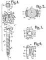
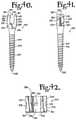
- FIG. 1is an exploded perspective view of a hinged bone screw assembly according to the present invention having a shank, a receiver and shown with a closure structure.
- FIG. 2is an enlarged cross-sectional view of the shank taken along the line 2 - 2 of FIG. 1 .
- FIG. 3is an enlarged top plan view of the receiver of FIG. 1 .
- FIG. 4is an enlarged side elevational view of the receiver of FIGS. 1 and 3 .
- FIG. 5is an enlarged top plan view of the closure structure of FIG. 1 .
- FIG. 6is an enlarged cross-sectional view of the receiver taken along the line 6 - 6 of FIG. 1 and the shank of FIG. 1 in partial front elevation, showing an initial stage of attachment of the shank to the receiver.
- FIG. 7is an enlarged cross-sectional view of the receiver taken along the line 6 - 6 of FIG. 1 and the shank of FIG. 1 in partial side elevation, rotated ninety degrees and lowered into a seated position within the receiver.
- FIG. 8is an enlarged cross-sectional view, similar to FIG. 7 , further showing the shank in cross-section along the line 8 - 8 of FIG. 1 , with the shank disposed at an angle with respect to the receiver and further showing an extent of articulation in phantom.
- FIG. 9is an enlarged perspective view of first and second hinged bone screws according to FIG. 1 shown with a longitudinal connecting member in the form of a cord and cord receiving spacer.
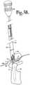
- FIG. 10is an exploded and partial front elevational view of a tool assembly according to the present invention showing a lock pin, an insertion tool and the bone screw of FIG. 1 .
- FIG. 11is a top plan view of the insertion tool of FIG. 10 .
- FIG. 12is a cross-sectional view taken along the line 12 - 12 of FIG. 10 .
- FIG. 13is a bottom plan view of the insertion tool of FIG. 10 .
- FIG. 14is a side elevational view of the insertion tool of FIG. 10 .
- FIG. 15is a cross-sectional view taken along the line 15 - 15 of FIG. 14 .
- FIG. 16is a partial cross-sectional view taken along the line 16 - 16 of FIG. 15 .
- FIG. 17is a partial cross-sectional view taken along the line 17 - 17 of FIG. 15 .
- FIG. 18is an enlarged and partial view of the insertion tool of FIG. 10 with portions broken away to show the detail thereof.
- FIG. 19is an enlarged front elevational view of a lock pin driver according to the invention shown mounted on a lock pin installed to the insertion tool of FIG. 10 , shown in partial front elevation.
- FIG. 20is an enlarged top plan view of the lock pin driver of FIG. 19 .
- FIG. 21is an enlarged bottom plan view of the lock pin driver of FIG. 19 .
- FIG. 22is a cross-sectional view taken along the line 22 - 22 of FIG. 20 .
- FIG. 23is an enlarged and partial front elevational view of the insertion tool and bone screw of FIG. 10 , showing the bone screw attached to the insertion tool and with two lock pins.
- FIG. 24is an enlarged and exploded front elevational view of a bone screw driver according to the invention and the insertion tool and attached bone screw of FIG. 23 .
- FIG. 25is an enlarged bottom plan view of the driver of FIG. 24 .
- FIG. 26is an enlarged and partial side elevational view of the driver of FIG. 24 .
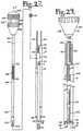
- FIG. 27is an enlarged and exploded front elevational view of a reduction tool according to the invention and the insertion tool and attached bone screw of FIG. 24 , also shown with the closure structure of FIG. 1 and a longitudinal connecting member.
- FIG. 28is an enlarged and partial bottom plan view of the reduction tool of FIG. 27 .
- FIG. 29is an enlarged and partial front elevational view similar to FIG. 27 , showing the reduction tool received in the insertion tool and engaged with the closure structure.
- FIG. 30is an enlarged and partial front elevational view of an upper portion of the reduction tool of FIG. 28 with portions broken away to show the detail thereof, a driving shaft being shown in an extended position.
- FIG. 31is an enlarged and partial front elevational view of the upper portion of the reduction tool of FIG. 27 with portions broken away to show the detail thereof, the driving shaft being shown in a retracted position.
- FIG. 32is an enlarged cross-sectional view taken along the line 32 - 32 of FIG. 30 .
- FIG. 33is an enlarged and partial front elevational view of a lower portion of the reduction tool of FIGS. 27 and 30 , shown engaged with the closure structure and reducing a longitudinal connecting member along the insertion tool of FIG. 27 and toward the attached bone screw.
- FIG. 34is an enlarged and partial front elevational view similar to FIG. 33 with portions broken away to show the detail thereof and further showing the closure structure fully seated in the bone screw.
- FIG. 35is an enlarged and partial front elevational view similar to FIGS. 33 and 34 , further showing the reduction tool in the retracted position of FIG. 31 and being moved away from a fully seated bone screw.
- FIG. 36is a partial and exploded front elevational view of a closure structure starter for use in accordance with the invention, further shown with a closure structure, a cord, and an insertion tool and attached bone screw.
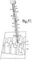
- FIG. 37is a partial and generally schematic view of a patient's spine showing a bone screw driver received within an insertion tool with an attached bone screw being guided toward a threaded bore in a vertebra in an early stage of a method according to the invention.
- FIG. 38is a partial and generally schematic view of a patient's spine, showing an implanted bone screw with attached insertion tool receiving a reduction tool engaged with a closure structure.
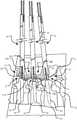
- FIG. 39is a partial and generally schematic view of a patient's spine, showing three insertion tools, each attached to an implanted bone screw and further showing a stage of implantation of a cord and threaded spacers.
- FIG. 40is a front elevational view of a first alternative monoaxial bone screw according to the invention having an open receiver.
- FIG. 41is a side elevational view of the bone screw of FIG. 40 .
- FIG. 42is a top plan view of the bone screw of FIG. 40 .
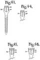
- FIG. 43is a side elevational view of a second alternative monoaxial bone screw according to the invention having an open receiver and trapezoidal profile.
- FIG. 44is a partial side elevational view of a third alternative monoaxial bone screw according to the invention having an open receiver and trapezoidal profile.
- FIG. 45is a partial side elevational view of a fourth alternative monoaxial bone screw according to the invention having an open receiver and reverse trapezoidal profile.
- FIG. 46is a partial side elevational view of a fifth alternative monoaxial bone screw according to the invention having an open receiver and reverse trapezoidal profile.
- FIG. 47is a side elevational view of a sixth alternative monoaxial bone screw according to the invention having a closed receiver and reverse trapezoidal profile.
- FIG. 48is a partial side elevational view of a seventh alternative monoaxial bone screw according to the invention having a closed receiver and trapezoidal profile.
- FIG. 49is a partial side elevational view of an eighth alternative monoaxial bone screw according to the invention having a closed receiver and trapezoidal profile.
- FIG. 50is a partial and generally schematic view of a patient's spine, showing two implanted monoaxial bone screws according to FIGS. 40-42 with a connecting cord and spacer having non-parallel end surfaces.
- FIG. 51is a partial and generally schematic view of a patient's spine, showing two implanted bone screws according to FIG. 43 with a connecting cord and spacer.
- FIG. 52is a perspective and partially exploded view of an alternative hinged screw according to the invention including a shank, a receiver and an attachment clip.
- FIG. 53is an enlarged and partial front elevational view of the hinged screw of FIG. 52 and shown in a second position in phantom.
- FIG. 54is an enlarged top plan view of the attachment clip of FIG. 51 .
- FIG. 55is an enlarged and exploded perspective view of a polyaxial bone screw assembly according to the invention shown with a dynamic longitudinal connecting member for use according to the invention.
- the reference numeral 1generally designates a hinged bone screw for cooperation with a dynamic stabilization connecting member, generally 3 , such as the illustrated cord 6 with cannulated spacers 8 .
- the spacers 8are substantially cylindrical with opposed planar sides 9 .
- Tools for implanting a bone screw 1 on a vertebra 10 of a human spine 12 and manipulating cooperating bone screws 1 and longitudinal connecting members 3may include one or more insertion tools, generally 14 , a bone screw driver 16 , a reduction tool 18 , and a closure starter 20 .
- the hinged bone screw assembly 1includes a shank 24 and a receiver 26 .
- a closure structure 28is further included for engagement with the receiver to capture and fix the cord 6 of the longitudinal connecting member 3 within the receiver.
- the shank 24further includes a body 36 integral with an upwardly extending end portion 38 .
- the shank 24 and the receiver 26are assembled prior to implantation of the shank body 36 into the vertebra 10 . It is noted that any reference to the words top, bottom, up and down, and the like, in this application refers to the alignment shown in the various drawings, as well as the normal connotations applied to such devices, and is not intended to restrict positioning of the bone screw assembly 1 and tools 14 , 16 , 18 and 20 in actual use.
- the shank 24 of the bone screw assembly 1is elongate, having an axis of rotation A.
- the shank body 36has a helically wound, radially outwardly extending bone implantable thread 40 axially extending from near a lower end or tip 44 of the body 36 to near a slanted or sloped surface 46 that is adjacent to a smooth substantially cylindrical surface 48 located adjacent to the end portion 38 .
- the body 36utilizing the thread 40 for gripping and advancement is implanted into the vertebra 10 leading with the tip 44 and driven down into the vertebra 10 with the driving tool 16 so as to be implanted in the vertebra 10 to near the sloped surface 46 .
- an outer surface 50 of the shank body 36 that includes the thread 40 and extends between the surface 46 and the tip 44is coated, perforated, made porous or otherwise treated 52 .
- the treatment 52may include, but is not limited to a plasma spray coating or other type of coating of a metal or, for example, a calcium phosphate; or a roughening, perforation or indentation in the surface 50 , such as by sputtering, sand blasting or acid etching, that allows for bony ingrowth or ongrowth. Certain metal coatings act as a scaffold for bone ingrowth.
- Bio-ceramic calcium phosphate coatingsinclude, but are not limited to: alpha-tri-calcium phosphate and beta-tri-calcium phosphate (Ca 3 (PO 4 ) 2 , tetra-calcium phosphate (Ca 4 P 2 O 9 ), amorphous calcium phosphate and hydroxyapatite (Ca 10 (PO 4 ) 6 (OH) 2 ).
- Coating with hydroxyapatitefor example, is desirable as hydroxyapatite is chemically similar to bone with respect to mineral content and has been identified as being bioactive and thus not only supportive of bone ingrowth, but actively taking part in bone bonding.
- the sloped surface 46extends radially inward and axially upward from the shank body 36 to the cylindrical portion 48 .
- the upper end portion 38Further extending laterally outwardly from the cylindrical portion 48 is the upper end portion 38 that provides a connective or capture apparatus disposed at a distance from the threaded shank body 36 and thus at a distance from the vertebra 10 when the body 36 is implanted in the vertebra 10 .
- the upper end portion 38is configured for connecting the shank 24 to the receiver 26 and capturing the shank 24 in the receiver 26 .
- the upper end portion 38has a pair of projections or wings 56 that extend laterally oppositely outwardly from the cylindrical surface 48 .
- Each projection 56has a lower curved, convex surface 57 with ridges or locking teeth 58 sized and shaped to engage a concave toothed surface of the receiver 26 , to be described more fully below.
- the locking teeth 58are sized and shaped to provide locking positions at about every ten degrees for a total range of hinged motion of about sixty degrees, about thirty degrees on either side of a central axis B of the receiver 26 as illustrated in FIG. 8 .
- the upper or end portion 38further includes a top surface 60 that includes a concave portion sized and shaped for receiving and engaging the driver 16 as will be described more fully below and also the cord 6 .
- a side surface 62extends between the top surface 60 and each curved lower surface 57 .
- the shank 24is cannulated with a small central bore 66 extending an entire length of the shank along the axis A.
- the bore 66is coaxial with the threaded body 36 and opens at the tip 44 and the top surface 60 , providing a passage through the shank interior for a length of wire or pin inserted into the vertebra 10 prior to the insertion of the shank body 36 , the wire or pin providing a guide for insertion of the shank body 36 into the vertebra 10 .
- the receiver 26includes a base 70 integral with a pair of opposed upstanding arms 72 and 73 that extend from the base 70 to respective top surfaces 74 and 75 .
- the arms 72 and 73form a U-shaped cradle and define a U-shaped channel 76 between the arms 72 and 73 and include an upper opening 77 and a lower seat 78 .
- the lower seat 78includes locking teeth 80 sized and shaped to engage the locking teeth 58 of the shank upper end portion 38 .
- Each of the arms 72 and 73has an interior surface that defines an inner cylindrical profile and includes a discontinuous helically wound guide and advancement structure 82 .
- the guide and advancement structure 82is a partial or discontinuous helically wound flangeform configured to mate under rotation with a similar structure on the substantially cylindrical closure structure 28 , as described more fully below.
- the guide and advancement structure 82could alternatively be a buttress thread, a square thread, a reverse angle thread or other thread like or non-thread like helically wound advancement structures for operably guiding under rotation and advancing the closure structure 28 downward between the arms 72 and 73 and having such a structural nature as to resist splaying of the arms 72 and 73 when the closure 28 is advanced into the U-shaped channel 76 and tightened.
- Each of the arms 72 and 73has a substantially planar outer surface 84 and 85 , respectively, that includes a substantially linear undercut tool engagement groove 86 and 87 , respectively, V-shaped in cross-section and formed in the receiver 26 near the respective top surfaces 74 and 75 . Sloping surfaces 88 and 89 run inwardly and upwardly from the respective outer surfaces 84 and 85 to the respective grooves 86 and 87 .
- the V-shaped grooves 86 and 87secure the insertion tool 14 to the bone screw receiver 26 during implantation of the screw into bone and manipulation of the longitudinal connecting member 3 and closure structure 28 , and in cooperation with the sloping surfaces 88 and 89 , allows for easy, sliding release of the tool 14 from the bone screw during removal of the tool at the end of the procedure.
- the grooves 86 and 87cooperate with projections of the insertion tool 14 , which will be described in greater detail below, the insertion tool projections being received in the grooves 86 and 87 during implantation of the shank body 36 into the vertebra 10 and subsequent installation of the connecting member 3 and closure structure 28 .
- Upper ledges 90 and 91 adjacent to top surfaces 74 and 75respectively, extend laterally from the respective receiver surfaces 84 and 85 and from a substantially planar side 92 to an opposite planar side 93 , partly defining the respective undercut grooves 86 and 87 .
- Each ledge 90 and 91includes a narrow opening or slit 94 and 95 , respectively, formed therein and running from the top surface 74 and 75 to respective side surfaces 84 and 85 .
- the slits 94 and 95run parallel with the axis B of the receiver.
- the ledges 90 and 91are substantially similar in size and shape with the exception of the position and size of the slits 94 and 95 .
- the slit 94is located substantially centrally in the ledge 90 while the slit 95 is substantially off-center and also wider than the slit 94 , such width measured in a direction perpendicular to the axis B.
- the slits 94 and 95cooperate with projections on the insertion tool 14 and cooperate and attach to the tool 14 in only one location and thus there is only one way in which to orient and attach the tool 14 to the receiver 26 .
- the slits 94 and 95may be of a variety of sizes and shapes with cooperating structure on the insertion tool 14 such that the tool 14 will only attach to the receiver 26 in a single position or orientation, resulting in a desired precise alignment between the bone screw 1 , the insertion tool 14 and thereafter, the reduction tool 18 .
- the receiver arm outer side surface 72further includes a laser or otherwise etched alignment stripe 98 running parallel to the axis B.
- the stripe 98corresponds to a similar stripe 100 on the insertion tool 14 (illustrated in FIGS. 38 and 39 ), providing a visual aid and ease in the alignment and proper attachment of the insertion tool 14 with the receiver 26 by aligning the stripe 98 with the stripe 100 .
- a chamber or cavity 102that opens upwardly into the U-shaped channel 76 and communicates and opens downwardly to an oblong lower opening or neck 104 in the base 70 .
- the lower opening 104communicates with an outer lower exterior or bottom 105 of the base 70 .
- the base lower opening 104 and the cavity 102are sized and shaped to receive the upper end portion 38 of the shank 24 as illustrated in FIG. 6 .
- the cavity 102is defined in part by upper ceiling or stop surfaces 106 disposed on either side of the channel 76 , the surfaces 106 prohibit the end portion 38 from being advanced through the channel 76 to the receiver upper opening 77 when the upper portion 38 is in a loading orientation, receivable in the oblong lower opening 104 .
- the cavity 102is also partially defined by opposed inner surfaces 107 that extend from the opening 104 to the upper surfaces 106 .
- the upper portion 38is slid upwardly along the surfaces 107 , then rotated ninety degrees about the receiver axis B within the cavity 102 and thereafter lowered toward the opening 104 as illustrated in FIG.
- the cavity 102is sized and shaped to accommodate the rotation of the wing projections 56 of the upper end portion 38 about the axis B.
- the neck 104is sized and shaped to have a width that is smaller than the shank upper portion 38 measured along the wing projections 56 so as to form a restriction at the location of the neck 104 relative to the winged upper portion 38 , to prevent the upper portion 38 from passing from the cavity 102 and out into the lower exterior 105 of the receiver 26 when the upper portion 38 is seated on the lower seating surface 78 .
- Communication between the curved surface 57 and the lower seat 78allow for articulated or hinged motion of the shank 24 with respect to the receiver 26 in a single plane as illustrated in FIG. 8 , with the teeth 58 and 80 providing for fixed engagement between the shank 24 and the receiver 26 when a force is placed on the shank end portion 38 by rotating and torquing the closure structure 28 against the cord 6 of the longitudinal connecting member 3 .
- the hinged motion of the shank 24is limited by the cylindrical surface 48 of the shank 24 abutting the oblong neck 104 near either outer side 84 and 85 of the receiver 26 .
- the illustrated longitudinal connecting member 3includes from one up to a plurality of cannulated spacers 8 sized and shaped to receive the cord 6 therethrough.
- the spacers 8are also sized and shaped to fit between pairs of bone screws 1 , cooperating with the cord 6 to support adjacent vertebrae when implanted between bone screws 1 .
- the spacers 8may be made of a variety of materials including metals, plastics and composites.
- the illustrated spaceris made from a plastic, such as polycarbonate-urethane.
- the illustrated cordis also made from plastic, such as polyethylene-terephthalate.
- the spacer/cord combinationprovides for a flexible anatomical holding and control of the spinal motion segment or segments to be treated.
- connecting membersmay be utilized with the bone screws or other implants according to the invention, including solid rods and dynamic stabilization connecting members and member assemblies including, but not limited to coils, springs, and coil or spring and rod combinations including coils having rod-like inserts.
- Such connecting memberscan provide for protected motion, including torsional elasticity and elastic axial compression and distraction in addition to flexibility.
- the structure 110can be of any type, including V-type threads, buttress threads, reverse angle threads, or square threads, that cooperate with the guide and advancement structure 82 on the bone screw arms 72 and 73 .
- a suitable flangeform locking guide and advancement structureis disclosed in U.S. Pat. No. 6,726,689, which is incorporated herein by reference.
- the closure structure 28further includes a top surface 112 and a substantially planar bottom surface 113 , the bottom surface 113 providing a smooth contact surface for engagement with a cord 6 of the longitudinal connecting member 3 .
- a substantially hex-shaped internal drive socket or aperture 115Formed in the top surface 112 is a substantially hex-shaped internal drive socket or aperture 115 , further including a key slot 116 for precise and particular engagement with the reduction tool 18 as will be described in further detail below.
- a hex-shaped drive 115is illustrated herein, it is foreseen that the closure structure internal drive may be of other shapes or sizes.
- the closure structure 28may include an external driving head that breaks away from the cylindrical body 102 upon the application of a preselected torque.
- the insertion tool 14is best illustrated in FIGS. 10-18 .
- the tool 14has an elongate body 118 and two cooperating lock pins 120 .
- the elongate body 118has an axis of rotation C and is sized and shaped to be sufficiently long to extend from an implanted bone screw 1 through an exterior of a patient's skin so as to provide an outwardly extending and upper handle portion 122 that allows and provides for gripping by a surgeon during procedures utilizing the insertion tool 14 , with or without a driver 16 , a reduction tool 18 or a closure starter 20 .
- the insertion tool 14further includes an intermediate portion 124 and a lower implant engaging portion 126 which includes opposed implant engaging members or tangs 128 and 129 for securing a bone screw 1 or other implant there between.
- the insertion tool 14has a generally rectangular shape when viewed on end or in a cross section taken perpendicular to the axis of rotation C.
- the tool 14further forms an open channel 132 running along the axis C from a top surface 134 to bottom surfaces 136 thereof.
- the channel 132is substantially defined by an inner discontinuous cylindrical wall 138 .
- the wall 138is sized and shaped to receive the driving and manipulating tools 16 , 18 and 20 as will be described in greater detail below.
- the tool 14further includes a front 140 and opposed back 142 , and opposed sides 144 and 146 that attach the front 140 to the back 142 .
- the back 142includes an upper substantially solid wall portion 147 .
- the side 144includes the laser etched alignment stripe 100 that aids a surgeon in properly aligning and mating the tool 14 with the receiver 26 by simply aligning the stripe 100 with the stripe 98 that is located on only one side 84 of the receive 26 .
- the side 146is substantially planar and solid and is integrally joined to the front 140 and the back 142 substantially along a length thereof parallel to the axis C.
- the opposite side 144is integral to the back 142 substantially along an entire length thereof parallel to the axis C.
- the side 144is also integral with the front 140 along the intermediate 124 and lower 126 portions of the tool 14 . It is foreseen that the cross-sectional shape of the tool 14 could be rounded or some other shape.
- a through channel 148is formed in both the front 140 and the back 142 portions of the tool 14 and communicates with the longitudinal channel 132 .
- the openings and channels described herein with respect to the tool 14are sized and shaped to receive and allow passage of both tools and implants as will be described more fully below.
- the through channel 148begins near the upper handle portion 122 and extends through the bottom surfaces 136 of the tangs 128 and 129 that define a lower portion of the channel 148 and the lower, implant engaging portion 126 of the tool 14 .
- a squared off, discontinuous and off-center opening 149is formed in the front 140 opposite the solid portion 147 of the back 142 , the opening 149 partially defined by a first corner 150 formed in the front 140 and a second corner 151 formed in the side 144 , the opening 149 communicating with an upper more narrow channel 152 that extends from the opening 149 through the top surface 134 .
- the opening 149then extends along the front 140 all the way through the bottom surfaces 136 of the tool 14 , communicating with the open longitudinal channel 132 .
- the opening 149is sized and shaped to readily receive a driving end of the bone screw driver 16 , the lower housing and retractable driving tip of the reduction tool 18 and the tip of the closure starter 20 , as well as the entire closure structure 28 .
- the lateral opening of the narrow channel 152is sized and shaped to receive slender shafts of the driver 16 , reduction tool 18 and closure starter 20 .
- the opening 149 communicating with both the narrow channel 152 and the through channel 148provides for a continuous lateral or side opening along an entire length of the tool 14 along the axis C that is sized and shaped to receive longitudinal connecting members including, but not limited to cords 6 , coils and rods, as well as closure implants and various manipulating tools.
- the opening 149also is partially defined by a cut-out portion of the front 140 that exposes the side 144 of the tool 14 .
- the opening 149includes an elongate wall 154 in the side 144 that faces toward the front 140 and a lower or base surface 155 that runs perpendicular to the axis C.
- the wall 154widens to form an upper portion 156 that extends to the top 134 of the tool 14 , the upper portion 156 partially defining the upper narrow channel 152 .
- a U-shaped opening 157 formed in the upper back portion 147marks the beginning of the through channel 148 that extends through the back 142 and downwardly through the bottom surfaces 136 .
- the through channel 148 that extends through the front opening 149 and the back opening 157begins at the U-shaped opening 157 and is substantially uniform in width measured perpendicular to the axis C over the intermediate 124 and lower 126 portions of the tool 14 , being substantially defined by the sides 144 and 146 that end in the tangs 128 and 129 .
- the through channel 148thus provides for some flexibility to allow for outward splaying of the tangs 128 and 129 near the bottom surfaces 136 and about the receiver 26 of the bone screw shank 1 as will be described in greater detail below.
- a narrow cylindrical side channel 158is formed in the tool 14 , running parallel to the axis C and partially defined by a threaded inner wall 160 , the channel 158 and threaded wall 160 sized and shaped to rotatingly receive a first lock pin 120 .
- a second narrow cylindrical side channel 162is formed in the tool 14 , parallel to the axis C and having a threaded inner wall 164 , the channel 162 and threaded wall 164 also sized and shaped for rotatingly receiving a lock pin 120 .
- the channels 158 and 162are open at both ends 134 and 136 , with the threaded portions 160 and 164 being located near the top 134 in the upper portion 122 of the tool 14 .
- a discontinuous guide and advancement structure 168disposed on the inner cylindrical wall 138 defining the central channel 132 .
- the guide and advancement structure 168is a substantially square thread sized and shaped to receive a cooperating guide and advancement structure of the reduction tool 18 to be described more fully below.
- a starting location 170 of the guide and advancement structure 168 on the insertion tool 14is coordinated with a starting position of the guide and advancement structure on the reduction tool 18 and a starting location of the guide and advancement structure 82 of the bone screw receiver 26 when attached to the insertion tool 14 , so as to provide for exact closure structure alignment and engagement within the receiver 26 to a specific, fully seated position, as also will be described more fully below.
- the front 140 of the tool 14includes two outer front faces 172 and 173 that are substantially similar in size and are spaced from one another, with the through channel 148 extending therebetween.
- the face 172begins adjacent to the bottom 155 of the cut-out portion of the opening 149 and extends to the bottom surface 136 .
- the face 173extends an entire length of the tool along the axis C.
- the face 173widens at an upper or top portion 175 of the front 140 .
- the portion 175partly defines the narrow channel 152 and supports the guide and advancement structure 168 .
- both the faces 172 and 173include a cut-out or recess 178 that extends into the sides 144 and 146 , respectively, and is defined in part by the tangs 128 and 129 , respectively.
- the cut-outs 178are each defined by an upper surface 180 disposed perpendicular to the axis C, an inner planar surface 182 disposed parallel to the axis C and a substantially planar lip surface 184 disposed at an acute angle with respect to the surface 182 .
- the lip surface 184is on each of a pair of opposed projections or implant engaging members 186 and 187 , disposed on respective tangs 128 and 129 , each projecting toward the axis C and sized and shaped to engage and slidingly fit within the grooves 86 and 87 respectively, of the receiver 26 .
- the inner surface 182 disposed above the projection 186further includes a raised strip or projection 194 that runs parallel to the axis C and is sized, shaped and positioned to slidingly engage with the slit 94 in the ledge 90 of the arm 72 of the receiver 26 .
- the inner surface 182 disposed above the projection 187further includes a raised strip or projection 195 that also runs parallel to the axis C and is sized, shaped and positioned to slidingly engage with the slit 95 in the ledge 91 of the arm 73 of the receiver 26 .
- the cooperation between the strip 194 and the slit 94 and the strip 195 and the slit 95ensures proper alignment and mating of the insertion tool 14 and the receiver 26 and further prohibits front to back movement of the receiver 26 with respect to the insertion tool 14 when the tool 14 is mounted on the receiver 26 and the lock pins 120 contact respective top surfaces 74 and 75 of the receiver 26 .
- Each lock pin 120is elongate, having a top surface 200 a curved bottom surface 202 , a hex-shaped upper driving portion 204 disposed near the top surface 200 and a threaded portion 206 disposed near the driving portion 204 and on a smooth cylindrical body portion 207 of the lock pin 120 .
- the smooth body portion 207extends from the driving portion 204 to the bottom surface 202 .
- the body portion 207may be of slightly reduced diameter as shown by the portion 208 to result in the bottom surface 202 being of a size and shape to fully contact the receiver 26 without overhang.
- the lock pin 120is sized and shaped to be received in either of the cylindrical channels 158 and 162 in the insertion tool 14 , with the threaded portion 206 rotatably receivable in either of the threaded inner walls 160 and 164 .
- the lock pin 120is sized and shaped to extend along and completely through either of the channels 158 and 162 until the curved bottom 202 abuts the top surface 74 or 75 of the receiver 26 with the upper driving portion 204 extending above the top 134 of the insertion tool 14 as illustrated, for example, in FIGS. 19 and 24 .
- the lock pins 120are rotated and driven downwardly into the insertion tool 14 by a lock pin driver 210 illustrated in FIGS. 19-22 .
- the lock pin driver 210includes a substantially cylindrical elongate body 212 having an axis of rotation D and shown with outer grooves 214 to aid a surgeon in handling and rotating the driver 210 .
- the driverfurther includes an upper projection or extension 216 that may be used to spread the tangs 128 and 129 of the insertion tool 14 when attaching the insertion tool 14 to a receiver 26 as will be described in greater detail below.
- the extension 216has a substantially rectangular cross-section viewed in a plane perpendicular to the axis D.
- the extensionincludes a pair of substantially planar opposed sides 217 , a pair of substantially curved opposed sides 218 and a curved top surface 219 .
- the body 212further includes an inner, curved entry aperture or easement 220 located opposite the extension 216 and an elongate hex-shaped aperture or driving socket 222 running along the axis D and communicating with the easement 220 .
- the driving socket 222is sized and shaped to receive and mate with the hex-shaped upper driving portion 204 of each of the lock pins 120 .
- the socket 222includes a stop or abutment surface 224 , sized and shaped for frictional contact with the top surface 200 of the lock pin 120 . Above the abutment surface 224 and extending through the upper extension 216 , the illustrated lock pin driver 210 is substantially solid.
- the bone screw driver 16includes an upper elongate handle 230 , an elongate shaft 232 and a driving end portion 234 integral with or fixedly attached to the shaft 232 .
- the handle 230is somewhat triangular when viewed on end as shown in FIG. 25 .
- the handle 230includes shallow apertures 236 to aid a surgeon in gripping and rotating the handle 230 .
- the handle 230is fixed to and coaxial with the shaft 232 that has an axis of rotation E. Protruding laterally from the shaft 232 are an alignment tab 238 and a centering tab 240 , the centering tab 240 being disposed between the alignment tab 238 and the driving end 234 .
- both of the tabs 238 and 240extend radially outwardly from the shaft 232 as illustrated in FIGS. 24, 25 and 37 .
- the tabs 238 and 240are not substantially co-linear or co-planar.
- the two tabs 238 and 240are sized, shaped and positioned to align with non-linear openings and/or surfaces in the insertion tool 14 to ensure proper engagement of the driver 16 driving end 234 within the U-shaped channel 76 of the bone screw receiver 26 .
- the shaft 232includes a lower portion 242 of reduced diameter.
- the driving end 234further includes a curved lower surface 244 that smoothly transitions to opposed planar surfaces 245 , the surfaces 244 and 245 being sized and shaped to be snugly received within the receiver U-shaped channel 76 and to fully engage inner surfaces of the arms 72 and 73 as well as the top curved surface 60 of the shank end portion 38 .
- Opposed front and rear surfaces 246 of the driving end 234are substantially planar and sized and shaped to be substantially flush with the receiver 26 along the sides 92 and 93 , and extending from near the top surfaces 74 and 75 to the seating surface 78 .
- the driving tool 16includes a longitudinal through bore 248 formed along an entire length thereof along the axis E.
- the through bore 248cooperates with cannulated bone screws, allowing for insertion of the driver 16 and attached bone screw 1 over guide wires or pins.
- the reduction tool 18is elongate, having an axis of rotation F and including a handle 260 that houses a driving tip extension and retraction mechanism, generally, 262 , an upper shaft housing 264 , a mid-shaft housing 266 having a threaded portion 268 and a lower shaft housing 270 attached to a driving tip housing 272 for an extendible driving tip 273 .
- the handle, shaft housings and driving tipare all aligned along the axis of rotation F.
- the handle 260further includes an upper end portion or palm handle 276 a lower grip portion 278 and a rotatable member or retraction lever 280 disposed between the upper 276 and lower 278 portions, the rotatable member or lever 280 being part of the extension and retraction mechanism 262 .
- the lever 280has a coarse inner thread 282 providing for a vertical travel distance to fully and accurately extend and retract the driving tip 273 in and out of the driving tip housing (in the illustrated embodiment, a vertical travel distance of about 3.5 mm) for a 1 ⁇ 4 rotation of the lever 280 .
- the mechanism 262further includes an elongate shaft 285 attached to the driving tip 273 and extending along the axis F from the driving tip 273 to an upper screw 288 disposed substantially within the rotatable lever 280 when the driving tip 273 is in an extended, closure member engaging position as shown in FIGS. 27, 29, 30, 33 and 34 .
- the screw 288is fixed to the shaft 284 at one end thereof and fixed to a slidable member or stopper 290 at an opposite end thereof.
- the stopper 290is disposed in a central void or aperture 292 formed in the upper handle portion 276 .
- the screw 288is sized and shaped to mate with the inner thread 282 of the rotatable lever 280 such that when the lever 280 is rotated a one quarter turn (ninety degrees) about the axis F in a clock-wise direction when viewed from the upper portion of the handle 276 , the screw 288 is moved from the position shown in FIG. 30 linearly upwardly along the axis F to the position shown in FIG. 31 .
- Such rotating action of the lever 280also slides the stopper 290 upwardly in the aperture 292 to a position abutting against an upper wall or stop 296 , with a portion of the screw 288 also disposed in the aperture 294 as illustrated in FIG. 31 .
- the stop 296prohibits any further upward movement of the screw 288 , attached shaft 285 and attached driving tip 273 , fully retracting the tip 273 into the housing 272 .
- the stopper 290abuts against a lower wall or stop 298 that also defines the aperture 294 , prohibiting any further downward movement of the driving tip 273 .
- a pair of pins 299fix the upper handle portion 276 to the lower handle portion 278 and capture the rotatable lever 280 therebetween.
- the lever 280further includes inner curved channels 300 , with the pins 299 received in and extending therethrough.
- the channels 300are sized and shaped to allow the lever 280 to slidingly rotate the one quarter turn or ninety degrees required for extending and retracting the driving tip 273 as previously described herein, but prohibiting any additional rotation of the lever 280 in either direction.
- the handle lower portion 278may be imprinted or otherwise marked with the words “UP” and “DOWN” on a surface 302 thereof to reveal to the surgeon whether the driving tip 273 is extended or retracted.
- the lever 280when the lever 280 is positioned over and covering the word “UP,” the word “DOWN” would be uncovered and visible when the tool 18 is in the position shown in FIG. 30 .
- the lever 280After rotating one quarter turn as shown in FIG. 31 , the lever 280 would be positioned over and covering the word “DOWN,” leaving the word “UP” uncovered and visible to the surgeon.
- the driving tip housing 272provides adequate space about the driving tip 273 to allow for full retraction of the tip 273 into the housing 272 .
- the housing 272forms a void or channel 304 sized and shaped to receive the driving tip 273 in the retracted position.
- the driving tip 273is substantially cylindrical and has a central through slot 306 and facets for capturing and holding the closure structure 28 prior to and during insertion in the receiver 26 .
- the tip 273further includes a lateral projection or key 308 sized and shaped to mate with the key slot 116 of the closure structure 28 for precise positioning of the closure structure 28 into the insertion tool 14 and the receiver 26 by the reduction tool 18 .
- the outer thread 268 formed on the reduction tool 18is sized and shaped to rotatably mate with the thread 168 of the insertion tool 14 .
- both the reduction tool 18 and the insertion tool 14are sized and shaped such that the closure structure 28 is advanced till snug, but cannot be driven past the top surfaces 74 and 75 of the receiver 26 , with a thread run-out portion 312 on the reduction tool 18 configured and positioned to stop rotation of the thread 268 with respect to the thread 168 of the insertion tool 14 , prohibiting any further rotation or downward motion of the tool 18 with respect to the tool 14 .
- the reduction tool 18in cooperation with the insertion tool 14 , provides apparatus for moving the cord 6 of the longitudinal connecting member 3 (or other type of connecting member, such as a coil or rod) downwardly in a controlled manner into the receiver 26 by rotating the reduction tool 18 , and also thereby precisely mating the thread 268 with the guide and advancement structure 168 , capturing the cord 6 or other longitudinal connecting member within the receiver 26 .
- the closure starter 20 for use in methods of the inventionincludes a handle 320 fixed to an elongate cylindrical stem or shaft 322 and a driving tip 324 integral to the shaft 322 .
- the handle 320 , shaft 322 and tip 324are coaxial along an axis of rotation G.
- the handle 320includes shallow apertures 326 to aid a surgeon in gripping and rotating the starter 20 about the axis G when the starter 20 is engaged with a closure structure 28 .
- the closure starter 20is sized and shaped to be used in cooperation with the insertion tool 14 , with the tip 324 in engagement with a closure structure 28 and the starter 20 extending through the tool 14 with the handle 320 located above the lock pins 120 to allow for adequate clearance between the handle 320 and the insertion tool 14 to allow for the rotation of the closure structure 28 into the receiver 26 by turning the handle 320 .
- the driving tip 324includes a slot and faceted geometry for capturing and holding the closure structure 28 prior to and during insertion of the structure 28 into the receiver 26 .
- the closure starter 20is useful when, as shown in FIG. 36 , the cord 6 or other longitudinal connecting member has been previously reduced into the receiver 26 such that the reduction tool 18 is not required.
- the previously described toolsare utilized to attach one or more longitudinal connecting member 3 to the human spinal column 12 .
- the procedureis begun by selection of a bone screw 1 in accordance with the size of the patient's vertebra 10 and the requirements of the spinal support needed.
- the illustrated hinged bone screws 1are preferred for use with the cord 6 and spacers 8 of the illustrated longitudinal connecting member 3 .
- the hinged screw 1advantageously allows for a plurality of angular or articulated locking positions between the shank 24 and the receiver 26 .
- an advantage of both fixed screws and the hinged screw 1 over polyaxial bone screwsis that the hinged or fixed screws maintain a set or constant distance between receivers that aids in keeping the cord 6 in a desired tension.
- Fixed bone screws as illustrated in FIGS. 40-49 , an alternative hinged bone screw illustrated in FIGS. 52-54 and an alternative polyaxial bone screw illustrated in FIG. 55are also described more fully below that may be utilized with tools according to the invention to attach one or more longitudinal connecting members 3 to a human spine 12 .
- other types of longitudinal connecting membersmay also be used according to the invention including rods and coils. Bone screws according to the invention are also preferably cannulated so as to be receivable over and guided by a guide pin or wire 330 as discussed more fully below.
- a hinged bone screw 1 of the inventionmay be assembled by up or bottom loading the bone screw shank 24 into the receiver 26 with the side surfaces 62 facing the inner side walls 107 of the receiver 26 .
- the shank 24is uploaded until the end portion 38 abuts against the upper wall surfaces 106 .
- the shank 24is rotated about the axis A about ninety degrees, followed by lowering the end portion 38 until the lowered curved surfaces 57 of the wing projections 56 contact the lower seat 78 of the receiver 26 at the locking teeth 80 .
- the insertion tool 14may be placed into engagement with the hinged bone screw 1 as follows:
- the bone screw receiver 26 that has been attached to a shank 24 as previously described hereinis first aligned with an insertion tool 14 by aligning the laser etched stripe 98 of the receiver with the laser etched stripe 100 of the insertion tool 14 .
- Such alignmentplaces the side 144 of the insertion tool 14 and the side 72 of the receiver 26 facing in the same direction and the through channel 148 communicating and aligned with the U-shaped channel 76 of the receive 26 .
- the upper extension 216 of the lock pin driver 210may then be inserted into the channel 148 with the opposed planar sides 217 being received in the channel 148 .
- the lock pin driver 210is then rotated about its axis D causing the opposed curved sides 218 to abut against the surfaces forming the channel 148 to spread the tangs 128 and 129 apart, followed by inserting the tool 14 onto the bone screw receiver 26 outer arm surfaces 72 and 73 at a location spaced from the top surfaces 74 and 75 .
- the lock pin driver 210is rotated again, thereby releasing the tool 14 from the curved surfaces 218 and thus snapping the tool 14 onto the receiver 26 .
- the lock pin extension 216is removed from the through channel 148 and the insertion tool 14 is pulled upwardly and away from the receiver 26 , the tool 14 sliding upwardly along the inwardly sloping surfaces 88 and 89 leading up to the undercut grooves 86 and 87 until the projections 186 and 187 are received and engaged with the receiver 26 at the respective grooves 86 and 87 .
- Such engagementresults in a firm attachment that also resists any attempt to spread or splay the tangs 128 and 129 .
- the raised strip 194 of the tool 14is received in the slit 94 of the receiver and the raised strip 195 of the tool 14 is received in the slit 95 of the receiver.
- the raised strips 194 and 195also extend upwardly from the top surfaces 74 and 75 of the receiver 26 as illustrated in FIG. 23 .
- a pair of lock pinsmay then be inserted in the insertion tool 14 cylindrical channels 158 and 162 with each lock pin tip or bottom 202 being inserted into the channels at the top surface 134 and guided downwardly toward the bottom 136 of the tool 14 .
- the lock pin 120is rotated and driven downwardly toward the receiver surface 74 or 75 by mounting the lock pin driver 210 on a lock pin 120 with the driving portion 204 of the pin 120 received in the elongate socket 222 and the top 200 of the pin 120 abutting against and frictionally engaging the top surface or stop 224 .
- the lock pin driver 210is rotated about the axis D until the bottom surface 202 frictionally engages with the receiver surfaces 74 or 75 .
- the raised strip 194prohibits movement of the pin 120 toward the receiver side surface 92 .
- the raised strip 195prohibits movement of the pin 120 toward the opposite receiver side surface 93 .
- the two strips 194 and 195cooperate to prevent front to back movement of the insertion tool 14 between the receiver side surfaces 92 and 93 .
- the driver 16is inserted into the insertion tool 14 by inserting the driving end 234 into the lateral opening 149 of the longitudinal channel 132 near the top 134 of the tool 14 with the shaft 232 being received in the narrow channel 152 , followed by sliding the shaft 232 downwardly along the axis C into the interior of the tool 14 with both the alignment tab 238 and the centering tab 240 aligned with and then passing into the narrow channel 152 at the front 140 of the alignment tool 14 .
- the driving end 234 of the driver 16is set up for proper engagement with the receiver 26 and the end portion 38 of the shank 24 .
- the tab 240is then passed through the narrow channel 152 and into the through channel 148 .
- the driving end lower surface 244engages the top surface 60 of the end portion 38 of the shank 24 and the lower seat 78 of the receiver 26 .
- the driving end 234also contacts the receiver 26 along an entire height of the U-shaped channel 76 from the lower seat 78 to the upper surfaces 74 and 75 .
- the driver 16is now in position to drive the bone screw 1 into a vertebra 10 as illustrated in FIG. 37 .
- the alignment tab 238 cooperating with and engaging the surfaces forming the channel opening 152 and the centering tab 240 cooperating with and engaging the front face 172 of the tool 14keep the driving end 234 in proper position, fully engaging the receiver 26 as the driver 16 is manually rotated about the axis E to rotate and drive the bone screw 1 into the vertebra 10 as will be described more fully below. Thereafter, the driver 16 may be removed by simply sliding the shaft 232 upwardly along the axis C and then laterally out of the tool 14 through the upper side opening formed by the channel 152 , with the driving end 234 being easily removable out of the squared off opening 149 of the upper portion of the channel 148 .
- a relatively minimally invasive incision or incisionsare made and stretched so as to snugly receive the tools of the invention.
- a drill(not shown) is utilized to form a first guide bore in a vertebra 10 under guidance of non invasive imaging techniques, which procedure is well known and established.
- a thin pin or guide wire 330is then inserted in the first guide bore, the pin and guide bore functioning to minimize stress on the vertebra 10 and providing an eventual guide for the placement and angle of the bone screw shank 24 with respect to the vertebra 10 .
- the guide boreis enlarged utilizing a cannulated drilling tool or tap having an integral or otherwise attached cannulated and threaded bit with an outer surface sized and shaped to correspond to the size and shape of the chosen threaded bone screw 1 .
- the pin 330With the pin 330 fixed to the vertebra 10 and in place in an enlarged guide bore 332 and extending upwardly through the bore and out of the incision, the pin 330 is threaded into the bore 66 at the tip 44 of the shank 24 and out of the opening at the top surface 66 of the bone screw shank 24 . The pin 330 is then threaded into the driver 16 at the bore 248 opening at the surface 244 and then up through the bore 248 of the driver 16 . Care is taken to insure that the axis A of the bone screw shank 24 is aligned and coaxial with the axis B of the receiver when the driver 16 driving end 234 engages the top surface 60 of the bone screw shank 24 .
- driver contact with the surface 60 of the shank 24maintains coaxial alignment of the shank and receiver during driving of the shank body 36 into the vertebra 10 .
- the driver 16installed on the insertion tool 14 properly aligned as illustrated in FIG. 37 and as previously described herein, the bone screw 1 is then rotated and driven into the tapped bore 332 in the vertebra 10 with the surgeon holding and rotating the bone screw assembly 1 and the insertion tool 14 with the driver handle 230 until the shank body 36 is disposed at a desired depth in the tapped bore 332 of the respective vertebra 10 .
- each vertebra 10at least two and up to a plurality of bone screws 1 with attached insertion tools 14 are installed in each vertebra 10 to be attached to the longitudinal connecting member 3 .
- the driver 16is removed by sliding the shaft 232 up through the open top 134 of the tool 14 , out of the side opening and away from the bone screw 1 and the attached insertion tool 14 .
- the assemblymay include first and second multi-part end structures 13 and 15 with a bone anchor 17 disposed therebetween.
- each of the first and second multi-part end structures 13 and 15includes the receiver 26 and the closure structure 28 and may be in the form of a bone anchor, such as the bone screw 1 or other bone anchors described herein.
- the first multi-part end structure 13may include a first closure structure 28 receivable into a first channel 76
- the second multi-part end structure 15may include a second closure structure 28 receivable into a second channel 76 .
- the reduction tool 18is then used to press the longitudinal connecting member 3 or other type of longitudinal connecting member, such as a rod or coil, downwardly into the receivers 26 of the implanted bone screws 1 .
- a first spacer 8 Ais cut to length and pre-loaded onto a cord 6 then the cord 6 of the longitudinal connecting member 3 is inserted into and through a through bore 148 of an insertion tool 14 with a tail or end 334 of the cord 6 extending out of the bore 148 .
- the other end of the cord 6is then inserted into a through bore 148 of an adjacent insertion tool 14 , followed by the threading of another spacer 8 B, with such process continuing until a threaded spacer 8 of appropriate length is disposed between each of the insertion tools 14 with the cord extending through each through bore 148 , either above or below the patient's skin.
- the cord 6further extends through first and second through bores 11 A and 11 B of the first and second spacers 8 A and 8 B, respectively. Then all of the spacers 8 are pressed downwardly through the incision and generally between the insertion tools 14 and near the bone screw receivers 26 . As shown in FIG.
- the spacer 8 Amay be disposed on a first side 5 of a first receiver 26 of the bone anchor 17
- the spacer 8 Bmay be disposed on a second side 7 of the first receiver 26 of the bone anchor 17
- the multi-part end structures 13 or 15may be a second bone anchor having a second receiver 26 .
- the reduction tool 18Prior to engagement with an insertion tool 14 , the reduction tool 18 is attached to a closure structure 28 as follows: The reduction tool 18 driving tip 273 is placed in an extended, closure structure engaging position as shown in FIG. 27 by rotating the lever 280 one quarter turn in a clock-wise direction, if necessary, to fully expose the tip 273 .
- the closure structure 28is then placed on the driving tip 273 with the tip 273 fully engaging the internal drive socket 115 and the laterally projecting key 308 being received in the key slot 116 , the driving tip 273 surfaces and key 308 frictionally holding the closure structure 28 on the driving tip 273 as the structure 28 is inserted into the open longitudinal channel 132 through the side opening 149 near the upper end or top 134 of the tool 14 , the reduction tool lower shaft housing 270 being received in the narrow channel 152 .
- closure structure 28 and attached reduction tool housing portions 266 , 270 and 272are then slidingly received and lowered in the longitudinal channel 132 along the axis C until the threaded portion 268 of the tool 18 makes contact with the guide and advancement structure 168 disposed near the top of the insertion tool 14 .
- the reduction tool 18is then rotated about the axes C and F by rotating the handle 260 to move the closure structure 28 toward the receiver 26 in a controlled manner.
- the closure structure bottom surface 113makes contact with the cord 6 and presses the cord 6 downwardly and toward and into the channel 76 of the receiver 26 .
- the starting locations 170 and 310 of the respective mating guide and advancement structures 168 and 268 , as well as the key 308 on the driving tip 273 and the key slot 116 on the closure structure 28are all positioned to precisely mate the closure structure guide and advancement structure 110 with the receiver guide and advancement structure 82 .
- the guide and advancement structures 168 and 268are sized and positioned such that once the closure structure 28 is threaded fully into the receiver 26 with the top surface 112 of the closure structure 28 being flush with the top surfaces 74 and 75 of the receiver 26 , further rotation of the tool 18 may be prohibited by abutment of the guide and advancement structure 168 with an optional thread run out stop 312 on the reduction tool 18 . At such time, the cord 6 is captured in the receiver 26 and the closure structure 28 may or may not be fully tightened and torqued within the receiver 26 .
- the driving tip 273 of the reduction tool 18is then retracted by rotating the lever 280 of the handle 260 in a counter-clockwise direction one quarter turn, detaching the driving tip 273 from the closure structure 28 , thereby deploying it.
- the reduction tool 18may then be removed from the insertion tool 14 by rotating the handle 260 in a counter-clockwise direction to move the tool 18 upwardly and away from the receiver 26 .
- the guide and advancement structure 268is disengaged from the guide and advancement structure 168 , the tool 18 may be pulled up and slid sideways out of the tool 14 .
- each insertion tool 14in order to install a longitudinal connecting member 3 in two or more bone screws 1 , it may or may not be necessary to equip each insertion tool 14 with a reduction tool 18 . It may be sufficient to utilized the reduction tool 18 with only one insertion tool 14 , for example the bone screw receiver 26 and attached insertion guide tool 14 shown in both FIGS. 38 and 39 located at an end of a group of bone screws, shown having a tail 334 of the cord 6 extending therefrom. Thereafter, the closure structures 28 may be placed in the remaining receivers 26 utilizing the closure starter 20 . As described in more detail below with reference to FIG. 39 , a first end portion 2 of the cord 6 may be directly secured to the first multi-part end structure 13 and a second end portion 4 of the cord 6 may be directly secured to the second multi-part end structure 15 , for example, using the closure structures 28 .
- the closure starter 20may be used similarly to the reduction tool 18 , with the closure structure 28 first placed on the tool 20 with the driving tip 324 engaging the internal drive socket 115 , the driving tip 324 surfaces and slot holding the closure structure 28 on the driving tip 324 as the structure 28 is side-loaded into the longitudinal channel 132 of the tool 14 with the driving tip 324 and attached structure 28 inserted into the lateral opening 149 of the tool 14 and a lower portion of the shaft 322 being received in the narrow channel 152 formed near the top of the tool 14 .
- the closure structure 28 and attached closure starter shaft 322are then slidingly received in the channel 132 along the axis C until the guide and advancement structure 110 of the closure structure 28 makes contact with the guide and advancement structure 82 of the receiver 26 .
- the closure starter 20is then rotated about the axis G by rotating the handle 320 to rotate and drive the closure structure 28 into the receiver 26 .
- the closure structure bottom surface 113contacts the cord 6 and presses the cord 6 into the channel 76 of the receiver 26 .
- the cord 6is captured in the receiver 26 .
- the closure structure 28may or may not be fully tightened and torqued within the receiver 26 .
- the closure starter 20is simply moved upwardly and away from the receiver 26 and then out of the insertion tool 14 .
- the structures 28may be locked into place with an elongate driving or torquing tool having a driving tip similar or identical to the reduction tool 18 driving tip 273 or the closure starter 20 driving tip 324 as well as an elongate shaft sized and shaped to be slidingly received in the insertion tool 14 .
- a torquing tooltypically includes a T-shaped handle to aid the surgeon in applying adequate tightening force, typically 70-120 inch pounds, to fully tighten and set the closure structure 28 within the receiver 26 so that the surface 113 is snug against the cord 6 .
- An anti-torque holding toolmay be utilized to hold the insertion tool 14 during tightening with the torquing tool.
- Such an anti-torque holding toolis also elongate and includes a hollow shaft sized and shaped to slidingly mate over the insertion tool 14 . Therefore, such an anti-torque holding tool would be substantially rectangular in cross-section, sized and shaped to closely fit about the insertion tool 14 , and include a handle for holding the insertion tool 14 in place during rotation of the torquing tool, thereby allowing a surgeon to counter the torque applied by the insertion tool 14 when applying torque to the closure structure 28 .
- the antitorque tooltypically also has an upper handle with an opening through which the torquing tool passes.
- each of the insertion tools 14are removed by mounting the lock pin driver 210 onto each lock pin 120 and loosening each of the pair of pins 120 from the insertion tool 14 by rotating the driver 210 in a counter-clockwise direction. Each pin 120 is then rotated upwardly and away from the tool 14 . Downward force is then placed on the insertion tool 14 by the surgeon to move the implant engaging members or projections 186 and 187 out of the grooves 86 and 87 of the receiver 26 . Then the lock pin driver upper extension 216 is inserted into the channel 148 with the opposed planar sides 217 being received in the channel 148 .
- the lock pin driver 210is then rotated about its axis D causing the opposed curved sides 218 to abut against the surfaces forming the channel 148 to spread the tangs 128 and 129 apart, followed by removing the tool 14 from the bone screw receiver 26 outer arm surfaces 72 and 73 and axially upwardly away from the receiver 26 .
- the lock pin driver 210is rotated again, thereby releasing the tool 14 from the curved surfaces 218 .
- the lock pin extension 216is removed from the through channel 148 and the insertion tool 14 is pulled away from the bone screw 1 and out of the incision 350 . Such procedure is followed to remove each insertion tool 14 out of the incision.
- an alternative open fixed bone screw generally 340includes a receiver 342 fixed to a shank 344 .
- the bone screw 340is substantially similar to the bone screw 1 with the exception that the fixed shank 344 cannot be articulated with respect to the receiver 342 and is thus in fixed substantially coaxial relationship therewith.
- the shank 344 of the bone screw 340is elongate, having a helically wound, radially outwardly extending bone implantable thread 346 axially extending from near a lower end or tip 348 of the body 346 to near the receiver 342 .
- the threaded shank 344is coated, perforated, made porous or otherwise treated 350 .
- the treatment 350may include, but is not limited to a plasma spray coating or other type of coating of a metal or, for example, a calcium phosphate; or a roughening, perforation or indentation in the shank surface, such as by sputtering, sand blasting or acid etching, that allows for bony ingrowth or ongrowth. Certain metal coatings act as a scaffold for bone ingrowth.
- Bio-ceramic calcium phosphate coatingsinclude, but are not limited to: alpha-tri-calcium phosphate and beta-tri-calcium phosphate (Ca 3 (PO 4 ) 2 , tetra-calcium phosphate (Ca 4 P 2 O 9 ), amorphous calcium phosphate and hydroxyapatite (Ca 10 (PO 4 ) 6 (OH) 2 ).
- Coating with hydroxyapatitefor example, is desirable as hydroxyapatite is chemically similar to bone with respect to mineral content and has been identified as being bioactive and thus not only supportive of bone ingrowth, but actively taking part in bone bonding.
- the shank 344is cannulated with a small central bore 352 extending an entire length of the shank.
- the bore 352is coaxial with the threaded body 344 and opens at the tip 348 and also at a curved seating surface 354 , providing a passage through the shank interior for a length of wire or pin inserted into the vertebra 10 prior to the insertion of the shank 344 , the wire or pin providing a guide for insertion of the shank body 344 into the vertebra 10 .
- the receiver 342includes a base 356 integral with a pair of opposed upstanding arms 358 and 359 that extend from the base 356 to respective top surfaces 360 and 361 .
- the arms 358 and 359form a U-shaped cradle and define a U-shaped channel 364 between the arms 358 and 359 and include an upper opening 365 and the lower seating surface 354 .
- the lower seating surface 354is sized and shaped to engage the cord 6 of the longitudinal connecting member 3 previously described herein.
- Each of the arms 358 and 359has an interior surface that defines an inner cylindrical profile and includes a discontinuous helically wound guide and advancement structure 366 .
- the guide and advancement structure 366is a partial or discontinuous helically wound flangeform configured to mate under rotation with the guide and advancement structure 110 on the closure structure 28 , as similarly previously described herein with respect to the bone screw 1 .
- the guide and advancement structure 366could alternatively be a buttress thread, a square thread, a reverse angle thread or other thread like or non-thread like helically wound advancement structure for operably guiding under rotation and advancing the closure structure 28 downward between the arms 358 and 359 and having such a nature as to resist splaying of the arms 358 and 359 when the closure 28 is advanced into the U-shaped channel 364 .
- Each of the arms 358 and 359has a substantially planar outer surface 370 and 372 , respectively, that includes a substantially linear undercut tool engagement groove 374 and 375 , identical to the tool engagement grooves 86 and 87 described previously herein with respect to the bone screw 1 that are sized and shaped to engage the insertion tool 14 projections 186 and 187 .
- offset opposed insertion tool engaging slits 378 and 379are identical to the slits 94 and 95 described previously herein with respect to the bone screw 1 .
- the side 370further includes a laser etched stripe 380 for alignment with the similar stripe 100 on the tool 14 , also as previously described herein with respect to the bone screw 1 .
- Opposed front and back surfaces 382 and 383are both substantially planar and parallel.
- the opposed sides 9 of the spacer 8may need to be cut or otherwise sized to be non-parallel in order to create or preserve spinal lordosis or kyphosis.
- the spacer 8has substantially trapezoidal opposing sides 385 to create or preserve spinal lordosis at one or more motion segments.
- the bone screw 340cooperates with the insertion tool 14 and the reduction tool 18 in a manner identical to the cooperation between the bone screw 1 and such tools as previously described herein.
- the receiver portion forming the U-shaped channel 364 and the lower seat 354cooperate with the driver 16 in a manner similar to the cooperation between the receiver 26 portion forming the U-shaped channel 76 and the lower seat 78 and upper surface 60 of the hinged shank 24 .
- FIGS. 43-46additional alternative open fixed screws according to the invention are illustrated that include receivers having opposed surfaces for creating or preserving spinal lordosis or kyphosis.
- such bone screwsallow for the use of a standard or consistent spacer 8 with parallel sides surfaces 9 , with the bone screw receiver being shaped to compensate for or create spinal lordosis or kyphosis at one or more motion segments.
- FIGS. 43 and 44illustrate open fixed bone screws 387 and 388 , respectively, having respective “lordosing” receiver opposed surfaces 390 and 391 .
- FIGS. 45 and 46illustrate open fixed bone screws 393 and 394 respectively, having respective “kyphosing” receiver opposed surfaces 396 and 397 .
- the respective bone screws 387 , 388 , 393 and 394are substantially identical to the bone screw 340 previously described herein and such discussion is incorporated by reference with respect to the screws 387 , 388 , 393 and 394 . Therefore the bone screws 387 , 388 , 393 and 394 all fully cooperate with each of the tools 14 , 16 , 18 and 20 as previously described herein with respect to the bone screw 340 and also the bone screw 1 .
- the “lordosing” pair of opposed surfaces 390 and pair of opposed surfaces 391each define receivers with lateral trapezoidal profiles, that are wider at the bottom than at the top of the receiver, so that when a pair of such bone screw receivers are compressed against opposed parallel sides 9 of a spacer 8 , the bone screw shanks will diverge, thereby creating or preserving lordosis, as illustrated in FIG. 51 .
- the bone screws 390 and 391differ from one another only in the angle or degree of upward convergence of the sides 390 or the sides 391 , corresponding to a degree of segmental lordosis occurring or desired in a patient's spine.
- the bone screw 387corresponds to about ten degrees lordosis while the bone screw 388 corresponds to about five degrees lordosis.
- other bone screws according to the inventionmay be made that result in greater or lesser degrees of lordosis.
- three or more bone screws 387may be implanted in adjacent vertebrae resulting in a greater regional lordosis, for example, of forty degrees or more.
- the “kyphosing” pair of opposed surfaces 396 and pair of opposed surfaces 397each define receivers with inverted lateral trapezoidal profiles, that are wider at the top than at the bottom of the receiver, so that when a pair of such bone screw receivers are compressed against opposed parallel sides 9 of a spacer 8 , the bone screw shanks will converge, thereby creating or preserving segmental or regional kyphosis.
- the bone screws 393 and 394differ from one another only in the angle or degree of upward divergence of the sides 393 or the sides 394 , corresponding to a degree of kyphosis occurring or desired in a patient's spine.
- the bone screw 393corresponds to about five degrees kyphosis while the bone screw 394 corresponds to about ten degrees kyphosis. It is foreseen that other bone screws according to the invention may be made that result in greater or lesser degrees of kyphosis. Also, it is foreseen that up to a plurality of kyphosing screws 393 and 394 may be used to create or preserve a greater amount of regional kyphosis.
- a kyphosing closed bone screwgenerally 401 , includes a receiver 404 having a closed inner channel for receiving a cord 6 of a longitudinal connecting member 3 therethrough.
- the receiver 404is fixed to a threaded shank 406 for implantation into a vertebra 10 .
- the receiver 404includes opposed upwardly diverging surfaces 408 defining an inverted lateral trapezoidal profile that is wider at the top than at the bottom of the receiver 404 , so that when the receiver 494 is compressed against parallel sides 9 of a spacer 8 , adjacent bone screw shanks 406 will converge, thereby creating or preserving kyphosis.
- the receiver 404corresponds to about ten degrees kyphosis. It is foreseen that other closed bone screws according to the invention may be made that result in greater or lesser degrees of kyphosis. Also, it is foreseen that up to a plurality of kyphosing screws 401 may be used to create or preserve a greater amount of regional kyphosis.
- closed lordosing screwsgenerally 410 and 411 , respectively, are illustrated. Both of the screws 410 and 411 have respective receivers 414 and 415 , that are each fixed to a bone screw shank similar or identical to the shank 406 . Each receiver 414 and 415 has a closed inner channel for receiving a cord 6 of a longitudinal connecting member 3 therethrough.
- the receivers 414 and 415have respective “lordosing” opposed surfaces 418 and opposed surfaces 419 , that define lateral trapezoidal profiles, that are wider at the bottom than at the top of the receiver, so that when a pair of such bone screw receivers are compressed against opposed parallel sides 9 of a spacer 8 , the bone screw shanks will diverge, thereby creating or preserving lordosis.
- the bone screws 410 and 411differ from one another only in the angle or degree of upward convergence of the sides 418 or the sides 419 , corresponding to a degree of lordosis occurring or desired in a patient's spine.
- the bone screw 418corresponds to about five degrees lordosis while the bone screw 419 corresponds to about ten degrees lordosis. It is foreseen that other bone screws according to the invention may be made that result in greater or lesser degrees of lordosis. Furthermore, it is noted that, for example, three or more bone screws 411 may be implanted in adjacent vertebrae resulting in a greater regional lordosis, for example, of forty degrees or more.
- the reference numeral 430generally designates an alternative hinged bone screw assembly according to the invention for cooperation with the dynamic stabilization connecting member 3 or other longitudinal connecting members including, but not limited to solid and hollow rods and coil-like members. Similar to what has been described previously herein with respect to the hinged bone screw 1 , the hinged bone screw 430 also cooperates with the closure structure 28 and may be manipulated by using the insertion tool 14 , the bone screw driver 16 , the reduction tool 18 and the closure starter 20 .
- the hinged bone screw assembly 430includes a shank 432 , a receiver 434 and an insert 435 for attaching the shank 432 to the receiver 434 .
- the shank 432is substantially similar to the shank 24 of the assembly 1 .
- the shank 432includes a body 436 integral with an upwardly extending end portion 438 .
- the shank 432 and the receiver 434are assembled using the insert 435 prior to implantation of the shank body 436 into the vertebra 10 .
- the shank 432 of the bone screw assembly 430is elongate, having an axis of rotation R.
- the shank body 436has a helically wound, radially outwardly extending bone implantable thread 440 axially extending from near a lower end or tip 444 of the body 436 to near a slanted or sloped surface 446 that is adjacent to a smooth substantially cylindrical surface 448 located adjacent to the end portion 438 .
- the body 436utilizing the thread 440 for gripping and advancement is implanted into the vertebra 10 leading with the tip 444 and driven down into the vertebra 10 with the driving tool 16 so as to be implanted in the vertebra 10 to near the sloped surface 446 .
- an outer surface 450 of the shank body 36 that includes the thread 440 and extends between the surface 446 and the tip 444is coated, perforated, made porous or otherwise treated 452 .
- the treatment 452may include, but is not limited to a plasma spray coating or other type of coating of a metal or, for example, a calcium phosphate; or a roughening, perforation or indentation in the surface 450 , such as by sputtering, sand blasting or acid etching, that allows for bony ingrowth or ongrowth. Certain metal coatings act as a scaffold for bone ingrowth.
- Bio-ceramic calcium phosphate coatingsinclude, but are not limited to: alpha-tri-calcium phosphate and beta-tri-calcium phosphate (Ca 3 (PO 4 ) 2 , tetra-calcium phosphate (Ca 4 P 2 O 9 ), amorphous calcium phosphate and hydroxyapatite (Ca 10 (PO 4 ) 6 (OH) 2 ).
- the sloped surface 446extends radially inward and axially upward from the shank body 436 to the cylindrical portion 448 .
- the upper end portion 438that provides a connective or capture apparatus disposed at a distance from the threaded shank body 436 and thus at a distance from the vertebra 10 when the body 436 is implanted in the vertebra 10 .
- the upper end portion 438is configured for connecting the shank 432 to the receiver 434 and capturing the shank 432 in the receiver 434 .
- the upper end portion 438has a pair of projections or wings 456 that extend laterally oppositely outwardly from the cylindrical surface 448 .
- Each projection 456has a lower curved, convex surface 457 shaped to engage a concave seating surface of the receiver 434 , to be described more fully below.
- the shank 432is sized and shaped for top- or down-loading of the shank 432 into the receiver 434 as illustrated in FIG. 52 , with the insert 435 thereafter being received in the receiver 434 and engaging the shank 432 at the cylindrical surface 448 and prohibiting upward motion of the shank 432 out of the channel opening 477 .
- the upper or end portion 438further includes a top surface 460 that includes a concave portion sized and shaped for receiving and engaging the driver 16 and also the cord 6 .
- a side surface 462extends between the top surface 460 and each curved lower surface 457 .
- the shank 432is cannulated with a small central bore 466 extending an entire length of the shank along the axis R.
- the bore 466is coaxial with the threaded body 436 and opens at the tip 444 and the top surface 460 , providing a passage through the shank interior for a length of wire or pin inserted into the vertebra 10 prior to the insertion of the shank body 436 , the wire or pin providing a guide for insertion of the shank body 436 into the vertebra 10 .
- the receiver 434is substantially similar to the receiver 26 of the assembly 1 , including a base 470 integral with a pair of opposed upstanding arms 472 and 473 that extend from the base 470 to respective top surfaces 474 and 475 .
- the arms 472 and 473form a U-shaped cradle and define a U-shaped channel 476 between the arms 472 and 473 and include an upper opening 477 and a lower seat 478 .
- the lower seat 478is sized and shaped to cooperate with and frictionally engage the lower surfaces 457 of the shank upper end portion 438 .
- Each of the arms 472 and 473has an interior surface that defines an inner cylindrical profile and includes a discontinuous helically wound guide and advancement structure 482 .
- the guide and advancement structure 482is a partial or discontinuous helically wound flangeform configured to mate under rotation with a similar structure on the substantially cylindrical closure structure 28 as previously discussed herein with respect to the receive 26 .
- the guide and advancement structure 482could alternatively be a buttress thread, a square thread, a reverse angle thread or other thread like or non-thread like helically wound advancement structures for operably guiding under rotation and advancing a closure structure downward between the arms 472 and 473 and having such a nature as to resist splaying of the arms 472 and 473 when the closure 28 is advanced into the U-shaped channel 476 .
- Each of the arms 472 and 473has planar outer surfaces, ledges, slits and linear undercut tool engagement grooves 486 and 487 identical to the outer arm surfaces, ledges, slits and grooves 86 and 87 , respectively, previously described herein with respect to the bone screw receiver 26 .
- Such grooves and surfacesallow for easy, sliding engagement and release of the tool 14 from the bone screw receiver 434 , identical to what has been previously described herein with respect to the bone screw assembly 1 .
- the receiver arm 472 outer side surfacefurther includes a centrally located laser or otherwise etched alignment stripe 488 running from near the groove 486 to near the receiver base 470 .
- the stripe 488is similar to the stripe 98 on the bone screw receiver 26 previously described herein and cooperates with the similar stripe 100 on the insertion tool 14 (illustrated in FIGS. 38 and 39 ), providing a visual aid and ease in the alignment and proper attachment of the insertion tool 14 with the receiver 434 by linearly aligning the stripe 488 with the stripe 100 .
- the receiver 434 base 470also has a laterally opening curved channel or slot 490 sized and shaped to slidingly receive the insert 435 .
- the lateral slot 490communicates with the U-shaped channel 476 and also with a bottom curved slot 492 that also communicates with the U-shaped channel 476 and opens to a lower exterior 494 of the receiver base 470 .
- the laterally opening slot 490is also sized and shaped to cooperate with the bottom curved slot 492 to allow for hinged motion of the shank 432 of about thirty degrees on either side of the axis R as partially illustrated in phantom in FIG. 53 .
- the insert 435includes a concave upper surface 498 A and a convex lower surface 498 B and further has a laterally opening U-shaped aperture or slot 499 .
- the insert 436is sized and shaped to be received in the curved laterally opening slot 190 of the receiver 434 with the aperture 499 receiving the cylindrical surface 448 of the shank 432 .
- the shank 432is top- or down-loaded into the receiver 434 tip 444 first into the channel upper opening 477 with the wings 456 of the end portion 438 directed towards the openings of the U-shaped channel 476 as illustrated in FIG. 52 .
- the shank 432is moved downwardly until the wings 456 abut against the lower seat 478 defining the U-shaped channel 476 of the receiver 434 .
- the insert 435is slid into the slot 490 until the cylindrical surface 448 is received in and engaged with the insert 436 at the U-shaped aperture 499 . As illustrated in FIG.
- the shank 432freely moves within the receiver 434 through the axis R and in a plane that includes both the arms 472 and 473 .
- the hinged motion of the shank body 436is limited by the bottom curved slot 492 .
- the shank end portion 438frictionally engages the lower seat 478 of the receiver 434 compressing the lateral slot 490 such that the receiver surfaces defining the slot 490 frictionally engage the insert 435 at the top surface 498 A thereof and also at the bottom surface 498 B thereof, locking the shank body 436 into an angular position with respect to the receiver 434 .
- the polyaxial bone screw 501includes a shank 508 , a receiver 510 and a retaining and articulating structure 512 .
- the shank 508further includes a threaded shank body 516 and an integral shank upper portion 518 .
- the illustrated receiver 510includes tool attachment structure generally, 520 for cooperating and engaging with the insertion tool 14 identical to the attachment structure disclosed previously herein with respect to the receiver 26 of the bone screw assembly 1 , including, but not limited to the grooves 86 and 87 and cooperating slits 94 and 95 , such that the insertion tool 14 , the reduction tool 18 and the closure starter 20 may be properly aligned and engaged with the closure structure 28 which in turn engages the receiver 510 , with some modification to such tools, if necessary, to allow for cooperation with different types of longitudinal members.
- a modified driving toolfor rotating and driving the bone screw 501 into a vertebra, similar to the driving tool 16 , includes alignment and centering tabs for engagement with the insertion tool 14 , but also includes a driving socket for engagement with the bone screw shank upper portion 518 in lieu of the driving end 234 .
- the illustrated receiver 510is further sized and shaped to cooperate and engage with the closure structure 28 previously described herein or other suitable bone screw closure structure.
- the bone screw 510is described in greater detail in U.S. Provisional Application 60/728,912 filed Oct. 21, 2005, the disclosure of which is incorporated herein by reference.
- Another bone screw assembly for use with longitudinal connecting members, insertion tools and reduction tools of the present inventionis described in U.S. Provisional Application 60/725,445, filed Oct. 11, 2005, the disclosure of which is also incorporated by reference herein.
- the illustrated bone screw assemblyfurther includes upper and lower compression structures sized and shaped to engage an outer coil-like member, but not an inner cylindrical rod core that is free to slide within the coil-like member, the upper and lower compression structures preventing the coil-like member from pressing or crushing against the inner cylindrical core.
- the illustrated longitudinal connecting member 505cooperates with two or more bone screws 501 and is a non-fusion dynamic stabilization longitudinal connecting member assembly having an outer, cannulated coil-like connecting member 530 and one or more threaded inserts 532 .
- the member 505is described in detail in U.S. Provisional Application 60/728,912, filed Oct. 21, 2005, the disclosure of which is incorporated by reference herein.
- a dynamic fixation assembly with a coil-like member similar to the member 530 and having a single elongate threaded coreis described in U.S. Provisional Application 60/736,112 filed Nov. 10, 2005, the disclosure of which is incorporated by reference herein.
- a solid cylindrical core or insertmay replace the insert 532 and be attached to the core at only one end thereof and be slidingly receivable within the core along a substantial or entire length of the coil-like member 530 .
- a solid cylindrical core or insertmay replace the insert 532 and be attached to the core at only one end thereof and be slidingly receivable within the core along a substantial or entire length of the coil-like member 530 .
- Such an embodimentis illustrated and described in U.S. Provisional Application 60/725,445 filed Oct. 11, 2005, the disclosure of which is incorporated by reference herein.
- longitudinal connecting membersmade from solid rods or rods having solid or substantially hollow portions of non-uniform cross-section may be used with bone screw assemblies and tools according to the invention. Examples of such connecting members are described in U.S. Provisional Application 60/722,300 filed Sep. 30, 2005, the disclosure of which is incorporated by reference herein.
Landscapes
- Health & Medical Sciences (AREA)
- Orthopedic Medicine & Surgery (AREA)
- Neurology (AREA)
- Life Sciences & Earth Sciences (AREA)
- Surgery (AREA)
- Heart & Thoracic Surgery (AREA)
- Engineering & Computer Science (AREA)
- Biomedical Technology (AREA)
- Nuclear Medicine, Radiotherapy & Molecular Imaging (AREA)
- Medical Informatics (AREA)
- Molecular Biology (AREA)
- Animal Behavior & Ethology (AREA)
- General Health & Medical Sciences (AREA)
- Public Health (AREA)
- Veterinary Medicine (AREA)
- Surgical Instruments (AREA)
Abstract
Description
Claims (29)
Priority Applications (4)
| Application Number | Priority Date | Filing Date | Title |
|---|---|---|---|
| US14/482,562US11241261B2 (en) | 2005-09-30 | 2014-09-10 | Apparatus and method for soft spinal stabilization using a tensionable cord and releasable end structure |
| US14/674,517US9522021B2 (en) | 2004-11-23 | 2015-03-31 | Polyaxial bone anchor with retainer with notch for mono-axial motion |
| US14/806,279US11147597B2 (en) | 2004-02-27 | 2015-07-22 | Dynamic spinal stabilization assemblies, tool set and method |
| US17/505,267US20220047306A1 (en) | 2005-09-30 | 2021-10-19 | Dynamic spinal stabilization assemblies, tool set and method |
Applications Claiming Priority (8)
| Application Number | Priority Date | Filing Date | Title |
|---|---|---|---|
| US72230005P | 2005-09-30 | 2005-09-30 | |
| US72544505P | 2005-10-11 | 2005-10-11 | |
| US72891205P | 2005-10-21 | 2005-10-21 | |
| US73611205P | 2005-11-10 | 2005-11-10 | |
| US11/272,508US9050148B2 (en) | 2004-02-27 | 2005-11-10 | Spinal fixation tool attachment structure |
| US11/328,481US7862587B2 (en) | 2004-02-27 | 2006-01-09 | Dynamic stabilization assemblies, tool set and method |
| US12/927,673US9216039B2 (en) | 2004-02-27 | 2010-11-19 | Dynamic spinal stabilization assemblies, tool set and method |
| US14/482,562US11241261B2 (en) | 2005-09-30 | 2014-09-10 | Apparatus and method for soft spinal stabilization using a tensionable cord and releasable end structure |
Related Parent Applications (1)
| Application Number | Title | Priority Date | Filing Date |
|---|---|---|---|
| US12/927,673DivisionUS9216039B2 (en) | 2004-02-27 | 2010-11-19 | Dynamic spinal stabilization assemblies, tool set and method |
Related Child Applications (3)
| Application Number | Title | Priority Date | Filing Date |
|---|---|---|---|
| US13/506,365Continuation-In-PartUS8444681B2 (en) | 2004-11-23 | 2012-04-13 | Polyaxial bone anchor with pop-on shank, friction fit retainer and winged insert |
| US14/674,517Continuation-In-PartUS9522021B2 (en) | 2004-11-23 | 2015-03-31 | Polyaxial bone anchor with retainer with notch for mono-axial motion |
| US14/806,279DivisionUS11147597B2 (en) | 2004-02-27 | 2015-07-22 | Dynamic spinal stabilization assemblies, tool set and method |
Publications (2)
| Publication Number | Publication Date |
|---|---|
| US20140379030A1 US20140379030A1 (en) | 2014-12-25 |
| US11241261B2true US11241261B2 (en) | 2022-02-08 |
Family
ID=80080807
Family Applications (2)
| Application Number | Title | Priority Date | Filing Date |
|---|---|---|---|
| US14/482,562Active2026-01-11US11241261B2 (en) | 2004-02-27 | 2014-09-10 | Apparatus and method for soft spinal stabilization using a tensionable cord and releasable end structure |
| US17/505,267PendingUS20220047306A1 (en) | 2005-09-30 | 2021-10-19 | Dynamic spinal stabilization assemblies, tool set and method |
Family Applications After (1)
| Application Number | Title | Priority Date | Filing Date |
|---|---|---|---|
| US17/505,267PendingUS20220047306A1 (en) | 2005-09-30 | 2021-10-19 | Dynamic spinal stabilization assemblies, tool set and method |
Country Status (1)
| Country | Link |
|---|---|
| US (2) | US11241261B2 (en) |
Cited By (1)
| Publication number | Priority date | Publication date | Assignee | Title |
|---|---|---|---|---|
| US20220168018A1 (en)* | 2007-01-26 | 2022-06-02 | Roger P. Jackson | Dynamic stabilization member |
Families Citing this family (17)
| Publication number | Priority date | Publication date | Assignee | Title |
|---|---|---|---|---|
| US20160242816A9 (en) | 2001-05-09 | 2016-08-25 | Roger P. Jackson | Dynamic spinal stabilization assembly with elastic bumpers and locking limited travel closure mechanisms |
| US10258382B2 (en) | 2007-01-18 | 2019-04-16 | Roger P. Jackson | Rod-cord dynamic connection assemblies with slidable bone anchor attachment members along the cord |
| US7862587B2 (en) | 2004-02-27 | 2011-01-04 | Jackson Roger P | Dynamic stabilization assemblies, tool set and method |
| US10729469B2 (en) | 2006-01-09 | 2020-08-04 | Roger P. Jackson | Flexible spinal stabilization assembly with spacer having off-axis core member |
| US8366745B2 (en) | 2007-05-01 | 2013-02-05 | Jackson Roger P | Dynamic stabilization assembly having pre-compressed spacers with differential displacements |
| US11224463B2 (en) | 2007-01-18 | 2022-01-18 | Roger P. Jackson | Dynamic stabilization connecting member with pre-tensioned flexible core member |
| US8475498B2 (en) | 2007-01-18 | 2013-07-02 | Roger P. Jackson | Dynamic stabilization connecting member with cord connection |
| US10383660B2 (en) | 2007-05-01 | 2019-08-20 | Roger P. Jackson | Soft stabilization assemblies with pretensioned cords |
| AU2010260521C1 (en) | 2008-08-01 | 2013-08-01 | Roger P. Jackson | Longitudinal connecting member with sleeved tensioned cords |
| US9668771B2 (en) | 2009-06-15 | 2017-06-06 | Roger P Jackson | Soft stabilization assemblies with off-set connector |
| AU2011299558A1 (en) | 2010-09-08 | 2013-05-02 | Roger P. Jackson | Dynamic stabilization members with elastic and inelastic sections |
| FR2988582B1 (en)* | 2012-04-02 | 2014-03-14 | Safe Orthopaedics | INSTRUMENTATION KIT |
| EP2846718B1 (en) | 2012-05-11 | 2019-11-20 | OrthoPediatrics Corp. | Surgical connectors and instrumentation |
| EP4183356B1 (en) | 2014-06-13 | 2025-04-30 | OrthoPediatrics Corp. | Bottom loaded pedicle screw |
| EP3193755B1 (en)* | 2014-09-19 | 2022-02-09 | In Queue Innovations, LLC | Fusion systems of assembly and use |
| US11633219B2 (en)* | 2019-06-26 | 2023-04-25 | Globus Medical, Inc. | Fenestrated pedicle nail |
| WO2022096753A1 (en)* | 2020-11-09 | 2022-05-12 | Medos International Sarl | Multiple set screw insertion instrument and methods |
Citations (953)
| Publication number | Priority date | Publication date | Assignee | Title |
|---|---|---|---|---|
| US854956A (en) | 1906-11-16 | 1907-05-28 | Charles F Martin | Veterinary surgical instrument. |
| US2092866A (en) | 1935-02-15 | 1937-09-14 | John S Wisniewski | Preparing wood material for beverage treatment |
| SU313538A3 (en) | 1968-11-28 | 1971-10-25 | ||
| WO1989012431A1 (en) | 1988-06-13 | 1989-12-28 | Michelson Gary K | Threaded spinal implant |
| US5020519A (en) | 1990-12-07 | 1991-06-04 | Zimmer, Inc. | Sagittal approximator |
| WO1991016020A1 (en) | 1990-04-26 | 1991-10-31 | Danninger Medical Technology, Inc. | Transpedicular screw system and method of use |
| WO1992003100A1 (en) | 1990-08-21 | 1992-03-05 | Synthes Ag, Chur | Implant for osteosynthesis device, in particular for correcting the vertebral column |
| US5171279A (en) | 1992-03-17 | 1992-12-15 | Danek Medical | Method for subcutaneous suprafascial pedicular internal fixation |
| WO1993021848A1 (en) | 1992-04-28 | 1993-11-11 | Huene Donald R | Absorbable bone screw and tool for its insertion |
| US5282862A (en) | 1991-12-03 | 1994-02-01 | Artifex Ltd. | Spinal implant system and a method for installing the implant onto a vertebral column |
| USD346217S (en) | 1992-07-13 | 1994-04-19 | Acromed Corporation | Combined hook holder and rod mover for spinal surgery |
| WO1994010927A1 (en) | 1992-11-10 | 1994-05-26 | Sofamor S.N.C. | Spine osteosynthesis instrumentation for an anterior approach |
| WO1994010944A1 (en) | 1992-11-09 | 1994-05-26 | Sofamor, S.N.C. | Apparatus and method for spinal fixation |
| US5330472A (en) | 1990-06-13 | 1994-07-19 | Howmedica Gmbh | Device for applying a tensional force between vertebrae of the human vertebral column |
| DE4239716C1 (en) | 1992-11-26 | 1994-08-04 | Kernforschungsz Karlsruhe | Elastic implant for stabilising degenerated spinal column segments |
| WO1994026191A1 (en) | 1993-05-18 | 1994-11-24 | Schäfer Micomed GmbH | Osteosynthesis device |
| WO1994028824A2 (en) | 1988-06-13 | 1994-12-22 | Karlin Technology, Inc. | Apparatus and method of inserting spinal implants |
| US5409489A (en) | 1993-01-12 | 1995-04-25 | Sioufi; Georges | Surgical instrument for cone-shaped sub-trochanteric rotational osteotomy |
| EP0667127A1 (en) | 1994-02-10 | 1995-08-16 | Acromed B.V. | Device for implantation for the purpose of limiting the movements between two vertebrae |
| FR2717370A1 (en) | 1994-03-18 | 1995-09-22 | Moreau Patrice | Intervertebral stabilising prosthesis for spinal reinforcement inserted during spinal surgery |
| EP0677277A2 (en) | 1994-03-18 | 1995-10-18 | Patrice Moreau | Spinal prosthetic assembly |
| FR2718946A1 (en) | 1994-04-25 | 1995-10-27 | Soprane Sa | Lumbar-sacral osteosynthesis fixing |
| DE4425392A1 (en) | 1994-04-28 | 1995-11-02 | Schaefer Micomed Gmbh | Holder for fixing bar in bone surgery |
| WO1995031947A1 (en) | 1994-05-23 | 1995-11-30 | Spine-Tech, Inc. | Intervertebral fusion implant |
| US5484440A (en) | 1992-11-03 | 1996-01-16 | Zimmer, Inc. | Bone screw and screwdriver |
| EP0699109A1 (en) | 1993-05-10 | 1996-03-06 | Svedala-Arbra Ab | Vibrating screen |
| WO1996006576A1 (en) | 1994-08-29 | 1996-03-07 | Societe De Fabrication De Materiel Orthopedique - Sofamor | Osteosynthesis instrument |
| WO1996021396A1 (en) | 1995-01-12 | 1996-07-18 | Euros | Spinal fixator |
| WO1996028118A1 (en) | 1995-03-15 | 1996-09-19 | Kuslich Stephen D | Spinal fixation device |
| WO1996028105A1 (en) | 1995-03-15 | 1996-09-19 | Harms Juergen | Cervical vertebra stabilisation |
| US5569251A (en) | 1993-07-16 | 1996-10-29 | Bhc Engineering, L.P. | Implant device and method of installing |
| US5569253A (en) | 1994-03-29 | 1996-10-29 | Danek Medical, Inc. | Variable-angle surgical cable crimp assembly and method |
| WO1996041582A1 (en) | 1995-06-13 | 1996-12-27 | Societe De Fabrication De Materiel Orthopedique En Abrege - Sofamor | Implant for surgically treating a vertebral isthmic fracture |
| WO1997014368A1 (en) | 1995-10-17 | 1997-04-24 | Wright Medical Technology, Inc. | Multi-planar locking mechanism for bone fixation |
| US5647873A (en) | 1995-04-13 | 1997-07-15 | Fastenetix, L.L.C. | Bicentric polyaxial locking screw and coupling element |
| WO1997027812A1 (en) | 1996-01-31 | 1997-08-07 | Axel Kirsch | Screw for insertion into a bone and tool for removing this screw |
| WO1998001091A1 (en) | 1995-10-16 | 1998-01-15 | Sdgi Holdings, Inc. | Implant insertion device |
| US5720751A (en) | 1996-11-27 | 1998-02-24 | Jackson; Roger P. | Tools for use in seating spinal rods in open ended implants |
| WO1998015233A1 (en) | 1996-10-09 | 1998-04-16 | Third Millennium Engineering, L.L.C. | A modular polyaxial locking pedicle screw |
| WO1998025534A1 (en) | 1996-12-12 | 1998-06-18 | Synthes Ag Chur | Device for connecting a longitudinal support to a pedicle screw |
| DE29806563U1 (en) | 1998-04-09 | 1998-06-18 | Howmedica GmbH, 24232 Schönkirchen | Pedicle screw and assembly aid for it |
| WO1998032386A1 (en) | 1997-01-22 | 1998-07-30 | Synthes Ag Chur | Device for connecting a longitudinal bar to a pedicle screw |
| US5792044A (en) | 1996-03-22 | 1998-08-11 | Danek Medical, Inc. | Devices and methods for percutaneous surgery |
| WO1998034554A1 (en) | 1997-02-11 | 1998-08-13 | Sdgi Holdings, Inc. | Multi-axial bone screw assembly |
| WO1998038924A2 (en) | 1997-03-06 | 1998-09-11 | Sulzer Spine-Tech, Inc. | Lordotic spinal implant |
| US5810816A (en) | 1994-04-20 | 1998-09-22 | Roussouly; Pierre | Device for stabilizing orthopedic anchors |
| US5817094A (en) | 1995-04-13 | 1998-10-06 | Fastenetix, Llc | Polyaxial locking screw and coupling element |
| JPH10277070A (en) | 1997-04-09 | 1998-10-20 | Shigeo Sano | Artificial intervertebral joint |
| WO1999005980A1 (en) | 1997-07-31 | 1999-02-11 | Plus Endoprothetik Ag | Device for stiffening and/or correcting a vertebral column or such like |
| US5891145A (en) | 1997-07-14 | 1999-04-06 | Sdgi Holdings, Inc. | Multi-axial screw |
| US5910141A (en) | 1997-02-12 | 1999-06-08 | Sdgi Holdings, Inc. | Rod introduction apparatus |
| WO1999038463A2 (en) | 1998-01-28 | 1999-08-05 | Sdgi Holdings, Inc. | Methods and instruments for interbody fusion |
| WO1999047083A1 (en) | 1998-03-20 | 1999-09-23 | Sulzer Spine-Tech Inc. | Intervertebral implant with reduced contact area and method |
| WO2000022997A1 (en) | 1998-10-22 | 2000-04-27 | Jackson Roger P | Set screw for medical implants |
| WO2000027297A1 (en) | 1998-11-09 | 2000-05-18 | Sdgi Holdings, Inc. | Reverse angle thread for preventing splaying in medical devices |
| US6132431A (en) | 1996-04-18 | 2000-10-17 | Tresona Instrument Ab | Device and method for correcting and stabilizing a deviating curvature of a spinal column |
| WO2000065268A1 (en) | 1999-04-23 | 2000-11-02 | John Gandy Corporation | Thread form with multifaceted flanks |
| WO2000066045A1 (en) | 1999-05-05 | 2000-11-09 | Michelson Gary K | Spinal fusion implants with opposed locking screws |
| JP2000325358A (en) | 1999-05-17 | 2000-11-28 | Robert Riido Shokai:Kk | Wire rod fixing device |
| WO2001010317A1 (en) | 1999-08-05 | 2001-02-15 | Traiber, S.A. | Intervertebral fixing system used in treatments of the spinal column |
| WO2001015612A1 (en) | 1999-09-01 | 2001-03-08 | Sdgi Holdings, Inc. | Multi-axial bone screw assembly |
| WO2001028435A1 (en) | 1999-10-15 | 2001-04-26 | Sdgi Holdings, Inc. | Distraction instrument with fins for maintaining insertion location |
| WO2001028436A1 (en) | 1999-10-20 | 2001-04-26 | Sdgi Holdings, Inc. | Instruments and methods for stabilization of bony structures |
| FR2799949A1 (en) | 1999-10-22 | 2001-04-27 | Abder Benazza | Spinal osteosynthesis apparatus has lengthwise supports in form of single or double spiral springs to allow for movement |
| US6235028B1 (en) | 2000-02-14 | 2001-05-22 | Sdgi Holdings, Inc. | Surgical guide rod |
| DE19951145A1 (en) | 1999-10-23 | 2001-05-31 | Schaefer Micomed Gmbh | Osteosynthetic device has bone-screw, with fork head with groove for holding correction bar, notches , snap-on cap, lugs and holders |
| US6248107B1 (en) | 2000-03-15 | 2001-06-19 | Sdgi Holdings, Inc. | System for reducing the displacement of a vertebra |
| US6251112B1 (en) | 2000-04-18 | 2001-06-26 | Roger P. Jackson | Thin profile closure cap for open ended medical implant |
| WO2001045576A1 (en) | 1999-12-20 | 2001-06-28 | Synthes Ag Chur | Device for the stabilisation of two adjacent verterbral bodies of the spine |
| WO2001049191A1 (en) | 2000-01-06 | 2001-07-12 | Spinal Concepts, Inc. | System and method for stabilizing the human spine with a bone plate |
| US6280445B1 (en) | 1999-04-16 | 2001-08-28 | Sdgi Holdings, Inc. | Multi-axial bone anchor system |
| WO2001067974A1 (en) | 2000-03-15 | 2001-09-20 | Sdgi Holdings, Inc. | Multi-axial bone anchor system |
| WO2001067972A2 (en) | 2000-03-15 | 2001-09-20 | Sdgi Holdings, Inc. | Spinal implant connection assembly |
| US6309391B1 (en) | 2000-03-15 | 2001-10-30 | Sdgi Holding, Inc. | Multidirectional pivoting bone screw and fixation system |
| GB2365345A (en) | 2000-07-22 | 2002-02-20 | Corin Spinal Systems Ltd | A pedicle attachment assembly |
| US20020035366A1 (en) | 2000-09-18 | 2002-03-21 | Reto Walder | Pedicle screw for intervertebral support elements |
| FR2814936A1 (en) | 2000-10-11 | 2002-04-12 | Frederic Fortin | Supple one-piece vertebral connector has central core with elastic fibres, fixings and polymerised resin covering |
| US20020049446A1 (en) | 2000-08-08 | 2002-04-25 | Harkey Haynes Louis | Orthopaedic rod/plate locking mechanisms and surgical methods |
| WO2002034150A2 (en) | 2000-10-23 | 2002-05-02 | Sdgi Holdings, Inc. | Spinal implant connection assembly |
| US20020055740A1 (en) | 2000-11-08 | 2002-05-09 | The Cleveland Clinic Foundation | Method and apparatus for correcting spinal deformity |
| WO2002054966A2 (en) | 2001-01-12 | 2002-07-18 | Depuy Acromed, Inc. | Polyaxial screw with improved locking |
| US20020107570A1 (en) | 2000-12-08 | 2002-08-08 | Sybert Daryl R. | Biocompatible osteogenic band for repair of spinal disorders |
| US20020116065A1 (en) | 1998-10-21 | 2002-08-22 | Jackson Roger P. | Spinal fusion apparatus and method |
| US20020116001A1 (en) | 2001-02-17 | 2002-08-22 | Bernd Schafer | Bone screw |
| US6440133B1 (en) | 2001-07-03 | 2002-08-27 | Sdgi Holdings, Inc. | Rod reducer instruments and methods |
| US6443956B1 (en) | 2000-09-22 | 2002-09-03 | Mekanika, Inc. | Vertebral drill bit and inserter |
| US6478801B1 (en) | 2001-07-16 | 2002-11-12 | Third Millennium Engineering, Llc | Insertion tool for use with tapered trial intervertebral distraction spacers |
| US6485491B1 (en) | 2000-09-15 | 2002-11-26 | Sdgi Holdings, Inc. | Posterior fixation system |
| US20020198526A1 (en)* | 2000-06-23 | 2002-12-26 | Shaolian Samuel M. | Formed in place fixation system with thermal acceleration |
| WO2002102259A2 (en) | 2001-06-16 | 2002-12-27 | Dilip Kumar Sengupta | An assembly for the stabilisation of vertebral bodies of the spine |
| WO2003007828A1 (en) | 2001-07-18 | 2003-01-30 | Frederic Fortin | Flexible vertebral linking device |
| US6520962B1 (en) | 2000-10-23 | 2003-02-18 | Sdgi Holdings, Inc. | Taper-locked adjustable connector |
| WO2003026523A1 (en) | 2001-09-28 | 2003-04-03 | Stephen Ritland | Connection rod for screw or hook polyaxial system and method of use |
| US20030083657A1 (en) | 2001-10-30 | 2003-05-01 | Drewry Troy D. | Flexible spinal stabilization system and method |
| US6565565B1 (en) | 1998-06-17 | 2003-05-20 | Howmedica Osteonics Corp. | Device for securing spinal rods |
| GB2382304A (en) | 2001-10-10 | 2003-05-28 | Dilip Kumar Sengupta | An assembly for soft stabilisation of vertebral bodies of the spine |
| WO2003047442A1 (en) | 2001-12-07 | 2003-06-12 | Mathys Medizinaltechnik Ag | Damping element and device for stabilisation of adjacent vertebral bodies |
| US6602255B1 (en) | 2000-06-26 | 2003-08-05 | Stryker Spine | Bone screw retaining system |
| US20030149432A1 (en) | 2000-08-24 | 2003-08-07 | Robert Frigg | Apparatus for connecting a bone fastener to a longitudinal rod |
| US20030153920A1 (en) | 2002-02-13 | 2003-08-14 | Ralph James D. | Longitudinal plate assembly having an adjustable length |
| US20030150897A1 (en) | 2002-02-11 | 2003-08-14 | Kim Kwee Ng | Fastener retaining device for fastener driver |
| US20030153911A1 (en) | 2002-02-13 | 2003-08-14 | Endius Incorporated | Apparatus for connecting a longitudinal member to a bone portion |
| US20030153912A1 (en) | 2000-06-30 | 2003-08-14 | Henry Graf | Intervertebral connecting device |
| WO2003068088A1 (en) | 2002-02-13 | 2003-08-21 | Cross Medical Products, Inc. | Posterior polyaxial system for the spine |
| US6613050B1 (en) | 1996-10-24 | 2003-09-02 | Spinal Concepts, Inc. | Method and apparatus for spinal fixation |
| US20030167058A1 (en) | 2002-03-01 | 2003-09-04 | Endius Incorporated | Apparatus for connecting a longitudinal member to a bone portion |
| US6616667B1 (en) | 1999-11-25 | 2003-09-09 | Sulzer Orthopedics, Ltd. | Surgical instrument for tensioning a cable-like tensioning element |
| US20030171749A1 (en) | 2000-07-25 | 2003-09-11 | Regis Le Couedic | Semirigid linking piece for stabilizing the spine |
| US20030176863A1 (en) | 2000-09-22 | 2003-09-18 | Showa Ika Kohgyo Co., Ltd. | Rod for cervical vertebra and connecting system thereof |
| US6623484B2 (en) | 1997-07-14 | 2003-09-23 | Sdgi Holdings, Inc. | Methods and apparatus for fusionless treatment of spinal deformities |
| US20030181913A1 (en) | 2000-10-05 | 2003-09-25 | The Cleveland Clinic Foundation | Apparatus for implantation into bone |
| US20030191469A1 (en) | 2001-02-15 | 2003-10-09 | Ralph James D. | Polyaxial pedicle screw having a rotating locking element |
| US20030191470A1 (en) | 2002-04-05 | 2003-10-09 | Stephen Ritland | Dynamic fixation device and method of use |
| US20030199872A1 (en) | 2002-04-17 | 2003-10-23 | Stryker Spine | Rod persuader |
| US20030199874A1 (en) | 2001-03-01 | 2003-10-23 | Michelson Gary K. | Dynamic lordotic guard with movable extensions for creating an implantation space posteriorly in the lumbar spine and method for use thereof |
| US20030199873A1 (en) | 2002-04-18 | 2003-10-23 | Marc Richelsoph | Screw and rod fixation assembly and device |
| US20030208203A1 (en) | 2002-05-06 | 2003-11-06 | Roy Lim | Minimally invasive instruments and methods for inserting implants |
| US20030208204A1 (en) | 2001-04-17 | 2003-11-06 | Bailey Kirk J. | Anterior cervical plating system |
| US20030208275A1 (en) | 2000-02-04 | 2003-11-06 | Michelson Gary K. | Expandable push-in interbody spinal fusion implant |
| US20030212398A1 (en) | 2002-05-09 | 2003-11-13 | Jackson Roger P. | Multiple diameter tangential set screw |
| US6648888B1 (en) | 2002-09-06 | 2003-11-18 | Endius Incorporated | Surgical instrument for moving a vertebra |
| US6648885B1 (en) | 1998-11-12 | 2003-11-18 | Sdgi Holdings, Inc. | Device for the osteosynthesis of a spinal segment |
| US20030216748A1 (en) | 2002-05-15 | 2003-11-20 | Norm Gitis | Multiportal device with linked cannulae and method for percutaneous surgery |
| US6652526B1 (en) | 2001-10-05 | 2003-11-25 | Ruben P. Arafiles | Spinal stabilization rod fastener |
| US6652765B1 (en) | 1994-11-30 | 2003-11-25 | Implant Innovations, Inc. | Implant surface preparation |
| US20030220642A1 (en) | 2002-05-21 | 2003-11-27 | Stefan Freudiger | Elastic stabilization system for vertebral columns |
| US20030220643A1 (en) | 2002-05-24 | 2003-11-27 | Ferree Bret A. | Devices to prevent spinal extension |
| US6656179B1 (en) | 1999-10-18 | 2003-12-02 | Bernd Schaefer | Bone plate |
| US20030225408A1 (en) | 2002-06-04 | 2003-12-04 | Howmedica Osteonics Corp. | Apparatus for securing a spinal rod system |
| US20030229345A1 (en) | 2002-06-11 | 2003-12-11 | Stahurski Terrence M. | Connector assembly with multidimensional accommodation and associated method |
| US6663632B1 (en) | 1998-05-19 | 2003-12-16 | Synthes (U.S.A.) | Osteosynthetic implant with an embedded hinge joint |
| US20030236529A1 (en) | 2002-06-24 | 2003-12-25 | Endius Incorporated | Surgical instrument for moving vertebrae |
| US20040002708A1 (en) | 2002-05-08 | 2004-01-01 | Stephen Ritland | Dynamic fixation device and method of use |
| US6673073B1 (en) | 1999-11-29 | 2004-01-06 | Schaefer Bernd | Transverse connector |
| US20040006342A1 (en) | 2002-02-13 | 2004-01-08 | Moti Altarac | Posterior polyaxial plate system for the spine |
| US6676661B1 (en) | 1999-07-23 | 2004-01-13 | Antonio Martin Benlloch | Multiaxial connector for spinal implant |
| US20040034351A1 (en) | 2002-08-14 | 2004-02-19 | Sherman Michael C. | Techniques for spinal surgery and attaching constructs to vertebral elements |
| US20040039385A1 (en) | 2000-12-07 | 2004-02-26 | Keyvan Mazda | Device for fixing a rod and a spherical symmetry screw head |
| US20040039384A1 (en) | 2002-08-21 | 2004-02-26 | Boehm Frank H. | Device and method for pertcutaneous placement of lumbar pedicle screws and connecting rods |
| US20040044335A1 (en) | 2001-07-27 | 2004-03-04 | Starion Instruments Corporation | Polypectomy device and method |
| US20040049189A1 (en) | 2000-07-25 | 2004-03-11 | Regis Le Couedic | Flexible linking piece for stabilising the spine |
| US20040049190A1 (en) | 2002-08-09 | 2004-03-11 | Biedermann Motech Gmbh | Dynamic stabilization device for bones, in particular for vertebrae |
| US6712818B1 (en) | 1997-02-11 | 2004-03-30 | Gary K. Michelson | Method for connecting adjacent vertebral bodies of a human spine with a plating system |
| US6716214B1 (en) | 2003-06-18 | 2004-04-06 | Roger P. Jackson | Polyaxial bone screw with spline capture connection |
| US20040073215A1 (en) | 2002-10-14 | 2004-04-15 | Scient ' X | Dynamic intervertebral connection device with controlled multidirectional deflection |
| US20040073218A1 (en) | 2002-10-15 | 2004-04-15 | The University Of North Carolina At Chapel Hill | Multi-angular fastening apparatus and method for surgical bone screw/plate systems |
| US20040078082A1 (en) | 2001-02-28 | 2004-04-22 | Lange Eric C. | Flexible spine stabilization systems |
| US20040078051A1 (en) | 1998-08-20 | 2004-04-22 | Davison Thomas W. | Cannula for receiving surgical instruments |
| US6726687B2 (en) | 2000-12-08 | 2004-04-27 | Jackson Roger P | Closure plug for open-headed medical implant |
| US20040087952A1 (en) | 2002-10-31 | 2004-05-06 | Amie Borgstrom | Universal polyaxial washer assemblies |
| US20040087949A1 (en) | 2002-10-31 | 2004-05-06 | Bono Frank S. | Snap-in washers and assemblies thereof |
| US20040087950A1 (en) | 2000-06-23 | 2004-05-06 | Teitelbaum George P. | Percutaneous vertebral fusion system |
| US6733502B2 (en) | 2002-05-15 | 2004-05-11 | Cross Medical Products, Inc. | Variable locking spinal screw having a knurled collar |
| US20040092934A1 (en) | 2002-04-24 | 2004-05-13 | Howland Robert S. | Multi selective axis spinal fixation system |
| US20040092938A1 (en) | 2002-11-08 | 2004-05-13 | Scient ' X | Clamping nut for an osteosynthesis device |
| US20040097933A1 (en) | 2002-11-19 | 2004-05-20 | Rodolphe Lourdel | Vertebral anchoring device and its blocking device on a polyaxial screw |
| WO2004041100A1 (en) | 2002-10-30 | 2004-05-21 | Spinal Concepts, Inc. | Spinal stabilization system insertion and methods |
| US6743231B1 (en) | 2000-10-02 | 2004-06-01 | Sulzer Spine-Tech Inc. | Temporary spinal fixation apparatuses and methods |
| US20040106925A1 (en) | 2002-11-25 | 2004-06-03 | Culbert Brad S. | Soft tissue anchor and method of using same |
| US20040111091A1 (en) | 2002-05-21 | 2004-06-10 | James Ogilvie | Reduction cable and bone anchor |
| US20040122442A1 (en) | 2002-12-20 | 2004-06-24 | High Plains Technology Group, Llc | Bone screw fastener and apparatus for inserting and removing same |
| US6755829B1 (en) | 2000-09-22 | 2004-06-29 | Depuy Acromed, Inc. | Lock cap anchor assembly for orthopaedic fixation |
| US6761719B2 (en) | 2000-03-01 | 2004-07-13 | Sdgi Holdings, Inc. | Superelastic spinal stabilization system and method |
| US20040147929A1 (en) | 2002-12-20 | 2004-07-29 | Biedermann Motech Gmbh | Tubular element for an implant for use in spine or bone surgery and implant having such an element |
| US20040147928A1 (en) | 2002-10-30 | 2004-07-29 | Landry Michael E. | Spinal stabilization system using flexible members |
| US20040147937A1 (en) | 2003-01-24 | 2004-07-29 | Depuy Spine, Inc. | Spinal rod approximators |
| US20040158245A1 (en) | 2003-02-11 | 2004-08-12 | Chin Kingsley Richard | Apparatus and method for connecting spinal vertebrae |
| US20040158258A1 (en) | 2003-02-12 | 2004-08-12 | Bonati Alfred O. | Method for removing orthopaedic hardware |
| US20040158247A1 (en) | 2003-02-07 | 2004-08-12 | Arthit Sitiso | Polyaxial pedicle screw system |
| US6778861B1 (en) | 1999-06-23 | 2004-08-17 | Geot Gesellschaft Fur Elektro-Osteo-Therapie G.M.B.H. | Bone screw comprising a device for electrostimulation |
| US20040162560A1 (en) | 2003-02-19 | 2004-08-19 | Raynor Donald E. | Implant device including threaded locking mechanism |
| US20040167523A1 (en) | 2000-12-08 | 2004-08-26 | Jackson Roger P. | Closure for rod receiving orthopedic implant having a pair of spaced apertures for removal |
| US20040172031A1 (en) | 2003-02-27 | 2004-09-02 | Reinhard Rubecamp | Compression bone screw and screwdriver blade therefor |
| US20040172032A1 (en) | 2002-09-06 | 2004-09-02 | Jackson Roger P. | Anti-splay medical implant closure with multi-surface removal aperture |
| US20040176776A1 (en) | 2003-03-06 | 2004-09-09 | Rafail Zubok | Instrumentation and methods for use in implanting a cervical disc replacement device |
| US20040186473A1 (en) | 2003-03-21 | 2004-09-23 | Cournoyer John R. | Spinal fixation devices of improved strength and rigidity |
| US20040186475A1 (en) | 2003-03-20 | 2004-09-23 | Falahee Mark H. | Posterior spinal reconstruction system |
| US20040186474A1 (en) | 2002-12-02 | 2004-09-23 | Biedermann Motech Gmbh | Implant having a shaft and a holding element connected therewith for connecting with a rod |
| US20040210216A1 (en) | 2003-04-17 | 2004-10-21 | Farris Robert A | Spinal fixation system and method |
| US20040215190A1 (en) | 2003-04-25 | 2004-10-28 | Nguyen Thanh V. | System and method for minimally invasive posterior fixation |
| US20040215191A1 (en) | 2003-04-25 | 2004-10-28 | Kitchen Michael S. | Spinal curvature correction device |
| US20040220567A1 (en) | 2003-02-12 | 2004-11-04 | Sdgi Holdings, Inc. | Instruments and methods for aligning implants for insertion |
| US20040220671A1 (en) | 2001-10-01 | 2004-11-04 | Ralph James D | Intervertebral spacer device utilizing a spirally slotted belleville washer and a rotational mounting |
| US20040225289A1 (en) | 2003-05-07 | 2004-11-11 | Biedermann Motech Gmbh | Dynamic anchoring device and dynamic stabilization device for bones, in particular for vertebrae, with such an anchoring device |
| US20040230100A1 (en) | 2003-05-16 | 2004-11-18 | Shluzas Alan E. | Access device for minimally invasive surgery |
| US20040236328A1 (en) | 2003-05-23 | 2004-11-25 | Paul David C. | Spine stabilization system |
| US20040236329A1 (en) | 2003-05-02 | 2004-11-25 | Panjabi Manohar M. | Dynamic spine stabilizer |
| US20040236330A1 (en) | 2003-05-22 | 2004-11-25 | Thomas Purcell | Variable angle spinal screw assembly |
| US20040249378A1 (en) | 2001-10-04 | 2004-12-09 | Saint Martin Pierre Henri | Spinal osteosynthesis assembly comprising the head of an anchoring member and a tool for fixing said head |
| US20040254574A1 (en) | 2003-06-11 | 2004-12-16 | Morrison Matthew M. | Variable offset spinal fixation system |
| US6832817B1 (en) | 2004-02-19 | 2004-12-21 | Ciber Chiu | Ball chair |
| US6835205B2 (en) | 2000-04-04 | 2004-12-28 | Spinalabs, Llc | Devices and methods for the treatment of spinal disorders |
| US20040267264A1 (en) | 2003-06-27 | 2004-12-30 | Konieczynski David D. | Polyaxial bone screw |
| US20040267260A1 (en) | 2003-06-16 | 2004-12-30 | Thomas Mack | Implant for correction and stabilization of the spinal column |
| FR2856578A1 (en) | 2003-06-27 | 2004-12-31 | Medicrea | Vertebral osteosynthesis material, has screw with deformable elastic circular wall interposed between connection piece and threaded distal screw body, where wall permits mobility of piece with respect to body |
| US20050010220A1 (en) | 2003-04-24 | 2005-01-13 | Simon Casutt | Instrument system for pedicle screws |
| US20050010219A1 (en) | 2003-07-07 | 2005-01-13 | Dalton Brain E. | Bone fixation assembly and method of securement |
| US20050027296A1 (en) | 2002-06-24 | 2005-02-03 | Jeffrey Thramann | Cervical plate with backout protection |
| US20050033436A1 (en) | 2001-12-31 | 2005-02-10 | Synthes U.S.A. | Device for a ball-and-socket joint type connection of two members |
| US20050033298A1 (en) | 2001-10-31 | 2005-02-10 | Ortho Development Corporation | Cervical plate for stabilizing the human spine |
| US20050033439A1 (en) | 2003-08-05 | 2005-02-10 | Charles Gordon | Artificial functional spinal unit assemblies |
| US20050038433A1 (en) | 2000-10-23 | 2005-02-17 | Stewart Young | Multi-planar adjustable connector |
| US20050038430A1 (en) | 2003-08-11 | 2005-02-17 | Mckinley Laurence M. | Low profile vertebral alignment and fixation assembly |
| US6857343B1 (en) | 2003-09-30 | 2005-02-22 | Codman & Shurtleff, Inc. | Spring-loaded threaded fastener holder |
| WO2005018466A2 (en) | 2003-08-26 | 2005-03-03 | Endius, Inc. | Access systems and methods for minimally invasive surgery |
| US20050055026A1 (en) | 2002-10-02 | 2005-03-10 | Biedermann Motech Gmbh | Bone anchoring element |
| US20050065517A1 (en) | 2003-09-24 | 2005-03-24 | Chin Kingsley Richard | Methods and devices for improving percutaneous access in minimally invasive surgeries |
| US20050065516A1 (en) | 2003-09-24 | 2005-03-24 | Tae-Ahn Jahng | Method and apparatus for flexible fixation of a spine |
| US6872208B1 (en) | 2000-10-06 | 2005-03-29 | Spinal Concepts, Inc. | Adjustable transverse connector |
| US20050070901A1 (en) | 2003-09-26 | 2005-03-31 | Stryker Spine | Bone fixation assembly and method |
| US20050070899A1 (en) | 2003-09-26 | 2005-03-31 | Doubler Robert L. | Polyaxial bone screw with torqueless fastening |
| US20050080415A1 (en) | 2003-10-14 | 2005-04-14 | Keyer Thomas R. | Polyaxial bone anchor and method of spinal fixation |
| US20050085815A1 (en) | 2003-10-17 | 2005-04-21 | Biedermann Motech Gmbh | Rod-shaped implant element for application in spine surgery or trauma surgery, stabilization apparatus comprising said rod-shaped implant element, and production method for the rod-shaped implant element |
| US20050085812A1 (en) | 2003-10-21 | 2005-04-21 | Sherman Michael C. | Apparatus and method for providing dynamizable translations to orthopedic implants |
| US20050085816A1 (en) | 2001-06-04 | 2005-04-21 | Michelson Gary K. | Method for installation of dynamic anterior cervical plate system having moveable segments |
| US20050085813A1 (en) | 2003-10-21 | 2005-04-21 | Innovative Spinal Technologies | System and method for stabilizing of internal structures |
| US20050096654A1 (en) | 2003-11-03 | 2005-05-05 | A-Spine Holding Group Corp. | Plug-type device for retrieving spinal column under treatment |
| US20050096653A1 (en) | 2003-11-03 | 2005-05-05 | Doubler Robert L. | Bone fixation system with low profile fastener |
| US20050096652A1 (en) | 2003-10-31 | 2005-05-05 | Burton Charles V. | Integral flexible spine stabilization device and method |
| US20050107788A1 (en) | 2001-12-12 | 2005-05-19 | Jacques Beaurain | Implant for osseous anchoring with polyaxial head |
| US6896677B1 (en) | 2003-12-11 | 2005-05-24 | A-Spine Holding Group Corp. | Rotary device for retrieving spinal column under treatment |
| US20050113927A1 (en) | 2003-11-25 | 2005-05-26 | Malek Michel H. | Spinal stabilization systems |
| US20050131404A1 (en) | 2002-02-25 | 2005-06-16 | Keyvan Mazda | Device for the connection between a shaft and a screw head with spherical symmetry |
| US20050131405A1 (en) | 2003-12-10 | 2005-06-16 | Sdgi Holdings, Inc. | Method and apparatus for replacing the function of facet joints |
| US20050131406A1 (en) | 2003-12-15 | 2005-06-16 | Archus Orthopedics, Inc. | Polyaxial adjustment of facet joint prostheses |
| US20050131419A1 (en) | 2003-12-16 | 2005-06-16 | Mccord David | Pivoting implant holder |
| US20050131408A1 (en) | 2003-12-16 | 2005-06-16 | Sicvol Christopher W. | Percutaneous access devices and bone anchor assemblies |
| US20050131413A1 (en) | 2003-06-20 | 2005-06-16 | O'driscoll Shawn W. | Bone plate with interference fit screw |
| US20050131407A1 (en) | 2003-12-16 | 2005-06-16 | Sicvol Christopher W. | Flexible spinal fixation elements |
| US20050137597A1 (en) | 2003-12-22 | 2005-06-23 | Life Spine | Dynamic cervical plates and cervical plate constructs |
| US20050137594A1 (en) | 2002-02-04 | 2005-06-23 | Doubler Robert L. | Spinal fixation assembly |
| US20050141986A1 (en) | 2003-10-24 | 2005-06-30 | Flesher Robert W. | Tamper-resistant fastener and method and tool for use with same |
| US20050143737A1 (en) | 2003-12-31 | 2005-06-30 | John Pafford | Dynamic spinal stabilization system |
| US20050149053A1 (en) | 2003-12-17 | 2005-07-07 | Varieur Michael S. | Instruments and methods for bone anchor engagement and spinal rod reduction |
| US20050149020A1 (en) | 2003-12-05 | 2005-07-07 | Tae-Ahn Jahng | Method and apparatus for flexible fixation of a spine |
| US20050154389A1 (en) | 2003-12-16 | 2005-07-14 | Depuy Spine, Inc. | Methods and devices for minimally invasive spinal fixation element placement |
| US20050154390A1 (en) | 2003-11-07 | 2005-07-14 | Lutz Biedermann | Stabilization device for bones comprising a spring element and manufacturing method for said spring element |
| US20050154391A1 (en) | 2003-12-30 | 2005-07-14 | Thomas Doherty | Bone anchor assemblies |
| US20050159750A1 (en) | 2003-12-30 | 2005-07-21 | Thomas Doherty | Bone anchor assemblies and methods of manufacturing bone anchor assemblies |
| US20050165400A1 (en) | 2004-01-26 | 2005-07-28 | Fernandez Alberto A. | Variable angle locked bone fixation system |
| US20050171543A1 (en) | 2003-05-02 | 2005-08-04 | Timm Jens P. | Spine stabilization systems and associated devices, assemblies and methods |
| US20050171540A1 (en) | 2004-01-30 | 2005-08-04 | Roy Lim | Instruments and methods for minimally invasive spinal stabilization |
| US20050177166A1 (en) | 2003-05-02 | 2005-08-11 | Timm Jens P. | Mounting mechanisms for pedicle screws and related assemblies |
| US20050182401A1 (en) | 2003-05-02 | 2005-08-18 | Timm Jens P. | Systems and methods for spine stabilization including a dynamic junction |
| US20050182410A1 (en) | 2002-09-06 | 2005-08-18 | Jackson Roger P. | Helical guide and advancement flange with radially loaded lip |
| US20050187548A1 (en) | 2004-01-13 | 2005-08-25 | Butler Michael S. | Pedicle screw constructs for spine fixation systems |
| US20050187555A1 (en) | 2004-02-24 | 2005-08-25 | Biedermann Motech Gmbh | Bone anchoring element |
| US20050192580A1 (en) | 2004-02-26 | 2005-09-01 | Dalton Brian E. | Polyaxial locking screw plate assembly |
| US20050192589A1 (en) | 2004-02-06 | 2005-09-01 | Douglas Raymond | Devices and methods for inserting a spinal fixation element |
| US20050192571A1 (en) | 2004-02-27 | 2005-09-01 | Custom Spine, Inc. | Polyaxial pedicle screw assembly |
| US20050203511A1 (en) | 2004-03-02 | 2005-09-15 | Wilson-Macdonald James | Orthopaedics device and system |
| US20050203518A1 (en) | 2004-03-05 | 2005-09-15 | Biedermann Motech Gmbh | Stabilization device for the dynamic stabilization of vertebrae or bones and rod like element for such a stabilization device |
| US20050203519A1 (en) | 2004-03-09 | 2005-09-15 | Jurgen Harms | Rod-like element for application in spinal or trauma surgery, and stabilization device with such a rod-like element |
| US20050203517A1 (en) | 2003-09-24 | 2005-09-15 | N Spine, Inc. | Spinal stabilization device |
| US20050203514A1 (en) | 2003-09-24 | 2005-09-15 | Tae-Ahn Jahng | Adjustable spinal stabilization system |
| US20050203516A1 (en) | 2004-03-03 | 2005-09-15 | Biedermann Motech Gmbh | Anchoring element and stabilization device for the dynamic stabilization of vertebrae or bones using such anchoring elements |
| US20050216003A1 (en) | 2004-03-03 | 2005-09-29 | Biedermann Motech Gmbh | Bone anchoring element for anchoring in a bone or vertebra, and stabilization device with such a bone anchoring element |
| US20050216001A1 (en) | 2004-03-23 | 2005-09-29 | Stryker Spine | Sphere and bone plate |
| US20050215999A1 (en) | 2004-03-19 | 2005-09-29 | Depuy Spine, Inc. | Spinal fixation element and methods |
| US20050216000A1 (en) | 2004-03-22 | 2005-09-29 | Innovative Spinal Technologies | Closure member for a medical implant device |
| US20050228326A1 (en) | 2004-03-31 | 2005-10-13 | Depuy Spine, Inc. | Head-to-head connector spinal fixation system |
| US20050228385A1 (en) | 2004-04-08 | 2005-10-13 | Globus Medical Inc. | Polyaxial screw |
| US20050228501A1 (en) | 2003-09-15 | 2005-10-13 | Sdgi Holdings, Inc. | Spinal implant system |
| US20050228400A1 (en) | 2004-03-31 | 2005-10-13 | Chao Nam T | Instrument for inserting, adjusting and removing pedicle screws and other orthopedic implants |
| US20050234452A1 (en) | 2004-04-16 | 2005-10-20 | Malandain Hugues F | Subcutaneous support |
| US20050234459A1 (en) | 2002-10-10 | 2005-10-20 | U.S. Spinal Technologies, Llc | Bone fixation implant system and method |
| US20050234456A1 (en) | 2004-04-16 | 2005-10-20 | Malandain Hugues F | Plate system for minimally invasive support of the spine |
| US20050234454A1 (en) | 2003-09-24 | 2005-10-20 | Chin Kingsley R | Multi-axial screw with a spherical landing |
| US20050234451A1 (en) | 2004-04-16 | 2005-10-20 | Markworth Aaron D | Pedicle screw assembly |
| US20050240181A1 (en) | 2004-04-23 | 2005-10-27 | Boomer Mark C | Spinal implant connectors |
| US20050240183A1 (en) | 2001-10-03 | 2005-10-27 | Vaughan Medical Technologies, Inc. | Vertebral stabilization assembly and method |
| WO2005102195A1 (en) | 2004-04-20 | 2005-11-03 | Allez Spine, Llc | Pedicle screw assembly |
| US20050245930A1 (en) | 2003-05-02 | 2005-11-03 | Timm Jens P | Dynamic spine stabilizer |
| WO2005104969A1 (en) | 2004-04-28 | 2005-11-10 | Synthes Gmbh | Device for dynamic bone stabilization |
| US20050251139A1 (en) | 2004-05-07 | 2005-11-10 | Roh Jeffrey S | Systems and methods that facilitate minimally invasive spine surgery |
| US20050260058A1 (en) | 2004-05-18 | 2005-11-24 | Cassagne Alphonse G Iii | Hex fastener |
| US20050267470A1 (en) | 2004-05-13 | 2005-12-01 | Mcbride Duncan Q | Spinal stabilization system to flexibly connect vertebrae |
| US20050267477A1 (en) | 2000-06-06 | 2005-12-01 | Jackson Roger P | Removable medical implant closure |
| US20050267471A1 (en) | 2004-05-04 | 2005-12-01 | Lutz Biedermann | Flexible space holder |
| US20050267577A1 (en) | 2004-05-26 | 2005-12-01 | Trieu Hai H | Methods for treating the spine |
| US20050267472A1 (en) | 2002-03-27 | 2005-12-01 | Biedermann Motech Gmbh | Bone anchoring device for stabilising bone segments and seat part of a bone anchoring device |
| US20050273101A1 (en) | 2004-05-28 | 2005-12-08 | Aesculap Ag & Co. Kg | Bone screw and osteosynthesis device |
| US20050277923A1 (en) | 2004-06-09 | 2005-12-15 | Sweeney Patrick J | Spinal fixation system |
| US20050277920A1 (en) | 2004-05-28 | 2005-12-15 | Slivka Michael A | Non-fusion spinal correction systems and methods |
| US20050277927A1 (en) | 2004-06-14 | 2005-12-15 | Guenther Kevin V | Fastening system for spinal stabilization system |
| US20050278023A1 (en) | 2004-06-10 | 2005-12-15 | Zwirkoski Paul A | Method and apparatus for filling a cavity |
| US20050277925A1 (en) | 2004-06-09 | 2005-12-15 | Mujwid James R | Spinal fixation device with internal drive structure |
| US20050277934A1 (en) | 2004-06-10 | 2005-12-15 | Vardiman Arnold B | Rod delivery device and method |
| US20050277922A1 (en) | 2004-06-09 | 2005-12-15 | Trieu Hai H | Systems and methods for flexible spinal stabilization |
| US20050277931A1 (en) | 2004-06-09 | 2005-12-15 | Spinal Generations, Llc | Spinal fixation system |
| US20050277928A1 (en) | 2004-06-14 | 2005-12-15 | Boschert Paul F | Spinal implant fixation assembly |
| US20050277919A1 (en) | 2004-05-28 | 2005-12-15 | Depuy Spine, Inc. | Anchoring systems and methods for correcting spinal deformities |
| US20050277932A1 (en) | 2004-06-15 | 2005-12-15 | Sdgi Holdings, Inc. | Spinal rod system |
| US20050283157A1 (en) | 2004-06-17 | 2005-12-22 | Coates Bradley J | Multi-axial bone attachment assembly |
| US20050283244A1 (en) | 2003-08-05 | 2005-12-22 | Gordon Charles R | Method of insertion of an expandable intervertebral implant |
| US20050283238A1 (en) | 1999-10-22 | 2005-12-22 | Reiley Mark A | Facet arthroplasty devices and methods |
| US20050283152A1 (en) | 2004-06-17 | 2005-12-22 | Lindemann Gary S | Method and apparatus for retaining screws in a plate |
| US20050288670A1 (en) | 2004-06-23 | 2005-12-29 | Panjabi Manohar M | Dynamic stabilization device including overhanging stabilizing member |
| US20050288673A1 (en) | 2003-12-19 | 2005-12-29 | Adrian Catbagan | Low profile anterior thoracic and thoracolumbar plate |
| US20060004359A1 (en) | 2002-09-04 | 2006-01-05 | Aesculap Ag & Co. Kg | Orthopedic fixation device |
| US20060004360A1 (en) | 2002-09-04 | 2006-01-05 | Aesculap Ag & Co. Kg | Orthopedic fixation device |
| US20060004363A1 (en) | 2004-05-25 | 2006-01-05 | University Of Utah Research Foundation | Occipitocervical plate |
| US20060009770A1 (en) | 2003-11-18 | 2006-01-12 | Andrew Speirs | Bone plate and bone screw system |
| US20060009767A1 (en) | 2004-07-02 | 2006-01-12 | Kiester P D | Expandable rod system to treat scoliosis and method of using the same |
| US20060009780A1 (en) | 1997-09-24 | 2006-01-12 | Foley Kevin T | Percutaneous registration apparatus and method for use in computer-assisted surgical navigation |
| US20060009775A1 (en) | 2004-07-06 | 2006-01-12 | Brian Dec | Spinal rod insertion instrument |
| US20060009846A1 (en) | 2001-02-28 | 2006-01-12 | Hai Trieu | Flexible systems for spinal stabilization and fixation |
| WO2006005198A1 (en) | 2004-07-12 | 2006-01-19 | Synthes Gmbh | Device for the dynamic fixation of bones |
| US20060015099A1 (en) | 2004-07-14 | 2006-01-19 | Cannon Bradley J | Force diffusion spinal hook |
| US20060025768A1 (en) | 2003-07-03 | 2006-02-02 | Andy Iott | Top loading spinal fixation device and instruments for loading and handling the same |
| US20060025767A1 (en) | 2002-11-04 | 2006-02-02 | Khalili Farid B | Orthopedic rod system |
| US20060025770A1 (en) | 2002-12-06 | 2006-02-02 | Fridolin Schlapfer | Device for stabilizing bones |
| US20060030850A1 (en) | 2004-07-23 | 2006-02-09 | Keegan Thomas E | Methods and apparatuses for percutaneous implant delivery |
| US20060036256A1 (en) | 2004-08-03 | 2006-02-16 | Carl Allen L | Spine stabilization device and method |
| US20060036244A1 (en) | 2003-10-21 | 2006-02-16 | Innovative Spinal Technologies | Implant assembly and method for use in an internal structure stabilization system |
| US20060036323A1 (en) | 2004-08-03 | 2006-02-16 | Carl Alan L | Facet device and method |
| US20060036240A1 (en)* | 2004-08-09 | 2006-02-16 | Innovative Spinal Technologies | System and method for dynamic skeletal stabilization |
| US20060036260A1 (en) | 2004-08-06 | 2006-02-16 | Runco Thomas J | Instrument for guiding a rod into an implant in a spinal fixation system |
| US20060036255A1 (en) | 2004-08-13 | 2006-02-16 | Pond John D Jr | System and method for positioning a connecting member adjacent the spinal column in minimally invasive procedures |
| US20060036242A1 (en) | 2004-08-10 | 2006-02-16 | Nilsson C M | Screw and rod fixation system |
| US20060036259A1 (en) | 2004-08-03 | 2006-02-16 | Carl Allen L | Spine treatment devices and methods |
| US20060036254A1 (en) | 2004-08-10 | 2006-02-16 | Roy Lim | Reducing instrument for spinal surgery |
| WO2006020530A2 (en) | 2004-08-09 | 2006-02-23 | Innovative Spinal Technologies | System and method for dynamic skeletal stabilization |
| US20060041259A1 (en) | 2003-05-23 | 2006-02-23 | Paul David C | Spine stabilization system |
| US20060052783A1 (en) | 2004-08-17 | 2006-03-09 | Dant Jack A | Polyaxial device for spine stabilization during osteosynthesis |
| US20060052780A1 (en) | 2001-02-15 | 2006-03-09 | Spinecore, Inc. | Wedge plate inserter/impactor and related methods for use in implanting an artificial intervertebral disc |
| US20060052784A1 (en) | 2004-08-17 | 2006-03-09 | Zimmer Spine, Inc. | Polyaxial device for spine stabilization during osteosynthesis |
| US20060052786A1 (en) | 2004-08-17 | 2006-03-09 | Zimmer Spine, Inc. | Polyaxial device for spine stabilization during osteosynthesis |
| US20060058788A1 (en) | 2004-08-27 | 2006-03-16 | Hammer Michael A | Multi-axial connection system |
| US20060058790A1 (en) | 2004-08-03 | 2006-03-16 | Carl Allen L | Spinous process reinforcement device and method |
| USRE39035E1 (en) | 1994-11-18 | 2006-03-21 | Howmedica Osteonics Corp. | Universal coupler for spinal fixation |
| US20060064091A1 (en) | 2004-03-31 | 2006-03-23 | Depuy Spine, Inc. | Rod attachment for head to head cross connector |
| US20060064092A1 (en) | 2001-05-17 | 2006-03-23 | Howland Robert S | Selective axis serrated rod low profile spinal fixation system |
| US20060064090A1 (en) | 2004-09-22 | 2006-03-23 | Kyung-Woo Park | Bio-flexible spinal fixation apparatus with shape memory alloy |
| US20060069390A1 (en) | 2003-04-15 | 2006-03-30 | Robert Frigg | Bone fixation device |
| US20060074419A1 (en) | 2004-10-05 | 2006-04-06 | Taylor Harold S | Spinal implants with multi-axial anchor assembly and methods |
| US20060079895A1 (en) | 2004-09-30 | 2006-04-13 | Mcleer Thomas J | Methods and devices for improved bonding of devices to bone |
| US20060079896A1 (en) | 2004-09-30 | 2006-04-13 | Depuy Spine, Inc. | Methods and devices for posterior stabilization |
| US20060079894A1 (en) | 2003-10-21 | 2006-04-13 | Innovative Spinal Technologies | Connector transfer tool for internal structure stabilization systems |
| US20060084982A1 (en) | 2004-10-20 | 2006-04-20 | The Board Of Trustees Of The Leland Stanford Junior University | Systems and methods for posterior dynamic stabilization of the spine |
| US20060084981A1 (en) | 2004-10-20 | 2006-04-20 | Endius Incorporated | Apparatus for connecting a longitudinal member to a bone portion |
| US20060084983A1 (en) | 2004-10-20 | 2006-04-20 | The Board Of Trustees Of The Leland Stanford Junior University | Systems and methods for posterior dynamic stabilization of the spine |
| US20060084980A1 (en) | 2004-10-05 | 2006-04-20 | Melkent Anthony J | Spinal implants and methods with extended multi-axial anchor assemblies |
| US20060084977A1 (en) | 2004-09-29 | 2006-04-20 | The Cleveland Clinic Foundation | Minimally invasive method and apparatus for fusing adjacent vertebrae |
| US20060085069A1 (en) | 2004-10-20 | 2006-04-20 | The Board Of Trustees Of The Leland Stanford Junior University | Systems and methods for posterior dynamic stabilization of the spine |
| US20060084985A1 (en) | 2004-10-20 | 2006-04-20 | The Board Of Trustees Of The Leland Stanford Junior University | Systems and methods for posterior dynamic stabilization of the spine |
| US20060084988A1 (en) | 2004-10-20 | 2006-04-20 | The Board Of Trustees Of The Leland Stanford Junior University | Systems and methods for posterior dynamic stabilization of the spine |
| US20060085070A1 (en) | 2004-10-20 | 2006-04-20 | Vertiflex, Inc. | Systems and methods for posterior dynamic stabilization of the spine |
| US20060084995A1 (en) | 2000-11-10 | 2006-04-20 | Biedermann Motech Gmbh | Bone screw |
| US20060084989A1 (en) | 2004-10-05 | 2006-04-20 | Sdgi Holdings, Inc. | Multi-axial anchor assemblies for spinal implants and methods |
| US20060084991A1 (en) | 2004-09-30 | 2006-04-20 | Depuy Spine, Inc. | Posterior dynamic stabilizer devices |
| US20060089643A1 (en) | 2004-06-09 | 2006-04-27 | Mujwid James R | Spinal fixation device |
| US20060089645A1 (en) | 2004-10-26 | 2006-04-27 | Concept Matrix, Llc | Internal fixation system for spine surgery |
| US20060089644A1 (en) | 2004-10-27 | 2006-04-27 | Felix Brent A | Spinal stabilizing system |
| USRE39089E1 (en) | 1995-04-13 | 2006-05-02 | Fastenetix, Llc | Polyaxial pedicle screw having a threaded and tapered compression locking mechanism |
| US20060095037A1 (en) | 2004-10-29 | 2006-05-04 | Jones Bryan S | Connector assemblies for connecting a bone anchor to a fixation element |
| WO2006047711A2 (en) | 2004-10-25 | 2006-05-04 | Alphaspine, Inc. | Pedicle screw systems and methods |
| US20060095035A1 (en) | 2004-11-03 | 2006-05-04 | Jones Robert J | Instruments and methods for reduction of vertebral bodies |
| US20060106394A1 (en) | 2004-11-16 | 2006-05-18 | Innovative Spinal Technologies, Inc. | Off-axis anchor guidance system |
| US20060106381A1 (en) | 2004-11-18 | 2006-05-18 | Ferree Bret A | Methods and apparatus for treating spinal stenosis |
| US20060116677A1 (en) | 2004-12-01 | 2006-06-01 | Burd Brian A | Side-loading bone anchor |
| US20060129239A1 (en) | 2004-12-13 | 2006-06-15 | Kwak Seungkyu D | Artificial facet joint device having a compression spring |
| US20060129149A1 (en) | 2004-04-08 | 2006-06-15 | Andrew Iott | Polyaxial screw |
| US20060129147A1 (en) | 2004-04-16 | 2006-06-15 | Biedermann Motech Gmbh | Elastic element for the use in a stabilization device for bones and vertebrae and method for the manufacture of such elastic element |
| US20060142760A1 (en) | 2004-12-15 | 2006-06-29 | Stryker Spine | Methods and apparatus for modular and variable spinal fixation |
| WO2006066685A1 (en) | 2004-12-17 | 2006-06-29 | Zimmer Gmbh | Intervertebral stabilisation system |
| US20060142758A1 (en) | 2002-09-11 | 2006-06-29 | Dominique Petit | Linking element for dynamically stabilizing a spinal fixing system and spinal fixing system comprising same |
| US20060149238A1 (en) | 2005-01-04 | 2006-07-06 | Sherman Michael C | Systems and methods for spinal stabilization with flexible elements |
| US20060149251A1 (en) | 2004-12-22 | 2006-07-06 | Tara Ziolo | Bone fixation system |
| US20060149241A1 (en) | 2002-04-18 | 2006-07-06 | Marc Richelsoph | Screw and rod fixation assembly and device |
| US20060149232A1 (en) | 2004-12-15 | 2006-07-06 | Sasing Jude L | Multi-axial bone screw mechanism |
| US20060149228A1 (en) | 2003-06-12 | 2006-07-06 | Stratec Medical | Device for dynamically stabilizing bones or bone fragments, especially thoracic vertebral bodies |
| US20060149229A1 (en) | 2004-12-30 | 2006-07-06 | Kwak Seungkyu Daniel | Artificial facet joint |
| US20060155277A1 (en) | 2002-03-21 | 2006-07-13 | Peter Metz-Stavenhagen | Anchoring element for securing a rod of a device for adjusting a human or animal vertrebal column on a vertreba |
| US20060161152A1 (en) | 2004-10-25 | 2006-07-20 | Alphaspine, Inc. | Bone fixation systems and methods of assembling and/or installing the same |
| US7081116B1 (en) | 1999-06-14 | 2006-07-25 | Scient'x | Implant for osteosynthesis device in particular of the backbone |
| US20060166535A1 (en) | 2005-01-26 | 2006-07-27 | Brumfield David L | Reducing instrument for spinal surgery |
| US20060167455A1 (en) | 2003-06-27 | 2006-07-27 | Mecidrea Technologies | Vertebral osteosynthesis equipment |
| US20060167454A1 (en) | 2004-11-09 | 2006-07-27 | Depuy Spine, Inc. | Minimally invasive spinal fixation guide systems and methods |
| WO2006079531A1 (en) | 2005-01-26 | 2006-08-03 | Aesculap Ag & Co. Kg | Self-contouring spinal rod |
| US20060173456A1 (en) | 2005-01-31 | 2006-08-03 | Hawkes David T | Polyaxial pedicle screw assembly |
| US20060184171A1 (en) | 2004-11-17 | 2006-08-17 | Lutz Biedermann | Flexible element for use in a stabilization device for bones or vertebrae |
| WO2006086537A2 (en) | 2005-02-10 | 2006-08-17 | Loubert Suddaby | Apparatus for and method of aligning a spine |
| US20060189985A1 (en) | 2005-02-09 | 2006-08-24 | Lewis David W | Device for providing a combination of flexibility and variable force to the spinal column for the treatment of scoliosis |
| US20060189983A1 (en) | 2005-02-22 | 2006-08-24 | Medicinelodge, Inc. | Apparatus and method for dynamic vertebral stabilization |
| US20060200149A1 (en) | 2005-02-22 | 2006-09-07 | Hoy Robert W | Polyaxial orhtopedic fastening apparatus |
| US20060200023A1 (en) | 2005-03-04 | 2006-09-07 | Sdgi Holdings, Inc. | Instruments and methods for nerve monitoring in spinal surgical procedures |
| US20060200132A1 (en) | 2005-03-04 | 2006-09-07 | Chao Nam T | Instruments and methods for manipulating a vertebra |
| US20060200138A1 (en) | 1988-06-13 | 2006-09-07 | Sdgi Holdings, Inc. | Surgical instrument for distracting a spinal disc space |
| US20060200130A1 (en) | 2005-02-18 | 2006-09-07 | Hawkins Nathaniel E | Spinal fixation device and associated method |
| US20060200131A1 (en) | 2005-03-04 | 2006-09-07 | Depuy Spine Sarl | Constrained motion bone screw assembly |
| WO2006096240A2 (en) | 2005-03-03 | 2006-09-14 | Accelerated Innovation, Llc | Methods and apparatus for vertebral stabilization using sleeved springs |
| WO2006096351A1 (en) | 2005-03-03 | 2006-09-14 | Accelerated Innovation, Llc | Spinal stabilization using bone anchor and anchor seat with tangential locking feature |
| US20060212033A1 (en) | 2005-03-03 | 2006-09-21 | Accin Corporation | Vertebral stabilization using flexible rods |
| US20060210494A1 (en) | 2005-03-16 | 2006-09-21 | North Carolina State University | Functionally graded biocompatible coating and coated implant |
| US20060217713A1 (en) | 2005-03-24 | 2006-09-28 | Serhan Hassan A | Low profile spinal tethering devices |
| WO2006104874A2 (en) | 2005-03-25 | 2006-10-05 | Blackstone Medical, Inc. | Multi-axial connection system |
| US20060229609A1 (en) | 2005-03-18 | 2006-10-12 | Chao-Jan Wang | Microadjustment spinal joint fixture |
| US20060229608A1 (en) | 2005-03-17 | 2006-10-12 | Foster Thomas A | Apparatus and methods for spinal implant with dynamic stabilization system |
| US20060229613A1 (en) | 2004-12-31 | 2006-10-12 | Timm Jens P | Sheath assembly for spinal stabilization device |
| WO2006110463A1 (en) | 2005-04-08 | 2006-10-19 | Warsaw Orthopedic, Inc. | Systems, devices and methods for stabilization of the spinal column |
| US20060241595A1 (en) | 2005-04-22 | 2006-10-26 | Sdgi Holdings, Inc. | Force limiting coupling assemblies for spinal implants |
| US20060241601A1 (en) | 2005-04-08 | 2006-10-26 | Trautwein Frank T | Interspinous vertebral and lumbosacral stabilization devices and methods of use |
| US20060241602A1 (en) | 2000-06-06 | 2006-10-26 | Jackson Roger P | Hooked transverse connector for spinal implant system |
| US20060241593A1 (en) | 2005-04-08 | 2006-10-26 | Sdgi Holdings, Inc. | Multi-piece vertebral attachment device |
| US20060241769A1 (en) | 2003-08-05 | 2006-10-26 | Southwest Research Institute | Artificial functional spinal implant unit system and method for use |
| US20060241600A1 (en) | 2005-03-23 | 2006-10-26 | Ensign Michael D | Percutaneous pedicle screw assembly |
| US20060247631A1 (en) | 2005-04-27 | 2006-11-02 | Ahn Sae Y | Spinal pedicle screw assembly |
| US20060247632A1 (en) | 2004-12-13 | 2006-11-02 | St. Francis Medical Technologies, Inc. | Inter-cervical facet implant with surface enhancements |
| US20060247630A1 (en) | 2005-04-27 | 2006-11-02 | Andrew Iott | Percutaneous vertebral stabilization system |
| US20060247658A1 (en) | 2005-04-28 | 2006-11-02 | Pond John D Jr | Instrument and method for guiding surgical implants and instruments during surgery |
| WO2006119447A1 (en) | 2005-05-04 | 2006-11-09 | K2M, Inc. | Mobile spine stabilization device |
| US20060264936A1 (en) | 2004-11-30 | 2006-11-23 | Partin Jason I | Systems and methods for bone fixation |
| US20060264934A1 (en) | 2005-05-18 | 2006-11-23 | Medicinelodge, Inc. | System and method for orthopedic implant configuration |
| US20060264935A1 (en) | 2005-05-04 | 2006-11-23 | White Patrick M | Orthopedic stabilization device |
| US20060264962A1 (en) | 2003-09-24 | 2006-11-23 | Chin Kingsley R | System and method for spinal implant placement |
| US7141051B2 (en) | 2003-02-05 | 2006-11-28 | Pioneer Laboratories, Inc. | Low profile spinal fixation system |
| US20060276791A1 (en) | 2002-02-13 | 2006-12-07 | Shluzas Alan E | Methods for connecting a longitudinal member to a bone portion |
| US20060276792A1 (en) | 2005-05-25 | 2006-12-07 | Ensign Michael D | Low profile pedicle screw and rod assembly |
| US20060276787A1 (en) | 2005-05-26 | 2006-12-07 | Accin Corporation | Pedicle screw, cervical screw and rod |
| US20060282078A1 (en) | 2005-06-10 | 2006-12-14 | Depuy Spine, Inc. | Posterior dynamic stabilization cross connectors |
| US20060282080A1 (en) | 2005-06-08 | 2006-12-14 | Accin Corporation | Vertebral facet stabilizer |
| US20060293693A1 (en) | 2005-06-08 | 2006-12-28 | Innovative Spine, Llc | Sleeve assembly for spinal stabilization system and methods of use |
| US20060293663A1 (en) | 2005-04-21 | 2006-12-28 | Spine Wave, Inc. | Dynamic stabilization system for the spine |
| US20060293657A1 (en) | 2003-09-29 | 2006-12-28 | Stephan Hartmann | Damping element |
| US20060293666A1 (en) | 2005-05-27 | 2006-12-28 | Wilfried Matthis | Receiving part for connecting a shank of a bone anchoring element to a rod and bone anchoring device with such a receiving part |
| US20070005062A1 (en) | 2005-06-20 | 2007-01-04 | Sdgi Holdings, Inc. | Multi-directional spinal stabilization systems and methods |
| US20070005137A1 (en) | 2005-06-30 | 2007-01-04 | Depuy Spine, Inc. | Non-linear artificial ligament system |
| US20070005063A1 (en) | 2005-06-20 | 2007-01-04 | Sdgi Holdings, Inc. | Multi-level multi-functional spinal stabilization systems and methods |
| WO2007002409A2 (en) | 2005-06-22 | 2007-01-04 | Stephen Ritland | Dynamic fixation device and method of use |
| US7160300B2 (en) | 2004-02-27 | 2007-01-09 | Jackson Roger P | Orthopedic implant rod reduction tool set and method |
| US7163539B2 (en) | 2004-02-27 | 2007-01-16 | Custom Spine, Inc. | Biased angle polyaxial pedicle screw assembly |
| US7163538B2 (en) | 2002-02-13 | 2007-01-16 | Cross Medical Products, Inc. | Posterior rod system |
| US20070016190A1 (en) | 2005-07-14 | 2007-01-18 | Medical Device Concepts Llc | Dynamic spinal stabilization system |
| US20070032123A1 (en) | 2005-08-03 | 2007-02-08 | Timm Jens P | Spring junction and assembly methods for spinal device |
| US20070043364A1 (en) | 2005-06-17 | 2007-02-22 | Cawley Trace R | Spinal correction system with multi-stage locking mechanism |
| US20070043357A1 (en) | 2005-07-29 | 2007-02-22 | X-Spine Systems, Inc. | Capless multiaxial screw and spinal fixation assembly and method |
| US20070043358A1 (en) | 2005-08-05 | 2007-02-22 | Sdgi Holdings, Inc. | Coupling assemblies for spinal implants |
| US20070043356A1 (en) | 2005-07-26 | 2007-02-22 | Timm Jens P | Dynamic spine stabilization device with travel-limiting functionality |
| US20070049936A1 (en) | 2005-08-26 | 2007-03-01 | Dennis Colleran | Alignment instrument for dynamic spinal stabilization systems |
| US20070049933A1 (en) | 2005-08-30 | 2007-03-01 | Ahn Sae Y | Multi-axial spinal pedicle screw |
| US20070055238A1 (en) | 2000-12-27 | 2007-03-08 | Biedermann Motech Gmbh | Screw |
| US20070055241A1 (en) | 2005-07-12 | 2007-03-08 | Wilfried Matthis | Bone anchoring device |
| US20070055239A1 (en) | 2004-06-09 | 2007-03-08 | Spinal Generations, Llc | Spinal fixation system |
| US20070055240A1 (en) | 2005-07-08 | 2007-03-08 | Wilfried Matthis | Bone anchoring device |
| US20070055236A1 (en) | 2005-09-02 | 2007-03-08 | Zimmer Spine, Inc. | Translaminar facet augmentation and flexible spinal stabilization |
| US20070073293A1 (en) | 2003-10-16 | 2007-03-29 | Martz Erik O | System and method for flexible correction of bony motion segment |
| US20070073290A1 (en) | 2005-09-13 | 2007-03-29 | Boehm Frank H Jr | Insertion of artificial/prosthetic facet joints with ballotable/compressible joint space component |
| US20070073291A1 (en) | 2005-09-12 | 2007-03-29 | Seaspine, Inc. | Implant system for Osteosynthesis |
| US20070073294A1 (en) | 2003-09-24 | 2007-03-29 | Spinefrontier Lls | System and method for implanting spinal stabilization devices |
| US20070073289A1 (en) | 2005-09-27 | 2007-03-29 | Depuy Spine, Inc. | Posterior dynamic stabilization systems and methods |
| WO2007038350A2 (en) | 2005-09-23 | 2007-04-05 | Synthes (Usa) | Bone support apparatus |
| US20070078461A1 (en) | 2005-09-27 | 2007-04-05 | Shluzas Alan E | Methods and apparatuses for stabilizing the spine through an access device |
| US20070078460A1 (en) | 2005-08-25 | 2007-04-05 | Robert Frigg | Methods of spinal fixation and instrumentation |
| WO2007040888A2 (en) | 2005-09-29 | 2007-04-12 | K2M, Inc. | Single action anti-torque rod reducer |
| WO2007041702A2 (en) | 2005-10-04 | 2007-04-12 | Alphaspine, Inc. | Pedicle screw system with provisional locking aspects |
| WO2007040750A2 (en) | 2005-09-29 | 2007-04-12 | K2M, Inc. | Spinal fixation system having locking and unlocking devices for use with a multi-planar taper lock screw |
| US20070088359A1 (en) | 2005-02-07 | 2007-04-19 | Woods Richard W | Universal dynamic spine stabilization device and method of use |
| WO2007044705A2 (en) | 2005-10-07 | 2007-04-19 | Abdou Samy M | Devices and methods for inter-verterbral orthopedic device placement |
| US20070093814A1 (en) | 2005-10-11 | 2007-04-26 | Callahan Ronald Ii | Dynamic spinal stabilization systems |
| US20070093824A1 (en) | 2005-09-22 | 2007-04-26 | Hestad Hugh D | Pedicle fixation rod alignment system |
| US20070093833A1 (en) | 2004-05-03 | 2007-04-26 | Kuiper Mark K | Crossbar spinal prosthesis having a modular design and related implantation methods |
| US20070093826A1 (en) | 2005-10-04 | 2007-04-26 | Hawkes David T | Modular pedicle screw systems and methods of intra-operatively assembling the same |
| US20070093818A1 (en) | 2005-08-03 | 2007-04-26 | Lutz Biedermann | Bone anchoring device |
| US20070093815A1 (en) | 2005-10-11 | 2007-04-26 | Callahan Ronald Ii | Dynamic spinal stabilizer |
| US20070093813A1 (en) | 2005-10-11 | 2007-04-26 | Callahan Ronald Ii | Dynamic spinal stabilizer |
| US20070100341A1 (en) | 2004-10-20 | 2007-05-03 | Reglos Joey C | Systems and methods for stabilization of bone structures |
| WO2007053566A2 (en) | 2005-10-31 | 2007-05-10 | Stryker Spine | System and method for dynamic vertebral stabilization |
| US20070118118A1 (en) | 2005-10-21 | 2007-05-24 | Depuy Spine, Inc. | Adjustable bone screw assembly |
| US20070118119A1 (en) | 2005-11-18 | 2007-05-24 | Zimmer Spine, Inc. | Methods and device for dynamic stabilization |
| US20070118123A1 (en) | 2005-11-21 | 2007-05-24 | Strausbaugh William L | Polyaxial bone anchors with increased angulation |
| US20070118122A1 (en) | 2005-11-18 | 2007-05-24 | Life Spine, Llc | Dynamic spinal stabilization device and systems |
| US20070118124A1 (en) | 2001-10-23 | 2007-05-24 | Lutz Biedermann | Bone fixation device and screw therefor |
| US20070118117A1 (en) | 2005-10-20 | 2007-05-24 | Ebi, L.P. | Bone fixation assembly |
| US20070123862A1 (en) | 2004-10-25 | 2007-05-31 | Warnick David R | Bone fixation system and method for using the same |
| US20070123870A1 (en) | 2005-07-18 | 2007-05-31 | Jeon Dong M | Bi-polar screw assembly |
| WO2007060534A2 (en) | 2005-11-24 | 2007-05-31 | Giuseppe Calvosa | Modular vertebral stabilizer |
| US20070129729A1 (en) | 2004-03-02 | 2007-06-07 | Spinevision, A Corporation Of France | Dynamic linking element for a spinal attachment system, and spinal attachment system including said linking element |
| US20070156142A1 (en) | 2005-12-30 | 2007-07-05 | Sdgi Holdings, Inc. | Top-tightening side-locking spinal connector assembly |
| WO2007075454A1 (en) | 2005-12-19 | 2007-07-05 | Synthes (U.S.A) | Polyaxial bone anchor with headless pedicle screw |
| US20070156237A1 (en) | 2005-12-29 | 2007-07-05 | Kwak Seungkyu D | Facet joint and spinal ligament replacement |
| US20070161995A1 (en) | 2005-10-06 | 2007-07-12 | Trautwein Frank T | Polyaxial Screw |
| US20070161994A1 (en) | 2005-09-30 | 2007-07-12 | Lowery Gary L | Hinged Polyaxial Screw and methods of use |
| US20070161997A1 (en) | 2005-05-12 | 2007-07-12 | Lanx, Llc | Dynamic spinal stabilization |
| US20070161999A1 (en) | 2005-11-17 | 2007-07-12 | Lutz Biedermann | Bone anchoring device |
| US20070161996A1 (en) | 2005-10-12 | 2007-07-12 | Lutz Biedermann | Bone anchoring device |
| US20070161986A1 (en) | 2005-12-13 | 2007-07-12 | Levy Mark M | Polyaxial fastener assembly |
| US20070173820A1 (en) | 2006-01-13 | 2007-07-26 | Sdgi Holdings, Inc. | Materials, devices, and methods for treating multiple spinal regions including the anterior region |
| US20070173819A1 (en) | 2006-01-11 | 2007-07-26 | Robin Sandlin | Spinal implant fixation assembly |
| US20070173828A1 (en) | 2006-01-20 | 2007-07-26 | Depuy Spine, Inc. | Spondylolistheses correction system and method of correcting spondylolistheses |
| US20070173822A1 (en) | 2006-01-13 | 2007-07-26 | Sdgi Holdings, Inc. | Use of a posterior dynamic stabilization system with an intradiscal device |
| US20070173818A1 (en) | 2006-01-09 | 2007-07-26 | Zimmer Spine, Inc. | Posterior dynamic stabilization of spine |
| US20070173832A1 (en) | 2004-10-20 | 2007-07-26 | Vertiflex, Inc. | Systems and methods for posterior dynamic stabilization of the spine |
| WO2007087628A1 (en) | 2006-01-27 | 2007-08-02 | Warsaw Orthopedic, Inc. | Pivoting joints for spinal implants including designed resistance to motion and methods of use |
| WO2007090021A1 (en) | 2006-01-31 | 2007-08-09 | Warsaw Orthopedic, Inc | Expandable spinal rods and methods of use |
| US20070191846A1 (en) | 2006-01-31 | 2007-08-16 | Aurelien Bruneau | Expandable spinal rods and methods of use |
| US20070191839A1 (en) | 2006-01-27 | 2007-08-16 | Sdgi Holdings, Inc. | Non-locking multi-axial joints in a vertebral implant and methods of use |
| US20070191841A1 (en) | 2006-01-27 | 2007-08-16 | Sdgi Holdings, Inc. | Spinal rods having different flexural rigidities about different axes and methods of use |
| WO2007092870A2 (en) | 2006-02-07 | 2007-08-16 | Warsaw Orthopedic, Inc. | Surgical instruments and techniques for percutaneous placement of spinal stabilization elements |
| WO2007092056A1 (en) | 2006-02-06 | 2007-08-16 | Stryker Spine | Rod contouring apparatus and method for percutaneous pedicle screw extension |
| US20070198014A1 (en) | 2006-02-07 | 2007-08-23 | Sdgi Holdings, Inc. | Articulating connecting member and anchor systems for spinal stabilization |
| WO2007097905A2 (en) | 2006-02-17 | 2007-08-30 | Holt Development L.L.C. | Apparatus and method for flexible spinal fixation |
| US20070208344A1 (en) | 2006-03-01 | 2007-09-06 | Sdgi Holdings, Inc. | Devices for securing elongated spinal connecting elements in bone anchors |
| US20070213720A1 (en) | 2006-03-08 | 2007-09-13 | Southwest Research Institute | Dynamic interbody device |
| US20070225711A1 (en) | 2006-03-22 | 2007-09-27 | Ensign Michael D | Low top bone fixation system and method for using the same |
| US20070225707A1 (en) | 2006-03-22 | 2007-09-27 | Sdgi Holdings, Inc. | Orthopedic spinal devices fabricated from two or more materials |
| US20070225708A1 (en) | 2005-12-23 | 2007-09-27 | Lutz Biedermann | Dynamic stabilization device for bones or vertebrae |
| US20070233073A1 (en) | 2006-03-02 | 2007-10-04 | Sdgi Holdings, Inc. | Spinal rod characterized by a time-varying stiffness |
| US20070233094A1 (en) | 2006-03-29 | 2007-10-04 | Dennis Colleran | Dynamic motion spinal stabilization system |
| US20070233092A1 (en) | 2006-02-24 | 2007-10-04 | Falahee Mark H | Dynamic/static facet fixation device and method |
| US20070233075A1 (en) | 2006-03-16 | 2007-10-04 | Zimmer Spine, Inc. | Spinal fixation device with variable stiffness |
| US20070233095A1 (en) | 2004-10-07 | 2007-10-04 | Schlaepfer Fridolin J | Device for dynamic stabilization of bones or bone fragments |
| US20070233086A1 (en) | 2006-01-11 | 2007-10-04 | Jurgen Harms | Bone anchoring assembly |
| US20070233155A1 (en) | 2005-12-07 | 2007-10-04 | Lovell John R | Device and method for holding and inserting one or more components of a pedicle screw assembly |
| US20070233080A1 (en) | 2006-03-20 | 2007-10-04 | Sean Joo Na | Poly-axial bone screw mating seat |
| US20070233085A1 (en) | 2005-12-23 | 2007-10-04 | Lutz Biedermann | Flexible stabilization device for dynamic stabilization of bones or vertebrae |
| US20070244481A1 (en) | 2006-04-17 | 2007-10-18 | Timm Jens P | Spinal stabilization device with weld cap |
| WO2007118045A1 (en) | 2006-04-07 | 2007-10-18 | Warsaw Orthopedic, Inc. | Devices and methods for receiving spinal connecting elements |
| WO2007121271A2 (en) | 2006-04-11 | 2007-10-25 | Synthes (U.S.A) | Minimally invasive fixation system |
| US20070250061A1 (en) | 2006-04-24 | 2007-10-25 | Spinefrontier Lls | Spine fixation method and apparatus |
| WO2007123920A2 (en) | 2006-04-18 | 2007-11-01 | Joseph Nicholas Logan | Spinal rod system |
| WO2007124222A1 (en) | 2006-04-20 | 2007-11-01 | Warsaw Orthopedic, Inc. | Polyaxial bone anchor and method of spinal fixation |
| WO2007124249A1 (en) | 2006-04-20 | 2007-11-01 | Warsaw Orthopedic, Inc | Vertebral stabilizer |
| US7290347B2 (en) | 2004-04-22 | 2007-11-06 | Archus Orthopedics, Inc. | Facet joint prosthesis measurement and implant tools |
| US7291151B2 (en) | 2003-07-25 | 2007-11-06 | Traiber, S.A. | Vertebral fixation device for the treatment of spondylolisthesis |
| US20070260243A1 (en) | 2004-11-02 | 2007-11-08 | Kazuo Kagami | Bone Correction Device |
| WO2007127595A2 (en) | 2006-04-28 | 2007-11-08 | Warsaw Orthopedic, Inc. | Open axle surgical implant |
| WO2007127604A2 (en) | 2006-04-25 | 2007-11-08 | Warsaw Orthopedic, Inc. | Surgical instruments and techniques for controlling spinal motion segments with positioning of spinal stabilization elements |
| US7294128B2 (en) | 2002-04-09 | 2007-11-13 | Nas Medical Technologies, Inc. | Bone fixation apparatus |
| WO2007130941A2 (en) | 2006-05-05 | 2007-11-15 | Warsaw Orthopedic, Inc. | Bone attachment devices with a threaded interconnection including a solid lubricious material |
| WO2007130835A2 (en) | 2006-05-01 | 2007-11-15 | Warsaw Orthopedic, Inc | Bone anchor system utilizing a molded coupling member for coupling a bone anchor to a stabilization member and method therefor |
| WO2007130840A1 (en) | 2006-05-01 | 2007-11-15 | Warsaw Orthopedic, Inc | Locking device and method, for use in a bone stabilization system, employing a set screw member and deformable saddle member |
| US20070270807A1 (en) | 2006-04-10 | 2007-11-22 | Sdgi Holdings, Inc. | Multi-piece circumferential retaining ring |
| US20070270843A1 (en) | 2006-05-16 | 2007-11-22 | Wilfried Matthis | Longitudinal member for use in spinal or trauma surgery and stabilization device with such a longitudinal member |
| US20070270821A1 (en) | 2006-04-28 | 2007-11-22 | Sdgi Holdings, Inc. | Vertebral stabilizer |
| US20070270810A1 (en) | 2006-04-11 | 2007-11-22 | Sdgi Holdings, Inc. | Pedicle screw spinal rod connector arrangement |
| US20070270813A1 (en) | 2006-04-12 | 2007-11-22 | Laszlo Garamszegi | Pedicle screw assembly |
| US20070270837A1 (en) | 2006-05-08 | 2007-11-22 | Sdgi Holdings, Inc. | Load bearing flexible spinal connecting element |
| US20070270840A1 (en) | 2006-03-21 | 2007-11-22 | Spinefrontier Lls | Spinous process fixation device |
| US20070270838A1 (en) | 2006-05-08 | 2007-11-22 | Sdgi Holdings, Inc. | Dynamic spinal stabilization device with dampener |
| US20070270869A1 (en) | 2006-04-25 | 2007-11-22 | Young John S | Surgical instrumentation for rod reduction |
| US20070276380A1 (en) | 2003-09-24 | 2007-11-29 | Tae-Ahn Jahng | Spinal stabilization device |
| US20070276379A1 (en) | 2005-02-09 | 2007-11-29 | Miller Keith E | Reducing instrument for spinal surgery |
| WO2007138270A2 (en) | 2006-05-26 | 2007-12-06 | Mark Richard Cunliffe | A bone fixation device |
| US20070288009A1 (en) | 2006-06-08 | 2007-12-13 | Steven Brown | Dynamic spinal stabilization device |
| US20070288012A1 (en) | 2006-04-21 | 2007-12-13 | Dennis Colleran | Dynamic motion spinal stabilization system and device |
| WO2007146032A2 (en) | 2006-06-07 | 2007-12-21 | Disc Motion Technologies, Inc. | Pedicle screw system |
| US7316684B1 (en) | 1999-07-22 | 2008-01-08 | Stryker Spine | Multiaxial connection for osteosynthesis |
| US20080009862A1 (en) | 2006-06-16 | 2008-01-10 | Zimmer Spine, Inc. | Removable polyaxial housing for a pedicle screw |
| WO2008005740A1 (en) | 2006-07-07 | 2008-01-10 | Warsaw Orthopedic, Inc | Minimal spacing spinal stabilization device and method |
| WO2008006098A2 (en) | 2006-07-07 | 2008-01-10 | Warsaw Orthopedic, Inc. | Dynamic constructs for spinal stablization |
| US20080015578A1 (en) | 2006-07-12 | 2008-01-17 | Dave Erickson | Orthopedic implants comprising bioabsorbable metal |
| US20080015580A1 (en) | 2006-04-28 | 2008-01-17 | Nam Chao | Large diameter bone anchor assembly |
| US20080015579A1 (en) | 2006-04-28 | 2008-01-17 | Whipple Dale E | Large diameter bone anchor assembly |
| US20080021455A1 (en) | 2006-07-21 | 2008-01-24 | Depuy Spine, Inc. | Articulating Sacral or Iliac Connector |
| US20080021462A1 (en) | 2006-07-24 | 2008-01-24 | Warsaw Orthopedic Inc. | Spinal stabilization implants |
| US20080021465A1 (en) | 2006-07-20 | 2008-01-24 | Shadduck John H | Spine treatment devices and methods |
| US20080021454A1 (en) | 2006-07-21 | 2008-01-24 | Depuy Spine, Inc. | Sacral or iliac connector |
| US20080021464A1 (en) | 2006-07-19 | 2008-01-24 | Joshua Morin | System and method for a spinal implant locking assembly |
| US20080021466A1 (en) | 2006-07-20 | 2008-01-24 | Shadduck John H | Spine treatment devices and methods |
| US20080027432A1 (en) | 2006-07-27 | 2008-01-31 | Strauss Kevin R | Multi-planar, taper lock screw |
| WO2008019006A2 (en) | 2006-08-03 | 2008-02-14 | Board Of Regents, Th E University Of Texas System | Serum dna methylation screening for cancer |
| US20080039843A1 (en) | 2006-08-11 | 2008-02-14 | Abdou M S | Spinal motion preservation devices and methods of use |
| US20080045951A1 (en) | 2006-08-16 | 2008-02-21 | Depuy Spine, Inc. | Modular multi-level spine stabilization system and method |
| US20080051787A1 (en) | 2006-08-22 | 2008-02-28 | Neuropro Technologies, Inc. | Percutaneous system for dynamic spinal stabilization |
| US20080051780A1 (en) | 2006-08-04 | 2008-02-28 | Zimmer Spine, Inc. | Spinal rod connector |
| US7338491B2 (en) | 2005-03-22 | 2008-03-04 | Spinefrontier Inc | Spinal fixation locking mechanism |
| US20080058812A1 (en) | 2006-02-03 | 2008-03-06 | Thomas Zehnder | Vertebral column implant |
| US20080065079A1 (en) | 2006-09-11 | 2008-03-13 | Aurelien Bruneau | Spinal Stabilization Devices and Methods of Use |
| US20080065077A1 (en) | 2001-03-26 | 2008-03-13 | Nuvasive, Inc. | Spinal alignment system and related methods |
| US20080065071A1 (en) | 2006-09-07 | 2008-03-13 | Kyung-Woo Park | Flexible rod manufacturing apparatus and method for a spinal fixation and the flexible rod manufactured through the same |
| US20080065073A1 (en) | 2006-09-08 | 2008-03-13 | Michael Perriello | Offset dynamic motion spinal stabilization system |
| US20080071274A1 (en) | 2006-09-15 | 2008-03-20 | Ensign Michael D | Percutaneous Screw Assembly and Placement Method |
| US20080071273A1 (en) | 2006-09-15 | 2008-03-20 | Hawkes David T | Dynamic Pedicle Screw System |
| US20080077138A1 (en) | 2006-09-26 | 2008-03-27 | Cohen Dan S | Percutaneous instrument assembly |
| US20080077143A1 (en) | 2006-09-25 | 2008-03-27 | Zimmer Spine, Inc. | Apparatus for connecting a longitudinal member to a bone portion |
| US20080077136A1 (en) | 2006-09-25 | 2008-03-27 | Stryker Spine | Rod inserter and rod with reduced diameter end |
| WO2008036975A2 (en) | 2006-09-22 | 2008-03-27 | Vessa Paul P | Flexible spinal stabilization |
| US20080077139A1 (en) | 2002-10-30 | 2008-03-27 | Landry Michael E | Spinal stabilization systems with quick-connect sleeve assemblies for use in surgical procedures |
| WO2008039777A2 (en) | 2006-09-26 | 2008-04-03 | Synthes Usa, Llc | Transconnector |
| WO2008042948A2 (en) | 2006-10-05 | 2008-04-10 | Javin Pierce | Anchor assembly for spinal implant system |
| US20080086131A1 (en) | 2006-10-06 | 2008-04-10 | Depuy Spine, Inc. | Bone screw fixation |
| US20080086125A1 (en) | 2006-08-29 | 2008-04-10 | Warsaw Orthopedic Inc. | Orthopaedic screw system with linear motion |
| US20080086132A1 (en) | 2006-08-24 | 2008-04-10 | Lutz Biedermann | Bone anchoring device |
| US20080086130A1 (en) | 2006-10-06 | 2008-04-10 | Depuy Spine, Inc. | Torsionally stable fixation |
| WO2008048923A2 (en) | 2006-10-17 | 2008-04-24 | Warsaw Orthopedic, Inc. | Central rod connector and t-rod |
| US20080097434A1 (en) | 2006-09-22 | 2008-04-24 | Missoum Moumene | Dynamic Stabilization System |
| US20080097441A1 (en) | 2004-10-20 | 2008-04-24 | Stanley Kyle Hayes | Systems and methods for posterior dynamic stabilization of the spine |
| US20080114403A1 (en) | 2006-11-09 | 2008-05-15 | Zimmer Spine, Inc. | Minimally invasive pedicle screw access system and associated method |
| US20080119850A1 (en) | 2006-11-20 | 2008-05-22 | Depuy Spine, Inc. | Break-off screw extension removal tools |
| US20080119858A1 (en) | 2006-11-16 | 2008-05-22 | Spine Wave, Inc. | Multi-Axial Spinal Fixation System |
| US7377922B2 (en) | 2004-04-15 | 2008-05-27 | Warsaw Orthopedic, Inc. | Transfer ring for offset tapered 3D connector |
| US20080125777A1 (en) | 2006-11-27 | 2008-05-29 | Warsaw Orthopedic, Inc. | Vertebral Stabilizer Having Adjustable Rigidity |
| US20080125787A1 (en) | 2006-11-27 | 2008-05-29 | Doubler Robert L | Dynamic rod |
| US20080132952A1 (en) | 2005-02-17 | 2008-06-05 | Malandain Hugues F | Percutaneous spinal implants and methods |
| US20080132957A1 (en) | 2006-11-22 | 2008-06-05 | Wilfried Matthis | Bone anchoring device |
| US20080140075A1 (en) | 2006-12-07 | 2008-06-12 | Ensign Michael D | Press-On Pedicle Screw Assembly |
| WO2008069420A1 (en) | 2006-12-07 | 2008-06-12 | Soo-Kyung Kim | Spinal stabilization apparatus |
| WO2008070716A2 (en) | 2006-12-05 | 2008-06-12 | Spine Wave, Inc. | Dynamic stabilization devices and methods |
| US20080140076A1 (en) | 2005-09-30 | 2008-06-12 | Jackson Roger P | Dynamic stabilization connecting member with slitted segment and surrounding external elastomer |
| US20080147122A1 (en) | 2006-10-12 | 2008-06-19 | Jackson Roger P | Dynamic stabilization connecting member with molded inner segment and surrounding external elastomer |
| US20080154279A1 (en) | 2006-12-22 | 2008-06-26 | Joerg Schumacher | Surgical instrument and osteosynthesis device |
| WO2008078163A2 (en) | 2006-12-21 | 2008-07-03 | Ldr Medical | Vertebral support device |
| US20080161859A1 (en) | 2006-10-16 | 2008-07-03 | Innovative Delta Technology Llc | Bone Screw and Associated Assembly and Methods of Use Thereof |
| US20080161857A1 (en) | 2006-10-06 | 2008-07-03 | Zimmer Spine, Inc. | Spinal stabilization system with flexible guides |
| US20080167687A1 (en) | 2007-01-03 | 2008-07-10 | Dennis Colleran | Dynamic linking member for spine stabilization system |
| WO2008082737A2 (en) | 2007-01-02 | 2008-07-10 | Zimmer Spine, Inc. | Spine stiffening device and associated method |
| US20080172091A1 (en) | 2007-01-12 | 2008-07-17 | Warsaw Orthopedic, Inc. | Spinal Stabilization System |
| US20080172090A1 (en) | 2007-01-12 | 2008-07-17 | Warsaw Orthopedic, Inc. | Spinal Prosthesis Systems |
| US20080172096A1 (en) | 2007-01-15 | 2008-07-17 | Ebi, L.P. | Spinal fixation device |
| US20080177319A1 (en) | 2006-12-09 | 2008-07-24 | Helmut Schwab | Expansion Rod, Self-Adjusting |
| US20080177322A1 (en) | 2006-12-29 | 2008-07-24 | Melissa Davis | Spinal stabilization systems and methods |
| US20080177316A1 (en) | 2006-11-30 | 2008-07-24 | Bergeron Brian J | Apparatus and methods for spinal implant |
| US20080177321A1 (en) | 2006-10-17 | 2008-07-24 | Warsaw Orthopedic, Inc. | Multi-axial bone attachment member |
| US20080183219A1 (en) | 2003-12-17 | 2008-07-31 | Morton Bertram | Anti-backout arthroscopic uni-compartmental prosthesis |
| US20080183213A1 (en) | 2007-01-30 | 2008-07-31 | Warsaw Orthopedic, Inc. | Collar Bore Configuration for Dynamic Spinal Stabilization Assembly |
| US20080183212A1 (en) | 2007-01-30 | 2008-07-31 | Warsaw Orthopedic, Inc. | Dynamic Spinal Stabilization Assembly with Sliding Collars |
| US20080183223A1 (en) | 2005-09-26 | 2008-07-31 | Jeon Dong M | Hybrid jointed bone screw system |
| DE102007055745A1 (en) | 2006-12-10 | 2008-07-31 | Paradigm Spine, Llc | Spinal stabilization unit for treating spinal pathologies in patient, has anchoring system with anchors to cooperate with arms of coupler to attach coupler to bone, where one arm is connected to body of coupler at connection |
| US20080195159A1 (en) | 2005-02-08 | 2008-08-14 | Henning Kloss | Spine Fixator |
| US20080195155A1 (en) | 2007-02-12 | 2008-08-14 | Jeffrey Hoffman | Locking instrument for implantable fixation device |
| US20080195100A1 (en) | 2007-02-08 | 2008-08-14 | Warsaw Orthopedic, Inc. | Adjustable coupling systems for spinal stabilization members |
| US20080195153A1 (en) | 2007-02-08 | 2008-08-14 | Matthew Thompson | Dynamic spinal deformity correction |
| US20080200918A1 (en) | 2007-02-12 | 2008-08-21 | James Spitler | Pedicle screw driver |
| US20080200956A1 (en) | 2007-02-19 | 2008-08-21 | Tutela Medicus, Llc | Low Profile Orthopedic Fastener Assembly Having Enhanced Flexibility |
| WO2008100590A1 (en) | 2007-02-14 | 2008-08-21 | Flex Technology Inc | Flexible spine components |
| US20080215095A1 (en) | 2007-02-23 | 2008-09-04 | Lutz Biedermann | Stabilization device for stabilizing bones of a vertebra and rod connector used therefor |
| US20080221692A1 (en) | 2002-10-29 | 2008-09-11 | Zucherman James F | Interspinous process implants and methods of use |
| US20080228184A1 (en) | 2007-03-15 | 2008-09-18 | Zimmer Spine, Inc. | System and method for minimally invasive spinal surgery |
| US20080234756A1 (en) | 2002-11-19 | 2008-09-25 | John Sutcliffe | Pedicle Screw |
| US20080234744A1 (en) | 2007-03-21 | 2008-09-25 | Emmanuel Zylber | Spinal stabilization system with rigid and flexible elements |
| US20080234691A1 (en) | 2007-02-21 | 2008-09-25 | Helmut Schwab | Flex-Rod, Curvature-Adaptable |
| US20080234739A1 (en) | 2007-03-13 | 2008-09-25 | Zimmer Spine, Inc. | Dynamic spinal stabilization system and method of using the same |
| US20080234737A1 (en) | 2007-03-16 | 2008-09-25 | Zimmer Spine, Inc. | Dynamic spinal stabilization system and method of using the same |
| US20080234736A1 (en) | 2007-02-28 | 2008-09-25 | Warsaw Orthopedic, Inc. | Vertebral Stabilizer |
| US20080234759A1 (en) | 2005-04-27 | 2008-09-25 | Trinity Orthopedics, Llc | Mono-Planar Pedicle Screw Method, System and Kit |
| US20080234738A1 (en) | 2007-03-23 | 2008-09-25 | Zimmer Gmbh | System and method for insertion of flexible spinal stabilization element |
| US20080243194A1 (en) | 2005-09-26 | 2008-10-02 | The Regents Of The University Of California | Articulating instrumentation for dynamic spinal stabilization |
| WO2008118295A2 (en) | 2007-03-26 | 2008-10-02 | Laszlo Garamszegi | Bottom-loading pedicle screw assembly |
| US20080243052A1 (en) | 2007-03-26 | 2008-10-02 | Warsaw Orthopedic, Inc. | Guide and Method for Inserting an Elongated Member Into a Patient |
| US20080243185A1 (en) | 2006-09-27 | 2008-10-02 | Felix Brent A | Spinal stabilizing system |
| US20080249570A1 (en) | 2007-04-06 | 2008-10-09 | Warsaw Orthopedic, Inc. | Adjustable multi-axial spinal coupling assemblies |
| WO2008124772A1 (en) | 2007-04-09 | 2008-10-16 | Synthes Usa, Llc | Bone fixation element |
| US20080262554A1 (en) | 2004-10-20 | 2008-10-23 | Stanley Kyle Hayes | Dyanamic rod |
| US20080262556A1 (en) | 2007-02-27 | 2008-10-23 | Jacofsky Marc C | Modular polyaxial pedicle screw system |
| US20080262551A1 (en) | 2007-04-19 | 2008-10-23 | Zimmer Spine, Inc. | Method and associated instrumentation for installation of spinal dynamic stabilization system |
| US20080262548A1 (en) | 2007-03-23 | 2008-10-23 | Coligne Ag | Elongated stabilization member and bone anchor useful in bone and especially spinal repair processes |
| US20080262553A1 (en) | 2007-04-18 | 2008-10-23 | Ebi, Llc | Spinal connector |
| US20080269742A1 (en) | 2007-04-25 | 2008-10-30 | Levy Mark M | Connector assembly for bone anchoring element |
| US20080269804A1 (en) | 2006-02-17 | 2008-10-30 | Holt Development L.L.C. | Apparatus and method for flexible spinal fixation |
| US20080269805A1 (en) | 2007-04-25 | 2008-10-30 | Warsaw Orthopedic, Inc. | Methods for correcting spinal deformities |
| US20080275504A1 (en) | 2007-05-02 | 2008-11-06 | Bonin Henry K | Constructs for dynamic spinal stabilization |
| WO2008134703A2 (en) | 2007-04-30 | 2008-11-06 | Globus Medical, Inc. | Flexible spine stabilization system |
| US20080275456A1 (en) | 2007-05-02 | 2008-11-06 | Zimmer Spine, Inc. | Installation systems for spinal stabilization system and related methods |
| US20080288002A1 (en) | 2006-12-29 | 2008-11-20 | Abbott Spine Inc. | Spinal Stabilization Systems and Methods |
| WO2008140756A2 (en) | 2007-05-09 | 2008-11-20 | Vertiflex, Inc. | Systems and methods for posterior dynamic stabilization of the spine |
| US20080287994A1 (en) | 2007-04-19 | 2008-11-20 | Mi4Spine, Llc | Pedicle Screw and Rod System |
| US20080294198A1 (en) | 2006-01-09 | 2008-11-27 | Jackson Roger P | Dynamic spinal stabilization assembly with torsion and shear control |
| US20080300630A1 (en) | 2007-05-31 | 2008-12-04 | Baat Holding B.V. | Medical device for positioning bone elements, in particular vertebrae, relative to each other, as well as a tool for the placement, part by part, of such a medical device |
| US20080306525A1 (en) | 2007-06-05 | 2008-12-11 | Spartek Medical, Inc. | Spine implant with a deflection rod system including a deflection limiting shield associated with a bone screw and method |
| US20080306543A1 (en) | 2007-06-05 | 2008-12-11 | Spartek Medical, Inc. | Super-elastic deflection rod for a dynamic stabilization and motion preservation spinal implantation system and method |
| US20080306533A1 (en) | 2007-06-05 | 2008-12-11 | Spartek Medical, Inc. | Deflection rod system for use with a vertebral fusion implant for dynamic stabilization and motion preservation spinal implantation system and method |
| US20080306536A1 (en) | 2007-06-08 | 2008-12-11 | Robert Frigg | Dynamic stabilization system |
| US20080306528A1 (en) | 2007-06-05 | 2008-12-11 | Spartek Medical, Inc. | Deflection rod system for spine implant with end connectors and method |
| US20080312701A1 (en) | 2007-06-15 | 2008-12-18 | Robert Reid, Inc. | System and Method for Polyaxially Adjustable Bone Anchorage |
| US20080312704A1 (en) | 2007-06-12 | 2008-12-18 | Zimmer Spine, Inc. | Instrumentation and associated techniques for minimally invasive spinal construct installation |
| US20080312703A1 (en) | 2007-06-12 | 2008-12-18 | Zimmer Spine, Inc. | Instrumentation and associated techniques for minimally invasive vertebral rod installation |
| US20080312694A1 (en) | 2007-06-15 | 2008-12-18 | Peterman Marc M | Dynamic stabilization rod for spinal implants and methods for manufacturing the same |
| US20080312692A1 (en) | 2007-06-15 | 2008-12-18 | Terrence Brennan | Multi-level spinal stabilization system |
| US20080312655A1 (en) | 2007-06-14 | 2008-12-18 | X-Spine Systems, Inc. | Polyaxial screw system and method having a hinged receiver |
| WO2008157589A1 (en) | 2007-06-19 | 2008-12-24 | Zimmer Spine, Inc. | Flexible member with variable flexibility for providing dynamic stability to a spine |
| US20080319482A1 (en) | 2007-01-18 | 2008-12-25 | Jackson Roger P | Dynamic fixation assemblies with pre-tensioned cord segments |
| US7470279B2 (en) | 2004-02-27 | 2008-12-30 | Jackson Roger P | Orthopedic implant rod reduction tool set and method |
| US20090005813A1 (en) | 2007-06-28 | 2009-01-01 | Angela Crall | Apparatus and methods for spinal implants |
| US20090005814A1 (en) | 2007-06-28 | 2009-01-01 | Peter Thomas Miller | Stabilization system and method |
| US20090005787A1 (en) | 2007-06-28 | 2009-01-01 | Angela Crall | Device and system for implanting polyaxial bone fasteners |
| US20090012567A1 (en) | 2006-03-31 | 2009-01-08 | Lutz Biedermann | Locking assembly for securing a rod member in a receiver part for use in spinal or trauma surgery, bone anchoring device with such a locking assembly and tool therefor |
| WO2009006225A2 (en) | 2007-06-28 | 2009-01-08 | Spinal Elements, Inc. | Spinal stabilization device |
| US7476228B2 (en) | 2002-10-11 | 2009-01-13 | Abdou M Samy | Distraction screw for skeletal surgery and method of use |
| US20090018583A1 (en) | 2007-07-12 | 2009-01-15 | Vermillion Technologies, Llc | Dynamic spinal stabilization system incorporating a wire rope |
| WO2009011845A1 (en) | 2007-07-13 | 2009-01-22 | George Frey | Systems and methods for spinal stabilization |
| US20090024169A1 (en) | 2004-06-02 | 2009-01-22 | Facet Solutions, Inc. | System and method for multiple level facet joint arthroplasty and fusion |
| US20090024165A1 (en) | 2007-07-17 | 2009-01-22 | Ferree Bret A | Methods of annulus and ligament reconstruction using flexible devices |
| US20090030465A1 (en) | 2004-10-20 | 2009-01-29 | Moti Altarac | Dynamic rod |
| WO2009015100A2 (en) | 2007-07-20 | 2009-01-29 | Synthes (U.S.A.) | Polyaxial bone fixation element |
| US20090036929A1 (en) | 2005-07-22 | 2009-02-05 | Joey Camia Reglos | Offset connector for a spinal stabilization rod |
| US20090036932A1 (en) | 2007-06-21 | 2009-02-05 | Guillaume Francois Rouyer | Fixation kit for medical or surgical use |
| US20090036934A1 (en) | 2007-07-31 | 2009-02-05 | Lutz Biedermann | Bone anchoring device |
| US20090048601A1 (en) | 2007-08-15 | 2009-02-19 | Forton Charles R | Mis crosslink apparatus and methods for spinal implant |
| US20090048631A1 (en) | 2007-08-17 | 2009-02-19 | Bhatnagar Mohit K | Dynamic Stabilization Device for Spine |
| US20090054932A1 (en) | 2007-08-23 | 2009-02-26 | Butler Michael S | Resilient Spinal Rod System With Controllable Angulation |
| US20090062860A1 (en) | 2007-08-31 | 2009-03-05 | Frasier William J | Spinal fixation implants |
| US20090062867A1 (en) | 2007-08-30 | 2009-03-05 | Aesculap Ag | Surgical retaining system |
| US20090062914A1 (en) | 2007-08-29 | 2009-03-05 | Marino James F | Devices and methods for intervertebral therapy |
| WO2009029928A1 (en) | 2007-08-31 | 2009-03-05 | University Of South Florida | Translational manipulation polyaxial screw head |
| US20090062865A1 (en) | 2007-08-30 | 2009-03-05 | Aesculap Ag | Orthopedic retaining system |
| US20090069852A1 (en) | 2007-09-06 | 2009-03-12 | Warsaw Orthopedic, Inc. | Multi-Axial Bone Anchor Assembly |
| US20090069849A1 (en) | 2007-09-10 | 2009-03-12 | Oh Younghoon | Dynamic screw system |
| US20090069853A1 (en) | 2007-08-30 | 2009-03-12 | Aesculap Ag | Surgical retaining screw |
| US7503918B2 (en) | 2002-10-07 | 2009-03-17 | Abbott Spine | Plate fixing system |
| US20090076552A1 (en) | 2007-09-17 | 2009-03-19 | Clariance | Vertebral anchoring device |
| US20090076550A1 (en) | 2007-09-18 | 2009-03-19 | Ortho Development Corporation | Spinal fixation system connectors |
| US20090082812A1 (en) | 2007-09-21 | 2009-03-26 | Lewis Trevor K | Provisional locking pedicle screw system and method |
| WO2009036541A2 (en) | 2007-09-21 | 2009-03-26 | Paulo Tadeu Maia Cavali | Flexible, sliding, dynamic implant system, for selective stabilization and correction of the vertebral column deformities and instabilities |
| US20090082815A1 (en) | 2007-09-20 | 2009-03-26 | Zimmer Gmbh | Spinal stabilization system with transition member |
| US20090088807A1 (en) | 2007-09-27 | 2009-04-02 | Castaneda Javier E | Locking Screw System With Relatively Hard Spiked Polyaxial Bushing |
| US20090088803A1 (en) | 2007-10-01 | 2009-04-02 | Warsaw Orthopedic, Inc. | Flexible members for correcting spinal deformities |
| US20090088799A1 (en) | 2007-10-01 | 2009-04-02 | Chung-Chun Yeh | Spinal fixation device having a flexible cable and jointed components received thereon |
| US20090088782A1 (en) | 2007-09-28 | 2009-04-02 | Missoum Moumene | Flexible Spinal Rod With Elastomeric Jacket |
| US20090093843A1 (en) | 2007-10-05 | 2009-04-09 | Lemoine Jeremy J | Dynamic spine stabilization system |
| US20090093820A1 (en) | 2007-10-09 | 2009-04-09 | Warsaw Orthopedic, Inc. | Adjustable spinal stabilization systems |
| US20090093846A1 (en) | 2007-10-04 | 2009-04-09 | Zimmer Spine Inc. | Pre-Curved Flexible Member For Providing Dynamic Stability To A Spine |
| US20090099599A1 (en) | 2007-10-11 | 2009-04-16 | Lutz Biedermann | Rod connection in a surgical device and rod-shaped bone stabilization device comprising the same |
| US20090099608A1 (en) | 2007-10-12 | 2009-04-16 | Aesculap Implant Systems, Inc. | Rod assembly for dynamic posterior stabilization |
| US20090099606A1 (en) | 2007-10-16 | 2009-04-16 | Zimmer Spine Inc. | Flexible member with variable flexibility for providing dynamic stability to a spine |
| US20090105757A1 (en) | 2007-10-22 | 2009-04-23 | Gimbel Jonathan A | Posterior stabilization systems with shared, dual dampener systems |
| US20090105769A1 (en) | 2007-10-22 | 2009-04-23 | Andy Rock | Uni-planar, taper lock bone screw |
| US20090105771A1 (en) | 2006-05-18 | 2009-04-23 | Wei Lei | Multi-Axial Expandable Pedicle Screw and an Expansion Method Thereof |
| US20090105758A1 (en) | 2007-10-22 | 2009-04-23 | Gimbel Jonathan A | Dampener system for a posterior stabilization system with a variable length elongated member |
| WO2009055407A1 (en) | 2007-10-23 | 2009-04-30 | K2M, Inc. | Posterior pedicle screw having a taper lock |
| US20090112266A1 (en) | 2007-10-25 | 2009-04-30 | Industrial Technology Research Institute | Spinal dynamic stabilization device |
| US20090112265A1 (en) | 2007-10-24 | 2009-04-30 | Zimmer Spine, Inc. | Flexible member for use in a spinal column and method for making |
| US20090118772A1 (en) | 2007-06-01 | 2009-05-07 | Jennifer Diederich | Polyaxial bone anchor with increased angulation |
| US20090131983A1 (en) | 2007-10-11 | 2009-05-21 | Lutz Biedermann | Bone anchoring device and bone stabilization device including the same |
| US20090138052A1 (en) | 2007-07-20 | 2009-05-28 | Lutz Biedermann | Bone anchoring device |
| US20090143827A1 (en) | 2007-12-04 | 2009-06-04 | Levy Mark M | Double collet connector assembly for bone anchoring element |
| US20090143828A1 (en) | 2007-10-04 | 2009-06-04 | Shawn Stad | Methods and Devices For Minimally Invasive Spinal Connection Element Delivery |
| US20090149885A1 (en) | 2007-12-10 | 2009-06-11 | Custom Spine, Inc. | Spinal flexion and extension motion damper |
| US20090149892A1 (en) | 2007-12-05 | 2009-06-11 | Depuy Spine, Inc. | System and method of manipulating spinal constructs |
| US20090163961A1 (en) | 2007-12-19 | 2009-06-25 | X-Spine Systems, Inc. | Offset multiaxial or polyaxial screw, system and assembly |
| US20090163953A1 (en) | 2007-10-11 | 2009-06-25 | Lutz Biedermann | Rod assembly and modular rod system for spinal stabilization |
| US20090163954A1 (en) | 2007-12-19 | 2009-06-25 | Kwak Seungkyu Daniel | Posterior Dynamic Stabilization Device |
| US20090163955A1 (en) | 2007-12-19 | 2009-06-25 | Missoum Moumene | Polymeric Pedicle Rods and Methods of Manufacturing |
| US20090163901A1 (en) | 2007-12-19 | 2009-06-25 | Depuy Spine, Inc. | Smart pedicle tool |
| US20090163956A1 (en) | 2007-12-13 | 2009-06-25 | Lutz Biedermann | Anchoring device for anchoring a rod in bones or vertebrae |
| FR2925288A1 (en) | 2007-12-21 | 2009-06-26 | Michel Timoteo | Pivotal connecting device for connecting backbone osteosynthesis screw to bone body of vertebra of spinal section to instrument vertebral column, has nut cooperating with element to allow locking of rod in position at interior of screw |
| US20090171395A1 (en) | 2007-12-28 | 2009-07-02 | Jeon Dong M | Dynamic spinal rod system |
| US20090171392A1 (en) | 2007-12-04 | 2009-07-02 | Javier Garcia-Bengochea | Guide wire mounting collar for spinal fixation using minimally invasive surgical techniques |
| US20090177231A1 (en) | 2008-01-03 | 2009-07-09 | Kiester P Douglas | Spine reconstruction rod extender |
| US20090177232A1 (en) | 2008-01-03 | 2009-07-09 | Kiester P Douglas | Spine reconstruction rod extender |
| EP2082709A1 (en) | 2008-01-24 | 2009-07-29 | Bort GmbH | Orthopaedic ankle joint support |
| US20090192551A1 (en) | 2008-01-24 | 2009-07-30 | Jason Cianfrani | Facet Fixation Prosthesis |
| US20090192548A1 (en) | 2008-01-25 | 2009-07-30 | Jeon Dong M | Pedicle-laminar dynamic spinal stabilization device |
| US20090198280A1 (en) | 2007-10-24 | 2009-08-06 | Frank Spratt | Assembly for Orthopaedic Surgery |
| US20090198281A1 (en) | 2008-02-05 | 2009-08-06 | Zimmer Spine, Inc. | System and method for insertion of flexible spinal stabilization element |
| US20090198289A1 (en) | 2008-02-02 | 2009-08-06 | Manderson Easton L | Fortified cannulated screw |
| US20090198291A1 (en) | 2006-10-26 | 2009-08-06 | Warsaw Orthopedic, Inc. | Bone screw |
| US7572279B2 (en) | 2004-11-10 | 2009-08-11 | Jackson Roger P | Polyaxial bone screw with discontinuous helically wound capture connection |
| US20090204152A1 (en) | 2004-02-06 | 2009-08-13 | Spinal Elements, Inc. | Vertebral facet joint prosthesis and method of fixation |
| US20090216280A1 (en) | 2008-02-04 | 2009-08-27 | John Hutchinson | Methods for Correction of Spinal Deformities |
| US20090221877A1 (en) | 2008-02-28 | 2009-09-03 | K2M, Inc. | Minimally Invasive Retraction Device Having Detachable Blades |
| US20090228045A1 (en) | 2004-10-20 | 2009-09-10 | Stanley Kyle Hayes | Dynamic rod |
| US7588593B2 (en) | 2006-04-18 | 2009-09-15 | International Spinal Innovations, Llc | Pedicle screw with vertical adjustment |
| US20090240292A1 (en) | 2008-03-21 | 2009-09-24 | Butler Michael S | Spinal Rod Guide For A Vertebral Screw Spinal Rod Connector Assembly |
| US20090248081A1 (en) | 2008-03-31 | 2009-10-01 | Warsaw Orthopedic, Inc. | Spinal Stabilization Devices and Methods |
| US20090248088A1 (en) | 2008-03-28 | 2009-10-01 | Lutz Biedermann | Bone anchoring device |
| US20090248030A1 (en) | 2008-03-27 | 2009-10-01 | Butler Michael S | Self-Contained Assembly For Installation of Orthopedic Implant Components Onto an Orthopedic Implant |
| US20090248077A1 (en) | 2008-03-31 | 2009-10-01 | Derrick William Johns | Hybrid dynamic stabilization |
| US20090248083A1 (en) | 2008-03-26 | 2009-10-01 | Warsaw Orthopedic, Inc. | Elongated connecting element with varying modulus of elasticity |
| US20090248075A1 (en) | 2008-03-26 | 2009-10-01 | Warsaw Orthopedic, Inc. | Devices and methods for correcting spinal deformities |
| US20090254125A1 (en) | 2008-04-03 | 2009-10-08 | Daniel Predick | Top Loading Polyaxial Spine Screw Assembly With One Step Lockup |
| US7601171B2 (en) | 2003-10-23 | 2009-10-13 | Trans1 Inc. | Spinal motion preservation assemblies |
| US20090259254A1 (en) | 2008-04-15 | 2009-10-15 | Madhavan Pisharodi | Apparatus ans method for aligning and/or stabilizing the spine |
| US20090259258A1 (en) | 2006-12-28 | 2009-10-15 | M14Spine, Llc | Vertebral disc tensioning device |
| US20090259257A1 (en) | 2008-04-15 | 2009-10-15 | Warsaw Orthopedic, Inc. | Pedicule-Based Motion- Preserving Device |
| US20090264930A1 (en) | 2008-04-16 | 2009-10-22 | Warsaw Orthopedic, Inc. | Minimally invasive Systems and Methods for Insertion of a Connecting Member Adjacent the Spinal Column |
| US20090264895A1 (en) | 2008-04-22 | 2009-10-22 | Warsaw Orthopedic, Inc. | Systems and methods for implanting a bone fastener and delivering a bone filling material |
| US20090264896A1 (en) | 2008-04-22 | 2009-10-22 | Lutz Biedermann | Instrument for assembling a bone anchoring device |
| US20090264933A1 (en) | 2008-04-22 | 2009-10-22 | Warsaw Orthopedic, Inc. | Anchors for securing a rod to a vertebral member |
| US20090270917A1 (en) | 2005-09-13 | 2009-10-29 | Boehm Frank H | Device and method for implantation that restores physiologic range of motion by establishing an adjustable constrained motion of the spine without intrusion of associated facet joints |
| US20090270920A1 (en) | 2008-04-24 | 2009-10-29 | Zimmer Spine S.A.S. | System for Stabilizing at Least a Portion of the Spine |
| US20090270921A1 (en) | 2008-02-14 | 2009-10-29 | Krause William R | Flexible spine components having a concentric slot |
| US20090270916A1 (en) | 2008-04-28 | 2009-10-29 | Ramsay Christopher L | Implants for securing spinal fixation elements |
| US20090270922A1 (en) | 2008-04-28 | 2009-10-29 | Lutz Biedermann | Rod-shaped implant, in particular for spinal stabilization, method and tool for producing the same |
| US20090275983A1 (en) | 2008-05-05 | 2009-11-05 | Warsaw Orthopedic, Inc. | Dynamic stabilization rod |
| US20090275986A1 (en) | 2008-05-05 | 2009-11-05 | Warsaw Orthopedic, Inc. | Flexible spinal stabilization element and system |
| US20090281571A1 (en) | 2008-05-08 | 2009-11-12 | Aesculap Implant Systems, Inc. | Minimally invasive spinal stabilization system |
| US20090281572A1 (en) | 2006-04-21 | 2009-11-12 | Patrick White | Dynamic intervertebral stabilization system |
| US20090281573A1 (en) | 2008-05-06 | 2009-11-12 | Lutz Biedermann | Rod-shaped implant, in particular for the dynamic stabilization of the spine |
| US7618443B2 (en) | 2004-06-14 | 2009-11-17 | Abdou M Samy | Occipito fixation system and method of use |
| US20090287252A1 (en) | 2008-05-14 | 2009-11-19 | Warsaw Orthopedic, Inc. | Connecting Element and System for Flexible Spinal Stabilization |
| US20090287251A1 (en) | 2008-05-13 | 2009-11-19 | Stryker Spine | Composite spinal rod |
| US20090287253A1 (en) | 2008-05-15 | 2009-11-19 | Innovasis, Inc. | Polyaxial screw system |
| US7621918B2 (en) | 2004-11-23 | 2009-11-24 | Jackson Roger P | Spinal fixation tool set and method |
| US20090299411A1 (en) | 2008-05-30 | 2009-12-03 | Daniel Laskowitz | System and Method for Replacement of Spinal Motion Segment |
| US20090299415A1 (en) | 2008-05-29 | 2009-12-03 | Luis Henrique Mattos Pimenta | Pedicular percutaneous minimally invasive screw |
| US20090306720A1 (en) | 2007-05-16 | 2009-12-10 | Doubler Robert L | Polyaxial bone screw |
| US20090306719A1 (en) | 2008-06-06 | 2009-12-10 | Syberspine Limited | Structure and method for driving a pedicle screw with an attached support rod for spinal osteosynthesis |
| WO2009152302A1 (en) | 2008-06-11 | 2009-12-17 | K2M, Inc. | Rod reduction device |
| US20090312804A1 (en) | 2008-06-17 | 2009-12-17 | Thomas Gamache | Adjustable implant assembly |
| WO2009155360A2 (en) | 2008-06-20 | 2009-12-23 | Neil Duggal | Systems and methods for posterior dynamic stabilization |
| US20090326583A1 (en) | 2008-06-25 | 2009-12-31 | Missoum Moumene | Posterior Dynamic Stabilization System With Flexible Ligament |
| US20090326582A1 (en) | 2008-04-10 | 2009-12-31 | Marcus Songer | Dynamic Rod |
| US20090326586A1 (en) | 2008-06-30 | 2009-12-31 | Duarte Luis E | Percutaneous spinal rod insertion system and related methods |
| US20100004692A1 (en) | 2008-07-01 | 2010-01-07 | Lutz Biedermann | Bone anchor with plug member and tool for inserting the plug member into the bone anchor |
| US20100004695A1 (en) | 2008-07-07 | 2010-01-07 | Depuy Spine, Inc. | System and method for manipulating a spinal construct |
| US20100010540A1 (en) | 2008-07-09 | 2010-01-14 | Gi-Hoon Park | Device for vertebral stabilization |
| US20100010542A1 (en) | 2006-01-09 | 2010-01-14 | Jackson Roger P | Flexible spinal stbilization assembly with spacer having off-axis core member |
| US20100010543A1 (en) | 2007-05-01 | 2010-01-14 | Jackson Roger P | Dynamic stabilization connecting member with floating core, compression spacer and over-mold |
| US7651502B2 (en) | 2004-09-24 | 2010-01-26 | Jackson Roger P | Spinal fixation tool set and method for rod reduction and fastener insertion |
| US20100023061A1 (en) | 2008-07-24 | 2010-01-28 | Randol David S | Locking mechanism with two-piece washer |
| US20100030224A1 (en) | 2008-02-26 | 2010-02-04 | Spartek Medical, Inc. | Surgical tool and method for connecting a dynamic bone anchor and dynamic vertical rod |
| US20100030283A1 (en) | 2008-07-31 | 2010-02-04 | Zimmer Spine Austin, Inc. | Surgical instrument with integrated compression and distraction mechanisms |
| US20100036424A1 (en) | 2007-06-22 | 2010-02-11 | Simpirica Spine, Inc. | Methods and systems for increasing the bending stiffness and constraining the spreading of a spinal segment |
| US20100036422A1 (en) | 2008-02-26 | 2010-02-11 | Spartek Medical, Inc. | Load-sharing component having a deflectable post and centering spring and method for dynamic stabilization of the spine |
| US20100036425A1 (en) | 2008-08-06 | 2010-02-11 | K2M, Inc. | Anti-torsion spine fixation device |
| US20100036443A1 (en) | 2007-10-23 | 2010-02-11 | Alphatec Spine, Inc. | Systems and methods for spinal fixation |
| US20100036423A1 (en) | 2004-10-20 | 2010-02-11 | Stanley Kyle Hayes | Dynamic rod |
| US20100042155A1 (en) | 2008-08-12 | 2010-02-18 | Lutz Biedermann | Modular system for the stabilization of the spinal column |
| US20100042149A1 (en) | 2008-08-18 | 2010-02-18 | Chao Nam T | Pelvic obliquity correction instrument |
| US20100042152A1 (en) | 2008-08-12 | 2010-02-18 | Blackstone Medical Inc. | Apparatus for Stabilizing Vertebral Bodies |
| WO2010018317A1 (en) | 2008-08-14 | 2010-02-18 | Henry Graf | Dynamic prosthesis for the extra-discal stabilisation of the intervertebral articulation |
| WO2010019857A2 (en) | 2008-08-14 | 2010-02-18 | Synthes Usa, Llc | Posterior dynamic stabilization system |
| WO2010018316A1 (en) | 2008-08-14 | 2010-02-18 | Henry Graf | Extra-discal assembly for intervertebral stabilisation for arthrodesis |
| US7666188B2 (en) | 2003-12-16 | 2010-02-23 | Depuy Spine, Inc. | Methods and devices for spinal fixation element placement |
| US20100057126A1 (en) | 2008-09-04 | 2010-03-04 | Zimmer Spine, Inc. | Dynamic vertebral fastener |
| US20100057125A1 (en) | 2008-09-03 | 2010-03-04 | Zimmer Spine Inc. | Vertebral fixation system |
| US20100063547A1 (en) | 2008-05-02 | 2010-03-11 | Joshua Morin | Dynamic motion spinal stabilization system and device |
| US20100063550A1 (en) | 2008-09-11 | 2010-03-11 | Innovasis, Inc, | Radiolucent screw with radiopaque marker |
| US20100063545A1 (en) | 2008-09-09 | 2010-03-11 | Richelsoph Marc E | Polyaxial screw assembly |
| US20100063552A1 (en) | 2005-05-04 | 2010-03-11 | Spinefrontier, Inc | Spinal screw assembly and screw insertion tool |
| US20100063544A1 (en) | 2008-09-10 | 2010-03-11 | Butler Michael S | Spinal Rod |
| WO2010030916A2 (en) | 2008-09-12 | 2010-03-18 | Synthes Usa, Llc | Reduction tool |
| US20100069919A1 (en) | 2008-09-16 | 2010-03-18 | Warsaw Orthopedic, Inc. | Electronic Guidance of Spinal Instrumentation |
| US20100069964A1 (en) | 2006-06-28 | 2010-03-18 | Beat Lechmann | Dynamic fixation system |
| US7686833B1 (en) | 2004-04-02 | 2010-03-30 | Muhanna Nabil L | Ball jointed pedicle screw and rod system |
| US20100087858A1 (en) | 2008-09-18 | 2010-04-08 | Abdou M Samy | Dynamic connector for spinal stabilization and method of use |
| US20100087864A1 (en) | 2008-10-03 | 2010-04-08 | Assaf Klein | Fastener assembly that fastens to polyaxial pedicle screw |
| US20100087862A1 (en) | 2008-10-08 | 2010-04-08 | Lutz Biedermann | Elongated implant device and bone stabilization device including the same |
| US20100087865A1 (en) | 2008-10-08 | 2010-04-08 | Lutz Biedermann | Bone anchoring device and stabilization device for bone parts or vertebrae comprising such a bone anchoring device |
| US20100087863A1 (en) | 2008-09-04 | 2010-04-08 | Lutz Biedermann | Rod-shaped implant in particular for stabilizing the spinal column and stabilization device including such a rod-shaped implant |
| US7695475B2 (en) | 2005-08-26 | 2010-04-13 | Warsaw Orthopedic, Inc. | Instruments for minimally invasive stabilization of bony structures |
| US20100094353A1 (en) | 2008-10-09 | 2010-04-15 | Korea Bone Bank, Inc. | Pedicle screw |
| US20100094348A1 (en) | 2008-09-05 | 2010-04-15 | Lutz Biedermann | Bone anchoring element and stabilization device for bones, in particular for the spinal column |
| US20100094349A1 (en) | 2004-08-27 | 2010-04-15 | Michael Hammer | Multi-Axial Connection System |
| US20100094343A1 (en) | 2008-10-10 | 2010-04-15 | Khiem Pham | Uniplanar screw |
| US20100094352A1 (en) | 2008-10-10 | 2010-04-15 | Andrew Iott | Bone screw |
| US7699876B2 (en) | 2006-11-08 | 2010-04-20 | Ebi, Llc | Multi-axial bone fixation apparatus |
| US20100100136A1 (en) | 2008-10-17 | 2010-04-22 | Omni Surgical, D/B/A Spine 360 | Poly-axial pedicle scre implements and lock screw therefor |
| WO2010045383A2 (en) | 2008-10-14 | 2010-04-22 | Trinity Orthopedics, Llc | Insertion and reduction tool for pedicle screw assembly |
| US7704271B2 (en) | 2005-12-19 | 2010-04-27 | Abdou M Samy | Devices and methods for inter-vertebral orthopedic device placement |
| US20100106189A1 (en) | 2008-10-29 | 2010-04-29 | Warsaw Orthopedic, Inc. | Anchor with two member securing mechanism for attaching an elongated member to a bone |
| US20100114180A1 (en) | 2008-11-05 | 2010-05-06 | K2M, Inc. | Multi-planar, taper lock screw with additional lock |
| US20100114171A1 (en) | 2008-11-05 | 2010-05-06 | K2M, Inc. | Multi-planar spinal fixation assembly with locking element |
| US20100114182A1 (en) | 2008-11-05 | 2010-05-06 | Warsaw Orthopedic, Inc. | Surgical instruments for delivering forces to bony strucures |
| US20100114108A1 (en) | 2008-11-05 | 2010-05-06 | K2M, Inc. | Multiplanar taper lock screw and lock indicator gauge |
| US20100114179A1 (en) | 2008-11-03 | 2010-05-06 | Shawn Moore | System And Method For Micro-Invasive Transfacet Lumbar Interbody Fusion |
| US20100121386A1 (en) | 2008-11-05 | 2010-05-13 | Warsaw Orthopedic, Inc. | Progressive Reduction Instrument for Reduction of a Vertebral Rod and Method of Use |
| US20100121385A1 (en) | 2008-11-10 | 2010-05-13 | Spinal Elements, Inc. | Rod reducer instrument for spinal surgery |
| US20100125302A1 (en) | 2008-11-14 | 2010-05-20 | Hammill Sr John E | Locking Polyaxial Ball And Socket Fastener |
| US7727260B2 (en) | 2005-03-24 | 2010-06-01 | Accelerated Innovation, Llc | Method and apparatus for bone stabilization |
| US20100137920A1 (en) | 2007-05-16 | 2010-06-03 | Hammill Sr John E | Pedicle screw implant system |
| US20100137912A1 (en) | 2008-12-03 | 2010-06-03 | Zimmer Gmbh | Cord for Vertebral Fixation Having Multiple Stiffness Phases |
| WO2010065648A1 (en) | 2008-12-02 | 2010-06-10 | Eminent Spine Llc | Pedicle screw fixation system and method for use of same |
| US20100152787A1 (en) | 2007-07-26 | 2010-06-17 | Biotechni America Spine Group, Inc. | Spinal fixation assembly |
| US20100152776A1 (en) | 2008-12-17 | 2010-06-17 | Synthes Usa, Llc | Posterior spine dynamic stabilizer |
| US20100152785A1 (en) | 2008-12-16 | 2010-06-17 | Abbott Spine Inc. | Coaxially lockable poly-axial bone fastener assemblies |
| US20100160974A1 (en) | 2008-12-22 | 2010-06-24 | Zimmer Spine, Inc. | Method of Bone Anchor Assembly |
| US20100160965A1 (en) | 2008-12-22 | 2010-06-24 | Zimmer Spine, Inc. | Bone Anchor Assembly and Methods of Use |
| US20100168803A1 (en) | 2008-12-29 | 2010-07-01 | Zimmer Spine, Inc. | Flexible Guide for Insertion of a Vertebral Stabilization System |
| US20100168796A1 (en) | 2008-07-29 | 2010-07-01 | Kenneth Arden Eliasen | Bone anchoring member with clamp mechanism |
| US20100168801A1 (en) | 2008-12-29 | 2010-07-01 | Lutz Biedermann | Receiving part for receiving a rod for coupling the rod to a bone anchoring element and bone anchoring device with such a receiving part |
| US20100168800A1 (en) | 2008-12-30 | 2010-07-01 | Lutz Biedermann | Receiving part for receiving a rod for coupling the rod to a bone anchoring element and a bone anchoring device with such a receiving part |
| US20100174319A1 (en) | 2001-05-09 | 2010-07-08 | Jackson Roger P | Dynamic spinal stabilization assembly with elastic bumpers and locking limited travel closure mechanisms |
| US20100174322A1 (en) | 2009-01-03 | 2010-07-08 | Custom Spine, Inc. | Biased Bumper Mechanism and Method |
| US20100179602A1 (en) | 2009-01-15 | 2010-07-15 | Aesculap Implant Systems, Inc. | Receiver body for spinal fixation system |
| US7766943B1 (en) | 2005-08-11 | 2010-08-03 | Medicine Lodge Inc. | Modular percutaneous spinal fusion system and method |
| US7766915B2 (en) | 2004-02-27 | 2010-08-03 | Jackson Roger P | Dynamic fixation assemblies with inner core and outer coil-like member |
| US7766946B2 (en) | 2005-07-27 | 2010-08-03 | Frank Emile Bailly | Device for securing spinal rods |
| US20100204735A1 (en) | 2009-02-11 | 2010-08-12 | Gephart Matthew P | Wide Angulation Coupling Members For Bone Fixation System |
| US7776067B2 (en) | 2005-05-27 | 2010-08-17 | Jackson Roger P | Polyaxial bone screw with shank articulation pressure insert and method |
| US20100211105A1 (en) | 2009-02-13 | 2010-08-19 | Missoum Moumene | Telescopic Rod For Posterior Dynamic Stabilization |
| US20100222828A1 (en) | 2009-02-27 | 2010-09-02 | Depuy Spine, Inc. | Spinal fixation element rotation instrument |
| US20100228292A1 (en) | 2006-07-24 | 2010-09-09 | Nuvasive, Inc. | Systems and methods for dynamic spinal stabilization |
| US20100249846A1 (en) | 2009-03-25 | 2010-09-30 | Simonson Peter M | Variable height, multi-axial bone screw assembly |
| US20100249856A1 (en) | 2009-03-27 | 2010-09-30 | Andrew Iott | Devices and Methods for Inserting a Vertebral Fixation Member |
| US7811288B2 (en) | 2004-12-02 | 2010-10-12 | Zimmer Spine, Inc. | Instruments and methods for adjusting separation distance of vertebral bodies with a minimally invasive spinal stabilization procedure |
| US7811310B2 (en) | 2005-05-04 | 2010-10-12 | Spinefrontier, Inc | Multistage spinal fixation locking mechanism |
| US7819902B2 (en) | 2004-02-27 | 2010-10-26 | Custom Spine, Inc. | Medialised rod pedicle screw assembly |
| US7824430B2 (en) | 2006-12-08 | 2010-11-02 | Warsaw Orthopedic, Inc. | Methods and devices for treating a multi-level spinal deformity |
| US7833252B2 (en) | 2006-01-27 | 2010-11-16 | Warsaw Orthopedic, Inc. | Pivoting joints for spinal implants including designed resistance to motion and methods of use |
| US7833250B2 (en) | 2004-11-10 | 2010-11-16 | Jackson Roger P | Polyaxial bone screw with helically wound capture connection |
| US7846190B2 (en) | 2003-12-12 | 2010-12-07 | Integra Lifesciences Corporation | Apparatuses, systems and methods for bone fixation |
| US7850715B2 (en) | 2005-04-29 | 2010-12-14 | Warsaw Orthopedic Inc. | Orthopedic implant apparatus |
| US20100331887A1 (en) | 2006-01-09 | 2010-12-30 | Jackson Roger P | Longitudinal connecting member with sleeved tensioned cords |
| US7862588B2 (en) | 2005-02-18 | 2011-01-04 | Samy Abdou | Devices and methods for dynamic fixation of skeletal structure |
| US7862587B2 (en) | 2004-02-27 | 2011-01-04 | Jackson Roger P | Dynamic stabilization assemblies, tool set and method |
| US20110004222A1 (en) | 2009-04-07 | 2011-01-06 | Lutz Biedermann | Tool for Use with a Bone Anchor, in Particular for Spinal Surgery |
| US20110004256A1 (en) | 2009-07-01 | 2011-01-06 | Lutz Biedermann | Instruments for use with a bone anchor with plug member |
| US20110046683A1 (en) | 2009-08-20 | 2011-02-24 | Lutz Biedermann | Bone anchoring device, tool and method for assembling the same and tool for use with the same |
| US7896902B2 (en) | 2006-04-05 | 2011-03-01 | Dong Myung Jeon | Multi-axial double locking bone screw assembly |
| US7901436B2 (en) | 2003-09-04 | 2011-03-08 | Zimmer Spine S.A.S. | Spinal implant |
| US7901437B2 (en) | 2007-01-26 | 2011-03-08 | Jackson Roger P | Dynamic stabilization member with molded connection |
| US20110093015A1 (en) | 2009-10-20 | 2011-04-21 | Ramsay Christopher L | Spinal implant with a flexible extension element |
| US20110106174A1 (en) | 2009-10-30 | 2011-05-05 | Warsaw Orthopedic, Inc. | Direct Control Spinal Implant |
| US20110106175A1 (en) | 2009-10-30 | 2011-05-05 | Warsaw Orthopedic, Inc. | Bone Engaging Implant With Adjustment Saddle |
| US7947064B2 (en) | 2007-11-28 | 2011-05-24 | Zimmer Spine, Inc. | Stabilization system and method |
| US7951170B2 (en) | 2007-05-31 | 2011-05-31 | Jackson Roger P | Dynamic stabilization connecting member with pre-tensioned solid core |
| US7955358B2 (en) | 2005-09-19 | 2011-06-07 | Albert Todd J | Bone screw apparatus, system and method |
| US7967848B2 (en) | 2008-01-16 | 2011-06-28 | Custom Spine, Inc. | Spring-loaded dynamic pedicle screw assembly |
| US20110166610A1 (en) | 2009-08-07 | 2011-07-07 | Moti Altarac | Systems and methods for stabilization of bone structures, including thorocolumbar stabilization systems and methods |
| US20110174471A1 (en) | 2010-01-15 | 2011-07-21 | Lennox Industries, Incorporated | Header box for a furnace, a furnace including the header box and a method of constructing a furnace |
| US20110178560A1 (en) | 2008-03-21 | 2011-07-21 | Life Spine, Inc. | Systems and methods for spinal rod insertion and reduction |
| US20110184469A1 (en) | 2010-01-28 | 2011-07-28 | Warsaw Orthopedic, Inc. | Set screw alignment tool |
| US20110184473A1 (en) | 2010-01-22 | 2011-07-28 | Javier Garcia-Bengochea | Method and apparatus for spinal fixation using minimally invasive surgical techniques |
| US20110190822A1 (en) | 2004-11-16 | 2011-08-04 | James Spitler | Internal Structure Stabilization System for Spanning Three or More Structures |
| US20110202094A1 (en) | 2009-11-11 | 2011-08-18 | Pereira Mario L | Trans-polyaxial screw |
| US20110202095A1 (en) | 2010-02-17 | 2011-08-18 | Blackstone Medical, Inc. | Anti-splay apparatus |
| US8034083B2 (en) | 2008-05-01 | 2011-10-11 | Custom Spine, Inc. | Artificial ligament assembly |
| US20110263945A1 (en) | 2010-04-23 | 2011-10-27 | Synthes Usa, Llc | Minimally invasive instrument set, devices and related methods |
| US8055487B2 (en) | 2005-02-22 | 2011-11-08 | Smith & Nephew, Inc. | Interactive orthopaedic biomechanics system |
| US8062340B2 (en) | 2006-08-16 | 2011-11-22 | Pioneer Surgical Technology, Inc. | Spinal rod anchor device and method |
| US8066739B2 (en) | 2004-02-27 | 2011-11-29 | Jackson Roger P | Tool system for dynamic spinal implants |
| US20110301644A1 (en) | 2010-06-08 | 2011-12-08 | Zimmer Spine | Spinal stabilization system |
| US8075599B2 (en) | 2005-10-18 | 2011-12-13 | Warsaw Orthopedic, Inc. | Adjustable bone anchor assembly |
| US20110313460A1 (en) | 2010-06-18 | 2011-12-22 | Spine Wave, Inc. | System for Percutaneously Fixing a Connecting Rod to a Spine |
| US20110313463A1 (en) | 2010-06-18 | 2011-12-22 | Spine Wave, Inc. | Method of Percutaneously Fixing a Connecting Rod to a Spine |
| US20110313471A1 (en) | 2010-06-18 | 2011-12-22 | Spine Wave, Inc. | Screw driver for a multiaxial bone screw |
| US8083776B2 (en) | 2006-06-05 | 2011-12-27 | Traiber, S.A. | Vertebral fixation device and tool for assembling the device |
| US20120035660A1 (en) | 2007-05-01 | 2012-02-09 | Jackson Roger P | Dynamic stabilization connecting member with pre-tensioned solid core |
| US20120053636A1 (en) | 2010-08-30 | 2012-03-01 | Zimmer Gmbh | Vertebral stabilization transition connector |
| US8152837B2 (en) | 2004-10-20 | 2012-04-10 | The Board Of Trustees Of The Leland Stanford Junior University | Systems and methods for posterior dynamic stabilization of the spine |
| US8172876B2 (en) | 2003-02-05 | 2012-05-08 | Pioneer Surgical Technology, Inc. | Spinal fixation systems |
| US8197517B1 (en) | 2007-05-08 | 2012-06-12 | Theken Spine, Llc | Frictional polyaxial screw assembly |
| US8211110B1 (en) | 2006-11-10 | 2012-07-03 | Lanx, Inc. | Minimally invasive tool to facilitate implanting a pedicle screw and housing |
| US8226690B2 (en) | 2005-07-22 | 2012-07-24 | The Board Of Trustees Of The Leland Stanford Junior University | Systems and methods for stabilization of bone structures |
| AU2012203959A1 (en) | 2009-12-28 | 2012-08-02 | Safe Orthopaedics | Device and method for spinal surgery |
| US20120221054A1 (en) | 2007-05-01 | 2012-08-30 | Jackson Roger P | Soft stabilization assemblies with pretensioned cords |
| US20120232598A1 (en) | 2011-03-09 | 2012-09-13 | Zimmer Spine, Inc. | Polyaxial pedicle screw with increased angulation |
| US8267969B2 (en) | 2004-10-20 | 2012-09-18 | Exactech, Inc. | Screw systems and methods for use in stabilization of bone structures |
| US20120239151A1 (en) | 2005-05-06 | 2012-09-20 | Titan Spine, Llc | Method of using instruments and interbody spinal implants to enhance distraction |
| US8292934B2 (en) | 2008-10-17 | 2012-10-23 | Warsaw Orthopedic, Inc. | Dynamic anchor assembly for connecting elements in spinal surgical procedures |
| US8292926B2 (en) | 2005-09-30 | 2012-10-23 | Jackson Roger P | Dynamic stabilization connecting member with elastic core and outer sleeve |
| US8292958B1 (en) | 2007-07-02 | 2012-10-23 | Theken Spine, Llc | Spinal cage having deployable member |
| US8343165B2 (en) | 2005-09-26 | 2013-01-01 | Pioneer Surgical Technology, Inc. | Apparatus and method for implantation of surgical devices |
| US8377101B2 (en) | 2008-11-05 | 2013-02-19 | K2M, Inc. | Multi-planar taper lock screw with increased rod friction |
| US8377100B2 (en) | 2000-12-08 | 2013-02-19 | Roger P. Jackson | Closure for open-headed medical implant |
| US8388659B1 (en) | 2008-10-17 | 2013-03-05 | Theken Spine, Llc | Spondylolisthesis screw and instrument for implantation |
| US8398683B2 (en) | 2007-10-23 | 2013-03-19 | Pioneer Surgical Technology, Inc. | Rod coupling assembly and methods for bone fixation |
| US8409256B2 (en) | 2006-12-28 | 2013-04-02 | Depuy Spine, Inc. | Spinal anchoring screw |
| US8439924B1 (en) | 2012-04-02 | 2013-05-14 | Warsaw Orthopedic, Inc. | Spinal implant system and method |
| US20130123853A1 (en) | 2011-11-16 | 2013-05-16 | Kspine, Inc. | Spinal correction and secondary stabilization |
| US8475498B2 (en) | 2007-01-18 | 2013-07-02 | Roger P. Jackson | Dynamic stabilization connecting member with cord connection |
| US20130197582A1 (en) | 2012-01-26 | 2013-08-01 | Warsaw Orthopedic, Inc. | Vertebral construct and methods of use |
| US8535352B2 (en) | 2004-10-20 | 2013-09-17 | Exactech, Inc. | Multi-level minimally invasive spinal stabilization system |
| US8585743B2 (en) | 2008-09-15 | 2013-11-19 | Biomet C.V. | Low profile screw and washer system for bone plating |
| US20140222076A1 (en) | 2009-06-15 | 2014-08-07 | Roger P. Jackson | Soft stabilization assemblies with off-set connector |
| US20150216567A1 (en) | 2006-12-10 | 2015-08-06 | Paradigm Spine, Llc | Posterior functionally dynamic stabilization system |
| US9451989B2 (en) | 2007-01-18 | 2016-09-27 | Roger P Jackson | Dynamic stabilization members with elastic and inelastic sections |
| US20160310169A1 (en) | 2009-06-15 | 2016-10-27 | Roger P. Jackson | Spinal connecting members with tensioned cords and rigid sleeves for engaging compression inserts |
| US20160354118A1 (en) | 2015-06-04 | 2016-12-08 | Karl P. Belliard | Dynamic stabilization system |
| US9861394B2 (en) | 2013-12-12 | 2018-01-09 | Roger P. Jackson | Bone anchor closure pivot-splay control flange form guide and advancement structure |
| US20180221063A1 (en) | 2007-01-18 | 2018-08-09 | Roger P. Jackson | Dynamic stabilization connecting member with pre-tensioned solid core |
Family Cites Families (2)
| Publication number | Priority date | Publication date | Assignee | Title |
|---|---|---|---|---|
| US5499983A (en)* | 1994-02-23 | 1996-03-19 | Smith & Nephew Richards, Inc. | Variable angle spinal screw |
| DE10005386A1 (en)* | 2000-02-07 | 2001-08-09 | Ulrich Gmbh & Co Kg | Pedicle screw for spinal implants takes round bar whose longitudinally rotating shoe notchably accepts notch-legged clip for bar. |
- 2014
- 2014-09-10USUS14/482,562patent/US11241261B2/enactiveActive
- 2021
- 2021-10-19USUS17/505,267patent/US20220047306A1/enactivePending
Patent Citations (1080)
| Publication number | Priority date | Publication date | Assignee | Title |
|---|---|---|---|---|
| US854956A (en) | 1906-11-16 | 1907-05-28 | Charles F Martin | Veterinary surgical instrument. |
| US2092866A (en) | 1935-02-15 | 1937-09-14 | John S Wisniewski | Preparing wood material for beverage treatment |
| SU313538A3 (en) | 1968-11-28 | 1971-10-25 | ||
| WO1989012431A1 (en) | 1988-06-13 | 1989-12-28 | Michelson Gary K | Threaded spinal implant |
| US20060200138A1 (en) | 1988-06-13 | 2006-09-07 | Sdgi Holdings, Inc. | Surgical instrument for distracting a spinal disc space |
| WO1994028824A2 (en) | 1988-06-13 | 1994-12-22 | Karlin Technology, Inc. | Apparatus and method of inserting spinal implants |
| US5360431A (en) | 1990-04-26 | 1994-11-01 | Cross Medical Products | Transpedicular screw system and method of use |
| WO1991016020A1 (en) | 1990-04-26 | 1991-10-31 | Danninger Medical Technology, Inc. | Transpedicular screw system and method of use |
| US5330472A (en) | 1990-06-13 | 1994-07-19 | Howmedica Gmbh | Device for applying a tensional force between vertebrae of the human vertebral column |
| WO1992003100A1 (en) | 1990-08-21 | 1992-03-05 | Synthes Ag, Chur | Implant for osteosynthesis device, in particular for correcting the vertebral column |
| US5020519A (en) | 1990-12-07 | 1991-06-04 | Zimmer, Inc. | Sagittal approximator |
| US5282862A (en) | 1991-12-03 | 1994-02-01 | Artifex Ltd. | Spinal implant system and a method for installing the implant onto a vertebral column |
| US5171279A (en) | 1992-03-17 | 1992-12-15 | Danek Medical | Method for subcutaneous suprafascial pedicular internal fixation |
| WO1993021848A1 (en) | 1992-04-28 | 1993-11-11 | Huene Donald R | Absorbable bone screw and tool for its insertion |
| USD346217S (en) | 1992-07-13 | 1994-04-19 | Acromed Corporation | Combined hook holder and rod mover for spinal surgery |
| US5484440A (en) | 1992-11-03 | 1996-01-16 | Zimmer, Inc. | Bone screw and screwdriver |
| WO1994010944A1 (en) | 1992-11-09 | 1994-05-26 | Sofamor, S.N.C. | Apparatus and method for spinal fixation |
| WO1994010927A1 (en) | 1992-11-10 | 1994-05-26 | Sofamor S.N.C. | Spine osteosynthesis instrumentation for an anterior approach |
| DE4239716C1 (en) | 1992-11-26 | 1994-08-04 | Kernforschungsz Karlsruhe | Elastic implant for stabilising degenerated spinal column segments |
| US5409489A (en) | 1993-01-12 | 1995-04-25 | Sioufi; Georges | Surgical instrument for cone-shaped sub-trochanteric rotational osteotomy |
| EP0699109A1 (en) | 1993-05-10 | 1996-03-06 | Svedala-Arbra Ab | Vibrating screen |
| WO1994026191A1 (en) | 1993-05-18 | 1994-11-24 | Schäfer Micomed GmbH | Osteosynthesis device |
| US5569251A (en) | 1993-07-16 | 1996-10-29 | Bhc Engineering, L.P. | Implant device and method of installing |
| EP0667127A1 (en) | 1994-02-10 | 1995-08-16 | Acromed B.V. | Device for implantation for the purpose of limiting the movements between two vertebrae |
| EP0677277A2 (en) | 1994-03-18 | 1995-10-18 | Patrice Moreau | Spinal prosthetic assembly |
| FR2717370A1 (en) | 1994-03-18 | 1995-09-22 | Moreau Patrice | Intervertebral stabilising prosthesis for spinal reinforcement inserted during spinal surgery |
| US5569253A (en) | 1994-03-29 | 1996-10-29 | Danek Medical, Inc. | Variable-angle surgical cable crimp assembly and method |
| US5810816A (en) | 1994-04-20 | 1998-09-22 | Roussouly; Pierre | Device for stabilizing orthopedic anchors |
| FR2718946A1 (en) | 1994-04-25 | 1995-10-27 | Soprane Sa | Lumbar-sacral osteosynthesis fixing |
| DE4425392A1 (en) | 1994-04-28 | 1995-11-02 | Schaefer Micomed Gmbh | Holder for fixing bar in bone surgery |
| WO1995031947A1 (en) | 1994-05-23 | 1995-11-30 | Spine-Tech, Inc. | Intervertebral fusion implant |
| WO1996006576A1 (en) | 1994-08-29 | 1996-03-07 | Societe De Fabrication De Materiel Orthopedique - Sofamor | Osteosynthesis instrument |
| USRE39035E1 (en) | 1994-11-18 | 2006-03-21 | Howmedica Osteonics Corp. | Universal coupler for spinal fixation |
| US6652765B1 (en) | 1994-11-30 | 2003-11-25 | Implant Innovations, Inc. | Implant surface preparation |
| FR2729291A1 (en) | 1995-01-12 | 1996-07-19 | Euros Sa | RACHIDIAN IMPLANT |
| WO1996021396A1 (en) | 1995-01-12 | 1996-07-18 | Euros | Spinal fixator |
| WO1996028105A1 (en) | 1995-03-15 | 1996-09-19 | Harms Juergen | Cervical vertebra stabilisation |
| WO1996028118A1 (en) | 1995-03-15 | 1996-09-19 | Kuslich Stephen D | Spinal fixation device |
| US5647873A (en) | 1995-04-13 | 1997-07-15 | Fastenetix, L.L.C. | Bicentric polyaxial locking screw and coupling element |
| US5817094A (en) | 1995-04-13 | 1998-10-06 | Fastenetix, Llc | Polyaxial locking screw and coupling element |
| USRE39089E1 (en) | 1995-04-13 | 2006-05-02 | Fastenetix, Llc | Polyaxial pedicle screw having a threaded and tapered compression locking mechanism |
| WO1996041582A1 (en) | 1995-06-13 | 1996-12-27 | Societe De Fabrication De Materiel Orthopedique En Abrege - Sofamor | Implant for surgically treating a vertebral isthmic fracture |
| WO1998001091A1 (en) | 1995-10-16 | 1998-01-15 | Sdgi Holdings, Inc. | Implant insertion device |
| WO1997014368A1 (en) | 1995-10-17 | 1997-04-24 | Wright Medical Technology, Inc. | Multi-planar locking mechanism for bone fixation |
| WO1997027812A1 (en) | 1996-01-31 | 1997-08-07 | Axel Kirsch | Screw for insertion into a bone and tool for removing this screw |
| US5792044A (en) | 1996-03-22 | 1998-08-11 | Danek Medical, Inc. | Devices and methods for percutaneous surgery |
| US6132431A (en) | 1996-04-18 | 2000-10-17 | Tresona Instrument Ab | Device and method for correcting and stabilizing a deviating curvature of a spinal column |
| WO1998015233A1 (en) | 1996-10-09 | 1998-04-16 | Third Millennium Engineering, L.L.C. | A modular polyaxial locking pedicle screw |
| US6613050B1 (en) | 1996-10-24 | 2003-09-02 | Spinal Concepts, Inc. | Method and apparatus for spinal fixation |
| US5720751A (en) | 1996-11-27 | 1998-02-24 | Jackson; Roger P. | Tools for use in seating spinal rods in open ended implants |
| WO1998025534A1 (en) | 1996-12-12 | 1998-06-18 | Synthes Ag Chur | Device for connecting a longitudinal support to a pedicle screw |
| WO1998032386A1 (en) | 1997-01-22 | 1998-07-30 | Synthes Ag Chur | Device for connecting a longitudinal bar to a pedicle screw |
| WO1998034554A1 (en) | 1997-02-11 | 1998-08-13 | Sdgi Holdings, Inc. | Multi-axial bone screw assembly |
| US6712818B1 (en) | 1997-02-11 | 2004-03-30 | Gary K. Michelson | Method for connecting adjacent vertebral bodies of a human spine with a plating system |
| US5910141A (en) | 1997-02-12 | 1999-06-08 | Sdgi Holdings, Inc. | Rod introduction apparatus |
| WO1998038924A2 (en) | 1997-03-06 | 1998-09-11 | Sulzer Spine-Tech, Inc. | Lordotic spinal implant |
| JPH10277070A (en) | 1997-04-09 | 1998-10-20 | Shigeo Sano | Artificial intervertebral joint |
| US5891145A (en) | 1997-07-14 | 1999-04-06 | Sdgi Holdings, Inc. | Multi-axial screw |
| US6623484B2 (en) | 1997-07-14 | 2003-09-23 | Sdgi Holdings, Inc. | Methods and apparatus for fusionless treatment of spinal deformities |
| US6290700B1 (en)* | 1997-07-31 | 2001-09-18 | Plus Endoprothetik Ag | Device for stiffening and/or correcting a vertebral column or such like |
| WO1999005980A1 (en) | 1997-07-31 | 1999-02-11 | Plus Endoprothetik Ag | Device for stiffening and/or correcting a vertebral column or such like |
| US20060009780A1 (en) | 1997-09-24 | 2006-01-12 | Foley Kevin T | Percutaneous registration apparatus and method for use in computer-assisted surgical navigation |
| WO1999038463A2 (en) | 1998-01-28 | 1999-08-05 | Sdgi Holdings, Inc. | Methods and instruments for interbody fusion |
| WO1999047083A1 (en) | 1998-03-20 | 1999-09-23 | Sulzer Spine-Tech Inc. | Intervertebral implant with reduced contact area and method |
| DE29806563U1 (en) | 1998-04-09 | 1998-06-18 | Howmedica GmbH, 24232 Schönkirchen | Pedicle screw and assembly aid for it |
| US6183472B1 (en) | 1998-04-09 | 2001-02-06 | Howmedica Gmbh | Pedicle screw and an assembly aid therefor |
| US6663632B1 (en) | 1998-05-19 | 2003-12-16 | Synthes (U.S.A.) | Osteosynthetic implant with an embedded hinge joint |
| US6565565B1 (en) | 1998-06-17 | 2003-05-20 | Howmedica Osteonics Corp. | Device for securing spinal rods |
| US20050288671A1 (en) | 1998-06-17 | 2005-12-29 | Hansen Yuan | Methods for securing spinal rods |
| US20060247636A1 (en) | 1998-06-17 | 2006-11-02 | Hansen Yuan | Methods for securing spinal rods |
| US20040078051A1 (en) | 1998-08-20 | 2004-04-22 | Davison Thomas W. | Cannula for receiving surgical instruments |
| US20020116065A1 (en) | 1998-10-21 | 2002-08-22 | Jackson Roger P. | Spinal fusion apparatus and method |
| WO2000022997A1 (en) | 1998-10-22 | 2000-04-27 | Jackson Roger P | Set screw for medical implants |
| WO2000027297A1 (en) | 1998-11-09 | 2000-05-18 | Sdgi Holdings, Inc. | Reverse angle thread for preventing splaying in medical devices |
| US6648885B1 (en) | 1998-11-12 | 2003-11-18 | Sdgi Holdings, Inc. | Device for the osteosynthesis of a spinal segment |
| US6280445B1 (en) | 1999-04-16 | 2001-08-28 | Sdgi Holdings, Inc. | Multi-axial bone anchor system |
| WO2000065268A1 (en) | 1999-04-23 | 2000-11-02 | John Gandy Corporation | Thread form with multifaceted flanks |
| WO2000066045A1 (en) | 1999-05-05 | 2000-11-09 | Michelson Gary K | Spinal fusion implants with opposed locking screws |
| JP2000325358A (en) | 1999-05-17 | 2000-11-28 | Robert Riido Shokai:Kk | Wire rod fixing device |
| US7081116B1 (en) | 1999-06-14 | 2006-07-25 | Scient'x | Implant for osteosynthesis device in particular of the backbone |
| US6778861B1 (en) | 1999-06-23 | 2004-08-17 | Geot Gesellschaft Fur Elektro-Osteo-Therapie G.M.B.H. | Bone screw comprising a device for electrostimulation |
| US7316684B1 (en) | 1999-07-22 | 2008-01-08 | Stryker Spine | Multiaxial connection for osteosynthesis |
| US6676661B1 (en) | 1999-07-23 | 2004-01-13 | Antonio Martin Benlloch | Multiaxial connector for spinal implant |
| WO2001010317A1 (en) | 1999-08-05 | 2001-02-15 | Traiber, S.A. | Intervertebral fixing system used in treatments of the spinal column |
| WO2001015612A1 (en) | 1999-09-01 | 2001-03-08 | Sdgi Holdings, Inc. | Multi-axial bone screw assembly |
| US6280442B1 (en) | 1999-09-01 | 2001-08-28 | Sdgi Holdings, Inc. | Multi-axial bone screw assembly |
| WO2001028435A1 (en) | 1999-10-15 | 2001-04-26 | Sdgi Holdings, Inc. | Distraction instrument with fins for maintaining insertion location |
| US6656179B1 (en) | 1999-10-18 | 2003-12-02 | Bernd Schaefer | Bone plate |
| US20060111714A1 (en) | 1999-10-20 | 2006-05-25 | Foley Kevin T | Instruments and methods for stabilization of bony structures |
| US20060200135A1 (en) | 1999-10-20 | 2006-09-07 | Sherman Michael C | Instruments and methods for stabilization of bony structures |
| US20060229614A1 (en) | 1999-10-20 | 2006-10-12 | Foley Kevin T | Instruments and methods for stabilization of bony structures |
| US20030229347A1 (en) | 1999-10-20 | 2003-12-11 | Sherman Michael C. | Instruments and methods for stabilization of bony structures |
| WO2001028436A1 (en) | 1999-10-20 | 2001-04-26 | Sdgi Holdings, Inc. | Instruments and methods for stabilization of bony structures |
| US20050283238A1 (en) | 1999-10-22 | 2005-12-22 | Reiley Mark A | Facet arthroplasty devices and methods |
| FR2799949A1 (en) | 1999-10-22 | 2001-04-27 | Abder Benazza | Spinal osteosynthesis apparatus has lengthwise supports in form of single or double spiral springs to allow for movement |
| DE19951145A1 (en) | 1999-10-23 | 2001-05-31 | Schaefer Micomed Gmbh | Osteosynthetic device has bone-screw, with fork head with groove for holding correction bar, notches , snap-on cap, lugs and holders |
| US6616667B1 (en) | 1999-11-25 | 2003-09-09 | Sulzer Orthopedics, Ltd. | Surgical instrument for tensioning a cable-like tensioning element |
| US6673073B1 (en) | 1999-11-29 | 2004-01-06 | Schaefer Bernd | Transverse connector |
| WO2001045576A1 (en) | 1999-12-20 | 2001-06-28 | Synthes Ag Chur | Device for the stabilisation of two adjacent verterbral bodies of the spine |
| WO2001049191A1 (en) | 2000-01-06 | 2001-07-12 | Spinal Concepts, Inc. | System and method for stabilizing the human spine with a bone plate |
| US20030208275A1 (en) | 2000-02-04 | 2003-11-06 | Michelson Gary K. | Expandable push-in interbody spinal fusion implant |
| US6235028B1 (en) | 2000-02-14 | 2001-05-22 | Sdgi Holdings, Inc. | Surgical guide rod |
| US6761719B2 (en) | 2000-03-01 | 2004-07-13 | Sdgi Holdings, Inc. | Superelastic spinal stabilization system and method |
| WO2001067972A2 (en) | 2000-03-15 | 2001-09-20 | Sdgi Holdings, Inc. | Spinal implant connection assembly |
| US6309391B1 (en) | 2000-03-15 | 2001-10-30 | Sdgi Holding, Inc. | Multidirectional pivoting bone screw and fixation system |
| WO2001067974A1 (en) | 2000-03-15 | 2001-09-20 | Sdgi Holdings, Inc. | Multi-axial bone anchor system |
| US6248107B1 (en) | 2000-03-15 | 2001-06-19 | Sdgi Holdings, Inc. | System for reducing the displacement of a vertebra |
| US6835205B2 (en) | 2000-04-04 | 2004-12-28 | Spinalabs, Llc | Devices and methods for the treatment of spinal disorders |
| US6251112B1 (en) | 2000-04-18 | 2001-06-26 | Roger P. Jackson | Thin profile closure cap for open ended medical implant |
| US20050267477A1 (en) | 2000-06-06 | 2005-12-01 | Jackson Roger P | Removable medical implant closure |
| US20060241602A1 (en) | 2000-06-06 | 2006-10-26 | Jackson Roger P | Hooked transverse connector for spinal implant system |
| US20050234453A1 (en) | 2000-06-23 | 2005-10-20 | Shaolian Samuel M | Formed in place fixation system with thermal acceleration |
| US20040087950A1 (en) | 2000-06-23 | 2004-05-06 | Teitelbaum George P. | Percutaneous vertebral fusion system |
| US20050251140A1 (en) | 2000-06-23 | 2005-11-10 | Shaolian Samuel M | Formed in place fixation system with thermal acceleration |
| US20020198526A1 (en)* | 2000-06-23 | 2002-12-26 | Shaolian Samuel M. | Formed in place fixation system with thermal acceleration |
| US6602255B1 (en) | 2000-06-26 | 2003-08-05 | Stryker Spine | Bone screw retaining system |
| US20030153912A1 (en) | 2000-06-30 | 2003-08-14 | Henry Graf | Intervertebral connecting device |
| GB2365345A (en) | 2000-07-22 | 2002-02-20 | Corin Spinal Systems Ltd | A pedicle attachment assembly |
| US20030171749A1 (en) | 2000-07-25 | 2003-09-11 | Regis Le Couedic | Semirigid linking piece for stabilizing the spine |
| US20040049189A1 (en) | 2000-07-25 | 2004-03-11 | Regis Le Couedic | Flexible linking piece for stabilising the spine |
| US20020049446A1 (en) | 2000-08-08 | 2002-04-25 | Harkey Haynes Louis | Orthopaedic rod/plate locking mechanisms and surgical methods |
| US20050251141A1 (en) | 2000-08-24 | 2005-11-10 | Synthes Usa | Apparatus for connecting a bone fastener to a longitudinal rod |
| US20030149432A1 (en) | 2000-08-24 | 2003-08-07 | Robert Frigg | Apparatus for connecting a bone fastener to a longitudinal rod |
| US6485491B1 (en) | 2000-09-15 | 2002-11-26 | Sdgi Holdings, Inc. | Posterior fixation system |
| US20070123864A1 (en) | 2000-09-18 | 2007-05-31 | Reto Walder | Pedicle screw for intervertebral support elements |
| US20020035366A1 (en) | 2000-09-18 | 2002-03-21 | Reto Walder | Pedicle screw for intervertebral support elements |
| US6755829B1 (en) | 2000-09-22 | 2004-06-29 | Depuy Acromed, Inc. | Lock cap anchor assembly for orthopaedic fixation |
| US20030176863A1 (en) | 2000-09-22 | 2003-09-18 | Showa Ika Kohgyo Co., Ltd. | Rod for cervical vertebra and connecting system thereof |
| US20050177154A1 (en) | 2000-09-22 | 2005-08-11 | Missoum Moumene | Locking cap assembly for spinal fixation instrumentation |
| US6443956B1 (en) | 2000-09-22 | 2002-09-03 | Mekanika, Inc. | Vertebral drill bit and inserter |
| US20050137593A1 (en) | 2000-10-02 | 2005-06-23 | Sulzer Spine-Tech Inc. | Temporary spinal fixation apparatuses and methods |
| US6743231B1 (en) | 2000-10-02 | 2004-06-01 | Sulzer Spine-Tech Inc. | Temporary spinal fixation apparatuses and methods |
| US20060009769A1 (en) | 2000-10-05 | 2006-01-12 | The Cleveland Clinic Foundation | Apparatus for implantation into bone |
| US20030181913A1 (en) | 2000-10-05 | 2003-09-25 | The Cleveland Clinic Foundation | Apparatus for implantation into bone |
| US6872208B1 (en) | 2000-10-06 | 2005-03-29 | Spinal Concepts, Inc. | Adjustable transverse connector |
| FR2814936A1 (en) | 2000-10-11 | 2002-04-12 | Frederic Fortin | Supple one-piece vertebral connector has central core with elastic fibres, fixings and polymerised resin covering |
| US20030176862A1 (en) | 2000-10-23 | 2003-09-18 | Taylor Harold Sparr | Taper-locked adjustable connector |
| US20050038433A1 (en) | 2000-10-23 | 2005-02-17 | Stewart Young | Multi-planar adjustable connector |
| WO2002034150A2 (en) | 2000-10-23 | 2002-05-02 | Sdgi Holdings, Inc. | Spinal implant connection assembly |
| US6520962B1 (en) | 2000-10-23 | 2003-02-18 | Sdgi Holdings, Inc. | Taper-locked adjustable connector |
| US20020055740A1 (en) | 2000-11-08 | 2002-05-09 | The Cleveland Clinic Foundation | Method and apparatus for correcting spinal deformity |
| US20060106383A1 (en) | 2000-11-10 | 2006-05-18 | Biedermann Motech Gmbh | Bone screw |
| US20060084995A1 (en) | 2000-11-10 | 2006-04-20 | Biedermann Motech Gmbh | Bone screw |
| US20040039385A1 (en) | 2000-12-07 | 2004-02-26 | Keyvan Mazda | Device for fixing a rod and a spherical symmetry screw head |
| US6726687B2 (en) | 2000-12-08 | 2004-04-27 | Jackson Roger P | Closure plug for open-headed medical implant |
| US8377100B2 (en) | 2000-12-08 | 2013-02-19 | Roger P. Jackson | Closure for open-headed medical implant |
| US20040167523A1 (en) | 2000-12-08 | 2004-08-26 | Jackson Roger P. | Closure for rod receiving orthopedic implant having a pair of spaced apertures for removal |
| US6997927B2 (en) | 2000-12-08 | 2006-02-14 | Jackson Roger P | closure for rod receiving orthopedic implant having a pair of spaced apertures for removal |
| US20020107570A1 (en) | 2000-12-08 | 2002-08-08 | Sybert Daryl R. | Biocompatible osteogenic band for repair of spinal disorders |
| US20070055238A1 (en) | 2000-12-27 | 2007-03-08 | Biedermann Motech Gmbh | Screw |
| WO2002054966A2 (en) | 2001-01-12 | 2002-07-18 | Depuy Acromed, Inc. | Polyaxial screw with improved locking |
| US20050119658A1 (en) | 2001-02-15 | 2005-06-02 | K2 Medical Llc | Polyaxial pedicle screw having a rotating locking element |
| US20030191469A1 (en) | 2001-02-15 | 2003-10-09 | Ralph James D. | Polyaxial pedicle screw having a rotating locking element |
| US20060052780A1 (en) | 2001-02-15 | 2006-03-09 | Spinecore, Inc. | Wedge plate inserter/impactor and related methods for use in implanting an artificial intervertebral disc |
| US20020116001A1 (en) | 2001-02-17 | 2002-08-22 | Bernd Schafer | Bone screw |
| US20040078082A1 (en) | 2001-02-28 | 2004-04-22 | Lange Eric C. | Flexible spine stabilization systems |
| US20060009846A1 (en) | 2001-02-28 | 2006-01-12 | Hai Trieu | Flexible systems for spinal stabilization and fixation |
| US20030199874A1 (en) | 2001-03-01 | 2003-10-23 | Michelson Gary K. | Dynamic lordotic guard with movable extensions for creating an implantation space posteriorly in the lumbar spine and method for use thereof |
| US20080065077A1 (en) | 2001-03-26 | 2008-03-13 | Nuvasive, Inc. | Spinal alignment system and related methods |
| US20030208204A1 (en) | 2001-04-17 | 2003-11-06 | Bailey Kirk J. | Anterior cervical plating system |
| US20100174319A1 (en) | 2001-05-09 | 2010-07-08 | Jackson Roger P | Dynamic spinal stabilization assembly with elastic bumpers and locking limited travel closure mechanisms |
| US20060064092A1 (en) | 2001-05-17 | 2006-03-23 | Howland Robert S | Selective axis serrated rod low profile spinal fixation system |
| US20050085816A1 (en) | 2001-06-04 | 2005-04-21 | Michelson Gary K. | Method for installation of dynamic anterior cervical plate system having moveable segments |
| WO2002102259A2 (en) | 2001-06-16 | 2002-12-27 | Dilip Kumar Sengupta | An assembly for the stabilisation of vertebral bodies of the spine |
| US6440133B1 (en) | 2001-07-03 | 2002-08-27 | Sdgi Holdings, Inc. | Rod reducer instruments and methods |
| US6478801B1 (en) | 2001-07-16 | 2002-11-12 | Third Millennium Engineering, Llc | Insertion tool for use with tapered trial intervertebral distraction spacers |
| WO2003007828A1 (en) | 2001-07-18 | 2003-01-30 | Frederic Fortin | Flexible vertebral linking device |
| US20040044335A1 (en) | 2001-07-27 | 2004-03-04 | Starion Instruments Corporation | Polypectomy device and method |
| US20060079899A1 (en) | 2001-09-28 | 2006-04-13 | Stephen Ritland | Connection rod for screw or hook polyaxial system and method of use |
| WO2003026523A1 (en) | 2001-09-28 | 2003-04-03 | Stephen Ritland | Connection rod for screw or hook polyaxial system and method of use |
| US20040220671A1 (en) | 2001-10-01 | 2004-11-04 | Ralph James D | Intervertebral spacer device utilizing a spirally slotted belleville washer and a rotational mounting |
| US20050240183A1 (en) | 2001-10-03 | 2005-10-27 | Vaughan Medical Technologies, Inc. | Vertebral stabilization assembly and method |
| US20040249378A1 (en) | 2001-10-04 | 2004-12-09 | Saint Martin Pierre Henri | Spinal osteosynthesis assembly comprising the head of an anchoring member and a tool for fixing said head |
| US6652526B1 (en) | 2001-10-05 | 2003-11-25 | Ruben P. Arafiles | Spinal stabilization rod fastener |
| GB2382304A (en) | 2001-10-10 | 2003-05-28 | Dilip Kumar Sengupta | An assembly for soft stabilisation of vertebral bodies of the spine |
| US20070118124A1 (en) | 2001-10-23 | 2007-05-24 | Lutz Biedermann | Bone fixation device and screw therefor |
| US20030083657A1 (en) | 2001-10-30 | 2003-05-01 | Drewry Troy D. | Flexible spinal stabilization system and method |
| US20060122599A1 (en) | 2001-10-30 | 2006-06-08 | Sdgi Holdings, Inc. | Flexible spinal stabilization system and method |
| US20040172025A1 (en) | 2001-10-30 | 2004-09-02 | Drewry Troy D. | Flexible spinal stabilization system and method |
| US20050033298A1 (en) | 2001-10-31 | 2005-02-10 | Ortho Development Corporation | Cervical plate for stabilizing the human spine |
| WO2003047442A1 (en) | 2001-12-07 | 2003-06-12 | Mathys Medizinaltechnik Ag | Damping element and device for stabilisation of adjacent vertebral bodies |
| US20050107788A1 (en) | 2001-12-12 | 2005-05-19 | Jacques Beaurain | Implant for osseous anchoring with polyaxial head |
| US20050033436A1 (en) | 2001-12-31 | 2005-02-10 | Synthes U.S.A. | Device for a ball-and-socket joint type connection of two members |
| US20050137594A1 (en) | 2002-02-04 | 2005-06-23 | Doubler Robert L. | Spinal fixation assembly |
| US20030150897A1 (en) | 2002-02-11 | 2003-08-14 | Kim Kwee Ng | Fastener retaining device for fastener driver |
| US7163538B2 (en) | 2002-02-13 | 2007-01-16 | Cross Medical Products, Inc. | Posterior rod system |
| US20060276791A1 (en) | 2002-02-13 | 2006-12-07 | Shluzas Alan E | Methods for connecting a longitudinal member to a bone portion |
| US20030153920A1 (en) | 2002-02-13 | 2003-08-14 | Ralph James D. | Longitudinal plate assembly having an adjustable length |
| US20030153911A1 (en) | 2002-02-13 | 2003-08-14 | Endius Incorporated | Apparatus for connecting a longitudinal member to a bone portion |
| US20060293665A1 (en) | 2002-02-13 | 2006-12-28 | Shluzas Alan E | Apparatus for connecting a longitudinal member to a bone portion |
| WO2003068088A1 (en) | 2002-02-13 | 2003-08-21 | Cross Medical Products, Inc. | Posterior polyaxial system for the spine |
| US20040176766A1 (en) | 2002-02-13 | 2004-09-09 | Shluzas Alan E. | Apparatus for connecting a longitudinal member to a bone portion |
| US20040006342A1 (en) | 2002-02-13 | 2004-01-08 | Moti Altarac | Posterior polyaxial plate system for the spine |
| US20050131404A1 (en) | 2002-02-25 | 2005-06-16 | Keyvan Mazda | Device for the connection between a shaft and a screw head with spherical symmetry |
| US20030167058A1 (en) | 2002-03-01 | 2003-09-04 | Endius Incorporated | Apparatus for connecting a longitudinal member to a bone portion |
| US20060155277A1 (en) | 2002-03-21 | 2006-07-13 | Peter Metz-Stavenhagen | Anchoring element for securing a rod of a device for adjusting a human or animal vertrebal column on a vertreba |
| US20050267472A1 (en) | 2002-03-27 | 2005-12-01 | Biedermann Motech Gmbh | Bone anchoring device for stabilising bone segments and seat part of a bone anchoring device |
| US20060009768A1 (en) | 2002-04-05 | 2006-01-12 | Stephen Ritland | Dynamic fixation device and method of use |
| US20030191470A1 (en) | 2002-04-05 | 2003-10-09 | Stephen Ritland | Dynamic fixation device and method of use |
| US20080058811A1 (en) | 2002-04-09 | 2008-03-06 | Nas Medical Technologies, Inc. | Bone fixation apparatus |
| US7294128B2 (en) | 2002-04-09 | 2007-11-13 | Nas Medical Technologies, Inc. | Bone fixation apparatus |
| US20030199872A1 (en) | 2002-04-17 | 2003-10-23 | Stryker Spine | Rod persuader |
| US20060149241A1 (en) | 2002-04-18 | 2006-07-06 | Marc Richelsoph | Screw and rod fixation assembly and device |
| US20080015584A1 (en) | 2002-04-18 | 2008-01-17 | Aesculap Implant Systems | Screw and rod fixation assembly and device |
| US20030199873A1 (en) | 2002-04-18 | 2003-10-23 | Marc Richelsoph | Screw and rod fixation assembly and device |
| US20040092934A1 (en) | 2002-04-24 | 2004-05-13 | Howland Robert S. | Multi selective axis spinal fixation system |
| US20030208203A1 (en) | 2002-05-06 | 2003-11-06 | Roy Lim | Minimally invasive instruments and methods for inserting implants |
| US20040002708A1 (en) | 2002-05-08 | 2004-01-01 | Stephen Ritland | Dynamic fixation device and method of use |
| US20070016193A1 (en) | 2002-05-08 | 2007-01-18 | Stephen Ritland | Dynamic fixation device and method of use |
| US6699248B2 (en) | 2002-05-09 | 2004-03-02 | Roger P. Jackson | Multiple diameter tangential set screw |
| US20030212398A1 (en) | 2002-05-09 | 2003-11-13 | Jackson Roger P. | Multiple diameter tangential set screw |
| US20030216748A1 (en) | 2002-05-15 | 2003-11-20 | Norm Gitis | Multiportal device with linked cannulae and method for percutaneous surgery |
| US6733502B2 (en) | 2002-05-15 | 2004-05-11 | Cross Medical Products, Inc. | Variable locking spinal screw having a knurled collar |
| US20040111091A1 (en) | 2002-05-21 | 2004-06-10 | James Ogilvie | Reduction cable and bone anchor |
| US20030220642A1 (en) | 2002-05-21 | 2003-11-27 | Stefan Freudiger | Elastic stabilization system for vertebral columns |
| US20030220643A1 (en) | 2002-05-24 | 2003-11-27 | Ferree Bret A. | Devices to prevent spinal extension |
| US20030225408A1 (en) | 2002-06-04 | 2003-12-04 | Howmedica Osteonics Corp. | Apparatus for securing a spinal rod system |
| US20030229345A1 (en) | 2002-06-11 | 2003-12-11 | Stahurski Terrence M. | Connector assembly with multidimensional accommodation and associated method |
| US20050027296A1 (en) | 2002-06-24 | 2005-02-03 | Jeffrey Thramann | Cervical plate with backout protection |
| US20030236529A1 (en) | 2002-06-24 | 2003-12-25 | Endius Incorporated | Surgical instrument for moving vertebrae |
| US20100204736A1 (en) | 2002-08-09 | 2010-08-12 | Biedermann Motech Gmbh | Dynamic stabilization device for bones, in particular for vertebrae |
| US20040049190A1 (en) | 2002-08-09 | 2004-03-11 | Biedermann Motech Gmbh | Dynamic stabilization device for bones, in particular for vertebrae |
| US20040034351A1 (en) | 2002-08-14 | 2004-02-19 | Sherman Michael C. | Techniques for spinal surgery and attaching constructs to vertebral elements |
| US20040039384A1 (en) | 2002-08-21 | 2004-02-26 | Boehm Frank H. | Device and method for pertcutaneous placement of lumbar pedicle screws and connecting rods |
| US20060004359A1 (en) | 2002-09-04 | 2006-01-05 | Aesculap Ag & Co. Kg | Orthopedic fixation device |
| US20060004360A1 (en) | 2002-09-04 | 2006-01-05 | Aesculap Ag & Co. Kg | Orthopedic fixation device |
| WO2004022108A2 (en) | 2002-09-06 | 2004-03-18 | Endius Incorporated | Surgical instrument for moving a vertebra |
| US6648888B1 (en) | 2002-09-06 | 2003-11-18 | Endius Incorporated | Surgical instrument for moving a vertebra |
| US8128667B2 (en) | 2002-09-06 | 2012-03-06 | Jackson Roger P | Anti-splay medical implant closure with multi-surface removal aperture |
| US20050182410A1 (en) | 2002-09-06 | 2005-08-18 | Jackson Roger P. | Helical guide and advancement flange with radially loaded lip |
| US20040172032A1 (en) | 2002-09-06 | 2004-09-02 | Jackson Roger P. | Anti-splay medical implant closure with multi-surface removal aperture |
| US20060142758A1 (en) | 2002-09-11 | 2006-06-29 | Dominique Petit | Linking element for dynamically stabilizing a spinal fixing system and spinal fixing system comprising same |
| US20050055026A1 (en) | 2002-10-02 | 2005-03-10 | Biedermann Motech Gmbh | Bone anchoring element |
| US7503918B2 (en) | 2002-10-07 | 2009-03-17 | Abbott Spine | Plate fixing system |
| US20050234459A1 (en) | 2002-10-10 | 2005-10-20 | U.S. Spinal Technologies, Llc | Bone fixation implant system and method |
| US7476228B2 (en) | 2002-10-11 | 2009-01-13 | Abdou M Samy | Distraction screw for skeletal surgery and method of use |
| US20040073215A1 (en) | 2002-10-14 | 2004-04-15 | Scient ' X | Dynamic intervertebral connection device with controlled multidirectional deflection |
| US20040073218A1 (en) | 2002-10-15 | 2004-04-15 | The University Of North Carolina At Chapel Hill | Multi-angular fastening apparatus and method for surgical bone screw/plate systems |
| US20080221692A1 (en) | 2002-10-29 | 2008-09-11 | Zucherman James F | Interspinous process implants and methods of use |
| WO2004041100A1 (en) | 2002-10-30 | 2004-05-21 | Spinal Concepts, Inc. | Spinal stabilization system insertion and methods |
| US20040138662A1 (en)* | 2002-10-30 | 2004-07-15 | Landry Michael E. | Spinal stabilization systems and methods |
| US20040143265A1 (en) | 2002-10-30 | 2004-07-22 | Landry Michael E. | Spinal stabilization systems and methods using minimally invasive surgical procedures |
| US20080077139A1 (en) | 2002-10-30 | 2008-03-27 | Landry Michael E | Spinal stabilization systems with quick-connect sleeve assemblies for use in surgical procedures |
| US20040147928A1 (en) | 2002-10-30 | 2004-07-29 | Landry Michael E. | Spinal stabilization system using flexible members |
| US20040087952A1 (en) | 2002-10-31 | 2004-05-06 | Amie Borgstrom | Universal polyaxial washer assemblies |
| US20040087949A1 (en) | 2002-10-31 | 2004-05-06 | Bono Frank S. | Snap-in washers and assemblies thereof |
| US20060025767A1 (en) | 2002-11-04 | 2006-02-02 | Khalili Farid B | Orthopedic rod system |
| US20040092938A1 (en) | 2002-11-08 | 2004-05-13 | Scient ' X | Clamping nut for an osteosynthesis device |
| US20040097933A1 (en) | 2002-11-19 | 2004-05-20 | Rodolphe Lourdel | Vertebral anchoring device and its blocking device on a polyaxial screw |
| US20080234756A1 (en) | 2002-11-19 | 2008-09-25 | John Sutcliffe | Pedicle Screw |
| US20040106925A1 (en) | 2002-11-25 | 2004-06-03 | Culbert Brad S. | Soft tissue anchor and method of using same |
| US20040186474A1 (en) | 2002-12-02 | 2004-09-23 | Biedermann Motech Gmbh | Implant having a shaft and a holding element connected therewith for connecting with a rod |
| US20060025770A1 (en) | 2002-12-06 | 2006-02-02 | Fridolin Schlapfer | Device for stabilizing bones |
| US20040122442A1 (en) | 2002-12-20 | 2004-06-24 | High Plains Technology Group, Llc | Bone screw fastener and apparatus for inserting and removing same |
| US20040147929A1 (en) | 2002-12-20 | 2004-07-29 | Biedermann Motech Gmbh | Tubular element for an implant for use in spine or bone surgery and implant having such an element |
| US20040147937A1 (en) | 2003-01-24 | 2004-07-29 | Depuy Spine, Inc. | Spinal rod approximators |
| US8172876B2 (en) | 2003-02-05 | 2012-05-08 | Pioneer Surgical Technology, Inc. | Spinal fixation systems |
| US7141051B2 (en) | 2003-02-05 | 2006-11-28 | Pioneer Laboratories, Inc. | Low profile spinal fixation system |
| US20040158247A1 (en) | 2003-02-07 | 2004-08-12 | Arthit Sitiso | Polyaxial pedicle screw system |
| US20040158245A1 (en) | 2003-02-11 | 2004-08-12 | Chin Kingsley Richard | Apparatus and method for connecting spinal vertebrae |
| US20040220567A1 (en) | 2003-02-12 | 2004-11-04 | Sdgi Holdings, Inc. | Instruments and methods for aligning implants for insertion |
| US20040158258A1 (en) | 2003-02-12 | 2004-08-12 | Bonati Alfred O. | Method for removing orthopaedic hardware |
| US20040162560A1 (en) | 2003-02-19 | 2004-08-19 | Raynor Donald E. | Implant device including threaded locking mechanism |
| US20040172031A1 (en) | 2003-02-27 | 2004-09-02 | Reinhard Rubecamp | Compression bone screw and screwdriver blade therefor |
| US20040176776A1 (en) | 2003-03-06 | 2004-09-09 | Rafail Zubok | Instrumentation and methods for use in implanting a cervical disc replacement device |
| US20040186475A1 (en) | 2003-03-20 | 2004-09-23 | Falahee Mark H. | Posterior spinal reconstruction system |
| US20040186473A1 (en) | 2003-03-21 | 2004-09-23 | Cournoyer John R. | Spinal fixation devices of improved strength and rigidity |
| US20060069390A1 (en) | 2003-04-15 | 2006-03-30 | Robert Frigg | Bone fixation device |
| US20040210216A1 (en) | 2003-04-17 | 2004-10-21 | Farris Robert A | Spinal fixation system and method |
| US20050010220A1 (en) | 2003-04-24 | 2005-01-13 | Simon Casutt | Instrument system for pedicle screws |
| US20040215190A1 (en) | 2003-04-25 | 2004-10-28 | Nguyen Thanh V. | System and method for minimally invasive posterior fixation |
| US20040215191A1 (en) | 2003-04-25 | 2004-10-28 | Kitchen Michael S. | Spinal curvature correction device |
| US20050038432A1 (en) | 2003-04-25 | 2005-02-17 | Shaolian Samuel M. | Articulating spinal fixation rod and system |
| US20070016194A1 (en) | 2003-04-25 | 2007-01-18 | Shaolian Samuel M | Articulating spinal fixation rod and system |
| US20050171543A1 (en) | 2003-05-02 | 2005-08-04 | Timm Jens P. | Spine stabilization systems and associated devices, assemblies and methods |
| US20090125063A1 (en) | 2003-05-02 | 2009-05-14 | Yale University | Dynamic Spine Stabilizer |
| US20050177166A1 (en) | 2003-05-02 | 2005-08-11 | Timm Jens P. | Mounting mechanisms for pedicle screws and related assemblies |
| US20050245930A1 (en) | 2003-05-02 | 2005-11-03 | Timm Jens P | Dynamic spine stabilizer |
| US20040236329A1 (en) | 2003-05-02 | 2004-11-25 | Panjabi Manohar M. | Dynamic spine stabilizer |
| US20050182401A1 (en) | 2003-05-02 | 2005-08-18 | Timm Jens P. | Systems and methods for spine stabilization including a dynamic junction |
| US20040225289A1 (en) | 2003-05-07 | 2004-11-11 | Biedermann Motech Gmbh | Dynamic anchoring device and dynamic stabilization device for bones, in particular for vertebrae, with such an anchoring device |
| US20040230100A1 (en) | 2003-05-16 | 2004-11-18 | Shluzas Alan E. | Access device for minimally invasive surgery |
| US20040236330A1 (en) | 2003-05-22 | 2004-11-25 | Thomas Purcell | Variable angle spinal screw assembly |
| US20050288672A1 (en) | 2003-05-23 | 2005-12-29 | Nuvasive, Inc. | Devices to prevent spinal extension |
| US20040236327A1 (en) | 2003-05-23 | 2004-11-25 | Paul David C. | Spine stabilization system |
| US20060041259A1 (en) | 2003-05-23 | 2006-02-23 | Paul David C | Spine stabilization system |
| US20040236328A1 (en) | 2003-05-23 | 2004-11-25 | Paul David C. | Spine stabilization system |
| US20040254574A1 (en) | 2003-06-11 | 2004-12-16 | Morrison Matthew M. | Variable offset spinal fixation system |
| US20060149228A1 (en) | 2003-06-12 | 2006-07-06 | Stratec Medical | Device for dynamically stabilizing bones or bone fragments, especially thoracic vertebral bodies |
| US20040267260A1 (en) | 2003-06-16 | 2004-12-30 | Thomas Mack | Implant for correction and stabilization of the spinal column |
| US6716214B1 (en) | 2003-06-18 | 2004-04-06 | Roger P. Jackson | Polyaxial bone screw with spline capture connection |
| US20050131413A1 (en) | 2003-06-20 | 2005-06-16 | O'driscoll Shawn W. | Bone plate with interference fit screw |
| US20060167455A1 (en) | 2003-06-27 | 2006-07-27 | Mecidrea Technologies | Vertebral osteosynthesis equipment |
| FR2856578A1 (en) | 2003-06-27 | 2004-12-31 | Medicrea | Vertebral osteosynthesis material, has screw with deformable elastic circular wall interposed between connection piece and threaded distal screw body, where wall permits mobility of piece with respect to body |
| US20040267264A1 (en) | 2003-06-27 | 2004-12-30 | Konieczynski David D. | Polyaxial bone screw |
| US20060025768A1 (en) | 2003-07-03 | 2006-02-02 | Andy Iott | Top loading spinal fixation device and instruments for loading and handling the same |
| US20050010219A1 (en) | 2003-07-07 | 2005-01-13 | Dalton Brain E. | Bone fixation assembly and method of securement |
| US20060015104A1 (en) | 2003-07-07 | 2006-01-19 | Dalton Brian E | Bone fixation assembly and method of securement |
| US20050267474A1 (en) | 2003-07-07 | 2005-12-01 | Dalton Brian E | Bone fixation assembly and method of securement |
| US7291151B2 (en) | 2003-07-25 | 2007-11-06 | Traiber, S.A. | Vertebral fixation device for the treatment of spondylolisthesis |
| US20050033439A1 (en) | 2003-08-05 | 2005-02-10 | Charles Gordon | Artificial functional spinal unit assemblies |
| US20050283244A1 (en) | 2003-08-05 | 2005-12-22 | Gordon Charles R | Method of insertion of an expandable intervertebral implant |
| US20060241769A1 (en) | 2003-08-05 | 2006-10-26 | Southwest Research Institute | Artificial functional spinal implant unit system and method for use |
| US20060247635A1 (en) | 2003-08-05 | 2006-11-02 | Gordon Charles R | Dynamic posterior stabilization systems and methods of use |
| US20060247779A1 (en) | 2003-08-05 | 2006-11-02 | Gordon Charles R | Artificial functional spinal unit system and method for use |
| US20050038430A1 (en) | 2003-08-11 | 2005-02-17 | Mckinley Laurence M. | Low profile vertebral alignment and fixation assembly |
| WO2005018466A2 (en) | 2003-08-26 | 2005-03-03 | Endius, Inc. | Access systems and methods for minimally invasive surgery |
| US7901436B2 (en) | 2003-09-04 | 2011-03-08 | Zimmer Spine S.A.S. | Spinal implant |
| US20050228501A1 (en) | 2003-09-15 | 2005-10-13 | Sdgi Holdings, Inc. | Spinal implant system |
| US20050065517A1 (en) | 2003-09-24 | 2005-03-24 | Chin Kingsley Richard | Methods and devices for improving percutaneous access in minimally invasive surgeries |
| US20050203513A1 (en) | 2003-09-24 | 2005-09-15 | Tae-Ahn Jahng | Spinal stabilization device |
| US20070123871A1 (en) | 2003-09-24 | 2007-05-31 | Tae-Ahn Jahng | Method and apparatus for flexible fixation of a spine |
| US20050234454A1 (en) | 2003-09-24 | 2005-10-20 | Chin Kingsley R | Multi-axial screw with a spherical landing |
| US20050177157A1 (en) | 2003-09-24 | 2005-08-11 | N Spine, Inc. | Method and apparatus for flexible fixation of a spine |
| US20050065516A1 (en) | 2003-09-24 | 2005-03-24 | Tae-Ahn Jahng | Method and apparatus for flexible fixation of a spine |
| US20060264962A1 (en) | 2003-09-24 | 2006-11-23 | Chin Kingsley R | System and method for spinal implant placement |
| US20050203517A1 (en) | 2003-09-24 | 2005-09-15 | N Spine, Inc. | Spinal stabilization device |
| US7988710B2 (en) | 2003-09-24 | 2011-08-02 | N Spine, Inc. | Spinal stabilization device |
| US20070276380A1 (en) | 2003-09-24 | 2007-11-29 | Tae-Ahn Jahng | Spinal stabilization device |
| US20060195093A1 (en) | 2003-09-24 | 2006-08-31 | Tae-Ahn Jahng | Method and apparatus for flexible fixation of a spine |
| US20070055247A1 (en) | 2003-09-24 | 2007-03-08 | N Spine, Inc. | Marking and guidance method and system for flexible fixation of a spine |
| US7815665B2 (en) | 2003-09-24 | 2010-10-19 | N Spine, Inc. | Adjustable spinal stabilization system |
| US20070073294A1 (en) | 2003-09-24 | 2007-03-29 | Spinefrontier Lls | System and method for implanting spinal stabilization devices |
| US20050203514A1 (en) | 2003-09-24 | 2005-09-15 | Tae-Ahn Jahng | Adjustable spinal stabilization system |
| US20050070899A1 (en) | 2003-09-26 | 2005-03-31 | Doubler Robert L. | Polyaxial bone screw with torqueless fastening |
| US20050070901A1 (en) | 2003-09-26 | 2005-03-31 | Stryker Spine | Bone fixation assembly and method |
| US20060293657A1 (en) | 2003-09-29 | 2006-12-28 | Stephan Hartmann | Damping element |
| US6857343B1 (en) | 2003-09-30 | 2005-02-22 | Codman & Shurtleff, Inc. | Spring-loaded threaded fastener holder |
| US20050080415A1 (en) | 2003-10-14 | 2005-04-14 | Keyer Thomas R. | Polyaxial bone anchor and method of spinal fixation |
| US20070073293A1 (en) | 2003-10-16 | 2007-03-29 | Martz Erik O | System and method for flexible correction of bony motion segment |
| US20100042156A1 (en) | 2003-10-17 | 2010-02-18 | Biedermann Motech Gmbh | Rod-shaped implant element with flexible section |
| US20050085815A1 (en) | 2003-10-17 | 2005-04-21 | Biedermann Motech Gmbh | Rod-shaped implant element for application in spine surgery or trauma surgery, stabilization apparatus comprising said rod-shaped implant element, and production method for the rod-shaped implant element |
| US20060036244A1 (en) | 2003-10-21 | 2006-02-16 | Innovative Spinal Technologies | Implant assembly and method for use in an internal structure stabilization system |
| US20050085812A1 (en) | 2003-10-21 | 2005-04-21 | Sherman Michael C. | Apparatus and method for providing dynamizable translations to orthopedic implants |
| US20050085813A1 (en) | 2003-10-21 | 2005-04-21 | Innovative Spinal Technologies | System and method for stabilizing of internal structures |
| US20060079894A1 (en) | 2003-10-21 | 2006-04-13 | Innovative Spinal Technologies | Connector transfer tool for internal structure stabilization systems |
| US20060173454A1 (en) | 2003-10-21 | 2006-08-03 | Innovative Spinal Technologies | Internal structure stabilization system for spanning three or more structures |
| US20060106380A1 (en) | 2003-10-21 | 2006-05-18 | Innovative Spinal Technologies | Extension for use with stabilization systems for internal structures |
| US7601171B2 (en) | 2003-10-23 | 2009-10-13 | Trans1 Inc. | Spinal motion preservation assemblies |
| US20050141986A1 (en) | 2003-10-24 | 2005-06-30 | Flesher Robert W. | Tamper-resistant fastener and method and tool for use with same |
| US20050096652A1 (en) | 2003-10-31 | 2005-05-05 | Burton Charles V. | Integral flexible spine stabilization device and method |
| US20050096653A1 (en) | 2003-11-03 | 2005-05-05 | Doubler Robert L. | Bone fixation system with low profile fastener |
| US20050096654A1 (en) | 2003-11-03 | 2005-05-05 | A-Spine Holding Group Corp. | Plug-type device for retrieving spinal column under treatment |
| US20050154390A1 (en) | 2003-11-07 | 2005-07-14 | Lutz Biedermann | Stabilization device for bones comprising a spring element and manufacturing method for said spring element |
| US20060009770A1 (en) | 2003-11-18 | 2006-01-12 | Andrew Speirs | Bone plate and bone screw system |
| US20050113927A1 (en) | 2003-11-25 | 2005-05-26 | Malek Michel H. | Spinal stabilization systems |
| US20050149020A1 (en) | 2003-12-05 | 2005-07-07 | Tae-Ahn Jahng | Method and apparatus for flexible fixation of a spine |
| US7763052B2 (en) | 2003-12-05 | 2010-07-27 | N Spine, Inc. | Method and apparatus for flexible fixation of a spine |
| US20050131405A1 (en) | 2003-12-10 | 2005-06-16 | Sdgi Holdings, Inc. | Method and apparatus for replacing the function of facet joints |
| US6896677B1 (en) | 2003-12-11 | 2005-05-24 | A-Spine Holding Group Corp. | Rotary device for retrieving spinal column under treatment |
| US7846190B2 (en) | 2003-12-12 | 2010-12-07 | Integra Lifesciences Corporation | Apparatuses, systems and methods for bone fixation |
| US20050131406A1 (en) | 2003-12-15 | 2005-06-16 | Archus Orthopedics, Inc. | Polyaxial adjustment of facet joint prostheses |
| US20050131407A1 (en) | 2003-12-16 | 2005-06-16 | Sicvol Christopher W. | Flexible spinal fixation elements |
| US20050154389A1 (en) | 2003-12-16 | 2005-07-14 | Depuy Spine, Inc. | Methods and devices for minimally invasive spinal fixation element placement |
| US20050131408A1 (en) | 2003-12-16 | 2005-06-16 | Sicvol Christopher W. | Percutaneous access devices and bone anchor assemblies |
| US7666188B2 (en) | 2003-12-16 | 2010-02-23 | Depuy Spine, Inc. | Methods and devices for spinal fixation element placement |
| US20050131419A1 (en) | 2003-12-16 | 2005-06-16 | Mccord David | Pivoting implant holder |
| US7527638B2 (en) | 2003-12-16 | 2009-05-05 | Depuy Spine, Inc. | Methods and devices for minimally invasive spinal fixation element placement |
| US20050149053A1 (en) | 2003-12-17 | 2005-07-07 | Varieur Michael S. | Instruments and methods for bone anchor engagement and spinal rod reduction |
| US20080183219A1 (en) | 2003-12-17 | 2008-07-31 | Morton Bertram | Anti-backout arthroscopic uni-compartmental prosthesis |
| US20050288673A1 (en) | 2003-12-19 | 2005-12-29 | Adrian Catbagan | Low profile anterior thoracic and thoracolumbar plate |
| US20050137597A1 (en) | 2003-12-22 | 2005-06-23 | Life Spine | Dynamic cervical plates and cervical plate constructs |
| US20050154391A1 (en) | 2003-12-30 | 2005-07-14 | Thomas Doherty | Bone anchor assemblies |
| US20050159750A1 (en) | 2003-12-30 | 2005-07-21 | Thomas Doherty | Bone anchor assemblies and methods of manufacturing bone anchor assemblies |
| US20050143737A1 (en) | 2003-12-31 | 2005-06-30 | John Pafford | Dynamic spinal stabilization system |
| US20050187548A1 (en) | 2004-01-13 | 2005-08-25 | Butler Michael S. | Pedicle screw constructs for spine fixation systems |
| US20080021473A1 (en) | 2004-01-13 | 2008-01-24 | Life Spine Llc | Pedicle screw constructs for spine fixation systetms |
| US20050165400A1 (en) | 2004-01-26 | 2005-07-28 | Fernandez Alberto A. | Variable angle locked bone fixation system |
| US20050171540A1 (en) | 2004-01-30 | 2005-08-04 | Roy Lim | Instruments and methods for minimally invasive spinal stabilization |
| US20050192589A1 (en) | 2004-02-06 | 2005-09-01 | Douglas Raymond | Devices and methods for inserting a spinal fixation element |
| US20090204152A1 (en) | 2004-02-06 | 2009-08-13 | Spinal Elements, Inc. | Vertebral facet joint prosthesis and method of fixation |
| US6832817B1 (en) | 2004-02-19 | 2004-12-21 | Ciber Chiu | Ball chair |
| US20050187555A1 (en) | 2004-02-24 | 2005-08-25 | Biedermann Motech Gmbh | Bone anchoring element |
| US20050192580A1 (en) | 2004-02-26 | 2005-09-01 | Dalton Brian E. | Polyaxial locking screw plate assembly |
| US7163539B2 (en) | 2004-02-27 | 2007-01-16 | Custom Spine, Inc. | Biased angle polyaxial pedicle screw assembly |
| US7470279B2 (en) | 2004-02-27 | 2008-12-30 | Jackson Roger P | Orthopedic implant rod reduction tool set and method |
| US7819902B2 (en) | 2004-02-27 | 2010-10-26 | Custom Spine, Inc. | Medialised rod pedicle screw assembly |
| US20150320449A1 (en) | 2004-02-27 | 2015-11-12 | Roger P. Jackson | Dynamic spinal stabilization assemblies, tool set and method |
| US7766915B2 (en) | 2004-02-27 | 2010-08-03 | Jackson Roger P | Dynamic fixation assemblies with inner core and outer coil-like member |
| US7862587B2 (en) | 2004-02-27 | 2011-01-04 | Jackson Roger P | Dynamic stabilization assemblies, tool set and method |
| US8066739B2 (en) | 2004-02-27 | 2011-11-29 | Jackson Roger P | Tool system for dynamic spinal implants |
| US7160300B2 (en) | 2004-02-27 | 2007-01-09 | Jackson Roger P | Orthopedic implant rod reduction tool set and method |
| US20050192571A1 (en) | 2004-02-27 | 2005-09-01 | Custom Spine, Inc. | Polyaxial pedicle screw assembly |
| US20050203511A1 (en) | 2004-03-02 | 2005-09-15 | Wilson-Macdonald James | Orthopaedics device and system |
| US20070129729A1 (en) | 2004-03-02 | 2007-06-07 | Spinevision, A Corporation Of France | Dynamic linking element for a spinal attachment system, and spinal attachment system including said linking element |
| US20050216003A1 (en) | 2004-03-03 | 2005-09-29 | Biedermann Motech Gmbh | Bone anchoring element for anchoring in a bone or vertebra, and stabilization device with such a bone anchoring element |
| US20050203516A1 (en) | 2004-03-03 | 2005-09-15 | Biedermann Motech Gmbh | Anchoring element and stabilization device for the dynamic stabilization of vertebrae or bones using such anchoring elements |
| US20050203518A1 (en) | 2004-03-05 | 2005-09-15 | Biedermann Motech Gmbh | Stabilization device for the dynamic stabilization of vertebrae or bones and rod like element for such a stabilization device |
| US20050203519A1 (en) | 2004-03-09 | 2005-09-15 | Jurgen Harms | Rod-like element for application in spinal or trauma surgery, and stabilization device with such a rod-like element |
| US20050215999A1 (en) | 2004-03-19 | 2005-09-29 | Depuy Spine, Inc. | Spinal fixation element and methods |
| US20050216000A1 (en) | 2004-03-22 | 2005-09-29 | Innovative Spinal Technologies | Closure member for a medical implant device |
| US20050216001A1 (en) | 2004-03-23 | 2005-09-29 | Stryker Spine | Sphere and bone plate |
| US20050228400A1 (en) | 2004-03-31 | 2005-10-13 | Chao Nam T | Instrument for inserting, adjusting and removing pedicle screws and other orthopedic implants |
| US20060064091A1 (en) | 2004-03-31 | 2006-03-23 | Depuy Spine, Inc. | Rod attachment for head to head cross connector |
| US20050228326A1 (en) | 2004-03-31 | 2005-10-13 | Depuy Spine, Inc. | Head-to-head connector spinal fixation system |
| US7686833B1 (en) | 2004-04-02 | 2010-03-30 | Muhanna Nabil L | Ball jointed pedicle screw and rod system |
| WO2005099400A2 (en) | 2004-04-08 | 2005-10-27 | Globus Medical | Polyaxial screw |
| US20050228385A1 (en) | 2004-04-08 | 2005-10-13 | Globus Medical Inc. | Polyaxial screw |
| US20060129149A1 (en) | 2004-04-08 | 2006-06-15 | Andrew Iott | Polyaxial screw |
| US7377922B2 (en) | 2004-04-15 | 2008-05-27 | Warsaw Orthopedic, Inc. | Transfer ring for offset tapered 3D connector |
| US20050234452A1 (en) | 2004-04-16 | 2005-10-20 | Malandain Hugues F | Subcutaneous support |
| US20060129147A1 (en) | 2004-04-16 | 2006-06-15 | Biedermann Motech Gmbh | Elastic element for the use in a stabilization device for bones and vertebrae and method for the manufacture of such elastic element |
| US20050234451A1 (en) | 2004-04-16 | 2005-10-20 | Markworth Aaron D | Pedicle screw assembly |
| US20050234456A1 (en) | 2004-04-16 | 2005-10-20 | Malandain Hugues F | Plate system for minimally invasive support of the spine |
| WO2005102195A1 (en) | 2004-04-20 | 2005-11-03 | Allez Spine, Llc | Pedicle screw assembly |
| US7290347B2 (en) | 2004-04-22 | 2007-11-06 | Archus Orthopedics, Inc. | Facet joint prosthesis measurement and implant tools |
| US20050240181A1 (en) | 2004-04-23 | 2005-10-27 | Boomer Mark C | Spinal implant connectors |
| WO2005104969A1 (en) | 2004-04-28 | 2005-11-10 | Synthes Gmbh | Device for dynamic bone stabilization |
| US20070093833A1 (en) | 2004-05-03 | 2007-04-26 | Kuiper Mark K | Crossbar spinal prosthesis having a modular design and related implantation methods |
| US20050267471A1 (en) | 2004-05-04 | 2005-12-01 | Lutz Biedermann | Flexible space holder |
| US20050251139A1 (en) | 2004-05-07 | 2005-11-10 | Roh Jeffrey S | Systems and methods that facilitate minimally invasive spine surgery |
| US20050267470A1 (en) | 2004-05-13 | 2005-12-01 | Mcbride Duncan Q | Spinal stabilization system to flexibly connect vertebrae |
| US20050260058A1 (en) | 2004-05-18 | 2005-11-24 | Cassagne Alphonse G Iii | Hex fastener |
| US20060004363A1 (en) | 2004-05-25 | 2006-01-05 | University Of Utah Research Foundation | Occipitocervical plate |
| US20050267577A1 (en) | 2004-05-26 | 2005-12-01 | Trieu Hai H | Methods for treating the spine |
| US20050277919A1 (en) | 2004-05-28 | 2005-12-15 | Depuy Spine, Inc. | Anchoring systems and methods for correcting spinal deformities |
| US20050273101A1 (en) | 2004-05-28 | 2005-12-08 | Aesculap Ag & Co. Kg | Bone screw and osteosynthesis device |
| US20050277920A1 (en) | 2004-05-28 | 2005-12-15 | Slivka Michael A | Non-fusion spinal correction systems and methods |
| US20090024169A1 (en) | 2004-06-02 | 2009-01-22 | Facet Solutions, Inc. | System and method for multiple level facet joint arthroplasty and fusion |
| US20050277922A1 (en) | 2004-06-09 | 2005-12-15 | Trieu Hai H | Systems and methods for flexible spinal stabilization |
| US20050277923A1 (en) | 2004-06-09 | 2005-12-15 | Sweeney Patrick J | Spinal fixation system |
| US20060089643A1 (en) | 2004-06-09 | 2006-04-27 | Mujwid James R | Spinal fixation device |
| US20050277931A1 (en) | 2004-06-09 | 2005-12-15 | Spinal Generations, Llc | Spinal fixation system |
| US20050277925A1 (en) | 2004-06-09 | 2005-12-15 | Mujwid James R | Spinal fixation device with internal drive structure |
| US20070055239A1 (en) | 2004-06-09 | 2007-03-08 | Spinal Generations, Llc | Spinal fixation system |
| US20050278023A1 (en) | 2004-06-10 | 2005-12-15 | Zwirkoski Paul A | Method and apparatus for filling a cavity |
| US20050277934A1 (en) | 2004-06-10 | 2005-12-15 | Vardiman Arnold B | Rod delivery device and method |
| US7618443B2 (en) | 2004-06-14 | 2009-11-17 | Abdou M Samy | Occipito fixation system and method of use |
| US20050277928A1 (en) | 2004-06-14 | 2005-12-15 | Boschert Paul F | Spinal implant fixation assembly |
| US20050277927A1 (en) | 2004-06-14 | 2005-12-15 | Guenther Kevin V | Fastening system for spinal stabilization system |
| US20050277932A1 (en) | 2004-06-15 | 2005-12-15 | Sdgi Holdings, Inc. | Spinal rod system |
| US20050283152A1 (en) | 2004-06-17 | 2005-12-22 | Lindemann Gary S | Method and apparatus for retaining screws in a plate |
| US20050283157A1 (en) | 2004-06-17 | 2005-12-22 | Coates Bradley J | Multi-axial bone attachment assembly |
| US20050288670A1 (en) | 2004-06-23 | 2005-12-29 | Panjabi Manohar M | Dynamic stabilization device including overhanging stabilizing member |
| WO2006012088A1 (en) | 2004-06-25 | 2006-02-02 | Kingsley Richard Chin | Multi-axial screw with a spherical landing |
| US20060009767A1 (en) | 2004-07-02 | 2006-01-12 | Kiester P D | Expandable rod system to treat scoliosis and method of using the same |
| US20060009775A1 (en) | 2004-07-06 | 2006-01-12 | Brian Dec | Spinal rod insertion instrument |
| WO2006005198A1 (en) | 2004-07-12 | 2006-01-19 | Synthes Gmbh | Device for the dynamic fixation of bones |
| US20060015099A1 (en) | 2004-07-14 | 2006-01-19 | Cannon Bradley J | Force diffusion spinal hook |
| US20060030850A1 (en) | 2004-07-23 | 2006-02-09 | Keegan Thomas E | Methods and apparatuses for percutaneous implant delivery |
| US20060036324A1 (en) | 2004-08-03 | 2006-02-16 | Dan Sachs | Adjustable spinal implant device and method |
| US20060058790A1 (en) | 2004-08-03 | 2006-03-16 | Carl Allen L | Spinous process reinforcement device and method |
| US20060036323A1 (en) | 2004-08-03 | 2006-02-16 | Carl Alan L | Facet device and method |
| US20060036259A1 (en) | 2004-08-03 | 2006-02-16 | Carl Allen L | Spine treatment devices and methods |
| US20060036256A1 (en) | 2004-08-03 | 2006-02-16 | Carl Allen L | Spine stabilization device and method |
| US20060036246A1 (en) | 2004-08-03 | 2006-02-16 | Carl Allen L | Device and method for correcting a spinal deformity |
| WO2006017616A1 (en) | 2004-08-05 | 2006-02-16 | Zimmer Spine, Inc. | Spinal fixation assembly |
| US20060036260A1 (en) | 2004-08-06 | 2006-02-16 | Runco Thomas J | Instrument for guiding a rod into an implant in a spinal fixation system |
| US20060036240A1 (en)* | 2004-08-09 | 2006-02-16 | Innovative Spinal Technologies | System and method for dynamic skeletal stabilization |
| US20060247637A1 (en) | 2004-08-09 | 2006-11-02 | Dennis Colleran | System and method for dynamic skeletal stabilization |
| WO2006020530A2 (en) | 2004-08-09 | 2006-02-23 | Innovative Spinal Technologies | System and method for dynamic skeletal stabilization |
| US20060036242A1 (en) | 2004-08-10 | 2006-02-16 | Nilsson C M | Screw and rod fixation system |
| US20060036254A1 (en) | 2004-08-10 | 2006-02-16 | Roy Lim | Reducing instrument for spinal surgery |
| US20060036255A1 (en) | 2004-08-13 | 2006-02-16 | Pond John D Jr | System and method for positioning a connecting member adjacent the spinal column in minimally invasive procedures |
| US20060052783A1 (en) | 2004-08-17 | 2006-03-09 | Dant Jack A | Polyaxial device for spine stabilization during osteosynthesis |
| US20060052784A1 (en) | 2004-08-17 | 2006-03-09 | Zimmer Spine, Inc. | Polyaxial device for spine stabilization during osteosynthesis |
| US20080065075A1 (en) | 2004-08-17 | 2008-03-13 | Zimmer Spine, Inc. | METHOD FOR SPINE STABILIZATION DURING OSTEOSYNTHESIS (As Amended) |
| US20060052786A1 (en) | 2004-08-17 | 2006-03-09 | Zimmer Spine, Inc. | Polyaxial device for spine stabilization during osteosynthesis |
| US20100094349A1 (en) | 2004-08-27 | 2010-04-15 | Michael Hammer | Multi-Axial Connection System |
| US20060058788A1 (en) | 2004-08-27 | 2006-03-16 | Hammer Michael A | Multi-axial connection system |
| US20060064090A1 (en) | 2004-09-22 | 2006-03-23 | Kyung-Woo Park | Bio-flexible spinal fixation apparatus with shape memory alloy |
| US7651502B2 (en) | 2004-09-24 | 2010-01-26 | Jackson Roger P | Spinal fixation tool set and method for rod reduction and fastener insertion |
| US20060084977A1 (en) | 2004-09-29 | 2006-04-20 | The Cleveland Clinic Foundation | Minimally invasive method and apparatus for fusing adjacent vertebrae |
| US20060084991A1 (en) | 2004-09-30 | 2006-04-20 | Depuy Spine, Inc. | Posterior dynamic stabilizer devices |
| US20060079896A1 (en) | 2004-09-30 | 2006-04-13 | Depuy Spine, Inc. | Methods and devices for posterior stabilization |
| US20060079895A1 (en) | 2004-09-30 | 2006-04-13 | Mcleer Thomas J | Methods and devices for improved bonding of devices to bone |
| US20060084989A1 (en) | 2004-10-05 | 2006-04-20 | Sdgi Holdings, Inc. | Multi-axial anchor assemblies for spinal implants and methods |
| US20100198269A1 (en) | 2004-10-05 | 2010-08-05 | Warsaw Orthopedic, Inc. | Spinal Implants with Multi-Axial Anchor Assembly and Methods |
| US20060074419A1 (en) | 2004-10-05 | 2006-04-06 | Taylor Harold S | Spinal implants with multi-axial anchor assembly and methods |
| US20060084980A1 (en) | 2004-10-05 | 2006-04-20 | Melkent Anthony J | Spinal implants and methods with extended multi-axial anchor assemblies |
| US20070233095A1 (en) | 2004-10-07 | 2007-10-04 | Schlaepfer Fridolin J | Device for dynamic stabilization of bones or bone fragments |
| WO2006042188A2 (en) | 2004-10-08 | 2006-04-20 | Innovative Spinal Technologies | A spinal implant stabilization system |
| US20090228045A1 (en) | 2004-10-20 | 2009-09-10 | Stanley Kyle Hayes | Dynamic rod |
| US20070100341A1 (en) | 2004-10-20 | 2007-05-03 | Reglos Joey C | Systems and methods for stabilization of bone structures |
| US20060084984A1 (en) | 2004-10-20 | 2006-04-20 | The Board Of Trustees For The Leland Stanford Junior University | Systems and methods for posterior dynamic stabilization of the spine |
| US20060085070A1 (en) | 2004-10-20 | 2006-04-20 | Vertiflex, Inc. | Systems and methods for posterior dynamic stabilization of the spine |
| US8535352B2 (en) | 2004-10-20 | 2013-09-17 | Exactech, Inc. | Multi-level minimally invasive spinal stabilization system |
| US20060084982A1 (en) | 2004-10-20 | 2006-04-20 | The Board Of Trustees Of The Leland Stanford Junior University | Systems and methods for posterior dynamic stabilization of the spine |
| US20060084987A1 (en) | 2004-10-20 | 2006-04-20 | Kim Daniel H | Systems and methods for posterior dynamic stabilization of the spine |
| US20090030465A1 (en) | 2004-10-20 | 2009-01-29 | Moti Altarac | Dynamic rod |
| US20060085069A1 (en) | 2004-10-20 | 2006-04-20 | The Board Of Trustees Of The Leland Stanford Junior University | Systems and methods for posterior dynamic stabilization of the spine |
| US20080262554A1 (en) | 2004-10-20 | 2008-10-23 | Stanley Kyle Hayes | Dyanamic rod |
| US20100036423A1 (en) | 2004-10-20 | 2010-02-11 | Stanley Kyle Hayes | Dynamic rod |
| US20060084981A1 (en) | 2004-10-20 | 2006-04-20 | Endius Incorporated | Apparatus for connecting a longitudinal member to a bone portion |
| US20070173832A1 (en) | 2004-10-20 | 2007-07-26 | Vertiflex, Inc. | Systems and methods for posterior dynamic stabilization of the spine |
| US20060084985A1 (en) | 2004-10-20 | 2006-04-20 | The Board Of Trustees Of The Leland Stanford Junior University | Systems and methods for posterior dynamic stabilization of the spine |
| US20060084983A1 (en) | 2004-10-20 | 2006-04-20 | The Board Of Trustees Of The Leland Stanford Junior University | Systems and methods for posterior dynamic stabilization of the spine |
| US20060084988A1 (en) | 2004-10-20 | 2006-04-20 | The Board Of Trustees Of The Leland Stanford Junior University | Systems and methods for posterior dynamic stabilization of the spine |
| US8267969B2 (en) | 2004-10-20 | 2012-09-18 | Exactech, Inc. | Screw systems and methods for use in stabilization of bone structures |
| US8152837B2 (en) | 2004-10-20 | 2012-04-10 | The Board Of Trustees Of The Leland Stanford Junior University | Systems and methods for posterior dynamic stabilization of the spine |
| US20080097441A1 (en) | 2004-10-20 | 2008-04-24 | Stanley Kyle Hayes | Systems and methods for posterior dynamic stabilization of the spine |
| US20070123862A1 (en) | 2004-10-25 | 2007-05-31 | Warnick David R | Bone fixation system and method for using the same |
| WO2006047711A2 (en) | 2004-10-25 | 2006-05-04 | Alphaspine, Inc. | Pedicle screw systems and methods |
| US20060161152A1 (en) | 2004-10-25 | 2006-07-20 | Alphaspine, Inc. | Bone fixation systems and methods of assembling and/or installing the same |
| US20060089645A1 (en) | 2004-10-26 | 2006-04-27 | Concept Matrix, Llc | Internal fixation system for spine surgery |
| US20060089644A1 (en) | 2004-10-27 | 2006-04-27 | Felix Brent A | Spinal stabilizing system |
| US20060095037A1 (en) | 2004-10-29 | 2006-05-04 | Jones Bryan S | Connector assemblies for connecting a bone anchor to a fixation element |
| US20070260243A1 (en) | 2004-11-02 | 2007-11-08 | Kazuo Kagami | Bone Correction Device |
| US20060095035A1 (en) | 2004-11-03 | 2006-05-04 | Jones Robert J | Instruments and methods for reduction of vertebral bodies |
| US20060167454A1 (en) | 2004-11-09 | 2006-07-27 | Depuy Spine, Inc. | Minimally invasive spinal fixation guide systems and methods |
| US7833250B2 (en) | 2004-11-10 | 2010-11-16 | Jackson Roger P | Polyaxial bone screw with helically wound capture connection |
| US7572279B2 (en) | 2004-11-10 | 2009-08-11 | Jackson Roger P | Polyaxial bone screw with discontinuous helically wound capture connection |
| US20060106394A1 (en) | 2004-11-16 | 2006-05-18 | Innovative Spinal Technologies, Inc. | Off-axis anchor guidance system |
| US20110190822A1 (en) | 2004-11-16 | 2011-08-04 | James Spitler | Internal Structure Stabilization System for Spanning Three or More Structures |
| US20060184171A1 (en) | 2004-11-17 | 2006-08-17 | Lutz Biedermann | Flexible element for use in a stabilization device for bones or vertebrae |
| US20060106381A1 (en) | 2004-11-18 | 2006-05-18 | Ferree Bret A | Methods and apparatus for treating spinal stenosis |
| US7621918B2 (en) | 2004-11-23 | 2009-11-24 | Jackson Roger P | Spinal fixation tool set and method |
| US20060264936A1 (en) | 2004-11-30 | 2006-11-23 | Partin Jason I | Systems and methods for bone fixation |
| US20060116677A1 (en) | 2004-12-01 | 2006-06-01 | Burd Brian A | Side-loading bone anchor |
| US7811288B2 (en) | 2004-12-02 | 2010-10-12 | Zimmer Spine, Inc. | Instruments and methods for adjusting separation distance of vertebral bodies with a minimally invasive spinal stabilization procedure |
| US20060247633A1 (en) | 2004-12-13 | 2006-11-02 | St. Francis Medical Technologies, Inc. | Inter-cervical facet implant with surface enhancements |
| US20060129239A1 (en) | 2004-12-13 | 2006-06-15 | Kwak Seungkyu D | Artificial facet joint device having a compression spring |
| US20060247632A1 (en) | 2004-12-13 | 2006-11-02 | St. Francis Medical Technologies, Inc. | Inter-cervical facet implant with surface enhancements |
| US20060142760A1 (en) | 2004-12-15 | 2006-06-29 | Stryker Spine | Methods and apparatus for modular and variable spinal fixation |
| US20060149232A1 (en) | 2004-12-15 | 2006-07-06 | Sasing Jude L | Multi-axial bone screw mechanism |
| US20090036924A1 (en) | 2004-12-17 | 2009-02-05 | Zimmer Spine, Inc. | Intervertebral stabilization system |
| WO2006066685A1 (en) | 2004-12-17 | 2006-06-29 | Zimmer Gmbh | Intervertebral stabilisation system |
| US20060149251A1 (en) | 2004-12-22 | 2006-07-06 | Tara Ziolo | Bone fixation system |
| US20060149229A1 (en) | 2004-12-30 | 2006-07-06 | Kwak Seungkyu Daniel | Artificial facet joint |
| US20060229613A1 (en) | 2004-12-31 | 2006-10-12 | Timm Jens P | Sheath assembly for spinal stabilization device |
| US20060149238A1 (en) | 2005-01-04 | 2006-07-06 | Sherman Michael C | Systems and methods for spinal stabilization with flexible elements |
| US20060166535A1 (en) | 2005-01-26 | 2006-07-27 | Brumfield David L | Reducing instrument for spinal surgery |
| WO2006079531A1 (en) | 2005-01-26 | 2006-08-03 | Aesculap Ag & Co. Kg | Self-contouring spinal rod |
| US20060173456A1 (en) | 2005-01-31 | 2006-08-03 | Hawkes David T | Polyaxial pedicle screw assembly |
| US20070088359A1 (en) | 2005-02-07 | 2007-04-19 | Woods Richard W | Universal dynamic spine stabilization device and method of use |
| US20080195159A1 (en) | 2005-02-08 | 2008-08-14 | Henning Kloss | Spine Fixator |
| US20060189985A1 (en) | 2005-02-09 | 2006-08-24 | Lewis David W | Device for providing a combination of flexibility and variable force to the spinal column for the treatment of scoliosis |
| US20070276379A1 (en) | 2005-02-09 | 2007-11-29 | Miller Keith E | Reducing instrument for spinal surgery |
| WO2006086537A2 (en) | 2005-02-10 | 2006-08-17 | Loubert Suddaby | Apparatus for and method of aligning a spine |
| US20080132952A1 (en) | 2005-02-17 | 2008-06-05 | Malandain Hugues F | Percutaneous spinal implants and methods |
| US7862588B2 (en) | 2005-02-18 | 2011-01-04 | Samy Abdou | Devices and methods for dynamic fixation of skeletal structure |
| US20060200130A1 (en) | 2005-02-18 | 2006-09-07 | Hawkins Nathaniel E | Spinal fixation device and associated method |
| US8055487B2 (en) | 2005-02-22 | 2011-11-08 | Smith & Nephew, Inc. | Interactive orthopaedic biomechanics system |
| US20060189983A1 (en) | 2005-02-22 | 2006-08-24 | Medicinelodge, Inc. | Apparatus and method for dynamic vertebral stabilization |
| US20060189984A1 (en) | 2005-02-22 | 2006-08-24 | Medicinelodge, Inc. | Apparatus and method for dynamic vertebral stabilization |
| US20060200149A1 (en) | 2005-02-22 | 2006-09-07 | Hoy Robert W | Polyaxial orhtopedic fastening apparatus |
| US20060212034A1 (en) | 2005-02-22 | 2006-09-21 | Triplett Daniel J | Polyaxial orhtopedic fastening apparatus with independent locking modes |
| WO2006096240A2 (en) | 2005-03-03 | 2006-09-14 | Accelerated Innovation, Llc | Methods and apparatus for vertebral stabilization using sleeved springs |
| WO2006096351A1 (en) | 2005-03-03 | 2006-09-14 | Accelerated Innovation, Llc | Spinal stabilization using bone anchor and anchor seat with tangential locking feature |
| US20060212033A1 (en) | 2005-03-03 | 2006-09-21 | Accin Corporation | Vertebral stabilization using flexible rods |
| US20060200131A1 (en) | 2005-03-04 | 2006-09-07 | Depuy Spine Sarl | Constrained motion bone screw assembly |
| US20060200132A1 (en) | 2005-03-04 | 2006-09-07 | Chao Nam T | Instruments and methods for manipulating a vertebra |
| US20060200023A1 (en) | 2005-03-04 | 2006-09-07 | Sdgi Holdings, Inc. | Instruments and methods for nerve monitoring in spinal surgical procedures |
| US20060210494A1 (en) | 2005-03-16 | 2006-09-21 | North Carolina State University | Functionally graded biocompatible coating and coated implant |
| US20060229608A1 (en) | 2005-03-17 | 2006-10-12 | Foster Thomas A | Apparatus and methods for spinal implant with dynamic stabilization system |
| US20060229609A1 (en) | 2005-03-18 | 2006-10-12 | Chao-Jan Wang | Microadjustment spinal joint fixture |
| US7338491B2 (en) | 2005-03-22 | 2008-03-04 | Spinefrontier Inc | Spinal fixation locking mechanism |
| US20060241600A1 (en) | 2005-03-23 | 2006-10-26 | Ensign Michael D | Percutaneous pedicle screw assembly |
| US20060217713A1 (en) | 2005-03-24 | 2006-09-28 | Serhan Hassan A | Low profile spinal tethering devices |
| US7727260B2 (en) | 2005-03-24 | 2010-06-01 | Accelerated Innovation, Llc | Method and apparatus for bone stabilization |
| WO2006104874A2 (en) | 2005-03-25 | 2006-10-05 | Blackstone Medical, Inc. | Multi-axial connection system |
| WO2006110463A1 (en) | 2005-04-08 | 2006-10-19 | Warsaw Orthopedic, Inc. | Systems, devices and methods for stabilization of the spinal column |
| US20060241601A1 (en) | 2005-04-08 | 2006-10-26 | Trautwein Frank T | Interspinous vertebral and lumbosacral stabilization devices and methods of use |
| US20060241593A1 (en) | 2005-04-08 | 2006-10-26 | Sdgi Holdings, Inc. | Multi-piece vertebral attachment device |
| US20060293663A1 (en) | 2005-04-21 | 2006-12-28 | Spine Wave, Inc. | Dynamic stabilization system for the spine |
| US20060241595A1 (en) | 2005-04-22 | 2006-10-26 | Sdgi Holdings, Inc. | Force limiting coupling assemblies for spinal implants |
| US20060247630A1 (en) | 2005-04-27 | 2006-11-02 | Andrew Iott | Percutaneous vertebral stabilization system |
| US20080234759A1 (en) | 2005-04-27 | 2008-09-25 | Trinity Orthopedics, Llc | Mono-Planar Pedicle Screw Method, System and Kit |
| US20060247631A1 (en) | 2005-04-27 | 2006-11-02 | Ahn Sae Y | Spinal pedicle screw assembly |
| US20060247658A1 (en) | 2005-04-28 | 2006-11-02 | Pond John D Jr | Instrument and method for guiding surgical implants and instruments during surgery |
| US7850715B2 (en) | 2005-04-29 | 2010-12-14 | Warsaw Orthopedic Inc. | Orthopedic implant apparatus |
| US7811310B2 (en) | 2005-05-04 | 2010-10-12 | Spinefrontier, Inc | Multistage spinal fixation locking mechanism |
| WO2006119447A1 (en) | 2005-05-04 | 2006-11-09 | K2M, Inc. | Mobile spine stabilization device |
| US20060264937A1 (en) | 2005-05-04 | 2006-11-23 | White Patrick M | Mobile spine stabilization device |
| US20060264935A1 (en) | 2005-05-04 | 2006-11-23 | White Patrick M | Orthopedic stabilization device |
| US20100063552A1 (en) | 2005-05-04 | 2010-03-11 | Spinefrontier, Inc | Spinal screw assembly and screw insertion tool |
| US20120239151A1 (en) | 2005-05-06 | 2012-09-20 | Titan Spine, Llc | Method of using instruments and interbody spinal implants to enhance distraction |
| US20070161997A1 (en) | 2005-05-12 | 2007-07-12 | Lanx, Llc | Dynamic spinal stabilization |
| US20060264934A1 (en) | 2005-05-18 | 2006-11-23 | Medicinelodge, Inc. | System and method for orthopedic implant configuration |
| US20060276792A1 (en) | 2005-05-25 | 2006-12-07 | Ensign Michael D | Low profile pedicle screw and rod assembly |
| US20060276787A1 (en) | 2005-05-26 | 2006-12-07 | Accin Corporation | Pedicle screw, cervical screw and rod |
| US20060293666A1 (en) | 2005-05-27 | 2006-12-28 | Wilfried Matthis | Receiving part for connecting a shank of a bone anchoring element to a rod and bone anchoring device with such a receiving part |
| US7776067B2 (en) | 2005-05-27 | 2010-08-17 | Jackson Roger P | Polyaxial bone screw with shank articulation pressure insert and method |
| US20060282080A1 (en) | 2005-06-08 | 2006-12-14 | Accin Corporation | Vertebral facet stabilizer |
| US20060293693A1 (en) | 2005-06-08 | 2006-12-28 | Innovative Spine, Llc | Sleeve assembly for spinal stabilization system and methods of use |
| US20060282077A1 (en) | 2005-06-10 | 2006-12-14 | Depuy Spine, Inc. | Multi-level posterior dynamic stabilization systems and methods |
| US20060282076A1 (en) | 2005-06-10 | 2006-12-14 | Depuy Spine, Inc. | Posterior dynamic stabilization y-device |
| US20060282079A1 (en) | 2005-06-10 | 2006-12-14 | Depuy Spine, Inc. | Posterior dynamic stabilization systems and methods |
| US20060282075A1 (en) | 2005-06-10 | 2006-12-14 | Depuy Spine, Inc. | Posterior dynamic stabilization x-device |
| US20060282078A1 (en) | 2005-06-10 | 2006-12-14 | Depuy Spine, Inc. | Posterior dynamic stabilization cross connectors |
| US20070043364A1 (en) | 2005-06-17 | 2007-02-22 | Cawley Trace R | Spinal correction system with multi-stage locking mechanism |
| US7828825B2 (en) | 2005-06-20 | 2010-11-09 | Warsaw Orthopedic, Inc. | Multi-level multi-functional spinal stabilization systems and methods |
| US20070005062A1 (en) | 2005-06-20 | 2007-01-04 | Sdgi Holdings, Inc. | Multi-directional spinal stabilization systems and methods |
| US20070005063A1 (en) | 2005-06-20 | 2007-01-04 | Sdgi Holdings, Inc. | Multi-level multi-functional spinal stabilization systems and methods |
| WO2007002409A2 (en) | 2005-06-22 | 2007-01-04 | Stephen Ritland | Dynamic fixation device and method of use |
| US20070005137A1 (en) | 2005-06-30 | 2007-01-04 | Depuy Spine, Inc. | Non-linear artificial ligament system |
| US20070055240A1 (en) | 2005-07-08 | 2007-03-08 | Wilfried Matthis | Bone anchoring device |
| US20070055241A1 (en) | 2005-07-12 | 2007-03-08 | Wilfried Matthis | Bone anchoring device |
| US20070016190A1 (en) | 2005-07-14 | 2007-01-18 | Medical Device Concepts Llc | Dynamic spinal stabilization system |
| US20070123870A1 (en) | 2005-07-18 | 2007-05-31 | Jeon Dong M | Bi-polar screw assembly |
| US20070021750A1 (en) | 2005-07-20 | 2007-01-25 | Shluzas Alan E | Apparatus for connecting a longitudinal member to a bone portion |
| US20090036929A1 (en) | 2005-07-22 | 2009-02-05 | Joey Camia Reglos | Offset connector for a spinal stabilization rod |
| US8226690B2 (en) | 2005-07-22 | 2012-07-24 | The Board Of Trustees Of The Leland Stanford Junior University | Systems and methods for stabilization of bone structures |
| US20070043356A1 (en) | 2005-07-26 | 2007-02-22 | Timm Jens P | Dynamic spine stabilization device with travel-limiting functionality |
| US7766946B2 (en) | 2005-07-27 | 2010-08-03 | Frank Emile Bailly | Device for securing spinal rods |
| US20070123867A1 (en) | 2005-07-29 | 2007-05-31 | X-Spine Systems, Inc. | Capless multiaxial screw and spinal fixation assembly and method |
| US20070043357A1 (en) | 2005-07-29 | 2007-02-22 | X-Spine Systems, Inc. | Capless multiaxial screw and spinal fixation assembly and method |
| US7713288B2 (en) | 2005-08-03 | 2010-05-11 | Applied Spine Technologies, Inc. | Spring junction and assembly methods for spinal device |
| US20070093818A1 (en) | 2005-08-03 | 2007-04-26 | Lutz Biedermann | Bone anchoring device |
| US20070032123A1 (en) | 2005-08-03 | 2007-02-08 | Timm Jens P | Spring junction and assembly methods for spinal device |
| US20070043358A1 (en) | 2005-08-05 | 2007-02-22 | Sdgi Holdings, Inc. | Coupling assemblies for spinal implants |
| US7766943B1 (en) | 2005-08-11 | 2010-08-03 | Medicine Lodge Inc. | Modular percutaneous spinal fusion system and method |
| US20100256682A1 (en) | 2005-08-11 | 2010-10-07 | Medicinelodge, Inc. Dba Imds Co-Innovation | Modular percutaneous spinal fusion |
| US20070078460A1 (en) | 2005-08-25 | 2007-04-05 | Robert Frigg | Methods of spinal fixation and instrumentation |
| US20070049936A1 (en) | 2005-08-26 | 2007-03-01 | Dennis Colleran | Alignment instrument for dynamic spinal stabilization systems |
| US7695475B2 (en) | 2005-08-26 | 2010-04-13 | Warsaw Orthopedic, Inc. | Instruments for minimally invasive stabilization of bony structures |
| US20070049933A1 (en) | 2005-08-30 | 2007-03-01 | Ahn Sae Y | Multi-axial spinal pedicle screw |
| US20070055236A1 (en) | 2005-09-02 | 2007-03-08 | Zimmer Spine, Inc. | Translaminar facet augmentation and flexible spinal stabilization |
| US20070073291A1 (en) | 2005-09-12 | 2007-03-29 | Seaspine, Inc. | Implant system for Osteosynthesis |
| US20070073290A1 (en) | 2005-09-13 | 2007-03-29 | Boehm Frank H Jr | Insertion of artificial/prosthetic facet joints with ballotable/compressible joint space component |
| US20090270917A1 (en) | 2005-09-13 | 2009-10-29 | Boehm Frank H | Device and method for implantation that restores physiologic range of motion by establishing an adjustable constrained motion of the spine without intrusion of associated facet joints |
| US7955358B2 (en) | 2005-09-19 | 2011-06-07 | Albert Todd J | Bone screw apparatus, system and method |
| US20070093824A1 (en) | 2005-09-22 | 2007-04-26 | Hestad Hugh D | Pedicle fixation rod alignment system |
| WO2007038350A2 (en) | 2005-09-23 | 2007-04-05 | Synthes (Usa) | Bone support apparatus |
| US20080183223A1 (en) | 2005-09-26 | 2008-07-31 | Jeon Dong M | Hybrid jointed bone screw system |
| US8343165B2 (en) | 2005-09-26 | 2013-01-01 | Pioneer Surgical Technology, Inc. | Apparatus and method for implantation of surgical devices |
| US20080243194A1 (en) | 2005-09-26 | 2008-10-02 | The Regents Of The University Of California | Articulating instrumentation for dynamic spinal stabilization |
| US20070078461A1 (en) | 2005-09-27 | 2007-04-05 | Shluzas Alan E | Methods and apparatuses for stabilizing the spine through an access device |
| US20070073289A1 (en) | 2005-09-27 | 2007-03-29 | Depuy Spine, Inc. | Posterior dynamic stabilization systems and methods |
| US7988694B2 (en) | 2005-09-29 | 2011-08-02 | K2M, Inc. | Spinal fixation system having locking and unlocking devices for use with a multi-planar, taper lock screw |
| WO2007040888A2 (en) | 2005-09-29 | 2007-04-12 | K2M, Inc. | Single action anti-torque rod reducer |
| WO2007040750A2 (en) | 2005-09-29 | 2007-04-12 | K2M, Inc. | Spinal fixation system having locking and unlocking devices for use with a multi-planar taper lock screw |
| US20190231395A1 (en) | 2005-09-30 | 2019-08-01 | Roger P. Jackson | Dynamic spinal stabilization assembly with elastic bumpers and locking limited travel closure mechanisms |
| US20070161994A1 (en) | 2005-09-30 | 2007-07-12 | Lowery Gary L | Hinged Polyaxial Screw and methods of use |
| US20080140076A1 (en) | 2005-09-30 | 2008-06-12 | Jackson Roger P | Dynamic stabilization connecting member with slitted segment and surrounding external elastomer |
| US8292926B2 (en) | 2005-09-30 | 2012-10-23 | Jackson Roger P | Dynamic stabilization connecting member with elastic core and outer sleeve |
| WO2007041702A2 (en) | 2005-10-04 | 2007-04-12 | Alphaspine, Inc. | Pedicle screw system with provisional locking aspects |
| US20070093826A1 (en) | 2005-10-04 | 2007-04-26 | Hawkes David T | Modular pedicle screw systems and methods of intra-operatively assembling the same |
| US20070161995A1 (en) | 2005-10-06 | 2007-07-12 | Trautwein Frank T | Polyaxial Screw |
| WO2007044705A2 (en) | 2005-10-07 | 2007-04-19 | Abdou Samy M | Devices and methods for inter-verterbral orthopedic device placement |
| US20070093815A1 (en) | 2005-10-11 | 2007-04-26 | Callahan Ronald Ii | Dynamic spinal stabilizer |
| US20070093814A1 (en) | 2005-10-11 | 2007-04-26 | Callahan Ronald Ii | Dynamic spinal stabilization systems |
| US20070093813A1 (en) | 2005-10-11 | 2007-04-26 | Callahan Ronald Ii | Dynamic spinal stabilizer |
| US20070161996A1 (en) | 2005-10-12 | 2007-07-12 | Lutz Biedermann | Bone anchoring device |
| US8075599B2 (en) | 2005-10-18 | 2011-12-13 | Warsaw Orthopedic, Inc. | Adjustable bone anchor assembly |
| US20070118117A1 (en) | 2005-10-20 | 2007-05-24 | Ebi, L.P. | Bone fixation assembly |
| US20070118118A1 (en) | 2005-10-21 | 2007-05-24 | Depuy Spine, Inc. | Adjustable bone screw assembly |
| US20070123866A1 (en) | 2005-10-31 | 2007-05-31 | Stryker Spine | System and method for dynamic vertebral stabilization |
| WO2007053566A2 (en) | 2005-10-31 | 2007-05-10 | Stryker Spine | System and method for dynamic vertebral stabilization |
| US20070161999A1 (en) | 2005-11-17 | 2007-07-12 | Lutz Biedermann | Bone anchoring device |
| US20070118119A1 (en) | 2005-11-18 | 2007-05-24 | Zimmer Spine, Inc. | Methods and device for dynamic stabilization |
| US20070118122A1 (en) | 2005-11-18 | 2007-05-24 | Life Spine, Llc | Dynamic spinal stabilization device and systems |
| US20070118123A1 (en) | 2005-11-21 | 2007-05-24 | Strausbaugh William L | Polyaxial bone anchors with increased angulation |
| WO2007060534A2 (en) | 2005-11-24 | 2007-05-31 | Giuseppe Calvosa | Modular vertebral stabilizer |
| US20070233155A1 (en) | 2005-12-07 | 2007-10-04 | Lovell John R | Device and method for holding and inserting one or more components of a pedicle screw assembly |
| US20070161986A1 (en) | 2005-12-13 | 2007-07-12 | Levy Mark M | Polyaxial fastener assembly |
| WO2007075454A1 (en) | 2005-12-19 | 2007-07-05 | Synthes (U.S.A) | Polyaxial bone anchor with headless pedicle screw |
| US7704271B2 (en) | 2005-12-19 | 2010-04-27 | Abdou M Samy | Devices and methods for inter-vertebral orthopedic device placement |
| US20070225708A1 (en) | 2005-12-23 | 2007-09-27 | Lutz Biedermann | Dynamic stabilization device for bones or vertebrae |
| US20070233085A1 (en) | 2005-12-23 | 2007-10-04 | Lutz Biedermann | Flexible stabilization device for dynamic stabilization of bones or vertebrae |
| US20070156237A1 (en) | 2005-12-29 | 2007-07-05 | Kwak Seungkyu D | Facet joint and spinal ligament replacement |
| US20070156142A1 (en) | 2005-12-30 | 2007-07-05 | Sdgi Holdings, Inc. | Top-tightening side-locking spinal connector assembly |
| US20070173818A1 (en) | 2006-01-09 | 2007-07-26 | Zimmer Spine, Inc. | Posterior dynamic stabilization of spine |
| US20140343610A1 (en) | 2006-01-09 | 2014-11-20 | Roger P. Jackson | Dynamic spinal stabilization assembly with elastic bumpers and locking limited travel closure mechanisms |
| US20080294198A1 (en) | 2006-01-09 | 2008-11-27 | Jackson Roger P | Dynamic spinal stabilization assembly with torsion and shear control |
| US20100010542A1 (en) | 2006-01-09 | 2010-01-14 | Jackson Roger P | Flexible spinal stbilization assembly with spacer having off-axis core member |
| US20100331887A1 (en) | 2006-01-09 | 2010-12-30 | Jackson Roger P | Longitudinal connecting member with sleeved tensioned cords |
| US20180168693A1 (en) | 2006-01-09 | 2018-06-21 | Roger P. Jackson | Longitudinal connecting member with sleeved tensioned cords |
| US20070233086A1 (en) | 2006-01-11 | 2007-10-04 | Jurgen Harms | Bone anchoring assembly |
| US20070173819A1 (en) | 2006-01-11 | 2007-07-26 | Robin Sandlin | Spinal implant fixation assembly |
| US20070173820A1 (en) | 2006-01-13 | 2007-07-26 | Sdgi Holdings, Inc. | Materials, devices, and methods for treating multiple spinal regions including the anterior region |
| US20070173822A1 (en) | 2006-01-13 | 2007-07-26 | Sdgi Holdings, Inc. | Use of a posterior dynamic stabilization system with an intradiscal device |
| US20070173828A1 (en) | 2006-01-20 | 2007-07-26 | Depuy Spine, Inc. | Spondylolistheses correction system and method of correcting spondylolistheses |
| US20070191841A1 (en) | 2006-01-27 | 2007-08-16 | Sdgi Holdings, Inc. | Spinal rods having different flexural rigidities about different axes and methods of use |
| US7833252B2 (en) | 2006-01-27 | 2010-11-16 | Warsaw Orthopedic, Inc. | Pivoting joints for spinal implants including designed resistance to motion and methods of use |
| WO2007087628A1 (en) | 2006-01-27 | 2007-08-02 | Warsaw Orthopedic, Inc. | Pivoting joints for spinal implants including designed resistance to motion and methods of use |
| US20070191839A1 (en) | 2006-01-27 | 2007-08-16 | Sdgi Holdings, Inc. | Non-locking multi-axial joints in a vertebral implant and methods of use |
| WO2007090021A1 (en) | 2006-01-31 | 2007-08-09 | Warsaw Orthopedic, Inc | Expandable spinal rods and methods of use |
| US20070191846A1 (en) | 2006-01-31 | 2007-08-16 | Aurelien Bruneau | Expandable spinal rods and methods of use |
| US20080058812A1 (en) | 2006-02-03 | 2008-03-06 | Thomas Zehnder | Vertebral column implant |
| WO2007092056A1 (en) | 2006-02-06 | 2007-08-16 | Stryker Spine | Rod contouring apparatus and method for percutaneous pedicle screw extension |
| US20070198014A1 (en) | 2006-02-07 | 2007-08-23 | Sdgi Holdings, Inc. | Articulating connecting member and anchor systems for spinal stabilization |
| WO2007092870A2 (en) | 2006-02-07 | 2007-08-16 | Warsaw Orthopedic, Inc. | Surgical instruments and techniques for percutaneous placement of spinal stabilization elements |
| US20070233064A1 (en) | 2006-02-17 | 2007-10-04 | Holt Development L.L.C. | Apparatus and method for flexible spinal fixation |
| WO2007097905A2 (en) | 2006-02-17 | 2007-08-30 | Holt Development L.L.C. | Apparatus and method for flexible spinal fixation |
| US20080021469A1 (en) | 2006-02-17 | 2008-01-24 | Richard Holt | Apparatus and method for flexible spinal fixation |
| US20080269804A1 (en) | 2006-02-17 | 2008-10-30 | Holt Development L.L.C. | Apparatus and method for flexible spinal fixation |
| US20070233092A1 (en) | 2006-02-24 | 2007-10-04 | Falahee Mark H | Dynamic/static facet fixation device and method |
| US20070208344A1 (en) | 2006-03-01 | 2007-09-06 | Sdgi Holdings, Inc. | Devices for securing elongated spinal connecting elements in bone anchors |
| US20070233073A1 (en) | 2006-03-02 | 2007-10-04 | Sdgi Holdings, Inc. | Spinal rod characterized by a time-varying stiffness |
| US20070213720A1 (en) | 2006-03-08 | 2007-09-13 | Southwest Research Institute | Dynamic interbody device |
| US20070233075A1 (en) | 2006-03-16 | 2007-10-04 | Zimmer Spine, Inc. | Spinal fixation device with variable stiffness |
| US7842072B2 (en) | 2006-03-16 | 2010-11-30 | Zimmer Spine, Inc. | Spinal fixation device with variable stiffness |
| US20070233080A1 (en) | 2006-03-20 | 2007-10-04 | Sean Joo Na | Poly-axial bone screw mating seat |
| US20070270840A1 (en) | 2006-03-21 | 2007-11-22 | Spinefrontier Lls | Spinous process fixation device |
| US20070225707A1 (en) | 2006-03-22 | 2007-09-27 | Sdgi Holdings, Inc. | Orthopedic spinal devices fabricated from two or more materials |
| US20070225711A1 (en) | 2006-03-22 | 2007-09-27 | Ensign Michael D | Low top bone fixation system and method for using the same |
| US20070233094A1 (en) | 2006-03-29 | 2007-10-04 | Dennis Colleran | Dynamic motion spinal stabilization system |
| US20090012567A1 (en) | 2006-03-31 | 2009-01-08 | Lutz Biedermann | Locking assembly for securing a rod member in a receiver part for use in spinal or trauma surgery, bone anchoring device with such a locking assembly and tool therefor |
| US7896902B2 (en) | 2006-04-05 | 2011-03-01 | Dong Myung Jeon | Multi-axial double locking bone screw assembly |
| WO2007118045A1 (en) | 2006-04-07 | 2007-10-18 | Warsaw Orthopedic, Inc. | Devices and methods for receiving spinal connecting elements |
| US20070270806A1 (en) | 2006-04-07 | 2007-11-22 | Foley Kevin T | Devices and methods for receiving elongated connecting elements in spinal surgical procedures |
| US20070270807A1 (en) | 2006-04-10 | 2007-11-22 | Sdgi Holdings, Inc. | Multi-piece circumferential retaining ring |
| WO2007121271A2 (en) | 2006-04-11 | 2007-10-25 | Synthes (U.S.A) | Minimally invasive fixation system |
| US20070270810A1 (en) | 2006-04-11 | 2007-11-22 | Sdgi Holdings, Inc. | Pedicle screw spinal rod connector arrangement |
| US20070270813A1 (en) | 2006-04-12 | 2007-11-22 | Laszlo Garamszegi | Pedicle screw assembly |
| US20070244481A1 (en) | 2006-04-17 | 2007-10-18 | Timm Jens P | Spinal stabilization device with weld cap |
| US20070288011A1 (en) | 2006-04-18 | 2007-12-13 | Joseph Nicholas Logan | Spinal Rod System |
| WO2007123920A2 (en) | 2006-04-18 | 2007-11-01 | Joseph Nicholas Logan | Spinal rod system |
| US7588593B2 (en) | 2006-04-18 | 2009-09-15 | International Spinal Innovations, Llc | Pedicle screw with vertical adjustment |
| US8114133B2 (en) | 2006-04-18 | 2012-02-14 | Joseph Nicholas Logan | Spinal rod system |
| WO2007124222A1 (en) | 2006-04-20 | 2007-11-01 | Warsaw Orthopedic, Inc. | Polyaxial bone anchor and method of spinal fixation |
| WO2007124249A1 (en) | 2006-04-20 | 2007-11-01 | Warsaw Orthopedic, Inc | Vertebral stabilizer |
| US20070270814A1 (en) | 2006-04-20 | 2007-11-22 | Sdgi Holdings, Inc. | Vertebral stabilizer |
| US20090281572A1 (en) | 2006-04-21 | 2009-11-12 | Patrick White | Dynamic intervertebral stabilization system |
| US20070288012A1 (en) | 2006-04-21 | 2007-12-13 | Dennis Colleran | Dynamic motion spinal stabilization system and device |
| US20070250061A1 (en) | 2006-04-24 | 2007-10-25 | Spinefrontier Lls | Spine fixation method and apparatus |
| US20070270869A1 (en) | 2006-04-25 | 2007-11-22 | Young John S | Surgical instrumentation for rod reduction |
| WO2007127604A2 (en) | 2006-04-25 | 2007-11-08 | Warsaw Orthopedic, Inc. | Surgical instruments and techniques for controlling spinal motion segments with positioning of spinal stabilization elements |
| US20080015579A1 (en) | 2006-04-28 | 2008-01-17 | Whipple Dale E | Large diameter bone anchor assembly |
| US20070270821A1 (en) | 2006-04-28 | 2007-11-22 | Sdgi Holdings, Inc. | Vertebral stabilizer |
| US20080015580A1 (en) | 2006-04-28 | 2008-01-17 | Nam Chao | Large diameter bone anchor assembly |
| WO2007127595A2 (en) | 2006-04-28 | 2007-11-08 | Warsaw Orthopedic, Inc. | Open axle surgical implant |
| WO2007130840A1 (en) | 2006-05-01 | 2007-11-15 | Warsaw Orthopedic, Inc | Locking device and method, for use in a bone stabilization system, employing a set screw member and deformable saddle member |
| WO2007130835A2 (en) | 2006-05-01 | 2007-11-15 | Warsaw Orthopedic, Inc | Bone anchor system utilizing a molded coupling member for coupling a bone anchor to a stabilization member and method therefor |
| WO2007130941A2 (en) | 2006-05-05 | 2007-11-15 | Warsaw Orthopedic, Inc. | Bone attachment devices with a threaded interconnection including a solid lubricious material |
| US20070270837A1 (en) | 2006-05-08 | 2007-11-22 | Sdgi Holdings, Inc. | Load bearing flexible spinal connecting element |
| US20070270838A1 (en) | 2006-05-08 | 2007-11-22 | Sdgi Holdings, Inc. | Dynamic spinal stabilization device with dampener |
| US20070270843A1 (en) | 2006-05-16 | 2007-11-22 | Wilfried Matthis | Longitudinal member for use in spinal or trauma surgery and stabilization device with such a longitudinal member |
| US20090105771A1 (en) | 2006-05-18 | 2009-04-23 | Wei Lei | Multi-Axial Expandable Pedicle Screw and an Expansion Method Thereof |
| WO2007138270A2 (en) | 2006-05-26 | 2007-12-06 | Mark Richard Cunliffe | A bone fixation device |
| US8083776B2 (en) | 2006-06-05 | 2011-12-27 | Traiber, S.A. | Vertebral fixation device and tool for assembling the device |
| WO2007146032A2 (en) | 2006-06-07 | 2007-12-21 | Disc Motion Technologies, Inc. | Pedicle screw system |
| US20070288009A1 (en) | 2006-06-08 | 2007-12-13 | Steven Brown | Dynamic spinal stabilization device |
| US20080009862A1 (en) | 2006-06-16 | 2008-01-10 | Zimmer Spine, Inc. | Removable polyaxial housing for a pedicle screw |
| US20100069964A1 (en) | 2006-06-28 | 2010-03-18 | Beat Lechmann | Dynamic fixation system |
| WO2008005740A1 (en) | 2006-07-07 | 2008-01-10 | Warsaw Orthopedic, Inc | Minimal spacing spinal stabilization device and method |
| WO2008006098A2 (en) | 2006-07-07 | 2008-01-10 | Warsaw Orthopedic, Inc. | Dynamic constructs for spinal stablization |
| US20080015578A1 (en) | 2006-07-12 | 2008-01-17 | Dave Erickson | Orthopedic implants comprising bioabsorbable metal |
| US20080021464A1 (en) | 2006-07-19 | 2008-01-24 | Joshua Morin | System and method for a spinal implant locking assembly |
| US20080021465A1 (en) | 2006-07-20 | 2008-01-24 | Shadduck John H | Spine treatment devices and methods |
| US20080021466A1 (en) | 2006-07-20 | 2008-01-24 | Shadduck John H | Spine treatment devices and methods |
| US20080021455A1 (en) | 2006-07-21 | 2008-01-24 | Depuy Spine, Inc. | Articulating Sacral or Iliac Connector |
| US20080021454A1 (en) | 2006-07-21 | 2008-01-24 | Depuy Spine, Inc. | Sacral or iliac connector |
| US20100228292A1 (en) | 2006-07-24 | 2010-09-09 | Nuvasive, Inc. | Systems and methods for dynamic spinal stabilization |
| US20080021462A1 (en) | 2006-07-24 | 2008-01-24 | Warsaw Orthopedic Inc. | Spinal stabilization implants |
| US20080027432A1 (en) | 2006-07-27 | 2008-01-31 | Strauss Kevin R | Multi-planar, taper lock screw |
| WO2008019006A2 (en) | 2006-08-03 | 2008-02-14 | Board Of Regents, Th E University Of Texas System | Serum dna methylation screening for cancer |
| US20080051780A1 (en) | 2006-08-04 | 2008-02-28 | Zimmer Spine, Inc. | Spinal rod connector |
| US20080039843A1 (en) | 2006-08-11 | 2008-02-14 | Abdou M S | Spinal motion preservation devices and methods of use |
| US8062340B2 (en) | 2006-08-16 | 2011-11-22 | Pioneer Surgical Technology, Inc. | Spinal rod anchor device and method |
| US20080045951A1 (en) | 2006-08-16 | 2008-02-21 | Depuy Spine, Inc. | Modular multi-level spine stabilization system and method |
| US20080051787A1 (en) | 2006-08-22 | 2008-02-28 | Neuropro Technologies, Inc. | Percutaneous system for dynamic spinal stabilization |
| US20080086132A1 (en) | 2006-08-24 | 2008-04-10 | Lutz Biedermann | Bone anchoring device |
| US20080086125A1 (en) | 2006-08-29 | 2008-04-10 | Warsaw Orthopedic Inc. | Orthopaedic screw system with linear motion |
| US20080065071A1 (en) | 2006-09-07 | 2008-03-13 | Kyung-Woo Park | Flexible rod manufacturing apparatus and method for a spinal fixation and the flexible rod manufactured through the same |
| US20080065073A1 (en) | 2006-09-08 | 2008-03-13 | Michael Perriello | Offset dynamic motion spinal stabilization system |
| US20080065079A1 (en) | 2006-09-11 | 2008-03-13 | Aurelien Bruneau | Spinal Stabilization Devices and Methods of Use |
| US20080071273A1 (en) | 2006-09-15 | 2008-03-20 | Hawkes David T | Dynamic Pedicle Screw System |
| US20080071274A1 (en) | 2006-09-15 | 2008-03-20 | Ensign Michael D | Percutaneous Screw Assembly and Placement Method |
| US20080097434A1 (en) | 2006-09-22 | 2008-04-24 | Missoum Moumene | Dynamic Stabilization System |
| WO2008036975A2 (en) | 2006-09-22 | 2008-03-27 | Vessa Paul P | Flexible spinal stabilization |
| US20080077143A1 (en) | 2006-09-25 | 2008-03-27 | Zimmer Spine, Inc. | Apparatus for connecting a longitudinal member to a bone portion |
| US20080077136A1 (en) | 2006-09-25 | 2008-03-27 | Stryker Spine | Rod inserter and rod with reduced diameter end |
| WO2008039777A2 (en) | 2006-09-26 | 2008-04-03 | Synthes Usa, Llc | Transconnector |
| US20080077138A1 (en) | 2006-09-26 | 2008-03-27 | Cohen Dan S | Percutaneous instrument assembly |
| US20080243185A1 (en) | 2006-09-27 | 2008-10-02 | Felix Brent A | Spinal stabilizing system |
| WO2008042948A2 (en) | 2006-10-05 | 2008-04-10 | Javin Pierce | Anchor assembly for spinal implant system |
| US20080086130A1 (en) | 2006-10-06 | 2008-04-10 | Depuy Spine, Inc. | Torsionally stable fixation |
| US20080086131A1 (en) | 2006-10-06 | 2008-04-10 | Depuy Spine, Inc. | Bone screw fixation |
| US20080161857A1 (en) | 2006-10-06 | 2008-07-03 | Zimmer Spine, Inc. | Spinal stabilization system with flexible guides |
| US20080228228A1 (en) | 2006-10-06 | 2008-09-18 | Zimmer Spine, Inc. | Spinal stabilization system with flexible guides |
| US20080147122A1 (en) | 2006-10-12 | 2008-06-19 | Jackson Roger P | Dynamic stabilization connecting member with molded inner segment and surrounding external elastomer |
| US20080161859A1 (en) | 2006-10-16 | 2008-07-03 | Innovative Delta Technology Llc | Bone Screw and Associated Assembly and Methods of Use Thereof |
| US20080177321A1 (en) | 2006-10-17 | 2008-07-24 | Warsaw Orthopedic, Inc. | Multi-axial bone attachment member |
| WO2008048923A2 (en) | 2006-10-17 | 2008-04-24 | Warsaw Orthopedic, Inc. | Central rod connector and t-rod |
| US20090198291A1 (en) | 2006-10-26 | 2009-08-06 | Warsaw Orthopedic, Inc. | Bone screw |
| US7699876B2 (en) | 2006-11-08 | 2010-04-20 | Ebi, Llc | Multi-axial bone fixation apparatus |
| US20080114403A1 (en) | 2006-11-09 | 2008-05-15 | Zimmer Spine, Inc. | Minimally invasive pedicle screw access system and associated method |
| US8211110B1 (en) | 2006-11-10 | 2012-07-03 | Lanx, Inc. | Minimally invasive tool to facilitate implanting a pedicle screw and housing |
| US20080119857A1 (en) | 2006-11-16 | 2008-05-22 | Spine Wave, Inc. | Multi-Axial Spinal Fixation System |
| US20080119858A1 (en) | 2006-11-16 | 2008-05-22 | Spine Wave, Inc. | Multi-Axial Spinal Fixation System |
| US20080119849A1 (en) | 2006-11-20 | 2008-05-22 | Depuy Spine Inc. | Break-off screw extensions |
| US20080119850A1 (en) | 2006-11-20 | 2008-05-22 | Depuy Spine, Inc. | Break-off screw extension removal tools |
| US20080132957A1 (en) | 2006-11-22 | 2008-06-05 | Wilfried Matthis | Bone anchoring device |
| US20080125777A1 (en) | 2006-11-27 | 2008-05-29 | Warsaw Orthopedic, Inc. | Vertebral Stabilizer Having Adjustable Rigidity |
| US20080125787A1 (en) | 2006-11-27 | 2008-05-29 | Doubler Robert L | Dynamic rod |
| US20080177316A1 (en) | 2006-11-30 | 2008-07-24 | Bergeron Brian J | Apparatus and methods for spinal implant |
| WO2008070716A2 (en) | 2006-12-05 | 2008-06-12 | Spine Wave, Inc. | Dynamic stabilization devices and methods |
| US20080140075A1 (en) | 2006-12-07 | 2008-06-12 | Ensign Michael D | Press-On Pedicle Screw Assembly |
| WO2008069420A1 (en) | 2006-12-07 | 2008-06-12 | Soo-Kyung Kim | Spinal stabilization apparatus |
| US7824430B2 (en) | 2006-12-08 | 2010-11-02 | Warsaw Orthopedic, Inc. | Methods and devices for treating a multi-level spinal deformity |
| US20080177319A1 (en) | 2006-12-09 | 2008-07-24 | Helmut Schwab | Expansion Rod, Self-Adjusting |
| US20150216567A1 (en) | 2006-12-10 | 2015-08-06 | Paradigm Spine, Llc | Posterior functionally dynamic stabilization system |
| DE102007055745A1 (en) | 2006-12-10 | 2008-07-31 | Paradigm Spine, Llc | Spinal stabilization unit for treating spinal pathologies in patient, has anchoring system with anchors to cooperate with arms of coupler to attach coupler to bone, where one arm is connected to body of coupler at connection |
| WO2008078163A2 (en) | 2006-12-21 | 2008-07-03 | Ldr Medical | Vertebral support device |
| US20080154279A1 (en) | 2006-12-22 | 2008-06-26 | Joerg Schumacher | Surgical instrument and osteosynthesis device |
| US8409256B2 (en) | 2006-12-28 | 2013-04-02 | Depuy Spine, Inc. | Spinal anchoring screw |
| US20090259258A1 (en) | 2006-12-28 | 2009-10-15 | M14Spine, Llc | Vertebral disc tensioning device |
| US20080288002A1 (en) | 2006-12-29 | 2008-11-20 | Abbott Spine Inc. | Spinal Stabilization Systems and Methods |
| US20080177322A1 (en) | 2006-12-29 | 2008-07-24 | Melissa Davis | Spinal stabilization systems and methods |
| US20090012562A1 (en) | 2007-01-02 | 2009-01-08 | Zimmer Spine, Inc. | Spine stiffening device and associated method |
| US8029544B2 (en) | 2007-01-02 | 2011-10-04 | Zimmer Spine, Inc. | Spine stiffening device |
| WO2008082737A2 (en) | 2007-01-02 | 2008-07-10 | Zimmer Spine, Inc. | Spine stiffening device and associated method |
| US20080167687A1 (en) | 2007-01-03 | 2008-07-10 | Dennis Colleran | Dynamic linking member for spine stabilization system |
| US20080172090A1 (en) | 2007-01-12 | 2008-07-17 | Warsaw Orthopedic, Inc. | Spinal Prosthesis Systems |
| US20080172091A1 (en) | 2007-01-12 | 2008-07-17 | Warsaw Orthopedic, Inc. | Spinal Stabilization System |
| US20080172096A1 (en) | 2007-01-15 | 2008-07-17 | Ebi, L.P. | Spinal fixation device |
| US20190239925A1 (en) | 2007-01-18 | 2019-08-08 | Roger P. Jackson | Rod-cord dynamic connection assemblies with slidable bone anchor attachment members along the cord |
| US20140018857A1 (en) | 2007-01-18 | 2014-01-16 | Roger P. Jackson | Dynamic stabilization connecting member with cord connection |
| US9451989B2 (en) | 2007-01-18 | 2016-09-27 | Roger P Jackson | Dynamic stabilization members with elastic and inelastic sections |
| US20160310171A1 (en) | 2007-01-18 | 2016-10-27 | Roger P. Jackson | Dynamic stabilization connecting member with pre-tensioned solid core |
| US20160346010A1 (en) | 2007-01-18 | 2016-12-01 | Roger P. Jackson | Dynamic stabilization members with elastic and inelastic sections |
| US20200138482A1 (en) | 2007-01-18 | 2020-05-07 | Roger P. Jackson | Dynamic spinal stabilization with rod-cord longitudinal connecting members |
| US8475498B2 (en) | 2007-01-18 | 2013-07-02 | Roger P. Jackson | Dynamic stabilization connecting member with cord connection |
| US20080319482A1 (en) | 2007-01-18 | 2008-12-25 | Jackson Roger P | Dynamic fixation assemblies with pre-tensioned cord segments |
| US20180221063A1 (en) | 2007-01-18 | 2018-08-09 | Roger P. Jackson | Dynamic stabilization connecting member with pre-tensioned solid core |
| US20180243008A1 (en) | 2007-01-26 | 2018-08-30 | Roger P. Jackson | Dynamic stabilization member with molded connection |
| US9956002B2 (en) | 2007-01-26 | 2018-05-01 | Roger P. Jackson | Dynamic stabilization member with molded connection |
| US7901437B2 (en) | 2007-01-26 | 2011-03-08 | Jackson Roger P | Dynamic stabilization member with molded connection |
| US9101404B2 (en) | 2007-01-26 | 2015-08-11 | Roger P. Jackson | Dynamic stabilization connecting member with molded connection |
| US9439683B2 (en) | 2007-01-26 | 2016-09-13 | Roger P Jackson | Dynamic stabilization member with molded connection |
| US20160354120A1 (en) | 2007-01-26 | 2016-12-08 | Roger P. Jackson | Dynamic stabilization member with molded connection |
| US20080183213A1 (en) | 2007-01-30 | 2008-07-31 | Warsaw Orthopedic, Inc. | Collar Bore Configuration for Dynamic Spinal Stabilization Assembly |
| US20080183212A1 (en) | 2007-01-30 | 2008-07-31 | Warsaw Orthopedic, Inc. | Dynamic Spinal Stabilization Assembly with Sliding Collars |
| US20080195153A1 (en) | 2007-02-08 | 2008-08-14 | Matthew Thompson | Dynamic spinal deformity correction |
| US20080195100A1 (en) | 2007-02-08 | 2008-08-14 | Warsaw Orthopedic, Inc. | Adjustable coupling systems for spinal stabilization members |
| US20080200918A1 (en) | 2007-02-12 | 2008-08-21 | James Spitler | Pedicle screw driver |
| US20080195155A1 (en) | 2007-02-12 | 2008-08-14 | Jeffrey Hoffman | Locking instrument for implantable fixation device |
| WO2008100590A1 (en) | 2007-02-14 | 2008-08-21 | Flex Technology Inc | Flexible spine components |
| US20080200956A1 (en) | 2007-02-19 | 2008-08-21 | Tutela Medicus, Llc | Low Profile Orthopedic Fastener Assembly Having Enhanced Flexibility |
| US20080234691A1 (en) | 2007-02-21 | 2008-09-25 | Helmut Schwab | Flex-Rod, Curvature-Adaptable |
| US20080215095A1 (en) | 2007-02-23 | 2008-09-04 | Lutz Biedermann | Stabilization device for stabilizing bones of a vertebra and rod connector used therefor |
| US20080262556A1 (en) | 2007-02-27 | 2008-10-23 | Jacofsky Marc C | Modular polyaxial pedicle screw system |
| US20080234736A1 (en) | 2007-02-28 | 2008-09-25 | Warsaw Orthopedic, Inc. | Vertebral Stabilizer |
| US20080234739A1 (en) | 2007-03-13 | 2008-09-25 | Zimmer Spine, Inc. | Dynamic spinal stabilization system and method of using the same |
| US20080228184A1 (en) | 2007-03-15 | 2008-09-18 | Zimmer Spine, Inc. | System and method for minimally invasive spinal surgery |
| US20080234737A1 (en) | 2007-03-16 | 2008-09-25 | Zimmer Spine, Inc. | Dynamic spinal stabilization system and method of using the same |
| US20150230827A1 (en) | 2007-03-21 | 2015-08-20 | Zimmer Spine, Inc. | Spinal stabilization system with rigid and flexible elements |
| US20080234744A1 (en) | 2007-03-21 | 2008-09-25 | Emmanuel Zylber | Spinal stabilization system with rigid and flexible elements |
| US20080262548A1 (en) | 2007-03-23 | 2008-10-23 | Coligne Ag | Elongated stabilization member and bone anchor useful in bone and especially spinal repair processes |
| US20080234738A1 (en) | 2007-03-23 | 2008-09-25 | Zimmer Gmbh | System and method for insertion of flexible spinal stabilization element |
| US20080243052A1 (en) | 2007-03-26 | 2008-10-02 | Warsaw Orthopedic, Inc. | Guide and Method for Inserting an Elongated Member Into a Patient |
| WO2008118295A2 (en) | 2007-03-26 | 2008-10-02 | Laszlo Garamszegi | Bottom-loading pedicle screw assembly |
| US20080249570A1 (en) | 2007-04-06 | 2008-10-09 | Warsaw Orthopedic, Inc. | Adjustable multi-axial spinal coupling assemblies |
| WO2008124772A1 (en) | 2007-04-09 | 2008-10-16 | Synthes Usa, Llc | Bone fixation element |
| US20080262553A1 (en) | 2007-04-18 | 2008-10-23 | Ebi, Llc | Spinal connector |
| US20080287994A1 (en) | 2007-04-19 | 2008-11-20 | Mi4Spine, Llc | Pedicle Screw and Rod System |
| US20080262551A1 (en) | 2007-04-19 | 2008-10-23 | Zimmer Spine, Inc. | Method and associated instrumentation for installation of spinal dynamic stabilization system |
| US20080269805A1 (en) | 2007-04-25 | 2008-10-30 | Warsaw Orthopedic, Inc. | Methods for correcting spinal deformities |
| US20080269742A1 (en) | 2007-04-25 | 2008-10-30 | Levy Mark M | Connector assembly for bone anchoring element |
| US8465526B2 (en) | 2007-04-30 | 2013-06-18 | Globus Medical, Inc. | Flexible spine stabilization system |
| US20090240285A1 (en) | 2007-04-30 | 2009-09-24 | Adam Friedrich | Flexible Element for Spine Stabilization System |
| US20090240286A1 (en) | 2007-04-30 | 2009-09-24 | Adam Friedrich | Flexible Element and Integrated Claim for Spine Stabilization System |
| WO2008134703A2 (en) | 2007-04-30 | 2008-11-06 | Globus Medical, Inc. | Flexible spine stabilization system |
| US20090005817A1 (en) | 2007-04-30 | 2009-01-01 | Adam Friedrich | Flexible Spine Stabilization System |
| US20100010543A1 (en) | 2007-05-01 | 2010-01-14 | Jackson Roger P | Dynamic stabilization connecting member with floating core, compression spacer and over-mold |
| US8366745B2 (en) | 2007-05-01 | 2013-02-05 | Jackson Roger P | Dynamic stabilization assembly having pre-compressed spacers with differential displacements |
| US20190365427A1 (en) | 2007-05-01 | 2019-12-05 | Roger P. Jackson | Soft stabilization assemblies with pretensioned cords |
| US20120035660A1 (en) | 2007-05-01 | 2012-02-09 | Jackson Roger P | Dynamic stabilization connecting member with pre-tensioned solid core |
| US20120221054A1 (en) | 2007-05-01 | 2012-08-30 | Jackson Roger P | Soft stabilization assemblies with pretensioned cords |
| US20080275456A1 (en) | 2007-05-02 | 2008-11-06 | Zimmer Spine, Inc. | Installation systems for spinal stabilization system and related methods |
| US20080275504A1 (en) | 2007-05-02 | 2008-11-06 | Bonin Henry K | Constructs for dynamic spinal stabilization |
| US8197517B1 (en) | 2007-05-08 | 2012-06-12 | Theken Spine, Llc | Frictional polyaxial screw assembly |
| WO2008140756A2 (en) | 2007-05-09 | 2008-11-20 | Vertiflex, Inc. | Systems and methods for posterior dynamic stabilization of the spine |
| US20090306720A1 (en) | 2007-05-16 | 2009-12-10 | Doubler Robert L | Polyaxial bone screw |
| US20100137920A1 (en) | 2007-05-16 | 2010-06-03 | Hammill Sr John E | Pedicle screw implant system |
| US20080300630A1 (en) | 2007-05-31 | 2008-12-04 | Baat Holding B.V. | Medical device for positioning bone elements, in particular vertebrae, relative to each other, as well as a tool for the placement, part by part, of such a medical device |
| US7951170B2 (en) | 2007-05-31 | 2011-05-31 | Jackson Roger P | Dynamic stabilization connecting member with pre-tensioned solid core |
| US20090118772A1 (en) | 2007-06-01 | 2009-05-07 | Jennifer Diederich | Polyaxial bone anchor with increased angulation |
| US20080306533A1 (en) | 2007-06-05 | 2008-12-11 | Spartek Medical, Inc. | Deflection rod system for use with a vertebral fusion implant for dynamic stabilization and motion preservation spinal implantation system and method |
| US20080306528A1 (en) | 2007-06-05 | 2008-12-11 | Spartek Medical, Inc. | Deflection rod system for spine implant with end connectors and method |
| US20080306513A1 (en) | 2007-06-05 | 2008-12-11 | Spartek Medical, Inc. | Shaped horizontal rod for dynamic stabilization and motion preservation spinal implantation system and method |
| US20080306540A1 (en) | 2007-06-05 | 2008-12-11 | Spartek Medical, Inc. | Spine implant with a defelction rod system anchored to a bone anchor and method |
| US20080306543A1 (en) | 2007-06-05 | 2008-12-11 | Spartek Medical, Inc. | Super-elastic deflection rod for a dynamic stabilization and motion preservation spinal implantation system and method |
| US20080306525A1 (en) | 2007-06-05 | 2008-12-11 | Spartek Medical, Inc. | Spine implant with a deflection rod system including a deflection limiting shield associated with a bone screw and method |
| US20080306536A1 (en) | 2007-06-08 | 2008-12-11 | Robert Frigg | Dynamic stabilization system |
| US20080312704A1 (en) | 2007-06-12 | 2008-12-18 | Zimmer Spine, Inc. | Instrumentation and associated techniques for minimally invasive spinal construct installation |
| US20080312703A1 (en) | 2007-06-12 | 2008-12-18 | Zimmer Spine, Inc. | Instrumentation and associated techniques for minimally invasive vertebral rod installation |
| US20080312655A1 (en) | 2007-06-14 | 2008-12-18 | X-Spine Systems, Inc. | Polyaxial screw system and method having a hinged receiver |
| US20080312692A1 (en) | 2007-06-15 | 2008-12-18 | Terrence Brennan | Multi-level spinal stabilization system |
| US20080312696A1 (en) | 2007-06-15 | 2008-12-18 | Robert Reid, Inc. | System and Method for Polyaxially Adjustable Bone Anchorage |
| US20080312694A1 (en) | 2007-06-15 | 2008-12-18 | Peterman Marc M | Dynamic stabilization rod for spinal implants and methods for manufacturing the same |
| US20080312701A1 (en) | 2007-06-15 | 2008-12-18 | Robert Reid, Inc. | System and Method for Polyaxially Adjustable Bone Anchorage |
| WO2008157589A1 (en) | 2007-06-19 | 2008-12-24 | Zimmer Spine, Inc. | Flexible member with variable flexibility for providing dynamic stability to a spine |
| US20080319486A1 (en) | 2007-06-19 | 2008-12-25 | Zimmer Spine, Inc. | Flexible member with variable flexibility for providing dynamic stability to a spine |
| US20090036932A1 (en) | 2007-06-21 | 2009-02-05 | Guillaume Francois Rouyer | Fixation kit for medical or surgical use |
| US20100036424A1 (en) | 2007-06-22 | 2010-02-11 | Simpirica Spine, Inc. | Methods and systems for increasing the bending stiffness and constraining the spreading of a spinal segment |
| US20090005813A1 (en) | 2007-06-28 | 2009-01-01 | Angela Crall | Apparatus and methods for spinal implants |
| WO2009006225A2 (en) | 2007-06-28 | 2009-01-08 | Spinal Elements, Inc. | Spinal stabilization device |
| US20090005814A1 (en) | 2007-06-28 | 2009-01-01 | Peter Thomas Miller | Stabilization system and method |
| US20090005787A1 (en) | 2007-06-28 | 2009-01-01 | Angela Crall | Device and system for implanting polyaxial bone fasteners |
| US8292958B1 (en) | 2007-07-02 | 2012-10-23 | Theken Spine, Llc | Spinal cage having deployable member |
| US20090018583A1 (en) | 2007-07-12 | 2009-01-15 | Vermillion Technologies, Llc | Dynamic spinal stabilization system incorporating a wire rope |
| WO2009011845A1 (en) | 2007-07-13 | 2009-01-22 | George Frey | Systems and methods for spinal stabilization |
| US20090024165A1 (en) | 2007-07-17 | 2009-01-22 | Ferree Bret A | Methods of annulus and ligament reconstruction using flexible devices |
| WO2009015100A2 (en) | 2007-07-20 | 2009-01-29 | Synthes (U.S.A.) | Polyaxial bone fixation element |
| US20090138052A1 (en) | 2007-07-20 | 2009-05-28 | Lutz Biedermann | Bone anchoring device |
| US20100152787A1 (en) | 2007-07-26 | 2010-06-17 | Biotechni America Spine Group, Inc. | Spinal fixation assembly |
| US20090036934A1 (en) | 2007-07-31 | 2009-02-05 | Lutz Biedermann | Bone anchoring device |
| US20090048601A1 (en) | 2007-08-15 | 2009-02-19 | Forton Charles R | Mis crosslink apparatus and methods for spinal implant |
| US20090048631A1 (en) | 2007-08-17 | 2009-02-19 | Bhatnagar Mohit K | Dynamic Stabilization Device for Spine |
| US20090054932A1 (en) | 2007-08-23 | 2009-02-26 | Butler Michael S | Resilient Spinal Rod System With Controllable Angulation |
| US20090062914A1 (en) | 2007-08-29 | 2009-03-05 | Marino James F | Devices and methods for intervertebral therapy |
| US20090062865A1 (en) | 2007-08-30 | 2009-03-05 | Aesculap Ag | Orthopedic retaining system |
| US20090069853A1 (en) | 2007-08-30 | 2009-03-12 | Aesculap Ag | Surgical retaining screw |
| US20090062867A1 (en) | 2007-08-30 | 2009-03-05 | Aesculap Ag | Surgical retaining system |
| US20090062860A1 (en) | 2007-08-31 | 2009-03-05 | Frasier William J | Spinal fixation implants |
| WO2009029928A1 (en) | 2007-08-31 | 2009-03-05 | University Of South Florida | Translational manipulation polyaxial screw head |
| US20090069852A1 (en) | 2007-09-06 | 2009-03-12 | Warsaw Orthopedic, Inc. | Multi-Axial Bone Anchor Assembly |
| US20090069849A1 (en) | 2007-09-10 | 2009-03-12 | Oh Younghoon | Dynamic screw system |
| US20090076552A1 (en) | 2007-09-17 | 2009-03-19 | Clariance | Vertebral anchoring device |
| US20090076550A1 (en) | 2007-09-18 | 2009-03-19 | Ortho Development Corporation | Spinal fixation system connectors |
| US20090082815A1 (en) | 2007-09-20 | 2009-03-26 | Zimmer Gmbh | Spinal stabilization system with transition member |
| US20090082812A1 (en) | 2007-09-21 | 2009-03-26 | Lewis Trevor K | Provisional locking pedicle screw system and method |
| WO2009036541A2 (en) | 2007-09-21 | 2009-03-26 | Paulo Tadeu Maia Cavali | Flexible, sliding, dynamic implant system, for selective stabilization and correction of the vertebral column deformities and instabilities |
| US20090088807A1 (en) | 2007-09-27 | 2009-04-02 | Castaneda Javier E | Locking Screw System With Relatively Hard Spiked Polyaxial Bushing |
| US20090088782A1 (en) | 2007-09-28 | 2009-04-02 | Missoum Moumene | Flexible Spinal Rod With Elastomeric Jacket |
| US20090088803A1 (en) | 2007-10-01 | 2009-04-02 | Warsaw Orthopedic, Inc. | Flexible members for correcting spinal deformities |
| US20090088799A1 (en) | 2007-10-01 | 2009-04-02 | Chung-Chun Yeh | Spinal fixation device having a flexible cable and jointed components received thereon |
| US20090093846A1 (en) | 2007-10-04 | 2009-04-09 | Zimmer Spine Inc. | Pre-Curved Flexible Member For Providing Dynamic Stability To A Spine |
| US20090143828A1 (en) | 2007-10-04 | 2009-06-04 | Shawn Stad | Methods and Devices For Minimally Invasive Spinal Connection Element Delivery |
| US20090093843A1 (en) | 2007-10-05 | 2009-04-09 | Lemoine Jeremy J | Dynamic spine stabilization system |
| US20090093820A1 (en) | 2007-10-09 | 2009-04-09 | Warsaw Orthopedic, Inc. | Adjustable spinal stabilization systems |
| US20090163953A1 (en) | 2007-10-11 | 2009-06-25 | Lutz Biedermann | Rod assembly and modular rod system for spinal stabilization |
| US20090131983A1 (en) | 2007-10-11 | 2009-05-21 | Lutz Biedermann | Bone anchoring device and bone stabilization device including the same |
| US20090099599A1 (en) | 2007-10-11 | 2009-04-16 | Lutz Biedermann | Rod connection in a surgical device and rod-shaped bone stabilization device comprising the same |
| US20090099608A1 (en) | 2007-10-12 | 2009-04-16 | Aesculap Implant Systems, Inc. | Rod assembly for dynamic posterior stabilization |
| US20090099606A1 (en) | 2007-10-16 | 2009-04-16 | Zimmer Spine Inc. | Flexible member with variable flexibility for providing dynamic stability to a spine |
| US20090105758A1 (en) | 2007-10-22 | 2009-04-23 | Gimbel Jonathan A | Dampener system for a posterior stabilization system with a variable length elongated member |
| US20090105769A1 (en) | 2007-10-22 | 2009-04-23 | Andy Rock | Uni-planar, taper lock bone screw |
| US20090105757A1 (en) | 2007-10-22 | 2009-04-23 | Gimbel Jonathan A | Posterior stabilization systems with shared, dual dampener systems |
| WO2009055407A1 (en) | 2007-10-23 | 2009-04-30 | K2M, Inc. | Posterior pedicle screw having a taper lock |
| US20100036443A1 (en) | 2007-10-23 | 2010-02-11 | Alphatec Spine, Inc. | Systems and methods for spinal fixation |
| US8398683B2 (en) | 2007-10-23 | 2013-03-19 | Pioneer Surgical Technology, Inc. | Rod coupling assembly and methods for bone fixation |
| US20090198280A1 (en) | 2007-10-24 | 2009-08-06 | Frank Spratt | Assembly for Orthopaedic Surgery |
| US20090112265A1 (en) | 2007-10-24 | 2009-04-30 | Zimmer Spine, Inc. | Flexible member for use in a spinal column and method for making |
| US20090112266A1 (en) | 2007-10-25 | 2009-04-30 | Industrial Technology Research Institute | Spinal dynamic stabilization device |
| US7947064B2 (en) | 2007-11-28 | 2011-05-24 | Zimmer Spine, Inc. | Stabilization system and method |
| US20090143827A1 (en) | 2007-12-04 | 2009-06-04 | Levy Mark M | Double collet connector assembly for bone anchoring element |
| US20090171392A1 (en) | 2007-12-04 | 2009-07-02 | Javier Garcia-Bengochea | Guide wire mounting collar for spinal fixation using minimally invasive surgical techniques |
| US20090149892A1 (en) | 2007-12-05 | 2009-06-11 | Depuy Spine, Inc. | System and method of manipulating spinal constructs |
| US20090149885A1 (en) | 2007-12-10 | 2009-06-11 | Custom Spine, Inc. | Spinal flexion and extension motion damper |
| US20090163956A1 (en) | 2007-12-13 | 2009-06-25 | Lutz Biedermann | Anchoring device for anchoring a rod in bones or vertebrae |
| US20090163961A1 (en) | 2007-12-19 | 2009-06-25 | X-Spine Systems, Inc. | Offset multiaxial or polyaxial screw, system and assembly |
| US20090163954A1 (en) | 2007-12-19 | 2009-06-25 | Kwak Seungkyu Daniel | Posterior Dynamic Stabilization Device |
| US20090163955A1 (en) | 2007-12-19 | 2009-06-25 | Missoum Moumene | Polymeric Pedicle Rods and Methods of Manufacturing |
| US20090163901A1 (en) | 2007-12-19 | 2009-06-25 | Depuy Spine, Inc. | Smart pedicle tool |
| FR2925288A1 (en) | 2007-12-21 | 2009-06-26 | Michel Timoteo | Pivotal connecting device for connecting backbone osteosynthesis screw to bone body of vertebra of spinal section to instrument vertebral column, has nut cooperating with element to allow locking of rod in position at interior of screw |
| US20090171395A1 (en) | 2007-12-28 | 2009-07-02 | Jeon Dong M | Dynamic spinal rod system |
| US20090177232A1 (en) | 2008-01-03 | 2009-07-09 | Kiester P Douglas | Spine reconstruction rod extender |
| US20090177231A1 (en) | 2008-01-03 | 2009-07-09 | Kiester P Douglas | Spine reconstruction rod extender |
| US7967848B2 (en) | 2008-01-16 | 2011-06-28 | Custom Spine, Inc. | Spring-loaded dynamic pedicle screw assembly |
| EP2082709A1 (en) | 2008-01-24 | 2009-07-29 | Bort GmbH | Orthopaedic ankle joint support |
| US20090192551A1 (en) | 2008-01-24 | 2009-07-30 | Jason Cianfrani | Facet Fixation Prosthesis |
| US20090192548A1 (en) | 2008-01-25 | 2009-07-30 | Jeon Dong M | Pedicle-laminar dynamic spinal stabilization device |
| US20090198289A1 (en) | 2008-02-02 | 2009-08-06 | Manderson Easton L | Fortified cannulated screw |
| US20090216280A1 (en) | 2008-02-04 | 2009-08-27 | John Hutchinson | Methods for Correction of Spinal Deformities |
| US20090198281A1 (en) | 2008-02-05 | 2009-08-06 | Zimmer Spine, Inc. | System and method for insertion of flexible spinal stabilization element |
| US20090270921A1 (en) | 2008-02-14 | 2009-10-29 | Krause William R | Flexible spine components having a concentric slot |
| US20100030224A1 (en) | 2008-02-26 | 2010-02-04 | Spartek Medical, Inc. | Surgical tool and method for connecting a dynamic bone anchor and dynamic vertical rod |
| US20100036422A1 (en) | 2008-02-26 | 2010-02-11 | Spartek Medical, Inc. | Load-sharing component having a deflectable post and centering spring and method for dynamic stabilization of the spine |
| US20090221877A1 (en) | 2008-02-28 | 2009-09-03 | K2M, Inc. | Minimally Invasive Retraction Device Having Detachable Blades |
| US20110178560A1 (en) | 2008-03-21 | 2011-07-21 | Life Spine, Inc. | Systems and methods for spinal rod insertion and reduction |
| US20090240292A1 (en) | 2008-03-21 | 2009-09-24 | Butler Michael S | Spinal Rod Guide For A Vertebral Screw Spinal Rod Connector Assembly |
| US20090248083A1 (en) | 2008-03-26 | 2009-10-01 | Warsaw Orthopedic, Inc. | Elongated connecting element with varying modulus of elasticity |
| US20090248075A1 (en) | 2008-03-26 | 2009-10-01 | Warsaw Orthopedic, Inc. | Devices and methods for correcting spinal deformities |
| US20090248030A1 (en) | 2008-03-27 | 2009-10-01 | Butler Michael S | Self-Contained Assembly For Installation of Orthopedic Implant Components Onto an Orthopedic Implant |
| US20090248088A1 (en) | 2008-03-28 | 2009-10-01 | Lutz Biedermann | Bone anchoring device |
| US20090248081A1 (en) | 2008-03-31 | 2009-10-01 | Warsaw Orthopedic, Inc. | Spinal Stabilization Devices and Methods |
| US20090248077A1 (en) | 2008-03-31 | 2009-10-01 | Derrick William Johns | Hybrid dynamic stabilization |
| US20090254125A1 (en) | 2008-04-03 | 2009-10-08 | Daniel Predick | Top Loading Polyaxial Spine Screw Assembly With One Step Lockup |
| US20090326582A1 (en) | 2008-04-10 | 2009-12-31 | Marcus Songer | Dynamic Rod |
| US20090259257A1 (en) | 2008-04-15 | 2009-10-15 | Warsaw Orthopedic, Inc. | Pedicule-Based Motion- Preserving Device |
| US20090259254A1 (en) | 2008-04-15 | 2009-10-15 | Madhavan Pisharodi | Apparatus ans method for aligning and/or stabilizing the spine |
| US20090264930A1 (en) | 2008-04-16 | 2009-10-22 | Warsaw Orthopedic, Inc. | Minimally invasive Systems and Methods for Insertion of a Connecting Member Adjacent the Spinal Column |
| US20140039555A1 (en) | 2008-04-18 | 2014-02-06 | Roger P. Jackson | Longitudinal connecting member with sleeved tensioned cords |
| US20090264895A1 (en) | 2008-04-22 | 2009-10-22 | Warsaw Orthopedic, Inc. | Systems and methods for implanting a bone fastener and delivering a bone filling material |
| US20090264896A1 (en) | 2008-04-22 | 2009-10-22 | Lutz Biedermann | Instrument for assembling a bone anchoring device |
| US20090264933A1 (en) | 2008-04-22 | 2009-10-22 | Warsaw Orthopedic, Inc. | Anchors for securing a rod to a vertebral member |
| US20090270920A1 (en) | 2008-04-24 | 2009-10-29 | Zimmer Spine S.A.S. | System for Stabilizing at Least a Portion of the Spine |
| US20090270922A1 (en) | 2008-04-28 | 2009-10-29 | Lutz Biedermann | Rod-shaped implant, in particular for spinal stabilization, method and tool for producing the same |
| US20090270916A1 (en) | 2008-04-28 | 2009-10-29 | Ramsay Christopher L | Implants for securing spinal fixation elements |
| US8034083B2 (en) | 2008-05-01 | 2011-10-11 | Custom Spine, Inc. | Artificial ligament assembly |
| US20100063547A1 (en) | 2008-05-02 | 2010-03-11 | Joshua Morin | Dynamic motion spinal stabilization system and device |
| US20090275983A1 (en) | 2008-05-05 | 2009-11-05 | Warsaw Orthopedic, Inc. | Dynamic stabilization rod |
| US20090275986A1 (en) | 2008-05-05 | 2009-11-05 | Warsaw Orthopedic, Inc. | Flexible spinal stabilization element and system |
| US20090281573A1 (en) | 2008-05-06 | 2009-11-12 | Lutz Biedermann | Rod-shaped implant, in particular for the dynamic stabilization of the spine |
| US20090281571A1 (en) | 2008-05-08 | 2009-11-12 | Aesculap Implant Systems, Inc. | Minimally invasive spinal stabilization system |
| US20090287251A1 (en) | 2008-05-13 | 2009-11-19 | Stryker Spine | Composite spinal rod |
| US20090287252A1 (en) | 2008-05-14 | 2009-11-19 | Warsaw Orthopedic, Inc. | Connecting Element and System for Flexible Spinal Stabilization |
| US20090287253A1 (en) | 2008-05-15 | 2009-11-19 | Innovasis, Inc. | Polyaxial screw system |
| US20090299415A1 (en) | 2008-05-29 | 2009-12-03 | Luis Henrique Mattos Pimenta | Pedicular percutaneous minimally invasive screw |
| US20090299411A1 (en) | 2008-05-30 | 2009-12-03 | Daniel Laskowitz | System and Method for Replacement of Spinal Motion Segment |
| US20090306719A1 (en) | 2008-06-06 | 2009-12-10 | Syberspine Limited | Structure and method for driving a pedicle screw with an attached support rod for spinal osteosynthesis |
| WO2009152302A1 (en) | 2008-06-11 | 2009-12-17 | K2M, Inc. | Rod reduction device |
| US20090312804A1 (en) | 2008-06-17 | 2009-12-17 | Thomas Gamache | Adjustable implant assembly |
| WO2009155360A2 (en) | 2008-06-20 | 2009-12-23 | Neil Duggal | Systems and methods for posterior dynamic stabilization |
| US20090326583A1 (en) | 2008-06-25 | 2009-12-31 | Missoum Moumene | Posterior Dynamic Stabilization System With Flexible Ligament |
| US20090326586A1 (en) | 2008-06-30 | 2009-12-31 | Duarte Luis E | Percutaneous spinal rod insertion system and related methods |
| US20100004692A1 (en) | 2008-07-01 | 2010-01-07 | Lutz Biedermann | Bone anchor with plug member and tool for inserting the plug member into the bone anchor |
| US20100004695A1 (en) | 2008-07-07 | 2010-01-07 | Depuy Spine, Inc. | System and method for manipulating a spinal construct |
| US20100010540A1 (en) | 2008-07-09 | 2010-01-14 | Gi-Hoon Park | Device for vertebral stabilization |
| US20100023061A1 (en) | 2008-07-24 | 2010-01-28 | Randol David S | Locking mechanism with two-piece washer |
| US20100168796A1 (en) | 2008-07-29 | 2010-07-01 | Kenneth Arden Eliasen | Bone anchoring member with clamp mechanism |
| US20100030283A1 (en) | 2008-07-31 | 2010-02-04 | Zimmer Spine Austin, Inc. | Surgical instrument with integrated compression and distraction mechanisms |
| US20100036425A1 (en) | 2008-08-06 | 2010-02-11 | K2M, Inc. | Anti-torsion spine fixation device |
| US20100042152A1 (en) | 2008-08-12 | 2010-02-18 | Blackstone Medical Inc. | Apparatus for Stabilizing Vertebral Bodies |
| US20100042155A1 (en) | 2008-08-12 | 2010-02-18 | Lutz Biedermann | Modular system for the stabilization of the spinal column |
| WO2010018316A1 (en) | 2008-08-14 | 2010-02-18 | Henry Graf | Extra-discal assembly for intervertebral stabilisation for arthrodesis |
| WO2010018317A1 (en) | 2008-08-14 | 2010-02-18 | Henry Graf | Dynamic prosthesis for the extra-discal stabilisation of the intervertebral articulation |
| WO2010019857A2 (en) | 2008-08-14 | 2010-02-18 | Synthes Usa, Llc | Posterior dynamic stabilization system |
| US20100042149A1 (en) | 2008-08-18 | 2010-02-18 | Chao Nam T | Pelvic obliquity correction instrument |
| US20100057125A1 (en) | 2008-09-03 | 2010-03-04 | Zimmer Spine Inc. | Vertebral fixation system |
| US20100087863A1 (en) | 2008-09-04 | 2010-04-08 | Lutz Biedermann | Rod-shaped implant in particular for stabilizing the spinal column and stabilization device including such a rod-shaped implant |
| US20100057126A1 (en) | 2008-09-04 | 2010-03-04 | Zimmer Spine, Inc. | Dynamic vertebral fastener |
| US20100094348A1 (en) | 2008-09-05 | 2010-04-15 | Lutz Biedermann | Bone anchoring element and stabilization device for bones, in particular for the spinal column |
| US20100063551A1 (en) | 2008-09-09 | 2010-03-11 | Richelsoph Marc E | Polyaxial screw assembly |
| US20100063545A1 (en) | 2008-09-09 | 2010-03-11 | Richelsoph Marc E | Polyaxial screw assembly |
| US20100063544A1 (en) | 2008-09-10 | 2010-03-11 | Butler Michael S | Spinal Rod |
| US20100063550A1 (en) | 2008-09-11 | 2010-03-11 | Innovasis, Inc, | Radiolucent screw with radiopaque marker |
| WO2010030916A2 (en) | 2008-09-12 | 2010-03-18 | Synthes Usa, Llc | Reduction tool |
| US8585743B2 (en) | 2008-09-15 | 2013-11-19 | Biomet C.V. | Low profile screw and washer system for bone plating |
| US20100069919A1 (en) | 2008-09-16 | 2010-03-18 | Warsaw Orthopedic, Inc. | Electronic Guidance of Spinal Instrumentation |
| US20100087858A1 (en) | 2008-09-18 | 2010-04-08 | Abdou M Samy | Dynamic connector for spinal stabilization and method of use |
| US20100087864A1 (en) | 2008-10-03 | 2010-04-08 | Assaf Klein | Fastener assembly that fastens to polyaxial pedicle screw |
| US20100087862A1 (en) | 2008-10-08 | 2010-04-08 | Lutz Biedermann | Elongated implant device and bone stabilization device including the same |
| US20100087865A1 (en) | 2008-10-08 | 2010-04-08 | Lutz Biedermann | Bone anchoring device and stabilization device for bone parts or vertebrae comprising such a bone anchoring device |
| US20100094353A1 (en) | 2008-10-09 | 2010-04-15 | Korea Bone Bank, Inc. | Pedicle screw |
| US20100094343A1 (en) | 2008-10-10 | 2010-04-15 | Khiem Pham | Uniplanar screw |
| US20100094352A1 (en) | 2008-10-10 | 2010-04-15 | Andrew Iott | Bone screw |
| WO2010045383A2 (en) | 2008-10-14 | 2010-04-22 | Trinity Orthopedics, Llc | Insertion and reduction tool for pedicle screw assembly |
| US8388659B1 (en) | 2008-10-17 | 2013-03-05 | Theken Spine, Llc | Spondylolisthesis screw and instrument for implantation |
| US20100100136A1 (en) | 2008-10-17 | 2010-04-22 | Omni Surgical, D/B/A Spine 360 | Poly-axial pedicle scre implements and lock screw therefor |
| US8292934B2 (en) | 2008-10-17 | 2012-10-23 | Warsaw Orthopedic, Inc. | Dynamic anchor assembly for connecting elements in spinal surgical procedures |
| US20100106189A1 (en) | 2008-10-29 | 2010-04-29 | Warsaw Orthopedic, Inc. | Anchor with two member securing mechanism for attaching an elongated member to a bone |
| US20100114179A1 (en) | 2008-11-03 | 2010-05-06 | Shawn Moore | System And Method For Micro-Invasive Transfacet Lumbar Interbody Fusion |
| US20100114108A1 (en) | 2008-11-05 | 2010-05-06 | K2M, Inc. | Multiplanar taper lock screw and lock indicator gauge |
| US20100114171A1 (en) | 2008-11-05 | 2010-05-06 | K2M, Inc. | Multi-planar spinal fixation assembly with locking element |
| US20100114180A1 (en) | 2008-11-05 | 2010-05-06 | K2M, Inc. | Multi-planar, taper lock screw with additional lock |
| US20100114182A1 (en) | 2008-11-05 | 2010-05-06 | Warsaw Orthopedic, Inc. | Surgical instruments for delivering forces to bony strucures |
| US20100121386A1 (en) | 2008-11-05 | 2010-05-13 | Warsaw Orthopedic, Inc. | Progressive Reduction Instrument for Reduction of a Vertebral Rod and Method of Use |
| US8377101B2 (en) | 2008-11-05 | 2013-02-19 | K2M, Inc. | Multi-planar taper lock screw with increased rod friction |
| US20100121385A1 (en) | 2008-11-10 | 2010-05-13 | Spinal Elements, Inc. | Rod reducer instrument for spinal surgery |
| US20100125302A1 (en) | 2008-11-14 | 2010-05-20 | Hammill Sr John E | Locking Polyaxial Ball And Socket Fastener |
| WO2010065648A1 (en) | 2008-12-02 | 2010-06-10 | Eminent Spine Llc | Pedicle screw fixation system and method for use of same |
| US20100137912A1 (en) | 2008-12-03 | 2010-06-03 | Zimmer Gmbh | Cord for Vertebral Fixation Having Multiple Stiffness Phases |
| US20100152785A1 (en) | 2008-12-16 | 2010-06-17 | Abbott Spine Inc. | Coaxially lockable poly-axial bone fastener assemblies |
| US20100152776A1 (en) | 2008-12-17 | 2010-06-17 | Synthes Usa, Llc | Posterior spine dynamic stabilizer |
| US20100160965A1 (en) | 2008-12-22 | 2010-06-24 | Zimmer Spine, Inc. | Bone Anchor Assembly and Methods of Use |
| US20100160974A1 (en) | 2008-12-22 | 2010-06-24 | Zimmer Spine, Inc. | Method of Bone Anchor Assembly |
| US20100168803A1 (en) | 2008-12-29 | 2010-07-01 | Zimmer Spine, Inc. | Flexible Guide for Insertion of a Vertebral Stabilization System |
| US20100168801A1 (en) | 2008-12-29 | 2010-07-01 | Lutz Biedermann | Receiving part for receiving a rod for coupling the rod to a bone anchoring element and bone anchoring device with such a receiving part |
| US20100168800A1 (en) | 2008-12-30 | 2010-07-01 | Lutz Biedermann | Receiving part for receiving a rod for coupling the rod to a bone anchoring element and a bone anchoring device with such a receiving part |
| US20100174322A1 (en) | 2009-01-03 | 2010-07-08 | Custom Spine, Inc. | Biased Bumper Mechanism and Method |
| US20100179602A1 (en) | 2009-01-15 | 2010-07-15 | Aesculap Implant Systems, Inc. | Receiver body for spinal fixation system |
| US20100204735A1 (en) | 2009-02-11 | 2010-08-12 | Gephart Matthew P | Wide Angulation Coupling Members For Bone Fixation System |
| US20100211105A1 (en) | 2009-02-13 | 2010-08-19 | Missoum Moumene | Telescopic Rod For Posterior Dynamic Stabilization |
| US20100222828A1 (en) | 2009-02-27 | 2010-09-02 | Depuy Spine, Inc. | Spinal fixation element rotation instrument |
| US20100249846A1 (en) | 2009-03-25 | 2010-09-30 | Simonson Peter M | Variable height, multi-axial bone screw assembly |
| US20100249856A1 (en) | 2009-03-27 | 2010-09-30 | Andrew Iott | Devices and Methods for Inserting a Vertebral Fixation Member |
| US20110004222A1 (en) | 2009-04-07 | 2011-01-06 | Lutz Biedermann | Tool for Use with a Bone Anchor, in Particular for Spinal Surgery |
| US20160310169A1 (en) | 2009-06-15 | 2016-10-27 | Roger P. Jackson | Spinal connecting members with tensioned cords and rigid sleeves for engaging compression inserts |
| US20180185068A1 (en) | 2009-06-15 | 2018-07-05 | Roger P. Jackson | Soft stabilization assemblies with off-set connector |
| US20140222076A1 (en) | 2009-06-15 | 2014-08-07 | Roger P. Jackson | Soft stabilization assemblies with off-set connector |
| US20110004256A1 (en) | 2009-07-01 | 2011-01-06 | Lutz Biedermann | Instruments for use with a bone anchor with plug member |
| US20110166610A1 (en) | 2009-08-07 | 2011-07-07 | Moti Altarac | Systems and methods for stabilization of bone structures, including thorocolumbar stabilization systems and methods |
| US20110046683A1 (en) | 2009-08-20 | 2011-02-24 | Lutz Biedermann | Bone anchoring device, tool and method for assembling the same and tool for use with the same |
| US20110093015A1 (en) | 2009-10-20 | 2011-04-21 | Ramsay Christopher L | Spinal implant with a flexible extension element |
| US20110106175A1 (en) | 2009-10-30 | 2011-05-05 | Warsaw Orthopedic, Inc. | Bone Engaging Implant With Adjustment Saddle |
| US20110106174A1 (en) | 2009-10-30 | 2011-05-05 | Warsaw Orthopedic, Inc. | Direct Control Spinal Implant |
| US20110202094A1 (en) | 2009-11-11 | 2011-08-18 | Pereira Mario L | Trans-polyaxial screw |
| AU2012203959A1 (en) | 2009-12-28 | 2012-08-02 | Safe Orthopaedics | Device and method for spinal surgery |
| US20110174471A1 (en) | 2010-01-15 | 2011-07-21 | Lennox Industries, Incorporated | Header box for a furnace, a furnace including the header box and a method of constructing a furnace |
| US20110184473A1 (en) | 2010-01-22 | 2011-07-28 | Javier Garcia-Bengochea | Method and apparatus for spinal fixation using minimally invasive surgical techniques |
| US20110184469A1 (en) | 2010-01-28 | 2011-07-28 | Warsaw Orthopedic, Inc. | Set screw alignment tool |
| US20110202095A1 (en) | 2010-02-17 | 2011-08-18 | Blackstone Medical, Inc. | Anti-splay apparatus |
| US20110263945A1 (en) | 2010-04-23 | 2011-10-27 | Synthes Usa, Llc | Minimally invasive instrument set, devices and related methods |
| US20110301644A1 (en) | 2010-06-08 | 2011-12-08 | Zimmer Spine | Spinal stabilization system |
| US20110313460A1 (en) | 2010-06-18 | 2011-12-22 | Spine Wave, Inc. | System for Percutaneously Fixing a Connecting Rod to a Spine |
| US20110313463A1 (en) | 2010-06-18 | 2011-12-22 | Spine Wave, Inc. | Method of Percutaneously Fixing a Connecting Rod to a Spine |
| US20110313471A1 (en) | 2010-06-18 | 2011-12-22 | Spine Wave, Inc. | Screw driver for a multiaxial bone screw |
| US20120053636A1 (en) | 2010-08-30 | 2012-03-01 | Zimmer Gmbh | Vertebral stabilization transition connector |
| US20120232598A1 (en) | 2011-03-09 | 2012-09-13 | Zimmer Spine, Inc. | Polyaxial pedicle screw with increased angulation |
| US20130123853A1 (en) | 2011-11-16 | 2013-05-16 | Kspine, Inc. | Spinal correction and secondary stabilization |
| US20130197582A1 (en) | 2012-01-26 | 2013-08-01 | Warsaw Orthopedic, Inc. | Vertebral construct and methods of use |
| US8439924B1 (en) | 2012-04-02 | 2013-05-14 | Warsaw Orthopedic, Inc. | Spinal implant system and method |
| US9861394B2 (en) | 2013-12-12 | 2018-01-09 | Roger P. Jackson | Bone anchor closure pivot-splay control flange form guide and advancement structure |
| US20180132901A1 (en) | 2013-12-12 | 2018-05-17 | Roger P. Jackson | Bone anchor closure pivot-splay control flange form guide and advancement structure |
| US20160354118A1 (en) | 2015-06-04 | 2016-12-08 | Karl P. Belliard | Dynamic stabilization system |
Non-Patent Citations (18)
| Title |
|---|
| Brochure of DePuySpine on Surgical Technique, Published 2004, pp. 1-36. |
| Brochure of Sofamor Danek the Spine Specialist, TSRH, Pedicle Screw Spinal System, Publication Date: Jan. 23, 1995. |
| Brochure of Spinal Concepts, an Abbott Laboratories Company, Pathfinder, Minimally Invasive Pedicle Fixation System, Publication Date: Nov. 2003. |
| Brochure of Spinal Concepts, InCompass, Thoracolumbar Fixation System, Publication Date: Oct. 2003. |
| Brochure of Spinal Concepts, Pathfinder, Minimally Invasive Pedicle Fixation System, Publication Date: May 2003. |
| Brochure of Spinal Concepts, Surgical Technique, InCompass, Thoracolumbar Fixation System, Publication Date: Oct. 2003. |
| Brochure of SpineLine, Current Concepts, Minimally Invasive Posterior Spinal Decompression and Fusion Procedures, Publication Date: Sep./Oct. 2003. |
| Brochure of Zimmer Spine, Inc., Dynesys® LIS Less Invasive Surgery, The Dynamic Stabilization System, Publication Date: 2005. |
| Claris Instrumentation Brochure, G Med, pub. 1997. |
| EBI Omega 21 Brochure, EBI Spine Systems, pub. 1999. |
| Overlap. Merriam-Webster, accessed Apr. 13, 2015 http://www.merriam-webster.com/dictionary/overlap. |
| SDRS Surgical Dynamics Rod System Brochure, Surgical Dynamics, pub. 1998-99. |
| The Rod Plate System Brochure, Stryker Howmedica Osteonics, pub. Oct. 1999. |
| U.S. Appl. No. 15/389,296, filed Dec. 22, 2016, Jackson. |
| U.S. Appl. No. 15/918,181, filed Mar. 12, 2018, Jackson. |
| U.S. Appl. No. 16/543,235, filed Aug. 16, 2019, Jackson. |
| U.S. Appl. No. 16/677,981, filed Nov. 8, 2019, Jackson. |
| Versalok Low Back Fixation System Brochure, Wright Medical Technology, Inc., pub. 1997. |
Cited By (1)
| Publication number | Priority date | Publication date | Assignee | Title |
|---|---|---|---|---|
| US20220168018A1 (en)* | 2007-01-26 | 2022-06-02 | Roger P. Jackson | Dynamic stabilization member |
Also Published As
| Publication number | Publication date |
|---|---|
| US20140379030A1 (en) | 2014-12-25 |
| US20220047306A1 (en) | 2022-02-17 |
Similar Documents
| Publication | Publication Date | Title |
|---|---|---|
| US20220047306A1 (en) | Dynamic spinal stabilization assemblies, tool set and method | |
| US9788868B2 (en) | Dynamic spinal stabilization assemblies, tool set and method | |
| US20210298796A1 (en) | Tool system for dynamic spinal implants | |
| US11648039B2 (en) | Spinal fixation tool attachment structure | |
| US12185983B2 (en) | Receiver assembly having a vertical tool-engaging slot for independent lock via tooling | |
| US11389214B2 (en) | Spinal fixation tool set and method | |
| US9999452B2 (en) | Bone anchor receiver with upper tool engaging grooves and planar faces | |
| AU2011211374B2 (en) | Tool system for dynamic spinal implants |
Legal Events
| Date | Code | Title | Description |
|---|---|---|---|
| STPP | Information on status: patent application and granting procedure in general | Free format text:FINAL REJECTION MAILED | |
| STPP | Information on status: patent application and granting procedure in general | Free format text:DOCKETED NEW CASE - READY FOR EXAMINATION | |
| STPP | Information on status: patent application and granting procedure in general | Free format text:NON FINAL ACTION MAILED | |
| AS | Assignment | Owner name:BANK OF AMERICA, N.A., AS ADMINISTRATIVE AGENT, NORTH CAROLINA Free format text:SECURITY INTEREST;ASSIGNORS:NUVASIVE, INC.;NUVASIVE CLINICAL SERVICES MONITORING, INC.;NUVASIVE CLINICAL SERVICES, INC.;AND OTHERS;REEL/FRAME:052918/0595 Effective date:20200224 | |
| STPP | Information on status: patent application and granting procedure in general | Free format text:DOCKETED NEW CASE - READY FOR EXAMINATION | |
| STPP | Information on status: patent application and granting procedure in general | Free format text:DOCKETED NEW CASE - READY FOR EXAMINATION | |
| FEPP | Fee payment procedure | Free format text:PETITION RELATED TO MAINTENANCE FEES GRANTED (ORIGINAL EVENT CODE: PTGR); ENTITY STATUS OF PATENT OWNER: SMALL ENTITY | |
| STPP | Information on status: patent application and granting procedure in general | Free format text:NOTICE OF ALLOWANCE MAILED -- APPLICATION RECEIVED IN OFFICE OF PUBLICATIONS | |
| STPP | Information on status: patent application and granting procedure in general | Free format text:AWAITING TC RESP., ISSUE FEE NOT PAID | |
| STPP | Information on status: patent application and granting procedure in general | Free format text:NOTICE OF ALLOWANCE MAILED -- APPLICATION RECEIVED IN OFFICE OF PUBLICATIONS | |
| STPP | Information on status: patent application and granting procedure in general | Free format text:PUBLICATIONS -- ISSUE FEE PAYMENT VERIFIED | |
| STCF | Information on status: patent grant | Free format text:PATENTED CASE | |
| FEPP | Fee payment procedure | Free format text:MAINTENANCE FEE REMINDER MAILED (ORIGINAL EVENT CODE: REM.); ENTITY STATUS OF PATENT OWNER: SMALL ENTITY |