US11241256B2 - Method and apparatus for altering biomechanics of the shoulder - Google Patents
Method and apparatus for altering biomechanics of the shoulderDownload PDFInfo
- Publication number
- US11241256B2 US11241256B2US16/431,385US201916431385AUS11241256B2US 11241256 B2US11241256 B2US 11241256B2US 201916431385 AUS201916431385 AUS 201916431385AUS 11241256 B2US11241256 B2US 11241256B2
- Authority
- US
- United States
- Prior art keywords
- fixation
- displacement
- displacement portion
- implant
- prosthesis
- Prior art date
- Legal status (The legal status is an assumption and is not a legal conclusion. Google has not performed a legal analysis and makes no representation as to the accuracy of the status listed.)
- Active, expires
Links
Images


Classifications
- A—HUMAN NECESSITIES
- A61—MEDICAL OR VETERINARY SCIENCE; HYGIENE
- A61B—DIAGNOSIS; SURGERY; IDENTIFICATION
- A61B17/00—Surgical instruments, devices or methods
- A61B17/56—Surgical instruments or methods for treatment of bones or joints; Devices specially adapted therefor
- A—HUMAN NECESSITIES
- A61—MEDICAL OR VETERINARY SCIENCE; HYGIENE
- A61B—DIAGNOSIS; SURGERY; IDENTIFICATION
- A61B17/00—Surgical instruments, devices or methods
- A61B17/56—Surgical instruments or methods for treatment of bones or joints; Devices specially adapted therefor
- A61B17/58—Surgical instruments or methods for treatment of bones or joints; Devices specially adapted therefor for osteosynthesis, e.g. bone plates, screws or setting implements
- A61B17/68—Internal fixation devices, including fasteners and spinal fixators, even if a part thereof projects from the skin
- A61B17/80—Cortical plates, i.e. bone plates; Instruments for holding or positioning cortical plates, or for compressing bones attached to cortical plates
- A61B17/8061—Cortical plates, i.e. bone plates; Instruments for holding or positioning cortical plates, or for compressing bones attached to cortical plates specially adapted for particular bones
- A—HUMAN NECESSITIES
- A61—MEDICAL OR VETERINARY SCIENCE; HYGIENE
- A61F—FILTERS IMPLANTABLE INTO BLOOD VESSELS; PROSTHESES; DEVICES PROVIDING PATENCY TO, OR PREVENTING COLLAPSING OF, TUBULAR STRUCTURES OF THE BODY, e.g. STENTS; ORTHOPAEDIC, NURSING OR CONTRACEPTIVE DEVICES; FOMENTATION; TREATMENT OR PROTECTION OF EYES OR EARS; BANDAGES, DRESSINGS OR ABSORBENT PADS; FIRST-AID KITS
- A61F2/00—Filters implantable into blood vessels; Prostheses, i.e. artificial substitutes or replacements for parts of the body; Appliances for connecting them with the body; Devices providing patency to, or preventing collapsing of, tubular structures of the body, e.g. stents
- A61F2/02—Prostheses implantable into the body
- A61F2/30—Joints
- A61F2002/30001—Additional features of subject-matter classified in A61F2/28, A61F2/30 and subgroups thereof
- A61F2002/30667—Features concerning an interaction with the environment or a particular use of the prosthesis
- A61F2002/30688—Means for allowing passage or sliding of tendons or ligaments
Definitions
- the present inventiongenerally relates to the field of orthopedics.
- the present inventionis directed to an interventional technique and implants for altering biomechanics of articular joints to provide a therapeutic effect.
- embodiments of the present inventionare directed to alleviating joint pain, effects of osteoarthritis (“OA”) and increasing stability in the shoulder.
- OAosteoarthritis
- the human bodycontains many joints that permit articulation of varying degrees between bones. Those that permit free articulation are referred to as diarthroses. Examples include the hip, knee, elbow and shoulder.
- a variety of connective tissuesare associated with the diarthroses joints, including intra-articular cartilages that provide cushioning and smooth sliding surfaces, ligaments that provide flexible connections between bones, and tendons that slide over joints and connect the muscles to provide motion. When connective tissues are compromised, joint pain and loss of function can result.
- Osteoarthritisis one of the most common causes of disability in the United States. OA is sometimes referred to as degenerative, or wear and tear, arthritis. OA is characterized by the breakdown of the articular cartilage within the joint. Over time, the cartilage may wear away entirely, resulting in bone-on-bone contact. Since bones, unlike cartilage, have many nerve cells, direct bone contact can be very painful to the OA sufferer. In addition to the pain and swelling, the OA sufferer can experience a progressive loss of mobility at the joint. This is due to loss of the joint space, where the articular cartilage has completely worn away.
- Surgical treatmentsinclude arthroscopy to clean the joint by removing loose fragments, osteotomy, or joint replacement.
- the gleno-humeral joint(also called the shoulder joint) is a ball-and-socket joint formed by the scapula and the head of the humerus bone ( FIGS. 1A-E ). This joint allows the shoulder to move forward and backward and the arm to move in a circular motion.
- the “socket”(the glenoid fossa of the scapula) is shallow, covering only a third of the “ball” (the head of the humerus).
- the socketis deepened by the glenoid labrum (see, e.g., FIG. 1C ).
- the labrumis a fibro-cartilaginous rubbery structure that encircles the glenoid cavity effectively deepening the socket to increase static stability of the gleno-humeral joint.
- the acromioclavicular jointis formed by a part of the scapula called the acromion and the clavicle (see, e.g., FIG. 1A ).
- the acromioclavicular joint capsuleis a soft tissue envelope that encircles the gleno-humeral joint and attaches to the scapula, humerus, and head of the biceps. It is lined by a thin, smooth synovial membrane.
- the rotator cuffis a group of four tendons that connects muscles from the scapula and allows the shoulder to rotate and elevate.
- the four rotator cuff musclesthe subscapularis, supraspinatus, infraspinatus and teres minor muscles—provide support for the gleno-humeral joint.
- the deltoid muscle(see, e.g., FIGS. 1B-C ) is the largest, strongest muscle of the shoulder. It originates in three portions, the anterior, middle and posterior portions. The anterior portion flexes and medially rotates the arm, the middle portion abducts the arm and the posterior portion extends and laterally rotates the arm. The deltoid muscle takes over lifting the arm once the arm is away from the side of the body.
- Rotator cuff tearsthe most common injury of the shoulder, cause morphologic changes to cuff tendons and muscles, which can alter muscle architecture and moment arm. These alterations can affect shoulder performance in terms of muscle force and joint strength. Rotator cuff tears are often accompanied by tears in the glenoid labrum due to the alterations in the biomechanics of the shoulder joint.
- Selectively-placed implantsare used to address pathologies of joints arising from improper force distribution.
- displacement of targeted connective and muscle tissues surrounding the jointis accomplished in order to realign force vectors and/or alter moment arms loading the joint to achieve therapeutic effects without cutting bone and with minimal cutting of the connective tissues.
- Exemplary methods disclosed hereincomprise selecting at least one of the muscles and connective tissues associated with the shoulder joint as target tissue for treatment, and displacing the target tissue without severing the bones or target tissue, thereby redistributing loading in the joint to achieve a therapeutic effect.
- increased forcescan be selectively applied to one side of a joint by forcing select muscle and/or connective tissues (target tissues) around a longer or more angled path, thus increasing the magnitude, altering the effective direction, and/or changing the moment arm of forces exerted by such muscles or tissues on the joint.
- target tissuesconnective tissues
- Thismay be accomplished, for example, by appropriately-shaped implants that may be placed under selected target tissues relatively non-invasively compared to current surgical techniques for addressing such conditions.
- the implantmay be secured to the humerus to increase stability in the shoulder.
- the target tissueis displaced by placing an implant in contact with the target tissue.
- the implantmay be secured to a bone and/or to soft tissues, which may include the target tissue.
- the implantreduces a load in a joint that includes the same bone to which the implant is secured.
- the implantmay be secured to the humerus in order to reduce or redistribute a load on an articular surface of the shoulder.
- the loadis reduced on a region of the labrum on the glenoid.
- the implantis completely outside the capsule surrounding the joint.
- the implantis secured on a first side of a joint to displace tissue on the first side of the joint in order to reduce a load on an opposing side of the joint.
- the implantmay be secured on a lateral side of the shoulder in order to beneficially alter loads or increase stability in the shoulder on the medial side.
- connective tissue near a jointis displaced such that a moment arm through which the connective tissue acts upon the joint is increased.
- An implantmay be secured to a bone near the joint such that the implant displaces the connective tissue sufficiently to increase the moment arm.
- connective tissue near a jointis displaced sufficiently to achieve a therapeutically effective reduction in a load in the joint.
- loadswill be reduced at least about 5%, preferably at least about 10%, more preferably at least about 15%.
- the magnitude of displacement required to achieve these load reductionswill vary depending upon the joint, size and condition of the patient, and other factors.
- the target tissuemay comprise the deltoid muscle.
- an implantis anchored onto the proximal shaft of the lateral humerus, and the deltoid muscle around the humeral head is displaced laterally, anterio-laterally, or posterolaterally.
- the implantmay include a fixation portion that is anchored by means of screws or other fixation devices to the humerus.
- a displacement portion coupled to the fixation portionmay be positioned between the bone and the deltoid muscle so as to atraumatically engage and displace the deltoid muscle from its natural path to a therapeutic path, whereby loads in the shoulder joint are redistributed.
- the deltoid musclemay be displaced laterally, anterio-laterally or in other suitable directions relative to the humerus to achieve a therapeutic effect.
- the target tissuemay comprise the biceps brachii tendon, in which case a fixation portion of an implant is anchored onto the proximal shaft of the humerus, and a displacement portion of the implant positioned to displace the biceps brachii tendon in a therapeutic direction, e.g. anteriorly.
- the displacement portionis configured to avoid interference with the acromion during arm abduction.
- the displacement portionmay have a cranial end shaped and dimensioned such that the displacement portion is spaced caudally and/or laterally from the acromion when the arm is abducted.
- cranial end of displacement portionmay be concave or flattened.
- the cranial end of the displacement portionmay be configured to slip under the acromion during arm abduction.
- the displacement portionmay be curved downward toward the humeral bone to avoid interference with the acromion during abduction of the arm.
- the bearing surfacemay have a curvature about a first axis transverse to the humeral shaft with a first radius, and the cranial end may curve toward the humerus about a second axis parallel to the first axis with a second radius, the second radius being less than the first radius.
- the cranial end of the displacement portionmay have a tapered thickness so as to pass under the acromion during arm abduction.
- FIG. 1Ais a front or anterior view of the shoulder joint with many muscles removed in order to reveal underlying bone, connective tissue and muscle structures;
- FIG. 1Bis a front or anterior view of the shoulder joint
- FIG. 1Cis a coronal section view of the shoulder joint
- FIG. 1Dis an anterior view of the shoulder joint
- FIG. 1Eis a posterior view of the shoulder joint
- FIGS. 2A, 2B, 2C and 2Dare schematic cross-sectional views of a displacement portion of a prostheses according to one embodiment of the present invention.
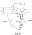
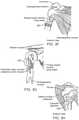
- FIGS. 3A-Hare views of an exemplary prosthesis for anterior displacement of the biceps brachii tendon in the shoulder, wherein FIG. 3A is a perspective view, FIG. 3B is an anterior (front) view, FIG. 3C is a lateral (side) view, FIG. 3D is a posterior (back) view, FIG. 3E is a caudal (top) view, and FIGS. 3F-H are further anterior views with the prosthesis implanted on the humerus;
- FIGS. 3I and 3Jare perspective views of further alternative embodiments employing supplemental fixation/support means
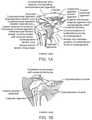
- FIG. 4is a schematic view of the cranial end of the humerus adjacent a shoulder joint with a prosthesis implanted according to an exemplary embodiment of the present invention
- FIG. 5is a schematic view of the cranial end of the humerus adjacent the shoulder joint with a prosthesis implanted according to an alternative exemplary embodiment of the present invention
- FIG. 6is an anterior view of a right humerus illustrating positioning of an implant for treatment of shoulder indications requiring lateral and anterior displacements;
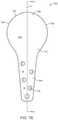
- FIGS. 7A-Iare views of an exemplary prosthesis for lateral displacement of the deltoid muscle in the shoulder in accordance with embodiments of the present invention, wherein FIG. 7A is a perspective view, FIG. 7B is a top view, FIG. 7C is a side view as seen from the anterior side of the implant, FIG. 7D is a side view as seen from the posterior side of the implant, FIG. 7E is a cross-sectional view of the implant sectioned through line A-A of FIG. 7B , FIG. 7F is a cross-sectional view of an alternative embodiment with two portions having different thicknesses, FIG. 7G is a lateral view implanted on the humerus, FIG. 7H is an anterior view implanted on the humerus, and FIG. 7I is a coronal section through the humerus;
- FIG. 8is a view illustrating positioning of an alternative exemplary embodiment of the present invention at the cranial end of the humerus to treat the shoulder;
- FIG. 9is a view illustrating positioning of an alternative exemplary embodiment of the present invention at the cranial end of the humerus to treat the shoulder;
- FIG. 10is a view illustrating positioning of an alternative exemplary embodiment of the present invention at the cranial end of the humerus to treat the shoulder;
- FIGS. 11-25are partial cross-sectional views of the end the humerus adjacent the shoulder illustrating alternative exemplary embodiments of the present invention.
- FIGS. 26A-Bare exemplary embodiments of the bearing unit of a two-part device.
- FIG. 27is an exemplary embodiment of a composite bearing unit of a two-part device.
- Joint conditions that result from or exacerbate unbalanced force distribution through the jointmay be addressed in embodiments of the present invention by interventional techniques involving a redistribution of forces exerted on the joint without the need for highly invasive surgeries requiring significant trauma to the joint and associated muscle and connective tissues.
- increased forcescan be selectively applied to one side of a joint by forcing select muscle and/or connective tissues (target tissues) around a longer, more angled or curved path, or other path different from their pre-treatment, natural path, thus increasing the magnitude, altering the effective direction, and/or changing the moment arm of forces exerted by such muscles or tissues on the joint. This may be accomplished, for example, through the use of appropriately-shaped implants that may be placed under or adjacent selected target tissues relatively non-invasively compared to current surgical techniques for addressing such conditions.
- joint conditions that result from or exacerbate unbalanced force distribution through the jointmay be addressed by interventional techniques involving a redistribution of forces exerted on the joint without the need for highly invasive surgeries requiring significant trauma to the joint and associated muscle and connective tissues. Redistribution of forces within the target joint in accordance with embodiments described herein may thus provide pain relief, slow down articular cartilage degeneration, and/or enhance cartilage regeneration.
- the amount of displacement of the target tissuemay not need to be large in order to provide a substantial therapeutic effect on the target joint.
- displacements of greater than about 5 mm up to about 30 mmmay be sufficient, with displacements in the range of about 10 mm to about 30 mm also suitable, or more specifically about 10-20 mm.
- the specific magnitude and direction of displacementwill depend upon the location and type of disease, the target tissue to be displaced, and other factors.
- Exemplary embodiments of the invention described hereinare particularly directed to treatment of the shoulder, although the principles of the invention may be applied to other joints as described in related co-pending applications and issued patents filed by and/or assigned to the present Applicant.
- specific features described in connection with one exemplary embodimentmay be incorporated in other exemplary embodiments unless otherwise noted.
- the exemplary embodiments describedare thus included to illustrate features of the invention, not limit it. It will be noted by persons of ordinary skill in the art that in some aspects general geometries and methodologies described herein are similar in certain respects to Applicant's prior disclosures with respect to treatment of other joints.
- the shoulderis a three-dimensional joint so the arm rotates anterior/posterior as well as up/down.
- the area of the bearing surface configured to engage target tissue in the shoulderwill typically be larger than in an embodiment configured to treat the knee as described in prior disclosures so target tissue does not slip off the bearing surface when the arm has anterior or posterior orientation.
- advantagesmay be realized by providing a relatively larger bearing surface area to help reduce tissue irritation and/or more broadly distribute load due to the absence of other interfering structures, such as the patella, which may limit implant size and shape.
- the displacement portion and bearing surface in embodiments described herein for treatment of the shoulderwill typically be more symmetrical, particularly in the anterior-posterior direction, as compared to embodiments described in prior disclosures related to treatment of the knee.
- therapeutic effectmeans an effect on a treated joint that reduces forces acting on the articular surfaces, reduces wear, lessens pain, improves stability or provides another positive outcome for the patient whether across the joint as a whole or in particular compartments of the shoulder, knee, or other joint. “Therapeutic effect,” however, does not imply, and should not be understood as requiring, any specific, quantified outcome other than as stated above.
- dorsalrefers to the back of an organism and ventral to the belly. Cranial refers to the head end and caudal to the feet. In humans, anterior is used to indicate the ventral surface and posterior to indicate the dorsal surface. Superior means toward the head and inferior toward the feet.
- Proximalrefers to the end of a structure nearest a major point of reference and distal to the end furthest from a point of reference. The point of reference is usually the origin of a structure (such as a limb). Proximal and distal are relative terms. Medial means nearer the midline of the body and lateral means further from the midline. Superficial refers to structures nearer the skin, and deep to structures further away from the skin.
- a sagittal planedivides the body into right and left (or medial and lateral) parts.
- a frontal (or coronal) planepasses from right to left and divides the body into dorsal and ventral (or posterior and anterior) parts.
- a transverse planepasses perpendicular to the long axis of the body and divides the body into cranial and caudal (head and tail) portions.
- Implants according to embodiments of the present inventionmay be configured and secured in a variety of ways as described below in more detail with respect to exemplary embodiments.
- prostheses or implants according to embodiments of the inventionwill, in preferred embodiments, comprise a fixation portion 704 that provides means for securing or anchoring the prosthesis relative to the joint or tissue, such as holes 716 for bone screws, and a displacement portion 708 configured and dimensioned to displace the target tissue(s) from a pretreatment path as described herein.
- Other means for securing the fixation portionmay include bone ingrowth surfaces, barbs, K-wires, bone cement and other devices known in the art for securing implants to bone.
- the fixation and displacement portionsmay be separated by a spanning section 712 that permits those portions to be separated from each other as appropriate to accommodate the anatomical structures between or near the locations of treatment and fixation.
- the displacement portion 708may be provided with a bearing member of the same or a different material than the underlying substrate.
- two or more of the displacement and fixation portions and spanning sectionmay be merged in whole or in part or may overlay one another.
- thickness of the fixation of the implanttypically ranges from about 2.0 mm to 8.0 mm, more typically from about 2.5 mm to 6.0 mm, and may be from about 3.0 mm to 4.5 mm.
- the thickness of the fixation portion of the implantmay be uniform throughout the implant or may vary, e.g., across the implant. Regions of the fixation portion under higher mechanical load may be thicker than regions under lower mechanical loads. The thickness of the fixation region may also be selected to ensure that the screw-heads used to fix the implant do not protrude over the surface of the implant.
- the spanning sectionmay have thickness similar to that of the fixation portion.
- a principal consideration for spanning sectionis sufficient structural integrity to maintain the displacement portion at the desired treatment position.
- Spanning sectionwill usually be rigid, but in some embodiments it may be desirable for the spanning section to have some flexibility and resilience so that it can deflect under sufficient loads.
- the spanning sectionmay be adjustable in length or angle relative to the fixation portion and/or displacement portion to allow the operator to configure the device optimally for the particular anatomy and condition being treated. In the displacement portion, displacement distance and thickness may be considered separately.
- Displacement distanceis the distance by which the bearing surface of the displacement portion displaces the target tissue beyond the natural anatomical track of the target tissue, in other words, the displacement of tissue created by the implant.
- the thickness of the displacement portionmay or may not be related to the displacement distance.
- the thickness of the materialmay be substantially less than the overall displacement distance.
- a material thickness of 4 or 5 mm in the displacement portionmay provide sufficient structural integrity for a displacement distance of 25 to 30 mm depending on the material selected.
- displacement of the target tissueresults in the decrease in the mechanical load on the articular cartilage in the target joint by at least 5%, more preferably by at least 8%, most preferably by at least 10%.
- Unloading as defined hererefers to a decrease in contact forces, either peak forces or average forces, either measured or calculated, during physical activity that results in mechanical loading of articular cartilage in a joint.
- the displacement distance provided by the displacement portion of the implantmay typically range from greater than about 5 mm to about 30 mm.
- the actual displacement distancewill depend upon the joint being treated, the location and physical characteristics of the target tissue, the severity and location of disease, and other factors.
- displacement distance across the displacement portionmay vary.
- the displacement portionmay be in contact with the underlying tissue and the target soft tissue is displaced by a distance equivalent to the thickness of the displacement portion; thus displacement distance would equal thickness in such an embodiment.
- the displacement portionmay be elevated above the underlying tissue and the target soft tissue is displaced by a distance greater than the thickness of the displacement region; thus displacement distance is greater than thickness.
- the surface of the displacement portionalso may be contoured to have a curved convex surface in contact with the target soft tissue.
- the cross-sectional view of the displacement portionmay look like a semi-circle or a semi ellipse (see, e.g., FIGS. 2A-D ).
- depth (D) of the implantthat governs the magnitude of tissue displacement, e.g., the perpendicular distance from an outermost point on the bearing surface to a point on the fixation surface, that is, the surface of the fixation portion, or the plane in which that surface substantially lies, configured to face the fixation site.
- depth (D)will be measured as perpendicular to a plane tangent to an outer most point on the bearing surface, between that plane and a point on the fixation surface that defines the location of fixation to the bone, for example a centerline of the fixation element(s) such as screw holes, provided in the fixation portion.
- components of the prosthesismay be a compliant material such as an elastomer, capsules filled with water, saline, silicone, hydrogels, etc.
- compliant portionscould be placed in a deflated state and then inflated to the appropriate thickness.
- bearing membersmay be filled with other flowable materials including beads, granules, or other particles made of metal, polymer, or foam material, optionally in a liquid medium, which conform to adjacent bone or tissue surfaces.
- Thixotropic materialssuch as hydrogels derived from hyaluronic acid, change their mechanical properties as shear stress is applied to them.
- Implantsmay be coated with materials to reduce friction such as hydrophilic coatings or polytetrafluoroethylene (PTFE) coatings.
- the prosthesismay be adjustable to allow the dimensions such as thickness of the prosthesis to be adjusted during surgery or any time after surgery.
- Rigid or substantially rigid prosthesesaccording to embodiments of the invention described herein could be made of known bone-compatible implant materials such as titanium or stainless steel. Biocompatible polymers, ceramics, and other materials may also be used.
- the bearing surface of the prosthesesshould be designed to minimize negative effects of movement of the connective tissues across the implant surface, e.g., comprising a smooth, atraumatic, low-friction material, coating or surface treatment.
- Such prosthesescould be implanted arthroscopically or using a mini-open or open surgical approach.
- the displacement portion and the fixation portion of prostheses according to the inventionmay be of unibody construction, or may be formed of two or more distinct parts depending on desired function.
- the fixation portionmay be stainless steel or titanium textured to enhance bony ingrowth and solid screw fixation
- the displacement portioncould be made of a different material, for example, pyrolytic carbon to enhance the ability of overlying tissues to slide across the implant, or PTFE, silicone or other low-friction polymer with suitable wear characteristics to provide a softer bearing surface.
- the displacement portionmay comprise a separate bearing member with a bearing surface on which the target tissue bears. Alternatively the bearing surface may be formed as an integral part of the displacement portion.
- the displacement portioncould be comprised of a substrate of one material with an overlying layer forming the bearing member.
- the substratecould be either attached to or contiguous with the fixation portion.
- the fixation portion of the implantmay have a relief feature to minimize contact with the underlying bone, thereby minimizing disruption of the periosteal layer.
- the bearing member and/or bearing surface in embodiments of the inventionwill be hard and smooth, made from materials such as polished pyrolytic carbon, steel, or titanium, or coated or covered with a lubricious material, such as PTFE.
- a lubricious materialsuch as PTFE.
- the bearing surfacewhich in some cases will comprise the entire displacement portion, be free of screw holes, other hole or gaps, or fixation means generally.
- the bearing surfacemay be designed to encourage adhesion and ingrowth of the connective tissue onto this surface.
- such a surfacemay be porous, roughened, or configured with openings into which bone or scar tissue may grow to enhance adhesion.
- the implantcould be anchored to the underlying bone with suitable fasteners such as screws.
- suitable fastenerssuch as screws.
- unicortical screws, bicortical screws, cancellous screws, cannulated screws, polyaxial screws, screws that lock into the implant, etc.may be used.
- the screw holesmay be locking threads or other locking features.
- the screw holesmay be oriented in different directions to improve the stability of the anchored implant.
- different types of screwsmay be used in different regions of the implant.
- cortical screwsmay be used in the region of an implant in contact with the humeral shaft while cancellous screws may be used in another part of the implant in contact with areas around the humeral tubercles or head.
- supplemental fixationsuch as cancellous bone screws
- fixation by means of bone screws or similar bone-penetrating devicesis not a “cutting” of the bone, the avoidance of which is one advantage of the present invention as elsewhere described.
- implantsmay be configured such that the displacement portion of the implant is separated or spaced apart from the fixation portion of the implant.
- the fixation portion of the implantWith the displacement portion positioned under the target tissue (e.g., biceps brachii tendon), the fixation portion of the implant may be configured to be affixed to the hone at a location that is suitable for securely fixing the implant in place, is accessible to the surgeon, is not covered by the target tissue, and is separated from tendon insertion points and other anatomical features.
- the implantmay have a spanning section shaped and dimensioned to bridge the distance between the fixation portion and the displacement portion.
- the implantsmay be configured to move the tendon anteriorly or medially or anterior-medially or laterally or antero-laterally.
- implantsmay be configured to be changed in size or shape by the physician in situ to the ideal shape and size for the patient's particular condition.
- FIGS. 3A-Hdepict an exemplary prototype of implant 300 for stabilizing or reducing pain in the shoulder.
- Implant 300has a fixation portion 304 having one or more holes 308 for receiving screws for anchoring the implant to bone.
- Fixation portion 304is generally straight and elongated, being configured for positioning in general alignment with the longitudinal axis of the humeral shaft on the lateral side of the humerus.
- a plurality of holes 308are spaced apart longitudinally along fixation portion 304 preferably positioned in approximate alignment with, or on alternating sides of, a longitudinal centerline of fixation portion 304 .
- Displacement portion 312is configured and dimensioned to be positioned under the target tissue. In the embodiment of FIG.
- displacement portion 312extends in a transverse direction relative to fixation portion 304 such that the overall implant has an “L” or “J” shape.
- the displacement portion 312is configured to atraumatically engage the target tissue and displace it anteriorly relative to the bone.
- the displacement portion 312has a length in the lateral-medial direction selected to accommodate the full width of the target tissue so that the target tissue remains engaged along its entire width as it slides on the displacement portion.
- Fixation portion 304will have a length significantly greater than the width W 2 of the displacement portion in the cranial-caudal direction (along the axis of the humeral shaft), usually being at least 2-4 times width W 2 , so as to increase the leverage of the screws used to secure the implant to the bone via holes 308 .
- Displacement portion 312preferably has a convex curvature on its outer tissue-engaging surface (bearing surface), preferably being curved at least around an axis generally parallel to the bone shaft, usually being curved also around an axis perpendicular to the bone shaft, and more preferably being spherical or partially spherical. Displacement portion 312 has a width, typically less than its length in the caudal-cranial direction, selected so that it does not interfere with other tissues, or engage the insertion/attachment points of surrounding soft tissue structures like the pectoralis major muscle or the latissimus dorsi muscle.
- a spanning section 316interconnects fixation portion 304 and displacement portion 312 .
- Spanning section 316extends cranially and laterally from fixation portion 304 to displacement portion 312 , forming a curve of about 90° about a dorsal-ventral axis. Where fixation portion 304 is configured for attachment to a more medial aspect of the bone, spanning section 316 will extend ventrally as well as cranially and laterally from fixation portion 304 , preferably being curved about an axis generally parallel to the bone shaft. Displacement portion 312 appropriately displaces the target tissue in cooperation with the fixation portion 304 and spanning section 316 .
- Displacement of the target tissuecan be altered by changing the length, curvature and angle of the spanning section among other features.
- the angle ⁇ between the displacement portion 312 and the fixation portion 304(as measured at the intersection of the center line axes of the two portions in the top view of the implant in FIG. 3A ) may range from about 80 degrees to 135 degrees, more specifically from about 85 degrees to 120 degrees, and in some embodiments about 90 degrees to 110 degrees. As shown in FIG.
- the width W 1 of the fixation portion 304will be large enough to span a substantial portion of the width of the bone to which implant 300 is affixed and to accommodate one or more screw holes of sufficient size, ranging from about 10 mm to 25 mm, more specifically about 12 mm to 20 mm, and in some embodiments about 14 mm to 18 mm.
- the length L 1 of the fixation portion 304will be selected to accommodate a sufficient number of screw holes in the cranial-caudal direction along the bone, usually at least two and in some embodiments up to five or more, and may range from about 20 mm to 50 mm, more specifically about 25 mm to 45 mm, and in some embodiments about 30 mm to 40 mm. As shown in FIG.
- the width W 2 of the displacement portion 312is selected to provide a broad area of contact with the target tissue to spread the force and reduce wear, while not interfering with joint structures as mentioned above throughout the full range of joint motion.
- Width W 2may thus range from about 10 mm to 25 mm, more specifically about 12 mm to 20 mm, and in some embodiments about 14 mm to 18 mm.
- the length L 2 of the displacement portion 312is selected so that the displacement portion extends under the full width of the target tissue so that the entire width of the target tissue remains in engagement and displaced the desired amount throughout the range of joint motion.
- Length L 2may thus range from about 20 mm to 50 mm, more specifically about 25 mm to 45 mm, and in certain embodiments about 30 mm to 40 mm.
- Implant depth D 1along with the radius of curvature R 1 of the outer surface of displacement portion 312 , shown in FIG. 3E , are selected to optimize target tissue displacement throughout the range of joint motion. Radius of curvature R 1 is usually 20 mm to 35 mm, more preferably 22 mm to 33 mm, and most preferably 25 mm to 30 mm.
- the inferior edge 320 of the spanning section 316can also be curved to minimize or eliminate any contact with the edge of the biceps brachii tendon when implanted to treat conditions in the shoulder.
- the superior surface edge 324 of the displacement portion 312can be curved to allow for easy motion of the tendon during flexion as well as to vary the displacement of the tendon during flexion by varying the region of the implant surface in contact with the tendon at higher flexion angles.
- FIG. 3Fshows the placement of implant 300 on the lateral side of the proximal humerus to stabilize or treat other conditions in the shoulder by displacing the biceps brachii tendon in an anterior direction.
- Fixation portion 304is on the lateral side of the humerus, under the deltoid muscle (see FIG. 3H ).
- Displacement portion 312goes under the long head of biceps brachii tendon as shown in FIGS. 3F and 3H , and displaces the tendon anteriorly.
- FIG. 3Gshows the attachment points of other muscles in that region.
- Displacement portion 312is shaped to avoid the attachment points of the pectoralis major muscle and the latissimus dorsi muscle.
- FIGS. 3I and 3Jillustrate further alternative embodiments employing supplemental support and fixation elements 328 and 332 .
- Implants 336 A and 336 Beach include fixation portion 340 with fixation means such as bone screw holes 344 , spanning section 348 and displacement portion 352 with bearing surface 356 .
- fixation portion 340is generally straight and elongated, being configured for positioning in general alignment with the shaft of the humerus.
- the displacement portion 352is configured to atraumatically engage the tendon and displace it anteriorly relative to the humerus.
- the displacement portion 352has a length in the lateral-medial direction generally selected to accommodate the full width of the tendon so that the tendon remains engaged along its entire width as it slides on the displacement portion.
- Displacement portion 352preferably has a convex curvature on its outer tissue-engaging surface (bearing surface 356 ), preferably being curved at least around an axis generally parallel to the humeral shaft, usually being curved also around an axis perpendicular to the humeral shaft, and more preferably being spherical or partially spherical.
- the bearing surfacemay have other curvatures such as elliptical, parabolic, logarithmic spiral, or other complex curvature.
- supplemental support and fixation tab member 328Positioned at the end of displacement portion 352 on implant 336 A is supplemental support and fixation tab member 328 with at least one bone screw hole 360 .
- tab member 328has no bone screw hole, but simply provides additional surface area resting against the bone surface to stabilize the device and to more widely distribute the pressure of the device due to the force of the tendon against the device.
- an alternative implantsuch as 336 B may be employed.
- displacement portion extension 364extends the displacement portion in a caudal direction around the medial side of the humerus.
- Supplemental support and fixation tab 332is disposed at the caudal and/or medial margin of the extended displacement portion. Placement of an embodiment such as implant 336 B is achieved by positioning the fixation portion on the lateral side of the humeral shaft with the extended displacement portion 364 extending around the tendon to the humerus and back down caudally on the opposite side of the humeral shaft.
- a further bone screw fixation hole(not shown) may alternatively be provided on fixation tab 332
- prosthesis 400provides displacement by inserting a passive, space-occupying implant under a target tissue associated with an articular joint.
- Prosthesis 400comprises a body member 404 that defines displacement portion 408 and fixation portion 412 .
- Displacement portion 408is the portion responsible for displacing the target tissues as required to accomplish altering the moment arm of the surrounding target tissue.
- the bone facing surface of displacement portion 408is preferably shaped to conform to the external shape of the bone surface on which it is secured and may have a hook- or spoon-like shape on its distal end to wrap partially around the end of a bone such as the end of the humerus at the shoulder.
- Displacement portion 408is preferably rounded and smooth on its outer non-bone facing side to provide a smooth surface over which the displaced soft tissues may slide.
- Fixation portion 412is shaped so that it lies more flat under the muscles and tendons along the bone spaced from the treated joint, away from the complexity of the areas adjacent to the joint or bone end, where many different tissues crossover and attachments to bone can occur. This more proximal segment of the bone would allow easier access to the underlying bone and potentially better fixation.
- Fixationcould be achieved by any known means for bone-secured implants, such as bone screws 416 , tacks, anchors or adhesives, to name a few possibilities.
- the implantcould be made from any suitable material, either hard or soft materials. In this case, silicones of varying grades and durometers, titanium, stainless steel or pyrolytic carbon are examples of materials which would be appropriate choices.
- Prosthesis 500shown in FIG. 5 , illustrates an example of such a prosthesis.
- the fixation and displacement portionsare collocated within body member 504 closer to the end of the humerus, for example the humeral head.
- the configuration of the body member with respect to its displacement functionwould be essentially the same as described above.
- Fixationwould also be substantially as previously described, e.g., using screws 508 or other attachment means, except that it is adapted to allow fixation and displacement functions to be collocated.
- apparatus for treating multiple indications with a single implantare disclosed. Examples include treatment of shoulder conditions benefiting from anterior and lateral displacement of target tissues such as the deltoid muscle and biceps brachii tendon.
- FIG. 6depicts an exemplary embodiment of a humeral implant to treat the shoulder.
- the dimensions of the implantwould preferably be similar to the dimensions of the implants to treat single indications described in connection with exemplary embodiments of the present invention discussed herein.
- the fixation portion of a multiple indication treatment implantmay be subject to higher mechanical forces compared to single compartment treatment implants. To withstand the higher mechanical loads, the fixation portion may preferably be thicker, wider or longer as may be selected by a person skilled in the art based on the teachings contained herein.
- fixation portion 600may be used to anchor implant 604 onto the humerus, first displacement portion 608 may displace the biceps brachii tendon and second displacement portion 612 may displace the deltoid muscle.
- the implantis anchored only on the lateral side of the humerus, thereby allowing the implantation procedure to be performed by a single incision.
- the opposite sidemay also be anchored with supplemental fixation 616 using a percutaneous technique, for example, by using a percutaneous screw.
- the displacement of the target tissuecan be altered by changing the thickness, length, curvature and angle of the spanning section and/or displacement portion and other aspects of the implant as described herein.
- First displacement portion 608may be configured to move the tendon anteriorly or medially or anterior-medially or laterally or antero-laterally. This may be accomplished by making one side (lateral or medial) of the displacement surface higher than the other, and/or by forming a track with ridges on one or both sides of the bearing surface to urge the tendon in a lateral or medial direction.
- the inferior region of the displacement sectionsmay be contoured to substantially conform to the curved anterior surface of the humerus.
- First displacement portion 608also may be designed to be in contact with the underlying bone or could be elevated so as to avoid contact with the underlying bone, thereby not disrupting the periosteal layer.
- Spanning section 620may be configured in a general y-shape such that first displacement portion 608 is generally orthogonal the fixation portion 600 .
- the first arm of spanning section 620may extend at an angle laterally and anteriorly from fixation portion 600 .
- First arm of spanning section 620extends first displacement portion 608 out anteriorly to achieve the necessary displacement.
- the spanning section second armalso may be configured to hold the second displacement portion 612 in a position spaced-apart from the underlying surface of the humerus to avoid any connective tissue underneath the displacement portion.
- the spanning sectionsmay also comprise adjustable mechanisms (e.g., a pin, slot, or hinge) to movably or pivotably alter the orientation or angle between the two parts to achieve the appropriate level of tissue displacement.
- FIGS. 7A-Ishow exemplary embodiments of the present invention for displacement of the deltoid muscle.
- FIGS. 7A-Eschematically depict implant 700
- FIG. 7Fdepicts an alternative cross-section
- FIGS. 7G-Ischematically depict implant 700 anchored on the lateral side of the humerus.
- implant 700includes fixation portion 704 to anchor the implant and displacement portion 708 to displace the target tissue, e.g., deltoid muscle.
- the fixation portion and the displacement portionare connected by spanning section 712 . Screw or screws in screw holes 716 in fixation portion 704 secure the implant.
- fixation portion 704is configured and dimensioned for attachment of the implant to the humerus, preferably on the lateral side of the proximal humeral shaft just below the humeral head.
- the implantmay be attached with screws positioned in the screw holes 716 .
- Displacement portion 708the region for displacing the target tissue, typically the deltoid muscle in this embodiment, is connected to fixation portion 704 through spanning section 712 .
- the displacement of the tissuecan be altered by changing the length, shape, and angle of the spanning section 712 , the shape, thickness and orientation of displacement portion 708 , and other aspects of the implant as described herein.
- a material thickness of 4 or 5 mm in the displacement portionmay provide sufficient structural integrity for a displacement distance of 25 to 30 mm depending on the material selected.
- fixation portion 704comprises a generally elongated section of the implant, specifically configured and dimensioned based on patient anatomy to be oriented along the longitudinal axis of the humeral shaft.
- An inner, bone engaging surface 706 of fixation portion 704has a concave curvature about its longitudinal axis generally matching that of the outer surface of the humerus to maximize surface contact between fixation portion 704 and the underlying bone.
- a plurality of screw holes 716are spaced longitudinally along fixation portion 704 and extend through fixation portion 704 such that screws may be inserted through them in a medial direction into the humerus.
- Displacement portion 708is preferably separated or offset from fixation portion 704 .
- spanning section 712extends laterally and cranially from fixation portion 704 to displacement portion 708 .
- Displacement portion 708is attached along its cranial extent to spanning section 712 , with its opposing cauda edge being a free end.
- implant 700may be fixed to the bone only at its caudal end, where fixation portion 704 is located, while remaining unattached to the bone at its free end where displacement portion 708 is located.
- implant 700may have one or more additional fixation portions, such that implant 700 may be secured to the bone at both ends or along its edges.
- Displacement portion 708preferably has an enlarged spoon-like rounded shape similar to the lateral profile of the humeral head adjacent the gleno-humeral joint.
- fixation portion 704has a length selected to extend longitudinally along the bone to which it attached sufficiently to stabilize the implant and to accommodate the desired number of hole(s) to receive screws for anchoring to the bone. The length of fixation portion 704 provides space for multiple screw holes and allows the screw holes to be located a significant distance apart from displacement portion 708 so as to maximize the leverage of the fixation screws in counteracting the force of the tissue on the displacement portion.
- the length of the fixation portionwill be substantially greater than the length from the cranial extent of fixation portion 704 to the cranial edge 732 of displacement portion 708 , with the fixation portion length being generally in the range of 25 mm to 55 mm in exemplary embodiments.
- Displacement portion 708preferably has a convex curvature on its outer or lateral side (bearing surface 720 ), and a concave curvature on its inner side 730 .
- Displacement portion 708has an outer bearing surface 720 , which engages the target tissue (e.g., deltoid muscle). Bearing surface 720 typically will be smooth, rounded and low-friction to minimize wear and trauma to the tissue targeted for treatment.
- bearing surface 720is free of significant ridges, bumps, voids, holes or other discontinuities of the kind that would cause abrasion or wear of the target tissue, particularly larger holes or channels for fixation devices such as screws or K-wires.
- Bearing surface 720may comprise simply a smoothed and/or polished region of displacement portion 708 , or it may comprise a coating or layer of a different material, e.g., a lubricous biocompatible polymer.
- bearing surface 720may have holes, protuberances, a polymeric or drug coating, or other features to promote adhesion with the displaced target tissue such that movement between the target tissue and implant 700 is minimized.
- the inner and outer surfaces of the displacement portionhave curvature about multiple axes, and may be generally or partially spherical.
- the radius of curvature of the outer surfaceis selected to provide the optimal displacement of the target tissue throughout the range of motion of the shoulder joint (flexion/extension, abduction/adduction, internal/external rotation).
- the shape and curvature of the outer surfacewill be selected such that the target tissue is under a substantially constant magnitude of displacement throughout the range of joint motion, while in other embodiments, the shape and curvature of the outer surface will be selected to displace the tissue more in certain portions of the range of motion, while reducing the displacement in other regions of the range of motion.
- Curvature of the outer surface of displacement portion 708is usually at a radius in a range of about 15 mm to 35 mm. The curvature of the surface may also be selected to avoid contact with the acromion during shoulder abduction.
- Displacement portion 708may be cantilevered or suspended by spanning section 712 in a plane laterally displaced from or angled relative to fixation portion 704 such that it is spaced apart from the lateral surface of the bone when the implant is fixed in its implanted position. This provides space between humeral head and the displacement portion through which non-target soft tissues may reside and/or move without interference.
- spanning section 712extends laterally and cranially at an oblique angle relative to fixation portion 704 such that a plane tangent to the surface of the spanning section 712 is disposed at an angle in the range of about 30° to 60° relative to a centerline through fixation portion 704 .
- Spanning section 712may be substantially rigid such that displacement portion 708 remains stationary relative to the humerus under the loads exerted by the deltoid muscle.
- spanning section 712 and/or displacement portion 708may have some degree of flexibility so as to allow some movement of displacement portion 708 relative to the bone under certain loads.
- spanning section 712may have a flexibility selected such that if loads on displacement portion 708 exceed a preselected threshold, spanning section 712 will flex to allow displacement portion 708 to be deflected relative to the bone to which it is affixed.
- the anterior edge 724 and the posterior edge 728 of the implantare also preferably convexly curved.
- the proximal, anterior and posterior edges of the displacement section 708are shaped to form a continuous arc similar to the lateral profile of the humeral head viewed in the sagittal plane.
- the proximal, anterior and posterior edges of the displacement section 708are shaped to form an arc viewed in the transverse plane.
- the inside surface 730 of the displacement portion 708is preferably concave with a spoon-like shape to minimize contact with underlying soft tissue including lateral ligaments, the joint capsule, rotator cuff, etc.
- the cranial edge 732 of the spoon-like surfacemay also be shaped arcuately to minimize tissue irritation in general, and more specifically to avoid contact with the acromion during shoulder abduction.
- the general dome shape of the displacement portionmay curve down further along the cranial edge as shown so as to ride under the acromion as depicted in FIGS. 7G-I .
- the bearing surfacemay have a first curvature about an axis transverse to the humeral shaft, and the cranial edge of the displacement portion may curve inwardly/medially toward the humeral head about a second axis parallel to the first axis with a curvature having a second radius less than the first radius.
- the cranial edgealso may be tapered in thickness to slide under the acromion, or alternatively shorter in the cranial direction or cut off on the cranial edge so it does not engage (is spaced laterally and/or caudally from) the acromion during arm abduction.
- This latter alternativemay be accomplished, for example, by providing the dome-shaped displacement portion as a flattened side or concave area on the cranial edge in an area adjacent the cranial edge.
- the fixation portion 704is tapered from the cranial end to the caudal end. In other embodiments, the fixation portion 704 may have constant width. In the exemplary embodiment as shown, the width of the displacement portion 708 is substantially larger than the width of fixation portion 704 , contributing to the overall spoon-like or paddle-like shape of implant 700 .
- the curvature and offset of the displacement portion 708may be configured to displace the target tissue, e.g., the deltoid muscle laterally or antero-laterally.
- the implantis placed on the lateral side of the humerus such that fixation portion 704 is substantially aligned with the humeral shaft, the spanning section 712 is in close apposition to a region of the humeral head, and the displacement portion 708 substantially covers or lies generally parallel to the humeral head.
- the top view of the implantwould mirror the lateral view of the proximal humerus, wherein the implant has a shaft region similar to the humeral shaft, an expanding neck region and a circular or oval or elliptical region similar to the coronal section of the humeral head.
- implant 700is configured to be rigid through the entire range of lateral loads such that the displacement portion of the implant remains substantially stationary relative to the humerus to which the implant is anchored.
- the rigidity of the implantcould be altered by choice of material, increasing the thickness of the entire implant or increasing the thickness of certain regions of the implant.
- the implantmay be designed to provide some flexibility at the higher loads experienced during lifting, throwing, or pushing heavier loads. The flexibility of the implant could result in the displacement portion of the implant bending closer to the humeral head at higher loads.
- an alternative exemplary implantis shown in FIG. 7F with two different possible thicknesses for spanning section 712 .
- the implantis still anchored to the humerus through fixation portion 704 and displacement portion 708 is connected to the fixation portion through the spanning section 712 .
- Spanning section 712may be formed with relatively thicker and thinner parts (as shown at 741 , 742 ), allowing the rigidity of the implant to be selected to provide the desired degree of deflection as it is subjected to a load due to the deltoid muscle crossing the displacement section 708 .
- the thickness of the spanning sectioncould be varied to have a rigid implant or a flexible compliant implant in the range of mechanical loads on the displacement portion.
- the thickness of the entire implantcould be varied to have a rigid implant or a flexible compliant implant.
- the elevated displacement portion 708enables retaining the bursa and also avoids contact with the attachment of the rotator cuff to the humeral head.
- the bursa(shown in FIG. 3H ) covers the attachment of the rotator cuff.
- FIGS. 7G and 7Hshow lateral and anterior views, respectively, illustrating positioning of implant 700 with the attachment region of the supraspinatus muscle (part of the rotator cuff) just cranial to displacement portion 708 when secured at a fixation site on the lateral, proximal humeral shaft as shown.
- the space created between the humeral head and displacement portion 708 as a result of the elevated or cantilevered configuration of the implantmay be best seen in the cross-sectional view of FIG. 7I . There it can be seen how this space accommodates a lateral/caudal-most portion of the Subdeltoid bursa.
- the size of the implant(as seen in the top view) would be proportionally smaller than the lateral profile of the proximal humerus, preferably about 5% to 25% smaller, or more preferably 10% to 20% smaller.
- the implants described abovemay be implanted in areas adjacent to the joint such that the soft tissue is displaced in a region it crosses the joint.
- the devicecould be implanted further away from the joint and displace the target soft tissue in a region that it is not crossing the joint.
- the devicecould be implanted proximally on the lateral humerus close to the humeral head to displace the deltoid muscle or the device could be implanted more distally along the humeral shaft where it displaces the deltoid muscle in a region away from the joint.
- FIG. 8depicts an alternative exemplary two-piece implant 800 according to an embodiment of the present invention wherein the two pieces are independent of each other and articulate over each other during joint motion.
- Fixation portion 804 of implant 800is the fixed section of the implant and is attached to the bone with screw or screws 808 .
- Displacement portion 812includes a mobile bearing member 816 that bears upon fixed surface 820 of displacement portion 812 . With this configuration, mobile bearing member 816 may be attached to the target soft tissue T.
- Either fixation portion 804 or displacement portion 812 , or bothmay have a shape and size selected to displace mobile bearing 816 , and thus tissue T, the desired degree.
- Mobile bearing member 816may be attached to the soft tissue using sutures, adhesives, pins, wires, bands, etc., or otherwise as described above, including having the surface in contact with the soft tissue modified to enable tissue integration.
- the articulating surfaces between parts 812 and 816also may have features like grooves to enable one surface to track a fixed path during flexion. The surfaces could be coated to minimize friction and wear.
- the mobile sectionis attached to or embedded in the deltoid muscle. In other embodiments, the mobile section may be attached or embedded into the tendon or any other soft tissue surrounding the target joint.
- bearing member 816may comprise a soft, flexible, polymer membrane which can conform to the soft tissue and prevent contact between the soft tissue and the implant surface 820 .
- bearing member 816may be inflatable, or include a capsule as previously described.
- implantsmay also be fabricated in-situ by layering a polymerizing material on the underlying tissue such as in the embodiments of FIGS. 9 and 10 .
- an implantcould be contoured as needed by varying the material being layered in different regions of the implant.
- Removable molds or formsmay be placed through an incision to the desired location against the bone to facilitate containment and shaping of the material prior to solidifying.
- implant 900includes layers 904 , 908 and 912 , layered on top of each other to achieve the necessary displacement. The materials and the properties of each of the layers could be identical or different.
- layer 904may have adhesive properties to attach to the underlying bone
- layer 908may have high compressive strength to withstand the compressive load of the overlying soft tissue
- layer 912may have a smooth hydrophilic surface to minimize friction between the implant and the soft tissue during flexion/extension.
- layer 904provides the fixation portion and layer 912 the displacement portion with layer 908 forming a spanning section therebetween.
- Adhesivesmay be used between the various layers. The materials could be polymerized in-situ using chemical crosslinkers, photo-initiated crosslinkers, thermally initiated crosslinkers, etc. The thicknesses of the various layers could be altered to achieve the necessary level of tissue displacement.
- a spacer 1000may be used to assist in fabricating the implant.
- the spacer 1000could potentially be removed after the implant has been fabricated or may dissolve after the implant is installed, leaving behind a gap (G) between section 904 and the underlying soft tissue and bone.
- the implant and/or spacermay be designed to rest permanently on the underlying soft tissue and bone.
- the inferior surface of the displacement portionis elevated off the underlying tissue.
- the underlying tissuecould be bone or soft tissue like tendon, muscle, ligament, bursa, capsule, etc.
- FIG. 11depicts an implant 1100 with the inferior surface 1104 of the displacement section 1108 elevated off the underlying tissue. Elevating the inferior surface off the underlying tissue could be beneficial by minimizing interference with or damage to soft tissue, reducing any potential restriction to joint motion due to compression of soft tissue, etc.
- the displacement regionwill have a continuous bearing surface which is in contact with the target connective tissue (muscle, tendon, ligament, etc.) and is devoid of any discontinuities.
- Such discontinuitiesare usually undesirable as they create voids and interruptions in the smooth bearing surface, may have sharp edges or transitions, and may cause wear or abrasion of the displaced target tissue.
- Discontinuitieswould include fixation channels for long-term fixation like screw holes, holes for sutures, etc., as well as fixation channels for temporary fixation like holes for Kirschner-wires (K-wires).
- FIG. 11depicts an implant 1100 with a displacement section 1108 with a superior bearing surface 1112 and an inferior surface 1104 .
- Displacement section 1108is free of discontinuities in the bearing surface, such as holes that extend from the superior bearing surface 1112 to the inferior surface 1104 or those that extend from the superior bearing surface 1112 part way to the inferior surface 1104 .
- the lack of discontinuities in the bearing surfaceminimizes the potential for wear or irritation of the target connective tissue.
- the bearing surface of the displacement sectionmay be polished, coated, covered, or modified in other ways to minimize wear of the bearing surface and/or wear of the target connective tissue.
- the bearing surface of the displacement region which is in contact with the target connective tissuemay have features that enable adhesion or attachment of the target connective tissue to the bearing surface. Attachment of the target connective tissue on the implant surface may minimize motion of the tissue across the implant surface during joint motion. These features would include channels for formation of fibrous tissue from the target connective tissue anchoring the connective tissue to the displacement surface of the implant.
- FIG. 12depicts an implant 1200 with channels 1204 that extend from the superior bearing surface 1208 to the inferior surface 1212 .
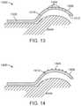
- FIG. 13depicts an implant 1300 with channels 1304 extending from the superior bearing surface 1308 part way to the inferior surface 1312 .
- the channels 1204 and 1304may have varying cross-sectional shapes, e.g., square, circle, rectangle, oval, etc., with the largest cross-sectional dimension (for example, diameter of the circle, diagonal of a square or rectangle, major diameter of an oval, etc.) and will be dimensioned to promote adhesion and ingrowth of the target tissue, usually ranging from less than 1 mm to about 5 mm.
- the channelsmay be located across the entire bearing surface or across part of the bearing surface.
- the displacement regionmay have one channel.
- the displacement regionmay have two channels.
- the displacement regionmay have three channels.
- the displacement regionmay have more than three channels.
- the channelsmay vary in depth across the bearing surface. The dimensions and cross-sectional shape of the channels across the displacement region may be identical or different.
- the spanning section (e.g., 1216 and 1316 ) and/or the fixation section (e.g., 1220 and 1320 )may also have similar features for attachment of the target connective tissue.
- a region of the displacement sectionmay have features for attachment of target connective tissue.
- FIG. 14depicts an implant 1400 with projections 1404 on the superior surface 1408 of the displacement section 1412 .
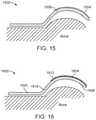
- FIG. 15depicts an implant 1500 with ridges on the superior surface 1504 of the displacement section 1508 .
- FIG. 16depicts an implant 1600 with a porous or granular surface 1604 on the superior surface 1608 of the displacement section 1612 .
- the spanning sectione.g., 1616
- the fixation sectione.g., 1620
- a region of the displacement sectionmay have features for attachment of target connective tissue.
- the inferior surface of the displacement regionmay be in contact with the underlying tissue.
- FIG. 17depicts an implant 1700 with the inferior surface 1704 of the displacement section 1708 in contact with the underlying tissue. In other embodiments, part of the inferior surface of the displacement section may be in contact with the underlying tissue.
- the inferior region of the displacement portion, spanning portion, or fixation portionmay have features like channels for fibrous or bony tissue ingrowth to enable adhesion or attachment of the underlying tissue to the bearing surface.
- the inferior regionmay have features like projections, microprojections, bumps, ridges, pin-like projections, granular surface, etc. Attachment of any soft connective tissue underneath the inferior surface of the displacement region may minimize motion of the tissue under the implant during joint motion.
- the inferior surfacemay have pins for anchoring the implanting into underlying bone.
- FIG. 18depicts an implant 1800 with holes or channels 1804 in the inferior portion 1808 of the displacement section 1812 .
- the holes or channels 1804may have varying cross-sectional shapes, e.g., square, circle, rectangle, oval, etc., with the largest cross-sectional dimension (for example, diameter of the circle, diagonal of a square or rectangle, major diameter of an oval, etc.) ranging from less than 1 mm to about 5 mm.
- the holes or channelsmay be distributed across the entire inferior surface or across part of the inferior surface of the displacement section.
- the holes or channelsmay extend entirely through the thickness of displacement section 1812 , but in preferred embodiments extend only partially through the thickness (e.g., in blind holes or channels) such that the outward-facing bearing surface of displacement section 1812 is continuously smooth and uninterrupted by such holes, channels, or other discontinuities.
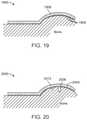
- FIG. 19depicts an implant 1900 with projections 1904 from an inferior surface of the displacement section 1908 .
- FIG. 20depicts an implant 2000 with pins 2004 and 2008 from the inferior surface of the displacement section 2012 .
- Such projections or pinsmay encourage tissue adhesion as well as stabilize the displacement portion and restrain it from motion relative to the underlying bone.
- the devicemay be a two-part device with the first part (base unit) comprising the fixation section, the displacement section (and optionally, the spanning section), and the second part (bearing unit) configured to attach to the displacement section of the base unit.
- the bearing unitmay be configured to attach to the spanning section and to cover the displacement section of the base unit.
- the bearing unitmay be configured to minimize tissue wear or to enable tissue adhesion or attachment.
- the displacement section and the bearing unitwould have features to attach the two units.
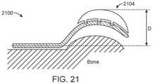
- FIG. 21depicts an exemplary two-part implant with a base unit 2100 and a bearing unit 2104 .
- FIG. 23depicts another exemplary embodiment of a two-part implant with a bearing unit 2300 slipped over the displacement section of the base unit 2304 so as to cover the superior surface, the cranial end, and at least a portion of the inferior surface of the displacement section. Attachment of the bearing unit would increase the depth of the composite implant D ( FIGS. 21, 22, and 23 ). To alter the depth of the composite implant, bearing units of different dimensions D 3 and D 4 ( FIGS.
- the bearing unitmay be attached intra-operatively to a base unit before it is anchored to the target site or to a base unit that has been anchored to the target site on the humerus to obtain the necessary target connective tissue displacement.
- the bearing unitmay cover the entire displacement section of the base unit. In other embodiments, the bearing unit may cover part of the displacement region. In some embodiments, the bearing unit 2200 may extend beyond the displacement section of the base unit 2204 ( FIG. 22 ).
- the bearing unitmay be rigid or may comprise a rigid base 2700 with a compliant surface 2704 ( FIG. 27 ).
- the displacement regionmay have channels to assist in positioning, placement or temporarily anchoring of the implant intra-operatively.
- FIG. 24depicts an implant with channels 2400 in the displacement section 2404 to assist in positioning of the implant during a percutaneous or minimally invasive surgery.
- FIG. 25depicts an implant with channels 2500 and 2504 in the displacement section 2508 to assist in positioning of the implant during a percutaneous or minimally invasive surgery.
- the channels in the implants shown in FIGS. 24 and 25may be covered with caps (e.g., 2512 , 2516 ) configured to fit into the channels to render the bearing surface of the displacement region completely smooth and substantially devoid of any discontinuities.
- the dimensions of the exemplary embodiments abovecan be altered to address differences in joint size, level of the tissue displacement, etc., as well as to enable positioning and securing the implant at the surgical site while minimizing trauma to the surrounding bone, tendons, muscles, ligaments and other anatomical structures.
- a further aspect of the present inventionincludes methods for treating the shoulder, including reducing pain and/or increasing stability by implanting prostheses as described herein.
- One exemplary methodthus comprises selecting at least one of the associated muscle and connective tissues surrounding a joint as target tissue for treatment, displacing the target tissue without severing the bones or target tissue, and altering the kinematics of the joint thereby.
- altering the kinematics of the jointachieves a therapeutic effect as described herein.
- altering the kinematics of the jointredistributes loading in the joint and/or reduces loading on the ligaments within the joint and/or tendons adjacent the joint (e.g., rotator cuff or portions thereof).
- prostheses according to the present inventionmay be placed with therapeutic effect without rupturing the joint capsule and without any portion of the implant entering the joint capsule.
- the implants of the inventionmay be implanted without cutting, removing, or reshaping any bones, other than drilling holes to receive fixation screws or other devices.
- methods of treatment in accordance with the present disclosurewill involve a pretreatment assessment of the joint and conditions to be addressed, for example, alterations in loading, pain reduction, stability enhancement, or combinations of such symptoms.
- Assessmentwill allow the treating physician to determine the most appropriate fixation site on appropriate bones associated with the joint to be treated, which, in the case of the shoulder, will typically be the humerus, and in many situations, more specifically a site disposed on the lateral, proximal humeral shaft adjacent the humeral head.
- Assessmentalso will involve a determination of the target tissue to be treated and the amount the target tissue is to be displaced from its natural, anatomical path in order to achieve the desired therapeutic effect.
- the prosthesesmay be specifically configured and dimensioned to address the anatomy of the joint to be treated for a particular patient. With respect to treatments of the shoulder, this will typically involve configuring a fixation portion of the implant specifically to be secured at a selected fixation point on the humeral surface and configuration of a displacement portion to insert under and engage the targeted tissue by an amount consistent with the needed displacement as determined in assessment. Configuration to properly position the displacement portion may also require a specific configuration of a spanning section as described herein in cooperation with the configuration of the displacement portion.
- the appropriately configured and dimensioned prosthesismay be implanted following accepted, less invasive surgical techniques. Such a surgery would typically involve an appropriately placed entry incision to gain access to the fixation site, while avoiding rupture of the joint capsule or positioning of the implant that would cause it to penetrate into the capsule. Based on the unique configuration of prostheses as described herein, surgical implantation and treatment by displacement of targeted tissue is accomplished without cutting or repositioning the bones associated with the joint to be treated. In this context, as previously mentioned and consistent with the less invasive approach of the present invention, the comparatively minor intrusion into the bone by bone screws or similar fixation means to secure the implant at the fixation site is not considered a cutting of the bone.
- the engagement with and displacement of the target tissueoccurs concomitantly with placement and fixation of the implant at the fixation site.
- the surgical incisionmay be closed in accordance with standard orthopedic surgical practices.
- Post-operative physical therapymay be prescribed as appropriate, however it is anticipated that in most cases the therapeutic benefit of the prosthesis will be felt essentially immediately post-operatively or at least as soon as the initial surgical side effects of pain and swelling diminish.
- displacement of the target tissueresults in the decrease in the mechanical load on targeted regions of the articular cartilage in the shoulder joint by at least 5%, more preferably by at least 8%, most preferably by at least 10%.
- Unloading as defined hererefers to a decrease in contact forces, either peak forces or average forces, either measured or calculated, during physical activity that results in mechanical loading of articular cartilage in a joint.
- the devices of the present inventionmay be used to displace any of the muscles and connective tissues around the shoulder to achieve a therapeutic effect.
- the tendon associated with any of the musclescould be displaced.
- the inventionmay also have application to treatment of focal defects caused by trauma or other reasons.
- the devices and methods of the inventioncould be used in conjunction with other therapies used to treat focal and diffuse lesions on the humeral head.
- the device for unloading a region of the humeral headcould be used in conjunction with microfracture or autologous chondrocyte implantation (ACI) therapy of a focal cartilage lesion on the humeral head.
- ACIautologous chondrocyte implantation
- devices and methods of the inventioninclude use in conjunction with labral repair treatment (e.g., suture anchors) to reduce loading on the repaired labrum.
- labral repair treatmente.g., suture anchors
- a device of the inventioncould be implanted surgically to anteriorly displace the biceps brachii long head. By increasing the moment arm of the biceps brachii tendon, the anterior stability of the shoulder could be increased.
- the load on the repaired glenoid labralmay be reduced thereby reducing the risk of failure or re-tearing of the repaired labrum.
- Devices and methods of the inventioncould be used in conjunction with rotator cuff repair treatment (sutures, tacks, suture anchors, patches, membranes, etc.).
- a device of the inventioncould be implanted surgically to laterally displace the deltoid muscle.
- the load of the rotator cuffmay be reduced during shoulder abduction, thereby reducing the risk of failure or re-tearing of the repaired rotator cuff and/or reducing pain due to the mechanical strain on the rotator cuff tissue.
- devices and methods of the inventioncould be used to treat rotator cuff injury, pain, tear, etc.
- a device of the inventioncould be implanted surgically to laterally displace the deltoid muscle.
- the load of the rotator cuffmay be reduced during shoulder abduction, thereby reducing pain due to the mechanical strain on the rotator cuff.
- another applicationis in use for treating shoulder laxity as an alternative or adjunct to capsular imbrication and thermal capsular shrinkage (capsulorrhaphy).
- Another applicationincludes use in conjunction with total shoulder replacement devices including reverse shoulder replacement devices to alter the mechanical forces on the new joint, thereby increasing the stability of the replaced joint and reducing the risk of implant wear.
- implants of the present inventioncould be implanted on the proximal humerus to increase the moment arm of the surrounding soft tissue, and thereby, improve the mechanical impact of the surrounding tissue on shoulder stability.
- implants of the present inventioncould be implanted simultaneously while performing another surgery (e.g., rotator cuff tear repair, shoulder replacement, etc.), the implant may also be surgically placed in a subsequent surgery.
- the implants of the present inventioncould be used as a permanent implant (for example, implant that survives in a patient for more than five years) or a temporary implant.
- implants of the present inventionmay be used as a temporary adjunct to improve the outcome of another procedure.
- the implant used in conjunction with an anterior labral tear repairmay be removed once the repaired labrum has healed.
- the inventionmay further be adapted to displace tissues acting on various other joints so as to reduce or otherwise alter loads therein, including the elbow, shoulder, wrist, fingers, spine, ankle, interphalangeal joints, jaw or other joints.
- the implants of the inventionmay be configured for attachment to the acetabulum, vertebrae of the spine, scapula, humerus, radius, ulna, carpals, metacarpals, tarsals, metatarsals, talus or other bones of the foot, among other bones.
- the conjunctive phrases in the foregoing examples in which the conjunctive list consists of X, Y, and Zshall each encompass: one or more of X; one or more of Y; one or more of Z; one or more of X and one or more of Y; one or more of Y and one or more of Z; one or more of X and one or more of Z; and one or more of X, one or more of Y and one or more of Z.
Landscapes
- Health & Medical Sciences (AREA)
- Orthopedic Medicine & Surgery (AREA)
- Life Sciences & Earth Sciences (AREA)
- Surgery (AREA)
- Animal Behavior & Ethology (AREA)
- Veterinary Medicine (AREA)
- Public Health (AREA)
- Engineering & Computer Science (AREA)
- Biomedical Technology (AREA)
- Heart & Thoracic Surgery (AREA)
- General Health & Medical Sciences (AREA)
- Molecular Biology (AREA)
- Medical Informatics (AREA)
- Nuclear Medicine, Radiotherapy & Molecular Imaging (AREA)
- Neurology (AREA)
- Prostheses (AREA)
- Cardiology (AREA)
- Oral & Maxillofacial Surgery (AREA)
- Transplantation (AREA)
- Vascular Medicine (AREA)
Abstract
Description
Claims (17)
Priority Applications (1)
| Application Number | Priority Date | Filing Date | Title |
|---|---|---|---|
| US16/431,385US11241256B2 (en) | 2015-10-15 | 2019-06-04 | Method and apparatus for altering biomechanics of the shoulder |
Applications Claiming Priority (3)
| Application Number | Priority Date | Filing Date | Title |
|---|---|---|---|
| US201562242099P | 2015-10-15 | 2015-10-15 | |
| US15/295,677US10349980B2 (en) | 2009-08-27 | 2016-10-17 | Method and apparatus for altering biomechanics of the shoulder |
| US16/431,385US11241256B2 (en) | 2015-10-15 | 2019-06-04 | Method and apparatus for altering biomechanics of the shoulder |
Related Parent Applications (1)
| Application Number | Title | Priority Date | Filing Date |
|---|---|---|---|
| US15/295,677DivisionUS10349980B2 (en) | 2009-08-27 | 2016-10-17 | Method and apparatus for altering biomechanics of the shoulder |
Publications (2)
| Publication Number | Publication Date |
|---|---|
| US20190282273A1 US20190282273A1 (en) | 2019-09-19 |
| US11241256B2true US11241256B2 (en) | 2022-02-08 |
Family
ID=67904704
Family Applications (2)
| Application Number | Title | Priority Date | Filing Date |
|---|---|---|---|
| US15/295,677Active2031-05-08US10349980B2 (en) | 2009-08-27 | 2016-10-17 | Method and apparatus for altering biomechanics of the shoulder |
| US16/431,385Active2037-03-04US11241256B2 (en) | 2015-10-15 | 2019-06-04 | Method and apparatus for altering biomechanics of the shoulder |
Family Applications Before (1)
| Application Number | Title | Priority Date | Filing Date |
|---|---|---|---|
| US15/295,677Active2031-05-08US10349980B2 (en) | 2009-08-27 | 2016-10-17 | Method and apparatus for altering biomechanics of the shoulder |
Country Status (1)
| Country | Link |
|---|---|
| US (2) | US10349980B2 (en) |
Families Citing this family (15)
| Publication number | Priority date | Publication date | Assignee | Title |
|---|---|---|---|---|
| US10349980B2 (en) | 2009-08-27 | 2019-07-16 | The Foundry, Llc | Method and apparatus for altering biomechanics of the shoulder |
| US9861408B2 (en) | 2009-08-27 | 2018-01-09 | The Foundry, Llc | Method and apparatus for treating canine cruciate ligament disease |
| CA2771332C (en) | 2009-08-27 | 2020-11-10 | Cotera, Inc. | Method and apparatus for force redistribution in articular joints |
| US9278004B2 (en)* | 2009-08-27 | 2016-03-08 | Cotera, Inc. | Method and apparatus for altering biomechanics of the articular joints |
| EP3049003B1 (en)* | 2013-09-26 | 2019-09-04 | Matthew Hansen | Prosthetic augments to improve muscle mechanics |
| TR201800344A2 (en)* | 2018-01-10 | 2018-03-21 | Tobb Ekonomi Ve Teknoloji Ueniversitesi | AN ACROMIOCLAVICULAR JOINT PLAQUE |
| CN108354654B (en)* | 2018-03-27 | 2020-06-30 | 中国人民解放军陆军总医院 | Circular groove periosteal peeler |
| FR3085836A1 (en)* | 2018-09-19 | 2020-03-20 | Assistance Publique - Hopitaux De Paris | IMPLANT OF LATERALIZATION AND TENSIONING OF THE DELTOID MUSCLE |
| EP3911280A1 (en) | 2019-01-15 | 2021-11-24 | Biopoly, Llc | Implant systems for repair of a humeral head |
| EP3911281A1 (en)* | 2019-01-15 | 2021-11-24 | Biopoly, Llc | Implant systems for repair of a glenoid cavity |
| US10398571B1 (en)* | 2019-01-29 | 2019-09-03 | Matthew D. Clayton | Protective cover for a prosthetic implant |
| CN110755179A (en)* | 2019-10-31 | 2020-02-07 | 上海市第六人民医院 | Prosthesis for shoulder joint |
| EP4059476A4 (en)* | 2019-12-27 | 2022-11-23 | Shanghai Endophix Co., Ltd. | ROTATOR CUFF BALLOON |
| CN111096824B (en)* | 2020-01-07 | 2025-05-09 | 上海竞捷医疗科技有限公司 | Rotator Cuff Balloon |
| US11559402B2 (en) | 2020-02-04 | 2023-01-24 | Medos International Sarl | Soft glenoid awning and related repair procedures |
Citations (541)
| Publication number | Priority date | Publication date | Assignee | Title |
|---|---|---|---|---|
| US2632440A (en) | 1947-12-17 | 1953-03-24 | John M Hauser | Leg brace joint and lock |
| US2877033A (en) | 1956-03-16 | 1959-03-10 | Dreher Mfg Company | Artificial joint |
| US3242922A (en) | 1963-06-25 | 1966-03-29 | Charles B Thomas | Internal spinal fixation means |
| US3648294A (en) | 1969-02-08 | 1972-03-14 | Esfandiar Shahrestani | Endoprostheses, especially for hip joints |
| US3681786A (en) | 1970-07-13 | 1972-08-08 | Medical Eng Corp | Solid human prosthesis of varying consistency |
| US3779654A (en) | 1971-08-06 | 1973-12-18 | R Horne | Artificial joint |
| US3872519A (en) | 1974-04-04 | 1975-03-25 | Nicholas J Giannestras | Total ankle prosthesis |
| US3875594A (en) | 1973-08-27 | 1975-04-08 | Dow Corning | Surgically implantable prosthetic joint having load distributing flexible hinge |
| US3879767A (en) | 1972-01-26 | 1975-04-29 | Cutter Lab | Prosthesis for articulating body structures |
| US3886599A (en) | 1974-07-25 | 1975-06-03 | Schlein Louis Charles | Surgically implantable total ankle prosthesis |
| US3889300A (en) | 1974-08-28 | 1975-06-17 | Wright Mfg | Articulated two-part prosthesis replacing the ankle joint |
| US3902482A (en) | 1974-05-21 | 1975-09-02 | George A Taylor | Mechanical joint for an orthopedic brace or prosthesis |
| US3964106A (en) | 1975-03-03 | 1976-06-22 | Physical Systems, Inc. | Three-part total knee prosthesis |
| US3985127A (en) | 1975-06-11 | 1976-10-12 | Mstislav Vasilievich Volkov | Apparatus for surgical treatment of the knee joint |
| US3988783A (en) | 1976-01-21 | 1976-11-02 | Richards Manufacturing Company, Inc. | Prosthetic collateral ligament |
| US4007495A (en) | 1976-05-28 | 1977-02-15 | Frazier Calvin H | Patello-femoral prothesis |
| US4041550A (en) | 1976-07-30 | 1977-08-16 | Frazier Calvin H | Artificial patella and method of repairing a natural patella |
| US4052753A (en) | 1976-08-02 | 1977-10-11 | Dedo Richard G | Knee spacer and method of reforming sliding body surfaces |
| US4054955A (en) | 1976-01-29 | 1977-10-25 | Arnold Ivanovich Seppo | Orthopaedic endoapparatus designed to grow a new live shoulder and hip joint, to reconstruct a deformed joint or to restore a pathologically dysplastic and congenitally luxated joint |
| SU578063A1 (en) | 1971-05-20 | 1977-10-30 | Seppo Arnold | Orthopedic endoapparatus for restoring hip joint |
| SU578957A1 (en) | 1976-03-30 | 1977-11-05 | Pozdnikin Yurij | Method of reconstruction of cotyloid cavity at dysplasia of hip joint |
| US4069518A (en) | 1976-08-31 | 1978-01-24 | Groth Jr Harry E | Total ankle prosthesis |
| SU624613A1 (en) | 1977-05-10 | 1978-09-25 | Tikhonenkov Egor S | Method of treating congenital femur dislocation |
| SU640740A1 (en) | 1977-07-12 | 1979-01-05 | Предприятие П/Я В-2769 | Arrangement for developing mobility of the joint of lower extremities |
| US4156944A (en) | 1976-11-15 | 1979-06-05 | Sulzer Brothers Limited | Total ankle prosthesis |
| US4158894A (en) | 1978-03-13 | 1979-06-26 | Worrell Richard V | Patellar prosthesis and method of implanting the same |
| US4164793A (en) | 1978-04-26 | 1979-08-21 | Swanson Alfred B | Lunate implant |
| SU704605A1 (en) | 1978-03-14 | 1979-12-25 | Е. С. Тихоненков и С. . И. Федоров | Method of fixing fragments of the femur after intertrochanteric and supratrochateric osteotomy |
| US4187841A (en) | 1978-07-07 | 1980-02-12 | Knutson Richard A | Bone compression or distraction device |
| SU719612A1 (en) | 1977-10-28 | 1980-03-05 | Tikhonenkov Egor S | Method of recessing cotyloid cavity |
| SU741872A1 (en) | 1978-05-04 | 1980-06-25 | за вители | Splint for treating femur congenital dislocation |
| US4246660A (en) | 1978-12-26 | 1981-01-27 | Queen's University At Kingston | Artificial ligament |
| US4285070A (en) | 1978-06-05 | 1981-08-25 | Minnesota Mining And Manufacturing Company | Prosthetic device |
| US4308863A (en) | 1979-10-18 | 1982-01-05 | Ace Orthopedic Manufacturing, Inc. | External fixation device |
| US4353361A (en) | 1980-08-25 | 1982-10-12 | Foster Robert W | Orthotic/prosthetic joint |
| US4367562A (en) | 1980-06-19 | 1983-01-11 | Georges Gauthier | Joint prosthesis |
| JPS59131348A (en) | 1982-09-10 | 1984-07-28 | ダブリユ・エル・ゴア・アンド・アソシエイツ,インコ−ポレイテイド | Prosthetic material for tensile load support tissue and production thereof |
| US4470158A (en) | 1978-03-10 | 1984-09-11 | Biomedical Engineering Corp. | Joint endoprosthesis |
| US4501266A (en) | 1983-03-04 | 1985-02-26 | Biomet, Inc. | Knee distraction device |
| SU1186204A1 (en) | 1984-05-28 | 1985-10-23 | Московский Ордена Ленина И Ордена Октябрьской Революции Авиационный Институт Им.Серго Орджоникидзе | Apparatus for surgical treatment of hip joint injures |
| US4570625A (en) | 1981-08-06 | 1986-02-18 | National Research Development Corporation | Apparatus for external fixation of bone fractures |
| US4576158A (en) | 1983-01-28 | 1986-03-18 | Region Wallone | Method for determining the stability of an orthopedic device composed of an external fixation bar during setting of bone fractures |
| CA1205602A (en) | 1982-09-10 | 1986-06-10 | William C. Bruchman | Prosthesis for tensile load-carrying tissue |
| SU1251889A1 (en) | 1984-01-27 | 1986-08-23 | Ленинградский Ордена Трудового Красного Знамени Научно-Исследовательский Детский Ортопедический Институт Им.Г.И.Турнера | Apparatus for dynamic unloading of hip joint |
| US4621627A (en) | 1984-12-18 | 1986-11-11 | Orthofix S.R.L. | External axial fixation device |
| US4637382A (en) | 1982-04-27 | 1987-01-20 | Brigham & Women's Hospital | Motion-guiding load-bearing external linkage for the knee |
| US4642122A (en) | 1986-04-02 | 1987-02-10 | Laure Prosthetics, Inc. | Toe implant |
| SU1316666A1 (en) | 1984-09-27 | 1987-06-15 | В. В. Василенкайтис | Arrangement for relieving the load of a joint |
| US4696293A (en) | 1982-09-30 | 1987-09-29 | Ciullo Jerome V | Hinged external fixator |
| US4759765A (en) | 1986-03-17 | 1988-07-26 | Minnesota Mining And Manufacturing Company | Tissue augmentation device |
| US4759766A (en) | 1984-09-04 | 1988-07-26 | Humboldt-Universitaet Zu Berlin | Intervertebral disc endoprosthesis |
| US4776851A (en) | 1986-07-23 | 1988-10-11 | Bruchman William C | Mechanical ligament |
| US4778472A (en) | 1985-04-30 | 1988-10-18 | Vitek, Inc. | Implant for reconstruction of temporomanibular joint |
| US4846842A (en) | 1987-06-25 | 1989-07-11 | Connolly & Mcmaster | Body joint rotation support device |
| US4863471A (en) | 1987-01-07 | 1989-09-05 | Sulzer Brothers Limited | Crucial ligament replacement for a knee joint |
| US4871367A (en) | 1987-09-03 | 1989-10-03 | Sutter Biomedical Corporation | Surgically implanted prosthesis |
| US4873967A (en) | 1987-04-27 | 1989-10-17 | Sutherland Jeffrey L | Knee orthosis |
| WO1989010730A1 (en) | 1988-05-11 | 1989-11-16 | Dall Desmond Meiring | Hip joint femoral prosthesis |
| US4883486A (en) | 1988-05-31 | 1989-11-28 | Indu Kapadia | Prosthetic ligament |
| US4904261A (en) | 1987-08-06 | 1990-02-27 | A. W. Showell (Surgicraft) Limited | Spinal implants |
| GB2223406A (en) | 1988-08-01 | 1990-04-11 | Univ Bristol | External fixator device |
| US4919672A (en) | 1989-01-23 | 1990-04-24 | Millar Edward A | Hip joint augmentation |
| US4923471A (en) | 1989-10-17 | 1990-05-08 | Timesh, Inc. | Bone fracture reduction and fixation devices with identity tags |
| US4942875A (en) | 1986-03-03 | 1990-07-24 | American Cyanamid Company | Surgical repair device having absorbable and nonabsorbable components |
| EP0383419A1 (en) | 1989-02-15 | 1990-08-22 | Johnson & Johnson Professional Products GmbH | Orthopaedic fixator |
| SU1588404A1 (en) | 1988-06-12 | 1990-08-30 | Тартуский государственный университет | Device for functional unloading of coxofemoral joint in fractures of cotyloid cavity |
| US4955915A (en) | 1989-06-02 | 1990-09-11 | Swanson Alfred B | Lunate implant and method of stabilizing same |
| US4959065A (en) | 1989-07-14 | 1990-09-25 | Techmedica, Inc. | Bone plate with positioning member |
| US4988349A (en) | 1987-01-21 | 1991-01-29 | Orthofix S.R.L. | Device for osteosynthesis |
| US4988350A (en) | 1988-06-24 | 1991-01-29 | Wolfgang Herzberg | Device for reconnecting a broken bone |
| US5002574A (en) | 1989-08-18 | 1991-03-26 | Minnesota Mining And Manufacturing Co. | Tensioning means for prosthetic devices |
| US5011497A (en) | 1987-10-29 | 1991-04-30 | Atos Medical Ab | Joint prosthesis |
| US5019077A (en) | 1989-03-17 | 1991-05-28 | Orthofix S.R.L. | External splint |
| US5019104A (en) | 1990-01-16 | 1991-05-28 | Dow Corning Wright Corporation | Patellar prosthesis and method of making the same |
| WO1991007137A1 (en) | 1989-11-14 | 1991-05-30 | Kuzovova, Ljudmila Ivanovna +Lf | Endoapparatus for restoration of hip joint |
| US5026372A (en) | 1987-11-05 | 1991-06-25 | Robert Sturtzkopf | Fixation device for the external adjusting of bone fragments |
| US5035700A (en) | 1988-02-03 | 1991-07-30 | Pfizer Hospital Products Group, Inc. | Prosthetic knee joint with improved patellar component tracking |
| US5041112A (en) | 1989-11-30 | 1991-08-20 | Citieffe S.R.L. | External splint for the treatment of fractures of the long bones of limbs |
| SU1699441A1 (en) | 1981-07-08 | 1991-12-23 | Предприятие П/Я Г-4778 | Endoprosthesis for reconstructing hip joint |
| US5100403A (en) | 1990-06-08 | 1992-03-31 | Smith & Nephew Richards, Inc. | Dynamic elbow support |
| US5103811A (en) | 1990-07-09 | 1992-04-14 | Crupi Jr Theodore P | Body part or joint brace |
| US5121742A (en) | 1989-10-27 | 1992-06-16 | Baylor College Of Medicine | Lower extremity orthotic device |
| US5152280A (en) | 1989-01-04 | 1992-10-06 | Confida S.A.S | Bone support device |
| US5152790A (en) | 1991-03-21 | 1992-10-06 | American Cyanamid Company | Ligament reconstruction graft anchor apparatus |
| SU1769868A1 (en) | 1990-03-05 | 1992-10-23 | Le Ni Detskij Ortoped | Method for treatment consequences of shoulder plexus |
| US5197966A (en) | 1992-05-22 | 1993-03-30 | Sommerkamp T Greg | Radiodorsal buttress blade plate implant for repairing distal radius fractures |
| US5197986A (en) | 1990-04-11 | 1993-03-30 | Mikhail Michael W E | Recessed patellar prosthesis |
| US5231977A (en) | 1991-09-11 | 1993-08-03 | Graston David A | Tools and method for performing soft tissue massage |
| US5258032A (en) | 1992-04-03 | 1993-11-02 | Bertin Kim C | Knee prosthesis provisional apparatus and resection guide and method of use in knee replacement surgery |
| WO1994006364A1 (en) | 1992-09-15 | 1994-03-31 | Dynastab Limited Partnership | Dynamic compensating stabilizer |
| US5304180A (en) | 1992-01-17 | 1994-04-19 | Slocum D Barclay | Tibial osteotomy fixation plate |
| US5314481A (en) | 1992-11-12 | 1994-05-24 | Wright Medical Technology, Inc. | Hinged knee prosthesis with extended patellar track |
| US5318567A (en) | 1991-07-02 | 1994-06-07 | Olivier Vichard | Screw-on plate for treatment of fractures of the odontoid apophysis |
| US5326364A (en) | 1992-12-16 | 1994-07-05 | Wright Medical Technology, Inc. | Trapezial implant |
| US5352190A (en) | 1990-03-16 | 1994-10-04 | Q-Motus, Inc. | Knee brace |
| US5375823A (en) | 1992-06-25 | 1994-12-27 | Societe Psi | Application of an improved damper to an intervertebral stabilization device |
| US5405347A (en) | 1993-02-12 | 1995-04-11 | Zimmer, Inc. | Adjustable connector for external fixation rods |
| US5415661A (en) | 1993-03-24 | 1995-05-16 | University Of Miami | Implantable spinal assist device |
| US5425775A (en) | 1992-06-23 | 1995-06-20 | N.K. Biotechnical Engineering Company | Method for measuring patellofemoral forces |
| US5456722A (en) | 1993-01-06 | 1995-10-10 | Smith & Nephew Richards Inc. | Load bearing polymeric cable |
| US5480443A (en) | 1992-01-31 | 1996-01-02 | Elias; Sarmed G. | Artifical implant component and method for securing same |
| JPH08159Y2 (en) | 1991-11-15 | 1996-01-10 | ユーエイチティー株式会社 | Cutting blade cleaning mechanism of cutting equipment |
| WO1996019944A1 (en) | 1994-12-23 | 1996-07-04 | Danieli Giorgio S | Articulation support device |
| US5540688A (en) | 1991-05-30 | 1996-07-30 | Societe "Psi" | Intervertebral stabilization device incorporating dampers |
| US5545229A (en) | 1988-08-18 | 1996-08-13 | University Of Medicine And Dentistry Of Nj | Functional and biocompatible intervertebral disc spacer containing elastomeric material of varying hardness |
| JP2532346B2 (en) | 1993-10-12 | 1996-09-11 | 良二 城 | Extracorporeal artificial joint |
| US5571198A (en) | 1994-01-21 | 1996-11-05 | David A. Drucker | Acetabular shell with selectively available bone screw holds |
| US5575819A (en) | 1986-09-19 | 1996-11-19 | Imperial College Of Science And Technology | Artificial ligaments |
| US5578038A (en) | 1992-06-18 | 1996-11-26 | Slocum; D. Barclay | Jig for use in osteotomies |
| US5580353A (en) | 1994-04-19 | 1996-12-03 | Mendes; David | Prosthetic patella implant of the knee joint |
| US5601553A (en) | 1994-10-03 | 1997-02-11 | Synthes (U.S.A.) | Locking plate and bone screw |
| US5624440A (en) | 1996-01-11 | 1997-04-29 | Huebner; Randall J. | Compact small bone fixator |
| RU2085148C1 (en) | 1994-12-02 | 1997-07-27 | Научно-производственное внедренческое малое предприятие "Медилар" | Endoapparatus for restoring coxofemoral joint |
| US5662648A (en) | 1993-03-15 | 1997-09-02 | Orthofix S.R.L. | Method and apparatus for the external setting of fractures |
| US5662650A (en) | 1995-05-12 | 1997-09-02 | Electro-Biology, Inc. | Method and apparatus for external fixation of large bones |
| US5676667A (en) | 1995-12-08 | 1997-10-14 | Hausman; Michael | Bone fixation apparatus and method |
| US5681313A (en) | 1995-02-06 | 1997-10-28 | Karl Leibinger Medizintechnik Gmbh & Co. Kg | Device for the extension of bones |
| US5695496A (en) | 1995-01-17 | 1997-12-09 | Smith & Nephew Inc. | Method of measuring bone strain to detect fracture consolidation |
| US5702460A (en) | 1995-02-15 | 1997-12-30 | Smith & Nephew, Inc. | Revision femoral trial prosthesis |
| US5702465A (en) | 1996-05-13 | 1997-12-30 | Sulzer Orthopedics Inc. | Patella prosthesis having rotational and translational freedom |
| US5702467A (en) | 1996-06-12 | 1997-12-30 | Johnson & Johnson Professional, Inc. | Patellar resurfacing component |
| US5716357A (en) | 1993-10-08 | 1998-02-10 | Rogozinski; Chaim | Spinal treatment and long bone fixation apparatus and method |
| US5733287A (en) | 1994-05-24 | 1998-03-31 | Synthes (U.S.A.) | Bone plate |
| US5749872A (en) | 1995-09-08 | 1998-05-12 | Ace Medical Company | Keyed/keyless barrel for bone plates |
| US5766251A (en) | 1992-03-13 | 1998-06-16 | Tomihisa Koshino | Wedge-shaped spacer for correction of deformed extremities |
| US5803924A (en) | 1993-08-05 | 1998-09-08 | Hi-Shear Fastners Europe Limited | External fixator |
| US5824106A (en) | 1996-04-11 | 1998-10-20 | Tornier Sa | Ankle prosthesis |
| US5871540A (en) | 1996-07-30 | 1999-02-16 | Osteonics Corp. | Patellar implant component and method |
| US5873843A (en) | 1994-02-18 | 1999-02-23 | Btg International Limited | Assessing the state of union in a bone fracture |
| US5879386A (en) | 1994-12-13 | 1999-03-09 | Jore; Matthew B. | Magnetic prosthetic system |
| US5888203A (en) | 1995-03-09 | 1999-03-30 | Goldberg; Robert | Biaxial ligamentous-restrained prostheses for upper and lower extremity arthroplasties |
| US5928234A (en) | 1997-10-10 | 1999-07-27 | Manspeizer; Sheldon | External fixture for tracking motion of a joint |
| US5931839A (en)* | 1995-01-27 | 1999-08-03 | Medoff; Robert J. | Pin plate for fixation of bone fractures |
| US5944757A (en) | 1995-09-22 | 1999-08-31 | Medinov-Amp | Total trochitero-acromial shoulder prosthesis |
| US5976136A (en) | 1998-05-11 | 1999-11-02 | Electro Biology, Inc. | Method and apparatus for external bone fixator |
| US5976125A (en) | 1995-08-29 | 1999-11-02 | The Cleveland Clinic Foundation | External distractor/fixator for the management of fractures and dislocations of interphalangeal joints |
| US5989292A (en) | 1994-12-21 | 1999-11-23 | Van Loon; Jan-Paul | Adjustable temporomandibular surgical implant |
| US6036691A (en) | 1993-12-14 | 2000-03-14 | Richardson; James Bruce | External orthopedic fixator with patient-operated mechanism |
| JP2000503865A (en) | 1996-01-22 | 2000-04-04 | ハンデベロプ アクチボラゲット | Joint prosthetic device |
| DE19855254A1 (en) | 1998-11-30 | 2000-06-08 | Richard Hans Albert | Device for the retention and protection of damaged bones |
| US6096040A (en) | 1996-06-14 | 2000-08-01 | Depuy Ace Medical Company | Upper extremity bone plates |
| US6113637A (en) | 1998-10-22 | 2000-09-05 | Sofamor Danek Holdings, Inc. | Artificial intervertebral joint permitting translational and rotational motion |
| US6132468A (en) | 1998-09-10 | 2000-10-17 | Mansmann; Kevin A. | Arthroscopic replacement of cartilage using flexible inflatable envelopes |
| US6139550A (en) | 1997-02-11 | 2000-10-31 | Michelson; Gary K. | Skeletal plating system |
| US6143032A (en) | 1997-11-12 | 2000-11-07 | Schafer Micomed Gmbh | Intervertebral implant |
| US6146423A (en) | 1999-01-28 | 2000-11-14 | Implex Corporation | Patella replacement apparatus |
| US6161080A (en) | 1997-11-17 | 2000-12-12 | The Trustees Of Columbia University In The City Of New York | Three dimensional multibody modeling of anatomical joints |
| US6162223A (en) | 1999-04-09 | 2000-12-19 | Smith & Nephew, Inc. | Dynamic wrist fixation apparatus for early joint motion in distal radius fractures |
| US6176860B1 (en) | 1995-07-24 | 2001-01-23 | Hadasit Medical Research Services & Development Company, Ltd. | Orthopaedic fixator |
| US6193225B1 (en) | 1997-11-27 | 2001-02-27 | Tama Spring Co., Ltd. | Non-linear non-circular coiled spring |
| US6200347B1 (en) | 1999-01-05 | 2001-03-13 | Lifenet | Composite bone graft, method of making and using same |
| JP2001145647A (en) | 1999-11-19 | 2001-05-29 | Naohide Tomita | Knee joint load removing appliance |
| USD443060S1 (en) | 2000-06-01 | 2001-05-29 | Bristol-Myers Squibb Company | Bone plate |
| US6245110B1 (en) | 1997-07-04 | 2001-06-12 | Eska Implants Gmbh & Co. | Shankless knee joint endoprosthesis |
| US6264696B1 (en) | 1999-01-04 | 2001-07-24 | Aesculap | Tibial knee prosthesis comprising a ball joint with double inserts |
| US6277124B1 (en) | 1999-10-27 | 2001-08-21 | Synthes (Usa) | Method and apparatus for ratcheting adjustment of bone segments |
| US6280474B1 (en) | 1997-01-09 | 2001-08-28 | Neucoll, Inc. | Devices for tissue repair and methods for preparation and use thereof |
| US20010020143A1 (en) | 1997-03-24 | 2001-09-06 | Stark John G. | Instrumented accelerometers for patient monitoring |
| US20010023371A1 (en) | 1993-04-12 | 2001-09-20 | Bonutti Peter M. | Bone implant and method of securing |
| US6302915B1 (en) | 2000-08-30 | 2001-10-16 | The Mayo Foundation For Medical Education & Research | Ulnar implant system |
| US20010037155A1 (en) | 2000-03-21 | 2001-11-01 | Merchant Alan C. | Patellar bearing implant |
| US6315798B1 (en) | 1994-10-05 | 2001-11-13 | Howmedica International S. De R.L. | Prosthetic implant attachment surface |
| US6315852B1 (en) | 1996-09-04 | 2001-11-13 | Anna Magrini | Production process of varying thickness osteosynthesis plates |
| US20020013587A1 (en) | 1998-03-31 | 2002-01-31 | Robert A. Winquist | Orthopaedic bone plate |
| US20020029084A1 (en) | 1998-08-03 | 2002-03-07 | Paul David C. | Bone implants with central chambers |
| US20020029045A1 (en) | 2000-01-14 | 2002-03-07 | Bonutti Peter M. | Method of performing surgery |
| US6355037B1 (en) | 2000-12-05 | 2002-03-12 | Smith & Nephew, Inc. | Apparatus and method of external skeletal support allowing for internal-external rotation |
| US6364881B1 (en) | 1997-07-30 | 2002-04-02 | Interpore Cross International | Longitudinally adjustable bone plates and method for use thereof |
| US6368326B1 (en) | 1998-09-28 | 2002-04-09 | Daos Limited | Internal cord fixation device |
| US6371985B1 (en) | 1995-03-09 | 2002-04-16 | Robert S. Goldberg | Prostheses restrained by immediate attachment while ingrowth proceeds naturally over time |
| US20020052606A1 (en) | 2000-01-14 | 2002-05-02 | Bonutti Peter M. | Method of performing surgery |
| US20020065560A1 (en) | 2000-06-12 | 2002-05-30 | Ortho Development Corporation | Intervertebral spacing implant system |
| US6409729B1 (en) | 1998-05-19 | 2002-06-25 | Synthes (Usa) | Clamp assembly for an external fixation system |
| US6409767B1 (en) | 1999-11-05 | 2002-06-25 | European Foot Platform | Ankle prosthesis |
| US20020091447A1 (en) | 2000-11-03 | 2002-07-11 | Osteotech, Inc. | Spinal intervertebral implant and method of making |
| US20020095154A1 (en) | 2000-04-04 | 2002-07-18 | Atkinson Robert E. | Devices and methods for the treatment of spinal disorders |
| US20020107574A1 (en) | 2000-11-13 | 2002-08-08 | Boehm Frank H. | Device and method for lumbar interbody fusion |
| US20020133230A1 (en) | 2000-12-26 | 2002-09-19 | Repicci John A. | Prosthetic knee |
| US20020151978A1 (en) | 1996-07-22 | 2002-10-17 | Fred Zacouto | Skeletal implant |
| US6468314B2 (en) | 1999-06-04 | 2002-10-22 | Depuy Orthopaedics, Inc. | Cartilage repair unit |
| US20020165550A1 (en) | 1999-10-21 | 2002-11-07 | George Frey | Devices and techniques for a posterior lateral disc space approach |
| US6482232B1 (en) | 1997-07-23 | 2002-11-19 | Biomet, Inc. | Apparatus and method for tibial fixation of soft tissue |
| US6485503B2 (en) | 2000-05-19 | 2002-11-26 | Coapt Systems, Inc. | Multi-point tissue tension distribution device, a brow and face lift variation, and a method of tissue approximation using the device |
| US6494914B2 (en) | 2000-12-05 | 2002-12-17 | Biomet, Inc. | Unicondylar femoral prosthesis and instruments |
| US6520964B2 (en) | 2000-05-01 | 2003-02-18 | Std Manufacturing, Inc. | System and method for joint resurface repair |
| US6527733B1 (en) | 2000-02-22 | 2003-03-04 | Dj Orthopedics, Llc | Hinge assembly for an orthopedic knee brace and knee brace incorporating the hinge assembly |
| US20030055500A1 (en) | 1999-05-10 | 2003-03-20 | Fell Barry M. | Surgically implantable knee prosthesis having two-piece keyed components |
| US6540708B1 (en) | 2000-02-18 | 2003-04-01 | Sheldon Manspeizer | Polycentric joint for internal and external knee brace |
| JP2003102744A (en) | 2001-09-26 | 2003-04-08 | Newdeal Sa | Plate for fixing bone of joint, especially bone of metatarsophalangeal joint |
| US20030083751A1 (en) | 2001-10-30 | 2003-05-01 | Tornier Sa | Patellar implant and knee prosthesis incorporating such an implant |
| US20030088315A1 (en) | 2001-11-08 | 2003-05-08 | Supinski Robert S | Patella replacement apparatus |
| US20030100950A1 (en) | 2000-03-22 | 2003-05-29 | Olivier Moret | Cage-type intervertebral implant |
| US6572653B1 (en) | 2001-12-07 | 2003-06-03 | Rush E. Simonson | Vertebral implant adapted for posterior insertion |
| US20030109928A1 (en) | 2000-07-12 | 2003-06-12 | Denis Pasquet | Intersomatic implant |
| US20030120344A1 (en) | 2001-04-02 | 2003-06-26 | Michelson Gary K. | Contoured spinal fusion implants made of bone or a bone composite material |
| US20030120346A1 (en) | 2001-08-07 | 2003-06-26 | James Mercinek | Patellar prosthetic arrangement and associated surgical method |
| US20030125807A1 (en) | 1999-08-18 | 2003-07-03 | Gregory Lambrecht | Encapsulated intervertebral disc prosthesis and methods of manufacture |
| US6589248B1 (en) | 2002-01-29 | 2003-07-08 | Joe L. Hughes | Patellar alignment device |
| US6592622B1 (en) | 2000-10-24 | 2003-07-15 | Depuy Orthopaedics, Inc. | Apparatus and method for securing soft tissue to an artificial prosthesis |
| US20030139813A1 (en) | 2001-05-03 | 2003-07-24 | Dominique Messerli | Intervertebral implant for transforaminal posterior lumbar interbody fusion procedure |
| US6599321B2 (en) | 2000-06-13 | 2003-07-29 | Edward R. Hyde, Jr. | Magnetic array implant and prosthesis |
| US6599322B1 (en) | 2001-01-25 | 2003-07-29 | Tecomet, Inc. | Method for producing undercut micro recesses in a surface, a surgical implant made thereby, and method for fixing an implant to bone |
| US6616696B1 (en) | 1998-09-04 | 2003-09-09 | Alan C. Merchant | Modular knee replacement system |
| US6620332B2 (en) | 2001-01-25 | 2003-09-16 | Tecomet, Inc. | Method for making a mesh-and-plate surgical implant |
| US6623486B1 (en) | 1999-09-13 | 2003-09-23 | Synthes (U.S.A.) | bone plating system |
| US6626945B2 (en) | 2000-03-14 | 2003-09-30 | Chondrosite, Llc | Cartilage repair plug |
| US6632247B2 (en) | 2000-03-22 | 2003-10-14 | Synthes (Usa) | Implants formed of coupled bone |
| US20030204265A1 (en) | 2002-04-29 | 2003-10-30 | Short Timothy J. | Ankle implant |
| US6652529B2 (en) | 2001-09-12 | 2003-11-25 | Todd V. Swanson | Method and apparatus for treating supracondylar fractures of the femur |
| RU2217105C2 (en) | 2002-01-21 | 2003-11-27 | Федеральное государственное унитарное предприятие "Красноярский машиностроительный завод" | Endoapparatus for repairing hip joint |
| US6663631B2 (en) | 2000-12-01 | 2003-12-16 | Charles A. Kuntz | Method and device to correct instability of hinge joints |
| US6679914B1 (en) | 2000-11-14 | 2004-01-20 | Shlomo Gabbay | Implantable orthopedic support apparatus |
| US6692498B1 (en) | 2000-11-27 | 2004-02-17 | Linvatec Corporation | Bioabsorbable, osteopromoting fixation plate |
| US6692497B1 (en) | 1998-03-06 | 2004-02-17 | Toermaelae Pertti | Bioabsorbable, deformable fixation plate |
| WO2004019831A2 (en) | 2002-08-12 | 2004-03-11 | Marc Franke | Artificial joint |
| US20040054409A1 (en) | 2002-08-19 | 2004-03-18 | Finsbury (Development) Limited | Prosthesis |
| WO2004024037A1 (en) | 2002-09-10 | 2004-03-25 | Ferree Bret A | Shock-absorbing joint and spine replacements |
| US6712856B1 (en) | 2000-03-17 | 2004-03-30 | Kinamed, Inc. | Custom replacement device for resurfacing a femur and method of making the same |
| EP0953317B1 (en) | 1998-04-30 | 2004-04-07 | Fred Zacouto | Skeletal implant |
| US6719794B2 (en) | 2001-05-03 | 2004-04-13 | Synthes (U.S.A.) | Intervertebral implant for transforaminal posterior lumbar interbody fusion procedure |
| US20040117020A1 (en) | 1999-10-21 | 2004-06-17 | George Frey | Devices and techniques for a posterior lateral disc space approach |
| US6752831B2 (en) | 2000-12-08 | 2004-06-22 | Osteotech, Inc. | Biocompatible osteogenic band for repair of spinal disorders |
| US20040127990A1 (en) | 2002-12-31 | 2004-07-01 | Bartish, Charles M. | Novel banana cage |
| US20040133278A1 (en) | 2002-10-31 | 2004-07-08 | Marino James F. | Spinal disc implant |
| US20040143336A1 (en) | 2003-01-22 | 2004-07-22 | Brian Burkinshaw | Two-piece modular patellar prosthetic system |
| US20040143338A1 (en) | 2003-01-21 | 2004-07-22 | Brian Burkinshaw | Multi-piece modular patellar prosthetic system |
| US20040148026A1 (en) | 1998-08-20 | 2004-07-29 | Bonutti Peter M. | Joint spacer with compartment for orthobiologic material |
| US20040167630A1 (en) | 2003-02-20 | 2004-08-26 | Rolston Lindsey R. | Device and method for bicompartmental arthroplasty |
| US20040186585A1 (en) | 2003-03-21 | 2004-09-23 | Lawrence Feiwell | Sphere-on-sphere ankle prosthesis |
| US6800094B2 (en) | 2003-01-21 | 2004-10-05 | Zimmer Technology, Inc. | Mobile bearing patellar prosthesis with orbital translation |
| US20040215195A1 (en) | 2003-04-25 | 2004-10-28 | Sdgi Holdings, Inc. | Non-metallic orthopedic plate |
| US6814757B2 (en) | 2000-03-23 | 2004-11-09 | Ascension Orthopedics, Inc. | Joint surface replacement of the distal radioulnar joint |
| US20040230315A1 (en) | 2000-05-01 | 2004-11-18 | Ek Steven W. | Articular surface implant |
| US20040230303A1 (en) | 2003-05-16 | 2004-11-18 | Gomes Katherine A. | Cartilage allograft plug |
| US6824567B2 (en) | 1999-08-03 | 2004-11-30 | Tornier | Method of positioning a malleolar implant for partial or total ankle prosthesis |
| US20040243240A1 (en) | 2001-05-04 | 2004-12-02 | Jacques Beaurain | Intervertebral disc prosthesis and fitting tools |
| RU2241400C2 (en) | 2002-09-23 | 2004-12-10 | Малахов Олег Алексеевич | Device for carrying hip joint decompression |
| US20040260302A1 (en) | 2003-06-19 | 2004-12-23 | Sheldon Manspeizer | Internal brace for distraction arthroplasty |
| US20040267179A1 (en) | 2003-06-30 | 2004-12-30 | Max Lerman | Knee unloading orthotic device and method |
| US20040267375A1 (en) | 2003-06-27 | 2004-12-30 | Arno Friedrichs | Hip joint endoprosthesis |
| US20050004671A1 (en) | 2003-07-01 | 2005-01-06 | Thomas Ross | Spinal spacer assembly |
| US20050027360A1 (en) | 2003-08-01 | 2005-02-03 | Webb Scott A. | Spinal implant |
| US6852330B2 (en) | 2000-12-21 | 2005-02-08 | Depuy Mitek, Inc. | Reinforced foam implants with enhanced integrity for soft tissue repair and regeneration |
| US20050033426A1 (en) | 2003-01-07 | 2005-02-10 | Ogilvie William F. | Carpometacarpal joint prosthesis |
| US20050033424A1 (en) | 1999-05-10 | 2005-02-10 | Fell Barry M. | Surgically implantable knee prosthesis |
| US6854330B2 (en) | 2001-10-26 | 2005-02-15 | Nth Tech Corporation | Accelerometer and methods thereof |
| US6855150B1 (en) | 2001-07-13 | 2005-02-15 | Timothy R. Linehan | Patellar trial and drill guide for use in knee replacement surgery |
| US20050043808A1 (en) | 1994-05-06 | 2005-02-24 | Advanced Bio Surfaces, Inc. | Knee joint prosthesis |
| NZ533300A (en) | 2001-12-07 | 2005-02-25 | Mathys Medizinaltechnik Ag | Damping element and device for stabilisation of adjacent vertebral bodies |
| US20050049711A1 (en) | 2003-09-03 | 2005-03-03 | Ball Robert J. | Modular total ankle prosthesis apparatuses and methods |
| US6866684B2 (en) | 1999-05-10 | 2005-03-15 | Barry M. Fell | Surgically implantable knee prosthesis having different tibial and femoral surface profiles |
| US20050085815A1 (en) | 2003-10-17 | 2005-04-21 | Biedermann Motech Gmbh | Rod-shaped implant element for application in spine surgery or trauma surgery, stabilization apparatus comprising said rod-shaped implant element, and production method for the rod-shaped implant element |
| US6884242B2 (en) | 2001-04-06 | 2005-04-26 | Society De Fabrication De Materiel Orthopedique, S.A. | Anterior plating system and method |
| US6890358B2 (en) | 2002-03-29 | 2005-05-10 | Depuy Products, Inc. | Distal component for wrist prosthesis |
| US6896702B2 (en) | 2002-05-10 | 2005-05-24 | Howmedica Osteonics Corp. | Securing an augment to a prosthetic implant component |
| US20050119744A1 (en) | 2000-01-11 | 2005-06-02 | Regeneration Technologies, Inc. | Soft and calcified tissue implants |
| US6905513B1 (en) | 2002-08-30 | 2005-06-14 | Biomet, Inc. | Knee prosthesis with graft ligaments |
| US20050137708A1 (en) | 2003-12-23 | 2005-06-23 | Ron Clark | Device and method of arthroscopic knee joint resurfacing |
| US6911044B2 (en) | 1999-05-10 | 2005-06-28 | Barry M. Fell | Surgically implantable knee prosthesis having medially shifted tibial surface |
| US20050143822A1 (en) | 2003-12-29 | 2005-06-30 | Paul David C. | Spinal fusion implant |
| US20050154390A1 (en) | 2003-11-07 | 2005-07-14 | Lutz Biedermann | Stabilization device for bones comprising a spring element and manufacturing method for said spring element |
| US6926739B1 (en) | 1999-05-13 | 2005-08-09 | John J. O'Connor | Prosthesis device for human articulations, in particular for the ankle articulation |
| US20050192674A1 (en) | 1999-10-08 | 2005-09-01 | Ferree Bret A. | Prosthetic joints with contained compressible resilient members |
| US20050222685A1 (en) | 2004-03-31 | 2005-10-06 | Hayden Adam I | Sliding patellar prosthesis |
| US20050251080A1 (en) | 2004-05-06 | 2005-11-10 | Hyde Edward R Jr | Magnetic vector control system |
| US6966910B2 (en) | 2002-04-05 | 2005-11-22 | Stephen Ritland | Dynamic fixation device and method of use |
| US6966928B2 (en) | 1999-05-10 | 2005-11-22 | Fell Barry M | Surgically implantable knee prosthesis having keels |
| US20050261680A1 (en) | 2001-03-28 | 2005-11-24 | Imperial College Innovations Ltd. | Bone fixated, articulated joint load control device |
| US20050267584A1 (en) | 2001-05-25 | 2005-12-01 | Burdulis Albert G Jr | Patient selectable knee joint arthroplasty devices |
| US6972020B1 (en) | 2001-06-01 | 2005-12-06 | New York University | Multi-directional internal distraction osteogenesis device |
| US20050273114A1 (en) | 2004-05-07 | 2005-12-08 | Novak Vincent P | Open wedge osteotomy system and surgical method |
| US20050288788A1 (en) | 2004-06-25 | 2005-12-29 | Gretchen Dougherty-Shah | Intervertebral implant and associated method |
| US6994730B2 (en) | 2003-01-31 | 2006-02-07 | Howmedica Osteonics Corp. | Meniscal and tibial implants |
| US6997940B2 (en) | 1998-02-06 | 2006-02-14 | Bonutti Ip, Llc | Bone suture assembly |
| US20060036321A1 (en) | 2002-05-06 | 2006-02-16 | Jurgen Henninger | Vertebral column implant consisting of bone material |
| US7004971B2 (en) | 2002-12-31 | 2006-02-28 | Depuy Acromed, Inc. | Annular nucleus pulposus replacement |
| US7008452B2 (en) | 2003-06-26 | 2006-03-07 | Depuy Acromed, Inc. | Dual durometer elastomer artificial disc |
| US7011687B2 (en) | 2003-01-06 | 2006-03-14 | Depuy Products, Inc. | Ankle prosthesis with a front loading bearing and associated method |
| US7018418B2 (en) | 2001-01-25 | 2006-03-28 | Tecomet, Inc. | Textured surface having undercut micro recesses in a surface |
| US20060074492A1 (en) | 2004-09-09 | 2006-04-06 | Theo Frey | Endoprosthesis for a metatarsophalangeal joint |
| US20060074423A1 (en) | 2004-08-30 | 2006-04-06 | Neville Alleyne | Method of using an implant for treament of ligaments and tendons |
| US7025790B2 (en) | 2002-06-27 | 2006-04-11 | Concepts In Medicine Iii, L.L.C. | Ankle joint prosthesis and its method of implantation |
| US7029475B2 (en) | 2003-05-02 | 2006-04-18 | Yale University | Spinal stabilization method |
| US20060085069A1 (en) | 2004-10-20 | 2006-04-20 | The Board Of Trustees Of The Leland Stanford Junior University | Systems and methods for posterior dynamic stabilization of the spine |
| WO2006045091A2 (en) | 2004-10-20 | 2006-04-27 | The Board Of Trustees Of The Leland Stanford Junior University | Systems and methods for posterior dynamic stabilization of the spine |
| WO2006049993A2 (en) | 2004-10-28 | 2006-05-11 | Axial Biotech, Inc. | Apparatus and method for concave scoliosis expansion |
| US20060100715A1 (en) | 2002-09-19 | 2006-05-11 | De Villiers Malan | Arthroplasty implant |
| US20060122620A1 (en) | 2004-10-20 | 2006-06-08 | The Board Of Trustees Of The Leland Stanford Junior University | Systems and methods for stabilizing the motion or adjusting the position of the spine |
| US20060129243A1 (en) | 2004-09-21 | 2006-06-15 | Wong Hee K | Interbody spinal device |
| CN2788765Y (en) | 2005-05-17 | 2006-06-21 | 吕龙 | Artificial metal cotyla top |
| US20060142858A1 (en) | 2004-12-16 | 2006-06-29 | Dennis Colleran | Expandable implants for spinal disc replacement |
| US20060149274A1 (en) | 2003-02-06 | 2006-07-06 | Medincelodge, Inc. | Methods for performing a tibial tubercle osteotomy |
| US20060161260A1 (en) | 2003-12-23 | 2006-07-20 | Gareth Thomas | Total wrist prosthesis |
| US20060178744A1 (en) | 2005-02-04 | 2006-08-10 | Spinalmotion, Inc. | Intervertebral prosthetic disc with shock absorption |
| US7105027B2 (en) | 2002-05-08 | 2006-09-12 | Mathys Medical Ltd. | Self-aligning knee prosthesis |
| US7105025B2 (en) | 1999-04-07 | 2006-09-12 | Howmedica Osteonics Corp. | Low profile fusion cage and insertion set |
| US20060235387A1 (en) | 2005-04-15 | 2006-10-19 | Sdgi Holdings, Inc. | Transverse process/laminar spacer |
| JP2006280951A (en) | 2005-03-31 | 2006-10-19 | Depuy Products Inc | Plate for uniting metatarsophalangeal joint |
| WO2006110578A2 (en) | 2005-04-08 | 2006-10-19 | Paradigm Spine, Llc. | Interspinous vertebral and lumbosacral stabilization devices and methods of use |
| US7124762B2 (en) | 2002-08-15 | 2006-10-24 | Arthrex, Inc. | Dovetail meniscal allograft technique and system |
| US7141073B2 (en) | 1993-11-01 | 2006-11-28 | Biomet, Inc. | Compliant fixation of external prosthesis |
| US7160333B2 (en) | 2000-08-04 | 2007-01-09 | Depuy Orthopaedics, Inc. | Reinforced small intestinal submucosa |
| US7163563B2 (en) | 2001-07-16 | 2007-01-16 | Depuy Products, Inc. | Unitary surgical device and method |
| US20070027547A1 (en) | 2003-06-27 | 2007-02-01 | Advanced Bio Surfaces, Inc. | System and method for ankle arthroplasty |
| US20070043356A1 (en) | 2005-07-26 | 2007-02-22 | Timm Jens P | Dynamic spine stabilization device with travel-limiting functionality |
| US7182787B2 (en) | 2001-12-12 | 2007-02-27 | Bioprofile | Trapezium or trapezometacarpal implant |
| US7188626B2 (en) | 1999-10-20 | 2007-03-13 | Warsaw Orthopedic, Inc. | Instruments and methods for stabilization of bony structures |
| EP1770302A1 (en) | 2005-09-30 | 2007-04-04 | Acandis GmbH & Co. KG | Damping method and device |
| US7201728B2 (en) | 2002-06-28 | 2007-04-10 | Shane Sterling | Anatomically designed orthopedic knee brace |
| WO2007056645A2 (en) | 2005-11-02 | 2007-05-18 | Zimmer Technology, Inc. | Joint spacer implant |
| US7226482B2 (en) | 2003-09-02 | 2007-06-05 | Synthes (U.S.A.) | Multipiece allograft implant |
| US20070129809A1 (en) | 2005-12-05 | 2007-06-07 | Biomet Manufacturing Corp. | Apparatus for use of porous implants |
| US20070129804A1 (en) | 2005-12-07 | 2007-06-07 | Zimmer Spine, Inc. | Transforaminal lumbar interbody fusion spacers |
| US7235077B1 (en) | 2001-11-09 | 2007-06-26 | Board Of Regents Of The University And Community College System Of Nevada On Behalf Of The University Of Nevada, Reno | Bone fixation device and method |
| US7235102B2 (en) | 2002-05-10 | 2007-06-26 | Ferree Bret A | Prosthetic components with contained compressible resilient members |
| US7238203B2 (en) | 2001-12-12 | 2007-07-03 | Vita Special Purpose Corporation | Bioactive spinal implants and method of manufacture thereof |
| JP2007167318A (en) | 2005-12-21 | 2007-07-05 | Niigata Univ | Joint-free device inspection device |
| JP2007170969A (en) | 2005-12-21 | 2007-07-05 | Niigata Univ | Joint-free device inspection device |
| JP2007167319A (en) | 2005-12-21 | 2007-07-05 | Niigata Univ | Hip joint loader |
| US7241298B2 (en) | 2003-01-31 | 2007-07-10 | Howmedica Osteonics Corp. | Universal alignment guide |
| US20070161993A1 (en) | 2005-09-27 | 2007-07-12 | Lowery Gary L | Interspinous vertebral stabilization devices |
| US20070168036A1 (en) | 2003-10-23 | 2007-07-19 | Trans1 Inc. | Spinal motion preservation assemblies |
| US20070168033A1 (en) | 2003-08-01 | 2007-07-19 | Kim Daniel H | Prosthetic intervertebral discs having substantially rigid end plates and fibers between those end plates |
| US7247157B2 (en) | 2003-01-23 | 2007-07-24 | Stryker Trauma Gmbh | Implant for osteosynthesis |
| US20070173946A1 (en) | 2000-01-14 | 2007-07-26 | Bonutti Peter M | Inlaid articular implant |
| US7252670B2 (en) | 1999-04-16 | 2007-08-07 | Sdgi Holdings, Inc. | Multi-axial bone anchor system |
| WO2007090009A1 (en) | 2006-01-27 | 2007-08-09 | Warsaw Orthopedic, Inc. | Interspinous devices and methods of use |
| WO2007090015A1 (en) | 2006-01-27 | 2007-08-09 | Warsaw Orthopedic, Inc. | Vertebral rods and methods of use |
| WO2007090017A1 (en) | 2006-01-27 | 2007-08-09 | Warsaw Orthopedic, Inc. | Intervertebral implants and methods of use |
| US20070198088A1 (en) | 2003-10-17 | 2007-08-23 | Lutz Biedermann | Flexible implant |
| US20070198091A1 (en) | 2005-12-06 | 2007-08-23 | Boyer Michael L | Facet joint prosthesis |
| US7261739B2 (en) | 2001-10-18 | 2007-08-28 | Spinecore, Inc. | Intervertebral spacer device having arch shaped spring element |
| US20070203581A1 (en) | 2005-09-07 | 2007-08-30 | Vanaclocha Vicente V | Lumbar disc prosthesis |
| US20070208343A1 (en) | 2004-03-10 | 2007-09-06 | Sepitec Foundation | Implant Used in Stabilising Operations on the Thoracic and Lumbar Vertebral Column |
| US7273481B2 (en) | 2002-10-28 | 2007-09-25 | Blackstone Medical, Inc. | Bone plate assembly provided with screw locking mechanisms |
| WO2007109140A2 (en) | 2006-03-17 | 2007-09-27 | Nexa Orthopedics, Inc. | Bone screw with selectively securable washer |
| WO2007109436A2 (en) | 2006-03-20 | 2007-09-27 | Depuy Products, Inc. | Bone stabilization system including multi-directional threaded fixation element |
| WO2007109417A2 (en) | 2005-03-17 | 2007-09-27 | Depuy Products, Inc. | Modular fracture fixation plate system |
| WO2007109132A2 (en) | 2006-03-17 | 2007-09-27 | Nexa Orthopedics, Inc. | Compression pin with opposed threaded regions |
| WO2007106962A1 (en) | 2006-03-17 | 2007-09-27 | Gm Dos Reis Jr Indústria E Comércio De Equipamentos Médicos | Bone plate |
| US7276070B2 (en) | 2003-06-11 | 2007-10-02 | Mueckter Helmut | Osteosynthesis plate or comparable implant plus ball socket |
| US20070233141A1 (en) | 2006-02-15 | 2007-10-04 | Ilwhan Park | Arthroplasty devices and related methods |
| WO2007114769A1 (en) | 2006-04-04 | 2007-10-11 | Gs Development Ab | Prosthetic device for joints |
| US7282065B2 (en) | 2004-04-09 | 2007-10-16 | X-Spine Systems, Inc. | Disk augmentation system and method |
| EP1682020B1 (en) | 2003-09-08 | 2007-10-17 | Synthes GmbH | Bone fixing device |
| US20070244488A1 (en) | 2006-03-03 | 2007-10-18 | Robert Metzger | Tensor for use in surgical navigation |
| WO2007117571A2 (en) | 2006-04-06 | 2007-10-18 | Lotus Medical, Llc | Active compression to facilitate healing of bones |
| US20070244483A9 (en) | 2005-05-10 | 2007-10-18 | Winslow Charles J | Inter-cervical facet implant with implantation tool |
| US7285134B2 (en) | 2003-10-22 | 2007-10-23 | Warsaw Orthopedic, Inc. | Vertebral body replacement implant |
| EP1847229A2 (en) | 1997-02-11 | 2007-10-24 | Warsaw Orthopedic, Inc. | Single lock skeletal plating system |
| EP1429675B1 (en) | 2001-08-24 | 2007-10-24 | Zimmer Spine, Inc. | Bone fixation device |
| EP1847228A1 (en) | 2006-04-21 | 2007-10-24 | DePuy Products, Inc. | Fixation plate with multifunctional holes |
| US7288094B2 (en) | 2005-06-10 | 2007-10-30 | Sdgi Holdings, Inc. | System and method for retaining screws relative to a vertebral plate |
| US7288095B2 (en) | 2004-08-12 | 2007-10-30 | Atlas Spine, Inc. | Bone plate with screw lock |
| US7291150B2 (en) | 1999-12-01 | 2007-11-06 | Sdgi Holdings, Inc. | Intervertebral stabilising device |
| US7291169B2 (en) | 2005-04-15 | 2007-11-06 | Zimmer Technology, Inc. | Cartilage implant |
| US20070265708A1 (en) | 2006-05-15 | 2007-11-15 | Biomet Manufacturing Corp. | Porous titanium modular revision patella system |
| US7297161B2 (en) | 1999-05-10 | 2007-11-20 | Fell Barry M | Surgically implantable knee prosthesis |
| US20070276491A1 (en) | 2006-05-24 | 2007-11-29 | Disc Dynamics, Inc. | Mold assembly for intervertebral prosthesis |
| US7306605B2 (en) | 2003-10-02 | 2007-12-11 | Zimmer Spine, Inc. | Anterior cervical plate |
| US20070288014A1 (en) | 2006-06-06 | 2007-12-13 | Shadduck John H | Spine treatment devices and methods |
| US20070293947A1 (en) | 2006-06-19 | 2007-12-20 | Mansmann Kevin A | Multi-part implants for combined repair of hyaline and meniscal cartilage in joints |
| US20070299528A9 (en) | 2004-01-12 | 2007-12-27 | Lotke Paul A | Patello-femoral prosthesis |
| WO2008006098A2 (en) | 2006-07-07 | 2008-01-10 | Warsaw Orthopedic, Inc. | Dynamic constructs for spinal stablization |
| US20080015604A1 (en) | 2006-06-30 | 2008-01-17 | Howmedica Osteonics Corp. | Method for performing a high tibial osteotomy |
| US20080015593A1 (en) | 2005-03-24 | 2008-01-17 | Joachim Pfefferle | Bone plate |
| US20080015592A1 (en) | 2006-06-28 | 2008-01-17 | Depuy Products, Inc. | CAM/compression lock plate |
| US20080015591A1 (en) | 2006-07-13 | 2008-01-17 | Castaneda Javier E | Threaded Guide for an Orthopedic Fixation Plate |
| US20080021566A1 (en) | 2006-07-18 | 2008-01-24 | Biomet Manufacturing Corp. | Method and apparatus for a knee implant |
| US7322983B2 (en) | 2002-02-12 | 2008-01-29 | Ebi, L.P. | Self-locking bone screw and implant |
| US7322984B2 (en) | 2005-01-06 | 2008-01-29 | Spinal, Llc | Spinal plate with internal screw locks |
| US7323012B1 (en) | 2004-03-17 | 2008-01-29 | Biomet Manufacturing Corp. | Ankle implant |
| US20080033552A1 (en) | 2004-05-17 | 2008-02-07 | Canon Kasushiki Kaisha | Sensor Device |
| EP1005290B1 (en) | 1997-07-29 | 2008-02-13 | DePuy Spine, Inc. | Polyaxial locking plate |
| US20080044449A1 (en) | 2006-08-17 | 2008-02-21 | Mckay William F | Medical implant sheets useful for tissue regeneration |
| US7341590B2 (en) | 2001-03-27 | 2008-03-11 | Nuvasive, Inc. | Hinged anterior thoracic/lumbar plate |
| US7341602B2 (en) | 1999-05-10 | 2008-03-11 | Fell Barry M | Proportioned surgically implantable knee prosthesis |
| US20080071373A1 (en) | 2004-01-30 | 2008-03-20 | Molz Fred J | Orthopedic distraction implants and techniques |
| US20080071375A1 (en) | 2005-10-10 | 2008-03-20 | Carver Donna J | Artificial spinal disc replacement system and method |
| US20080091270A1 (en) | 2005-01-14 | 2008-04-17 | Miller Timothy R | Expandable osteoimplant |
| US7361196B2 (en) | 2005-02-22 | 2008-04-22 | Stryker Spine | Apparatus and method for dynamic vertebral stabilization |
| US20080097434A1 (en) | 2006-09-22 | 2008-04-24 | Missoum Moumene | Dynamic Stabilization System |
| US20080097441A1 (en) | 2004-10-20 | 2008-04-24 | Stanley Kyle Hayes | Systems and methods for posterior dynamic stabilization of the spine |
| US20080097617A1 (en) | 2004-11-08 | 2008-04-24 | Alphamed Medizintechnik Fischer Gmbh | Ankle Joint Endoprosthesis Elements |
| EP1468655B1 (en) | 2003-03-26 | 2008-05-21 | Precimed S.A. | Locking bone plate |
| US20080132954A1 (en) | 2005-05-02 | 2008-06-05 | Kinetic Spine Technologies, Inc. | Spinal stabilisation implant |
| US20080140094A1 (en) | 2006-12-11 | 2008-06-12 | Schwartz Herbert E | Unitary surgical device and method |
| US20080140213A1 (en) | 2005-01-31 | 2008-06-12 | Ammann Kelly G | Method and apparatus for performing an open wedge, high tibial osteotomy |
| US20080154311A1 (en) | 2004-12-23 | 2008-06-26 | Hans Ulrich Staeubli | Bone Fixing Device |
| US20080154378A1 (en) | 2006-12-22 | 2008-06-26 | Warsaw Orthopedic, Inc. | Bone implant having engineered surfaces |
| US20080161933A1 (en) | 2005-09-26 | 2008-07-03 | Innvotec Surgical, Inc. | Selectively expanding spine cage, hydraulically controllable in three dimensions for vertebral body replacement |
| US20080161815A1 (en) | 2006-02-27 | 2008-07-03 | Biomet Manufacturing Corp. | Patient Specific Knee Alignment Guide And Associated Method |
| US20080195099A1 (en) | 2007-02-13 | 2008-08-14 | The Brigham And Women's Hospital, Inc. | Osteotomy system |
| US20080200995A1 (en) | 2007-02-21 | 2008-08-21 | Sidebotham Christopher G | Percutaneous implant for limb salvage |
| US20080208341A1 (en) | 2006-12-29 | 2008-08-28 | Providence Medical Technology, Inc. | Cervical distraction method |
| US20080208346A1 (en) | 2007-02-26 | 2008-08-28 | Marvin Schwartz | Prosthesis for interpositional location between bone joint articular surfaces and method of use |
| US20080262549A1 (en) | 2006-10-19 | 2008-10-23 | Simpirica Spine, Inc. | Methods and systems for deploying spinous process constraints |
| US20080262618A1 (en) | 2007-04-23 | 2008-10-23 | Jointsphere B.V. | Device for cartilage repair |
| US20080275552A1 (en) | 2007-05-01 | 2008-11-06 | Exploramed Nc4, Inc. | Adjustable absorber designs for implantable device |
| US20080275571A1 (en) | 2007-05-01 | 2008-11-06 | Exploramed Nc4, Inc. | Extra-articular implantable mechanical energy absorbing systems and implantation method |
| US20080275564A1 (en) | 2007-05-01 | 2008-11-06 | Exploramed Nc4, Inc. | Adjustable absorber designs for implantable device |
| US20080275509A1 (en) | 2007-05-01 | 2008-11-06 | Exploramed Nc4, Inc. | Mounts for implantable extra-articular systems |
| US20080275567A1 (en) | 2007-05-01 | 2008-11-06 | Exploramed Nc4, Inc. | Extra-Articular Implantable Mechanical Energy Absorbing Systems |
| US20080275560A1 (en) | 2007-05-01 | 2008-11-06 | Exploramed Nc4, Inc. | Femoral and tibial base components |
| US20080275563A1 (en) | 2007-05-01 | 2008-11-06 | Exploramed Nc4, Inc. | Adjustable absorber designs for implantable device |
| US20080281422A1 (en) | 2007-05-01 | 2008-11-13 | Reinhold Schmieding | Arthroscopic knotless technique for collagen patch fixation |
| US20080281425A1 (en) | 2007-02-21 | 2008-11-13 | John Thalgott | Orthopaedic Implants and Prostheses |
| US20090012615A1 (en) | 2006-01-13 | 2009-01-08 | Fell Barry M | Surgically implantable prosthesis with active component |
| US7476225B2 (en) | 2003-03-14 | 2009-01-13 | J. Dean Cole | Percutaneous fixator method of insertion |
| US20090018656A1 (en) | 2007-07-09 | 2009-01-15 | Exploramed Nc4, Inc. | Surgical implantation method and devices for an extra-articular mechanical energy absorbing apparatus |
| US20090018665A1 (en) | 2007-07-09 | 2009-01-15 | Exploramed Nc4, Inc. | Surgical implantation method and devices for an extra-articular mechanical energy absorbing apparatus |
| US20090014016A1 (en) | 2007-07-09 | 2009-01-15 | Exploramed Nc4, Inc. | Surgical implantation method and devices for an extra-articular mechanical energy absorbing apparatus |
| US7479160B2 (en) | 1998-10-28 | 2009-01-20 | Warsaw Orthopedic, Inc. | Interbody fusion grafts and instrumentation |
| US7485147B2 (en) | 2004-02-13 | 2009-02-03 | Pappas Michael J | Ankle prosthesis including tibial component having peripheral wall for preventing the formation of bone cysts |
| WO2009018365A1 (en) | 2007-08-01 | 2009-02-05 | Jeffrey Halbrecht | Method and system for patella tendon realignment |
| US20090036893A1 (en) | 2007-08-02 | 2009-02-05 | Proactive Orthopedic, Llc | Fixation and alignment device and method used in orthopaedic surgery |
| US20090048683A1 (en)* | 2007-08-13 | 2009-02-19 | Arch Day Design, Llc | Tissue positioning device |
| US20090076605A1 (en) | 2007-09-17 | 2009-03-19 | Linares Medical Devices, Llc | Artificial joint support between first and second bones |
| US20090082808A1 (en) | 2007-09-20 | 2009-03-26 | Butler Michael S | Expandable Spinal Spacer |
| US20090088763A1 (en) | 2007-09-30 | 2009-04-02 | Aram Luke J | Customized Patient-Specific Bone Cutting Block with External Reference |
| US20090088846A1 (en) | 2007-04-17 | 2009-04-02 | David Myung | Hydrogel arthroplasty device |
| US20090132047A1 (en) | 2004-11-30 | 2009-05-21 | Mansmann Kevin A | Anchoring systems and interfaces for flexible surgical implants for replacing cartilage |
| US7544210B2 (en) | 2004-02-27 | 2009-06-09 | Roberto Schaefer | Medial and lateral femoral implants for single-compartment knee prosthesis |
| US20090164014A1 (en) | 2005-10-21 | 2009-06-25 | Artimplant Ab | Biodegradable ostochondreal implant |
| US20090182433A1 (en) | 2005-03-14 | 2009-07-16 | Inbone Technologies, Inc. | Ankle Replacement System |
| US20090187252A1 (en) | 2006-04-28 | 2009-07-23 | Zimmer Gmbh | Implant |
| FR2926456A1 (en) | 2008-01-21 | 2009-07-24 | Fournitures Hospitalieres Ind | Ligament transplant fixing device for reconstructing e.g. posterior cruciate ligament, has insertion part impacted in tunnel that is formed in bone, where insertion part has passage hole through which transplant is passed |
| US20090198341A1 (en) | 2006-03-02 | 2009-08-06 | Talus Medical, Inc. | Bone prosthesis |
| US7572291B2 (en) | 2006-03-28 | 2009-08-11 | Warsaw Orthopedic, Inc. | Osteochondral repair assembly including retracting spacer, kit and method |
| US20090210063A1 (en) | 2007-12-05 | 2009-08-20 | Patrick Barrett | Disc nucleus replacement and method of use |
| US20090226068A1 (en) | 2008-03-05 | 2009-09-10 | Conformis, Inc. | Implants for Altering Wear Patterns of Articular Surfaces |
| US20090259311A1 (en) | 2008-04-09 | 2009-10-15 | Active Implants Corporation | Tensioned Meniscus Prosthetic Devices and Associated Methods |
| US20090259312A1 (en) | 2008-04-09 | 2009-10-15 | Active Implants Corporation | Meniscus Prosthetic Devices with Anti-Migration Features |
| US20090275945A1 (en) | 2008-04-30 | 2009-11-05 | Exploramed Nc4, Inc. | Sheaths for extra-articular implantable systems |
| US20090306783A1 (en) | 2008-06-06 | 2009-12-10 | Blum Michael F | Total Knee Prosthesis and Method for Total Knee Arthroplasty |
| US7632311B2 (en) | 2003-10-28 | 2009-12-15 | Xiros Plc | Repair of damaged tissue on a bone site |
| US20090312807A1 (en) | 2008-06-13 | 2009-12-17 | The Foundry, Llc | Methods and apparatus for joint distraction |
| US20090318924A1 (en) | 2008-06-19 | 2009-12-24 | Helenbolt Kenneth T | Amz tibial tuberosity transfer system |
| US20090318976A1 (en) | 2007-05-01 | 2009-12-24 | Moximed, Inc. | Implantable brace for providing joint support |
| US7641689B2 (en) | 2004-04-22 | 2010-01-05 | Fell Barry M | Surgically implantable knee prosthesis |
| US20100023126A1 (en) | 2008-07-24 | 2010-01-28 | Grotz R Thomas | Resilient arthroplasty device |
| US20100023127A1 (en) | 2007-03-15 | 2010-01-28 | Ortho-Space Ltd. | Prosthetic devices and methods for using same |
| US7655029B2 (en) | 2001-05-28 | 2010-02-02 | Synthes Usa, Llc | Bone plate |
| US20100049322A1 (en) | 2008-08-19 | 2010-02-25 | Warsaw Orthopedic, Inc. | Osteochondral repair implants and methods |
| US20100049325A1 (en) | 2003-12-09 | 2010-02-25 | Biedermann Motech Gmbh | Height-adjustable intervertebrae implant |
| US20100057216A1 (en) | 2008-07-23 | 2010-03-04 | Jamy Gannoe | System and method for joint resurfacing with dynamic fixation |
| US20100076564A1 (en) | 2008-09-23 | 2010-03-25 | Schilling Eric M | Tibial tuberosity advancement implant |
| US20100121355A1 (en) | 2008-10-24 | 2010-05-13 | The Foundry, Llc | Methods and devices for suture anchor delivery |
| US20100125266A1 (en) | 2008-11-17 | 2010-05-20 | The Foundry, Llc | Methods and devices to treat compressive neuropathy and other diseases |
| US7722676B2 (en) | 2003-02-05 | 2010-05-25 | Wright Medical Technology, Inc. | Articulating implant system |
| US7723395B2 (en) | 2004-04-29 | 2010-05-25 | Kensey Nash Corporation | Compressed porous materials suitable for implant |
| US20100131069A1 (en) | 2007-08-01 | 2010-05-27 | Jeffrey Halbrecht | Method and system for patella tendon realignment |
| US7726319B1 (en) | 2000-08-24 | 2010-06-01 | Osteotech, Inc. | Method for removal of water associated with bone while diminishing the dimensional changes associated with lyophilization |
| US20100137996A1 (en) | 2007-05-01 | 2010-06-03 | Moximed, Inc. | Femoral and tibial base components |
| US20100145449A1 (en) | 2007-05-01 | 2010-06-10 | Moximed, Inc. | Adjustable absorber designs for implantable device |
| US20100161057A1 (en) | 2008-12-19 | 2010-06-24 | Amicus, Llc | Interbody Vertebral Prosthetic Device With Self-Deploying Screws |
| US7744638B2 (en) | 2004-01-23 | 2010-06-29 | Depuy Products, Inc. | System for stabilization of fractures of convex articular bone surfaces including subchondral support structure |
| US20100168857A1 (en) | 2008-05-30 | 2010-07-01 | Edwin Burton Hatch | Flexibly compliant ceramic prosthetic meniscus for the replacement of damaged cartilage in orthopedic surgical repair or reconstruction of hip, knee, ankle, shoulder, elbow. wrist and other anatomical joints |
| US7749276B2 (en) | 2004-01-23 | 2010-07-06 | Depuy Products, Inc. | Bone protector, kit and method |
| US7758651B2 (en) | 2006-10-18 | 2010-07-20 | Howmedica Osteonics Corp. | Mis patellar preparation |
| US20100204798A1 (en) | 2005-10-21 | 2010-08-12 | Stryker Spine | System and method for fusion cage implantation |
| US7806898B2 (en) | 2004-07-09 | 2010-10-05 | Zimmer, Inc. | Modular guide systems and related rasps and methods for resecting a joint articulation surface |
| US20100262246A1 (en) | 2007-06-12 | 2010-10-14 | David Attia | Expandable cage for vertebral surgery involving lumbar intersomatic fusion by a transforaminal posterior approach |
| US7819918B2 (en) | 2001-07-16 | 2010-10-26 | Depuy Products, Inc. | Implantable tissue repair device |
| US20100292731A1 (en) | 2009-05-12 | 2010-11-18 | Foundry Newco Xl, Inc. | Methods and devices to treat diseased or injured musculoskeletal tissue |
| US20100292733A1 (en) | 2009-05-12 | 2010-11-18 | Foundry Newco Xi, Inc. | Knotless suture anchor and methods of use |
| US20100305698A1 (en) | 2009-05-28 | 2010-12-02 | Biomet Manufacturing Corp. | Knee Prosthesis Assembly With Ligament Link |
| US20110004305A1 (en) | 2009-07-06 | 2011-01-06 | Aesculap Ag | Elevated implant for the reconstruction of meniscus defects or partial meniscus defects |
| US7875082B2 (en) | 2008-05-09 | 2011-01-25 | Remi Sciences, Inc. | Ulnar head prosthesis system |
| US7879105B2 (en) | 2004-11-23 | 2011-02-01 | Arthrex, Inc. | Method and apparatus for arthroscopic joint resurfacing |
| US7896921B2 (en) | 2004-12-30 | 2011-03-01 | Depuy Products, Inc. | Orthopaedic bearing and method for making the same |
| US7896923B2 (en) | 2006-11-30 | 2011-03-01 | Biomet Manufacturing Corp. | Arthroscopic unicompartmental knee implantation system and related method |
| US20110054627A1 (en) | 2009-09-01 | 2011-03-03 | Bear Brian J | Biologic Soft Tissue Arthroplasty Spacer and Joint Resurfacing of Wrist and Hand |
| WO2011025959A1 (en) | 2009-08-27 | 2011-03-03 | The Foundry Llc | Method and apparatus for force redistributon in articular joints |
| US20110093080A1 (en) | 2009-10-20 | 2011-04-21 | Slone Clinton N | Extra-articular implantable mechanical energy absorbing assemblies having two deflecting members and methods |
| US20110093073A1 (en) | 2008-06-02 | 2011-04-21 | Gatt Charles J | Tissue engineered fibrocartilage replacement |
| US20110093079A1 (en) | 2009-10-20 | 2011-04-21 | Slone Clinton N | Extra-articular implantable mechanical energy absorbing assemblies having a tension member, and methods |
| US20110121457A1 (en) | 2009-11-11 | 2011-05-26 | International Business Machines Corporation | Process for Reversing Tone of Patterns on Integrated Circuit and Structural Process for Nanoscale Production |
| US7951176B2 (en) | 2003-05-30 | 2011-05-31 | Synthes Usa, Llc | Bone plate |
| US7959675B2 (en) | 2005-04-08 | 2011-06-14 | G&L Consulting, Llc | Spine implant insertion device and method |
| US7972383B2 (en) | 2008-06-30 | 2011-07-05 | Depuy Products, Inc. | Implantable patella component having a thickened superior edge |
| JP2011519303A (en) | 2008-04-30 | 2011-07-07 | モキシメッド インコーポレイテッド | Base component for femur and tibia |
| US20110172768A1 (en) | 2006-10-19 | 2011-07-14 | Cragg Andrew H | Knee joint prosthesis and hyaluronate compositions for treatment of osteoarthritis |
| US20110178603A1 (en) | 2010-01-15 | 2011-07-21 | Depuy Products, Inc. | Acromion Spacer |
| US7993402B2 (en) | 2004-07-14 | 2011-08-09 | Hkross AG | Filler, supply device and method for forming a support structure in a bone cavity |
| US8002841B2 (en) | 2006-01-20 | 2011-08-23 | Synthes Usa, Llc | Method of preparing an ankle joint for replacement, joint prosthesis, and cutting alignment apparatus for use in performing an arthroplasty procedure |
| US8002833B2 (en) | 2002-02-26 | 2011-08-23 | Warsaw Orthopedic, Inc. | Connectable interbody implant |
| US8002837B2 (en) | 2006-05-19 | 2011-08-23 | Pioneer Surgical Technology | Spinal stabilization device and methods |
| US20110224734A1 (en) | 2009-10-28 | 2011-09-15 | Orthopro Llc | Compression plate kit and methods for repairing bone discontinuities |
| US20110230972A1 (en) | 2009-09-18 | 2011-09-22 | Biomet Manufacturing Corp. | Elbow resurfacing prosthesis |
| US20110230919A1 (en) | 2009-12-16 | 2011-09-22 | Neville Alleyne | Implant for promoting stability of the canine stifle joint |
| US20110238180A1 (en) | 2003-10-13 | 2011-09-29 | Aesculap Ag & Co. Kg | Cartilage replacement implant and method for producing a cartilage replacement implant |
| US20110245928A1 (en) | 2010-04-06 | 2011-10-06 | Moximed, Inc. | Femoral and Tibial Bases |
| US8034117B2 (en) | 2003-12-09 | 2011-10-11 | Hoya Corporation | Bone replacement material |
| US8043380B1 (en) | 2003-07-31 | 2011-10-25 | Aesculap Implant Systems, Llc. | Bone implant with osteo-inducing structure |
| US8043375B2 (en) | 2008-03-06 | 2011-10-25 | MoiRai Orthopaedic, LLC | Cartilage implants |
| US20110264216A1 (en) | 2007-05-01 | 2011-10-27 | Moximed, Inc. | Unlinked Implantable Knee Unloading Device |
| US20110270393A1 (en) | 2008-06-04 | 2011-11-03 | James Marvel | Buffer for a human joint and method of arthroscopically inserting |
| US8052753B2 (en) | 2005-01-07 | 2011-11-08 | University Of Cincinnati | Prosthetic anchor and method of making same |
| US8052755B2 (en) | 2008-05-09 | 2011-11-08 | Remi Sciences, Inc. | Ulnar head prosthesis system |
| US20110276097A1 (en) | 2010-05-07 | 2011-11-10 | Osteomed L.P. | System for Treating Bone Fractures |
| US20110288643A1 (en) | 2008-04-09 | 2011-11-24 | Active Implants Corporation | Meniscus Prosthetic Device Selection and Implantation Methods |
| US8088168B2 (en) | 2005-11-17 | 2012-01-03 | Tornier Sas | Implant, more particularly partial ulnar head implant |
| US8092544B2 (en) | 2008-06-30 | 2012-01-10 | Depuy Products, Inc. | Implantable patella component having a thickened superior edge |
| US20120022655A1 (en) | 2010-07-26 | 2012-01-26 | Moximed, Inc. | Absorber design for implantable device |
| US20120022649A1 (en) | 2009-09-11 | 2012-01-26 | Articulinx, Inc. | Disc-shaped orthopedic devices |
| US20120046754A1 (en) | 2010-08-18 | 2012-02-23 | Moximed, Inc. | Apparatus for controlling a load on a hip joint |
| US20120053644A1 (en) | 2010-08-26 | 2012-03-01 | Moximed, Inc. | Implantable Device For Relieving Ankle Pain |
| US8128704B2 (en) | 2007-02-06 | 2012-03-06 | Zimmer, Inc. | Femoral trochlea prostheses |
| US20120065640A1 (en) | 2006-06-09 | 2012-03-15 | Biomet Manufacturing Corp. | Patient-specific knee alignment guide and associated method |
| US8142503B2 (en) | 2000-12-14 | 2012-03-27 | Depuy Spine, Inc. | Devices and methods for facilitating controlled bone growth or repair |
| EP2452641A1 (en) | 2010-11-12 | 2012-05-16 | Kyon AG | Patellar ligament spacer for ACL injuries |
| US20120197410A1 (en) | 2011-01-31 | 2012-08-02 | Horan Timothy J | System and methods for patellar tendon advancement in quadrupeds |
| US8257444B2 (en) | 2009-09-21 | 2012-09-04 | Linares Medical Devices, Llc | End surface mounted plugs incorporated into an artificial joint and including cushioned soft plastic between outer hardened plastic layers |
| US8262707B2 (en) | 2008-07-31 | 2012-09-11 | Biomet C.V. | Periarticular bone plate with biplanar offset head member |
| US8267972B1 (en) | 2006-12-01 | 2012-09-18 | Gehlert Rick J | Bone plate |
| US8282681B2 (en) | 2007-08-13 | 2012-10-09 | Nuvasive, Inc. | Bioresorbable spinal implant and related methods |
| US20120271366A1 (en) | 2011-04-19 | 2012-10-25 | Biomet Manufacturing Corp. | Patient-specific fracture fixation instrumentation and method |
| US20120290088A1 (en) | 2002-03-19 | 2012-11-15 | The Board Of Trustees Of The University Of Illinois | System and Method for Prosthetic Fitting and Balancing in Joints |
| US20130013067A1 (en) | 2011-07-06 | 2013-01-10 | Moximed, Inc. | Transcutaneous Joint Unloading Device and Method |
| US20130013066A1 (en) | 2011-07-06 | 2013-01-10 | Moximed, Inc. | Methods and Devices for Joint Load Control During Healing of Joint Tissue |
| US20130018479A1 (en) | 2010-01-22 | 2013-01-17 | Grotz R Thomas | Resilient interpositional hip arthroplasty device |
| US20130041416A1 (en) | 2009-11-06 | 2013-02-14 | Moximed, Inc. | Positioning systems and methods for implanting an energy absorbing system |
| US8382807B2 (en) | 2005-07-25 | 2013-02-26 | Smith & Nephew, Inc. | Systems and methods for using polyaxial plates |
| US20130096629A1 (en) | 2010-07-09 | 2013-04-18 | Medartis Ag | Osteosynthesis System |
| US20130150977A1 (en) | 2011-12-08 | 2013-06-13 | Moximed, Inc. | Spacers for Redistributing Forces for the Patella |
| US20130166036A1 (en) | 2010-06-23 | 2013-06-27 | André De Cortanze | Orthopedic device to be provided on the knee joint |
| US20130211521A1 (en) | 2009-08-27 | 2013-08-15 | Cotera, Inc. | Method and Apparatus for Altering Biomechanics of the Articular Joints |
| US8523921B2 (en) | 2006-02-24 | 2013-09-03 | DePuy Synthes Products, LLC | Tibial plateau leveling osteotomy plate |
| US20130304208A1 (en) | 2012-05-14 | 2013-11-14 | Moximed, Inc. | Active and passive devices for redistributing forces for the medial and lateral knee |
| US20130325123A1 (en) | 2012-05-14 | 2013-12-05 | Moximed, Inc. | Load Transferring Systems and Methods for Transferring Load in a Joint |
| US20140128974A1 (en) | 2012-11-05 | 2014-05-08 | Empire Technology Development Llc | Tumid implant and pump |
| US8771363B2 (en) | 2010-01-22 | 2014-07-08 | R. Thomas Grotz | Resilient knee implant and methods |
| US20140257292A1 (en) | 2013-03-11 | 2014-09-11 | Embark Enterprises Inc. | Quadruped stifle stabilization system |
| US20140343675A1 (en) | 2013-03-14 | 2014-11-20 | Microaire Surgical Instruments Llc | Balloon Implant Device |
| US20140371864A1 (en) | 2011-10-18 | 2014-12-18 | Ortho-Space Ltd. | Prosthetic devices and methods for using same |
| US9216091B2 (en) | 2012-02-27 | 2015-12-22 | Arthrex, Inc. | Glenoid extension block |
| US20170027708A1 (en) | 2009-08-27 | 2017-02-02 | Cotera, Inc. | Method and Apparatus for Altering Biomechanics of the Shoulder |
| US9668868B2 (en) | 2009-08-27 | 2017-06-06 | Cotera, Inc. | Apparatus and methods for treatment of patellofemoral conditions |
| US9861408B2 (en) | 2009-08-27 | 2018-01-09 | The Foundry, Llc | Method and apparatus for treating canine cruciate ligament disease |
| US10299939B2 (en) | 2011-10-27 | 2019-05-28 | Toby Orthopaedics, Inc. | Bone joint replacement and repair assembly and method of repairing and replacing a bone joint |
Family Cites Families (1)
| Publication number | Priority date | Publication date | Assignee | Title |
|---|---|---|---|---|
| JP3397891B2 (en) | 1994-06-17 | 2003-04-21 | 三和澱粉工業株式会社 | Cake composition for microwave cooking |
- 2016
- 2016-10-17USUS15/295,677patent/US10349980B2/enactiveActive
- 2019
- 2019-06-04USUS16/431,385patent/US11241256B2/enactiveActive
Patent Citations (645)
| Publication number | Priority date | Publication date | Assignee | Title |
|---|---|---|---|---|
| US2632440A (en) | 1947-12-17 | 1953-03-24 | John M Hauser | Leg brace joint and lock |
| US2877033A (en) | 1956-03-16 | 1959-03-10 | Dreher Mfg Company | Artificial joint |
| US3242922A (en) | 1963-06-25 | 1966-03-29 | Charles B Thomas | Internal spinal fixation means |
| US3648294A (en) | 1969-02-08 | 1972-03-14 | Esfandiar Shahrestani | Endoprostheses, especially for hip joints |
| US3681786A (en) | 1970-07-13 | 1972-08-08 | Medical Eng Corp | Solid human prosthesis of varying consistency |
| SU578063A1 (en) | 1971-05-20 | 1977-10-30 | Seppo Arnold | Orthopedic endoapparatus for restoring hip joint |
| US3779654A (en) | 1971-08-06 | 1973-12-18 | R Horne | Artificial joint |
| US3879767A (en) | 1972-01-26 | 1975-04-29 | Cutter Lab | Prosthesis for articulating body structures |
| US3875594A (en) | 1973-08-27 | 1975-04-08 | Dow Corning | Surgically implantable prosthetic joint having load distributing flexible hinge |
| US3872519A (en) | 1974-04-04 | 1975-03-25 | Nicholas J Giannestras | Total ankle prosthesis |
| US3902482A (en) | 1974-05-21 | 1975-09-02 | George A Taylor | Mechanical joint for an orthopedic brace or prosthesis |
| US3886599A (en) | 1974-07-25 | 1975-06-03 | Schlein Louis Charles | Surgically implantable total ankle prosthesis |
| US3889300A (en) | 1974-08-28 | 1975-06-17 | Wright Mfg | Articulated two-part prosthesis replacing the ankle joint |
| US3964106A (en) | 1975-03-03 | 1976-06-22 | Physical Systems, Inc. | Three-part total knee prosthesis |
| US3985127A (en) | 1975-06-11 | 1976-10-12 | Mstislav Vasilievich Volkov | Apparatus for surgical treatment of the knee joint |
| US3988783A (en) | 1976-01-21 | 1976-11-02 | Richards Manufacturing Company, Inc. | Prosthetic collateral ligament |
| US4054955A (en) | 1976-01-29 | 1977-10-25 | Arnold Ivanovich Seppo | Orthopaedic endoapparatus designed to grow a new live shoulder and hip joint, to reconstruct a deformed joint or to restore a pathologically dysplastic and congenitally luxated joint |
| GB1507953A (en) | 1976-01-29 | 1978-04-19 | Tallinsk Polt Inst | Orthopaedic apparatus |
| SU578957A1 (en) | 1976-03-30 | 1977-11-05 | Pozdnikin Yurij | Method of reconstruction of cotyloid cavity at dysplasia of hip joint |
| US4007495A (en) | 1976-05-28 | 1977-02-15 | Frazier Calvin H | Patello-femoral prothesis |
| US4041550A (en) | 1976-07-30 | 1977-08-16 | Frazier Calvin H | Artificial patella and method of repairing a natural patella |
| US4052753A (en) | 1976-08-02 | 1977-10-11 | Dedo Richard G | Knee spacer and method of reforming sliding body surfaces |
| US4069518A (en) | 1976-08-31 | 1978-01-24 | Groth Jr Harry E | Total ankle prosthesis |
| US4156944A (en) | 1976-11-15 | 1979-06-05 | Sulzer Brothers Limited | Total ankle prosthesis |
| SU624613A1 (en) | 1977-05-10 | 1978-09-25 | Tikhonenkov Egor S | Method of treating congenital femur dislocation |
| SU640740A1 (en) | 1977-07-12 | 1979-01-05 | Предприятие П/Я В-2769 | Arrangement for developing mobility of the joint of lower extremities |
| SU719612A1 (en) | 1977-10-28 | 1980-03-05 | Tikhonenkov Egor S | Method of recessing cotyloid cavity |
| US4470158A (en) | 1978-03-10 | 1984-09-11 | Biomedical Engineering Corp. | Joint endoprosthesis |
| US4158894A (en) | 1978-03-13 | 1979-06-26 | Worrell Richard V | Patellar prosthesis and method of implanting the same |
| SU704605A1 (en) | 1978-03-14 | 1979-12-25 | Е. С. Тихоненков и С. . И. Федоров | Method of fixing fragments of the femur after intertrochanteric and supratrochateric osteotomy |
| US4164793A (en) | 1978-04-26 | 1979-08-21 | Swanson Alfred B | Lunate implant |
| SU741872A1 (en) | 1978-05-04 | 1980-06-25 | за вители | Splint for treating femur congenital dislocation |
| US4285070A (en) | 1978-06-05 | 1981-08-25 | Minnesota Mining And Manufacturing Company | Prosthetic device |
| US4187841A (en) | 1978-07-07 | 1980-02-12 | Knutson Richard A | Bone compression or distraction device |
| US4246660A (en) | 1978-12-26 | 1981-01-27 | Queen's University At Kingston | Artificial ligament |
| US4308863A (en) | 1979-10-18 | 1982-01-05 | Ace Orthopedic Manufacturing, Inc. | External fixation device |
| US4367562A (en) | 1980-06-19 | 1983-01-11 | Georges Gauthier | Joint prosthesis |
| US4353361A (en) | 1980-08-25 | 1982-10-12 | Foster Robert W | Orthotic/prosthetic joint |
| SU1699441A1 (en) | 1981-07-08 | 1991-12-23 | Предприятие П/Я Г-4778 | Endoprosthesis for reconstructing hip joint |
| US4570625A (en) | 1981-08-06 | 1986-02-18 | National Research Development Corporation | Apparatus for external fixation of bone fractures |
| US4637382A (en) | 1982-04-27 | 1987-01-20 | Brigham & Women's Hospital | Motion-guiding load-bearing external linkage for the knee |
| JPS59131348A (en) | 1982-09-10 | 1984-07-28 | ダブリユ・エル・ゴア・アンド・アソシエイツ,インコ−ポレイテイド | Prosthetic material for tensile load support tissue and production thereof |
| CA1205602A (en) | 1982-09-10 | 1986-06-10 | William C. Bruchman | Prosthesis for tensile load-carrying tissue |
| US4696293A (en) | 1982-09-30 | 1987-09-29 | Ciullo Jerome V | Hinged external fixator |
| US4576158A (en) | 1983-01-28 | 1986-03-18 | Region Wallone | Method for determining the stability of an orthopedic device composed of an external fixation bar during setting of bone fractures |
| US4501266A (en) | 1983-03-04 | 1985-02-26 | Biomet, Inc. | Knee distraction device |
| SU1251889A1 (en) | 1984-01-27 | 1986-08-23 | Ленинградский Ордена Трудового Красного Знамени Научно-Исследовательский Детский Ортопедический Институт Им.Г.И.Турнера | Apparatus for dynamic unloading of hip joint |
| SU1186204A1 (en) | 1984-05-28 | 1985-10-23 | Московский Ордена Ленина И Ордена Октябрьской Революции Авиационный Институт Им.Серго Орджоникидзе | Apparatus for surgical treatment of hip joint injures |
| US4759766A (en) | 1984-09-04 | 1988-07-26 | Humboldt-Universitaet Zu Berlin | Intervertebral disc endoprosthesis |
| SU1316666A1 (en) | 1984-09-27 | 1987-06-15 | В. В. Василенкайтис | Arrangement for relieving the load of a joint |
| US4621627A (en) | 1984-12-18 | 1986-11-11 | Orthofix S.R.L. | External axial fixation device |
| US4778472A (en) | 1985-04-30 | 1988-10-18 | Vitek, Inc. | Implant for reconstruction of temporomanibular joint |
| US4942875A (en) | 1986-03-03 | 1990-07-24 | American Cyanamid Company | Surgical repair device having absorbable and nonabsorbable components |
| US4759765A (en) | 1986-03-17 | 1988-07-26 | Minnesota Mining And Manufacturing Company | Tissue augmentation device |
| US4642122A (en) | 1986-04-02 | 1987-02-10 | Laure Prosthetics, Inc. | Toe implant |
| US4776851A (en) | 1986-07-23 | 1988-10-11 | Bruchman William C | Mechanical ligament |
| US5575819A (en) | 1986-09-19 | 1996-11-19 | Imperial College Of Science And Technology | Artificial ligaments |
| US4863471A (en) | 1987-01-07 | 1989-09-05 | Sulzer Brothers Limited | Crucial ligament replacement for a knee joint |
| US4988349A (en) | 1987-01-21 | 1991-01-29 | Orthofix S.R.L. | Device for osteosynthesis |
| US4873967A (en) | 1987-04-27 | 1989-10-17 | Sutherland Jeffrey L | Knee orthosis |
| US4846842A (en) | 1987-06-25 | 1989-07-11 | Connolly & Mcmaster | Body joint rotation support device |
| US4904261A (en) | 1987-08-06 | 1990-02-27 | A. W. Showell (Surgicraft) Limited | Spinal implants |
| US4871367A (en) | 1987-09-03 | 1989-10-03 | Sutter Biomedical Corporation | Surgically implanted prosthesis |
| US5011497A (en) | 1987-10-29 | 1991-04-30 | Atos Medical Ab | Joint prosthesis |
| US5026372A (en) | 1987-11-05 | 1991-06-25 | Robert Sturtzkopf | Fixation device for the external adjusting of bone fragments |
| US5035700A (en) | 1988-02-03 | 1991-07-30 | Pfizer Hospital Products Group, Inc. | Prosthetic knee joint with improved patellar component tracking |
| WO1989010730A1 (en) | 1988-05-11 | 1989-11-16 | Dall Desmond Meiring | Hip joint femoral prosthesis |
| US4883486A (en) | 1988-05-31 | 1989-11-28 | Indu Kapadia | Prosthetic ligament |
| SU1588404A1 (en) | 1988-06-12 | 1990-08-30 | Тартуский государственный университет | Device for functional unloading of coxofemoral joint in fractures of cotyloid cavity |
| US4988350A (en) | 1988-06-24 | 1991-01-29 | Wolfgang Herzberg | Device for reconnecting a broken bone |
| GB2223406A (en) | 1988-08-01 | 1990-04-11 | Univ Bristol | External fixator device |
| US5545229A (en) | 1988-08-18 | 1996-08-13 | University Of Medicine And Dentistry Of Nj | Functional and biocompatible intervertebral disc spacer containing elastomeric material of varying hardness |
| US5152280A (en) | 1989-01-04 | 1992-10-06 | Confida S.A.S | Bone support device |
| US4919672A (en) | 1989-01-23 | 1990-04-24 | Millar Edward A | Hip joint augmentation |
| EP0383419A1 (en) | 1989-02-15 | 1990-08-22 | Johnson & Johnson Professional Products GmbH | Orthopaedic fixator |
| US5019077A (en) | 1989-03-17 | 1991-05-28 | Orthofix S.R.L. | External splint |
| US4955915A (en) | 1989-06-02 | 1990-09-11 | Swanson Alfred B | Lunate implant and method of stabilizing same |
| US4959065A (en) | 1989-07-14 | 1990-09-25 | Techmedica, Inc. | Bone plate with positioning member |
| US5002574A (en) | 1989-08-18 | 1991-03-26 | Minnesota Mining And Manufacturing Co. | Tensioning means for prosthetic devices |
| US4923471A (en) | 1989-10-17 | 1990-05-08 | Timesh, Inc. | Bone fracture reduction and fixation devices with identity tags |
| US5121742A (en) | 1989-10-27 | 1992-06-16 | Baylor College Of Medicine | Lower extremity orthotic device |
| WO1991007137A1 (en) | 1989-11-14 | 1991-05-30 | Kuzovova, Ljudmila Ivanovna +Lf | Endoapparatus for restoration of hip joint |
| GB2250919A (en) | 1989-11-14 | 1992-06-24 | Lazar Lvovich Rodnyansky | Endoapparatus for restoration of hip joint |
| US5041112A (en) | 1989-11-30 | 1991-08-20 | Citieffe S.R.L. | External splint for the treatment of fractures of the long bones of limbs |
| US5019104A (en) | 1990-01-16 | 1991-05-28 | Dow Corning Wright Corporation | Patellar prosthesis and method of making the same |
| SU1769868A1 (en) | 1990-03-05 | 1992-10-23 | Le Ni Detskij Ortoped | Method for treatment consequences of shoulder plexus |
| US5352190A (en) | 1990-03-16 | 1994-10-04 | Q-Motus, Inc. | Knee brace |
| US5197986A (en) | 1990-04-11 | 1993-03-30 | Mikhail Michael W E | Recessed patellar prosthesis |
| US5383937A (en) | 1990-04-11 | 1995-01-24 | Mikhail; W. E. Michael | Recessed patellar prosthesis |
| US5100403A (en) | 1990-06-08 | 1992-03-31 | Smith & Nephew Richards, Inc. | Dynamic elbow support |
| US5103811A (en) | 1990-07-09 | 1992-04-14 | Crupi Jr Theodore P | Body part or joint brace |
| US5152790A (en) | 1991-03-21 | 1992-10-06 | American Cyanamid Company | Ligament reconstruction graft anchor apparatus |
| US5540688A (en) | 1991-05-30 | 1996-07-30 | Societe "Psi" | Intervertebral stabilization device incorporating dampers |
| US5318567A (en) | 1991-07-02 | 1994-06-07 | Olivier Vichard | Screw-on plate for treatment of fractures of the odontoid apophysis |
| US5231977A (en) | 1991-09-11 | 1993-08-03 | Graston David A | Tools and method for performing soft tissue massage |
| JPH08159Y2 (en) | 1991-11-15 | 1996-01-10 | ユーエイチティー株式会社 | Cutting blade cleaning mechanism of cutting equipment |
| US5304180A (en) | 1992-01-17 | 1994-04-19 | Slocum D Barclay | Tibial osteotomy fixation plate |
| US5480443A (en) | 1992-01-31 | 1996-01-02 | Elias; Sarmed G. | Artifical implant component and method for securing same |
| US5766251A (en) | 1992-03-13 | 1998-06-16 | Tomihisa Koshino | Wedge-shaped spacer for correction of deformed extremities |
| US5258032A (en) | 1992-04-03 | 1993-11-02 | Bertin Kim C | Knee prosthesis provisional apparatus and resection guide and method of use in knee replacement surgery |
| US5197966A (en) | 1992-05-22 | 1993-03-30 | Sommerkamp T Greg | Radiodorsal buttress blade plate implant for repairing distal radius fractures |
| US5578038A (en) | 1992-06-18 | 1996-11-26 | Slocum; D. Barclay | Jig for use in osteotomies |
| US5425775A (en) | 1992-06-23 | 1995-06-20 | N.K. Biotechnical Engineering Company | Method for measuring patellofemoral forces |
| US5375823A (en) | 1992-06-25 | 1994-12-27 | Societe Psi | Application of an improved damper to an intervertebral stabilization device |
| WO1994006364A1 (en) | 1992-09-15 | 1994-03-31 | Dynastab Limited Partnership | Dynamic compensating stabilizer |
| US5314481A (en) | 1992-11-12 | 1994-05-24 | Wright Medical Technology, Inc. | Hinged knee prosthesis with extended patellar track |
| US5326364A (en) | 1992-12-16 | 1994-07-05 | Wright Medical Technology, Inc. | Trapezial implant |
| US5456722A (en) | 1993-01-06 | 1995-10-10 | Smith & Nephew Richards Inc. | Load bearing polymeric cable |
| US5405347A (en) | 1993-02-12 | 1995-04-11 | Zimmer, Inc. | Adjustable connector for external fixation rods |
| US5662648A (en) | 1993-03-15 | 1997-09-02 | Orthofix S.R.L. | Method and apparatus for the external setting of fractures |
| US5415661A (en) | 1993-03-24 | 1995-05-16 | University Of Miami | Implantable spinal assist device |
| US20010023371A1 (en) | 1993-04-12 | 2001-09-20 | Bonutti Peter M. | Bone implant and method of securing |
| US5803924A (en) | 1993-08-05 | 1998-09-08 | Hi-Shear Fastners Europe Limited | External fixator |
| US5716357A (en) | 1993-10-08 | 1998-02-10 | Rogozinski; Chaim | Spinal treatment and long bone fixation apparatus and method |
| JP2532346B2 (en) | 1993-10-12 | 1996-09-11 | 良二 城 | Extracorporeal artificial joint |
| US7141073B2 (en) | 1993-11-01 | 2006-11-28 | Biomet, Inc. | Compliant fixation of external prosthesis |
| US6036691A (en) | 1993-12-14 | 2000-03-14 | Richardson; James Bruce | External orthopedic fixator with patient-operated mechanism |
| US5571198A (en) | 1994-01-21 | 1996-11-05 | David A. Drucker | Acetabular shell with selectively available bone screw holds |
| US5873843A (en) | 1994-02-18 | 1999-02-23 | Btg International Limited | Assessing the state of union in a bone fracture |
| US5580353A (en) | 1994-04-19 | 1996-12-03 | Mendes; David | Prosthetic patella implant of the knee joint |
| US20050043808A1 (en) | 1994-05-06 | 2005-02-24 | Advanced Bio Surfaces, Inc. | Knee joint prosthesis |
| US5733287A (en) | 1994-05-24 | 1998-03-31 | Synthes (U.S.A.) | Bone plate |
| US5601553A (en) | 1994-10-03 | 1997-02-11 | Synthes (U.S.A.) | Locking plate and bone screw |
| US6315798B1 (en) | 1994-10-05 | 2001-11-13 | Howmedica International S. De R.L. | Prosthetic implant attachment surface |
| RU2085148C1 (en) | 1994-12-02 | 1997-07-27 | Научно-производственное внедренческое малое предприятие "Медилар" | Endoapparatus for restoring coxofemoral joint |
| US5879386A (en) | 1994-12-13 | 1999-03-09 | Jore; Matthew B. | Magnetic prosthetic system |
| US5989292A (en) | 1994-12-21 | 1999-11-23 | Van Loon; Jan-Paul | Adjustable temporomandibular surgical implant |
| WO1996019944A1 (en) | 1994-12-23 | 1996-07-04 | Danieli Giorgio S | Articulation support device |
| US5695496A (en) | 1995-01-17 | 1997-12-09 | Smith & Nephew Inc. | Method of measuring bone strain to detect fracture consolidation |
| US5931839A (en)* | 1995-01-27 | 1999-08-03 | Medoff; Robert J. | Pin plate for fixation of bone fractures |
| US5681313A (en) | 1995-02-06 | 1997-10-28 | Karl Leibinger Medizintechnik Gmbh & Co. Kg | Device for the extension of bones |
| US5702460A (en) | 1995-02-15 | 1997-12-30 | Smith & Nephew, Inc. | Revision femoral trial prosthesis |
| US5888203A (en) | 1995-03-09 | 1999-03-30 | Goldberg; Robert | Biaxial ligamentous-restrained prostheses for upper and lower extremity arthroplasties |
| US6371985B1 (en) | 1995-03-09 | 2002-04-16 | Robert S. Goldberg | Prostheses restrained by immediate attachment while ingrowth proceeds naturally over time |
| US5662650A (en) | 1995-05-12 | 1997-09-02 | Electro-Biology, Inc. | Method and apparatus for external fixation of large bones |
| US6176860B1 (en) | 1995-07-24 | 2001-01-23 | Hadasit Medical Research Services & Development Company, Ltd. | Orthopaedic fixator |
| US5976125A (en) | 1995-08-29 | 1999-11-02 | The Cleveland Clinic Foundation | External distractor/fixator for the management of fractures and dislocations of interphalangeal joints |
| US5749872A (en) | 1995-09-08 | 1998-05-12 | Ace Medical Company | Keyed/keyless barrel for bone plates |
| US5944757A (en) | 1995-09-22 | 1999-08-31 | Medinov-Amp | Total trochitero-acromial shoulder prosthesis |
| US5676667A (en) | 1995-12-08 | 1997-10-14 | Hausman; Michael | Bone fixation apparatus and method |
| US5624440A (en) | 1996-01-11 | 1997-04-29 | Huebner; Randall J. | Compact small bone fixator |
| JP2000503865A (en) | 1996-01-22 | 2000-04-04 | ハンデベロプ アクチボラゲット | Joint prosthetic device |
| US5824106A (en) | 1996-04-11 | 1998-10-20 | Tornier Sa | Ankle prosthesis |
| US5702465A (en) | 1996-05-13 | 1997-12-30 | Sulzer Orthopedics Inc. | Patella prosthesis having rotational and translational freedom |
| US5702467A (en) | 1996-06-12 | 1997-12-30 | Johnson & Johnson Professional, Inc. | Patellar resurfacing component |
| US6096040A (en) | 1996-06-14 | 2000-08-01 | Depuy Ace Medical Company | Upper extremity bone plates |
| US20020151978A1 (en) | 1996-07-22 | 2002-10-17 | Fred Zacouto | Skeletal implant |
| US5871540A (en) | 1996-07-30 | 1999-02-16 | Osteonics Corp. | Patellar implant component and method |
| US6315852B1 (en) | 1996-09-04 | 2001-11-13 | Anna Magrini | Production process of varying thickness osteosynthesis plates |
| US6280474B1 (en) | 1997-01-09 | 2001-08-28 | Neucoll, Inc. | Devices for tissue repair and methods for preparation and use thereof |
| EP1847229A2 (en) | 1997-02-11 | 2007-10-24 | Warsaw Orthopedic, Inc. | Single lock skeletal plating system |
| US6139550A (en) | 1997-02-11 | 2000-10-31 | Michelson; Gary K. | Skeletal plating system |
| US20010020143A1 (en) | 1997-03-24 | 2001-09-06 | Stark John G. | Instrumented accelerometers for patient monitoring |
| US6245110B1 (en) | 1997-07-04 | 2001-06-12 | Eska Implants Gmbh & Co. | Shankless knee joint endoprosthesis |
| US6482232B1 (en) | 1997-07-23 | 2002-11-19 | Biomet, Inc. | Apparatus and method for tibial fixation of soft tissue |
| EP1005290B1 (en) | 1997-07-29 | 2008-02-13 | DePuy Spine, Inc. | Polyaxial locking plate |
| US6364881B1 (en) | 1997-07-30 | 2002-04-02 | Interpore Cross International | Longitudinally adjustable bone plates and method for use thereof |
| US5928234A (en) | 1997-10-10 | 1999-07-27 | Manspeizer; Sheldon | External fixture for tracking motion of a joint |
| US6143032A (en) | 1997-11-12 | 2000-11-07 | Schafer Micomed Gmbh | Intervertebral implant |
| US6161080A (en) | 1997-11-17 | 2000-12-12 | The Trustees Of Columbia University In The City Of New York | Three dimensional multibody modeling of anatomical joints |
| US6193225B1 (en) | 1997-11-27 | 2001-02-27 | Tama Spring Co., Ltd. | Non-linear non-circular coiled spring |
| US6997940B2 (en) | 1998-02-06 | 2006-02-14 | Bonutti Ip, Llc | Bone suture assembly |
| US6692497B1 (en) | 1998-03-06 | 2004-02-17 | Toermaelae Pertti | Bioabsorbable, deformable fixation plate |
| US20020013587A1 (en) | 1998-03-31 | 2002-01-31 | Robert A. Winquist | Orthopaedic bone plate |
| EP0953317B1 (en) | 1998-04-30 | 2004-04-07 | Fred Zacouto | Skeletal implant |
| US5976136A (en) | 1998-05-11 | 1999-11-02 | Electro Biology, Inc. | Method and apparatus for external bone fixator |
| US6409729B1 (en) | 1998-05-19 | 2002-06-25 | Synthes (Usa) | Clamp assembly for an external fixation system |
| US20020029084A1 (en) | 1998-08-03 | 2002-03-07 | Paul David C. | Bone implants with central chambers |
| US7780670B2 (en) | 1998-08-20 | 2010-08-24 | P Tech, Llc | Changing relationship between bones |
| US20040148026A1 (en) | 1998-08-20 | 2004-07-29 | Bonutti Peter M. | Joint spacer with compartment for orthobiologic material |
| US6616696B1 (en) | 1998-09-04 | 2003-09-09 | Alan C. Merchant | Modular knee replacement system |
| US6132468A (en) | 1998-09-10 | 2000-10-17 | Mansmann; Kevin A. | Arthroscopic replacement of cartilage using flexible inflatable envelopes |
| US6368326B1 (en) | 1998-09-28 | 2002-04-09 | Daos Limited | Internal cord fixation device |
| US6113637A (en) | 1998-10-22 | 2000-09-05 | Sofamor Danek Holdings, Inc. | Artificial intervertebral joint permitting translational and rotational motion |
| US7479160B2 (en) | 1998-10-28 | 2009-01-20 | Warsaw Orthopedic, Inc. | Interbody fusion grafts and instrumentation |
| US7637953B2 (en) | 1998-10-28 | 2009-12-29 | Warsaw Orthopedic, Inc. | Interbody fusion grafts and instrumentation |
| DE19855254A1 (en) | 1998-11-30 | 2000-06-08 | Richard Hans Albert | Device for the retention and protection of damaged bones |
| US6264696B1 (en) | 1999-01-04 | 2001-07-24 | Aesculap | Tibial knee prosthesis comprising a ball joint with double inserts |
| US6200347B1 (en) | 1999-01-05 | 2001-03-13 | Lifenet | Composite bone graft, method of making and using same |
| US20050261767A1 (en) | 1999-01-05 | 2005-11-24 | Lifenet | Composite bone graft, method of making and using same |
| US6146423A (en) | 1999-01-28 | 2000-11-14 | Implex Corporation | Patella replacement apparatus |
| US20080154371A1 (en) | 1999-04-02 | 2008-06-26 | Fell Barry M | Proportioned surgically implantable knee prosthesis |
| US8128697B2 (en) | 1999-04-02 | 2012-03-06 | Fell Barry M | Proportioned surgically implantable knee prosthesis |
| US7105025B2 (en) | 1999-04-07 | 2006-09-12 | Howmedica Osteonics Corp. | Low profile fusion cage and insertion set |
| US6162223A (en) | 1999-04-09 | 2000-12-19 | Smith & Nephew, Inc. | Dynamic wrist fixation apparatus for early joint motion in distal radius fractures |
| US7252670B2 (en) | 1999-04-16 | 2007-08-07 | Sdgi Holdings, Inc. | Multi-axial bone anchor system |
| US6966928B2 (en) | 1999-05-10 | 2005-11-22 | Fell Barry M | Surgically implantable knee prosthesis having keels |
| US6911044B2 (en) | 1999-05-10 | 2005-06-28 | Barry M. Fell | Surgically implantable knee prosthesis having medially shifted tibial surface |
| US6893463B2 (en) | 1999-05-10 | 2005-05-17 | Barry M. Fell | Surgically implantable knee prosthesis having two-piece keyed components |
| US20030055500A1 (en) | 1999-05-10 | 2003-03-20 | Fell Barry M. | Surgically implantable knee prosthesis having two-piece keyed components |
| US6866684B2 (en) | 1999-05-10 | 2005-03-15 | Barry M. Fell | Surgically implantable knee prosthesis having different tibial and femoral surface profiles |
| US20050033424A1 (en) | 1999-05-10 | 2005-02-10 | Fell Barry M. | Surgically implantable knee prosthesis |
| US7297161B2 (en) | 1999-05-10 | 2007-11-20 | Fell Barry M | Surgically implantable knee prosthesis |
| US7341602B2 (en) | 1999-05-10 | 2008-03-11 | Fell Barry M | Proportioned surgically implantable knee prosthesis |
| US6926739B1 (en) | 1999-05-13 | 2005-08-09 | John J. O'Connor | Prosthesis device for human articulations, in particular for the ankle articulation |
| US6468314B2 (en) | 1999-06-04 | 2002-10-22 | Depuy Orthopaedics, Inc. | Cartilage repair unit |
| US6824567B2 (en) | 1999-08-03 | 2004-11-30 | Tornier | Method of positioning a malleolar implant for partial or total ankle prosthesis |
| US20030125807A1 (en) | 1999-08-18 | 2003-07-03 | Gregory Lambrecht | Encapsulated intervertebral disc prosthesis and methods of manufacture |
| US7128744B2 (en) | 1999-09-13 | 2006-10-31 | Synthes (Usa) | Bone plating system |
| US6623486B1 (en) | 1999-09-13 | 2003-09-23 | Synthes (U.S.A.) | bone plating system |
| US7341589B2 (en) | 1999-09-13 | 2008-03-11 | Synthes (U.S.A.) | Bone plating system |
| US20050192674A1 (en) | 1999-10-08 | 2005-09-01 | Ferree Bret A. | Prosthetic joints with contained compressible resilient members |
| US7188626B2 (en) | 1999-10-20 | 2007-03-13 | Warsaw Orthopedic, Inc. | Instruments and methods for stabilization of bony structures |
| US7060073B2 (en) | 1999-10-21 | 2006-06-13 | Sdgi Holdings, Inc. | Devices and techniques for a posterior lateral disc space approach |
| US20040117020A1 (en) | 1999-10-21 | 2004-06-17 | George Frey | Devices and techniques for a posterior lateral disc space approach |
| US7967863B2 (en) | 1999-10-21 | 2011-06-28 | Warsaw Orthopedic, Inc. | Devices and techniques for a posterior lateral disc space approach |
| US20020165550A1 (en) | 1999-10-21 | 2002-11-07 | George Frey | Devices and techniques for a posterior lateral disc space approach |
| US6277124B1 (en) | 1999-10-27 | 2001-08-21 | Synthes (Usa) | Method and apparatus for ratcheting adjustment of bone segments |
| US6409767B1 (en) | 1999-11-05 | 2002-06-25 | European Foot Platform | Ankle prosthesis |
| JP2001145647A (en) | 1999-11-19 | 2001-05-29 | Naohide Tomita | Knee joint load removing appliance |
| US7291150B2 (en) | 1999-12-01 | 2007-11-06 | Sdgi Holdings, Inc. | Intervertebral stabilising device |
| US20050119744A1 (en) | 2000-01-11 | 2005-06-02 | Regeneration Technologies, Inc. | Soft and calcified tissue implants |
| US6702821B2 (en) | 2000-01-14 | 2004-03-09 | The Bonutti 2003 Trust A | Instrumentation for minimally invasive joint replacement and methods for using same |
| US20020029045A1 (en) | 2000-01-14 | 2002-03-07 | Bonutti Peter M. | Method of performing surgery |
| US6770078B2 (en) | 2000-01-14 | 2004-08-03 | Peter M. Bonutti | Movable knee implant and methods therefor |
| US20070173946A1 (en) | 2000-01-14 | 2007-07-26 | Bonutti Peter M | Inlaid articular implant |
| US20020052606A1 (en) | 2000-01-14 | 2002-05-02 | Bonutti Peter M. | Method of performing surgery |
| US7828852B2 (en) | 2000-01-14 | 2010-11-09 | Marctec, Llc. | Inlaid articular implant |
| US6540708B1 (en) | 2000-02-18 | 2003-04-01 | Sheldon Manspeizer | Polycentric joint for internal and external knee brace |
| US6527733B1 (en) | 2000-02-22 | 2003-03-04 | Dj Orthopedics, Llc | Hinge assembly for an orthopedic knee brace and knee brace incorporating the hinge assembly |
| US6626945B2 (en) | 2000-03-14 | 2003-09-30 | Chondrosite, Llc | Cartilage repair plug |
| US6852125B2 (en) | 2000-03-14 | 2005-02-08 | Chondrosite, Inc. | Cartilage repair plug |
| US6712856B1 (en) | 2000-03-17 | 2004-03-30 | Kinamed, Inc. | Custom replacement device for resurfacing a femur and method of making the same |
| US20050119664A1 (en) | 2000-03-17 | 2005-06-02 | Kinamed, Inc. | Marking template for installing a custom replacement device for resurfacing a femur and associated installation method |
| US6709460B2 (en) | 2000-03-21 | 2004-03-23 | Alan C. Merchant | Patellar bearing implant |
| US20010037155A1 (en) | 2000-03-21 | 2001-11-01 | Merchant Alan C. | Patellar bearing implant |
| US20030100950A1 (en) | 2000-03-22 | 2003-05-29 | Olivier Moret | Cage-type intervertebral implant |
| US6632247B2 (en) | 2000-03-22 | 2003-10-14 | Synthes (Usa) | Implants formed of coupled bone |
| US20060276907A1 (en) | 2000-03-22 | 2006-12-07 | Boyer Michael L Ii | Multipiece implants formed of bone material |
| US6814757B2 (en) | 2000-03-23 | 2004-11-09 | Ascension Orthopedics, Inc. | Joint surface replacement of the distal radioulnar joint |
| US20050049708A1 (en) | 2000-04-04 | 2005-03-03 | Atkinson Robert E. | Devices and methods for the treatment of spinal disorders |
| US20020095154A1 (en) | 2000-04-04 | 2002-07-18 | Atkinson Robert E. | Devices and methods for the treatment of spinal disorders |
| US6520964B2 (en) | 2000-05-01 | 2003-02-18 | Std Manufacturing, Inc. | System and method for joint resurface repair |
| US20040230315A1 (en) | 2000-05-01 | 2004-11-18 | Ek Steven W. | Articular surface implant |
| US6485503B2 (en) | 2000-05-19 | 2002-11-26 | Coapt Systems, Inc. | Multi-point tissue tension distribution device, a brow and face lift variation, and a method of tissue approximation using the device |
| USD443060S1 (en) | 2000-06-01 | 2001-05-29 | Bristol-Myers Squibb Company | Bone plate |
| US6579318B2 (en) | 2000-06-12 | 2003-06-17 | Ortho Development Corporation | Intervertebral spacer |
| US20020065560A1 (en) | 2000-06-12 | 2002-05-30 | Ortho Development Corporation | Intervertebral spacing implant system |
| US6599321B2 (en) | 2000-06-13 | 2003-07-29 | Edward R. Hyde, Jr. | Magnetic array implant and prosthesis |
| US20030109928A1 (en) | 2000-07-12 | 2003-06-12 | Denis Pasquet | Intersomatic implant |
| US7160333B2 (en) | 2000-08-04 | 2007-01-09 | Depuy Orthopaedics, Inc. | Reinforced small intestinal submucosa |
| US7726319B1 (en) | 2000-08-24 | 2010-06-01 | Osteotech, Inc. | Method for removal of water associated with bone while diminishing the dimensional changes associated with lyophilization |
| US6302915B1 (en) | 2000-08-30 | 2001-10-16 | The Mayo Foundation For Medical Education & Research | Ulnar implant system |
| US20030216809A1 (en) | 2000-10-24 | 2003-11-20 | Ferguson Joe W. | Method for securing soft tissue to an artificial prosthesis |
| US6592622B1 (en) | 2000-10-24 | 2003-07-15 | Depuy Orthopaedics, Inc. | Apparatus and method for securing soft tissue to an artificial prosthesis |
| US20020091447A1 (en) | 2000-11-03 | 2002-07-11 | Osteotech, Inc. | Spinal intervertebral implant and method of making |
| US20020107574A1 (en) | 2000-11-13 | 2002-08-08 | Boehm Frank H. | Device and method for lumbar interbody fusion |
| US6679914B1 (en) | 2000-11-14 | 2004-01-20 | Shlomo Gabbay | Implantable orthopedic support apparatus |
| US6692498B1 (en) | 2000-11-27 | 2004-02-17 | Linvatec Corporation | Bioabsorbable, osteopromoting fixation plate |
| US6663631B2 (en) | 2000-12-01 | 2003-12-16 | Charles A. Kuntz | Method and device to correct instability of hinge joints |
| US6494914B2 (en) | 2000-12-05 | 2002-12-17 | Biomet, Inc. | Unicondylar femoral prosthesis and instruments |
| US6355037B1 (en) | 2000-12-05 | 2002-03-12 | Smith & Nephew, Inc. | Apparatus and method of external skeletal support allowing for internal-external rotation |
| US6752831B2 (en) | 2000-12-08 | 2004-06-22 | Osteotech, Inc. | Biocompatible osteogenic band for repair of spinal disorders |
| US8142503B2 (en) | 2000-12-14 | 2012-03-27 | Depuy Spine, Inc. | Devices and methods for facilitating controlled bone growth or repair |
| US6852330B2 (en) | 2000-12-21 | 2005-02-08 | Depuy Mitek, Inc. | Reinforced foam implants with enhanced integrity for soft tissue repair and regeneration |
| US20020133230A1 (en) | 2000-12-26 | 2002-09-19 | Repicci John A. | Prosthetic knee |
| US6599322B1 (en) | 2001-01-25 | 2003-07-29 | Tecomet, Inc. | Method for producing undercut micro recesses in a surface, a surgical implant made thereby, and method for fixing an implant to bone |
| US6620332B2 (en) | 2001-01-25 | 2003-09-16 | Tecomet, Inc. | Method for making a mesh-and-plate surgical implant |
| US7018418B2 (en) | 2001-01-25 | 2006-03-28 | Tecomet, Inc. | Textured surface having undercut micro recesses in a surface |
| US7341590B2 (en) | 2001-03-27 | 2008-03-11 | Nuvasive, Inc. | Hinged anterior thoracic/lumbar plate |
| US20050261680A1 (en) | 2001-03-28 | 2005-11-24 | Imperial College Innovations Ltd. | Bone fixated, articulated joint load control device |
| US20090248026A1 (en) | 2001-03-28 | 2009-10-01 | Moximed, Inc. | Bone fixated, articulated joint load control device |
| US20030120344A1 (en) | 2001-04-02 | 2003-06-26 | Michelson Gary K. | Contoured spinal fusion implants made of bone or a bone composite material |
| US6884242B2 (en) | 2001-04-06 | 2005-04-26 | Society De Fabrication De Materiel Orthopedique, S.A. | Anterior plating system and method |
| US20030139813A1 (en) | 2001-05-03 | 2003-07-24 | Dominique Messerli | Intervertebral implant for transforaminal posterior lumbar interbody fusion procedure |
| US20040172133A1 (en) | 2001-05-03 | 2004-09-02 | Synthes(U.S.A.) | Intervertebral Implant for transforaminal posterior lumbar interbody fusion procedure |
| US6974480B2 (en) | 2001-05-03 | 2005-12-13 | Synthes (Usa) | Intervertebral implant for transforaminal posterior lumbar interbody fusion procedure |
| US6719794B2 (en) | 2001-05-03 | 2004-04-13 | Synthes (U.S.A.) | Intervertebral implant for transforaminal posterior lumbar interbody fusion procedure |
| US20060106460A1 (en) | 2001-05-03 | 2006-05-18 | Synthes (Usa) | Intervertebral implant for transforaminal posterior lumbar interbody fusion procedure |
| US7223292B2 (en) | 2001-05-03 | 2007-05-29 | Synthes (U.S.A.) | Intervertebral implant for transforaminal posterior lumbar interbody fusion procedure |
| US7226483B2 (en) | 2001-05-03 | 2007-06-05 | Synthes (U.S.A.) | Method of performing a transforaminal posterior lumber interbody fusion procedure |
| US20040243240A1 (en) | 2001-05-04 | 2004-12-02 | Jacques Beaurain | Intervertebral disc prosthesis and fitting tools |
| US20080234686A1 (en) | 2001-05-04 | 2008-09-25 | Jacques Beaurain | Intervertebral disc prosthesis, surgical methods, and fitting tools |
| US20100305708A1 (en) | 2001-05-25 | 2010-12-02 | Conformis, Inc. | Patient Selectable Knee Joint Arthroplasty Devices |
| US20050267584A1 (en) | 2001-05-25 | 2005-12-01 | Burdulis Albert G Jr | Patient selectable knee joint arthroplasty devices |
| US7655029B2 (en) | 2001-05-28 | 2010-02-02 | Synthes Usa, Llc | Bone plate |
| US6972020B1 (en) | 2001-06-01 | 2005-12-06 | New York University | Multi-directional internal distraction osteogenesis device |
| US6855150B1 (en) | 2001-07-13 | 2005-02-15 | Timothy R. Linehan | Patellar trial and drill guide for use in knee replacement surgery |
| US7163563B2 (en) | 2001-07-16 | 2007-01-16 | Depuy Products, Inc. | Unitary surgical device and method |
| US7819918B2 (en) | 2001-07-16 | 2010-10-26 | Depuy Products, Inc. | Implantable tissue repair device |
| US20050143830A1 (en) | 2001-08-07 | 2005-06-30 | James Marcinek | Patellar prosthetic arrangement and associated surgical method |
| US20030120346A1 (en) | 2001-08-07 | 2003-06-26 | James Mercinek | Patellar prosthetic arrangement and associated surgical method |
| EP1429675B1 (en) | 2001-08-24 | 2007-10-24 | Zimmer Spine, Inc. | Bone fixation device |
| US6652529B2 (en) | 2001-09-12 | 2003-11-25 | Todd V. Swanson | Method and apparatus for treating supracondylar fractures of the femur |
| JP2003102744A (en) | 2001-09-26 | 2003-04-08 | Newdeal Sa | Plate for fixing bone of joint, especially bone of metatarsophalangeal joint |
| US7261739B2 (en) | 2001-10-18 | 2007-08-28 | Spinecore, Inc. | Intervertebral spacer device having arch shaped spring element |
| US6854330B2 (en) | 2001-10-26 | 2005-02-15 | Nth Tech Corporation | Accelerometer and methods thereof |
| US20030083751A1 (en) | 2001-10-30 | 2003-05-01 | Tornier Sa | Patellar implant and knee prosthesis incorporating such an implant |
| US20030088315A1 (en) | 2001-11-08 | 2003-05-08 | Supinski Robert S | Patella replacement apparatus |
| US7235077B1 (en) | 2001-11-09 | 2007-06-26 | Board Of Regents Of The University And Community College System Of Nevada On Behalf Of The University Of Nevada, Reno | Bone fixation device and method |
| US6572653B1 (en) | 2001-12-07 | 2003-06-03 | Rush E. Simonson | Vertebral implant adapted for posterior insertion |
| NZ533300A (en) | 2001-12-07 | 2005-02-25 | Mathys Medizinaltechnik Ag | Damping element and device for stabilisation of adjacent vertebral bodies |
| US7182787B2 (en) | 2001-12-12 | 2007-02-27 | Bioprofile | Trapezium or trapezometacarpal implant |
| US7238203B2 (en) | 2001-12-12 | 2007-07-03 | Vita Special Purpose Corporation | Bioactive spinal implants and method of manufacture thereof |
| RU2217105C2 (en) | 2002-01-21 | 2003-11-27 | Федеральное государственное унитарное предприятие "Красноярский машиностроительный завод" | Endoapparatus for repairing hip joint |
| US6589248B1 (en) | 2002-01-29 | 2003-07-08 | Joe L. Hughes | Patellar alignment device |
| US7322983B2 (en) | 2002-02-12 | 2008-01-29 | Ebi, L.P. | Self-locking bone screw and implant |
| US8002833B2 (en) | 2002-02-26 | 2011-08-23 | Warsaw Orthopedic, Inc. | Connectable interbody implant |
| US20120290088A1 (en) | 2002-03-19 | 2012-11-15 | The Board Of Trustees Of The University Of Illinois | System and Method for Prosthetic Fitting and Balancing in Joints |
| US6890358B2 (en) | 2002-03-29 | 2005-05-10 | Depuy Products, Inc. | Distal component for wrist prosthesis |
| US6966910B2 (en) | 2002-04-05 | 2005-11-22 | Stephen Ritland | Dynamic fixation device and method of use |
| US20030204265A1 (en) | 2002-04-29 | 2003-10-30 | Short Timothy J. | Ankle implant |
| US20060036321A1 (en) | 2002-05-06 | 2006-02-16 | Jurgen Henninger | Vertebral column implant consisting of bone material |
| US7105027B2 (en) | 2002-05-08 | 2006-09-12 | Mathys Medical Ltd. | Self-aligning knee prosthesis |
| US6896702B2 (en) | 2002-05-10 | 2005-05-24 | Howmedica Osteonics Corp. | Securing an augment to a prosthetic implant component |
| US7235102B2 (en) | 2002-05-10 | 2007-06-26 | Ferree Bret A | Prosthetic components with contained compressible resilient members |
| US7025790B2 (en) | 2002-06-27 | 2006-04-11 | Concepts In Medicine Iii, L.L.C. | Ankle joint prosthesis and its method of implantation |
| US7201728B2 (en) | 2002-06-28 | 2007-04-10 | Shane Sterling | Anatomically designed orthopedic knee brace |
| WO2004019831A2 (en) | 2002-08-12 | 2004-03-11 | Marc Franke | Artificial joint |
| US7124762B2 (en) | 2002-08-15 | 2006-10-24 | Arthrex, Inc. | Dovetail meniscal allograft technique and system |
| EP1410769A2 (en) | 2002-08-19 | 2004-04-21 | Finsbury (Development) Limited | Flexor tendon prosthesis |
| US20040054409A1 (en) | 2002-08-19 | 2004-03-18 | Finsbury (Development) Limited | Prosthesis |
| US6905513B1 (en) | 2002-08-30 | 2005-06-14 | Biomet, Inc. | Knee prosthesis with graft ligaments |
| US20060064169A1 (en) | 2002-09-10 | 2006-03-23 | Ferree Bret A | Shock-absorbing joint and spine replacements |
| WO2004024037A1 (en) | 2002-09-10 | 2004-03-25 | Ferree Bret A | Shock-absorbing joint and spine replacements |
| US20060100715A1 (en) | 2002-09-19 | 2006-05-11 | De Villiers Malan | Arthroplasty implant |
| RU2241400C2 (en) | 2002-09-23 | 2004-12-10 | Малахов Олег Алексеевич | Device for carrying hip joint decompression |
| US7273481B2 (en) | 2002-10-28 | 2007-09-25 | Blackstone Medical, Inc. | Bone plate assembly provided with screw locking mechanisms |
| US20040133278A1 (en) | 2002-10-31 | 2004-07-08 | Marino James F. | Spinal disc implant |
| US7500991B2 (en) | 2002-12-31 | 2009-03-10 | Depuy Acromed, Inc. | Banana cage |
| US7004971B2 (en) | 2002-12-31 | 2006-02-28 | Depuy Acromed, Inc. | Annular nucleus pulposus replacement |
| US20040127990A1 (en) | 2002-12-31 | 2004-07-01 | Bartish, Charles M. | Novel banana cage |
| US7011687B2 (en) | 2003-01-06 | 2006-03-14 | Depuy Products, Inc. | Ankle prosthesis with a front loading bearing and associated method |
| US20050033426A1 (en) | 2003-01-07 | 2005-02-10 | Ogilvie William F. | Carpometacarpal joint prosthesis |
| US20040143338A1 (en) | 2003-01-21 | 2004-07-22 | Brian Burkinshaw | Multi-piece modular patellar prosthetic system |
| US20040236428A1 (en) | 2003-01-21 | 2004-11-25 | Zimmer Technology, Inc. | Multi-piece modular patellar prosthetic system |
| US6800094B2 (en) | 2003-01-21 | 2004-10-05 | Zimmer Technology, Inc. | Mobile bearing patellar prosthesis with orbital translation |
| US20040143336A1 (en) | 2003-01-22 | 2004-07-22 | Brian Burkinshaw | Two-piece modular patellar prosthetic system |
| US7247157B2 (en) | 2003-01-23 | 2007-07-24 | Stryker Trauma Gmbh | Implant for osteosynthesis |
| US7241298B2 (en) | 2003-01-31 | 2007-07-10 | Howmedica Osteonics Corp. | Universal alignment guide |
| US6994730B2 (en) | 2003-01-31 | 2006-02-07 | Howmedica Osteonics Corp. | Meniscal and tibial implants |
| US7722676B2 (en) | 2003-02-05 | 2010-05-25 | Wright Medical Technology, Inc. | Articulating implant system |
| US20060149274A1 (en) | 2003-02-06 | 2006-07-06 | Medincelodge, Inc. | Methods for performing a tibial tubercle osteotomy |
| US6916341B2 (en) | 2003-02-20 | 2005-07-12 | Lindsey R. Rolston | Device and method for bicompartmental arthroplasty |
| US20040167630A1 (en) | 2003-02-20 | 2004-08-26 | Rolston Lindsey R. | Device and method for bicompartmental arthroplasty |
| US7476225B2 (en) | 2003-03-14 | 2009-01-13 | J. Dean Cole | Percutaneous fixator method of insertion |
| US20090112268A1 (en) | 2003-03-14 | 2009-04-30 | Cole J Dean | Percutaneous Fixator and Method of Insertion |
| US8328805B2 (en) | 2003-03-14 | 2012-12-11 | J. Dean Cole | Percutaneous fixator and method of insertion |
| US20040186585A1 (en) | 2003-03-21 | 2004-09-23 | Lawrence Feiwell | Sphere-on-sphere ankle prosthesis |
| EP1468655B1 (en) | 2003-03-26 | 2008-05-21 | Precimed S.A. | Locking bone plate |
| US20040215195A1 (en) | 2003-04-25 | 2004-10-28 | Sdgi Holdings, Inc. | Non-metallic orthopedic plate |
| US7029475B2 (en) | 2003-05-02 | 2006-04-18 | Yale University | Spinal stabilization method |
| US20040230303A1 (en) | 2003-05-16 | 2004-11-18 | Gomes Katherine A. | Cartilage allograft plug |
| US7951176B2 (en) | 2003-05-30 | 2011-05-31 | Synthes Usa, Llc | Bone plate |
| US7276070B2 (en) | 2003-06-11 | 2007-10-02 | Mueckter Helmut | Osteosynthesis plate or comparable implant plus ball socket |
| US20070106299A1 (en) | 2003-06-19 | 2007-05-10 | Sheldon Manspeizer | Internal brace for distraction arthroplasty |
| US20040260302A1 (en) | 2003-06-19 | 2004-12-23 | Sheldon Manspeizer | Internal brace for distraction arthroplasty |
| US7553331B2 (en) | 2003-06-19 | 2009-06-30 | Sheldon Manspeizer | Internal brace for distraction arthroplasty |
| US7008452B2 (en) | 2003-06-26 | 2006-03-07 | Depuy Acromed, Inc. | Dual durometer elastomer artificial disc |
| US20040267375A1 (en) | 2003-06-27 | 2004-12-30 | Arno Friedrichs | Hip joint endoprosthesis |
| US20070027547A1 (en) | 2003-06-27 | 2007-02-01 | Advanced Bio Surfaces, Inc. | System and method for ankle arthroplasty |
| US20040267179A1 (en) | 2003-06-30 | 2004-12-30 | Max Lerman | Knee unloading orthotic device and method |
| US20050004671A1 (en) | 2003-07-01 | 2005-01-06 | Thomas Ross | Spinal spacer assembly |
| US8043380B1 (en) | 2003-07-31 | 2011-10-25 | Aesculap Implant Systems, Llc. | Bone implant with osteo-inducing structure |
| US20070168033A1 (en) | 2003-08-01 | 2007-07-19 | Kim Daniel H | Prosthetic intervertebral discs having substantially rigid end plates and fibers between those end plates |
| US20050027360A1 (en) | 2003-08-01 | 2005-02-03 | Webb Scott A. | Spinal implant |
| US7226482B2 (en) | 2003-09-02 | 2007-06-05 | Synthes (U.S.A.) | Multipiece allograft implant |
| US7534270B2 (en) | 2003-09-03 | 2009-05-19 | Integra Lifesciences Corporation | Modular total ankle prosthesis apparatuses and methods |
| US20050049711A1 (en) | 2003-09-03 | 2005-03-03 | Ball Robert J. | Modular total ankle prosthesis apparatuses and methods |
| EP1682020B1 (en) | 2003-09-08 | 2007-10-17 | Synthes GmbH | Bone fixing device |
| US7306605B2 (en) | 2003-10-02 | 2007-12-11 | Zimmer Spine, Inc. | Anterior cervical plate |
| US20110238180A1 (en) | 2003-10-13 | 2011-09-29 | Aesculap Ag & Co. Kg | Cartilage replacement implant and method for producing a cartilage replacement implant |
| US20070198088A1 (en) | 2003-10-17 | 2007-08-23 | Lutz Biedermann | Flexible implant |
| US20050085815A1 (en) | 2003-10-17 | 2005-04-21 | Biedermann Motech Gmbh | Rod-shaped implant element for application in spine surgery or trauma surgery, stabilization apparatus comprising said rod-shaped implant element, and production method for the rod-shaped implant element |
| US7285134B2 (en) | 2003-10-22 | 2007-10-23 | Warsaw Orthopedic, Inc. | Vertebral body replacement implant |
| US20070168036A1 (en) | 2003-10-23 | 2007-07-19 | Trans1 Inc. | Spinal motion preservation assemblies |
| US7632311B2 (en) | 2003-10-28 | 2009-12-15 | Xiros Plc | Repair of damaged tissue on a bone site |
| US20050154390A1 (en) | 2003-11-07 | 2005-07-14 | Lutz Biedermann | Stabilization device for bones comprising a spring element and manufacturing method for said spring element |
| US20100049325A1 (en) | 2003-12-09 | 2010-02-25 | Biedermann Motech Gmbh | Height-adjustable intervertebrae implant |
| US8034117B2 (en) | 2003-12-09 | 2011-10-11 | Hoya Corporation | Bone replacement material |
| US20050137708A1 (en) | 2003-12-23 | 2005-06-23 | Ron Clark | Device and method of arthroscopic knee joint resurfacing |
| US20060161260A1 (en) | 2003-12-23 | 2006-07-20 | Gareth Thomas | Total wrist prosthesis |
| US20070225820A1 (en) | 2003-12-23 | 2007-09-27 | Ascension Orthopedics, Inc. | Total wrist prosthesis |
| US20050143822A1 (en) | 2003-12-29 | 2005-06-30 | Paul David C. | Spinal fusion implant |
| US20070299528A9 (en) | 2004-01-12 | 2007-12-27 | Lotke Paul A | Patello-femoral prosthesis |
| US7749276B2 (en) | 2004-01-23 | 2010-07-06 | Depuy Products, Inc. | Bone protector, kit and method |
| US7744638B2 (en) | 2004-01-23 | 2010-06-29 | Depuy Products, Inc. | System for stabilization of fractures of convex articular bone surfaces including subchondral support structure |
| US20080071373A1 (en) | 2004-01-30 | 2008-03-20 | Molz Fred J | Orthopedic distraction implants and techniques |
| US7485147B2 (en) | 2004-02-13 | 2009-02-03 | Pappas Michael J | Ankle prosthesis including tibial component having peripheral wall for preventing the formation of bone cysts |
| US7544210B2 (en) | 2004-02-27 | 2009-06-09 | Roberto Schaefer | Medial and lateral femoral implants for single-compartment knee prosthesis |
| US20070208343A1 (en) | 2004-03-10 | 2007-09-06 | Sepitec Foundation | Implant Used in Stabilising Operations on the Thoracic and Lumbar Vertebral Column |
| US7323012B1 (en) | 2004-03-17 | 2008-01-29 | Biomet Manufacturing Corp. | Ankle implant |
| US20050222685A1 (en) | 2004-03-31 | 2005-10-06 | Hayden Adam I | Sliding patellar prosthesis |
| US7282065B2 (en) | 2004-04-09 | 2007-10-16 | X-Spine Systems, Inc. | Disk augmentation system and method |
| US7641689B2 (en) | 2004-04-22 | 2010-01-05 | Fell Barry M | Surgically implantable knee prosthesis |
| US20090118830A1 (en) | 2004-04-26 | 2009-05-07 | Fell Barry M | Surgically Implantable Knee Prosthesis |
| US7723395B2 (en) | 2004-04-29 | 2010-05-25 | Kensey Nash Corporation | Compressed porous materials suitable for implant |
| US20050251080A1 (en) | 2004-05-06 | 2005-11-10 | Hyde Edward R Jr | Magnetic vector control system |
| US8083746B2 (en) | 2004-05-07 | 2011-12-27 | Arthrex, Inc. | Open wedge osteotomy system and surgical method |
| US20050273114A1 (en) | 2004-05-07 | 2005-12-08 | Novak Vincent P | Open wedge osteotomy system and surgical method |
| US20080033552A1 (en) | 2004-05-17 | 2008-02-07 | Canon Kasushiki Kaisha | Sensor Device |
| US20050288788A1 (en) | 2004-06-25 | 2005-12-29 | Gretchen Dougherty-Shah | Intervertebral implant and associated method |
| US7806898B2 (en) | 2004-07-09 | 2010-10-05 | Zimmer, Inc. | Modular guide systems and related rasps and methods for resecting a joint articulation surface |
| US7993402B2 (en) | 2004-07-14 | 2011-08-09 | Hkross AG | Filler, supply device and method for forming a support structure in a bone cavity |
| US7288095B2 (en) | 2004-08-12 | 2007-10-30 | Atlas Spine, Inc. | Bone plate with screw lock |
| US20060074423A1 (en) | 2004-08-30 | 2006-04-06 | Neville Alleyne | Method of using an implant for treament of ligaments and tendons |
| US20060074492A1 (en) | 2004-09-09 | 2006-04-06 | Theo Frey | Endoprosthesis for a metatarsophalangeal joint |
| US20060129243A1 (en) | 2004-09-21 | 2006-06-15 | Wong Hee K | Interbody spinal device |
| US20060122620A1 (en) | 2004-10-20 | 2006-06-08 | The Board Of Trustees Of The Leland Stanford Junior University | Systems and methods for stabilizing the motion or adjusting the position of the spine |
| US20060085069A1 (en) | 2004-10-20 | 2006-04-20 | The Board Of Trustees Of The Leland Stanford Junior University | Systems and methods for posterior dynamic stabilization of the spine |
| WO2006045091A2 (en) | 2004-10-20 | 2006-04-27 | The Board Of Trustees Of The Leland Stanford Junior University | Systems and methods for posterior dynamic stabilization of the spine |
| US20080097441A1 (en) | 2004-10-20 | 2008-04-24 | Stanley Kyle Hayes | Systems and methods for posterior dynamic stabilization of the spine |
| WO2006049993A2 (en) | 2004-10-28 | 2006-05-11 | Axial Biotech, Inc. | Apparatus and method for concave scoliosis expansion |
| US20080097617A1 (en) | 2004-11-08 | 2008-04-24 | Alphamed Medizintechnik Fischer Gmbh | Ankle Joint Endoprosthesis Elements |
| US7879105B2 (en) | 2004-11-23 | 2011-02-01 | Arthrex, Inc. | Method and apparatus for arthroscopic joint resurfacing |
| US20090132047A1 (en) | 2004-11-30 | 2009-05-21 | Mansmann Kevin A | Anchoring systems and interfaces for flexible surgical implants for replacing cartilage |
| US20060142858A1 (en) | 2004-12-16 | 2006-06-29 | Dennis Colleran | Expandable implants for spinal disc replacement |
| US20080154311A1 (en) | 2004-12-23 | 2008-06-26 | Hans Ulrich Staeubli | Bone Fixing Device |
| US7896921B2 (en) | 2004-12-30 | 2011-03-01 | Depuy Products, Inc. | Orthopaedic bearing and method for making the same |
| US7322984B2 (en) | 2005-01-06 | 2008-01-29 | Spinal, Llc | Spinal plate with internal screw locks |
| US8052753B2 (en) | 2005-01-07 | 2011-11-08 | University Of Cincinnati | Prosthetic anchor and method of making same |
| US20080091270A1 (en) | 2005-01-14 | 2008-04-17 | Miller Timothy R | Expandable osteoimplant |
| US20080140213A1 (en) | 2005-01-31 | 2008-06-12 | Ammann Kelly G | Method and apparatus for performing an open wedge, high tibial osteotomy |
| US20060178744A1 (en) | 2005-02-04 | 2006-08-10 | Spinalmotion, Inc. | Intervertebral prosthetic disc with shock absorption |
| US7361196B2 (en) | 2005-02-22 | 2008-04-22 | Stryker Spine | Apparatus and method for dynamic vertebral stabilization |
| US20090182433A1 (en) | 2005-03-14 | 2009-07-16 | Inbone Technologies, Inc. | Ankle Replacement System |
| WO2007109417A2 (en) | 2005-03-17 | 2007-09-27 | Depuy Products, Inc. | Modular fracture fixation plate system |
| US20080015593A1 (en) | 2005-03-24 | 2008-01-17 | Joachim Pfefferle | Bone plate |
| JP2006280951A (en) | 2005-03-31 | 2006-10-19 | Depuy Products Inc | Plate for uniting metatarsophalangeal joint |
| WO2006110578A2 (en) | 2005-04-08 | 2006-10-19 | Paradigm Spine, Llc. | Interspinous vertebral and lumbosacral stabilization devices and methods of use |
| WO2006110578A3 (en) | 2005-04-08 | 2007-01-18 | Paradigm Spine Llc | Interspinous vertebral and lumbosacral stabilization devices and methods of use |
| US7959675B2 (en) | 2005-04-08 | 2011-06-14 | G&L Consulting, Llc | Spine implant insertion device and method |
| US20060235387A1 (en) | 2005-04-15 | 2006-10-19 | Sdgi Holdings, Inc. | Transverse process/laminar spacer |
| US7291169B2 (en) | 2005-04-15 | 2007-11-06 | Zimmer Technology, Inc. | Cartilage implant |
| US20080132954A1 (en) | 2005-05-02 | 2008-06-05 | Kinetic Spine Technologies, Inc. | Spinal stabilisation implant |
| US20070244483A9 (en) | 2005-05-10 | 2007-10-18 | Winslow Charles J | Inter-cervical facet implant with implantation tool |
| CN2788765Y (en) | 2005-05-17 | 2006-06-21 | 吕龙 | Artificial metal cotyla top |
| US7288094B2 (en) | 2005-06-10 | 2007-10-30 | Sdgi Holdings, Inc. | System and method for retaining screws relative to a vertebral plate |
| US8382807B2 (en) | 2005-07-25 | 2013-02-26 | Smith & Nephew, Inc. | Systems and methods for using polyaxial plates |
| US20070043356A1 (en) | 2005-07-26 | 2007-02-22 | Timm Jens P | Dynamic spine stabilization device with travel-limiting functionality |
| US20070203581A1 (en) | 2005-09-07 | 2007-08-30 | Vanaclocha Vicente V | Lumbar disc prosthesis |
| US20080161933A1 (en) | 2005-09-26 | 2008-07-03 | Innvotec Surgical, Inc. | Selectively expanding spine cage, hydraulically controllable in three dimensions for vertebral body replacement |
| US20070161993A1 (en) | 2005-09-27 | 2007-07-12 | Lowery Gary L | Interspinous vertebral stabilization devices |
| EP1770302A1 (en) | 2005-09-30 | 2007-04-04 | Acandis GmbH & Co. KG | Damping method and device |
| US20080071375A1 (en) | 2005-10-10 | 2008-03-20 | Carver Donna J | Artificial spinal disc replacement system and method |
| US20100204798A1 (en) | 2005-10-21 | 2010-08-12 | Stryker Spine | System and method for fusion cage implantation |
| US20090164014A1 (en) | 2005-10-21 | 2009-06-25 | Artimplant Ab | Biodegradable ostochondreal implant |
| WO2007056645A2 (en) | 2005-11-02 | 2007-05-18 | Zimmer Technology, Inc. | Joint spacer implant |
| US8088168B2 (en) | 2005-11-17 | 2012-01-03 | Tornier Sas | Implant, more particularly partial ulnar head implant |
| US20070129809A1 (en) | 2005-12-05 | 2007-06-07 | Biomet Manufacturing Corp. | Apparatus for use of porous implants |
| US20070198091A1 (en) | 2005-12-06 | 2007-08-23 | Boyer Michael L | Facet joint prosthesis |
| US20070129804A1 (en) | 2005-12-07 | 2007-06-07 | Zimmer Spine, Inc. | Transforaminal lumbar interbody fusion spacers |
| US7618454B2 (en) | 2005-12-07 | 2009-11-17 | Zimmer Spine, Inc. | Transforaminal lumbar interbody fusion spacers |
| JP2007170969A (en) | 2005-12-21 | 2007-07-05 | Niigata Univ | Joint-free device inspection device |
| JP2007167318A (en) | 2005-12-21 | 2007-07-05 | Niigata Univ | Joint-free device inspection device |
| JP2007167319A (en) | 2005-12-21 | 2007-07-05 | Niigata Univ | Hip joint loader |
| US20090012615A1 (en) | 2006-01-13 | 2009-01-08 | Fell Barry M | Surgically implantable prosthesis with active component |
| US8002841B2 (en) | 2006-01-20 | 2011-08-23 | Synthes Usa, Llc | Method of preparing an ankle joint for replacement, joint prosthesis, and cutting alignment apparatus for use in performing an arthroplasty procedure |
| WO2007090009A1 (en) | 2006-01-27 | 2007-08-09 | Warsaw Orthopedic, Inc. | Interspinous devices and methods of use |
| WO2007090015A1 (en) | 2006-01-27 | 2007-08-09 | Warsaw Orthopedic, Inc. | Vertebral rods and methods of use |
| WO2007090017A1 (en) | 2006-01-27 | 2007-08-09 | Warsaw Orthopedic, Inc. | Intervertebral implants and methods of use |
| US20070233141A1 (en) | 2006-02-15 | 2007-10-04 | Ilwhan Park | Arthroplasty devices and related methods |
| US8523921B2 (en) | 2006-02-24 | 2013-09-03 | DePuy Synthes Products, LLC | Tibial plateau leveling osteotomy plate |
| US20080161815A1 (en) | 2006-02-27 | 2008-07-03 | Biomet Manufacturing Corp. | Patient Specific Knee Alignment Guide And Associated Method |
| US20090198341A1 (en) | 2006-03-02 | 2009-08-06 | Talus Medical, Inc. | Bone prosthesis |
| US20070244488A1 (en) | 2006-03-03 | 2007-10-18 | Robert Metzger | Tensor for use in surgical navigation |
| WO2007109132A2 (en) | 2006-03-17 | 2007-09-27 | Nexa Orthopedics, Inc. | Compression pin with opposed threaded regions |
| WO2007106962A1 (en) | 2006-03-17 | 2007-09-27 | Gm Dos Reis Jr Indústria E Comércio De Equipamentos Médicos | Bone plate |
| WO2007109140A2 (en) | 2006-03-17 | 2007-09-27 | Nexa Orthopedics, Inc. | Bone screw with selectively securable washer |
| WO2007109436A2 (en) | 2006-03-20 | 2007-09-27 | Depuy Products, Inc. | Bone stabilization system including multi-directional threaded fixation element |
| US7572291B2 (en) | 2006-03-28 | 2009-08-11 | Warsaw Orthopedic, Inc. | Osteochondral repair assembly including retracting spacer, kit and method |
| WO2007114769A1 (en) | 2006-04-04 | 2007-10-11 | Gs Development Ab | Prosthetic device for joints |
| WO2007117571A2 (en) | 2006-04-06 | 2007-10-18 | Lotus Medical, Llc | Active compression to facilitate healing of bones |
| EP1847228A1 (en) | 2006-04-21 | 2007-10-24 | DePuy Products, Inc. | Fixation plate with multifunctional holes |
| US20090187252A1 (en) | 2006-04-28 | 2009-07-23 | Zimmer Gmbh | Implant |
| US20070265708A1 (en) | 2006-05-15 | 2007-11-15 | Biomet Manufacturing Corp. | Porous titanium modular revision patella system |
| US20100131068A1 (en) | 2006-05-15 | 2010-05-27 | Biomet Manufacturing Corp. | Porous Titanium Modular Revision Patella System |
| US8002837B2 (en) | 2006-05-19 | 2011-08-23 | Pioneer Surgical Technology | Spinal stabilization device and methods |
| US20070276491A1 (en) | 2006-05-24 | 2007-11-29 | Disc Dynamics, Inc. | Mold assembly for intervertebral prosthesis |
| US20070288014A1 (en) | 2006-06-06 | 2007-12-13 | Shadduck John H | Spine treatment devices and methods |
| US20120065640A1 (en) | 2006-06-09 | 2012-03-15 | Biomet Manufacturing Corp. | Patient-specific knee alignment guide and associated method |
| US20070293947A1 (en) | 2006-06-19 | 2007-12-20 | Mansmann Kevin A | Multi-part implants for combined repair of hyaline and meniscal cartilage in joints |
| US20080015592A1 (en) | 2006-06-28 | 2008-01-17 | Depuy Products, Inc. | CAM/compression lock plate |
| US20080015604A1 (en) | 2006-06-30 | 2008-01-17 | Howmedica Osteonics Corp. | Method for performing a high tibial osteotomy |
| US20080015603A1 (en) | 2006-06-30 | 2008-01-17 | Howmedica Osteonics Corp. | High tibial osteotomy system |
| US8372078B2 (en) | 2006-06-30 | 2013-02-12 | Howmedica Osteonics Corp. | Method for performing a high tibial osteotomy |
| WO2008006098A2 (en) | 2006-07-07 | 2008-01-10 | Warsaw Orthopedic, Inc. | Dynamic constructs for spinal stablization |
| US20080015591A1 (en) | 2006-07-13 | 2008-01-17 | Castaneda Javier E | Threaded Guide for an Orthopedic Fixation Plate |
| US20080021566A1 (en) | 2006-07-18 | 2008-01-24 | Biomet Manufacturing Corp. | Method and apparatus for a knee implant |
| US20080044449A1 (en) | 2006-08-17 | 2008-02-21 | Mckay William F | Medical implant sheets useful for tissue regeneration |
| US20080097434A1 (en) | 2006-09-22 | 2008-04-24 | Missoum Moumene | Dynamic Stabilization System |
| US7758651B2 (en) | 2006-10-18 | 2010-07-20 | Howmedica Osteonics Corp. | Mis patellar preparation |
| US20080262549A1 (en) | 2006-10-19 | 2008-10-23 | Simpirica Spine, Inc. | Methods and systems for deploying spinous process constraints |
| US20110172768A1 (en) | 2006-10-19 | 2011-07-14 | Cragg Andrew H | Knee joint prosthesis and hyaluronate compositions for treatment of osteoarthritis |
| US7896923B2 (en) | 2006-11-30 | 2011-03-01 | Biomet Manufacturing Corp. | Arthroscopic unicompartmental knee implantation system and related method |
| US8267972B1 (en) | 2006-12-01 | 2012-09-18 | Gehlert Rick J | Bone plate |
| US20080140094A1 (en) | 2006-12-11 | 2008-06-12 | Schwartz Herbert E | Unitary surgical device and method |
| US20080154378A1 (en) | 2006-12-22 | 2008-06-26 | Warsaw Orthopedic, Inc. | Bone implant having engineered surfaces |
| US20080208341A1 (en) | 2006-12-29 | 2008-08-28 | Providence Medical Technology, Inc. | Cervical distraction method |
| US8128704B2 (en) | 2007-02-06 | 2012-03-06 | Zimmer, Inc. | Femoral trochlea prostheses |
| US20080195099A1 (en) | 2007-02-13 | 2008-08-14 | The Brigham And Women's Hospital, Inc. | Osteotomy system |
| US20080281425A1 (en) | 2007-02-21 | 2008-11-13 | John Thalgott | Orthopaedic Implants and Prostheses |
| US20080200995A1 (en) | 2007-02-21 | 2008-08-21 | Sidebotham Christopher G | Percutaneous implant for limb salvage |
| US20080208346A1 (en) | 2007-02-26 | 2008-08-28 | Marvin Schwartz | Prosthesis for interpositional location between bone joint articular surfaces and method of use |
| US20100023127A1 (en) | 2007-03-15 | 2010-01-28 | Ortho-Space Ltd. | Prosthetic devices and methods for using same |
| US20090088846A1 (en) | 2007-04-17 | 2009-04-02 | David Myung | Hydrogel arthroplasty device |
| US20080262618A1 (en) | 2007-04-23 | 2008-10-23 | Jointsphere B.V. | Device for cartilage repair |
| US20100114322A1 (en) | 2007-05-01 | 2010-05-06 | Moximed, Inc. | Extra-Articular Implantable Mechanical Energy Absorbing Systems and Implantation Method |
| US20080281422A1 (en) | 2007-05-01 | 2008-11-13 | Reinhold Schmieding | Arthroscopic knotless technique for collagen patch fixation |
| US7678147B2 (en) | 2007-05-01 | 2010-03-16 | Moximed, Inc. | Extra-articular implantable mechanical energy absorbing systems and implantation method |
| US20120221106A1 (en) | 2007-05-01 | 2012-08-30 | Moximed, Inc. | Extra-Articular Implantable Load Sharing Systems |
| US20100106248A1 (en) | 2007-05-01 | 2010-04-29 | Moximed, Inc. | Extra-Articular Implantable Mechanical Energy Absorbing Systems |
| US20100106247A1 (en) | 2007-05-01 | 2010-04-29 | Moximed, Inc. | Extra-Articular Implantable Mechanical Energy Absorbing Systems |
| US20120116522A1 (en) | 2007-05-01 | 2012-05-10 | Moximed, Inc. | Adjustable absorber designs for implantable device |
| US20120179273A1 (en) | 2007-05-01 | 2012-07-12 | Moximed, Inc. | Extra-articular implantable mechanical energy absorbing systems and implantation method |
| US20100121457A1 (en) | 2007-05-01 | 2010-05-13 | Moximed, Inc. | Extra-articular implantable mechanical energy absorbing systems and implantation method |
| US7655041B2 (en) | 2007-05-01 | 2010-02-02 | Moximed, Inc. | Extra-articular implantable mechanical energy absorbing systems and implantation method |
| US20120136449A1 (en) | 2007-05-01 | 2012-05-31 | Moximed, Inc. | Adjustable Absorber Designs For Implantable Device |
| US20090318976A1 (en) | 2007-05-01 | 2009-12-24 | Moximed, Inc. | Implantable brace for providing joint support |
| US8088166B2 (en) | 2007-05-01 | 2012-01-03 | Moximed, Inc. | Adjustable absorber designs for implantable device |
| US20080275571A1 (en) | 2007-05-01 | 2008-11-06 | Exploramed Nc4, Inc. | Extra-articular implantable mechanical energy absorbing systems and implantation method |
| US20130289728A1 (en) | 2007-05-01 | 2013-10-31 | Moximed, Inc. | Extra-articular implantable mechanical energy absorbing systems |
| US20100137996A1 (en) | 2007-05-01 | 2010-06-03 | Moximed, Inc. | Femoral and tibial base components |
| US20100145449A1 (en) | 2007-05-01 | 2010-06-10 | Moximed, Inc. | Adjustable absorber designs for implantable device |
| US20080275552A1 (en) | 2007-05-01 | 2008-11-06 | Exploramed Nc4, Inc. | Adjustable absorber designs for implantable device |
| US8100967B2 (en) | 2007-05-01 | 2012-01-24 | Moximed, Inc. | Adjustable absorber designs for implantable device |
| US20110264216A1 (en) | 2007-05-01 | 2011-10-27 | Moximed, Inc. | Unlinked Implantable Knee Unloading Device |
| US20080275563A1 (en) | 2007-05-01 | 2008-11-06 | Exploramed Nc4, Inc. | Adjustable absorber designs for implantable device |
| US8123805B2 (en) | 2007-05-01 | 2012-02-28 | Moximed, Inc. | Adjustable absorber designs for implantable device |
| US20080275555A1 (en) | 2007-05-01 | 2008-11-06 | Exploramed Nc4, Inc. | Extra-Articular Implantable Mechanical Energy Absorbing Systems |
| US20080275556A1 (en) | 2007-05-01 | 2008-11-06 | Exploramed Nc4, Inc. | Adjustable absorber designs for implantable device |
| US20080275561A1 (en) | 2007-05-01 | 2008-11-06 | Exploramed Nc4, Inc. | Extra-articular implantable mechanical energy absorbing systems and implantation method |
| US20080275562A1 (en) | 2007-05-01 | 2008-11-06 | Exploramed Nc4, Inc. | Femoral and tibial base components |
| US20080275557A1 (en) | 2007-05-01 | 2008-11-06 | Exploramed Nc4, Inc. | Adjustable absorber designs for implantable device |
| US20080275558A1 (en) | 2007-05-01 | 2008-11-06 | Exploramed Nc4, Inc. | Extra-articular implantable mechanical energy absorbing systems and implantation method |
| US20080275560A1 (en) | 2007-05-01 | 2008-11-06 | Exploramed Nc4, Inc. | Femoral and tibial base components |
| US7611540B2 (en) | 2007-05-01 | 2009-11-03 | Moximed, Inc. | Extra-articular implantable mechanical energy absorbing systems and implantation method |
| US20080275567A1 (en) | 2007-05-01 | 2008-11-06 | Exploramed Nc4, Inc. | Extra-Articular Implantable Mechanical Energy Absorbing Systems |
| US20080275559A1 (en) | 2007-05-01 | 2008-11-06 | Exploramed Nc4, Inc. | Adjustable absorber designs for implantable device |
| US20080275565A1 (en) | 2007-05-01 | 2008-11-06 | Exploramed Nc4, Inc. | Adjustable absorber designs for implantable device |
| US20110137415A1 (en) | 2007-05-01 | 2011-06-09 | Moximed, Inc. | Extra-Articular Implantable Mechanical Energy Absorbing Systems and Implantation Method |
| US20080275509A1 (en) | 2007-05-01 | 2008-11-06 | Exploramed Nc4, Inc. | Mounts for implantable extra-articular systems |
| US20110060422A1 (en) | 2007-05-01 | 2011-03-10 | Moximed, Inc. | Adjustable Absorber Designs for Implantable Device |
| US20080275564A1 (en) | 2007-05-01 | 2008-11-06 | Exploramed Nc4, Inc. | Adjustable absorber designs for implantable device |
| US20100262246A1 (en) | 2007-06-12 | 2010-10-14 | David Attia | Expandable cage for vertebral surgery involving lumbar intersomatic fusion by a transforaminal posterior approach |
| US7632310B2 (en) | 2007-07-09 | 2009-12-15 | Moximed, Inc. | Surgical implantation method and devices for an extra-articular mechanical energy absorbing apparatus |
| US20090018656A1 (en) | 2007-07-09 | 2009-01-15 | Exploramed Nc4, Inc. | Surgical implantation method and devices for an extra-articular mechanical energy absorbing apparatus |
| US20090018665A1 (en) | 2007-07-09 | 2009-01-15 | Exploramed Nc4, Inc. | Surgical implantation method and devices for an extra-articular mechanical energy absorbing apparatus |
| WO2009009618A1 (en) | 2007-07-09 | 2009-01-15 | Exploramed Nc4, Inc. | Extra-articular implantable mechanical energy absorbing systems and implantation method |
| US7846211B2 (en) | 2007-07-09 | 2010-12-07 | Moximed, Inc. | Surgical implantation method and devices for an extra-articular mechanical energy absorbing apparatus |
| US20090014016A1 (en) | 2007-07-09 | 2009-01-15 | Exploramed Nc4, Inc. | Surgical implantation method and devices for an extra-articular mechanical energy absorbing apparatus |
| US20100131069A1 (en) | 2007-08-01 | 2010-05-27 | Jeffrey Halbrecht | Method and system for patella tendon realignment |
| US20100198354A1 (en) | 2007-08-01 | 2010-08-05 | Jeffrey Halbrecht | Method and system for patella tendon realignment |
| WO2009018365A1 (en) | 2007-08-01 | 2009-02-05 | Jeffrey Halbrecht | Method and system for patella tendon realignment |
| US20090036893A1 (en) | 2007-08-02 | 2009-02-05 | Proactive Orthopedic, Llc | Fixation and alignment device and method used in orthopaedic surgery |
| US20160256286A1 (en) | 2007-08-13 | 2016-09-08 | Microaire Surgical Instruments Llc | Tissue Positioning Device |
| US20090048683A1 (en)* | 2007-08-13 | 2009-02-19 | Arch Day Design, Llc | Tissue positioning device |
| US8282681B2 (en) | 2007-08-13 | 2012-10-09 | Nuvasive, Inc. | Bioresorbable spinal implant and related methods |
| US20090076605A1 (en) | 2007-09-17 | 2009-03-19 | Linares Medical Devices, Llc | Artificial joint support between first and second bones |
| US20090082808A1 (en) | 2007-09-20 | 2009-03-26 | Butler Michael S | Expandable Spinal Spacer |
| US20090088763A1 (en) | 2007-09-30 | 2009-04-02 | Aram Luke J | Customized Patient-Specific Bone Cutting Block with External Reference |
| US20090210063A1 (en) | 2007-12-05 | 2009-08-20 | Patrick Barrett | Disc nucleus replacement and method of use |
| FR2926456A1 (en) | 2008-01-21 | 2009-07-24 | Fournitures Hospitalieres Ind | Ligament transplant fixing device for reconstructing e.g. posterior cruciate ligament, has insertion part impacted in tunnel that is formed in bone, where insertion part has passage hole through which transplant is passed |
| US20090226068A1 (en) | 2008-03-05 | 2009-09-10 | Conformis, Inc. | Implants for Altering Wear Patterns of Articular Surfaces |
| US8092530B2 (en) | 2008-03-06 | 2012-01-10 | Moirai Orthopedics, Llc | Cartilage implants |
| US8043375B2 (en) | 2008-03-06 | 2011-10-25 | MoiRai Orthopaedic, LLC | Cartilage implants |
| US20110288643A1 (en) | 2008-04-09 | 2011-11-24 | Active Implants Corporation | Meniscus Prosthetic Device Selection and Implantation Methods |
| US20090259312A1 (en) | 2008-04-09 | 2009-10-15 | Active Implants Corporation | Meniscus Prosthetic Devices with Anti-Migration Features |
| US20090259311A1 (en) | 2008-04-09 | 2009-10-15 | Active Implants Corporation | Tensioned Meniscus Prosthetic Devices and Associated Methods |
| US20090275945A1 (en) | 2008-04-30 | 2009-11-05 | Exploramed Nc4, Inc. | Sheaths for extra-articular implantable systems |
| JP2011519303A (en) | 2008-04-30 | 2011-07-07 | モキシメッド インコーポレイテッド | Base component for femur and tibia |
| US7875082B2 (en) | 2008-05-09 | 2011-01-25 | Remi Sciences, Inc. | Ulnar head prosthesis system |
| US8052755B2 (en) | 2008-05-09 | 2011-11-08 | Remi Sciences, Inc. | Ulnar head prosthesis system |
| US20100168857A1 (en) | 2008-05-30 | 2010-07-01 | Edwin Burton Hatch | Flexibly compliant ceramic prosthetic meniscus for the replacement of damaged cartilage in orthopedic surgical repair or reconstruction of hip, knee, ankle, shoulder, elbow. wrist and other anatomical joints |
| US8114156B2 (en) | 2008-05-30 | 2012-02-14 | Edwin Burton Hatch | Flexibly compliant ceramic prosthetic meniscus for the replacement of damaged cartilage in orthopedic surgical repair or reconstruction of hip, knee, ankle, shoulder, elbow, wrist and other anatomical joints |
| US20110093073A1 (en) | 2008-06-02 | 2011-04-21 | Gatt Charles J | Tissue engineered fibrocartilage replacement |
| US20110270393A1 (en) | 2008-06-04 | 2011-11-03 | James Marvel | Buffer for a human joint and method of arthroscopically inserting |
| US20090306783A1 (en) | 2008-06-06 | 2009-12-10 | Blum Michael F | Total Knee Prosthesis and Method for Total Knee Arthroplasty |
| US20090312807A1 (en) | 2008-06-13 | 2009-12-17 | The Foundry, Llc | Methods and apparatus for joint distraction |
| US8986311B2 (en) | 2008-06-13 | 2015-03-24 | Pivot Medical, Inc. | Methods and apparatus for joint distraction |
| US20090318924A1 (en) | 2008-06-19 | 2009-12-24 | Helenbolt Kenneth T | Amz tibial tuberosity transfer system |
| US8092544B2 (en) | 2008-06-30 | 2012-01-10 | Depuy Products, Inc. | Implantable patella component having a thickened superior edge |
| US7972383B2 (en) | 2008-06-30 | 2011-07-05 | Depuy Products, Inc. | Implantable patella component having a thickened superior edge |
| US20100057216A1 (en) | 2008-07-23 | 2010-03-04 | Jamy Gannoe | System and method for joint resurfacing with dynamic fixation |
| US20100023126A1 (en) | 2008-07-24 | 2010-01-28 | Grotz R Thomas | Resilient arthroplasty device |
| US8262707B2 (en) | 2008-07-31 | 2012-09-11 | Biomet C.V. | Periarticular bone plate with biplanar offset head member |
| US20100049322A1 (en) | 2008-08-19 | 2010-02-25 | Warsaw Orthopedic, Inc. | Osteochondral repair implants and methods |
| US20100076564A1 (en) | 2008-09-23 | 2010-03-25 | Schilling Eric M | Tibial tuberosity advancement implant |
| US20100121355A1 (en) | 2008-10-24 | 2010-05-13 | The Foundry, Llc | Methods and devices for suture anchor delivery |
| US20100125266A1 (en) | 2008-11-17 | 2010-05-20 | The Foundry, Llc | Methods and devices to treat compressive neuropathy and other diseases |
| US20100161057A1 (en) | 2008-12-19 | 2010-06-24 | Amicus, Llc | Interbody Vertebral Prosthetic Device With Self-Deploying Screws |
| US20100292733A1 (en) | 2009-05-12 | 2010-11-18 | Foundry Newco Xi, Inc. | Knotless suture anchor and methods of use |
| US20100292731A1 (en) | 2009-05-12 | 2010-11-18 | Foundry Newco Xl, Inc. | Methods and devices to treat diseased or injured musculoskeletal tissue |
| US20100305698A1 (en) | 2009-05-28 | 2010-12-02 | Biomet Manufacturing Corp. | Knee Prosthesis Assembly With Ligament Link |
| US20110004305A1 (en) | 2009-07-06 | 2011-01-06 | Aesculap Ag | Elevated implant for the reconstruction of meniscus defects or partial meniscus defects |
| US20140156005A1 (en) | 2009-08-27 | 2014-06-05 | Cotera, Inc. | Method and Apparatus for Altering Biomechanics of the Articular Joints |
| US20180206887A1 (en) | 2009-08-27 | 2018-07-26 | The Foundry, Llc | Method and Apparatus for Altering Biomechanics of Articular Joints |
| US8597362B2 (en) | 2009-08-27 | 2013-12-03 | Cotera, Inc. | Method and apparatus for force redistribution in articular joints |
| US9795410B2 (en) | 2009-08-27 | 2017-10-24 | Cotera, Inc. | Method and apparatus for force redistribution in articular joints |
| US9668868B2 (en) | 2009-08-27 | 2017-06-06 | Cotera, Inc. | Apparatus and methods for treatment of patellofemoral conditions |
| US9114016B2 (en) | 2009-08-27 | 2015-08-25 | Cotera, Inc. | Method and apparatus for altering biomechanics of the articular joints |
| US20130211521A1 (en) | 2009-08-27 | 2013-08-15 | Cotera, Inc. | Method and Apparatus for Altering Biomechanics of the Articular Joints |
| US20170027708A1 (en) | 2009-08-27 | 2017-02-02 | Cotera, Inc. | Method and Apparatus for Altering Biomechanics of the Shoulder |
| US20110213466A1 (en) | 2009-08-27 | 2011-09-01 | The Foundry Llc | Method and Apparatus for Force Redistribution in Articular Joints |
| US20140156004A1 (en) | 2009-08-27 | 2014-06-05 | Cotera, Inc. | Method and Apparatus for Altering Biomechanics of the Articular Joints |
| US9931136B2 (en) | 2009-08-27 | 2018-04-03 | The Foundry, Llc | Method and apparatus for altering biomechanics of articular joints |
| US20110202138A1 (en) | 2009-08-27 | 2011-08-18 | The Foundry Llc | Method and Apparatus for Force Redistribution in Articular Joints |
| US8845724B2 (en) | 2009-08-27 | 2014-09-30 | Cotera, Inc. | Method and apparatus for altering biomechanics of the articular joints |
| US9861408B2 (en) | 2009-08-27 | 2018-01-09 | The Foundry, Llc | Method and apparatus for treating canine cruciate ligament disease |
| WO2011025959A1 (en) | 2009-08-27 | 2011-03-03 | The Foundry Llc | Method and apparatus for force redistributon in articular joints |
| US10349980B2 (en) | 2009-08-27 | 2019-07-16 | The Foundry, Llc | Method and apparatus for altering biomechanics of the shoulder |
| US10695094B2 (en)* | 2009-08-27 | 2020-06-30 | The Foundry, Llc | Method and apparatus for altering biomechanics of articular joints |
| US20160213402A1 (en) | 2009-08-27 | 2016-07-28 | Cotera, Inc. | Method and Apparatus for Altering Biomechanics of Articular Joints |
| US9278004B2 (en) | 2009-08-27 | 2016-03-08 | Cotera, Inc. | Method and apparatus for altering biomechanics of the articular joints |
| US20110054627A1 (en) | 2009-09-01 | 2011-03-03 | Bear Brian J | Biologic Soft Tissue Arthroplasty Spacer and Joint Resurfacing of Wrist and Hand |
| US8292955B2 (en) | 2009-09-11 | 2012-10-23 | Articulinx, Inc. | Disc-shaped orthopedic devices |
| US20120022649A1 (en) | 2009-09-11 | 2012-01-26 | Articulinx, Inc. | Disc-shaped orthopedic devices |
| US20110230972A1 (en) | 2009-09-18 | 2011-09-22 | Biomet Manufacturing Corp. | Elbow resurfacing prosthesis |
| US8257444B2 (en) | 2009-09-21 | 2012-09-04 | Linares Medical Devices, Llc | End surface mounted plugs incorporated into an artificial joint and including cushioned soft plastic between outer hardened plastic layers |
| US8523948B2 (en) | 2009-10-20 | 2013-09-03 | Moximed, Inc. | Extra-articular implantable mechanical energy absorbing assemblies having a tension member, and methods |
| US20110093080A1 (en) | 2009-10-20 | 2011-04-21 | Slone Clinton N | Extra-articular implantable mechanical energy absorbing assemblies having two deflecting members and methods |
| US20130204378A1 (en) | 2009-10-20 | 2013-08-08 | Moximed, Inc. | Extra-articular implantable mechanical energy absorbing assemblies having two deflecting members and methods |
| US20110093079A1 (en) | 2009-10-20 | 2011-04-21 | Slone Clinton N | Extra-articular implantable mechanical energy absorbing assemblies having a tension member, and methods |
| US20130338783A1 (en) | 2009-10-20 | 2013-12-19 | Moximed, Inc. | Extra-Articular Implantable Mechanical Energy Absorbing Assemblies Having a Tension Member, and Methods |
| US20140052266A1 (en) | 2009-10-20 | 2014-02-20 | Moximed, Inc. | Extra-articular implantable mechanical energy absorbing assemblies having two deflecting members and methods |
| US20110224734A1 (en) | 2009-10-28 | 2011-09-15 | Orthopro Llc | Compression plate kit and methods for repairing bone discontinuities |
| US20130041416A1 (en) | 2009-11-06 | 2013-02-14 | Moximed, Inc. | Positioning systems and methods for implanting an energy absorbing system |
| US20110121457A1 (en) | 2009-11-11 | 2011-05-26 | International Business Machines Corporation | Process for Reversing Tone of Patterns on Integrated Circuit and Structural Process for Nanoscale Production |
| US20110230919A1 (en) | 2009-12-16 | 2011-09-22 | Neville Alleyne | Implant for promoting stability of the canine stifle joint |
| US20110178603A1 (en) | 2010-01-15 | 2011-07-21 | Depuy Products, Inc. | Acromion Spacer |
| US8771363B2 (en) | 2010-01-22 | 2014-07-08 | R. Thomas Grotz | Resilient knee implant and methods |
| US20130018479A1 (en) | 2010-01-22 | 2013-01-17 | Grotz R Thomas | Resilient interpositional hip arthroplasty device |
| US20110245928A1 (en) | 2010-04-06 | 2011-10-06 | Moximed, Inc. | Femoral and Tibial Bases |
| US20110276097A1 (en) | 2010-05-07 | 2011-11-10 | Osteomed L.P. | System for Treating Bone Fractures |
| US20130166036A1 (en) | 2010-06-23 | 2013-06-27 | André De Cortanze | Orthopedic device to be provided on the knee joint |
| US20130096629A1 (en) | 2010-07-09 | 2013-04-18 | Medartis Ag | Osteosynthesis System |
| US20120022655A1 (en) | 2010-07-26 | 2012-01-26 | Moximed, Inc. | Absorber design for implantable device |
| US20120046754A1 (en) | 2010-08-18 | 2012-02-23 | Moximed, Inc. | Apparatus for controlling a load on a hip joint |
| US20120053644A1 (en) | 2010-08-26 | 2012-03-01 | Moximed, Inc. | Implantable Device For Relieving Ankle Pain |
| EP2452641A1 (en) | 2010-11-12 | 2012-05-16 | Kyon AG | Patellar ligament spacer for ACL injuries |
| US20130190886A1 (en) | 2010-11-12 | 2013-07-25 | Kyon Ag | Patellar ligament spacer for acl injuries |
| WO2012062908A1 (en) | 2010-11-12 | 2012-05-18 | Kyon Ag | Patellar ligament spacer for acl injuries |
| US20120197410A1 (en) | 2011-01-31 | 2012-08-02 | Horan Timothy J | System and methods for patellar tendon advancement in quadrupeds |
| US20120271366A1 (en) | 2011-04-19 | 2012-10-25 | Biomet Manufacturing Corp. | Patient-specific fracture fixation instrumentation and method |
| US20130013066A1 (en) | 2011-07-06 | 2013-01-10 | Moximed, Inc. | Methods and Devices for Joint Load Control During Healing of Joint Tissue |
| US20130013067A1 (en) | 2011-07-06 | 2013-01-10 | Moximed, Inc. | Transcutaneous Joint Unloading Device and Method |
| US20140371864A1 (en) | 2011-10-18 | 2014-12-18 | Ortho-Space Ltd. | Prosthetic devices and methods for using same |
| US10299939B2 (en) | 2011-10-27 | 2019-05-28 | Toby Orthopaedics, Inc. | Bone joint replacement and repair assembly and method of repairing and replacing a bone joint |
| US20130150977A1 (en) | 2011-12-08 | 2013-06-13 | Moximed, Inc. | Spacers for Redistributing Forces for the Patella |
| US9216091B2 (en) | 2012-02-27 | 2015-12-22 | Arthrex, Inc. | Glenoid extension block |
| US20130325123A1 (en) | 2012-05-14 | 2013-12-05 | Moximed, Inc. | Load Transferring Systems and Methods for Transferring Load in a Joint |
| US20130304208A1 (en) | 2012-05-14 | 2013-11-14 | Moximed, Inc. | Active and passive devices for redistributing forces for the medial and lateral knee |
| US20140128974A1 (en) | 2012-11-05 | 2014-05-08 | Empire Technology Development Llc | Tumid implant and pump |
| US20140257292A1 (en) | 2013-03-11 | 2014-09-11 | Embark Enterprises Inc. | Quadruped stifle stabilization system |
| US20140343675A1 (en) | 2013-03-14 | 2014-11-20 | Microaire Surgical Instruments Llc | Balloon Implant Device |
Non-Patent Citations (155)
| Title |
|---|
| Advisory Action dated Apr. 23, 2013 in connection with related U.S. Appl. No. 13/002,829, filed Jan. 6, 2011. |
| Advisory Action dated Jun. 20, 2013 in connection with related U.S. Appl. No. 13/002,829, filed Jan. 6, 2011. |
| Aldegheri, Roberto, M.C., et al.; "Articulated Distraction of the Hip Conservative Surgery for Arthritis in Young Patients," Clinical Orthopaedics and Related Research, No. 301, pp. 94-101. |
| Amendment and Response to Final Office Action dated May 20, 2013, in connection with related U.S. Appl. No. 12/870,462, filed Aug. 27, 2010. |
| Amendment and Response to First Non-Final Office Action dated Feb. 3, 2016, in connection with U.S. Appl. No. 14/644,792, filed Mar. 11, 2015, Shenoy. |
| Amendment and Response to Second Non-Final Office Action dated Sep. 19, 2016, in connection with U.S. Appl. No. 14/644,792, filed Mar. 11, 2015, Shenoy. |
| Anatomic Locked Plating System Brochure, BIOMET® Orthopedics, Form BMET0002.0, Rev 053112, pp. 1-16, Copyright 2012. |
| Andriacchi, Thomas P., Ph.D. et al.; "Methods for Evaluating the Progression of Osteoarthritis"; Journal of Rehabilitation Research and Development, vol. 37, No. 2., Mar./Apr. 2000, pp. 163-170. |
| Appellant's Brief dated Mar. 15, 2016, in connection with related U.S. Appl. No. 13/002,829, filed Jan. 6, 2011. |
| Arendt, Elizabeth, M.D.; "Anatomy and Malalignment of the Patellofemoral Joint—Its Relation to Patellofemoral Arthrosis"; Clinical Orthopaedics and Related Research; 2005, No. 436, pp. 71-75. |
| Arnoczky et al., Biomechanical Analysis of Forces Acting About the Canine Hip, American Journal Veterinary Research, vol. 42, Issue: 9, Sep. 1981, pp. 1581-1585. |
| Arnold, Allison S., et al., Do the hamstrings operate at increased muscle-tendon lengths and velocities after surgical lengthening? Journal of Biomechanics, Mar. 2005; pp. 1-9. |
| Becker et al., Surgical Treatment of Isolated Patellofemoral Osteoarthritis, Clinical Orthopaedics and Related Research vol. 466, No. 2, Feb. 2008, pp. 443-449. |
| Benli, Semih et al., Evaluation of bone plate with low-stiffness material in terms of stress distribution, Journal of Biomechanics, 41 (2008) 3229-3235. |
| Benzel, Edward; "Qualitative Attributes of Spinal Implants"; in: Biomechanics of Spine Stabilization, 1995, pp. 137-150. |
| Bruce et al., "Patellar Contact Pressure Changes with Anteromedialization of Tibial Tubercle, Lateral Release, and New Technique for Elevating Quadriceps Tendon: A Biomechanical Study," Journal of Surgical Orthopaedic Advances 22(4), pp. 270-276, 2013. |
| Buckwalter, Joseph A.; "Joint Distraction for Osteoarthritis"; The Lancet, Department of Orthopaedic Surgery, University of Iowa Hospitals and Clinics, vol. 347, Feb. 3, 1996, pp. 279-280. |
| Cerejo et al., The Influence of Alignment on Risk of Knee Osteoarthritis Progression According to Baseline Stage of Disease, Arthritis & Rheumatism, vol. 46, No. 10, Oct. 2002, pp. 2632-2636. |
| Chow, S. P. et al., Fracture of the Tibial Tubercle in the Adolescent; British Editorial Society of Bone and Joint Surgery, vol. 72-B. No. 2, Mar. 1990. |
| Clifford et al., The KineSpring load absorber implant: Rationale, Design and Biomechanical Characterization, Journal of Medical Engineering & Technology, vol. 35, No. 1, Jan. 2011, pp. 65-71. |
| Coathup, M.J. et al.; "Osseo-mechanical induction of extra-cortical plates with reference to their surface properties and gemoetric designs", Elsevier, Biomaterials 20 (1999) pp. 793-800. |
| Deie, Masataka, M.D. et al.; "A New Articulated Distraction Arthroplasty Device for Treatment of the Osteoarthritic Knee Joint: A Preliminary Report"; Arthroscopy: The Journal of Arthroscopic and Related Surgery; vol. 23, No. 8 Aug. 2007: pp. 833-838. |
| Delp et al., An Interactive Graphics-Based Model of the Lower Extremity to Study Orthopaedic Surgical Procedures, IEEE Transactions on Biomedical Engineering, vol. 37, No. 8, Aug. 1990, pp. 757-767. |
| Delp et al., Biomechanical Analysis of the Chiari Pelvic Osteotomy Preserving Hip Abductor Strength, Reprinted from Clinical Orthopaedics, vol. 25, May 1990, pp. 189-198. |
| Dienst, M. et al.; "Dynamic External Fixation for Distal Radius Fractures"; Clinical Orthopaedics and Related Research, 1997, vol. 338, pp. 160-171. |
| European Search Report dated Aug. 7, 2014, issued in connection with related EP14164658. |
| Examination Search Report dated Sep. 6, 2016, in connection with Canadian Application No. 2,771,332. |
| Extended Search Report dated Aug. 26, 2014, issued in connection with related EP14164658. |
| Final (Rejection) Office Action dated Jan. 31, 2013, in connection with related U.S. Appl. No. 13/002,829, filed Jan. 6, 2011. |
| Final (Rejection) Office Action dated Mar. 18, 2013, in connection with related U.S. Appl. No. 12/870,462, filed Aug. 27, 2010. |
| Final Office Action dated Feb. 26, 2015, in connection with related U.S. Appl. No. 13/002,829, filed Jan. 6, 2011. |
| Final Office Action dated Jan. 31, 2013, in connection with related U.S. Appl. No. 13/002,829, filed Jan. 6, 2011. |
| Final Office Action dated Jun. 10, 2015, in connection with related U.S. Appl. No. 13/843,128, filed Mar. 15, 2013. |
| Final Office Action dated Jun. 14, 2018, in connection with U.S. Appl. No. 15/295,560, filed Oct. 17, 2016. |
| Final Office Action dated Sep. 15, 2015, in connection with related U.S. Appl. No. 13/002,829, filed Jan. 6, 2011. |
| Free et al., Trochanteric Transfer in Total Hip Replacement: Effects on the Moment Arms and Force-Generating Capacities of the Hip Abductors, Journal of Orthopaedic Research, vol. 14, No. 2, 1996, pp. 245-250. |
| Ganesh, V.K., et al., Biomechanics of bone-fracture fixation by stiffness-graded plates in comparison with stainless-steel plates, Biomedical Engineering Online, 2005, 4:46, 15 pgs. |
| Goetz et al., Hip Joint Contact Force in the Emu (Dromaius novaehollandiae) during Normal Level Walking, Journal of Biomechanics, 41(4), 2008, pp. 770-778. |
| Gumpel et al., An Objective Assessment of Synovitis of the Knee: Measurement of the Size of the Suprapatellar Pouch on Xeroradiography. Annals of the Rheumatic Diseases. 1980, (39): 359-366. |
| Gunther, Klaus-Peter, M.D.; "Surgical Approaches for Osteoarthritis"; Best Practice & Research Clinical Rheumatology, vol. 15, No. 4, 2001, pp. 627-643. |
| Haase, Kristina et al., A Discussion on Plating Factors that Affect Stress Shielding Using Finite Element Analysis, Journal of Biomechanical Science and Engineering, vol. 5, No. 2, 2010, pp. 129-. |
| Halbrecht, Jeffrey L., Arthroscopic Patella Realignment: An All-Inside Technique, Arthroscopy: The Journal of Arthroscopic and Related Surgery, vol. 17, No. 9 Nov.-Dec. 2001; pp. 940-945. |
| Hall, J. et al.; "Use of a Hinged External Fixator for Elbow instability after Severe Distal Humeral Fracture"; Journal of Orthopaedic Trauma, 2000, vol. 14, No. 6, pp. 442-448. |
| Hessmann et al., Compression Plate With or Without Lag Screw; AO Surgery Reference—Online reference in clinical life; Distal Tibia—Reduction & Fixation—Compression Plate; https://www2.aofoundation.org/wps/portal; pp. 1-9; Dec. 3, 2008. |
| Hunter, David et al., Alignment and Osteoarthritis of the Knee, Journal of Bone and Joint Surgery, 2009: 91 Suppl. 1:85-9, pp. 85-89. |
| International Search Report and Written Opinion dated Jul. 3, 2015, in connection with related PCT/US2015/019938, filed Mar. 11, 2015. |
| Jack Farr, M.D., Tibial Tubercle Osteotomy, Techniques in Knee Surgery, vol. 2, Issue 1, 2003, pp. 28-42. |
| Jacobsen et al., Hip dysplasia: a significant risk factor for the development of hip osteoarthritis. A cross-sectional survey, Rheumatology vol. 44 No. 2, 2005, pp. 211-218. |
| Jingushi et al., Transtrochanteric Valgus Osteotomy for the Treatment of Osteoarthritis of the Hip Secondary to Acetabular Dysplasia, The Journal of Bone & Joint Surgery [Br], vol. 84-B, No. 4, May 2002, pp. 535-539. |
| Kirkley et al., The Effect of Bracing on Varus Gonarthrosis, The Journal of Bone and Joint Surgery, vol. 81-A, No. 4, Apr. 1999, pp. 539-548. |
| Klein, D. et al.; "Percutaneous Treatment of Carpal, Metacarpal, and Phalangeal Injuries"; Clinical Orthopaedics and Related Research, 2000, vol. 375, pp. 116-125. |
| Krakauer J. et al.; "Hinged Device for Fractures involving the Proximal Interphalangeal Joint"; Clinical Orthopaedics and Related Research, 1996, vol. 327, pp. 29-37. |
| Kwak, et al., Hamstrings and Iliotibial Band Forces Affect Knee Kinematics and Contact Pattern, Journal of Orthopaedic Research, 18: 101-108; The Journal of Bone and Joint Surgery, Inc. 1999. |
| Lafaver, et al., "Tibial Tuberosity Advancement for Stabilization of the Canine Cranial Cruciate Ligament-Deficient Stifle Joint: Surgical Technique, Early Results, and Complications in 101 Dogs", Veterinary Surgery, 36:573-586, 2007. |
| Lafeber et al., Unloading Joints to Treat Osteoarthritis, including Joint Distraction, Current Opinion in Rheumatology 2006, 18, pp. 519-525. |
| Lapinskaya, V.S., et al., "An Endoapparatus for Restoration of the Hip Joint," Writers Collective, 2008, UDK 615.472.03:616.728.2-089.28; pp. 8-12. |
| Lapinskaya, Valentina Spiridonovna, "Treatment of Diseases and Injuries of Hip Joint Using a Method of Distraction", Kuibyshev Medical Institute, 1990. |
| Larionov D. Yu, et al., "Medical Devices," Scientific and Technical Bimonthly Journal, May-Jun. 2008. |
| Lasmar, et al., Importance of the Different Posterolateral Knee Static Stabilizers: Biomechanical Study; Clinics 2010; 65(4) pp. 433-440. |
| LCP Locking Compression Plate—Ordering Information; SYNTHES®, 036.000.017, SE_042064 AD, 31080015; pp. 1-68; Copyright 2008. |
| Lentsner, A.A., et al., "Device For Functional Relief of Hip Joint in Cotyloid Cavity Fracture Cases", Ortop Travmatol Protez. Apr. 1990 (4) 44-6. |
| Leon, Heriberto Ojeda, M.D. et al.; "Minimally Invasive Selective Osteotomy of the Knee: A New Surgical Technique"; Arthroscopy: The Journal of Arthroscopic and Related Surgery, vol. 17, No. 5, May-Jun. 2001: pp. 510-516. |
| Lloyd et al., An EMG-driven Musculoskeletal Model to Estimate Muscle Forces and Knee Joint Moments in Vivo, Journal of Biomechanics 36, 2003, pp. 765-776. |
| Lloyd et al., Strategies of Muscular Support of Varus Andvalgus Isometric Loads at the Human Knee, Journal of Biomechanics 34, 2001, pp. 1257-1267. |
| LOQTEQ Anatomical Plating System Design Rationale. Locking Compression Technology by aap. aap Implantate AG. 11 pages. |
| Madey, S. et al.; "Hinged External Fixation of the elbow: optimal axis alignment to minimize motion resistance"; Journal of Orthopaedic Trauma, 2000, vol. 14, No. 1, pp. 41-47. |
| Maquet P., Importance of the position of the greater trochanter, PMID: 2382566, Acta Orthop Belg. 1990; 56 (1 Pt. B): 307 (Abstract only). |
| Maquet P., Reduction of the articular pressure of the hip by surgical lateralization of the greater trochanter, PMID: 1015273, Clin Orthop Relat Res., Mar.-Apr. 1977; (123): 138 (Abstract only). |
| Maquet Paul, "Advancement of the Tibial Tubersosity," Clinical Orthopaedics and Related Research, No. 15, 1976, pp. 225-230. |
| Maquet, P, Biomechanics of Hip Dysplasia, Acta Ortopaedica Belgica, vol. 65-3, 1999, pp. 302-314. |
| Maquet, P., Biomechanical Aspects of the Relationship between Femur and Patella, Z. Orthop. 112 (1974); pp. 620-623. |
| Maquet, P., Biomechanical Treatment of Patellofemoral Osteoarthritis. Advancement of the Patellar Tendon; Review of Rheumatism and Osteoarticular Diseases, National Library of Medicine, Dec. 1963, vol. 30, Issue 12, pp. 780-785. |
| Maquet, Paul G.J., Biomechanics of the Knee With Application to the Pathogenesis and the Surgical Treatment of Osteoarthritis; Springer-Verlag Berlin Heidelberg New York, 1976, pp. 134-204. |
| McWilliams et al., Mild Acetabular Dysplasia and Risk of Osteoarthritis of the hip: a case-control study, Annals of the Rheumatic Diseases, 2010; 69, pp. 1774-1778. |
| Merritt et al., Influence of Muscle-Tendon Wrapping on Calculations of Joint Reaction Forces in the Equine Distal Forelimb, Journal of Biomedicine and Biotechnology, vol. 2008, Article ID 165730, 9 pages. |
| Miller, R.K., Goodfellow, J.W., Murray, D.W. and O'Connor, J.J., In vitro measurement of patellofemoral force after three types of knee replacement; The Journal of Bone & Joint Surgery (Br), vol. 80-B, No. 5, Sep. 1998; pp. 900-906. |
| Nagai, et al., "B109 Mobility Evaluation of Hip-Joint Nonweight-Bearing Device," The Japan Society of Mechanical Engineers No. 02-26. |
| Neel, Michael D., M.D. et al.; "Early Multicenter Experience With a Noninvasive Expandable Prosthesis"; Clinical Orthopaedics and Related Research, 2003, No. 415, pp. 72-81. |
| Neel, Michael D., M.D.; "Repiphysis-Limb Salvage System for the Skeletally Immature"; Wright Medical Technology, Reipiphysis Limb Salvage System, 2004, pp. 1-8. |
| Nockels, Russ P.; "Dynamic Stabilization in the Surgical Management of Painful Lumbar Spinal Disorders"; Spine, 2005, vol. 30, No. 16S, pp. S68-S72. |
| Non-Final Office Action dated Apr. 11, 2014, in connection with related U.S. Appl. No. 14/175,829, filed Feb. 2, 2014, Vivek Shenoy. |
| Non-Final Office Action dated Oct. 7, 2015, in connection with U.S. Appl. No. 14/642,121, filed Mar. 9, 2015. |
| Non-final Office Action dated Sep. 25, 2015, in connection with related U.S. Appl. No. 14/644,792, filed Mar. 11, 2015. |
| Non-Final Rejection Office Action dated Aug. 27, 2014, in connection with related U.S. Appl. No. 14/175,813, filed Feb. 7, 2014. |
| Notice of Allowance dated Aug. 4, 2014 in connection with related U.S. Appl. No. 14/175,829, filed Feb. 7, 2014, Vivek Shenoy. |
| Notice of Allowance dated Feb. 3, 2015, in connection with related U.S. Appl. No. 14/175,813, filed Feb. 7, 2014. |
| Notice of Allowance dated Jun. 21, 2016, in connection with U.S. Appl. No. 13/974,930, filed Aug. 23, 2013, Shenoy. |
| Office Action dated Dec. 19, 2014, in connection with U.S. Appl. No. 13/843,128, filed Mar. 15, 2013. |
| Office Action dated Feb. 26, 2016, in connection with related U.S. Appl. No. 13/974,930, filed Aug. 23, 2013. |
| Office Action dated Jul. 1, 2015, in connection with related U.S. Appl. No. 13/974,930, filed Aug. 23, 2013. |
| Office Action dated Jul. 24, 2012, in connection with related U.S. Appl. No. 12/870,462, filed Aug. 27, 2010, Shenoy. |
| Office Action dated Jul. 9, 2012, in connection with related European Application No. 10812664, entitled Method and Apparatus for Force Redistributon in Articular Joints, filed Aug. 27, 2010, Cotera, Inc. |
| Office Action dated May 17, 2012, in connection with related U.S. Appl. No. 13/002,829, filed Jan. 6, 2011, Shenoy. |
| Office Action dated May 18, 2016, in connection with U.S. Appl. No. 14/644,792, filed Mar. 11, 2015, Shenoy. |
| Office Action dated May 5, 2016, in connection with U.S. Appl. No. 14/642,121, filed Mar. 9, 2015, Shenoy. |
| Office Action dated Oct. 2, 2017, in connection with U.S. Appl. No. 15/295,560, filed Oct. 17, 2016. |
| Office Action dated Oct. 6, 2016, in connection with U.S. Appl. No. 13/002,829, filed Jan. 6, 2011, Shenoy. |
| ORTHOFIX; "Gentle Limb Deformity Correction"; website pages, http://www.eight-plate.com/, 2008. |
| ORTHOFIX; "Xcaliber Articulated Ankle"; advertising brochure, May 2004. |
| Partial International Search dated May 11, 2015, in connection with related PCT/US2015/019938, filed Mar. 11, 2015. |
| PCT International Search Report and Written Opinion dated Jan. 9, 2014, for related application PCT/US2013/058877 filed Sep. 10, 2013 entitled "Method and Apparatus for Treating Canine Cruciate Ligament Disease," Vivek Shenoy. |
| PCT International Search Report and Written Opinion dated Oct. 20, 2010, for related application PCT/US2010/046996 filed Aug. 27, 2010 entitled "Method and Apparatus for Force Redistribution in Articular Joints"; Vivek Shenoy, Mark Deem and Hanson Gifford. |
| Pedersen et al., A Model to Predict Canine Pelvic Limb Musuloskeletal Geometry, Acta Anat 1991; 140, pp. 139-145. |
| Perry, Clayton R. et al.; "Patellar Fixation Protected with a Load-Sharing Cable: A Mechanical and Clinical Study"; Journal of Orthopaedic Trauma, 1988, vol. 2, No. 3, pp. 234-240. |
| Pilliar et al., "Bone Ingrowth and Stress Shielding with a Porous Surface Coated Fracture Fixation Plate," Journal of Biomedical Materials Research, vol. 13, (1979), pp. 799-810. |
| Plates for 4.5 mm and 6.5 mm Screws; Raj Surgical Works; http://www.orthoindustries.com/plates-for-4-5-mm-and-6-5-mm-screws.html; pp. 1-8; printed Nov. 19, 2012. |
| Pollo et al., Knee Bracing for Unicompartmental Osteoarthritis, Journal of the American Academy of Orthopaedic Surgeons, vol. 14, No. 1, Jan. 2006, pp. 5-11. |
| Pollo et al., Reduction of Medial Compartment Loads with Valgus Bracing of the Osteoarthritic Knee, The American Journal of Sports Medicine, vol. 30, No. 3, 2002, pp. 414-421. |
| Repicci, John A., M.D. et al. "Minimally Invasive Unicondylar Knee Arthroplasty for the Treatment of Unicompartmental Osteoarthritis: an outpatient arthritic bypass procedure"; Orthopedic Clinics of North America, 35 (2004), pp. 201-216. |
| Response to Election/Restriction dated Jul. 1, 2014 in connection with related U.S. Appl. No. 14/175,813, filed Feb. 7, 2014. |
| Response to Final Office Action dated Apr. 1, 2013, in connection with related U.S. Appl. No. 13/002,829 International filing date Aug. 27, 2010. |
| Response to Final Office Action dated Apr. 1, 2013, in connection with related U.S. Appl. No. 13/002,829, filed Aug. 27, 2009. |
| Response to Final Office Action dated Apr. 26, 2016, in connection with U.S. Appl. No. 13/974,930, filed Aug. 23, 2013, Shenoy. |
| Response to Final Office Action dated Apr. 26, 2016, in connection with U.S. Appl. No. 13/974,930, filed Aug. 23, 2013. |
| Response to Final Office Action dated Aug. 10, 2015, in connection with related U.S. Appl. No. 13/843,128, filed Mar. 15, 2013. |
| Response to First Non-Final Office Action dated Jan. 25, 2016, in connection with related U.S. Appl. No. 14/642,121, filed Mar. 9, 2015. |
| Response to First Non-Final Office Action dated May 5, 2014, in connection with related U.S. Appl. No. 14/175,829, filed Feb. 7, 2014. |
| Response to First Non-Final Office Action dated Nov. 2, 2015, in connection with U.S. Appl. No. 13/974,930, filed Aug. 23, 2013. |
| Response to Non-Final Office Action dated Apr. 20, 2015, in connection with related U.S. Appl. No. 13/843,128, filed Mar. 15, 2013. |
| Response to Non-Final Office Action dated May 26, 2015, in connection with related U.S. Appl. No. 13/002,829, filed Jan. 6, 2011. |
| Response to Office Action dated Mar. 2, 2018, in connection with U.S. Appl. No. 15/295,560, filed Oct. 17, 2016. |
| Response to Restriction Requirement dated Oct. 27, 2014, issued in connection with related U.S. Appl. No. 13/843,128, filed Mar. 15, 2013. |
| Response to Restriction Requirement dated Sep. 11, 2015, in connection with related U.S. Appl. No. 14/644,792, filed Mar. 11, 2015. |
| Response to Restriction Requirement dated Sep. 23, 2015, in connection with related U.S. Appl. No. 14/642,121, filed Mar. 9, 2015. |
| Response to Second Non-Final Office Action dated Oct. 5, 2016, in connection with U.S. Appl. No. 14/642,121, filed Mar. 9, 2015, Shenoy. |
| Restriction Requirement dated Aug. 25, 2014, issued in connection with related U.S. Appl. No. 13/843,128, filed Mar. 15, 2013. |
| Restriction Requirement dated Jul. 22, 2015, in connection with related U.S. Appl. No. 14/644,792, filed Mar. 11, 2015. |
| Restriction Requirement dated Jul. 23, 2015, in connection with related U.S. Appl. No. 14/642,121, filed Mar. 9, 2015. |
| Saleh et al., Operative Treatment of Patellofemoral Arthritis, The Journal of Bone & Joint Surgery, vol. 87-A, No. 3, Mar. 2005, pp. 659-671. |
| Sharma et al., The Role of Knee Alignment in Disease Progression and Functional Decline in Knee Osteoarthritis, JAMA, vol. 286, No. 2, Jul. 11, 2001, pp. 188-195. |
| Sharma, Leena et al. "The Mechanism of the Effect of Obesity in Knee Osteoarthritis—The Mediating Role of Malalignment"; Arthritis & Rheumatism, vol. 43, No. 3, Mar. 2000, pp. 568-575. |
| Sims et al., Investigation of Hip Abductor Activation in Subjects with Clinical Unilateral Hip Osteoarthritis, Annals of the Rheumatic Diseases, 2002; 61: pp. 687-692. |
| Sommerkamp, G. et al.; "Dynamic External Fixation of Unstable Fractures of the Distal Part of the Radius"; The Journal of Bone and Joint Surgery; Aug. 1994, vol. 76-A, No. 8, pp. 1149-1161. |
| SPS Periarticular Plates Brochure, STRYKER® Trauma AG, Literature No. 982274, Lot B46404, pp. 1-8; Copyright 2004. |
| Sridhar et al. Obesity and symptomatic osteoarthritis of the knee, The Journal of Bone & Joint Surgery, Instructional Review, vol. 94-B, No. 4, Apr. 2012, pp. 433-441. |
| Supplemental Response to Final Office Action dated Sep. 3, 2015, in connection with related U.S. Appl. No. 13/843,128, filed Mar. 15, 2013. |
| Supplementary European Search Report dated May 23, 2012 for related application EP10812664 filed Aug. 27, 2010, entitled "Method and Apparatus for Force Redistribution in Articular," Cotera, Inc. |
| SYNTHES TomoFix Osteotomy System Technique Guide. A comprehensive plating system for stable fixation of osteotomies around the knee. 38 pages. |
| Synthes, Inc., LCP Proximal Tibial Plate 3.5; Technique Guide; pp. 1-20; Jun. 2011. |
| Tencer, Allan F. et al. "Fixation of the Patella (Chap. 9.3)"; in: Biomechanics in Orthopedic Trauma Bone Fracture and Fixation, 1994. |
| Tew, M et al.; Anteriorization of the quadriceps tendon. A biomechanical study on a new technique for unloading the patellofemoral joint. University of Tennessee College of Medicine; Poster No. 0848 ⋅ ORS 2012 Annual Meeting. |
| Thakur, A.J.; "Tension Band Wiring"; in; The Elements of Fracture Fixation, 1997, pp. 126-146. |
| Thorp et al., The biomechanical effects of focused muscle training on medial knee loads in OA of the knee: a pilot, proof of concept study, Journal of Musculoskeletal and Neuronal Interactions, 10(2): 2010, pp. 166-173. |
| Tomita, Naohide, "Development of Treatment Devices for Cartilage Regeneration", BME vol. 16, No. 2. |
| Townsend et al., "The Biomechanics of the Human Patella and its Implications for Chodromalacia," Journal of Biomechanics, 1977, vol. 10, pp. 403-407. |
| Uchikura, C. et al.; "Comparative Study of Nonbridging and Bridging External Fixators from Unstable Distal Radius fractures"; Journal of Orthopaedic Science, 2004, vol. 9, No. 6, pp. 560-565. |
| Unnanuntana, Aasis et al., Management of chronic lateral instability due to lateral collateral ligament deficiency after total knee arthroplasty: a case report; Journal of Medical Case Reports, 2010, 4:144; p. 1-5. |
| Van Der Esch, M. et al.; "Structural Joint Changes, Malalignment, and Laxity in Osteoarthritis of the knee"; Scand J Rheumatol 2005; 34: pp. 298-301. |
| Weisstein, Jason S., M.D. et al.; "Oncologic Approaches to Pediatric Limb Preservation"; Journal of the American Academy of Orthopaedic Surgeons; vol. 13, No. 8, Dec. 2005, pp. 544-554. |
| Wenger et al., Early Surgical Correction of Residual Hip Dysplasia: The San Diego Children's Hospital Approach, Acta Orthopaedica Belgica, vol. 65, 1999, pp. 277-287. |
| Wilke, Hans-Joachim et al.; "Biomechanical Evaluation of a New Total Posterior-Element Replacement System"; Spine, 2006, vol. 31, No. 24, pp. 2790-2796. |
| Wilkins, Ross M., M.D. et al. "The Phenix Expandable Prosthesis"; Clinical Orthopaedics and Related Research, No. 382, pp. 51-58. |
| Winby et al., Muscle and External Load Contribution to Knee Joint Contact Loads during Normal Gait, Journal of Biomechanics 42, 2009, pp. 2294-2300. |
| Yamamoto, Ei et al.; "Effects of Stress Shielding on the Transverse Mechanical Properties of Rabbit Patellar Tendons"; Journal of Biomechanical Engineering, 2000, vol. 122, pp. 608-614. |
| Zimmer® Periarticular Distal Femoral Locking Plate Surgical Technique, the Science of the Landscape, ZIMMER, 97-2347-044-00 Rev. 1 7.5 ML; pp. 1-20; Copyright 2005. |
Also Published As
| Publication number | Publication date |
|---|---|
| US20170027708A1 (en) | 2017-02-02 |
| US10349980B2 (en) | 2019-07-16 |
| US20190282273A1 (en) | 2019-09-19 |
Similar Documents
| Publication | Publication Date | Title |
|---|---|---|
| US11241256B2 (en) | Method and apparatus for altering biomechanics of the shoulder | |
| US10695094B2 (en) | Method and apparatus for altering biomechanics of articular joints | |
| US20230320754A1 (en) | Method and Apparatus For Force Redistribution in Articular Joints | |
| US8523948B2 (en) | Extra-articular implantable mechanical energy absorbing assemblies having a tension member, and methods | |
| US11517360B2 (en) | Method and apparatus for treating canine cruciate ligament disease | |
| HK1169300A (en) | Method and apparatus for force redistribution in articular joints |
Legal Events
| Date | Code | Title | Description |
|---|---|---|---|
| AS | Assignment | Owner name:THE FOUNDRY, LLC, CALIFORNIA Free format text:ASSIGNMENT OF ASSIGNORS INTEREST;ASSIGNOR:COTERA, INC.;REEL/FRAME:049365/0677 Effective date:20170815 Owner name:COTERA, INC., CALIFORNIA Free format text:ASSIGNMENT OF ASSIGNORS INTEREST;ASSIGNOR:SHENOY, VIVEK;REEL/FRAME:049365/0606 Effective date:20161017 | |
| FEPP | Fee payment procedure | Free format text:ENTITY STATUS SET TO UNDISCOUNTED (ORIGINAL EVENT CODE: BIG.); ENTITY STATUS OF PATENT OWNER: SMALL ENTITY | |
| FEPP | Fee payment procedure | Free format text:ENTITY STATUS SET TO SMALL (ORIGINAL EVENT CODE: SMAL); ENTITY STATUS OF PATENT OWNER: SMALL ENTITY | |
| STPP | Information on status: patent application and granting procedure in general | Free format text:DOCKETED NEW CASE - READY FOR EXAMINATION | |
| STPP | Information on status: patent application and granting procedure in general | Free format text:NON FINAL ACTION MAILED | |
| STPP | Information on status: patent application and granting procedure in general | Free format text:RESPONSE TO NON-FINAL OFFICE ACTION ENTERED AND FORWARDED TO EXAMINER | |
| STPP | Information on status: patent application and granting procedure in general | Free format text:NOTICE OF ALLOWANCE MAILED -- APPLICATION RECEIVED IN OFFICE OF PUBLICATIONS | |
| STPP | Information on status: patent application and granting procedure in general | Free format text:PUBLICATIONS -- ISSUE FEE PAYMENT RECEIVED | |
| STPP | Information on status: patent application and granting procedure in general | Free format text:PUBLICATIONS -- ISSUE FEE PAYMENT VERIFIED | |
| STCF | Information on status: patent grant | Free format text:PATENTED CASE | |
| MAFP | Maintenance fee payment | Free format text:PAYMENT OF MAINTENANCE FEE, 4TH YR, SMALL ENTITY (ORIGINAL EVENT CODE: M2551); ENTITY STATUS OF PATENT OWNER: SMALL ENTITY Year of fee payment:4 |