US11239919B2 - Side channel communication for an optical coherent transceiver - Google Patents
Side channel communication for an optical coherent transceiverDownload PDFInfo
- Publication number
- US11239919B2 US11239919B2US16/670,159US201916670159AUS11239919B2US 11239919 B2US11239919 B2US 11239919B2US 201916670159 AUS201916670159 AUS 201916670159AUS 11239919 B2US11239919 B2US 11239919B2
- Authority
- US
- United States
- Prior art keywords
- optical
- side channel
- information
- transceiver
- transmitter
- Prior art date
- Legal status (The legal status is an assumption and is not a legal conclusion. Google has not performed a legal analysis and makes no representation as to the accuracy of the status listed.)
- Active
Links
Images


Classifications
- H—ELECTRICITY
- H04—ELECTRIC COMMUNICATION TECHNIQUE
- H04B—TRANSMISSION
- H04B10/00—Transmission systems employing electromagnetic waves other than radio-waves, e.g. infrared, visible or ultraviolet light, or employing corpuscular radiation, e.g. quantum communication
- H04B10/07—Arrangements for monitoring or testing transmission systems; Arrangements for fault measurement of transmission systems
- H04B10/075—Arrangements for monitoring or testing transmission systems; Arrangements for fault measurement of transmission systems using an in-service signal
- H04B10/077—Arrangements for monitoring or testing transmission systems; Arrangements for fault measurement of transmission systems using an in-service signal using a supervisory or additional signal
- H04B10/0775—Performance monitoring and measurement of transmission parameters
- H—ELECTRICITY
- H04—ELECTRIC COMMUNICATION TECHNIQUE
- H04B—TRANSMISSION
- H04B10/00—Transmission systems employing electromagnetic waves other than radio-waves, e.g. infrared, visible or ultraviolet light, or employing corpuscular radiation, e.g. quantum communication
- H04B10/07—Arrangements for monitoring or testing transmission systems; Arrangements for fault measurement of transmission systems
- H04B10/073—Arrangements for monitoring or testing transmission systems; Arrangements for fault measurement of transmission systems using an out-of-service signal
- H—ELECTRICITY
- H04—ELECTRIC COMMUNICATION TECHNIQUE
- H04B—TRANSMISSION
- H04B10/00—Transmission systems employing electromagnetic waves other than radio-waves, e.g. infrared, visible or ultraviolet light, or employing corpuscular radiation, e.g. quantum communication
- H04B10/40—Transceivers
- H—ELECTRICITY
- H04—ELECTRIC COMMUNICATION TECHNIQUE
- H04B—TRANSMISSION
- H04B10/00—Transmission systems employing electromagnetic waves other than radio-waves, e.g. infrared, visible or ultraviolet light, or employing corpuscular radiation, e.g. quantum communication
- H04B10/50—Transmitters
- H—ELECTRICITY
- H04—ELECTRIC COMMUNICATION TECHNIQUE
- H04B—TRANSMISSION
- H04B10/00—Transmission systems employing electromagnetic waves other than radio-waves, e.g. infrared, visible or ultraviolet light, or employing corpuscular radiation, e.g. quantum communication
- H04B10/50—Transmitters
- H04B10/516—Details of coding or modulation
- H04B10/54—Intensity modulation
- H—ELECTRICITY
- H04—ELECTRIC COMMUNICATION TECHNIQUE
- H04B—TRANSMISSION
- H04B10/00—Transmission systems employing electromagnetic waves other than radio-waves, e.g. infrared, visible or ultraviolet light, or employing corpuscular radiation, e.g. quantum communication
- H04B10/60—Receivers
- H04B10/61—Coherent receivers
Definitions
- An optical communication systemmay be used to transmit data between transceivers.
- FIG. 1is a simplified illustration of an optical communication system with a side channel, in accordance with an embodiment of the present disclosure
- FIG. 2 ais a simplified method for sending and receiving a frame, in accordance with an embodiment of the present disclosure
- FIG. 2 bis a simplified method for transmitting side channel information, in accordance with an embodiment of the present disclosure
- FIG. 2 cis a simplified method for receiving side channel information, in accordance with an embodiment of the present disclosure
- FIG. 3is an alternative simplified illustration of an optical communication system with a side channel, in accordance with an embodiment of the present disclosure
- FIG. 4is a simplified illustration of combining side channel and other information, in accordance with an embodiment of the present disclosure
- FIG. 5is a simplified method for combining side channel and other information, in accordance with an embodiment of the present disclosure
- FIG. 6is a simplified illustration of combining side channel and other information, in accordance with an embodiment of the present disclosure.
- FIG. 7is a simplified method for combining side channel and other information, in accordance with an embodiment of the present disclosure.
- a method, system and apparatus for optimizing parameters between two optical coherent transceivers connected via an optical linkincluding determine performance of a second optical receiver; wherein the second optical transceiver uses a set of parameters; and inputting information into a side channel communication between a first optical transceiver and the second optical transceiver to update the set of parameters for the second transceiver.
- optical coherent transceiversmay have a number of settings or parameters that are changeable by a user.
- the current disclosurehas realized that it may be beneficial to have an automated way to optimize setting of operational parameters.
- the current disclosuremay enable optimization of parameters and settings of an optical coherent transceiver through information sent over a side channel.
- side channel communicationsmay occur from a transceiver of a transceiver pair at another end of an optical link.
- an optimal set up of a cardmay occur during turn-up or initialization.
- changes to parameters or settingsmay be made on the fly.
- optimization changesmay be made while a system is running.
- a change in bit error ratemay trigger changes through side channel communication.
- change in Q-marginmay trigger changes in settings.
- optical coherent transceiversneeded to be configured by a host.
- a hostmay select an operational mode, which defines parameters like utilized bandwidth, noise/impairment tolerance and data-rate.
- operational modedefines parameters like utilized bandwidth, noise/impairment tolerance and data-rate.
- two transceiversmay be connected to each other through a link such as an optical link.
- a transceivermay be able to send information to another transceiver through an optical link.
- information sent over the linkmay be framed or placed into a line side communication.
- a frame or line side communicationmay correspond to a communication format or protocol containing data and overhead.
- amplitude modulation of a signalmay be used to add information for side channel communication.
- side channel communicationmay be denoted by the use of a special or unique code word.
- side channel communicationmay be placed in empty or unused data fields of a packet.
- side channel communicationmay be packed into an OTN (optical transport network) frame.
- side channel informationmay be packed into a header field of a GCC (general communication channel) header field.
- side channel communicationmay be placed in an OHIO (overhead input/output) interface.
- side channel informationmay be placed in an oFrame (optical frame).
- side channel informationmay be placed in an OIF (optical interworking forum) DSP (digital signal processing) frame.
- side channel informationmay be placed in a signal by modulating the amplitude of the signal.
- side channel informationmay be placed anywhere there is additional or blank space in a communication.
- a portion or slice of a bandwidth or spectrum between transceiversmay be allocated for side channel communication.
- two coherent transceiversmay be defined to be in a bi-directional configuration that enables side channel communication, if the coherent transceivers are connected in a way that TX0 (the transmitter at the near-end location A) sends data to RX1 (the receiver at the far-end location B) and there is a way to send side-channel data from TX0 to RX1 and/or data back from RX1 to TX0.
- side channel communicationmay be achieved by another link from TX1 (the transmitter at the far-end location B) to RX0 (the receiver at the near-end location A), or other means such as out of band communication.
- an architecture of an optical coherent transceivermay enable sending information to a far-end in a side channel in order to optimize parameters of the far-end system.
- an architecture of an optical coherent transceivermay enable automatically adjusting parameters of the far-end with information gained at the near-end in order to optimize performance.
- a near endmay send information to a far end, where the far end returns information to the near end to update its configuration.
- an architecture of an optical coherent transceivermay enable automatically determining a best operating conditions by means of communicating between near-end and far-end through the side channel in an iterative manner.
- side channel communicationmay be send back and forth between transceivers to arrive at an optimized set of settings.
- a coherent transmittermay have knowledge of certain signal parameters, for example about the laser linewidth of the TX laser, or the spectral roll-off of the signal.
- information that a coherent transmitter hasmay be useful for a receiver to optimize its digital signal processing (DSP) parameters.
- DSPdigital signal processing
- the current disclosuremay enable sending such information to the far-end side in order to optimize parameters on the far-end system.
- a coherent receivermay, for example calculate certain parameters of the received signal like transmitter I/Q power imbalance (where I and Q stand for the in-phase and quadrature-phase component of a complex baseband communication signal respectively), I/Q phase error, I/Q offset, H/V power imbalance (where H and V stand for the horizontal and vertical polarization component of dual polarization optical signal respectively).
- near-end and far-end systemsmay be operating in a bi-directional configuration, or if there are other ways for the near-end receiver to convey information to the far-end transmitter, then such information may be used by the far-end transmitter to update and optimize its parameters and therefore optimize transmission performance.
- side channel informationmay include or be related to transmitter skew, transmitter pulse shape, transmitter laser frequency, transmitter amplitude and phase profile, transmitter chromatic dispersion pre-compensation, modulation format, baud rate, shaping gain, shaping factors, non-linearity compensation for a transmitter, non-linearity pre-compensation, FEC (forward error correction) overhead rate, interleaver settings, bypassing use of a FEC, encryption change information, and encryption key exchanges.
- transmitter skewtransmitter pulse shape, transmitter laser frequency, transmitter amplitude and phase profile
- transmitter chromatic dispersion pre-compensationmodulation format
- baud ratebaud rate
- shaping gainshaping factors
- non-linearity compensation for a transmitternon-linearity pre-compensation
- FECforward error correction
- two coherent transceiversmay automatically find a near optimum operating condition aided by communication through a side channel.
- side channel communicationmay be achieved, for example, by trying to operate in various configurations and then picking the mode that achieves maximum data-rate or maximum tolerance to certain impairments.
- a genetic algorithmmay be used to fine tune operational parameters.
- machine learning algorithmsmay be used to fine tune operational parameters.
- side channel communicationmay be combined with data from a data source into a frame or line side communication.
- side channel datamay be encoded using a side channel forward error correction (scFEC) encoder.
- side channel informationmay be written to a memory space.
- a side channel FECmay read information from a memory page when a message is finished.
- a side channel FECmay insert encoded side channel information into a frame or line side communication.
- a side channel FECmay combine encoded side channel information with data encoded by another FEC. In most embodiments, information in a side channel may have higher levels of redundancy and error correction than other encoded data.
- a SCFECmay encode side channel information with a higher level of redundancy than is use by a normal FEC.
- a receiver side of a signalmay have an ASIC pull information out of a side channel communication and place it into a memory.
- side channel information used to optimize system performancemay be combined with other side channel information.
- an operator of a cardin addition to a transceiver capturing side channel information to be transmitted to another transceiver, an operator of a card may also insert additional side channel or other information into a side channel. In most embodiments, additional information may be combined with system measures, generated, or calculated information and sent across a side channel.
- 8-QAMquadrature phase shift keying
- FEC overhead75%, 25%, 35%, . . .
- baud-rate30 to 70 GBd
- spectral roll-off0.0 to 1.0
- spectral shaperaised-cosine, root-raised-cosine, . . .
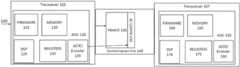
- Transceiver 105receives data 100 from transceiver 105 .
- Transceiver 105is linked via communication link 140 to Transceiver 107 .
- Transceiver 105has ASIC (application specific integrated circuit) 110 which has firmware 115 , memory 120 , DSP 125 , Registers 130 , and side channel FEC (SCFEC) encoder 135 .
- Transceiver 107has ASIC 155 which has Firmware 160 , Memory 165 , DSP 170 , Registers 175 , and side channel FEC (SCFEC) encoder 180 .
- Transceiver 105sends frame 145 across communication link 140 .
- Frame 145has side channel communication 150 .
- Transceiver 107receive frame 145 from communication link 140 .
- FIG. 2 awhich illustrates sending a frame.
- Transceiver 105sends Frame 145 to Transceiver 107 (Step 200 ).
- Transceiver 107receives Frame 145 (Step 205 ).
- DSP 125writes information into registers 130 (Step 210 ).
- Firmware 115reads information from registers 130 (Step 215 ).
- Firmware 115performs calculation (Step 220 ).
- Firmware 115writes information into memory 120 (Step 225 ).
- SCFEC 135reads side channel information from memory 120 (Step 230 ).
- SCFEC 135encodes the information in memory 120 (Step 235 ).
- SCFEC 135encoded the information in a highly redundant manner that is more robust and has more error checking information than data that is written into frame 145 .
- SCFEC 135writes side channel information that has been encoded into side channel communication 150 of frame 145 (Step 240 ). Frame 145 is transmitted from transceiver 105 to transceiver 107 (Step 245 ).
- Transceiver 107receives packet (Step 250 ).
- ASICreads side channel information from SC COMM 150 (Step 255 ).
- SCFEC 180decodes side channel information (Step 260 ).
- SCFEC 180writes side channel information into memory 165 (Step 265 ).
- Firmware 160reads side channel information from memory 165 (Step 270 ).
- Firmware 160writes information into registers 175 (Step 275 ).
- DSP 170reads information from registers 175 (Step 280 ).
- Settings on transceiver 107are changed (step 285 ).
- Transceiver 305 and 307are connected by communication link 340 and each transceiver has an ASIC, such as ASIC 310 and 355 respectfully.
- Communication link 340has a portion of its bandwidth dedicated to side channel communication as SC COMM 345 .
- SCFEC encoder 335writes side channel communication information into SC COMM 345 .
- Transceiver 307removes side channel communication from SC COMM 345 .
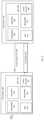
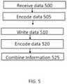
- a transceiversuch as transceiver 105 of FIG. 1 receives data 400 (step 500 ).
- FEC 405 of the transceiverencodes data 400 (step 505 ).
- Firmware 410 of a transceiversuch as transceiver 105 of FIG. 1 , writes side channel information into memory 415 (step 510 ).
- side channel FEC 420encodes the side channel information (step 520 ).
- Data 400 encoded by FEC 405 and side channel information encoded by side channel FEC 420are combined into a header and side channel insert 425 (step 525 ).
- a transceiversuch as transceiver 105 of FIG. 1 receives data 600 (step 700 ).
- FEC 605 of the transceiverencodes data 600 (step 705 ).
- Firmware 610 of a transceiversuch as transceiver 105 of FIG. 1 , writes side channel information into memory 615 (step 710 ).
- firmware 610is finished writing side channel information into memory 615
- data from memoryis combined by combiner 625 with information from hardware PIN 620 (step 715 ).
- data from hardware PIN 620represents data input by a controller of a transceiver.
- This datais additional data to the data information being received and transmitted but may not be side channel information used to optimize or change a transceiver's settings.
- Side channel FEC 630encodes the combined information from combiner 625 (step 720 ). Data 600 encoded by FEC 605 and side channel information encoded by side channel FEC 630 are combined into a header and side channel insert 635 (step 725 ).
- firmware on a transceivermay perform calculations to determine what information is to be put into a side channel. In other embodiments, firmware on a transceiver may perform calculations on information retrieved from a side channel to determine what parameters or settings should be changed. In some embodiments, bit error rate may be used in the calculations or to determine what settings or parameters should be changed.
- a device controllermay be any type of controller.
- a microprocessormay be a device controller and run a control loop.
- an ASICmay be a device controller and may run a control loop.
- a device controllermay be an analog circuitry.
- a bias controllermay be a device controller.
- a bias controllermay be an analog circuitry.
- one or more of the embodiments described hereinmay be stored on a computer readable medium.
- a computer readable mediummay be one or more memories, one or more hard drives, one or more flash drives, one or more compact disk drives, or any other type of computer readable medium.
- one or more of the embodiments described hereinmay be embodied in a computer program product that may enable a processor to execute the embodiments. In many embodiments, one or more of the embodiments described herein may be executed on at least a portion of a processor.
- a processormay be a physical or virtual processor. In other embodiments, a virtual processor may be spread across one or more portions of one or more physical processors. In certain embodiments, one or more of the embodiments described herein may be embodied in hardware such as a Digital Signal Processor DSP. In certain embodiments, one or more of the embodiments herein may be executed on a DSP. One or more of the embodiments herein may be programmed into a DSP. In some embodiments, a DSP may have one or more processors and one or more memories. In certain embodiments, a DSP may have one or more computer readable storages. In many embodiments, a DSP may be a custom designed ASIC chip. In other embodiments, one or more of the embodiments stored on a computer readable medium may be loaded into a processor and executed.
- some aspectsmay be embodied as one or more methods.
- the acts performed as part of the methodmay be ordered in any suitable way. Accordingly, embodiments may be constructed in which acts are performed in an order different than illustrated, which may include performing some acts simultaneously, even though shown as sequential acts in illustrative embodiments.
- the phrase “at least one,” in reference to a list of one or more elements,should be understood to mean at least one element selected from any one or more of the elements in the list of elements, but not necessarily including at least one of each and every element specifically listed within the list of elements and not excluding any combinations of elements in the list of elements.
- This definitionalso allows that elements may optionally be present other than the elements specifically identified within the list of elements to which the phrase “at least one” refers, whether related or unrelated to those elements specifically identified.
- the terms “approximately” and “about”may be used to mean within ⁇ 20% of a target value in some embodiments, within ⁇ 10% of a target value in some embodiments, within ⁇ 5% of a target value in some embodiments, and yet within ⁇ 2% of a target value in some embodiments.
- the terms “approximately” and “about”may include the target value.
Landscapes
- Physics & Mathematics (AREA)
- Electromagnetism (AREA)
- Engineering & Computer Science (AREA)
- Computer Networks & Wireless Communication (AREA)
- Signal Processing (AREA)
- Optical Communication System (AREA)
Abstract
Description
- 1) Both transceivers start up in lowest modulation-mode (i.e. a certain baud rate, modulation order and data-rate, e.g. 30 GBd, BPSK (binary phase shift keying) and 50 Gbit/s).
- 2) They communicate via the side-channel to ensure they are in a bi-directional configuration:
- a. Each transceiver creates a unique ID (e.g. ASIC-serial #*2+lane)
- b. Each transceiver sends its own ID to the other end
- c. Each transceiver also sends the ID it received to the other end
- d. Each transceiver checks that its own ID matches the ID that the other transceiver received. If that is not the case, then it is not a bi-directional configuration so the detection process needs to be aborted.
- e. A special case is if the transceiver is looped back to itself, then both IDs that the “other” transceiver sends are identical and match the “own” ID. Potential optimizations of LO-S offsets cannot be made in this case.
- 3) Transceivers decide on a master (e.g. the transceiver with the lower ID is the master).
- 4) They measure the latency between the transceiver (in order to know how long to wait for responses, etc.).
- 5) Both transceiver measure OSNR (optical signal to noise ratio), QdB margin, BER (bit error ratio), UCB (uncorrected block), etc. The master collects the data.
- 6) If there is enough margin, the master decides to try a different configuration, e.g. wider signal bandwidth, or the next available data-rate supported by the client side, e.g. 25 Gbit/s or 50 Gbit/s higher. It will send the new parameters to the slave, including a time-out which might depend on latency.
- 7) Once the slave acknowledges the new configuration, both transceivers switch to the new configuration (for example, by changing the modulation order, i.e. bits/symbol).
- 8) If both transceivers cannot establish the side-channel at the new configuration, then both switch back to the lowest mode (or the previous mode)→algorithm jumps back to 1).
- 9) If the link can be established, then margin is evaluated again. There is a potential that the new configuration does not allow enough margin (even though it was expected it would), so the master will trigger a switch to the previous mode.
- 10) The optimum configuration has been established and will be reported to the host.
In many embodiments, increasing a QAM (quadrature amplitude modulation) setting may mean starting at BPSK, switching to QPSK, then 8-QAM, etc.—i.e. increasing the bits/symbol by 1 each step. In most embodiments, a specific loss threshold may refer to the amount of errors experience in the transmission of data between optical transceivers.
Claims (20)
Priority Applications (3)
| Application Number | Priority Date | Filing Date | Title |
|---|---|---|---|
| US16/670,159US11239919B2 (en) | 2018-12-20 | 2019-10-31 | Side channel communication for an optical coherent transceiver |
| EP19214830.2AEP3672106A1 (en) | 2018-12-20 | 2019-12-10 | Side channel communication for an optical coherent transceiver |
| US17/558,873US11838054B2 (en) | 2018-12-20 | 2021-12-22 | Side channel communication for an optical coherent transceiver |
Applications Claiming Priority (2)
| Application Number | Priority Date | Filing Date | Title |
|---|---|---|---|
| US201862782884P | 2018-12-20 | 2018-12-20 | |
| US16/670,159US11239919B2 (en) | 2018-12-20 | 2019-10-31 | Side channel communication for an optical coherent transceiver |
Related Child Applications (1)
| Application Number | Title | Priority Date | Filing Date |
|---|---|---|---|
| US17/558,873ContinuationUS11838054B2 (en) | 2018-12-20 | 2021-12-22 | Side channel communication for an optical coherent transceiver |
Publications (2)
| Publication Number | Publication Date |
|---|---|
| US20200204262A1 US20200204262A1 (en) | 2020-06-25 |
| US11239919B2true US11239919B2 (en) | 2022-02-01 |
Family
ID=68848049
Family Applications (2)
| Application Number | Title | Priority Date | Filing Date |
|---|---|---|---|
| US16/670,159ActiveUS11239919B2 (en) | 2018-12-20 | 2019-10-31 | Side channel communication for an optical coherent transceiver |
| US17/558,873Active2039-12-05US11838054B2 (en) | 2018-12-20 | 2021-12-22 | Side channel communication for an optical coherent transceiver |
Family Applications After (1)
| Application Number | Title | Priority Date | Filing Date |
|---|---|---|---|
| US17/558,873Active2039-12-05US11838054B2 (en) | 2018-12-20 | 2021-12-22 | Side channel communication for an optical coherent transceiver |
Country Status (2)
| Country | Link |
|---|---|
| US (2) | US11239919B2 (en) |
| EP (1) | EP3672106A1 (en) |
Families Citing this family (4)
| Publication number | Priority date | Publication date | Assignee | Title |
|---|---|---|---|---|
| US11588559B2 (en)* | 2021-01-26 | 2023-02-21 | Nokia Solutions And Networks Oy | In-phase to quadrature-phase imbalance in an optical data modulator |
| US20230079971A1 (en)* | 2021-09-10 | 2023-03-16 | Nguyen Tan Hung | Bidirectional coherent optical transceiver with self-optimization and communication method thereof |
| US11581951B1 (en) | 2022-01-31 | 2023-02-14 | Huawei Technologies Co., Ltd. | Apparatuses and methods of far-end transmitter skew monitoring in digital subcarrier multiplexing systems |
| CN117040722B (en)* | 2023-10-08 | 2024-02-02 | 杭州海康威视数字技术股份有限公司 | Side channel analysis method based on multi-loss regularized noise reduction automatic encoder |
Citations (34)
| Publication number | Priority date | Publication date | Assignee | Title |
|---|---|---|---|---|
| US20020039217A1 (en)* | 2000-08-25 | 2002-04-04 | Saunders Ross Alexander | Method of adaptive signal degradation compensation |
| US6433904B1 (en)* | 1999-07-27 | 2002-08-13 | Sycamore Networks, Inc. | Method and apparatus for improving transmission performance over wavelength division multiplexed optical communication links using forward error correction coding |
| US20040037569A1 (en)* | 2002-08-22 | 2004-02-26 | Kamalov Valey F. | Method and device for evaluating and improving the quality of transmission of a telecommunications signal through an optical fiber |
| US20040076430A1 (en)* | 2001-03-01 | 2004-04-22 | Zaacks Mark Raymond | Method and system for handling optical signals |
| US6934479B2 (en)* | 2000-08-08 | 2005-08-23 | Fujitsu Limited | Wavelength division multiplexing optical communication system and wavelength division multiplexing optical communication method |
| US7389049B2 (en)* | 2003-03-31 | 2008-06-17 | Fujitsu Limited | Chromatic dispersion compensation controlling system |
| US7437080B2 (en)* | 2005-02-03 | 2008-10-14 | Stratalight Communications, Inc. | Optical transmission system having optimized filter wavelength offsets |
| US7519295B2 (en)* | 2003-10-30 | 2009-04-14 | Tyco Telecommunications (Us) Inc. | Apparatus and method for commissioning an optical transmission system |
| US7725033B2 (en)* | 2005-09-30 | 2010-05-25 | Fujitsu Limited | Optical wavelength controlling method and a system thereof |
| US7945161B2 (en)* | 2004-07-23 | 2011-05-17 | Ericsson Ab | Channel power pre-emphasis in wavelength division multiplex optical communication systems |
| US8184978B2 (en)* | 2005-12-16 | 2012-05-22 | Deutsche Telekom Ag | Method and device for channel-adapted signal transmission in optical networks |
| US8305871B2 (en)* | 2004-05-19 | 2012-11-06 | Rambus Inc. | Crosstalk minimization in serial link systems |
| US8406637B2 (en)* | 2008-05-27 | 2013-03-26 | Xtera Communications, Inc. | Automatic pre-emphasis |
| US8457491B2 (en)* | 2007-11-06 | 2013-06-04 | Telefonaktiebolaget Lm Ericsson (Publ) | Allocation of transmission power in an optical communication system |
| US8526823B2 (en)* | 2010-09-28 | 2013-09-03 | Acacia Communications, Inc. | Reconfigurable DSP performance in optical transceivers |
| US8649686B1 (en)* | 2010-11-24 | 2014-02-11 | Applied Micro Circuits Corporation | System and method for closed-loop optical network power backoff |
| US8707137B2 (en)* | 2009-09-14 | 2014-04-22 | Celtro Ltd. Company | Adapting bit error rate to a target quality of service |
| US9008505B2 (en)* | 2010-03-12 | 2015-04-14 | Zte Corporation | Optical power adjustment method for ethernet passive optical network system, and optical line terminal |
| US9088378B2 (en)* | 2010-05-17 | 2015-07-21 | Adva Optical Networking Se | Method for transmitting a digital signal in inverse multiplexing, particularly via an optical transport network, and reception device for a system to carry out the method |
| US9191103B2 (en)* | 2012-05-10 | 2015-11-17 | Telefonaktiebolaget L M Ericsson (Publ) | Node and method for iterative improvement of spectral use |
| US9197324B1 (en)* | 2012-04-09 | 2015-11-24 | Inphi Corporation | Method and system for transmitter optimization of an optical PAM serdes based on receiver feedback |
| US9331780B1 (en)* | 2014-05-11 | 2016-05-03 | Google Inc. | Systems and methods for adaptive energy utilization of optical interconnection networks |
| US9350446B2 (en)* | 2010-12-22 | 2016-05-24 | Telefonaktiebolaget Lm Ericsson (Publ) | Optical signal power selection and control |
| US9419720B2 (en)* | 2008-09-26 | 2016-08-16 | Fujitsu Limited | Optical signal transmitter |
| US9634789B2 (en)* | 2013-03-22 | 2017-04-25 | Mitsubishi Electric Corporation | Method and device for determining whether a configuration of an optical transmission interface has to be adjusted and the configuring thereof |
| US9654212B2 (en)* | 2013-10-07 | 2017-05-16 | Telefonaktiebolaget L M Ericsson (Publ) | Communications controller and method for wavelength control |
| US9985727B2 (en)* | 2014-04-28 | 2018-05-29 | Neptune Subsea Ip Limited | Feedback controlled Raman amplification in optical system |
| US20180212712A1 (en)* | 2017-01-20 | 2018-07-26 | Inphi Corporation | Closed loop module control for communication |
| US10070206B2 (en)* | 2014-12-30 | 2018-09-04 | Infinera Corporation | Reduction of wavelength selective switch (WSS) filter-based impairment using differentiated channel modulation formats |
| US10181968B2 (en)* | 2014-12-04 | 2019-01-15 | Avago Technologies International Sales Pte. Limited | System and method for backchannel closed loop feedback for channel equalization over Ethernet |
| US10200131B2 (en)* | 2012-08-06 | 2019-02-05 | Skorpios Technologies, Inc. | Method and system for the monolithic integration of circuits for monitoring and control of RF signals |
| US10469176B2 (en)* | 2017-07-07 | 2019-11-05 | Inphi Corporation | Histogram based optimization for optical modulation |
| US10547408B2 (en)* | 2018-05-03 | 2020-01-28 | Juniper Networks, Inc. | Methods and apparatus for improving the skew tolerance of a coherent optical transponder in an optical communication system |
| US10554300B2 (en)* | 2016-04-11 | 2020-02-04 | British Telecommunications Public Limited Company | Optical communications |
Family Cites Families (17)
| Publication number | Priority date | Publication date | Assignee | Title |
|---|---|---|---|---|
| US8380126B1 (en)* | 2005-10-13 | 2013-02-19 | Abbott Medical Optics Inc. | Reliable communications for wireless devices |
| JP4642679B2 (en)* | 2006-03-14 | 2011-03-02 | 富士通株式会社 | Wireless communication apparatus and wireless communication method |
| DE102007041902A1 (en)* | 2007-09-04 | 2009-03-12 | Siemens Ag | Method and device for the wireless transmission of signals |
| US7986878B2 (en)* | 2008-02-05 | 2011-07-26 | Opnext Subsystems, Inc. | Adjustable bit rate optical transmission using programmable signal modulation |
| CN103081439B (en)* | 2010-12-28 | 2016-06-29 | 三菱电机株式会社 | Logical Link Management method and communicator |
| EP2715952A1 (en)* | 2011-06-01 | 2014-04-09 | Telefonaktiebolaget LM Ericsson (PUBL) | Modulator for optical transmitter |
| US9374166B2 (en)* | 2012-02-13 | 2016-06-21 | Ciena Corporation | High speed optical communication systems and methods with flexible bandwidth adaptation |
| EP2851669A1 (en)* | 2012-06-05 | 2015-03-25 | Airbus Operations GmbH | System and method for monitoring a component of an aircraft or spacecraft in production and/or in service |
| US9148710B2 (en)* | 2012-09-19 | 2015-09-29 | Ciena Corporation | Raman amplifier system and method with integrated optical time domain reflectometer |
| US8917988B2 (en)* | 2012-12-07 | 2014-12-23 | At&T Intellectual Property I, L.P. | End-to-end carrier frequency control to improve bandwidth utilization in an optical network |
| US9991593B1 (en)* | 2014-12-19 | 2018-06-05 | Rockwell Collins, Inc. | Optically controlled electronically scanned array |
| US10802480B2 (en)* | 2016-12-07 | 2020-10-13 | Abb Power Grids Switzerland Ag | Submersible inspection device and redundant wireless communication with a base station |
| BR112019019804A2 (en)* | 2017-03-23 | 2020-04-22 | Fraunhofer Ges Forschung | transmission of reliable data packet between entities in a radio access network of a mobile communication network |
| US10680778B2 (en)* | 2018-02-16 | 2020-06-09 | At&T Intellectual Property I, L.P. | Reducing control channel overhead in 5G or other next generation networks |
| CN111049865B (en)* | 2018-10-12 | 2023-05-02 | 中兴通讯股份有限公司 | Method, device and system for building chain |
| US11942991B2 (en)* | 2019-03-27 | 2024-03-26 | Nec Corporation | Optical submarine branching apparatus, optical submarine cable system, switching method, non-transitory computer-readable medium |
| US11523343B2 (en)* | 2019-03-29 | 2022-12-06 | Qualcomm Incorporated | Monitoring wake-up signal using common identifier |
- 2019
- 2019-10-31USUS16/670,159patent/US11239919B2/enactiveActive
- 2019-12-10EPEP19214830.2Apatent/EP3672106A1/enactivePending
- 2021
- 2021-12-22USUS17/558,873patent/US11838054B2/enactiveActive
Patent Citations (34)
| Publication number | Priority date | Publication date | Assignee | Title |
|---|---|---|---|---|
| US6433904B1 (en)* | 1999-07-27 | 2002-08-13 | Sycamore Networks, Inc. | Method and apparatus for improving transmission performance over wavelength division multiplexed optical communication links using forward error correction coding |
| US6934479B2 (en)* | 2000-08-08 | 2005-08-23 | Fujitsu Limited | Wavelength division multiplexing optical communication system and wavelength division multiplexing optical communication method |
| US20020039217A1 (en)* | 2000-08-25 | 2002-04-04 | Saunders Ross Alexander | Method of adaptive signal degradation compensation |
| US20040076430A1 (en)* | 2001-03-01 | 2004-04-22 | Zaacks Mark Raymond | Method and system for handling optical signals |
| US20040037569A1 (en)* | 2002-08-22 | 2004-02-26 | Kamalov Valey F. | Method and device for evaluating and improving the quality of transmission of a telecommunications signal through an optical fiber |
| US7389049B2 (en)* | 2003-03-31 | 2008-06-17 | Fujitsu Limited | Chromatic dispersion compensation controlling system |
| US7519295B2 (en)* | 2003-10-30 | 2009-04-14 | Tyco Telecommunications (Us) Inc. | Apparatus and method for commissioning an optical transmission system |
| US8305871B2 (en)* | 2004-05-19 | 2012-11-06 | Rambus Inc. | Crosstalk minimization in serial link systems |
| US7945161B2 (en)* | 2004-07-23 | 2011-05-17 | Ericsson Ab | Channel power pre-emphasis in wavelength division multiplex optical communication systems |
| US7437080B2 (en)* | 2005-02-03 | 2008-10-14 | Stratalight Communications, Inc. | Optical transmission system having optimized filter wavelength offsets |
| US7725033B2 (en)* | 2005-09-30 | 2010-05-25 | Fujitsu Limited | Optical wavelength controlling method and a system thereof |
| US8184978B2 (en)* | 2005-12-16 | 2012-05-22 | Deutsche Telekom Ag | Method and device for channel-adapted signal transmission in optical networks |
| US8457491B2 (en)* | 2007-11-06 | 2013-06-04 | Telefonaktiebolaget Lm Ericsson (Publ) | Allocation of transmission power in an optical communication system |
| US8406637B2 (en)* | 2008-05-27 | 2013-03-26 | Xtera Communications, Inc. | Automatic pre-emphasis |
| US9419720B2 (en)* | 2008-09-26 | 2016-08-16 | Fujitsu Limited | Optical signal transmitter |
| US8707137B2 (en)* | 2009-09-14 | 2014-04-22 | Celtro Ltd. Company | Adapting bit error rate to a target quality of service |
| US9008505B2 (en)* | 2010-03-12 | 2015-04-14 | Zte Corporation | Optical power adjustment method for ethernet passive optical network system, and optical line terminal |
| US9088378B2 (en)* | 2010-05-17 | 2015-07-21 | Adva Optical Networking Se | Method for transmitting a digital signal in inverse multiplexing, particularly via an optical transport network, and reception device for a system to carry out the method |
| US8526823B2 (en)* | 2010-09-28 | 2013-09-03 | Acacia Communications, Inc. | Reconfigurable DSP performance in optical transceivers |
| US8649686B1 (en)* | 2010-11-24 | 2014-02-11 | Applied Micro Circuits Corporation | System and method for closed-loop optical network power backoff |
| US9350446B2 (en)* | 2010-12-22 | 2016-05-24 | Telefonaktiebolaget Lm Ericsson (Publ) | Optical signal power selection and control |
| US9197324B1 (en)* | 2012-04-09 | 2015-11-24 | Inphi Corporation | Method and system for transmitter optimization of an optical PAM serdes based on receiver feedback |
| US9191103B2 (en)* | 2012-05-10 | 2015-11-17 | Telefonaktiebolaget L M Ericsson (Publ) | Node and method for iterative improvement of spectral use |
| US10200131B2 (en)* | 2012-08-06 | 2019-02-05 | Skorpios Technologies, Inc. | Method and system for the monolithic integration of circuits for monitoring and control of RF signals |
| US9634789B2 (en)* | 2013-03-22 | 2017-04-25 | Mitsubishi Electric Corporation | Method and device for determining whether a configuration of an optical transmission interface has to be adjusted and the configuring thereof |
| US9654212B2 (en)* | 2013-10-07 | 2017-05-16 | Telefonaktiebolaget L M Ericsson (Publ) | Communications controller and method for wavelength control |
| US9985727B2 (en)* | 2014-04-28 | 2018-05-29 | Neptune Subsea Ip Limited | Feedback controlled Raman amplification in optical system |
| US9331780B1 (en)* | 2014-05-11 | 2016-05-03 | Google Inc. | Systems and methods for adaptive energy utilization of optical interconnection networks |
| US10181968B2 (en)* | 2014-12-04 | 2019-01-15 | Avago Technologies International Sales Pte. Limited | System and method for backchannel closed loop feedback for channel equalization over Ethernet |
| US10070206B2 (en)* | 2014-12-30 | 2018-09-04 | Infinera Corporation | Reduction of wavelength selective switch (WSS) filter-based impairment using differentiated channel modulation formats |
| US10554300B2 (en)* | 2016-04-11 | 2020-02-04 | British Telecommunications Public Limited Company | Optical communications |
| US20180212712A1 (en)* | 2017-01-20 | 2018-07-26 | Inphi Corporation | Closed loop module control for communication |
| US10469176B2 (en)* | 2017-07-07 | 2019-11-05 | Inphi Corporation | Histogram based optimization for optical modulation |
| US10547408B2 (en)* | 2018-05-03 | 2020-01-28 | Juniper Networks, Inc. | Methods and apparatus for improving the skew tolerance of a coherent optical transponder in an optical communication system |
Also Published As
| Publication number | Publication date |
|---|---|
| US20200204262A1 (en) | 2020-06-25 |
| US20220116114A1 (en) | 2022-04-14 |
| US11838054B2 (en) | 2023-12-05 |
| EP3672106A1 (en) | 2020-06-24 |
Similar Documents
| Publication | Publication Date | Title |
|---|---|---|
| US11838054B2 (en) | Side channel communication for an optical coherent transceiver | |
| US10057012B2 (en) | Error correction circuit and optical transmission system | |
| US8660425B2 (en) | Optical transmitting device and optical receiving device | |
| JP5462267B2 (en) | Physical layer data unit format | |
| US9634796B2 (en) | Optical transmission device and optical transmission system | |
| WO2016061036A1 (en) | Hitless, multi-rate optical transmission and reception | |
| US9425836B2 (en) | Asymmetrical transmitter-receiver system for short range communications | |
| JP2018515956A (en) | Full-duplex wireless communication in a wireless tunneling system | |
| US8879921B2 (en) | Apparatus and a method for modulation of an optical signal | |
| Ribeiro et al. | Opportunistic multipath for bandwidth-efficient cooperative networking | |
| KR20140037313A (en) | Method and apparatus for transmitting uncompressed video signal | |
| US20170126352A1 (en) | Optical modem | |
| CN105993143A (en) | Coded modulation for small step-size variable spectral efficiency | |
| US9014188B2 (en) | Communication system | |
| WO2017059776A1 (en) | System and method for state reduction in trellis equalizers using bounded state enumeration | |
| US20170302406A1 (en) | Device and method for transmitting frame in optical transmission system | |
| US11658737B2 (en) | Messaging channel in a coherent optical DSP frame | |
| JP2022510867A (en) | Hybrid Digital Multiband Optical Receivers and Transmitters | |
| CN108307672A (en) | Control is transmitted using the microwave link of low rate virtual data transmission | |
| KR20050071546A (en) | Simplified implementation of optimal decoding for cofdm transmitter diversity system | |
| US12381650B2 (en) | Optical transmission device, optical transmission system, and optical transmission method | |
| CN119341685B (en) | Data transmission method and data transmission device | |
| US12381624B2 (en) | Signal-to-noise ratio-based bit error ratio calculation for reporting beyond a forward error correction threshold | |
| US10637578B1 (en) | Encoding a first modulation type with a first spectral efficiency into a second modulation type capable of having a second spectral efficiency | |
| US10567209B1 (en) | Geometrically shaping QAM modulation |
Legal Events
| Date | Code | Title | Description |
|---|---|---|---|
| AS | Assignment | Owner name:ACACIA COMMUNICATIONS, INC., MASSACHUSETTS Free format text:ASSIGNMENT OF ASSIGNORS INTEREST;ASSIGNORS:GEYER, JONAS;PFAU, TIMO;REEL/FRAME:050882/0008 Effective date:20191031 | |
| FEPP | Fee payment procedure | Free format text:ENTITY STATUS SET TO UNDISCOUNTED (ORIGINAL EVENT CODE: BIG.); ENTITY STATUS OF PATENT OWNER: LARGE ENTITY | |
| FEPP | Fee payment procedure | Free format text:ENTITY STATUS SET TO SMALL (ORIGINAL EVENT CODE: SMAL); ENTITY STATUS OF PATENT OWNER: LARGE ENTITY | |
| STPP | Information on status: patent application and granting procedure in general | Free format text:NON FINAL ACTION MAILED | |
| STPP | Information on status: patent application and granting procedure in general | Free format text:FINAL REJECTION MAILED | |
| FEPP | Fee payment procedure | Free format text:ENTITY STATUS SET TO UNDISCOUNTED (ORIGINAL EVENT CODE: BIG.); ENTITY STATUS OF PATENT OWNER: LARGE ENTITY | |
| STPP | Information on status: patent application and granting procedure in general | Free format text:DOCKETED NEW CASE - READY FOR EXAMINATION | |
| STPP | Information on status: patent application and granting procedure in general | Free format text:NON FINAL ACTION MAILED | |
| STPP | Information on status: patent application and granting procedure in general | Free format text:RESPONSE TO NON-FINAL OFFICE ACTION ENTERED AND FORWARDED TO EXAMINER | |
| STPP | Information on status: patent application and granting procedure in general | Free format text:NOTICE OF ALLOWANCE MAILED -- APPLICATION RECEIVED IN OFFICE OF PUBLICATIONS | |
| STPP | Information on status: patent application and granting procedure in general | Free format text:PUBLICATIONS -- ISSUE FEE PAYMENT VERIFIED | |
| STCF | Information on status: patent grant | Free format text:PATENTED CASE | |
| AS | Assignment | Owner name:ACACIA TECHNOLOGY, INC., CALIFORNIA Free format text:ASSIGNMENT OF ASSIGNORS INTEREST;ASSIGNOR:ACACIA COMMUNICATIONS, INC.;REEL/FRAME:066832/0659 Effective date:20230712 | |
| MAFP | Maintenance fee payment | Free format text:PAYMENT OF MAINTENANCE FEE, 4TH YEAR, LARGE ENTITY (ORIGINAL EVENT CODE: M1551); ENTITY STATUS OF PATENT OWNER: LARGE ENTITY Year of fee payment:4 |