US11239674B2 - Power pack vending apparatus, system and method of use for charging packs with biased locking arrangement - Google Patents
Power pack vending apparatus, system and method of use for charging packs with biased locking arrangementDownload PDFInfo
- Publication number
- US11239674B2 US11239674B2US16/105,672US201816105672AUS11239674B2US 11239674 B2US11239674 B2US 11239674B2US 201816105672 AUS201816105672 AUS 201816105672AUS 11239674 B2US11239674 B2US 11239674B2
- Authority
- US
- United States
- Prior art keywords
- power pack
- kiosk
- power
- magazine
- slot
- Prior art date
- Legal status (The legal status is an assumption and is not a legal conclusion. Google has not performed a legal analysis and makes no representation as to the accuracy of the status listed.)
- Active, expires
Links
Images


Classifications
- H—ELECTRICITY
- H02—GENERATION; CONVERSION OR DISTRIBUTION OF ELECTRIC POWER
- H02J—CIRCUIT ARRANGEMENTS OR SYSTEMS FOR SUPPLYING OR DISTRIBUTING ELECTRIC POWER; SYSTEMS FOR STORING ELECTRIC ENERGY
- H02J7/00—Circuit arrangements for charging or depolarising batteries or for supplying loads from batteries
- H02J7/0042—Circuit arrangements for charging or depolarising batteries or for supplying loads from batteries characterised by the mechanical construction
- H02J7/0045—Circuit arrangements for charging or depolarising batteries or for supplying loads from batteries characterised by the mechanical construction concerning the insertion or the connection of the batteries
- G—PHYSICS
- G06—COMPUTING OR CALCULATING; COUNTING
- G06Q—INFORMATION AND COMMUNICATION TECHNOLOGY [ICT] SPECIALLY ADAPTED FOR ADMINISTRATIVE, COMMERCIAL, FINANCIAL, MANAGERIAL OR SUPERVISORY PURPOSES; SYSTEMS OR METHODS SPECIALLY ADAPTED FOR ADMINISTRATIVE, COMMERCIAL, FINANCIAL, MANAGERIAL OR SUPERVISORY PURPOSES, NOT OTHERWISE PROVIDED FOR
- G06Q20/00—Payment architectures, schemes or protocols
- G06Q20/08—Payment architectures
- G06Q20/18—Payment architectures involving self-service terminals [SST], vending machines, kiosks or multimedia terminals
- G—PHYSICS
- G07—CHECKING-DEVICES
- G07F—COIN-FREED OR LIKE APPARATUS
- G07F15/00—Coin-freed apparatus with meter-controlled dispensing of liquid, gas or electricity
- G07F15/003—Coin-freed apparatus with meter-controlled dispensing of liquid, gas or electricity for electricity
- G07F15/006—Coin-freed apparatus with meter-controlled dispensing of liquid, gas or electricity for electricity dispensed for the electrical charging of other devices than vehicles
- G—PHYSICS
- G07—CHECKING-DEVICES
- G07F—COIN-FREED OR LIKE APPARATUS
- G07F17/00—Coin-freed apparatus for hiring articles; Coin-freed facilities or services
- G07F17/0042—Coin-freed apparatus for hiring articles; Coin-freed facilities or services for hiring of objects
- G—PHYSICS
- G07—CHECKING-DEVICES
- G07F—COIN-FREED OR LIKE APPARATUS
- G07F7/00—Mechanisms actuated by objects other than coins to free or to actuate vending, hiring, coin or paper currency dispensing or refunding apparatus
- G07F7/06—Mechanisms actuated by objects other than coins to free or to actuate vending, hiring, coin or paper currency dispensing or refunding apparatus by returnable containers, i.e. reverse vending systems in which a user is rewarded for returning a container that serves as a token of value, e.g. bottles
- G07F7/069—Mechanisms actuated by objects other than coins to free or to actuate vending, hiring, coin or paper currency dispensing or refunding apparatus by returnable containers, i.e. reverse vending systems in which a user is rewarded for returning a container that serves as a token of value, e.g. bottles by box-like containers, e.g. videocassettes, books
- G—PHYSICS
- G07—CHECKING-DEVICES
- G07F—COIN-FREED OR LIKE APPARATUS
- G07F9/00—Details other than those peculiar to special kinds or types of apparatus
- G07F9/001—Interfacing with vending machines using mobile or wearable devices
- G—PHYSICS
- G07—CHECKING-DEVICES
- G07F—COIN-FREED OR LIKE APPARATUS
- G07F9/00—Details other than those peculiar to special kinds or types of apparatus
- G07F9/02—Devices for alarm or indication, e.g. when empty; Advertising arrangements in coin-freed apparatus
- G07F9/023—Arrangements for display, data presentation or advertising
- G07F9/0235—Arrangements for display, data presentation or advertising the arrangements being full-front touchscreens
- H—ELECTRICITY
- H02—GENERATION; CONVERSION OR DISTRIBUTION OF ELECTRIC POWER
- H02J—CIRCUIT ARRANGEMENTS OR SYSTEMS FOR SUPPLYING OR DISTRIBUTING ELECTRIC POWER; SYSTEMS FOR STORING ELECTRIC ENERGY
- H02J7/00—Circuit arrangements for charging or depolarising batteries or for supplying loads from batteries
- H02J7/0013—Circuit arrangements for charging or depolarising batteries or for supplying loads from batteries acting upon several batteries simultaneously or sequentially
- H02J7/0021—
- H—ELECTRICITY
- H02—GENERATION; CONVERSION OR DISTRIBUTION OF ELECTRIC POWER
- H02J—CIRCUIT ARRANGEMENTS OR SYSTEMS FOR SUPPLYING OR DISTRIBUTING ELECTRIC POWER; SYSTEMS FOR STORING ELECTRIC ENERGY
- H02J7/00—Circuit arrangements for charging or depolarising batteries or for supplying loads from batteries
- H02J7/0047—Circuit arrangements for charging or depolarising batteries or for supplying loads from batteries with monitoring or indicating devices or circuits
- H02J7/0048—Detection of remaining charge capacity or state of charge [SOC]
- H—ELECTRICITY
- H02—GENERATION; CONVERSION OR DISTRIBUTION OF ELECTRIC POWER
- H02J—CIRCUIT ARRANGEMENTS OR SYSTEMS FOR SUPPLYING OR DISTRIBUTING ELECTRIC POWER; SYSTEMS FOR STORING ELECTRIC ENERGY
- H02J7/00—Circuit arrangements for charging or depolarising batteries or for supplying loads from batteries
- H02J7/0047—Circuit arrangements for charging or depolarising batteries or for supplying loads from batteries with monitoring or indicating devices or circuits
- H02J7/005—Detection of state of health [SOH]
Definitions
- the present inventionrelates to a power pack vending apparatus, system and method of using same, and more particularly relates to a plurality of vending apparatus capable of receiving and disbursing power packs, recharging received power packs, and a network system for communicating customer information, inventory and transactional information.
- One embodiment of the present inventioncomprises geographically distributed automated retail kiosks containing power packs for portable electronic devices to create a nationwide mobile charging service network aimed at allowing customers to never be without power for their portable electronic devices while on the go.
- the automated kiosksdispense fully-charged mobile charging power packs to customers for a rental fee, monthly subscription fee, purchase fee, or coupon code for a free rental.
- the mobile charging power packconnects to the customer's portable electronic device providing needed power.
- the power packmay be used to immediately power the portable electronic device and/or recharge the battery of the portable electronic device.
- the customerUpon the power pack becoming discharged, the customer returns the power pack to any geographically distributed kiosk or mails it back.
- the kiosksare equipped to automatically recharge the returned power packs and prepare them for rental by future customers.
- the recharging of the power packsis proprietary to the vending system so the customer is unable to recharge the power packs on their own.
- the kioskcommunicates with the power pack, while in the kiosk, to retrieve power pack data to determine cycle life, battery health, performance, etc.
- the power packcommunicates with the customer's device during use via a power pack app installed on the customer's device to display information related to charge life, time-to-charge, kiosk locations, etc.
- the kiosksare widely distributed, especially in places frequented by large numbers of people on the go. Some examples include airports, convention centers, theme parks, malls, hotels, supermarkets, convenience stores and fueling service stations.
- location of the power packsis tracked by the networked system and the system knows when the power pack is returned by the customer.
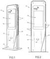
- FIG. 1is a front and side perspective view of a vending kiosk according to a preferred embodiment of the present invention
- FIG. 2is a front view of the vending kiosk of FIG. 1 ;
- FIGS. 3 and 4is a front view of another preferred embodiment of vending kiosk according to the present invention.
- FIG. 4is a front and side perspective view of another preferred embodiment of vending kiosk according to the present invention.
- FIGS. 5 and 6are front and side views, respectively, of a mini kiosk embodiment according to the present invention.
- FIG. 7is an exploded view of the inner structure of the kiosk in accordance with the principles of a preferred embodiment of the present invention.
- FIG. 8is a front and side perspective view of another preferred embodiment of vending kiosk according to the present invention showing a magazine removed from the kiosk;
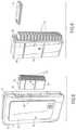
- FIG. 9is a side and front perspective view of the magazine of FIG. 8 showing a power pack removed from the magazine;
- FIG. 10is a partial perspective view of the magazine of FIG. 8 with the casing assembly of the magazine removed;
- FIG. 11is a top view of an alternative embodiment of the magazine with the top of the magazine casing assembly removed;
- FIG. 11Ais a top view of the locking member shown in FIG. 11 , and showing the insertion of a locking tab of the spring-biased locking member in a cavity of the outer case of the power pack;
- FIG. 12is a perspective view of a power pack according to a preferred embodiment of the present invention.
- FIG. 13is a back view of the power pack of FIG. 12 ;
- FIG. 14is a side view of the power pack of FIG. 12 ;
- FIG. 15is a section view of a device connector assembly of the power pack of FIG. 12 shown in a stored position
- FIGS. 16 and 17are perspective views of the power pack of FIG. 12 showing the device connector assembly in a “ready to connect” position;
- FIG. 17Ais a perspective view of the power pack of FIG. 17 showing the device connector assembly connected to a smartphone;
- FIG. 18is an illustration of a system for communicating and processing information in a network of vending kiosks and a central management operation
- FIG. 19shows one composition of the central management operation
- FIG. 20is a flow diagram showing a method of operating the power pack vending system according to one embodiment
- FIGS. 21-24are flow diagrams showing methods of operating the power pack vending system according to various embodiments of the invention.
- FIGS. 1 and 2illustrate a vending machine or kiosk generally designated 10 .
- the kiosk 10is one of a plurality of such machines included within a system 100 of kiosks.
- the system 100has a plurality of the kiosks 10 situated at a plurality of locations and a central management operation 102 in electrical communication with the kiosks 10 to form a network 104 .
- the central management operation 102may comprise a host computer system and controller 106 , a central server 110 , one or more central databases 108 , etc. as shown in FIG. 19 .
- the central management operation 102is connected to the kiosks 10 by any means suitable to transmit communications between the central management operation 102 and the kiosks 10 .
- the connectionmay be hardwired or by a communication network line, for example, a PSTN (Public Switched Telephone Network), an ISDN (Integrated Service Digital Network), a wireless telephone network, etc.
- PSTNPublic Switched Telephone Network
- ISDNIntegrated Service Digital Network
- wireless telephone networketc.
- each vending apparatus or kiosk 10 of the system 100contains a plurality of portable power packs 12 that are adapted to recharge and/or power a customer's portable device P ( FIG. 17A ).
- Portable electronic devices P as used hereinincludes, but is not limited to, smartphones, tablets, laptops, digital cameras, video cameras, flashlights, personal wearable devices, etc.
- the kiosk 10may vend multiple types of power packs 12 that can be utilized by customers with various types of portable electronic devices.
- the kiosk 10may vend power packs 12 having a power capacity suitable to recharge and/or power portable devices such as cell phones and smartphones, etc. requiring one (1) amp.
- the kiosk 10may vend power packs 12 having two (2) amp capacity.
- the kiosk 10may be designed to vend a plurality of power packs 12 of various sizes, shapes, and/or capacities. Those skilled in the art will appreciate that the kiosk 10 is not limited to power packs 12 for the aforementioned products, but rather will have applicability for use in the vending of a variety of power packs 12 .
- the kiosks 10are preferably located at places frequented by large numbers of people, such as shopping centers and malls, airports, convention centers, public transit stations, colleges and universities, metropolitan areas, stadiums, ball parks, public recreational areas, etc.
- the kiosks 10may basically be placed anywhere that experiences a number of people “on the go” or people having limited access to standard electrical outlets that are needed to recharge/power their portable devices. For example, it may be desirable to have a kiosk near a retail establishment, such as Starbucks, where people tend to stay for extended periods of time using their portable devices while enjoying a large latte.
- one embodiment of the kiosk 10includes an outer housing assembly 14 with front, rear, top and side surfaces.
- the outer housing assembly 14may be mounted to a base plate 16 or other support structure.
- FIGS. 3 and 4show other embodiments of the kiosk 10 .
- the kiosk 10 in FIG. 3has a header 20 mounted to the top of the outer housing assembly 14 .
- the header 20may be a decorative lighted header or a header providing public announcement and/or advertising functions.
- a solar panel 22is mounted to the top of the outer housing assembly 14 to provide renewable energy to the kiosk 10 .
- the kiosk 10 with solar panel 22may be desirable for outdoor use.
- FIGS. 5 and 6show another embodiment of the kiosk 10 ′ arranged and designed to be mounted to or within a wall, eliminating the need for the base plate 16 .
- the kiosk 10 ′is a mini kiosk that is smaller in size than the kiosks of FIGS. 1-4 .
- the mini kiosk 10 ′may be desirable at locations where the needed quantity of power packs is small or the space is limited.
- a mini kiosk 10 ′may have a stand allowing it to be freestanding as opposed to being wall-mounted.
- the present inventionis not limited to the kiosk shapes and configurations shown in the attached figures. It is to be understood that the following discussion pertaining to the kiosks is intended to apply generally to all types and sizes of kiosks according to the principles of the preferred embodiment of the present invention. Thus, references to kiosk 10 are intended to also apply to kiosk 10 ′ unless noted otherwise.
- FIG. 7is an exploded view of the inner structure of one embodiment of the kiosk 10 in accordance with the present invention. It is to be understood that the inner structure shown in FIG. 7 is merely exemplary and is not intended to be limiting of the inner structure of the kiosk.
- the kiosk 10preferably includes an internal computer 50 that locally controls several functions at the kiosk 10 as will explained below.
- the kiosk 10further includes at least one user interface portion 18 .
- the user interface portion 18preferably comprises a display monitor 19 incorporating known touch screen technology with configurable messaging.
- the touchscreen 19is preferably legible in full sunlight. As such, it presents a visual display of pertinent information to customers and operates as a user interface permitting customers to communicate with the kiosk 10 and/or the central management operation 102 in communication with the kiosk 10 .
- One preferred embodiment of the kiosk 10includes a front panel having existing “touch through glass” technology utilizing a full length glass front.
- the glasshas two layers—the inner layer being cutout to accommodate a closer proximity for the touch technology to the outer surface and an outer layer that remains fully intact.
- the user interface portion 18 of the kiosk 10further includes a card reader 40 ( FIG. 7 ) to read magnetically encoded credit cards or debit cards, for generating payment information.
- the magnetically encoded cardsmay comprise membership cards.
- the card reader 40preferably includes a card slot 42 for receiving the card.
- the card slot 42is preferably located adjacent or near the touch screen 19 of the user interface portion 18 on the front of the kiosk 10 .
- the card reader 40is preferably designed in known fashion to read magnetically encoded or smart chip (EMV) encrypted data prior to authorizing the customer access to a power pack 12 in the kiosk 10 .
- EMVstands for Europay, MasterCard and Visa, a global standard for inter-operation of integrated circuit cards (“IC cards”) and IC card capable point of sale terminals and automated teller machines for authenticating credit and debit card transactions.
- the kiosk 10is equipped to also accept currency.
- the kiosk 10may not require any physical payment acceptance means, but shall accept payment over secure internet or contactless payment methods through a mobile app on the customer's device.
- Contactless payment methodsinclude, for example, Apple Pay, Google Wallet, and other methods such as QR code readers.
- the second user interface portion 18could be added to the back of the kiosk 10 .
- the back of the kiosk 10could be equipped to display advertising, promotions or other information via a display monitor.
- the kiosk systems tower 26includes wiring 30 run within the upright structural member 28 .
- the wiring 30is connected to a power source, typically a 120 VAC power source.
- a power sourcetypically a 120 VAC power source.
- the wiring 30may extend through the base plate 16 for connection to the power source.
- the power cordmay extend from the kiosk 10 at other locations.
- the kiosk 10includes at least one back-up battery 32 within the outer housing assembly 14 .
- the back-up battery 32can provide the kiosk 10 with power temporarily to allow some customer usage even during such situations.
- This back-up battery power source 32can easily and frequently be switched to during power outages, without interrupting kiosk operation, to continue service for customer usage.
- the kiosk 10includes an overflow return module or an overflow bin 34 contained within the outer housing assembly 14 ( FIG. 7 ).
- the overflow bin 34includes an overflow slot or opening 36 for receiving returned power packs 12 .
- access to the overflow slot or opening 36only becomes available to a customer when there is no available empty power pack shelf or slot 38 in the magazines 24 for reasons which are discussed below.
- the power packs 12are preferably accessed at the sides of the kiosk 10 . It is to be understood that the invention is not limited to such side access.
- the kiosk 10is preferably modular in design and includes one or more magazines 24 , each adapted to contain a plurality of power packs 12 .
- the magazines 24are modular and the same magazine 24 can be used across multiple sizes of kiosks to insure operational efficiency and ease of design.
- the pair of magazines 24 in the mini kiosk 10 ′ of FIGS. 5 and 6each contain a maximum of fifteen ( 15 ) power packs.
- other sizes of kioskswould use multiples of the same size magazine 24 as used in the mini kiosk 10 ′.
- a mid-size kioskmay have two magazines 24 , one stacked above the other, on each side of the kiosk and a large-size kiosk may have three or four stacked magazines 24 on each side of the kiosk, with every magazine being interchangeable with any other magazine. It is to be understood that the number of power packs 12 capable of being received in a magazine 24 is a matter of design choice.
- Each magazine 24includes a casing assembly 52 and a plurality of shelves or slots 38 . Each slot 38 is adapted and configured to receive one power pack 12 as shown in FIG. 9 .
- each magazine 24slides in and out of the kiosk 10 through a side opening 44 in the outer housing assembly 14 as shown in FIG. 8 .
- various means known by one of ordinary skill in the artmay be used to slidably receive the magazine 24 in the kiosk 10 .
- Each magazine 24may be guided into the side opening 44 via one or more pairs of generally spaced and parallel cooperating guide rails 46 positioned within the outer housing assembly 14 and on the magazine outer casing 52 to facilitate installation and removal of the magazine 24 .
- the magazines 24are preferably manually slid into and out of the kiosk 10 , as desired, for installation and maintenance by service personnel.
- the magazine 24Upon full insertion of the magazine 24 into the kiosk 10 , the magazine 24 is locked in place to prevent removal or tampering by unauthorized personnel.
- the magazine 24is locked to an internal upright structural member 28 of kiosk systems tower 26 ( FIG. 7 ).
- the magazine 24is locked within the kiosk 10 via a locking mechanism 48 , preferably a conventional rotational lock, preventing removal of the magazine 24 when in a locked position.
- the magazine 24includes a lock engager 51 on the exterior of the magazine casing assembly 52 which precludes removal of the magazine 24 when the lock 48 is in the locked position.
- the lock 48has a key for locking/unlocking by the maintenance personnel. The lock 48 is accessed from the back of the kiosk 10 and there is a separate lock 48 for securing each magazine 24 .
- the kiosk 10includes a charging unit 25 responsible for recharging the power packs 12 received in the slots 38 of the magazine 24 .
- the charging unit 25is included in the magazine 24 ( FIG. 7 ).
- the charging unit 25may be separated from the magazine 24 and remain within the kiosk 10 when the magazine 24 is removed.
- the charging unit 25 and/or magazine 24include electrical contacts for making physical contact with each power pack 12 received in the slot 38 for metal-to-metal connection conductive charging.
- the charging unit 25 and magazine 24cooperate to inductively charge the power packs 12 .
- the charging unit 25can charge power packs 12 individually or multiple power packs 12 simultaneously.
- a data/power interface 56exists between the kiosk 10 and the installed magazine 24 .
- the data/power interface 56comprises a pair of mating, releasable connectors, for example a 4-pin Molex male/female connector. This is a common mechanical connector with the male connector having four metal pins and the female connector having four sockets enclosed in a plastic housing.
- two pinsare for data communication and the other two pins are for power, typically 24 VDC power.
- there is one connector mounted at the rear of the magazine 24that aligns with the mating connector in a fixed position inside the kiosk 10 .
- the male and female connectorsaxially mate and form the data/power interface 56 ( FIG. 11 ).
- FIGS. 12-17show a preferred embodiment of the power pack 12 .
- the power pack 12includes a main body 71 and a device connector assembly 70 .
- the main body 71includes an outer case 78 having a substantially rectangular prism shape with upper and lower surfaces 78 a and 78 b , first and second side surfaces 78 c and 78 d , and front and rear end surfaces 78 e and 78 f , respectively.
- the outer case 78defines a case opening 79 in the upper surface 78 a and rear end surface 78 f.
- FIGS. 12-15show the device connector assembly 70 in its stored position
- FIGS. 16 and 17show the device connector assembly 70 in its “ready to connect” position
- FIG. 17Ashows the device connector assembly 70 connected to the portable electronic device P, such as a smartphone.
- the connector assembly 70preferably comprises a preformed substrate 72 , a connector 74 with wiring (not shown), and an out layer 76 .
- the outer case 78 of the main body 71 of the power pack 12includes a receptacle 80 for storing the connector 74 in the stored position.
- the preformed substrate 72is preferably a bent or curved portion having a slight amount of flexibility while remembering its preformed shape.
- the preformed substrate 72may be a plastic or metal.
- the outer layer 76is a soft overmold comprising a thermoplastic polyurethane (TPU).
- TPUthermoplastic polyurethane
- the preformed substrate 72is flexible for different heights, holds the wiring in place when insert molding the TPU and holds the soft TPU outer layer 76 in a “C” shape—which is better for storage and connecting to a device such as a phone.
- the connector 74is substantially parallel to the upper surface 78 a of the outer case 78 when in the “ready to connect” position, to facilitate connecting with portable electronic device P as shown in FIGS. 17 and 17A . Molding the connector assembly 70 into the “C” shape means the connector 74 naturally remains in one of its two functional positions: storage position or ready to connect position.
- the preformed substrate 72may not be required.
- the TPUmay be molded in the curved or bent position allowing it to naturally hold its form, while also acting as a hinge to allow the connector 74 to be tucked away in the stored position.
- the connector assembly 70does not extend below the lower surface 78 b and beyond the rear end surface 78 f of the outer case 78 .
- the connector assembly 70is slightly raised relative to the upper surface 78 a in the stored position as shown in FIGS. 13-15 .
- the connector assembly 70is easily released from the stored position by pushing the outer layer 76 rearwardly and sliding the connector 74 out of the receptacle 80 .
- the connector 74is preferably substantially parallel to the upper surface 78 a of the power pack main body 71 when the connector assembly 70 is in the stored position.
- the preformed connector assembly 70elevates to the raised or “ready-to-connect” position shown in FIGS. 16 and 17 .
- the required connector 74varies between different portable electronic devices, such as smartphones P.
- a different connector 74is required for each of the iPhone 5, iPhone 4 and Android phones.
- power packs 12 with different connectors 74may be provided from a kiosk 10 .
- each of the power packsis identical with the exception of the connector 74 .
- a field service technicianis capable of replacing one connector with another type of connector to change the type of power pack 12 .
- the field service techniciancan replace an iPhone 4 connector with an Android connector.
- each power pack 12is a “smart” pack.
- the smart pack 12may record or convey various information.
- the smart pack 12may record information such as the number of times the power pack 12 has been recharged for purposes of monitoring the useful life of the individual power pack 12 .
- the smart pack 12may also include active subscription detection to enable and disable providing power/charging when a user passes the rented power pack 12 to a third party for further use.
- the smart pack 12may include the ability to communicate with the customer's device, via wired or wireless technologies, to verify customer account status, mobile app installation, device type, etc.
- the kiosk 10communicates with the power pack 12 , while in the kiosk 10 , to retrieve power pack data to determine cycle life, battery health, performance, etc.
- the power pack 10communicates with the customer's device during use via a power pack app installed on the customer's device to display information related to charge life, time-to-charge, kiosk locations, etc. Additionally, in one preferred embodiment the power pack app allows a customer to reserve or pay for a power pack rental or purchase at a kiosk location convenient to the customer.
- the userdownloads the mobile app to the user's device, typically, for example a smartphone P.
- the appincludes a map feature identifying kiosk locations.
- the usercan use the map feature in the app to find a kiosk 10 nearest to the user's location or other desired destination kiosk (i.e., airport, mall, etc.).
- the usercould then proceed to that kiosk 10 to interact with the kiosk user interface 18 , or could use the mobile app to reserve a power pack 12 at that specific kiosk 10 .
- the userpays via electronic payment such as Credit Card, Paypal, Apple Pay, Google Wallet, etc.
- the userWhen the user arrives at the specific kiosk at which the user has a power pack reservation, the user inputs his or her identifier (e.g., email address, phone number, or reservation number, etc.) to retrieve his or her reserved power pack 12 .
- the kiosk user interface 18then instructs the user to retrieve the power pack 12 in the same way as a rental transaction discussed herein.
- the mobile appcan allow the user to view and/or edit their power pack rental history, favorite kiosk locations, preferred payment method, custom low-battery alarms, notification settings, etc.
- each power pack 12has its own unique identifier to enable sophisticated tracking and logging of individual power packs 12 .
- the unique identifiermay include, for example, a computer readable code, an electronic tag, a color or text pattern, MAC address (WiFi, Bluetooth, or other RF technology), IP address, or any other type of identification feature.
- each of the power packs 12includes an internal memory chip on a printed circuit board having the stored unique identifier. Additionally or alternatively, the unique identifier may be affixed, adhered, attached or secured to, or screened or laser printed on, the outer case 78 of the power pack 12 .
- the unique identifier of the power pack 12is read or determined at the kiosk 10 upon return of the power pack 12 , preferably upon insertion into the slot 38 in the magazine 24 .
- the kiosk 10does not read a visual tag on the outer case 78 of the power pack 12 , but instead reads the unique identifier through a serial communication port (the four pin conductive contactors) discussed below.
- the kiosk 10preferably has an overflow bin 34 and an overflow slot 36 . If a customer returning a vended power pack 12 approaches a kiosk 10 that has every magazine slot 38 filled with a power pack 12 , the customer is instructed via the user interface portion 18 to insert the power pack into the overflow slot 36 .
- a mechanical actuatoropens an overflow slot door 35 ( FIGS. 1 and 2 ) allowing the customer to insert the returned power pack 12 into the overflow bin 34 .
- the customer's rental recordis updated as “return claimed” until one of the field service personnel visits the kiosk 10 to unload the overflow bin 34 .
- the customer's rental recordis updated to reflect that the power pack was returned.
- the overflow slot/binfunctions simply to collect power packs 12 when the kiosk magazine slots 38 are all full.
- each slot 38is sized to receive and guide each power pack 12 such that upon full insertion of the power pack 12 into the slot 38 , the power pack 12 is mechanically connected to the charging unit 25 in the kiosk 10 .
- a pair of charging pins positioned at uniform fixed locations within each slot 38may engage a pair of pin receivers in the battery pack 12 upon full insertion of the power pack 12 .
- a pair of contacts of the magazine/charging unitphysically contact a pair of exposed contacts on the power pack 12 upon full insertion in the slot 38 .
- wireless or inductive chargingmay be accomplished by controlling the placement of the power pack 12 relative to charging coils.
- the power pack 12includes a plurality of contact pads 82 arranged and designed to interface with the magazine 24 .
- four contact pads 82are provided.
- the contact pads 82are preferably on the rear end of the power pack 12 adjacent the device connector assembly 70 .
- each slot 38 of the magazine 24has a plurality of “pogo pins” or pins 54 that contact the metal contact pads 82 on the power pack 12 upon insertion of power pack 12 .
- four pogo pins 54are provided to contact the four contact pads 82 . Two pairs of pogo pins and contact pads are for power, and the other two pair are for data communication.
- pads/pinsmay be used. For example, five pads/pins with three pair for power and two pair for communication may be desired. Alternatively, it may be desired to have four pair of pads/pins with three pair for power and one pair for communication.
- the data onboard the power pack 12is read via 12 C (serial communication protocol).
- 12 Cserial communication protocol
- the conductive contacts of the power pack 12mate, contact or flush up to the conductive contacts of the slot 38 in the magazine 24 .
- each power pack 12 and slot 38has four conductive contacts—two for power to recharge the power pack 12 and two for data transfer.
- the power pack 12communicates its unique identifier and connector type, charge level and current temperature.
- the power pack 12includes a micro USB input port 84 for home charging.
- the power pack 12includes a light strip 88 ( FIG. 16 ) on the outer case 78 .
- the light strip 88can be used to show the user upon making a transaction which power pack 12 to take from the kiosk 10 .
- the light strip 88may be individually illuminated to show the user which power pack 12 to take.
- the light strip 88may be used to show the current power level of the power pack 12 .
- the power packs 12all have the same physical size such that any vended power pack 12 can be received in any unoccupied slot 38 of the magazine 24 .
- the connector 74may vary, each power pack 12 is adapted to be received and re-charged in any magazine slot 38 .
- the power packs 12 and magazine slots 38are arranged and designed so that the power packs 12 can only be inserted into the slots 38 in the correct orientation.
- each power pack 12 and magazine slot 38has functional design features (i.e., protrusions or other geometry) that prevent the power packs 12 from being inserted into the magazine 24 with improper orientation (i.e., oriented backwards or upside down).
- the power pack 12has a small protrusion 58 ( FIG. 16 ) that makes the power pack width slightly larger than the slot width to prevent backwards insertion.
- the magazine slots 38may have a protruding pad at the top of the slot 38 to prevent the power pack 12 from being inserted upside down. It is to be understood that there are several techniques that are suitable for assuring that the power pack 12 is properly inserted and the above are merely examples which are not intended to be limiting.
- the power pack 12upon full insertion into the slot 38 , the power pack 12 is prevented from being removed from the magazine 24 without authorization.
- the power pack 12is locked to the magazine 24 upon full insertion.
- Various meansmay be utilized to lock the power pack 12 to the magazine 24 .
- a locking pin within the slot 38may be inserted through an opening or recess in the power pack 12 to prevent removal.
- Another examplecomprises providing a door or gate that covers the slot 38 upon full insertion of the power pack 12 .
- the power pack 12upon full insertion of the power pack 12 , the power pack 12 is flush with or recessed within the kiosk 10 such that the power pack 12 cannot be grasped.
- Each of the slots 38includes a generally L-shaped locking member 60 having an inwardly protruding locking tab 62 near one end of the locking member 60 .
- the locking tab 62includes a first slanted surface 62 a and a second angulated surface 62 b .
- the locking memberalso includes a push pad 64 and a pivot point 66 as shown in FIG. 11A .
- the locking member 60is pivotally mounted to the magazine 24 and is biased, preferably via a spring 67 to the position shown in FIG. 11 .
- the outer case 78 of the power pack 12includes a cavity 86 ( FIGS.
- An actuator or solenoid 68mounted in the magazine 24 , is positioned adjacent to the push pad 64 of the locking member 60 .
- the solenoid 68pushes on the push pad 64 and pivots the locking member 60 which removes the locking tab 62 from the cavity 86 .
- the power pack 12can be removed from the slot 38 .
- each slot 38has its own solenoid 68 .
- the kiosk 10does not move the power pack 12 at any time.
- the userplaces it manually into place, where it is mechanically locked and charged.
- the solenoidmoves the locking member 60 to allow the power pack 12 to be taken.
- the solenoidcan be withdrawn and the biased locking member 60 locks the power pack 12 once again.
- the kiosk 10includes a network communications module 112 ( FIG. 18 ) having a network card such as an Ethernet card.
- a network communications module 112FIG. 18
- Each of the kiosks 10 on the network 104is configured to use the TCP/IP protocol to communicate via the network 104 .
- TCP/IP protocolsuch as IPX/SPX, Netware, PPP and others.
- the kiosk 10has a broadband connection to the network 104 , however, wireless network connections are also contemplated, such as wireless Ethernet, satellite, infrared, cellular/machine-to-machine telecommunications, and radio frequency networks.
- the computer 50 in the kiosk 10is configured to transmit information to, and receive information from, the network 104 . While the Internet is preferred for interconnecting the network of kiosks 10 , the invention is not so limited and may be any network for placing the kiosks 10 in communication with the central management operation 102 .
- the central management operation 102is responsible for communicating with the kiosk controller 50 via the network 104 .
- the central management operation 102is preferably located at a central location that is remote from the plurality of kiosks 10 .
- the central management operation 102operates as the server for communicating over the network 104 between the plurality of kiosks 10 .
- the central management operation 102receives communication from and transmits information to the kiosks 10 . For example, when a power pack 12 rental transaction is performed at a kiosk 10 , transaction data such as the rented power pack unique identifier is then transmitted from the kiosk 10 to the central management operation 102 via the network 104 .
- the kiosk controller 50determines which slots 38 in the magazines 24 contain the requested charged power pack 12 .
- each magazine slot 38 within the kiosk 10has a slot identification number or slot ID.
- the controller 50sends a signal to the magazine 24 indicating which power pack 12 the customer is allowed to remove from the magazine 24 .
- the controller 50signals for the selected power pack 12 to be unlocked from the magazine 24 and signals that a lamp 88 ( FIG. 16 ) on the selected power pack 12 or a lamp adjacent to the selected power pack 12 be illuminated. This informs the customer as to which power pack 12 the customer can remove.
- the magazine 24Upon removal of the power pack 12 from the magazine 24 , the magazine 24 senses the removal of the power pack 12 and the information is transmitted to the central management operation 102 .
- the kiosk controller 50maintains and updates a database indicating for each slot 38 in the kiosk's magazines 24 the following information: whether or not it has a power pack 12 , the power pack unique identifier, the charge status, and the power pack type. This allows the kiosk controller 50 to provide the appropriate power pack 12 to the customer. Some or all of this information is conveyed to the central management operation 102 .
- the magazine 24continually polls all of its slots 38 , preferably at a high frequency, to detect the presence of a power pack 12 . If a slot 38 has a change in power pack presence, the magazine 24 communicates that status change to the kiosk computer 50 then to the central management operation 102 , which updates the appropriate database records (inventory, customer record, etc.).
- the kiosk controller 50controls the recharging of each of the returned power packs 12 .
- poweris constantly provided to each magazine 24 and the kiosk computer 50 instructs the magazine 24 which power pack 12 to provide power to.
- the kiosk computer 50 and/or central management operation 102algorithmically prioritizes the order of which power packs 12 should receive recharging.
- the charging system design and logic within the kiosk 10steps down the voltage requirements and allows for rotational charging of each of the magazines 24 .
- the logicdetects which of the power packs 12 is going to become available first and focuses the charging effort. As one example, consider the scenario where two power packs 12 are returned. One is returned 50% charged while the other is returned 10% charged. If the kiosk 10 was only able to recharge one at a time, the power pack 12 at 50% would receive priority to receive a recharge over the 10% charged power pack 12 since it will take less time to fully charged and available for rental.
- the kiosk 10is capable of charging multiple power packs 12 in all magazines 24 simultaneously during period of peak consumption.
- the kiosk computer 50is programmed to decide which power packs 12 should be charged. Since charging causes a build-up of heat it may be desirable to spread out the charging zones and avoid solid clusters within the kiosk 10 .
- the rulemay be not to charge three adjacent power packs 12 simultaneously.
- the central management operation 102is able to implement and modify the rules.
- more than one central management operation 102may be implemented in communication with a router to improve the speed and efficiency of the system 100 .
- the plurality of central management operations 102are in communication with the router and the router receives communication from the network 104 and distributes the communication to one of the plurality of central management operations 102 .
- one of the central management operations 102transmits information, that information is received by the router and then transmitted to the network 104 .
- the central management operation 102includes one or more central controllers 106 in communication with at least one central database 108 as shown in FIG. 19 .
- the central database 108stores several types of information relating to the system 100 .
- the central database 108stores data regarding each power pack 12 , the inventory of power packs 12 at each kiosk 10 , customer information, and rental transaction information.
- the central database 108may include a power pack database 108 a for storing power pack information for every power pack 12 distributed in the power pack vending system and a customer database 108 b for storing customer information for the power pack vending system.
- the central database 108is preferably capable of being shared between a plurality of central controllers 106 and its information is also preferably capable of being transmitted via the network 104 .
- the central database 108includes a blend of database technologies, such as relational and non-relational databases.
- the network communications module 112can be configured to communicate with another entity on the network 104 .
- the network communications module 112can be configured to communicate with the central server 110 of the central management operation 102 across the network 104 , such as, for example, across the internet, and can include features configured for wired or wireless communication.
- the network communications module 112may be configured to transmit information to the central server 110 relating to the identification of a user, to the purchase by the user, to user payment details, and any other desired information.
- the central server 110can determine which, if any, account is associated with the user, and provide account information to the kiosk 10 .
- the kiosk 10when the user makes a payment at the kiosk 10 , the kiosk 10 provides information relating to the payment to the central server 110 .
- this informationcan include the amount of payment, payment account information such as a credit card or bank card number or identifier, or any other payment information.
- the central server 110can then associate this payment information with the user account stored on the central database 108 .
- the kiosk 10provides information relating to the power pack or packs 12 rented by the user. For example, the unique identifier of each vended power pack 12 and the associated customer identifier or payment account information, or any other desired information, is transmitted to the central controller 106 and stored on the central database 108 . Additionally, upon the customer returning the power pack 12 the kiosk 10 transmits this information so that it can be associated with the customer's account to indicate the rented power pack 12 has been returned by the customer.
- the network communications module 112can communicate information to the central server 110 relating to the status of the kiosk 10 .
- the network communications module 112can send a signal to the server 110 when the kiosk 10 requires servicing such as, for example, to replenish the stock of available power packs 12 , to remove power packs 12 deposited in the drop-off box 34 , to indicate a malfunction of the kiosk 10 such as failure of a charging unit 25 to charge the power packs 12 , or any other required service.
- the network communications module 112can communicate a variety of other information to the server 110 , and that the present disclosure is not limited to the above-described specific embodiments.
- the touchscreen 19may allow service or stocking personnel to communicate with the computer 50 within the kiosk 10 and/or central management operation 102 during servicing or inventory stocking of the kiosk 10 (i.e., the “Maintenance Mode”).
- the service or stocking personnelcommunicate with the internal computer 50 in the kiosk 10 and/or central management operation 102 via their portable devices.
- the “Maintenance Mode”is a “smart” operation that gives service personnel a simple, instructive interface to prevent erroneous servicing and minimize maintenance visit times.
- the kiosk computer 50 and touchscreen 19may provide information in a visual indicator method to inform service personnel which power packs 12 and magazines 24 need to be removed/replaced.
- the central management operation 102 and/or kiosk computer 50could send commands to the power packs 12 and/or magazines 24 to illuminate those that are properly functioning with the service personnel being instructed to remove the power packs 12 and/or magazines 24 that are not illuminated.
- the kiosk softwareprovides service personnel step-by-step instructions on how to service the kiosk 10 .
- the kiosk softwarecommands all “good” power packs 12 and/or magazines 24 to be fully illuminated while the “bad” power packs 12 and/or magazines 24 remain unlit. Service personnel are instructed to remove all of the unlit items and replace with new inventory. The illumination/removal process is conducted at the start and end of each maintenance visit.
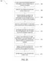
- FIG. 20shows a method 200 of operating the power pack vending system 100 having a central management operation 102 and a plurality of kiosks 10 , each kiosk 10 having a plurality of slots 38 and a plurality of rechargeable power packs 12 , each slot 38 arranged and designed to receive a power pack 12 , and each power pack 12 having a unique identifier and each slot 38 having a slot identification number.
- the central management operation 102stores unique identifier and information pertaining to each power pack 12 in a central database 108 , and the power pack received in each kiosk slot 38 is identified at 204 .
- the unique identifier and information pertaining to each power pack 12 by the kiosk slot identification numberis stored in the central database 108 .
- a user request for a particular type of power pack 12is received at one kiosk 10 .
- Selection of the power pack 12 to vend, responsive to the user request, located in a specific kiosk slot identification numberoccurs at 212 .
- a signal to unlock the selected power pack 12 in the specific slot identification number of the kiosk 10is sent, and the user is informed to take the selected power pack 12 at 216 .
- the step 206 of storing in the central database the unique identifier and information pertaining to each power pack by the kiosk slot identification numbercomprises maintaining and updating a database indicating for each kiosk slot identification number the following information: whether a power pack is present, the power pack unique identifier, the power pack charge status, and the power pack type as shown in FIG. 21 at 207 .
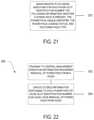
- FIG. 22shows a method 300 of operating the power pack vending system 100 described above.
- FIG. 23shows a method 400 of operating the power pack vending system 100 described above.
- a kiosk 10slidably receives a vended power pack 12 inserted into the kiosk slot 38 .
- the power pack 12is locked in the kiosk 10 when fully inserted into the kiosk slot 38 and the presence of the power pack in the specific kiosk slot identification number is determined.
- the step 406 of determining the presence of the power packcomprises continually polling all of the kiosk slots to detect the presence of a power pack as shown in FIG. 24 at 407 .
- a processormay be any conventional general purpose single- or multi-chip processor including, but not limited to, a Pentium® processor, a Pentium® Pro processor, an 8051 processor, a MIPS® processor, a Power PC® processor, or an Alpha® processor.
- the processormay be a microcontroller or any conventional special purpose processor such as a digital signal processor or a graphics processor.
- Instructionsrefer to computer-implemented steps for processing information in the system 100 . Instructions can be implemented in software, firmware or hardware and include any type of programmed step undertaken by components of the system 100 .
- the system 100is comprised of various modules as discussed in detail.
- each of the modulescomprises various subroutines, procedures, definitional statements and macros.
- Each of the modulesare typically separately compiled and linked into a single executable program. Therefore, the description of each of the modules is used for convenience to describe the functionality of the preferred system.
- the processes that are undergone by each of the modulesmay be arbitrarily redistributed to one of the other modules, combined together in a single module, or made available in, for example, a shareable dynamic link library.
- the system 100may be used in connection with various operating systems such as Linux®, UNIX® or Microsoft Windows® and may be written in any conventional programming language for which commercial compilers can be used to create executable code.
- DSPdigital signal processor
- ASICapplication specific integrated circuit
- FPGAfield programmable gate array
- a general purpose processormay be a microprocessor, but in the alternative, the processor may be any conventional processor, controller, microcontroller, or state machine.
- a processormay also be implemented as a combination of computing devices, e.g., a combination of a DSP and a microprocessor, a plurality of microprocessors, one or more microprocessors in conjunction with a DSP core, or any other such configuration.
Landscapes
- Engineering & Computer Science (AREA)
- Physics & Mathematics (AREA)
- General Physics & Mathematics (AREA)
- Power Engineering (AREA)
- Business, Economics & Management (AREA)
- Accounting & Taxation (AREA)
- General Business, Economics & Management (AREA)
- Strategic Management (AREA)
- Finance (AREA)
- Theoretical Computer Science (AREA)
- Multimedia (AREA)
- Health & Medical Sciences (AREA)
- General Health & Medical Sciences (AREA)
- Medical Informatics (AREA)
- Charge And Discharge Circuits For Batteries Or The Like (AREA)
- Emergency Management (AREA)
Abstract
Description
Claims (21)
Priority Applications (1)
| Application Number | Priority Date | Filing Date | Title |
|---|---|---|---|
| US16/105,672US11239674B2 (en) | 2014-02-28 | 2018-08-20 | Power pack vending apparatus, system and method of use for charging packs with biased locking arrangement |
Applications Claiming Priority (3)
| Application Number | Priority Date | Filing Date | Title |
|---|---|---|---|
| US201461946447P | 2014-02-28 | 2014-02-28 | |
| US14/635,750US10084329B2 (en) | 2014-02-28 | 2015-03-02 | Power pack vending apparatus, system, and method of use for charging power packs with biased locking arrangement |
| US16/105,672US11239674B2 (en) | 2014-02-28 | 2018-08-20 | Power pack vending apparatus, system and method of use for charging packs with biased locking arrangement |
Related Parent Applications (1)
| Application Number | Title | Priority Date | Filing Date |
|---|---|---|---|
| US14/635,750ContinuationUS10084329B2 (en) | 2014-02-28 | 2015-03-02 | Power pack vending apparatus, system, and method of use for charging power packs with biased locking arrangement |
Publications (2)
| Publication Number | Publication Date |
|---|---|
| US20190006862A1 US20190006862A1 (en) | 2019-01-03 |
| US11239674B2true US11239674B2 (en) | 2022-02-01 |
Family
ID=54007207
Family Applications (2)
| Application Number | Title | Priority Date | Filing Date |
|---|---|---|---|
| US14/635,750Active2036-02-23US10084329B2 (en) | 2014-02-28 | 2015-03-02 | Power pack vending apparatus, system, and method of use for charging power packs with biased locking arrangement |
| US16/105,672Active2035-07-20US11239674B2 (en) | 2014-02-28 | 2018-08-20 | Power pack vending apparatus, system and method of use for charging packs with biased locking arrangement |
Family Applications Before (1)
| Application Number | Title | Priority Date | Filing Date |
|---|---|---|---|
| US14/635,750Active2036-02-23US10084329B2 (en) | 2014-02-28 | 2015-03-02 | Power pack vending apparatus, system, and method of use for charging power packs with biased locking arrangement |
Country Status (1)
| Country | Link |
|---|---|
| US (2) | US10084329B2 (en) |
Cited By (3)
| Publication number | Priority date | Publication date | Assignee | Title |
|---|---|---|---|---|
| US20210408806A1 (en)* | 2020-06-25 | 2021-12-30 | Milwaukee Electric Tool Corporation | Charge balancing for a multi-bay power supply |
| US20220024340A1 (en)* | 2018-11-29 | 2022-01-27 | Honda Motor Co., Ltd. | Battery use system, charging device, information processing device, battery use method, program, and storage medium |
| US20220278377A1 (en)* | 2019-08-07 | 2022-09-01 | Moshe Amzaleg | A portable device and an apparatus for replacing used battery of the portable device |
Families Citing this family (82)
| Publication number | Priority date | Publication date | Assignee | Title |
|---|---|---|---|---|
| US10381856B2 (en)* | 2014-10-03 | 2019-08-13 | Robert Bosch Tool Corporation | Inductive charging holster for power tool |
| US10445708B2 (en) | 2014-10-03 | 2019-10-15 | Ecoatm, Llc | System for electrically testing mobile devices at a consumer-operated kiosk, and associated devices and methods |
| WO2016086274A1 (en) | 2014-12-04 | 2016-06-09 | Dignan Herbert Rayner | An apparatus and system for providing a secondary power source for an electric vehicle |
| USD772084S1 (en) | 2014-12-19 | 2016-11-22 | Park 'n Fly Service Llc | Parking kiosk |
| US10283984B2 (en)* | 2015-07-31 | 2019-05-07 | Bretford Manufacturing, Inc. | Charging locker |
| US10715972B2 (en)* | 2015-07-31 | 2020-07-14 | CityBeacon IP BV | Multifunctional interactive beacon with mobile device interaction |
| US9451060B1 (en) | 2015-10-15 | 2016-09-20 | Civiq Smartscapes, Llc | Techniques and apparatus for controlling access to components of a personal communication structure (PCS) |
| US20170098947A1 (en)* | 2015-10-02 | 2017-04-06 | Hand Held Products, Inc. | Battery handling apparatus |
| US10270918B2 (en)* | 2015-10-15 | 2019-04-23 | Civiq Smartscapes, Llc | Method and apparatus for power and temperature control of compartments within a personal communication structure (PCS) |
| WO2017087496A1 (en) | 2015-11-16 | 2017-05-26 | Civiq Smartscapes, Llc | Systems and techniques for vandalism detection in a personal communication structure (pcs) |
| JP6582909B2 (en)* | 2015-11-17 | 2019-10-02 | オムロン株式会社 | Battery reservation device and battery reservation method |
| JP6597218B2 (en)* | 2015-11-17 | 2019-10-30 | オムロン株式会社 | Battery reservation device and battery reservation method |
| JP6724343B2 (en)* | 2015-11-17 | 2020-07-15 | オムロン株式会社 | Reservation management device, reservation management system, and reservation management method |
| JP6766343B2 (en) | 2015-11-17 | 2020-10-14 | オムロン株式会社 | Battery reservation device |
| WO2018029543A2 (en) | 2016-04-01 | 2018-02-15 | Ijuze Corporation Pte Ltd. | An automated system for managing and providing a network of charging stations |
| USD790457S1 (en)* | 2016-04-19 | 2017-06-27 | Ds Mediatech, Inc. | Combination charging and display station |
| US10496957B2 (en)* | 2016-05-23 | 2019-12-03 | Taser International, Inc. | Systems for replenishing deployment units for conducted electrical weapons |
| US10846674B2 (en)* | 2016-06-15 | 2020-11-24 | Dignan Rayner | Rechargeable devices and kiosks for same |
| CN106182009A (en)* | 2016-08-18 | 2016-12-07 | 深圳市云充吧科技有限公司 | A kind of portable power source leased equipment |
| CA172417S (en)* | 2016-12-29 | 2017-09-27 | Pyramid Computer Gmbh | Combined control unit with display |
| WO2018177339A1 (en)* | 2017-03-28 | 2018-10-04 | Kwok Ching Kwong | A kiosk cluster |
| US11796340B2 (en) | 2017-04-03 | 2023-10-24 | Power Hero Corp. | Universal automated system for identifying, registering and verifying the existence, location and characteristics of electric and other power outlets by random users and for retrieval and utilization of such parametric data and outlets by all users |
| CN107256591B (en)* | 2017-06-19 | 2019-09-17 | 上海工业控制安全创新科技有限公司 | A kind of electric energy sharing method and system |
| CN107293056B (en)* | 2017-06-19 | 2020-01-03 | 国网河南省电力公司商丘供电公司 | Electric energy sharing method and system |
| US10672218B1 (en)* | 2017-06-20 | 2020-06-02 | Rick Lawson | Personal electronic charging station |
| CN107230293A (en)* | 2017-07-14 | 2017-10-03 | 深圳市华宝新能源股份有限公司 | Environment protection movable power supply and its rental device |
| KR101983624B1 (en)* | 2017-07-24 | 2019-05-29 | 주식회사 리베르곤 | Auxiliary Battery and Auxiliary Battery Rental Machine |
| USD867986S1 (en)* | 2017-11-07 | 2019-11-26 | Energy2Go Srl | Accumulator charging apparatus |
| US20190214936A1 (en)* | 2018-01-09 | 2019-07-11 | Sunflare Co. | Solar panel and portable power bank |
| USD860932S1 (en)* | 2018-02-22 | 2019-09-24 | Hermes Sellier (Société par Actions Simplifiée) | Electric charger for telephone |
| US11813950B2 (en)* | 2018-02-28 | 2023-11-14 | Walmart Apollo, Llc | System for storing unmanned aerial vehicles |
| US11315057B2 (en)* | 2018-09-20 | 2022-04-26 | Honda Motor Co., Ltd. | Power storage device management system, storage device, server device, power storage device management method, program, and storage medium |
| USD893627S1 (en)* | 2018-09-24 | 2020-08-18 | Sos Group, Inc. | Vending machine |
| JP1715207S (en)* | 2018-11-29 | 2022-05-17 | Self-order terminal with touch screen | |
| US12322259B2 (en)* | 2018-12-19 | 2025-06-03 | Ecoatm, Llc | Systems and methods for vending and/or purchasing mobile phones and other electronic devices |
| US10797497B2 (en)* | 2019-01-04 | 2020-10-06 | Neutron Holdings, Inc. | Rechargeable battery kiosk for light electric vehicles |
| WO2020179262A1 (en)* | 2019-03-06 | 2020-09-10 | パナソニックIpマネジメント株式会社 | Battery managing system, battery managing method, and terminal device |
| CN110136338B (en)* | 2019-04-04 | 2021-06-22 | 上海挚想科技有限公司 | Identity recognition communication device and method for mobile power supply leasing equipment |
| USD942378S1 (en)* | 2019-04-26 | 2022-02-01 | Lg Electronics Inc. | Charger for vehicles driven electrically |
| USD943519S1 (en)* | 2019-04-26 | 2022-02-15 | Lg Electronics Inc. | Charger for vehicles driven electrically |
| USD942937S1 (en)* | 2019-04-26 | 2022-02-08 | Lg Electronics Inc. | Charger for vehicles driven electrically |
| USD943518S1 (en)* | 2019-04-26 | 2022-02-15 | Lg Electronics Inc. | Charger for vehicles driven electrically |
| USD937201S1 (en)* | 2019-04-26 | 2021-11-30 | Lg Electronics Inc. | Charger for vehicles driven electrically |
| US12223487B2 (en)* | 2019-05-02 | 2025-02-11 | IKE Smart City, LLC | Interactive kiosk for displaying a code that is imaged by a portable electronic to cause the portable electronic device to perform an operation and method thereof |
| MX2021014165A (en)* | 2019-05-20 | 2022-01-24 | Hubbell Inc | Device charging system. |
| JP7444168B2 (en)* | 2019-07-12 | 2024-03-06 | 日本電気株式会社 | Sharing management device, sharing management method, program |
| CN210377672U (en)* | 2019-07-31 | 2020-04-21 | 深圳市倍斯特科技股份有限公司 | Sharing treasured advertisement machine that charges |
| USD958059S1 (en) | 2019-10-29 | 2022-07-19 | Manufacturing Resources International, Inc. | Solar powered electronic display assembly with pole mount |
| CN110827478A (en)* | 2019-11-13 | 2020-02-21 | 深圳市搜电科技发展有限公司 | Device, system and method for returning and judging charge pal of rented equipment |
| US11495975B2 (en) | 2019-11-13 | 2022-11-08 | Samsung Sdi Co., Ltd. | Battery system, and method of allocating CAN ID |
| BR112022011203A2 (en)* | 2019-12-10 | 2022-08-23 | Verisure Sarl | MODULAR SYSTEM FOR AN ALARM AND PERIPHERAL SYSTEM INSTALLATION |
| WO2021127291A2 (en) | 2019-12-18 | 2021-06-24 | Ecoatm, Llc | Systems and methods for vending and/or purchasing mobile phones and other electronic devices |
| US11502546B2 (en) | 2020-02-17 | 2022-11-15 | Covidien Ag | Wireless charging system for medical devices |
| USD988256S1 (en)* | 2020-04-30 | 2023-06-06 | Siemens Aktiengesellschaft | Charging station |
| CN111799868B (en)* | 2020-07-22 | 2021-09-07 | 穿梭(深圳)传媒有限公司 | Mobile power supply, mobile power supply leasing equipment and control method thereof |
| USD948423S1 (en)* | 2020-09-28 | 2022-04-12 | Crown Castle Investment Corp. | Vehicle charging station |
| USD950485S1 (en)* | 2020-11-04 | 2022-05-03 | Volta Charging, Llc | Charging station |
| USD988992S1 (en)* | 2021-02-11 | 2023-06-13 | I-Charging—Mobilidade Elétrica, Sa | Charger |
| USD983141S1 (en)* | 2021-08-25 | 2023-04-11 | Vestel Elektronik Sanayi Ve Ticaret Anonim Sirketi | Charging station for electric vehicles |
| CA208994S (en)* | 2021-12-17 | 2023-07-11 | Big Digital Corp | Freestanding digital display unit |
| USD1008950S1 (en)* | 2022-01-11 | 2023-12-26 | Volta Charging, Llc | Charging station |
| USD1019547S1 (en)* | 2022-04-21 | 2024-03-26 | Nanjing Powercore Tech Co., Ltd. | Charging pile with two plugs |
| USD1030645S1 (en)* | 2022-04-27 | 2024-06-11 | EV Mode LLC | Electric vehicle charging device |
| USD1075919S1 (en)* | 2022-05-12 | 2025-05-20 | Wildflower Flow Inc. | Smart vending machine |
| USD1043829S1 (en)* | 2022-05-12 | 2024-09-24 | Wildflower Flow Inc. | Smart vending machine |
| USD1038123S1 (en)* | 2022-06-14 | 2024-08-06 | Ineo Solutions Inc. | Electronic article surveillance pedestal with two-sided display |
| USD1040229S1 (en)* | 2022-06-14 | 2024-08-27 | Fenfang Huang | Vending machine |
| US20230406149A1 (en)* | 2022-06-21 | 2023-12-21 | II Alton E. Ofczarzak | Electric vehicle replaceable battery system |
| CA214641S (en)* | 2022-07-29 | 2024-02-01 | Big Digital Corp | Freestanding digital display unit |
| USD1029939S1 (en)* | 2022-08-31 | 2024-06-04 | Manufacturing Resources International, Inc. | Electronic display unit |
| US12106687B2 (en) | 2022-08-31 | 2024-10-01 | Manufacturing Resources International, Inc. | Display assembly with unobstructed zone |
| US11997808B2 (en) | 2022-08-31 | 2024-05-28 | Manufacturing Resources International, Inc. | Display assembly with unobstructed zone |
| CN115277027B (en)* | 2022-09-26 | 2022-12-20 | 广州万协通信息技术有限公司 | Security chip charging attack detection method, security chip device, equipment and medium |
| USD1087900S1 (en)* | 2022-11-18 | 2025-08-12 | Hyundai Motor Company | Charger for an electric vehicle |
| USD1030873S1 (en) | 2023-03-02 | 2024-06-11 | Manufacturing Resources International, Inc. | Electronic display unit |
| DE202023101515U1 (en) | 2023-03-27 | 2023-05-15 | Kwesi Dei-Anang | Charging machine for the simultaneous charging of several mobile end devices in public spaces using solar energy |
| WO2024228776A1 (en)* | 2023-05-04 | 2024-11-07 | Milwaukee Electric Tool Corporation | Multiple pack charging control for power tool battery packs |
| USD1030691S1 (en) | 2023-06-02 | 2024-06-11 | Manufacturing Resources International, Inc. | Electronic display assembly structure |
| USD1070843S1 (en) | 2023-07-17 | 2025-04-15 | Manufacturing Resources International, Inc. | Electronic display assembly |
| USD1076846S1 (en) | 2024-09-12 | 2025-05-27 | Manufacturing Resources International, Inc. | Electronic display assembly |
| USD1066280S1 (en) | 2024-09-12 | 2025-03-11 | Manufacturing Resources International, Inc. | Electronic display assembly |
| CN119376316B (en)* | 2024-12-25 | 2025-04-18 | 杭州数蚕智能科技有限公司 | Configuration internet of things equipment |
Citations (179)
| Publication number | Priority date | Publication date | Assignee | Title |
|---|---|---|---|---|
| US3327278A (en)* | 1964-09-23 | 1967-06-20 | American Mach & Foundry | Electrical interconnecting devices |
| US3752360A (en)* | 1972-08-18 | 1973-08-14 | Vendo Co | Selective dispensing apparatus for bottled products or the like |
| US3870135A (en)* | 1971-03-17 | 1975-03-11 | Carton Sales Inc | Cigarette carton dispensing system |
| US4121707A (en)* | 1976-03-02 | 1978-10-24 | E. B. Metal & Rubber Industries, Inc. | Satellite vending machine |
| US4196951A (en)* | 1978-03-20 | 1980-04-08 | Gross-Given Manufacturing Company | Vendor with door and shelf interlock |
| US4236649A (en)* | 1979-04-06 | 1980-12-02 | Fellner N Van | Compact vending machine |
| US4324325A (en)* | 1979-12-21 | 1982-04-13 | Dewoolfson Bruce H | Apparatus for collection of metallic containers and method therefor |
| US4345679A (en)* | 1980-05-09 | 1982-08-24 | Dewoolfson Bruce H | Container collection apparatus with electromagnetic sensor and method |
| US4440284A (en)* | 1980-05-09 | 1984-04-03 | Environmental Products Corporation | Automated aluminum can redemption center for direct return deposit payout |
| US4469212A (en)* | 1982-04-20 | 1984-09-04 | Environmental Products Corporation | Container collection apparatus with piston-actuated crusher |
| US4491240A (en)* | 1982-12-03 | 1985-01-01 | Frank Ruskin | Compact vending machine |
| US4492295A (en)* | 1982-03-05 | 1985-01-08 | Environmental Products Corporation | Automated redemption center for metal containers |
| US4573641A (en)* | 1983-11-17 | 1986-03-04 | Environmental Products Corporation | Glass bottle collection and crushing apparatus |
| US4577144A (en) | 1984-10-11 | 1986-03-18 | General Electric Company | Battery charging system including means for distinguishing between rechargeable and non-rechargeable batteries |
| US4611160A (en)* | 1984-01-09 | 1986-09-09 | U.S. Philips Corporation | Charging device |
| US4789054A (en)* | 1985-01-02 | 1988-12-06 | Abm Industries, Inc. | Vending machine for returnable cartridges |
| US4869395A (en)* | 1987-05-19 | 1989-09-26 | Aktiebolaget Electrolux | Vending machine with interchangeable magazines |
| US4893705A (en)* | 1987-12-04 | 1990-01-16 | Brown Leonard C | Vending machine having plural compartments which are independently selected and controlled |
| US5025950A (en)* | 1990-01-16 | 1991-06-25 | Hobart Corporation | Apparatus for storing and dispensing frozen comestibles |
| US5133441A (en)* | 1985-06-17 | 1992-07-28 | Keyosk Corporation | Video cassette vending machine |
| US5364592A (en)* | 1992-07-22 | 1994-11-15 | Akzo N.V. | Cassette for storing and dispensing cuvettes |
| US5499707A (en)* | 1995-01-31 | 1996-03-19 | Compu-Shop, Inc. | Automated merchandising kiosk |
| US5544784A (en) | 1995-05-26 | 1996-08-13 | Motorola, Inc. | Rechargeable battery vending machine |
| US5631536A (en)* | 1994-05-16 | 1997-05-20 | Tseng; Ling-Yuan | Rechargeable battery vending apparatus |
| US5651476A (en)* | 1995-06-07 | 1997-07-29 | Dixie-Narco, Inc. | Modular vending machine |
| US5691618A (en)* | 1992-11-16 | 1997-11-25 | Yupiteru Industries Co., Ltd. | Battery pack charging device |
| US5694019A (en) | 1995-09-29 | 1997-12-02 | Ricoh Company, Ltd. | Battery charging apparatus and network system with enhanced versatility in dispensing recharged batteries |
| DE19626164A1 (en) | 1996-06-29 | 1998-01-08 | Hecht Siegmar Dr | Vending machine for rechargeable battery |
| US5711648A (en)* | 1994-01-06 | 1998-01-27 | Unlimited Range Electric Car Systems Company | Battery charging and transfer system |
| US5744933A (en)* | 1995-11-13 | 1998-04-28 | Kn Technos Co., Ltd. | Vending machine for charging a secondary battery of a mobile phone |
| US5764026A (en)* | 1996-10-04 | 1998-06-09 | Issa; Darrell E. | Spare cellular telephone charging unit |
| US5812643A (en)* | 1997-02-06 | 1998-09-22 | Powertel, Inc. | Power and telecommunications access vending machine |
| WO1998047799A1 (en) | 1997-04-22 | 1998-10-29 | Charmasson Henri J A | Compact table-top vending machine |
| US5844401A (en)* | 1996-05-16 | 1998-12-01 | Samsung Electronics Co., Ltd. | Charging device for easy mounting/dismounting of a battery |
| US5926627A (en)* | 1996-04-26 | 1999-07-20 | Canon Kabushiki Kaisha | Electronic apparatus for engaging a portable computer with an expansion unit |
| US6049192A (en) | 1999-03-18 | 2000-04-11 | Motorola, Inc. | Battery charger having moving door housing for a battery |
| JP2001266954A (en) | 2000-03-15 | 2001-09-28 | Sony Corp | Vending machine and selling method of charged battery |
| US6314169B1 (en)* | 1997-02-06 | 2001-11-06 | Poweroasis, Inc. | Power and telecommunications access vending machine |
| US6330958B1 (en)* | 1997-04-22 | 2001-12-18 | Frank Ruskin | Compact table-top vending machine |
| US6356053B1 (en)* | 1999-09-22 | 2002-03-12 | Lucent Technologies Inc. | Charging mechanism for cordless telephone and other electrical devices |
| US6367653B1 (en)* | 1997-04-22 | 2002-04-09 | Frank Ruskin | Centralized machine vending method |
| US20020117510A1 (en)* | 2001-02-26 | 2002-08-29 | Simson Anton K. | Compact vending machine |
| US20020156537A1 (en)* | 2001-04-18 | 2002-10-24 | Kazuyuki Sakakibara | Methods and apparatus for managing a plurality of charging devices via a network |
| US20020153382A1 (en)* | 1997-04-22 | 2002-10-24 | Frank Ruskin | Processing method for vending machine with substitutable magazines |
| US20030010827A1 (en)* | 2001-02-20 | 2003-01-16 | Hilton Graham H. | Dual magazine recirculating transport |
| US6516858B1 (en)* | 1999-01-11 | 2003-02-11 | Hunter Douglas | Headrail including a detachable battery holder for powered coverings for architectural openings |
| US20030069050A1 (en)* | 2001-10-05 | 2003-04-10 | Chien-Min Lin | Portable electronic system equipped with a spare battery device |
| US20030120380A1 (en)* | 2001-12-21 | 2003-06-26 | Bean Heather N. | Battery recycling |
| US20030136794A1 (en)* | 2002-11-23 | 2003-07-24 | Munroe Chirnomas | Method and apparatus for storing articles for use with an article handling device |
| US20030209375A1 (en)* | 1999-01-25 | 2003-11-13 | Zip Charge Corporation | Electrical vehicle energy supply system, electrical vehicle battery, electrical vehicle battery charging apparatus, battery supply apparatus, and electrical vehicle battery management system |
| US20040016620A1 (en)* | 2002-06-28 | 2004-01-29 | Davis Melanee A. | Method for providing vendable items of entertainment |
| US20040026441A1 (en)* | 2000-05-23 | 2004-02-12 | Munroe Chirnomas | Method and apparatus for storing articles for use with an article handling device |
| US20040056041A1 (en)* | 2002-09-19 | 2004-03-25 | Jerome Renard | Vending machine for chemiluminescent novelty items |
| US6822422B2 (en)* | 2002-03-07 | 2004-11-23 | Nec Corporation | Battery recycle system |
| US20050001591A1 (en)* | 2002-11-05 | 2005-01-06 | Masayuki Nagamine | Trade-in battery system |
| US20050007066A1 (en)* | 2003-07-07 | 2005-01-13 | Jason Long | Charging stand having open and closed positions |
| US20050211721A1 (en)* | 2002-06-13 | 2005-09-29 | Munroe Chirnomas | Article storage magazine for an article handling device |
| US20050247721A1 (en)* | 2004-03-24 | 2005-11-10 | Simson Anton K | Pneumatic vending machine |
| US20050280395A1 (en)* | 2004-06-18 | 2005-12-22 | Lg Electronics Inc. | Battery-charging assembly for image display device and cradle with the same |
| USD520013S1 (en)* | 2004-09-20 | 2006-05-02 | Reigncom Ltd. | Cradle |
| US20060226805A1 (en)* | 2005-04-11 | 2006-10-12 | Tsung-I Yu | Mobile battery-charging container |
| US7166987B2 (en)* | 2003-10-10 | 2007-01-23 | R. F. Tech Co., Ltd | Portable charger for mobile phone |
| US20070050266A1 (en)* | 2000-05-25 | 2007-03-01 | Barber William H | System and kiosk for commerce of optical media through multiple locations |
| US20070236180A1 (en) | 2006-04-11 | 2007-10-11 | Andrew Rodgers | Recharging device for use with portable electronic devices |
| US20080007211A1 (en)* | 2006-06-30 | 2008-01-10 | David Poisner | Battery charger chute |
| US20080164279A1 (en)* | 2003-06-13 | 2008-07-10 | Munroe Chirnomas | Article storage magazine for an article handling device |
| US20080234013A1 (en)* | 2007-03-23 | 2008-09-25 | Bury Sp Z O.O. | Mobile phone holder, especially for mechanical vehicle |
| US20080281732A1 (en)* | 2005-02-22 | 2008-11-13 | Kazuo Yamada | Battery Exchange Service System and Charging Method Therefor, and Portable Device |
| US20090014460A1 (en)* | 2007-07-12 | 2009-01-15 | Kobus Ii Joseph M | Mobile self-contained power vending station and method |
| US20090033278A1 (en)* | 2007-07-31 | 2009-02-05 | Apple Inc. | Host machines for battery charging system |
| US20090051319A1 (en)* | 2007-08-21 | 2009-02-26 | Asustek Computer Inc. | Phone charging stand |
| USD592132S1 (en)* | 2008-05-12 | 2009-05-12 | Cheng Uei Precision Industry Co., Ltd. | Recharging device |
| US20090133733A1 (en)* | 2007-11-27 | 2009-05-28 | Retti Kahrl L | Autonomous, modular power generation, storage and distribution apparatus, system and method thereof |
| US20090198372A1 (en)* | 2008-02-05 | 2009-08-06 | Unlimited Range Electric Car Systems Company | Battery charging and transfer system for electrically powered vehicles |
| US7584868B2 (en)* | 2004-06-30 | 2009-09-08 | Airbus Deutschland Gmbh | Vending machine for an aircraft |
| USD601089S1 (en)* | 2008-12-11 | 2009-09-29 | Cheng Uei Precision Industry Co., Ltd. | Charging connector |
| US20090263704A1 (en)* | 2008-04-19 | 2009-10-22 | Jitendra Batra | Power stroage and power transfer method and apparatus |
| US7619388B1 (en) | 2007-03-05 | 2009-11-17 | Nana Prince K | Detachable back-up battery pack for cell phone |
| USD607817S1 (en)* | 2009-06-09 | 2010-01-12 | Teleway Industrial Ltd. | Phone holder and charger |
| US20100088192A1 (en)* | 2008-10-02 | 2010-04-08 | Mark Bowles | Secondary market and vending system for devices |
| USD618237S1 (en) | 2009-05-12 | 2010-06-22 | Datastore Technology Corp. | External storage device case |
| US20100228405A1 (en)* | 2007-06-13 | 2010-09-09 | Intrago Corporation | Shared vehicle management system |
| USD628153S1 (en) | 2010-07-16 | 2010-11-30 | T-Mobile Usa, Inc. | Micro USB charger |
| USD628535S1 (en) | 2010-06-24 | 2010-12-07 | Cheng Uei Precision Industry Co., Ltd. | Portable charger |
| US20100312938A1 (en)* | 2009-06-03 | 2010-12-09 | Urs Stampfli | Portable electronic device holster with guided docking station |
| US20100312380A1 (en)* | 2005-04-22 | 2010-12-09 | Redbox Automated Retail, Llc | System and method for regulating vendible media products |
| US20110074334A1 (en)* | 2009-09-25 | 2011-03-31 | Ku-Fang Wang | Power-saving solar power supply system for automatic vending machine |
| US7923964B2 (en)* | 2008-06-06 | 2011-04-12 | Cheng Uei Precision Industry Co., Ltd. | Charger including a rotatable module having an output connector, the module pivotally disposed in a cavity defined in an upper surface of a base of the charger |
| US20110106329A1 (en)* | 2009-11-03 | 2011-05-05 | GRIDbot, LLC | Methods and apparatus for charging station with sms user interface |
| US7956576B2 (en) | 2004-09-15 | 2011-06-07 | Belkin International, Inc. | Rechargeable battery packs and related methods |
| US20110169451A1 (en)* | 2009-06-19 | 2011-07-14 | Urs Stampfli | Portable electronic device holster with pivoting docking station |
| USD641695S1 (en)* | 2010-12-09 | 2011-07-19 | T-Mobile Usa, Inc. | Device charger with dual folding power plugs |
| US8013571B2 (en)* | 2008-09-19 | 2011-09-06 | Better Place GmbH | Battery exchange station |
| US20110234160A1 (en)* | 2010-03-29 | 2011-09-29 | Smith Stephen J | Battery charger for charging batteries of different sizes |
| US8033424B2 (en)* | 2000-06-08 | 2011-10-11 | Instymeds Corporation | Automatic prescription drug dispenser |
| US20110273180A1 (en)* | 2010-05-07 | 2011-11-10 | Mansik Park | Battery testing method |
| USD652379S1 (en) | 2011-04-22 | 2012-01-17 | Scosche Industries, Inc. | Portable electronic device recharger |
| US20120016518A1 (en)* | 2010-07-14 | 2012-01-19 | Saario Ross D | Consumer-operated kiosks for buying and/or selling consumer products and associated systems and methods |
| US20120029691A1 (en)* | 2010-06-02 | 2012-02-02 | Darrell Scott Mockus | Mobile device assisted retail system and process in a vending unit, retail display or automated retail store |
| US20120078413A1 (en)* | 2010-09-29 | 2012-03-29 | Baker Jr Therman A | Secured electrical recharging facility method and apparatus |
| US20120091961A1 (en)* | 2010-01-11 | 2012-04-19 | Leviton Manufacturing Co., Inc. | Electric vehicle supply equipment with storage connector |
| US8165643B2 (en)* | 2009-02-20 | 2012-04-24 | Cheng Uei Precision Industry Co., Ltd. | Charging cradle |
| USD659094S1 (en) | 2011-08-19 | 2012-05-08 | Mophie, Inc. | Portable battery charger |
| USD662050S1 (en) | 2011-10-28 | 2012-06-19 | Hon Hai Precision Industry Co., Ltd. | Portable power bank |
| US20120169277A1 (en)* | 2010-12-29 | 2012-07-05 | Hon Hai Precision Industry Co., Ltd. | Portable charging device |
| USD666144S1 (en) | 2011-08-19 | 2012-08-28 | Mophie, Inc. | Universal battery pack |
| US20120222938A1 (en)* | 2011-03-02 | 2012-09-06 | Rose Jr R Edward | Large bottle vending apparatus and method |
| WO2012119289A1 (en) | 2011-03-04 | 2012-09-13 | Liu Hui | Rechargeable battery, battery rental method, power supply system, and power supply method |
| US20120268064A1 (en) | 2011-04-19 | 2012-10-25 | Powermat Usa, Llc | Inductively Rechargeable Portable Charger |
| US20120271723A1 (en)* | 2011-04-22 | 2012-10-25 | Penilla Angel A | Electric vehicle (ev) range extending charge systems, distributed networks of charge kiosks, and charge locating mobile apps |
| US20120306431A1 (en)* | 2011-06-03 | 2012-12-06 | Hon Hai Precision Industry Co., Ltd. | Protective cover with battery for electronic device |
| USD672309S1 (en) | 2011-11-16 | 2012-12-11 | Hon Hai Precision Industry Co., Ltd. | Portable power bank |
| US20130002049A1 (en) | 2011-07-01 | 2013-01-03 | Urs Stampfli | Battery booster for an electronic device |
| US8348450B2 (en) | 2010-01-07 | 2013-01-08 | Amazon Technologies, Inc. | Book light for electronic book reader devices |
| USD674748S1 (en) | 2012-05-03 | 2013-01-22 | Fka Distributing Co. | Portable power supply for a mobile device |
| US20130026971A1 (en)* | 2011-07-26 | 2013-01-31 | Gogoro, Inc. | Apparatus, method and article for collection, charging and distributing power storage devices, such as batteries |
| US20130030920A1 (en)* | 2011-07-26 | 2013-01-31 | Gogoro, Inc. | Apparatus, method and article for providing information regarding availability of power storage devices at a power storage device collection, charging and distribution machine |
| US20130063073A1 (en) | 2011-09-09 | 2013-03-14 | Bettery, Inc. | Battery exchange, recharge and recycle apparatus, system and method |
| USD680063S1 (en) | 2012-01-18 | 2013-04-16 | Sanyo Electric Co., Ltd. | Battery |
| US20130106352A1 (en) | 2011-10-31 | 2013-05-02 | Hiroshi Nagamine | Battery charger, battery pack docking module, and battery pack module |
| USD682197S1 (en) | 2012-11-07 | 2013-05-14 | Globexpress Co. Limited, DBA HKGE US Inc | Battery pack |
| USD682196S1 (en) | 2012-11-07 | 2013-05-14 | Globexpress Co. Limited | Battery pack with illuminated power button |
| WO2013074819A1 (en) | 2011-11-16 | 2013-05-23 | Yau Chi W | Two-way vending |
| US20130150134A1 (en)* | 2011-10-06 | 2013-06-13 | Anthem Grand Llc | Smart Phone and/or Consumer Electronics Device Charger System |
| USD686153S1 (en) | 2012-06-20 | 2013-07-16 | Dexin Ming Electronics (Shenzhen) Co., Ltd. | Battery |
| US20130181661A1 (en)* | 2012-01-06 | 2013-07-18 | Goal Zero Llc | Reconfigurable energy storage and power supply device |
| US20130187607A1 (en) | 2012-01-23 | 2013-07-25 | Ko-Ming WANG | Charging device used in handheld devices |
| US20130193911A1 (en)* | 2011-08-10 | 2013-08-01 | Garold C. Miller | Motion-actuated portable charger |
| US20130241470A1 (en)* | 2012-03-13 | 2013-09-19 | Samsung Electronics Co., Ltd. | Universal dock for portable phone |
| WO2013142154A1 (en) | 2012-03-20 | 2013-09-26 | Tricopian, Llc | Two-way exchange vending |
| US20130278215A1 (en)* | 2012-04-22 | 2013-10-24 | lGregory Dea | Case For Portable Electronic Device With Integral Detachable Power Converter For Battery Charging |
| US20130328526A1 (en)* | 2012-06-07 | 2013-12-12 | Navajo Manufacturing Company, Inc. | Compact car charger |
| US20130335027A1 (en)* | 2012-06-14 | 2013-12-19 | Jiang Xin | Secure Mobile Electronic Device Servicing Kiosk |
| US8630088B2 (en)* | 2009-03-27 | 2014-01-14 | Qualcomm Incorporated | Portable docking station for a portable computing device |
| USD697867S1 (en) | 2012-08-10 | 2014-01-21 | Halo2Cloud Llc | Portable power charger |
| US20140032412A1 (en)* | 2012-06-26 | 2014-01-30 | Harexinfotech Inc. | Payment system and method for vending machine using mobile terminal and storage medium storing program for implementing the method |
| US20140028247A1 (en) | 2012-07-25 | 2014-01-30 | Unihan Corporation | Angle adjustable connecting module |
| US8680869B2 (en)* | 2010-02-16 | 2014-03-25 | Blackberry Limited | AC charging contact mechanism |
| USD702632S1 (en) | 2013-09-05 | 2014-04-15 | Flying Dragon Development Limited | Portable charger with LED light |
| US20140110206A1 (en) | 2012-10-24 | 2014-04-24 | Hon Hai Precision Industry Co., Ltd. | Mobile power pack with built-in retractable cable |
| US20140143074A1 (en)* | 2001-03-26 | 2014-05-22 | Usa Technologies, Inc. | Interactive interface effectuated vending |
| US20140175031A1 (en)* | 2012-12-21 | 2014-06-26 | Nathan R. Roberts | Storage and charging station system for portable electronic devices |
| US20140176072A1 (en)* | 2012-12-24 | 2014-06-26 | Hon Hai Precision Industry Co., Ltd. | Portable electrical energy source |
| US8862388B2 (en)* | 2011-07-26 | 2014-10-14 | Gogoro, Inc. | Apparatus, method and article for providing locations of power storage device collection, charging and distribution machines |
| US8862304B2 (en)* | 2011-07-26 | 2014-10-14 | Gogoro, Inc. | Apparatus, method and article for providing vehicle diagnostic data |
| US20140312831A1 (en)* | 2013-03-15 | 2014-10-23 | Shaw Industries Group, Inc. | Battery Management System and Method |
| US20140340021A1 (en)* | 2013-05-20 | 2014-11-20 | Hon Hai Precision Industry Co., Ltd. | Portable electrical power source |
| US20140350716A1 (en)* | 2013-05-21 | 2014-11-27 | Snap-On Incorporated | Battery monitoring in a networked inventory control system |
| US20140368156A1 (en)* | 2013-06-13 | 2014-12-18 | John Aloe | Battery and Charger Kiosk |
| US20150032502A1 (en)* | 2013-07-29 | 2015-01-29 | Askuity Inc. | Systems and methods for sales and inventory management |
| US20150077221A1 (en)* | 2013-09-18 | 2015-03-19 | Renovo Software, Inc. | Apparatus for controlling access to and use of portable electronic devices |
| US8988872B2 (en)* | 2011-03-18 | 2015-03-24 | Woox Innovations Belgium Nv | Cradle for a portable device having a connector rotatably mounted on a base |
| US20150137759A1 (en)* | 2013-08-22 | 2015-05-21 | MobileQubes, LLC | Automated Mobile Device Battery Charging Kiosks |
| US9182244B2 (en)* | 2011-07-26 | 2015-11-10 | Gogoro Inc. | Apparatus, method and article for authentication, security and control of power storage devices, such as batteries |
| US9240007B2 (en)* | 2013-10-03 | 2016-01-19 | Vendwatch Telematics, Llc | Vending system |
| US9275505B2 (en)* | 2011-07-26 | 2016-03-01 | Gogoro Inc. | Apparatus, method and article for physical security of power storage devices in vehicles |
| US20160068075A1 (en)* | 2014-09-04 | 2016-03-10 | Gogoro Inc. | Apparatus, system, and method for vending, charging, and two-way distribution of electrical energy storage devices |
| US20160099590A1 (en)* | 2014-10-06 | 2016-04-07 | Black & Decker Inc. | System and method for renting, charging, and discharging battery packs |
| USD758965S1 (en)* | 2015-02-03 | 2016-06-14 | Jerry Jen | Charging adapter |
| US20160180632A1 (en)* | 2014-12-19 | 2016-06-23 | Alejandro Santana | Method for Renting a Portable and Universal Power Charger from a Vending Machine |
| US20160197337A1 (en)* | 2013-08-22 | 2016-07-07 | Tricopian, Llc | Standardized rechargeable battery cell |
| US9389660B2 (en)* | 2011-07-28 | 2016-07-12 | Quanta Computer Inc. | Rack server system and operation method applicable thereto |
| US20160205800A1 (en)* | 2012-12-21 | 2016-07-14 | Nathan R. Roberts | Storage and charging station system for portable electronic devices |
| US20160236867A1 (en)* | 2015-02-13 | 2016-08-18 | Amazon Technologies, Inc. | Modular, multi-function smart storage containers |
| US9424697B2 (en)* | 2011-07-26 | 2016-08-23 | Gogoro Inc. | Apparatus, method and article for a power storage device compartment |
| US20160268822A1 (en)* | 2015-03-09 | 2016-09-15 | Panasonic Intellectual Property Management Co., Ltd. | Storage battery housing device |
| US9496720B2 (en)* | 2004-08-20 | 2016-11-15 | Midtronics, Inc. | System for automatically gathering battery information |
| US9552682B2 (en)* | 2011-07-26 | 2017-01-24 | Gogoro Inc. | Apparatus, method and article for redistributing power storage devices, such as batteries, between collection, charging and distribution machines |
| US20170085103A1 (en)* | 2015-09-22 | 2017-03-23 | Bseng, Llc | Battery charger rental kiosk system |
| US20170190259A1 (en)* | 2011-04-22 | 2017-07-06 | Angel A. Penilla | Cloud access to exchangeable batteries for use by electric vehicles |
| US20170322561A1 (en)* | 2016-05-03 | 2017-11-09 | Bby Solutions, Inc. | Robotic inventory dispensary operational enhancements |
| US20170330158A1 (en)* | 2008-10-02 | 2017-11-16 | ecoATM, Inc. | Apparatus and method for recycling mobile phones |
| US20170331318A1 (en)* | 2016-05-11 | 2017-11-16 | Electrochem Solutions, Inc. | Wireless charging autoclavable batteries inside a sterilizable tray |
| US9904911B2 (en)* | 2008-10-02 | 2018-02-27 | ecoATM, Inc. | Secondary market and vending system for devices |
| US9919277B2 (en) | 2004-10-08 | 2018-03-20 | Medical Research Council | In vitro evolution in microfluidic systems |
| US20190168876A1 (en)* | 2017-12-01 | 2019-06-06 | International Business Machines Corporation | Methods and systems for transfer of data storage components in an automated data storage system using drones |
| US20190252894A1 (en)* | 2016-11-07 | 2019-08-15 | Tianjin Synergy Groups Co., Ltd. | Mobile power bank |
| US20200044207A1 (en)* | 2018-08-03 | 2020-02-06 | Ryan Joseph Murphey | Wearable power supply system |
| US20210044128A1 (en)* | 2019-08-07 | 2021-02-11 | Nathan R. Roberts | Storage and charging station for storing and charging a plurality of mobile electronic devices, system including the station, and method of communication among the same |
- 2015
- 2015-03-02USUS14/635,750patent/US10084329B2/enactiveActive
- 2018
- 2018-08-20USUS16/105,672patent/US11239674B2/enactiveActive
Patent Citations (261)
| Publication number | Priority date | Publication date | Assignee | Title |
|---|---|---|---|---|
| US3327278A (en)* | 1964-09-23 | 1967-06-20 | American Mach & Foundry | Electrical interconnecting devices |
| US3870135A (en)* | 1971-03-17 | 1975-03-11 | Carton Sales Inc | Cigarette carton dispensing system |
| US3752360A (en)* | 1972-08-18 | 1973-08-14 | Vendo Co | Selective dispensing apparatus for bottled products or the like |
| US4121707A (en)* | 1976-03-02 | 1978-10-24 | E. B. Metal & Rubber Industries, Inc. | Satellite vending machine |
| US4196951A (en)* | 1978-03-20 | 1980-04-08 | Gross-Given Manufacturing Company | Vendor with door and shelf interlock |
| US4236649A (en)* | 1979-04-06 | 1980-12-02 | Fellner N Van | Compact vending machine |
| US4324325A (en)* | 1979-12-21 | 1982-04-13 | Dewoolfson Bruce H | Apparatus for collection of metallic containers and method therefor |
| US4345679A (en)* | 1980-05-09 | 1982-08-24 | Dewoolfson Bruce H | Container collection apparatus with electromagnetic sensor and method |
| US4440284A (en)* | 1980-05-09 | 1984-04-03 | Environmental Products Corporation | Automated aluminum can redemption center for direct return deposit payout |
| US4492295A (en)* | 1982-03-05 | 1985-01-08 | Environmental Products Corporation | Automated redemption center for metal containers |
| US4469212A (en)* | 1982-04-20 | 1984-09-04 | Environmental Products Corporation | Container collection apparatus with piston-actuated crusher |
| US4491240A (en)* | 1982-12-03 | 1985-01-01 | Frank Ruskin | Compact vending machine |
| US4573641A (en)* | 1983-11-17 | 1986-03-04 | Environmental Products Corporation | Glass bottle collection and crushing apparatus |
| US4611160A (en)* | 1984-01-09 | 1986-09-09 | U.S. Philips Corporation | Charging device |
| US4577144A (en) | 1984-10-11 | 1986-03-18 | General Electric Company | Battery charging system including means for distinguishing between rechargeable and non-rechargeable batteries |
| US4789054A (en)* | 1985-01-02 | 1988-12-06 | Abm Industries, Inc. | Vending machine for returnable cartridges |
| US5133441A (en)* | 1985-06-17 | 1992-07-28 | Keyosk Corporation | Video cassette vending machine |
| US4869395A (en)* | 1987-05-19 | 1989-09-26 | Aktiebolaget Electrolux | Vending machine with interchangeable magazines |
| US4893705A (en)* | 1987-12-04 | 1990-01-16 | Brown Leonard C | Vending machine having plural compartments which are independently selected and controlled |
| US5025950A (en)* | 1990-01-16 | 1991-06-25 | Hobart Corporation | Apparatus for storing and dispensing frozen comestibles |
| US5364592A (en)* | 1992-07-22 | 1994-11-15 | Akzo N.V. | Cassette for storing and dispensing cuvettes |
| US5456884A (en)* | 1992-07-22 | 1995-10-10 | Akzo Nobel N.V. | Cassette and cuvette loading mechanism |
| US5691618A (en)* | 1992-11-16 | 1997-11-25 | Yupiteru Industries Co., Ltd. | Battery pack charging device |
| US5711648A (en)* | 1994-01-06 | 1998-01-27 | Unlimited Range Electric Car Systems Company | Battery charging and transfer system |
| US5631536A (en)* | 1994-05-16 | 1997-05-20 | Tseng; Ling-Yuan | Rechargeable battery vending apparatus |
| US5499707A (en)* | 1995-01-31 | 1996-03-19 | Compu-Shop, Inc. | Automated merchandising kiosk |
| US5544784A (en) | 1995-05-26 | 1996-08-13 | Motorola, Inc. | Rechargeable battery vending machine |
| US5651476A (en)* | 1995-06-07 | 1997-07-29 | Dixie-Narco, Inc. | Modular vending machine |
| US5694019A (en) | 1995-09-29 | 1997-12-02 | Ricoh Company, Ltd. | Battery charging apparatus and network system with enhanced versatility in dispensing recharged batteries |
| US5744933A (en)* | 1995-11-13 | 1998-04-28 | Kn Technos Co., Ltd. | Vending machine for charging a secondary battery of a mobile phone |
| US5926627A (en)* | 1996-04-26 | 1999-07-20 | Canon Kabushiki Kaisha | Electronic apparatus for engaging a portable computer with an expansion unit |
| US5844401A (en)* | 1996-05-16 | 1998-12-01 | Samsung Electronics Co., Ltd. | Charging device for easy mounting/dismounting of a battery |
| DE19626164A1 (en) | 1996-06-29 | 1998-01-08 | Hecht Siegmar Dr | Vending machine for rechargeable battery |
| US5764026A (en)* | 1996-10-04 | 1998-06-09 | Issa; Darrell E. | Spare cellular telephone charging unit |
| US6466658B2 (en)* | 1997-02-06 | 2002-10-15 | Poweroasis, Inc. | Power and telecommunications access vending machine |
| US5812643A (en)* | 1997-02-06 | 1998-09-22 | Powertel, Inc. | Power and telecommunications access vending machine |
| US20060182240A1 (en)* | 1997-02-06 | 2006-08-17 | Schelberg Charles C Jr | Power and telecommunications access vending machine |
| US20060182241A1 (en)* | 1997-02-06 | 2006-08-17 | Schelberg Charles C Jr | System providing direct internet access in public or semi-public places |
| US6314169B1 (en)* | 1997-02-06 | 2001-11-06 | Poweroasis, Inc. | Power and telecommunications access vending machine |
| US20040190694A1 (en)* | 1997-02-06 | 2004-09-30 | Schelberg Charles C. | Power and telecommunications access vending machine |
| US6721400B2 (en)* | 1997-02-06 | 2004-04-13 | Poweroasis, Inc. | Power and telecommunications access vending machine |
| US20030091168A1 (en)* | 1997-02-06 | 2003-05-15 | Schelberg Charles C. | Power and telecommunications access vending machine |
| US20020064258A1 (en)* | 1997-02-06 | 2002-05-30 | Schelberg Charles C. | Power and telecommunications access vending machine |
| US20040108329A1 (en)* | 1997-04-22 | 2004-06-10 | Frank Ruskin | Processing method for vending machine wtih substitutable magazines |
| US6644495B2 (en)* | 1997-04-22 | 2003-11-11 | Distributed Vending Company | Processing method for vending machine with substitutable magazines |
| US20100161114A1 (en)* | 1997-04-22 | 2010-06-24 | Frank Ruskin | Electronic vending machine management method |
| US20020153382A1 (en)* | 1997-04-22 | 2002-10-24 | Frank Ruskin | Processing method for vending machine with substitutable magazines |
| US6330958B1 (en)* | 1997-04-22 | 2001-12-18 | Frank Ruskin | Compact table-top vending machine |
| WO1998047799A1 (en) | 1997-04-22 | 1998-10-29 | Charmasson Henri J A | Compact table-top vending machine |
| US6367653B1 (en)* | 1997-04-22 | 2002-04-09 | Frank Ruskin | Centralized machine vending method |
| US6516858B1 (en)* | 1999-01-11 | 2003-02-11 | Hunter Douglas | Headrail including a detachable battery holder for powered coverings for architectural openings |
| US20030209375A1 (en)* | 1999-01-25 | 2003-11-13 | Zip Charge Corporation | Electrical vehicle energy supply system, electrical vehicle battery, electrical vehicle battery charging apparatus, battery supply apparatus, and electrical vehicle battery management system |
| US6049192A (en) | 1999-03-18 | 2000-04-11 | Motorola, Inc. | Battery charger having moving door housing for a battery |
| US6356053B1 (en)* | 1999-09-22 | 2002-03-12 | Lucent Technologies Inc. | Charging mechanism for cordless telephone and other electrical devices |
| JP2001266954A (en) | 2000-03-15 | 2001-09-28 | Sony Corp | Vending machine and selling method of charged battery |
| US20050211720A1 (en)* | 2000-05-23 | 2005-09-29 | Munroe Chirnomas | Method and apparatus for storing articles for use with an article handling device |
| US7063232B2 (en)* | 2000-05-23 | 2006-06-20 | Munroe Chirnomas | Method and apparatus for storing articles for use with an article handling device |
| US20040026441A1 (en)* | 2000-05-23 | 2004-02-12 | Munroe Chirnomas | Method and apparatus for storing articles for use with an article handling device |
| US20060074524A1 (en)* | 2000-05-23 | 2006-04-06 | Munroe Chirnomas | Method and apparatus for storing articles for use with an article handling device |
| US20070050266A1 (en)* | 2000-05-25 | 2007-03-01 | Barber William H | System and kiosk for commerce of optical media through multiple locations |
| US8744619B2 (en)* | 2000-06-08 | 2014-06-03 | Instymeds Corporation | Automatic prescription drug dispenser |
| US9436803B2 (en)* | 2000-06-08 | 2016-09-06 | Instymeds Corporation | Automatic prescription drug dispenser |
| US8033424B2 (en)* | 2000-06-08 | 2011-10-11 | Instymeds Corporation | Automatic prescription drug dispenser |
| US9779215B2 (en)* | 2000-06-08 | 2017-10-03 | Instymeds Corporation | Automatic prescription drug dispenser |
| US20030010827A1 (en)* | 2001-02-20 | 2003-01-16 | Hilton Graham H. | Dual magazine recirculating transport |
| US20020117510A1 (en)* | 2001-02-26 | 2002-08-29 | Simson Anton K. | Compact vending machine |
| US6478187B2 (en)* | 2001-02-26 | 2002-11-12 | Anton K. Simson | Compact vending machine |
| US20140143074A1 (en)* | 2001-03-26 | 2014-05-22 | Usa Technologies, Inc. | Interactive interface effectuated vending |
| US7045989B2 (en)* | 2001-04-18 | 2006-05-16 | Makita Corporation | Methods and apparatus for managing a plurality of charging devices via a network |
| US20020156537A1 (en)* | 2001-04-18 | 2002-10-24 | Kazuyuki Sakakibara | Methods and apparatus for managing a plurality of charging devices via a network |
| US20030069050A1 (en)* | 2001-10-05 | 2003-04-10 | Chien-Min Lin | Portable electronic system equipped with a spare battery device |
| US20030120380A1 (en)* | 2001-12-21 | 2003-06-26 | Bean Heather N. | Battery recycling |
| US6618644B2 (en) | 2001-12-21 | 2003-09-09 | Hewlett-Packard Company, Lp. | Battery recycling |
| US6822422B2 (en)* | 2002-03-07 | 2004-11-23 | Nec Corporation | Battery recycle system |
| US20050211721A1 (en)* | 2002-06-13 | 2005-09-29 | Munroe Chirnomas | Article storage magazine for an article handling device |
| US7334701B2 (en)* | 2002-06-13 | 2008-02-26 | Munroe Chirnomas | Article storage magazine for an article handling device |
| US20040016620A1 (en)* | 2002-06-28 | 2004-01-29 | Davis Melanee A. | Method for providing vendable items of entertainment |
| US6786357B2 (en)* | 2002-09-19 | 2004-09-07 | Oxalight L.L.C. | Vending machine for chemiluminescent novelty items |
| US20040056041A1 (en)* | 2002-09-19 | 2004-03-25 | Jerome Renard | Vending machine for chemiluminescent novelty items |
| US6940254B2 (en)* | 2002-11-05 | 2005-09-06 | Sony Corporation | Trade-in battery system |
| US20050001591A1 (en)* | 2002-11-05 | 2005-01-06 | Masayuki Nagamine | Trade-in battery system |
| US20030136794A1 (en)* | 2002-11-23 | 2003-07-24 | Munroe Chirnomas | Method and apparatus for storing articles for use with an article handling device |
| US20080164279A1 (en)* | 2003-06-13 | 2008-07-10 | Munroe Chirnomas | Article storage magazine for an article handling device |
| US20050007066A1 (en)* | 2003-07-07 | 2005-01-13 | Jason Long | Charging stand having open and closed positions |
| US7166987B2 (en)* | 2003-10-10 | 2007-01-23 | R. F. Tech Co., Ltd | Portable charger for mobile phone |
| US7367472B2 (en)* | 2004-03-24 | 2008-05-06 | Anton K Simson | Pneumatic vending machine |
| US20050247721A1 (en)* | 2004-03-24 | 2005-11-10 | Simson Anton K | Pneumatic vending machine |
| US8459496B2 (en)* | 2004-03-24 | 2013-06-11 | Anton K. Simson | Pneumatic vending machine |
| US20090057333A1 (en)* | 2004-03-24 | 2009-03-05 | Simson Anton K | Pneumatic vending machine |
| US20050280395A1 (en)* | 2004-06-18 | 2005-12-22 | Lg Electronics Inc. | Battery-charging assembly for image display device and cradle with the same |
| US7584868B2 (en)* | 2004-06-30 | 2009-09-08 | Airbus Deutschland Gmbh | Vending machine for an aircraft |
| US9496720B2 (en)* | 2004-08-20 | 2016-11-15 | Midtronics, Inc. | System for automatically gathering battery information |
| US7956576B2 (en) | 2004-09-15 | 2011-06-07 | Belkin International, Inc. | Rechargeable battery packs and related methods |
| USD520013S1 (en)* | 2004-09-20 | 2006-05-02 | Reigncom Ltd. | Cradle |
| US9919277B2 (en) | 2004-10-08 | 2018-03-20 | Medical Research Council | In vitro evolution in microfluidic systems |
| US8355965B2 (en) | 2005-02-22 | 2013-01-15 | Sharp Kabushiki Kaisha | Battery exchange service system and charging method therefor, and portable device |
| US20080281732A1 (en)* | 2005-02-22 | 2008-11-13 | Kazuo Yamada | Battery Exchange Service System and Charging Method Therefor, and Portable Device |
| US20060226805A1 (en)* | 2005-04-11 | 2006-10-12 | Tsung-I Yu | Mobile battery-charging container |
| US8155784B2 (en) | 2005-04-22 | 2012-04-10 | Redbox Automated Retail, Llc | System and method for regulating vendible media products |
| US20100312380A1 (en)* | 2005-04-22 | 2010-12-09 | Redbox Automated Retail, Llc | System and method for regulating vendible media products |
| US20070236180A1 (en) | 2006-04-11 | 2007-10-11 | Andrew Rodgers | Recharging device for use with portable electronic devices |
| US20080007211A1 (en)* | 2006-06-30 | 2008-01-10 | David Poisner | Battery charger chute |
| US7723951B2 (en)* | 2006-06-30 | 2010-05-25 | Intel Corporation | Battery charging apparatus having a chute and method of recharging a battery |
| US20100201307A1 (en)* | 2006-06-30 | 2010-08-12 | David Poisner | Battery charging apparatus having a chute and method of recharging a battery |
| US8098046B2 (en)* | 2006-06-30 | 2012-01-17 | Intel Corporation | Battery charging apparatus having a chute and method of recharging a battery |
| US7619388B1 (en) | 2007-03-05 | 2009-11-17 | Nana Prince K | Detachable back-up battery pack for cell phone |
| US7920905B2 (en)* | 2007-03-23 | 2011-04-05 | Bury Sp. Z O.O. | Mobile phone holder, especially for mechanical vehicle |
| US20080234013A1 (en)* | 2007-03-23 | 2008-09-25 | Bury Sp Z O.O. | Mobile phone holder, especially for mechanical vehicle |
| US20100228405A1 (en)* | 2007-06-13 | 2010-09-09 | Intrago Corporation | Shared vehicle management system |
| US20090014460A1 (en)* | 2007-07-12 | 2009-01-15 | Kobus Ii Joseph M | Mobile self-contained power vending station and method |
| US20090033278A1 (en)* | 2007-07-31 | 2009-02-05 | Apple Inc. | Host machines for battery charging system |
| US20090051319A1 (en)* | 2007-08-21 | 2009-02-26 | Asustek Computer Inc. | Phone charging stand |
| US20090133733A1 (en)* | 2007-11-27 | 2009-05-28 | Retti Kahrl L | Autonomous, modular power generation, storage and distribution apparatus, system and method thereof |
| US20090198372A1 (en)* | 2008-02-05 | 2009-08-06 | Unlimited Range Electric Car Systems Company | Battery charging and transfer system for electrically powered vehicles |
| US8288028B2 (en)* | 2008-04-19 | 2012-10-16 | Jitendra Batra | Power storage and power transfer method and apparatus |
| US20090263704A1 (en)* | 2008-04-19 | 2009-10-22 | Jitendra Batra | Power stroage and power transfer method and apparatus |
| USD592132S1 (en)* | 2008-05-12 | 2009-05-12 | Cheng Uei Precision Industry Co., Ltd. | Recharging device |
| US7923964B2 (en)* | 2008-06-06 | 2011-04-12 | Cheng Uei Precision Industry Co., Ltd. | Charger including a rotatable module having an output connector, the module pivotally disposed in a cavity defined in an upper surface of a base of the charger |
| US8164300B2 (en)* | 2008-09-19 | 2012-04-24 | Better Place GmbH | Battery exchange station |
| US8013571B2 (en)* | 2008-09-19 | 2011-09-06 | Better Place GmbH | Battery exchange station |
| WO2010040116A1 (en) | 2008-10-02 | 2010-04-08 | Mark Bowles | Secondary market and vending system for devices |
| US8195511B2 (en)* | 2008-10-02 | 2012-06-05 | ecoATM, Inc. | Secondary market and vending system for devices |
| US20100088192A1 (en)* | 2008-10-02 | 2010-04-08 | Mark Bowles | Secondary market and vending system for devices |
| US20170330158A1 (en)* | 2008-10-02 | 2017-11-16 | ecoATM, Inc. | Apparatus and method for recycling mobile phones |
| US9904911B2 (en)* | 2008-10-02 | 2018-02-27 | ecoATM, Inc. | Secondary market and vending system for devices |
| USD601089S1 (en)* | 2008-12-11 | 2009-09-29 | Cheng Uei Precision Industry Co., Ltd. | Charging connector |
| US8165643B2 (en)* | 2009-02-20 | 2012-04-24 | Cheng Uei Precision Industry Co., Ltd. | Charging cradle |
| US8630088B2 (en)* | 2009-03-27 | 2014-01-14 | Qualcomm Incorporated | Portable docking station for a portable computing device |
| USD618237S1 (en) | 2009-05-12 | 2010-06-22 | Datastore Technology Corp. | External storage device case |
| US20100312938A1 (en)* | 2009-06-03 | 2010-12-09 | Urs Stampfli | Portable electronic device holster with guided docking station |
| US7889494B2 (en)* | 2009-06-03 | 2011-02-15 | Urs Stampfli | Portable electronic device holster with guided docking station |
| USD607817S1 (en)* | 2009-06-09 | 2010-01-12 | Teleway Industrial Ltd. | Phone holder and charger |
| US20110169451A1 (en)* | 2009-06-19 | 2011-07-14 | Urs Stampfli | Portable electronic device holster with pivoting docking station |
| US20110074334A1 (en)* | 2009-09-25 | 2011-03-31 | Ku-Fang Wang | Power-saving solar power supply system for automatic vending machine |
| US20110106329A1 (en)* | 2009-11-03 | 2011-05-05 | GRIDbot, LLC | Methods and apparatus for charging station with sms user interface |
| US8348450B2 (en) | 2010-01-07 | 2013-01-08 | Amazon Technologies, Inc. | Book light for electronic book reader devices |
| US20120091961A1 (en)* | 2010-01-11 | 2012-04-19 | Leviton Manufacturing Co., Inc. | Electric vehicle supply equipment with storage connector |
| US8680869B2 (en)* | 2010-02-16 | 2014-03-25 | Blackberry Limited | AC charging contact mechanism |
| US20110234160A1 (en)* | 2010-03-29 | 2011-09-29 | Smith Stephen J | Battery charger for charging batteries of different sizes |
| US20110273180A1 (en)* | 2010-05-07 | 2011-11-10 | Mansik Park | Battery testing method |
| US8781622B2 (en)* | 2010-06-02 | 2014-07-15 | Utique, Inc. | Mobile device assisted retail system and process in a vending unit, retail display or automated retail store |
| US9472043B2 (en)* | 2010-06-02 | 2016-10-18 | Utique, Inc. | Mobile device assisted retail system and process in a vending unit, retail display or automated retail store |
| US20120029691A1 (en)* | 2010-06-02 | 2012-02-02 | Darrell Scott Mockus | Mobile device assisted retail system and process in a vending unit, retail display or automated retail store |
| US20150005933A1 (en)* | 2010-06-02 | 2015-01-01 | Utique, Inc. | Mobile device assisted retail system and process in a vending unit, retail display or automated retail store |
| USD628535S1 (en) | 2010-06-24 | 2010-12-07 | Cheng Uei Precision Industry Co., Ltd. | Portable charger |
| US20120016518A1 (en)* | 2010-07-14 | 2012-01-19 | Saario Ross D | Consumer-operated kiosks for buying and/or selling consumer products and associated systems and methods |
| USD628153S1 (en) | 2010-07-16 | 2010-11-30 | T-Mobile Usa, Inc. | Micro USB charger |
| US20120078413A1 (en)* | 2010-09-29 | 2012-03-29 | Baker Jr Therman A | Secured electrical recharging facility method and apparatus |
| USD641695S1 (en)* | 2010-12-09 | 2011-07-19 | T-Mobile Usa, Inc. | Device charger with dual folding power plugs |
| US20120169277A1 (en)* | 2010-12-29 | 2012-07-05 | Hon Hai Precision Industry Co., Ltd. | Portable charging device |
| US20120222938A1 (en)* | 2011-03-02 | 2012-09-06 | Rose Jr R Edward | Large bottle vending apparatus and method |
| WO2012119289A1 (en) | 2011-03-04 | 2012-09-13 | Liu Hui | Rechargeable battery, battery rental method, power supply system, and power supply method |
| US8988872B2 (en)* | 2011-03-18 | 2015-03-24 | Woox Innovations Belgium Nv | Cradle for a portable device having a connector rotatably mounted on a base |
| US20120268064A1 (en) | 2011-04-19 | 2012-10-25 | Powermat Usa, Llc | Inductively Rechargeable Portable Charger |
| US20170190259A1 (en)* | 2011-04-22 | 2017-07-06 | Angel A. Penilla | Cloud access to exchangeable batteries for use by electric vehicles |
| US20150321571A1 (en)* | 2011-04-22 | 2015-11-12 | Angel A. Penilla | Systems Providing Electric Vehicles with Access to Exchangeable Batteries |
| US9129272B2 (en)* | 2011-04-22 | 2015-09-08 | Angel A. Penilla | Methods for providing electric vehicles with access to exchangeable batteries and methods for locating, accessing and reserving batteries |
| US9123035B2 (en)* | 2011-04-22 | 2015-09-01 | Angel A. Penilla | Electric vehicle (EV) range extending charge systems, distributed networks of charge kiosks, and charge locating mobile apps |
| US9177306B2 (en)* | 2011-04-22 | 2015-11-03 | Angel A. Penilla | Kiosks for storing, charging and exchanging batteries usable in electric vehicles and servers and applications for locating kiosks and accessing batteries |
| US20150134467A1 (en)* | 2011-04-22 | 2015-05-14 | Angel A. Penilla | Kiosks for storing, charging and exchanging batteries usable in electric vehicles and servers and applications for locating kiosks and accessing batteries |
| US20150134546A1 (en)* | 2011-04-22 | 2015-05-14 | Angel A. Penilla | Methods for providing electric vehicles with access to exchangeable batteries and methods for locating, accessing and reserving batteries |
| US20150127479A1 (en)* | 2011-04-22 | 2015-05-07 | Angel A. Penilla | Electric vehicles (evs) operable with exchangeable batteries and applications for locating kiosks of batteries and reserving batteries |
| USD652379S1 (en) | 2011-04-22 | 2012-01-17 | Scosche Industries, Inc. | Portable electronic device recharger |
| US20160214535A1 (en)* | 2011-04-22 | 2016-07-28 | Angel A. Penilla | Vehicle contact detect notification system and cloud services system for interfacing with vehicle |
| US9738168B2 (en)* | 2011-04-22 | 2017-08-22 | Emerging Automotive, Llc | Cloud access to exchangeable batteries for use by electric vehicles |
| US9177305B2 (en)* | 2011-04-22 | 2015-11-03 | Angel A. Penilla | Electric vehicles (EVs) operable with exchangeable batteries and applications for locating kiosks of batteries and reserving batteries |
| US9193277B1 (en)* | 2011-04-22 | 2015-11-24 | Angel A. Penilla | Systems providing electric vehicles with access to exchangeable batteries |
| US20160025506A1 (en)* | 2011-04-22 | 2016-01-28 | Angel A. Penilla | Systems for Providing Electric Vehicles Data to Enable Access to Charge Stations |
| US9335179B2 (en)* | 2011-04-22 | 2016-05-10 | Angel A. Penilla | Systems for providing electric vehicles data to enable access to charge stations |
| US20120271723A1 (en)* | 2011-04-22 | 2012-10-25 | Penilla Angel A | Electric vehicle (ev) range extending charge systems, distributed networks of charge kiosks, and charge locating mobile apps |
| US10286842B2 (en)* | 2011-04-22 | 2019-05-14 | Emerging Automotive, Llc | Vehicle contact detect notification system and cloud services system for interfacing with vehicle |
| US20120306431A1 (en)* | 2011-06-03 | 2012-12-06 | Hon Hai Precision Industry Co., Ltd. | Protective cover with battery for electronic device |
| US20130002049A1 (en) | 2011-07-01 | 2013-01-03 | Urs Stampfli | Battery booster for an electronic device |
| US8862388B2 (en)* | 2011-07-26 | 2014-10-14 | Gogoro, Inc. | Apparatus, method and article for providing locations of power storage device collection, charging and distribution machines |
| US9552682B2 (en)* | 2011-07-26 | 2017-01-24 | Gogoro Inc. | Apparatus, method and article for redistributing power storage devices, such as batteries, between collection, charging and distribution machines |
| US9129461B2 (en)* | 2011-07-26 | 2015-09-08 | Gogoro Inc. | Apparatus, method and article for collection, charging and distributing power storage devices, such as batteries |
| US20130026971A1 (en)* | 2011-07-26 | 2013-01-31 | Gogoro, Inc. | Apparatus, method and article for collection, charging and distributing power storage devices, such as batteries |
| US8996212B2 (en)* | 2011-07-26 | 2015-03-31 | Gogoro Inc. | Apparatus, method and article for providing vehicle diagnostic data |
| US20140019255A1 (en)* | 2011-07-26 | 2014-01-16 | Yi-Tsung Wu | Apparatus, method and article for providing information regarding availability of power storage devices at a power storage device collection, charging and distribution machine |
| US8996308B2 (en)* | 2011-07-26 | 2015-03-31 | Gogoro Inc. | Apparatus, method and article for providing locations of power storage device collection, charging, and distribution machines |
| US9176680B2 (en)* | 2011-07-26 | 2015-11-03 | Gogoro Inc. | Apparatus, method and article for providing vehicle diagnostic data |
| US8862304B2 (en)* | 2011-07-26 | 2014-10-14 | Gogoro, Inc. | Apparatus, method and article for providing vehicle diagnostic data |
| US9182244B2 (en)* | 2011-07-26 | 2015-11-10 | Gogoro Inc. | Apparatus, method and article for authentication, security and control of power storage devices, such as batteries |
| US9275505B2 (en)* | 2011-07-26 | 2016-03-01 | Gogoro Inc. | Apparatus, method and article for physical security of power storage devices in vehicles |
| US8878487B2 (en)* | 2011-07-26 | 2014-11-04 | Gogoro, Inc. | Apparatus, method and article for providing to a user device information regarding availability of portable electrical energy storage devices at a portable electrical energy storage device collection, charging and distribution machine |
| US20150025923A1 (en)* | 2011-07-26 | 2015-01-22 | Gogoro, Inc. | Apparatus, method and article for providing to a user device information regarding availability of portable electrical energy storage devices at a portable electrical energy storage device collection, charging and distribution machine |
| US20130030920A1 (en)* | 2011-07-26 | 2013-01-31 | Gogoro, Inc. | Apparatus, method and article for providing information regarding availability of power storage devices at a power storage device collection, charging and distribution machine |
| US9424697B2 (en)* | 2011-07-26 | 2016-08-23 | Gogoro Inc. | Apparatus, method and article for a power storage device compartment |
| US9389660B2 (en)* | 2011-07-28 | 2016-07-12 | Quanta Computer Inc. | Rack server system and operation method applicable thereto |
| US20130193911A1 (en)* | 2011-08-10 | 2013-08-01 | Garold C. Miller | Motion-actuated portable charger |
| USD666144S1 (en) | 2011-08-19 | 2012-08-28 | Mophie, Inc. | Universal battery pack |
| USD659094S1 (en) | 2011-08-19 | 2012-05-08 | Mophie, Inc. | Portable battery charger |
| US20130063073A1 (en) | 2011-09-09 | 2013-03-14 | Bettery, Inc. | Battery exchange, recharge and recycle apparatus, system and method |
| US9276418B2 (en)* | 2011-09-09 | 2016-03-01 | Green Box Batteries, LLC. | Battery exchange, recharge and recycle apparatus, system and method |
| US20130150134A1 (en)* | 2011-10-06 | 2013-06-13 | Anthem Grand Llc | Smart Phone and/or Consumer Electronics Device Charger System |
| USD662050S1 (en) | 2011-10-28 | 2012-06-19 | Hon Hai Precision Industry Co., Ltd. | Portable power bank |
| US20130106352A1 (en) | 2011-10-31 | 2013-05-02 | Hiroshi Nagamine | Battery charger, battery pack docking module, and battery pack module |
| US20140310165A1 (en)* | 2011-11-16 | 2014-10-16 | Tricopian, Llc | Two-way vending |
| WO2013074819A1 (en) | 2011-11-16 | 2013-05-23 | Yau Chi W | Two-way vending |
| USD672309S1 (en) | 2011-11-16 | 2012-12-11 | Hon Hai Precision Industry Co., Ltd. | Portable power bank |
| US20130181661A1 (en)* | 2012-01-06 | 2013-07-18 | Goal Zero Llc | Reconfigurable energy storage and power supply device |
| USD680063S1 (en) | 2012-01-18 | 2013-04-16 | Sanyo Electric Co., Ltd. | Battery |
| US20130187607A1 (en) | 2012-01-23 | 2013-07-25 | Ko-Ming WANG | Charging device used in handheld devices |
| US8912755B2 (en) | 2012-01-23 | 2014-12-16 | Merry Electronics Co., Ltd. | Charging device used in handheld devices |
| US20130241470A1 (en)* | 2012-03-13 | 2013-09-19 | Samsung Electronics Co., Ltd. | Universal dock for portable phone |
| US20150045947A1 (en)* | 2012-03-20 | 2015-02-12 | Tricopian, Llc | Two-way exchange vending |
| US20200066081A1 (en)* | 2012-03-20 | 2020-02-27 | Tricopian, Llc | Two-way exchange vending |
| US10460547B2 (en)* | 2012-03-20 | 2019-10-29 | Tricopian, Llc | Two-way exchange vending |
| US9870670B2 (en)* | 2012-03-20 | 2018-01-16 | Tricopian, Llc | Two-way exchange vending |
| WO2013142154A1 (en) | 2012-03-20 | 2013-09-26 | Tricopian, Llc | Two-way exchange vending |
| US20180137715A1 (en)* | 2012-03-20 | 2018-05-17 | Tricopian, Llc | Two-way exchange vending |
| US20130278215A1 (en)* | 2012-04-22 | 2013-10-24 | lGregory Dea | Case For Portable Electronic Device With Integral Detachable Power Converter For Battery Charging |
| USD674748S1 (en) | 2012-05-03 | 2013-01-22 | Fka Distributing Co. | Portable power supply for a mobile device |
| US8988040B2 (en)* | 2012-06-07 | 2015-03-24 | Navajo Manufacturing Company, Inc. | Compact car charger |
| US20130328526A1 (en)* | 2012-06-07 | 2013-12-12 | Navajo Manufacturing Company, Inc. | Compact car charger |
| US20130335027A1 (en)* | 2012-06-14 | 2013-12-19 | Jiang Xin | Secure Mobile Electronic Device Servicing Kiosk |
| USD686153S1 (en) | 2012-06-20 | 2013-07-16 | Dexin Ming Electronics (Shenzhen) Co., Ltd. | Battery |
| US20140032412A1 (en)* | 2012-06-26 | 2014-01-30 | Harexinfotech Inc. | Payment system and method for vending machine using mobile terminal and storage medium storing program for implementing the method |
| US20140028247A1 (en) | 2012-07-25 | 2014-01-30 | Unihan Corporation | Angle adjustable connecting module |
| USD697867S1 (en) | 2012-08-10 | 2014-01-21 | Halo2Cloud Llc | Portable power charger |
| US20140110206A1 (en) | 2012-10-24 | 2014-04-24 | Hon Hai Precision Industry Co., Ltd. | Mobile power pack with built-in retractable cable |
| USD682196S1 (en) | 2012-11-07 | 2013-05-14 | Globexpress Co. Limited | Battery pack with illuminated power button |
| USD682197S1 (en) | 2012-11-07 | 2013-05-14 | Globexpress Co. Limited, DBA HKGE US Inc | Battery pack |
| US10084327B2 (en)* | 2012-12-21 | 2018-09-25 | Nathan R. Roberts | Storage and charging station system for portable electronic devices |
| US10076050B2 (en)* | 2012-12-21 | 2018-09-11 | Nathan R. Roberts | Storage and charging station system for portable electronic devices |
| US20140175031A1 (en)* | 2012-12-21 | 2014-06-26 | Nathan R. Roberts | Storage and charging station system for portable electronic devices |
| US20160205800A1 (en)* | 2012-12-21 | 2016-07-14 | Nathan R. Roberts | Storage and charging station system for portable electronic devices |
| US20140176072A1 (en)* | 2012-12-24 | 2014-06-26 | Hon Hai Precision Industry Co., Ltd. | Portable electrical energy source |
| US9440544B2 (en)* | 2013-03-15 | 2016-09-13 | Columbia Insurance Company | Battery management system and method |
| US20140312831A1 (en)* | 2013-03-15 | 2014-10-23 | Shaw Industries Group, Inc. | Battery Management System and Method |
| US20140340021A1 (en)* | 2013-05-20 | 2014-11-20 | Hon Hai Precision Industry Co., Ltd. | Portable electrical power source |
| US9197087B2 (en)* | 2013-05-20 | 2015-11-24 | Hon Hai Precision Industry Co., Ltd. | Portable charger with rotatable locking portions |
| US20140350716A1 (en)* | 2013-05-21 | 2014-11-27 | Snap-On Incorporated | Battery monitoring in a networked inventory control system |
| US20160071079A1 (en)* | 2013-06-13 | 2016-03-10 | John Aloe | Battery and Charger Kiosk |
| US9203245B2 (en)* | 2013-06-13 | 2015-12-01 | John Aloe | Battery and charger kiosk |
| US20140368156A1 (en)* | 2013-06-13 | 2014-12-18 | John Aloe | Battery and Charger Kiosk |
| US20150032502A1 (en)* | 2013-07-29 | 2015-01-29 | Askuity Inc. | Systems and methods for sales and inventory management |
| US20160197337A1 (en)* | 2013-08-22 | 2016-07-07 | Tricopian, Llc | Standardized rechargeable battery cell |
| US20150137759A1 (en)* | 2013-08-22 | 2015-05-21 | MobileQubes, LLC | Automated Mobile Device Battery Charging Kiosks |
| USD702632S1 (en) | 2013-09-05 | 2014-04-15 | Flying Dragon Development Limited | Portable charger with LED light |
| US20160300409A1 (en)* | 2013-09-18 | 2016-10-13 | Renovo Software, Inc. | Apparatus for controlling access to and use of portable electronic device |
| US20150077221A1 (en)* | 2013-09-18 | 2015-03-19 | Renovo Software, Inc. | Apparatus for controlling access to and use of portable electronic devices |
| US9508212B2 (en)* | 2013-09-18 | 2016-11-29 | Renovo Software, Inc. | Apparatus for controlling access to and use of portable electronic devices |
| US9240007B2 (en)* | 2013-10-03 | 2016-01-19 | Vendwatch Telematics, Llc | Vending system |
| US20160068075A1 (en)* | 2014-09-04 | 2016-03-10 | Gogoro Inc. | Apparatus, system, and method for vending, charging, and two-way distribution of electrical energy storage devices |
| US10040359B2 (en)* | 2014-09-04 | 2018-08-07 | Gogoro Inc. | Apparatus, system, and method for vending, charging, and two-way distribution of electrical energy storage devices |
| US20190157881A1 (en)* | 2014-10-06 | 2019-05-23 | Black & Decker Inc. | Battery carrier system |
| US20160099590A1 (en)* | 2014-10-06 | 2016-04-07 | Black & Decker Inc. | System and method for renting, charging, and discharging battery packs |
| US20160180632A1 (en)* | 2014-12-19 | 2016-06-23 | Alejandro Santana | Method for Renting a Portable and Universal Power Charger from a Vending Machine |
| USD758965S1 (en)* | 2015-02-03 | 2016-06-14 | Jerry Jen | Charging adapter |
| US20160236867A1 (en)* | 2015-02-13 | 2016-08-18 | Amazon Technologies, Inc. | Modular, multi-function smart storage containers |
| US10014701B2 (en)* | 2015-03-09 | 2018-07-03 | Panasonic Intellectual Property Management Co., Ltd. | Storage battery housing device |
| US20160268822A1 (en)* | 2015-03-09 | 2016-09-15 | Panasonic Intellectual Property Management Co., Ltd. | Storage battery housing device |
| US10116151B2 (en)* | 2015-09-22 | 2018-10-30 | Bseng, Llc | Battery charger rental kiosk system |
| US20170085103A1 (en)* | 2015-09-22 | 2017-03-23 | Bseng, Llc | Battery charger rental kiosk system |
| US20170322561A1 (en)* | 2016-05-03 | 2017-11-09 | Bby Solutions, Inc. | Robotic inventory dispensary operational enhancements |
| US20170331318A1 (en)* | 2016-05-11 | 2017-11-16 | Electrochem Solutions, Inc. | Wireless charging autoclavable batteries inside a sterilizable tray |
| US20190252894A1 (en)* | 2016-11-07 | 2019-08-15 | Tianjin Synergy Groups Co., Ltd. | Mobile power bank |
| US20190168876A1 (en)* | 2017-12-01 | 2019-06-06 | International Business Machines Corporation | Methods and systems for transfer of data storage components in an automated data storage system using drones |
| US20200044207A1 (en)* | 2018-08-03 | 2020-02-06 | Ryan Joseph Murphey | Wearable power supply system |
| US20210044128A1 (en)* | 2019-08-07 | 2021-02-11 | Nathan R. Roberts | Storage and charging station for storing and charging a plurality of mobile electronic devices, system including the station, and method of communication among the same |
Cited By (4)
| Publication number | Priority date | Publication date | Assignee | Title |
|---|---|---|---|---|
| US20220024340A1 (en)* | 2018-11-29 | 2022-01-27 | Honda Motor Co., Ltd. | Battery use system, charging device, information processing device, battery use method, program, and storage medium |
| US12128787B2 (en) | 2018-11-29 | 2024-10-29 | Honda Motor Co., Ltd. | Battery use system, charging device, information processing device, battery use method, program, and storage medium |
| US20220278377A1 (en)* | 2019-08-07 | 2022-09-01 | Moshe Amzaleg | A portable device and an apparatus for replacing used battery of the portable device |
| US20210408806A1 (en)* | 2020-06-25 | 2021-12-30 | Milwaukee Electric Tool Corporation | Charge balancing for a multi-bay power supply |
Also Published As
| Publication number | Publication date |
|---|---|
| US20150249353A1 (en) | 2015-09-03 |
| US10084329B2 (en) | 2018-09-25 |
| US20190006862A1 (en) | 2019-01-03 |
Similar Documents
| Publication | Publication Date | Title |
|---|---|---|
| US11239674B2 (en) | Power pack vending apparatus, system and method of use for charging packs with biased locking arrangement | |
| US11341800B2 (en) | Mobile kiosk for intelligent securable devices system | |
| US20120078413A1 (en) | Secured electrical recharging facility method and apparatus | |
| CN102341987B (en) | Metered Delivery of Wireless Power | |
| US9536235B2 (en) | System and method for direct transfer of electronic parking meter data | |
| US20180012438A1 (en) | Charging Stations For Portable Electronic Devices | |
| KR102136338B1 (en) | Vending machine with automatic ordering function based on product stock | |
| CN105069922B (en) | Freeze locker | |
| US20150137759A1 (en) | Automated Mobile Device Battery Charging Kiosks | |
| WO2007120858A2 (en) | Exclusivity system and method | |
| WO2014085678A2 (en) | Cellular vending apparatus, systems, and methods of vending | |
| EP3928042B1 (en) | Mobile battery powered beverage distribution cart | |
| CN108599301A (en) | Method is leased and given back to a kind of mobile power sharing means of Spliced type, system and shared mobile power | |
| KR101762483B1 (en) | Charging unit unattended rental system | |
| JP2002304559A (en) | Electronic lock type coin locker, reservation system therefor, and luggage delivery system using the same | |
| US11942809B1 (en) | Method and apparatus for a battery charging station infrastructure including individual battery chargers | |
| EP3831172B1 (en) | Wearable power supply system | |
| GB2478315A (en) | Energy management | |
| KR101566018B1 (en) | integredat-prepayment electronic cash card system with non-compatable multi-infra rechargeability | |
| WO2007100400A2 (en) | Propane vending machine and method of providing propane cylinders | |
| CN213024597U (en) | Silver-colored device is received to sharing treasured that charges | |
| AU2011201104B2 (en) | Distributed Vehicle Service System and Method | |
| CN111181216B (en) | Shared power bank intelligent management cabinet | |
| CN109165938A (en) | Pre-payment Product Management System | |
| WO2024112308A2 (en) | A charger with contactless payment system |
Legal Events
| Date | Code | Title | Description |
|---|---|---|---|
| FEPP | Fee payment procedure | Free format text:ENTITY STATUS SET TO UNDISCOUNTED (ORIGINAL EVENT CODE: BIG.); ENTITY STATUS OF PATENT OWNER: LARGE ENTITY | |
| STPP | Information on status: patent application and granting procedure in general | Free format text:DOCKETED NEW CASE - READY FOR EXAMINATION | |
| AS | Assignment | Owner name:DEUTSCHE BANK TRUST COMPANY AMERICAS, NEW JERSEY Free format text:SECURITY INTEREST;ASSIGNOR:NRG ENERGY, INC.;REEL/FRAME:050867/0911 Effective date:20191030 | |
| STPP | Information on status: patent application and granting procedure in general | Free format text:NON FINAL ACTION MAILED | |
| STPP | Information on status: patent application and granting procedure in general | Free format text:NON FINAL ACTION MAILED | |
| STPP | Information on status: patent application and granting procedure in general | Free format text:RESPONSE TO NON-FINAL OFFICE ACTION ENTERED AND FORWARDED TO EXAMINER | |
| STPP | Information on status: patent application and granting procedure in general | Free format text:FINAL REJECTION MAILED | |
| STPP | Information on status: patent application and granting procedure in general | Free format text:RESPONSE AFTER FINAL ACTION FORWARDED TO EXAMINER | |
| STPP | Information on status: patent application and granting procedure in general | Free format text:ADVISORY ACTION MAILED | |
| STPP | Information on status: patent application and granting procedure in general | Free format text:DOCKETED NEW CASE - READY FOR EXAMINATION | |
| STPP | Information on status: patent application and granting procedure in general | Free format text:NON FINAL ACTION MAILED | |
| STPP | Information on status: patent application and granting procedure in general | Free format text:RESPONSE TO NON-FINAL OFFICE ACTION ENTERED AND FORWARDED TO EXAMINER | |
| STPP | Information on status: patent application and granting procedure in general | Free format text:NOTICE OF ALLOWANCE MAILED -- APPLICATION RECEIVED IN OFFICE OF PUBLICATIONS | |
| STPP | Information on status: patent application and granting procedure in general | Free format text:PUBLICATIONS -- ISSUE FEE PAYMENT VERIFIED | |
| STCF | Information on status: patent grant | Free format text:PATENTED CASE | |
| MAFP | Maintenance fee payment | Free format text:PAYMENT OF MAINTENANCE FEE, 4TH YEAR, LARGE ENTITY (ORIGINAL EVENT CODE: M1551); ENTITY STATUS OF PATENT OWNER: LARGE ENTITY Year of fee payment:4 |