US11238652B2 - Presenting integrated building information using building models - Google Patents
Presenting integrated building information using building modelsDownload PDFInfo
- Publication number
- US11238652B2 US11238652B2US17/064,608US202017064608AUS11238652B2US 11238652 B2US11238652 B2US 11238652B2US 202017064608 AUS202017064608 AUS 202017064608AUS 11238652 B2US11238652 B2US 11238652B2
- Authority
- US
- United States
- Prior art keywords
- information
- displayed
- building
- gui
- floor map
- Prior art date
- Legal status (The legal status is an assumption and is not a legal conclusion. Google has not performed a legal analysis and makes no representation as to the accuracy of the status listed.)
- Active
Links
Images


Classifications
- G—PHYSICS
- G06—COMPUTING OR CALCULATING; COUNTING
- G06T—IMAGE DATA PROCESSING OR GENERATION, IN GENERAL
- G06T19/00—Manipulating 3D models or images for computer graphics
- G06T19/003—Navigation within 3D models or images
- G—PHYSICS
- G06—COMPUTING OR CALCULATING; COUNTING
- G06F—ELECTRIC DIGITAL DATA PROCESSING
- G06F3/00—Input arrangements for transferring data to be processed into a form capable of being handled by the computer; Output arrangements for transferring data from processing unit to output unit, e.g. interface arrangements
- G06F3/01—Input arrangements or combined input and output arrangements for interaction between user and computer
- G06F3/048—Interaction techniques based on graphical user interfaces [GUI]
- G06F3/0481—Interaction techniques based on graphical user interfaces [GUI] based on specific properties of the displayed interaction object or a metaphor-based environment, e.g. interaction with desktop elements like windows or icons, or assisted by a cursor's changing behaviour or appearance
- G06F3/04815—Interaction with a metaphor-based environment or interaction object displayed as three-dimensional, e.g. changing the user viewpoint with respect to the environment or object
- G—PHYSICS
- G06—COMPUTING OR CALCULATING; COUNTING
- G06F—ELECTRIC DIGITAL DATA PROCESSING
- G06F3/00—Input arrangements for transferring data to be processed into a form capable of being handled by the computer; Output arrangements for transferring data from processing unit to output unit, e.g. interface arrangements
- G06F3/01—Input arrangements or combined input and output arrangements for interaction between user and computer
- G06F3/048—Interaction techniques based on graphical user interfaces [GUI]
- G06F3/0481—Interaction techniques based on graphical user interfaces [GUI] based on specific properties of the displayed interaction object or a metaphor-based environment, e.g. interaction with desktop elements like windows or icons, or assisted by a cursor's changing behaviour or appearance
- G06F3/0482—Interaction with lists of selectable items, e.g. menus
- G—PHYSICS
- G06—COMPUTING OR CALCULATING; COUNTING
- G06T—IMAGE DATA PROCESSING OR GENERATION, IN GENERAL
- G06T15/00—3D [Three Dimensional] image rendering
- G06T15/50—Lighting effects
- G06T15/506—Illumination models
- G—PHYSICS
- G06—COMPUTING OR CALCULATING; COUNTING
- G06T—IMAGE DATA PROCESSING OR GENERATION, IN GENERAL
- G06T17/00—Three dimensional [3D] modelling, e.g. data description of 3D objects
- G06T17/05—Geographic models
- G—PHYSICS
- G06—COMPUTING OR CALCULATING; COUNTING
- G06T—IMAGE DATA PROCESSING OR GENERATION, IN GENERAL
- G06T19/00—Manipulating 3D models or images for computer graphics
- G06T19/006—Mixed reality
- G—PHYSICS
- G06—COMPUTING OR CALCULATING; COUNTING
- G06V—IMAGE OR VIDEO RECOGNITION OR UNDERSTANDING
- G06V20/00—Scenes; Scene-specific elements
- G06V20/20—Scenes; Scene-specific elements in augmented reality scenes
- G—PHYSICS
- G06—COMPUTING OR CALCULATING; COUNTING
- G06T—IMAGE DATA PROCESSING OR GENERATION, IN GENERAL
- G06T2200/00—Indexing scheme for image data processing or generation, in general
- G06T2200/24—Indexing scheme for image data processing or generation, in general involving graphical user interfaces [GUIs]
- G—PHYSICS
- G06—COMPUTING OR CALCULATING; COUNTING
- G06T—IMAGE DATA PROCESSING OR GENERATION, IN GENERAL
- G06T2210/00—Indexing scheme for image generation or computer graphics
- G06T2210/04—Architectural design, interior design
Definitions
- the following disclosurerelates generally to techniques for providing visual information of multiple types about a defined area in an integrated manner, such as to present a three-dimensional computer model of an interior of an as-built building along with multiple other types of information about the building interior in a simultaneous and coordinated manner.
- FIGS. 1A-1Bare diagrams depicting an exemplary building interior environment and computing system(s) for use in embodiments of the present disclosure, including to generate and present information representing the building interior.
- FIGS. 2A-2Lillustrate examples of automated operations for presenting visual information that includes a 3D (three-dimensional) computer model of a building's interior along with multiple additional types of information about the building interior in a simultaneous and coordinated manner.
- FIG. 3is a block diagram illustrating computing systems suitable for executing embodiments of one or more systems that perform at least some of the techniques described in the present disclosure.
- FIG. 4illustrates an example embodiment of a flow diagram for an Image Capture and Analysis (ICA) system routine in accordance with an embodiment of the present disclosure.
- ICAImage Capture and Analysis
- FIGS. 5A-5Billustrate an example embodiment of a flow diagram for a Floor Map Generation Manager (FMGM) system routine in accordance with an embodiment of the present disclosure.
- FMGMFloor Map Generation Manager
- FIG. 6illustrates an example embodiment of a flow diagram for a Building Information Integrated Presentation (BIIP) system routine in accordance with an embodiment of the present disclosure.
- BIIPBuilding Information Integrated Presentation
- the present disclosuredescribes techniques for using one or more computing devices to perform automated operations related to providing visual information of multiple types about a defined area in an integrated manner, such as information about a building and by using a computer model of the building's interior.
- the techniquesinclude generating and presenting a GUI (graphical user interface) on a client device that includes a visual representation of a computer model of the building's interior with one or more first types of information (e.g., in a first pane of the GUI), and to simultaneously present other types of related information about the building interior (e.g., in one or more additional separate panes of the GUI) that is coordinated with the first type(s) of information being currently displayed.
- GUIgraphical user interface
- the buildingmay, for example, be a house
- the computer model of the building's interiormay be a 3D (three-dimensional) or 2.5D (two and a half dimensional) representation that is generated after the house is built and that shows the house's actual interior (e.g., walls, windows, doors, stairs, fireplaces, kitchen islands, cabinets, counters, lighting and/or plumbing fixtures and associated built-in elements such as sinks and showers/baths, curtains, wall paper or paint, floor coverings, etc.), and the types of presented information about the building interior may include panorama images (e.g., 360° panorama images with 360° of coverage around a vertical axis), 2D (two-dimensional) perspective photos and other images, videos, an interactive tour of inter-connected viewing/capture locations, and various other types of information.
- panorama imagese.g., 360° panorama images with 360° of coverage around a vertical axis
- 2Dtwo-dimensional
- BHPBuilding Information Integrated Presentation
- the types of information that are presented in a simultaneous and coordinated manner about a building's interior (and in some cases surroundings)may have various forms in various embodiments, and may be acquired in various manners.
- at least some of those types of informationmay be associated with corresponding positions in a computer model of the building (e.g., a 3D model with full height information represented, a 2.5D model with partial representations of height represented, etc.).
- types of additional information about a buildingmay include one or more of the following, and may be associated with locations from which the information was captured and/or locations that are shown or otherwise represented in the captured information: photos or other images (e.g., 2D perspective images, 360 panorama images and/or other panorama images, etc.), such as to be associated with viewing locations (also referred to at times as ‘capture locations’ or ‘recording locations’ or ‘viewing/capture locations’) within the rooms of the building where they were taken; video recordings, such as to each include a sequence of multiple images and to be associated with viewing locations within the rooms of the building where they were taken; textual and/or audio annotations or other descriptions of particular points of interest (POIs) in the building's rooms or other locations; other audio information, such as recordings of ambient noise that are associated with recording locations within the rooms of the building where they were taken; a time-lapse or other accelerated video and/or animation of an area in or around a home, such as from a front door and/or front window of a house
- estimated scale informationsuch as room width, length and/or height dimensions
- geographical location and/or orientation information for the buildinge.g., a 2D (two-dimensional) floor map of the building interior, such as using an overhead schematic view (e.g., an orthographic top view); etc. Additional details are included elsewhere herein regarding types of information that may be presented about a building in a coordinated and simultaneous manner, such as to displayed for a computer model of an interior of a house or other building in a displayed GUI.
- the automated operationsmay include controlling how multiple types of information are presented in various embodiments in a simultaneous and coordinated manner about a building's interior (and in some cases, the building's surroundings).
- such automated operationsinclude presenting a GUI with multiple panes that are simultaneously displayed, and with each pane including information of a different type that are all related to a common location or area in the building interior or other common aspect/feature of the building interior.
- a first panemay be displaying a photo taken in a room of the building to show at least some of that room
- a second panemay be displaying a portion of a 3D computer model of the building that includes the room
- a third panemay be displaying a video taken within the room or a part of an interactive tour of the building that includes one or more viewing locations situated within the room
- one of the panesmay be a primary pane (e.g., that is larger than other secondary panes, and/or that has user-selectable controls via which the user may interact with the content shown in that pane in various manners)
- the GUImay further enable the user to easily switch content between the primary pane and one of the secondary panes, or to otherwise change information shown in one or more of the panes.
- Various user-selectable controlsmay also be displayed in or otherwise associated with one or more of the displayed panes (e.g., with the primary pane, and optionally in a contextual manner based on the type of content displayed in the primary pane) and provide functionality to make various types of modifications to the displayed information, such as one or more of the following: to change the contents of a secondary pane to a primary pane; to change the contents of the primary pane or a secondary pane to another type of information that is not currently displayed, with the new information of the other type similarly being coordinated with the content currently displayed in the other panes; to toggle on and off one or more additional types of information that are overlaid on the contents of a pane, such as textual and/or audio descriptions, information about points of interest, questions and/or answers, lighting information, etc.; to add user-specified content (e.g., a photo, a description, a question, etc.) to the content of a particular pane and/or to a location of the building shown in that
- the described techniquesprovide various benefits in various embodiments, including to use 3D models and/or 2.5D models and/or 2D floor maps of multi-room buildings and other structures (e.g., that are generated from images acquired in the buildings or other structures) to display various types of information about building interiors in a coordinated and simultaneous manner with other types of related information, including to use information about the actual as-built buildings (e.g., internal structural components and/or other interior elements, nearby external buildings and/or vegetation, actual building geographical location and/or orientation, actual typical weather patterns, etc.) rather than using information from plans on how the building is designed and should theoretically be constructed.
- 3D models and/or 2.5D models and/or 2D floor maps of multi-room buildings and other structurese.g., that are generated from images acquired in the buildings or other structures
- 3D models and/or 2.5D models and/or 2D floor maps of multi-room buildings and other structurese.g., that are generated from images acquired in the buildings or other structures
- Such described techniquesmay further provide benefits in at least some embodiments for allowing improved automated navigation of a building by mobile devices (e.g., semi-autonomous or fully-autonomous vehicles) via use of information of various types, including to significantly reduce their computing power used and time used to attempt to otherwise learn a building's layout.
- the described techniquesmay be used to provide an improved GUI in which an end user may more accurately and quickly obtain information about a building's interior (e.g., for use in navigating that interior, such as via a virtual interactive tour), including in response to search requests, as part of providing personalized information to the end user, as part of providing value estimates and/or other information about a building to an end user, etc.
- Various other benefitsare also provided by the described techniques, some of which are further described elsewhere herein.
- buildingsrefers herein to any partially or fully enclosed structure, typically but not necessarily encompassing one or more rooms that visually or otherwise divide the interior space of the structure—non-limiting examples of such buildings include houses, apartment buildings or individual apartments therein, condominiums, office buildings, commercial buildings or other wholesale and retail structures (e.g., shopping malls, department stores, warehouses, etc.), etc.
- acquireor “capture” as used herein with reference to a building interior, viewing location, or other location (unless context clearly indicates otherwise) may refer to any recording, storage, or logging of media, sensor data, and/or other information related to spatial and/or visual characteristics of the building interior or subsets thereof, such as by a recording device or by another device that receives information from the recording device.
- various detailsare provided in the drawings and text for exemplary purposes, but are not intended to limit the scope of the invention. For example, sizes and relative positions of elements in the drawings are not necessarily drawn to scale, with some details omitted and/or provided with greater prominence (e.g., via size and positioning) to enhance legibility and/or clarity.
- identical reference numbersmay be used in the drawings to identify similar elements or acts.
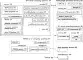
- FIG. 1Ais an example block diagram of various computing devices and systems that may participate in the described techniques in some embodiments.
- an Interior Capture and Analysis (“ICA”) systeme.g., a system 160 that is executing on one or more server computing systems 180 , and/or a system provided by application 155 executing on one or more mobile image acquisition devices 185
- images 165e.g., 360° spherical panorama images in equirectangular format
- images 165e.g., 360° spherical panorama images in equirectangular format
- FIG. 1Ashows one example of acquisition of panorama images for a particular house at multiple capture/viewing locations 210
- FIGS. 2A-2Lillustrate additional details about using a computer model generated from such panorama images to control how multiple types of information are presented in a simultaneous and coordinated manner about the house, as discussed further below.
- a BHP (Building Information Integrated Presentation) system 140is further executing on one or more server computing systems to use building models, maps and images 145 (e.g., acquired from the information 165 ) and/or other mapping-related information or associated information (not shown) in order to control the simultaneous and coordinated presentation of multiple types of information (including such building models 145 ) about the house or other building.
- building modelsmaps and images 145 (e.g., acquired from the information 165 ) and/or other mapping-related information or associated information (not shown) in order to control the simultaneous and coordinated presentation of multiple types of information (including such building models 145 ) about the house or other building.
- the BIIP systemmay receive requests or instructions or other information via computer network(s) 170 from end users of building information viewer client computing devices 175 about types of information to include, before generating and providing such information for display on the client computing devices 175 , and may further optionally obtain and use supporting information supplied by BHP system operator users via computing devices 105 and intervening computer network(s) 170 to configure or modify operations of the BHP system in some embodiments. Additional details related to the automated operation of the BHP system are included elsewhere herein, including with respect to FIGS. 2A-2L and FIG. 6 .
- the ICA system(s) 160 and/or FMGM system(s) 160 and/or BHP system 140may execute on the same server computing system(s), such as if two or more of the systems are operated by a single entity or are otherwise executed in coordination with each other (e.g., with some or all functionality of such systems integrated together into a larger system), while in other embodiments the BHP system may instead operate separately from such an ICA system (e.g., without an ICA system by instead obtaining panorama images or other images from one or more external sources) and/or may instead operate separately from such an FMGM system (e.g., without an FMGM system by instead obtaining 2D floor maps or other computer models of buildings from one or more external sources).
- the BHP systemmay instead operate separately from such an ICA system (e.g., without an ICA system by instead obtaining panorama images or other images from one or more external sources) and/or may instead operate separately from such an FMGM system (e.g., without an FMGM system by instead obtaining 2D floor maps or other computer models
- FIG. 1AVarious components of the mobile image acquisition device 185 are illustrated in FIG. 1A , including a browser 162 and/or an ICA system application 155 and/or an FMGM system application 157 that are executed in memory 152 of the device 185 by one or more hardware processors 132 , and including one or more imaging systems 135 to acquire visual data.
- the illustrated embodiment of mobile device 185further includes one or more sensor modules 148 that include a gyroscope 148 a , accelerometer 148 b and compass 148 c in this example (e.g., as part of one or more IMU units, not shown separately, on the mobile device), optionally a GPS (or Global Positioning System) sensor 137 or other position determination sensor (not shown in this example), a display system 142 , a control system 147 to control acquisition of images (e.g., to rotate the mobile device), etc.
- sensor modules 148that include a gyroscope 148 a , accelerometer 148 b and compass 148 c in this example (e.g., as part of one or more IMU units, not shown separately, on the mobile device), optionally a GPS (or Global Positioning System) sensor 137 or other position determination sensor (not shown in this example), a display system 142 , a control system 147 to control acquisition of images (e.g., to rotate the
- computing devices/systems 105 , 175 and 180may include various hardware components and stored information in a manner analogous to mobile device 185 , but are not shown in this example for the sake of brevity, although some related further details are discussed below with respect to FIG. 3 .
- the ICA systemmay perform automated operations involved in acquiring multiple images at multiple associated viewing locations (e.g., in multiple rooms or other locations within a building or other structure and optionally around some or all of the exterior of the building or other structure), such as using visual data acquired via the mobile device(s) 185 , and for subsequent use in generating and providing a representation of an interior of the building or other structure.
- such techniquesmay include using one or more mobile devices (e.g., a camera having one or more fisheye lenses or other lenses that simultaneously capture 360° horizontally around a vertical axis, such as to produce a 360° spherical panorama image without rotation; a camera having one or more fisheye lenses or other lenses that capture less than 360° horizontally at a given time, and that is mounted on a rotatable tripod or otherwise having an automated rotation mechanism to enable 360° image capture over a period of time corresponding to the rotation; a smart phone held and moved by a user, such as to rotate the user's body and held smart phone in a 360° circle around a vertical axis; a camera held by or mounted on a user or the user's clothing; a camera mounted on an aerial and/or ground-based drone or robotic device; etc.) to capture data from a sequence of multiple viewing locations within multiple rooms of a house (or other building), and to optionally further capture data involved in movement or travel between some or all of
- the techniquesmay include producing a panorama image from that viewing location (e.g., a 360° panorama image that includes 360° of horizontal coverage around a vertical axis, a 360° spherical panorama image that further shows the surrounding room in an equirectangular format, another type of panorama image in another format, etc.), and then providing the panorama images for subsequent use by an FMGM system and/or BHP system.
- a panorama imagee.g., a 360° panorama image that includes 360° of horizontal coverage around a vertical axis, a 360° spherical panorama image that further shows the surrounding room in an equirectangular format, another type of panorama image in another format, etc.
- Additional details related to embodiments of a system providing at least some such functionality of an ICA systemare included in U.S. Non-Provisional patent application Ser. No. 16/236,187, filed Dec. 28, 2018 and entitled “Automated Control Of Image Acquisition Via Use Of Acquisition Device Sensors”; in U.S.
- the FMGM systemmay perform automated operations involved in using images acquired at multiple associated viewing locations (e.g., in multiple rooms or other locations within a building or other structure and optionally around some or all of the exterior of the building or other structure) to generate a 2D floor map for the building or other structure and/or to generate a computer model for the building or other structure (e.g., a 3D model and/or a 2.5D model), such as by analyzing visual information available in the images, and for providing a representation of an interior of the building or other structure (e.g., for subsequent use in controlling the simultaneous and coordinated presentation of multiple types of information about the interior of the building or other structure).
- images acquired at multiple associated viewing locationse.g., in multiple rooms or other locations within a building or other structure and optionally around some or all of the exterior of the building or other structure
- a 2D floor mapfor the building or other structure
- a computer model for the building or other structuree.g., a 3D model and/or a 2.5D model
- such techniquesmay include analyzing one or more images taken in a room to determine a shape of the room and/or to identify inter-room passages (e.g., doorways and other openings in walls) into and/or out of the room.
- inter-room passagese.g., doorways and other openings in walls
- the techniquesmay further include positioning the room shapes relative to each other to form a 2D floor map (e.g., based at least in part on connecting inter-room passages between rooms, and optionally using travel or other movement information captured between the viewing locations to determine relative locations of the viewing locations with respect to each other), optionally combined with height and/or other size information to generate a 3D and/or 2.5D model of the building or other structure, and then providing the generated computer model(s) and optionally 2D floor map for subsequent use by the BHP system. Additional details related to embodiments of a system providing at least some such functionality of an FMGM system are included in U.S. Non-Provisional patent application Ser. No. 16/190,162, filed Nov.
- One or more end users (not shown) of one or more building information viewer client computing devices 175may each further interact over computer networks 170 with the BHP system 140 (and optionally the ICA system 160 and/or FMGM system 160 ), such as to obtain, display and interact with a generated computer model and/or floor map that are part of multiple types of information about the house or other building being presented in a simultaneous and coordinated manner in a GUI displayed on a device 175 (e.g., based at least in part on user-specified conditions).
- the BHP system 140and optionally the ICA system 160 and/or FMGM system 160
- a generated computer model and/or floor mapthat are part of multiple types of information about the house or other building being presented in a simultaneous and coordinated manner in a GUI displayed on a device 175 (e.g., based at least in part on user-specified conditions).
- a computer model (or portion of it) and/or floor mapmay be linked to or otherwise associated with one or more additional types of information, such as one or more associated and linked images or other associated and linked information, including for a two-dimensional (“2D”) floor map of a building to be inter-linked with or otherwise associated with a separate 2.5D model rendering of the building and/or a 3D floor plan model rendering of the building, etc., and including for a computer model and/or floor map of a multi-story or otherwise multi-level building to have multiple associated sub-floor models or maps for different stories or levels that are interlinked (e.g., via connecting stairway passages).
- 2Dtwo-dimensional
- floor map of a buildingto be inter-linked with or otherwise associated with a separate 2.5D model rendering of the building and/or a 3D floor plan model rendering of the building, etc.
- a computer model and/or floor map of a multi-story or otherwise multi-level buildingto have multiple associated sub-floor models or maps for different stories or levels that are interlinked (
- non-exclusive examples of an end user's interactions with a displayed or otherwise generated computer modelmay include one or more of the following: to change between a computer model view and a floor map view (collectively referred to herein as one or more mapping views); to change between a mapping view and a view of a particular image at a viewing location within or near the building's interior; to change the horizontal and/or vertical viewing direction from which a corresponding subset view of (or portal into) a panorama image is displayed, such as to determine a portion of a panorama image in a 3D spherical coordinate system to which a current user viewing direction is directed, and to render a corresponding planar image that illustrates that portion of the panorama image without the curvature or other distortions present in the original panorama image; etc.
- the client computing devices 175may receive and use generated computer models and/or other generated mapping-related information in additional manners, such as to control or assist automated navigation activities by those devices (e.g., by autonomous vehicles or other devices), whether instead of or in addition to display of the generated information.
- the network 170may be one or more publicly accessible linked networks, possibly operated by various distinct parties, such as the Internet.
- the network 170may have other forms, such as to instead be a private network (such as a corporate or university network) that is wholly or partially inaccessible to non-privileged users.
- the network 170may include both private and public networks, with one or more of the private networks having access to and/or from one or more of the public networks.
- the network 170may include various types of wired and/or wireless networks and connections in various situations.
- FIG. 1Bdepicts a block diagram of an exemplary building interior environment in which images are acquired and for which one or more computer models and/or 2D floor maps are generated, such as for further use by the BHP system to control the simultaneous and coordinated presentation of multiple types of information about the interior of the house, as discussed in greater detail with respect to FIGS. 2A-2L , as well as for use in some embodiments in otherwise presenting the computer models and/or floor maps and/or images to users.
- FIG. 1Bdepicts a block diagram of an exemplary building interior environment in which images are acquired and for which one or more computer models and/or 2D floor maps are generated, such as for further use by the BHP system to control the simultaneous and coordinated presentation of multiple types of information about the interior of the house, as discussed in greater detail with respect to FIGS. 2A-2L , as well as for use in some embodiments in otherwise presenting the computer models and/or floor maps and/or images to users.
- FIG. 1Bdepicts a block diagram of an exemplary building interior environment in which images are acquired
- FIG. 1Billustrates a first story of a multi-story building 198 (e.g., with a partial or full basement and/or a second story, not shown) with an interior that was captured at least in part via multiple panorama images, such as by a mobile image acquisition device 185 with image acquisition capabilities as it is moved through the building interior to a sequence of multiple viewing locations 210 (e.g., starting at viewing location 210 A, moving to viewing location 210 B along travel path 115 , etc.).
- a mobile image acquisition device 185with image acquisition capabilities as it is moved through the building interior to a sequence of multiple viewing locations 210 (e.g., starting at viewing location 210 A, moving to viewing location 210 B along travel path 115 , etc.).
- An embodiment of the ICA systemmay automatically perform or assist in the capturing of the data representing the building interior, as well as to further analyze the captured data to generate panorama images to provide a visual representation of the building interior
- an embodiment of the FMGM systeme.g., FMGM system 160 on server computing system(s) 180 , a copy 157 of some or all of the FMGM system executing on the mobile image acquisition device 185 , etc.
- a mobile image acquisition devicemay include various hardware components, such as a camera, one or more sensors (e.g., a gyroscope, an accelerometer, a compass, etc., such as part of one or more IMUs, or inertial measurement units, of the mobile device; an altimeter; light detector; etc.), a GPS receiver, one or more hardware processors, memory, a display, a microphone, etc.
- the mobile devicemay not in at least some embodiments have access to or use equipment to measure the depth of objects in the building relative to a location of the mobile device, such that relationships between different panorama images and their viewing locations may be determined in part or in whole based on features in different images, but without using any data from any such depth sensors.
- the mobile device and/or ICA system and/or FMGM systemmay not use such absolute directional information in at least some embodiments, such as to instead determine relative directions and distances between viewing locations 210 without regard to actual geographical positions or directions in such embodiments.
- the mobile image acquisition device 185arrives at a first viewing location 210 A within a first room of the building interior (in this example, in a living room accessible via an external door 190 - 1 ), and captures a view of a portion of the building interior that is visible from that viewing location 210 A (e.g., some or all of the first room, and optionally small portions of one or more other adjacent or nearby rooms, such as through doors, halls, stairs or other connecting passages from the first room).
- the view capturemay be performed in various manners as discussed herein, and may capture information about a number of objects or other features (e.g., structural details) that are visible in images captured from the viewing location—in the example of FIG.
- such objects or other features throughout the houseinclude the doorways 190 (including 190 - 1 and 190 - 3 ) and 197 (e.g., with swinging and/or sliding doors), windows 196 (including 196 - 1 , 196 - 2 , 196 - 3 and 196 - 4 ), corners or edges 195 (including corner 195 - 1 in the northwest corner of the building 198 , corner 195 - 2 in the northeast corner of the first room, corner 195 - 3 in the southwest corner of the first room, corner 195 - 4 at the northern edge of the inter-room passage between the first room and a hallway, etc.), furniture 191 - 193 (e.g., a couch 191 ; chair 192 ; table 193 ; etc.), pictures or paintings or televisions or other hanging objects 194 (such as 194 - 1 and 194 - 2 ) hung on walls, light fixtures, various built-in appliances or fixtures (not shown), etc.
- the doorways 190including 190
- the usermay also optionally provide a textual or auditory identifier to be associated with a viewing location, such as “living room” for the room including viewing locations 210 A and/or 210 B and/or identifiers “entry” and “living room -NE” for the viewing locations 210 A and 210 B, respectively, while in other embodiments the ICA system and/or FMGM may automatically generate some or all such identifiers (e.g., by automatically analyzing video and/or other recorded information for a building to perform a corresponding automated determination, such as by using machine learning) or the BHP system may determine such identifiers (e.g., based at least in part on input from BHP system operator users and/or end users) or the identifiers may not be used.
- the mobile device 185may move or be moved to a next viewing location (such as viewing location 210 B), optionally recording movement data such as video and/or other data from the hardware components (e.g., from one or more IMUs, from the camera, etc.) during movement between the viewing locations.
- a next viewing locationsuch as viewing location 210 B
- movement datasuch as video and/or other data from the hardware components (e.g., from one or more IMUs, from the camera, etc.) during movement between the viewing locations.
- the mobile devicemay similarly capture a panorama image from that viewing location. This process may repeat for some or all rooms of the building and optionally external to the building, as illustrated for viewing locations 210 C- 210 J in this example.
- the acquired panorama images for each viewing locationmay be further analyzed, including in some embodiments to render or otherwise place each panorama image in an equirectangular format, whether at the time of image capture or later.
- FIGS. 1A-1BVarious details are provided with respect to FIGS. 1A-1B , but it will be appreciated that the provided details are non-exclusive examples included for illustrative purposes, and other embodiments may be performed in other manners without some or all such details.
- FIGS. 2A-2Lillustrate examples of presenting a GUI that simultaneously displays multiple types of information about an interior of a building in an integrated and coordinated manner, such as for the building 198 and using images and their viewing/capture locations 210 discussed in FIG. 1B .
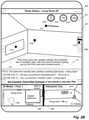
- FIG. 2Aillustrates an example embodiment of a GUI with various information 204 a , which is displayed in this example on a mobile client device 205 (e.g., a smart phone or tablet), and which shows multiple types of information about a common area of example building 198 .
- the GUI in this exampleincludes a primary pane 207 and two secondary panes 208 and 209 , with each of the panes showing information of a different type about the same area of the example house 198 shown in FIG. 1B .
- the primary pane 207is showing an image taken from viewing location 210 A in the living room in this example, with the direction of the image being in the northeast direction (as shown by visual indicator 109 a overlaid on the primary pane, as well as the visual indicator 219 a shown in secondary pane 209 ).
- the primary pane 207also includes a header 206 that provides a description of the type of content shown (here, an image, as illustrated by the “photo gallery” label), as well as optionally having an additional label specific to the photo or other image being displayed (here, “Living Room # 1 ”).
- the primary pane 207may also have one or more user-selectable controls that enable the end user (not shown) to modify information being displayed in the GUI, such as control 218 a in the header area 206 to change the type of information being shown in the primary pane to a different type of content (e.g., by cycling through each of the available types of content).
- a toggle control 203 cto show or hide information about points of interest that are present in the current image
- a toggle control 203 dto show or hide a description of the area of the house shown by the image
- a toggle control 203 eto show or hide information about questions and answers corresponding to the area of the house shown in the image and to optionally allow the end user to supply one or more additional questions or answers
- a toggle control 203 bto switch to a so-called “AR” (or augmented reality) mode in which tilting and rotating the body of the mobile device causes the displayed image to move accordingly (e.g., if the image shown in the primary pane is a 360° panorama image with only a subset of it currently shown, such that tilting to the left causes an additional portion of the panorama image to the left of the visible area to be shown, and with the control 203 b not being shown if the content is not a panorama image), a selection control
- the secondary panes 208 and 209show other types of content about the same location or area of the example house.
- the secondary pane 209 in this exampleshows a portion of a 3D computer model of the house, and in particular shows a portion of the computer model that includes the northeast corner of the living room, as well as optionally including some or all of other parts of the same floor—as previously noted, the computer model is overlaid in this example with the visual indicator 219 a to illustrate where the image shown in the primary pane was captured, and the orientation of the camera that captured the image.
- the secondary pane 208 in this exampleshows a portion of an interface to an interactive virtual tour of the house, with the interactive tour having a plurality of inter-connected viewing/capture locations at which images and/or other information that are available for viewing or other presentation were captured.
- the interfaceincludes an image that was also captured from viewing location 210 A (e.g., a panorama image captured from that viewing location), with the interface further including visual indicators 214 b and 214 c that each correspond to other viewing locations different from viewing location 210 A (in particular, to viewing locations 210 B and 210 C of FIG. 1B , respectively)—as discussed in greater detail with respect to FIG.
- visual indicators 214may be user-selectable controls in at least some situations (e.g., when the interface to the interactive tour is shown in the primary pane) such that selection of one of the controls changes the image displayed to change to one from the viewing location associated with the selected control.
- GUIGUI
- an end usernot shown
- new contents of that secondary panebeing selected to correspond to the new primary pane contents
- Other optional user-selectable controls 202are further shown in this example for reference purposes, although they may not be visible in some embodiments when three GUI panes are displayed as shown, such as if the controls 202 are associated with a different part of the GUI as discussed in greater detail with respect to FIG. 2F .
- FIG. 2Bcontinues the example of FIG. 2A , and in particular corresponds to the end user having selected the control 203 a in FIG. 2A to change the image that is displayed in the primary pane to another image from the photo gallery.
- the new image displayed in the primary pane 207 as part of the updated information 204 b in the updated GUIis also taken from the same viewing location 210 A, but in a northwesterly direction (as illustrated by the updated visual indicator 219 b shown in the 3D computer model of the secondary pane 209 ).
- the contents of the secondary pane 209continue to be the same portion of the 3D computer model as in FIG.
- FIG. 2Bfurther illustrates additional information that has been overlaid on the primary pane 207 , based on selection by the end user of the user-selectable controls 203 c , 203 d and 203 e in this example, although it will be appreciated that the end user may instead select only zero, one, or two of those three controls in other situations.
- selection of the user-selectable control 203 chas caused several visual indicators 212 for points of interest in the room to be illustrated, with visual indicator 212 b being currently selected and having a corresponding textual comment in the area 213 of the primary pane (to comment about paint on the walls of the room).
- Other visual POI indicators in this exampleinclude 212 a on the west-facing picture window, 212 d on the north-facing window, and 212 c on the overhead track lighting on the ceiling. While the selected visual indicator 212 b has associated text that is displayed in this example, other visual indicators for POIs may have other types of information associated, such as if the window visual indicators 212 a and/or 212 d have images and/or video associated with them, such as to show images or videos looking out the window (e.g., a time-lapse video over a 24-hour period of the exterior of the house from a window or door, such as to show road traffic or people traffic outside over that time period).
- the user-selectable control 203 dhas also been activated to provide an audio description of the area shown in the image, with the visual information 211 shown in this example representing audio information that may be audibly presented in response to the selection of that control (e.g., instead of having a textual representation of the information as shown in this example, or instead in addition to the textual information, such as if a closed captioning option is selected).
- the user-selectable control 203 b corresponding to questions and answersis also selected, causing additional information in the area 213 to be shown, such as a question from another end user and a corresponding answer from a real estate listing agent for the house, as well as further user-selectable controls to allow the end user to ask a question to be answered, submit a comment for display to others, or to cycle through other existing questions and comments.
- additional information in the area 213such as a question from another end user and a corresponding answer from a real estate listing agent for the house, as well as further user-selectable controls to allow the end user to ask a question to be answered, submit a comment for display to others, or to cycle through other existing questions and comments.
- illustrated types of informationmay be presented in other manners in other embodiments, or may not be shown.
- FIG. 2Ccontinues the examples of FIGS. 2A-2B , and illustrates an example of the end user interacting with the GUI displayed in FIG. 2A to initiate a switch of the content between the primary pane 207 and the secondary pane 208 , such that the primary pane 207 in the updated information 204 c of the updated GUI of FIG. 2C is the interface to the interactive tour of the house, with the visual indicators 214 b and 214 c in FIG. 2C now being selectable by the user to change the current viewing location, as further illustrated with respect to FIG. 2D .
- the information displayed in the secondary pane 209would not change in FIG.
- the information in the secondary pane 209has been updated for the purposes of illustration to show the entire 3D computer model for the current floor of the house.
- contents of the secondary pane 208have been updated in this example to show the image that was previously present in the primary pane in FIG. 2A .
- the header portion 206 of the primary pane 207is also updated in FIG. 2C to reflect the new type of content being shown in the primary pane.
- FIG. 2Dcontinues the examples of FIGS. 2A-2C , and in this example corresponds to the end user having selected the user-selectable visual indicator 214 b in FIG. 2C to change the current viewing location for the interactive tour.
- 2Dhas changed to the updated information 204 d shown in the primary pane for the updated GUI, corresponding to an image taken from the viewing location 210 B in the northeast part of the living room, and the user-selectable visual indicators in the primary pane have similarly been updated, with the direction of the previous indicator 214 c changing to point to the direction of the hallway from the new background image that is shown, and with the previous visual indicator 214 b for the northeast living room viewing location 210 B (which is now the current viewing location) being changed to the new user-selectable visual indicator 214 a for the entry viewing location 210 A in the living room (which was the previous viewing location).
- a new visual indicator 203 fhas been added to reflect an alternative manner for the end user to adjust the panorama image shown as the background of the primary pane, such as to manually drag the image up, down, left and/or right to display other parts of the panorama image that are not currently visible in the subset shown in the primary pane, as discussed further in FIG. 2E .
- the visual indicator 219 d in the 3D computer model of the secondary pane 209has been updated to correspond to the location and orientation at which the new background image shown in the primary pane was captured.
- the content previously shown in the secondary pane 208 of FIG. 2Cmay in some embodiments and situations continue to be shown in the secondary pane 208 in FIG.
- the contenthas been changed for illustrative purposes to provide content of another type that corresponds to the same area of the house, which in this example is a video of at least that portion of the house.
- the video in the secondary pane 208includes a visual indicator 203 g of a play button for the video, although the visual indicator may not be user-selectable in at least some embodiments until the video content is moved to the primary pane.
- FIG. 2Econtinues the examples of FIG. 2A-2D , and in this example illustrates the effects of the end user having used the control 203 f of FIG. 2D to change the subset of the background panorama image (e.g., a 360° panorama image) that is shown by rotating approximately 180°, so as to now point toward the southwest corner of the living room from the viewing location 210 B in the northeast corner of the living room, as shown in the updated information 204 e of the updated GUI.
- the subset of the background panorama imagee.g., a 360° panorama image
- the user-selectable visual indicators 214 c and 214 ahave been updated to correspond to the positions of those viewing locations relative to the content shown in the background image, and the visual indicator 219 e in the 3D computer model of the secondary pane 209 has been similarly updated.
- the image in the photo gallery of secondary pane 208has been changed in this example to an image that is closest to that of the current background image in the primary pane (so as to maintain a coordinated display of information that is integrated with the primary pane), which in this example is of the window of the west wall of the living room.
- this examplefurther illustrates that additional types of information may be overlaid on images in at least some situations, such as in this example to overlay simulated lighting information 216 a on that image (although a corresponding user-selectable control to initiate that display is not shown in this example). It will be appreciated that additional overlay information, such as that of the simulated lighting, may be controlled by the end user in various manners, including as is discussed in greater detail with respect to FIG. 2F .
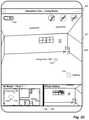
- FIG. 2Fcontinues the examples of FIGS. 2A-2E , and illustrates updated information 204 f in the updated GUI in which the secondary panes 208 and 209 are not shown, but the additional user-selectable controls 202 are included (e.g., based on the primary pane 207 being changed to show the 3D computer model of the house).
- the header information 206is updated to include an additional user-selectable control 218 b that allows the end user to select which floor of the house is shown, with the house in this example having an additional basement floor accessible via the stairs (as illustrated further with respect to FIG. 2G ).
- the 3D computer modelincludes illustrations of the positions of the viewing/capture locations for the interactive tour, with the visual indicator 216 a being added to correspond to the current viewing location that was last selected.
- This examplefurther includes a user-selectable control 216 b that allows an end user to orient the computer model of the house in different manners according to different specified criteria, such as to have a top of the primary pane correspond to magnetic or geographic north, have the top or bottom of the primary pane correspond to the main entry of the house, to provide a best fit of the 3D computer model to the current size and shape of the primary pane, etc.
- control 202 aactivates a default mode that allows the end user to move to a detailed view of a particular room or viewing location by selecting that room or viewing location on the 3D computer model;
- control 202 bshows additional descriptive information of one or more types on the computer model;
- control 202 cshows measurements or other scale information on the 3D computer model;
- control 202 dshows simulated sunlight on the 3D computer model for specified conditions (e.g., one or more times of day and/or times of year);
- control 202 eshows actual interior lighting, optionally under specified conditions;
- control 202 fshows information about a surrounding environment of the building (with FIG.
- control 202 gprovides sound recordings from one or more locations of the building (e.g., of ambient sound at specified times); control 202 z allows virtual objects to be added to the 3D computer model and/or surfaces in the 3D computer model to have virtual changes (e.g., to change color, texture etc. of walls, floors, object surfaces, etc.).
- FIG. 2Gcontinues the examples of FIGS. 2A-2F , and illustrates an example of the GUI being updated with information 204 g to again include only a single primary pane 207 , which in this example has no header or separate area for user-selectable controls—in addition, the information being displayed has been adjusted to reflect that the device 205 has been rotated to a landscape orientation.
- the end userhas selected to display information about the surroundings of the building, which in this example includes a street to the west of the house, with two additional houses across the street being shown, as well as additional information on the house's property that includes two trees, sidewalks, a driveway and garage, and bushes or other shrubs on the south side of the house (as indicated by the visual indicator 109 g ).
- This examplefurther illustrates a deck to the east of the house, and includes visual information about a basement existing below ground level, although details of the interior of the basement are not shown in this example.
- the vegetation and surrounding buildingsare shown in this example using simplified geometrical shapes, such as to enable the use of such shapes to simulate shading (not shown) if a simulated lighting information option is selected for the display, although actual images of surroundings may instead be used in other embodiments and situations. It will be appreciated that a variety of other types of information may be shown about the surroundings of the building, including images and/or video from ground level and/or an aerial view, as well as additional points of interest in descriptive information about the surrounding neighborhood.
- FIG. 2Hcontinues the examples of FIGS. 2A-2G , and illustrates an example of the GUI similar to that of FIG. 2F , but updated with information 204 h corresponding to selection of control 202 h by the end user.
- the control 202 hcorresponds to updating the displayed floor plan of the house to visually show information about spaces of the house that are public (e.g., living room, kitchen, dining room, hallways, stairs, etc.) and that are private (e.g., bathrooms, bedrooms, etc.), such as displaying one or both types of spaces with specified colors and/or patterns.
- a legend 221 his displayed to show options 222 h for patterns to use, with the displayed floor plan having corresponding displayed information (e.g., via a public/private visual layer that is overlaid on the floor plan).
- the public and private spaces of the housemay be determined in various manners in various embodiments, such as automatically (e.g., based on previously determined room types, based on analysis of images) and/or based on user annotations or other input (e.g., from one or more system operator users of the BHP and/or ICA systems, from end users, etc.).
- FIG. 2Icontinues the examples of FIGS. 2A-2H , and illustrates an example of the GUI similar to that of FIG. 2H , but instead being updated with information 204 i (instead of information 204 h ) corresponding to selection of control 202 i by the end user.
- the control 202 icorresponds to updating the displayed floor plan of the house to visually show icon information about types of rooms of the house (e.g., instead of the room type textual labels shown in FIG. 2H ).
- a legend 221 iis displayed to show icons 222 i to use for different types of rooms, with the displayed floor plan having corresponding displayed icons (e.g., via a room type icon visual layer that is overlaid on the floor plan, such as instead of or in addition to a room type textual label visual layer).
- types of roomsmay be determined in various manners in various embodiments, such as automatically (e.g., based on analysis of images and/or use of machine learning techniques) and/or based on user annotations or other input (e.g., from one or more system operator users of the BHP and/or ICA systems, from end users, etc.).
- FIG. 2Jcontinues the examples of FIGS. 2A-2I , and illustrates an example of the GUI similar to that of FIG. 2I , but being updated with information 204 j corresponding to selection of control 202 j by the end user.
- the control 202 jcorresponds to updating the displayed floor plan of the house to visually show examples of inhabitant flow pattern information 221 j corresponding to typical or common movement patterns of people (e.g., in addition to room type icons, while in other embodiments may be shown without room type label or icon information).
- the flow pattern informationmay be displayed, for example, via a flow pattern visual layer that is overlaid on the floor plan, such as instead of or in addition to one or more other visual layers.
- Such flow pattern informationmay be determined in various manners in various embodiments, such as automatically (e.g., based on analysis of video taken over time within the house interior, based on other tracking of user movements within the house interior, based on analysis of images to determine open lanes or spaces for user movement, etc.) and/or based on user annotations or other input (e.g., from one or more system operator users of the BHP and/or ICA systems, from end users, etc.).
- automaticallye.g., based on analysis of video taken over time within the house interior, based on other tracking of user movements within the house interior, based on analysis of images to determine open lanes or spaces for user movement, etc.
- user annotations or other inpute.g., from one or more system operator users of the BHP and/or ICA systems, from end users, etc.
- FIG. 2Kcontinues the examples of FIGS. 2A-2J , and illustrates an example of the GUI similar to that of FIG. 2H , but updated with information 204 k corresponding to selection of control 202 k by the end user.
- the control 202 kcorresponds to updating the displayed floor plan of the house to visually show information about spaces of the house that are likely to be of most interest to the end user, such as displaying spaces corresponding to different levels of likely user interest with different specified colors and/or patterns.
- a legend 221 kis displayed to show patterns 222 k for patterns to use, with the displayed floor plan having corresponding displayed information (e.g., via a user-specific personalized visual layer that is overlaid on the floor plan).
- the areas of the house that are likely to be of interest to the end usermay be determined in various manners in various embodiments, such as automatically (e.g., based on tracking a quantity of time and/or a length of time that the end user has previously spent viewing different parts of this house, based on an analysis of corresponding types of information for the end user from multiple other houses, etc.) and/or based on user annotations or other input (e.g., from previously specified preferences of the end user; from previous indications of the end user of particular parts of the house that are of interest, such as by flagging or pinning particular rooms and/or images; etc.).
- automaticallye.g., based on tracking a quantity of time and/or a length of time that the end user has previously spent viewing different parts of this house, based on an analysis of corresponding types of information for the end user from multiple other houses, etc.
- user annotations or other inpute.g., from previously specified preferences of the end user; from previous indications of the end user of particular parts of the
- FIG. 2Lcontinues the examples of FIGS. 2A-2K , and illustrates an example of the GUI similar to that of FIG. 2F , but updated with information 204 l corresponding to selection of control 202 l by the end user.
- the control 202 lcorresponds to providing interactive functionality for the end user to specify a length on the displayed floor plan of the house (e.g., by dragging a line 223 l , by selecting two end points, etc.) and receive information about the distance of that length (e.g., displayed distance information 224 l ).
- the distancemay be automatically determined in various manners in various embodiments, such as based on previous and/or concurrent analysis of images of the house interior to determine sizes of known or unknown objects, as discussed in greater detail elsewhere herein.
- the distance functionalityis provided using a 3D floor plan in this example, similar functionality may be provided on other media or types of information in other embodiments, such as on displayed panorama or perspective images, during interactive virtual tours of inter-linked viewing locations, etc.
- FIGS. 2A-2LVarious details have been provided with respect to FIGS. 2A-2L , but it will be appreciated that the provided details are non-exclusive examples included for illustrative purposes, and other embodiments may be performed in other manners without some or all such details. For example, while not illustrated in the examples of FIGS.
- the GUIcould have other forms in other embodiments, such as to have other user-selectable and/or user-modifiable controls (whether instead of or in addition to the illustrated controls), and/or to have particular controls be accessed and used in other manners, and/or to be displayed or otherwise presented on other types of devices (e.g., desktop or laptop computers, tablet computers, etc.), and/or to be displayed or otherwise presented in other types of formats and layouts (e.g., to have more or less GUI panes, to have different layouts and/or sizes of GUI panes, to display multiple types of information simultaneously without using GUI panes like those of the examples, etc.).
- additional types of functionality related to displaying or otherwise presenting building interior informationmay be provided in other embodiments.
- Various other changes to the GUImay be further made in other embodiments.
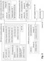
- FIG. 3is a block diagram illustrating an embodiment of one or more server computing systems 300 executing an implementation of a BHP system 340 , optionally one or more server computing systems 380 executing an implementation of an ICA system 389 , and optionally one or more server computing systems 370 executing an implementation of an FMGM system 379 —the server computing system(s) and BHP and/or FMGM and/or ICA systems may be implemented using a plurality of hardware components that form electronic circuits suitable for and configured to, when in combined operation, perform at least some of the techniques described herein.
- each server computing system 300includes one or more hardware central processing units (“CPUs”) or other hardware processors 305 , various input/output (“I/O”) components 310 , storage 320 , and memory 330 , with the illustrated I/O components including a display 311 , a network connection 312 , a computer-readable media drive 313 , and other I/O devices 315 (e.g., keyboards, mice or other pointing devices, microphones, speakers, GPS receivers, etc.).
- Each server computing system 380 and 370may have similar components, although only one or more hardware processors 381 and 371 , memory 387 and 377 , storage 385 and 375 , and I/O components 382 and 372 , respectively, are illustrated for the sake of brevity.
- the server computing system(s) 300 and executing BHP system 340 , and server computing system(s) 380 and executing ICA system 389 if present, and server computing system(s) 370 and executing FMGM system 379 if present,may communicate with each other and with other computing systems and devices in this illustrated embodiment via one or more networks 399 (e.g., the Internet, one or more cellular telephone networks, etc.), such as to interact with user client computing devices 390 (e.g., used to view a GUI that simultaneously displays multiple types of information about an interior of a building in an integrated and coordinated manner, or to otherwise present information about a building), and/or one or more mobile image acquisition devices 360 (e.g., used to acquire images and optionally other information for buildings or other environments to be modeled), and/or optionally other navigable devices 395 that receive and use computer models and/or other building information (e.g., 2D floor maps) for navigation purposes (e.g., for use by semi-autonomous or fully autonomous vehicles or other devices).
- some of the described functionalitymay be combined in less computing systems, such as to combine the ICA system 389 and the image acquisition functionality of device(s) 360 in a single system or device (e.g. via the optional ICA application 368 executing in memory 367 of the mobile device 360 ), to combine the BHP system 340 and/or the ICA system 389 and/or the FMGM system 379 in a single system or device, to combine the BHP system 340 and the ICA system 389 and the FMGM system 379 and the image acquisition functionality of device(s) 360 in a single system or device, etc.
- an embodiment of the BHP system 340executes in memory 330 of the server computing system(s) 300 in order to perform at least some of the described techniques, such as by using the processor(s) 305 to execute software instructions of the system 340 in a manner that configures the processor(s) 305 and computing system 300 to perform automated operations that implement those described techniques.
- the illustrated embodiment of the BHP systemmay include one or more components, not shown, to each perform portions of the functionality of the BHP system, and the memory may further optionally execute one or more other programs 335 —as one specific example, a copy of the ICA and/or FMGM systems may each execute as one of the other programs 335 in at least some embodiments, such as instead of or in addition to the ICA system 389 on the server computing system(s) 380 and the FMGM system 379 on the server computing system(s) 370 .
- the BHP system 340may further, during its operation, store and/or retrieve various types of data on storage 320 (e.g., in one or more databases or other data structures), such as various types of user information 322 , images and other media information 325 acquired from or about a building (e.g., received from ICA system 389 , to provide to users of client computing devices 390 for display; etc.), generated computer models and optionally floor maps and other associated mapping information 326 (e.g., received from FMGM system 379 , such as generated and saved 2.5D and/or 3D models, 2D floor maps, etc.), other types of building information 324 (e.g., annotations and other descriptions, information about points of interest, information about surrounding buildings and/or vegetation and/or other exterior information for the building, etc.; as well as information from end users, such as questions; information from BHP system operator users or other authorized users, such as answers to questions; etc.), and/or various types of optional additional information 328 (e.g., various analytical information related to analysis of other
- an embodiment of the ICA system 389executes in memory 387 of the server computing system(s) 380 in the illustrated embodiment in order to perform automated operations related to acquiring images of building interiors (and optionally exteriors of buildings, including their surroundings), such as by using the processor(s) 381 to execute software instructions of the system 389 in a manner that configures the processor(s) 381 and computing system 380 to perform such automated operations.
- an embodiment of the FMGM system 379executes in memory 377 of the server computing system(s) 370 in the illustrated embodiment in order to perform automated operations related to generating computer models and optionally floor maps of building interiors, such as by using the processor(s) 371 to execute software instructions of the system 379 in a manner that configures the processor(s) 371 and computing system 370 to perform such automated operations.
- the illustrated embodiments of the ICA and/or FMGM systemsmay each include one or more components, not shown, to each perform portions of the functionality of their respective ICA or FMGM system, and the respective computer memories may further optionally execute one or more other programs (not shown).
- the ICA system 389 and/or FMGM system 379may further, during their operation, store and/or retrieve various types of data on storage 385 or 375 , respectively (e.g., in one or more databases or other data structures), such as acquired images 386 , generated computer models 376 (e.g., generated and saved 2.5D and/or 3D models) and optionally floor maps and other associated information 376 (e.g., building and room dimensions for use with associated floor plans, additional images and/or annotation information, various analytical information related to presentation or other use of one or more building interiors or other environments, etc.)—while not illustrated in FIG. 3 , the ICA and/or FMGM systems may further store and use additional types of information, such as about system operator users of the respective systems, metadata about acquisition of images to be analyzed, etc.
- data on storage 385 or 375respectively (e.g., in one or more databases or other data structures), such as acquired images 386 , generated computer models 376 (e.g., generated and saved 2.5D and/or 3
- the mobile image acquisition device(s) 360are each shown to include one or more hardware CPU(s) 361 , I/O components 362 , storage 365 , and memory 367 , with one or both of a browser and one or more client applications 368 (e.g., an application specific to the FMGM system and/or ICA system and/or BHP system) executing within memory 367 , such as to participate in communication with the BHP system 340 , ICA system 389 , FMGM system 379 and/or other computing systems—the devices 360 each further include one or more imaging systems 364 and IMU hardware sensors 369 , such as for use in acquisition of images and associated movement/travel data of the device 360 . While particular components are not illustrated for the other navigable devices 395
- computing systems 300 , 370 and 380 and the other systems and devices included within FIG. 3are merely illustrative and are not intended to limit the scope of the present invention.
- the systems and/or devicesmay instead each include multiple interacting computing systems or devices, and may be connected to other devices that are not specifically illustrated, including via Bluetooth communication or other direct communication, through one or more networks such as the Internet, via the Web, or via one or more private networks (e.g., mobile communication networks, etc.).
- a device or other computing systemmay comprise any combination of hardware that may interact and perform the described types of functionality, optionally when programmed or otherwise configured with particular software instructions and/or data structures, including without limitation desktop or other computers (e.g., tablets, slates, etc.), database servers, network storage devices and other network devices, smart phones and other cell phones, consumer electronics, wearable devices, digital music player devices, handheld gaming devices, PDAs, wireless phones, Internet appliances, and various other consumer products that include appropriate communication capabilities.
- the functionality provided by the illustrated systems 340 and/or 379 and/or 389may in some embodiments each be distributed in various components, some of the described functionality of the systems 340 and/or 379 and/or 389 may not be provided, and/or other additional functionality may be provided.
- some or all of the described techniquesmay be performed by hardware means that include one or more processors and/or memory and/or storage when configured by one or more software programs (e.g., by the BHP system software 340 executing on server computing systems 300 and/or on devices 360 , by the ICA system software 389 executing on server computing systems 380 , by the FMGM system software 379 executing on server computing systems 370 , etc.) and/or data structures, such as by execution of software instructions of the one or more software programs and/or by storage of such software instructions and/or data structures, and such as to perform algorithms as described in the flow charts and other disclosure herein.
- software programse.g., by the BHP system software 340 executing on server computing systems 300 and/or on devices 360 , by the ICA system software 389 executing on server computing systems 380 , by the FMGM system software 379 executing on server computing systems 370 , etc.
- data structuressuch as by execution of software instructions of the one or more software programs and/or by storage of such software
- some or all of the systems and/or componentsmay be implemented or provided in other manners, such as by consisting of one or more means that are implemented partially or fully in firmware and/or hardware (e.g., rather than as a means implemented in whole or in part by software instructions that configure a particular CPU or other processor), including, but not limited to, one or more application-specific integrated circuits (ASICs), standard integrated circuits, controllers (e.g., by executing appropriate instructions, and including microcontrollers and/or embedded controllers), field-programmable gate arrays (FPGAs), complex programmable logic devices (CPLDs), etc.
- ASICsapplication-specific integrated circuits
- controllerse.g., by executing appropriate instructions, and including microcontrollers and/or embedded controllers
- FPGAsfield-programmable gate arrays
- CPLDscomplex programmable logic devices
- Non-transitory computer-readable storage mediumssuch as a hard disk or flash drive or other non-volatile storage device, volatile or non-volatile memory (e.g., RAM or flash RAM), a network storage device, or a portable media article (e.g., a DVD disk, a CD disk, an optical disk, a flash memory device, etc.) to be read by an appropriate drive or via an appropriate connection.
- a non-transitory computer-readable storage mediumssuch as a hard disk or flash drive or other non-volatile storage device, volatile or non-volatile memory (e.g., RAM or flash RAM), a network storage device, or a portable media article (e.g., a DVD disk, a CD disk, an optical disk, a flash memory device, etc.) to be read by an appropriate drive or via an appropriate connection.
- the systems, components and data structuresmay also in some embodiments be transmitted via generated data signals (e.g., as part of a carrier wave or other analog or digital propagated signal) on a variety of computer-readable transmission mediums, including wireless-based and wired/cable-based mediums, and may take a variety of forms (e.g., as part of a single or multiplexed analog signal, or as multiple discrete digital packets or frames).
- generated data signalse.g., as part of a carrier wave or other analog or digital propagated signal
- Such computer program productsmay also take other forms in other embodiments. Accordingly, embodiments of the present disclosure may be practiced with other computer system configurations.
- FIG. 4illustrates an example flow diagram of an embodiment of an ICA System routine 400 .
- the routinemay be performed by, for example, the ICA system 160 of FIG. 1A , the ICA system 389 of FIG. 3 , and/or the ICA system described with respect to FIGS. 1B-2L and as otherwise described herein, such as to acquire images (e.g., 360° spherical panorama images) at viewing locations within buildings or other structures, such as for use in subsequent generation of related floor maps and/or other mapping information. While portions of the example routine 400 are discussed with respect to acquiring particular types of images at particular viewing locations, it will be appreciated that this or a similar routine may be used to acquire video or other data (e.g., audio), whether instead of or in addition to such images.
- video or other datae.g., audio
- the illustrated embodimentacquires and uses information from the interior of a target building
- other embodimentsmay perform similar techniques for other types of data, including for non-building structures and/or for information external to one or more target buildings of interest.
- some or all of the routinemay be executed on a mobile device used by a user to acquire image information, and/or by a system remote from such a mobile device.
- the illustrated embodiment of the routinebegins at block 405 , where instructions or information are received.
- the routinedetermines whether the received instructions or information indicate to acquire data representing a building interior, and if not continues to block 490 . Otherwise, the routine proceeds to block 412 to receive an indication from a user of a mobile image acquisition device to begin the image acquisition process at a first viewing location.
- the routineproceeds to block 415 in order to perform viewing location image acquisition activities in order to acquire an image (e.g., a 360° panorama image) for the viewing location in the interior of the target building of interest, optionally via one or more fisheye lenses on the mobile device to provide horizontal coverage of at least 360° around a vertical axis.
- an imagee.g., a 360° panorama image
- the mobile image acquisition devicemay be a rotating (scanning) panorama camera equipped with a fisheye lens, such as a 180° fisheye giving a full sphere at 360° rotation.
- the routinemay also optionally obtain annotation and/or other information (e.g., information about points of interest, other descriptions, etc.) from the user regarding the viewing location and/or the surrounding environment, such as for later use in presentation of information regarding that viewing location and/or surrounding environment.
- the routinecontinues to block 420 to determine if there are more viewing locations at which to acquire images, such as based on corresponding information provided by the user of the mobile device, and/or based on automated tracking of viewing locations visited (e.g., based on a predefined group of viewing locations, based on acquiring at least one viewing location in each of a predefined group of rooms, etc.).
- the routinecontinues to block 422 to optionally initiate the capture of linking information (e.g., acceleration data and/or other data that changes as the device moves) during movement of the mobile device along a travel path away from the current viewing location and towards a next viewing location within the building interior.
- linking informatione.g., acceleration data and/or other data that changes as the device moves
- the captured linking informationmay include additional sensor data (e.g., from one or more IMUs, or inertial measurement units, on the mobile device or otherwise carried by the user), as well as additional video information, recorded during such movement.
- Initiating the capture of such linking informationmay be performed in response to an explicit indication from a user of the mobile device or based on one or more automated analyses of information recorded from the mobile device.
- the routinemay further optionally monitor the motion of the mobile device in some embodiments during movement to the next viewing location, and provide one or more guidance cues to the user regarding the motion of the mobile device, quality of the sensor data and/or video information being captured, associated lighting/environmental conditions, advisability of capturing a next viewing location, information about how to reach a defined next viewing location and/or about when the defined next viewing location is reached, and any other suitable aspects of capturing the linking information.
- the routinemay optionally obtain annotation and/or other information (e.g., information about points of interest, other descriptions, etc.) from the user regarding the travel path, such as for later use in presentation of information regarding that travel path or a resulting inter-panorama connection link.
- the routinedetermines that the mobile device has arrived at the next viewing location (e.g., based on an indication from the user, based on the forward movement of the user stopping for at least a predefined amount of time, based on reaching a predefined spot for the next viewing location, etc.), for use as the new current viewing location, and returns to block 415 in order to perform the viewing location image acquisition activities for the new current viewing location.
- the routineproceeds to block 425 to optionally analyze the viewing location information for the building or other structure, such as to identify possible additional coverage (and/or other information) to acquire within the building interior.
- the ICA systemmay provide one or more notifications to the user regarding the information acquired during capture of the multiple viewing locations and optionally corresponding linking information, such as if it determines that one or more segments of the recorded information are of insufficient or undesirable quality, or do not appear to provide complete coverage of the building.
- the routinecontinues to block 435 to optionally preprocess the acquired images before their subsequent use for generating related mapping information, such as to perform an equirectangular projection for each such image so that straight vertical data (e.g., the sides of a typical rectangular door frame, a typical border between 2 adjacent walls, etc.) remains straight and in which straight horizontal data (e.g., the top of a typical rectangular door frame, border between a wall and a floor, etc.) at a horizontal midline of the image remains straight but is increasingly curved in the equirectangular projection image in a convex manner relative to the horizontal midline as the distance increases in the image from the horizontal midline.
- straight vertical datae.g., the sides of a typical rectangular door frame, a typical border between 2 adjacent walls, etc.
- straight horizontal datae.g., the top of a typical rectangular door frame, border between a wall and a floor, etc.
- an automated analysis of some or all of the imagesmay further be performed to determine corresponding information about the building interior, such as types of rooms, points of interest in particular locations, etc.
- the images and any associated generated or obtained informationis stored for later use, and optionally provided to an FMGM routine for further analysis.
- FIGS. 5A-5Billustrate one example of a routine for generating a floor map representation of a building interior from the generated panorama information.
- routinecontinues instead to block 490 to perform any other indicated operations as appropriate, such as any housekeeping tasks, to configure parameters to be used in various operations of the system (e.g., based at least in part on information specified by a user of the system, such as a user of a mobile device who captures one or more building interiors, an operator user of the ICA system, etc.), to obtain and store other information about users of the system, to respond to requests for generated and stored information, etc.
- any other indicated operationsas appropriate, such as any housekeeping tasks, to configure parameters to be used in various operations of the system (e.g., based at least in part on information specified by a user of the system, such as a user of a mobile device who captures one or more building interiors, an operator user of the ICA system, etc.), to obtain and store other information about users of the system, to respond to requests for generated and stored information, etc.
- routineproceeds to block 495 to determine whether to continue, such as until an explicit indication to terminate is received, or instead only if an explicit indication to continue is received. If it is determined to continue, the routine returns to block 405 to await additional instructions or information, and if not proceeds to step 499 and ends.
- FIGS. 5A-5Billustrate an example embodiment of a flow diagram for a Floor Map Generation Manager (FMGM) System routine 500 .
- the routinemay be performed by, for example, execution of the FMGM system 160 of FIG. 1A , the FMGM system 379 of FIG. 3 , and/or an FMGM system as discussed with respect to FIGS. 1B-2L and elsewhere as described herein, such as to generate a computer model and optionally other mapping information for a defined area based at least in part on images of the area.
- FIGS. 1Athe example, execution of the FMGM system 160 of FIG. 1A , the FMGM system 379 of FIG. 3 , and/or an FMGM system as discussed with respect to FIGS. 1B-2L and elsewhere as described herein, such as to generate a computer model and optionally other mapping information for a defined area based at least in part on images of the area.
- the generated mapping informationincludes a 3D computer model and 2D floor map of a building, such as a house, but in other embodiments, other types of mapping information may be determined and generated for other types of buildings and used in other manners, as discussed elsewhere herein.
- the illustrated embodiment of the routinebegins at block 505 , where information or instructions are received.
- the routinecontinues to block 510 to determine whether the instructions received in block 505 indicate to generate mapping information for an indicated building, optionally along with associated information about the building, and if so the routine continues to perform blocks 515 - 588 to do so, and otherwise continues to block 590 .
- the routinedetermines whether image information is already available for the building, or if such information instead needs to be acquired. If it is determined in block 515 that the information needs to be acquired, the routine continues to block 520 to acquire such information, optionally waiting for one or more users or devices to move throughout the building and acquire panoramas or other images at multiple viewing locations in multiple rooms of the building, and to optionally further analyze the images and/or metadata information about their acquisition to interconnect the images, as discussed in greater detail elsewhere herein— FIG. 4 provides one example embodiment of an ICA system routine for performing such image acquisition.
- routinecontinues instead to block 530 to obtain existing panoramas or other images from multiple viewing locations in multiple rooms of the building, optionally along with interconnection information for the images and acquisition of metadata information related to movement between the viewing locations, such as may in some situations have been supplied in block 505 along with the corresponding instructions.
- routinecontinues to block 535 to optionally obtain additional information about the building, such as from activities performed during acquisition and optionally analysis of the images, and/or from one or more external sources (e.g., online databases, information provided by one or more end users, etc.)—such additional information may include, for example, exterior dimensions and/or shape of the building, additional images and/or annotation information acquired corresponding to particular locations within the building (optionally for locations different from viewing locations of the acquired panorama or other images), etc.
- additional informationmay include, for example, exterior dimensions and/or shape of the building, additional images and/or annotation information acquired corresponding to particular locations within the building (optionally for locations different from viewing locations of the acquired panorama or other images), etc.
- the routinecontinues to block 550 to determine, for each room inside the building with one or more viewing locations and associated acquired images, a room shape of the room for data in the image(s) taken inside the room, and optionally a position within the room of its viewing location(s), such as in an automated manner.
- the routinefurther uses visual data in the images and/or the acquisition metadata for them to determine, for each room in the building, any connecting passages in or out of the room, such as in an automated manner. It will be appreciated that, while blocks 550 - 555 , are illustrated as separate operations in this example, in some embodiments a single analysis of the images may be performed to acquire or determine multiple types of information, such as those discussed with respect to blocks 550 - 555 .
- the routinedetermines estimated positions of the room shapes to create an initial 2D floor map, such as by connecting inter-room passages in their respective rooms, by optionally positioning room shapes around determined viewing location positions (e.g., if the viewing location positions are inter-connected), and by optionally applying one or more constraints or optimizations.
- a floor mapmay include, for example, relative position and shape information for the various rooms without providing any actual dimension information for the individual rooms or building as a whole, and may further include multiple linked or associated sub-maps (e.g., to reflect different stories, levels, sections, etc.) of the building.
- the routineoptionally performs one or more steps 575 - 580 to determine and associate additional information with the floor map.
- the routineoptionally estimates the dimensions of some or all of the rooms, such as from analysis of images and/or their acquisition metadata or from overall dimension information obtained for the exterior of the building, and associates the estimated dimensions with the floor map—it will be appreciated that if sufficiently detailed dimension information were available, a floor plan (e.g., architectural drawings, blue prints, etc.) may be generated from the floor map.
- a floor plane.g., architectural drawings, blue prints, etc.
- the routinecontinues to block 580 to optionally associate further information with the floor map (e.g., with particular rooms or other locations within the building), such as additional images and/or annotation information.
- the routinefurther estimates heights of walls in some or all rooms, such as from analysis of images and optionally sizes of known objects in the images, as well as height information about a camera when the images were acquired, and further uses such information to generate a 3D computer model of the building, with the 3D model and the floor map being associated with each other.
- the routinecontinues to block 588 to store the generated mapping information and optionally other generated information, and to optionally further use the generated mapping information, such as to provide the generated 3D computer model and/or 2D floor map for display on one or more client devices, provide that generated information to one or more other devices for use in automating navigation of those devices and/or associated vehicles or other entities, etc.
- Such other operationsmay include, for example, receiving and responding to requests for previously generated computer models and/or floor maps and/or other generated information (e.g., requests for such information for use by a BHP system in generating and presenting a GUI that simultaneously displays multiple types of information about a building in an integrated and coordinated manner, requests for such information for display on one or more client devices, requests for such information to provide it to one or more other devices for use in automated navigation, etc.), obtaining and storing information about buildings for use in later operations (e.g., information about dimensions, numbers or types of rooms, total square footage, adjacent or nearby other buildings, adjacent or nearby vegetation, exterior images, etc.), etc.
- requests for such information for use by a BHP systemin generating and presenting a GUI that simultaneously displays multiple types of information about a building in an integrated and coordinated manner, requests for such information for display on one or more client devices, requests for such information to provide it to one or more other devices for use in automated navigation, etc.
- obtaining and storing information about buildings for use in later operationse
- routinecontinues to block 595 to determine whether to continue, such as until an explicit indication to terminate is received. If it is determined to continue, the routine returns to block 505 to wait for and receive additional instructions or information, and otherwise continues to block 599 and ends.
- FIG. 6illustrates an example embodiment of a flow diagram for a Building Information Integrated Presentation (BIIP) system routine 600 .
- the routinemay be performed by, for example, execution of the BHP system 140 of FIG. 1A , the BHP system 340 of FIG. 3 , and/or a BHP system as discussed with respect to FIGS. 1B-2L and/or as described elsewhere herein, such as to generate and present a GUI that simultaneously displays multiple types of information about a building in an integrated and coordinated manner.
- the GUIuses multiple panes to simultaneously present multiple types of information in an integrated and coordinated manner, but in other embodiments, other types of GUIs with other types of structures and layouts may be used to present the same or similar types of information, as discussed elsewhere herein.
- the illustrated embodiment of the routinebegins in block 605 , where information or instructions are received.
- the routinecontinues to block 610 to determine whether the instructions in block 605 are to present integrated information for an indicated building, such as in a corresponding GUI. If so, the routine continues to perform blocks 615 - 650 , and otherwise continues to block 690 .
- the routinecontinues to block 615 to obtain building information of multiple types for the indicated building, such as a 3D model of the building, images of the interior (and optionally, exterior) of the building, videos of the interior (and optionally, exterior) of the building, information about an interactive tour of a plurality of viewing/capture locations within the building interior (and optionally, exterior) at which image and/or other information was captured, a 2-D floor plan, audio and/or textual descriptions of particular locations or areas (e.g., rooms, points of interest, etc.), simulated and/or actual lighting information, information about surrounding buildings and/or vegetation and/or other exterior aspects (vehicle traffic, foot traffic, noises, etc.), surfaces and/or areas available for virtual staging or otherwise for adding virtual objects, etc.
- building information of multiple types for the indicated buildingsuch as a 3D model of the building, images of the interior (and optionally, exterior) of the building, videos of the interior (and optionally, exterior) of the building, information about an interactive tour of a plurality of viewing/
- the routinecontinues to block 620 to determine an initial GUI display for the building (e.g., to retrieve a preexisting initial GUI to be used; to retrieve predefined information to add to the GUI; to generate the initial GUI, such as from one or more selections made in the instructions received in block 605 ; etc.), such as a GUI with three or more separate panes that simultaneously show at least three types of information about the building in a coordinated manner.
- the at least three types of informationmay include one or more images and/or videos, at least some of the 3D computer model, at least some of an interactive tour, etc., such as with all of the information focused on a common location or other area of the building or other common feature or aspect.
- the GUImay further include various user-selectable controls (e.g., user-modifiable controls in which the user may modify a value or select from multiple options, other user-selectable controls in which functionality is toggled on and off or otherwise invoked upon selection, etc.) for display to an end user, such as within one or more of the separate panes or instead in separate areas of the GUI (e.g., at the top, at the bottom, on the left and/or right edges, etc.)—in at least some embodiments and situations, some or all of the user-selectable controls may be selected contextually based on other information that is displayed in the GUI, such as to have a primary pane (e.g., that is larger than other secondary page) and to overlay the content shown in the primary pane with one or more user-selectable controls that are specific to that type of content.
- user-selectable controlse.g., user-modifiable controls in which the user may modify a value or select from multiple options, other user-
- the routinefurther generates a visual representation to supply to one or more display devices or other output devices of that computer, and otherwise generates a visual representation for transmission to another client device on which the visual representation of the GUI will be displayed.
- the routinecontinues to block 625 to provide the generated GUI visual representation to the computer device on which it will be displayed, and then waits for an event to trigger a change in the GUI (e.g., a user selection to modify the displayed information, a change in the underlying displayed information, an amount of time having elapsed since a last user input and/or a last display activity by the routine, etc.).
- a change in the GUIe.g., a user selection to modify the displayed information, a change in the underlying displayed information, an amount of time having elapsed since a last user input and/or a last display activity by the routine, etc.
- the routinecontinues to block 630 to determine whether the event that has occurred with respect to block 625 indicates a change in the information to be displayed for the current building, and if so continues to block 635 to determine an updated visual representation of the GUI to use as a new current GUI visual representation with the changed information, and then returns to block 625 to initiate display of the updated visual representation.
- the changemay occur, for example, based on a user selection (e.g., of a user-selectable control in the displayed GUI) and/or a change in the underlying displayed information.
- the updated visual representationagain shows multiple types of information in multiple GUI panes that all focus on a common area, location or other aspect of the building (whether the same common area, location or other aspect, or instead a different one) and that further include user-selectable controls corresponding to one or more panes of the GUI—in other embodiments and situations, information displayed in the GUI at a given time may include all or substantially all of the displayed area of the GUI, such as in a single pane and optionally being of a single type.
- routinecontinues to block 650 to determine whether the event instead indicates to display information for a new building, and if so the routine returns to block 615 to initiate a display of information for the new building in an updated version of the GUI.
- routinecontinues instead to block 690 to perform one or more other indicated operations as appropriate.
- Such other operationsmay include, for example, receiving and responding to requests for previously generated GUI information and/or for underlying information that may be used in a GUI, obtaining and storing information about buildings for use in later GUI presentation operations (e.g., information from external sources, such as one or more databases; information from end users, such as questions about an indicated building and/or an answer to an existing question and/or images or other media captured in or around a building; etc.), performing automated analysis of available building information and/or activities of one or more end users to determine patterns or otherwise identify additional information for subsequent use, etc.
- GUI presentation operationse.g., information from external sources, such as one or more databases; information from end users, such as questions about an indicated building and/or an answer to an existing question and/or images or other media captured in or around a building; etc.
- the routinecontinues to block 695 to determine whether to continue, such as until an explicit indication to terminate is received. If it is determined to continue, the routine returns to block 605 to wait for and receive additional instructions or information, and otherwise continues to block 699 and ends.
- any data structures discussed abovemay also be structured in different manners, such as by having a single data structure split into multiple data structures and/or by having multiple data structures consolidated into a single data structure.
- illustrated data structuresmay store more or less information than is described, such as when other illustrated data structures instead lack or include such information respectively, or when the amount or types of information that is stored is altered.
Landscapes
- Engineering & Computer Science (AREA)
- Physics & Mathematics (AREA)
- Theoretical Computer Science (AREA)
- General Physics & Mathematics (AREA)
- Software Systems (AREA)
- General Engineering & Computer Science (AREA)
- Computer Graphics (AREA)
- Remote Sensing (AREA)
- Computer Hardware Design (AREA)
- Geometry (AREA)
- Radar, Positioning & Navigation (AREA)
- Human Computer Interaction (AREA)
- Multimedia (AREA)
- Processing Or Creating Images (AREA)
- User Interface Of Digital Computer (AREA)
- Management, Administration, Business Operations System, And Electronic Commerce (AREA)
Abstract
Description
Claims (37)
Priority Applications (5)
| Application Number | Priority Date | Filing Date | Title |
|---|---|---|---|
| US17/064,608US11238652B2 (en) | 2019-11-12 | 2020-10-07 | Presenting integrated building information using building models |
| US17/589,842US11676344B2 (en) | 2019-11-12 | 2022-01-31 | Presenting building information using building models |
| US18/112,352US12333655B2 (en) | 2019-11-12 | 2023-02-21 | Presenting building information using video and building models |
| US18/208,271US11935196B2 (en) | 2019-11-12 | 2023-06-10 | Presenting building information using building models |
| US19/207,242US20250272922A1 (en) | 2019-11-12 | 2025-05-13 | Presenting Building Information Using Images And Building Models |
Applications Claiming Priority (2)
| Application Number | Priority Date | Filing Date | Title |
|---|---|---|---|
| US16/681,787US10825247B1 (en) | 2019-11-12 | 2019-11-12 | Presenting integrated building information using three-dimensional building models |
| US17/064,608US11238652B2 (en) | 2019-11-12 | 2020-10-07 | Presenting integrated building information using building models |
Related Parent Applications (1)
| Application Number | Title | Priority Date | Filing Date |
|---|---|---|---|
| US16/681,787ContinuationUS10825247B1 (en) | 2019-11-12 | 2019-11-12 | Presenting integrated building information using three-dimensional building models |
Related Child Applications (1)
| Application Number | Title | Priority Date | Filing Date |
|---|---|---|---|
| US17/589,842Continuation-In-PartUS11676344B2 (en) | 2019-11-12 | 2022-01-31 | Presenting building information using building models |
Publications (2)
| Publication Number | Publication Date |
|---|---|
| US20210142564A1 US20210142564A1 (en) | 2021-05-13 |
| US11238652B2true US11238652B2 (en) | 2022-02-01 |
Family
ID=73019696
Family Applications (2)
| Application Number | Title | Priority Date | Filing Date |
|---|---|---|---|
| US16/681,787ActiveUS10825247B1 (en) | 2019-11-12 | 2019-11-12 | Presenting integrated building information using three-dimensional building models |
| US17/064,608ActiveUS11238652B2 (en) | 2019-11-12 | 2020-10-07 | Presenting integrated building information using building models |
Family Applications Before (1)
| Application Number | Title | Priority Date | Filing Date |
|---|---|---|---|
| US16/681,787ActiveUS10825247B1 (en) | 2019-11-12 | 2019-11-12 | Presenting integrated building information using three-dimensional building models |
Country Status (2)
| Country | Link |
|---|---|
| US (2) | US10825247B1 (en) |
| CA (1) | CA3097163C (en) |
Cited By (13)
| Publication number | Priority date | Publication date | Assignee | Title |
|---|---|---|---|---|
| US11645781B2 (en) | 2020-11-23 | 2023-05-09 | MFTB Holdco, Inc. | Automated determination of acquisition locations of acquired building images based on determined surrounding room data |
| US11676344B2 (en) | 2019-11-12 | 2023-06-13 | MFTB Holdco, Inc. | Presenting building information using building models |
| US11790648B2 (en) | 2021-02-25 | 2023-10-17 | MFTB Holdco, Inc. | Automated usability assessment of buildings using visual data of captured in-room images |
| US11830135B1 (en) | 2022-07-13 | 2023-11-28 | MFTB Holdco, Inc. | Automated building identification using floor plans and acquired building images |
| US11836973B2 (en) | 2021-02-25 | 2023-12-05 | MFTB Holdco, Inc. | Automated direction of capturing in-room information for use in usability assessment of buildings |
| US11842464B2 (en) | 2021-09-22 | 2023-12-12 | MFTB Holdco, Inc. | Automated exchange and use of attribute information between building images of multiple types |
| US12045951B2 (en) | 2021-12-28 | 2024-07-23 | MFTB Holdco, Inc. | Automated building information determination using inter-image analysis of multiple building images |
| US12056900B2 (en) | 2021-08-27 | 2024-08-06 | MFTB Holdco, Inc. | Automated mapping information generation from analysis of building photos |
| US12175562B2 (en) | 2022-11-11 | 2024-12-24 | MFTB Holdco, Inc. | Automated inter-image analysis of multiple building images for building information determination |
| US12260156B2 (en) | 2022-07-25 | 2025-03-25 | MFTB Holdco, Inc. | Automated tools for incremental generation of building mapping information |
| US12333655B2 (en) | 2019-11-12 | 2025-06-17 | MFTB Holdco, Inc. | Presenting building information using video and building models |
| US12347033B1 (en) | 2022-11-11 | 2025-07-01 | MFTB Holdco, Inc. | Automated inter-image analysis of multiple building images for building floor plan generation |
| US12444139B2 (en) | 2022-09-22 | 2025-10-14 | MFTB Holdco, Inc. | Automated generation and presentation of visual data enhancements on camera view images captured in a building |
Families Citing this family (49)
| Publication number | Priority date | Publication date | Assignee | Title |
|---|---|---|---|---|
| US10949579B2 (en) | 2017-02-22 | 2021-03-16 | Middle Chart, LLC | Method and apparatus for enhanced position and orientation determination |
| US11436389B2 (en) | 2017-02-22 | 2022-09-06 | Middle Chart, LLC | Artificial intelligence based exchange of geospatial related digital content |
| US11475177B2 (en) | 2017-02-22 | 2022-10-18 | Middle Chart, LLC | Method and apparatus for improved position and orientation based information display |
| US10762251B2 (en)* | 2017-02-22 | 2020-09-01 | Middle Chart, LLC | System for conducting a service call with orienteering |
| US11468209B2 (en) | 2017-02-22 | 2022-10-11 | Middle Chart, LLC | Method and apparatus for display of digital content associated with a location in a wireless communications area |
| US11194938B2 (en) | 2020-01-28 | 2021-12-07 | Middle Chart, LLC | Methods and apparatus for persistent location based digital content |
| US11900021B2 (en) | 2017-02-22 | 2024-02-13 | Middle Chart, LLC | Provision of digital content via a wearable eye covering |
| US10740503B1 (en) | 2019-01-17 | 2020-08-11 | Middle Chart, LLC | Spatial self-verifying array of nodes |
| US12086507B2 (en) | 2017-02-22 | 2024-09-10 | Middle Chart, LLC | Method and apparatus for construction and operation of connected infrastructure |
| US10902160B2 (en) | 2017-02-22 | 2021-01-26 | Middle Chart, LLC | Cold storage environmental control and product tracking |
| US10984146B2 (en) | 2017-02-22 | 2021-04-20 | Middle Chart, LLC | Tracking safety conditions of an area |
| US11900022B2 (en) | 2017-02-22 | 2024-02-13 | Middle Chart, LLC | Apparatus for determining a position relative to a reference transceiver |
| US10733334B2 (en) | 2017-02-22 | 2020-08-04 | Middle Chart, LLC | Building vital conditions monitoring |
| US11481527B2 (en) | 2017-02-22 | 2022-10-25 | Middle Chart, LLC | Apparatus for displaying information about an item of equipment in a direction of interest |
| US12400048B2 (en) | 2020-01-28 | 2025-08-26 | Middle Chart, LLC | Methods and apparatus for two dimensional location based digital content |
| US12314638B2 (en) | 2017-02-22 | 2025-05-27 | Middle Chart, LLC | Methods and apparatus for secure persistent location based digital content associated with a three-dimensional reference |
| US11625510B2 (en) | 2017-02-22 | 2023-04-11 | Middle Chart, LLC | Method and apparatus for presentation of digital content |
| US11507714B2 (en) | 2020-01-28 | 2022-11-22 | Middle Chart, LLC | Methods and apparatus for secure persistent location based digital content |
| US10740502B2 (en) | 2017-02-22 | 2020-08-11 | Middle Chart, LLC | Method and apparatus for position based query with augmented reality headgear |
| US10824774B2 (en) | 2019-01-17 | 2020-11-03 | Middle Chart, LLC | Methods and apparatus for healthcare facility optimization |
| JP7298116B2 (en)* | 2018-08-03 | 2023-06-27 | ソニーグループ株式会社 | Information processing device, information processing method, program |
| US20200357064A1 (en)* | 2019-05-07 | 2020-11-12 | Nestmarket Inc. | System and method for managing distributed ownership of tangible assets |
| WO2020242047A1 (en)* | 2019-05-30 | 2020-12-03 | Samsung Electronics Co., Ltd. | Method and apparatus for acquiring virtual object data in augmented reality |
| US11640486B2 (en) | 2021-03-01 | 2023-05-02 | Middle Chart, LLC | Architectural drawing based exchange of geospatial related digital content |
| US11734767B1 (en) | 2020-02-28 | 2023-08-22 | State Farm Mutual Automobile Insurance Company | Systems and methods for light detection and ranging (lidar) based generation of a homeowners insurance quote |
| JP7545486B2 (en)* | 2020-02-28 | 2024-09-04 | マジック リープ, インコーポレイテッド | 3D models for the displayed 2D elements |
| US11244411B2 (en)* | 2020-03-30 | 2022-02-08 | Sharp Nec Display Solutions. Ltd. | Information processing system, method, and computer readable medium for graphical user interface |
| US11676343B1 (en) | 2020-04-27 | 2023-06-13 | State Farm Mutual Automobile Insurance Company | Systems and methods for a 3D home model for representation of property |
| US11137976B1 (en)* | 2020-09-11 | 2021-10-05 | Google Llc | Immersive audio tours |
| US11699001B2 (en)* | 2020-10-13 | 2023-07-11 | Flyreel, Inc. | Generating measurements of physical structures and environments through automated analysis of sensor data |
| US12165089B1 (en)* | 2020-12-01 | 2024-12-10 | Inicio Solutions LLC | Remote virtual management system |
| JP6913814B1 (en)* | 2020-12-23 | 2021-08-04 | Kddi株式会社 | Information display device, information display method and program |
| CA3147611C (en)* | 2021-02-06 | 2024-02-13 | Nadeem Alam Shah | System and method of capturing and processing exterior environment of a structure via an autonomous vehicle |
| US11683462B2 (en)* | 2021-06-04 | 2023-06-20 | Dierks Technology, Inc. | Matching segments of video for virtual display of a space |
| US11625893B2 (en)* | 2021-06-21 | 2023-04-11 | The Travelers Indemnity Company | Systems and methods for artificial intelligence (AI) three-dimensional modeling |
| US11501497B1 (en)* | 2021-06-28 | 2022-11-15 | Monsarrat, Inc. | Placing virtual location-based experiences into a real-world space where they don't fit |
| US11538217B1 (en)* | 2021-07-08 | 2022-12-27 | Adloid Technologies Private Limited | System and method for interplay between elements of an augmented reality environment |
| CN113744412B (en)* | 2021-08-16 | 2024-06-18 | 长沙眸瑞网络科技有限公司 | A method and device for processing 3D model data |
| KR20230039097A (en)* | 2021-09-13 | 2023-03-21 | 삼성전자주식회사 | Electronic apparatus and method for controlling thereof |
| US11410362B1 (en)* | 2021-10-12 | 2022-08-09 | Procore Technologies, Inc. | Automatic area detection |
| US12271967B2 (en) | 2021-11-19 | 2025-04-08 | R.E. Data Lab, Inc. | Comparative searching in a real estate search engine |
| CN114494593A (en)* | 2022-01-18 | 2022-05-13 | 南京奥拓电子科技有限公司 | A 3D display processing method and device combined with map data |
| CN114554092B (en)* | 2022-02-24 | 2024-11-01 | 北京有竹居网络技术有限公司 | Equipment control method and device and electronic equipment |
| CN114708407A (en)* | 2022-04-06 | 2022-07-05 | 如你所视(北京)科技有限公司 | Virtual three-dimensional space information display method, device and program product |
| US20230360154A1 (en)* | 2022-05-05 | 2023-11-09 | Zero Street LLC | Live walkthrough platform |
| GB2639762A (en)* | 2022-07-08 | 2025-10-01 | Quantum Interface Llc | Apparatuses, systems, and interfaces for a 360 environment including overlaid panels and hot spots and methods for implementing and using same |
| JP2024017224A (en)* | 2022-07-27 | 2024-02-08 | 株式会社リコー | Information processing device, input/output device, information processing system, information processing method, input/output method, and program |
| CA3188628A1 (en)* | 2022-08-22 | 2024-02-22 | MFTB Holdco, Inc. | Automated generation and use of building videos with accompanying narration from analysis of acquired images and other building information |
| AU2024200714A1 (en)* | 2023-11-14 | 2025-05-29 | MFTB Holdco, Inc. | Automated generation and use of building videos based on analysis of building floor plan information |
Citations (117)
| Publication number | Priority date | Publication date | Assignee | Title |
|---|---|---|---|---|
| US5140352A (en) | 1990-10-31 | 1992-08-18 | Occipital, Inc. | Ccd camera and method for fundus imaging |
| US6031540A (en) | 1995-11-02 | 2000-02-29 | Imove Inc. | Method and apparatus for simulating movement in multidimensional space with polygonal projections from subhemispherical imagery |
| US6141034A (en) | 1995-12-15 | 2000-10-31 | Immersive Media Co. | Immersive imaging method and apparatus |
| US6317166B1 (en) | 1998-08-31 | 2001-11-13 | Immersive Media Company | Synchronization frame generator for multichannel imaging system |
| US6323858B1 (en) | 1998-05-13 | 2001-11-27 | Imove Inc. | System for digitally capturing and recording panoramic movies |
| US6337683B1 (en) | 1998-05-13 | 2002-01-08 | Imove Inc. | Panoramic movies which simulate movement through multidimensional space |
| US6580441B2 (en)* | 1999-04-06 | 2003-06-17 | Vergics Corporation | Graph-based visual navigation through store environments |
| US6690374B2 (en) | 1999-05-12 | 2004-02-10 | Imove, Inc. | Security camera system for tracking moving objects in both forward and reverse directions |
| US6731305B1 (en) | 2000-07-17 | 2004-05-04 | Imove, Inc. | Camera system which records camera identification in image file |
| US6738073B2 (en) | 1999-05-12 | 2004-05-18 | Imove, Inc. | Camera system with both a wide angle view and a high resolution view |
| US20050086612A1 (en) | 2003-07-25 | 2005-04-21 | David Gettman | Graphical user interface for an information display system |
| WO2005091894A2 (en) | 2004-03-09 | 2005-10-06 | Lowe's Companies, Inc. | Systems, methods and computer program products for implementing processes relating to retail sales |
| US7050085B1 (en) | 2000-10-26 | 2006-05-23 | Imove, Inc. | System and method for camera calibration |
| US7129971B2 (en) | 2000-02-16 | 2006-10-31 | Immersive Media Company | Rotating scan self-cleaning camera |
| US20060256109A1 (en)* | 2005-03-18 | 2006-11-16 | Kristin Acker | Interactive floorplan viewer |
| US7196722B2 (en) | 2000-05-18 | 2007-03-27 | Imove, Inc. | Multiple camera video system which displays selected images |
| US20080028328A1 (en)* | 2006-07-31 | 2008-01-31 | Sap Ag | System and method to dynamically change object data patterns |
| US20080263465A1 (en)* | 2007-04-19 | 2008-10-23 | The Wendell Group, Inc. | Systems and methods for field data collection |
| US7620909B2 (en) | 1999-05-12 | 2009-11-17 | Imove Inc. | Interactive image seamer for panoramic images |
| US7627235B2 (en) | 2006-03-17 | 2009-12-01 | Immersive Media Company | Spinning camera enclosure for environmental protection |
| US20100005427A1 (en)* | 2008-07-01 | 2010-01-07 | Rui Zhang | Systems and Methods of Touchless Interaction |
| US20100131857A1 (en)* | 2008-11-21 | 2010-05-27 | Uta Prigge | Software for integrated modeling of user interfaces with applications |
| US7782319B2 (en) | 2007-03-28 | 2010-08-24 | Autodesk, Inc. | Three-dimensional orientation indicator and controller |
| US7791638B2 (en) | 2004-09-29 | 2010-09-07 | Immersive Media Co. | Rotating scan camera |
| US20100232709A1 (en)* | 2009-03-10 | 2010-09-16 | Liang Zhang | Estimation of image relations from point correspondences between images |
| US7973838B2 (en) | 2006-07-07 | 2011-07-05 | Immersive Media Company | Active mask for electronic imaging system |
| US8072455B2 (en) | 2007-04-27 | 2011-12-06 | Graphisoft R&D Zrt. | Virtual trace-multiple view modeling system and method |
| US8094182B2 (en) | 2006-11-16 | 2012-01-10 | Imove, Inc. | Distributed video sensor panoramic imaging system |
| EP2413097A2 (en) | 2010-08-01 | 2012-02-01 | Sensopia, Inc. | A method, tool, and device for determining the coordinates of points on a surface by means of an accelerometer and a camera |
| EP2505961A2 (en) | 2011-03-31 | 2012-10-03 | Sensopia, Inc. | An apparatus, tool, and method for modifying a portion of a floor plan based on measurements made by one or more sensors |
| EP2506170A2 (en) | 2011-03-31 | 2012-10-03 | Sensopia, Inc. | Method, tool, and device for assembling a plurality of partial floor plans into a combined floor plan |
| USRE43786E1 (en) | 2002-07-24 | 2012-11-06 | Immersive Media Of Texas, Llc | Digital observation system |
| US20120293613A1 (en) | 2011-05-17 | 2012-11-22 | Occipital, Inc. | System and method for capturing and editing panoramic images |
| US20130050407A1 (en) | 2011-08-24 | 2013-02-28 | Htc Corporation | Method and electric device for taking panoramic photograph |
| US8463020B1 (en) | 2008-07-08 | 2013-06-11 | Imove, Inc. | Centralized immersive image rendering for thin client |
| US8520060B2 (en) | 2007-02-25 | 2013-08-27 | Humaneyes Technologies Ltd. | Method and a system for calibrating and/or visualizing a multi image display and for reducing ghosting artifacts |
| US8594428B2 (en) | 2006-07-25 | 2013-11-26 | Humaneyes Technologies Ltd. | Interactive segmentation of images with single scribbles |
| US20130342533A1 (en) | 2012-06-22 | 2013-12-26 | Matterport, Inc. | Multi-modal method for interacting with 3d models |
| US20140044344A1 (en) | 2011-06-29 | 2014-02-13 | Matterport, Inc. | Building a three-dimensional composite scene |
| US20140043436A1 (en) | 2012-02-24 | 2014-02-13 | Matterport, Inc. | Capturing and Aligning Three-Dimensional Scenes |
| US8654180B2 (en) | 2008-08-04 | 2014-02-18 | Humaneyes Technologies Ltd. | Method and a system for reducing artifacts |
| US20140068445A1 (en)* | 2012-09-06 | 2014-03-06 | Sap Ag | Systems and Methods for Mobile Access to Enterprise Work Area Information |
| US8699005B2 (en) | 2012-05-27 | 2014-04-15 | Planitar Inc | Indoor surveying apparatus |
| US8705892B2 (en) | 2010-10-26 | 2014-04-22 | 3Ditize Sl | Generating three-dimensional virtual tours from two-dimensional images |
| US20140236482A1 (en)* | 2013-02-19 | 2014-08-21 | Navteq B.V. | Path curve confidence factors |
| US20140267631A1 (en) | 2013-03-15 | 2014-09-18 | Occipital, Inc. | Methods for reducing power consumption of a 3d image capture system |
| US8854684B2 (en) | 2010-01-14 | 2014-10-07 | Humaneyes Technologies Ltd. | Lenticular image articles and method and apparatus of reducing banding artifacts in lenticular image articles |
| US20140307100A1 (en) | 2013-04-12 | 2014-10-16 | Kari MYLLYKOSKI | Orthographic image capture system |
| US8989440B2 (en) | 2012-03-27 | 2015-03-24 | Way Out Ip, Llc | System and method of room decoration for use with a mobile device |
| US20150116691A1 (en) | 2013-10-25 | 2015-04-30 | Planitar Inc. | Indoor surveying apparatus and method |
| US9021947B2 (en) | 2008-06-16 | 2015-05-05 | Humaneyes Technologies Ltd. | Method and an apparatus for processing a lenticular printing substrate |
| US9035968B2 (en) | 2007-07-23 | 2015-05-19 | Humaneyes Technologies Ltd. | Multi view displays and methods for producing the same |
| US20150153182A1 (en)* | 2013-02-07 | 2015-06-04 | Google Inc. | System and method for calibrating a navigation heading |
| US20150189165A1 (en) | 2013-12-30 | 2015-07-02 | Nxp B.V. | Graphical user interface for video recording device |
| US9129438B2 (en) | 2011-01-18 | 2015-09-08 | NedSense Loft B.V. | 3D modeling and rendering from 2D images |
| US20150262421A1 (en) | 2014-03-14 | 2015-09-17 | Matterport, Inc. | Processing and/or transmitting 3d data |
| US20150269785A1 (en) | 2014-03-19 | 2015-09-24 | Matterport, Inc. | Selecting two-dimensional imagery data for display within a three-dimensional model |
| US20150310596A1 (en)* | 2014-04-24 | 2015-10-29 | Google Inc. | Automatically Generating Panorama Tours |
| US20150332464A1 (en) | 2014-05-19 | 2015-11-19 | Occipital, Inc. | Methods for automatic registration of 3d image data |
| US20160055268A1 (en) | 2014-06-06 | 2016-02-25 | Matterport, Inc. | Semantic understanding of 3d data |
| US20160134860A1 (en) | 2014-11-12 | 2016-05-12 | Dejan Jovanovic | Multiple template improved 3d modeling of imaged objects using camera position and pose to obtain accuracy |
| US20160140676A1 (en) | 2013-06-20 | 2016-05-19 | Diakrit International Ltd. | Visualization tool for furniture arrangement in a real estate property |
| US9361717B2 (en) | 2010-10-19 | 2016-06-07 | Humaneyes Technologies Ltd. | Methods and systems of generating an interlaced composite image |
| US20160217225A1 (en) | 2015-01-28 | 2016-07-28 | Matterport, Inc. | Classifying, separating and displaying individual stories of a three-dimensional model of a multi-story structure based on captured image data of the multi-story structure |
| US9438775B2 (en) | 2013-09-17 | 2016-09-06 | Occipital, Inc. | Apparatus for real-time 3D capture |
| US20160260250A1 (en) | 2015-03-05 | 2016-09-08 | Dejan Jovanovic | Method and system for 3d capture based on structure from motion with pose detection tool |
| US20160286119A1 (en)* | 2011-04-18 | 2016-09-29 | 360fly, Inc. | Mobile Device-Mountable Panoramic Camera System and Method of Displaying Images Captured Therefrom |
| WO2016154306A1 (en) | 2015-03-24 | 2016-09-29 | Carrier Corporation | System and method for capturing and analyzing multidimensional building information |
| US9495783B1 (en) | 2012-07-25 | 2016-11-15 | Sri International | Augmented reality vision system for tracking and geolocating objects of interest |
| US20170034430A1 (en) | 2015-07-31 | 2017-02-02 | Xiaomi Inc. | Video recording method and device |
| US9576401B2 (en) | 2011-01-22 | 2017-02-21 | Humaneyes Technologies Ltd. | Methods and systems of reducing blurring artifacts in lenticular printing and display |
| US20170067739A1 (en) | 2014-05-05 | 2017-03-09 | Hexagon Technology Center Gmbh | Surveying system |
| US9619933B2 (en) | 2014-06-16 | 2017-04-11 | Occipital, Inc | Model and sizing information from smartphone acquired image sequences |
| US9635252B2 (en) | 2013-04-16 | 2017-04-25 | Disney Enterprises, Inc. | Live panoramic image capture and distribution |
| US9641702B2 (en) | 2012-04-25 | 2017-05-02 | Humaneyes Technologies Ltd. | Methods and systems of generating a lenticular article using a printing blanket |
| US20170194768A1 (en) | 2016-01-04 | 2017-07-06 | Occipital, Inc. | Apparatus and methods for three-dimensional sensing |
| KR101770648B1 (en) | 2016-05-18 | 2017-08-23 | 주식회사 큐픽스 | A method for providing indoor virtual experience based on panorama pictures and a 3d floor plan, a portable terminal and a method for providing floor plans using the portable terminal |
| US20170263050A1 (en) | 2014-11-28 | 2017-09-14 | Urbanbase Inc. | Automatic three-dimensional solid modeling method and program based on two-dimensional drawing |
| US9787904B2 (en) | 2013-10-31 | 2017-10-10 | InsideMaps Inc. | Methods and apparatuses for capturing images used for generating 3D models of rooms |
| US20170324941A1 (en) | 2016-05-04 | 2017-11-09 | InsideMaps Inc. | Stereoscopic Imaging Using Mobile Computing Devices Having Front-Facing And Rear-Facing Cameras |
| US20170330273A1 (en) | 2016-05-10 | 2017-11-16 | Lowes Companies, Inc. | Systems and Methods for Displaying a Simulated Room and Portions Thereof |
| US20170337737A1 (en) | 2016-05-17 | 2017-11-23 | Occipital, Inc. | Self-contained mixed reality head mounted display |
| US9836885B1 (en) | 2013-10-25 | 2017-12-05 | Appliance Computing III, Inc. | Image-based rendering of real spaces |
| US9852351B2 (en) | 2014-12-16 | 2017-12-26 | 3Ditize Sl | 3D rotational presentation generated from 2D static images |
| US9953430B1 (en) | 2015-10-29 | 2018-04-24 | Indoor Reality Inc. | Methods for detecting luminary fixtures |
| US20180139431A1 (en) | 2012-02-24 | 2018-05-17 | Matterport, Inc. | Capturing and aligning panoramic image and depth data |
| US20180146193A1 (en) | 2016-11-22 | 2018-05-24 | Pixvana, Inc. | Analytic Reprocessing for Data Stream System and Method |
| US20180143756A1 (en) | 2012-06-22 | 2018-05-24 | Matterport, Inc. | Defining, displaying and interacting with tags in a three-dimensional model |
| US20180144535A1 (en) | 2014-06-06 | 2018-05-24 | Matterport, Inc. | Optimal texture memory allocation |
| US20180143023A1 (en) | 2016-07-29 | 2018-05-24 | Matterport, Inc. | Determining and/or generating a navigation path through a captured three-dimensional model rendered on a device |
| US20180144555A1 (en) | 2015-12-08 | 2018-05-24 | Matterport, Inc. | Determining and/or generating data for an architectural opening area associated with a captured three-dimensional model |
| US20180144547A1 (en) | 2015-06-30 | 2018-05-24 | Matterport, Inc. | Mobile capture visualization incorporating three-dimensional and two-dimensional imagery |
| US9990767B1 (en) | 2017-10-24 | 2018-06-05 | Lowe's Companies, Inc. | Generation of 3D models using stochastic shape distribution |
| US9990760B2 (en) | 2013-09-03 | 2018-06-05 | 3Ditize Sl | Generating a 3D interactive immersive experience from a 2D static image |
| US20180165871A1 (en) | 2016-12-13 | 2018-06-14 | Indoor Reality Inc. | Point cloud cleaning method |
| US10068344B2 (en) | 2014-03-05 | 2018-09-04 | Smart Picture Technologies Inc. | Method and system for 3D capture based on structure from motion with simplified pose detection |
| US10083522B2 (en) | 2015-06-19 | 2018-09-25 | Smart Picture Technologies, Inc. | Image based measurement system |
| US10122997B1 (en) | 2017-05-03 | 2018-11-06 | Lowe's Companies, Inc. | Automated matrix photo framing using range camera input |
| US10120397B1 (en) | 2016-02-11 | 2018-11-06 | Indoor Reality Inc. | Interior climate control utilizing multimodal sensor positioning |
| US10127718B2 (en) | 2015-09-16 | 2018-11-13 | Indoor Reality Inc. | Methods for indoor 3D surface reconstruction and 2D floor plan recovery utilizing segmentation of building and object elements |
| US20180348854A1 (en) | 2017-05-31 | 2018-12-06 | Occipital, Inc. | Six degree of freedom tracking with scale recovery and obstacle avoidance |
| KR101930796B1 (en) | 2018-06-20 | 2018-12-19 | 주식회사 큐픽스 | 3 Dimensional Coordinates Calculating Apparatus, 3 Dimensional Coordinates Calculating Method, 3 Dimensional Distance Measuring Apparatus and 3 Dimensional Distance Measuring Method Using Images |
| US20180365496A1 (en) | 2017-06-17 | 2018-12-20 | Matterport, Inc. | Automated classification based on photo-realistic image/model mappings |
| US10163271B1 (en) | 2016-04-04 | 2018-12-25 | Occipital, Inc. | System for multimedia spatial annotation, visualization, and recommendation |
| US10181215B2 (en) | 2017-03-30 | 2019-01-15 | EyeSpy360 Limited | Generating a virtual map |
| US20190026958A1 (en) | 2012-02-24 | 2019-01-24 | Matterport, Inc. | Employing three-dimensional (3d) data predicted from two-dimensional (2d) images using neural networks for 3d modeling applications and other applications |
| US10192115B1 (en) | 2017-12-13 | 2019-01-29 | Lowe's Companies, Inc. | Virtualizing objects using object models and object position data |
| US20190041972A1 (en) | 2017-08-04 | 2019-02-07 | Cupix, Inc. | Method for providing indoor virtual experience based on a panorama and a 3d building floor plan, a portable terminal using the same, and an operation method thereof |
| US10204185B2 (en) | 2016-08-02 | 2019-02-12 | Indoor Reality Inc. | Building scan window detection |
| US20190051054A1 (en) | 2017-08-08 | 2019-02-14 | Smart Picture Technologies, Inc. | Method for measuring and modeling spaces using markerless augmented reality |
| US10210285B2 (en) | 2016-08-10 | 2019-02-19 | Indoor Reality Inc. | Methods for generating a floor plan from a building scan |
| US10235797B1 (en) | 2017-11-27 | 2019-03-19 | Lowe's Companies, Inc. | Inverse rendering of visual material properties |
| US20190087067A1 (en) | 2017-09-20 | 2019-03-21 | Matterport, Inc. | Navigation point selection for navigating through virtual environments |
| US10339716B1 (en) | 2016-09-19 | 2019-07-02 | Occipital, Inc. | System and method for dense, large scale scene reconstruction |
| US10366531B2 (en) | 2017-10-24 | 2019-07-30 | Lowe's Companies, Inc. | Robot motion planning for photogrammetry |
| US20190251645A1 (en) | 2018-02-15 | 2019-08-15 | Flyreel, Inc. | Property inspection system and method |
| US10395435B2 (en) | 2016-04-04 | 2019-08-27 | Occipital, Inc. | System for multimedia spatial annotation, visualization, and recommendation |
Family Cites Families (1)
| Publication number | Priority date | Publication date | Assignee | Title |
|---|---|---|---|---|
| US3463020A (en) | 1966-11-17 | 1969-08-26 | John Gelb | Reversing drive mechanism |
- 2019
- 2019-11-12USUS16/681,787patent/US10825247B1/enactiveActive
- 2020
- 2020-10-07USUS17/064,608patent/US11238652B2/enactiveActive
- 2020-10-27CACA3097163Apatent/CA3097163C/enactiveActive
Patent Citations (188)
| Publication number | Priority date | Publication date | Assignee | Title |
|---|---|---|---|---|
| US5140352A (en) | 1990-10-31 | 1992-08-18 | Occipital, Inc. | Ccd camera and method for fundus imaging |
| US6031540A (en) | 1995-11-02 | 2000-02-29 | Imove Inc. | Method and apparatus for simulating movement in multidimensional space with polygonal projections from subhemispherical imagery |
| US6320584B1 (en) | 1995-11-02 | 2001-11-20 | Imove Inc. | Method and apparatus for simulating movement in multidimensional space with polygonal projections from subhemispherical imagery |
| US6683608B2 (en) | 1995-11-02 | 2004-01-27 | Imove Inc. | Seaming polygonal projections from subhemispherical imagery |
| US6141034A (en) | 1995-12-15 | 2000-10-31 | Immersive Media Co. | Immersive imaging method and apparatus |
| US6323858B1 (en) | 1998-05-13 | 2001-11-27 | Imove Inc. | System for digitally capturing and recording panoramic movies |
| US6337683B1 (en) | 1998-05-13 | 2002-01-08 | Imove Inc. | Panoramic movies which simulate movement through multidimensional space |
| US6654019B2 (en) | 1998-05-13 | 2003-11-25 | Imove, Inc. | Panoramic movie which utilizes a series of captured panoramic images to display movement as observed by a viewer looking in a selected direction |
| US6317166B1 (en) | 1998-08-31 | 2001-11-13 | Immersive Media Company | Synchronization frame generator for multichannel imaging system |
| US6580441B2 (en)* | 1999-04-06 | 2003-06-17 | Vergics Corporation | Graph-based visual navigation through store environments |
| US6690374B2 (en) | 1999-05-12 | 2004-02-10 | Imove, Inc. | Security camera system for tracking moving objects in both forward and reverse directions |
| US6738073B2 (en) | 1999-05-12 | 2004-05-18 | Imove, Inc. | Camera system with both a wide angle view and a high resolution view |
| US7620909B2 (en) | 1999-05-12 | 2009-11-17 | Imove Inc. | Interactive image seamer for panoramic images |
| US7129971B2 (en) | 2000-02-16 | 2006-10-31 | Immersive Media Company | Rotating scan self-cleaning camera |
| US7525567B2 (en) | 2000-02-16 | 2009-04-28 | Immersive Media Company | Recording a stereoscopic image of a wide field of view |
| US7196722B2 (en) | 2000-05-18 | 2007-03-27 | Imove, Inc. | Multiple camera video system which displays selected images |
| US6731305B1 (en) | 2000-07-17 | 2004-05-04 | Imove, Inc. | Camera system which records camera identification in image file |
| US7050085B1 (en) | 2000-10-26 | 2006-05-23 | Imove, Inc. | System and method for camera calibration |
| USRE44924E1 (en) | 2002-07-24 | 2014-06-03 | Star Co. | Digital observation system |
| USRE43786E1 (en) | 2002-07-24 | 2012-11-06 | Immersive Media Of Texas, Llc | Digital observation system |
| US20050086612A1 (en) | 2003-07-25 | 2005-04-21 | David Gettman | Graphical user interface for an information display system |
| US8528816B2 (en) | 2004-03-09 | 2013-09-10 | Lowe's Companies, Inc. | Systems, methods and computer program products for implementing processes relating to retail sales |
| WO2005091894A2 (en) | 2004-03-09 | 2005-10-06 | Lowe's Companies, Inc. | Systems, methods and computer program products for implementing processes relating to retail sales |
| US8540153B2 (en) | 2004-03-09 | 2013-09-24 | Lowe's Companies, Inc. | Systems, methods and computer program products for implementing processes relating to retail sales |
| US7909241B2 (en) | 2004-03-09 | 2011-03-22 | Lowe's Companies, Inc. | Systems, methods and computer program products for implementing processes relating to retail sales |
| US8523066B2 (en) | 2004-03-09 | 2013-09-03 | Lowe's Companies, Inc. | Systems, methods and computer program products for implementing processes relating to retail sales |
| US8523067B2 (en) | 2004-03-09 | 2013-09-03 | Lowe's Companies, Inc. | Systems, methods and computer program products for implementing processes relating to retail sales |
| US8517256B2 (en) | 2004-03-09 | 2013-08-27 | Lowe's Companies, Inc. | Systems, methods and computer program products for implementing processes relating to retail sales |
| US7791638B2 (en) | 2004-09-29 | 2010-09-07 | Immersive Media Co. | Rotating scan camera |
| US20060256109A1 (en)* | 2005-03-18 | 2006-11-16 | Kristin Acker | Interactive floorplan viewer |
| US7627235B2 (en) | 2006-03-17 | 2009-12-01 | Immersive Media Company | Spinning camera enclosure for environmental protection |
| US7973838B2 (en) | 2006-07-07 | 2011-07-05 | Immersive Media Company | Active mask for electronic imaging system |
| US8594428B2 (en) | 2006-07-25 | 2013-11-26 | Humaneyes Technologies Ltd. | Interactive segmentation of images with single scribbles |
| US20080028328A1 (en)* | 2006-07-31 | 2008-01-31 | Sap Ag | System and method to dynamically change object data patterns |
| US8094182B2 (en) | 2006-11-16 | 2012-01-10 | Imove, Inc. | Distributed video sensor panoramic imaging system |
| US20120075414A1 (en) | 2006-11-16 | 2012-03-29 | Park Michael C | Distributed Video Sensor Panoramic Imaging System |
| US8520060B2 (en) | 2007-02-25 | 2013-08-27 | Humaneyes Technologies Ltd. | Method and a system for calibrating and/or visualizing a multi image display and for reducing ghosting artifacts |
| US7782319B2 (en) | 2007-03-28 | 2010-08-24 | Autodesk, Inc. | Three-dimensional orientation indicator and controller |
| US20080263465A1 (en)* | 2007-04-19 | 2008-10-23 | The Wendell Group, Inc. | Systems and methods for field data collection |
| US8072455B2 (en) | 2007-04-27 | 2011-12-06 | Graphisoft R&D Zrt. | Virtual trace-multiple view modeling system and method |
| US9035968B2 (en) | 2007-07-23 | 2015-05-19 | Humaneyes Technologies Ltd. | Multi view displays and methods for producing the same |
| US9021947B2 (en) | 2008-06-16 | 2015-05-05 | Humaneyes Technologies Ltd. | Method and an apparatus for processing a lenticular printing substrate |
| US20100005427A1 (en)* | 2008-07-01 | 2010-01-07 | Rui Zhang | Systems and Methods of Touchless Interaction |
| US8463020B1 (en) | 2008-07-08 | 2013-06-11 | Imove, Inc. | Centralized immersive image rendering for thin client |
| US8654180B2 (en) | 2008-08-04 | 2014-02-18 | Humaneyes Technologies Ltd. | Method and a system for reducing artifacts |
| US20100131857A1 (en)* | 2008-11-21 | 2010-05-27 | Uta Prigge | Software for integrated modeling of user interfaces with applications |
| US20100232709A1 (en)* | 2009-03-10 | 2010-09-16 | Liang Zhang | Estimation of image relations from point correspondences between images |
| US9438759B2 (en) | 2010-01-14 | 2016-09-06 | Humaneyes Technologies Ltd. | Method and system for adjusting depth values of objects in a three dimensional (3D) display |
| US9071714B2 (en) | 2010-01-14 | 2015-06-30 | Humaneyes Technologies Ltd. | Lenticular image articles and method and apparatus of reducing banding artifacts in lenticular image articles |
| US8854684B2 (en) | 2010-01-14 | 2014-10-07 | Humaneyes Technologies Ltd. | Lenticular image articles and method and apparatus of reducing banding artifacts in lenticular image articles |
| US8953871B2 (en) | 2010-01-14 | 2015-02-10 | Humaneyes Technologies Ltd. | Method and system for adjusting depth values of objects in a three dimensional (3D) display |
| US9041796B2 (en) | 2010-08-01 | 2015-05-26 | Francis Ruben Malka | Method, tool, and device for determining the coordinates of points on a surface by means of an accelerometer and a camera |
| EP2413097A2 (en) | 2010-08-01 | 2012-02-01 | Sensopia, Inc. | A method, tool, and device for determining the coordinates of points on a surface by means of an accelerometer and a camera |
| US9361717B2 (en) | 2010-10-19 | 2016-06-07 | Humaneyes Technologies Ltd. | Methods and systems of generating an interlaced composite image |
| US8705892B2 (en) | 2010-10-26 | 2014-04-22 | 3Ditize Sl | Generating three-dimensional virtual tours from two-dimensional images |
| US9129438B2 (en) | 2011-01-18 | 2015-09-08 | NedSense Loft B.V. | 3D modeling and rendering from 2D images |
| US20150302636A1 (en) | 2011-01-18 | 2015-10-22 | NedSense Loft B.V. | 3d modeling and rendering from 2d images |
| US9576401B2 (en) | 2011-01-22 | 2017-02-21 | Humaneyes Technologies Ltd. | Methods and systems of reducing blurring artifacts in lenticular printing and display |
| US9151608B2 (en) | 2011-03-31 | 2015-10-06 | Francis Ruben Malka | Apparatus, tool, and method for modifying a portion of a floor plan based on measurements made by one or more sensors |
| EP2505961A2 (en) | 2011-03-31 | 2012-10-03 | Sensopia, Inc. | An apparatus, tool, and method for modifying a portion of a floor plan based on measurements made by one or more sensors |
| US8996336B2 (en) | 2011-03-31 | 2015-03-31 | Francis Ruben Malka | Method, tool, and device for assembling a plurality of partial floor plans into a combined floor plan |
| EP2506170A2 (en) | 2011-03-31 | 2012-10-03 | Sensopia, Inc. | Method, tool, and device for assembling a plurality of partial floor plans into a combined floor plan |
| US20160286119A1 (en)* | 2011-04-18 | 2016-09-29 | 360fly, Inc. | Mobile Device-Mountable Panoramic Camera System and Method of Displaying Images Captured Therefrom |
| US20120293613A1 (en) | 2011-05-17 | 2012-11-22 | Occipital, Inc. | System and method for capturing and editing panoramic images |
| US10102639B2 (en) | 2011-06-29 | 2018-10-16 | Matterport, Inc. | Building a three-dimensional composite scene |
| US8861840B2 (en) | 2011-06-29 | 2014-10-14 | Matterport, Inc. | Identifying and filling holes across multiple aligned three-dimensional scenes |
| US8861841B2 (en) | 2011-06-29 | 2014-10-14 | Matterport, Inc. | Building a three-dimensional composite scene |
| US9165410B1 (en) | 2011-06-29 | 2015-10-20 | Matterport, Inc. | Building a three-dimensional composite scene |
| US8879828B2 (en) | 2011-06-29 | 2014-11-04 | Matterport, Inc. | Capturing and aligning multiple 3-dimensional scenes |
| US9171405B1 (en) | 2011-06-29 | 2015-10-27 | Matterport, Inc. | Identifying and filling holes across multiple aligned three-dimensional scenes |
| US20140044343A1 (en) | 2011-06-29 | 2014-02-13 | Matterport, Inc. | Identifying and filling holes across multiple aligned three-dimensional scenes |
| US20180144487A1 (en) | 2011-06-29 | 2018-05-24 | Matterport, Inc. | Building a three-dimensional composite scene |
| US20140044344A1 (en) | 2011-06-29 | 2014-02-13 | Matterport, Inc. | Building a three-dimensional composite scene |
| US9760994B1 (en) | 2011-06-29 | 2017-09-12 | Matterport, Inc. | Building a three-dimensional composite scene |
| US9489775B1 (en) | 2011-06-29 | 2016-11-08 | Matterport, Inc. | Building a three-dimensional composite scene |
| US20130050407A1 (en) | 2011-08-24 | 2013-02-28 | Htc Corporation | Method and electric device for taking panoramic photograph |
| US20140125770A1 (en) | 2012-02-24 | 2014-05-08 | Matterport, Inc. | Capturing and aligning three-dimensional scenes |
| US20140125769A1 (en) | 2012-02-24 | 2014-05-08 | Matterport, Inc. | Capturing and aligning three-dimensional scenes |
| US20140125768A1 (en) | 2012-02-24 | 2014-05-08 | Matterport, Inc. | Capturing and aligning three-dimensional scenes |
| US20190026958A1 (en) | 2012-02-24 | 2019-01-24 | Matterport, Inc. | Employing three-dimensional (3d) data predicted from two-dimensional (2d) images using neural networks for 3d modeling applications and other applications |
| US20140125767A1 (en) | 2012-02-24 | 2014-05-08 | Matterport, Inc. | Capturing and aligning three-dimensional scenes |
| US20180139431A1 (en) | 2012-02-24 | 2018-05-17 | Matterport, Inc. | Capturing and aligning panoramic image and depth data |
| US20140125658A1 (en) | 2012-02-24 | 2014-05-08 | Matterport, Inc. | Capturing and aligning three-dimensional scenes |
| US20140043436A1 (en) | 2012-02-24 | 2014-02-13 | Matterport, Inc. | Capturing and Aligning Three-Dimensional Scenes |
| US20190026957A1 (en) | 2012-02-24 | 2019-01-24 | Matterport, Inc. | Employing three-dimensional (3d) data predicted from two-dimensional (2d) images using neural networks for 3d modeling applications and other applications |
| US9324190B2 (en) | 2012-02-24 | 2016-04-26 | Matterport, Inc. | Capturing and aligning three-dimensional scenes |
| US20190026956A1 (en) | 2012-02-24 | 2019-01-24 | Matterport, Inc. | Employing three-dimensional (3d) data predicted from two-dimensional (2d) images using neural networks for 3d modeling applications and other applications |
| US20190035165A1 (en) | 2012-02-24 | 2019-01-31 | Matterport, Inc. | Employing three-dimensional (3d) data predicted from two-dimensional (2d) images using neural networks for 3d modeling applications and other applications |
| US8989440B2 (en) | 2012-03-27 | 2015-03-24 | Way Out Ip, Llc | System and method of room decoration for use with a mobile device |
| US9641702B2 (en) | 2012-04-25 | 2017-05-02 | Humaneyes Technologies Ltd. | Methods and systems of generating a lenticular article using a printing blanket |
| US8699005B2 (en) | 2012-05-27 | 2014-04-15 | Planitar Inc | Indoor surveying apparatus |
| US20190050137A1 (en) | 2012-06-22 | 2019-02-14 | Matterport, Inc. | Defining, displaying and interacting with tags in a three-dimensional model |
| US20180143756A1 (en) | 2012-06-22 | 2018-05-24 | Matterport, Inc. | Defining, displaying and interacting with tags in a three-dimensional model |
| US20130342533A1 (en) | 2012-06-22 | 2013-12-26 | Matterport, Inc. | Multi-modal method for interacting with 3d models |
| US20180025536A1 (en) | 2012-06-22 | 2018-01-25 | Matterport, Inc. | Multi-modal method for interacting with 3d models |
| US9786097B2 (en) | 2012-06-22 | 2017-10-10 | Matterport, Inc. | Multi-modal method for interacting with 3D models |
| US10139985B2 (en) | 2012-06-22 | 2018-11-27 | Matterport, Inc. | Defining, displaying and interacting with tags in a three-dimensional model |
| US9495783B1 (en) | 2012-07-25 | 2016-11-15 | Sri International | Augmented reality vision system for tracking and geolocating objects of interest |
| US20140068445A1 (en)* | 2012-09-06 | 2014-03-06 | Sap Ag | Systems and Methods for Mobile Access to Enterprise Work Area Information |
| US20150153182A1 (en)* | 2013-02-07 | 2015-06-04 | Google Inc. | System and method for calibrating a navigation heading |
| US20140236482A1 (en)* | 2013-02-19 | 2014-08-21 | Navteq B.V. | Path curve confidence factors |
| US20140267631A1 (en) | 2013-03-15 | 2014-09-18 | Occipital, Inc. | Methods for reducing power consumption of a 3d image capture system |
| US20140307100A1 (en) | 2013-04-12 | 2014-10-16 | Kari MYLLYKOSKI | Orthographic image capture system |
| US9635252B2 (en) | 2013-04-16 | 2017-04-25 | Disney Enterprises, Inc. | Live panoramic image capture and distribution |
| US20160140676A1 (en) | 2013-06-20 | 2016-05-19 | Diakrit International Ltd. | Visualization tool for furniture arrangement in a real estate property |
| US9990760B2 (en) | 2013-09-03 | 2018-06-05 | 3Ditize Sl | Generating a 3D interactive immersive experience from a 2D static image |
| US9438775B2 (en) | 2013-09-17 | 2016-09-06 | Occipital, Inc. | Apparatus for real-time 3D capture |
| US20190012833A1 (en) | 2013-10-25 | 2019-01-10 | Appliance Computing III, Inc. | Image-based rendering of real spaces |
| US9836885B1 (en) | 2013-10-25 | 2017-12-05 | Appliance Computing III, Inc. | Image-based rendering of real spaces |
| US10102673B2 (en) | 2013-10-25 | 2018-10-16 | Appliance Computing III, Inc. | Image-based rendering of real spaces |
| US10242400B1 (en) | 2013-10-25 | 2019-03-26 | Appliance Computing III, Inc. | User interface for image-based rendering of virtual tours |
| US20190287164A1 (en) | 2013-10-25 | 2019-09-19 | Appliance Computing III, Inc. | User interface for image-based rendering of virtual tours |
| US20150116691A1 (en) | 2013-10-25 | 2015-04-30 | Planitar Inc. | Indoor surveying apparatus and method |
| US9787904B2 (en) | 2013-10-31 | 2017-10-10 | InsideMaps Inc. | Methods and apparatuses for capturing images used for generating 3D models of rooms |
| US20150189165A1 (en) | 2013-12-30 | 2015-07-02 | Nxp B.V. | Graphical user interface for video recording device |
| US10068344B2 (en) | 2014-03-05 | 2018-09-04 | Smart Picture Technologies Inc. | Method and system for 3D capture based on structure from motion with simplified pose detection |
| US9396586B2 (en) | 2014-03-14 | 2016-07-19 | Matterport, Inc. | Processing and/or transmitting 3D data |
| US20180293793A1 (en) | 2014-03-14 | 2018-10-11 | Matterport, Inc. | Processing and/or transmitting 3d data |
| US10026224B2 (en) | 2014-03-14 | 2018-07-17 | Matterport, Inc. | Processing and/or transmitting 3D data |
| US20150262421A1 (en) | 2014-03-14 | 2015-09-17 | Matterport, Inc. | Processing and/or transmitting 3d data |
| US20160300385A1 (en) | 2014-03-14 | 2016-10-13 | Matterport, Inc. | Processing and/or transmitting 3d data |
| US20190051050A1 (en) | 2014-03-19 | 2019-02-14 | Matterport, Inc. | Selecting two-dimensional imagery data for display within a three-dimensional model |
| US20150269785A1 (en) | 2014-03-19 | 2015-09-24 | Matterport, Inc. | Selecting two-dimensional imagery data for display within a three-dimensional model |
| US10163261B2 (en) | 2014-03-19 | 2018-12-25 | Matterport, Inc. | Selecting two-dimensional imagery data for display within a three-dimensional model |
| US20150310596A1 (en)* | 2014-04-24 | 2015-10-29 | Google Inc. | Automatically Generating Panorama Tours |
| US20170067739A1 (en) | 2014-05-05 | 2017-03-09 | Hexagon Technology Center Gmbh | Surveying system |
| US20150332464A1 (en) | 2014-05-19 | 2015-11-19 | Occipital, Inc. | Methods for automatic registration of 3d image data |
| US20180241985A1 (en) | 2014-05-19 | 2018-08-23 | Occipital, Inc. | Methods for automatic registration of 3d image data |
| US20180203955A1 (en) | 2014-06-06 | 2018-07-19 | Matterport, Inc. | Semantic understanding of 3d data |
| US20180144535A1 (en) | 2014-06-06 | 2018-05-24 | Matterport, Inc. | Optimal texture memory allocation |
| US9953111B2 (en) | 2014-06-06 | 2018-04-24 | Matterport, Inc. | Semantic understanding of 3D data |
| US20160055268A1 (en) | 2014-06-06 | 2016-02-25 | Matterport, Inc. | Semantic understanding of 3d data |
| US10055876B2 (en) | 2014-06-06 | 2018-08-21 | Matterport, Inc. | Optimal texture memory allocation |
| US20180300936A1 (en) | 2014-06-06 | 2018-10-18 | Matterport, Inc. | Optimal texture memory allocation |
| US9619933B2 (en) | 2014-06-16 | 2017-04-11 | Occipital, Inc | Model and sizing information from smartphone acquired image sequences |
| US20160134860A1 (en) | 2014-11-12 | 2016-05-12 | Dejan Jovanovic | Multiple template improved 3d modeling of imaged objects using camera position and pose to obtain accuracy |
| US20170263050A1 (en) | 2014-11-28 | 2017-09-14 | Urbanbase Inc. | Automatic three-dimensional solid modeling method and program based on two-dimensional drawing |
| US9852351B2 (en) | 2014-12-16 | 2017-12-26 | 3Ditize Sl | 3D rotational presentation generated from 2D static images |
| US20160217225A1 (en) | 2015-01-28 | 2016-07-28 | Matterport, Inc. | Classifying, separating and displaying individual stories of a three-dimensional model of a multi-story structure based on captured image data of the multi-story structure |
| US20160260250A1 (en) | 2015-03-05 | 2016-09-08 | Dejan Jovanovic | Method and system for 3d capture based on structure from motion with pose detection tool |
| WO2016154306A1 (en) | 2015-03-24 | 2016-09-29 | Carrier Corporation | System and method for capturing and analyzing multidimensional building information |
| US20180075168A1 (en) | 2015-03-24 | 2018-03-15 | Carrier Corporation | System and method for capturing and analyzing multidimensional building information |
| US10083522B2 (en) | 2015-06-19 | 2018-09-25 | Smart Picture Technologies, Inc. | Image based measurement system |
| US10127722B2 (en) | 2015-06-30 | 2018-11-13 | Matterport, Inc. | Mobile capture visualization incorporating three-dimensional and two-dimensional imagery |
| US20180144547A1 (en) | 2015-06-30 | 2018-05-24 | Matterport, Inc. | Mobile capture visualization incorporating three-dimensional and two-dimensional imagery |
| US20170034430A1 (en) | 2015-07-31 | 2017-02-02 | Xiaomi Inc. | Video recording method and device |
| US10127718B2 (en) | 2015-09-16 | 2018-11-13 | Indoor Reality Inc. | Methods for indoor 3D surface reconstruction and 2D floor plan recovery utilizing segmentation of building and object elements |
| US9953430B1 (en) | 2015-10-29 | 2018-04-24 | Indoor Reality Inc. | Methods for detecting luminary fixtures |
| US20180144555A1 (en) | 2015-12-08 | 2018-05-24 | Matterport, Inc. | Determining and/or generating data for an architectural opening area associated with a captured three-dimensional model |
| US20170194768A1 (en) | 2016-01-04 | 2017-07-06 | Occipital, Inc. | Apparatus and methods for three-dimensional sensing |
| US20170195654A1 (en) | 2016-01-04 | 2017-07-06 | Occipital, Inc. | Apparatus and methods for three-dimensional sensing |
| US10120397B1 (en) | 2016-02-11 | 2018-11-06 | Indoor Reality Inc. | Interior climate control utilizing multimodal sensor positioning |
| US10395435B2 (en) | 2016-04-04 | 2019-08-27 | Occipital, Inc. | System for multimedia spatial annotation, visualization, and recommendation |
| US10163271B1 (en) | 2016-04-04 | 2018-12-25 | Occipital, Inc. | System for multimedia spatial annotation, visualization, and recommendation |
| US20170324941A1 (en) | 2016-05-04 | 2017-11-09 | InsideMaps Inc. | Stereoscopic Imaging Using Mobile Computing Devices Having Front-Facing And Rear-Facing Cameras |
| US20170330273A1 (en) | 2016-05-10 | 2017-11-16 | Lowes Companies, Inc. | Systems and Methods for Displaying a Simulated Room and Portions Thereof |
| US20170337737A1 (en) | 2016-05-17 | 2017-11-23 | Occipital, Inc. | Self-contained mixed reality head mounted display |
| KR101770648B1 (en) | 2016-05-18 | 2017-08-23 | 주식회사 큐픽스 | A method for providing indoor virtual experience based on panorama pictures and a 3d floor plan, a portable terminal and a method for providing floor plans using the portable terminal |
| US10030979B2 (en) | 2016-07-29 | 2018-07-24 | Matterport, Inc. | Determining and/or generating a navigation path through a captured three-dimensional model rendered on a device |
| US20180143023A1 (en) | 2016-07-29 | 2018-05-24 | Matterport, Inc. | Determining and/or generating a navigation path through a captured three-dimensional model rendered on a device |
| US20180306588A1 (en) | 2016-07-29 | 2018-10-25 | Matterport, Inc. | Determining and/or generating a navigation path through a captured three-dimensional model rendered on a device |
| US10204185B2 (en) | 2016-08-02 | 2019-02-12 | Indoor Reality Inc. | Building scan window detection |
| US10210285B2 (en) | 2016-08-10 | 2019-02-19 | Indoor Reality Inc. | Methods for generating a floor plan from a building scan |
| US10339716B1 (en) | 2016-09-19 | 2019-07-02 | Occipital, Inc. | System and method for dense, large scale scene reconstruction |
| US20180146121A1 (en) | 2016-11-22 | 2018-05-24 | Pixvana, Inc. | Variable image data reduction system and method |
| US20180146193A1 (en) | 2016-11-22 | 2018-05-24 | Pixvana, Inc. | Analytic Reprocessing for Data Stream System and Method |
| US20180146212A1 (en) | 2016-11-22 | 2018-05-24 | Pixvana, Inc. | System and method for data reduction based on scene content |
| US20180165871A1 (en) | 2016-12-13 | 2018-06-14 | Indoor Reality Inc. | Point cloud cleaning method |
| US10181215B2 (en) | 2017-03-30 | 2019-01-15 | EyeSpy360 Limited | Generating a virtual map |
| WO2018204279A1 (en) | 2017-05-03 | 2018-11-08 | Lowe's Companies, Inc. | Automated matrix photo framing using range camera input |
| US10122997B1 (en) | 2017-05-03 | 2018-11-06 | Lowe's Companies, Inc. | Automated matrix photo framing using range camera input |
| US20180348854A1 (en) | 2017-05-31 | 2018-12-06 | Occipital, Inc. | Six degree of freedom tracking with scale recovery and obstacle avoidance |
| US20180365496A1 (en) | 2017-06-17 | 2018-12-20 | Matterport, Inc. | Automated classification based on photo-realistic image/model mappings |
| US20190041972A1 (en) | 2017-08-04 | 2019-02-07 | Cupix, Inc. | Method for providing indoor virtual experience based on a panorama and a 3d building floor plan, a portable terminal using the same, and an operation method thereof |
| US20190051054A1 (en) | 2017-08-08 | 2019-02-14 | Smart Picture Technologies, Inc. | Method for measuring and modeling spaces using markerless augmented reality |
| US20190087067A1 (en) | 2017-09-20 | 2019-03-21 | Matterport, Inc. | Navigation point selection for navigating through virtual environments |
| US20190122422A1 (en) | 2017-10-24 | 2019-04-25 | Lowe's Companies, Inc | Generation of 3d models using stochastic shape distribution |
| WO2019083832A1 (en) | 2017-10-24 | 2019-05-02 | Lowe's Companies, Inc. | Generation of 3d models using stochastic shape distribution |
| US9990767B1 (en) | 2017-10-24 | 2018-06-05 | Lowe's Companies, Inc. | Generation of 3D models using stochastic shape distribution |
| US10366531B2 (en) | 2017-10-24 | 2019-07-30 | Lowe's Companies, Inc. | Robot motion planning for photogrammetry |
| US10235797B1 (en) | 2017-11-27 | 2019-03-19 | Lowe's Companies, Inc. | Inverse rendering of visual material properties |
| US20190164335A1 (en) | 2017-11-27 | 2019-05-30 | Lowe's Companies, Inc. | Inverse rendering of visual material properties |
| WO2019104049A1 (en) | 2017-11-27 | 2019-05-31 | Lowe's Companies, Inc. | Inverse rendering of visual material properties |
| US20190180104A1 (en) | 2017-12-13 | 2019-06-13 | Lowe's Companies, Inc. | Virtualizing objects using object models and object position data |
| WO2019118599A2 (en) | 2017-12-13 | 2019-06-20 | Lowe's Companies, Inc. | Virtualizing objects using object models and object position data |
| US10192115B1 (en) | 2017-12-13 | 2019-01-29 | Lowe's Companies, Inc. | Virtualizing objects using object models and object position data |
| US20190251645A1 (en) | 2018-02-15 | 2019-08-15 | Flyreel, Inc. | Property inspection system and method |
| KR101930796B1 (en) | 2018-06-20 | 2018-12-19 | 주식회사 큐픽스 | 3 Dimensional Coordinates Calculating Apparatus, 3 Dimensional Coordinates Calculating Method, 3 Dimensional Distance Measuring Apparatus and 3 Dimensional Distance Measuring Method Using Images |
Non-Patent Citations (27)
| Title |
|---|
| Biersdorfer, J.D., "How To Make A 3-D Model Of Your Home Renovation Vision," in The New York Times, Feb. 13, 2019, retrieved Mar. 28, 2019, 6 pages. |
| Chen et al. "Rise of the indoor crowd: Reconstruction of building interior view via mobile crowdsourcing." In: Proceedings of the 13th ACM Conference on Embedded Networked Sensor Systems. Nov. 4, 2015, 13 pages. |
| CubiCasa | From video to floor plan in under 5 minutes, retrieved on Mar. 26, 2019, from https://www.cubi.casa/, 6 pages. |
| CubiCasa FAQ & Manual, retrieved on Mar. 26, 2019, from https://www.cubi.casa/faq/, 5 pages. |
| Cupix Home, retrieved on Mar. 26, 2019, from https://www.cupix.com/, 1 page. |
| Cupix—FAQ, retrieved on Mar. 26, 2019, from https://www.cupix.com/faq.html, 3 pages. |
| EyeSpy360 Virtual Tours | Virtual Tour with any 360 camera, retrieved on Mar. 27, 2019, from https://www.eyespy360.com/en-us/, 15 pages. |
| GeoCV, retrieved on Mar. 28, 2019, from https://geocv.com/, 4 pages. |
| GUIDE: 3D Virtual Tours, retrieved on Mar. 26, 2019, from https://goiguide.com/, 6 pages. |
| Imersive 3D for the Real World, retrieved from https://matterport.com/, on Mar. 27, 2017, 5 pages. |
| immoviewer.com | Automated Video Creation & Simple Affordable 3D 360 Tours, retrieved on Mar. 26, 2019, from https://www.immoviewer.com/, 5 pages. |
| Indoor Reality, retrieved on Mar. 27, 2019, from https://www.indoorreality.com/, 9 pages. |
| InsideMaps, retrieved on Mar. 27, 2019, from https://www.insidemaps.com/, 7 pages. |
| Learn About Our Complete 3D System, retrieved from https://matterport.com/how-it-works/, on Mar. 27, 2017, 6 pages. |
| Lee et al. "RoomNet: End-to-End Room Layout Estimation" in arXiv:1703.00241v2, submitted Aug. 7, 2017, 10 pages. |
| MagicPlan | #1 Floor Plan App, Construction & Surveying Samples, retrieved on Mar. 26, 2019, from https://www.magicplan.app/, 9 pages. |
| Magicplan—Android Apps on Go . . . , retrieved from https://play.google.com/store/apps/details?id=com.sensopia.magicplan, on Feb. 21, 2018, 5 pages. |
| Metareal, retrieved on Mar. 27, 2019, from https://www.metareal.com/, 4 pages. |
| PLNAR—The AR 3D Measuring / Modeling Platform, retrieved on Mar. 27, 2019, from https://www.plnar.co, 6 pages. |
| Schneider, V., "Create immersive photo experiences with Google Photo Sphere," retrieved from http://geojoumalism.org/2015/02/create-immersive-photo-experiences-with-google-photo-sphere/, on Mar. 27, 2017, 7 pages. |
| Staging | Augmented & Virtual Reality Platform For Business, retrieved on Mar. 27, 2019, from https://www.istaging.com/en/, 7 pages. |
| Surefield FAQ, retrieved from https://surefield.com/faq, on Mar. 27, 2017, 1 page. |
| Tango (platform), Wikipedia, retrieved from https://en.wikipedia.org/wiki/Tango_(platform), on Jun. 12, 2018, 5 pages. |
| Time-of-flight camera, Wikipedia, retrieved from https://en.wikipedia.org/wiki/Time-of-flight_camera, on Aug. 30, 2018, 8 pages. |
| Why Surefield, retrieved from https://surefield.com/why-surefield, on Mar. 27, 2017, 7 pages. |
| YouVR Global, retrieved on Mar. 27, 2019, from https://global.youvr.io/, 9 pages. |
| Zou et al. "LayoutNet: Reconstructing the 3D Room Layout from a Single RGB Image" in arXiv:1803.08999, submitted Mar. 23, 2018, 9 pages. |
Cited By (14)
| Publication number | Priority date | Publication date | Assignee | Title |
|---|---|---|---|---|
| US11676344B2 (en) | 2019-11-12 | 2023-06-13 | MFTB Holdco, Inc. | Presenting building information using building models |
| US12333655B2 (en) | 2019-11-12 | 2025-06-17 | MFTB Holdco, Inc. | Presenting building information using video and building models |
| US11645781B2 (en) | 2020-11-23 | 2023-05-09 | MFTB Holdco, Inc. | Automated determination of acquisition locations of acquired building images based on determined surrounding room data |
| US12190581B2 (en) | 2021-02-25 | 2025-01-07 | MFTB Holdco, Inc. | Automated usability assessment of buildings using visual data of captured in-room images |
| US11790648B2 (en) | 2021-02-25 | 2023-10-17 | MFTB Holdco, Inc. | Automated usability assessment of buildings using visual data of captured in-room images |
| US11836973B2 (en) | 2021-02-25 | 2023-12-05 | MFTB Holdco, Inc. | Automated direction of capturing in-room information for use in usability assessment of buildings |
| US12056900B2 (en) | 2021-08-27 | 2024-08-06 | MFTB Holdco, Inc. | Automated mapping information generation from analysis of building photos |
| US11842464B2 (en) | 2021-09-22 | 2023-12-12 | MFTB Holdco, Inc. | Automated exchange and use of attribute information between building images of multiple types |
| US12045951B2 (en) | 2021-12-28 | 2024-07-23 | MFTB Holdco, Inc. | Automated building information determination using inter-image analysis of multiple building images |
| US11830135B1 (en) | 2022-07-13 | 2023-11-28 | MFTB Holdco, Inc. | Automated building identification using floor plans and acquired building images |
| US12260156B2 (en) | 2022-07-25 | 2025-03-25 | MFTB Holdco, Inc. | Automated tools for incremental generation of building mapping information |
| US12444139B2 (en) | 2022-09-22 | 2025-10-14 | MFTB Holdco, Inc. | Automated generation and presentation of visual data enhancements on camera view images captured in a building |
| US12175562B2 (en) | 2022-11-11 | 2024-12-24 | MFTB Holdco, Inc. | Automated inter-image analysis of multiple building images for building information determination |
| US12347033B1 (en) | 2022-11-11 | 2025-07-01 | MFTB Holdco, Inc. | Automated inter-image analysis of multiple building images for building floor plan generation |
Also Published As
| Publication number | Publication date |
|---|---|
| CA3097163A1 (en) | 2021-03-09 |
| US10825247B1 (en) | 2020-11-03 |
| US20210142564A1 (en) | 2021-05-13 |
| CA3097163C (en) | 2023-08-08 |
Similar Documents
| Publication | Publication Date | Title |
|---|---|---|
| US11238652B2 (en) | Presenting integrated building information using building models | |
| US11935196B2 (en) | Presenting building information using building models | |
| US11823325B2 (en) | Providing simulated lighting information for building models | |
| CA3139429C (en) | Automated determination of image acquisition locations in building interiors using determined room shapes | |
| US11243656B2 (en) | Automated tools for generating mapping information for buildings | |
| US11164361B2 (en) | Generating floor maps for buildings from automated analysis of visual data of the buildings' interiors | |
| AU2021211999B2 (en) | Automated analysis of image contents to determine the acquisition location of the image | |
| CA3144033C (en) | Automated room shape determination using visual data of multiple captured in-room images | |
| US11842464B2 (en) | Automated exchange and use of attribute information between building images of multiple types | |
| US12333655B2 (en) | Presenting building information using video and building models | |
| AU2023201774B2 (en) | Automated localization using beacon transmitter devices of data acquired in buildings |
Legal Events
| Date | Code | Title | Description |
|---|---|---|---|
| AS | Assignment | Owner name:ZILLOW GROUP, INC., WASHINGTON Free format text:ASSIGNMENT OF ASSIGNORS INTEREST;ASSIGNORS:VINCENT, JOSHUAH;BOYADZHIEV, IVAYLO;IMPAS, ROMUALDO;AND OTHERS;SIGNING DATES FROM 20200826 TO 20200916;REEL/FRAME:053992/0395 | |
| FEPP | Fee payment procedure | Free format text:ENTITY STATUS SET TO UNDISCOUNTED (ORIGINAL EVENT CODE: BIG.); ENTITY STATUS OF PATENT OWNER: LARGE ENTITY | |
| STPP | Information on status: patent application and granting procedure in general | Free format text:APPLICATION DISPATCHED FROM PREEXAM, NOT YET DOCKETED | |
| AS | Assignment | Owner name:ZILLOW, INC., WASHINGTON Free format text:ASSIGNMENT OF ASSIGNORS INTEREST;ASSIGNOR:ZILLOW GROUP, INC.;REEL/FRAME:056389/0650 Effective date:20210528 | |
| STPP | Information on status: patent application and granting procedure in general | Free format text:DOCKETED NEW CASE - READY FOR EXAMINATION | |
| STPP | Information on status: patent application and granting procedure in general | Free format text:NOTICE OF ALLOWANCE MAILED -- APPLICATION RECEIVED IN OFFICE OF PUBLICATIONS | |
| STPP | Information on status: patent application and granting procedure in general | Free format text:PUBLICATIONS -- ISSUE FEE PAYMENT RECEIVED | |
| STPP | Information on status: patent application and granting procedure in general | Free format text:PUBLICATIONS -- ISSUE FEE PAYMENT VERIFIED | |
| STCF | Information on status: patent grant | Free format text:PATENTED CASE | |
| AS | Assignment | Owner name:PUSH SUB I, INC., WASHINGTON Free format text:ASSIGNMENT OF ASSIGNORS INTEREST;ASSIGNOR:ZILLOW, LLC;REEL/FRAME:062116/0094 Effective date:20221030 Owner name:ZILLOW, LLC, WASHINGTON Free format text:ENTITY CONVERSION;ASSIGNOR:ZILLOW, INC.;REEL/FRAME:062116/0084 Effective date:20221029 | |
| AS | Assignment | Owner name:MFTB HOLDCO, INC., WASHINGTON Free format text:MERGER AND CHANGE OF NAME;ASSIGNORS:PUSH SUB I, INC.;MFTB HOLDCO, INC.;REEL/FRAME:062117/0936 Effective date:20221031 | |
| MAFP | Maintenance fee payment | Free format text:PAYMENT OF MAINTENANCE FEE, 4TH YEAR, LARGE ENTITY (ORIGINAL EVENT CODE: M1551); ENTITY STATUS OF PATENT OWNER: LARGE ENTITY Year of fee payment:4 |