US11238248B2 - Systems and methods using single antenna for multiple resonant frequency ranges - Google Patents
Systems and methods using single antenna for multiple resonant frequency rangesDownload PDFInfo
- Publication number
- US11238248B2 US11238248B2US16/940,240US202016940240AUS11238248B2US 11238248 B2US11238248 B2US 11238248B2US 202016940240 AUS202016940240 AUS 202016940240AUS 11238248 B2US11238248 B2US 11238248B2
- Authority
- US
- United States
- Prior art keywords
- frequency
- antenna
- communication
- communication apparatus
- function
- Prior art date
- Legal status (The legal status is an assumption and is not a legal conclusion. Google has not performed a legal analysis and makes no representation as to the accuracy of the status listed.)
- Active
Links
Images


Classifications
- G—PHYSICS
- G06—COMPUTING OR CALCULATING; COUNTING
- G06K—GRAPHICAL DATA READING; PRESENTATION OF DATA; RECORD CARRIERS; HANDLING RECORD CARRIERS
- G06K7/00—Methods or arrangements for sensing record carriers, e.g. for reading patterns
- G06K7/10—Methods or arrangements for sensing record carriers, e.g. for reading patterns by electromagnetic radiation, e.g. optical sensing; by corpuscular radiation
- G06K7/10009—Methods or arrangements for sensing record carriers, e.g. for reading patterns by electromagnetic radiation, e.g. optical sensing; by corpuscular radiation sensing by radiation using wavelengths larger than 0.1 mm, e.g. radio-waves or microwaves
- G06K7/10316—Methods or arrangements for sensing record carriers, e.g. for reading patterns by electromagnetic radiation, e.g. optical sensing; by corpuscular radiation sensing by radiation using wavelengths larger than 0.1 mm, e.g. radio-waves or microwaves using at least one antenna particularly designed for interrogating the wireless record carriers
- G06K7/10346—Methods or arrangements for sensing record carriers, e.g. for reading patterns by electromagnetic radiation, e.g. optical sensing; by corpuscular radiation sensing by radiation using wavelengths larger than 0.1 mm, e.g. radio-waves or microwaves using at least one antenna particularly designed for interrogating the wireless record carriers the antenna being of the far field type, e.g. HF types or dipoles
- H—ELECTRICITY
- H04—ELECTRIC COMMUNICATION TECHNIQUE
- H04Q—SELECTING
- H04Q9/00—Arrangements in telecontrol or telemetry systems for selectively calling a substation from a main station, in which substation desired apparatus is selected for applying a control signal thereto or for obtaining measured values therefrom
- G—PHYSICS
- G06—COMPUTING OR CALCULATING; COUNTING
- G06K—GRAPHICAL DATA READING; PRESENTATION OF DATA; RECORD CARRIERS; HANDLING RECORD CARRIERS
- G06K7/00—Methods or arrangements for sensing record carriers, e.g. for reading patterns
- G06K7/10—Methods or arrangements for sensing record carriers, e.g. for reading patterns by electromagnetic radiation, e.g. optical sensing; by corpuscular radiation
- G06K7/10009—Methods or arrangements for sensing record carriers, e.g. for reading patterns by electromagnetic radiation, e.g. optical sensing; by corpuscular radiation sensing by radiation using wavelengths larger than 0.1 mm, e.g. radio-waves or microwaves
- G06K7/10198—Methods or arrangements for sensing record carriers, e.g. for reading patterns by electromagnetic radiation, e.g. optical sensing; by corpuscular radiation sensing by radiation using wavelengths larger than 0.1 mm, e.g. radio-waves or microwaves setting parameters for the interrogator, e.g. programming parameters and operating modes
- G06K7/10227—Methods or arrangements for sensing record carriers, e.g. for reading patterns by electromagnetic radiation, e.g. optical sensing; by corpuscular radiation sensing by radiation using wavelengths larger than 0.1 mm, e.g. radio-waves or microwaves setting parameters for the interrogator, e.g. programming parameters and operating modes loading programming parameters or programs into the interrogator, e.g. for configuring the interrogator
- G—PHYSICS
- G06—COMPUTING OR CALCULATING; COUNTING
- G06K—GRAPHICAL DATA READING; PRESENTATION OF DATA; RECORD CARRIERS; HANDLING RECORD CARRIERS
- G06K7/00—Methods or arrangements for sensing record carriers, e.g. for reading patterns
- G06K7/10—Methods or arrangements for sensing record carriers, e.g. for reading patterns by electromagnetic radiation, e.g. optical sensing; by corpuscular radiation
- G06K7/10009—Methods or arrangements for sensing record carriers, e.g. for reading patterns by electromagnetic radiation, e.g. optical sensing; by corpuscular radiation sensing by radiation using wavelengths larger than 0.1 mm, e.g. radio-waves or microwaves
- G06K7/10316—Methods or arrangements for sensing record carriers, e.g. for reading patterns by electromagnetic radiation, e.g. optical sensing; by corpuscular radiation sensing by radiation using wavelengths larger than 0.1 mm, e.g. radio-waves or microwaves using at least one antenna particularly designed for interrogating the wireless record carriers
- H—ELECTRICITY
- H04—ELECTRIC COMMUNICATION TECHNIQUE
- H04Q—SELECTING
- H04Q2209/00—Arrangements in telecontrol or telemetry systems
- H04Q2209/40—Arrangements in telecontrol or telemetry systems using a wireless architecture
- H04Q2209/47—Arrangements in telecontrol or telemetry systems using a wireless architecture using RFID associated with sensors
- H—ELECTRICITY
- H04—ELECTRIC COMMUNICATION TECHNIQUE
- H04Q—SELECTING
- H04Q2209/00—Arrangements in telecontrol or telemetry systems
- H04Q2209/70—Arrangements in the main station, i.e. central controller
- H04Q2209/75—Arrangements in the main station, i.e. central controller by polling or interrogating the sub-stations
Definitions
- the present inventionrelates to a radio frequency identification (RFID) device using a single antenna for multiple resonant frequency ranges.
- RFIDis a technology that incorporates the use of electromagnetic or electrostatic coupling in the radio frequency (RF) portion of the electromagnetic spectrum to uniquely identify and communicate with a device attached to an object, animal, or person. With RFID, the electromagnetic or electrostatic coupling in the RF portion of the electromagnetic spectrum is used to transmit signals.
- the amount of time that an RFID device can receive and transmit data per sessionis limited, due to the minimal amount of charge that the RFID passive device can store.
- the communication link between interrogator and RFID device in current RFID systemsis limited in range due to constraint distance parameters of powering the RFID device.
- the present disclosureincludes a radio frequency device utilizing an antenna having a single antenna structure resonant on multiple resonant frequency ranges.
- the antennacan be configured to operate within multiple frequency ranges for communication according to respective protocols associated with the respective frequency ranges.
- the present disclosureprovides a radio frequency identification (RFID) device using a single antenna for multiple resonant frequency ranges.
- RFIDradio frequency identification
- an embodiment of the inventionfeatures an RFID system that includes an RFID interrogator having an interrogator antenna configured to operate within multiple frequency ranges.
- the systemalso includes an RFID device having an RFID circuit, and a device antenna coupled to the RFID circuit.
- the RFID device antennacan be configured to operate within multiple frequency ranges that match at least those of the interrogator antenna(s) for communicating with the RFID interrogator according to respective protocols associated with each respective frequency range.
- an embodiment of the inventionfeatures an RFID device including an RFID circuit, and an antenna coupled to the RFID circuit.
- the antennacan be configured to operate within multiple frequency ranges for communicating with at least one RFID interrogator, according to respective protocols associated with each respective frequency range.
- an embodiment the inventionprovides a method that includes 1) receiving radio frequency (RF) signals having different frequency ranges on an antenna coupled to an RFID device and tuned to the different frequency ranges, 2) selecting protocols, such that each protocol is associated with only one of the frequency ranges of the received signals, and 3) processing the received signals according to the protocols associated with the frequency ranges.
- RFradio frequency
- FIG. 1is a block diagram of an RFID system linked to a network.
- FIG. 2is a block diagram of an exemplary RFID system.
- FIG. 3is a block diagram of an exemplary RFID device.
- FIG. 4is a block diagram of an exemplary RFID device antenna.
- FIG. 5Ais a graphical representation of primary and secondary resonant frequencies of an exemplary RFID device antenna.
- FIG. 5Bis a block diagram of an exemplary RFID device.
- FIG. 6is a block diagram of an exemplary RFID device.
- FIG. 7is a block diagram of an exemplary RFID device.
- FIG. 8is a flow diagram.
- the terms “including” and “comprising”are used in an open-ended fashion, and thus should be interpreted to mean “including, but not limited to . . . .”
- the term “couple” or “couples”is intended to mean an indirect or direct connection. Thus, if a first device couples to a second device, that connection may be through a direct connection or through an indirect connection via other intermediate devices and connections.
- the term “system”is understood to include “one or more components” combined together. Thus, a system can include an “entire system,” “subsystems” within a system, a radio frequency identification (RFID) tag, a reader circuit, or any other devices including one or more components.
- RFIDradio frequency identification
- various embodiments of the present inventionconfigure RFID devices with single antenna structures, for instance, multiband resonant antennas that are designed to operate at multiple carrier frequency ranges.
- a different communication protocolis utilized with each frequency range, and power can be received by RFID devices over multiple frequency ranges.
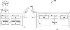
- FIG. 1illustrates an exemplary RFID system 10 that includes a computer 3 coupled to a network 2 and to an RFID interrogator 4 .
- the RFID interrogator 4which may sometimes be referred to as an RFID reader, includes a processor 5 , a transceiver 6 , a memory 7 , a power supply 8 , and an antenna 9 .
- the RFID interrogator 4is programmable and performs transmitting and receiving functions with the transceiver 6 and antenna 9 . Alternatively, multiple antennas may be connected to transmitters and receivers.
- the RFID interrogator 4can communicate with one or more RFID devices 11 that are within communication range of the RFID interrogator 4 . Data downloaded from an RFID device 11 can be stored in memory 7 , or transferred by the processor 5 to computer 3 . Thereafter, this transferred data can be further processed or distributed to network 2 .
- the exemplary RFID device 11includes device antenna 16 and RFID circuit 17 .
- the RFID circuit 17can include a transceiver 12 , a processor 13 , memory 14 , and depending on whether or not RFID device 11 is active, semi-active or passive, a battery 15 .
- Any RF interrogation signal 18 transmitted by the RFID interrogator 4 to the RFID device 11is received by the antenna 16 , and passed to transceiver 12 in RFID circuit 17 .
- processor 13fetches the data (e.g., time stamp, unique RFID code, and so forth) from memory 14 and transmits a return signal 19 through antenna 16 to RFID interrogator 4 , as multiplexed data packets from transceiver 12 .
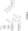
- the RFID interrogator 4can be configured with antenna 9 that is designed to operate within multiple frequency ranges.
- Antenna 9can be a multiband resonant antenna.
- Another RFID interrogator 25may be configured with multiple antennas 21 , 26 that can be tuned to different respective frequencies or frequency ranges.
- antenna 21may operate in a 100 MHz wide frequency range centered at 900 MHz
- antenna 26may operate in a 100 MHz wide frequency range centered at 2.45 GHz.
- the RFID device 11can be configured with an antenna 16 , such as a multiband resonant antenna, that is designed to operate at multiple frequency ranges. Some antenna designs have a primary resonance and secondary resonances, which enable the use of one antenna 16 for multiple carrier frequencies. Another option is to implement antenna 16 as a single antenna structure, such as a patch antenna array, which includes multiple antennas and is resonant on multiple frequency ranges. A single antenna is desirable where space and antenna size are limited.
- the antenna 16 on device 11is coupled to the RFID circuit 17 , and tuned to frequencies or frequency ranges that match at least those of the corresponding antennas 9 , 21 , 26 on RFID interrogators 4 , 25 .
- antenna 16 on RFID device 11may operate in a 100 MHz wide frequency range centered at 900 MHz to correspond to antenna 21 on RFID interrogator 25
- antenna 16 on device 11may also operate in a 100 MHz wide frequency range centered at 2.45 GHz to correspond with antenna 26 on RFID interrogator 25 .
- Such a configurationallows antenna 16 to receive multiple signals 18 , 23 , 27 from the antennas 9 , 21 , 26 on RFID interrogators 4 , 25 , and to respond by transmitting signals 19 , 24 on respective frequency ranges that match those of antennas 9 , 21 , 26 .
- device antenna 16is connected to the RFID circuit 17 , which may include a respective transceiver 12 and a power supply 15 . It should be noted that in place of transceiver 12 , receivers such as a diode detectors and transmitters can be substituted and coupled to antenna 16 .
- RFID processing circuitry 33is coupled to the transceiver 12 and power supply 15 , and processes a signal according to respective protocols.
- a multiband (two-band) resonant antenna 40can be constructed by coupling filter circuits 42 , 43 (traps) to antenna 16 .
- Filter circuit 42includes inductor 45 connected in parallel with capacitor 46 .
- filter circuit 43includes inductor 47 connected in parallel with capacitor 48 .
- the value of inductors 45 , 47 and capacitors 46 , 48are selected depending on the expected resonant frequency at which antenna 40 is to operate.
- the resonant frequency (or trapping frequency) of the filter circuits 42 , 43can be calculated by one divided by the square root of the product of the inductor times the capacitor (1/square root (L*C)).
- Antenna 16can be a dipole antenna having a feedpoint 44 .
- the two-band resonant antenna 40can be constructed with off-the-shelf components, or fabricated using microstrip, stripline, copper etching on PC boards, films, etc.
- dipole antennasare specifically depicted in the figures, other antennas are possible, such as log periodic dipole array, triband Yagi antennas, multiple parallel antennas joined at a common feedpoint (dipoles, patches, etc.), multiple antennas connected serially, and quarter wave dipoles, monopoles and whips.
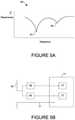
- FIG. 5Ashows a graphical representation 50 of two resonances, a primary 51 and secondary 52 , which may be used to construct a multiband resonant antenna without the use of filter circuits 42 , 43 in each arm of the dipole antenna 16 .
- the secondary resonance 52is usually not very pronounced, typically resulting in less than optimal performance at the secondary (higher) frequency. However, this antenna design may be useful where space is at a premium.
- FIG. 5Bshows an embodiment of the antenna graphically represented in FIG. 5A .
- antenna 16is coupled to two external filter circuits 42 , 43 .
- Filter circuit 42may pertain to resonant frequency 51
- filter circuit 43may pertain to resonant frequency 52 .
- the filter circuits 42 , 43 and antenna 16are coupled to one or more RFID circuits 17 on RFID device 11 .
- the RFID circuits 17may include a power supply 15 , receivers/transceivers 12 , and a processor 13 .
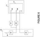
- FIG. 6shows an exemplary RFID device 11 configured with the two-band antenna structure 40 coupled to two additional respective filter circuits 61 and 62 .
- Power supplies 15 , transceivers 12 , and additional circuitry 33may be attached to the filter circuit outputs 63 , 64 on RFID circuit 17 , and configured to operate simultaneously or one at a time. Matching circuits or components may also be added. Multiple protocols, each carried at a different frequency, can be used simultaneously by connecting the appropriate protocol processing circuitry 33 in RFID circuit 17 to each filter circuit output 63 , 64 . Two different protocols can be used by connecting the appropriate processor 13 , transceiver 12 , (and even power supply 15 ) circuitry to the respective outputs 63 , 64 of filter circuits 61 , 62 .
- FIG. 7shows exemplary RFID device 11 configured as a two frequency system in which one output 63 is used as a power supply, and the other output 64 is used for receiving, transmitting, and processing signals.
- RFID device 11includes the two-band antenna structure 40 that is coupled to the two filter circuits 61 and 62 .
- the output 63 of filter circuit 61is connected to the RFID circuit 17 and used as a power supply.
- a diode 72is connected to output 63 and used as a half-wave rectifier to generate direct current (dc) voltage for powering processor 13 and the RFID circuit 17 .
- a filtering capacitor 73is coupled to the diode 72 to smooth out the dc voltage signal.
- the output 64 of filter circuit 62is also connected to RFID circuit 17 .
- RFID circuit 17can also include an automated voltage control 71 for modulating the frequency on which the processed data is to be transmitted.
- System 20can also be configured to utilize a different communication protocol (e.g., EPCglobal® protocol, EPC HF Class 1, EPC UHF Class 0, EPC UHF Class 1, EPC UHF Class 1 Gen 2) on each respective frequency range.
- a different communication protocole.g., EPCglobal® protocol, EPC HF Class 1, EPC UHF Class 0, EPC UHF Class 1, EPC UHF Class 1 Gen 2
- EPCglobal® protocolEPC HF Class 1
- EPC UHF Class 1 Gen 2EPC HF Class 1
- EPC UHF Class 1 Gen 2EPC HF Class 1 Gen 2
- an EPC UHF Class 1 protocolmay be used by RFID device 11 for identification of a hospital patient, and the same RFID device 11 using an entirely different protocol (e.g., EPC HF Class 1) on a different frequency range can be used for communicating with hospital equipment, monitoring patient data, or communicating with a nurse station to report patient status at a greater distance.
- EPC HF Class 1e.g., EPC HF Class 1
- tuning or selecting antenna 9 on RFID interrogator 4 and antenna 16 on the RFID device 11 to operate within a frequency range centered at 900 MHzestablishes a first communication link between the RFID interrogator 4 and RFID device 11 .
- tuning antenna 9 on RFID interrogator 4 and antenna 16 on the RFID device 11to also operate within a frequency range centered at 2.45 GHz, establishes a second communication link between the RFID interrogator 4 and the RFID device 11 .
- the 900 MHz frequency rangecan be used as a carrier for communications according to a first protocol
- the 2.45 GHz frequency rangecan be used as a carrier for communications according to a second protocol.
- the RFID interrogator 4 and device 11can communicate simultaneously or serially over the two frequency ranges.
- the first frequency rangemay be used to provide power from the RFID interrogator 4 to the RFID device 11
- the second frequency rangemay be used for communication according to a particular protocol. Powering the passive device 11 on the first frequency range, while simultaneously communicating over the second frequency range, has the advantage of enabling the device 11 to stay energized longer, to receive or transmit more data per session and to extend processing time.
- the device 11can also be configured to receive power from the RFID interrogators 4 , 25 at multiple frequency ranges.
- the powering of the RFID device 11is typically a range-limiting factor in the communications link between RFID interrogators 4 , 25 and RFID device 11 . This is primarily due to free-space path loss, which tends to increase with frequency. Free-space path loss is the loss in signal strength of an electromagnetic wave that results from a line-of-sight path through free space, with no obstacles nearby to cause reflection or diffraction. Free-space power loss is proportional to the square of the distance between the transmitter and receiver, and also proportional to the square of the frequency of the radio signal.
- frequency rangesare selected that are non-harmonic, non-integer multiple or non-integer-fraction frequencies relative to the other selected frequency ranges. For example, if a first frequency range is centered at 900 MHz, a subsequent frequency range should not be selected at 1800 MHz (the first harmonic of the first range). An advantage is if multipath interference exists at the first frequency range, such interference would be very unlikely at the second frequency range. Using this configuration, reliability and range can be improved by using redundant power transmissions at multiple frequency ranges, either simultaneously or multiplexed one at a time.
- the RFID device 11 with antennacan be implemented as part of rigid (e.g., substrate-based) or flexible (e.g., RFID label) configuration.
- rigide.g., substrate-based
- flexiblee.g., RFID label
- printed or etched layout techniquesincluding stripline, microstrip, organic or polymer semiconductors can be utilized for fabricating planar components or components on substrates that may be rigid or flexible.
- FIG. 8illustrates a method of operation 80 of an RFID device that is in accordance with an embodiment of the present invention.
- the method ( 80 )starts ( 81 ) by receiving radio frequency (RF) signals ( 82 ) having different frequency ranges on an antenna tuned to the different frequency ranges. Once the signals are received, protocols are selected ( 83 ) so that each protocol is associated with only one of the frequency ranges of the received signals.
- the method ( 80 )then processes ( 84 ) the received signals according to the protocols associated with the frequency ranges.
- Method ( 80 )can then either end ( 85 ), or if implemented in an automated system e.g., firmware, the method ( 80 ) can proceed to step ( 82 ) and continue to repeat.
- RFradio frequency
- various functions and operationsmay be described as being performed by or caused by software code to simplify description. However, those skilled in the art will recognize what is meant by such expressions is that the functions result from execution of the code by a processor, such as a microprocessor.
- the functions and operationscan be implemented using special purpose circuitry, with or without software instructions, such as using Application-Specific Integrated Circuit (ASIC) or Field-Programmable Gate Array (FPGA).
- ASICApplication-Specific Integrated Circuit
- FPGAField-Programmable Gate Array
- Embodimentscan be implemented using hardwired circuitry without software instructions, or in combination with software instructions. Thus, the techniques are limited neither to any specific combination of hardware circuitry and software, nor to any particular source for the instructions executed by the data processing system.
- At least some aspects disclosedcan be embodied, at least in part, in software. That is, the techniques may be carried out in a computer system or other data processing system in response to its processor, such as a microprocessor, executing sequences of instructions contained in a memory, such as ROM, volatile RAM, non-volatile memory, cache or a remote storage device.
- processorsuch as a microprocessor
- a memorysuch as ROM, volatile RAM, non-volatile memory, cache or a remote storage device.
- Routines executed to implement the embodimentsmay be implemented as part of an operating system or a specific application, component, program, object, module or sequence of instructions referred to as “computer programs.”
- the computer programstypically comprise one or more instructions set at various times in various memory and storage devices in a computer, and that, when read and executed by one or more processors in a computer, cause the computer to perform operations necessary to execute elements involving the various aspects.
- a machine readable mediumcan be used to store software and data which when executed by a data processing system causes the system to perform various methods.
- the executable software and datamay be stored in various places including for example ROM, volatile RAM, non-volatile memory and/or cache. Portions of this software and/or data may be stored in any one of these storage devices.
- the data and instructionscan be obtained from centralized servers or peer to peer networks. Different portions of the data and instructions can be obtained from different centralized servers and/or peer to peer networks at different times and in different communication sessions or in a same communication session.
- the data and instructionscan be obtained in entirety prior to the execution of the applications. Alternatively, portions of the data and instructions can be obtained dynamically, just in time, when needed for execution. Thus, it is not required that the data and instructions be on a machine readable medium in entirety at a particular instance of time.
- Examples of computer-readable mediainclude but are not limited to recordable and non-recordable type media such as volatile and non-volatile memory devices, read only memory (ROM), random access memory (RAM), flash memory devices, floppy and other removable disks, magnetic disk storage media, optical storage media (e.g., Compact Disk Read-Only Memory (CD ROMS), Digital Versatile Disks (DVDs), etc.), among others.
- the instructionsmay be embodied in digital and analog communication links for electrical, optical, acoustical or other forms of propagated signals, such as carrier waves, infrared signals, digital signals, etc.
- a machine readable mediumincludes any mechanism that provides (i.e., stores and/or transmits) information in a form accessible by a machine (e.g., a computer, network device, personal digital assistant, manufacturing tool, any device with a set of one or more processors, etc.).
- a machinee.g., a computer, network device, personal digital assistant, manufacturing tool, any device with a set of one or more processors, etc.
- hardwired circuitrymay be used in combination with software instructions to implement the techniques.
- the techniquesare neither limited to any specific combination of hardware circuitry and software nor to any particular source for the instructions executed by the data processing system.
Landscapes
- Engineering & Computer Science (AREA)
- Health & Medical Sciences (AREA)
- Toxicology (AREA)
- Physics & Mathematics (AREA)
- Computer Networks & Wireless Communication (AREA)
- General Health & Medical Sciences (AREA)
- Electromagnetism (AREA)
- Artificial Intelligence (AREA)
- Computer Vision & Pattern Recognition (AREA)
- General Physics & Mathematics (AREA)
- Theoretical Computer Science (AREA)
- Software Systems (AREA)
- Near-Field Transmission Systems (AREA)
Abstract
Description
Claims (16)
Priority Applications (2)
| Application Number | Priority Date | Filing Date | Title |
|---|---|---|---|
| US16/940,240US11238248B2 (en) | 2008-05-20 | 2020-07-27 | Systems and methods using single antenna for multiple resonant frequency ranges |
| US17/555,161US20220108089A1 (en) | 2008-05-20 | 2021-12-17 | Systems and Methods using Single Antenna for Multiple Resonant Frequency Ranges |
Applications Claiming Priority (6)
| Application Number | Priority Date | Filing Date | Title |
|---|---|---|---|
| US12/123,826US8712334B2 (en) | 2008-05-20 | 2008-05-20 | RFID device using single antenna for multiple resonant frequency ranges |
| US14/183,240US9047523B2 (en) | 2008-05-20 | 2014-02-18 | Systems and methods using single antenna for multiple resonant frequency ranges |
| US14/710,498US9465964B2 (en) | 2008-05-20 | 2015-05-12 | Systems and methods using single antenna for multiple resonant frequency ranges |
| US15/250,632US10242239B2 (en) | 2008-05-20 | 2016-08-29 | Systems and methods using single antenna for multiple resonant frequency ranges |
| US16/297,526US10726217B2 (en) | 2008-05-20 | 2019-03-08 | Systems and methods using single antenna for multiple resonant frequency ranges |
| US16/940,240US11238248B2 (en) | 2008-05-20 | 2020-07-27 | Systems and methods using single antenna for multiple resonant frequency ranges |
Related Parent Applications (1)
| Application Number | Title | Priority Date | Filing Date |
|---|---|---|---|
| US16/297,526ContinuationUS10726217B2 (en) | 2008-05-20 | 2019-03-08 | Systems and methods using single antenna for multiple resonant frequency ranges |
Related Child Applications (1)
| Application Number | Title | Priority Date | Filing Date |
|---|---|---|---|
| US17/555,161ContinuationUS20220108089A1 (en) | 2008-05-20 | 2021-12-17 | Systems and Methods using Single Antenna for Multiple Resonant Frequency Ranges |
Publications (2)
| Publication Number | Publication Date |
|---|---|
| US20200356738A1 US20200356738A1 (en) | 2020-11-12 |
| US11238248B2true US11238248B2 (en) | 2022-02-01 |
Family
ID=41341683
Family Applications (7)
| Application Number | Title | Priority Date | Filing Date |
|---|---|---|---|
| US12/123,826Active2031-02-10US8712334B2 (en) | 2008-05-20 | 2008-05-20 | RFID device using single antenna for multiple resonant frequency ranges |
| US14/183,240ActiveUS9047523B2 (en) | 2008-05-20 | 2014-02-18 | Systems and methods using single antenna for multiple resonant frequency ranges |
| US14/710,498ActiveUS9465964B2 (en) | 2008-05-20 | 2015-05-12 | Systems and methods using single antenna for multiple resonant frequency ranges |
| US15/250,632Active2028-12-20US10242239B2 (en) | 2008-05-20 | 2016-08-29 | Systems and methods using single antenna for multiple resonant frequency ranges |
| US16/297,526ActiveUS10726217B2 (en) | 2008-05-20 | 2019-03-08 | Systems and methods using single antenna for multiple resonant frequency ranges |
| US16/940,240ActiveUS11238248B2 (en) | 2008-05-20 | 2020-07-27 | Systems and methods using single antenna for multiple resonant frequency ranges |
| US17/555,161PendingUS20220108089A1 (en) | 2008-05-20 | 2021-12-17 | Systems and Methods using Single Antenna for Multiple Resonant Frequency Ranges |
Family Applications Before (5)
| Application Number | Title | Priority Date | Filing Date |
|---|---|---|---|
| US12/123,826Active2031-02-10US8712334B2 (en) | 2008-05-20 | 2008-05-20 | RFID device using single antenna for multiple resonant frequency ranges |
| US14/183,240ActiveUS9047523B2 (en) | 2008-05-20 | 2014-02-18 | Systems and methods using single antenna for multiple resonant frequency ranges |
| US14/710,498ActiveUS9465964B2 (en) | 2008-05-20 | 2015-05-12 | Systems and methods using single antenna for multiple resonant frequency ranges |
| US15/250,632Active2028-12-20US10242239B2 (en) | 2008-05-20 | 2016-08-29 | Systems and methods using single antenna for multiple resonant frequency ranges |
| US16/297,526ActiveUS10726217B2 (en) | 2008-05-20 | 2019-03-08 | Systems and methods using single antenna for multiple resonant frequency ranges |
Family Applications After (1)
| Application Number | Title | Priority Date | Filing Date |
|---|---|---|---|
| US17/555,161PendingUS20220108089A1 (en) | 2008-05-20 | 2021-12-17 | Systems and Methods using Single Antenna for Multiple Resonant Frequency Ranges |
Country Status (1)
| Country | Link |
|---|---|
| US (7) | US8712334B2 (en) |
Families Citing this family (30)
| Publication number | Priority date | Publication date | Assignee | Title |
|---|---|---|---|---|
| US6057779A (en)* | 1997-08-14 | 2000-05-02 | Micron Technology, Inc. | Method of controlling access to a movable container and to a compartment of a vehicle, and a secure cargo transportation system |
| US6356535B1 (en)* | 1998-02-04 | 2002-03-12 | Micron Technology, Inc. | Communication systems and methods of communicating |
| US8636648B2 (en) | 1999-03-01 | 2014-01-28 | West View Research, Llc | Endoscopic smart probe |
| US10973397B2 (en) | 1999-03-01 | 2021-04-13 | West View Research, Llc | Computerized information collection and processing apparatus |
| US8065155B1 (en) | 1999-06-10 | 2011-11-22 | Gazdzinski Robert F | Adaptive advertising apparatus and methods |
| US7710273B2 (en) | 1999-09-02 | 2010-05-04 | Round Rock Research, Llc | Remote communication devices, radio frequency identification devices, wireless communication systems, wireless communication methods, radio frequency identification device communication methods, and methods of forming a remote communication device |
| US7427024B1 (en) | 2003-12-17 | 2008-09-23 | Gazdzinski Mark J | Chattel management apparatus and methods |
| US20090015407A1 (en)* | 2007-07-13 | 2009-01-15 | Micron Technology, Inc. | Rifid tags and methods of designing rfid tags |
| US7777630B2 (en)* | 2007-07-26 | 2010-08-17 | Round Rock Research, Llc | Methods and systems of RFID tags using RFID circuits and antennas having unmatched frequency ranges |
| US8179232B2 (en) | 2008-05-05 | 2012-05-15 | Round Rock Research, Llc | RFID interrogator with adjustable signal characteristics |
| US7852221B2 (en)* | 2008-05-08 | 2010-12-14 | Round Rock Research, Llc | RFID devices using RFID circuits and antennas having unmatched frequency ranges |
| US8712334B2 (en)* | 2008-05-20 | 2014-04-29 | Micron Technology, Inc. | RFID device using single antenna for multiple resonant frequency ranges |
| US9142881B1 (en) | 2008-08-29 | 2015-09-22 | Impinj, Inc. | RFID tag circuits with floating differential inputs |
| US9087281B2 (en)* | 2009-06-12 | 2015-07-21 | Impinj, Inc. | Dual-frequency RFID tag with isolated inputs |
| WO2011114329A1 (en)* | 2010-03-16 | 2011-09-22 | Levi Lior Guttman | Signaling device |
| US20110273273A1 (en)* | 2010-04-29 | 2011-11-10 | Jun Liu | Methods and Apparatus of a Multi-Frequency RFID System |
| JP5327171B2 (en)* | 2010-09-15 | 2013-10-30 | オムロン株式会社 | RFID system |
| FI20116014A7 (en)* | 2011-10-13 | 2013-04-14 | Mariella Labels Oy | Transferring of information in electronic price label systems |
| WO2013076353A1 (en)* | 2011-11-25 | 2013-05-30 | Nokia Corporation | Over-load protection of radio receivers |
| KR102542466B1 (en) | 2015-11-27 | 2023-06-12 | 삼성전자주식회사 | Beam steering device and system employing the same |
| US10656263B2 (en) | 2017-09-14 | 2020-05-19 | Qualcomm Incorporated | Extended localization range and assets tracking |
| GB2580094B (en)* | 2018-12-21 | 2021-12-22 | Pragmatic Printing Ltd | A multi-protocol RFID tag and system |
| US10425129B1 (en) | 2019-02-27 | 2019-09-24 | Capital One Services, Llc | Techniques to reduce power consumption in near field communication systems |
| CN114399012B (en)* | 2019-04-17 | 2024-08-06 | 苹果公司 | Wireless locatable tag |
| US10789391B1 (en) | 2019-07-22 | 2020-09-29 | Alibaba Group Holding Limited | RFID information processing |
| US11790191B2 (en)* | 2019-09-11 | 2023-10-17 | RadicalID, Inc. | Multipurpose RFID transponder and a system for reading it |
| CA3165239A1 (en) | 2019-12-18 | 2021-06-24 | National Research Council Of Canada | Quantum tunneling devices for generation of harmonics in passive wireless tags and sensors |
| CN112766444B (en)* | 2020-12-22 | 2024-09-24 | 努比亚技术有限公司 | Antenna tuning method, device, terminal and storage medium of electronic price tag |
| IL280374B2 (en)* | 2021-01-24 | 2023-11-01 | Scr Eng Ltd | An animal marking control system and method |
| US11068674B1 (en)* | 2021-02-15 | 2021-07-20 | King Abdulaziz University | RFID tag identification methods, devices, and algorithms based on eigen-mode technique |
Citations (122)
| Publication number | Priority date | Publication date | Assignee | Title |
|---|---|---|---|---|
| US3569976A (en) | 1968-08-29 | 1971-03-09 | William Korvin | Antenna array at focal plane of reflector with coupling network for beam switching |
| US3733608A (en) | 1971-12-09 | 1973-05-15 | Motorola Inc | Circuit for coupling radio receiver and radio transmitter to a common antenna for duplex operation |
| US3745568A (en) | 1972-04-11 | 1973-07-10 | Us Air Force | Spectrum analysis radar |
| US3745569A (en) | 1971-07-22 | 1973-07-10 | Raytheon Co | Remotely powered transponder |
| US4075632A (en) | 1974-08-27 | 1978-02-21 | The United States Of America As Represented By The United States Department Of Energy | Interrogation, and detection system |
| US4173019A (en) | 1977-02-11 | 1979-10-30 | U.S. Philips Corporation | Microstrip antenna array |
| US4623874A (en) | 1984-11-02 | 1986-11-18 | Gte Communication Systems Corp. | Word length converter |
| US4630044A (en) | 1982-12-23 | 1986-12-16 | Ant Nachrichtentechnik Gmbh | Programmable inductively coupled transponder |
| US4692769A (en) | 1986-04-14 | 1987-09-08 | The United States Of America As Represented By The Secretary Of The Navy | Dual band slotted microstrip antenna |
| US4926182A (en) | 1986-05-30 | 1990-05-15 | Sharp Kabushiki Kaisha | Microwave data transmission apparatus |
| US4963887A (en) | 1988-08-31 | 1990-10-16 | Yamatake-Honeywell Co., Ltd. | Full duplex transponder system |
| US5023866A (en) | 1987-02-27 | 1991-06-11 | Motorola, Inc. | Duplexer filter having harmonic rejection to control flyback |
| US5053774A (en) | 1987-07-31 | 1991-10-01 | Texas Instruments Deutschland Gmbh | Transponder arrangement |
| US5081458A (en) | 1990-02-09 | 1992-01-14 | Compagnie De Signaux Et D'equipements Electroniques | Hyperfrequency system for remote data transmission |
| US5084699A (en) | 1989-05-26 | 1992-01-28 | Trovan Limited | Impedance matching coil assembly for an inductively coupled transponder |
| US5119099A (en) | 1989-06-02 | 1992-06-02 | Yamatake-Honeywell Co., Ltd. | Microwave responder |
| US5164985A (en) | 1987-10-27 | 1992-11-17 | Nysen Paul A | Passive universal communicator system |
| US5182570A (en) | 1989-11-13 | 1993-01-26 | X-Cyte Inc. | End fed flat antenna |
| US5320561A (en) | 1992-06-19 | 1994-06-14 | Motorola, Inc. | Connector for providing programming, testing, and power signals |
| US5374930A (en) | 1993-04-14 | 1994-12-20 | Texas Instruments Deutschland Gmbh | High speed read/write AVI system |
| US5446447A (en) | 1994-02-16 | 1995-08-29 | Motorola, Inc. | RF tagging system including RF tags with variable frequency resonant circuits |
| US5448110A (en) | 1992-06-17 | 1995-09-05 | Micron Communications, Inc. | Enclosed transceiver |
| US5450086A (en) | 1993-12-03 | 1995-09-12 | Texas Instruments Deutschland Gmbh | Self-tuning receiver/decoder for frequency shift keying RF data transmission |
| US5465099A (en) | 1991-09-25 | 1995-11-07 | Nippon Information Industry Corporation | Detectable device and movable item detecting system |
| US5467099A (en) | 1993-04-20 | 1995-11-14 | Mcdonnell Douglas Corporation | Resonated notch antenna |
| US5491715A (en) | 1993-06-28 | 1996-02-13 | Texas Instruments Deutschland Gmbh | Automatic antenna tuning method and circuit |
| US5491484A (en) | 1992-12-15 | 1996-02-13 | Texas Instruments Incorporated | Electronic transponder tuning circuitry |
| US5512910A (en) | 1987-09-25 | 1996-04-30 | Aisin Seiki, Co., Ltd. | Microstrip antenna device having three resonance frequencies |
| US5528222A (en) | 1994-09-09 | 1996-06-18 | International Business Machines Corporation | Radio frequency circuit and memory in thin flexible package |
| US5537105A (en) | 1991-01-04 | 1996-07-16 | British Technology Group Limited | Electronic identification system |
| US5561435A (en) | 1995-02-09 | 1996-10-01 | The United States Of America As Represented By The Secretary Of The Army | Planar lower cost multilayer dual-band microstrip antenna |
| US5572226A (en) | 1992-05-15 | 1996-11-05 | Micron Technology, Inc. | Spherical antenna pattern(s) from antenna(s) arranged in a two-dimensional plane for use in RFID tags and labels |
| US5598169A (en) | 1995-03-24 | 1997-01-28 | Lucent Technologies Inc. | Detector and modulator circuits for passive microwave links |
| US5606323A (en) | 1995-08-31 | 1997-02-25 | International Business Machines Corporation | Diode modulator for radio frequency transponder |
| US5617060A (en) | 1994-04-28 | 1997-04-01 | Qualcomm Incorporated | Method and apparatus for automatic gain control and DC offset cancellation in quadrature receiver |
| US5621412A (en) | 1994-04-26 | 1997-04-15 | Texas Instruments Incorporated | Multi-stage transponder wake-up, method and structure |
| US5649295A (en) | 1995-06-19 | 1997-07-15 | Lucent Technologies Inc. | Dual mode modulated backscatter system |
| US5649296A (en) | 1995-06-19 | 1997-07-15 | Lucent Technologies Inc. | Full duplex modulated backscatter system |
| US5682143A (en) | 1994-09-09 | 1997-10-28 | International Business Machines Corporation | Radio frequency identification tag |
| US5726630A (en) | 1992-11-18 | 1998-03-10 | British Technology Group Limited | Detection of multiple articles |
| US5771021A (en) | 1993-10-04 | 1998-06-23 | Amtech Corporation | Transponder employing modulated backscatter microstrip double patch antenna |
| US5838235A (en) | 1995-09-06 | 1998-11-17 | France Telecom | Station, a passive portable object and apparatus for the remote exchange of information between the passive portable object and the station |
| US5842118A (en) | 1996-12-18 | 1998-11-24 | Micron Communications, Inc. | Communication system including diversity antenna queuing |
| US5889478A (en) | 1996-04-01 | 1999-03-30 | Matra Transport International | Fault tolerant apparatus for detecting the passage of a moving body |
| US5900808A (en) | 1997-02-21 | 1999-05-04 | Lebo; Michael E. | Low pressure warning system |
| US5923298A (en) | 1997-04-30 | 1999-07-13 | Ford Motor Company | Multiband reception antenna for terrestrial digital audio broadcast bands |
| US5942977A (en) | 1997-08-13 | 1999-08-24 | Ludwig Kipp | Radio transponder |
| US5959357A (en) | 1998-02-17 | 1999-09-28 | General Electric Company | Fet array for operation at different power levels |
| US5977928A (en) | 1998-05-29 | 1999-11-02 | Telefonaktiebolaget Lm Ericsson | High efficiency, multi-band antenna for a radio communication device |
| US6028564A (en) | 1997-01-29 | 2000-02-22 | Intermec Ip Corp. | Wire antenna with optimized impedance for connecting to a circuit |
| US6037907A (en) | 1997-06-17 | 2000-03-14 | Samsung Electronics Co., Ltd. | Dual band antenna for mobile communications |
| US6122494A (en) | 1996-07-30 | 2000-09-19 | Micron Technology, Inc. | Radio frequency antenna with current controlled sensitivity |
| US6130602A (en) | 1996-05-13 | 2000-10-10 | Micron Technology, Inc. | Radio frequency data communications device |
| US6177872B1 (en) | 1998-03-13 | 2001-01-23 | Intermec Ip Corp. | Distributed impedance matching circuit for high reflection coefficient load |
| US6184841B1 (en) | 1996-12-31 | 2001-02-06 | Lucent Technologies Inc. | Antenna array in an RFID system |
| US6192222B1 (en) | 1998-09-03 | 2001-02-20 | Micron Technology, Inc. | Backscatter communication systems, interrogators, methods of communicating in a backscatter system, and backscatter communication methods |
| US6239765B1 (en) | 1999-02-27 | 2001-05-29 | Rangestar Wireless, Inc. | Asymmetric dipole antenna assembly |
| US6243012B1 (en) | 1996-12-31 | 2001-06-05 | Lucent Technologies Inc. | Inexpensive modulated backscatter reflector |
| US6317027B1 (en) | 1999-01-12 | 2001-11-13 | Randy Watkins | Auto-tunning scanning proximity reader |
| US6329139B1 (en) | 1995-04-25 | 2001-12-11 | Discovery Partners International | Automated sorting system for matrices with memory |
| US6329915B1 (en) | 1997-12-31 | 2001-12-11 | Intermec Ip Corp | RF Tag having high dielectric constant material |
| US6356535B1 (en) | 1998-02-04 | 2002-03-12 | Micron Technology, Inc. | Communication systems and methods of communicating |
| US6362737B1 (en) | 1998-06-02 | 2002-03-26 | Rf Code, Inc. | Object Identification system with adaptive transceivers and methods of operation |
| US6411212B1 (en) | 1998-07-21 | 2002-06-25 | Daimlerchrysler Ag | Transponder arrangement |
| US20030045244A1 (en) | 1999-08-03 | 2003-03-06 | Allied Signal, Inc. | Single antenna for receipt of signals from multiple communications systems |
| US6611691B1 (en) | 1998-12-24 | 2003-08-26 | Motorola, Inc. | Antenna adapted to operate in a plurality of frequency bands |
| US20030179092A1 (en)* | 2000-03-03 | 2003-09-25 | Loftus Stephen Clive | Returnable item for use in storage and transportation of commercial goods |
| US20040008151A1 (en) | 2002-06-05 | 2004-01-15 | Kazuhiro Kurihara | Variable type antenna matching circuit |
| US6738025B2 (en) | 2001-02-28 | 2004-05-18 | Battelle Memorial Institute K1-53 | Antenna matching circuit |
| US20040178912A1 (en)* | 1999-09-02 | 2004-09-16 | Smith Freddie W. | Remote communication devices, radio frequency identification devices, wireless communication systems, wireless communication methods, radio frequency identification device communication methods, and methods of forming a remote communication device |
| US20050052283A1 (en) | 2003-09-09 | 2005-03-10 | Collins Timothy J. | Method and apparatus for multiple frequency RFID tag architecture |
| US20050237198A1 (en)* | 2004-04-08 | 2005-10-27 | Waldner Michele A | Variable frequency radio frequency indentification (RFID) tags |
| US7006048B2 (en) | 2003-09-15 | 2006-02-28 | Tatung Co., Ltd. | Dual operational frequency slot antenna |
| US7026935B2 (en) | 2003-11-10 | 2006-04-11 | Impinj, Inc. | Method and apparatus to configure an RFID system to be adaptable to a plurality of environmental conditions |
| US20060080819A1 (en) | 2004-09-14 | 2006-04-20 | Mcallister Clarke W | Systems and methods for deployment and recycling of RFID tags, wireless sensors, and the containers attached thereto |
| US20060103535A1 (en) | 2004-11-15 | 2006-05-18 | Kourosh Pahlaven | Radio frequency tag and reader with asymmetric communication bandwidth |
| US20060145851A1 (en) | 2004-12-17 | 2006-07-06 | Joshua Posamentier | RFID tag with modifiable and reversible read range |
| US7091860B2 (en) | 2002-08-08 | 2006-08-15 | Neology, Inc. | Multi-frequency identification device |
| US20060202827A1 (en) | 2003-03-03 | 2006-09-14 | Volpi John P | Interrogator and interrogation system employing the same |
| US20060293027A1 (en) | 2005-06-24 | 2006-12-28 | Visa U.S.A., Inc. | Apparatus and method for preventing wireless interrogation of portable consumer devices |
| US20070001851A1 (en)* | 2005-07-01 | 2007-01-04 | Thingmagic, Inc. | Configurable, calibrated radio frequency identification tag system |
| US20070069862A1 (en) | 2005-09-23 | 2007-03-29 | Hee-Sook Mo | Apparatus and method for reading multiple tags with different protocols in RFID system |
| US20070096881A1 (en)* | 2005-10-28 | 2007-05-03 | Vijay Pillai | System and method of enhancing range in a radio frequency identification system |
| US20070279286A1 (en) | 2006-06-05 | 2007-12-06 | Mark Iv Industries Corp. | Multi-Mode Antenna Array |
| US20070298838A1 (en) | 2006-06-22 | 2007-12-27 | Honeywell International Inc. | Apparatus and method for improving reception in a system with multiple transmitters and receivers operating on a single antenna |
| US20080024279A1 (en) | 2004-07-09 | 2008-01-31 | Kelly Gravelle | Multi-protocol or multi command rfid system |
| US20080076476A1 (en)* | 2006-09-22 | 2008-03-27 | Broadcom Corporation, A California Corporation | RF transceiver with a plurality of programmable antennas and methods for use therewith |
| US20080084310A1 (en)* | 2006-10-05 | 2008-04-10 | Pavel Nikitin | Configurable RFID tag with protocol and band selection |
| US20080094183A1 (en) | 2006-08-29 | 2008-04-24 | Shinichiro Fukushima | Ic memory, as well as, accessing apparatus and validity testing method for use of ic memory |
| US20080174410A1 (en)* | 2007-01-08 | 2008-07-24 | Jagannathan Sarangapani | Decentralized radio frequency identification system |
| US20080189142A1 (en) | 2007-02-02 | 2008-08-07 | Hartford Fire Insurance Company | Safety evaluation and feedback system and method |
| US20080227478A1 (en) | 2007-03-15 | 2008-09-18 | Greene Charles E | Multiple frequency transmitter, receiver, and systems thereof |
| US20080233880A1 (en)* | 2007-03-19 | 2008-09-25 | Ahmadreza Rofougaran | Method and system for sharing a single antenna for frequency modulation (fm) transmission, fm reception and near field communication (nfc) |
| US20080231450A1 (en)* | 2007-03-23 | 2008-09-25 | Joshua Posementier | RFID receive-only system |
| US20080287067A1 (en)* | 2007-04-05 | 2008-11-20 | Kabushiki Kaisha Tokai Rika Denki Seisakusho | System for controlling wireless communication between portable device and communication controller |
| US20090015407A1 (en) | 2007-07-13 | 2009-01-15 | Micron Technology, Inc. | Rifid tags and methods of designing rfid tags |
| US20090027168A1 (en)* | 2007-07-26 | 2009-01-29 | Micron Technology, Inc. | Methods and systems of rfid tags using rfid circuits and antennas having unmatched frequency ranges |
| US20090045921A1 (en) | 2007-08-16 | 2009-02-19 | Farpointe Data, Inc., A California Corporation | System and method for multi-protocol radio-frequency identification |
| US20090058612A1 (en)* | 2007-08-29 | 2009-03-05 | Electronics And Telecommunications Research Institute | Method and apparatus for avoiding collision between each of radio frequency identification readers |
| US20090093223A1 (en)* | 2007-10-05 | 2009-04-09 | Matsushita Electric Industrial Co., Ltd. | Methods and apparatus for reducing radiated field feedback in radio frequency transmitters |
| US20090096611A1 (en)* | 2007-10-16 | 2009-04-16 | Sensormatic Electronics Corporation | Mobile radio frequency identification antenna system and method |
| US20090207092A1 (en) | 2008-02-15 | 2009-08-20 | Paul Nysen | Compact diversity antenna system |
| US20090267737A1 (en)* | 2008-04-29 | 2009-10-29 | Dean Kawaguchi | Rfid system with distributed readers |
| US20090273449A1 (en) | 2008-05-05 | 2009-11-05 | Keystone Technology Solutions, Llc | RFID Interrogator With Adjustable Signal Characteristics |
| US20090278688A1 (en) | 2008-05-08 | 2009-11-12 | Keystone Technology Solutions, Llc | RFID Devices Using RFID Circuits and Antennas Having Unmatched Frequency Ranges |
| US20090289771A1 (en)* | 2008-05-20 | 2009-11-26 | Keystone Technology Solutions, Llc | RFID Device Using Single Antenna For Multiple Resonant Frequency Ranges |
| US20090303005A1 (en)* | 2008-06-05 | 2009-12-10 | Keystone Technology Solutions, Llc | Systems and Methods to Determine Kinematical Parameters using RFID Tags |
| US20090309797A1 (en)* | 2006-09-06 | 2009-12-17 | Nokia Corporation | Multi-part radio apparatus |
| US20090322634A1 (en)* | 2006-10-26 | 2009-12-31 | Electronics And Telecommunications Research Institute | Loop antenna |
| US20100073138A1 (en) | 2008-09-25 | 2010-03-25 | Brother Kogyo Kabushiki Kaisha | RFID tag communication system and RFID tag communication apparatus |
| US20110065402A1 (en)* | 2006-05-30 | 2011-03-17 | Kraft Christian R | Dynamic Radio Data System Options |
| US7924802B2 (en) | 2008-01-23 | 2011-04-12 | Wilinx Corporation | Wireless communication systems and methods |
| US7953454B2 (en) | 2003-03-21 | 2011-05-31 | Sony Ericsson Mobile Communications Ab | Wireless hands-free system with silent user signaling |
| US20110254749A1 (en) | 2009-08-25 | 2011-10-20 | Satoru Amari | Antenna apparatus including multiple antenna portions on one antenna element operable at multiple frequencies |
| US20110285511A1 (en) | 2009-06-12 | 2011-11-24 | Impinji, Inc. | Dual-frequency rfid tag with isolated inputs |
| US20120026040A1 (en) | 2008-11-12 | 2012-02-02 | Thomas Hohne | Method, Apparatus, Computer Program and a Computer Readable Storage Medium |
| US8174386B2 (en) | 2008-11-28 | 2012-05-08 | Electronics And Telecommunications Research Institute | RFID reader controlling device, interlocking method for RFID reader, and RFID reader controlling method |
| US8232865B2 (en) | 1997-08-14 | 2012-07-31 | Round Rock Research, Llc | Wireless communication devices |
| US20120329407A1 (en)* | 2011-06-22 | 2012-12-27 | Renesas Mobile Corporation | Antenna Arrangement |
| US8355313B2 (en) | 2002-10-25 | 2013-01-15 | Qualcomm Incorporated | MIMO system with multiple spatial multiplexing modes |
| US20130154802A1 (en)* | 2011-12-19 | 2013-06-20 | Symbol Technologies, Inc. | Method and apparatus for updating a central plan for an area based on a location of a plurality of radio frequency identification readers |
| US8648721B2 (en)* | 2010-08-09 | 2014-02-11 | Tyco Fire & Security Gmbh | Security tag with integrated EAS and energy harvesting magnetic element |
Family Cites Families (2)
| Publication number | Priority date | Publication date | Assignee | Title |
|---|---|---|---|---|
| SE517380C2 (en)* | 2000-10-12 | 2002-06-04 | Ericsson Telefon Ab L M | Method and apparatus for utilizing frequency space in a wireless communication system with unsymmetrical traffic congestion |
| US8447626B2 (en)* | 2005-07-29 | 2013-05-21 | Koninklijke Philips Electronics N.V. | System and method for context dependent service discovery for mobile medical devices |
- 2008
- 2008-05-20USUS12/123,826patent/US8712334B2/enactiveActive
- 2014
- 2014-02-18USUS14/183,240patent/US9047523B2/enactiveActive
- 2015
- 2015-05-12USUS14/710,498patent/US9465964B2/enactiveActive
- 2016
- 2016-08-29USUS15/250,632patent/US10242239B2/enactiveActive
- 2019
- 2019-03-08USUS16/297,526patent/US10726217B2/enactiveActive
- 2020
- 2020-07-27USUS16/940,240patent/US11238248B2/enactiveActive
- 2021
- 2021-12-17USUS17/555,161patent/US20220108089A1/enactivePending
Patent Citations (143)
| Publication number | Priority date | Publication date | Assignee | Title |
|---|---|---|---|---|
| US3569976A (en) | 1968-08-29 | 1971-03-09 | William Korvin | Antenna array at focal plane of reflector with coupling network for beam switching |
| US3745569A (en) | 1971-07-22 | 1973-07-10 | Raytheon Co | Remotely powered transponder |
| US3733608A (en) | 1971-12-09 | 1973-05-15 | Motorola Inc | Circuit for coupling radio receiver and radio transmitter to a common antenna for duplex operation |
| US3745568A (en) | 1972-04-11 | 1973-07-10 | Us Air Force | Spectrum analysis radar |
| US4075632A (en) | 1974-08-27 | 1978-02-21 | The United States Of America As Represented By The United States Department Of Energy | Interrogation, and detection system |
| US4173019A (en) | 1977-02-11 | 1979-10-30 | U.S. Philips Corporation | Microstrip antenna array |
| US4630044A (en) | 1982-12-23 | 1986-12-16 | Ant Nachrichtentechnik Gmbh | Programmable inductively coupled transponder |
| US4623874A (en) | 1984-11-02 | 1986-11-18 | Gte Communication Systems Corp. | Word length converter |
| US4692769A (en) | 1986-04-14 | 1987-09-08 | The United States Of America As Represented By The Secretary Of The Navy | Dual band slotted microstrip antenna |
| US4926182A (en) | 1986-05-30 | 1990-05-15 | Sharp Kabushiki Kaisha | Microwave data transmission apparatus |
| US5023866A (en) | 1987-02-27 | 1991-06-11 | Motorola, Inc. | Duplexer filter having harmonic rejection to control flyback |
| US5053774A (en) | 1987-07-31 | 1991-10-01 | Texas Instruments Deutschland Gmbh | Transponder arrangement |
| US5512910A (en) | 1987-09-25 | 1996-04-30 | Aisin Seiki, Co., Ltd. | Microstrip antenna device having three resonance frequencies |
| US5164985A (en) | 1987-10-27 | 1992-11-17 | Nysen Paul A | Passive universal communicator system |
| US4963887A (en) | 1988-08-31 | 1990-10-16 | Yamatake-Honeywell Co., Ltd. | Full duplex transponder system |
| US5084699A (en) | 1989-05-26 | 1992-01-28 | Trovan Limited | Impedance matching coil assembly for an inductively coupled transponder |
| US5119099A (en) | 1989-06-02 | 1992-06-02 | Yamatake-Honeywell Co., Ltd. | Microwave responder |
| US5182570A (en) | 1989-11-13 | 1993-01-26 | X-Cyte Inc. | End fed flat antenna |
| US5081458A (en) | 1990-02-09 | 1992-01-14 | Compagnie De Signaux Et D'equipements Electroniques | Hyperfrequency system for remote data transmission |
| US5537105A (en) | 1991-01-04 | 1996-07-16 | British Technology Group Limited | Electronic identification system |
| US5465099A (en) | 1991-09-25 | 1995-11-07 | Nippon Information Industry Corporation | Detectable device and movable item detecting system |
| US5572226A (en) | 1992-05-15 | 1996-11-05 | Micron Technology, Inc. | Spherical antenna pattern(s) from antenna(s) arranged in a two-dimensional plane for use in RFID tags and labels |
| US5448110A (en) | 1992-06-17 | 1995-09-05 | Micron Communications, Inc. | Enclosed transceiver |
| US5320561A (en) | 1992-06-19 | 1994-06-14 | Motorola, Inc. | Connector for providing programming, testing, and power signals |
| US5726630A (en) | 1992-11-18 | 1998-03-10 | British Technology Group Limited | Detection of multiple articles |
| US5491484A (en) | 1992-12-15 | 1996-02-13 | Texas Instruments Incorporated | Electronic transponder tuning circuitry |
| US5374930A (en) | 1993-04-14 | 1994-12-20 | Texas Instruments Deutschland Gmbh | High speed read/write AVI system |
| US5467099A (en) | 1993-04-20 | 1995-11-14 | Mcdonnell Douglas Corporation | Resonated notch antenna |
| US5491715A (en) | 1993-06-28 | 1996-02-13 | Texas Instruments Deutschland Gmbh | Automatic antenna tuning method and circuit |
| US5771021A (en) | 1993-10-04 | 1998-06-23 | Amtech Corporation | Transponder employing modulated backscatter microstrip double patch antenna |
| US5450086A (en) | 1993-12-03 | 1995-09-12 | Texas Instruments Deutschland Gmbh | Self-tuning receiver/decoder for frequency shift keying RF data transmission |
| US5446447A (en) | 1994-02-16 | 1995-08-29 | Motorola, Inc. | RF tagging system including RF tags with variable frequency resonant circuits |
| US5621412A (en) | 1994-04-26 | 1997-04-15 | Texas Instruments Incorporated | Multi-stage transponder wake-up, method and structure |
| US5617060A (en) | 1994-04-28 | 1997-04-01 | Qualcomm Incorporated | Method and apparatus for automatic gain control and DC offset cancellation in quadrature receiver |
| US5528222A (en) | 1994-09-09 | 1996-06-18 | International Business Machines Corporation | Radio frequency circuit and memory in thin flexible package |
| US5682143A (en) | 1994-09-09 | 1997-10-28 | International Business Machines Corporation | Radio frequency identification tag |
| US5561435A (en) | 1995-02-09 | 1996-10-01 | The United States Of America As Represented By The Secretary Of The Army | Planar lower cost multilayer dual-band microstrip antenna |
| US5598169A (en) | 1995-03-24 | 1997-01-28 | Lucent Technologies Inc. | Detector and modulator circuits for passive microwave links |
| US6329139B1 (en) | 1995-04-25 | 2001-12-11 | Discovery Partners International | Automated sorting system for matrices with memory |
| US5649295A (en) | 1995-06-19 | 1997-07-15 | Lucent Technologies Inc. | Dual mode modulated backscatter system |
| US5649296A (en) | 1995-06-19 | 1997-07-15 | Lucent Technologies Inc. | Full duplex modulated backscatter system |
| US5606323A (en) | 1995-08-31 | 1997-02-25 | International Business Machines Corporation | Diode modulator for radio frequency transponder |
| US5838235A (en) | 1995-09-06 | 1998-11-17 | France Telecom | Station, a passive portable object and apparatus for the remote exchange of information between the passive portable object and the station |
| US5889478A (en) | 1996-04-01 | 1999-03-30 | Matra Transport International | Fault tolerant apparatus for detecting the passage of a moving body |
| US6825773B1 (en) | 1996-05-13 | 2004-11-30 | Micron Technology, Inc. | Radio frequency data communications device |
| US6130602A (en) | 1996-05-13 | 2000-10-10 | Micron Technology, Inc. | Radio frequency data communications device |
| US6574454B1 (en) | 1996-07-30 | 2003-06-03 | Micron Technology, Inc. | Radio frequency antenna with current controlled sensitivity |
| US6122494A (en) | 1996-07-30 | 2000-09-19 | Micron Technology, Inc. | Radio frequency antenna with current controlled sensitivity |
| US5842118A (en) | 1996-12-18 | 1998-11-24 | Micron Communications, Inc. | Communication system including diversity antenna queuing |
| US6243012B1 (en) | 1996-12-31 | 2001-06-05 | Lucent Technologies Inc. | Inexpensive modulated backscatter reflector |
| US6184841B1 (en) | 1996-12-31 | 2001-02-06 | Lucent Technologies Inc. | Antenna array in an RFID system |
| US6028564A (en) | 1997-01-29 | 2000-02-22 | Intermec Ip Corp. | Wire antenna with optimized impedance for connecting to a circuit |
| US5900808A (en) | 1997-02-21 | 1999-05-04 | Lebo; Michael E. | Low pressure warning system |
| US5923298A (en) | 1997-04-30 | 1999-07-13 | Ford Motor Company | Multiband reception antenna for terrestrial digital audio broadcast bands |
| US6037907A (en) | 1997-06-17 | 2000-03-14 | Samsung Electronics Co., Ltd. | Dual band antenna for mobile communications |
| US5942977A (en) | 1997-08-13 | 1999-08-24 | Ludwig Kipp | Radio transponder |
| US8232865B2 (en) | 1997-08-14 | 2012-07-31 | Round Rock Research, Llc | Wireless communication devices |
| US6329915B1 (en) | 1997-12-31 | 2001-12-11 | Intermec Ip Corp | RF Tag having high dielectric constant material |
| US7075901B2 (en) | 1998-02-04 | 2006-07-11 | Micron Technology, Inc. | Communication systems, communication apparatuses, radio frequency communication methods, methods of communicating using a radio frequency communication system, and methods of forming a radio frequency communication device |
| US20070018904A1 (en) | 1998-02-04 | 2007-01-25 | Smith Freddie W | Communication devices, communication systems and methods of communicating |
| US6717923B1 (en) | 1998-02-04 | 2004-04-06 | Micron Technology, Inc. | Communication devices, a radio frequency identification device, and methods of communicating |
| US6356535B1 (en) | 1998-02-04 | 2002-03-12 | Micron Technology, Inc. | Communication systems and methods of communicating |
| US5959357A (en) | 1998-02-17 | 1999-09-28 | General Electric Company | Fet array for operation at different power levels |
| US6177872B1 (en) | 1998-03-13 | 2001-01-23 | Intermec Ip Corp. | Distributed impedance matching circuit for high reflection coefficient load |
| US5977928A (en) | 1998-05-29 | 1999-11-02 | Telefonaktiebolaget Lm Ericsson | High efficiency, multi-band antenna for a radio communication device |
| US6362737B1 (en) | 1998-06-02 | 2002-03-26 | Rf Code, Inc. | Object Identification system with adaptive transceivers and methods of operation |
| US6411212B1 (en) | 1998-07-21 | 2002-06-25 | Daimlerchrysler Ag | Transponder arrangement |
| US6192222B1 (en) | 1998-09-03 | 2001-02-20 | Micron Technology, Inc. | Backscatter communication systems, interrogators, methods of communicating in a backscatter system, and backscatter communication methods |
| US6611691B1 (en) | 1998-12-24 | 2003-08-26 | Motorola, Inc. | Antenna adapted to operate in a plurality of frequency bands |
| US6317027B1 (en) | 1999-01-12 | 2001-11-13 | Randy Watkins | Auto-tunning scanning proximity reader |
| US6239765B1 (en) | 1999-02-27 | 2001-05-29 | Rangestar Wireless, Inc. | Asymmetric dipole antenna assembly |
| US20030045244A1 (en) | 1999-08-03 | 2003-03-06 | Allied Signal, Inc. | Single antenna for receipt of signals from multiple communications systems |
| US20040178912A1 (en)* | 1999-09-02 | 2004-09-16 | Smith Freddie W. | Remote communication devices, radio frequency identification devices, wireless communication systems, wireless communication methods, radio frequency identification device communication methods, and methods of forming a remote communication device |
| US7710273B2 (en) | 1999-09-02 | 2010-05-04 | Round Rock Research, Llc | Remote communication devices, radio frequency identification devices, wireless communication systems, wireless communication methods, radio frequency identification device communication methods, and methods of forming a remote communication device |
| US20070290807A1 (en) | 1999-09-02 | 2007-12-20 | Smith Freddie W | Remote Communication Devices, Radio Frequency Identification Devices, Wireless Communication Systems, Wireless Communication Methods, Radio Frequency Identification Device Communication Methods, and Methods of Forming a Remote Communication Device |
| US20030179092A1 (en)* | 2000-03-03 | 2003-09-25 | Loftus Stephen Clive | Returnable item for use in storage and transportation of commercial goods |
| US6738025B2 (en) | 2001-02-28 | 2004-05-18 | Battelle Memorial Institute K1-53 | Antenna matching circuit |
| US6885353B2 (en) | 2002-06-05 | 2005-04-26 | Nec Corporation | Variable type antenna matching circuit |
| US20040008151A1 (en) | 2002-06-05 | 2004-01-15 | Kazuhiro Kurihara | Variable type antenna matching circuit |
| US7091860B2 (en) | 2002-08-08 | 2006-08-15 | Neology, Inc. | Multi-frequency identification device |
| US8355313B2 (en) | 2002-10-25 | 2013-01-15 | Qualcomm Incorporated | MIMO system with multiple spatial multiplexing modes |
| US20060202827A1 (en) | 2003-03-03 | 2006-09-14 | Volpi John P | Interrogator and interrogation system employing the same |
| US7953454B2 (en) | 2003-03-21 | 2011-05-31 | Sony Ericsson Mobile Communications Ab | Wireless hands-free system with silent user signaling |
| US20050052283A1 (en) | 2003-09-09 | 2005-03-10 | Collins Timothy J. | Method and apparatus for multiple frequency RFID tag architecture |
| US7006048B2 (en) | 2003-09-15 | 2006-02-28 | Tatung Co., Ltd. | Dual operational frequency slot antenna |
| US7026935B2 (en) | 2003-11-10 | 2006-04-11 | Impinj, Inc. | Method and apparatus to configure an RFID system to be adaptable to a plurality of environmental conditions |
| US7132946B2 (en) | 2004-04-08 | 2006-11-07 | 3M Innovative Properties Company | Variable frequency radio frequency identification (RFID) tags |
| US20050237198A1 (en)* | 2004-04-08 | 2005-10-27 | Waldner Michele A | Variable frequency radio frequency indentification (RFID) tags |
| US20080024279A1 (en) | 2004-07-09 | 2008-01-31 | Kelly Gravelle | Multi-protocol or multi command rfid system |
| US20060080819A1 (en) | 2004-09-14 | 2006-04-20 | Mcallister Clarke W | Systems and methods for deployment and recycling of RFID tags, wireless sensors, and the containers attached thereto |
| US20060103535A1 (en) | 2004-11-15 | 2006-05-18 | Kourosh Pahlaven | Radio frequency tag and reader with asymmetric communication bandwidth |
| US20060145851A1 (en) | 2004-12-17 | 2006-07-06 | Joshua Posamentier | RFID tag with modifiable and reversible read range |
| US7327257B2 (en) | 2004-12-17 | 2008-02-05 | Intel Corporation | RFID tag with modifiable and reversible read range |
| US20060293027A1 (en) | 2005-06-24 | 2006-12-28 | Visa U.S.A., Inc. | Apparatus and method for preventing wireless interrogation of portable consumer devices |
| US20090227281A1 (en) | 2005-06-24 | 2009-09-10 | Ayman Hammad | Apparatus and method for preventing wireless interrogation of phones |
| US20070001851A1 (en)* | 2005-07-01 | 2007-01-04 | Thingmagic, Inc. | Configurable, calibrated radio frequency identification tag system |
| US20070069862A1 (en) | 2005-09-23 | 2007-03-29 | Hee-Sook Mo | Apparatus and method for reading multiple tags with different protocols in RFID system |
| US20070096881A1 (en)* | 2005-10-28 | 2007-05-03 | Vijay Pillai | System and method of enhancing range in a radio frequency identification system |
| US20110065402A1 (en)* | 2006-05-30 | 2011-03-17 | Kraft Christian R | Dynamic Radio Data System Options |
| US20070279286A1 (en) | 2006-06-05 | 2007-12-06 | Mark Iv Industries Corp. | Multi-Mode Antenna Array |
| US20070298838A1 (en) | 2006-06-22 | 2007-12-27 | Honeywell International Inc. | Apparatus and method for improving reception in a system with multiple transmitters and receivers operating on a single antenna |
| US20080094183A1 (en) | 2006-08-29 | 2008-04-24 | Shinichiro Fukushima | Ic memory, as well as, accessing apparatus and validity testing method for use of ic memory |
| US20090309797A1 (en)* | 2006-09-06 | 2009-12-17 | Nokia Corporation | Multi-part radio apparatus |
| US20080076476A1 (en)* | 2006-09-22 | 2008-03-27 | Broadcom Corporation, A California Corporation | RF transceiver with a plurality of programmable antennas and methods for use therewith |
| US20080084310A1 (en)* | 2006-10-05 | 2008-04-10 | Pavel Nikitin | Configurable RFID tag with protocol and band selection |
| US20090322634A1 (en)* | 2006-10-26 | 2009-12-31 | Electronics And Telecommunications Research Institute | Loop antenna |
| US20080174410A1 (en)* | 2007-01-08 | 2008-07-24 | Jagannathan Sarangapani | Decentralized radio frequency identification system |
| US20080189142A1 (en) | 2007-02-02 | 2008-08-07 | Hartford Fire Insurance Company | Safety evaluation and feedback system and method |
| US20080227478A1 (en) | 2007-03-15 | 2008-09-18 | Greene Charles E | Multiple frequency transmitter, receiver, and systems thereof |
| US20080233880A1 (en)* | 2007-03-19 | 2008-09-25 | Ahmadreza Rofougaran | Method and system for sharing a single antenna for frequency modulation (fm) transmission, fm reception and near field communication (nfc) |
| US20080231450A1 (en)* | 2007-03-23 | 2008-09-25 | Joshua Posementier | RFID receive-only system |
| US20080287067A1 (en)* | 2007-04-05 | 2008-11-20 | Kabushiki Kaisha Tokai Rika Denki Seisakusho | System for controlling wireless communication between portable device and communication controller |
| US20090015407A1 (en) | 2007-07-13 | 2009-01-15 | Micron Technology, Inc. | Rifid tags and methods of designing rfid tags |
| US20090027168A1 (en)* | 2007-07-26 | 2009-01-29 | Micron Technology, Inc. | Methods and systems of rfid tags using rfid circuits and antennas having unmatched frequency ranges |
| US20090045921A1 (en) | 2007-08-16 | 2009-02-19 | Farpointe Data, Inc., A California Corporation | System and method for multi-protocol radio-frequency identification |
| US20090058612A1 (en)* | 2007-08-29 | 2009-03-05 | Electronics And Telecommunications Research Institute | Method and apparatus for avoiding collision between each of radio frequency identification readers |
| US20090093223A1 (en)* | 2007-10-05 | 2009-04-09 | Matsushita Electric Industrial Co., Ltd. | Methods and apparatus for reducing radiated field feedback in radio frequency transmitters |
| US20090096611A1 (en)* | 2007-10-16 | 2009-04-16 | Sensormatic Electronics Corporation | Mobile radio frequency identification antenna system and method |
| US7924802B2 (en) | 2008-01-23 | 2011-04-12 | Wilinx Corporation | Wireless communication systems and methods |
| US20090207092A1 (en) | 2008-02-15 | 2009-08-20 | Paul Nysen | Compact diversity antenna system |
| US20090267737A1 (en)* | 2008-04-29 | 2009-10-29 | Dean Kawaguchi | Rfid system with distributed readers |
| US20090273449A1 (en) | 2008-05-05 | 2009-11-05 | Keystone Technology Solutions, Llc | RFID Interrogator With Adjustable Signal Characteristics |
| US20090278688A1 (en) | 2008-05-08 | 2009-11-12 | Keystone Technology Solutions, Llc | RFID Devices Using RFID Circuits and Antennas Having Unmatched Frequency Ranges |
| US7852221B2 (en) | 2008-05-08 | 2010-12-14 | Round Rock Research, Llc | RFID devices using RFID circuits and antennas having unmatched frequency ranges |
| US8712334B2 (en)* | 2008-05-20 | 2014-04-29 | Micron Technology, Inc. | RFID device using single antenna for multiple resonant frequency ranges |
| US20140167922A1 (en)* | 2008-05-20 | 2014-06-19 | Micron Technology, Inc. | Systems and methods using single antenna for multiple resonant frequency ranges |
| US10726217B2 (en) | 2008-05-20 | 2020-07-28 | Micron Technology, Inc. | Systems and methods using single antenna for multiple resonant frequency ranges |
| US20190205577A1 (en) | 2008-05-20 | 2019-07-04 | Micron Technology, Inc. | Systems and Methods using Single Antenna for Multiple Resonant Frequency Ranges |
| US10242239B2 (en) | 2008-05-20 | 2019-03-26 | Micron Technology, Inc. | Systems and methods using single antenna for multiple resonant frequency ranges |
| US20160371518A1 (en)* | 2008-05-20 | 2016-12-22 | Micron Technology, Inc. | Systems and methods using single antenna for multiple resonant frequency ranges |
| US9465964B2 (en) | 2008-05-20 | 2016-10-11 | Micron Technology, Inc. | Systems and methods using single antenna for multiple resonant frequency ranges |
| US20090289771A1 (en)* | 2008-05-20 | 2009-11-26 | Keystone Technology Solutions, Llc | RFID Device Using Single Antenna For Multiple Resonant Frequency Ranges |
| US20150242664A1 (en)* | 2008-05-20 | 2015-08-27 | Micron Technology, Inc. | Systems and methods using single antenna for multiple resonant frequency ranges |
| US9047523B2 (en)* | 2008-05-20 | 2015-06-02 | Micron Technology, Inc. | Systems and methods using single antenna for multiple resonant frequency ranges |
| US20090303005A1 (en)* | 2008-06-05 | 2009-12-10 | Keystone Technology Solutions, Llc | Systems and Methods to Determine Kinematical Parameters using RFID Tags |
| US20100073138A1 (en) | 2008-09-25 | 2010-03-25 | Brother Kogyo Kabushiki Kaisha | RFID tag communication system and RFID tag communication apparatus |
| US20120026040A1 (en) | 2008-11-12 | 2012-02-02 | Thomas Hohne | Method, Apparatus, Computer Program and a Computer Readable Storage Medium |
| US8174386B2 (en) | 2008-11-28 | 2012-05-08 | Electronics And Telecommunications Research Institute | RFID reader controlling device, interlocking method for RFID reader, and RFID reader controlling method |
| US20110285511A1 (en) | 2009-06-12 | 2011-11-24 | Impinji, Inc. | Dual-frequency rfid tag with isolated inputs |
| US20110254749A1 (en) | 2009-08-25 | 2011-10-20 | Satoru Amari | Antenna apparatus including multiple antenna portions on one antenna element operable at multiple frequencies |
| US8648721B2 (en)* | 2010-08-09 | 2014-02-11 | Tyco Fire & Security Gmbh | Security tag with integrated EAS and energy harvesting magnetic element |
| US20120329407A1 (en)* | 2011-06-22 | 2012-12-27 | Renesas Mobile Corporation | Antenna Arrangement |
| US20130154802A1 (en)* | 2011-12-19 | 2013-06-20 | Symbol Technologies, Inc. | Method and apparatus for updating a central plan for an area based on a location of a plurality of radio frequency identification readers |
Non-Patent Citations (5)
| Title |
|---|
| Chartered Semiconductor Manufacturing, "Toppan Announces Volume Production of Next Generation RFID Chip," press release, Jul. 8, 2003. |
| Peng, Chen et al., "The Analysis and Design of a Novel Passive Reflection Modulation Tag," IEEE Proceedings of the 4th International Conference on Microwave and Millimeter Wave Technology, pp. 402-405, Aug. 2004. |
| Sakamura, Ken, "TRON News Items for Jan. 2004," located at http://tronweb.super-nova.co.jp/tronnews04-1.html, Jan. 2004. |
| Turner, Chris, "Backscatter Modulation of Impedance Modulated RFID Tags," located at www.rfip.eu/backscatter_tag_link_budget_and_modulation_at_reader_receiver.pdf, Feb. 2003. |
| Tuttle, John R., U.S. Appl. No. 08/806,158, filed Feb. 25, 1997, now abandoned. |
Also Published As
| Publication number | Publication date |
|---|---|
| US9465964B2 (en) | 2016-10-11 |
| US10726217B2 (en) | 2020-07-28 |
| US20190205577A1 (en) | 2019-07-04 |
| US20150242664A1 (en) | 2015-08-27 |
| US20160371518A1 (en) | 2016-12-22 |
| US8712334B2 (en) | 2014-04-29 |
| US10242239B2 (en) | 2019-03-26 |
| US9047523B2 (en) | 2015-06-02 |
| US20140167922A1 (en) | 2014-06-19 |
| US20090289771A1 (en) | 2009-11-26 |
| US20220108089A1 (en) | 2022-04-07 |
| US20200356738A1 (en) | 2020-11-12 |
Similar Documents
| Publication | Publication Date | Title |
|---|---|---|
| US11238248B2 (en) | Systems and methods using single antenna for multiple resonant frequency ranges | |
| US7852221B2 (en) | RFID devices using RFID circuits and antennas having unmatched frequency ranges | |
| US8836512B2 (en) | Self tuning RFID | |
| US7557757B2 (en) | Inductively coupled feed structure and matching circuit for RFID device | |
| US20080238623A1 (en) | Transceiver front-end having tx and rx isolation | |
| EP1813085B1 (en) | Technique and hardware for communicating with backscatter radio frequency identification readers | |
| CN106470040B (en) | Dual band transmitter | |
| US10192160B2 (en) | Radio-frequency identification device | |
| AU2006214501A1 (en) | Techniques to configure radio-frequency identification readers | |
| US20140203989A1 (en) | High frequency (hf)/ultra high frequency (uhf) radio frequency identification (rfid) dual-band tag antenna | |
| EP3279836A1 (en) | Method and apparatus for multi-band energy harvesting | |
| Mishra et al. | Modified rectangular resonators based multi‐frequency narrow‐band RFID reader antenna | |
| WO2021196118A1 (en) | Resonance-based high-frequency radio frequency identification communication system | |
| Habib et al. | Multi-resonator Based Passive Chipless RFID Tag for Tracking Applications | |
| KR20100060887A (en) | Antanna module for operating multi band, and communication system for the same | |
| Deleruyelle et al. | Dual band mono-chip HF-UHF tag antenna | |
| CN110770755A (en) | Piezoelectric Radio Frequency Identification (RFID) antenna | |
| KR20090100578A (en) | Multi-loop radio recognition tag (RFC) tag antenna and RDF tag using same | |
| US20250226587A1 (en) | Antenna for radio frequency attenuating enclosure | |
| US11551017B2 (en) | RFID system with improved signal transmission characteristics | |
| CN217880346U (en) | Subminiature UHF RFID electronic tag |
Legal Events
| Date | Code | Title | Description |
|---|---|---|---|
| AS | Assignment | Owner name:MICRON TECHNOLOGY, INC., IDAHO Free format text:ASSIGNMENT OF ASSIGNORS INTEREST;ASSIGNOR:KEYSTONE TECHNOLOGY SOLUTIONS, LLC;REEL/FRAME:053324/0050 Effective date:20091222 Owner name:KEYSTONE TECHNOLOGY SOLUTIONS, LLC, IDAHO Free format text:ASSIGNMENT OF ASSIGNORS INTEREST;ASSIGNOR:TUTTLE, JOHN R.;REEL/FRAME:053322/0517 Effective date:20080423 | |
| FEPP | Fee payment procedure | Free format text:ENTITY STATUS SET TO UNDISCOUNTED (ORIGINAL EVENT CODE: BIG.); ENTITY STATUS OF PATENT OWNER: LARGE ENTITY | |
| STPP | Information on status: patent application and granting procedure in general | Free format text:RESPONSE TO NON-FINAL OFFICE ACTION ENTERED AND FORWARDED TO EXAMINER | |
| STPP | Information on status: patent application and granting procedure in general | Free format text:FINAL REJECTION MAILED | |
| STPP | Information on status: patent application and granting procedure in general | Free format text:DOCKETED NEW CASE - READY FOR EXAMINATION | |
| STPP | Information on status: patent application and granting procedure in general | Free format text:NON FINAL ACTION MAILED | |
| STPP | Information on status: patent application and granting procedure in general | Free format text:RESPONSE TO NON-FINAL OFFICE ACTION ENTERED AND FORWARDED TO EXAMINER | |
| STPP | Information on status: patent application and granting procedure in general | Free format text:NOTICE OF ALLOWANCE MAILED -- APPLICATION RECEIVED IN OFFICE OF PUBLICATIONS | |
| STPP | Information on status: patent application and granting procedure in general | Free format text:AWAITING TC RESP, ISSUE FEE PAYMENT VERIFIED | |
| STPP | Information on status: patent application and granting procedure in general | Free format text:PUBLICATIONS -- ISSUE FEE PAYMENT VERIFIED | |
| STCF | Information on status: patent grant | Free format text:PATENTED CASE | |
| AS | Assignment | Owner name:LODESTAR LICENSING GROUP LLC, ILLINOIS Free format text:ASSIGNMENT OF ASSIGNORS INTEREST;ASSIGNOR:MICRON TECHNOLOGY, INC.;REEL/FRAME:069906/0463 Effective date:20230323 | |
| MAFP | Maintenance fee payment | Free format text:PAYMENT OF MAINTENANCE FEE, 4TH YEAR, LARGE ENTITY (ORIGINAL EVENT CODE: M1551); ENTITY STATUS OF PATENT OWNER: LARGE ENTITY Year of fee payment:4 |