US11237574B2 - Fluid monitoring and control system - Google Patents
Fluid monitoring and control systemDownload PDFInfo
- Publication number
- US11237574B2 US11237574B2US16/948,713US202016948713AUS11237574B2US 11237574 B2US11237574 B2US 11237574B2US 202016948713 AUS202016948713 AUS 202016948713AUS 11237574 B2US11237574 B2US 11237574B2
- Authority
- US
- United States
- Prior art keywords
- fluid
- control device
- pipe section
- preset threshold
- exceeding
- Prior art date
- Legal status (The legal status is an assumption and is not a legal conclusion. Google has not performed a legal analysis and makes no representation as to the accuracy of the status listed.)
- Active
Links
Images


Classifications
- G—PHYSICS
- G05—CONTROLLING; REGULATING
- G05D—SYSTEMS FOR CONTROLLING OR REGULATING NON-ELECTRIC VARIABLES
- G05D16/00—Control of fluid pressure
- G05D16/20—Control of fluid pressure characterised by the use of electric means
- F—MECHANICAL ENGINEERING; LIGHTING; HEATING; WEAPONS; BLASTING
- F16—ENGINEERING ELEMENTS AND UNITS; GENERAL MEASURES FOR PRODUCING AND MAINTAINING EFFECTIVE FUNCTIONING OF MACHINES OR INSTALLATIONS; THERMAL INSULATION IN GENERAL
- F16K—VALVES; TAPS; COCKS; ACTUATING-FLOATS; DEVICES FOR VENTING OR AERATING
- F16K31/00—Actuating devices; Operating means; Releasing devices
- F16K31/02—Actuating devices; Operating means; Releasing devices electric; magnetic
- F16K31/04—Actuating devices; Operating means; Releasing devices electric; magnetic using a motor
- F16K31/041—Actuating devices; Operating means; Releasing devices electric; magnetic using a motor for rotating valves
- F16K31/042—Actuating devices; Operating means; Releasing devices electric; magnetic using a motor for rotating valves with electric means, e.g. for controlling the motor or a clutch between the valve and the motor
- F—MECHANICAL ENGINEERING; LIGHTING; HEATING; WEAPONS; BLASTING
- F16—ENGINEERING ELEMENTS AND UNITS; GENERAL MEASURES FOR PRODUCING AND MAINTAINING EFFECTIVE FUNCTIONING OF MACHINES OR INSTALLATIONS; THERMAL INSULATION IN GENERAL
- F16K—VALVES; TAPS; COCKS; ACTUATING-FLOATS; DEVICES FOR VENTING OR AERATING
- F16K37/00—Special means in or on valves or other cut-off apparatus for indicating or recording operation thereof, or for enabling an alarm to be given
- F16K37/0025—Electrical or magnetic means
- F16K37/005—Electrical or magnetic means for measuring fluid parameters
- G—PHYSICS
- G05—CONTROLLING; REGULATING
- G05D—SYSTEMS FOR CONTROLLING OR REGULATING NON-ELECTRIC VARIABLES
- G05D7/00—Control of flow
- G05D7/06—Control of flow characterised by the use of electric means
- G05D7/0617—Control of flow characterised by the use of electric means specially adapted for fluid materials
- G05D7/0629—Control of flow characterised by the use of electric means specially adapted for fluid materials characterised by the type of regulator means
- G05D7/0635—Control of flow characterised by the use of electric means specially adapted for fluid materials characterised by the type of regulator means by action on throttling means
- E—FIXED CONSTRUCTIONS
- E03—WATER SUPPLY; SEWERAGE
- E03B—INSTALLATIONS OR METHODS FOR OBTAINING, COLLECTING, OR DISTRIBUTING WATER
- E03B7/00—Water main or service pipe systems
- E03B7/07—Arrangement of devices, e.g. filters, flow controls, measuring devices, siphons or valves, in the pipe systems
- E03B7/078—Combined units with different devices; Arrangement of different devices with respect to each other
- Y—GENERAL TAGGING OF NEW TECHNOLOGICAL DEVELOPMENTS; GENERAL TAGGING OF CROSS-SECTIONAL TECHNOLOGIES SPANNING OVER SEVERAL SECTIONS OF THE IPC; TECHNICAL SUBJECTS COVERED BY FORMER USPC CROSS-REFERENCE ART COLLECTIONS [XRACs] AND DIGESTS
- Y10—TECHNICAL SUBJECTS COVERED BY FORMER USPC
- Y10T—TECHNICAL SUBJECTS COVERED BY FORMER US CLASSIFICATION
- Y10T137/00—Fluid handling
- Y10T137/7722—Line condition change responsive valves
- Y10T137/7758—Pilot or servo controlled
- Y10T137/7761—Electrically actuated valve
Definitions
- the present inventiongenerally relates to fluid monitoring and control. More particularly, the present invention relates to a central hub that is in communication with a plurality of control devices placed at various locations to monitor and control fluids.
- An embodiment of a fluid control device 32has a fluid pipe section 33 including a fluid inlet 35 and a fluid outlet 34 configured to be connectable in series to a fluid pipe 36 .
- a fluid valve 22is coupled in series within the fluid pipe section separating a fluid inlet side 35 from a fluid outlet side 34 .
- the fluid inlet sidecorresponds to the fluid inlet of the fluid pipe section and the fluid outlet side corresponds to the fluid outlet of the fluid pipe section.
- the fluid valvecontrols a fluid flow through the fluid pipe section.
- An electric motor 2is mechanically connected to the fluid valve.
- At least one sensoris coupled to the fluid pipe section.
- the at least one sensorcomprises: a temperature sensor 39 monitoring a temperature of the fluid flow within the fluid pipe section; a pressure sensor 40 monitoring a pressure of the fluid flow within the fluid pipe section; and/or a flow rate sensor 38 monitoring a flow rate of the fluid flow within the fluid pipe section;
- a control device processor 41is controllably and electrically connected to the electric motor and electrically connected to the at least one sensor.
- a communication device 42 , 46 , 47is coupled to the control device processor, the communication device configured to be wirelessly connectable to a remotely disposed fluid monitoring and control system 43 , 50 , 51 , 52 , 54 .
- the control device processoris configured to enter into a pre-occupancy mode when powered and never previously wirelessly connected to the fluid monitoring and control system.
- the pre-occupancy modeis configured to fully close the fluid valve if at least one of the following occurs: exceeding a first preset threshold for a pressure decay test; exceeding a second preset threshold for a maximum flow rate; exceeding a third preset threshold for a maximum flow duration; exceeding a fourth preset threshold for a maximum flow volume; exceeding below a fifth preset threshold for a low temperature; exceeding above a sixth preset threshold for a high temperature; and/or exceeding above a seventh preset threshold for a high pressure.
- control device processormay be configured to illuminate an LED 60 or a display 60 , the LED or the display being electrically connected to the control device processor.
- control device processoris configured to sound an audible alarm by a speaker 61 , the speaker being electrically connected to the control device processor.
- the fluid control devicemay be configured to be in wireless communication with a second fluid control device disposed a distance apart.
- the second fluid control devicemay be configured to illuminate an LED or a display or sound an audible alarm by a speaker if the fluid control device has shut the fluid valve, wherein the LED, the display or the audible alarm is electrically connected to a control device processor of the second fluid control device.
- the fluid control devicemay be configured to exit the pre-occupancy mode when the fluid control device is wirelessly connected to the fluid monitoring and control system and a user has requested the pre-occupancy mode be turned off.
- the communication devicemay comprise a wireless communication transmitter and receiver 46 , 47 configured to wirelessly communicate with the fluid monitoring and control system.
- the transmitter and receivermay be integrated inside the housing 1 , such that no external modular units 46 are needed.
- a housing 1may enclose at least the electric motor and the control device processor.
- the fluid flowmay comprise a liquid flow, a gas flow, an air flow or a combination thereof.
- a battery 49 or a power input 48may be electrically connected to the control device processor.
- the pressure sensormay be disposed on the fluid outlet side of the fluid valve and wherein no pressure sensor is disposed on the fluid inlet side of the fluid valve.
- the flow rate sensormay be a turbine wheel.
- the fluid valvemay be a ball valve.
- the temperature sensor and the pressure sensormay both be disposed on the fluid outlet side of the fluid valve.
- the temperature sensor, the pressure sensor and the flow rate sensormay be all disposed on the fluid outlet side of the fluid valve.
- the fluid monitoring and control devicemay comprise a portable electronic device 51 , a computer 53 or a smart phone 54 .
- a fluid monitoring and control systemin another embodiment, includes a central hub having a central processor, a user interface electronically coupled to the central processor and an input/output port electronically coupled to the central processor.
- a plurality of control devicescommunicate with the central hub.
- Each control deviceincludes a fluid pipe section including a fluid inlet and a fluid outlet configured to be connectable in series to a fluid pipe.
- a fluid valveis coupled in series within the fluid pipe section, the fluid valve controlling a fluid flow through the fluid pipe section.
- An electric motoris mechanically connected to the fluid valve.
- a temperature sensoris coupled to the fluid pipe section monitoring a temperature of the fluid flow within the fluid pipe section.
- a pressure sensoris coupled to the fluid pipe section monitoring a pressure of the fluid flow within the fluid pipe section.
- a flow rate sensoris coupled to the fluid pipe section monitoring a flow rate of the fluid flow within the fluid pipe section.
- a control device processoris controllably connected to the electric motor, temperature sensor, pressure sensor and flow sensor.
- a control device input/output portis coupled to the control device processor, the control device input/output port in communication with the input/output port of the central hub.
- the fluid flow through any individual devicemay be a liquid flow, a gas flow, an air flow or a combination thereof.
- a housingmay enclose at least the electric motor and control device processor.
- control device wireless communication transmitter and receivermay be connectable to the control device input/output port.
- a proximity sensor or a moisture sensormay be in communication with the central hub.
- the input/output port of the central hubmay include a central hub wireless communication transmitter and receiver in communication with the control device wireless communication transmitter and receiver.
- the user interfacemay be a computer screen and a keyboard or a touch activated computer screen.
- the user interfacemay be a website accessible from a remote computer, a fire alarm system, a burglar alarm system, a mobile computer or a portable electronic device.
- a communication wiremay be connected physically between the input/output ports of the central hub and control device.
- a batterymay be coupled to the control device processor.
- a power inputmay be electrically connected to the control device processor.
- a speakermay be electrically connected to the central hub processor for sounding a warning sound.
- a lightmay be electrically connected the central hub processor for illuminating a warning light.
- An exemplary method of fluid controlincludes providing a fluid monitoring and control system having the central hub and the plurality of control devices discussed herein and also installing software on the central processor of the central hub controlling the plurality of controlling devices, programming into the software a temperature threshold, a pressure threshold or a flow rate threshold of the fluid flow for at least one control device of the plurality of devices, automatically monitoring the temperature, the pressure and the flow rate of the fluid flow of the at least one control device of the plurality of devices by the software, and automatically closing the respective fluid valve of the at least one control device of the plurality of control devices by the software wherein either the temperature, the pressure or the flow rate threshold was exceeded.
- the step of programming into the software the temperature threshold, the pressure threshold or the flow rate threshold of the fluid flow for at least one control device of the plurality of devicesmay include automatically monitoring the temperature, the pressure and the flow rate of the fluid flow by the software for a defined learning period of time and automatically establishing the temperature threshold, the pressure threshold or the flow rate threshold by the software during the defined learning period of time.
- itmay include the step of automatically alerting the user by the software when either the temperature, the pressure or the flow rate exceeds at least one of the thresholds, where the step of automatically alerting the user comprises a warning light, a warning sound, a text message, an email, a pager notification, a voicemail or other electronic communication means.
- itmay include the step of automatically closing a fluid valve of at least one control device of the plurality of devices by the software for a defined test period of time when a threshold has not been exceeded, and including the step of monitoring a pressure decay during the defined test period of time, and including the step of automatically closing the respective fluid valve of the at least one control device of the plurality of control devices when the pressure decay during the defined test period of time exceeds a predefined pressure decay threshold.
- itmay include providing a moisture sensor in communication with the central processor of the central hub and including the step of automatically closing a fluid valve of a respective control device of the plurality of devices when the moisture sensor detects a leak.
- itmay include providing a proximity sensor in communication with the central processor of the central hub. Furthermore, this may include providing a second temperature threshold, a second pressure threshold or a second flow rate threshold utilized for monitoring by the software, and including the step of the user commanding the software to utilize the second thresholds through the user interface or the step of the software automatically utilizing the second thresholds based upon an input from the proximity sensor.
- a vacation modecan be entered where a burglar use or other unexpected fluid flow use may be quickly determined and the control device closed and an alert message sent to the user. Also, in this way use of the fluid can be better controlled based upon the movements of the user within a building or structure.
- FIG. 1is an exploded perspective view of an exemplary control device embodying the present invention
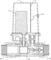
- FIG. 2is a sectional view taken through the assembled structure of FIG. 1 ;
- FIG. 3is a front view of an exemplary wireless communication module attachable to the structure of FIG. 1 ;
- FIG. 4is a side view of the structure of FIG. 3 ;
- FIG. 5is a back view of the structure of FIG. 3 ;
- FIG. 6is a sectional view similar to FIG. 2 now showing the wireless communication module
- FIG. 7is a schematic overview of an exemplary fluid monitoring and control system embodying the present invention.
- FIG. 1is an exploded perspective view of an exemplary control device 32 embodying the present invention.
- Each control device 32includes a fluid pipe section 33 including a fluid inlet 35 and a fluid outlet 34 configured to be connectable in series to a fluid pipe 36 .
- a brass union nut 17screws onto an adapter 20 to retain the tail piece that is in turn attached to the inlet pipe. This attachment is sealed by the union ring 18 .
- a fluid valve 22is coupled in series within the fluid pipe section 33 and is housed in the valve body 24 .
- the fluid valve 22controls a fluid flow 37 through the fluid pipe section 33 .
- the adapter 20abuts an adapter o-ring 21 and captures the ball valve 22 along with the plastic balls seats 23 against the valve body 24 .
- the motor 2is coupled to the ball valve 22 through the motor coupling 6 which engages a limit stop 7 .
- the valve stem 12engages the motor coupling 6 and also the ball valve 22 .
- the valve stem 12also slips through the spring seal 13 and the o-ring 14 for providing a water tight seal.
- the tactile switches 11indicate the position of the valve ball 22 .
- the motor 2may be directly connected to the ball valve 22 as shown or may be connected through a gear reduction system (not shown). Many gear reduction systems known to those skilled in the art may be used to effectively couple the motor 2 to the ball valve 22 such as belts, pulleys or gears.
- a ball valve 22is used, but it is understood that other fluid valves could be utilized such as a gate valve, cylinder valve, globe valve, butterfly valve, diaphragm valve or needle valve.
- the motor 2is connected to a motor baseplate 4 by screws 5 . Screws 3 then fasten the baseplate 4 to the enclosure 10 .
- a cover or housing 1encloses the motor 2 and other associated parts. It is understood that the enclosure 10 and cover 1 can be fashioned in a multitude of shapes and sizes and is not to be limited by this particular shape and configuration. Screws 9 help hold the enclosure 2 to the valve body 24 . It is understood that the enclosure 10 and valve body 24 could be formed as a single part and not two separate parts attached with screws or fasteners 9 . Screws 31 hold the cover 1 to the enclosure 10 . It is understood that the cover 1 could be snap fitted to the enclosure 10 or other various latches and fasteners utilized.
- a flow sensor 38 as shown hereinincludes a turbine wheel 27 that utilizes a magnet 28 and a turbine counter weight 29 placed opposite the turbine magnet 28 for balance.
- a turbine shaft 26spins within the turbine bearing 25 .
- a fluid flow 37flows through the rear bearing support 30 .
- a Hall Effect sensor 15 and flow sensor PCB 16are utilized to sense the rotation of the turbine wheel 27 due to the magnet 28 .
- a Hall Effect sensoris a transducer that varies its output voltage in response to a magnetic field.
- Hall Effect sensorsare commonly used to time the speed of wheels and shafts, such as for internal combustion engine ignition timing, tachometers and anti-lock braking systems. Herein, they are used to detect the position of the permanent magnet 28 . It is understood by one skilled in the art that other sensors could be utilized to determine the flow rate of the fluid. Other sensors include a thermal mass flow sensors, an ultrasonic flow sensors and a piston sensor. In place of the Hall Effect sensor 15 a reed switch can also be used.
- a transducer base 8includes a temperature sensor 39 and a pressure sensor 40 .
- the temperature sensor 39 , pressure sensor 40 and Hall Effect sensor 15all send their information to a control device processor 41 .
- Tactile switches 11are also connected to processor 41 and the motor is also powered by the processor 41 .
- the control device processor 41can then send the information to an input/output port 42 .
- the control device 32may also be powered through port 42 .
- the control device 32communicates with a central hub 43 .
- the communicationcan be from the input/output port 42 of the control device 32 to an input/output port 44 on the central hub 43 .
- This means a hardwire 45is connected between the control device 32 and the central hub 43 .
- FIG. 7shows three hardwires 45 a - c however a single or a multitude of hardwires 45 and control devices 32 may be used.
- a modular unit 46 as seen in FIGS. 3-5can be attached to the cover 1 as seen in FIG. 6 .
- the modular unit 46contains a wireless communication transmitter and receiver 47 .
- the modular unit 46is designed to connect to the input/output port 42 of the control device 32 .
- the modular unit 46also contains a power input 48 for an external battery 49 or from a hardwired power supply line (not shown).
- the modular unit 46can be utilized or not utilized and this does not change the design the control device 32 as this adds the adaptability and functionality of the system.
- the central hub 43controls all of the control devices 32 .
- FIG. 7is just one embodiment the system can encompass, as many variations of FIG. & are possible.
- the central hub 43has a central processor 50 and an input/output port 44 .
- the central hub 43also includes a user interface 51 .
- the user interface 51may be a touch computer screen or a screen and a keyboard.
- the user interface 51may be physically attached or formed with the central hub 43 . This means the central hub 43 can be mounted within an optimal location within a building or structure. After the initial setup the system will be functional without the local interface.
- the user interface 51may also include a remote user interface wirelessly connected via a router 52 or hardwire connected to the central hub 43 .
- the user interfacemay include a remote computer and keyboard 53 accessible over the Internet through a LAN connection or wireless connection 59 .
- a smart phone or portable electronic device 54could even access the central hub 43 via the cloud/internet 59 or specialized software running in the cloud or on the central hub 43 itself.
- the user interface 51could also be incorporated into a fire system 55 or a burglar/alarm system 56 .
- Many fire systems and burglar/alarm systemsalready run sophisticated software already.
- One skilled in the artcould adapt the central hub 43 to receive and send commands via the fire and burglar/alarm systems.
- the central hub 43could be configured to automatically close the valve on a control device controlling the flow of natural gas.
- Other devicesmay also be hardwire connected or wirelessly connected to the central hub.
- Thisincludes proximity/occupancy sensors 57 or moisture sensors 58 .
- a proximity sensorcan register this non-occurrence and shut various fluid flows.
- a fluid flowcan be started. For instance, it is a common nuisance to have to wait a significant amount of time for hot water to reach a particular faucet.
- Some buildingsconstantly run a small amount of heated fluid through the pipes so that when needed hot water is quickly supplied.
- the present inventioncould be utilized to only provide this small amount of hot water flow based upon the proximity sensor. For instance, if a proximity sensor detected a user was near the bathroom the hot water to the shower could be started to pre-warm the water pipes.
- the signal generated by each sensor 57 , 58can either be used by one zone or multiple zones based on system set up.
- the moisture sensor 58can also send information to the central hub 43 .
- a moisture sensor 58could be placed around a water heater, washing machine or under a sink to determine if a leak occurred.
- a moisture sensorcould be placed within a basement to detect leaks. If a leak occurred, it could send a signal to the central hub 43 which would then shut the appropriate valve in a corresponding control device 32 .
- the moisture sensor 58 and occupancy sensor 57could be directly connected to the central hub or wirelessly connected through a wireless communication transmitter and receiver 47 .
- FIG. 7is just one example where three control devices 32 are utilized directly connected to the central hub and three control devices 32 are remotely connected via the modular unit 46 with the wireless communication transmitter and receiver 47 .
- ZONE Ais connected to the whole house. If water to the whole house needs to shut off it can by controlling just this single control device 32 .
- the control device 32 in ZONE Bis connected to the lawn/sprinkler system. This means that the lawn and sprinklers can be controlled from a single control device 32 .
- the control device for ZONE Ccontrols the laundry room. If a floor moisture sensor 58 was placed within the laundry room, it could detect a leak and automatically turn just the flow of water off to the laundry room. This way, the water flow to the rest of the house would remain usable and flowing.
- the control device 32 for ZONE Xcontrols the kitchen. If work is needed to be performed in the kitchen to install new appliances or fix a leak, the control device 32 can just shut down the kitchen and not the rest of the house. Additionally, a moisture sensor 58 can be placed near the refrigerator to detect any leaks and automatically turn off the water.
- the control devices 32 for ZONE Y and ZONE Zcontrol various bathrooms. It is very common for a shower or faucet to leak. Usually one valve controls the flow of water to the whole house. This means water to the whole house must be turned off when servicing any component in the piping system. With the present invention just a single bathroom can have the water turned off to easily allow maintenance to be performed while not disrupting the rest of the water supply.
- Relays 62can be utilized to send and receive information from the central hub 43 either directly or wirelessly to control various functions.
- the relays 62are intended to be utilized just as easily as the rest of the components providing the user the ability to create a custom system.
- the relays 62can be connected to any system or other use not directly mentioned in this disclosure.
- Relays 62can be programed by a user to engage and create either a dry contact or produce a voltage based on variety of conditions.
- Each individual control device 32is configured to control and monitor all fluid flows including liquids, gas, air or any combination thereof. In this way the same control device 32 can be used for water or for natural gas. This increases the uses of the present invention to cover all fluids used in buildings.
- the control device 32can control the flow of natural gas. If the fire alarm 56 or any device sends a signal, the natural gas can be shut off. For instance, a fire may be detected and the flow of gas should be shut down for safety. Also, if an earthquake occurs, this can damage pipes and creates leaks. The central hub 43 can shut down all control devices to ensure that no leaks are present.
- Each control devicemeasures all three states of a fluid: temperature, pressure and flow rate. In this way the control device can monitor all states of the fluid and create alarms, notifications or shut valves if the individual or any combination of values based on the desired algorithm exceeds a set threshold. For instance, if a pressure threshold was set at 75 psi and the water entering the house was above this, it would indicate that the pressure regulator for the house had failed and needed replaced. A warning signal or notification could be sent. For instance, a visual notification 60 or an auditory notification 61 could be sent by the central hub 43 itself or also sent to any of the remote user interfaces such as the router 52 , the smart device 54 or the remote computer 53 .
- the temperature of the hot waterwas below a certain threshold, it could signal that the water heater was failing and send the user a notification or alarm. If the pressure to the water heater was rising above a threshold, it could signal that the water heater's blow off valve was malfunctioning and needed maintenance. If a small flow rate that was detected that was constant, it could signal a leak had occurred.
- data on the usage and consumption of the fluidwould also be available. A user could see exactly what zone was using the most fluid. This may be helpful in improving conservation of the fluid.
- the software of the central hub 43Through the software of the central hub 43 , all of these notices and alerts for anything can be sent to the user interface or to the remote user interfaces. For example, if a leak was detected in the laundry room and the water shut off in ZONE C, a text message could be sent to the smart device 54 .
- the software controlling the central hub 43can be an open platform so that others may easily modify and use it. Also, a simple user interface 51 and associated software can make programming the various control devices easy and effortless.
- the software of the systemcan also be programmed to perform a learn mode.
- a learn modeIn some installations it may be difficult for a user to set the limits and parameters in a newly installed system.
- the systemwould monitor the usage and characteristics of the fluid under what is considered by the user as “Normal Conditions”. Then, after the learn mode has completed and deployed, if the fluid characteristics stray outside of the bounds of the Normal Condition a notification can be sent. This added functionality would be helpful in identifying unusual occurrences that would normally go unnoticed.
- a zone isolation testcan be performed by the software programmed into the central hub 43 controlling the individual control devices 32 .
- a zone isolation testis when the central hub 43 closes a particular valve 22 at a preset time when it senses that a particular zone is not being used to then check for small leaks.
- the systemcan be programmed to perform a zone isolation test once a day, once a week, once a month or any period of time desired.
- the systemcan use it's learn mode to determine the time and the day to perform the zone isolation test when downstream usage is most unlikely. Because the system can be programmed to perform the zone isolation test in off-peak hours it minimizes any impact a user might experience from a closed fluid line 36 .
- the zone isolation testisolates a downstream zone that is connected to a control device and monitors the pressure decay within the zone to then detect very small leaks that are not otherwise detected through other means, such as the flow rate sensor.
- a small leakcan be a drip behind the wall that can cause mold or other water damage. It is very common for various plumbing fixtures to leak such as dripping faucets, leaky toilet valves or leaky appliances. Because the pressure decay due to a small leak is easier to detect than a very low flow rate due to a small leak, the pressure decay is one optimal way to identify small leaks.
- the systemcan send notifications on the user interface 51 or send notifications through the remote user interfaces such as texts or voicemail on the smart devices 54 or by email through the Internet to a remote computer 53 . This then would notify the user of a problem so that corrective action could be taken or a zone can be configured to be immediately shut down upon detection of a small leak. Any of the notification methods discussed herein could be utilized.
- a total flow thresholdmay be set to occur over a defined period of time. For example, a total flow threshold may be set for a period of 6, 12 or 24 hours. If the total flow exceeds this threshold it could indicate that a major leak has occurred and all control devices 32 should close their respective valves 22 . Because each control device 32 has a flow sensor 38 , only the control devices 32 with the excess flow could be shut.
- the total flow thresholdscan also be adjusted automatically depending upon the proximity sensors or other means. For instance, the user may set the system into a vacation mode. In vacation mode the thresholds are very small as any use of fluid could signal a problem. Furthermore, a fluid flow during vacation mode could indicate that an intruder was present and used a fluid supply. For instance a burglar could drink a glass of water or flush the toilet which could then alert the authorities.
- Various modes of operationinclude: a) a normal operation with confirmation of user presence (proximity/presence sensor activation); b) a normal operation without user presence; c) a vacation mode; and d) a manual mode that can be used for test of individual system components or operating each device valve manually.
- the present inventioncan have other devices (wired or wireless) added to the system at any time to provide added capability and functionality.
- the present inventionis not to be limited to just the devices disclosed herein as the present invention can detect and integrate a variety of devices and inputs.
- the previous embodimentsdisclosed monitoring and controlling the water that is used in a dwelling by the occupants.
- These technologiesmay be designed for dwellings with occupants and the parameters that provide notifications or actions to shut the water off may be configured and based on occupancy or offer machine learning to set its own parameters based on an occupant's usage patterns and/or behavior.
- Alternative modes of operationmay be based on occupants being home or away, such as a maintenance mode or an inactive mode.
- the present inventionhas created a pre-occupancy (pre-occupation) mode which can also be referred to as a “Builder Mode” and/or a “Construction Mode”.
- a pre-occupancy modein water monitoring and control devices allows the builder/contractor to protect the dwelling from the time water is turned on to the dwelling and the pipes are pressurized with water to until the dwelling is permanently occupied. Normally in this period the only utility that is available to the construction site is electricity and that may be limited to certain hours only. Accordingly, the present invention may also include a battery pack and/or battery back-up device such that power can be provided to the device even if local power is intermittent or not available to the site.
- the pre-occupancy modemay be configured to: not require Wi-Fi or internet connection; not require any pairing; and/or to enter pre-occupancy mode as long as the device is electrically connected while mechanically connected to a pressurized fluid system. Then, at a later point in time, the occupants can pair the device for permanent use without uninstalling the device form plumbing.
- the devicewill protect the dwelling based on a set of preset parameters that does not change with usage pattern but may vary at different times of the day. For example, the parameters may be much tighter at night when construction crews are not present.
- One or more sets of preset parametersmay be installed by the manufacturer of the device or optionally may be provided to the builder to set custom parameters when installing the device.
- the devicecan modify the preset parameters with a local fluid monitoring and control system such as a smart phone.
- the embedded softwaremay be configured to automatically default to the pre-occupancy mode.
- the devicecan be configured to start providing protection when the system is pressurized with pressures over a preset amount.
- the preset pressure amountcan also be set before the device is sold for installation. Once a preset pressure is detected, this may also then trigger a process within the software that the device is connected to pressurized media. This may then activate the pre-occupancy mode and software which can then start running various tests and monitoring routines based on preset parameters.
- the testmay include but not be limited to one or more of the following: pressure decay test to detect small leaks; maximum flow rate; maximum flow duration; maximum per event usage; combination of any or all the above with pressure; and/or a combination of any or all the above with temperature.
- the devicemay not send its normal warnings through paired devices, notifications can now be either be in the form of valve shut off or status light color change and/or lighting pattern. Additionally, an audible alarm may be part of the device that can indicate an issue has occurred.
- the devicemay also have a display that could communicate various conditions. Even though the device may not be connected to the internet or to a smart device, either through the use of sound, lights (LEDs) or a display the device may be able to communicate its current status.
- the devicemay further be programed by means of one or more switches and LEDs (multi-color or mono-color) that are built into the device.
- switches and LEDsmulti-color or mono-color
- a combination of switch presses and status LEDscan indicate the alternative parameter settings.
- the pre-occupation modestill allows the device to provide value to the builder even though the device has not been connected/paired to the internet or to a smart device through local communication (such as Bluetooth or alike).
- the pre-occupation modeallows the device to operate and perform various tests without such connectivity and then is able to communicate the status through lights, displays, sounds or shut the water to the site.
- the pre-occupation modemay also be configured to search for additional similar units.
- each housemay have a device installed. Therefore, closely disposed devices may be able to communicate with one another or form a mesh network.
- This featureprovides the means to simplify the management at the sites with many devices in the same proximity (such as track housing sites) to set update parameters or make changes to all devices or one device through one or more end points. For example, a first device that experiences a problem may then be able to communicate with a second (third, fourth, fifth, etc.) device such that these other devices could also display the warning or provide the site management with specific notifications.
- a builder looking at device number 15may be able to see device number 15 and understand that device number 6 is experiencing a problem.
- the devicesmay all be able to communicate with one another, if one device is connected to the internet or to a smart device, all of the other devices may also be controlled and monitored through this one device. Therefore, a builder can use a fluid monitoring and control system such as a smart phone running a custom made application that can then communicate with just one of the devices and yet be able to see the status and health of all the devices that are coupled together through the track housing while using the pre-occupancy mode.
- a fluid monitoring and control systemsuch as a smart phone running a custom made application that can then communicate with just one of the devices and yet be able to see the status and health of all the devices that are coupled together through the track housing while using the pre-occupancy mode.
- the deviceis configured to enter into a pre-occupancy mode, as the following ways are examples but are not intended to cover all the variations possible that are now understandable by those skilled in the art in light of the present teaching.
- the control device processoris configured to enter into a pre-occupancy mode the first time the device is powered. The device will stay in the pre-occupancy mode until it connects to the fluid monitoring and control system where it can then be turned off by the user.
- a second wayis where the control device processor is configured to enter into a pre-occupancy mode when all of the following occurs: when it is electrically powered; when it has not been previously wirelessly connected to the fluid monitoring and control system; and when the pressure sensor detects a pre-occupancy pressure threshold has been reached indicating the fluid pipe section has been fluidically connected in series to the fluid pipe.
- a third wayis where the control device processor is configured to enter into a pre-occupancy mode when first powered and remain in the pre-occupancy mode until connected to the fluid monitoring and control system and commanded to exit the pre-occupancy mode.
- a fourth wayis to include a button that a user can depress to default the control device processor into the pre-occupancy mode.
- a fifth wayis to include an insert that can be manually removed by the end user, where when the insert is still installed the control device processor is configured to remain in the pre-occupancy mode.
- the devicecan be configured to enter into the pre-occupancy mode such that it protects the building even before the end user takes control the property.
- a sixth wayis to configure the device to default upon initial start-up in the pre-occupancy mode. Thereafter, when the device is paired for the first time to the fluid monitoring and control system, then will it not go back to the pre-occupancy mode but rather stay in the new settings obtained from the pairing to the fluid monitoring and control system.
- any of the ways discussed hereinmay be combined together to form a multitude of ways of activating the pre-occupancy mode.
Landscapes
- Engineering & Computer Science (AREA)
- General Engineering & Computer Science (AREA)
- Physics & Mathematics (AREA)
- Mechanical Engineering (AREA)
- General Physics & Mathematics (AREA)
- Automation & Control Theory (AREA)
- Fluid Mechanics (AREA)
- Measuring Volume Flow (AREA)
Abstract
Description
Claims (18)
Priority Applications (4)
| Application Number | Priority Date | Filing Date | Title |
|---|---|---|---|
| US16/948,713US11237574B2 (en) | 2013-02-18 | 2020-09-29 | Fluid monitoring and control system |
| US17/649,363US11762400B2 (en) | 2013-02-18 | 2022-01-30 | Fluid monitoring and control system |
| US18/448,655US12314063B2 (en) | 2013-02-18 | 2023-08-11 | Fluid monitoring and control system |
| US18/958,599US20250085726A1 (en) | 2013-02-18 | 2024-11-25 | Fluid monitoring and control system |
Applications Claiming Priority (5)
| Application Number | Priority Date | Filing Date | Title |
|---|---|---|---|
| US201361766105P | 2013-02-18 | 2013-02-18 | |
| US14/182,213US9857805B2 (en) | 2013-02-18 | 2014-02-17 | Fluid monitoring and control system |
| US15/849,669US10866601B2 (en) | 2013-02-18 | 2017-12-21 | Fluid monitoring and control system |
| US201962909176P | 2019-10-01 | 2019-10-01 | |
| US16/948,713US11237574B2 (en) | 2013-02-18 | 2020-09-29 | Fluid monitoring and control system |
Related Parent Applications (1)
| Application Number | Title | Priority Date | Filing Date |
|---|---|---|---|
| US15/849,669Continuation-In-PartUS10866601B2 (en) | 2013-02-18 | 2017-12-21 | Fluid monitoring and control system |
Related Child Applications (1)
| Application Number | Title | Priority Date | Filing Date |
|---|---|---|---|
| US17/649,363ContinuationUS11762400B2 (en) | 2013-02-18 | 2022-01-30 | Fluid monitoring and control system |
Publications (2)
| Publication Number | Publication Date |
|---|---|
| US20210011500A1 US20210011500A1 (en) | 2021-01-14 |
| US11237574B2true US11237574B2 (en) | 2022-02-01 |
Family
ID=74101581
Family Applications (4)
| Application Number | Title | Priority Date | Filing Date |
|---|---|---|---|
| US16/948,713ActiveUS11237574B2 (en) | 2013-02-18 | 2020-09-29 | Fluid monitoring and control system |
| US17/649,363ActiveUS11762400B2 (en) | 2013-02-18 | 2022-01-30 | Fluid monitoring and control system |
| US18/448,655ActiveUS12314063B2 (en) | 2013-02-18 | 2023-08-11 | Fluid monitoring and control system |
| US18/958,599PendingUS20250085726A1 (en) | 2013-02-18 | 2024-11-25 | Fluid monitoring and control system |
Family Applications After (3)
| Application Number | Title | Priority Date | Filing Date |
|---|---|---|---|
| US17/649,363ActiveUS11762400B2 (en) | 2013-02-18 | 2022-01-30 | Fluid monitoring and control system |
| US18/448,655ActiveUS12314063B2 (en) | 2013-02-18 | 2023-08-11 | Fluid monitoring and control system |
| US18/958,599PendingUS20250085726A1 (en) | 2013-02-18 | 2024-11-25 | Fluid monitoring and control system |
Country Status (1)
| Country | Link |
|---|---|
| US (4) | US11237574B2 (en) |
Cited By (2)
| Publication number | Priority date | Publication date | Assignee | Title |
|---|---|---|---|---|
| US20220404227A1 (en)* | 2021-06-10 | 2022-12-22 | Waterx Technologies, Inc. | Devices, systems and methods for detecting leaks and measuring usage |
| US20230384806A1 (en)* | 2013-02-18 | 2023-11-30 | Fortune Brands Water Innovations LLC | Fluid monitoring and control system |
Families Citing this family (9)
| Publication number | Priority date | Publication date | Assignee | Title |
|---|---|---|---|---|
| US10282966B2 (en) | 2017-03-29 | 2019-05-07 | The Travelers Indemnity Company | Systems and methods for systemic resource utilization analysis and management |
| US11268876B2 (en)* | 2017-06-30 | 2022-03-08 | Kitz Corporation | Apparatus for valve-seat inspection and pressure-resistance inspection for valves, and valve |
| US12392152B2 (en) | 2019-09-11 | 2025-08-19 | Hayward Industries, Inc. | Swimming pool pressure and flow control pumping and water distribution systems and methods |
| US11656145B2 (en)* | 2020-10-26 | 2023-05-23 | Alarm.Com Incorporated | Consumable gas leak detection |
| US11204106B1 (en)* | 2021-02-25 | 2021-12-21 | Valve Technologies, LLC | Valve assembly |
| US11946565B2 (en) | 2021-02-25 | 2024-04-02 | Hayward Industries, Inc. | Valve assembly |
| US11137780B1 (en) | 2021-02-25 | 2021-10-05 | Valve Technologies, LLC | Fluid distribution manifold |
| US11579636B2 (en) | 2021-04-22 | 2023-02-14 | Hayward Industries, Inc. | Systems and methods for controlling operations of multi-manifold fluid distribution systems |
| WO2023150390A2 (en) | 2022-02-07 | 2023-08-10 | Iot Technologies Llc | Systems and methods for detecting events using data classification |
Citations (31)
| Publication number | Priority date | Publication date | Assignee | Title |
|---|---|---|---|---|
| US4418712A (en) | 1980-01-16 | 1983-12-06 | Braley Charles A | Overflow control system |
| US5038268A (en) | 1989-05-12 | 1991-08-06 | Aquametrics, Inc. | Irrigation system controller apparatus |
| US5038821A (en) | 1990-08-06 | 1991-08-13 | Maget Henri J R | Electrochemical control valve |
| US5660198A (en) | 1995-12-21 | 1997-08-26 | J. C. Carter Company, Inc. | Flow compensated pressure control system |
| US5821636A (en) | 1997-08-08 | 1998-10-13 | Compaq Computer Corp. | Low profile, redundant source power distribution unit |
| US5927400A (en) | 1995-06-06 | 1999-07-27 | Eltek S.P.A. | Device and method for the adjustment of the flow rate of a liquid, with closed loop control |
| US5971011A (en) | 1998-02-21 | 1999-10-26 | Price; Stephen Jeffrey | Water shut-off valve and leak detection system |
| US6539968B1 (en) | 2000-09-20 | 2003-04-01 | Fugasity Corporation | Fluid flow controller and method of operation |
| US6789411B2 (en) | 1998-03-05 | 2004-09-14 | Palmer Environmental Limited | Detecting leaks in pipes |
| US20050016592A1 (en) | 2001-11-13 | 2005-01-27 | Jeromson Peter James | Process control valve |
| US6963808B1 (en) | 2000-06-05 | 2005-11-08 | Aqua Conserve, Inc. | Methods and apparatus for using water use signatures in improving water use efficiency |
| US6994309B2 (en) | 2004-06-28 | 2006-02-07 | Fernandez-Sein Rafael | Remotely operated self-powered gas safety valve |
| US20060028355A1 (en) | 1999-10-16 | 2006-02-09 | Tim Patterson | Automated meter reader having peak product delivery rate generator |
| US7119698B2 (en) | 2003-10-16 | 2006-10-10 | Itron, Inc. | Consumptive leak detection system |
| US7304587B2 (en) | 2003-02-14 | 2007-12-04 | Energy Technology Group, Inc. | Automated meter reading system, communication and control network for automated meter reading, meter data collector program product, and associated methods |
| US7317404B2 (en) | 2004-01-14 | 2008-01-08 | Itron, Inc. | Method and apparatus for collecting and displaying consumption data from a meter reading system |
| US7330796B2 (en) | 2000-06-05 | 2008-02-12 | Aqua Conserve, Inc. | Methods and apparatus for using water use signatures and water pressure in improving water use efficiency |
| US7360413B2 (en) | 2004-12-29 | 2008-04-22 | Water Cents, Llc | Wireless water flow monitoring and leak detection system, and method |
| US7383721B2 (en) | 2002-06-24 | 2008-06-10 | Arichell Technologies Inc. | Leak Detector |
| US7426875B1 (en) | 2007-09-14 | 2008-09-23 | Mcmillan Company | Low flow rate measurement and control |
| US7920983B1 (en) | 2010-03-04 | 2011-04-05 | TaKaDu Ltd. | System and method for monitoring resources in a water utility network |
| US7966099B2 (en) | 2002-09-23 | 2011-06-21 | Liquidbreaker, Llc | Monitoring and controlling water consumption and devices in a structure |
| US7969318B2 (en) | 2007-06-15 | 2011-06-28 | Matt White | Flow detector with alarm features |
| US20110303311A1 (en) | 2007-10-24 | 2011-12-15 | Michael Klicpera | Water Use Monitoring Apparatus |
| US8701703B2 (en) | 2010-08-09 | 2014-04-22 | Sensus Usa Inc. | Method and apparatus for controlling gas flow via a gas shut-off valve assembly |
| US20140130878A1 (en) | 2012-10-11 | 2014-05-15 | Luis Marinez | Intelligent valve network |
| US8887324B2 (en) | 2007-10-24 | 2014-11-18 | Michael Klicpera | Water use monitoring apparatus |
| US9019120B2 (en) | 2010-11-09 | 2015-04-28 | General Electric Company | Energy manager—water leak detection |
| US9297150B2 (en) | 2007-10-24 | 2016-03-29 | Michael Edward Klicpera | Water use monitoring apparatus and water damage prevention system |
| US9494480B2 (en) | 2009-08-11 | 2016-11-15 | Michael Edward Klicpera | Water use monitoring apparatus |
| US9749792B2 (en) | 2009-08-11 | 2017-08-29 | Michael Edward Klicpera | Water use monitoring apparatus |
Family Cites Families (121)
| Publication number | Priority date | Publication date | Assignee | Title |
|---|---|---|---|---|
| GB2120349B (en) | 1982-05-12 | 1985-08-29 | Rotork Controls | Valve actuators having alternative manual and power inputs |
| IL90041A (en) | 1989-04-19 | 1992-02-16 | Yehuda Berkowitz | Fluid flow control device |
| US6181257B1 (en) | 1994-09-29 | 2001-01-30 | Kemp-Meek Manufacturing, Inc. | Universal utility usage data gathering system |
| US7937461B2 (en) | 2000-11-09 | 2011-05-03 | Intel-Ge Care Innovations Llc | Method for controlling a daily living activity monitoring system from a remote location |
| US7188003B2 (en) | 1994-12-30 | 2007-03-06 | Power Measurement Ltd. | System and method for securing energy management systems |
| DE19502148C2 (en) | 1995-01-25 | 2003-08-28 | Grohe Armaturen Friedrich | Control for a sanitary fitting |
| US5719564A (en) | 1996-05-10 | 1998-02-17 | Sears; Lawrence M. | Utility meter reading system |
| GB2314901B (en)* | 1996-07-02 | 2001-02-14 | Luk Getriebe Systeme Gmbh | Fluid-operated regulating apparatus and method of using the same |
| US5752025A (en) | 1996-07-12 | 1998-05-12 | Microsoft Corporation | Method, computer program product, and system for creating and displaying a categorization table |
| US6246677B1 (en) | 1996-09-06 | 2001-06-12 | Innovatec Communications, Llc | Automatic meter reading data communication system |
| US5983164A (en) | 1997-02-25 | 1999-11-09 | Stella, Llc | Method and apparatus for measuring and controlling the flow of natural gas from gas wells |
| US5794653A (en) | 1997-04-25 | 1998-08-18 | Charles DeSmet | Water shut-off valve and control system |
| DE19723312A1 (en) | 1997-06-04 | 1998-12-10 | Grohe Armaturen Friedrich | Water outlet valve arrangement |
| US5771920A (en) | 1997-08-04 | 1998-06-30 | Flologic, Inc. | Domestic water valve assembly |
| US6216105B1 (en) | 1998-06-04 | 2001-04-10 | Loop Telecommunication International, Inc. | Method and device for differentiating between data and voice digital signals |
| US6526807B1 (en) | 1998-06-18 | 2003-03-04 | Joseph Doumit | Early warning water leak detection system |
| US7103511B2 (en) | 1998-10-14 | 2006-09-05 | Statsignal Ipc, Llc | Wireless communication networks for providing remote monitoring of devices |
| US6216727B1 (en) | 1999-03-08 | 2001-04-17 | Flologic, Inc. | Water flow sensing device |
| US6186162B1 (en) | 1999-07-06 | 2001-02-13 | Michael J. Purvis | Leak detection and shut-off apparatus |
| US20010003286A1 (en) | 1999-07-14 | 2001-06-14 | Jay E. Philippbar | Flood control device |
| US6392592B1 (en) | 1999-09-30 | 2002-05-21 | Siemens Automotive Corporation | Hand held car locator |
| WO2001095277A2 (en) | 2000-06-05 | 2001-12-13 | Aqua Conservation Systems, Inc. | Methods and apparatus for using water use signatures in improving water use efficiency |
| US6237618B1 (en) | 2000-07-06 | 2001-05-29 | Nicholas D. Kushner | System and method for controlling the unwanted flow of water through a water supply line |
| US6404345B1 (en) | 2000-09-13 | 2002-06-11 | Berwyn Travis Frasier | Electrical system |
| US6944523B2 (en) | 2000-12-07 | 2005-09-13 | Aqua Conserve, Inc. | Recording and processing utility commodity usage |
| US6374846B1 (en) | 2001-01-19 | 2002-04-23 | Flologic, Inc. | System for excercising the control valve for a water shut-off valve |
| US6655413B2 (en) | 2001-04-11 | 2003-12-02 | Securus, Inc. | Method and apparatus for pressure testing pipe lines |
| US7009530B2 (en) | 2001-09-13 | 2006-03-07 | M&Fc Holding, Llc | Modular wireless fixed network for wide-area metering data collection and meter module apparatus |
| US6556142B2 (en) | 2001-09-20 | 2003-04-29 | Intel Corporation | System and method to communicate flow information between a service distribution line and a destination point |
| US7328344B2 (en) | 2001-09-28 | 2008-02-05 | Imagitas, Inc. | Authority-neutral certification for multiple-authority PKI environments |
| US6489895B1 (en) | 2001-10-15 | 2002-12-03 | Steven P. Apelman | Fail-safe leak detection and flood prevention apparatus |
| US6766835B1 (en) | 2002-09-23 | 2004-07-27 | Raoul G. Fima | Tank monitor system |
| US7574896B1 (en) | 2003-09-18 | 2009-08-18 | Michigan Aqua Tech, Inc. | Leak detection and control |
| US7174771B2 (en) | 2003-09-18 | 2007-02-13 | Michigan Aqua Tech | Leak detection system |
| JP2007529826A (en) | 2004-03-16 | 2007-10-25 | アイコントロール ネットワークス, インコーポレイテッド | Object management network |
| US7711796B2 (en) | 2006-06-12 | 2010-05-04 | Icontrol Networks, Inc. | Gateway registry methods and systems |
| US9172553B2 (en) | 2005-03-16 | 2015-10-27 | Icontrol Networks, Inc. | Security system with networked touchscreen and gateway |
| US8988221B2 (en) | 2005-03-16 | 2015-03-24 | Icontrol Networks, Inc. | Integrated security system with parallel processing architecture |
| US9141276B2 (en) | 2005-03-16 | 2015-09-22 | Icontrol Networks, Inc. | Integrated interface for mobile device |
| US8086702B2 (en) | 2005-03-16 | 2011-12-27 | Icontrol Networks, Inc. | Takeover processes in security network integrated with premise security system |
| US8086703B2 (en) | 2005-03-16 | 2011-12-27 | Icontrol Networks, Inc. | Takeover processes in security network integrated with premise security system |
| US8209400B2 (en) | 2005-03-16 | 2012-06-26 | Icontrol Networks, Inc. | System for data routing in networks |
| US8612591B2 (en) | 2005-03-16 | 2013-12-17 | Icontrol Networks, Inc. | Security system with networked touchscreen |
| US10142392B2 (en) | 2007-01-24 | 2018-11-27 | Icontrol Networks, Inc. | Methods and systems for improved system performance |
| US8996665B2 (en) | 2005-03-16 | 2015-03-31 | Icontrol Networks, Inc. | Takeover processes in security network integrated with premise security system |
| US8473619B2 (en) | 2005-03-16 | 2013-06-25 | Icontrol Networks, Inc. | Security network integrated with premise security system |
| US8963713B2 (en) | 2005-03-16 | 2015-02-24 | Icontrol Networks, Inc. | Integrated security network with security alarm signaling system |
| US8073931B2 (en) | 2005-03-16 | 2011-12-06 | Icontrol Networks, Inc. | Networked touchscreen with integrated interfaces |
| CA2509019C (en) | 2004-09-28 | 2007-08-14 | Dymocom, Inc. | A method and system for controlling a network of water appliances |
| US20070152074A1 (en) | 2004-12-27 | 2007-07-05 | Edgewater Faucet Llc | Electronic kitchen dispensing faucet |
| US7308824B2 (en) | 2005-02-17 | 2007-12-18 | Sentinel Hydrosolutions, Llc | Thermal dispersion flow meter with chronometric monitor for fluid leak detection |
| US8713132B2 (en) | 2005-03-16 | 2014-04-29 | Icontrol Networks, Inc. | Device for data routing in networks |
| US9059863B2 (en) | 2005-03-16 | 2015-06-16 | Icontrol Networks, Inc. | Method for data routing in networks |
| US8825871B2 (en) | 2005-03-16 | 2014-09-02 | Icontrol Networks, Inc. | Controlling data routing among networks |
| US8819178B2 (en) | 2005-03-16 | 2014-08-26 | Icontrol Networks, Inc. | Controlling data routing in integrated security systems |
| US8122131B2 (en) | 2005-03-16 | 2012-02-21 | Icontrol Networks, Inc. | Takeover processes in security network integrated with premise security system |
| US7424399B2 (en) | 2005-06-10 | 2008-09-09 | Ge Analytical Instruments, Inc. | Systems and methods for fluid quality sensing, data sharing and data visualization |
| US20070289635A1 (en) | 2005-06-22 | 2007-12-20 | Ghazarian John D | Secure wireless leak detection system |
| US7310052B2 (en) | 2005-07-06 | 2007-12-18 | Bowman Eric L | Wireless meter-reading system and methods thereof |
| WO2007024894A2 (en) | 2005-08-22 | 2007-03-01 | Flologic, Inc. | Water shutoff system with a flow sensing unit having dual flow paths |
| WO2007131169A2 (en) | 2006-05-04 | 2007-11-15 | Capstone Mobile Technologies, Llc | System and method for remotely monitoring and controlling a water meter |
| US20080149180A1 (en) | 2006-12-21 | 2008-06-26 | Parris Earl H | Method of associating a water utility service line to a customer service line |
| CA2628301C (en) | 2007-04-09 | 2014-06-10 | Masco Corporation Of Indiana | Wireless power transfer device for a fluid delivery apparatus |
| RU2438157C2 (en) | 2007-04-20 | 2011-12-27 | Коулер Ко. | User interface for controlling bathroom plumbing fixture |
| US8451986B2 (en) | 2007-04-23 | 2013-05-28 | Icontrol Networks, Inc. | Method and system for automatically providing alternate network access for telecommunications |
| US20090096586A1 (en) | 2007-10-12 | 2009-04-16 | Icontrol, Inc. | Radiofrequency Tracking and Communication Device and Method for Operating the Same |
| US9061307B2 (en) | 2007-10-24 | 2015-06-23 | Michael Klicpera | Apparatus for displaying, monitoring and controlling shower or bath water parameters |
| US9254499B2 (en) | 2007-10-24 | 2016-02-09 | Michael Klicpera | Apparatus for displaying shower or bath water parameters |
| JP5034875B2 (en) | 2007-11-02 | 2012-09-26 | 株式会社Lixil | Water leak detection device |
| DE102009000966A1 (en) | 2008-02-22 | 2009-08-27 | Ceramtec Ag | Oscillatory pressure sensor |
| US20120037725A1 (en) | 2008-03-27 | 2012-02-16 | Orion Energy Systems, Inc. | Sprinkler control systems and methods |
| CA2950142C (en) | 2008-08-15 | 2018-11-27 | Securus, Inc. | Pressure testing method and apparatus |
| US9047753B2 (en) | 2008-08-25 | 2015-06-02 | Icontrol Networks, Inc. | Networked touchscreen with integrated interfaces |
| MX2011005021A (en) | 2008-11-14 | 2011-05-30 | Abb Technology Ag | System and method for optimized decision-making in water supply networks and/or water supply operations. |
| JP5406551B2 (en) | 2009-02-16 | 2014-02-05 | 株式会社ニューフレアテクノロジー | Charged particle beam drawing method and charged particle beam drawing apparatus |
| US8618941B2 (en) | 2009-02-25 | 2013-12-31 | Aquacue, Inc. | Systems and methods of interaction with water usage information |
| US8638211B2 (en) | 2009-04-30 | 2014-01-28 | Icontrol Networks, Inc. | Configurable controller and interface for home SMA, phone and multimedia |
| US8477011B2 (en) | 2009-05-08 | 2013-07-02 | Icontrol, Inc. | mLOCK device and associated methods |
| US8878690B2 (en) | 2009-06-23 | 2014-11-04 | Badger Meter, Inc. | AMR transmitter and method using multiple radio messages |
| US8439062B1 (en) | 2009-08-20 | 2013-05-14 | Keith J. Ziegenbein | Flood preventing system, and method of use |
| US8402984B1 (en) | 2009-08-20 | 2013-03-26 | Keith J. Ziegenbein | Flood preventing system, and method of use |
| US8644804B2 (en) | 2009-10-02 | 2014-02-04 | Badger Meter, Inc. | Method and system for providing web-enabled cellular access to meter reading data |
| US20110035063A1 (en) | 2009-10-20 | 2011-02-10 | Saju Anthony Palayur | Water Management System |
| US9777470B2 (en) | 2010-02-01 | 2017-10-03 | Kohler Co. | Shower control system with network features |
| US20110320134A1 (en) | 2010-04-29 | 2011-12-29 | Andy Butler | Smart Faucet and Water Filtration System and Method |
| WO2011137458A1 (en) | 2010-04-30 | 2011-11-03 | Icontrol Networks, Inc. | Power and data solution for remote low-power devices |
| WO2011146943A2 (en) | 2010-05-21 | 2011-11-24 | Masco Corporation Of Indiana | Electronic shower user interface |
| US20110298635A1 (en) | 2010-06-04 | 2011-12-08 | Bernie Yip | Self dynamo smart flow utility meter and system for flow utility real-time flow usage monitoring and control, self error and leakages monitoring |
| GB2483909B (en) | 2010-09-24 | 2014-04-16 | Dlp Ltd | Improvements in or relating to shower water apparatus |
| US8836467B1 (en) | 2010-09-28 | 2014-09-16 | Icontrol Networks, Inc. | Method, system and apparatus for automated reporting of account and sensor zone information to a central station |
| US8644960B2 (en) | 2010-10-22 | 2014-02-04 | Gecko Alliance Group Inc. | Method and system for providing ambiance settings in a bathing system |
| US8907810B2 (en) | 2010-12-02 | 2014-12-09 | Masco Corporation | Water usage monitoring system |
| US9147337B2 (en) | 2010-12-17 | 2015-09-29 | Icontrol Networks, Inc. | Method and system for logging security event data |
| CA2817157C (en) | 2010-12-23 | 2017-05-16 | Sensus Usa Inc. | Multi-band channel capacity for meter network |
| US9759632B2 (en) | 2011-01-03 | 2017-09-12 | Sentinel Hydrosolutions, Llc | Non-invasive thermal dispersion flow meter with chronometric monitor for fluid leak detection and freeze burst prevention |
| US9534978B2 (en) | 2011-01-03 | 2017-01-03 | Sentinel Hydrosolutions, Llc | Non-invasive thermal dispersion flow meter with fluid leak detection and alert |
| US9146172B2 (en) | 2011-01-03 | 2015-09-29 | Sentinel Hydrosolutions, Llc | Non-invasive thermal dispersion flow meter with chronometric monitor for fluid leak detection |
| US10489038B2 (en) | 2011-01-08 | 2019-11-26 | Michael Edward Klicpera | Remote apparatus for displaying, monitoring and controlling shower, bath or faucet water parameters |
| US8539827B2 (en) | 2011-01-31 | 2013-09-24 | Badger Meter, Inc. | Water meter with integral flow restriction valve |
| JP5679842B2 (en) | 2011-01-31 | 2015-03-04 | 株式会社Lixil | Water pressure measuring device |
| EP2686643A4 (en) | 2011-03-18 | 2014-09-10 | Soneter Llc | Methods and apparatus for fluid flow measurement |
| GB2491804B (en) | 2011-05-11 | 2018-01-17 | Syrinix Ltd | Pipeline fault detection system and monitor unit |
| US8833390B2 (en) | 2011-05-31 | 2014-09-16 | Mueller International, Llc | Valve meter assembly and method |
| JP5782631B2 (en) | 2011-09-29 | 2015-09-24 | 株式会社Lixil | Mixer tap |
| NL2007770C2 (en) | 2011-11-10 | 2013-05-13 | Spiritit B V | Determining a quantity of transported fluid. |
| CN102587468B (en) | 2012-03-21 | 2014-11-19 | 科勒(中国)投资有限公司 | Bathtub overflow and drain control device and bathtub having same |
| GB2513094B (en) | 2013-02-14 | 2019-03-13 | Syrinix Ltd | Pipeline pressure transient event monitoring unit and method |
| US9857805B2 (en)* | 2013-02-18 | 2018-01-02 | Flo Technologies, Inc. | Fluid monitoring and control system |
| US10962993B2 (en) | 2013-02-18 | 2021-03-30 | Flo Technologies, Inc. | Manual control for actuated fluid monitoring and control device |
| US11237574B2 (en)* | 2013-02-18 | 2022-02-01 | Flo Technologies, Inc. | Fluid monitoring and control system |
| DE102013003824A1 (en) | 2013-03-07 | 2014-09-11 | Grohe Ag | Sanitary fitting with electric sensor |
| US9139986B2 (en) | 2013-12-05 | 2015-09-22 | Waxman Consumer Products Group Inc. | Shut off valve apparatus |
| CN104820380B (en) | 2014-02-02 | 2019-09-24 | 科勒公司 | Shower cabinet control system |
| US9390381B2 (en) | 2014-03-31 | 2016-07-12 | Shahram Davari | Intelligent water heater controller |
| US20150376874A1 (en) | 2014-04-30 | 2015-12-31 | Aqualock Global Corporation | Water leak detection, prevention and water conservation systems and methods |
| WO2015178904A1 (en) | 2014-05-21 | 2015-11-26 | Sentinel Hydrosolutions, Llc | Non-invasive thermal dispersion flow meter with chronometric monitor or fluid leak detection and freeze burst prevention |
| US9928724B2 (en) | 2015-05-13 | 2018-03-27 | Rachio, Inc. | Flow characteristic detection and automatic flow shutoff |
| US11549837B2 (en) | 2016-02-04 | 2023-01-10 | Michael Edward Klicpera | Water meter and leak detection system |
| US11095960B2 (en) | 2018-03-07 | 2021-08-17 | Michael Edward Klicpera | Water meter and leak detection system having communication with a intelligent central hub listening and speaking apparatus, wireless thermostat and/or home automation system |
| US20190332990A1 (en) | 2018-04-29 | 2019-10-31 | Michael Edward Klicpera | Business Method for Reimbursing Costs Associated with Installing Advanced Water Metering Technology |
| WO2020154384A1 (en) | 2019-01-22 | 2020-07-30 | Michael Edward Klicpera | Water meter and leak detection system |
- 2020
- 2020-09-29USUS16/948,713patent/US11237574B2/enactiveActive
- 2022
- 2022-01-30USUS17/649,363patent/US11762400B2/enactiveActive
- 2023
- 2023-08-11USUS18/448,655patent/US12314063B2/enactiveActive
- 2024
- 2024-11-25USUS18/958,599patent/US20250085726A1/enactivePending
Patent Citations (33)
| Publication number | Priority date | Publication date | Assignee | Title |
|---|---|---|---|---|
| US4418712A (en) | 1980-01-16 | 1983-12-06 | Braley Charles A | Overflow control system |
| US5038268A (en) | 1989-05-12 | 1991-08-06 | Aquametrics, Inc. | Irrigation system controller apparatus |
| US5038821A (en) | 1990-08-06 | 1991-08-13 | Maget Henri J R | Electrochemical control valve |
| US5927400A (en) | 1995-06-06 | 1999-07-27 | Eltek S.P.A. | Device and method for the adjustment of the flow rate of a liquid, with closed loop control |
| US5660198A (en) | 1995-12-21 | 1997-08-26 | J. C. Carter Company, Inc. | Flow compensated pressure control system |
| US5821636A (en) | 1997-08-08 | 1998-10-13 | Compaq Computer Corp. | Low profile, redundant source power distribution unit |
| US5971011A (en) | 1998-02-21 | 1999-10-26 | Price; Stephen Jeffrey | Water shut-off valve and leak detection system |
| US6789411B2 (en) | 1998-03-05 | 2004-09-14 | Palmer Environmental Limited | Detecting leaks in pipes |
| US20060028355A1 (en) | 1999-10-16 | 2006-02-09 | Tim Patterson | Automated meter reader having peak product delivery rate generator |
| US7330796B2 (en) | 2000-06-05 | 2008-02-12 | Aqua Conserve, Inc. | Methods and apparatus for using water use signatures and water pressure in improving water use efficiency |
| US6963808B1 (en) | 2000-06-05 | 2005-11-08 | Aqua Conserve, Inc. | Methods and apparatus for using water use signatures in improving water use efficiency |
| US6539968B1 (en) | 2000-09-20 | 2003-04-01 | Fugasity Corporation | Fluid flow controller and method of operation |
| US20050016592A1 (en) | 2001-11-13 | 2005-01-27 | Jeromson Peter James | Process control valve |
| US7383721B2 (en) | 2002-06-24 | 2008-06-10 | Arichell Technologies Inc. | Leak Detector |
| US7966099B2 (en) | 2002-09-23 | 2011-06-21 | Liquidbreaker, Llc | Monitoring and controlling water consumption and devices in a structure |
| US7304587B2 (en) | 2003-02-14 | 2007-12-04 | Energy Technology Group, Inc. | Automated meter reading system, communication and control network for automated meter reading, meter data collector program product, and associated methods |
| US7119698B2 (en) | 2003-10-16 | 2006-10-10 | Itron, Inc. | Consumptive leak detection system |
| US7317404B2 (en) | 2004-01-14 | 2008-01-08 | Itron, Inc. | Method and apparatus for collecting and displaying consumption data from a meter reading system |
| US6994309B2 (en) | 2004-06-28 | 2006-02-07 | Fernandez-Sein Rafael | Remotely operated self-powered gas safety valve |
| US7360413B2 (en) | 2004-12-29 | 2008-04-22 | Water Cents, Llc | Wireless water flow monitoring and leak detection system, and method |
| US7969318B2 (en) | 2007-06-15 | 2011-06-28 | Matt White | Flow detector with alarm features |
| US7426875B1 (en) | 2007-09-14 | 2008-09-23 | Mcmillan Company | Low flow rate measurement and control |
| US9266136B2 (en) | 2007-10-24 | 2016-02-23 | Michael Klicpera | Apparatus for displaying, monitoring and/or controlling shower, bath or sink faucet water parameters with an audio or verbal annunciations or control means |
| US20110303311A1 (en) | 2007-10-24 | 2011-12-15 | Michael Klicpera | Water Use Monitoring Apparatus |
| US8347427B2 (en) | 2007-10-24 | 2013-01-08 | Michael Klicpera | Water use monitoring apparatus |
| US8887324B2 (en) | 2007-10-24 | 2014-11-18 | Michael Klicpera | Water use monitoring apparatus |
| US9297150B2 (en) | 2007-10-24 | 2016-03-29 | Michael Edward Klicpera | Water use monitoring apparatus and water damage prevention system |
| US9749792B2 (en) | 2009-08-11 | 2017-08-29 | Michael Edward Klicpera | Water use monitoring apparatus |
| US9494480B2 (en) | 2009-08-11 | 2016-11-15 | Michael Edward Klicpera | Water use monitoring apparatus |
| US7920983B1 (en) | 2010-03-04 | 2011-04-05 | TaKaDu Ltd. | System and method for monitoring resources in a water utility network |
| US8701703B2 (en) | 2010-08-09 | 2014-04-22 | Sensus Usa Inc. | Method and apparatus for controlling gas flow via a gas shut-off valve assembly |
| US9019120B2 (en) | 2010-11-09 | 2015-04-28 | General Electric Company | Energy manager—water leak detection |
| US20140130878A1 (en) | 2012-10-11 | 2014-05-15 | Luis Marinez | Intelligent valve network |
Cited By (6)
| Publication number | Priority date | Publication date | Assignee | Title |
|---|---|---|---|---|
| US20230384806A1 (en)* | 2013-02-18 | 2023-11-30 | Fortune Brands Water Innovations LLC | Fluid monitoring and control system |
| US12314063B2 (en)* | 2013-02-18 | 2025-05-27 | Fortune Brands Water Innovations LLC | Fluid monitoring and control system |
| US20220404227A1 (en)* | 2021-06-10 | 2022-12-22 | Waterx Technologies, Inc. | Devices, systems and methods for detecting leaks and measuring usage |
| US11629721B2 (en)* | 2021-06-10 | 2023-04-18 | Iot Technologies Llc | Devices, systems and methods for detecting leaks and measuring usage |
| US12031687B2 (en) | 2021-06-10 | 2024-07-09 | Iot Technologies Llc | Devices, systems and methods for detecting leaks and measuring usage |
| US12410890B2 (en) | 2021-06-10 | 2025-09-09 | Iot Technologies Llc | Devices, systems and methods for detecting leaks and measuring usage |
Also Published As
| Publication number | Publication date |
|---|---|
| US20210011500A1 (en) | 2021-01-14 |
| US11762400B2 (en) | 2023-09-19 |
| US20220155804A1 (en) | 2022-05-19 |
| US12314063B2 (en) | 2025-05-27 |
| US20250085726A1 (en) | 2025-03-13 |
| US20230384806A1 (en) | 2023-11-30 |
Similar Documents
| Publication | Publication Date | Title |
|---|---|---|
| US12314063B2 (en) | Fluid monitoring and control system | |
| US10866601B2 (en) | Fluid monitoring and control system | |
| US10935455B2 (en) | Passive leak detection for building water supply | |
| US7970494B2 (en) | Systems and methods for monitoring relief valve drain in hot water Heater | |
| US11047761B1 (en) | Integrated leak detection | |
| US11866916B2 (en) | Water monitoring and isolation apparatus | |
| ES2779651T3 (en) | Leak protection arrangement | |
| US9297467B1 (en) | Fluid leak detector apparatus | |
| US20080185049A1 (en) | Fluid supply monitoring system | |
| US10962133B2 (en) | Universal automated regulator valve with remote monitoring and control | |
| US11073304B2 (en) | Water pressure alarm | |
| US20160041565A1 (en) | Intelligent electronic water flow regulation system | |
| US20100155635A1 (en) | Systems & Methods For Monitoring And Controlling Water Consumption | |
| CA2789481A1 (en) | Detection and alarm system | |
| US12033226B2 (en) | Smart water monitoring and leak detection system | |
| US20050248465A1 (en) | Water leak alarm and method | |
| WO2020188248A1 (en) | A water flow device | |
| CN108550250A (en) | A kind of gas meter, flow meter system with dismounting warning function | |
| JP2005157417A (en) | Liquefied natural gas alarm and liquefied natural gas security system | |
| CA2548626A1 (en) | Hot water tank flow management system | |
| US20200209096A1 (en) | Fluid leak and microleak detector and procedure for detecting leaks and microleaks | |
| WO2008129578A4 (en) | Gas and water leak detecting system with human presence detector | |
| NZ725902A (en) | Ultrasonic Flow Meter for use in or near a Valve Assembly | |
| ITPI20100012A1 (en) | CONTROL SYSTEM TO MONITOR AND PREVENT GAS LEAKS. |
Legal Events
| Date | Code | Title | Description |
|---|---|---|---|
| FEPP | Fee payment procedure | Free format text:ENTITY STATUS SET TO UNDISCOUNTED (ORIGINAL EVENT CODE: BIG.); ENTITY STATUS OF PATENT OWNER: LARGE ENTITY | |
| STPP | Information on status: patent application and granting procedure in general | Free format text:APPLICATION DISPATCHED FROM PREEXAM, NOT YET DOCKETED | |
| AS | Assignment | Owner name:FLO TECHNOLOGIES, INC., CALIFORNIA Free format text:ASSIGNMENT OF ASSIGNORS INTEREST;ASSIGNORS:HALIMI, HENRY M.;BROCK, TIMOTHY CLAVER;SIGNING DATES FROM 20200929 TO 20201010;REEL/FRAME:054051/0027 | |
| STPP | Information on status: patent application and granting procedure in general | Free format text:DOCKETED NEW CASE - READY FOR EXAMINATION | |
| STPP | Information on status: patent application and granting procedure in general | Free format text:NOTICE OF ALLOWANCE MAILED -- APPLICATION RECEIVED IN OFFICE OF PUBLICATIONS | |
| STPP | Information on status: patent application and granting procedure in general | Free format text:PUBLICATIONS -- ISSUE FEE PAYMENT RECEIVED | |
| STPP | Information on status: patent application and granting procedure in general | Free format text:PUBLICATIONS -- ISSUE FEE PAYMENT VERIFIED | |
| STCF | Information on status: patent grant | Free format text:PATENTED CASE | |
| AS | Assignment | Owner name:FORTUNE BRANDS WATER INNOVATIONS LLC, OHIO Free format text:ASSIGNMENT OF ASSIGNORS INTEREST;ASSIGNOR:MOEN INCORPORATED;REEL/FRAME:062143/0981 Effective date:20220723 Owner name:MOEN INCORPORATED, OHIO Free format text:MERGER;ASSIGNOR:FLO TECHNOLOGIES, INC.;REEL/FRAME:062141/0824 Effective date:20220721 | |
| MAFP | Maintenance fee payment | Free format text:PAYMENT OF MAINTENANCE FEE, 4TH YEAR, LARGE ENTITY (ORIGINAL EVENT CODE: M1551); ENTITY STATUS OF PATENT OWNER: LARGE ENTITY Year of fee payment:4 |