US11236682B2 - Fuel pump systems for turbomachines - Google Patents
Fuel pump systems for turbomachinesDownload PDFInfo
- Publication number
- US11236682B2 US11236682B2US15/902,898US201815902898AUS11236682B2US 11236682 B2US11236682 B2US 11236682B2US 201815902898 AUS201815902898 AUS 201815902898AUS 11236682 B2US11236682 B2US 11236682B2
- Authority
- US
- United States
- Prior art keywords
- branch
- pump
- boost
- bypass
- fuel
- Prior art date
- Legal status (The legal status is an assumption and is not a legal conclusion. Google has not performed a legal analysis and makes no representation as to the accuracy of the status listed.)
- Active, expires
Links
Images


Classifications
- F—MECHANICAL ENGINEERING; LIGHTING; HEATING; WEAPONS; BLASTING
- F02—COMBUSTION ENGINES; HOT-GAS OR COMBUSTION-PRODUCT ENGINE PLANTS
- F02C—GAS-TURBINE PLANTS; AIR INTAKES FOR JET-PROPULSION PLANTS; CONTROLLING FUEL SUPPLY IN AIR-BREATHING JET-PROPULSION PLANTS
- F02C9/00—Controlling gas-turbine plants; Controlling fuel supply in air- breathing jet-propulsion plants
- F02C9/26—Control of fuel supply
- F—MECHANICAL ENGINEERING; LIGHTING; HEATING; WEAPONS; BLASTING
- F02—COMBUSTION ENGINES; HOT-GAS OR COMBUSTION-PRODUCT ENGINE PLANTS
- F02C—GAS-TURBINE PLANTS; AIR INTAKES FOR JET-PROPULSION PLANTS; CONTROLLING FUEL SUPPLY IN AIR-BREATHING JET-PROPULSION PLANTS
- F02C7/00—Features, components parts, details or accessories, not provided for in, or of interest apart form groups F02C1/00 - F02C6/00; Air intakes for jet-propulsion plants
- F02C7/22—Fuel supply systems
- F02C7/236—Fuel delivery systems comprising two or more pumps
- F—MECHANICAL ENGINEERING; LIGHTING; HEATING; WEAPONS; BLASTING
- F02—COMBUSTION ENGINES; HOT-GAS OR COMBUSTION-PRODUCT ENGINE PLANTS
- F02C—GAS-TURBINE PLANTS; AIR INTAKES FOR JET-PROPULSION PLANTS; CONTROLLING FUEL SUPPLY IN AIR-BREATHING JET-PROPULSION PLANTS
- F02C9/00—Controlling gas-turbine plants; Controlling fuel supply in air- breathing jet-propulsion plants
- F02C9/26—Control of fuel supply
- F02C9/46—Emergency fuel control
- F—MECHANICAL ENGINEERING; LIGHTING; HEATING; WEAPONS; BLASTING
- F02—COMBUSTION ENGINES; HOT-GAS OR COMBUSTION-PRODUCT ENGINE PLANTS
- F02M—SUPPLYING COMBUSTION ENGINES IN GENERAL WITH COMBUSTIBLE MIXTURES OR CONSTITUENTS THEREOF
- F02M39/00—Arrangements of fuel-injection apparatus with respect to engines; Pump drives adapted to such arrangements
- F02M39/02—Arrangements of fuel-injection apparatus to facilitate the driving of pumps; Arrangements of fuel-injection pumps; Pump drives
- F—MECHANICAL ENGINEERING; LIGHTING; HEATING; WEAPONS; BLASTING
- F02—COMBUSTION ENGINES; HOT-GAS OR COMBUSTION-PRODUCT ENGINE PLANTS
- F02M—SUPPLYING COMBUSTION ENGINES IN GENERAL WITH COMBUSTIBLE MIXTURES OR CONSTITUENTS THEREOF
- F02M59/00—Pumps specially adapted for fuel-injection and not provided for in groups F02M39/00 -F02M57/00, e.g. rotary cylinder-block type of pumps
- F02M59/44—Details, components parts, or accessories not provided for in, or of interest apart from, the apparatus of groups F02M59/02 - F02M59/42; Pumps having transducers, e.g. to measure displacement of pump rack or piston
- F02M59/447—Details, components parts, or accessories not provided for in, or of interest apart from, the apparatus of groups F02M59/02 - F02M59/42; Pumps having transducers, e.g. to measure displacement of pump rack or piston means specially adapted to limit fuel delivery or to supply excess of fuel temporarily, e.g. for starting of the engine
- F—MECHANICAL ENGINEERING; LIGHTING; HEATING; WEAPONS; BLASTING
- F04—POSITIVE - DISPLACEMENT MACHINES FOR LIQUIDS; PUMPS FOR LIQUIDS OR ELASTIC FLUIDS
- F04C—ROTARY-PISTON, OR OSCILLATING-PISTON, POSITIVE-DISPLACEMENT MACHINES FOR LIQUIDS; ROTARY-PISTON, OR OSCILLATING-PISTON, POSITIVE-DISPLACEMENT PUMPS
- F04C15/00—Component parts, details or accessories of machines, pumps or pumping installations, not provided for in groups F04C2/00 - F04C14/00
- F04C15/0057—Driving elements, brakes, couplings, transmission specially adapted for machines or pumps
- F04C15/0061—Means for transmitting movement from the prime mover to driven parts of the pump, e.g. clutches, couplings, transmissions
- F—MECHANICAL ENGINEERING; LIGHTING; HEATING; WEAPONS; BLASTING
- F04—POSITIVE - DISPLACEMENT MACHINES FOR LIQUIDS; PUMPS FOR LIQUIDS OR ELASTIC FLUIDS
- F04D—NON-POSITIVE-DISPLACEMENT PUMPS
- F04D13/00—Pumping installations or systems
- F04D13/12—Combinations of two or more pumps
- F—MECHANICAL ENGINEERING; LIGHTING; HEATING; WEAPONS; BLASTING
- F04—POSITIVE - DISPLACEMENT MACHINES FOR LIQUIDS; PUMPS FOR LIQUIDS OR ELASTIC FLUIDS
- F04D—NON-POSITIVE-DISPLACEMENT PUMPS
- F04D25/00—Pumping installations or systems
- F04D25/02—Units comprising pumps and their driving means
- F04D25/06—Units comprising pumps and their driving means the pump being electrically driven
- F—MECHANICAL ENGINEERING; LIGHTING; HEATING; WEAPONS; BLASTING
- F04—POSITIVE - DISPLACEMENT MACHINES FOR LIQUIDS; PUMPS FOR LIQUIDS OR ELASTIC FLUIDS
- F04D—NON-POSITIVE-DISPLACEMENT PUMPS
- F04D27/00—Control, e.g. regulation, of pumps, pumping installations or pumping systems specially adapted for elastic fluids
- F04D27/009—Control, e.g. regulation, of pumps, pumping installations or pumping systems specially adapted for elastic fluids by bleeding, by passing or recycling fluid
- F—MECHANICAL ENGINEERING; LIGHTING; HEATING; WEAPONS; BLASTING
- F04—POSITIVE - DISPLACEMENT MACHINES FOR LIQUIDS; PUMPS FOR LIQUIDS OR ELASTIC FLUIDS
- F04D—NON-POSITIVE-DISPLACEMENT PUMPS
- F04D29/00—Details, component parts, or accessories
- F04D29/18—Rotors
- F04D29/22—Rotors specially for centrifugal pumps
- F—MECHANICAL ENGINEERING; LIGHTING; HEATING; WEAPONS; BLASTING
- F04—POSITIVE - DISPLACEMENT MACHINES FOR LIQUIDS; PUMPS FOR LIQUIDS OR ELASTIC FLUIDS
- F04D—NON-POSITIVE-DISPLACEMENT PUMPS
- F04D29/00—Details, component parts, or accessories
- F04D29/58—Cooling; Heating; Diminishing heat transfer
- F04D29/5806—Cooling the drive system
- F—MECHANICAL ENGINEERING; LIGHTING; HEATING; WEAPONS; BLASTING
- F04—POSITIVE - DISPLACEMENT MACHINES FOR LIQUIDS; PUMPS FOR LIQUIDS OR ELASTIC FLUIDS
- F04C—ROTARY-PISTON, OR OSCILLATING-PISTON, POSITIVE-DISPLACEMENT MACHINES FOR LIQUIDS; ROTARY-PISTON, OR OSCILLATING-PISTON, POSITIVE-DISPLACEMENT PUMPS
- F04C2/00—Rotary-piston machines or pumps
- F04C2/08—Rotary-piston machines or pumps of intermeshing-engagement type, i.e. with engagement of co-operating members similar to that of toothed gearing
- F04C2/082—Details specially related to intermeshing engagement type machines or pumps
- F04C2/084—Toothed wheels
- F—MECHANICAL ENGINEERING; LIGHTING; HEATING; WEAPONS; BLASTING
- F05—INDEXING SCHEMES RELATING TO ENGINES OR PUMPS IN VARIOUS SUBCLASSES OF CLASSES F01-F04
- F05D—INDEXING SCHEME FOR ASPECTS RELATING TO NON-POSITIVE-DISPLACEMENT MACHINES OR ENGINES, GAS-TURBINES OR JET-PROPULSION PLANTS
- F05D2220/00—Application
- F05D2220/30—Application in turbines
- F05D2220/32—Application in turbines in gas turbines
- F05D2220/323—Application in turbines in gas turbines for aircraft propulsion, e.g. jet engines
- F—MECHANICAL ENGINEERING; LIGHTING; HEATING; WEAPONS; BLASTING
- F05—INDEXING SCHEMES RELATING TO ENGINES OR PUMPS IN VARIOUS SUBCLASSES OF CLASSES F01-F04
- F05D—INDEXING SCHEME FOR ASPECTS RELATING TO NON-POSITIVE-DISPLACEMENT MACHINES OR ENGINES, GAS-TURBINES OR JET-PROPULSION PLANTS
- F05D2260/00—Function
- F05D2260/85—Starting
Definitions
- the present disclosurerelates to fuel pump systems for turbomachines.
- any engine gearbox-driven fuel pumpsmay not provide sufficient fuel flow and pressure to the engine fuel nozzles which can inhibit reliable engine restart. It is desirable to ensure a reliable engine re-light during windmill engine conditions, for example.
- a fuel pump system for a turbomachine enginecan include a boost pump driven by an electric motor and configured to be in fluid communication with a fuel tank, a primary pump configured to be driven by a shaft connected to the turbomachine engine, wherein the primary pump is in fluid communication with the boost pump downstream of the boost pump by a boost branch, a bypass flow branch that connects the boost branch to a downstream branch that is downstream of the primary pump, the downstream branch is in fluid communication with one or more metering valves and/or one or more fuel nozzles, and a bypass valve disposed in the bypass flow branch and/or the downstream branch and configured to selectively directly fluidly communicate the boost branch and the downstream branch.
- the bypass valvecan be or can include a check valve.
- the check valvecan be configured to open with a predetermined pressure from the boost pump to cause fluid communication between the boost branch and the downstream branch.
- the bypass valvecan be or can include a three way valve, for example. Any other suitable valve type is contemplated herein.
- the primary pumpcan be a gear pump and the boost pump can be a centrifugal pump. Any other suitable pump types as appreciated by those having ordinary skill in the art are contemplated herein.
- the electric motorcan be controlled by a controller.
- the controllercan be a full authority digital engine control (FADEC).
- FADECfull authority digital engine control
- at least one of the FADEC and the electric motor(e.g., both) can be cooled by fuel flowing through the system.
- the FADECcan be in cooling flow communication with the bypass branch, and the electric motor can be in cooling flow communication with both the FADEC and the boost pump to create loop through the boost pump.
- the controllercan be operatively connected to a speed sensor that senses the speed of the shaft.
- the controllercan control the electric motor as a function of shaft speed (e.g., the controller can increase speed of the electric motor when shaft speed is low).
- the controllercan be configured to control the bypass valve between a normal flow position where flow is prevented from flowing through the bypass branch to the downstream branch, and a bypass position where flow is allowed to flow through the bypass branch to the downstream branch.
- the controllercan be configured to control the electric motor as a function of bypass valve position such that the controller increases electric motor speed when the bypass valve is in the bypass position.
- the shaft that the primary pump is connected tocan be a gear box shaft connected to a gear box.
- the gear boxcan be connected to an engine shaft.
- a fuel system for turbomachine enginecan include an electric motor driven boost pump and a mechanically driven primary pump, the boost pump configured to supply boost pressure to the primary pump, and a flow system configured to allow the boost pump to bypass the primary pump to allow the boost pump to provide direct pressure to one or more fuel metering valves and/or one or more fuel nozzles.
- fuel system for turbomachine enginecan include a mechanically driven primary pump, a boost pump driven by an electric motor configured to supply pressurized fuel to the primary pump, and a flow system configured to allow the boost pump to also directly provide pressurized fuel to one or more fuel metering valves and/or one or more fuel nozzles.
- a method of providing fuel to a turbomachine enginecan include pumping fuel with a primary pump mechanically driven by the turbomachine engine, pumping fuel with a boost pump driven by an electric motor, supplying pressurized fuel from the boost pump to the primary pump, and supplying pressurized fuel from the boost pump directly to one or more fuel metering valves and/or one or more fuel nozzles.
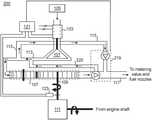
- FIG. 1is a schematic diagram of an embodiment of a system in accordance with this disclosure.
- FIG. 2is a schematic diagram of an embodiment of a system in accordance with this disclosure.
- FIG. 1An illustrative view of an embodiment of a system in accordance with the disclosure is shown in FIG. 1 and is designated generally by reference character 100 .
- FIG. 2Other embodiments and/or aspects of this disclosure are shown in FIG. 2 .
- a fuel pump system 100 for a turbomachine enginecan include a boost pump 101 driven by an electric motor 103 and configured to be in fluid communication with a fuel tank 105 .
- the system 100can include a primary pump 107 configured to be driven by an input shaft 109 connected to the turbomachine engine (e.g., via a gear box 111 ).
- the primary pump 107is in fluid communication with the boost pump 101 downstream of the boost pump 101 by a boost branch 113 .
- the system 100also includes a bypass flow branch 115 that connects the boost branch 113 to a downstream branch 117 that is downstream of the primary pump 107 .
- the downstream branch 117is in fluid communication with one or more metering valves and/or one or more fuel nozzles, for example.
- a bypass valve 119disposed in the bypass flow branch 115 and/or the downstream branch 117 and configured to selectively directly fluidly communicate the boost branch 113 and the downstream branch 117 .
- the bypass valve 119can be or can include a check valve, as shown in FIG. 1 .
- the check valvecan be configured to open with a predetermined pressure from the boost pump 101 to cause fluid communication between the boost branch 115 and the downstream branch 117 .
- a system 100can include a bypass valve 219 that can be or can include a three-way valve, for example. Any other suitable valve type (e.g., a selector valve, a four-way valve) and/or number of valves is contemplated herein.
- the primary pump 107can be a gear pump and the boost pump 101 can be a centrifugal pump. Any other suitable pump types as appreciated by those having ordinary skill in the art are contemplated herein.
- the shaft 109 that the primary pump 107 is connected tocan be a gear box shaft connected to a gear box 111 .
- the gear box 111can be connected to an engine shaft 112 , for example.
- the electric motor 103can be operatively connected to and controlled by a controller 121 .
- the controllercan include any suitable hardware modules and/or software modules to perform functions as described herein and as appreciated by those having ordinary skilled in the art.
- the controller 121can be a full authority digital engine control (FADEC).
- FADECfull authority digital engine control
- at least one of the controller 121 and the electric motor(e.g., both) can be cooled by fuel flowing through the system 100 , 200 .
- the controller 121can be in cooling flow communication with the bypass branch 115 and/or the boost branch 113
- the electric motor 103can be in cooling flow communication with both the controller 121 and the boost pump 101 to create loop through the boost pump 101 .
- the controller 121can be operatively connected to a speed sensor 123 that senses the speed of the input shaft 109 .
- the controller 121can control the electric motor 103 as a function of the input shaft speed. For example, the controller 121 can increase speed of the electric motor when the input shaft speed is low to cause the valve 119 to open to provide more pump pressure to the fuel metering valves and/or the fuel nozzles (e.g., when the engine is at low RPM caused by wind milling, and/or in flight settings where pressure from the boost pump 101 alone is sufficient and/or desired, and/or at start up).
- the controller 121can be operatively connected to the bypass valve 219 and configured to control the bypass valve 219 between a normal flow position where flow is prevented from flowing through the bypass branch 115 to the downstream branch 117 , and a bypass position where flow is allowed to flow through the bypass branch 115 to the downstream branch 117 .
- the controller 121can be configured to control the electric motor 103 as a function of bypass valve 219 position such that the controller increases electric motor speed when the bypass valve 219 is in the bypass position.
- a return line 225that allows pressure from the primary pump 107 to return to the boost branch 113 if the primary pump 107 is blocked by the bypass valve 219 when the bypass valve 219 allows flow from the bypass branch 115 to the downstream branch 117 .
- Thiscan prevent dead heading, for example.
- the controllercan control valve 219 to allow flow from bypass branch 115 to the downstream branch 117 , and at the same time, cut off flow from the primary pump 107 to the downstream branch 117 but cause fluid communication between an output of the primary pump 107 and the boost branch 113 . Any other suitable flow circuit to prevent dead heading is contemplated herein.
- a fuel systemfor turbomachine engine can include an electric motor driven boost pump and a mechanically driven primary pump, the boost pump configured to supply boost pressure to the primary pump, and a flow system configured to allow the boost pump to bypass the primary pump to allow the boost pump to provide direct pressure to one or more fuel metering valves and/or one or more fuel nozzles.
- Embodimentsutilize a compact electro-mechanical hybrid fuel pump system.
- Embodimentsinclude a centrifugal pump driven by an electric motor and a gear pumps driven by the engine gearbox. Fuel flow from the fuel tanks can be drawn into the centrifugal pump.
- the centrifugal pumpis driven by an electric motor.
- the electric motormay be fuel-cooled as well.
- the electrical motor-driven boost pumpprovides pressurized fuel to the inlet of primary pump similar to a mechanical driven boost pump, thus ensuring no cavitation occurs in primary pump.
- the speed of the boost pumpcan be increased or decreased to stay below maximum allowed boost pressure for actuator force margins, to allow optimization of the boost pump sizing, and provide optimal gear pump feed pressure to satisfy low inlet conditions and high inlet conditions for minimizing cavitation, for example.
- Use of the electric hybrid path boost pumpalso allows for a smaller primary pump by allowing use of the boost pump during normal speed starts.
- Embodimentsinclude an electric boost pump in parallel and series with the primary pump to provide multiple advantages. Embodiments allow control between series mode and parallel mode as needed or desired.
- Embodimentsallow sufficient pressure for engine restart after an in-flight shut down where the primary mechanical pump is operating at low speed and, thus, provides unreliable fuel pressure.
- the boost pumpcan be used to provide fuel as needed in cruise (e.g., as needed for thermal efficiency instead of based on engine speed since boost pump speed can be controlled independent of engine speed, which in turn, improves the heat sink capabilities of the on-board fuel).
- the rotation of the engine-driven gear pump's input shaftcan be detected by an engine speed sensor.
- These signalscan be sent to the controller, e.g., the FADEC.
- the FADECcan command the electric motor of the centrifugal pump to increase its rotational speed. This results in higher fuel flow being drawn from the fuel tanks by the centrifugal pump.
- the centrifugal pumpcan pressurize this increased fuel flow prior to delivering it as boost fuel pressure to the engine's fuel nozzles. In turn, this allows a reliable engine re-light during engine wind milling conditions.
- the output of the centrifugal pumpcan flows through a bypass valve such as a check valve, most selector, or three-way valve downstream of the outlet of the gear pump.
- This fuelcan be modulated downstream to the correct fuel flow/pressure delivery to the engine fuel nozzles.
- the speed of the electrically-driven centrifugal pumpcan be varied independently from the speed of the gearbox-driven gear pump. Embodiments allow operational flexibility of the fuel flow and pressure delivery, making it independent of engine rotational speed. For example, during initial engine start, the centrifugal pump can be commanded to turn at higher/maximum speed, thus providing boost pressure flow to start the engine reliably.
- the speed of the electrically-driven centrifugal pumpcan be controlled by the FADEC at all times.
- Embodimentsallow compact, simplified fuel delivery system utilizing an electro-mechanical hybrid fuel pump system, optimal centrifugal pump speeds during operation, optimal gear pump sizing and boost pump sizing, limitation of max boost pressure for actuator force margin sizing points, a compact centrifugal pump that always provides pressurized fuel to the primary pump thus eliminating cavitation in the primary pump, capabilities to deliver higher fuel flow/pressure to fuel nozzles during windmill engine re-lighting, and capability to vary rotational speed of electrically-driven centrifugal pump independently of mechanically-driven gear pump.
- aspects of the present disclosuremay be embodied as a system, method or computer program product. Accordingly, aspects of this disclosure may take the form of an entirely hardware embodiment, an entirely software embodiment (including firmware, resident software, micro-code, etc.), or an embodiment combining software and hardware aspects, all possibilities of which can be referred to herein as a “circuit,” “module,” or “system.”
- a “circuit,” “module,” or “system”can include one or more portions of one or more separate physical hardware and/or software components that can together perform the disclosed function of the “circuit,” “module,” or “system”, or a “circuit,” “module,” or “system” can be a single self-contained unit (e.g., of hardware and/or software).
- aspects of this disclosuremay take the form of a computer program product embodied in one or more computer readable medium(s) having computer readable program code embodied thereon.
- the computer readable mediummay be a computer readable signal medium or a computer readable storage medium.
- a computer readable storage mediummay be, for example, but not limited to, an electronic, magnetic, optical, electromagnetic, infrared, or semiconductor system, apparatus, or device, or any suitable combination of the foregoing.
- a computer readable storage mediummay be any tangible medium that can contain, or store a program for use by or in connection with an instruction execution system, apparatus, or device.
- a computer readable signal mediummay include a propagated data signal with computer readable program code embodied therein, for example, in baseband or as part of a carrier wave. Such a propagated signal may take any of a variety of forms, including, but not limited to, electro-magnetic, optical, or any suitable combination thereof.
- a computer readable signal mediummay be any computer readable medium that is not a computer readable storage medium and that can communicate, propagate, or transport a program for use by or in connection with an instruction execution system, apparatus, or device.
- Program code embodied on a computer readable mediummay be transmitted using any appropriate medium, including but not limited to wireless, wireline, optical fiber cable, RF, etc., or any suitable combination of the foregoing.
- Computer program code for carrying out operations for aspects of this disclosuremay be written in any combination of one or more programming languages, including an object oriented programming language such as Java, Smalltalk, C++ or the like and conventional procedural programming languages, such as the “C” programming language or similar programming languages.
- the program codemay execute entirely on the user's computer, partly on the user's computer, as a stand-alone software package, partly on the user's computer and partly on a remote computer or entirely on the remote computer or server.
- the remote computermay be connected to the user's computer through any type of network, including a local area network (LAN) or a wide area network (WAN), or the connection may be made to an external computer (for example, through the Internet using an Internet Service Provider).
- LANlocal area network
- WANwide area network
- Internet Service Providerfor example, AT&T, MCI, Sprint, EarthLink, MSN, GTE, etc.
- These computer program instructionsmay also be stored in a computer readable medium that can direct a computer, other programmable data processing apparatus, or other devices to function in a particular manner, such that the instructions stored in the computer readable medium produce an article of manufacture including instructions which implement the function/act specified in the flowchart and/or block diagram block or blocks.
- the computer program instructionsmay also be loaded onto a computer, other programmable data processing apparatus, or other devices to cause a series of operational steps to be performed on the computer, other programmable apparatus or other devices to produce a computer implemented process such that the instructions which execute on the computer or other programmable apparatus provide processes for implementing the functions/acts specified herein.
- any numerical values disclosed hereincan be exact values or can be values within a range. Further, any terms of approximation (e.g., “about”, “approximately”, “around”) used in this disclosure can mean the stated value within a range. For example, in certain embodiments, the range can be within (plus or minus) 20%, or within 10%, or within 5%, or within 2%, or within any other suitable percentage or number as appreciated by those having ordinary skill in the art (e.g., for known tolerance limits or error ranges).
Landscapes
- Engineering & Computer Science (AREA)
- Mechanical Engineering (AREA)
- General Engineering & Computer Science (AREA)
- Chemical & Material Sciences (AREA)
- Combustion & Propulsion (AREA)
- Life Sciences & Earth Sciences (AREA)
- Sustainable Development (AREA)
- Physics & Mathematics (AREA)
- Thermal Sciences (AREA)
- Structures Of Non-Positive Displacement Pumps (AREA)
Abstract
Description
Claims (15)
Priority Applications (2)
| Application Number | Priority Date | Filing Date | Title |
|---|---|---|---|
| US15/902,898US11236682B2 (en) | 2018-02-22 | 2018-02-22 | Fuel pump systems for turbomachines |
| EP19156984.7AEP3530909B1 (en) | 2018-02-22 | 2019-02-13 | Fuel pump systems for turbomachines |
Applications Claiming Priority (1)
| Application Number | Priority Date | Filing Date | Title |
|---|---|---|---|
| US15/902,898US11236682B2 (en) | 2018-02-22 | 2018-02-22 | Fuel pump systems for turbomachines |
Publications (2)
| Publication Number | Publication Date |
|---|---|
| US20190257250A1 US20190257250A1 (en) | 2019-08-22 |
| US11236682B2true US11236682B2 (en) | 2022-02-01 |
Family
ID=65496710
Family Applications (1)
| Application Number | Title | Priority Date | Filing Date |
|---|---|---|---|
| US15/902,898Active2040-02-10US11236682B2 (en) | 2018-02-22 | 2018-02-22 | Fuel pump systems for turbomachines |
Country Status (2)
| Country | Link |
|---|---|
| US (1) | US11236682B2 (en) |
| EP (1) | EP3530909B1 (en) |
Cited By (4)
| Publication number | Priority date | Publication date | Assignee | Title |
|---|---|---|---|---|
| US11629643B1 (en)* | 2022-01-07 | 2023-04-18 | Hamilton Sundstrand Corporation | Fuel pump systems |
| US20230243306A1 (en)* | 2022-02-02 | 2023-08-03 | Rolls-Royce Plc | Combination of a gas turbine engine and a power electronics |
| US12326120B1 (en) | 2024-03-28 | 2025-06-10 | Hamilton Sundstrand Corporation | Compact single variable displacement pump fuel system with augmentor controlled high pressure fuel oil cooler and gas generator fault accommodation |
| US12352211B1 (en) | 2024-02-28 | 2025-07-08 | Hamilton Sundstrand Corporation | Dual pump electrified fuel system with parallelism |
Families Citing this family (5)
| Publication number | Priority date | Publication date | Assignee | Title |
|---|---|---|---|---|
| US20210102517A1 (en)* | 2019-10-04 | 2021-04-08 | Hamilton Sundstrand Corporation | Electric pump assisted fuel system |
| US11629652B2 (en) | 2020-02-05 | 2023-04-18 | Hamilton Sundstrand Corporation | Metering pump system |
| GB202118041D0 (en) | 2021-12-14 | 2022-01-26 | Rolls Royce Plc | Restarting a gas turbine engine |
| GB2613789B (en)* | 2021-12-14 | 2024-03-27 | Rolls Royce Plc | Restarting a gas turbine engine |
| US11761387B1 (en)* | 2023-01-05 | 2023-09-19 | Ford Global Technologies, Llc | System and method for fuel pump shutdown |
Citations (21)
| Publication number | Priority date | Publication date | Assignee | Title |
|---|---|---|---|---|
| DE19539885A1 (en) | 1995-05-26 | 1996-11-28 | Bosch Gmbh Robert | Fuel supply system for IC engine |
| US5918578A (en)* | 1996-02-29 | 1999-07-06 | Mitsubishi Jidosha Kogyo Kabushiki Kaisha | Fuel feeding system for internal combustion engine |
| US6058912A (en)* | 1995-05-26 | 2000-05-09 | Robert Bosch Gmbh | Fuel supply system and method for operating an internal combustion engine |
| US20020069856A1 (en)* | 2000-09-29 | 2002-06-13 | Hanspeter Mayer | Fuel supply device for an internal combustion engine |
| US20040211395A1 (en)* | 2003-04-23 | 2004-10-28 | Luca Greco | Electronic control system for fuel system priming |
| US6889656B1 (en)* | 1998-04-24 | 2005-05-10 | Robert Bosch Gmbh | Fuel supply system of an internal combustion engine |
| US20050205065A1 (en)* | 2004-03-17 | 2005-09-22 | Helmut Rembold | High-pressure fuel pump with a pressure relief valve |
| US20050284148A1 (en)* | 2003-06-16 | 2005-12-29 | Wernberg Donald E | Centrifugal pump fuel system and method for gas turbine engine |
| US20060266047A1 (en)* | 2005-05-27 | 2006-11-30 | Honeywell International Inc. | Reduced-weight fuel system for gas turbine engine, gas turbine engine having a reduced-weight fuel system, and method of providing fuel to a gas turbine engine using a reduced-weight fuel system |
| US20070044768A1 (en)* | 2005-04-11 | 2007-03-01 | Honeywell International, Inc. | Enhanced accuracy fuel metering system and method |
| US7281520B2 (en)* | 2004-02-28 | 2007-10-16 | Daimlerchrysler Ag | Arrangement for supplying fuel to the fuel injectors of an internal combustion engine |
| DE102009029573A1 (en) | 2009-09-18 | 2011-03-24 | Robert Bosch Gmbh | Fuel injection system |
| US7983541B2 (en)* | 2004-06-30 | 2011-07-19 | Eaton Industrial Corporation | Heat exchanger performance |
| US8234875B2 (en)* | 2007-01-10 | 2012-08-07 | Hamilton Sundstrand Corporation | Gas turbine fuel metering unit |
| US8276360B2 (en)* | 2009-05-22 | 2012-10-02 | Hamilton Sundstrand Corporation | Dual-pump fuel system and method for starting a gas turbine engine |
| US20130192679A1 (en)* | 2012-02-01 | 2013-08-01 | Hamilton Sundstrand Corporation | Fuel preheating using electric pump |
| US20140174409A1 (en) | 2012-12-21 | 2014-06-26 | United Techologies Corporation | Gear Pump Protection Valve |
| US8833343B2 (en)* | 2007-10-12 | 2014-09-16 | Ford Global Technologies, Llc | Fuel system for improved engine starting |
| US20160047394A1 (en)* | 2014-08-18 | 2016-02-18 | Hyundai Motor Company | Electric water pump with coolant passage |
| US9702301B2 (en)* | 2011-01-06 | 2017-07-11 | Snecma | Fuel circuit for an aviation turbine engine, the circuit having a fuel pressure regulator valve |
| US10337513B2 (en)* | 2015-12-09 | 2019-07-02 | Fte Automotive Gmbh | Electric-motor-driven liquid pump |
- 2018
- 2018-02-22USUS15/902,898patent/US11236682B2/enactiveActive
- 2019
- 2019-02-13EPEP19156984.7Apatent/EP3530909B1/enactiveActive
Patent Citations (21)
| Publication number | Priority date | Publication date | Assignee | Title |
|---|---|---|---|---|
| US6058912A (en)* | 1995-05-26 | 2000-05-09 | Robert Bosch Gmbh | Fuel supply system and method for operating an internal combustion engine |
| DE19539885A1 (en) | 1995-05-26 | 1996-11-28 | Bosch Gmbh Robert | Fuel supply system for IC engine |
| US5918578A (en)* | 1996-02-29 | 1999-07-06 | Mitsubishi Jidosha Kogyo Kabushiki Kaisha | Fuel feeding system for internal combustion engine |
| US6889656B1 (en)* | 1998-04-24 | 2005-05-10 | Robert Bosch Gmbh | Fuel supply system of an internal combustion engine |
| US20020069856A1 (en)* | 2000-09-29 | 2002-06-13 | Hanspeter Mayer | Fuel supply device for an internal combustion engine |
| US20040211395A1 (en)* | 2003-04-23 | 2004-10-28 | Luca Greco | Electronic control system for fuel system priming |
| US20050284148A1 (en)* | 2003-06-16 | 2005-12-29 | Wernberg Donald E | Centrifugal pump fuel system and method for gas turbine engine |
| US7281520B2 (en)* | 2004-02-28 | 2007-10-16 | Daimlerchrysler Ag | Arrangement for supplying fuel to the fuel injectors of an internal combustion engine |
| US20050205065A1 (en)* | 2004-03-17 | 2005-09-22 | Helmut Rembold | High-pressure fuel pump with a pressure relief valve |
| US7983541B2 (en)* | 2004-06-30 | 2011-07-19 | Eaton Industrial Corporation | Heat exchanger performance |
| US20070044768A1 (en)* | 2005-04-11 | 2007-03-01 | Honeywell International, Inc. | Enhanced accuracy fuel metering system and method |
| US20060266047A1 (en)* | 2005-05-27 | 2006-11-30 | Honeywell International Inc. | Reduced-weight fuel system for gas turbine engine, gas turbine engine having a reduced-weight fuel system, and method of providing fuel to a gas turbine engine using a reduced-weight fuel system |
| US8234875B2 (en)* | 2007-01-10 | 2012-08-07 | Hamilton Sundstrand Corporation | Gas turbine fuel metering unit |
| US8833343B2 (en)* | 2007-10-12 | 2014-09-16 | Ford Global Technologies, Llc | Fuel system for improved engine starting |
| US8276360B2 (en)* | 2009-05-22 | 2012-10-02 | Hamilton Sundstrand Corporation | Dual-pump fuel system and method for starting a gas turbine engine |
| DE102009029573A1 (en) | 2009-09-18 | 2011-03-24 | Robert Bosch Gmbh | Fuel injection system |
| US9702301B2 (en)* | 2011-01-06 | 2017-07-11 | Snecma | Fuel circuit for an aviation turbine engine, the circuit having a fuel pressure regulator valve |
| US20130192679A1 (en)* | 2012-02-01 | 2013-08-01 | Hamilton Sundstrand Corporation | Fuel preheating using electric pump |
| US20140174409A1 (en) | 2012-12-21 | 2014-06-26 | United Techologies Corporation | Gear Pump Protection Valve |
| US20160047394A1 (en)* | 2014-08-18 | 2016-02-18 | Hyundai Motor Company | Electric water pump with coolant passage |
| US10337513B2 (en)* | 2015-12-09 | 2019-07-02 | Fte Automotive Gmbh | Electric-motor-driven liquid pump |
Non-Patent Citations (1)
| Title |
|---|
| Extended European search report issued in corresponding European patent application No. 19156984.7, dated Jul. 9, 2019. |
Cited By (5)
| Publication number | Priority date | Publication date | Assignee | Title |
|---|---|---|---|---|
| US11629643B1 (en)* | 2022-01-07 | 2023-04-18 | Hamilton Sundstrand Corporation | Fuel pump systems |
| US20230243306A1 (en)* | 2022-02-02 | 2023-08-03 | Rolls-Royce Plc | Combination of a gas turbine engine and a power electronics |
| US12392288B2 (en)* | 2022-02-02 | 2025-08-19 | Rolls-Royce Plc | Combination of a gas turbine engine and a power electronics |
| US12352211B1 (en) | 2024-02-28 | 2025-07-08 | Hamilton Sundstrand Corporation | Dual pump electrified fuel system with parallelism |
| US12326120B1 (en) | 2024-03-28 | 2025-06-10 | Hamilton Sundstrand Corporation | Compact single variable displacement pump fuel system with augmentor controlled high pressure fuel oil cooler and gas generator fault accommodation |
Also Published As
| Publication number | Publication date |
|---|---|
| US20190257250A1 (en) | 2019-08-22 |
| EP3530909A1 (en) | 2019-08-28 |
| EP3530909B1 (en) | 2022-07-20 |
Similar Documents
| Publication | Publication Date | Title |
|---|---|---|
| US11236682B2 (en) | Fuel pump systems for turbomachines | |
| EP3667047B1 (en) | Fuel systems having reduced bypass flow | |
| EP3232036B1 (en) | Dual pump fuel system with pump sharing connection | |
| US8726674B2 (en) | Propulsion unit | |
| EP4209680B1 (en) | Fuel pump systems | |
| EP2796688B1 (en) | System for controlling two positive displacement pumps | |
| EP3734048B1 (en) | System and method for controlling engine speed in multi-engine aircraft | |
| US20180050812A1 (en) | Aircraft fuel pump systems | |
| US20100003148A1 (en) | Assistance and emergency backup for the electrical drive of a fuel pump in a turbine engine | |
| US10899433B2 (en) | System and method for feathering an aircraft propeller | |
| EP3502444B1 (en) | Methods and apparatus for controlling electrical power supplied to a component of a vehicle | |
| US12077279B2 (en) | System and method for detecting and mitigating a propeller failure condition | |
| US20160319745A1 (en) | Controller modulated oil system for a gas turbine propulsion system | |
| US10907598B2 (en) | Self-limiting regenerative pumping element start stage for high speed centrifugal engine fuel pump and associated method | |
| EP3901440A1 (en) | System and method for controlling engine speed | |
| US11028726B2 (en) | Starter air valve systems configured for low speed motoring | |
| EP4484730A1 (en) | Fuel systems | |
| EP3594109B1 (en) | System and method for feathering an aircraft propeller | |
| US12352211B1 (en) | Dual pump electrified fuel system with parallelism | |
| US20220243668A1 (en) | Fault detection of a fuel control unit | |
| EP3343003B1 (en) | Method of starter air valve low speed motoring |
Legal Events
| Date | Code | Title | Description |
|---|---|---|---|
| FEPP | Fee payment procedure | Free format text:ENTITY STATUS SET TO UNDISCOUNTED (ORIGINAL EVENT CODE: BIG.); ENTITY STATUS OF PATENT OWNER: LARGE ENTITY | |
| AS | Assignment | Owner name:HAMILTON SUNDSTRAND CORPORATION, NORTH CAROLINA Free format text:ASSIGNMENT OF ASSIGNORS INTEREST;ASSIGNORS:VEILLEUX, LEO J., JR;RIBAROV, LUBOMIR A.;SIGNING DATES FROM 20180219 TO 20180220;REEL/FRAME:045892/0224 | |
| STPP | Information on status: patent application and granting procedure in general | Free format text:NON FINAL ACTION MAILED | |
| STPP | Information on status: patent application and granting procedure in general | Free format text:PRE-INTERVIEW COMMUNICATION MAILED | |
| STPP | Information on status: patent application and granting procedure in general | Free format text:NON FINAL ACTION MAILED | |
| STPP | Information on status: patent application and granting procedure in general | Free format text:RESPONSE TO NON-FINAL OFFICE ACTION ENTERED AND FORWARDED TO EXAMINER | |
| STPP | Information on status: patent application and granting procedure in general | Free format text:FINAL REJECTION MAILED | |
| STPP | Information on status: patent application and granting procedure in general | Free format text:RESPONSE AFTER FINAL ACTION FORWARDED TO EXAMINER | |
| STPP | Information on status: patent application and granting procedure in general | Free format text:NOTICE OF ALLOWANCE MAILED -- APPLICATION RECEIVED IN OFFICE OF PUBLICATIONS | |
| STPP | Information on status: patent application and granting procedure in general | Free format text:PUBLICATIONS -- ISSUE FEE PAYMENT RECEIVED | |
| STPP | Information on status: patent application and granting procedure in general | Free format text:PUBLICATIONS -- ISSUE FEE PAYMENT VERIFIED | |
| STCF | Information on status: patent grant | Free format text:PATENTED CASE | |
| MAFP | Maintenance fee payment | Free format text:PAYMENT OF MAINTENANCE FEE, 4TH YEAR, LARGE ENTITY (ORIGINAL EVENT CODE: M1551); ENTITY STATUS OF PATENT OWNER: LARGE ENTITY Year of fee payment:4 |