US11235423B2 - Laser cladding method and device for implementing same - Google Patents
Laser cladding method and device for implementing sameDownload PDFInfo
- Publication number
- US11235423B2 US11235423B2US15/123,752US201515123752AUS11235423B2US 11235423 B2US11235423 B2US 11235423B2US 201515123752 AUS201515123752 AUS 201515123752AUS 11235423 B2US11235423 B2US 11235423B2
- Authority
- US
- United States
- Prior art keywords
- laser
- beams
- series
- conical
- cladding
- Prior art date
- Legal status (The legal status is an assumption and is not a legal conclusion. Google has not performed a legal analysis and makes no representation as to the accuracy of the status listed.)
- Active
Links
Images


Classifications
- B—PERFORMING OPERATIONS; TRANSPORTING
- B23—MACHINE TOOLS; METAL-WORKING NOT OTHERWISE PROVIDED FOR
- B23K—SOLDERING OR UNSOLDERING; WELDING; CLADDING OR PLATING BY SOLDERING OR WELDING; CUTTING BY APPLYING HEAT LOCALLY, e.g. FLAME CUTTING; WORKING BY LASER BEAM
- B23K26/00—Working by laser beam, e.g. welding, cutting or boring
- B23K26/34—Laser welding for purposes other than joining
- B23K26/342—Build-up welding
- B—PERFORMING OPERATIONS; TRANSPORTING
- B22—CASTING; POWDER METALLURGY
- B22F—WORKING METALLIC POWDER; MANUFACTURE OF ARTICLES FROM METALLIC POWDER; MAKING METALLIC POWDER; APPARATUS OR DEVICES SPECIALLY ADAPTED FOR METALLIC POWDER
- B22F3/00—Manufacture of workpieces or articles from metallic powder characterised by the manner of compacting or sintering; Apparatus specially adapted therefor ; Presses and furnaces
- B22F3/115—Manufacture of workpieces or articles from metallic powder characterised by the manner of compacting or sintering; Apparatus specially adapted therefor ; Presses and furnaces by spraying molten metal, i.e. spray sintering, spray casting
- B—PERFORMING OPERATIONS; TRANSPORTING
- B23—MACHINE TOOLS; METAL-WORKING NOT OTHERWISE PROVIDED FOR
- B23K—SOLDERING OR UNSOLDERING; WELDING; CLADDING OR PLATING BY SOLDERING OR WELDING; CUTTING BY APPLYING HEAT LOCALLY, e.g. FLAME CUTTING; WORKING BY LASER BEAM
- B23K26/00—Working by laser beam, e.g. welding, cutting or boring
- B23K26/02—Positioning or observing the workpiece, e.g. with respect to the point of impact; Aligning, aiming or focusing the laser beam
- B23K26/06—Shaping the laser beam, e.g. by masks or multi-focusing
- B23K26/0604—Shaping the laser beam, e.g. by masks or multi-focusing by a combination of beams
- B23K26/0613—Shaping the laser beam, e.g. by masks or multi-focusing by a combination of beams having a common axis
- B23K26/0617—Shaping the laser beam, e.g. by masks or multi-focusing by a combination of beams having a common axis and with spots spaced along the common axis
- B—PERFORMING OPERATIONS; TRANSPORTING
- B23—MACHINE TOOLS; METAL-WORKING NOT OTHERWISE PROVIDED FOR
- B23K—SOLDERING OR UNSOLDERING; WELDING; CLADDING OR PLATING BY SOLDERING OR WELDING; CUTTING BY APPLYING HEAT LOCALLY, e.g. FLAME CUTTING; WORKING BY LASER BEAM
- B23K26/00—Working by laser beam, e.g. welding, cutting or boring
- B23K26/02—Positioning or observing the workpiece, e.g. with respect to the point of impact; Aligning, aiming or focusing the laser beam
- B23K26/06—Shaping the laser beam, e.g. by masks or multi-focusing
- B23K26/064—Shaping the laser beam, e.g. by masks or multi-focusing by means of optical elements, e.g. lenses, mirrors or prisms
- B23K26/0643—Shaping the laser beam, e.g. by masks or multi-focusing by means of optical elements, e.g. lenses, mirrors or prisms comprising mirrors
- B—PERFORMING OPERATIONS; TRANSPORTING
- B23—MACHINE TOOLS; METAL-WORKING NOT OTHERWISE PROVIDED FOR
- B23K—SOLDERING OR UNSOLDERING; WELDING; CLADDING OR PLATING BY SOLDERING OR WELDING; CUTTING BY APPLYING HEAT LOCALLY, e.g. FLAME CUTTING; WORKING BY LASER BEAM
- B23K26/00—Working by laser beam, e.g. welding, cutting or boring
- B23K26/02—Positioning or observing the workpiece, e.g. with respect to the point of impact; Aligning, aiming or focusing the laser beam
- B23K26/06—Shaping the laser beam, e.g. by masks or multi-focusing
- B23K26/064—Shaping the laser beam, e.g. by masks or multi-focusing by means of optical elements, e.g. lenses, mirrors or prisms
- B23K26/0648—Shaping the laser beam, e.g. by masks or multi-focusing by means of optical elements, e.g. lenses, mirrors or prisms comprising lenses
- B—PERFORMING OPERATIONS; TRANSPORTING
- B23—MACHINE TOOLS; METAL-WORKING NOT OTHERWISE PROVIDED FOR
- B23K—SOLDERING OR UNSOLDERING; WELDING; CLADDING OR PLATING BY SOLDERING OR WELDING; CUTTING BY APPLYING HEAT LOCALLY, e.g. FLAME CUTTING; WORKING BY LASER BEAM
- B23K26/00—Working by laser beam, e.g. welding, cutting or boring
- B23K26/02—Positioning or observing the workpiece, e.g. with respect to the point of impact; Aligning, aiming or focusing the laser beam
- B23K26/06—Shaping the laser beam, e.g. by masks or multi-focusing
- B23K26/0665—Shaping the laser beam, e.g. by masks or multi-focusing by beam condensation on the workpiece, e.g. for focusing
- B—PERFORMING OPERATIONS; TRANSPORTING
- B23—MACHINE TOOLS; METAL-WORKING NOT OTHERWISE PROVIDED FOR
- B23K—SOLDERING OR UNSOLDERING; WELDING; CLADDING OR PLATING BY SOLDERING OR WELDING; CUTTING BY APPLYING HEAT LOCALLY, e.g. FLAME CUTTING; WORKING BY LASER BEAM
- B23K26/00—Working by laser beam, e.g. welding, cutting or boring
- B23K26/02—Positioning or observing the workpiece, e.g. with respect to the point of impact; Aligning, aiming or focusing the laser beam
- B23K26/06—Shaping the laser beam, e.g. by masks or multi-focusing
- B23K26/067—Dividing the beam into multiple beams, e.g. multifocusing
- B23K26/0676—Dividing the beam into multiple beams, e.g. multifocusing into dependently operating sub-beams, e.g. an array of spots with fixed spatial relationship or for performing simultaneously identical operations
- B—PERFORMING OPERATIONS; TRANSPORTING
- B23—MACHINE TOOLS; METAL-WORKING NOT OTHERWISE PROVIDED FOR
- B23K—SOLDERING OR UNSOLDERING; WELDING; CLADDING OR PLATING BY SOLDERING OR WELDING; CUTTING BY APPLYING HEAT LOCALLY, e.g. FLAME CUTTING; WORKING BY LASER BEAM
- B23K26/00—Working by laser beam, e.g. welding, cutting or boring
- B23K26/02—Positioning or observing the workpiece, e.g. with respect to the point of impact; Aligning, aiming or focusing the laser beam
- B23K26/06—Shaping the laser beam, e.g. by masks or multi-focusing
- B23K26/073—Shaping the laser spot
- B23K26/0734—Shaping the laser spot into an annular shape
- B—PERFORMING OPERATIONS; TRANSPORTING
- B23—MACHINE TOOLS; METAL-WORKING NOT OTHERWISE PROVIDED FOR
- B23K—SOLDERING OR UNSOLDERING; WELDING; CLADDING OR PLATING BY SOLDERING OR WELDING; CUTTING BY APPLYING HEAT LOCALLY, e.g. FLAME CUTTING; WORKING BY LASER BEAM
- B23K26/00—Working by laser beam, e.g. welding, cutting or boring
- B23K26/02—Positioning or observing the workpiece, e.g. with respect to the point of impact; Aligning, aiming or focusing the laser beam
- B23K26/06—Shaping the laser beam, e.g. by masks or multi-focusing
- B23K26/073—Shaping the laser spot
- B23K26/0736—Shaping the laser spot into an oval shape, e.g. elliptic shape
- B—PERFORMING OPERATIONS; TRANSPORTING
- B23—MACHINE TOOLS; METAL-WORKING NOT OTHERWISE PROVIDED FOR
- B23K—SOLDERING OR UNSOLDERING; WELDING; CLADDING OR PLATING BY SOLDERING OR WELDING; CUTTING BY APPLYING HEAT LOCALLY, e.g. FLAME CUTTING; WORKING BY LASER BEAM
- B23K26/00—Working by laser beam, e.g. welding, cutting or boring
- B23K26/14—Working by laser beam, e.g. welding, cutting or boring using a fluid stream, e.g. a jet of gas, in conjunction with the laser beam; Nozzles therefor
- B23K26/144—Working by laser beam, e.g. welding, cutting or boring using a fluid stream, e.g. a jet of gas, in conjunction with the laser beam; Nozzles therefor the fluid stream containing particles, e.g. powder
- B—PERFORMING OPERATIONS; TRANSPORTING
- B23—MACHINE TOOLS; METAL-WORKING NOT OTHERWISE PROVIDED FOR
- B23K—SOLDERING OR UNSOLDERING; WELDING; CLADDING OR PLATING BY SOLDERING OR WELDING; CUTTING BY APPLYING HEAT LOCALLY, e.g. FLAME CUTTING; WORKING BY LASER BEAM
- B23K26/00—Working by laser beam, e.g. welding, cutting or boring
- B23K26/14—Working by laser beam, e.g. welding, cutting or boring using a fluid stream, e.g. a jet of gas, in conjunction with the laser beam; Nozzles therefor
- B23K26/146—Working by laser beam, e.g. welding, cutting or boring using a fluid stream, e.g. a jet of gas, in conjunction with the laser beam; Nozzles therefor the fluid stream containing a liquid
- B—PERFORMING OPERATIONS; TRANSPORTING
- B23—MACHINE TOOLS; METAL-WORKING NOT OTHERWISE PROVIDED FOR
- B23K—SOLDERING OR UNSOLDERING; WELDING; CLADDING OR PLATING BY SOLDERING OR WELDING; CUTTING BY APPLYING HEAT LOCALLY, e.g. FLAME CUTTING; WORKING BY LASER BEAM
- B23K26/00—Working by laser beam, e.g. welding, cutting or boring
- B23K26/14—Working by laser beam, e.g. welding, cutting or boring using a fluid stream, e.g. a jet of gas, in conjunction with the laser beam; Nozzles therefor
- B23K26/1462—Nozzles; Features related to nozzles
- B23K26/1464—Supply to, or discharge from, nozzles of media, e.g. gas, powder, wire
- B23K26/1476—Features inside the nozzle for feeding the fluid stream through the nozzle
- B—PERFORMING OPERATIONS; TRANSPORTING
- B23—MACHINE TOOLS; METAL-WORKING NOT OTHERWISE PROVIDED FOR
- B23K—SOLDERING OR UNSOLDERING; WELDING; CLADDING OR PLATING BY SOLDERING OR WELDING; CUTTING BY APPLYING HEAT LOCALLY, e.g. FLAME CUTTING; WORKING BY LASER BEAM
- B23K26/00—Working by laser beam, e.g. welding, cutting or boring
- B23K26/34—Laser welding for purposes other than joining
- C—CHEMISTRY; METALLURGY
- C23—COATING METALLIC MATERIAL; COATING MATERIAL WITH METALLIC MATERIAL; CHEMICAL SURFACE TREATMENT; DIFFUSION TREATMENT OF METALLIC MATERIAL; COATING BY VACUUM EVAPORATION, BY SPUTTERING, BY ION IMPLANTATION OR BY CHEMICAL VAPOUR DEPOSITION, IN GENERAL; INHIBITING CORROSION OF METALLIC MATERIAL OR INCRUSTATION IN GENERAL
- C23C—COATING METALLIC MATERIAL; COATING MATERIAL WITH METALLIC MATERIAL; SURFACE TREATMENT OF METALLIC MATERIAL BY DIFFUSION INTO THE SURFACE, BY CHEMICAL CONVERSION OR SUBSTITUTION; COATING BY VACUUM EVAPORATION, BY SPUTTERING, BY ION IMPLANTATION OR BY CHEMICAL VAPOUR DEPOSITION, IN GENERAL
- C23C26/00—Coating not provided for in groups C23C2/00 - C23C24/00
- C23C26/02—Coating not provided for in groups C23C2/00 - C23C24/00 applying molten material to the substrate
- C—CHEMISTRY; METALLURGY
- C23—COATING METALLIC MATERIAL; COATING MATERIAL WITH METALLIC MATERIAL; CHEMICAL SURFACE TREATMENT; DIFFUSION TREATMENT OF METALLIC MATERIAL; COATING BY VACUUM EVAPORATION, BY SPUTTERING, BY ION IMPLANTATION OR BY CHEMICAL VAPOUR DEPOSITION, IN GENERAL; INHIBITING CORROSION OF METALLIC MATERIAL OR INCRUSTATION IN GENERAL
- C23C—COATING METALLIC MATERIAL; COATING MATERIAL WITH METALLIC MATERIAL; SURFACE TREATMENT OF METALLIC MATERIAL BY DIFFUSION INTO THE SURFACE, BY CHEMICAL CONVERSION OR SUBSTITUTION; COATING BY VACUUM EVAPORATION, BY SPUTTERING, BY ION IMPLANTATION OR BY CHEMICAL VAPOUR DEPOSITION, IN GENERAL
- C23C4/00—Coating by spraying the coating material in the molten state, e.g. by flame, plasma or electric discharge
- G—PHYSICS
- G02—OPTICS
- G02B—OPTICAL ELEMENTS, SYSTEMS OR APPARATUS
- G02B5/00—Optical elements other than lenses
- G02B5/001—Axicons, waxicons, reflaxicons
- H—ELECTRICITY
- H01—ELECTRIC ELEMENTS
- H01S—DEVICES USING THE PROCESS OF LIGHT AMPLIFICATION BY STIMULATED EMISSION OF RADIATION [LASER] TO AMPLIFY OR GENERATE LIGHT; DEVICES USING STIMULATED EMISSION OF ELECTROMAGNETIC RADIATION IN WAVE RANGES OTHER THAN OPTICAL
- H01S3/00—Lasers, i.e. devices using stimulated emission of electromagnetic radiation in the infrared, visible or ultraviolet wave range
- H01S3/005—Optical devices external to the laser cavity, specially adapted for lasers, e.g. for homogenisation of the beam or for manipulating laser pulses, e.g. pulse shaping
- H01S3/0071—Beam steering, e.g. whereby a mirror outside the cavity is present to change the beam direction
Definitions
- This inventionrelates to laser processing of materials and can be used for laser cladding, including selective laser cladding, laser thermal processing.
- the objective of the claimed inventionto provide a method and apparatus for laser cladding that ensures empowerment of the laser processing method, increased productivity and manufacturing precision parts, lower energy costs and high quality products.
- a methodis known of laser cladding, consisting in applying weld material in the focal region of the laser beam disposed on the surface of the workpiece.
- the disadvantage of this methodis the inability to separate the deposited material and heating the workpiece in the area of the laser focus spot.
- Patent BY No 6931The closest to the proposed method is shown in Patent BY No 6931 by the current inventor disclosing a process consisting in applying consisting weldable material in the focal region of the laser beam is disposed on the surface of the workpiece.
- the disadvantage of this methodis the inability to separate the deposited material and the heating region of the workpiece to focus the laser spot, resulting in a considerable loss of energy to maintain the molten bath deposition and reduces accuracy.
- Laser cladding deviceknown in literature comprises a laser optically coupled to a beam forming system of the ring, rotatable mirror lens.
- the disadvantage of this deviceis the complexity, as well as the inability to separate the heating of the deposited material (wire) and the surface of the workpiece in the field of welding.
- Patent RU No 2447979The closest in technical essence to the claimed device is presented in Patent RU No 2447979 by the current inventor, the device comprising a laser for selective laser melting, optically coupled to the system and the formation of a conical beam a focusing lens for separate heating of the workpiece and the stream of powder, and the powder feed system.
- the disadvantage of this deviceis the inability to control parameters of the radiation acting on the surface of the workpiece and the powder stream.
- the inventionrelates to a method and device for the laser cladding of materials.
- This laser cladding methodconsists in feeding a cladding material into the focal region of a laser beam, said region being located on the surface of a workpiece.
- a series of parallel annular laser beams with an adjustable distribution of laser radiation power across the annular beamsis formed from an initial circular laser beam
- the annular beamsare transformed into a series of conical beams and are separately focused along a single optical axis, along which the cladding material is fed.
- Wavelengths of the laser radiationmay be different for annular beams.
- a cladding materialmay be a solid, liquid, gas, powder, aerosol or heterogeneous plasma.
- the present devicecomprises a laser, which is optically linked to a system for forming a conical beam, a focusing lens and system for feeding cladding material.
- the deviceadditionally comprises an optical system for forming a series of annular laser beams with an adjustable distribution of laser radiation power across the annular beams.
- the deviceadditionally comprises a rotating mirror with an opening through which tubes for feeding gas, cooling liquid and cladding material are passed.
- the deviceadditionally comprises a system of conical focusing mirrors.
- Lens focus and conical mirrors focusesare located along a single optical axis along which the cladding material is fed.
- the deviceis supplemented with an cylindrical mirror for the mulipass laser radiation through the stream of cladding material with the possibility of the laser radiation return to the laser resonator.
- a workpiece and a cladding material deviceis supplemented with an optical system for converting the laser wavelength, an optical system for forming a series of annular laser beams of different wavelengths with an adjustable distribution of laser radiation power across the annular beams, a rotating mirror with the dichroic areas and with an opening through which tubes for feeding gas, cooling liquid and cladding material are passed, and a system of conical focusing mirrors.
- Lens focus and conical mirrors focusesare located along a single optical axis along which the cladding material is fed.
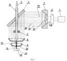
- FIG. 1is the variant of an optical scheme of the inventive device.
- FIG. 2is the variant of an optical scheme of the production a series of parallel annular laser beams with an adjustable distribution of laser radiation power across the annular beams.
- FIG. 3is another variant of an optical scheme of the production a series of parallel annular laser beams with an adjustable distribution of laser radiation power across the annular beams.
- FIG. 4is the variant of an optical scheme of the inventive device with reflective optics and system of laser beams control.
- FIG. 5is the variant of an optical scheme of the inventive device with annular beams having different wavelengths.
- FIG. 6is the variant of a multipass optical scheme.
- the objective of the claimed inventionis to elaborate a method and apparatus for laser cladding that ensures improvement of the laser processing method, increase of productivity, reduce of energy consumption while ensuring high precision in the manufacture of parts.
- the claimed method of laser claddingconsists in applying the deposited material in the focal region of the laser beam which is placed on the surface of the workpiece. Unlike other methods from the initial circular laser beam a series of annular laser beams are formed with an adjustable power distribution across the annular beams. The annular beams are transformed into a series of conical laser beams using conical lens and conical mirrors.
- Conical beamsare separately focused as to the surface of the workpiece to heat it, and to various areas of the optical axis along which the cladding material is fed.
- a stream of gas, liquid, powder, heterogeneous plasma jet or wirecan be used as cladding material.
- Focused conical beamsheat various regions of the stream of cladding material.
- Space-independent and separated heating of workpiece and stream of cladding materialprovides optimum thermal process conditions, can significantly reduce energy costs and increase cladding accuracy.
- a wavelengths of the laser radiationmay be different for annular beams.
- new device for laser claddingcomprising a laser optically coupled with the system of forming a series of conical beams for separate heating of the workpiece and the stream of cladding material.
- the deviceis further provided with a system of forming a series of parallel annular laser beams with adjustable laser power distribution across the annular beams, deflecting mirror with an opening for wiring the gas supply tubes, coolant and the cladding material, focusing lens and conical mirrors.
- the focus of the lens and the foci of conical mirrorslie on the same optical axis along which the cladding material is fed to the surface.
- the device( FIG. 1 ) comprises a laser 1 with a resonator, optically coupled with an optical system forming a series of annular laser beams with an adjustable power distribution across annular laser beams which comprises adjustable beam expander 2 , multifacet conical mirror 47 and multifacet reflective waxicon 3 .
- Series of parallel annular beams 21 , 22 , 45are deflected by mirror 4 with an opening for wiring tubes with the coolant 6 , the feed gas and the cladding material 5 .
- the deviceincludes a focusing lens 7 , the focusing conical mirrors 8 , 9 .
- One annular beamis focused by lens 7 into the surface of the workpiece 11 and others annular beams are focused by conical mirrors 8 , 9 into various regions 13 , 14 of the cladding material stream 10 .
- the deviceoperates as follows.
- the circular laser beam 1 after passing through the beam expander 2 and multifacet waxicon 3is transformed into a series of annular beams.
- One of the beamsis focused by lens 7 on the product surface 11 to an irradiation spot 12 and melt the product surface 11 in the irradiation spot 12 .
- Cladding materialis fed through the tube 5 in the form of a powder stream 10 , liquid, plasma or heterogeneous gas stream or wire.
- Other beamsare focused by means of conical mirrors 8 , 9 in the predetermined region 13 , 14 of the stream 10 to heat these regions 13 , 14 .
- the systemsfurther comprises a multiaxicon 41 , multifacet conical mirror 47 , multifacet waxicon 3 or multifacet lens 42 , adjustable beam expander 2 and beam shaper 40 .
- the devicesoperate as follows. Radiation of laser 1 with a Gaussian intensity distribution over the cross section of the circular beam 43 is translated using beam shaper 40 into the beam 44 with predetermined intensity distribution—rectangular or any other (super-Gaussian, Lager-Gaussa etc.).
- An adjustable beam expander 2transforms the beam 44 into a beam 15 of a given size and with a certain intensity distribution over the beam cross section.
- the beam 15is converted by negative 41 multiaxicon or multifacet conical mirror 47 in a series of divergent beams, which are converted into a series of parallel annular beams 21 , 22 using multifacet lens 42 or multifacet waxicon 3 .
- Changing the size of the circular beam 15 and the intensity distribution over the cross section of the laser beam 44the distribution of laser power between annular beams 21 and 22 is changed.
- FIG. 4Variant of the claimed device with conical reflective optics, which is important when using high-power lasers, is shown in FIG. 4 .
- the conical focusing mirror 23is set.
- This schemealso introduces the option of using part of the laser radiation, shaded by tube 5 . This part of radiation can be used for heating tube 5 and cladding material passing through it. In other embodiment of the device ( FIG. 4 ), this part of the radiation is deflected by mirror 24 to the unit of the laser parameters control 25 .
- the claimed deviceis supplemented with an optical system for forming a series of annular laser beams of different wavelengths with an adjustable distribution of laser radiation power across the annular beams, the optical system comprises wavelength converter 26 , rotary mirrors 27 , 30 ; refractive axicon 32 and refractive waxicon 31 , conical mirror 29 , waxicon 28 and a rotating dichroic mirrors 46 , 35 ( FIG. 5 ).
- the deviceoperates as follows.
- the circular beam 33 with ⁇ 1 wavelength ( FIG. 5 ) of radiationis converted using converter 26 to circular beam 34 with wavelength ⁇ 2 .
- the heating of the workpiece 11 in the focus of the lens 7 and the stream 10 of the cladding materialis carried out by laser radiation with different wavelengths.
- a multipass scheme using a cylindrical mirror 36 and a conical mirror 37( FIG. 6 ) is provided. This increases the number of passes of laser radiation through the stream: the return backwards radiation by conical mirror 37 the laser radiation returns to the laser resonator of the laser 1 by conical mirror 37 . It first increases the stream heating and secondly allows efficient use of the laser radiation when returning the coherent (not scattered) part of the laser radiation to resonator of laser 1 .
- the claimed method and apparatus of laser claddingreduces energy consumption, improve the accuracy and quality of cladding.
Landscapes
- Physics & Mathematics (AREA)
- Optics & Photonics (AREA)
- Engineering & Computer Science (AREA)
- Mechanical Engineering (AREA)
- Plasma & Fusion (AREA)
- Chemical & Material Sciences (AREA)
- Chemical Kinetics & Catalysis (AREA)
- Electromagnetism (AREA)
- Materials Engineering (AREA)
- Metallurgy (AREA)
- Organic Chemistry (AREA)
- General Physics & Mathematics (AREA)
- Manufacturing & Machinery (AREA)
- Laser Beam Processing (AREA)
- Lasers (AREA)
- Manufacture Of Metal Powder And Suspensions Thereof (AREA)
Abstract
Description
Claims (7)
Applications Claiming Priority (3)
| Application Number | Priority Date | Filing Date | Title |
|---|---|---|---|
| RU2014108832/02ARU2580180C2 (en) | 2014-03-06 | 2014-03-06 | Laser cladding method and apparatus therefor |
| RU2014108832 | 2014-03-06 | ||
| PCT/IB2015/000125WO2015132640A1 (en) | 2014-03-06 | 2015-02-06 | Laser cladding method and device for implementing same |
Publications (2)
| Publication Number | Publication Date |
|---|---|
| US20170312856A1 US20170312856A1 (en) | 2017-11-02 |
| US11235423B2true US11235423B2 (en) | 2022-02-01 |
Family
ID=54054631
Family Applications (1)
| Application Number | Title | Priority Date | Filing Date |
|---|---|---|---|
| US15/123,752ActiveUS11235423B2 (en) | 2014-03-06 | 2015-02-06 | Laser cladding method and device for implementing same |
Country Status (3)
| Country | Link |
|---|---|
| US (1) | US11235423B2 (en) |
| RU (1) | RU2580180C2 (en) |
| WO (1) | WO2015132640A1 (en) |
Families Citing this family (24)
| Publication number | Priority date | Publication date | Assignee | Title |
|---|---|---|---|---|
| IT201600070259A1 (en)* | 2016-07-06 | 2018-01-06 | Adige Spa | Process of laser processing of a metal material with control of the position of the optical axis of the laser with respect to a flow of assistance gas, as well as a machine and computer program for carrying out such a process. |
| RU2676064C1 (en)* | 2018-01-11 | 2018-12-25 | Федеральное государственное бюджетное образовательное учреждение высшего образования "Казанский национальный исследовательский технический университет им. А.Н. Туполева-КАИ" (КНИТУ-КАИ) | Method of supersonic laser deposition of powder materials and device for its implementation |
| CN108931855B (en)* | 2018-09-27 | 2023-06-30 | 中国工程物理研究院激光聚变研究中心 | Annular light beam conversion device and conversion method |
| CN109663915B (en)* | 2018-12-28 | 2024-03-26 | 淮阴工学院 | Anti-cracking method for laser additive manufacturing |
| US12121994B2 (en)* | 2019-03-29 | 2024-10-22 | Dmg Mori Co., Ltd. | Processing machine |
| CN109852967B (en)* | 2019-04-17 | 2021-01-19 | 中国人民解放军军事科学院国防科技创新研究院 | Fine beam current laser melting deposition additive manufacturing method and laser processing head used by same |
| CN110004496B (en)* | 2019-05-16 | 2024-01-30 | 中国电子科技集团公司第二十六研究所 | A ring laser heating system |
| IL290911B1 (en)* | 2019-08-27 | 2025-09-01 | Edison Welding Inst Inc | Coaxial laser-wire optical system for use in additive manufacturing |
| CN111805088B (en)* | 2019-10-31 | 2025-08-05 | 山东建筑大学 | A laser additive device with coaxial wire feeding inside the light |
| CN110747467B (en)* | 2019-11-29 | 2023-05-23 | 浙江工业大学 | Laser rapid cladding process and device based on electromagnetic induction heating |
| RU200648U1 (en)* | 2019-12-27 | 2020-11-03 | Общество с ограниченной ответственностью «Термолазер» | Optical head for laser cladding |
| RU200649U1 (en)* | 2019-12-27 | 2020-11-03 | Общество с ограниченной ответственностью «Термолазер» | Laser cladding device |
| RU200650U1 (en)* | 2019-12-29 | 2020-11-03 | Общество с ограниченной ответственностью «Термолазер» | Optical head for laser cladding |
| RU200662U1 (en)* | 2019-12-29 | 2020-11-05 | Общество с ограниченной ответственностью «Термолазер» | Laser cladding device |
| CN110923706A (en)* | 2019-12-31 | 2020-03-27 | 华南理工大学 | A 3D printing-based laser cladding device and its nozzle |
| CN111455377B (en)* | 2020-05-19 | 2024-03-26 | 宝宇(武汉)激光技术有限公司 | Laser cladding device and method |
| KR102793341B1 (en)* | 2020-05-21 | 2025-04-09 | 삼성디스플레이 주식회사 | Lazer device |
| CN112828471B (en)* | 2020-12-31 | 2022-12-16 | 中国人民解放军军事科学院国防科技创新研究院 | Method and device for manufacturing refractory high-entropy alloy by laser cladding cable type welding wire additive manufacturing |
| US12275066B2 (en)* | 2021-10-05 | 2025-04-15 | Nikon Corporation | Systems and methods for improved melting in three-dimensional printing processes |
| CN114231976B (en)* | 2021-12-27 | 2024-06-25 | 中国人民解放军军事科学院国防科技创新研究院 | Ultra-high speed annular laser cladding processing device with adjustable long focal depth |
| CN115074722A (en)* | 2022-05-27 | 2022-09-20 | 江苏智远激光装备科技有限公司 | Handheld laser cladding head device |
| CN116021038B (en)* | 2022-12-14 | 2025-05-09 | 大连理工大学 | A silk powder coaxial laser manufacturing method and device |
| CN116248041A (en)* | 2023-02-27 | 2023-06-09 | 哈尔滨工程大学 | Laser wireless energy transmission device based on cone-shaped spectroscope structure |
| CN119387853A (en)* | 2024-10-24 | 2025-02-07 | 南京航空航天大学 | Laser coaxial fuse additive device and method based on split-beam heating |
Citations (36)
| Publication number | Priority date | Publication date | Assignee | Title |
|---|---|---|---|---|
| US3865564A (en)* | 1973-07-09 | 1975-02-11 | Bell Telephone Labor Inc | Fabrication of glass fibers from preform by lasers |
| US4135902A (en)* | 1978-03-03 | 1979-01-23 | Western Electric Co., Inc. | Method and apparatus for drawing optical fibers |
| US4456811A (en)* | 1982-06-21 | 1984-06-26 | Avco Everett Research Laboratory, Inc. | Method of and apparatus for heat treating axisymmetric surfaces with an annular laser beam |
| US4689467A (en)* | 1982-12-17 | 1987-08-25 | Inoue-Japax Research Incorporated | Laser machining apparatus |
| US4724299A (en)* | 1987-04-15 | 1988-02-09 | Quantum Laser Corporation | Laser spray nozzle and method |
| US5187761A (en)* | 1990-05-22 | 1993-02-16 | France Telecom | Method of making an inlet cone on a connection endpiece for optical fibers, and apparatus for performing the method |
| US5208434A (en)* | 1991-01-10 | 1993-05-04 | Nippon Steel Corporation | Method and apparatus for laser heat treatment for metal wire |
| US5449879A (en)* | 1993-10-07 | 1995-09-12 | Laser Machining, Inc. | Laser beam delivery system for heat treating work surfaces |
| US5557628A (en)* | 1993-09-24 | 1996-09-17 | Mitsubishi Denki Kabushiki Kaisha | Solid state laser apparatus and laser machining apparatus |
| US5690845A (en)* | 1994-10-07 | 1997-11-25 | Sumitomo Electric Industries, Ltd. | Optical device for laser machining |
| US5848091A (en)* | 1997-01-21 | 1998-12-08 | The Twentyfirst Century Corp. | Laser resonator with improved output beam characteristics |
| US6016227A (en)* | 1998-07-31 | 2000-01-18 | The University Of Tennessee Research Corporation | Apparatus and method for producing an improved laser beam |
| US20020021723A1 (en)* | 2000-08-02 | 2002-02-21 | Seiko Epson Corporation | Method and apparatus for laser processing |
| US20020162973A1 (en)* | 2001-03-29 | 2002-11-07 | Cordingley James J. | Methods and systems for processing a device, methods and systems for modeling same and the device |
| US20030052105A1 (en)* | 2001-09-10 | 2003-03-20 | Fuji Photo Film Co., Ltd. | Laser sintering apparatus |
| US20030075529A1 (en)* | 2001-05-22 | 2003-04-24 | Jyoti Mazumder | Focusing optics for adaptive deposition in rapid manufacturing |
| US20030102291A1 (en)* | 2001-11-30 | 2003-06-05 | Xinbing Liu | System and method of laser drilling |
| US6756561B2 (en)* | 1999-09-30 | 2004-06-29 | National Research Council Of Canada | Laser consolidation apparatus for manufacturing precise structures |
| US20040188396A1 (en)* | 2002-11-06 | 2004-09-30 | Somit Talwar | Laser scanning apparatus and methods for thermal processing |
| US6860960B1 (en)* | 2000-09-05 | 2005-03-01 | Scimed Life Systems, Inc. | Method of applying a laser beam around the circumference of a catheter |
| BY6931C1 (en) | 2002-03-13 | 2005-03-30 | ||
| US20060091283A1 (en)* | 2002-08-28 | 2006-05-04 | Stefan Acker | Beam formation unit comprising two axicon lenses, and device comprising one such beam formation unit for introducing radiation energy into a workpiece consisting of a weakly-absorbent material |
| US20060119012A1 (en)* | 2004-12-07 | 2006-06-08 | 3D Systems, Inc. | Controlled densification of fusible powders in laser sintering |
| EA007043B1 (en) | 2003-11-25 | 2006-06-30 | Гну "Институт Молекулярной И Атомной Физики Нанб" | Device for laser building-up and alloying |
| US20060213885A1 (en) | 2003-09-12 | 2006-09-28 | Orbotech Ltd | Micro-machining employing multiple independently focused and independently steered beams |
| US20060289410A1 (en)* | 2004-03-05 | 2006-12-28 | Terumasa Morita | Laser machining apparatus |
| US20100008205A1 (en)* | 2008-07-11 | 2010-01-14 | Victor Company Of Japan, Limited | Optical pickup and optical device |
| US20100025387A1 (en)* | 2005-09-08 | 2010-02-04 | Imra America, Inc. | Transparent material processing with an ultrashort pulse laser |
| US7820936B2 (en)* | 2004-07-02 | 2010-10-26 | Boston Scientific Scimed, Inc. | Method and apparatus for controlling and adjusting the intensity profile of a laser beam employed in a laser welder for welding polymeric and metallic components |
| RU2447979C2 (en) | 2009-11-05 | 2012-04-20 | Юрий Александрович Чивель | Device for laser surfacing and alloying |
| US20120195334A1 (en)* | 2011-01-28 | 2012-08-02 | Halliburton Energy Services, Inc. | Laser material processing tool |
| RU2467851C2 (en) | 2006-02-23 | 2012-11-27 | Пикодеон Лтд Ой | Solar cell and method and system for making said solar cell |
| US20140065320A1 (en)* | 2012-08-30 | 2014-03-06 | Dechao Lin | Hybrid coating systems and methods |
| US20160074900A1 (en)* | 2014-09-17 | 2016-03-17 | Fuji Xerox Co., Ltd. | Powder coating apparatus |
| US20190047894A1 (en)* | 2017-08-11 | 2019-02-14 | Corning Incorporated | Apparatuses and methods for synchronous multi-laser processing of transparent workpieces |
| US20190329357A1 (en)* | 2016-11-18 | 2019-10-31 | Ipg Photonics Corporation | System and method laser for processing of materials |
Family Cites Families (1)
| Publication number | Priority date | Publication date | Assignee | Title |
|---|---|---|---|---|
| RU2502588C2 (en)* | 2011-04-05 | 2013-12-27 | Общество с ограниченной ответственностью Вятское машиностроительное предприятие "Лазерная техника и технологии" | Method of pulse laser building up of metals |
- 2014
- 2014-03-06RURU2014108832/02Apatent/RU2580180C2/enactiveIP Right Revival
- 2015
- 2015-02-06WOPCT/IB2015/000125patent/WO2015132640A1/enactiveApplication Filing
- 2015-02-06USUS15/123,752patent/US11235423B2/enactiveActive
Patent Citations (38)
| Publication number | Priority date | Publication date | Assignee | Title |
|---|---|---|---|---|
| US3865564A (en)* | 1973-07-09 | 1975-02-11 | Bell Telephone Labor Inc | Fabrication of glass fibers from preform by lasers |
| US4135902A (en)* | 1978-03-03 | 1979-01-23 | Western Electric Co., Inc. | Method and apparatus for drawing optical fibers |
| US4456811A (en)* | 1982-06-21 | 1984-06-26 | Avco Everett Research Laboratory, Inc. | Method of and apparatus for heat treating axisymmetric surfaces with an annular laser beam |
| US4689467A (en)* | 1982-12-17 | 1987-08-25 | Inoue-Japax Research Incorporated | Laser machining apparatus |
| US4724299A (en)* | 1987-04-15 | 1988-02-09 | Quantum Laser Corporation | Laser spray nozzle and method |
| US5187761A (en)* | 1990-05-22 | 1993-02-16 | France Telecom | Method of making an inlet cone on a connection endpiece for optical fibers, and apparatus for performing the method |
| US5208434A (en)* | 1991-01-10 | 1993-05-04 | Nippon Steel Corporation | Method and apparatus for laser heat treatment for metal wire |
| US5557628A (en)* | 1993-09-24 | 1996-09-17 | Mitsubishi Denki Kabushiki Kaisha | Solid state laser apparatus and laser machining apparatus |
| US5449879A (en)* | 1993-10-07 | 1995-09-12 | Laser Machining, Inc. | Laser beam delivery system for heat treating work surfaces |
| US5690845A (en)* | 1994-10-07 | 1997-11-25 | Sumitomo Electric Industries, Ltd. | Optical device for laser machining |
| US5848091A (en)* | 1997-01-21 | 1998-12-08 | The Twentyfirst Century Corp. | Laser resonator with improved output beam characteristics |
| US6016227A (en)* | 1998-07-31 | 2000-01-18 | The University Of Tennessee Research Corporation | Apparatus and method for producing an improved laser beam |
| US6756561B2 (en)* | 1999-09-30 | 2004-06-29 | National Research Council Of Canada | Laser consolidation apparatus for manufacturing precise structures |
| US20020021723A1 (en)* | 2000-08-02 | 2002-02-21 | Seiko Epson Corporation | Method and apparatus for laser processing |
| US6860960B1 (en)* | 2000-09-05 | 2005-03-01 | Scimed Life Systems, Inc. | Method of applying a laser beam around the circumference of a catheter |
| US20020162973A1 (en)* | 2001-03-29 | 2002-11-07 | Cordingley James J. | Methods and systems for processing a device, methods and systems for modeling same and the device |
| US20030075529A1 (en)* | 2001-05-22 | 2003-04-24 | Jyoti Mazumder | Focusing optics for adaptive deposition in rapid manufacturing |
| US20030052105A1 (en)* | 2001-09-10 | 2003-03-20 | Fuji Photo Film Co., Ltd. | Laser sintering apparatus |
| US6717106B2 (en)* | 2001-09-10 | 2004-04-06 | Fuji Photo Film Co., Ltd. | Laser sintering apparatus |
| US20030102291A1 (en)* | 2001-11-30 | 2003-06-05 | Xinbing Liu | System and method of laser drilling |
| BY6931C1 (en) | 2002-03-13 | 2005-03-30 | ||
| US7102118B2 (en)* | 2002-08-28 | 2006-09-05 | Jenoptik Automatisierungstechnik Gmbh | Beam formation unit comprising two axicon lenses, and device comprising one such beam formation unit for introducing radiation energy into a workpiece consisting of a weakly-absorbent material |
| US20060091283A1 (en)* | 2002-08-28 | 2006-05-04 | Stefan Acker | Beam formation unit comprising two axicon lenses, and device comprising one such beam formation unit for introducing radiation energy into a workpiece consisting of a weakly-absorbent material |
| US20040188396A1 (en)* | 2002-11-06 | 2004-09-30 | Somit Talwar | Laser scanning apparatus and methods for thermal processing |
| US20060213885A1 (en) | 2003-09-12 | 2006-09-28 | Orbotech Ltd | Micro-machining employing multiple independently focused and independently steered beams |
| EA007043B1 (en) | 2003-11-25 | 2006-06-30 | Гну "Институт Молекулярной И Атомной Физики Нанб" | Device for laser building-up and alloying |
| US20060289410A1 (en)* | 2004-03-05 | 2006-12-28 | Terumasa Morita | Laser machining apparatus |
| US7820936B2 (en)* | 2004-07-02 | 2010-10-26 | Boston Scientific Scimed, Inc. | Method and apparatus for controlling and adjusting the intensity profile of a laser beam employed in a laser welder for welding polymeric and metallic components |
| US20060119012A1 (en)* | 2004-12-07 | 2006-06-08 | 3D Systems, Inc. | Controlled densification of fusible powders in laser sintering |
| US20100025387A1 (en)* | 2005-09-08 | 2010-02-04 | Imra America, Inc. | Transparent material processing with an ultrashort pulse laser |
| RU2467851C2 (en) | 2006-02-23 | 2012-11-27 | Пикодеон Лтд Ой | Solar cell and method and system for making said solar cell |
| US20100008205A1 (en)* | 2008-07-11 | 2010-01-14 | Victor Company Of Japan, Limited | Optical pickup and optical device |
| RU2447979C2 (en) | 2009-11-05 | 2012-04-20 | Юрий Александрович Чивель | Device for laser surfacing and alloying |
| US20120195334A1 (en)* | 2011-01-28 | 2012-08-02 | Halliburton Energy Services, Inc. | Laser material processing tool |
| US20140065320A1 (en)* | 2012-08-30 | 2014-03-06 | Dechao Lin | Hybrid coating systems and methods |
| US20160074900A1 (en)* | 2014-09-17 | 2016-03-17 | Fuji Xerox Co., Ltd. | Powder coating apparatus |
| US20190329357A1 (en)* | 2016-11-18 | 2019-10-31 | Ipg Photonics Corporation | System and method laser for processing of materials |
| US20190047894A1 (en)* | 2017-08-11 | 2019-02-14 | Corning Incorporated | Apparatuses and methods for synchronous multi-laser processing of transparent workpieces |
Also Published As
| Publication number | Publication date |
|---|---|
| RU2580180C2 (en) | 2016-04-10 |
| RU2014108832A (en) | 2015-09-20 |
| WO2015132640A1 (en) | 2015-09-11 |
| US20170312856A1 (en) | 2017-11-02 |
Similar Documents
| Publication | Publication Date | Title |
|---|---|---|
| US11235423B2 (en) | Laser cladding method and device for implementing same | |
| KR102426820B1 (en) | Method for laser processing of metallic materials for controlling the lateral power distribution of a laser beam in a working plane and a machine and computer program for implementing said method | |
| JP6063670B2 (en) | Laser cutting method and apparatus | |
| US20190389001A1 (en) | Welding method and welding apparatus | |
| US20170361405A1 (en) | Irradiation system for an additive manufacturing device | |
| US8404994B2 (en) | Laser beam welding device and method | |
| CN107584205B (en) | Method for laser machining of metallic materials, and associated machine and computer program | |
| CN204504505U (en) | A kind of dual-beam combined laser processing head | |
| JP2021514841A (en) | Laser processing equipment and method | |
| CN107584204B (en) | Method for laser treatment of metallic materials, and associated machine and computer program | |
| WO2021053105A4 (en) | Machining apparatus for laser machining a workpiece, method for laser machining a workpiece | |
| CN104816087A (en) | Laser processing head based on single-beam time-space characteristic regulation | |
| WO2017043460A1 (en) | Laser processing method and laser processing device for minimizing incidence of self-burning | |
| Kuznetsov et al. | Annular laser beam cladding process feasibility study | |
| CN116323075A (en) | Beam shaping system in laser welding process | |
| GB2582331A (en) | Apparatus for laser processing a material | |
| JP6069280B2 (en) | Direct diode laser processing apparatus and sheet metal processing method using the same | |
| JPH01245992A (en) | Multiwavelength laser beam machine | |
| RU2466842C1 (en) | Method of laser gas bonding and plant to this end | |
| JP6043773B2 (en) | Sheet metal processing method using direct diode laser light and direct diode laser processing apparatus for executing the same | |
| JP2019037997A (en) | Laser cladding device | |
| JP2016221579A (en) | Direct diode laser processing device and processing method for metal plate using the same | |
| TW201722605A (en) | Laser cutting method of brittle material, and laser cutter to reduce the temperature difference between the focused point and the surroundings of the processed material resulted from the over-concentrated distribution of laser beam energy | |
| JP6937865B2 (en) | Direct diode laser machining equipment and sheet metal machining method using this | |
| JP2016078046A (en) | Direct diode laser processing apparatus and metal plate processing method using the same |
Legal Events
| Date | Code | Title | Description |
|---|---|---|---|
| STPP | Information on status: patent application and granting procedure in general | Free format text:FINAL REJECTION MAILED | |
| STPP | Information on status: patent application and granting procedure in general | Free format text:RESPONSE AFTER FINAL ACTION FORWARDED TO EXAMINER | |
| STPP | Information on status: patent application and granting procedure in general | Free format text:ADVISORY ACTION MAILED | |
| STPP | Information on status: patent application and granting procedure in general | Free format text:DOCKETED NEW CASE - READY FOR EXAMINATION | |
| STPP | Information on status: patent application and granting procedure in general | Free format text:NON FINAL ACTION MAILED | |
| STPP | Information on status: patent application and granting procedure in general | Free format text:NON FINAL ACTION MAILED | |
| STPP | Information on status: patent application and granting procedure in general | Free format text:FINAL REJECTION MAILED | |
| STPP | Information on status: patent application and granting procedure in general | Free format text:NON FINAL ACTION MAILED | |
| STPP | Information on status: patent application and granting procedure in general | Free format text:RESPONSE TO NON-FINAL OFFICE ACTION ENTERED AND FORWARDED TO EXAMINER | |
| STPP | Information on status: patent application and granting procedure in general | Free format text:FINAL REJECTION MAILED | |
| STPP | Information on status: patent application and granting procedure in general | Free format text:RESPONSE AFTER FINAL ACTION FORWARDED TO EXAMINER | |
| STPP | Information on status: patent application and granting procedure in general | Free format text:ADVISORY ACTION MAILED | |
| STPP | Information on status: patent application and granting procedure in general | Free format text:AWAITING TC RESP., ISSUE FEE NOT PAID | |
| STPP | Information on status: patent application and granting procedure in general | Free format text:NOTICE OF ALLOWANCE MAILED -- APPLICATION RECEIVED IN OFFICE OF PUBLICATIONS | |
| STPP | Information on status: patent application and granting procedure in general | Free format text:PUBLICATIONS -- ISSUE FEE PAYMENT VERIFIED | |
| STCF | Information on status: patent grant | Free format text:PATENTED CASE | |
| MAFP | Maintenance fee payment | Free format text:PAYMENT OF MAINTENANCE FEE, 4TH YEAR, MICRO ENTITY (ORIGINAL EVENT CODE: M3551); ENTITY STATUS OF PATENT OWNER: MICROENTITY Year of fee payment:4 |