US11235124B2 - Collapsible catheter and method for calculating fractional flow reserve - Google Patents
Collapsible catheter and method for calculating fractional flow reserveDownload PDFInfo
- Publication number
- US11235124B2 US11235124B2US15/672,792US201715672792AUS11235124B2US 11235124 B2US11235124 B2US 11235124B2US 201715672792 AUS201715672792 AUS 201715672792AUS 11235124 B2US11235124 B2US 11235124B2
- Authority
- US
- United States
- Prior art keywords
- shaft
- distal
- catheter
- proximal
- pressure sensor
- Prior art date
- Legal status (The legal status is an assumption and is not a legal conclusion. Google has not performed a legal analysis and makes no representation as to the accuracy of the status listed.)
- Active, expires
Links
Images


Classifications
- A—HUMAN NECESSITIES
- A61—MEDICAL OR VETERINARY SCIENCE; HYGIENE
- A61M—DEVICES FOR INTRODUCING MEDIA INTO, OR ONTO, THE BODY; DEVICES FOR TRANSDUCING BODY MEDIA OR FOR TAKING MEDIA FROM THE BODY; DEVICES FOR PRODUCING OR ENDING SLEEP OR STUPOR
- A61M25/00—Catheters; Hollow probes
- A61M25/0021—Catheters; Hollow probes characterised by the form of the tubing
- A61M25/0023—Catheters; Hollow probes characterised by the form of the tubing by the form of the lumen, e.g. cross-section, variable diameter
- A—HUMAN NECESSITIES
- A61—MEDICAL OR VETERINARY SCIENCE; HYGIENE
- A61B—DIAGNOSIS; SURGERY; IDENTIFICATION
- A61B5/00—Measuring for diagnostic purposes; Identification of persons
- A—HUMAN NECESSITIES
- A61—MEDICAL OR VETERINARY SCIENCE; HYGIENE
- A61B—DIAGNOSIS; SURGERY; IDENTIFICATION
- A61B5/00—Measuring for diagnostic purposes; Identification of persons
- A61B5/02—Detecting, measuring or recording for evaluating the cardiovascular system, e.g. pulse, heart rate, blood pressure or blood flow
- A61B5/02007—Evaluating blood vessel condition, e.g. elasticity, compliance
- A—HUMAN NECESSITIES
- A61—MEDICAL OR VETERINARY SCIENCE; HYGIENE
- A61B—DIAGNOSIS; SURGERY; IDENTIFICATION
- A61B5/00—Measuring for diagnostic purposes; Identification of persons
- A61B5/02—Detecting, measuring or recording for evaluating the cardiovascular system, e.g. pulse, heart rate, blood pressure or blood flow
- A61B5/021—Measuring pressure in heart or blood vessels
- A61B5/0215—Measuring pressure in heart or blood vessels by means inserted into the body
- A—HUMAN NECESSITIES
- A61—MEDICAL OR VETERINARY SCIENCE; HYGIENE
- A61B—DIAGNOSIS; SURGERY; IDENTIFICATION
- A61B5/00—Measuring for diagnostic purposes; Identification of persons
- A61B5/68—Arrangements of detecting, measuring or recording means, e.g. sensors, in relation to patient
- A61B5/6846—Arrangements of detecting, measuring or recording means, e.g. sensors, in relation to patient specially adapted to be brought in contact with an internal body part, i.e. invasive
- A61B5/6867—Arrangements of detecting, measuring or recording means, e.g. sensors, in relation to patient specially adapted to be brought in contact with an internal body part, i.e. invasive specially adapted to be attached or implanted in a specific body part
- A61B5/6876—Blood vessel
- A—HUMAN NECESSITIES
- A61—MEDICAL OR VETERINARY SCIENCE; HYGIENE
- A61M—DEVICES FOR INTRODUCING MEDIA INTO, OR ONTO, THE BODY; DEVICES FOR TRANSDUCING BODY MEDIA OR FOR TAKING MEDIA FROM THE BODY; DEVICES FOR PRODUCING OR ENDING SLEEP OR STUPOR
- A61M25/00—Catheters; Hollow probes
- A61M25/0067—Catheters; Hollow probes characterised by the distal end, e.g. tips
- A61M25/0068—Static characteristics of the catheter tip, e.g. shape, atraumatic tip, curved tip or tip structure
- A61M25/007—Side holes, e.g. their profiles or arrangements; Provisions to keep side holes unblocked
- A—HUMAN NECESSITIES
- A61—MEDICAL OR VETERINARY SCIENCE; HYGIENE
- A61M—DEVICES FOR INTRODUCING MEDIA INTO, OR ONTO, THE BODY; DEVICES FOR TRANSDUCING BODY MEDIA OR FOR TAKING MEDIA FROM THE BODY; DEVICES FOR PRODUCING OR ENDING SLEEP OR STUPOR
- A61M25/00—Catheters; Hollow probes
- A61M25/0067—Catheters; Hollow probes characterised by the distal end, e.g. tips
- A61M25/0074—Dynamic characteristics of the catheter tip, e.g. openable, closable, expandable or deformable
- A61M25/0075—Valve means
- A—HUMAN NECESSITIES
- A61—MEDICAL OR VETERINARY SCIENCE; HYGIENE
- A61M—DEVICES FOR INTRODUCING MEDIA INTO, OR ONTO, THE BODY; DEVICES FOR TRANSDUCING BODY MEDIA OR FOR TAKING MEDIA FROM THE BODY; DEVICES FOR PRODUCING OR ENDING SLEEP OR STUPOR
- A61M25/00—Catheters; Hollow probes
- A61M2025/0001—Catheters; Hollow probes for pressure measurement
- A61M2025/0002—Catheters; Hollow probes for pressure measurement with a pressure sensor at the distal end
- A—HUMAN NECESSITIES
- A61—MEDICAL OR VETERINARY SCIENCE; HYGIENE
- A61M—DEVICES FOR INTRODUCING MEDIA INTO, OR ONTO, THE BODY; DEVICES FOR TRANSDUCING BODY MEDIA OR FOR TAKING MEDIA FROM THE BODY; DEVICES FOR PRODUCING OR ENDING SLEEP OR STUPOR
- A61M25/00—Catheters; Hollow probes
- A61M25/0021—Catheters; Hollow probes characterised by the form of the tubing
- A61M25/0023—Catheters; Hollow probes characterised by the form of the tubing by the form of the lumen, e.g. cross-section, variable diameter
- A61M2025/0024—Expandable catheters or sheaths
- A—HUMAN NECESSITIES
- A61—MEDICAL OR VETERINARY SCIENCE; HYGIENE
- A61M—DEVICES FOR INTRODUCING MEDIA INTO, OR ONTO, THE BODY; DEVICES FOR TRANSDUCING BODY MEDIA OR FOR TAKING MEDIA FROM THE BODY; DEVICES FOR PRODUCING OR ENDING SLEEP OR STUPOR
- A61M25/00—Catheters; Hollow probes
- A61M25/01—Introducing, guiding, advancing, emplacing or holding catheters
- A61M2025/0177—Introducing, guiding, advancing, emplacing or holding catheters having external means for receiving guide wires, wires or stiffening members, e.g. loops, clamps or lateral tubes
- A—HUMAN NECESSITIES
- A61—MEDICAL OR VETERINARY SCIENCE; HYGIENE
- A61M—DEVICES FOR INTRODUCING MEDIA INTO, OR ONTO, THE BODY; DEVICES FOR TRANSDUCING BODY MEDIA OR FOR TAKING MEDIA FROM THE BODY; DEVICES FOR PRODUCING OR ENDING SLEEP OR STUPOR
- A61M25/00—Catheters; Hollow probes
- A61M25/01—Introducing, guiding, advancing, emplacing or holding catheters
- A61M2025/0183—Rapid exchange or monorail catheters
- A—HUMAN NECESSITIES
- A61—MEDICAL OR VETERINARY SCIENCE; HYGIENE
- A61M—DEVICES FOR INTRODUCING MEDIA INTO, OR ONTO, THE BODY; DEVICES FOR TRANSDUCING BODY MEDIA OR FOR TAKING MEDIA FROM THE BODY; DEVICES FOR PRODUCING OR ENDING SLEEP OR STUPOR
- A61M25/00—Catheters; Hollow probes
- A61M25/0043—Catheters; Hollow probes characterised by structural features
- A61M25/005—Catheters; Hollow probes characterised by structural features with embedded materials for reinforcement, e.g. wires, coils, braids
- A61M25/0052—Localized reinforcement, e.g. where only a specific part of the catheter is reinforced, for rapid exchange guidewire port
- A—HUMAN NECESSITIES
- A61—MEDICAL OR VETERINARY SCIENCE; HYGIENE
- A61M—DEVICES FOR INTRODUCING MEDIA INTO, OR ONTO, THE BODY; DEVICES FOR TRANSDUCING BODY MEDIA OR FOR TAKING MEDIA FROM THE BODY; DEVICES FOR PRODUCING OR ENDING SLEEP OR STUPOR
- A61M25/00—Catheters; Hollow probes
- A61M25/10—Balloon catheters
- A61M25/1018—Balloon inflating or inflation-control devices
- A61M25/10184—Means for controlling or monitoring inflation or deflation
Definitions
- the present inventionrelates to systems and methods for calculating a Fractional Flow Reserve. More particularly, the present invention relates to a collapsible catheter for calculating a Fractional Flow Reserve.
- FFRFractional Flow Reserve
- a sensoris placed on a distal portion of a guidewire (FFR wire) to obtain/measure the distal pressure P d , while an external pressure transducer is fluidly connected via tubing to a guide catheter for obtaining the proximal, or aortic (AO) pressure P a .
- FFR wirea guidewire
- AOaortic
- tubing that fluidly connects the proximal end of the guide catheter to the external pressure transduceralso fills with blood such that the external pressure transducer measures the pressure of the blood at the distal tip of the guide catheter.
- the FFR wireis advanced through the guide catheter and through the lesion to a distal side of the lesion.
- the sensor on the FFR wiremeasures the distal pressure.
- Calculation of the FFR valueprovides a stenosis specific index of the functional severity of the stenosis in order to determine whether the blockage limits blood flow within the vessel to an extent that treatment is needed.
- An optimal or normal value of FFR in a healthy vesselis 1.00, while values less than about 0.80 are generally deemed significant and in need of an interventional treatment.
- Common interventional treatment optionsinclude balloon angioplasty and/or stent implantation. If an interventional treatment is required, the interventional device, such as a balloon catheter, is tracked over a guidewire to the site of the stenosis.
- Conventional FFR wiresgenerally are not desired by clinicians to be used as guidewires for such interventional devices. Accordingly, if an interventional treatment is required, the clinician generally removes the FFR wire, inserts a conventional guidewire, and tracks the interventional device to the treatment site over the conventional guidewire.
- a clinicianmay use a preferred guidewire for tracking the FFR catheter to the site of the stenosis. If an interventional treatment is required, the FFR catheter may be removed while the guidewire used with the FFR catheter may remain in situ, and the interventional device may be tracked over the existing guidewire to the site of the stenosis.
- FFR cathetersare generally larger in cross-sectional profile than FFR wires. Therefore, some error may be introduced into the measured proximal pressure P a and the measured distal pressure P d , as compared to measurements taken using an FFR wire.
- an FFR catheter disposed over a guidewireoccupies a larger percentage of the guide catheter lumen than a comparatively smaller profile FFR wire. Occupying a larger percentage of the guide catheter lumen may affect the accuracy of the measured proximal pressure P a , which, as explained above, is based on blood filling the lumen of the guide catheter. This error is referred to as dampening of the AO pressure wave.
- the pressure at the distal end of the guide catheterdoes not propagate proximally through the guide catheter such that changes in the pressure at the distal end of the guide catheter are not properly measured by the external pressure transducer.
- using a larger profile FFR cathetermay introduce errors in the measured proximal pressure (P a ). Such errors would then be transferred to the calculation of FFR, which is based in part on the measured proximal pressure.
- the lager cross-sectional profile of a distal portion of an FFR catheteroccupies a larger percentage of the vessel distal of the guide catheter and across the stenosis. Occupying a larger percentage of the vessel affects the fluid dynamics of the blood flow through the stenosis, thereby causing the measured distal pressure P d to deviate from distal pressure of the same vessel and same stenosis measured with a conventional FFR wire. Deviation of the measured distal pressure P d is transferred to the calculated FFR.
- FFR cathetermay cause the calculated FFR to deviate from FFR calculated using measurements taken with an FFR wire. Because interventional decisions have been made based on FFR measured using FFR wires, this may lead to “false positives” or “false negatives”.
- a “false positive”is where the FFR calculated using measurements taken with an FFR catheter is lower than the threshold for intervention (e.g. below 0.80) but if the FFR were calculated using measurements taken with an FFR wire, the FFR would have been higher than the threshold (e.g. above 0.80).
- a “false negative”is where the FFR calculated using measurements taken with an FFR catheter is higher than the threshold for intervention (e.g. above 0.80) but if the FFR were calculated using measurements taken with an FFR wire, the FFR would have been lower than the threshold (e.g. below 0.80).
- Embodiments hereofrelate to a catheter for measuring a fractional flow reserve including a proximal shaft, a distal shaft, a pressure sensor, and at least one pressure sensor wire.
- the proximal shaftincludes a radially expanded configuration and a radially collapsed configuration.
- the proximal shafthas a first outer diameter in the radially expanded configuration and a second outer diameter in the radially collapsed configuration.
- the distal shaftdefines a guidewire lumen configured to receive a guidewire.
- the pressure sensoris coupled to the distal shaft.
- the at least one pressure sensor wireis operably connected to the pressure sensor and extends proximally from the pressure sensor within a distal shaft wall of the distal shaft and into a proximal shaft wall of proximal shaft.
- Embodiments hereofalso relate to a catheter for measuring a fractional flow reserve including a proximal shaft, a distal shaft coupled to the proximal shaft, a pressure sensor coupled to the distal shaft, at least one pressure sensor wire, and a movable shaft.
- the distal shaftis coupled to the proximal shaft.
- the distal shaftdefines a guidewire lumen configured to receive a guidewire.
- the at least one pressure sensor wireis operably connected to the pressure sensor and extends proximally from the pressure sensor within the distal shaft proximally through the proximal shaft.
- the movable shaftincludes a lumen sized to receive the proximal shaft.
- the catheterincludes a first configuration with the movable shaft disposed over the proximal shaft and a second configuration with the movable shaft removed from the proximal shaft.
- Embodiments hereofalso related to a method for calculating a Fractional Flow Reserve in a vessel.
- the methodincludes delivering a catheter to a treatment site in the vessel.
- the catheterincludes a pressure sensor coupled to a distal shaft, a proximal shaft, and a stiffening shaft disposed within an expansion lumen of the proximal shaft.
- the catheteris delivered to the treatment site with the stiffening shaft disposed in the expansion lumen and such that the pressure sensor is located on a distal side of a stenosis of the vessel.
- the methodfurther includes removing the stiffening shaft from the expansion lumen such that the proximal shaft collapses from a radially expanded configuration to a radially collapsed configuration.
- the methodfurther includes measuring a distal pressure distal of the stenosis using the pressure sensor and measuring a proximal pressure on a proximal side of the stenosis.
- the proximal pressureis measured with the proximal shaft in the radially collapsed configuration.
- the methodfurther includes calculating the Fractional Flow Reserve using the measured distal pressure and the measured proximal pressure.
- Embodiments hereofalso relate to a method for calculating a Fractional Flow Reserve in a vessel.
- the methodincludes delivering a catheter to a treatment site in the vessel.
- the catheterincludes a pressure sensor coupled to a distal shaft, a proximal shaft, and a movable shaft slidingly disposed around an outer surface of the proximal shaft.
- the catheteris delivered to the treatment site with the movable shaft disposed around the proximal shaft and such that the pressure sensor is located on a distal side of a stenosis of the vessel.
- the methodfurther includes removing the movable shaft from around the proximal shaft.
- the methodfurther includes measuring a distal pressure distal of the stenosis using the pressure sensor and measuring a proximal pressure on a proximal side of the stenosis.
- the proximal pressureis measured with the movable shaft removed from the proximal shaft.
- the methodfurther includes calculating the Fractional Flow Reserve using the measured distal pressure and the measured proximal pressure.
- Embodiments hereofalso relate to a catheter for measuring a fractional flow reserve including a proximal shaft, a distal shaft coupled to the proximal shaft, a pressure sensor coupled to the distal shaft, and at least one pressure sensor wire operably connected to the pressure sensor.
- the proximal shaftincludes a distal portion configured to extend through a stenosis in a vessel.
- the distal portion of the proximal shaftincludes a radially expanded configuration having a first diameter and a radially collapsed configuration having a second diameter, wherein the first diameter is larger than the second diameter.
- the distal shaftincludes a guidewire lumen configured to receive a guidewire therein.
- the at least one pressure sensor wireextends proximally from the pressure sensor through the distal shaft.
- Embodiments hereofare also directed to a catheter for measuring a fractional flow reserve include a proximal shaft, a distal shaft coupled to the proximal shaft, a pressure sensor coupled to the distal shaft, and at least one pressure sensor wire operably connected to the pressure sensor.
- the distal shaftincludes a distal portion and a collapsible portion proximal of the distal portion.
- the collapsible portionincludes a radially expanded configuration having a first diameter and a radially collapsed configuration having a second diameter, wherein the first diameter is larger than the second diameter.
- a guidewire lumenextends through the collapsible portion and the distal portion of the distal shaft. The guidewire lumen is configured to receive a guidewire therein.
- the collapsible portionis in the radially expanded configuration with a guidewire disposed in the guidewire lumen of the collapsible portion, and the collapsible portion is in the radially collapsed configuration when the guidewire is removed from the guidewire lumen of the collapsible portion.
- Embodiments hereofare also direct to method for calculating a Fractional Flow Reserve in a vessel.
- the methodincludes delivering a catheter to a treatment site in the vessel.
- the catheterincludes a pressure sensor coupled to a distal portion of the catheter.
- the catheteris delivered to the treatment site such that the pressure sensor is located on a distal side of a stenosis of the vessel and a radially expandable portion of the catheter is disposed through the stenosis.
- the catheteris delivered to the treatment site with the radially expandable portion in a radially expanded configuration having a first diameter.
- the methodfurther includes collapsing the radially expandable portion to a radially collapsed configuration having a second diameter smaller than the first diameter.
- the methodfurther includes measuring a distal pressure distal of the stenosis using the pressure sensor.
- the distal pressureis measured with the radially expandable portion in the radially collapsed configuration.
- the methodfurther includes measuring a proximal pressure proximal of the stenosis.
- the methodfurther includes calculating the Fractional Flow Reserve using the measured distal pressure and the measured proximal pressure.
- FIG. 1is a side illustration of a catheter for calculating a Fractional Flow Reserve (FFR) in accordance with an embodiment hereof, with a proximal shaft in a radially expanded configuration.
- FFRFractional Flow Reserve
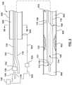
- FIG. 2is a side illustration of the catheter of FIG. 1 with the proximal shaft in a radially collapsed configuration.
- FIG. 3Ais a cross-sectional illustration of an embodiment of the proximal shaft of the catheter of FIG. 1 , taken along line 3 A- 3 A of FIG. 1 .
- FIG. 3Bis a cross-sectional illustration of an embodiment of the proximal shaft of the catheter of FIG. 2 , taken along line 3 B- 3 B of FIG. 2 .
- FIG. 4is a side illustration of an embodiment of a stiffening shaft and hub of the catheter of FIG. 1 .
- FIG. 5is a side illustration of another embodiment of a catheter for calculating a Fractional Flow Reserve (FFR) with the proximal shaft in the radially expanded configuration.
- FFRFractional Flow Reserve
- FIG. 6is a side illustration of the catheter of FIG. 5 with the proximal shaft in the radially collapsed configuration.
- FIG. 7Ais a cross-sectional illustration of an embodiment of the proximal shaft of the catheter of FIG. 5 , taken along line 7 A- 7 A of FIG. 5 .
- FIG. 7Bis a cross-sectional illustration of an embodiment of the proximal shaft of the catheter of FIG. 6 , taken along line 7 B- 7 B of FIG. 6 .
- FIG. 8is a side illustration of an embodiment of the stiffening shaft and hub of the catheter of FIG. 5 .
- FIG. 9is a side illustration of another embodiment of a catheter for calculating a Fractional Flow Reserve (FFR) in a first configuration.
- FFRFractional Flow Reserve
- FIG. 9Ais a detail view of portion A of FIG. 9 .
- FIG. 10is a side illustration of the catheter of FIG. 9 in a second configuration.
- FIG. 10Ais detailed view of section B of FIG. 10 as the movable shaft is being removed.
- FIG. 10Bis a detailed view of section B of FIG. 10 with the movable shaft removed.
- FIG. 11Ais a cross-sectional illustration of an embodiment of a proximal shaft of the catheter of FIG. 9 , taken along line 11 A- 11 A of FIG. 9 .
- FIG. 11Bis a cross-sectional illustration of an embodiment of the proximal shaft of the catheter of FIG. 10 , taken along line 11 B- 11 B of FIG. 10 .
- FIG. 12is a side illustration of another embodiment of a catheter for calculating a Fractional Flow Reserve (FFR) with a distal portion of the proximal shaft in a radially expanded configuration.
- FFRFractional Flow Reserve
- FIG. 13is a side illustration of the catheter of FIG. 12 with the distal portion of the proximal shaft in a radially collapsed configuration.
- FIG. 14Ais a cross-sectional illustration of an embodiment of the distal portion of the proximal shaft of the catheter of FIG. 12 , taken along line 134 - 14 A of FIG. 12 .
- FIG. 14Bis a cross-sectional illustration of an embodiment of the distal portion of the proximal shaft of the catheter of FIG. 13 , taken along line 14 B- 14 B of FIG. 13 .
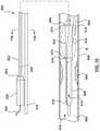
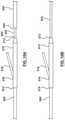
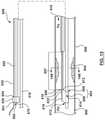
- FIG. 15is a side illustration of another embodiment of a catheter for calculating a Fractional Flow Reserve (FFR) with a distal portion of a proximal shaft in a radially expanded configuration.
- FFRFractional Flow Reserve
- FIG. 16is a side illustration of the catheter of FIG. 15 with the distal portion of the proximal shaft in a radially collapsed configuration.
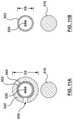
- FIG. 17Ais a cross-sectional illustration of an embodiment of the distal portion of the proximal shaft of the catheter of FIG. 15 , taken along line 17 A- 17 A of FIG. 15
- FIG. 17Bis a cross-sectional illustration of an embodiment of the distal portion of the proximal shaft of the catheter of FIG. 16 , taken along line 17 B- 17 B of FIG. 16 .
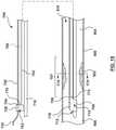
- FIG. 18is a side illustration of another embodiment of a catheter for calculating a Fractional Flow Reserve (FFR) with an expandable portion of a distal in a radially expanded configuration.
- FFRFractional Flow Reserve
- FIG. 19is a side illustration of the catheter of FIG. 18 with the expandable portion a radially collapsed configuration.
- FIG. 20Ais a cross-sectional illustration of an embodiment of the expandable portion of the catheter of FIG. 18 , taken along line 20 A- 20 A of FIG. 18
- FIG. 20Bis a cross-sectional illustration of an embodiment of the expandable portion of the catheter of FIG. 19 , taken along line 20 B- 20 B of FIG. 19 .
- distal and proximalwhen used in the following description to refer to a catheter or delivery system are with respect to a position or direction relative to the treating clinician.
- distal and proximalrefer to positions distant from, or in a direction away from the treating clinician
- proximaland proximally refer to positions near, or in a direction toward the clinician.
- distal and proximalwhen used in the following description to refer to a vessel or a stenosis are used with reference to the direction of blood flow.
- distal and disallywhen used in the following description to refer to a downstream direction with respect to the direction of blood flow
- proximal and proximallyrefer to positions in an upstream direction with respect to the direction of blood flow.
- the catheter 100includes a proximal shaft 102 , a distal shaft 108 , a pressure sensor 118 , and at least one pressure sensor wire 120 .
- the catheter 100may further include a hub or handle 126 coupled to a proximal end of the proximal shaft 102 for convenient handling of the catheter 100 , as shown in FIGS. 1 and 2 .
- the catheter 100is configured to be disposed in a vessel 900 with a proximal portion of the proximal shaft 102 extending outside of a patient, and a distal portion of the distal shaft 108 positioned in situ within a lumen 910 of the vessel 900 having a lesion or stenosis 902 .
- the catheter 100is configured to measure a distal pressure P d on a distal side 906 of the stenosis 902 .
- Various features of the components of the catheter 100 reflected in FIGS. 1-4 and described belowcan be modified or replaced with different structures and/or mechanisms.
- the proximal shaft 102 of the catheter 100includes a proximal end 104 and a distal end 106 .
- the proximal shaft 102includes an expansion lumen 128 extending therethrough from the proximal end 104 to the distal end 106 , as shown in FIG. 1 .
- the expansion lumen 128may stop proximally of the distal end 106 , but preferably at least to a location where the proximal shaft 102 exits the guide catheter 920 (described below).
- the proximal shaft 102includes a radially expanded configuration ( FIGS.
- the expansion lumen 128 of the proximal shaft 102is configured to receive a stiffening shaft 130 such that with the stiffening shaft 130 received with the expansion lumen 128 , the proximal shaft 102 is in the radially expanded configuration and with the stiffening shaft 130 not received within the expansion lumen 128 , the proximal shaft 102 is in the radially collapsed configuration.
- the proximal shaft 102has a first outer diameter D 1 when in the radially expanded configuration and a second outer diameter D 2 when in the radially collapsed configuration, with the first outer diameter D 1 being greater than the second outer diameter D 2 , as shown in FIGS. 3A-3B .
- the term “diameter”does not have to refer to a circular profile, but instead is used generally to refer to a cross-sectional dimension.
- the proximal shaft 102may be formed of a shape-memory material with a pre-set shape. In the embodiment of FIGS. 1-3B , the proximal shaft 102 has a pre-set shape in the radially collapsed configuration, as shown in FIGS. 2 and 3B . Due to the shape memory material and pre-set shape thereof, the proximal shaft 102 actively recoils to the radially collapsed configuration upon removal of the stiffening shaft 130 from the expansion lumen 128 .
- the proximal shaft 102may be formed of, for example, and not by way of limitation, polyether block amide (e.g., VESTAMID or PEBAX), thermoplastic elastomers (TPE), or other materials suitable for the purposes described herein.
- the proximal shaft 102may be coupled to the hub/handle 126 by, for example, and not by way of limitation, adhesives, mechanical connection, fusing, welding, for any other method suitable for the purposes of the present disclosure.
- FIGS. 1-2show an embodiment of the distal shaft 108 of the catheter 100 .
- the distal shaft 108includes a proximal end 110 and a distal end 112 .
- a guidewire lumen 114extends from the proximal end 110 to the distal end 112 .
- the distal shaft 108further includes the pressure sensor 118 and a distal portion of the pressure sensor wire 120 .
- the distal shaft 108is configured to extend from a proximal side 904 of the stenosis 902 to the distal side 906 of stenosis 902 such that the pressure sensor 118 is disposed on the distal side 906 of stenosis 902 , as shown in FIGS. 1-2 .
- the guidewire lumen 114is configured to receive a guidewire 116 therein.
- a proximal guidewire port 168is disposed at the proximal end 110 of the distal shaft 108 .
- a distal guidewire port 113is disposed at the distal end 112 of the distal shaft 108 .
- the distal portion of the pressure sensor wire 120is disposed within a distal shaft wall 122 of the distal shaft 108 .
- the distal shaft 108may be formed of, for example, and not by way of limitation, polyethylene, polyether block amide (e.g., VESTAMID or PEBAX), polyamide and/or combinations thereof, either blended or co-extruded, or other materials suitable for the purposes described herein.
- the distal shaft 108may be coupled to the proximal shaft 102 by, for example, and not by way of limitation, adhesives, fusing, welding, for any other method suitable for the purposes of the present disclosure.
- the proximal shaft 102 and the distal shaft 108may be formed unitarily.
- the pressure sensor 118 of the distal shaft 108may be a piezo-resistive pressure sensor, a piezo-electric pressure sensor, a capacitive pressure sensor, an electromagnetic pressure sensor, an optical pressure sensor, and/or combinations thereof or other sensors suitable for the purpose described herein.
- the pressure sensor 118is configured to measure a pressure of a fluid outside the distal shaft 108 . With the pressure sensor 118 disposed on the distal side 906 of the lesion 902 , the pressure sensor 118 measures the distal pressure P d of a fluid outside of the distal shaft 108 .
- the pressure sensor 118is further configured to communicate the distal pressure P d with a processor 140 .
- the pressure sensor 118is coupled to the distal shaft 108 of the catheter 100 such that the pressure sensor 118 is disposed on the distal side 906 of stenosis 902 when the distal shaft 108 is positioned at a treatment site therein, as shown in FIGS. 1-2 .
- the pressure sensor 118is coupled to the distal shaft 108 by, for example and not by way of limitation, adhesives, fusing, welding, for any other method suitable for the purposes of the present disclosure. Further, additional features may be provided as part of the distal shaft 108 for housing the pressure sensor 118 , such as pockets, openings, and similar features.
- the pressure sensor wire(s) 120include(s) a proximal end coupled to the processor 140 and a distal end 121 coupled to the pressure sensor 118 .
- the pressure sensor wire(s) 120is/are configured such that pressure sensor 118 is in communication with the processor 140 .
- the pressure sensor wire(s) 120may be disposed within the proximal shaft wall 124 of the proximal shaft 102 and a corresponding distal shaft wall 122 of the distal shaft 108 such that the pressure sensor wire(s) 120 extend(s) proximally from the pressure sensor 118 , through the distal shaft wall 122 , through the corresponding proximal shaft wall 124 , exiting through the hub/handle 126 to the processor 140 .
- the pressure sensor wire(s) 120may be coupled to the pressure sensor 118 by, for example, and not by way of limitation, adhesives, fusing, welding, or any other method suitable for the purposes of the present disclosure.
- the pressure sensor wire(s) 120may be coupled to the processor 140 by, for example and not by way of limitation, cables, connectors, antennas, routers, switches, or any other coupling suitable for the purposes described herein.
- FIGS. 3A-3Bshow three (3) pressure sensor wires 120 , this is not meant to limit the design, and more or fewer pressure sensor wires 120 may be utilized. Moreover, the pressure sensor wires 120 may be eliminated in embodiments wherein a signal from the pressure sensor 118 is sent to the processor 140 other than via the pressure sensor wires 120 , such as, but not limited to, a wireless transmission.
- the processor 140may be any processor suitable for the purposes described herein.
- the processor 140may include such components as a CPU, a display device, an amplification and filtering device, an analog-to-digital converter, and various other components.
- the processor 140is configured to receive a measured proximal pressure P a and a measured distal pressure P d .
- the processor 140is further configured to provide a continuous display of calculated Fractional Flow Reserve (FFR).
- FFRFractional Flow Reserve
- the processor 140is coupled to the pressure sensor wires(s) 120 such that the processor 140 is in communication with the pressure sensor 118 as described previously.
- the processor 140may be coupled to a proximal end of the pressure sensor wire(s) 120 via various communication pathways, including but not limited to one or more physical connections including electrical, optical, and/or fluid connections, a wireless connection, and/or combinations thereof. Accordingly, it is understood that additional components (e.g., cables, connectors, antennas, routers, switches, etc.) not illustrated in FIGS. 1-4 may include devices to facilitate communication between the proximal end of the pressure sensor wire(s) 120 and the processor 140 . In other embodiments, instead of the pressure sensor wire(s) 120 , communication between the pressure sensor 118 and the processor 140 may be accomplished wirelessly.
- additional componentse.g., cables, connectors, antennas, routers, switches, etc.
- the stiffening shaft 130may be a solid core wire.
- the stiffening shaft 130is configured to be movable within the expansion lumen 128 of the proximal shaft 102 , as shown in FIGS. 1-2 .
- the stiffening shaft 130is further configured such that when disposed within the expansion lumen 128 of the proximal shelf 102 , the stiffening shaft 130 expands the proximal shaft 102 to the radially expanded configuration ( FIGS. 1 and 3A ).
- the stiffening shaft 130when so disposed, is configured to provide strength and pushability to the proximal shaft 102 for delivery of the catheter 100 to the desired treatment site.
- the stiffening shaft 130is further configured such that upon removal from the expansion lumen 128 of the proximal shaft 102 , the proximal shaft 102 collapses to the radially collapsed configuration ( FIGS. 2 and 3B ).
- An outer surface of the stiffening shaft 130may have a lubricious coating thereon.
- the stiffening shaft 130may be formed of, for example, and not by way of limitation, metals such as stainless steel, cobalt, chromium, nickel and/or molybdenum based alloys (MP35N, MP20N, L605), nickel titanium alloys (NITINOL) or combinations thereof.
- the stiffening shaft 130may be made of other materials provided that the stiffening shaft provides sufficient strength and pushability for the purposes described herein.
- the lubricious coating on the outer surface of the stiffening shaft 130may be polytetrafluoroethylene (PTFE) or any other materials suitable for purposes of the present disclosure.
- the hub 126 of the catheter 100includes a proximal end 136 and a distal end 138 .
- the hub 126defines a stiffening shaft lumen 139 therein between the proximal end 136 and the distal end 138 .
- the stiffening shaft lumen 139is disposed within the hub 126 such that the stiffening shaft lumen 139 aligns longitudinally with the expansion lumen 128 , effectively creating a continuous lumen from proximal end 136 of the hub 126 extending distally through the proximal end 104 of the proximal shaft 102 to the distal end 106 of the proximal shaft 102 ( FIG. 1 ) and configured to receive the stiffening shaft 130 therein.
- the stiffening shaft 130is configured to be movable within both the stiffening shaft lumen 139 of hub 126 and the expansion lumen 128 of the proximal shaft 102 .
- a guide catheter 920 and the guidewire 116are advanced through the vasculature to a desired site.
- the guidewire 116may be back-loaded into the catheter 100 (i.e., the proximal end of the guidewire 116 is loaded into the distal end of the guidewire lumen 114 at the distal end 112 of distal shaft 108 ).
- the catheter 100with the proximal shaft 102 in the radially expanded configuration (i.e., with the stiffening shaft 130 disposed within the expansion lumen 128 ) may then be advanced over the guidewire 116 and through a lumen 928 of the guide catheter 920 to the desired treatment site.
- a distal end (not shown) of the guide catheter 920 disposed at a desired site proximal of the stenosis 902such as in the sinus of an aortic valve
- the distal shaft 108 of the catheter 100is advanced through the lumen 928 and distal of the distal end of the guide catheter 920 .
- the catheter 100is advanced such that distal shaft 108 is disposed across the stenosis 902 of the vessel 900 .
- the stiffening shaft 130is removed from the expansion lumen 128 of the proximal shaft 102 . Removing the stiffening shaft 130 results in the proximal shaft 102 collapsing to the radially collapsed configuration with second outer diameter D 2 , as shown in FIGS. 2 and 3B . With the proximal shaft 102 in the radially collapsed configuration, the combination of the guidewire 116 and the proximal shaft 102 occupies a smaller percentage of the lumen 928 of the guide catheter 920 , as shown by comparing FIG. 3B to FIG. 3A . With the catheter 100 in position and the proximal shaft 102 in the radially collapsed configuration, the appropriate pressure measurements may be taken.
- proximal pressure P a at the distal end of the guide catheter 920is measured by an external pressure transducer 922 via the fluid (blood) column extending through the lumen 928 and the tubing 922 .
- the external pressure transducer 922is configured to measure proximal or aortic (AO) pressure P a at the distal end of the guide catheter 920 .
- the external pressure transducer 922is configured to communicate the measured proximal pressure P a to the processor 140 via a pressure transducer wire 929 , as shown in FIG. 2 .
- the pressure sensor 118measures distal pressure P d distal of the stenosis 902 .
- the distal pressure P dis communicated to the processor 140 , as explained above.
- FFRFractional Flow Reserve
- the catheter 100 with the proximal shaft 102 in the radially collapsed configurationhas a reduced cross-sectional profile ( FIG. 3B ) as compared to the proximal shaft 102 in the radially expanded configuration ( FIG. 3A ).
- a larger profilemay lead to errors in the measured proximal or aortic pressure P a . Such errors are carried through to the FFR calculation noted above because the measured proximal pressure P a is used in the FFR calculation.
- reducing the cross-sectional profileleads to a smaller potential for error in the proximal pressure P a , and hence a smaller potential for error in the FFR calculation.
- the size of the guidewire 116remains constant, the smaller the cross-sectional profile of the proximal shaft 102 , the smaller the potential error in proximal (AO) pressure measurement P a .
- the smaller the cross-sectional profile of the proximal shaft 102 of the catheter 100the more accurate the proximal (AO) pressure measurement P a , and therefore a more accurate FFR value.
- the catheter 200includes a proximal shaft 202 , a distal shaft 208 , a pressure sensor 218 , and at least one pressure sensor wire 220 , as shown in FIGS. 5-7B and described in greater detail below.
- the distal shaft 208 , the pressure sensor 218 , and the at least one pressure sensor wire 220are similar to the distal shaft 108 , the pressure sensor 118 , and the at least one pressure sensor wire 120 of the catheter 100 of FIGS. 1-4 .
- the catheter 200is configured to be disposed with a proximal portion of the proximal shaft 202 extending outside of a patient, and a distal portion of the distal shaft 208 positioned in situ within a lumen 910 of a vessel 900 having a stenosis or lesion 902 .
- the catheter 200is configured such that the catheter 200 measures a distal pressure P d of blood on a distal side 906 of the stenosis 902 .
- the proximal shaft 202 of the catheter 200includes a proximal end 204 , a distal end 206 , and an expansion lumen 228 extending from the proximal end 204 to the distal end 206 of the proximal shaft 202 .
- the expansion lumen 228may stop proximally of the distal end 206 , but preferably extends distally at least to a location where the proximal shaft 202 exits the guide catheter.
- the proximal shaft 202includes a radially expanded configuration ( FIGS.
- the expansion lumen 228 of the proximal shaft 202is configured to receive a stiffening shaft 230 such that with the stiffening shaft 230 received within expansion lumen 228 , the proximal shaft 202 is in the radially expanded configuration, and with the stiffening shaft 230 not received with expansion lumen 228 , the proximal shaft 202 is in the radially collapsed configuration.
- the proximal shaft 202has a first outer diameter D 3 when in the radially expanded configuration and a second outer diameter D 4 when in the radially collapsed configuration, with the first outer diameter D 3 being greater than the second outer diameter D 4 , as shown in FIGS.
- the proximal shaft 202is disposed distal of and coupled to a hub 226 for convenient handling of the catheter 200 .
- the proximal shaft 202may be coupled to the hub 226 by, for example and not by way of limitation, adhesives, fusing, welding, for any other method suitable for the purposes of the present disclosure.
- the proximal shaft 202may be formed of a shape-memory configuration with a pre-set shape, non-limiting examples of which are described in U.S. Pat. No. 9,192,751 to Macaulay et al., which is incorporated by reference herein in its entirety.
- the proximal shaft 202has a pre-set shape in the radially collapsed configuration with the second outer diameter D 4 . Due to the shape memory material and pre-set shape thereof, the proximal shaft 202 of the catheter 200 actively recoils to the radially collapsed configuration after removal of the stiffening shaft 230 from the expansion lumen 228 .
- FIGS. 7A-7Billustrate an embodiment of how the proximal shaft 202 is configured to collapse upon removal of the stiffening shaft 230 from the expansion lumen 228 .
- the proximal shaft 202includes an elastic frame 254 , a liner 250 , and a jacket 252 .
- the elastic frame 254may be coupled between the liner 250 and the jacket 252 by lamination, embedding, or other methods suitable for the purposes described herein.
- elastic frame 254is generally tubular.
- the elastic frame 254may assume various shapes suitable for the purposes described herein, embodiments of which are described in detail in U.S. Pat. No.
- the elastic frame 254may be formed of materials such as, but not limited to, nickel-titanium alloys (e.g. NITINOL), nickel-cobalt-chromium-molybdenum alloys (e.g. MP35N), stainless steel, high spring temper steel, or any other metal or elastomer or composite having elastic properties to permit expansion and recoil suitable for purposes of the present disclosure.
- the liner 250may be constructed of materials such as, but not limited to, polytetrafluoroethylene (PTFE; e.g.
- the jacket 252may be constructed of materials such as, but not limited to, polyurethane (e.g. Peliethane ⁇ , EiasthaneTM, Texin®, Tecothane®), polyamide polyether block copolymer (e.g. Pebax®, nylon 12), polyethylene, TPE, Propel, Fuoroguard or other materials suitable for the purposes of the present disclosure.
- polyurethanee.g. Peliethane ⁇ , EiasthaneTM, Texin®, Tecothane®
- polyamide polyether block copolymere.g. Pebax®, nylon 12
- polyethyleneTPE
- PropelFuoroguard
- the elastic frame 254is of a shape memory material with a pre-set shape.
- the elastic frame 254has a pre-set shape in the radially collapsed configuration as shown in FIG. 7B .
- the elastic frame 254enables the proximal shaft 202 to expand to the radially expanded configuration with the first outer diameter D 3 , as shown in FIG. 7A . Due to the shape memory material and pre-set shape thereof, the elastic frame 254 causes the proximal shaft 202 to actively recoil to the radially collapsed configuration after removal of the stiffening shaft 230 from the expansion lumen 228 of the proximal shaft 202 .
- the liner 250is circumferentially continuous and forms the expansion lumen 228 , as shown in FIG. 7A .
- the elastic frame 254 and the jacket 252are non-circumferentially continuous. Accordingly, a circumferential jacket gap 258 is disposed between a first circumferential end 270 and a second circumferential end 272 of jacket 252 , as shown in FIG. 7A .
- the liner 250folds to form a liner overlap portion 262 defined by at least one fold. In one embodiment, overlap portion is defined by an inner fold 264 and an outer fold 266 of the liner 250 .
- the liner 250folds by the radially collapse of the elastic frame 254 , the liner 250 forms the liner overlap portion 262 , and the first circumferential end 270 and the second circumferential 272 of the jacket 252 move closer together, as shown in FIG. 7B .
- the circumferential jacket gap 258is reduced in size, as shown by comparing FIGS. 7A and 7B .
- the inner fold 264 and the outer fold 266are flattened or stretched apart such that the first and second circumferential ends 270 , 272 of the jacket 252 move apart from each other, thereby increasing the circumferential jacket gap 258 , as shown in FIG. 7A .
- the stiffening shaft 230may be a solid core wire, as explained above with respect to the stiffening shaft 130 .
- the stiffening shaft 230is configured to be movable within the expansion lumen 228 of the proximal shaft 202 as shown in FIGS. 5-6 .
- the stiffening shaft 230is further configured such that when disposed within the expansion lumen 228 of the proximal shaft 202 , the stiffening shaft 230 expands the proximal shaft 202 to the radially expanded configuration ( FIGS. 5 and 7A ).
- the stiffening shaft 230when so disposed, is configured to provide strength and pushability to the proximal shaft 202 for delivery of the catheter 200 to the desired treatment site.
- the stiffening shaft 230is further configured such that upon removal of the stiffening shaft 230 from the expansion lumen 228 of the proximal shaft 202 , the proximal shaft 202 collapses to the radially collapsed configuration ( FIGS. 6 and 7B ).
- An outer surface of the stiffening shaft 230may have a lubricious coating thereon.
- the stiffening shaft 230may be formed of, for example, and not by way of limitation, metals such as stainless steel, cobalt, chromium, nickel and/or molybdenum based alloys (MP35N, MP20N, L605), nickel titanium alloys (NITINOL) or combinations thereof.
- the stiffening shaft 230may be made of other materials provided that the stiffening shaft provides sufficient strength and pushability for the purposes described herein.
- the lubricious coating on the outer surface of the stiffening shaft 230may be polytetrafluoroethylene (PTFE) or any other materials suitable for purposes of the present disclosure.
- the hub 226 of the catheter 200includes a proximal end 236 and a distal end 238 .
- a short stiff shaft 232is coupled to the distal end 238 of the hub 226 .
- the short stiff shaft 232extends distally within a proximal portion 205 of the expansion lumen 228 of the proximal shaft 202 .
- the short stiff shaft 232provides strength and pushability to the proximal portion 205 of the proximal shaft 202 .
- a stiffening shaft exit port 234is in communication with the expansion lumen 228 for entry and exit of the stiffening shaft 230 to the expansion lumen 228 .
- the stiffening shaft 230is configured to be movable within expansion shaft 228 via the stiffening shaft exit port 234 .
- the design of the proximal shaft 202 with the stiffening shaft exit port 234 and the short stiff shaft 232may be interchanged with other embodiments herein.
- the proximal shaft 102 of the embodiment of FIGS. 1-4may be used with the stiffening shaft exit port 234 and the short stiff shaft 232 of the embodiment of FIGS. 5-8 .
- the proximal shaft 202 of the embodiment of FIGS. 5-8may be used with the manner in which the stiffening shaft 130 is introduced and removed from the proximal shaft 102 of FIGS. 1-4 .
- a guide catheter(not shown but may be similar to guide catheter 920 of FIGS. 1-2 ) and the guidewire 216 are advanced through the vasculature to a desired site.
- the guidewire 216may be back-loaded into the catheter 200 (i.e., the proximal end of the guidewire 216 is loaded into the distal end of the guidewire lumen 214 at the distal end 212 of the distal shaft 208 ).
- the catheter 200with the proximal shaft 202 in the radially expanded configuration (i.e., with the stiffening shaft 230 disposed within the expansion lumen 228 ) may then be advanced over the guidewire 216 and through a lumen of the guide catheter to the desired treatment site.
- a distal end (not shown) of the guide catheter disposed at a desired site proximal of the stenosis 902such as in the sinus of an aortic valve
- the distal shaft 208 of the catheter 200is advanced through the lumen of the guide catheter and distal of the distal end of the guide catheter.
- the catheter 200is advanced such that distal shaft 208 is disposed through the stenosis 902 of the vessel 900 .
- the stiffening shaft 230is removed from the expansion lumen 228 of the proximal shaft 202 . Removing the stiffening shaft 230 results in the proximal shaft 202 collapsing to the radially collapsed configuration with the second outer diameter D 3 , as shown in FIGS. 6 and 7B . With the proximal shaft 202 in the radially collapsed configuration, the combination of the guidewire 216 and the proximal shaft 202 occupies a smaller percentage of the lumen of the guide catheter, as shown by comparing FIG. 7B to FIG. 7A . With the catheter 200 in position and the proximal shaft 202 in the radially collapsed configuration, the appropriate pressure measurements may be taken.
- proximal pressure P a at the distal end of the guide catheteris measured by an external pressure transducer via the fluid (blood) column extending through the lumen of the guide catheter and the tubing.
- the external pressure transduceris configured to measure the proximal or aortic (AO) pressure P a at the distal end of the guide catheter.
- the external pressure transduceris configured to communicate the measured proximal pressure P a to a processor 240 via a pressure transducer wire, similar to as described above with respect to FIG. 2 .
- the pressure sensor 218measures the distal pressure P d distal of the stenosis 902 .
- the distal pressure P dis communicated to the processor 240 , as explained above.
- FFRFractional Flow Reserve
- the catheter 200 with the proximal shaft 202 in the radially collapsed configurationhas a reduced cross-sectional profile ( FIG. 7B ) as compared to the proximal shaft 202 in the radially expanded configuration ( FIG. 7A ).
- a larger profilemay lead to errors in the measured proximal or aortic pressure P a . Such errors are carried through to the FFR calculation noted above because the measured proximal pressure P a is used in the FFR calculation.
- reducing the cross-sectional profileleads to a smaller potential for error in the proximal pressure P a , and hence a smaller potential for error in the FFR calculation.
- the size of the guidewire 216remains constant, the smaller the cross-sectional profile of the proximal shaft 202 , the smaller the potential error in measured proximal (AO) pressure P a .
- the smaller the cross-sectional profile of the proximal shaft 202 of the catheter 200the more accurate the measured proximal (AO) pressure P a , and therefore a more accurate FFR value is calculated.
- the catheter 500includes a proximal shaft 502 , a distal shaft 508 , transition shaft 570 , a pressure sensor 518 , at least one pressure sensor wire 520 , and a movable shaft 542 .
- the distal shaft 508 , the pressure sensor 518 , and the at least one pressure sensor wire 520are similar to the distal shaft 108 , the pressure sensor 118 , and the at least one pressure sensor wire 120 of the catheter 100 of FIGS. 1-4 .
- the catheter 500is configured to be disposed with a proximal portion of the proximal shaft 502 extending outside of a patient, and a distal portion of the distal shaft 508 positioned in situ within a lumen 910 of a vessel 900 having a stenosis or lesion 902 .
- the catheter 500is configured such that the catheter 500 measures a distal pressure P d of blood in the vessel 900 on a distal side 906 of the stenosis 902 .
- the catheter 500includes a first configuration ( FIGS. 9, 9A and 11A ) with the movable shaft 542 disposed over the proximal shaft 502 , and a second configuration ( FIGS. 10, 10B and 11B ) with the movable shaft 542 not disposed over the proximal shaft 502 .
- the first configurationis generally used to deliver the catheter 500 through the vasculature to the desired treatment site.
- the movable shaft 542provides strength and pushability to the proximal shaft 502 .
- the movable shaft 542may be retracted proximally such that the proximal shaft 502 occupies a smaller area of the guide catheter.
- the catheter 500includes a transition shaft 570 .
- the transition shaft 570is disposed between the proximal shaft 502 and the distal shaft 508 .
- a proximal end 572 of the transition shaft 570is disposed adjacent a distal end 506 of the proximal shaft 502 and a distal end 574 of the transition shaft 570 is disposed adjacent a proximal end 510 of the distal shaft 508 .
- the transition shaft 570serves as a transition from the proximal shaft 502 to the distal shaft 508 .
- the transition shaft 570includes a guidewire port 576 for entry of the guidewire 516 into the transition shaft 570 and the distal shaft 508 .
- transition shaft 570is described separately in the embodiment of FIGS. 9-11B , the transition shaft may be considered part of the distal shaft 508 . Further, other embodiments described herein may include such a transition shaft even if not specifically described, and the present embodiment need not include a transition shaft.
- the proximal shaft 502may be a hollow shaft with the pressure sensor wire(s) 520 disposed within a central passageway of the hollow shaft.
- the proximal shaft 502includes a proximal end 504 coupled to a hub/handle 526 and a distal end 506 coupled to the transition shaft 570 .
- the proximal shaft 502is disposed distal of and coupled to a hub/handle 526 . It is desirable for the proximal shaft to have a minimized cross-sectional profile in order to occupy a smaller percentage of a passageway of a guide catheter.
- the proximal shaft 502has an outer diameter of approximately 0.014 inch, which is equivalent to the outer diameter of FFR wires.
- the proximal shaft 502may be formed of materials such as, but not limited to, stainless steel, cobalt, chromium, nickel and/or molybdenum based alloys (MP35N, MP20N, L605), nickel titanium alloys (NITINOL) or combinations thereof.
- the proximal shaft 502may also be formed of materials such, but not limited to, polyethylene, polyether block amide (PEBA, e.g. VESTAMID, PEBAX), thermoplastic elastomers (TPE), polyamide and/or combinations thereof, either blended or co-extruded, or other materials suitable for the purposes described herein.
- PEBApolyether block amide
- TPEthermoplastic elastomers
- the proximal shaft 502may be coupled to the hub 526 by, for example, and not by way of limitation, adhesives, fusing, welding, for any other method suitable for the purposes of the present disclosure.
- the movable shaft 542is generally tubular with a c-shape cross-section, as shown in FIGS. 9 and 11A .
- the movable shaft 542includes a proximal end 546 and a distal end 548 .
- the movable shaft 542includes a lumen 544 extending from the proximal end 546 to the distal end 548 ( FIG. 11A ).
- the movable shaft 542further includes a groove 550 extending longitudinally from the proximal end 546 distally to the distal end 548 .
- the groove 550also extends radially from an inner surface of the movable shaft 542 to an outer surface of the movable shaft 542 , as shown in FIG. 11A .
- the movable shaft 542is configured to be slidably disposed over the proximal shaft 502 such that when the movable shaft 542 is disposed over the proximal shaft 502 , the catheter 500 is in the first configuration ( FIGS. 9 and 11A ), and when the movable shaft 542 is not disposed over the proximal shaft, the catheter 500 is in the second configuration ( FIGS. 10 and 11B ).
- the movable shaft 542is further configured to be selectively coupled to the hub 526 such that with the movable shaft 542 disposed over the proximal shaft 502 and selectively coupled to the hub 526 , the distal end 548 of the movable shaft 542 contacts a proximal end 572 of the transition shaft 570 ( FIGS. 9, 9A ) (the first configuration).
- a distally directed force DF applied to the hub 526is transferred to the movable shaft 542 coupled thereto.
- the distally directed force DFis transferred along the movable shaft 542 .
- the distal end 548 of the movable shaft 542transfers the distally directed force DF to the proximal end 572 of the transition shaft 570 ( FIGS. 9 and 9A ).
- the movable shaft 542provides strength and pushability to the catheter 500 for delivery to the desired treatment site.
- the groove 550 in the movable shaft 542is a longitudinal groove configured such that the movable shaft 542 may be advanced or retracted over the proximal shaft 502 while providing an exit for the proximal portion of the pressure sensor wire(s) 520 . While the groove 550 is desirable, it is not required. If the movable shaft 542 did not include a groove 550 , when the movable shaft 542 is retracted, the portion of the pressure sensor wire(s) 520 proximal of the hub 526 would need to be at least as long as the movable shaft 542 in order to provide room for the movable shaft 542 to retract over the pressure sensor wire(s) 520 proximal of the hub 526 .
- the moveable shaft 542may be formed of, for example, and not by way of limitation, polyethylene, polyether block amide (PEBA, e.g. VESTAMID, PEBAX), thermoplastic elastomers (TPE), polyamide and/or combinations thereof, either blended or co-extruded, or other materials suitable for the purposes described herein.
- PEBApolyether block amide
- TPEthermoplastic elastomers
- the movable shaft 542may be selectively coupled to the hub 526 by a mechanical locking mechanism disposed with the hub 526 and actuated by a trigger, coupling mechanisms suitable for the purposes described herein.
- the movable shaft 542may be selectively coupled to the hub 526 by a locking key/pin arrangement, a reversible snap fit connection, an interference fit, or other suitable couple mechanisms.
- the proximal shaft 502can have a smaller cross-sectional profile than would be required for pushability without the movable shaft 542 .
- the proximal portion of the catheter 500has a first outer diameter D 5 ( FIG. 11A ) which is the outer diameter of the movable shaft 542 .
- the combined strength of the proximal shaft 502 and the movable shaft 542provides sufficient strength and pushability for the delivering the catheter 500 to the desired treatment site.
- the movable shaft 542may be retracted proximally and withdrawn ( FIGS.
- the proximal portion of the catheter 500has a second outer diameter D 6 which is smaller than the first outer diameter D 5 .
- the second outer diameter D 6is the outer diameter of the proximal shaft 502 .
- the second outer diameter D 6is 0.014 inch, but this is not meant to be limiting.
- a guide catheter(not shown but similar to FIG. 1 ) and the guidewire 516 are advanced through the vasculature to a desired site.
- the guidewire 516may be back-loaded into the catheter 500 (i.e., the proximal end of the guidewire 516 is loaded into the distal end of the guidewire lumen 514 at the distal end of distal shaft 508 ).
- the catheter 500is in the first configuration with the movable shaft 542 disposed over the proximal shaft 502 and locked in place by the locking mechanism of the hub 526 .
- the catheter 500may then be advanced over the guidewire 516 and through a lumen of the guide catheter to the desired treatment site.
- a distal end of the guide catheterdisposed at a desired site proximal of the stenosis 902 , such as in the sinus of an aortic valve
- the distal shaft 508 of the catheter 500is advanced through the lumen of the guide catheter and distal of the distal end of the guide catheter.
- the catheter 500is advanced such that distal shaft 508 is disposed across the stenosis 902 of the vessel 900 .
- the movable shaft 542With the catheter 500 in position at the treatment site, the movable shaft 542 is removed from around the proximal shaft 502 . Removing the movable shaft 542 results in the catheter 500 being in the second configuration with only the proximal shaft 502 as the proximal portion of the catheter, as shown in FIGS. 10 and 11B . With the movable shaft 542 removed, the combination of the guidewire 516 and the proximal shaft 502 occupies a smaller percentage of the lumen of the guide catheter, as shown by comparing FIG. 11B to FIG. 11A . With the catheter 500 in position and in the second configuration, the appropriate pressure measurements may be taken.
- proximal pressure P a at the distal end of the guide catheteris measured by an external pressure transducer via the fluid (blood) column extending through the lumen of the guide catheter and the tubing.
- an external pressure transduceris configured to measure the proximal or aortic (AO) pressure P a at the distal end of the guide catheter.
- the external pressure transduceris configured to communicate the measured proximal pressure P a to a processor (not shown) via a pressure transducer wire, as explained above with respect to the catheter 100 .
- a processornot shown
- the external pressure transducermay communicate with the processor by any means suitable for the purposes described, including, but not limited to, electrical cables, optical cables, or wireless devices.
- the pressure sensor 518measures distal pressure P d of blood distal of the stenosis.
- the distal pressure P dis communicated to the processor, as explained above.
- FFRFractional Flow Reserve
- the proximal portion of the catheter 500 with the movable shaft 542 removedhas a reduced cross-sectional profile ( FIG. 11B ) as compared to the proximal portion of the catheter 500 with the movable shaft 542 disposed over the proximal shaft 502 ( FIG. 11A ).
- a larger profilemay lead to errors in the measured proximal or aortic pressure P a .
- the catheter 600includes a proximal shaft 602 , a distal shaft 608 , a pressure sensor 618 , and at least one pressure sensor wire 620 , as shown in FIGS. 12-13 .
- the pressure sensor 618 and the at least one pressure sensor wire 620are similar to the pressure sensor 118 and the at least one pressure sensor wire 120 of the catheter 100 . Therefore, details of the pressure sensor 618 and the at least one pressure sensor wire 620 will not be repeated here.
- the catheter 600is configured to be disposed with a proximal portion of the proximal shaft 602 extending outside of a patient, and a distal portion of the distal shaft 608 positioned in situ within a lumen 910 of a vessel 900 having a stenosis or lesion 902 .
- the catheter 600is configured such that the catheter 600 measures a distal pressure P d of blood on a distal side 906 of the stenosis 902 .
- the proximal shaft 602 of the catheter 600is a hollow shaft including a proximal end 604 coupled a hub/handle 626 , a distal end 606 , and an inflation lumen 660 extending from the proximal end 604 of the proximal shaft 602 to a distal portion 607 of the proximal shaft 602 .
- the distal portion 607 of the proximal shaft 602is configured to extend through the stenosis 902 of the vessel 900 when the catheter 600 is positioned for measuring the distal pressure P d .
- the distal portion 607 of the proximal shaft 602is further configured to be radially expandable from a radially collapsed configuration ( FIGS.
- the distal portion 607 of the proximal shaft 602has a first outer diameter D 7 when in the radially expanded configuration ( FIG. 14A ) and a second outer diameter D 8 when in the radially collapsed configuration ( FIG. 14B ), with the first diameter D 7 being greater than the second diameter D 8 .
- the distal portion 607 of the proximal shaft 602is formed of an elastic shape-memory material with a pre-set shape.
- the proximal shaft 602has a pre-set shape in the radially collapsed configuration with the second outer diameter D 8 , as shown in FIGS.
- the distal portion 607 of the proximal shaft 602 of the catheter 600actively recoils to the second outer diameter D 8 after removal of the inflation fluid from the inflation lumen 660 .
- the expandable distal portion 607 of the proximal shaft 602may be formed as described above with respect to the proximal shafts 102 , 202 of the catheters 100 , 200 .
- the distal portion 607 of the proximal shaft 602may be formed as described in U.S. Pat. No. 9,192,751 to Macaulay et al., which is incorporated by reference herein in its entirety.
- the distal portion 607 of the proximal shaft 601may be formed of material such as, but not limited to, polyether block amide (PEBA, e.g. VESTAMID, PEBAX), thermoplastic elastomers (TPE), or other materials suitable for the purposes described herein.
- PEBApolyether block amide
- TPEthermoplastic elastomers
- the proximal shaft 602may be coupled to the hub/handle 626 by adhesives, fusing, welding, or any other method suitable for the purposes of the present disclosure.
- the inflation lumen 660includes a proximal end 670 at a proximal end 601 of the catheter 600 configured to be in fluid communication with an inflation fluid source (not shown).
- the inflation lumen 660extends through the proximal shaft 602 to a distal end 672 of the inflation lumen 660 in fluid communication with an interior cavity 609 of the distal portion 607 of the proximal shaft 602 , as shown in FIGS. 12-13 .
- the distal portion 607 of the proximal shaft 602is configured to radially expand when the interior cavity 609 of the distal portion is filled with an inflation fluid, thereby transitioning to the radially expanded configuration with the first outer diameter D 7 ( FIGS. 12 and 14A ).
- the distal portion 607 of the proximal shaft 602is further configured such that as the pressure of the inflation fluid within the interior cavity 609 is reduced, the outward radial force of the inflation fluid exerted on the inner surface of the distal portion 607 decreases such that the distal portion 607 transitions to the radially collapsed configuration with the second outer diameter D 8 ( FIGS. 13 and 14B ).
- the interior cavity 609 of the distal portion 607 of the proximal shaft 602is filled with inflation fluid such that the distal portion is in the radially expanded configuration, strength and pushability of the distal portion 607 is increased as compared to when the inflation fluid is drained from the interior cavity 609 .
- the distal portion 607is in the radially expanded configuration during delivery of the catheter 600 to the desired treatment site.
- the distal shaft 608 of the catheter 600includes a proximal end 610 and a distal end 612 .
- a portion of the proximal end 610 of the distal shaft 608is coupled to a distal end 606 of the proximal shaft 602 by adhesives, fusing, welding, or any other method suitable for the purposes of the present disclosure.
- the distal shaft 608further includes a guidewire lumen 614 configured to receive a guidewire 616 therein, as shown in FIGS. 12-13 .
- the distal shaft 608further includes a proximal guidewire exit port 668 at a proximal portion 664 of the distal shaft 608 configured to provide entry and exit of the guidewire 616 to the guidewire lumen 614 .
- the distal shaft 608further includes a distal guidewire exit port at the distal end 612 of the distal shaft 608 .
- the distal shaft 608further includes the pressure sensor 618 and a distal portion of the pressure sensor wire(s) 620 .
- the distal portion of the pressure sensor wire(s) 620may be disposed within a distal shaft wall 622 of the distal shaft 608 .
- the distal shaft 608is configured to be disposed on the distal side 906 of the stenosis 902 such that the pressure sensor 618 is disposed on the distal side 906 of stenosis 902 .
- a guide catheter(not shown but as described above with respect to FIGS. 1-2 ) and the guidewire 616 are advanced through the vasculature to a desired site.
- the guidewire 616may be back-loaded into the catheter 600 (i.e., the proximal end of the guidewire 616 is loaded into the distal end of the guidewire lumen 614 at the distal end 612 of the distal shaft 608 ).
- the catheter 600is in the radially expanded configuration with the distal portion 607 of the proximal shaft 602 inflated.
- the catheter 600may then be advanced over the guidewire 616 and through a lumen of the guide catheter to the desired treatment site.
- a distal end of the guide catheter disposed at a desired site proximal of the stenosis 902such as in the sinus of an aortic valve
- the catheter 600is advanced through the lumen of the guide catheter until the distal shaft 608 is distal of the distal end of the guide catheter and on the distal side 906 of the stenosis 902 , as shown in FIG. 12 .
- the inflation fluidis drained from the interior cavity 609 of the distal portion 607 of the proximal shaft 602 .
- the distal portion 607 of the proximal shaft 602returns to the radially collapsed configuration shown in FIGS. 13 and 14B .
- the combination of the guidewire 616 and the distal portion 607occupies a smaller percentage of the vessel 900 through the stenosis 902 , as shown by comparing FIG. 14B to FIG. 14A .
- the catheter 600in position and in the radially collapsed configuration, the appropriate pressure measurements may be taken.
- blood flow adjacent the distal end of the guide catheterfills the lumen and tubing via a port in a proximal portion of the guide catheter.
- the blood pressure P a at the distal end of the guide catheteris measured by an external pressure transducer via the fluid (blood) column extending through the lumen of the guide catheter and the tubing.
- an external pressure transduceris configured to measure proximal or aortic (AO) pressure P a at the distal end of the guide catheter.
- the external pressure transduceris configured to communicate measured proximal pressure P a to a processor (not shown) via a pressure transducer wire, as explained above with respect to the catheter 100 .
- a processornot shown
- the external pressure transducermay communicate with the processor by any means suitable for the purposes described, including, but not limited to, electrical cables, optical cables, or wireless devices.
- the pressure sensor 618measures distal pressure P d of blood distal of the stenosis.
- the distal pressure P dis communicated to the processor, as explained above.
- FFRFractional Flow Reserve
- an FFR catheter with a guidewire extending therethroughoccupies a larger percentage of the vessel 900 through the stenosis 902 than a conventional FFR wire. This disrupts the blood flow through the stenosis, which can lead to a measured distal pressure P d which does not correlate to a distal pressure measured distal of the same stenosis with an FFR wire. Further, the FFR catheter needs sufficient pushability to be delivered through the vasculature to the treatment site, which may increase the size of such FFR catheters. In the embodiment of FIGS. 12-14B , the distal portion 607 of the proximal shaft 602 is inflated during delivery of the catheter 600 to the treatment site to provide sufficient pushability.
- the distal portion 607may be deflated such that the overall cross-sectional profile of the guidewire 616 and distal portion 607 in the radially collapsed configuration is equivalent to the cross-sectional profile of an FFR wire.
- the measured distal pressure P dis equivalent to the measured distal pressure using an FFR wire.
- a catheter (or micro-catheter) 700 for calculating a Fractional Flow Reserve (FFR)according to another embodiment of the present disclosure is shown.
- the catheter 700includes a proximal shaft 702 , a distal shaft 708 , a pressure sensor 718 , and at least one pressure sensor wire 720 .
- the distal shaft 708 , pressure sensor 718 and the at least one pressure sensor wire 720are similar to the distal shaft 608 , pressure sensor 118 and the at least one pressure sensor wire 120 described above with respect to the catheter 600 (regarding the distal shaft) and the catheter 100 (regarding the pressure sensor and the pressure sensor wire(s)).
- the catheter 700is configured to be disposed with a proximal portion of the proximal shaft 702 extending outside of a patient, and a distal portion of the distal shaft 708 positioned in situ within a lumen 910 of a vessel 900 having a stenosis or lesion 902 .
- the catheter 700is configured to measure a distal pressure P d of blood on a distal side 906 of the stenosis 902 .
- the proximal shaft 702is disposed distal of and coupled to a hub 726 by adhesives, fusing, welding, or any other method suitable for the purposes of the present disclosure.
- Proximal shaft 702is a hollow shaft having a proximal end 704 , and distal end 706 , and an interior cavity 760 .
- Proximal shaft 702may be formed of an elastic shape-memory material with a pre-set shape such that proximal shaft 702 is radially expandable from a radially collapsed configuration ( FIGS. 16 and 17B ) to a radially expanded configuration ( FIGS. 15 and 17A ).
- the proximal shaft 702has a first diameter D 9 when in the radially expanded configuration and a second diameter D 10 when in the radially collapsed configuration, with the first diameter D 9 being greater than the second diameter D 10 , as shown in FIGS. 17A-17B .
- the proximal shaft 702has a pre-set shape in a radially collapsed configuration with the second diameter D 10 , as shown in FIGS. 16 and 17B . Due to the shape memory material and pre-set shape thereof, the proximal shaft 702 actively recoils to the radially collapsed configuration upon removal of inflation fluid from the inflation interior cavity 760 .
- the expandable proximal shaft 702may be formed as described above with respect to the proximal shafts 102 , 202 of the catheters 100 , 200 .
- the proximal shaft 702may be formed as described in U.S. Pat. No. 9,192,751 to Macaulay et al., which is incorporated by reference herein in its entirety.
- the proximal shaft 702may be formed of, for example, and not by way of limitation, polyether block amide (PEBA, e.g. VESTAMID, PEBAX), thermoplastic elastomers (TPE), or other materials suitable for the purposes described herein.
- PEBApolyether block amide
- TPEthermoplastic elastomers
- the interior cavity 760includes a proximal end 770 in fluid communication with an inflation fluid source (not shown) through an inflation lumen 762 disposed through the hub 726 .
- the interior cavity 760also includes a distal end 772 adjacent a location where the proximal shaft 702 is coupled to the distal shaft 708 .
- the proximal shaft 702is configured such that the inflation fluid, pumped under pressure into the interior cavity 760 , fills the interior cavity 760 and exerts an outward radial force on an inner surface of the proximal shaft 702 such that the proximal shaft 702 transitions to the radially expanded configuration ( FIGS. 15 and 17A ).
- the proximal shaft 702is further configured such that as the pressure of the inflation fluid within the interior cavity 760 is reduced, the outward radial force of the inflation fluid exerted on the inner surface of the proximal shaft 702 decreases such that the proximal shaft 702 transitions to the radially collapsed configuration ( FIGS. 16 and 17B ).
- the proximal shaft 702 with interior cavity 760 filled with inflation fluid under pressurei.e., the radially expanded configuration
- a guide catheter(not shown but as described above with respect to FIGS. 1-2 ) and the guidewire 716 are advanced through the vasculature to a desired site.
- the guidewire 716may be back-loaded into the catheter 700 (i.e., the proximal end of the guidewire 716 is loaded into the distal end of the guidewire lumen 714 at the distal end 712 of the distal shaft 708 ).
- the catheter 700is in the radially expanded configuration with the proximal shaft 702 inflated with inflation fluid.
- the catheter 700may then be advanced over the guidewire 716 and through a lumen of the guide catheter to the desired treatment site.
- a distal end of the guide catheter disposed at a desired site proximal of the stenosis 902such as in the sinus of an aortic valve
- the catheter 700is advanced through the lumen of the guide catheter until the distal shaft 708 is distal of the distal end of the guide catheter and on the distal side 906 of the stenosis 902 , as shown in FIG. 15 .
- the inflation fluidis drained from the interior cavity 760 of the proximal shaft 702 .
- the proximal shaft 702returns to the radially collapsed configuration shown in FIGS. 16 and 17B .
- the appropriate pressure measurementsmay be taken.
- blood flow adjacent the distal end of the guide catheterfills the lumen of the guide catheter to an external transducer via tubing and a port in a proximal portion of the guide catheter.
- the blood pressure P a at the distal end of the guide catheteris measured by the external pressure transducer via the fluid (blood) column extending through the lumen of the guide catheter and the tubing.
- the external pressure transduceris configured to measure the proximal or aortic (AO) pressure P a at the distal end of the guide catheter.
- the external pressure transduceris configured to communicate measured proximal pressure P a to a processor (not shown) via a pressure transducer wire, as explained above with respect to the catheter 100 .
- a processornot shown
- the external pressure transducermay communicate with the processor by any means suitable for the purposes described, including, but not limited to, electrical cables, optical cables, or wireless devices.
- the pressure sensor 718measures distal pressure P d of blood distal of the stenosis.
- the distal pressure P dis communicated to the processor, as explained above.
- FFRFractional Flow Reserve
- an FFR catheter with a guidewire extending therethroughoccupies a larger percentage of the vessel 900 through the stenosis 902 than a conventional FFR wire. This disrupts the blood flow through the stenosis, which can lead to a measured distal pressure P d which does not correlate to a distal pressure measured distal of the same stenosis with an FFR wire.
- a proximal portion of an FFR catheter with a guidewire disposed thereinoccupies a larger percentage of the lumen of the guide catheter, thereby possibly causing the measured proximal pressure P a to not correlate to a proximal pressure measured by an FFR wire.
- the cross-sectional profile of the distal portion 707 of the proximal shaft 702 disposed through the stenosis 902is negligible.
- the combined cross-sectional profile of the guidewire 716 and the distal portion 707 of the proximal shaftis equivalent to an FFR wire alone passing through the stenosis 902 .
- the cross-sectional of the proximal portion of the proximal shaft 702 extending through the lumen of the guide catheter occupiesis also negligible.
- the cross-sectional profile if the guidewire 716 and the proximal portion of the proximal shaft 702 extending through the guide catheteris equivalent to the cross-sectional profile of an FFR wire. Therefore, FFR measured with the catheter 700 with the proximal shaft in the radially collapsed configuration is equivalent to the FFR measured with an FFR wire, thereby alleviating the need for a correction factor.
- a catheter (or micro-catheter) 800 for calculating a Fractional Flow Reserve (FFR)according to another embodiment of the present disclosure is shown.
- the catheter 800includes a proximal shaft 802 , a distal shaft 808 , a pressure sensor 818 , and at least one pressure sensor wire 820 .
- the pressure sensor 818 and the at least one pressure sensor wire 820are similar to the pressure sensor 118 , and the at least one pressure sensor wire 120 described above with respect to the catheter 100 . Therefore, details of the pressure sensor 818 and the at least one pressure sensor wire 820 will not be repeated here.
- the catheter 800is configured to be disposed with a proximal portion of the proximal shaft 802 extending outside of a patient and a distal portion of the distal shaft 808 positioned in situ within a lumen 910 of a vessel 900 having a stenosis or lesion 902 .
- the catheter 800is configured to measure a distal pressure P d of blood on a distal side 906 of the stenosis 902 .
- the proximal shaft 802 of the catheter 800may be a hollow shaft with the pressure sensor wires(s) 820 extending through a lumen of the proximal shaft 802 .
- the proximal shaft 822may be a solid core wire with the pressure sensor wire(s) attached to an outer surface thereof.
- the proximal shaft 802includes a proximal end coupled to a handle or hub 826 and a distal end 806 coupled to the distal shaft 808 .
- the proximal shaft 802is configured to provide sufficient stability and pushability to advance catheter 800 to the desired treatment site.
- the distal shaft 808 of the catheter 800includes a proximal end 810 coupled to the distal end 806 of the proximal shaft 802 , and a distal end 812 defining a distal end of the catheter 800 .
- the distal shaft 808may be described as including a proximal or guidewire receiving portion 811 , an expandable portion 809 , and a distal or sensor portion 813 .
- a guidewire lumen 814is defined within the distal shaft 808 .
- the guidewire lumen 814extends distally from a guidewire port 868 in the proximal portion 811 of the distal shaft 808 to a guidewire exit port 813 at the distal end of the distal shaft 808 .
- the guidewire lumen 814is configured to accept a distal portion of the guidewire 816 therein, as shown in FIG. 18 .
- the distal shaft 808further includes the pressure sensor 818 and a distal portion of the pressure sensor wire(s) 820 disposed within a distal shaft wall 822 .
- the distal shaft 808is configured to be disposed on the distal side 906 of the stenosis 902 such that the pressure sensor 818 is disposed on the distal side 906 of stenosis 902 .
- the distal shaft 808may be coupled to the proximal shaft 802 by, for example, and not by way of limitation, adhesives, fusing, welding, for any other method suitable for the purposes of the present disclosure.
- the expandable portion 809 of the distal shaft 808is configured to extend through the stenosis 902 of the vessel 900 when the catheter 800 is positioned for measuring the distal pressure P d on a distal side 906 of the stenosis 902 .
- the expandable portion 809is expandable and collapsible such that the expandable portion 809 includes a radially expanded configuration ( FIGS. 18 and 20A ) and a radially collapsed configuration ( FIGS. 19 and 20B ).
- the expandable portion 809has a first diameter D 11 when in the radially expanded configuration and a second diameter D 12 when in the radially collapsed configuration, with the first diameter D 11 being greater than the second diameter D 11 , as shown in FIGS. 20A-20B .
- the expandable portion 809is formed of an elastic shape-memory material with a pre-set shape.
- the expandable portion 809has a pre-set shape in the radially collapsed configuration with the second diameter D 12 , as shown in FIGS. 19 and 20B . Due to the shape memory material and pre-set shape thereof, the expandable portion 809 actively recoils to the second diameter D 12 upon removal of the guidewire 816 from the guidewire lumen 814 .
- the expandable portion 809may be formed as described above with respect to the proximal shafts 102 , 202 of the catheters 100 , 200 .
- the expandable portion 809may be formed as described in U.S. Pat. No. 9,192,751 to Macaulay et al., which is incorporated by reference herein in its entirety.
- the guidewire 816provides stability to the expandable portion 809 during delivery of the catheter 800 to the treatment site. Because the expandable portion 809 is near the distal end 812 of the catheter 800 , less pushability is required than near the proximal end of the catheter 800 .
- the guidewire 816is configured to be movable within the guidewire lumen 814 of the catheter 800 as shown in FIGS. 18-19 . Upon retraction of the guidewire 814 from the expandable portion 809 , as shown in FIG. 19 , the expandable portion 809 of the proximal shaft 802 collapses to the radially collapsed configuration, as previously described.
- a guide catheter(not shown but as described above with respect to FIGS. 1-2 ) and the guidewire 816 are advanced through the vasculature to a desired site.
- the guidewire 816may be back-loaded into the catheter 800 (i.e., the proximal end of the guidewire 816 is loaded into the guidewire exit port 813 at the distal end of the guidewire lumen 814 ).
- the guidewire 816expands the expandable portion 809 to the radially expanded configuration.
- the guidewireexits the catheter 800 through guidewire port 868 proximal of the expandable portion 809 .
- the catheter 800is advanced over the guidewire 816 and through a lumen of the guide catheter to the desired treatment site.
- the catheter 800is advanced through the lumen of the guide catheter until the distal shaft 808 is distal of the distal end of the guide catheter such that the expandable portion 809 traverses the stenosis 902 and the pressure sensor 818 is on the distal side 906 of the stenosis 902 , as shown in FIG. 18 .
- the guidewire 816is retracted proximally such that the guidewire 816 is proximal of the expandable portion 809 but still disposed within the guidewire lumen 814 , as shown in FIG. 19 .
- a distal end of the guidewire 816is disposed within the guidewire lumen 814 between the guidewire port 868 and the expandable portion 809 , as shown in FIG. 19 .
- Retraction of the guidewire from the guidewire lumen 814 of the expandable portion 809causes the expandable portion 809 to radially collapse to the radially collapsed configuration shown in FIGS. 19 and 20B .
- the appropriate pressure measurementsmay be taken.
- blood flow adjacent the distal end of the guide catheterfills the lumen of the guide catheter to an external transducer via tubing and a port in a proximal portion of the guide catheter.
- the blood pressure P a at the distal end of the guide catheteris measured by the external pressure transducer via the fluid (blood) column extending through the lumen of the guide catheter and the tubing.
- the external pressure transduceris configured to measure proximal, or aortic (AO) pressure P a at the distal end of the guide catheter.
- AOaortic
- the external pressure transduceris configured to communicate measured proximal pressure P a to a processor (not shown) via a pressure transducer wire, as explained above with respect to the catheter 100 .
- a processornot shown
- the external pressure transducermay communicate with the processor by any means suitable for the purposes described, including, but not limited to, electrical cables, optical cables, or wireless devices.
- the pressure sensor 818measures distal pressure P d of blood distal of the stenosis.
- the distal pressure P dis communicated to the processor, as explained above.
- FFRFractional Flow Reserve
- an FFR catheter with a guidewire extending therethroughoccupies a larger percentage of the vessel 900 through the stenosis 902 than a conventional FFR wire. This disrupts the blood flow through the stenosis, which can lead to a measured distal pressure P d which does not correlate to a distal pressure measured distal of the same stenosis with an FFR wire.
- the cross-sectional profile of the collapsible portion 809 disposed through the stenosis 902is equivalent to the cross-sectional profile of an FFR wire.
- the second diameter D 12may be approximately 0.014 inch. Therefore, because the cross-sectional profile of the expandable portion 809 is similar to the cross-sectional profile of an FFR wire crossing the stenosis 902 , the measured distal pressure P d is equivalent to the measured distal pressure using an FFR wire. Therefore, the FFR calculated using measurements taken with the catheter 800 with the expandable portion 809 in the radially collapsed configuration is equivalent to the FFR calculated using measurements taken with an FFR wire, thereby alleviating the need for a correction factor.
Landscapes
- Health & Medical Sciences (AREA)
- Life Sciences & Earth Sciences (AREA)
- General Health & Medical Sciences (AREA)
- Biophysics (AREA)
- Engineering & Computer Science (AREA)
- Veterinary Medicine (AREA)
- Biomedical Technology (AREA)
- Heart & Thoracic Surgery (AREA)
- Public Health (AREA)
- Animal Behavior & Ethology (AREA)
- Pathology (AREA)
- Physics & Mathematics (AREA)
- Medical Informatics (AREA)
- Molecular Biology (AREA)
- Surgery (AREA)
- Vascular Medicine (AREA)
- Cardiology (AREA)
- Hematology (AREA)
- Anesthesiology (AREA)
- Pulmonology (AREA)
- Physiology (AREA)
- Media Introduction/Drainage Providing Device (AREA)
- Measuring Pulse, Heart Rate, Blood Pressure Or Blood Flow (AREA)
Abstract
Description
Claims (17)
Priority Applications (1)
| Application Number | Priority Date | Filing Date | Title |
|---|---|---|---|
| US15/672,792US11235124B2 (en) | 2017-08-09 | 2017-08-09 | Collapsible catheter and method for calculating fractional flow reserve |
Applications Claiming Priority (1)
| Application Number | Priority Date | Filing Date | Title |
|---|---|---|---|
| US15/672,792US11235124B2 (en) | 2017-08-09 | 2017-08-09 | Collapsible catheter and method for calculating fractional flow reserve |
Publications (2)
| Publication Number | Publication Date |
|---|---|
| US20190046762A1 US20190046762A1 (en) | 2019-02-14 |
| US11235124B2true US11235124B2 (en) | 2022-02-01 |
Family
ID=65274534
Family Applications (1)
| Application Number | Title | Priority Date | Filing Date |
|---|---|---|---|
| US15/672,792Active2039-10-30US11235124B2 (en) | 2017-08-09 | 2017-08-09 | Collapsible catheter and method for calculating fractional flow reserve |
Country Status (1)
| Country | Link |
|---|---|
| US (1) | US11235124B2 (en) |
Cited By (1)
| Publication number | Priority date | Publication date | Assignee | Title |
|---|---|---|---|---|
| US12345926B2 (en)* | 2009-09-28 | 2025-07-01 | Commscope Technologies Llc | Sealing enclosure for a connector on a cable such as a standardized fiber-optic connector having coordinated bodies radially compressing a cable seal |
Families Citing this family (5)
| Publication number | Priority date | Publication date | Assignee | Title |
|---|---|---|---|---|
| EP4327732A3 (en) | 2017-01-12 | 2024-04-24 | The Regents of The University of California | Endovascular perfusion augmentation for critical care |
| CA3060519A1 (en) | 2017-04-21 | 2018-10-25 | The Regents Of The University Of California | Aortic flow meter and pump for partial-aortic occlusion |
| EP4121159A2 (en) | 2020-03-16 | 2023-01-25 | Certus Critical Care, Inc. | Blood flow control devices, systems, and methods and error detection thereof |
| WO2023086344A1 (en)* | 2021-11-09 | 2023-05-19 | Certus Critical Care, Inc. | Systems, devices, and methods for monitoring physiologic conditions during a medical procedure |
| US20230338089A1 (en)* | 2022-04-25 | 2023-10-26 | Bolt Medical, Inc. | Catheter inflation tube for use in intravascular lithotripsy |
Citations (228)
| Publication number | Priority date | Publication date | Assignee | Title |
|---|---|---|---|---|
| US4406656A (en)* | 1981-06-01 | 1983-09-27 | Brack Gillium Hattler | Venous catheter having collapsible multi-lumens |
| US4601713A (en)* | 1985-06-11 | 1986-07-22 | Genus Catheter Technologies, Inc. | Variable diameter catheter |
| US4718425A (en) | 1985-05-29 | 1988-01-12 | Mitsui Toatsu Chemicals Incorporated | Catheter with pressure sensor |
| EP0263190A1 (en) | 1986-10-02 | 1988-04-13 | Dräger Nederland B.V. | Pressure transducer for medical applications |
| US4771782A (en) | 1986-11-14 | 1988-09-20 | Millar Instruments, Inc. | Method and assembly for introducing multiple catheters into a biological vessel |
| US4796641A (en) | 1987-07-06 | 1989-01-10 | Data Sciences, Inc. | Device and method for chronic in-vivo measurement of internal body pressure |
| US4815472A (en) | 1987-06-01 | 1989-03-28 | The Regents Of The University Of Michigan | Multipoint pressure-sensing catheter system |
| US4850358A (en) | 1986-11-14 | 1989-07-25 | Millar Instruments, Inc. | Method and assembly for introducing multiple devices into a biological vessel |
| US4901731A (en) | 1988-04-27 | 1990-02-20 | Millar Instruments, Inc. | Single sensor pressure differential device |
| US4924877A (en) | 1988-11-25 | 1990-05-15 | Ambrook Medical Concepts, Inc. | Pressure sensing catheter |
| US4928693A (en) | 1989-03-13 | 1990-05-29 | Schneider (Usa), Inc. | Pressure monitor catheter |
| US4936310A (en) | 1988-04-22 | 1990-06-26 | Radisensor Ab | Catheter for intravascular pressure measurement |
| US4941473A (en) | 1986-08-04 | 1990-07-17 | Radisensor Ab | Guide for mechanical guiding of a catheter in connection with cardio and vascular examination |
| US4966148A (en) | 1986-11-14 | 1990-10-30 | Millar Instruments, Inc. | Assembly for positioning diagnostic devices in a biological vessel |
| US4966156A (en) | 1988-02-25 | 1990-10-30 | Colin Electronics Co., Ltd. | Pressurization system for continuous blood pressure monitor transducer |
| US5029585A (en) | 1989-07-14 | 1991-07-09 | Baxter International Inc. | Comformable intralumen electrodes |
| US5046497A (en) | 1986-11-14 | 1991-09-10 | Millar Instruments, Inc. | Structure for coupling a guidewire and a catheter |
| US5050297A (en) | 1989-09-21 | 1991-09-24 | Becton, Dickinson And Company | Method for assembly of a directly exposed catheter sensor on a support tip |
| US5085223A (en) | 1988-07-29 | 1992-02-04 | Radi Medical Systems Ab | Miniaturized pressure sensor having means for protection of diaphragm |
| US5106368A (en)* | 1990-04-20 | 1992-04-21 | Cook Incorporated | Collapsible lumen catheter for extracorporeal treatment |
| US5125058A (en) | 1990-07-11 | 1992-06-23 | Radi Medical Systems Ab | Fiber optic connection and method of measuring intravascular pressure using same |
| US5195375A (en) | 1989-01-13 | 1993-03-23 | Radi Medical Systems Ab | Miniaturized pressure sensor |
| US5267958A (en) | 1992-03-30 | 1993-12-07 | Medtronic, Inc. | Exchange catheter having exterior guide wire loops |
| US5280786A (en) | 1992-01-21 | 1994-01-25 | Fiberoptic Sensor Technologies, Inc. | Fiberoptic blood pressure and oxygenation sensor |
| US5318588A (en)* | 1990-06-20 | 1994-06-07 | Danforth Biomedical, Inc. | Radially-expandable tubular elements for use in the construction of medical devices |
| US5427114A (en) | 1993-08-19 | 1995-06-27 | Fiberoptic Sensor Technologies, Inc. | Dual pressure sensing catheter |
| US5451233A (en) | 1986-04-15 | 1995-09-19 | Yock; Paul G. | Angioplasty apparatus facilitating rapid exchanges |
| US5466222A (en) | 1994-03-30 | 1995-11-14 | Scimed Life Systems, Inc. | Longitudinally collapsible and exchangeable catheter |
| US5472418A (en)* | 1994-07-28 | 1995-12-05 | Palestrant; Aubrey M. | Flattened collapsible vascular catheter |
| US5526820A (en) | 1994-09-19 | 1996-06-18 | Myelotec, Inc. | Catheter with integral pressure sensor |
| US5542434A (en) | 1994-10-28 | 1996-08-06 | Intelliwire Inc. | Guide wire with deflectable tip and method |
| US5564425A (en) | 1993-08-24 | 1996-10-15 | Tonokura Ika Kogyo K.K. | Catheter with built-in-display |
| US5569219A (en) | 1994-09-13 | 1996-10-29 | Hakki; A-Hamid | Collapsible catheter |
| US5573007A (en) | 1994-08-08 | 1996-11-12 | Innerspace, Inc. | Gas column pressure monitoring catheters |
| US5591129A (en) | 1994-03-02 | 1997-01-07 | Scimed Life Systems, Inc. | Perfusion balloon angioplasty catheter |
| WO1997000641A1 (en) | 1995-06-22 | 1997-01-09 | Radi Medical Systems Ab | Sensor/guide device |
| US5637091A (en) | 1995-08-31 | 1997-06-10 | Hakky; Said I. | Collapsible catheter |
| USRE35648E (en) | 1990-07-11 | 1997-11-04 | Radi Medical Systems Ab | Sensor guide construction and use thereof |
| US5694946A (en) | 1993-06-23 | 1997-12-09 | Radi Medical Systems Ab | Method for in vivo monitoring of physiological pressures |
| US5701905A (en) | 1995-11-13 | 1997-12-30 | Localmed, Inc. | Guide catheter with sensing element |
| US5715827A (en) | 1994-09-02 | 1998-02-10 | Cardiometrics, Inc. | Ultra miniature pressure sensor and guide wire using the same and method |
| US5738901A (en)* | 1993-09-20 | 1998-04-14 | Scimed Life Systems, Inc. | Catheter balloon with retraction coating |
| US5827243A (en) | 1996-11-29 | 1998-10-27 | Palestrant; Aubrey M. | Collapsible aspiration catheter |
| US5873835A (en) | 1993-04-29 | 1999-02-23 | Scimed Life Systems, Inc. | Intravascular pressure and flow sensor |
| US5902248A (en) | 1996-11-06 | 1999-05-11 | Millar Instruments, Inc. | Reduced size catheter tip measurement device |
| US5964714A (en) | 1996-03-07 | 1999-10-12 | Scimed Life Systems, Inc. | Pressure sensing guide wire |
| WO1999058059A1 (en) | 1998-03-05 | 1999-11-18 | Vardi Gil M | Optical-acoustic imaging device |
| US5997508A (en) | 1996-03-28 | 1999-12-07 | Medtronic, Inc. | Expandable percutaneous introducer sheath |
| US6033366A (en) | 1997-10-14 | 2000-03-07 | Data Sciences International, Inc. | Pressure measurement device |
| US6056719A (en)* | 1998-03-04 | 2000-05-02 | Scimed Life Systems, Inc. | Convertible catheter incorporating a collapsible lumen |
| US6089103A (en) | 1998-05-06 | 2000-07-18 | Radi Medical Systems Ab | Method of flow measurements |
| US6106486A (en) | 1997-12-22 | 2000-08-22 | Radi Medical Systems Ab | Guide wire |
| US6142958A (en) | 1998-12-23 | 2000-11-07 | Radi Medical Systems Ab | Sensor and guide wire assembly |
| US6179856B1 (en) | 1989-07-05 | 2001-01-30 | Medtronic Ave, Inc. | Coaxial PTCA catheter with anchor joint |
| US6182513B1 (en) | 1998-12-23 | 2001-02-06 | Radi Medical Systems Ab | Resonant sensor and method of making a pressure sensor comprising a resonant beam structure |
| US6193669B1 (en) | 1998-12-11 | 2001-02-27 | Florence Medical Ltd. | System and method for detecting, localizing, and characterizing occlusions, stent positioning, dissections and aneurysms in a vessel |
| US6224585B1 (en) | 1997-08-07 | 2001-05-01 | Pulsion Medical Systems Ag | Catheter system |
| US6248083B1 (en) | 1997-03-25 | 2001-06-19 | Radi Medical Systems Ab | Device for pressure measurements |
| US6295990B1 (en)* | 1998-02-03 | 2001-10-02 | Salient Interventional Systems, Inc. | Methods and systems for treating ischemia |
| US6296615B1 (en) | 1999-03-05 | 2001-10-02 | Data Sciences International, Inc. | Catheter with physiological sensor |
| US6312380B1 (en) | 1998-12-23 | 2001-11-06 | Radi Medical Systems Ab | Method and sensor for wireless measurement of physiological variables |
| US20010051769A1 (en) | 2000-03-21 | 2001-12-13 | Bertil Hoek | Method and a device for measuring physical variables in a living body |
| US6354999B1 (en) | 2000-01-14 | 2002-03-12 | Florence Medical Ltd. | System and method for detecting, localizing, and characterizing occlusions and aneurysms in a vessel |
| US20020059827A1 (en) | 1996-01-30 | 2002-05-23 | Leif Smith | Combined flow, pressure and temperature sensor |
| US6394986B1 (en) | 1999-11-06 | 2002-05-28 | Millar Instruments, Inc. | Pressure sensing module for a catheter pressure transducer |
| US20020072880A1 (en) | 2000-08-25 | 2002-06-13 | Johan Svanerudh | Method and system for determining physiological variables |
| US6409677B1 (en) | 1999-05-27 | 2002-06-25 | Radi Medical Systems Ab | Method for temperature compensation in a combined pressure and temperature sensor |
| US6471656B1 (en) | 1999-06-25 | 2002-10-29 | Florence Medical Ltd | Method and system for pressure based measurements of CFR and additional clinical hemodynamic parameters |
| US20020173724A1 (en) | 2001-05-18 | 2002-11-21 | Dorando Dale Gene | Signal conditioning device for interfacing intravascular sensors having varying operational characteristics to a physiology monitor |
| EP1260175A2 (en) | 2001-05-23 | 2002-11-27 | Radi Medical Systems Ab | Interactive measurement system |
| US20030032886A1 (en) | 1999-03-09 | 2003-02-13 | Elhanan Dgany | System for determining coronary flow reserve (CFR) value for a stenosed blood vessel, CFR processor therefor, and method therefor |
| WO2003022122A2 (en) | 2001-09-10 | 2003-03-20 | Florence Medical Ltd. | Individual ffr determination for lesions of a multi-lesioned blood vessel |
| US6551250B2 (en) | 2001-03-29 | 2003-04-22 | Hassan Khalil | Transit time thermodilution guidewire system for measuring coronary flow velocity |
| US20030159518A1 (en) | 2002-02-22 | 2003-08-28 | Takeo Sawatari | Ultra-miniature optical pressure sensing system |
| US20030163052A1 (en) | 2002-02-27 | 2003-08-28 | Mott Eric V. | Connector for interfacing intravascular sensors to a physiology monitor |
| US20030176850A1 (en) | 2000-04-04 | 2003-09-18 | Patrik Melvas | Sensing device and a method for measuring at least two features, for example pressure and/or flow rate and temperature |
| US20030216621A1 (en) | 2002-05-20 | 2003-11-20 | Jomed N.V. | Multipurpose host system for invasive cardiovascular diagnostic measurement acquisition and display |
| US6716178B1 (en) | 2001-05-31 | 2004-04-06 | Advanced Cardiovascular Systems, Inc. | Apparatus and method for performing thermal and laser doppler velocimetry measurements |
| US20040067000A1 (en) | 2002-10-07 | 2004-04-08 | Bates Kenneth N. | Systems and methods for minimally-invasive optical-acoustic imaging |
| US6733459B1 (en) | 1999-05-28 | 2004-05-11 | Aisin Seiki Kabushiki Kaisha | Balloon catheter for intra-aortic balloon pump apparatus |
| EP1419796A2 (en) | 2000-12-12 | 2004-05-19 | Datascope Investment Corp. | Intra-aortic balloon catheter having a fiberoptic sensor |
| US20040116816A1 (en) | 2001-04-19 | 2004-06-17 | Lars Tenerz | Combined pressure-volume sensor and guide wire assembly |
| JP2004194996A (en) | 2002-12-19 | 2004-07-15 | Fukuda Denshi Co Ltd | Biological information display device |
| US20040143261A1 (en) | 2003-01-21 | 2004-07-22 | Hartley Amanda April | Surgical device with pressure monitoring ability |
| US20040143240A1 (en) | 2003-01-17 | 2004-07-22 | Armstrong Joseph R. | Adjustable length catheter |
| US20040157790A1 (en) | 2003-02-07 | 2004-08-12 | Hans Herweijer | Process for delivering sirna to cardiac muscle tissue |
| US20040162548A1 (en) | 2003-02-18 | 2004-08-19 | Christopher Reiser | Method and apparatus for excimer laser ablation of obstructions |
| US20040167385A1 (en) | 2002-12-18 | 2004-08-26 | Rioux Robert F. | Catheter based sensing for intraluminal procedures |
| US20040176790A1 (en) | 2003-03-03 | 2004-09-09 | Medtronic Ave, Inc. | Single lumen catheter shaft for a balloon catheter |
| US20040230131A1 (en) | 2003-02-21 | 2004-11-18 | Kassab Ghassan S. | System and method for measuring cross-sectional areas and pressure gradients in luminal organs |
| US6821287B1 (en) | 1991-05-24 | 2004-11-23 | Advanced Cardiovascular Systems, Inc. | Multi-mode vascular catheter system |
| US20040254442A1 (en) | 2002-09-23 | 2004-12-16 | Volcano Therapeutics, Inc. | Sensor catheter having reduced cross-talk wiring arrangements |
| EP1493381A1 (en) | 2003-07-02 | 2005-01-05 | Radi Medical Systems Ab | Sensor and guide wire assembly |
| US20050011272A1 (en) | 2003-07-18 | 2005-01-20 | Radi Medical Systems Ab | Sensor and guide wire assembly |
| US20050043670A1 (en) | 2003-08-22 | 2005-02-24 | Codman & Shurtleff, Inc. | Intra-ventricular pressure sensing catheter |
| US6860851B2 (en) | 2002-11-27 | 2005-03-01 | Enteromedics Inc. | Vulnerable plaque diagnosis and treatment |
| US20050049451A1 (en) | 2000-12-12 | 2005-03-03 | Datascope Investment Corp. | Intra-aortic balloon catheter having a dual sensor pressure sensing system |
| JP3638066B2 (en) | 1996-11-15 | 2005-04-13 | 株式会社東海理化電機製作所 | Catheter with sensor mechanism |
| US20050187487A1 (en) | 2004-01-23 | 2005-08-25 | Azizkhan Richard G. | Microsensor catheter and method for making the same |
| JP3705458B2 (en) | 1996-11-15 | 2005-10-12 | 株式会社東海理化電機製作所 | Catheter with sensor mechanism |
| US6966890B2 (en) | 2002-08-23 | 2005-11-22 | Medtronic Vascular, Inc. | Convertible balloon catheter and manufacture thereof |
| US20050268725A1 (en) | 2004-06-04 | 2005-12-08 | Radi Medical Systems Ab | Sensor and guide wire assembly |
| US20050268724A1 (en) | 2004-06-07 | 2005-12-08 | Radi Medical Systems Ab | Sensor and guide wire assembly |
| US20060052700A1 (en) | 2004-09-08 | 2006-03-09 | Radi Medical Systems Ab | Pressure measurement system |
| US7017416B1 (en) | 2004-10-22 | 2006-03-28 | Honeywell International, Inc. | Disposable pressure diaphragm and wireless sensor systems and methods |
| US20060074318A1 (en) | 2004-09-27 | 2006-04-06 | Masood Ahmed | Combination sensor guidewire and methods of use |
| US7060038B2 (en) | 2003-04-24 | 2006-06-13 | Medtronic Vascular, Inc. | Device for delivering a sensor to the endovascular system and method of use |
| US20060142756A1 (en) | 2003-01-21 | 2006-06-29 | Baylis Medical Company Inc. | Method of surgical perforation via the delivery of energy |
| JP2006204378A (en) | 2005-01-25 | 2006-08-10 | Gifu Univ | Pressure sensor for catheter |
| US20060184105A1 (en) | 2005-02-15 | 2006-08-17 | Townsend Gregory L | Thin wall catheter and method of placing same |
| EP1702641A2 (en) | 2005-03-15 | 2006-09-20 | Codman & Shurtleff, Inc. | Pressure sensing devices |
| US20060235458A1 (en)* | 2005-04-15 | 2006-10-19 | Amir Belson | Instruments having an external working channel |
| WO2006117154A1 (en) | 2005-05-03 | 2006-11-09 | Rheinisch-Westfälische Technische Hochschule Aachen | Device for detecting physiological measured variables within the body |
| US7137953B2 (en) | 2000-01-11 | 2006-11-21 | Cedars-Sinai Medical Center | Implantable system and method for measuring left atrial pressure to detect, diagnose and treating congestive heart failure |
| US20070060820A1 (en) | 2005-08-25 | 2007-03-15 | Millicore Ab | Vascular resistance gauge |
| US20070078352A1 (en) | 2005-09-30 | 2007-04-05 | Radi Medical System Ab | Method for determining the blood flow in a coronary artery |
| US7211048B1 (en) | 2002-10-07 | 2007-05-01 | Integrated Sensing Systems, Inc. | System for monitoring conduit obstruction |
| US20070106165A1 (en) | 2005-10-12 | 2007-05-10 | Radi Medical Systems Ab | Sensor wire assembly |
| US20070106142A1 (en) | 2003-11-21 | 2007-05-10 | Radi Medical Systems Ab | Sensor and guide wire assembly |
| US20070116408A1 (en) | 2005-11-22 | 2007-05-24 | Eberle Michael J | Optical imaging probe connector |
| US20070191717A1 (en) | 2006-02-13 | 2007-08-16 | Drexel University | Catheter based implanted wireless pressure sensor |
| US20070220986A1 (en) | 2006-03-21 | 2007-09-27 | Radi Medical Systems Ab | Pressure sensor |
| US20070255144A1 (en) | 2004-06-07 | 2007-11-01 | Radi Medical Systems Ab | Powering a Guide Wire Mounted Sensor for Intra-Vascular Measurements of Physiological Variables by Means of Inductive Coupling |
| US20070255145A1 (en) | 2006-04-28 | 2007-11-01 | Radi Medical Systems Ab | Sensor and guide wire assembly |
| US7294117B2 (en) | 2004-08-20 | 2007-11-13 | Medtronic Vascular, Inc. | Aspiration catheter with tracking portion |
| US7329223B1 (en) | 2001-05-31 | 2008-02-12 | Abbott Cardiovascular Systems Inc. | Catheter with optical fiber sensor |
| US20080077085A1 (en) | 2006-09-27 | 2008-03-27 | Boston Scientific Scimed, Inc. | Catheter shaft designs |
| US20080119758A1 (en) | 2006-11-20 | 2008-05-22 | Radi Medical Systems Ab | Transceiver unit in a pressure measurement system |
| US20080132806A1 (en) | 2006-12-01 | 2008-06-05 | Radi Medical Systems Ab | Sensor and guide wire assembly |
| US20080146993A1 (en) | 2006-12-19 | 2008-06-19 | Cytyc Corporation | Systems and Methods for Drug Infusion with Feedback Control |
| US20080200770A1 (en) | 2007-02-16 | 2008-08-21 | Radi Medical Systems Ab | Measurement system to measure a physiological condition in a body |
| US20080255471A1 (en) | 2002-08-23 | 2008-10-16 | Endothelix, Inc. | Method and apparatus for determining vascular health conditions |
| US20080262470A1 (en) | 2007-04-20 | 2008-10-23 | Abbott Cardiovascular Systems | Catheter having a readily bondable multilayer soft tip |
| US20080269572A1 (en) | 2006-10-10 | 2008-10-30 | Volcano Corporation | Multipurpose host system for invasive cardiovascular diagnostic measurement acquisition including an enhanced dynamically configured graphical display |
| US7450989B2 (en) | 2003-03-31 | 2008-11-11 | Radi Medical Systems Ab | Method and device in connection with pressure measurement |
| US7458938B2 (en) | 2002-09-24 | 2008-12-02 | Mayo Foundation For Medical Education & Research | Peripherally inserted central catheter with continuous central venous oximetry and proximal high flow port |
| US7472601B1 (en) | 2007-09-21 | 2009-01-06 | Radi Medical Systems Ab | Sensor for intravascular measurements within a living body |
| US20090082678A1 (en) | 2007-09-25 | 2009-03-26 | Radi Medical Systems Ab | Pressure wire assembly |
| US20090088650A1 (en) | 2007-09-28 | 2009-04-02 | Volcano Corporation | Intravascular pressure devices incorporating sensors manufactured using deep reactive ion etching |
| US7532920B1 (en) | 2001-05-31 | 2009-05-12 | Advanced Cardiovascular Systems, Inc. | Guidewire with optical fiber |
| US20090124880A1 (en) | 2007-11-08 | 2009-05-14 | Radi Medical Systems Ab | Removable energy source for sensor guidewire |
| US20090125007A1 (en) | 2007-11-09 | 2009-05-14 | Spectranetics | Intra-Vascular Device With Pressure Detection Capabilities Using Pressure Sensitive Material |
| US20090248049A1 (en) | 2008-03-25 | 2009-10-01 | Medtronic Vascular, Inc. | Methods for Treating Vulnerable Plaque |
| US20090281394A1 (en) | 2006-09-25 | 2009-11-12 | Brian Keith Russell | Bio-mechanical sensor system |
| DE102008045878A1 (en) | 2008-09-06 | 2010-03-11 | Robert Prof. Bauernschmitt | Hose e.g. intravascular hose, or tubular medical device for use with heart-lung machine and extracorporal blood circulation set, has sensor determining parameters of patient, and device arranged in lumen and connected with sensor |
| US20100087732A1 (en) | 2008-10-02 | 2010-04-08 | Vascular Imaging Corporation | Optical ultrasound receiver |
| US20100094392A1 (en) | 2008-10-10 | 2010-04-15 | Edwards Lifesciences Corporation | Expandable Sheath for Introducing an Endovascular Delivery Device into a Body |
| US20100109104A1 (en) | 2008-10-30 | 2010-05-06 | Radi Medical Systems Ab | Pressure sensor and wire guide assembly |
| US20100113942A1 (en) | 2008-10-31 | 2010-05-06 | Vascular Imaging Corporation | Optical imaging probe connector |
| US20100152607A1 (en) | 2003-02-21 | 2010-06-17 | Kassab Ghassan S | Devices, systems, and methods for measuring parallel tissue conductance, luminal cross-sectional areas, fluid velocity, and/or determining plaque vulnerability using temperature |
| US20100234698A1 (en) | 2008-09-11 | 2010-09-16 | Acist Medical Systems, Inc. | Physiological sensor delivery device and method |
| US20100241008A1 (en) | 2009-03-17 | 2010-09-23 | Opsens Inc. | Eccentric pressure catheter with guidewire compatibility |
| US20100280330A1 (en) | 2006-11-20 | 2010-11-04 | St. Jude Medical Systems Ab | Transceiver unit in a measurement system |
| US20100286536A1 (en) | 2006-11-20 | 2010-11-11 | St. Jude Medical Systems Ab | Transceiver unit in a measurement system |
| US7837650B1 (en) | 2004-12-30 | 2010-11-23 | Advanced Cardiovascular Systems, Inc. | Method and apparatus to prevent reperfusion injury |
| US20110004198A1 (en) | 2008-03-05 | 2011-01-06 | Robert Hoch | Pressure Sensing Catheter |
| US20110060229A1 (en) | 2009-08-19 | 2011-03-10 | Mirador Biomedical | Systems, methods, and devices for facilitating access to target anatomical sites or environments |
| US20110071407A1 (en) | 2009-09-18 | 2011-03-24 | Radi Medical System Ab | Device for acquiring physiological variables measured in a body |
| US20110083521A1 (en) | 2009-10-10 | 2011-04-14 | Hollander Milton B | Wireless circular chart recorder |
| US20110137140A1 (en) | 2009-07-14 | 2011-06-09 | The General Hospital Corporation | Apparatus, Systems and Methods for Measuring Flow and Pressure within a Vessel |
| US20110178417A1 (en) | 2008-09-22 | 2011-07-21 | Kassab Ghassan S | Methods for determining fractional flow reserve |
| US20110178413A1 (en) | 2010-01-19 | 2011-07-21 | Schmitt Joseph M | Intravascular optical coherence tomography system with pressure monitoring interface and accessories |
| US20110196255A1 (en) | 2010-02-05 | 2011-08-11 | Kassab Ghassan S | Devices, systems, and methods for measuring parallel tissue conductance, luminal cross-sectional areas, fluid velocity, and/or determining plaque vulnerability using temperature |
| WO2011120565A1 (en) | 2009-03-31 | 2011-10-06 | St Jude Medical Systems Ab | Sensor guide wire |
| US20110245693A1 (en) | 2010-03-30 | 2011-10-06 | Boston Scientific Scimed, Inc. | Intravascular pressure sensing |
| US20110306867A1 (en) | 2010-06-13 | 2011-12-15 | Venugopal Gopinathan | Methods and Systems for Determining Vascular Bodily Lumen Information and Guiding Medical Devices |
| WO2011161212A1 (en) | 2010-06-23 | 2011-12-29 | P2-Science Aps | Combined flow directed intraarterial microcatheter for the infusion of hyperemic agent and concomitant pressure measurements for diagnostic purposes |
| US20120053918A1 (en) | 2010-08-12 | 2012-03-01 | Heartflow, Inc. | Method and system for patient-specific modeling of blood flow |
| US8140146B2 (en) | 2008-05-30 | 2012-03-20 | General Electric Company | Catheter tip device and method for manufacturing same |
| US20120071782A1 (en) | 2010-06-13 | 2012-03-22 | Angiometrix Corporation | Methods and systems for determining vascular bodily lumen information and guiding medical devices |
| US20120072190A1 (en) | 2010-09-16 | 2012-03-22 | Siemens Corporation | Method and System for Non-Invasive Assessment of Coronary Artery Disease |
| US20120172731A1 (en)* | 2009-09-15 | 2012-07-05 | St. Jude Medical Systems Ab | Rapid exchange guide unit |
| US20120172732A1 (en) | 2010-12-31 | 2012-07-05 | Volcano Corporation | Lumen Based Pressure Sensing Guidewire System with Distortion Correction |
| WO2012093260A1 (en) | 2011-01-06 | 2012-07-12 | Medsolve Limited | Apparatus and method of characterising a narrowing in a fluid filled tube |
| US8249815B2 (en) | 2010-08-12 | 2012-08-21 | Heartflow, Inc. | Method and system for patient-specific modeling of blood flow |
| US20120227505A1 (en) | 2011-03-09 | 2012-09-13 | Opsens Inc. | Miniature high sensitivity pressure sensor |
| US8282565B2 (en) | 2007-03-19 | 2012-10-09 | University Of Virginia Patent Foundation | Access needle pressure sensor device and method of use |
| US20120278008A1 (en) | 2011-01-06 | 2012-11-01 | Helen Davies | Apparatus and Method of Assessing a Narrowing in a Fluid Filled Tube |
| US20120316419A1 (en) | 2010-02-18 | 2012-12-13 | Eric Chevalier | Multimodal catheter |
| WO2012173697A1 (en) | 2011-06-13 | 2012-12-20 | Angiometrix Corporation | Multifunctional guidewire assemblies and system for analyzing anatomical and functional parameters |
| US20130015975A1 (en) | 2011-04-08 | 2013-01-17 | Volcano Corporation | Distributed Medical Sensing System and Method |
| US20130046190A1 (en) | 2011-08-20 | 2013-02-21 | Justin Davies | Devices, Systems, and Methods for Assessing a Vessel |
| US20130060133A1 (en) | 2011-09-01 | 2013-03-07 | Ghassan S. Kassab | Non-invasive systems and methods for determining fractional flow reserve |
| US20130090555A1 (en) | 2011-10-05 | 2013-04-11 | Ghassan S. Kassab | Devices, systems and methods for determining fractional flow reserve in the presence of a catheter |
| US20130096409A1 (en) | 2011-10-14 | 2013-04-18 | Acist Medical Systems, Inc. | Device and methods for measuring and treating an anatomical structure |
| WO2013061281A1 (en) | 2011-10-28 | 2013-05-02 | Hemodynamix Medical Systems Inc. | Apparatus, system and methods for measuring a blood pressure gradient |
| US20130109980A1 (en) | 2011-11-01 | 2013-05-02 | Tat-Jin Teo | Systems and methods for a wireless vascular pressure measurement device |
| US20130116579A1 (en) | 2011-10-28 | 2013-05-09 | St. Jude Medical Systems Ab | Medical system, and a method in relation to the medical system |
| US20130131523A1 (en) | 2011-05-11 | 2013-05-23 | Acist Medical Systems, Inc. | Intravascular sensing method and system |
| US20130190633A1 (en) | 2012-01-19 | 2013-07-25 | Volcano Corporation | Interface Devices, Systems, and Methods for Use With Intravascular Pressure Monitoring Devices |
| US20130216481A1 (en) | 2009-08-10 | 2013-08-22 | P2 Science Aps | Use of utp for the diagnosis of stenoses and other conditions of restricted blood flow |
| US8556520B2 (en) | 2009-09-28 | 2013-10-15 | Tyco Electronics Nederland Bv | Sealing enclosures for a connector on a cable, such as a standardized fiber-optic connector |
| US20130303914A1 (en) | 2012-05-14 | 2013-11-14 | Acist Medical Systems, Inc. | Multiple transducer delivery device and method |
| US20140024950A1 (en) | 2012-07-20 | 2014-01-23 | Acist Medical Systems, Inc. | Fiber optic sensor assembly for sensor delivery device |
| US20140024235A1 (en) | 2012-07-20 | 2014-01-23 | Acist Medical Systems, Inc. | Connector cover for protecting a connection from contaminants |
| NL2009285C2 (en) | 2012-08-06 | 2014-02-10 | Wellinq Medical B V | Pressure sensor catheter and method for measuring a pressure difference in a body lumen. |
| WO2014025255A1 (en) | 2012-08-06 | 2014-02-13 | Wellinq Medical B.V. | Pressure sensor catheter and associated method |
| US20140086461A1 (en) | 2012-09-25 | 2014-03-27 | The Johns Hopkins University | Method and system for determining time-based index for blood circulation from angiographic imaging data |
| US20140121629A1 (en) | 2012-10-26 | 2014-05-01 | Medtronic, Inc. | Elastic Introducer Sheath |
| US8714021B2 (en) | 2012-02-27 | 2014-05-06 | Amphenol Thermometrics, Inc. | Catheter die and method of fabricating the same |
| US20140180141A1 (en) | 2012-12-21 | 2014-06-26 | Volcano Corporation | Mounting Structures for Components of Intravascular Devices |
| US20140180140A1 (en) | 2012-12-21 | 2014-06-26 | Volcano Corporation | Wireless Interface Devices, Systems, And Methods For Use With Intravascular Pressure Monitoring Devices |
| US20140187980A1 (en) | 2012-12-28 | 2014-07-03 | Volcano Corporation | Hypotube Sensor Mount for Sensored Guidewire |
| US20140187984A1 (en) | 2012-12-31 | 2014-07-03 | Volcano Corporation | In-Wall Hypotube Sensor Mount for Sensored Guidewire |
| US20140276142A1 (en) | 2013-03-15 | 2014-09-18 | Volcano Corporation | Interface Devices, Systems, and Methods for Use with Intravascular Pressure Monitoring Devices |
| US8857264B2 (en) | 2012-03-30 | 2014-10-14 | Amphenol Thermometrics, Inc. | Catheter die |
| WO2014176448A2 (en) | 2013-04-25 | 2014-10-30 | Boston Scientific Scimed, Inc. | Thermodilution catheter systems and methods for determining blood flow rates |
| US20140379269A1 (en) | 2011-08-03 | 2014-12-25 | Lightlab Imaging, Inc. | Systems, methods and apparatus for determining a fractional flow reserve |
| US20150032011A1 (en) | 2013-07-26 | 2015-01-29 | Boston Scientific Scimed, Inc. | Ffr sensor head design that minimizes stress induced pressure offsets |
| US20150074995A1 (en) | 2012-05-08 | 2015-03-19 | Angiometrix Corporation | Guidewire assembly methods and apparatus |
| US20150105673A1 (en) | 2013-10-14 | 2015-04-16 | Boston Scientific Scimed, Inc. | Pressure sensing guidewire and methods for calculating fractional flow reserve |
| US20150112191A1 (en) | 2013-10-22 | 2015-04-23 | Koninklijke Philips Electronics N.V. | Fractional flow reserve (ffr) index with adaptive boundary condition parameters |
| US20150141853A1 (en) | 2013-11-15 | 2015-05-21 | Acist Medical Systems, Inc. | Multi-sensor lesion assessment device and method |
| US20150148693A1 (en) | 2013-11-22 | 2015-05-28 | Volcano Corporation | Sensor Mounting Assembly for Sensored Guidewire and Associated Devices, Systems, and Methods |
| US20150157216A1 (en) | 2013-12-06 | 2015-06-11 | Volcano Corporation | Device, system, and method for assessing intravascular pressure |
| US20150196210A1 (en) | 2014-01-15 | 2015-07-16 | Medtronic Vascular Galway | Catheter For Providing Vascular Pressure Measurements |
| US20150265167A1 (en) | 2014-03-18 | 2015-09-24 | Boston Scientific Scimed, Inc. | Pressure sensing guidewires and methods of use |
| US20150272449A1 (en) | 2014-03-26 | 2015-10-01 | Volcano Corporation | Hybrid Intravascular Pressure Measurement Devices and Associated Systems and Methods |
| US20150282765A1 (en) | 2012-11-06 | 2015-10-08 | Koninklijke Philips N.V. | Fractional flow reserve (ffr) index |
| WO2015150128A1 (en) | 2014-03-31 | 2015-10-08 | Koninklijke Philips N.V. | Processing apparatus and method for processing cardiac data of a living being |
| US20150313479A1 (en) | 2014-05-02 | 2015-11-05 | Koninklijke Philips N.V | Device, System, and Method for Assessing Intravascular Pressure |
| US20150359438A1 (en) | 2014-06-16 | 2015-12-17 | Medtronic Vascular, Inc. | Pressure measuring catheter having reduced error from bending stresses |
| US20150360000A1 (en)* | 2009-07-02 | 2015-12-17 | Covidien Lp | Catheter having an expandable lumen and method of manufacture |
| WO2016001017A1 (en) | 2014-06-30 | 2016-01-07 | Koninklijke Philips N.V. | Apparatus for determining a fractional flow reserve value |
| US20160066802A1 (en) | 2014-09-04 | 2016-03-10 | Volcano Corporation | Pressure-sensing intravascular devices, systems, and methods with wrapped pressure-sensing component |
| US9314584B1 (en) | 2011-06-27 | 2016-04-19 | Bayer Healthcare Llc | Method and apparatus for fractional flow reserve measurements |
| US20160106321A1 (en) | 2013-10-17 | 2016-04-21 | Siemens Aktiengesellschaft | Method and System for Machine Learning Based Assessment of Fractional Flow Reserve |
| US20160199003A1 (en) | 2014-06-16 | 2016-07-14 | Medtronic Vascular, Inc. | Microcatheter sensor design for mounting sensor to minimize induced strain |
- 2017
- 2017-08-09USUS15/672,792patent/US11235124B2/enactiveActive
Patent Citations (373)
| Publication number | Priority date | Publication date | Assignee | Title |
|---|---|---|---|---|
| US4406656A (en)* | 1981-06-01 | 1983-09-27 | Brack Gillium Hattler | Venous catheter having collapsible multi-lumens |
| US4718425A (en) | 1985-05-29 | 1988-01-12 | Mitsui Toatsu Chemicals Incorporated | Catheter with pressure sensor |
| US4601713A (en)* | 1985-06-11 | 1986-07-22 | Genus Catheter Technologies, Inc. | Variable diameter catheter |
| US5451233A (en) | 1986-04-15 | 1995-09-19 | Yock; Paul G. | Angioplasty apparatus facilitating rapid exchanges |
| US4941473A (en) | 1986-08-04 | 1990-07-17 | Radisensor Ab | Guide for mechanical guiding of a catheter in connection with cardio and vascular examination |
| EP0263190A1 (en) | 1986-10-02 | 1988-04-13 | Dräger Nederland B.V. | Pressure transducer for medical applications |
| US4771782A (en) | 1986-11-14 | 1988-09-20 | Millar Instruments, Inc. | Method and assembly for introducing multiple catheters into a biological vessel |
| US4850358A (en) | 1986-11-14 | 1989-07-25 | Millar Instruments, Inc. | Method and assembly for introducing multiple devices into a biological vessel |
| US5046497A (en) | 1986-11-14 | 1991-09-10 | Millar Instruments, Inc. | Structure for coupling a guidewire and a catheter |
| US4966148A (en) | 1986-11-14 | 1990-10-30 | Millar Instruments, Inc. | Assembly for positioning diagnostic devices in a biological vessel |
| US4815472A (en) | 1987-06-01 | 1989-03-28 | The Regents Of The University Of Michigan | Multipoint pressure-sensing catheter system |
| US4796641A (en) | 1987-07-06 | 1989-01-10 | Data Sciences, Inc. | Device and method for chronic in-vivo measurement of internal body pressure |
| US4966156A (en) | 1988-02-25 | 1990-10-30 | Colin Electronics Co., Ltd. | Pressurization system for continuous blood pressure monitor transducer |
| US4936310A (en) | 1988-04-22 | 1990-06-26 | Radisensor Ab | Catheter for intravascular pressure measurement |
| US4901731A (en) | 1988-04-27 | 1990-02-20 | Millar Instruments, Inc. | Single sensor pressure differential device |
| US5085223A (en) | 1988-07-29 | 1992-02-04 | Radi Medical Systems Ab | Miniaturized pressure sensor having means for protection of diaphragm |
| US4924877A (en) | 1988-11-25 | 1990-05-15 | Ambrook Medical Concepts, Inc. | Pressure sensing catheter |
| US5195375A (en) | 1989-01-13 | 1993-03-23 | Radi Medical Systems Ab | Miniaturized pressure sensor |
| US4928693A (en) | 1989-03-13 | 1990-05-29 | Schneider (Usa), Inc. | Pressure monitor catheter |
| US6179856B1 (en) | 1989-07-05 | 2001-01-30 | Medtronic Ave, Inc. | Coaxial PTCA catheter with anchor joint |
| US5029585A (en) | 1989-07-14 | 1991-07-09 | Baxter International Inc. | Comformable intralumen electrodes |
| US5050297A (en) | 1989-09-21 | 1991-09-24 | Becton, Dickinson And Company | Method for assembly of a directly exposed catheter sensor on a support tip |
| US5106368A (en)* | 1990-04-20 | 1992-04-21 | Cook Incorporated | Collapsible lumen catheter for extracorporeal treatment |
| US5318588A (en)* | 1990-06-20 | 1994-06-07 | Danforth Biomedical, Inc. | Radially-expandable tubular elements for use in the construction of medical devices |
| US5125058A (en) | 1990-07-11 | 1992-06-23 | Radi Medical Systems Ab | Fiber optic connection and method of measuring intravascular pressure using same |
| USRE35648E (en) | 1990-07-11 | 1997-11-04 | Radi Medical Systems Ab | Sensor guide construction and use thereof |
| US6821287B1 (en) | 1991-05-24 | 2004-11-23 | Advanced Cardiovascular Systems, Inc. | Multi-mode vascular catheter system |
| US5280786A (en) | 1992-01-21 | 1994-01-25 | Fiberoptic Sensor Technologies, Inc. | Fiberoptic blood pressure and oxygenation sensor |
| US5267958A (en) | 1992-03-30 | 1993-12-07 | Medtronic, Inc. | Exchange catheter having exterior guide wire loops |
| US5873835A (en) | 1993-04-29 | 1999-02-23 | Scimed Life Systems, Inc. | Intravascular pressure and flow sensor |
| US5694946A (en) | 1993-06-23 | 1997-12-09 | Radi Medical Systems Ab | Method for in vivo monitoring of physiological pressures |
| US5427114A (en) | 1993-08-19 | 1995-06-27 | Fiberoptic Sensor Technologies, Inc. | Dual pressure sensing catheter |
| US5564425A (en) | 1993-08-24 | 1996-10-15 | Tonokura Ika Kogyo K.K. | Catheter with built-in-display |
| US5738901A (en)* | 1993-09-20 | 1998-04-14 | Scimed Life Systems, Inc. | Catheter balloon with retraction coating |
| US5591129A (en) | 1994-03-02 | 1997-01-07 | Scimed Life Systems, Inc. | Perfusion balloon angioplasty catheter |
| US5466222A (en) | 1994-03-30 | 1995-11-14 | Scimed Life Systems, Inc. | Longitudinally collapsible and exchangeable catheter |
| US5472418A (en)* | 1994-07-28 | 1995-12-05 | Palestrant; Aubrey M. | Flattened collapsible vascular catheter |
| US5573007A (en) | 1994-08-08 | 1996-11-12 | Innerspace, Inc. | Gas column pressure monitoring catheters |
| EP1658808A1 (en) | 1994-09-02 | 2006-05-24 | Volcano Corporation | Microminiature pressure sensor and guidewire using the same |
| US6767327B1 (en) | 1994-09-02 | 2004-07-27 | Volcano Therapeutics, Inc. | Method of measuring blood pressure and velocity proximally and distally of a stenosis |
| US5715827A (en) | 1994-09-02 | 1998-02-10 | Cardiometrics, Inc. | Ultra miniature pressure sensor and guide wire using the same and method |
| US20030018273A1 (en) | 1994-09-02 | 2003-01-23 | Jomed Inc. | Guidewire with pressure and temperature sensing capabilities |
| US20070135718A1 (en) | 1994-09-02 | 2007-06-14 | Corl Paul D | Ultra miniature pressure sensor |
| US8419647B2 (en) | 1994-09-02 | 2013-04-16 | Volcano Corporation | Ultra miniature pressure sensor |
| US7967762B2 (en) | 1994-09-02 | 2011-06-28 | Volcano Corporation | Ultra miniature pressure sensor |
| US6106476A (en) | 1994-09-02 | 2000-08-22 | Endosonics Corporation | Ultra miniature pressure sensor and guide wire using the same and method |
| US8419648B2 (en) | 1994-09-02 | 2013-04-16 | Volcano Corporation | Ultra miniature pressure sensor |
| US20110251497A1 (en) | 1994-09-02 | 2011-10-13 | Volcano Corporation | Ultra Miniature Pressure Sensor |
| US20060094982A1 (en) | 1994-09-02 | 2006-05-04 | Volcano Corporation | Ultra miniature pressure sensor |
| US20030040674A1 (en) | 1994-09-02 | 2003-02-27 | Jomed, Inc. | Ultra miniature pressure sensor |
| US7097620B2 (en) | 1994-09-02 | 2006-08-29 | Volcano Corporation | Guidewire with pressure and temperature sensing capabilities |
| US6976965B2 (en) | 1994-09-02 | 2005-12-20 | Volcano Corporation | Ultra miniature pressure sensor |
| US5569219A (en) | 1994-09-13 | 1996-10-29 | Hakki; A-Hamid | Collapsible catheter |
| US5526820A (en) | 1994-09-19 | 1996-06-18 | Myelotec, Inc. | Catheter with integral pressure sensor |
| US5542434A (en) | 1994-10-28 | 1996-08-06 | Intelliwire Inc. | Guide wire with deflectable tip and method |
| US5813997A (en) | 1994-10-28 | 1998-09-29 | Intelliwire, Inc. | Guide wire with deflectable tip and method |
| WO1997000641A1 (en) | 1995-06-22 | 1997-01-09 | Radi Medical Systems Ab | Sensor/guide device |
| US6112598A (en) | 1995-06-22 | 2000-09-05 | Radi Medical Systems Ab | Pressure sensor and guide wire assembly for biological pressure measurements |
| US6167763B1 (en) | 1995-06-22 | 2001-01-02 | Radi Medical Systems Ab | Pressure sensor and guide wire assembly for biological pressure measurements |
| US5637091A (en) | 1995-08-31 | 1997-06-10 | Hakky; Said I. | Collapsible catheter |
| US5701905A (en) | 1995-11-13 | 1997-12-30 | Localmed, Inc. | Guide catheter with sensing element |
| US20020059827A1 (en) | 1996-01-30 | 2002-05-23 | Leif Smith | Combined flow, pressure and temperature sensor |
| USRE39863E1 (en) | 1996-01-30 | 2007-10-02 | Radi Medical Systems Ab | Combined flow, pressure and temperature sensor |
| US6615667B2 (en) | 1996-01-30 | 2003-09-09 | Radi Medical Systems Ab | Combined flow, pressure and temperature sensor |
| US5964714A (en) | 1996-03-07 | 1999-10-12 | Scimed Life Systems, Inc. | Pressure sensing guide wire |
| US5997508A (en) | 1996-03-28 | 1999-12-07 | Medtronic, Inc. | Expandable percutaneous introducer sheath |
| US5902248A (en) | 1996-11-06 | 1999-05-11 | Millar Instruments, Inc. | Reduced size catheter tip measurement device |
| JP3705458B2 (en) | 1996-11-15 | 2005-10-12 | 株式会社東海理化電機製作所 | Catheter with sensor mechanism |
| JP3638066B2 (en) | 1996-11-15 | 2005-04-13 | 株式会社東海理化電機製作所 | Catheter with sensor mechanism |
| US5827243A (en) | 1996-11-29 | 1998-10-27 | Palestrant; Aubrey M. | Collapsible aspiration catheter |
| US6248083B1 (en) | 1997-03-25 | 2001-06-19 | Radi Medical Systems Ab | Device for pressure measurements |
| US6224585B1 (en) | 1997-08-07 | 2001-05-01 | Pulsion Medical Systems Ag | Catheter system |
| US20020035331A1 (en) | 1997-10-14 | 2002-03-21 | Data Sciences International, Inc. | Pressure measurement device |
| US7025727B2 (en) | 1997-10-14 | 2006-04-11 | Transoma Medical, Inc. | Pressure measurement device |
| US7347822B2 (en) | 1997-10-14 | 2008-03-25 | Transoma Medical, Inc. | Pressure measurement device |
| US6033366A (en) | 1997-10-14 | 2000-03-07 | Data Sciences International, Inc. | Pressure measurement device |
| US20060094966A1 (en) | 1997-10-14 | 2006-05-04 | Transoma Medical, Inc. | Pressure measurement device |
| US6379308B1 (en) | 1997-10-14 | 2002-04-30 | Data Sciences International, Inc. | Pressure measurement device |
| US6106486A (en) | 1997-12-22 | 2000-08-22 | Radi Medical Systems Ab | Guide wire |
| US6295990B1 (en)* | 1998-02-03 | 2001-10-02 | Salient Interventional Systems, Inc. | Methods and systems for treating ischemia |
| US6056719A (en)* | 1998-03-04 | 2000-05-02 | Scimed Life Systems, Inc. | Convertible catheter incorporating a collapsible lumen |
| US20080119739A1 (en) | 1998-03-05 | 2008-05-22 | Vascular Imaging Corporation | Optical-acoustic imaging device |
| US6659957B1 (en) | 1998-03-05 | 2003-12-09 | Gil M. Vardi | Optical-acoustic imaging device |
| US7527594B2 (en) | 1998-03-05 | 2009-05-05 | Vascular Imaging Corporation | Optical-acoustic imaging device |
| WO1999058059A1 (en) | 1998-03-05 | 1999-11-18 | Vardi Gil M | Optical-acoustic imaging device |
| US20040082844A1 (en) | 1998-03-05 | 2004-04-29 | Vardi Gil M. | Optical-acoustic imaging device |
| US6089103A (en) | 1998-05-06 | 2000-07-18 | Radi Medical Systems Ab | Method of flow measurements |
| US6193669B1 (en) | 1998-12-11 | 2001-02-27 | Florence Medical Ltd. | System and method for detecting, localizing, and characterizing occlusions, stent positioning, dissections and aneurysms in a vessel |
| US6517481B2 (en) | 1998-12-23 | 2003-02-11 | Radi Medical Systems Ab | Method and sensor for wireless measurement of physiological variables |
| US6142958A (en) | 1998-12-23 | 2000-11-07 | Radi Medical Systems Ab | Sensor and guide wire assembly |
| US20020013527A1 (en) | 1998-12-23 | 2002-01-31 | Bertil Hoek | Method and sensor for wireless measurement of physiological variables |
| US6546804B2 (en) | 1998-12-23 | 2003-04-15 | Radi Medical Systems Ab | Method of making a pressure sensor comprising a resonant beam structure |
| US6336906B1 (en) | 1998-12-23 | 2002-01-08 | Radi Medical Systems Ab | Sensor and guide wire assembly |
| US6312380B1 (en) | 1998-12-23 | 2001-11-06 | Radi Medical Systems Ab | Method and sensor for wireless measurement of physiological variables |
| US6182513B1 (en) | 1998-12-23 | 2001-02-06 | Radi Medical Systems Ab | Resonant sensor and method of making a pressure sensor comprising a resonant beam structure |
| US20020157473A1 (en) | 1998-12-23 | 2002-10-31 | Goeran Stemme | Resonant sensor and method of making a pressure sensor comprising a resonant beam structure |
| US7481774B2 (en) | 1999-03-05 | 2009-01-27 | Transoma Medical, Inc. | Catheter with physiological sensor |
| US6659959B2 (en) | 1999-03-05 | 2003-12-09 | Transoma Medical, Inc. | Catheter with physiological sensor |
| US20030195428A1 (en) | 1999-03-05 | 2003-10-16 | Data Sciences International, Inc. | Catheter with physiological sensor |
| US20020065472A1 (en) | 1999-03-05 | 2002-05-30 | Data Sciences International, Inc. | Catheter with physiological sensor |
| US6296615B1 (en) | 1999-03-05 | 2001-10-02 | Data Sciences International, Inc. | Catheter with physiological sensor |
| US20030032886A1 (en) | 1999-03-09 | 2003-02-13 | Elhanan Dgany | System for determining coronary flow reserve (CFR) value for a stenosed blood vessel, CFR processor therefor, and method therefor |
| US6409677B1 (en) | 1999-05-27 | 2002-06-25 | Radi Medical Systems Ab | Method for temperature compensation in a combined pressure and temperature sensor |
| US6733459B1 (en) | 1999-05-28 | 2004-05-11 | Aisin Seiki Kabushiki Kaisha | Balloon catheter for intra-aortic balloon pump apparatus |
| US6471656B1 (en) | 1999-06-25 | 2002-10-29 | Florence Medical Ltd | Method and system for pressure based measurements of CFR and additional clinical hemodynamic parameters |
| US8025623B1 (en) | 1999-11-06 | 2011-09-27 | Millar Instruments, Inc. | Pressure sensing module for a catheter pressure transducer |
| US7731664B1 (en) | 1999-11-06 | 2010-06-08 | Millar Instruments, Inc. | Pressure sensing module for a catheter pressure transducer |
| US6994695B1 (en) | 1999-11-06 | 2006-02-07 | Millar Instruments, Inc. | Pressure sensing module for a catheter pressure transducer |
| US6974422B1 (en) | 1999-11-06 | 2005-12-13 | Millar Instruments, Inc. | Catheter pressure transducer with pressure sensing module |
| US6394986B1 (en) | 1999-11-06 | 2002-05-28 | Millar Instruments, Inc. | Pressure sensing module for a catheter pressure transducer |
| US7137953B2 (en) | 2000-01-11 | 2006-11-21 | Cedars-Sinai Medical Center | Implantable system and method for measuring left atrial pressure to detect, diagnose and treating congestive heart failure |
| US6354999B1 (en) | 2000-01-14 | 2002-03-12 | Florence Medical Ltd. | System and method for detecting, localizing, and characterizing occlusions and aneurysms in a vessel |
| US20010051769A1 (en) | 2000-03-21 | 2001-12-13 | Bertil Hoek | Method and a device for measuring physical variables in a living body |
| US20030176850A1 (en) | 2000-04-04 | 2003-09-18 | Patrik Melvas | Sensing device and a method for measuring at least two features, for example pressure and/or flow rate and temperature |
| US6938474B2 (en) | 2000-04-04 | 2005-09-06 | Patrik Melvas | Sensing device and method for measuring features in a fluid |
| US6565514B2 (en) | 2000-08-25 | 2003-05-20 | Radi Medical Systems Ab | Method and system for determining physiological variables |
| US20020072880A1 (en) | 2000-08-25 | 2002-06-13 | Johan Svanerudh | Method and system for determining physiological variables |
| US7112170B2 (en) | 2000-12-12 | 2006-09-26 | Datascope Investment Corp. | Intra-aortic balloon catheter having a dual sensor pressure sensing system |
| US20060287569A1 (en) | 2000-12-12 | 2006-12-21 | Datascope Investment Corp. | Intra-aortic balloon catheter having a dual sensor pressure sensing system |
| EP1419796A2 (en) | 2000-12-12 | 2004-05-19 | Datascope Investment Corp. | Intra-aortic balloon catheter having a fiberoptic sensor |
| US7229403B2 (en) | 2000-12-12 | 2007-06-12 | Datascope Investment Corp. | Intra-aortic balloon catheter having a dual sensor pressure sensing system |
| US20050049451A1 (en) | 2000-12-12 | 2005-03-03 | Datascope Investment Corp. | Intra-aortic balloon catheter having a dual sensor pressure sensing system |
| US6551250B2 (en) | 2001-03-29 | 2003-04-22 | Hassan Khalil | Transit time thermodilution guidewire system for measuring coronary flow velocity |
| US6926674B2 (en) | 2001-04-19 | 2005-08-09 | Radi Medical Systems Ab | Combined pressure-volume sensor and guide wire assembly |
| US20040116816A1 (en) | 2001-04-19 | 2004-06-17 | Lars Tenerz | Combined pressure-volume sensor and guide wire assembly |
| US20020173724A1 (en) | 2001-05-18 | 2002-11-21 | Dorando Dale Gene | Signal conditioning device for interfacing intravascular sensors having varying operational characteristics to a physiology monitor |
| US6585660B2 (en) | 2001-05-18 | 2003-07-01 | Jomed Inc. | Signal conditioning device for interfacing intravascular sensors having varying operational characteristics to a physiology monitor |
| US6754608B2 (en) | 2001-05-23 | 2004-06-22 | Radi Medical Systems Ab | Interactive measurement system |
| US20030033095A1 (en) | 2001-05-23 | 2003-02-13 | Radi Medical Systems Ab | Interactive measurement system |
| EP1260175A2 (en) | 2001-05-23 | 2002-11-27 | Radi Medical Systems Ab | Interactive measurement system |
| US7783338B2 (en) | 2001-05-31 | 2010-08-24 | Advanced Cardiovascular Systems, Inc. | Catheter with optical fiber sensor |
| US7329223B1 (en) | 2001-05-31 | 2008-02-12 | Abbott Cardiovascular Systems Inc. | Catheter with optical fiber sensor |
| US6716178B1 (en) | 2001-05-31 | 2004-04-06 | Advanced Cardiovascular Systems, Inc. | Apparatus and method for performing thermal and laser doppler velocimetry measurements |
| US7532920B1 (en) | 2001-05-31 | 2009-05-12 | Advanced Cardiovascular Systems, Inc. | Guidewire with optical fiber |
| US20080139897A1 (en) | 2001-05-31 | 2008-06-12 | Ainsworth Robert D | Catheter with optical fiber sensor |
| WO2003022122A2 (en) | 2001-09-10 | 2003-03-20 | Florence Medical Ltd. | Individual ffr determination for lesions of a multi-lesioned blood vessel |
| US20030159518A1 (en) | 2002-02-22 | 2003-08-28 | Takeo Sawatari | Ultra-miniature optical pressure sensing system |
| US6868736B2 (en) | 2002-02-22 | 2005-03-22 | Sentec Corporation | Ultra-miniature optical pressure sensing system |
| US7274956B2 (en) | 2002-02-27 | 2007-09-25 | Volcano Corporation | Connector for interfacing intravascular sensors to a physiology monitor |
| US20040082866A1 (en) | 2002-02-27 | 2004-04-29 | Mott Eric V. | Connector for interfacing intravascular sensors to a physiology monitor |
| US6663570B2 (en) | 2002-02-27 | 2003-12-16 | Volcano Therapeutics, Inc. | Connector for interfacing intravascular sensors to a physiology monitor |
| US20030163052A1 (en) | 2002-02-27 | 2003-08-28 | Mott Eric V. | Connector for interfacing intravascular sensors to a physiology monitor |
| US20120220837A1 (en) | 2002-05-20 | 2012-08-30 | Volcano Corporation | Multipurpose Host System for Invasive Cardiovascular Diagnostic Measurement Acquisition and Display |
| US7134994B2 (en) | 2002-05-20 | 2006-11-14 | Volcano Corporation | Multipurpose host system for invasive cardiovascular diagnostic measurement acquisition and display |
| US8636659B2 (en) | 2002-05-20 | 2014-01-28 | Volcano Corporation | Multipurpose host system for invasive cardiovascular diagnostic measurement acquisition and display |
| US8562537B2 (en) | 2002-05-20 | 2013-10-22 | Volcano Corporation | Multipurpose host system for invasive cardiovascular diagnostic measurement acquisition and display |
| US20120220836A1 (en) | 2002-05-20 | 2012-08-30 | Volcano Corporation | Multipurpose Host System for Invasive Cardiovascular Diagnostic Measurement Acquisition and Display |
| US20030216621A1 (en) | 2002-05-20 | 2003-11-20 | Jomed N.V. | Multipurpose host system for invasive cardiovascular diagnostic measurement acquisition and display |
| US20070060822A1 (en) | 2002-05-20 | 2007-03-15 | Volcano Corp. | Multipurpose host system for invasive cardiovascular diagnostic measurement acquisition and display |
| US20080255471A1 (en) | 2002-08-23 | 2008-10-16 | Endothelix, Inc. | Method and apparatus for determining vascular health conditions |
| US6966890B2 (en) | 2002-08-23 | 2005-11-22 | Medtronic Vascular, Inc. | Convertible balloon catheter and manufacture thereof |
| US8162856B2 (en) | 2002-09-23 | 2012-04-24 | Volcano Corporation | Sensor catheter having reduced cross-talk wiring arrangements |
| US20040254442A1 (en) | 2002-09-23 | 2004-12-16 | Volcano Therapeutics, Inc. | Sensor catheter having reduced cross-talk wiring arrangements |
| US7458938B2 (en) | 2002-09-24 | 2008-12-02 | Mayo Foundation For Medical Education & Research | Peripherally inserted central catheter with continuous central venous oximetry and proximal high flow port |
| US20090059727A1 (en) | 2002-10-07 | 2009-03-05 | Vascular Imaging Corporation | Systems and methods for minimally-invasive optical-acoustic imaging |
| US8059923B2 (en) | 2002-10-07 | 2011-11-15 | Vascular Imaging Corporation | Systems and methods for minimally-invasive optical-acoustic imaging |
| US7447388B2 (en) | 2002-10-07 | 2008-11-04 | Vascular Imaging Corporation | Systems and methods for minimally-invasive optical-acoustic imaging |
| US20100135111A1 (en) | 2002-10-07 | 2010-06-03 | Vascular Imaging Corporation | Systems and methods for minimally-invasive optical-acoustic imaging |
| US7660492B2 (en) | 2002-10-07 | 2010-02-09 | Vascular Imaging Corporation | Systems and methods for minimally-invasive optical-acoustic imaging |
| US20070133925A1 (en) | 2002-10-07 | 2007-06-14 | Vascular Imaging Corporation. | Systems and methods for minimally-invasive optical-acoustic imaging |
| US7245789B2 (en) | 2002-10-07 | 2007-07-17 | Vascular Imaging Corporation | Systems and methods for minimally-invasive optical-acoustic imaging |
| US20120108943A1 (en) | 2002-10-07 | 2012-05-03 | Vascular Imaging Corporation | Systems and methods for minimally-invasive optical-acoustic imaging |
| US7211048B1 (en) | 2002-10-07 | 2007-05-01 | Integrated Sensing Systems, Inc. | System for monitoring conduit obstruction |
| US20040067000A1 (en) | 2002-10-07 | 2004-04-08 | Bates Kenneth N. | Systems and methods for minimally-invasive optical-acoustic imaging |
| US6860851B2 (en) | 2002-11-27 | 2005-03-01 | Enteromedics Inc. | Vulnerable plaque diagnosis and treatment |
| US20040167385A1 (en) | 2002-12-18 | 2004-08-26 | Rioux Robert F. | Catheter based sensing for intraluminal procedures |
| JP2004194996A (en) | 2002-12-19 | 2004-07-15 | Fukuda Denshi Co Ltd | Biological information display device |
| US20040143240A1 (en) | 2003-01-17 | 2004-07-22 | Armstrong Joseph R. | Adjustable length catheter |
| US20040143261A1 (en) | 2003-01-21 | 2004-07-22 | Hartley Amanda April | Surgical device with pressure monitoring ability |
| US20060142756A1 (en) | 2003-01-21 | 2006-06-29 | Baylis Medical Company Inc. | Method of surgical perforation via the delivery of energy |
| US20040157790A1 (en) | 2003-02-07 | 2004-08-12 | Hans Herweijer | Process for delivering sirna to cardiac muscle tissue |
| US20040162548A1 (en) | 2003-02-18 | 2004-08-19 | Christopher Reiser | Method and apparatus for excimer laser ablation of obstructions |
| US7454244B2 (en) | 2003-02-21 | 2008-11-18 | Electro-Cat, Llc | System and method for measuring cross-sectional areas and pressure gradients in luminal organs |
| US20040230131A1 (en) | 2003-02-21 | 2004-11-18 | Kassab Ghassan S. | System and method for measuring cross-sectional areas and pressure gradients in luminal organs |
| US20100152607A1 (en) | 2003-02-21 | 2010-06-17 | Kassab Ghassan S | Devices, systems, and methods for measuring parallel tissue conductance, luminal cross-sectional areas, fluid velocity, and/or determining plaque vulnerability using temperature |
| US20040176790A1 (en) | 2003-03-03 | 2004-09-09 | Medtronic Ave, Inc. | Single lumen catheter shaft for a balloon catheter |
| US7450989B2 (en) | 2003-03-31 | 2008-11-11 | Radi Medical Systems Ab | Method and device in connection with pressure measurement |
| US7060038B2 (en) | 2003-04-24 | 2006-06-13 | Medtronic Vascular, Inc. | Device for delivering a sensor to the endovascular system and method of use |
| US20050000294A1 (en) | 2003-07-02 | 2005-01-06 | Radi Medical Systems Ab | Sensor and guide wire assembly |
| US6993974B2 (en) | 2003-07-02 | 2006-02-07 | Radi Medical Systems Ab | Sensor and guide wire assembly |
| EP1493381A1 (en) | 2003-07-02 | 2005-01-05 | Radi Medical Systems Ab | Sensor and guide wire assembly |
| US20050011272A1 (en) | 2003-07-18 | 2005-01-20 | Radi Medical Systems Ab | Sensor and guide wire assembly |
| US7021152B2 (en) | 2003-07-18 | 2006-04-04 | Radi Medical Systems Ab | Sensor and guide wire assembly |
| US20050043670A1 (en) | 2003-08-22 | 2005-02-24 | Codman & Shurtleff, Inc. | Intra-ventricular pressure sensing catheter |
| EP1514512A1 (en) | 2003-08-22 | 2005-03-16 | CODMAN & SHURTLEFF, INC. | Intra-ventricular pressure sensing catheter |
| US7931603B2 (en) | 2003-11-21 | 2011-04-26 | Radi Medical Systems Ab | Sensor and guide wire assembly |
| US20070106142A1 (en) | 2003-11-21 | 2007-05-10 | Radi Medical Systems Ab | Sensor and guide wire assembly |
| US20050187487A1 (en) | 2004-01-23 | 2005-08-25 | Azizkhan Richard G. | Microsensor catheter and method for making the same |
| US20050268725A1 (en) | 2004-06-04 | 2005-12-08 | Radi Medical Systems Ab | Sensor and guide wire assembly |
| US7222539B2 (en) | 2004-06-04 | 2007-05-29 | Radi Medical Systems Ab | Sensor and guide wire assembly |
| US20050268724A1 (en) | 2004-06-07 | 2005-12-08 | Radi Medical Systems Ab | Sensor and guide wire assembly |
| US7645233B2 (en) | 2004-06-07 | 2010-01-12 | Radi Medical Systems Ab | Powering a guide wire mounted sensor for intra-vascular measurements of physiological variables by means of inductive coupling |
| US7263894B2 (en) | 2004-06-07 | 2007-09-04 | Radi Medical Systems Ab | Sensor and guide wire assembly |
| US20070255144A1 (en) | 2004-06-07 | 2007-11-01 | Radi Medical Systems Ab | Powering a Guide Wire Mounted Sensor for Intra-Vascular Measurements of Physiological Variables by Means of Inductive Coupling |
| US7294117B2 (en) | 2004-08-20 | 2007-11-13 | Medtronic Vascular, Inc. | Aspiration catheter with tracking portion |
| US20060052700A1 (en) | 2004-09-08 | 2006-03-09 | Radi Medical Systems Ab | Pressure measurement system |
| US20060074318A1 (en) | 2004-09-27 | 2006-04-06 | Masood Ahmed | Combination sensor guidewire and methods of use |
| US8277386B2 (en) | 2004-09-27 | 2012-10-02 | Volcano Corporation | Combination sensor guidewire and methods of use |
| US20060241505A1 (en) | 2004-09-27 | 2006-10-26 | Masood Ahmed | Combination sensor guidewire and methods of use |
| US8231537B2 (en) | 2004-09-27 | 2012-07-31 | Volcano Corporation | Combination sensor guidewire and methods of use |
| WO2006037082A2 (en) | 2004-09-27 | 2006-04-06 | Volcano Corporation | Improved combination sensor guidewire and methods of use |
| US7017416B1 (en) | 2004-10-22 | 2006-03-28 | Honeywell International, Inc. | Disposable pressure diaphragm and wireless sensor systems and methods |
| US7837650B1 (en) | 2004-12-30 | 2010-11-23 | Advanced Cardiovascular Systems, Inc. | Method and apparatus to prevent reperfusion injury |
| JP2006204378A (en) | 2005-01-25 | 2006-08-10 | Gifu Univ | Pressure sensor for catheter |
| US20060184105A1 (en) | 2005-02-15 | 2006-08-17 | Townsend Gregory L | Thin wall catheter and method of placing same |
| US7343811B2 (en) | 2005-02-24 | 2008-03-18 | Radi Medical Systems Ab | Sensor and guide wire assembly |
| US20060207335A1 (en) | 2005-02-24 | 2006-09-21 | Radi Medical Systems Ab | Sensor and guide wire assembly |
| EP1702641A2 (en) | 2005-03-15 | 2006-09-20 | Codman & Shurtleff, Inc. | Pressure sensing devices |
| US20060235458A1 (en)* | 2005-04-15 | 2006-10-19 | Amir Belson | Instruments having an external working channel |
| US20090088609A1 (en) | 2005-05-03 | 2009-04-02 | Thomas Schmitz-Rode | Method of taking internal physiological measurements |
| WO2006117154A1 (en) | 2005-05-03 | 2006-11-09 | Rheinisch-Westfälische Technische Hochschule Aachen | Device for detecting physiological measured variables within the body |
| US20070060820A1 (en) | 2005-08-25 | 2007-03-15 | Millicore Ab | Vascular resistance gauge |
| US7775988B2 (en) | 2005-09-30 | 2010-08-17 | Radi Medical Systems Ab | Method for determining the blood flow in a coronary artery |
| US20100286537A1 (en) | 2005-09-30 | 2010-11-11 | Radi Medical Systems Ab | System for determining the blood flow in a coronary artery |
| US20070078352A1 (en) | 2005-09-30 | 2007-04-05 | Radi Medical System Ab | Method for determining the blood flow in a coronary artery |
| US8187195B2 (en) | 2005-10-12 | 2012-05-29 | Radi Medical Systems Ab | Sensor wire assembly |
| US20070106165A1 (en) | 2005-10-12 | 2007-05-10 | Radi Medical Systems Ab | Sensor wire assembly |
| US20100014810A1 (en) | 2005-11-22 | 2010-01-21 | Vascular Imaging Corporation | Optical imaging probe connector |
| US7599588B2 (en) | 2005-11-22 | 2009-10-06 | Vascular Imaging Corporation | Optical imaging probe connector |
| US20070116408A1 (en) | 2005-11-22 | 2007-05-24 | Eberle Michael J | Optical imaging probe connector |
| US20110123154A1 (en) | 2005-11-22 | 2011-05-26 | Vascular Imaging Corporation | Optical imaging probe connector |
| US8320723B2 (en) | 2005-11-22 | 2012-11-27 | Vascular Imaging Corporation | Optical imaging probe connector |
| US7881573B2 (en) | 2005-11-22 | 2011-02-01 | Vascular Imaging Corporation | Optical imaging probe connector |
| US20070191717A1 (en) | 2006-02-13 | 2007-08-16 | Drexel University | Catheter based implanted wireless pressure sensor |
| US20070220986A1 (en) | 2006-03-21 | 2007-09-27 | Radi Medical Systems Ab | Pressure sensor |
| US7331236B2 (en) | 2006-03-21 | 2008-02-19 | Radi Medical Systems Ab | Pressure sensor |
| US20070255145A1 (en) | 2006-04-28 | 2007-11-01 | Radi Medical Systems Ab | Sensor and guide wire assembly |
| US20090281394A1 (en) | 2006-09-25 | 2009-11-12 | Brian Keith Russell | Bio-mechanical sensor system |
| US20080077085A1 (en) | 2006-09-27 | 2008-03-27 | Boston Scientific Scimed, Inc. | Catheter shaft designs |
| US20110319773A1 (en) | 2006-10-10 | 2011-12-29 | Volcano Corporation | Multipurpose Host System for Invasive Cardiovascular Diagnostic Measurement Acquisition Including an Enhanced Dynamically Configured Graphical Display |
| US8029447B2 (en) | 2006-10-10 | 2011-10-04 | Volcano Corporation | Multipurpose host system for invasive cardiovascular diagnostic measurement acquisition including an enhanced dynamically configured graphical display |
| US20080269572A1 (en) | 2006-10-10 | 2008-10-30 | Volcano Corporation | Multipurpose host system for invasive cardiovascular diagnostic measurement acquisition including an enhanced dynamically configured graphical display |
| US20100280330A1 (en) | 2006-11-20 | 2010-11-04 | St. Jude Medical Systems Ab | Transceiver unit in a measurement system |
| US8410940B2 (en) | 2006-11-20 | 2013-04-02 | St. Jude Medical Systems Ab | Transceiver unit in a measurement system |
| US8461997B2 (en) | 2006-11-20 | 2013-06-11 | St. Jude Medical Systems Ab | Transceiver unit in a measurement system |
| US8698638B2 (en) | 2006-11-20 | 2014-04-15 | St. Jude Medical Systems Ab | Transceiver unit in a measurement system |
| US7724148B2 (en) | 2006-11-20 | 2010-05-25 | Radi Medical Systems Ab | Transceiver unit in a pressure measurement system |
| US8174395B2 (en) | 2006-11-20 | 2012-05-08 | St. Jude Medical Systems Ab | Transceiver unit in a measurement system |
| US20080119758A1 (en) | 2006-11-20 | 2008-05-22 | Radi Medical Systems Ab | Transceiver unit in a pressure measurement system |
| US9220461B2 (en) | 2006-11-20 | 2015-12-29 | St. Jude Medical Coordination Center Bvba | Transceiver unit in a measurement system |
| US20100286536A1 (en) | 2006-11-20 | 2010-11-11 | St. Jude Medical Systems Ab | Transceiver unit in a measurement system |
| US20120203118A1 (en) | 2006-11-20 | 2012-08-09 | St. Jude Medical Systems Ab | Transceiver unit in a measurement system |
| US7967761B2 (en) | 2006-12-01 | 2011-06-28 | Radi Medical Systems Ab | Sensor and guide wire assembly |
| US20080132806A1 (en) | 2006-12-01 | 2008-06-05 | Radi Medical Systems Ab | Sensor and guide wire assembly |
| US20080146993A1 (en) | 2006-12-19 | 2008-06-19 | Cytyc Corporation | Systems and Methods for Drug Infusion with Feedback Control |
| US20080200770A1 (en) | 2007-02-16 | 2008-08-21 | Radi Medical Systems Ab | Measurement system to measure a physiological condition in a body |
| US7946997B2 (en) | 2007-02-16 | 2011-05-24 | Radi Medical Systems Ab | Measurement system to measure a physiological condition in a body |
| US8282565B2 (en) | 2007-03-19 | 2012-10-09 | University Of Virginia Patent Foundation | Access needle pressure sensor device and method of use |
| US20080262470A1 (en) | 2007-04-20 | 2008-10-23 | Abbott Cardiovascular Systems | Catheter having a readily bondable multilayer soft tip |
| US7472601B1 (en) | 2007-09-21 | 2009-01-06 | Radi Medical Systems Ab | Sensor for intravascular measurements within a living body |
| US20120271178A1 (en) | 2007-09-25 | 2012-10-25 | Radi Medical Systems Ab | Pressure wire assembly |
| US20090082678A1 (en) | 2007-09-25 | 2009-03-26 | Radi Medical Systems Ab | Pressure wire assembly |
| US8216151B2 (en) | 2007-09-25 | 2012-07-10 | Radi Medical Systems Ab | Pressure wire assembly |
| US9289137B2 (en) | 2007-09-28 | 2016-03-22 | Volcano Corporation | Intravascular pressure devices incorporating sensors manufactured using deep reactive ion etching |
| US20090088650A1 (en) | 2007-09-28 | 2009-04-02 | Volcano Corporation | Intravascular pressure devices incorporating sensors manufactured using deep reactive ion etching |
| US20090124880A1 (en) | 2007-11-08 | 2009-05-14 | Radi Medical Systems Ab | Removable energy source for sensor guidewire |
| US7998089B2 (en) | 2007-11-08 | 2011-08-16 | Radi Medical Systems Ab | Method of making a guide wire based assembly and reusing an energy source |
| US20090125007A1 (en) | 2007-11-09 | 2009-05-14 | Spectranetics | Intra-Vascular Device With Pressure Detection Capabilities Using Pressure Sensitive Material |
| US20110004198A1 (en) | 2008-03-05 | 2011-01-06 | Robert Hoch | Pressure Sensing Catheter |
| US20090248049A1 (en) | 2008-03-25 | 2009-10-01 | Medtronic Vascular, Inc. | Methods for Treating Vulnerable Plaque |
| US8140146B2 (en) | 2008-05-30 | 2012-03-20 | General Electric Company | Catheter tip device and method for manufacturing same |
| DE102008045878A1 (en) | 2008-09-06 | 2010-03-11 | Robert Prof. Bauernschmitt | Hose e.g. intravascular hose, or tubular medical device for use with heart-lung machine and extracorporal blood circulation set, has sensor determining parameters of patient, and device arranged in lumen and connected with sensor |
| US20120220883A1 (en) | 2008-09-11 | 2012-08-30 | Acist Medical Systems, Inc. | Physiological sensor delivery device and method |
| US9011342B2 (en) | 2008-09-11 | 2015-04-21 | Acist Medical Systems, Inc. | Physiological sensor delivery device and method |
| US20130324864A1 (en) | 2008-09-11 | 2013-12-05 | Acist Medical Systems, Inc. | Physiological sensor delivery device and method |
| US9113843B2 (en) | 2008-09-11 | 2015-08-25 | Acist Medical Systems, Inc. | Physiological sensor delivery device and method |
| US9186072B2 (en) | 2008-09-11 | 2015-11-17 | Acist Medical Systems, Inc. | Physiological sensor delivery device and method |
| US20150359439A1 (en) | 2008-09-11 | 2015-12-17 | Acist Medical Systems, Inc. | Physiological sensor delivery device and method |
| US8998823B2 (en) | 2008-09-11 | 2015-04-07 | Acist Medical Systems, Inc. | Physiological sensor delivery device and method |
| US20120136244A1 (en) | 2008-09-11 | 2012-05-31 | Acist Medical Systems, Inc. | Physiological sensor delivery device and method |
| US8298156B2 (en) | 2008-09-11 | 2012-10-30 | Acist Medical Systems, Inc. | Physiological sensor delivery device and method |
| US20100234698A1 (en) | 2008-09-11 | 2010-09-16 | Acist Medical Systems, Inc. | Physiological sensor delivery device and method |
| US8485985B2 (en) | 2008-09-11 | 2013-07-16 | Acist Medical Systems, Inc. | Physiological sensor delivery device and method |
| US20110178383A1 (en) | 2008-09-22 | 2011-07-21 | Kassab Ghassan S | Devices and systems for determining fractional flow reserve |
| US20110178417A1 (en) | 2008-09-22 | 2011-07-21 | Kassab Ghassan S | Methods for determining fractional flow reserve |
| US20100087732A1 (en) | 2008-10-02 | 2010-04-08 | Vascular Imaging Corporation | Optical ultrasound receiver |
| US20100094392A1 (en) | 2008-10-10 | 2010-04-15 | Edwards Lifesciences Corporation | Expandable Sheath for Introducing an Endovascular Delivery Device into a Body |
| US20100109104A1 (en) | 2008-10-30 | 2010-05-06 | Radi Medical Systems Ab | Pressure sensor and wire guide assembly |
| US20100113942A1 (en) | 2008-10-31 | 2010-05-06 | Vascular Imaging Corporation | Optical imaging probe connector |
| US8317715B2 (en) | 2009-03-17 | 2012-11-27 | Opsens Inc. | Eccentric pressure catheter with guidewire compatibility |
| US20110066047A1 (en) | 2009-03-17 | 2011-03-17 | Claude Belleville | Eccentric pressure catheter with guidewire compatibility |
| US20100241008A1 (en) | 2009-03-17 | 2010-09-23 | Opsens Inc. | Eccentric pressure catheter with guidewire compatibility |
| WO2011120565A1 (en) | 2009-03-31 | 2011-10-06 | St Jude Medical Systems Ab | Sensor guide wire |
| US20150360000A1 (en)* | 2009-07-02 | 2015-12-17 | Covidien Lp | Catheter having an expandable lumen and method of manufacture |
| US20110137140A1 (en) | 2009-07-14 | 2011-06-09 | The General Hospital Corporation | Apparatus, Systems and Methods for Measuring Flow and Pressure within a Vessel |
| US20130216481A1 (en) | 2009-08-10 | 2013-08-22 | P2 Science Aps | Use of utp for the diagnosis of stenoses and other conditions of restricted blood flow |
| US20110060229A1 (en) | 2009-08-19 | 2011-03-10 | Mirador Biomedical | Systems, methods, and devices for facilitating access to target anatomical sites or environments |
| US20120172731A1 (en)* | 2009-09-15 | 2012-07-05 | St. Jude Medical Systems Ab | Rapid exchange guide unit |
| US20110071407A1 (en) | 2009-09-18 | 2011-03-24 | Radi Medical System Ab | Device for acquiring physiological variables measured in a body |
| US8556520B2 (en) | 2009-09-28 | 2013-10-15 | Tyco Electronics Nederland Bv | Sealing enclosures for a connector on a cable, such as a standardized fiber-optic connector |
| US20110083521A1 (en) | 2009-10-10 | 2011-04-14 | Hollander Milton B | Wireless circular chart recorder |
| US20110178413A1 (en) | 2010-01-19 | 2011-07-21 | Schmitt Joseph M | Intravascular optical coherence tomography system with pressure monitoring interface and accessories |
| US20110196255A1 (en) | 2010-02-05 | 2011-08-11 | Kassab Ghassan S | Devices, systems, and methods for measuring parallel tissue conductance, luminal cross-sectional areas, fluid velocity, and/or determining plaque vulnerability using temperature |
| US20120316419A1 (en) | 2010-02-18 | 2012-12-13 | Eric Chevalier | Multimodal catheter |
| US20110245693A1 (en) | 2010-03-30 | 2011-10-06 | Boston Scientific Scimed, Inc. | Intravascular pressure sensing |
| US20120101355A1 (en) | 2010-06-13 | 2012-04-26 | Angiometrix Corporation | Methods and systems for determining vascular bodily lumen information and guiding medical devices |
| US20120071782A1 (en) | 2010-06-13 | 2012-03-22 | Angiometrix Corporation | Methods and systems for determining vascular bodily lumen information and guiding medical devices |
| US20120101369A1 (en) | 2010-06-13 | 2012-04-26 | Angiometrix Corporation | Methods and systems for determining vascular bodily lumen information and guiding medical devices |
| US20110306867A1 (en) | 2010-06-13 | 2011-12-15 | Venugopal Gopinathan | Methods and Systems for Determining Vascular Bodily Lumen Information and Guiding Medical Devices |
| WO2011161212A1 (en) | 2010-06-23 | 2011-12-29 | P2-Science Aps | Combined flow directed intraarterial microcatheter for the infusion of hyperemic agent and concomitant pressure measurements for diagnostic purposes |
| US8311748B2 (en) | 2010-08-12 | 2012-11-13 | Heartflow, Inc. | Method and system for patient-specific modeling of blood flow |
| US8321150B2 (en) | 2010-08-12 | 2012-11-27 | Heartflow, Inc. | Method and system for patient-specific modeling of blood flow |
| US8311747B2 (en) | 2010-08-12 | 2012-11-13 | Heartflow, Inc. | Method and system for patient-specific modeling of blood flow |
| US8315814B2 (en) | 2010-08-12 | 2012-11-20 | Heartflow, Inc. | Method and system for patient-specific modeling of blood flow |
| US8311750B2 (en) | 2010-08-12 | 2012-11-13 | Heartflow, Inc. | Method and system for patient-specific modeling of blood flow |
| US8315812B2 (en) | 2010-08-12 | 2012-11-20 | Heartflow, Inc. | Method and system for patient-specific modeling of blood flow |
| US8157742B2 (en) | 2010-08-12 | 2012-04-17 | Heartflow, Inc. | Method and system for patient-specific modeling of blood flow |
| US8315813B2 (en) | 2010-08-12 | 2012-11-20 | Heartflow, Inc. | Method and system for patient-specific modeling of blood flow |
| US8249815B2 (en) | 2010-08-12 | 2012-08-21 | Heartflow, Inc. | Method and system for patient-specific modeling of blood flow |
| US20120053918A1 (en) | 2010-08-12 | 2012-03-01 | Heartflow, Inc. | Method and system for patient-specific modeling of blood flow |
| US20120072190A1 (en) | 2010-09-16 | 2012-03-22 | Siemens Corporation | Method and System for Non-Invasive Assessment of Coronary Artery Disease |
| US20120172732A1 (en) | 2010-12-31 | 2012-07-05 | Volcano Corporation | Lumen Based Pressure Sensing Guidewire System with Distortion Correction |
| US20120278008A1 (en) | 2011-01-06 | 2012-11-01 | Helen Davies | Apparatus and Method of Assessing a Narrowing in a Fluid Filled Tube |
| WO2012093260A1 (en) | 2011-01-06 | 2012-07-12 | Medsolve Limited | Apparatus and method of characterising a narrowing in a fluid filled tube |
| US20120227505A1 (en) | 2011-03-09 | 2012-09-13 | Opsens Inc. | Miniature high sensitivity pressure sensor |
| US8977336B2 (en) | 2011-04-08 | 2015-03-10 | Volcano Corporation | Distributed medical sensing system and method |
| US20150173722A1 (en) | 2011-04-08 | 2015-06-25 | Volcano Corporation | Distributed Medical Sensing System and Method |
| US8958863B2 (en) | 2011-04-08 | 2015-02-17 | Volcano Corporation | Distributed medical sensing system and method |
| US20130015975A1 (en) | 2011-04-08 | 2013-01-17 | Volcano Corporation | Distributed Medical Sensing System and Method |
| US20130023762A1 (en) | 2011-04-08 | 2013-01-24 | Volcano Corporation | Distributed Medical Sensing System and Method |
| US20130023763A1 (en) | 2011-04-08 | 2013-01-24 | Volcano Corporation | Distributed Medical Sensing System and Method |
| US8797155B2 (en) | 2011-04-08 | 2014-08-05 | Volcano Corporation | Distributed medical sensing system and method |
| US20130131523A1 (en) | 2011-05-11 | 2013-05-23 | Acist Medical Systems, Inc. | Intravascular sensing method and system |
| US9259161B2 (en) | 2011-05-11 | 2016-02-16 | Acist Medical Systems, Inc. | Intravascular sensing method and system |
| WO2012173697A1 (en) | 2011-06-13 | 2012-12-20 | Angiometrix Corporation | Multifunctional guidewire assemblies and system for analyzing anatomical and functional parameters |
| US9314584B1 (en) | 2011-06-27 | 2016-04-19 | Bayer Healthcare Llc | Method and apparatus for fractional flow reserve measurements |
| US20140379269A1 (en) | 2011-08-03 | 2014-12-25 | Lightlab Imaging, Inc. | Systems, methods and apparatus for determining a fractional flow reserve |
| US9339348B2 (en) | 2011-08-20 | 2016-05-17 | Imperial Colege of Science, Technology and Medicine | Devices, systems, and methods for assessing a vessel |
| US20130046190A1 (en) | 2011-08-20 | 2013-02-21 | Justin Davies | Devices, Systems, and Methods for Assessing a Vessel |
| US20130060133A1 (en) | 2011-09-01 | 2013-03-07 | Ghassan S. Kassab | Non-invasive systems and methods for determining fractional flow reserve |
| US20130090555A1 (en) | 2011-10-05 | 2013-04-11 | Ghassan S. Kassab | Devices, systems and methods for determining fractional flow reserve in the presence of a catheter |
| US8696584B2 (en) | 2011-10-05 | 2014-04-15 | 3Dt Holdings, Llc | Devices, systems and methods for determining fractional flow reserve in the presence of a catheter |
| US9332916B2 (en) | 2011-10-05 | 2016-05-10 | 3Dt Holdings, Llc | Systems, devices, and methods for determining fractional flow reserve in the presence of a catheter |
| US20130096409A1 (en) | 2011-10-14 | 2013-04-18 | Acist Medical Systems, Inc. | Device and methods for measuring and treating an anatomical structure |
| WO2013061281A1 (en) | 2011-10-28 | 2013-05-02 | Hemodynamix Medical Systems Inc. | Apparatus, system and methods for measuring a blood pressure gradient |
| US20130116579A1 (en) | 2011-10-28 | 2013-05-09 | St. Jude Medical Systems Ab | Medical system, and a method in relation to the medical system |
| US20130109980A1 (en) | 2011-11-01 | 2013-05-02 | Tat-Jin Teo | Systems and methods for a wireless vascular pressure measurement device |
| US20130190633A1 (en) | 2012-01-19 | 2013-07-25 | Volcano Corporation | Interface Devices, Systems, and Methods for Use With Intravascular Pressure Monitoring Devices |
| US8714021B2 (en) | 2012-02-27 | 2014-05-06 | Amphenol Thermometrics, Inc. | Catheter die and method of fabricating the same |
| US8857264B2 (en) | 2012-03-30 | 2014-10-14 | Amphenol Thermometrics, Inc. | Catheter die |
| US20150074995A1 (en) | 2012-05-08 | 2015-03-19 | Angiometrix Corporation | Guidewire assembly methods and apparatus |
| US20130303914A1 (en) | 2012-05-14 | 2013-11-14 | Acist Medical Systems, Inc. | Multiple transducer delivery device and method |
| US20140024235A1 (en) | 2012-07-20 | 2014-01-23 | Acist Medical Systems, Inc. | Connector cover for protecting a connection from contaminants |
| US20140024950A1 (en) | 2012-07-20 | 2014-01-23 | Acist Medical Systems, Inc. | Fiber optic sensor assembly for sensor delivery device |
| US20150223707A1 (en) | 2012-08-06 | 2015-08-13 | Wellinq Medical B.V. | Pressure Sensor Catheter and Associated Method |
| WO2014025255A1 (en) | 2012-08-06 | 2014-02-13 | Wellinq Medical B.V. | Pressure sensor catheter and associated method |
| NL2009285C2 (en) | 2012-08-06 | 2014-02-10 | Wellinq Medical B V | Pressure sensor catheter and method for measuring a pressure difference in a body lumen. |
| US20140086461A1 (en) | 2012-09-25 | 2014-03-27 | The Johns Hopkins University | Method and system for determining time-based index for blood circulation from angiographic imaging data |
| US20140121629A1 (en) | 2012-10-26 | 2014-05-01 | Medtronic, Inc. | Elastic Introducer Sheath |
| US20150282765A1 (en) | 2012-11-06 | 2015-10-08 | Koninklijke Philips N.V. | Fractional flow reserve (ffr) index |
| US20140180141A1 (en) | 2012-12-21 | 2014-06-26 | Volcano Corporation | Mounting Structures for Components of Intravascular Devices |
| US20140180140A1 (en) | 2012-12-21 | 2014-06-26 | Volcano Corporation | Wireless Interface Devices, Systems, And Methods For Use With Intravascular Pressure Monitoring Devices |
| US20140187980A1 (en) | 2012-12-28 | 2014-07-03 | Volcano Corporation | Hypotube Sensor Mount for Sensored Guidewire |
| US20140187984A1 (en) | 2012-12-31 | 2014-07-03 | Volcano Corporation | In-Wall Hypotube Sensor Mount for Sensored Guidewire |
| US20140276142A1 (en) | 2013-03-15 | 2014-09-18 | Volcano Corporation | Interface Devices, Systems, and Methods for Use with Intravascular Pressure Monitoring Devices |
| US20160022153A1 (en) | 2013-03-15 | 2016-01-28 | Volcano Corporation | Interface Devices, Systems, And Methods For Use With Intravascular Pressure Monitoring Devices |
| WO2014176448A2 (en) | 2013-04-25 | 2014-10-30 | Boston Scientific Scimed, Inc. | Thermodilution catheter systems and methods for determining blood flow rates |
| US20150032011A1 (en) | 2013-07-26 | 2015-01-29 | Boston Scientific Scimed, Inc. | Ffr sensor head design that minimizes stress induced pressure offsets |
| US20150105673A1 (en) | 2013-10-14 | 2015-04-16 | Boston Scientific Scimed, Inc. | Pressure sensing guidewire and methods for calculating fractional flow reserve |
| US20160106321A1 (en) | 2013-10-17 | 2016-04-21 | Siemens Aktiengesellschaft | Method and System for Machine Learning Based Assessment of Fractional Flow Reserve |
| US20150112191A1 (en) | 2013-10-22 | 2015-04-23 | Koninklijke Philips Electronics N.V. | Fractional flow reserve (ffr) index with adaptive boundary condition parameters |
| US20150141853A1 (en) | 2013-11-15 | 2015-05-21 | Acist Medical Systems, Inc. | Multi-sensor lesion assessment device and method |
| US20150148693A1 (en) | 2013-11-22 | 2015-05-28 | Volcano Corporation | Sensor Mounting Assembly for Sensored Guidewire and Associated Devices, Systems, and Methods |
| US20150157216A1 (en) | 2013-12-06 | 2015-06-11 | Volcano Corporation | Device, system, and method for assessing intravascular pressure |
| US20150196210A1 (en) | 2014-01-15 | 2015-07-16 | Medtronic Vascular Galway | Catheter For Providing Vascular Pressure Measurements |
| US20150265167A1 (en) | 2014-03-18 | 2015-09-24 | Boston Scientific Scimed, Inc. | Pressure sensing guidewires and methods of use |
| US20150272449A1 (en) | 2014-03-26 | 2015-10-01 | Volcano Corporation | Hybrid Intravascular Pressure Measurement Devices and Associated Systems and Methods |
| WO2015150128A1 (en) | 2014-03-31 | 2015-10-08 | Koninklijke Philips N.V. | Processing apparatus and method for processing cardiac data of a living being |
| US20150313479A1 (en) | 2014-05-02 | 2015-11-05 | Koninklijke Philips N.V | Device, System, and Method for Assessing Intravascular Pressure |
| US20150359438A1 (en) | 2014-06-16 | 2015-12-17 | Medtronic Vascular, Inc. | Pressure measuring catheter having reduced error from bending stresses |
| US20160199003A1 (en) | 2014-06-16 | 2016-07-14 | Medtronic Vascular, Inc. | Microcatheter sensor design for mounting sensor to minimize induced strain |
| WO2016001017A1 (en) | 2014-06-30 | 2016-01-07 | Koninklijke Philips N.V. | Apparatus for determining a fractional flow reserve value |
| US20160066802A1 (en) | 2014-09-04 | 2016-03-10 | Volcano Corporation | Pressure-sensing intravascular devices, systems, and methods with wrapped pressure-sensing component |
Cited By (1)
| Publication number | Priority date | Publication date | Assignee | Title |
|---|---|---|---|---|
| US12345926B2 (en)* | 2009-09-28 | 2025-07-01 | Commscope Technologies Llc | Sealing enclosure for a connector on a cable such as a standardized fiber-optic connector having coordinated bodies radially compressing a cable seal |
Also Published As
| Publication number | Publication date |
|---|---|
| US20190046762A1 (en) | 2019-02-14 |
Similar Documents
| Publication | Publication Date | Title |
|---|---|---|
| US11235124B2 (en) | Collapsible catheter and method for calculating fractional flow reserve | |
| EP3068291B1 (en) | Dual lumen catheter for providing a vascular pressure measurement | |
| JP6343009B2 (en) | Low profile occlusion catheter | |
| US8585643B2 (en) | Balloon catheter and method of manufacture | |
| US4964409A (en) | Flexible hollow guiding member with means for fluid communication therethrough | |
| CN105536121B (en) | Balloon catheter | |
| KR20150037872A (en) | Balloon catheter with enhanced locatability | |
| JP2017205574A (en) | Balloon catheter with expandable shaft | |
| JP6382112B2 (en) | Balloon catheter with floating hub | |
| JP6310403B2 (en) | Medical balloon with co-extruded radiopaque part | |
| US11116939B2 (en) | Rapid exchange balloon catheter | |
| WO2013140669A1 (en) | Balloon catheter | |
| US11219741B2 (en) | Collapsible catheter and method for calculating fractional flow reserve | |
| US20070073331A1 (en) | Rapid exchange stent delivery catheter | |
| US20120232528A1 (en) | Delivery system with incremental markers | |
| CN108366745A (en) | Pressure Sensing Guidewire | |
| KR20140133557A (en) | Medical balloon including radiopaque insert for precisely identifying a working surface location | |
| US20080171979A1 (en) | Rapid exchange stent delivery catheter | |
| US20160114125A1 (en) | Variable Stiffness Balloon Catheter and Related Systems and Methods | |
| EP3634216A1 (en) | Contrast removal system | |
| US20050131512A1 (en) | Stent delivery catheter | |
| KR20140132727A (en) | Medical balloon including a radiopaque wire for precisely identifying a working surface location | |
| US11330994B2 (en) | Reduced profile FFR catheter | |
| JP2023515332A (en) | Devices and methods for selecting stents | |
| US11272850B2 (en) | Catheter and method for calculating fractional flow reserve |
Legal Events
| Date | Code | Title | Description |
|---|---|---|---|
| AS | Assignment | Owner name:MEDTRONIC VASCULAR, INC., CALIFORNIA Free format text:ASSIGNMENT OF ASSIGNORS INTEREST;ASSIGNORS:ROGERS, RONAN;FLEMING, MATTHEW;O'CONNELL, BARRY;AND OTHERS;SIGNING DATES FROM 20170607 TO 20170626;REEL/FRAME:043246/0928 | |
| STPP | Information on status: patent application and granting procedure in general | Free format text:DOCKETED NEW CASE - READY FOR EXAMINATION | |
| STPP | Information on status: patent application and granting procedure in general | Free format text:NON FINAL ACTION MAILED | |
| STPP | Information on status: patent application and granting procedure in general | Free format text:RESPONSE TO NON-FINAL OFFICE ACTION ENTERED AND FORWARDED TO EXAMINER | |
| STPP | Information on status: patent application and granting procedure in general | Free format text:NON FINAL ACTION MAILED | |
| STPP | Information on status: patent application and granting procedure in general | Free format text:FINAL REJECTION MAILED | |
| STPP | Information on status: patent application and granting procedure in general | Free format text:ADVISORY ACTION MAILED | |
| STPP | Information on status: patent application and granting procedure in general | Free format text:DOCKETED NEW CASE - READY FOR EXAMINATION | |
| STPP | Information on status: patent application and granting procedure in general | Free format text:NON FINAL ACTION MAILED | |
| STPP | Information on status: patent application and granting procedure in general | Free format text:NON FINAL ACTION MAILED | |
| STPP | Information on status: patent application and granting procedure in general | Free format text:RESPONSE TO NON-FINAL OFFICE ACTION ENTERED AND FORWARDED TO EXAMINER | |
| STPP | Information on status: patent application and granting procedure in general | Free format text:NOTICE OF ALLOWANCE MAILED -- APPLICATION RECEIVED IN OFFICE OF PUBLICATIONS | |
| STPP | Information on status: patent application and granting procedure in general | Free format text:PUBLICATIONS -- ISSUE FEE PAYMENT RECEIVED | |
| STPP | Information on status: patent application and granting procedure in general | Free format text:PUBLICATIONS -- ISSUE FEE PAYMENT VERIFIED | |
| STCF | Information on status: patent grant | Free format text:PATENTED CASE | |
| MAFP | Maintenance fee payment | Free format text:PAYMENT OF MAINTENANCE FEE, 4TH YEAR, LARGE ENTITY (ORIGINAL EVENT CODE: M1551); ENTITY STATUS OF PATENT OWNER: LARGE ENTITY Year of fee payment:4 |