US11235115B2 - Breathable gas apparatus with humidifier - Google Patents
Breathable gas apparatus with humidifierDownload PDFInfo
- Publication number
- US11235115B2 US11235115B2US17/318,393US202117318393AUS11235115B2US 11235115 B2US11235115 B2US 11235115B2US 202117318393 AUS202117318393 AUS 202117318393AUS 11235115 B2US11235115 B2US 11235115B2
- Authority
- US
- United States
- Prior art keywords
- lid
- wall
- water receptacle
- base
- humidifier
- Prior art date
- Legal status (The legal status is an assumption and is not a legal conclusion. Google has not performed a legal analysis and makes no representation as to the accuracy of the status listed.)
- Expired - Lifetime
Links
Images


Classifications
- A—HUMAN NECESSITIES
- A61—MEDICAL OR VETERINARY SCIENCE; HYGIENE
- A61M—DEVICES FOR INTRODUCING MEDIA INTO, OR ONTO, THE BODY; DEVICES FOR TRANSDUCING BODY MEDIA OR FOR TAKING MEDIA FROM THE BODY; DEVICES FOR PRODUCING OR ENDING SLEEP OR STUPOR
- A61M16/00—Devices for influencing the respiratory system of patients by gas treatment, e.g. ventilators; Tracheal tubes
- A61M16/0057—Pumps therefor
- A61M16/0066—Blowers or centrifugal pumps
- A—HUMAN NECESSITIES
- A61—MEDICAL OR VETERINARY SCIENCE; HYGIENE
- A61B—DIAGNOSIS; SURGERY; IDENTIFICATION
- A61B5/00—Measuring for diagnostic purposes; Identification of persons
- A61B5/02—Detecting, measuring or recording for evaluating the cardiovascular system, e.g. pulse, heart rate, blood pressure or blood flow
- A61B5/024—Measuring pulse rate or heart rate
- A61B5/0245—Measuring pulse rate or heart rate by using sensing means generating electric signals, i.e. ECG signals
- A—HUMAN NECESSITIES
- A61—MEDICAL OR VETERINARY SCIENCE; HYGIENE
- A61B—DIAGNOSIS; SURGERY; IDENTIFICATION
- A61B5/00—Measuring for diagnostic purposes; Identification of persons
- A61B5/145—Measuring characteristics of blood in vivo, e.g. gas concentration or pH-value ; Measuring characteristics of body fluids or tissues, e.g. interstitial fluid or cerebral tissue
- A61B5/1455—Measuring characteristics of blood in vivo, e.g. gas concentration or pH-value ; Measuring characteristics of body fluids or tissues, e.g. interstitial fluid or cerebral tissue using optical sensors, e.g. spectral photometrical oximeters
- A61B5/14551—Measuring characteristics of blood in vivo, e.g. gas concentration or pH-value ; Measuring characteristics of body fluids or tissues, e.g. interstitial fluid or cerebral tissue using optical sensors, e.g. spectral photometrical oximeters for measuring blood gases
- A—HUMAN NECESSITIES
- A61—MEDICAL OR VETERINARY SCIENCE; HYGIENE
- A61B—DIAGNOSIS; SURGERY; IDENTIFICATION
- A61B7/00—Instruments for auscultation
- A—HUMAN NECESSITIES
- A61—MEDICAL OR VETERINARY SCIENCE; HYGIENE
- A61M—DEVICES FOR INTRODUCING MEDIA INTO, OR ONTO, THE BODY; DEVICES FOR TRANSDUCING BODY MEDIA OR FOR TAKING MEDIA FROM THE BODY; DEVICES FOR PRODUCING OR ENDING SLEEP OR STUPOR
- A61M16/00—Devices for influencing the respiratory system of patients by gas treatment, e.g. ventilators; Tracheal tubes
- A61M16/0003—Accessories therefor, e.g. sensors, vibrators, negative pressure
- A—HUMAN NECESSITIES
- A61—MEDICAL OR VETERINARY SCIENCE; HYGIENE
- A61M—DEVICES FOR INTRODUCING MEDIA INTO, OR ONTO, THE BODY; DEVICES FOR TRANSDUCING BODY MEDIA OR FOR TAKING MEDIA FROM THE BODY; DEVICES FOR PRODUCING OR ENDING SLEEP OR STUPOR
- A61M16/00—Devices for influencing the respiratory system of patients by gas treatment, e.g. ventilators; Tracheal tubes
- A61M16/0051—Devices for influencing the respiratory system of patients by gas treatment, e.g. ventilators; Tracheal tubes with alarm devices
- A—HUMAN NECESSITIES
- A61—MEDICAL OR VETERINARY SCIENCE; HYGIENE
- A61M—DEVICES FOR INTRODUCING MEDIA INTO, OR ONTO, THE BODY; DEVICES FOR TRANSDUCING BODY MEDIA OR FOR TAKING MEDIA FROM THE BODY; DEVICES FOR PRODUCING OR ENDING SLEEP OR STUPOR
- A61M16/00—Devices for influencing the respiratory system of patients by gas treatment, e.g. ventilators; Tracheal tubes
- A61M16/0057—Pumps therefor
- A—HUMAN NECESSITIES
- A61—MEDICAL OR VETERINARY SCIENCE; HYGIENE
- A61M—DEVICES FOR INTRODUCING MEDIA INTO, OR ONTO, THE BODY; DEVICES FOR TRANSDUCING BODY MEDIA OR FOR TAKING MEDIA FROM THE BODY; DEVICES FOR PRODUCING OR ENDING SLEEP OR STUPOR
- A61M16/00—Devices for influencing the respiratory system of patients by gas treatment, e.g. ventilators; Tracheal tubes
- A61M16/021—Devices for influencing the respiratory system of patients by gas treatment, e.g. ventilators; Tracheal tubes operated by electrical means
- A61M16/022—Control means therefor
- A61M16/024—Control means therefor including calculation means, e.g. using a processor
- A—HUMAN NECESSITIES
- A61—MEDICAL OR VETERINARY SCIENCE; HYGIENE
- A61M—DEVICES FOR INTRODUCING MEDIA INTO, OR ONTO, THE BODY; DEVICES FOR TRANSDUCING BODY MEDIA OR FOR TAKING MEDIA FROM THE BODY; DEVICES FOR PRODUCING OR ENDING SLEEP OR STUPOR
- A61M16/00—Devices for influencing the respiratory system of patients by gas treatment, e.g. ventilators; Tracheal tubes
- A61M16/08—Bellows; Connecting tubes ; Water traps; Patient circuits
- A61M16/0816—Joints or connectors
- A—HUMAN NECESSITIES
- A61—MEDICAL OR VETERINARY SCIENCE; HYGIENE
- A61M—DEVICES FOR INTRODUCING MEDIA INTO, OR ONTO, THE BODY; DEVICES FOR TRANSDUCING BODY MEDIA OR FOR TAKING MEDIA FROM THE BODY; DEVICES FOR PRODUCING OR ENDING SLEEP OR STUPOR
- A61M16/00—Devices for influencing the respiratory system of patients by gas treatment, e.g. ventilators; Tracheal tubes
- A61M16/08—Bellows; Connecting tubes ; Water traps; Patient circuits
- A61M16/0875—Connecting tubes
- A—HUMAN NECESSITIES
- A61—MEDICAL OR VETERINARY SCIENCE; HYGIENE
- A61M—DEVICES FOR INTRODUCING MEDIA INTO, OR ONTO, THE BODY; DEVICES FOR TRANSDUCING BODY MEDIA OR FOR TAKING MEDIA FROM THE BODY; DEVICES FOR PRODUCING OR ENDING SLEEP OR STUPOR
- A61M16/00—Devices for influencing the respiratory system of patients by gas treatment, e.g. ventilators; Tracheal tubes
- A61M16/10—Preparation of respiratory gases or vapours
- A61M16/105—Filters
- A—HUMAN NECESSITIES
- A61—MEDICAL OR VETERINARY SCIENCE; HYGIENE
- A61M—DEVICES FOR INTRODUCING MEDIA INTO, OR ONTO, THE BODY; DEVICES FOR TRANSDUCING BODY MEDIA OR FOR TAKING MEDIA FROM THE BODY; DEVICES FOR PRODUCING OR ENDING SLEEP OR STUPOR
- A61M16/00—Devices for influencing the respiratory system of patients by gas treatment, e.g. ventilators; Tracheal tubes
- A61M16/10—Preparation of respiratory gases or vapours
- A61M16/1075—Preparation of respiratory gases or vapours by influencing the temperature
- A61M16/109—Preparation of respiratory gases or vapours by influencing the temperature the humidifying liquid or the beneficial agent
- A—HUMAN NECESSITIES
- A61—MEDICAL OR VETERINARY SCIENCE; HYGIENE
- A61M—DEVICES FOR INTRODUCING MEDIA INTO, OR ONTO, THE BODY; DEVICES FOR TRANSDUCING BODY MEDIA OR FOR TAKING MEDIA FROM THE BODY; DEVICES FOR PRODUCING OR ENDING SLEEP OR STUPOR
- A61M16/00—Devices for influencing the respiratory system of patients by gas treatment, e.g. ventilators; Tracheal tubes
- A61M16/10—Preparation of respiratory gases or vapours
- A61M16/14—Preparation of respiratory gases or vapours by mixing different fluids, one of them being in a liquid phase
- A61M16/16—Devices to humidify the respiration air
- A61M16/162—Water-reservoir filling system, e.g. automatic
- B—PERFORMING OPERATIONS; TRANSPORTING
- B01—PHYSICAL OR CHEMICAL PROCESSES OR APPARATUS IN GENERAL
- B01F—MIXING, e.g. DISSOLVING, EMULSIFYING OR DISPERSING
- B01F23/00—Mixing according to the phases to be mixed, e.g. dispersing or emulsifying
- B01F23/20—Mixing gases with liquids
- B01F23/23—Mixing gases with liquids by introducing gases into liquid media, e.g. for producing aerated liquids
- B01F23/232—Mixing gases with liquids by introducing gases into liquid media, e.g. for producing aerated liquids using flow-mixing means for introducing the gases, e.g. baffles
- B01F3/0446—
- F—MECHANICAL ENGINEERING; LIGHTING; HEATING; WEAPONS; BLASTING
- F04—POSITIVE - DISPLACEMENT MACHINES FOR LIQUIDS; PUMPS FOR LIQUIDS OR ELASTIC FLUIDS
- F04D—NON-POSITIVE-DISPLACEMENT PUMPS
- F04D17/00—Radial-flow pumps, e.g. centrifugal pumps; Helico-centrifugal pumps
- F04D17/08—Centrifugal pumps
- F04D17/16—Centrifugal pumps for displacing without appreciable compression
- F—MECHANICAL ENGINEERING; LIGHTING; HEATING; WEAPONS; BLASTING
- F04—POSITIVE - DISPLACEMENT MACHINES FOR LIQUIDS; PUMPS FOR LIQUIDS OR ELASTIC FLUIDS
- F04D—NON-POSITIVE-DISPLACEMENT PUMPS
- F04D25/00—Pumping installations or systems
- F04D25/02—Units comprising pumps and their driving means
- F04D25/06—Units comprising pumps and their driving means the pump being electrically driven
- F04D25/0693—Details or arrangements of the wiring
- F—MECHANICAL ENGINEERING; LIGHTING; HEATING; WEAPONS; BLASTING
- F04—POSITIVE - DISPLACEMENT MACHINES FOR LIQUIDS; PUMPS FOR LIQUIDS OR ELASTIC FLUIDS
- F04D—NON-POSITIVE-DISPLACEMENT PUMPS
- F04D29/00—Details, component parts, or accessories
- F04D29/40—Casings; Connections of working fluid
- F04D29/42—Casings; Connections of working fluid for radial or helico-centrifugal pumps
- F04D29/4206—Casings; Connections of working fluid for radial or helico-centrifugal pumps especially adapted for elastic fluid pumps
- F—MECHANICAL ENGINEERING; LIGHTING; HEATING; WEAPONS; BLASTING
- F04—POSITIVE - DISPLACEMENT MACHINES FOR LIQUIDS; PUMPS FOR LIQUIDS OR ELASTIC FLUIDS
- F04D—NON-POSITIVE-DISPLACEMENT PUMPS
- F04D29/00—Details, component parts, or accessories
- F04D29/66—Combating cavitation, whirls, noise, vibration or the like; Balancing
- F04D29/661—Combating cavitation, whirls, noise, vibration or the like; Balancing especially adapted for elastic fluid pumps
- F04D29/663—Sound attenuation
- F04D29/664—Sound attenuation by means of sound absorbing material
- A—HUMAN NECESSITIES
- A61—MEDICAL OR VETERINARY SCIENCE; HYGIENE
- A61B—DIAGNOSIS; SURGERY; IDENTIFICATION
- A61B2560/00—Constructional details of operational features of apparatus; Accessories for medical measuring apparatus
- A61B2560/04—Constructional details of apparatus
- A61B2560/0443—Modular apparatus
- A—HUMAN NECESSITIES
- A61—MEDICAL OR VETERINARY SCIENCE; HYGIENE
- A61B—DIAGNOSIS; SURGERY; IDENTIFICATION
- A61B2560/00—Constructional details of operational features of apparatus; Accessories for medical measuring apparatus
- A61B2560/04—Constructional details of apparatus
- A61B2560/0462—Apparatus with built-in sensors
- A—HUMAN NECESSITIES
- A61—MEDICAL OR VETERINARY SCIENCE; HYGIENE
- A61B—DIAGNOSIS; SURGERY; IDENTIFICATION
- A61B2560/00—Constructional details of operational features of apparatus; Accessories for medical measuring apparatus
- A61B2560/04—Constructional details of apparatus
- A61B2560/0475—Special features of memory means, e.g. removable memory cards
- A—HUMAN NECESSITIES
- A61—MEDICAL OR VETERINARY SCIENCE; HYGIENE
- A61M—DEVICES FOR INTRODUCING MEDIA INTO, OR ONTO, THE BODY; DEVICES FOR TRANSDUCING BODY MEDIA OR FOR TAKING MEDIA FROM THE BODY; DEVICES FOR PRODUCING OR ENDING SLEEP OR STUPOR
- A61M16/00—Devices for influencing the respiratory system of patients by gas treatment, e.g. ventilators; Tracheal tubes
- A61M16/10—Preparation of respiratory gases or vapours
- A61M16/105—Filters
- A61M16/106—Filters in a path
- A61M16/107—Filters in a path in the inspiratory path
- A—HUMAN NECESSITIES
- A61—MEDICAL OR VETERINARY SCIENCE; HYGIENE
- A61M—DEVICES FOR INTRODUCING MEDIA INTO, OR ONTO, THE BODY; DEVICES FOR TRANSDUCING BODY MEDIA OR FOR TAKING MEDIA FROM THE BODY; DEVICES FOR PRODUCING OR ENDING SLEEP OR STUPOR
- A61M2205/00—General characteristics of the apparatus
- A61M2205/02—General characteristics of the apparatus characterised by a particular materials
- A61M2205/0216—Materials providing elastic properties, e.g. for facilitating deformation and avoid breaking
- A—HUMAN NECESSITIES
- A61—MEDICAL OR VETERINARY SCIENCE; HYGIENE
- A61M—DEVICES FOR INTRODUCING MEDIA INTO, OR ONTO, THE BODY; DEVICES FOR TRANSDUCING BODY MEDIA OR FOR TAKING MEDIA FROM THE BODY; DEVICES FOR PRODUCING OR ENDING SLEEP OR STUPOR
- A61M2205/00—General characteristics of the apparatus
- A61M2205/12—General characteristics of the apparatus with interchangeable cassettes forming partially or totally the fluid circuit
- A61M2205/123—General characteristics of the apparatus with interchangeable cassettes forming partially or totally the fluid circuit with incorporated reservoirs
- A—HUMAN NECESSITIES
- A61—MEDICAL OR VETERINARY SCIENCE; HYGIENE
- A61M—DEVICES FOR INTRODUCING MEDIA INTO, OR ONTO, THE BODY; DEVICES FOR TRANSDUCING BODY MEDIA OR FOR TAKING MEDIA FROM THE BODY; DEVICES FOR PRODUCING OR ENDING SLEEP OR STUPOR
- A61M2205/00—General characteristics of the apparatus
- A61M2205/14—Detection of the presence or absence of a tube, a connector or a container in an apparatus
- A—HUMAN NECESSITIES
- A61—MEDICAL OR VETERINARY SCIENCE; HYGIENE
- A61M—DEVICES FOR INTRODUCING MEDIA INTO, OR ONTO, THE BODY; DEVICES FOR TRANSDUCING BODY MEDIA OR FOR TAKING MEDIA FROM THE BODY; DEVICES FOR PRODUCING OR ENDING SLEEP OR STUPOR
- A61M2205/00—General characteristics of the apparatus
- A61M2205/33—Controlling, regulating or measuring
- A61M2205/3303—Using a biosensor
- A—HUMAN NECESSITIES
- A61—MEDICAL OR VETERINARY SCIENCE; HYGIENE
- A61M—DEVICES FOR INTRODUCING MEDIA INTO, OR ONTO, THE BODY; DEVICES FOR TRANSDUCING BODY MEDIA OR FOR TAKING MEDIA FROM THE BODY; DEVICES FOR PRODUCING OR ENDING SLEEP OR STUPOR
- A61M2205/00—General characteristics of the apparatus
- A61M2205/33—Controlling, regulating or measuring
- A61M2205/3306—Optical measuring means
- A—HUMAN NECESSITIES
- A61—MEDICAL OR VETERINARY SCIENCE; HYGIENE
- A61M—DEVICES FOR INTRODUCING MEDIA INTO, OR ONTO, THE BODY; DEVICES FOR TRANSDUCING BODY MEDIA OR FOR TAKING MEDIA FROM THE BODY; DEVICES FOR PRODUCING OR ENDING SLEEP OR STUPOR
- A61M2205/00—General characteristics of the apparatus
- A61M2205/33—Controlling, regulating or measuring
- A61M2205/3368—Temperature
- A—HUMAN NECESSITIES
- A61—MEDICAL OR VETERINARY SCIENCE; HYGIENE
- A61M—DEVICES FOR INTRODUCING MEDIA INTO, OR ONTO, THE BODY; DEVICES FOR TRANSDUCING BODY MEDIA OR FOR TAKING MEDIA FROM THE BODY; DEVICES FOR PRODUCING OR ENDING SLEEP OR STUPOR
- A61M2205/00—General characteristics of the apparatus
- A61M2205/36—General characteristics of the apparatus related to heating or cooling
- A—HUMAN NECESSITIES
- A61—MEDICAL OR VETERINARY SCIENCE; HYGIENE
- A61M—DEVICES FOR INTRODUCING MEDIA INTO, OR ONTO, THE BODY; DEVICES FOR TRANSDUCING BODY MEDIA OR FOR TAKING MEDIA FROM THE BODY; DEVICES FOR PRODUCING OR ENDING SLEEP OR STUPOR
- A61M2205/00—General characteristics of the apparatus
- A61M2205/42—Reducing noise
- A—HUMAN NECESSITIES
- A61—MEDICAL OR VETERINARY SCIENCE; HYGIENE
- A61M—DEVICES FOR INTRODUCING MEDIA INTO, OR ONTO, THE BODY; DEVICES FOR TRANSDUCING BODY MEDIA OR FOR TAKING MEDIA FROM THE BODY; DEVICES FOR PRODUCING OR ENDING SLEEP OR STUPOR
- A61M2205/00—General characteristics of the apparatus
- A61M2205/50—General characteristics of the apparatus with microprocessors or computers
- A61M2205/502—User interfaces, e.g. screens or keyboards
- A—HUMAN NECESSITIES
- A61—MEDICAL OR VETERINARY SCIENCE; HYGIENE
- A61M—DEVICES FOR INTRODUCING MEDIA INTO, OR ONTO, THE BODY; DEVICES FOR TRANSDUCING BODY MEDIA OR FOR TAKING MEDIA FROM THE BODY; DEVICES FOR PRODUCING OR ENDING SLEEP OR STUPOR
- A61M2205/00—General characteristics of the apparatus
- A61M2205/50—General characteristics of the apparatus with microprocessors or computers
- A61M2205/52—General characteristics of the apparatus with microprocessors or computers with memories providing a history of measured variating parameters of apparatus or patient
- A—HUMAN NECESSITIES
- A61—MEDICAL OR VETERINARY SCIENCE; HYGIENE
- A61M—DEVICES FOR INTRODUCING MEDIA INTO, OR ONTO, THE BODY; DEVICES FOR TRANSDUCING BODY MEDIA OR FOR TAKING MEDIA FROM THE BODY; DEVICES FOR PRODUCING OR ENDING SLEEP OR STUPOR
- A61M2205/00—General characteristics of the apparatus
- A61M2205/60—General characteristics of the apparatus with identification means
- A61M2205/6063—Optical identification systems
- A—HUMAN NECESSITIES
- A61—MEDICAL OR VETERINARY SCIENCE; HYGIENE
- A61M—DEVICES FOR INTRODUCING MEDIA INTO, OR ONTO, THE BODY; DEVICES FOR TRANSDUCING BODY MEDIA OR FOR TAKING MEDIA FROM THE BODY; DEVICES FOR PRODUCING OR ENDING SLEEP OR STUPOR
- A61M2206/00—Characteristics of a physical parameter; associated device therefor
- A61M2206/10—Flow characteristics
- A61M2206/16—Rotating swirling helical flow, e.g. by tangential inflows
- A—HUMAN NECESSITIES
- A61—MEDICAL OR VETERINARY SCIENCE; HYGIENE
- A61M—DEVICES FOR INTRODUCING MEDIA INTO, OR ONTO, THE BODY; DEVICES FOR TRANSDUCING BODY MEDIA OR FOR TAKING MEDIA FROM THE BODY; DEVICES FOR PRODUCING OR ENDING SLEEP OR STUPOR
- A61M2230/00—Measuring parameters of the user
- A61M2230/005—Parameter used as control input for the apparatus
- A—HUMAN NECESSITIES
- A61—MEDICAL OR VETERINARY SCIENCE; HYGIENE
- A61M—DEVICES FOR INTRODUCING MEDIA INTO, OR ONTO, THE BODY; DEVICES FOR TRANSDUCING BODY MEDIA OR FOR TAKING MEDIA FROM THE BODY; DEVICES FOR PRODUCING OR ENDING SLEEP OR STUPOR
- A61M2230/00—Measuring parameters of the user
- A61M2230/40—Respiratory characteristics
- A61M2230/46—Resistance or compliance of the lungs
- A—HUMAN NECESSITIES
- A62—LIFE-SAVING; FIRE-FIGHTING
- A62B—DEVICES, APPARATUS OR METHODS FOR LIFE-SAVING
- A62B9/00—Component parts for respiratory or breathing apparatus
- A62B9/003—Means for influencing the temperature or humidity of the breathing gas
- B01F2003/04872—
- B—PERFORMING OPERATIONS; TRANSPORTING
- B01—PHYSICAL OR CHEMICAL PROCESSES OR APPARATUS IN GENERAL
- B01F—MIXING, e.g. DISSOLVING, EMULSIFYING OR DISPERSING
- B01F2101/00—Mixing characterised by the nature of the mixed materials or by the application field
- B01F2101/55—Mixing liquid air humidifiers with air
- B01F2215/0091—
- B—PERFORMING OPERATIONS; TRANSPORTING
- B01—PHYSICAL OR CHEMICAL PROCESSES OR APPARATUS IN GENERAL
- B01F—MIXING, e.g. DISSOLVING, EMULSIFYING OR DISPERSING
- B01F23/00—Mixing according to the phases to be mixed, e.g. dispersing or emulsifying
- B01F23/20—Mixing gases with liquids
- B01F23/23—Mixing gases with liquids by introducing gases into liquid media, e.g. for producing aerated liquids
- B01F23/237—Mixing gases with liquids by introducing gases into liquid media, e.g. for producing aerated liquids characterised by the physical or chemical properties of gases or vapours introduced in the liquid media
- B01F23/2376—Mixing gases with liquids by introducing gases into liquid media, e.g. for producing aerated liquids characterised by the physical or chemical properties of gases or vapours introduced in the liquid media characterised by the gas being introduced
- B01F23/23761—Aerating, i.e. introducing oxygen containing gas in liquids
- B01F23/237611—Air
- B—PERFORMING OPERATIONS; TRANSPORTING
- B29—WORKING OF PLASTICS; WORKING OF SUBSTANCES IN A PLASTIC STATE IN GENERAL
- B29L—INDEXING SCHEME ASSOCIATED WITH SUBCLASS B29C, RELATING TO PARTICULAR ARTICLES
- B29L2031/00—Other particular articles
- B29L2031/753—Medical equipment; Accessories therefor
Definitions
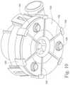
- FIG. 10is an underneath view of the fan
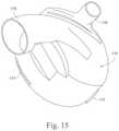
- FIG. 12shows the humidifier in partly disassembled state
- FIG. 28is a perspective view from the front and above, of a lid of the humidifier of FIG. 22 ;
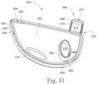
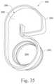
- FIG. 31is a perspective view from the front and above, of a lid seal of the humidifier of FIG. 22 ;
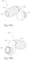
- FIG. 46is a perspective view from the front and above of the seal of FIG. 45 ;
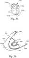
- FIG. 56is an underside perspective of the humidifier lid of FIG. 54 ;
- FIG. 58Bis a longitudinal cross section of the humidifier tub lid of FIG. 54 .
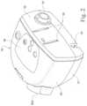
- the illustrated apparatuscomprises a flow generator 50 and a humidifier 150 , shown in their assembled condition in FIG. 1 .
- the flow generatorengages with the separable humidifier at an engagement face 52 , from which protrudes an air connector 53 for the delivery of air from the fan to the humidifier container, and electrical connectors 54 for the delivery of power to the humidifier heater described below.
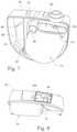
- the fan 90therefore floats within its cavity 70 in the chassis 64 with minimum acoustic coupling to the remainder of the flow generator.
- the characteristics of the mounting springs and the coupling memberare chosen to minimise the transmission of characteristic vibration frequencies of the fan.
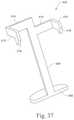
- the first cradle component 202includes a horizontally extending portion 206 and a vertically extending portion 208 .
- the horizontally extending portion 206has an outer wall 210 and a floor 212 , the outer wall and floor defining a recess 214 .
- An aperture 216is provided in the front extremity of the outer wall 210 .
- an opening 242is defined between the lowermost edge of the vertically extending portion 208 and the floor 212 .
- the horizontally extending portion 244includes an outer wall 248 and a floor 250 .
- the floor 250defines a circular opening for retaining a circular heater pad (not shown), generally similar to the circular metal pad 163 shown in FIG. 12 .
- a hole 254passing through the floor. Beneath the floor 250 , there is provided an extension tube 255 , the passage of which forms a continuation of the hole 254 .
- the vertically extending portion 246 of the second cradle component 204has a circular aperture 260 with a rearwardly extending spigot 261 , as well as a pair of narrow vertical slots 262 , opening through it.
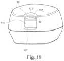
- a pipe 336Extending at an acute angle to the horizontal, from the upper surface of the upper wall 320 , is a pipe 336 . This is for attachment of a hose to supply humidified air to a patient.
- the pipe 336passes through the upper wall 320 , with the lower end of the pipe projecting beyond the lower surface of the upper wall, to terminate at a rim 338 .
- the passage 340 of the pipe 336opens into the internal region 334 .
- the lower surface of the centre wall 352 of the lid seal 350is concave as shown in FIG. 32 , to define a rear, forwardly projecting face 387 .
- the lid seal 350may be provided with a downwardly extending, and inwardly curved, sealing flange 388 as shown in FIG. 38 .
- the lid catch 392is mounted on the brackets 256 at the front of the horizontally extending portion 244 of the second cradle component 204 . This is achieved by the axles 394 being accommodated in the slots 258 .
- the centre portion 400 of the lid catch 392is slid into place in the aperture 216 at the front of the horizontally extending portion 206 of the first cradle component 202 .
- the aperture 216is shaped complementarily to the centre portion 400 , so that the centre portion is surrounded by that part of the horizontally extending portion 206 which defines the aperture 216 .
- the catch formation 396then projects above the upper edge of the outer wall 210 of the horizontally extending portion 206 .
- the chamfers 416allow the catch formations 410 and 412 , and hence the catch 404 as a whole, to ride over the relevant formation on the flow generator so as to move upwards against the urging of the biasing means, so that the catch formations can snap-engage with the flow generator.
- the actuation portion 406can be depressed from a position below the humidifier, in an upward direction, to release the catch formations 410 and 412 .
- the humidifier of FIGS. 22-38is configured to reduce the risk of water backflow into the flow generator, for example by the relative positioning of the opening 376 and the aperture 226 and the height differential between the aperture 226 and the air outlet of the flow generator.
- first and second cradle components 202 and 204are adapted to allow fitting together in a vertical orientation, to minimise the need for reorientation during assembly of the humidifier unit on the production line.
- the resilience of the connection between the lid and the water receptacle, provided by the lid sealis adapted to maintain downwards pressure on the water receptacle when the lid is closed, to maintain good heat-transfer contact between the base of the water receptacle and the heater pad without the added complexity and expense of spring-loaded mounting of the heater pad.
- the sealing member 676at the bottom of each of the first and second portions 678 and 680 , has a sealing flange 694 and 696 , respectively.
- the sealing flange 694(which is similar to the sealing flange 696 ) is shown schematically in cross-section in FIG. 46A .
- the configuration of the air connector component 722is such that the flexible hose 724 and second tube 728 are arranged in a dog-leg configuration so as not to be in alignment with each other.
- the bottom case 1061 of flow generator 1050has a shell 1120 of rigid plastics material, such polycarbonate/ABS blend, forming the structure of the case, integrally overmoulded with a lining 1121 of an elastomer such as a synthetic rubber which forms the seal 1063 between the top and bottom cases and the chassis 1064 and forms the external feet of the case (not shown).
- the lining 1121also covers the internal surface of the chassis-receiving cavity 1122 of the bottom case and the dividing wall 1123 between the power supply cavity 1065 and chassis-receiving cavity, to reduce radiated noise levels from the flow generator by damping acoustic resonance of the walls.
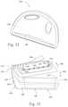
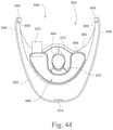
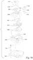
- FIGS. 54 to 58Billustrate a modified version of the humidifier arrangement of FIGS. 39 to 49B , adapted to mate with the flow generator unit of FIGS. 50-53 .
- the general arrangement of the humidifier componentsis similar to that of FIGS. 39 to 49B , including a front cover 1602 onto which is fitted a heater pad 1799 comprising and an upper part 1806 and a heater pad cover 1632 which supports a water tub (tub base 1698 , seal 1699 and tub lid 1700 ) and a hinged humidifier lid 1648 which seals against the tub lid 1700 to form an air path into the tub through the tub lid.
- the floor of the tub base 1698is of complementary shape to the heater pad 1799 .
- the floorhas a generally horizontal portion 1900 corresponding to the upper surface 1634 of the heater pad cover 1632 and a U-shaped portion below the level of the upper surface 1634 , including a generally vertical heat transfer portion 1902 below the horizontal portion 1900 corresponding to the downwardly extending peripheral wall 1636 of the heater pad cover 1632 .
- the humidifier of FIG. 54differs substantially from that of FIGS. 39-49B by a modified sealing arrangement for the air path from the flow generator outlet into the humidifier tub, without the flexible connector component 722 of FIGS. 49A and 49B .
- the humidifier front cover 1602 and tub lid 1700 of FIG. 54are similar in many respects, including their attachment, to their correspondingly numbered components 602 , 700 described and shown with reference to FIGS. 39, 40 and 49 .
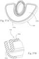
- the aperture 1626 of the modified front coveris enlarged, and receives an elastomer seal 1722 ( FIG. 55 ) having an inlet connector portion 1722 a (which connects to the flow generator outlet by way of the air port 1807 formed in the back cover 1803 ) and a peripheral seal portion 1722 b which extends about the aperture 1626 periphery at the front face of the cover 1602 .
- a wall portion 1722 c of the sealcloses off a lower part of the aperture 1626 , leaving a smaller aperture 1722 d defined by the seal.
Landscapes
- Health & Medical Sciences (AREA)
- Engineering & Computer Science (AREA)
- Life Sciences & Earth Sciences (AREA)
- Animal Behavior & Ethology (AREA)
- Heart & Thoracic Surgery (AREA)
- Biomedical Technology (AREA)
- General Health & Medical Sciences (AREA)
- Public Health (AREA)
- Veterinary Medicine (AREA)
- Emergency Medicine (AREA)
- Hematology (AREA)
- Anesthesiology (AREA)
- Pulmonology (AREA)
- General Engineering & Computer Science (AREA)
- Mechanical Engineering (AREA)
- Physics & Mathematics (AREA)
- Chemical Kinetics & Catalysis (AREA)
- Chemical & Material Sciences (AREA)
- Surgery (AREA)
- Medical Informatics (AREA)
- Molecular Biology (AREA)
- Biophysics (AREA)
- Pathology (AREA)
- Cardiology (AREA)
- Optics & Photonics (AREA)
- Spectroscopy & Molecular Physics (AREA)
- Signal Processing (AREA)
- Physiology (AREA)
- Air Humidification (AREA)
- Structures Of Non-Positive Displacement Pumps (AREA)
- Compressor (AREA)
- Respiratory Apparatuses And Protective Means (AREA)
- Percussion Or Vibration Massage (AREA)
- Motor Or Generator Frames (AREA)
- Measurement Of The Respiration, Hearing Ability, Form, And Blood Characteristics Of Living Organisms (AREA)
- Treatment Of Fiber Materials (AREA)
Abstract
Description
Claims (23)
Priority Applications (1)
| Application Number | Priority Date | Filing Date | Title |
|---|---|---|---|
| US17/318,393US11235115B2 (en) | 2003-06-20 | 2021-05-12 | Breathable gas apparatus with humidifier |
Applications Claiming Priority (13)
| Application Number | Priority Date | Filing Date | Title |
|---|---|---|---|
| AU2003903139 | 2003-06-20 | ||
| AU2003903139AAU2003903139A0 (en) | 2003-06-20 | 2003-06-20 | Breathable gas apparatus with humidifier |
| AU2003905136 | 2003-09-22 | ||
| AU2003905136AAU2003905136A0 (en) | 2003-09-22 | Breathable Gas Apparatus with Humidifier | |
| AU2004901008AAU2004901008A0 (en) | 2004-02-27 | Breathable Gas Apparatus with Humidifier | |
| AU2004901008 | 2004-02-27 | ||
| PCT/AU2004/000810WO2004112873A1 (en) | 2003-06-20 | 2004-06-21 | Breathable gas apparatus with humidifier |
| US12/659,963US10293125B2 (en) | 2003-06-20 | 2010-03-26 | Flow generator with patient reminder |
| US14/445,190US9227035B2 (en) | 2003-06-20 | 2014-07-29 | Breathable gas apparatus with humidifier |
| US14/987,275US9539409B2 (en) | 2003-06-20 | 2016-01-04 | Breathable gas apparatus with humidifier |
| US15/364,874US10881820B2 (en) | 2003-06-20 | 2016-11-30 | Breathable gas apparatus with humidifier |
| US202017102756A | 2020-11-24 | 2020-11-24 | |
| US17/318,393US11235115B2 (en) | 2003-06-20 | 2021-05-12 | Breathable gas apparatus with humidifier |
Related Parent Applications (1)
| Application Number | Title | Priority Date | Filing Date |
|---|---|---|---|
| US202017102756AContinuation | 2003-06-20 | 2020-11-24 |
Publications (2)
| Publication Number | Publication Date |
|---|---|
| US20210260316A1 US20210260316A1 (en) | 2021-08-26 |
| US11235115B2true US11235115B2 (en) | 2022-02-01 |
Family
ID=42357983
Family Applications (18)
| Application Number | Title | Priority Date | Filing Date |
|---|---|---|---|
| US12/900,008Expired - LifetimeUS8020551B2 (en) | 2003-06-20 | 2010-10-07 | Breathable gas apparatus with humidifier |
| US12/900,781Expired - Fee RelatedUS8028693B2 (en) | 2003-06-20 | 2010-10-08 | Breathable gas apparatus with humidifier |
| US13/080,300CeasedUS8042535B2 (en) | 2003-06-20 | 2011-04-05 | Breathable gas apparatus with humidifier |
| US14/445,143Expired - LifetimeUS9038631B2 (en) | 2003-06-20 | 2014-07-29 | Breathable gas apparatus with humidifier |
| US14/445,152Expired - LifetimeUS9038632B2 (en) | 2003-06-20 | 2014-07-29 | Breathable gas apparatus with humidifier |
| US14/445,190Expired - Fee RelatedUS9227035B2 (en) | 2003-06-20 | 2014-07-29 | Breathable gas apparatus with humidifier |
| US14/501,253Expired - LifetimeUS9072860B2 (en) | 2003-06-20 | 2014-09-30 | Breathable gas apparatus with humidifier |
| US14/790,693Expired - Fee RelatedUS9358359B2 (en) | 2003-06-20 | 2015-07-02 | Breathable gas apparatus with humidifier |
| US14/987,275Expired - Fee RelatedUS9539409B2 (en) | 2003-06-20 | 2016-01-04 | Breathable gas apparatus with humidifier |
| US15/054,820Expired - Fee RelatedUS9610420B2 (en) | 2003-06-20 | 2016-02-26 | Breathable gas apparatus with humidifier |
| US15/079,098Expired - Fee RelatedUSRE46543E1 (en) | 2003-06-20 | 2016-03-24 | Breathable gas apparatus with humidifier |
| US15/364,874Active2027-05-18US10881820B2 (en) | 2003-06-20 | 2016-11-30 | Breathable gas apparatus with humidifier |
| US15/454,534Active2028-04-04US11260187B2 (en) | 2003-06-20 | 2017-03-09 | Breathable gas supply apparatus |
| US15/869,491Expired - LifetimeUS10201676B2 (en) | 2003-06-20 | 2018-01-12 | Breathable gas supply apparatus |
| US16/893,663Expired - Fee RelatedUS10850053B2 (en) | 2003-06-20 | 2020-06-05 | Breathable gas supply apparatus |
| US17/318,393Expired - LifetimeUS11235115B2 (en) | 2003-06-20 | 2021-05-12 | Breathable gas apparatus with humidifier |
| US17/554,124Expired - LifetimeUS11413412B2 (en) | 2003-06-20 | 2021-12-17 | Breathable gas supply apparatus |
| US17/852,962AbandonedUS20230007968A1 (en) | 2003-06-20 | 2022-06-29 | Device, system, and/or method for treating and monitoring a patient |
Family Applications Before (15)
| Application Number | Title | Priority Date | Filing Date |
|---|---|---|---|
| US12/900,008Expired - LifetimeUS8020551B2 (en) | 2003-06-20 | 2010-10-07 | Breathable gas apparatus with humidifier |
| US12/900,781Expired - Fee RelatedUS8028693B2 (en) | 2003-06-20 | 2010-10-08 | Breathable gas apparatus with humidifier |
| US13/080,300CeasedUS8042535B2 (en) | 2003-06-20 | 2011-04-05 | Breathable gas apparatus with humidifier |
| US14/445,143Expired - LifetimeUS9038631B2 (en) | 2003-06-20 | 2014-07-29 | Breathable gas apparatus with humidifier |
| US14/445,152Expired - LifetimeUS9038632B2 (en) | 2003-06-20 | 2014-07-29 | Breathable gas apparatus with humidifier |
| US14/445,190Expired - Fee RelatedUS9227035B2 (en) | 2003-06-20 | 2014-07-29 | Breathable gas apparatus with humidifier |
| US14/501,253Expired - LifetimeUS9072860B2 (en) | 2003-06-20 | 2014-09-30 | Breathable gas apparatus with humidifier |
| US14/790,693Expired - Fee RelatedUS9358359B2 (en) | 2003-06-20 | 2015-07-02 | Breathable gas apparatus with humidifier |
| US14/987,275Expired - Fee RelatedUS9539409B2 (en) | 2003-06-20 | 2016-01-04 | Breathable gas apparatus with humidifier |
| US15/054,820Expired - Fee RelatedUS9610420B2 (en) | 2003-06-20 | 2016-02-26 | Breathable gas apparatus with humidifier |
| US15/079,098Expired - Fee RelatedUSRE46543E1 (en) | 2003-06-20 | 2016-03-24 | Breathable gas apparatus with humidifier |
| US15/364,874Active2027-05-18US10881820B2 (en) | 2003-06-20 | 2016-11-30 | Breathable gas apparatus with humidifier |
| US15/454,534Active2028-04-04US11260187B2 (en) | 2003-06-20 | 2017-03-09 | Breathable gas supply apparatus |
| US15/869,491Expired - LifetimeUS10201676B2 (en) | 2003-06-20 | 2018-01-12 | Breathable gas supply apparatus |
| US16/893,663Expired - Fee RelatedUS10850053B2 (en) | 2003-06-20 | 2020-06-05 | Breathable gas supply apparatus |
Family Applications After (2)
| Application Number | Title | Priority Date | Filing Date |
|---|---|---|---|
| US17/554,124Expired - LifetimeUS11413412B2 (en) | 2003-06-20 | 2021-12-17 | Breathable gas supply apparatus |
| US17/852,962AbandonedUS20230007968A1 (en) | 2003-06-20 | 2022-06-29 | Device, system, and/or method for treating and monitoring a patient |
Country Status (9)
| Country | Link |
|---|---|
| US (18) | US8020551B2 (en) |
| EP (3) | EP2392375B1 (en) |
| JP (17) | JP4865545B2 (en) |
| CN (6) | CN103816592B (en) |
| AT (1) | ATE517649T1 (en) |
| CA (5) | CA3045674C (en) |
| DE (6) | DE202004021777U1 (en) |
| ES (1) | ES2559015T3 (en) |
| NZ (8) | NZ728764A (en) |
Cited By (2)
| Publication number | Priority date | Publication date | Assignee | Title |
|---|---|---|---|---|
| US11426554B2 (en) | 2006-11-06 | 2022-08-30 | Fisher & Paykel Healthcare Limited | Humidifier system |
| US12268818B2 (en) | 2006-11-06 | 2025-04-08 | Fisher & Paykel Healthcare Limited | Integrated humidifier chamber and lid |
Families Citing this family (203)
| Publication number | Priority date | Publication date | Assignee | Title |
|---|---|---|---|---|
| EP2308539B1 (en) | 1999-08-05 | 2016-04-20 | ResMed R&D Germany GmbH | Device for supplying respiratory gas, humidifying device, respiratory gas tube, and connecting device therefor |
| US7588033B2 (en) | 2003-06-18 | 2009-09-15 | Breathe Technologies, Inc. | Methods, systems and devices for improving ventilation in a lung area |
| AU2003903139A0 (en) | 2003-06-20 | 2003-07-03 | Resmed Limited | Breathable gas apparatus with humidifier |
| JP4865545B2 (en) | 2003-06-20 | 2012-02-01 | レスメド・リミテッド | Breathable gas supply device with humidifier |
| CN1905917B (en) | 2003-08-18 | 2011-08-03 | 门罗生命公司 | Method and device for non-invasive ventilation with nasal interface |
| USD544598S1 (en) | 2004-06-18 | 2007-06-12 | Resmed Limited | Air delivery device |
| EP4049703B1 (en) | 2004-08-20 | 2023-09-27 | Fisher & Paykel Healthcare Limited | Apparatus for measuring properties of gases supplied to a patient |
| DE102005033650B4 (en)* | 2005-07-19 | 2017-06-14 | Resmed R&D Germany Gmbh | Respiratory mask device and method of making the same |
| DE102006034028B4 (en) | 2005-08-01 | 2025-07-10 | Löwenstein Medical Technology S.A. | Ventilation device |
| USD550349S1 (en)* | 2005-08-15 | 2007-09-04 | Resmed Limited | Flow generator |
| CN102133447B (en)* | 2005-08-15 | 2015-01-07 | 瑞思迈有限公司 | Humidifier and/or flow generator for CPAP device |
| JP2009508645A (en) | 2005-09-20 | 2009-03-05 | ルッツ フレイテッグ, | System, method and apparatus for assisting patient breathing |
| US8997740B2 (en)* | 2005-09-27 | 2015-04-07 | Ric Investments, Llc | Humidifier with back-flow prevention valve |
| US7913689B2 (en)* | 2005-12-21 | 2011-03-29 | Resmed Limited | Identification system and method for mask and ventilator components |
| US20090199857A1 (en)* | 2006-03-01 | 2009-08-13 | Resmed Limited | Method and Apparatus for Reminding user to Replace and/or Service Cpap Apparatus and/or Component Thereof |
| JP5191005B2 (en) | 2006-05-18 | 2013-04-24 | ブリーズ テクノロジーズ, インコーポレイテッド | Method and device for tracheostomy |
| EP2068992B1 (en) | 2006-08-03 | 2016-10-05 | Breathe Technologies, Inc. | Devices for minimally invasive respiratory support |
| WO2008144589A1 (en) | 2007-05-18 | 2008-11-27 | Breathe Technologies, Inc. | Methods and devices for sensing respiration and providing ventilation therapy |
| CN101690385B (en) | 2007-06-05 | 2015-05-27 | 瑞思迈有限公司 | Electric heater, in particular for humidification and liquid heating |
| US8365726B2 (en) | 2007-06-07 | 2013-02-05 | Resmed Limited | Tub for humidifier |
| EP3871722A1 (en) | 2007-07-18 | 2021-09-01 | Vapotherm, Inc. | System for delivering a heated and humidified gas |
| EP2203206A4 (en) | 2007-09-26 | 2017-12-06 | Breathe Technologies, Inc. | Methods and devices for treating sleep apnea |
| EP2200686A4 (en) | 2007-09-26 | 2017-11-01 | Breathe Technologies, Inc. | Methods and devices for providing inspiratory and expiratory flow relief during ventilation therapy |
| US8905023B2 (en) | 2007-10-05 | 2014-12-09 | Vapotherm, Inc. | Hyperthermic humidification system |
| US8776793B2 (en) | 2008-04-18 | 2014-07-15 | Breathe Technologies, Inc. | Methods and devices for sensing respiration and controlling ventilator functions |
| WO2009129506A1 (en) | 2008-04-18 | 2009-10-22 | Breathe Technologies, Inc. | Methods and devices for sensing respiration and controlling ventilator functions |
| DE102008022663B4 (en) | 2008-05-07 | 2012-10-31 | Schauenburg Hose Technology Gmbh | Stretch hose |
| US9505164B2 (en) | 2009-12-30 | 2016-11-29 | Schauenburg Technology Se | Tapered helically reinforced hose and its manufacture |
| USD659235S1 (en)* | 2008-06-19 | 2012-05-08 | Resmed Limited | Positive airway pressure delivery device |
| CN102196837B (en) | 2008-08-22 | 2015-09-09 | 呼吸科技公司 | Methods and devices for providing mechanical ventilation utilizing an open airway interface |
| EP2337604B1 (en) | 2008-09-17 | 2018-01-24 | ResMed Limited | Humidification of respiratory gases |
| US10252020B2 (en) | 2008-10-01 | 2019-04-09 | Breathe Technologies, Inc. | Ventilator with biofeedback monitoring and control for improving patient activity and health |
| US9964238B2 (en) | 2009-01-15 | 2018-05-08 | Globalmed, Inc. | Stretch hose and hose production method |
| US9132250B2 (en) | 2009-09-03 | 2015-09-15 | Breathe Technologies, Inc. | Methods, systems and devices for non-invasive ventilation including a non-sealing ventilation interface with an entrainment port and/or pressure feature |
| CN111420208B (en) | 2009-04-02 | 2023-07-04 | 呼吸科技公司 | Methods, systems and devices for non-invasive open ventilation using a gas delivery nozzle within an outer tube |
| US9962512B2 (en) | 2009-04-02 | 2018-05-08 | Breathe Technologies, Inc. | Methods, systems and devices for non-invasive ventilation including a non-sealing ventilation interface with a free space nozzle feature |
| WO2011029074A1 (en) | 2009-09-03 | 2011-03-10 | Breathe Technologies, Inc. | Methods, systems and devices for non-invasive ventilation including a non-sealing ventilation interface with an entrainment port and/or pressure feature |
| US9737682B2 (en)* | 2009-09-17 | 2017-08-22 | Resmed Limited | Humidification of respiratory gases |
| USD671206S1 (en)* | 2009-12-04 | 2012-11-20 | Vapotherm, Inc. | Respiratory therapy system |
| CA2807416C (en) | 2010-08-16 | 2019-02-19 | Breathe Technologies, Inc. | Methods, systems and devices using lox to provide ventilatory support |
| CA2811423C (en) | 2010-09-30 | 2019-03-12 | Breathe Technologies, Inc. | Methods, systems and devices for humidifying a respiratory tract |
| WO2012113027A1 (en)* | 2011-02-25 | 2012-08-30 | Resmed Motor Technologies Inc. | Blower and pap system |
| US9849258B2 (en) | 2011-04-05 | 2017-12-26 | Resmed Limited | Respiratory breathing apparatus |
| US9616194B2 (en) | 2011-06-22 | 2017-04-11 | Breathe Technologies, Inc. | Ventilation mask with integrated piloted exhalation valve and method of ventilating a patient using the same |
| US8844533B2 (en) | 2011-06-22 | 2014-09-30 | Breathe Technologies, Inc. | Ventilation mask with integrated piloted exhalation valve |
| US9038634B2 (en) | 2011-06-22 | 2015-05-26 | Breathe Technologies, Inc. | Ventilation mask with integrated piloted exhalation valve |
| US10137264B2 (en) | 2011-07-13 | 2018-11-27 | Fisher & Paykel Healthcare Limited | Respiratory assistance apparatus |
| EP4169560B1 (en) | 2011-07-13 | 2025-09-17 | Fisher & Paykel Healthcare Limited | Bearing mount for a compressor or blower for providing respiratory assistance |
| NZ711507A (en)* | 2011-08-05 | 2017-03-31 | Resmed Motor Technologies Inc | Blower |
| ES2935418T3 (en) | 2011-08-10 | 2023-03-06 | Fisher & Paykel Healthcare Ltd | Conduit connector for a patient breathing device |
| US9649459B2 (en) | 2011-09-26 | 2017-05-16 | Resmed Paris Sas | Ventilator apparatus and method |
| US10213573B2 (en) | 2011-12-22 | 2019-02-26 | Resmed Limited | Humidifiers for respiratory apparatus |
| JP6170947B2 (en)* | 2012-02-02 | 2017-07-26 | アイアセット アーゲー | Soundproof enclosure for ventilators |
| GB2500012B (en)* | 2012-03-06 | 2016-07-06 | Dyson Technology Ltd | A Humidifying Apparatus |
| GB2500017B (en) | 2012-03-06 | 2015-07-29 | Dyson Technology Ltd | A Humidifying Apparatus |
| GB2512192B (en)* | 2012-03-06 | 2015-08-05 | Dyson Technology Ltd | A Humidifying Apparatus |
| EP3738638A1 (en)* | 2012-03-15 | 2020-11-18 | Fisher & Paykel Healthcare Limited | Respiratory gas humidification system |
| EP2825236B1 (en)* | 2012-03-15 | 2019-12-25 | ResMed Pty Ltd | Heating apparatus |
| EP2830694B1 (en)* | 2012-03-30 | 2021-12-08 | Fisher & Paykel Healthcare Limited | Humidification apparatus |
| US20130284176A1 (en)* | 2012-04-03 | 2013-10-31 | Benjamin D. Dickerson | Force gauged continuous positive airway pressure nasal interface |
| EP3915620B8 (en)* | 2012-04-05 | 2024-03-13 | Fisher & Paykel Healthcare Limited | Respiratory assistance apparatus |
| GB2575894A (en) | 2012-04-27 | 2020-01-29 | Fisher & Paykel Healthcare Ltd | Usability features for respiratory humidification system |
| EP3744377B1 (en)* | 2012-05-02 | 2025-09-17 | Fisher & Paykel Healthcare Limited | Respiratory humidifier communication systems |
| EP2850324A2 (en)* | 2012-05-16 | 2015-03-25 | Dyson Technology Limited | A fan |
| GB2518935B (en)* | 2012-05-16 | 2016-01-27 | Dyson Technology Ltd | A fan |
| US10398861B2 (en) | 2012-05-23 | 2019-09-03 | Fisher & Paykel Healthcare Limited | Flow path fault detection method for a respiratory assistance apparatus |
| EP2703034B1 (en)* | 2012-08-28 | 2017-05-17 | Löwenstein Medical Technology S.A. | Device for the humidification of respiratory gas |
| SG10201701548TA (en)* | 2012-09-07 | 2017-03-30 | Fisher & Paykel Healthcare Ltd | Humidification chamber for a respiratory assistance apparatus |
| CA2885362C (en) | 2012-09-25 | 2022-12-06 | Fisher & Paykel Healthcare Limited | Lid construction for breathing apparatus |
| WO2014085431A1 (en)* | 2012-11-27 | 2014-06-05 | William Marsh Rice University | Bubble continuous positive airway pressure |
| EP2742906B8 (en) | 2012-12-17 | 2016-08-24 | Ivoclar Vivadent AG | Method and system for creating a dental prosthesis |
| CN205515844U (en) | 2012-12-18 | 2016-08-31 | 费雪派克医疗保健有限公司 | Breathe auxiliary device and be used for assembly of motor |
| USD745137S1 (en)* | 2012-12-20 | 2015-12-08 | Koninklijke Philips N.V. | Nebulizer compressor |
| SG11201505665RA (en) | 2013-01-29 | 2015-08-28 | Dyson Technology Ltd | A fan assembly |
| EP2950866B1 (en) | 2013-01-30 | 2021-06-02 | Fisher & Paykel Healthcare Limited | Respiratory assistance apparatus and method of disinfecting at least part of a respiratory assistance apparatus |
| US9878121B2 (en) | 2013-03-13 | 2018-01-30 | Breathe Technologies, Inc. | Ventilation mask with heat and moisture exchange device |
| EP3909633B1 (en)* | 2013-03-14 | 2023-11-22 | Fisher & Paykel Healthcare Limited | Humidification chamber with a mixing element comprising microstructures |
| US20140261419A1 (en)* | 2013-03-15 | 2014-09-18 | Apex Medical Corp. | Water chamber for a respiratory therapy apparatus and a partition of the water chamber |
| US9861778B2 (en) | 2013-03-15 | 2018-01-09 | Resmed Limited | Humidifier reservoir |
| WO2014145812A1 (en)* | 2013-03-15 | 2014-09-18 | Human Design Medical, Llc | Portable positive airway pressure apparatus and method for attenuating the noise emitted therefrom |
| CN115337517A (en)* | 2013-03-15 | 2022-11-15 | 瑞思迈私人有限公司 | Humidifier reservoir |
| JP6189073B2 (en)* | 2013-04-10 | 2017-08-30 | アトムメディカル株式会社 | Respiratory gas heating humidifier |
| USD738488S1 (en)* | 2013-05-31 | 2015-09-08 | Resmed Limited | Positive airway pressure delivery console |
| USD738489S1 (en)* | 2013-05-31 | 2015-09-08 | Resmed Limited | Positive airway pressure delivery console |
| USD710493S1 (en)* | 2013-06-05 | 2014-08-05 | Tecmen Electronics Co., Ltd. | Respirator |
| WO2014205513A1 (en) | 2013-06-25 | 2014-12-31 | Resmed Limited | Outlet connection assembly and method of making the same |
| USD730518S1 (en) | 2013-09-12 | 2015-05-26 | Nordson Corporation | Quick connect fluid connector |
| GB2584026B (en) | 2013-09-13 | 2021-03-17 | Fisher & Paykel Healthcare Ltd | A heater base for supplying humidified gases to a patient |
| JP6663850B2 (en)* | 2013-09-13 | 2020-03-13 | フィッシャー アンド ペイケル ヘルスケア リミテッド | Humidification system connection |
| USD725768S1 (en)* | 2013-11-14 | 2015-03-31 | Human Design Medical, Llc | Flow generator |
| USD749721S1 (en)* | 2013-11-25 | 2016-02-16 | Avent, Inc. | Base for enteral feeding device |
| USD710494S1 (en)* | 2013-12-16 | 2014-08-05 | Tecmen Electronics Co., Ltd. | Respirator |
| EP4166176B1 (en) | 2013-12-17 | 2025-08-06 | ResMed Pty Ltd | Apparatus for use in treating a respiratory disorder |
| CN106029147B (en)* | 2013-12-20 | 2020-01-21 | 费雪派克医疗保健有限公司 | Humidification system connection |
| NL1040590C2 (en)* | 2014-01-07 | 2015-07-08 | Alcmair Partners B V | PIPE SYSTEM FOR A BREATHING PATIENT DEVICE. |
| CN103800982B (en)* | 2014-01-08 | 2015-12-23 | 北京怡和嘉业医疗科技有限公司 | For humidifier and the respirator of respirator |
| CA2936923C (en)* | 2014-01-30 | 2022-07-26 | Fisher & Paykel Healthcare Limited | Breathing assistance apparatus with liquid containment |
| US10449319B2 (en) | 2014-02-07 | 2019-10-22 | Fisher & Paykel Healthcare Limited | Respiratory humidification system |
| USD744108S1 (en) | 2014-02-19 | 2015-11-24 | Resmed Limited | Humidifier reservoir for positive airway pressure delivery console |
| USD743556S1 (en) | 2014-02-19 | 2015-11-17 | Resmed Limited | Positive airway pressure delivery console |
| WO2015132682A1 (en)* | 2014-03-04 | 2015-09-11 | Koninklijke Philips N.V. | Blending gaz enriched pressure support system and method |
| TWM481735U (en)* | 2014-03-14 | 2014-07-11 | Lead Data Inc | Humidifier and breathing apparatus using the same |
| USD762843S1 (en) | 2014-03-18 | 2016-08-02 | Resmed Limited | Air delivery tube |
| CN110124174A (en) | 2014-05-13 | 2019-08-16 | 费雪派克医疗保健有限公司 | Availability aspect for breathing humidification system |
| US11433210B2 (en) | 2014-05-27 | 2022-09-06 | Fisher & Paykel Healthcare Limited | Gases mixing and measuring for a medical device |
| USD760258S1 (en) | 2014-05-30 | 2016-06-28 | Resmed Limited | Display screen with graphical user interface |
| CN106535971B (en) | 2014-06-03 | 2020-12-04 | 费雪派克医疗保健有限公司 | Flow mixers for respiratory therapy systems |
| US9316405B2 (en)* | 2014-07-10 | 2016-04-19 | Dana Electronics Co., Ltd. | Cyclone type humidifier and wet air purifier combination device using centrifugal force |
| CA3175751A1 (en)* | 2014-09-03 | 2016-03-10 | Fisher & Paykel Healthcare Limited | Deterministically controlled humidification system |
| USD809124S1 (en) | 2014-09-12 | 2018-01-30 | Resmed Limited | Pressurized air delivery console |
| WO2016080847A1 (en) | 2014-11-17 | 2016-05-26 | Fisher & Paykel Healthcare Limited | Humidification of respiratory gases |
| RU2674080C1 (en)* | 2014-12-18 | 2018-12-04 | Конинклейке Филипс Н.В. | System and method for disconnecting liquid chamber |
| US10596345B2 (en) | 2014-12-31 | 2020-03-24 | Vapotherm, Inc. | Systems and methods for humidity control |
| USD790683S1 (en) | 2015-03-11 | 2017-06-27 | Resmed Limited | Pressurized air delivery console |
| USD774180S1 (en) | 2015-03-12 | 2016-12-13 | Tecmen Electronics Co., Ltd. | Respirator |
| US10806877B2 (en)* | 2015-03-24 | 2020-10-20 | Micomme Medical Technology Development Co., Ltd. | Portable breathing machine |
| US11446462B2 (en) | 2015-03-31 | 2022-09-20 | Fisher & Paykel Healthcare Limited | Apparatus for use in a respiratory support system |
| EP4186548A1 (en) | 2015-04-02 | 2023-05-31 | Hill-Rom Services PTE. LTD. | Mask leakage detection for a respiratory device |
| CN104815373B (en)* | 2015-04-16 | 2017-10-20 | 北京怡和嘉业医疗科技股份有限公司 | Lung ventilator and its Poewr control method and system |
| NZ737589A (en) | 2015-06-24 | 2023-03-31 | Fisher & Paykel Healthcare Ltd | Breathing assistance apparatus |
| GB2540165B (en) | 2015-07-07 | 2019-09-11 | Dyson Technology Ltd | Humidifying apparatus |
| GB2540164A (en)* | 2015-07-07 | 2017-01-11 | Dyson Technology Ltd | Humidifying apparatus |
| GB2540166B (en) | 2015-07-07 | 2019-06-12 | Dyson Technology Ltd | Humidifying apparatus |
| NZ773777A (en) | 2015-07-07 | 2023-12-22 | ResMed Pty Ltd | Respiratory pressure therapy device |
| CN107923411B (en) | 2015-08-18 | 2021-04-23 | 株式会社村田制作所 | Air supply device |
| WO2017037660A1 (en) | 2015-09-04 | 2017-03-09 | Fisher & Paykel Healthcare Limited | Connectors for conduits |
| USD798428S1 (en) | 2015-10-07 | 2017-09-26 | Resmed Limited | Positive airway pressure delivery console |
| US10030961B2 (en) | 2015-11-27 | 2018-07-24 | General Electric Company | Gap measuring device |
| AU2016364628B2 (en) | 2015-12-02 | 2022-06-23 | Fisher & Paykel Healthcare Limited | Flow path sensing for flow therapy apparatus |
| USD844787S1 (en) | 2015-12-28 | 2019-04-02 | Resmed Limited | Pressurized air delivery console |
| USD805630S1 (en) | 2016-02-02 | 2017-12-19 | Resmed Limited | Air delivery tube |
| WO2017141263A1 (en)* | 2016-02-18 | 2017-08-24 | O2-Matic Products Private Limited | Modular portable oxygen generator |
| USD857189S1 (en) | 2016-03-11 | 2019-08-20 | ResMed Pty Ltd | Battery pack for an air delivery module |
| WO2017192051A1 (en) | 2016-05-02 | 2017-11-09 | Fisher & Paykel Healthcare Limited | Humidification chamber and chamber seal for a respiratory assistance apparatus |
| CN105823278A (en)* | 2016-05-25 | 2016-08-03 | 南京天加空调设备有限公司 | Cooling device of frequency conversion module of variable frequency air conditioner |
| USD809656S1 (en) | 2016-06-10 | 2018-02-06 | Fisher & Paykel Healthcare Limited | Connector for a breathing circuit |
| USD864480S1 (en)* | 2016-07-07 | 2019-10-22 | Calor | Water tank for hair straightening apparatus |
| JP2018078996A (en)* | 2016-11-15 | 2018-05-24 | 日本電産コパル電子株式会社 | Cpap apparatus |
| EP3551978B1 (en) | 2016-12-07 | 2022-01-26 | Fisher&Paykel Healthcare Limited | Sensing arrangements for medical devices |
| US11400247B2 (en) | 2016-12-22 | 2022-08-02 | Fisher & Paykel Healthcare Limited | Breathing assistance apparatus |
| US11052214B2 (en) | 2017-01-30 | 2021-07-06 | Globalmed, Inc. | Heated respiratory hose wiring |
| CN115154781B (en) | 2017-04-10 | 2024-12-24 | 株式会社村田制作所 | Air supply devices and fluid control devices |
| CN114288512B (en) | 2017-04-23 | 2024-12-13 | 费雪派克医疗保健有限公司 | Respiratory assistance equipment |
| CN110944701A (en) | 2017-05-26 | 2020-03-31 | 费雪派克医疗保健有限公司 | Powering a respiratory device |
| CN107226458B (en)* | 2017-07-24 | 2019-04-12 | 合肥康居人智能科技有限公司 | A kind of assemble mechanism for oxygenerator humidification |
| CN107572759A (en)* | 2017-09-25 | 2018-01-12 | 宝鸡市永盛泰钛业有限公司 | A kind of compensator or trimmer pressure mould for part processing |
| US10792449B2 (en) | 2017-10-03 | 2020-10-06 | Breathe Technologies, Inc. | Patient interface with integrated jet pump |
| EP3697484B1 (en) | 2017-10-18 | 2023-05-31 | Resmed Pty Ltd | Respiratory apparatus with multiple power supplies |
| CN107696366B (en)* | 2017-11-16 | 2024-03-08 | 宁波圣宇瑞医疗器械有限公司 | Nose immersion mould |
| CN109838399B (en)* | 2017-11-24 | 2024-11-19 | 追觅科技(苏州)有限公司 | A fan |
| CN109854542B (en)* | 2017-11-30 | 2024-11-19 | 深圳市美好创亿医疗科技股份有限公司 | Silencer tube and ventilator having the same |
| SG11202005385UA (en) | 2017-12-08 | 2020-07-29 | Fisher & Paykel Healthcare Ltd | Graphical user interface for a flow therapy apparatus |
| USD917039S1 (en)* | 2018-02-01 | 2021-04-20 | Resvent Medical Technology Co., Ltd | Positive airway pressure assembly |
| AU2019232610B2 (en)* | 2018-03-07 | 2021-12-16 | Astrazeneca Ab | Inhaler |
| US11338105B2 (en) | 2018-03-27 | 2022-05-24 | Globalmed, Inc. | Respiratory humidification device |
| CN208957952U (en)* | 2018-03-31 | 2019-06-11 | 天佑电器(苏州)有限公司 | Box combination tool |
| US11376392B2 (en)* | 2018-04-24 | 2022-07-05 | ResMed Pty Ltd | Tub for use in a humidifier |
| CN108815672B (en)* | 2018-05-02 | 2020-08-11 | 鹤壁市人民医院 | Medical silence oxygen humidifying bottle |
| CN108434577B (en)* | 2018-05-02 | 2020-08-11 | 周晓琪 | Medical low-noise oxygen humidification bottle |
| CN108688936B (en)* | 2018-05-29 | 2025-01-10 | 上海箱箱智能科技有限公司 | A vehicle |
| US11484682B2 (en)* | 2018-09-28 | 2022-11-01 | Koninklijke Philips N.V. | Humidifier with ingress protection for use in CPAP therapy |
| EP4623979A2 (en)* | 2018-10-26 | 2025-10-01 | BMC Medical Co., Ltd. | Humidification assembly |
| DE102018008493A1 (en)* | 2018-10-30 | 2020-04-30 | Drägerwerk AG & Co. KGaA | Transfer unit, ventilation device, ventilation system and method for changing a ventilation device used for a patient's ventilation process |
| CN109200414B (en)* | 2018-11-22 | 2024-02-09 | 广东欧格斯科技有限公司 | Noise-reduction breathing machine system |
| DE102018129612A1 (en)* | 2018-11-23 | 2020-05-28 | Ebm-Papst St. Georgen Gmbh & Co. Kg | Rotor assembly |
| US11712529B2 (en) | 2018-12-13 | 2023-08-01 | ResMed Pty Ltd | Pneumatic block for respiratory pressure therapy device |
| KR102308884B1 (en)* | 2018-12-13 | 2021-10-06 | 이해곤 | A fine dust blocking mask having air curtain |
| WO2020128829A1 (en) | 2018-12-18 | 2020-06-25 | ResMed Pty Ltd | Humidifier reservoir |
| USD921900S1 (en) | 2018-12-19 | 2021-06-08 | ResMed Pty Ltd | Humidification tub |
| GB201900018D0 (en) | 2019-01-02 | 2019-02-13 | Dyson Technology Ltd | Air treatment apparatus |
| GB201900016D0 (en) | 2019-01-02 | 2019-02-13 | Dyson Technology Ltd | Air treatment apparatus |
| GB201900020D0 (en) | 2019-01-02 | 2019-02-13 | Dyson Technology Ltd | Air treatment apparatus |
| EP3679839A1 (en)* | 2019-01-14 | 2020-07-15 | Koninklijke Philips N.V. | Steam cooking apparatus |
| US11745033B2 (en) | 2019-03-17 | 2023-09-05 | Brett Patrick | Process and apparatus to preclude unfiltered atmospheric gases and human respiration products including carbon-dioxide with carbon-14 from entering controlled greenhouse atmospheric gases |
| US20200306683A1 (en) | 2019-04-01 | 2020-10-01 | Inogen, Inc. | Compact portable oxygen concentrator |
| CN116637264A (en) | 2019-04-17 | 2023-08-25 | 瑞思迈私人有限公司 | CPAP system |
| WO2020251376A1 (en)* | 2019-06-14 | 2020-12-17 | Fisher & Paykel Healthcare Limited | An apparatus for delivering a gas stream |
| JP7275977B2 (en)* | 2019-08-08 | 2023-05-18 | 株式会社村田製作所 | CPAP device |
| USD1006981S1 (en) | 2019-09-06 | 2023-12-05 | Fisher & Paykel Healthcare Limited | Breathing conduit |
| USD948027S1 (en) | 2019-09-10 | 2022-04-05 | Fisher & Paykel Healthcare Limited | Connector for a breathing conduit |
| CN110584607A (en)* | 2019-09-17 | 2019-12-20 | 广州奥滴尔科技有限公司 | Work and rest adjusting and executing device and real-time work and rest adjusting system |
| TWI785276B (en)* | 2019-09-27 | 2022-12-01 | 雃博股份有限公司 | respiratory system |
| JP7363909B2 (en) | 2019-10-17 | 2023-10-18 | 株式会社村田製作所 | humidifier |
| JP6667708B1 (en)* | 2019-10-24 | 2020-03-18 | 日本たばこ産業株式会社 | Power supply unit for aerosol inhaler |
| CN112870518B (en)* | 2019-11-29 | 2022-09-06 | 深圳市大雅医疗技术有限公司 | Water tank assembly and breathing machine |
| US11988220B2 (en)* | 2019-12-17 | 2024-05-21 | Zhongshan Broad-Ocean Motor Co., Ltd. | Volute assembly and induced draft fan comprising the same |
| WO2021134372A1 (en)* | 2019-12-30 | 2021-07-08 | 深圳迈瑞生物医疗电子股份有限公司 | Anesthesia machine |
| JP7315036B2 (en)* | 2020-01-24 | 2023-07-26 | 株式会社村田製作所 | CPAP device |
| JP7302505B2 (en)* | 2020-02-27 | 2023-07-04 | 株式会社デンソー | blower |
| USD940861S1 (en) | 2020-03-03 | 2022-01-11 | Fisher & Paykel Healthcare Limited | Connector for a respiratory system conduit |
| US20230381444A1 (en)* | 2020-10-29 | 2023-11-30 | ResMed Pty Ltd | Assembly for diverting liquid from a respiratory device |
| JP7723089B2 (en)* | 2020-11-03 | 2025-08-13 | レスメド・プロプライエタリー・リミテッド | Respiratory Pressure Therapy Device |
| USD974551S1 (en) | 2020-12-09 | 2023-01-03 | Fisher & Paykel Healthcare Limited | Connector assembly and connector |
| CN112755347B (en)* | 2020-12-31 | 2024-04-05 | 东莞永昇医疗科技有限公司 | Breathing machine control method, breathing machine and computer readable storage medium |
| CN112843411B (en)* | 2021-01-12 | 2022-03-11 | 四川大学华西医院 | A non-invasive ventilator with automatic heating and humidification |
| USD1073919S1 (en) | 2021-05-17 | 2025-05-06 | Fisher & Paykel Healthcare Limited | Respiratory system conduit with connector |
| USD995758S1 (en) | 2021-06-11 | 2023-08-15 | Fisher & Paykel Healthcare Limited | Tube assembly and connector |
| CN115111198B (en)* | 2022-06-24 | 2024-05-07 | 大连海事大学 | A recessed structure of a multi-blade centrifugal fan and a multi-blade centrifugal fan |
| US20250228703A1 (en)* | 2024-01-12 | 2025-07-17 | Sharkninja Operating Llc | Face masks with noise attenuation |
| CN117691798B (en)* | 2024-02-01 | 2024-04-05 | 爱几度(深圳)科技有限公司 | Mute electric motor |
| CN118629144B (en)* | 2024-05-31 | 2025-03-21 | 北京青鸟环宇消防系统软件服务有限公司 | Aspirating smoke fire detector, fire protection system, air flow detection circuit and method |
| CN120576191A (en)* | 2025-08-01 | 2025-09-02 | 中南大学 | An inertial amplification quasi-zero stiffness vibration isolator |
| CN120608899B (en)* | 2025-08-11 | 2025-10-03 | 浙江强脑科技有限公司 | Fan system and breathing machine |
Citations (234)
| Publication number | Priority date | Publication date | Assignee | Title |
|---|---|---|---|---|
| DE275612C (en) | ||||
| US1974843A (en) | 1932-11-05 | 1934-09-25 | Scanlan Morris Company | Gas humidifying device |
| USRE19826E (en) | 1936-01-21 | aisenstein | ||
| US2220669A (en) | 1936-06-26 | 1940-11-05 | Allen Sherman Hoff Co | Impeller for centrifugal pumps |
| US2598978A (en) | 1950-05-29 | 1952-06-03 | Mary De Martin | Bed lamp with alarm clock |
| US2945619A (en) | 1954-09-21 | 1960-07-19 | Mclure Carl Ballard | Stage expansion reaction turbines |
| US3171353A (en) | 1962-02-27 | 1965-03-02 | Kenton D Mcmahan | Centrifugal fluid pump |
| US3316910A (en) | 1963-12-20 | 1967-05-02 | Thomas A Davis | Method and apparatus for dissolving renal calculi |
| US3584401A (en) | 1969-07-01 | 1971-06-15 | Burtek Inc | Educational display device and method |
| US3612710A (en) | 1970-04-30 | 1971-10-12 | Carrier Corp | Centrifugal refrigerant gas compressor |
| US3620638A (en) | 1970-08-24 | 1971-11-16 | J Arthur Kaye | Liquid propulsion device |
| US3690317A (en) | 1970-10-29 | 1972-09-12 | Bendix Corp | Sonic nebulizer |
| US3806102A (en) | 1972-06-20 | 1974-04-23 | Arirco Inc | Medical humidifier |
| US3864440A (en) | 1972-01-21 | 1975-02-04 | Respiratory Care | Humidifier and heater for delivered gas |
| US3954920A (en) | 1973-09-04 | 1976-05-04 | Parkland International Inc. | Gas humidification system |
| US4037994A (en) | 1975-03-31 | 1977-07-26 | Bird F M | Pressure unloading valve device for compressor |
| US4051205A (en) | 1972-09-13 | 1977-09-27 | Graham Cameron Grant | Apparatus for saturated gas delivery |
| US4060576A (en) | 1972-09-13 | 1977-11-29 | Graham Cameron Grant | Method and apparatus for vapor saturated gas delivery |
| US4098853A (en) | 1974-03-25 | 1978-07-04 | Chemetron Corporation | Humidifier and automatic control system therefor |
| US4105372A (en) | 1975-01-31 | 1978-08-08 | Hitachi, Ltd. | Fluid rotary machine |
| US4171190A (en) | 1976-11-08 | 1979-10-16 | Molded Products Company | Blower motor mounting assembly |
| US4222971A (en) | 1978-11-14 | 1980-09-16 | Eilert Richard L | Humidifier liner |
| US4229142A (en) | 1977-11-10 | 1980-10-21 | Le Materiel Telephonique | One-piece pumping device with ambivalent operation |
| US4237080A (en) | 1979-01-11 | 1980-12-02 | Skuttle Mfg. Co. | Humidifier assemblies |
| US4243396A (en) | 1979-04-16 | 1981-01-06 | Becton, Dickinson And Company | Humidifier separator |
| DE3005094A1 (en) | 1980-02-12 | 1981-08-20 | Klein, Schanzlin & Becker Ag, 6710 Frankenthal | CENTRIFUGAL PUMP WITH OPEN DIPPLE SPIRAL HOUSING |
| US4336798A (en) | 1980-10-06 | 1982-06-29 | Anthony V. Beran | Medical corrugated respiratory tube |
| US4351327A (en) | 1980-02-02 | 1982-09-28 | Dragerwerk Aktiengesellschaft | Device for connection to a respiratory gas line |
| JPS5836560A (en) | 1981-08-27 | 1983-03-03 | 日本ゼオン株式会社 | blood pump |
| US4523896A (en) | 1982-06-04 | 1985-06-18 | Creusot-Loire | Centrifugal compressor |
| US4532088A (en) | 1983-05-19 | 1985-07-30 | Inspiron Corporation | Heated respiratory therapy humidifier |
| US4576616A (en) | 1982-07-27 | 1986-03-18 | Proto-Med. Inc. | Method and apparatus for concentrating oxygen |
| JPS61179161A (en) | 1983-11-10 | 1986-08-11 | シチズン時計株式会社 | Humidifier for anesthetic device |
| US4621632A (en) | 1984-11-01 | 1986-11-11 | Bear Medical Systems, Inc. | Humidifier system |
| EP0201985A1 (en) | 1985-04-04 | 1986-11-20 | The BOC Group plc | Inhalation apparatus |
| US4629590A (en) | 1984-10-15 | 1986-12-16 | Cimco | Nebulizer |
| GB2177006A (en) | 1985-06-21 | 1987-01-14 | Kendall & Co | Feeding system |
| DE3623162A1 (en) | 1985-07-15 | 1987-01-22 | Carus Carl Gustav | Ventilator with universal valve combination for neonatology |
| US4644790A (en) | 1985-04-01 | 1987-02-24 | Sharp Kabushiki Kaisha | Liquid level indicator for humidifier |
| US4676237A (en) | 1985-01-29 | 1987-06-30 | Boutade Worldwide Investments Nv | Inhaler device |
| GB2192136A (en) | 1986-07-04 | 1988-01-06 | Virotherm Lab Ltd | Humidifiers for inhalers |
| DE3642637A1 (en) | 1986-12-13 | 1988-06-23 | Ruetgerswerke Ag | METHOD FOR PRODUCING COMPONENTS |
| US4753758A (en) | 1983-05-19 | 1988-06-28 | Intertech Resources Inc. | Respiratory humidifier |
| EP0274996A2 (en) | 1986-12-31 | 1988-07-20 | ELMED GINEVRI s.r.l. | Constant flow pressure-responsive pulmotor |
| US4767576A (en) | 1984-10-15 | 1988-08-30 | Cimco | Nebulizer with auxiliary gas input |
| US4789388A (en) | 1984-12-27 | 1988-12-06 | Teijin Limited | Oxygen enriching apparatus |
| US4799287A (en) | 1987-05-04 | 1989-01-24 | Belanger, Inc. | Blower housing construction |
| US4802819A (en) | 1987-09-14 | 1989-02-07 | Mcneil (Ohio) Corporation | Centrifugal pump |
| US4807616A (en) | 1987-07-09 | 1989-02-28 | Carmeli Adahan | Portable ventilator apparatus |
| US4823787A (en) | 1987-07-09 | 1989-04-25 | Carmeli Adahan | Portable ventilator apparatus |
| US4838258A (en) | 1987-10-26 | 1989-06-13 | Gibeck-Dryden Corporation | Gas sampling lumen for breathing system |
| JPH0219168A (en) | 1988-07-08 | 1990-01-23 | Atom Kk | humidifier |
| US4921642A (en) | 1987-12-03 | 1990-05-01 | Puritan-Bennett Corporation | Humidifier module for use in a gas humidification assembly |
| US4926856A (en) | 1985-06-21 | 1990-05-22 | Hudson Oxygen Therapy Sales Company | Feeding system |
| US4941469A (en) | 1987-11-12 | 1990-07-17 | Carmeli Adahan | Portable ventilator apparatus |
| US4943704A (en) | 1989-02-06 | 1990-07-24 | Ryder International Corporation | Humidifier apparatus |
| US4946348A (en) | 1989-02-14 | 1990-08-07 | Airflow Research & Manufacturing Corporation | Centrifugal fan with airfoil vanes in annular volute envelope |
| US4953546A (en) | 1985-07-16 | 1990-09-04 | Transpirator Technologies, Inc. | Method and apparatus for pulmonary and cariovascular conditioning of the young of large animals |
| US4973234A (en) | 1989-10-23 | 1990-11-27 | Davidson Textron Inc. | Shell mold mechanism |
| DE9014848U1 (en) | 1990-10-26 | 1991-02-07 | Carl Heyer GmbH, 5427 Bad Ems | Device on inhalation devices with a container holder for storing a liquid container |
| US5014338A (en) | 1988-12-21 | 1991-05-07 | Glucksman Dov Z | Portable air humidifier |
| CN2086150U (en) | 1990-10-12 | 1991-10-09 | 吴诗德 | Oxygen thermal insulation damp device |
| US5061405A (en) | 1990-02-12 | 1991-10-29 | Emerson Electric Co. | Constant humidity evaporative wicking filter humidifier |
| US5080093A (en) | 1987-07-08 | 1992-01-14 | Vortran Medical Technology, Inc. | Intermittant signal actuated nebulizer |
| US5086766A (en) | 1988-04-16 | 1992-02-11 | Virotherm Laboratories Ltd. | Medical breathing apparatus |
| JPH0469434A (en) | 1990-07-06 | 1992-03-04 | Fujitsu Ltd | gear system |
| US5127800A (en) | 1984-03-20 | 1992-07-07 | Baker Hughes Incorporated | Flow-stabilizing volute pump and liner |
| WO1993005451A1 (en) | 1991-09-03 | 1993-03-18 | Geno Svast | Reminder clock |
| JPH05104681A (en) | 1991-10-15 | 1993-04-27 | Bridgestone Corp | Vibration damping material |
| DE4244493A1 (en) | 1992-01-18 | 1993-07-22 | Eilentropp Hew Kabel | |
| US5237987A (en) | 1990-06-07 | 1993-08-24 | Infrasonics, Inc. | Human lung ventilator system |
| JPH05285220A (en) | 1992-04-13 | 1993-11-02 | Daikin Ind Ltd | humidifier |
| US5271391A (en) | 1991-12-20 | 1993-12-21 | Linda Graves | Apparatus for delivering a continuous positive airway pressure to an infant |
| JPH0626894A (en) | 1992-07-06 | 1994-02-04 | Fujitsu Ten Ltd | Abnormality judging device |
| EP0589429A1 (en) | 1992-09-23 | 1994-03-30 | FISHER & PAYKEL LIMITED | Humidifier with dual float valves |
| DE9317450U1 (en) | 1993-11-15 | 1994-06-09 | Metrax Gmbh, 78628 Rottweil | Ventilator |
| JPH06190928A (en) | 1992-12-25 | 1994-07-12 | Bridgestone Corp | Manufacture of laminate |
| US5329939A (en) | 1992-12-11 | 1994-07-19 | Cimco, Inc. | Humidifier with liquid level control |
| US5339825A (en) | 1991-04-18 | 1994-08-23 | Clement Clarke International Ltd. | Apparatus to measure and record peak air passage pressure |
| DE9409231U1 (en) | 1994-06-07 | 1994-11-03 | Madaus Schwarzer Medizintechnik GmbH & Co. KG, 81245 München | Respirator for sleep medicine |
| JPH073195A (en) | 1993-06-18 | 1995-01-06 | Ricoh Co Ltd | Inkjet recording ink |
| US5391063A (en) | 1994-04-25 | 1995-02-21 | General Motors Corporation | Magnet assembly for electric fuel pump |
| JPH07145795A (en) | 1993-11-22 | 1995-06-06 | Pacific Ind Co Ltd | Centrifugal blower with flow sensor and its drive device |
| WO1995015778A1 (en) | 1993-12-07 | 1995-06-15 | Technimeca International Inc. | Anti-gaslock filling device for a liquid receptacle |
| FR2714985A1 (en) | 1994-01-11 | 1995-07-13 | Lenfant Jean Pierre | Storage and recovery of personal secret code for transaction card |
| US5443061A (en) | 1991-03-21 | 1995-08-22 | Taema | Apparatus for providing a breathing gas with an overpressure and process of controlling such apparatus installation |
| US5483616A (en) | 1994-12-21 | 1996-01-09 | Duracraft Corporation | Humidifier tank with improved handle |
| GB2293325A (en) | 1994-09-20 | 1996-03-27 | Fisher & Paykel | Humidification chamber for respiratory gases |
| DE4138098C2 (en) | 1991-11-19 | 1996-07-04 | Devilbiss Medizinische Produkt | Device for providing warm humidified breathing gas |
| JPH08178781A (en) | 1994-12-27 | 1996-07-12 | Nagano Keiki Seisakusho Ltd | Gas residue meter |
| US5551419A (en) | 1994-12-15 | 1996-09-03 | Devilbiss Health Care, Inc. | Control for CPAP apparatus |
| US5558084A (en) | 1991-10-04 | 1996-09-24 | Fisher & Paykel Limited | Humidifier with delivery tube condensation preventing structure and control |
| US5564415A (en) | 1995-06-07 | 1996-10-15 | Lifecare International, Inc. | Humidifier for a ventilator |
| US5573713A (en) | 1995-06-06 | 1996-11-12 | Emerson Electric Co. | Humidifier having multi-stage fans |
| CN2239819Y (en) | 1995-10-12 | 1996-11-13 | 杨守诠 | Oxygen inhalator for hyperbaric oxygen chamber |
| US5577496A (en) | 1993-04-14 | 1996-11-26 | Mine Safety Appliances Company | Respiratory protective apparatus |
| US5598837A (en) | 1995-06-06 | 1997-02-04 | Respironics, Inc. | Passive humidifier for positive airway pressure devices |
| EP0760247A2 (en) | 1995-08-30 | 1997-03-05 | DeVilbiss Health Care, Inc. | Oxygen concentrator monitoring system |
| US5637687A (en) | 1993-08-31 | 1997-06-10 | Wiggins; James C. | Methods and compositions for isolating nucleic acids |
| US5651775A (en) | 1995-07-12 | 1997-07-29 | Walker; Richard Bradley | Medication delivery and monitoring system and methods |
| DE19515739C2 (en) | 1995-05-03 | 1997-09-11 | Holger Krohn | Method and device for generating health-friendly breathing air in nasal positive pressure respirators |
| WO1997032619A1 (en) | 1996-03-08 | 1997-09-12 | Medisize B.V. | Device and process for monitoring the respiration parameters of an artificial respiration system |
| US5682289A (en) | 1991-12-11 | 1997-10-28 | Hewlett-Packard Company | Chassis of a device |
| DE19630466A1 (en) | 1996-07-27 | 1998-02-05 | Nikolaus Netzer | Device for supplying gas for sleep apnea |
| JPH10122611A (en) | 1996-10-16 | 1998-05-15 | Tiger Vacuum Bottle Co Ltd | humidifier |
| EP0845277A2 (en) | 1996-12-02 | 1998-06-03 | FISHER & PAYKEL LIMITED | Humidifier sleep apnea treatment apparatus |
| WO1998031937A1 (en) | 1997-01-17 | 1998-07-23 | ABB Fläkt Oy | High-pressure fan |
| US5794219A (en) | 1996-02-20 | 1998-08-11 | Health Hero Network, Inc. | Method of conducting an on-line auction with bid pooling |
| WO1998041306A1 (en) | 1997-03-14 | 1998-09-24 | Minnesota Mining And Manufacturing Company | A filter element having a storage device for keeping track of filter usage and a system for use therewith |
| US5822715A (en) | 1997-01-10 | 1998-10-13 | Health Hero Network | Diabetes management system and method for controlling blood glucose |
| US5828943A (en) | 1994-04-26 | 1998-10-27 | Health Hero Network, Inc. | Modular microprocessor-based diagnostic measurement apparatus and method for psychological conditions |
| US5832448A (en) | 1996-10-16 | 1998-11-03 | Health Hero Network | Multiple patient monitoring system for proactive health management |
| US5844862A (en) | 1998-07-22 | 1998-12-01 | Cocatre-Zilgien; Jan H. | Skin temperature radio telemetry and alarms |
| US5848592A (en) | 1995-09-25 | 1998-12-15 | Sibley; Nels B. | Air filter |
| WO1998057691A1 (en) | 1997-06-18 | 1998-12-23 | Resmed Limited | An apparatus for supplying breathable gas |
| JPH11398A (en) | 1997-06-11 | 1999-01-06 | Fukuda Sangyo:Kk | Oxygen therapy oxygen concentrator |
| EP0893750A1 (en) | 1997-07-26 | 1999-01-27 | Bayerische Motoren Werke Aktiengesellschaft, Patentabteilung AJ-3 | Dispositif de commande multifonction |
| US5865171A (en) | 1996-03-26 | 1999-02-02 | System Assistance Medical | Nebulizer with pressure sensor |
| DE19752672C1 (en) | 1997-11-28 | 1999-03-04 | Buhler Motor Gmbh | Setting drive housing |
| US5879163A (en) | 1996-06-24 | 1999-03-09 | Health Hero Network, Inc. | On-line health education and feedback system using motivational driver profile coding and automated content fulfillment |
| CN1210020A (en) | 1997-06-17 | 1999-03-10 | 菲舍尔和佩克尔有限公司 | respiratory system humidifier |
| US5887133A (en) | 1997-01-15 | 1999-03-23 | Health Hero Network | System and method for modifying documents sent over a communications network |
| EP0903160A1 (en) | 1997-09-11 | 1999-03-24 | Siemens-Elema AB | Inspiratory tube |
| WO1999013932A1 (en) | 1997-09-19 | 1999-03-25 | Respironics, Inc. | Medical ventilator |
| US5888053A (en) | 1995-02-10 | 1999-03-30 | Ebara Corporation | Pump having first and second outer casing members |
| US5895595A (en) | 1996-05-23 | 1999-04-20 | D. H. Haden Plc | Apparatus for making beverages |
| US5897493A (en) | 1997-03-28 | 1999-04-27 | Health Hero Network, Inc. | Monitoring system for remotely querying individuals |
| US5899855A (en) | 1992-11-17 | 1999-05-04 | Health Hero Network, Inc. | Modular microprocessor-based health monitoring system |
| DE29817685U1 (en) | 1998-10-05 | 1999-05-06 | Hoffrichter, Helmut, 19057 Schwerin | Coupling device for a respirator with a humidifier |
| WO1999022794A1 (en) | 1997-11-03 | 1999-05-14 | Resmed Limited | Noise damping mounting body for cpap compressor |
| US5913310A (en) | 1994-05-23 | 1999-06-22 | Health Hero Network, Inc. | Method for diagnosis and treatment of psychological and emotional disorders using a microprocessor-based video game |
| US5916493A (en) | 1997-08-12 | 1999-06-29 | Pegasus Research Corporation | Humidifier system |
| US5918603A (en) | 1994-05-23 | 1999-07-06 | Health Hero Network, Inc. | Method for treating medical conditions using a microprocessor-based video game |
| US5928177A (en) | 1995-09-15 | 1999-07-27 | Cobe Laboratories, Inc. | Technique for loading a pump header within a peristaltic pump of a dialysis machine |
| US5933136A (en) | 1996-12-23 | 1999-08-03 | Health Hero Network, Inc. | Network media access control system for encouraging patient compliance with a treatment plan |
| US5940801A (en) | 1994-04-26 | 1999-08-17 | Health Hero Network, Inc. | Modular microprocessor-based diagnostic measurement apparatus and method for psychological conditions |
| US5943473A (en) | 1997-05-29 | 1999-08-24 | Levine; Walter | Heated cartridge humidifier |
| DE29909611U1 (en) | 1999-06-02 | 1999-09-02 | Hoffrichter, Helmut, Dipl.-Ing., 19057 Schwerin | Arrangement for a heatable humidifier |
| US5951300A (en) | 1997-03-10 | 1999-09-14 | Health Hero Network | Online system and method for providing composite entertainment and health information |
| WO1999064747A1 (en) | 1998-06-11 | 1999-12-16 | Resmed Limited | A housing for a centrifugal impeller |
| US6052511A (en) | 1998-12-18 | 2000-04-18 | Honeywell Inc. | Humidifier with removable water supply tank |
| WO2000021602A1 (en) | 1998-10-13 | 2000-04-20 | Fisher & Paykel Limited | Respiratory humidification chamber |
| WO2000027457A1 (en) | 1998-11-05 | 2000-05-18 | Resmed Ltd. | Fault diagnosis in cpap and nippv devices |
| EP1002552A2 (en) | 1998-11-18 | 2000-05-24 | Intersurgical Limited | Medical respiratory apparatus |
| WO2000032261A1 (en) | 1998-12-04 | 2000-06-08 | Bunnel, Incorporated | Variable flow and pressure ventilation system |
| WO2000038771A1 (en) | 1998-12-23 | 2000-07-06 | Resmed Limited | An apparatus for supplying breathable gas |
| WO2000042324A2 (en) | 1999-01-18 | 2000-07-20 | MAP Medizintechnik für Arzt und Patient GmbH & Co. KG | Blow device |
| EP1023912A2 (en) | 1999-01-30 | 2000-08-02 | GOTTLIEB WEINMANN GERÄTE FÜR MEDIZIN UND ARBEITSSCHUTZ GMBH & CO. | Respiratory device and method for the preparation of a respiratory gas |
| US6109865A (en) | 1997-11-14 | 2000-08-29 | Kioritz Corporation | Portable air-blowing working machine |
| JP2000237316A (en) | 1999-02-17 | 2000-09-05 | Teijin Ltd | Humidifier |
| DE20013392U1 (en) | 2000-08-01 | 2000-10-05 | Messer Griesheim Gmbh | Soundproofed oxygen concentrator |
| US6129524A (en) | 1998-12-07 | 2000-10-10 | Turbodyne Systems, Inc. | Motor-driven centrifugal air compressor with axial airflow |
| US6131571A (en) | 1997-04-30 | 2000-10-17 | University Of Florida | Ventilation apparatus and anesthesia delivery system |
| US6135432A (en) | 1995-06-08 | 2000-10-24 | Resmed Limited | Humidifier |
| DE10021782A1 (en) | 1999-05-04 | 2000-11-16 | Map Gmbh | Diagnosis and treatment system for sleep related breathing problems controls air supply from physiological measurements |
| EP1055431A2 (en) | 1999-05-10 | 2000-11-29 | FISHER & PAYKEL LIMITED | A water chamber |
| US6158978A (en) | 1998-08-26 | 2000-12-12 | Cary Products Co., Inc. | Blower housing motor mount adapter and gaskets |
| WO2001010489A2 (en) | 1999-08-05 | 2001-02-15 | MAP Medizintechnik für Arzt und Patient GmbH & Co. KG | Device for supplying a respiratory gas, humidifying device, respiratory gas tube, and connecting device therefor |
| GB2353904A (en) | 1999-09-02 | 2001-03-07 | Alberice Meters Ltd | Mains supply socket attached to a printed circuit board (PCB) |
| JP2001061814A (en) | 1999-08-31 | 2001-03-13 | Nagano Keiki Co Ltd | Apnea detector |
| US6210116B1 (en) | 1998-11-05 | 2001-04-03 | John E. Kuczaj | High efficiency pump impeller |
| US6213119B1 (en) | 1995-10-23 | 2001-04-10 | Resmed Limited | Inspiratory duration in CPAP or assisted respiration treatment |
| WO2001032069A2 (en) | 1999-11-01 | 2001-05-10 | Respironics, Inc. | Apparatus for controlling a medical device |
| JP2001160102A (en) | 1999-09-23 | 2001-06-12 | Rxvp Inc | Method and device for monitoring patient movement |
| US6257171B1 (en) | 1998-01-16 | 2001-07-10 | Animal Care Systems, Inc. | Animal caging and biological storage systems |
| US6275652B1 (en) | 1999-08-09 | 2001-08-14 | The Holmes Group, Inc. | Heating element for a humidifier |
| CN1314192A (en) | 2000-03-21 | 2001-09-26 | 菲什尔·派克尔公司 | breathing assistance equipment |
| WO2001073653A1 (en) | 2000-03-24 | 2001-10-04 | Respironics, Inc. | Medical information management system and patient interface appliance |
| US6314237B1 (en) | 2000-05-16 | 2001-11-06 | Appliance Development Corporation | Vapor generator |
| DE10016005A1 (en) | 2000-03-31 | 2001-12-06 | Map Gmbh | Device for humidifying breathing air has cover element in combination with holder part forming externally sealed gas conducting path leading into humidification zone in water holder part |
| WO2002002169A1 (en) | 2000-07-05 | 2002-01-10 | Compumedics Sleep Pty. Ltd. | Dual-pressure blower for positive air pressure device |
| US20020020930A1 (en) | 2000-08-14 | 2002-02-21 | Gary Austin | CPAP humidifier |
| USD454393S1 (en) | 2000-07-14 | 2002-03-12 | Resmed Limited | Flow generator |
| WO2002020075A2 (en) | 2000-09-04 | 2002-03-14 | Louw Louis Francois | Nebulizer |
| WO2002053217A1 (en) | 2000-12-29 | 2002-07-11 | Resmed Ltd. | Characterisation of mask systems |
| JP2002206498A (en) | 2001-01-10 | 2002-07-26 | Kajima Corp | Exhaust fan air volume control system |
| US6435180B1 (en) | 1999-07-01 | 2002-08-20 | J&M Distributors Limited | Method and apparatus for delivering humidified air to a face mask |
| WO2002066107A1 (en) | 2001-02-16 | 2002-08-29 | Resmed Limited | Air pressure signal monitoring in apparatus for treating sleep disordered breathing |
| WO2002066105A1 (en) | 2001-02-16 | 2002-08-29 | Resmed Ltd. | Methods and apparatus for supplying clean breathable gas |
| JP2002248167A (en) | 2001-02-23 | 2002-09-03 | Terumo Corp | Syringe pump and method for transporting liquid |
| JP2002253672A (en) | 2001-03-06 | 2002-09-10 | Teijin Ltd | Method for processing information for apparatus for feeding gas for respiration |
| JP2002306601A (en) | 2001-04-10 | 2002-10-22 | Teijin Ltd | Home medical apparatus maintenance and inspection system |
| US6471493B2 (en) | 2000-09-27 | 2002-10-29 | Lg Electronics Inc. | Assembly structure for a turbo compressor |
| US20020159897A1 (en) | 2001-04-27 | 2002-10-31 | Kegg Steven W. | Motor-fan assembly for a floor cleaning machine |
| USD467335S1 (en) | 2001-08-27 | 2002-12-17 | Resmed Limited | Air delivery device |
| USD468011S1 (en) | 2001-08-27 | 2002-12-31 | Resmed Limited | Air delivery device |
| USD468017S1 (en) | 2001-08-16 | 2002-12-31 | Airsep Corporation | Portable oxygen supply apparatus |
| US6514053B2 (en) | 2000-02-10 | 2003-02-04 | Toshiba Tec Kabushiki Kaisha | Motor-driven pump with a plurality of impellers |
| DE20213232U1 (en) | 2002-08-23 | 2003-03-20 | EUROmed Medical Partners GmbH, 17268 Groß Dölln | Respirator, comprising noise absorbing housing for accommodation of turbine provided with inner layer of foam rubber |
| US20030062045A1 (en) | 1998-09-18 | 2003-04-03 | Respironics, Inc. | Medical ventilator |
| US20030065308A1 (en) | 2000-01-21 | 2003-04-03 | Lebel Ronald J. | Ambulatory medical apparatus with hand held communication device |
| US20030066526A1 (en) | 2000-03-21 | 2003-04-10 | Mohammad Thudor | Apparatus for delivering humidified gases |
| US6546930B1 (en) | 2000-09-29 | 2003-04-15 | Mallinckrodt Inc. | Bi-level flow generator with manual standard leak adjustment |
| US20030076745A1 (en) | 2001-10-22 | 2003-04-24 | Chapman Peter A. | Combination clock radio, weather station and message organizer |
| US6554260B1 (en) | 1999-10-13 | 2003-04-29 | Resmed Limited | Humidifier for breathable gas apparatus |
| US20030084900A1 (en) | 2001-10-10 | 2003-05-08 | Daniel Leclerc | Respiratory assistance apparatus with two-stage turbine |
| EP1318307A1 (en) | 2001-12-10 | 2003-06-11 | Resmed Limited | Double-ended blower and volutes therefor |
| US20030115085A1 (en) | 2001-12-13 | 2003-06-19 | Allied Telesis Kabushiki Kaisha | Management system and method |
| US6604390B1 (en) | 2002-01-24 | 2003-08-12 | Sean Nooner | Device for securing an insulated chest to a stationary member |
| US6615444B2 (en) | 2001-05-09 | 2003-09-09 | The Hoover Company | Dirt collection system for a vacuum cleaner |
| US6622724B1 (en) | 2000-06-19 | 2003-09-23 | Respironics, Inc. | Impeller and a pressure support system and method using such an impeller |
| US20030187525A1 (en) | 1998-08-18 | 2003-10-02 | Medtronic Minimed, Inc. | External infusion device with remote programming, bolus estimator and/or vibration alarm capabilities |
| WO2003090827A1 (en) | 2002-04-23 | 2003-11-06 | Resmed Limited | Ergonomic and adjustable respiratory mask assembly |
| US20030236450A1 (en) | 2002-06-24 | 2003-12-25 | Kocinski Richard J. | System for remotely monitoring and controlling CPAP apparatus |
| US6669630B1 (en) | 1998-04-02 | 2003-12-30 | Koninklijke Philips Electronics N. V. | Remote physiological monitoring system with configurable settings |
| EP1374938A1 (en) | 2002-06-18 | 2004-01-02 | Siemens-Elema AB | Medical ventilator |
| US6672300B1 (en) | 1999-06-23 | 2004-01-06 | Graham Cameron Grant | Respiration assistor |
| US6678215B1 (en) | 1999-12-28 | 2004-01-13 | G. Victor Treyz | Digital audio devices |
| US20040035422A1 (en) | 1999-07-02 | 2004-02-26 | Respironics, Inc. | Pressure support system and method and a pressure control valve for use in such a system and method |
| USD487311S1 (en) | 2001-08-27 | 2004-03-02 | Resmed Limited | Air delivery device |
| US6718974B1 (en) | 2000-10-06 | 2004-04-13 | Mallinckrodt, Inc. | CPAP humidifier having sliding access door |
| USD493520S1 (en) | 2003-05-30 | 2004-07-27 | Resmed Limited | Flow generator casing |
| USD493884S1 (en) | 2003-05-30 | 2004-08-03 | Resmed Limited | Flow generator casing with humidifier |
| US6775882B2 (en) | 2002-01-11 | 2004-08-17 | Royal Appliance Mfg. Co. | Stick vacuum with dirt cup |
| WO2004112873A1 (en) | 2003-06-20 | 2004-12-29 | Resmed Limited | Breathable gas apparatus with humidifier |
| US6837260B1 (en) | 1999-11-02 | 2005-01-04 | Respironics, Inc. | Pressure support system having a two-piece assembly |
| US20050005937A1 (en) | 2003-06-20 | 2005-01-13 | Farrugia Steven Paul | Method and apparatus for improving the comfort of CPAP |
| WO2005011556A2 (en) | 2003-07-28 | 2005-02-10 | Salter Labs | Respiratory therapy system including a nasal cannula assembly |
| US6874771B2 (en) | 2002-08-09 | 2005-04-05 | Kaz, Inc. | Humidifier with a heating disc |
| US20050103339A1 (en) | 2001-12-10 | 2005-05-19 | Resmed Limited | Multiple stage blowers and volutes therefor |
| US6896478B2 (en) | 2002-12-16 | 2005-05-24 | Visteon Global Technologies, Inc. | Dual fan blower with axial expansion |
| US6910483B2 (en) | 2001-12-10 | 2005-06-28 | Resmed Limited | Double-ended blower and volutes therefor |
| US6935337B2 (en) | 2001-02-16 | 2005-08-30 | Resmed Limited | Humidifier with structure to prevent backflow of liquid through the humidifier inlet |
| DE102005007773A1 (en) | 2004-02-20 | 2005-09-15 | Weinmann Geräte für Medizin GmbH & Co. KG | Device for humidifying respiratory air contains a component which can change place in a modular manner with an alternative part |
| US7056289B2 (en) | 2000-11-06 | 2006-06-06 | The Johns Hopkins University | Method and system for outpatient monitoring |
| US7089930B2 (en) | 2002-08-20 | 2006-08-15 | Audiopack Technologies, Inc. | Wireless heads-up display for a self-contained breathing apparatus |
| US7128729B2 (en) | 1995-04-20 | 2006-10-31 | Acist Medical Systems, Inc. | Angiographic injector system and method of use |
| US20070036662A1 (en) | 2005-08-05 | 2007-02-15 | C.R.F Societa Consortilla Per Azioni | Multistage motor-compressor for the compression of a fluid |
| WO2007019628A1 (en) | 2005-08-15 | 2007-02-22 | Resmed Ltd | Low cost cpap flow generator and humidifier assembly |
| WO2009059359A1 (en) | 2007-11-05 | 2009-05-14 | Resmed Ltd | Ventilation system and control thereof |
| WO2009156921A1 (en) | 2008-06-27 | 2009-12-30 | Koninklijke Philips Electronics N.V. | Humidifier for a breathing system |
| WO2010092496A1 (en) | 2009-02-13 | 2010-08-19 | Koninklijke Philips Electronics, N.V. | Pressure support device user interface |
| US8020551B2 (en) | 2003-06-20 | 2011-09-20 | Resmed Limited | Breathable gas apparatus with humidifier |
| EP3823242A1 (en) | 2016-04-06 | 2021-05-19 | Karamba Security | Centralized controller management and anomaly detection |
Family Cites Families (106)
| Publication number | Priority date | Publication date | Assignee | Title |
|---|---|---|---|---|
| US1085833A (en) | 1913-04-17 | 1914-02-03 | Clay Wilson | Inhaler. |
| US2780708A (en) | 1953-06-23 | 1957-02-05 | Blue Ridge Glass Corp | Electric resistance heater |
| US3638926A (en)* | 1967-09-27 | 1972-02-01 | Alfred W Melville | Humidification |
| US3659604A (en) | 1970-03-30 | 1972-05-02 | Fisher & Paykel | Humidifying means |
| US4028444A (en) | 1974-03-25 | 1977-06-07 | Chemetron Corporation | Humidifier and automatic control system therefor |
| AU503578B2 (en) | 1975-09-10 | 1979-09-13 | Grant, Graham Cameron | Task humidifier for respiratory gas |
| US4025590A (en)* | 1976-06-10 | 1977-05-24 | Victor Igich | Self-sealing humidifier for inhalation therapy |
| US4132883A (en)* | 1976-06-14 | 1979-01-02 | Champion Spark Plug Company | Electric steam vaporizer |
| US4152379A (en) | 1977-05-26 | 1979-05-01 | Airco, Inc. | Anesthesia humidifier |
| US4201737A (en)* | 1977-07-15 | 1980-05-06 | Airco, Inc. | Nebulizing apparatus |
| JPS5836560Y2 (en) | 1978-06-21 | 1983-08-17 | 河口湖精密株式会社 | decorative parts |
| JPS55104925U (en) | 1979-01-19 | 1980-07-22 | ||
| JPS5820892B2 (en) | 1979-02-02 | 1983-04-26 | 小名浜堺化学株式会社 | Production method of basic ferric sulfate |
| US4261353A (en)* | 1979-08-20 | 1981-04-14 | Bourns Medical Systems, Inc. | Humidifier filler |
| US4311317A (en)* | 1979-08-20 | 1982-01-19 | Bartels Harold U | Lip and radial seal |
| US4657713A (en) | 1983-05-19 | 1987-04-14 | Intertech Resources Inc. | Heated respiratory therapy humidifier |
| JPS59188465U (en) | 1983-05-31 | 1984-12-14 | 田辺 潤 | Running starter |
| ATE44470T1 (en) | 1983-11-08 | 1989-07-15 | Bunnell Life Systems Inc | HUMIDIFIER, ESPECIALLY FOR RESPIRATORY ASSISTANCE SYSTEMS. |
| JPH0334373Y2 (en) | 1985-04-30 | 1991-07-22 | ||
| JPS6222930A (en) | 1985-07-23 | 1987-01-31 | Matsushita Seiko Co Ltd | Humidifier |
| DE3611384A1 (en)* | 1986-04-04 | 1987-10-08 | Reinhard Badewien | Inhalation device |
| JPH0737195Y2 (en) | 1986-09-10 | 1995-08-23 | 矢崎総業株式会社 | Gas alarm device |
| US4870961A (en)* | 1986-09-22 | 1989-10-03 | Barnard Gordon D | Medical ventilator tube and manifold assembly |
| JPH0626894B2 (en) | 1987-01-12 | 1994-04-13 | 沖電気工業株式会社 | Method for manufacturing wire dot print head |
| US5322057A (en) | 1987-07-08 | 1994-06-21 | Vortran Medical Technology, Inc. | Intermittent signal actuated nebulizer synchronized to operate in the exhalation phase, and its method of use |
| EP0298367B1 (en) | 1987-07-09 | 1993-10-13 | Carmeli Adahan | Portable ventilator apparatus |
| NZ221689A (en) | 1987-09-07 | 1990-09-26 | Fisher & Paykel | Humidifier: float in gas chamber controls water inlet |
| US4819625A (en) | 1987-11-12 | 1989-04-11 | Cimco, Inc. | Nebulizer heater |
| US5259370A (en) | 1987-11-12 | 1993-11-09 | Cimco, Inc. | Nebulizer heater |
| JPH0626894Y2 (en) | 1987-12-26 | 1994-07-20 | 株式会社精工舎 | Motor driven blade actuation device |
| US4906417A (en) | 1988-02-08 | 1990-03-06 | Associated Mills Inc. | Humidifier |
| DE3823242A1 (en) | 1988-07-08 | 1990-02-22 | Lang Volker | Y adapter with integrated water trap and automatic condensate eliminating system for connecting ventilated patients to ventilator tubing systems |
| JPH073195Y2 (en) | 1989-04-27 | 1995-01-30 | 防衛庁技術研究本部長 | Equipment operation training device |
| US4993411A (en) | 1990-04-06 | 1991-02-19 | Medway | Ultrasonic oxygen humidifier |
| JPH0469434U (en) | 1990-10-30 | 1992-06-19 | ||
| DE4101825A1 (en)* | 1991-01-23 | 1992-07-30 | Peter Kuss | INHALATION DEVICE |
| US5195515A (en)* | 1991-03-06 | 1993-03-23 | Walter Levine | Heated cartridge humidifier and humidification chamber for use therewith |
| US5231981A (en) | 1991-03-20 | 1993-08-03 | N.A.D., Inc. | Display panel with pistol grip for use with anesthesia apparatus |
| SE503089C2 (en) | 1991-09-20 | 1996-03-25 | Gibeck Respiration Ab | Apparatus for connecting a patient to a respirator comprising a humidifier heat exchanger and use of a humidifier for heat exchanger in this apparatus |
| US5231979A (en) | 1992-02-14 | 1993-08-03 | Puritan-Bennett Corporation | Humidifier for CPAP device |
| JPH0626894U (en)* | 1992-09-08 | 1994-04-12 | 山陽電子工業株式会社 | Medical oxygen enriched gas supply device |
| US5601435A (en) | 1994-11-04 | 1997-02-11 | Intercare | Method and apparatus for interactively monitoring a physiological condition and for interactively providing health related information |
| US5997476A (en) | 1997-03-28 | 1999-12-07 | Health Hero Network, Inc. | Networked system for interactive communication and remote monitoring of individuals |
| US5985559A (en) | 1997-04-30 | 1999-11-16 | Health Hero Network | System and method for preventing, diagnosing, and treating genetic and pathogen-caused disease |
| US5960403A (en) | 1992-11-17 | 1999-09-28 | Health Hero Network | Health management process control system |
| US6023686A (en) | 1996-02-20 | 2000-02-08 | Health Hero Network | Method for conducting an on-line bidding session with bid pooling |
| US6101478A (en) | 1997-04-30 | 2000-08-08 | Health Hero Network | Multi-user remote health monitoring system |
| JP2857005B2 (en) | 1993-02-19 | 1999-02-10 | 帝人株式会社 | Respiratory gas supply device |
| US5645531A (en) | 1993-05-26 | 1997-07-08 | Quest Medical, Inc. | Constant pressure blood mixture delivery system and method |
| JP3000826B2 (en) | 1993-07-19 | 2000-01-17 | 株式会社デンソー | In-vehicle receiver for road-to-vehicle communication |
| CN2161320Y (en)* | 1993-07-28 | 1994-04-13 | 朱英贵 | Temp. control oxygen supply humidified device |
| JP2606724Y2 (en)* | 1993-12-21 | 2001-01-09 | 株式会社エー・アンド・デイ | Handy atomizer |
| JPH07275362A (en)* | 1994-04-08 | 1995-10-24 | Teijin Ltd | Respiration promoting device of air duct positive pressure type |
| JPH0875197A (en) | 1994-09-09 | 1996-03-19 | Sanyo Electric Co Ltd | Humidifier |
| US20020005196A1 (en)* | 1994-11-15 | 2002-01-17 | Pari Gmbh Spezialisten Fur Effektive Inhalation | Portable inhalator compressor device |
| US5537997A (en) | 1995-01-26 | 1996-07-23 | Respironics, Inc. | Sleep apnea treatment apparatus and passive humidifier for use therewith |
| US5735054A (en) | 1995-06-02 | 1998-04-07 | Cole; Jerry W. | Fixture for a table saw |
| US6338473B1 (en) | 1995-06-08 | 2002-01-15 | Resmed Limited | Humidifier |
| US5676133A (en)* | 1995-06-14 | 1997-10-14 | Apotheus Laboratories, Inc. | Expiratory scavenging method and apparatus and oxygen control system for post anesthesia care patients |
| JP4031062B2 (en)* | 1995-08-11 | 2008-01-09 | 株式会社荏原製作所 | Plastic parts and manufacturing method thereof |
| US6000396A (en) | 1995-08-17 | 1999-12-14 | University Of Florida | Hybrid microprocessor controlled ventilator unit |
| US6463930B2 (en)* | 1995-12-08 | 2002-10-15 | James W. Biondi | System for automatically weaning a patient from a ventilator, and method thereof |
| US6790178B1 (en)* | 1999-09-24 | 2004-09-14 | Healthetech, Inc. | Physiological monitor and associated computation, display and communication unit |
| JPH09269848A (en) | 1996-03-28 | 1997-10-14 | Internatl Business Mach Corp <Ibm> | Docking device for portable computer |
| US5735017A (en) | 1996-03-29 | 1998-04-07 | Bissell Inc. | Compact wet/dry vacuum cleaner with flexible bladder |
| US6513526B2 (en)* | 1996-07-26 | 2003-02-04 | Resmed Limited | Full-face mask and mask cushion therefor |
| US5878743A (en) | 1996-09-23 | 1999-03-09 | Respironics, Inc. | Pressure sensitive flow control valve |
| US6032119A (en) | 1997-01-16 | 2000-02-29 | Health Hero Network, Inc. | Personalized display of health information |
| AU6262998A (en) | 1997-01-31 | 1998-08-25 | Healthdyne Technologies, Inc. | Method and apparatus for treating airway disorders |
| US6189870B1 (en) | 1997-07-01 | 2001-02-20 | Gordon Withall | Dual port medical oxygen humidifier |
| US6371114B1 (en)* | 1998-07-24 | 2002-04-16 | Minnesota Innovative Technologies & Instruments Corporation | Control device for supplying supplemental respiratory oxygen |
| US6049924A (en)* | 1997-09-09 | 2000-04-18 | Hill-Rom, Inc. | Hinged panels for a thermal support apparatus |
| AUPP015197A0 (en) | 1997-11-03 | 1997-11-27 | Resmed Limited | A muffler for an apparatus for supplying breathable gas |
| JPH11137692A (en) | 1997-11-12 | 1999-05-25 | Sumitomo Bakelite Co Ltd | Oxygen enriched gas supplier for medical treatment |
| US6185095B1 (en) | 1998-08-28 | 2001-02-06 | Hewlett-Packard Company | Computer docking station with retractable release lever |
| USD419658S (en) | 1998-08-28 | 2000-01-25 | Resmed Limited | Humidifier |
| US6161095A (en) | 1998-12-16 | 2000-12-12 | Health Hero Network, Inc. | Treatment regimen compliance and efficacy with feedback |
| CA2253762A1 (en)* | 1998-12-04 | 2000-06-04 | Hydro-Quebec | Apparatus and switching method for electric power transmission lines |
| US6202991B1 (en) | 1999-02-03 | 2001-03-20 | Nicholas Edward Coniglio | Bubble humidifier with valve inlet for supplying liquid therein |
| FR2793684B1 (en) | 1999-05-17 | 2001-08-10 | Ethypharm Lab Prod Ethiques | USE OF BIODEGRADABLE MICROSPHERES RELEASING ANTI-CANCER AGENT FOR THE TREATMENT OF GLIOBLASTOMA, PROCESS FOR PREPARING SUCH MICROSPHERES AND SUSPENSION CONTAINING THEM |
| US6796305B1 (en)* | 1999-06-30 | 2004-09-28 | University Of Florida Research Foundation, Inc. | Ventilator monitor system and method of using same |
| US6192883B1 (en) | 1999-08-03 | 2001-02-27 | Richard L. Miller, Jr. | Oxygen flow control system and method |
| DE19936499A1 (en) | 1999-08-05 | 2001-02-08 | Map Gmbh | Breathing gas moistening arrangement, having dosage arrangement for conveying part of fluid from storage chamber into moistening area |
| US7063086B2 (en) | 1999-09-23 | 2006-06-20 | Fisher & Paykel Healthcare Limited | Breathing assistance apparatus |
| DE19949633C2 (en)* | 1999-10-14 | 2003-04-10 | Map Medizin Technologie Gmbh | Device for supplying a breathing gas under positive pressure |
| SE0000605D0 (en) | 2000-02-24 | 2000-02-24 | Siemens Elema Ab | Conduit for connecting a fluid transfer device to a patient |
| JP3654125B2 (en)* | 2000-02-29 | 2005-06-02 | 株式会社日立製作所 | Rotating electric machine |
| JP2001321443A (en)* | 2000-05-17 | 2001-11-20 | Chest M I Inc | Positive pressure respiration therapeutic device |
| US8485862B2 (en) | 2000-05-19 | 2013-07-16 | Applied Materials, Inc. | Polishing pad for endpoint detection and related methods |
| CA2416096C (en)* | 2000-07-12 | 2010-04-13 | Bart Donald Beaumont | Appliance attachable to a dryer and a dryer for use therewith |
| WO2002065901A2 (en)* | 2000-12-29 | 2002-08-29 | Ares Medical, Inc. | Sleep apnea risk evaluation |
| GB0125132D0 (en)* | 2001-10-19 | 2001-12-12 | Glaxo Group Ltd | Medicament dispenser |
| DE10163800A1 (en) | 2001-12-22 | 2003-07-03 | Heptec Gmbh | Vaporizer for ventilators and vaporizing process |
| US6850788B2 (en)* | 2002-03-25 | 2005-02-01 | Masimo Corporation | Physiological measurement communications adapter |
| US20030208465A1 (en) | 2002-04-12 | 2003-11-06 | Respironics, Inc. | Method for managing medical information and medical information management system |
| US6953354B2 (en)* | 2002-06-05 | 2005-10-11 | Fisher & Paykel Healthcare Limited | Connector for breathing conduits |
| AU2003278649B2 (en)* | 2002-11-01 | 2009-06-11 | Fisher & Paykel Healthcare Limited | System for sensing the delivery of gases to a patient |
| CN1314192C (en) | 2002-11-05 | 2007-05-02 | 南京航空航天大学 | Piezoelectric travelling-wave type ring-shape supersonic motor |
| ES2568459T3 (en) | 2002-11-12 | 2016-04-29 | Fisher & Paykel Healthcare Limited | Respiratory aid |
| WO2004069318A1 (en) | 2003-02-04 | 2004-08-19 | Fisher & Paykel Healthcare Limited | Breathing assistance apparatus |
| JP4728957B2 (en) | 2003-08-20 | 2011-07-20 | フィッシャー アンド ペイケル ヘルスケア リミテッド | Humidifier water chamber |
| US7413173B2 (en) | 2004-09-10 | 2008-08-19 | Ric Investments, Llc | Molded water chamber base plate for use in a humidifier and ventilator assembly |
| US7677246B2 (en) | 2005-09-23 | 2010-03-16 | Ric Investments, Llc | Modular pressure support system |
| FR3058310B1 (en) | 2016-11-09 | 2019-01-25 | Arioneo | CARDIO-FREQUENCEMETE ELECTRODE AND METHOD OF MEASURING HEART RATE |
| WO2020064682A1 (en) | 2018-09-25 | 2020-04-02 | Philip Morris Products S.A. | Inductively heatable aerosol-generating article comprising an aerosol-forming substrate and a susceptor assembly |
| JP2020154568A (en)* | 2019-03-19 | 2020-09-24 | 株式会社日立製作所 | A system that makes decisions based on data communication |
- 2004
- 2004-06-21JPJP2006515549Apatent/JP4865545B2/ennot_activeExpired - Fee Related
- 2004-06-21DEDE202004021777Upatent/DE202004021777U1/ennot_activeExpired - Lifetime
- 2004-06-21CACA3045674Apatent/CA3045674C/ennot_activeExpired - Lifetime
- 2004-06-21CACA3146667Apatent/CA3146667A1/enactivePending
- 2004-06-21CNCN201410017494.4Apatent/CN103816592B/ennot_activeExpired - Fee Related
- 2004-06-21DEDE202004021795Upatent/DE202004021795U1/ennot_activeExpired - Lifetime
- 2004-06-21NZNZ728764Apatent/NZ728764A/ennot_activeIP Right Cessation
- 2004-06-21CACA2912125Apatent/CA2912125C/ennot_activeExpired - Lifetime
- 2004-06-21EPEP11175449.5Apatent/EP2392375B1/ennot_activeExpired - Lifetime
- 2004-06-21NZNZ710686Apatent/NZ710686A/ennot_activeIP Right Cessation
- 2004-06-21NZNZ573227Apatent/NZ573227A/ennot_activeIP Right Cessation
- 2004-06-21ESES11175449.5Tpatent/ES2559015T3/ennot_activeExpired - Lifetime
- 2004-06-21DEDE202004021794Upatent/DE202004021794U1/ennot_activeExpired - Lifetime
- 2004-06-21DEDE202004021798Upatent/DE202004021798U1/ennot_activeExpired - Lifetime
- 2004-06-21NZNZ596207Apatent/NZ596207A/ennot_activeIP Right Cessation
- 2004-06-21CNCN201010154162.2Apatent/CN101947343B/ennot_activeExpired - Lifetime
- 2004-06-21NZNZ748073Apatent/NZ748073A/ennot_activeIP Right Cessation
- 2004-06-21CNCN201410559916.0Apatent/CN104353165B/ennot_activeExpired - Lifetime
- 2004-06-21DEDE202004021774Upatent/DE202004021774U1/ennot_activeExpired - Lifetime
- 2004-06-21DEDE202004021796Upatent/DE202004021796U1/ennot_activeExpired - Lifetime
- 2004-06-21NZNZ585683Apatent/NZ585683A/ennot_activeIP Right Cessation
- 2004-06-21ATAT04737434Tpatent/ATE517649T1/ennot_activeIP Right Cessation
- 2004-06-21NZNZ745073Apatent/NZ745073A/ennot_activeIP Right Cessation
- 2004-06-21CACA2753378Apatent/CA2753378C/ennot_activeExpired - Lifetime
- 2004-06-21EPEP14200112.2Apatent/EP2910271B8/ennot_activeExpired - Lifetime
- 2004-06-21EPEP20150201.0Apatent/EP3695870A1/ennot_activeWithdrawn
- 2004-06-21CACA3081288Apatent/CA3081288C/ennot_activeExpired - Lifetime
- 2004-06-21CNCN201810464119.2Apatent/CN108837255B/ennot_activeExpired - Lifetime
- 2004-06-21CNCN201210297972.2Apatent/CN102784432B/ennot_activeExpired - Fee Related
- 2004-06-21CNCN201510512418.5Apatent/CN105194774B/ennot_activeExpired - Lifetime
- 2010
- 2010-07-05JPJP2010153008Apatent/JP5702958B2/ennot_activeExpired - Fee Related
- 2010-10-04JPJP2010224862Apatent/JP4932932B2/ennot_activeExpired - Fee Related
- 2010-10-04JPJP2010224861Apatent/JP4865899B2/ennot_activeExpired - Fee Related
- 2010-10-07USUS12/900,008patent/US8020551B2/ennot_activeExpired - Lifetime
- 2010-10-08USUS12/900,781patent/US8028693B2/ennot_activeExpired - Fee Related
- 2011
- 2011-01-18JPJP2011007671Apatent/JP4880786B2/ennot_activeExpired - Fee Related
- 2011-04-05USUS13/080,300patent/US8042535B2/ennot_activeCeased
- 2011-09-15JPJP2011201622Apatent/JP5666406B2/ennot_activeExpired - Fee Related
- 2012
- 2012-12-24NZNZ607671Apatent/NZ607671A/ennot_activeApplication Discontinuation
- 2014
- 2014-01-17JPJP2014006622Apatent/JP6035256B2/ennot_activeExpired - Fee Related
- 2014-07-29USUS14/445,143patent/US9038631B2/ennot_activeExpired - Lifetime
- 2014-07-29USUS14/445,152patent/US9038632B2/ennot_activeExpired - Lifetime
- 2014-07-29USUS14/445,190patent/US9227035B2/ennot_activeExpired - Fee Related
- 2014-09-30USUS14/501,253patent/US9072860B2/ennot_activeExpired - Lifetime
- 2014-12-16JPJP2014253908Apatent/JP6113140B2/ennot_activeExpired - Fee Related
- 2015
- 2015-03-23JPJP2015059122Apatent/JP6198766B2/ennot_activeExpired - Fee Related
- 2015-07-02USUS14/790,693patent/US9358359B2/ennot_activeExpired - Fee Related
- 2016
- 2016-01-04USUS14/987,275patent/US9539409B2/ennot_activeExpired - Fee Related
- 2016-02-26USUS15/054,820patent/US9610420B2/ennot_activeExpired - Fee Related
- 2016-03-24USUS15/079,098patent/USRE46543E1/ennot_activeExpired - Fee Related
- 2016-11-30USUS15/364,874patent/US10881820B2/enactiveActive
- 2016-11-30JPJP2016232574Apatent/JP6773537B2/ennot_activeExpired - Fee Related
- 2017
- 2017-03-09USUS15/454,534patent/US11260187B2/enactiveActive
- 2017-03-24JPJP2017058875Apatent/JP6715794B2/ennot_activeExpired - Fee Related
- 2018
- 2018-01-12USUS15/869,491patent/US10201676B2/ennot_activeExpired - Lifetime
- 2018-05-02JPJP2018088743Apatent/JP6903031B2/ennot_activeExpired - Lifetime
- 2018-12-06JPJP2018228939Apatent/JP7132108B2/ennot_activeExpired - Lifetime
- 2020
- 2020-02-18JPJP2020025254Apatent/JP6916325B2/ennot_activeExpired - Lifetime
- 2020-06-05USUS16/893,663patent/US10850053B2/ennot_activeExpired - Fee Related
- 2020-09-15JPJP2020154568Apatent/JP7021315B2/ennot_activeExpired - Lifetime
- 2021
- 2021-05-12USUS17/318,393patent/US11235115B2/ennot_activeExpired - Lifetime
- 2021-12-17USUS17/554,124patent/US11413412B2/ennot_activeExpired - Lifetime
- 2021-12-22JPJP2021208171Apatent/JP2022031372A/enactivePending
- 2022
- 2022-06-29USUS17/852,962patent/US20230007968A1/ennot_activeAbandoned
- 2023
- 2023-03-02JPJP2023031890Apatent/JP2023060090A/enactivePending
Patent Citations (280)
| Publication number | Priority date | Publication date | Assignee | Title |
|---|---|---|---|---|
| DE275612C (en) | ||||
| USRE19826E (en) | 1936-01-21 | aisenstein | ||
| US1974843A (en) | 1932-11-05 | 1934-09-25 | Scanlan Morris Company | Gas humidifying device |
| US2220669A (en) | 1936-06-26 | 1940-11-05 | Allen Sherman Hoff Co | Impeller for centrifugal pumps |
| US2598978A (en) | 1950-05-29 | 1952-06-03 | Mary De Martin | Bed lamp with alarm clock |
| US2945619A (en) | 1954-09-21 | 1960-07-19 | Mclure Carl Ballard | Stage expansion reaction turbines |
| US3171353A (en) | 1962-02-27 | 1965-03-02 | Kenton D Mcmahan | Centrifugal fluid pump |
| US3316910A (en) | 1963-12-20 | 1967-05-02 | Thomas A Davis | Method and apparatus for dissolving renal calculi |
| US3584401A (en) | 1969-07-01 | 1971-06-15 | Burtek Inc | Educational display device and method |
| US3612710A (en) | 1970-04-30 | 1971-10-12 | Carrier Corp | Centrifugal refrigerant gas compressor |
| US3620638A (en) | 1970-08-24 | 1971-11-16 | J Arthur Kaye | Liquid propulsion device |
| US3690317A (en) | 1970-10-29 | 1972-09-12 | Bendix Corp | Sonic nebulizer |
| US3864440A (en) | 1972-01-21 | 1975-02-04 | Respiratory Care | Humidifier and heater for delivered gas |
| US3806102A (en) | 1972-06-20 | 1974-04-23 | Arirco Inc | Medical humidifier |
| US4051205A (en) | 1972-09-13 | 1977-09-27 | Graham Cameron Grant | Apparatus for saturated gas delivery |
| US4060576A (en) | 1972-09-13 | 1977-11-29 | Graham Cameron Grant | Method and apparatus for vapor saturated gas delivery |
| US3954920A (en) | 1973-09-04 | 1976-05-04 | Parkland International Inc. | Gas humidification system |
| US4098853A (en) | 1974-03-25 | 1978-07-04 | Chemetron Corporation | Humidifier and automatic control system therefor |
| US4105372A (en) | 1975-01-31 | 1978-08-08 | Hitachi, Ltd. | Fluid rotary machine |
| US4037994A (en) | 1975-03-31 | 1977-07-26 | Bird F M | Pressure unloading valve device for compressor |
| US4171190A (en) | 1976-11-08 | 1979-10-16 | Molded Products Company | Blower motor mounting assembly |
| US4229142A (en) | 1977-11-10 | 1980-10-21 | Le Materiel Telephonique | One-piece pumping device with ambivalent operation |
| US4222971A (en) | 1978-11-14 | 1980-09-16 | Eilert Richard L | Humidifier liner |
| US4237080A (en) | 1979-01-11 | 1980-12-02 | Skuttle Mfg. Co. | Humidifier assemblies |
| US4243396A (en) | 1979-04-16 | 1981-01-06 | Becton, Dickinson And Company | Humidifier separator |
| US4351327A (en) | 1980-02-02 | 1982-09-28 | Dragerwerk Aktiengesellschaft | Device for connection to a respiratory gas line |
| DE3005094A1 (en) | 1980-02-12 | 1981-08-20 | Klein, Schanzlin & Becker Ag, 6710 Frankenthal | CENTRIFUGAL PUMP WITH OPEN DIPPLE SPIRAL HOUSING |
| GB2069607A (en) | 1980-02-12 | 1981-08-26 | Klein Schanzlin & Becker Ag | Centrifugal pump having a double volute casing |
| US4336798A (en) | 1980-10-06 | 1982-06-29 | Anthony V. Beran | Medical corrugated respiratory tube |
| JPS5836560A (en) | 1981-08-27 | 1983-03-03 | 日本ゼオン株式会社 | blood pump |
| US4523896A (en) | 1982-06-04 | 1985-06-18 | Creusot-Loire | Centrifugal compressor |
| US4576616A (en) | 1982-07-27 | 1986-03-18 | Proto-Med. Inc. | Method and apparatus for concentrating oxygen |
| US4753758A (en) | 1983-05-19 | 1988-06-28 | Intertech Resources Inc. | Respiratory humidifier |
| US4532088A (en) | 1983-05-19 | 1985-07-30 | Inspiron Corporation | Heated respiratory therapy humidifier |
| JPS61179161A (en) | 1983-11-10 | 1986-08-11 | シチズン時計株式会社 | Humidifier for anesthetic device |
| US5127800A (en) | 1984-03-20 | 1992-07-07 | Baker Hughes Incorporated | Flow-stabilizing volute pump and liner |
| US4629590A (en) | 1984-10-15 | 1986-12-16 | Cimco | Nebulizer |
| US4767576A (en) | 1984-10-15 | 1988-08-30 | Cimco | Nebulizer with auxiliary gas input |
| US4621632A (en) | 1984-11-01 | 1986-11-11 | Bear Medical Systems, Inc. | Humidifier system |
| US4789388A (en) | 1984-12-27 | 1988-12-06 | Teijin Limited | Oxygen enriching apparatus |
| US4676237A (en) | 1985-01-29 | 1987-06-30 | Boutade Worldwide Investments Nv | Inhaler device |
| US4644790A (en) | 1985-04-01 | 1987-02-24 | Sharp Kabushiki Kaisha | Liquid level indicator for humidifier |
| EP0201985A1 (en) | 1985-04-04 | 1986-11-20 | The BOC Group plc | Inhalation apparatus |
| GB2177006A (en) | 1985-06-21 | 1987-01-14 | Kendall & Co | Feeding system |
| US4926856A (en) | 1985-06-21 | 1990-05-22 | Hudson Oxygen Therapy Sales Company | Feeding system |
| DE3623162A1 (en) | 1985-07-15 | 1987-01-22 | Carus Carl Gustav | Ventilator with universal valve combination for neonatology |
| US4953546A (en) | 1985-07-16 | 1990-09-04 | Transpirator Technologies, Inc. | Method and apparatus for pulmonary and cariovascular conditioning of the young of large animals |
| JPH01500088A (en) | 1986-07-04 | 1989-01-19 | ヴイロサーム・ラボラトリーズ・リミテド | medical breathing equipment |
| WO1988000068A1 (en) | 1986-07-04 | 1988-01-14 | Virotherm Laboratories Ltd | Medical breathing apparatus |
| GB2192136A (en) | 1986-07-04 | 1988-01-06 | Virotherm Lab Ltd | Humidifiers for inhalers |
| DE3642637A1 (en) | 1986-12-13 | 1988-06-23 | Ruetgerswerke Ag | METHOD FOR PRODUCING COMPONENTS |
| EP0274996A2 (en) | 1986-12-31 | 1988-07-20 | ELMED GINEVRI s.r.l. | Constant flow pressure-responsive pulmotor |
| DE3789221T2 (en) | 1986-12-31 | 1994-08-04 | Elmed Ginevri Srl | Pressure controlled ventilator with constant flow. |
| EP0274996B1 (en) | 1986-12-31 | 1994-03-02 | ELMED GINEVRI s.r.l. | Constant flow pressure-responsive pulmotor |
| US5097424A (en) | 1986-12-31 | 1992-03-17 | Elmed Genevri Srl | Constant flow and controlled ventilation, pressure responsive pulmotor |
| US4799287A (en) | 1987-05-04 | 1989-01-24 | Belanger, Inc. | Blower housing construction |
| US5080093A (en) | 1987-07-08 | 1992-01-14 | Vortran Medical Technology, Inc. | Intermittant signal actuated nebulizer |
| US4807616A (en) | 1987-07-09 | 1989-02-28 | Carmeli Adahan | Portable ventilator apparatus |
| US4823787A (en) | 1987-07-09 | 1989-04-25 | Carmeli Adahan | Portable ventilator apparatus |
| US4802819A (en) | 1987-09-14 | 1989-02-07 | Mcneil (Ohio) Corporation | Centrifugal pump |
| US4838258A (en) | 1987-10-26 | 1989-06-13 | Gibeck-Dryden Corporation | Gas sampling lumen for breathing system |
| US4941469A (en) | 1987-11-12 | 1990-07-17 | Carmeli Adahan | Portable ventilator apparatus |
| US4921642A (en) | 1987-12-03 | 1990-05-01 | Puritan-Bennett Corporation | Humidifier module for use in a gas humidification assembly |
| US5086766A (en) | 1988-04-16 | 1992-02-11 | Virotherm Laboratories Ltd. | Medical breathing apparatus |
| JPH0219168A (en) | 1988-07-08 | 1990-01-23 | Atom Kk | humidifier |
| US5014338A (en) | 1988-12-21 | 1991-05-07 | Glucksman Dov Z | Portable air humidifier |
| US4943704A (en) | 1989-02-06 | 1990-07-24 | Ryder International Corporation | Humidifier apparatus |
| US4946348A (en) | 1989-02-14 | 1990-08-07 | Airflow Research & Manufacturing Corporation | Centrifugal fan with airfoil vanes in annular volute envelope |
| US4973234A (en) | 1989-10-23 | 1990-11-27 | Davidson Textron Inc. | Shell mold mechanism |
| US5061405A (en) | 1990-02-12 | 1991-10-29 | Emerson Electric Co. | Constant humidity evaporative wicking filter humidifier |
| US5237987A (en) | 1990-06-07 | 1993-08-24 | Infrasonics, Inc. | Human lung ventilator system |
| JPH0469434A (en) | 1990-07-06 | 1992-03-04 | Fujitsu Ltd | gear system |
| CN2086150U (en) | 1990-10-12 | 1991-10-09 | 吴诗德 | Oxygen thermal insulation damp device |
| DE9014848U1 (en) | 1990-10-26 | 1991-02-07 | Carl Heyer GmbH, 5427 Bad Ems | Device on inhalation devices with a container holder for storing a liquid container |
| US5443061A (en) | 1991-03-21 | 1995-08-22 | Taema | Apparatus for providing a breathing gas with an overpressure and process of controlling such apparatus installation |
| US5339825A (en) | 1991-04-18 | 1994-08-23 | Clement Clarke International Ltd. | Apparatus to measure and record peak air passage pressure |
| WO1993005451A1 (en) | 1991-09-03 | 1993-03-18 | Geno Svast | Reminder clock |
| US5558084A (en) | 1991-10-04 | 1996-09-24 | Fisher & Paykel Limited | Humidifier with delivery tube condensation preventing structure and control |
| JPH05104681A (en) | 1991-10-15 | 1993-04-27 | Bridgestone Corp | Vibration damping material |
| DE4138098C2 (en) | 1991-11-19 | 1996-07-04 | Devilbiss Medizinische Produkt | Device for providing warm humidified breathing gas |
| US5682289A (en) | 1991-12-11 | 1997-10-28 | Hewlett-Packard Company | Chassis of a device |
| US5271391A (en) | 1991-12-20 | 1993-12-21 | Linda Graves | Apparatus for delivering a continuous positive airway pressure to an infant |
| DE4244493A1 (en) | 1992-01-18 | 1993-07-22 | Eilentropp Hew Kabel | |
| JPH05285220A (en) | 1992-04-13 | 1993-11-02 | Daikin Ind Ltd | humidifier |
| JPH0626894A (en) | 1992-07-06 | 1994-02-04 | Fujitsu Ten Ltd | Abnormality judging device |
| EP0589429A1 (en) | 1992-09-23 | 1994-03-30 | FISHER & PAYKEL LIMITED | Humidifier with dual float valves |
| US5899855A (en) | 1992-11-17 | 1999-05-04 | Health Hero Network, Inc. | Modular microprocessor-based health monitoring system |
| US5329939A (en) | 1992-12-11 | 1994-07-19 | Cimco, Inc. | Humidifier with liquid level control |
| JPH06190928A (en) | 1992-12-25 | 1994-07-12 | Bridgestone Corp | Manufacture of laminate |
| DE69409024T2 (en) | 1993-04-14 | 1998-10-22 | Msa Britain Ltd | Breathing apparatus |
| US5577496A (en) | 1993-04-14 | 1996-11-26 | Mine Safety Appliances Company | Respiratory protective apparatus |
| JPH073195A (en) | 1993-06-18 | 1995-01-06 | Ricoh Co Ltd | Inkjet recording ink |
| US5637687A (en) | 1993-08-31 | 1997-06-10 | Wiggins; James C. | Methods and compositions for isolating nucleic acids |
| DE9317450U1 (en) | 1993-11-15 | 1994-06-09 | Metrax Gmbh, 78628 Rottweil | Ventilator |
| JPH07145795A (en) | 1993-11-22 | 1995-06-06 | Pacific Ind Co Ltd | Centrifugal blower with flow sensor and its drive device |
| WO1995015778A1 (en) | 1993-12-07 | 1995-06-15 | Technimeca International Inc. | Anti-gaslock filling device for a liquid receptacle |
| FR2714985A1 (en) | 1994-01-11 | 1995-07-13 | Lenfant Jean Pierre | Storage and recovery of personal secret code for transaction card |
| US5391063A (en) | 1994-04-25 | 1995-02-21 | General Motors Corporation | Magnet assembly for electric fuel pump |
| US5940801A (en) | 1994-04-26 | 1999-08-17 | Health Hero Network, Inc. | Modular microprocessor-based diagnostic measurement apparatus and method for psychological conditions |
| US5828943A (en) | 1994-04-26 | 1998-10-27 | Health Hero Network, Inc. | Modular microprocessor-based diagnostic measurement apparatus and method for psychological conditions |
| US5918603A (en) | 1994-05-23 | 1999-07-06 | Health Hero Network, Inc. | Method for treating medical conditions using a microprocessor-based video game |
| US5913310A (en) | 1994-05-23 | 1999-06-22 | Health Hero Network, Inc. | Method for diagnosis and treatment of psychological and emotional disorders using a microprocessor-based video game |
| DE9409231U1 (en) | 1994-06-07 | 1994-11-03 | Madaus Schwarzer Medizintechnik GmbH & Co. KG, 81245 München | Respirator for sleep medicine |
| GB2293325A (en) | 1994-09-20 | 1996-03-27 | Fisher & Paykel | Humidification chamber for respiratory gases |
| US5551419A (en) | 1994-12-15 | 1996-09-03 | Devilbiss Health Care, Inc. | Control for CPAP apparatus |
| US5483616A (en) | 1994-12-21 | 1996-01-09 | Duracraft Corporation | Humidifier tank with improved handle |
| JPH08178781A (en) | 1994-12-27 | 1996-07-12 | Nagano Keiki Seisakusho Ltd | Gas residue meter |
| US5888053A (en) | 1995-02-10 | 1999-03-30 | Ebara Corporation | Pump having first and second outer casing members |
| US7128729B2 (en) | 1995-04-20 | 2006-10-31 | Acist Medical Systems, Inc. | Angiographic injector system and method of use |
| DE19515739C2 (en) | 1995-05-03 | 1997-09-11 | Holger Krohn | Method and device for generating health-friendly breathing air in nasal positive pressure respirators |
| US6332462B1 (en) | 1995-05-03 | 2001-12-25 | Holger Krohn | Method and device for producing respiratory air which is harmless to health in positive pressure nasal breathing apparatus |
| US5573713A (en) | 1995-06-06 | 1996-11-12 | Emerson Electric Co. | Humidifier having multi-stage fans |
| US5598837A (en) | 1995-06-06 | 1997-02-04 | Respironics, Inc. | Passive humidifier for positive airway pressure devices |
| US5673687A (en) | 1995-06-07 | 1997-10-07 | Respironics, Inc. | Humidifier for a ventilator and an associated attachment |
| US5564415A (en) | 1995-06-07 | 1996-10-15 | Lifecare International, Inc. | Humidifier for a ventilator |
| US6135432A (en) | 1995-06-08 | 2000-10-24 | Resmed Limited | Humidifier |
| US5651775A (en) | 1995-07-12 | 1997-07-29 | Walker; Richard Bradley | Medication delivery and monitoring system and methods |
| EP0760247A2 (en) | 1995-08-30 | 1997-03-05 | DeVilbiss Health Care, Inc. | Oxygen concentrator monitoring system |
| JPH09103490A (en) | 1995-08-30 | 1997-04-22 | Devilbiss Health Care Inc | Oxygen concentrator monitor system |
| US5928177A (en) | 1995-09-15 | 1999-07-27 | Cobe Laboratories, Inc. | Technique for loading a pump header within a peristaltic pump of a dialysis machine |
| US5848592A (en) | 1995-09-25 | 1998-12-15 | Sibley; Nels B. | Air filter |
| CN2239819Y (en) | 1995-10-12 | 1996-11-13 | 杨守诠 | Oxygen inhalator for hyperbaric oxygen chamber |
| US6213119B1 (en) | 1995-10-23 | 2001-04-10 | Resmed Limited | Inspiratory duration in CPAP or assisted respiration treatment |
| US5794219A (en) | 1996-02-20 | 1998-08-11 | Health Hero Network, Inc. | Method of conducting an on-line auction with bid pooling |
| WO1997032619A1 (en) | 1996-03-08 | 1997-09-12 | Medisize B.V. | Device and process for monitoring the respiration parameters of an artificial respiration system |
| US5865171A (en) | 1996-03-26 | 1999-02-02 | System Assistance Medical | Nebulizer with pressure sensor |
| US5895595A (en) | 1996-05-23 | 1999-04-20 | D. H. Haden Plc | Apparatus for making beverages |
| US5879163A (en) | 1996-06-24 | 1999-03-09 | Health Hero Network, Inc. | On-line health education and feedback system using motivational driver profile coding and automated content fulfillment |
| DE19630466A1 (en) | 1996-07-27 | 1998-02-05 | Nikolaus Netzer | Device for supplying gas for sleep apnea |
| US5832448A (en) | 1996-10-16 | 1998-11-03 | Health Hero Network | Multiple patient monitoring system for proactive health management |
| JPH10122611A (en) | 1996-10-16 | 1998-05-15 | Tiger Vacuum Bottle Co Ltd | humidifier |
| EP0845277A2 (en) | 1996-12-02 | 1998-06-03 | FISHER & PAYKEL LIMITED | Humidifier sleep apnea treatment apparatus |
| US5933136A (en) | 1996-12-23 | 1999-08-03 | Health Hero Network, Inc. | Network media access control system for encouraging patient compliance with a treatment plan |
| US5956501A (en) | 1997-01-10 | 1999-09-21 | Health Hero Network, Inc. | Disease simulation system and method |
| US5822715A (en) | 1997-01-10 | 1998-10-13 | Health Hero Network | Diabetes management system and method for controlling blood glucose |
| US5887133A (en) | 1997-01-15 | 1999-03-23 | Health Hero Network | System and method for modifying documents sent over a communications network |
| WO1998031937A1 (en) | 1997-01-17 | 1998-07-23 | ABB Fläkt Oy | High-pressure fan |
| US5951300A (en) | 1997-03-10 | 1999-09-14 | Health Hero Network | Online system and method for providing composite entertainment and health information |
| JP2001516277A (en) | 1997-03-14 | 2001-09-25 | ミネソタ マイニング アンド マニュファクチャリング カンパニー | Filter element having a storage device for storing a use state of a filter, and a system used therewith |
| US6186140B1 (en) | 1997-03-14 | 2001-02-13 | 3M Innovative Properties Company | Respiratory filter element having a storage device for keeping track of filter usage and a system for use therewith |
| WO1998041306A1 (en) | 1997-03-14 | 1998-09-24 | Minnesota Mining And Manufacturing Company | A filter element having a storage device for keeping track of filter usage and a system for use therewith |
| US5897493A (en) | 1997-03-28 | 1999-04-27 | Health Hero Network, Inc. | Monitoring system for remotely querying individuals |
| US6131571A (en) | 1997-04-30 | 2000-10-17 | University Of Florida | Ventilation apparatus and anesthesia delivery system |
| US5943473A (en) | 1997-05-29 | 1999-08-24 | Levine; Walter | Heated cartridge humidifier |
| JPH11398A (en) | 1997-06-11 | 1999-01-06 | Fukuda Sangyo:Kk | Oxygen therapy oxygen concentrator |
| CN1210020A (en) | 1997-06-17 | 1999-03-10 | 菲舍尔和佩克尔有限公司 | respiratory system humidifier |
| WO1998057691A1 (en) | 1997-06-18 | 1998-12-23 | Resmed Limited | An apparatus for supplying breathable gas |
| US6397841B1 (en) | 1997-06-18 | 2002-06-04 | Resmed Limited | Apparatus for supplying breathable gas |
| EP0893750A1 (en) | 1997-07-26 | 1999-01-27 | Bayerische Motoren Werke Aktiengesellschaft, Patentabteilung AJ-3 | Dispositif de commande multifonction |
| US5916493A (en) | 1997-08-12 | 1999-06-29 | Pegasus Research Corporation | Humidifier system |
| EP0903160A1 (en) | 1997-09-11 | 1999-03-24 | Siemens-Elema AB | Inspiratory tube |
| US6543449B1 (en) | 1997-09-19 | 2003-04-08 | Respironics, Inc. | Medical ventilator |
| WO1999013932A1 (en) | 1997-09-19 | 1999-03-25 | Respironics, Inc. | Medical ventilator |
| WO1999022794A1 (en) | 1997-11-03 | 1999-05-14 | Resmed Limited | Noise damping mounting body for cpap compressor |
| US6216691B1 (en) | 1997-11-03 | 2001-04-17 | Resmed Limited | Mounting body |
| US6109865A (en) | 1997-11-14 | 2000-08-29 | Kioritz Corporation | Portable air-blowing working machine |
| DE19752672C1 (en) | 1997-11-28 | 1999-03-04 | Buhler Motor Gmbh | Setting drive housing |
| US6257171B1 (en) | 1998-01-16 | 2001-07-10 | Animal Care Systems, Inc. | Animal caging and biological storage systems |
| US6669630B1 (en) | 1998-04-02 | 2003-12-30 | Koninklijke Philips Electronics N. V. | Remote physiological monitoring system with configurable settings |
| WO1999064747A1 (en) | 1998-06-11 | 1999-12-16 | Resmed Limited | A housing for a centrifugal impeller |
| US5844862A (en) | 1998-07-22 | 1998-12-01 | Cocatre-Zilgien; Jan H. | Skin temperature radio telemetry and alarms |
| US20030187525A1 (en) | 1998-08-18 | 2003-10-02 | Medtronic Minimed, Inc. | External infusion device with remote programming, bolus estimator and/or vibration alarm capabilities |
| US6158978A (en) | 1998-08-26 | 2000-12-12 | Cary Products Co., Inc. | Blower housing motor mount adapter and gaskets |
| US20030062045A1 (en) | 1998-09-18 | 2003-04-03 | Respironics, Inc. | Medical ventilator |
| DE29817685U1 (en) | 1998-10-05 | 1999-05-06 | Hoffrichter, Helmut, 19057 Schwerin | Coupling device for a respirator with a humidifier |
| WO2000021602A1 (en) | 1998-10-13 | 2000-04-20 | Fisher & Paykel Limited | Respiratory humidification chamber |
| WO2000027457A1 (en) | 1998-11-05 | 2000-05-18 | Resmed Ltd. | Fault diagnosis in cpap and nippv devices |
| US6210116B1 (en) | 1998-11-05 | 2001-04-03 | John E. Kuczaj | High efficiency pump impeller |
| EP1002552A2 (en) | 1998-11-18 | 2000-05-24 | Intersurgical Limited | Medical respiratory apparatus |
| WO2000032261A1 (en) | 1998-12-04 | 2000-06-08 | Bunnel, Incorporated | Variable flow and pressure ventilation system |
| US6129524A (en) | 1998-12-07 | 2000-10-10 | Turbodyne Systems, Inc. | Motor-driven centrifugal air compressor with axial airflow |
| US6052511A (en) | 1998-12-18 | 2000-04-18 | Honeywell Inc. | Humidifier with removable water supply tank |
| WO2000038771A1 (en) | 1998-12-23 | 2000-07-06 | Resmed Limited | An apparatus for supplying breathable gas |
| US20020056453A1 (en) | 1999-01-18 | 2002-05-16 | Andreas Klopp | Blowing device |
| WO2000042324A2 (en) | 1999-01-18 | 2000-07-20 | MAP Medizintechnik für Arzt und Patient GmbH & Co. KG | Blow device |
| EP1023912A2 (en) | 1999-01-30 | 2000-08-02 | GOTTLIEB WEINMANN GERÄTE FÜR MEDIZIN UND ARBEITSSCHUTZ GMBH & CO. | Respiratory device and method for the preparation of a respiratory gas |
| JP2000237316A (en) | 1999-02-17 | 2000-09-05 | Teijin Ltd | Humidifier |
| DE10021782A1 (en) | 1999-05-04 | 2000-11-16 | Map Gmbh | Diagnosis and treatment system for sleep related breathing problems controls air supply from physiological measurements |
| EP1055431A2 (en) | 1999-05-10 | 2000-11-29 | FISHER & PAYKEL LIMITED | A water chamber |
| DE29909611U1 (en) | 1999-06-02 | 1999-09-02 | Hoffrichter, Helmut, Dipl.-Ing., 19057 Schwerin | Arrangement for a heatable humidifier |
| US6672300B1 (en) | 1999-06-23 | 2004-01-06 | Graham Cameron Grant | Respiration assistor |
| US6435180B1 (en) | 1999-07-01 | 2002-08-20 | J&M Distributors Limited | Method and apparatus for delivering humidified air to a face mask |
| US20040035422A1 (en) | 1999-07-02 | 2004-02-26 | Respironics, Inc. | Pressure support system and method and a pressure control valve for use in such a system and method |
| US20060191531A1 (en) | 1999-08-04 | 2006-08-31 | Map Medizin-Technologie Gmbh | Device for supplying respiratory gas |
| WO2001010489A2 (en) | 1999-08-05 | 2001-02-15 | MAP Medizintechnik für Arzt und Patient GmbH & Co. KG | Device for supplying a respiratory gas, humidifying device, respiratory gas tube, and connecting device therefor |
| JP2003506161A (en) | 1999-08-05 | 2003-02-18 | エムアーペー メディツィンテクニーク フュア アールツト ウント パツィエント ゲーエムベーハー ウント コー カーゲー | Device for supplying respiratory gas, humidifier, respiratory gas tube and connecting device therefor |
| US7096864B1 (en) | 1999-08-05 | 2006-08-29 | Map Medizin-Technologie Gmbh | Device for supplying respiratory gas |
| US6275652B1 (en) | 1999-08-09 | 2001-08-14 | The Holmes Group, Inc. | Heating element for a humidifier |
| JP2001061814A (en) | 1999-08-31 | 2001-03-13 | Nagano Keiki Co Ltd | Apnea detector |
| GB2353904A (en) | 1999-09-02 | 2001-03-07 | Alberice Meters Ltd | Mains supply socket attached to a printed circuit board (PCB) |
| JP2001160102A (en) | 1999-09-23 | 2001-06-12 | Rxvp Inc | Method and device for monitoring patient movement |
| US6554260B1 (en) | 1999-10-13 | 2003-04-29 | Resmed Limited | Humidifier for breathable gas apparatus |
| US6772999B2 (en) | 1999-10-13 | 2004-08-10 | Resmed Limited | Humidifier for breathable gas apparatus |
| WO2001032069A2 (en) | 1999-11-01 | 2001-05-10 | Respironics, Inc. | Apparatus for controlling a medical device |
| JP2003527160A (en) | 1999-11-01 | 2003-09-16 | レスピロニクス・インコーポレイテッド | Monitoring control method and monitoring control device for medical equipment |
| US6837260B1 (en) | 1999-11-02 | 2005-01-04 | Respironics, Inc. | Pressure support system having a two-piece assembly |
| US6678215B1 (en) | 1999-12-28 | 2004-01-13 | G. Victor Treyz | Digital audio devices |
| US20030065308A1 (en) | 2000-01-21 | 2003-04-03 | Lebel Ronald J. | Ambulatory medical apparatus with hand held communication device |
| US6514053B2 (en) | 2000-02-10 | 2003-02-04 | Toshiba Tec Kabushiki Kaisha | Motor-driven pump with a plurality of impellers |
| US20010050080A1 (en) | 2000-03-21 | 2001-12-13 | Seakins Paul John | Breathing assistance apparatus |
| US6918389B2 (en) | 2000-03-21 | 2005-07-19 | Fisher & Paykel Healthcare Limited | Breathing assistance apparatus |
| US20030066526A1 (en) | 2000-03-21 | 2003-04-10 | Mohammad Thudor | Apparatus for delivering humidified gases |
| CN1314192A (en) | 2000-03-21 | 2001-09-26 | 菲什尔·派克尔公司 | breathing assistance equipment |
| US20020022973A1 (en) | 2000-03-24 | 2002-02-21 | Jianguo Sun | Medical information management system and patient interface appliance |
| WO2001073653A1 (en) | 2000-03-24 | 2001-10-04 | Respironics, Inc. | Medical information management system and patient interface appliance |
| DE10016005A1 (en) | 2000-03-31 | 2001-12-06 | Map Gmbh | Device for humidifying breathing air has cover element in combination with holder part forming externally sealed gas conducting path leading into humidification zone in water holder part |
| US6314237B1 (en) | 2000-05-16 | 2001-11-06 | Appliance Development Corporation | Vapor generator |
| US6622724B1 (en) | 2000-06-19 | 2003-09-23 | Respironics, Inc. | Impeller and a pressure support system and method using such an impeller |
| US6349724B1 (en) | 2000-07-05 | 2002-02-26 | Compumedics Sleep Pty. Ltd. | Dual-pressure blower for positive air pressure device |
| WO2002002169A1 (en) | 2000-07-05 | 2002-01-10 | Compumedics Sleep Pty. Ltd. | Dual-pressure blower for positive air pressure device |
| USD454393S1 (en) | 2000-07-14 | 2002-03-12 | Resmed Limited | Flow generator |
| DE20013392U1 (en) | 2000-08-01 | 2000-10-05 | Messer Griesheim Gmbh | Soundproofed oxygen concentrator |
| US6827340B2 (en) | 2000-08-14 | 2004-12-07 | Taga Medical Technologies, Inc. | CPAP humidifier |
| US20020020930A1 (en) | 2000-08-14 | 2002-02-21 | Gary Austin | CPAP humidifier |
| WO2002020075A2 (en) | 2000-09-04 | 2002-03-14 | Louw Louis Francois | Nebulizer |
| US6471493B2 (en) | 2000-09-27 | 2002-10-29 | Lg Electronics Inc. | Assembly structure for a turbo compressor |
| US6546930B1 (en) | 2000-09-29 | 2003-04-15 | Mallinckrodt Inc. | Bi-level flow generator with manual standard leak adjustment |
| US6718974B1 (en) | 2000-10-06 | 2004-04-13 | Mallinckrodt, Inc. | CPAP humidifier having sliding access door |
| US7056289B2 (en) | 2000-11-06 | 2006-06-06 | The Johns Hopkins University | Method and system for outpatient monitoring |
| WO2002053217A1 (en) | 2000-12-29 | 2002-07-11 | Resmed Ltd. | Characterisation of mask systems |
| JP2004532666A (en) | 2000-12-29 | 2004-10-28 | レスメッド・リミテッド | Characterization of the mask system |
| JP2002206498A (en) | 2001-01-10 | 2002-07-26 | Kajima Corp | Exhaust fan air volume control system |
| US20060237005A1 (en) | 2001-02-16 | 2006-10-26 | Resmed Limited | Air pressure signal monitoring in apparatus for treating sleep disordered breathing |
| WO2002066105A1 (en) | 2001-02-16 | 2002-08-29 | Resmed Ltd. | Methods and apparatus for supplying clean breathable gas |
| US7137388B2 (en) | 2001-02-16 | 2006-11-21 | Resmed Limited | Air pressure signal monitoring in apparatus for treating sleep disordered breathing |
| WO2002066107A1 (en) | 2001-02-16 | 2002-08-29 | Resmed Limited | Air pressure signal monitoring in apparatus for treating sleep disordered breathing |
| US7614398B2 (en) | 2001-02-16 | 2009-11-10 | Resmed Limited | Humidifier with structure to prevent backflow of liquid through the humidifier inlet |
| US6935337B2 (en) | 2001-02-16 | 2005-08-30 | Resmed Limited | Humidifier with structure to prevent backflow of liquid through the humidifier inlet |
| JP2002248167A (en) | 2001-02-23 | 2002-09-03 | Terumo Corp | Syringe pump and method for transporting liquid |
| JP2002253672A (en) | 2001-03-06 | 2002-09-10 | Teijin Ltd | Method for processing information for apparatus for feeding gas for respiration |
| JP2002306601A (en) | 2001-04-10 | 2002-10-22 | Teijin Ltd | Home medical apparatus maintenance and inspection system |
| US20020159897A1 (en) | 2001-04-27 | 2002-10-31 | Kegg Steven W. | Motor-fan assembly for a floor cleaning machine |
| US6615444B2 (en) | 2001-05-09 | 2003-09-09 | The Hoover Company | Dirt collection system for a vacuum cleaner |
| USD468017S1 (en) | 2001-08-16 | 2002-12-31 | Airsep Corporation | Portable oxygen supply apparatus |
| USD487311S1 (en) | 2001-08-27 | 2004-03-02 | Resmed Limited | Air delivery device |
| USD468011S1 (en) | 2001-08-27 | 2002-12-31 | Resmed Limited | Air delivery device |
| USD467335S1 (en) | 2001-08-27 | 2002-12-17 | Resmed Limited | Air delivery device |
| US20030084900A1 (en) | 2001-10-10 | 2003-05-08 | Daniel Leclerc | Respiratory assistance apparatus with two-stage turbine |
| US20030076745A1 (en) | 2001-10-22 | 2003-04-24 | Chapman Peter A. | Combination clock radio, weather station and message organizer |
| EP1318307A1 (en) | 2001-12-10 | 2003-06-11 | Resmed Limited | Double-ended blower and volutes therefor |
| US20050217673A1 (en) | 2001-12-10 | 2005-10-06 | Resmed Limited | Double-ended blower and volutes therefor |
| US20050103339A1 (en) | 2001-12-10 | 2005-05-19 | Resmed Limited | Multiple stage blowers and volutes therefor |
| US20070134085A1 (en) | 2001-12-10 | 2007-06-14 | Resmed Limited | Double-ended blower and volutes therefor |
| US6910483B2 (en) | 2001-12-10 | 2005-06-28 | Resmed Limited | Double-ended blower and volutes therefor |
| US20030115085A1 (en) | 2001-12-13 | 2003-06-19 | Allied Telesis Kabushiki Kaisha | Management system and method |
| US6775882B2 (en) | 2002-01-11 | 2004-08-17 | Royal Appliance Mfg. Co. | Stick vacuum with dirt cup |
| US6604390B1 (en) | 2002-01-24 | 2003-08-12 | Sean Nooner | Device for securing an insulated chest to a stationary member |
| WO2003090827A1 (en) | 2002-04-23 | 2003-11-06 | Resmed Limited | Ergonomic and adjustable respiratory mask assembly |
| EP1374938A1 (en) | 2002-06-18 | 2004-01-02 | Siemens-Elema AB | Medical ventilator |
| US20030236450A1 (en) | 2002-06-24 | 2003-12-25 | Kocinski Richard J. | System for remotely monitoring and controlling CPAP apparatus |
| US6874771B2 (en) | 2002-08-09 | 2005-04-05 | Kaz, Inc. | Humidifier with a heating disc |
| US7089930B2 (en) | 2002-08-20 | 2006-08-15 | Audiopack Technologies, Inc. | Wireless heads-up display for a self-contained breathing apparatus |
| DE20213232U1 (en) | 2002-08-23 | 2003-03-20 | EUROmed Medical Partners GmbH, 17268 Groß Dölln | Respirator, comprising noise absorbing housing for accommodation of turbine provided with inner layer of foam rubber |
| US6896478B2 (en) | 2002-12-16 | 2005-05-24 | Visteon Global Technologies, Inc. | Dual fan blower with axial expansion |
| USD498527S1 (en) | 2003-05-30 | 2004-11-16 | Resmed Limited | Humidifier assembly |
| USD493520S1 (en) | 2003-05-30 | 2004-07-27 | Resmed Limited | Flow generator casing |
| USD493884S1 (en) | 2003-05-30 | 2004-08-03 | Resmed Limited | Flow generator casing with humidifier |
| US9227035B2 (en) | 2003-06-20 | 2016-01-05 | Resmed Limited | Breathable gas apparatus with humidifier |
| US20160114122A1 (en) | 2003-06-20 | 2016-04-28 | Resmed Limited | Breathable gas apparatus with humidifier |
| US10293125B2 (en) | 2003-06-20 | 2019-05-21 | Resmed Limited | Flow generator with patient reminder |
| US10201676B2 (en) | 2003-06-20 | 2019-02-12 | Resmed Limited | Breathable gas supply apparatus |
| US20050005937A1 (en) | 2003-06-20 | 2005-01-13 | Farrugia Steven Paul | Method and apparatus for improving the comfort of CPAP |
| US20080072900A1 (en) | 2003-06-20 | 2008-03-27 | Resmed Limited | Breathable Gas Apparatus With Humidifier |
| USRE46543E1 (en) | 2003-06-20 | 2017-09-12 | Resmed Limited | Breathable gas apparatus with humidifier |
| US20170087327A1 (en) | 2003-06-20 | 2017-03-30 | Resmed Limited | Breathable gas apparatus with humidifier |
| US9539409B2 (en) | 2003-06-20 | 2017-01-10 | Resmed Limited | Breathable gas apparatus with humidifier |
| US20100192094A1 (en) | 2003-06-20 | 2010-07-29 | Resmed Limited | Flow generator with patient reminder |
| WO2004112873A1 (en) | 2003-06-20 | 2004-12-29 | Resmed Limited | Breathable gas apparatus with humidifier |
| US8006691B2 (en) | 2003-06-20 | 2011-08-30 | Resmed Limited | Humidifier with removable water tank |
| US8020551B2 (en) | 2003-06-20 | 2011-09-20 | Resmed Limited | Breathable gas apparatus with humidifier |
| US8028693B2 (en) | 2003-06-20 | 2011-10-04 | Resmed Limited | Breathable gas apparatus with humidifier |
| US9038632B2 (en) | 2003-06-20 | 2015-05-26 | Resmed Limited | Breathable gas apparatus with humidifier |
| WO2005011556A2 (en) | 2003-07-28 | 2005-02-10 | Salter Labs | Respiratory therapy system including a nasal cannula assembly |
| DE102005007773A1 (en) | 2004-02-20 | 2005-09-15 | Weinmann Geräte für Medizin GmbH & Co. KG | Device for humidifying respiratory air contains a component which can change place in a modular manner with an alternative part |
| US20070036662A1 (en) | 2005-08-05 | 2007-02-15 | C.R.F Societa Consortilla Per Azioni | Multistage motor-compressor for the compression of a fluid |
| WO2007019628A1 (en) | 2005-08-15 | 2007-02-22 | Resmed Ltd | Low cost cpap flow generator and humidifier assembly |
| WO2009059359A1 (en) | 2007-11-05 | 2009-05-14 | Resmed Ltd | Ventilation system and control thereof |
| WO2009156921A1 (en) | 2008-06-27 | 2009-12-30 | Koninklijke Philips Electronics N.V. | Humidifier for a breathing system |
| WO2010092496A1 (en) | 2009-02-13 | 2010-08-19 | Koninklijke Philips Electronics, N.V. | Pressure support device user interface |
| EP3823242A1 (en) | 2016-04-06 | 2021-05-19 | Karamba Security | Centralized controller management and anomaly detection |
Non-Patent Citations (71)
| Title |
|---|
| Australian Office Action for corresponding AU Appln. No. 2004248855, dated Nov. 6, 2009, 5 pages. |
| Australian Office Action for corresponding AU Appln. No. 2010201899, dated Jun. 10, 2010, 5 pages. |
| Australian Office Action for corresponding Australian Appln. No. 2010257238, dated Mar. 10, 2011 (2 pages). |
| Breas Medical AB "iSleep@ 20" Brochure, Dec. 2007, 2 pages. |
| Chinese Office Action for co-pending Chinese Application No. 200480017315.1 and English Translation, dated Oct. 9, 2009, 14 pages. |
| Decision of Rejection dated Apr. 25, 2016 issued in Japanese Application No. 2014-006622 with English translation (5 pages). |
| Examination Report for copending European Appln No. 04737434.3, dated Apr. 14, 2010, 8 pages. |
| Examination Report for copending European Appln No. 04737434.3, dated Apr. 26, 2010, 8 pages. |
| Examiner Summary from Meeting corresponding AU Appln. No. 2010201899, dated Aug. 12, 2010, 3 pages. |
| First Examination Report dated Aug. 28, 2015 issued in related New Zealand Application No. 710686 (2 pages). |
| Fischer & Paykel, "Two Easy Steps to Comfort", 4 pages, Aug. 1995. |
| Fisher & Paykel Healthcare "SleepStyle™ 200 CPAP Series" Specification Sheet, 2005, 4 pages. |
| Fisher & Paykel Healthcare "SleepStyle™ 600 CPAP Series" Specification Sheet, 2005, 4 pages. |
| Fisher & Paykel Healthcare Two Easy Steps to Comfort, Humidification and Nasal CPAP Therapy, Aug. 1995, 4 pages. |
| Fisher & Paykel Healthcare, "HC200 Series Nasal CPAP Blower & Heated Humidifier User's Manual", 1998, 17 pages. |
| German Patient Manual for Hoffrichter/Sandmann CPAP Respirator—Perfect CPAP Therapy, 30 pages plus Translation Verification Certificate, no date, but admitted as prior art prior to critical date. |
| German Patient Manual for Hoffrichter/Sandmann CPAP Respirator—Perfect CPAP Therapy, 30 pages plus Translation Verification Certificate, no date, but admitted as prior to critical date. |
| HC200 Series CPAP User Manual, Fisher & Paykel Healthcare, Rev C, Jun. 1999. |
| Hoffrichter "Vector CPAP—Therapy With Technical Mastery", 4 pages, Oct. 1998. |
| Hoffrichter GmbH "VECTOR therapy in perfection" Brochure, 2002, 2 pages. |
| Hoffrichter Medizintechnik GmbH, "Sandmann CPAP—Therapie in Perfektion" brochure, 32 pages, Mar. 1998. |
| International Search Report of PCT/AU2004/000810 dated Oct. 1, 2004. |
| J. H. Emerson Co., Cough Assist, "Non-Invasive Removal of Bronchial Secretions," 2 pages. |
| Jan. 23, 2019 Letter from Baldwins Intellectual Property Reporting Opposition Filed in New Zealand Patent Application No. 728764. |
| Jan. 23, 2019 Notice of Opposition to Grant of Patent Filed in New Zealand Patent Application No. 728764. |
| Japanese Office Action (Decision of Rejection) for Application No. 2011-201622 dated Aug. 13, 2013 w/ English Translation (7 pages). |
| Japanese Office Action and its English Translation for corresponding Japanese Appln. No. 2010-224861, dated Jan. 18, 2011 (7 pages). |
| Japanese Office Action and its English Translation for Corresponding Japanese Appln. No. 2010-224862, dated Jan. 4, 2011 (9 pages). |
| Japanese Office Action and its English Translation for Corresponding Japanese Appln. No. 2011-007671, dated Mar. 1, 2011 (6 pages). |
| Kenyon et al., U.S. Appl. No. 12/900,008, filed Oct. 7, 2010. |
| Kenyon et al., U.S. Appl. No. 12/900,781, filed Oct. 8, 2010. |
| Madaus Schwarzer Medizintechnik, "New Approaches in Diagnosis and Therapy—Max nCPAP User Manual", Mar. 1994, 38 pages. |
| Madaus Schwarzer Medizintechnik, "New Approaches in Diagnosis and Therapy—Moritz biLevel User Manual", May 1994, 38 pages. |
| MAP Medizintechnik fuer Arzt und Patient "max II nCPAP moritz II biLevel—The gentle therapy for sleep-related breathing disorders" Brochure, 2000, 4 pages. |
| MAP Medizintechnik, "minni Max nCPAP@" brochure, 12 pages, Mar. 2005. |
| MAP Medizintechnik, "Moritz II biLEVEL®—The gentle therapy for sleep-related breathing disorders" brochure, 6 pages, Jan. 2001. |
| MAP Medizin-Technologie GmbH "minni Max nCPAP®, The respiratory therapy device with-out an integrated humidifier", Dec. 2003, 17 pages. |
| MAP Medizin-Technologie GmbH, Moritz® S/Moritz® ST—Sailing toward therapeutic success. . . , 4 pages, undated. |
| Notice of Allowance dated Jan. 13, 2015 issued in U.S. Appl. No. 14/445,152 (35 pages). |
| Notice of Allowance dated Jan. 7, 2015 issued in U.S. Appl. No. 14/445,143 (32 pages). |
| Notice of Reasons for Rejection dated Apr. 4, 2016 issued in Japanese Application No. 2015-059122 with English translation (6 pages). |
| Notice of Reasons for Rejection dated Dec. 22, 2014 issued in Japanese Application No. 2014-0006622 with English translation (6 pages). |
| Notification of Second Office Action dated Dec. 24, 2014 issued in Chinese Application No. 201210297972.2 with English-language translation (14 pages). |
| Notification of the First Office Action dated Mar. 25, 2016 issued in Chinese Application No. 201410559916.0 with English translation (17 pages). |
| Notification of the Second Office Action dated Mar. 17, 2016 issued in Chinese Application No. 201410017494.4 with English translation (12 pages). |
| Office Action and English Translation for corresponding Japanese Application No. 2006-515549, dated Mar. 15, 2011, 4 pages. |
| Office Action and English Translation from copending JP Appln. No. 2006-515549, dated Jan. 5, 2010, 11 pages. |
| Office Action and English Translation from copending JP Appln. No. 2006-515549, dated Nov. 2, 2010, 7 pages. |
| Office Action dated Aug. 24, 2012 in corresponding Australian Application No. 2010257238. |
| Office Action dated Aug. 7, 2012 in corresponding Japanese Application No. 2010-153008 (with translation). |
| Office Action dated Feb. 25, 2015 issued in U.S. Appl. No. 12/659,963 citing U.S. Pat. No. 6,000,396 and U.S. Pat. No. 5,645,531 (99 pages). |
| Office Action dated Jan. 22, 2013 in corresponding Japanese Application No. 2011-201622. |
| Office Action dated Jun. 2, 2016 issued in U.S. Appl. No. 13/916,930 (28 pages). |
| Office Action dated Jun. 7, 2016 issued in U.S. Appl. No. 15/042,474 (32 pages). |
| Office Action dated Jun. 8, 2016 issued in European Application No. 14200112.2 (7 pages). |
| Office Action dated Mar. 7, 2013 in corresponding New Zealand Application No. 596207. |
| Office Action dated Mar. 7, 2013 in corresponding New Zealand Application No. 607671. |
| Office Action dated May 26, 2016 issued in U.S. Appl. No. 15/054,820 (37 pages). |
| Office Action from corresponding European Appln. No. 04737434.3, dated Apr. 14, 2010, 8 pages. |
| Office Action from corresponding European Appln. No. 04737434.3, dated Apr. 26, 2010, 8 pages. |
| Office Action of Parent U.S. Appl. No. 10/533,940, filed Dec. 29, 2006, dated Oct. 12, 2010, 10 pages. |
| Photos of MAP Humidifier and Tub, 2 pages and cover sheet, undated. |
| Proceedings Correspondence dated Mar. 1, 2012 in corresponding New Zealand Patent No. 567371. |
| ResMed "Sullivan® HumidAire® User's Instructions", 8 pages, undated. |
| ResMed S7 Elite AutoSet Spirit, Promotional Document, ResMed Ltd., 2002. |
| ResMed, "The Sullivan® Humid Aire™", 1997, 1 page. |
| Respironics "System One Heated Humidifier User Manual", May 2009, 20 pages. |
| Search Report dated Jun. 6, 2013 in corresponding European Application No. 11175449.5. |
| Sullivan Humidaire User Manual, ResMed Ltd., 2001. |
| Supplementary European Search Report for Co-pending European Application No. 04737434.3, dated Oct. 15, 2009, 4 pages. |
| USPTO File Extract for U.S. Pat. No. 7,096,864. |
Cited By (6)
| Publication number | Priority date | Publication date | Assignee | Title |
|---|---|---|---|---|
| US11426554B2 (en) | 2006-11-06 | 2022-08-30 | Fisher & Paykel Healthcare Limited | Humidifier system |
| US11497877B2 (en) | 2006-11-06 | 2022-11-15 | Fisher & Paykel Healthcare Limited | Integrated humidifier chamber and lid |
| US11497881B2 (en) | 2006-11-06 | 2022-11-15 | Fisher & Paykel Healthcare Limited | Humidified respiratory gas supply system |
| US11857729B2 (en) | 2006-11-06 | 2024-01-02 | Fisher & Paykel Healthcare Limited | Integrated humidifier chamber and lid |
| US12168099B2 (en) | 2006-11-06 | 2024-12-17 | Fisher & Paykel Healthcare Limited | Integrated humidifier chamber and lid |
| US12268818B2 (en) | 2006-11-06 | 2025-04-08 | Fisher & Paykel Healthcare Limited | Integrated humidifier chamber and lid |
Also Published As
Similar Documents
| Publication | Publication Date | Title |
|---|---|---|
| US11235115B2 (en) | Breathable gas apparatus with humidifier | |
| US8006691B2 (en) | Humidifier with removable water tank | |
| AU2014246586A1 (en) | Pap Device with Noise Reducing Enclosure |
Legal Events
| Date | Code | Title | Description |
|---|---|---|---|
| AS | Assignment | Owner name:RESMED PTY LTD, AUSTRALIA Free format text:CHANGE OF NAME;ASSIGNOR:RESMED LIMITED;REEL/FRAME:056224/0359 Effective date:20190301 Owner name:RESMED LIMITED, AUSTRALIA Free format text:CHANGE OF ADDRESS;ASSIGNOR:RESMED LIMITED;REEL/FRAME:056224/0353 Effective date:20061211 Owner name:RESMED LIMITED, AUSTRALIA Free format text:ASSIGNMENT OF ASSIGNORS INTEREST;ASSIGNOR:E-PRO SERVICES PTY LTD;REEL/FRAME:056217/0530 Effective date:20060918 Owner name:E-PRO SERVICES PTY LTD, AUSTRALIA Free format text:ASSIGNMENT OF ASSIGNORS INTEREST;ASSIGNOR:SAADA, JIM;REEL/FRAME:056217/0484 Effective date:20060918 Owner name:RESMED LIMITED, AUSTRALIA Free format text:ASSIGNMENT OF ASSIGNORS INTEREST;ASSIGNOR:JOHN SNOW & COMPANY PTY LIMITED;REEL/FRAME:056217/0373 Effective date:20060901 Owner name:JOHN SNOW & COMPANY PTY LIMITED, AUSTRALIA Free format text:ASSIGNMENT OF ASSIGNORS INTEREST;ASSIGNOR:SNOW, JOHN MICHAEL;REEL/FRAME:056217/0310 Effective date:20060901 Owner name:RESMED LIMITED, AUSTRALIA Free format text:ASSIGNMENT OF ASSIGNORS INTEREST;ASSIGNOR:JANIAK, MICHAEL THOMAS;REEL/FRAME:056217/0192 Effective date:20100716 Owner name:RESMED LIMITED, AUSTRALIA Free format text:ASSIGNMENT OF ASSIGNORS INTEREST;ASSIGNOR:KAO, DAN;REEL/FRAME:056217/0150 Effective date:20100621 Owner name:RESMED LIMITED, AUSTRALIA Free format text:ASSIGNMENT OF ASSIGNORS INTEREST;ASSIGNORS:KENYON, BARTON JOHN;YEE, ARTHUR KIN-WAI;PRIMROSE, ROHAN NEIL;AND OTHERS;SIGNING DATES FROM 20060822 TO 20060918;REEL/FRAME:056217/0094 Owner name:RESMED LIMITED, AUSTRALIA Free format text:ASSIGNMENT OF ASSIGNORS INTEREST;ASSIGNOR:TREVOR-WILSON, DUNCAN LOVEL;REEL/FRAME:056217/0025 Effective date:20060905 | |
| FEPP | Fee payment procedure | Free format text:ENTITY STATUS SET TO UNDISCOUNTED (ORIGINAL EVENT CODE: BIG.); ENTITY STATUS OF PATENT OWNER: LARGE ENTITY | |
| STPP | Information on status: patent application and granting procedure in general | Free format text:SPECIAL NEW | |
| STPP | Information on status: patent application and granting procedure in general | Free format text:NOTICE OF ALLOWANCE MAILED -- APPLICATION RECEIVED IN OFFICE OF PUBLICATIONS | |
| STPP | Information on status: patent application and granting procedure in general | Free format text:PUBLICATIONS -- ISSUE FEE PAYMENT VERIFIED | |
| STPP | Information on status: patent application and granting procedure in general | Free format text:AWAITING TC RESP, ISSUE FEE PAYMENT VERIFIED | |
| STPP | Information on status: patent application and granting procedure in general | Free format text:PUBLICATIONS -- ISSUE FEE PAYMENT VERIFIED | |
| STCF | Information on status: patent grant | Free format text:PATENTED CASE | |
| CC | Certificate of correction | ||
| FEPP | Fee payment procedure | Free format text:MAINTENANCE FEE REMINDER MAILED (ORIGINAL EVENT CODE: REM.); ENTITY STATUS OF PATENT OWNER: LARGE ENTITY |