US11234835B2 - Transversely expandable minimally invasive intervertebral cage - Google Patents
Transversely expandable minimally invasive intervertebral cageDownload PDFInfo
- Publication number
- US11234835B2 US11234835B2US16/292,565US201916292565AUS11234835B2US 11234835 B2US11234835 B2US 11234835B2US 201916292565 AUS201916292565 AUS 201916292565AUS 11234835 B2US11234835 B2US 11234835B2
- Authority
- US
- United States
- Prior art keywords
- segment
- body segment
- posterior
- mediolateral
- anterior
- Prior art date
- Legal status (The legal status is an assumption and is not a legal conclusion. Google has not performed a legal analysis and makes no representation as to the accuracy of the status listed.)
- Active, expires
Links
Images


Classifications
- A—HUMAN NECESSITIES
- A61—MEDICAL OR VETERINARY SCIENCE; HYGIENE
- A61F—FILTERS IMPLANTABLE INTO BLOOD VESSELS; PROSTHESES; DEVICES PROVIDING PATENCY TO, OR PREVENTING COLLAPSING OF, TUBULAR STRUCTURES OF THE BODY, e.g. STENTS; ORTHOPAEDIC, NURSING OR CONTRACEPTIVE DEVICES; FOMENTATION; TREATMENT OR PROTECTION OF EYES OR EARS; BANDAGES, DRESSINGS OR ABSORBENT PADS; FIRST-AID KITS
- A61F2/00—Filters implantable into blood vessels; Prostheses, i.e. artificial substitutes or replacements for parts of the body; Appliances for connecting them with the body; Devices providing patency to, or preventing collapsing of, tubular structures of the body, e.g. stents
- A61F2/02—Prostheses implantable into the body
- A61F2/30—Joints
- A61F2/44—Joints for the spine, e.g. vertebrae, spinal discs
- A61F2/4455—Joints for the spine, e.g. vertebrae, spinal discs for the fusion of spinal bodies, e.g. intervertebral fusion of adjacent spinal bodies, e.g. fusion cages
- A61F2/447—Joints for the spine, e.g. vertebrae, spinal discs for the fusion of spinal bodies, e.g. intervertebral fusion of adjacent spinal bodies, e.g. fusion cages substantially parallelepipedal, e.g. having a rectangular or trapezoidal cross-section
- A—HUMAN NECESSITIES
- A61—MEDICAL OR VETERINARY SCIENCE; HYGIENE
- A61F—FILTERS IMPLANTABLE INTO BLOOD VESSELS; PROSTHESES; DEVICES PROVIDING PATENCY TO, OR PREVENTING COLLAPSING OF, TUBULAR STRUCTURES OF THE BODY, e.g. STENTS; ORTHOPAEDIC, NURSING OR CONTRACEPTIVE DEVICES; FOMENTATION; TREATMENT OR PROTECTION OF EYES OR EARS; BANDAGES, DRESSINGS OR ABSORBENT PADS; FIRST-AID KITS
- A61F2/00—Filters implantable into blood vessels; Prostheses, i.e. artificial substitutes or replacements for parts of the body; Appliances for connecting them with the body; Devices providing patency to, or preventing collapsing of, tubular structures of the body, e.g. stents
- A61F2/02—Prostheses implantable into the body
- A61F2/30—Joints
- A61F2/44—Joints for the spine, e.g. vertebrae, spinal discs
- A61F2/442—Intervertebral or spinal discs, e.g. resilient
- A—HUMAN NECESSITIES
- A61—MEDICAL OR VETERINARY SCIENCE; HYGIENE
- A61F—FILTERS IMPLANTABLE INTO BLOOD VESSELS; PROSTHESES; DEVICES PROVIDING PATENCY TO, OR PREVENTING COLLAPSING OF, TUBULAR STRUCTURES OF THE BODY, e.g. STENTS; ORTHOPAEDIC, NURSING OR CONTRACEPTIVE DEVICES; FOMENTATION; TREATMENT OR PROTECTION OF EYES OR EARS; BANDAGES, DRESSINGS OR ABSORBENT PADS; FIRST-AID KITS
- A61F2/00—Filters implantable into blood vessels; Prostheses, i.e. artificial substitutes or replacements for parts of the body; Appliances for connecting them with the body; Devices providing patency to, or preventing collapsing of, tubular structures of the body, e.g. stents
- A61F2/02—Prostheses implantable into the body
- A61F2/30—Joints
- A61F2/44—Joints for the spine, e.g. vertebrae, spinal discs
- A61F2/4455—Joints for the spine, e.g. vertebrae, spinal discs for the fusion of spinal bodies, e.g. intervertebral fusion of adjacent spinal bodies, e.g. fusion cages
- A—HUMAN NECESSITIES
- A61—MEDICAL OR VETERINARY SCIENCE; HYGIENE
- A61F—FILTERS IMPLANTABLE INTO BLOOD VESSELS; PROSTHESES; DEVICES PROVIDING PATENCY TO, OR PREVENTING COLLAPSING OF, TUBULAR STRUCTURES OF THE BODY, e.g. STENTS; ORTHOPAEDIC, NURSING OR CONTRACEPTIVE DEVICES; FOMENTATION; TREATMENT OR PROTECTION OF EYES OR EARS; BANDAGES, DRESSINGS OR ABSORBENT PADS; FIRST-AID KITS
- A61F2/00—Filters implantable into blood vessels; Prostheses, i.e. artificial substitutes or replacements for parts of the body; Appliances for connecting them with the body; Devices providing patency to, or preventing collapsing of, tubular structures of the body, e.g. stents
- A61F2/02—Prostheses implantable into the body
- A61F2/30—Joints
- A61F2/46—Special tools for implanting artificial joints
- A61F2/4603—Special tools for implanting artificial joints for insertion or extraction of endoprosthetic joints or of accessories thereof
- A61F2/4611—Special tools for implanting artificial joints for insertion or extraction of endoprosthetic joints or of accessories thereof of spinal prostheses
- A—HUMAN NECESSITIES
- A61—MEDICAL OR VETERINARY SCIENCE; HYGIENE
- A61F—FILTERS IMPLANTABLE INTO BLOOD VESSELS; PROSTHESES; DEVICES PROVIDING PATENCY TO, OR PREVENTING COLLAPSING OF, TUBULAR STRUCTURES OF THE BODY, e.g. STENTS; ORTHOPAEDIC, NURSING OR CONTRACEPTIVE DEVICES; FOMENTATION; TREATMENT OR PROTECTION OF EYES OR EARS; BANDAGES, DRESSINGS OR ABSORBENT PADS; FIRST-AID KITS
- A61F2/00—Filters implantable into blood vessels; Prostheses, i.e. artificial substitutes or replacements for parts of the body; Appliances for connecting them with the body; Devices providing patency to, or preventing collapsing of, tubular structures of the body, e.g. stents
- A61F2/02—Prostheses implantable into the body
- A61F2/30—Joints
- A61F2002/30001—Additional features of subject-matter classified in A61F2/28, A61F2/30 and subgroups thereof
- A61F2002/30003—Material related properties of the prosthesis or of a coating on the prosthesis
- A61F2002/30004—Material related properties of the prosthesis or of a coating on the prosthesis the prosthesis being made from materials having different values of a given property at different locations within the same prosthesis
- A61F2002/30014—Material related properties of the prosthesis or of a coating on the prosthesis the prosthesis being made from materials having different values of a given property at different locations within the same prosthesis differing in elasticity, stiffness or compressibility
- A—HUMAN NECESSITIES
- A61—MEDICAL OR VETERINARY SCIENCE; HYGIENE
- A61F—FILTERS IMPLANTABLE INTO BLOOD VESSELS; PROSTHESES; DEVICES PROVIDING PATENCY TO, OR PREVENTING COLLAPSING OF, TUBULAR STRUCTURES OF THE BODY, e.g. STENTS; ORTHOPAEDIC, NURSING OR CONTRACEPTIVE DEVICES; FOMENTATION; TREATMENT OR PROTECTION OF EYES OR EARS; BANDAGES, DRESSINGS OR ABSORBENT PADS; FIRST-AID KITS
- A61F2/00—Filters implantable into blood vessels; Prostheses, i.e. artificial substitutes or replacements for parts of the body; Appliances for connecting them with the body; Devices providing patency to, or preventing collapsing of, tubular structures of the body, e.g. stents
- A61F2/02—Prostheses implantable into the body
- A61F2/30—Joints
- A61F2002/30001—Additional features of subject-matter classified in A61F2/28, A61F2/30 and subgroups thereof
- A61F2002/30108—Shapes
- A61F2002/3011—Cross-sections or two-dimensional shapes
- A61F2002/30138—Convex polygonal shapes
- A61F2002/30146—Convex polygonal shapes octagonal
- A—HUMAN NECESSITIES
- A61—MEDICAL OR VETERINARY SCIENCE; HYGIENE
- A61F—FILTERS IMPLANTABLE INTO BLOOD VESSELS; PROSTHESES; DEVICES PROVIDING PATENCY TO, OR PREVENTING COLLAPSING OF, TUBULAR STRUCTURES OF THE BODY, e.g. STENTS; ORTHOPAEDIC, NURSING OR CONTRACEPTIVE DEVICES; FOMENTATION; TREATMENT OR PROTECTION OF EYES OR EARS; BANDAGES, DRESSINGS OR ABSORBENT PADS; FIRST-AID KITS
- A61F2/00—Filters implantable into blood vessels; Prostheses, i.e. artificial substitutes or replacements for parts of the body; Appliances for connecting them with the body; Devices providing patency to, or preventing collapsing of, tubular structures of the body, e.g. stents
- A61F2/02—Prostheses implantable into the body
- A61F2/30—Joints
- A61F2002/30001—Additional features of subject-matter classified in A61F2/28, A61F2/30 and subgroups thereof
- A61F2002/30316—The prosthesis having different structural features at different locations within the same prosthesis; Connections between prosthetic parts; Special structural features of bone or joint prostheses not otherwise provided for
- A61F2002/30329—Connections or couplings between prosthetic parts, e.g. between modular parts; Connecting elements
- A61F2002/30405—Connections or couplings between prosthetic parts, e.g. between modular parts; Connecting elements made by screwing complementary threads machined on the parts themselves
- A—HUMAN NECESSITIES
- A61—MEDICAL OR VETERINARY SCIENCE; HYGIENE
- A61F—FILTERS IMPLANTABLE INTO BLOOD VESSELS; PROSTHESES; DEVICES PROVIDING PATENCY TO, OR PREVENTING COLLAPSING OF, TUBULAR STRUCTURES OF THE BODY, e.g. STENTS; ORTHOPAEDIC, NURSING OR CONTRACEPTIVE DEVICES; FOMENTATION; TREATMENT OR PROTECTION OF EYES OR EARS; BANDAGES, DRESSINGS OR ABSORBENT PADS; FIRST-AID KITS
- A61F2/00—Filters implantable into blood vessels; Prostheses, i.e. artificial substitutes or replacements for parts of the body; Appliances for connecting them with the body; Devices providing patency to, or preventing collapsing of, tubular structures of the body, e.g. stents
- A61F2/02—Prostheses implantable into the body
- A61F2/30—Joints
- A61F2002/30001—Additional features of subject-matter classified in A61F2/28, A61F2/30 and subgroups thereof
- A61F2002/30316—The prosthesis having different structural features at different locations within the same prosthesis; Connections between prosthetic parts; Special structural features of bone or joint prostheses not otherwise provided for
- A61F2002/30329—Connections or couplings between prosthetic parts, e.g. between modular parts; Connecting elements
- A61F2002/30471—Connections or couplings between prosthetic parts, e.g. between modular parts; Connecting elements connected by a hinged linkage mechanism, e.g. of the single-bar or multi-bar linkage type
- A—HUMAN NECESSITIES
- A61—MEDICAL OR VETERINARY SCIENCE; HYGIENE
- A61F—FILTERS IMPLANTABLE INTO BLOOD VESSELS; PROSTHESES; DEVICES PROVIDING PATENCY TO, OR PREVENTING COLLAPSING OF, TUBULAR STRUCTURES OF THE BODY, e.g. STENTS; ORTHOPAEDIC, NURSING OR CONTRACEPTIVE DEVICES; FOMENTATION; TREATMENT OR PROTECTION OF EYES OR EARS; BANDAGES, DRESSINGS OR ABSORBENT PADS; FIRST-AID KITS
- A61F2/00—Filters implantable into blood vessels; Prostheses, i.e. artificial substitutes or replacements for parts of the body; Appliances for connecting them with the body; Devices providing patency to, or preventing collapsing of, tubular structures of the body, e.g. stents
- A61F2/02—Prostheses implantable into the body
- A61F2/30—Joints
- A61F2002/30001—Additional features of subject-matter classified in A61F2/28, A61F2/30 and subgroups thereof
- A61F2002/30316—The prosthesis having different structural features at different locations within the same prosthesis; Connections between prosthetic parts; Special structural features of bone or joint prostheses not otherwise provided for
- A61F2002/30329—Connections or couplings between prosthetic parts, e.g. between modular parts; Connecting elements
- A61F2002/30476—Connections or couplings between prosthetic parts, e.g. between modular parts; Connecting elements locked by an additional locking mechanism
- A—HUMAN NECESSITIES
- A61—MEDICAL OR VETERINARY SCIENCE; HYGIENE
- A61F—FILTERS IMPLANTABLE INTO BLOOD VESSELS; PROSTHESES; DEVICES PROVIDING PATENCY TO, OR PREVENTING COLLAPSING OF, TUBULAR STRUCTURES OF THE BODY, e.g. STENTS; ORTHOPAEDIC, NURSING OR CONTRACEPTIVE DEVICES; FOMENTATION; TREATMENT OR PROTECTION OF EYES OR EARS; BANDAGES, DRESSINGS OR ABSORBENT PADS; FIRST-AID KITS
- A61F2/00—Filters implantable into blood vessels; Prostheses, i.e. artificial substitutes or replacements for parts of the body; Appliances for connecting them with the body; Devices providing patency to, or preventing collapsing of, tubular structures of the body, e.g. stents
- A61F2/02—Prostheses implantable into the body
- A61F2/30—Joints
- A61F2002/30001—Additional features of subject-matter classified in A61F2/28, A61F2/30 and subgroups thereof
- A61F2002/30316—The prosthesis having different structural features at different locations within the same prosthesis; Connections between prosthetic parts; Special structural features of bone or joint prostheses not otherwise provided for
- A61F2002/30535—Special structural features of bone or joint prostheses not otherwise provided for
- A61F2002/30537—Special structural features of bone or joint prostheses not otherwise provided for adjustable
- A61F2002/30556—Special structural features of bone or joint prostheses not otherwise provided for adjustable for adjusting thickness
- A—HUMAN NECESSITIES
- A61—MEDICAL OR VETERINARY SCIENCE; HYGIENE
- A61F—FILTERS IMPLANTABLE INTO BLOOD VESSELS; PROSTHESES; DEVICES PROVIDING PATENCY TO, OR PREVENTING COLLAPSING OF, TUBULAR STRUCTURES OF THE BODY, e.g. STENTS; ORTHOPAEDIC, NURSING OR CONTRACEPTIVE DEVICES; FOMENTATION; TREATMENT OR PROTECTION OF EYES OR EARS; BANDAGES, DRESSINGS OR ABSORBENT PADS; FIRST-AID KITS
- A61F2/00—Filters implantable into blood vessels; Prostheses, i.e. artificial substitutes or replacements for parts of the body; Appliances for connecting them with the body; Devices providing patency to, or preventing collapsing of, tubular structures of the body, e.g. stents
- A61F2/02—Prostheses implantable into the body
- A61F2/30—Joints
- A61F2002/30001—Additional features of subject-matter classified in A61F2/28, A61F2/30 and subgroups thereof
- A61F2002/30316—The prosthesis having different structural features at different locations within the same prosthesis; Connections between prosthetic parts; Special structural features of bone or joint prostheses not otherwise provided for
- A61F2002/30535—Special structural features of bone or joint prostheses not otherwise provided for
- A61F2002/30579—Special structural features of bone or joint prostheses not otherwise provided for with mechanically expandable devices, e.g. fixation devices
- A—HUMAN NECESSITIES
- A61—MEDICAL OR VETERINARY SCIENCE; HYGIENE
- A61F—FILTERS IMPLANTABLE INTO BLOOD VESSELS; PROSTHESES; DEVICES PROVIDING PATENCY TO, OR PREVENTING COLLAPSING OF, TUBULAR STRUCTURES OF THE BODY, e.g. STENTS; ORTHOPAEDIC, NURSING OR CONTRACEPTIVE DEVICES; FOMENTATION; TREATMENT OR PROTECTION OF EYES OR EARS; BANDAGES, DRESSINGS OR ABSORBENT PADS; FIRST-AID KITS
- A61F2/00—Filters implantable into blood vessels; Prostheses, i.e. artificial substitutes or replacements for parts of the body; Appliances for connecting them with the body; Devices providing patency to, or preventing collapsing of, tubular structures of the body, e.g. stents
- A61F2/02—Prostheses implantable into the body
- A61F2/30—Joints
- A61F2002/30001—Additional features of subject-matter classified in A61F2/28, A61F2/30 and subgroups thereof
- A61F2002/30316—The prosthesis having different structural features at different locations within the same prosthesis; Connections between prosthetic parts; Special structural features of bone or joint prostheses not otherwise provided for
- A61F2002/30535—Special structural features of bone or joint prostheses not otherwise provided for
- A61F2002/30593—Special structural features of bone or joint prostheses not otherwise provided for hollow
- A—HUMAN NECESSITIES
- A61—MEDICAL OR VETERINARY SCIENCE; HYGIENE
- A61F—FILTERS IMPLANTABLE INTO BLOOD VESSELS; PROSTHESES; DEVICES PROVIDING PATENCY TO, OR PREVENTING COLLAPSING OF, TUBULAR STRUCTURES OF THE BODY, e.g. STENTS; ORTHOPAEDIC, NURSING OR CONTRACEPTIVE DEVICES; FOMENTATION; TREATMENT OR PROTECTION OF EYES OR EARS; BANDAGES, DRESSINGS OR ABSORBENT PADS; FIRST-AID KITS
- A61F2/00—Filters implantable into blood vessels; Prostheses, i.e. artificial substitutes or replacements for parts of the body; Appliances for connecting them with the body; Devices providing patency to, or preventing collapsing of, tubular structures of the body, e.g. stents
- A61F2/02—Prostheses implantable into the body
- A61F2/30—Joints
- A61F2002/30001—Additional features of subject-matter classified in A61F2/28, A61F2/30 and subgroups thereof
- A61F2002/30621—Features concerning the anatomical functioning or articulation of the prosthetic joint
- A61F2002/30622—Implant for fusing a joint or bone material
- A—HUMAN NECESSITIES
- A61—MEDICAL OR VETERINARY SCIENCE; HYGIENE
- A61F—FILTERS IMPLANTABLE INTO BLOOD VESSELS; PROSTHESES; DEVICES PROVIDING PATENCY TO, OR PREVENTING COLLAPSING OF, TUBULAR STRUCTURES OF THE BODY, e.g. STENTS; ORTHOPAEDIC, NURSING OR CONTRACEPTIVE DEVICES; FOMENTATION; TREATMENT OR PROTECTION OF EYES OR EARS; BANDAGES, DRESSINGS OR ABSORBENT PADS; FIRST-AID KITS
- A61F2/00—Filters implantable into blood vessels; Prostheses, i.e. artificial substitutes or replacements for parts of the body; Appliances for connecting them with the body; Devices providing patency to, or preventing collapsing of, tubular structures of the body, e.g. stents
- A61F2/02—Prostheses implantable into the body
- A61F2/30—Joints
- A61F2/44—Joints for the spine, e.g. vertebrae, spinal discs
- A61F2002/4415—Joints for the spine, e.g. vertebrae, spinal discs elements of the prosthesis being arranged in a chain like manner
- A—HUMAN NECESSITIES
- A61—MEDICAL OR VETERINARY SCIENCE; HYGIENE
- A61F—FILTERS IMPLANTABLE INTO BLOOD VESSELS; PROSTHESES; DEVICES PROVIDING PATENCY TO, OR PREVENTING COLLAPSING OF, TUBULAR STRUCTURES OF THE BODY, e.g. STENTS; ORTHOPAEDIC, NURSING OR CONTRACEPTIVE DEVICES; FOMENTATION; TREATMENT OR PROTECTION OF EYES OR EARS; BANDAGES, DRESSINGS OR ABSORBENT PADS; FIRST-AID KITS
- A61F2/00—Filters implantable into blood vessels; Prostheses, i.e. artificial substitutes or replacements for parts of the body; Appliances for connecting them with the body; Devices providing patency to, or preventing collapsing of, tubular structures of the body, e.g. stents
- A61F2/02—Prostheses implantable into the body
- A61F2/30—Joints
- A61F2/46—Special tools for implanting artificial joints
- A61F2/4603—Special tools for implanting artificial joints for insertion or extraction of endoprosthetic joints or of accessories thereof
- A61F2002/4625—Special tools for implanting artificial joints for insertion or extraction of endoprosthetic joints or of accessories thereof with relative movement between parts of the instrument during use
- A61F2002/4627—Special tools for implanting artificial joints for insertion or extraction of endoprosthetic joints or of accessories thereof with relative movement between parts of the instrument during use with linear motion along or rotating motion about the instrument axis or the implantation direction, e.g. telescopic, along a guiding rod, screwing inside the instrument
- A—HUMAN NECESSITIES
- A61—MEDICAL OR VETERINARY SCIENCE; HYGIENE
- A61F—FILTERS IMPLANTABLE INTO BLOOD VESSELS; PROSTHESES; DEVICES PROVIDING PATENCY TO, OR PREVENTING COLLAPSING OF, TUBULAR STRUCTURES OF THE BODY, e.g. STENTS; ORTHOPAEDIC, NURSING OR CONTRACEPTIVE DEVICES; FOMENTATION; TREATMENT OR PROTECTION OF EYES OR EARS; BANDAGES, DRESSINGS OR ABSORBENT PADS; FIRST-AID KITS
- A61F2/00—Filters implantable into blood vessels; Prostheses, i.e. artificial substitutes or replacements for parts of the body; Appliances for connecting them with the body; Devices providing patency to, or preventing collapsing of, tubular structures of the body, e.g. stents
- A61F2/02—Prostheses implantable into the body
- A61F2/30—Joints
- A61F2/46—Special tools for implanting artificial joints
- A61F2/4603—Special tools for implanting artificial joints for insertion or extraction of endoprosthetic joints or of accessories thereof
- A61F2002/4629—Special tools for implanting artificial joints for insertion or extraction of endoprosthetic joints or of accessories thereof connected to the endoprosthesis or implant via a threaded connection
- A—HUMAN NECESSITIES
- A61—MEDICAL OR VETERINARY SCIENCE; HYGIENE
- A61F—FILTERS IMPLANTABLE INTO BLOOD VESSELS; PROSTHESES; DEVICES PROVIDING PATENCY TO, OR PREVENTING COLLAPSING OF, TUBULAR STRUCTURES OF THE BODY, e.g. STENTS; ORTHOPAEDIC, NURSING OR CONTRACEPTIVE DEVICES; FOMENTATION; TREATMENT OR PROTECTION OF EYES OR EARS; BANDAGES, DRESSINGS OR ABSORBENT PADS; FIRST-AID KITS
- A61F2/00—Filters implantable into blood vessels; Prostheses, i.e. artificial substitutes or replacements for parts of the body; Appliances for connecting them with the body; Devices providing patency to, or preventing collapsing of, tubular structures of the body, e.g. stents
- A61F2/02—Prostheses implantable into the body
- A61F2/30—Joints
- A61F2/46—Special tools for implanting artificial joints
- A61F2002/4631—Special tools for implanting artificial joints the prosthesis being specially adapted for being cemented
- A—HUMAN NECESSITIES
- A61—MEDICAL OR VETERINARY SCIENCE; HYGIENE
- A61F—FILTERS IMPLANTABLE INTO BLOOD VESSELS; PROSTHESES; DEVICES PROVIDING PATENCY TO, OR PREVENTING COLLAPSING OF, TUBULAR STRUCTURES OF THE BODY, e.g. STENTS; ORTHOPAEDIC, NURSING OR CONTRACEPTIVE DEVICES; FOMENTATION; TREATMENT OR PROTECTION OF EYES OR EARS; BANDAGES, DRESSINGS OR ABSORBENT PADS; FIRST-AID KITS
- A61F2/00—Filters implantable into blood vessels; Prostheses, i.e. artificial substitutes or replacements for parts of the body; Appliances for connecting them with the body; Devices providing patency to, or preventing collapsing of, tubular structures of the body, e.g. stents
- A61F2/02—Prostheses implantable into the body
- A61F2/30—Joints
- A61F2/46—Special tools for implanting artificial joints
- A61F2002/4635—Special tools for implanting artificial joints using minimally invasive surgery
Definitions
- the present inventionrelates to the fusion of vertebral bodies. More specifically, the present invention relates to devices and associated methods for fusion of vertebral bodies that provide robust spinal support in a less invasive manner.
- At least two devicesare commonly used to perform the intervertebral portion of an intervertebral body fusion: the first is the distraction device and the second is the intervertebral body fusion device, often referred to as a cage.
- Cagescan be implanted as standalone devices or as part of a circumferential fusion approach with pedicle screws and rods.
- the conceptis to introduce a distraction device that will distract a collapsed disc in a generally axial direction, decompress the nerve root, and allow load sharing to enhance bone formation, and then implant an intervertebral fusion device that is small enough to allow implantation with minimal retraction and pulling on nerves.
- a portion of the intervertebral discis first removed from between the vertebral bodies. This can be done through either a direct open approach or a minimally invasive approach.
- Disc shavers, pituitary rongeours, curettes, and/or disc scraperscan be used to remove the nucleus and a portion of either the anterior or posterior annulus to allow implantation and access to the inner disc space.
- the distraction deviceis inserted into the cleared space to enlarge the disc space such that the vertebral bodies are separated in a generally axial direction by actuating the distraction device. Enlarging the disc space is important because it also opens the foramen where the nerve root exists.
- An intervertebral fusion deviceis next inserted into the distracted space and bone growth factor, such as autograft, a collagen sponge with bone morphogenetic protein, or other bone enhancing substance may be inserted into the space within the intervertebral fusion device to promote the fusion of the vertebral bodies.
- bone growth factorsuch as autograft, a collagen sponge with bone morphogenetic protein, or other bone enhancing substance may be inserted into the space within the intervertebral fusion device to promote the fusion of the vertebral bodies.
- Intervertebral distraction and fusioncan be performed through anterior, posterior, oblique, and lateral approaches. Each approach has its own anatomical challenges, but the general concept is to fuse adjacent vertebra in the cervical thoracic or lumbar spine.
- Deviceshave been made from various materials. Such materials include cadaveric cancellous bone, carbon fiber, titanium and polyetheretherketone (PEEK). Devices have also been made into different shapes such as a bean shape, football shape, banana shape, wedge shape and a threaded cylindrical cage.
- a primary goalis to provide equivalent or near equivalent treatment as more invasive surgical techniques but with less discomfort, recovery time, etc. for the patient.
- One problem with minimally invasive intervertebral fusion proceduresis that the limited size of the surgical access limits the size of the implant(s) that can be inserted. While devices that are vertically expandable in a generally axial direction have addressed some of these issues by being able to be inserted through a smaller opening and then made taller in a generally axial direction within the disc space, such devices are still limited in the transverse footprint that can be covered within the disc space which can affect the stability of the device within the disc space and limits the area for bone grown.
- Intervertebral body fusion devicescan have a unitary monolithic body including a plurality of body segments interconnected with each other by flexure members. Devices be configured to be inserted through an opening in a compressed configuration and then expanded within the disc space to an expanded configuration. In the expanded configuration, devices can have a greater mediolateral or transverse to the disc space footprint. This wider footprint provides greater support for the vertebrae relative to the size of the opening through which the device is inserted.
- an expandable intervertebral body fusion deviceincludes a unitary monolithic body having a plurality of body segments connected to each other with flexure members and an opening defined between the plurality of body segments.
- the device bodycan include an anterior body segment, a posterior body segment and one or more mediolateral body segments extending between the anterior body segment and the posterior body segment along both a lateral side and a medial side of the anterior body segment and the posterior body segment.
- a threaded openingcan be formed in one or more of the anterior body segment and the posterior body segment.
- the bodyis configured to be mediolaterally expanded from a compressed configuration to an expanded configuration by interaction of an expansion tool with the threaded opening causing the one or more mediolateral body segments on the lateral side and the one or more mediolateral body segments on the medial side to generally move away from each other and expand the opening between the plurality of body segments such that the body forms a greater mediolateral footprint in the expanded configuration than in the compressed configuration.
- a transversely expandable intervertebral body fusion devicefor a disc space between adjacent vertebra of a spine of a human patient includes a unitary monolithic body configured in size and shape to be implantable in the disc space.
- the bodycan have at least four body segments each connected to adjacent body segments by one or more flexure members with the body segments surrounding and collectively defining an opening within a transverse plane bisecting the body.
- the body segmentscan include an anterior body segment, a posterior body segment and at least one mediolateral body segment extending between the anterior body segment and the posterior body segment along each of a lateral side and a medial side of the body.
- a threaded openingcan be formed in at least one of the anterior body segment and the posterior body segment.
- the bodycan be configured to be mediolaterally expanded from a transversely compressed configuration to a transversely expanded configuration by interaction of an expansion tool with the threaded opening causing the at least one mediolateral body segments on each side to generally move transversely away from each other, thereby expanding the opening of the body and forming a perimeter defined by an outer edge of the body that presents a mediolateral footprint in the expanded configuration that is greater than in the compressed configuration.
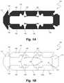
- FIGS. 1A-1Ddepict an expandable intervertebral body fusion device in a collapsed configuration according to an embodiment.
- FIGS. 2A-2Ddepict the expandable intervertebral body fusion device of FIGS. 1A-1D in an expanded configuration.
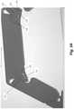
- FIGS. 3A-3Cdepict a portion of the expandable intervertebral body fusion device of FIGS. 2A-2D .
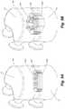
- FIG. 4depicts a schematic representation of an expandable intervertebral body fusion device according to an embodiment being inserted between vertebrae of a patient.
- FIGS. 5A-5Bdepict a schematic representation of an expandable intervertebral body fusion device according to an embodiment inserted between vertebrae of a patient in a compressed and an expanded configuration.
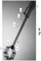
- FIGS. 6A-6Bdepict an expandable intervertebral body fusion device and a corresponding insertion device according to an embodiment.
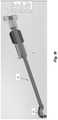
- FIGS. 7A-7Fdepict portions of an insertion device for an expandable intervertebral body fusion device according to an embodiment.
- FIGS. 8A-8Cdepict portions of an insertion device for an expandable intervertebral body fusion device according to an embodiment.
- FIGS. 9A-9Idepict portions of an insertion device and an expandable intervertebral body fusion device according to an embodiment
- FIGS. 1A-1D and 2A-2Ddepict an expandable intervertebral body fusion device 100 according to an embodiment.
- FIGS. 1A-1Ddepict the device 100 in a collapsed configuration
- FIGS. 2A-2Ddepict the device 100 in an expanded configuration.
- the device 100is inserted into the disc space through a minimally invasive access in the collapsed configuration and then expanded inside of the disc space.
- the device 100is inserted between adjacent vertebrae 10 on its side as depicted in FIG. 4 such that when it is expanded in the disc space rather than expanding vertically it expands horizontally/transversely to the disc space to enable the device to take up a larger footprint within the disc space as can be seen contrasting FIG. 5A and FIG. 5B .
- the deviceis therefore able to occupy more lateral to medial and anterior to posterior space within the disc space relative to the size of the access that has heretofore been possible.
- the devicein its insertion and un-expanded state the device is 8 mm in height, 11.5 mm in width and 26 mm in length.
- the devicecan have many heights from 8 mm up to 16 mm.
- the widthcan go from 8-12 mm and the length from 22 mm-32 mm.
- the heightremains the same but the width can double or nearly double (from 11.5 to 22 mm or 47%) and the length goes from 26 mm to 20 mm (16% decrease).
- the devicecan have many lordotic angles from 0 to 15 degrees or higher; the most common being 0, 6, 12 degrees.
- the horizontal top and bottom of the devicecan have different shapes to better fit the endplates such as football shaped or domed.
- the different segments of the device separated by flexurescould be tailored or cut by wire EDM or 3D printed to create different horizontal expanded states such as oval, elliptical, circular, bean shaped, banana shaped or many other polygons and non-polygon shapes.
- the mean disc height at the L3-4 levelis 11.3 mm+/ ⁇ 1.8 mm, LA-5 11.3+/ ⁇ 2.1 mm and L5-S1 10.7+/ ⁇ 2.1 mm.
- the average circumference of the L4 endplateis about 141 mm and surface area 1,492 mm 2 above.
- the devicecan have difference foot prints to try to fill the endplate or disc space circumference.
- device 100can include a device body 102 .
- device body 102can be unitarily formed as a single monolithic construct, although multiple component embodiments are also contemplated.
- Device body 102can include upper 104 a and lower 104 b bearing surfaces.
- device 100can be inserted generally on its side such that bearing surfaces 104 a , 104 b interface with and bear the forces of the adjacent vertebrae 10 (see FIGS. 4 and 5A-5B ).
- the larger threaded opening 126are positioned dorsal or posterior and the smaller opening 124 is positioned ventral or anterior.
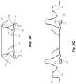
- Device body 102can include a plurality of mediolateral body segments 106 unitary connected to each other by flexure 108 comprising a thin, flexible strip of material. As can be seen in, e.g., FIGS. 1C-1D , mediolateral body segments 106 and flexures 108 can perform a continuous, unitary out perimeter surface 110 . Device body 102 can further include an anterior body segment 112 and posterior body segment 114 . Anterior and posterior body segments 112 , 114 can also be connected with mediolateral body segments by flexures 108 . Device body 102 further defines an open interior 116 between the body segments.
- the device 100includes three mediolateral body segments 106 on each side such that the device includes a total of eight body segments.
- a device having eight body segmentsmay be generally octagonally shaped in the expanded configuration as depicted in FIGS. 2A-2D .
- devicemay have greater or fewer mediolateral body segments on each side.
- Device body 102can further include a plurality of locking flexures 118 disposed in the open interior 116 .
- locking flexures 118can extend from a lock base 120 that is recessed with respect to bearing surfaces 104 a , 104 b .
- each locking flexure 118corresponds with locking projection 122 extending from an adjacent body segment 106 .
- anterior body segment 112 and posterior body segment 114can include a threaded opening that aids in insertion and expansion of device.
- anterior body segment 112includes an anterior threaded opening 124 configured to interface with a stabilizing element for inserting the device 100 into the disc space.
- Posterior body segment 114can include a posterior threaded opening 126 that is larger than anterior opening 124 and can be configured to interface with an expansion element that is rotated to expand device body 112 , which will be described in more detail below.
- anterior opening 124may interface with the expansion elements while posterior opening 126 interfaces with the stabilizing element.
- anterior body segment 112can be tapered to facilitate insertion of the device 100 into the disc space through the minimally invasive access opening.
- FIGS. 2A-2Ddepict device 100 in an expanded configuration.
- the mediolateral body segments 106 on opposing sides of the device body 102are moved away from each other causing the device to expand medially and laterally within the disc space.
- the locking flexures 118interface and lock with the locking projections 122 to prevent external forces from causes the device to compress from the expanded position following expansion.
- each locking flexure 118includes a pointed tip 128 that interfaces with a notch 130 in locking projections to lock the components together.
- device 100is inserted between adjacent vertebrae 10 on its side, as shown in FIG. 4 , with bearing surfaces 104 a , 104 b configured to interface with the vertebrae.
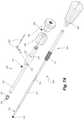
- FIGS. 6A-6Bdepict device 100 with an insertion device 200 used to insert and expand device 100 within the disc space according to an embodiment.
- insertion device 200generally includes a stabilizing component 204 and an expansion component 202 .
- Expansion component 202includes a knob 209 configured to be rotated to secure the expansion component 202 to intervertebral device 100 and a dial 208 configured to be rotated to expand intervertebral device 100 , as discussed in more detail below.
- Stabilizing component 204includes a handle 206 configured to be rotated to secure the component to device 100 .
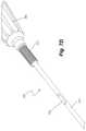
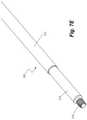
- FIGS. 7A-7Edepict further detail regarding the components of insertion device 200 .
- Expansion component 202includes a body 224 , a shaft 222 extending from the body 224 , a flange 226 at the distal end of shaft 222 and a distal threaded tip 228 .
- Shaft 222 and body 224include internal lumens that enable passage of shaft body 214 of stabilizing component 204 to pass through expansion component 202 .
- Distal tip 228is sized to be rotatingly received by posterior or proximal threaded opening 126 of device.
- Flange 226is wider than shaft 222 and threaded tip 228 to prevent expansion component 204 from being over-inserted when attached to expandable device 100 .
- Knob 209 and dial 208are selectively attachable to expansion component 202 via, for example, a rotational coupling with knob 209 and with a screw 220 for dial 208 .
- Dial 208can also include a threaded portion 221 configured to interface with a proximal threaded portion 212 of shaft 210 .
- a lock 230can be selectively insert into a lock aperture 232 through body 224 of expansion component 202 to lock rotation of stabilizing component 204 with respect to expansion component 202 , as will be discussed in more detail below. Lock 230 can be selectively held in place with screw 234 .
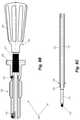
- Stabilizing component 204includes a shaft 210 extending from handle 206 .
- Shaft 210includes a proximal threaded portion 212 configured to interface with dial 208 , a shaft body 214 configured to be extended through the expansion component 202 , an implant extension 216 configured to extend through the implantable device 100 during implantation, and a threaded tip 218 .
- Shaft 210further includes a lock slot 236 configured to interface with lock 230 .
- Lock 230includes a handle 238 and a lock body 240 .
- Lock body 240is configured to be inserted through lock aperture 232 in body 224 of stabilizing component 202 .
- Lock body 240further includes a recessed portion 242 having a reduced diameter that interfaces with the lock slot 236 in shaft body 214 of shaft 210 .
- Recessed portion 242 of lock body 240further includes a cutout 244 that allows for limited rotation of shaft body 214 when lock 230 is engaged with shaft 210 .
- FIGS. 8A-8Cfurther depict the interrelation of the components of inserter 200 .
- Dial 208is threaded onto proximal threaded portion 212 of stabilizing component 204 .
- Shaft 210 of stabilizing componentis inserted through expansion component 202 with implant extension 216 and threaded tip 218 extending distally from expansion component 202 .
- Proximal end of expansion component 202is secured to dial 208 with screw 220 .
- Lock 230can be selectively inserted into aperture 232 and through lock slot 236 in shaft 210 .
- FIGS. 9A-9Idepict further details regarding the interaction between inserter 200 and expandable device 100 .
- the distal tip 228 of the expansion component 202is engaged with the posterior threaded opening 126 of implantable device 100 and the knob 209 is rotated to secure the tip 228 to the opening 126 .
- stabilizing component 204is inserted through stabilizing component 202 to the distal side of the expandable device 100 .
- the implant extension 216can be extended through the body of the implant 100 to engage the threaded tip 218 of the stabilizing component 204 to interface with the distal threaded opening 124 of the implant.
- Handle 206can be rotated to secure the tip 218 to the opening 124 .
- Lock 230can now be inserted through slot 232 in expansion component and across slot 236 in shaft 214 of stabilizing component.
- the dial 208 of the expansion component 202can now be rotated to expand the implant 100 within the disc space.
- Dial 208is rotated while the user holds the knob 209 such that the dial rotates relative to knob 209 .
- Lock 230prevents shaft 214 from rotating such that stabilizing component 204 maintains device 100 in a stable position.
- Dial 208therefore rotates shaft 222 and distal tip 228 about shaft 214 of stabilizing component 204 .
- This rotationpushes on the proximal or anterior end of device 100 while the distal or posterior end of the device is maintained stable, causing the distance between the anterior and posterior ends of the device to shorten and the device 100 to expand laterally outwardly.
- deviceexpands from the collapsed configuration shown in, e.g., FIGS.
- Implantis therefore able to provide more robust and stable support in the disc space that is laterally wider than the access opening through which the implant is implanted.
- the slot 236 in shaft 210 of stabilizing component 204can also serve to limit an amount that expansion component 202 can be rotated to expand device 100 .
- the lock 230is positioned in at a proximal end of slot 236 .
- the dial 208is rotated to rotate the shaft 222 to expand the device 100 , the dial 208 travels linearly along the threaded portion 212 of the stabilizing component and the lock 230 , which is inserted through a locking tube 231 of expansion component that enables shaft 222 to be rotated, is advanced linearly along slot 236 .
- the fully expanded positionas shown in FIG.
- the lock 230abuts a distal end of the slot 236 such that further rotation of dial 208 with not cause any further linear advancement of shaft 222 .
- the length of the slot 236can be predetermined based on a desired or actual maximum expansion of the implanted device 100 .
- the stabilizing component 204can be removed by rotating handle 206 to disengage the threaded tip 218 from the device and withdrawing the shaft 210 from the expansion component 202 .
- the hollow expansion component 202can then serve as a funnel to infuse one or more of, for example, bone puddy, demineralized bone matrix, and bone chips into the now empty opening in the device 100 to aid the fusion process.
- the expansion component 202can be disengaged from the implant 100 and removed, leaving the implant in the disc space with, e.g., bone graft in the interior of the device 100 .
- the typical height opening after a discectomy available to insert the implantcan be from 4-14 mm depending on how collapsed the disc space is.
- the typical width of the surgical path into the disc space after retracting the nerve rootcould be 10-12 mm.
- devicein another embodiment, can be inserted into the disc space and expanded vertically to expand the disc space, with the flexures locking the device at the expanded height and maintaining the expanded disc space.
Landscapes
- Health & Medical Sciences (AREA)
- Engineering & Computer Science (AREA)
- Biomedical Technology (AREA)
- Orthopedic Medicine & Surgery (AREA)
- Neurology (AREA)
- Transplantation (AREA)
- Heart & Thoracic Surgery (AREA)
- Oral & Maxillofacial Surgery (AREA)
- Cardiology (AREA)
- Vascular Medicine (AREA)
- Life Sciences & Earth Sciences (AREA)
- Animal Behavior & Ethology (AREA)
- General Health & Medical Sciences (AREA)
- Public Health (AREA)
- Veterinary Medicine (AREA)
- Physical Education & Sports Medicine (AREA)
- Prostheses (AREA)
Abstract
Description
Claims (16)
Priority Applications (9)
| Application Number | Priority Date | Filing Date | Title |
|---|---|---|---|
| US16/292,565US11234835B2 (en) | 2019-03-05 | 2019-03-05 | Transversely expandable minimally invasive intervertebral cage |
| US16/574,265US11497622B2 (en) | 2019-03-05 | 2019-09-18 | Transversely expandable minimally invasive intervertebral cage and insertion and extraction device |
| KR1020217031855AKR102786358B1 (en) | 2019-03-05 | 2019-12-30 | Transversely expandable minimally invasive intervertebral cage and insertion and extraction device |
| JP2021552741AJP7289564B2 (en) | 2019-03-05 | 2019-12-30 | Laterally Expandable Minimally Invasive Intervertebral Cage and Insertion and Extraction Device |
| PCT/US2019/068890WO2020180389A1 (en) | 2019-03-05 | 2019-12-30 | Transversely expandable minimally invasive intervertebral cage and insertion and extraction device |
| EP19918341.9AEP3934574A4 (en) | 2019-03-05 | 2019-12-30 | TRANSVERSELY EXPANDABLE MINIMALLY INVASIVE DISC CAGE AND INSERTOR AND EXTRACTOR |
| AU2019433217AAU2019433217B2 (en) | 2019-03-05 | 2019-12-30 | Transversely expandable minimally invasive intervertebral cage and insertion and extraction device |
| US17/590,195US11911292B2 (en) | 2019-03-05 | 2022-02-01 | Transversely expandable minimally invasive intervertebral cage |
| US18/415,589US20240197494A1 (en) | 2019-03-05 | 2024-01-17 | Transversely expandable minimally invasive intervertebral cage |
Applications Claiming Priority (1)
| Application Number | Priority Date | Filing Date | Title |
|---|---|---|---|
| US16/292,565US11234835B2 (en) | 2019-03-05 | 2019-03-05 | Transversely expandable minimally invasive intervertebral cage |
Related Child Applications (2)
| Application Number | Title | Priority Date | Filing Date |
|---|---|---|---|
| US16/574,265Continuation-In-PartUS11497622B2 (en) | 2019-03-05 | 2019-09-18 | Transversely expandable minimally invasive intervertebral cage and insertion and extraction device |
| US17/590,195ContinuationUS11911292B2 (en) | 2019-03-05 | 2022-02-01 | Transversely expandable minimally invasive intervertebral cage |
Publications (2)
| Publication Number | Publication Date |
|---|---|
| US20200281739A1 US20200281739A1 (en) | 2020-09-10 |
| US11234835B2true US11234835B2 (en) | 2022-02-01 |
Family
ID=72336717
Family Applications (3)
| Application Number | Title | Priority Date | Filing Date |
|---|---|---|---|
| US16/292,565Active2039-07-19US11234835B2 (en) | 2019-03-05 | 2019-03-05 | Transversely expandable minimally invasive intervertebral cage |
| US17/590,195ActiveUS11911292B2 (en) | 2019-03-05 | 2022-02-01 | Transversely expandable minimally invasive intervertebral cage |
| US18/415,589PendingUS20240197494A1 (en) | 2019-03-05 | 2024-01-17 | Transversely expandable minimally invasive intervertebral cage |
Family Applications After (2)
| Application Number | Title | Priority Date | Filing Date |
|---|---|---|---|
| US17/590,195ActiveUS11911292B2 (en) | 2019-03-05 | 2022-02-01 | Transversely expandable minimally invasive intervertebral cage |
| US18/415,589PendingUS20240197494A1 (en) | 2019-03-05 | 2024-01-17 | Transversely expandable minimally invasive intervertebral cage |
Country Status (1)
| Country | Link |
|---|---|
| US (3) | US11234835B2 (en) |
Cited By (1)
| Publication number | Priority date | Publication date | Assignee | Title |
|---|---|---|---|---|
| US12102537B2 (en) | 2022-07-18 | 2024-10-01 | Loubert S. Suddaby | Minimally invasive expandable intervertebral fusion implant |
Families Citing this family (4)
| Publication number | Priority date | Publication date | Assignee | Title |
|---|---|---|---|---|
| CL2017000107A1 (en)* | 2017-01-16 | 2017-07-14 | Hernan Rebolledo Berrios Y Cia Ltda | Ring assist device |
| WO2022232957A1 (en) | 2021-05-02 | 2022-11-10 | Caratsch Alexander | Expandable and flexible intervertebral implant |
| WO2023285675A1 (en) | 2021-07-16 | 2023-01-19 | Blue Ocean Spine Gmbh | Adjustable intervertebral cage, associated instrument and manufacturing process therefor |
| US20240407928A1 (en)* | 2023-06-12 | 2024-12-12 | Octagon Spine Llc | Expandable intevertebral cage with shape memory material |
Citations (234)
| Publication number | Priority date | Publication date | Assignee | Title |
|---|---|---|---|---|
| US283218A (en) | 1883-08-14 | joseph de eyoke | ||
| US703251A (en) | 1902-04-14 | 1902-06-24 | James A Haire | Pipe-puller. |
| US811344A (en) | 1905-10-27 | 1906-01-30 | John C Wands | Lifting device. |
| US1388836A (en) | 1921-08-23 | A corpora | ||
| US1500859A (en) | 1922-08-04 | 1924-07-08 | Charles V Wright | Lifting jack |
| US1547946A (en) | 1923-03-30 | 1925-07-28 | Corson L Myers | Jack |
| US2106088A (en) | 1936-05-08 | 1938-01-18 | Gen Electric | Drive mechanism |
| US2231221A (en) | 1937-06-01 | 1941-02-11 | Laurence L Rector | Packing device |
| US2453656A (en) | 1945-09-15 | 1948-11-09 | Bullard Co | Rack and pinion gear means |
| US2666334A (en) | 1947-07-17 | 1954-01-19 | Charles R Nalle | Threaded article and support therefor |
| US2711105A (en) | 1951-06-02 | 1955-06-21 | Williams Earl Charles | Power transmission |
| US2842976A (en) | 1955-11-21 | 1958-07-15 | Young Sidney Geoffrey | Gear mechanisms |
| US2891408A (en) | 1953-03-23 | 1959-06-23 | Jr Joseph P Burt | Oil well pumping assembly |
| US3386128A (en) | 1966-09-26 | 1968-06-04 | Ryan Aeronautical Co | Self-actuating, self-locking hinge |
| US3449971A (en) | 1967-06-12 | 1969-06-17 | Lear Siegler Inc | Linear actuator |
| US3575475A (en) | 1969-06-03 | 1971-04-20 | Singer General Precision | Flexure joint |
| US3596863A (en) | 1969-01-28 | 1971-08-03 | Nasa | Fine adjustment mount |
| US3597938A (en) | 1969-05-21 | 1971-08-10 | Singer General Precision | Flexure joint |
| US3700289A (en) | 1970-04-15 | 1972-10-24 | Singer Co | Flexure hinge assembly |
| US3700290A (en) | 1971-04-05 | 1972-10-24 | Singer Co | Flexure hinge assembly |
| US3709132A (en) | 1970-11-27 | 1973-01-09 | Polaroid Corp | Photographic focus adjustment apparatus |
| US3708925A (en) | 1969-09-30 | 1973-01-09 | Tsukihoshi Gomu Kk | Screw-shaped gear hone and method of forming and using the same |
| US3916596A (en) | 1973-02-28 | 1975-11-04 | Hanley Ronald | Joint structure |
| US3985000A (en) | 1974-11-13 | 1976-10-12 | Helmut Hartz | Elastic joint component |
| US3988906A (en) | 1975-08-01 | 1976-11-02 | Smith Thomas R | Flexible coupling |
| FR2372998A1 (en) | 1976-12-02 | 1978-06-30 | Sev Marchal | Worm gear transmission |
| US4261211A (en) | 1976-11-24 | 1981-04-14 | Anschutz & Co. G.M.B.H. | Flexure joint, particularly for connecting a gyroscope to its driving shaft |
| US4396047A (en) | 1981-06-01 | 1983-08-02 | Balkus Carl E | Electric wood splitter |
| US4478109A (en) | 1981-09-28 | 1984-10-23 | Jacob Kobelt | Twin lever control assembly |
| US4516303A (en) | 1983-03-16 | 1985-05-14 | Kloster Kenneth D | Spring compressor |
| US4528864A (en) | 1980-05-19 | 1985-07-16 | Incosym, Inc. | Universal joint flexure hinge suspension system and method for manufacturing this system |
| US4559717A (en) | 1984-02-21 | 1985-12-24 | The United States Of America As Represented By The Secretary Of Commerce | Flexure hinge |
| US4630495A (en) | 1982-02-11 | 1986-12-23 | Fairey Hydraulics Limited | Variable ratio power transmission means |
| US4691586A (en) | 1985-03-05 | 1987-09-08 | Staat Der Nederlanden (Staatsbedrijf Der Posterijen, Telegrafie En Telfonie) | Fine-adjusting device for accurate positioning an adjusting element |
| US4694703A (en) | 1984-06-28 | 1987-09-22 | Lear Siegler, Inc. | Circumferentially oriented flexure suspension |
| US4869552A (en) | 1988-09-14 | 1989-09-26 | Shelby Williams Industries, Inc. | Flexible backrest assembly for a chair |
| US5133108A (en) | 1990-06-26 | 1992-07-28 | Ftfm La Toulousaine | Panel articulation system |
| US5172442A (en) | 1992-01-03 | 1992-12-22 | Stryker Corporation | Litter support having telescoping threaded rod arrangement |
| US5181371A (en) | 1991-08-05 | 1993-01-26 | Crane Plastics Company | Flexible joint assembly for partition assemblage |
| US5196857A (en) | 1991-06-03 | 1993-03-23 | General Electric Company | Stowable and deployable antenna array |
| US5198932A (en) | 1990-11-14 | 1993-03-30 | Fuji Photo Film Co., Ltd. | Zoom lens assembly |
| JPH0581194A (en) | 1991-09-19 | 1993-04-02 | Nec Software Kansai Ltd | On line data processing method |
| US5222986A (en) | 1992-01-27 | 1993-06-29 | Wright Donald M | Hand prosthesis for grasping large and small objects |
| US5313852A (en) | 1992-11-06 | 1994-05-24 | Grumman Aerospace Corporation | Differential linear actuator |
| US5374556A (en) | 1992-07-23 | 1994-12-20 | Cell Robotics, Inc. | Flexure structure for stage positioning |
| US5439377A (en) | 1994-04-21 | 1995-08-08 | Milanovich; Philip J. | Bi-directional orthodontic appliance |
| US5445471A (en) | 1992-07-25 | 1995-08-29 | Euwe Eugen Wexler Gmbh | Plastic joint for articulating two components |
| US5554191A (en) | 1994-01-26 | 1996-09-10 | Biomat | Intersomatic vertebral cage |
| US5645599A (en) | 1994-07-26 | 1997-07-08 | Fixano | Interspinal vertebral implant |
| US5653763A (en) | 1996-03-29 | 1997-08-05 | Fastenetix, L.L.C. | Intervertebral space shape conforming cage device |
| US5664457A (en) | 1992-06-05 | 1997-09-09 | Amir Nejati | Screw gear means and method for same |
| US5904479A (en) | 1992-11-12 | 1999-05-18 | Staples; Jeffrey J. | Orthodontic palate expander apparatus |
| US5960670A (en) | 1995-12-12 | 1999-10-05 | Ut Automotive Dearborn, Inc. | Actuator for gear transfer case with cushion at end of travel |
| US5980252A (en) | 1995-05-08 | 1999-11-09 | Samchukov; Mikhail L. | Device and method for enhancing the shape, mass, and strength of alveolar and intramembranous bone |
| US5988006A (en) | 1994-12-12 | 1999-11-23 | Fleytman; Yakov | Method of moving objects with self-locking mechanical transmission |
| US6039761A (en) | 1997-02-12 | 2000-03-21 | Li Medical Technologies, Inc. | Intervertebral spacer and tool and method for emplacement thereof |
| US6045579A (en) | 1997-05-01 | 2000-04-04 | Spinal Concepts, Inc. | Adjustable height fusion device |
| US6056491A (en) | 1999-04-23 | 2000-05-02 | Hsu; Kuo-Tai | Screw having cutting teeth formed on threads thereof |
| US6136031A (en) | 1998-06-17 | 2000-10-24 | Surgical Dynamics, Inc. | Artificial intervertebral disc |
| US6175989B1 (en) | 1998-05-26 | 2001-01-23 | Lockheed Corp | Shape memory alloy controllable hinge apparatus |
| US6350317B1 (en) | 1999-12-30 | 2002-02-26 | Lam Research Corporation | Linear drive system for use in a plasma processing system |
| US6378172B1 (en) | 2000-08-01 | 2002-04-30 | Fabri-Craft, Inc. | Airplane container door hinge |
| US6395035B2 (en) | 1998-10-20 | 2002-05-28 | Synthes (U.S.A.) | Strain regulating fusion cage for spinal fusion surgery |
| US20020128716A1 (en) | 1999-07-26 | 2002-09-12 | Howard Cohen | Spinal surgical prosthesis |
| US6454807B1 (en) | 2000-11-30 | 2002-09-24 | Roger P. Jackson | Articulated expandable spinal fusion cage system |
| US6454806B1 (en) | 1999-07-26 | 2002-09-24 | Advanced Prosthetic Technologies, Inc. | Spinal surgical prosthesis |
| US20020138146A1 (en) | 2000-04-18 | 2002-09-26 | Jackson Roger P. | Anterior expandable spinal fusion cage system |
| US6484608B1 (en) | 2000-06-20 | 2002-11-26 | Hughes Electronics Corporation | Method and apparatus for providing two axis motion with a single drive device |
| US6517772B1 (en) | 2001-09-26 | 2003-02-11 | Federal-Mogul World Wide, Inc. | Apparatus and method for forming powder metal gears |
| US20030077110A1 (en) | 2001-10-22 | 2003-04-24 | Knowles Steven M. | Flexible joint assembly, service, and system using a flexible joint assembly |
| US6554526B1 (en) | 1999-10-20 | 2003-04-29 | Laerdal Medical As | Fastening device |
| US6616695B1 (en) | 1998-01-30 | 2003-09-09 | Stryker Spine | Implant for replacing a vertebra |
| EP1342456A1 (en) | 1996-11-22 | 2003-09-10 | Glenn R. Buttermann | Intervertebral prosthetic device |
| US6641614B1 (en) | 1997-05-01 | 2003-11-04 | Spinal Concepts, Inc. | Multi-variable-height fusion device |
| US20030233145A1 (en) | 2002-03-11 | 2003-12-18 | Landry Michael E. | Instrumentation and procedure for implanting spinal implant devices |
| US20040049271A1 (en) | 2001-08-03 | 2004-03-11 | Lutz Biedermann | Spacer having a variable axial length |
| WO2004026188A2 (en) | 2002-09-23 | 2004-04-01 | Sdgi Holdings, Inc. | Expandable spinal fusion device and methods of promoting spinal fusion |
| US20040111157A1 (en) | 2001-10-18 | 2004-06-10 | Ralph James D. | Intervertebral spacer device having a slotted domed arch strip spring |
| US6752832B2 (en) | 2000-12-27 | 2004-06-22 | Ulrich Gmbh & Co., Kg | Vertebral implant and setting tool therefor |
| US6772479B2 (en) | 2001-06-21 | 2004-08-10 | The Aerospace Corporation | Conductive shape memory metal deployment latch hinge |
| US20040193158A1 (en) | 2002-06-25 | 2004-09-30 | Roy Lim | Minimally invasive expanding spacer and method |
| US6802229B1 (en) | 2003-06-02 | 2004-10-12 | Michael Lambert | Gear drive having continuously variable drive ratio |
| US6808537B2 (en) | 2000-07-07 | 2004-10-26 | Gary Karlin Michelson | Expandable implant with interlocking walls |
| JP2004301135A (en) | 2003-03-28 | 2004-10-28 | Ntn Corp | Linear driving device |
| US20040225364A1 (en) | 2003-05-06 | 2004-11-11 | Marc Richelsoph | Artificial intervertebral disc |
| US20050000228A1 (en) | 2003-05-20 | 2005-01-06 | Snecma Moteurs | Combustion chamber having a flexible connexion between a chamber end wall and a chamber side wall |
| US20050033431A1 (en) | 2003-08-05 | 2005-02-10 | Charles Gordon | Artificial functional spinal unit assemblies |
| US6863673B2 (en) | 2001-10-17 | 2005-03-08 | Movdice Holding, Inc. | Methods for adjustable bone fusion implants |
| US20050095384A1 (en) | 2003-11-04 | 2005-05-05 | Wittmeyer Larry E.Jr. | Multi-functional stack of repositionable sheets |
| US20050113921A1 (en) | 1999-09-02 | 2005-05-26 | Stryker Spine | Distractable corpectomy device |
| US20050113924A1 (en) | 2003-08-07 | 2005-05-26 | Dynamic Spine, Inc. | Apparatus and method for performing spinal surgery |
| EP1552797A2 (en) | 1999-01-27 | 2005-07-13 | Disc-O-Tech Medical Technologies, Ltd. | Expandable intervertebral spacer |
| US20050175406A1 (en) | 2002-01-22 | 2005-08-11 | Airbus Deutschland Gmbh | Joint for connecting a longitudinal side to an upper side of components and flexible strip for use in such a joint |
| US20050182416A1 (en) | 2004-02-13 | 2005-08-18 | Roy Lim | Spacer with height and angle adjustments for spacing vertebral members |
| WO2005081330A2 (en) | 2004-02-20 | 2005-09-01 | Thorlabs, Inc. | Positioner device |
| US6953477B2 (en) | 2002-11-01 | 2005-10-11 | Sdgi Holdings, Inc. | Laterally expandable cage |
| WO2005096975A2 (en) | 2004-04-05 | 2005-10-20 | Expanding Orthopedics Inc. | Expandable bone device |
| US20050261769A1 (en) | 2004-05-13 | 2005-11-24 | Moskowitz Nathan C | Artificial expansile total lumbar and thoracic discs for posterior placement without supplemental instrumentation and its adaptation for anterior placement of artificial cervical, thoracic and lumbar discs |
| US20060004455A1 (en) | 2004-06-09 | 2006-01-05 | Alain Leonard | Methods and apparatuses for bone restoration |
| US20060004447A1 (en) | 2004-06-30 | 2006-01-05 | Depuy Spine, Inc. | Adjustable posterior spinal column positioner |
| US20060025862A1 (en) | 2004-07-30 | 2006-02-02 | Spinalmotion, Inc. | Intervertebral prosthetic disc with metallic core |
| US20060058878A1 (en) | 2001-03-27 | 2006-03-16 | Michelson Gary K | Radially expanding implants |
| US7051610B2 (en) | 2001-11-13 | 2006-05-30 | Douglas Holtz | Ball-worm transmission |
| US20060129244A1 (en) | 2004-10-25 | 2006-06-15 | Alphaspine, Inc. | Expandable intervertebral spacer method and apparatus |
| US7087055B2 (en) | 2002-06-25 | 2006-08-08 | Sdgi Holdings, Inc. | Minimally invasive expanding spacer and method |
| US20060184171A1 (en) | 2004-11-17 | 2006-08-17 | Lutz Biedermann | Flexible element for use in a stabilization device for bones or vertebrae |
| WO2006094535A1 (en) | 2005-03-09 | 2006-09-14 | Ares Engineering S.R.L. | Rolling screw |
| WO2006116052A2 (en) | 2005-04-21 | 2006-11-02 | Globus Medical, Inc. | Expandable vertebral prosthesis |
| US20060247781A1 (en) | 2005-04-29 | 2006-11-02 | Sdgi Holdings, Inc. | Implant |
| US20060253201A1 (en) | 2004-11-03 | 2006-11-09 | Mcluen Design, Inc. | Bone fusion device |
| WO2006125329A1 (en) | 2005-05-24 | 2006-11-30 | Tecpharma Licensing Ag | Threaded rod and dosing device for an injection device |
| US20060293752A1 (en) | 2005-06-27 | 2006-12-28 | Missoum Moumene | Intervertebral disc prosthesis and associated methods |
| WO2007002583A2 (en) | 2005-06-24 | 2007-01-04 | Spineworks, Llc | A prosthetic implant, and a method and tool for the insertion of same |
| WO2007009107A2 (en) | 2005-07-14 | 2007-01-18 | Stout Medical Group, P.L. | Expandable support device and method of use |
| US20070032791A1 (en) | 2005-07-14 | 2007-02-08 | Greenhalgh E S | Expandable support device and method of use |
| US20070049943A1 (en) | 2005-04-12 | 2007-03-01 | Nathan Moskowitz | Bi-directional fixating transvertebral body screws, zero-profile horizontal intervertebral miniplates, total intervertebral body fusion devices, and posterior motion-calibrating interarticulating joint stapling device for spinal fusion |
| WO2007028140A2 (en) | 2005-08-31 | 2007-03-08 | Spineworks Medical, Inc. | Implantable devices and methods for treating micro-architecture deterioration of bone tissue |
| US7201751B2 (en) | 1997-01-02 | 2007-04-10 | St. Francis Medical Technologies, Inc. | Supplemental spine fixation device |
| US20070083267A1 (en) | 2005-09-26 | 2007-04-12 | George Miz | Posterior metal-on-metal disc replacement device and method |
| US20070093901A1 (en) | 2005-09-26 | 2007-04-26 | Thomas Grotz | Selectively Expanding Spine Cage, Hydraulically Controllable in Three Dimensions for Enhanced Spinal Fusion |
| US20070129730A1 (en) | 2005-09-12 | 2007-06-07 | Woods Richard W | Posterior modular disc replacement system |
| WO2007076377A2 (en) | 2005-12-19 | 2007-07-05 | Stout Medical Group, L.P. | Expandable support device |
| US20070173826A1 (en) | 2006-01-20 | 2007-07-26 | Alpha Orthopaedics | Intramedullar devices and methods to reduce and/or fix damaged bone |
| US20070185577A1 (en) | 2003-09-30 | 2007-08-09 | Malek Michel H | Intervertebral disc prosthesis |
| US20070191958A1 (en) | 2006-02-15 | 2007-08-16 | Abdou M S | Devices and Methods for Inter-Vertebral Orthopedic Device Placement |
| US20070191954A1 (en) | 2005-04-21 | 2007-08-16 | Noah Hansell | Expandable Vertebral Prosthesis |
| US20070198089A1 (en) | 2004-05-13 | 2007-08-23 | Nathan Moskowitz | Artificial total lumbar disc for unilateral safe and simple posterior placement in the lumbar spine, and removable bifunctional screw which drives vertical sliding expansile plate expansion, and interplate widening,and angled traction spikes |
| US20070219634A1 (en) | 2004-09-21 | 2007-09-20 | Greenhalgh E S | Expandable support device and method of use |
| US7273373B2 (en) | 2002-10-31 | 2007-09-25 | K. K. Hollyx | Artificial root of a tooth |
| US20070222100A1 (en) | 2006-03-21 | 2007-09-27 | Huber Engineered Woods L.L.C. | Method and system using NIR spectroscopy for in-line monitoring and controlling content in continuous production of engineered wood products |
| WO2007111979A2 (en) | 2006-03-24 | 2007-10-04 | Ebi, Llc. | Expandable spinal prosthesis |
| US20070250171A1 (en) | 2006-04-24 | 2007-10-25 | Sdgi Holdings, Inc. | Expandable intervertebral devices and methods of use |
| US20070255415A1 (en) | 2006-05-01 | 2007-11-01 | Sdgi Holdings, Inc. | Expandable intervertebral spacers and methods of use |
| US20070282449A1 (en) | 2006-04-12 | 2007-12-06 | Spinalmotion, Inc. | Posterior spinal device and method |
| US20070288092A1 (en) | 2006-06-01 | 2007-12-13 | Bambakidis Nicholas | Expandable intervertebral implant and method |
| US7308747B2 (en) | 2003-01-21 | 2007-12-18 | Insitutec, Inc. | Method of positioning a platform relative to a fixed frame and a small scale positioning device |
| US20070293948A1 (en) | 2001-12-12 | 2007-12-20 | Vita Special Purpose Corporation | Bioactive Spinal Implants and Method of Manufacture Thereof |
| US20070293329A1 (en) | 2006-06-08 | 2007-12-20 | Emuge-Werk Richard Glimpel Gmbh & Co. Kg Fabrik Fur Prazisionswerkzeuge | Method and tool set for producing a thread in at least two working steps |
| US7316381B2 (en) | 2001-06-15 | 2008-01-08 | Trumpf Lasertechnik Gmbh | Articulated bearing supports for laser resonators |
| EP1881209A1 (en) | 2006-07-20 | 2008-01-23 | Kuo-Tai Hsu | Wood screw with cutting teeth on threads and groove in shank |
| US20080026903A1 (en) | 2006-07-26 | 2008-01-31 | Iowa State University Research Foundation, Inc. | Geared, continuously variable speed transmission |
| US20080077246A1 (en) | 2006-09-21 | 2008-03-27 | Fehling Ag | Vertebral disc prosthesis |
| US20080091211A1 (en) | 2006-10-11 | 2008-04-17 | G & L Consulting | Spine implant insertion device and method |
| US20080100179A1 (en) | 2006-10-20 | 2008-05-01 | The Boeing Company | Enhanced displacement piezoelectric motor |
| US20080103601A1 (en) | 1999-07-26 | 2008-05-01 | Ladislau Biro | Corpectomy vertebral body replacement implant system |
| US20080114367A1 (en) | 2006-11-10 | 2008-05-15 | Syberspine Limited | Method and relaxable distracters for in-situ formation of intervertebral disc prosthesis |
| US20080140207A1 (en) | 2006-12-07 | 2008-06-12 | Interventional Spine, Inc. | Intervertebral implant |
| US20080154266A1 (en) | 2006-12-21 | 2008-06-26 | Warsaw Orthopedic, Inc. | Methods for positioning a load-bearing orthopedic implant device in vivo |
| US20080161931A1 (en) | 2006-12-28 | 2008-07-03 | Mi4Spine, Llc | Vertebral disc annular fibrosis tensioning and lengthening device |
| US20080161920A1 (en) | 2006-10-03 | 2008-07-03 | Warsaw Orthopedic, Inc. | Dynamizing Interbody Implant and Methods for Stabilizing Vertebral Members |
| US20080168855A1 (en) | 2004-10-15 | 2008-07-17 | Bsh Bosch Und Siemens Hausgerate Gmbh | Adjusting Device, In Particular For the Adjustable Base of a Household Device |
| US20080188941A1 (en) | 2005-08-12 | 2008-08-07 | Innvotec Surgical, Inc. | Linearly expanding spine cage for enhanced spinal fusion |
| US7410201B1 (en) | 2004-10-29 | 2008-08-12 | Dana Automotive Systems Group, Llc | Actuator structure and method for attaching a gear or pulley to lead screw |
| JP2008208932A (en) | 2007-02-27 | 2008-09-11 | Aisin Seiki Co Ltd | Linear actuator |
| US20080221694A1 (en) | 2006-03-22 | 2008-09-11 | Warnick David R | Pivotable Interbody Spacer System and Method |
| US7425103B2 (en) | 2002-01-22 | 2008-09-16 | Airbus Deutschland Gmbh | Joint for connecting components together on opposite longitudinal sides in addition to a flexible strip used for said joint |
| US20080234736A1 (en) | 2007-02-28 | 2008-09-25 | Warsaw Orthopedic, Inc. | Vertebral Stabilizer |
| US20080243255A1 (en)* | 2007-03-29 | 2008-10-02 | Butler Michael S | Radially expandable spinal interbody device and implantation tool |
| US7431735B2 (en) | 1998-08-28 | 2008-10-07 | Sofamor S.N.C. | Expandable interbody fusion cage |
| US7435032B1 (en) | 2006-08-08 | 2008-10-14 | The United States Of America As Represented By The Secretary Of The Air Force | Resilient joint for deployable structures |
| US20080281423A1 (en) | 2007-05-09 | 2008-11-13 | Ebi, L.P. | Interspinous implant |
| WO2008137192A1 (en) | 2007-05-08 | 2008-11-13 | Spinealign Medical, Inc. | Systems, devices and methods for stabilizing bone |
| US20080292392A1 (en) | 2007-05-21 | 2008-11-27 | Usa As Represented By The Administrator Of The National Aeronautics And Space Administrator | Flexure Based Linear and Rotary Bearings |
| US20080319487A1 (en) | 2007-06-22 | 2008-12-25 | Simpirica Spine, Inc. | Methods and Devices for Controlled Flexion Restriction of Spinal Segments |
| US20090012564A1 (en) | 2007-03-07 | 2009-01-08 | Spineworks Medical, Inc. | Transdiscal interbody fusion device and method |
| WO2009018349A2 (en) | 2007-07-30 | 2009-02-05 | Karidis, John, Peter | Adjustable length strut apparatus for orthopaedic applications |
| US20090076614A1 (en) | 2007-09-17 | 2009-03-19 | Spinalmotion, Inc. | Intervertebral Prosthetic Disc with Shock Absorption Core |
| US20090099568A1 (en) | 2007-08-07 | 2009-04-16 | David Lowry | Device and method for variably adjusting intervertebral distraction and lordosis |
| US20090164017A1 (en) | 2007-12-19 | 2009-06-25 | Robert Sommerich | Expandable Corpectomy Spinal Fusion Cage |
| US20090210061A1 (en) | 2008-02-14 | 2009-08-20 | U. S. Spinal Technologies, L.L.C. | Anterior lumbar interbody fusion cage device and associated method |
| US20090222100A1 (en) | 2008-02-28 | 2009-09-03 | Stryker Spine | Tool for implanting expandable intervertebral implant |
| US7584682B2 (en) | 2007-08-07 | 2009-09-08 | Chern Shing Top Co., Ltd. | Adjustment device with a dual-guiding structure |
| US20090234362A1 (en) | 2008-03-12 | 2009-09-17 | Spinal Elements, Inc. | Offset opposing arm spinal implant distractor/inserter |
| US20090259316A1 (en) | 2008-04-15 | 2009-10-15 | Ginn Richard S | Spacer Devices and Systems for the Treatment of Spinal Stenosis and Methods for Using the Same |
| US7611538B2 (en) | 2003-08-04 | 2009-11-03 | Zimmer Spine S.A.S. | Intervertebral disk prosthesis |
| US20090299478A1 (en) | 2008-06-03 | 2009-12-03 | Warsaw Orthopedic, Inc. | Lordotic Implant for Posterior Approach |
| US20090306672A1 (en) | 2008-06-05 | 2009-12-10 | Alphatec Spine,Inc. | Alif inserter/distractor |
| US7632281B2 (en) | 2001-07-16 | 2009-12-15 | Spinecore, Inc. | Instrumentation for manipulating artificial intervertebral disc trials having a cylindrical engagement surface |
| US20100004688A1 (en) | 2008-07-04 | 2010-01-07 | Aesculap Ag | Implant for mutual support of the spinous processes of vertebral bodies |
| US7682376B2 (en) | 2006-01-27 | 2010-03-23 | Warsaw Orthopedic, Inc. | Interspinous devices and methods of use |
| US20100076557A1 (en) | 2008-09-19 | 2010-03-25 | Abbot Spine Inc. | Geared spinal implant inserter-distractor |
| US20100082109A1 (en) | 2008-09-22 | 2010-04-01 | Stout Medical Group, L.P. | Expandable intervertebral implant |
| US20100094305A1 (en) | 2008-10-13 | 2010-04-15 | Arvin Chang | Spinal distraction system |
| US7712389B2 (en) | 2006-05-16 | 2010-05-11 | T-Motion Technology Co., Ltd. | Lifting device having parallel double screw rods |
| US20100161062A1 (en) | 1998-10-29 | 2010-06-24 | Kevin Foley | Expandable intervertebral spacers |
| WO2010078468A2 (en) | 2008-12-31 | 2010-07-08 | Jimenez Omar F | Methods and apparatus for vertebral body distraction and fusion employing flexure members |
| WO2010078520A2 (en) | 2008-12-31 | 2010-07-08 | Jimenez, Omar, F. | Flexible joint arrangement incorporating flexure members |
| US7753958B2 (en) | 2003-08-05 | 2010-07-13 | Gordon Charles R | Expandable intervertebral implant |
| US7758645B2 (en) | 2004-04-02 | 2010-07-20 | Synthes Usa, Llc | Modular intervertebral implant or intervertebral disk prosthesis |
| US7758648B2 (en) | 2006-04-27 | 2010-07-20 | Warsaw Orthopedic, Inc. | Stabilized, adjustable expandable implant and method |
| US20100192715A1 (en) | 2007-06-19 | 2010-08-05 | Aircelle | Multiple-acting linear actuator |
| US20110015638A1 (en) | 2009-07-17 | 2011-01-20 | Pischl Susanne | Spinal-column distractor |
| WO2011011609A2 (en) | 2009-07-22 | 2011-01-27 | Spinex Tec, Llc. | Methods and apparatuses for vertebral body distraction and fusion employing a coaxial screw gear sleeve mechanism |
| US7892285B2 (en) | 2007-01-02 | 2011-02-22 | Zimmer Spine, Inc. | Universal joint total disc replacement |
| US20110054616A1 (en) | 2009-02-19 | 2011-03-03 | Aflatoon Kamran | Open body box form interbody fusion cage |
| US20110093075A1 (en) | 2008-04-22 | 2011-04-21 | Kinetic Spine Technologies Inc. | Artificial intervertebral spacer |
| US20110112644A1 (en) | 2009-11-12 | 2011-05-12 | Zilberstein Boris | Disc prosthetic implant device |
| US7947078B2 (en) | 2007-01-09 | 2011-05-24 | Nonlinear Technologies Ltd. | Devices for forming curved or closed-loop structures |
| US7951199B2 (en) | 2005-06-15 | 2011-05-31 | Miller Jimmy D | Lateral expandable interbody fusion cage |
| US20110172774A1 (en) | 2010-01-11 | 2011-07-14 | Armando Varela | Expandable intervertebral implant and associated surgical method |
| US8070813B2 (en) | 2005-09-26 | 2011-12-06 | Coalign Innovations, Inc. | Selectively expanding spine cage, hydraulically controllable in three dimensions for vertebral body replacement |
| US8088163B1 (en) | 2008-02-06 | 2012-01-03 | Kleiner Jeffrey B | Tools and methods for spinal fusion |
| US20120010653A1 (en) | 2010-05-17 | 2012-01-12 | Seifert Jody L | Soft Tissue Repair System |
| US20120029636A1 (en) | 2010-08-02 | 2012-02-02 | Ragab Ashraf A | Bone Cage with Components for Controlled Expansion |
| US20120083887A1 (en)* | 2010-10-05 | 2012-04-05 | Alphatec Spine, Inc. | Intervertebral device and methods of use |
| US8192495B2 (en) | 2008-12-10 | 2012-06-05 | Coalign Innovations, Inc. | Lockable spinal implant |
| US20120158071A1 (en) | 2009-12-31 | 2012-06-21 | Jimenez Omar F | Methods and apparatus for insertion of vertebral body distraction and fusion devices |
| US20120185049A1 (en) | 2010-01-11 | 2012-07-19 | Innova Spinal Technologies, Llc | Expandable intervertebral implant and associated surgical method |
| US20120226357A1 (en) | 2010-01-11 | 2012-09-06 | Innova Spinal Technologies, Llc | Expandable intervertebral implant and associated surgical method |
| US20120271419A1 (en) | 2011-04-21 | 2012-10-25 | Warsaw Orthopedic, Inc. | Expandable implant system and methods of use |
| US20120290094A1 (en) | 2002-06-25 | 2012-11-15 | Warsaw Orthopedic, Inc. | Minimally invasive expanding spacer and method |
| US20120303124A1 (en) | 2004-11-03 | 2012-11-29 | Mcluen Gary R | Bone fusion device |
| US20130144388A1 (en) | 2010-05-28 | 2013-06-06 | Benvenue Medical, Inc. | Disc Space Sizing Devices And Methods Of Using The Same |
| US20130158664A1 (en) | 2011-12-19 | 2013-06-20 | Warsaw Orthopedic, Inc. | Expandable interbody implant and methods of use |
| US20130197642A1 (en) | 2012-01-28 | 2013-08-01 | Mark J. Ernst | Expandable implant for mammalian bony segment stabilization |
| US20140012383A1 (en) | 2011-02-14 | 2014-01-09 | Imds Corporation | Expandable intervertebral implants and instruments |
| US8628577B1 (en) | 2009-03-19 | 2014-01-14 | Ex Technology, Llc | Stable device for intervertebral distraction and fusion |
| US20140018924A1 (en) | 2008-03-07 | 2014-01-16 | DePuy Synthes Products, LLC | Expandable interbody spacer device |
| US20140039622A1 (en) | 2010-09-03 | 2014-02-06 | Chad Glerum | Expandable Fusion Device and Method of Installation Thereof |
| US20140058512A1 (en)* | 2012-08-27 | 2014-02-27 | Samuel Petersheim | Intevertebral Implant |
| US20140088714A1 (en) | 2011-12-19 | 2014-03-27 | Warsaw Orthopedic, Inc. | Expandable interbody implant and methods of use |
| US20140156007A1 (en) | 2012-11-26 | 2014-06-05 | Spontech Spine Intelligence Ag | Expandable Cage for the Intercorporal Fusion of Lumbar Vertebrae |
| US20140236296A1 (en) | 2013-02-20 | 2014-08-21 | Erik Wagner | Expandable fusion device for positioning between adjacent vertebral bodies |
| US20140249629A1 (en) | 2005-04-12 | 2014-09-04 | Ahmnon D. Moskowitz | Zero-profile expandable intervertebral spacer devices for distraction and spinal fusion and a universal tool for their placement and expansion |
| US20140277490A1 (en)* | 2012-05-30 | 2014-09-18 | Jonathan Perloff | Expandable Interbody Spacer |
| US20140343608A1 (en) | 2013-05-16 | 2014-11-20 | Smokey Mountain Spine, Llc | Expansion interspinous fixation device and method |
| US20150018951A1 (en) | 2013-07-09 | 2015-01-15 | Nlt Spine Ltd. | Orthopedic Implant with Adjustable Angle between Tissue Contact Surfaces |
| US8940049B1 (en) | 2014-04-01 | 2015-01-27 | Ex Technology, Llc | Expandable intervertebral cage |
| US20150100128A1 (en) | 2009-10-15 | 2015-04-09 | Globus Medical, Inc. | Expandable Fusion Device and Method of Installation Thereof |
| US20150148908A1 (en) | 2012-05-18 | 2015-05-28 | Trinity Orthopedics,. LLC | Articulating Interbody Cage and Methods Thereof |
| US20150230929A1 (en)* | 2012-08-27 | 2015-08-20 | Morgan Packard Lorio | Intervertebral cage apparatus and system and methods of using the same |
| US20150272743A1 (en) | 2014-04-01 | 2015-10-01 | Ex Technology, Llc | Expandable intervertebral cage |
| US20150351925A1 (en) | 2013-01-24 | 2015-12-10 | Biomet Spine, Llc | Adjustable interbody fusion device and method of use |
| US20170056200A1 (en)* | 2015-08-25 | 2017-03-02 | Imds Llc | Expandable intervertebral implants |
Family Cites Families (6)
| Publication number | Priority date | Publication date | Assignee | Title |
|---|---|---|---|---|
| DE60224850T2 (en) | 2001-02-04 | 2009-01-22 | Warsaw Orthopedic, Inc., Warsaw | Instrumentation for introducing and positioning an expandable intervertebral fusion implant |
| US7976549B2 (en) | 2006-03-23 | 2011-07-12 | Theken Spine, Llc | Instruments for delivering spinal implants |
| BR112013002765A2 (en)* | 2010-07-15 | 2017-09-19 | Nlt Spine Ltd | deflectable implant, system and methods for implantation |
| US9445918B1 (en) | 2012-10-22 | 2016-09-20 | Nuvasive, Inc. | Expandable spinal fusion implants and related instruments and methods |
| DE102016113488B3 (en) | 2016-07-21 | 2017-11-16 | Medicon Eg. Chirurgiemechaniker-Genossenschaft | Instrument for introducing a spinal implant and spinal implant |
| US10940016B2 (en)* | 2017-07-05 | 2021-03-09 | Medos International Sarl | Expandable intervertebral fusion cage |
- 2019
- 2019-03-05USUS16/292,565patent/US11234835B2/enactiveActive
- 2022
- 2022-02-01USUS17/590,195patent/US11911292B2/enactiveActive
- 2024
- 2024-01-17USUS18/415,589patent/US20240197494A1/enactivePending
Patent Citations (290)
| Publication number | Priority date | Publication date | Assignee | Title |
|---|---|---|---|---|
| US283218A (en) | 1883-08-14 | joseph de eyoke | ||
| US1388836A (en) | 1921-08-23 | A corpora | ||
| US703251A (en) | 1902-04-14 | 1902-06-24 | James A Haire | Pipe-puller. |
| US811344A (en) | 1905-10-27 | 1906-01-30 | John C Wands | Lifting device. |
| US1500859A (en) | 1922-08-04 | 1924-07-08 | Charles V Wright | Lifting jack |
| US1547946A (en) | 1923-03-30 | 1925-07-28 | Corson L Myers | Jack |
| US2106088A (en) | 1936-05-08 | 1938-01-18 | Gen Electric | Drive mechanism |
| US2231221A (en) | 1937-06-01 | 1941-02-11 | Laurence L Rector | Packing device |
| US2453656A (en) | 1945-09-15 | 1948-11-09 | Bullard Co | Rack and pinion gear means |
| US2666334A (en) | 1947-07-17 | 1954-01-19 | Charles R Nalle | Threaded article and support therefor |
| US2711105A (en) | 1951-06-02 | 1955-06-21 | Williams Earl Charles | Power transmission |
| US2891408A (en) | 1953-03-23 | 1959-06-23 | Jr Joseph P Burt | Oil well pumping assembly |
| US2842976A (en) | 1955-11-21 | 1958-07-15 | Young Sidney Geoffrey | Gear mechanisms |
| US3386128A (en) | 1966-09-26 | 1968-06-04 | Ryan Aeronautical Co | Self-actuating, self-locking hinge |
| US3449971A (en) | 1967-06-12 | 1969-06-17 | Lear Siegler Inc | Linear actuator |
| US3596863A (en) | 1969-01-28 | 1971-08-03 | Nasa | Fine adjustment mount |
| US3597938A (en) | 1969-05-21 | 1971-08-10 | Singer General Precision | Flexure joint |
| US3575475A (en) | 1969-06-03 | 1971-04-20 | Singer General Precision | Flexure joint |
| US3708925A (en) | 1969-09-30 | 1973-01-09 | Tsukihoshi Gomu Kk | Screw-shaped gear hone and method of forming and using the same |
| US3700289A (en) | 1970-04-15 | 1972-10-24 | Singer Co | Flexure hinge assembly |
| US3709132A (en) | 1970-11-27 | 1973-01-09 | Polaroid Corp | Photographic focus adjustment apparatus |
| US3700290A (en) | 1971-04-05 | 1972-10-24 | Singer Co | Flexure hinge assembly |
| US3916596A (en) | 1973-02-28 | 1975-11-04 | Hanley Ronald | Joint structure |
| US3985000A (en) | 1974-11-13 | 1976-10-12 | Helmut Hartz | Elastic joint component |
| US3988906A (en) | 1975-08-01 | 1976-11-02 | Smith Thomas R | Flexible coupling |
| US4261211A (en) | 1976-11-24 | 1981-04-14 | Anschutz & Co. G.M.B.H. | Flexure joint, particularly for connecting a gyroscope to its driving shaft |
| FR2372998A1 (en) | 1976-12-02 | 1978-06-30 | Sev Marchal | Worm gear transmission |
| US4528864A (en) | 1980-05-19 | 1985-07-16 | Incosym, Inc. | Universal joint flexure hinge suspension system and method for manufacturing this system |
| US4396047A (en) | 1981-06-01 | 1983-08-02 | Balkus Carl E | Electric wood splitter |
| US4478109A (en) | 1981-09-28 | 1984-10-23 | Jacob Kobelt | Twin lever control assembly |
| US4630495A (en) | 1982-02-11 | 1986-12-23 | Fairey Hydraulics Limited | Variable ratio power transmission means |
| US4516303A (en) | 1983-03-16 | 1985-05-14 | Kloster Kenneth D | Spring compressor |
| US4559717A (en) | 1984-02-21 | 1985-12-24 | The United States Of America As Represented By The Secretary Of Commerce | Flexure hinge |
| US4694703A (en) | 1984-06-28 | 1987-09-22 | Lear Siegler, Inc. | Circumferentially oriented flexure suspension |
| US4691586A (en) | 1985-03-05 | 1987-09-08 | Staat Der Nederlanden (Staatsbedrijf Der Posterijen, Telegrafie En Telfonie) | Fine-adjusting device for accurate positioning an adjusting element |
| US4869552A (en) | 1988-09-14 | 1989-09-26 | Shelby Williams Industries, Inc. | Flexible backrest assembly for a chair |
| US5133108A (en) | 1990-06-26 | 1992-07-28 | Ftfm La Toulousaine | Panel articulation system |
| US5198932A (en) | 1990-11-14 | 1993-03-30 | Fuji Photo Film Co., Ltd. | Zoom lens assembly |
| US5196857A (en) | 1991-06-03 | 1993-03-23 | General Electric Company | Stowable and deployable antenna array |
| US5181371A (en) | 1991-08-05 | 1993-01-26 | Crane Plastics Company | Flexible joint assembly for partition assemblage |
| JPH0581194A (en) | 1991-09-19 | 1993-04-02 | Nec Software Kansai Ltd | On line data processing method |
| US5172442A (en) | 1992-01-03 | 1992-12-22 | Stryker Corporation | Litter support having telescoping threaded rod arrangement |
| US5222986A (en) | 1992-01-27 | 1993-06-29 | Wright Donald M | Hand prosthesis for grasping large and small objects |
| US5664457A (en) | 1992-06-05 | 1997-09-09 | Amir Nejati | Screw gear means and method for same |
| US5374556A (en) | 1992-07-23 | 1994-12-20 | Cell Robotics, Inc. | Flexure structure for stage positioning |
| US5445471A (en) | 1992-07-25 | 1995-08-29 | Euwe Eugen Wexler Gmbh | Plastic joint for articulating two components |
| US5313852A (en) | 1992-11-06 | 1994-05-24 | Grumman Aerospace Corporation | Differential linear actuator |
| US5904479A (en) | 1992-11-12 | 1999-05-18 | Staples; Jeffrey J. | Orthodontic palate expander apparatus |
| US5554191A (en) | 1994-01-26 | 1996-09-10 | Biomat | Intersomatic vertebral cage |
| US5439377A (en) | 1994-04-21 | 1995-08-08 | Milanovich; Philip J. | Bi-directional orthodontic appliance |
| US5645599A (en) | 1994-07-26 | 1997-07-08 | Fixano | Interspinal vertebral implant |
| US5988006A (en) | 1994-12-12 | 1999-11-23 | Fleytman; Yakov | Method of moving objects with self-locking mechanical transmission |
| US5980252A (en) | 1995-05-08 | 1999-11-09 | Samchukov; Mikhail L. | Device and method for enhancing the shape, mass, and strength of alveolar and intramembranous bone |
| US5960670A (en) | 1995-12-12 | 1999-10-05 | Ut Automotive Dearborn, Inc. | Actuator for gear transfer case with cushion at end of travel |
| US5653763A (en) | 1996-03-29 | 1997-08-05 | Fastenetix, L.L.C. | Intervertebral space shape conforming cage device |
| EP1342456A1 (en) | 1996-11-22 | 2003-09-10 | Glenn R. Buttermann | Intervertebral prosthetic device |
| US7201751B2 (en) | 1997-01-02 | 2007-04-10 | St. Francis Medical Technologies, Inc. | Supplemental spine fixation device |
| US6039761A (en) | 1997-02-12 | 2000-03-21 | Li Medical Technologies, Inc. | Intervertebral spacer and tool and method for emplacement thereof |
| US6045579A (en) | 1997-05-01 | 2000-04-04 | Spinal Concepts, Inc. | Adjustable height fusion device |
| US6641614B1 (en) | 1997-05-01 | 2003-11-04 | Spinal Concepts, Inc. | Multi-variable-height fusion device |
| US6080193A (en) | 1997-05-01 | 2000-06-27 | Spinal Concepts, Inc. | Adjustable height fusion device |
| US6616695B1 (en) | 1998-01-30 | 2003-09-09 | Stryker Spine | Implant for replacing a vertebra |
| US6175989B1 (en) | 1998-05-26 | 2001-01-23 | Lockheed Corp | Shape memory alloy controllable hinge apparatus |
| US6136031A (en) | 1998-06-17 | 2000-10-24 | Surgical Dynamics, Inc. | Artificial intervertebral disc |
| US6315797B1 (en) | 1998-06-17 | 2001-11-13 | Surgical Dynamics, Inc. | Artificial intervertebral disc |
| US7431735B2 (en) | 1998-08-28 | 2008-10-07 | Sofamor S.N.C. | Expandable interbody fusion cage |
| US6395035B2 (en) | 1998-10-20 | 2002-05-28 | Synthes (U.S.A.) | Strain regulating fusion cage for spinal fusion surgery |
| US20100161062A1 (en) | 1998-10-29 | 2010-06-24 | Kevin Foley | Expandable intervertebral spacers |
| EP1552797A2 (en) | 1999-01-27 | 2005-07-13 | Disc-O-Tech Medical Technologies, Ltd. | Expandable intervertebral spacer |
| US6056491A (en) | 1999-04-23 | 2000-05-02 | Hsu; Kuo-Tai | Screw having cutting teeth formed on threads thereof |
| US20020128716A1 (en) | 1999-07-26 | 2002-09-12 | Howard Cohen | Spinal surgical prosthesis |
| US6454806B1 (en) | 1999-07-26 | 2002-09-24 | Advanced Prosthetic Technologies, Inc. | Spinal surgical prosthesis |
| US20080103601A1 (en) | 1999-07-26 | 2008-05-01 | Ladislau Biro | Corpectomy vertebral body replacement implant system |
| US6719796B2 (en) | 1999-07-26 | 2004-04-13 | Advanced Prosthetic Technologies, Inc. | Spinal surgical prosthesis |
| US20040153156A1 (en) | 1999-07-26 | 2004-08-05 | Howard Cohen | Artificial disc spinal surgical prosthesis |
| US20050113921A1 (en) | 1999-09-02 | 2005-05-26 | Stryker Spine | Distractable corpectomy device |
| US6554526B1 (en) | 1999-10-20 | 2003-04-29 | Laerdal Medical As | Fastening device |
| US6350317B1 (en) | 1999-12-30 | 2002-02-26 | Lam Research Corporation | Linear drive system for use in a plasma processing system |
| US20020138146A1 (en) | 2000-04-18 | 2002-09-26 | Jackson Roger P. | Anterior expandable spinal fusion cage system |
| US6484608B1 (en) | 2000-06-20 | 2002-11-26 | Hughes Electronics Corporation | Method and apparatus for providing two axis motion with a single drive device |
| US6808537B2 (en) | 2000-07-07 | 2004-10-26 | Gary Karlin Michelson | Expandable implant with interlocking walls |
| US6378172B1 (en) | 2000-08-01 | 2002-04-30 | Fabri-Craft, Inc. | Airplane container door hinge |
| US6454807B1 (en) | 2000-11-30 | 2002-09-24 | Roger P. Jackson | Articulated expandable spinal fusion cage system |
| US6752832B2 (en) | 2000-12-27 | 2004-06-22 | Ulrich Gmbh & Co., Kg | Vertebral implant and setting tool therefor |
| US20060058878A1 (en) | 2001-03-27 | 2006-03-16 | Michelson Gary K | Radially expanding implants |
| US7316381B2 (en) | 2001-06-15 | 2008-01-08 | Trumpf Lasertechnik Gmbh | Articulated bearing supports for laser resonators |
| US6772479B2 (en) | 2001-06-21 | 2004-08-10 | The Aerospace Corporation | Conductive shape memory metal deployment latch hinge |
| US7632281B2 (en) | 2001-07-16 | 2009-12-15 | Spinecore, Inc. | Instrumentation for manipulating artificial intervertebral disc trials having a cylindrical engagement surface |
| US7547325B2 (en) | 2001-08-03 | 2009-06-16 | Biedermann Motech Gmbh | Space keeper with adjustable axial length |
| US20040049271A1 (en) | 2001-08-03 | 2004-03-11 | Lutz Biedermann | Spacer having a variable axial length |
| US6517772B1 (en) | 2001-09-26 | 2003-02-11 | Federal-Mogul World Wide, Inc. | Apparatus and method for forming powder metal gears |
| US6863673B2 (en) | 2001-10-17 | 2005-03-08 | Movdice Holding, Inc. | Methods for adjustable bone fusion implants |
| US6932844B2 (en) | 2001-10-18 | 2005-08-23 | Spinecore, Inc. | Intervertebral spacer device having a slotted domed arch strip spring |
| US20040111157A1 (en) | 2001-10-18 | 2004-06-10 | Ralph James D. | Intervertebral spacer device having a slotted domed arch strip spring |
| US20030077110A1 (en) | 2001-10-22 | 2003-04-24 | Knowles Steven M. | Flexible joint assembly, service, and system using a flexible joint assembly |
| US7051610B2 (en) | 2001-11-13 | 2006-05-30 | Douglas Holtz | Ball-worm transmission |
| US20070293948A1 (en) | 2001-12-12 | 2007-12-20 | Vita Special Purpose Corporation | Bioactive Spinal Implants and Method of Manufacture Thereof |
| US20050175406A1 (en) | 2002-01-22 | 2005-08-11 | Airbus Deutschland Gmbh | Joint for connecting a longitudinal side to an upper side of components and flexible strip for use in such a joint |
| US7425103B2 (en) | 2002-01-22 | 2008-09-16 | Airbus Deutschland Gmbh | Joint for connecting components together on opposite longitudinal sides in addition to a flexible strip used for said joint |
| US20030233145A1 (en) | 2002-03-11 | 2003-12-18 | Landry Michael E. | Instrumentation and procedure for implanting spinal implant devices |
| US7087055B2 (en) | 2002-06-25 | 2006-08-08 | Sdgi Holdings, Inc. | Minimally invasive expanding spacer and method |
| US20120290094A1 (en) | 2002-06-25 | 2012-11-15 | Warsaw Orthopedic, Inc. | Minimally invasive expanding spacer and method |
| US20040193158A1 (en) | 2002-06-25 | 2004-09-30 | Roy Lim | Minimally invasive expanding spacer and method |
| US7070598B2 (en) | 2002-06-25 | 2006-07-04 | Sdgi Holdings, Inc. | Minimally invasive expanding spacer and method |
| US20060149385A1 (en) | 2002-09-23 | 2006-07-06 | Mckay William F | Expandable spinal fusion device and methods of promoting spinal fusion |
| WO2004026188A2 (en) | 2002-09-23 | 2004-04-01 | Sdgi Holdings, Inc. | Expandable spinal fusion device and methods of promoting spinal fusion |
| US7018415B1 (en) | 2002-09-23 | 2006-03-28 | Sdgi Holdings, Inc. | Expandable spinal fusion device and methods of promoting spinal fusion |
| US7273373B2 (en) | 2002-10-31 | 2007-09-25 | K. K. Hollyx | Artificial root of a tooth |
| US6953477B2 (en) | 2002-11-01 | 2005-10-11 | Sdgi Holdings, Inc. | Laterally expandable cage |
| US7308747B2 (en) | 2003-01-21 | 2007-12-18 | Insitutec, Inc. | Method of positioning a platform relative to a fixed frame and a small scale positioning device |
| JP2004301135A (en) | 2003-03-28 | 2004-10-28 | Ntn Corp | Linear driving device |
| US20040225364A1 (en) | 2003-05-06 | 2004-11-11 | Marc Richelsoph | Artificial intervertebral disc |
| US20050000228A1 (en) | 2003-05-20 | 2005-01-06 | Snecma Moteurs | Combustion chamber having a flexible connexion between a chamber end wall and a chamber side wall |
| US6802229B1 (en) | 2003-06-02 | 2004-10-12 | Michael Lambert | Gear drive having continuously variable drive ratio |
| WO2004109155A1 (en) | 2003-06-02 | 2004-12-16 | Michael Lambert | Gear drive having continuously variable drive |
| US7611538B2 (en) | 2003-08-04 | 2009-11-03 | Zimmer Spine S.A.S. | Intervertebral disk prosthesis |
| US7896919B2 (en) | 2003-08-04 | 2011-03-01 | Zimmer Spine S.A.S. | Method of implanting intervertebral disk prosthesis |
| US7753958B2 (en) | 2003-08-05 | 2010-07-13 | Gordon Charles R | Expandable intervertebral implant |
| US20050033431A1 (en) | 2003-08-05 | 2005-02-10 | Charles Gordon | Artificial functional spinal unit assemblies |
| US8057549B2 (en) | 2003-08-07 | 2011-11-15 | Dynamic Spine, Inc. | Apparatus and method for performing spinal surgery |
| US20050113924A1 (en) | 2003-08-07 | 2005-05-26 | Dynamic Spine, Inc. | Apparatus and method for performing spinal surgery |
| US20070185577A1 (en) | 2003-09-30 | 2007-08-09 | Malek Michel H | Intervertebral disc prosthesis |
| US20050095384A1 (en) | 2003-11-04 | 2005-05-05 | Wittmeyer Larry E.Jr. | Multi-functional stack of repositionable sheets |
| US20050182416A1 (en) | 2004-02-13 | 2005-08-18 | Roy Lim | Spacer with height and angle adjustments for spacing vertebral members |
| WO2005081330A2 (en) | 2004-02-20 | 2005-09-01 | Thorlabs, Inc. | Positioner device |
| US7758645B2 (en) | 2004-04-02 | 2010-07-20 | Synthes Usa, Llc | Modular intervertebral implant or intervertebral disk prosthesis |
| WO2005096975A2 (en) | 2004-04-05 | 2005-10-20 | Expanding Orthopedics Inc. | Expandable bone device |
| US20050261769A1 (en) | 2004-05-13 | 2005-11-24 | Moskowitz Nathan C | Artificial expansile total lumbar and thoracic discs for posterior placement without supplemental instrumentation and its adaptation for anterior placement of artificial cervical, thoracic and lumbar discs |
| US20070198089A1 (en) | 2004-05-13 | 2007-08-23 | Nathan Moskowitz | Artificial total lumbar disc for unilateral safe and simple posterior placement in the lumbar spine, and removable bifunctional screw which drives vertical sliding expansile plate expansion, and interplate widening,and angled traction spikes |
| US20060004455A1 (en) | 2004-06-09 | 2006-01-05 | Alain Leonard | Methods and apparatuses for bone restoration |
| US20060004447A1 (en) | 2004-06-30 | 2006-01-05 | Depuy Spine, Inc. | Adjustable posterior spinal column positioner |
| US20060025862A1 (en) | 2004-07-30 | 2006-02-02 | Spinalmotion, Inc. | Intervertebral prosthetic disc with metallic core |
| US20070219634A1 (en) | 2004-09-21 | 2007-09-20 | Greenhalgh E S | Expandable support device and method of use |
| US20080168855A1 (en) | 2004-10-15 | 2008-07-17 | Bsh Bosch Und Siemens Hausgerate Gmbh | Adjusting Device, In Particular For the Adjustable Base of a Household Device |
| US20060129244A1 (en) | 2004-10-25 | 2006-06-15 | Alphaspine, Inc. | Expandable intervertebral spacer method and apparatus |
| US7410201B1 (en) | 2004-10-29 | 2008-08-12 | Dana Automotive Systems Group, Llc | Actuator structure and method for attaching a gear or pulley to lead screw |
| US20120303124A1 (en) | 2004-11-03 | 2012-11-29 | Mcluen Gary R | Bone fusion device |
| US20060253201A1 (en) | 2004-11-03 | 2006-11-09 | Mcluen Design, Inc. | Bone fusion device |
| US20060184171A1 (en) | 2004-11-17 | 2006-08-17 | Lutz Biedermann | Flexible element for use in a stabilization device for bones or vertebrae |
| US20080210039A1 (en) | 2005-03-09 | 2008-09-04 | Giancarlo Brun | Rolling Screw |
| WO2006094535A1 (en) | 2005-03-09 | 2006-09-14 | Ares Engineering S.R.L. | Rolling screw |
| US20140249629A1 (en) | 2005-04-12 | 2014-09-04 | Ahmnon D. Moskowitz | Zero-profile expandable intervertebral spacer devices for distraction and spinal fusion and a universal tool for their placement and expansion |
| US20070049943A1 (en) | 2005-04-12 | 2007-03-01 | Nathan Moskowitz | Bi-directional fixating transvertebral body screws, zero-profile horizontal intervertebral miniplates, total intervertebral body fusion devices, and posterior motion-calibrating interarticulating joint stapling device for spinal fusion |
| US20070191954A1 (en) | 2005-04-21 | 2007-08-16 | Noah Hansell | Expandable Vertebral Prosthesis |
| US7674296B2 (en) | 2005-04-21 | 2010-03-09 | Globus Medical, Inc. | Expandable vertebral prosthesis |
| WO2006116052A2 (en) | 2005-04-21 | 2006-11-02 | Globus Medical, Inc. | Expandable vertebral prosthesis |
| US20060247781A1 (en) | 2005-04-29 | 2006-11-02 | Sdgi Holdings, Inc. | Implant |
| WO2006125329A1 (en) | 2005-05-24 | 2006-11-30 | Tecpharma Licensing Ag | Threaded rod and dosing device for an injection device |
| US7951199B2 (en) | 2005-06-15 | 2011-05-31 | Miller Jimmy D | Lateral expandable interbody fusion cage |
| WO2007002583A2 (en) | 2005-06-24 | 2007-01-04 | Spineworks, Llc | A prosthetic implant, and a method and tool for the insertion of same |
| US20060293752A1 (en) | 2005-06-27 | 2006-12-28 | Missoum Moumene | Intervertebral disc prosthesis and associated methods |
| US20080183204A1 (en) | 2005-07-14 | 2008-07-31 | Stout Medical Group, L.P. | Expandable support device and method of use |
| WO2007009107A2 (en) | 2005-07-14 | 2007-01-18 | Stout Medical Group, P.L. | Expandable support device and method of use |
| US20070032791A1 (en) | 2005-07-14 | 2007-02-08 | Greenhalgh E S | Expandable support device and method of use |
| US20080188941A1 (en) | 2005-08-12 | 2008-08-07 | Innvotec Surgical, Inc. | Linearly expanding spine cage for enhanced spinal fusion |
| WO2007028140A2 (en) | 2005-08-31 | 2007-03-08 | Spineworks Medical, Inc. | Implantable devices and methods for treating micro-architecture deterioration of bone tissue |
| US20070129730A1 (en) | 2005-09-12 | 2007-06-07 | Woods Richard W | Posterior modular disc replacement system |
| US20080147194A1 (en) | 2005-09-26 | 2008-06-19 | Innvotec Srgical, Inc. | Selectively expanding spine cage, hydraulically controllable in three dimensions for enhanced spinal fusion |
| US20120116518A1 (en) | 2005-09-26 | 2012-05-10 | Coalign Innovations, Inc. | Selectively Expanding Spine Cage, Hydraulically Controllable In Three Dimensions for Vertebral Body Replacement |
| US20070083267A1 (en) | 2005-09-26 | 2007-04-12 | George Miz | Posterior metal-on-metal disc replacement device and method |
| US20070093901A1 (en) | 2005-09-26 | 2007-04-26 | Thomas Grotz | Selectively Expanding Spine Cage, Hydraulically Controllable in Three Dimensions for Enhanced Spinal Fusion |
| US8070813B2 (en) | 2005-09-26 | 2011-12-06 | Coalign Innovations, Inc. | Selectively expanding spine cage, hydraulically controllable in three dimensions for vertebral body replacement |
| US20110270398A1 (en) | 2005-09-26 | 2011-11-03 | Coalign Innovations, Inc. | Selectively Expanding Spine Cage, Hydraulically Controllable In Three Dimensions For Enhanced Spinal Fusion |
| US7985256B2 (en) | 2005-09-26 | 2011-07-26 | Coalign Innovations, Inc. | Selectively expanding spine cage, hydraulically controllable in three dimensions for enhanced spinal fusion |
| WO2007076377A2 (en) | 2005-12-19 | 2007-07-05 | Stout Medical Group, L.P. | Expandable support device |
| US20070173826A1 (en) | 2006-01-20 | 2007-07-26 | Alpha Orthopaedics | Intramedullar devices and methods to reduce and/or fix damaged bone |
| US7901409B2 (en) | 2006-01-20 | 2011-03-08 | Canaveral Villegas Living Trust | Intramedullar devices and methods to reduce and/or fix damaged bone |
| US7682376B2 (en) | 2006-01-27 | 2010-03-23 | Warsaw Orthopedic, Inc. | Interspinous devices and methods of use |
| US20070191958A1 (en) | 2006-02-15 | 2007-08-16 | Abdou M S | Devices and Methods for Inter-Vertebral Orthopedic Device Placement |
| US20070222100A1 (en) | 2006-03-21 | 2007-09-27 | Huber Engineered Woods L.L.C. | Method and system using NIR spectroscopy for in-line monitoring and controlling content in continuous production of engineered wood products |
| US20080221694A1 (en) | 2006-03-22 | 2008-09-11 | Warnick David R | Pivotable Interbody Spacer System and Method |
| WO2007111979A2 (en) | 2006-03-24 | 2007-10-04 | Ebi, Llc. | Expandable spinal prosthesis |
| US20070282449A1 (en) | 2006-04-12 | 2007-12-06 | Spinalmotion, Inc. | Posterior spinal device and method |
| US20070250171A1 (en) | 2006-04-24 | 2007-10-25 | Sdgi Holdings, Inc. | Expandable intervertebral devices and methods of use |
| US7758648B2 (en) | 2006-04-27 | 2010-07-20 | Warsaw Orthopedic, Inc. | Stabilized, adjustable expandable implant and method |
| US7708779B2 (en) | 2006-05-01 | 2010-05-04 | Warsaw Orthopedic, Inc. | Expandable intervertebral spacers and methods of use |
| US20070255415A1 (en) | 2006-05-01 | 2007-11-01 | Sdgi Holdings, Inc. | Expandable intervertebral spacers and methods of use |
| US7712389B2 (en) | 2006-05-16 | 2010-05-11 | T-Motion Technology Co., Ltd. | Lifting device having parallel double screw rods |
| US20070288092A1 (en) | 2006-06-01 | 2007-12-13 | Bambakidis Nicholas | Expandable intervertebral implant and method |
| US20070293329A1 (en) | 2006-06-08 | 2007-12-20 | Emuge-Werk Richard Glimpel Gmbh & Co. Kg Fabrik Fur Prazisionswerkzeuge | Method and tool set for producing a thread in at least two working steps |
| EP1881209A1 (en) | 2006-07-20 | 2008-01-23 | Kuo-Tai Hsu | Wood screw with cutting teeth on threads and groove in shank |
| US20080026903A1 (en) | 2006-07-26 | 2008-01-31 | Iowa State University Research Foundation, Inc. | Geared, continuously variable speed transmission |
| US7435032B1 (en) | 2006-08-08 | 2008-10-14 | The United States Of America As Represented By The Secretary Of The Air Force | Resilient joint for deployable structures |
| US20080077246A1 (en) | 2006-09-21 | 2008-03-27 | Fehling Ag | Vertebral disc prosthesis |
| US20080161920A1 (en) | 2006-10-03 | 2008-07-03 | Warsaw Orthopedic, Inc. | Dynamizing Interbody Implant and Methods for Stabilizing Vertebral Members |
| US20080091211A1 (en) | 2006-10-11 | 2008-04-17 | G & L Consulting | Spine implant insertion device and method |
| US20080100179A1 (en) | 2006-10-20 | 2008-05-01 | The Boeing Company | Enhanced displacement piezoelectric motor |
| US20080114367A1 (en) | 2006-11-10 | 2008-05-15 | Syberspine Limited | Method and relaxable distracters for in-situ formation of intervertebral disc prosthesis |
| US20080140207A1 (en) | 2006-12-07 | 2008-06-12 | Interventional Spine, Inc. | Intervertebral implant |
| US20080154266A1 (en) | 2006-12-21 | 2008-06-26 | Warsaw Orthopedic, Inc. | Methods for positioning a load-bearing orthopedic implant device in vivo |
| US20080161931A1 (en) | 2006-12-28 | 2008-07-03 | Mi4Spine, Llc | Vertebral disc annular fibrosis tensioning and lengthening device |
| US7892285B2 (en) | 2007-01-02 | 2011-02-22 | Zimmer Spine, Inc. | Universal joint total disc replacement |
| US7947078B2 (en) | 2007-01-09 | 2011-05-24 | Nonlinear Technologies Ltd. | Devices for forming curved or closed-loop structures |
| JP2008208932A (en) | 2007-02-27 | 2008-09-11 | Aisin Seiki Co Ltd | Linear actuator |
| US20080234736A1 (en) | 2007-02-28 | 2008-09-25 | Warsaw Orthopedic, Inc. | Vertebral Stabilizer |
| US20090012564A1 (en) | 2007-03-07 | 2009-01-08 | Spineworks Medical, Inc. | Transdiscal interbody fusion device and method |
| US20080243255A1 (en)* | 2007-03-29 | 2008-10-02 | Butler Michael S | Radially expandable spinal interbody device and implantation tool |
| WO2008137192A1 (en) | 2007-05-08 | 2008-11-13 | Spinealign Medical, Inc. | Systems, devices and methods for stabilizing bone |
| US20080281423A1 (en) | 2007-05-09 | 2008-11-13 | Ebi, L.P. | Interspinous implant |
| US20080292392A1 (en) | 2007-05-21 | 2008-11-27 | Usa As Represented By The Administrator Of The National Aeronautics And Space Administrator | Flexure Based Linear and Rotary Bearings |
| US20100192715A1 (en) | 2007-06-19 | 2010-08-05 | Aircelle | Multiple-acting linear actuator |
| US20080319487A1 (en) | 2007-06-22 | 2008-12-25 | Simpirica Spine, Inc. | Methods and Devices for Controlled Flexion Restriction of Spinal Segments |
| WO2009018349A2 (en) | 2007-07-30 | 2009-02-05 | Karidis, John, Peter | Adjustable length strut apparatus for orthopaedic applications |
| US7584682B2 (en) | 2007-08-07 | 2009-09-08 | Chern Shing Top Co., Ltd. | Adjustment device with a dual-guiding structure |
| US20090099568A1 (en) | 2007-08-07 | 2009-04-16 | David Lowry | Device and method for variably adjusting intervertebral distraction and lordosis |
| US20090076614A1 (en) | 2007-09-17 | 2009-03-19 | Spinalmotion, Inc. | Intervertebral Prosthetic Disc with Shock Absorption Core |
| US20090164017A1 (en) | 2007-12-19 | 2009-06-25 | Robert Sommerich | Expandable Corpectomy Spinal Fusion Cage |
| US8088163B1 (en) | 2008-02-06 | 2012-01-03 | Kleiner Jeffrey B | Tools and methods for spinal fusion |
| US20090210061A1 (en) | 2008-02-14 | 2009-08-20 | U. S. Spinal Technologies, L.L.C. | Anterior lumbar interbody fusion cage device and associated method |
| US20090222100A1 (en) | 2008-02-28 | 2009-09-03 | Stryker Spine | Tool for implanting expandable intervertebral implant |
| US20140018924A1 (en) | 2008-03-07 | 2014-01-16 | DePuy Synthes Products, LLC | Expandable interbody spacer device |
| US20090234362A1 (en) | 2008-03-12 | 2009-09-17 | Spinal Elements, Inc. | Offset opposing arm spinal implant distractor/inserter |
| US20090259316A1 (en) | 2008-04-15 | 2009-10-15 | Ginn Richard S | Spacer Devices and Systems for the Treatment of Spinal Stenosis and Methods for Using the Same |
| US20110093075A1 (en) | 2008-04-22 | 2011-04-21 | Kinetic Spine Technologies Inc. | Artificial intervertebral spacer |
| US20090299478A1 (en) | 2008-06-03 | 2009-12-03 | Warsaw Orthopedic, Inc. | Lordotic Implant for Posterior Approach |
| US20090306672A1 (en) | 2008-06-05 | 2009-12-10 | Alphatec Spine,Inc. | Alif inserter/distractor |
| US20100004688A1 (en) | 2008-07-04 | 2010-01-07 | Aesculap Ag | Implant for mutual support of the spinous processes of vertebral bodies |
| US20100076557A1 (en) | 2008-09-19 | 2010-03-25 | Abbot Spine Inc. | Geared spinal implant inserter-distractor |
| US20100082109A1 (en) | 2008-09-22 | 2010-04-01 | Stout Medical Group, L.P. | Expandable intervertebral implant |
| US20100094305A1 (en) | 2008-10-13 | 2010-04-15 | Arvin Chang | Spinal distraction system |
| US8192495B2 (en) | 2008-12-10 | 2012-06-05 | Coalign Innovations, Inc. | Lockable spinal implant |
| WO2010078468A2 (en) | 2008-12-31 | 2010-07-08 | Jimenez Omar F | Methods and apparatus for vertebral body distraction and fusion employing flexure members |
| US8540452B2 (en) | 2008-12-31 | 2013-09-24 | Spinex Tec, Llc | Flexible joint arrangement incorporating flexure members |
| US20140140757A1 (en) | 2008-12-31 | 2014-05-22 | Spinex Tec, Llc | Flexible Joint Arrangement Incorporating Flexure Members |
| US20100185291A1 (en) | 2008-12-31 | 2010-07-22 | Jimenez Omar F | Methods and apparatus for vertebral body distraction and fusion employing flexure members |
| US9381092B2 (en) | 2008-12-31 | 2016-07-05 | Ex Technology, Llc | Flexible joint arrangement incorporating flexure members |
| US20130317615A1 (en) | 2008-12-31 | 2013-11-28 | Spinex Tec, Llc | Methods and apparatus for vertebral body distraction and fusion employing flexure members |
| US8906100B2 (en) | 2008-12-31 | 2014-12-09 | Ex Technology, Llc | Methods and apparatus for vertebral body distraction and fusion employing flexure members |
| US9445917B2 (en) | 2008-12-31 | 2016-09-20 | Ex Technology, Llc | Methods and apparatus for expandable medical device employing flexure members |
| US20150272745A1 (en)* | 2008-12-31 | 2015-10-01 | Spinex Tec Llc | Methods and Apparatus for Vertebral Body Distraction and Fusion Employing Flexure Members |
| US8523944B2 (en) | 2008-12-31 | 2013-09-03 | Spinex Tec, Llc | Methods and apparatus for vertebral body distraction and fusion employing flexure members |
| US10060469B2 (en) | 2008-12-31 | 2018-08-28 | Ex Technology, Llc | Flexible joint arrangement incorporating flexure members |
| US20100209184A1 (en) | 2008-12-31 | 2010-08-19 | Jimenez Omar F | Flexible joint arrangement incorporating flexure members |
| WO2010078520A2 (en) | 2008-12-31 | 2010-07-08 | Jimenez, Omar, F. | Flexible joint arrangement incorporating flexure members |
| US20110054616A1 (en) | 2009-02-19 | 2011-03-03 | Aflatoon Kamran | Open body box form interbody fusion cage |
| US20140194991A1 (en) | 2009-03-19 | 2014-07-10 | Ex Technology, Llc | Stable device for intervertebral distraction and fusion |
| US8628577B1 (en) | 2009-03-19 | 2014-01-14 | Ex Technology, Llc | Stable device for intervertebral distraction and fusion |
| US9867717B2 (en) | 2009-03-19 | 2018-01-16 | Ex Technology, Llc | Stable device for intervertebral distraction and fusion |
| US20110015638A1 (en) | 2009-07-17 | 2011-01-20 | Pischl Susanne | Spinal-column distractor |
| US20120323329A1 (en) | 2009-07-22 | 2012-12-20 | Jimenez Omar F | Methods and apparatuses for vertebral body distraction and fusion employing a coaxial screw gear sleeve mechanism |
| US9358125B2 (en) | 2009-07-22 | 2016-06-07 | Spinex Tec, Llc | Coaxial screw gear sleeve mechanism |
| US20150088258A1 (en) | 2009-07-22 | 2015-03-26 | Spinex Tec Llc | Methods and Apparatuses for Vertebral Body Distraction and Fusion Employing a Coaxial Screw Gear Sleeve Mechanism |
| US9474626B2 (en) | 2009-07-22 | 2016-10-25 | Spinex Tec Llc | Methods and apparatuses for vertebral body distraction and fusion employing a coaxial screw gear sleeve mechanism |
| US8771360B2 (en) | 2009-07-22 | 2014-07-08 | Spinex Tec, Llc | Methods and apparatuses for vertebral body distraction and fusion employing a coaxial screw gear sleeve mechanism |
| US20160356368A1 (en) | 2009-07-22 | 2016-12-08 | Spinex Tec, Llc | Coaxial screw gear sleeve mechanism |
| WO2011011626A2 (en) | 2009-07-22 | 2011-01-27 | Spinex Tec, Llc | Coaxial screw gear sleeve mechanism |
| US20110160861A1 (en) | 2009-07-22 | 2011-06-30 | Jimenez Omar F | Methods and apparatuses for vertebral body distraction and fusion employing a coaxial screw gear sleeve mechanism |
| US8303663B2 (en) | 2009-07-22 | 2012-11-06 | Spinex Tec, Llc | Methods and apparatuses for vertebral body distraction and fusion employing a coaxial screw gear sleeve mechanism |
| US20110138948A1 (en) | 2009-07-22 | 2011-06-16 | Jimenez Omar F | Coaxial screw gear sleeve mechanism |
| WO2011011609A2 (en) | 2009-07-22 | 2011-01-27 | Spinex Tec, Llc. | Methods and apparatuses for vertebral body distraction and fusion employing a coaxial screw gear sleeve mechanism |
| US20150100128A1 (en) | 2009-10-15 | 2015-04-09 | Globus Medical, Inc. | Expandable Fusion Device and Method of Installation Thereof |
| US20110112644A1 (en) | 2009-11-12 | 2011-05-12 | Zilberstein Boris | Disc prosthetic implant device |
| US8636746B2 (en) | 2009-12-31 | 2014-01-28 | Spinex Tec, Llc | Methods and apparatus for insertion of vertebral body distraction and fusion devices |
| US20120158071A1 (en) | 2009-12-31 | 2012-06-21 | Jimenez Omar F | Methods and apparatus for insertion of vertebral body distraction and fusion devices |
| US20120185049A1 (en) | 2010-01-11 | 2012-07-19 | Innova Spinal Technologies, Llc | Expandable intervertebral implant and associated surgical method |
| US20110172774A1 (en) | 2010-01-11 | 2011-07-14 | Armando Varela | Expandable intervertebral implant and associated surgical method |
| US8795366B2 (en) | 2010-01-11 | 2014-08-05 | Innova Spinal Technologies, Llc | Expandable intervertebral implant and associated surgical method |
| US20120226357A1 (en) | 2010-01-11 | 2012-09-06 | Innova Spinal Technologies, Llc | Expandable intervertebral implant and associated surgical method |
| US8894712B2 (en) | 2010-01-11 | 2014-11-25 | Innova Spinal Technologies, Llc | Expandable intervertebral implant and associated surgical method |
| US20120010653A1 (en) | 2010-05-17 | 2012-01-12 | Seifert Jody L | Soft Tissue Repair System |
| US20130144388A1 (en) | 2010-05-28 | 2013-06-06 | Benvenue Medical, Inc. | Disc Space Sizing Devices And Methods Of Using The Same |
| US8496706B2 (en) | 2010-08-02 | 2013-07-30 | Ashraf A. Ragab | Bone cage with components for controlled expansion |
| US20120029636A1 (en) | 2010-08-02 | 2012-02-02 | Ragab Ashraf A | Bone Cage with Components for Controlled Expansion |
| US20140039622A1 (en) | 2010-09-03 | 2014-02-06 | Chad Glerum | Expandable Fusion Device and Method of Installation Thereof |
| US20120083887A1 (en)* | 2010-10-05 | 2012-04-05 | Alphatec Spine, Inc. | Intervertebral device and methods of use |
| US20140012383A1 (en) | 2011-02-14 | 2014-01-09 | Imds Corporation | Expandable intervertebral implants and instruments |
| US20120271419A1 (en) | 2011-04-21 | 2012-10-25 | Warsaw Orthopedic, Inc. | Expandable implant system and methods of use |
| WO2014066890A1 (en) | 2011-07-22 | 2014-05-01 | Spinex Tec, Llc | Methods and apparatus for insertion of vertebral body distraction and fusion devices |
| US20130053966A1 (en) | 2011-07-22 | 2013-02-28 | Omar F. Jimenez | Methods and apparatus for insertion of vertebral body distraction and fusion devices |
| US8932302B2 (en) | 2011-07-22 | 2015-01-13 | Spinex Tec, Llc | Methods and apparatus for insertion of vertebral body distraction and fusion devices |
| US9498270B2 (en) | 2011-07-22 | 2016-11-22 | SpineX Tee, LLC | Methods and apparatus for insertion of vertebral body distraction and fusion devices |
| US20150272746A1 (en) | 2011-07-22 | 2015-10-01 | Spinex Tec, Llc | Methods and Apparatus for Insertion of Vertebral Body Distraction and Fusion Devices |
| US20140088714A1 (en) | 2011-12-19 | 2014-03-27 | Warsaw Orthopedic, Inc. | Expandable interbody implant and methods of use |
| US20130158664A1 (en) | 2011-12-19 | 2013-06-20 | Warsaw Orthopedic, Inc. | Expandable interbody implant and methods of use |
| US20130197642A1 (en) | 2012-01-28 | 2013-08-01 | Mark J. Ernst | Expandable implant for mammalian bony segment stabilization |
| US20150148908A1 (en) | 2012-05-18 | 2015-05-28 | Trinity Orthopedics,. LLC | Articulating Interbody Cage and Methods Thereof |
| US20140277490A1 (en)* | 2012-05-30 | 2014-09-18 | Jonathan Perloff | Expandable Interbody Spacer |
| US20150230929A1 (en)* | 2012-08-27 | 2015-08-20 | Morgan Packard Lorio | Intervertebral cage apparatus and system and methods of using the same |
| US20140058512A1 (en)* | 2012-08-27 | 2014-02-27 | Samuel Petersheim | Intevertebral Implant |
| US20140156007A1 (en) | 2012-11-26 | 2014-06-05 | Spontech Spine Intelligence Ag | Expandable Cage for the Intercorporal Fusion of Lumbar Vertebrae |
| US20150351925A1 (en) | 2013-01-24 | 2015-12-10 | Biomet Spine, Llc | Adjustable interbody fusion device and method of use |
| US20140236296A1 (en) | 2013-02-20 | 2014-08-21 | Erik Wagner | Expandable fusion device for positioning between adjacent vertebral bodies |
| US20140343608A1 (en) | 2013-05-16 | 2014-11-20 | Smokey Mountain Spine, Llc | Expansion interspinous fixation device and method |
| US20150018951A1 (en) | 2013-07-09 | 2015-01-15 | Nlt Spine Ltd. | Orthopedic Implant with Adjustable Angle between Tissue Contact Surfaces |
| US20160262907A1 (en) | 2014-04-01 | 2016-09-15 | Ex Technology, Llc | Expandable intervertebral cage |
| US9486328B2 (en) | 2014-04-01 | 2016-11-08 | Ex Technology, Llc | Expandable intervertebral cage |
| US20150272743A1 (en) | 2014-04-01 | 2015-10-01 | Ex Technology, Llc | Expandable intervertebral cage |
| US9668879B2 (en) | 2014-04-01 | 2017-06-06 | Ex Technology, Llc | Expandable intervertebral cage |
| US8940049B1 (en) | 2014-04-01 | 2015-01-27 | Ex Technology, Llc | Expandable intervertebral cage |
| US20170056200A1 (en)* | 2015-08-25 | 2017-03-02 | Imds Llc | Expandable intervertebral implants |
Non-Patent Citations (52)
| Title |
|---|
| Alexander H. Slocum, Fundamentals of Design, 2005. |
| Amelie Jeanneau, et. al., A Compliant Rolling Contact Joint and its Application in a 3-DOF Planar Parallel Mechanism with Kinematic Analysis, ASME, Design Engineering Technical Conferences, 9 pages, 2004. |
| Application and File History for U.S. Appl. No. 12/407,608, filed Mar. 19, 2009, now U.S. Pat. No. 8,628,577, Inventors Jimenez et al. |
| Application and File History for U.S. Appl. No. 12/650,994, filed Dec. 31, 2009, now U.S. Pat. No. 8,523,944, Inventors Jimenez et al. |
| Application and File History for U.S. Appl. No. 12/651,266, filed Dec. 31, 2009, now U.S. Pat. No. 8,540,452, Inventors Jimenez et al. |
| Application and File History for U.S. Appl. No. 12/841,465, filed Jul. 22, 2010, now U.S. Pat. No. 8,303,663, Inventors Jimenez et al. |
| Application and File History for U.S. Appl. No. 12/841,869, filed Jul. 22, 2010, Now U.S. Pat. No. 9,358,125, Inventors Jimenez et al. |
| Application and File History for U.S. Appl. No. 13/189,410, filed Jul. 22, 2011, now U.S. Pat. No. 8,636,746, Inventor Jimenez. |
| Application and File History for U.S. Appl. No. 13/591,463, filed Aug. 22, 2012, now U.S. Pat. No. 8,771,360, Inventor Jimenez. |
| Application and File History for U.S. Appl. No. 13/661,534, filed Oct. 26, 2012, now U.S. Pat. No. 8,932,302, Inventor Jimenez. |
| Application and File History for U.S. Appl. No. 13/891,356, filed May 10, 2013, now U.S. Pat. No. 8,906,100, Inventor Jimenez et al. |
| Application and File History for U.S. Appl. No. 14/024,764, filed Sep. 12, 2013, now U.S. Pat. No. 9,381,092, Inventor Jimenez et al. |
| Application and File History for U.S. Appl. No. 14/153,281, filed Jan. 13, 2014, now U.S. Pat. No. 9,867,717, Inventor Jimenez. |
| Application and File History for U.S. Appl. No. 14/242,451, filed Apr. 1, 2014, now U.S. Pat. No. 8,940,049, Inventor Jimenez et al. |
| Application and File History for U.S. Appl. No. 14/318,196, filed Jun. 27, 2014, now U.S. Pat. No. 9,474,626, Inventor Jimenez et al. |
| Application and File History for U.S. Appl. No. 14/563,660, filed Dec. 8, 2014, now U.S. Pat. No. 9,445,917, Inventor Jimenez et al. |
| Application and File History for U.S. Appl. No. 14/585,544, filed Dec. 30, 2014, now U.S. Pat. No. 9,486,328, Inventor Jimenez et al. |
| Application and File History for U.S. Appl. No. 14/592,507, filed Jan. 8, 2015, now U.S. Pat. No. 9,498,270, Inventor Jimenez et al. |
| Application and File history for U.S. Appl. No. 15/164,498, filed May 25, 2016, now U.S. Pat. No. 9,668,879, Inventors: Jimenez et al. |
| Application and File history for U.S. Appl. No. 15/174,454, filed Jun. 6, 2016, now U.S. Pat. No. 10,117,757. Inventors: Jimenez et al. |
| Application and File history for U.S. Appl. No. 15/198,557, filed June 30, 2016, now U.S. Pat. No. 10,060,469, Inventors: Jimenez et al. |
| Application and File history for U.S. Appl. No. 15/332,066, filed Oct. 24, 2016. Inventors: Jimenez et al. |
| Application and File history for U.S. Appl. No. 15/591,214, filed May 10, 2017. Inventors: Jimenez et al. |
| Application and File history for U.S. Appl. No. 16/184,509, filed Nov. 8, 2018. Inventors: Jimenez et al. |
| Application and File history for U.S. Appl. No. 16/574,265, filed Sep. 18, 2019. Inventors: Jimenez et al. |
| Application and File history for U.S. Appl. No. 16/750,784, filed Jan. 23, 2020. Inventors: Jimenez et al. |
| Canadian Application No. 2,768,867, Office Action dated Apr. 19, 2017, 4 pages. |
| Canadian Application No. 2,768,867, Office Action dated Aug. 4, 2016, 4 pages. |
| Chou et al., Efficacy of Anterior Cervical Fusion: Comparison of Titanium Cages, polyetheretherketone (PEEK) cages and autogenous bone grafts, Journal of Clinical Neuroscience, 2008, pp. 1240-1245. |
| European Application No. EP 09837185.9, European Search Report dated May 14, 2013, 7 pages. |
| European Application No. EP 10802916.6, Examination Report dated May 12, 2016, 4 pages. |
| European Application No. EP14887838.2, Extended European Search Report, dated Oct. 25, 2017, 8 pages. |
| Hunter et al., Overview of Medical Devices, Department of Radiology, University of Arizona, Aug. 2001, pp. 89-140, vol. 30, No. 4, ISSN: 0363-0188. |
| International Search Report and Written Opinion for International Application No. PCT/US2019/068890 dated Apr. 29, 2020. |
| Japanese Application No. 2012-521784, JP Office Action dated Feb. 18, 2014, 8 pages. |
| Just L. Herder, Force Directed Design of Laparoscopic Forceps, ASME Design Engineering Technical Conference, 8 pages, 1998. |
| Medtronic Sofamor Danek USA, Inc., CAPSTONE Instrument Set Technique, http://www.mtortho.com/public/capstone.pdf, © 2005, 25 pages. |
| Medtronic, CAPSTONE PEEK Spinal System Surgical Technique, http://www.mtortho.com/public/capstone_peek_st.pdf, © 2009, 36 pages. |
| PCT/US2009/069876, filed Dec. 30, 2009, International Search Report and Written Opinion dated Sep. 27, 2010, 10 pages. |
| PCT/US2009/069958, filed Dec. 31, 2009, International Search Report and Written Opinion dated Nov. 29, 2010, 7 pages. |
| PCT/US2010/042915, filed Jul. 22, 2010, Search Report and Written Opinion dated Apr. 22, 2011. |
| PCT/US2010/042941, filed Jul. 22, 2010, International Search Report and Written Opinion, dated Apr. 25, 2011. |
| PCT/US2013/067070, PCT Written Opinion/Search Report dated Feb. 27, 2014, 14 pages. |
| PCT/US2014/052913, PCT Written Opinion/Search Report dated Dec. 22, 2014, 10 pages. |
| PCT/US2015/032977, filed May 28, 2015, International Search Report and Written Opinion dated Sep. 21, 2015, 10 pages. |
| PCT/US2015/055449, filed Oct. 14, 2015, International Search Report and Written Opinion dated Dec. 11, 2015, 9 pages. |
| Peter A. Halverson, et. al., Tension-based Multi-stable Compliant: Rolling-contact Elements, Department of Mechanical Engineering, Brigham Young University, Provo UT, USA 84602, 34 pages, 2007. |
| Printout from Video for OmniLIF Anterior Insertion Approach from Lumber Jax; https://seelio.com/w/fgf/omnilif-the-new-standard-in-spinal-deformity-correction-and-fusion?student=lumbarjax; dated Nov. 27, 2014, 7 pages. |
| Printout from Video for OmniLIF Features from Lumber Jax; https://seelio.com/w/fgf/omnilif-the-new-standard-in-spinal-deformity-correction-and-fusion?student=lumbarjax; dated Nov. 27, 2014, 11 pages. |
| W. Küsswetter, A Supplementary Instrumentation for Posterior Fusion of Spine in Scoliosis, Archives of Orthopedic Traumatic Surgery, 1980, 1 page. |
| Website printout from https://seelio.com/w/fgf/omnilif-the-new-standard-in-spinal-deformity-correction-and-fusion?student=lumbarjax; dated Nov. 27, 2014, 5 pages. |
| Wenzel Spine, Inc., VariLift®-L Expandable Interbody Fusion Device: A proven solution for stand-alone fusion, Product Overview, 12 pages, 2010. |
Cited By (1)
| Publication number | Priority date | Publication date | Assignee | Title |
|---|---|---|---|---|
| US12102537B2 (en) | 2022-07-18 | 2024-10-01 | Loubert S. Suddaby | Minimally invasive expandable intervertebral fusion implant |
Also Published As
| Publication number | Publication date |
|---|---|
| US20200281739A1 (en) | 2020-09-10 |
| US11911292B2 (en) | 2024-02-27 |
| US20220226124A1 (en) | 2022-07-21 |
| US20240197494A1 (en) | 2024-06-20 |
Similar Documents
| Publication | Publication Date | Title |
|---|---|---|
| US11911292B2 (en) | Transversely expandable minimally invasive intervertebral cage | |
| US11382761B2 (en) | Expandable interbody spacer | |
| US11497622B2 (en) | Transversely expandable minimally invasive intervertebral cage and insertion and extraction device | |
| US10987227B2 (en) | Expandable interbody spacer | |
| EP3384877B1 (en) | Expanding interbody implant and articulating inserter | |
| US10285823B2 (en) | Spinal implants | |
| US8496706B2 (en) | Bone cage with components for controlled expansion | |
| EP3111896B1 (en) | Prosthetic device | |
| US9814598B2 (en) | Spinal implants and implantation system | |
| US20120089228A1 (en) | Lordotic expandable interbody implant and method | |
| US20110087329A1 (en) | Lumbar implant | |
| US20090012620A1 (en) | Implantable Cervical Fusion Device | |
| US12011365B2 (en) | Transversely expandable minimally invasive inter vertebral cage | |
| US20240407928A1 (en) | Expandable intevertebral cage with shape memory material |
Legal Events
| Date | Code | Title | Description |
|---|---|---|---|
| FEPP | Fee payment procedure | Free format text:ENTITY STATUS SET TO UNDISCOUNTED (ORIGINAL EVENT CODE: BIG.); ENTITY STATUS OF PATENT OWNER: SMALL ENTITY | |
| FEPP | Fee payment procedure | Free format text:ENTITY STATUS SET TO SMALL (ORIGINAL EVENT CODE: SMAL); ENTITY STATUS OF PATENT OWNER: SMALL ENTITY | |
| AS | Assignment | Owner name:OCTAGON SPINE LLC, WASHINGTON Free format text:ASSIGNMENT OF ASSIGNORS INTEREST;ASSIGNOR:EX TECHNOLOGY, LLC;REEL/FRAME:051369/0682 Effective date:20191212 Owner name:EX TECHNOLOGY, LLC, WASHINGTON Free format text:ASSIGNMENT OF ASSIGNORS INTEREST;ASSIGNORS:JIMENEZ, OMAR F.;SAFRIS, YEFIM I.;SIGNING DATES FROM 20191025 TO 20191029;REEL/FRAME:051369/0647 | |
| STPP | Information on status: patent application and granting procedure in general | Free format text:RESPONSE TO NON-FINAL OFFICE ACTION ENTERED AND FORWARDED TO EXAMINER | |
| STPP | Information on status: patent application and granting procedure in general | Free format text:FINAL REJECTION MAILED | |
| STPP | Information on status: patent application and granting procedure in general | Free format text:DOCKETED NEW CASE - READY FOR EXAMINATION | |
| STPP | Information on status: patent application and granting procedure in general | Free format text:NON FINAL ACTION MAILED | |
| STPP | Information on status: patent application and granting procedure in general | Free format text:RESPONSE TO NON-FINAL OFFICE ACTION ENTERED AND FORWARDED TO EXAMINER | |
| STPP | Information on status: patent application and granting procedure in general | Free format text:NOTICE OF ALLOWANCE MAILED -- APPLICATION RECEIVED IN OFFICE OF PUBLICATIONS | |
| STPP | Information on status: patent application and granting procedure in general | Free format text:PUBLICATIONS -- ISSUE FEE PAYMENT VERIFIED | |
| STCF | Information on status: patent grant | Free format text:PATENTED CASE | |
| MAFP | Maintenance fee payment | Free format text:PAYMENT OF MAINTENANCE FEE, 4TH YR, SMALL ENTITY (ORIGINAL EVENT CODE: M2551); ENTITY STATUS OF PATENT OWNER: SMALL ENTITY Year of fee payment:4 |