US11234816B2 - Prosthetic valve delivery apparatus having clutch mechanism - Google Patents
Prosthetic valve delivery apparatus having clutch mechanismDownload PDFInfo
- Publication number
- US11234816B2 US11234816B2US16/439,406US201916439406AUS11234816B2US 11234816 B2US11234816 B2US 11234816B2US 201916439406 AUS201916439406 AUS 201916439406AUS 11234816 B2US11234816 B2US 11234816B2
- Authority
- US
- United States
- Prior art keywords
- threads
- nut
- grooves
- component
- delivery apparatus
- Prior art date
- Legal status (The legal status is an assumption and is not a legal conclusion. Google has not performed a legal analysis and makes no representation as to the accuracy of the status listed.)
- Active, expires
Links
Images


Classifications
- A—HUMAN NECESSITIES
- A61—MEDICAL OR VETERINARY SCIENCE; HYGIENE
- A61F—FILTERS IMPLANTABLE INTO BLOOD VESSELS; PROSTHESES; DEVICES PROVIDING PATENCY TO, OR PREVENTING COLLAPSING OF, TUBULAR STRUCTURES OF THE BODY, e.g. STENTS; ORTHOPAEDIC, NURSING OR CONTRACEPTIVE DEVICES; FOMENTATION; TREATMENT OR PROTECTION OF EYES OR EARS; BANDAGES, DRESSINGS OR ABSORBENT PADS; FIRST-AID KITS
- A61F2/00—Filters implantable into blood vessels; Prostheses, i.e. artificial substitutes or replacements for parts of the body; Appliances for connecting them with the body; Devices providing patency to, or preventing collapsing of, tubular structures of the body, e.g. stents
- A61F2/02—Prostheses implantable into the body
- A61F2/24—Heart valves ; Vascular valves, e.g. venous valves; Heart implants, e.g. passive devices for improving the function of the native valve or the heart muscle; Transmyocardial revascularisation [TMR] devices; Valves implantable in the body
- A61F2/2427—Devices for manipulating or deploying heart valves during implantation
- A61F2/243—Deployment by mechanical expansion
- A—HUMAN NECESSITIES
- A61—MEDICAL OR VETERINARY SCIENCE; HYGIENE
- A61F—FILTERS IMPLANTABLE INTO BLOOD VESSELS; PROSTHESES; DEVICES PROVIDING PATENCY TO, OR PREVENTING COLLAPSING OF, TUBULAR STRUCTURES OF THE BODY, e.g. STENTS; ORTHOPAEDIC, NURSING OR CONTRACEPTIVE DEVICES; FOMENTATION; TREATMENT OR PROTECTION OF EYES OR EARS; BANDAGES, DRESSINGS OR ABSORBENT PADS; FIRST-AID KITS
- A61F2/00—Filters implantable into blood vessels; Prostheses, i.e. artificial substitutes or replacements for parts of the body; Appliances for connecting them with the body; Devices providing patency to, or preventing collapsing of, tubular structures of the body, e.g. stents
- A61F2/02—Prostheses implantable into the body
- A61F2/24—Heart valves ; Vascular valves, e.g. venous valves; Heart implants, e.g. passive devices for improving the function of the native valve or the heart muscle; Transmyocardial revascularisation [TMR] devices; Valves implantable in the body
- A61F2/2412—Heart valves ; Vascular valves, e.g. venous valves; Heart implants, e.g. passive devices for improving the function of the native valve or the heart muscle; Transmyocardial revascularisation [TMR] devices; Valves implantable in the body with soft flexible valve members, e.g. tissue valves shaped like natural valves
- A61F2/2418—Scaffolds therefor, e.g. support stents
- A—HUMAN NECESSITIES
- A61—MEDICAL OR VETERINARY SCIENCE; HYGIENE
- A61F—FILTERS IMPLANTABLE INTO BLOOD VESSELS; PROSTHESES; DEVICES PROVIDING PATENCY TO, OR PREVENTING COLLAPSING OF, TUBULAR STRUCTURES OF THE BODY, e.g. STENTS; ORTHOPAEDIC, NURSING OR CONTRACEPTIVE DEVICES; FOMENTATION; TREATMENT OR PROTECTION OF EYES OR EARS; BANDAGES, DRESSINGS OR ABSORBENT PADS; FIRST-AID KITS
- A61F2/00—Filters implantable into blood vessels; Prostheses, i.e. artificial substitutes or replacements for parts of the body; Appliances for connecting them with the body; Devices providing patency to, or preventing collapsing of, tubular structures of the body, e.g. stents
- A61F2/02—Prostheses implantable into the body
- A61F2/24—Heart valves ; Vascular valves, e.g. venous valves; Heart implants, e.g. passive devices for improving the function of the native valve or the heart muscle; Transmyocardial revascularisation [TMR] devices; Valves implantable in the body
- A61F2/2427—Devices for manipulating or deploying heart valves during implantation
- A61F2/2439—Expansion controlled by filaments
- A—HUMAN NECESSITIES
- A61—MEDICAL OR VETERINARY SCIENCE; HYGIENE
- A61F—FILTERS IMPLANTABLE INTO BLOOD VESSELS; PROSTHESES; DEVICES PROVIDING PATENCY TO, OR PREVENTING COLLAPSING OF, TUBULAR STRUCTURES OF THE BODY, e.g. STENTS; ORTHOPAEDIC, NURSING OR CONTRACEPTIVE DEVICES; FOMENTATION; TREATMENT OR PROTECTION OF EYES OR EARS; BANDAGES, DRESSINGS OR ABSORBENT PADS; FIRST-AID KITS
- A61F2/00—Filters implantable into blood vessels; Prostheses, i.e. artificial substitutes or replacements for parts of the body; Appliances for connecting them with the body; Devices providing patency to, or preventing collapsing of, tubular structures of the body, e.g. stents
- A61F2/95—Instruments specially adapted for placement or removal of stents or stent-grafts
- A61F2/9517—Instruments specially adapted for placement or removal of stents or stent-grafts handle assemblies therefor
Definitions
- the present disclosurerelates generally to moving a travelling component axially along an elongated component upon rotation of the elongated component.
- Particular implementationsrelate to elongated components having a disengagement portion for receiving the travelling component and, when so received, continued rotation of the elongated component in a first rotational direction does not result in further axial movement of the travelling component in a first axial direction.
- Prosthetic cardiac valveshave been used for many years to treat cardiac valvular disorders.
- the native heart valves(such as the aortic, pulmonary, and mitral valves) serve critical functions in assuring the forward flow of an adequate supply of blood through the cardiovascular system.
- These heart valvescan be rendered less effective by congenital, inflammatory, or infectious conditions. Such damage to the valves can result in serious cardiovascular compromise or death.
- the definitive treatment for such disorderswas the surgical repair or replacement of the valve during open heart surgery, but such surgeries are prone to many complications.
- a transvascular techniquehas been developed for introducing and implanting a prosthetic heart valve using a flexible catheter in a manner that is less invasive than open heart surgery.
- a prosthetic valveis mounted in a crimped state on the end portion of a flexible catheter and advanced through a blood vessel of the patient until the prosthetic valve reaches the implantation site.
- the prosthetic valve at the catheter tipis then expanded to its functional size at the site of the defective native valve, such as by inflating a balloon on which the prosthetic valve is mounted.
- the prosthetic valvecan have a resilient, self-expanding stent or frame that expands the prosthetic valve to its functional size when it is advanced from a delivery sheath at the distal end of the catheter.
- Balloon-expandable prosthetic valvestypically are preferred for replacing calcified native valves because the catheter balloon can apply sufficient expanding force to anchor the frame of the prosthetic valve to the surrounding calcified tissue.
- self-expanding prosthetic valvessometimes are preferred for replacing a defective, non-stenotic (non-calcified) native valve, although they also can be used to replace stenotic valves.
- the cathetermust be directed through a patient's vasculature, it typically is beneficial for the operator to be able to precisely control the operation of the catheter, including mechanisms that allow the catheter to be bent to assist in navigating the vasculature, and mechanisms that control deployment of the prosthetic valve.
- the clutch mechanismWhen the elongated component is rotated in the second rotational direction, the clutch mechanism facilitates reengagement of the travelling component with the elongated component such that rotation of the elongated component in first and second directions again results in axial movement of the travelling component in, respectively, first or second axial directions.
- the delivery apparatuscan include an elongated, first component having an engagement portion having threads or grooves and a disengagement portion lacking the threads or grooves.
- the delivery apparatuscan further include a travelling component coaxially disposed relative to the first elongated component.
- the travelling componentcan include threads or grooves for engaging the threads or grooves of the first elongated component.
- the travelling componentis a threaded nut, ring, or sleeve.
- the disengagement portionin some implementations, has a length that is equal to or greater than the length of a threaded or grooved portion of the travelling component, such as a length that is at least the length of the travelling component.
- the delivery apparatusincludes a biasing member located proximate the disengagement portion of the first elongated component.
- the biasing memberin a more particular implementation, is a spring.
- the biasing membersuch as the spring, is selected to provide audible or tactile feedback to a user when the biasing member is sufficiently compressed by the travelling component, such as when the traveling component is located in the disengagement portion.
- the first elongated componentis configured to be rotatable relative to the traveling component such that rotation of the first elongated component in a first rotational direction causes the travelling component to move axially along the threads or grooves of the engagement portion in a first axial direction.
- rotation of the first elongated component in a first rotational directioncauses the travelling component to move axially along the threads or grooves of the engagement portion in a first axial direction.
- the travelling componentmoves into the disengagement portion, it disengages from the threads or grooves of the engagement portion. Further rotation of the first elongated component in the first rotational direction does not cause further axial movement of the travelling component in the first axial direction.
- the biasing memberbiases the traveling component against the threads or grooves of the engagement portion such that, upon reversing the rotational direction of the first elongated component, the travelling component is urged by the biasing member to reengage the engagement portion.
- the travelling componentBy allowing the travelling component to disengage from the first elongated component, continued rotation of the first elongated component does not continue to axially move the travelling component along the length of the first elongated component, where it could abut and apply undue stress to components located at an end of the first elongated component.
- the ability of the travelling component to disengage from the first elongated shaftcan help prevent the travelling component from causing the delivery apparatus to twist, as it might if the torque from the travelling component were transmitted to components at an end of the first elongated component.
- the engagement portion and the disengagement portionare formed on an inner surface of the first elongated component.
- the delivery apparatusincludes a pull wire coupled to the travelling component.
- the pull wiremay be further coupled to a distal end portion of a shaft of the delivery apparatus. Axial movement of the travelling component along the first elongated component causes the distal end portion of the shaft to deflect or return to a pre-deflected position, depending on the direction of axial movement.
- the engagement portion and the disengagement portionare formed on an outer surface of the first elongated component.
- the delivery apparatusin some examples, includes a delivery sheath configured to receive and retain a prosthetic valve in a compressed delivery state. The sheath is coupled to the travelling component. Rotation of the first elongated component causes the delivery sheath to advance or retract relative to the prosthetic valve when the travelling component is located on the engagement portion, depending on the direction of rotation.
- the disengagement portionis a first disengagement portion located at a first end of the first elongated component and the first elongated component includes a second disengagement portion located at a second end of the first elongated component.
- the biasing memberis a first biasing member located at the first end of the first elongated component and the delivery apparatus includes a second biasing member located at the second end of first elongated component.
- the present disclosureprovides a method that includes inserting the distal end of an elongated delivery apparatus into the vasculature of a patient.
- the elongated delivery apparatuscan include an elongated component having an engagement portion that includes threads or grooves and a disengagement portion lacking the threads or grooves.
- the elongated componentis rotated in a first rotational direction to move a travelling component axially along the engagement portion of the elongated component in a first axial direction.
- the travelling componentis axially moved into the disengagement portion of the elongated component. Continued rotation of the elongated component in the first rotational direction does not cause the travelling component to continue to move axially in the first axial direction.
- the travelling componentWhen the rotational direction of the elongated component is reversed, the travelling component reengages the engagement portion of the elongated component and moves axially along the elongated component in a second axial direction.
- the travelling componentwhen in the disengagement portion, the travelling component is biased, such as by compressing a spring, to facilitate reengagement of the travelling component with the engagement portion of the elongated component.
- rotating the elongated componentcauses deflection of a portion of a distal end of the elongated delivery apparatus.
- the travelling componentmay pull a pull wire coupled to a distal portion of the travelling component.
- the elongated delivery apparatusincludes a delivery sheath containing a prosthetic valve in a radially compressed state. Rotating the elongated component causes the delivery sheath to move relative to the prosthetic valve.
- the methodincludes providing tactile or audible feedback to a user when the travelling component is moved within the disengagement portion of the elongated component.
- the tactile or audible feedbackis provided by a biasing member, such as a spring selected to have a suitable spring constant.
- FIG. 1is a perspective view of a prosthetic valve that can be used to replace the native aortic valve of the heart, according to one embodiment.
- FIG. 2is a perspective view of a portion of the prosthetic valve of FIG. 1 illustrating the connection of two leaflets to the support frame of the prosthetic valve.
- FIG. 3is side elevation view of the support frame of the prosthetic valve of FIG. 1 .
- FIG. 4is a perspective view of the support frame of the prosthetic valve of FIG. 1 .
- FIG. 5Ais a cross-sectional view of the heart showing the prosthetic valve of FIG. 1 implanted within the aortic annulus.
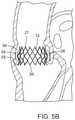
- FIG. 5Bis an enlarged view of FIG. 5A illustrating the prosthetic valve implanted within the aortic annulus, shown with the leaflet structure of the prosthetic valve removed for clarity.
- FIG. 6is a perspective view of the leaflet structure of the prosthetic valve of FIG. 1 shown prior to being secured to the support frame.
- FIG. 7is a cross-sectional view of the prosthetic valve of FIG. 1 .
- FIG. 8is a cross-sectional view of an embodiment of a delivery apparatus that can be used to deliver and implant a prosthetic valve, such as the prosthetic valve shown in FIG. 1 .
- FIGS. 8A-8Care enlarged cross-sectional views of sections of FIG. 8 .
- FIG. 9is an exploded view of the delivery apparatus of FIG. 8 .
- FIG. 10is a side view of the guide catheter of the delivery apparatus of FIG. 8 .
- FIG. 11is a perspective, exploded view of the proximal end portion of the guide catheter of FIG. 10 .
- FIG. 12is a perspective, exploded view of the distal end portion of the guide catheter of FIG. 10 .
- FIG. 13is a side view of the torque shaft catheter of the delivery apparatus of FIG. 8 .
- FIG. 14is an enlarged side view of the rotatable screw of the torque shaft catheter of FIG. 13 .
- FIG. 15is an enlarged perspective view of a coupling member that may be disposed at the end of the torque shaft of FIG. 13 .
- FIG. 16is an enlarged perspective view of the threaded nut used in the torque shaft catheter of FIG. 13 .
- FIG. 17is an enlarged side view of the distal end portion of the nose cone catheter of the delivery apparatus of FIG. 8 .
- FIG. 17Ais an enlarged, cross-sectional view of the nose cone of the nose cone catheter shown FIG. 17 .
- FIG. 17Bis an enlarged cross-sectional view of the distal end portion of the delivery apparatus of FIG. 8 showing the stent of a prosthetic valve retained in a compressed state within a delivery sheath.
- FIG. 18is an enlarged side view of the distal end portion of the delivery apparatus of FIG. 8 showing the delivery sheath in a delivery position covering a prosthetic valve in a compressed state for delivery into a patient.
- FIG. 19is an enlarged cross-sectional view of a section of the distal end portion of the delivery apparatus of FIG. 8 showing the valve-retaining mechanism securing the stent of a prosthetic valve to the delivery apparatus.
- FIG. 20is an enlarged cross-sectional view similar to FIG. 19 , showing the inner fork of the valve-retaining mechanism in a release position for releasing the prosthetic valve from the delivery apparatus.
- FIGS. 21 and 22are enlarged side views of a distal end portion of the delivery apparatus of FIG. 8 , illustrating the operation of the torque shaft for deploying a prosthetic valve from a delivery sheath.
- FIGS. 23-26are various views of an embodiment of a motorized delivery apparatus that can be used to operate the torque shaft of the delivery apparatus shown in FIG. 8 .
- FIG. 27is a perspective view of an alternative motor that can be used to operate the torque shaft of the delivery apparatus shown in FIG. 8 .
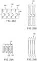
- FIG. 28Ais an enlarged view of a distal segment of the guide catheter shaft of FIG. 10 .
- FIG. 28Bshows the cut pattern for forming the portion of the shaft shown in FIG. 28A , such as by laser cutting a metal tube.
- FIG. 29Ais an enlarged view of a distal segment of a guide catheter shaft, according to another embodiment.
- FIG. 29Bshows the cut pattern for forming the shaft of FIG. 29A , such as by laser cutting a metal tube.
- FIGS. 30A-30Care enlarged, cross-sectional views of an alternative implementation of a flex control mechanism useable in the guide catheter of FIG. 11 .
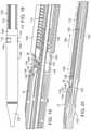
- FIG. 31Ais a side view of an alternative implementation of a torque shaft catheter useable in the delivery apparatus of FIG. 8 .
- FIGS. 31B and 31Care cross-sectional views of the torque shaft catheter of FIG. 31A .
- the prosthetic valve 10includes an expandable frame member, or stent, 12 that supports a flexible leaflet section 14 .
- the prosthetic valve 10is radially compressible to a compressed state for delivery through the body to a deployment site and expandable to its functional size shown in FIG. 1 at the deployment site.
- the prosthetic valve 10is self-expanding; that is, the prosthetic valve can radially expand to its functional size when advanced from the distal end of a delivery sheath. Apparatuses particularly suited for percutaneous delivery and implantation of a self-expanding prosthetic valve are described in detail below.
- the prosthetic valvecan be a balloon-expandable prosthetic valve that can be adapted to be mounted in a compressed state on the balloon of a delivery catheter.
- the prosthetic valvecan be expanded to its functional size at a deployment site by inflating the balloon, as known in the art.
- the illustrated prosthetic valve 10is adapted to be deployed in the native aortic annulus, although it also can be used to replace the other native valves of the heart. Moreover, the prosthetic valve 10 can be adapted to replace other valves within the body, such venous valves.
- FIGS. 3 and 4show the stent 12 without the leaflet section 14 for purposes of illustration.
- the stent 12can be formed from a plurality of longitudinally extending, generally sinusoidal shaped frame members, or struts, 16 .
- the struts 16are formed with alternating bends and are welded or otherwise secured to each other at nodes 18 formed from the vertices of adjacent bends so as to form a mesh structure.
- the struts 16can be made of a suitable shape memory material, such as the nickel titanium alloy known as Nitinol, that allows the prosthetic valve to be compressed to a reduced diameter for delivery in a delivery apparatus (such as described below) and then causes the prosthetic valve to expand to its functional size inside the patient's body when deployed from the delivery apparatus.
- a suitable shape memory materialsuch as the nickel titanium alloy known as Nitinol
- the prosthetic valveis a balloon-expandable prosthetic valve that is adapted to be crimped onto an inflatable balloon of a delivery apparatus and expanded to its functional size by inflation of the balloon
- the stent 12can be made of a suitable ductile material, such as stainless steel.
- the stent 12has an inflow end 26 and an outflow end 27 .
- the mesh structure formed by the struts 16comprises a generally cylindrical “upper” or outflow end portion 20 , an outwardly bowed or distended intermediate section 22 , and an inwardly bowed “lower” or inflow end portion 24 .
- the intermediate section 22desirably is sized and shaped to extend into the Valsalva sinuses in the root of the aorta to assist in anchoring the prosthetic valve in place once implanted.
- the mesh structuredesirably has a curved shape along its entire length that gradually increases in diameter from the outflow end portion 20 to the intermediate section 22 , then gradually decreases in diameter from the intermediate section 22 to a location on the inflow end portion 24 , and then gradually increases in diameter to form a flared portion terminating at the inflow end 26 .
- the intermediate section 22When the prosthetic valve is in its expanded state, the intermediate section 22 has a diameter D 1 , the inflow end portion 24 has a minimum diameter D 2 , the inflow end 26 has a diameter D 3 , and the outflow end portion 20 has a diameter D 4 , where D 2 is less than D 1 and D 3 , and D 4 is less than D 2 .
- D 1 and D 3desirably are greater than the diameter of the native annulus in which the prosthetic valve is to be implanted. In this manner, the overall shape of the stent 12 assists in retaining the prosthetic valve at the implantation site. More specifically, and referring to FIGS.
- the prosthetic valve 10can be implanted within a native valve (the aortic valve in the illustrated example) such that the lower section 24 is positioned within the aortic annulus 28 , the intermediate section 24 extends above the aortic annulus into the Valsalva's sinuses 56 , and the lower flared end 26 extends below the aortic annulus.
- the prosthetic valve 10is retained within the native valve by the radial outward force of the lower section 24 against the surrounding tissue of the aortic annulus 28 as well as the geometry of the stent.
- the intermediate section 24 and the flared lower end 26extend radially outwardly beyond the aortic annulus 28 to better resist against axial dislodgement of the prosthetic valve in the upstream and downstream directions (toward and away from the aorta).
- the prosthetic valve 10typically is deployed within the native annulus 28 with the native leaflets 58 folded upwardly and compressed between the outer surface of the stent 12 and the walls of the Valsalva sinuses, as depicted in FIG. 5B . In some cases, it may be desirable to excise the leaflets 58 prior to implanting the prosthetic valve 10 .
- Known prosthetic valves having a self-expanding frametypically have additional anchoring devices or frame portions that extend into and become fixed to non-diseased areas of the vasculature. Because the shape of the stent 12 assists in retaining the prosthetic valve, additional anchoring devices are not required and the overall length L of the stent can be minimized to prevent the stent upper portion 20 from extending into the non-diseased area of the aorta, or to at least minimize the extent to which the upper portion 20 extends into the non-diseased area of the aorta. Avoiding the non-diseased area of the patient's vasculature helps avoid complications if future intervention is required. For example, the prosthetic valve can be more easily removed from the patient because the stent is primarily anchored to the diseased part of the native valve. Furthermore, a shorter prosthetic valve is more easily navigated around the aortic arch.
- the diameter D 1is about 28 mm to about 32 mm, with 30 mm being a specific example
- the diameter D 2is about 24 mm to about 28 mm, with 26 mm being a specific example
- the diameter D 3is about 28 mm to about 32 mm, with 30 mm being a specific example
- the diameter D 4is about 24 mm to about 28 mm, with 26 mm being a specific example.
- the length L in particular embodimentsis about 20 mm to about 24 mm, with 22 mm being a specific example.
- the stent 12can have a plurality of angularly spaced retaining arms, or projections, in the form of posts 30 (three in the illustrated embodiment) that extend from the stent upper portion 20 .
- Each retaining arm 30has a respective aperture 32 that is sized to receive prongs of a valve-retaining mechanism that can be used to form a releasable connection between the prosthetic valve and a delivery apparatus (described below).
- the retaining arms 30need not be provided if a valve-retaining mechanism is not used.
- the leaflet assembly 14 in the illustrated embodimentcomprises three leaflets 34 a , 34 b , 34 c made of a flexible material.
- Each leaflethas an inflow end portion 60 and an outflow end portion 62 .
- the leafletscan comprise any suitable biological material (e.g., pericardial tissue, such as bovine or equine pericardium), bio-compatible synthetic materials, or other such materials, such as those described in U.S. Pat. No. 6,730,118, which is incorporated herein by reference.
- the leaflet assembly 14can include an annular reinforcing skirt 42 that is secured to the outer surfaces of the inflow end portions of the leaflets 34 a , 34 b , 34 c at a suture line 44 adjacent the inflow end of the prosthetic valve.
- the inflow end portion of the leaflet assembly 14can be secured to the stent 12 by suturing the skirt 42 to struts 16 of the lower section 24 of the stent (best shown in FIG. 1 ).
- the leaflet assembly 14can further include an inner reinforcing strip 46 that is secured to the inner surfaces of the inflow end portions 60 of the leaflets.
- each commissure attachmentcan be formed by wrapping a reinforcing section 36 around adjacent upper edge portions 38 of a pair of leaflets at the commissure formed by the two leaflets and securing the reinforcing section 36 to the edge portions 38 with sutures 48 .
- the sandwiched layers of the reinforcing material and leafletscan then be secured to the struts 16 of the stent 12 with sutures 50 adjacent the outflow end of the stent.
- the leafletstherefore desirably extend the entire length or substantially the entire length of the stent from the inflow end 26 to the outflow end 27 .
- the reinforcing sections 36reinforce the attachment of the leaflets to the stent so as to minimize stress concentrations at the suture lines and avoid “needle holes” on the portions of the leaflets that flex during use.
- the reinforcing sections 36 , the skirt 42 , and the inner reinforcing strip 46desirably are made of a bio-compatible synthetic material, such as polytetrafluoroethylene (PTFE), or a woven fabric material, such as woven polyester (e.g., polyethylene terephtalate (PET)).
- PTFEpolytetrafluoroethylene
- PETpolyethylene terephtalate
- FIG. 7shows the operation of the prosthetic valve 10 .
- the leaflets 34 a , 34 b , 34 ccollapse to effectively close the prosthetic valve.
- the curved shape of the intermediate section 22 of the stent 12defines a space between the intermediate section and the leaflets that mimics the Valsalva sinuses.
- backflow entering the “sinuses”creates a turbulent flow of blood along the upper surfaces of the leaflets, as indicated by arrows 52 . This turbulence assists in washing the leaflets and the skirt 42 to minimize clot formation.
- the prosthetic valve 10can be implanted in a retrograde approach where the prosthetic valve, mounted in a crimped state at the distal end of a delivery apparatus, is introduced into the body via the femoral artery and advanced through the aortic arch to the heart, as further described in U.S. Patent Publication No. 2008/0065011, which is incorporated herein by reference.
- FIGS. 8 and 9show a delivery apparatus 100 , according to one embodiment, that can be used to deliver a self-expanding prosthetic valve, such as prosthetic valve 10 described above, through a patient's vasculature.
- the delivery apparatus 100comprises a first, outermost or main catheter 102 (shown alone in FIG. 10 ) having an elongated shaft 104 , the distal end of which is coupled to a delivery sheath 106 ( FIG. 18 ; also referred to as a delivery cylinder).
- the proximal end of the main catheter 102is connected to a handle of the delivery apparatus.
- FIGS. 23-26show an embodiment of a handle mechanism having an electric motor for operating the delivery apparatus.
- the handle mechanismis described in detail below.
- the handlecan be used by a surgeon to advance and retract the delivery apparatus through the patient's vasculature.
- the main catheter 102can comprise a guide catheter that is configured to allow a surgeon to guide or control the amount of bending or flexing of a distal portion of the shaft 104 as it is advanced through the patient's vasculature, such as further described below.
- Another embodiment of a guide catheteris disclosed in U.S. Patent Publication No. 2008/0065011, which is incorporated herein by reference.
- the delivery apparatus 100also includes a second, intermediate catheter 108 (also referred to herein as a torque shaft catheter) having an elongated shaft 110 (also referred to herein as a torque shaft) and an elongated screw 112 connected to the distal end of the shaft 110 .
- the shaft 110 of the intermediate catheter 108extends coaxially through the shaft 104 of the main catheter 102 .
- the delivery apparatus 100can also include a third, nose-cone catheter 118 having an elongated shaft 120 and a nose piece, or nose cone, 122 secured to the distal end portion of the shaft 120 .
- the nose piece 122can have a tapered outer surface as shown for atraumatic tracking through the patient's vasculature.
- the shaft 120 of the nose-cone catheter 118extends through the prosthetic valve 10 (not shown in FIGS. 8-9 ) and the shaft 110 of the intermediate catheter 108 .
- the innermost shaft 120is configured to be moveable axially and rotatably relative to the shafts 104 , 110
- the torque shaft 110is configured to be rotatable relative to the shafts 104 , 120 to effect valve deployment and release of the prosthetic valve from the delivery apparatus, as described in detail below.
- the innermost shaft 120can have a lumen for receiving a guide wire so that the delivery apparatus can be advanced over the guide wire inside the patient's vasculature.
- the outer catheter 102can comprise a flex control mechanism 168 at a proximal end thereof to control the amount the bending or flexing of a distal portion of the outer shaft 104 as it is advanced through the patient's vasculature, such as further described below.
- the outer shaft 104can comprise a proximal segment 166 that extends from the flex control mechanism 168 and a distal segment 126 that comprises a slotted metal tube that increases the flexibility of the outer shaft at this location.
- the distal end portion of the distal segment 126can comprises an outer fork 130 of a valve-retaining mechanism 114 ( FIG. 8 ) that is configured to releasably secure a prosthetic valve 10 to the delivery apparatus 100 during valve delivery, as described in detail below.
- FIG. 28Ais an enlarged view of a portion of the distal segment 126 of the outer shaft 104 .
- FIG. 28Bshows the cut pattern that can be used to form the distal segment 126 by laser cutting the pattern in a metal tube.
- the distal segment 126comprises a plurality of interconnected circular bands or links 160 forming a slotted metal tube.
- a pull wire 162can be positioned inside the distal segment 126 and can extend from a location 164 of the distal segment 126 ( FIGS. 10 and 12 ) to the flex control mechanism. The distal end of the pull wire 162 can be secured to the inner surface of the distal segment 126 at location 164 , such as by welding.
- the proximal end of the pull wire 162can be operatively connected to the flex control mechanism 168 , which is configured to apply and release tension to the pull wire in order to control bending of the shaft, as further described below.
- the links 160 of the shaft and the gaps between adjacent linksare shaped to allow bending of the shaft upon application of light pulling force on the pull wire 162 .
- the distal segment 126is secured to a proximal segment 166 having a different construction (e.g., one or more layers of polymeric tubing).
- the proximal segment 166extends from the flex control mechanism 168 to the distal segment 126 and therefore makes up the majority of the length of the outer shaft 104 .
- the entire length or substantially the entire length of the outer shaft 104can be formed from a slotted metal tube comprising one or more sections of interconnected links 160 .
- a main shaft having such a constructioncan allow the delivery apparatus to be highly steerable, especially when use in combination with a torque shaft having the construction shown in FIGS. 13 and 14 (described below).
- the width of the links 160can be varied to vary the flexibility of the distal segment along its length.
- the links within the distal end portion of the slotted tubecan be relatively narrower to increase the flexibility of the shaft at that location while the links within the proximal end portion of the slotted tube can be relatively wider so that the shaft is relatively less flexible at that location.
- FIG. 29Ashows an alternative embodiment of a distal segment, indicated at 126 ′, which can be formed, for example, by laser cutting a metal tube.
- the segment 126 ′can comprise the distal segment of an outer shaft of a delivery apparatus (as shown in FIG. 12 ) or substantially the entire length of an outer shaft can have the construction shown in FIG. 29A .
- FIG. 29Bshows the cut pattern for forming the segment 126 ′.
- a delivery apparatuscan include a composite outer shaft comprising a laser-cut metal tube laminated with a polymeric outer layer that is fused within the gaps in the metal layer.
- a composite shaftcan comprise a laser cut metal tube having the cut pattern of FIGS.
- a composite shaftcan comprise a laser cut metal tube having the cut pattern of FIGS. 28A and 28B and a polymeric outer layer fused in the gaps between the links 160 of the metal tube.
- a composite shaftalso can include a polymeric inner layer fused in the gaps between the links 160 of the metal tube.
- the flex control mechanism 168can comprise a rotatable housing, or handle portion, 186 that houses a slide nut 188 mounted on a rail 190 .
- the slide nut 188is prevented from rotating within the housing by one or more rods 192 , each of which is partially disposed in a corresponding recess within the rail 190 and a slot or recess on the inside of the nut 188 .
- the proximal end of the pull wire 162is secured to the nut 188 .
- the nut 188has external threads that engage internal threads of the housing 186 .
- rotating the housing 186causes the nut 188 to move axially within the housing in the proximal or distal direction, depending on the direction of rotation of the housing.
- Rotating the housing in a first directione.g., clockwise
- Rotating the housing in a second directione.g., counterclockwise
- Rotating the housing 186 in a second directioncauses the nut 188 to travel in the distal direction, which relieves tension in the pull wire 162 and allows the distal end of the delivery apparatus to flex back to its pre-flexed configuration under its own resiliency.
- FIGS. 30A-30Cillustrate an alternative implementation of a flex control mechanism 300 , which includes a clutch mechanism that permits a travelling component, such as the slide nut 188 , to engage and disengage from the threads of an elongated component, such as a handle portion, or housing, 304 .
- the housing 304includes an engagement portion 308 located along a proximal end portion 310 of the housing 304 .
- the engagement portion 308includes threads or grooves 314 for engaging the threads or grooves 316 of the slide nut 188 (as best shown in FIG. 30C ).
- the housing 304further includes a disengagement portion 320 located along the distal end portion 322 of the housing 304 .
- the disengagement portion 320lacks the threads or grooves of the engagement portion 308 , such as having a smooth annular surface.
- the disengagement portion 320may have a different configuration, provided that the slide nut 188 does not move axially with respect to the housing 304 by further rotation of the housing 304 when all of the threads 316 of the nut 188 disengage from the threads 314 of the engagement portion 308 and are received in the disengagement portion 320 .
- the rail 190desirably extends the entire, or substantially the entire, combined length of the engagement portion 308 and the disengagement portion 320 , such that the nut 188 is supported on the rail 190 as the nut 188 is moved axially between the engagement portion 308 and the disengagement portion 320 , as further described below.
- One or more rods 192also desirably extend the entire, or substantially the entire, combined length of the engagement portion 308 and the disengagement portion 320 , so that the nut 188 remains engaged with the one or more rods 192 as the nut 188 is moved axially between the engagement portion 308 and the disengagement portion 320 .
- the size of the disengagement portion 320is at least about as large, such as being as large or larger than, the threaded portion of the slide nut 188 .
- the disengagement portion 320may have a diameter and length greater than at least the threaded portion of the slide nut 188 , or otherwise be sized to receive all, or at least the threaded portion, of the slide nut 188 .
- the disengagement portion 320may have a different size, in other examples, provided that the slide nut 188 does not move axially with respect to the housing 304 by further rotation of the housing 304 when all of the threads 316 of the slide nut 188 disengage from the threads 314 of the engagement portion 308 and are received within the disengagement portion 320 .
- the flex control mechanism 300can allow a user to rotate the housing 304 without causing the slide nut 188 to abut and exert undue pressure against the distal end of the housing 304 , or components thereof, such as a ring or bushing 328 disposed at the distal end of the housing 304 , as may happen if the threads or grooves 314 of the housing 304 extended further towards the distal end 322 of the housing 304 .
- the housing 304includes a biasing device 332 configured to promote re-engagement of the threads 316 of the slide nut 188 with the threads 314 of the housing 304 .
- the biasing device 332 and the disengagement portion 320 of the housing 304function as a clutch mechanism that engages and disengages the slide nut 188 from the threads 314 of the housing 304 .
- the biasing device 332may be, for example, a spring, a spring washer (such as a Belleville washer), or a resilient material, including an elastomer, such as rubber, or a foam. As shown in FIG.
- the biasing device 332 in the illustrated embodimentcan be located within the disengagement portion 320 and has one end that abuts the ring 328 and an opposite end that abuts the slide nut 188 .
- the biasing device 332is configured to exert an axial, proximally directed force against the slide nut 188 when the slide nut 188 is moved into contact with the biasing device 332 .
- the biasing device 332may be selected such that it exerts a desired amount of force against the slide nut 188 .
- the biasing device 332is a spring
- the springmay be selected to have a sufficiently large spring constant to exert the desired amount of axial force.
- the biasing device 332may be selected based on additional properties, in further examples.
- the biasing device 332may be selected, for example, to provide tactile or audible feedback to a user when the biasing device 332 reaches a particular level of compression, such as being fully compressed.
- the tactile or audible feedbackmay be provided, for example, by selecting a spring with an appropriate spring constant.
- FIG. 30Billustrates the slide nut 188 having been moved into contact with the biasing device 332 .
- continued rotation of the housing 304causes the slide nut 188 to enter the disengagement portion 320 and to compress the biasing device 332 .
- the biasing device 332exerts an axial, proximally-directed force against the slide nut 188 .
- further rotation of the housing 304does not cause distal axial movement of the slide nut 188 .
- the biasing device 332will urge the threads 316 of the slide nut 188 into reengagement with the threads 314 of the housing 304 , and cause the slide nut 188 to move proximally along the engagement section 308 .
- FIGS. 30A-30Cillustrate a disengagement portion 320 and biasing device 332 at the distal end 322 of the housing 304
- the flex control mechanism 300may have other configurations.
- the housing 304may include a disengagement portion, and optionally a biasing device, at the proximal end 310 of the housing 304 , in place of, or in addition to, the disengagement portion 320 and biasing device 332 located at the distal end 322 of the housing 304 .
- the torque shaft catheter 108includes an annular projection in the form of a ring 128 (also referred to as an anchoring disc) mounted on the distal end portion of the torque shaft 110 adjacent the screw 112 .
- the ring 128is secured to the outer surface of the torque shaft 110 such that it cannot move axially or rotationally relative to the torque shaft.
- the inner surface of the outer shaft 104is formed with a feature, such as a slot or recess, that receives the ring 128 in such a manner that the ring and the corresponding feature on the inner surface of the outer shaft 104 allow the torque shaft 110 to rotate relative to the outer shaft 104 , but prevent the torque shaft from moving axially relative to the outer shaft.
- the corresponding feature on the outer shaft 104 that receives the ring 128can be inwardly extending tab portions formed in the distal segment 126 , such as shown at 164 in FIG. 12 .
- the ring 128is an integral part of the screw 112 (i.e., the screw 112 and the ring 128 are portions of single component).
- the screw 112 and the ring 128are separately formed components but are both fixedly secured to the distal end of the torque shaft 110 .
- the torque shaft 110desirably is configured to be rotatable relative to the delivery sheath 106 to effect incremental and controlled advancement of the prosthetic valve 10 from the delivery sheath 106 .
- the delivery apparatus 100can include a sheath retaining ring in the form of a threaded nut 150 mounted on the external threads of the screw 112 .
- the nut 150includes internal threads 152 that engage the external threads of the screw 112 and axially extending legs 154 .
- Each leg 154has a raised distal end portion that extends into and/or forms a snap fit connection with openings 172 in the proximal end of the sheath 106 (as best shown in FIG.
- the sheath 106extends over the prosthetic valve 10 and retains the prosthetic valve in a radially compressed state until the sheath 106 is retracted by the user to deploy the prosthetic valve.
- the outer fork 130 ( FIG. 10 ) of the valve-retaining mechanismcomprises a plurality of prongs 134 , each of which extends through a region defined between two adjacent legs 154 of the nut so as to prevent rotation of the nut 150 relative to the screw 112 upon rotation of the screw.
- rotation of the torque shaft 110causes corresponding axial movement of the nut 150 .
- the connection between the nut 150 and the sheath 106is configured such that axial movement of the nut along the screw 112 (in the distal or proximal direction) causes the sheath 106 to move axially in the same direction relative to the screw and the valve-retaining mechanism.
- FIG. 21shows the nut 150 in a distal position wherein the sheath 106 (not shown in FIG. 21 ) extends over and retains the prosthetic valve 10 in a compressed state for delivery. Movement of the nut 150 from the distal position ( FIG. 21 ) to a proximal position ( FIG. 22 ) causes the sheath 106 to move in the proximal direction, thereby deploying the prosthetic valve 10 from the sheath 106 . Rotation of the torque shaft 110 to effect axial movement of the sheath 106 can be accomplished with a motorized mechanism (such as shown in FIGS. 23-26 and described below) or by manually turning a crank or wheel.
- a motorized mechanismsuch as shown in FIGS. 23-26 and described below
- FIGS. 31A-31Cillustrate an alternative implementation 400 of a torque shaft catheter (generally similar to the torque shaft catheter 108 of FIG. 13 ), which in this implementation includes a clutch mechanism that allows a travelling component, such as the nut 150 , to engage and disengage from an elongated component, such as a screw 410 .
- the torque shaft 404 in this embodimentincludes an engagement portion 408 corresponding to a screw 410 , and thus includes threads or grooves 412 for engaging the mating threads or grooves 152 on the nut 150 (as best shown in FIG. 16 ).
- rotation of the torque shaft 404causes the nut 150 to move axially along the screw 410 , thereby moving the sheath 106 , as discussed above.
- the torque shaft 404further includes a disengagement portion 416 .
- the disengagement portion 416lacks threads or grooves, such as having a smooth annular surface.
- the disengagement portion 416has a different configuration, provided that the nut 150 does not move axially with respect to the torque shaft 404 by further rotation of the torque shaft when all of the threads 152 of the nut 150 disengage from the threads 412 of the screw 410 .
- the size of the disengagement portion 416is at least about as large, such as being as large or larger than, the threaded portion of the nut 150 .
- the disengagement portion 416may have a length greater than at least the threaded portion of the nut 150 , or otherwise be sized to receive all, or at least the threaded portion, of the nut 150 .
- the threads 152are only on a proximal portion of the nut 150 (the portion of the nut between the proximal ends of the legs 154 and the proximal end of the nut) and not on the legs.
- the disengagement portion 416has an axial length at least greater than the length of the proximal portion of the nut 150 .
- the disengagement portion 416may have a different size and/or shape, provided that the nut 150 does not move axially with respect to the torque shaft 404 by further rotation of the torque shaft 404 when all of the threads 152 of the nut 150 disengage from the threads 412 of the screw 410 .
- the size of the disengagement portion 416may be correspondingly increased.
- the torque shaft catheter 400can allow a user to freely rotate the torque shaft 404 without causing the nut 150 to abut and exert undue pressure against the annular projection 128 once the nut 150 reaches the end of the screw 410 , thereby avoiding torque build-up and undesirable stress on the components of the delivery apparatus.
- the torque shaft catheter 400includes a biasing device 426 configured to promote re-engagement of the threads 152 of the nut 150 with the threads 412 of the screw 410 .
- the biasing device 426 and the disengagement portion 416 of the torque shaft 404function as a clutch mechanism that engages and disengages the nut 150 from the screw 410 .
- the biasing device 426may be, in various implementations, a spring, a spring washer (such as a Belleville washer), or a resilient material, including elastomers, such as rubber, or foam.
- the biasing device 426 in the illustrated embodimentis coaxially disposed on the torque shaft 404 , within the disengagement portion 416 , and has one end that abuts the annular projection 128 and an opposite end that abuts the nut 150 .
- the biasing device 426is configured to exert an axial, distally directed, force against the nut 150 when the nut is moved into contact with the biasing device.
- the biasing device 426may be selected such that it exerts a desired amount of force against the nut 150 .
- the biasing device 426is a spring
- the springmay be selected to have a sufficiently large spring constant to exert the desired amount of axial force.
- the biasing device 426may be selected based on additional properties, in further examples.
- the biasing device 426may be selected, in some examples, to provide tactile or audible feedback to a user when the biasing device 426 reaches a particular level of compression, such as being fully compressed.
- the tactile or audible feedbackmay be provided by, for example, selecting a spring with an appropriate spring constant, such that the spring vibrates sufficiently to be felt by a user, or emits a noise audible to a user, when compressed.
- FIG. 31Billustrates the nut 150 having been rotated into contact with the biasing device 426 .
- FIG. 31Cfurther rotation of the torque shaft 404 causes the nut 150 to enter the disengagement portion 416 , and to compress the biasing device 426 .
- the biasing device 426exerts an axial, distally directed force against the nut 150 .
- further rotation of the torque shaft 404does not cause axial movement of the nut 150 .
- the biasing device 426will urge the threads of the nut 150 into reengagement with the threads 412 of the screw 410 , and cause the nut 1 to move distally along the screw.
- FIGS. 31A-31Cillustrate a disengagement portion 416 and biasing device 426 adjacent the proximal end of the screw 410
- the torque shaft catheter 400may have other configurations.
- the torque shaft catheter 400may include a disengagement portion, and optionally a biasing device, adjacent the distal end of the screw 410 , in place of, or in addition to, the disengagement portion 416 and biasing device 426 adjacent the proximal end of the screw 410 .
- FIG. 17shows an enlarged view of the nose cone 122 secured to the distal end of the innermost shaft 120 .
- the nose cone 122 in the illustrated embodimentincludes a proximal end portion 174 that is sized to fit inside the distal end of the sheath 106 .
- An intermediate section 176 of the nose coneis positioned immediately adjacent the end of the sheath 106 in use and is formed with a plurality of longitudinal grooves, or recessed portions, 178 .
- the diameter of the intermediate section 176 at its proximal end 180desirably is slightly larger than the outer diameter of the sheath 106 .
- the proximal end 180can be held in close contact with the distal end of the sheath 106 to protect surrounding tissue from coming into contact with the metal edge of the sheath.
- the grooves 178allow the intermediate section 176 to be compressed radially as the delivery apparatus is advanced through an introducer sheath. This allows the nose cone 122 to be slightly oversized relative to the inner diameter of the introducer sheath.
- FIG. 17Bshows a cross-section of the nose cone 122 and the sheath 106 in a delivery position, with the prosthetic valve retained in a compressed delivery state inside the sheath 106 (for purposes of illustration, only the stent 12 of the prosthetic valve is shown).
- the proximal end 180 of the intermediate section 176can abut the distal end of the sheath 106 and a tapered proximal surface 182 of the nose cone can extend within a distal portion of the stent 12 .
- the delivery apparatus 100can include a valve-retaining mechanism 114 ( FIG. 8B ) for releasably retaining a stent 12 of a prosthetic valve.
- the valve-retaining mechanism 114can include a first valve-securement component in the form of an outer fork 130 (as best shown in FIG. 12 ) (also referred to as an “outer trident” or “release trident”), and a second valve-securement component in the form of an inner fork 132 (as best shown in FIG. 17 ) (also referred to as an “inner trident” or “locking trident”).
- the outer fork 130cooperates with the inner fork 132 to form a releasable connection with the retaining arms 30 of the stent 12 .
- the proximal end of the outer fork 130is connected to the distal segment 126 of the outer shaft 104 , and the distal end of the outer fork is releasably connected to the stent 12 .
- the outer fork 130 and the distal segment 126can be integrally formed as a single component (e.g., the outer fork and the distal segment can be laser cut or otherwise machined from a single piece of metal tubing), although these components can be separately formed and subsequently connected to each other.
- the inner fork 132can be mounted on the nose catheter shaft 120 (as best shown in FIG. 17 ). The inner fork 132 connects the stent to the distal end portion of the nose catheter shaft 120 .
- the nose catheter shaft 120can be moved axially relative to the outer shaft 104 to release the prosthetic valve from the valve-retaining mechanism, as further described below.
- the outer fork 130includes a plurality of angularly-spaced prongs 134 (three in the illustrated embodiment) corresponding to the retaining arms 30 of the stent 12 , which prongs extend from the distal end of distal segment 126 .
- the distal end portion of each prong 134includes a respective opening 140 .
- the inner fork 132includes a plurality of angularly-spaced prongs 136 (three in the illustrated embodiment) corresponding to the retaining arms 30 of the stent 12 , which prongs extend from a base portion 138 at the proximal end of the inner fork.
- the base portion 138 of the inner forkis fixedly secured to the nose catheter shaft 120 (e.g., with a suitable adhesive) to prevent axial and rotational movement of the inner fork relative to the nose catheter shaft 120 .
- each prong 134 of the outer fork 130cooperates with a corresponding prong 136 of the inner fork 132 to form a releasable connection with a retaining arm 30 of the stent 12 .
- the distal end portion of each prong 134is formed with an opening 140 .
- FIG. 19shows the prosthetic valve 10 secured to the delivery apparatus by the inner 132 and outer 130 forks before the prosthetic valve is loaded into the sheath 106 .
- Retracting the inner prongs 136 proximally (in the direction of arrow 184 in FIG. 20 ) to remove the inner prongs from the openings 32is effective to release the prosthetic valve 10 from the retaining mechanism.
- the inner fork 132is moved to a proximal position ( FIG. 20 )
- the retaining arms 30 of the stent 12can move radially outwardly from the openings 140 in the outer fork 130 under the resiliency of the stent.
- the valve-retaining mechanism 114forms a releasable connection with the prosthetic valve that is secure enough to retain the prosthetic valve relative to the delivery apparatus to allow the user to fine tune or adjust the position of the prosthetic valve after it is deployed from the delivery sheath.
- the connection between the prosthetic valve and the retaining mechanismcan be released by retracting the nose catheter shaft 120 relative to the outer shaft 104 (which retracts the inner fork 132 relative to the outer fork 130 ).
- the delivery apparatus 100can be inserted into the patient's body for delivery of the prosthetic valve.
- the prosthetic valvecan be delivered in a retrograde procedure where a delivery apparatus is inserted into a femoral artery and advanced through the patient's vasculature to the heart.
- an introducer sheathcan be inserted into the femoral artery followed by a guide wire, which is advanced through the patient's vasculature through the aorta and into the left ventricle.
- the delivery apparatus 100can then be inserted through the introducer sheath and advanced over the guide wire until the distal end portion of the delivery apparatus containing the prosthetic valve 10 is advanced to a location adjacent to or within the native aortic valve.
- the prosthetic valve 10can be deployed from the delivery apparatus 100 by rotating the torque shaft 110 relative to the outer shaft 104 .
- the proximal end of the torque shaft 110can be operatively connected to a manually rotatable handle portion or a motorized mechanism that allows the surgeon to effect rotation of the torque shaft 110 relative to the outer shaft 104 .
- Rotation of the torque shaft 110 and the screw 112causes the nut 150 and the sheath 106 to move in the proximal direction toward the outer shaft ( FIG. 22 ), which deploys the prosthetic valve from the sheath.
- Rotation of the torque shaft 110causes the sheath 106 to move relative to the prosthetic valve in a precise and controlled manner as the prosthetic valve advances from the open distal end of the delivery sheath and begins to expand.
- the prosthetic valve 10begins to advance from the delivery sheath 106 and expand, the prosthetic valve is held against uncontrolled movement from the sheath caused by the expansion force of the prosthetic valve against the distal end of the sheath.
- the prosthetic valve 10is retained in a stationary position relative to the ends of the inner shaft 120 and the outer shaft 104 by virtue of the valve-retaining mechanism 114 .
- the prosthetic valve 10can be held stationary relative to the target location in the body as the sheath 106 is retracted. Moreover, after the prosthetic valve 10 is partially advanced from the sheath 106 , it may be desirable to retract the prosthetic valve back into the sheath, for example, to reposition the prosthetic valve or to withdraw the prosthetic valve entirely from the body.
- the partially deployed prosthetic valve 10can be retracted back into the sheath 106 by reversing the rotation of the torque shaft, which causes the sheath to advance back over the prosthetic valve in the distal direction.
- the surgeonmust apply push-pull forces to the shaft and/or the sheath to unsheathe the prosthetic valve. It is therefore difficult to transmit forces to the distal end of the device without distorting the shaft (e.g., compressing or stretching the shaft axially), which in turn causes uncontrolled movement of the prosthetic valve during the unsheathing process.
- the shaft and/or sheathcan be made more rigid, which is undesirable because the device becomes harder to steer through the vasculature.
- the manner of unsheathing the prosthetic valve described aboveeliminates the application of push-pull forces on the shaft, as required in known devices, so that relatively high and accurate forces can be applied to the distal end of the shaft without compromising the flexibility of the device.
- the prosthetic valve 10After the prosthetic valve 10 is advanced from the delivery sheath 106 and expands to its functional size, the prosthetic valve remains connected to the delivery apparatus via the retaining mechanism 114 . Consequently, after the prosthetic valve 10 is advanced from the delivery sheath 106 , the surgeon can reposition the prosthetic valve relative to the desired implantation position in the native valve, such as by moving the delivery apparatus in the proximal and distal directions or side to side, or rotating the delivery apparatus, which causes corresponding movement of the prosthetic valve.
- the retaining mechanism 114desirably provides a connection between the prosthetic valve 10 and the delivery apparatus that is secure and rigid enough to retain the position of the prosthetic valve relative to the delivery apparatus against the flow of the blood as the position of the prosthetic valve is adjusted relative to the desired implantation position in the native valve.
- the connection between the prosthetic valve and the delivery apparatuscan be released by retracting the innermost shaft 120 in the proximal direction relative to the outer shaft 104 , which is effective to retract the inner fork 132 to withdraw its prongs 136 from the openings 32 in the retaining arms 30 of the prosthetic valve ( FIG. 20 ).
- Slightly retracting of the outer shaft 104allows the outer fork 130 to back off the retaining arms 30 of the prosthetic valve 10 , which slide outwardly through openings 140 in the outer fork to completely disconnect the prosthetic valve from the retaining mechanism 114 .
- the delivery apparatuscan be withdrawn from the body, leaving the prosthetic aortic valve 10 implanted within the native valve (such as shown in FIGS. 5A and 5B ).
- the delivery apparatus 100has at its distal end a semi-rigid segment comprised of relatively rigid components used to transform rotation of the torque shaft into axial movement of the sheath.
- this semi-rigid segment in the illustrated embodimentis comprised of the prosthetic valve and the screw 112 .
- An advantage of the delivery apparatus 100is that the overall length of the semi-rigid segment is minimized because the nut 150 is used rather than internal threads on the outer shaft to affect translation of the sheath 106 .
- the reduced length of the semi-rigid segmentincreases the overall flexibility along the distal end portion of the delivery catheter.
- the length and location of the semi-rigid segmentremains constant because the torque shaft does not translate axially relative to the outer shaft.
- the curved shape of the delivery cathetercan be maintained during valve deployment, which improves the stability of the deployment.
- a further benefit of the delivery apparatus 100is that the ring 128 prevents the transfer of axial loads (compression and tension) to the section of the torque shaft 110 that is distal to the ring.
- the delivery apparatuscan be adapted to deliver a balloon-expandable prosthetic valve 10 .
- the valve retaining mechanism 114can be used to secure the prosthetic valve to the end of the delivery apparatus. Since the stent 12 of the prosthetic valve 10 is not self-expanding, the sheath 106 can be optional. The retaining mechanism 114 enhances the pushability of the delivery apparatus and prosthetic valve assembly through an introducer sheath.
- FIGS. 23-26illustrate the proximal end portion of the delivery apparatus 100 , according to one embodiment.
- the delivery apparatus 100can comprise a handle 202 that is configured to be releasably connectable to the proximal end portion of a catheter assembly 204 comprising catheters 102 , 108 , 118 . It may be desirable to disconnect the handle 202 from the catheter assembly 204 for various reasons. For example, disconnecting the handle 202 can allow another device to be slid over the catheter assembly 204 , such as a valve-retrieval device or a device to assist in steering the catheter assembly. It should be noted that any of the features of the handle 202 and the catheter assembly 204 can be implemented in any of the embodiments of the delivery apparatuses disclosed herein.
- FIGS. 23 and 24show the proximal end portion of the catheter assembly 204 partially inserted into a distal opening of the handle 202 .
- the proximal end portion of the main shaft 104is formed with an annular groove 212 (as best shown in FIG. 24 ) that cooperates with a holding mechanism, or latch mechanism, 214 inside the handle 202 .
- a holding mechanismor latch mechanism
- One side of the holding mechanism 214is connected to a button 218 that extends through the housing of the handle 202 .
- the opposite side of the holding mechanism 214is contacted by a spring 220 that biases the holding mechanism to a position engaging the main shaft 104 at the groove 212 .
- the engagement of the holding mechanism 214 within the groove 212prevents axial separation of the catheter assembly 204 from the handle 202 .
- the catheter assembly 204can be released from the handle 202 by depressing button 218 , which moves the holding mechanism 214 from locking engagement with the main shaft 104 .
- the main shaft 104can be formed with a flat surface portion within the groove 212 .
- the flat surface portionis positioned against a corresponding flat surface portion of the engaging portion 216 . This engagement holds the main shaft 104 stationary relative to the torque shaft 110 as the torque shaft is rotated during valve deployment.
- the proximal end portion of the torque shaft 110can have a driven nut 222 ( FIG. 26 ) that is slidably received in a drive cylinder 224 ( FIG. 25 ) mounted inside the handle 202 .
- the nut 222can be secured to the proximal end of the torque shaft 100 by securing the driven nut over a coupling member 170 ( FIG. 15 ).
- FIG. 26is a perspective view of the inside of the handle 202 with the drive cylinder 224 and other components removed to show the driven nut 222 and other components positioned within the drive cylinder.
- the drive cylinder 224has a through opening (or lumen) extending the length of the cylinder that is shaped to correspond to the flats of the nut 222 such that rotation of the drive cylinder is effective to rotate the nut and the torque shaft 110 .
- the drive cylinder 224can have an enlarged distal end portion 236 that can house one or more seals (e.g., O-rings 246 ) that form a seal with the outer surface of the main shaft 104 ( FIG. 25 ).
- the handle 202can also house a fitting 238 that has a flush port in communication with the lumen of the torque shaft 110 and/or the lumen of the main shaft 104 .
- the drive cylinder 224is operatively connected to an electric motor 226 through gears 228 and 230 .
- the handle 202can also house a battery compartment 232 that contains batteries for powering the motor 226 .
- Rotation of the motor 226 in one directioncauses the torque shaft 110 to rotate, which in turn causes the sheath 106 to retract and uncover a prosthetic valve 10 at the distal end of the catheter assembly.
- Rotation of the motor 226 in the opposite directioncauses the torque shaft 110 to rotate in an opposite direction, which causes the sheath 106 to move back over the prosthetic valve 10 .
- An operator button 234 on the handle 202allows a user to activate the motor 226 , which can be rotated in either direction to un-sheath a prosthetic valve 10 or retrieve an expanded or partially expanded prosthetic valve.
- the distal end portion of the nose catheter shaft 120can be secured to an inner fork 132 that is moved relative to an outer fork 130 to release a prosthetic valve 10 secured to the end of the delivery apparatus. Movement of the shaft 120 relative to the main shaft 104 (which secures the outer fork 130 ) can be effected by a proximal end portion 240 of the handle 202 that is slidable relative to the main housing 244 .
- the end portion 240is operatively connected to the shaft 120 such that movement of the end portion 240 is effective to translate the shaft 120 axially relative to the main shaft 104 (causing a prosthetic valve 10 to be released from the inner 132 and outer 130 forks).
- the end portion 240can have flexible side panels 242 on opposite sides of the handle 202 that are normally biased outwardly in a locked position to retain the end portion relative to the main housing 244 .
- the usercan depress the side panels 242 , which disengage from corresponding features in the housing 244 and allow the end portion 240 to be pulled proximally relative to the main housing, which causes corresponding axial movement of the shaft 120 relative to the main shaft.
- Proximal movement of the shaft 120causes the prongs 136 of the inner fork 132 to disengage from the apertures 32 in the stent 12 , which in turn allows the retaining arms 30 of the stent to deflect radially outwardly from the openings 140 in the prongs 134 of the outer fork 130 , thereby releasing the prosthetic valve.
- FIG. 27shows an alternative embodiment of a motor, indicated at 400 , that can be used to drive a torque shaft (e.g., torque shaft 110 ).
- a catheter assemblycan be connected directly to one end of a shaft 402 of the motor, without gearing.
- the shaft 402includes a lumen that allows for passage of an innermost shaft (e.g., shaft 120 ) of the catheter assembly, a guide wire, and/or fluids for flushing the lumens of the catheter assembly.
- the power source for rotating the torque shaft 110can be a hydraulic power source (e.g., hydraulic pump) or pneumatic (air-operated) power source that is configured to rotate the torque shaft.
- the handle 202can have a manually movable lever or wheel that is operable to rotate the torque shaft 110 .
- a power sourcee.g., an electric, hydraulic, or pneumatic power source
- the power sourceis configured to reciprocate the shaft longitudinally in the distal direction relative to a valve sheath in a precise and controlled manner in order to advance the prosthetic valve from the sheath.
- the power sourcecan be operatively connected to the sheath in order to reciprocate the sheath longitudinally in the proximal direction relative to the prosthetic valve to deploy the prosthetic valve from the sheath.
- the terms “a”, “an” and “at least one”encompass one or more of the specified element. That is, if two of a particular element are present, one of these elements is also present and thus “an” element is present.
- the terms “a plurality of” and “plural”mean two or more of the specified element.
- the term “and/or” used between the last two of a list of elementsmeans any one or more of the listed elements.
- the phrase “A, B, and/or C”means “A,” “B,” “C,” “A and B,” “A and C,” “B and C” or “A, B and C.”
- Coupledgenerally means physically coupled or linked and does not exclude the presence of intermediate elements between the coupled items absent specific contrary language.
Landscapes
- Health & Medical Sciences (AREA)
- Cardiology (AREA)
- Engineering & Computer Science (AREA)
- Biomedical Technology (AREA)
- Life Sciences & Earth Sciences (AREA)
- Transplantation (AREA)
- Heart & Thoracic Surgery (AREA)
- Vascular Medicine (AREA)
- Oral & Maxillofacial Surgery (AREA)
- Animal Behavior & Ethology (AREA)
- General Health & Medical Sciences (AREA)
- Public Health (AREA)
- Veterinary Medicine (AREA)
- Mechanical Engineering (AREA)
- Prostheses (AREA)
- Infusion, Injection, And Reservoir Apparatuses (AREA)
Abstract
Description
Claims (21)
Priority Applications (1)
| Application Number | Priority Date | Filing Date | Title |
|---|---|---|---|
| US16/439,406US11234816B2 (en) | 2015-11-11 | 2019-06-12 | Prosthetic valve delivery apparatus having clutch mechanism |
Applications Claiming Priority (3)
| Application Number | Priority Date | Filing Date | Title |
|---|---|---|---|
| US201562254124P | 2015-11-11 | 2015-11-11 | |
| US15/346,355US10321996B2 (en) | 2015-11-11 | 2016-11-08 | Prosthetic valve delivery apparatus having clutch mechanism |
| US16/439,406US11234816B2 (en) | 2015-11-11 | 2019-06-12 | Prosthetic valve delivery apparatus having clutch mechanism |
Related Parent Applications (1)
| Application Number | Title | Priority Date | Filing Date |
|---|---|---|---|
| US15/346,355ContinuationUS10321996B2 (en) | 2015-11-11 | 2016-11-08 | Prosthetic valve delivery apparatus having clutch mechanism |
Publications (2)
| Publication Number | Publication Date |
|---|---|
| US20190290424A1 US20190290424A1 (en) | 2019-09-26 |
| US11234816B2true US11234816B2 (en) | 2022-02-01 |
Family
ID=58668209
Family Applications (2)
| Application Number | Title | Priority Date | Filing Date |
|---|---|---|---|
| US15/346,355Active2037-09-19US10321996B2 (en) | 2015-11-11 | 2016-11-08 | Prosthetic valve delivery apparatus having clutch mechanism |
| US16/439,406Active2037-01-07US11234816B2 (en) | 2015-11-11 | 2019-06-12 | Prosthetic valve delivery apparatus having clutch mechanism |
Family Applications Before (1)
| Application Number | Title | Priority Date | Filing Date |
|---|---|---|---|
| US15/346,355Active2037-09-19US10321996B2 (en) | 2015-11-11 | 2016-11-08 | Prosthetic valve delivery apparatus having clutch mechanism |
Country Status (9)
| Country | Link |
|---|---|
| US (2) | US10321996B2 (en) |
| EP (3) | EP4091580A1 (en) |
| CN (2) | CN108472137B (en) |
| CA (1) | CA3002832A1 (en) |
| CR (1) | CR20180226A (en) |
| ES (2) | ES2916715T3 (en) |
| MX (2) | MX381272B (en) |
| SG (2) | SG11201803417WA (en) |
| WO (1) | WO2017083510A1 (en) |
Families Citing this family (34)
| Publication number | Priority date | Publication date | Assignee | Title |
|---|---|---|---|---|
| US8652202B2 (en) | 2008-08-22 | 2014-02-18 | Edwards Lifesciences Corporation | Prosthetic heart valve and delivery apparatus |
| US8579964B2 (en) | 2010-05-05 | 2013-11-12 | Neovasc Inc. | Transcatheter mitral valve prosthesis |
| US9155619B2 (en) | 2011-02-25 | 2015-10-13 | Edwards Lifesciences Corporation | Prosthetic heart valve delivery apparatus |
| US9554897B2 (en) | 2011-04-28 | 2017-01-31 | Neovasc Tiara Inc. | Methods and apparatus for engaging a valve prosthesis with tissue |
| US9308087B2 (en) | 2011-04-28 | 2016-04-12 | Neovasc Tiara Inc. | Sequentially deployed transcatheter mitral valve prosthesis |
| CN104114127B (en) | 2011-12-09 | 2017-09-05 | 爱德华兹生命科学公司 | Prosthetic heart valve with improved commissural support |
| US8652145B2 (en) | 2011-12-14 | 2014-02-18 | Edwards Lifesciences Corporation | System and method for crimping a prosthetic valve |
| US9345573B2 (en) | 2012-05-30 | 2016-05-24 | Neovasc Tiara Inc. | Methods and apparatus for loading a prosthesis onto a delivery system |
| US9572665B2 (en) | 2013-04-04 | 2017-02-21 | Neovasc Tiara Inc. | Methods and apparatus for delivering a prosthetic valve to a beating heart |
| EP2999436B1 (en) | 2013-05-20 | 2018-08-29 | Edwards Lifesciences Corporation | Prosthetic heart valve delivery apparatus |
| US10350047B2 (en) | 2015-09-02 | 2019-07-16 | Edwards Lifesciences Corporation | Method and system for packaging and preparing a prosthetic heart valve and associated delivery system |
| US10321996B2 (en) | 2015-11-11 | 2019-06-18 | Edwards Lifesciences Corporation | Prosthetic valve delivery apparatus having clutch mechanism |
| US11033387B2 (en) | 2015-11-23 | 2021-06-15 | Edwards Lifesciences Corporation | Methods for controlled heart valve delivery |
| US10265169B2 (en) | 2015-11-23 | 2019-04-23 | Edwards Lifesciences Corporation | Apparatus for controlled heart valve delivery |
| US10357351B2 (en) | 2015-12-04 | 2019-07-23 | Edwards Lifesciences Corporation | Storage assembly for prosthetic valve |
| CA3007660A1 (en) | 2015-12-15 | 2017-06-22 | Neovasc Tiara Inc. | Transseptal delivery system |
| US10433952B2 (en) | 2016-01-29 | 2019-10-08 | Neovasc Tiara Inc. | Prosthetic valve for avoiding obstruction of outflow |
| US10363130B2 (en) | 2016-02-05 | 2019-07-30 | Edwards Lifesciences Corporation | Devices and systems for docking a heart valve |
| US10779941B2 (en) | 2016-03-08 | 2020-09-22 | Edwards Lifesciences Corporation | Delivery cylinder for prosthetic implant |
| CA3042588A1 (en) | 2016-11-21 | 2018-05-24 | Neovasc Tiara Inc. | Methods and systems for rapid retraction of a transcatheter heart valve delivery system |
| USD867595S1 (en) | 2017-02-01 | 2019-11-19 | Edwards Lifesciences Corporation | Stent |
| US10959846B2 (en) | 2017-05-10 | 2021-03-30 | Edwards Lifesciences Corporation | Mitral valve spacer device |
| EP4112009A1 (en)* | 2017-07-06 | 2023-01-04 | Edwards Lifesciences Corporation | Steerable rail delivery system |
| CA3073834A1 (en) | 2017-08-25 | 2019-02-28 | Neovasc Tiara Inc. | Sequentially deployed transcatheter mitral valve prosthesis |
| CN113271890B (en) | 2018-11-08 | 2024-08-30 | 内奥瓦斯克迪亚拉公司 | Ventricular deployment of transcatheter mitral valve prosthesis |
| CA3132873A1 (en) | 2019-03-08 | 2020-09-17 | Neovasc Tiara Inc. | Retrievable prosthesis delivery system |
| CA3135753C (en) | 2019-04-01 | 2023-10-24 | Neovasc Tiara Inc. | Controllably deployable prosthetic valve |
| US11491006B2 (en) | 2019-04-10 | 2022-11-08 | Neovasc Tiara Inc. | Prosthetic valve with natural blood flow |
| US11779742B2 (en) | 2019-05-20 | 2023-10-10 | Neovasc Tiara Inc. | Introducer with hemostasis mechanism |
| JP7520897B2 (en) | 2019-06-20 | 2024-07-23 | ニオバスク ティアラ インコーポレイテッド | Thin prosthetic mitral valve |
| CN114126537A (en)* | 2019-12-02 | 2022-03-01 | 爱德华兹生命科学公司 | Frames with different strut widths for prosthetic implants |
| EP4438098A3 (en)* | 2020-06-10 | 2024-12-18 | Edwards Lifesciences Corporation | Release mechanism for a delivery apparatus for an implantable medical device |
| JPWO2022101960A1 (en)* | 2020-11-10 | 2022-05-19 | ||
| CN116585084B (en)* | 2023-07-17 | 2023-09-15 | 四川国屹医疗科技有限公司 | Support conveying device |
Citations (183)
| Publication number | Priority date | Publication date | Assignee | Title |
|---|---|---|---|---|
| US519297A (en) | 1894-05-01 | Bauer | ||
| US4035849A (en) | 1975-11-17 | 1977-07-19 | William W. Angell | Heart valve stent and process for preparing a stented heart valve prosthesis |
| US4592340A (en) | 1984-05-02 | 1986-06-03 | Boyles Paul W | Artificial catheter means |
| US4955895A (en) | 1986-12-23 | 1990-09-11 | Terumo Kabushiki Kaisha | Vasodilating catheter |
| US4994077A (en) | 1989-04-21 | 1991-02-19 | Dobben Richard L | Artificial heart valve for implantation in a blood vessel |
| US5059177A (en) | 1990-04-19 | 1991-10-22 | Cordis Corporation | Triple lumen balloon catheter |
| WO1991017720A1 (en) | 1990-05-18 | 1991-11-28 | Henning Rud Andersen | A valve prosthesis for implantation in the body and a catheter for implantating such valve prosthesis |
| US5176698A (en) | 1991-01-09 | 1993-01-05 | Scimed Life Systems, Inc. | Vented dilatation cathether and method for venting |
| US5192297A (en) | 1991-12-31 | 1993-03-09 | Medtronic, Inc. | Apparatus and method for placement and implantation of a stent |
| US5266073A (en) | 1987-12-08 | 1993-11-30 | Wall W Henry | Angioplasty stent |
| US5325845A (en) | 1992-06-08 | 1994-07-05 | Adair Edwin Lloyd | Steerable sheath for use with selected removable optical catheter |
| US5358496A (en) | 1991-10-18 | 1994-10-25 | Ethicon, Inc. | Endoscopic tissue manipulator |
| US5411552A (en) | 1990-05-18 | 1995-05-02 | Andersen; Henning R. | Valve prothesis for implantation in the body and a catheter for implanting such valve prothesis |
| US5554185A (en) | 1994-07-18 | 1996-09-10 | Block; Peter C. | Inflatable prosthetic cardiovascular valve for percutaneous transluminal implantation of same |
| US5591195A (en) | 1995-10-30 | 1997-01-07 | Taheri; Syde | Apparatus and method for engrafting a blood vessel |
| US5599305A (en) | 1994-10-24 | 1997-02-04 | Cardiovascular Concepts, Inc. | Large-diameter introducer sheath having hemostasis valve and removable steering mechanism |
| DE19532846A1 (en) | 1995-09-06 | 1997-03-13 | Georg Dr Berg | Valve for use in heart |
| US5632760A (en) | 1994-10-20 | 1997-05-27 | Cordis Corporation | Balloon catheter for stent implantation |
| US5639274A (en) | 1995-06-02 | 1997-06-17 | Fischell; Robert E. | Integrated catheter system for balloon angioplasty and stent delivery |
| US5728068A (en) | 1994-06-14 | 1998-03-17 | Cordis Corporation | Multi-purpose balloon catheter |
| US5749890A (en) | 1996-12-03 | 1998-05-12 | Shaknovich; Alexander | Method and system for stent placement in ostial lesions |
| EP0850607A1 (en) | 1996-12-31 | 1998-07-01 | Cordis Corporation | Valve prosthesis for implantation in body channels |
| US5782809A (en) | 1994-06-20 | 1998-07-21 | Terumo Kabushiki Kaisha | Vascular catheter |
| US5824044A (en) | 1994-05-12 | 1998-10-20 | Endovascular Technologies, Inc. | Bifurcated multicapsule intraluminal grafting system |
| WO1999012483A1 (en) | 1997-09-11 | 1999-03-18 | Genzyme Corporation | Articulating endoscopic implant rotator surgical apparatus and method for using same |
| US5908405A (en) | 1994-10-28 | 1999-06-01 | Intella Interventional Systems, Inc. | Low profile balloon-on-a-wire catheter with shapeable and/or deflectable tip and method |
| US5916147A (en) | 1997-09-22 | 1999-06-29 | Boury; Harb N. | Selectively manipulable catheter |
| US5961536A (en) | 1997-10-14 | 1999-10-05 | Scimed Life Systems, Inc. | Catheter having a variable length balloon and method of using the same |
| US5968068A (en) | 1996-09-12 | 1999-10-19 | Baxter International Inc. | Endovascular delivery system |
| US6019777A (en) | 1997-04-21 | 2000-02-01 | Advanced Cardiovascular Systems, Inc. | Catheter and method for a stent delivery system |
| US6027510A (en) | 1997-12-08 | 2000-02-22 | Inflow Dynamics Inc. | Stent delivery system |
| US6033381A (en) | 1989-09-06 | 2000-03-07 | Boston Scientific Corporation | Angioplasty balloon catheter and adaptor |
| US6040416A (en) | 1999-02-18 | 2000-03-21 | Johnson & Johnson Vision Products, Inc. | Melt polymer synthesis of poly ether phosphine oxides |
| DE19907646A1 (en) | 1999-02-23 | 2000-08-24 | Georg Berg | Valve for blood vessels uses flap holders and counterpart holders on stent to latch together in place and all channeled for guide wire. |
| US6143016A (en) | 1997-04-21 | 2000-11-07 | Advanced Cardiovascular Systems, Inc. | Sheath and method of use for a stent delivery system |
| US6174327B1 (en) | 1998-02-27 | 2001-01-16 | Scimed Life Systems, Inc. | Stent deployment apparatus and method |
| US6217585B1 (en) | 1996-08-16 | 2001-04-17 | Converge Medical, Inc. | Mechanical stent and graft delivery system |
| US20010002445A1 (en) | 1997-12-29 | 2001-05-31 | The Cleveland Clinic Foundation | Bioprosthetic cardiovascular valve system |
| US6251092B1 (en) | 1997-12-30 | 2001-06-26 | Medtronic, Inc. | Deflectable guiding catheter |
| US20010007082A1 (en) | 1996-08-23 | 2001-07-05 | Dusbabek Andrew J. | Stent delivery system having stent securement apparatus |
| WO2001049213A2 (en) | 1999-12-31 | 2001-07-12 | Advanced Bio Prosthetic Surfaces, Ltd. | Endoluminal cardiac and venous valve prostheses and methods of manufacture and delivery thereof |
| WO2001054625A1 (en) | 2000-01-31 | 2001-08-02 | Cook Biotech Incorporated | Stent valves and uses of same |
| WO2001076510A2 (en) | 2000-04-06 | 2001-10-18 | Edwards Lifesciences Corporation | Minimally-invasive heart valves and methods of use |
| US20020032481A1 (en) | 2000-09-12 | 2002-03-14 | Shlomo Gabbay | Heart valve prosthesis and sutureless implantation of a heart valve prosthesis |
| WO2002022054A1 (en) | 2000-09-12 | 2002-03-21 | Gabbay S | Valvular prosthesis and method of using same |
| FR2815844A1 (en) | 2000-10-31 | 2002-05-03 | Jacques Seguin | TUBULAR SUPPORT FOR SETTING UP, BY PERCUTANEOUS, OF A REPLACEMENT HEART VALVE |
| US6383171B1 (en) | 1999-10-12 | 2002-05-07 | Allan Will | Methods and devices for protecting a passageway in a body when advancing devices through the passageway |
| US20020058995A1 (en) | 1991-07-16 | 2002-05-16 | Stevens John H. | Endovascular aortic valve replacement |
| WO2002047575A2 (en) | 2000-12-15 | 2002-06-20 | Angiomed Gmbh & Co. Medizintechnik Kg | Stent with valve |
| WO2002060352A1 (en) | 2001-01-30 | 2002-08-08 | Ev3 Santa Rosa, Inc. | Medical system and method for remodeling an extravascular tissue structure |
| US6461382B1 (en) | 2000-09-22 | 2002-10-08 | Edwards Lifesciences Corporation | Flexible heart valve having moveable commissures |
| US6471672B1 (en) | 1999-11-10 | 2002-10-29 | Scimed Life Systems | Selective high pressure dilation balloon |
| US20020161377A1 (en) | 2001-04-27 | 2002-10-31 | Dmitry Rabkin | Apparatus for delivering, repositioning and/or retrieving self-expanding stents |
| US20020165461A1 (en) | 2001-05-02 | 2002-11-07 | Hayzelden Robert C. | Steerable catheter with shaft support system for resisting axial compressive loads |
| US6500147B2 (en) | 1999-02-22 | 2002-12-31 | Medtronic Percusurge, Inc. | Flexible catheter |
| US6514228B1 (en) | 1999-03-05 | 2003-02-04 | Scimed Life Systems, Inc. | Balloon catheter having high flow tip |
| US6527979B2 (en) | 1999-08-27 | 2003-03-04 | Corazon Technologies, Inc. | Catheter systems and methods for their use in the treatment of calcified vascular occlusions |
| US20030050694A1 (en) | 2001-09-13 | 2003-03-13 | Jibin Yang | Methods and apparatuses for deploying minimally-invasive heart valves |
| WO2003047468A1 (en) | 2001-10-11 | 2003-06-12 | Percutaneous Valve Technologies | Implantable prosthetic valve |
| US6579305B1 (en) | 1995-12-07 | 2003-06-17 | Medtronic Ave, Inc. | Method and apparatus for delivery deployment and retrieval of a stent comprising shape-memory material |
| US20030120341A1 (en) | 2001-12-21 | 2003-06-26 | Hani Shennib | Devices and methods of repairing cardiac valves |
| US6669716B1 (en)* | 1998-03-31 | 2003-12-30 | Salviac Limited | Delivery catheter |
| WO2004019825A1 (en) | 2002-08-13 | 2004-03-11 | Fraunhofer-Gesellschaft zur Förderung der angewandten Forschung e.V. | Device for the implantation and fixing of heart valve prostheses |
| US6733525B2 (en) | 2001-03-23 | 2004-05-11 | Edwards Lifesciences Corporation | Rolled minimally-invasive heart valves and methods of use |
| US20040093061A1 (en) | 2001-12-03 | 2004-05-13 | Xtent, Inc. A Delaware Corporation | Apparatus and methods for delivery of multiple distributed stents |
| US20040111095A1 (en) | 2002-12-05 | 2004-06-10 | Cardiac Dimensions, Inc. | Medical device delivery system |
| US6764504B2 (en) | 2001-01-04 | 2004-07-20 | Scimed Life Systems, Inc. | Combined shaped balloon and stent protector |
| US20040143197A1 (en) | 2001-08-21 | 2004-07-22 | Synovis Interventional Solutions | Steerable stylet |
| US20040186563A1 (en) | 2003-03-18 | 2004-09-23 | Lobbi Mario M. | Minimally-invasive heart valve with cusp positioners |
| US20040210304A1 (en) | 1999-11-17 | 2004-10-21 | Corevalve, S.A. | Prosthetic valve for transluminal delivery |
| US20040236411A1 (en) | 2001-07-19 | 2004-11-25 | The Cleveland Clinic Foundation | Prosthetic cardiac valve and method for making same |
| US6830584B1 (en) | 1999-11-17 | 2004-12-14 | Jacques Seguin | Device for replacing a cardiac valve by percutaneous route |
| US20040260389A1 (en) | 2003-04-24 | 2004-12-23 | Cook Incorporated | Artificial valve prosthesis with improved flow dynamics |
| US20050027305A1 (en)* | 2002-04-23 | 2005-02-03 | Brian Shiu | Integrated mechanical handle with quick slide mechanism |
| US20050075731A1 (en) | 2003-10-06 | 2005-04-07 | Jason Artof | Minimally invasive valve replacement system |
| US20050080476A1 (en)* | 2003-10-09 | 2005-04-14 | Gunderson Richard C. | Medical device delivery system |
| US20050080474A1 (en) | 2003-10-14 | 2005-04-14 | Xtent, Inc. | Fixed stent delivery devices and methods |
| US20050113910A1 (en) | 2002-01-04 | 2005-05-26 | David Paniagua | Percutaneously implantable replacement heart valve device and method of making same |
| US20050137689A1 (en) | 2003-12-23 | 2005-06-23 | Sadra Medical, A Delware Corporation | Retrievable heart valve anchor and method |
| US20050137693A1 (en) | 2003-12-23 | 2005-06-23 | Haug Ulrich R. | Methods and apparatus for endovascularly replacing a patient's heart valve |
| US20050137688A1 (en) | 2003-12-23 | 2005-06-23 | Sadra Medical, A Delaware Corporation | Repositionable heart valve and method |
| US20050137697A1 (en) | 2003-12-23 | 2005-06-23 | Amr Salahieh | Leaflet engagement elements and methods for use thereof |
| US20050149160A1 (en) | 2003-12-23 | 2005-07-07 | Scimed Life Systems, Inc. | Stent delivery catheter |
| US20050149159A1 (en) | 2003-12-23 | 2005-07-07 | Xtent, Inc., A Delaware Corporation | Devices and methods for controlling and indicating the length of an interventional element |
| US20050203614A1 (en) | 2004-02-27 | 2005-09-15 | Cardiacmd, Inc. | Prosthetic heart valves, scaffolding structures, and systems and methods for implantation of same |
| US20050245894A1 (en) | 1996-05-20 | 2005-11-03 | Medtronic Vascular, Inc. | Methods and apparatuses for drug delivery to an intravascular occlusion |
| WO2005102015A2 (en) | 2004-04-23 | 2005-11-03 | 3F Therapeutics, Inc. | Implantable prosthetic valve |
| US7011094B2 (en) | 2001-03-02 | 2006-03-14 | Emphasys Medical, Inc. | Bronchial flow control devices and methods of use |
| WO2006032051A2 (en) | 2004-09-14 | 2006-03-23 | Edwards Lifesciences Ag | Device and method for treatment of heart valve regurgitation |
| US7018406B2 (en) | 1999-11-17 | 2006-03-28 | Corevalve Sa | Prosthetic valve for transluminal delivery |
| US20060149360A1 (en) | 2003-07-08 | 2006-07-06 | Ventor Technologies Ltd. | Fluid flow prosthetic device |
| WO2006111391A1 (en) | 2005-04-21 | 2006-10-26 | Edwards Lifesciences Ag | A blood flow controlling apparatus |
| US20060259136A1 (en) | 2005-05-13 | 2006-11-16 | Corevalve Sa | Heart valve prosthesis and methods of manufacture and use |
| US20060276813A1 (en) | 2005-05-20 | 2006-12-07 | The Cleveland Clinic Foundation | Apparatus and methods for repairing the function of a diseased valve and method for making same |
| US20060282150A1 (en) | 2005-06-08 | 2006-12-14 | Xtent, Inc. | Devices and methods for operating and controlling interventional apparatus |
| US20060287719A1 (en) | 2005-05-24 | 2006-12-21 | Rowe Stanton J | Rapid deployment prosthetic heart valve |
| WO2006138173A2 (en) | 2005-06-13 | 2006-12-28 | Edwards Lifesciences Corporation | Heart valve delivery system |
| US20070073389A1 (en) | 2001-11-28 | 2007-03-29 | Aptus Endosystems, Inc. | Endovascular aneurysm devices, systems, and methods |
| US20070088431A1 (en) | 2005-10-18 | 2007-04-19 | Henry Bourang | Heart valve delivery system with valve catheter |
| US20070112422A1 (en) | 2005-11-16 | 2007-05-17 | Mark Dehdashtian | Transapical heart valve delivery system and method |
| WO2007067942A1 (en) | 2005-12-07 | 2007-06-14 | Arbor Surgical Technologies, Inc. | Connection systems for two piece prosthetic heart valve assemblies |
| US20070203575A1 (en) | 2006-02-27 | 2007-08-30 | Cardiacmd, Inc., A California Corporation | Methods and devices for delivery of prosthetic heart valves and other prosthetics |
| US20070213813A1 (en) | 2005-12-22 | 2007-09-13 | Symetis Sa | Stent-valves for valve replacement and associated methods and systems for surgery |
| US20070219612A1 (en) | 2006-03-20 | 2007-09-20 | Xtent, Inc. | Apparatus and methods for deployment of linked prosthetic segments |
| US20070239254A1 (en) | 2006-04-07 | 2007-10-11 | Chris Chia | System for percutaneous delivery and removal of a prosthetic valve |
| US20070244546A1 (en) | 2006-04-18 | 2007-10-18 | Medtronic Vascular, Inc. | Stent Foundation for Placement of a Stented Valve |
| US20070265700A1 (en) | 2005-10-26 | 2007-11-15 | Eliasen Kenneth A | Safety for Mitral Valve Plug |
| US7318278B2 (en) | 2002-09-20 | 2008-01-15 | Edwards Lifesciences Corporation | Method of manufacture of a heart valve support frame |
| US7320704B2 (en) | 2004-05-05 | 2008-01-22 | Direct Flow Medical, Inc. | Nonstented temporary valve for cardiovascular therapy |
| US7320702B2 (en) | 2005-06-08 | 2008-01-22 | Xtent, Inc. | Apparatus and methods for deployment of multiple custom-length prostheses (III) |
| US20080065011A1 (en)* | 2006-09-08 | 2008-03-13 | Philippe Marchand | Integrated heart valve delivery system |
| US7374571B2 (en) | 2001-03-23 | 2008-05-20 | Edwards Lifesciences Corporation | Rolled minimally-invasive heart valves and methods of manufacture |
| WO2008124844A1 (en) | 2007-04-10 | 2008-10-16 | Edwards Lifesciences Corporation | Catheter having retractable sheath |
| US20080294230A1 (en) | 2007-05-24 | 2008-11-27 | Cook Incorporated | Apparatus and methods for deploying self-expanding stents |
| US20080319526A1 (en) | 2007-02-05 | 2008-12-25 | Hill Jason P | Percutaneous valve, system and method |
| US20090024428A1 (en) | 2007-07-19 | 2009-01-22 | Hudock Jr Robert | System for and method of processing business personnel information |
| US20090069889A1 (en) | 2007-09-07 | 2009-03-12 | Sorin Biomedica Cardio S.R.L. | Streamlined, apical delivery system for in situ deployment of cardiac valve prostheses |
| US20090099638A1 (en) | 2007-10-11 | 2009-04-16 | Med Institute, Inc. | Motorized deployment system |
| US20090138079A1 (en) | 2007-10-10 | 2009-05-28 | Vector Technologies Ltd. | Prosthetic heart valve for transfemoral delivery |
| US20090157175A1 (en) | 2007-12-14 | 2009-06-18 | Edwards Lifesciences Corporation | Leaflet attachment frame for a prosthetic valve |
| US20090192585A1 (en) | 2008-01-24 | 2009-07-30 | Medtronic, Inc. | Delivery Systems and Methods of Implantation for Prosthetic Heart Valves |
| US20090228093A1 (en) | 2008-02-29 | 2009-09-10 | Edwards Lifesciences Corporation | Expandable member for deploying a prosthetic device |
| US7594926B2 (en) | 2001-11-09 | 2009-09-29 | Boston Scientific Scimed, Inc. | Methods, systems and devices for delivering stents |
| US7597709B2 (en) | 2001-10-24 | 2009-10-06 | Boston Scientific Scimed, Inc. | Inner member support block |
| US20090276040A1 (en) | 2008-05-01 | 2009-11-05 | Edwards Lifesciences Corporation | Device and method for replacing mitral valve |
| US20090281619A1 (en) | 2008-05-09 | 2009-11-12 | Edwards Lifesciences Corporation | Low Profile Delivery System for Transcatheter Heart Valve |
| US20090299456A1 (en) | 2005-01-12 | 2009-12-03 | Cook Incorporated | Delivery system with helical shaft |
| US20090319037A1 (en) | 2008-06-20 | 2009-12-24 | Edwards Lifesciences Corporation | Retaining mechanisms for prosthetic valves |
| US20100030255A1 (en)* | 2008-06-30 | 2010-02-04 | Humberto Berra | Abdominal aortic aneurysms: systems and methods of use |
| US20100030318A1 (en) | 2003-09-03 | 2010-02-04 | Bolton Medical, Inc. | Dual Capture Device for Stent Graft Delivery System and Method for Capturing a Stent Graft |
| US20100036472A1 (en) | 2008-08-08 | 2010-02-11 | Abbott Cardiovascular Systems Inc. | Delivery system with variable delivery rate for deploying a medical device |
| US20100036473A1 (en) | 2007-06-22 | 2010-02-11 | Icon Medical Corp. | Heatable delivery device |
| US20100049313A1 (en)* | 2008-08-22 | 2010-02-25 | Edwards Lifesciences Corporation | Prosthetic heart valve and delivery apparatus |
| US20100076402A1 (en) | 2008-09-22 | 2010-03-25 | James Mazzone | Biasing a Catheter Balloon |
| US20100076541A1 (en) | 2007-04-27 | 2010-03-25 | Terumo Kabushiki Kaisha | Stent delivery system |
| US20100082089A1 (en) | 2008-10-01 | 2010-04-01 | Arshad Quadri | Delivery system for vascular implant |
| US20100094394A1 (en) | 2008-10-06 | 2010-04-15 | Bradley Beach | Reconstrainable stent delivery system |
| US20100121425A1 (en) | 2007-04-05 | 2010-05-13 | Tamotsu Shimada | Stent delivery system |
| US20100145431A1 (en) | 2003-09-12 | 2010-06-10 | Abbott Vascular Solutions Inc. | Delivery system for medical devices |
| US20100161036A1 (en) | 2008-12-19 | 2010-06-24 | Edwards Lifesciences Corporation | Quick-connect prosthetic heart valve and methods |
| US7749266B2 (en) | 2006-02-27 | 2010-07-06 | Aortx, Inc. | Methods and devices for delivery of prosthetic heart valves and other prosthetics |
| US20100174363A1 (en) | 2009-01-07 | 2010-07-08 | Endovalve, Inc. | One Piece Prosthetic Valve Support Structure and Related Assemblies |
| US20100191326A1 (en) | 2007-06-26 | 2010-07-29 | Alkhatib Yousef F | Apparatus and method for implanting collapsible/expandable prosthetic heart valves |
| EP2218403A1 (en) | 2009-02-13 | 2010-08-18 | Cardiokinetix, Inc. | Delivery catheter handle cover |
| US7780726B2 (en) | 2001-07-04 | 2010-08-24 | Medtronic, Inc. | Assembly for placing a prosthetic valve in a duct in the body |
| US7785366B2 (en) | 2005-10-26 | 2010-08-31 | Maurer Christopher W | Mitral spacer |
| WO2010121076A2 (en) | 2009-04-15 | 2010-10-21 | Cardiaq Valve Technologies, Inc. | Vascular implant and delivery system |
| US20110015729A1 (en) | 2009-07-14 | 2011-01-20 | Edwards Lifesciences Corporation | Transapical delivery system for heart valves |
| CA2767527A1 (en) | 2009-07-14 | 2011-01-20 | Edwards Lifesciences Corporation | Transapical delivery system for heart valves |
| US20110040374A1 (en) | 2006-02-16 | 2011-02-17 | Transcatheter Technologies Gmbh | Minimally invasive heart valve replacement |
| US20110137331A1 (en) | 2009-12-07 | 2011-06-09 | Michael Walsh | Perfusion device |
| US7959661B2 (en) | 1999-05-20 | 2011-06-14 | Boston Scientific Scimed, Inc. | Delivery system for endoluminal implant |
| US20110160846A1 (en) | 2007-08-23 | 2011-06-30 | Direct Flow Medical, Inc. | Translumenally implantable heart valve with formed in place support |
| US7993394B2 (en) | 2008-06-06 | 2011-08-09 | Ilia Hariton | Low profile transcatheter heart valve |
| US8029556B2 (en) | 2006-10-04 | 2011-10-04 | Edwards Lifesciences Corporation | Method and apparatus for reshaping a ventricle |
| US20110282424A1 (en) | 2010-05-11 | 2011-11-17 | St. Jude Medical, Inc. | Percutaneous lead with distal fixation |
| US20120071969A1 (en) | 2010-09-20 | 2012-03-22 | St. Jude Medical, Cardiology Division, Inc.d/b/a St. Jude Medical, Cardiovascular Division | Valve leaflet attachment in collapsible prosthetic valves |
| US20120123529A1 (en) | 2010-10-05 | 2012-05-17 | Edwards Lifesciences Corporation | Prosthetic heart valve |
| US8182530B2 (en) | 2004-10-02 | 2012-05-22 | Christoph Hans Huber | Methods and devices for repair or replacement of heart valves or adjacent tissue without the need for full cardiopulmonary support |
| US20120221091A1 (en)* | 2009-10-20 | 2012-08-30 | Cook Medical Technologies Llc | Rotational controlled deployment device |
| US20120239142A1 (en)* | 2011-02-25 | 2012-09-20 | Jun Liu | Prosthetic heart valve delivery apparatus |
| USRE43882E1 (en) | 1999-07-30 | 2012-12-25 | Incept, Llc | Vascular device for emboli, thrombus and foreign body removal and methods of use |
| US20130030519A1 (en) | 2011-07-27 | 2013-01-31 | Edwards Lifesciences Corporation | Delivery systems for prosthetic heart valve |
| US8449606B2 (en) | 2005-10-26 | 2013-05-28 | Cardiosolutions, Inc. | Balloon mitral spacer |
| US8475523B2 (en) | 2010-02-17 | 2013-07-02 | Medtronic, Inc. | Distal tip assembly for a heart valve delivery catheter |
| US8652145B2 (en) | 2011-12-14 | 2014-02-18 | Edwards Lifesciences Corporation | System and method for crimping a prosthetic valve |
| US8801776B2 (en) | 2008-02-25 | 2014-08-12 | Medtronic Vascular, Inc. | Infundibular reducer devices |
| US20140243960A1 (en) | 2011-05-16 | 2014-08-28 | Hlt, Inc. | Inversion Delivery Device and Method For A Prosthesis |
| US20140296962A1 (en) | 2011-10-21 | 2014-10-02 | Syntheon Cardiology, Llc | Actively Controllable Stent, Stent Graft, Heart Valve and Method of Controlling Same |
| US20140343670A1 (en) | 2013-05-20 | 2014-11-20 | Edwards Lifesciences Corporation | Prosthetic heart valve delivery apparatus |
| US20150157455A1 (en) | 2013-12-05 | 2015-06-11 | Edwards Lifesciences Corporation | Prosthetic heart valve and delivery apparatus |
| US9168131B2 (en) | 2011-12-09 | 2015-10-27 | Edwards Lifesciences Corporation | Prosthetic heart valve having improved commissure supports |
| US9480818B2 (en)* | 2011-08-22 | 2016-11-01 | Boston Scientific Scimed, Inc. | Rotatable tip for endoscopic medical devices |
| US20170056149A1 (en) | 2015-09-02 | 2017-03-02 | Edwards Lifesciences Corporation | Method and system for packaging and preparing a prosthetic heart valve and associated delivery system |
| US20170065415A1 (en) | 2015-09-04 | 2017-03-09 | Edwards Lifesciences Corporation | Delivery system for prosthetic heart valve |
| EP2832318B1 (en) | 2013-07-31 | 2017-04-05 | Venus MedTech (HangZhou), Inc. | Handle assembly for implant delivery apparatus comprising a force limiter, a displacement limiter and/or a brake frame assembly |
| US20170128197A1 (en) | 2015-11-11 | 2017-05-11 | Edwards Lifesciences Corporation | Prosthetic valve delivery apparatus having clutch mechanism |
| US20170156839A1 (en) | 2015-12-04 | 2017-06-08 | Edwards Lifesciences Corporation | Storage assembly for prosthetic valve |
| US20170156859A1 (en) | 2015-12-02 | 2017-06-08 | Edwards Lifesciences Corporation | Suture deployment of prosthetic heart valve |
| US20170231765A1 (en) | 2015-11-23 | 2017-08-17 | Edwards Lifesciences Corporation | Apparatus for controlled heart valve delivery |
| US20170258584A1 (en) | 2016-03-08 | 2017-09-14 | Edwards Lifesciences Corporation | Delivery cylinder for prosthetic implant |
| US20180153689A1 (en) | 2016-12-06 | 2018-06-07 | Edwards Lifesciences Corporation | Mechanically expanding heart valve and delivery apparatus therefor |
| US20180344456A1 (en) | 2017-06-05 | 2018-12-06 | Edwards Lifesciences Corporation | Mechanically expandable heart valve |
Family Cites Families (5)
| Publication number | Priority date | Publication date | Assignee | Title |
|---|---|---|---|---|
| US7052511B2 (en)* | 2002-04-04 | 2006-05-30 | Scimed Life Systems, Inc. | Delivery system and method for deployment of foreshortening endoluminal devices |
| US7722622B2 (en)* | 2005-02-25 | 2010-05-25 | Synthes Usa, Llc | Implant insertion apparatus and method of use |
| WO2011143474A1 (en)* | 2010-05-14 | 2011-11-17 | Medtronic Vascular Inc. | Catheter handle for prosthesis delivery system |
| WO2012106351A1 (en)* | 2011-01-31 | 2012-08-09 | St. Jude Medical, Inc. | Tool for the adjustment of a prosthetic anatomical device |
| US10226368B2 (en)* | 2014-04-23 | 2019-03-12 | Medtronic Vascular, Inc. | Delivery system for a retractable outer sheath |
- 2016
- 2016-11-08USUS15/346,355patent/US10321996B2/enactiveActive
- 2016-11-10EPEP22164597.1Apatent/EP4091580A1/enactivePending
- 2016-11-10CRCR20180226Apatent/CR20180226A/enunknown
- 2016-11-10SGSG11201803417WApatent/SG11201803417WA/enunknown
- 2016-11-10ESES20164589Tpatent/ES2916715T3/enactiveActive
- 2016-11-10SGSG10202103400VApatent/SG10202103400VA/enunknown
- 2016-11-10EPEP20164589.2Apatent/EP3711711B1/enactiveActive
- 2016-11-10WOPCT/US2016/061318patent/WO2017083510A1/ennot_activeCeased
- 2016-11-10CNCN201680076314.7Apatent/CN108472137B/enactiveActive
- 2016-11-10CNCN202010258523.1Apatent/CN111419473B/enactiveActive
- 2016-11-10MXMX2018005531Apatent/MX381272B/enunknown
- 2016-11-10CACA3002832Apatent/CA3002832A1/enactivePending
- 2016-11-10EPEP16864996.0Apatent/EP3373863B1/enactiveActive
- 2016-11-10ESES16864996Tpatent/ES2801373T3/enactiveActive
- 2018
- 2018-05-02MXMX2021003986Apatent/MX2021003986A/enunknown
- 2019
- 2019-06-12USUS16/439,406patent/US11234816B2/enactiveActive
Patent Citations (234)
| Publication number | Priority date | Publication date | Assignee | Title |
|---|---|---|---|---|
| US519297A (en) | 1894-05-01 | Bauer | ||
| US4035849A (en) | 1975-11-17 | 1977-07-19 | William W. Angell | Heart valve stent and process for preparing a stented heart valve prosthesis |
| US4592340A (en) | 1984-05-02 | 1986-06-03 | Boyles Paul W | Artificial catheter means |
| US4955895A (en) | 1986-12-23 | 1990-09-11 | Terumo Kabushiki Kaisha | Vasodilating catheter |
| US5266073A (en) | 1987-12-08 | 1993-11-30 | Wall W Henry | Angioplasty stent |
| US4994077A (en) | 1989-04-21 | 1991-02-19 | Dobben Richard L | Artificial heart valve for implantation in a blood vessel |
| US6033381A (en) | 1989-09-06 | 2000-03-07 | Boston Scientific Corporation | Angioplasty balloon catheter and adaptor |
| US5059177A (en) | 1990-04-19 | 1991-10-22 | Cordis Corporation | Triple lumen balloon catheter |
| WO1991017720A1 (en) | 1990-05-18 | 1991-11-28 | Henning Rud Andersen | A valve prosthesis for implantation in the body and a catheter for implantating such valve prosthesis |
| US6168614B1 (en) | 1990-05-18 | 2001-01-02 | Heartport, Inc. | Valve prosthesis for implantation in the body |
| US5840081A (en) | 1990-05-18 | 1998-11-24 | Andersen; Henning Rud | System and method for implanting cardiac valves |
| US6582462B1 (en) | 1990-05-18 | 2003-06-24 | Heartport, Inc. | Valve prosthesis for implantation in the body and a catheter for implanting such valve prosthesis |
| US5411552A (en) | 1990-05-18 | 1995-05-02 | Andersen; Henning R. | Valve prothesis for implantation in the body and a catheter for implanting such valve prothesis |
| EP0592410B1 (en) | 1990-05-18 | 1995-10-11 | ANDERSEN, Henning Rud | A valve prosthesis for implantation in the body and a catheter for implantating such valve prosthesis |
| US7618446B2 (en) | 1990-05-18 | 2009-11-17 | Edwards Lifesciences Ag | Valve prosthesis for implantation in the body and a catheter for implanting such valve prosthesis |
| US5176698A (en) | 1991-01-09 | 1993-01-05 | Scimed Life Systems, Inc. | Vented dilatation cathether and method for venting |
| US20020058995A1 (en) | 1991-07-16 | 2002-05-16 | Stevens John H. | Endovascular aortic valve replacement |
| US5358496A (en) | 1991-10-18 | 1994-10-25 | Ethicon, Inc. | Endoscopic tissue manipulator |
| US5192297A (en) | 1991-12-31 | 1993-03-09 | Medtronic, Inc. | Apparatus and method for placement and implantation of a stent |
| US5325845A (en) | 1992-06-08 | 1994-07-05 | Adair Edwin Lloyd | Steerable sheath for use with selected removable optical catheter |
| US6235050B1 (en) | 1994-05-12 | 2001-05-22 | Endovascular Technologies, Inc. | System and method for intraluminally deploying a bifurcated graft |
| US5824044A (en) | 1994-05-12 | 1998-10-20 | Endovascular Technologies, Inc. | Bifurcated multicapsule intraluminal grafting system |
| US5728068A (en) | 1994-06-14 | 1998-03-17 | Cordis Corporation | Multi-purpose balloon catheter |
| US5782809A (en) | 1994-06-20 | 1998-07-21 | Terumo Kabushiki Kaisha | Vascular catheter |
| US5554185A (en) | 1994-07-18 | 1996-09-10 | Block; Peter C. | Inflatable prosthetic cardiovascular valve for percutaneous transluminal implantation of same |
| US5632760A (en) | 1994-10-20 | 1997-05-27 | Cordis Corporation | Balloon catheter for stent implantation |
| US5599305A (en) | 1994-10-24 | 1997-02-04 | Cardiovascular Concepts, Inc. | Large-diameter introducer sheath having hemostasis valve and removable steering mechanism |
| US5908405A (en) | 1994-10-28 | 1999-06-01 | Intella Interventional Systems, Inc. | Low profile balloon-on-a-wire catheter with shapeable and/or deflectable tip and method |
| US5639274A (en) | 1995-06-02 | 1997-06-17 | Fischell; Robert E. | Integrated catheter system for balloon angioplasty and stent delivery |
| DE19532846A1 (en) | 1995-09-06 | 1997-03-13 | Georg Dr Berg | Valve for use in heart |
| US5591195A (en) | 1995-10-30 | 1997-01-07 | Taheri; Syde | Apparatus and method for engrafting a blood vessel |
| US6579305B1 (en) | 1995-12-07 | 2003-06-17 | Medtronic Ave, Inc. | Method and apparatus for delivery deployment and retrieval of a stent comprising shape-memory material |
| US20050245894A1 (en) | 1996-05-20 | 2005-11-03 | Medtronic Vascular, Inc. | Methods and apparatuses for drug delivery to an intravascular occlusion |
| US6217585B1 (en) | 1996-08-16 | 2001-04-17 | Converge Medical, Inc. | Mechanical stent and graft delivery system |
| US20010007082A1 (en) | 1996-08-23 | 2001-07-05 | Dusbabek Andrew J. | Stent delivery system having stent securement apparatus |
| US20040133263A1 (en) | 1996-08-23 | 2004-07-08 | Scimed Life Systems, Inc. | Stent delivery system having stent securement apparatus |
| US20100274344A1 (en) | 1996-08-23 | 2010-10-28 | Boston Scientific Scimed, Inc. | Stent Delivery System Having Stent Securement Apparatus |
| US5968068A (en) | 1996-09-12 | 1999-10-19 | Baxter International Inc. | Endovascular delivery system |
| US6379372B1 (en) | 1996-09-12 | 2002-04-30 | Edwards Lifesciences Corp. | Endovascular delivery system |
| US5749890A (en) | 1996-12-03 | 1998-05-12 | Shaknovich; Alexander | Method and system for stent placement in ostial lesions |
| US6908481B2 (en) | 1996-12-31 | 2005-06-21 | Edwards Lifesciences Pvt, Inc. | Value prosthesis for implantation in body channels |
| EP0850607A1 (en) | 1996-12-31 | 1998-07-01 | Cordis Corporation | Valve prosthesis for implantation in body channels |
| US7585321B2 (en) | 1996-12-31 | 2009-09-08 | Edwards Lifesciences Pvt, Inc. | Methods of implanting a prosthetic heart valve within a native heart valve |
| WO1998029057A1 (en) | 1996-12-31 | 1998-07-09 | Cordis Corporation | Valve prosthesis for implantation in body channels |
| US6143016A (en) | 1997-04-21 | 2000-11-07 | Advanced Cardiovascular Systems, Inc. | Sheath and method of use for a stent delivery system |
| US6019777A (en) | 1997-04-21 | 2000-02-01 | Advanced Cardiovascular Systems, Inc. | Catheter and method for a stent delivery system |
| US6162208A (en) | 1997-09-11 | 2000-12-19 | Genzyme Corporation | Articulating endoscopic implant rotator surgical apparatus and method for using same |
| WO1999012483A1 (en) | 1997-09-11 | 1999-03-18 | Genzyme Corporation | Articulating endoscopic implant rotator surgical apparatus and method for using same |
| US5916147A (en) | 1997-09-22 | 1999-06-29 | Boury; Harb N. | Selectively manipulable catheter |
| US5961536A (en) | 1997-10-14 | 1999-10-05 | Scimed Life Systems, Inc. | Catheter having a variable length balloon and method of using the same |
| US6027510A (en) | 1997-12-08 | 2000-02-22 | Inflow Dynamics Inc. | Stent delivery system |
| US20010002445A1 (en) | 1997-12-29 | 2001-05-31 | The Cleveland Clinic Foundation | Bioprosthetic cardiovascular valve system |
| US6251092B1 (en) | 1997-12-30 | 2001-06-26 | Medtronic, Inc. | Deflectable guiding catheter |
| US6174327B1 (en) | 1998-02-27 | 2001-01-16 | Scimed Life Systems, Inc. | Stent deployment apparatus and method |
| US6669716B1 (en)* | 1998-03-31 | 2003-12-30 | Salviac Limited | Delivery catheter |
| US6040416A (en) | 1999-02-18 | 2000-03-21 | Johnson & Johnson Vision Products, Inc. | Melt polymer synthesis of poly ether phosphine oxides |
| US6500147B2 (en) | 1999-02-22 | 2002-12-31 | Medtronic Percusurge, Inc. | Flexible catheter |
| DE19907646A1 (en) | 1999-02-23 | 2000-08-24 | Georg Berg | Valve for blood vessels uses flap holders and counterpart holders on stent to latch together in place and all channeled for guide wire. |
| US6514228B1 (en) | 1999-03-05 | 2003-02-04 | Scimed Life Systems, Inc. | Balloon catheter having high flow tip |
| US7959661B2 (en) | 1999-05-20 | 2011-06-14 | Boston Scientific Scimed, Inc. | Delivery system for endoluminal implant |
| USRE43882E1 (en) | 1999-07-30 | 2012-12-25 | Incept, Llc | Vascular device for emboli, thrombus and foreign body removal and methods of use |
| US6527979B2 (en) | 1999-08-27 | 2003-03-04 | Corazon Technologies, Inc. | Catheter systems and methods for their use in the treatment of calcified vascular occlusions |
| US6383171B1 (en) | 1999-10-12 | 2002-05-07 | Allan Will | Methods and devices for protecting a passageway in a body when advancing devices through the passageway |
| US6471672B1 (en) | 1999-11-10 | 2002-10-29 | Scimed Life Systems | Selective high pressure dilation balloon |
| US20040210304A1 (en) | 1999-11-17 | 2004-10-21 | Corevalve, S.A. | Prosthetic valve for transluminal delivery |
| US6830584B1 (en) | 1999-11-17 | 2004-12-14 | Jacques Seguin | Device for replacing a cardiac valve by percutaneous route |
| US7018406B2 (en) | 1999-11-17 | 2006-03-28 | Corevalve Sa | Prosthetic valve for transluminal delivery |
| US6652578B2 (en) | 1999-12-31 | 2003-11-25 | Abps Venture One, Ltd. | Endoluminal cardiac and venous valve prostheses and methods of manufacture and delivery thereof |
| US7018408B2 (en) | 1999-12-31 | 2006-03-28 | Abps Venture One, Ltd. | Endoluminal cardiac and venous valve prostheses and methods of manufacture and delivery thereof |
| US20080125853A1 (en) | 1999-12-31 | 2008-05-29 | Abps Venture One, Ltd. | Endoluminal cardiac and venous valve prostheses and methods of manufacture and delivery thereof |
| WO2001049213A2 (en) | 1999-12-31 | 2001-07-12 | Advanced Bio Prosthetic Surfaces, Ltd. | Endoluminal cardiac and venous valve prostheses and methods of manufacture and delivery thereof |
| US6458153B1 (en) | 1999-12-31 | 2002-10-01 | Abps Venture One, Ltd. | Endoluminal cardiac and venous valve prostheses and methods of manufacture and delivery thereof |
| US20050096736A1 (en) | 2000-01-31 | 2005-05-05 | Osse Francisco J. | Percutaneous heart valve devices |
| WO2001054625A1 (en) | 2000-01-31 | 2001-08-02 | Cook Biotech Incorporated | Stent valves and uses of same |
| US6454799B1 (en) | 2000-04-06 | 2002-09-24 | Edwards Lifesciences Corporation | Minimally-invasive heart valves and methods of use |
| WO2001076510A2 (en) | 2000-04-06 | 2001-10-18 | Edwards Lifesciences Corporation | Minimally-invasive heart valves and methods of use |
| US20040186565A1 (en) | 2000-04-06 | 2004-09-23 | Stefan Schreck | Minimally-invasive heart valves with wireforms |
| US6767362B2 (en) | 2000-04-06 | 2004-07-27 | Edwards Lifesciences Corporation | Minimally-invasive heart valves and methods of use |
| WO2002022054A1 (en) | 2000-09-12 | 2002-03-21 | Gabbay S | Valvular prosthesis and method of using same |
| US20020032481A1 (en) | 2000-09-12 | 2002-03-14 | Shlomo Gabbay | Heart valve prosthesis and sutureless implantation of a heart valve prosthesis |
| US20030040792A1 (en) | 2000-09-12 | 2003-02-27 | Shlomo Gabbay | Heart valve prosthesis and sutureless implantation of a heart valve prosthesis |
| US6461382B1 (en) | 2000-09-22 | 2002-10-08 | Edwards Lifesciences Corporation | Flexible heart valve having moveable commissures |
| FR2815844A1 (en) | 2000-10-31 | 2002-05-03 | Jacques Seguin | TUBULAR SUPPORT FOR SETTING UP, BY PERCUTANEOUS, OF A REPLACEMENT HEART VALVE |
| WO2002036048A1 (en) | 2000-10-31 | 2002-05-10 | Jacques Seguin | Tubular support for setting, by percutaneous route, a substitution cusp |
| WO2002047575A2 (en) | 2000-12-15 | 2002-06-20 | Angiomed Gmbh & Co. Medizintechnik Kg | Stent with valve |
| US6764504B2 (en) | 2001-01-04 | 2004-07-20 | Scimed Life Systems, Inc. | Combined shaped balloon and stent protector |
| WO2002060352A1 (en) | 2001-01-30 | 2002-08-08 | Ev3 Santa Rosa, Inc. | Medical system and method for remodeling an extravascular tissue structure |
| US7011094B2 (en) | 2001-03-02 | 2006-03-14 | Emphasys Medical, Inc. | Bronchial flow control devices and methods of use |
| US7276084B2 (en) | 2001-03-23 | 2007-10-02 | Edwards Lifesciences Corporation | Rolled minimally invasive heart valves |
| US7374571B2 (en) | 2001-03-23 | 2008-05-20 | Edwards Lifesciences Corporation | Rolled minimally-invasive heart valves and methods of manufacture |
| US6733525B2 (en) | 2001-03-23 | 2004-05-11 | Edwards Lifesciences Corporation | Rolled minimally-invasive heart valves and methods of use |
| US20020161377A1 (en) | 2001-04-27 | 2002-10-31 | Dmitry Rabkin | Apparatus for delivering, repositioning and/or retrieving self-expanding stents |
| US20020165461A1 (en) | 2001-05-02 | 2002-11-07 | Hayzelden Robert C. | Steerable catheter with shaft support system for resisting axial compressive loads |
| US7780726B2 (en) | 2001-07-04 | 2010-08-24 | Medtronic, Inc. | Assembly for placing a prosthetic valve in a duct in the body |
| US20040236411A1 (en) | 2001-07-19 | 2004-11-25 | The Cleveland Clinic Foundation | Prosthetic cardiac valve and method for making same |
| US20040143197A1 (en) | 2001-08-21 | 2004-07-22 | Synovis Interventional Solutions | Steerable stylet |
| US20030050694A1 (en) | 2001-09-13 | 2003-03-13 | Jibin Yang | Methods and apparatuses for deploying minimally-invasive heart valves |
| WO2003030776A2 (en) | 2001-10-09 | 2003-04-17 | Shlomo Gabbay | Heart valve prosthesis and method of its implantation |
| US6893460B2 (en) | 2001-10-11 | 2005-05-17 | Percutaneous Valve Technologies Inc. | Implantable prosthetic valve |
| WO2003047468A1 (en) | 2001-10-11 | 2003-06-12 | Percutaneous Valve Technologies | Implantable prosthetic valve |
| US7393360B2 (en) | 2001-10-11 | 2008-07-01 | Edwards Lifesciences Pvt, Inc. | Implantable prosthetic valve |
| US7510575B2 (en) | 2001-10-11 | 2009-03-31 | Edwards Lifesciences Corporation | Implantable prosthetic valve |
| US6730118B2 (en) | 2001-10-11 | 2004-05-04 | Percutaneous Valve Technologies, Inc. | Implantable prosthetic valve |
| US7597709B2 (en) | 2001-10-24 | 2009-10-06 | Boston Scientific Scimed, Inc. | Inner member support block |
| US7594926B2 (en) | 2001-11-09 | 2009-09-29 | Boston Scientific Scimed, Inc. | Methods, systems and devices for delivering stents |
| US20070073389A1 (en) | 2001-11-28 | 2007-03-29 | Aptus Endosystems, Inc. | Endovascular aneurysm devices, systems, and methods |
| US7137993B2 (en) | 2001-12-03 | 2006-11-21 | Xtent, Inc. | Apparatus and methods for delivery of multiple distributed stents |
| US20040093061A1 (en) | 2001-12-03 | 2004-05-13 | Xtent, Inc. A Delaware Corporation | Apparatus and methods for delivery of multiple distributed stents |
| US20030120341A1 (en) | 2001-12-21 | 2003-06-26 | Hani Shennib | Devices and methods of repairing cardiac valves |
| US20050113910A1 (en) | 2002-01-04 | 2005-05-26 | David Paniagua | Percutaneously implantable replacement heart valve device and method of making same |
| US20050027305A1 (en)* | 2002-04-23 | 2005-02-03 | Brian Shiu | Integrated mechanical handle with quick slide mechanism |
| WO2004019825A1 (en) | 2002-08-13 | 2004-03-11 | Fraunhofer-Gesellschaft zur Förderung der angewandten Forschung e.V. | Device for the implantation and fixing of heart valve prostheses |
| US7318278B2 (en) | 2002-09-20 | 2008-01-15 | Edwards Lifesciences Corporation | Method of manufacture of a heart valve support frame |
| US20040111095A1 (en) | 2002-12-05 | 2004-06-10 | Cardiac Dimensions, Inc. | Medical device delivery system |
| US20040186563A1 (en) | 2003-03-18 | 2004-09-23 | Lobbi Mario M. | Minimally-invasive heart valve with cusp positioners |
| US20040260389A1 (en) | 2003-04-24 | 2004-12-23 | Cook Incorporated | Artificial valve prosthesis with improved flow dynamics |
| US20060149360A1 (en) | 2003-07-08 | 2006-07-06 | Ventor Technologies Ltd. | Fluid flow prosthetic device |
| US20100030318A1 (en) | 2003-09-03 | 2010-02-04 | Bolton Medical, Inc. | Dual Capture Device for Stent Graft Delivery System and Method for Capturing a Stent Graft |
| US20100145431A1 (en) | 2003-09-12 | 2010-06-10 | Abbott Vascular Solutions Inc. | Delivery system for medical devices |
| US20050075731A1 (en) | 2003-10-06 | 2005-04-07 | Jason Artof | Minimally invasive valve replacement system |
| US20050080476A1 (en)* | 2003-10-09 | 2005-04-14 | Gunderson Richard C. | Medical device delivery system |
| US20050080474A1 (en) | 2003-10-14 | 2005-04-14 | Xtent, Inc. | Fixed stent delivery devices and methods |
| US20050149160A1 (en) | 2003-12-23 | 2005-07-07 | Scimed Life Systems, Inc. | Stent delivery catheter |
| US20050149159A1 (en) | 2003-12-23 | 2005-07-07 | Xtent, Inc., A Delaware Corporation | Devices and methods for controlling and indicating the length of an interventional element |
| US20050137689A1 (en) | 2003-12-23 | 2005-06-23 | Sadra Medical, A Delware Corporation | Retrievable heart valve anchor and method |
| US20050137693A1 (en) | 2003-12-23 | 2005-06-23 | Haug Ulrich R. | Methods and apparatus for endovascularly replacing a patient's heart valve |
| US20050137688A1 (en) | 2003-12-23 | 2005-06-23 | Sadra Medical, A Delaware Corporation | Repositionable heart valve and method |
| US20050137697A1 (en) | 2003-12-23 | 2005-06-23 | Amr Salahieh | Leaflet engagement elements and methods for use thereof |
| WO2005084595A1 (en) | 2004-02-27 | 2005-09-15 | Cardiacmd, Inc. | Prosthetic heart valve delivery systems and methods |
| US20050203617A1 (en) | 2004-02-27 | 2005-09-15 | Cardiacmd, Inc. | Prosthetic heart valves, scaffolding structures, and systems and methods for implantation of same |
| US20050203614A1 (en) | 2004-02-27 | 2005-09-15 | Cardiacmd, Inc. | Prosthetic heart valves, scaffolding structures, and systems and methods for implantation of same |
| US20060025857A1 (en) | 2004-04-23 | 2006-02-02 | Bjarne Bergheim | Implantable prosthetic valve |
| WO2005102015A2 (en) | 2004-04-23 | 2005-11-03 | 3F Therapeutics, Inc. | Implantable prosthetic valve |
| WO2005102015A3 (en) | 2004-04-23 | 2007-04-19 | 3F Therapeutics Inc | Implantable prosthetic valve |
| US7435257B2 (en) | 2004-05-05 | 2008-10-14 | Direct Flow Medical, Inc. | Methods of cardiac valve replacement using nonstented prosthetic valve |
| US7320704B2 (en) | 2004-05-05 | 2008-01-22 | Direct Flow Medical, Inc. | Nonstented temporary valve for cardiovascular therapy |
| EP1796597A2 (en) | 2004-09-14 | 2007-06-20 | Edwards Lifesciences AG | Device and method for treatment of heart valve regurgitation |
| US20100198347A1 (en) | 2004-09-14 | 2010-08-05 | Edwards Lifesciences Ag | Device and method for treatment of heart valve regurgitation |
| WO2006032051A2 (en) | 2004-09-14 | 2006-03-23 | Edwards Lifesciences Ag | Device and method for treatment of heart valve regurgitation |
| US8182530B2 (en) | 2004-10-02 | 2012-05-22 | Christoph Hans Huber | Methods and devices for repair or replacement of heart valves or adjacent tissue without the need for full cardiopulmonary support |
| US20090299456A1 (en) | 2005-01-12 | 2009-12-03 | Cook Incorporated | Delivery system with helical shaft |
| WO2006111391A1 (en) | 2005-04-21 | 2006-10-26 | Edwards Lifesciences Ag | A blood flow controlling apparatus |
| US20060259136A1 (en) | 2005-05-13 | 2006-11-16 | Corevalve Sa | Heart valve prosthesis and methods of manufacture and use |
| US20060276813A1 (en) | 2005-05-20 | 2006-12-07 | The Cleveland Clinic Foundation | Apparatus and methods for repairing the function of a diseased valve and method for making same |
| US20130317598A1 (en) | 2005-05-24 | 2013-11-28 | Edwards Lifesciences Corporation | Rapid deployment prosthetic heart valves |
| US20060287719A1 (en) | 2005-05-24 | 2006-12-21 | Rowe Stanton J | Rapid deployment prosthetic heart valve |
| US20060282150A1 (en) | 2005-06-08 | 2006-12-14 | Xtent, Inc. | Devices and methods for operating and controlling interventional apparatus |
| US7320702B2 (en) | 2005-06-08 | 2008-01-22 | Xtent, Inc. | Apparatus and methods for deployment of multiple custom-length prostheses (III) |
| US20110054596A1 (en) | 2005-06-13 | 2011-03-03 | Edwards Lifesciences Corporation | Method of Delivering a Prosthetic Heart Valve |
| US20070005131A1 (en)* | 2005-06-13 | 2007-01-04 | Taylor David M | Heart valve delivery system |
| US7780723B2 (en) | 2005-06-13 | 2010-08-24 | Edwards Lifesciences Corporation | Heart valve delivery system |
| WO2006138173A2 (en) | 2005-06-13 | 2006-12-28 | Edwards Lifesciences Corporation | Heart valve delivery system |
| US8167932B2 (en) | 2005-10-18 | 2012-05-01 | Edwards Lifesciences Corporation | Heart valve delivery system with valve catheter |
| US20070088431A1 (en) | 2005-10-18 | 2007-04-19 | Henry Bourang | Heart valve delivery system with valve catheter |
| WO2007047488A2 (en) | 2005-10-18 | 2007-04-26 | Edwards Lifesciences Corporation | Heart valve delivery system with valve catheter |
| US7785366B2 (en) | 2005-10-26 | 2010-08-31 | Maurer Christopher W | Mitral spacer |
| US8449606B2 (en) | 2005-10-26 | 2013-05-28 | Cardiosolutions, Inc. | Balloon mitral spacer |
| US20070265700A1 (en) | 2005-10-26 | 2007-11-15 | Eliasen Kenneth A | Safety for Mitral Valve Plug |
| US20070112422A1 (en) | 2005-11-16 | 2007-05-17 | Mark Dehdashtian | Transapical heart valve delivery system and method |
| WO2007067942A1 (en) | 2005-12-07 | 2007-06-14 | Arbor Surgical Technologies, Inc. | Connection systems for two piece prosthetic heart valve assemblies |
| US20070213813A1 (en) | 2005-12-22 | 2007-09-13 | Symetis Sa | Stent-valves for valve replacement and associated methods and systems for surgery |
| US20110040374A1 (en) | 2006-02-16 | 2011-02-17 | Transcatheter Technologies Gmbh | Minimally invasive heart valve replacement |
| US20070203575A1 (en) | 2006-02-27 | 2007-08-30 | Cardiacmd, Inc., A California Corporation | Methods and devices for delivery of prosthetic heart valves and other prosthetics |
| US7749266B2 (en) | 2006-02-27 | 2010-07-06 | Aortx, Inc. | Methods and devices for delivery of prosthetic heart valves and other prosthetics |
| US20070219612A1 (en) | 2006-03-20 | 2007-09-20 | Xtent, Inc. | Apparatus and methods for deployment of linked prosthetic segments |
| US20070239254A1 (en) | 2006-04-07 | 2007-10-11 | Chris Chia | System for percutaneous delivery and removal of a prosthetic valve |
| US20070244546A1 (en) | 2006-04-18 | 2007-10-18 | Medtronic Vascular, Inc. | Stent Foundation for Placement of a Stented Valve |
| US20080065011A1 (en)* | 2006-09-08 | 2008-03-13 | Philippe Marchand | Integrated heart valve delivery system |
| US8568472B2 (en) | 2006-09-08 | 2013-10-29 | Edwards Lifesciences Corporation | Integrated heart valve delivery system |
| US8029556B2 (en) | 2006-10-04 | 2011-10-04 | Edwards Lifesciences Corporation | Method and apparatus for reshaping a ventricle |
| US20080319526A1 (en) | 2007-02-05 | 2008-12-25 | Hill Jason P | Percutaneous valve, system and method |
| US20100121425A1 (en) | 2007-04-05 | 2010-05-13 | Tamotsu Shimada | Stent delivery system |
| WO2008124844A1 (en) | 2007-04-10 | 2008-10-16 | Edwards Lifesciences Corporation | Catheter having retractable sheath |
| US20100076541A1 (en) | 2007-04-27 | 2010-03-25 | Terumo Kabushiki Kaisha | Stent delivery system |
| US20080294230A1 (en) | 2007-05-24 | 2008-11-27 | Cook Incorporated | Apparatus and methods for deploying self-expanding stents |
| US20100036473A1 (en) | 2007-06-22 | 2010-02-11 | Icon Medical Corp. | Heatable delivery device |
| US20100191326A1 (en) | 2007-06-26 | 2010-07-29 | Alkhatib Yousef F | Apparatus and method for implanting collapsible/expandable prosthetic heart valves |
| US20090024428A1 (en) | 2007-07-19 | 2009-01-22 | Hudock Jr Robert | System for and method of processing business personnel information |
| US20110160846A1 (en) | 2007-08-23 | 2011-06-30 | Direct Flow Medical, Inc. | Translumenally implantable heart valve with formed in place support |
| US20090069889A1 (en) | 2007-09-07 | 2009-03-12 | Sorin Biomedica Cardio S.R.L. | Streamlined, apical delivery system for in situ deployment of cardiac valve prostheses |
| US20090138079A1 (en) | 2007-10-10 | 2009-05-28 | Vector Technologies Ltd. | Prosthetic heart valve for transfemoral delivery |
| US20090099638A1 (en) | 2007-10-11 | 2009-04-16 | Med Institute, Inc. | Motorized deployment system |
| US20090157175A1 (en) | 2007-12-14 | 2009-06-18 | Edwards Lifesciences Corporation | Leaflet attachment frame for a prosthetic valve |
| US20090192585A1 (en) | 2008-01-24 | 2009-07-30 | Medtronic, Inc. | Delivery Systems and Methods of Implantation for Prosthetic Heart Valves |
| US8801776B2 (en) | 2008-02-25 | 2014-08-12 | Medtronic Vascular, Inc. | Infundibular reducer devices |
| US20090228093A1 (en) | 2008-02-29 | 2009-09-10 | Edwards Lifesciences Corporation | Expandable member for deploying a prosthetic device |
| US20090276040A1 (en) | 2008-05-01 | 2009-11-05 | Edwards Lifesciences Corporation | Device and method for replacing mitral valve |
| US20090281619A1 (en) | 2008-05-09 | 2009-11-12 | Edwards Lifesciences Corporation | Low Profile Delivery System for Transcatheter Heart Valve |
| US9061119B2 (en) | 2008-05-09 | 2015-06-23 | Edwards Lifesciences Corporation | Low profile delivery system for transcatheter heart valve |
| US7993394B2 (en) | 2008-06-06 | 2011-08-09 | Ilia Hariton | Low profile transcatheter heart valve |
| US20090319037A1 (en) | 2008-06-20 | 2009-12-24 | Edwards Lifesciences Corporation | Retaining mechanisms for prosthetic valves |
| US9364314B2 (en)* | 2008-06-30 | 2016-06-14 | Bolton Medical, Inc. | Abdominal aortic aneurysms: systems and methods of use |
| US20100030255A1 (en)* | 2008-06-30 | 2010-02-04 | Humberto Berra | Abdominal aortic aneurysms: systems and methods of use |
| US20100036472A1 (en) | 2008-08-08 | 2010-02-11 | Abbott Cardiovascular Systems Inc. | Delivery system with variable delivery rate for deploying a medical device |
| US8652202B2 (en) | 2008-08-22 | 2014-02-18 | Edwards Lifesciences Corporation | Prosthetic heart valve and delivery apparatus |
| US20100049313A1 (en)* | 2008-08-22 | 2010-02-25 | Edwards Lifesciences Corporation | Prosthetic heart valve and delivery apparatus |
| US20100076402A1 (en) | 2008-09-22 | 2010-03-25 | James Mazzone | Biasing a Catheter Balloon |
| US20100082089A1 (en) | 2008-10-01 | 2010-04-01 | Arshad Quadri | Delivery system for vascular implant |
| US20100094394A1 (en) | 2008-10-06 | 2010-04-15 | Bradley Beach | Reconstrainable stent delivery system |
| US20100161036A1 (en) | 2008-12-19 | 2010-06-24 | Edwards Lifesciences Corporation | Quick-connect prosthetic heart valve and methods |
| US20100174363A1 (en) | 2009-01-07 | 2010-07-08 | Endovalve, Inc. | One Piece Prosthetic Valve Support Structure and Related Assemblies |
| EP2218403A1 (en) | 2009-02-13 | 2010-08-18 | Cardiokinetix, Inc. | Delivery catheter handle cover |
| WO2010121076A2 (en) | 2009-04-15 | 2010-10-21 | Cardiaq Valve Technologies, Inc. | Vascular implant and delivery system |
| US20110015729A1 (en) | 2009-07-14 | 2011-01-20 | Edwards Lifesciences Corporation | Transapical delivery system for heart valves |
| CA2767527A1 (en) | 2009-07-14 | 2011-01-20 | Edwards Lifesciences Corporation | Transapical delivery system for heart valves |
| US20120221091A1 (en)* | 2009-10-20 | 2012-08-30 | Cook Medical Technologies Llc | Rotational controlled deployment device |
| US20110137331A1 (en) | 2009-12-07 | 2011-06-09 | Michael Walsh | Perfusion device |
| US8475523B2 (en) | 2010-02-17 | 2013-07-02 | Medtronic, Inc. | Distal tip assembly for a heart valve delivery catheter |
| US20110282424A1 (en) | 2010-05-11 | 2011-11-17 | St. Jude Medical, Inc. | Percutaneous lead with distal fixation |
| US20120071969A1 (en) | 2010-09-20 | 2012-03-22 | St. Jude Medical, Cardiology Division, Inc.d/b/a St. Jude Medical, Cardiovascular Division | Valve leaflet attachment in collapsible prosthetic valves |
| US20120123529A1 (en) | 2010-10-05 | 2012-05-17 | Edwards Lifesciences Corporation | Prosthetic heart valve |
| US9155619B2 (en) | 2011-02-25 | 2015-10-13 | Edwards Lifesciences Corporation | Prosthetic heart valve delivery apparatus |
| US20120239142A1 (en)* | 2011-02-25 | 2012-09-20 | Jun Liu | Prosthetic heart valve delivery apparatus |
| US20140243960A1 (en) | 2011-05-16 | 2014-08-28 | Hlt, Inc. | Inversion Delivery Device and Method For A Prosthesis |
| US9119716B2 (en) | 2011-07-27 | 2015-09-01 | Edwards Lifesciences Corporation | Delivery systems for prosthetic heart valve |
| US9795477B2 (en) | 2011-07-27 | 2017-10-24 | Edwards Lifesciences Corporation | Delivery systems for prosthetic heart valve |
| US20130030519A1 (en) | 2011-07-27 | 2013-01-31 | Edwards Lifesciences Corporation | Delivery systems for prosthetic heart valve |
| US9480818B2 (en)* | 2011-08-22 | 2016-11-01 | Boston Scientific Scimed, Inc. | Rotatable tip for endoscopic medical devices |
| US20140296962A1 (en) | 2011-10-21 | 2014-10-02 | Syntheon Cardiology, Llc | Actively Controllable Stent, Stent Graft, Heart Valve and Method of Controlling Same |
| US9168131B2 (en) | 2011-12-09 | 2015-10-27 | Edwards Lifesciences Corporation | Prosthetic heart valve having improved commissure supports |
| US8652145B2 (en) | 2011-12-14 | 2014-02-18 | Edwards Lifesciences Corporation | System and method for crimping a prosthetic valve |
| US20140343670A1 (en) | 2013-05-20 | 2014-11-20 | Edwards Lifesciences Corporation | Prosthetic heart valve delivery apparatus |
| US9867700B2 (en) | 2013-05-20 | 2018-01-16 | Edwards Lifesciences Corporation | Prosthetic heart valve delivery apparatus |
| EP2832318B1 (en) | 2013-07-31 | 2017-04-05 | Venus MedTech (HangZhou), Inc. | Handle assembly for implant delivery apparatus comprising a force limiter, a displacement limiter and/or a brake frame assembly |
| US20150157455A1 (en) | 2013-12-05 | 2015-06-11 | Edwards Lifesciences Corporation | Prosthetic heart valve and delivery apparatus |
| US20170056149A1 (en) | 2015-09-02 | 2017-03-02 | Edwards Lifesciences Corporation | Method and system for packaging and preparing a prosthetic heart valve and associated delivery system |
| US20170065415A1 (en) | 2015-09-04 | 2017-03-09 | Edwards Lifesciences Corporation | Delivery system for prosthetic heart valve |
| US20170128197A1 (en) | 2015-11-11 | 2017-05-11 | Edwards Lifesciences Corporation | Prosthetic valve delivery apparatus having clutch mechanism |
| US20170231765A1 (en) | 2015-11-23 | 2017-08-17 | Edwards Lifesciences Corporation | Apparatus for controlled heart valve delivery |
| US20170156859A1 (en) | 2015-12-02 | 2017-06-08 | Edwards Lifesciences Corporation | Suture deployment of prosthetic heart valve |
| US20170156839A1 (en) | 2015-12-04 | 2017-06-08 | Edwards Lifesciences Corporation | Storage assembly for prosthetic valve |
| US20170258584A1 (en) | 2016-03-08 | 2017-09-14 | Edwards Lifesciences Corporation | Delivery cylinder for prosthetic implant |
| US20180153689A1 (en) | 2016-12-06 | 2018-06-07 | Edwards Lifesciences Corporation | Mechanically expanding heart valve and delivery apparatus therefor |
| US20180344456A1 (en) | 2017-06-05 | 2018-12-06 | Edwards Lifesciences Corporation | Mechanically expandable heart valve |
Also Published As
| Publication number | Publication date |
|---|---|
| ES2801373T3 (en) | 2021-01-11 |
| SG10202103400VA (en) | 2021-05-28 |
| CN108472137A (en) | 2018-08-31 |
| ES2916715T3 (en) | 2022-07-05 |
| US20170128197A1 (en) | 2017-05-11 |
| CN111419473A (en) | 2020-07-17 |
| EP4091580A1 (en) | 2022-11-23 |
| EP3711711B1 (en) | 2022-03-30 |
| EP3711711A1 (en) | 2020-09-23 |
| MX2021003986A (en) | 2021-06-23 |
| US20190290424A1 (en) | 2019-09-26 |
| EP3373863A1 (en) | 2018-09-19 |
| EP3373863A4 (en) | 2019-06-26 |
| EP3373863B1 (en) | 2020-04-29 |
| CN111419473B (en) | 2022-09-13 |
| US10321996B2 (en) | 2019-06-18 |
| MX2018005531A (en) | 2018-08-01 |
| MX381272B (en) | 2025-03-12 |
| CR20180226A (en) | 2018-06-01 |
| CA3002832A1 (en) | 2017-05-18 |
| CN108472137B (en) | 2020-04-24 |
| SG11201803417WA (en) | 2018-05-30 |
| WO2017083510A1 (en) | 2017-05-18 |
Similar Documents
| Publication | Publication Date | Title |
|---|---|---|
| US11234816B2 (en) | Prosthetic valve delivery apparatus having clutch mechanism | |
| US12059348B2 (en) | Prosthetic heart valve delivery apparatus | |
| US20220296352A1 (en) | Storage assembly for prosthetic valve | |
| US20150157455A1 (en) | Prosthetic heart valve and delivery apparatus | |
| HK40037740B (en) | Prosthetic valve delivery apparatus having clutch mechanism | |
| HK40037740A (en) | Prosthetic valve delivery apparatus having clutch mechanism | |
| HK40034059A (en) | Prosthetic valve delivery apparatus having clutch mechanism | |
| HK40034059B (en) | Prosthetic valve delivery apparatus having clutch mechanism |
Legal Events
| Date | Code | Title | Description |
|---|---|---|---|
| FEPP | Fee payment procedure | Free format text:ENTITY STATUS SET TO UNDISCOUNTED (ORIGINAL EVENT CODE: BIG.); ENTITY STATUS OF PATENT OWNER: LARGE ENTITY | |
| STPP | Information on status: patent application and granting procedure in general | Free format text:DOCKETED NEW CASE - READY FOR EXAMINATION | |
| AS | Assignment | Owner name:EDWARDS LIFESCIENCES CORPORATION, CALIFORNIA Free format text:ASSIGNMENT OF ASSIGNORS INTEREST;ASSIGNORS:BIALAS, MICHAEL R.;METCHIK, ASHER L.;REEL/FRAME:051098/0356 Effective date:20160310 | |
| STPP | Information on status: patent application and granting procedure in general | Free format text:NON FINAL ACTION MAILED | |
| STPP | Information on status: patent application and granting procedure in general | Free format text:RESPONSE TO NON-FINAL OFFICE ACTION ENTERED AND FORWARDED TO EXAMINER | |
| STPP | Information on status: patent application and granting procedure in general | Free format text:NOTICE OF ALLOWANCE MAILED -- APPLICATION RECEIVED IN OFFICE OF PUBLICATIONS Free format text:AWAITING TC RESP., ISSUE FEE NOT PAID | |
| STPP | Information on status: patent application and granting procedure in general | Free format text:PUBLICATIONS -- ISSUE FEE PAYMENT RECEIVED | |
| STPP | Information on status: patent application and granting procedure in general | Free format text:PUBLICATIONS -- ISSUE FEE PAYMENT VERIFIED | |
| STCF | Information on status: patent grant | Free format text:PATENTED CASE | |
| MAFP | Maintenance fee payment | Free format text:PAYMENT OF MAINTENANCE FEE, 4TH YEAR, LARGE ENTITY (ORIGINAL EVENT CODE: M1551); ENTITY STATUS OF PATENT OWNER: LARGE ENTITY Year of fee payment:4 |