US11234814B2 - Gripping and pushing device for medical instrument - Google Patents
Gripping and pushing device for medical instrumentDownload PDFInfo
- Publication number
- US11234814B2 US11234814B2US16/222,992US201816222992AUS11234814B2US 11234814 B2US11234814 B2US 11234814B2US 201816222992 AUS201816222992 AUS 201816222992AUS 11234814 B2US11234814 B2US 11234814B2
- Authority
- US
- United States
- Prior art keywords
- gripping
- pushing device
- shaft
- deflectable
- medical instrument
- Prior art date
- Legal status (The legal status is an assumption and is not a legal conclusion. Google has not performed a legal analysis and makes no representation as to the accuracy of the status listed.)
- Active, expires
Links
Images

Classifications
- A—HUMAN NECESSITIES
- A61—MEDICAL OR VETERINARY SCIENCE; HYGIENE
- A61F—FILTERS IMPLANTABLE INTO BLOOD VESSELS; PROSTHESES; DEVICES PROVIDING PATENCY TO, OR PREVENTING COLLAPSING OF, TUBULAR STRUCTURES OF THE BODY, e.g. STENTS; ORTHOPAEDIC, NURSING OR CONTRACEPTIVE DEVICES; FOMENTATION; TREATMENT OR PROTECTION OF EYES OR EARS; BANDAGES, DRESSINGS OR ABSORBENT PADS; FIRST-AID KITS
- A61F2/00—Filters implantable into blood vessels; Prostheses, i.e. artificial substitutes or replacements for parts of the body; Appliances for connecting them with the body; Devices providing patency to, or preventing collapsing of, tubular structures of the body, e.g. stents
- A61F2/02—Prostheses implantable into the body
- A61F2/24—Heart valves ; Vascular valves, e.g. venous valves; Heart implants, e.g. passive devices for improving the function of the native valve or the heart muscle; Transmyocardial revascularisation [TMR] devices; Valves implantable in the body
- A61F2/2427—Devices for manipulating or deploying heart valves during implantation
- A—HUMAN NECESSITIES
- A61—MEDICAL OR VETERINARY SCIENCE; HYGIENE
- A61F—FILTERS IMPLANTABLE INTO BLOOD VESSELS; PROSTHESES; DEVICES PROVIDING PATENCY TO, OR PREVENTING COLLAPSING OF, TUBULAR STRUCTURES OF THE BODY, e.g. STENTS; ORTHOPAEDIC, NURSING OR CONTRACEPTIVE DEVICES; FOMENTATION; TREATMENT OR PROTECTION OF EYES OR EARS; BANDAGES, DRESSINGS OR ABSORBENT PADS; FIRST-AID KITS
- A61F2/00—Filters implantable into blood vessels; Prostheses, i.e. artificial substitutes or replacements for parts of the body; Appliances for connecting them with the body; Devices providing patency to, or preventing collapsing of, tubular structures of the body, e.g. stents
- A61F2/95—Instruments specially adapted for placement or removal of stents or stent-grafts
- A—HUMAN NECESSITIES
- A61—MEDICAL OR VETERINARY SCIENCE; HYGIENE
- A61M—DEVICES FOR INTRODUCING MEDIA INTO, OR ONTO, THE BODY; DEVICES FOR TRANSDUCING BODY MEDIA OR FOR TAKING MEDIA FROM THE BODY; DEVICES FOR PRODUCING OR ENDING SLEEP OR STUPOR
- A61M25/00—Catheters; Hollow probes
- A61M25/01—Introducing, guiding, advancing, emplacing or holding catheters
- A61M25/0105—Steering means as part of the catheter or advancing means; Markers for positioning
- A61M25/0113—Mechanical advancing means, e.g. catheter dispensers
- A—HUMAN NECESSITIES
- A61—MEDICAL OR VETERINARY SCIENCE; HYGIENE
- A61M—DEVICES FOR INTRODUCING MEDIA INTO, OR ONTO, THE BODY; DEVICES FOR TRANSDUCING BODY MEDIA OR FOR TAKING MEDIA FROM THE BODY; DEVICES FOR PRODUCING OR ENDING SLEEP OR STUPOR
- A61M25/00—Catheters; Hollow probes
- A61M25/01—Introducing, guiding, advancing, emplacing or holding catheters
- A61M25/0105—Steering means as part of the catheter or advancing means; Markers for positioning
- A61M25/013—One-way gripping collars
- A—HUMAN NECESSITIES
- A61—MEDICAL OR VETERINARY SCIENCE; HYGIENE
- A61B—DIAGNOSIS; SURGERY; IDENTIFICATION
- A61B17/00—Surgical instruments, devices or methods
- A61B2017/0046—Surgical instruments, devices or methods with a releasable handle; with handle and operating part separable
- A61B2017/00469—Surgical instruments, devices or methods with a releasable handle; with handle and operating part separable for insertion of instruments, e.g. guide wire, optical fibre
- A—HUMAN NECESSITIES
- A61—MEDICAL OR VETERINARY SCIENCE; HYGIENE
- A61M—DEVICES FOR INTRODUCING MEDIA INTO, OR ONTO, THE BODY; DEVICES FOR TRANSDUCING BODY MEDIA OR FOR TAKING MEDIA FROM THE BODY; DEVICES FOR PRODUCING OR ENDING SLEEP OR STUPOR
- A61M25/00—Catheters; Hollow probes
- A61M25/01—Introducing, guiding, advancing, emplacing or holding catheters
- A61M25/09—Guide wires
- A61M2025/09116—Design of handles or shafts or gripping surfaces thereof for manipulating guide wires
- A—HUMAN NECESSITIES
- A61—MEDICAL OR VETERINARY SCIENCE; HYGIENE
- A61M—DEVICES FOR INTRODUCING MEDIA INTO, OR ONTO, THE BODY; DEVICES FOR TRANSDUCING BODY MEDIA OR FOR TAKING MEDIA FROM THE BODY; DEVICES FOR PRODUCING OR ENDING SLEEP OR STUPOR
- A61M25/00—Catheters; Hollow probes
- A61M25/01—Introducing, guiding, advancing, emplacing or holding catheters
- A61M25/09—Guide wires
- A61M25/09041—Mechanisms for insertion of guide wires
Definitions
- This inventionrelates generally to embodiments of a gripping and pushing device for inserting a medical instrument, such as a catheter, into a patient's body.
- Elongated medical instrumentsare inserted into a patient's body to perform a wide variety of procedures.
- Cathetersfor example, are often inserted into a subject to drain fluids, or used to deliver and implant a medical device, such as a stent or a prosthetic valve, at a location inside a subject.
- Cardiac catheterizationsuch as for performing angioplasty or implanting a prosthetic heart valve, can involve the use of a relatively long catheter that is advanced through a patient's vasculature to access the heart. In one approach, for example, the catheter can be advanced through a femoral artery and the aorta to access the heart.
- the present disclosureis directed to embodiments of a gripping and pushing device for use with a medical instrument that is insertable into a patient's body.
- the gripping and pushing deviceis placed on a relatively narrow, elongated structure of the medical instrument, such as a shaft or tubular member.
- a practitionercan squeeze or grip the gripping and pushing device, which in turn grips the medical instrument and transfers pushing, pulling and/or rotational motion of the practitioner's hand to the shaft.
- the gripping and pushing deviceprovides a larger gripping area for the practitioner to allow the practitioner to maintain a better grip and control over the medical instrument with less fatigue as the medical instrument is pushed into the patient's body, torqued, or otherwise manipulated within the patient's body.
- the devicecan include at least one gripping layer secured to an inner surface of a deflectable portion of the device. Gripping the deflectable portion causes the deflectable portion to deflect radially inwardly toward the shaft and press the gripping layer against the shaft.
- the gripping layercan be formed from a material having a greater coefficient of friction than the deflectable portion.
- the gripping layeris secured to the inner surface of the deflectable portion at axially spaced apart attachment locations (such as with a suitable adhesive) so as to define unsecured portions between the attachment locations.
- the unsecured portions of the gripping layerare axially deformable. Thus, when gripping and pushing forces are applied to the device, the unsecured portions can “bunch up” or form non-linear segments that further enhance the effective gripping force of the gripping layer against the shaft.
- a gripping and pushing device for a medical instrumentcomprises an elongated main body defining a lumen.
- the elongated main bodycomprises one or more deflectable portions that can be pressed radially inwardly toward a shaft of the medical instrument extending through the lumen.
- One or more elastomeric gripping layerscan be secured to the inner surface of a respective deflectable portion at axially spaced apart attachment locations.
- the one or more gripping layersare axially deformable relative to the one or more deflectable portions between the attachment locations when manual pressure is applied to the one or more deflectable portions to press the one or more gripping layers against the shaft and move the shaft longitudinally into a patient's body.
- a method of inserting a medical instrument into the body of a patientcomprises gripping a gripping and pushing device disposed on a shaft of the medical instrument.
- the gripping and pushing devicecomprises at least one elongated deflectable portion and at least one gripping layer secured to an inner surface of the deflectable portion at axially spaced attachment locations, wherein gripping the gripping and pushing device causes the deflectable portion to deflect toward the shaft and press the gripping layer against the shaft. While gripping the gripping and pushing device, the gripping and pushing device is pushed toward the patient to advance the medical instrument into the patient's body.
- a medical assemblycomprises a delivery apparatus for delivering a prosthetic device into a patient's body.
- the delivery apparatuscomprises a handle and an elongated shaft extending from the handle.
- the assemblyfurther comprises a gripping and pushing device disposed on the shaft of the delivery apparatus.
- the gripping and pushing devicecomprises an elongated main body defining a lumen through which the shaft extends.
- the elongated main bodycomprises at least one deflectable portion and at least one gripping layer secured to an inner surface of the deflectable portion at axially spaced apart attachment locations so as to define one or more unsecured portions of the gripping layers between the attachment locations.
- the deflectable portionis deflectable from a non-deflected position with the gripping layer radially spaced from the shaft and a deflected position with the gripping layer engaging the shaft.
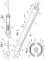
- FIG. 1is a side elevation view of a delivery system for delivering a prosthetic device into a patient's body, showing a catheter gripping and pushing device disposed on a shaft of a delivery catheter of the system.
- FIG. 2is a perspective view of the catheter gripping and pushing device of FIG. 1 .
- FIG. 3is a cross-sectional view of the catheter gripping and pushing device taken along line 3 - 3 of FIG. 2 .
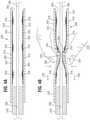
- FIG. 4Ais a cross-sectional view of the catheter gripping and pushing device of FIG. 1 taken along a plane extending lengthwise of the gripping and pushing device, showing the gripping and pushing device in a relaxed, non-use position.
- FIG. 4Bis a cross-sectional view of the catheter gripping and pushing device similar to FIG. 4A but showing the gripping and pushing device being used to grip and push the shaft of the delivery catheter into the patient's body.
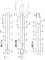
- FIG. 5Ais a side elevation view of the catheter gripping and pushing device of FIG. 1 shown in a relaxed, non-use position.
- FIG. 5Bis a side elevation view of the catheter gripping and pushing device of FIG. 1 shown being used to grip the shaft of the delivery catheter.
- FIG. 6is a side elevation view of the catheter gripping and pushing device of FIG. 1 , showing the opposite side the device from the view shown in FIG. 5B .
- the terms “a”, “an”, and “at least one”encompass one or more of the specified element. That is, if two of a particular element are present, one of these elements is also present and thus “an” element is present.
- the terms “a plurality of” and “plural”mean two or more of the specified element.
- the term “and/or” used between the last two of a list of elementsmeans any one or more of the listed elements.
- the phrase “A, B, and/or C”means “A”, “B,”, “C”, “A and B”, “A and C”, “B and C”, or “A, B, and C.”
- Coupledgenerally means physically coupled or linked and does not exclude the presence of intermediate elements between the coupled items absent specific contrary language.
- the present disclosureis directed to embodiments of a gripping and pushing device for use with a medical instrument that is insertable into a patient's body.
- the illustrated embodimentis described in the context of inserting a delivery apparatus or catheter into a patient's vasculature.
- the embodiments disclosed hereincan be used with any of various medical instruments to perform any of various medical procedures, such as administration of medication or fluids, implantation of prosthetic devices, drainage of fluids, to name a few examples.
- Some examples of medical instruments (other than catheters) that can be used with the disclosed embodimentsinclude but are not limited to, needles, stylets, cannulas, endoscopic devices, laparoscopic instruments, and/or combinations thereof.
- the gripping and pushing deviceis placed on a relatively narrow, elongated structure of the medical instrument, such as a shaft or tubular member.
- a practitionercan squeeze or grip the gripping and pushing device, which in turn grips the medical instrument and transfers pushing, pulling and/or rotational motion of the practitioner's hand to the shaft.
- the gripping and pushing deviceprovides a larger gripping area for the practitioner to allow the practitioner to maintain a better grip and control over the medical instrument with less fatigue. This can be especially helpful when the practitioner is wearing gloves made from latex or other polymers, the outer surface of which can become slippery if covered in blood, saline, or other fluid.
- FIG. 1shows a delivery system 100 for a delivering a prosthetic device (e.g., a prosthetic valve or stent) into the body of a patient.
- the delivery system 100can include a delivery apparatus (also referred to as a delivery catheter) 102 and an introducer 104 .
- the delivery apparatus 102can include a handle 106 and an elongated shaft 108 extending distally from the handle 106 .
- An implantable prosthetic devicee.g., a prosthetic valve or stent
- the shaft 108can be sized and shaped to be advanced through the patient's vasculature to a desired implantation site for the prosthetic device. For example, for delivering a prosthetic heart valve in a transfemoral procedure, the shaft 108 is pushed through a femoral artery and the aorta in a retrograde direction to access the heart. In another transfemoral procedure, the shaft 108 is pushed through a femoral vein and the inferior vena cava in an antegrade direction to access the heart. For transfemoral delivery of a prosthetic valve to the heart, the shaft 108 can have a length of 48 inches or longer.
- the introducer 104can include a housing 110 and an elongated sheath 112 extending distally from the housing 110 .
- the sheath 112can be inserted first into the access location of the patient's vasculature (e.g., a surgical cut down of a femoral artery) and the shaft 108 of the delivery apparatus 102 can then be inserted through the introducer 104 and into the patient's vasculature.
- the housing 110can have one or more seals (not shown) that can engage the shaft 108 and therefore minimize blood loss during the procedure.
- the introducer 104facilitates the initial introduction of the delivery apparatus into the vasculature and can protect against trauma to the vessel where the delivery apparatus is inserted.
- the delivery apparatus 102may be inserted directly into the patient's vasculature without the use of the introducer 104 . Further details of the delivery apparatus 102 and the introducer 104 are described in U.S. Patent Application Publication 2013/0030519, which is incorporated herein by reference.
- a catheter gripping and pushing device 200is mounted on the shaft 108 of the delivery apparatus 102 and can be used for manipulating the shaft 108 , such as for pushing the shaft into the patient's vasculature (e.g., a femoral artery and the aorta) and/or torqueing the shaft to effect steering or placement of the prosthetic device within the body.
- the gripping and pushing device 200could be used in a variety of other applications for pushing and/or manipulating catheters and other medical instruments within various parts of the body and is not limited for use with a delivery apparatus for delivering a prosthetic device.
- the pushing device 200 in the illustrated embodimentcomprises an elongated main body 202 mounted on and extending from an inner tube or shaft 218 .
- the body 202defines a lumen 204 and can be formed with first and second longitudinally extending slots 206 , 208 , respectively on opposite sides of the body, thereby defining two elongated, deflectable portions, such as in the form of diametrically opposed legs 210 , 212 .
- the first slot 206can extend the entire length of the body 202 ( FIG. 5A ), while the second slot 208 can be a partial slot extending less than the entire length of the body 202 .
- the second slot 208can extend from the proximal end of the body 202 to a location at the proximal end of the inner tube 218 ( FIG. 6 ).
- a distal end portion 222 of the body 202is secured to the inner tube 218 (e.g., with a suitable adhesive) such that the legs 210 , 212 are cantilevered from the inner tube 218 and can be pressed inwardly toward each other and against the shaft during use, as further described below.
- the pushing deviceincludes two slots 206 , 208 and two legs 210 , 212
- the pushing devicecan be formed with any number of slots and legs in alternative embodiments.
- the body 202need not be formed with separate legs 210 , 212 but is otherwise deformable or deflectable to allow opposing portions of the body 202 to be pressed against the shaft 108 during use.
- the main bodycan have a substantially C-shaped cross-section (in a plane perpendicular to the length of the main body) defining one slot extending partially or along the entire length of the main body, wherein opposing sides of the main body are deflectable and can be pressed against the shaft 108 during use.
- the main bodycan have a substantially circular cross-section without any slots (or another closed annular shape) and is sufficiently flexible to allow opposing sides of the main body to be pressed inwardly against the shaft 108 .
- the inner tube 218can be formed with a longitudinal slit 220 that is aligned with the first slot 206 .
- the pushing device 200can be placed on the shaft 108 from the side by pushing the shaft 108 laterally through the first slot 206 and the slit 220 such that the shaft 108 extends co-axially through the inner tube 218 and the lumen 204 of the body.
- the pushing device 200can be removed the shaft 108 by simply by pulling the pushing device 200 laterally away from the shaft 108 so that the shaft 108 slides through the slit 220 and the first slot 206 .
- the inner tube 218need not be formed with a slit 220 , in which case the pushing device 200 would be placed on the shaft 108 by threading an end of the shaft co-axially through the inner tube 218 .
- each gripping layer 214can be secured to a respective leg 210 , 212 by one or more axially spaced-apart attachment locations, such as the illustrated adhesive spots 216 , defining unsecured portions 224 of the layers 214 between the attachment locations that are unattached to the inner surfaces of the legs 210 , 212 .
- the unsecured portions 224can deform under manual pressure of user pressing against the legs 210 , 212 to enhance the gripping action of the layers 214 , as further described below.
- each gripper layer 214 in the illustrated embodimentis secured to a respective leg 210 , 212 at three spaced-apart attachment locations by three spaced-apart adhesive spots 216 .
- each gripping layer 214can be secured to a respective leg 210 , 212 at greater than or fewer than three attachment locations.
- the adhesive spots 216are separate layers of an adhesive disposed between the inner surface of the legs 210 , 212 and the outer surface of the gripping layers 214 and can have any of various shapes (e.g., circular, elliptical, etc.).
- the adhesive spots 216can be equally spaced from each other as shown in the drawings. Alternatively, the spacing between adjacent adhesive spots 216 can vary along the length the pushing device.
- the spacing and/or positioning of the adhesive spots 216 of one gripping layer 214can be different than the spacing and/or positioning of the adhesive spots of another gripping layer 214 .
- additional gripping layers 214can be secured to each other at spaced apart attachment locations.
- multiple gripping layerscan be secured to the inner surface of one or both legs 210 , 212 with adjacent gripping layers being secured to each other at spaced apart attachment locations.
- the inner tube 218has a lumen 230 sized and shaped to receive the shaft 108 .
- the diameter of the lumen 230can be slightly greater than the diameter of the shaft 108 to allow the pushing device 200 to slide along the length of the shaft 108 .
- the lumen 204 of the body 202is oversized relative to the shaft 108 , which allows the legs 210 , 212 to move between a non-deflected state in which the legs are spaced apart from the shaft 108 ( FIGS. 4A and 5A ) and a deflected state in which the legs are pressed against the shaft 108 by manual pressure from a user's hand ( FIGS. 4B and 5B ).
- the body 202desirably comprises a material with sufficient flexibility and/or elasticity to be easily compressed under manual pressure allowing the internal gripping layers 214 to contact the shaft 108 when gripping pressure is applied and revert back to the non-deflected state under its own resiliency when gripping pressure is released.
- Any of various suitable materialssuch as any of various metals (e.g., stainless steel) or polymeric materials can be used to form the body 202 , such as but not limited to Nylon, Pebax, and/or combinations thereof.
- the legs 210 , 212can have roughened or textured inner and outer surfaces to enhance adherence with the gripping layers 214 and improve gripping by a user's hand.
- the inner gripping layers 214desirably comprise an elastomeric material that can deform when manual pressure is applied to the legs 210 , 212 .
- the gripping layers 214are formed from a material that is relatively more elastic and/or deformable than the legs 210 , 212 and has a relatively greater coefficient of friction with respect to the shaft 108 than the legs and a relatively low shore A hardness. Any of various suitable elastomers can be used for forming the gripping layers 214 such as, for example, low hardness silicone rubber.
- the inner tube 218can be made from any of various suitable materials, such as any of various polymeric materials, such as but not limited to Nylon, Pebax, PTFE, and/or combinations thereof.
- the inner tube 218can be made from a low-friction material and can have a relatively low coefficient of friction with respect to the shaft 108 compared to the gripping layers 214 to promote sliding of the pushing device 200 relative to the shaft when the legs 210 , 212 are not in contact with the shaft.
- the inner tube 218can include an inner liner or layer of low friction material, such as PTFE, to reduce sliding friction with the shaft 108 .
- the outer surface of the body 202can be provided with gripping layers (not shown) similar to gripping layers 214 to enhance a user's grip on the body 202 .
- gripping layerscan be placed along the outer surface of the legs 210 , 212 in alignment with the gripping layers 214 .
- the gripping layers on the outer surface of the bodycan be formed from the same materials as the gripping layers 214 (e.g., silicone rubber).
- the pushing device 200is placed on the shaft 108 of the delivery apparatus 102 as shown in FIG. 1 .
- the shaft 108can be several feet long and is relatively flexible. Consequently, the physician may need to grasp the shaft 108 close to the insertion point of the patient's body and away from the handle 106 while pushing the shaft into the body to prevent buckling of the shaft.
- the pushing device 200can be initially positioned along the shaft 108 at a desired distance from the entry point and the introducer 104 (if used), such as a few inches from the entry point.
- the legs 210 , 212 of the pushing device 200can then be squeezed between the fingers 228 (e.g., a thumb and an index finger) to press the gripping layers 214 against the shaft 108 . While maintaining manual pressure against the legs 210 , 212 , the pushing device 200 is advanced distally in the direction of arrows 232 , which pushes the shaft 108 through the introducer 104 and into the patient's vasculature. As illustrated in FIG.
- the unsecured portions 224 of the gripping layers 214 between the adhesive spots 216are axially deformable, and can bunch up and/or or stretch or deform axially, forming wave-like deformations that enhance the gripping force against the shaft 108 and minimize slippage of the gripping device relative to the shaft.
- the deformation of the gripping layers 214allow the physician to push the shaft 108 through the patient's vasculature with less manual force, thereby reducing finger fatigue and enhancing control over the shaft 108 .
- the pushing device 200After the pushing device 200 has been moved distally to a location at the introducer 104 (which is effective to insert the shaft 108 partially into the patient's vasculature), manual pressure can be released from the legs 210 , 212 (which can revert back to their non-deflected state), and the pushing device 200 can be slid proximally relative to the shaft 108 and away from the patient a desired distance, such as by grasping the inner tube 218 or the distal end portion 222 of the body and retracting the pushing device relative to the shaft. Thereafter, the physician can again grasp the legs 210 , 212 and use the pushing device 200 to push the shaft 108 further into the patient's vasculature. The process of retracting the pushing device and using the pushing device to push the shaft further into the patient's body can be repeated as needed until the handle 106 can be effectively used to push or otherwise manipulate the shaft without buckling.
Landscapes
- Health & Medical Sciences (AREA)
- Life Sciences & Earth Sciences (AREA)
- Biomedical Technology (AREA)
- Engineering & Computer Science (AREA)
- Cardiology (AREA)
- Veterinary Medicine (AREA)
- General Health & Medical Sciences (AREA)
- Heart & Thoracic Surgery (AREA)
- Public Health (AREA)
- Animal Behavior & Ethology (AREA)
- Oral & Maxillofacial Surgery (AREA)
- Transplantation (AREA)
- Vascular Medicine (AREA)
- Hematology (AREA)
- Pulmonology (AREA)
- Biophysics (AREA)
- Anesthesiology (AREA)
- Prostheses (AREA)
- Surgery (AREA)
- Pathology (AREA)
- Nuclear Medicine, Radiotherapy & Molecular Imaging (AREA)
- Medical Informatics (AREA)
- Molecular Biology (AREA)
- Media Introduction/Drainage Providing Device (AREA)
- Gastroenterology & Hepatology (AREA)
Abstract
Description
Claims (20)
Priority Applications (3)
| Application Number | Priority Date | Filing Date | Title |
|---|---|---|---|
| US16/222,992US11234814B2 (en) | 2015-08-14 | 2018-12-17 | Gripping and pushing device for medical instrument |
| US17/587,843US11998446B2 (en) | 2015-08-14 | 2022-01-28 | Gripping and pushing device for medical instrument |
| US18/656,808US20240285402A1 (en) | 2015-08-14 | 2024-05-07 | Gripping and pushing device for medical instrument |
Applications Claiming Priority (3)
| Application Number | Priority Date | Filing Date | Title |
|---|---|---|---|
| US201562205567P | 2015-08-14 | 2015-08-14 | |
| US15/232,722US10179046B2 (en) | 2015-08-14 | 2016-08-09 | Gripping and pushing device for medical instrument |
| US16/222,992US11234814B2 (en) | 2015-08-14 | 2018-12-17 | Gripping and pushing device for medical instrument |
Related Parent Applications (1)
| Application Number | Title | Priority Date | Filing Date |
|---|---|---|---|
| US15/232,722ContinuationUS10179046B2 (en) | 2015-08-14 | 2016-08-09 | Gripping and pushing device for medical instrument |
Related Child Applications (1)
| Application Number | Title | Priority Date | Filing Date |
|---|---|---|---|
| US17/587,843ContinuationUS11998446B2 (en) | 2015-08-14 | 2022-01-28 | Gripping and pushing device for medical instrument |
Publications (2)
| Publication Number | Publication Date |
|---|---|
| US20190117395A1 US20190117395A1 (en) | 2019-04-25 |
| US11234814B2true US11234814B2 (en) | 2022-02-01 |
Family
ID=57994353
Family Applications (4)
| Application Number | Title | Priority Date | Filing Date |
|---|---|---|---|
| US15/232,722Active2037-07-22US10179046B2 (en) | 2015-08-14 | 2016-08-09 | Gripping and pushing device for medical instrument |
| US16/222,992Active2038-01-29US11234814B2 (en) | 2015-08-14 | 2018-12-17 | Gripping and pushing device for medical instrument |
| US17/587,843Active2036-12-28US11998446B2 (en) | 2015-08-14 | 2022-01-28 | Gripping and pushing device for medical instrument |
| US18/656,808PendingUS20240285402A1 (en) | 2015-08-14 | 2024-05-07 | Gripping and pushing device for medical instrument |
Family Applications Before (1)
| Application Number | Title | Priority Date | Filing Date |
|---|---|---|---|
| US15/232,722Active2037-07-22US10179046B2 (en) | 2015-08-14 | 2016-08-09 | Gripping and pushing device for medical instrument |
Family Applications After (2)
| Application Number | Title | Priority Date | Filing Date |
|---|---|---|---|
| US17/587,843Active2036-12-28US11998446B2 (en) | 2015-08-14 | 2022-01-28 | Gripping and pushing device for medical instrument |
| US18/656,808PendingUS20240285402A1 (en) | 2015-08-14 | 2024-05-07 | Gripping and pushing device for medical instrument |
Country Status (3)
| Country | Link |
|---|---|
| US (4) | US10179046B2 (en) |
| EP (1) | EP3334487B1 (en) |
| WO (1) | WO2017030897A1 (en) |
Families Citing this family (50)
| Publication number | Priority date | Publication date | Assignee | Title |
|---|---|---|---|---|
| US7686825B2 (en) | 2004-03-25 | 2010-03-30 | Hauser David L | Vascular filter device |
| US8579964B2 (en) | 2010-05-05 | 2013-11-12 | Neovasc Inc. | Transcatheter mitral valve prosthesis |
| US9554897B2 (en) | 2011-04-28 | 2017-01-31 | Neovasc Tiara Inc. | Methods and apparatus for engaging a valve prosthesis with tissue |
| US9308087B2 (en) | 2011-04-28 | 2016-04-12 | Neovasc Tiara Inc. | Sequentially deployed transcatheter mitral valve prosthesis |
| US9345573B2 (en) | 2012-05-30 | 2016-05-24 | Neovasc Tiara Inc. | Methods and apparatus for loading a prosthesis onto a delivery system |
| US8784434B2 (en) | 2012-11-20 | 2014-07-22 | Inceptus Medical, Inc. | Methods and apparatus for treating embolism |
| US9572665B2 (en) | 2013-04-04 | 2017-02-21 | Neovasc Tiara Inc. | Methods and apparatus for delivering a prosthetic valve to a beating heart |
| US10238406B2 (en) | 2013-10-21 | 2019-03-26 | Inari Medical, Inc. | Methods and apparatus for treating embolism |
| CN108348319B (en) | 2015-09-28 | 2020-03-10 | 斯瑞克公司 | Mechanical embolectomy device and method |
| CN113796927B (en) | 2015-10-23 | 2025-03-04 | 伊纳里医疗公司 | Intravascular treatment of vascular occlusion and related devices, systems and methods |
| CA3007660A1 (en) | 2015-12-15 | 2017-06-22 | Neovasc Tiara Inc. | Transseptal delivery system |
| US10433952B2 (en) | 2016-01-29 | 2019-10-08 | Neovasc Tiara Inc. | Prosthetic valve for avoiding obstruction of outflow |
| US11497512B2 (en) | 2016-04-25 | 2022-11-15 | Stryker Corporation | Inverting thrombectomy apparatuses and methods |
| US11896247B2 (en) | 2016-04-25 | 2024-02-13 | Stryker Corporation | Inverting mechanical thrombectomy apparatuses |
| EP3448276B1 (en) | 2016-04-25 | 2020-03-04 | Stryker Corporation | Clot-engulfing mechanical thrombectomy apparatuses |
| CN109561903B (en) | 2016-06-03 | 2021-07-27 | 斯瑞克公司 | Flip thrombectomy device |
| WO2018049317A1 (en) | 2016-09-12 | 2018-03-15 | Stryker Corporation | Self-rolling thrombectomy apparatuses and methods |
| FI3528717T3 (en) | 2016-10-24 | 2024-08-09 | Inari Medical Inc | Devices for treating vascular occlusion |
| CA3042588A1 (en) | 2016-11-21 | 2018-05-24 | Neovasc Tiara Inc. | Methods and systems for rapid retraction of a transcatheter heart valve delivery system |
| US10751514B2 (en) | 2016-12-09 | 2020-08-25 | Teleflex Life Sciences Limited | Guide extension catheter |
| US20180311468A1 (en)* | 2017-04-27 | 2018-11-01 | The Regents Of The University Of California | Force sensor and monitoring device |
| CA3073834A1 (en) | 2017-08-25 | 2019-02-28 | Neovasc Tiara Inc. | Sequentially deployed transcatheter mitral valve prosthesis |
| WO2019050765A1 (en) | 2017-09-06 | 2019-03-14 | Inari Medical, Inc. | Hemostasis valves and methods of use |
| EP4176830A1 (en) | 2017-11-09 | 2023-05-10 | Stryker Corporation | Inverting thrombectomy apparatuses having enhanced tracking |
| US11154314B2 (en) | 2018-01-26 | 2021-10-26 | Inari Medical, Inc. | Single insertion delivery system for treating embolism and associated systems and methods |
| EP4039315B1 (en)* | 2018-02-14 | 2023-12-20 | Teleflex Life Sciences Limited | Guide extension catheter |
| WO2019222117A1 (en) | 2018-05-14 | 2019-11-21 | Stryker Corporation | Inverting thrombectomy apparatuses and methods of use |
| CA3114285A1 (en) | 2018-08-13 | 2020-02-20 | Inari Medical, Inc. | System for treating embolism and associated devices and methods |
| CN112969420B (en) | 2018-09-10 | 2024-12-17 | 史赛克公司 | Inverted thrombectomy device and method of using thrombectomy device |
| CN112702961A (en) | 2018-09-10 | 2021-04-23 | 斯瑞克公司 | Laser grooving and grabbing device |
| CN113271890B (en) | 2018-11-08 | 2024-08-30 | 内奥瓦斯克迪亚拉公司 | Ventricular deployment of transcatheter mitral valve prosthesis |
| US11524142B2 (en) | 2018-11-27 | 2022-12-13 | Teleflex Life Sciences Limited | Guide extension catheter |
| CA3132873A1 (en) | 2019-03-08 | 2020-09-17 | Neovasc Tiara Inc. | Retrievable prosthesis delivery system |
| CA3135753C (en) | 2019-04-01 | 2023-10-24 | Neovasc Tiara Inc. | Controllably deployable prosthetic valve |
| US11491006B2 (en) | 2019-04-10 | 2022-11-08 | Neovasc Tiara Inc. | Prosthetic valve with natural blood flow |
| US11779742B2 (en) | 2019-05-20 | 2023-10-10 | Neovasc Tiara Inc. | Introducer with hemostasis mechanism |
| JP7520897B2 (en) | 2019-06-20 | 2024-07-23 | ニオバスク ティアラ インコーポレイテッド | Thin prosthetic mitral valve |
| JP7638273B2 (en) | 2019-10-16 | 2025-03-03 | イナリ メディカル, インコーポレイテッド | Systems, devices and methods for treating vascular obstructions |
| US20210213245A1 (en)* | 2020-01-09 | 2021-07-15 | Becton, Dickinson And Company | Multi-lumen extension system |
| WO2021167594A1 (en)* | 2020-02-18 | 2021-08-26 | Stryker Corporation | Systems and methods for removing material from a vessel |
| US12128193B2 (en)* | 2020-03-23 | 2024-10-29 | Becton, Dickinson And Company | Extension set with a patency instrument |
| CN111084658B (en)* | 2020-03-23 | 2020-07-24 | 上海导向医疗系统有限公司 | Freezing adhesion device |
| US12201800B2 (en)* | 2020-03-27 | 2025-01-21 | Becton, Dickinson And Company | Extension set and related systems and methods |
| CA3203376A1 (en)* | 2021-01-08 | 2022-07-14 | Curtis H. Blanchard | Probe advancement device and related systems and methods |
| JP2024512759A (en)* | 2021-04-02 | 2024-03-19 | ベクトン・ディキンソン・アンド・カンパニー | Instrument advancement device with anti-buckling function |
| US20230001156A1 (en)* | 2021-07-02 | 2023-01-05 | Becton, Dickinson And Company | Vascular Access Device with Non-Contact Guidewire Advancement |
| EP4463083A1 (en) | 2022-01-11 | 2024-11-20 | Inari Medical, Inc. | Devices for removing clot material from intravascularly implanted devices, and associated systems and methods |
| US20240156333A1 (en)* | 2022-11-13 | 2024-05-16 | Light Line Medical, Inc. | Disposable Introducer for Advancing an Elongate Member into a Tubular Structure |
| WO2025160488A1 (en)* | 2024-01-26 | 2025-07-31 | Abiomed, Inc. | Steerable catheter assemblies |
| CN118750186B (en)* | 2024-08-02 | 2025-10-03 | 深圳爱博合创医疗机器人有限公司 | Control systems for driving slender medical devices |
Citations (171)
| Publication number | Priority date | Publication date | Assignee | Title |
|---|---|---|---|---|
| US519297A (en) | 1894-05-01 | Bauer | ||
| US4035849A (en) | 1975-11-17 | 1977-07-19 | William W. Angell | Heart valve stent and process for preparing a stented heart valve prosthesis |
| US4592340A (en) | 1984-05-02 | 1986-06-03 | Boyles Paul W | Artificial catheter means |
| US4726369A (en)* | 1986-07-31 | 1988-02-23 | Advanced Cardiovascular Systems, Inc. | Tool and method for steering an angioplasty guide wire |
| US4858810A (en)* | 1987-04-30 | 1989-08-22 | Heart Technology, Inc. | Quick acting pin vise for use with angiographic guidewires |
| US4955895A (en) | 1986-12-23 | 1990-09-11 | Terumo Kabushiki Kaisha | Vasodilating catheter |
| US4994077A (en) | 1989-04-21 | 1991-02-19 | Dobben Richard L | Artificial heart valve for implantation in a blood vessel |
| US5059177A (en) | 1990-04-19 | 1991-10-22 | Cordis Corporation | Triple lumen balloon catheter |
| WO1991017720A1 (en) | 1990-05-18 | 1991-11-28 | Henning Rud Andersen | A valve prosthesis for implantation in the body and a catheter for implantating such valve prosthesis |
| US5137517A (en) | 1989-11-28 | 1992-08-11 | Scimed Life Systems, Inc. | Device and method for gripping medical shaft |
| US5176698A (en) | 1991-01-09 | 1993-01-05 | Scimed Life Systems, Inc. | Vented dilatation cathether and method for venting |
| US5192297A (en) | 1991-12-31 | 1993-03-09 | Medtronic, Inc. | Apparatus and method for placement and implantation of a stent |
| US5266073A (en) | 1987-12-08 | 1993-11-30 | Wall W Henry | Angioplasty stent |
| US5325746A (en)* | 1991-09-27 | 1994-07-05 | Cook Incorporated | Wire guide control handle |
| US5325868A (en)* | 1993-05-04 | 1994-07-05 | Kimmelstiel Carey D | Self-gripping medical wire torquer |
| US5325845A (en) | 1992-06-08 | 1994-07-05 | Adair Edwin Lloyd | Steerable sheath for use with selected removable optical catheter |
| US5358496A (en) | 1991-10-18 | 1994-10-25 | Ethicon, Inc. | Endoscopic tissue manipulator |
| US5392778A (en)* | 1993-08-11 | 1995-02-28 | B. Braun Medical, Inc. | Guidewire torque device for single-hand manipulation |
| US5411552A (en) | 1990-05-18 | 1995-05-02 | Andersen; Henning R. | Valve prothesis for implantation in the body and a catheter for implanting such valve prothesis |
| US5423331A (en) | 1988-11-03 | 1995-06-13 | Ramsey Foundation | One-handed angioplasty steering device and method |
| US5554185A (en) | 1994-07-18 | 1996-09-10 | Block; Peter C. | Inflatable prosthetic cardiovascular valve for percutaneous transluminal implantation of same |
| US5591195A (en) | 1995-10-30 | 1997-01-07 | Taheri; Syde | Apparatus and method for engrafting a blood vessel |
| US5599305A (en) | 1994-10-24 | 1997-02-04 | Cardiovascular Concepts, Inc. | Large-diameter introducer sheath having hemostasis valve and removable steering mechanism |
| DE19532846A1 (en) | 1995-09-06 | 1997-03-13 | Georg Dr Berg | Valve for use in heart |
| US5632760A (en) | 1994-10-20 | 1997-05-27 | Cordis Corporation | Balloon catheter for stent implantation |
| US5634475A (en)* | 1994-09-01 | 1997-06-03 | Datascope Investment Corp. | Guidewire delivery assist device and system |
| US5639274A (en) | 1995-06-02 | 1997-06-17 | Fischell; Robert E. | Integrated catheter system for balloon angioplasty and stent delivery |
| US5728068A (en) | 1994-06-14 | 1998-03-17 | Cordis Corporation | Multi-purpose balloon catheter |
| US5749890A (en) | 1996-12-03 | 1998-05-12 | Shaknovich; Alexander | Method and system for stent placement in ostial lesions |
| EP0850607A1 (en) | 1996-12-31 | 1998-07-01 | Cordis Corporation | Valve prosthesis for implantation in body channels |
| US5782809A (en) | 1994-06-20 | 1998-07-21 | Terumo Kabushiki Kaisha | Vascular catheter |
| US5824044A (en) | 1994-05-12 | 1998-10-20 | Endovascular Technologies, Inc. | Bifurcated multicapsule intraluminal grafting system |
| US5908405A (en) | 1994-10-28 | 1999-06-01 | Intella Interventional Systems, Inc. | Low profile balloon-on-a-wire catheter with shapeable and/or deflectable tip and method |
| US5916147A (en) | 1997-09-22 | 1999-06-29 | Boury; Harb N. | Selectively manipulable catheter |
| US5961536A (en) | 1997-10-14 | 1999-10-05 | Scimed Life Systems, Inc. | Catheter having a variable length balloon and method of using the same |
| US5968068A (en) | 1996-09-12 | 1999-10-19 | Baxter International Inc. | Endovascular delivery system |
| US6019777A (en) | 1997-04-21 | 2000-02-01 | Advanced Cardiovascular Systems, Inc. | Catheter and method for a stent delivery system |
| US6027510A (en) | 1997-12-08 | 2000-02-22 | Inflow Dynamics Inc. | Stent delivery system |
| US6030349A (en)* | 1998-02-23 | 2000-02-29 | Cartika Medical, Inc. | Medical guide wire torquer |
| US6033381A (en) | 1989-09-06 | 2000-03-07 | Boston Scientific Corporation | Angioplasty balloon catheter and adaptor |
| DE19907646A1 (en) | 1999-02-23 | 2000-08-24 | Georg Berg | Valve for blood vessels uses flap holders and counterpart holders on stent to latch together in place and all channeled for guide wire. |
| US6143016A (en) | 1997-04-21 | 2000-11-07 | Advanced Cardiovascular Systems, Inc. | Sheath and method of use for a stent delivery system |
| US6162208A (en) | 1997-09-11 | 2000-12-19 | Genzyme Corporation | Articulating endoscopic implant rotator surgical apparatus and method for using same |
| US6174327B1 (en) | 1998-02-27 | 2001-01-16 | Scimed Life Systems, Inc. | Stent deployment apparatus and method |
| US6217585B1 (en) | 1996-08-16 | 2001-04-17 | Converge Medical, Inc. | Mechanical stent and graft delivery system |
| US20010002445A1 (en) | 1997-12-29 | 2001-05-31 | The Cleveland Clinic Foundation | Bioprosthetic cardiovascular valve system |
| US6251092B1 (en) | 1997-12-30 | 2001-06-26 | Medtronic, Inc. | Deflectable guiding catheter |
| US20010007082A1 (en) | 1996-08-23 | 2001-07-05 | Dusbabek Andrew J. | Stent delivery system having stent securement apparatus |
| WO2001049213A2 (en) | 1999-12-31 | 2001-07-12 | Advanced Bio Prosthetic Surfaces, Ltd. | Endoluminal cardiac and venous valve prostheses and methods of manufacture and delivery thereof |
| WO2001054625A1 (en) | 2000-01-31 | 2001-08-02 | Cook Biotech Incorporated | Stent valves and uses of same |
| WO2001076510A2 (en) | 2000-04-06 | 2001-10-18 | Edwards Lifesciences Corporation | Minimally-invasive heart valves and methods of use |
| US20020032481A1 (en) | 2000-09-12 | 2002-03-14 | Shlomo Gabbay | Heart valve prosthesis and sutureless implantation of a heart valve prosthesis |
| WO2002022054A1 (en) | 2000-09-12 | 2002-03-21 | Gabbay S | Valvular prosthesis and method of using same |
| FR2815844A1 (en) | 2000-10-31 | 2002-05-03 | Jacques Seguin | TUBULAR SUPPORT FOR SETTING UP, BY PERCUTANEOUS, OF A REPLACEMENT HEART VALVE |
| US6383171B1 (en) | 1999-10-12 | 2002-05-07 | Allan Will | Methods and devices for protecting a passageway in a body when advancing devices through the passageway |
| US20020058995A1 (en) | 1991-07-16 | 2002-05-16 | Stevens John H. | Endovascular aortic valve replacement |
| WO2002047575A2 (en) | 2000-12-15 | 2002-06-20 | Angiomed Gmbh & Co. Medizintechnik Kg | Stent with valve |
| WO2002060352A1 (en) | 2001-01-30 | 2002-08-08 | Ev3 Santa Rosa, Inc. | Medical system and method for remodeling an extravascular tissue structure |
| US6461382B1 (en) | 2000-09-22 | 2002-10-08 | Edwards Lifesciences Corporation | Flexible heart valve having moveable commissures |
| US6471672B1 (en) | 1999-11-10 | 2002-10-29 | Scimed Life Systems | Selective high pressure dilation balloon |
| US20020165461A1 (en) | 2001-05-02 | 2002-11-07 | Hayzelden Robert C. | Steerable catheter with shaft support system for resisting axial compressive loads |
| US6500147B2 (en) | 1999-02-22 | 2002-12-31 | Medtronic Percusurge, Inc. | Flexible catheter |
| US6514228B1 (en) | 1999-03-05 | 2003-02-04 | Scimed Life Systems, Inc. | Balloon catheter having high flow tip |
| US6527979B2 (en) | 1999-08-27 | 2003-03-04 | Corazon Technologies, Inc. | Catheter systems and methods for their use in the treatment of calcified vascular occlusions |
| US20030050694A1 (en) | 2001-09-13 | 2003-03-13 | Jibin Yang | Methods and apparatuses for deploying minimally-invasive heart valves |
| WO2003047468A1 (en) | 2001-10-11 | 2003-06-12 | Percutaneous Valve Technologies | Implantable prosthetic valve |
| US6579305B1 (en) | 1995-12-07 | 2003-06-17 | Medtronic Ave, Inc. | Method and apparatus for delivery deployment and retrieval of a stent comprising shape-memory material |
| US20030120341A1 (en) | 2001-12-21 | 2003-06-26 | Hani Shennib | Devices and methods of repairing cardiac valves |
| US20030226421A1 (en)* | 2002-06-10 | 2003-12-11 | Livingston Paul M. | Shock absorbing handle bar grip |
| WO2004019825A1 (en) | 2002-08-13 | 2004-03-11 | Fraunhofer-Gesellschaft zur Förderung der angewandten Forschung e.V. | Device for the implantation and fixing of heart valve prostheses |
| US6733525B2 (en) | 2001-03-23 | 2004-05-11 | Edwards Lifesciences Corporation | Rolled minimally-invasive heart valves and methods of use |
| US20040093061A1 (en) | 2001-12-03 | 2004-05-13 | Xtent, Inc. A Delaware Corporation | Apparatus and methods for delivery of multiple distributed stents |
| US6764504B2 (en) | 2001-01-04 | 2004-07-20 | Scimed Life Systems, Inc. | Combined shaped balloon and stent protector |
| US20040143197A1 (en) | 2001-08-21 | 2004-07-22 | Synovis Interventional Solutions | Steerable stylet |
| US20040186563A1 (en) | 2003-03-18 | 2004-09-23 | Lobbi Mario M. | Minimally-invasive heart valve with cusp positioners |
| US6830584B1 (en) | 1999-11-17 | 2004-12-14 | Jacques Seguin | Device for replacing a cardiac valve by percutaneous route |
| US20040260389A1 (en) | 2003-04-24 | 2004-12-23 | Cook Incorporated | Artificial valve prosthesis with improved flow dynamics |
| US20050070820A1 (en)* | 2003-09-30 | 2005-03-31 | Scimed Life Systems, Inc. | Side loading wire torquing device |
| US20050080474A1 (en) | 2003-10-14 | 2005-04-14 | Xtent, Inc. | Fixed stent delivery devices and methods |
| US20050096688A1 (en) | 2003-10-30 | 2005-05-05 | Robert Slazas | Gripper for catheter shaft |
| US20050137689A1 (en) | 2003-12-23 | 2005-06-23 | Sadra Medical, A Delware Corporation | Retrievable heart valve anchor and method |
| US20050149160A1 (en) | 2003-12-23 | 2005-07-07 | Scimed Life Systems, Inc. | Stent delivery catheter |
| WO2005084595A1 (en) | 2004-02-27 | 2005-09-15 | Cardiacmd, Inc. | Prosthetic heart valve delivery systems and methods |
| WO2005102015A2 (en) | 2004-04-23 | 2005-11-03 | 3F Therapeutics, Inc. | Implantable prosthetic valve |
| US20050245894A1 (en) | 1996-05-20 | 2005-11-03 | Medtronic Vascular, Inc. | Methods and apparatuses for drug delivery to an intravascular occlusion |
| US20050277946A1 (en)* | 2004-06-15 | 2005-12-15 | Secant Medical, Llc | Access port for laparoscopic surgery |
| US7011094B2 (en) | 2001-03-02 | 2006-03-14 | Emphasys Medical, Inc. | Bronchial flow control devices and methods of use |
| US20060058738A1 (en)* | 2004-09-14 | 2006-03-16 | Ponzi Dean M | Catheter clamp |
| WO2006032051A2 (en) | 2004-09-14 | 2006-03-23 | Edwards Lifesciences Ag | Device and method for treatment of heart valve regurgitation |
| US7018406B2 (en) | 1999-11-17 | 2006-03-28 | Corevalve Sa | Prosthetic valve for transluminal delivery |
| US20060217687A1 (en) | 2005-03-24 | 2006-09-28 | Ethicon Endo-Surgery, Inc. | Catheter-gripping device which measures insertion force during a medical procedure |
| WO2006111391A1 (en) | 2005-04-21 | 2006-10-26 | Edwards Lifesciences Ag | A blood flow controlling apparatus |
| US20060282150A1 (en) | 2005-06-08 | 2006-12-14 | Xtent, Inc. | Devices and methods for operating and controlling interventional apparatus |
| WO2006138173A2 (en) | 2005-06-13 | 2006-12-28 | Edwards Lifesciences Corporation | Heart valve delivery system |
| US20070066963A1 (en)* | 2003-04-11 | 2007-03-22 | Allan Tanghoj | Catheter assembly with catheter handle and container |
| US20070073389A1 (en) | 2001-11-28 | 2007-03-29 | Aptus Endosystems, Inc. | Endovascular aneurysm devices, systems, and methods |
| US20070088431A1 (en) | 2005-10-18 | 2007-04-19 | Henry Bourang | Heart valve delivery system with valve catheter |
| US20070112422A1 (en) | 2005-11-16 | 2007-05-17 | Mark Dehdashtian | Transapical heart valve delivery system and method |
| WO2007067942A1 (en) | 2005-12-07 | 2007-06-14 | Arbor Surgical Technologies, Inc. | Connection systems for two piece prosthetic heart valve assemblies |
| US20070203575A1 (en) | 2006-02-27 | 2007-08-30 | Cardiacmd, Inc., A California Corporation | Methods and devices for delivery of prosthetic heart valves and other prosthetics |
| US20070219612A1 (en) | 2006-03-20 | 2007-09-20 | Xtent, Inc. | Apparatus and methods for deployment of linked prosthetic segments |
| US20070239254A1 (en) | 2006-04-07 | 2007-10-11 | Chris Chia | System for percutaneous delivery and removal of a prosthetic valve |
| US20070244546A1 (en) | 2006-04-18 | 2007-10-18 | Medtronic Vascular, Inc. | Stent Foundation for Placement of a Stented Valve |
| US20070265700A1 (en) | 2005-10-26 | 2007-11-15 | Eliasen Kenneth A | Safety for Mitral Valve Plug |
| US7318278B2 (en) | 2002-09-20 | 2008-01-15 | Edwards Lifesciences Corporation | Method of manufacture of a heart valve support frame |
| US7320704B2 (en) | 2004-05-05 | 2008-01-22 | Direct Flow Medical, Inc. | Nonstented temporary valve for cardiovascular therapy |
| US7320702B2 (en) | 2005-06-08 | 2008-01-22 | Xtent, Inc. | Apparatus and methods for deployment of multiple custom-length prostheses (III) |
| US20080051630A1 (en)* | 2003-12-16 | 2008-02-28 | Levey John M | Endoscopic Lubricating And Gripping Device |
| US20080065011A1 (en) | 2006-09-08 | 2008-03-13 | Philippe Marchand | Integrated heart valve delivery system |
| US20080097362A1 (en)* | 2006-10-24 | 2008-04-24 | Mosler Theodore J | Catheter gripping device |
| US7374571B2 (en) | 2001-03-23 | 2008-05-20 | Edwards Lifesciences Corporation | Rolled minimally-invasive heart valves and methods of manufacture |
| US20080294230A1 (en) | 2007-05-24 | 2008-11-27 | Cook Incorporated | Apparatus and methods for deploying self-expanding stents |
| US20090024428A1 (en) | 2007-07-19 | 2009-01-22 | Hudock Jr Robert | System for and method of processing business personnel information |
| US20090069889A1 (en) | 2007-09-07 | 2009-03-12 | Sorin Biomedica Cardio S.R.L. | Streamlined, apical delivery system for in situ deployment of cardiac valve prostheses |
| US20090076417A1 (en) | 2007-08-08 | 2009-03-19 | Gregory Allen Jones | Glide Clip |
| US20090138079A1 (en) | 2007-10-10 | 2009-05-28 | Vector Technologies Ltd. | Prosthetic heart valve for transfemoral delivery |
| US20090157175A1 (en) | 2007-12-14 | 2009-06-18 | Edwards Lifesciences Corporation | Leaflet attachment frame for a prosthetic valve |
| US20090192585A1 (en) | 2008-01-24 | 2009-07-30 | Medtronic, Inc. | Delivery Systems and Methods of Implantation for Prosthetic Heart Valves |
| US20090228093A1 (en) | 2008-02-29 | 2009-09-10 | Edwards Lifesciences Corporation | Expandable member for deploying a prosthetic device |
| US7594926B2 (en) | 2001-11-09 | 2009-09-29 | Boston Scientific Scimed, Inc. | Methods, systems and devices for delivering stents |
| US7597709B2 (en) | 2001-10-24 | 2009-10-06 | Boston Scientific Scimed, Inc. | Inner member support block |
| US20090276040A1 (en) | 2008-05-01 | 2009-11-05 | Edwards Lifesciences Corporation | Device and method for replacing mitral valve |
| US20090281619A1 (en) | 2008-05-09 | 2009-11-12 | Edwards Lifesciences Corporation | Low Profile Delivery System for Transcatheter Heart Valve |
| US20090299456A1 (en) | 2005-01-12 | 2009-12-03 | Cook Incorporated | Delivery system with helical shaft |
| US20090319037A1 (en) | 2008-06-20 | 2009-12-24 | Edwards Lifesciences Corporation | Retaining mechanisms for prosthetic valves |
| US20100030318A1 (en) | 2003-09-03 | 2010-02-04 | Bolton Medical, Inc. | Dual Capture Device for Stent Graft Delivery System and Method for Capturing a Stent Graft |
| US20100036473A1 (en) | 2007-06-22 | 2010-02-11 | Icon Medical Corp. | Heatable delivery device |
| US20100036472A1 (en) | 2008-08-08 | 2010-02-11 | Abbott Cardiovascular Systems Inc. | Delivery system with variable delivery rate for deploying a medical device |
| US20100049313A1 (en) | 2008-08-22 | 2010-02-25 | Edwards Lifesciences Corporation | Prosthetic heart valve and delivery apparatus |
| US20100076541A1 (en) | 2007-04-27 | 2010-03-25 | Terumo Kabushiki Kaisha | Stent delivery system |
| US20100076402A1 (en) | 2008-09-22 | 2010-03-25 | James Mazzone | Biasing a Catheter Balloon |
| US20100082089A1 (en) | 2008-10-01 | 2010-04-01 | Arshad Quadri | Delivery system for vascular implant |
| US20100094394A1 (en) | 2008-10-06 | 2010-04-15 | Bradley Beach | Reconstrainable stent delivery system |
| US7699809B2 (en)* | 2006-12-14 | 2010-04-20 | Urmey William F | Catheter positioning system |
| US20100121425A1 (en) | 2007-04-05 | 2010-05-13 | Tamotsu Shimada | Stent delivery system |
| US20100145431A1 (en) | 2003-09-12 | 2010-06-10 | Abbott Vascular Solutions Inc. | Delivery system for medical devices |
| US20100161036A1 (en) | 2008-12-19 | 2010-06-24 | Edwards Lifesciences Corporation | Quick-connect prosthetic heart valve and methods |
| US20100174363A1 (en) | 2009-01-07 | 2010-07-08 | Endovalve, Inc. | One Piece Prosthetic Valve Support Structure and Related Assemblies |
| US7785366B2 (en) | 2005-10-26 | 2010-08-31 | Maurer Christopher W | Mitral spacer |
| WO2010121076A2 (en) | 2009-04-15 | 2010-10-21 | Cardiaq Valve Technologies, Inc. | Vascular implant and delivery system |
| US20100286664A1 (en) | 2009-05-08 | 2010-11-11 | Abbott Cardiovascular Systems, Inc. | Catheter push device |
| US20110015729A1 (en) | 2009-07-14 | 2011-01-20 | Edwards Lifesciences Corporation | Transapical delivery system for heart valves |
| US20110137331A1 (en) | 2009-12-07 | 2011-06-09 | Michael Walsh | Perfusion device |
| US7959661B2 (en) | 1999-05-20 | 2011-06-14 | Boston Scientific Scimed, Inc. | Delivery system for endoluminal implant |
| US20110160846A1 (en) | 2007-08-23 | 2011-06-30 | Direct Flow Medical, Inc. | Translumenally implantable heart valve with formed in place support |
| US7972282B2 (en) | 2006-03-20 | 2011-07-05 | Merit Medical Systems, Inc. | Torque device for a medical guidewire |
| US8025629B2 (en)* | 2005-05-12 | 2011-09-27 | Cook Medical Technologies Llc | Wire guide torque device |
| US8029556B2 (en) | 2006-10-04 | 2011-10-04 | Edwards Lifesciences Corporation | Method and apparatus for reshaping a ventricle |
| US20110306900A1 (en) | 2010-06-10 | 2011-12-15 | WindCrest, LLC | Guidewire control device |
| US20120073086A1 (en)* | 2010-09-28 | 2012-03-29 | Boyesen Engineering | Ergonomic Hand Grip |
| US20120123529A1 (en) | 2010-10-05 | 2012-05-17 | Edwards Lifesciences Corporation | Prosthetic heart valve |
| US20120239005A1 (en)* | 2011-03-14 | 2012-09-20 | Conway Anthony J | Catheter grip and method |
| US20120239142A1 (en) | 2011-02-25 | 2012-09-20 | Jun Liu | Prosthetic heart valve delivery apparatus |
| USRE43882E1 (en) | 1999-07-30 | 2012-12-25 | Incept, Llc | Vascular device for emboli, thrombus and foreign body removal and methods of use |
| US20130030519A1 (en) | 2011-07-27 | 2013-01-31 | Edwards Lifesciences Corporation | Delivery systems for prosthetic heart valve |
| US8449606B2 (en) | 2005-10-26 | 2013-05-28 | Cardiosolutions, Inc. | Balloon mitral spacer |
| US8475523B2 (en) | 2010-02-17 | 2013-07-02 | Medtronic, Inc. | Distal tip assembly for a heart valve delivery catheter |
| US20130231641A1 (en)* | 2012-03-05 | 2013-09-05 | Dentsply International Inc. | Catheter with partially slitted insertion aid |
| US20130317598A1 (en) | 2005-05-24 | 2013-11-28 | Edwards Lifesciences Corporation | Rapid deployment prosthetic heart valves |
| US20140066905A1 (en)* | 2012-08-29 | 2014-03-06 | Sayco Pty. Ltd. | Catheter Grip and Catheter Assembly |
| US20140296962A1 (en) | 2011-10-21 | 2014-10-02 | Syntheon Cardiology, Llc | Actively Controllable Stent, Stent Graft, Heart Valve and Method of Controlling Same |
| US20140364889A1 (en)* | 2011-12-07 | 2014-12-11 | Research Medical Pty Ltd | Surgical Trocar |
| US20170065415A1 (en) | 2015-09-04 | 2017-03-09 | Edwards Lifesciences Corporation | Delivery system for prosthetic heart valve |
| USD784523S1 (en)* | 2014-12-10 | 2017-04-18 | Hollister Incorporated | Catheter gripper aid |
| US9700703B2 (en)* | 2013-02-26 | 2017-07-11 | Coeur, Inc. | Guidewire insertion tool |
| US20180070927A9 (en)* | 2012-10-31 | 2018-03-15 | Terumo Kabushiki Kaisha | Flexible tube assembly |
| US20180153689A1 (en) | 2016-12-06 | 2018-06-07 | Edwards Lifesciences Corporation | Mechanically expanding heart valve and delivery apparatus therefor |
| US20180344456A1 (en) | 2017-06-05 | 2018-12-06 | Edwards Lifesciences Corporation | Mechanically expandable heart valve |
| US10349958B2 (en)* | 2012-03-27 | 2019-07-16 | Cook Medical Technologies Llc | Lithotripsy probes and methods for performing lithotripsy |
| US10639451B2 (en)* | 2015-09-25 | 2020-05-05 | Hollister Incorporated, Inc. | Applicators for gripping urinary catheters and catheter assemblies including the same |
| USD903111S1 (en)* | 2018-01-15 | 2020-11-24 | Hollister Incorporated | Catheter gripping aid |
Family Cites Families (4)
| Publication number | Priority date | Publication date | Assignee | Title |
|---|---|---|---|---|
| US2009825A (en)* | 1933-04-03 | 1935-07-30 | Frederick C Wappler | Aseptic catheter-handling device |
| US4615472A (en)* | 1985-06-19 | 1986-10-07 | Intravascular Surgical Instruments, Inc. | Catheter placement device |
| US8414604B2 (en)* | 2008-10-13 | 2013-04-09 | Covidien Lp | Devices and methods for manipulating a catheter shaft |
| US9320872B2 (en)* | 2011-10-14 | 2016-04-26 | William F. Urmey | Catheter positioning system |
- 2016
- 2016-08-09USUS15/232,722patent/US10179046B2/enactiveActive
- 2016-08-11EPEP16837545.9Apatent/EP3334487B1/enactiveActive
- 2016-08-11WOPCT/US2016/046545patent/WO2017030897A1/ennot_activeCeased
- 2018
- 2018-12-17USUS16/222,992patent/US11234814B2/enactiveActive
- 2022
- 2022-01-28USUS17/587,843patent/US11998446B2/enactiveActive
- 2024
- 2024-05-07USUS18/656,808patent/US20240285402A1/enactivePending
Patent Citations (215)
| Publication number | Priority date | Publication date | Assignee | Title |
|---|---|---|---|---|
| US519297A (en) | 1894-05-01 | Bauer | ||
| US4035849A (en) | 1975-11-17 | 1977-07-19 | William W. Angell | Heart valve stent and process for preparing a stented heart valve prosthesis |
| US4592340A (en) | 1984-05-02 | 1986-06-03 | Boyles Paul W | Artificial catheter means |
| US4726369A (en)* | 1986-07-31 | 1988-02-23 | Advanced Cardiovascular Systems, Inc. | Tool and method for steering an angioplasty guide wire |
| US4955895A (en) | 1986-12-23 | 1990-09-11 | Terumo Kabushiki Kaisha | Vasodilating catheter |
| US4858810A (en)* | 1987-04-30 | 1989-08-22 | Heart Technology, Inc. | Quick acting pin vise for use with angiographic guidewires |
| US5266073A (en) | 1987-12-08 | 1993-11-30 | Wall W Henry | Angioplasty stent |
| US5423331A (en) | 1988-11-03 | 1995-06-13 | Ramsey Foundation | One-handed angioplasty steering device and method |
| US4994077A (en) | 1989-04-21 | 1991-02-19 | Dobben Richard L | Artificial heart valve for implantation in a blood vessel |
| US6033381A (en) | 1989-09-06 | 2000-03-07 | Boston Scientific Corporation | Angioplasty balloon catheter and adaptor |
| US5137517A (en) | 1989-11-28 | 1992-08-11 | Scimed Life Systems, Inc. | Device and method for gripping medical shaft |
| US5059177A (en) | 1990-04-19 | 1991-10-22 | Cordis Corporation | Triple lumen balloon catheter |
| US6168614B1 (en) | 1990-05-18 | 2001-01-02 | Heartport, Inc. | Valve prosthesis for implantation in the body |
| WO1991017720A1 (en) | 1990-05-18 | 1991-11-28 | Henning Rud Andersen | A valve prosthesis for implantation in the body and a catheter for implantating such valve prosthesis |
| US6582462B1 (en) | 1990-05-18 | 2003-06-24 | Heartport, Inc. | Valve prosthesis for implantation in the body and a catheter for implanting such valve prosthesis |
| US7618446B2 (en) | 1990-05-18 | 2009-11-17 | Edwards Lifesciences Ag | Valve prosthesis for implantation in the body and a catheter for implanting such valve prosthesis |
| US5411552A (en) | 1990-05-18 | 1995-05-02 | Andersen; Henning R. | Valve prothesis for implantation in the body and a catheter for implanting such valve prothesis |
| EP0592410B1 (en) | 1990-05-18 | 1995-10-11 | ANDERSEN, Henning Rud | A valve prosthesis for implantation in the body and a catheter for implantating such valve prosthesis |
| US5840081A (en) | 1990-05-18 | 1998-11-24 | Andersen; Henning Rud | System and method for implanting cardiac valves |
| US5176698A (en) | 1991-01-09 | 1993-01-05 | Scimed Life Systems, Inc. | Vented dilatation cathether and method for venting |
| US20020058995A1 (en) | 1991-07-16 | 2002-05-16 | Stevens John H. | Endovascular aortic valve replacement |
| US5325746A (en)* | 1991-09-27 | 1994-07-05 | Cook Incorporated | Wire guide control handle |
| US5358496A (en) | 1991-10-18 | 1994-10-25 | Ethicon, Inc. | Endoscopic tissue manipulator |
| US5192297A (en) | 1991-12-31 | 1993-03-09 | Medtronic, Inc. | Apparatus and method for placement and implantation of a stent |
| US5325845A (en) | 1992-06-08 | 1994-07-05 | Adair Edwin Lloyd | Steerable sheath for use with selected removable optical catheter |
| US5325868A (en)* | 1993-05-04 | 1994-07-05 | Kimmelstiel Carey D | Self-gripping medical wire torquer |
| US5392778A (en)* | 1993-08-11 | 1995-02-28 | B. Braun Medical, Inc. | Guidewire torque device for single-hand manipulation |
| US6235050B1 (en) | 1994-05-12 | 2001-05-22 | Endovascular Technologies, Inc. | System and method for intraluminally deploying a bifurcated graft |
| US5824044A (en) | 1994-05-12 | 1998-10-20 | Endovascular Technologies, Inc. | Bifurcated multicapsule intraluminal grafting system |
| US5728068A (en) | 1994-06-14 | 1998-03-17 | Cordis Corporation | Multi-purpose balloon catheter |
| US5782809A (en) | 1994-06-20 | 1998-07-21 | Terumo Kabushiki Kaisha | Vascular catheter |
| US5554185A (en) | 1994-07-18 | 1996-09-10 | Block; Peter C. | Inflatable prosthetic cardiovascular valve for percutaneous transluminal implantation of same |
| US5634475A (en)* | 1994-09-01 | 1997-06-03 | Datascope Investment Corp. | Guidewire delivery assist device and system |
| US5632760A (en) | 1994-10-20 | 1997-05-27 | Cordis Corporation | Balloon catheter for stent implantation |
| US5599305A (en) | 1994-10-24 | 1997-02-04 | Cardiovascular Concepts, Inc. | Large-diameter introducer sheath having hemostasis valve and removable steering mechanism |
| US5908405A (en) | 1994-10-28 | 1999-06-01 | Intella Interventional Systems, Inc. | Low profile balloon-on-a-wire catheter with shapeable and/or deflectable tip and method |
| US5639274A (en) | 1995-06-02 | 1997-06-17 | Fischell; Robert E. | Integrated catheter system for balloon angioplasty and stent delivery |
| DE19532846A1 (en) | 1995-09-06 | 1997-03-13 | Georg Dr Berg | Valve for use in heart |
| US5591195A (en) | 1995-10-30 | 1997-01-07 | Taheri; Syde | Apparatus and method for engrafting a blood vessel |
| US6579305B1 (en) | 1995-12-07 | 2003-06-17 | Medtronic Ave, Inc. | Method and apparatus for delivery deployment and retrieval of a stent comprising shape-memory material |
| US20050245894A1 (en) | 1996-05-20 | 2005-11-03 | Medtronic Vascular, Inc. | Methods and apparatuses for drug delivery to an intravascular occlusion |
| US6217585B1 (en) | 1996-08-16 | 2001-04-17 | Converge Medical, Inc. | Mechanical stent and graft delivery system |
| US20100274344A1 (en) | 1996-08-23 | 2010-10-28 | Boston Scientific Scimed, Inc. | Stent Delivery System Having Stent Securement Apparatus |
| US20040133263A1 (en) | 1996-08-23 | 2004-07-08 | Scimed Life Systems, Inc. | Stent delivery system having stent securement apparatus |
| US20010007082A1 (en) | 1996-08-23 | 2001-07-05 | Dusbabek Andrew J. | Stent delivery system having stent securement apparatus |
| US5968068A (en) | 1996-09-12 | 1999-10-19 | Baxter International Inc. | Endovascular delivery system |
| US6379372B1 (en) | 1996-09-12 | 2002-04-30 | Edwards Lifesciences Corp. | Endovascular delivery system |
| US5749890A (en) | 1996-12-03 | 1998-05-12 | Shaknovich; Alexander | Method and system for stent placement in ostial lesions |
| EP0850607A1 (en) | 1996-12-31 | 1998-07-01 | Cordis Corporation | Valve prosthesis for implantation in body channels |
| US7585321B2 (en) | 1996-12-31 | 2009-09-08 | Edwards Lifesciences Pvt, Inc. | Methods of implanting a prosthetic heart valve within a native heart valve |
| US6908481B2 (en) | 1996-12-31 | 2005-06-21 | Edwards Lifesciences Pvt, Inc. | Value prosthesis for implantation in body channels |
| US6143016A (en) | 1997-04-21 | 2000-11-07 | Advanced Cardiovascular Systems, Inc. | Sheath and method of use for a stent delivery system |
| US6019777A (en) | 1997-04-21 | 2000-02-01 | Advanced Cardiovascular Systems, Inc. | Catheter and method for a stent delivery system |
| US6162208A (en) | 1997-09-11 | 2000-12-19 | Genzyme Corporation | Articulating endoscopic implant rotator surgical apparatus and method for using same |
| US5916147A (en) | 1997-09-22 | 1999-06-29 | Boury; Harb N. | Selectively manipulable catheter |
| US5961536A (en) | 1997-10-14 | 1999-10-05 | Scimed Life Systems, Inc. | Catheter having a variable length balloon and method of using the same |
| US6027510A (en) | 1997-12-08 | 2000-02-22 | Inflow Dynamics Inc. | Stent delivery system |
| US20010002445A1 (en) | 1997-12-29 | 2001-05-31 | The Cleveland Clinic Foundation | Bioprosthetic cardiovascular valve system |
| US6251092B1 (en) | 1997-12-30 | 2001-06-26 | Medtronic, Inc. | Deflectable guiding catheter |
| US6030349A (en)* | 1998-02-23 | 2000-02-29 | Cartika Medical, Inc. | Medical guide wire torquer |
| US6174327B1 (en) | 1998-02-27 | 2001-01-16 | Scimed Life Systems, Inc. | Stent deployment apparatus and method |
| US6500147B2 (en) | 1999-02-22 | 2002-12-31 | Medtronic Percusurge, Inc. | Flexible catheter |
| DE19907646A1 (en) | 1999-02-23 | 2000-08-24 | Georg Berg | Valve for blood vessels uses flap holders and counterpart holders on stent to latch together in place and all channeled for guide wire. |
| US6514228B1 (en) | 1999-03-05 | 2003-02-04 | Scimed Life Systems, Inc. | Balloon catheter having high flow tip |
| US7959661B2 (en) | 1999-05-20 | 2011-06-14 | Boston Scientific Scimed, Inc. | Delivery system for endoluminal implant |
| USRE43882E1 (en) | 1999-07-30 | 2012-12-25 | Incept, Llc | Vascular device for emboli, thrombus and foreign body removal and methods of use |
| US6527979B2 (en) | 1999-08-27 | 2003-03-04 | Corazon Technologies, Inc. | Catheter systems and methods for their use in the treatment of calcified vascular occlusions |
| US6383171B1 (en) | 1999-10-12 | 2002-05-07 | Allan Will | Methods and devices for protecting a passageway in a body when advancing devices through the passageway |
| US6471672B1 (en) | 1999-11-10 | 2002-10-29 | Scimed Life Systems | Selective high pressure dilation balloon |
| US6830584B1 (en) | 1999-11-17 | 2004-12-14 | Jacques Seguin | Device for replacing a cardiac valve by percutaneous route |
| US7018406B2 (en) | 1999-11-17 | 2006-03-28 | Corevalve Sa | Prosthetic valve for transluminal delivery |
| US6652578B2 (en) | 1999-12-31 | 2003-11-25 | Abps Venture One, Ltd. | Endoluminal cardiac and venous valve prostheses and methods of manufacture and delivery thereof |
| WO2001049213A2 (en) | 1999-12-31 | 2001-07-12 | Advanced Bio Prosthetic Surfaces, Ltd. | Endoluminal cardiac and venous valve prostheses and methods of manufacture and delivery thereof |
| US7018408B2 (en) | 1999-12-31 | 2006-03-28 | Abps Venture One, Ltd. | Endoluminal cardiac and venous valve prostheses and methods of manufacture and delivery thereof |
| US20080125853A1 (en) | 1999-12-31 | 2008-05-29 | Abps Venture One, Ltd. | Endoluminal cardiac and venous valve prostheses and methods of manufacture and delivery thereof |
| US6458153B1 (en) | 1999-12-31 | 2002-10-01 | Abps Venture One, Ltd. | Endoluminal cardiac and venous valve prostheses and methods of manufacture and delivery thereof |
| WO2001054625A1 (en) | 2000-01-31 | 2001-08-02 | Cook Biotech Incorporated | Stent valves and uses of same |
| US20050096736A1 (en) | 2000-01-31 | 2005-05-05 | Osse Francisco J. | Percutaneous heart valve devices |
| WO2001076510A2 (en) | 2000-04-06 | 2001-10-18 | Edwards Lifesciences Corporation | Minimally-invasive heart valves and methods of use |
| US6454799B1 (en) | 2000-04-06 | 2002-09-24 | Edwards Lifesciences Corporation | Minimally-invasive heart valves and methods of use |
| US6767362B2 (en) | 2000-04-06 | 2004-07-27 | Edwards Lifesciences Corporation | Minimally-invasive heart valves and methods of use |
| US20040186565A1 (en) | 2000-04-06 | 2004-09-23 | Stefan Schreck | Minimally-invasive heart valves with wireforms |
| WO2002022054A1 (en) | 2000-09-12 | 2002-03-21 | Gabbay S | Valvular prosthesis and method of using same |
| US20020032481A1 (en) | 2000-09-12 | 2002-03-14 | Shlomo Gabbay | Heart valve prosthesis and sutureless implantation of a heart valve prosthesis |
| US20030040792A1 (en) | 2000-09-12 | 2003-02-27 | Shlomo Gabbay | Heart valve prosthesis and sutureless implantation of a heart valve prosthesis |
| US6461382B1 (en) | 2000-09-22 | 2002-10-08 | Edwards Lifesciences Corporation | Flexible heart valve having moveable commissures |
| FR2815844A1 (en) | 2000-10-31 | 2002-05-03 | Jacques Seguin | TUBULAR SUPPORT FOR SETTING UP, BY PERCUTANEOUS, OF A REPLACEMENT HEART VALVE |
| WO2002036048A1 (en) | 2000-10-31 | 2002-05-10 | Jacques Seguin | Tubular support for setting, by percutaneous route, a substitution cusp |
| WO2002047575A2 (en) | 2000-12-15 | 2002-06-20 | Angiomed Gmbh & Co. Medizintechnik Kg | Stent with valve |
| US6764504B2 (en) | 2001-01-04 | 2004-07-20 | Scimed Life Systems, Inc. | Combined shaped balloon and stent protector |
| WO2002060352A1 (en) | 2001-01-30 | 2002-08-08 | Ev3 Santa Rosa, Inc. | Medical system and method for remodeling an extravascular tissue structure |
| US7011094B2 (en) | 2001-03-02 | 2006-03-14 | Emphasys Medical, Inc. | Bronchial flow control devices and methods of use |
| US7276084B2 (en) | 2001-03-23 | 2007-10-02 | Edwards Lifesciences Corporation | Rolled minimally invasive heart valves |
| US6733525B2 (en) | 2001-03-23 | 2004-05-11 | Edwards Lifesciences Corporation | Rolled minimally-invasive heart valves and methods of use |
| US7374571B2 (en) | 2001-03-23 | 2008-05-20 | Edwards Lifesciences Corporation | Rolled minimally-invasive heart valves and methods of manufacture |
| US20020165461A1 (en) | 2001-05-02 | 2002-11-07 | Hayzelden Robert C. | Steerable catheter with shaft support system for resisting axial compressive loads |
| US20040143197A1 (en) | 2001-08-21 | 2004-07-22 | Synovis Interventional Solutions | Steerable stylet |
| US20030050694A1 (en) | 2001-09-13 | 2003-03-13 | Jibin Yang | Methods and apparatuses for deploying minimally-invasive heart valves |
| WO2003030776A2 (en) | 2001-10-09 | 2003-04-17 | Shlomo Gabbay | Heart valve prosthesis and method of its implantation |
| US7393360B2 (en) | 2001-10-11 | 2008-07-01 | Edwards Lifesciences Pvt, Inc. | Implantable prosthetic valve |
| US7510575B2 (en) | 2001-10-11 | 2009-03-31 | Edwards Lifesciences Corporation | Implantable prosthetic valve |
| US6730118B2 (en) | 2001-10-11 | 2004-05-04 | Percutaneous Valve Technologies, Inc. | Implantable prosthetic valve |
| US6893460B2 (en) | 2001-10-11 | 2005-05-17 | Percutaneous Valve Technologies Inc. | Implantable prosthetic valve |
| WO2003047468A1 (en) | 2001-10-11 | 2003-06-12 | Percutaneous Valve Technologies | Implantable prosthetic valve |
| US7597709B2 (en) | 2001-10-24 | 2009-10-06 | Boston Scientific Scimed, Inc. | Inner member support block |
| US7594926B2 (en) | 2001-11-09 | 2009-09-29 | Boston Scientific Scimed, Inc. | Methods, systems and devices for delivering stents |
| US20070073389A1 (en) | 2001-11-28 | 2007-03-29 | Aptus Endosystems, Inc. | Endovascular aneurysm devices, systems, and methods |
| US7137993B2 (en) | 2001-12-03 | 2006-11-21 | Xtent, Inc. | Apparatus and methods for delivery of multiple distributed stents |
| US20040093061A1 (en) | 2001-12-03 | 2004-05-13 | Xtent, Inc. A Delaware Corporation | Apparatus and methods for delivery of multiple distributed stents |
| US20030120341A1 (en) | 2001-12-21 | 2003-06-26 | Hani Shennib | Devices and methods of repairing cardiac valves |
| US20030226421A1 (en)* | 2002-06-10 | 2003-12-11 | Livingston Paul M. | Shock absorbing handle bar grip |
| WO2004019825A1 (en) | 2002-08-13 | 2004-03-11 | Fraunhofer-Gesellschaft zur Förderung der angewandten Forschung e.V. | Device for the implantation and fixing of heart valve prostheses |
| US7318278B2 (en) | 2002-09-20 | 2008-01-15 | Edwards Lifesciences Corporation | Method of manufacture of a heart valve support frame |
| US20040186563A1 (en) | 2003-03-18 | 2004-09-23 | Lobbi Mario M. | Minimally-invasive heart valve with cusp positioners |
| US20070066963A1 (en)* | 2003-04-11 | 2007-03-22 | Allan Tanghoj | Catheter assembly with catheter handle and container |
| US20040260389A1 (en) | 2003-04-24 | 2004-12-23 | Cook Incorporated | Artificial valve prosthesis with improved flow dynamics |
| US20100030318A1 (en) | 2003-09-03 | 2010-02-04 | Bolton Medical, Inc. | Dual Capture Device for Stent Graft Delivery System and Method for Capturing a Stent Graft |
| US20100145431A1 (en) | 2003-09-12 | 2010-06-10 | Abbott Vascular Solutions Inc. | Delivery system for medical devices |
| US20050070820A1 (en)* | 2003-09-30 | 2005-03-31 | Scimed Life Systems, Inc. | Side loading wire torquing device |
| US20050080474A1 (en) | 2003-10-14 | 2005-04-14 | Xtent, Inc. | Fixed stent delivery devices and methods |
| US20050096688A1 (en) | 2003-10-30 | 2005-05-05 | Robert Slazas | Gripper for catheter shaft |
| US20080051630A1 (en)* | 2003-12-16 | 2008-02-28 | Levey John M | Endoscopic Lubricating And Gripping Device |
| US20050137689A1 (en) | 2003-12-23 | 2005-06-23 | Sadra Medical, A Delware Corporation | Retrievable heart valve anchor and method |
| US20050149160A1 (en) | 2003-12-23 | 2005-07-07 | Scimed Life Systems, Inc. | Stent delivery catheter |
| US20050203617A1 (en) | 2004-02-27 | 2005-09-15 | Cardiacmd, Inc. | Prosthetic heart valves, scaffolding structures, and systems and methods for implantation of same |
| WO2005084595A1 (en) | 2004-02-27 | 2005-09-15 | Cardiacmd, Inc. | Prosthetic heart valve delivery systems and methods |
| US20050203614A1 (en) | 2004-02-27 | 2005-09-15 | Cardiacmd, Inc. | Prosthetic heart valves, scaffolding structures, and systems and methods for implantation of same |
| US20060025857A1 (en) | 2004-04-23 | 2006-02-02 | Bjarne Bergheim | Implantable prosthetic valve |
| WO2005102015A3 (en) | 2004-04-23 | 2007-04-19 | 3F Therapeutics Inc | Implantable prosthetic valve |
| WO2005102015A2 (en) | 2004-04-23 | 2005-11-03 | 3F Therapeutics, Inc. | Implantable prosthetic valve |
| US7320704B2 (en) | 2004-05-05 | 2008-01-22 | Direct Flow Medical, Inc. | Nonstented temporary valve for cardiovascular therapy |
| US7435257B2 (en) | 2004-05-05 | 2008-10-14 | Direct Flow Medical, Inc. | Methods of cardiac valve replacement using nonstented prosthetic valve |
| US20050277946A1 (en)* | 2004-06-15 | 2005-12-15 | Secant Medical, Llc | Access port for laparoscopic surgery |
| US20060058738A1 (en)* | 2004-09-14 | 2006-03-16 | Ponzi Dean M | Catheter clamp |
| US20100198347A1 (en) | 2004-09-14 | 2010-08-05 | Edwards Lifesciences Ag | Device and method for treatment of heart valve regurgitation |
| WO2006032051A2 (en) | 2004-09-14 | 2006-03-23 | Edwards Lifesciences Ag | Device and method for treatment of heart valve regurgitation |
| US20090299456A1 (en) | 2005-01-12 | 2009-12-03 | Cook Incorporated | Delivery system with helical shaft |
| US20060217687A1 (en) | 2005-03-24 | 2006-09-28 | Ethicon Endo-Surgery, Inc. | Catheter-gripping device which measures insertion force during a medical procedure |
| WO2006111391A1 (en) | 2005-04-21 | 2006-10-26 | Edwards Lifesciences Ag | A blood flow controlling apparatus |
| US8025629B2 (en)* | 2005-05-12 | 2011-09-27 | Cook Medical Technologies Llc | Wire guide torque device |
| US20130317598A1 (en) | 2005-05-24 | 2013-11-28 | Edwards Lifesciences Corporation | Rapid deployment prosthetic heart valves |
| US20060282150A1 (en) | 2005-06-08 | 2006-12-14 | Xtent, Inc. | Devices and methods for operating and controlling interventional apparatus |
| US7320702B2 (en) | 2005-06-08 | 2008-01-22 | Xtent, Inc. | Apparatus and methods for deployment of multiple custom-length prostheses (III) |
| WO2006138173A2 (en) | 2005-06-13 | 2006-12-28 | Edwards Lifesciences Corporation | Heart valve delivery system |
| US20070005131A1 (en) | 2005-06-13 | 2007-01-04 | Taylor David M | Heart valve delivery system |
| US7780723B2 (en) | 2005-06-13 | 2010-08-24 | Edwards Lifesciences Corporation | Heart valve delivery system |
| US20110054596A1 (en) | 2005-06-13 | 2011-03-03 | Edwards Lifesciences Corporation | Method of Delivering a Prosthetic Heart Valve |
| WO2007047488A2 (en) | 2005-10-18 | 2007-04-26 | Edwards Lifesciences Corporation | Heart valve delivery system with valve catheter |
| US20070088431A1 (en) | 2005-10-18 | 2007-04-19 | Henry Bourang | Heart valve delivery system with valve catheter |
| US8167932B2 (en) | 2005-10-18 | 2012-05-01 | Edwards Lifesciences Corporation | Heart valve delivery system with valve catheter |
| US8449606B2 (en) | 2005-10-26 | 2013-05-28 | Cardiosolutions, Inc. | Balloon mitral spacer |
| US7785366B2 (en) | 2005-10-26 | 2010-08-31 | Maurer Christopher W | Mitral spacer |
| US20070265700A1 (en) | 2005-10-26 | 2007-11-15 | Eliasen Kenneth A | Safety for Mitral Valve Plug |
| US20070112422A1 (en) | 2005-11-16 | 2007-05-17 | Mark Dehdashtian | Transapical heart valve delivery system and method |
| WO2007067942A1 (en) | 2005-12-07 | 2007-06-14 | Arbor Surgical Technologies, Inc. | Connection systems for two piece prosthetic heart valve assemblies |
| US20070203575A1 (en) | 2006-02-27 | 2007-08-30 | Cardiacmd, Inc., A California Corporation | Methods and devices for delivery of prosthetic heart valves and other prosthetics |
| US20070219612A1 (en) | 2006-03-20 | 2007-09-20 | Xtent, Inc. | Apparatus and methods for deployment of linked prosthetic segments |
| US7972282B2 (en) | 2006-03-20 | 2011-07-05 | Merit Medical Systems, Inc. | Torque device for a medical guidewire |
| US20070239254A1 (en) | 2006-04-07 | 2007-10-11 | Chris Chia | System for percutaneous delivery and removal of a prosthetic valve |
| US20070244546A1 (en) | 2006-04-18 | 2007-10-18 | Medtronic Vascular, Inc. | Stent Foundation for Placement of a Stented Valve |
| US8568472B2 (en) | 2006-09-08 | 2013-10-29 | Edwards Lifesciences Corporation | Integrated heart valve delivery system |
| US20080065011A1 (en) | 2006-09-08 | 2008-03-13 | Philippe Marchand | Integrated heart valve delivery system |
| US8029556B2 (en) | 2006-10-04 | 2011-10-04 | Edwards Lifesciences Corporation | Method and apparatus for reshaping a ventricle |
| US20080097362A1 (en)* | 2006-10-24 | 2008-04-24 | Mosler Theodore J | Catheter gripping device |
| US7699809B2 (en)* | 2006-12-14 | 2010-04-20 | Urmey William F | Catheter positioning system |
| US20100121425A1 (en) | 2007-04-05 | 2010-05-13 | Tamotsu Shimada | Stent delivery system |
| US20100076541A1 (en) | 2007-04-27 | 2010-03-25 | Terumo Kabushiki Kaisha | Stent delivery system |
| US20080294230A1 (en) | 2007-05-24 | 2008-11-27 | Cook Incorporated | Apparatus and methods for deploying self-expanding stents |
| US20100036473A1 (en) | 2007-06-22 | 2010-02-11 | Icon Medical Corp. | Heatable delivery device |
| US20090024428A1 (en) | 2007-07-19 | 2009-01-22 | Hudock Jr Robert | System for and method of processing business personnel information |
| US20090076417A1 (en) | 2007-08-08 | 2009-03-19 | Gregory Allen Jones | Glide Clip |
| US20110160846A1 (en) | 2007-08-23 | 2011-06-30 | Direct Flow Medical, Inc. | Translumenally implantable heart valve with formed in place support |
| US20090069889A1 (en) | 2007-09-07 | 2009-03-12 | Sorin Biomedica Cardio S.R.L. | Streamlined, apical delivery system for in situ deployment of cardiac valve prostheses |
| US20090138079A1 (en) | 2007-10-10 | 2009-05-28 | Vector Technologies Ltd. | Prosthetic heart valve for transfemoral delivery |
| US20090157175A1 (en) | 2007-12-14 | 2009-06-18 | Edwards Lifesciences Corporation | Leaflet attachment frame for a prosthetic valve |
| US20090192585A1 (en) | 2008-01-24 | 2009-07-30 | Medtronic, Inc. | Delivery Systems and Methods of Implantation for Prosthetic Heart Valves |
| US20090228093A1 (en) | 2008-02-29 | 2009-09-10 | Edwards Lifesciences Corporation | Expandable member for deploying a prosthetic device |
| US20090276040A1 (en) | 2008-05-01 | 2009-11-05 | Edwards Lifesciences Corporation | Device and method for replacing mitral valve |
| US9061119B2 (en) | 2008-05-09 | 2015-06-23 | Edwards Lifesciences Corporation | Low profile delivery system for transcatheter heart valve |
| US20090281619A1 (en) | 2008-05-09 | 2009-11-12 | Edwards Lifesciences Corporation | Low Profile Delivery System for Transcatheter Heart Valve |
| US20090319037A1 (en) | 2008-06-20 | 2009-12-24 | Edwards Lifesciences Corporation | Retaining mechanisms for prosthetic valves |
| US20100036472A1 (en) | 2008-08-08 | 2010-02-11 | Abbott Cardiovascular Systems Inc. | Delivery system with variable delivery rate for deploying a medical device |
| US20100049313A1 (en) | 2008-08-22 | 2010-02-25 | Edwards Lifesciences Corporation | Prosthetic heart valve and delivery apparatus |
| US20100076402A1 (en) | 2008-09-22 | 2010-03-25 | James Mazzone | Biasing a Catheter Balloon |
| US20100082089A1 (en) | 2008-10-01 | 2010-04-01 | Arshad Quadri | Delivery system for vascular implant |
| US20100094394A1 (en) | 2008-10-06 | 2010-04-15 | Bradley Beach | Reconstrainable stent delivery system |
| US20100161036A1 (en) | 2008-12-19 | 2010-06-24 | Edwards Lifesciences Corporation | Quick-connect prosthetic heart valve and methods |
| US20100174363A1 (en) | 2009-01-07 | 2010-07-08 | Endovalve, Inc. | One Piece Prosthetic Valve Support Structure and Related Assemblies |
| WO2010121076A2 (en) | 2009-04-15 | 2010-10-21 | Cardiaq Valve Technologies, Inc. | Vascular implant and delivery system |
| US20100286664A1 (en) | 2009-05-08 | 2010-11-11 | Abbott Cardiovascular Systems, Inc. | Catheter push device |
| US20110015729A1 (en) | 2009-07-14 | 2011-01-20 | Edwards Lifesciences Corporation | Transapical delivery system for heart valves |
| US20110137331A1 (en) | 2009-12-07 | 2011-06-09 | Michael Walsh | Perfusion device |
| US8475523B2 (en) | 2010-02-17 | 2013-07-02 | Medtronic, Inc. | Distal tip assembly for a heart valve delivery catheter |
| US20110306900A1 (en) | 2010-06-10 | 2011-12-15 | WindCrest, LLC | Guidewire control device |
| US20120073086A1 (en)* | 2010-09-28 | 2012-03-29 | Boyesen Engineering | Ergonomic Hand Grip |
| US20120123529A1 (en) | 2010-10-05 | 2012-05-17 | Edwards Lifesciences Corporation | Prosthetic heart valve |
| US20120239142A1 (en) | 2011-02-25 | 2012-09-20 | Jun Liu | Prosthetic heart valve delivery apparatus |
| US20120239005A1 (en)* | 2011-03-14 | 2012-09-20 | Conway Anthony J | Catheter grip and method |
| US20130030519A1 (en) | 2011-07-27 | 2013-01-31 | Edwards Lifesciences Corporation | Delivery systems for prosthetic heart valve |
| US9119716B2 (en) | 2011-07-27 | 2015-09-01 | Edwards Lifesciences Corporation | Delivery systems for prosthetic heart valve |
| US9795477B2 (en) | 2011-07-27 | 2017-10-24 | Edwards Lifesciences Corporation | Delivery systems for prosthetic heart valve |
| US20140296962A1 (en) | 2011-10-21 | 2014-10-02 | Syntheon Cardiology, Llc | Actively Controllable Stent, Stent Graft, Heart Valve and Method of Controlling Same |
| US20140364889A1 (en)* | 2011-12-07 | 2014-12-11 | Research Medical Pty Ltd | Surgical Trocar |
| US20130231641A1 (en)* | 2012-03-05 | 2013-09-05 | Dentsply International Inc. | Catheter with partially slitted insertion aid |
| US10349958B2 (en)* | 2012-03-27 | 2019-07-16 | Cook Medical Technologies Llc | Lithotripsy probes and methods for performing lithotripsy |
| US20140066905A1 (en)* | 2012-08-29 | 2014-03-06 | Sayco Pty. Ltd. | Catheter Grip and Catheter Assembly |
| US20180070927A9 (en)* | 2012-10-31 | 2018-03-15 | Terumo Kabushiki Kaisha | Flexible tube assembly |
| US9700703B2 (en)* | 2013-02-26 | 2017-07-11 | Coeur, Inc. | Guidewire insertion tool |
| USD784523S1 (en)* | 2014-12-10 | 2017-04-18 | Hollister Incorporated | Catheter gripper aid |
| USD813383S1 (en)* | 2014-12-10 | 2018-03-20 | Hollister Incorporated | Catheter gripper aid |
| US20170065415A1 (en) | 2015-09-04 | 2017-03-09 | Edwards Lifesciences Corporation | Delivery system for prosthetic heart valve |
| US10639451B2 (en)* | 2015-09-25 | 2020-05-05 | Hollister Incorporated, Inc. | Applicators for gripping urinary catheters and catheter assemblies including the same |
| US20180153689A1 (en) | 2016-12-06 | 2018-06-07 | Edwards Lifesciences Corporation | Mechanically expanding heart valve and delivery apparatus therefor |
| US20180344456A1 (en) | 2017-06-05 | 2018-12-06 | Edwards Lifesciences Corporation | Mechanically expandable heart valve |
| USD903111S1 (en)* | 2018-01-15 | 2020-11-24 | Hollister Incorporated | Catheter gripping aid |
Non-Patent Citations (1)
| Title |
|---|
| International Search Report for PCT/US2016/046545 dated Nov. 17, 2016. |
Also Published As
| Publication number | Publication date |
|---|---|
| US10179046B2 (en) | 2019-01-15 |
| EP3334487B1 (en) | 2020-04-22 |
| US11998446B2 (en) | 2024-06-04 |
| EP3334487A1 (en) | 2018-06-20 |
| US20240285402A1 (en) | 2024-08-29 |
| US20190117395A1 (en) | 2019-04-25 |
| WO2017030897A1 (en) | 2017-02-23 |
| US20170042571A1 (en) | 2017-02-16 |
| US20220151778A1 (en) | 2022-05-19 |
| EP3334487A4 (en) | 2019-03-13 |
Similar Documents
| Publication | Publication Date | Title |
|---|---|---|
| US11998446B2 (en) | Gripping and pushing device for medical instrument | |
| US20230355938A1 (en) | Dilator for vascular access systems, and associated devices and methods | |
| US12274634B2 (en) | Pliant members for receiving and aiding in the deployment of vascular prostheses | |
| CN102791320B (en) | Intravenous catheter device and manufacture method thereof | |
| JP7188847B2 (en) | Maneuverable devices and systems | |
| CN103751899B (en) | Modular catheter and conduit tube component | |
| US20100076405A1 (en) | Endovascular sheath with gradable stiffness device and method | |
| US20080004569A1 (en) | Expandable Introducer Sheath to Preserve Guidewire Access | |
| US8246585B2 (en) | Hemostatic clip | |
| KR20060026405A (en) | Multipurpose Interventional Coronary Induction Catheter | |
| EP3177356B1 (en) | Length-adjustable catheter to treat vascular pathologies | |
| US20180339136A1 (en) | Catheter grip device and method | |
| US20170056045A1 (en) | Catheter extraction | |
| CN217447802U (en) | Instrument propulsion device | |
| WO2015141392A1 (en) | Catheter and catheter set | |
| CN219595557U (en) | Catheter containment device for holding a portion of a catheter placement system or medical device | |
| EP2635342B1 (en) | Haemostatic valve assembly | |
| EP4297703A1 (en) | Devices and methods for deployment of a vascular prosthesis | |
| US20180008362A1 (en) | Secure Insertion Of An Insertion Device | |
| HK1140405B (en) | Devices and methods for stent advancement | |
| HK1140405A1 (en) | Devices and methods for stent advancement |
Legal Events
| Date | Code | Title | Description |
|---|---|---|---|
| FEPP | Fee payment procedure | Free format text:ENTITY STATUS SET TO UNDISCOUNTED (ORIGINAL EVENT CODE: BIG.); ENTITY STATUS OF PATENT OWNER: LARGE ENTITY | |
| AS | Assignment | Owner name:EDWARDS LIFESCIENCES CORPORATION, CALIFORNIA Free format text:ASSIGNMENT OF ASSIGNORS INTEREST;ASSIGNOR:LEVI, TAMIR S.;REEL/FRAME:048790/0559 Effective date:20150930 | |
| STPP | Information on status: patent application and granting procedure in general | Free format text:DOCKETED NEW CASE - READY FOR EXAMINATION | |
| STPP | Information on status: patent application and granting procedure in general | Free format text:NON FINAL ACTION MAILED | |
| STPP | Information on status: patent application and granting procedure in general | Free format text:RESPONSE TO NON-FINAL OFFICE ACTION ENTERED AND FORWARDED TO EXAMINER | |
| STPP | Information on status: patent application and granting procedure in general | Free format text:NOTICE OF ALLOWANCE MAILED -- APPLICATION RECEIVED IN OFFICE OF PUBLICATIONS | |
| STPP | Information on status: patent application and granting procedure in general | Free format text:PUBLICATIONS -- ISSUE FEE PAYMENT VERIFIED | |
| STCF | Information on status: patent grant | Free format text:PATENTED CASE | |
| MAFP | Maintenance fee payment | Free format text:PAYMENT OF MAINTENANCE FEE, 4TH YEAR, LARGE ENTITY (ORIGINAL EVENT CODE: M1551); ENTITY STATUS OF PATENT OWNER: LARGE ENTITY Year of fee payment:4 |