US11234688B2 - Compression and tension instruments and methods of use to reinforce ligaments - Google Patents
Compression and tension instruments and methods of use to reinforce ligamentsDownload PDFInfo
- Publication number
- US11234688B2 US11234688B2US16/545,444US201916545444AUS11234688B2US 11234688 B2US11234688 B2US 11234688B2US 201916545444 AUS201916545444 AUS 201916545444AUS 11234688 B2US11234688 B2US 11234688B2
- Authority
- US
- United States
- Prior art keywords
- force
- flexible strand
- clamp
- tension instrument
- engagement feature
- Prior art date
- Legal status (The legal status is an assumption and is not a legal conclusion. Google has not performed a legal analysis and makes no representation as to the accuracy of the status listed.)
- Active, expires
Links
Images


Classifications
- A—HUMAN NECESSITIES
- A61—MEDICAL OR VETERINARY SCIENCE; HYGIENE
- A61B—DIAGNOSIS; SURGERY; IDENTIFICATION
- A61B17/00—Surgical instruments, devices or methods
- A61B17/04—Surgical instruments, devices or methods for suturing wounds; Holders or packages for needles or suture materials
- A61B17/0485—Devices or means, e.g. loops, for capturing the suture thread and threading it through an opening of a suturing instrument or needle eyelet
- A—HUMAN NECESSITIES
- A61—MEDICAL OR VETERINARY SCIENCE; HYGIENE
- A61B—DIAGNOSIS; SURGERY; IDENTIFICATION
- A61B17/00—Surgical instruments, devices or methods
- A61B17/04—Surgical instruments, devices or methods for suturing wounds; Holders or packages for needles or suture materials
- A61B17/0401—Suture anchors, buttons or pledgets, i.e. means for attaching sutures to bone, cartilage or soft tissue; Instruments for applying or removing suture anchors
- A—HUMAN NECESSITIES
- A61—MEDICAL OR VETERINARY SCIENCE; HYGIENE
- A61B—DIAGNOSIS; SURGERY; IDENTIFICATION
- A61B17/00—Surgical instruments, devices or methods
- A61B17/04—Surgical instruments, devices or methods for suturing wounds; Holders or packages for needles or suture materials
- A61B17/06—Needles ; Sutures; Needle-suture combinations; Holders or packages for needles or suture materials
- A61B17/06166—Sutures
- A—HUMAN NECESSITIES
- A61—MEDICAL OR VETERINARY SCIENCE; HYGIENE
- A61B—DIAGNOSIS; SURGERY; IDENTIFICATION
- A61B17/00—Surgical instruments, devices or methods
- A61B17/16—Instruments for performing osteoclasis; Drills or chisels for bones; Trepans
- A61B17/1604—Chisels; Rongeurs; Punches; Stamps
- A—HUMAN NECESSITIES
- A61—MEDICAL OR VETERINARY SCIENCE; HYGIENE
- A61B—DIAGNOSIS; SURGERY; IDENTIFICATION
- A61B17/00—Surgical instruments, devices or methods
- A61B17/56—Surgical instruments or methods for treatment of bones or joints; Devices specially adapted therefor
- A61B17/58—Surgical instruments or methods for treatment of bones or joints; Devices specially adapted therefor for osteosynthesis, e.g. bone plates, screws or setting implements
- A61B17/88—Osteosynthesis instruments; Methods or means for implanting or extracting internal or external fixation devices
- A61B17/885—Tools for expanding or compacting bones or discs or cavities therein
- A—HUMAN NECESSITIES
- A61—MEDICAL OR VETERINARY SCIENCE; HYGIENE
- A61B—DIAGNOSIS; SURGERY; IDENTIFICATION
- A61B17/00—Surgical instruments, devices or methods
- A61B17/56—Surgical instruments or methods for treatment of bones or joints; Devices specially adapted therefor
- A61B17/58—Surgical instruments or methods for treatment of bones or joints; Devices specially adapted therefor for osteosynthesis, e.g. bone plates, screws or setting implements
- A61B17/88—Osteosynthesis instruments; Methods or means for implanting or extracting internal or external fixation devices
- A61B17/8869—Tensioning devices
- A—HUMAN NECESSITIES
- A61—MEDICAL OR VETERINARY SCIENCE; HYGIENE
- A61B—DIAGNOSIS; SURGERY; IDENTIFICATION
- A61B90/00—Instruments, implements or accessories specially adapted for surgery or diagnosis and not covered by any of the groups A61B1/00 - A61B50/00, e.g. for luxation treatment or for protecting wound edges
- A61B90/06—Measuring instruments not otherwise provided for
- A—HUMAN NECESSITIES
- A61—MEDICAL OR VETERINARY SCIENCE; HYGIENE
- A61B—DIAGNOSIS; SURGERY; IDENTIFICATION
- A61B17/00—Surgical instruments, devices or methods
- A61B17/56—Surgical instruments or methods for treatment of bones or joints; Devices specially adapted therefor
- A61B17/58—Surgical instruments or methods for treatment of bones or joints; Devices specially adapted therefor for osteosynthesis, e.g. bone plates, screws or setting implements
- A61B17/68—Internal fixation devices, including fasteners and spinal fixators, even if a part thereof projects from the skin
- A61B17/80—Cortical plates, i.e. bone plates; Instruments for holding or positioning cortical plates, or for compressing bones attached to cortical plates
- A—HUMAN NECESSITIES
- A61—MEDICAL OR VETERINARY SCIENCE; HYGIENE
- A61B—DIAGNOSIS; SURGERY; IDENTIFICATION
- A61B17/00—Surgical instruments, devices or methods
- A61B17/56—Surgical instruments or methods for treatment of bones or joints; Devices specially adapted therefor
- A61B17/58—Surgical instruments or methods for treatment of bones or joints; Devices specially adapted therefor for osteosynthesis, e.g. bone plates, screws or setting implements
- A61B17/68—Internal fixation devices, including fasteners and spinal fixators, even if a part thereof projects from the skin
- A61B17/84—Fasteners therefor or fasteners being internal fixation devices
- A61B17/846—Nails or pins, i.e. anchors without movable parts, holding by friction only, with or without structured surface
- A61B17/848—Kirschner wires, i.e. thin, long nails
- A—HUMAN NECESSITIES
- A61—MEDICAL OR VETERINARY SCIENCE; HYGIENE
- A61B—DIAGNOSIS; SURGERY; IDENTIFICATION
- A61B17/00—Surgical instruments, devices or methods
- A61B2017/00526—Methods of manufacturing
- A—HUMAN NECESSITIES
- A61—MEDICAL OR VETERINARY SCIENCE; HYGIENE
- A61B—DIAGNOSIS; SURGERY; IDENTIFICATION
- A61B17/00—Surgical instruments, devices or methods
- A61B2017/00831—Material properties
- A61B2017/00867—Material properties shape memory effect
- A—HUMAN NECESSITIES
- A61—MEDICAL OR VETERINARY SCIENCE; HYGIENE
- A61B—DIAGNOSIS; SURGERY; IDENTIFICATION
- A61B17/00—Surgical instruments, devices or methods
- A61B17/04—Surgical instruments, devices or methods for suturing wounds; Holders or packages for needles or suture materials
- A61B17/0401—Suture anchors, buttons or pledgets, i.e. means for attaching sutures to bone, cartilage or soft tissue; Instruments for applying or removing suture anchors
- A61B2017/0403—Dowels
- A—HUMAN NECESSITIES
- A61—MEDICAL OR VETERINARY SCIENCE; HYGIENE
- A61B—DIAGNOSIS; SURGERY; IDENTIFICATION
- A61B17/00—Surgical instruments, devices or methods
- A61B17/04—Surgical instruments, devices or methods for suturing wounds; Holders or packages for needles or suture materials
- A61B17/0401—Suture anchors, buttons or pledgets, i.e. means for attaching sutures to bone, cartilage or soft tissue; Instruments for applying or removing suture anchors
- A61B2017/0404—Buttons
- A—HUMAN NECESSITIES
- A61—MEDICAL OR VETERINARY SCIENCE; HYGIENE
- A61B—DIAGNOSIS; SURGERY; IDENTIFICATION
- A61B17/00—Surgical instruments, devices or methods
- A61B17/04—Surgical instruments, devices or methods for suturing wounds; Holders or packages for needles or suture materials
- A61B17/0401—Suture anchors, buttons or pledgets, i.e. means for attaching sutures to bone, cartilage or soft tissue; Instruments for applying or removing suture anchors
- A61B2017/0409—Instruments for applying suture anchors
- A—HUMAN NECESSITIES
- A61—MEDICAL OR VETERINARY SCIENCE; HYGIENE
- A61B—DIAGNOSIS; SURGERY; IDENTIFICATION
- A61B17/00—Surgical instruments, devices or methods
- A61B17/04—Surgical instruments, devices or methods for suturing wounds; Holders or packages for needles or suture materials
- A61B17/0401—Suture anchors, buttons or pledgets, i.e. means for attaching sutures to bone, cartilage or soft tissue; Instruments for applying or removing suture anchors
- A61B2017/0414—Suture anchors, buttons or pledgets, i.e. means for attaching sutures to bone, cartilage or soft tissue; Instruments for applying or removing suture anchors having a suture-receiving opening, e.g. lateral opening
- A—HUMAN NECESSITIES
- A61—MEDICAL OR VETERINARY SCIENCE; HYGIENE
- A61B—DIAGNOSIS; SURGERY; IDENTIFICATION
- A61B17/00—Surgical instruments, devices or methods
- A61B17/04—Surgical instruments, devices or methods for suturing wounds; Holders or packages for needles or suture materials
- A61B17/0401—Suture anchors, buttons or pledgets, i.e. means for attaching sutures to bone, cartilage or soft tissue; Instruments for applying or removing suture anchors
- A61B2017/044—Suture anchors, buttons or pledgets, i.e. means for attaching sutures to bone, cartilage or soft tissue; Instruments for applying or removing suture anchors with a threaded shaft, e.g. screws
- A61B2017/0441—Suture anchors, buttons or pledgets, i.e. means for attaching sutures to bone, cartilage or soft tissue; Instruments for applying or removing suture anchors with a threaded shaft, e.g. screws the shaft being a rigid coil or spiral
- A—HUMAN NECESSITIES
- A61—MEDICAL OR VETERINARY SCIENCE; HYGIENE
- A61B—DIAGNOSIS; SURGERY; IDENTIFICATION
- A61B17/00—Surgical instruments, devices or methods
- A61B17/04—Surgical instruments, devices or methods for suturing wounds; Holders or packages for needles or suture materials
- A61B17/0401—Suture anchors, buttons or pledgets, i.e. means for attaching sutures to bone, cartilage or soft tissue; Instruments for applying or removing suture anchors
- A61B2017/0445—Suture anchors, buttons or pledgets, i.e. means for attaching sutures to bone, cartilage or soft tissue; Instruments for applying or removing suture anchors cannulated, e.g. with a longitudinal through-hole for passage of an instrument
- A—HUMAN NECESSITIES
- A61—MEDICAL OR VETERINARY SCIENCE; HYGIENE
- A61B—DIAGNOSIS; SURGERY; IDENTIFICATION
- A61B17/00—Surgical instruments, devices or methods
- A61B17/04—Surgical instruments, devices or methods for suturing wounds; Holders or packages for needles or suture materials
- A61B17/0401—Suture anchors, buttons or pledgets, i.e. means for attaching sutures to bone, cartilage or soft tissue; Instruments for applying or removing suture anchors
- A61B2017/0446—Means for attaching and blocking the suture in the suture anchor
- A61B2017/0448—Additional elements on or within the anchor
- A61B2017/045—Additional elements on or within the anchor snug fit within the anchor
- A—HUMAN NECESSITIES
- A61—MEDICAL OR VETERINARY SCIENCE; HYGIENE
- A61B—DIAGNOSIS; SURGERY; IDENTIFICATION
- A61B17/00—Surgical instruments, devices or methods
- A61B17/04—Surgical instruments, devices or methods for suturing wounds; Holders or packages for needles or suture materials
- A61B17/0401—Suture anchors, buttons or pledgets, i.e. means for attaching sutures to bone, cartilage or soft tissue; Instruments for applying or removing suture anchors
- A61B2017/0446—Means for attaching and blocking the suture in the suture anchor
- A61B2017/0448—Additional elements on or within the anchor
- A61B2017/0453—Additional elements on or within the anchor threaded elements, e.g. set screws
- A—HUMAN NECESSITIES
- A61—MEDICAL OR VETERINARY SCIENCE; HYGIENE
- A61B—DIAGNOSIS; SURGERY; IDENTIFICATION
- A61B17/00—Surgical instruments, devices or methods
- A61B17/04—Surgical instruments, devices or methods for suturing wounds; Holders or packages for needles or suture materials
- A61B17/0401—Suture anchors, buttons or pledgets, i.e. means for attaching sutures to bone, cartilage or soft tissue; Instruments for applying or removing suture anchors
- A61B2017/0464—Suture anchors, buttons or pledgets, i.e. means for attaching sutures to bone, cartilage or soft tissue; Instruments for applying or removing suture anchors for soft tissue
- A—HUMAN NECESSITIES
- A61—MEDICAL OR VETERINARY SCIENCE; HYGIENE
- A61B—DIAGNOSIS; SURGERY; IDENTIFICATION
- A61B90/00—Instruments, implements or accessories specially adapted for surgery or diagnosis and not covered by any of the groups A61B1/00 - A61B50/00, e.g. for luxation treatment or for protecting wound edges
- A61B90/06—Measuring instruments not otherwise provided for
- A61B2090/061—Measuring instruments not otherwise provided for for measuring dimensions, e.g. length
Definitions
- Ligamentsinterconnect bones of the skeletal system and are involved with the stabilization and kinematics of skeletal joints. Various injuries may occur that result in compromised ligament function. Such injuries include, for example, partial and complete tears and avulsion of the bone where a ligament attaches to a bone. Ligament injuries occur throughout the skeletal system.
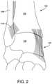
- the human ankle 100is a complex junction of multiple bones and soft tissues, as shown in FIGS. 1-3 .
- the ankle 100includes joints between the tibia 102 , fibula 104 , and talus 106 .
- the joint between the tibia 102 and fibula 104is a syndesmosis or slightly movable joint in which the bones are joined together by connective tissue.
- the syndesmosis between the tibia 102 and fibula 104includes the anterior inferior tibiofibular ligament (AITFL) 110 , the posterior inferior tibiofibular ligament (PITFL) 112 , and the interosseous ligament (IOL) 114 .
- AITFLanterior inferior tibiofibular ligament
- PITFLposterior inferior tibiofibular ligament
- IOLinterosseous ligament
- the syndesmosis ligamentsare often injured in high ankle sprains.
- Other injury prone ligaments of the ankle jointinclude, among others, the anterior talofibular ligament (ATFL) 120 , the posterior talofibular ligament (PTFL) 122 and the deltoid ligament complex 124 including superficial and deep deltoid ligaments.
- ATFLanterior talofibular ligament
- PTFLposterior talofibular ligament
- deltoid ligament complex 124including superficial and deep deltoid ligaments.
- the clampfor compressing first and second bone portions together to reduce a space therebetween.
- the clampincludes a body comprising opposing first and second ends, the first and second ends comprising respective first and second jaws that define a longitudinal clamp axis, the first jaw engageable with the first bone portion and the second jaw engageable with the second bone portion to define a directional force vector between the first and the second bone portions that is coaxial with the longitudinal clamp axis.
- the clampalso includes an adjustment mechanism coupled with the second jaw and configured to translate the second jaw distally toward the first jaw along the longitudinal axis to compress the first and the second bone portions between the first and the second jaws.
- the adjustment mechanismincludes a force gauge configured to indicate a compression force placed upon the first and the second bone portions by the first and the second jaws along the directional force vector.
- FIG. 1Another embodiment provides a tension instrument for tensioning and knotlessly locking a flexible strand having first and second opposing flexible strand ends, where the first flexible strand end is fixed adjacent to a first member, and the second flexible strand end is free proximal to the first member and adjacent to a second member.
- the tension instrumentcomprises a member engagement feature configured to engage with the second member through which the second flexible strand end passes and an adjustment mechanism operably coupled to a proximal end of the member engagement feature.
- the adjustment mechanismincludes (a) a selectively adjustable flexible strand clamp configured to capture the second flexible strand end and translate the second flexible strand end proximally relative to the member engagement feature to place a tensile force on the flexible strand between the first and the second members; (b) a force gauge operably coupled with the selectively adjustable flexible strand clamp, the force gauge including force indicia to provide an indication of the tensile force placed on the flexible strand; and (c) a pathway extending through the adjustment mechanism from a proximal end to a distal end adjacent the member engagement feature to provide clearance for fixation hardware that knotlessly locks the second flexible strand end relative to the second member to maintain the tensile force between the first and the second flexible strand ends.
- Yet another embodimentprovides a method of reinforcing a syndesmosis joint of a patient using: (a) a clamp having first and second opposing jaws that define a longitudinal clamp axis, an angle gauge configured to set an angle of the longitudinal clamp axis relative to a reference line of a patient's anatomy, and an adjustment mechanism configured to apply a measurable compression force along a directional force vector between the first and the second clamp jaws that is coaxial with the longitudinal clamp axis; and (b) a tension instrument having an anchor engagement feature coupled with an adjustment mechanism configured place a measurable tensile force on a flexible strand extending between a first anchor in a first bone portion and a second anchor in a second bone portion.
- the methodincludes the steps of (i) using the angle gauge, positioning the clamp such that the first jaw is engaged with the first bone portion and the second jaw is engaged with the second bone portion at a desired angle of the directional force vector relative to the reference line of the patient's anatomy; (ii) actuating the adjustment mechanism of the clamp to translate the second jaw of the clamp distally to achieve a desired compression force between the first and the second bone portions along the directional force vector; (iii) noting the desired compression force reflected upon a force gauge of the adjustment mechanism of the clamp; (iv) inserting a guide along the longitudinal clamp axis through the first jaw and into the first and the second bone portions to form a bone tunnel extending between the first and the second bone portions; (v) removing the clamp, leaving the guide in position; (vi) affixing a first end of a flexible strand to a first fixation anchor; (vii) using the guide, pulling a second end of the flexible strand through the bone tunnel to insert the first fixation anchor into the bone tunnel at the
- FIG. 1illustrates a right view of a human ankle joint
- FIG. 2illustrates a front view of a human ankle joint
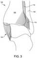
- FIG. 3illustrates a rear view of a human ankle joint
- FIG. 4illustrates a front view of one embodiment of a clamp instrument for compressing two bone portions together
- FIG. 5illustrates two alternative embodiments of a first jaw of the clamp instrument of FIG. 4 ;
- FIG. 6illustrates another front view of the clamp instrument of FIG. 4 ;
- FIG. 7illustrates a longitudinal cross-sectional view of an adjustment mechanism of the clamp instrument of FIG. 4 ;
- FIGS. 8-9illustrate transverse cross-sectional views of a first end of the clamp instrument of FIG. 4 in respective closed and open configurations
- FIG. 10illustrates the clamp instrument of FIG. 4 with a patient's tibia and fibula compressed therebetween;
- FIG. 11illustrates a perspective view of a force gauge of the clamp instrument of FIG. 4 ;
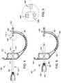
- FIG. 12illustrates a top view of a tension instrument for tensioning a flexible strand to a known amount of tension force
- FIG. 13illustrates a side view of the tension instrument of FIG. 12 ;
- FIG. 14illustrates a bottom view of the tension instrument of FIG. 12 ;
- FIG. 15illustrates an exploded view of the tension instrument of FIG. 12 , as cannulated to permit a shaft of a set screw driver to pass through the cannula to insert a set screw into a fixation anchor;
- FIG. 16provides a flowchart detailing an exemplary syndesmosis reinforcement procedure using the clamp instrument of FIG. 4 and the tension instrument of FIG. 12 ;
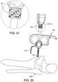
- FIGS. 17-21illustrate the operative steps described in the flowchart of FIG. 16 ;
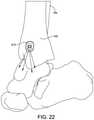
- FIG. 22illustrates a number of supplemental flexible strands attached to a locking anchor used in the syndesmosis reinforcement procedure described and illustrated in FIGS. 16-21 ;
- FIG. 23illustrates a bone plate substituted for a first anchor used in the syndesmosis reinforcement procedure described and illustrated in FIGS. 16-21 .
- a compression instrumentprovides a mechanism for clamping bone portions together to reduce the space therebetween with a force vector having both a known direction and a known magnitude.
- Embodiments of the clampmay provide a pin guide for inserting a pin coaxial with the force vector and may include features to facilitate rapid application of clamping pressure as well as fine tuning of the clamping pressure.
- Embodiments of the clampmay provide multiple modes of operation, including one-way incremental clamping and dynamic, continuously adjustable clamping.
- the clampmay include a quick release mechanism to release clamping pressure.
- the clampmay also include a depth gauge for indicating the length of a path through a bone coaxial with the force vector.
- FIGS. 4-11illustrate one exemplary embodiment of a compression instrument or clamp 600 having a bow-shaped body 602 defining a longitudinal clamp axis 604 .
- a first end 606 of the body 602includes a first jaw 608 that extends proximally toward a second end 610 of the body 602 .
- one embodiment of the first jaw 608 located at the first end 606may feature a v-notch 608 a that registers on and is engageable with a bone portion.
- the first jaw 608may be rigidly attached to the first end 606 and include the v-notch 608 a formed by an angled opening directly engageable with a curved bone surface.
- the angled openingmay be shaped to engage the shaft of a fibula, a malleolus, or any other desired bone location.
- the first jaw 608may be formed by making an angled cut through a tubular body to create the v-notched jaw 608 a having opposed angled edges diverging toward the second end 610 of the body 602 , as shown.
- the first jaw 608may feature a spherical end 608 b configured to register on a bone plate. In both end embodiments 608 a - b , the first jaw 608 is intersected by the clamp axis 604 .
- the second end 610 of the body 602defines a receiver 612 able to mount a second jaw 614 for movement relative to the first jaw 608 along the clamp axis 604 .
- the second jaw 614includes a point contact element 615 engageable with a bone portion to define a directional vector between the first and the second jaws 608 , 614 , and thus the two bone portions, that is parallel or, as may be more specifically, coaxial with the clamp axis 604 .
- the orientationis referred to hereinafter as “coaxial” but may be parallel as well.
- the point contact element 615may form a sharpened spike able to engage with a bone surface.
- the second jaw 614is mounted to an adjustment mechanism 616 , detailed in the cross-sectional view of FIG. 7 .
- the adjustment mechanism 616includes an inner shaft 618 , a hollow outer shaft 620 (i.e., sleeve), a release trigger 622 , a force gauge 624 , and a handle 626 .
- the release trigger 622is mounted in a translating relationship transverse to the clamp axis 604 and includes a screw thread 627 along its lower edge.
- the outer shaft 620extends through a through hole 625 in the receiver 612 from a proximal end 628 to a distal end 630 coaxial with the clamp axis 604 .
- the proximal end 628 of the outer shaft 620is fixed to the force gauge 624 .
- the inner shaft 618is coaxially received within the outer shaft 620 and the force gauge 624 and is affixed to the handle 626 at its proximal end in an axial force and torque transmitting relationship via a pin 631 .
- the second jaw 614is mounted to the distal end 630 of the outer shaft 620 .
- a first offset 621separates the proximal end of the force gauge 624 and the proximal end of the inner shaft 618
- a second offset 623separates the second jaw 614 from the distal end of the inner shaft 618 .
- the force gauge 624is a hollow cylinder received within a gap 636 between the handle 626 and the inner shaft 618 .
- a force spring 640biases the force gauge 624 distally away from the handle 626 ;
- a return spring 642biases the distal end of the inner shaft 618 proximally away from the receiver 612 ;
- a trigger spring 644biases the trigger partial threads 627 into engagement with external threads 646 formed on the inner shaft 618 .
- the receiverincludes loops 650 , 652 forming finger grips, and the handle 626 includes a groove 654 forming a thumb grip.
- a usermay place one or more fingers in the finger loops 650 , 652 and apply pressure to the handle 626 with a thumb engaged in the thumb groove 654 . This provides a syringe-like grip such that the handle 626 may be pressed distally.
- the threads 646 on the inner shaft 618 and the threads 627 on the lower portion of the trigger 622are formed such that distal motion of the inner shaft 618 wedges or arcs the upper portion of the trigger 622 proximally, against the biasing of trigger spring 644 , and allows the inner shaft 618 to ratchet forward (along with the outer shaft 620 ) upon the advancement of the handle 626 for gross adjustment control of the clamp 600 .
- the handle 626may be rotated to minimally advance the inner and outer shafts 618 , 620 by advancing the inner shaft threads 646 relative to the trigger threads 627 .
- the threads 646 of the inner shaft 618 and the threads 627 of the lower portion of the trigger 622engage to prevent proximal motion of the inner shaft 618 relative to the release trigger 622 .
- a usermay pull the release trigger 622 proximally to move or arc the trigger threads 627 upwardly and release the inner shaft 618 so that the inner shaft 618 and the outer shaft 620 may automatically be biased proximally by the return spring 642 .
- the handle 626When the second jaw 614 engages another object (e.g., bone) that resists its distal motion relative to the first jaw 608 , and the inner shaft 618 is advanced further, the handle 626 will advance over the casing of the force gauge 624 through the offset 621 , thereby compressing the force spring 640 as the handle 626 moves over the force gauge 624 .
- the amount of force required to advance the inner shaft 618 , and thus the handle 626distally is proportional to the distance the force spring is compressed from its resting position.
- the compression or joint reduction force placed upon the bone portions positioned between the first jaw 608 and the second jaw 614is indicated by reading the force indicia 666 (e.g., 10 lbs., 20 lbs., 30 lbs.) on the force gauge 624 relative to an edge 668 of the handle, as detailed in FIGS. 10-11 .
- the force indicia 666e.g. 10 lbs., 20 lbs., 30 lbs.
- the body 602 of the clamp 600includes an angle gauge 680 in the form of angle indicia 682 on a portion of the bow shaped body 602 between the first and second ends 606 , 610 .
- the indicia 682are graduated so that a reference feature such as, for example, a reference line defined by portions of a patient's body, will align with the zero-degree mark when the reference line is perpendicular to the clamp axis 604 .
- Angular marks on either side of the zero-degree markindicate the amount of angular deviation of the reference line from the perpendicular, as shown in FIG. 17 .
- the clamp 600provides an optimal functional outcome that combines the compression or clamping of two bone portions together in the correct direction along an axis of the native ligament with an integrated force measurement that ensures the application of the correct clamping force needed to provide the requisite compression (e.g., oftentimes approximately 25-30 lbs. or, as commonly known in the industry, the approximate amount of force needed to crush an aluminum can).
- the first end 606 of the body 602includes a C-shaped arm 684 , as shown in the lateral cross-sectional views of the first end 606 of FIGS. 8-9 .
- a sheath 686 forming a U-shaped groove 688is rotatively coupled about the C-shaped arm 684 . When the sheath 686 is manually rotated into a closed configuration 690 , shown in FIG.
- the U-shaped groove 688is blocked by the wall of the C-shaped arm 684 , such that a user may use the blocked U-shaped groove 688 as a guide for the insertion of a drill, a length of k-wire, and/or a pin 804 into the bone portions compressed between the first and second jaws 608 , 614 of the clamp 600 , as shown in FIG. 10 .
- the sheath 686is manually rotated into an open configuration 692 , shown in FIG.
- the first end 606 of the clamp 600essentially contains an open slot that allows the drill, length of k-wire, or pin 804 to pass unimpeded from the open U-shaped groove 688 in a direction transverse to the longitudinal clamp axis 604 .
- the entire clamp 600may disengaged from the bone portions clamped therein and transversely lifted away from the clamping site, leaving only the drill, k-wire, or pin 804 in place.
- the sheath 686when the sheath 686 is rotated into the closed configuration 690 , the user may drill from a distal end of the first end 606 of the body 602 toward the bone portions clamped between the first and second jaws 608 , 614 .
- the usermay slip the drill or other hardware in a direction transverse to the axis 604 from the first end 606 of the clamp 600 through the open U-shaped groove 688 before disengaging the entire clamp 600 from the compressed bone portions and removing it from the clamp site.
- the clamp 600may be employed in a variety of functional capacities, including the initial drilling of a bone tunnel, fixation of hardware, or as a stabilization device applied to realign bone tunnels after they have been drilled and have deviated from alignment.
- FIGS. 12-14illustrate front, side, and rear views of one embodiment of a tension instrument 700 able to tension a suture or other flexible strand to a known amount of tension force.
- the tension instrument 700may be used to recreate the tension force applied via the clamp 600 , discussed above, before enabling lockout of the suture at the correct tension using a variety of fixation hardware and/or fixation techniques.
- the disclosed devicesmay be used in conjunction with a flexible synthetic strand such as, for example, a suture, a suture tape, a cable, or another suitable flexible synthetic strand (hereinafter a “flexible strand,” “flexible synthetic strand,” or “suture”).
- the tension instrument 700is arranged proximally like the clamp 600 of FIGS. 4-11 with an adjustment mechanism 716 including an inner shaft 718 , a hollow outer shaft 720 , a trigger 722 , a force gauge 724 , a handle 726 , and a receiver 712 , all configured as in the clamp example discussed in relation to FIGS. 4-11 above.
- the outer shaft 706includes a distal end 711 and a fastener engagement feature 713 at its distal end configured like that of the distal end of the counter-torque anchor driver 570 disclosed in FIGS. 15-18 of U.S. patent application Ser. No. 15/641,592, entitled “EXTRA JOINT STABILIZATION CONSTRUCT” and co-filed with this application on Jul. 5, 2017.
- FIG. 15illustrates that the tension instrument 700 includes a cannula 719 and is cannulated proximally to distally to permit a shaft of a set screw driver 717 and a set screw like, for example, that disclosed in FIGS. 5-7, 12, and/or 15-18 of U.S. patent application Ser. No. 15/641,592, entitled “EXTRA JOINT STABILIZATION CONSTRUCT” and co-filed with this application on Jul. 5, 2017 to pass through the cannula 719 in order to insert the set screw into an anchor like that disclosed in, for example, FIG. 5-7 or 12-14 of U.S. patent application Ser. No. 15/641,592, entitled “EXTRA JOINT STABILIZATION CONSTRUCT” and co-filed with this application on Jul. 5, 2017 that is attached to the tension instrument 700 .
- the receiver 712 of the tension instrument 700includes a flexible strand clamp 730 or suture clamp 730 (referred hereinbelow as suture clamp 730 ) including a moveable jaw 732 and a thumb screw 734 .
- a suturemay be placed between the receiver 712 and the moveable jaw 732 and clamped in place by tightening the thumb screw 734 .
- the receiver 712With the distal end of the tension instrument engaging or leveraging off of adjacent member such as a bone, anchor, or another member through which a suture passes, and with the suture secured in the suture clamp 730 , the receiver 712 may be moved proximally relative to the inner shaft 718 .
- the outer shaft 720 and the force gauge 724are forced distally relative to the inner shaft 718 , causing the handle 726 to move over the force gauge 724 against the force spring (not shown).
- the tension in the suturemay be read on the force gauge relative to the edge 768 of the handle.
- the tension instrument 700may be used in conjunction with an interference screw, anchor, or any other appropriate fixation hardware to recreate the correct tension force and lock the suture in place.
- a first suture anchormay be positioned at a first ligament attachment point on a bone.
- a suturemay be routed from the first suture anchor to a second, locking suture anchor at a second ligament attachment point on a bone.
- the suturemay be tensioned to provide a desired level of reinforcement of the ligament and then locked with the second suture anchor.
- Ligament reinforcing constructsmay be provided for any ligament of the skeletal system.
- various ligament reinforcement constructswill be illustrated for the human ankle.
- an anchoris placed in the proximity of the origin of a ligament and a second anchor is placed in the proximity of the insertion of the ligament.
- One anchormay be any ordinary suture returning anchor, and the second anchor may be a knotless suture locking anchor.
- the ligamentmay also undergo a direct repair, e.g., mid substance suturing.
- the ligamentsmay include the AITFL, PITFL, ATFL, PTFL, the deep and superficial ligaments of the deltoid complex, and/or any other ligament in need of reinforcement.
- FIG. 16provides a flowchart detailing the steps of an exemplary syndesmosis reinforcement procedure 1100
- FIGS. 17-21illustrate the corresponding steps of the exemplary syndesmosis reinforcement procedure.
- the clamp 600is positioned such that the v-notch 608 a of the first jaw 608 is engaged with the fibula 104 on the lateral side of the ankle, and the point 615 of the second jaw 614 is positioned over the tibia 102 on the medial side of the ankle ( FIG. 16, 1102 ).
- the angle gauge 680may be used to set the angle of the clamp axis relative to reference line of the patient's anatomy, e.g., a midline 802 of the foot. For example, it has been found by the present inventors that a force vector of around 30 degrees from perpendicular often provides the best reduction of the fibula relative to the tibia. With the clamp 600 in this initial position, the jaws can be closed to reduce the syndesmosis ( FIG. 16, 1104 ). The ankle can be moved through a range of motion and the reduction evaluated. The reduction force may be increased or decreased by adjusting the clamp pressure and the force direction may be varied by repositioning one or both jaws 608 , 614 of the clamp 600 on the bones. The amount of force used to achieve the desired reduction can be read and noted from the force gauge 624 .
- the pin 804(or a k-wire, etc.) is inserted along the clamp axis 604 through the bones to establish the reinforcement vector direction, as shown in FIG. 10 ( FIG. 16, 1106 ).
- the clampmay then be removed by rotating the sheath 686 such that the U-shaped groove 688 moves into the open configuration 692 and lifting the clamp from the compression site, as discussed above in relation to FIGS. 8-10 ( FIG. 16, 1108 ).
- the proceduremay continue through the clamp 600 .
- FIGS. 18-19the clamp 600 has been removed, and a drill 806 is advanced part-way over the pin 804 to provide clearance for the shaft of a first anchor 808 , e.g., anchor 920 disclosed in FIGS. 6-12 of U.S. patent application Ser. No. 15/641,573, entitled “INTRA JOINT STABILIZATION CONSTRUCT,” co-filed with this application on Jul. 5, 2017, if necessary as shown in FIG. 18 ( FIG. 16, 1110 ).
- the pin 804may be sized to provide the right size hole for the anchor shaft or an anchor without a shaft may be used such as button 200 disclosed in FIG. 4 of U.S. patent application Ser. No.
- a suture 810is attached to the first anchor 808 and pulled through the bone tunnel, e.g., by threading the suture 810 through an eye in the pin 804 and pulling the pin and the suture through the bones in the direction of arrow 813 , as shown in FIG. 19 ( FIG. 16, 1112 ).
- the sutureis next threaded through a second anchor 812 such as, for example, anchor 300 disclosed in FIGS. 13-19 of U.S. patent application Ser. No. 15/641,573, entitled “INTRA JOINT STABILIZATION CONSTRUCT” co-filed with this application on Jul. 5, 2017 ( FIG.
- the second anchor 812is engaged with the bone ( FIG. 16, 1116 )
- the tension instrument 700is engaged with the second anchor 812 ( FIG. 16, 1118 )
- the sutureis clamped within the suture clamp 730 of the tension instrument 700 , as shown in FIG. 20 ( FIG. 16, 1120 ).
- Tensionis applied to the suture to match the force used to clamp the joint and obtain the desired reduction ( FIG. 16, 1122 ) and the suture is knotlessly locked ( FIG. 16, 1124 ), as shown in FIGS. 20-21 .
- the directional force vector determined/set during the reduction with the clamp 600is reproduced precisely, both in direction and force amplitude, by the suture construct.
- the ends of the suture coming from the second locking anchor 812may be trimmed. Alternatively, they may be used to tie to other bones or soft tissues. Likewise, if desired, supplemental sutures may be attached to one or both anchors and used to further reinforce the joint or adjacent joints and soft tissue, as shown in FIG. 22 . As shown in FIG. 23 , the exemplary reinforcement construct may also be used in conjunction with a bone plate 814 .
- the syndesmosis reinforcement procedure 1100is described above in relation to reinforcement of the interosseous ligament (IOL) 114 ( FIG. 3 ) between the tibia and fibula, the method could be used to form ligament reinforcement constructs that compress any two bones together to reduce the space between bones and/or to reinforce a ligament across a bone joint to achieve optimal anatomic positioning in both directional alignment and the reduction force applied by the construct.
- IOLinterosseous ligament
Landscapes
- Health & Medical Sciences (AREA)
- Surgery (AREA)
- Life Sciences & Earth Sciences (AREA)
- Animal Behavior & Ethology (AREA)
- Public Health (AREA)
- Engineering & Computer Science (AREA)
- Biomedical Technology (AREA)
- Heart & Thoracic Surgery (AREA)
- Medical Informatics (AREA)
- Molecular Biology (AREA)
- Veterinary Medicine (AREA)
- General Health & Medical Sciences (AREA)
- Nuclear Medicine, Radiotherapy & Molecular Imaging (AREA)
- Orthopedic Medicine & Surgery (AREA)
- Oral & Maxillofacial Surgery (AREA)
- Rheumatology (AREA)
- Dentistry (AREA)
- Pathology (AREA)
- Surgical Instruments (AREA)
- Prostheses (AREA)
Abstract
Description
Claims (12)
Priority Applications (2)
| Application Number | Priority Date | Filing Date | Title |
|---|---|---|---|
| US16/545,444US11234688B2 (en) | 2016-07-05 | 2019-08-20 | Compression and tension instruments and methods of use to reinforce ligaments |
| US17/589,337US12357295B2 (en) | 2016-07-05 | 2022-01-31 | Compression and tension instruments and methods of use to reinforce ligaments |
Applications Claiming Priority (6)
| Application Number | Priority Date | Filing Date | Title |
|---|---|---|---|
| US201662358231P | 2016-07-05 | 2016-07-05 | |
| US201662425560P | 2016-11-22 | 2016-11-22 | |
| US201762456217P | 2017-02-08 | 2017-02-08 | |
| US201762458975P | 2017-02-14 | 2017-02-14 | |
| US15/642,053US10426460B2 (en) | 2016-07-05 | 2017-07-05 | Compression and tension instruments and methods of use to reinforce ligaments |
| US16/545,444US11234688B2 (en) | 2016-07-05 | 2019-08-20 | Compression and tension instruments and methods of use to reinforce ligaments |
Related Parent Applications (1)
| Application Number | Title | Priority Date | Filing Date |
|---|---|---|---|
| US15/642,053ContinuationUS10426460B2 (en) | 2016-07-05 | 2017-07-05 | Compression and tension instruments and methods of use to reinforce ligaments |
Related Child Applications (1)
| Application Number | Title | Priority Date | Filing Date |
|---|---|---|---|
| US17/589,337ContinuationUS12357295B2 (en) | 2016-07-05 | 2022-01-31 | Compression and tension instruments and methods of use to reinforce ligaments |
Publications (2)
| Publication Number | Publication Date |
|---|---|
| US20190380696A1 US20190380696A1 (en) | 2019-12-19 |
| US11234688B2true US11234688B2 (en) | 2022-02-01 |
Family
ID=60892447
Family Applications (11)
| Application Number | Title | Priority Date | Filing Date |
|---|---|---|---|
| US15/641,600AbandonedUS20180008286A1 (en) | 2016-07-05 | 2017-07-05 | Noncircular broach and methods of use |
| US15/641,592Active2038-05-11US10426459B2 (en) | 2015-08-04 | 2017-07-05 | Extra joint stabilization construct |
| US15/641,573Active2038-03-01US10682131B2 (en) | 2015-08-04 | 2017-07-05 | Intra joint stabilization construct |
| US15/642,053Active2038-05-11US10426460B2 (en) | 2016-07-05 | 2017-07-05 | Compression and tension instruments and methods of use to reinforce ligaments |
| US15/641,618Active2038-06-10US10842480B2 (en) | 2016-07-05 | 2017-07-05 | Multiple suture threader and methods of use |
| US16/545,371Active2038-03-31US11241225B2 (en) | 2015-08-04 | 2019-08-20 | Extra joint stabilization construct |
| US16/545,444Active2038-05-25US11234688B2 (en) | 2016-07-05 | 2019-08-20 | Compression and tension instruments and methods of use to reinforce ligaments |
| US16/871,485Active2039-04-16US11937801B2 (en) | 2015-08-04 | 2020-05-11 | Intra joint stabilization construct |
| US17/094,566Active2039-05-02US12042138B2 (en) | 2016-07-05 | 2020-11-10 | Multiple suture threader and methods of use |
| US17/589,308Active2038-01-06US12343002B2 (en) | 2016-07-05 | 2022-01-31 | Extra joint stabilization construct |
| US17/589,337Active2037-12-05US12357295B2 (en) | 2016-07-05 | 2022-01-31 | Compression and tension instruments and methods of use to reinforce ligaments |
Family Applications Before (6)
| Application Number | Title | Priority Date | Filing Date |
|---|---|---|---|
| US15/641,600AbandonedUS20180008286A1 (en) | 2016-07-05 | 2017-07-05 | Noncircular broach and methods of use |
| US15/641,592Active2038-05-11US10426459B2 (en) | 2015-08-04 | 2017-07-05 | Extra joint stabilization construct |
| US15/641,573Active2038-03-01US10682131B2 (en) | 2015-08-04 | 2017-07-05 | Intra joint stabilization construct |
| US15/642,053Active2038-05-11US10426460B2 (en) | 2016-07-05 | 2017-07-05 | Compression and tension instruments and methods of use to reinforce ligaments |
| US15/641,618Active2038-06-10US10842480B2 (en) | 2016-07-05 | 2017-07-05 | Multiple suture threader and methods of use |
| US16/545,371Active2038-03-31US11241225B2 (en) | 2015-08-04 | 2019-08-20 | Extra joint stabilization construct |
Family Applications After (4)
| Application Number | Title | Priority Date | Filing Date |
|---|---|---|---|
| US16/871,485Active2039-04-16US11937801B2 (en) | 2015-08-04 | 2020-05-11 | Intra joint stabilization construct |
| US17/094,566Active2039-05-02US12042138B2 (en) | 2016-07-05 | 2020-11-10 | Multiple suture threader and methods of use |
| US17/589,308Active2038-01-06US12343002B2 (en) | 2016-07-05 | 2022-01-31 | Extra joint stabilization construct |
| US17/589,337Active2037-12-05US12357295B2 (en) | 2016-07-05 | 2022-01-31 | Compression and tension instruments and methods of use to reinforce ligaments |
Country Status (1)
| Country | Link |
|---|---|
| US (11) | US20180008286A1 (en) |
Cited By (1)
| Publication number | Priority date | Publication date | Assignee | Title |
|---|---|---|---|---|
| US12383322B2 (en) | 2023-08-22 | 2025-08-12 | DePuy Synthes Products, Inc. | Methods and devices for syndesmosis tensioning |
Families Citing this family (38)
| Publication number | Priority date | Publication date | Assignee | Title |
|---|---|---|---|---|
| US10363140B2 (en) | 2012-03-09 | 2019-07-30 | Si-Bone Inc. | Systems, device, and methods for joint fusion |
| US11147688B2 (en) | 2013-10-15 | 2021-10-19 | Si-Bone Inc. | Implant placement |
| US10820918B2 (en) | 2015-07-17 | 2020-11-03 | Crossroads Extremity Systems, Llc | Transosseous guide and method |
| US12383253B2 (en) | 2015-08-04 | 2025-08-12 | Crossroads Extremity Systems, Llc | Suture anchor |
| US20180008286A1 (en)* | 2016-07-05 | 2018-01-11 | Mortise Medical, LLC | Noncircular broach and methods of use |
| WO2018118931A1 (en)* | 2016-12-21 | 2018-06-28 | Wright Medical Technology, Inc. | Syndesmosis construct |
| US11298143B2 (en)* | 2017-04-12 | 2022-04-12 | Smith & Nephew, Inc. | Surgical drill guide systems and methods of use thereof |
| US11116519B2 (en) | 2017-09-26 | 2021-09-14 | Si-Bone Inc. | Systems and methods for decorticating the sacroiliac joint |
| CA3078902A1 (en)* | 2017-11-30 | 2019-06-06 | DePuy Synthes Products, Inc. | Bone fracture fixation clamp with bone remodeling adaptability |
| ES3011907T3 (en) | 2018-03-28 | 2025-04-08 | Si Bone Inc | Threaded implants for use across bone segments |
| US11432812B2 (en) | 2018-05-11 | 2022-09-06 | Dunamis Medical Technologies, Llc | Knotless anchor assembly and methods thereof |
| EP3856043A1 (en)* | 2018-09-24 | 2021-08-04 | CONMED Corporation | Backstop loader |
| US20210338228A1 (en)* | 2018-09-25 | 2021-11-04 | The Board of Supervisors of Louisiana State Universityand Agricultual amd Mechanical Colleg | Surgical line fixation device and methods of use thereof |
| EP3669825A1 (en)* | 2018-12-19 | 2020-06-24 | Abanza Tecnomed, S.L. | Medical fastening device for the fastening of grafts |
| JP2022517187A (en)* | 2019-01-04 | 2022-03-07 | パンサー オーソピディックス, インコーポレイテッド | Bone and joint stabilization device features and delivery system |
| EP4613244A2 (en) | 2019-02-14 | 2025-09-10 | SI-Bone Inc. | Implants for spinal fixation and or fusion |
| EP3934546B1 (en) | 2019-03-06 | 2025-08-27 | Speed Clip Solutions, LLC | Suture tensioning and securement device and system |
| EP3941363A4 (en)* | 2019-03-21 | 2022-12-07 | New York Society for the Relief of the Ruptured and Crippled, Maintaining the Hospital for Special Surgery | INTEROSSOUS COUPLER |
| JP7266704B2 (en)* | 2019-03-26 | 2023-04-28 | メダクタ・インターナショナル・ソシエテ・アノニム | Templates and methods for measuring cross-sections of grafts |
| CN110051395A (en)* | 2019-04-25 | 2019-07-26 | 北京天星博迈迪医疗器械有限公司 | Threading apparatus |
| US11426154B2 (en) | 2019-09-11 | 2022-08-30 | Medline Industries, Lp | Orthopedic stabilization device, kit, and method |
| US11832806B2 (en)* | 2019-09-11 | 2023-12-05 | Acumed Llc | Near bone suture button |
| JP7646654B2 (en) | 2019-11-21 | 2025-03-17 | エスアイ-ボーン・インコーポレイテッド | Rod coupling assembly for bone stabilization construct - Patent application |
| AU2020392121B2 (en) | 2019-11-27 | 2025-05-22 | Si-Bone, Inc. | Bone stabilizing implants and methods of placement across SI joints |
| EP4072452A4 (en) | 2019-12-09 | 2023-12-20 | SI-Bone, Inc. | Sacro-iliac joint stabilizing implants and methods of implantation |
| WO2021202123A1 (en) | 2020-03-30 | 2021-10-07 | Responsive Arthroscopy, LLC | Suture based clamping device |
| WO2022055983A1 (en)* | 2020-09-10 | 2022-03-17 | Acumed Llc | Near bone suture button |
| WO2022094434A1 (en) | 2020-10-30 | 2022-05-05 | Anderson M D Christian | Dynamic ligament repair device |
| US12161318B2 (en) | 2020-12-01 | 2024-12-10 | Dunamis Medical Technologies, Llc | Re-tensionable suture anchor system and related methods |
| EP4259015A4 (en) | 2020-12-09 | 2024-09-11 | SI-Bone, Inc. | SACROILIAC JOINT STABILIZATION IMPLANTS AND METHODS OF IMPLANTATION |
| WO2022144644A1 (en) | 2020-12-28 | 2022-07-07 | DePuy Synthes Products, Inc. | Suture threader for bone plate |
| WO2023031702A1 (en) | 2021-08-31 | 2023-03-09 | Crossroads Extremity Systems, Llc | Suture anchor |
| EP4401645A4 (en)* | 2021-09-14 | 2025-07-16 | Responsive Arthroscopy Llc | IMPROVED PUSH-IN SEAM ANCHOR SYSTEM |
| US12239310B2 (en)* | 2022-04-27 | 2025-03-04 | Medline Industries, Lp | Orthopedic stabilization device, kit and method |
| WO2024108224A1 (en)* | 2022-11-20 | 2024-05-23 | Dunamis Medical Technologies, Llc | Knotless orthopedic stabilization system and related methods |
| US12433654B2 (en) | 2023-02-08 | 2025-10-07 | Medline Industries, Lp | Lisfranc reconstruction device, kit, and method |
| USD1092739S1 (en)* | 2023-03-03 | 2025-09-09 | Abanza Tecnomed, S.L. | Medical implant |
| WO2025038769A1 (en) | 2023-08-15 | 2025-02-20 | Si-Bone Inc. | Pelvic stabilization implants, methods of use and manufacture |
Citations (195)
| Publication number | Priority date | Publication date | Assignee | Title |
|---|---|---|---|---|
| US2181746A (en) | 1939-02-04 | 1939-11-28 | John R Siebrandt | Combination bone clamp and adjustable drill guide |
| US2291413A (en) | 1941-06-13 | 1942-07-28 | John R Siebrandt | Bone clamping and wire adjusting means |
| US2362957A (en) | 1941-09-27 | 1944-11-14 | Harry Herschel Leiter | Surgical bone clamp |
| US2427128A (en) | 1946-01-28 | 1947-09-09 | Zimmer Mfg Company | Surgical bone clamp |
| US2485531A (en) | 1948-01-13 | 1949-10-18 | Dzus William | Surgical toggle bolt |
| US2489870A (en) | 1946-03-02 | 1949-11-29 | Dzus William | Bone fastening device |
| US2511051A (en) | 1946-06-19 | 1950-06-13 | Dzus William | Fastening device |
| US2706475A (en) | 1953-12-07 | 1955-04-19 | Reynolds Horn Res Foundation I | Surgical tongs |
| US2715403A (en) | 1954-06-07 | 1955-08-16 | Tucker Eli Jordan | Tourniquet |
| CA551446A (en) | 1958-01-14 | S. Caesar Orville | Internal fixation of fractures | |
| US3114367A (en) | 1961-05-08 | 1963-12-17 | Collins W Carpenter | Instrument for reducing bone fractures |
| US3664022A (en) | 1971-01-28 | 1972-05-23 | Irwin A Small | Drill guide for mandibular staple and staple construction |
| US3727611A (en) | 1971-07-01 | 1973-04-17 | R Schultz | Alignment means for inserting guide wire prior to inserting hip nail for a fractured hip |
| US3867932A (en) | 1974-01-18 | 1975-02-25 | Donald R Huene | Assembly for inserting rigid shafts into fractured bones |
| US3959960A (en) | 1975-03-12 | 1976-06-01 | Santos Manuel V | Tensioning, twisting and cutting device for sutures |
| US4050464A (en) | 1975-04-28 | 1977-09-27 | Downs Surgical Limited | Surgical cable tensioning instrument |
| US4159716A (en) | 1977-10-17 | 1979-07-03 | Borchers Clinton H | Method of compressing and realigning bone structures to correct splay foot |
| US4364381A (en) | 1980-01-31 | 1982-12-21 | Sher Jay H | Surgical clamp and drill-guiding instrument |
| USD273326S (en) | 1981-02-27 | 1984-04-03 | Ab Stille-Werner | Surgical instrument for guiding a drill bit for drilling through bone sections |
| EP0132284A1 (en) | 1983-06-24 | 1985-01-30 | Queen's University At Kingston | Apparatus for locating an elbow prothesis |
| US4586497A (en) | 1983-10-31 | 1986-05-06 | David J. Dapra | Drill fixation device and method for vertebra cutting |
| US4587963A (en) | 1983-05-26 | 1986-05-13 | Karl Leibinger | Instrument for positioning a cerclage fixation device around fractured bone parts |
| US4712542A (en) | 1986-06-30 | 1987-12-15 | Medmetric Corporation | System for establishing ligament graft orientation and isometry |
| US4787377A (en) | 1986-05-07 | 1988-11-29 | Laboureau Jacques Philippe | Surgical instrument for positioning and insertion of posterior cruciate ligament of the knee in plasty (or prosthetic replacement) |
| US4945904A (en) | 1989-10-25 | 1990-08-07 | W. L. Gore & Associates, Inc. | Orthopedic drill guide device |
| US4964862A (en) | 1989-08-31 | 1990-10-23 | Micro Strain Company | Method of and means for measuring ligament tension |
| US4969895A (en) | 1989-01-23 | 1990-11-13 | Richards Medical Company | Apparatus and method for determining the tension on a ligament graft |
| US4969471A (en) | 1989-01-09 | 1990-11-13 | Medmetric Corporation | Knee ligament testing device and method of use |
| US5035701A (en) | 1988-12-26 | 1991-07-30 | Jamil Kabbara | Device and method to check the tension of a suture during a surgical operation |
| US5116340A (en) | 1989-01-26 | 1992-05-26 | Songer Robert J | Surgical securance apparatus |
| US5300077A (en) | 1990-07-16 | 1994-04-05 | Arthrotek | Method and instruments for ACL reconstruction |
| US5306290A (en) | 1993-02-12 | 1994-04-26 | Mitek Surgical Products, Inc. | Suture button |
| US5312412A (en) | 1993-02-03 | 1994-05-17 | Whipple Terry L | Fixation alignment guide for surgical use |
| US5312410A (en) | 1992-12-07 | 1994-05-17 | Danek Medical, Inc. | Surgical cable tensioner |
| US5409490A (en) | 1993-08-16 | 1995-04-25 | Depuy Inc. | Shoulder separation reconstruction |
| US5431659A (en) | 1993-08-17 | 1995-07-11 | Texas Scottish Rite Hospital For Children | Pneumatic wire tensioner |
| US5449361A (en) | 1993-04-21 | 1995-09-12 | Amei Technologies Inc. | Orthopedic cable tensioner |
| US5476465A (en) | 1993-04-21 | 1995-12-19 | Amei Technologies Inc. | Surgical cable crimp |
| US5540698A (en) | 1993-04-21 | 1996-07-30 | Amei Technologies Inc. | System and method for securing a medical cable |
| US5545168A (en) | 1994-03-11 | 1996-08-13 | Burke; Dennis W. | Apparatus for both tensioning and crimping a surgical wire |
| US5578057A (en) | 1993-07-28 | 1996-11-26 | Mitek Surgical Products, Inc. | Anchoring device installation tool assembly and method |
| US5584839A (en) | 1994-12-12 | 1996-12-17 | Gieringer; Robert E. | Intraarticular drill guide and arthroscopic methods |
| US5643321A (en) | 1994-11-10 | 1997-07-01 | Innovasive Devices | Suture anchor assembly and methods |
| US5702397A (en) | 1996-02-20 | 1997-12-30 | Medicinelodge, Inc. | Ligament bone anchor and method for its use |
| US5713897A (en) | 1997-03-06 | 1998-02-03 | Goble; E. Marlowe | Anterior cruciate ligament tensioning device and method for its use |
| US5725532A (en) | 1996-09-10 | 1998-03-10 | Shoemaker; Steven | Integrated surgical reduction clamp and drill guide |
| US5741281A (en) | 1992-11-17 | 1998-04-21 | Smith & Nephew, Inc. | Suture securing apparatus |
| US5895389A (en) | 1997-05-29 | 1999-04-20 | Synthes (U.S.A.) | Drilling guide and measuring instrumentation |
| US6001106A (en) | 1997-09-03 | 1999-12-14 | M & R Medical, Inc. | System for tensioning ligament grafts |
| US6027523A (en) | 1997-10-06 | 2000-02-22 | Arthrex, Inc. | Suture anchor with attached disk |
| US6045573A (en) | 1999-01-21 | 2000-04-04 | Ethicon, Inc. | Suture anchor having multiple sutures |
| US6254605B1 (en) | 1990-07-16 | 2001-07-03 | Stephen M. Howell | Tibial guide |
| US20010049483A1 (en) | 2000-05-31 | 2001-12-06 | Clive Reay-Young | Tension measuring device |
| US6368326B1 (en) | 1998-09-28 | 2002-04-09 | Daos Limited | Internal cord fixation device |
| JP2002102236A (en) | 2000-10-02 | 2002-04-09 | Koseki Ika Kk | Drill guide for patella |
| US20020087190A1 (en) | 1999-02-02 | 2002-07-04 | Benavitz William C. | Insert molded push-in suture anchor |
| US6443955B1 (en) | 1998-11-25 | 2002-09-03 | Alliance Orthopedic, Inc. | Fracture reduction clamp |
| US20030009171A1 (en) | 2001-07-09 | 2003-01-09 | Alain Tornier | Ancillary tool for fitting a humeral component of an elbow prosthesis |
| US6517564B1 (en) | 1999-02-02 | 2003-02-11 | Arthrex, Inc. | Bioabsorbable tissue tack with oval-shaped head and method of tissue fixation using same |
| US6527794B1 (en) | 1999-08-10 | 2003-03-04 | Ethicon, Inc. | Self-locking suture anchor |
| US6547778B1 (en) | 2000-07-21 | 2003-04-15 | Joseph H. Sklar | Graft ligament strand tensioner |
| US6554852B1 (en) | 1999-08-25 | 2003-04-29 | Michael A. Oberlander | Multi-anchor suture |
| US6557426B2 (en) | 2000-02-01 | 2003-05-06 | Richard L. Reinemann, Jr. | Method and apparatus for testing suture anchors |
| US6616667B1 (en) | 1999-11-25 | 2003-09-09 | Sulzer Orthopedics, Ltd. | Surgical instrument for tensioning a cable-like tensioning element |
| US6669698B1 (en) | 2000-10-24 | 2003-12-30 | Sdgi Holdings, Inc. | Vertebrae fastener placement guide |
| US20040098045A1 (en) | 1999-02-02 | 2004-05-20 | Grafton R. Donald | Bioabsorbable tissue tack with oval-shaped head and method of tissue fixation using the same |
| US6739068B1 (en) | 2003-01-06 | 2004-05-25 | Pilling Weck Incorporated | Pliers with jaw spacing and load measuring readings |
| US20040102788A1 (en) | 2002-11-19 | 2004-05-27 | Huebner Randall J. | Guide system for bone-repair devices |
| US6761722B2 (en) | 1998-01-26 | 2004-07-13 | Orthodyne, Inc. | Tissue anchoring system and method |
| US20040153153A1 (en) | 2001-05-31 | 2004-08-05 | Elson Robert J. | Anterior cruciate ligament reconstruction system and method of implementing same |
| US6780198B1 (en) | 2001-12-06 | 2004-08-24 | Opus Medical, Inc. | Bone anchor insertion device |
| US6866673B2 (en) | 2002-12-20 | 2005-03-15 | Ran Oren | Suture manipulating and/or cutting implement |
| US20050065533A1 (en) | 2001-05-31 | 2005-03-24 | Magen Hugh E. | Apparatus for assembling anterior cruciate ligament reconstruction system |
| US20050070906A1 (en) | 1999-11-30 | 2005-03-31 | Ron Clark | Endosteal tibial ligament fixation with adjustable tensioning |
| ES2226791T3 (en) | 1999-09-15 | 2005-04-01 | Synthes Ag Chur | REDUCTION DEVICE FOR BEAR FRAGMENTS. |
| US20050222618A1 (en) | 2004-04-06 | 2005-10-06 | Arthrex, Inc. | Fully threaded suture anchor with transverse anchor pin |
| US20050240226A1 (en) | 2002-02-04 | 2005-10-27 | Arthrocare Corporation | Method and apparatus for attaching connective tissues to bone using a knotless suture anchoring device |
| US20060085006A1 (en) | 2002-12-03 | 2006-04-20 | Ek Steven W | System and method for retrograde procedure |
| US20060161159A1 (en) | 1999-02-02 | 2006-07-20 | Dreyfuss Peter J | PEEK ribbed suture anchor |
| US7083638B2 (en) | 2001-02-12 | 2006-08-01 | Arthrocare Corporation | Method and apparatus for attaching connective tissues to bone using a knotless suture anchoring device |
| US7090690B2 (en) | 2002-11-19 | 2006-08-15 | Arthrocare Corporation | Devices and methods for repairing soft tissue |
| US20060229623A1 (en)* | 2004-10-26 | 2006-10-12 | Bonutti Peter M | Tissue fixation system and method |
| US20060271060A1 (en) | 2005-05-26 | 2006-11-30 | Arthrocare Corporation | Threaded knotless suture anchoring device and method |
| US20060276804A1 (en) | 2003-01-10 | 2006-12-07 | Molz Fred J Iv | Flexible member tensioning instruments and methods |
| US20060293709A1 (en) | 2005-06-24 | 2006-12-28 | Bojarski Raymond A | Tissue repair device |
| US7172626B1 (en) | 2002-06-10 | 2007-02-06 | Andrews Scott A | Method for reconstructing a knee |
| US20070060922A1 (en) | 2005-09-13 | 2007-03-15 | Arthrex, Inc. | Fully-threaded bioabsorbable suture anchor |
| US20070060931A1 (en) | 2005-09-14 | 2007-03-15 | Rhaphis Medical, Inc. | Suturing Device, System, and Method |
| US20070073299A1 (en) | 1999-02-02 | 2007-03-29 | Arthrex, Inc. | Suture anchor with insert-molded eyelet shield |
| US20070083236A1 (en) | 2005-06-24 | 2007-04-12 | Smith & Nephew, Inc. | Methods and devices for tissue repair |
| US20070088362A1 (en) | 2004-10-26 | 2007-04-19 | Bonutti,Ip, Llc | Apparatus and methods for surgery |
| US7235091B2 (en) | 2002-06-20 | 2007-06-26 | Brian Thornes | Apparatus and method for fixation of ankle syndesmosis |
| US20070150003A1 (en) | 2000-02-02 | 2007-06-28 | Dreyfuss Peter J | Suture anchor with insert-molded suture eyelet |
| WO2007102829A1 (en) | 2006-03-09 | 2007-09-13 | Tyco Healthcare Group Lp | Cannulated suture anchor system |
| US20070225764A1 (en) | 1999-02-02 | 2007-09-27 | Benavitz William C | Insert molded suture anchor |
| US7326222B2 (en) | 2002-05-01 | 2008-02-05 | Arthrex, Inc. | Suture tensioning device |
| US20080077182A1 (en) | 2004-02-26 | 2008-03-27 | Depuy Mitek, Inc. | Methods and devices for repairing triangular fibrocartilage complex tears |
| US7431692B2 (en) | 2006-03-09 | 2008-10-07 | Edwards Lifesciences Corporation | Apparatus, system, and method for applying and adjusting a tensioning element to a hollow body organ |
| US20080249567A1 (en) | 2006-07-20 | 2008-10-09 | Kaplan Lee D | Surgical instruments |
| US7442202B2 (en) | 2002-08-26 | 2008-10-28 | Arthrex, Inc. | Suture anchor attached to tissue-fixation disk without top knot |
| US7537596B2 (en) | 2003-06-20 | 2009-05-26 | Acumed Llc | Bone plates with intraoperatively tapped apertures |
| US7572275B2 (en) | 2004-12-08 | 2009-08-11 | Stryker Endoscopy | System and method for anchoring suture to bone |
| US7578824B2 (en) | 2003-12-30 | 2009-08-25 | Zimmer, Inc. | Methods and apparatus for forming a tunnel through a proximal end of a tibia |
| US20090228049A1 (en) | 2008-03-09 | 2009-09-10 | Park Sangdo | Connecting Cannulated Bone Screws |
| US20090306711A1 (en) | 2006-02-03 | 2009-12-10 | Biomet Sports Medicine, Llc | Method for Tissue Fixation |
| US20100010496A1 (en) | 2006-04-19 | 2010-01-14 | Depuy Spine, Inc. | Sacroiliac joint fusion alignment guide |
| US20100262185A1 (en) | 2009-04-10 | 2010-10-14 | Suspension Orthopaedic Solutions, Llc | Method and apparatus for aperture fixation by securing flexible material with a knotless fixation device |
| US7875058B2 (en) | 2007-01-17 | 2011-01-25 | Arthrex, Inc. | Bunion repair using suture-button construct |
| US20110022054A1 (en) | 2009-07-21 | 2011-01-27 | Distefano James G | Suture Tensioner with Gauge |
| US7887551B2 (en) | 1999-12-02 | 2011-02-15 | Smith & Nephew, Inc. | Soft tissue attachment and repair |
| US7901431B2 (en) | 2007-01-17 | 2011-03-08 | Arthrex, Inc. | Lisfranc repair using suture-button construct |
| US20110112576A1 (en) | 2009-11-10 | 2011-05-12 | Linh Tuong Nguyen | Tissue Repair Devices |
| US7963966B2 (en) | 2000-06-06 | 2011-06-21 | Cole J Dean | Bone fixation system and method of use |
| US20110184426A1 (en) | 2007-09-04 | 2011-07-28 | Garces Martin Gerardo | Device for fixing screws in osteoporotic bones |
| US20110224727A1 (en) | 2009-10-28 | 2011-09-15 | Mark Edwin Housman | Threaded Suture Anchor |
| WO2011153417A1 (en) | 2010-06-03 | 2011-12-08 | Tarsus Medical Inc. | Devices for treating hallux valgus |
| US8083769B2 (en) | 2006-11-01 | 2011-12-27 | Depuy Mitek, Inc. | Wired sutures |
| US8109936B2 (en) | 2001-10-18 | 2012-02-07 | Orthoip, Llc | Cap device for use in the fixation of bone structures |
| US8114127B2 (en) | 2004-06-22 | 2012-02-14 | Hs West Investments, Llc | Bone anchors for use in attaching soft tissue to bone |
| US20120053626A1 (en) | 2010-02-17 | 2012-03-01 | Koepke Ryan D | Fully threaded suture anchor with internal, recessed eyelets |
| US20120060847A1 (en) | 2009-05-21 | 2012-03-15 | Renishaw (Ireland) Limited | Head clamp for imaging and neurosurgery |
| US8162997B2 (en) | 2007-11-05 | 2012-04-24 | Steven Struhl | Device for treatment of acromioclavicular joint dislocations |
| US20120123417A1 (en) | 2010-11-04 | 2012-05-17 | Smith & Nephew, Inc. | Drill Guide with Depth Stop |
| US20120123428A1 (en) | 2010-11-10 | 2012-05-17 | Sascha Berberich | Repositioning Forceps With A Drilling Aid |
| US20120165867A1 (en) | 2006-02-03 | 2012-06-28 | Biomet Sports Medicine, Llc | Method and Apparatus for Coupling Anatomical Features |
| US20120172936A1 (en) | 2010-12-29 | 2012-07-05 | Tarsus Medical Inc. | Methods and devices for treating a syndesmosis injury |
| US8277459B2 (en) | 2009-09-25 | 2012-10-02 | Tarsus Medical Inc. | Methods and devices for treating a structural bone and joint deformity |
| US8277484B2 (en) | 2005-03-10 | 2012-10-02 | Tyco Healthcare Group Lp | Suture anchors |
| US20120253410A1 (en) | 2011-03-07 | 2012-10-04 | Kyle Taylor | Apparatus and methods for bone repair preparation |
| US8298247B2 (en) | 2007-05-02 | 2012-10-30 | Arthrex, Inc. | Suture tensioning device |
| US8303591B1 (en) | 2008-03-18 | 2012-11-06 | Dallen Medical, Inc. | Load shaping for dynamic tensioning mechanisms and methods |
| US8317828B2 (en) | 2004-04-21 | 2012-11-27 | United States Surgical Corporation | Suture anchor installation system and method |
| US8414599B1 (en) | 2007-12-31 | 2013-04-09 | Dallen Medical, Inc. | Dynamic suture tensioning device and methods |
| US20130138150A1 (en) | 2010-03-15 | 2013-05-30 | Arthrex, Inc. | Hallux valgus repairs using suture-button construct |
| US8460379B2 (en) | 2009-03-31 | 2013-06-11 | Arthrex, Inc. | Adjustable suture button construct and methods of tissue reconstruction |
| US20130165972A1 (en) | 2011-12-09 | 2013-06-27 | Arthrex, Inc. | Tensionable knotless anchor systems and methods of tissue repair |
| US20130184708A1 (en) | 2010-08-29 | 2013-07-18 | Bonfix Ltd. | Orthopedic implant for treatment of bone deformities |
| US8500745B2 (en) | 2004-02-20 | 2013-08-06 | DePuy Synthes Products, LLC | Aiming device for inserting stable-angle, long screws in the articular region of a bone |
| US8506597B2 (en) | 2011-10-25 | 2013-08-13 | Biomet Sports Medicine, Llc | Method and apparatus for interosseous membrane reconstruction |
| US8579901B1 (en) | 2009-06-17 | 2013-11-12 | Dallen Medical, Inc. | Suture band buckle and methods |
| US20130345750A1 (en) | 2012-06-22 | 2013-12-26 | Arthrex, Inc. | Tensionable knotless labral anchor and methods of tissue repair |
| US8617185B2 (en) | 2007-02-13 | 2013-12-31 | P Tech, Llc. | Fixation device |
| US8623049B2 (en) | 2006-09-28 | 2014-01-07 | Tendon Technology, Ltd. | Soft tissue anchor and methods and apparatus for securing soft tissue |
| US20140018828A1 (en) | 2011-05-19 | 2014-01-16 | Dallen Medical, Inc. | Variable friction buckle tightening system with friction indicator |
| US20140031882A1 (en) | 2012-07-25 | 2014-01-30 | Stryker Leibinger Gmbh & Co. Kg | Surgical reduction clamp |
| US20140039551A1 (en) | 2012-08-03 | 2014-02-06 | Joseph P. Donahue | Suture Anchor Device and Methods of Use |
| US20140081322A1 (en) | 2012-09-20 | 2014-03-20 | Depuy Mitek, Llc | Methods and devices for threading sutures |
| US20140081324A1 (en) | 2012-09-20 | 2014-03-20 | Depuy Mitek, Llc | Systems, devices, and methods for securing tissue using hard anchors |
| US20140081323A1 (en) | 2012-09-20 | 2014-03-20 | Depuy Mitek, Llc | Anti-backup suture anchor |
| US20140081325A1 (en) | 2012-09-20 | 2014-03-20 | Depuy Mitek, Llc | Self-cinching suture anchors, systems, and methods |
| US8679122B2 (en) | 2009-10-09 | 2014-03-25 | Acute Innovations Llc | System for tensioning a surgical wire |
| US8715297B1 (en) | 2009-07-14 | 2014-05-06 | Dallen Medical, Inc. | Flat suture banding system and methods |
| US8764763B2 (en) | 2008-05-30 | 2014-07-01 | Wright Medical Technology, Inc. | Procedure for repairing foot injury |
| US20140194927A1 (en) | 2006-02-03 | 2014-07-10 | Biomet Sports Medicine, Llc | Method And Apparatus For Coupling Soft Tissue To A Bone |
| US20140194907A1 (en) | 2013-01-05 | 2014-07-10 | P Tech, Llc | Fixation systems and methods |
| US8814902B2 (en) | 2000-05-03 | 2014-08-26 | Bonutti Skeletal Innovations Llc | Method of securing body tissue |
| US20140277134A1 (en) | 2000-06-22 | 2014-09-18 | Arthrex, Inc. | Knotless graft fixation assembly |
| US8870876B2 (en) | 2009-02-13 | 2014-10-28 | Tarsus Medical Inc. | Methods and devices for treating hallux valgus |
| US8876900B2 (en) | 2008-11-17 | 2014-11-04 | Arthrex, Inc. | AC joint repair using suture button graft construct and method of surgery |
| US8882833B2 (en) | 2006-08-16 | 2014-11-11 | Arthrex, Inc. | Drill pin for fixation of ligaments using button/loop construct |
| US20140364905A1 (en) | 2011-03-22 | 2014-12-11 | Smith & Newphew ,Inc, | Anchor system and delivery device for use therewith |
| US20140379028A1 (en) | 2013-06-20 | 2014-12-25 | Ian Lo | Suture anchor and associated systems and methods |
| US20150005779A1 (en) | 2012-01-19 | 2015-01-01 | Kyon Ag | Surgical bone holding forceps with a drilling guide |
| US8926626B2 (en) | 2009-11-10 | 2015-01-06 | Wake Forest University Health Sciences | Tissue tensioning devices and related methods |
| US20150012015A1 (en) | 2013-07-08 | 2015-01-08 | Biomet Sports Medicine, Llc | Suture anchor and related method |
| US8945026B2 (en) | 2004-04-22 | 2015-02-03 | Smith & Nephew Orthopaedics Ag | Device and method for ascertaining the force-displacement characteristic curve of one or more ligaments |
| US20150039029A1 (en) | 2013-08-01 | 2015-02-05 | Dallen Medical, Inc. | Implant device and system for stabilized fixation of bone and soft tissue |
| US20150051601A1 (en) | 2013-08-15 | 2015-02-19 | DePuy Synthes Products, LLC | Apparatus and method for syndesmosis fixation |
| US8961575B2 (en) | 2012-03-14 | 2015-02-24 | Arthrex, Inc. | CMC repair using suture-button construct |
| US20150073475A1 (en) | 2013-09-12 | 2015-03-12 | Michael Paul Schaller | Joint stability device and method |
| US8979850B2 (en) | 2010-06-03 | 2015-03-17 | Clear Surgical Limited | Surgical guide device |
| US8984720B2 (en) | 2011-12-28 | 2015-03-24 | Pioneer Surgical Technology, Inc. | Tensioning instrument and method |
| US9017330B2 (en) | 2009-08-20 | 2015-04-28 | Dallen Medical, Inc. | Low friction buckle tightening systems and methods |
| US9039682B2 (en) | 2008-03-14 | 2015-05-26 | Merit Medical Systems, Inc. | Suture securement apparatus |
| US20150173739A1 (en) | 2013-12-20 | 2015-06-25 | Arthrocare Corporation | Knotless all suture tissue repair |
| US9072509B2 (en) | 2007-10-12 | 2015-07-07 | Howmedica Osteonics Corp. | Toggle bolt suture anchor kit |
| US20150201923A1 (en) | 2012-07-26 | 2015-07-23 | Smith & Nephew, Inc. | Knotless anchor for instability repair |
| US9131937B2 (en) | 2011-11-16 | 2015-09-15 | VentureMD Innovations, LLC | Suture anchor |
| US20150272567A1 (en) | 2012-08-03 | 2015-10-01 | Stabilynx, Inc. | Devices, systems, and methods for attaching soft tissue to bone tissue |
| US20150289868A1 (en) | 2011-05-04 | 2015-10-15 | Lsi Solutions, Inc. | Multiple loop surgical snare assembly and suturing methods thereof |
| US20150305737A1 (en) | 2014-04-25 | 2015-10-29 | DePuy Synthes Products, Inc. | Flexible suture anchor threader and suture anchor kit |
| US20150313640A1 (en) | 2014-04-30 | 2015-11-05 | Andres Eduardo O'DALY | Surgical instrument with movable guide and sleeve |
| US9179950B2 (en) | 2010-11-17 | 2015-11-10 | Arthrex, Inc. | Adjustable suture-button construct for ankle syndesmosis repair |
| US20150342594A1 (en) | 2014-05-30 | 2015-12-03 | Biomet Sports Medicine, Llc | Knotless Twist Suture Anchor |
| US20160008041A1 (en) | 2013-12-30 | 2016-01-14 | Monsour Vincent Makhlouf | Temporarily secured bone reduction clamp |
| US20160038186A1 (en) | 2013-03-15 | 2016-02-11 | Cycla Orthopedics Ltd. | Devices and methods for bone anchoring |
| US20160038201A1 (en) | 2014-08-11 | 2016-02-11 | Wright Medical Technology, Inc. | Flexible screw and methods for syndesmosis repair |
| US20160038267A1 (en) | 2013-03-15 | 2016-02-11 | Ams Research Corporation | Surgical implant system and method |
| US9259217B2 (en) | 2012-01-03 | 2016-02-16 | Biomet Manufacturing, Llc | Suture Button |
| US20160051250A1 (en) | 2002-06-20 | 2016-02-25 | Arthrex, Inc. | Apparatuses and methods for fixation of ankle syndesmosis or acromioclavicular joint dislocations of the shoulder |
| US9277912B2 (en) | 2011-06-14 | 2016-03-08 | University Of South Florida | Systems and methods for ankle syndesmosis fixation |
| US20160089131A1 (en) | 2014-09-26 | 2016-03-31 | Dallen Medical, Inc. | Implant devices and systems for stabilized fixation of bone and soft tissue |
| US20160270902A1 (en) | 2012-11-13 | 2016-09-22 | Universitat Zurich | Device for fixation of a flexible element, particularly a natural or synthetical ligament or tendon, to a bone |
| US20160287302A1 (en) | 2015-02-16 | 2016-10-06 | Akros Medical, Inc. | Devices, systems, and methods for semi-rigid bone fixation |
| US20170071592A1 (en) | 2012-08-03 | 2017-03-16 | Stabilynx, Inc. | Devices, Systems, and Methods for Attaching Soft Tissue to Bone Tissue |
Family Cites Families (17)
| Publication number | Priority date | Publication date | Assignee | Title |
|---|---|---|---|---|
| US1123201A (en) | 1913-09-22 | 1914-12-29 | Juan A Almirall | Water-heater. |
| US4013024A (en) | 1976-01-07 | 1977-03-22 | The Air Preheater Company, Inc. | Slotted band type spacer for high temperature superheater tubes |
| US5641573A (en) | 1993-11-19 | 1997-06-24 | Lermer Packaging Corp. | Printed synthetic resinous corks and method of making same |
| US5948002A (en)* | 1996-11-15 | 1999-09-07 | Bonutti; Peter M. | Apparatus and method for use in positioning a suture anchor |
| US7507244B2 (en)* | 2003-02-10 | 2009-03-24 | Integra Lifesciences Corporation | Radiolucent skull clamp with removable pin load applicator |
| US7776067B2 (en) | 2005-05-27 | 2010-08-17 | Jackson Roger P | Polyaxial bone screw with shank articulation pressure insert and method |
| AU2008316604B2 (en) | 2007-10-25 | 2014-11-06 | Smith & Nephew, Inc. | Anchor assembly |
| WO2009076526A1 (en) | 2007-12-13 | 2009-06-18 | Smith & Nephew, Inc. | Anchoring system |
| US8591545B2 (en) | 2011-03-25 | 2013-11-26 | Smith & Nephew, Inc. | Flat suture anchor |
| US9907582B1 (en)* | 2011-04-25 | 2018-03-06 | Nuvasive, Inc. | Minimally invasive spinal fixation system and related methods |
| WO2012170837A2 (en) | 2011-06-08 | 2012-12-13 | Nader Najafi | Implantable wireless sensor systems |
| US9451954B2 (en) | 2013-03-15 | 2016-09-27 | Howmedica Osteonics Corp. | Ratcheting inserter device and suture anchor arrangement |
| US9717533B2 (en) | 2013-12-12 | 2017-08-01 | Roger P. Jackson | Bone anchor closure pivot-splay control flange form guide and advancement structure |
| US10064658B2 (en) | 2014-06-04 | 2018-09-04 | Roger P. Jackson | Polyaxial bone anchor with insert guides |
| US10184426B2 (en) | 2015-06-22 | 2019-01-22 | Rohr, Inc. | Thrust reverser with forward positioned blocker doors |
| US10224727B2 (en) | 2015-06-30 | 2019-03-05 | Dong-Sheng Li | Multi-functional hub integrated with AC power supply |
| US20180008286A1 (en) | 2016-07-05 | 2018-01-11 | Mortise Medical, LLC | Noncircular broach and methods of use |
- 2017
- 2017-07-05USUS15/641,600patent/US20180008286A1/ennot_activeAbandoned
- 2017-07-05USUS15/641,592patent/US10426459B2/enactiveActive
- 2017-07-05USUS15/641,573patent/US10682131B2/enactiveActive
- 2017-07-05USUS15/642,053patent/US10426460B2/enactiveActive
- 2017-07-05USUS15/641,618patent/US10842480B2/enactiveActive
- 2019
- 2019-08-20USUS16/545,371patent/US11241225B2/enactiveActive
- 2019-08-20USUS16/545,444patent/US11234688B2/enactiveActive
- 2020
- 2020-05-11USUS16/871,485patent/US11937801B2/enactiveActive
- 2020-11-10USUS17/094,566patent/US12042138B2/enactiveActive
- 2022
- 2022-01-31USUS17/589,308patent/US12343002B2/enactiveActive
- 2022-01-31USUS17/589,337patent/US12357295B2/enactiveActive
Patent Citations (269)
| Publication number | Priority date | Publication date | Assignee | Title |
|---|---|---|---|---|
| CA551446A (en) | 1958-01-14 | S. Caesar Orville | Internal fixation of fractures | |
| US2181746A (en) | 1939-02-04 | 1939-11-28 | John R Siebrandt | Combination bone clamp and adjustable drill guide |
| US2291413A (en) | 1941-06-13 | 1942-07-28 | John R Siebrandt | Bone clamping and wire adjusting means |
| US2362957A (en) | 1941-09-27 | 1944-11-14 | Harry Herschel Leiter | Surgical bone clamp |
| US2427128A (en) | 1946-01-28 | 1947-09-09 | Zimmer Mfg Company | Surgical bone clamp |
| US2489870A (en) | 1946-03-02 | 1949-11-29 | Dzus William | Bone fastening device |
| US2511051A (en) | 1946-06-19 | 1950-06-13 | Dzus William | Fastening device |
| US2485531A (en) | 1948-01-13 | 1949-10-18 | Dzus William | Surgical toggle bolt |
| US2706475A (en) | 1953-12-07 | 1955-04-19 | Reynolds Horn Res Foundation I | Surgical tongs |
| US2715403A (en) | 1954-06-07 | 1955-08-16 | Tucker Eli Jordan | Tourniquet |
| US3114367A (en) | 1961-05-08 | 1963-12-17 | Collins W Carpenter | Instrument for reducing bone fractures |
| US3664022A (en) | 1971-01-28 | 1972-05-23 | Irwin A Small | Drill guide for mandibular staple and staple construction |
| US3727611A (en) | 1971-07-01 | 1973-04-17 | R Schultz | Alignment means for inserting guide wire prior to inserting hip nail for a fractured hip |
| US3867932A (en) | 1974-01-18 | 1975-02-25 | Donald R Huene | Assembly for inserting rigid shafts into fractured bones |
| US3959960A (en) | 1975-03-12 | 1976-06-01 | Santos Manuel V | Tensioning, twisting and cutting device for sutures |
| US4050464A (en) | 1975-04-28 | 1977-09-27 | Downs Surgical Limited | Surgical cable tensioning instrument |
| US4159716A (en) | 1977-10-17 | 1979-07-03 | Borchers Clinton H | Method of compressing and realigning bone structures to correct splay foot |
| US4364381A (en) | 1980-01-31 | 1982-12-21 | Sher Jay H | Surgical clamp and drill-guiding instrument |
| USD273326S (en) | 1981-02-27 | 1984-04-03 | Ab Stille-Werner | Surgical instrument for guiding a drill bit for drilling through bone sections |
| US4587963A (en) | 1983-05-26 | 1986-05-13 | Karl Leibinger | Instrument for positioning a cerclage fixation device around fractured bone parts |
| EP0132284A1 (en) | 1983-06-24 | 1985-01-30 | Queen's University At Kingston | Apparatus for locating an elbow prothesis |
| US4586497A (en) | 1983-10-31 | 1986-05-06 | David J. Dapra | Drill fixation device and method for vertebra cutting |
| US4787377A (en) | 1986-05-07 | 1988-11-29 | Laboureau Jacques Philippe | Surgical instrument for positioning and insertion of posterior cruciate ligament of the knee in plasty (or prosthetic replacement) |
| US4712542A (en) | 1986-06-30 | 1987-12-15 | Medmetric Corporation | System for establishing ligament graft orientation and isometry |
| US5035701A (en) | 1988-12-26 | 1991-07-30 | Jamil Kabbara | Device and method to check the tension of a suture during a surgical operation |
| US4969471A (en) | 1989-01-09 | 1990-11-13 | Medmetric Corporation | Knee ligament testing device and method of use |
| US4969895A (en) | 1989-01-23 | 1990-11-13 | Richards Medical Company | Apparatus and method for determining the tension on a ligament graft |
| US5116340A (en) | 1989-01-26 | 1992-05-26 | Songer Robert J | Surgical securance apparatus |
| US4964862A (en) | 1989-08-31 | 1990-10-23 | Micro Strain Company | Method of and means for measuring ligament tension |
| US4945904A (en) | 1989-10-25 | 1990-08-07 | W. L. Gore & Associates, Inc. | Orthopedic drill guide device |
| US6254604B1 (en) | 1990-07-16 | 2001-07-03 | Arthrotek, Inc. | Tibial guide |
| US5300077A (en) | 1990-07-16 | 1994-04-05 | Arthrotek | Method and instruments for ACL reconstruction |
| US5570706A (en) | 1990-07-16 | 1996-11-05 | Howell; Stephen M. | Method for ACL reconstruction |
| US6254605B1 (en) | 1990-07-16 | 2001-07-03 | Stephen M. Howell | Tibial guide |
| US5741281A (en) | 1992-11-17 | 1998-04-21 | Smith & Nephew, Inc. | Suture securing apparatus |
| US5312410A (en) | 1992-12-07 | 1994-05-17 | Danek Medical, Inc. | Surgical cable tensioner |
| US5312412A (en) | 1993-02-03 | 1994-05-17 | Whipple Terry L | Fixation alignment guide for surgical use |
| US5306290A (en) | 1993-02-12 | 1994-04-26 | Mitek Surgical Products, Inc. | Suture button |
| US5476465A (en) | 1993-04-21 | 1995-12-19 | Amei Technologies Inc. | Surgical cable crimp |
| US5540698A (en) | 1993-04-21 | 1996-07-30 | Amei Technologies Inc. | System and method for securing a medical cable |
| US5449361A (en) | 1993-04-21 | 1995-09-12 | Amei Technologies Inc. | Orthopedic cable tensioner |
| US5578057A (en) | 1993-07-28 | 1996-11-26 | Mitek Surgical Products, Inc. | Anchoring device installation tool assembly and method |
| US5409490A (en) | 1993-08-16 | 1995-04-25 | Depuy Inc. | Shoulder separation reconstruction |
| US5431659A (en) | 1993-08-17 | 1995-07-11 | Texas Scottish Rite Hospital For Children | Pneumatic wire tensioner |
| US5545168A (en) | 1994-03-11 | 1996-08-13 | Burke; Dennis W. | Apparatus for both tensioning and crimping a surgical wire |
| US5868748A (en) | 1994-03-11 | 1999-02-09 | Burke; Dennis W. | Apparatus for both tensioning and crimping a surgical wire |
| US5643321A (en) | 1994-11-10 | 1997-07-01 | Innovasive Devices | Suture anchor assembly and methods |
| US5584839A (en) | 1994-12-12 | 1996-12-17 | Gieringer; Robert E. | Intraarticular drill guide and arthroscopic methods |
| US5702397A (en) | 1996-02-20 | 1997-12-30 | Medicinelodge, Inc. | Ligament bone anchor and method for its use |
| US5725532A (en) | 1996-09-10 | 1998-03-10 | Shoemaker; Steven | Integrated surgical reduction clamp and drill guide |
| US5713897A (en) | 1997-03-06 | 1998-02-03 | Goble; E. Marlowe | Anterior cruciate ligament tensioning device and method for its use |
| US5895389A (en) | 1997-05-29 | 1999-04-20 | Synthes (U.S.A.) | Drilling guide and measuring instrumentation |
| US6001106A (en) | 1997-09-03 | 1999-12-14 | M & R Medical, Inc. | System for tensioning ligament grafts |
| US6027523A (en) | 1997-10-06 | 2000-02-22 | Arthrex, Inc. | Suture anchor with attached disk |
| US6761722B2 (en) | 1998-01-26 | 2004-07-13 | Orthodyne, Inc. | Tissue anchoring system and method |
| US6368326B1 (en) | 1998-09-28 | 2002-04-09 | Daos Limited | Internal cord fixation device |
| US20020188297A1 (en) | 1998-09-28 | 2002-12-12 | Dakin Edward B. | Internal cord fixation device |
| US6482208B1 (en) | 1998-11-25 | 2002-11-19 | Alliance Orthopedic, Inc. | Fracture reduction clamp |
| US6443955B1 (en) | 1998-11-25 | 2002-09-03 | Alliance Orthopedic, Inc. | Fracture reduction clamp |
| US6045573A (en) | 1999-01-21 | 2000-04-04 | Ethicon, Inc. | Suture anchor having multiple sutures |
| US6517564B1 (en) | 1999-02-02 | 2003-02-11 | Arthrex, Inc. | Bioabsorbable tissue tack with oval-shaped head and method of tissue fixation using same |
| US20070073299A1 (en) | 1999-02-02 | 2007-03-29 | Arthrex, Inc. | Suture anchor with insert-molded eyelet shield |
| US20060161159A1 (en) | 1999-02-02 | 2006-07-20 | Dreyfuss Peter J | PEEK ribbed suture anchor |
| US20150342596A1 (en) | 1999-02-02 | 2015-12-03 | Arthrex, Inc. | Suture anchor with insert-molded rigid member |
| US20140364909A1 (en) | 1999-02-02 | 2014-12-11 | Arthrex, Inc. | Suture anchor with insert-molded rigid member |
| US20070288027A1 (en) | 1999-02-02 | 2007-12-13 | Grafton R D | Bioabsorbable tissue tack with oval-shaped head and method of tissue fixation using the same |
| US8821541B2 (en) | 1999-02-02 | 2014-09-02 | Arthrex, Inc. | Suture anchor with insert-molded rigid member |
| US9549726B2 (en) | 1999-02-02 | 2017-01-24 | Arthrex, Inc. | Suture anchor with insert-molded rigid member |
| US7211088B2 (en) | 1999-02-02 | 2007-05-01 | Arthrex, Inc. | Bioabsorbable tissue tack with oval-shaped head and method of tissue fixation using the same |
| US7226469B2 (en) | 1999-02-02 | 2007-06-05 | Arthrex, Inc. | Insert molded suture anchor |
| US20020087190A1 (en) | 1999-02-02 | 2002-07-04 | Benavitz William C. | Insert molded push-in suture anchor |
| US20070225764A1 (en) | 1999-02-02 | 2007-09-27 | Benavitz William C | Insert molded suture anchor |
| US9526493B2 (en) | 1999-02-02 | 2016-12-27 | Arthrex, Inc. | Suture anchor with insert-molded rigid member |
| US20040098045A1 (en) | 1999-02-02 | 2004-05-20 | Grafton R. Donald | Bioabsorbable tissue tack with oval-shaped head and method of tissue fixation using the same |
| US6527794B1 (en) | 1999-08-10 | 2003-03-04 | Ethicon, Inc. | Self-locking suture anchor |
| US6660023B2 (en) | 1999-08-10 | 2003-12-09 | Ethicon, Inc. | Self-locking suture anchor |
| US7081126B2 (en) | 1999-08-10 | 2006-07-25 | Ethicon, Inc. | Self-locking suture anchor |
| US6554852B1 (en) | 1999-08-25 | 2003-04-29 | Michael A. Oberlander | Multi-anchor suture |
| ES2226791T3 (en) | 1999-09-15 | 2005-04-01 | Synthes Ag Chur | REDUCTION DEVICE FOR BEAR FRAGMENTS. |
| US6616667B1 (en) | 1999-11-25 | 2003-09-09 | Sulzer Orthopedics, Ltd. | Surgical instrument for tensioning a cable-like tensioning element |
| US20050070906A1 (en) | 1999-11-30 | 2005-03-31 | Ron Clark | Endosteal tibial ligament fixation with adjustable tensioning |
| US7887551B2 (en) | 1999-12-02 | 2011-02-15 | Smith & Nephew, Inc. | Soft tissue attachment and repair |
| US6557426B2 (en) | 2000-02-01 | 2003-05-06 | Richard L. Reinemann, Jr. | Method and apparatus for testing suture anchors |
| US8764797B2 (en) | 2000-02-02 | 2014-07-01 | Arthrex, Inc. | Suture anchor with insert-molded suture eyelet |
| US20070150003A1 (en) | 2000-02-02 | 2007-06-28 | Dreyfuss Peter J | Suture anchor with insert-molded suture eyelet |
| US8814902B2 (en) | 2000-05-03 | 2014-08-26 | Bonutti Skeletal Innovations Llc | Method of securing body tissue |
| US6478753B2 (en) | 2000-05-31 | 2002-11-12 | Atlantech House | Tension measuring device |
| US20010049483A1 (en) | 2000-05-31 | 2001-12-06 | Clive Reay-Young | Tension measuring device |
| US7963966B2 (en) | 2000-06-06 | 2011-06-21 | Cole J Dean | Bone fixation system and method of use |
| US20140277134A1 (en) | 2000-06-22 | 2014-09-18 | Arthrex, Inc. | Knotless graft fixation assembly |
| US9179907B2 (en) | 2000-06-22 | 2015-11-10 | Arthrex, Inc. | Knotless graft fixation assembly |
| US7160285B2 (en) | 2000-07-21 | 2007-01-09 | Sklar Joseph H | Graft ligament strand tensioner |
| US20030176920A1 (en) | 2000-07-21 | 2003-09-18 | Sklar Joseph H. | Graft ligament strand tensioner |
| US20070198036A1 (en) | 2000-07-21 | 2007-08-23 | Sklar Joseph H | Graft ligament strand tensioner |
| US6547778B1 (en) | 2000-07-21 | 2003-04-15 | Joseph H. Sklar | Graft ligament strand tensioner |
| JP2002102236A (en) | 2000-10-02 | 2002-04-09 | Koseki Ika Kk | Drill guide for patella |
| US7060068B2 (en) | 2000-10-24 | 2006-06-13 | Sdgi Holdings, Inc. | Vertebrae fastener placement guide |
| US6669698B1 (en) | 2000-10-24 | 2003-12-30 | Sdgi Holdings, Inc. | Vertebrae fastener placement guide |
| US7083638B2 (en) | 2001-02-12 | 2006-08-01 | Arthrocare Corporation | Method and apparatus for attaching connective tissues to bone using a knotless suture anchoring device |
| US20050065533A1 (en) | 2001-05-31 | 2005-03-24 | Magen Hugh E. | Apparatus for assembling anterior cruciate ligament reconstruction system |
| US20040153153A1 (en) | 2001-05-31 | 2004-08-05 | Elson Robert J. | Anterior cruciate ligament reconstruction system and method of implementing same |
| US20030009171A1 (en) | 2001-07-09 | 2003-01-09 | Alain Tornier | Ancillary tool for fitting a humeral component of an elbow prosthesis |
| US8109936B2 (en) | 2001-10-18 | 2012-02-07 | Orthoip, Llc | Cap device for use in the fixation of bone structures |
| US20160066901A1 (en) | 2001-12-06 | 2016-03-10 | Arthrocare Corporation | Bone anchor insertion device |
| US6780198B1 (en) | 2001-12-06 | 2004-08-24 | Opus Medical, Inc. | Bone anchor insertion device |
| US9186133B2 (en) | 2001-12-06 | 2015-11-17 | Arthrocare Corporation | Bone anchor insertion device |
| US7637926B2 (en) | 2002-02-04 | 2009-12-29 | Arthrocare Corporation | Method and apparatus for attaching connective tissues to bone using a knotless suture anchoring device |
| US20050240226A1 (en) | 2002-02-04 | 2005-10-27 | Arthrocare Corporation | Method and apparatus for attaching connective tissues to bone using a knotless suture anchoring device |
| US7326222B2 (en) | 2002-05-01 | 2008-02-05 | Arthrex, Inc. | Suture tensioning device |
| US7172626B1 (en) | 2002-06-10 | 2007-02-06 | Andrews Scott A | Method for reconstructing a knee |
| US7235091B2 (en) | 2002-06-20 | 2007-06-26 | Brian Thornes | Apparatus and method for fixation of ankle syndesmosis |
| US20160051250A1 (en) | 2002-06-20 | 2016-02-25 | Arthrex, Inc. | Apparatuses and methods for fixation of ankle syndesmosis or acromioclavicular joint dislocations of the shoulder |
| US7442202B2 (en) | 2002-08-26 | 2008-10-28 | Arthrex, Inc. | Suture anchor attached to tissue-fixation disk without top knot |
| US20040102788A1 (en) | 2002-11-19 | 2004-05-27 | Huebner Randall J. | Guide system for bone-repair devices |
| US7090690B2 (en) | 2002-11-19 | 2006-08-15 | Arthrocare Corporation | Devices and methods for repairing soft tissue |
| US20060085006A1 (en) | 2002-12-03 | 2006-04-20 | Ek Steven W | System and method for retrograde procedure |
| US6866673B2 (en) | 2002-12-20 | 2005-03-15 | Ran Oren | Suture manipulating and/or cutting implement |
| US6739068B1 (en) | 2003-01-06 | 2004-05-25 | Pilling Weck Incorporated | Pliers with jaw spacing and load measuring readings |
| US20060276804A1 (en) | 2003-01-10 | 2006-12-07 | Molz Fred J Iv | Flexible member tensioning instruments and methods |
| US7556630B2 (en) | 2003-01-10 | 2009-07-07 | Warsaw Orthopedic, Inc. | Flexible member tensioning instruments and methods |
| US7537596B2 (en) | 2003-06-20 | 2009-05-26 | Acumed Llc | Bone plates with intraoperatively tapped apertures |
| US7578824B2 (en) | 2003-12-30 | 2009-08-25 | Zimmer, Inc. | Methods and apparatus for forming a tunnel through a proximal end of a tibia |
| US8500745B2 (en) | 2004-02-20 | 2013-08-06 | DePuy Synthes Products, LLC | Aiming device for inserting stable-angle, long screws in the articular region of a bone |
| US7455683B2 (en) | 2004-02-26 | 2008-11-25 | Depuy Mitek, Inc. | Methods and devices for repairing triangular fibrocartilage complex tears |
| US20080077182A1 (en) | 2004-02-26 | 2008-03-27 | Depuy Mitek, Inc. | Methods and devices for repairing triangular fibrocartilage complex tears |
| US20050222618A1 (en) | 2004-04-06 | 2005-10-06 | Arthrex, Inc. | Fully threaded suture anchor with transverse anchor pin |
| US20130296937A1 (en) | 2004-04-06 | 2013-11-07 | Arthrex, Inc. | Suture anchor |
| US8623052B2 (en) | 2004-04-06 | 2014-01-07 | Arthrex, Inc. | Suture anchor |
| US8343186B2 (en) | 2004-04-06 | 2013-01-01 | Arthrex, Inc. | Fully threaded suture anchor with transverse anchor pin |
| US20140121701A1 (en) | 2004-04-06 | 2014-05-01 | Arthrex, Inc. | Suture anchor |
| US9622739B2 (en) | 2004-04-06 | 2017-04-18 | Arthrex, Inc. | Suture anchor |
| US20140128915A1 (en) | 2004-04-06 | 2014-05-08 | Arthrex, Inc. | Suture anchor |
| US8801755B2 (en) | 2004-04-06 | 2014-08-12 | Arthrex, Inc. | Suture anchor |
| US20150005819A1 (en) | 2004-04-06 | 2015-01-01 | Arthrex, Inc. | Suture anchor |
| US20100191284A1 (en) | 2004-04-06 | 2010-07-29 | Dreyfuss Peter J | Fully threaded suture anchor with transverse anchor pin |
| US8317828B2 (en) | 2004-04-21 | 2012-11-27 | United States Surgical Corporation | Suture anchor installation system and method |
| US8945026B2 (en) | 2004-04-22 | 2015-02-03 | Smith & Nephew Orthopaedics Ag | Device and method for ascertaining the force-displacement characteristic curve of one or more ligaments |
| US20140074163A1 (en) | 2004-06-22 | 2014-03-13 | Hs West Investments, Llc | Suture anchors and assemblies for attaching soft tissue to bone |
| US9161748B2 (en) | 2004-06-22 | 2015-10-20 | Hugh S. West, Jr. | Bone anchors for use in attaching soft tissue to bone |
| US20120065677A1 (en) | 2004-06-22 | 2012-03-15 | West Jr Hugh S | Bone anchors for use in attaching soft tissue to bone |
| US8114127B2 (en) | 2004-06-22 | 2012-02-14 | Hs West Investments, Llc | Bone anchors for use in attaching soft tissue to bone |
| US20070088362A1 (en) | 2004-10-26 | 2007-04-19 | Bonutti,Ip, Llc | Apparatus and methods for surgery |
| US20060229623A1 (en)* | 2004-10-26 | 2006-10-12 | Bonutti Peter M | Tissue fixation system and method |
| US7572275B2 (en) | 2004-12-08 | 2009-08-11 | Stryker Endoscopy | System and method for anchoring suture to bone |
| US20100160963A1 (en) | 2004-12-08 | 2010-06-24 | Stryker Endoscopy | System and Method for Anchoring Suture to Bone |
| US8277484B2 (en) | 2005-03-10 | 2012-10-02 | Tyco Healthcare Group Lp | Suture anchors |
| US20060271060A1 (en) | 2005-05-26 | 2006-11-30 | Arthrocare Corporation | Threaded knotless suture anchoring device and method |
| US20140114353A1 (en) | 2005-06-24 | 2014-04-24 | Smith & Nephew, Inc. | Tissue repair device |
| US8623051B2 (en) | 2005-06-24 | 2014-01-07 | Smith & Nephew, Inc. | Tissue repair device |
| US20060293709A1 (en) | 2005-06-24 | 2006-12-28 | Bojarski Raymond A | Tissue repair device |
| US20070083236A1 (en) | 2005-06-24 | 2007-04-12 | Smith & Nephew, Inc. | Methods and devices for tissue repair |
| US20070060922A1 (en) | 2005-09-13 | 2007-03-15 | Arthrex, Inc. | Fully-threaded bioabsorbable suture anchor |
| US9521999B2 (en) | 2005-09-13 | 2016-12-20 | Arthrex, Inc. | Fully-threaded bioabsorbable suture anchor |
| US7998149B2 (en) | 2005-09-14 | 2011-08-16 | Suturenetics, Inc. | Suturing device, system, and method |
| US20070060931A1 (en) | 2005-09-14 | 2007-03-15 | Rhaphis Medical, Inc. | Suturing Device, System, and Method |
| US20140194927A1 (en) | 2006-02-03 | 2014-07-10 | Biomet Sports Medicine, Llc | Method And Apparatus For Coupling Soft Tissue To A Bone |
| US20120165867A1 (en) | 2006-02-03 | 2012-06-28 | Biomet Sports Medicine, Llc | Method and Apparatus for Coupling Anatomical Features |
| US20130023930A1 (en) | 2006-02-03 | 2013-01-24 | Biomet Sports Medicine, Llc | Method for Tissue Fixation |
| US20090306711A1 (en) | 2006-02-03 | 2009-12-10 | Biomet Sports Medicine, Llc | Method for Tissue Fixation |
| WO2007102829A1 (en) | 2006-03-09 | 2007-09-13 | Tyco Healthcare Group Lp | Cannulated suture anchor system |
| US7431692B2 (en) | 2006-03-09 | 2008-10-07 | Edwards Lifesciences Corporation | Apparatus, system, and method for applying and adjusting a tensioning element to a hollow body organ |
| US20090043153A1 (en) | 2006-03-09 | 2009-02-12 | Edwards Lifesciences Corporation | Apparatus, system, and method for applying and adjusting a tensioning element to a hollow body organ |
| US7871368B2 (en) | 2006-03-09 | 2011-01-18 | Edwards Lifesciences Corporation | Apparatus, system, and method for applying and adjusting a tensioning element to a hollow body organ |
| US20100010496A1 (en) | 2006-04-19 | 2010-01-14 | Depuy Spine, Inc. | Sacroiliac joint fusion alignment guide |
| US20080249567A1 (en) | 2006-07-20 | 2008-10-09 | Kaplan Lee D | Surgical instruments |
| US20150342651A1 (en) | 2006-08-01 | 2015-12-03 | J. Dean Cole | Bone Fixation System and Method of Use |
| US9107701B2 (en) | 2006-08-01 | 2015-08-18 | J. Dean Cole | Bone fixation system and method of use |
| US8882833B2 (en) | 2006-08-16 | 2014-11-11 | Arthrex, Inc. | Drill pin for fixation of ligaments using button/loop construct |
| US8623049B2 (en) | 2006-09-28 | 2014-01-07 | Tendon Technology, Ltd. | Soft tissue anchor and methods and apparatus for securing soft tissue |
| US8597328B2 (en) | 2006-11-01 | 2013-12-03 | Depuy Mitek, Llc | Cannulated suture anchor |
| US20160192924A1 (en) | 2006-11-01 | 2016-07-07 | Depuy Mitek, Llc | Suture Anchor with Pulley |
| US9271715B2 (en) | 2006-11-01 | 2016-03-01 | Depuy Mitek, Llc | Suture anchor with pulley |
| US8394123B2 (en) | 2006-11-01 | 2013-03-12 | Depuy Mitek, Inc. | Wired sutures |
| US8083769B2 (en) | 2006-11-01 | 2011-12-27 | Depuy Mitek, Inc. | Wired sutures |
| US8114128B2 (en) | 2006-11-01 | 2012-02-14 | Depuy Mitek, Inc. | Cannulated suture anchor |
| US8167906B2 (en) | 2006-11-01 | 2012-05-01 | Depuy Mitek, Inc. | Suture anchor with pulley |
| US8888815B2 (en) | 2007-01-17 | 2014-11-18 | Arthrex, Inc. | Bone fixation using suture-button construct |
| US7901431B2 (en) | 2007-01-17 | 2011-03-08 | Arthrex, Inc. | Lisfranc repair using suture-button construct |
| US20150073477A1 (en) | 2007-01-17 | 2015-03-12 | Arthrex, Inc. | Bunion repair using suture-button construct |
| US7875058B2 (en) | 2007-01-17 | 2011-01-25 | Arthrex, Inc. | Bunion repair using suture-button construct |
| US8221455B2 (en) | 2007-01-17 | 2012-07-17 | Arthrex, Inc. | Lispranc repair using suture anchor-button construct |
| US8617185B2 (en) | 2007-02-13 | 2013-12-31 | P Tech, Llc. | Fixation device |
| US8939999B2 (en) | 2007-05-02 | 2015-01-27 | Arthrex, Inc. | Suture tensioning device |
| US8298247B2 (en) | 2007-05-02 | 2012-10-30 | Arthrex, Inc. | Suture tensioning device |
| US20110184426A1 (en) | 2007-09-04 | 2011-07-28 | Garces Martin Gerardo | Device for fixing screws in osteoporotic bones |
| US9072509B2 (en) | 2007-10-12 | 2015-07-07 | Howmedica Osteonics Corp. | Toggle bolt suture anchor kit |
| US8162997B2 (en) | 2007-11-05 | 2012-04-24 | Steven Struhl | Device for treatment of acromioclavicular joint dislocations |
| US8414599B1 (en) | 2007-12-31 | 2013-04-09 | Dallen Medical, Inc. | Dynamic suture tensioning device and methods |
| US20090228049A1 (en) | 2008-03-09 | 2009-09-10 | Park Sangdo | Connecting Cannulated Bone Screws |
| US9039682B2 (en) | 2008-03-14 | 2015-05-26 | Merit Medical Systems, Inc. | Suture securement apparatus |
| US8303591B1 (en) | 2008-03-18 | 2012-11-06 | Dallen Medical, Inc. | Load shaping for dynamic tensioning mechanisms and methods |
| US8790344B1 (en) | 2008-03-18 | 2014-07-29 | Dallen Medical, Inc. | Load shaping for dynamic tensioning mechanisms and methods |
| US8613755B1 (en) | 2008-03-18 | 2013-12-24 | Dallen Medical, Inc. | Knotless dynamic suture tensioning device and methods |
| US8764763B2 (en) | 2008-05-30 | 2014-07-01 | Wright Medical Technology, Inc. | Procedure for repairing foot injury |
| US8876900B2 (en) | 2008-11-17 | 2014-11-04 | Arthrex, Inc. | AC joint repair using suture button graft construct and method of surgery |
| US8870876B2 (en) | 2009-02-13 | 2014-10-28 | Tarsus Medical Inc. | Methods and devices for treating hallux valgus |
| US8460379B2 (en) | 2009-03-31 | 2013-06-11 | Arthrex, Inc. | Adjustable suture button construct and methods of tissue reconstruction |
| US20100262185A1 (en) | 2009-04-10 | 2010-10-14 | Suspension Orthopaedic Solutions, Llc | Method and apparatus for aperture fixation by securing flexible material with a knotless fixation device |
| US20120060847A1 (en) | 2009-05-21 | 2012-03-15 | Renishaw (Ireland) Limited | Head clamp for imaging and neurosurgery |
| US8579901B1 (en) | 2009-06-17 | 2013-11-12 | Dallen Medical, Inc. | Suture band buckle and methods |
| US8715297B1 (en) | 2009-07-14 | 2014-05-06 | Dallen Medical, Inc. | Flat suture banding system and methods |
| US20140371749A1 (en) | 2009-07-14 | 2014-12-18 | Dallen Medical, Inc. | Flat suture banding system and methods |
| US8182495B2 (en) | 2009-07-21 | 2012-05-22 | Distefano James G | Suture tensioner with gauge |
| US20110022054A1 (en) | 2009-07-21 | 2011-01-27 | Distefano James G | Suture Tensioner with Gauge |
| US20150216576A1 (en) | 2009-08-20 | 2015-08-06 | Dallen Medical, Inc. | Low friction buckle tightening systems and methods |
| US9017330B2 (en) | 2009-08-20 | 2015-04-28 | Dallen Medical, Inc. | Low friction buckle tightening systems and methods |
| US8795286B2 (en) | 2009-09-25 | 2014-08-05 | Tarsus Medical Inc. | Methods and devices for treating a structural bone and joint deformity |
| US8277459B2 (en) | 2009-09-25 | 2012-10-02 | Tarsus Medical Inc. | Methods and devices for treating a structural bone and joint deformity |
| US8679122B2 (en) | 2009-10-09 | 2014-03-25 | Acute Innovations Llc | System for tensioning a surgical wire |
| US20110224727A1 (en) | 2009-10-28 | 2011-09-15 | Mark Edwin Housman | Threaded Suture Anchor |
| US20160235399A1 (en) | 2009-10-28 | 2016-08-18 | Smith & Nephew, Inc. | Threaded suture anchor |
| US20160374661A1 (en) | 2009-10-28 | 2016-12-29 | Smith & Nephew, Inc. | Threaded suture anchor |
| US8926626B2 (en) | 2009-11-10 | 2015-01-06 | Wake Forest University Health Sciences | Tissue tensioning devices and related methods |
| US20110112576A1 (en) | 2009-11-10 | 2011-05-12 | Linh Tuong Nguyen | Tissue Repair Devices |
| US9204872B2 (en) | 2010-02-17 | 2015-12-08 | Tornier, Inc. | Fully threaded suture anchor with internal, recessed eyelets |
| US20160051251A1 (en) | 2010-02-17 | 2016-02-25 | Tornier, Inc. | Fully threaded suture anchor with internal, recessed eyelets |
| US20120053626A1 (en) | 2010-02-17 | 2012-03-01 | Koepke Ryan D | Fully threaded suture anchor with internal, recessed eyelets |
| US20130138150A1 (en) | 2010-03-15 | 2013-05-30 | Arthrex, Inc. | Hallux valgus repairs using suture-button construct |
| US8979850B2 (en) | 2010-06-03 | 2015-03-17 | Clear Surgical Limited | Surgical guide device |
| US8696719B2 (en) | 2010-06-03 | 2014-04-15 | Tarsus Medical Inc. | Methods and devices for treating hallux valgus |
| WO2011153417A1 (en) | 2010-06-03 | 2011-12-08 | Tarsus Medical Inc. | Devices for treating hallux valgus |
| US20130184708A1 (en) | 2010-08-29 | 2013-07-18 | Bonfix Ltd. | Orthopedic implant for treatment of bone deformities |
| US20120123417A1 (en) | 2010-11-04 | 2012-05-17 | Smith & Nephew, Inc. | Drill Guide with Depth Stop |
| US20120123428A1 (en) | 2010-11-10 | 2012-05-17 | Sascha Berberich | Repositioning Forceps With A Drilling Aid |
| US9179950B2 (en) | 2010-11-17 | 2015-11-10 | Arthrex, Inc. | Adjustable suture-button construct for ankle syndesmosis repair |
| WO2012092027A2 (en) | 2010-12-29 | 2012-07-05 | Tarsus Medical Inc. | Methods and devices for treating a syndesmosis injury |
| US20120172936A1 (en) | 2010-12-29 | 2012-07-05 | Tarsus Medical Inc. | Methods and devices for treating a syndesmosis injury |
| US9138219B2 (en) | 2010-12-29 | 2015-09-22 | Tarsus Medical Inc. | Methods and devices for treating a syndesmosis injury |
| US20120253410A1 (en) | 2011-03-07 | 2012-10-04 | Kyle Taylor | Apparatus and methods for bone repair preparation |
| US20140364905A1 (en) | 2011-03-22 | 2014-12-11 | Smith & Newphew ,Inc, | Anchor system and delivery device for use therewith |
| US20150289868A1 (en) | 2011-05-04 | 2015-10-15 | Lsi Solutions, Inc. | Multiple loop surgical snare assembly and suturing methods thereof |
| US20140018828A1 (en) | 2011-05-19 | 2014-01-16 | Dallen Medical, Inc. | Variable friction buckle tightening system with friction indicator |
| US9277912B2 (en) | 2011-06-14 | 2016-03-08 | University Of South Florida | Systems and methods for ankle syndesmosis fixation |
| US8506597B2 (en) | 2011-10-25 | 2013-08-13 | Biomet Sports Medicine, Llc | Method and apparatus for interosseous membrane reconstruction |
| US9131937B2 (en) | 2011-11-16 | 2015-09-15 | VentureMD Innovations, LLC | Suture anchor |
| US20130165972A1 (en) | 2011-12-09 | 2013-06-27 | Arthrex, Inc. | Tensionable knotless anchor systems and methods of tissue repair |
| US8984720B2 (en) | 2011-12-28 | 2015-03-24 | Pioneer Surgical Technology, Inc. | Tensioning instrument and method |
| US9259217B2 (en) | 2012-01-03 | 2016-02-16 | Biomet Manufacturing, Llc | Suture Button |
| US20150005779A1 (en) | 2012-01-19 | 2015-01-01 | Kyon Ag | Surgical bone holding forceps with a drilling guide |
| US8961575B2 (en) | 2012-03-14 | 2015-02-24 | Arthrex, Inc. | CMC repair using suture-button construct |
| US20130345750A1 (en) | 2012-06-22 | 2013-12-26 | Arthrex, Inc. | Tensionable knotless labral anchor and methods of tissue repair |
| US20140031882A1 (en) | 2012-07-25 | 2014-01-30 | Stryker Leibinger Gmbh & Co. Kg | Surgical reduction clamp |
| US20150201923A1 (en) | 2012-07-26 | 2015-07-23 | Smith & Nephew, Inc. | Knotless anchor for instability repair |
| US20170071592A1 (en) | 2012-08-03 | 2017-03-16 | Stabilynx, Inc. | Devices, Systems, and Methods for Attaching Soft Tissue to Bone Tissue |
| US20140039551A1 (en) | 2012-08-03 | 2014-02-06 | Joseph P. Donahue | Suture Anchor Device and Methods of Use |
| US20150272567A1 (en) | 2012-08-03 | 2015-10-01 | Stabilynx, Inc. | Devices, systems, and methods for attaching soft tissue to bone tissue |
| US20140081325A1 (en) | 2012-09-20 | 2014-03-20 | Depuy Mitek, Llc | Self-cinching suture anchors, systems, and methods |
| US20140081323A1 (en) | 2012-09-20 | 2014-03-20 | Depuy Mitek, Llc | Anti-backup suture anchor |
| US20150351741A1 (en) | 2012-09-20 | 2015-12-10 | Depuy Mitek, Llc | Anti-Backup Suture Anchor |
| US20140081324A1 (en) | 2012-09-20 | 2014-03-20 | Depuy Mitek, Llc | Systems, devices, and methods for securing tissue using hard anchors |
| US20140081322A1 (en) | 2012-09-20 | 2014-03-20 | Depuy Mitek, Llc | Methods and devices for threading sutures |
| US20160270902A1 (en) | 2012-11-13 | 2016-09-22 | Universitat Zurich | Device for fixation of a flexible element, particularly a natural or synthetical ligament or tendon, to a bone |
| US20140194907A1 (en) | 2013-01-05 | 2014-07-10 | P Tech, Llc | Fixation systems and methods |
| US20160038267A1 (en) | 2013-03-15 | 2016-02-11 | Ams Research Corporation | Surgical implant system and method |
| US20160038186A1 (en) | 2013-03-15 | 2016-02-11 | Cycla Orthopedics Ltd. | Devices and methods for bone anchoring |
| US20140379028A1 (en) | 2013-06-20 | 2014-12-25 | Ian Lo | Suture anchor and associated systems and methods |
| US9532776B2 (en) | 2013-06-20 | 2017-01-03 | Soteria Industries, Inc. | Suture anchor and associated systems and methods |
| US20150012015A1 (en) | 2013-07-08 | 2015-01-08 | Biomet Sports Medicine, Llc | Suture anchor and related method |
| US20150039029A1 (en) | 2013-08-01 | 2015-02-05 | Dallen Medical, Inc. | Implant device and system for stabilized fixation of bone and soft tissue |
| US20150051601A1 (en) | 2013-08-15 | 2015-02-19 | DePuy Synthes Products, LLC | Apparatus and method for syndesmosis fixation |
| US20150073475A1 (en) | 2013-09-12 | 2015-03-12 | Michael Paul Schaller | Joint stability device and method |
| US20150173739A1 (en) | 2013-12-20 | 2015-06-25 | Arthrocare Corporation | Knotless all suture tissue repair |
| US20160008041A1 (en) | 2013-12-30 | 2016-01-14 | Monsour Vincent Makhlouf | Temporarily secured bone reduction clamp |
| US20150305737A1 (en) | 2014-04-25 | 2015-10-29 | DePuy Synthes Products, Inc. | Flexible suture anchor threader and suture anchor kit |
| US20150313640A1 (en) | 2014-04-30 | 2015-11-05 | Andres Eduardo O'DALY | Surgical instrument with movable guide and sleeve |
| US20150342594A1 (en) | 2014-05-30 | 2015-12-03 | Biomet Sports Medicine, Llc | Knotless Twist Suture Anchor |
| US20160038201A1 (en) | 2014-08-11 | 2016-02-11 | Wright Medical Technology, Inc. | Flexible screw and methods for syndesmosis repair |
| US20160089131A1 (en) | 2014-09-26 | 2016-03-31 | Dallen Medical, Inc. | Implant devices and systems for stabilized fixation of bone and soft tissue |
| US20160287302A1 (en) | 2015-02-16 | 2016-10-06 | Akros Medical, Inc. | Devices, systems, and methods for semi-rigid bone fixation |
Non-Patent Citations (15)
| Title |
|---|
| Akros Fibulink, Akros Medical, 2017, www.akrosmedical.com, 3 pp. |
| Deltoid Ligament Reconstruction Tunnel Sites, Arthrex, Inc., www.arthrex.com, 2014, 2 pp. |
| Get your athlete back in the game!—Syndesmosis TightRope, Arthrex, Inc., http://cptr.it/TRHAS, 2015, 1 pp. |
| InternalBrace—Advanced Treatment for Ligament & Tendon Repair, Arthrex, Inc., www.arthrex.com, 2 pp. |
| InternalBrace—Ligament Augmentaion Repair—Deltoid Ligament, Arthex, Inc., www.arthrex.com, 2015, 2 pp. |
| InternalBrace—Ligament Augmentation Repair, Arthrex, Inc., www.arthrex.com, 2015, 2 pp. |
| International Search Report and Written Opinion for Int. Appl. No. PCT/US2017/064173 dated Feb. 14, 2018, 8 pp. |
| International Search Report and Written Opinion for Int. Appl. No. PCT/US2017/064178 date Mar. 9, 2018, 9 pp. |
| Invisiknot—Ankle Syndesmosis Repair Kit, Smith & Nephew, Inc., www.smith-nephew.com, 1 pp. |
| Invisiknot—Foot and Ankle Technique Guide—Ankle Syndesmosis Repair, Operative Technique, Smith & Nephew, Inc., www.smith-nephew.com, Jun. 2017, 8 pp. |
| Knotless TightRope Syndesmosis Fixation—Surgical Technique, Arthrex, Inc., www.arthrex.com, 2015, 5 pp. |
| Modified Brostrom-Gould Technique for Lateral Ankle Ligament Reconstruction—Surgical Technique, Arthrex, Inc., www.arthrex.com, 2015, 6 pp. |
| Nelson, Owen A., "Examination and Repair of the AITFL in Transmalleolar Fractures", J. Orthop Trauma, vol. 20, No. 9, Oct. 2006, p. 637-643. |
| Van Heest, Tyler J., et al., "Injuries to the Ankle Syndesmosis", J. Bone Joint Surg. Am. 2014;96:603-13, http://dx.dor.org/10.2106/JBJS.M.00094, 11 pp. |
| ZipTight Fixation System, BioMet Sports Medicine, www.biometsportsmedicine.com, 2009, 8 pp. |
Cited By (1)
| Publication number | Priority date | Publication date | Assignee | Title |
|---|---|---|---|---|
| US12383322B2 (en) | 2023-08-22 | 2025-08-12 | DePuy Synthes Products, Inc. | Methods and devices for syndesmosis tensioning |
Also Published As
| Publication number | Publication date |
|---|---|
| US10426460B2 (en) | 2019-10-01 |
| US20220151605A1 (en) | 2022-05-19 |
| US20180008286A1 (en) | 2018-01-11 |
| US11937801B2 (en) | 2024-03-26 |
| US20190380696A1 (en) | 2019-12-19 |
| US20210052267A1 (en) | 2021-02-25 |
| US20180008258A1 (en) | 2018-01-11 |
| US20180008256A1 (en) | 2018-01-11 |
| US12343002B2 (en) | 2025-07-01 |
| US20180008255A1 (en) | 2018-01-11 |
| US12042138B2 (en) | 2024-07-23 |
| US20200268372A1 (en) | 2020-08-27 |
| US20220151604A1 (en) | 2022-05-19 |
| US11241225B2 (en) | 2022-02-08 |
| US10842480B2 (en) | 2020-11-24 |
| US20180008330A1 (en) | 2018-01-11 |
| US12357295B2 (en) | 2025-07-15 |
| US10426459B2 (en) | 2019-10-01 |
| US20190380695A1 (en) | 2019-12-19 |
| US10682131B2 (en) | 2020-06-16 |
Similar Documents
| Publication | Publication Date | Title |
|---|---|---|
| US12357295B2 (en) | Compression and tension instruments and methods of use to reinforce ligaments | |
| US8551123B2 (en) | Device for the intraosteal seizing of sutures | |
| US8348960B2 (en) | Applicator for suture/button construct | |
| US8361079B2 (en) | Method for drilling enlarged sections of angled osteal tunnels | |
| US8979850B2 (en) | Surgical guide device | |
| US9198676B2 (en) | PCL guides for drilling tibial and femoral tunnels | |
| JPH03503493A (en) | Device for reducing fractures | |
| US20080275477A1 (en) | Suture tensioning device | |
| CA2840400A1 (en) | Orthopedic instruments | |
| KR20150058525A (en) | Guide assembly for guiding cuts to a femur and tibia during a knee arthroplasty | |
| US20120123416A1 (en) | Methods and devices for soft tissue and joint repair | |
| US20230320838A1 (en) | Apparatus and method for implanting bone anchor under controlled tension | |
| WO2019108222A1 (en) | Intra joint stabilization construct | |
| US11185385B1 (en) | Axis aligning, force-limiting forceps | |
| JP2011515186A (en) | Device for fixing bone fragments in fractures | |
| US20210353309A1 (en) | Syndesmotic reconstruction guide assembly | |
| Müller et al. | The internal fixation—method of the AO |
Legal Events
| Date | Code | Title | Description |
|---|---|---|---|
| AS | Assignment | Owner name:MORTISE MEDICAL, LLC, UTAH Free format text:ASSIGNMENT OF ASSIGNORS INTEREST;ASSIGNORS:TABER, JUSTIN;FALLIN, T. WADE;PHISITKUL, PHINIT;SIGNING DATES FROM 20170707 TO 20170711;REEL/FRAME:050104/0226 | |
| FEPP | Fee payment procedure | Free format text:ENTITY STATUS SET TO UNDISCOUNTED (ORIGINAL EVENT CODE: BIG.); ENTITY STATUS OF PATENT OWNER: SMALL ENTITY | |
| FEPP | Fee payment procedure | Free format text:ENTITY STATUS SET TO SMALL (ORIGINAL EVENT CODE: SMAL); ENTITY STATUS OF PATENT OWNER: SMALL ENTITY | |
| STPP | Information on status: patent application and granting procedure in general | Free format text:DOCKETED NEW CASE - READY FOR EXAMINATION | |
| AS | Assignment | Owner name:CROSSROADS EXTREMITY SYSTEMS, LLC, TENNESSEE Free format text:NUNC PRO TUNC ASSIGNMENT;ASSIGNOR:SF MERGER CORP.;REEL/FRAME:051820/0969 Effective date:20200213 Owner name:SF MERGER CORP., NEW YORK Free format text:NUNC PRO TUNC ASSIGNMENT;ASSIGNOR:MORTISE MEDICAL, LLC;REEL/FRAME:051820/0044 Effective date:20191120 | |
| STPP | Information on status: patent application and granting procedure in general | Free format text:NOTICE OF ALLOWANCE MAILED -- APPLICATION RECEIVED IN OFFICE OF PUBLICATIONS | |
| STPP | Information on status: patent application and granting procedure in general | Free format text:PUBLICATIONS -- ISSUE FEE PAYMENT RECEIVED | |
| AS | Assignment | Owner name:CROSSROADS EXTREMITY SYSTEMS, LLC, TENNESSEE Free format text:ASSIGNMENT OF ASSIGNORS INTEREST;ASSIGNORS:VENTUREMD INNOVATIONS, LLC;VENTUREMD, LLC;SURGICAL FRONTIERS, LLC;AND OTHERS;REEL/FRAME:058568/0154 Effective date:20211208 | |
| STPP | Information on status: patent application and granting procedure in general | Free format text:PUBLICATIONS -- ISSUE FEE PAYMENT VERIFIED | |
| STCF | Information on status: patent grant | Free format text:PATENTED CASE | |
| FEPP | Fee payment procedure | Free format text:ENTITY STATUS SET TO UNDISCOUNTED (ORIGINAL EVENT CODE: BIG.); ENTITY STATUS OF PATENT OWNER: LARGE ENTITY | |
| FEPP | Fee payment procedure | Free format text:MAINTENANCE FEE REMINDER MAILED (ORIGINAL EVENT CODE: REM.); ENTITY STATUS OF PATENT OWNER: LARGE ENTITY |