US11234626B2 - Devices and methods for syringe-based fluid transfer for bodily-fluid sampling - Google Patents
Devices and methods for syringe-based fluid transfer for bodily-fluid samplingDownload PDFInfo
- Publication number
- US11234626B2 US11234626B2US15/180,454US201615180454AUS11234626B2US 11234626 B2US11234626 B2US 11234626B2US 201615180454 AUS201615180454 AUS 201615180454AUS 11234626 B2US11234626 B2US 11234626B2
- Authority
- US
- United States
- Prior art keywords
- fluid
- housing
- reservoir
- bodily
- volume
- Prior art date
- Legal status (The legal status is an assumption and is not a legal conclusion. Google has not performed a legal analysis and makes no representation as to the accuracy of the status listed.)
- Active, expires
Links
Images


Classifications
- A—HUMAN NECESSITIES
- A61—MEDICAL OR VETERINARY SCIENCE; HYGIENE
- A61B—DIAGNOSIS; SURGERY; IDENTIFICATION
- A61B5/00—Measuring for diagnostic purposes; Identification of persons
- A61B5/15—Devices for taking samples of blood
- A61B5/150007—Details
- A61B5/150206—Construction or design features not otherwise provided for; manufacturing or production; packages; sterilisation of piercing element, piercing device or sampling device
- A61B5/150267—Modular design or construction, i.e. subunits are assembled separately before being joined together or the device comprises interchangeable or detachable modules
- A—HUMAN NECESSITIES
- A61—MEDICAL OR VETERINARY SCIENCE; HYGIENE
- A61B—DIAGNOSIS; SURGERY; IDENTIFICATION
- A61B5/00—Measuring for diagnostic purposes; Identification of persons
- A61B5/15—Devices for taking samples of blood
- A61B5/150007—Details
- A61B5/150053—Details for enhanced collection of blood or interstitial fluid at the sample site, e.g. by applying compression, heat, vibration, ultrasound, suction or vacuum to tissue; for reduction of pain or discomfort; Skin piercing elements, e.g. blades, needles, lancets or canulas, with adjustable piercing speed
- A61B5/150061—Means for enhancing collection
- A61B5/150099—Means for enhancing collection by negative pressure, other than vacuum extraction into a syringe by pulling on the piston rod or into pre-evacuated tubes
- A—HUMAN NECESSITIES
- A61—MEDICAL OR VETERINARY SCIENCE; HYGIENE
- A61B—DIAGNOSIS; SURGERY; IDENTIFICATION
- A61B5/00—Measuring for diagnostic purposes; Identification of persons
- A61B5/15—Devices for taking samples of blood
- A61B5/150007—Details
- A61B5/150015—Source of blood
- A61B5/15003—Source of blood for venous or arterial blood
- A—HUMAN NECESSITIES
- A61—MEDICAL OR VETERINARY SCIENCE; HYGIENE
- A61B—DIAGNOSIS; SURGERY; IDENTIFICATION
- A61B5/00—Measuring for diagnostic purposes; Identification of persons
- A61B5/15—Devices for taking samples of blood
- A61B5/150007—Details
- A61B5/150206—Construction or design features not otherwise provided for; manufacturing or production; packages; sterilisation of piercing element, piercing device or sampling device
- A61B5/150236—Pistons, i.e. cylindrical bodies that sit inside the syringe barrel, typically with an air tight seal, and slide in the barrel to create a vacuum or to expel blood
- A—HUMAN NECESSITIES
- A61—MEDICAL OR VETERINARY SCIENCE; HYGIENE
- A61B—DIAGNOSIS; SURGERY; IDENTIFICATION
- A61B5/00—Measuring for diagnostic purposes; Identification of persons
- A61B5/15—Devices for taking samples of blood
- A61B5/150007—Details
- A61B5/150206—Construction or design features not otherwise provided for; manufacturing or production; packages; sterilisation of piercing element, piercing device or sampling device
- A61B5/150244—Rods for actuating or driving the piston, i.e. the cylindrical body that sits inside the syringe barrel, typically with an air tight seal, and slides in the barrel to create a vacuum or to expel blood
- A—HUMAN NECESSITIES
- A61—MEDICAL OR VETERINARY SCIENCE; HYGIENE
- A61B—DIAGNOSIS; SURGERY; IDENTIFICATION
- A61B5/00—Measuring for diagnostic purposes; Identification of persons
- A61B5/15—Devices for taking samples of blood
- A61B5/150007—Details
- A61B5/150206—Construction or design features not otherwise provided for; manufacturing or production; packages; sterilisation of piercing element, piercing device or sampling device
- A61B5/150251—Collection chamber divided into at least two compartments, e.g. for division of samples
- A—HUMAN NECESSITIES
- A61—MEDICAL OR VETERINARY SCIENCE; HYGIENE
- A61B—DIAGNOSIS; SURGERY; IDENTIFICATION
- A61B5/00—Measuring for diagnostic purposes; Identification of persons
- A61B5/15—Devices for taking samples of blood
- A61B5/150007—Details
- A61B5/150206—Construction or design features not otherwise provided for; manufacturing or production; packages; sterilisation of piercing element, piercing device or sampling device
- A61B5/150312—Sterilisation of piercing elements, piercing devices or sampling devices
- A—HUMAN NECESSITIES
- A61—MEDICAL OR VETERINARY SCIENCE; HYGIENE
- A61B—DIAGNOSIS; SURGERY; IDENTIFICATION
- A61B5/00—Measuring for diagnostic purposes; Identification of persons
- A61B5/15—Devices for taking samples of blood
- A61B5/150007—Details
- A61B5/150732—Needle holders, for instance for holding the needle by the hub, used for example with double-ended needle and pre-evacuated tube
- A—HUMAN NECESSITIES
- A61—MEDICAL OR VETERINARY SCIENCE; HYGIENE
- A61B—DIAGNOSIS; SURGERY; IDENTIFICATION
- A61B5/00—Measuring for diagnostic purposes; Identification of persons
- A61B5/15—Devices for taking samples of blood
- A61B5/150007—Details
- A61B5/150755—Blood sample preparation for further analysis, e.g. by separating blood components or by mixing
- A—HUMAN NECESSITIES
- A61—MEDICAL OR VETERINARY SCIENCE; HYGIENE
- A61B—DIAGNOSIS; SURGERY; IDENTIFICATION
- A61B5/00—Measuring for diagnostic purposes; Identification of persons
- A61B5/15—Devices for taking samples of blood
- A61B5/150007—Details
- A61B5/150946—Means for varying, regulating, indicating or limiting the speed or time of blood collection
- A—HUMAN NECESSITIES
- A61—MEDICAL OR VETERINARY SCIENCE; HYGIENE
- A61B—DIAGNOSIS; SURGERY; IDENTIFICATION
- A61B5/00—Measuring for diagnostic purposes; Identification of persons
- A61B5/15—Devices for taking samples of blood
- A61B5/150992—Blood sampling from a fluid line external to a patient, such as a catheter line, combined with an infusion line; Blood sampling from indwelling needle sets, e.g. sealable ports, luer couplings or valves
- A—HUMAN NECESSITIES
- A61—MEDICAL OR VETERINARY SCIENCE; HYGIENE
- A61B—DIAGNOSIS; SURGERY; IDENTIFICATION
- A61B5/00—Measuring for diagnostic purposes; Identification of persons
- A61B5/15—Devices for taking samples of blood
- A61B5/153—Devices specially adapted for taking samples of venous or arterial blood, e.g. with syringes
- A61B5/154—Devices using pre-evacuated means
- B—PERFORMING OPERATIONS; TRANSPORTING
- B01—PHYSICAL OR CHEMICAL PROCESSES OR APPARATUS IN GENERAL
- B01L—CHEMICAL OR PHYSICAL LABORATORY APPARATUS FOR GENERAL USE
- B01L3/00—Containers or dishes for laboratory use, e.g. laboratory glassware; Droppers
- B01L3/02—Burettes; Pipettes
- B01L3/021—Pipettes, i.e. with only one conduit for withdrawing and redistributing liquids
- B01L3/0217—Pipettes, i.e. with only one conduit for withdrawing and redistributing liquids of the plunger pump type
- A—HUMAN NECESSITIES
- A61—MEDICAL OR VETERINARY SCIENCE; HYGIENE
- A61B—DIAGNOSIS; SURGERY; IDENTIFICATION
- A61B5/00—Measuring for diagnostic purposes; Identification of persons
- A61B5/15—Devices for taking samples of blood
- A61B5/150007—Details
- A61B5/150206—Construction or design features not otherwise provided for; manufacturing or production; packages; sterilisation of piercing element, piercing device or sampling device
- A61B5/150221—Valves
- A—HUMAN NECESSITIES
- A61—MEDICAL OR VETERINARY SCIENCE; HYGIENE
- A61B—DIAGNOSIS; SURGERY; IDENTIFICATION
- A61B5/00—Measuring for diagnostic purposes; Identification of persons
- A61B5/15—Devices for taking samples of blood
- A61B5/150007—Details
- A61B5/150374—Details of piercing elements or protective means for preventing accidental injuries by such piercing elements
- A61B5/150381—Design of piercing elements
- A61B5/150389—Hollow piercing elements, e.g. canulas, needles, for piercing the skin
- A—HUMAN NECESSITIES
- A61—MEDICAL OR VETERINARY SCIENCE; HYGIENE
- A61B—DIAGNOSIS; SURGERY; IDENTIFICATION
- A61B5/00—Measuring for diagnostic purposes; Identification of persons
- A61B5/15—Devices for taking samples of blood
- A61B5/150007—Details
- A61B5/150374—Details of piercing elements or protective means for preventing accidental injuries by such piercing elements
- A61B5/150381—Design of piercing elements
- A61B5/150503—Single-ended needles
- A—HUMAN NECESSITIES
- A61—MEDICAL OR VETERINARY SCIENCE; HYGIENE
- A61B—DIAGNOSIS; SURGERY; IDENTIFICATION
- A61B5/00—Measuring for diagnostic purposes; Identification of persons
- A61B5/15—Devices for taking samples of blood
- A61B5/150007—Details
- A61B5/150374—Details of piercing elements or protective means for preventing accidental injuries by such piercing elements
- A61B5/150534—Design of protective means for piercing elements for preventing accidental needle sticks, e.g. shields, caps, protectors, axially extensible sleeves, pivotable protective sleeves
- A61B5/150572—Pierceable protectors, e.g. shields, caps, sleeves or films, e.g. for hygienic purposes
- A—HUMAN NECESSITIES
- A61—MEDICAL OR VETERINARY SCIENCE; HYGIENE
- A61B—DIAGNOSIS; SURGERY; IDENTIFICATION
- A61B5/00—Measuring for diagnostic purposes; Identification of persons
- A61B5/15—Devices for taking samples of blood
- A61B5/150007—Details
- A61B5/15074—Needle sets comprising wings, e.g. butterfly type, for ease of handling
- B—PERFORMING OPERATIONS; TRANSPORTING
- B01—PHYSICAL OR CHEMICAL PROCESSES OR APPARATUS IN GENERAL
- B01L—CHEMICAL OR PHYSICAL LABORATORY APPARATUS FOR GENERAL USE
- B01L2300/00—Additional constructional details
- B01L2300/06—Auxiliary integrated devices, integrated components
- B01L2300/0672—Integrated piercing tool
- B—PERFORMING OPERATIONS; TRANSPORTING
- B01—PHYSICAL OR CHEMICAL PROCESSES OR APPARATUS IN GENERAL
- B01L—CHEMICAL OR PHYSICAL LABORATORY APPARATUS FOR GENERAL USE
- B01L2300/00—Additional constructional details
- B01L2300/08—Geometry, shape and general structure
- B01L2300/0832—Geometry, shape and general structure cylindrical, tube shaped
- B—PERFORMING OPERATIONS; TRANSPORTING
- B01—PHYSICAL OR CHEMICAL PROCESSES OR APPARATUS IN GENERAL
- B01L—CHEMICAL OR PHYSICAL LABORATORY APPARATUS FOR GENERAL USE
- B01L2400/00—Moving or stopping fluids
- B01L2400/04—Moving fluids with specific forces or mechanical means
- B01L2400/0475—Moving fluids with specific forces or mechanical means specific mechanical means and fluid pressure
- B01L2400/0478—Moving fluids with specific forces or mechanical means specific mechanical means and fluid pressure pistons
Definitions
- Embodiments described hereinrelate generally to the parenteral procurement of bodily-fluid samples, and more particularly, to devices and methods for parenterally procuring bodily-fluid samples with reduced contamination from microbes or other contaminants exterior to the bodily-fluid source (e.g., dermally-residing microbes) via syringe-based fluid transfer and/or the like.
- bodily-fluid sourcee.g., dermally-residing microbes
- microbial testingmay include diagnostic methods including but not limited to incubating patient samples in one or more sterile vessels containing culture media that is conducive to microbial growth, molecular sample analysis, gene sequencing, PCR-based approaches, mass spectrometry, and/or the like as noted above.
- diagnostic methodsincluding but not limited to incubating patient samples in one or more sterile vessels containing culture media that is conducive to microbial growth, molecular sample analysis, gene sequencing, PCR-based approaches, mass spectrometry, and/or the like as noted above.
- the microbesflourish over time in the culture medium or can be detected and/or identified by one of the aforementioned technological approaches.
- culture mediumis utilized for microbial testing, after a variable amount of time (e.g., a few hours to several days), organism growth can be detected by automated, continuous monitoring (e.g., by detecting carbon dioxide and/or the like).
- the culture mediumcan then be tested for the presence of the microbes, which if present, suggests the presence of the same microbes in the patient sample and thus, in the bodily-fluid of the patient from which the sample was obtained.
- the amount of time required to determine a presence of microbesmay vary (e.g. from nearly instantaneously to several minutes, hours, or days). These technologies, however, are still sensitive to the inherent quality and/or integrity of the specimen that is being analyzed. Accordingly, when microbes are determined to be present in the culture medium or identified by another diagnostic test, the patient may be prescribed one or more antibiotics or other treatments specifically designed to treat or otherwise remove the undesired microbes from the patient.
- microbes from a bodily surfacee.g., dermally-residing microbes
- a culture mediumwith the patient sample and/or included in the specimen that is to be analyzed for non-culture based testing.
- Another possible source of contaminationis from the person drawing the patient sample. For example, a doctor, phlebotomist, nurse, etc.
- equipment and/or devices used during a patient sample procurement processe.g., patient to needle, needle/tubing to sample vessels, etc.
- equipment and/or devices used during a patient sample procurement processoften include multiple fluidic interfaces that can each introduce points of potential contamination.
- contaminantsmay thrive in a culture medium and/or may be identified by another diagnostic technology and eventually yield a positive microbial test result, thereby falsely indicating the presence of such microbes in vivo.
- false positive results and/or false negative resultscan be attributed to a specific volume of the patient sample.
- overfilling of volume-sensitive blood culture bottlescan lead to false positive results as noted in the instructions for use and/or warning labeling from manufacturers of such culture bottles, as well as associated automated continuous monitoring microbial detection systems.
- insufficient patient sample volume within a culture mediumcan result in false negative results.
- a patient sample volume of 20 milliliters (mL)can result in detection of about 80% of bacteremias present in a patient sample
- a patient sample volume of 40 mLcan result in detection of about 88% of the bacteremias
- a patient sample volume of 60 mLcan result in detection of about 99% of the bacteremias.
- a concentration of colony forming units (CFUs) in the septic patient's bloodstreamcan be highly variable (including very low levels of less than 1 CFU per 10 ml of blood).
- CFUscolony forming units
- an apparatusincludes a housing, defining an inner volume, and an actuator mechanism movably disposed therein.
- the actuator mechanismis configured to be transitioned from a first configuration to a second configuration to define a pre-sample reservoir fluidically couplable to receive a pre-sample volume of bodily-fluid via an inlet port of the housing.
- the actuator mechanismis movable from a first position to a second position within the housing after the pre-sample reservoir receives the pre-sample volume such that the housing and the actuator mechanism collectively define a sample reservoir to receive a sample volume of bodily-fluid via the inlet port.
- the outlet portis in fluid communication with the sample reservoir and is configured to be fluidically coupled to an external fluid reservoir after the sample volume is disposed in the sample reservoir to transfer at least a portion of the sample volume into the external fluid reservoir.
- FIG. 1is a schematic illustration of a syringe-based transfer device according to an embodiment.
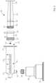
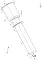
- FIG. 2is a perspective view of a syringe-based transfer device according to an embodiment.
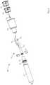
- FIG. 3is an exploded view of the syringe-based transfer device of FIG. 2 .
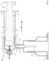
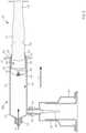
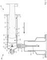
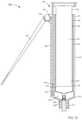
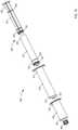
- FIGS. 4-7are cross-sectional views of the syringe-based transfer device illustrated in FIG. 2 taken along the line X 1 -X 1 , in the first configuration, a second configuration, a third configuration, and a fourth configuration, respectively.
- FIG. 8is a perspective view of a syringe-based transfer device according to another embodiment.
- FIG. 9is an exploded view of the syringe-based transfer device of FIG. 8 .
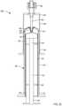
- FIG. 10is a cross-sectional view of the syringe-based transfer device illustrated in FIG. 8 taken along the like X 2 -X 2 .
- FIG. 11is a perspective view of a syringe-based transfer device according to another embodiment.
- FIG. 12is an exploded view of the syringe-based transfer device of FIG. 11 .
- FIGS. 13-15are cross-sectional views of the syringe-based transfer device of FIG. 11 taken along the line X 3 -X 3 , in a first configuration, a second configuration, and a third configuration, respectively.
- FIG. 16is a perspective view of a syringe-based transfer device according to another embodiment.
- FIG. 17is a cross-sectional view of the syringe-based transfer device of FIG. 16 taken along the line X 4 -X 4 .
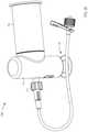
- FIG. 18is a partially exploded view of a syringe-based transfer system according to an embodiment.
- FIG. 19is an exploded view of a syringe-based transfer device and a transfer adapter included in the syringe-based transfer system of FIG. 18 .
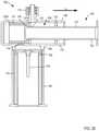
- FIGS. 20-22are cross-sectional view of the syringe-based transfer device and the transfer adapter taken along the line X 5 -X 5 , in a first configuration, a second configuration, and a third configuration, respectively.
- FIGS. 23 and 24are a cross-sectional view of the syringe-based transfer system of FIG. 18 .
- FIG. 25is a perspective view of a syringe-based transfer device according to another embodiment.
- FIG. 26is an exploded view of a syringe-based transfer device and a transfer adapter included in the syringe-based transfer system of FIG. 25 .
- FIGS. 27-29are cross-sectional view of the syringe-based transfer device and the transfer adapter taken along the line X 6 -X 6 , in a first configuration, a second configuration, and a third configuration, respectively.
- FIG. 30is a flowchart illustrating a method of using a syringe-based fluid transfer device according to an embodiment.
- an apparatusincludes a housing, defining an inner volume, and an actuator mechanism movably disposed therein.
- the actuator mechanismis configured to be transitioned from a first configuration to a second configuration to define a pre-sample reservoir fluidically couplable to receive a pre-sample volume of bodily-fluid via an inlet port of the housing.
- the actuator mechanismis movable from a first position to a second position within the housing after the pre-sample reservoir receives the pre-sample volume such that the housing and the actuator mechanism collectively define a sample reservoir to receive a sample volume of bodily-fluid via the inlet port.
- the outlet portis in fluid communication with the sample reservoir and is configured to be fluidically coupled to an external fluid reservoir after the sample volume is disposed in the sample reservoir to transfer at least a portion of the sample volume into the external fluid reservoir.
- a system for syringe-based fluid transferincludes an adapter, a transfer device, and a coupler.
- the adapterincludes a puncture member.
- the adapteris configured to place the puncture member in fluid communication with a portion of a patient.
- the transfer deviceincludes a housing having an inlet port.
- the transfer deviceis configured to removably couple to the adapter such that a portion of the puncture member is disposed within the housing via the inlet port.
- the transfer deviceincludes an actuator mechanism that defines a pre-sample reservoir.
- a portion of the actuator mechanismis movably disposed in the housing such that (1) the puncture member is in fluid communication with the pre-sample when the actuator mechanism is moved from a first configuration to a second configuration and (2) the puncture member is in fluid communication with a sample reservoir collectively defined by the housing and a portion of the actuator mechanism when the actuator mechanism is moved from the second configuration to a third configuration.
- the couplerhas a first end portion that is configured to removably couple to the housing when the adapter is decoupled from the housing and a second end portion configured to removably couple to an external fluid reservoir.
- the couplerincludes a medial portion configured to establish fluid communication between the transfer device and the external fluid reservoir when coupled therebetween.
- a method of using a syringe-based fluid transfer device having a housing and an actuator mechanismincludes establishing fluid communication between a patient and the syringe-based transfer device.
- a first member of the actuator mechanismis moved relative to the housing from a first position to a second position.
- a portion of the first membermoves within a second member of the actuator mechanism such that the first member and the second member collectively define a pre-sample reservoir.
- the pre-sample reservoiris in fluid communication with the patient as the first member is moved from the first position to the second position.
- a pre-sample volume of bodily-fluidis transferred to the pre-sample reservoir.
- the first memberAfter transferring the pre-sample volume, the first member is moved relative to the housing from the second position to a third position.
- the second memberis moved by the first member when the first member moves from the second position to the third position such that a portion of the second member and a portion of the housing collectively define a sample reservoir fluidically isolated from the pre-sample reservoir.
- the sample reservoiris in fluid communication with the patient as the first member is moved from the second position to the third position. A sample volume is then transferred to the sample reservoir.
- a syringe-based devicein some embodiments, includes a housing defining an inner volume, and an actuator mechanism movably disposed therein.
- the housinghas an inlet port in fluid communication with the inner volume and an outlet port in fluid communication with the inner volume.
- the inlet portis configured to receive bodily-fluids from the patient.
- the actuator mechanismis configured to be transitioned from a first configuration to a second configuration to define a pre-sample reservoir fluidically couplable to the inlet port to receive a pre-sample volume of bodily-fluid.
- the actuator mechanismis configured to be moved from a first position to a second position after the pre-sample volume of bodily-fluid is disposed in the pre-sample reservoir such that the housing and a portion of the actuator mechanism collectively define a sample reservoir configured to receive a sample volume of bodily-fluid via the inlet port.
- the actuator mechanismis configured to be moved from the second position toward the first position after the sample volume of bodily-fluid is disposed in the sample reservoir to expel at least a portion of the sample volume of bodily-fluid from the outlet port.
- a bodily-fluid transfer devicecan be configured to selectively divert a first, predetermined or variable amount of a flow of a bodily-fluid to a first reservoir before permitting the flow of a second amount of the bodily-fluid into a second reservoir.
- the second amount of bodily-fluidcan be used for diagnostic or other testing, while the first amount of bodily-fluid, which may contain microbes and/or other types of contaminants from a bodily surface and/or other external sources, is isolated from the bodily-fluid to be tested (e.g., to determine microbial presence, tuberculin, and/or the like) but can be used for other blood tests as ordered by clinician (e.g., complete blood count CBC).
- cliniciane.g., complete blood count CBC
- the term “bodily-fluid”can include any fluid obtained from a body of a patient, including, but not limited to, blood, cerebrospinal fluid, urine, bile, lymph, saliva, synovial fluid, serous fluid, pleural fluid, amniotic fluid, and the like, or any combination thereof.
- proximal and distalrefer to the direction closer to and away from, respectively, a user who would place the device into contact with a patient.
- distal endthe end of a device first touching the body of the patient
- opposite end of the devicee.g., the end of the device being manipulated by the user
- first, predetermined amountAs used herein, the terms “first, predetermined amount,” “first amount,” and “first volume” describe an amount of bodily-fluid received or contained by a first reservoir or a pre-sample reservoir. While the terms “first amount” and “first volume” do not explicitly describe a predetermined amount or volume, it should be understood that the first amount or first volume can be predetermined or can be variable. In some instances, a predetermined amount and/or predetermined volume can include a range of amounts and/or volumes. For example, in some instances, a predetermined amount of bodily-fluid can include a single drop of bodily fluid to a few drops of bodily-fluid.
- a predetermined amount of bodily-fluidcan include a range of amounts or fluids such as, for example, about 0.01 milliliters (mL) to about 10 mL or more. In other instances, a first amount or first volume of bodily-fluid need not be predetermined.
- second amountand “second volume” describe an amount of bodily-fluid received or contained by a second reservoir or sample reservoir.
- the second amountcan be any suitable amount of bodily-fluid and need not be predetermined.
- the second amount received and contained by the second reservoir or sample reservoircan be a second, predetermined amount.
- FIG. 1is a schematic illustration of a portion of a syringe-based transfer device 100 , according to an embodiment.
- the syringe-based transfer device 100(also referred to herein as “bodily-fluid transfer device,” “transfer device,” or “device”) is configured to withdraw of bodily-fluid from a patient such that a first portion or amount of the withdrawn fluid is fluidically isolated and diverted away from a second portion or amount of the withdrawn fluid that is to be used as a biological sample, such as for testing for the purpose of medical diagnosis and/or treatment.
- the transfer device 100can be a syringe-based device that is configured to transfer a first, predetermined amount of a bodily-fluid to a first collection reservoir and a second amount of bodily-fluid to one or more bodily-fluid collection reservoirs (e.g., sample reservoirs) fluidically isolated from the first collection reservoir, as described in more detail herein.
- the transfer device 100can be substantially similar to those described in U.S. Pat. No. 9,155,495 entitled, “Syringe-Based Fluid Diversion Mechanism For Bodily Fluid Sampling,” filed Dec. 2, 2013, the disclosure of which is incorporated herein by reference in its entirety.
- the transfer device 100includes a housing 110 , an actuator mechanism 120 , a first fluid reservoir 160 (also referred to herein as “first reservoir” or “pre-sample reservoir”), and a second fluid reservoir 170 (also referred to herein as “second reservoir” or “sample reservoir”), different from the first reservoir 160 .
- the housing 110can be any suitable shape, size, or configuration and is described in further detail herein with respect to specific embodiments. As shown in FIG. 1 , the housing 110 includes an inlet port 113 that can be at least temporarily physically and fluidically coupled to a medical device defining a pathway P for withdrawing and/or conveying the bodily-fluid from the patient to the transfer device 100 .
- the inlet port 113can be a Luer-Lok® or the like that can be physically and fluidically coupled to a butterfly needle, a cannula, and/or other lumen-containing device. In other embodiments, the inlet port 113 can be monolithically formed with at least a portion of the lumen-containing device.
- the housing 110includes an outlet port 114 that can be at least temporarily coupled to a medical device such as, for example, a sample reservoir containing a culture medium, a VacutainerTM, a cartridge configured for insertion into a diagnostic analysis machine (e.g., a PCR diagnostic machine, a DNA diagnostic machine, etc.) or the like.
- a diagnostic analysis machinee.g., a PCR diagnostic machine, a DNA diagnostic machine, etc.
- a usercan manipulate the device 100 to withdraw a volume of bodily-fluid from a patient via the inlet port 113 of the housing 110 and subsequently can manipulate the device 100 to expel at least a portion of the volume of bodily-fluid into a sampling device or reservoir via the outlet port 114 defined by the housing 110 .
- the housing 110defines an inner volume 115 that is configured to receive a portion of the actuator mechanism 120 . More specifically, the actuator mechanism 120 is at least partially disposed within the inner volume 115 of the housing 110 and is movable between a first position and a second position relative to the housing 110 . Moreover, the housing 110 is configured to define and/or house at least a portion of the first reservoir 160 and at least a portion of the second reservoir 170 .
- the first reservoir 160can be defined by the actuator mechanism 120 and disposed within the housing 110
- the second reservoir 170can be collectively defined by a portion of the housing 110 and a portion of the actuator mechanism 120 disposed within the inner volume 115 .
- the first reservoir 160 and/or the second reservoir 170can be any suitable configuration, which can be placed in fluid communication with the inlet port 113 of the housing 110 , for example, via at least a portion of the inner volume 115 .
- the actuator mechanism 120can be any suitable shape, size, or configuration.
- the shape and size of at least a portion of the actuator mechanism 120substantially corresponds to the shape and size of a portion of the housing 110 defining the inner volume 115 .
- at least a portion of the actuator mechanism 120is movably disposed within the inner volume 115 of the housing 110 .
- a distal end portion of the actuator mechanism 120can be disposed within the inner volume 115 of the housing 110
- a proximal end portion of the actuator mechanism 120is disposed substantially outside the housing 110 .
- the actuator mechanism 120can be disposed in a third position (or storage configuration) relative to the housing 110 , as further described herein.
- the actuator mechanism 120can include a first member and a second member. In such embodiments, both the first member and the second member can be collectively moved within the inner volume 115 of the housing 110 to move the actuator mechanism 120 between the first position and the second position. In addition, the first member and the second member can be configured to move independently within the housing 110 .
- the second membercan be at least partially disposed in the first member and movable in an axial direction (e.g., proximal and/or distal direction) to transition the actuator mechanism 120 between a first configuration and a second configuration.
- the first member and/or the second membercan form and/or can include a piston or plunger configured to move within the inner volume 115 .
- a portion of the piston or plungercan form a substantially fluid tight seal with the walls of the housing 110 defining the inner volume 115 .
- the housing 110 and the actuator mechanism 120can collectively form a substantially sealed, airtight cavity such that movement of the actuator mechanism 120 (or at least a portion of the actuator mechanism 120 ) introduces or otherwise facilitates the development of a vacuum within the inner volume 115 .
- the vacuumcan be created via a plurality of mechanisms including but not limited to manual user intervention, negative pressure created in manufacturing process, springs, coils or the like.
- the device 100can be arranged as a syringe or the like, as described in further detail herein.
- the first reservoir 160can be any suitable reservoir for containing the bodily-fluid.
- the first reservoir 160is defined by a portion of the walls of the housing 110 defining the inner volume 115 and a portion of the actuator mechanism 120 .
- the first reservoir 160is defined by only the actuator mechanism 120 .
- the actuator mechanism 120includes a first member and a second member, movement of the second member relative to the first member can be such that the first member and the second member collectively define the first reservoir 160 .
- the first reservoir 160can be a pre-sample reservoir described in detail in U.S. Pat. No.
- the first reservoir 160can be any number of pre-sample reservoirs or a set of fluid reservoirs (e.g., more than one reservoir). Moreover, the first reservoir 160 can be selectively placed in fluid communication with the housing 110 or the actuator mechanism 120 either directly (e.g., physically and fluidically coupled to the housing 110 or the actuator mechanism 120 ) or indirectly (e.g., fluidically coupled via intervening structure such as sterile flexible tubing).
- the first reservoir 160is configured to receive and contain the first, predetermined amount of the bodily-fluid. That is to say, the first reservoir 160 can define any suitable volume configured to receive and contain the first, predetermined amount of the bodily-fluid.
- the first reservoir 160can be a nanovial or microvial configured to receive one drop of bodily-fluid up to a few drops of bodily fluid.
- the first reservoir 160can be a container, reservoir, microvial, via, etc.
- ⁇configured to receive, for example, 0.01 mL, 0.05 mL, about 0.1 mL, about 0.5 mL, about 1.0 mL, about 2.0 mL, about 3.0 mL, about 4.0 mL, about 5.0 mL, about 6.0 mL, about 7.0 mL, about 8.0 mL, about 9.0 mL, about 10.0 mL, about 15.0 mL, about 20.0 mL or more.
- a portion of the actuator mechanism 120 and a portion of the housing 110can define a first fluid flow path configured to fluidically couple the inlet port 113 of the housing 110 to the first reservoir 160 .
- the actuator mechanism 120can be moved to the first configuration (e.g., from the third configuration described above) and can introduce a vacuum that facilitates the flow of the bodily-fluid through the first flow path and into the first reservoir 160 .
- the actuator mechanism 120can include a one-way valve or the like, which can be transitioned from a closed configuration to an open configuration in response to the vacuum, thereby placing the first reservoir 160 in fluid communication with the inlet port 113 .
- the first reservoir 160is configured to contain the first amount of the bodily-fluid such that the first amount is fluidically isolated from a subsequently drawn, second amount of the bodily-fluid (different from the first amount of bodily-fluid).
- the second reservoir 170can be any suitable reservoir and is configured to receive and contain, at least temporarily, the second amount of the bodily-fluid.
- the second reservoir 170is defined by a portion of the walls of the housing 110 defining the inner volume 115 and a portion of the actuator member 120 . In this manner, when the actuator mechanism 120 is moved from the first position (e.g., a distal position) to the second position (e.g., a proximal position), a portion of the actuator mechanism 120 and a portion of the housing 110 can define a second fluid flow path configured to fluidically couple the inlet port 113 to the second reservoir 170 .
- the movement of the actuator mechanism 120 to the second positioncan introduce a second vacuum force, which facilitates the flow of the bodily-fluid through the second flow path and into the second reservoir 170 .
- the second amount of bodily-fluidcan be an amount withdrawn from the patient subsequent to withdrawal of the first amount.
- the second reservoir 170is configured to contain the second amount of the bodily-fluid such that the second amount is fluidically isolated from the first amount of the bodily-fluid.
- the second reservoir 170is configured to temporarily contain the second amount of the bodily-fluid.
- a usercan manipulate the device 100 (e.g., the actuator mechanism 120 ) to expel at least a portion of the second amount of bodily-fluid through the outlet port 114 and into, for example, a sample reservoir and sampling device.
- the device 100e.g., the actuator mechanism 120
- the second amount of bodily-fluidcan be any suitable volume of bodily-fluid from, for example, one or a few drops of bodily-fluid (e.g., nanoliters or microliters) to 10 mL, 20 mL, 30 mL, 40 mL, 50 mL, 100 mL, 1,000 mL, 10,000 mL, or more (or any value or fraction of a value therebetween) of bodily-fluid.
- bodily-fluide.g., nanoliters or microliters
- the transfer device 100can be used to transfer a bodily-fluid from a patient to the first reservoir 160 and/or second reservoir 170 included in the transfer device 100 .
- the transfer device 100can be used to transfer at least a portion of a volume of bodily-fluid disposed in the second reservoir 170 into a sample reservoir and/or sampling device via the outlet port 114 .
- a usercan, for example, couple the inlet port 113 to a lumen-defining device and/or the like that defines the fluid pathway P between the patient and the inlet port 113 . The user can then manipulate the actuator member 120 to begin a flow of the bodily-fluid into, for example, the first fluid reservoir 160 .
- the usercan manipulate the actuator mechanism 120 such that a second member of the actuator mechanism 120 is moved relative to a first member, thereby defining the first reservoir 160 and introducing a vacuum therein that is operable in drawing the flow of the first amount of bodily-fluid into the first reservoir 160 .
- the flow of the first amount of bodily-fluid transferred to the first reservoir 160can include dermally-residing microbes dislodged during a venipuncture event and/or other external sources (e.g. ambient airborne microbes, transferred from the skin of the practitioner collecting the sample, etc.), which become entrained in the flow and are thereby transferred to the first reservoir 160 .
- the first amount of bodily-fluidcan then be 160 fluidically isolated in the first reservoir 160 such that when the subsequent second amount is withdrawn into the second reservoir 170 , the second amount is substantially free from the dermally-residing microbes or other undesirable external contaminants as described above. More specifically, with the first amount of bodily-fluid fluidically isolated in the first reservoir 160 , a user can manipulate the actuator mechanism 120 by moving the actuator mechanism 120 from the first position (e.g., a distal position) to the second position (e.g., a proximal position) within the housing 110 .
- first positione.g., a distal position
- the second positione.g., a proximal position
- the movement of the actuator mechanism 120 within the inner volume 115can define the second reservoir 170 and can introduce a vacuum therein, which in turn, is operable in drawing the flow of the second amount of bodily-fluid into the second reservoir 170 .
- a usercan manipulate the device 100 by coupling a sampling device and/or reservoir to the outlet port 114 if not already coupled thereto.
- the usercan manipulate the actuator mechanism 120 by moving the actuator mechanism 120 from the second position toward the first position (e.g., in a distal position).
- the transfer device 100can transfer a portion of the second amount of the bodily-fluid from the second reservoir 170 to any suitable container (e.g., a vile, a test tube, a petri dish, a culture medium, a test apparatus, or the like) such that the portion of the second amount of bodily-fluid can be tested.
- a suitable containere.g., a vile, a test tube, a petri dish, a culture medium, a test apparatus, or the like
- the usercan replace the container having the desired fill volume with an empty container (e.g., can decouple the filled container and couple a different, unused container).
- the usercan manipulate the transfer device 100 to transfer a desired volume of bodily-fluid from the transfer device 100 into, for example, the unused container (e.g., a second container).
- the transfer device 100can include and/or can pre-assembled with such an external reservoir(s), etc.
- the preassembled and/or all-in-one syringe-based transfer devicecan include, for example, any suitable number of external fluid reservoirs (e.g., one fluid reservoir, two fluid reservoirs, three fluid reservoirs, four fluid reservoirs, or more) that can be preassembled and/or unitarily formed with and/or incorporated in (e.g., during manufacturing) the transfer device.
- the transfer device 100can be preassembled and/or unitarily formed with any suitable reservoir as described in, for example, U.S. Patent Publication No. 2015/0342510 entitled, “Sterile Bodily-Fluid Collection Device and Methods,” filed Jun. 2, 2015, the disclosure of which is incorporated herein by reference in its entirety.
- the transfer device 100can be configured such that the first amount of bodily-fluid need be conveyed to the first reservoir 160 before the transfer device 100 will permit the flow of the second amount of bodily-fluid to be conveyed through the second flow path to the second reservoir 160 .
- the transfer device 100can be characterized as requiring compliance by a health care practitioner regarding the collection of the first, predetermined amount (e.g., a pre-sample) prior to collection of the second amount (e.g., a sample) of bodily-fluid.
- the transfer device 100can be configured to prevent a health care practitioner from collecting the second amount, or the sample, of bodily-fluid into the second reservoir 170 without first diverting the first amount, or pre-sample, of bodily-fluid into the first reservoir 160 .
- the health care practitioneris prevented from including (whether intentionally or unintentionally) the first amount of bodily-fluid, which is more likely to contain dermally-residing microbes and/or other external undesirable contaminants, in the bodily-fluid sample to be used for analysis.
- the fluid transfer device 100need not include a forced-compliance feature or component.
- FIGS. 2-7illustrate a syringe-based transfer device 200 according to an embodiment.
- the syringe-based transfer device 200(also referred to herein as “bodily-fluid transfer device,” “fluid transfer device,” or “transfer device”) includes a housing 210 and an actuator mechanism 220 .
- the transfer device 200is configured to include or define a first fluid reservoir 260 (also referred to herein as “first reservoir” or “pre-sample reservoir”) and a second fluid reservoir 270 (also referred to herein as “second reservoir” or “sample reservoir”).
- the transfer device 200can be any suitable shape, size, or configuration.
- the transfer device 200can be square, rectangular, polygonal, and/or any other non-cylindrical shape.
- the housing 210includes a proximal end portion 211 and a distal end portion 212 and defines an inner volume 215 therebetween.
- the housing 210includes an indicator portion 216 .
- the indicator portion 216can be any suitable arrangement configured to provide a visual indication associated with a volume of fluid disposed within the housing 210 .
- the indicator portion 216can be indicia such as, for example, a substantially uniform gradation of tick marks, lines, markings, and/or other suitable indicators that correspond to a position along the housing 210 that is associated with a given volume within the inner volume 215 .
- the housing 210can be at least partially transparent to allow for a visualization of the inner volume 215 .
- the indicator portion 216can provide the user with a visual indication associated with a volume of the fluid disposed in the inner volume 215 .
- the housing 210does not include an indicator portion 216 and/or is not transparent. That is to say, in some embodiments, a housing does not provide a visual indication associated with a volume of fluid disposed therein.
- a transfer devicecan include any suitable feature, component, mechanism, and/or the like configured to actuate and/or otherwise manipulate the transfer device to transfer a volume (e.g., a predetermined volume or a variable volume) of bodily-fluid into the housing.
- a transfer devicecan be configured to define a negative pressure and/or can include a spring, a coil, and/or any other suitable mechanism configured to actuate at least a portion of the transfer device such that a desired amount of bodily-fluid is transferred to the transfer device.
- the housing 210can be substantially similar to a syringe body.
- the proximal end portion 211 of the housing 210is substantially open and movably receives at least a portion of the actuator mechanism 220 .
- the portion of the actuator mechanism 220is movably disposed within the inner volume 215 .
- an inner surface of the housing 210 that defines the inner volume and a surface of the actuator mechanism 220collectively define at least a portion of the second fluid reservoir 270 , as further described herein.
- the distal end portion 212 of the housing 210includes an inlet port 213 and an outlet port 214 , which are each selectively in fluid communication with the inner volume 215 .
- the inlet port 213 and the outlet port 214can be any suitable shape, size, or configuration.
- the inlet port 213 and/or the outlet portion 214can be monolithically formed with the housing 210 (e.g., as shown in FIGS. 2-7 ).
- the inlet port 213 and/or outlet port 214can be coupled to the distal end portion 212 in any suitable manner such as, for example, via a friction fit, a threaded coupling, a mechanical fastener, an adhesive (e.g.
- the inlet port 213can form a lock mechanism, which in turn, can physically and fluidically couple to a needle, a cannula, or other lumen-containing device (not shown in FIGS. 2-7 ).
- the inlet port 213can be a Luer-Lok® or similar locking mechanism.
- the inlet port 213can include a valve or the like that can be transitioned between a closed configuration, in which the inner volume 215 of the housing 210 is fluidically isolated from at least a portion of the inlet port 213 , to an open configuration, in which the inner volume 215 is in fluid communication with the inlet port 213 .
- a valvecan transition from the closed configuration to the open configuration, for example, in response to a negative pressure produced within the inner volume 215 (whether by user actuation or mechanically generated force), as described in further detail herein.
- the inlet port 213can be physically and fluidically coupled to a lumen-defining device at least partially disposed within a patient to define a portion of a fluid flow path between the patient and the inner volume 215 , as further described herein.
- the outlet port 214can be substantially similar to the inlet port 213 and configured to selectively place the inner volume 215 in fluid communication with a sampling device and/or reservoir.
- the outlet port 214can include a valve or the like configured to transition from a closed configuration to an open configuration in response to an increase in pressure within the inner volume 215 (i.e., operate substantially opposite to the valve in the inlet port 213 ).
- the outlet port 214can be physically and fluidically coupled to a portion of an adapter 250 .
- the adapter 250can be any suitable shape, size, or configuration. As shown in FIG. 3 , the adapter 250 includes a proximal end portion 251 , a distal end portion 252 , and a puncture member 253 .
- the distal end portion 252can include any suitable coupling mechanism, locking mechanism, and/or the like configured to physically and fluidically couple the adapter 250 to the outlet port 214 of the housing 210 .
- the outlet port 214can be a male Luer-Lok® and the distal end portion 252 of the adapter 250 can include and/or can form a corresponding female Luer-Lok®.
- the proximal end portion 251is open and is configured to receive a portion of a sampling reservoir such as, for example, an ampoule, a vial, an evacuated container (e.g., a VacutainerTM), and/or the like.
- a sampling reservoirsuch as, for example, an ampoule, a vial, an evacuated container (e.g., a VacutainerTM), and/or the like.
- an evacuated container(not shown in FIGS. 2-7 ) can be inserted into the adapter 250 and positioned such that the puncture member 253 of the adapter 250 punctures and/or pierces a septum of the evacuated container.
- the puncture member 253e.g., a needle
- the distal end portion 252 of the adapter 250can collectively define a fluid flow path between the inner volume 215 of the housing 210 and an inner volume of the evacuated container (see e.g., FIG. 4 ), as described in further detail herein.
- the actuator mechanism 220 of the device 200is at least partially disposed within the inner volume 215 and is movable between a first position (e.g., a distal position relative to the housing 210 ) and a second position (e.g., a proximal position relative to the housing 210 ).
- the movement of the actuator mechanism 220 relative to the housing 210can transition the device 200 between a first, a second, a third, and a fourth configuration as further described herein.
- the actuator mechanism 220includes a first member 221 and a second member 231 .
- the first member 221 of the actuator mechanism 220includes a proximal end portion 222 and a distal end portion 223 and defines an inner volume 226 therebetween. At least a portion of the inner volume 226 is configured to define the first reservoir 260 , as further described herein.
- the proximal end portion 222 of the first member 221is open and configured to receive at least a portion of the second member 231 therethrough.
- the proximal end portion 222also includes a protrusion 224 that extends from an outer surface of the first member 221 (e.g., an at least partially circumferential protrusion) configured to selectively engage the proximal end portion 211 of the housing 210 to limit a proximal movement of the first member 221 , as described in further detail herein.
- the distal end portion 223 of the first member 221includes a plunger 227 .
- the plunger 227is configured to form a friction fit with the inner surface of the housing 210 that defines the inner volume 215 when the actuator mechanism 220 is disposed within the housing 210 .
- the plunger 227defines a fluidic seal with the inner surface of the housing 210 that defines the inner volume 215 such that a portion of the inner volume 215 proximal to the plunger 227 is fluidically isolated from a portion of the inner volume 215 distal to the plunger 227 .
- the plunger 227defines a channel 228 that extends through the plunger 227 (e.g., through a distal end and a proximal end of the plunger 227 ).
- the channel 228can receive a valve 230 , which can be fixedly disposed therein by a friction fit, a snap fit, a treaded coupling, glue, bond, weld, and/or the like.
- the valve 230can form a substantially fluid tight seal with surface of the plunger 227 that defines at least a portion of the channel 228 .
- the valve 230can be any suitable valve (e.g., check valve, ball valve, float valve, etc.).
- the valve 230is a one-way check valve configured to allow a flow of a fluid from a distal end of the valve 230 to a proximal end of the valve 230 but substantially not allow a flow of the fluid from the proximal end to the distal end.
- the valve 230when the valve 230 is in the open configuration, the inner volume 226 defined by the first member 221 is placed in fluid communication with the portion of the inner volume 215 of the housing 210 that is distal to the plunger 227 , and when the valve is in the closed configuration, the inner volume 226 of the first member 221 is fluidically isolated from the portion of the inner volume 215 that is distal to the plunger 227 .
- a transfer devicecan include any suitable means for selectively allowing a flow of fluid.
- a transfer devicecan include a diaphragm, membrane, tubing, and/or the like.
- the second member 231 of the actuator mechanism 220includes a proximal end portion 232 and a distal end portion 233 .
- the proximal end portion 222can have a size and/or shape configured to facilitate a user's engagement thereof.
- the proximal end portion 222can include a flange, a tab, and/or the like that can be engaged by a user (e.g., a phlebotomist, a nurse, a technician, a physician, etc.) to move the first member 221 relative to the housing 210 , as described in further detail herein.
- the distal end portion 233includes a plunger 237 configured to form a friction fit with the inner surface of the first member 221 defining the inner volume 226 when the second member 231 is disposed therein.
- the plunger 237defines a fluidic seal with the inner surface first member 221 that defines the inner volume 226 such that a portion of the inner volume 226 proximal to the plunger 237 is fluidically isolated from a portion of the inner volume 226 distal to the plunger 237 .
- the second member 231is configured to be movably disposed within the inner volume 226 of the first member 221 . More specifically, the second member 231 can be movable between a first position (e.g., a distal position) and a second position (e.g., a proximal position) thereby transitioning the actuator mechanism 220 between a first configuration and a second configuration, respectively.
- the second member 231includes a protrusion 234 that extends in a radial direction to selectively engage a proximal surface of the first member 221 .
- the protrusion 224 of the first member 221can be placed in contact with the proximal surface of the first member 221 to substantially limit a distal movement of the second member 231 relative the first member 221 , as described in further detail herein.
- a usercan engage the transfer device 200 to couple the inlet port 213 to a proximal end portion of a lumen-defining device (not shown) such as, for example, a butterfly needle, a cannula assembly, a trocar (which is some cases is used to insert a catheter into a patient), or the like.
- a lumen-defining devicesuch as, for example, a butterfly needle, a cannula assembly, a trocar (which is some cases is used to insert a catheter into a patient), or the like.
- the distal end portion of the lumen-defining devicecan be disposed within a portion of the body of a patient (e.g., a vein). In this manner, the inlet port 213 is placed in fluid communication with the portion of the body.
- a usere.g., a phlebotomist, a nurse, a technician, a physician, or the like
- the transfer device 200can transition the transfer device 200 from the first configuration (see e.g., FIG. 4 ) to the second configuration (see e.g., FIG. 5 ). More specifically, the user can engage the proximal end portion 232 of the second member 231 to move the second member 231 in the proximal direction relative to the first member 221 from its first position (e.g., a distal position) to its second configuration (e.g., a proximal position), thereby placing the transfer device 200 in the second configuration, as indicated by the arrow AA in FIG.
- first positione.g., a distal position
- second configuratione.g., a proximal position
- the second member 231 of the actuator mechanism 220is moved in a proximal direction relative to the first member 221 (e.g., the first member 221 does not substantially move in the proximal direction) until a proximal surface of the plunger 237 of the second member 231 is placed in contact with the proximal end portion 222 of the first member 221 (e.g., a tab or flange extending into the inner volume 226 ).
- the arrangement of the second member 231 within the first member 221is such that the proximal motion of the second member 231 increases the volume of the portion of the inner volume 226 that is distal to the plunger 237 , thereby defining the first reservoir 260 . Furthermore, with the plunger 237 forming a fluid tight seal with the inner surface of the walls defining the inner volume 226 , the increase of volume can produce a negative pressure within the first reservoir 260 , which can be sufficient to transition the valve 230 from a closed configuration to an open configuration.
- the inlet port 213 , the valve 230 , and the channel 228define a fluid flow path that places the first reservoir 260 in fluid communication with the lumen-defining device and more particularly, the portion of the patient (e.g., the vein), as indicated by the arrow BB in FIG. 5 .
- the negative pressure within the within the first reservoir 260 produced by the movement of the plunger 237 of the second member 231 within the inner volume 226 defined by the first member 221introduces a suction force within the portion of the patient.
- a volume of bodily-fluidis drawn through the inlet port 213 and the valve 230 and into the first reservoir 260 .
- the bodily-fluidcan contain undesirable microbes such as, for example, dermally-residing microbes and/or other external contaminants (e.g., microbes within a lumen defined by the transfer device 200 , microbes within the lumen defined by the lumen defining device, and/or any other undesirable microbe not present in the bodily-fluid source such as the bloodstream).
- undesirable microbessuch as, for example, dermally-residing microbes and/or other external contaminants (e.g., microbes within a lumen defined by the transfer device 200 , microbes within the lumen defined by the lumen defining device, and/or any other undesirable microbe not present in the bodily-fluid source such as the bloodstream).
- the magnitude of the suction forcecan be modulated by increasing or decreasing the amount of a force applied to the actuation mechanism 220 .
- itcan be desirable to limit the amount of suction force introduced to a vein.
- the usercan reduce the amount of force applied to the proximal end portion 232 of the second member 231 .
- the rate of changee.g., the increase
- the volume of the first reservoir 260can be sufficiently slow to allow time for the negative pressure differential between the vein and the fluid reservoir to come to equilibrium before further increasing the volume of the first reservoir 260 .
- the magnitude of the suction forcecan be modulated.
- the transfer device 200can be configured to transfer a desired amount (e.g., a predetermined amount) of bodily-fluid transferred to the first reservoir 260 .
- a desired amounte.g., a predetermined amount
- the first, predetermined amountcan substantially correspond to the size of the first reservoir 260 .
- the first amountcan substantially correspond to an equalization of pressure within the first reservoir 260 and the portion of the patient.
- the equalization of the pressurecan be such that the valve 230 is allowed to return to the closed configuration.
- the first reservoir 260is fluidically isolated from a volume substantially outside the first reservoir 260 .
- the device 200can be transitioned from the second configuration ( FIG. 5 ) to the third configuration ( FIG. 6 ) by further moving the actuator mechanism 220 in the proximal direction.
- the usercan apply a force to the proximal end portion 232 of the second member 231 to move the actuator mechanism 220 relative to the housing 210 .
- the plunger 237in contact with the proximal end portion 222 of the first member 221
- the further application of force on the proximal end portion 232 of the second member 231collectively moves the first member 221 and the second member 231 in the proximal direction relative to the housing 210 .
- the arrangement of the first member 221 within the inner volume 215 of the housing 210is such that the proximal motion of the first member 221 increases the volume of the portion of the inner volume 215 that is distal to the plunger 227 , thereby defining the second reservoir 270 . Furthermore, with the plunger 227 forming a fluid tight seal with the inner surface of the housing 210 that defines the inner volume 215 and with the valve 230 in the closed configuration, the increase of volume produce a negative pressure within the second reservoir 270 . Therefore, the second reservoir 270 is placed in fluid communication with the portion of the patient (e.g., the vein), as indicated by the arrow DD in FIG. 6 .
- the portion of the patiente.g., the vein
- the negative pressure within the second reservoir 270 produced by the movement of the plunger 227introduces a suction force within the portion of the patient that is sufficient to draw a volume of bodily-fluid through the inlet port 213 and into the second reservoir 270 .
- the bodily-fluid contained within the second reservoir 270is substantially free from microbes generally found outside of the portion of the patient (as described above).
- the usercan visualize and/or otherwise quantify the volume of the bodily-fluid disposed in the second reservoir 270 via the indication portion 216 of the housing 210 .
- the volume of the bodily-fluid disposed in the second reservoir 270substantially corresponds to a line, gradation, marker, tic mark, etc. included in the indication portion 216 .
- the usercan withdraw a bodily-fluid from the patient until a desired volume of the bodily-fluid is disposed in the second reservoir 270 .
- the transfer device 200can be transitioned from the third configuration to the fourth configuration.
- the inlet port 213 of the housing 210can be removed from the lumen-defining device and the adapter 250 can be coupled to a sampling container (e.g., a vile, a test tube, a petri dish, a culture medium, a test apparatus, a cartridge designed for use with an automated, rapid microbial detection system, or the like (not shown)) such that at least a portion of the volume of bodily-fluid can be transferred from the second reservoir 270 to the sampling container to be tested.
- a sampling containere.g., a vile, a test tube, a petri dish, a culture medium, a test apparatus, a cartridge designed for use with an automated, rapid microbial detection system, or the like (not shown)
- the usercan apply a force to the proximal end portion 232 of the second member 231 to move the actuator mechanism 220 in the distal direction, as indicated by the arrow EE in FIG. 7 .
- the valve 230With the valve 230 in the closed configuration the bodily-fluid contained within the first reservoir 260 is maintained in fluid isolation with a volume outside the first reservoir 260 .
- the volume of the first reservoir 260is sufficient to contain a drop of bodily-fluid or a few drops of bodily-fluid.
- the volume of the first reservoir 260is sufficient to contain the first centiliter or few centiliters of bodily-fluid.
- the first reservoir 260can be configured to contain from about 0.1 ml to about 3.0 ml. In still other embodiments, the first reservoir 260 can be configured to contain from about 3.0 ml, 4.0 ml, 5.0 ml, 6.0 ml, 7.0 ml, 8.0 ml, 9.0 ml, 10.0 ml, 15.0 ml, 20.0 ml, 25.0 ml, 50 ml, or any volume or fraction of volume therebetween. Furthermore, the pressure within the first reservoir 260 can be such that the force applied to the second member 231 does not substantially move the second member 231 relative to the first member 221 .
- the force applied to the proximal end portion 232collectively moves the second member 231 and the first member 221 in the distal direction relative to the housing 210 to expel a desired portion of the second amount of bodily-fluid from the lumen-defining device and into the container via the outlet port 214 and adapter 250 , as indicated by the arrow FF in FIG. 7 .
- the expelled bodily-fluidcan be used for any number of testing processes or procedures such as, for example, blood culture testing, real-time diagnostics, and/or PCR-based approaches, while minimizing false results that might otherwise result from undesirable microbes or the like.
- the syringe-based transfer device 200can be coupled to a device in fluid communication with the patient that is also configured to reduce contamination of a patient sample.
- the syringe-based transfer device 200can be used with a device configured to selectively occlude a lumen of a needle or the like such as those described in U.S. Patent Publication No. 2014/0276578 entitled, “Methods and Apparatus for Selectively Occluding the Lumen of a Needle,” filed Mar. 7, 2014 (the ′′′578′′ publication); U.S. Pat. No.
- the transfer device 200can be coupled to a device configured to selectively occlude a lumen of a needle (e.g., during insertion into the body), a device configured to selectively deliver fluid into the body (e.g., reinfuse a portion of a pre-sample or sample volume of bodily-fluid and/or infuse a volume of fluid such as a medicament or the like otherwise contained in the transfer device 200 ), and/or a device configured to reduce hemolysis of a blood sample withdrawn from a portion of the body by selectively controlling fluid flow and/or pressures within a portion of the device.
- a deviceconfigured to selectively occlude a lumen of a needle (e.g., during insertion into the body)
- a deviceconfigured to selectively deliver fluid into the body (e.g., reinfuse a portion of a pre-sample or sample volume of bodily-fluid and/or infuse a volume of fluid such as a medicament or the like otherwise contained in the transfer
- a transfer device(e.g., the transfer device 200 ) can be configured to selectively occlude an inlet port and/or an outlet port during withdrawal of a bodily-fluid (e.g., occlusion of the outlet port) and/or during expulsion of the bodily-fluid (e.g., occlusion of the inlet port).
- a transfer devicecan include and/or can be coupled to a needle in fluid communication with a lumen defined by an inlet port of the transfer device.
- the needlecan be configured to retract after venipuncture and withdrawal of a desired volume of bodily-fluid into the transfer device (e.g., a second reservoir such as the second reservoir 270 ).
- the retraction of the needlecan result in a portion of the needle retracting into the lumen of the inlet port, thereby occluding the lumen.
- the needlecan be operably coupled to an actuator mechanism (e.g., the actuator mechanism 220 ) such that a proximal movement of the actuator mechanism results in a corresponding proximal movement of the needle (i.e., retraction).
- a needleafter withdrawing a desired amount of bodily-fluid, a needle can be removed from the patient and disposed in, for example, an external seal member or the like, which in turn, occludes a lumen of the needle and thus, a lumen of an inlet port coupled thereto.
- a decoupling of a needle from an inlet portcan be operable in transitioning a valve from an open configuration to a closed configuration (e.g., a spring loaded valve, a septum, and/or the like).
- an inlet portcan include a valve (e.g., a one-way valve, a force balance check valve, a ball valve, and/or the like) configured to transition between a first configuration (e.g., an open configuration) to a second configuration (e.g., a closed configuration) after a desired volume of bodily-fluid is transferred to a fluid reservoir.
- a valvee.g., a one-way valve, a force balance check valve, a ball valve, and/or the like
- a first configuratione.g., an open configuration
- a second configuratione.g., a closed configuration
- coupling a sampling device and/or containere.g., a culture bottle
- an outlet portcan push, rotate, and/or otherwise transition a valve of an inlet port from a first, open configuration to a second, closed configuration.
- the inlet port and/or the outlet portcan include a flow controller such as, for example, an actuator disposed exterior to the inlet port and/or outlet port and operably coupled to the valve.
- actuatione.g., translation, rotation, and/or other movement
- the actuatorcan be operable in transitioning the valve from its open configuration to its closed configuration.
- a usercan rotate an actuator of an inlet port, thereby transitioning a valve of the inlet port to a closed configuration, and can rotate an actuator of an outlet port, thereby transitioning a valve of the inlet port to an open configuration.
- an actuatorcan be configured to control a flow of bodily-fluid through an inlet port and/or an outlet port via a flow controller, a diverter, and/or the like.
- actuation of at least a portion of an actuator mechanismcan transition a valve from an open configuration to a closed configuration.
- an actuator mechanisme.g., translational motion, rotational motion, etc.
- movement of the actuator mechanism in the proximal direction beyond a position associated with the collection of about 20 milliliters (mL) of bodily-fluidcan “trigger” and/or otherwise result in the valve being transitioned to a closed configuration.
- the coupling of a sampling device to an outlet port and/or an actuation of an actuator mechanismcan push, rotate, move, and/or otherwise position an occlusion member such as a gate or seal about a proximal end portion of the inlet port, thereby fluidically isolating the inlet port from a remaining inner volume (e.g., a fluid reservoir) of a transfer device.
- an occlusion membersuch as a gate or seal about a proximal end portion of the inlet port, thereby fluidically isolating the inlet port from a remaining inner volume (e.g., a fluid reservoir) of a transfer device.
- a portion of an actuator mechanismcan be operably coupled to a valve and/or occlusion member via a tether, rod, a rack and pinion linkage, and/or the like.
- an inlet port and/or an outlet portcan be transitioned between an open configuration and a closed configuration via an electromechanical device and/or mechanism such as a pressure die and battery, a solenoid, servomotor, and/or the like.
- a differential pressure sensorcan detect a flow of fluid through an outlet port, and in response, an electromechanical device can closes a valve of the inlet port.
- a gauge pressure sensorcan detect a drop in pressure associated with, for example, about 20 mL of bodily-fluid being disposed in the transfer device and in response, can close a valve of an inlet port.
- an air detection sensorcan sense a flow of air within the inlet port and/or outlet port and in response can open or close a valve.
- the air detection sensorcan sense an airflow at the outlet port associated with coupling an evacuated container thereto and in response, can be operable in transitioning the valve of the inlet port to a closed configuration and the valve of the outlet port to an open configuration.
- a valve of an inlet port and/or an outlet portcan be passively transitioned in response to a change in pressure.
- an inlet portcan include a valve configured to transition to an open configuration in response to a negative pressure within a fluid reservoir and transition of a closed configuration in response to a positive pressure within the fluid reservoir.
- an outlet portcan include a valve configured to transition to a closed configuration in response to the negative pressure and to transition to an open configuration in response to the positive pressure.
- a one-way valvecan have pressure threshold to allow flow of bodily-fluid therethrough.
- actuating an actuator mechanismcreates a sufficient pressure drop to overcome the threshold associated with the valve of the inlet port, thereby allowing bodily-fluid to flow therethrough.
- an actuator mechanisme.g., a syringe
- a culture bottle, a VacutainerTM or any other suitable sample vesselcan be coupled to an outlet port and can create a pressure drop that is insufficient to overcome the threshold of associated with the valve of the inlet port while being sufficient to overcome a threshold associated with the valve of the outlet port.
- FIGS. 8-10illustrate a syringe-based transfer device 300 according to another embodiment.
- the syringe-based transfer device 300(also referred to herein as “transfer device”) includes a housing 310 , an actuator mechanism 320 , an adapter 350 , and one or more sterilization members 380 .
- the transfer device 300is also configured to include or define a first fluid reservoir 360 (also referred to herein as “first reservoir” or “pre-sample reservoir”) and a second fluid reservoir 370 (also referred to herein as “second reservoir” or “sample reservoir”).
- the transfer device 300can be any suitable shape, size, or configuration.
- at least a portion of the transfer device 300can be similar in form and/or function to the transfer device 200 , described above with reference to FIGS. 2-7 . As such, portions of the transfer device 300 that are similar to associated portions of the transfer device 200 are not described in further detail herein.
- the housing 310includes a proximal end portion 311 and a distal end portion 312 and defines an inner volume 315 therebetween.
- the proximal end portion 311 of the housing 310is substantially open and movably receives at least a portion of the actuator mechanism 320 .
- an inner surface of the housing 310 that defines the inner volume 315 and a surface of the actuator mechanism 320collectively define at least a portion of the second fluid reservoir 370 .
- the inner volume 315 of the housing 310includes and/or houses a transfer conduit 318 configured to selectively place a portion of the inner volume 315 in fluid communication with a portion of the actuator mechanism 320 , as described in further detail herein.
- the distal end portion 312 of the housing 310includes an inlet port 313 that is selectively in fluid communication with the inner volume 315 .
- the inlet port 313can be any suitable shape, size, or configuration.
- the inlet port 313can be substantially similar to the inlet port 213 of the transfer device 200 .
- at least a portion of the inlet port 313can form a lock mechanism (e.g., a Luer-Lok®, which in turn, can physically and fluidically couple to a needle, a cannula, or other lumen-containing device (not shown in FIGS. 8-10 ).
- a lock mechanisme.g., a Luer-Lok®, which in turn, can physically and fluidically couple to a needle, a cannula, or other lumen-containing device (not shown in FIGS. 8-10 ).
- the housing 310can include an indicator portion or the like configured to provide a visual indication associated with a volume of fluid disposed within the housing 310 .
- the housing 310can include an indicator portion substantially similar to the indicator portion 216 included in the transfer device 200 .
- the actuator mechanism 320 of the transfer device 300is at least partially disposed within the inner volume 315 and is movable between a first position (e.g., a distal position relative to the housing 310 ) and a second position (e.g., a proximal position relative to the housing 310 ).
- the movement of the actuator mechanism 320 relative to the housing 310can transition the device 300 between any suitable configurations, as further described herein.
- the actuator mechanism 320includes a first member 321 and a second member 331 .
- the first member 321 of the actuator mechanism 320includes a proximal end portion 322 and a distal end portion 323 and defines an inner volume 326 therebetween. At least a portion of the inner volume 326 is configured to define the first reservoir 360 , as further described herein.
- the proximal end portion 322 of the first member 321is open and configured to receive at least a portion of the second member 331 .
- the distal end portion 323 of the first member 321includes a plunger 327 .
- the plunger 327is configured to form a friction fit with the inner surface of the housing 310 that defines the inner volume 315 when the actuator mechanism 320 is disposed within the housing 310 .
- the plunger 327defines a fluidic seal with the inner surface of the housing 310 that defines the inner volume 315 such that a portion of the inner volume 315 proximal to the plunger 327 is fluidically isolated from a portion of the inner volume 315 distal to the plunger 327 .
- the plunger 327includes a port 329 and a valve 330 .
- the valve 330can be any suitable valve, diaphragm, membrane, and/or the like and can be fixedly coupled to the plunger 327 via a friction fit, a snap fit, a treaded coupling, glue, bond, weld, and/or the like.
- the valve 330can be substantially similar to the valve 230 included in the transfer device 200 and thus, is not described in further detail herein.
- the port 329is configured to be coupled to and/or to receive a portion of a transfer conduit 318 .
- the port 329can define a channel, opening, passageway, valve, membrane, diaphragm, and/or the like configured to selectively place the transfer conduit 318 in fluid communication with a portion of the inner volume 315 that is distal to the plunger 327 , as described in further detail herein.
- the second member 331 of the actuator mechanism 320includes a proximal end portion 332 and a distal end portion 333 and defines an inner volume 339 .
- the proximal end portion 332 of the second member 331is substantially open and is configured to be coupled to a distal end portion 352 of the adapter 350 .
- the distal end portion 352 of the adapter 350includes an inlet port 354 that is disposed within the inner volume 339 of the second member 331 and that is in fluid communication with the transfer conduit 318 . For example, as shown in FIG.
- proximal end portion 332 of the second member 331defines a slot 338 that receives a portion of the transfer conduit 318 such that an end portion of the transfer conduit 318 can physically and fluidically couple to the inlet port 354 of the adapter 350 , as described in further detail herein.
- the distal end portion 333includes a plunger 337 configured to form a friction fit with the inner surface of the first member 321 defining the inner volume 326 when the second member 331 is disposed therein.
- the plunger 337defines a fluidic seal with the inner surface first member 321 that defines the inner volume 326 such that a portion of the inner volume 326 proximal to the plunger 337 is fluidically isolated from a portion of the inner volume 326 distal to the plunger 337 .
- at least a portion of the second member 331is movable within the inner volume 326 of the first member 321 between a first position (e.g., a distal position) and a second position (e.g., a proximal position). In some instances, such movement of the second member 331 can, in turn, transition the actuator mechanism 320 between a first configuration and a second configuration, respectively.
- the adapter 350 included in the transfer devicecan be any suitable shape, size, or configuration. As shown in FIGS. 8-10 , the adapter 350 includes a proximal end portion 351 , the distal end portion 352 , the inlet port 354 , and a puncture member 353 .
- the distal end portion 352includes and/or is coupled to the inlet port 354 and the puncture member 353 , as shown in FIG. 10 .
- the inlet port 354 and the puncture member 353collectively define a fluid flow path between a volume substantially outside of the adapter 350 (e.g., distal to the adapter 350 such as the inner volume 339 of the second member 331 ) and an inner volume 355 of the adapter 350 .
- the distal end portion 352 of the adapter 350can include any suitable coupling mechanism, locking mechanism, and/or the like (not shown) configured to physically and fluidically couple the adapter 350 to the second member 331 of the actuator mechanism 320 .
- the distal end portion 352 of the adapter 350can be coupled to the second member 331 via a friction fit, a snap fit, a press fit, and/or the like.
- the inlet port 354 of the adapter 350is physically and fluidically coupled to the transfer conduit 318 when the adapter 350 is coupled to the second member 331 .
- the puncture member 353can be selectively placed in fluid communication with a portion of the inner volume 315 of the housing 310 that is distal to the plunger 327 of the first member 321 , as described in further detail herein.
- the proximal end portion 351 of the adapter 350is open and is configured to receive a portion of a sample reservoir such as, for example, an ampoule, a vial, an evacuated container (e.g., a VacutainerTM), a culture bottle, and/or the like.
- a sample reservoirsuch as, for example, an ampoule, a vial, an evacuated container (e.g., a VacutainerTM), a culture bottle, and/or the like.
- an evacuated container(not shown in FIGS. 8-10 ) can be inserted into the adapter 350 and positioned such that the puncture member 353 of the adapter 350 punctures and/or pierces a septum of the evacuated container.
- the puncture member 353e.g., a needle
- the distal end portion 352 of the adapter 350can collectively define a fluid flow path between at least a portion of the inner volume 315 of the housing 310 and an inner volume of the evacuated container, as described in further detail herein.
- the adapter 350includes at least one sterilization member 380 .
- the adapter 350includes two sterilization members 380 , as shown in FIGS. 9 and 10 .
- the sterilization members 380can be any suitable shape, size, and/or configuration.
- the sterilization members 380can have a size and/or shape associated with a given fluid reservoir, culture bottle, and/or the like.
- the sterilization members 380include a sterilization pad 381 that is configured to sterilize a surface of a given fluid reservoir when the fluid reservoir is placed in contact with the sterilization member 380 .
- a portion of a fluid reservoircan be inserted into the sterilization member 380 to place the sterilization pad 381 in contact with a surface of the fluid reservoir, which in turn, can be punctured by the puncture member 353 of the adapter 350 .
- the sterilization member 380is configured to be temporarily coupled to the fluid reservoir when the portion of the fluid reservoir is disposed therein. As such, a user can move the fluid reservoir relative to the transfer device 300 to remove the sterilization member 380 from the adapter 350 . In this manner, the adapter 350 can be configured to force compliance with sterilization protocols and/or the like.
- the sterilization members 380can be substantially similar in form and function to those described in U.S. Patent Publication No. 2015/0246352 entitled, “Apparatus and Methods for Disinfection of a Specimen Container,” filed Mar. 3, 2015, the disclosure of which is incorporated herein by reference in its entirety.
- a usercan engage the transfer device 300 to couple the inlet port 313 to a proximal end portion of a lumen-defining device (not shown) such as, for example, a butterfly needle, a cannula assembly, a trocar (which is some cases is used to insert a catheter into a patient), and/or any of the devices described above with reference to the transfer device 200 in FIGS. 2-7 .
- a lumen-defining devicesuch as, for example, a butterfly needle, a cannula assembly, a trocar (which is some cases is used to insert a catheter into a patient), and/or any of the devices described above with reference to the transfer device 200 in FIGS. 2-7 .
- the distal end portion of the lumen-defining devicecan be disposed within a portion of the body of a patient (e.g., a vein), as described in detail above with reference to the transfer device 200 in FIGS. 2-7 .
- a usere.g., a phlebotomist, a nurse, a technician, a physician, or the like
- the transfer device 300can transition the transfer device 300 from a first configuration ( FIG. 10 ) to a second configuration. More specifically, the user can engage the proximal end portion 332 of the second member 331 and/or the adapter 350 to move the second member 331 in the proximal direction relative to the first member 321 from its first position (e.g., a distal position) to its second configuration (e.g., a proximal position), thereby placing the transfer device 300 in the second configuration, as described in detail above with reference to the transfer device 200 .
- first positione.g., a distal position
- second configuratione.g., a proximal position
- the inlet port 313 of the housing 310 and the valve 330 disposed within the plunger 327 of the first member 321define a fluid flow path that places the first reservoir 360 in fluid communication with the lumen-defining device and more particularly, the portion of the patient (e.g., the vein), as described in detail above with reference to the transfer device 200 .
- a volume of bodily-fluidis drawn through the inlet port 313 and the valve 330 and into the first reservoir 360 , which, in some instances, can contain undesirable microbes such as dermally-residing microbes and/or other external contaminants (e.g., microbes within a lumen defined by the transfer device 300 , microbes within the lumen defined by the lumen defining device, and/or any other undesirable microbe not present in the bodily-fluid source such as the bloodstream).
- the magnitude of the suction forcecan be modulated by increasing or decreasing the amount of a force applied to the actuation mechanism 320 . In this manner, the rate of change (e.g., the increase) in the volume of the first reservoir 360 can be sufficiently slow to allow time for the negative pressure differential between the vein and the first reservoir 360 to come to equilibrium before further increasing the volume of the first reservoir 360 .
- the transfer device 300can be configured to transfer a desired amount (e.g., a predetermined amount) of bodily-fluid transferred to the first reservoir 360 .
- a desired amounte.g., a predetermined amount
- the first, predetermined amountcan substantially correspond to the size of the first reservoir 360 .
- the first amountcan substantially correspond to an equalization of pressure within the first reservoir 360 and the portion of the patient.
- the equalization of the pressurecan be such that the valve 330 is allowed to return to the closed configuration.
- the first reservoir 360is fluidically isolated from a volume substantially outside the first reservoir 360 .
- the device 300can be transitioned from the second configuration to a third configuration by further moving the actuator mechanism 320 in the proximal direction.
- the usercan apply a force to the proximal end portion 332 of the second member 331 to move the actuator mechanism 320 relative to the housing 310 .
- the plunger 337 of the second member 331can be in contact with the proximal end portion 322 of the first member 321 , such that further application of force on the proximal end portion 332 of the second member 331 collectively moves the first member 321 and the second member 331 in the proximal direction relative to the housing 310 .
- the arrangement of the first member 321 within the inner volume 315 of the housing 310is such that the proximal motion of the first member 321 increases the volume of the portion of the inner volume 315 that is distal to the plunger 327 , thereby defining the second reservoir 370 . Furthermore, with the plunger 327 forming a fluid tight seal with the inner surface of the housing 310 that defines the inner volume 315 and with the valve 330 in the closed configuration, the increase of volume produce a negative pressure within the second reservoir 370 , as described in detail above with reference to the transfer device 200 .
- the negative pressure within the second reservoir 370 produced by the movement of the plunger 327introduces a suction force within the portion of the patient that is sufficient to draw a volume of bodily-fluid through the inlet port 313 and into the second reservoir 370 .
- the bodily-fluid contained within the second reservoir 370is substantially free from microbes generally found outside of the portion of the patient (as described above).
- the usercan withdraw a bodily-fluid from the patient until a desired volume of the bodily-fluid is disposed in the second reservoir 370 .
- the inlet port 313 of the housing 310can be removed from the lumen-defining device and the adapter 350 can be coupled to a sampling container (e.g., a vile, a test tube, a petri dish, a culture medium, a test apparatus, a cartridge designed for use with an automated, rapid microbial detection system, or the like (not shown) such that at least a portion of the volume of bodily-fluid can be transferred from the second reservoir 370 to the sampling container to be tested.
- a sampling containere.g., a vile, a test tube, a petri dish, a culture medium, a test apparatus, a cartridge designed for use with an automated, rapid microbial detection system, or the like (not shown) such that at least a portion of the volume of bodily-fluid can be transferred from the second reservoir 370 to the sampling container to be tested.
- a usercan insert a portion of a sampling container (e.g., specimen container, culture bottle, and/or the like) into the adapter 350 and a sterilization member 380 to place a surface of the sampling container and/or the like in contact with the sterilization pad 381 .
- a sampling containere.g., specimen container, culture bottle, and/or the like
- the sterilization member 380can be removed from the sampling container and a portion of the sampling container can be re-inserted into the adapter 350 such that the puncture member 353 punctures the surface of the sampling container.
- the puncture member 353can penetrate through the sterilization member 380 and/or the sterilization pad 381 to prevent having to remove the sterilization member 380 prior to facilitating fluid communication with the sampling container.
- the sampling containerin fluid communication with the puncture member 353 , at least a portion of the bodily-fluid disposed within the second reservoir 370 can be transferred to the sampling container via, for example, the port 328 of the first member 321 , the transfer conduit 318 , and the outlet port 319 , and the puncture member 353 .
- the sampling containere.g., culture bottle and/or the like
- the sampling containercan define a negative pressure and/or any other suitable mechanism configured to produce a negative pressure differential that is operable in drawing a volume of bodily-fluid from the second reservoir 370 and into an inner volume of the sampling container and/or fluid reservoir.
- the bodily-fluid within the sampling containercan be used for any number of testing processes or procedures such as, for example, blood culture testing, real-time diagnostics, and/or PCR-based approaches, while minimizing false results that might otherwise result from undesirable microbes or the like.
- the usercan manipulate the transfer device 300 to move the actuator mechanism 320 relative to the housing 310 in the distal direction.
- at least a portion of the bodily-fluid disposed in the second volume 370can be expelled therefrom and into, for example, an assay, dish, fluid reservoir, and/or the like used in, for example, blood culture testing, real-time diagnostics, and/or PCR-based approaches, while minimizing false results that might otherwise result from undesirable microbes or the like, as described in detail above with reference to the transfer device 200 .
- FIGS. 11-15illustrate a syringe-based transfer device 400 according to an embodiment.
- the syringe-based transfer device 400(also referred to herein as “bodily-fluid transfer device,” “fluid transfer device,” or “transfer device”) includes a housing 410 and an actuator mechanism 420 .
- the transfer device 400is configured to include or define a first fluid reservoir 460 (also referred to herein as “first reservoir” or “pre-sample reservoir”) and a second fluid reservoir 470 (also referred to herein as “second reservoir” or “sample reservoir”).
- the transfer device 400can be any suitable shape, size, or configuration. For example, while shown in FIGS.
- the transfer device 400can be square, rectangular, polygonal, and/or any other non-cylindrical shape. Moreover, portions of the transfer device 400 can be substantially similar in form and/or function to portions of the transfer devices 200 and/or 300 described above. Therefore, such portions are not described in further detail herein.
- the housing 410 of the transfer device 400includes a proximal end portion 411 and a distal end portion 412 and defines an inner volume configured to at least partially define the second fluid reservoir 470 (as described in further detail herein).
- the proximal end portion 411 of the housing 410is substantially open and movably receives at least a portion of the actuator mechanism 420 .
- the distal end portion 412 of the housing 410includes an inlet port 413 that is in selective fluid communication with the inner volume of the housing 410 and a volume defined by the actuator mechanism 420 (e.g., the first fluid reservoir 460 ).
- the inlet port 413can form a lock mechanism, which in turn, can physically and fluidically couple to a needle, a cannula, and/or other lumen-containing device (not shown in FIGS. 11-15 ) configured to be inserted into a portion of a patient.
- the inlet port 413can define at least a portion of a fluid flow path between the patient and the inner volume of the housing 410 , the first fluid reservoir 460 , and/or the second fluid reservoir 470 , as further described herein.
- the housing 410also includes an indicator portion 416 configured to provide a visual indication associated with a volume of fluid disposed within the housing 410 .
- the indicator portion 416can be any suitable configuration.
- the indicator portion 416can be substantially similar to the indicator portion 216 of the housing 210 described above with reference to the transfer device 200 and thus, is not described in further detail herein.
- the housing 410does not include an indicator portion and as an alternative, includes any suitable feature or mechanism configured to indicate a volume of bodily-fluid within the housing 410 and/or configured to otherwise dictate an amount of bodily-fluid that is transferred into the housing 410 (e.g., an expandable volume, a predetermined level of negative pressure, and/or the like).
- any suitable feature or mechanismconfigured to indicate a volume of bodily-fluid within the housing 410 and/or configured to otherwise dictate an amount of bodily-fluid that is transferred into the housing 410 (e.g., an expandable volume, a predetermined level of negative pressure, and/or the like).
- the actuator mechanism 420 of the device 400is at least partially disposed within the inner volume and is movable between a first position (e.g., a distal position relative to the housing 410 ) and a second position (e.g., a proximal position relative to the housing 410 ).
- the movement of the actuator mechanism 420 relative to the housing 410can transition the device 400 between at least a first, a second, and a third configuration, as further described herein.
- the actuator mechanism 420includes a first member 421 , a second member 431 , an actuator lever 441 , and a rack 445 .
- the actuator lever 441 and the rack 445are movably coupled to the housing 410 and are operable in moving the first member 421 and/or the second member 431 relative to the housing 410 .
- the actuator lever 441is coupled to a portion of the housing 410 and is configured to move relative thereto in a rotational or pivoting motion to selectively engage the rack 445 .
- the actuator lever 441includes a clip 443 or the like configured to selectively engage the rack 445 as the actuator lever 441 is rotated relative to the housing 410 .
- the rack 445is slidably disposed in a channel 419 (e.g., a slot, track, etc.) defined by an outer portion of the housing 410 and is configured to move relative thereto in a translational motion (e.g., in a proximal and/or a distal direction) in response to being engaged and/or moved by the actuator lever 441 .
- the rack 445includes a set of linearly arranged teeth or the like that are selectively engaged by the clip 443 of the actuator lever 441 when the actuator lever 441 is rotated relative to the housing 410 .
- An end portion of the rack 445is coupled to the second member 431 of the actuator mechanism 420 . In this manner, a user can manipulate the actuator lever 441 to move the first member 421 and/or the second member 431 of the actuator mechanism 420 relative to the housing 410 , as described in further detail herein.
- the first member 421 of the actuator mechanism 420can be any suitable shape, size, and/or configuration.
- the first member 421can be substantially similar in form and/or function to the first member 221 of the transfer device 220 and thus, similar aspects are not described in further detail herein.
- the first member 421includes a proximal end portion 422 and a distal end portion 423 and defines an inner volume therebetween configured to define at least a portion of the first reservoir 460 , as further described herein.
- the proximal end portion 422 of the first member 421is open and configured to receive at least a portion of the second member 431 therethrough.
- the distal end portion 423 of the first member 421includes a plunger 427 .
- the plunger 427is configured to form a friction fit with the inner surface of the housing 410 that defines the inner volume to collectively define a fluidic seal therebetween.
- the plunger 427defines a channel 428 , which receives and/or includes a valve 430 .
- the valve 430can be any suitable valve such as those described herein and is configured to selectively place the inner volume defined by the first member 421 (e.g., the first fluid reservoir 460 ) in fluid communication with the inlet port 413 of the housing 410 (e.g., when in an open configuration).
- the second member 431 of the actuator mechanism 420includes a proximal end portion 432 and a distal end portion 433 .
- the proximal end portion 432is coupled to the rack 445 such that movement of the rack 445 results in movement of the second member 431 , as described in further detail herein.
- the distal end portion 433 of the second member 431includes a plunger 437 configured to form a friction fit with an inner surface of the first member 421 defining the inner volume to collectively define a fluidic seal therebetween.
- the second member 431is configured to be movably disposed within the inner volume of the first member 421 .
- the second member 431can be movable between a first position (e.g., a distal position) and a second position (e.g., a proximal position) thereby transitioning the actuator mechanism 420 between a first configuration and a second configuration, respectively.
- the second member 431includes a protrusion 434 that extends in a radial direction to selectively engage a proximal surface of the first member 421 (see e.g., FIGS. 14 and 15 ), which in turn, selectively limits a distal movement of the second member 431 relative the first member 421 , as described in further detail herein.
- a usercan engage the transfer device 400 to couple the inlet port 413 to a proximal end portion of a lumen-defining device (not shown) such as, for example, a butterfly needle, a cannula assembly, a trocar (which is some cases is used to insert a catheter into a patient), and/or any of the devices described above with reference to the transfer device 200 in FIGS. 2-7 .
- a lumen-defining devicesuch as, for example, a butterfly needle, a cannula assembly, a trocar (which is some cases is used to insert a catheter into a patient), and/or any of the devices described above with reference to the transfer device 200 in FIGS. 2-7 .
- the distal end portion of the lumen-defining devicecan be disposed within a portion of the body of a patient (e.g., a vein). In this manner, the inlet port 413 is placed in fluid communication with the portion of the body.
- a usere.g., a phlebotomist, a nurse, a technician, a physician, or the like
- the transfer device 400can transition the transfer device 400 from the first configuration (see e.g., FIG. 13 ) to the second configuration (see e.g., FIG. 14 ).
- the usercan engage the actuator lever 441 to pivot the actuator lever 441 relative to the housing 410 , as indicated by the arrow GG in FIG. 14 .
- the rotation of the actuator lever 441results in a similar rotation of the clip 443 , which in turn, engages and/or contacts at least a portion of the rack 445 , thereby moving the rack 445 in a linear direction along or within the channel 419 of the housing 410 .
- the rotation of the actuator lever 441 and the clip 443moves the rack 445 relative to the housing 410 in the proximal direction, as indicated by the arrow HH in FIG. 14 .
- the second member 431is moved in the proximal direction relative to the first member 421 (e.g., the first member 421 does not substantially move in the proximal direction) until the protrusion 434 of the second member 431 is placed in contact with a surface of the first member 421 (e.g., a protrusion extending from an inner surface of the first member 421 at or near the proximal end portion 423 .
- the arrangement of the second member 431 within the first member 421is such that the proximal motion of the second member 431 increases a distance between the plunger 427 of the first member 421 and the plunger 437 of the second member 431 .
- the movement of the second member 431 relative to the first member 421increases a volume of the first member 421 defined between the plungers 427 and 437 .
- the increase in the volumeis such that the first reservoir 460 is defined between the plungers 427 and 437 , as shown in FIG. 14 .
- the increase of volumeproduces a negative pressure within the first reservoir 460 , which can be sufficient to transition the valve 430 from a closed configuration to an open configuration, as described above with reference to the transfer device 200 .
- the inlet port 413 , the valve 430 , and the channel 428define a fluid flow path that places the first reservoir 460 in fluid communication with the lumen-defining device and more particularly, the portion of the patient (e.g., the vein) such that a volume of bodily-fluid can flow from the patient and into the first reservoir 460 .
- the bodily-fluidcan contain undesirable microbes such as, for example, dermally-residing microbes and/or other external contaminants (e.g., microbes within a lumen defined by the transfer device 400 , microbes within the lumen defined by the lumen defining device, and/or any other undesirable microbe not present in the bodily-fluid source such as the bloodstream), as described above with reference to the transfer device 200 .
- undesirable microbessuch as, for example, dermally-residing microbes and/or other external contaminants (e.g., microbes within a lumen defined by the transfer device 400 , microbes within the lumen defined by the lumen defining device, and/or any other undesirable microbe not present in the bodily-fluid source such as the bloodstream), as described above with reference to the transfer device 200 .
- the transfer device 400transfers a desired amount (e.g., a predetermined amount) of bodily-fluid to the first reservoir 460 .
- a desired amounte.g., a predetermined amount
- the first, predetermined amountcan substantially correspond to the size of the first reservoir 460 .
- the first amountcan substantially correspond to an equalization of pressure within the first reservoir 460 and the portion of the patient.
- the equalization of the pressurecan be such that the valve 430 returns to the closed configuration.
- the first reservoir 460is fluidically isolated from a volume substantially outside the first reservoir 460 .
- the device 400can be transitioned from the second configuration ( FIG. 14 ) to the third configuration ( FIG. 15 ) by further manipulating the actuator lever 441 .
- the actuator lever 441can include and/or can be coupled to a bias member such as a rotational spring or the like that can bias the actuator lever 441 in the first position (e.g., in the position shown in FIG. 13 ).
- the clip 443can be a bias member or the like.
- the usercan remove and/or reduce a force applied on the actuator lever 441 that can allow and/or can result in the actuator lever 441 rotating relative to the housing 410 in a substantially opposite direction (e.g., such that the end portion of the actuator lever 441 is moved away from the housing 410 .
- the arrangement of the rack 445can be such that the clip 441 moves along the rack 445 as the actuator lever 441 is moved toward the first position. In this manner, the rack 445 can remain in a substantially fixed position relative to the housing 410 and/or the actuator lever 441 as the actuator lever 441 moves to the first position.
- the usercan again exert a force on the actuator lever 441 to rotate the actuator lever 441 in the direction of the arrow GG in FIG. 14 .
- the actuator lever 441can act as a ratchet or trigger that can be manipulated a series or number of times to move the rack 445 relative to the housing 410 .
- the actuator lever 441can be actuated and/or manipulated any number of times to move the second member 431 to a third position, as indicated by the arrow II in FIG. 15 .
- the first member 421is configured to move with the second member 431 as the second member 431 is moved from the second position to the first position. More specifically, once the protrusions 434 of the second member 431 are placed in contact with the portion of the first member 421 , any further movement of the second member 431 in the proximal direction results in a similar movement of the first member 421 in the proximal direction (see e.g., FIGS. 14 and 15 ).
- the arrangement of the first member 421 within the housing 410is such that the proximal motion of the first member 421 increases a volume within the housing 410 that is distal to the plunger 427 , thereby defining the second reservoir 470 , as shown in FIG. 15 . Furthermore, with the plunger 427 forming a fluid tight seal with the inner surface of the housing 410 and with the valve 430 in the closed configuration, the increase of volume produce a negative pressure within the second reservoir 470 .
- the negative pressure within the second reservoir 470 produced by the movement of the plunger 427introduces a suction force within the portion of the patient that is sufficient to draw a volume of bodily-fluid through the inlet port 413 and into the second reservoir 470 .
- the bodily-fluid contained within the second reservoir 470is substantially free from microbes generally found outside of the portion of the patient (as described above).
- the usercan visualize and/or otherwise quantify the volume of the bodily-fluid disposed in the second reservoir 470 via the indication portion 416 of the housing 410 .
- the volume of the bodily-fluid disposed in the second reservoir 470substantially corresponds to a line, gradation, marker, tic mark, etc. included in the indication portion 416 .
- the usercan withdraw a bodily-fluid from the patient until a desired volume of the bodily-fluid is disposed in the second reservoir 470 , as described in detail above with reference to the transfer device 200 .
- the transfer device 400can be transitioned from the third configuration to a fourth configuration.
- the inlet port 413 of the housing 410can be removed from the lumen-defining device and can be coupled to a sampling container (e.g., a vile, a test tube, a petri dish, a culture medium, a test apparatus, a cartridge designed for use with an automated, rapid microbial detection system, or the like (not shown)) such that at least a portion of the volume of bodily-fluid can be transferred from the second reservoir 470 to the sampling container to be tested, as described above with reference to the transfer device 200 .
- a sampling containere.g., a vile, a test tube, a petri dish, a culture medium, a test apparatus, a cartridge designed for use with an automated, rapid microbial detection system, or the like (not shown)
- the bodily-fluidcan be expelled from the second fluid reservoir 470 to be used for any number of testing processes or procedures such as, for example, blood culture testing, real-time diagnostics, and/or PCR-based approaches, while minimizing false results that might otherwise result from undesirable microbes or the like.
- the arrangement of the actuator lever 441 and the rack 445can, for example, control and/or limit a magnitude and/or rate of pressure change within the fluid reservoirs 460 and/or 470 .
- the rate of changee.g., the increase
- the volume of the first reservoir 460 and/or the second reservoir 470can be sufficiently slow to allow time for the negative pressure differential between the vein and the fluid reservoirs 460 and/or 470 to come to equilibrium before further increasing the volume.
- the magnitude of the suction forcecan be modulated.
- FIGS. 16 and 17illustrate a syringe-based transfer device 500 according to an embodiment.
- the syringe-based transfer device 500(also referred to herein as “bodily-fluid transfer device,” “fluid transfer device,” or “transfer device”) includes a housing 510 and an actuator mechanism 520 .
- the transfer device 500is configured to include or define a first fluid reservoir 560 (also referred to herein as “first reservoir” or “pre-sample reservoir”) and a second fluid reservoir 570 (also referred to herein as “second reservoir” or “sample reservoir”).
- first reservoiralso referred to herein as “first reservoir” or “pre-sample reservoir”
- second reservoiralso referred to herein as “second reservoir” or “sample reservoir”.
- the transfer device 500can be substantially similar in form and/or function to transfer device 400 described above. Therefore, portions of the transfer device 500 that are similar to the transfer device 400 are briefly discussed below to identify relevant components but are not described in further detail herein.
- the housing 510 of the transfer device 500is substantially similar to the housing 410 of the transfer device 400 .
- the housing 510defines an inner volume configured to at least partially define the second fluid reservoir 570 (as described in further detail herein).
- a proximal end portion of the housing 510is substantially open and movably receives at least a portion of the actuator mechanism 520 .
- a distal end portion 512 of the housing 510includes an inlet port 513 that is in selective fluid communication with the inner volume of the housing 510 and a volume defined by the actuator mechanism 520 (e.g., the first fluid reservoir 560 ).
- the inlet port 513can form a lock mechanism, which in turn, can physically and fluidically couple to a needle, a cannula, and/or other lumen-containing device (not shown in FIGS. 11-15 ) configured to be inserted into a portion of a patient.
- the inlet port 513can define at least a portion of a fluid flow path between the patient and the inner volume of the housing 510 , the first fluid reservoir 560 , and/or the second fluid reservoir 570 , as further described herein.
- the actuator mechanism 520 of the device 500is at least partially disposed within the inner volume and is movable between a first position (e.g., a distal position relative to the housing 510 ) and a second position (e.g., a proximal position relative to the housing 510 ).
- the movement of the actuator mechanism 520 relative to the housing 510can transition the device 500 between at least a first, a second, and a third configuration, as further described herein.
- the actuator mechanism 520includes a first member 521 , a second member 531 , and a slider 544 .
- the actuator mechanism 520can be substantially similar to the actuator mechanism 420 described above with reference to FIGS. 11-15 .
- the first member 521 of the actuator mechanism 520can be any suitable shape, size, and/or configuration.
- the first member 521can be substantially similar in form and/or function to the first member 421 of the transfer device 420 and thus, similar aspects are not described in further detail herein.
- the first member 521is movably disposed in the housing 510 .
- a proximal end portion of the first member 521is substantially open to allow the second member 531 to be movably disposed within an inner volume defined by the first member 521 such that the first member 521 and the second member 531 collectively define the first fluid reservoir 560 , as described above with reference to the transfer devices 200 , 300 , and/or 400 .
- a distal end portion of the first member 521includes and/or is coupled to a plunger 527 configured to form a friction fit with the inner surface of the housing 510 such that the first member 521 and the housing 510 collectively define the second fluid reservoir 570 .
- the plunger 527receives and/or includes a valve 530 configured to selectively place the inner volume defined by the first member 521 (e.g., the first fluid reservoir 560 ) in fluid communication with the inlet port 513 of the housing 510 (e.g., when in an open configuration).
- the second member 531 of the actuator mechanism 520can be any suitable shape, size, and/or configuration.
- the second member 531can be substantially similar in form and/or function to the second member 431 of the transfer device 420 and thus, similar aspects are not described in further detail herein.
- a proximal end portion of second member 531is coupled to an end portion of the slider 544 such that movement of the slider 544 results in movement of the second member 531 (e.g., similar to the rack 445 coupled to the second member 431 of the transfer device 400 ), as described in further detail herein.
- a distal end portion of the second member 531includes and/or is coupled to a plunger 537 configured to form a friction fit with an inner surface of the first member 521 defining the inner volume to collectively define a fluidic seal therebetween.
- the second member 531can be movable between a first position (e.g., a distal position) and a second position (e.g., a proximal position) thereby transitioning the actuator mechanism 520 between a first configuration and a second configuration, respectively.
- the slider 544 of the actuator mechanism 520is slidably disposed in a channel 519 (e.g., a slot, track, etc.) defined by an outer portion of the housing 510 and is configured to move relative thereto in a translational motion (e.g., in a proximal and/or a distal direction) in response to being engaged and/or moved by a user.
- a first portion of the slider 544can be movably or slidably disposed within the channel 519
- a second portione.g., an engagement portion or the like
- the transfer device 500can be transitioned between a first configuration (e.g., prior to use), a second configuration (e.g., the second member 531 is in a second position relative to the first member 521 ), and a third configuration (e.g., the first member 521 is in a second position relative to the housing 510 ) in a manner substantially similar to that described above with reference to the transfer device 400 .
- the use of the transfer device 500differs from the use of the transfer device 400 (described in detail above) in that the actuator mechanism 520 is moved relative to the housing 510 by exerting a manual force on the slider 544 rather than in response to movement of the actuator lever 441 included in the transfer device 400 .
- the use of the transfer device 500is not described in further detail herein.
- a syringe-based transfer devicecan include a port or the like configured to receive at least of a device configured to establish fluid communication between an inner volume of the transfer device and a volume outside of the transfer device.
- FIGS. 18-24illustrate a syringe-based fluid transfer system 600 according to an embodiment.
- the syringe-based fluid transfer system 600(“fluid transfer system” or “transfer system”) can be used to receive and/or transfer a volume of fluid with reduced contamination such as dermally residing microbes or the like.
- the transfer system 600includes a transfer device 605 , an adapter 650 , an external fluid reservoir 685 (e.g., a sample bottle or the like), and a coupler 690 .
- the transfer device 605can be substantially similar in form and/or function to any of the transfer devices 200 , 300 , 400 , and/or 500 described herein. Thus, such portions are described hereinbelow to identify relevant components and/or features of the transfer device 605 but are not described in further detail.
- the transfer device 605includes a housing 610 and an actuator mechanism 620 , and includes and/or defines a first fluid reservoir 660 and a second fluid reservoir 670 .
- the housing 610 of the transfer device 605can be any suitable shape, size, or configuration.
- the housing 610can be substantially similar in form and/or function to the housings 210 , 310 , 410 , and/or 510 described above.
- the housing 610includes a proximal end portion 611 and a distal end portion 612 and defines an inner volume configured to at least partially define the second fluid reservoir 670 , as described above, for example, with reference to the housing 210 .
- the proximal end portion 611 of the housing 610is substantially open and movably receives at least a portion of the actuator mechanism 620 .
- the distal end portion 612 of the housing 610includes an inlet port 613 that is in selective fluid communication with the inner volume of the housing 610 and a volume defined by the actuator mechanism 620 (e.g., the first fluid reservoir 660 ).
- the inlet port 613can be arranged to receive a portion of a device configured to establish fluid communication between the inner volume of the housing 610 and/or a volume defined by the actuator mechanism 620 (described in further detail herein).
- the inlet port 613can be a septum, a frangible seal, a membrane, a cap, a self-healing port, a saline lock, a heparin lock, and/or any other suitable port configured to transition between a closed configuration and an open configuration.
- the distal end portion 612 of the housing 610is configured to be coupled to and/or disposed within the transfer adapter 650 . Said another way, at least a portion of the transfer adapter 650 can be disposed about the proximal end portion 612 of the housing 610 to at least temporarily couple the transfer adapter 650 to the housing 610 .
- the transfer adapter 650includes a proximal end portion 651 and a distal end portion 652 .
- the proximal end portion 651is substantially open to allow at least a portion of the transfer device 605 to be disposed therein.
- the distal end portion 652includes a port 654 in fluid communication with a puncture member 653 .
- the port 654can be substantially similar to any of the inlet ports described above (e.g., the inlet port 213 ).
- the port 654can form a lock mechanism, which in turn, can physically and fluidically couple to a needle, a cannula, and/or other lumen-containing device (see e.g., FIG. 18 ) configured to establish fluid communication with a portion of a patient.
- the puncture member 653e.g., a needle
- the adapter 650is coupled thereto (see e.g., FIG. 20 ).
- the port 654 and the puncture member 653can define at least a portion of a fluid flow path between the patient and the inner volume of the housing 610 , the first fluid reservoir 660 , and/or the second fluid reservoir 670 , as further described herein.
- the actuator mechanism 620 of the transfer device 605is at least partially disposed within the inner volume of the housing 610 and is movable between a first position (e.g., a distal position relative to the housing 610 ) and a second position (e.g., a proximal position relative to the housing 610 ).
- the movement of the actuator mechanism 620 relative to the housing 610can transition the device 605 between at least a first configuration ( FIG. 20 ), a second configuration ( FIG. 21 ), and a third configuration ( FIG. 22 ), as further described herein.
- the actuator mechanism 620includes a first member 621 and a second member 631 .
- the first member 621 of the actuator mechanism 620can be any suitable shape, size, and/or configuration.
- the first member 621can be substantially similar in form and/or function to the first member 221 of the transfer device 220 and thus, similar aspects are not described in further detail herein.
- the first member 621includes a proximal end portion 622 and a distal end portion 623 and defines an inner volume therebetween configured to define at least a portion of the first reservoir 660 , as further described herein.
- the proximal end portion 622 of the first member 621is open and configured to receive at least a portion of the second member 631 therethrough.
- the distal end portion 623 of the first member 621includes a plunger 627 .
- the plunger 627is configured to form a friction fit with the inner surface of the housing 610 that defines the inner volume to collectively define a fluidic seal therebetween.
- the plunger 627defines a channel 628 that receives and/or includes a valve 630 , as described above, for example, with reference to the first member 221 of the transfer device 200 .
- the second member 631 of the actuator mechanism 620includes a proximal end portion 632 and a distal end portion 633 .
- the proximal end portion 632can be any suitable shape, size, and/or configuration.
- the proximal end portion 632can have a size and/or shape that allows a user to engage the proximal end portion 632 to move the second member 631 relative to the first member 621 .
- the distal end portion 633 of the second member 631includes a plunger 637 configured to form a friction fit with an inner surface of the first member 621 defining the inner volume to collectively define a fluidic seal therebetween.
- the second member 631is configured to be movably disposed within the inner volume of the first member 621 .
- the second member 631can be movable between a first position (e.g., a distal position) and a second position (e.g., a proximal position) thereby transitioning the actuator mechanism 620 between a first configuration and a second configuration, respectively.
- the second member 631includes a protrusion 634 that extends in a radial direction to selectively engage a proximal surface of the first member 621 (see e.g., FIGS. 21 and 22 ), which in turn, selectively limits a distal movement of the second member 631 relative the first member 621 , as described in further detail herein.
- the coupler 690can be any suitable device configured to establish fluid communication between the transfer device 605 and the external fluid reservoir 685 (see e.g., FIGS. 23 and 24 ).
- the coupler 690includes a first end portion 691 configured to be coupled to the external fluid reservoir 685 and a second end portion 692 configured to be coupled to the transfer device 605 .
- the coupler 690includes a medial portion 694 coupled to and/or including a puncture member 696 .
- the puncture member 696is a double sided puncture member or needle. In other embodiments, the puncture member 696 can have any suitable arrangement.
- the puncture member 696is configured to engage a portion of the transfer device 605 and a portion of the external fluid reservoir 685 when the coupler 695 is coupled to the transfer device 605 and the external fluid reservoir 685 , thereby fluidically coupling the transfer device 605 to the external fluid reservoir 685 , as described in further detail herein.
- a usercan manipulate the transfer device 605 to couple the adapter 650 to the distal end portion 612 of the housing 610 (see e.g., FIG. 20 ).
- the puncture member 653can puncture, pierce, and/or otherwise be inserted through the inlet port 613 to place the puncture member 653 and the port 654 of the adapter 650 in fluid communication with an inner volume defined by the housing 610 .
- FIG. 20In other embodiments, such as the embodiment shown in FIG.
- the puncture member 653can extend through the valve 630 disposed within the plunger 627 , which in turn, places the puncture member 653 and the port 654 in fluid communication with the inner volume defined by the first member 621 of the actuator mechanism 620 (e.g., the first fluid reservoir 660 ).
- a lumen-defining devicesee e.g., FIG.
- the adapter 650can be coupled to any of the devices described above with reference to the transfer device 200 in FIGS. 2-7 .
- the usercan engage the proximal end portion 632 of the second member 631 and can exert a force operable to move the second member 631 relative to the first member 621 and the housing 610 , as indicated by the arrow JJ in FIG. 21 .
- the arrangement of the second member 631 within the first member 621is such that the proximal motion of the second member 631 increases a distance between the plunger 627 of the first member 621 and the plunger 637 of the second member 631 . In other words, the movement of the second member 631 relative to the first member 621 increases a volume of the first member 621 defined between the plungers 627 and 637 .
- the increase in the volumeis such that the first reservoir 660 is defined between the plungers 627 and 637 , as shown in FIG. 21 . Furthermore, with the plunger 637 forming a fluid tight seal with the inner surface of the first member 621 , the increase of volume produces a negative pressure within the first reservoir 660 , which can be sufficient to draw a volume of bodily-fluid through the fluid flow path (described above) and into the first fluid reservoir 660 .
- the bodily-fluidcan contain undesirable microbes such as, for example, dermally-residing microbes and/or other external contaminants (e.g., microbes within a lumen defined by the transfer device 605 , microbes within the lumen defined by the lumen defining device, and/or any other undesirable microbe not present in the bodily-fluid source such as the bloodstream), as described above with reference to the transfer device 200 .
- undesirable microbessuch as, for example, dermally-residing microbes and/or other external contaminants (e.g., microbes within a lumen defined by the transfer device 605 , microbes within the lumen defined by the lumen defining device, and/or any other undesirable microbe not present in the bodily-fluid source such as the bloodstream), as described above with reference to the transfer device 200 .
- the transfer device 605transfers a desired amount (e.g., a predetermined amount) of bodily-fluid to the first reservoir 660 .
- a desired amounte.g., a predetermined amount
- the first, predetermined amountcan substantially correspond to the size of the first reservoir 660 .
- the first amountcan substantially correspond to an equalization of pressure within the first reservoir 660 and the portion of the patient.
- the equalization of the pressurecan be such that the valve 630 returns to the closed configuration.
- the first reservoir 660is fluidically isolated from a volume substantially outside the first reservoir 660 .
- the device 605can be transitioned from the second configuration ( FIG. 21 ) to the third configuration ( FIG. 22 ) by further manipulating the proximal end portion 632 of the second member 631 .
- a usercan continue to exert a force on the proximal end portion 632 of the second member 631 to move the second member 631 to a third position, as indicated by the arrow KK in FIG. 22 .
- the first member 621is configured to move with the second member 631 as the second member 631 is moved from the first position to the second position.
- any further movement of the second member 631 in the proximal directionresults in a similar movement of the first member 621 in the proximal direction (see e.g., FIGS. 21 and 22 ).
- the movement of the second member 631 and the first member 621can be substantially continuous. That is to say, the second member 631 can be moved from the first position through the second position and to the third position in a substantially smooth and/or continuous manner. In other instances, the second member 631 can be moved from the first position to the second position in a first movement and the second member 631 can be moved from the second position to the third position in a second movement discreet or non-continuous with the first movement.
- the movement of the first member 621 within the housing 610results in an increased volume within the housing 610 that is distal to the plunger 627 of the first member 621 , thereby defining the second reservoir 670 , as shown in FIG. 22 .
- the increase of volumeproduce a negative pressure within the second reservoir 670 that is sufficient to draw a volume of bodily-fluid from the patient, through the fluid flow path, and into the second reservoir 670 .
- the bodily-fluid contained within the second reservoir 670is substantially free from microbes generally found outside of the portion of the patient (as described above).
- the usercan visualize and/or otherwise quantify the volume of the bodily-fluid disposed in the second reservoir 670 via an indication portion of the housing 610 and/or the like.
- the usercan withdraw a bodily-fluid from the patient until a desired volume of the bodily-fluid is disposed in the second reservoir 670 , as described in detail above with reference to the transfer device 200 .
- the transfer device 605can be transitioned from the third configuration to a fourth configuration.
- the usercan manipulate the coupler 690 by disposing a first end portion 691 of the coupler 690 about the external fluid reservoir 685 .
- the coupler 690is coupled to the external fluid reservoir 685 such that a first side of the puncture member 696 punctures, pierces, breaks, opens, and/or otherwise moves through a port 686 of the external fluid reservoir 685 to be placed in fluid communication with an inner volume thereof.
- a first side of the puncture member 696punctures, pierces, breaks, opens, and/or otherwise moves through a port 686 of the external fluid reservoir 685 to be placed in fluid communication with an inner volume thereof.
- the external fluid reservoir 685can include a cap, a top, and/or any suitable closure means.
- the capfor example, can include and/or define the port 686 .
- the port 686can be a seal, a membrane, a frangible seal, a self-healing port, and/or any other suitable port.
- the usercan manipulate the transfer device 605 by inserting a portion of the transfer device 605 the second end portion 692 of the coupler 690 .
- a second side of the puncture member 696 opposite the first sidecan puncture, pierce, open, and/or otherwise move through the port 613 included in the housing 610 , which in turn, places the puncture member 696 in fluid communication with the second fluid reservoir 670 defined by a portion of the inner volume of the housing 610 that is distal to the plunger 627 of the first member 621 of the actuator mechanism 620 , as shown in FIG. 24 .
- the puncture member 696establishes fluid communication between the second fluid reservoir 670 and an inner volume of the external fluid reservoir 685 (e.g., a vile, a test tube, a petri dish, a test apparatus, a cartridge designed for use with an automated, rapid microbial detection system, an evacuated container or microcontainer, and/or any other suitable reservoir).
- an inner volume of the external fluid reservoir 685e.g., a vile, a test tube, a petri dish, a test apparatus, a cartridge designed for use with an automated, rapid microbial detection system, an evacuated container or microcontainer, and/or any other suitable reservoir.
- the usercan exert a force on the proximal end portion 632 of the second member 631 that is operable in moving the second member 631 and the first member 621 in the distal direction such that at least a portion of the volume of bodily-fluid can be transferred from the second reservoir 670 to the external fluid reservoir 685 , as described above with reference to the transfer device 200 .
- the bodily-fluidcan be expelled from the second fluid reservoir 670 to be used for any number of testing processes or procedures such as, for example, blood culture testing, real-time diagnostics, and/or PCR-based approaches, while minimizing false results that might otherwise result from undesirable microbes or the like.
- a fluid transfer devicecan include one or more members configured to move along at least two different axes.
- FIGS. 25-29illustrate a fluid transfer device 700 according to an embodiment.
- the transfer device 700includes a housing 710 , an actuator mechanism 720 , and an adapter 750 , and includes and/or defines a first fluid reservoir 760 and a second fluid reservoir 770 .
- the housing 710 of the transfer device 700can be any suitable shape, size, or configuration.
- the housing 710includes an actuator portion 788 and an adapter portion 789 .
- the actuator portion 788 of the housing 710is substantially open at one end and is configured to movably receive the actuator mechanism 720 (see e.g., FIGS. 27-29 ).
- the actuator portion 788 of the housing 710can form a first bore or the like with one open side and one closed side.
- the actuator portion 788 of the housing 710includes an inlet port 713 that is in selective fluid communication with one or more portions of the housing 710 (e.g., the first fluid reservoir 760 and/or the second fluid reservoir 770 ), as described in further detail herein.
- the port 713can be any suitable port.
- the port 713is substantially similar to the port 213 described above with reference to the transfer device 200 .
- the port 713is configured to physically and fluidically couple to a lumen-defining device such as a needle and/or cannula to be placed in fluid communication with a portion of a patient, as described in detail above with reference to the transfer device 200 .
- the adapter portion 789 of the housing 710is coupled to the actuator portion 788 and is arranged in a transverse or substantially perpendicular orientation relative to the actuator portion 788 . As shown, for example, in FIG. 27 , the adapter portion 789 is in fluid communication with a portion of the actuator portion 788 via an opening 714 (an outlet port or the like) in a wall of the housing 710 otherwise isolating the actuator portion 788 from the adapter portion 789 .
- the adapter portion 789is configured to movably engage the adapter 750 .
- the adapter portion 789is substantially cylindrical having an annular set of walls that define an inner volume.
- the annular walls of the adapter portion 789are movably disposed within a portion of the adapter 750 .
- the adapter 750is movably coupled to the adapter portion 789 such that a first portion of the adapter 750 is disposed within the adapter portion 789 and a second portion is disposed outside of the adapter portion 789 , as shown in FIGS. 27-29 .
- the adapter portion 789includes an indicator portion 716 that is configured to provide an indication of a volume of bodily-fluid disposed within the adapter portion 789 .
- the arrangement of the adapter 750is such that a surface of the adapter 750 can be placed in a position relative to the indicator portion 716 that is indicative of a volume of bodily-fluid transferred into the adapter portion 789 (e.g., the second reservoir 770 ), as described in further detail herein.
- the actuator mechanism 720 of the transfer device 700is at least partially disposed within an inner volume of the actuator portion 788 of the housing 710 .
- the actuator mechanism 720is movable between a first position (e.g., a distal position relative to the housing 710 ) and a second position (e.g., a proximal position relative to the housing 710 ) within the actuator portion 788 .
- the movement of the actuator mechanism 720 relative to the housing 710can transition the device 700 between at least a first configuration ( FIG. 27 ) and second configuration ( FIG. 28 ), as further described herein.
- the actuator mechanism 720includes a first member 721 and a second member 731 .
- the first member 721 of the actuator mechanism 720can be any suitable shape, size, and/or configuration.
- the first member 721is substantially cylindrical having a proximal end portion 722 and a distal end portion 723 .
- the proximal end portion 722is disposed outside of the actuator portion 788 of the housing 710 and is configured to be engaged and/or manipulated by a user to move the first member 721 within the actuator portion 788 .
- the distal end portion 723is disposed within the actuator portion 788 of the housing 710 .
- the distal end portion 723includes and/or forms a protrusion 724 configured to selectively engage a portion of the second member 731 , as described in further detail herein.
- the first member 721further includes a plunger 727 disposed along a length of the first member 721 .
- the plunger 727can be positioned along the length of the first member 721 such that the plunger 727 remains between a lumen defined by the inlet port 713 and the open end of the actuator portion 788 . That is to say, the plunger 727 remains on a single side of the lumen of the inlet port 713 when the first member 721 is moved within the actuator portion 788 between the first position and the second position.
- the plunger 727is configured to engage an inner surface of the actuator portion 788 to form a substantially fluid tight seal therebetween. In this manner, the plunger 727 forms a portion of the first fluid reservoir 760 when the first member 721 is in the second position ( FIG. 28 ), as described in further detail herein.
- the second member 731 of the actuator mechanism 720is movably disposed about the first member 721 , as shown in FIGS. 27-29 . More particularly, the second member 731 is disposed about the first member 721 such that the plunger 727 is disposed between the second member 731 and the proximal end portion 722 of the first member 721 .
- the second member 731can be any suitable shape, size, and/or configuration.
- the second member 731includes a first plunger 737 A disposed on a first end portion of the second member 731 and a second plunger 737 B disposed on a second end portion of the second member 731 .
- the arrangement of the second member 731 and the plungers 737 A and 737 Bis such that a diameter of the plungers 737 A and 737 B is greater than a diameter of the second member 731 .
- an annular channel or the likeis defined by the inner surface of the actuator portion 788 and an outer surface of the first member 721 between the plungers 737 A and 737 B.
- a portion of the plunger 737 Ais configured to engage the outer surface of the first member 721 to form a substantially fluid tight seal therebetween.
- the annular channel or the likeis fluidically isolated from a volume outside of the plungers 737 A and 737 B unless and/or until the second member 731 is moved to a position in which the annular channel or the like is in fluid communication with the inlet port 713 and/or the opening 714 .
- the adapter 750can be any suitable shape, size, and/or configuration. As described above, the adapter 750 includes a first portion that is movably disposed within the adapter portion 789 of the housing 710 and a second portion that is movably disposed about an outer surface of the adapter portion 789 . The portion of the adapter 750 disposed within the adapter portion 789 of the housing 710 includes and/or is coupled to a plunger 756 configured to engage an inner surface of the adapter portion 789 to form a substantially fluid tight seal therebetween. In this manner, the plunger 756 and the adapter portion 789 collectively define the second fluid reservoir 770 . As shown in FIG.
- the plunger 756is coupled to a puncture member 753 such as a sheathed needle or the like.
- the puncture member 753can be configured to puncture, pierce, open, and/or otherwise move through a seal or port of an external fluid reservoir to place the second fluid reservoir 770 in fluid communication with the external fluid reservoir (not shown).
- the adapter 750can include a valve or seal configured to selectively control a flow of fluid through the puncture member 753 .
- the valve or sealcan be in a substantially closed or sealed configuration until a pressure differential is exerted on the valve and/or seal sufficient to transition the valve and/or seal to an open configuration.
- a usere.g., a phlebotomist, a nurse, a technician, a physician, or the like
- the transfer device 700can engage the transfer device 700 to couple the inlet port 713 to a proximal end portion of a lumen-defining device (not shown) such as, for example, a butterfly needle, a cannula assembly, any of the devices described above with reference to the transfer device 200 in FIGS. 2-7 , etc.
- the distal end portion of the lumen-defining devicecan be inserted into and/or can be previously disposed within a portion of the body of a patient (e.g., a vein).
- the inlet port 713is placed in fluid communication with the portion of the body and can transition the transfer device 700 from the first configuration (see e.g., FIG. 27 ) to the second configuration (see e.g., FIG. 28 ).
- the usercan exert a force on the proximal end portion 722 of the first member 721 that is operable to move the first member 721 relative to the actuator portion 788 of the housing 710 , as indicated by the arrow LL in FIG. 28 .
- the proximal motion of the first member 721increases a distance between the plunger 727 of the first member 721 and the plunger 737 A of the second member 731 .
- the first member 721is moved relative to the second member 731 such that a distance and/or volume defined between the plungers 727 and 737 A is increased.
- This increase in the volumeestablishes and/or defines the first fluid reservoir 760 between the plungers 727 and 737 A, as shown in FIG. 28 . Furthermore, with the plungers 727 and 737 A forming a fluid tight seal with the inner surface of the actuator portion 788 of the housing 710 , the increase in volume therebetween produces a negative pressure within the first reservoir 760 , which can be sufficient to draw a volume of bodily-fluid from the patient, through the fluid flow path (described above), and into the first fluid reservoir 760 .
- the bodily-fluidcan contain undesirable microbes such as, for example, dermally-residing microbes and/or other external contaminants (e.g., microbes within a lumen defined by the transfer device 700 , microbes within the lumen defined by the lumen defining device, and/or any other undesirable microbe not present in the bodily-fluid source such as the bloodstream), as described above with reference to the transfer device 200 .
- undesirable microbessuch as, for example, dermally-residing microbes and/or other external contaminants (e.g., microbes within a lumen defined by the transfer device 700 , microbes within the lumen defined by the lumen defining device, and/or any other undesirable microbe not present in the bodily-fluid source such as the bloodstream), as described above with reference to the transfer device 200 .
- the usercan transition the device 700 from the second configuration ( FIG. 28 ) to the third configuration ( FIG. 29 ) by continuing to exert the force and/or exerting an additional force on the proximal end portion 722 of the first member 721 , which in turn, moves the first member 721 to a third position, as indicated by the arrow MM in FIG. 29 .
- the second member 731is configured to move with the first member 721 as the first member 721 is moved from the second position to the third position.
- any further movement of the first member 721 in the proximal directionresults in a similar movement of the second member 731 in the proximal direction (see e.g., FIGS. 28 and 29 ).
- the movement of the first member 721 and the second member 731can be substantially continuous or can be non-continuous, as described above with reference to the transfer device 400 .
- the movement of the second member 731 within the actuator portion 788 of the housing 710results in a position of the plungers 737 A and 737 B being changed, for example, relative to the inlet port 713 .
- each of the plungers 737 A and 737 Bcan be disposed on the same side of the inlet port 713 prior to the second member 731 being moved (see e.g., FIGS. 27 and 28 ).
- the plunger 737 Acan be disposed one a first side of the inlet and the plunger 737 B can be disposed on a second side of the inlet port 713 opposite the first side ( FIG. 29 ).
- moving the second member 731 in the MM directionplaces the inlet port 713 in fluid communication with the annular volume defined between the plungers 737 A and 737 B.
- the second member 731can be moved to a position in which the opening 714 is also in fluid communication with the annular volume defined between the plungers 737 A and 737 B.
- placing the first member 721 in the third positionmoves the second member 731 such that the annular volume defined between the plungers 737 A and 737 B fluidically couples the inlet port 713 to the opening 714 .
- the usercan manipulate the adapter 750 by moving the adapter 750 relative to the adapter portion 789 of the housing 710 , as indicated by the arrow NN in FIG. 29 .
- the plunger 756 of the adapter 750is moved within the adapter portion 789 such that the adapter portion 789 and the plunger 756 collectively define the second fluid reservoir 770 .
- the movement of the plunger 756produces a negative pressure within the second fluid reservoir 770 (as described above) that is operable in drawing a volume of bodily-fluid from the patient into the second fluid reservoir 770 (e.g., via the inlet port 713 , the annular volume defined between the plungers 737 A and 737 B, and the opening 714 ).
- the bodily-fluid contained within the second reservoir 770is substantially free from microbes generally found outside of the portion of the patient (as described above).
- the usercan visualize and/or otherwise quantify the volume of the bodily-fluid disposed in the second reservoir 770 via the indicator portion 716 of the housing 710 .
- moving the adapter 750 relative to the adapter portion 789results in a movement of a surface of the adapter 750 relative to the indicator portion 716 .
- the position of the surface along the indicator portion 716is such that the surface is aligned with an indicator and/or indicia (e.g., a tick mark, a number, and/or the like) that provides the user with an indication of the volume of bodily-fluid within the second fluid reservoir 770 .
- the arrangement of the adapter 750 and the indicator portion 716can be such that the user can draw a volume of bodily-fluid into the second fluid reservoir 770 that is within a desired tolerance.
- the tolerancecan be a tolerance associated with a desired volume of bodily-fluid to be used with a given culture medium and/or test. In this manner, the user can mitigate a risk of false positive or false negative results associated with providing a volume of bodily-fluid that is outside of a desired tolerance for a give use (e.g., sample, test, assay, culture, etc.).
- the usercan insert at least a portion of an external fluid reservoir (not shown) into the adapter 750 such that the puncture member 753 punctures, pierces, breaks, opens, and/or otherwise moves through a port or seal of the external fluid reservoir, as described above with reference to the transfer system 600 .
- the puncture member 753can establish fluid communication between the second fluid reservoir 770 and the external fluid reservoir.
- the external fluid reservoircan define a negative pressure or the like that can be operable in transitioning a valve or seal of the puncture from a closed configuration to an open configuration.
- the usercan remove a cap and/or seal from the puncture member 753 prior to inserting the puncture member 753 into the external fluid reservoir.
- inserting the puncture member 753 into the external fluid reservoircan automatically remove a cap, seal, and/or any other obstruction.
- the opening 714can be fluidically isolated from the inlet port 713 prior to establishing fluid communication between the second fluid reservoir 770 and an external fluid reservoir.
- such an arrangementcan limit and/or can substantially prevent a negative pressure within the external fluid reservoir from drawing additional bodily-fluid through the opening 714 an into the second fluid reservoir 770 , which may otherwise result in an inaccurate measurement of the volume of bodily-fluid that is transferred to the external fluid reservoir.
- the usercan mitigate a risk of false positive or false negative results associated with providing a volume of bodily-fluid that is outside of a desired tolerance for a give use (e.g., sample, test, assay, culture, etc.).
- FIG. 30is a flowchart illustrating a method 10 of using a syringe-based fluid transfer device according to an embodiment.
- the method 10includes establishing fluid communication between a patient and the syringe-based transfer device, at 11 .
- the syringe-based transfer devicecan be any of the transfer device described herein (e.g., the transfer devices 100 , 200 , 300 , 400 , 500 , 605 , and/or 700 ).
- the syringe-based transfer device(also referred to herein as “transfer device”) can include at least a housing and an actuator mechanism. At least a portion of the actuator mechanism is movably disposed within the housing.
- the actuator mechanismcan include a first member and a second member that can be moved collectively or independently to transfer fluid to or from the transfer device.
- the method 30includes moving a first member of the actuator mechanism relative to the housing from a first position to a second position to define a pre-sample reservoir in fluid communication with the patient as the first member is moved from the first position to the second position, at 12 .
- the pre-sample reservoircan be in fluid communication with the patient via any suitable structure and/or means, such as those described herein.
- the transfer devicecan be coupled to an adapter that includes a puncture member. As described above with reference to the transfer device 605 , in such embodiments, the adapter can be in fluid communication with the patient and the puncture member can be at least partially disposed within and/or otherwise in fluid communication with the pre-sample reservoir.
- a portion of the first membercan be movably disposed within the second member such that the first member and the second member collectively define the pre-sample reservoir.
- the first member and/or the second membercan include one or more plungers configured to contact a surface to form a substantially fluid tight seal.
- the first membercan include a plunger configured to contact an inner surface of the second member to define a substantially fluid tight seal therebetween. Therefore, the movement of the first member can increase a volume disposed between a portion of the second member and the plunger of the first member, which in turn, can produce a negative pressure therein, as described in detail above with reference to, for example, the transfer device 200 .
- a pre-sample volume of bodily-fluidis transferred to the pre-sample reservoir, at 13 .
- the pre-sample volume of bodily-fluidcan be any suitable volume.
- the pre-sample volume of bodily-fluidcan be a volume substantially equal to a volume of the pre-sample reservoir.
- bodily-fluidcan be transferred into the pre-sample reservoir until a pressure differential is equalized or the like.
- the pre-sample volume of bodily-fluidcan contain contaminants such as dermally-residing microbes or the like, as described above.
- the first memberAfter transferring the pre-sample volume of bodily-fluid into the pre-sample reservoir, the first member is moved relative to the housing from the second position t to a third position to move the second member such that a sample reservoir in fluid communication with the patient is defined as the first member is moved from the second position to the third position, at 14 .
- a puncture member of an adapter(as described above) can be fluidically isolated from the pre-sample reservoir and placed in fluid communication with the sample reservoir as the first member is moved from the second position to the third position.
- the second memberis moved by the first member when the first member moves from the second position to the third position.
- placing the first member in the second positioncan place one or more protrusions of the first member in contact with a portion of the second member such that further movement of the first member results in a concurrent movement of the second member, as described above.
- the movement of the second memberis such that the second member and a portion of the housing collectively defining the sample reservoir.
- the second membercan include a plunger or the like configured to form a substantially fluid tight seal with an inner surface of the housing, thereby defining at least a portion of the sample reservoir.
- a sample volume of bodily-fluidis transferred to the sample reservoir, at 15 .
- the sample volumecan be, for example, a predetermined volume of bodily-fluid that is based on, for example, the type of test that will be used to analyze the bodily-fluid.
- the sample volumecan be monitored and/or verified via an indicator portion of the housing and/or any other suitable means for verifying a sample volume.
- the syringe-based transfer devicecan be used to transfer a desired volume of bodily-fluid from a patient to a sample reservoir and/or testing device.
- the use of the method 10 and/or any of the transfer devices 100 , 200 , 300 , 400 , 500 , 605 , and/or 700 described hereincan result in a volume of bodily-fluid having a volume within a given tolerance of a state and/or desired value and with reduced contamination.
- the adapters 250 and 750are not shown and/or described above as including a sterilization member or the like, in other embodiments, the adapters 250 and/or 750 can include any suitable sterilization member such as, for example, the sterilization member(s) 380 included in the adapter 350 described above with reference to FIGS. 9 and 10 .
- an adapter and/or a housing of a transfer devicecan be configured to establish fluid communication with an external fluid reservoir in any suitable manner.
- fluid communicationcan be established via a heparin lock, a saline lock, a Luer Lok®, a selective seal, valve, or membrane, a selective engagement configured to remove an obstruction (e.g., a cap or the like), and/or any other suitable means of establishing fluid communication.
- an obstructione.g., a cap or the like
- a transfer devicecan be substantially similar to those described in U.S. Pat. No. 9,155,495 incorporated by reference above. Expanding further, while the transfer device 200 is shown and described above as having the actuator mechanism 220 that defines the first reservoir 260 within which a first volume of bodily-fluid is isolated, in other embodiments, a transfer device can include any suitable means for diverting and isolating a first volume of bodily-fluid such as those described in the U.S. Pat. No. 9,155,495.
- a transfer devicecan be actuated automatically or at least partially automatically.
- a transfer devicecan include an energy storage member such as a spring, a coil, a compressed gas storage member, a chemical energy storage (e.g., a battery or the like), and/or any other suitable device configured to actuate at least a portion of the transfer device.
- a springcan be disposed within a housing of a transfer device and can be stored in a first configuration, in which the spring has a relatively high potential energy (e.g., compressed or loaded).
- a usercan manipulate the device to transition the spring from the first configuration to a second configuration, thereby exerting a force associated with converting potential energy to kinetic energy.
- the springcan expand and/or otherwise reconfigure to the second configuration and in turn, can exert a force on, for example, an actuator mechanism, a plunger, and/or the like to move the actuator mechanism, plunger, and/or the like relative to the housing.
- a transfer devicecan be at least partially automatically actuated.
- a transfer devicecan include a housing that defines multiple volumes, which can be in fluid communication or can be fluidically isolated from each other.
- an actuator mechanismcan include a corresponding number of plungers and/or the like.
- a housingcan define a first volume and a second volume and an actuator mechanism can be, for example, monolithically constructed to include a first plunger and a second plunger.
- the first volumecan be configured to movably receive at least a portion of the first plunger and the second volume can be configured to movably receive at least a portion of the second plunger.
- the first volume and the second volumecan each be in fluid communication with an inlet port of the housing.
- a usercan manipulate the actuator mechanism to move the first plunger and the second plunger within the first volume and the second volume, respectively, to draw a fluid therein.
- the usercan actuate the actuator mechanism to move the first plunger and the second plunger in a substantially concurrent process.
- the first plungercan be actuated independent of the second plunger.
- a syringe-based transfer devicecan include a housing that defines four volumes each of which movably receives a different plunger (i.e., four plungers).
- each volumecan be in fluid communication with a separate transfer adapter and/or the like, which in turn, can allow the syringe-based transfer device to fill, for example, four external fluid reservoirs substantially concurrently or in independent processes.
- a transfer devicecan include any suitable number of pre-sample reservoirs, as described above with reference to transfer device 100 .
- an actuator mechanism and/or the likecan define a fluid reservoir (e.g., a pre-sample reservoir) having one or more chambers or the like (e.g., one, two, three, four, or more).
- the transfer devicecan be configured to transfer a pre-sample volume of bodily-fluid into one or more of the chambers forming the pre-sample reservoir.
- the pre-sample volume of bodily-fluidcan be transferred to the chambers substantially concurrently. In other embodiments, the pre-sample volume of bodily-fluid can be transferred to each chamber serially. That is to say, the transfer device can transfer a first portion of the pre-sample volume of bodily-fluid into a first chamber and once the first chamber is filled to a desired level, the transfer device can transfer a second portion of the pre-sample volume of bodily-fluid into a second chamber, and so on.
- the transfer deviceis automatically switched, transitioned, and/or actuated such that the transfer of bodily-fluid into the first chamber is stopped and the transfer of bodily-fluid into the second chamber is initiated.
- the transfer devicecan transition in response to a manual and/or user input.
- a transfer devicecan be configured to couple to one or more external fluid reservoirs.
- a transfer devicecan include an adapter configured to establish fluid communication with two fluid reservoirs contemporaneously.
- a usercan manipulate such a transfer device to transfer a sample volume of bodily-fluid (as described above) and then can manipulate the transfer device such that the sample volume of bodily-fluid is distributed into the two fluid reservoirs.
- the sample volume of bodily-fluidcan be equally distributed between the two fluid reservoirs and can be transferred thereto in a substantially concurrent process. In other instances, the sample volume can be transferred in a serial process (e.g., one after the other) and the sample volume need not be equally distributed therebetween.
- a transfer devicecan be preassembled with a sample bottle, culture bottle, and/or any other suitable fluid reservoir, for example, during manufacturing.
- a fluid reservoircan be coupled to and/or otherwise placed in fluid communication with, for example, an adapter of a transfer device during a manufacturing process.
- the fluid reservoircan be coupled to the device in a sterile environment or the like such as, for example, an ethylene oxide environment.
- the specific configurations of the various componentscan also be varied.
- the size and specific shape of the various componentscan be different from the embodiments shown, while still providing the functions as described herein. More specifically, the size and shape of the various components can be specifically selected for a desired rate of bodily-fluid flow into a fluid reservoir.
- the pre-sample volume of bodily-fluidcan also be used for testing.
- a pre-sample volume of bodily-fluidcan be used for testing procedures that are not sensitive to contamination.
Landscapes
- Health & Medical Sciences (AREA)
- Life Sciences & Earth Sciences (AREA)
- Engineering & Computer Science (AREA)
- Surgery (AREA)
- General Health & Medical Sciences (AREA)
- Hematology (AREA)
- Biophysics (AREA)
- Pathology (AREA)
- Biomedical Technology (AREA)
- Heart & Thoracic Surgery (AREA)
- Medical Informatics (AREA)
- Molecular Biology (AREA)
- Veterinary Medicine (AREA)
- Animal Behavior & Ethology (AREA)
- Physics & Mathematics (AREA)
- Public Health (AREA)
- Manufacturing & Machinery (AREA)
- Dermatology (AREA)
- Pain & Pain Management (AREA)
- Clinical Laboratory Science (AREA)
- Chemical & Material Sciences (AREA)
- Chemical Kinetics & Catalysis (AREA)
- Sampling And Sample Adjustment (AREA)
- Measurement Of The Respiration, Hearing Ability, Form, And Blood Characteristics Of Living Organisms (AREA)
Abstract
Description
Claims (16)
Priority Applications (2)
| Application Number | Priority Date | Filing Date | Title |
|---|---|---|---|
| US15/180,454US11234626B2 (en) | 2015-06-12 | 2016-06-13 | Devices and methods for syringe-based fluid transfer for bodily-fluid sampling |
| US17/559,081US20220361786A1 (en) | 2015-06-12 | 2021-12-22 | Devices and methods for syringe-based fluid transfer for bodily-fluid sampling |
Applications Claiming Priority (2)
| Application Number | Priority Date | Filing Date | Title |
|---|---|---|---|
| US201562174890P | 2015-06-12 | 2015-06-12 | |
| US15/180,454US11234626B2 (en) | 2015-06-12 | 2016-06-13 | Devices and methods for syringe-based fluid transfer for bodily-fluid sampling |
Related Child Applications (1)
| Application Number | Title | Priority Date | Filing Date |
|---|---|---|---|
| US17/559,081ContinuationUS20220361786A1 (en) | 2015-06-12 | 2021-12-22 | Devices and methods for syringe-based fluid transfer for bodily-fluid sampling |
Publications (2)
| Publication Number | Publication Date |
|---|---|
| US20160361006A1 US20160361006A1 (en) | 2016-12-15 |
| US11234626B2true US11234626B2 (en) | 2022-02-01 |
Family
ID=57504308
Family Applications (2)
| Application Number | Title | Priority Date | Filing Date |
|---|---|---|---|
| US15/180,454Active2039-03-07US11234626B2 (en) | 2015-06-12 | 2016-06-13 | Devices and methods for syringe-based fluid transfer for bodily-fluid sampling |
| US17/559,081PendingUS20220361786A1 (en) | 2015-06-12 | 2021-12-22 | Devices and methods for syringe-based fluid transfer for bodily-fluid sampling |
Family Applications After (1)
| Application Number | Title | Priority Date | Filing Date |
|---|---|---|---|
| US17/559,081PendingUS20220361786A1 (en) | 2015-06-12 | 2021-12-22 | Devices and methods for syringe-based fluid transfer for bodily-fluid sampling |
Country Status (3)
| Country | Link |
|---|---|
| US (2) | US11234626B2 (en) |
| EP (4) | EP3769681B1 (en) |
| WO (1) | WO2016201406A1 (en) |
Cited By (15)
| Publication number | Priority date | Publication date | Assignee | Title |
|---|---|---|---|---|
| US20210068732A1 (en)* | 2019-09-10 | 2021-03-11 | Becton, Dickinson And Company | Blood collection devices, systems, and methods |
| US11786155B2 (en) | 2019-02-08 | 2023-10-17 | Magnolia Medical Technologies, Inc. | Devices and methods for bodily fluid collection and distribution |
| US11789017B2 (en) | 2019-12-11 | 2023-10-17 | Magnolia Medical Technologies, Inc. | Fluid transfer devices with integrated flow-based assay and methods of using the same |
| WO2023230520A1 (en) | 2022-05-24 | 2023-11-30 | Magnolia Medical Technologies, Inc. | Fluid transfer devices with integrated flow-based assay and methods of using the same for identifying sepsis |
| US11857321B2 (en) | 2019-03-11 | 2024-01-02 | Magnolia Medical Technologies, Inc. | Fluid control devices and methods of using the same |
| US11890452B2 (en) | 2012-10-11 | 2024-02-06 | Magnolia Medical Technologies, Inc. | Systems and methods for delivering a fluid to a patient with reduced contamination |
| US11903710B2 (en) | 2017-09-12 | 2024-02-20 | Magnolia Medical Technologies, Inc. | Fluid control devices and methods of using the same |
| US11963769B2 (en) | 2015-07-24 | 2024-04-23 | Kurin, Inc. | Blood sample optimization system and blood contaminant sequestration device and method |
| US11998332B2 (en) | 2012-05-30 | 2024-06-04 | Magnolia Medical Technologies, Inc. | Fluid diversion mechanism for bodily-fluid sampling |
| US12083234B2 (en) | 2015-09-03 | 2024-09-10 | Magnolia Medical Technologies, Inc. | Apparatus and methods for maintaining sterility of a specimen container |
| US12150763B2 (en) | 2012-12-04 | 2024-11-26 | Magnolia Medical Technologies, Inc. | Sterile bodily-fluid collection device and methods |
| US12186080B2 (en) | 2012-05-30 | 2025-01-07 | Magnolia Medical Technologies, Inc. | Fluid diversion mechanism for bodily-fluid sampling |
| US12257051B2 (en) | 2017-02-10 | 2025-03-25 | Kurin, Inc. | Blood contaminant sequestration device with one-way air valve and air-permeable blood barrier with closure mechanism |
| US12383174B2 (en) | 2019-04-01 | 2025-08-12 | Kurin, Inc. | Non-venting bodily fluid sample optimization device and system |
| US12390596B2 (en) | 2021-12-17 | 2025-08-19 | Kurin, Inc. | Syringes configured to inhibit forward plunger movement |
Families Citing this family (29)
| Publication number | Priority date | Publication date | Assignee | Title |
|---|---|---|---|---|
| CN109171766A (en) | 2012-11-30 | 2019-01-11 | 木兰医药技术股份有限公司 | Body fluid barrier means and the method for completely cutting off body fluid using body fluid barrier means |
| CA3183294A1 (en) | 2012-12-04 | 2014-06-12 | Magnolia Medical Technologies, Inc. | Sterile bodily-fluid collection device and methods |
| US10143413B2 (en) | 2014-06-13 | 2018-12-04 | Kurin, Inc. | Catheter insertion device with blood analyzer |
| EP3777684B1 (en) | 2016-12-27 | 2022-06-29 | Kurin, Inc. | Blood contaminat sequestration device |
| ES2675824B1 (en)* | 2017-01-12 | 2019-04-29 | Biotechnology Inst I Mas D Sl | CONTAINER DEVICE FOR THE COLLECTION, STORAGE AND PROCESSING OF BLOOD OR A BLOOD COMPOUND |
| US11617525B2 (en) | 2017-02-10 | 2023-04-04 | Kurin, Inc. | Blood contaminant sequestration device with passive fluid control junction |
| CN110709979B (en)* | 2017-04-05 | 2024-04-09 | 科睿思生物科技(私人)有限公司 | Method, device and apparatus for cleaning samples on an array plate |
| CN111132602B (en) | 2017-06-09 | 2023-04-07 | 木兰医药技术股份有限公司 | Fluid control device |
| JP7229267B2 (en) | 2017-12-07 | 2023-02-27 | マグノリア メディカル テクノロジーズ,インコーポレイテッド | Fluid control device and method of use |
| JP7083889B2 (en)* | 2018-03-27 | 2022-06-13 | 富士フイルム株式会社 | Blood sampling device and blood test kit |
| WO2019232196A1 (en) | 2018-05-31 | 2019-12-05 | Magnolia Medical Technologies, Inc. | Fluid control devices and methods of using the same |
| US11857320B2 (en)* | 2018-06-08 | 2024-01-02 | Smiths Medical Asd, Inc. | Blood sequestration device and method |
| CN110507333A (en)* | 2019-07-16 | 2019-11-29 | 李肖莉 | A special capsule blood collection device for genetic metabolic disease detection |
| AU2020324538A1 (en)* | 2019-08-06 | 2022-03-10 | Bd Kiestra B.V. | Disposable blood metering device |
| MX2022001587A (en)* | 2019-08-07 | 2022-03-11 | Becton Dickinson Co | Blood collection device that sequesters an initial collected portion. |
| WO2021178910A1 (en) | 2020-03-06 | 2021-09-10 | Magnolia Medical Technologies, Inc. | Universal transfer adapters and methods of using the same |
| WO2021253094A1 (en)* | 2020-06-19 | 2021-12-23 | The Florey Institute Of Neuroscience And Mental Health | System and device for quantifying motor control disorder |
| US20240353298A1 (en)* | 2020-10-26 | 2024-10-24 | Kenota Inc. | Sample collection apparatus |
| US12023156B2 (en) | 2021-10-13 | 2024-07-02 | Satio, Inc. | Dermal patch for collecting a physiological sample |
| US12053284B2 (en)* | 2021-11-08 | 2024-08-06 | Satio, Inc. | Dermal patch for collecting a physiological sample |
| US12048543B2 (en)* | 2021-11-08 | 2024-07-30 | Satio, Inc. | Dermal patch for collecting a physiological sample with removable vial |
| US11964121B2 (en) | 2021-10-13 | 2024-04-23 | Satio, Inc. | Mono dose dermal patch for pharmaceutical delivery |
| US11877848B2 (en) | 2021-11-08 | 2024-01-23 | Satio, Inc. | Dermal patch for collecting a physiological sample |
| US12214346B2 (en) | 2021-10-13 | 2025-02-04 | Satio, Inc. | Dermal patch with a diagnostic test strip |
| US12178979B2 (en) | 2021-10-13 | 2024-12-31 | Satio, Inc. | Dermal patch for delivering a pharmaceutical |
| US12029562B2 (en) | 2021-04-14 | 2024-07-09 | Satio, Inc. | Dermal patch system |
| EP4568573A1 (en)* | 2022-08-08 | 2025-06-18 | Noble House Group Pty. Ltd. | Measured volume tube sampler |
| GB2616695B (en)* | 2022-10-12 | 2024-03-13 | Volumeer Ab | Fluid sampling apparatus, method and kit |
| WO2024215628A2 (en)* | 2023-04-10 | 2024-10-17 | Becton, Dickinson And Company | Single port collection system for blood collection from an a-line, pic, or catheter |
Citations (289)
| Publication number | Priority date | Publication date | Assignee | Title |
|---|---|---|---|---|
| US2707953A (en) | 1952-07-15 | 1955-05-10 | Abbott Lab | Transfusion equipment |
| US2992974A (en) | 1960-04-04 | 1961-07-18 | Allan S Belcove | Biological testing device |
| US3013557A (en) | 1959-04-13 | 1961-12-19 | Hazleton Lab Inc | Combination syringe, shipping container and centrifuge tube |
| US3098016A (en) | 1961-07-26 | 1963-07-16 | American Cyanamid Co | Process for producing sterile vials containing culture media and a carbon dioxide atmosphere |
| US3382865A (en) | 1965-10-18 | 1968-05-14 | Ashton L. Worrall Jr. | Device for taking multiple blood samples or the like |
| US3405706A (en) | 1965-04-22 | 1968-10-15 | Cinqualbre Paul | Arrangement for taking blood |
| US3467095A (en) | 1967-04-24 | 1969-09-16 | Eugene Ross Lab Inc | Blood collection set |
| US3494352A (en) | 1969-03-26 | 1970-02-10 | Becton Dickinson Co | Apparatus for taking multiple samples |
| US3494351A (en) | 1966-06-21 | 1970-02-10 | Ferrell S Horn | Multiple vial fluid collecting device |
| US3577980A (en) | 1968-05-28 | 1971-05-11 | Milton J Cohen | Fluid extraction device |
| US3604410A (en) | 1968-09-11 | 1971-09-14 | Gary L Whitacre | Multitube blood sampler |
| US3635798A (en) | 1969-03-24 | 1972-01-18 | William R Kirkham | Blood and fluid culturing system |
| US3648684A (en) | 1970-08-04 | 1972-03-14 | Cleora W Barnwell | Device for the direct transfer of blood from a human to culture bottles |
| DE7203008U (en) | 1971-11-05 | 1972-05-10 | Immuno Ag Fuer Chem-Med Prod | COMBINED BLOOD COLLECTION AND INFUSION DEVICE |
| US3680558A (en) | 1970-05-27 | 1972-08-01 | Robert F Kapelowitz | Syringe with multiple compartments |
| US3730168A (en) | 1970-09-10 | 1973-05-01 | Kendall & Co | Manometer |
| US3741197A (en) | 1970-09-04 | 1973-06-26 | Micromedia Syst Inc | Percussion apparatus for blood sampling |
| JPS4846180A (en) | 1971-10-08 | 1973-07-02 | ||
| US3777773A (en) | 1972-02-22 | 1973-12-11 | Koehring Co | Pressure compensating valve mechanism |
| US3803810A (en) | 1972-05-01 | 1974-04-16 | Pall Corp | Liquid-gas separator and filter |
| US3817240A (en) | 1972-06-28 | 1974-06-18 | Becton Dickinson Co | Multiple sample needle assembly with one-way valve and blood flow indicator |
| US3831602A (en) | 1972-02-11 | 1974-08-27 | Union Plastics Corp | Adjustable syringe assemblies |
| US3834372A (en) | 1973-01-12 | 1974-09-10 | S Turney | Disposable manifold with atmospheric vent |
| US3835835A (en) | 1972-11-07 | 1974-09-17 | Richardson Merrell Inc | Two compartment locking sampling syringe |
| US3848579A (en) | 1973-02-23 | 1974-11-19 | Real A Villa | Automatic elasto-valvular hypodermic sampling needle |
| US3874367A (en) | 1972-06-29 | 1975-04-01 | Becton Dickinson Co | Valved blood sampling needle assembly |
| US3886930A (en) | 1971-04-30 | 1975-06-03 | Abbott Lab | Blood collecting assembly |
| US3890203A (en) | 1972-01-06 | 1975-06-17 | Becton Dickinson Co | Method and apparatus for the collection, cultivation and identification of microorganisms from body fluid |
| US3890968A (en) | 1971-06-25 | 1975-06-24 | Sci Systems Inc | Fluid flow control means |
| US3937211A (en) | 1972-10-27 | 1976-02-10 | Fa. Walter Sarstedt Kunststoff-Spritzgusswerk | Multi-purpose syringe |
| US3945380A (en) | 1974-08-21 | 1976-03-23 | Cutter Laboratories, Inc. | Plasmapheresis assembly |
| US3960139A (en) | 1975-01-15 | 1976-06-01 | Bailey Donald L | Syringe device with means for removing contaminates when drawing blood sample |
| US3978846A (en) | 1975-01-02 | 1976-09-07 | Bailey Donald L | Syringe for taking blood samples |
| DE2541494A1 (en) | 1975-08-18 | 1977-03-31 | Guerra Luis A | Hypodermic needle blood taking device - has valves at needle end and at attachable evacuated chamber connection |
| US4056101A (en) | 1976-09-01 | 1977-11-01 | Baxter Travenol Laboratories, Inc. | Means for reducing tissue thromboplastin in collected blood |
| US4057050A (en) | 1974-11-29 | 1977-11-08 | Sarstedt W | Devices for extracting blood |
| US4063460A (en) | 1975-08-28 | 1977-12-20 | Jan Axel Svensson | Method for evacuating and then collecting medium samples in containers sealed by a resilient stopper at substantially atmospheric pressure |
| US4077395A (en) | 1975-10-15 | 1978-03-07 | St. Thomas's Hospital Medical School | Apparatus for taking blood samples from a living patient |
| US4106497A (en) | 1977-02-04 | 1978-08-15 | Becton, Dickinson And Company | Multiple sample needle assembly with indicator means |
| US4133863A (en) | 1977-03-23 | 1979-01-09 | Sherwood Medical Industries, Inc. | Collection tube assembly and method for collecting biological fluids |
| US4150089A (en) | 1977-09-06 | 1979-04-17 | Linet Michael S | Multi-chamber test tube |
| US4154229A (en) | 1977-08-10 | 1979-05-15 | Becton, Dickinson And Company | Blood collection system with venipuncture indicator |
| US4166450A (en) | 1977-07-22 | 1979-09-04 | Metatech Corporation | Device and procedure for collecting a succession of intravenous blood samples |
| US4190426A (en) | 1977-11-30 | 1980-02-26 | Baxter Travenol Laboratories, Inc. | Gas separating and venting filter |
| US4193400A (en) | 1978-06-16 | 1980-03-18 | The Deseret Company | Intravenous needle assembly with air bleed plug |
| US4207870A (en) | 1978-06-15 | 1980-06-17 | Becton, Dickinson And Company | Blood sampling assembly having porous vent means vein entry indicator |
| US4210173A (en) | 1976-12-06 | 1980-07-01 | American Hospital Supply Corporation | Syringe pumping system with valves |
| US4212308A (en) | 1977-12-27 | 1980-07-15 | Becton, Dickinson And Company | Parallel-flow one-way blood sampling device |
| US4238207A (en) | 1979-01-11 | 1980-12-09 | Baxter Travenol Laboratories, Inc. | Method of mounting a filter membrane |
| US4257416A (en) | 1979-05-03 | 1981-03-24 | David Prager | Multi-channel venipuncture infusion set |
| US4275730A (en) | 1979-11-05 | 1981-06-30 | Becton, Dickinson And Company | Syringe with pressure-limited delivery |
| US4298358A (en) | 1979-01-11 | 1981-11-03 | Baxter Travenol Laboratories, Inc. | Gas separating and venting filter |
| US4340068A (en) | 1980-06-18 | 1982-07-20 | Becton, Dickinson And Company | Multiple sample needle with vein entry indicator |
| US4340067A (en) | 1980-03-31 | 1982-07-20 | Rattenborg Christen C | Blood collection syringe |
| US4349035A (en) | 1978-03-14 | 1982-09-14 | Johnson & Johnson | Blood collection assembly with unidirectional flow valve |
| US4370987A (en) | 1980-10-07 | 1983-02-01 | Seymour Bazell | Medical fluid collection device |
| US4398544A (en) | 1981-10-15 | 1983-08-16 | Becton Dickinson And Company | Single and multiple sample needle assembly with vein entry indicator |
| US4411275A (en) | 1981-11-02 | 1983-10-25 | Concord Laboratories, Inc. | Syringe |
| US4412548A (en) | 1981-07-30 | 1983-11-01 | Becton Dickinson And Company | Multiple sample needle assembly |
| US4416290A (en) | 1982-08-30 | 1983-11-22 | Becton Dickinson And Company | Multiple sample needle assembly with vein indication |
| US4425235A (en) | 1982-03-22 | 1984-01-10 | Sherwood Medical Company | Blood collection device with phase partitioning means |
| US4444203A (en) | 1982-03-26 | 1984-04-24 | Lab-A-Cath, Inc. | Intravenous catheter placing and specimen gathering device |
| US4459997A (en) | 1981-11-03 | 1984-07-17 | Walter Sarstedt Kunststoff-Spritzgusswerk | Blood extracting and centrifuging device |
| US4509534A (en) | 1982-06-14 | 1985-04-09 | Tassin Jr Myron J | Blood withdrawal apparatus and method of using same |
| US4608996A (en) | 1984-08-10 | 1986-09-02 | Cordis Corporation | External blood parameter diagnostic system |
| EP0207304A1 (en) | 1985-05-31 | 1987-01-07 | TERUMO KABUSHIKI KAISHA trading as TERUMO CORPORATION | Blood reservoir |
| US4654027A (en) | 1985-10-30 | 1987-03-31 | Dragan William B | Vascular dilating device |
| US4657160A (en) | 1984-09-13 | 1987-04-14 | Andy Woods | Pressure infusion control |
| US4657027A (en) | 1984-02-04 | 1987-04-14 | Ferring Biotechnik Gmbh | Means for taking blood samples for the diagnosis of bodily functions |
| US4673386A (en) | 1986-03-06 | 1987-06-16 | Gordon Mark G | Blood sampler device |
| US4676256A (en) | 1986-03-24 | 1987-06-30 | Golden Theodore A | Hypodermic device |
| US4679571A (en) | 1984-08-31 | 1987-07-14 | Becton, Dickinson And Company | Blood sample needle assembly with vein indicator |
| US4714461A (en) | 1985-11-07 | 1987-12-22 | Becton, Dickinson And Company | Catheter assembly with air purging feature |
| US4715854A (en) | 1986-07-17 | 1987-12-29 | Vaillancourt Vincent L | Multidose disposable syringe and method of filling same |
| US4772273A (en) | 1985-12-13 | 1988-09-20 | Becton, Dickinson And Company | Variable-volume vented container |
| US4820287A (en) | 1986-03-27 | 1989-04-11 | Micro-Mega | Syringe for high pressure injection of fluid or paste products |
| US4865583A (en) | 1987-05-04 | 1989-09-12 | Tu Ho C | Combination blood sampling and intravenous infusion apparatus and method |
| US4879098A (en) | 1985-01-25 | 1989-11-07 | Becton, Dickinson And Company | Device for the separation of the lighter fraction from the heavier fraction of a liquid sample |
| US4886072A (en) | 1983-12-16 | 1989-12-12 | Becton, Dickinson And Company | Multiple sample needle assembly with vein indicator |
| US4890627A (en) | 1987-11-09 | 1990-01-02 | Habley Medical Technology Corporation | Manually evacuated suction tube |
| US4904240A (en) | 1988-06-09 | 1990-02-27 | Hoover Rocklin L | Method and apparatus for starting intravenous solutions |
| WO1990004351A1 (en) | 1988-10-20 | 1990-05-03 | Lineback Paul I | Methods and apparatus for obtaining arterial blood samples |
| US4980297A (en) | 1987-02-27 | 1990-12-25 | Becton, Dickinson And Company | Device for the membrane separation of the components of a liquid sample |
| US5009847A (en) | 1984-06-22 | 1991-04-23 | Solomons Clive C | Kit for determining blood platelet stress |
| US5027827A (en) | 1990-03-28 | 1991-07-02 | Cody Michael P | Vacuum biopsy apparatus |
| US5032116A (en) | 1991-01-09 | 1991-07-16 | Becton, Dickinson And Company | Flashback plug |
| US5045185A (en) | 1986-11-10 | 1991-09-03 | Terumo Kabushiki Kaisha | Blood separator for separating blood components from a blood bag into separation bags |
| EP0448795A2 (en) | 1990-03-29 | 1991-10-02 | Becton, Dickinson and Company | Compartmental body fluid collection tube |
| US5066284A (en) | 1989-05-11 | 1991-11-19 | Becton, Dickinson And Company | Vent for flashback plug |
| WO1991018632A1 (en) | 1990-05-25 | 1991-12-12 | St. Jude Medical, Inc. | Fluid control valve |
| US5084034A (en) | 1990-06-08 | 1992-01-28 | Tufts University | Method for sampling body fluids |
| US5097842A (en) | 1990-07-23 | 1992-03-24 | Bonn Gina B | Device for withdrawing fluids |
| US5100394A (en) | 1988-01-25 | 1992-03-31 | Baxter International Inc. | Pre-slit injection site |
| US5108927A (en) | 1985-09-04 | 1992-04-28 | Wadley Technologies, Inc. | Specimen transport device containing a specimen stabilizing composition |
| US5116323A (en) | 1991-01-22 | 1992-05-26 | Becton, Dickinson And Company | Arterial catheter |
| US5122129A (en) | 1990-05-09 | 1992-06-16 | Olson Donald J | Sampler coupler device useful in the medical arts |
| US5135489A (en) | 1988-01-25 | 1992-08-04 | Baxter International Inc. | Pre-slit injection site and tapered cannula |
| WO1992016144A1 (en) | 1991-03-15 | 1992-10-01 | Goldspill Pty. Ltd. | Body fluid extraction device |
| US5222502A (en) | 1990-09-26 | 1993-06-29 | Terumo Kabushiki Kaisha | Blood collecting needle |
| US5269317A (en) | 1989-06-08 | 1993-12-14 | Bennett Scientific, Inc. | Intravenous blood sampling apparatus |
| US5330464A (en) | 1992-03-11 | 1994-07-19 | Baxter International Inc. | Reliable breakable closure mechanism |
| US5360011A (en) | 1993-07-13 | 1994-11-01 | Mccallister Teresa D | Blood sample collection |
| JPH0716219A (en) | 1993-06-30 | 1995-01-20 | Yoshikiyo Amagi | Method and instrument for collecting blood from self-retaining catheter |
| US5395339A (en) | 1992-01-31 | 1995-03-07 | Sherwood Medical Company | Medical device with sterile fluid pathway |
| US5417673A (en) | 1993-01-13 | 1995-05-23 | Medex, Inc. | Whole blood sample needleless sample site |
| US5429610A (en) | 1993-11-19 | 1995-07-04 | Vaillancourt; Vincent L. | Dual chamber syringe for collecting samples and blood collecting system |
| US5431811A (en) | 1992-05-19 | 1995-07-11 | Hospal Ag | Artificial kidney with device for filtering dialysis liquid |
| US5439450A (en) | 1994-07-18 | 1995-08-08 | Becton, Dickinson And Company | Method of delivering a blood sample to an evacuated receptacle |
| US5450856A (en) | 1994-04-25 | 1995-09-19 | Norris; Wendal A. | Phlebotomy needle attachable to a vacuum container with a vent to preclude blood flashback |
| US5454786A (en) | 1993-03-15 | 1995-10-03 | Eli Lilly And Company | Cartridge assembly for a lyophilized compound forming a disposable portion of an injector pen and method for same |
| US5466228A (en) | 1991-01-25 | 1995-11-14 | California State University, Fresno Foundation | Fluid control apparatus |
| US5472605A (en) | 1994-03-10 | 1995-12-05 | Hemasure, Inc. | Filtration device useable for removal of leukocytes and other blood components |
| US5485854A (en) | 1994-04-12 | 1996-01-23 | Smiths Industries Medical Systems, Inc. | Safety blood collection tube holder and assembly therefor |
| US5507299A (en) | 1994-06-13 | 1996-04-16 | Roland; Patricia D. | Multi-vial blood collection system |
| US5520193A (en) | 1993-02-22 | 1996-05-28 | Issei Suzuki | Blood collecting needle with vein indicator |
| US5522804A (en) | 1994-02-15 | 1996-06-04 | Lynn; Lawrence A. | Aspiration, mixing, and injection syringe |
| US5575777A (en) | 1993-11-15 | 1996-11-19 | Becton Dickinson And Company | Retractable needle cannula insertion set with refinements to better control leakage, retraction speed and reuse |
| US5577513A (en) | 1994-08-31 | 1996-11-26 | Activated Cell Therapy, Inc. | Centrifugation syringe, system and method |
| US5603700A (en) | 1993-12-27 | 1997-02-18 | Daneshvar; Yousef | Suction and injection system |
| US5632906A (en) | 1992-06-30 | 1997-05-27 | Terumo Kabushiki Kaisha | Apparatus and method for transferring separated component in liquid from a flexible bag in a centrifugal container |
| WO1997018845A1 (en) | 1995-11-23 | 1997-05-29 | Santiago Coca Perez | Automatic, pressurized and precharged syringe |
| US5649912A (en) | 1994-03-07 | 1997-07-22 | Bioject, Inc. | Ampule filling device |
| US5691486A (en) | 1996-07-30 | 1997-11-25 | Bayer Corporation | Apparatus and methods for selecting a variable number of test sample aliquots to mix with respective reagents |
| US5749857A (en) | 1996-04-25 | 1998-05-12 | Cuppy; Michael J. | Catheter system |
| US5762633A (en) | 1993-10-26 | 1998-06-09 | Eastland Technology Australia Pty, Ltd. | Syringe or like parenteral device |
| US5772608A (en) | 1994-12-28 | 1998-06-30 | The Research Foundation Of State University Of New York | System for sampling arterial blood from a patient |
| US5785682A (en) | 1995-03-22 | 1998-07-28 | Abbott Laboratories | Pre-filled syringe drug delivery system |
| US5811658A (en) | 1997-04-29 | 1998-09-22 | Medtronic, Inc. | Ultrasonic diversion of microair in blood |
| US5824001A (en) | 1996-06-10 | 1998-10-20 | Becton Dickinson And Company | Radially vented flashback chamber and plug assembly |
| US5865812A (en) | 1995-09-27 | 1999-02-02 | United States Surgical Corporation | Fluid flow control apparatus for surgical cannulae |
| US5871699A (en) | 1995-01-10 | 1999-02-16 | Ruggeri; Guido | Apparatus and method for drawing liquid samples and dispensing them into a plurality of test tubes |
| US5882318A (en) | 1992-09-30 | 1999-03-16 | Tom Robin Caine Boyde | Multichamber container for blood or other fluid samples |
| WO1999013925A1 (en) | 1997-09-12 | 1999-03-25 | Asahi Medical Co., Ltd. | Leukocyte removing filter unit and method of using the same |
| US5911705A (en) | 1996-04-04 | 1999-06-15 | Becton Dickinson And Company | One step catheter advancement automatic needle retraction system |
| US5922551A (en) | 1997-03-20 | 1999-07-13 | Accumetrics, Inc. | Agglutrimetric platelet binding assays in blood |
| US5961472A (en)* | 1997-09-26 | 1999-10-05 | Baxter International Inc. | Closed, one-handed blood sampling system |
| US5971956A (en) | 1997-04-15 | 1999-10-26 | Biosurgical Corporation | Medical suctioning apparatus and methods of use |
| US5980830A (en) | 1996-05-20 | 1999-11-09 | Sendx Medical, Inc. | Portable modular blood analyzer with simplified fluid handling sequence |
| US6001307A (en) | 1996-04-26 | 1999-12-14 | Kyoto Daiichi Kagaku Co., Ltd. | Device for analyzing a sample |
| US6010633A (en) | 1997-03-06 | 2000-01-04 | Hemasure Inc. | Method of preventing air from becoming entrapped within a filtration device |
| US6016712A (en) | 1997-09-18 | 2000-01-25 | Accumetrics | Device for receiving and processing a sample |
| US6057105A (en) | 1995-03-17 | 2000-05-02 | Ngi/Cancer Tech Company, Llc | Detection of melanoma or breast metastasis with a multiple marker assay |
| WO2000024313A1 (en) | 1998-10-26 | 2000-05-04 | Noble House Group Pty Ltd | Sampling in blood collection |
| WO2000041624A1 (en) | 1999-01-12 | 2000-07-20 | Elcam Plastic | Blood sampling device |
| US6106509A (en) | 1996-02-08 | 2000-08-22 | Loubser; Paul G. | Closed circuit autologous sequestration reservoir system |
| US6126643A (en) | 1997-03-06 | 2000-10-03 | Vaillancouert; Vincent L. | Blood collecting syringe |
| US6159164A (en) | 1995-11-20 | 2000-12-12 | Utah Medical Products | Blood sampling system |
| DE29913417U1 (en) | 1999-08-06 | 2000-12-28 | Zierden, Peter, Dr., 40764 Langenfeld | Device for taking blood from a blood vessel |
| WO2001008546A2 (en) | 1999-07-29 | 2001-02-08 | Baxter International Inc. | Sampling tube holder for blood sampling system |
| US6210909B1 (en) | 1991-04-18 | 2001-04-03 | Lamina, Inc. | Liquid specimen container and attachable testing modules |
| US6254581B1 (en) | 1998-09-18 | 2001-07-03 | Creighton University | Pleural cavity drainage device |
| US6299131B1 (en) | 1998-10-05 | 2001-10-09 | Rymed Technologies, Inc. | Swabbable needleless injection port system having low reflux |
| US6325975B1 (en) | 1997-08-27 | 2001-12-04 | Arkray, Inc. | Suction generating device and sample analysis apparatus using the same |
| US6328726B1 (en) | 1998-01-16 | 2001-12-11 | Terumo Kabushiki Kaisha | Blood collecting apparatus and blood-collecting method using blood collecting apparatus |
| US20020002349A1 (en) | 1996-10-11 | 2002-01-03 | Transvascular, Inc. | Systems and methods for delivering drugs to selected locations within the body |
| US20020004647A1 (en) | 2000-05-02 | 2002-01-10 | Leong Alvin Tan Chee | Flashback blood collection needle |
| US6355023B1 (en) | 1999-11-15 | 2002-03-12 | Gaylord Hospital | Closed system access device |
| US6364890B1 (en) | 1999-03-08 | 2002-04-02 | Agilent Technologies, Inc. | Extraction and transportation of blood for analysis |
| US6368306B1 (en) | 1996-07-15 | 2002-04-09 | Star Syringe Ltd | Syringes |
| US6387086B2 (en) | 1999-07-29 | 2002-05-14 | Baxter International Inc. | Blood processing set including an integrated blood sampling system |
| US6403381B1 (en) | 1998-06-08 | 2002-06-11 | University Of Vermont And State Agriculture College | Inhibition of coagulation in blood and blood products |
| WO2002051520A1 (en) | 2000-12-21 | 2002-07-04 | Hemerus Medical, Llc | Biological fluid filter |
| US20020183651A1 (en) | 2001-05-29 | 2002-12-05 | Hyun Dongchul D. | Blood drawing system |
| US20020193751A1 (en) | 1999-10-12 | 2002-12-19 | Felix Theeuwes | Regulation of drug delivery through flow diversion |
| US6506182B2 (en) | 1996-06-12 | 2003-01-14 | Biolink Corporation | Method for subcutaneous access to the vascular system of a patient |
| US20030013991A1 (en) | 2001-01-23 | 2003-01-16 | Stone Benjamin Curtis | Method of body fluid specimen collection |
| US6511439B1 (en) | 1999-12-07 | 2003-01-28 | Terumo Kabushiki Kaisha | Blood-collecting device |
| WO2003008012A2 (en) | 2001-07-18 | 2003-01-30 | Hiberna Ag | Device and method for preparing blood |
| US20030055381A1 (en) | 2001-09-17 | 2003-03-20 | Wilkinson Bradley M. | Medical devices |
| US20030069543A1 (en) | 2001-07-10 | 2003-04-10 | Carpenter Kenneth W. | Sterile aspiration/reinjection systems |
| US6569117B1 (en) | 1999-01-01 | 2003-05-27 | Elcam+Plastic Cooperative Agriculture Association Ltd. | Blood sampling/injecting valve |
| US20030105414A1 (en) | 2001-05-02 | 2003-06-05 | Bd Medical Products, Pte. Ltd. | Flashback blood collection needle |
| US6592555B1 (en) | 2000-06-23 | 2003-07-15 | Wang Wen-Pi | Syringe device |
| US6638252B2 (en) | 2001-05-25 | 2003-10-28 | Becton Dickinson And Company | Cantilever push tab for an intravenous medical device |
| US20030208151A1 (en)* | 2000-02-14 | 2003-11-06 | Menachem Kraus | Predonation blood sampling apparatus |
| US6648835B1 (en) | 1999-02-24 | 2003-11-18 | Teva Medical Ltd. | Fluid sampling apparatus |
| US20040010228A1 (en) | 2001-09-25 | 2004-01-15 | Becton, Dickinson And Company | Activation of dual blunting needle assembly |
| US20040009542A1 (en) | 2002-05-03 | 2004-01-15 | Gambro, Inc. | Apparatus and method for detecting bacteria in blood products |
| US6695004B1 (en) | 2002-12-16 | 2004-02-24 | Alaris Medical Systems, Inc. | Magnetic automatic stop valve |
| US20040054283A1 (en) | 2002-08-28 | 2004-03-18 | Scott Corey | Apparatus for hematocrit determination and method for its use |
| DE10243129A1 (en) | 2002-09-18 | 2004-04-01 | Ritter Gmbh | Multiple compartment blood collecting device for collecting blood from small animals such as dogs and cats comprises a cannula, blood receiving vessels and tubes connected to the rear end of the cannula |
| US6716187B1 (en) | 1999-07-08 | 2004-04-06 | Implant Innovations, Inc. | Platelet concentration syringe kit |
| US6733433B1 (en) | 1998-12-24 | 2004-05-11 | Biosafe S.A. | Blood separation system particularly for concentrating hematopoietic stem cells |
| US6736783B2 (en) | 2000-04-12 | 2004-05-18 | Merck & Co., Inc. | Automated blood sampling apparatus |
| US6746420B1 (en) | 1998-12-11 | 2004-06-08 | Dean B. Prestidge | Parenteral apparatus |
| US20040127816A1 (en) | 2002-12-30 | 2004-07-01 | Adriano Braun Galvao | Handheld blood collection device |
| US20040147855A1 (en) | 2003-01-23 | 2004-07-29 | Becton, Dickinson And Company | Coupling device for blood collection assembly |
| US20050004524A1 (en) | 2002-06-07 | 2005-01-06 | Becton, Dickinson And Company | Flashback device for venous specimen collection |
| US6860871B2 (en) | 2001-04-30 | 2005-03-01 | Injectimed, Inc. | Needle tip guard for percutaneous entry needles |
| US20050148993A1 (en) | 1999-07-29 | 2005-07-07 | Jean-Marie Mathias | Method and apparatus for blood sampling |
| US20050154368A1 (en) | 2003-11-21 | 2005-07-14 | Vasogen Ireland Limited | Medical material handling systems |
| WO2005068011A1 (en) | 2004-01-13 | 2005-07-28 | Cell Center Cologne Gmbh | An apparatus and a method for controlling a fluid of extracorporeal circulation systems |
| US20050161112A1 (en) | 2002-04-09 | 2005-07-28 | Rudolf Ehwald | Automatic sample collector |
| US20050199077A1 (en) | 2004-03-15 | 2005-09-15 | Prybella John R. | Closed method and system for the sampling and testing of fluid |
| US6945948B2 (en) | 2000-03-09 | 2005-09-20 | Gambro, Inc. | Extra-corporeal dual stage blood processing method and apparatus |
| US20050240161A1 (en) | 2002-05-02 | 2005-10-27 | Becton, Dickinson And Company | Needle assembly |
| US20050245885A1 (en) | 2004-05-03 | 2005-11-03 | Leroy Brown | Blood drawing device with flash detection |
| US20050273019A1 (en) | 2004-06-02 | 2005-12-08 | Becton, Dickinson And Company | Blood collection set with venting mechanism |
| US20050281713A1 (en) | 2004-06-18 | 2005-12-22 | Bioanalytical Systems, Inc. (An Indiana Company) | System and method for sample collection |
| WO2006031500A2 (en) | 2004-09-10 | 2006-03-23 | Becton, Dickinson And Company | Reconstituting infusion device |
| US7052603B2 (en) | 2002-06-14 | 2006-05-30 | Scilog, Inc. | Single-use manifold for automated, aseptic transfer of soulutions in bioprocessing applications |
| US20060251622A1 (en) | 2003-05-21 | 2006-11-09 | Koji Suzuki | Container for serum production and method of regenerative medicine using the same |
| US7141097B2 (en) | 2003-01-15 | 2006-11-28 | Filtertek Inc. | Bacterial retentive, air venting, intravenous filter |
| US20060287639A1 (en) | 2005-06-15 | 2006-12-21 | Inviro Medical Devices Ltd. | Safety fluid transfer cannula |
| WO2007033319A1 (en) | 2005-09-13 | 2007-03-22 | Edwards Lifesciences Corporation | Closed blood sampling system with isolated pressure monitoring |
| US20070088279A1 (en) | 2005-07-26 | 2007-04-19 | Ming-Jeng Shue | Intravenous catheter introducing device with a tubular outlet member |
| US20070100250A1 (en) | 2003-02-14 | 2007-05-03 | The Charlotte-Mecklenburg Hospital Authority | Device and method for collection of exhaled alveolar breath condensate |
| US20070119508A1 (en) | 2005-11-29 | 2007-05-31 | West Richard L | Fluid Flow Diversion Valve and Blood Collection System Employing Same |
| CN2907683Y (en) | 2003-11-21 | 2007-06-06 | 瓦索金爱尔兰有限公司 | System for treating one-self blood sample |
| US7241281B2 (en) | 2002-04-08 | 2007-07-10 | Thermogenesis Corporation | Blood component separation method and apparatus |
| US7306736B2 (en) | 2000-12-08 | 2007-12-11 | Nephros, Inc. | Valve mechanism for infusion fluid systems |
| US20070287948A1 (en) | 2006-06-07 | 2007-12-13 | Paul Sakiewicz | Method and device for reversing lines in the procedure of hemodialysis |
| US7314452B2 (en) | 2005-01-10 | 2008-01-01 | Edwards Lifesciences Corporation | Self flushing luer activated blood sampling devices |
| US7316662B2 (en) | 2002-07-09 | 2008-01-08 | Gambro Lundia Ab | Infusion device for medical use |
| US7335188B2 (en) | 2004-06-12 | 2008-02-26 | Graf Christian D | Lumbar puncture fluid collection device |
| US7351228B2 (en) | 2003-11-06 | 2008-04-01 | Becton, Dickinson And Company | Plunger rod for arterial blood collection syringes |
| US20080086085A1 (en) | 2004-05-03 | 2008-04-10 | Leroy Brown | Blood drawing device with flash detection |
| US20080108954A1 (en) | 2006-11-02 | 2008-05-08 | Jean-Marie Mathias | Flow Controllers |
| US7384416B2 (en) | 2002-08-12 | 2008-06-10 | Macopharma | Device and method for irreversible closure of fluid communication in a container system |
| US20080167577A1 (en) | 2006-12-29 | 2008-07-10 | Weilbacher Eugene E | Vented phlebotomy needle with flashback chamber |
| WO2008101025A1 (en) | 2007-02-15 | 2008-08-21 | Edwards Lifesciences Corporation | Disposable, closed blood sampling system for use in medical conduit line |
| US20080255523A1 (en) | 2007-04-13 | 2008-10-16 | Yair Grinberg | Hypodermic Syringe With Vial Attachment |
| US20080254471A1 (en) | 2005-10-13 | 2008-10-16 | Alamo Scientific | Apparatus and Method for Microbial and Forensic Sampling and Manipulation |
| US20080319346A1 (en) | 2007-03-07 | 2008-12-25 | Becton, Dickinson And Company | Safety Blood Collection Assembly With Indicator |
| US7479131B2 (en) | 1999-07-29 | 2009-01-20 | Fenwal, Inc. | Biological fluid sampling apparatus, assembly and method |
| CN101352357A (en) | 2007-07-25 | 2009-01-28 | 伊西康内外科公司 | Biopsy device with manually rotated sample barrel |
| CN101437450A (en) | 2006-05-08 | 2009-05-20 | 贝克顿·迪金森公司 | Blood collection device with needle container means |
| US20090192447A1 (en) | 2008-01-25 | 2009-07-30 | Smiths Medical Asd, Inc. | Gas vent valve assembly |
| US7614857B2 (en) | 2001-11-16 | 2009-11-10 | Medinnovation Ag | Medical pump device |
| US7615033B2 (en) | 2004-08-16 | 2009-11-10 | Becton, Dickinson And Company | Flashback blood collection needle |
| US7618407B2 (en) | 2003-02-19 | 2009-11-17 | Macopharma | Bag system with device for associating sampling receptacles |
| US20090306601A1 (en) | 2008-06-10 | 2009-12-10 | Shaw Thomas J | Fluid Flow Control Device with Retractable Cannula |
| US20100010372A1 (en) | 2004-05-03 | 2010-01-14 | Clearview Patient Safety Technologies, Llc | Porous multiple sample sleeve and blood drawing device for flash detection |
| US7648491B2 (en) | 2005-05-13 | 2010-01-19 | Bob Rogers | Medical substance transfer system |
| US20100042048A1 (en) | 2008-08-15 | 2010-02-18 | Becton, Dickinson And Company | Luer Integrated Air Venting System |
| US7666166B1 (en) | 2004-12-27 | 2010-02-23 | Blivic, Llc | Bloodless intravenous integrated catheter |
| US20100057004A1 (en) | 2006-10-05 | 2010-03-04 | Becton, Dickinson And Company | Extravascular System In-Line Venting |
| CN101676001A (en) | 2008-09-02 | 2010-03-24 | 埃里克·塞邦 | Aspirator assembly |
| US20100152681A1 (en) | 2002-01-31 | 2010-06-17 | Jean-Marie Mathias | Irreversible flow control clamp |
| US7766879B2 (en) | 2008-03-07 | 2010-08-03 | Becton, Dickinson And Company | Flashback blood collection needle |
| CN101801445A (en) | 2007-08-14 | 2010-08-11 | 弗雷德哈钦森癌症研究中心 | Needle array assembly and method for delivering therapeutic agents |
| US20100268118A1 (en) | 2007-09-27 | 2010-10-21 | Gerd Schweiger | System for removal and infusion of body fluid, and method for its operation |
| US20100286513A1 (en) | 2008-01-23 | 2010-11-11 | Pollard Jr Ralph E | Plunger Adapter for Coaxial Syringe System |
| WO2011069145A2 (en) | 2009-12-04 | 2011-06-09 | Becton, Dickinson And Company | Blood collection tube with separation barrier |
| US20120022404A1 (en)* | 2006-05-09 | 2012-01-26 | Control Medical Technology, Llc | Aspiration apparatus and methods |
| WO2012012127A2 (en) | 2010-06-30 | 2012-01-26 | Hoyle John D Jr | Dosage control syringe |
| US20120035540A1 (en) | 2006-04-12 | 2012-02-09 | Searete Llc, A Limited Liability Corporation Of The State Of Delaware | Event-based control of a lumen traveling device |
| US8197420B2 (en) | 2006-12-18 | 2012-06-12 | Magnolia Medical Technologies, Inc. | Systems and methods for parenterally procuring bodily-fluid samples with reduced contamination |
| US8287499B2 (en) | 2010-04-30 | 2012-10-16 | Tyco Healthcare Group Lp | Syringe and catheter set comprising same |
| US20120265099A1 (en) | 2011-04-12 | 2012-10-18 | Goodnow Ii James E | Systems and Methods for Managing Blood Donations |
| US20120265128A1 (en) | 2009-12-11 | 2012-10-18 | Harm Kolln | Continuously Conveying Infusion Pump |
| US8349254B2 (en) | 2005-07-08 | 2013-01-08 | Terumo Kabushiki Kaisha | Circuit for collecting blood component and apparatus for collecting blood component |
| US8377040B2 (en) | 2006-11-06 | 2013-02-19 | Becton, Dickinson And Company | Extravascular system venting |
| US8383044B2 (en) | 2009-07-09 | 2013-02-26 | Becton, Dickinson And Company | Blood sampling device |
| US8382712B2 (en) | 2009-02-09 | 2013-02-26 | E-Wha Fresenius Kabi Inc. | Filter device and liquid injection apparatus having the same |
| US8412300B2 (en) | 2009-02-12 | 2013-04-02 | Becton, Dickinson And Company | Arterial flashback confirmation chamber |
| CN103027727A (en) | 2011-09-30 | 2013-04-10 | 泰科保健集团有限合伙公司 | Rotating occlusion treatment system |
| US8523826B2 (en) | 2009-02-13 | 2013-09-03 | Cytyc Corporation | Luer-type needle-free valve fitting with bypass |
| US8535241B2 (en)* | 2011-10-13 | 2013-09-17 | Magnolia Medical Technologies, Inc. | Fluid diversion mechanism for bodily-fluid sampling |
| US8540663B2 (en) | 1998-02-24 | 2013-09-24 | Navilyst Medical, Inc. | High flow rate dialysis catheters and related methods |
| US8568371B2 (en) | 2009-06-22 | 2013-10-29 | Np Medical Inc. | Medical valve with improved back-pressure sealing |
| US8574203B2 (en) | 2009-02-11 | 2013-11-05 | Becton, Dickinson And Company | Systems and methods for providing a flushable catheter assembly |
| US8603009B2 (en) | 2008-03-07 | 2013-12-10 | Becton, Dickinson And Company | Flashback blood collection needle |
| WO2014022750A1 (en) | 2012-08-03 | 2014-02-06 | Pdap, Llc | Dispensing and aspirating system including a syringe holding and actuation device |
| US20140066880A1 (en) | 2011-06-22 | 2014-03-06 | Crisi Medical Systems, Inc. | Selectively Controlling Fluid Flow Through A Fluid Pathway |
| US20140124542A1 (en) | 2011-04-26 | 2014-05-08 | Santen Pharmaceutical Co., Ltd. | Fixed Amount Discharge Container |
| US20140155782A1 (en) | 2012-12-04 | 2014-06-05 | Magnolia Medical Technologies, Inc. | Sterile bodily-fluid collection device and methods |
| WO2014085800A1 (en) | 2012-11-30 | 2014-06-05 | Magnolia Medical Technologies, Inc. | Syringe based fluid diversion mechanism for bodily-fluid sampling |
| US8795198B2 (en) | 2008-03-07 | 2014-08-05 | Becton, Dickinson And Company | Flashback blood collection needle |
| US8827958B2 (en) | 2009-05-12 | 2014-09-09 | Access Scientific, Llc | Access device with valve |
| US8864684B2 (en) | 2011-10-13 | 2014-10-21 | Magnolia Medical Technologies, Inc. | Fluid diversion mechanism for bodily-fluid sampling |
| US20150018715A1 (en) | 2013-03-19 | 2015-01-15 | Juan Nepomuc Walterspiel | Devices and Methods to Reduce Contamination of Fluid Collected from a Patient |
| US20150025454A1 (en) | 2013-07-16 | 2015-01-22 | Unitract Syringe Pty Ltd | Syringes for prefilled and fill-at-use mixing and drug delivery |
| US9022951B2 (en) | 2012-05-30 | 2015-05-05 | Magnolia Medical Technologies, Inc. | Fluid diversion mechanism for bodily-fluid sampling |
| US9060724B2 (en) | 2012-05-30 | 2015-06-23 | Magnolia Medical Technologies, Inc. | Fluid diversion mechanism for bodily-fluid sampling |
| US9138572B2 (en) | 2010-06-24 | 2015-09-22 | Np Medical Inc. | Medical valve with fluid volume alteration |
| US20150342510A1 (en) | 2012-12-04 | 2015-12-03 | Magnolia Medical Technologies, Inc. | Sterile bodily-fluid collection device and methods |
| US9204864B2 (en) | 2012-08-01 | 2015-12-08 | Magnolia Medical Technologies, Inc. | Fluid diversion mechanism for bodily-fluid sampling |
| WO2016054252A1 (en) | 2014-09-30 | 2016-04-07 | Exosome Diagnostics, Inc. | Apparatuses, methods, and systems for sample collection and dispersion |
| US9314201B2 (en) | 2010-07-15 | 2016-04-19 | Becton, Dickinson And Company | Removable flash chamber |
| US20160174888A1 (en) | 2014-08-01 | 2016-06-23 | Tasso, Inc. | Devices, systems and methods for gravity-enhanced microfluidic collection, handling and transferring of fluids |
| US20170020427A1 (en) | 2015-07-24 | 2017-01-26 | Calliope Solutions, Inc. | Blood sample optimization system and blood contaminant sequestration device and method |
| US20170071519A1 (en) | 2013-04-15 | 2017-03-16 | Becton, Dickinson And Company | Biological Fluid Collection Device and Biological Fluid Separation and Testing System |
| US9855386B2 (en) | 2012-12-31 | 2018-01-02 | Medtg, Llc | Infusion and blood collection device and method |
| US9895092B2 (en) | 2010-07-15 | 2018-02-20 | Becton, Dickinson And Company | Vented blood sampling device |
| US9950084B2 (en) | 2015-09-03 | 2018-04-24 | Magnolia Medical Technologies, Inc. | Apparatus and methods for maintaining sterility of a specimen container |
| US9980878B2 (en) | 2014-04-21 | 2018-05-29 | Becton Dickinson and Company Limited | System with adapter for closed transfer of fluids |
| US10086142B2 (en) | 2012-08-20 | 2018-10-02 | Becton, Dickinson And Company | Medical devices for blood reflux prevention and methods of use |
| US10219982B2 (en) | 2013-11-06 | 2019-03-05 | Becton Dickinson and Company Limited | System with adapter for closed transfer of fluids |
Family Cites Families (5)
| Publication number | Priority date | Publication date | Assignee | Title |
|---|---|---|---|---|
| CN101364999B (en)* | 2008-09-18 | 2012-07-04 | 华为技术有限公司 | QoS processing method, apparatus and system based on stream |
| EP2906269B1 (en) | 2012-10-11 | 2018-01-03 | Magnolia Medical Technologies, Inc. | System for delivering a fluid to a patient with reduced contamination |
| WO2014124542A1 (en)* | 2013-02-14 | 2014-08-21 | Acden Technologies Ltd. | A method and apparatus for cleaning a workpiece using ultrasonics |
| CN108433732B (en) | 2013-03-12 | 2021-05-28 | 木兰医药技术股份有限公司 | Apparatus and method for selectively occluding a lumen of a needle body |
| EP3721854B1 (en) | 2014-03-03 | 2023-04-05 | Magnolia Medical Technologies, Inc. | Apparatus and methods for disinfection of a specimen container |
- 2016
- 2016-06-13WOPCT/US2016/037160patent/WO2016201406A1/ennot_activeCeased
- 2016-06-13EPEP20176877.7Apatent/EP3769681B1/enactiveActive
- 2016-06-13EPEP16808502.5Apatent/EP3307359B1/enactiveActive
- 2016-06-13EPEP23209844.2Apatent/EP4331643A3/enactivePending
- 2016-06-13EPEP22158983.1Apatent/EP4059426B1/enactiveActive
- 2016-06-13USUS15/180,454patent/US11234626B2/enactiveActive
- 2021
- 2021-12-22USUS17/559,081patent/US20220361786A1/enactivePending
Patent Citations (334)
| Publication number | Priority date | Publication date | Assignee | Title |
|---|---|---|---|---|
| US2707953A (en) | 1952-07-15 | 1955-05-10 | Abbott Lab | Transfusion equipment |
| US3013557A (en) | 1959-04-13 | 1961-12-19 | Hazleton Lab Inc | Combination syringe, shipping container and centrifuge tube |
| US2992974A (en) | 1960-04-04 | 1961-07-18 | Allan S Belcove | Biological testing device |
| US3098016A (en) | 1961-07-26 | 1963-07-16 | American Cyanamid Co | Process for producing sterile vials containing culture media and a carbon dioxide atmosphere |
| US3405706A (en) | 1965-04-22 | 1968-10-15 | Cinqualbre Paul | Arrangement for taking blood |
| US3382865A (en) | 1965-10-18 | 1968-05-14 | Ashton L. Worrall Jr. | Device for taking multiple blood samples or the like |
| US3494351A (en) | 1966-06-21 | 1970-02-10 | Ferrell S Horn | Multiple vial fluid collecting device |
| US3467095A (en) | 1967-04-24 | 1969-09-16 | Eugene Ross Lab Inc | Blood collection set |
| US3577980A (en) | 1968-05-28 | 1971-05-11 | Milton J Cohen | Fluid extraction device |
| US3604410A (en) | 1968-09-11 | 1971-09-14 | Gary L Whitacre | Multitube blood sampler |
| US3635798A (en) | 1969-03-24 | 1972-01-18 | William R Kirkham | Blood and fluid culturing system |
| US3494352A (en) | 1969-03-26 | 1970-02-10 | Becton Dickinson Co | Apparatus for taking multiple samples |
| US3680558A (en) | 1970-05-27 | 1972-08-01 | Robert F Kapelowitz | Syringe with multiple compartments |
| US3648684A (en) | 1970-08-04 | 1972-03-14 | Cleora W Barnwell | Device for the direct transfer of blood from a human to culture bottles |
| US3741197A (en) | 1970-09-04 | 1973-06-26 | Micromedia Syst Inc | Percussion apparatus for blood sampling |
| US3730168A (en) | 1970-09-10 | 1973-05-01 | Kendall & Co | Manometer |
| US3886930A (en) | 1971-04-30 | 1975-06-03 | Abbott Lab | Blood collecting assembly |
| US3890968A (en) | 1971-06-25 | 1975-06-24 | Sci Systems Inc | Fluid flow control means |
| US3848581A (en) | 1971-10-08 | 1974-11-19 | L Cinqualbre | Apparatus for taking multiple samples of biological liquid |
| JPS4846180A (en) | 1971-10-08 | 1973-07-02 | ||
| DE2203858B2 (en) | 1971-11-05 | 1977-10-27 | Immuno AG für chemisch-medizinische Produkte, Wien | Combined blood withdrawal and transfusion appts - for obtaining blood plasma by plasmaphaeresis |
| DE7203008U (en) | 1971-11-05 | 1972-05-10 | Immuno Ag Fuer Chem-Med Prod | COMBINED BLOOD COLLECTION AND INFUSION DEVICE |
| US3890203A (en) | 1972-01-06 | 1975-06-17 | Becton Dickinson Co | Method and apparatus for the collection, cultivation and identification of microorganisms from body fluid |
| US3831602A (en) | 1972-02-11 | 1974-08-27 | Union Plastics Corp | Adjustable syringe assemblies |
| US3777773A (en) | 1972-02-22 | 1973-12-11 | Koehring Co | Pressure compensating valve mechanism |
| US3803810A (en) | 1972-05-01 | 1974-04-16 | Pall Corp | Liquid-gas separator and filter |
| US3817240A (en) | 1972-06-28 | 1974-06-18 | Becton Dickinson Co | Multiple sample needle assembly with one-way valve and blood flow indicator |
| US3874367A (en) | 1972-06-29 | 1975-04-01 | Becton Dickinson Co | Valved blood sampling needle assembly |
| US3937211A (en) | 1972-10-27 | 1976-02-10 | Fa. Walter Sarstedt Kunststoff-Spritzgusswerk | Multi-purpose syringe |
| US3835835A (en) | 1972-11-07 | 1974-09-17 | Richardson Merrell Inc | Two compartment locking sampling syringe |
| US3834372A (en) | 1973-01-12 | 1974-09-10 | S Turney | Disposable manifold with atmospheric vent |
| US3848579A (en) | 1973-02-23 | 1974-11-19 | Real A Villa | Automatic elasto-valvular hypodermic sampling needle |
| US3945380A (en) | 1974-08-21 | 1976-03-23 | Cutter Laboratories, Inc. | Plasmapheresis assembly |
| US4057050A (en) | 1974-11-29 | 1977-11-08 | Sarstedt W | Devices for extracting blood |
| US3978846A (en) | 1975-01-02 | 1976-09-07 | Bailey Donald L | Syringe for taking blood samples |
| US3960139A (en) | 1975-01-15 | 1976-06-01 | Bailey Donald L | Syringe device with means for removing contaminates when drawing blood sample |
| DE2541494A1 (en) | 1975-08-18 | 1977-03-31 | Guerra Luis A | Hypodermic needle blood taking device - has valves at needle end and at attachable evacuated chamber connection |
| US4063460A (en) | 1975-08-28 | 1977-12-20 | Jan Axel Svensson | Method for evacuating and then collecting medium samples in containers sealed by a resilient stopper at substantially atmospheric pressure |
| US4077395A (en) | 1975-10-15 | 1978-03-07 | St. Thomas's Hospital Medical School | Apparatus for taking blood samples from a living patient |
| US4056101A (en) | 1976-09-01 | 1977-11-01 | Baxter Travenol Laboratories, Inc. | Means for reducing tissue thromboplastin in collected blood |
| US4210173A (en) | 1976-12-06 | 1980-07-01 | American Hospital Supply Corporation | Syringe pumping system with valves |
| US4106497A (en) | 1977-02-04 | 1978-08-15 | Becton, Dickinson And Company | Multiple sample needle assembly with indicator means |
| US4133863A (en) | 1977-03-23 | 1979-01-09 | Sherwood Medical Industries, Inc. | Collection tube assembly and method for collecting biological fluids |
| US4166450A (en) | 1977-07-22 | 1979-09-04 | Metatech Corporation | Device and procedure for collecting a succession of intravenous blood samples |
| US4154229A (en) | 1977-08-10 | 1979-05-15 | Becton, Dickinson And Company | Blood collection system with venipuncture indicator |
| US4150089A (en) | 1977-09-06 | 1979-04-17 | Linet Michael S | Multi-chamber test tube |
| US4190426A (en) | 1977-11-30 | 1980-02-26 | Baxter Travenol Laboratories, Inc. | Gas separating and venting filter |
| US4212308A (en) | 1977-12-27 | 1980-07-15 | Becton, Dickinson And Company | Parallel-flow one-way blood sampling device |
| US4349035A (en) | 1978-03-14 | 1982-09-14 | Johnson & Johnson | Blood collection assembly with unidirectional flow valve |
| US4207870A (en) | 1978-06-15 | 1980-06-17 | Becton, Dickinson And Company | Blood sampling assembly having porous vent means vein entry indicator |
| US4193400A (en) | 1978-06-16 | 1980-03-18 | The Deseret Company | Intravenous needle assembly with air bleed plug |
| US4298358A (en) | 1979-01-11 | 1981-11-03 | Baxter Travenol Laboratories, Inc. | Gas separating and venting filter |
| US4238207A (en) | 1979-01-11 | 1980-12-09 | Baxter Travenol Laboratories, Inc. | Method of mounting a filter membrane |
| US4257416A (en) | 1979-05-03 | 1981-03-24 | David Prager | Multi-channel venipuncture infusion set |
| US4275730A (en) | 1979-11-05 | 1981-06-30 | Becton, Dickinson And Company | Syringe with pressure-limited delivery |
| US4340067A (en) | 1980-03-31 | 1982-07-20 | Rattenborg Christen C | Blood collection syringe |
| US4340068A (en) | 1980-06-18 | 1982-07-20 | Becton, Dickinson And Company | Multiple sample needle with vein entry indicator |
| US4370987A (en) | 1980-10-07 | 1983-02-01 | Seymour Bazell | Medical fluid collection device |
| US4412548A (en) | 1981-07-30 | 1983-11-01 | Becton Dickinson And Company | Multiple sample needle assembly |
| US4398544A (en) | 1981-10-15 | 1983-08-16 | Becton Dickinson And Company | Single and multiple sample needle assembly with vein entry indicator |
| US4411275A (en) | 1981-11-02 | 1983-10-25 | Concord Laboratories, Inc. | Syringe |
| US4459997A (en) | 1981-11-03 | 1984-07-17 | Walter Sarstedt Kunststoff-Spritzgusswerk | Blood extracting and centrifuging device |
| US4425235A (en) | 1982-03-22 | 1984-01-10 | Sherwood Medical Company | Blood collection device with phase partitioning means |
| US4444203A (en) | 1982-03-26 | 1984-04-24 | Lab-A-Cath, Inc. | Intravenous catheter placing and specimen gathering device |
| US4509534A (en) | 1982-06-14 | 1985-04-09 | Tassin Jr Myron J | Blood withdrawal apparatus and method of using same |
| US4416290A (en) | 1982-08-30 | 1983-11-22 | Becton Dickinson And Company | Multiple sample needle assembly with vein indication |
| US4886072A (en) | 1983-12-16 | 1989-12-12 | Becton, Dickinson And Company | Multiple sample needle assembly with vein indicator |
| US4657027A (en) | 1984-02-04 | 1987-04-14 | Ferring Biotechnik Gmbh | Means for taking blood samples for the diagnosis of bodily functions |
| US5009847A (en) | 1984-06-22 | 1991-04-23 | Solomons Clive C | Kit for determining blood platelet stress |
| US4608996A (en) | 1984-08-10 | 1986-09-02 | Cordis Corporation | External blood parameter diagnostic system |
| US4679571A (en) | 1984-08-31 | 1987-07-14 | Becton, Dickinson And Company | Blood sample needle assembly with vein indicator |
| US4657160A (en) | 1984-09-13 | 1987-04-14 | Andy Woods | Pressure infusion control |
| US4879098A (en) | 1985-01-25 | 1989-11-07 | Becton, Dickinson And Company | Device for the separation of the lighter fraction from the heavier fraction of a liquid sample |
| EP0207304A1 (en) | 1985-05-31 | 1987-01-07 | TERUMO KABUSHIKI KAISHA trading as TERUMO CORPORATION | Blood reservoir |
| US4705497A (en) | 1985-05-31 | 1987-11-10 | Terumo Kabushiki Kaisha | Blood reservoir |
| US5108927A (en) | 1985-09-04 | 1992-04-28 | Wadley Technologies, Inc. | Specimen transport device containing a specimen stabilizing composition |
| US4654027A (en) | 1985-10-30 | 1987-03-31 | Dragan William B | Vascular dilating device |
| US4714461A (en) | 1985-11-07 | 1987-12-22 | Becton, Dickinson And Company | Catheter assembly with air purging feature |
| US4772273A (en) | 1985-12-13 | 1988-09-20 | Becton, Dickinson And Company | Variable-volume vented container |
| US4673386A (en) | 1986-03-06 | 1987-06-16 | Gordon Mark G | Blood sampler device |
| US4676256A (en) | 1986-03-24 | 1987-06-30 | Golden Theodore A | Hypodermic device |
| US4820287A (en) | 1986-03-27 | 1989-04-11 | Micro-Mega | Syringe for high pressure injection of fluid or paste products |
| US4715854A (en) | 1986-07-17 | 1987-12-29 | Vaillancourt Vincent L | Multidose disposable syringe and method of filling same |
| US5045185A (en) | 1986-11-10 | 1991-09-03 | Terumo Kabushiki Kaisha | Blood separator for separating blood components from a blood bag into separation bags |
| US4980297A (en) | 1987-02-27 | 1990-12-25 | Becton, Dickinson And Company | Device for the membrane separation of the components of a liquid sample |
| US4865583A (en) | 1987-05-04 | 1989-09-12 | Tu Ho C | Combination blood sampling and intravenous infusion apparatus and method |
| US4890627A (en) | 1987-11-09 | 1990-01-02 | Habley Medical Technology Corporation | Manually evacuated suction tube |
| US5135489A (en) | 1988-01-25 | 1992-08-04 | Baxter International Inc. | Pre-slit injection site and tapered cannula |
| US5100394A (en) | 1988-01-25 | 1992-03-31 | Baxter International Inc. | Pre-slit injection site |
| US4904240A (en) | 1988-06-09 | 1990-02-27 | Hoover Rocklin L | Method and apparatus for starting intravenous solutions |
| WO1990004351A1 (en) | 1988-10-20 | 1990-05-03 | Lineback Paul I | Methods and apparatus for obtaining arterial blood samples |
| US5066284A (en) | 1989-05-11 | 1991-11-19 | Becton, Dickinson And Company | Vent for flashback plug |
| US5269317A (en) | 1989-06-08 | 1993-12-14 | Bennett Scientific, Inc. | Intravenous blood sampling apparatus |
| US5027827A (en) | 1990-03-28 | 1991-07-02 | Cody Michael P | Vacuum biopsy apparatus |
| EP0448795A2 (en) | 1990-03-29 | 1991-10-02 | Becton, Dickinson and Company | Compartmental body fluid collection tube |
| US5122129A (en) | 1990-05-09 | 1992-06-16 | Olson Donald J | Sampler coupler device useful in the medical arts |
| WO1991018632A1 (en) | 1990-05-25 | 1991-12-12 | St. Jude Medical, Inc. | Fluid control valve |
| US5084034A (en) | 1990-06-08 | 1992-01-28 | Tufts University | Method for sampling body fluids |
| US5097842A (en) | 1990-07-23 | 1992-03-24 | Bonn Gina B | Device for withdrawing fluids |
| US5222502A (en) | 1990-09-26 | 1993-06-29 | Terumo Kabushiki Kaisha | Blood collecting needle |
| US5032116A (en) | 1991-01-09 | 1991-07-16 | Becton, Dickinson And Company | Flashback plug |
| US5116323A (en) | 1991-01-22 | 1992-05-26 | Becton, Dickinson And Company | Arterial catheter |
| US5466228A (en) | 1991-01-25 | 1995-11-14 | California State University, Fresno Foundation | Fluid control apparatus |
| WO1992016144A1 (en) | 1991-03-15 | 1992-10-01 | Goldspill Pty. Ltd. | Body fluid extraction device |
| US6210909B1 (en) | 1991-04-18 | 2001-04-03 | Lamina, Inc. | Liquid specimen container and attachable testing modules |
| US5395339A (en) | 1992-01-31 | 1995-03-07 | Sherwood Medical Company | Medical device with sterile fluid pathway |
| US5330464A (en) | 1992-03-11 | 1994-07-19 | Baxter International Inc. | Reliable breakable closure mechanism |
| US5431811A (en) | 1992-05-19 | 1995-07-11 | Hospal Ag | Artificial kidney with device for filtering dialysis liquid |
| US5632906A (en) | 1992-06-30 | 1997-05-27 | Terumo Kabushiki Kaisha | Apparatus and method for transferring separated component in liquid from a flexible bag in a centrifugal container |
| US5882318A (en) | 1992-09-30 | 1999-03-16 | Tom Robin Caine Boyde | Multichamber container for blood or other fluid samples |
| US5417673A (en) | 1993-01-13 | 1995-05-23 | Medex, Inc. | Whole blood sample needleless sample site |
| US5520193A (en) | 1993-02-22 | 1996-05-28 | Issei Suzuki | Blood collecting needle with vein indicator |
| US5454786A (en) | 1993-03-15 | 1995-10-03 | Eli Lilly And Company | Cartridge assembly for a lyophilized compound forming a disposable portion of an injector pen and method for same |
| JPH0716219A (en) | 1993-06-30 | 1995-01-20 | Yoshikiyo Amagi | Method and instrument for collecting blood from self-retaining catheter |
| US5360011A (en) | 1993-07-13 | 1994-11-01 | Mccallister Teresa D | Blood sample collection |
| US5762633A (en) | 1993-10-26 | 1998-06-09 | Eastland Technology Australia Pty, Ltd. | Syringe or like parenteral device |
| US5575777A (en) | 1993-11-15 | 1996-11-19 | Becton Dickinson And Company | Retractable needle cannula insertion set with refinements to better control leakage, retraction speed and reuse |
| US5429610A (en) | 1993-11-19 | 1995-07-04 | Vaillancourt; Vincent L. | Dual chamber syringe for collecting samples and blood collecting system |
| US5603700A (en) | 1993-12-27 | 1997-02-18 | Daneshvar; Yousef | Suction and injection system |
| US5522804A (en) | 1994-02-15 | 1996-06-04 | Lynn; Lawrence A. | Aspiration, mixing, and injection syringe |
| US5649912A (en) | 1994-03-07 | 1997-07-22 | Bioject, Inc. | Ampule filling device |
| US5472605A (en) | 1994-03-10 | 1995-12-05 | Hemasure, Inc. | Filtration device useable for removal of leukocytes and other blood components |
| US5485854A (en) | 1994-04-12 | 1996-01-23 | Smiths Industries Medical Systems, Inc. | Safety blood collection tube holder and assembly therefor |
| US5450856A (en) | 1994-04-25 | 1995-09-19 | Norris; Wendal A. | Phlebotomy needle attachable to a vacuum container with a vent to preclude blood flashback |
| US5507299A (en) | 1994-06-13 | 1996-04-16 | Roland; Patricia D. | Multi-vial blood collection system |
| US5439450A (en) | 1994-07-18 | 1995-08-08 | Becton, Dickinson And Company | Method of delivering a blood sample to an evacuated receptacle |
| US5577513A (en) | 1994-08-31 | 1996-11-26 | Activated Cell Therapy, Inc. | Centrifugation syringe, system and method |
| US5772608A (en) | 1994-12-28 | 1998-06-30 | The Research Foundation Of State University Of New York | System for sampling arterial blood from a patient |
| US5871699A (en) | 1995-01-10 | 1999-02-16 | Ruggeri; Guido | Apparatus and method for drawing liquid samples and dispensing them into a plurality of test tubes |
| US6057105A (en) | 1995-03-17 | 2000-05-02 | Ngi/Cancer Tech Company, Llc | Detection of melanoma or breast metastasis with a multiple marker assay |
| US5785682A (en) | 1995-03-22 | 1998-07-28 | Abbott Laboratories | Pre-filled syringe drug delivery system |
| US5865812A (en) | 1995-09-27 | 1999-02-02 | United States Surgical Corporation | Fluid flow control apparatus for surgical cannulae |
| US6159164A (en) | 1995-11-20 | 2000-12-12 | Utah Medical Products | Blood sampling system |
| WO1997018845A1 (en) | 1995-11-23 | 1997-05-29 | Santiago Coca Perez | Automatic, pressurized and precharged syringe |
| US6106509A (en) | 1996-02-08 | 2000-08-22 | Loubser; Paul G. | Closed circuit autologous sequestration reservoir system |
| US5911705A (en) | 1996-04-04 | 1999-06-15 | Becton Dickinson And Company | One step catheter advancement automatic needle retraction system |
| US5749857A (en) | 1996-04-25 | 1998-05-12 | Cuppy; Michael J. | Catheter system |
| US6001307A (en) | 1996-04-26 | 1999-12-14 | Kyoto Daiichi Kagaku Co., Ltd. | Device for analyzing a sample |
| US5980830A (en) | 1996-05-20 | 1999-11-09 | Sendx Medical, Inc. | Portable modular blood analyzer with simplified fluid handling sequence |
| US5824001A (en) | 1996-06-10 | 1998-10-20 | Becton Dickinson And Company | Radially vented flashback chamber and plug assembly |
| US6506182B2 (en) | 1996-06-12 | 2003-01-14 | Biolink Corporation | Method for subcutaneous access to the vascular system of a patient |
| US6368306B1 (en) | 1996-07-15 | 2002-04-09 | Star Syringe Ltd | Syringes |
| US5691486A (en) | 1996-07-30 | 1997-11-25 | Bayer Corporation | Apparatus and methods for selecting a variable number of test sample aliquots to mix with respective reagents |
| US20020002349A1 (en) | 1996-10-11 | 2002-01-03 | Transvascular, Inc. | Systems and methods for delivering drugs to selected locations within the body |
| US6010633A (en) | 1997-03-06 | 2000-01-04 | Hemasure Inc. | Method of preventing air from becoming entrapped within a filtration device |
| US6126643A (en) | 1997-03-06 | 2000-10-03 | Vaillancouert; Vincent L. | Blood collecting syringe |
| US5922551A (en) | 1997-03-20 | 1999-07-13 | Accumetrics, Inc. | Agglutrimetric platelet binding assays in blood |
| US5971956A (en) | 1997-04-15 | 1999-10-26 | Biosurgical Corporation | Medical suctioning apparatus and methods of use |
| US5811658A (en) | 1997-04-29 | 1998-09-22 | Medtronic, Inc. | Ultrasonic diversion of microair in blood |
| US6325975B1 (en) | 1997-08-27 | 2001-12-04 | Arkray, Inc. | Suction generating device and sample analysis apparatus using the same |
| WO1999013925A1 (en) | 1997-09-12 | 1999-03-25 | Asahi Medical Co., Ltd. | Leukocyte removing filter unit and method of using the same |
| US6016712A (en) | 1997-09-18 | 2000-01-25 | Accumetrics | Device for receiving and processing a sample |
| US5961472A (en)* | 1997-09-26 | 1999-10-05 | Baxter International Inc. | Closed, one-handed blood sampling system |
| US6224561B1 (en) | 1997-09-26 | 2001-05-01 | Edwards Lifesciences Corporation | Closed one-handed blood sampling system |
| US6328726B1 (en) | 1998-01-16 | 2001-12-11 | Terumo Kabushiki Kaisha | Blood collecting apparatus and blood-collecting method using blood collecting apparatus |
| US8540663B2 (en) | 1998-02-24 | 2013-09-24 | Navilyst Medical, Inc. | High flow rate dialysis catheters and related methods |
| US6403381B1 (en) | 1998-06-08 | 2002-06-11 | University Of Vermont And State Agriculture College | Inhibition of coagulation in blood and blood products |
| US6254581B1 (en) | 1998-09-18 | 2001-07-03 | Creighton University | Pleural cavity drainage device |
| US6299131B1 (en) | 1998-10-05 | 2001-10-09 | Rymed Technologies, Inc. | Swabbable needleless injection port system having low reflux |
| WO2000024313A1 (en) | 1998-10-26 | 2000-05-04 | Noble House Group Pty Ltd | Sampling in blood collection |
| US6626884B1 (en) | 1998-10-26 | 2003-09-30 | Noble House Group Pty. Ltd. | Sampling in blood collection |
| US6746420B1 (en) | 1998-12-11 | 2004-06-08 | Dean B. Prestidge | Parenteral apparatus |
| US6733433B1 (en) | 1998-12-24 | 2004-05-11 | Biosafe S.A. | Blood separation system particularly for concentrating hematopoietic stem cells |
| US6569117B1 (en) | 1999-01-01 | 2003-05-27 | Elcam+Plastic Cooperative Agriculture Association Ltd. | Blood sampling/injecting valve |
| WO2000041624A1 (en) | 1999-01-12 | 2000-07-20 | Elcam Plastic | Blood sampling device |
| US6648835B1 (en) | 1999-02-24 | 2003-11-18 | Teva Medical Ltd. | Fluid sampling apparatus |
| US6364890B1 (en) | 1999-03-08 | 2002-04-02 | Agilent Technologies, Inc. | Extraction and transportation of blood for analysis |
| US6716187B1 (en) | 1999-07-08 | 2004-04-06 | Implant Innovations, Inc. | Platelet concentration syringe kit |
| WO2001008546A2 (en) | 1999-07-29 | 2001-02-08 | Baxter International Inc. | Sampling tube holder for blood sampling system |
| US6387086B2 (en) | 1999-07-29 | 2002-05-14 | Baxter International Inc. | Blood processing set including an integrated blood sampling system |
| US7479131B2 (en) | 1999-07-29 | 2009-01-20 | Fenwal, Inc. | Biological fluid sampling apparatus, assembly and method |
| US20050148993A1 (en) | 1999-07-29 | 2005-07-07 | Jean-Marie Mathias | Method and apparatus for blood sampling |
| US7044941B2 (en) | 1999-07-29 | 2006-05-16 | Baxter International Inc. | Method and apparatus for collecting blood samples prior to a blood collection procedure |
| US6520948B1 (en) | 1999-07-29 | 2003-02-18 | Baxter International Inc. | Sampling tube holder for blood sampling system |
| DE10038026A1 (en) | 1999-08-06 | 2001-02-22 | Zierden Peter | Blood extractor for patient has extraction container with needle housing to receive retractable hollow needle to extract blood |
| DE29913417U1 (en) | 1999-08-06 | 2000-12-28 | Zierden, Peter, Dr., 40764 Langenfeld | Device for taking blood from a blood vessel |
| US20040054333A1 (en) | 1999-10-12 | 2004-03-18 | Felix Theeuwes | Regulation of drug delivery through flow diversion |
| US20020193751A1 (en) | 1999-10-12 | 2002-12-19 | Felix Theeuwes | Regulation of drug delivery through flow diversion |
| US6355023B1 (en) | 1999-11-15 | 2002-03-12 | Gaylord Hospital | Closed system access device |
| US6511439B1 (en) | 1999-12-07 | 2003-01-28 | Terumo Kabushiki Kaisha | Blood-collecting device |
| US20030208151A1 (en)* | 2000-02-14 | 2003-11-06 | Menachem Kraus | Predonation blood sampling apparatus |
| US7087047B2 (en) | 2000-02-14 | 2006-08-08 | Teva Medical Ltd. | Predonation blood sampling apparatus |
| US6692479B2 (en) | 2000-02-14 | 2004-02-17 | Teva Medical Ltd. | Donor blood sampling system |
| US6945948B2 (en) | 2000-03-09 | 2005-09-20 | Gambro, Inc. | Extra-corporeal dual stage blood processing method and apparatus |
| US6736783B2 (en) | 2000-04-12 | 2004-05-18 | Merck & Co., Inc. | Automated blood sampling apparatus |
| US20020004647A1 (en) | 2000-05-02 | 2002-01-10 | Leong Alvin Tan Chee | Flashback blood collection needle |
| US6592555B1 (en) | 2000-06-23 | 2003-07-15 | Wang Wen-Pi | Syringe device |
| US7306736B2 (en) | 2000-12-08 | 2007-12-11 | Nephros, Inc. | Valve mechanism for infusion fluid systems |
| WO2002051520A1 (en) | 2000-12-21 | 2002-07-04 | Hemerus Medical, Llc | Biological fluid filter |
| US20030013991A1 (en) | 2001-01-23 | 2003-01-16 | Stone Benjamin Curtis | Method of body fluid specimen collection |
| US6913580B2 (en) | 2001-01-23 | 2005-07-05 | Benjamin Curtis Stone | Method of body fluid specimen collection |
| US6860871B2 (en) | 2001-04-30 | 2005-03-01 | Injectimed, Inc. | Needle tip guard for percutaneous entry needles |
| US20030105414A1 (en) | 2001-05-02 | 2003-06-05 | Bd Medical Products, Pte. Ltd. | Flashback blood collection needle |
| US6638252B2 (en) | 2001-05-25 | 2003-10-28 | Becton Dickinson And Company | Cantilever push tab for an intravenous medical device |
| US6843775B2 (en) | 2001-05-29 | 2005-01-18 | Smiths Medical Asd, Inc. | Blood drawing system |
| US20020183651A1 (en) | 2001-05-29 | 2002-12-05 | Hyun Dongchul D. | Blood drawing system |
| US20030069543A1 (en) | 2001-07-10 | 2003-04-10 | Carpenter Kenneth W. | Sterile aspiration/reinjection systems |
| WO2003008012A2 (en) | 2001-07-18 | 2003-01-30 | Hiberna Ag | Device and method for preparing blood |
| DE10134913A1 (en) | 2001-07-18 | 2003-02-20 | Hiberna Ag | Device and method for blood preparation |
| DE10134913C2 (en) | 2001-07-18 | 2003-06-26 | Hiberna Ag | Device and method for blood preparation |
| US20030055381A1 (en) | 2001-09-17 | 2003-03-20 | Wilkinson Bradley M. | Medical devices |
| US20040010228A1 (en) | 2001-09-25 | 2004-01-15 | Becton, Dickinson And Company | Activation of dual blunting needle assembly |
| US7614857B2 (en) | 2001-11-16 | 2009-11-10 | Medinnovation Ag | Medical pump device |
| US20100152681A1 (en) | 2002-01-31 | 2010-06-17 | Jean-Marie Mathias | Irreversible flow control clamp |
| US7241281B2 (en) | 2002-04-08 | 2007-07-10 | Thermogenesis Corporation | Blood component separation method and apparatus |
| US7461671B2 (en) | 2002-04-09 | 2008-12-09 | Humboldt-Universitaet Zu Berlin | Automatic sample collector |
| US20050161112A1 (en) | 2002-04-09 | 2005-07-28 | Rudolf Ehwald | Automatic sample collector |
| US20050240161A1 (en) | 2002-05-02 | 2005-10-27 | Becton, Dickinson And Company | Needle assembly |
| US20040009542A1 (en) | 2002-05-03 | 2004-01-15 | Gambro, Inc. | Apparatus and method for detecting bacteria in blood products |
| US6905483B2 (en) | 2002-06-07 | 2005-06-14 | Becton, Dickinson And Company | Flashback device for venous specimen collection |
| US20050004524A1 (en) | 2002-06-07 | 2005-01-06 | Becton, Dickinson And Company | Flashback device for venous specimen collection |
| US7052603B2 (en) | 2002-06-14 | 2006-05-30 | Scilog, Inc. | Single-use manifold for automated, aseptic transfer of soulutions in bioprocessing applications |
| US7316662B2 (en) | 2002-07-09 | 2008-01-08 | Gambro Lundia Ab | Infusion device for medical use |
| US7384416B2 (en) | 2002-08-12 | 2008-06-10 | Macopharma | Device and method for irreversible closure of fluid communication in a container system |
| US20040054283A1 (en) | 2002-08-28 | 2004-03-18 | Scott Corey | Apparatus for hematocrit determination and method for its use |
| DE10243129A1 (en) | 2002-09-18 | 2004-04-01 | Ritter Gmbh | Multiple compartment blood collecting device for collecting blood from small animals such as dogs and cats comprises a cannula, blood receiving vessels and tubes connected to the rear end of the cannula |
| US6695004B1 (en) | 2002-12-16 | 2004-02-24 | Alaris Medical Systems, Inc. | Magnetic automatic stop valve |
| US20040127816A1 (en) | 2002-12-30 | 2004-07-01 | Adriano Braun Galvao | Handheld blood collection device |
| US7141097B2 (en) | 2003-01-15 | 2006-11-28 | Filtertek Inc. | Bacterial retentive, air venting, intravenous filter |
| US20040147855A1 (en) | 2003-01-23 | 2004-07-29 | Becton, Dickinson And Company | Coupling device for blood collection assembly |
| US20070100250A1 (en) | 2003-02-14 | 2007-05-03 | The Charlotte-Mecklenburg Hospital Authority | Device and method for collection of exhaled alveolar breath condensate |
| US7618407B2 (en) | 2003-02-19 | 2009-11-17 | Macopharma | Bag system with device for associating sampling receptacles |
| US20060251622A1 (en) | 2003-05-21 | 2006-11-09 | Koji Suzuki | Container for serum production and method of regenerative medicine using the same |
| US7351228B2 (en) | 2003-11-06 | 2008-04-01 | Becton, Dickinson And Company | Plunger rod for arterial blood collection syringes |
| CN2907683Y (en) | 2003-11-21 | 2007-06-06 | 瓦索金爱尔兰有限公司 | System for treating one-self blood sample |
| US20050154368A1 (en) | 2003-11-21 | 2005-07-14 | Vasogen Ireland Limited | Medical material handling systems |
| WO2005068011A1 (en) | 2004-01-13 | 2005-07-28 | Cell Center Cologne Gmbh | An apparatus and a method for controlling a fluid of extracorporeal circulation systems |
| US7055401B2 (en) | 2004-03-15 | 2006-06-06 | Haemonetics Corporation | Closed method and system for the sampling and testing of fluid |
| US20050199077A1 (en) | 2004-03-15 | 2005-09-15 | Prybella John R. | Closed method and system for the sampling and testing of fluid |
| US20100010372A1 (en) | 2004-05-03 | 2010-01-14 | Clearview Patient Safety Technologies, Llc | Porous multiple sample sleeve and blood drawing device for flash detection |
| US20110306899A1 (en) | 2004-05-03 | 2011-12-15 | Clearview Patient Safety Technologies, Llc | Blood drawing device with flash detection |
| US20050245885A1 (en) | 2004-05-03 | 2005-11-03 | Leroy Brown | Blood drawing device with flash detection |
| US20080086085A1 (en) | 2004-05-03 | 2008-04-10 | Leroy Brown | Blood drawing device with flash detection |
| US20100094171A1 (en) | 2004-06-02 | 2010-04-15 | Becton, Dickinson And Company | Blood collection set with venting mechanism |
| US20050273019A1 (en) | 2004-06-02 | 2005-12-08 | Becton, Dickinson And Company | Blood collection set with venting mechanism |
| US7335188B2 (en) | 2004-06-12 | 2008-02-26 | Graf Christian D | Lumbar puncture fluid collection device |
| US20050281713A1 (en) | 2004-06-18 | 2005-12-22 | Bioanalytical Systems, Inc. (An Indiana Company) | System and method for sample collection |
| US7615033B2 (en) | 2004-08-16 | 2009-11-10 | Becton, Dickinson And Company | Flashback blood collection needle |
| WO2006031500A2 (en) | 2004-09-10 | 2006-03-23 | Becton, Dickinson And Company | Reconstituting infusion device |
| CN101060871A (en) | 2004-09-10 | 2007-10-24 | 贝克顿·迪金森公司 | Reconstituting infusion device |
| US7666166B1 (en) | 2004-12-27 | 2010-02-23 | Blivic, Llc | Bloodless intravenous integrated catheter |
| US7314452B2 (en) | 2005-01-10 | 2008-01-01 | Edwards Lifesciences Corporation | Self flushing luer activated blood sampling devices |
| US7648491B2 (en) | 2005-05-13 | 2010-01-19 | Bob Rogers | Medical substance transfer system |
| US20060287639A1 (en) | 2005-06-15 | 2006-12-21 | Inviro Medical Devices Ltd. | Safety fluid transfer cannula |
| US8349254B2 (en) | 2005-07-08 | 2013-01-08 | Terumo Kabushiki Kaisha | Circuit for collecting blood component and apparatus for collecting blood component |
| US20070088279A1 (en) | 2005-07-26 | 2007-04-19 | Ming-Jeng Shue | Intravenous catheter introducing device with a tubular outlet member |
| US7744573B2 (en) | 2005-09-13 | 2010-06-29 | Edwards Lifesciences Corporation | Closed blood sampling system with isolated pressure monitoring |
| WO2007033319A1 (en) | 2005-09-13 | 2007-03-22 | Edwards Lifesciences Corporation | Closed blood sampling system with isolated pressure monitoring |
| US20080254471A1 (en) | 2005-10-13 | 2008-10-16 | Alamo Scientific | Apparatus and Method for Microbial and Forensic Sampling and Manipulation |
| US20070119508A1 (en) | 2005-11-29 | 2007-05-31 | West Richard L | Fluid Flow Diversion Valve and Blood Collection System Employing Same |
| US20120035540A1 (en) | 2006-04-12 | 2012-02-09 | Searete Llc, A Limited Liability Corporation Of The State Of Delaware | Event-based control of a lumen traveling device |
| CN101437450A (en) | 2006-05-08 | 2009-05-20 | 贝克顿·迪金森公司 | Blood collection device with needle container means |
| US20120022404A1 (en)* | 2006-05-09 | 2012-01-26 | Control Medical Technology, Llc | Aspiration apparatus and methods |
| US20070287948A1 (en) | 2006-06-07 | 2007-12-13 | Paul Sakiewicz | Method and device for reversing lines in the procedure of hemodialysis |
| US20100057004A1 (en) | 2006-10-05 | 2010-03-04 | Becton, Dickinson And Company | Extravascular System In-Line Venting |
| US20080108954A1 (en) | 2006-11-02 | 2008-05-08 | Jean-Marie Mathias | Flow Controllers |
| US8377040B2 (en) | 2006-11-06 | 2013-02-19 | Becton, Dickinson And Company | Extravascular system venting |
| US8647286B2 (en) | 2006-12-18 | 2014-02-11 | Magnolia Medical Technologies, Inc. | Systems and methods for parenterally procuring bodily-fluid samples with reduced contamination |
| US8876734B2 (en) | 2006-12-18 | 2014-11-04 | Magnolia Medical Technologies, Inc. | Systems and methods for parenterally procuring bodily-fluid samples with reduced contamination |
| US20150094615A1 (en) | 2006-12-18 | 2015-04-02 | Magnolia Medical Technologies, Inc. | Systems and methods for parenterally procuring bodily-fluid samples with reduced contamination |
| US8337418B2 (en) | 2006-12-18 | 2012-12-25 | Magnolia Medical Technologies, Inc. | Systems and methods for parenterally procuring bodily-fluid samples with reduced contamination |
| US8197420B2 (en) | 2006-12-18 | 2012-06-12 | Magnolia Medical Technologies, Inc. | Systems and methods for parenterally procuring bodily-fluid samples with reduced contamination |
| US8231546B2 (en) | 2006-12-18 | 2012-07-31 | Magnolia Medical Technologies, Inc. | Systems and methods for parenterally procuring bodily-fluid samples with reduced contamination |
| US20160213294A1 (en) | 2006-12-18 | 2016-07-28 | Magnolia Medical Technologies, Inc. | Systems and methods for parenterally procuring bodily-fluid samples with reduced contamination |
| US20080167577A1 (en) | 2006-12-29 | 2008-07-10 | Weilbacher Eugene E | Vented phlebotomy needle with flashback chamber |
| WO2008101025A1 (en) | 2007-02-15 | 2008-08-21 | Edwards Lifesciences Corporation | Disposable, closed blood sampling system for use in medical conduit line |
| US20080319346A1 (en) | 2007-03-07 | 2008-12-25 | Becton, Dickinson And Company | Safety Blood Collection Assembly With Indicator |
| US20080255523A1 (en) | 2007-04-13 | 2008-10-16 | Yair Grinberg | Hypodermic Syringe With Vial Attachment |
| CN101352357A (en) | 2007-07-25 | 2009-01-28 | 伊西康内外科公司 | Biopsy device with manually rotated sample barrel |
| CN101801445A (en) | 2007-08-14 | 2010-08-11 | 弗雷德哈钦森癌症研究中心 | Needle array assembly and method for delivering therapeutic agents |
| US20100268118A1 (en) | 2007-09-27 | 2010-10-21 | Gerd Schweiger | System for removal and infusion of body fluid, and method for its operation |
| US20100286513A1 (en) | 2008-01-23 | 2010-11-11 | Pollard Jr Ralph E | Plunger Adapter for Coaxial Syringe System |
| US20090192447A1 (en) | 2008-01-25 | 2009-07-30 | Smiths Medical Asd, Inc. | Gas vent valve assembly |
| US7766879B2 (en) | 2008-03-07 | 2010-08-03 | Becton, Dickinson And Company | Flashback blood collection needle |
| US8795198B2 (en) | 2008-03-07 | 2014-08-05 | Becton, Dickinson And Company | Flashback blood collection needle |
| US8603009B2 (en) | 2008-03-07 | 2013-12-10 | Becton, Dickinson And Company | Flashback blood collection needle |
| US20090306601A1 (en) | 2008-06-10 | 2009-12-10 | Shaw Thomas J | Fluid Flow Control Device with Retractable Cannula |
| US20100042048A1 (en) | 2008-08-15 | 2010-02-18 | Becton, Dickinson And Company | Luer Integrated Air Venting System |
| US8070725B2 (en) | 2008-08-15 | 2011-12-06 | Becton, Dickinson And Company | Luer integrated air venting system |
| CN101676001A (en) | 2008-09-02 | 2010-03-24 | 埃里克·塞邦 | Aspirator assembly |
| US8382712B2 (en) | 2009-02-09 | 2013-02-26 | E-Wha Fresenius Kabi Inc. | Filter device and liquid injection apparatus having the same |
| US8574203B2 (en) | 2009-02-11 | 2013-11-05 | Becton, Dickinson And Company | Systems and methods for providing a flushable catheter assembly |
| US8412300B2 (en) | 2009-02-12 | 2013-04-02 | Becton, Dickinson And Company | Arterial flashback confirmation chamber |
| US8523826B2 (en) | 2009-02-13 | 2013-09-03 | Cytyc Corporation | Luer-type needle-free valve fitting with bypass |
| US8827958B2 (en) | 2009-05-12 | 2014-09-09 | Access Scientific, Llc | Access device with valve |
| US8568371B2 (en) | 2009-06-22 | 2013-10-29 | Np Medical Inc. | Medical valve with improved back-pressure sealing |
| US8383044B2 (en) | 2009-07-09 | 2013-02-26 | Becton, Dickinson And Company | Blood sampling device |
| WO2011069145A2 (en) | 2009-12-04 | 2011-06-09 | Becton, Dickinson And Company | Blood collection tube with separation barrier |
| US20120265128A1 (en) | 2009-12-11 | 2012-10-18 | Harm Kolln | Continuously Conveying Infusion Pump |
| US8287499B2 (en) | 2010-04-30 | 2012-10-16 | Tyco Healthcare Group Lp | Syringe and catheter set comprising same |
| US9138572B2 (en) | 2010-06-24 | 2015-09-22 | Np Medical Inc. | Medical valve with fluid volume alteration |
| WO2012012127A2 (en) | 2010-06-30 | 2012-01-26 | Hoyle John D Jr | Dosage control syringe |
| US9895092B2 (en) | 2010-07-15 | 2018-02-20 | Becton, Dickinson And Company | Vented blood sampling device |
| US9314201B2 (en) | 2010-07-15 | 2016-04-19 | Becton, Dickinson And Company | Removable flash chamber |
| US20120265099A1 (en) | 2011-04-12 | 2012-10-18 | Goodnow Ii James E | Systems and Methods for Managing Blood Donations |
| US20140124542A1 (en) | 2011-04-26 | 2014-05-08 | Santen Pharmaceutical Co., Ltd. | Fixed Amount Discharge Container |
| US20140066880A1 (en) | 2011-06-22 | 2014-03-06 | Crisi Medical Systems, Inc. | Selectively Controlling Fluid Flow Through A Fluid Pathway |
| CN103027727A (en) | 2011-09-30 | 2013-04-10 | 泰科保健集团有限合伙公司 | Rotating occlusion treatment system |
| US10265007B2 (en) | 2011-10-13 | 2019-04-23 | Magnolia Medical Technologies, Inc. | Fluid diversion mechanism for bodily-fluid sampling |
| US8864684B2 (en) | 2011-10-13 | 2014-10-21 | Magnolia Medical Technologies, Inc. | Fluid diversion mechanism for bodily-fluid sampling |
| US9060725B2 (en) | 2011-10-13 | 2015-06-23 | Magnolia Medical Technologies, Inc. | Fluid diversion mechanism for bodily-fluid sampling |
| US8535241B2 (en)* | 2011-10-13 | 2013-09-17 | Magnolia Medical Technologies, Inc. | Fluid diversion mechanism for bodily-fluid sampling |
| US9022950B2 (en) | 2012-05-30 | 2015-05-05 | Magnolia Medical Technologies, Inc. | Fluid diversion mechanism for bodily-fluid sampling |
| US9022951B2 (en) | 2012-05-30 | 2015-05-05 | Magnolia Medical Technologies, Inc. | Fluid diversion mechanism for bodily-fluid sampling |
| US9060724B2 (en) | 2012-05-30 | 2015-06-23 | Magnolia Medical Technologies, Inc. | Fluid diversion mechanism for bodily-fluid sampling |
| US20150257691A1 (en) | 2012-05-30 | 2015-09-17 | Magnolia Medical Technologies, Inc. | Fluid diversion mechanism for bodily-fluid sampling |
| US20160113560A1 (en) | 2012-08-01 | 2016-04-28 | Magnolia Medical Technologies, Inc. | Fluid diversion mechanism for bodily-fluid sampling |
| US9204864B2 (en) | 2012-08-01 | 2015-12-08 | Magnolia Medical Technologies, Inc. | Fluid diversion mechanism for bodily-fluid sampling |
| WO2014022750A1 (en) | 2012-08-03 | 2014-02-06 | Pdap, Llc | Dispensing and aspirating system including a syringe holding and actuation device |
| US10086142B2 (en) | 2012-08-20 | 2018-10-02 | Becton, Dickinson And Company | Medical devices for blood reflux prevention and methods of use |
| US20160135724A1 (en) | 2012-11-30 | 2016-05-19 | Magnolia Medical Technologies, Inc. | Syringe-based fluid diversion mechanism for bodily fluid sampling |
| US9155495B2 (en) | 2012-11-30 | 2015-10-13 | Magnolia Medical Technologies, Inc. | Syringe-based fluid diversion mechanism for bodily fluid sampling |
| US10206613B2 (en) | 2012-11-30 | 2019-02-19 | Magnolia Medical Technologies, Inc. | Syringe-based fluid diversion mechanism for bodily fluid sampling |
| WO2014085800A1 (en) | 2012-11-30 | 2014-06-05 | Magnolia Medical Technologies, Inc. | Syringe based fluid diversion mechanism for bodily-fluid sampling |
| US9999383B2 (en) | 2012-11-30 | 2018-06-19 | Magnolia Medical Technologies, Inc. | Syringe-based fluid diversion mechanism for bodily fluid sampling |
| US20140163419A1 (en) | 2012-11-30 | 2014-06-12 | Magnolia Medical Technologies, Inc. | Syringe-based fluid diversion mechanism for bodily fluid sampling |
| US20140155782A1 (en) | 2012-12-04 | 2014-06-05 | Magnolia Medical Technologies, Inc. | Sterile bodily-fluid collection device and methods |
| US10251590B2 (en) | 2012-12-04 | 2019-04-09 | Magnolia Medical Technologies, Inc. | Sterile bodily-fluid collection device and methods |
| US20150342510A1 (en) | 2012-12-04 | 2015-12-03 | Magnolia Medical Technologies, Inc. | Sterile bodily-fluid collection device and methods |
| US9855386B2 (en) | 2012-12-31 | 2018-01-02 | Medtg, Llc | Infusion and blood collection device and method |
| US20150018715A1 (en) | 2013-03-19 | 2015-01-15 | Juan Nepomuc Walterspiel | Devices and Methods to Reduce Contamination of Fluid Collected from a Patient |
| US20170071519A1 (en) | 2013-04-15 | 2017-03-16 | Becton, Dickinson And Company | Biological Fluid Collection Device and Biological Fluid Separation and Testing System |
| US20150025454A1 (en) | 2013-07-16 | 2015-01-22 | Unitract Syringe Pty Ltd | Syringes for prefilled and fill-at-use mixing and drug delivery |
| US20150025456A1 (en) | 2013-07-16 | 2015-01-22 | Unitract Syringe Pty Ltd | Syringes for sequential delivery of injectables |
| US20150025455A1 (en) | 2013-07-16 | 2015-01-22 | Unitract Syringe Pty Ltd | Syringes for repetitive mixing and delivery of injectables |
| US10219982B2 (en) | 2013-11-06 | 2019-03-05 | Becton Dickinson and Company Limited | System with adapter for closed transfer of fluids |
| US9980878B2 (en) | 2014-04-21 | 2018-05-29 | Becton Dickinson and Company Limited | System with adapter for closed transfer of fluids |
| US20160174888A1 (en) | 2014-08-01 | 2016-06-23 | Tasso, Inc. | Devices, systems and methods for gravity-enhanced microfluidic collection, handling and transferring of fluids |
| WO2016054252A1 (en) | 2014-09-30 | 2016-04-07 | Exosome Diagnostics, Inc. | Apparatuses, methods, and systems for sample collection and dispersion |
| US9820682B2 (en) | 2015-07-24 | 2017-11-21 | Kurin, Inc. | Blood sample optimization system and blood contaminant sequestration device and method |
| US20170020428A1 (en) | 2015-07-24 | 2017-01-26 | Calliope Solutions, Inc. | Blood sample optimization system and blood contaminant sequestration device and method |
| US20170020427A1 (en) | 2015-07-24 | 2017-01-26 | Calliope Solutions, Inc. | Blood sample optimization system and blood contaminant sequestration device and method |
| US20190159711A1 (en) | 2015-07-24 | 2019-05-30 | Kurin, Inc. | Blood sample optimization system and blood contaminant sequestration device and method |
| US9950084B2 (en) | 2015-09-03 | 2018-04-24 | Magnolia Medical Technologies, Inc. | Apparatus and methods for maintaining sterility of a specimen container |
Non-Patent Citations (163)
| Title |
|---|
| "Leukotrap Filtration Systems for Whole Blood Derived Platelets: Leukotrap RC PL and Leukotrap PL Systems," 2005 Brochure, Pall Corporation, 2 pages. |
| Arkin, C. F. et al., "Procedures for the Collection of Diagnostic Blood Specimens by Venipuncture; Approved Standard," Fifth Edition, Clinical and Laboratory Standards Institute, vol. 23, No. 32 (2003), 52 pages. |
| Barnard, D. R. & Arthur, M. M., "Fibronectin (cold insoluble globulin) in the neonate," Clinical and Laboratory Observations, 102(3): 453-455 (1983). |
| Baxter, "IV Tubing and Access Devices" authored by and published by Baxter, dated Nov. 6, 2006, 105 pages. |
| BD Saf-T-Intima Closed IV Catheter System, Becton, Dickinson and Company, 2015 Brochure. Retrieved from the Internet (Sep. 11, 2019) <https://www.bd.com/en-us/offerings/capabilities/infusion-therapy/iv-catheters/bd-saf-tintima-closed-iv-catheter-system>, 2 pages. |
| BD Vacutainer Passive Shielding Blood Collection Needle Brochure; Becton Dickinson and Company (2005), 2 pages. |
| Brecher, M. E. et al., "Bacterial Contamination of Blood Components," Clinical Microbiology Reviews, 18(1):195-204 (2005). |
| Calam, R. R., "Recommended ‘Order of Draw’ for Collecting Blood Specimens Into Additive-Containing Tubes," Letter to the Editor, Clinical Chemistry, 28(6):1399 (1982). |
| Cartridge and Test Information, Abbott, Art: 714258-01O Rev. Date: Aug. 16, 2015, 6 pages. |
| Challiner, A. et al., Queen Alexandra Hospital, Portsmouth P06 3LY, "Venous/arterial blood management protection system," Correspondence, p. 169. |
| De Korte, D. et al., "Diversion of first blood volume results in a reduction of bacterial contamination for whole-blood collections," Vox Sanguinis, 83:13-16 (2002). |
| De Korte, D. et al., "Effects of skin disinfection method, deviation bag, and bacterial screening on clinical safety of platelet transfusions in the Netherlands," Transfusion, 46: 476-485 (2006). |
| Edwards Lifesciences, "Conservation. Safety. Simplicity. Edwards VAMP and VAMP Jr. Systems," 2002 Brochure. Retrieved from the Internet (Sep. 11, 2019) <https://www.medline.com/media/catalog/Docs/MKT/VAMPSYSTEMBROCHURE.PDF>, 4 pages. |
| Ernst, D. J. et al., "NCCLS simplifies the order of draw: a brief history," MLO, 26-27 (2004). |
| Examination Report for Canadian Application No. 2,931,983, dated Oct. 16, 2019, 4 pages. |
| Examination Report for United Kingdom Application No. GB1805101.1, dated May 25, 2018, 8 pages. |
| Exhibit 10—Defendant's Invalidity Contentions, Invalidity Claim Chart—U.S. Pat. No. 9,855,001 vs Stopcock-Syringe NPL, Aug. 30, 2019, 85 pages. |
| Exhibit 11—Defendant's Invalidity Contentions, Invalidity Claim Chart—U.S. Pat. No. 9,855,001 vs Ziegler NPL, Aug. 30, 2019, 8 pages. |
| Exhibit 12—Defendant's Invalidity Contentions, Invalidity Claim Chart—U.S. Pat. No. 10,028,689 vs Barnard NPL, Aug. 30, 2019, 12 pages. |
| Exhibit 13—Defendant's Invalidity Contentions, Invalidity Claim Chart—U.S. Pat. No. 10,028,689 vs U.S. Pat. No. 6,626,884, Aug. 30, 2019, 29 pages. |
| Exhibit 14—Defendant's Invalidity Contentions, Invalidity Claim Chart—U.S. Pat. No. 10,028,689 vs U.S. Pat. Pub. No. 2005/161112, Aug. 30, 2019, 48 pages. |
| Exhibit 15—Defendant's Invalidity Contentions, Invalidity Claim Chart—U.S. Pat. No. 10,028,689 vs U.S. Pat. No. 4,673,386, Aug. 30, 2019, 44 pages. |
| Exhibit 16—Defendant's Invalidity Contentions, Invalidity Claim Chart—U.S. Pat. No. 10,028,689 vs U.S. Pat. No. 4,904,240, Aug. 30, 2019, 31 pages. |
| Exhibit 17—Defendant's Invalidity Contentions, Invalidity Claim Chart—U.S. Pat. No. 10,028,689 vs Leukotrap NPL, Aug. 30, 2019, 113 pages. |
| Exhibit 19—Defendant's Invalidity Contentions, Invalidity Claim Chart—U.S. Pat. No. 10,028,689 vs U.S. Pat. No. 4,106,497, Aug. 30, 2019, 38 pages. |
| Exhibit 1—Defendant's Invalidity Contentions, Invalidity Claim Chart—U.S. Pat. No. 9,855,001 vs Barnard NPL, Aug. 30, 2019, 8 pages. |
| Exhibit 20—Defendant's Invalidity Contentions, Invalidity Claim Chart—U.S. Pat. No. 10,028,689 vs Stopcock-Syringe NPL, Aug. 30, 2019, 268 pages. |
| Exhibit 21—Defendant's Invalidity Contentions, Invalidity Claim Chart—U.S. Pat. No. 10,220,139 vs U.S. Pat. No. 6,626,884, Aug. 30, 2019, 35 pages. |
| Exhibit 22—Defendant's Invalidity Contentions, Invalidity Claim Chart—U.S. Pat. No. 10,220,139 vs U.S. Pat. Pub. No. 2005/161112, Aug. 30, 2019, 46 pages. |
| Exhibit 23—Defendant's Invalidity Contentions, Invalidity Claim Chart—U.S. Pat. No. 10,220,139 vs U.S. Pat. No. 4,207,870, Aug. 30, 2019, 20 pages. |
| Exhibit 24—Defendant's Invalidity Contentions, Invalidity Claim Chart—U.S. Pat. No. 10,220,139 vs U.S. Pat. No. 6,506,182, Aug. 30, 2019, 15 pages. |
| Exhibit 25—Defendant's Invalidity Contentions, Invalidity Claim Chart—U.S. Pat. No. 10,220,139 vs U.S. Pat. No. 4,673,386, Aug. 30, 2019, 53 pages. |
| Exhibit 26—Defendant's Invalidity Contentions, Invalidity Claim Chart—U.S. Pat. No. 10,220,139 vs U.S. Pat. No. 4,904,240, Aug. 30, 2019, 39 pages. |
| Exhibit 27—Defendant's Invalidity Contentions, Invalidity Claim Chart—U.S. Pat. No. 10,220,139 vs Leukotrap NPL, Aug. 30, 2019, 115 pages. |
| Exhibit 29—Defendant's Invalidity Contentions, Invalidity Claim Chart—U.S. Pat. No. 10,220,139 vs U.S. Pat. No. 4,106,497, Aug. 30, 2019, 45 pages. |
| Exhibit 2—Defendant's Invalidity Contentions, Invalidity Claim Chart—U.S. Pat. No. 9,855,001 vs BD Needle NPL, Aug. 30, 2019, 7 pages. |
| Exhibit 30—Defendant's Invalidity Contentions, Invalidity Claim Chart—U.S. Pat. No. 10,220,139 vs Stopcock-Syringe NPL, Aug. 30, 2019, 246 pages. |
| Exhibit 31—Defendant's Invalidity Contentions, Invalidity Claim Chart—U.S. Pat. No. 10,220,139 vs U.S. Pat. No. 4,349,035, Aug. 30, 2019, 26 pages. |
| Exhibit 32—Defendant's Invalidity Contentions, Invalidity Claim Chart—U.S. Pat. No. 10,220,139 vs U.S. Pat. Pub. No. 2008/0145933A1, Aug. 30, 2019, 39 pages. |
| Exhibit 33—Defendant's Invalidity Contentions, Invalidity Claim Chart—U.S. Pat. No. 10,039,483 vs Barnard NPL, Aug. 30, 2019, 14 pages. |
| Exhibit 34—Defendant's Invalidity Contentions, Invalidity Claim Chart—U.S. Pat. No. 10,039,483 vs U.S. Pat. No. 6,626,884, Aug. 30, 2019, 22 pages. |
| Exhibit 35—Defendant's Invalidity Contentions, Invalidity Claim Chart—U.S. Pat. No. 10,039,483 vs U.S. Pat. Pub. No. 2005/161112, Aug. 30, 2019, 45 pages. |
| Exhibit 36—Defendant's Invalidity Contentions, Invalidity Claim Chart—U.S. Pat. No. 10,039,483 vs U.S. Pat. No. 4,673,386, Aug. 30, 2019, 47 pages. |
| Exhibit 37—Defendant's Invalidity Contentions, Invalidity Claim Chart—U.S. Pat. No. 10,039,483 vs U.S. Pat. No. 4,904,240, Aug. 30, 2019, 30 pages. |
| Exhibit 38—Defendant's Invalidity Contentions, Invalidity Claim Chart—U.S. Pat. No. 10,039,483 vs Leukotrap NPL, Aug. 30, 2019, 115 pages. |
| Exhibit 3—Defendant's Invalidity Contentions, Invalidity Claim Chart—U.S. Pat. No. 9,855,001 vs U.S. Pat. No. 6,626,884, Aug. 30, 2019, 11 pages. |
| Exhibit 40—Defendant's Invalidity Contentions, Invalidity Claim Chart—U.S. Pat. No. 10,039,483 vs U.S. Pat. No. 4,106,497, Aug. 30, 2019, 45 pages. |
| Exhibit 41—Defendant's Invalidity Contentions, Invalidity Claim Chart—U.S. Pat. No. 10,039,483 vs Stopcock-Syringe NPL, Aug. 30, 2019, 214 pages. |
| Exhibit 42—Defendant's Invalidity Contentions, Invalidity Claim Chart—U.S. Pat. No. 10,039,483 vs U.S. Pat. Pub. No. 2008/0145933A1, Aug. 30, 2019, 38 pages. |
| Exhibit 4—Defendant's Invalidity Contentions, Invalidity Claim Chart—U.S. Pat. No. 9,855,001 vs U.S. Pat. Pub. No. 2005/161112, Aug. 30, 2019, 22 pages. |
| Exhibit 5—Defendant's Invalidity Contentions, Invalidity Claim Chart—U.S. Pat. No. 9,855,001 vs U.S. Pat. No. 4,673,386, Aug. 30, 2019, 21 pages. |
| Exhibit 6—Defendant's Invalidity Contentions, Invalidity Claim Chart—U.S. Pat. No. 9,855,001 vs U.S. Pat. No. 4,904,240, Aug. 30, 2019, 15 pages. |
| Exhibit 7—Defendant's Invalidity Contentions, Invalidity Claim Chart—U.S. Pat. No. 9,855,001 vs Leukotrap NPL, Aug. 30, 2019, 38 pages. |
| Exhibit 9—Defendant's Invalidity Contentions, Invalidity Claim Chart—U.S. Pat. No. 9,855,001 vs U.S. Pat. No. 4,106,497, Aug. 30, 2019, 22 pages. |
| Extended European Search Report for European Application No. 13859067.4, dated Aug. 16, 2017, 6 pages. |
| Extended European Search Report for European Application No. 13859067.4, dated Jan. 27, 2017, 4 pages. |
| Extended European Search Report for European Application No. 13859067.4, dated Jun. 7, 2016, 4 pages. |
| Extended European Search Report for European Application No. 16808502.5, dated Jan. 23, 2019, 5 pages. |
| Extended European Search Report for European Application No. 17204012.3, dated Feb. 14, 2018, 7 pages. |
| Extended European Search Report for European Application No. 18188136.8, dated May 16, 2019, 9 pages. |
| Extended European Search Report for European Application No. 20176877.7, dated Dec. 1, 2020, 9 pages. |
| Gottlieb, T., "Hazards of Bacterial Contamination of Blood Products," Anaesth Intens Care, 21: 20-23 (1993). |
| Hall, K. K. et al., "Updated Review of Blood Culture Contamination," Clinical Microbiology Reviews, 19(4):788-802 (2006). |
| Hillyer, C. D. et al., "Bacterial Contamination of Blood Components Risks, Strategies, and Regulation," Hematology, 575-589 (2003). |
| International Search Report and Written Opinion dated Aug. 22, 2019 for International Application No. PCT/US2019/034626, 16 pages. |
| International Search Report and Written Opinion for International Application No. PCT/US2007/087951 dated May 16, 2008, 8 pages. |
| International Search Report and Written Opinion for International Application No. PCT/US2013/043289, dated Oct. 24, 2013, 15 pages. |
| International Search Report and Written Opinion for International Application No. PCT/US2013/052493, dated Nov. 27, 2013, 7 pages. |
| International Search Report and Written Opinion for International Application No. PCT/US2013/071491, dated Aug. 5, 2014, 9 pages. |
| International Search Report and Written Opinion for International Application No. PCT/US2013/072563, dated Feb. 7, 2014, 11 pages. |
| International Search Report and Written Opinion for International Application No. PCT/US2013/073080, dated Feb. 18, 2014, 14 pages. |
| International Search Report and Written Opinion for International Application No. PCT/US2016/037160, dated Sep. 30, 2016, 15 pages. |
| International Search Report and Written Opinion for International Application No. PCT/US2016/050380, dated Dec. 1, 2016, 6 pages. |
| International Search Report and Written Opinion for International Application No. PCT/US2018/050621, dated Feb. 26, 2018, 11 pages. |
| International Search Report and Written Opinion for International Application No. PCT/US2018/064561, dated Feb. 11, 2019, 9 pages. |
| International Search Report and Written Opinion for International Application No. PCT/US2018/36910, dated Sep. 4, 2018, 21 pages. |
| Kim, J. Y. et al., "The Sum of the Parts is Greater Than the Whole: Reducing Blood Culture Contamination," Annals of Internal Medicine, 154:202-203 (2011). |
| Levin, P. D. et al., "Use of the Nonwire Central Line Hub to Reduce Blood Culture Contamination," Chest, 143(3):640-645 (2013). |
| Li, Y. et al., "Direct labeling and visualization of blood vessels with lipophilic carbocyanine dye Dil," Nature Protocols, 3(11): 1703-1708 (2008). |
| Liumbruno, G. M. et al., "Reduction of the risk of bacterial contamination of blood components through diversion of the first part of the donation of blood and blood components," Blood Transfus, 7: 86-93 (2009). |
| Mayer, G. A., "A Method for the Reliable Determination of Clotting Time in Whole Blood," Can Med Assoc J., 72(12): 927-929 (1955). |
| McDonald, C. P., "Interventions Implemented to Reduce the Risk of Transmission of Bacteria by Transfusion in the English National Blood Service," Transfus Med Hemother, 38:255-258 (2011). |
| Meissner, G. F. et al., "A Method Based on the Use of Whole Venous Blood in Capillary Tubes," American Journal of Clinical Pathology, 33(2): 29-31 (1963). |
| Murphy, M., "Better Blood Transfusion," Journal of the Intensive Core Society, 4(3): 78-80 (2003). |
| Napolitano, M. et al., "Quality control of bacterial contamination of blood components: the feasibility of diversion system testing," Blood Transfus, 2: 231-232 (2004). |
| Norberg, A. et al., "Contamination Rates of Blood Cultures Obtained by Dedicated Phlebotomy vs Intravenous Catheter," JAMA, 289(6): 726-729 (2003). |
| Notice of Reasons for Rejection for Japanese Application No. 2015-545494, dated Jun. 19, 2017, 9 pages. |
| Notice of Reasons for Rejection for Japanese Application No. 2015-545813, dated Jul. 4, 2017, 14 pages. |
| Notice of Reasons for Rejection for Japanese Application No. 2018-081980, dated Feb. 21, 2019, 7 pages. |
| Notice of Reasons for Rejection for Japanese Application No. 2018-086721, with English translation, dated Mar. 15, 2019, 6 pages. |
| Notification of the First Office Action for Chinese Application No. 201380040468.7, dated Jun. 30, 2016, 9 pages. |
| Notification of the First Office Action for Chinese Application No. 201380072185.0, dated Sep. 28, 2016, 9 pages. |
| Office Action for Chinese Application No. 201380071681.4, dated Aug. 16, 2016, 9 pages. |
| Office Action for Chinese Application No. 201380071681.4, dated Jun. 28, 2017, 9 pages. |
| Office Action for U.S. Appl. No. 11/955,635, dated Dec. 3, 2010, 11 pages. |
| Office Action for U.S. Appl. No. 11/955,635, dated Jul. 22, 2010, 11 pages. |
| Office Action for U.S. Appl. No. 13/335,241, dated Apr. 20, 2012, 12 pages. |
| Office Action for U.S. Appl. No. 13/458,508, dated Jul. 24, 2012, 13 pages. |
| Office Action for U.S. Appl. No. 13/675,295, dated May 23, 2013, 15 pages. |
| Office Action for U.S. Appl. No. 13/952,964, dated Mar. 20, 2015, 11 pages. |
| Office Action for U.S. Appl. No. 13/954,528, dated Mar. 17, 2014, 10 pages. |
| Office Action for U.S. Appl. No. 14/089,267, dated Jun. 19, 2014, 13 pages. |
| Office Action for U.S. Appl. No. 14/096,826, dated Jul. 26, 2017, 12 pages. |
| Office Action for U.S. Appl. No. 14/096,826, dated Mar. 8, 2018, 14 pages. |
| Office Action for U.S. Appl. No. 14/264,481, dated Apr. 13, 2017, 14 pages. |
| Office Action for U.S. Appl. No. 14/264,481, dated Feb. 26, 2016, 10 pages. |
| Office Action for U.S. Appl. No. 14/264,481, dated Jul. 1, 2015, 13 pages. |
| Office Action for U.S. Appl. No. 14/264,481, dated Jul. 14, 2016, 9 pages. |
| Office Action for U.S. Appl. No. 14/264,481, dated Oct. 21, 2016, 10 pages. |
| Office Action for U.S. Appl. No. 14/264,481, dated Sep. 7, 2017, 12 pages. |
| Office Action for U.S. Appl. No. 14/493,796, dated Jan. 27, 2015, 7 pages. |
| Office Action for U.S. Appl. No. 14/494,208, dated Jan. 27, 2015, 7 pages. |
| Office Action for U.S. Appl. No. 14/498,102, dated Oct. 17, 2017, 20 pages. |
| Office Action for U.S. Appl. No. 14/498,102, dated Sep. 24, 2018, 18 pages. |
| Office Action for U.S. Appl. No. 14/662,676, dated Sep. 5, 2018, 25 pages. |
| Office Action for U.S. Appl. No. 14/712,437 dated Oct. 25, 2018, 20 pages. |
| Office Action for U.S. Appl. No. 14/728,318, dated Dec. 20, 2018, 26 pages. |
| Office Action for U.S. Appl. No. 14/728,318, dated Jan. 8, 2018, 36 pages. |
| Office Action for U.S. Appl. No. 14/728,318, dated May 19, 2017, 26 pages. |
| Office Action for U.S. Appl. No. 14/880,397, dated Apr. 17, 2018, 6 pages. |
| Office Action for U.S. Appl. No. 14/880,397, dated Sep. 24, 2018, 5 pages. |
| Office Action for U.S. Appl. No. 14/926,784, dated Jan. 15, 2019, 15 pages. |
| Office Action for U.S. Appl. No. 14/926,784, dated Jan. 21, 2020, 17 pages. |
| Office Action for U.S. Appl. No. 14/926,784, dated May 25, 2018, 15 pages. |
| Office Action for U.S. Appl. No. 15/088,842, dated Nov. 23, 2016, 20 pages. |
| Office Action for U.S. Appl. No. 15/432,310, dated Apr. 12, 2017, 14 pages. |
| Office Action for U.S. Appl. No. 15/435,684, dated Jun. 12, 2017, 28 pages. |
| Office Action for U.S. Appl. No. 15/448,891, dated Jun. 16, 2017, 34 pages. |
| Office Action for U.S. Appl. No. 15/457,082, dated Jun. 15, 2017, 22 pages. |
| Office Action for U.S. Appl. No. 15/829,015, dated Feb. 6, 2018, 24 pages. |
| Office Action for U.S. Appl. No. 15/829,018, dated Feb. 16, 2018, 24 pages. |
| Office Action for U.S. Appl. No. 15/829,023, dated Feb. 7, 2018, 25 pages. |
| Office Action for U.S. Appl. No. 15/832,055, dated Feb. 8, 2018, 21 pages. |
| Office Action for U.S. Appl. No. 15/832,087, dated Feb. 7, 2018, 24 pages. |
| Office Action for U.S. Appl. No. 15/832,091, dated Feb. 22, 2018, 16 pages. |
| Office Action for U.S. Appl. No. 15/854,273, dated Jan. 13, 2020, 13 pages. |
| Office Action for U.S. Appl. No. 15/854,273, dated Sep. 7, 2018, 15 pages. |
| Office Action for U.S. Appl. No. 16/299,962, dated Dec. 26, 2019, 14 pages. |
| Office Action for U.S. Appl. No. 16/299,962, dated May 2, 2019, 14 pages. |
| Order of Draw for Multiple Tube Collections, LabNotes, a newsletter from BD Diagnostics,—Preanalytical Systems, 17(1):3 (2007). |
| Page, C. et al., "Blood conservation devices in critical care: a narrative review," Annals of Intensive Care, 3:14 (2013), 6 pages. |
| Palavecino, E. L. et al., "Detecting Bacterial Contamination in Platelet Products," Clin. Lab., 52:443-456 (2006). |
| Patton, R. G. et al., "Innovation for Reducing Blood Culture Contamination: Initial Specimen Diversion Technique," Journal of Clinical Microbiology, 48(12):4501-4503 (2010). |
| Perez, P. et al., "Multivariate analysis of determinants of bacterial contamination of whole-blood donations," Vox Sanguinis, 82:55-60 (2002). |
| Proehl, J. A. et al., "Clinical Practice Guideline: Prevention of Blood Culture Contamination, Full Version," 2012 ENA Emergency Nurses Resources Development Committee, Emergency Nurses Association (Dec. 2012), 14 pages. |
| Quilici, N. et al., "Differential Quantitative Blood Cultures in the Diagnosis of Catheter-Related Sepsis in Intensive Care Units," Clinical Infectious Diseases 25:1066-1070 (1997). |
| Schuur, J., "Blood Cultures: When Do they Help and When Do They Harm?" Brigham & Women's Hospital, Department of Emergency Medicine, (Jun. 21-23, 2012), 42 pages. |
| Sheppard, C. A. et al., "Bacterial Contamination of Platelets for Transfusion: Recent Advances and Issues," LabMedicine, 36(12):767-770 (2005). |
| Shulman, G., "Quality of Processed Blood for Autotransfusion," The Journal of Extra-Corporeal Technology, 32(1): 11-19 (2000). |
| Sibley, C. D. et al., "Molecular Methods for Pathogen and Microbial Community Detection and Characterization: Current and Potential Application in Diagnostic Microbiology," Infection, Genetics and Evolution 12:505-521 (2012). |
| Stohl, S. et al., "Blood Cultures at Central Line Insertion in the Intensive Care Unit: Comparison with Peripheral Venipuncture," Journal of Clinical Microbiology, 49(7):2398-2403 (2011). |
| Supplementary European Search Report for European Application No. 13797732.8, dated Dec. 7, 2015, 6 pages. |
| Supplementary European Search Report for European Application No. 13860741.1, dated Jun. 7, 2016, 6 pages. |
| Tang, M. et al., "Closed Blood Conservation Device for Reducing Catheter-Related Infections in Children After Cardiac Surgery," Critical Care Nurse, 34(5): 53-61 (2014). |
| Wagner et al., "Diversion of Initial Blood Flow to Prevent Whole-Blood Contamination by Skin Surface Bacteria: an in vitro model," Transfusion, 40:335-338 (2000). |
| Wang, P. et al., "Strategies on Reducing Blood Culture Contamination," Reviews in Medical Microbiology, 23:63-66 (2012). |
| Weinbaum, F. I. et al., "Doing It Right the First Time: Quality Improvement and the Contaminant Blood Culture," Journal of Clinical Microbiology, 35(3): 563-565 (1997). |
| Weinstein, M. P. et al., "The Clinical Significance of Positive Blood Cultures in the 1990s: A Prospective Comprehensive Evaluation of the Microbiology, Epidemiology, and Outcome of Bacteremia and Fungemia in Adults," Clinical Infectious Diseases, 24:584-602 (1997). |
| Weinstein, M. P., "Current Blood Culture Methods and Systems: Clinical Concepts, Technology, and Interpretation of Results," Clinical Infectious Diseases, 23: 40-46 (1996). |
| Weinstein, M. P., "Minireview: Blood Culture Contamination: Persisting Problems and Partial Progress," Journal of Clinical Microbiology, 41(6): 2275-2278 (2003). |
| Ziegler, et al., "Controlled Clinical Laboratory Comparison of Two Supplemented Aerobic and Anaerobic Media Used in Automated Blood Culture Systems to Detect Bloodstream Infections," J. Clinical Microbiology, 36(3):657-661 (1998). |
| Zimmon, D. S. et al., "Effect of Portal Venous Blood Flow Diversion on Portal Pressure," J Clin Invest, 65(6): 1388-1397 (1980). |
| Zundert, A. V., "New Closed IV Catheter System," Acta Anaesth. Belg., 56: 283-285 (2005). |
Cited By (25)
| Publication number | Priority date | Publication date | Assignee | Title |
|---|---|---|---|---|
| US12186080B2 (en) | 2012-05-30 | 2025-01-07 | Magnolia Medical Technologies, Inc. | Fluid diversion mechanism for bodily-fluid sampling |
| US12193816B2 (en) | 2012-05-30 | 2025-01-14 | Magnolia Medical Technologies, Inc. | Fluid diversion mechanism for bodily-fluid sampling |
| US11998332B2 (en) | 2012-05-30 | 2024-06-04 | Magnolia Medical Technologies, Inc. | Fluid diversion mechanism for bodily-fluid sampling |
| US11890452B2 (en) | 2012-10-11 | 2024-02-06 | Magnolia Medical Technologies, Inc. | Systems and methods for delivering a fluid to a patient with reduced contamination |
| US12133968B2 (en) | 2012-10-11 | 2024-11-05 | Magnolia Medical Technologies, Inc. | Systems and methods for delivering a fluid to a patient with reduced contamination |
| US12150763B2 (en) | 2012-12-04 | 2024-11-26 | Magnolia Medical Technologies, Inc. | Sterile bodily-fluid collection device and methods |
| US12390137B2 (en) | 2015-07-24 | 2025-08-19 | Kurin, Inc. | Blood sample optimization device |
| US12357209B2 (en) | 2015-07-24 | 2025-07-15 | Kurin, Inc. | Blood sample optimization device |
| US12138052B1 (en) | 2015-07-24 | 2024-11-12 | Kurin, Inc. | Blood sample optimization device |
| US11963769B2 (en) | 2015-07-24 | 2024-04-23 | Kurin, Inc. | Blood sample optimization system and blood contaminant sequestration device and method |
| US12083234B2 (en) | 2015-09-03 | 2024-09-10 | Magnolia Medical Technologies, Inc. | Apparatus and methods for maintaining sterility of a specimen container |
| US12257051B2 (en) | 2017-02-10 | 2025-03-25 | Kurin, Inc. | Blood contaminant sequestration device with one-way air valve and air-permeable blood barrier with closure mechanism |
| US12290363B2 (en) | 2017-09-12 | 2025-05-06 | Magnolia Medical Technologies, Inc. | Fluid control devices and methods of using the same |
| US11903709B2 (en) | 2017-09-12 | 2024-02-20 | Magnolia Medical Technologies, Inc. | Fluid control devices and methods of using the same |
| US11903710B2 (en) | 2017-09-12 | 2024-02-20 | Magnolia Medical Technologies, Inc. | Fluid control devices and methods of using the same |
| US11786155B2 (en) | 2019-02-08 | 2023-10-17 | Magnolia Medical Technologies, Inc. | Devices and methods for bodily fluid collection and distribution |
| US11857321B2 (en) | 2019-03-11 | 2024-01-02 | Magnolia Medical Technologies, Inc. | Fluid control devices and methods of using the same |
| US12383174B2 (en) | 2019-04-01 | 2025-08-12 | Kurin, Inc. | Non-venting bodily fluid sample optimization device and system |
| US20210068732A1 (en)* | 2019-09-10 | 2021-03-11 | Becton, Dickinson And Company | Blood collection devices, systems, and methods |
| US12207926B2 (en)* | 2019-09-10 | 2025-01-28 | Becton, Dickinson And Company | Blood collection devices, systems, and methods |
| US20230255530A1 (en)* | 2019-09-10 | 2023-08-17 | Becton, Dickinson And Company | Blood collection devices, systems, and methods |
| US11666257B2 (en)* | 2019-09-10 | 2023-06-06 | Becton, Dickinson And Company | Blood collection devices, systems, and methods |
| US11789017B2 (en) | 2019-12-11 | 2023-10-17 | Magnolia Medical Technologies, Inc. | Fluid transfer devices with integrated flow-based assay and methods of using the same |
| US12390596B2 (en) | 2021-12-17 | 2025-08-19 | Kurin, Inc. | Syringes configured to inhibit forward plunger movement |
| WO2023230520A1 (en) | 2022-05-24 | 2023-11-30 | Magnolia Medical Technologies, Inc. | Fluid transfer devices with integrated flow-based assay and methods of using the same for identifying sepsis |
Also Published As
| Publication number | Publication date |
|---|---|
| EP4331643A2 (en) | 2024-03-06 |
| EP3307359A4 (en) | 2019-02-20 |
| EP3769681B1 (en) | 2022-03-02 |
| EP3769681A1 (en) | 2021-01-27 |
| EP3307359A1 (en) | 2018-04-18 |
| US20220361786A1 (en) | 2022-11-17 |
| EP3307359B1 (en) | 2020-07-01 |
| WO2016201406A1 (en) | 2016-12-15 |
| US20160361006A1 (en) | 2016-12-15 |
| EP4059426A1 (en) | 2022-09-21 |
| EP4331643A3 (en) | 2024-04-17 |
| EP4059426B1 (en) | 2023-12-13 |
Similar Documents
| Publication | Publication Date | Title |
|---|---|---|
| US20220361786A1 (en) | Devices and methods for syringe-based fluid transfer for bodily-fluid sampling | |
| US11607159B2 (en) | Bodily-fluid transfer system for bodily fluid sampling | |
| US20230190157A1 (en) | Fluid control devices and methods of using the same | |
| IL321622A (en) | Sterile device and methods for collecting body fluids | |
| IL296048A (en) | Syringe based fluid diversion mechanism for bodily-fluid sampling |
Legal Events
| Date | Code | Title | Description |
|---|---|---|---|
| STPP | Information on status: patent application and granting procedure in general | Free format text:DOCKETED NEW CASE - READY FOR EXAMINATION | |
| STPP | Information on status: patent application and granting procedure in general | Free format text:NON FINAL ACTION MAILED | |
| STPP | Information on status: patent application and granting procedure in general | Free format text:RESPONSE TO NON-FINAL OFFICE ACTION ENTERED AND FORWARDED TO EXAMINER | |
| STPP | Information on status: patent application and granting procedure in general | Free format text:FINAL REJECTION MAILED | |
| STPP | Information on status: patent application and granting procedure in general | Free format text:ADVISORY ACTION MAILED | |
| AS | Assignment | Owner name:MAGNOLIA MEDICAL TECHNOLOGIES, INC., WASHINGTON Free format text:ASSIGNMENT OF ASSIGNORS INTEREST;ASSIGNORS:BULLINGTON, GREGORY J.;GAW, SHAN E.;MIAZGA, JAY M.;AND OTHERS;SIGNING DATES FROM 20200820 TO 20200823;REEL/FRAME:053657/0334 | |
| STPP | Information on status: patent application and granting procedure in general | Free format text:NON FINAL ACTION MAILED | |
| AS | Assignment | Owner name:FISH & RICHARDSON P.C., MINNESOTA Free format text:LIEN;ASSIGNOR:MAGNOLIA MEDICAL TECHNOLOGIES, INC.;REEL/FRAME:057204/0676 Effective date:20210318 | |
| STPP | Information on status: patent application and granting procedure in general | Free format text:RESPONSE TO NON-FINAL OFFICE ACTION ENTERED AND FORWARDED TO EXAMINER | |
| STPP | Information on status: patent application and granting procedure in general | Free format text:NOTICE OF ALLOWANCE MAILED -- APPLICATION RECEIVED IN OFFICE OF PUBLICATIONS | |
| AS | Assignment | Owner name:MAGNOLIA MEDICAL TECHNOLOGIES, INC, WASHINGTON Free format text:RELEASE BY SECURED PARTY;ASSIGNOR:FISH & RICHARDSON PC;REEL/FRAME:058964/0845 Effective date:20211214 | |
| STPP | Information on status: patent application and granting procedure in general | Free format text:PUBLICATIONS -- ISSUE FEE PAYMENT VERIFIED | |
| STCF | Information on status: patent grant | Free format text:PATENTED CASE | |
| AS | Assignment | Owner name:SYMBIOTIC CAPITAL AGENCY LLC, AS ADMINISTRATIVE AGENT, CALIFORNIA Free format text:PATENT SECURITY AGREEMENT;ASSIGNOR:MAGNOLIA MEDICAL TECHNOLOGIES, INC.;REEL/FRAME:066178/0969 Effective date:20231229 | |
| MAFP | Maintenance fee payment | Free format text:PAYMENT OF MAINTENANCE FEE, 4TH YR, SMALL ENTITY (ORIGINAL EVENT CODE: M2551); ENTITY STATUS OF PATENT OWNER: SMALL ENTITY Year of fee payment:4 |