US11230897B2 - System and method for intelligent flow control system for production cementing returns - Google Patents
System and method for intelligent flow control system for production cementing returnsDownload PDFInfo
- Publication number
- US11230897B2 US11230897B2US16/137,515US201816137515AUS11230897B2US 11230897 B2US11230897 B2US 11230897B2US 201816137515 AUS201816137515 AUS 201816137515AUS 11230897 B2US11230897 B2US 11230897B2
- Authority
- US
- United States
- Prior art keywords
- drilling fluid
- gas
- mud
- returned
- returned drilling
- Prior art date
- Legal status (The legal status is an assumption and is not a legal conclusion. Google has not performed a legal analysis and makes no representation as to the accuracy of the status listed.)
- Active, expires
Links
Images


Classifications
- E—FIXED CONSTRUCTIONS
- E21—EARTH OR ROCK DRILLING; MINING
- E21B—EARTH OR ROCK DRILLING; OBTAINING OIL, GAS, WATER, SOLUBLE OR MELTABLE MATERIALS OR A SLURRY OF MINERALS FROM WELLS
- E21B21/00—Methods or apparatus for flushing boreholes, e.g. by use of exhaust air from motor
- E21B21/06—Arrangements for treating drilling fluids outside the borehole
- E21B21/063—Arrangements for treating drilling fluids outside the borehole by separating components
- E21B21/067—Separating gases from drilling fluids
- E—FIXED CONSTRUCTIONS
- E21—EARTH OR ROCK DRILLING; MINING
- E21B—EARTH OR ROCK DRILLING; OBTAINING OIL, GAS, WATER, SOLUBLE OR MELTABLE MATERIALS OR A SLURRY OF MINERALS FROM WELLS
- E21B21/00—Methods or apparatus for flushing boreholes, e.g. by use of exhaust air from motor
- E21B21/06—Arrangements for treating drilling fluids outside the borehole
- E21B21/063—Arrangements for treating drilling fluids outside the borehole by separating components
- E—FIXED CONSTRUCTIONS
- E21—EARTH OR ROCK DRILLING; MINING
- E21B—EARTH OR ROCK DRILLING; OBTAINING OIL, GAS, WATER, SOLUBLE OR MELTABLE MATERIALS OR A SLURRY OF MINERALS FROM WELLS
- E21B21/00—Methods or apparatus for flushing boreholes, e.g. by use of exhaust air from motor
- E21B21/08—Controlling or monitoring pressure or flow of drilling fluid, e.g. automatic filling of boreholes, automatic control of bottom pressure
- E—FIXED CONSTRUCTIONS
- E21—EARTH OR ROCK DRILLING; MINING
- E21B—EARTH OR ROCK DRILLING; OBTAINING OIL, GAS, WATER, SOLUBLE OR MELTABLE MATERIALS OR A SLURRY OF MINERALS FROM WELLS
- E21B21/00—Methods or apparatus for flushing boreholes, e.g. by use of exhaust air from motor
- E21B21/10—Valve arrangements in drilling-fluid circulation systems
- E—FIXED CONSTRUCTIONS
- E21—EARTH OR ROCK DRILLING; MINING
- E21B—EARTH OR ROCK DRILLING; OBTAINING OIL, GAS, WATER, SOLUBLE OR MELTABLE MATERIALS OR A SLURRY OF MINERALS FROM WELLS
- E21B33/00—Sealing or packing boreholes or wells
- E21B33/10—Sealing or packing boreholes or wells in the borehole
- E21B33/13—Methods or devices for cementing, for plugging holes, crevices or the like
- E21B33/14—Methods or devices for cementing, for plugging holes, crevices or the like for cementing casings into boreholes
- E—FIXED CONSTRUCTIONS
- E21—EARTH OR ROCK DRILLING; MINING
- E21B—EARTH OR ROCK DRILLING; OBTAINING OIL, GAS, WATER, SOLUBLE OR MELTABLE MATERIALS OR A SLURRY OF MINERALS FROM WELLS
- E21B47/00—Survey of boreholes or wells
- E21B47/06—Measuring temperature or pressure
- E—FIXED CONSTRUCTIONS
- E21—EARTH OR ROCK DRILLING; MINING
- E21B—EARTH OR ROCK DRILLING; OBTAINING OIL, GAS, WATER, SOLUBLE OR MELTABLE MATERIALS OR A SLURRY OF MINERALS FROM WELLS
- E21B47/00—Survey of boreholes or wells
- E21B47/10—Locating fluid leaks, intrusions or movements
- G—PHYSICS
- G01—MEASURING; TESTING
- G01F—MEASURING VOLUME, VOLUME FLOW, MASS FLOW OR LIQUID LEVEL; METERING BY VOLUME
- G01F1/00—Measuring the volume flow or mass flow of fluid or fluent solid material wherein the fluid passes through a meter in a continuous flow
- G01F1/05—Measuring the volume flow or mass flow of fluid or fluent solid material wherein the fluid passes through a meter in a continuous flow by using mechanical effects
- G01F1/34—Measuring the volume flow or mass flow of fluid or fluent solid material wherein the fluid passes through a meter in a continuous flow by using mechanical effects by measuring pressure or differential pressure
- G01F1/36—Measuring the volume flow or mass flow of fluid or fluent solid material wherein the fluid passes through a meter in a continuous flow by using mechanical effects by measuring pressure or differential pressure the pressure or differential pressure being created by the use of flow constriction
- G01F1/40—Details of construction of the flow constriction devices
- G01F1/44—Venturi tubes
- G—PHYSICS
- G01—MEASURING; TESTING
- G01F—MEASURING VOLUME, VOLUME FLOW, MASS FLOW OR LIQUID LEVEL; METERING BY VOLUME
- G01F1/00—Measuring the volume flow or mass flow of fluid or fluent solid material wherein the fluid passes through a meter in a continuous flow
- G01F1/66—Measuring the volume flow or mass flow of fluid or fluent solid material wherein the fluid passes through a meter in a continuous flow by measuring frequency, phase shift or propagation time of electromagnetic or other waves, e.g. using ultrasonic flowmeters
- G—PHYSICS
- G01—MEASURING; TESTING
- G01F—MEASURING VOLUME, VOLUME FLOW, MASS FLOW OR LIQUID LEVEL; METERING BY VOLUME
- G01F1/00—Measuring the volume flow or mass flow of fluid or fluent solid material wherein the fluid passes through a meter in a continuous flow
- G01F1/76—Devices for measuring mass flow of a fluid or a fluent solid material
- G01F1/78—Direct mass flowmeters
- G01F1/80—Direct mass flowmeters operating by measuring pressure, force, momentum, or frequency of a fluid flow to which a rotational movement has been imparted
- G01F1/84—Coriolis or gyroscopic mass flowmeters
Definitions
- the present disclosurerelates to fluid flow control systems and methods, and in particular, to a system and method for intelligent flow control and monitoring during production cementing returns.
- cementIn oil and gas production, cement is used to hold the casing in place and to prevent fluid migration between subsurface formations. “Cementing,” one of the most critical steps, is the process of pumping a slurry of cement, cement additives, and water down through the casing to critical points in the annulus around the casing or in the open hole below the casing string.
- the cement slurryflows to the bottom of the wellbore through the well casing and displaces the drilling fluids still located within the well and allows the drilling fluids to come back up the well.
- the cement slurryflows to the bottom of the wellbore through the casing, which will eventually be the pipe through which the hydrocarbons flow to the surface. From there it fills in the space between the casing and the actual wellbore and hardens.
- cementingcreates a seal so that outside materials cannot enter the well flow, as well as permanently positions the casing in place.
- Cementingachieves many objectives: it provides a hydraulic seal, creates zonal isolation, protects the environment, provides structural support for the casing, protects the casing from corrosion, and isolates the casing seat for subsequent drilling.
- a gas kickis an unscheduled and unwanted entry of gas into the wellbore, which travels up the well and rapidly expands due to change in atmosphere pressure in an uncontrolled fashion. Serious consequences of a gas kick include unsafe conditions for operators where return gas or kick gas has the potential to reach an ignition source, or be released to the atmosphere in an uncontrolled manner in a blowout.
- FIG. 1is a diagram of an exemplary system for controlling and monitoring wellbore fluid flow out of a wellhead during production cementing operations according to the teachings of the present disclosure
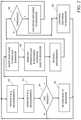
- FIG. 2is a flowchart of an exemplary embodiment of a method for controlling and monitoring wellbore fluid flow out of a wellhead during production cementing operations according to the teachings of the present disclosure.
- FIG. 1is a diagram of an exemplary system and method 10 for controlling and monitoring wellbore fluid flow out of a wellhead during production cementing operations according to the teachings of the present disclosure.
- production cement slurryis introduced and pumped down into a wellhead between the wellbore and the casing, and the cement slurry displaces the drilling mud or fluid in the well and pushes it back up through the casing.
- the system and method 10 described hereinare used to monitor the mud fluid that is returned back up the well to the drilling mud system.
- the system 10includes a pressure sensor 12 that measures the fluid pressure (P 1 ) of the inbound cement flurry, and a second pressure sensor 14 that measures the fluid pressure (P 2 ) of the drilling fluid return flow in the primary return conduit 16 . Additional pressure sensors may be used in addition to sensors 12 and 14 to provide for redundancy and backup.
- the sensed pressure measurements (P 1 and P 2 )are transmitted or relayed, via wired or wireless communication, to an intelligent controller 18 where the information is used to monitor the cementing operation. For example, a rapidly rising pressure reading in P 2 may indicate the presence of expanding gases in the return flow.
- flowmeters 20 and 22Downstream from the second pressure sensor 14 are one or more flowmeters 20 and 22 used to measure the return flow rate. Because the return flow may include a mixture of gas and liquids, flowmeters 20 and 22 preferably measure flow rate based on different principles/technology.
- flowmeter 20can be of type “A,” including wedge, ultrasonic, venturi, etc.
- Flowmeter 22can be of type “B,” including Coriolis, wedge, venturi, etc. Because the Coriolis flowmeter is capable of providing the density of the flow in addition to mass flow rate, its output is highly accurate regardless of the gas and liquid composition of the flow. However, because of its sensitivity and the harsh operating environment at a well site, a secondary flowmeter provides redundancy and enables a flow rate measurement comparison.
- another embodimentmay include using two flowmeters where one is best suited for measuring gas flow rate and the other most accurate for measuring liquid flow rate.
- the sensed flow rates (Q 1 and Q 2 ) from the flowmeters 20 and 22are also transmitted or relayed to the intelligent controller 18 , where the flow rates are compared to determine the gas/liquid composition in the return flow. For example, if the differential between flow rates Q 1 and Q 2 has been relatively constant but is now experiencing a smaller or larger delta, this may indicate a composition change in the return flow and potentially the presence of gas in the slurry.
- a pressure sensor 24that provides a fluid pressure measurement (P 3 ) to the intelligent controller 18 . Additional pressure sensors may be used to provide backup and redundancy. The measurements P 2 and P 3 provide a pressure differential across the flowmeters 20 and 22 . For example, a pressure drop above a certain threshold may indicate disruption in the flow that may require maintenance and attention.
- a first return conduit 26is coupled to the primary return conduit 16 that guides the drilling fluid back to a reservoir of the drilling mud system. Because the choke valve 28 disposed in the primary return conduit 16 , under remote control signal (Ck), is normally closed, the returned flow of mud is guided to the drilling mud system via the first return conduit 26 .
- a control valve 30under manual or remote control (C 1 ), is disposed in the first return conduit 26 to guide the flow of the returned drilling fluid to a drilling mud reservoir (not explicitly shown).
- the choke valve 28may be manual, electric-actuated, hydraulic-actuated, electro-hydraulic actuated, electric-over-hydraulic actuated, as known in the art or to be developed. However, if the presence of gas or a “kick” situation is detected in the returned flow by evaluating flow rates Q 1 and Q 2 , for example, the control valve 30 is immediately closed and the choke valve 28 is immediately opened to divert the return flow away from the first return conduit 26 and instead provided to a mud-gas separator (MGS) 32 downstream for processing.
- MCSmud-gas separator
- the mud-gas separator 32is equipment used to separate and capture gas from the drilling fluid. Any type of mud-gas separator as known in the art may be used.
- the mud-gas separator 32may include a level sensor 34 to provide a liquid level measurement, L, which is transmitted or relayed to the intelligent controller 18 .
- the separator 32may also include a discharge control valve 36 disposed in the separator discharge conduit 37 to the drilling mud reservoir. The discharge control valve 36 may be manually or remotely actuated based on measured liquid level and liquid level rate-of-change within the separator 32 .
- the control valve 36is shut off completely or partially to temporarily stop or slow down the flow of mud to the reservoir to prevent the separated gas in the mud-gas separator to escape to the drilling mud system via the separator discharge conduit 37 .
- the discharge control valve 36is reopened to continue to return the drilling mud to the reservoir.
- the intelligent controller 18is configured to also receive the position of the control valves and choke valve so that it is aware of the open/shut states of these valves at all times.
- the mud-gas separator 32may be a two-phase or three-phase separator configured to separate gas materials from fluid flow, and to separate other materials, such as oil, sand, etc. from the fluid flow.
- the separated gasmay be fed to a vent gas analyzer 38 that provides real-time information about the separated gas, including the gas flow rate measured by a flowmeter 40 , total gas volume over a certain time period, and gas composition.
- the vent gas analyzer 38monitors the methane gas concentration in the vent gas stream by measuring the total flow rate and calculating the methane gas flow rate (Q 3 ).
- the separated gascan be ignited and burned off in a controlled manner in a flare stack 42 .
- the vent gas analyzer 38ay also monitor hydrogen sulfide gas concentration in the vent gas stream. If hydrogen sulfide is present in high enough concentrations, the system would initiate visible and audible alarms for this safety concern.
- FIG. 2is a flowchart of an exemplary embodiment of a method for controlling and monitoring wellbore fluid flow out of a wellhead during production cementing operations according to the teachings of the present disclosure.
- the intelligent controller 18receives the pressure and flow rate measurements produced by the sensors disposed in the primary return conduit as described above.
- the received pressure and flow rate measurementsare monitored and analyzed by the intelligent controller 18 . If the analysis indicates that gas is not present in the return flow, as queried in step 54 , then execution proceeds to step 56 , where the drilling mud is guided to a reservoir via the first return conduit 26 .
- the returned drilling mudis diverted to a mud-gas separator 32 , which can separate the gas from the liquid in the returned flow.
- the liquidis then discharged from the mud-gas separator 32 via the second return conduit 37 to the reservoir, as shown in step 60 .
- the gas that was separated from the return flowis provided to a flare stack 42 and burned in a controlled manner.
- the intelligent controller 18also receives a liquid level measurement, L, from the mud-gas separator 32 . If L drops below a certain threshold, as determined in step 64 , then the valve 36 at the discharge conduit 37 is closed to halt the discharge of the return flow to the reservoir. If the liquid level is not below the threshold, then the separated liquid from the mud-gas separator is allowed to continue to be discharge to the reservoir, as shown in step 68 , and execution returns to step 50 .
- the intelligent controller 18receives and analyzes the pressure measurements (P 1 , P 2 , and P 3 ), flow rates (Q 1 , Q 2 , and Q 3 ), and level measurement (L), to control the actuation of valves 28 , 30 , and 36 (using control signals C 1 , C 2 , and CK) to conduct the flow of the returned drilling mud, and to prevent unsafe conditions such as gas kicks from the wellbore causing unsafe conditions at the surface operations.
- the flow of the drilling mudis diverted to a mud-gas separator 34 so that the gas can be captured and supplied to a flare stack in a controlled manner.
- Usersmay also access real-time measurement and monitoring data via a data portal and generate operational reports. Local and/or remote users are also alerted in real-time when operating parameters exceed certain thresholds or when operator attention is needed.
- the intelligent controller 18includes a microprocessor executing software code that analyzes the sensor measurements (P, Q, and L), and wireless and wired data transmission interfaces now known or to be developed for communicating with the sensors, control valves (C 1 , C 2 , and Ck), mud-gas separator, and vent gas analyzer, and local computing devices, such as smartphones, notepad computers, RFID devices, as well as remote cloud databases and servers.
- the intelligent controller 18may further include user interface devices such as display screen, touch screen, keyboard, and/or keypad.
Landscapes
- Engineering & Computer Science (AREA)
- Geology (AREA)
- Mining & Mineral Resources (AREA)
- Life Sciences & Earth Sciences (AREA)
- Physics & Mathematics (AREA)
- Fluid Mechanics (AREA)
- General Life Sciences & Earth Sciences (AREA)
- Environmental & Geological Engineering (AREA)
- Geochemistry & Mineralogy (AREA)
- Mechanical Engineering (AREA)
- Geophysics (AREA)
- General Physics & Mathematics (AREA)
- Flow Control (AREA)
- Earth Drilling (AREA)
- Control Of Non-Electrical Variables (AREA)
Abstract
Description
Claims (15)
Priority Applications (1)
| Application Number | Priority Date | Filing Date | Title |
|---|---|---|---|
| US16/137,515US11230897B2 (en) | 2017-09-22 | 2018-09-20 | System and method for intelligent flow control system for production cementing returns |
Applications Claiming Priority (2)
| Application Number | Priority Date | Filing Date | Title |
|---|---|---|---|
| US201762561908P | 2017-09-22 | 2017-09-22 | |
| US16/137,515US11230897B2 (en) | 2017-09-22 | 2018-09-20 | System and method for intelligent flow control system for production cementing returns |
Publications (2)
| Publication Number | Publication Date |
|---|---|
| US20190093435A1 US20190093435A1 (en) | 2019-03-28 |
| US11230897B2true US11230897B2 (en) | 2022-01-25 |
Family
ID=65806219
Family Applications (1)
| Application Number | Title | Priority Date | Filing Date |
|---|---|---|---|
| US16/137,515Active2039-06-14US11230897B2 (en) | 2017-09-22 | 2018-09-20 | System and method for intelligent flow control system for production cementing returns |
Country Status (2)
| Country | Link |
|---|---|
| US (1) | US11230897B2 (en) |
| CA (1) | CA3018276A1 (en) |
Families Citing this family (2)
| Publication number | Priority date | Publication date | Assignee | Title |
|---|---|---|---|---|
| CN110273676B (en)* | 2019-07-19 | 2023-07-18 | 西安思坦仪器股份有限公司 | Well diameter flow adjustment test system and method |
| WO2021026300A1 (en)* | 2019-08-06 | 2021-02-11 | Q.E.D. Environmental Systems, Inc. | System and method for monitoring and controlling of venting of a fluid discharge line in a well system |
Citations (20)
| Publication number | Priority date | Publication date | Assignee | Title |
|---|---|---|---|---|
| US2341169A (en)* | 1940-12-30 | 1944-02-08 | Nat Lead Co | Method and apparatus for detecting gas in well drilling fluids |
| US2748884A (en)* | 1952-06-30 | 1956-06-05 | Salt Water Control Inc | Apparatus for treating drilling mud |
| US3325974A (en)* | 1963-09-11 | 1967-06-20 | Bass Brothers Entpr Inc | Drilling mud degassers for oil wells |
| US3633687A (en)* | 1969-12-12 | 1972-01-11 | Alfred Gordon West | Apparatus for separating and measuring gas in drilling fluid |
| US4635735A (en)* | 1984-07-06 | 1987-01-13 | Schlumberger Technology Corporation | Method and apparatus for the continuous analysis of drilling mud |
| US5327969A (en)* | 1993-04-30 | 1994-07-12 | Halliburton Company | Method of preventing gas migration during primary well cementing |
| US5339899A (en)* | 1992-09-02 | 1994-08-23 | Halliburton Company | Drilling fluid removal in primary well cementing |
| US20040265176A1 (en)* | 2003-06-27 | 2004-12-30 | Geolog S.P.A. | System for degassing muds and for analysing the gases contained in the muds |
| US20080060846A1 (en)* | 2005-10-20 | 2008-03-13 | Gary Belcher | Annulus pressure control drilling systems and methods |
| US20110094736A1 (en)* | 2005-04-27 | 2011-04-28 | Jean-Francois Evrard | Device for extracting at least one type of gas contained in a drilling mud, an analysis arrangement and a related extraction method |
| US20110303463A1 (en)* | 2009-01-16 | 2011-12-15 | Schlumberger Technology Corporation | Method for Determining the Content of A Plurality of Compounds Contained In A Drilling Fluid |
| US20130118752A1 (en)* | 2011-11-16 | 2013-05-16 | Weatherford/Lamb, Inc. | Managed pressure cementing |
| US20160290131A1 (en)* | 2014-11-10 | 2016-10-06 | Halliburton Energy Services,Inc. | Systems and methods for real-time measurement of gas content in drilling fluids |
| US20170107773A1 (en)* | 2015-05-29 | 2017-04-20 | Halliburton Energy Services, Inc. | Bypass flushing for gas extraction systems |
| US20170227387A1 (en)* | 2016-02-04 | 2017-08-10 | Absolute Control, LLC | Tank Level And Flow Rate Monitoring System |
| US20170370167A1 (en)* | 2014-12-10 | 2017-12-28 | Seaboard International Inc. | Mud-gas separator apparatus and methods |
| US20180135367A1 (en)* | 2015-06-25 | 2018-05-17 | Schlumberger Technology Corporation | Fluid Loss and Gain for Flow, Managed Pressure and Underbalanced Drilling |
| US20180245466A1 (en)* | 2015-10-22 | 2018-08-30 | Halliburton Energy Services, Inc. | Extraction cleaner and gas system check |
| US20180328173A1 (en)* | 2016-01-25 | 2018-11-15 | Halliburton Energy Services, Inc. | Drilling Rig Gas Trap Testing |
| US20180363414A1 (en)* | 2015-12-16 | 2018-12-20 | Schlumberger Technology Corporation | System and method for performing a real-time integrated cementing operation |
- 2018
- 2018-09-20USUS16/137,515patent/US11230897B2/enactiveActive
- 2018-09-21CACA3018276Apatent/CA3018276A1/enactivePending
Patent Citations (21)
| Publication number | Priority date | Publication date | Assignee | Title |
|---|---|---|---|---|
| US2341169A (en)* | 1940-12-30 | 1944-02-08 | Nat Lead Co | Method and apparatus for detecting gas in well drilling fluids |
| US2748884A (en)* | 1952-06-30 | 1956-06-05 | Salt Water Control Inc | Apparatus for treating drilling mud |
| US3325974A (en)* | 1963-09-11 | 1967-06-20 | Bass Brothers Entpr Inc | Drilling mud degassers for oil wells |
| US3633687A (en)* | 1969-12-12 | 1972-01-11 | Alfred Gordon West | Apparatus for separating and measuring gas in drilling fluid |
| US4635735A (en)* | 1984-07-06 | 1987-01-13 | Schlumberger Technology Corporation | Method and apparatus for the continuous analysis of drilling mud |
| US5339899A (en)* | 1992-09-02 | 1994-08-23 | Halliburton Company | Drilling fluid removal in primary well cementing |
| US5327969A (en)* | 1993-04-30 | 1994-07-12 | Halliburton Company | Method of preventing gas migration during primary well cementing |
| US20040265176A1 (en)* | 2003-06-27 | 2004-12-30 | Geolog S.P.A. | System for degassing muds and for analysing the gases contained in the muds |
| US20110094736A1 (en)* | 2005-04-27 | 2011-04-28 | Jean-Francois Evrard | Device for extracting at least one type of gas contained in a drilling mud, an analysis arrangement and a related extraction method |
| US20080060846A1 (en)* | 2005-10-20 | 2008-03-13 | Gary Belcher | Annulus pressure control drilling systems and methods |
| US20110303463A1 (en)* | 2009-01-16 | 2011-12-15 | Schlumberger Technology Corporation | Method for Determining the Content of A Plurality of Compounds Contained In A Drilling Fluid |
| US20130118752A1 (en)* | 2011-11-16 | 2013-05-16 | Weatherford/Lamb, Inc. | Managed pressure cementing |
| US20160290131A1 (en)* | 2014-11-10 | 2016-10-06 | Halliburton Energy Services,Inc. | Systems and methods for real-time measurement of gas content in drilling fluids |
| US20170370167A1 (en)* | 2014-12-10 | 2017-12-28 | Seaboard International Inc. | Mud-gas separator apparatus and methods |
| US20170107773A1 (en)* | 2015-05-29 | 2017-04-20 | Halliburton Energy Services, Inc. | Bypass flushing for gas extraction systems |
| US20180135367A1 (en)* | 2015-06-25 | 2018-05-17 | Schlumberger Technology Corporation | Fluid Loss and Gain for Flow, Managed Pressure and Underbalanced Drilling |
| US10718172B2 (en)* | 2015-06-25 | 2020-07-21 | Schlumberger Technology Corporation | Fluid loss and gain for flow, managed pressure and underbalanced drilling |
| US20180245466A1 (en)* | 2015-10-22 | 2018-08-30 | Halliburton Energy Services, Inc. | Extraction cleaner and gas system check |
| US20180363414A1 (en)* | 2015-12-16 | 2018-12-20 | Schlumberger Technology Corporation | System and method for performing a real-time integrated cementing operation |
| US20180328173A1 (en)* | 2016-01-25 | 2018-11-15 | Halliburton Energy Services, Inc. | Drilling Rig Gas Trap Testing |
| US20170227387A1 (en)* | 2016-02-04 | 2017-08-10 | Absolute Control, LLC | Tank Level And Flow Rate Monitoring System |
Also Published As
| Publication number | Publication date |
|---|---|
| US20190093435A1 (en) | 2019-03-28 |
| CA3018276A1 (en) | 2019-03-22 |
Similar Documents
| Publication | Publication Date | Title |
|---|---|---|
| Islam et al. | Real time risk analysis of kick detection: testing and validation | |
| US11035184B2 (en) | Method of drilling a subterranean borehole | |
| EP3262273B1 (en) | Automatic event detection and control while drilling in closed loop systems | |
| US6234250B1 (en) | Real time wellbore pit volume monitoring system and method | |
| AU2002219322B2 (en) | Closed loop fluid-handing system for well drilling | |
| US20180187498A1 (en) | Systems and methods for early well kick detection | |
| US20210164340A1 (en) | Method and apparatus for automated pressure integrity testing (apit) | |
| US20170023435A1 (en) | In-Line Composition and Volumetric Analysis of Vent Gases and Flooding of the Annular Space of Flexible Pipe | |
| US9175531B2 (en) | Method and system for identifying a self-sustained influx of formation fluids into a wellbore | |
| CA2792031A1 (en) | System and method for safe well control operations | |
| US9650884B2 (en) | Use of downhole isolation valve to sense annulus pressure | |
| US11230897B2 (en) | System and method for intelligent flow control system for production cementing returns | |
| Johnson et al. | Advancing deepwater kick detection | |
| Reitsma | Development of an automated system for the rapid detection of drilling anomalies using standpipe and discharge pressure | |
| US20200324224A1 (en) | Well clean-up monitoring technique | |
| Shi et al. | Novel Kick Detection Tool Based on Knowledge-Data-Dual-Driven Approaches | |
| Jardine et al. | Computer-Aided real-Time kick analysis and control | |
| US11603724B1 (en) | Mud flow measurement system for wellheads | |
| US20250270928A1 (en) | Formation testing with controlled pressure drilling | |
| US11624264B2 (en) | Controlling corrosion within wellbores | |
| GB2545666A (en) | A Drilling fluid monitoring system and method | |
| WO2025177088A1 (en) | Formation testing with controlled pressure drilling | |
| Huebner et al. | Sand Production in Sand Controlled Completions and Topside Wall Loss Assessment | |
| Sule | Safety and reliability assessment of managed pressure drilling in well control operations | |
| Pavel et al. | Advanced pressure control improves kick, loss detection |
Legal Events
| Date | Code | Title | Description |
|---|---|---|---|
| FEPP | Fee payment procedure | Free format text:ENTITY STATUS SET TO UNDISCOUNTED (ORIGINAL EVENT CODE: BIG.); ENTITY STATUS OF PATENT OWNER: LARGE ENTITY | |
| STPP | Information on status: patent application and granting procedure in general | Free format text:DOCKETED NEW CASE - READY FOR EXAMINATION | |
| AS | Assignment | Owner name:SEABOARD INTERNATIONAL, INC., TEXAS Free format text:ASSIGNMENT OF ASSIGNORS INTEREST;ASSIGNOR:GREEN, MATTHEW BRADY;REEL/FRAME:054047/0976 Effective date:20171031 | |
| AS | Assignment | Owner name:SEABOARD INTERNATIONAL LLC, TEXAS Free format text:CHANGE OF NAME;ASSIGNOR:SEABOARD INTERNATIONAL INC.;REEL/FRAME:054914/0617 Effective date:20200930 Owner name:SEABOARD INTERNATIONAL LLC, TEXAS Free format text:CHANGE OF NAME;ASSIGNOR:SEABOARD INTERNATIONAL INC.;REEL/FRAME:054914/0652 Effective date:20200930 | |
| STPP | Information on status: patent application and granting procedure in general | Free format text:NOTICE OF ALLOWANCE MAILED -- APPLICATION RECEIVED IN OFFICE OF PUBLICATIONS | |
| STCB | Information on status: application discontinuation | Free format text:ABANDONMENT FOR FAILURE TO CORRECT DRAWINGS/OATH/NONPUB REQUEST | |
| AS | Assignment | Owner name:SPM OIL & GAS PC LLC, TEXAS Free format text:CHANGE OF NAME;ASSIGNOR:SEABOARD INTERNATIONAL LLC;REEL/FRAME:058897/0913 Effective date:20210211 | |
| AS | Assignment | Owner name:SPM OIL & GAS PC LLC, TEXAS Free format text:CHANGE OF NAME;ASSIGNOR:SEABOARD INTERNATIONAL LLC;REEL/FRAME:058533/0465 Effective date:20210211 | |
| STPP | Information on status: patent application and granting procedure in general | Free format text:PUBLICATIONS -- ISSUE FEE PAYMENT VERIFIED | |
| STCF | Information on status: patent grant | Free format text:PATENTED CASE | |
| FEPP | Fee payment procedure | Free format text:MAINTENANCE FEE REMINDER MAILED (ORIGINAL EVENT CODE: REM.); ENTITY STATUS OF PATENT OWNER: LARGE ENTITY |