US11229989B2 - Methods of forming cutting elements with cutting faces exhibiting multiple coefficients of friction, and related methods - Google Patents
Methods of forming cutting elements with cutting faces exhibiting multiple coefficients of friction, and related methodsDownload PDFInfo
- Publication number
- US11229989B2 US11229989B2US15/793,077US201715793077AUS11229989B2US 11229989 B2US11229989 B2US 11229989B2US 201715793077 AUS201715793077 AUS 201715793077AUS 11229989 B2US11229989 B2US 11229989B2
- Authority
- US
- United States
- Prior art keywords
- area
- cutting
- cutting face
- forming
- substantially planar
- Prior art date
- Legal status (The legal status is an assumption and is not a legal conclusion. Google has not performed a legal analysis and makes no representation as to the accuracy of the status listed.)
- Active, expires
Links
Images


Classifications
- B—PERFORMING OPERATIONS; TRANSPORTING
- B24—GRINDING; POLISHING
- B24D—TOOLS FOR GRINDING, BUFFING OR SHARPENING
- B24D18/00—Manufacture of grinding tools or other grinding devices, e.g. wheels, not otherwise provided for
- B24D18/009—Tools not otherwise provided for
- B—PERFORMING OPERATIONS; TRANSPORTING
- B23—MACHINE TOOLS; METAL-WORKING NOT OTHERWISE PROVIDED FOR
- B23K—SOLDERING OR UNSOLDERING; WELDING; CLADDING OR PLATING BY SOLDERING OR WELDING; CUTTING BY APPLYING HEAT LOCALLY, e.g. FLAME CUTTING; WORKING BY LASER BEAM
- B23K26/00—Working by laser beam, e.g. welding, cutting or boring
- B23K26/352—Working by laser beam, e.g. welding, cutting or boring for surface treatment
- B23K26/3568—Modifying rugosity
- B23K26/3584—Increasing rugosity, e.g. roughening
- E—FIXED CONSTRUCTIONS
- E21—EARTH OR ROCK DRILLING; MINING
- E21B—EARTH OR ROCK DRILLING; OBTAINING OIL, GAS, WATER, SOLUBLE OR MELTABLE MATERIALS OR A SLURRY OF MINERALS FROM WELLS
- E21B10/00—Drill bits
- E21B10/46—Drill bits characterised by wear resisting parts, e.g. diamond inserts
- E21B10/56—Button-type inserts
- E21B10/567—Button-type inserts with preformed cutting elements mounted on a distinct support, e.g. polycrystalline inserts
- E21B10/5671—Button-type inserts with preformed cutting elements mounted on a distinct support, e.g. polycrystalline inserts with chip breaking arrangements
- E—FIXED CONSTRUCTIONS
- E21—EARTH OR ROCK DRILLING; MINING
- E21B—EARTH OR ROCK DRILLING; OBTAINING OIL, GAS, WATER, SOLUBLE OR MELTABLE MATERIALS OR A SLURRY OF MINERALS FROM WELLS
- E21B10/00—Drill bits
- E21B10/46—Drill bits characterised by wear resisting parts, e.g. diamond inserts
- E21B10/56—Button-type inserts
- E21B10/567—Button-type inserts with preformed cutting elements mounted on a distinct support, e.g. polycrystalline inserts
- E21B10/5676—Button-type inserts with preformed cutting elements mounted on a distinct support, e.g. polycrystalline inserts having a cutting face with different segments, e.g. mosaic-type inserts
- B—PERFORMING OPERATIONS; TRANSPORTING
- B23—MACHINE TOOLS; METAL-WORKING NOT OTHERWISE PROVIDED FOR
- B23P—METAL-WORKING NOT OTHERWISE PROVIDED FOR; COMBINED OPERATIONS; UNIVERSAL MACHINE TOOLS
- B23P15/00—Making specific metal objects by operations not covered by a single other subclass or a group in this subclass
- B23P15/28—Making specific metal objects by operations not covered by a single other subclass or a group in this subclass cutting tools
Definitions
- the present disclosurerelates to cutting elements for earth-boring tools having cutting surfaces with two or more areas exhibiting different frictional characteristics, and to methods of forming such devices.
- Earth-boring tools for forming wellbores in subterranean earth formationsmay include a plurality of cutting elements secured to a body.
- fixed-cutter earth-boring rotary drill bitsalso referred to as “drag bits”
- reamersalso referred to as “drag bits”
- back-up cuttersdrilling-with casing tools
- reaming-with casing toolsand exit mills
- the cutting elements used in such earth-boring toolsoften include polycrystalline diamond compact (often referred to as “PDC”) cutting elements, which are cutting elements that include a polycrystalline diamond (PCD) material.
- PDCpolycrystalline diamond compact
- PCDpolycrystalline diamond
- Such polycrystalline diamond cutting elementsare formed by sintering and bonding together relatively small diamond grains or crystals under conditions of high temperature and high pressure in the presence of a catalyst (such as, for example, cobalt, iron, nickel, or alloys and mixtures thereof) to form a layer of polycrystalline diamond material on a cutting element substrate.
- a catalystsuch as, for example, cobalt, iron, nickel, or alloys and mixtures thereof
- HTHPhigh temperature/high pressure
- the cutting element substratemay comprise a cermet material (i.e., a ceramic-metal composite material) such as cobalt-cemented tungsten carbide.
- the cobalt (or other catalyst material) in the cutting element substratemay be drawn into the diamond grains or crystals during sintering and serve as a catalyst material for forming a diamond table from the diamond grains or crystals.
- powdered catalyst materialmay be mixed with the diamond grains or crystals prior to sintering the grains or crystals together in an HTHP process.
- PDC cutting elementscommonly have a planar, disc-shaped diamond table on an end surface of a cylindrical cemented carbide substrate. Such a PDC cutting element may be mounted to an earth-boring rotary drag bit or other drilling or reaming tool using fixed PDC cutting elements in a position and orientation that causes a peripheral edge of the diamond table to scrape against and shear away the surface of the formation being cut as the tool is rotated within a wellbore.
- Other types of cutting elementssuch as carbide cutting elements or carbide-covered PDC cutting elements are also used in subterranean drilling operations.
- cutting elements having a cutting face with a surface finish roughness in the range of 0.3 microinch (0.3 ⁇ in.) to 2.0 microinches (2.0 ⁇ in.) root mean square (RMS), which may be referred to as a “polished” cutting faceexhibit favorable performance characteristics as the cutting element shears formation material from the formation being cut, including, for example, the shearing of formation chips of uniform thickness that slide in a substantially unimpeded manner up the cutting face of the cutting element instead of agglomerating as a mass on the cutting face, accumulating in a fluid course rotationally ahead of the cutting element and potentially causing “balling” of formation material on the tool face, resulting in severe degradation of drilling performance of the rotary drag bit or other drilling or reaming tool.
- RMSroot mean square
- the drilling action of the toolgenerates cuttings of subterranean formation material at a cutting edge of the cutting element, which cuttings or “chips” travel on the cutting face of the cutting element toward the evacuation areas of the tool, such as junk slots, and from there to the surface transported by drilling mud.
- the present disclosureincludes an earth-boring tool with a tool crown and at least one cutting element attached thereon.
- the cutting elementcomprises a superabrasive material and has a cutting face with a cutting edge extending along a periphery of the cutting face.
- the cutting facecomprises at least a first area and at least a second area.
- the at least a first areahas a first average surface roughness
- the at least a second areahas a second average surface roughness which is greater than the average surface roughness of the at least a first area.
- the first at least a first area and the at least a second area of the cutting faceare located in a manner to cause the at least a second area to provide a greater sliding friction force than a greater sliding friction force provided by the at least a first area to a chip of subterranean formation material as the chip moves over the cutting face.
- This friction differential between the at least a first area and the at least a second areamay impede movement of the chip over the at least a second area, causing the chip to move in a desired direction over the cutting face and enable “steering” of the chip.
- the present disclosureincludes a method of forming an earth-boring tool.
- the methodincludes attaching a plurality of cutting elements to a tool crown. At least one of the cutting elements has a cutting face provided thereon.
- the cutting facehas at least a first area and at least a second area, the at least a first area having an average surface roughness less than an average surface roughness of the at least a second area.
- the methodalso includes orienting a boundary between the at least a first area and the at least a second area so that a proximal end of the boundary is adjacent to a profile of the tool crown at the location of attachment on the tool crown and a distal end of the boundary is remote from the tool crown.
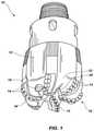
- FIG. 1is a perspective view of a typical earth-boring tool.
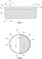
- FIG. 2illustrates a simplified perspective view of a cutting element showing a cutaway portion.
- FIG. 3illustrates a simplified cross-sectional view of a cutting element.
- FIG. 4illustrates a simplified front view of a cutting element similar to the cutting element of FIG. 3 having a polished surface and an unpolished surface.
- FIG. 5illustrates a side elevation of the cutting element as the cutting element engages and cuts a subterranean formation and a formation chip is cut and slides over the cutting face of the cutting element.
- FIG. 6illustrates a front elevation of the cutting element of FIG. 5 showing the formation chip being urged toward a portion of the cutting face having a higher coefficient of sliding friction.
- FIG. 7illustrates an example of a surface finish profile of an unpolished cutting face of a cutting element.
- FIG. 8illustrates an example of a surface finish profile of a polished cutting face of a cutting element.
- FIGS. 9 through 11 and 13 through 27illustrate different orientations of the cutting face.
- FIG. 9illustrates a front elevation view of a cutting face having a second area with a coefficient of sliding friction greater than a coefficient of sliding friction of a first area, a boundary between the first and second areas is linear and coincides with the vertical centerline of the cutting face, the first and second areas are oriented to urge a chip toward the second area and laterally away from the center of the cutting face.
- FIG. 10illustrates a front elevation view of a cutting face having an arcuate boundary between the first and second areas of the cutting face, the first and second areas are oriented to urge the chip toward the second area of the cutting face and laterally away from the center of the cutting face.
- FIG. 11illustrates a front elevation view of a cutting face having the first and second areas oriented at an acute angle with respect to the vertical centerline of the cutting face, the first and second areas are oriented to urge the chip toward the second area of the cutting face and away from the center of the cutting face.
- FIG. 12illustrates the cutting element of FIG. 9 having a wear-flat worn into the cutting element.
- FIG. 13illustrates a front elevation view of a cutting face wherein the second area occupies one quadrant of the cutting face.
- FIG. 14illustrates a front elevation view of a cutting face wherein the first and second areas each occupy two non-consecutive quadrants of the cutting face.
- FIG. 15illustrates a front elevation view of a cutting face wherein the first and second areas are divided into sectors of non-equivalent surface area by a linear boundary that does not extend through the center of the cutting face, the boundary being oriented at an angle with respect to the vertical centerline of the cutting face.
- FIG. 16illustrates a front elevation view of a cutting face wherein the second area comprises two sectors on either side of the first area, the first area having two opposite linear boundaries with the second area, each boundary being oriented at an angle with respect to the vertical centerline of the cutting face.
- FIG. 17illustrates a front elevation view of a cutting face wherein the second area comprises two sections on either side of the first area, the first area having two opposite arcuate boundaries with the second area.
- FIG. 18illustrates a front elevation view of a cutting face having a continuous first area wherein the second area occupies four portions of the cutting face.
- FIG. 19illustrates a front elevation view of a cutting face having a generally linear boundary between the first and second areas that coincides with the vertical centerline of the cutting face, the second area comprising a plurality of barcode-pattern etch paths.
- FIG. 20illustrates a front elevation view of a cutting face having a generally linear boundary between the first and second areas that does not coincide with the center of the cutting face, the second area comprising a plurality of barcode-pattern etch paths.
- FIGS. 21 through 27illustrate alternative orientations of the first and second areas that may be achieved at least by a laser etching process.
- FIG. 21illustrates a front elevation view of a cutting face having an alternative orientation of the first and second areas.
- FIG. 22illustrates a front elevation view of a cutting face having an alternative orientation of the first and second areas.
- FIG. 23illustrates a front elevation view of a cutting face having an alternative orientation of the first and second areas.
- FIG. 24illustrates a front elevation view of a cutting face having an alternative orientation of the first and second areas.
- FIG. 25illustrates a front elevation view of a cutting face having an alternative orientation of the first and second areas.
- FIG. 26illustrates a front elevation view of a cutting face having an alternative orientation of the first and second areas.
- FIG. 27illustrates a front elevation view of a cutting face having an alternative orientation of the first and second areas.
- FIG. 28illustrates a perspective view of a cutting element having one or more marks on a rear surface of a substrate of the cutting element.
- FIG. 29illustrates a front view of an unpolished cutting element prior to being formed into a multi-friction cutting element.
- FIG. 30illustrates a front view of the cutting element of FIG. 29 having an area of the cutting face polished and a second area remaining unpolished.
- FIG. 31illustrates a front view of a polished cutting element prior to being formed into a multi-friction cutting element.
- FIG. 32illustrates a front view of the cutting element of FIG. 31 having a first area of the cutting face “roughened” and an area remaining polished.
- FIG. 33illustrates a perspective view of a polished cutting element blank prior to being cut.
- FIG. 34illustrates a perspective view of the polished cutting element blank of FIG. 33 being cut and separated to form a first half of a multi-friction cutting element.
- FIG. 35illustrates a perspective view of an unpolished cutting element blank prior to being cut.
- FIG. 36illustrates a perspective view of the unpolished cutting element blank of FIG. 35 being cut and separated to form a second half of a multi-friction cutting element.
- FIG. 37illustrates a perspective view of a multi-friction cutting element formed by bonding the first and second halves depicted in FIGS. 34 and 36 .
- FIG. 38illustrates a perspective view of a multi-friction cutting element having a non-planar cutting face.
- the present disclosureincludes earth-boring tools having cutting elements having a cutting face with at least two portions, which may also be characterized as areas, the first portion of the cutting face having a different coefficient of sliding friction than the second portion.
- the portions of the cutting facemay be polished or roughened to achieve the desired friction coefficient thereon.
- the cutting elementsmay include a table of superabrasive material having a cutting face and bonded to a supporting substrate along an interface opposite the cutting face. The inventors have discovered that cutting elements exhibiting such frictional characteristics can influence the direction of formation chip flow over the face of the cutting element, in addition to the size and character of the chip.
- the present disclosurealso includes methods of forming such cutting elements. Examples of such cutting elements and methods of forming the cutting elements are disclosed in further detail below.
- FIG. 1 of the drawingsdepicts an earth-boring tool 10 , shown as being a rotary drill bit, having a body 12 secured to a shank (not shown) having a threaded pin connection thereon, whereby the earth-boring tool 10 is made up to the end of a drill string or to a down hole motor disposed at the end of a drill string (not shown).
- Cutting elements 14are shown secured in a predetermined pattern and at predetermined heights and orientations on the face of a tool crown 16 to provide effective cutting for the formation type to be cut, nozzles 18 on body 12 being positioned to clear chips of formation material leaving cutting elements 14 through evacuation features of the earth-boring tool 10 , including fluid courses 20 and junk slots 22 .
- the bit body 12may further include a plurality of blades 24 that are separated by the junk slots 22 .
- the cutting elements 14may be mounted on the tool crown 16 of the bit body 12 in cutting element pockets that are located along each of the blades 24 . It is to be appreciated that the cutting elements, as disclosed in more detail below, may be utilized on a crown or body of any earth-boring tool, and are not limited to use on drill bits.
- any downhole toolsuch as reamers, back-up cutters, drilling-with casing tools, reaming-with casing tools, exit mills, and stabilizer pads, as non-limiting examples, may be fitted with cutting elements attached to a crown or body thereof wherein the cutting elements exhibit multiple coefficients of sliding friction capable of influencing the direction of formation chip flow over the face of the cutting element.
- cutting elements exhibiting such frictional characteristicsmay be used to advantage to influence the direction of chip flow of metallic cuttings, such as occurs when a downhole mill, such as a casing exit mill, is used to mill through metallic downhole components.
- Cutting element 14includes a substrate 26 having a table 28 of superabrasive material (e.g., a diamond table), such as a PDC, thereon.
- a table 28 of superabrasive materiale.g., a diamond table
- the diamond table 28may be formed on the substrate 26 , or the diamond table 28 and the substrate 26 may be separately formed and subsequently attached together.
- FIG. 3is an enlarged cross-sectional view of the cutting element 14 shown in FIG. 2 .
- the diamond table 28may have a chamfered edge 30 .
- the chamfered edge 30 of the cutting element 14has a single chamfer surface 32 , although the chamfered edge 30 also may have additional chamfer surfaces, and such chamfer surfaces may be oriented at chamfer angles that differ from the chamfer angle of the chamfer surface 32 , as known in the art. In lieu of chamfered edge 30 , the cutting face end may be rounded, as is known to those of ordinary skill in the art.
- the diamond table 28also has a side surface 33 extending from the chamfer surface 32 to the interface between the diamond table 28 and the substrate 26 .
- the substrate 26may have a generally cylindrical shape, as shown in FIG. 2 .
- the substrate 26may have an at least substantially planar first end surface 34 , and an at least substantially planar second end surface 36 , and a generally cylindrical lateral side surface 38 extending between the first end surface 34 and the second end surface 36 .
- first end surface 34 shown in FIG. 3is at least substantially planar, it is well known in the art to employ non-planar interface geometries between substrates and diamond tables attached thereto, and additional embodiments of the present disclosure may employ such non-planar interface geometries at the interface between the substrate 26 and the diamond table 28 .
- substrates and their cutting elementscommonly have a cylindrical shape, like that of substrate 26
- other cross-sectional shapes of substrates and cutting elementsare also known in the art
- embodiments of the present disclosureinclude cutting elements having shapes other than a generally cylindrical shape. For example, tombstone-shaped cutters and rectangular-shaped cutters, as disclosed in U.S. Pat. No. 5,881,830, issued on Mar.
- the substrate 26may be formed from a material that is relatively hard and resistant to wear.
- the substrate 26may be formed from and include a ceramic-metal composite material (which are often referred to as “cermet” materials).
- the substrate 26may include a cemented carbide material, such as a cemented tungsten carbide material, in which tungsten carbide particles are cemented together in a metallic binder material.
- the metallic binder materialmay include, for example, cobalt, nickel, iron, or alloys and mixtures thereof. Alternatively, other substrate materials may be used.
- the diamond table 28may be disposed on or over the first end surface 34 of the cutting element substrate 26 .
- the diamond table 28may comprise a multi-layer diamond table 28 , with various layers of differing average diamond grain size.
- Diamond table 28may also comprise multiple diamond grain sizes, such as between two grain sizes and five grain sizes, by way of non-limiting example.
- Diamond table 28may also comprise a multiple diamond grain size distribution, such as a mono-modal, bi-modal, tri-modal, tetra-modal or penta-modal grain size distribution, by way of a non-limiting example.
- each layermay comprise a number of different average diamond grain sizes.
- the diamond table 28may be primarily comprised of polycrystalline diamond material.
- diamond materialmay comprise at least about seventy percent (70%) by volume of the diamond table 28 .
- the diamond materialmay comprise at least about eighty percent (80%) by volume of the diamond table 28
- the diamond materialmay comprise at least about ninety percent (90%) by volume of the diamond table 28 .
- the diamond table 28 of the cutting element 14has a leading surface face or cutting face 40 , the outermost edge of which (as the cutting element 14 is mounted to the body 12 of earth-boring tool 10 ) may be defined as a cutting edge 42 by which the cutting element 14 engages and cuts the formation.
- the cutting face 40 of PDC cutting element 14is commonly lapped to a surface finish in the range of about 20 to 40 microinches (20 ⁇ in.-40 ⁇ in.) root mean square (“RMS”) (all surface finishes referenced herein being RMS).
- RMSroot mean square
- a surface finish roughness in the range of 20 ⁇ in.-40 ⁇ in.is relatively smooth to the touch and visually planar (if the cutting face is itself flat), but includes a number of surface anomalies and exhibits a degree of roughness, which is readily visible to one even under very low power magnification, such as a 10 times jeweler's loupe.
- an area of the cutting face 40may be polished to a mirror finish of 0.3 ⁇ in.
- one mode currently known to the inventors for polishing the cutting face 40 of superabrasive, such as PDC, cutting elements to obtain cutting elements having a mirror-like finish in the range of 0.3 ⁇ in.-2.0 ⁇ in.is lapping of the cutting face 40 on conventional cast iron laps known in the art using progressively smaller diamond grit suspended in a glycol, glycerine or other suitable carrier liquid.
- the lappingis conducted as a three-step process commencing with a 70 micron grit, progressing to a 40 micron grit and then to a grit of about 1-3 microns in size.
- standard lapping techniques for a conventional, unpolished PDC cutting element having a surface finish roughness on the order of 20 ⁇ in.-40 ⁇ in.may include an initial electrodischarge grinding of the cutting face and a finish lap in one step with 70 micron grit.
- 70 micron gritis of the consistency of fine sand or crystalline material, while 1-3 micron grit is similar in consistency to powdered sugar.
- the normal 20 ⁇ in.-40 ⁇ in. surface roughness, averaging 30 ⁇ in., of state-of-the-art PDC cutting elementsmay be smoothed to a finish of 0.3 ⁇ m. in a one-step process.
- the cutting elements 14as received from the manufacturer, are placed with their cutting faces 40 against a dry, rotating diamond wheel, as disclosed in U.S. Pat. No. 6,145,608 to Lund et al., which disclosure is incorporated by reference in its entirety herein. It may be preferred that the finish of at least a portion of the cutting faces 40 be smoothed to a 0.3 ⁇ in. or less surface finish roughness approaching a true “mirror” finish.
- polishing cutting facesmay be applied to polish a chamfer surface 32 at the cutting edge 42 of the cutting face 40 , as well as the side of the superhard table to the rear of the chamfer.
- the cutting elementsheld by their substrates, are disposed at the desired angle to the rotating wheel.
- the cutting elementsare themselves rotated about their axis of symmetry to smooth and polish the desired chamfer and side areas of the superhard table.
- Other methods of polishing the cutting face 40may also be used, including the use of belt polishers.
- a cutting element 14may be formed having a cutting face 40 with a first area 44 possessing a coefficient of sliding friction, ⁇ 1 , less than a coefficient of sliding friction, ⁇ 2 , possessed by a second area 46 of the cutting face 40 .
- the relative difference between ⁇ 1 and ⁇ 2causes the portion of the formation chip sliding over the second area 46 to encounter a greater friction force, F f2 , than the friction force, F f1 , encountered by the portion of the chip sliding over the first area 44 .
- FIG. 5depicts a cutting element 14 engaging and cutting a subterranean formation 48 .
- F fthe friction force exerted on the chip
- ⁇the coefficient of sliding friction of the surface of the cutting face
- F nthe normal force exerted on the cutting face 40 by the chip.
- FIG. 5depicts a cutting element 14 engaging and cutting a subterranean formation 48 .
- the cutting edge 42 of the cutting element 14is substantially fully engaged with the pristine or previously uncut and undisturbed area 50 of subterranean formation 48 . Failure of the formation material occurs immediately adjacent, and forward of, the cutting edge 42 .
- the cutting edge 42is able to cut or shear a formation chip 52 from the subterranean formation 48 in a substantially unimpeded manner.
- the formation chip 52of substantially uniform thickness, moves relatively freely from the point of contact or line of contact with the subterranean formation 48 from the cutting edge 42 upwardly along the cutting face 40 .
- a pressure differentialis created between an outer or leading side 54 of the formation chip 52 (the side away from the cutting face 40 ) and an inner side 56 of the formation chip 52 immediately abutting the cutting face 40 .
- the force, F f1 , encountered by the portion of the chip sliding over the first area 44resists the motion of the chip as it slides up the cutting face, in essence “braking” movement of the portion of the chip sliding over the first area 44 .
- the force, F f2encountered by the portion of the chip sliding over the second area 46 resists the movement of that portion of the chip to a greater extent than the first area 44 resists the movement of the portion sliding over the first area 44 , in essence “braking” harder on the portion of the chip sliding over the second area 46 .
- Testshave also indicated other favorable behaviors of the formation chip 52 as it is sheared from the subterranean formation 48 by a multi-friction cutting element 14 .
- the formation chip 52in addition to being urged toward the second area 46 of the cutting face 40 , the formation chip 52 also exhibits a twisting behavior, which may assist in breaking the formation chip 52 into smaller pieces, increasing the ease with which the formation chip 52 is urged laterally away from the center of the cutting face 40 and off the multi-friction cutting element 14 and further increasing the efficiency in which the formation cuttings are transported by the drilling fluid up the annulus of the wellbore.
- one method of providing a coefficient of sliding friction on the first area 44 less than the coefficient of sliding friction on the second area 46is to provide the first area 44 with a surface finish roughness less than the surface finish roughness of the second area 46 .
- the first area 44 of the cutting face 40may be polished to a surface finish roughness of about 0.3 ⁇ in, while the second area 46 may have a standard surface finish roughness for PDC cutting elements of about 20 ⁇ in.-40 ⁇ in.
- the first area 44has a polished surface finish roughness in the range 0.3 ⁇ in.-2.0 ⁇ in.
- the first area 44may be polished to a surface finish roughness of about 2.0 ⁇ in. while the second area 46 may have a surface finish roughness of about 20-40 ⁇ in. Alternatively, the first area 44 may be polished to a surface finish roughness of about 0.3 ⁇ in. while the second area 46 may have a surface finish roughness of about 2.0 ⁇ in.
- the degree of difference between the surface finish roughness of first area 44 and that of second area 46may be selected to alter the bending moment applied to a formation chip 52 moving over the cutting face 40 , and thus the directionality of the chip's movement. Accordingly, different surface finish combinations may be employed for cutting elements 14 at different locations on the tool face, to provide preferred steering of chips at the various locations. It is to be appreciated that providing the first area 44 with a coefficient of sliding friction different than a coefficient of sliding friction of the second area 46 , as described above, may also be utilized to advantage with alternative types of cutting elements. For example, cutting element 14 may alternatively be a carbide-covered PDC cutting element.
- the cutting element 14may have a carbide table or a ceramic table, instead of a diamond table, bonded to the substrate. Additionally, yet other various types of cutting elements may utilize the embodiments disclosed herein to advantage, and the present disclosure is not limited only to the types of cutting elements expressly described herein.
- the cutting element 14 of FIG. 4may also have a first chamfer surface 58 at a periphery of the first area 44 of the cutting face 40 and a second chamfer surface 60 at a periphery of the second area 46 of the cutting face 40 .
- the first chamfer surface 58may be polished to have substantially the same surface finish roughness as the first area 44
- the second chamfer surface 60may be formed to have substantially the same surface finish roughness as the second area 46 .
- portions of the side surface 33 ( FIG. 3 ) of the cutting element 14may be polished to any of the surface finish roughnesses described above.
- FIGS. 7 and 8the difference in surface topography between an area of the cutting face 40 of a polished cutting element 14 having a surface finish roughness in the range of about 0.3 ⁇ in.-2.0 ⁇ in. and that of an area of the cutting face 40 of a cutting element 14 having a surface finish roughness in the range of about 20 ⁇ in.-40 ⁇ in. will be readily appreciated.
- FIGS. 7 and 8comprise renderings as if portions of a diamond or other superabrasive table were sectioned perpendicular to the cutting face, and not tracings of actual photomicrographs.
- FIG. 1is shown to contain microscopic “peaks” 62 and “valleys” 64 in the surface 66 .
- Such minute elementsmay always be present, as well as large “ranges” or “waves” 68 and “canyons” or “troughs” 70 , which comprise the major topographic features or perturbations on cutting face 40 . It is these ranges or waves 68 and canyons or troughs 70 and not the much smaller microscopic peaks 62 and valleys 64 in surface 66 which provide or result in the 20 ⁇ in.-40 ⁇ in. surface roughness of the cutting face 40 .
- Chips cut by the polished cutting face PDC cutting elementwere of substantially uniform thickness and substantially continuous appearance.
- the kerf cut by the polished cutting elementwas very smooth, almost machined in uniformity, while the kerf cut by the standard lapped cutting element possessed an irregular profile and bottom surface.
- While the present embodimentshave been described with reference to individual cutting elements mounted at separate locations on a tool face, it is contemplated that the present embodiments have equal utility with blade-type tools wherein very large, substantially continuous cutting faces are presented to engage the formation.
- Such cutting facesmay be fabricated from adjacent round, square or otherwise shaped individual cutting elements of the same or different material, closely spaced and with cooperative or even interlocking borders.
- the individual cutting elementsmay have different cutting face roughnesses, and be assembled into a larger mosaic cutting face having areas of different coefficients of friction.
- Convex, concave or other arcuately surfaced cutting elementsmay be polished, as may the alternate geometry (stepped, ridged, waved, etc.) cutting element surfaces.
- FIGS. 9 through 12are front elevation views illustrating examples of different orientations of the first area 44 and the second area 46 of the cutting face to urge the formation chip 52 in predetermined directions (indicated by the arrow) as it slides up the cutting face of the cutting element 14 .
- FIG. 9is a front elevation view of the cutting element 14 engaging a subterranean formation 48 .
- the first area 44 and the second area 46have a linear boundary 74 coincident with the center of the cutting face and substantially perpendicular to the tool crown 16 (not shown) at the point of attachment of the cutting element 14 to the tool crown 16 .
- the higher friction force encountered by the portion of the formation chip 52 on the second area 46 in comparison to the first area 44urges the formation chip 52 laterally away from the center of the cutting face toward the second area 46 (as indicated by the direction of the arrow) as the formation chip 52 slides over the cutting face.
- FIG. 10illustrates an orientation of the first area 44 and the second area 46 of the cutting face having a non-linear boundary 74 therebetween.
- the linear boundary 74 between the first area 44 and the second area 46extends from a location on the cutting face proximate a profile of the tool crown 16 at the point of attachment of the cutting element 14 to the tool crown 16 to an area remote from the profile of the tool crown 16 .
- FIG. 10illustrates an orientation of the first area 44 and the second area 46 of the cutting face having a non-linear boundary 74 therebetween.
- the linear boundary 74 between the first area 44 and the second area 46follows an arcuate path from a point along the centerline of the face proximate the profile of the tool crown 16 (not shown) and arcs toward a lateral side of the cutting face remote from the profile of the tool crown 16 , imparting a greater surface area to the second area 46 in relation to the first area 44 .
- the cutting facemay have an arcuate boundary 74 between the first area 44 and the second area 46 oriented in a manner to impart the second area 46 with a greater surface area than the first area 44 .
- FIG. 11illustrates an orientation of the first area 44 and the second area 46 of the cutting face having a linear boundary 74 coincident with the center of the cutting face and slanted at an acute angle ⁇ with respect to the centerline of the cutting face perpendicular to the tool crown 16 (not shown) at the point of attachment of the cutting element 14 to the tool crown 16 .
- a formation chip 52begins to form at the cutting edge 42 .
- the cutting edge 42commences shearing the formation chip 52 from the subterranean formation 48 , a majority portion of the formation chip 52 in FIG.
- the angle ⁇may be in the range of 0°-60°.
- the effect of the angle ⁇ of slant of the boundary between the first area 44 and the second area 46is such that as the angle ⁇ increases, the extent to which the formation chip 52 is urged laterally away from the center of the cutting face decreases. If the angle ⁇ were set at more than 60°, the steering effect would be negated and the interface between the first area 44 and the second area 46 may act more as a “chip-breaker.”
- FIG. 12depicts the cutting element 14 being oriented similarly to the cutting element illustrated in FIG. 9 .
- the wear-flat 76 formationdoes not affect the radius of curvature of movement of the formation chip 52 (indicated by the direction of the arrow) as the formation chip 52 is urged toward the second area 46 and laterally away from the center of the cutting face; however, the wear-flat 76 decreases the amount of vertical surface area of the cutting face upon which the chip slides across, thus the wear-flat 76 affects the surface area of the portion of the cutting face from which the formation chip 52 exits as it slides off the cutting face.
- FIG. 13illustrates an orientation of the first area 44 and the second area 46 wherein the second area 46 occupies one quadrant of the cutting face and the first area 44 occupies the remaining area of the cutting face.
- FIG. 13depicts a linear boundary line 74 being aligned with the vertical centerline of the cutting face, although in other embodiments the quadrant may be aligned at an angle with respect to the vertical centerline of the cutting face.
- FIG. 14illustrates an orientation of the first area 44 and the second area 46 wherein each of the first area 44 and the second area 46 occupy two non-consecutive quadrants of the cutting face.
- One or more boundary lines 74are depicted as being aligned with the vertical centerline of the cutting face, however, in other embodiments the quadrants may be aligned at an angle with respect to the vertical centerline of the cutting face.
- FIG. 15illustrates an orientation of the first area 44 and the second area 46 having a linear boundary 74 therebetween, the linear boundary 74 extending from an edge of the cutting face at a point coincident with the vertical centerline of the cutting face to an edge of the cutting face at an angle ⁇ with respect to the vertical centerline of the cutting face.
- the angle ⁇may be in the range of about 0°-60°.
- the linear boundary 74 at an edge of the cutting faceneed not be coincident with the vertical centerline of the cutting face.
- FIG. 16illustrates a cutting element 14 , similar to the cutting element of FIG. 15 , wherein the second area 46 occupies two separate portions on opposite sides of the first area 44 , there being two linear boundaries 74 therebetween.
- Each linear boundary 74extends from a substantially opposite edge of the cutting face at a point coincident with the vertical centerline of the cutting face, and extends at an angle, ⁇ 1 and ⁇ 2 , respectively, with respect to the vertical centerline.
- the angles ⁇ 1 and ⁇ 2may each be in the range of about 0°-60°.
- FIG. 16depicts the linear boundaries 74 being parallel, although, in additional embodiments, the linear boundaries 74 may be non-parallel. Furthermore, in other embodiments, one or both of the linear boundaries 74 need not be coincident with the vertical centerline of the cutting face.
- FIG. 17illustrates a cutting element, similar to the cutting element of FIG. 10 , wherein the second area 46 occupies two separate, symmetrical portions on opposite sides of the first area 44 , there being two arcuate boundaries 74 therebetween. In other embodiments, the two portions of the second area 46 are not required to be symmetrical.
- FIG. 18illustrates an additional orientation of the first area 44 and the second area 46 in a partially ringed, quadrant pattern.
- FIG. 19illustrates an orientation of the first area 44 and the second area of the cutting face similar to FIG. 9 , wherein the second area 46 comprises a multiplicity of barcode-pattern etch paths 75 .
- the etch paths 75may be formed using a laser etching process to “roughen” portions of a polished cutting face, as will be disclosed in more detail below.
- One or more lasersmay be positioned and controlled in a manner analogous to standardized computer numerical control (CNC) machining processes.
- the one or more lasersmay be configured to emit a beam of electromagnetic radiation at any wavelength that will be at least partially absorbed by the cutting face of the diamond table in a manner to roughen the second area 46 of the cutting face along the etch paths 75 .
- one or more gas jetsmay be provided to enhance the roughening of the second area 46 of the cutting face 40 by the one or more lasers.
- the laser etching processis more fully disclosed in U.S. patent application Ser. No. 12/265,462, which published as U.S. Patent Publication No. 2009/0114628, which application is incorporated by reference herein in its entirety.
- FIG. 20illustrates an orientation of the first area 44 and the second area 46 similar to FIG. 15 , wherein the second area 46 comprises a multiplicity of barcode-pattern etch paths 75 .
- the etch paths 75 depicted in FIG. 20may be formed by the laser etching process discussed previously.
- FIGS. 9 through 20illustrate various orientations of the first area 44 and the second area 46 on the cutting face, other orientations are within the scope of the embodiments disclosed herein.
- FIGS. 21 through 27illustrate various alternative orientations within the scope of the present disclosure.
- the shapes and/or orientations of the first area 44 and second area 46may be reflectively symmetric or reflectively asymmetric about at least two planes defined by x, y, and z axes of a Cartesian coordinate system defined to align a z axis of the coordinate system with a central axis of the cutting element 14 and to locate the center of the coordinate system the center of the cutting face 40 .
- the second area 46may include a symmetrical pattern of spaced-apart circular regions.
- the circular regionsare one example of shapes that may be used in such an orientation, while other shapes may also be used.
- FIG. 28illustrates a perspective view of a multi-friction cutting element 14 having a substrate 26 bonded to a diamond table 28 , the diamond table having a cutting edge 42 .
- the second end surface 36 of the substrate 26is shown having one or more marks 77 formed on the substrate 26 proximate the second end surface 36 in a manner to aid the process of orienting the cutting element when attaching the cutting element 14 to the tool crown.
- the marks 77may be painted, etched, or otherwise formed on the substrate 26 .
- FIGS. 29 through 37illustrate examples of methods that may be used to form an earth-boring tool having a plurality of cutting elements attached to the tool crown, wherein at least one of the cutting elements is a multi-friction cutting element.
- FIGS. 29 through 32illustrate examples of forming a multi-friction cutting element 14 from a single existing cutting element.
- the multi-friction cutting face 40may be formed by polishing a portion of an unpolished cutting element.
- FIG. 29illustrates a front view of a cutting element 78 , similar to the cutting element 14 of FIGS. 2 and 3 , and may be formed as previously described herein.
- the cutting element 78may have an unpolished cutting face 80 , which may or may not have been previously lapped.
- a portion of the cutting face 80 on one side of a boundary line 82may be polished to form a first area 44 with one substantially constant surface finish roughness that is less rough than the remaining unpolished area, which forms the second area 46 and having another substantially constant surface finish roughness different from the surface finish roughness of the first area 44 , as shown in FIG. 30 .
- the first area 44may be polished to a surface finish roughness, for example, in the range of about 0.1 ⁇ in.-2.0 ⁇ in. while the second area 46 may have a surface finish roughness in the range of about 10 ⁇ in.-400 ⁇ in.
- the entire cutting face 80may be polished to a surface finish roughness less than 20 ⁇ in. prior to forming the first area 44 , and the first area 44 may subsequently be formed by polishing a portion of the cutting face 80 on one side of the boundary line 82 to a surface finish roughness less than that of the remaining portion of the cutting face 80 that forms the second area 46 .
- the boundary line 82 depicted in FIG. 29is not required to be a centerline of the cutting face 80 .
- the boundary line 82is not required to be straight, although a straight boundary line 82 causes less difficulty in forming the first area 44 and the second area 46 of the cutting face.
- the multi-friction cutting element 14may also be formed by roughening a portion of a polished cutting face.
- FIG. 31shows a front view of a cutting element 84 , similar to the cutting element 14 of FIGS. 2 and 3 , and which may be formed as previously described herein.
- the cutting element 84may have a lapped or polished cutting face 86 .
- the cutting face 86may be polished to a substantially constant surface finish roughness in the range of 0.3 ⁇ in.-2.0 ⁇ in, or may be of a conventional lapped surface finish roughness in the range of about 20 ⁇ in.-40 ⁇ in.
- a portion of the cutting face 86 on one side of a boundary line 82may be roughened to form the second area 46 possessing a substantially constant surface finish roughness greater than that of the remaining polished area, which forms the first area 44 , as shown in FIG. 32 .
- the second area 46may be roughened by a laser etching process, as disclosed previously, a chemical etching process, a mechanical etching process, or an electrochemical etching process. Other roughening processes are also within the scope of the embodiments disclosed herein.
- the first area 44may be further polished after the second area 46 is roughened. It is to be appreciated that the boundary line 82 depicted in FIG. 31 is not required to be a centerline of the cutting face 86 . Moreover, the boundary line 82 is not required to be straight.
- the multi-friction cutting element 14may be attached to the tool crown 16 of the earth-boring tool 10 .
- the multi-friction cutting element 14may be characterized as having a plane orthogonal to the cutting face, the cutting element 14 having a first portion on one side of the plane and a second portion on a second, opposite side of the plane.
- the multi-friction cutting element 14may be attached to the tool crown 16 in a manner where a proximal end of the plane P is proximate to a profile of the tool crown 16 in the area where the cutting element 14 is attached to the tool crown 16 and a distal end of the plane P is remote from the tool crown.
- FIGS. 33 through 37illustrate examples of methods that may be used to form a multi-friction cutting element 14 from two existing cutting elements.
- FIG. 33illustrates a first single cutting element blank 88 , similar to the cutting element 84 of FIG. 31 , having a cutting face 86 that has been polished to a substantially constant surface finish roughness.
- the first blank 88may have a generally cylindrical shape, although other shapes may be used.
- the first blank 88includes a diamond table 28 bonded to a substrate 26 .
- the diamond table 28possesses the cutting face 86 , the outermost edge of which forms the cutting edge 42 by which the first blank 88 may engage and cut the formation.
- the diamond table 28may have a chamfered edge (not shown) including one or more chamfer surfaces (not shown).
- the diamond table 28also has a side surface 33 extending from the cutting edge 42 to the interface between the diamond table 28 and the substrate 26 .
- the boundary line 82may be aligned to produce a symmetrical halving cut of the first blank 88 , although other alignments are within the scope of the embodiments disclosed herein.
- the first blank 88may be cut along boundary line 82 , separating a first half 90 of the multi-friction cutting element 14 (as shown in FIG. 34 ) from a remaining first portion 91 of the first single cutting element blank 88 .
- the first half 90may be characterized as a first cutting unit. Referring now to FIG. 34 , the first half 90 may be semi-cylindrical in shape, although other shapes are also within the scope of the embodiments disclosed herein.
- the cutting processforms a first bonding surface 92 on the first half 90 extending the expanse of the cut.
- the first bonding surface 92may be substantially planar; although a non-planar first bonding surface 92 is also within the scope of the embodiments disclosed herein.
- the first half 90 of the multi-friction cutting element 14 formed by the cutting processincludes a first cutting element substrate 94 bonded to a first diamond table 96 thereon.
- the first diamond table 96possesses a first cutting face 98 , the outermost arcuate edge of which may be defined as a first cutting edge 100 .
- the first diamond table 96also has a first side surface 102 extending from the first cutting edge 100 to the interface between the first diamond table 96 and the first cutting element substrate 94 .
- the first cutting element substrate 94may have a first forward end surface 104 , and an at least substantially planar first rear end surface 106 , and a generally semi-cylindrical first lateral side surface 108 extending between the first forward end surface 104 and the first rear end surface 106 .
- FIG. 35illustrates a second cutting element blank 88 ′, similar to the cutting element 78 of FIG. 29 , having a cutting face 80 with a substantially constant surface finish roughness greater than the surface finish roughness of the cutting face 86 of the first single cutting element blank 88 ( FIG. 33 ).
- the second cutting element blank 88 ′may have a generally cylindrical shape, although other shapes may be incorporated.
- the second cutting element blank 88 ′includes a diamond table 28 ′ bonded to a substrate 26 ′.
- the diamond table 28 ′possesses the cutting face 80 , the outermost edge of which forms a cutting edge 42 ′ by which the second cutting element blank 88 ′ may engage and cut the formation.
- the diamond table 28 ′may have a chamfered edge (not shown) including one or more chamfer surfaces (not shown).
- the diamond table 28 ′also has a side surface 33 ′ extending from the cutting edge 42 ′ to the interface between the diamond table 28 ′ and the substrate 26 ′.
- FIG. 35also shows a boundary line 82 ′ imposed on the second cutting element blank 88 ′ at a location where the second cutting element blank 88 ′ is to be cut.
- the boundary line 82 ′may be aligned to produce a symmetrical halving cut of the second cutting element blank 88 ′, although other alignments are contemplated to be within the scope of the embodiments disclosed herein.
- the second cutting element blank 88 ′may be cut along boundary line 82 ′, separating the second half 90 ′ of the multi-friction cutting element 14 (as shown in FIG. 36 ) from a remaining second portion 91 ′ of the second cutting element blank 88 ′.
- the second half 90 ′may be characterized as a second cutting unit.
- the second half 90 ′may be semi-cylindrical in shape, although other shapes are also within the scope of the embodiments disclosed herein.
- the second half 90 ′may be symmetrical to the first half 90 , although symmetry between the first half 90 and the second half 90 ′ is not required.
- the cutting processforms a second bonding surface 92 ′ on the second half 90 ′ extending the expanse of the cut.
- the second bonding surface 92 ′corresponds to the first bonding surface 92 and is configured to be bonded to the first bonding surface 92 .
- the second bonding surface 92 ′may be substantially planar; although a non-planar second bonding surface 92 ′ is within the scope of the embodiments disclosed herein.
- the second half 90 ′ of the multi-friction cutting element 14 formed by the cutting processincludes a second cutting element substrate 94 ′ bonded to a second diamond table 96 ′ thereon.
- the second diamond table 96 ′may comprise a multi-layer diamond table 96 ′ while the first diamond table 96 may comprise a single-layer diamond table 96 , and vice versa. Furthermore, the second diamond table 96 ′ may comprise a different volume percentage of diamond material than the volume percentage of diamond material of the first diamond table 96 .
- the second diamond table 96 ′possesses a second cutting face 98 ′, the outermost arcuate edge of which may be defined as a second cutting edge 100 ′.
- the second diamond table 96 ′also has a second side surface 102 ′ extending from the second cutting edge 100 ′ to the interface between the second diamond table 96 ′ and the second cutting element substrate 94 ′.
- the first half 90 of the cutting element 14may have an interface geometry between the first diamond table 96 and the first cutting element substrate 94 different than the interface geometry between the second diamond table 96 ′ and the second cutting element substrate 94 ′ of the second half 90 ′ of the cutting element 14 .
- the second cutting element substrate 94 ′may have a second forward end surface 104 ′, and an at least substantially planar second rear end surface 106 ′, and a generally semi-cylindrical second lateral side surface 108 ′ extending between the second forward end surface 104 ′ and the second rear end surface 106 ′.
- the first bonding surface 92 of the first half 90 and the second bonding surface 92 ′ of the second half 90 ′may be bonded together to form the multi-friction cutting element 14 depicted in FIG. 37 .
- the bondingmay be performed by welding or brazing.
- a brazing alloysuch as a high-silver-content alloy, may be placed between the first bonding surface 92 and the second bonding surface 92 ′ and heated to a temperature of about 1200° F.
- first half 90 and the second half 90 ′may be bonded by an epoxy glue.
- first half 90 and the second half 90 ′may be mechanically coupled together, for example, by the use of one or more clamps, locking blocks, bolts, or other mechanical fasteners. Referring now to FIG. 37 , after the first half 90 and the second half 90 ′ are bonded together, the first cutting face 98 forms the first area 44 of the cutting face 40 , and the second cutting face 98 ′ forms the second area 46 of the cutting face 40 .
- the first area 44 and the second area 46 of the cutting face 40may possess any of the relative surface finish roughnesses described above.
- first cutting face 98 and the second cutting face 98 ′may be further polished or roughened to form the desirable relative surface finishes of the first area 44 and the second area 46 .
- additional finishing processesmay be performed before or after the first half 90 is bonded to the second half 90 ′.
- both the first blank 88 and the second cutting element blank 88 ′may have an unpolished cutting face.
- the first cutting face 98may be polished to the final desired surface finish roughness of the first area 44 before or after bonding the first half 90 to the second half 90 ′.
- both the first blank 88 and the second cutting element blank 88 ′may have a polished cutting face.
- the second cutting face 98 ′may be roughened to the final desired surface finish roughness of the second area 46 before or after bonding the first half 90 to the second half 90 ′.
- the first half 90may be polished after the first blank 88 is cut and either before or after the first half 90 is bonded to the second half 90 ′, while the second half 90 ′ may be roughened after the second cutting element blank 88 ′ is cut and either before or after the second half 90 ′ is bonded to the first half 90 .
- the remaining first portion 91 of the first blank 88 and the remaining second portion 91 ′ of the second cutting element blank 88 ′may be bonded together using any of the methods described above, and optionally may have their respective cutting faces further processed using any of the methods described above, to form a second multi-friction cutting element from the first blank 88 and the second cutting element blank 88 ′.
- cutting element 14 depicted hereinhas a substantially planar cutting face 40
- non-planar cutting face geometriesare also within the scope of the embodiments disclosed herein.
- a cutting element 14 having one or more indentations or grooves in the cutting face 40 of the diamond table 28may be utilized to advantage in accordance to the embodiments disclosed herein, as shown in FIG. 38 .
- the embodiments disclosed hereinenable the formation of a multi-friction cutting element capable of steering formation chip cuttings in a predetermined direction off of the cutting face of the cutting element.
- Other methods of forming the second area 46 to have a greater coefficient of sliding friction than the first area 44are considered to be within the scope of the embodiments disclosed herein, such as, for example, using a belt polisher to polish a portion of an unpolished cutting element 14 .
Landscapes
- Engineering & Computer Science (AREA)
- Life Sciences & Earth Sciences (AREA)
- Mining & Mineral Resources (AREA)
- Geology (AREA)
- Mechanical Engineering (AREA)
- Physics & Mathematics (AREA)
- Environmental & Geological Engineering (AREA)
- Fluid Mechanics (AREA)
- Chemical & Material Sciences (AREA)
- Crystallography & Structural Chemistry (AREA)
- General Life Sciences & Earth Sciences (AREA)
- Geochemistry & Mineralogy (AREA)
- Manufacturing & Machinery (AREA)
- Optics & Photonics (AREA)
- Plasma & Fusion (AREA)
- Drilling Tools (AREA)
- Polishing Bodies And Polishing Tools (AREA)
Abstract
Description
Ff=μFn,
where Ffis the friction force exerted on the chip, μ is the coefficient of sliding friction of the surface of the cutting face, and Fnis the normal force exerted on the cutting
Ff1=μ1Fn, and
Ff2=μ2Fn,
where Ff1is the friction force exerted on the portion of the chip sliding over the
Claims (17)
Priority Applications (1)
| Application Number | Priority Date | Filing Date | Title |
|---|---|---|---|
| US15/793,077US11229989B2 (en) | 2012-05-01 | 2017-10-25 | Methods of forming cutting elements with cutting faces exhibiting multiple coefficients of friction, and related methods |
Applications Claiming Priority (3)
| Application Number | Priority Date | Filing Date | Title |
|---|---|---|---|
| US13/461,388US8991525B2 (en) | 2012-05-01 | 2012-05-01 | Earth-boring tools having cutting elements with cutting faces exhibiting multiple coefficients of friction, and related methods |
| US14/660,716US9821437B2 (en) | 2012-05-01 | 2015-03-17 | Earth-boring tools having cutting elements with cutting faces exhibiting multiple coefficients of friction, and related methods |
| US15/793,077US11229989B2 (en) | 2012-05-01 | 2017-10-25 | Methods of forming cutting elements with cutting faces exhibiting multiple coefficients of friction, and related methods |
Related Parent Applications (1)
| Application Number | Title | Priority Date | Filing Date |
|---|---|---|---|
| US14/660,716DivisionUS9821437B2 (en) | 2012-05-01 | 2015-03-17 | Earth-boring tools having cutting elements with cutting faces exhibiting multiple coefficients of friction, and related methods |
Publications (2)
| Publication Number | Publication Date |
|---|---|
| US20180043509A1 US20180043509A1 (en) | 2018-02-15 |
| US11229989B2true US11229989B2 (en) | 2022-01-25 |
Family
ID=49511698
Family Applications (3)
| Application Number | Title | Priority Date | Filing Date |
|---|---|---|---|
| US13/461,388Active2033-01-26US8991525B2 (en) | 2011-04-22 | 2012-05-01 | Earth-boring tools having cutting elements with cutting faces exhibiting multiple coefficients of friction, and related methods |
| US14/660,716Active2032-12-21US9821437B2 (en) | 2012-05-01 | 2015-03-17 | Earth-boring tools having cutting elements with cutting faces exhibiting multiple coefficients of friction, and related methods |
| US15/793,077Active2032-09-06US11229989B2 (en) | 2012-05-01 | 2017-10-25 | Methods of forming cutting elements with cutting faces exhibiting multiple coefficients of friction, and related methods |
Family Applications Before (2)
| Application Number | Title | Priority Date | Filing Date |
|---|---|---|---|
| US13/461,388Active2033-01-26US8991525B2 (en) | 2011-04-22 | 2012-05-01 | Earth-boring tools having cutting elements with cutting faces exhibiting multiple coefficients of friction, and related methods |
| US14/660,716Active2032-12-21US9821437B2 (en) | 2012-05-01 | 2015-03-17 | Earth-boring tools having cutting elements with cutting faces exhibiting multiple coefficients of friction, and related methods |
Country Status (3)
| Country | Link |
|---|---|
| US (3) | US8991525B2 (en) |
| EP (1) | EP2844819B1 (en) |
| WO (1) | WO2013166087A1 (en) |
Cited By (1)
| Publication number | Priority date | Publication date | Assignee | Title |
|---|---|---|---|---|
| US12320199B1 (en) | 2022-11-22 | 2025-06-03 | Baker Hughes Oilfield Operations Llc | Cutting elements and geometries for reduced vibrations, earth-boring tools, and related methods |
Families Citing this family (39)
| Publication number | Priority date | Publication date | Assignee | Title |
|---|---|---|---|---|
| US10016876B2 (en) | 2007-11-05 | 2018-07-10 | Baker Hughes, A Ge Company, Llc | Methods of forming polycrystalline compacts and earth-boring tools including polycrystalline compacts |
| US9259803B2 (en)* | 2007-11-05 | 2016-02-16 | Baker Hughes Incorporated | Methods and apparatuses for forming cutting elements having a chamfered edge for earth-boring tools |
| MX2012012226A (en) | 2010-04-23 | 2013-04-03 | Element Six Production Pty Ltd | Cutting elements for earth-boring tools, earth-boring tools including such cutting elements and related methods. |
| US9080400B1 (en)* | 2010-11-24 | 2015-07-14 | Dover Bmcs Acquisition Corporation | Rotational drill bits and drilling apparatuses including the same |
| US9482057B2 (en) | 2011-09-16 | 2016-11-01 | Baker Hughes Incorporated | Cutting elements for earth-boring tools, earth-boring tools including such cutting elements and related methods |
| US9103174B2 (en) | 2011-04-22 | 2015-08-11 | Baker Hughes Incorporated | Cutting elements for earth-boring tools, earth-boring tools including such cutting elements and related methods |
| US8991525B2 (en) | 2012-05-01 | 2015-03-31 | Baker Hughes Incorporated | Earth-boring tools having cutting elements with cutting faces exhibiting multiple coefficients of friction, and related methods |
| US9243452B2 (en) | 2011-04-22 | 2016-01-26 | Baker Hughes Incorporated | Cutting elements for earth-boring tools, earth-boring tools including such cutting elements, and related methods |
| US9650837B2 (en) | 2011-04-22 | 2017-05-16 | Baker Hughes Incorporated | Multi-chamfer cutting elements having a shaped cutting face and earth-boring tools including such cutting elements |
| US9428966B2 (en) | 2012-05-01 | 2016-08-30 | Baker Hughes Incorporated | Cutting elements for earth-boring tools, earth-boring tools including such cutting elements, and related methods |
| JP5878086B2 (en)* | 2012-06-21 | 2016-03-08 | 住友電工ハードメタル株式会社 | Cutting tool manufacturing method |
| US10022840B1 (en) | 2013-10-16 | 2018-07-17 | Us Synthetic Corporation | Polycrystalline diamond compact including crack-resistant polycrystalline diamond table |
| KR101690516B1 (en)* | 2014-02-04 | 2016-12-28 | 일진다이아몬드(주) | Polycrystalline diamond compact having multiplex sintered polycrystalline diamond and the manufacturing method thereof |
| US11041558B2 (en) | 2014-03-14 | 2021-06-22 | ZPE Licensing Inc. | Super charger components |
| US10851884B2 (en) | 2014-03-14 | 2020-12-01 | ZPE Licensing Inc. | Super charger components |
| ES2556541B1 (en)* | 2014-07-18 | 2016-11-03 | Wartsila Ibérica, S.A. | Method of treatment of metallic, ceramic or stone surfaces and surface obtainable with said method |
| WO2016183172A1 (en)* | 2015-05-11 | 2016-11-17 | Smith International, Inc. | Method of designing and optimizing fixed cutter drill bits using dynamic cutter velocity, displacement, forces and work |
| US9931714B2 (en) | 2015-09-11 | 2018-04-03 | Baker Hughes, A Ge Company, Llc | Methods and systems for removing interstitial material from superabrasive materials of cutting elements using energy beams |
| MX2018002022A (en)* | 2015-09-14 | 2018-04-13 | Halliburton Energy Services Inc | Multi-tool analysis of annuluses in cased holes. |
| US10801268B2 (en)* | 2015-09-21 | 2020-10-13 | National Oilwell DHT, L.P. | Downhole drill bit with balanced cutting elements and method for making and using same |
| US9920576B2 (en)* | 2015-10-02 | 2018-03-20 | Baker Hughes, A Ge Company, Llc | Cutting elements for earth-boring tools, earth-boring tools including such cutting elements, and related methods |
| US10399206B1 (en) | 2016-01-15 | 2019-09-03 | Us Synthetic Corporation | Polycrystalline diamond compacts, methods of fabricating the same, and methods of using the same |
| USD835163S1 (en)* | 2016-03-30 | 2018-12-04 | Us Synthetic Corporation | Superabrasive compact |
| CN106695586B (en)* | 2016-07-01 | 2019-05-21 | 台山市兰宝磨具有限公司 | A kind of grinding tool |
| US10458189B2 (en) | 2017-01-27 | 2019-10-29 | Baker Hughes, A Ge Company, Llc | Earth-boring tools utilizing selective placement of polished and non-polished cutting elements, and related methods |
| KR102437366B1 (en)* | 2017-02-09 | 2022-08-29 | 유에스 신써틱 코포레이션 | Energy machined polycrystalline diamond compacts and related methods |
| US10400517B2 (en)* | 2017-05-02 | 2019-09-03 | Baker Hughes, A Ge Company, Llc | Cutting elements configured to reduce impact damage and related tools and methods |
| US10794663B2 (en) | 2017-05-11 | 2020-10-06 | ZPE Licensing Inc. | Laser induced friction surface on firearm |
| USD951313S1 (en) | 2018-07-12 | 2022-05-10 | Halliburton Energy Services, Inc. | PDC cutter |
| US11105158B2 (en) | 2018-07-12 | 2021-08-31 | Halliburton Energy Services, Inc. | Drill bit and method using cutter with shaped channels |
| WO2021020007A1 (en)* | 2019-08-01 | 2021-02-04 | 住友電工ハードメタル株式会社 | Cutting tool manufacturing method and cutting tool |
| CN116917594A (en) | 2021-02-05 | 2023-10-20 | 贝克休斯油田作业有限责任公司 | Cutting element for an earth-boring tool and method of manufacturing an earth-boring tool |
| CN113587853B (en)* | 2021-07-29 | 2023-03-31 | 杭州电子科技大学 | Method for measuring chip deformation |
| GB202115411D0 (en) | 2021-10-26 | 2021-12-08 | Advancete Ltd | Laser cutting |
| US12168281B2 (en) | 2022-01-11 | 2024-12-17 | Baker Hughes Oilfield Operations Llc | Polycrystalline diamond compact cutting elements, methods of forming same and earth-boring tools |
| EP4508299A1 (en)* | 2022-04-13 | 2025-02-19 | National Oilwell Varco, L.P. | Drill bit cutter elements with multiple surface finishes |
| US12209619B2 (en) | 2022-04-20 | 2025-01-28 | ZPE Licensing Inc. | Electromagnetic clutch |
| US11920409B2 (en) | 2022-07-05 | 2024-03-05 | Baker Hughes Oilfield Operations Llc | Cutting elements, earth-boring tools including the cutting elements, and methods of forming the earth-boring tools |
| US12384009B2 (en) | 2022-11-15 | 2025-08-12 | ZPE Licensing Inc. | Socket with laser induced friction surfaces |
Citations (118)
| Publication number | Priority date | Publication date | Assignee | Title |
|---|---|---|---|---|
| US2952951A (en)* | 1952-07-28 | 1960-09-20 | Simpson Harry Arthur | Abrasive or like materials and articles |
| US4224380A (en) | 1978-03-28 | 1980-09-23 | General Electric Company | Temperature resistant abrasive compact and method for making same |
| US4539018A (en) | 1984-05-07 | 1985-09-03 | Hughes Tool Company--USA | Method of manufacturing cutter elements for drill bits |
| US4538690A (en) | 1983-02-22 | 1985-09-03 | Nl Industries, Inc. | PDC cutter and bit |
| US4558753A (en) | 1983-02-22 | 1985-12-17 | Nl Industries, Inc. | Drag bit and cutters |
| US4593777A (en) | 1983-02-22 | 1986-06-10 | Nl Industries, Inc. | Drag bit and cutters |
| US4629373A (en) | 1983-06-22 | 1986-12-16 | Megadiamond Industries, Inc. | Polycrystalline diamond body with enhanced surface irregularities |
| US4858707A (en) | 1988-07-19 | 1989-08-22 | Smith International, Inc. | Convex shaped diamond cutting elements |
| US4872520A (en) | 1987-01-16 | 1989-10-10 | Triton Engineering Services Company | Flat bottom drilling bit with polycrystalline cutters |
| US4984642A (en) | 1989-05-17 | 1991-01-15 | Societe Industrielle De Combustible Nucleaire | Composite tool comprising a polycrystalline diamond active part |
| US4997049A (en) | 1988-08-15 | 1991-03-05 | Klaus Tank | Tool insert |
| US5007207A (en) | 1987-12-22 | 1991-04-16 | Cornelius Phaal | Abrasive product |
| US5027912A (en) | 1988-07-06 | 1991-07-02 | Baker Hughes Incorporated | Drill bit having improved cutter configuration |
| US5054246A (en) | 1988-09-09 | 1991-10-08 | Cornelius Phaal | Abrasive compacts |
| US5078219A (en) | 1990-07-16 | 1992-01-07 | The United States Of America As Represented By The Secretary Of The Interior | Concave drag bit cutter device and method |
| US5127923A (en) | 1985-01-10 | 1992-07-07 | U.S. Synthetic Corporation | Composite abrasive compact having high thermal stability |
| US5172778A (en) | 1991-11-14 | 1992-12-22 | Baker-Hughes, Inc. | Drill bit cutter and method for reducing pressure loading of cutters |
| EP0546725A1 (en) | 1991-11-30 | 1993-06-16 | Camco Drilling Group Limited | Improvents in or relating to cutting elements for rotary drill bits |
| WO1994015058A1 (en) | 1992-12-23 | 1994-07-07 | Baroid Technology, Inc. | Drill bit having chip breaker polycrystalline diamond compact and hard metal insert at gauge surface |
| US5333699A (en) | 1992-12-23 | 1994-08-02 | Baroid Technology, Inc. | Drill bit having polycrystalline diamond compact cutter with spherical first end opposite cutting end |
| US5351772A (en) | 1993-02-10 | 1994-10-04 | Baker Hughes, Incorporated | Polycrystalline diamond cutting element |
| US5355969A (en) | 1993-03-22 | 1994-10-18 | U.S. Synthetic Corporation | Composite polycrystalline cutting element with improved fracture and delamination resistance |
| WO1994027769A1 (en) | 1993-05-27 | 1994-12-08 | Sandvik Ab | Chip breaking insert provided with at least one body of diamond or cubic boron nitride, and a method of making the insert |
| US5377773A (en) | 1992-02-18 | 1995-01-03 | Baker Hughes Incorporated | Drill bit having combined positive and negative or neutral rake cutters |
| US5437343A (en) | 1992-06-05 | 1995-08-01 | Baker Hughes Incorporated | Diamond cutters having modified cutting edge geometry and drill bit mounting arrangement therefor |
| US5477208A (en) | 1992-04-01 | 1995-12-19 | Henderson; Steven | Motorcycle signaller |
| US5533582A (en) | 1994-12-19 | 1996-07-09 | Baker Hughes, Inc. | Drill bit cutting element |
| US5549171A (en) | 1994-08-10 | 1996-08-27 | Smith International, Inc. | Drill bit with performance-improving cutting structure |
| US5607024A (en) | 1995-03-07 | 1997-03-04 | Smith International, Inc. | Stability enhanced drill bit and cutting structure having zones of varying wear resistance |
| US5653300A (en) | 1993-11-22 | 1997-08-05 | Baker Hughes Incorporated | Modified superhard cutting elements having reduced surface roughness method of modifying, drill bits equipped with such cutting elements, and methods of drilling therewith |
| CN2278759Y (en) | 1996-09-01 | 1998-04-15 | 中国地质大学(武汉) | Concave type drill bit |
| EP0835981A2 (en) | 1996-10-11 | 1998-04-15 | Camco Drilling Group Limited | Cutting structure for rotary drill bits |
| US5881830A (en) | 1997-02-14 | 1999-03-16 | Baker Hughes Incorporated | Superabrasive drill bit cutting element with buttress-supported planar chamfer |
| US5890552A (en) | 1992-01-31 | 1999-04-06 | Baker Hughes Incorporated | Superabrasive-tipped inserts for earth-boring drill bits |
| US5944129A (en) | 1997-11-28 | 1999-08-31 | U.S. Synthetic Corporation | Surface finish for non-planar inserts |
| US5984005A (en) | 1995-09-22 | 1999-11-16 | Weatherford/Lamb, Inc. | Wellbore milling inserts and mills |
| US6006846A (en) | 1997-09-19 | 1999-12-28 | Baker Hughes Incorporated | Cutting element, drill bit, system and method for drilling soft plastic formations |
| EP0979699A1 (en) | 1998-08-10 | 2000-02-16 | General Electric Company | Polycrystalline diamond compact insert with improved cutting by preventing chip build up |
| US6026919A (en) | 1998-04-16 | 2000-02-22 | Diamond Products International Inc. | Cutting element with stress reduction |
| US6045440A (en) | 1997-11-20 | 2000-04-04 | General Electric Company | Polycrystalline diamond compact PDC cutter with improved cutting capability |
| US6050354A (en) | 1992-01-31 | 2000-04-18 | Baker Hughes Incorporated | Rolling cutter bit with shear cutting gage |
| US6059054A (en) | 1996-06-21 | 2000-05-09 | Smith International, Inc. | Non-symmetrical stress-resistant rotary drill bit cutter element |
| US6065554A (en) | 1996-10-11 | 2000-05-23 | Camco Drilling Group Limited | Preform cutting elements for rotary drill bits |
| US6068071A (en) | 1996-05-23 | 2000-05-30 | U.S. Synthetic Corporation | Cutter with polycrystalline diamond layer and conic section profile |
| WO2000048789A1 (en) | 1999-02-19 | 2000-08-24 | U.S. Synthetic Corporation | Method for forming a superabrasive polycrystalline cutting tool with an integral chipbreaker feature |
| US6164394A (en) | 1996-09-25 | 2000-12-26 | Smith International, Inc. | Drill bit with rows of cutters mounted to present a serrated cutting edge |
| US6187068B1 (en) | 1998-10-06 | 2001-02-13 | Phoenix Crystal Corporation | Composite polycrystalline diamond compact with discrete particle size areas |
| US6196340B1 (en) | 1997-11-28 | 2001-03-06 | U.S. Synthetic Corporation | Surface geometry for non-planar drill inserts |
| US6202770B1 (en) | 1996-02-15 | 2001-03-20 | Baker Hughes Incorporated | Superabrasive cutting element with enhanced durability and increased wear life and apparatus so equipped |
| US6202771B1 (en) | 1997-09-23 | 2001-03-20 | Baker Hughes Incorporated | Cutting element with controlled superabrasive contact area, drill bits so equipped |
| US6216805B1 (en) | 1999-07-12 | 2001-04-17 | Baker Hughes Incorporated | Dual grade carbide substrate for earth-boring drill bit cutting elements, drill bits so equipped, and methods |
| US6220376B1 (en) | 1998-11-20 | 2001-04-24 | Sandvik Ab | Drill bit and button |
| US6227319B1 (en) | 1999-07-01 | 2001-05-08 | Baker Hughes Incorporated | Superabrasive cutting elements and drill bit so equipped |
| WO2001060554A1 (en) | 2000-02-14 | 2001-08-23 | U.S. Synthetic Corporation | Chip breaker design using polycrystalline diamond |
| US6328117B1 (en) | 2000-04-06 | 2001-12-11 | Baker Hughes Incorporated | Drill bit having a fluid course with chip breaker |
| US6450271B1 (en) | 2000-07-21 | 2002-09-17 | Baker Hughes Incorporated | Surface modifications for rotary drill bits |
| US6488106B1 (en) | 2001-02-05 | 2002-12-03 | Varel International, Inc. | Superabrasive cutting element |
| US6524363B2 (en) | 1998-11-20 | 2003-02-25 | Kennametal Pc Inc. | Diamond coated cutting tools and method of manufacture |
| US6527065B1 (en) | 2000-08-30 | 2003-03-04 | Baker Hughes Incorporated | Superabrasive cutting elements for rotary drag bits configured for scooping a formation |
| US6550556B2 (en) | 2000-12-07 | 2003-04-22 | Smith International, Inc | Ultra hard material cutter with shaped cutting surface |
| CN2579580Y (en) | 2002-11-21 | 2003-10-15 | 大庆石油管理局 | Embedding type composite cutting tooth sleeve milling drill bit |
| US20040009376A1 (en) | 2002-07-10 | 2004-01-15 | Shan Wan | Abrasive tool inserts with diminished residual tensile stresses and their production |
| US6935444B2 (en) | 2003-02-24 | 2005-08-30 | Baker Hughes Incorporated | Superabrasive cutting elements with cutting edge geometry having enhanced durability, method of producing same, and drill bits so equipped |
| US6962218B2 (en) | 2003-06-03 | 2005-11-08 | Smith International, Inc. | Cutting elements with improved cutting element interface design and bits incorporating the same |
| US20050247492A1 (en) | 2004-04-30 | 2005-11-10 | Smith International, Inc. | Cutter having shaped working surface with varying edge chamber |
| US20050269139A1 (en) | 2004-04-30 | 2005-12-08 | Smith International, Inc. | Shaped cutter surface |
| CN1714224A (en) | 2002-10-30 | 2005-12-28 | 六号元素(控股)公司 | Composite tool lining |
| US7000715B2 (en) | 1997-09-08 | 2006-02-21 | Baker Hughes Incorporated | Rotary drill bits exhibiting cutting element placement for optimizing bit torque and cutter life |
| US20060201712A1 (en) | 2005-03-11 | 2006-09-14 | Smith International, Inc. | Cutter for maintaining edge sharpness |
| US20070235230A1 (en) | 2005-12-20 | 2007-10-11 | Bruno Cuillier | PDC cutter for high compressive strength and highly abrasive formations |
| US20080006448A1 (en) | 2004-04-30 | 2008-01-10 | Smith International, Inc. | Modified Cutters |
| WO2008006010A2 (en) | 2006-07-07 | 2008-01-10 | Baker Hughes Incorporated | Cutters for downhole cutting devices |
| US20080035380A1 (en) | 2006-08-11 | 2008-02-14 | Hall David R | Pointed Diamond Working Ends on a Shear Bit |
| CN201024900Y (en) | 2006-11-27 | 2008-02-20 | 深圳市海明润实业有限公司 | Gear-coated diamond compound sheet |
| US7373998B2 (en) | 2004-04-01 | 2008-05-20 | Smith International, Inc. | Cutting element with improved cutter to blade transition |
| USD570384S1 (en) | 2007-10-22 | 2008-06-03 | Konstantin Evgenievich Morozov | Substrate for manufacturing cutting elements |
| US20080164071A1 (en) | 2006-12-18 | 2008-07-10 | Patel Suresh G | Superabrasive cutting elements with enhanced durability and increased wear life, and drilling apparatus so equipped |
| US20080264696A1 (en) | 2005-12-20 | 2008-10-30 | Varel International, Ind., L.P. | Auto adaptable cutting structure |
| US20080308321A1 (en) | 2007-06-14 | 2008-12-18 | Enis Aliko | Interchangeable bearing blocks for drill bits, and drill bits including same |
| US20090008155A1 (en) | 2007-07-02 | 2009-01-08 | Baker Hughes Incorporated | Pdc cutter with oval cross-section |
| US7493972B1 (en) | 2006-08-09 | 2009-02-24 | Us Synthetic Corporation | Superabrasive compact with selected interface and rotary drill bit including same |
| CN201202408Y (en) | 2008-06-04 | 2009-03-04 | 河南四方达超硬材料股份有限公司 | Polycrystalline diamond hard alloy composite sheet grooving on surface |
| US20090057031A1 (en) | 2007-08-27 | 2009-03-05 | Patel Suresh G | Chamfered edge gage cutters, drill bits so equipped, and methods of cutter manufacture |
| US20090114628A1 (en) | 2007-11-05 | 2009-05-07 | Digiovanni Anthony A | Methods and apparatuses for forming cutting elements having a chamfered edge for earth-boring tools |
| US7533740B2 (en) | 2005-02-08 | 2009-05-19 | Smith International Inc. | Thermally stable polycrystalline diamond cutting elements and bits incorporating the same |
| US20090260877A1 (en) | 2008-04-21 | 2009-10-22 | Wirth Sean W | Cutting Elements and Earth-Boring Tools Having Grading Features, Methods of Forming Such Elements and Tools, and Methods of Grading Cutting Element Loss in Earth-Boring Tools |
| US20090321146A1 (en) | 2007-07-13 | 2009-12-31 | Baker Hughes Incorporated | Earth Boring Bit with DLC Coated Bearing and Seal |
| US20100084198A1 (en) | 2008-10-08 | 2010-04-08 | Smith International, Inc. | Cutters for fixed cutter bits |
| US20100104874A1 (en) | 2008-10-29 | 2010-04-29 | Smith International, Inc. | High pressure sintering with carbon additives |
| US20100108403A1 (en) | 2008-11-06 | 2010-05-06 | Smith International, Inc. | Surface coatings on cutting elements |
| US7740090B2 (en) | 2005-04-04 | 2010-06-22 | Smith International, Inc. | Stress relief feature on PDC cutter |
| US20100243337A1 (en) | 2009-03-31 | 2010-09-30 | Baker Hughes Incorporated | Methods for bonding preformed cutting tables to cutting element substrates and cutting elements formed by such processes |
| US20100276200A1 (en) | 2009-04-30 | 2010-11-04 | Baker Hughes Incorporated | Bearing blocks for drill bits, drill bit assemblies including bearing blocks and related methods |
| US20100288564A1 (en) | 2009-05-13 | 2010-11-18 | Baker Hughes Incorporated | Cutting element for use in a drill bit for drilling subterranean formations |
| US20100307829A1 (en) | 2009-06-05 | 2010-12-09 | Baker Hughes Incorporated | Cutting elements including cutting tables with shaped faces configured to provide continuous effective positive back rake angles, drill bits so equipped and methods of drilling |
| US20100326741A1 (en) | 2009-06-29 | 2010-12-30 | Baker Hughes Incorporated | Non-parallel face polycrystalline diamond cutter and drilling tools so equipped |
| US20100326742A1 (en) | 2009-06-25 | 2010-12-30 | Baker Hughes Incorporated | Drill bit for use in drilling subterranean formations |
| US20110000714A1 (en) | 2009-07-01 | 2011-01-06 | Smith International, Inc. | Stabilizing members for fixed cutter drill bit |
| US20110031031A1 (en) | 2009-07-08 | 2011-02-10 | Baker Hughes Incorporated | Cutting element for a drill bit used in drilling subterranean formations |
| US20110031036A1 (en) | 2009-08-07 | 2011-02-10 | Baker Hughes Incorporated | Superabrasive cutters with grooves on the cutting face, and drill bits and drilling tools so equipped |
| US20110088950A1 (en) | 2009-10-02 | 2011-04-21 | Baker Hughes Incorporated | Cutting elements configured to generate shear lips during use in cutting, earth boring tools including such cutting elements, and methods of forming and using such cutting elements and earth boring tools |
| US20110171414A1 (en) | 2010-01-14 | 2011-07-14 | National Oilwell DHT, L.P. | Sacrificial Catalyst Polycrystalline Diamond Element |
| US8016054B2 (en) | 2003-05-27 | 2011-09-13 | Brett Lancaster | Polycrystalline diamond abrasive elements |
| US20110259642A1 (en)* | 2010-04-23 | 2011-10-27 | Element Six (Production) (Pty) Ltd. | Cutting elements for earth-boring tools, earth-boring tools including such cutting elements and related methods |
| US20110303466A1 (en) | 2010-06-10 | 2011-12-15 | Baker Hughes Incorporated | Superabrasive cutting elements with cutting edge geometry having enhanced durability and cutting efficiency and drill bits so equipped |
| US20120037431A1 (en) | 2010-08-13 | 2012-02-16 | Baker Hughes Incorporated | Cutting elements including nanoparticles in at least one portion thereof, earth-boring tools including such cutting elements, and related methods |
| US20120132468A1 (en)* | 2010-11-30 | 2012-05-31 | Baker Hughes Incorporated | Cutter with diamond sensors for acquiring information relating to an earth-boring drilling tool |
| US8210288B2 (en) | 2007-01-31 | 2012-07-03 | Halliburton Energy Services, Inc. | Rotary drill bits with protected cutting elements and methods |
| US20120205162A1 (en) | 2010-01-18 | 2012-08-16 | Baker Hughes Incorporated | Downhole tools having features for reducing balling, methods of forming such tools, and methods of repairing such tools |
| US20130068537A1 (en) | 2011-04-22 | 2013-03-21 | Baker Hughes Incorporated | Cutting elements for earth-boring tools, earth-boring tools including such cutting elements and related methods |
| US20130068534A1 (en) | 2011-09-16 | 2013-03-21 | Baker Hughes Incorporated | Cutting elements for earth-boring tools, earth-boring tools including such cutting elements and related methods |
| US20130068538A1 (en) | 2011-04-22 | 2013-03-21 | Element Six Limited | Cutting elements for earth-boring tools, earth-boring tools including such cutting elements, and related methods |
| US20130292188A1 (en) | 2012-05-01 | 2013-11-07 | Baker Hughes Incorporated | Earth-boring tools having cutting elements with cutting faces exhibiting multiple coefficients of friction, and related methods |
| US20140238753A1 (en) | 2013-02-28 | 2014-08-28 | Baker Hughes Incorporated | Cutting elements including non-planar interfaces, earth-boring tools including such cutting elements, and methods of forming cutting elements |
| US20140246252A1 (en)* | 2013-03-01 | 2014-09-04 | Baker Hughes Incorporated | Polycrystalline compact tables for cutting elements and methods of fabrication |
| US20140246253A1 (en) | 2012-05-01 | 2014-09-04 | Baker Hughes Incorporated | Cutting elements for earth-boring tools, earth-boring tools including such cutting elements, and related methods |
| USD712941S1 (en) | 2012-06-27 | 2014-09-09 | Mingzhong Mo | Diamond cutter |
| US20160069140A1 (en) | 2011-04-22 | 2016-03-10 | Baker Hughes Incorporated | Multi-chamfer cutting elements having a shaped cutting face, earth-boring tools including such cutting elements, and related methods |
Family Cites Families (1)
| Publication number | Priority date | Publication date | Assignee | Title |
|---|---|---|---|---|
| EP0350045B1 (en)* | 1988-07-06 | 1996-01-17 | Baker Hughes Incorporated | Drill bit with composite cutting members |
- 2012
- 2012-05-01USUS13/461,388patent/US8991525B2/enactiveActive
- 2013
- 2013-05-01EPEP13785153.1Apatent/EP2844819B1/enactiveActive
- 2013-05-01WOPCT/US2013/038973patent/WO2013166087A1/enactiveApplication Filing
- 2015
- 2015-03-17USUS14/660,716patent/US9821437B2/enactiveActive
- 2017
- 2017-10-25USUS15/793,077patent/US11229989B2/enactiveActive
Patent Citations (141)
| Publication number | Priority date | Publication date | Assignee | Title |
|---|---|---|---|---|
| US2952951A (en)* | 1952-07-28 | 1960-09-20 | Simpson Harry Arthur | Abrasive or like materials and articles |
| US4224380A (en) | 1978-03-28 | 1980-09-23 | General Electric Company | Temperature resistant abrasive compact and method for making same |
| US4538690A (en) | 1983-02-22 | 1985-09-03 | Nl Industries, Inc. | PDC cutter and bit |
| US4558753A (en) | 1983-02-22 | 1985-12-17 | Nl Industries, Inc. | Drag bit and cutters |
| US4593777A (en) | 1983-02-22 | 1986-06-10 | Nl Industries, Inc. | Drag bit and cutters |
| US4629373A (en) | 1983-06-22 | 1986-12-16 | Megadiamond Industries, Inc. | Polycrystalline diamond body with enhanced surface irregularities |
| US4539018A (en) | 1984-05-07 | 1985-09-03 | Hughes Tool Company--USA | Method of manufacturing cutter elements for drill bits |
| US5127923A (en) | 1985-01-10 | 1992-07-07 | U.S. Synthetic Corporation | Composite abrasive compact having high thermal stability |
| US4872520A (en) | 1987-01-16 | 1989-10-10 | Triton Engineering Services Company | Flat bottom drilling bit with polycrystalline cutters |
| US5007207A (en) | 1987-12-22 | 1991-04-16 | Cornelius Phaal | Abrasive product |
| US5027912A (en) | 1988-07-06 | 1991-07-02 | Baker Hughes Incorporated | Drill bit having improved cutter configuration |
| US4858707A (en) | 1988-07-19 | 1989-08-22 | Smith International, Inc. | Convex shaped diamond cutting elements |
| US4997049A (en) | 1988-08-15 | 1991-03-05 | Klaus Tank | Tool insert |
| US5054246A (en) | 1988-09-09 | 1991-10-08 | Cornelius Phaal | Abrasive compacts |
| US4984642A (en) | 1989-05-17 | 1991-01-15 | Societe Industrielle De Combustible Nucleaire | Composite tool comprising a polycrystalline diamond active part |
| US5078219A (en) | 1990-07-16 | 1992-01-07 | The United States Of America As Represented By The Secretary Of The Interior | Concave drag bit cutter device and method |
| US5172778A (en) | 1991-11-14 | 1992-12-22 | Baker-Hughes, Inc. | Drill bit cutter and method for reducing pressure loading of cutters |
| EP0546725A1 (en) | 1991-11-30 | 1993-06-16 | Camco Drilling Group Limited | Improvents in or relating to cutting elements for rotary drill bits |
| US5890552A (en) | 1992-01-31 | 1999-04-06 | Baker Hughes Incorporated | Superabrasive-tipped inserts for earth-boring drill bits |
| US6050354A (en) | 1992-01-31 | 2000-04-18 | Baker Hughes Incorporated | Rolling cutter bit with shear cutting gage |
| US5377773A (en) | 1992-02-18 | 1995-01-03 | Baker Hughes Incorporated | Drill bit having combined positive and negative or neutral rake cutters |
| US5477208A (en) | 1992-04-01 | 1995-12-19 | Henderson; Steven | Motorcycle signaller |
| US5437343A (en) | 1992-06-05 | 1995-08-01 | Baker Hughes Incorporated | Diamond cutters having modified cutting edge geometry and drill bit mounting arrangement therefor |
| WO1994015058A1 (en) | 1992-12-23 | 1994-07-07 | Baroid Technology, Inc. | Drill bit having chip breaker polycrystalline diamond compact and hard metal insert at gauge surface |
| US5333699A (en) | 1992-12-23 | 1994-08-02 | Baroid Technology, Inc. | Drill bit having polycrystalline diamond compact cutter with spherical first end opposite cutting end |
| US5449048A (en) | 1992-12-23 | 1995-09-12 | Baroid Technology, Inc. | Drill bit having chip breaker polycrystalline diamond compact and hard metal insert at gauge surface |
| US5351772A (en) | 1993-02-10 | 1994-10-04 | Baker Hughes, Incorporated | Polycrystalline diamond cutting element |
| US5355969A (en) | 1993-03-22 | 1994-10-18 | U.S. Synthetic Corporation | Composite polycrystalline cutting element with improved fracture and delamination resistance |
| WO1994027769A1 (en) | 1993-05-27 | 1994-12-08 | Sandvik Ab | Chip breaking insert provided with at least one body of diamond or cubic boron nitride, and a method of making the insert |
| US5569000A (en) | 1993-05-27 | 1996-10-29 | Sandvik Ab | Cutting insert adjacent chip breakers having sintered hard bodies disposed in corners |
| US5967250A (en) | 1993-11-22 | 1999-10-19 | Baker Hughes Incorporated | Modified superhard cutting element having reduced surface roughness and method of modifying |
| US5653300A (en) | 1993-11-22 | 1997-08-05 | Baker Hughes Incorporated | Modified superhard cutting elements having reduced surface roughness method of modifying, drill bits equipped with such cutting elements, and methods of drilling therewith |
| US6145608A (en)* | 1993-11-22 | 2000-11-14 | Baker Hughes Incorporated | Superhard cutting structure having reduced surface roughness and bit for subterranean drilling so equipped |
| EP0656458B1 (en) | 1993-11-22 | 1999-02-03 | Baker Hughes Incorporated | Superhard cutting element having reduced surface roughness |
| US5549171A (en) | 1994-08-10 | 1996-08-27 | Smith International, Inc. | Drill bit with performance-improving cutting structure |
| US5533582A (en) | 1994-12-19 | 1996-07-09 | Baker Hughes, Inc. | Drill bit cutting element |
| US5607024A (en) | 1995-03-07 | 1997-03-04 | Smith International, Inc. | Stability enhanced drill bit and cutting structure having zones of varying wear resistance |
| US5984005A (en) | 1995-09-22 | 1999-11-16 | Weatherford/Lamb, Inc. | Wellbore milling inserts and mills |
| US6202770B1 (en) | 1996-02-15 | 2001-03-20 | Baker Hughes Incorporated | Superabrasive cutting element with enhanced durability and increased wear life and apparatus so equipped |
| US6068071A (en) | 1996-05-23 | 2000-05-30 | U.S. Synthetic Corporation | Cutter with polycrystalline diamond layer and conic section profile |
| US6059054A (en) | 1996-06-21 | 2000-05-09 | Smith International, Inc. | Non-symmetrical stress-resistant rotary drill bit cutter element |
| CN2278759Y (en) | 1996-09-01 | 1998-04-15 | 中国地质大学(武汉) | Concave type drill bit |
| US6164394A (en) | 1996-09-25 | 2000-12-26 | Smith International, Inc. | Drill bit with rows of cutters mounted to present a serrated cutting edge |
| US6065554A (en) | 1996-10-11 | 2000-05-23 | Camco Drilling Group Limited | Preform cutting elements for rotary drill bits |
| EP0835981A2 (en) | 1996-10-11 | 1998-04-15 | Camco Drilling Group Limited | Cutting structure for rotary drill bits |
| US5881830A (en) | 1997-02-14 | 1999-03-16 | Baker Hughes Incorporated | Superabrasive drill bit cutting element with buttress-supported planar chamfer |
| US7000715B2 (en) | 1997-09-08 | 2006-02-21 | Baker Hughes Incorporated | Rotary drill bits exhibiting cutting element placement for optimizing bit torque and cutter life |
| US6006846A (en) | 1997-09-19 | 1999-12-28 | Baker Hughes Incorporated | Cutting element, drill bit, system and method for drilling soft plastic formations |
| US6202771B1 (en) | 1997-09-23 | 2001-03-20 | Baker Hughes Incorporated | Cutting element with controlled superabrasive contact area, drill bits so equipped |
| US6045440A (en) | 1997-11-20 | 2000-04-04 | General Electric Company | Polycrystalline diamond compact PDC cutter with improved cutting capability |
| US5944129A (en) | 1997-11-28 | 1999-08-31 | U.S. Synthetic Corporation | Surface finish for non-planar inserts |
| US6196340B1 (en) | 1997-11-28 | 2001-03-06 | U.S. Synthetic Corporation | Surface geometry for non-planar drill inserts |
| US6026919A (en) | 1998-04-16 | 2000-02-22 | Diamond Products International Inc. | Cutting element with stress reduction |
| US6196910B1 (en) | 1998-08-10 | 2001-03-06 | General Electric Company | Polycrystalline diamond compact cutter with improved cutting by preventing chip build up |
| EP0979699A1 (en) | 1998-08-10 | 2000-02-16 | General Electric Company | Polycrystalline diamond compact insert with improved cutting by preventing chip build up |
| US6187068B1 (en) | 1998-10-06 | 2001-02-13 | Phoenix Crystal Corporation | Composite polycrystalline diamond compact with discrete particle size areas |
| US6524363B2 (en) | 1998-11-20 | 2003-02-25 | Kennametal Pc Inc. | Diamond coated cutting tools and method of manufacture |
| US6220376B1 (en) | 1998-11-20 | 2001-04-24 | Sandvik Ab | Drill bit and button |
| WO2000048789A1 (en) | 1999-02-19 | 2000-08-24 | U.S. Synthetic Corporation | Method for forming a superabrasive polycrystalline cutting tool with an integral chipbreaker feature |
| US6227319B1 (en) | 1999-07-01 | 2001-05-08 | Baker Hughes Incorporated | Superabrasive cutting elements and drill bit so equipped |
| US6216805B1 (en) | 1999-07-12 | 2001-04-17 | Baker Hughes Incorporated | Dual grade carbide substrate for earth-boring drill bit cutting elements, drill bits so equipped, and methods |
| WO2001060554A1 (en) | 2000-02-14 | 2001-08-23 | U.S. Synthetic Corporation | Chip breaker design using polycrystalline diamond |
| US6328117B1 (en) | 2000-04-06 | 2001-12-11 | Baker Hughes Incorporated | Drill bit having a fluid course with chip breaker |
| US6450271B1 (en) | 2000-07-21 | 2002-09-17 | Baker Hughes Incorporated | Surface modifications for rotary drill bits |
| US6527065B1 (en) | 2000-08-30 | 2003-03-04 | Baker Hughes Incorporated | Superabrasive cutting elements for rotary drag bits configured for scooping a formation |
| US6550556B2 (en) | 2000-12-07 | 2003-04-22 | Smith International, Inc | Ultra hard material cutter with shaped cutting surface |
| US6488106B1 (en) | 2001-02-05 | 2002-12-03 | Varel International, Inc. | Superabrasive cutting element |
| US20040009376A1 (en) | 2002-07-10 | 2004-01-15 | Shan Wan | Abrasive tool inserts with diminished residual tensile stresses and their production |
| CN1714224A (en) | 2002-10-30 | 2005-12-28 | 六号元素(控股)公司 | Composite tool lining |
| CN2579580Y (en) | 2002-11-21 | 2003-10-15 | 大庆石油管理局 | Embedding type composite cutting tooth sleeve milling drill bit |
| US6935444B2 (en) | 2003-02-24 | 2005-08-30 | Baker Hughes Incorporated | Superabrasive cutting elements with cutting edge geometry having enhanced durability, method of producing same, and drill bits so equipped |
| US7188692B2 (en) | 2003-02-24 | 2007-03-13 | Baker Hughes Incorporated | Superabrasive cutting elements having enhanced durability, method of producing same, and drill bits so equipped |
| US8469121B2 (en) | 2003-05-27 | 2013-06-25 | Baker Hughes Incorporated | Polycrystalline diamond abrasive elements |
| US8016054B2 (en) | 2003-05-27 | 2011-09-13 | Brett Lancaster | Polycrystalline diamond abrasive elements |
| US8240405B2 (en) | 2003-05-27 | 2012-08-14 | Onesteel Trading Pty Ltd. | Polycrystalline diamond abrasive elements |
| US6962218B2 (en) | 2003-06-03 | 2005-11-08 | Smith International, Inc. | Cutting elements with improved cutting element interface design and bits incorporating the same |
| US7373998B2 (en) | 2004-04-01 | 2008-05-20 | Smith International, Inc. | Cutting element with improved cutter to blade transition |
| US20050247492A1 (en) | 2004-04-30 | 2005-11-10 | Smith International, Inc. | Cutter having shaped working surface with varying edge chamber |
| US20050269139A1 (en) | 2004-04-30 | 2005-12-08 | Smith International, Inc. | Shaped cutter surface |
| US20080006448A1 (en) | 2004-04-30 | 2008-01-10 | Smith International, Inc. | Modified Cutters |
| US20110031030A1 (en) | 2004-04-30 | 2011-02-10 | Smith International, Inc. | Cutter having shaped working surface with varying edge chamfer |
| US7533740B2 (en) | 2005-02-08 | 2009-05-19 | Smith International Inc. | Thermally stable polycrystalline diamond cutting elements and bits incorporating the same |
| US7861808B2 (en) | 2005-03-11 | 2011-01-04 | Smith International, Inc. | Cutter for maintaining edge sharpness |
| US20060201712A1 (en) | 2005-03-11 | 2006-09-14 | Smith International, Inc. | Cutter for maintaining edge sharpness |
| US7740090B2 (en) | 2005-04-04 | 2010-06-22 | Smith International, Inc. | Stress relief feature on PDC cutter |
| US20080264696A1 (en) | 2005-12-20 | 2008-10-30 | Varel International, Ind., L.P. | Auto adaptable cutting structure |
| US8191656B2 (en) | 2005-12-20 | 2012-06-05 | Varel International, Ind., L.P. | Auto adaptable cutting structure |
| US20070235230A1 (en) | 2005-12-20 | 2007-10-11 | Bruno Cuillier | PDC cutter for high compressive strength and highly abrasive formations |
| WO2008006010A2 (en) | 2006-07-07 | 2008-01-10 | Baker Hughes Incorporated | Cutters for downhole cutting devices |
| WO2008006010A3 (en) | 2006-07-07 | 2008-05-08 | Baker Hughes Inc | Cutters for downhole cutting devices |
| US7363992B2 (en) | 2006-07-07 | 2008-04-29 | Baker Hughes Incorporated | Cutters for downhole cutting devices |
| US7493972B1 (en) | 2006-08-09 | 2009-02-24 | Us Synthetic Corporation | Superabrasive compact with selected interface and rotary drill bit including same |
| US7757790B1 (en) | 2006-08-09 | 2010-07-20 | Us Synthetic Corporation | Superabrasive compact with selected interface and rotary drill bit including same |
| US20080035380A1 (en) | 2006-08-11 | 2008-02-14 | Hall David R | Pointed Diamond Working Ends on a Shear Bit |
| CN201024900Y (en) | 2006-11-27 | 2008-02-20 | 深圳市海明润实业有限公司 | Gear-coated diamond compound sheet |
| US7814998B2 (en) | 2006-12-18 | 2010-10-19 | Baker Hughes Incorporated | Superabrasive cutting elements with enhanced durability and increased wear life, and drilling apparatus so equipped |
| US20080164071A1 (en) | 2006-12-18 | 2008-07-10 | Patel Suresh G | Superabrasive cutting elements with enhanced durability and increased wear life, and drilling apparatus so equipped |
| US8210288B2 (en) | 2007-01-31 | 2012-07-03 | Halliburton Energy Services, Inc. | Rotary drill bits with protected cutting elements and methods |
| US20080308321A1 (en) | 2007-06-14 | 2008-12-18 | Enis Aliko | Interchangeable bearing blocks for drill bits, and drill bits including same |
| US20090008155A1 (en) | 2007-07-02 | 2009-01-08 | Baker Hughes Incorporated | Pdc cutter with oval cross-section |
| US20090321146A1 (en) | 2007-07-13 | 2009-12-31 | Baker Hughes Incorporated | Earth Boring Bit with DLC Coated Bearing and Seal |
| US8061456B2 (en) | 2007-08-27 | 2011-11-22 | Baker Hughes Incorporated | Chamfered edge gage cutters and drill bits so equipped |
| US20090057031A1 (en) | 2007-08-27 | 2009-03-05 | Patel Suresh G | Chamfered edge gage cutters, drill bits so equipped, and methods of cutter manufacture |
| USD570384S1 (en) | 2007-10-22 | 2008-06-03 | Konstantin Evgenievich Morozov | Substrate for manufacturing cutting elements |
| US20090114628A1 (en) | 2007-11-05 | 2009-05-07 | Digiovanni Anthony A | Methods and apparatuses for forming cutting elements having a chamfered edge for earth-boring tools |
| US20090260877A1 (en) | 2008-04-21 | 2009-10-22 | Wirth Sean W | Cutting Elements and Earth-Boring Tools Having Grading Features, Methods of Forming Such Elements and Tools, and Methods of Grading Cutting Element Loss in Earth-Boring Tools |
| CN201202408Y (en) | 2008-06-04 | 2009-03-04 | 河南四方达超硬材料股份有限公司 | Polycrystalline diamond hard alloy composite sheet grooving on surface |
| US20100084198A1 (en) | 2008-10-08 | 2010-04-08 | Smith International, Inc. | Cutters for fixed cutter bits |
| US8833492B2 (en) | 2008-10-08 | 2014-09-16 | Smith International, Inc. | Cutters for fixed cutter bits |
| US20100104874A1 (en) | 2008-10-29 | 2010-04-29 | Smith International, Inc. | High pressure sintering with carbon additives |
| US20100108403A1 (en) | 2008-11-06 | 2010-05-06 | Smith International, Inc. | Surface coatings on cutting elements |
| US20100243337A1 (en) | 2009-03-31 | 2010-09-30 | Baker Hughes Incorporated | Methods for bonding preformed cutting tables to cutting element substrates and cutting elements formed by such processes |
| US20100276200A1 (en) | 2009-04-30 | 2010-11-04 | Baker Hughes Incorporated | Bearing blocks for drill bits, drill bit assemblies including bearing blocks and related methods |
| US20100288564A1 (en) | 2009-05-13 | 2010-11-18 | Baker Hughes Incorporated | Cutting element for use in a drill bit for drilling subterranean formations |
| US20100307829A1 (en) | 2009-06-05 | 2010-12-09 | Baker Hughes Incorporated | Cutting elements including cutting tables with shaped faces configured to provide continuous effective positive back rake angles, drill bits so equipped and methods of drilling |
| US20100326742A1 (en) | 2009-06-25 | 2010-12-30 | Baker Hughes Incorporated | Drill bit for use in drilling subterranean formations |
| US20100326741A1 (en) | 2009-06-29 | 2010-12-30 | Baker Hughes Incorporated | Non-parallel face polycrystalline diamond cutter and drilling tools so equipped |
| US20110000714A1 (en) | 2009-07-01 | 2011-01-06 | Smith International, Inc. | Stabilizing members for fixed cutter drill bit |
| US20110031031A1 (en) | 2009-07-08 | 2011-02-10 | Baker Hughes Incorporated | Cutting element for a drill bit used in drilling subterranean formations |
| US8739904B2 (en) | 2009-08-07 | 2014-06-03 | Baker Hughes Incorporated | Superabrasive cutters with grooves on the cutting face, and drill bits and drilling tools so equipped |
| US20110031036A1 (en) | 2009-08-07 | 2011-02-10 | Baker Hughes Incorporated | Superabrasive cutters with grooves on the cutting face, and drill bits and drilling tools so equipped |
| US20110088950A1 (en) | 2009-10-02 | 2011-04-21 | Baker Hughes Incorporated | Cutting elements configured to generate shear lips during use in cutting, earth boring tools including such cutting elements, and methods of forming and using such cutting elements and earth boring tools |
| US20110171414A1 (en) | 2010-01-14 | 2011-07-14 | National Oilwell DHT, L.P. | Sacrificial Catalyst Polycrystalline Diamond Element |
| US20120205162A1 (en) | 2010-01-18 | 2012-08-16 | Baker Hughes Incorporated | Downhole tools having features for reducing balling, methods of forming such tools, and methods of repairing such tools |
| US8684112B2 (en) | 2010-04-23 | 2014-04-01 | Baker Hughes Incorporated | Cutting elements for earth-boring tools, earth-boring tools including such cutting elements and related methods |
| US20110259642A1 (en)* | 2010-04-23 | 2011-10-27 | Element Six (Production) (Pty) Ltd. | Cutting elements for earth-boring tools, earth-boring tools including such cutting elements and related methods |
| US20110303466A1 (en) | 2010-06-10 | 2011-12-15 | Baker Hughes Incorporated | Superabrasive cutting elements with cutting edge geometry having enhanced durability and cutting efficiency and drill bits so equipped |
| US20120037431A1 (en) | 2010-08-13 | 2012-02-16 | Baker Hughes Incorporated | Cutting elements including nanoparticles in at least one portion thereof, earth-boring tools including such cutting elements, and related methods |
| US20120132468A1 (en)* | 2010-11-30 | 2012-05-31 | Baker Hughes Incorporated | Cutter with diamond sensors for acquiring information relating to an earth-boring drilling tool |
| US20130068538A1 (en) | 2011-04-22 | 2013-03-21 | Element Six Limited | Cutting elements for earth-boring tools, earth-boring tools including such cutting elements, and related methods |
| US20130068537A1 (en) | 2011-04-22 | 2013-03-21 | Baker Hughes Incorporated | Cutting elements for earth-boring tools, earth-boring tools including such cutting elements and related methods |
| US20160069140A1 (en) | 2011-04-22 | 2016-03-10 | Baker Hughes Incorporated | Multi-chamfer cutting elements having a shaped cutting face, earth-boring tools including such cutting elements, and related methods |
| US20130068534A1 (en) | 2011-09-16 | 2013-03-21 | Baker Hughes Incorporated | Cutting elements for earth-boring tools, earth-boring tools including such cutting elements and related methods |
| US20130292188A1 (en) | 2012-05-01 | 2013-11-07 | Baker Hughes Incorporated | Earth-boring tools having cutting elements with cutting faces exhibiting multiple coefficients of friction, and related methods |
| US20140246253A1 (en) | 2012-05-01 | 2014-09-04 | Baker Hughes Incorporated | Cutting elements for earth-boring tools, earth-boring tools including such cutting elements, and related methods |
| US8991525B2 (en)* | 2012-05-01 | 2015-03-31 | Baker Hughes Incorporated | Earth-boring tools having cutting elements with cutting faces exhibiting multiple coefficients of friction, and related methods |
| US20150190904A1 (en) | 2012-05-01 | 2015-07-09 | Baker Hughes Incorporated | Earth-boring tools having cutting elements with cutting faces exhibiting multiple coefficients of friction, and related methods |
| US9821437B2 (en)* | 2012-05-01 | 2017-11-21 | Baker Hughes Incorporated | Earth-boring tools having cutting elements with cutting faces exhibiting multiple coefficients of friction, and related methods |
| USD712941S1 (en) | 2012-06-27 | 2014-09-09 | Mingzhong Mo | Diamond cutter |
| US20140238753A1 (en) | 2013-02-28 | 2014-08-28 | Baker Hughes Incorporated | Cutting elements including non-planar interfaces, earth-boring tools including such cutting elements, and methods of forming cutting elements |
| US20140246252A1 (en)* | 2013-03-01 | 2014-09-04 | Baker Hughes Incorporated | Polycrystalline compact tables for cutting elements and methods of fabrication |
Non-Patent Citations (9)
| Title |
|---|
| Chinese Fourth Office Action for Chinese Application No. 201580056595, dated Dec. 18, 2019, 8 pages with English Translation. |
| European Office Action for European Application No. 13785153.1, dated Mar. 30, 2017, 4 pages. |
| GUILIN Color Engineered Diamond Technology (EDT) Co. Ltd., Brochure, Offshore Technology Conference Apr. 30-May 3, 2012. |
| GUILIN Star Diamond Superhard Material Co. Ltd., Brochure, Offshore Technology Conference Apr. 30-May 3, 2012. |
| International Preliminary Report on Patentability for International Application No. PCT/US2013/038973 dated Nov. 4, 2014, 9 pages. |
| International Search Report for International Application No. PCT/US2013/038973 dated Sep. 17, 2013, 4 pages. |
| International Written Opinion for International Application No. PCT/US2013/038973 dated Sep. 17, 2013, 8 pages. |
| PILKEY in Peterson's Stress Concentration Factors (2d ed., Wiley Interscience 1997), in Section 2.6.6, on p. 71 (1997). |
| Supplementary European Search Report and Opinion for European Application No. 13785153, dated Feb. 18, 2016, 8 Pages. |
Cited By (1)
| Publication number | Priority date | Publication date | Assignee | Title |
|---|---|---|---|---|
| US12320199B1 (en) | 2022-11-22 | 2025-06-03 | Baker Hughes Oilfield Operations Llc | Cutting elements and geometries for reduced vibrations, earth-boring tools, and related methods |
Also Published As
| Publication number | Publication date |
|---|---|
| EP2844819A1 (en) | 2015-03-11 |
| US20180043509A1 (en) | 2018-02-15 |
| US20130292188A1 (en) | 2013-11-07 |
| US9821437B2 (en) | 2017-11-21 |
| US20150190904A1 (en) | 2015-07-09 |
| EP2844819A4 (en) | 2016-03-30 |
| WO2013166087A1 (en) | 2013-11-07 |
| US8991525B2 (en) | 2015-03-31 |
| EP2844819B1 (en) | 2018-08-15 |
Similar Documents
| Publication | Publication Date | Title |
|---|---|---|
| US11229989B2 (en) | Methods of forming cutting elements with cutting faces exhibiting multiple coefficients of friction, and related methods | |
| US10066442B2 (en) | Cutting elements for earth-boring tools, earth-boring tools including such cutting elements, and related methods | |
| US10053917B2 (en) | Rotatable cutting elements and related earth-boring tools and methods | |
| US6145608A (en) | Superhard cutting structure having reduced surface roughness and bit for subterranean drilling so equipped | |
| US10337255B2 (en) | Cutting elements for earth-boring tools, earth-boring tools including such cutting elements, and related methods | |
| US10006253B2 (en) | Cutting elements for earth-boring tools and earth-boring tools including such cutting elements | |
| CA2704758C (en) | Methods and apparatuses for forming cutting elements having a chamfered edge for earth-boring tools | |
| CN103890306B (en) | Cutting elements for earth-boring tools, earth-boring tools including such cutting elements, and related methods | |
| WO2017172431A2 (en) | Multiple ridge cutting element | |
| US10508503B2 (en) | Cutting elements, earth-boring tools including the cutting elements, and methods of forming the earth-boring tools | |
| US9644430B2 (en) | Cutting elements for earth-boring tools, earth-boring tools including such cutting elements, and related methods | |
| US11719050B2 (en) | Cutting elements for earth-boring tools and related earth-boring tools and methods |
Legal Events
| Date | Code | Title | Description |
|---|---|---|---|
| FEPP | Fee payment procedure | Free format text:ENTITY STATUS SET TO UNDISCOUNTED (ORIGINAL EVENT CODE: BIG.); ENTITY STATUS OF PATENT OWNER: LARGE ENTITY | |
| STPP | Information on status: patent application and granting procedure in general | Free format text:DOCKETED NEW CASE - READY FOR EXAMINATION | |
| STPP | Information on status: patent application and granting procedure in general | Free format text:NON FINAL ACTION MAILED | |
| STPP | Information on status: patent application and granting procedure in general | Free format text:NON FINAL ACTION MAILED | |
| STPP | Information on status: patent application and granting procedure in general | Free format text:RESPONSE TO NON-FINAL OFFICE ACTION ENTERED AND FORWARDED TO EXAMINER | |
| STPP | Information on status: patent application and granting procedure in general | Free format text:FINAL REJECTION MAILED | |
| STPP | Information on status: patent application and granting procedure in general | Free format text:NON FINAL ACTION MAILED | |
| STPP | Information on status: patent application and granting procedure in general | Free format text:RESPONSE TO NON-FINAL OFFICE ACTION ENTERED AND FORWARDED TO EXAMINER | |
| AS | Assignment | Owner name:BAKER HUGHES HOLDINGS LLC, TEXAS Free format text:CHANGE OF NAME;ASSIGNOR:BAKER HUGHES, A GE COMPANY, LLC;REEL/FRAME:054586/0540 Effective date:20200413 | |
| STPP | Information on status: patent application and granting procedure in general | Free format text:FINAL REJECTION MAILED | |
| STPP | Information on status: patent application and granting procedure in general | Free format text:RESPONSE AFTER FINAL ACTION FORWARDED TO EXAMINER | |
| STPP | Information on status: patent application and granting procedure in general | Free format text:ADVISORY ACTION MAILED | |
| STPP | Information on status: patent application and granting procedure in general | Free format text:DOCKETED NEW CASE - READY FOR EXAMINATION | |
| STPP | Information on status: patent application and granting procedure in general | Free format text:NON FINAL ACTION MAILED | |
| STPP | Information on status: patent application and granting procedure in general | Free format text:RESPONSE TO NON-FINAL OFFICE ACTION ENTERED AND FORWARDED TO EXAMINER | |
| STPP | Information on status: patent application and granting procedure in general | Free format text:NOTICE OF ALLOWANCE MAILED -- APPLICATION RECEIVED IN OFFICE OF PUBLICATIONS | |
| STPP | Information on status: patent application and granting procedure in general | Free format text:AWAITING TC RESP, ISSUE FEE PAYMENT VERIFIED | |
| STPP | Information on status: patent application and granting procedure in general | Free format text:PUBLICATIONS -- ISSUE FEE PAYMENT VERIFIED | |
| STCF | Information on status: patent grant | Free format text:PATENTED CASE | |
| CC | Certificate of correction | ||
| MAFP | Maintenance fee payment | Free format text:PAYMENT OF MAINTENANCE FEE, 4TH YEAR, LARGE ENTITY (ORIGINAL EVENT CODE: M1551); ENTITY STATUS OF PATENT OWNER: LARGE ENTITY Year of fee payment:4 |