US11229297B2 - Adjustable foundation with service position - Google Patents
Adjustable foundation with service positionDownload PDFInfo
- Publication number
- US11229297B2 US11229297B2US16/930,680US202016930680AUS11229297B2US 11229297 B2US11229297 B2US 11229297B2US 202016930680 AUS202016930680 AUS 202016930680AUS 11229297 B2US11229297 B2US 11229297B2
- Authority
- US
- United States
- Prior art keywords
- foundation
- deck panel
- foot
- deck
- panel
- Prior art date
- Legal status (The legal status is an assumption and is not a legal conclusion. Google has not performed a legal analysis and makes no representation as to the accuracy of the status listed.)
- Active
Links
Images


Classifications
- A—HUMAN NECESSITIES
- A47—FURNITURE; DOMESTIC ARTICLES OR APPLIANCES; COFFEE MILLS; SPICE MILLS; SUCTION CLEANERS IN GENERAL
- A47C—CHAIRS; SOFAS; BEDS
- A47C27/00—Spring, stuffed or fluid mattresses or cushions specially adapted for chairs, beds or sofas
- A47C27/08—Fluid mattresses
- A47C27/081—Fluid mattresses of pneumatic type
- A47C27/082—Fluid mattresses of pneumatic type with non-manual inflation, e.g. with electric pumps
- A—HUMAN NECESSITIES
- A47—FURNITURE; DOMESTIC ARTICLES OR APPLIANCES; COFFEE MILLS; SPICE MILLS; SUCTION CLEANERS IN GENERAL
- A47C—CHAIRS; SOFAS; BEDS
- A47C20/00—Head-, foot- or like rests for beds, sofas or the like
- A47C20/04—Head-, foot- or like rests for beds, sofas or the like with adjustable inclination
- A47C20/041—Head-, foot- or like rests for beds, sofas or the like with adjustable inclination by electric motors
- A—HUMAN NECESSITIES
- A47—FURNITURE; DOMESTIC ARTICLES OR APPLIANCES; COFFEE MILLS; SPICE MILLS; SUCTION CLEANERS IN GENERAL
- A47C—CHAIRS; SOFAS; BEDS
- A47C19/00—Bedsteads
- A47C19/02—Parts or details of bedsteads not fully covered in a single one of the following subgroups, e.g. bed rails, post rails
- A47C19/021—Bedstead frames
- A47C19/025—Direct mattress support frames, Cross-bars
- A—HUMAN NECESSITIES
- A47—FURNITURE; DOMESTIC ARTICLES OR APPLIANCES; COFFEE MILLS; SPICE MILLS; SUCTION CLEANERS IN GENERAL
- A47C—CHAIRS; SOFAS; BEDS
- A47C27/00—Spring, stuffed or fluid mattresses or cushions specially adapted for chairs, beds or sofas
- A47C27/08—Fluid mattresses
- A47C27/081—Fluid mattresses of pneumatic type
- A47C27/083—Fluid mattresses of pneumatic type with pressure control, e.g. with pressure sensors
- A—HUMAN NECESSITIES
- A47—FURNITURE; DOMESTIC ARTICLES OR APPLIANCES; COFFEE MILLS; SPICE MILLS; SUCTION CLEANERS IN GENERAL
- A47C—CHAIRS; SOFAS; BEDS
- A47C27/00—Spring, stuffed or fluid mattresses or cushions specially adapted for chairs, beds or sofas
- A47C27/08—Fluid mattresses
- A47C27/10—Fluid mattresses with two or more independently-fillable chambers
- A—HUMAN NECESSITIES
- A47—FURNITURE; DOMESTIC ARTICLES OR APPLIANCES; COFFEE MILLS; SPICE MILLS; SUCTION CLEANERS IN GENERAL
- A47C—CHAIRS; SOFAS; BEDS
- A47C31/00—Details or accessories for chairs, beds, or the like, not provided for in other groups of this subclass, e.g. upholstery fasteners, mattress protectors, stretching devices for mattress nets
- A47C31/008—Use of remote controls
Definitions
- This inventionrelates to beds, and more particularly to adjustable foundations for beds.
- bedsPeople have traditionally used beds that come in many shapes, sizes, and styles. Such beds can range from extremely simple designs to rather complex designs that include a variety of features.
- some bedsinclude mattresses that include foam, inner-springs, fluid-inflatable bladders, other materials, or combinations thereof. Such mattresses may or may not be supported by a frame, box spring, adjustable foundation, non-adjustable foundation, or other support structure.
- an adjustable foundation for a bedcan raise and lower portions of the bed, such as the head and/or the foot.
- Such adjustable foundationscan allow the bed to be flat for use in some situations (e.g. when a user wants to sleep flat) and at least partially raised for other situations (e.g. when reading, watching television, and preferring to sleep with a portion of the body raised).
- an adjustable foundationthat can be raised to a service position that is high enough to allow for servicing of components in the adjustable foundation.
- An electric actuatorcan raise a deck panel of the adjustable foundation between lower and raised positions.
- a usercan select actuation positions between the lower and raised position for user during normal operation and can also manually push the deck panel to a service position that is further than the upper position in order to move the deck panel out of the way and allow access for servicing components, such as electrical components.
- the service positionmay be further than the actuator can possibly move the deck panel on its own (e.g. without someone pushing the deck panel to the service position.
- a foundation for a bed systemcan include an actuator, a deck mechanism operably related to the actuator so as to be actuated between raised and lowered positions in response to actuation by the actuator, and a controller operably connected to the actuator and configured to drive the actuator to actuate the deck mechanism between a lower position and an upper position.
- the deck mechanismis configured to move to a service position that is further than the upper position in response to a user manually moving the deck mechanism to the service position.
- the deck mechanismincludes a first deck panel hingedly connected to at least a second deck panel.
- the deck mechanismincludes a lever arm operably connected to the actuator, a roller attached to the lever arm, and a deck panel.
- the rollerabuts a bottom surface of the deck panel such that actuation of the lever arm to raise the roller causes the roller to press against and lift the deck panel to the upper position.
- the deck panelis in contact with the roller when in the lower and upper positions and the deck panel is spaced from the roller when the deck panel is in the service position.
- the deck mechanismincludes a foot panel, a second panel hingedly connected to the foot panel, and a third panel hingedly connected to the second panel.
- the foot panelis positioned at a foot of the foundation.
- the deck mechanismfurther includes a frame and a linkage arm connecting the foot panel to the frame.
- the second panelis hingedly connected to both the foot panel and the frame such that the foot panel functions substantially as a coupler in a four-bar-linkage system that includes the linkage arm, the frame, the second panel, and the foot panel.
- the linkage armrotates to a position that is less than vertical when rotating from the lower position to the upper position and the linkage arm rotates to a position that is past vertical when rotated from the upper position to the service position.
- a compartmentis positioned proximate a foot of the foundation and has an openable cover that at least partially conceals components contained therein.
- the foot panelat least partially conceals the compartment in the lower position and upper positions.
- An inflatable air mattressis positioned on the foundation and supportable by the foundation.
- An air controllerhas a pump positioned in the compartment and fluidly connected to the inflatable air mattress. The air controller can be accessed and serviced when the deck mechanism is in the service position and the air controller is difficult or impossible to access when the deck mechanism is in the lower and upper positions.
- the controlleris configured to drive the actuator to actuate the deck mechanism between the lower position and the upper position and is configured to drive the actuator to actuate the deck mechanism no higher than the upper position.
- the upper positionis the highest position to which the actuator can raise the deck mechanism.
- the deck mechanismis configured to stay in the service position without assistance of the actuator once the deck mechanism is moved to the service position.
- the deck mechanismcomprises a head panel hingedly connected to a second panel, wherein the head panel is positioned at a head of the foundation.
- the second panelis rigidly connected to a frame of the foundation.
- the lower positionincludes the head panel being substantially flat so as to form an angle with the second panel of about 180 degrees
- the upper positionincludes the head panel forming an angle with the second panel of between 180 and 90 degrees
- the service positionincludes the head panel forming an angle with the second panel of less than 90 degrees.
- the head panelcan be rotated so far as to lay substantially flat against the second panel.
- a surroundextends around the foundation and has no service openings.
- a foundation for a bed systemin another embodiment, includes a means for supporting a mattress, a means for actuating at least a portion of the means for supporting the mattress between a lower position and an upper position, and a controller operably connected to the means for actuating.
- the controlleris configured to drive the means for actuating to actuate the means for supporting between the lower position and the upper position.
- the means for supportingis configured to be manually moved to a service position that is further than the upper position.
- Another embodimentis a method for operating a foundation of a bed system.
- the methodincludes activating an electrically-powered actuator to raise a portion of the foundation of a bed system from a lower position to an upper position.
- the upper positionis configured for supporting a user resting on a mattress that is supported by the foundation.
- the methodalso includes manually pushing the portion of the foundation to a service position that is further than the upper position.
- the service positionis configured to allow access to one or more serviceable components in the foundation.
- Implementationscan include any, all, or none of the following features.
- a mattress positioned on the foundation when the foundation is in the upper positioncan be rested on.
- the mattresscan be removed from the foundation after resting on the mattress and before manually pushing the portion of the foundation to the service position.
- the one or more serviceable componentscan be serviced after manually pushing the portion of the foundation to the service position.
- FIG. 1shows an example air bed system.
- FIG. 2is a block diagram of various components of the air bed system of FIG. 1 , according to an example.
- FIG. 3is a perspective view of an embodiment of a foundation.
- FIG. 4is perspective view of the foundation of FIG. 3 , with deck panels removed.
- FIG. 5is perspective view of the foundation of FIG. 3 , also with a foot rail removed.
- FIG. 6is perspective view of the foundation of FIG. 3 , also with a cover and side rail removed.
- FIG. 7is perspective view of the foundation of FIG. 3 , also with a head rail and side rail removed.
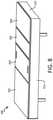
- FIG. 8is a perspective top view of a foundation in a lower position.
- FIG. 9is a perspective bottom view of the foundation of FIG. 8 at a foot of the foundation.
- FIG. 10is a perspective side view of a portion of the foundation of FIG. 8 .
- FIG. 11is a perspective side view of the foundation of FIG. 8 with a deck panel in an upper position.
- FIG. 12is a perspective side view of the foundation of FIG. 8 with the deck panel in a service position.
- FIG. 13is a perspective side view of the foundation of FIG. 8 with the deck panel in a service position and a compartment opened.
- FIGS. 14-16are perspective side view of a portion of the foundation of FIG. 8 with rails removed to better show interior components.
- FIG. 17is a perspective view of the foundation of FIG. 8 at a head of the foundation with a deck panel in a raised position.
- FIG. 18is a perspective view of the foundation of FIG. 8 at a head of the foundation with a deck panel in a service position.
- FIG. 1shows an example air bed system 100 that includes a mattress 112 .
- the mattress 112includes at least one air chamber 114 surrounded by a resilient border 116 and encapsulated by bed ticking 118 .
- the resilient border 116can comprise any suitable material, such as foam.
- the mattress 112can be a two chamber design having first and second fluid chambers, such as a first air chamber 114 A and a second air chamber 114 B.
- the mattress 112can include chambers for use with fluids other than air that are suitable for the application.
- the mattress 112can include a single air chamber 114 A or 114 B or multiple air chambers 114 A and 114 B.
- the first and second air chambers 114 A and 114 Bcan be in fluid communication with a pump 120 .
- the pump 120can be part of an air controller 124 , which can be in electrical communication with a remote control 122 .
- the air controller 124can include a wired or wireless communications interface for communicating with one or more devices, including the remote control 122 .
- the air controller 124can be configured to operate the pump 120 to cause increases and decreases in the fluid pressure of the first and second air chambers 114 A and 114 B based upon commands input by a user using the remote control 122 .
- the pump 120 and the air controller 124can be integrated into a common housing. In other embodiments, the air controller 124 and the pump 120 can be in separate housings.
- the remote control 122can include a display 126 , an output selecting mechanism 128 , a pressure increase button 129 , and a pressure decrease button 130 .
- the output selecting mechanism 128can allow the user to switch air flow generated by the pump 120 between the first and second air chambers 114 A and 114 B, thus enabling control of multiple air chambers with a single remote control 122 and a single pump 120 .
- the output selecting mechanism 128can by a physical control (e.g., switch or button) or an input control displayed on display 126 .
- separate remote control unitscan be provided for each air chamber and can each include the ability to control multiple air chambers.
- Pressure increase and decrease buttons 129 and 130can allow a user to increase or decrease the pressure, respectively, in the air chamber selected with the output selecting mechanism 128 . Adjusting the pressure within the selected air chamber can cause a corresponding adjustment to the firmness of the respective air chamber.
- the remote control 122can be omitted or modified as appropriate for an application.
- the air bed system 100can be controlled by a computer, tablet, smart phone, or other device in wired or wireless communication with the air bed system 100 .
- FIG. 2is a block diagram of an example of various components of an air bed system.
- the air controller 124can include the pump 120 , a power supply 134 , a processor 136 , a memory 137 , a switching mechanism 138 , and an analog to digital (A/D) converter 140 , an air manifold 143 (having valves 144 , 145 A, and 145 B), and one or more pressure transducers 146 .
- the switching mechanism 138can be, for example, a relay or a solid state switch.
- the pump 120can include a motor 142 .
- the pump 120can be fluidly connected to the pump manifold, which is fluidically connected with the first air chamber 114 A and the second air chamber 114 B via a first tube 148 A and a second tube 148 B, respectively.
- the first and second control valves 145 A and 145 Bcan be controlled by switching mechanism 138 , and are operable to regulate the flow of fluid between the pump 120 and first and second air chambers 114 A and 114 B, respectively.
- the pump 120 and the air controller 124can be provided and packaged as a single unit. In some alternative implementations, the pump 120 and the air controller 124 can be provided as physically separate units. In some implementations, the air controller 124 , the pump 120 , or both are integrated within or otherwise contained within a bed frame or bed support structure that supports the mattress 112 . In some implementations, the air controller 124 , the pump 120 , or both are located outside of a bed frame or bed support structure (as shown in the example in FIG. 1 ).
- the example air bed system 100 depicted in FIG. 2includes the two air chambers 114 A and 114 B and the single pump 120 .
- other implementationscan include an air bed system having two or more air chambers and one or more pumps incorporated into the air bed system to control the air chambers.
- a separate pumpcan be associated with each air chamber of the air bed system or a pump can be associated with multiple chambers of the air bed system.
- Separate pumpscan allow each air chamber to be inflated or deflated independently and simultaneously.
- additional pressure transducerscan also be incorporated into the air bed system such that, for example, a separate pressure transducer can be associated with each air chamber.
- the processor 136can, for example, send a decrease pressure command for one of the air chambers 114 A or 114 B, and the switching mechanism 138 can be used to convert the low voltage command signals sent by the processor 136 to higher operating voltages sufficient to operate the relief valve 144 of the pump 120 and open the control valve 145 A or 145 B. Opening the relief valve 144 can allow air to escape from the air chamber 114 A or 114 B through the respective air tube 148 A or 148 B.
- the pressure transducer 146can send pressure readings to the processor 136 via the A/D converter 140 .
- the A/D converter 140can receive analog information from pressure transducer 146 and can convert the analog information to digital information useable by the processor 136 .
- the processor 136can send the digital signal to the remote control 122 to update the display 126 in order to convey the pressure information to the user.
- one or more of the air chambers 114 A and 114 Bcan be deflated without opening the relief valve 144 as further described below.
- the processor 136can send an increase pressure command.
- the pump motor 142can be energized in response to the increase pressure command and send air to the designated one of the air chambers 114 A or 114 B through the air tube 148 A or 148 B via electronically operating the corresponding valve 145 A or 145 B.
- the pressure transducer 146can sense pressure within the air manifold 143 .
- the pressure transducer 146can send pressure readings to the processor 136 via the A/D converter 140 .
- the processor 136can use the information received from the A/D converter 140 to determine the difference between the actual pressure in air chamber 114 A or 114 B and the desired pressure.
- the processor 136can send the digital signal to the remote control 122 to update display 126 in order to convey the pressure information to the user.
- the mattress 112can be used with foundation, such as an adjustable foundation (not shown in FIG. 2 ).
- foundationsuch as an adjustable foundation (not shown in FIG. 2 ).
- the mattress 112can be positioned on and supported by an adjustable foundation that is configured to raise and lower portions of the mattress 112 , such as the head and foot of the mattress 112 .
- the remote control 122can one or more selections for actuating the adjustable foundation. Examples of such adjustable foundations are further described below.
- FIG. 3is a perspective view of a foundation 200 .
- the foundation 200can include one or more deck panels 202 , 204 , 206 , 208 , side rails 210 and 212 (the side rail 212 is not shown in FIG. 3 ), a foot rail 214 , and a head rail 216 (not shown in FIG. 3 ).
- the foundation 200can be an articulating foundation, such that one or more of the deck panels 202 , 204 , 206 , 208 are raised and lowered in response to actuating motors.
- the deck panel 202can be a head deck panel for raising and lowering a head of a mattress.
- the deck panel 204can be a back or hip deck panel that remains substantially stationary during actuation.
- the deck panel 206can be a thigh deck panel for raising a thigh section of the mattress at an angle.
- the deck panel 208can be a foot deck panel for raising and lowering a foot portion of the mattress.
- the deck panels 202 , 204 , 206 , 208can be connected to an articulation mechanism (not shown in FIG. 3 ) for articulating one or more of the deck panels 202 , 204 , 206 , 208 .
- the deck panel 204defines a pair of passages 218 and 220 which can accommodate connections between components below and above the deck panels 202 , 204 , 206 , 208 .
- one or more hosescan extend from a component, such as the air controller 124 , positioned below the deck panels 202 , 204 , 206 , 208 to a portion of a mattress positioned above the deck panels 202 , 204 , 206 , 208 , such as one or more inflatable mattress air chambers as described above.
- the passages 218 and 220can extend through the a non-articulating deck panel 204 so as to help conceal hoses extending therethrough, even when one or more of the deck panels 202 , 206 , 208 are articulated up.
- FIG. 4is a perspective view of the foundation 200 , with the deck panels 202 , 204 , 206 , 208 (shown in FIG. 3 ) removed, exposing interior components of the foundation 200 . With the deck panels 202 , 204 , 206 , 208 removed, inner portions of the head rail 216 and the side rail 212 can be viewed.
- FIG. 4also shows the foundation 200 having a sub frame 222 and an articulation mechanism 224 positioned in the foundation and at least partially concealed by the deck panels 202 , 204 , 206 , 208 and the rails 210 , 212 , 214 , 216 .
- the sub frame 222can provide structural support for other components of the foundation 200 , including the deck panels 202 , 204 , 206 , 208 , the rails 210 , 212 , 214 , 216 , and the articulation mechanism 224 .
- the deck panels 202 , 204 , 206 , 208can be connected to the sub frame 222 via the articulation mechanism 224 .
- the foundation 200can include a cover 226 near a foot of the foundation 200 for covering components contained within the foundation 200 at the foot of the foundation 200 .
- the cover 226can be hingedly connected to the sub frame 222 via an opening mechanism 228 .
- At least some components in the foundation 200can be substantially concealed by the cover 226 and the foot rail 214 when the cover 226 is in a closed position even when the deck panel 208 is raised to expose the cover 226 .
- FIG. 5is a perspective view of the foundation 200 , with the foot rail 214 also removed.
- the air controller 124(including the pump 120 ) and an actuation controller 260 can be positioned below the cover 226 .
- the cover 226can be pivoted open to expose and allow access to the air controller 124 and the actuation controller 260 to allow service of components contained within.
- FIG. 6is a perspective view of the foundation 200 , with the cover 226 and the side rail 210 also removed.
- FIG. 6shows a central power hub 230 , which can include a high voltage power system 232 and a low voltage power system 234 .
- the high voltage power system 232can include an AC (alternating current) power cord 236 which can extend from the foundation 200 to a power source, such as an electrical wall outlet.
- the high voltage power system 232can supply power to the air controller 124 and to the actuation controller 260 .
- the low voltage power system 234can extend from the actuation controller 260 to one or more additional components of the foundation, such as one or more actuation motors (not shown in FIG.
- the high voltage power system 232can be an AC power system that operates, for example, at 120V
- the low voltage power system 234can be a DC (direct current) power system that operates, for example, at one or more lower voltages than the high voltage power system.
- FIG. 6also shows air hoses 240 and 242 extending from the air controller 124 .
- the air hoses 240 and 242can extend along a perimeter of the foundation 200 to a central portion of the foundation 200 , and extend up through the passages 218 and 220 (shown in FIG. 3 ) to supply air for controlling pressure in air chambers of a mattress.
- the air hoses 240 and 242can include connectors 244 configured for quickly connecting and disconnecting at one or more end.
- Cords of the high voltage power system 232 and the low voltage power system 234can also extend along a perimeter of the foundation 200 and can also include connectors 246 configured for quickly connecting and disconnecting at one or more end.
- Componentssuch as the air controller 124 , the actuation controller 260 , the hoses 240 , 242 , and the central power hub 230 can be positioned within the foundation 200 in a manner that is substantially concealed from view but is also configured to be repeatably disassembled and reassembled. Components can be disconnected at one or more of the connectors 244 and 246 to be removed from the foundation 200 without necessarily requiring removal of extended length of hose or cable.
- FIG. 7is a perspective view of the foundation 200 , with the head rail 216 and the side rail 212 also removed.
- FIG. 7shows the sub frame 222 having a plurality of interconnected supports 248 , 250 , 252 , 254 , 256 .
- the supports 248 , 250 , 252 , 254 , 256can extend substantially in a horizontal plane.
- the supports 248 and 250can extend along at least part of a length of the foundation 200 , substantially parallel to the side rails 210 and 212 and spaced inward of the side rails 210 and 212 .
- the supports 252 and 254can extend along at least part of a width of the foundation 200 , substantially parallel to the head rail 216 and the foot rail 214 and spaced inward of the head rail 216 and the foot rail 214 .
- the supports 252 and 254can be positioned below and extending across the supports 248 and 250 to provide strength and rigidity for the sub frame 222 .
- the supports 248 and 250can have a substantially flat upper surface configured for supporting the deck panels 202 , 204 , 206 , 208 (shown in FIG. 3 ) when the deck panels 202 , 204 , 206 , 208 rest on the supports 248 and 250 .
- the support 256can extend from the support 252 in a cantilevered manner toward the foot of the bed.
- connection brackets 258can be connected to one or more of the supports 248 , 250 , 252 , 254 , 256 and be configured for allowing connection of the rails 210 , 212 , 214 , 216 to the supports 248 , 250 , 252 , 254 , 256 .
- the rails 210 , 212 , 214 , 216can combine to form a substantially continuous surround.
- the rails 210 , 212 , 214 , 216can be difficult to open, such as being designed not to be opened except during disassembly.
- the foundation 200can have access mechanisms that allow access for servicing components that do not require removal of the rails 210 , 212 , 214 , 216 .
- FIG. 8is a perspective top view of a foundation 300 .
- the foundation 300can have functions and features that are the same or similar as that described above with respect to foundation 200 (shown in FIGS. 3-7 ).
- the foundation 300can include one or more deck panels 302 , 304 , 306 , 308 , side rails 310 and 312 (the side rail 310 is not shown in FIG. 8 ), a foot rail 314 , and a head rail 316 (not shown in FIG. 8 ).
- the foundation 300can be an articulating foundation, such that one or more of the deck panels 302 , 304 , 306 , 308 are raised and lowered in response to actuating motors.
- the deck panels 302 , 304 , 306 , and 308can be interconnected by one or more hinges that connect adjacent deck panels.
- FIG. 8shows the foundation and its deck panels 302 , 304 , 306 , 308 in a lower, substantially flat position.
- the rails 310 , 312 , 314 , and 316can form a substantially continuous surround.
- FIG. 9is a perspective bottom view of a portion of the foundation 300 at a foot of the foundation 300 .
- the foundation 300can include a compartment 318 with a cover 320 and one or more support platforms 322 .
- One or more componentscan be positioned in the compartment 318 to be raised off the floor and positioned in the foundation 300 .
- the air controller 124shown in FIGS. 1 and 2
- the compartment 318can be positioned at or near a foot of the foundation 300 .
- the foundation 300can include a sub frame 322 for providing a supporting structure for other components of the foundation 300 .
- Actuators 324 and 326can be connected to the sub frame 322 for raising and lowering portions of the foundation 300 .
- the actuators 324 and 326can be electrically powered actuators having electrical motors 328 and 330 , respectively (the motor 328 is shown in FIGS. 17-18 ).
- the actuator 324can be operably connected to one or more lever arms 332 with one or more rollers 334 attached thereto.
- the roller 334can abut a bottom surface of the deck panel 306 for imparting a lifting force on the deck panel 306 in response to actuation of the lever arm 332 by the actuator 324 .
- the foundation 300can also include one or more linkage arms 336 extending from and hingedly connected to the sub frame 322 and the deck panel 308 .
- the deck panel 306can be hingedly connected to both of the deck panels 304 and 308 to effectively act as a second linkage arm.
- the deck panel 308can function as a coupler between the deck panel 306 and the linkage arms 336 so as to form a four-bar-linkage system. Accordingly, when the actuator 324 causes the lever arm 332 to press the roller 334 against the deck panel 306 , the resulting force can lift both of the deck panels 306 and 308 , where the motion of the deck panel 308 is passively guided by the linkage arms 336 .
- FIG. 10is a perspective side view of a portion of the foundation 300 at a foot of the foundation 300 . Certain components including the side rail 312 have been removed to better illustrate other components positioned therein, including the linkage arms 336 pivotably connected to both the deck panel 308 and the sub frame 322 .
- FIG. 11is a perspective side view of the foundation 300 with the deck panel 308 in an upper position.
- the deck panels 306 and 308can be raised from their positions as shown in FIG. 8 , where the deck panels 306 and 308 are substantially flat.
- the deck panels 306 and 308can be raised by the actuator 324 (shown in FIG. 9 ) from the position shown in FIG. 8 to the position shown in FIG. 11 , or to positions in-between the illustrated positions, in response to a user request.
- the upper position illustrated in FIG. 11can be a maximum articulable position for normal operation.
- the foundation 300could be mechanically stopped from actuating further, such as by blocking further rotation by the lever arms 332 .
- the actuation controller 260can be configured to limit actuation of the lever arms 332 to a certain maximum.
- FIG. 12is a perspective side view of the foundation 300 with the deck panel 308 in a service position.
- the service positioncan be further than the upper position and can be configured to be far enough to allow for access to interior components of the foundation 300 for servicing of the foundation.
- the service positioncan be a position that is further than the maximum position articulable via the actuator 324 (shown in FIG. 9 ), which can be achieved manually.
- the actuator 324shown in FIG. 9
- a usercan manually push on the deck panel 308 to force the deck panel 306 to be lifted off the rollers 334 , such that the bottom of the deck panel 306 is spaced from the rollers 334 . Accordingly, neither of the deck panels 306 and 308 need to be in contact with or otherwise connected to an actuator mechanism in the service position.
- the foundation 300can include an actuator mechanism that remains connected to one or more of the deck panels 306 and 308 in the service position.
- the actuator 324can first actuate the lever arms 332 and rollers 334 to the upper position, so as to also raise the deck panels 306 and 308 to the upper position. The user can then push the deck panels 306 and 308 from the upper position to the service position. In other example, the user can push the deck panels 306 and 308 to the service position from a position other than the upper position, such as from the lower position or from a position between the lower position and the upper position.
- the linkage arms 336can be rotated to a position that is less than vertical in the lower and upper positions (as shown in FIGS. 9-11 ) and can be over-rotated to a position that is past vertical in the service position (as shown in FIG. 12 ). Rotating the linkage arms 336 past vertical can allow the deck panels 306 and 308 to remain elevated in the service position, without requiring the user to keep holding the deck panels, due to force of gravity on the deck panel 308 pulling downward to bias the deck panel 308 to the elevated position.
- a mattress supported by the foundation 300can be removed from the foundation 300 prior to moving the deck panels 306 and 308 to the service position. Removing the mattress can make it easier to push the deck panels 306 and 308 without the additional weight of the mattress. In other embodiments, the deck panels 306 and 308 can be pushed to the service position even with the weight of a mattress that remains on the foundation 300 .
- FIG. 13is a perspective side view of the foundation 300 with the deck panel 308 in the service position and with the compartment 318 open.
- the cover 320can be opened to expose serviceable components in the compartment 318 .
- the air controller 124can be positioned in the compartment, and can be accessed for repair or replacement by moving the deck panels 306 and 308 to the service position and raising the cover 320 of the compartment 318 .
- FIGS. 14-16are perspective side view of a portion of the foundation 300 with the rails 310 , 312 , 314 , and 316 removed to better show interior components.
- FIG. 14shows the foundation 300 in the lower position, with the deck panels 302 , 304 , 306 , and 308 lying substantially flat so as to support a mattress lying flat on the foundation 300 .
- FIG. 15shows the foundation 300 articulated to the upper position so as to support a mattress lying on the foundation 300 with the foot end of the mattress elevated.
- FIG. 16shows the foundation 300 in the service position, which has the deck panels 306 and 308 rotated even further than in the upper position to create easier access to an interior of the foundation 300 .
- FIGS. 14-16show one example of movement of the deck panel 306 , the deck panel 308 , and the linkage arms 336 when moving between the lower, upper, and service positions.
- FIGS. 14-16also show an example of movement of the actuator 324 , the linkage arm 332 , and the roller 334 in the lower, upper, and service positions, including that the actuator 324 , the linkage arm 332 , and the roller 334 can be stationary when the deck panels 306 and 308 are moved to the service position.
- the one or more linkage arms 336can be angled less than vertical in the lower and upper positions and can be over-rotated past vertical in the service position.
- the linkage arms 336can have an angle between 0 and 40 degrees with respect to horizontal in the lower position
- the linkage arms 336can have an angle between 40 and 80 degrees with respect to horizontal in the upper position
- the linkage arms 336can be over-rotated to a position with an angle between 100 and 140 degrees with respect to horizontal in the service position.
- the linkage arms 336can have an angle between 17 and 20 degrees with respect to horizontal in the lower position, the linkage arms 336 can have an angle between 59 and 63 degrees with respect to horizontal in the upper position, and the linkage arms 336 can be over-rotated to a position with an angle between 116 and 119 degrees with respect to horizontal in the service position.
- the foundation 300can be an adjustable foundation with deck panels that can be raised to a service position to allow for service access at a foot of the foundation 300 .
- the foundation 300can also include a service position that allows for service access at a head of the foundation 300 , as further described below with respect to FIGS. 17-18 .
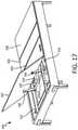
- FIGS. 17 and 18are perspective views of the foundation 300 at a head of the foundation 300 .
- FIG. 17shows the deck panel 302 raised to an upper position and
- FIG. 18shows the deck panel 302 in a service position.
- the deck panel 302can be raised from a lower position as shown in FIG. 8 , where the deck panel 302 , as well as one, more, or all of the deck panels 304 , 306 , and 308 , are substantially flat.
- the deck panel 302can be raised by the actuator 326 from the position shown in FIG. 8 to the position shown in FIG. 17 , or to positions in-between the illustrated positions, in response to a user request.
- the electrical motor 330 of the actuator 326can drive the actuator 326 to extend and to pivot one or more lever arms 338 that are operably attached to the actuator 326 .
- the lever arms 338can have rollers 340 attached thereto, which can contact a bottom side of the deck panel 302 . As the actuator 326 pivots the lever arms 338 upwards, the lever arms 338 and rollers 340 can raise the deck panel 302 to the upper position shown in FIG. 17 .
- the upper position illustrated in FIG. 17can be a maximum articulable position for normal operation.
- the foundation 300can be mechanically stopped from actuating further, such as by blocking further rotation by the lever arms 338 .
- the actuation controller 260can be configured to limit actuation of the lever arms 338 to a certain maximum.
- the deck panel 302can have a service position that is further than the upper position and that can be configured to be far enough to allow for access to interior components of the foundation 300 for servicing of the foundation 300 .
- the service position of the deck panel 302can be a position that is further than the maximum position articulable via the actuator 324 (such as shown in FIG. 17 ), which can be achieved manually.
- the actuator 324such as shown in FIG. 17
- a usercan manually push on the deck panel 302 to be lifted off the rollers 340 , such that the bottom of the deck panel 302 is spaced from the rollers 340 .
- the deck panel 302need not be in contact with or otherwise connected to an actuator mechanism in the service position.
- the foundation 300can include an actuator mechanism that remains connected to the deck panel 302 in the service position.
- the service position of the deck panel 302can be much further than the upper position.
- the deck panel 302can have a service position in which the deck panel is rotated substantially 180 degrees from its lower position. The deck panel 302 can be rotated so far as to lay substantially flat against the deck panel 304 .
- the actuator 326first can first actuate the lever arms 338 and rollers 340 to the upper position, so as to also raise the deck panel 302 to the upper position. The user can then push the deck panel 302 from the upper position to the service position. In other example, the user can push the deck panel 302 to the service position from a position other than the upper position, such as from the lower position or from a position between the lower position and the upper position.
- the foundation 300can have one or more service positions to allow for service access of components in the foundation 300 .
- One or more of the deck panels 302 , 304 , 306 , and 308can be raised to allow for service access at a head of the foundation 300 , at a foot of the foundation 300 , or both at the head and the foot of the foundation 300 .
- the foundation 300can include the air controller 124 positioned in the compartment 318 at or near the foot of the foundation 300 , while one or more other components can be positioned at or near the head and/or center of the foundation 300 .
- the actuation controller 260can be positioned at a location under the deck panel 304 , which can be more easily serviced by moving the deck panel 302 to a service position.
- the actuators 324 and 326can be more easily serviced by having service access at both the head and the foot of the foundation 300 .
- the foundationcan be used with a bed system having a mattress that does not include adjustable air chambers.
- various components of the foundationcan be shaped differently than as illustrated.
- the figuresshow one example of frame components and actuation components suitable for the application.
- the foundationcan be modified to include different frame and actuation components that are suitable for the application of providing service access as described herein.
- the foundationcan also have more or fewer deck panels than as illustrated.
- different aspects of the different embodiments of foundations, mattresses, and other bed system components described abovecan be combined while other aspects as suitable for the application. Accordingly, other embodiments are within the scope of the following claims.
Landscapes
- Health & Medical Sciences (AREA)
- General Health & Medical Sciences (AREA)
- Nursing (AREA)
- Invalid Beds And Related Equipment (AREA)
Abstract
Description
Claims (19)
Priority Applications (4)
| Application Number | Priority Date | Filing Date | Title |
|---|---|---|---|
| US16/930,680US11229297B2 (en) | 2016-11-09 | 2020-07-16 | Adjustable foundation with service position |
| US17/582,253US11786044B2 (en) | 2016-11-09 | 2022-01-24 | Adjustable foundation with service position |
| US18/367,634US12096856B2 (en) | 2016-11-09 | 2023-09-13 | Adjustable foundation for a mattress |
| US18/893,828US20250082108A1 (en) | 2016-11-09 | 2024-09-23 | Adjustable Foundation with Service Position |
Applications Claiming Priority (3)
| Application Number | Priority Date | Filing Date | Title |
|---|---|---|---|
| US201662419710P | 2016-11-09 | 2016-11-09 | |
| US15/806,810US10729253B1 (en) | 2016-11-09 | 2017-11-08 | Adjustable foundation with service position |
| US16/930,680US11229297B2 (en) | 2016-11-09 | 2020-07-16 | Adjustable foundation with service position |
Related Parent Applications (1)
| Application Number | Title | Priority Date | Filing Date |
|---|---|---|---|
| US15/806,810ContinuationUS10729253B1 (en) | 2016-11-09 | 2017-11-08 | Adjustable foundation with service position |
Related Child Applications (1)
| Application Number | Title | Priority Date | Filing Date |
|---|---|---|---|
| US17/582,253ContinuationUS11786044B2 (en) | 2016-11-09 | 2022-01-24 | Adjustable foundation with service position |
Publications (2)
| Publication Number | Publication Date |
|---|---|
| US20210037986A1 US20210037986A1 (en) | 2021-02-11 |
| US11229297B2true US11229297B2 (en) | 2022-01-25 |
Family
ID=71838759
Family Applications (5)
| Application Number | Title | Priority Date | Filing Date |
|---|---|---|---|
| US15/806,810Active2038-06-03US10729253B1 (en) | 2016-11-09 | 2017-11-08 | Adjustable foundation with service position |
| US16/930,680ActiveUS11229297B2 (en) | 2016-11-09 | 2020-07-16 | Adjustable foundation with service position |
| US17/582,253ActiveUS11786044B2 (en) | 2016-11-09 | 2022-01-24 | Adjustable foundation with service position |
| US18/367,634ActiveUS12096856B2 (en) | 2016-11-09 | 2023-09-13 | Adjustable foundation for a mattress |
| US18/893,828PendingUS20250082108A1 (en) | 2016-11-09 | 2024-09-23 | Adjustable Foundation with Service Position |
Family Applications Before (1)
| Application Number | Title | Priority Date | Filing Date |
|---|---|---|---|
| US15/806,810Active2038-06-03US10729253B1 (en) | 2016-11-09 | 2017-11-08 | Adjustable foundation with service position |
Family Applications After (3)
| Application Number | Title | Priority Date | Filing Date |
|---|---|---|---|
| US17/582,253ActiveUS11786044B2 (en) | 2016-11-09 | 2022-01-24 | Adjustable foundation with service position |
| US18/367,634ActiveUS12096856B2 (en) | 2016-11-09 | 2023-09-13 | Adjustable foundation for a mattress |
| US18/893,828PendingUS20250082108A1 (en) | 2016-11-09 | 2024-09-23 | Adjustable Foundation with Service Position |
Country Status (1)
| Country | Link |
|---|---|
| US (5) | US10729253B1 (en) |
Cited By (9)
| Publication number | Priority date | Publication date | Assignee | Title |
|---|---|---|---|---|
| US11857076B2 (en) | 2013-03-11 | 2024-01-02 | Sleep Number Corporation | Adjustable bed system with foundations having first and second configurations |
| US11937705B2 (en) | 2016-10-28 | 2024-03-26 | Sleep Number Corporation | Air bed system with an air manifold |
| US12004651B2 (en) | 2020-12-18 | 2024-06-11 | Sleep Number Corporation | Bed foundation adjustment controls |
| USD1032243S1 (en) | 2022-01-03 | 2024-06-25 | Sleep Number Corporation | Mattress |
| US12053093B2 (en) | 2019-11-15 | 2024-08-06 | Sleep Number Corporation | Zipper mattress attachment |
| US12171339B2 (en) | 2014-04-15 | 2024-12-24 | Sleep Number Corporation | Sleep system with modular foundation |
| US12392332B2 (en) | 2016-10-28 | 2025-08-19 | Sleep Number Corporation | Pump housing with vertically supported vibration isolators |
| US12414638B2 (en) | 2021-07-19 | 2025-09-16 | Sleep Number Corporation | Mattress with stacked air chambers |
| US12419436B2 (en) | 2021-07-19 | 2025-09-23 | Sleep Number Corporation | Multi-air chamber mattress with localized support |
Families Citing this family (26)
| Publication number | Priority date | Publication date | Assignee | Title |
|---|---|---|---|---|
| US8332975B2 (en) | 2009-08-31 | 2012-12-18 | Gentherm Incorporated | Climate-controlled topper member for medical beds |
| US10674832B2 (en) | 2013-12-30 | 2020-06-09 | Sleep Number Corporation | Inflatable air mattress with integrated control |
| EP3242576A4 (en) | 2015-01-05 | 2018-07-25 | Select Comfort Corporation | Bed with user occupancy tracking |
| US10149549B2 (en) | 2015-08-06 | 2018-12-11 | Sleep Number Corporation | Diagnostics of bed and bedroom environment |
| US10539170B2 (en) | 2015-12-31 | 2020-01-21 | Sleep Number Corporation | Foundation and frame for bed |
| US10729253B1 (en)* | 2016-11-09 | 2020-08-04 | Sleep Number Corporation | Adjustable foundation with service position |
| USD932808S1 (en) | 2016-11-09 | 2021-10-12 | Select Comfort Corporation | Mattress |
| US11140999B2 (en) | 2016-11-09 | 2021-10-12 | Select Comfort Corporation | Bed with magnetic couplers |
| US10772438B2 (en) | 2017-08-23 | 2020-09-15 | Sleep Number Corporation | Air system for a bed |
| US10957335B2 (en) | 2017-12-28 | 2021-03-23 | Sleep Number Corporation | Home automation having user privacy protections |
| CN112839566A (en) | 2018-03-07 | 2021-05-25 | 数眠公司 | Home-Based Stress Test |
| AU2019379575A1 (en) | 2018-11-14 | 2020-11-26 | Sleep Number Corporation | Using force sensors to determine sleep parameters |
| US11690461B2 (en) | 2018-12-31 | 2023-07-04 | Sleep Number Corporation | Home automation with features to improve sleep |
| USD968436S1 (en) | 2019-01-08 | 2022-11-01 | Sleep Number Corporation | Display screen or portion thereof with graphical user interface |
| US20200221882A1 (en)* | 2019-01-10 | 2020-07-16 | Nisco Co., Ltd | Adjustable bed system having fans |
| CN112367906B (en) | 2019-04-08 | 2024-12-20 | 数眠公司 | Systems for sensing and controlling the bed environment |
| JP7530837B2 (en) | 2019-04-16 | 2024-08-08 | スリープ ナンバー コーポレイション | A pillow with wireless charging capabilities |
| USD916745S1 (en) | 2019-05-08 | 2021-04-20 | Sleep Number Corporation | Display screen or portion thereof with graphical user interface |
| CN114929072A (en) | 2020-01-03 | 2022-08-19 | 数眠公司 | Bed gas flow and temperature control |
| CN113133605A (en)* | 2020-01-20 | 2021-07-20 | 麒盛科技股份有限公司 | Intelligent bed body structure |
| WO2021178353A1 (en) | 2020-03-02 | 2021-09-10 | Sleep Number Corporation | Bed having user context sensing features |
| JP7691999B2 (en) | 2020-04-01 | 2025-06-12 | スリープ ナンバー コーポレイション | Systems and methods for remote patient screening and triage - Patents.com |
| US12022954B2 (en)* | 2021-02-11 | 2024-07-02 | Motomotion China Corporation | Ready to assemble structural system for a bed |
| US11832728B2 (en) | 2021-08-24 | 2023-12-05 | Sleep Number Corporation | Controlling vibration transmission within inflation assemblies |
| CN114028102B (en)* | 2021-12-06 | 2025-03-14 | 惠州富乐士智能家居有限公司 | A chair bed capable of being adjusted in multiple directions |
| TWI803397B (en)* | 2022-07-21 | 2023-05-21 | 施權航 | electric bed |
Citations (102)
| Publication number | Priority date | Publication date | Assignee | Title |
|---|---|---|---|---|
| US3465373A (en) | 1967-12-06 | 1969-09-09 | Harriet A Wilson | Hospital bed |
| US4766628A (en) | 1986-01-21 | 1988-08-30 | Walker Robert A | Air mattress with filler check valve and cap therefor |
| US4788729A (en) | 1985-04-14 | 1988-12-06 | Walker Robert A | Air mattress with audible pressure relief valve |
| USD300194S (en) | 1984-10-12 | 1989-03-14 | Walker Robert A | Air mattress |
| US4829616A (en) | 1985-10-25 | 1989-05-16 | Walker Robert A | Air control system for air bed |
| US4897890A (en) | 1983-01-05 | 1990-02-06 | Walker Robert A | Air control system for air bed |
| US4908895A (en) | 1989-03-20 | 1990-03-20 | Walker Robert A | Air mattress |
| USD313973S (en) | 1988-12-30 | 1991-01-22 | Walker Robert A | Hand-held control unit for the operation of an inflatable air mattress |
| US4991244A (en) | 1990-01-05 | 1991-02-12 | Walker Robert A | Border for air bed |
| US5020173A (en) | 1989-01-24 | 1991-06-04 | Dreyer Jr John F | Bedstead storage box |
| US5072463A (en) | 1991-04-11 | 1991-12-17 | Willis William J | EZ access bed |
| US5095561A (en) | 1991-05-09 | 1992-03-17 | Green Kenneth J | Invalid bed |
| US5144706A (en) | 1990-12-03 | 1992-09-08 | Walker Robert A | Bed foundation |
| US5170522A (en) | 1991-12-16 | 1992-12-15 | Select Comfort Corporation | Air adjustable bed |
| USD368475S (en) | 1994-11-01 | 1996-04-02 | Select Comfort Corporation | Hand held remote control unit |
| US5509154A (en) | 1994-11-01 | 1996-04-23 | Select Comfort Corporation | Air control system for an air bed |
| US5564140A (en) | 1994-07-22 | 1996-10-15 | Select Comfort Corporation | Frame assembly for supporting a mattress |
| US5642546A (en) | 1995-09-19 | 1997-07-01 | Select Comfort Corporation | Inflatable mattress with improved border support wall |
| US5715548A (en) | 1994-01-25 | 1998-02-10 | Hill-Rom, Inc. | Chair bed |
| US5904172A (en) | 1997-07-28 | 1999-05-18 | Select Comfort Corporation | Valve enclosure assembly |
| US6012186A (en) | 1997-04-29 | 2000-01-11 | Hill-Rom Compnay, Inc. | Mattress articulation structure |
| US6079065A (en) | 1998-04-22 | 2000-06-27 | Patmark Company, Inc. | Bed assembly with an air mattress and controller |
| US6108844A (en) | 1998-03-11 | 2000-08-29 | Sleeptec, Inc. | Air mattress for a sleeper sofa |
| US6163904A (en) | 1998-12-08 | 2000-12-26 | Everett Associates, Inc. | Articulated table for supporting a person |
| US6202239B1 (en) | 1998-02-25 | 2001-03-20 | Select Comfort Corp. | Multi-zone support |
| US6209157B1 (en) | 1998-04-22 | 2001-04-03 | Patmark Company, Inc. | Articulating bed frame |
| US6397419B1 (en) | 1999-03-10 | 2002-06-04 | Select Comfort Corporation | System and method for sleep surface adjustment |
| US6686711B2 (en) | 2000-11-15 | 2004-02-03 | Comfortaire Corporation | Air mattress control system and method |
| US6708357B2 (en) | 2002-01-14 | 2004-03-23 | Select Comfort Corporation | Corner piece for a soft-sided mattress |
| US6763541B2 (en) | 2001-06-07 | 2004-07-20 | Select Comfort Corporation | Interactive air bed |
| US6804848B1 (en) | 2003-03-14 | 2004-10-19 | Comfortaire Corporation | High-profile mattress having an upper low-profile module with an air posturizing sleep surface |
| US6832397B2 (en) | 2000-07-07 | 2004-12-21 | Select Comfort Corporation | Bed foundation |
| USD502929S1 (en) | 2004-03-02 | 2005-03-15 | Select Comfort Corporation | Remote control |
| US6883191B2 (en) | 2000-07-07 | 2005-04-26 | Select Comfort Corporation | Leg and bracket assembly for a bed foundation |
| US20070245489A1 (en) | 2004-06-23 | 2007-10-25 | Martin Boudreau | Folding Bed |
| US20080077020A1 (en) | 2006-09-22 | 2008-03-27 | Bam Labs, Inc. | Method and apparatus for monitoring vital signs remotely |
| US20080262657A1 (en) | 2007-04-17 | 2008-10-23 | L&P Property Management Company | System and method for controlling adjustable furniture |
| US20080276373A1 (en) | 2006-06-29 | 2008-11-13 | Alain Clenet | Adjustable bed frame assembly |
| US7865988B2 (en) | 2004-03-16 | 2011-01-11 | Select Comfort Corporation | Sleeping surface having two longitudinally connected bladders with a support member |
| US20110144455A1 (en) | 2007-08-31 | 2011-06-16 | Bam Labs, Inc. | Systems and methods for monitoring a subject at rest |
| US20110247138A1 (en) | 2010-04-12 | 2011-10-13 | Ergomotion, Inc. | Bed frame for an adjustable bed |
| US8099807B2 (en) | 2004-09-22 | 2012-01-24 | Hill-Rom Services, Inc. | Storable foot section for a bed |
| US20120124752A1 (en) | 2005-01-14 | 2012-05-24 | Smart Medical Technology, Inc. | Body transport apparatus |
| US8209801B2 (en) | 2009-10-28 | 2012-07-03 | Ruoey Lung Enterprise Corp. | Leg lift mechanism for electric bed or chair |
| US8209800B2 (en) | 2009-10-28 | 2012-07-03 | Ruoey Lung Enterprise Corp. | Single driver connecting structure for an electric bed or chair |
| US8336369B2 (en) | 2007-05-24 | 2012-12-25 | Select Comfort Corporation | System and method for detecting a leak in an air bed |
| US8444558B2 (en) | 2009-01-07 | 2013-05-21 | Bam Labs, Inc. | Apparatus for monitoring vital signs having fluid bladder beneath padding |
| US8484773B2 (en) | 2009-07-21 | 2013-07-16 | Ipc Holdings, Inc. | Combined bed/chair transporter with leg lift |
| USD691118S1 (en) | 2013-03-14 | 2013-10-08 | Select Comfort Corporation | Remote control |
| USD697874S1 (en) | 2013-03-15 | 2014-01-21 | Select Comfort Corporation | Remote control |
| USD698338S1 (en) | 2013-03-14 | 2014-01-28 | Select Comfort Corporation | Remote control |
| US8672853B2 (en) | 2010-06-15 | 2014-03-18 | Bam Labs, Inc. | Pressure sensor for monitoring a subject and pressure sensor with inflatable bladder |
| USD701536S1 (en) | 2013-07-26 | 2014-03-25 | Select Comfort Corporation | Air pump |
| US8769747B2 (en) | 2008-04-04 | 2014-07-08 | Select Comfort Corporation | System and method for improved pressure adjustment |
| US8806682B2 (en) | 2004-07-30 | 2014-08-19 | Hill-Rom Services, Inc. | Advanced articulation system and mattress support for a bed |
| US20140250597A1 (en) | 2013-03-11 | 2014-09-11 | Select Comfort Corporation | Adjustable bed foundation system with built-in self-test |
| US20140277822A1 (en) | 2013-03-14 | 2014-09-18 | Rob Nunn | Inflatable air mattress sleep environment adjustment and suggestions |
| US20140259418A1 (en) | 2013-03-14 | 2014-09-18 | Rob Nunn | Inflatable air mattress with light and voice controls |
| US20140259433A1 (en) | 2013-03-14 | 2014-09-18 | Rob Nunn | Inflatable air mattress alarm and monitoring system |
| US20140277611A1 (en) | 2013-03-14 | 2014-09-18 | Rob Nunn | Inflatable air mattress system architecture |
| US20140277778A1 (en) | 2013-03-14 | 2014-09-18 | Rob Nunn | Inflatable air mattress autofill and off bed pressure adjustment |
| US8893339B2 (en) | 2013-03-14 | 2014-11-25 | Select Comfort Corporation | System and method for adjusting settings of a bed with a remote control |
| US8909378B2 (en) | 2006-09-14 | 2014-12-09 | Martin B Rawls-Meehan | Adjustable bed position control |
| US8910328B2 (en) | 2012-07-20 | 2014-12-16 | Ergomotion, Inc. | Articulating bed with flexible mattress support |
| US20150007393A1 (en) | 2013-07-02 | 2015-01-08 | Select Comfort Corporation | Controller for multi-zone fluid chamber mattress system |
| US20150025327A1 (en) | 2013-07-18 | 2015-01-22 | Bam Labs, Inc. | Device and Method of Monitoring a Position and Predicting an Exit of a Subject on or from a Substrate |
| US8966689B2 (en) | 2012-11-19 | 2015-03-03 | Select Comfort Corporation | Multi-zone fluid chamber and mattress system |
| US8973183B1 (en) | 2014-01-02 | 2015-03-10 | Select Comfort Corporation | Sheet for a split-top adjustable bed |
| US8984687B2 (en) | 2013-03-14 | 2015-03-24 | Select Comfort Corporation | Partner snore feature for adjustable bed foundation |
| US20150182399A1 (en) | 2014-01-02 | 2015-07-02 | Select Comfort Corporation | Adjustable bed system with split head and split foot configuration |
| US20150182397A1 (en) | 2014-01-02 | 2015-07-02 | Select Comfort Corporation | Adjustable bed system having split-head and joined foot configuration |
| US20150182418A1 (en) | 2014-01-02 | 2015-07-02 | Select Comfort Corporation | Massage furniture item and method of operation |
| USD737250S1 (en) | 2013-03-14 | 2015-08-25 | Select Comfort Corporation | Remote control |
| US9119753B2 (en) | 2008-06-27 | 2015-09-01 | Kreg Medical, Inc. | Bed with modified foot deck |
| US9131781B2 (en) | 2012-12-27 | 2015-09-15 | Select Comfort Corporation | Distribution pad for a temperature control system |
| US20150290059A1 (en) | 2014-04-15 | 2015-10-15 | Select Comfort Corporation | Adjustable bed system |
| US20160100696A1 (en) | 2014-10-10 | 2016-04-14 | Select Comfort Corporation | Bed having logic controller |
| US20160120327A1 (en)* | 2013-05-13 | 2016-05-05 | Paramount Bed Co., Ltd. | Bed apparatus |
| US9370457B2 (en) | 2013-03-14 | 2016-06-21 | Select Comfort Corporation | Inflatable air mattress snoring detection and response |
| US20160193095A1 (en) | 2013-09-06 | 2016-07-07 | Stryker Corporation | Patient support usable with bariatric patients |
| US20160192886A1 (en) | 2015-01-05 | 2016-07-07 | Select Comfort Corporation | Bed with User Occupancy Tracking |
| US20160206488A1 (en) | 2015-01-19 | 2016-07-21 | Sino Europe Gmbh & Co. Kg | Adjustable slatted bed base |
| US20160242562A1 (en) | 2015-02-24 | 2016-08-25 | Select Comfort Corporation | Mattress with Adjustable Firmness |
| US9510688B2 (en) | 2013-03-14 | 2016-12-06 | Select Comfort Corporation | Inflatable air mattress system with detection techniques |
| US20160367039A1 (en) | 2015-06-16 | 2016-12-22 | Sleepiq Labs Inc. | Device and Method of Automated Substrate Control and Non-Intrusive Subject Monitoring |
| US20170003666A1 (en) | 2015-07-02 | 2017-01-05 | Select Comfort Corporation | Automation for improved sleep quality |
| US20170035212A1 (en) | 2015-08-06 | 2017-02-09 | Select Comfort Corporation | Diagnostics of bed and bedroom environment |
| US9730524B2 (en) | 2013-03-11 | 2017-08-15 | Select Comfort Corporation | Switching means for an adjustable foundation system |
| US9770114B2 (en) | 2013-12-30 | 2017-09-26 | Select Comfort Corporation | Inflatable air mattress with integrated control |
| US20170354268A1 (en) | 2013-12-30 | 2017-12-14 | Select Comfort Corporation | Inflatable Air Mattress With Integrated Control |
| USD809843S1 (en) | 2016-11-09 | 2018-02-13 | Sleep Number Corporation | Bed foundation |
| USD812393S1 (en) | 2016-09-15 | 2018-03-13 | Sleep Number Corporation | Bed |
| US9918555B2 (en) | 2015-07-07 | 2018-03-20 | L&P Property Management Company | Adjustable bed with storage compartment |
| US20180116419A1 (en) | 2016-10-28 | 2018-05-03 | Select Comfort Corporation | Air Controller With Vibration Isolators |
| US20180116415A1 (en) | 2016-10-28 | 2018-05-03 | Select Comfort Corporation | Bed with foot warming system |
| US20180119686A1 (en) | 2016-10-28 | 2018-05-03 | Select Comfort Corporation | Pump With Vibration Isolators |
| US20180116418A1 (en) | 2016-10-28 | 2018-05-03 | Select Comfort Corporation | Noise Reducing Plunger |
| US20180125260A1 (en) | 2016-11-09 | 2018-05-10 | Select Comfort Corporation | Bed With Magnetic Couplers |
| US20180125259A1 (en) | 2016-11-09 | 2018-05-10 | Select Comfort Corporation | Bed With Magnetic Couplers |
| US20190059603A1 (en) | 2017-08-23 | 2019-02-28 | Sleep Number Corporation | Air system for a bed |
| US10342358B1 (en) | 2014-10-16 | 2019-07-09 | Sleep Number Corporation | Bed with integrated components and features |
| US10729253B1 (en) | 2016-11-09 | 2020-08-04 | Sleep Number Corporation | Adjustable foundation with service position |
Family Cites Families (24)
| Publication number | Priority date | Publication date | Assignee | Title |
|---|---|---|---|---|
| US4644597A (en) | 1983-05-09 | 1987-02-24 | Dynatech, Inc. | Air mattress with pressure relief valve |
| US20050204475A1 (en) | 2004-03-16 | 2005-09-22 | Select Comfort Corporation | Sleeping surface having two longitudinally connected bladders |
| DE102004019144B3 (en)* | 2004-04-21 | 2005-09-22 | Barthelt, Hans-Peter, Dipl.-Ing. | Nursing bed with improved lift |
| US20050235417A1 (en) | 2004-04-26 | 2005-10-27 | Select Comfort Corporation | Knock down bed foundation |
| US20080052830A1 (en) | 2006-08-30 | 2008-03-06 | Select Comfort Corporation | Bed foundation with drop-in unit |
| US20100043148A1 (en) | 2008-08-21 | 2010-02-25 | Comfortaire Corporation | Air mattress internal support structure |
| CN201542119U (en)* | 2009-06-23 | 2010-08-11 | 许汉忠 | Chair capable of actively supporting human body spine curve |
| US9314118B2 (en) | 2011-07-19 | 2016-04-19 | Jiajing Usa, Inc. | Comfort customizable pillow |
| US9578941B2 (en) | 2013-10-21 | 2017-02-28 | Select Comfort Corporation | Tablet or laptop support cushion |
| USD728254S1 (en) | 2014-05-20 | 2015-05-05 | Select Comfort Corporation | Tablet or laptop support cushion |
| US9924813B1 (en) | 2015-05-29 | 2018-03-27 | Sleep Number Corporation | Bed sheet system |
| US10539170B2 (en) | 2015-12-31 | 2020-01-21 | Sleep Number Corporation | Foundation and frame for bed |
| US10575654B2 (en) | 2016-10-28 | 2020-03-03 | Sleep Number Corporation | Air manifold |
| USD932808S1 (en) | 2016-11-09 | 2021-10-12 | Select Comfort Corporation | Mattress |
| US11001447B2 (en) | 2018-09-05 | 2021-05-11 | Sleep Number Corporation | Lifting furniture |
| CA3103491A1 (en) | 2019-06-03 | 2020-12-10 | Sleep Number Corporation | Mattress covering |
| US11497322B2 (en) | 2019-11-15 | 2022-11-15 | Sleep Number Corporation | Zipper mattress attachment |
| CA3193916A1 (en) | 2020-12-18 | 2022-06-23 | Sleep Number Corporation | Bed foundation adustment controls |
| EP4312667A1 (en) | 2021-05-20 | 2024-02-07 | Sleep Number Corporation | Hybrid mattress |
| US12414638B2 (en) | 2021-07-19 | 2025-09-16 | Sleep Number Corporation | Mattress with stacked air chambers |
| EP4373359A1 (en) | 2021-07-19 | 2024-05-29 | Sleep Number Corporation | Multi-air chamber mattress with localized support |
| AU2022319611A1 (en) | 2021-07-29 | 2024-02-15 | Sleep Number Corporation | Bed having features for sensing sleeper pressure and generating estimates of brain activity for use in disease |
| US11832728B2 (en) | 2021-08-24 | 2023-12-05 | Sleep Number Corporation | Controlling vibration transmission within inflation assemblies |
| WO2023076084A1 (en) | 2021-10-27 | 2023-05-04 | Sleep Number Corporation | Mattress with attachable cores |
- 2017
- 2017-11-08USUS15/806,810patent/US10729253B1/enactiveActive
- 2020
- 2020-07-16USUS16/930,680patent/US11229297B2/enactiveActive
- 2022
- 2022-01-24USUS17/582,253patent/US11786044B2/enactiveActive
- 2023
- 2023-09-13USUS18/367,634patent/US12096856B2/enactiveActive
- 2024
- 2024-09-23USUS18/893,828patent/US20250082108A1/enactivePending
Patent Citations (122)
| Publication number | Priority date | Publication date | Assignee | Title |
|---|---|---|---|---|
| US3465373A (en) | 1967-12-06 | 1969-09-09 | Harriet A Wilson | Hospital bed |
| US4890344A (en) | 1983-01-05 | 1990-01-02 | Walker Robert A | Air control system for air bed |
| US4897890A (en) | 1983-01-05 | 1990-02-06 | Walker Robert A | Air control system for air bed |
| USD300194S (en) | 1984-10-12 | 1989-03-14 | Walker Robert A | Air mattress |
| US4788729A (en) | 1985-04-14 | 1988-12-06 | Walker Robert A | Air mattress with audible pressure relief valve |
| US4829616A (en) | 1985-10-25 | 1989-05-16 | Walker Robert A | Air control system for air bed |
| US4766628A (en) | 1986-01-21 | 1988-08-30 | Walker Robert A | Air mattress with filler check valve and cap therefor |
| USD313973S (en) | 1988-12-30 | 1991-01-22 | Walker Robert A | Hand-held control unit for the operation of an inflatable air mattress |
| US5020173A (en) | 1989-01-24 | 1991-06-04 | Dreyer Jr John F | Bedstead storage box |
| US4908895A (en) | 1989-03-20 | 1990-03-20 | Walker Robert A | Air mattress |
| US4991244A (en) | 1990-01-05 | 1991-02-12 | Walker Robert A | Border for air bed |
| US5144706A (en) | 1990-12-03 | 1992-09-08 | Walker Robert A | Bed foundation |
| US5072463A (en) | 1991-04-11 | 1991-12-17 | Willis William J | EZ access bed |
| US5095561A (en) | 1991-05-09 | 1992-03-17 | Green Kenneth J | Invalid bed |
| US5170522A (en) | 1991-12-16 | 1992-12-15 | Select Comfort Corporation | Air adjustable bed |
| US5715548A (en) | 1994-01-25 | 1998-02-10 | Hill-Rom, Inc. | Chair bed |
| US5564140A (en) | 1994-07-22 | 1996-10-15 | Select Comfort Corporation | Frame assembly for supporting a mattress |
| USD368475S (en) | 1994-11-01 | 1996-04-02 | Select Comfort Corporation | Hand held remote control unit |
| US5509154A (en) | 1994-11-01 | 1996-04-23 | Select Comfort Corporation | Air control system for an air bed |
| US6037723A (en) | 1994-11-01 | 2000-03-14 | Select Comfort Corporation | Air control system for an air bed |
| US5652484A (en) | 1994-11-01 | 1997-07-29 | Select Comfort Corporation | Air control system for an air bed |
| US6483264B1 (en) | 1994-11-01 | 2002-11-19 | Select Comfort Corporation | Air control system for an air bed |
| US5903941A (en) | 1994-11-01 | 1999-05-18 | Select Comfort Corporation | Air control system for an air bed |
| US5642546A (en) | 1995-09-19 | 1997-07-01 | Select Comfort Corporation | Inflatable mattress with improved border support wall |
| US5765246A (en) | 1995-09-19 | 1998-06-16 | Select Comfort Corporation | Inflatable mattress with improved border support wall |
| US6012186A (en) | 1997-04-29 | 2000-01-11 | Hill-Rom Compnay, Inc. | Mattress articulation structure |
| US5904172A (en) | 1997-07-28 | 1999-05-18 | Select Comfort Corporation | Valve enclosure assembly |
| US6202239B1 (en) | 1998-02-25 | 2001-03-20 | Select Comfort Corp. | Multi-zone support |
| US6161231A (en) | 1998-03-11 | 2000-12-19 | Sleeptec, Inc. | Sleeper sofa with an air mattress |
| US6108844A (en) | 1998-03-11 | 2000-08-29 | Sleeptec, Inc. | Air mattress for a sleeper sofa |
| US6209157B1 (en) | 1998-04-22 | 2001-04-03 | Patmark Company, Inc. | Articulating bed frame |
| US6079065A (en) | 1998-04-22 | 2000-06-27 | Patmark Company, Inc. | Bed assembly with an air mattress and controller |
| US6708358B2 (en) | 1998-04-22 | 2004-03-23 | Hill-Rom Services, Inc. | Articulating bed frame |
| US6163904A (en) | 1998-12-08 | 2000-12-26 | Everett Associates, Inc. | Articulated table for supporting a person |
| US6397419B1 (en) | 1999-03-10 | 2002-06-04 | Select Comfort Corporation | System and method for sleep surface adjustment |
| US6832397B2 (en) | 2000-07-07 | 2004-12-21 | Select Comfort Corporation | Bed foundation |
| US6883191B2 (en) | 2000-07-07 | 2005-04-26 | Select Comfort Corporation | Leg and bracket assembly for a bed foundation |
| US6686711B2 (en) | 2000-11-15 | 2004-02-03 | Comfortaire Corporation | Air mattress control system and method |
| US6763541B2 (en) | 2001-06-07 | 2004-07-20 | Select Comfort Corporation | Interactive air bed |
| US6708357B2 (en) | 2002-01-14 | 2004-03-23 | Select Comfort Corporation | Corner piece for a soft-sided mattress |
| US6804848B1 (en) | 2003-03-14 | 2004-10-19 | Comfortaire Corporation | High-profile mattress having an upper low-profile module with an air posturizing sleep surface |
| US7389554B1 (en) | 2003-03-14 | 2008-06-24 | Comfortaire Corporation | Air sleep system with dual elevating air posturizing sleep surfaces |
| USD502929S1 (en) | 2004-03-02 | 2005-03-15 | Select Comfort Corporation | Remote control |
| US7865988B2 (en) | 2004-03-16 | 2011-01-11 | Select Comfort Corporation | Sleeping surface having two longitudinally connected bladders with a support member |
| US20070245489A1 (en) | 2004-06-23 | 2007-10-25 | Martin Boudreau | Folding Bed |
| US8806682B2 (en) | 2004-07-30 | 2014-08-19 | Hill-Rom Services, Inc. | Advanced articulation system and mattress support for a bed |
| US8099807B2 (en) | 2004-09-22 | 2012-01-24 | Hill-Rom Services, Inc. | Storable foot section for a bed |
| US20120124752A1 (en) | 2005-01-14 | 2012-05-24 | Smart Medical Technology, Inc. | Body transport apparatus |
| US20080276373A1 (en) | 2006-06-29 | 2008-11-13 | Alain Clenet | Adjustable bed frame assembly |
| US8909378B2 (en) | 2006-09-14 | 2014-12-09 | Martin B Rawls-Meehan | Adjustable bed position control |
| US20080077020A1 (en) | 2006-09-22 | 2008-03-27 | Bam Labs, Inc. | Method and apparatus for monitoring vital signs remotely |
| US20080262657A1 (en) | 2007-04-17 | 2008-10-23 | L&P Property Management Company | System and method for controlling adjustable furniture |
| US8931329B2 (en) | 2007-05-24 | 2015-01-13 | Select Comfort Corporation | System and method for detecting a leak in an air bed |
| US8336369B2 (en) | 2007-05-24 | 2012-12-25 | Select Comfort Corporation | System and method for detecting a leak in an air bed |
| US20110144455A1 (en) | 2007-08-31 | 2011-06-16 | Bam Labs, Inc. | Systems and methods for monitoring a subject at rest |
| US9737154B2 (en) | 2008-04-04 | 2017-08-22 | Select Comfort Corporation | System and method for improved pressure adjustment |
| US8769747B2 (en) | 2008-04-04 | 2014-07-08 | Select Comfort Corporation | System and method for improved pressure adjustment |
| US20170318980A1 (en) | 2008-04-04 | 2017-11-09 | Select Comfort Corporation | System and Method for Improved Pressure Adjustment |
| US9119753B2 (en) | 2008-06-27 | 2015-09-01 | Kreg Medical, Inc. | Bed with modified foot deck |
| US8444558B2 (en) | 2009-01-07 | 2013-05-21 | Bam Labs, Inc. | Apparatus for monitoring vital signs having fluid bladder beneath padding |
| US8484773B2 (en) | 2009-07-21 | 2013-07-16 | Ipc Holdings, Inc. | Combined bed/chair transporter with leg lift |
| US8209800B2 (en) | 2009-10-28 | 2012-07-03 | Ruoey Lung Enterprise Corp. | Single driver connecting structure for an electric bed or chair |
| US8209801B2 (en) | 2009-10-28 | 2012-07-03 | Ruoey Lung Enterprise Corp. | Leg lift mechanism for electric bed or chair |
| US20110247138A1 (en) | 2010-04-12 | 2011-10-13 | Ergomotion, Inc. | Bed frame for an adjustable bed |
| US8672853B2 (en) | 2010-06-15 | 2014-03-18 | Bam Labs, Inc. | Pressure sensor for monitoring a subject and pressure sensor with inflatable bladder |
| US8910328B2 (en) | 2012-07-20 | 2014-12-16 | Ergomotion, Inc. | Articulating bed with flexible mattress support |
| US8966689B2 (en) | 2012-11-19 | 2015-03-03 | Select Comfort Corporation | Multi-zone fluid chamber and mattress system |
| US20150366366A1 (en) | 2012-12-27 | 2015-12-24 | Select Comfort Corporation | Distribution pad for a temperature control system |
| US9131781B2 (en) | 2012-12-27 | 2015-09-15 | Select Comfort Corporation | Distribution pad for a temperature control system |
| US20170303697A1 (en) | 2013-03-11 | 2017-10-26 | Select Comfort Corporation | Switching Means for an Adjustable Foundation System |
| US9730524B2 (en) | 2013-03-11 | 2017-08-15 | Select Comfort Corporation | Switching means for an adjustable foundation system |
| US20140250597A1 (en) | 2013-03-11 | 2014-09-11 | Select Comfort Corporation | Adjustable bed foundation system with built-in self-test |
| USD698338S1 (en) | 2013-03-14 | 2014-01-28 | Select Comfort Corporation | Remote control |
| US20160338871A1 (en) | 2013-03-14 | 2016-11-24 | Select Comfort Corporation | Inflatable Air Mattress Snoring Detection and Response |
| US8893339B2 (en) | 2013-03-14 | 2014-11-25 | Select Comfort Corporation | System and method for adjusting settings of a bed with a remote control |
| USD691118S1 (en) | 2013-03-14 | 2013-10-08 | Select Comfort Corporation | Remote control |
| US20150026896A1 (en) | 2013-03-14 | 2015-01-29 | Select Comfort Corporation | System and Method for Adjusting Settings of a Bed With a Remote Control |
| US20140277778A1 (en) | 2013-03-14 | 2014-09-18 | Rob Nunn | Inflatable air mattress autofill and off bed pressure adjustment |
| US20140277822A1 (en) | 2013-03-14 | 2014-09-18 | Rob Nunn | Inflatable air mattress sleep environment adjustment and suggestions |
| US8984687B2 (en) | 2013-03-14 | 2015-03-24 | Select Comfort Corporation | Partner snore feature for adjustable bed foundation |
| US20150157519A1 (en) | 2013-03-14 | 2015-06-11 | Select Comfort Corporation | Partner Snore Feature for Adjustable Bed Foundation |
| US20170196369A1 (en) | 2013-03-14 | 2017-07-13 | Select Comfort Corporation | Inflatable Air Mattress Autofill and Off Bed Pressure Adjustment |
| US20170049243A1 (en) | 2013-03-14 | 2017-02-23 | Select Comfort Corporation | Inflatable Air Mattress System With Detection Techniques |
| US9510688B2 (en) | 2013-03-14 | 2016-12-06 | Select Comfort Corporation | Inflatable air mattress system with detection techniques |
| USD737250S1 (en) | 2013-03-14 | 2015-08-25 | Select Comfort Corporation | Remote control |
| US20140277611A1 (en) | 2013-03-14 | 2014-09-18 | Rob Nunn | Inflatable air mattress system architecture |
| US20140259433A1 (en) | 2013-03-14 | 2014-09-18 | Rob Nunn | Inflatable air mattress alarm and monitoring system |
| US9392879B2 (en) | 2013-03-14 | 2016-07-19 | Select Comfort Corporation | Inflatable air mattress system architecture |
| US20140259418A1 (en) | 2013-03-14 | 2014-09-18 | Rob Nunn | Inflatable air mattress with light and voice controls |
| US9370457B2 (en) | 2013-03-14 | 2016-06-21 | Select Comfort Corporation | Inflatable air mattress snoring detection and response |
| USD697874S1 (en) | 2013-03-15 | 2014-01-21 | Select Comfort Corporation | Remote control |
| US20160120327A1 (en)* | 2013-05-13 | 2016-05-05 | Paramount Bed Co., Ltd. | Bed apparatus |
| US20150007393A1 (en) | 2013-07-02 | 2015-01-08 | Select Comfort Corporation | Controller for multi-zone fluid chamber mattress system |
| US20150025327A1 (en) | 2013-07-18 | 2015-01-22 | Bam Labs, Inc. | Device and Method of Monitoring a Position and Predicting an Exit of a Subject on or from a Substrate |
| USD701536S1 (en) | 2013-07-26 | 2014-03-25 | Select Comfort Corporation | Air pump |
| US20160193095A1 (en) | 2013-09-06 | 2016-07-07 | Stryker Corporation | Patient support usable with bariatric patients |
| US20170354268A1 (en) | 2013-12-30 | 2017-12-14 | Select Comfort Corporation | Inflatable Air Mattress With Integrated Control |
| US9770114B2 (en) | 2013-12-30 | 2017-09-26 | Select Comfort Corporation | Inflatable air mattress with integrated control |
| US20150182418A1 (en) | 2014-01-02 | 2015-07-02 | Select Comfort Corporation | Massage furniture item and method of operation |
| US20150182399A1 (en) | 2014-01-02 | 2015-07-02 | Select Comfort Corporation | Adjustable bed system with split head and split foot configuration |
| US8973183B1 (en) | 2014-01-02 | 2015-03-10 | Select Comfort Corporation | Sheet for a split-top adjustable bed |
| US20150182397A1 (en) | 2014-01-02 | 2015-07-02 | Select Comfort Corporation | Adjustable bed system having split-head and joined foot configuration |
| US20150290059A1 (en) | 2014-04-15 | 2015-10-15 | Select Comfort Corporation | Adjustable bed system |
| US20160100696A1 (en) | 2014-10-10 | 2016-04-14 | Select Comfort Corporation | Bed having logic controller |
| US10342358B1 (en) | 2014-10-16 | 2019-07-09 | Sleep Number Corporation | Bed with integrated components and features |
| US20160192886A1 (en) | 2015-01-05 | 2016-07-07 | Select Comfort Corporation | Bed with User Occupancy Tracking |
| US20160206488A1 (en) | 2015-01-19 | 2016-07-21 | Sino Europe Gmbh & Co. Kg | Adjustable slatted bed base |
| US20160242562A1 (en) | 2015-02-24 | 2016-08-25 | Select Comfort Corporation | Mattress with Adjustable Firmness |
| US20160367039A1 (en) | 2015-06-16 | 2016-12-22 | Sleepiq Labs Inc. | Device and Method of Automated Substrate Control and Non-Intrusive Subject Monitoring |
| US20170003666A1 (en) | 2015-07-02 | 2017-01-05 | Select Comfort Corporation | Automation for improved sleep quality |
| US9918555B2 (en) | 2015-07-07 | 2018-03-20 | L&P Property Management Company | Adjustable bed with storage compartment |
| US20170035212A1 (en) | 2015-08-06 | 2017-02-09 | Select Comfort Corporation | Diagnostics of bed and bedroom environment |
| USD812393S1 (en) | 2016-09-15 | 2018-03-13 | Sleep Number Corporation | Bed |
| US20180116419A1 (en) | 2016-10-28 | 2018-05-03 | Select Comfort Corporation | Air Controller With Vibration Isolators |
| US20180116415A1 (en) | 2016-10-28 | 2018-05-03 | Select Comfort Corporation | Bed with foot warming system |
| US20180119686A1 (en) | 2016-10-28 | 2018-05-03 | Select Comfort Corporation | Pump With Vibration Isolators |
| US20180116418A1 (en) | 2016-10-28 | 2018-05-03 | Select Comfort Corporation | Noise Reducing Plunger |
| US20180125260A1 (en) | 2016-11-09 | 2018-05-10 | Select Comfort Corporation | Bed With Magnetic Couplers |
| US20180125259A1 (en) | 2016-11-09 | 2018-05-10 | Select Comfort Corporation | Bed With Magnetic Couplers |
| USD809843S1 (en) | 2016-11-09 | 2018-02-13 | Sleep Number Corporation | Bed foundation |
| US10729253B1 (en) | 2016-11-09 | 2020-08-04 | Sleep Number Corporation | Adjustable foundation with service position |
| US20190059603A1 (en) | 2017-08-23 | 2019-02-28 | Sleep Number Corporation | Air system for a bed |
Non-Patent Citations (1)
| Title |
|---|
| U.S. Appl. No. 29/583,852, filed Nov. 9, 2016, Keeley. |
Cited By (11)
| Publication number | Priority date | Publication date | Assignee | Title |
|---|---|---|---|---|
| US11857076B2 (en) | 2013-03-11 | 2024-01-02 | Sleep Number Corporation | Adjustable bed system with foundations having first and second configurations |
| US12310506B2 (en) | 2013-03-11 | 2025-05-27 | Sleep Number Corporation | Adjustable bed system with foundations having first and second configurations |
| US12171339B2 (en) | 2014-04-15 | 2024-12-24 | Sleep Number Corporation | Sleep system with modular foundation |
| US11937705B2 (en) | 2016-10-28 | 2024-03-26 | Sleep Number Corporation | Air bed system with an air manifold |
| US12290181B2 (en) | 2016-10-28 | 2025-05-06 | Sleep Number Corporation | Pump and manifold with unvalved vent |
| US12392332B2 (en) | 2016-10-28 | 2025-08-19 | Sleep Number Corporation | Pump housing with vertically supported vibration isolators |
| US12053093B2 (en) | 2019-11-15 | 2024-08-06 | Sleep Number Corporation | Zipper mattress attachment |
| US12004651B2 (en) | 2020-12-18 | 2024-06-11 | Sleep Number Corporation | Bed foundation adjustment controls |
| US12414638B2 (en) | 2021-07-19 | 2025-09-16 | Sleep Number Corporation | Mattress with stacked air chambers |
| US12419436B2 (en) | 2021-07-19 | 2025-09-23 | Sleep Number Corporation | Multi-air chamber mattress with localized support |
| USD1032243S1 (en) | 2022-01-03 | 2024-06-25 | Sleep Number Corporation | Mattress |
Also Published As
| Publication number | Publication date |
|---|---|
| US20250082108A1 (en) | 2025-03-13 |
| US20240074592A1 (en) | 2024-03-07 |
| US20220322840A1 (en) | 2022-10-13 |
| US10729253B1 (en) | 2020-08-04 |
| US20210037986A1 (en) | 2021-02-11 |
| US12096856B2 (en) | 2024-09-24 |
| US11786044B2 (en) | 2023-10-17 |
Similar Documents
| Publication | Publication Date | Title |
|---|---|---|
| US11229297B2 (en) | Adjustable foundation with service position | |
| US20250151921A1 (en) | Bed with climate control cover | |
| US12171339B2 (en) | Sleep system with modular foundation | |
| US11857076B2 (en) | Adjustable bed system with foundations having first and second configurations | |
| US7395568B2 (en) | Self-contained articulated mattress | |
| US20040168256A1 (en) | Inflatable device | |
| US6772462B1 (en) | Tiltable bed | |
| KR20200002308U (en) | Motion bed | |
| CA3146625C (en) | Universal system to mechanize a cover lifter on a spa tub | |
| US20250318658A1 (en) | Adjustable bed system with foundations having first and second configurations | |
| AU2017100342B9 (en) | Adjustable mattress assembly | |
| GB2486955A (en) | Mechanism for reclining chair or adjustable bed |
Legal Events
| Date | Code | Title | Description |
|---|---|---|---|
| FEPP | Fee payment procedure | Free format text:ENTITY STATUS SET TO UNDISCOUNTED (ORIGINAL EVENT CODE: BIG.); ENTITY STATUS OF PATENT OWNER: LARGE ENTITY | |
| STPP | Information on status: patent application and granting procedure in general | Free format text:APPLICATION DISPATCHED FROM PREEXAM, NOT YET DOCKETED | |
| AS | Assignment | Owner name:SELECT COMFORT CORPORATION, MINNESOTA Free format text:ASSIGNMENT OF ASSIGNORS INTEREST;ASSIGNOR:GAUNT, BRUCE WILLIAM;REEL/FRAME:054349/0207 Effective date:20170112 Owner name:SLEEP NUMBER CORPORATION, MINNESOTA Free format text:CHANGE OF NAME;ASSIGNOR:SELECT COMFORT CORPORATION;REEL/FRAME:054399/0995 Effective date:20171101 | |
| STPP | Information on status: patent application and granting procedure in general | Free format text:NOTICE OF ALLOWANCE MAILED -- APPLICATION RECEIVED IN OFFICE OF PUBLICATIONS | |
| STPP | Information on status: patent application and granting procedure in general | Free format text:DOCKETED NEW CASE - READY FOR EXAMINATION | |
| STPP | Information on status: patent application and granting procedure in general | Free format text:NOTICE OF ALLOWANCE MAILED -- APPLICATION RECEIVED IN OFFICE OF PUBLICATIONS | |
| AS | Assignment | Owner name:U.S. BANK NATIONAL ASSOCIATION, AS ADMINISTRATIVE AGENT, MINNESOTA Free format text:SECURITY INTEREST;ASSIGNOR:SLEEP NUMBER CORPORATION;REEL/FRAME:058392/0742 Effective date:20211203 | |
| STPP | Information on status: patent application and granting procedure in general | Free format text:PUBLICATIONS -- ISSUE FEE PAYMENT RECEIVED | |
| STPP | Information on status: patent application and granting procedure in general | Free format text:PUBLICATIONS -- ISSUE FEE PAYMENT VERIFIED | |
| STCF | Information on status: patent grant | Free format text:PATENTED CASE | |
| MAFP | Maintenance fee payment | Free format text:PAYMENT OF MAINTENANCE FEE, 4TH YEAR, LARGE ENTITY (ORIGINAL EVENT CODE: M1551); ENTITY STATUS OF PATENT OWNER: LARGE ENTITY Year of fee payment:4 |