US11228182B2 - Converter disabling photovoltaic electrical energy power system - Google Patents
Converter disabling photovoltaic electrical energy power systemDownload PDFInfo
- Publication number
- US11228182B2 US11228182B2US16/439,430US201916439430AUS11228182B2US 11228182 B2US11228182 B2US 11228182B2US 201916439430 AUS201916439430 AUS 201916439430AUS 11228182 B2US11228182 B2US 11228182B2
- Authority
- US
- United States
- Prior art keywords
- photovoltaic
- converter
- power
- clause
- coordinated
- Prior art date
- Legal status (The legal status is an assumption and is not a legal conclusion. Google has not performed a legal analysis and makes no representation as to the accuracy of the status listed.)
- Active
Links
Images


Classifications
- H02J3/385—
- H—ELECTRICITY
- H02—GENERATION; CONVERSION OR DISTRIBUTION OF ELECTRIC POWER
- H02J—CIRCUIT ARRANGEMENTS OR SYSTEMS FOR SUPPLYING OR DISTRIBUTING ELECTRIC POWER; SYSTEMS FOR STORING ELECTRIC ENERGY
- H02J3/00—Circuit arrangements for AC mains or AC distribution networks
- H02J3/38—Arrangements for parallely feeding a single network by two or more generators, converters or transformers
- H02J3/381—Dispersed generators
- H—ELECTRICITY
- H02—GENERATION; CONVERSION OR DISTRIBUTION OF ELECTRIC POWER
- H02J—CIRCUIT ARRANGEMENTS OR SYSTEMS FOR SUPPLYING OR DISTRIBUTING ELECTRIC POWER; SYSTEMS FOR STORING ELECTRIC ENERGY
- H02J13/00—Circuit arrangements for providing remote indication of network conditions, e.g. an instantaneous record of the open or closed condition of each circuitbreaker in the network; Circuit arrangements for providing remote control of switching means in a power distribution network, e.g. switching in and out of current consumers by using a pulse code signal carried by the network
- H02J13/0003—
- H—ELECTRICITY
- H02—GENERATION; CONVERSION OR DISTRIBUTION OF ELECTRIC POWER
- H02J—CIRCUIT ARRANGEMENTS OR SYSTEMS FOR SUPPLYING OR DISTRIBUTING ELECTRIC POWER; SYSTEMS FOR STORING ELECTRIC ENERGY
- H02J3/00—Circuit arrangements for AC mains or AC distribution networks
- H—ELECTRICITY
- H02—GENERATION; CONVERSION OR DISTRIBUTION OF ELECTRIC POWER
- H02J—CIRCUIT ARRANGEMENTS OR SYSTEMS FOR SUPPLYING OR DISTRIBUTING ELECTRIC POWER; SYSTEMS FOR STORING ELECTRIC ENERGY
- H02J3/00—Circuit arrangements for AC mains or AC distribution networks
- H02J3/38—Arrangements for parallely feeding a single network by two or more generators, converters or transformers
- H02J3/388—Islanding, i.e. disconnection of local power supply from the network
- H—ELECTRICITY
- H02—GENERATION; CONVERSION OR DISTRIBUTION OF ELECTRIC POWER
- H02J—CIRCUIT ARRANGEMENTS OR SYSTEMS FOR SUPPLYING OR DISTRIBUTING ELECTRIC POWER; SYSTEMS FOR STORING ELECTRIC ENERGY
- H02J2300/00—Systems for supplying or distributing electric power characterised by decentralized, dispersed, or local generation
- H02J2300/20—The dispersed energy generation being of renewable origin
- H02J2300/22—The renewable source being solar energy
- H02J2300/24—The renewable source being solar energy of photovoltaic origin
- H02J2300/26—The renewable source being solar energy of photovoltaic origin involving maximum power point tracking control for photovoltaic sources
- H—ELECTRICITY
- H02—GENERATION; CONVERSION OR DISTRIBUTION OF ELECTRIC POWER
- H02M—APPARATUS FOR CONVERSION BETWEEN AC AND AC, BETWEEN AC AND DC, OR BETWEEN DC AND DC, AND FOR USE WITH MAINS OR SIMILAR POWER SUPPLY SYSTEMS; CONVERSION OF DC OR AC INPUT POWER INTO SURGE OUTPUT POWER; CONTROL OR REGULATION THEREOF
- H02M1/00—Details of apparatus for conversion
- H02M1/0067—Converter structures employing plural converter units, other than for parallel operation of the units on a single load
- H02M1/0077—Plural converter units whose outputs are connected in series
- Y—GENERAL TAGGING OF NEW TECHNOLOGICAL DEVELOPMENTS; GENERAL TAGGING OF CROSS-SECTIONAL TECHNOLOGIES SPANNING OVER SEVERAL SECTIONS OF THE IPC; TECHNICAL SUBJECTS COVERED BY FORMER USPC CROSS-REFERENCE ART COLLECTIONS [XRACs] AND DIGESTS
- Y02—TECHNOLOGIES OR APPLICATIONS FOR MITIGATION OR ADAPTATION AGAINST CLIMATE CHANGE
- Y02E—REDUCTION OF GREENHOUSE GAS [GHG] EMISSIONS, RELATED TO ENERGY GENERATION, TRANSMISSION OR DISTRIBUTION
- Y02E10/00—Energy generation through renewable energy sources
- Y02E10/50—Photovoltaic [PV] energy
- Y02E10/56—Power conversion systems, e.g. maximum power point trackers
- Y—GENERAL TAGGING OF NEW TECHNOLOGICAL DEVELOPMENTS; GENERAL TAGGING OF CROSS-SECTIONAL TECHNOLOGIES SPANNING OVER SEVERAL SECTIONS OF THE IPC; TECHNICAL SUBJECTS COVERED BY FORMER USPC CROSS-REFERENCE ART COLLECTIONS [XRACs] AND DIGESTS
- Y02—TECHNOLOGIES OR APPLICATIONS FOR MITIGATION OR ADAPTATION AGAINST CLIMATE CHANGE
- Y02E—REDUCTION OF GREENHOUSE GAS [GHG] EMISSIONS, RELATED TO ENERGY GENERATION, TRANSMISSION OR DISTRIBUTION
- Y02E40/00—Technologies for an efficient electrical power generation, transmission or distribution
- Y02E40/70—Smart grids as climate change mitigation technology in the energy generation sector
- Y—GENERAL TAGGING OF NEW TECHNOLOGICAL DEVELOPMENTS; GENERAL TAGGING OF CROSS-SECTIONAL TECHNOLOGIES SPANNING OVER SEVERAL SECTIONS OF THE IPC; TECHNICAL SUBJECTS COVERED BY FORMER USPC CROSS-REFERENCE ART COLLECTIONS [XRACs] AND DIGESTS
- Y02—TECHNOLOGIES OR APPLICATIONS FOR MITIGATION OR ADAPTATION AGAINST CLIMATE CHANGE
- Y02P—CLIMATE CHANGE MITIGATION TECHNOLOGIES IN THE PRODUCTION OR PROCESSING OF GOODS
- Y02P80/00—Climate change mitigation technologies for sector-wide applications
- Y02P80/20—Climate change mitigation technologies for sector-wide applications using renewable energy
- Y—GENERAL TAGGING OF NEW TECHNOLOGICAL DEVELOPMENTS; GENERAL TAGGING OF CROSS-SECTIONAL TECHNOLOGIES SPANNING OVER SEVERAL SECTIONS OF THE IPC; TECHNICAL SUBJECTS COVERED BY FORMER USPC CROSS-REFERENCE ART COLLECTIONS [XRACs] AND DIGESTS
- Y04—INFORMATION OR COMMUNICATION TECHNOLOGIES HAVING AN IMPACT ON OTHER TECHNOLOGY AREAS
- Y04S—SYSTEMS INTEGRATING TECHNOLOGIES RELATED TO POWER NETWORK OPERATION, COMMUNICATION OR INFORMATION TECHNOLOGIES FOR IMPROVING THE ELECTRICAL POWER GENERATION, TRANSMISSION, DISTRIBUTION, MANAGEMENT OR USAGE, i.e. SMART GRIDS
- Y04S10/00—Systems supporting electrical power generation, transmission or distribution
- Y04S10/12—Monitoring or controlling equipment for energy generation units, e.g. distributed energy generation [DER] or load-side generation
- Y04S10/123—Monitoring or controlling equipment for energy generation units, e.g. distributed energy generation [DER] or load-side generation the energy generation units being or involving renewable energy sources
- Y—GENERAL TAGGING OF NEW TECHNOLOGICAL DEVELOPMENTS; GENERAL TAGGING OF CROSS-SECTIONAL TECHNOLOGIES SPANNING OVER SEVERAL SECTIONS OF THE IPC; TECHNICAL SUBJECTS COVERED BY FORMER USPC CROSS-REFERENCE ART COLLECTIONS [XRACs] AND DIGESTS
- Y10—TECHNICAL SUBJECTS COVERED BY FORMER USPC
- Y10S—TECHNICAL SUBJECTS COVERED BY FORMER USPC CROSS-REFERENCE ART COLLECTIONS [XRACs] AND DIGESTS
- Y10S136/00—Batteries: thermoelectric and photoelectric
- Y10S136/291—Applications
- Y10S136/293—Circuits
Definitions
- solar cellsThese devices create a photovoltaic DC current through the photovoltaic effect.
- solar cellsare linked together electrically to make a combination of cells into a solar panel or a PV (photovoltaic) panel.
- PV panelsare often connected in series to provide high voltage at a reasonable current. Voltage, current, and power levels may be provided at an individual domestic level, such as for an individual house or the like.
- large arrays of many, many panelsmay be combined in a sea of panels to create significant, perhaps megawatt outputs to public benefit perhaps as an alternative to creating a new coal burning power plant, a new nuclear power plant, or the like.
- the output(perhaps of a solar cell or a solar panel, or even combinations thereof) is then converted to make the electrical power most usable since the power converters often employed can use high voltage input more effectively.
- This converted outputis then often inverted to provide an AC output as generally exists in more dispersed power systems whether at an individual domestic or even a public level.
- MPPTmaximum power point tracking
- a possible configurationcould have 36 diodes or panels connected in series to make 21.6 volts. With the shunt diode and interconnect losses in practice such panels might only generate 15 volts at their maximum power point (MPP). For some larger systems having many such panels, even 15 volts may be too low to deliver over a wire without substantial losses.
- typical systems todaymay combine many panels in series to provide voltages in the 100's of volts in order to minimize the conduction loss between the PV panels and a power converter. Electrically, however, there can be challenges to finding the right input impedance for a converter to extract the maximum power from such a string of PV panels. Naturally, the input usually influences the output.
- Another less understood problem with large series strings of PV panelsmay be with highly varying output voltage, the inverter stage driving the grid my need to operate over a very wide range also lowering its efficiency. It may also be a problem if during periods of time when the inverter section is not powering the grid that the input voltage to this stage may increase above regulatory limits. Or conversely, if the voltage during this time is not over a regulatory limit then the final operational voltage may be much lower than the ideal point of efficiency for the inverter. In addition, there may be start-up and protection issues which add significant cost to the overall power conversion process. Other less obvious issues affecting Balance of System (BOS) costs for a solar power installation are also involved. Thus, what at least one aspect of electrical solar power needs is an improvement in efficiency in the conversion stage of the electrical system. The present invention provides this needed improvement.
- BOSBalance of System
- the inventionincludes a variety of aspects, which may be combined in different ways.
- the following descriptionsare provided to list elements and describe some of the embodiments of the present invention. These elements are listed with initial embodiments, however it should be understood that they may be combined in any manner and in any number to create additional embodiments.
- the variously described examples and preferred embodimentsshould not be construed to limit the present invention to only the explicitly described systems, techniques, and applications. Further, this description should be understood to support and encompass descriptions and claims of all the various embodiments, systems, techniques, methods, devices, and applications with any number of the disclosed elements, with each element alone, and also with any and all various permutations and combinations of all elements in this or any subsequent application.
- the present inventiondiscloses achievements, systems, and different initial exemplary control functionalities through which one may achieve some of the goals of the present invention.
- Systemsprovide for inverter controlled systems of photovoltaic conversion, high efficiency renewable energy creation, inverter protection designs, and even dynamically reactive conversion systems.
- Some architecturesmay combine a PV panel with MPP and even a dual mode power conversion circuitry to make what may be referred to as a Power Conditioner (PC) element.
- Convertersmay have a topology such as the initial examples shown in FIGS. 10A and 10B ; these are discussed in more detail in the priority applications.
- the Power Conditionersmay be combined in series or parallel or any combination of series/parallel strings and even seas of panels that largely or even always produce their full output. Even differing types of panels, differing types of converters, and differing types of inverters may be combined.
- FIG. 1shows a block diagram of a conversion system according to one embodiment of the invention for a single representative solar source.
- FIG. 2shows a schematic of a sea of interconnected strings of panels according to one embodiment of the invention.
- FIG. 3shows a plot of a current and voltage relationship for a representative solar panel.
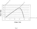
- FIG. 4shows a plot of a power and voltage relationship for a similar panel.
- FIG. 5shows an embodiment of the invention with series connected panels and a single grid-tied inverter configuration.
- FIGS. 6A and 6Bshow plots of solar panel output operational conditions for differing temperatures and output paradigms.
- FIG. 8shows a plot of combined sweet spot, protective, and coordinated process conditions according to one operational embodiment of the invention.
- FIGS. 10A and 10Bshow two types of dual mode power conversion circuits such as might be used in embodiments of the invention.
- FIG. 1shows one embodiment of a renewable electrical energy power system illustrating the basic conversion and inversion principles of the present invention. As shown, it involves an alternative electrical energy source ( 1 ) (here indicated by nomenclature as a solar energy source) feeding into a photovoltaic DC-DC power converter ( 4 ) providing a converted output to a DC-AC inverter ( 5 ) that may perhaps ultimately interface with a grid ( 10 ).
- the alternative electrical energy source ( 1 )may be a solar cell, a solar panel, or perhaps even a string of panels. Regardless, the alternative electrical energy source ( 1 ) may create an output such as a DC photovoltaic output ( 2 ).
- This DC photovoltaic output ( 2 )may be established as a DC photovoltaic input ( 3 ) to the DC-DC power converter ( 4 ).
- the DC-DC power converter ( 4 )may create an output such as a DC photovoltaic output ( 6 ).
- This DC photovoltaic output ( 6 ), or more generally photovoltaic DC converter output,may be established as an inverter input ( 29 ) to the DC-AC inverter ( 5 ).
- the DC-AC inverter ( 5 )may act to invert the converted DC and create an AC output such as a photovoltaic AC power output ( 30 ) which may be be established an an input to a grid ( 10 ), a domestic electrical system, or both, or some other power consuming device or thing.
- the DC-AC inverter ( 5 )may also have its operation controlled by inverter control circuitry ( 38 ) that likewise may be embodied as true circuitry hardware or it may be firmware or even software to accomplish the desired control and would still fall within the meaning of an inverter controlling step or an inverter control circuitry ( 38 ).
- the various elementsmay be connected to each other.
- Direct connectionis but one manner in which the various elements may be responsive to each other, that is, some effect in one may directly or indirectly cause an effect or change in another.
- effectscan occur and responsiveness can exist even without the connection.
- no such direct connectionis used as the effect can be cause even without such a connection.
- certain of these cells, panels, or stringsmay be adjacent in that they may be exposed to somewhat similar electrical, mechanical, environmental, solar exposure (or insolative) conditions.
- thismay be achieved by a direct control input or, for preferred embodiments of the invention may be achieved by simply alter an effect until the converter's DC photovoltaic output ( 6 ) and thus the inverter input ( 29 ) are as desired.
- Thiscan be considered as one manner of photovoltaic inverter sourced converting within such a system.
- a controlmay be considered inverter sourced or derived from conditions or functions or circuitry associated with the DC-AC inverter ( 5 ) and thus embodiments of the invention may include inverter sourced photovoltaic power conversion output control circuitry within or associated with the inverter control circuitry ( 38 ).
- a surprising aspect of embodiments of the inventionmay be the fact that inverter input may be maintained independent of and even without regard to a separately maintained MPP level of operation.
- inverter optimum inputcan exist while simultaneously maintaining MPP level of conversion functionality.
- embodimentscan include independent inverter operating condition converter output control circuitry or the step of independently controlling an inverter operating condition perhaps through the photovoltaic DC-DC converter or the photovoltaic DC-DC power converter ( 4 ). As mentioned above in embodiments, this can be achieved through duty cycle switching of both the photovoltaic DC-DC power converter ( 4 ) and the DC-AC inverter ( 5 ). In this manner, embodiments may include the step of maximum power point independently controlling the inverter input voltage.
- systemsmay have solar panel maximum power point independent inverter input voltage control circuitry ( 38 ).
- This circuitrymay be configured for an optimal level and thus embodiments may have solar panel maximum power point independent inverter input optimization photovoltaic power control circuitry.
- An aspect of operational capability that afford advantageis the capability of embodiments of the invention to accommodate differing operating conditions for various solar sources or panels.
- voltages ( 48 ) of operation for maximum power point ( 51 )can vary based upon not just changes in insolation but also whether the solar source is experiencing hot or cold temperature conditions.
- embodiments according to the inventionmay provide expansive panel capability.
- Such operationcan be at levels of from 97, 97.5, 98, 98.5 up to either 99.2 or essentially the wire transmission loss efficiency (which can be considered the highest possible).
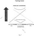
- FIG. 7shows a plot of converter losses ( 55 ) by topology and range ( 56 ) for a traditional approach considered for a converter element as may be used in embodiments of the present invention.
- such embodimentscan be considered as having substantially power isomorphic photovoltaic inverter duty cycle control circuitry or as providing the step of substantially power isomorphically duty cycle switching the photovoltaic DC-AC inverter.
- the ability to set a constant input regardless of MPP needsallows the inverter controller to optimize the input for the inverter and so serve as inverter efficiency optimized converter control circuitry or provide the step of inverter efficiency optimization controlling of the operation of the system.
- the systemcan be understood as including inverter sweet spot control circuitry or even as inverter sweet spot converter control circuitry ( 46 ) when this is accomplished through the converter's output.
- inverter sweet spot control circuitrycan be slaved inverter sweet spot control circuitry or as providing the step of slavedly controlling sweet spot operation of the photovoltaic DC-AC inverter.
- Such embodimentsmay include a parallel capacitance and a series inductance. These may be used to store energy at at least some times in the operation of converting. It may even be considered that full energy conversion is not accomplished, only the amount of conversion necessary to achieve the desired result.
- three of the panelsmay have 105.3 volts and one may have 84.2 volts.
- a power blockmay be considered as a group of PV panels with power conversion and MPP per panel configurations. As such they may adapt their output as needed to always maintain maximum power from each and every power block.
- the three panelsmay have a voltage of 114.2 volts and the remaining one may have half as much, or 57.1 volts.
- the DC-AC inverter ( 5 )can be coordinated with the photovoltaic DC-DC converter ( 4 ).
- Embodimentscan have inverter coordinated photovoltaic power conversion control circuitry ( 45 ) or can provide the step of inverter coordinated converting or inverter coordinated controlling of the operations. As mentioned this can be direct or indirect. As shown in FIG. 1 , there could be a direct connection from the inverter control circuitry ( 38 ) to the converter functionality control circuitry ( 8 ), however, in preferred embodiments, no such direct connection may be needed.
- the DC-AC inverter ( 5 )can cause the photovoltaic DC-DC converter ( 4 ) to alter its operation as it simply tries to maintain its duty cycle to maintain MPP.
- This indirect controlis still considered as providing photovoltaic converter output control circuitry, and even more specifically, as providing photovoltaic converter output voltage control circuitry ( 32 ) because it causes the step of controlling a photovoltaic DC-DC converter output (also referred to as the DC photovoltaic output ( 2 )) of the photovoltaic DC-DC converter ( 4 ), and even more specifically, as providing the step of controlling a photovoltaic DC-DC converter voltage output of the photovoltaic DC-DC converter ( 4 ).
- the dual mode circuit(described in more detail in the priority applications) could go to infinite output voltage if there were no load present. This situation can actually occur frequently.
- the power conditioner ( 17 )might in practical terms increase its output voltage until the inverter would break.
- the invertercould have overvoltage protection on its input adding additional power conversion components or, the power conditioner may simply have its own internal output voltage limit.
- each power conditioner ( 17 )could only produce 100 volts maximum and there was a string of ten PCs in series the maximum output voltage would be 1000 volts.
- This output voltage limitcould make the grid-tied inverter less complex or costly and is illustrated in FIG. 6A as a preset overvoltage limit ( 52 ).
- embodimentscan present maximum voltage determinative switching photovoltaic power conversion control circuitry and maximum photovoltaic voltage determinative duty cycle switching (as shown in FIG. 6A as the preset overvoltage limit ( 52 )).
- Thiscan be inverter specific and so an additional aspect of embodiments of the invention can be the inclusion of inverter protection schemes.
- Embodiments of the present inventioncan account for these aspects as well and may even provide this through the DC-DC power converter ( 4 ) and/or the DC-AC inverter ( 5 ) thus including inverter protection photovoltaic power conversion control circuitry ( 33 ) at either or both levels.
- embodimentscan provide the steps of providing photovoltaic inverter protection power conversion control and even controlling a limited photovoltaic converter current output through operation of the photovoltaic DC-DC converter ( 4 ). These may be configured with consideration of maximum inverter inputs and converter outputs so there can be included maximum inverter input converter output control circuitry ( 37 ), maximum inverter voltage determinative switching photovoltaic power conversion control circuitry, or also the step of controlling a maximum inverter input converter output.
- slaved photovoltaic power control circuitry34
- such slaved photovoltaic power control circuitry ( 34 )can be provided at either the photovoltaic DC-DC power converter ( 4 ), the DC-AC inverter ( 5 ), or both, or elsewhere.
- Thesecan include converter current output limited photovoltaic power control circuitry, converter voltage output limited photovoltaic power control circuitry, or the like.
- embodimentscan have slaved photovoltaic inverter protection control circuitry, or more specifically, slaved photovoltaic current level control circuitry or slaved photovoltaic voltage level control circuitry, or may provide the steps of slavedly providing photovoltaic inverter protection control of the photovoltaic DC-AC inverter ( 5 ), slavedly controlling current from the photovoltaic DC-DC converter ( 4 ), or the like.
- systemmay more generally be considered as including photovoltaic boundary condition power conversion control circuitry and as providing the step of photovoltaic boundary condition power conversion control.
- boundary conditionsmay be set such as the overcurrent limit ( 53 ) and the overvoltage limit ( 52 ).
- the DC-AC inverter ( 5 ), the photovoltaic DC-DC converter ( 4 ), and/or either or both of their control circuitriesmay serve as photovoltaic boundary condition converter functionality control circuitry, may achieve a photovoltaic boundary condition modality of photovoltaic DC-DC power conversion, and may accomplish the step of controlling a photovoltaic boundary condition of the photovoltaic DC-DC converter.
- a maximum output current limitit should be understood that this may also be useful as illustrated in FIG. 6A as a preset overcurrent limit ( 53 ).
- Thisis less straightforward and is related to the nature of a PV panel. If a PV panel is subjected to insufficient light its output voltage may drop but its output current may not be capable of increasing. There can be an advantage to only allowing a small margin of additional current. For example, this same 100 watt panel which has a 100 volt maximum voltage limit could also have a 2 amp current limit without limiting its intended use. This may also greatly simplify the following grid tied inverter stage. Consider an inverter in a large installation which may need a crowbar shunt front end for protection.
- inventionscan present maximum photovoltaic inverter current converter functionality control circuitry, inverter maximum current determinative switching, photovoltaic inverter maximum current determinative duty cycle switch control circuitry, and photovoltaic inverter maximum current determinatively duty cycle switching or the like.
- embodimentsmay include photovoltaic inverter operating condition converter functionality control circuitry.
- embodimentsmay also be embodiments that have small output voltage (even within an allowed output voltage range). This may accommodate an inverter with a small energy storage capacitor. The output voltage may even be coordinated with an inverter's energy storage capability.
- certain aspectmay be slaved to (subservient) or may slave other aspects (dominant).
- One possible goal in switching for some embodimentsmay include the maximum power point operation and sweet spot operational characteristics discussed above as well as a number of modalities as discussed below. Some of these modalities may even be slaved such that one takes precedence of one or another at some point in time, in some power regime, or perhaps based on some power parameter to achieve a variety of modalities of operation.
- DC-AC inverter ( 5 )there may be more generally the slaved photovoltaic power control circuitry ( 34 ) mentioned above, slaved inverter operating condition control circuitry, slaved photovoltaic voltage level control circuitry and even the steps of slavedly controlling voltage from the photovoltaic DC-DC converter ( 4 ) or slavedly controlling operation of the photovoltaic DC-DC converter ( 4 ).
- Another aspect of some embodiments of the inventioncan be protection or operation of components or the DC-AC inverter ( 5 ) so as to address abrupt changes in condition. This can be accomplished through the inclusion of soft transition photovoltaic power conversion control circuitry ( 35 ) or the step of softly transitioning a photovoltaic electrical parameter or more specifically even softly transitioning a converted photovoltaic power level electrical parameter.
- another mode of operationmay be to make a value proportional (in its broadest sense) to some other aspect. For example, there can be advantages to making voltage proportional to current such as to provide soft start capability or the like.
- embodimentsmay be configured for controlling a maximum photovoltaic output voltage proportional to a photovoltaic output current at at least some times during the process of converting a DC input to a DC output.
- thismay provide soft transition photovoltaic power conversion control circuitry ( 35 ).
- embodimentscan include ramped photovoltaic current power conversion control circuitry, ramped photovoltaic voltage power conversion control circuitry, or the steps of ramping (which be linear or may have any other shape) a photovoltaic current level, ramping a photovoltaic voltage level, or the like.
- One of the many ways in which such soft transition can be accomplishedcan be by making one parameter proportional to another.
- embodimentscan include photovoltaic output voltage-photovoltaic output current proportional control circuitry ( 39 ) or can provide the step of controlling a photovoltaic output voltage proportional to a photovoltaic output current.
- embodiments of the systemmay include duty cycle control or switch operation that can be conducted so as to achieve one or more proportionalities between parameters perhaps such as the initial examples of maximum voltage output and current output or the like. Further, not only can any of the above by combined with any other of the above, but each may be provided in a slaved manner such that consideration of one modality is secondary to or dominant over that of another modality.
- one technique of some control activitiescan be through the use of duty cycle switching or the like. Switches on either or both of the photovoltaic DC-DC power converter ( 4 ) or the DC-AC inverter ( 5 ) can be controlled in a variable duty cycle mode of operation such that frequency of switching alters to achieve the desired facet.
- the converter functionality control circuitry ( 8 )perhaps providing the step of maximum photovoltaic power point duty cycle switching of a photovoltaic DC-DC converter, or the inverter control circuitry ( 38 ) may serve as photovoltaic duty cycle switch control circuitry.
- the duty cycle operations and switchingcan achieve a variety of results, from serving as photovoltaic transformation duty cycle switching, to photovoltaic impedance transformation duty cycle switching, to photovoltaic input control duty cycle switching, to photovoltaic output duty cycle switching, to photovoltaic voltage duty cycle switching, to photovoltaic current duty cycle switching, to soft transition duty cycle switching, to photovoltaic optimization duty cycle switching, to other operations.
- the photovoltaic inverter duty cycle switch control circuitry ( 31 )may even act to provide the step of maximum photovoltaic voltage determinatively duty cycle switching the DC-AC inverter ( 5 ).
- a photovoltaic DC-DC power converter( 4 ) may include modes of increasing and, perhaps alternatively, decreasing photovoltaic load impedance, the output, or otherwise.
- Systems according to embodiments of the inventionmay combine inverter aspects with a photovoltaic DC-DC power converter ( 4 ) that serves as a multimodal photovoltaic DC-DC power converter perhaps controlled by multimodal converter functionality control circuitry ( 26 ) in that it has more than one mode of operation.
- These modesmay include, but should be understood as not limited to, photovoltaic output increasing and photovoltaic output decreasing, among others.
- the aspect of multimodal activityencompasses at least processes where only one mode of conversion occurs at any one time.
- a power conditioner ( 17 )may provide at least first modality and second modality photovoltaic DC-DC power conversion circuitry, DC-DC power converter, or DC-DC power conversion in conjunction with the inverter capabilities discussed herein.
- the systemmay accomplish the step of multimodally operating.
- the systemmay accomplish the step of multimodally controlling operation of a photovoltaic DC-DC power converter ( 4 ) or a DC-AC inverter ( 5 ).
- Embodimentsmay include a photovoltaic DC-DC power converter ( 4 ) that has even two or more modes of operation and thus may be considered a dual mode power conversion circuit or dual mode converter.
- the dual mode nature of this circuitmay embody a significant benefit and another distinction may be that most DC/DC converters are often intended to take an unregulated source and produce a regulated output.
- the input to the DC/DC converteris regulated either up or down—and in a highly efficient manner—to be at the PV panel MPP.
- the dual mode nature of the convertermay also serve to facilitate an effect caused by the inverter's operation even without a direct connection. Of course, such modes of operation can be adapted for application with respect to the inverter's duty cycle switching as well.
- the PCs and photovoltaic DC-DC power converters ( 4 )may handle individual panels. They may be attached to a panel, to a frame, or separate. Embodiments may have converters physically integral to such panels in the sense that they are provided as one attached unit for ultimate installation. This can be desirable such as when there are independent operating conditions for separate solar sources, and even adjacent solar sources to accommodate variations in insolation, condition, or otherwise. Each panel or the like may achieve its own MPP, and may coordinate protection with all others in a string or the like.
- systemscan include an aspect of reacting to operational conditions to which elements are subjected. This can occur in a dynamic fashion so that as one condition changes, nearly instantly a reaction to control appropriately is caused. They can also react to installation conditions and can react to the particular elements. This can make installation easier. For example, if connected to differing types of solar panels, differing age or condition elements, differing types of converters, or even differing types of inverters, some embodiments of the invention can automatically act to accommodate the element, to stay within code, or to otherwise act so that regardless of the overall system or the overall dissimilarity, an optimal result can be achieved.
- this dynamically reactive control featurecan be configured at either or both the photovoltaic DC-DC power converter ( 4 ) or the DC-AC inverter ( 5 ).
- embodimentscan provide dynamically reactive internal output limited photovoltaic power control circuitry ( 42 ) it can also provide the step of dynamically reactively controlling an internal output or even dynamically reactively converting. Both of these features, or even any other dynamically reactive capability, can be slaved either dominantly or subserviently.
- embodiments of the inventioncan provide slaved dynamically reactive photovoltaic power control circuitry or the step of slavedly dynamically reactively controlling an aspect of the system. This could include slavedly dynamically reactively controlling an internal output through operation of the photovoltaic DC-DC converter ( 4 ).
- embodimentscan provide the dynamically reactive control as code compliant dynamically reactive photovoltaic power control circuitry ( 41 ). It may also provide the step of code compliantly dynamically reactively controlling an internal output. This can occur through operation of the photovoltaic DC-DC converter ( 4 ), the DC-AC inverter ( 5 ), or otherwise.
- this code complaint featurecan be slaved to take dominance over other features such as MPP activity, sweet spot activity, boundary condition activity, or the like.
- embodimentscan provide slaved code compliant dynamically reactive photovoltaic power control circuitry or can provide the step of slavedly code compliantly dynamically reactively controlling internal output, perhaps through operation of the photovoltaic DC-DC converter ( 4 ) or otherwise.
- code complianceit can be readily understood how the general feature of a dynamically reactive control can act to permit connection to existing or dissimilar sources as well.
- embodimentscan provide dynamically multisource reactive photovoltaic power control circuitry ( 43 ) or may provide the step of multisource dynamically reactively controlling internal output, perhaps through operation of the photovoltaic DC-DC converter ( 4 ).
- thiscan all be accomplished while maintaining the inverter input at an optimum level in appropriate circumstances and thus embodiments can include reactive inverter input optimization photovoltaic power control circuitry.
- embodimentsmay include a solar power conversion comparator ( 44 ) that can compare first and second modes of operation, perhaps the improved mode of an embodiment of the present invention and a traditional, less efficient mode.
- This comparatormay involve indicating some solar energy parameter for each.
- the shunt switch operation disable elementmay be helpful. From this a variety of difference can be indicated, perhaps: solar power output, solar power efficiency differences, solar power cost differences, solar power insolation utilization comparisons, and the like.
- embodimentscan include an ability to function with a first power capability and a second power capability. These may be traditional and improved capabilities, perhaps such as a traditional power conversion capability and an improved power conversion capability or a traditional power inversion capability and an improved power inversion capability.
- the inverter control circuitry ( 38 ) or the converter functionality control circuitry ( 8 ) or otherwisecan be configured to achieve either or both of these first and second capabilities.
- the invertercan act to achieve an input voltage that would have been seen without the features of the present invention and thus embodiments can provide an off-maximum efficiency inverter input voltage control ( 47 ) or may act to provide the step of controlling inverter input voltage off a maximum efficiency level.
- embodimentsmay act to compare the steps of traditionally power inverting a DC photovoltaic input and sweet spot input inverting a DC photovoltaic input. Any of these can provide a user any type of output to inform the user for comparison with other systems.
- circuitry, concepts and methods of various embodiments of the inventionmay be broadly applied. It may be that one or more PCs per panel may be used. For example there may be non-uniformities on a single panel or other reasons for harvesting power from even portions of a panel. It may be for example that small power converters may be used on panel segments optimizing the power which may be extracted from a panel. This invention is explicitly stated to include sub panel applications.
- This inventionmay be optimally applied to strings of panels. It may be more economical for example to simply use a PC for each string of panels in a larger installation. This could be particularly beneficial in parallel connected strings if one string was not able to produce much power into the voltage the remainder of the strings is producing. In this case one PC per string may increase the power harvested from a large installation.
- This inventionis assumed to include many physical installation options. For example there may be a hard physical connection between the PC and a panel. There may be an interconnection box for strings in which a PC per string may be installed. A given panel may have one or more PCs incorporated into the panel. A PC may also be a stand-alone physical entity.
- the basic concepts of the present inventionmay be embodied in a variety of ways. It involves both solar power generation techniques as well as devices to accomplish the appropriate power generation.
- the power generation techniquesare disclosed as part of the results shown to be achieved by the various circuits and devices described and as steps which are inherent to utilization. They are simply the natural result of utilizing the devices and circuits as intended and described.
- circuitsare disclosed, it should be understood that these not only accomplish certain methods but also can be varied in a number of ways.
- all of these facetsshould be understood to be encompassed by this disclosure.
- each of the various elements of the invention and claimsmay also be achieved in a variety of manners.
- an elementis to be understood as encompassing individual as well as plural structures that may or may not be physically connected.
- This disclosureshould be understood to encompass each such variation, be it a variation of an embodiment of any apparatus embodiment, a method or process embodiment, or even merely a variation of any element of these.
- the words for each elementmay be expressed by equivalent apparatus terms or method terms—even if only the function or result is the same. Such equivalent, broader, or even more generic terms should be considered to be encompassed in the description of each element or action.
- each of the power source devicesas herein disclosed and described, ii) the related methods disclosed and described, iii) similar, equivalent, and even implicit variations of each of these devices and methods, iv) those alternative designs which accomplish each of the functions shown as are disclosed and described, v) those alternative designs and methods which accomplish each of the functions shown as are implicit to accomplish that which is disclosed and described, vi) each feature, component, and step shown as separate and independent inventions, vii) the applications enhanced by the various systems or components disclosed, viii) the resulting products produced by such systems or components, ix) each system, method, and element shown or described as now applied to any specific field or devices mentioned, x) methods and apparatuses substantially as described hereinbefore and with reference to any of the accompanying examples, xi) the various combinations and permutations of each of the elements disclosed, xii) each potentially dependent claim or concept as a dependency on each and every one of
- any claims set forth at any timeare hereby incorporated by reference as part of this description of the invention, and the applicant expressly reserves the right to use all of or a portion of such incorporated content of such claims as additional description to support any of or all of the claims or any element or component thereof, and the applicant further expressly reserves the right to move any portion of or all of the incorporated content of such claims or any element or component thereof from the description into the claims or vice-versa as necessary to define the matter for which protection is sought by this application or by any subsequent continuation, division, or continuation-in-part application thereof, or to obtain any benefit of, reduction in fees pursuant to, or to comply with the patent laws, rules, or regulations of any country or treaty, and such content incorporated by reference shall survive during the entire pendency of this application including any subsequent continuation, division, or continuation-in-part application thereof or any reissue or extension thereon.
Landscapes
- Engineering & Computer Science (AREA)
- Power Engineering (AREA)
- Photovoltaic Devices (AREA)
- Control Of Electrical Variables (AREA)
- Inverter Devices (AREA)
- Supply And Distribution Of Alternating Current (AREA)
- Dc-Dc Converters (AREA)
- Remote Monitoring And Control Of Power-Distribution Networks (AREA)
- Management, Administration, Business Operations System, And Electronic Commerce (AREA)
Abstract
Description
| TABLE 1 | ||||
| V′ Positive | P′ Positive | Raise Panel Voltage | ||
| V′ Positive | P′ Negative | Lower Panel Voltage | ||
| V′ Negative | P′ Positive | Lower Panel Voltage | ||
| V′ Negative | P′ Negative | Raise Panel Voltage | ||
3V+0.8V=400 volts, where V is the voltage on each full power panel.
3V+0.5V=400 volts
- Every PV panel may produce its individual maximum power. Many estimates today indicate this may increase the power generated in a PV installation by 20% or even more.
- The grid tied inverter may be greatly simplified and operate more efficiently.
- The Balance of System costs for a PV installation may be reduced.
- 1. An inverter coordinated renewable electrical energy power system comprising:
- at least one alternative electrical energy source having a DC photovoltaic output;
- at least one photovoltaic DC-DC power converter responsive to said DC photovoltaic output and having a photovoltaic DC converter output;
- a DC-AC inverter responsive to said photovoltaic DC converter output;
- indirect inverter coordinated photovoltaic power conversion control circuitry; and
- a photovoltaic AC power output responsive to said photovoltaic DC-AC inverter.
- 2. An inverter coordinated photovoltaic electrical energy power system comprising:
- at least one alternative electrical energy source having a DC photovoltaic output;
- at least one photovoltaic DC-DC power converter responsive to said DC photovoltaic output and having a photovoltaic DC converter output;
- an indirect inverter coordinated converter functionality control to which said at least one photovoltaic DC-DC power converter is responsive;
- a DC-AC inverter responsive to said photovoltaic DC converter output; and
- a photovoltaic AC power output responsive to said photovoltaic DC-AC inverter.
- 3. An inverter coordinated photovoltaic electrical energy power system as described in
clause 2 or any other clause, wherein said indirect inverter coordinated converter functionality control to which said at least one photovoltaic DC-DC power converter is responsive comprises a direct inverter connection free inverter coordinated converter functionality control. - 4. An inverter coordinated photovoltaic electrical energy power system as described in
clause 2 or any other clause, wherein said indirect inverter coordinated converter functionality control to which said at least one photovoltaic DC-DC power converter is responsive comprises no direct inverter-converter control connection converter functionality control. - 5. An inverter coordinated photovoltaic electrical energy power system as described in
clause 4 or any other clause, wherein said no direct inverter-converter control connection converter functionality control comprises no separate direct inverter-converter control connection converter functionality control. - 6. An inverter coordinated photovoltaic electrical energy power system as described in
clause 4 or any other clause, wherein said no direct inverter-converter control connection converter functionality control comprises no control dedicated direct inverter-converter control connection converter functionality control. - 7. An inverter coordinated photovoltaic electrical energy power system as described in
clause 3 or any other clause, wherein said direct inverter connection free inverter coordinated converter functionality control comprises an inverter control communication free inverter coordinated converter functionality control. - 8. An inverter coordinated photovoltaic electrical energy power system as described in
clause 7 or any other clause, wherein said inverter control communication free inverter coordinated converter functionality control comprises no communication inverter-reactive converter functionality control. - 9. An inverter coordinated photovoltaic electrical energy power system as described in
clause - 10. An inverter coordinated photovoltaic electrical energy power system as described in
clause 9 or any other clause, wherein said converter switch operation converter functionality control comprises a converter duty cycle switching converter functionality control. - 11. An inverter coordinated photovoltaic electrical energy power system as described in
clause - 12. An inverter coordinated photovoltaic electrical energy power system as described in
clause 11 or any other clause, wherein said converter operation control comprises a power conversion deactivation converter functionality control. - 13. An inverter coordinated photovoltaic electrical energy power system as described in
clause 11 or any other clause, wherein said converter operation control comprises a power conversion activation converter functionality control. - 14. An inverter coordinated photovoltaic electrical energy power system as described in
clause 13 or any other clause, wherein said power conversion activation converter functionality control comprises a conversion startup converter functionality control. - 15. An inverter coordinated photovoltaic electrical energy power system as described in clause 214 or any other clause, wherein said conversion startup converter functionality control comprises a conversion soft start converter functionality control.
- 16. An inverter coordinated photovoltaic electrical energy power system as described in
clause - 17. An inverter coordinated photovoltaic electrical energy power system as described in
clause - 18. An inverter coordinated photovoltaic electrical energy power system as described in
clause 17 or any other clause, wherein said inverter operational condition responsive converter functionality control comprises a slaved inverter operational condition converter functionality control. - 19. An inverter coordinated photovoltaic electrical energy power system as described in
clause - 20. An inverter coordinated photovoltaic electrical energy power system as described in
clause 19 or any other clause, wherein said separate converter functionality control comprises a slaved separate converter functionality control. - 21. An inverter coordinated photovoltaic electrical energy power system as described in
clause 20 or any other clause, wherein said slaved separate converter functionality control comprises a slaved separate converter functionality control that is slavedly responsive to said indirect inverter coordinated converter functionality control. - 22. An inverter coordinated photovoltaic electrical energy power system as described in
clause 19 or any other clause, wherein said separate converter functionality control comprises a maximum power point converter functionality control, and wherein said indirect inverter coordinated converter functionality control comprises a maximum power point independent converter functionality control. - 23. An inverter coordinated photovoltaic electrical energy power system as described in
clause 22 or any other clause, wherein said indirect inverter coordinated converter functionality control and said maximum power point converter functionality control both comprise simultaneous converter functionality control options. - 24. An inverter coordinated photovoltaic electrical energy power system as described in clause 23 or any other clause, wherein said maximum power point converter functionality control comprises a slaved maximum power point converter functionality control that is slavedly responsive to said indirect inverter coordinated converter functionality control.
- 25. An inverter coordinated photovoltaic electrical energy power system as described in
clause 19 or any other clause, wherein said separate converter functionality control comprises a power producing photovoltaic boundary condition converter functionality control, and wherein said indirect inverter coordinated converter functionality control comprises a power producing photovoltaic boundary condition independent converter functionality control. - 26. An inverter coordinated photovoltaic electrical energy power system as described in
clause 25 or any other clause, wherein said indirect inverter coordinated converter functionality control and said power producing photovoltaic boundary condition converter functionality control both comprise simultaneous converter functionality control options. - 27. An inverter coordinated photovoltaic electrical energy power system as described in
clause 25 or any other clause, wherein said power producing photovoltaic boundary condition converter functionality control comprises a slaved power producing photovoltaic boundary condition converter functionality control that is slavedly responsive to said indirect inverter coordinated converter functionality control. - 28. An inverter coordinated photovoltaic electrical energy power system as described in
clause - 29. An inverter coordinated photovoltaic electrical energy power system as described in clause 28 or any other clause, wherein said load effect converter functionality control comprises a no load present converter functionality control.
- 30. An inverter coordinated photovoltaic electrical energy power system as described in
clause 29 or any other clause, wherein said no load present converter functionality control comprises a power conversion deactivation converter functionality control. - 31. An inverter coordinated photovoltaic electrical energy power system as described in
clause - 32. An inverter coordinated photovoltaic electrical energy power system as described in clause 31 or any other clause, wherein said insolation effect converter functionality control comprises insolation initiation converter functionality control.
- 33. An inverter coordinated photovoltaic electrical energy power system as described in clause 31 or any other clause, wherein said insolation effect converter functionality control comprises over insolation converter functionality control.
- 34. An inverter coordinated photovoltaic electrical energy power system as described in
clause - 35. An inverter coordinated photovoltaic electrical energy power system as described in
clause 34 or any other clause, wherein said grid effect converter functionality control comprises a grid unconnected converter functionality control. - 36. An inverter coordinated photovoltaic electrical energy power system as described in
clause - 37. An inverter coordinated photovoltaic electrical energy power system as described in clause 36 or any other clause, wherein said automatic change accommodation converter functionality control comprises a power conversion activation converter functionality control.
- 38. An inverter coordinated photovoltaic electrical energy power system as described in clause 36 or any other clause, wherein said automatic change accommodation converter functionality control comprises a power conversion deactivation converter functionality control.
- 39. An inverter coordinated photovoltaic electrical energy power system as described in
clause 37 or any other clause, wherein said automatic change accommodation converter functionality control further comprises a power conversion deactivation converter functionality control. - 40. An inverter coordinated photovoltaic electrical energy power system as described in
clause - 41. An inverter coordinated photovoltaic electrical energy power system as described in
clause 40 or any other clause, wherein said inverter-specific converter functionality control comprises inverter-specific effects converter functionality control. - 42. An inverter coordinated photovoltaic electrical energy power system as described in
clause 41 or any other clause, wherein said inverter-specific effects converter functionality control comprises inverter-specific make and model converter functionality control. - 43. An inverter coordinated photovoltaic electrical energy power system as described in
clause 41 or any other clause, wherein said inverter-specific effects converter functionality control further comprises inverter-specific make and model converter functionality control. - 44. An inverter coordinated photovoltaic electrical energy power system as described in
clause 40 or any other clause, wherein said inverter-specific converter functionality control comprises an inverter-specific small energy storage capacitor converter functionality control. - 45. An inverter coordinated photovoltaic electrical energy power system as described in
clause - 46. An inverter coordinated photovoltaic electrical energy power system as described in
clause 45 or any other clause, wherein said abrupt change in inverter condition converter functionality control comprise power conversion activation converter functionality control. - 47. An inverter coordinated photovoltaic electrical energy power system as described in
clause 45 or any other clause, wherein said abrupt change in inverter condition converter functionality control comprise power conversion deactivation converter functionality control. - 48. An inverter coordinated photovoltaic electrical energy power system as described in
clause 46 or any other clause, wherein said abrupt change in inverter condition converter functionality control comprise power conversion deactivation converter functionality control. - 49. An inverter coordinated photovoltaic electrical energy power system as described in
clause 45 or any other clause, wherein said abrupt change in inverter condition converter functionality control comprise soft transition converter functionality control. - 50. An inverter coordinated photovoltaic electrical energy power system as described in
clause 45 or any other clause, wherein said abrupt change in inverter condition converter functionality control comprise crowbar shunt protection effect converter functionality control. - 51. An inverter coordinated photovoltaic electrical energy power system as described in
clause - 52. An inverter coordinated photovoltaic electrical energy power system as described in
clause - 53. An inverter coordinated photovoltaic electrical energy power system as described in
clause 52 or any other clause, wherein said crowbar shunt protection effect converter functionality control comprises power conversion deactivation converter functionality control. - 54. An inverter coordinated photovoltaic electrical energy power system as described in
clause - 55. An inverter coordinated photovoltaic electrical energy power system as described in
clause 54 or any other clause, wherein said proportional value converter functionality control comprises voltage-current proportional converter functionality control. - 56. An inverter coordinated photovoltaic electrical energy power system as described in
clause - 57. An inverter coordinated photovoltaic electrical energy power system as described in
clause 56 or any other clause, wherein said ramped value converter functionality control comprises linearly ramped value converter functionality control. - 58. An inverter coordinated photovoltaic electrical energy power system as described in
clause 56 or any other clause, wherein said ramped value converter functionality control comprises voltage ramped converter functionality control. - 59. An inverter coordinated photovoltaic electrical energy power system as described in
clause 56 or any other clause, wherein said ramped value converter functionality control comprises current ramped converter functionality control. - 60. An inverter coordinated photovoltaic electrical energy power system as described in clause 58 or any other clause, wherein said ramped value converter functionality control comprises current ramped converter functionality control.
- 61. An inverter coordinated photovoltaic electrical energy power system as described in
clause 56 or any other clause, wherein said ramped value converter functionality control comprises power ramped converter functionality control. - 62. An inverter coordinated photovoltaic electrical energy power system as described in
clause - 63. An inverter coordinated photovoltaic electrical energy power system as described in clause 62 or any other clause, wherein said threshold triggered converter functionality control comprises inverter operational condition threshold responsive converter functionality control.
- 64. An inverter coordinated photovoltaic electrical energy power system as described in clause 62 or any other clause, wherein said threshold triggered converter functionality control comprises power conversion activation converter functionality control.
- 65. An inverter coordinated photovoltaic electrical energy power system as described in clause 62 or any other clause, wherein said threshold triggered converter functionality control comprises power conversion deactivation converter functionality control.
- 66. An inverter coordinated photovoltaic electrical energy power system as described in clause 64 or any other clause, wherein said threshold triggered converter functionality control comprises power conversion deactivation converter functionality control.
- 67. A method of providing inverter coordinated photovoltaic electrical energy power comprising the steps of:
- creating a DC photovoltaic output from said at least one alternative electrical energy source;
- establishing said DC photovoltaic output as a DC photovoltaic input to a at least one photovoltaic DC-DC power converter;
- converting said DC photovoltaic input to create a converted DC photovoltaic output;
- indirectly inverter coordinated controlling said step of converting said DC photovoltaic input to create a converted DC photovoltaic output;
- establishing said converted DC photovoltaic output as a converted DC photovoltaic input to a photovoltaic DC-AC inverter; and
- inverting said converted DC photovoltaic input into a photovoltaic AC power output.
- 68. A method of providing inverter coordinated photovoltaic electrical energy power as described in clause 67 or any other clause, wherein said step of indirectly inverter coordinated controlling said step of converting said DC photovoltaic input to create a converted DC photovoltaic output comprises the step of direct inverter connection free inverter coordinated converter functionality controlling a photovoltaic DC-DC converter.
- 69. A method of providing inverter coordinated photovoltaic electrical energy power as described in clause 67 or any other clause, wherein said step of indirectly inverter coordinated controlling said step of converting said DC photovoltaic input to create a converted DC photovoltaic output comprises the step of inverter coordinated controlling said step of converting without any direct inverter-converter control connection.
- 70. A method of providing inverter coordinated photovoltaic electrical energy power as described in clause 69 or any other clause, wherein the step of the step of inverter coordinated controlling said step of converting without any direct inverter-converter control connection comprises the step of inverter coordinated controlling said step of converting without any separate direct inverter-converter control connection.
- 71. A method of providing inverter coordinated photovoltaic electrical energy power as described in clause 69 or any other clause, wherein the step of the step of inverter coordinated controlling said step of converting without any direct inverter-converter control connection comprises the step of inverter coordinated controlling said step of converting without any control dedicated direct inverter-converter control connection.
- 72. A method of providing inverter coordinated photovoltaic electrical energy power as described in clause 68 or any other clause, wherein said step of direct inverter connection free inverter coordinated converter functionality controlling a photovoltaic DC-DC converter comprises the step of inverter control communication free inverter operating condition coordinating conversion.
- 73. A method of providing inverter coordinated photovoltaic electrical energy power as described in clause 72 or any other clause, wherein said step of inverter control communication free inverter operating condition coordinating conversion comprises the step of reacting to said inverter without any communication from said inverter.
- 74. A method of providing inverter coordinated photovoltaic electrical energy power comprising the steps of:
- establishing a plurality of solar panels;
- creating a highly varying DC photovoltaic output from each of said plurality of solar panels;
- individually establishing each said highly varying DC photovoltaic output as an individual DC photovoltaic input to an individual inverter operating condition coordinated photovoltaic DC-DC converter; thereby
- establishing a plurality of DC-DC converters;
- indirectly, by said DC-DC converters, inverter operating condition coordinating conversion of each said individual DC photovoltaic input into a converted DC photovoltaic output for a high voltage, high power photovoltaic DC-AC inverter;
- serially connecting a plurality of said converted DC photovoltaic outputs to create a combined higher voltage converted DC photovoltaic output;
- establishing said combined higher voltage converted DC photovoltaic output as a converted DC photovoltaic input to said high voltage, high power photovoltaic DCAC inverter; and
- inputting said converted DC photovoltaic input at a coordinated inverter operating condition of said high voltage, high power photovoltaic DC-AC inverter.
- 75. A method of providing inverter coordinated photovoltaic electrical energy power as described in clause 74 or any other clause, wherein said step of indirectly, by said DC-DC converters, inverter operating condition coordinating conversion of each said individual DC photovoltaic input into a converted DC photovoltaic output for a high voltage, high power photovoltaic DC-AC inverter comprises the step of direct inverter connection free inverter coordinated converter functionality controlling said inverter operating condition coordinated photovoltaic DC-DC converter.
- 76. A method of providing inverter coordinated photovoltaic electrical energy power as described in clause 74 or any other clause, wherein said step of indirectly, by said DC-DC converters, inverter operating condition coordinating conversion of each said individual DC photovoltaic input into a converted DC photovoltaic output for a high voltage, high power photovoltaic DC-AC inverter comprises the step of inverter operating condition coordinating conversion without any direct inverter-converter control connection
- 77. A method of providing inverter coordinated photovoltaic electrical energy power as described in clause 76 or any other clause, wherein said step of inverter operating condition coordinating conversion without any direct inverter-converter control connection comprises the step of inverter operating condition coordinating conversion without any separate direct inverter-converter control connection.
- 78. A method of providing inverter coordinated photovoltaic electrical energy power as described in clause 76 or any other clause, wherein said step of inverter operating condition coordinating conversion without any direct inverter-converter control connection comprises the step of inverter operating condition coordinating conversion without any control dedicated direct inverter-converter control connection.
- 79. A method of providing inverter coordinated photovoltaic electrical energy power as described in clause 75 or any other clause, wherein said step of direct inverter connection free inverter coordinated converter functionality controlling said inverter operating condition coordinated photovoltaic DC-DC converter comprises the step of inverter control communication free inverter operating condition coordinating conversion.
- 80. A method of providing inverter coordinated photovoltaic electrical energy power as described in clause 79 or any other clause, wherein said step of inverter control communication free inverter operating condition coordinating conversion comprises the step of reacting to said inverter without any communication from said inverter.
- 81. A method of providing inverter coordinated photovoltaic electrical energy power comprising the steps of:
- establishing at least one solar energy source;
- creating a highly varying DC photovoltaic output from said at least one solar energy source;
- establishing said highly varying DC photovoltaic output as a DC photovoltaic input to a photovoltaic DC-DC converter;
- indirectly inverter operating condition coordinating conversion of said DC photovoltaic input into a converted DC photovoltaic output for a high power photovoltaic DC-AC inverter, by said DC-DC converter;
- establishing said converted DC photovoltaic output as a converted DC photovoltaic input to said high power photovoltaic DC-AC inverter; and
- inverting said converted DC photovoltaic input into a high power inverted AC photovoltaic output.
- 82. A method of providing inverter coordinated photovoltaic electrical energy power as described in clause 81 or any other clause, wherein said step of indirectly inverter operating condition coordinating conversion of said DC photovoltaic input into a converted DC photovoltaic output for a high power photovoltaic DC-AC inverter, by said DC-DC converter comprises the step of direct inverter connection free inverter coordinated converter functionality controlling a photovoltaic DC-DC converter.
- 83. A method of providing inverter coordinated photovoltaic electrical energy power as described in clause 81 or any other clause, wherein said step of indirectly inverter operating condition coordinating conversion of said DC photovoltaic input into a converted DC photovoltaic output for a high power photovoltaic DC-AC inverter, by said DC-DC converter comprises the step of inverter operating condition coordinating conversion without any direct inverter-converter control connection.
- 84. A method of providing inverter coordinated photovoltaic electrical energy power as described in clause 83 or any other clause, wherein said step of inverter operating condition coordinating conversion without any direct inverter-converter control connection comprises the step of inverter operating condition coordinating conversion without any separate direct inverter-converter control connection.
- 85. A method of providing inverter coordinated photovoltaic electrical energy power as described in clause 83 or any other clause, wherein said step of inverter operating condition coordinating conversion without any direct inverter-converter control connection comprises the step of inverter operating condition coordinating conversion without any control dedicated direct inverter-converter control connection.
- 86. A method of providing inverter coordinated photovoltaic electrical energy power as described in clause 82 or any other clause, wherein said step of direct inverter connection free inverter coordinated converter functionality controlling a photovoltaic DC-DC converter comprises the step of inverter control communication free inverter operating condition coordinating conversion.
- 87. A method of providing inverter coordinated photovoltaic electrical energy power as described in clause 86 or any other clause, wherein said step of inverter control communication free inverter operating condition coordinating conversion comprises the step of reacting to said inverter without any communication from said inverter.
- 88. A converter coordinated photovoltaic electrical energy power system comprising:
- at least one alternative electrical energy source having a DC photovoltaic output;
- at least one photovoltaic DC-DC power converter responsive to said DC photovoltaic output and having a photovoltaic DC converter output;
- a DC-AC inverter responsive to said photovoltaic DC converter output;
- an indirect converter coordinated inverter functionality control to which said DC-AC inverter is responsive; and
- a photovoltaic AC power output responsive to said photovoltaic DC-AC inverter.
B: Priority Case PCT/US2008/060345 Claims Now Stated as Clauses
- 1. An integrated renewable electrical energy power system comprising:
- at least one alternative electrical energy source having a DC photovoltaic output;
- at least one photovoltaic DC-DC power converter responsive to said DC photovoltaic output and having a photovoltaic DC converter output;
- a DC-AC inverter responsive to said photovoltaic DC converter output;
- inverter sourced photovoltaic power conversion output control circuitry; and
- a photovoltaic AC power output responsive to said photovoltaic DC-AC inverter.
- 2. An integrated renewable electrical energy power system as described in
clause 1 or any other clause, wherein said inverter sourced photovoltaic power conversion output control circuitry comprises solar panel maximum power point independent power conversion output control circuitry. - 3. An integrated renewable electrical energy power system as described in
clause 2 or any other clause, wherein said solar panel maximum power point independent power conversion output control circuitry comprises solar panel maximum power point independent inverter input voltage control circuitry. - 4. An integrated renewable electrical energy power system as described in
clause 1 or any other clause, wherein said inverter sourced photovoltaic power conversion output control circuitry comprises substantially constant power conversion voltage output control circuitry. - 5. An integrated renewable electrical energy power system as described in
clause 4 or any other clause, wherein said substantially constant power conversion voltage output control circuitry comprises photovoltaic inverter duty cycle switch control circuitry. - 6. An integrated renewable electrical energy power system as described in
clause 1 or any other clause, wherein said inverter sourced photovoltaic power conversion output control circuitry comprises slaved inverter operating condition control circuitry. - 7. An integrated renewable electrical energy power system as described in
clause 6 or any other clause, wherein said slaved inverter operating condition control circuitry comprises slaved inverter sweet spot control circuitry. - 8. An inverter optimized renewable electrical energy power system comprising:
- at least one alternative electrical energy source having a DC photovoltaic output;
- at least one photovoltaic DC-DC power converter responsive to said DC photovoltaic output and having a photovoltaic DC converter output;
- a DC-AC inverter responsive to said photovoltaic DC converter output;
- reactive inverter input optimization photovoltaic power control circuitry; and
- a photovoltaic AC power output responsive to said photovoltaic DC-AC inverter.
- 9. An inverter optimized renewable electrical energy power system as described in
clause 8 or any other clause, wherein said reactive inverter input optimization photovoltaic power control circuitry comprises solar panel maximum power point independent inverter input optimization photovoltaic power control circuitry. - 10. An inverter optimized renewable electrical energy power system as described in
clause - 11. An inverter optimized renewable electrical energy power system as described in
clause - 12. An inverter optimized renewable electrical energy power system as described in
clause 11 or any other clause, wherein said inverter voltage input set point converter output voltage control circuitry comprises inverter sweet spot converter control circuitry. - 13. An inverter optimized renewable electrical energy power system as described in
clause 12 or any other clause, wherein said inverter sweet spot converter control circuitry comprises photovoltaic inverter duty cycle switch control circuitry. - 14. An inverter optimized renewable electrical energy power system as described in
clause 10 or any other clause, wherein said inverter efficiency optimized converter control circuitry comprises substantially power isomorphic photovoltaic inverter input control circuitry. - 15. An inverter optimized renewable electrical energy power system as described in
clause 14 or any other clause, wherein said substantially power isomorphic photovoltaic inverter input control circuitry comprises substantially power isomorphic photovoltaic inverter duty cycle control circuitry. - 16. An inverter optimized renewable electrical energy power system as described in
clause - at least about 97% efficient photovoltaic conversion circuitry,
- at least about 97.5% efficient photovoltaic conversion circuitry,
- at least about 98% efficient photovoltaic conversion circuitry,
- at least about 98.5% efficient photovoltaic conversion circuitry,
- at least about 97% up to about 99.2% efficient photovoltaic conversion circuitry,
- at least about 97.5% up to about 99.2% efficient photovoltaic conversion circuitry,
- at least about 98% up to about 99.2% efficient photovoltaic conversion circuitry,
- at least about 98.5% up to about 99.2% efficient photovoltaic conversion circuitry,
- at least about 97% up to about wire transmission loss efficient photovoltaic conversion circuitry,
- at least about 97.5% up to about wire transmission loss efficient photovoltaic conversion circuitry,
- at least about 98% up to about wire transmission loss efficient photovoltaic conversion circuitry, and
- at least about 98.5% up to about wire transmission loss efficient photovoltaic conversion circuitry.
- 17. An inverter protected renewable electrical energy power system comprising:
- at least one alternative electrical energy source having a DC photovoltaic output;
- at least one photovoltaic DC-DC power converter responsive to said DC photovoltaic output and having a photovoltaic DC converter output;
- a DC-AC inverter responsive to said photovoltaic DC converter output;
- inverter coordinated photovoltaic power conversion control circuitry; and
- a photovoltaic AC power output responsive to said photovoltaic DC-AC inverter.
- 18. An inverter protected renewable electrical energy power system as described in
clause 17 or any other clause, wherein said inverter coordinated photovoltaic power conversion control circuitry comprises photovoltaic converter output control circuitry. - 19. An inverter protected renewable electrical energy power system as described in clause 18 or any other clause, wherein said photovoltaic converter output control circuitry comprises photovoltaic converter output voltage control circuitry.
- 20. An inverter protected renewable electrical energy power system as described in
clause 19 or any other clause, wherein said photovoltaic converter output voltage control circuitry comprises photovoltaic inverter duty cycle switch control circuitry. - 21. An inverter protected renewable electrical energy power system as described in
clause 22 or any other clause, wherein said inverter coordinated photovoltaic power conversion control circuitry comprises slaved photovoltaic power control circuitry. - 22. An inverter protected renewable electrical energy power system as described in
clause 21 or any other clause, wherein said slaved photovoltaic power control circuitry comprises slaved photovoltaic inverter protection control circuitry. - 23. An inverter protected renewable electrical energy power system as described in
clause 21 or any other clause, wherein said slaved photovoltaic power control circuitry comprises slaved photovoltaic voltage level control circuitry. - 24. An inverter protected renewable electrical energy power system as described in
clause 21, 23, or any other clause, wherein said slaved photovoltaic power control circuitry comprises slaved photovoltaic current level control circuitry. - 25. An inverter protected renewable electrical energy power system as described in
clause 17 or any other clause, wherein said inverter coordinated photovoltaic power conversion control circuitry comprises inverter protection photovoltaic power conversion control circuitry. - 26. An inverter protected renewable electrical energy power system as described in
clause 25 or any other clause, wherein said inverter protection photovoltaic power conversion control circuitry comprises photovoltaic boundary condition power conversion control circuitry. - 27. An inverter protected renewable electrical energy power system as described in
clause 26 or any other clause, wherein said inverter coordinated photovoltaic power conversion control circuitry further comprises independent inverter operating condition converter output control circuitry. - 28. An inverter protected renewable electrical energy power system as described in
clause - 29. An inverter protected renewable electrical energy power system as described in
clause 17 or any other clause, wherein said inverter coordinated photovoltaic power conversion control circuitry comprises:- maximum photovoltaic inverter current converter functionality control circuitry;
- slaved maximum photovoltaic power point converter functionality control circuitry; and
- maximum photovoltaic inverter input photovoltaic voltage converter output voltage functionality control circuitry.
- 30. A dynamically reactive renewable electrical energy power system comprising:
- at least one alternative electrical energy source having a DC photovoltaic output;
- at least one photovoltaic DC-DC power converter responsive to said DC photovoltaic output and having a photovoltaic DC converter output;
- a DC-AC inverter responsive to said photovoltaic DC converter output;
- dynamically reactive internal output limited photovoltaic power control circuitry; and
- a photovoltaic AC power output responsive to said photovoltaic DC-AC inverter.
- 31. A dynamically reactive renewable electrical energy power system as described in
clause 30 or any other clause, wherein said dynamically reactive internal output limited photovoltaic power control circuitry comprises dynamically multisource reactive photovoltaic power control circuitry. - 32. A dynamically reactive renewable electrical energy power system as described in clause 31 or any other clause, wherein said dynamically multisource reactive photovoltaic power control circuitry comprises converter voltage output limited photovoltaic power control circuitry.
- 33. A dynamically reactive renewable electrical energy power system as described in
clause 31, 32, or any other clause, wherein said dynamically multisource reactive photovoltaic power control circuitry comprises converter current output limited photovoltaic power control circuitry. - 34. A dynamically reactive renewable electrical energy power system as described in
clause 30 through 33, or any other clause, wherein said dynamically reactive internal output limited photovoltaic power control circuitry comprises code compliant dynamically reactive photovoltaic power control circuitry. - 35. A dynamically reactive renewable electrical energy power system as described in
clause 34 or any other clause, wherein said code compliant dynamically reactive photovoltaic power control circuitry comprises slaved dynamically reactive photovoltaic power control circuitry. - 36. A dynamically reactive renewable electrical energy power system as described in
clause 35 or any other clause, wherein said slaved dynamically reactive photovoltaic power control circuitry comprises slaved code compliant dynamically reactive photovoltaic power control circuitry. - 37. A renewable electrical energy power system as described in
clause - 38. A renewable electrical energy power system as described in
clause - 39. A renewable electrical energy power system as described in
clause - 40. A renewable electrical energy power system as described in
clause - 41. A renewable electrical energy power system as described in
clause - 42. A renewable electrical energy power system as described in
clause - 43. A renewable electrical energy power system as described in
clause 41 or any other clause, wherein said at least one photovoltaic DC-DC power converter comprises a plurality of individually panel dedicated photovoltaic DC-DC power converters. - 44. A renewable electrical energy power system as described in clause 43 or any other clause, wherein said at least one photovoltaic DC-DC power converter comprises a plurality of individually panel dedicated maximum photovoltaic power point converter functionality control circuitries.
- 45. A renewable electrical energy power system as described in clause 44 or any other clause, wherein said plurality of individually panel dedicated photovoltaic DC-DC power converters and said plurality of individually panel dedicated maximum power point converter functionality control circuitries are each physically integrated with individual solar panels.
- 46. A renewable electrical energy power system as described in clause 43 or any other clause, wherein said plurality of individually panel dedicated photovoltaic DC-DC power converters and said plurality of solar panels comprise a plurality of series connected strings of solar power circuits.
- 47. A renewable electrical energy power system as described in
clause 46 or any other clause, wherein said DC-AC inverter comprises a high voltage DC-AC solar power inverter. - 48. A renewable electrical energy power system as described in
clause 47 or any other clause, wherein said photovoltaic AC power output comprises a three-phase photovoltaic AC power output. - 49. A renewable electrical energy power system as described in
clause 41 or any other clause, wherein said plurality of solar panels comprises a plurality of cadmium-telluride solar panels. - 50. A renewable electrical energy power system as described in
clause - 51. A renewable electrical energy power system as described in
clause 50 or any other clause, wherein said wherein said multimodal converter functionality control circuitry comprises photovoltaic boundary condition converter functionality control circuitry. - 52. A renewable electrical energy power system as described in
clause - 53. A renewable electrical energy power system as described in
clause - 54. A renewable electrical energy power system as described in
clause 50 or any other clause, wherein said multimodal converter functionality control circuitry comprises:- maximum photovoltaic inverter current converter functionality control circuitry;
- slaved maximum photovoltaic power point converter functionality control circuitry; and
- maximum photovoltaic inverter input photovoltaic voltage converter output voltage functionality control circuitry.
- 55. A renewable electrical energy power system as described in
clause 50 or any other clause, wherein said multimodal converter functionality control circuitry comprises:- maximum photovoltaic inverter current converter functionality control circuitry;
- slaved photovoltaic voltage increase and photovoltaic voltage decrease maximum photovoltaic power point converter functionality control circuitry; and
- maximum photovoltaic inverter input voltage photovoltaic converter output voltage functionality control circuitry.
- A renewable electrical energy power system as described in
clause 50 or any other clause, wherein said multimodal converter functionality control circuitry comprises multimodal converter functionality control circuitry selected from a group consisting of:- alternative mode photovoltaic power converter functionality control circuitry configured to alternatively switch at least some times between first modality photovoltaic DC-DC power conversion circuitry and second modality photovoltaic DC-DC power conversion circuitry;
- both photovoltaic load impedance increase converter functionality control circuitry and photovoltaic load impedance decrease converter functionality control circuitry;
- photovoltaic boundary condition converter functionality control circuitry;
- posterior photovoltaic operating condition converter functionality control circuitry;
- posterior photovoltaic element protection converter functionality control circuitry;
- substantially power isomorphic photovoltaic converter functionality control circuitry;
- photovoltaic disable mode converter functionality control circuitry;
- photovoltaic inverter protection converter functionality control circuitry; photovoltaic inverter coordinated converter functionality control circuitry;
- photovoltaic slaved mode converter functionality control circuitry; and
- photovoltaic inverter slaved converter functionality control circuitry.
- 57. A renewable electrical energy power system as described in
clause - 58. A renewable electrical energy power system as described in clause 57 or any other clause, wherein said dynamically reactive internal output limited photovoltaic power control circuitry comprises code compliant dynamically reactive photovoltaic power control circuitry.
- 59. A renewable electrical energy power system as described in clause 58 or any other clause, wherein said code compliant dynamically reactive photovoltaic power control circuitry comprises slaved dynamically reactive photovoltaic power control circuitry.
- 60. A renewable electrical energy power system as described in clause 59 or any other clause, wherein said slaved dynamically reactive photovoltaic power control circuitry comprises slaved code compliant dynamically reactive photovoltaic power control circuitry.
- 61. A renewable electrical energy power system as described in
clause - 62. A renewable electrical energy power system as described in clause 61 or any other clause, wherein said inverter sourced photovoltaic power conversion output control circuitry comprises solar panel maximum power point independent power conversion output control circuitry.
- 63. A renewable electrical energy power system as described in clause 62 or any other clause, wherein said solar panel maximum power point independent power conversion output control circuitry comprises solar panel maximum power point independent inverter input voltage control circuitry.
- 64. A renewable electrical energy power system as described in clause 61 or any other clause, wherein said inverter sourced photovoltaic power conversion output control circuitry comprises substantially constant power conversion voltage output control circuitry.
- 65. A renewable electrical energy power system as described in clause 64 or any other clause, wherein said substantially constant power conversion voltage output control circuitry comprises photovoltaic inverter duty cycle switch control circuitry.
- 66. A renewable electrical energy power system as described in clause 61 or any other clause, wherein said inverter sourced photovoltaic power conversion output control circuitry comprises slaved inverter operating condition control circuitry.
- 67. An integrated renewable electrical energy power system as described in clause 66 or any other clause, wherein said slaved inverter operating condition control circuitry comprises slaved inverter sweet spot control circuitry.
- 68. A renewable electrical energy power system as described in
clause - 69. A renewable electrical energy power system as described in clause 68 or any other clause, wherein said reactive inverter input optimization photovoltaic power control circuitry comprises solar panel maximum power point independent inverter input optimization photovoltaic power control circuitry.
- 70. A renewable electrical energy power system as described in clause 68, 69, or any other clause, wherein said reactive inverter input optimization photovoltaic power control circuitry comprises inverter efficiency optimized converter control circuitry.
- 71. A renewable electrical energy power system as described in clause 68, 69, or any other clause, wherein said reactive inverter input optimization photovoltaic power control circuitry comprises inverter voltage input set point converter output voltage control circuitry.
- 72. A renewable electrical energy power system as described in
clause 71 or any other clause, wherein said inverter voltage input set point converter output voltage control circuitry comprises inverter sweet spot converter control circuitry. - 73. A renewable electrical energy power system as described in clause 72 or any other clause, wherein said inverter sweet spot converter control circuitry comprises photovoltaic inverter duty cycle switch control circuitry.
- 74. A renewable electrical energy power system as described in clause 70 or any other clause, wherein said inverter efficiency optimized converter control circuitry comprises substantially power isomorphic photovoltaic inverter input control circuitry.
- 75. A renewable electrical energy power system as described in clause 74 or any other clause, wherein said substantially power isomorphic photovoltaic inverter input control circuitry comprises substantially power isomorphic photovoltaic inverter duty cycle control circuitry.
- 76. A renewable electrical energy power system as described in clause 70, 75, or any other clause, wherein said inverter efficiency optimized converter control circuitry comprises inverter efficiency optimized converter control circuitry selected from a group consisting of:
- at least about 97% efficient photovoltaic conversion circuitry,
- at least about 97.5% efficient photovoltaic conversion circuitry,
- at least about 98% efficient photovoltaic conversion circuitry,
- at least about 98.5% efficient photovoltaic conversion circuitry,
- at least about 97% up to about 99.2% efficient photovoltaic conversion circuitry,
- at least about 97.5% up to about 99.2% efficient photovoltaic conversion circuitry,
- at least about 98% up to about 99.2% efficient photovoltaic conversion circuitry,
- at least about 98.5% up to about 99.2% efficient photovoltaic conversion circuitry,
- at least about 97% up to about wire transmission loss efficient photovoltaic conversion circuitry,
- at least about 97.5% up to about wire transmission loss efficient photovoltaic conversion circuitry,
- at least about 98% up to about wire transmission loss efficient photovoltaic conversion circuitry, and
- at least about 98.5% up to about wire transmission loss efficient photovoltaic conversion circuitry.
- 77. A renewable electrical energy power system as described in
clause - 78. A renewable electrical energy power system as described in
clause 77 or any other clause, wherein said inverter coordinated photovoltaic power conversion control circuitry comprises photovoltaic converter output voltage control circuitry. - 79. A renewable electrical energy power system as described in clause 78 or any other clause, wherein said photovoltaic converter output voltage control circuitry comprises photovoltaic inverter duty cycle switch control circuitry.
- 80. A renewable electrical energy power system as described in
clause 77 or any other clause, wherein said inverter coordinated photovoltaic power conversion control circuitry comprises slaved photovoltaic power control circuitry. - 81. A renewable electrical energy power system as described in
clause 80 or any other clause, wherein said slaved photovoltaic power control circuitry comprises slaved photovoltaic inverter protection control circuitry. - 82. A renewable electrical energy power system as described in
clause 80 or any other clause, wherein said slaved photovoltaic power control circuitry comprises slaved photovoltaic voltage level control circuitry. - 83. A renewable electrical energy power system as described in
clause 80, 82 or any other clause, wherein said slaved photovoltaic power control circuitry comprises slaved photovoltaic current level control circuitry. - 84. A renewable electrical energy power system as described in
clause 77 or any other clause, wherein said inverter coordinated photovoltaic power conversion control circuitry comprises inverter protection photovoltaic power conversion control circuitry. - 85. A renewable electrical energy power system as described in clause 84 or any other clause, wherein said inverter protection photovoltaic power conversion control circuitry comprises photovoltaic boundary condition power conversion control circuitry.
- 86. A renewable electrical energy power system as described in clause 85 or any other clause, wherein said inverter coordinated photovoltaic power conversion control circuitry further comprises independent inverter operating condition converter output control circuitry.
- 87. A renewable electrical energy power system as described in
clause 77, 85, 86, or any other clause, wherein said inverter coordinated photovoltaic power conversion control circuitry comprises maximum inverter input converter output control circuitry. - 88. A renewable electrical energy power system as described in
clause 77 or any other clause, wherein said inverter coordinated photovoltaic power conversion control circuitry comprises:- maximum photovoltaic inverter current converter functionality control circuitry;
- slaved maximum photovoltaic power point converter functionality control circuitry; and
- maximum photovoltaic inverter input photovoltaic voltage converter output voltage functionality control circuitry.
- 89. A renewable electrical energy power system as described in
clause - 90. A renewable electrical energy power system as described in clause 89 or any other clause, wherein said first power capability comprises a traditional power conversion capability and wherein said second power capability comprises an inverter sweet spot operation capability.
- 91. A renewable electrical energy power system as described in clause 90 or any other clause, wherein said solar power conversion comparator comprises a solar power conversion comparator selected from a group consisting of: a solar power output difference comparator; a solar power efficiency difference comparator; a solar power cost difference comparator; and a solar power insolation utilization comparator.
- 92. A renewable electrical energy power system as described in clause 89, 91, or any other clause, wherein said solar power conversion comparator comprises an off-maximum efficiency inverter input voltage control.
- 93. A renewable electrical energy power system as described in
clause - 94. A renewable electrical energy power system as described in clause 93 or any other clause, wherein said soft transition photovoltaic power conversion control circuitry comprises ramped photovoltaic voltage power conversion control circuitry.
- 95. A renewable electrical energy power system as described in clause 93, 94, or any other clause, wherein said soft transition photovoltaic power conversion control circuitry comprises ramped photovoltaic current power conversion control circuitry.
- 96. A renewable electrical energy power system as described in clause 93 or any other clause, wherein said soft transition photovoltaic power conversion control circuitry comprises photovoltaic output voltage-photovoltaic output current proportional duty cycle switch control circuitry.
- 97. A renewable electrical energy power system as described in
clause - 98. A renewable electrical energy power system as described in clause 97 or any other clause, wherein said photovoltaic inverter duty cycle switch control circuitry comprises photovoltaic inverter duty cycle switch control circuitry selected from a group consisting of:
- maximum inverter voltage determinative switching photovoltaic power conversion control circuitry; and
- maximum inverter current determinative switching photovoltaic power conversion control circuitry.
- 99. A renewable electrical energy power system as described in clause 97 or any other clause, wherein said photovoltaic duty cycle switch control circuitry further comprises maximum photovoltaic voltage determinative duty cycle switch control circuitry.
- 100. A renewable electrical energy power system as described in clause 97, 99, or any other clause, wherein said photovoltaic duty cycle switch control circuitry further comprises photovoltaic inverter maximum current determinative duty cycle switch control circuitry.
- 101. A renewable electrical energy power system as described in
clause - 102. A renewable electrical energy power system as described in
clause - 103. A renewable electrical energy power system as described in
clause 102 or any other clause, wherein said photovoltaic AC power output comprises a three phase photovoltaic AC power output. - 104. A method of integrated renewable electrical energy power creation comprising the steps of:
- creating a DC photovoltaic output from at least one alternative electrical energy source;
- establishing said DC photovoltaic output as a DC photovoltaic input to a photovoltaic DC-DC power converter;
- photovoltaic inverter sourced converting said DC photovoltaic input into a converted DC photovoltaic output;
- photovoltaic inverter sourced controlling operation of said photovoltaic DC-DC converter while it acts to convert said DC photovoltaic input into said converted DC photovoltaic output;
- establishing said converted DC photovoltaic output as a converted DC photovoltaic input to a photovoltaic DC-AC inverter; and
- inverting said converted DC photovoltaic input into a photovoltaic AC power output.
- 105. A method of integrated renewable electrical energy power creation as described in clause 104 or any other clause, wherein said step of photovoltaic inverter sourced controlling operation of said photovoltaic DC-DC converter comprises the step of solar panel maximum power point independently controlling operation of said photovoltaic DC-DC converter.
- 106. A method of integrated renewable electrical energy power creation as described in clause 105 or any other clause, wherein said step of solar panel maximum power point independent controlling operation of said photovoltaic DC-DC converter comprises the step of maximum power point independently controlling inverter input voltage from said photovoltaic DC-DC converter.
- 107. A method of integrated renewable electrical energy power creation as described in clause 104 or any other clause, wherein said step of photovoltaic inverter sourced controlling operation comprises the step of substantially constant voltage output controlling operation of said photovoltaic DC-DC converter.
- 108. A method of integrated renewable electrical energy power creation as described in clause 107 or any other clause, wherein said step of substantially constant voltage output controlling operation of said photovoltaic DC-DC converter comprises the step of duty cycle switching said photovoltaic DC-AC inverter.
- 109. A method of integrated renewable electrical energy power creation as described in clause 104 or any other clause, wherein said step of photovoltaic inverter sourced controlling operation comprises the step of slavedly controlling operation of said photovoltaic DC-DC converter.
- 110. A method of integrated renewable electrical energy power creation as described in clause 109 or any other clause, wherein said step of slavedly controlling operation of said photovoltaic DC-DC converter comprises the step of slavedly controlling sweet spot operation of said photovoltaic DC-AC inverter.
- 111. A method of inverter optimized renewable electrical energy power creation comprising the steps of:
- creating a DC photovoltaic output from at least one alternative electrical energy source;
- establishing said DC photovoltaic output as a DC photovoltaic input to a photovoltaic DC-DC power converter;
- converting said DC photovoltaic input into a converted DC photovoltaic output;
- reactive inverter input optimization controlling operation of said photovoltaic DC-DC converter while it acts to convert said DC photovoltaic input into said converted DC photovoltaic output;
- establishing said converted DC photovoltaic output as a converted DC photovoltaic input to a photovoltaic DC-AC inverter; and
- inverting said converted DC photovoltaic input into a photovoltaic AC power output.
- 112. A method of inverter optimized renewable electrical energy power creation as described in clause 111 or any other clause, wherein said step of reactive inverter input optimization controlling operation of said photovoltaic DC-DC converter comprises the step of solar panel maximum power point independently controlling operation of said photovoltaic DC-DC converter.
- 113. A method of inverter optimized renewable electrical energy power creation as described in clause 111, 112, or any other clause, wherein said step of reactive inverter input optimization controlling operation of said photovoltaic DC-DC converter comprises the step of inverter efficiency optimization controlling operation of said photovoltaic DC-DC converter.
- 114. A method of inverter optimized renewable electrical energy power creation as described in clause 111, 112, or any other clause, wherein said step of reactive inverter input optimization controlling operation of said photovoltaic DC-DC converter comprises the step of inverter voltage input set point controlling operation of said photovoltaic DC-DC converter.
- 115. A method of inverter optimized renewable electrical energy power creation as described in clause 114 or any other clause, wherein said step of inverter voltage input set point controlling operation of said photovoltaic DC-DC converter comprises the step of inverter sweet spot controlling operation of said photovoltaic DC-DC converter.
- 116. A method of inverter optimized renewable electrical energy power creation as described in clause 115 or any other clause, wherein said step of inverter sweet spot controlling operation of said photovoltaic DC-DC converter comprises the step of duty cycle switching said photovoltaic DC-AC inverter.
- 117. A method of inverter optimized renewable electrical energy power creation as described in clause 113 or any other clause, wherein said step of inverter efficiency optimization controlling operation of said photovoltaic DC-DC converter comprises the step of substantially power isomorphically controlling operation of said photovoltaic DC-DC converter.
- 118. A method of inverter optimized renewable electrical energy power creation as described in clause 117 or any other clause, wherein said step of substantially power isomorphically controlling operation of said photovoltaic DC-DC converter comprises the step of substantially power isomorphically duty cycle switching said photovoltaic DC-AC inverter.
- 119. A method of inverter optimized renewable electrical energy power creation as described in clause 113, 118, or any other clause, wherein said step of substantially power isomorphically converting comprises the step of substantially power isomorphically converting selected from a group consisting of:
- solar power converting with at least about 97% efficiency,
- solar power converting with at least about 97.5% efficiency,
- solar power converting with at least about 98% efficiency,
- solar power converting with at least about 98.5% efficiency,
- solar power converting with at least about 97% up to about 99.2% efficiency,
- solar power converting with at least about 97.5% up to about 99.2% efficiency,
- solar power converting with at least about 98% up to about 99.2% efficiency,
- solar power converting with at least about 98.5% up to about 99.2% efficiency,
- solar power converting with at least about 97% up to about wire transmission loss efficiency,
- solar power converting with at least about 97.5% up to about wire transmission loss efficiency,
- solar power converting with at least about 98% up to about wire transmission loss efficiency, and
- solar power converting with at least about 98.5% up to about wire transmission loss efficiency.
- 120. A method of inverter protected renewable electrical energy power creation comprising the steps of:
- creating a DC photovoltaic output from at least one alternative electrical energy source;
- establishing said DC photovoltaic output as a DC photovoltaic input to a photovoltaic DC-DC power converter;
- photovoltaic inverter coordinated converting said DC photovoltaic input into a converted DC photovoltaic output;
- photovoltaic inverter coordinated controlling operation of said photovoltaic DC-DC converter while it acts to convert said DC photovoltaic input into said converted DC photovoltaic output;
- establishing said converted DC photovoltaic output as a converted DC photovoltaic input to a photovoltaic DC-AC inverter; and
- inverting said converted DC photovoltaic input into a photovoltaic AC power output.
- 121. A method of inverter protected renewable electrical energy power creation as described in
clause 120 or any other clause, wherein said step of photovoltaic inverter coordinated controlling operation of said photovoltaic DC-DC converter comprises the step of controlling a photovoltaic DC-DC converter output of said photovoltaic DC-DC converter. - 122. A method of inverter protected renewable electrical energy power creation as described in clause 121 or any other clause, wherein said step of controlling a photovoltaic DC-DC converter output of said photovoltaic DC-DC converter comprises the step of controlling a photovoltaic DC-DC converter voltage output of said photovoltaic DC-DC converter.
- 123. A method of inverter protected renewable electrical energy power creation as described in clause 122 or any other clause, wherein said step of controlling a photovoltaic DC-DC converter output of said photovoltaic DC-DC converter comprises the step of duty cycle switching said photovoltaic DC-AC inverter.
- 124. A method of inverter protected renewable electrical energy power creation as described in
clause 120 or any other clause, wherein said step of photovoltaic inverter coordinated controlling operation of said photovoltaic DC-DC converter comprises the step of slavedly controlling operation of said photovoltaic DC-DC converter. - 125. A method of inverter protected renewable electrical energy power creation as described in clause 124 or any other clause, wherein said step of slavedly controlling operation of said photovoltaic DC-DC converter comprises the step of slavedly providing photovoltaic inverter protection control of said photovoltaic DC-AC inverter.
- 126. A method of inverter protected renewable electrical energy power creation as described in clause 124 or any other clause, wherein said step of slavedly controlling operation of said photovoltaic DC-DC converter comprises the step of slavedly controlling voltage from said photovoltaic DC-DC converter.
- 127. A method of inverter protected renewable electrical energy power creation as described in clause 124, 126, or any other clause, wherein said step of slavedly controlling operation of said photovoltaic DC-DC converter comprises the step of slavedly controlling current from said photovoltaic DC-DC converter.
- 128. A method of inverter protected renewable electrical energy power creation as described in
clause 120 or any other clause, wherein said step of photovoltaic inverter coordinated controlling operation of said photovoltaic DC-DC converter comprises the step of providing photovoltaic inverter protection power conversion control. - 129. A method of inverter protected renewable electrical energy power creation as described in clause 128 or any other clause, wherein said step of providing photovoltaic inverter protection power conversion control comprises the step of providing photovoltaic boundary condition power conversion control.
- 130. A method of inverter protected renewable electrical energy power creation as described in clause 129 or any other clause, wherein said step of photovoltaic inverter coordinated controlling operation of said photovoltaic DC-DC converter comprises the step of independently controlling an inverter operating condition through said photovoltaic DC-DC converter.
- 131. A method of inverter protected renewable electrical energy power creation as described in
clause 120, 129, 130, or any other clause, wherein said step of photovoltaic inverter coordinated controlling operation of said photovoltaic DC-DC converter comprises the step of controlling a maximum inverter input converter output. - 132. A method of inverter protected renewable electrical energy power creation as described in
clause 120 or any other clause, wherein said step of photovoltaic inverter coordinated controlling operation of said photovoltaic DC-DC converter comprises the steps of:- controlling a maximum photovoltaic inverter input current from said photovoltaic DC-DC converter;
- slavedly controlling a maximum photovoltaic power point operation through said photovoltaic DC-DC converter; and
- controlling a maximum photovoltaic inverter input voltage from said photovoltaic DC-DC converter.
- 133. A method of dynamically reactive renewable electrical energy power creation comprising the steps of:
- creating a DC photovoltaic output from at least one alternative electrical energy source;
- establishing said DC photovoltaic output as a DC photovoltaic input to a photovoltaic DC-DC power converter;
- dynamically reactively converting said DC photovoltaic input into a converted DC photovoltaic output;
- dynamically reactively controlling internal output through operation of said photovoltaic DC-DC converter while it acts to convert said DC photovoltaic input into said converted DC photovoltaic output;
- establishing said converted DC photovoltaic output as a converted DC photovoltaic input to a photovoltaic DC-AC inverter; and
- inverting said converted DC photovoltaic input into a photovoltaic AC power output.
- 134. A method of dynamically reactive renewable electrical energy power creation as described in clause 133 or any other clause, wherein said step of dynamically reactively controlling internal output through operation of said photovoltaic DC-DC converter comprises the step of multisource dynamically reactively controlling internal output through operation of said photovoltaic DC-DC converter.
- 135. A method of dynamically reactive renewable electrical energy power creation as described in clause 134 or any other clause, wherein said step of multisource dynamically reactively controlling internal output through operation of said photovoltaic DC-DC converter comprises the step of controlling a limited photovoltaic converter voltage output through operation of said photovoltaic DC-DC converter.
- 136. A method of dynamically reactive renewable electrical energy power creation as described in clause 134, 135, or any other clause, wherein said step of multisource dynamically reactively controlling internal output through operation of said photovoltaic DC-DC converter comprises the step of controlling a limited photovoltaic converter current output through operation of said photovoltaic DC-DC converter.
- 137. A method of dynamically reactive renewable electrical energy power creation as described in clause 133 through 136, or any other clause, wherein said step of dynamically reactively controlling internal output through operation of said photovoltaic DC-DC converter comprises the step of code compliantly dynamically reactively controlling internal output through operation of said photovoltaic DC-DC converter.
- 138. A method of dynamically reactive renewable electrical energy power creation as described in clause 137 or any other clause, wherein said step of code compliantly dynamically reactively controlling internal output through operation of said photovoltaic DC-DC converter comprises the step of slavedly dynamically reactively controlling internal output through operation of said photovoltaic DC-DC converter.
- 139. A method of dynamically reactive renewable electrical energy power creation as described in clause 138 or any other clause, wherein said step of slavedly dynamically reactively controlling internal output through operation of said photovoltaic DC-DC converter comprises the step of slavedly code compliantly dynamically reactively controlling internal output through operation of said photovoltaic DC-DC converter.
- 140. A method of renewable electrical energy power creation as described in
clause 104, 111, 120, 133, or any other clause, wherein said step of creating a DC photovoltaic output from at least one solar energy source comprises the step of creating a DC photovoltaic output from at least one solar cell. - 141. A method of renewable electrical energy power creation as described in
clause 104, 110, 120, 133, or any other clause, wherein said step of creating a DC photovoltaic output from at least one solar energy source comprises the step of creating a DC photovoltaic output from a plurality of electrically connected solar cells. - 142. A method of renewable electrical energy power creation as described in
clause 104, 110, 120, 133, or any other clause, wherein said step of creating a DC photovoltaic output from at least one solar energy source comprises the step of creating a DC photovoltaic output from a plurality of adjacent electrically connected solar cells. - 143. A method of renewable electrical energy power creation as described in
clause 104, 111, 120, 133, or any other clause, wherein said step of creating a DC photovoltaic output from at least one solar energy source comprises the step of creating a DC photovoltaic output from at least one solar panel. - 144. A method of renewable electrical energy power creation as described in
clause 104, 111, 120, 133, or any other clause, wherein said step of creating a DC photovoltaic output from at least one solar energy source comprises the step of combining outputs from a plurality of electrically connected solar panels. - 145. A method of renewable electrical energy power creation as described in
clause 104, 111, 120, 133, or any other clause, wherein said step of creating a DC photovoltaic output from at least one solar energy source comprises the step of creating a DC photovoltaic output from at least one string of electrically connected solar panels. - 146. A method of renewable electrical energy power creation as described in clause 144 or any other clause, wherein said step of converting said DC photovoltaic input further comprises the step of individual dedicated panel converting a DC photovoltaic input from each of said plurality of solar panels.
- 147. A method of renewable electrical energy power creation as described in clause 146 or any other clause, wherein said step of individual dedicated panel converting a DC photovoltaic input from each of said plurality of solar panels comprises the step of individual dedicated maximum photovoltaic power point converting a DC photovoltaic input from each of said plurality of solar panels.
- 148. A method of renewable electrical energy power creation as described in clause 147 or any other clause, wherein said step of converting said DC photovoltaic input comprises the step of physically integrally converting said DC photovoltaic input for individual solar panels.
- 149. A method of renewable electrical energy power creation as described in clause 146 or any other clause, and further comprising the step of serially connecting a plurality of photovoltaic DC-DC power converters to serially connect outputs from said plurality of solar panels.
- 150. A method of renewable electrical energy power creation as described in clause 149 or any other clause, wherein said step of inverting said converted DC photovoltaic input into an inverted AC photovoltaic output comprises the step of high voltage inverting said converted DC photovoltaic input into a high voltage inverted AC photovoltaic output.
- 151. A method of renewable electrical energy power creation as described in clause 150 or any other clause, wherein said step of high voltage inverting said converted DC photovoltaic input into a high voltage inverted AC photovoltaic output comprises the step of high voltage inverting said converted DC photovoltaic input into a three-phase high voltage inverted AC photovoltaic output.
- 152. A method of renewable electrical energy power creation as described in clause 144 or any other clause, wherein said step of combining outputs from a plurality of electrically connected solar panels comprises the step of combining outputs from a plurality of cadmium-telluride solar panels.
- 153. A method of renewable electrical energy power creation as described in
clause 104, 111, 120, 133, or any other clause, and further comprising the steps of:- multimodally converting said DC photovoltaic input into a converted DC photovoltaic output; and
- multimodally controlling operation of said photovoltaic DC-DC converter while it acts to convert said DC photovoltaic input into said converted DC photovoltaic output.
- 154. A method of renewable electrical energy power creation as described in clause 153 or any other clause, wherein said step of multimodally controlling operation of said photovoltaic DC-DC converter comprises the step of controlling a photovoltaic boundary condition of said photovoltaic DC-DC converter.
- 155. A method of renewable electrical energy power creation as described in clause 153, 154, or any other clause, wherein said step of multimodally controlling operation of said photovoltaic DC-DC converter comprises the step of controlling a maximum photovoltaic inverter input voltage output by said photovoltaic DC-DC converter.
- 156. A method of renewable electrical energy power creation as described in clause 153, 154, or any other clause, wherein said step of multimodally controlling operation of said photovoltaic DC-DC converter comprises the step of controlling a maximum photovoltaic output voltage proportional to a photovoltaic output current at at least some time during the process of converting said DC photovoltaic input into a converted DC photovoltaic output.
- 157. A method of renewable electrical energy power creation as described in clause 153 or any other clause, wherein said step of controlling said photovoltaic DC-DC converter while it acts to convert said DC photovoltaic input into said converted DC photovoltaic output comprises the steps of:
- controlling a maximum photovoltaic inverter input current from said photovoltaic DC-DC converter;
- slavedly controlling a maximum photovoltaic power point operation through said photovoltaic DC-DC converter; and
- controlling a maximum photovoltaic inverter input voltage from said photovoltaic DC-DC converter.
- 158. A method of renewable electrical energy power creation as described in clause 153 or any other clause, wherein said step of controlling said photovoltaic DC-DC converter while it acts to convert said DC photovoltaic input into said converted DC photovoltaic output comprises the steps of:
- controlling a maximum photovoltaic inverter input current from said photovoltaic DC-DC converter;
- slavedly controlling a photovoltaic impedance increase and photovoltaic impedance decrease through said photovoltaic DC-DC converter; and
- controlling a maximum photovoltaic inverter input voltage through operation of said photovoltaic DC-DC converter.
- 159. A method of renewable electrical energy power creation as described in clause 153 or any other clause, wherein said step of controlling said photovoltaic DC-DC converter while it acts to convert said DC photovoltaic input into said converted DC photovoltaic output comprises a step selected from a group consisting of the steps of:
- alternating between a first modality of photovoltaic DC-DC power conversion and a second modality of photovoltaic DC-DC power conversion at at least some times;
- both photovoltaic load impedance increasing and photovoltaic load impedance decreasing;
- controlling a photovoltaic conversion boundary condition;
- controlling a posterior photovoltaic operating condition through control of said photovoltaic DC-DC converter;
- protecting a posterior photovoltaic element through control of said photovoltaic DC-DC converter;
- substantially power isomorphically controlling operation of said photovoltaic DC-DC converter;
- substantially power isomorphic photovoltaic converter functionality control circuitry;
- disabling a photovoltaic conversion mode through control of said photovoltaic DC-DC converter;
- protecting a photovoltaic inverter through control of said photovoltaic DC-DC converter
- controlling said photovoltaic DC-DC converter to coordinate with characteristics of a photovoltaic inverter;
- slavedly controlling a photovoltaic conversion modality through said photovoltaic DC-DC converter; and
- photovoltaic inverter slavedly controlling a photovoltaic conversion modality through said photovoltaic DC-DC converter.
- 160. A method of renewable electrical energy power creation as described in
clause 104, 111, 120, or any other clause, further comprising dynamically reactively controlling internal output through operation of said photovoltaic DC-DC converter while it acts to convert said DC photovoltaic input into said converted DC photovoltaic output. - 161. A method of renewable electrical energy power creation as described in clause 160 or any other clause, wherein said step of dynamically reactively controlling internal output through operation of said photovoltaic DC-DC converter comprises the step of code compliantly dynamically reactively controlling internal output through operation of said photovoltaic DC-DC converter.
- 162. A method of renewable electrical energy power creation as described in clause 161 or any other clause, wherein said step of code compliantly dynamically reactively controlling internal output through operation of said photovoltaic DC-DC converter comprises the step of slavedly dynamically reactively controlling internal output through operation of said photovoltaic DC-DC converter.
- 163. A method of renewable electrical energy power creation as described in clause 162 or any other clause, wherein said step of slavedly dynamically reactively controlling internal output through operation of said photovoltaic DC-DC converter comprises the step of slavedly code compliantly dynamically reactively controlling internal output through operation of said photovoltaic DC-DC converter.
- 164. A method of renewable electrical energy power creation as described in
clause 111, 120, 133, or any other clause, further comprising the step of photovoltaic inverter sourced controlling operation of said photovoltaic DC-DC converter. - 165. A method of renewable electrical energy power creation as described in clause 164 or any other clause, wherein said step of photovoltaic inverter sourced controlling operation of said photovoltaic DC-DC converter comprises the step of solar panel maximum power point independently controlling operation of said photovoltaic DC-DC converter.
- 166. A method of renewable electrXal energy power creation as described in clause 165 or any other clause, wherein said step of solar panel maximum power point independent controlling operation of said photovoltaic DC-DC converter comprises the step of maximum power point independently controlling inverter input voltage from said photovoltaic DC-DC converter.
- 167. A method of renewable electrical energy power creation as described in clause 164 or any other clause, wherein said step of photovoltaic inverter sourced controlling operation comprises the step of substantially constant voltage output controlling operation of said photovoltaic DC-DC converter.
- 168. A method of renewable electrical energy power creation as described in clause 167 or any other clause, wherein said step of substantially constant voltage output controlling operation of said photovoltaic DC-DC converter comprises the step of duty cycle switching said photovoltaic DC-AC inverter.
- 169. A method of renewable electrical energy power creation as described in clause 164 or any other clause, wherein said step of photovoltaic inverter sourced controlling operation comprises the step of slavedly controlling operation of said photovoltaic DC-DC converter.
- 170. A method of renewable electrical energy power creation as described in clause 169 or any other clause, wherein said step of slavedly controlling operation of said photovoltaic DC-DC converter comprises the step of slavedly controlling sweet spot operation of said photovoltaic DC-AC inverter.
- 171. A method of renewable electrical energy power creation as described in
clause 104, 120, 133, or any other clause, and further comprising the step of reactive inverter input optimization controlling operation of said photovoltaic DC-DC converter while it acts to convert said DC photovoltaic input into said converted DC photovoltaic output. - 172. A method of renewable electrical energy power creation as described in clause 171 or any other clause, wherein said step of reactive inverter input optimization controlling operation of said photovoltaic DC-DC converter comprises the step of solar panel maximum power point independently controlling operation of said photovoltaic DC-DC converter.
- 173. A method of renewable electrical energy power creation as described in clause 171, 172, or any other clause, wherein said step of reactive inverter input optimization controlling operation of said photovoltaic DC-DC converter comprises the step of inverter efficiency optimization controlling operation of said photovoltaic DC-DC converter.
- 174. A method of renewable electrical energy power creation as described in clause 171, 172, or any other clause, wherein said step of reactive inverter input optimization controlling operation of said photovoltaic DC-DC converter comprises the step of inverter voltage input set point controlling operation of said photovoltaic DC-DC converter.
- 175. A method of renewable electrical energy power creation as described in clause 174 or any other clause, wherein said step of inverter voltage input set point controlling operation of said photovoltaic DC-DC converter comprises the step of inverter sweet spot controlling operation of said photovoltaic DC-DC converter.
- 176. A method of renewable electrical energy power creation as described in clause 175 or any other clause, wherein said step of inverter sweet spot controlling operation of said photovoltaic DC-DC converter comprises the step of duty cycle switching said photovoltaic DC-AC inverter.
- 177. A method of renewable electrical energy power creation as described in clause 173 or any other clause, wherein said step of inverter efficiency optimization controlling operation of said photovoltaic DC-DC converter comprises the step of substantially power isomorphically controlling operation of said photovoltaic DC-DC converter.
- 178. A method of renewable electrical energy power creation as described in clause 177 or any other clause, wherein said step of substantially power isomorphically controlling operation of said photovoltaic DC-DC converter comprises the step of substantially power isomorphically duty cycle switching said photovoltaic DC-AC inverter.
- 179. A method of renewable electrical energy power creation as described in clause 173, 178, or any other clause, wherein said step of substantially power isomorphically converting comprises the step of substantially power isomorphically converting selected from a group consisting of:
- solar power converting with at least about 97% efficiency,
- solar power converting with at least about 97.5% efficiency,
- solar power converting with at least about 98% efficiency,
- solar power converting with at least about 98.5% efficiency,
- solar power converting with at least about 97% up to about 99.2% efficiency,
- solar power converting with at least about 97.5% up to about 99.2% efficiency,
- solar power converting with at least about 98% up to about 99.2% efficiency,
- solar power converting with at least about 98.5% up to about 99.2% efficiency,
- solar power converting with at least about 97% up to about wire transmission loss efficiency,
- solar power converting with at least about 97.5% up to about wire transmission loss efficiency,
- solar power converting with at least about 98% up to about wire transmission loss efficiency, and
- solar power converting with at least about 98.5% up to about wire transmission loss efficiency.
- 180. A method of renewable electrical energy power creation as described in clause 104, 111, 133, or any other clause, and further comprising the step of photovoltaic inverter coordinated controlling operation of said photovoltaic DC-DC converter while it acts to convert said DC photovoltaic input into said converted DC photovoltaic output.
- 181. A method of renewable electrical energy power creation as described in clause 180 or any other clause, wherein said step of controlling a photovoltaic DC-DC converter output of said photovoltaic DC-DC converter comprises the step of controlling a photovoltaic DC-DC converter voltage output of said photovoltaic DC-DC converter.
- 182. A method of renewable electrical energy power creation as described in clause 181 or any other clause, wherein said step of controlling a photovoltaic DC-DC converter output of said photovoltaic DC-DC converter comprises the step of duty cycle switching said photovoltaic DC-AC inverter.
- 183. A method of renewable electrical energy power creation as described in clause 180 or any other clause, wherein said step of photovoltaic inverter coordinated controlling operation of said photovoltaic DC-DC converter comprises the step of slavedly controlling operation of said photovoltaic DC-DC converter.
- 184. A method of renewable electrical energy power creation as described in clause 183 or any other clause, wherein said step of slavedly controlling operation of said photovoltaic DC-DC converter comprises the step of slavedly providing photovoltaic inverter protection control of said photovoltaic DC-AC inverter.
- 185. A method of renewable electrical energy power creation as described in clause 183 or any other clause, wherein said step of slavedly controlling operation of said photovoltaic DC-DC converter comprises the step of slavedly controlling voltage from said photovoltaic DC-DC converter.
- 186. A method of renewable electrical energy power creation as described in clause 183, 185, or any other clause, wherein said step of slavedly controlling operation of said photovoltaic DC-DC converter comprises the step of slavedly controlling current from said photovoltaic DC-DC converter.
- 187. A method of renewable electrical energy power creation as described in clause 180 or any other clause, wherein said step of photovoltaic inverter coordinated controlling operation of said photovoltaic DC-DC converter comprises the step of providing photovoltaic inverter protection power conversion control.
- 188. A method of renewable electrical energy power creation as described in clause 187 or any other clause, wherein said step of providing photovoltaic inverter protection power conversion control comprises the step of providing photovoltaic boundary condition power conversion control.
- 189. A method of renewable electrical energy power creation as described in clause 188 or any other clause, wherein said step of photovoltaic inverter coordinated controlling operation of said photovoltaic DC-DC converter comprises the step of independently controlling an inverter operating condition through said photovoltaic DC-DC converter.
- 190. A method of renewable electrical energy power creation as described in clause 180, 188, 189, or any other clause, wherein said step of photovoltaic inverter coordinated controlling operation of said photovoltaic DC-DC converter comprises the step of controlling a maximum inverter input converter output.
- controlling a maximum photovoltaic inverter input current from said photovoltaic DC-DC converter;
- slavedly controlling a maximum photovoltaic power point operation through said photovoltaic DC-DC converter; and
- controlling a maximum photovoltaic inverter input voltage from said photovoltaic DC-DC converter.
- 191. A method of renewable electrical energy power creation as described in clause 180 or any other clause, wherein said step of photovoltaic inverter coordinated controlling operation of said photovoltaic DC-DC converter comprises the steps of:
- 192. A method of renewable electrical energy power creation as described in
clause 104, 111, 120, 133, or any other clause, and further comprising the step of comparing solar power conversion between a first power capability as compared to a second power capability. - 193. A method of renewable electrical energy power creation as described in clause 192 or any other clause, wherein said step of comparing solar power conversion between a first power capability as compared to a second power capability comprises the step of switching between the steps of traditionally power inverting said DC photovoltaic input and sweet spot input inverting said DC photovoltaic input.
- 194. A method of renewable electrical energy power creation as described in clause 192, 193, or any other clause, wherein said step of comparing solar power conversions comprises a step selected from a group consisting of:
- comparing solar power output differences;
- comparing solar power efficiency differences;
- comparing solar power cost differences; and
- comparing solar power insolation utilizations.
- 195. A method of renewable electrical energy power creation as described in clause 192, 194, or any other clause, wherein said step of comparing solar power conversions comprises the step of controlling inverter input voltage off a maximum efficiency level.
- 196. A method of renewable electrical energy power creation as described in
clause 104, 111, 120, 133, or any other clause, and further comprising the step of softly transitioning a converted photovoltaic power level electrical parameter. - 197. A method of renewable electrical energy power creation as described in clause 196 or any other clause, wherein said step of softly transitioning a converted photovoltaic power level electrical parameter comprises the step of ramping a photovoltaic voltage level.
- 198. A method of renewable electrical energy power creation as described in clause 196, 197, or any other clause, wherein said step of softly transitioning a converted photovoltaic power level electrical parameter comprises the step of ramping a photovoltaic current level.
- 199. A method of renewable electrical energy power creation as described in clause 196 or any other clause, wherein said step of softly transitioning a converted photovoltaic power level electrical parameter comprises the step of controlling a photovoltaic output voltage proportional to a photovoltaic output current.
- 200. A method of renewable electrical energy power creation as described in
clause 104, 111, 120, 133, or any other clause, wherein said step of controlling operation of said photovoltaic DC-DC converter comprises the step of duty cycle switching said photovoltaic DC-AC inverter. - 201. A method of renewable electrical energy power creation as described in clause 200 or any other clause, wherein said step of duty cycle switching said DC-AC inverter comprises a step selected from a group consisting of:
- maximum photovoltaic voltage determinatively duty cycle switching a photovoltaic DC-AC inverter; and
- photovoltaic inverter maximum current determinatively duty cycle switching a photovoltaic DC-AC inverter.
- 202. A method of renewable electrical energy power creation as described in clause 200 or any other clause, wherein said step of duty cycle switching said DC-AC inverter comprises the step of maximum photovoltaic power point duty cycle switching a photovoltaic DC-DC converter.
- 203. A method of renewable electrical energy power creation as described in clause 200 through 202, or any other clause, wherein said step of duty cycle switching a photovoltaic DC-DC converter comprises the step of photovoltaic inverter maximum current determinatively duty cycle switching a photovoltaic DC-DC converter.
- 204. An alternative electrical energy power system as described in
clause 104, 111, 120, 133, or any other clause, and further comprising the step of interfacing said inverted AC photovoltaic output with an AC power grid. - 205. An alternative electrical energy power system as described in
clause 104, 111, 120, 133, or any other clause, wherein said step of photovoltaic DC-AC inverting comprises the step of high voltage inverting said converted DC photovoltaic input into a high voltage inverted AC photovoltaic output. - 206. An alternative electrical energy power system as described in clause 205 or any other clause, wherein said step of high voltage inverting said converted DC photovoltaic input into a high voltage inverted AC photovoltaic output comprises the step of high voltage inverting said converted DC photovoltaic input into a three-phase high voltage inverted AC photovoltaic output.
C: Priority Case PCT/US2008/057105 Claims Now Stated as Clauses: - 1. A vacillatory conversion mode solar energy power system comprising:
- at least one solar energy source having a DC photovoltaic output;
- a DC input that accepts power from said DC photovoltaic output;
- first modality photovoltaic DC-DC power conversion circuitry responsive to said DC input;
- second modality photovoltaic DC-DC power conversion circuitry responsive to said DC input;
- alternative mode photovoltaic power converter functionality control circuitry configured to alternatively switch at at least some times between said first modality photovoltaic DC-DC power conversion circuitry and said second modality photovoltaic DC-DC power conversion circuitry;
- a photovoltaic DC-DC power converter responsive to said alternative mode photovoltaic power converter functionality control circuitry;
- a photovoltaic DC power output connected to said photovoltaic DC-DC power converter;
- a photovoltaic DC-AC inverter responsive to said photovoltaic DC power output; and
- a photovoltaic AC power output responsive to said photovoltaic DC-AC inverter.
- 2. A vacillatory conversion mode solar energy power system as described in
clause 1 or any other clause, wherein said alternative mode photovoltaic power converter functionality control circuitry comprises disable alternative mode photovoltaic power conversion control circuitry. - 3. A vacillatory conversion mode solar energy power system as described in
clause 2 or any other clause, wherein said first modality photovoltaic DC-DC power conversion circuitry and said second modality photovoltaic DC-DC power conversion circuitry comprise opposite modality photovoltaic DC-DC power conversion circuitries. - 4. A vacillatory conversion mode solar energy power system as described in
clause 3 or any other clause, wherein said opposite modality photovoltaic DC-DC power conversion circuitries comprise at least one photovoltaic impedance increase photovoltaic DC-DC power conversion circuitry and at least one photovoltaic impedance decrease photovoltaic DC-DC power conversion circuitry. - 5. A vacillatory conversion mode solar energy power system as described in
clause 1 or any other clause, wherein said alternative mode photovoltaic power converter functionality control circuitry comprises substantially disjunctive impedance transformation photovoltaic power conversion control circuitry. - 6. A vacillatory conversion mode solar energy power system as described in
clause 1 or any other clause, wherein said alternative mode photovoltaic power converter functionality control circuitry comprises alternative mode photovoltaic power converter functionality control circuitry selected from a group consisting of:- photovoltaic impedance transformation power conversion control circuitry;
- maximum photovoltaic inverter current converter functionality control circuitry;
- maximum photovoltaic power point converter functionality control circuitry;
- photovoltaic inverter operating condition converter functionality control circuitry;
- both photovoltaic load impedance increase converter functionality control circuitry and photovoltaic load impedance decrease converter functionality control circuitry;
- slaved maximum photovoltaic power point converter functionality control circuitry;
- slaved photovoltaic inverter operating condition converter functionality control circuitry;
- slaved photovoltaic load impedance increase converter functionality control circuitry;
- slaved photovoltaic load impedance decrease converter functionality control circuitry;
- both slaved photovoltaic load impedance increase converter functionality control circuitry and slaved photovoltaic load impedance decrease converter functionality control circuitry;
- photovoltaic boundary condition converter functionality control circuitry;
- posterior photovoltaic element protection converter functionality control circuitry;
- photovoltaic inverter protection converter functionality control circuitry;
- photovoltaic inverter coordinated converter functionality control circuitry; and
- all permutations and combinations of each of the above.
- 7. A vacillatory conversion mode solar energy power system as described in
clause 1 or any other clause, and further comprising photovoltaic power condition responsive circuitry to which said alternative mode photovoltaic power conversion control circuitry is responsive. - 8. A vacillatory conversion mode solar energy power system as described in
clause 7 or any other clause, wherein said alternative mode photovoltaic power converter functionality control circuitry comprises threshold triggered alternative mode photovoltaic power conversion control circuitry. - 9. A vacillatory conversion mode solar energy power system as described in
clause - 10. A solar energy power converter comprising:
- at least one solar energy source having a DC photovoltaic output;
- a DC input that accepts power from said DC photovoltaic output;
- first modality photovoltaic DC-DC power conversion circuitry responsive to said DC input;
- second modality photovoltaic DC-DC power conversion circuitry responsive to said DC input;
- alternative mode photovoltaic power converter functionality control circuitry configured to alternatively switch at at least some times between said first modality photovoltaic DC-DC power conversion circuitry and said second modality photovoltaic DC-DC power conversion circuitry;
- a photovoltaic DC-DC power converter responsive to said alternative mode photovoltaic power converter functionality control circuitry; and
- a photovoltaic DC power output connected to said photovoltaic DC-DC power converter.
- 11. An efficient solar energy power system comprising:
- at least one solar energy source having a DC photovoltaic output;
- a DC input that accepts power from said DC photovoltaic output;
- at least one substantially power isomorphic photovoltaic DC-DC power converter responsive to said DC input;
- substantially power isomorphic photovoltaic converter functionality control circuitry to which at least one of said substantially isomorphic DC-DC power converters are responsive;
- a photovoltaic DC power output connected to said photovoltaic DC-DC power converter;
- a photovoltaic DC-AC inverter responsive to said photovoltaic DC power output; and
- a photovoltaic AC power output responsive to said photovoltaic DC-AC inverter.
- 12. An efficient solar energy power system as described in
clause 11 or any other clause, wherein said substantially power isomorphic photovoltaic DC-DC power converter comprises a substantially power isomorphic photovoltaic impedance converter. - 13. An efficient solar energy power system as described in
clause 12 or any other clause, wherein said substantially power isomorphic photovoltaic impedance converter comprises a substantially power isomorphic switchmode photovoltaic impedance converter. - 14. An efficient solar energy power system as described in
clause 13 or any other clause, wherein said at least one solar power source comprises at least one plurality of solar panels, wherein said DC-DC power converter comprises a plurality of series connected DC-DC power converters, each independently responsive to one of said plurality of solar panels, and wherein said plurality of series connected DC-DC power converters each individually comprise:- individual first modality photovoltaic DC-DC power conversion circuitry responsive to said DC input;
- individual second modality photovoltaic DC-DC power conversion circuitry responsive to said DC input; and
- individual alternative mode photovoltaic power converter functionality control circuitry configured to alternatively switch at at least some times between said first modality photovoltaic DC-DC power conversion circuitry and said second modality photovoltaic DC-DC power conversion circuitry.
- 15. An efficient solar energy power system as described in
clause 14 or any other clause, wherein said individual alternative mode photovoltaic power converter functionality control circuitry comprises static switch alternative mode photovoltaic power conversion control circuitry. - 16. An efficient solar energy power system as described in
clause - at least about 97% efficient photovoltaic conversion circuitry,
- at least about 97.5% efficient photovoltaic conversion circuitry,
- at least about 98% efficient photovoltaic conversion circuitry,
- at least about 98.5% efficient photovoltaic conversion circuitry,
- at least about 97% up to about 99.2% efficient photovoltaic conversion circuitry,
- at least about 97.5% up to about 99.2% efficient photovoltaic conversion circuitry,
- at least about 98% up to about 99.2% efficient photovoltaic conversion circuitry,
- at least about 98.5% up to about 99.2% efficient photovoltaic conversion circuitry,
- at least about 97% up to about wire transmission loss efficient photovoltaic conversion circuitry,
- at least about 97.5% up to about wire transmission loss efficient photovoltaic conversion circuitry,
- at least about 98% up to about wire transmission loss efficient photovoltaic conversion circuitry, and
- at least about 98.5% up to about wire transmission loss efficient photovoltaic conversion circuitry.
- 17. An efficient solar energy power system as described in
clause - 18. A solar energy power converter comprising:
- at least one solar energy source having a DC photovoltaic output;
- a DC input that accepts power from said DC photovoltaic output;
- at least one substantially power isomorphic photovoltaic DC-DC power converter responsive to said DC input;
- substantially power isomorphic photovoltaic converter functionality control circuitry to which at least one of said substantially isomorphic DC-DC power converters are responsive; and
- a photovoltaic DC power output connected to said photovoltaic DC-DC power converter.
- 19. A multimodal solar energy power system comprising:
- at least one solar energy source having a DC photovoltaic output;
- a DC input that accepts power from said DC photovoltaic output;
- at least one multimodal photovoltaic DC-DC power converter responsive to said DC input;
- multimodal converter functionality control circuitry to which said at least one multimodal photovoltaic DC-DC power converter is responsive;
- a photovoltaic DC power output connected to said multimodal photovoltaic DC-DC power converter;
- a photovoltaic DC-AC inverter responsive to said photovoltaic DC power output; and
- a photovoltaic AC power output responsive to said photovoltaic DC-AC inverter.
- 20. A multimodal solar energy power system as described in
clause 19 or any other clause, wherein said at least one multimodal photovoltaic DC-DC power converter comprises at least one low energy storage photovoltaic DC-DC power converter. - 21. A multimodal solar energy power system as described in
clause 20 or any other clause, wherein said at least one low energy storage photovoltaic DC-DC power converter comprises at least one partial energy storage photovoltaic DC-DC power converter. - 22. A multimodal solar energy power system as described in
clause 20 or any other clause, wherein said at least one low energy storage photovoltaic DC-DC power converter comprises at least one substantially constant energy storage photovoltaic DC-DC power converter. - 23. A multimodal solar energy power system as described in
clause 20 or any other clause, wherein said at least one low energy storage photovoltaic DC-DC power converter comprises at least one energy storage-duty cycle proportionality photovoltaic DC-DC power converter. - 24. A multimodal solar energy power system as described in
clause 20 or any other clause, wherein said at least one low energy storage photovoltaic DC-DC power converter comprises at least one switch cycle inductor energy-duty cycle proportionality photovoltaic DC-DC power converter. - 25. A multimodal solar energy power system as described in
clause 20 or any other clause, wherein said at least one low energy storage photovoltaic DC-DC power converter comprises at least one cycle-by-cycle energy storage-conversion voltage difference proportionality photovoltaic DC-DC power converter. - 26. A multimodal solar energy power system as described in
clause - 27. A multimodal solar energy power system as described in
clause 19 or any other clause, wherein said at least one solar energy source comprises at least one plurality of solar panels, wherein said at least one multimodal photovoltaic DC-DC power converter comprises a plurality of series connected multimodal photovoltaic DC-DC power converters, each responsive to one of said plurality of solar panels and further comprising a series connection combining a plurality of photovoltaic DC converter outputs to create said converter photovoltaic DC power output. - 28. A multimodal solar energy power system as described in clause 27 or any other clause, wherein said plurality of series connected multimodal photovoltaic DC-DC power converters are physically integrated with individual solar panels.
- 29. A multimodal solar energy power system as described in
clause 19 or any other clause, wherein said multimodal converter functionality control circuitry comprises photovoltaic boundary condition converter functionality control circuitry. - 30. A multimodal solar energy power system as described in
clause 29 or any other clause, wherein said multimodal converter functionality control circuitry further comprises independent photovoltaic operating condition converter functionality control circuitry. - 31. A multimodal solar energy power system as described in
clause - 32. A multimodal solar energy power system as described in
clause - 33. A multimodal solar energy power system as described in
clause 19 or any other clause, wherein said multimodal converter functionality control circuitry comprises:- maximum photovoltaic inverter current converter functionality control circuitry;
- slaved maximum photovoltaic power point converter functionality control circuitry; and
- maximum photovoltaic inverter input photovoltaic voltage converter output voltage functionality control circuitry.
- 34. A multimodal solar energy power system as described in
clause 19 or any other clause, wherein said multimodal converter functionality control circuitry comprises:- maximum photovoltaic inverter current converter functionality control circuitry;
- slaved photovoltaic voltage increase and photovoltaic voltage decrease maximum photovoltaic power point converter functionality control circuitry; and
- maximum photovoltaic inverter input voltage photovoltaic converter output-voltage functionality control circuitry.
- 35. A multimodal solar energy power system as described in
clause 19 or any other clause, wherein said multimodal converter functionality control circuitry comprises multimodal converter functionality control circuitry selected from a group consisting of:- alternative mode photovoltaic power converter functionality control circuitry configured to alternatively switch at at least some times between first modality photovoltaic DC-DC power conversion circuitry and second modality photovoltaic DC-DC power conversion circuitry;
- both photovoltaic load impedance increase converter functionality control circuitry and photovoltaic load impedance decrease converter functionality control circuitry;
- photovoltaic boundary condition converter functionality control circuitry;
- posterior photovoltaic operating condition converter functionality control circuitry;
- posterior photovoltaic element protection converter functionality control circuitry;
- substantially power isomorphic photovoltaic converter functionality control circuitry;
- photovoltaic disable mode converter functionality control circuitry;
- photovoltaic inverter protection converter functionality control circuitry;
- photovoltaic inverter coordinated converter functionality control circuitry;
- photovoltaic slaved mode converter functionality control circuitry; and
- photovoltaic inverter slaved converter functionality control circuitry.
- 36. A multimodal solar energy power system as described in
clause - 37. A solar energy power converter comprising:
- at least one solar energy source having a DC photovoltaic output;
- a DC input that accepts power from said DC photovoltaic output;
- at least one multimodal photovoltaic DC-DC power converter responsive to said DC input;
- multimodal converter functionality control circuitry to which said at least one multimodal photovoltaic DC-DC power converter is responsive; and
- a photovoltaic DC power output connected to said multimodal photovoltaic DC-DC power converter.
- 38. A solar energy power system as described in
clause 37 or any other clause, wherein said photovoltaic DC-AC inverter comprises a high voltage DC-AC solar power inverter. - 39. A solar energy power system as described in
clause 38 or any other clause, wherein said photovoltaic AC power output comprises a three phase photovoltaic AC power output. - 40. A solar energy power system as described in
clause - 41. A solar energy power system as described in
clause - 42. A solar energy power system as described in
clause - 43. A solar energy power system as described in
clause - 44. A solar energy power system as described in
clause - 45. A solar energy power system as described in
clause - 46. A solar energy power system as described in clause 44 or any other clause, wherein said wherein said photovoltaic DC-DC power converter comprises:
- at least one photovoltaic power interrupt switch element;
- at least one photovoltaic power shunt switch element; and
- photovoltaic switch control circuitry to which said at least one photovoltaic power interrupt switch element and said at least one photovoltaic power shunt switch element are responsive.
- 47. A solar energy power system as described in clause 44 or any other clause, wherein said at least one power interrupt switch element comprises a pair of power series pathed semiconductor switches, and wherein said at least one power shunt switch element comprises a pair of power shunt pathed semiconductor switches.
- 48. A solar energy power system as described in
clause 47 or any other clause, wherein said photovoltaic DC-DC power converter further comprises:- a. at least one parallel capacitance; and
- b. at least one series inductance.
- 49. A solar energy power system as described in
clause 47 or any other clause, wherein said converter functionality control circuitry comprises fractional switch element control circuitry. - 50. A solar energy power system as described in clause 44 through 49 or any other clause, wherein said control circuitry comprises photovoltaic impedance transformation duty cycle switch control circuitry.
- 51. A solar energy power system as described in clause 44 through 50 or any other clause, wherein said at least one solar energy source comprises at least one plurality of solar panels, wherein said at least one photovoltaic DC-DC power converter comprises a plurality of series connected photovoltaic DC-DC power converters, each responsive to one of said plurality of solar panels and further comprising a series connection combining a plurality of photovoltaic DC converter outputs to create said converter photovoltaic DC power output.
- 52. A solar energy power system as described in
clause 51 or any other clause, wherein said plurality of photovoltaic DC-DC power converters comprise a plurality of individually panel dedicated photovoltaic DC-DC power converters. - 53. A solar energy power system as described in
clause 52 or any other clause, wherein said converter functionality control circuitry comprises a plurality of individually panel dedicated maximum photovoltaic power point converter functionality control circuitries. - 54. A solar energy power system as described in
clause 53 or any other clause, wherein said plurality of individually panel dedicated photovoltaic DC-DC power converters and said plurality of individually panel dedicated maximum power point converter functionality control circuitries are each physically integrated with individual solar panels. - 55. A solar energy power system as described in
clause 52 or any other clause, wherein said plurality of individually panel dedicated photovoltaic DC-DC power converters and said plurality of solar panels comprise a plurality of series connected strings of solar power circuits. - 56. A solar energy power system as described in
clause 55 or any other clause, wherein said photovoltaic DC-AC inverter comprises a high voltage DC-AC solar power inverter. - 57. A solar energy power system as described in
clause 56 or any other clause, wherein said photovoltaic AC power output comprises a three phase photovoltaic AC power output. - 58. A solar energy power system as described in clause 44 or any other clause, wherein said plurality of solar panels comprises a plurality of cadmium-telluride solar panels.
- 59. A solar energy power system as described in
clause - 60. A solar energy power system as described in
clause - first modality photovoltaic DC-DC power conversion circuitry responsive to said DC input; and
- second modality photovoltaic DC-DC power conversion circuitry responsive to said DC input; and
- wherein said converter functionality control circuitry comprises alternative mode photovoltaic power converter functionality control circuitry configured to alternatively switch at at least some times between said first modality photovoltaic DC-DC power conversion circuitry and said second modality photovoltaic DC-DC power conversion circuitry.
- 61. A solar energy power system as described in
clause 60 or any other clause, wherein said alternative mode photovoltaic power converter functionality control circuitry comprises disable alternative mode photovoltaic power conversion control circuitry. - 62. A solar energy power system as described in clause 61 or any other clause, wherein said first modality photovoltaic DC-DC power conversion circuitry and said second modality photovoltaic DC-DC power conversion circuitry comprise opposite modality photovoltaic DC-DC power conversion circuitries.
- 63. A solar energy power system as described in clause 62 or any other clause, wherein said opposite modality photovoltaic DC-DC power conversion circuitries comprise at least one impedance increase photovoltaic DC-DC power conversion circuitry and at least one impedance decrease photovoltaic DC-DC power conversion circuitry.
- 64. A solar energy power system as described in
clause 60 or any other clause, wherein said alternative mode photovoltaic power converter functionality control circuitry comprises substantially disjunctive impedance transformation photovoltaic power conversion control circuitry. - 65. A solar energy power system as described in
clause 60 or any other clause, wherein said alternative mode photovoltaic power converter functionality control circuitry comprises alternative mode photovoltaic power converter functionality control circuitry selected from a group consisting of:- photovoltaic impedance transformation power conversion control circuitry;
- maximum photovoltaic inverter current converter functionality control circuitry;
- maximum photovoltaic power point converter functionality control circuitry;
- photovoltaic inverter operating condition converter functionality control circuitry;
- both photovoltaic load impedance increase converter functionality control circuitry and photovoltaic load impedance decrease converter functionality control circuitry;
- slaved maximum photovoltaic power point converter functionality control circuitry;
- slaved photovoltaic inverter operating condition converter functionality control circuitry;
- slaved photovoltaic load impedance increase converter functionality control circuitry;
- slaved photovoltaic load impedance decrease converter functionality control circuitry;
- both slaved photovoltaic load impedance increase converter functionality control circuitry and slaved photovoltaic load impedance decrease converter functionality control circuitry;
- photovoltaic boundary condition converter functionality control circuitry;
- posterior photovoltaic element protection converter functionality control circuitry;
- photovoltaic inverter protection converter functionality control circuitry;
- photovoltaic inverter coordinated converter functionality control circuitry; and
- all permutations and combinations of each of the above.
- 66. A solar energy power system as described in clause 65 or any other clause, and further comprising photovoltaic power condition responsive circuitry to which said alternative mode photovoltaic power conversion control circuitry is responsive.
- 67. A solar energy power system as described in clause 66 or any other clause, wherein said alternative mode photovoltaic power converter functionality control circuitry comprises threshold triggered alternative mode photovoltaic power conversion control circuitry.
- 68. A solar energy power system as described in
clause - 69. A solar energy power system as described in clause 68 or any other clause, wherein said wherein said multimodal converter functionality control circuitry comprises photovoltaic boundary condition converter functionality control circuitry.
- 70. A solar energy power system as described in clause 69 or any other clause, wherein said multimodal converter functionality control circuitry further comprises independent photovoltaic operating condition converter functionality control circuitry.
- 71. A solar energy power system as described in clause 68, 69, or 70 or any other clause, wherein said multimodal converter functionality control circuitry comprises a maximum photovoltaic inverter input photovoltaic converter output voltage functionality control circuitry.
- 72. A solar energy power system as described in clause 68, 69, or 70 or any other clause, wherein said multimodal converter functionality control circuitry comprises maximum photovoltaic output voltage-photovoltaic output current proportional photovoltaic converter functionality control circuitry.
- 73. A solar energy power system as described in clause 68 or any other clause, wherein said multimodal converter functionality control circuitry comprises:
- maximum photovoltaic inverter current converter functionality control circuitry;
- slaved maximum photovoltaic power point converter functionality control circuitry; and maximum photovoltaic inverter input photovoltaic voltage converter output voltage fun-ctionality control circuitry.
- 74. A solar energy power system as described in clause 68 or any other clause, wherein said multimodal converter functionality control circuitry comprises:
- maximum photovoltaic inverter current converter functionality control circuitry;
- slaved photovoltaic voltage increase and photovoltaic voltage decrease maximum photovoltaic power point converter functionality control circuitry; and
- maximum photovoltaic inverter input voltage photovoltaic converter output voltage functionality control circuitry.
- 75. A solar energy power system as described in clause 68 or any other clause, wherein said multimodal converter functionality control circuitry comprises multimodal converter functionality control circuitry selected from a group consisting of:
- alternative mode photovoltaic power converter functionality control circuitry configured to alternatively switch at at least some times between first modality photovoltaic DC-DC power conversion circuitry and second modality photovoltaic DC-DC power conversion circuitry; both photovoltaic load impedance increase converter functionality control circuitry and photovoltaic load impedance decrease converter functionality control circuitry;
- photovoltaic boundary condition converter functionality control circuitry;
- posterior photovoltaic operating condition converter functionality control circuitry;
- posterior photovoltaic element protection converter functionality control circuitry;
- substantially power isomorphic photovoltaic converter functionality control circuitry;
- photovoltaic disable mode converter functionality control circuitry;
- photovoltaic inverter protection converter functionality control circuitry;
- photovoltaic inverter coordinated converter functionality control circuitry;
- photovoltaic slaved mode converter functionality control circuitry; and
- photovoltaic inverter slaved converter functionality control circuitry.
- 76. A solar energy power system as described in
clause - 77. A solar energy power system as described in clause 76 or any other clause, wherein said solar power conversion comparator comprises a conversion operation switch that switches operation between said first power capability and said second power capability.
- 78. A solar energy power system as described in
clause 77 or any other clause, wherein said first power capability comprises a traditional power conversion capability and wherein said second power capability comprises an improved power conversion capability. - 79. A solar energy power system as described in
clause 76 or 77 or any other clause, wherein said solar power conversion comparator comprises a solar power conversion comparator selected from a group consisting of:- a solar power output difference comparator;
- a solar power efficiency difference comparator;
- a solar power cost difference comparator; and
- a solar power insolation utilization comparator.
- 80. A solar energy power system as described in clause 78 or any other clause, wherein said improved power conversion capability comprises an improved power conversion capability selected from a group consisting of:
- alternative mode photovoltaic power converter capability;
- substantially power isomorphic photovoltaic impedance converter capability; and
- multimodal photovoltaic DC-DC power converter capability.
- 81. A solar energy power system as described in
clause 80 or any other clause, wherein said photovoltaic DC-DC power converter comprises a pair of power series pathed semiconductor switches, and wherein said at least one power shunt switch element comprises a pair of power shunt pathed semiconductor switches and wherein said solar power conversion comparator comprises a shunt switch operation disable element. - 82. A solar energy power system as described in
clause - 83. A solar energy power system as described in clause 82 or any other clause, wherein said photovoltaic DC-DC power converter comprises a substantially power isomorphic photovoltaic impedance converter.
- 84. A solar energy power system as described in clause 83 or any other clause, wherein said at least one solar energy source comprises at least one plurality of solar panels, wherein said DC-DC power converter comprises a plurality of series connected DC-DC power converters, each independently responsive to one of said plurality of solar panels, and wherein said plurality of series connected DC-DC power converters each individually comprise:
- individual first modality photovoltaic DC-DC power conversion circuitry responsive to said DC input;
- individual second modality photovoltaic DC-DC power conversion circuitry responsive to said DC input; and
- individual alternative mode photovoltaic power converter functionality control circuitry configured to alternatively switch at at least some times between said first modality photovoltaic DC-DC power conversion circuitry and said second modality photovoltaic DC-DC power conversion circuitry.
- 85. A solar energy power system as described in clause 84 or any other clause, wherein said individual alternative mode photovoltaic power converter functionality control circuitry comprises static switch alternative mode photovoltaic power conversion control circuitry.
- 86. A solar energy power system as described in clause 83 or 84 or any other clause, wherein said substantially power isomorphic photovoltaic converter functionality control circuitry comprises substantially power isomorphic photovoltaic converter functionality control circuitry selected from a group consisting of:
- at least about 97% efficient photovoltaic conversion circuitry,
- at least about 97.5% efficient photovoltaic conversion circuitry,
- at least about 98% efficient photovoltaic conversion circuitry,
- at least about 98.5% efficient photovoltaic conversion circuitry,
- at least about 97% up to about 99.2% efficient photovoltaic conversion circuitry,
- at least about 97.5% up to about 99.2% efficient photovoltaic conversion circuitry,
- at least about 98% up to about 99.2% efficient photovoltaic conversion circuitry,
- at least about 98.5% up to about 99.2% efficient photovoltaic conversion circuitry,
- at least about 97% up to about wire transmission loss efficient photovoltaic conversion circuitry,
- at least about 97.5% up to about wire transmission loss efficient photovoltaic conversion circuitry,
- at least about 98% up to about wire transmission loss efficient photovoltaic conversion circuitry, and
- at least about 98.5% up to about wire transmission loss efficient photovoltaic conversion circuitry.
- 87. A solar energy power system as described in
clause - 88. A solar energy power system as described in clause 87 or any other clause, and further comprising power calculation circuitry to which said maximum photovoltaic power point converter functionality control circuitry is responsive.
- 89. A solar energy power system as described in clause 88 or any other clause, wherein said power calculation circuitry comprises photovoltaic multiplicative resultant circuitry.
- 90. A solar energy power system as described in clause 87 or any other clause, wherein said converter functionality control circuitry further comprises independent photovoltaic converter maximum voltage output control circuitry that is independent of said maximum photovoltaic power point converter functionality control circuitry.
- 91. A solar energy power system as described in clause 90 or any other clause, wherein said at least one solar energy source comprises at least one plurality of solar panels, wherein said photovoltaic DC-DC power converter comprises a plurality of individually panel dedicated photovoltaic DC-DC power converters having a plurality of photovoltaic DC power outputs, wherein each of said individually panel dedicated photovoltaic DC-DC power converters is physically integrated with an individual solar panel, and further comprising a plurality of converter output series connections to which said plurality of photovoltaic DC power outputs are serially connected, and wherein said converter functionality control circuitry comprises a plurality of individually panel dedicated maximum photovoltaic power point converter functionality control circuitries.
- 92. A solar energy power system as described in clause 90 or any other clause, wherein said independent photovoltaic converter maximum voltage output control circuitry comprises insolation variable adaptive photovoltaic converter control circuitry.
- 93. A solar energy power system as described in
clause - 94. A solar energy power system as described in clause 93 or any other clause, wherein said photovoltaic duty cycle switch control circuitry comprises photovoltaic impedance transformation duty cycle switch control circuitry.
- 95. A solar energy power system as described in clause 93 or any other clause, wherein said photovoltaic duty cycle switch control circuitry comprises photovoltaic duty cycle switch control circuitry selected from a group consisting of:
- threshold determinative switching photovoltaic power conversion control circuitry;
- switch frequency alteration switching photovoltaic power conversion control circuitry;
- burst mode switching photovoltaic power conversion control circuitry; and
- all permutations and combinations of each of the above.
- 96. A solar energy power system as described in clause 93 or any other clause, wherein said photovoltaic duty cycle switch control circuitry comprises:
- threshold determinative mode activation switching photovoltaic power conversion control circuitry; and
- threshold determinative mode deactivation switching photovoltaic power conversion control circuitry.
- 97. A solar energy power system as described in clause 93 or any other clause, wherein said photovoltaic duty cycle switch control circuitry comprises photovoltaic duty cycle switch control circuitry selected from a group consisting of:
- solar energy source open circuit cold voltage determinative switching photovoltaic power conversion control circuitry;
- solar energy source maximum power point hot voltage determinative switching photovoltaic power conversion control circuitry;
- maximum voltage determinative switching photovoltaic power conversion control circuitry;
- inverter maximum current determinative switching photovoltaic power conversion control circuitry; and
- all permutations and combinations of each of the above.
- 98. A solar energy power system as described in clause 93 or any other clause, wherein said photovoltaic duty cycle switch control circuitry comprises maximum photovoltaic power point converter control circuitry.
- 99. A solar energy power system as described in clause 98 or any other clause, wherein said photovoltaic duty cycle switch control circuitry further comprises photovoltaic inverter maximum voltage determinative duty cycle switch control circuitry.
- 100. A solar energy power system as described in clause 98, or 99 or any other clause, wherein said photovoltaic duty cycle switch control circuitry further comprises maximum photovoltaic voltage determinative duty cycle switch control circuitry.
- 101. A solar energy power system as described in
clause 98, 99, or 100 or any other clause, wherein said photovoltaic duty cycle switch control circuitry further comprises photovoltaic inverter maximum current determinative duty cycle switch control circuitry. - 102. A solar energy power system as described in
clause 98, 99, 100, or 101 or any other clause, wherein said photovoltaic duty cycle switch control circuitry further comprises soft transition photovoltaic power conversion control circuitry. - 103. A solar energy power system as described in
clause 102 or any other clause, wherein said soft transition photovoltaic power conversion control circuitry comprises maximum photovoltaic output voltage-photovoltaic output current proportional duty cycle switch control circuitry. - 104. A solar energy power system as described in
clause 98, 99, 100, 101, or 103 or any other clause, wherein said photovoltaic duty cycle switch control circuitry further comprises transient opposition mode photovoltaic duty cycle switch control circuitry. - 105. A vacillatory method of solar energy power creation comprising the steps of:
- creating a DC photovoltaic output from at least one solar energy source;
- establishing said DC photovoltaic output as a DC photovoltaic input to a photovoltaic DC-DC power converter;
- providing a first modality of photovoltaic DC-DC power conversion;
- providing a second modality of photovoltaic DC-DC power conversion;
- alternatingly switching between said first modality of photovoltaic DC-DC power conversion and said second modality of photovoltaic DC-DC power conversion to accomplish controlling operation of said photovoltaic DC-DC converter;
- converting said DC photovoltaic input utilizing at least one of said first or said second modalities of photovoltaic DC-DC power conversion into a converted DC photovoltaic output;
- establishing said converted DC photovoltaic output as a converted DC photovoltaic input to a DC-AC inverter; and
- inverting said converted DC photovoltaic input into an inverted AC photovoltaic output.
- 106. A vacillatory method of solar energy power creation as described in clause 105 or any other clause, wherein said step of alternatingly switching between said first modality of photovoltaic DC-DC power conversion and said second modality of photovoltaic DC-DC power conversion comprises the step of disabling a modality of photovoltaic DC-DC power conversion.
- 107. A vacillatory method of solar energy power creation as described in clause 106 or any other clause, wherein said steps of providing a first modality of photovoltaic DC-DC power conversion and providing a second modality of photovoltaic DC-DC power conversion comprise the step of providing opposing modalities of photovoltaic DC-DC power conversion.
- 108. A vacillatory method of solar energy power creation as described in clause 107 or any other clause, wherein said step of providing opposing modalities of photovoltaic DC-DC power conversion comprises the steps of:
- providing at least one photovoltaic impedance increase modality of photovoltaic DC-DC power conversion; and
- providing at least one photovoltaic impedance decrease modality of photovoltaic DC-DC power conversion.
- 109. A vacillatory method of solar energy power creation as described in clause 105 or any other clause, wherein said steps of providing a first modality of photovoltaic DC-DC power conversion and providing a second modality of photovoltaic DC-DC power conversion comprise the step of providing disjunctive modalities of photovoltaic DC-DC power conversion.
- 110. A vacillatory method of solar energy power creation as described in clause 105 or any other clause, wherein said step of alternatingly switching between said first modality of photovoltaic DC-DC power conversion and said second modality of photovoltaic DC-DC power conversion comprises the step of alternatingly switching between modalities of photovoltaic DC-DC power conversion selected from a group consisting of:
- a photovoltaic impedance transformation modality of photovoltaic DC-DC power conversion;
- a maximum photovoltaic inverter current modality of photovoltaic DC-DC power conversion;
- a maximum photovoltaic power point modality of photovoltaic DC-DC power conversion;
- a photovoltaic inverter operating condition modality of photovoltaic DC-DC power conversion;
- a combined photovoltaic load impedance increase modality of photovoltaic DC-DC power conversion and photovoltaic load impedance decrease modality of photovoltaic DC-DC power conversion;
- a slaved maximum photovoltaic power point modality of photovoltaic DC-DC power conversion;
- a slaved photovoltaic inverter operating condition modality of photovoltaic DC-DC power conversion;
- a slaved photovoltaic load impedance increase modality of photovoltaic DC-DC power conversion;
- a slaved photovoltaic load impedance decrease modality of photovoltaic DC-DC power conversion;
- combined slaved photovoltaic load impedance increase modality of photovoltaic DC-DC power conversion and slaved photovoltaic load impedance decrease modality of photovoltaic DC-DC power conversion;
- a photovoltaic boundary condition modality of photovoltaic DC-DC power conversion;
- a posterior photovoltaic element protection modality of photovoltaic DC-DC power conversion;
- a photovoltaic inverter protection modality of photovoltaic DC-DC power conversion;
- a photovoltaic inverter coordinated modality of photovoltaic DC-DC power conversion; and
- all permutations and combinations of each of the above.
- 111. A vacillatory method of solar energy power creation as described in clause 105 or any other clause, and further comprising the step of conversion modality responding to at least one photovoltaic power condition.
- 112. A vacillatory method of solar energy power creation as described in clause 111 or any other clause, wherein said step of conversion modality responding to at least one photovoltaic power condition comprises the step of threshold triggering an alternative modality of photovoltaic DC-DC power conversion.
- 113. A vacillatory method of solar energy power creation as described in clause 105 or 110 or any other clause, and further comprising the step of interfacing said inverted AC photovoltaic output with an AC power grid.
- 114. A method of solar energy power conversion comprising the steps of:
- creating a DC photovoltaic output from at least one solar energy source;
- establishing said DC photovoltaic output as a DC photovoltaic input to a photovoltaic DC-DC power converter;
- providing a first modality of photovoltaic DC-DC power conversion;
- providing a second modality of photovoltaic DC-DC power conversion;
- alternatingly switching between said first modality of photovoltaic DC-DC power conversion and said second modality of photovoltaic DC-DC power conversion to accomplish controlling operation of said photovoltaic DC-DC converter; and
- converting said DC photovoltaic input utilizing at least one of said first or said second modalities of photovoltaic DC-DC power conversion into a converted DC photovoltaic output.
- 115. An efficient method of solar energy power creation comprising the steps of:
- creating a DC photovoltaic output from at least one solar energy source;
- establishing said DC photovoltaic output as a DC photovoltaic input to a photovoltaic DC-DC converter;
- substantially power isomorphically converting said DC photovoltaic input into a converted DC photovoltaic output;
- substantially power isomorphically controlling operation of said photovoltaic DC-DC converter while it acts to convert said DC photovoltaic input into said converted DC photovoltaic output;
- establishing said converted DC photovoltaic output as a converted DC photovoltaic input to a DC-AC inverter; and
- inverting said converted DC photovoltaic input into an inverted AC photovoltaic output.
- 116. An efficient method of solar energy power creation as described in clause 115 or any other clause, wherein said step of substantially power isomorphically converting said DC photovoltaic input into a converted DC photovoltaic output comprises the step of substantially power isomorphically converting a photovoltaic circuitry impedance.
- 117. An efficient method of solar energy power creation as described in clause 116 or any other clause, wherein said step of substantially power isomorphically converting a photovoltaic circuitry impedance comprises the step of switchmode converting a photovoltaic circuitry impedance.
- 118. An efficient method of solar energy power creation as described in clause 117 or any other clause, wherein said step of switchmode converting a photovoltaic circuitry impedance comprises the step of alternatingly switching between a first modality of photovoltaic DC-DC power conversion and a second modality of photovoltaic DC-DC power conversion.
- 119. An efficient method of solar energy power creation as described in clause 118 or any other clause, wherein said step of substantially power isomorphically converting said DC photovoltaic input comprises the step of static switch converting said DC photovoltaic input.
- 120. An efficient method of solar energy power creation as described in clause 116 or 118 or any other clause, wherein said step of substantially power isomorphically converting comprises the step of substantially power isomorphically converting selected from a group consisting of:
- solar power converting with at least about 97% efficiency,
- solar power converting with at least about 97.5% efficiency,
- solar power converting with at least about 98% efficiency,
- solar power converting with at least about 98.5% efficiency,
- solar power converting with at least about 97% up to about 99.2% efficiency,
- solar power converting with at least about 97.5% up to about 99.2% efficiency,
- solar power converting with at least about 98% up to about 99.2% efficiency,
- solar power converting with at least about 98.5% up to about 99.2% efficiency,
- solar power converting with at least about 97% up to about wire transmission loss efficiency,
- solar power converting with at least about 97.5% up to about wire transmission loss efficiency,
- solar power converting with at least about 98% up to about wire transmission loss efficiency, and
- solar power converting with at least about 98.5% up to about wire transmission loss efficiency.
- 121. An efficient method of solar energy power creation as described in
clause 115, 118, or 120 or any other clause, and further comprising the step of interfacing said inverted AC photovoltaic output with an AC power grid. - 122. A method of solar energy power conversion comprising the steps of:
- creating a DC photovoltaic output from at least one solar energy source;
- establishing said DC photovoltaic output as a DC photovoltaic input to a photovoltaic DC-DC converter;
- substantially power isomorphically converting said DC photovoltaic input into a converted DC photovoltaic output; and
- substantially power isomorphically controlling operation of said photovoltaic DC-DC converter while it acts to convert said DC photovoltaic input into said converted DC photovoltaic output.
- 123. A multimodal method of solar energy power creation comprising the steps of:
- creating a DC photovoltaic output from at least one solar energy source;
- establishing said DC photovoltaic output as a DC photovoltaic input to a photovoltaic DC-DC converter;
- multimodally converting said DC photovoltaic input into a converted DC photovoltaic output;
- multimodally controlling operation of said photovoltaic DC-DC converter while it acts to convert said DC photovoltaic input into said converted DC photovoltaic output;
- establishing said converted DC photovoltaic output as a converted DC photovoltaic input to a DC-AC inverter; and
- inverting said converted DC photovoltaic input into an inverted AC photovoltaic output.
- 124. A multimodal method of solar energy power creation as described in clause 123 or any other clause, wherein said step of multimodally converting said DC photovoltaic input into a converted DC photovoltaic output comprises the step of low energy storage converting said DC photovoltaic input into a converted DC photovoltaic output.
- 125. A multimodal method of solar energy power creation as described in clause 124 or any other clause, wherein said step of low energy storage converting said DC photovoltaic input into a converted DC photovoltaic output comprises the step of only partially storing energy during the process of converting said DC photovoltaic input into a converted DC photovoltaic output.
- 126. A multimodal method of solar energy power creation as described in clause 124 or any other clause, wherein said step of low energy storage converting said DC photovoltaic input into a converted DC photovoltaic output comprises the step of providing substantially constant energy storage when unity converting said DC photovoltaic input into a converted DC photovoltaic output.
- 127. A multimodal method of solar energy power creation as described in clause 124 or any other clause, wherein said step of low energy storage converting said DC photovoltaic input into a converted DC photovoltaic output comprises the step of storing energy proportional to a duty cycle used in converting said DC photovoltaic input into a converted DC photovoltaic output.
- 128. A multimodal method of solar energy power creation as described in clause 124 or any other clause, wherein said step of low energy storage converting said DC photovoltaic input into a converted DC photovoltaic output comprises the step of storing energy in an inductor proportional to a switch duty cycle used in converting said DC photovoltaic input into a converted DC photovoltaic output.
- 129. A multimodal method of solar energy power creation as described in clause 124 or any other clause, wherein said step of low energy storage converting said DC photovoltaic input into a converted DC photovoltaic output comprises the step of storing cycle-by-cycle energy proportional to a voltage difference caused by said step of converting said DC photovoltaic input into a converted DC photovoltaic output.
- 130. A multimodal method of solar energy power creation as described in clause 123 or 124 or any other clause, wherein said step of multimodally converting said DC photovoltaic input into a converted DC photovoltaic output comprises the step of alternatingly switching between a first modality of photovoltaic DC-DC power conversion and a second modality of photovoltaic DC-DC power conversion.
- 131. A multimodal method of solar energy power creation as described in clause 123 or any other clause, wherein said step of creating a DC photovoltaic output from at least one solar energy source comprises the step of creating a plurality of DC photovoltaic outputs from a plurality of solar panels and a plurality of converted DC photovoltaic outputs, and further comprising the step of serially combining said converted DC photovoltaic outputs to create said converted DC photovoltaic input to said photovoltaic DC-AC inverter.
- 132. A multimodal method of solar energy power creation as described in clause 131 or any other clause, wherein said step of multimodally converting said DC photovoltaic input into a converted DC photovoltaic output comprises the step of integrally converting said DC photovoltaic input into a converted DC photovoltaic output on at least one solar panel.
- 133. A multimodal method of solar energy power creation as described in clause 123 or any other clause, wherein said step of multimodally controlling operation of said photovoltaic DC-DC converter comprises the step of controlling a photovoltaic boundary condition of said photovoltaic DC-DC converter.
- 134. A multimodal method of solar energy power creation as described in clause 133 or any other clause, wherein said step of multimodally controlling operation of said photovoltaic DC-DC converter further comprises the step of independently controlling a photovoltaic operating condition of said photovoltaic DC-DC converter apart from said step of controlling a boundary condition of said photovoltaic DC-DC converter.
- 135. A multimodal method of solar energy power creation as described in clause 123, 133, or 134 or any other clause, wherein said step of multimodally controlling operation of said photovoltaic DC-DC converter comprises the step of controlling a maximum photovoltaic inverter input voltage output by said photovoltaic DC-DC converter.
- 136. A multimodal method of solar energy power creation as described in clause 123, 133, or 134 or any other clause, wherein said step of multimodally controlling operation of said photovoltaic DC-DC converter comprises the step of controlling a maximum photovoltaic output voltage proportional to a photovoltaic output current at at least some time during the process of converting said DC photovoltaic input into a converted DC photovoltaic output.
- 137. A multimodal method of solar energy power creation as described in clause 123 or any other clause, wherein said step of multimodally controlling operation of said photovoltaic DC-DC converter comprises the steps of:
- controlling a maximum photovoltaic inverter input current from said photovoltaic DC-DC converter;
- slavedly controlling a maximum photovoltaic power point operation through said photovoltaic DC-DC converter; and
- controlling a maximum photovoltaic inverter input voltage from said photovoltaic DC-DC converter.
- 138. A multimodal method of solar energy power creation as described in clause 123 or any other clause, wherein said step of multimodally controlling operation of said photovoltaic DC-DC converter comprises the steps of:
- controlling a maximum photovoltaic inverter input current from said photovoltaic DC-DC converter;
- slavedly controlling a photovoltaic impedance increase and photovoltaic impedance decrease through said photovoltaic DC-DC converter; and
- controlling a maximum photovoltaic inverter input voltage through operation of said photovoltaic DC-DC converter.
- 139. A multimodal method of solar energy power creation as described in clause 123 or any other clause, wherein said step of multimodally controlling operation of said photovoltaic DC-DC converter comprises a step selected from a group consisting of the steps of:
- alternating between a first modality of photovoltaic DC-DC power conversion and a second modality of photovoltaic DC-DC power conversion at at least some times;
- both photovoltaic load impedance increasing and photovoltaic load impedance decreasing;
- controlling a photovoltaic conversion boundary condition;
- controlling a posterior photovoltaic operating condition through control of said photovoltaic DC-DC converter;
- protecting a posterior photovoltaic element through control of said photovoltaic DC-DC converter;
- substantially power isomorphically controlling operation of said photovoltaic DC-DC converter;
- substantially power isomorphic photovoltaic converter functionality control circuitry;
- disabling a photovoltaic conversion mode through control of said photovoltaic DC-DC converter;
- protecting a photovoltaic inverter through control of said photovoltaic DC-DC converter
- controlling said photovoltaic DC-DC converter to coordinate with characteristics of a photovoltaic inverter;
- slavedly controlling a photovoltaic conversion modality through said photovoltaic DC-DC converter; and
- photovoltaic inverter slavedly controlling a photovoltaic conversion modality through said photovoltaic DC-DC converter.
- 140. An efficient method of solar energy power creation as described in clause 123, 131, or 139 or any other clause, and further comprising the step of interfacing said inverted AC photovoltaic output with an AC power grid.
- 141. A method of solar energy power conversion comprising the steps of:
- creating a DC photovoltaic output from at least one solar energy source;
- establishing said DC photovoltaic output as a DC photovoltaic input to a photovoltaic DC-DC converter;
- multimodally converting said DC photovoltaic input into a converted DC photovoltaic output; and
- multimodally controlling operation of said photovoltaic DC-DC converter while it acts to convert said DC photovoltaic input into said converted DC photovoltaic output.
- 142. A method of solar energy power creation as described in clause 105, 115, or 123 or any other clause, wherein said step of creating a DC photovoltaic output from at least one solar energy source comprises the step of creating a DC photovoltaic output from at least one solar cell.
- 143. A method of solar energy power creation as described in clause 105, 115, or 123 or any other clause, wherein said step of creating a DC photovoltaic output from at least one solar energy source comprises the step of creating a DC photovoltaic output from a plurality of electrically connected solar cells.
- 144. A method of solar energy power creation as described in clause 105, 115, or 123 or any other clause, wherein said step of creating a DC photovoltaic output from at least one solar energy source comprises the step of creating a DC photovoltaic output from a plurality of adjacent electrically connected solar cells.
- 145. A method of solar energy power creation as described in clause 105, 115, or 123 or any other clause, wherein said step of creating a DC photovoltaic output from at least one solar energy source comprises the step of creating a DC photovoltaic output from at least one solar panel.
- 146. A method of solar energy power creation as described in clause 105, 115, or 123 or any other clause, wherein said step of creating a DC photovoltaic output from at least one solar energy source comprises the step of combining outputs from a plurality of electrically connected solar panels.
- 147. A method of solar energy power creation as described in clause 105, 115, or 123 or any other clause, wherein said step of creating a DC photovoltaic output from at least one solar energy source comprises the step of creating a DC photovoltaic output from at least one string of electrically connected solar panels.
- 148. A method of solar energy power creation as described in clause 146 or any other clause, wherein said step of converting said DC photovoltaic input into a converted DC photovoltaic output comprises the steps of:
- serially interrupting a transmission of said photovoltaic power; and
- shunting a transmission of said photovoltaic power.
- 149. A method of solar energy power creation as described in clause 146 or any other clause, wherein both said steps of serially interrupting a transmission of said photovoltaic power and shunting a transmission of said photovoltaic power can each occur at at least two separate semiconductor switch locations.
- 150. A method of solar energy power creation as described in clause 149 or any other clause, wherein said step of converting said DC photovoltaic input into a converted DC photovoltaic output comprises the steps of:
- capacitively storing parallel energy at at least some time during said step of converting; and
- inductively storing series energy at at least some time during said step of converting.
- 151. A method of solar energy power creation as described in clause 149 or any other clause, wherein said step of controlling operation of said photovoltaic DC-DC converter comprises the step of fractionally switching semiconductor switch elements within said photovoltaic DC-DC converter.
- 152. A method of solar energy power creation as described in clause 151 or any other clause, wherein said step of controlling operation of said photovoltaic DC-DC converter comprises the step of duty cycle transforming a photovoltaic impedance.
- 153. A method of solar energy power creation as described in clause 146 through 21.6 wherein said step of converting said DC photovoltaic input comprises the step of serially connecting a plurality of photovoltaic DC-DC power converters, each responsive to one of said plurality of solar panels.
- 154. A method of solar energy power creation as described in clause 153 or any other clause, wherein said step of converting said DC photovoltaic input further comprises the step of individual dedicated panel converting a DC photovoltaic input from each of said plurality of solar panels.
- 155. A method of solar energy power creation as described in clause 154 or any other clause, wherein said step of individual dedicated panel converting a DC photovoltaic input from each of said plurality of solar panels comprises the step of individual dedicated maximum photovoltaic power point converting a DC photovoltaic input from each of said plurality of solar panels.
- 156. A method of solar energy power creation as described in clause 155 or any other clause, wherein said step of converting said DC photovoltaic input comprises the step of physically integrally converting said DC photovoltaic input for individual solar panels.
- 157. A method of solar energy power creation as described in clause 154 or any other clause, and further comprising the step of serially connecting a plurality of photovoltaic DC-DC power converters to serially connect outputs from said plurality of solar panels.
- 158. A method of solar energy power creation as described in clause 157 or any other clause, wherein said step of inverting said converted DC photovoltaic input into an inverted AC photovoltaic output comprises the step of high voltage inverting said converted DC photovoltaic input into a high voltage inverted AC photovoltaic output.
- 159. A method of solar energy power creation as described in clause 158 or any other clause, wherein said step of inverting said converted DC photovoltaic input into an inverted AC photovoltaic output comprises the step of high voltage inverting said converted DC photovoltaic input into a three phase high voltage inverted AC photovoltaic output.
- 160. A method of solar energy power creation as described in clause 146 or any other clause, wherein said step of combining outputs from a plurality of electrically connected solar panels comprises the step of combining outputs from a plurality of cadmium-telluride solar panels.
- 161. A method of solar energy power creation as described in clause 146 through 21.6 or any other clause, wherein said step of converting said DC photovoltaic input comprises the step of parallelly connecting a plurality of photovoltaic DC-DC power converters, each responsive to one of said plurality of solar panels.
- 162. A method of solar energy power creation as described in clause 153 or 157 or any other clause, wherein said step of converting said DC photovoltaic input comprises the step of full photovoltaic temperature voltage operating range converting said DC photovoltaic input.
- 163. A method of solar energy power creation as described in clause 115 or 123 or any other clause, wherein said step of converting said DC photovoltaic input comprises the step of alternatingly switching between a first modality of photovoltaic DC-DC power conversion and a second modality of photovoltaic DC-DC power conversion.
- 164. A method of solar energy power creation as described in clause 163 or any other clause, wherein said step of converting said DC photovoltaic input comprises the step of disabling a modality of photovoltaic DC-DC power conversion.
- 165. A method of solar energy power creation as described in clause 164 or any other clause, wherein said step of converting said DC photovoltaic input comprises the step of providing opposing modalities of photovoltaic DC-DC power conversion.
- 166. A method of solar energy power creation as described in clause 165 or any other clause, wherein said step of providing opposing modalities of photovoltaic DC-DC power conversion comprises the steps of:
- providing at least one photovoltaic impedance increase modality of photovoltaic DC-DC power conversion; and
- providing at least one photovoltaic impedance decrease modality of photovoltaic DC-DC power conversion.
- 167. A method of solar energy power creation as described in clause 163 or any other clause, wherein said first modality of photovoltaic DC-DC power conversion and said second modality of photovoltaic DC-DC power conversion comprise the step of providing disjunctive modalities of photovoltaic DC-DC power conversion.
- 168. A method of solar energy power creation as described in clause 163 or any other clause, wherein said step of alternatingly switching between said first modality of photovoltaic DC-DC power conversion and said second modality of photovoltaic DC-DC power conversion comprises the step of alternatingly switching between modalities of photovoltaic DC-DC power conversion selected from a group consisting of:
- a photovoltaic impedance transformation modality of photovoltaic DC-DC power conversion;
- a maximum photovoltaic inverter current modality of photovoltaic DC-DC power conversion;
- a maximum photovoltaic power point modality of photovoltaic DC-DC power conversion;
- a photovoltaic inverter operating condition modality of photovoltaic DC-DC power conversion;
- a combined photovoltaic load impedance increase modality of photovoltaic DC-DC power conversion and photovoltaic load impedance decrease modality of photovoltaic DC-DC power conversion;
- a slaved maximum photovoltaic power point modality of photovoltaic DC-DC power conversion;
- a slaved photovoltaic inverter operating condition modality of photovoltaic DC-DC power conversion;
- a slaved photovoltaic load impedance increase modality of photovoltaic DC-DC power conversion;
- a slaved photovoltaic load impedance decrease modality of photovoltaic DC-DC power conversion;
- combined slaved photovoltaic load impedance increase modality of photovoltaic DC-DC power conversion and slaved photovoltaic load impedance decrease modality of photovoltaic DC-DC power conversion;
- a photovoltaic boundary condition modality of photovoltaic DC-DC power conversion;
- a posterior photovoltaic element protection modality of photovoltaic DC-DC power conversion;
- a photovoltaic inverter protection modality of photovoltaic DC-DC power conversion;
- a photovoltaic inverter coordinated modality of photovoltaic DC-DC power conversion; and
- all permutations and combinations of each of the above.
- 169. A method of solar energy power creation as described in clause 168 or any other clause, and further comprising the step of conversion modality responding to at least one photovoltaic power condition.
- 170. A method of solar energy power creation as described in clause 169 or any other clause, wherein said step of conversion modality responding to at least one photovoltaic power condition comprises the step of threshold triggering an alternative modality of photovoltaic DC-DC power conversion.
- 171. A method of solar energy power creation as described in clause 105 or 115 or any other clause, wherein and further comprising the steps of:
- multimodally converting said DC photovoltaic input into a converted DC photovoltaic output; and
- multimodally controlling operation of said photovoltaic DC-DC converter while it acts to convert said DC photovoltaic input into said converted DC photovoltaic output.
- 172. A method of solar energy power creation as described in clause 171 or any other clause, wherein said step of multimodally controlling operation of said photovoltaic DC-DC converter comprises the step of controlling a photovoltaic boundary condition of said photovoltaic DC-DC converter.
- 173. A method of solar energy power creation as described in clause 172 or any other clause, wherein said step of multimodally controlling operation of said photovoltaic DC-DC converter further comprises the step of independently controlling a photovoltaic operating condition of a photovoltaic DC-DC converter apart from said step of controlling a boundary condition of said photovoltaic DC-DC converter.
- 174. A method of solar energy power creation as described in clause 171, 172, or 173 or any other clause, wherein said step of multimodally controlling operation of said photovoltaic DC-DC converter comprises the step of controlling a maximum photovoltaic inverter input voltage output by said photovoltaic DC-DC converter.
- 175. A method of solar energy power creation as described in clause 171, 172, or 173 or any other clause, wherein said step of multimodally controlling operation of said photovoltaic DC-DC converter comprises the step of controlling a maximum photovoltaic output voltage proportional to a photovoltaic output current at at least some time during the process of converting said DC photovoltaic input into a converted DC photovoltaic output.
- 176. A method of solar energy power creation as described in clause 171 or any other clause, wherein said step of multimodally controlling operation of said photovoltaic DC-DC converter comprises the steps of:
- controlling a maximum photovoltaic inverter input current from said photovoltaic DC-DC converter;
- slavedly controlling a maximum photovoltaic power point operation through said photovoltaic DC-DC converter; and
- controlling a maximum photovoltaic inverter input voltage from said photovoltaic DC-DC converter.
- 177. A method of solar energy power creation as described in clause 171 or any other clause, wherein said step of multimodally controlling operation of said photovoltaic DC-DC converter comprises the steps of:
- controlling a maximum photovoltaic inverter input current from said photovoltaic DC-DC converter;
- slavedly controlling a photovoltaic impedance increase and photovoltaic impedance decrease through said photovoltaic DC-DC converter; and
- controlling a maximum photovoltaic inverter input voltage through operation of said photovoltaic DC-DC converter.
- 178. A method of solar energy power creation as described in clause 171 or any other clause, wherein said step of multimodally controlling operation of said photovoltaic DC-DC converter comprises a step selected from a group consisting of the steps of:
- alternating between a first modality of photovoltaic DC-DC power conversion and a second modality of photovoltaic DC-DC power conversion at at least some times;
- both photovoltaic load impedance increasing and photovoltaic load impedance decreasing;
- controlling a photovoltaic conversion boundary condition;
- controlling a posterior photovoltaic operating condition through control of said photovoltaic DC-DC converter;
- protecting a posterior photovoltaic element through control of said photovoltaic DC-DC converter;
- substantially power isomorphically controlling operation of said photovoltaic DC-DC converter;
- substantially power isomorphic photovoltaic converter functionality control circuitry;
- disabling a photovoltaic conversion mode through control of said photovoltaic DC-DC converter;
- protecting a photovoltaic inverter through control of said photovoltaic DC-DC converter
- controlling said photovoltaic DC-DC converter to coordinate with characteristics of a photovoltaic inverter;
- slavedly controlling a photovoltaic conversion modality through said photovoltaic DC-DC converter; and
- photovoltaic inverter slavedly controlling a photovoltaic conversion modality through said photovoltaic DC-DC converter.
- 179 A method of solar energy power creation as described in clause 105, 115, or 123 or any other clause, and further comprising the step of comparing solar power conversion between a first power capability as compared to a second power capability.
- 180. A method of solar energy power creation as described in clause 179 or any other clause, wherein said step of comparing solar power conversion between a first power capability as compared to a second power capability comprises the step of switching operation between said first power capability and said second power capability.
- 181. A method of solar energy power creation as described in clause 180 or any other clause, wherein said step of switching operation between said first power capability and said second power capability comprises the step of switching between the steps of traditionally power converting said DC photovoltaic input and improved power converting said DC photovoltaic input.
- 182 A method of solar energy power creation as described in clause 179 or 180 or any other clause, wherein said step of comparing solar power conversion comprises a step selected from a group consisting of:
- comparing solar power output differences;
- comparing solar power efficiency differences;
- comparing solar power cost differences; and
- comparing solar power insolation utilizations.
- 183. A method of solar energy power creation as described in clause 181 or any other clause, wherein said step of improved power converting said DC photovoltaic input comprises a step selected from a group consisting of:
- alternatingly switching between a first modality of photovoltaic DC-DC power conversion and a second modality of photovoltaic DC-DC power conversion,
- substantially power isomorphically converting said DC photovoltaic input into a converted DC photovoltaic output, and
- multimodally converting said DC photovoltaic input into a converted DC photovoltaic output.
- 184. A method of solar energy power creation as described in clause 183 or any other clause, wherein said step of improved power converting said DC photovoltaic input comprises the steps of:
- serially interrupting a transmission of said photovoltaic power through circuitry such that it can each occur at at least two separate semiconductor switch locations; and
- shunting a transmission of said photovoltaic power through circuitry such that it can each occur at at least two separate semiconductor switch locations.
- 185. A method of solar energy power creation as described in clause 105 or 123 or any other clause, wherein said step of converting said DC photovoltaic input into a converted DC photovoltaic output comprises the step of substantially power isomorphically converting said DC photovoltaic input into a converted DC photovoltaic output.
- 186. A method of solar energy power creation as described in clause 185 or any other clause, wherein said step of substantially power isomorphically converting said DC photovoltaic input into a converted DC photovoltaic output comprises the step of substantially power isomorphically converting a photovoltaic circuitry impedance.
- 187. A method of solar energy power creation as described in clause 186 or any other clause, wherein said step of converting said DC photovoltaic input into a converted DC photovoltaic output comprises the step of alternatingly switching between a first modality of photovoltaic DC-DC power conversion and a second modality of photovoltaic DC-DC power conversion.
- 188. A method of solar energy power creation as described in clause 187 or any other clause, wherein said step of substantially power isomorphically converting said DC photovoltaic input comprises the step of static switch converting said DC photovoltaic input.
- 189. A method of solar energy power creation as described in clause 186 or 187 or any other clause, wherein said step of substantially power isomorphically converting comprises the step of substantially power isomorphically converting selected from a group consisting of:
- solar power converting with at least about 97% efficiency,
- solar power converting with at least about 97.5% efficiency,
- solar power converting with at least about 98% efficiency,
- solar power converting with at least about 98.5% efficiency,
- solar power converting with at least about 97% up to about 99.2% efficiency,
- solar power converting with at least about 97.5% up to about 99.2% efficiency,
- solar power converting with at least about 98% up to about 99.2% efficiency,
- solar power converting with at least about 98.5% up to about 99.2% efficiency,
- solar power converting with at least about 97% up to about wire transmission loss efficiency,
- solar power converting with at least about 97.5% up to about wire transmission loss efficiency,
- solar power converting with at least about 98% up to about wire transmission loss efficiency, and
- solar power converting with at least about 98.5% up to about wire transmission loss efficiency.
- 190. A method of solar energy power creation as described in clause 105, 115, or 123 or any other clause, wherein said step of converting said DC photovoltaic input into a converted DC photovoltaic output comprises the step of maximum photovoltaic power point converting a DC photovoltaic input into a converted DC photovoltaic output.
- 191. A method of solar energy power creation as described in clause 190 or any other clause, wherein said step of maximum photovoltaic power point converting a DC photovoltaic input into a converted DC photovoltaic output comprises the step of:
- calculating a photovoltaic power parameter; and
- responding to said photovoltaic power parameter in accomplishing said step of maximum photovoltaic power point converting a DC photovoltaic input into a converted DC photovoltaic output.
- 192. A method of solar energy power creation as described in clause 191 or any other clause, wherein said step of calculating a photovoltaic power parameter comprises the step of calculating a photovoltaic multiplicative power parameter.
- 193. A method of solar energy power creation as described in clause 190 or any other clause, wherein said step of converting said DC photovoltaic input into a converted DC photovoltaic output comprises the step of causing a converted DC photovoltaic output voltage, and wherein said step of maximum photovoltaic power point converting a DC photovoltaic input into a converted DC photovoltaic output comprises the step of independently maximum photovoltaic power point converting a DC photovoltaic input into a converted DC photovoltaic output in a manner that is independent of said converted DC photovoltaic output voltage.
- 194. A method of solar energy power creation as described in clause 193 or any other clause, wherein said step of creating a DC photovoltaic output from at least one solar energy source comprises the step of combining outputs from a plurality of electrically connected solar panels, comprises the step of and wherein said step of converting said DC photovoltaic input comprises the step of physically integrally converting said DC photovoltaic input for individual solar panels.
- 195. A method of solar energy power creation as described in clause 193 or any other clause, wherein said step of converting a DC photovoltaic input into a converted DC photovoltaic output comprises the step of insolation variably adaptively converting said DC photovoltaic input into said converted DC photovoltaic output.
- 196. A method of solar energy power creation as described in clause 105, 115, or 123 or any other clause, wherein said step of converting said DC photovoltaic input comprises the step of duty cycle switching a photovoltaic DC-DC converter.
- 197. A method of solar energy power creation as described in clause 196 or any other clause, wherein said step of duty cycle switching a photovoltaic DC-DC converter comprises the step of impedance transformation duty cycle switching a photovoltaic DC-DC converter.
- 198. A method of solar energy power creation as described in clause 197 or any other clause, wherein said step of impedance transformation duty cycle switching a photovoltaic DC-DC converter comprises a step selected from a group consisting of:
- threshold determinatively duty cycle switching a photovoltaic DC-DC converter;
- frequency altered switching a photovoltaic DC-DC converter;
- burst mode switching a photovoltaic DC-DC converter; and
- all permutations and combinations of each of the above.
- 199. A method of solar energy power creation as described in clause 196 or any other clause, wherein said step of duty cycle switching a photovoltaic DC-DC converter comprises the steps of:
- threshold determinatively activating a switching mode of a photovoltaic DC-DC converter; and
- threshold determinatively deactivating a switching mode of a photovoltaic DC-DC converter.
- 200. A method of solar energy power creation as described in clause 196 or any other clause, wherein said step of duty cycle switching a photovoltaic DC-DC converter comprises a step selected from a group consisting of:
- solar energy source open circuit cold voltage determinatively duty cycle switching a photovoltaic DC-DC converter;
- solar energy source maximum power point hot voltage determinatively duty cycle switching a photovoltaic DC-DC converter;
- maximum photovoltaic voltage determinatively duty cycle switching a photovoltaic DC-DC converter;
- photovoltaic inverter maximum current determinatively duty cycle switching a photovoltaic DC-DC converter; and
- all permutations and combinations of each of the above.
- 201. A method of solar energy power creation as described in clause 196 or any other clause, wherein said step of duty cycle switching a photovoltaic DC-DC converter comprises the step of maximum photovoltaic power point converting a DC photovoltaic input into a converted DC photovoltaic output.
- 202. A method of solar energy power creation as described in clause 201 or any other clause, wherein said step of duty cycle switching a photovoltaic DC-DC converter comprises the step of photovoltaic inverter maximum voltage determinatively duty cycle switching a photovoltaic DC-DC converter.
- 203. A method of solar energy power creation as described in
clause 201 or 202 or any other clause, wherein said step of maximum photovoltaic power point converting a DC photovoltaic input into a converted DC photovoltaic output comprises the step of maximum photovoltaic power point duty cycle switching a photovoltaic DC-DC converter. - 204. A method of solar energy power creation as described in clause 201 through 203 or any other clause, wherein said step of duty cycle switching a photovoltaic DC-DC converter comprises the step of photovoltaic inverter maximum current determinatively duty cycle switching a photovoltaic DC-DC converter.
- 205. A method of solar energy power creation as described in clause 201 through 204 or any other clause, wherein said step of duty cycle switching a photovoltaic DC-DC converter comprises the step of softly transitioning a photovoltaic DC-DC converter.
- 206. A method of solar energy power creation as described in clause 205 or any other clause, wherein said step of softly transitioning a photovoltaic DC-DC converter comprises the step of establishing a maximum photovoltaic output voltage-photovoltaic output current proportional duty cycle.
- 207. A method of solar energy power creation as described in clause 201 through 206 or any other clause, wherein said step of duty cycle switching a photovoltaic DC-DC converter comprises the step of transiently establishing opposing photovoltaic duty cycle switching modes in a photovoltaic DC-DC converter.
- 208. Methods substantially as described hereinbefore and with reference to any of the accompanying examples
- 209. Apparatuses substantially as described hereinbefore and with reference to any of the accompanying examples.
Claims (23)
Priority Applications (2)
| Application Number | Priority Date | Filing Date | Title |
|---|---|---|---|
| US16/439,430US11228182B2 (en) | 2007-10-15 | 2019-06-12 | Converter disabling photovoltaic electrical energy power system |
| US17/537,116US12027867B2 (en) | 2007-10-15 | 2021-11-29 | Coordinated converter reactively altering disabling photovoltaic electrical energy power system |
Applications Claiming Priority (9)
| Application Number | Priority Date | Filing Date | Title |
|---|---|---|---|
| US98015707P | 2007-10-15 | 2007-10-15 | |
| US98205307P | 2007-10-23 | 2007-10-23 | |
| US98697907P | 2007-11-09 | 2007-11-09 | |
| PCT/US2008/057105WO2009051853A1 (en) | 2007-10-15 | 2008-03-14 | Systems for highly efficient solar power |
| PCT/US2008/060345WO2009051854A1 (en) | 2007-10-15 | 2008-04-15 | Ac power systems for renewable electrical energy |
| US13/346,532US20120104864A1 (en) | 2007-10-15 | 2012-01-09 | AC Power Systems for Renewable Electrical Energy |
| US15/094,803US20160226257A1 (en) | 2007-10-15 | 2016-04-08 | Operationally Optimized Renewable Electrical Energy Power System |
| US15/793,704US10326283B2 (en) | 2007-10-15 | 2017-10-25 | Converter intuitive photovoltaic electrical energy power system |
| US16/439,430US11228182B2 (en) | 2007-10-15 | 2019-06-12 | Converter disabling photovoltaic electrical energy power system |
Related Parent Applications (1)
| Application Number | Title | Priority Date | Filing Date |
|---|---|---|---|
| US15/793,704ContinuationUS10326283B2 (en) | 2007-10-15 | 2017-10-25 | Converter intuitive photovoltaic electrical energy power system |
Related Child Applications (1)
| Application Number | Title | Priority Date | Filing Date |
|---|---|---|---|
| US17/537,116ContinuationUS12027867B2 (en) | 2007-10-15 | 2021-11-29 | Coordinated converter reactively altering disabling photovoltaic electrical energy power system |
Publications (2)
| Publication Number | Publication Date |
|---|---|
| US20190296555A1 US20190296555A1 (en) | 2019-09-26 |
| US11228182B2true US11228182B2 (en) | 2022-01-18 |
Family
ID=40567717
Family Applications (23)
| Application Number | Title | Priority Date | Filing Date |
|---|---|---|---|
| US12/682,889ActiveUS7843085B2 (en) | 2007-10-15 | 2008-03-14 | Systems for highly efficient solar power |
| US12/682,882ActiveUS8093756B2 (en) | 2007-02-15 | 2008-04-15 | AC power systems for renewable electrical energy |
| US12/682,559ActiveUS8242634B2 (en) | 2007-10-15 | 2008-07-18 | High efficiency remotely controllable solar energy system |
| US12/363,709Active2028-04-21US7605498B2 (en) | 2007-10-15 | 2009-01-30 | Systems for highly efficient solar power conversion |
| US12/581,726ActiveUS7719140B2 (en) | 2007-10-15 | 2009-10-19 | Systems for boundary controlled solar power conversion |
| US12/955,704ActiveUS8004116B2 (en) | 2007-10-15 | 2010-11-29 | Highly efficient solar power systems |
| US13/192,329ActiveUS8304932B2 (en) | 2007-10-15 | 2011-07-27 | Efficient solar energy power creation systems |
| US13/275,147ActiveUS8482153B2 (en) | 2007-10-15 | 2011-10-17 | Systems for optimized solar power inversion |
| US13/346,532AbandonedUS20120104864A1 (en) | 2007-10-15 | 2012-01-09 | AC Power Systems for Renewable Electrical Energy |
| US13/934,102Active2029-03-06US9438037B2 (en) | 2007-10-15 | 2013-07-02 | Systems for optimized solar power inversion |
| US15/094,803AbandonedUS20160226257A1 (en) | 2007-10-15 | 2016-04-08 | Operationally Optimized Renewable Electrical Energy Power System |
| US15/219,149ActiveUS9673630B2 (en) | 2007-10-15 | 2016-07-25 | Protected conversion solar power system |
| US15/612,892AbandonedUS20170271879A1 (en) | 2007-10-15 | 2017-06-02 | Feedback Based Photovoltaic Conversion Systems |
| US15/679,745Active2028-04-04US10608437B2 (en) | 2007-10-15 | 2017-08-17 | Feedback based photovoltaic conversion systems |
| US15/793,704ActiveUS10326283B2 (en) | 2007-10-15 | 2017-10-25 | Converter intuitive photovoltaic electrical energy power system |
| US16/439,430ActiveUS11228182B2 (en) | 2007-10-15 | 2019-06-12 | Converter disabling photovoltaic electrical energy power system |
| US16/834,639ActiveUS11070062B2 (en) | 2007-10-15 | 2020-03-30 | Photovoltaic conversion systems |
| US17/036,630ActiveUS10886746B1 (en) | 2007-10-15 | 2020-09-29 | Alternating conversion solar power system |
| US17/063,669ActiveUS11070063B2 (en) | 2007-10-15 | 2020-10-05 | Method for alternating conversion solar power |
| US17/379,516ActiveUS11289917B1 (en) | 2007-10-15 | 2021-07-19 | Optimized photovoltaic conversion system |
| US17/537,116ActiveUS12027867B2 (en) | 2007-10-15 | 2021-11-29 | Coordinated converter reactively altering disabling photovoltaic electrical energy power system |
| US17/706,194ActiveUS12027869B2 (en) | 2007-10-15 | 2022-03-28 | Optimized photovoltaic conversion configuration |
| US17/902,650ActiveUS12003110B2 (en) | 2007-10-15 | 2022-09-02 | Optimized conversion system |
Family Applications Before (15)
| Application Number | Title | Priority Date | Filing Date |
|---|---|---|---|
| US12/682,889ActiveUS7843085B2 (en) | 2007-10-15 | 2008-03-14 | Systems for highly efficient solar power |
| US12/682,882ActiveUS8093756B2 (en) | 2007-02-15 | 2008-04-15 | AC power systems for renewable electrical energy |
| US12/682,559ActiveUS8242634B2 (en) | 2007-10-15 | 2008-07-18 | High efficiency remotely controllable solar energy system |
| US12/363,709Active2028-04-21US7605498B2 (en) | 2007-10-15 | 2009-01-30 | Systems for highly efficient solar power conversion |
| US12/581,726ActiveUS7719140B2 (en) | 2007-10-15 | 2009-10-19 | Systems for boundary controlled solar power conversion |
| US12/955,704ActiveUS8004116B2 (en) | 2007-10-15 | 2010-11-29 | Highly efficient solar power systems |
| US13/192,329ActiveUS8304932B2 (en) | 2007-10-15 | 2011-07-27 | Efficient solar energy power creation systems |
| US13/275,147ActiveUS8482153B2 (en) | 2007-10-15 | 2011-10-17 | Systems for optimized solar power inversion |
| US13/346,532AbandonedUS20120104864A1 (en) | 2007-10-15 | 2012-01-09 | AC Power Systems for Renewable Electrical Energy |
| US13/934,102Active2029-03-06US9438037B2 (en) | 2007-10-15 | 2013-07-02 | Systems for optimized solar power inversion |
| US15/094,803AbandonedUS20160226257A1 (en) | 2007-10-15 | 2016-04-08 | Operationally Optimized Renewable Electrical Energy Power System |
| US15/219,149ActiveUS9673630B2 (en) | 2007-10-15 | 2016-07-25 | Protected conversion solar power system |
| US15/612,892AbandonedUS20170271879A1 (en) | 2007-10-15 | 2017-06-02 | Feedback Based Photovoltaic Conversion Systems |
| US15/679,745Active2028-04-04US10608437B2 (en) | 2007-10-15 | 2017-08-17 | Feedback based photovoltaic conversion systems |
| US15/793,704ActiveUS10326283B2 (en) | 2007-10-15 | 2017-10-25 | Converter intuitive photovoltaic electrical energy power system |
Family Applications After (7)
| Application Number | Title | Priority Date | Filing Date |
|---|---|---|---|
| US16/834,639ActiveUS11070062B2 (en) | 2007-10-15 | 2020-03-30 | Photovoltaic conversion systems |
| US17/036,630ActiveUS10886746B1 (en) | 2007-10-15 | 2020-09-29 | Alternating conversion solar power system |
| US17/063,669ActiveUS11070063B2 (en) | 2007-10-15 | 2020-10-05 | Method for alternating conversion solar power |
| US17/379,516ActiveUS11289917B1 (en) | 2007-10-15 | 2021-07-19 | Optimized photovoltaic conversion system |
| US17/537,116ActiveUS12027867B2 (en) | 2007-10-15 | 2021-11-29 | Coordinated converter reactively altering disabling photovoltaic electrical energy power system |
| US17/706,194ActiveUS12027869B2 (en) | 2007-10-15 | 2022-03-28 | Optimized photovoltaic conversion configuration |
| US17/902,650ActiveUS12003110B2 (en) | 2007-10-15 | 2022-09-02 | Optimized conversion system |
Country Status (8)
| Country | Link |
|---|---|
| US (23) | US7843085B2 (en) |
| EP (3) | EP2212983B1 (en) |
| JP (3) | JP5498388B2 (en) |
| CN (3) | CN101904073B (en) |
| CA (2) | CA2737134C (en) |
| MX (2) | MX2010004129A (en) |
| PL (1) | PL2212983T3 (en) |
| WO (3) | WO2009051853A1 (en) |
Cited By (3)
| Publication number | Priority date | Publication date | Assignee | Title |
|---|---|---|---|---|
| US11289917B1 (en) | 2007-10-15 | 2022-03-29 | Ampt, Llc | Optimized photovoltaic conversion system |
| US11411126B2 (en) | 2009-10-19 | 2022-08-09 | Ampt, Llc | DC power conversion circuit |
| US11967653B2 (en) | 2013-03-15 | 2024-04-23 | Ampt, Llc | Phased solar power supply system |
Families Citing this family (372)
| Publication number | Priority date | Publication date | Assignee | Title |
|---|---|---|---|---|
| US7839022B2 (en) | 2004-07-13 | 2010-11-23 | Tigo Energy, Inc. | Device for distributed maximum power tracking for solar arrays |
| US10693415B2 (en) | 2007-12-05 | 2020-06-23 | Solaredge Technologies Ltd. | Testing of a photovoltaic panel |
| US11881814B2 (en) | 2005-12-05 | 2024-01-23 | Solaredge Technologies Ltd. | Testing of a photovoltaic panel |
| GB2434490B (en) | 2006-01-13 | 2009-04-01 | Enecsys Ltd | Power conditioning unit |
| US8405367B2 (en) | 2006-01-13 | 2013-03-26 | Enecsys Limited | Power conditioning units |
| US20070288265A1 (en)* | 2006-04-28 | 2007-12-13 | Thomas Quinian | Intelligent device and data network |
| US8751053B2 (en)* | 2006-10-19 | 2014-06-10 | Tigo Energy, Inc. | Method and system to provide a distributed local energy production system with high-voltage DC bus |
| US8384243B2 (en) | 2007-12-04 | 2013-02-26 | Solaredge Technologies Ltd. | Distributed power harvesting systems using DC power sources |
| US11687112B2 (en) | 2006-12-06 | 2023-06-27 | Solaredge Technologies Ltd. | Distributed power harvesting systems using DC power sources |
| US8963369B2 (en) | 2007-12-04 | 2015-02-24 | Solaredge Technologies Ltd. | Distributed power harvesting systems using DC power sources |
| US12316274B2 (en) | 2006-12-06 | 2025-05-27 | Solaredge Technologies Ltd. | Pairing of components in a direct current distributed power generation system |
| US11888387B2 (en) | 2006-12-06 | 2024-01-30 | Solaredge Technologies Ltd. | Safety mechanisms, wake up and shutdown methods in distributed power installations |
| US8618692B2 (en) | 2007-12-04 | 2013-12-31 | Solaredge Technologies Ltd. | Distributed power system using direct current power sources |
| US9112379B2 (en) | 2006-12-06 | 2015-08-18 | Solaredge Technologies Ltd. | Pairing of components in a direct current distributed power generation system |
| US8319471B2 (en) | 2006-12-06 | 2012-11-27 | Solaredge, Ltd. | Battery power delivery module |
| US8013472B2 (en) | 2006-12-06 | 2011-09-06 | Solaredge, Ltd. | Method for distributed power harvesting using DC power sources |
| US11569659B2 (en) | 2006-12-06 | 2023-01-31 | Solaredge Technologies Ltd. | Distributed power harvesting systems using DC power sources |
| US8947194B2 (en) | 2009-05-26 | 2015-02-03 | Solaredge Technologies Ltd. | Theft detection and prevention in a power generation system |
| US9130401B2 (en) | 2006-12-06 | 2015-09-08 | Solaredge Technologies Ltd. | Distributed power harvesting systems using DC power sources |
| US8816535B2 (en) | 2007-10-10 | 2014-08-26 | Solaredge Technologies, Ltd. | System and method for protection during inverter shutdown in distributed power installations |
| US11735910B2 (en) | 2006-12-06 | 2023-08-22 | Solaredge Technologies Ltd. | Distributed power system using direct current power sources |
| US11309832B2 (en) | 2006-12-06 | 2022-04-19 | Solaredge Technologies Ltd. | Distributed power harvesting systems using DC power sources |
| US11296650B2 (en) | 2006-12-06 | 2022-04-05 | Solaredge Technologies Ltd. | System and method for protection during inverter shutdown in distributed power installations |
| US8473250B2 (en) | 2006-12-06 | 2013-06-25 | Solaredge, Ltd. | Monitoring of distributed power harvesting systems using DC power sources |
| US8319483B2 (en) | 2007-08-06 | 2012-11-27 | Solaredge Technologies Ltd. | Digital average input current control in power converter |
| US9088178B2 (en) | 2006-12-06 | 2015-07-21 | Solaredge Technologies Ltd | Distributed power harvesting systems using DC power sources |
| US11855231B2 (en) | 2006-12-06 | 2023-12-26 | Solaredge Technologies Ltd. | Distributed power harvesting systems using DC power sources |
| US9172296B2 (en)* | 2007-05-23 | 2015-10-27 | Advanced Energy Industries, Inc. | Common mode filter system and method for a solar power inverter |
| US8697980B2 (en)* | 2007-06-19 | 2014-04-15 | Hanergy Holding Group Ltd. | Photovoltaic module utilizing an integrated flex circuit and incorporating a bypass diode |
| US8203069B2 (en)* | 2007-08-03 | 2012-06-19 | Advanced Energy Industries, Inc | System, method, and apparatus for coupling photovoltaic arrays |
| WO2009055474A1 (en) | 2007-10-23 | 2009-04-30 | And, Llc | High reliability power systems and solar power converters |
| US11228278B2 (en) | 2007-11-02 | 2022-01-18 | Tigo Energy, Inc. | System and method for enhanced watch dog in solar panel installations |
| US7884278B2 (en)* | 2007-11-02 | 2011-02-08 | Tigo Energy, Inc. | Apparatuses and methods to reduce safety risks associated with photovoltaic systems |
| US7602080B1 (en) | 2008-11-26 | 2009-10-13 | Tigo Energy, Inc. | Systems and methods to balance solar panels in a multi-panel system |
| US8823218B2 (en) | 2007-11-02 | 2014-09-02 | Tigo Energy, Inc. | System and method for enhanced watch dog in solar panel installations |
| US8933321B2 (en)* | 2009-02-05 | 2015-01-13 | Tigo Energy, Inc. | Systems and methods for an enhanced watchdog in solar module installations |
| US9218013B2 (en)* | 2007-11-14 | 2015-12-22 | Tigo Energy, Inc. | Method and system for connecting solar cells or slices in a panel system |
| US8294451B2 (en)* | 2007-12-03 | 2012-10-23 | Texas Instruments Incorporated | Smart sensors for solar panels |
| US11264947B2 (en) | 2007-12-05 | 2022-03-01 | Solaredge Technologies Ltd. | Testing of a photovoltaic panel |
| WO2009072076A2 (en) | 2007-12-05 | 2009-06-11 | Solaredge Technologies Ltd. | Current sensing on a mosfet |
| WO2009073867A1 (en) | 2007-12-05 | 2009-06-11 | Solaredge, Ltd. | Parallel connected inverters |
| EP2225778B1 (en) | 2007-12-05 | 2019-06-26 | Solaredge Technologies Ltd. | Testing of a photovoltaic panel |
| CN105244905B (en) | 2007-12-05 | 2019-05-21 | 太阳能安吉有限公司 | Release mechanism in distributed power device is waken up and method for closing |
| US9291696B2 (en) | 2007-12-05 | 2016-03-22 | Solaredge Technologies Ltd. | Photovoltaic system power tracking method |
| US7898112B2 (en)* | 2007-12-06 | 2011-03-01 | Tigo Energy, Inc. | Apparatuses and methods to connect power sources to an electric power system |
| US7964837B2 (en)* | 2007-12-31 | 2011-06-21 | Advanced Energy Industries, Inc. | Photovoltaic inverter interface device, system, and method |
| ITVA20080002A1 (en)* | 2008-01-10 | 2009-07-11 | St Microelectronics Srl | PHOTOVOLTAIC SYSTEM WITH MULTICELLULAR PANELS WITH MULTIPLATE DC-DC CONVERSION FOR CELL GROUPS IN SERIES OF EACH PANEL AND PHOTOVOLTAIC PANEL STRUCTURE |
| US9418864B2 (en) | 2008-01-30 | 2016-08-16 | Infineon Technologies Ag | Method of forming a non volatile memory device using wet etching |
| US20090234692A1 (en)* | 2008-03-13 | 2009-09-17 | Tigo Energy, Inc. | Method and System for Configuring Solar Energy Systems |
| US8111052B2 (en) | 2008-03-24 | 2012-02-07 | Solaredge Technologies Ltd. | Zero voltage switching |
| US8154892B2 (en)* | 2008-04-02 | 2012-04-10 | Arraypower, Inc. | Method for controlling electrical power |
| US8289183B1 (en) | 2008-04-25 | 2012-10-16 | Texas Instruments Incorporated | System and method for solar panel array analysis |
| EP2294669B8 (en) | 2008-05-05 | 2016-12-07 | Solaredge Technologies Ltd. | Direct current power combiner |
| US8279644B2 (en)* | 2008-05-14 | 2012-10-02 | National Semiconductor Corporation | Method and system for providing maximum power point tracking in an energy generating system |
| JP2011522505A (en)* | 2008-05-14 | 2011-07-28 | ナショナル セミコンダクタ コーポレイション | System and method for an array of multiple intelligent inverters |
| US8139382B2 (en)* | 2008-05-14 | 2012-03-20 | National Semiconductor Corporation | System and method for integrating local maximum power point tracking into an energy generating system having centralized maximum power point tracking |
| US9077206B2 (en)* | 2008-05-14 | 2015-07-07 | National Semiconductor Corporation | Method and system for activating and deactivating an energy generating system |
| KR100993108B1 (en)* | 2008-05-30 | 2010-11-08 | 군산대학교산학협력단 | Grid-connected photovoltaic power generation system with improved power quality and power saving |
| US20090315336A1 (en)* | 2008-06-23 | 2009-12-24 | Hudson Worthington Harr | Renewable energy generation system |
| US8098055B2 (en)* | 2008-08-01 | 2012-01-17 | Tigo Energy, Inc. | Step-up converter systems and methods |
| US7619200B1 (en)* | 2008-08-10 | 2009-11-17 | Advanced Energy Industries, Inc. | Device system and method for coupling multiple photovoltaic arrays |
| US8461508B2 (en) | 2008-08-10 | 2013-06-11 | Advanced Energy Industries, Inc. | Device, system, and method for sectioning and coupling multiple photovoltaic strings |
| US8401706B2 (en)* | 2008-08-28 | 2013-03-19 | ETM Electromatic | Networked multi-inverter maximum power-point tracking |
| US7845126B2 (en) | 2008-09-23 | 2010-12-07 | Architectural Glass And Aluminum Corporation, Inc. | UL compliant building integrated photovoltaic conversion system |
| US7768155B2 (en) | 2008-10-10 | 2010-08-03 | Enphase Energy, Inc. | Method and apparatus for improved burst mode during power conversion |
| DE102008053702A1 (en)* | 2008-10-29 | 2010-05-06 | Phoenix Contact Gmbh & Co. Kg | Circuit arrangement for the protection of electronic devices against faulty logic voltages |
| DK176983B1 (en)* | 2008-11-07 | 2010-09-20 | Danfoss Solar Inverters As | Photovoltaic power plant |
| KR101326420B1 (en)* | 2008-11-11 | 2013-11-11 | 피브이 파워드, 인크. | System and method of determining maximum power point tracking for a solar power inverter |
| US8653689B2 (en)* | 2008-11-12 | 2014-02-18 | Tigo Energy, Inc. | Method and system for current-mode power line communications |
| US8325059B2 (en)* | 2008-11-12 | 2012-12-04 | Tigo Energy, Inc. | Method and system for cost-effective power line communications for sensor data collection |
| US10153383B2 (en)* | 2008-11-21 | 2018-12-11 | National Semiconductor Corporation | Solar string power point optimization |
| US8860241B2 (en)* | 2008-11-26 | 2014-10-14 | Tigo Energy, Inc. | Systems and methods for using a power converter for transmission of data over the power feed |
| US8362644B2 (en)* | 2008-12-02 | 2013-01-29 | Advanced Energy Industries, Inc. | Device, system, and method for managing an application of power from photovoltaic arrays |
| US20100156188A1 (en)* | 2008-12-24 | 2010-06-24 | Fishman Oleg S | Solar Photovoltaic Power Collection via High Voltage, Direct Current Systems with Conversion and Supply to an Alternating Current Transmission Network |
| US8212408B2 (en)* | 2008-12-24 | 2012-07-03 | Alencon Acquisition Co., Llc. | Collection of electric power from renewable energy sources via high voltage, direct current systems with conversion and supply to an alternating current transmission network |
| US8352091B2 (en)* | 2009-01-02 | 2013-01-08 | International Business Machines Corporation | Distributed grid-interactive photovoltaic-based power dispatching |
| JP2012515116A (en)* | 2009-01-15 | 2012-07-05 | フィスカー オートモーティブ インク. | Solar power charging and supply for vehicles |
| US8648497B2 (en)* | 2009-01-30 | 2014-02-11 | Renewable Power Conversion, Inc. | Photovoltaic power plant with distributed DC-to-DC power converters |
| US8058752B2 (en) | 2009-02-13 | 2011-11-15 | Miasole | Thin-film photovoltaic power element with integrated low-profile high-efficiency DC-DC converter |
| US20100206378A1 (en)* | 2009-02-13 | 2010-08-19 | Miasole | Thin-film photovoltaic power system with integrated low-profile high-efficiency inverter |
| US20100301670A1 (en)* | 2009-03-01 | 2010-12-02 | William Wilhelm | Dc peak power tracking devices, methods, and systems |
| US9401439B2 (en) | 2009-03-25 | 2016-07-26 | Tigo Energy, Inc. | Enhanced systems and methods for using a power converter for balancing modules in single-string and multi-string configurations |
| WO2010121181A2 (en)* | 2009-04-17 | 2010-10-21 | National Semiconductor Corporation | System and method for over-voltage protection in a photovoltaic system |
| SG175717A1 (en) | 2009-04-17 | 2011-12-29 | Ampt Llc | Methods and apparatus for adaptive operation of solar power systems |
| CN102484364B (en)* | 2009-04-17 | 2016-04-13 | 美国国家半导体公司 | By distributed MPPT maximum power point tracking, photovoltaic system is carried out to the system and method for overvoltage protection |
| CA2762184A1 (en) | 2009-05-12 | 2010-11-18 | Icr Turbine Engine Corporation | Gas turbine energy storage and conversion system |
| US20100288327A1 (en)* | 2009-05-13 | 2010-11-18 | National Semiconductor Corporation | System and method for over-Voltage protection of a photovoltaic string with distributed maximum power point tracking |
| EP2602831B1 (en) | 2009-05-22 | 2014-07-16 | Solaredge Technologies Ltd. | Electrically isolated heat dissipating junction box |
| US20100301676A1 (en)* | 2009-05-28 | 2010-12-02 | General Electric Company | Solar power generation system including weatherable units including photovoltaic modules and isolated power converters |
| DE102009024212B4 (en)* | 2009-06-08 | 2012-03-01 | Adensis Gmbh | Method and device for avoiding an impending reduction in the feed-in power of a photovoltaic system and use of a device for carrying out the method |
| US8039730B2 (en)* | 2009-06-18 | 2011-10-18 | Tigo Energy, Inc. | System and method for prevention of open loop damage during or immediately after manufacturing |
| KR101344024B1 (en)* | 2009-06-18 | 2013-12-24 | 한국전자통신연구원 | Maximum power tracking device using orthogonal perturbation signal and maximum power tracking control method thereof |
| US8954203B2 (en)* | 2009-06-24 | 2015-02-10 | Tigo Energy, Inc. | Systems and methods for distributed power factor correction and phase balancing |
| US8405349B2 (en)* | 2009-06-25 | 2013-03-26 | Tigo Energy, Inc. | Enhanced battery storage and recovery energy systems |
| US8239149B2 (en)* | 2009-06-25 | 2012-08-07 | Array Power, Inc. | Method for determining the operating condition of a photovoltaic panel |
| DE102009027991A1 (en)* | 2009-07-24 | 2011-01-27 | Robert Bosch Gmbh | Power supply assembly |
| US8102074B2 (en)* | 2009-07-30 | 2012-01-24 | Tigo Energy, Inc. | Systems and method for limiting maximum voltage in solar photovoltaic power generation systems |
| US9312697B2 (en) | 2009-07-30 | 2016-04-12 | Tigo Energy, Inc. | System and method for addressing solar energy production capacity loss due to field buildup between cells and glass and frame assembly |
| EP2284973B1 (en)* | 2009-08-06 | 2012-04-25 | SMA Solar Technology AG | Reverse current sensor for solar modules connected in parallel |
| US8099197B2 (en)* | 2009-08-18 | 2012-01-17 | Enphase Energy, Inc. | Method and system for distributed energy generator message aggregation |
| US8314375B2 (en) | 2009-08-21 | 2012-11-20 | Tigo Energy, Inc. | System and method for local string management unit |
| US20110048502A1 (en)* | 2009-08-28 | 2011-03-03 | Tigo Energy, Inc. | Systems and Methods of Photovoltaic Cogeneration |
| US9143036B2 (en) | 2009-09-02 | 2015-09-22 | Tigo Energy, Inc. | Systems and methods for enhanced efficiency auxiliary power supply module |
| US8482156B2 (en) | 2009-09-09 | 2013-07-09 | Array Power, Inc. | Three phase power generation from a plurality of direct current sources |
| CA2774982A1 (en)* | 2009-09-21 | 2011-03-24 | Renewable Energy Solution Systems, Inc. | Solar power distribution system |
| US9035497B2 (en)* | 2009-09-30 | 2015-05-19 | University Of Florida Research Foundation, Inc. | Method and apparatus for providing an electrical energy system |
| US9324885B2 (en) | 2009-10-02 | 2016-04-26 | Tigo Energy, Inc. | Systems and methods to provide enhanced diode bypass paths |
| US8258644B2 (en)* | 2009-10-12 | 2012-09-04 | Kaplan A Morris | Apparatus for harvesting energy from flow-induced oscillations and method for the same |
| US20110084646A1 (en)* | 2009-10-14 | 2011-04-14 | National Semiconductor Corporation | Off-grid led street lighting system with multiple panel-storage matching |
| US10121913B2 (en) | 2009-10-19 | 2018-11-06 | Helios Focus Llc | Solar photovoltaic module safety shutdown system |
| US8859884B2 (en) | 2009-10-19 | 2014-10-14 | Helios Focus Llc | Solar photovoltaic module safety shutdown system |
| US9941421B2 (en) | 2009-10-19 | 2018-04-10 | Helios Focus Llc | Solar photovaltaic module rapid shutdown and safety system |
| US12418177B2 (en) | 2009-10-24 | 2025-09-16 | Solaredge Technologies Ltd. | Distributed power system using direct current power sources |
| WO2011051943A2 (en)* | 2009-10-29 | 2011-05-05 | Watts & More Ltd. | Energy collection system and method |
| US8421400B1 (en) | 2009-10-30 | 2013-04-16 | National Semiconductor Corporation | Solar-powered battery charger and related system and method |
| EP2325984A1 (en)* | 2009-11-24 | 2011-05-25 | SMA Solar Technology AG | Start up of a photovoltiac field with high open circuit voltage |
| US8710699B2 (en) | 2009-12-01 | 2014-04-29 | Solaredge Technologies Ltd. | Dual use photovoltaic system |
| KR101311528B1 (en)* | 2009-12-11 | 2013-09-25 | 한국전자통신연구원 | Device and Method for Tracing Maximum Power of Solar Cell |
| GB2476508B (en)* | 2009-12-23 | 2013-08-21 | Control Tech Ltd | Voltage compensation for photovoltaic generator systems |
| US8773236B2 (en)* | 2009-12-29 | 2014-07-08 | Tigo Energy, Inc. | Systems and methods for a communication protocol between a local controller and a master controller |
| US8854193B2 (en) | 2009-12-29 | 2014-10-07 | Tigo Energy, Inc. | Systems and methods for remote or local shut-off of a photovoltaic system |
| US20110156484A1 (en)* | 2009-12-30 | 2011-06-30 | Du Pont Apollo Ltd. | Reliable photovoltaic power system employing smart virtual low voltage photovoltaic modules |
| CN102118043B (en)* | 2009-12-31 | 2013-12-04 | 比亚迪股份有限公司 | Solar charger for charging power battery |
| US8271599B2 (en)* | 2010-01-08 | 2012-09-18 | Tigo Energy, Inc. | Systems and methods for an identification protocol between a local controller and a master controller in a photovoltaic power generation system |
| US8766696B2 (en) | 2010-01-27 | 2014-07-01 | Solaredge Technologies Ltd. | Fast voltage level shifter circuit |
| US9142960B2 (en)* | 2010-02-03 | 2015-09-22 | Draker, Inc. | Constraint weighted regulation of DC/DC converters |
| TWI394349B (en)* | 2010-02-05 | 2013-04-21 | Univ Nat Chiao Tung | Solar power management system with maximum power tracking |
| CN102148508B (en)* | 2010-02-08 | 2013-10-16 | 南京冠亚电源设备有限公司 | Application of power combination technology based on phase shift pulse-width modulation (PMW) control policy in photovoltaic grid-connected system |
| US8432143B2 (en)* | 2010-02-16 | 2013-04-30 | Femtogrid Energy Solutions B.V. | Electrically parallel connection of photovoltaic modules in a string to provide a DC voltage to a DC voltage bus |
| US8502129B2 (en)* | 2010-02-16 | 2013-08-06 | Western Gas And Electric, Inc. | Integrated remotely controlled photovoltaic system |
| WO2011101916A1 (en)* | 2010-02-19 | 2011-08-25 | オーナンバ株式会社 | Method for detecting failure of photovoltaic power system |
| US8866334B2 (en) | 2010-03-02 | 2014-10-21 | Icr Turbine Engine Corporation | Dispatchable power from a renewable energy facility |
| CN101771294B (en)* | 2010-03-05 | 2012-08-15 | 矽力杰半导体技术(杭州)有限公司 | Integrated drive control circuit and control method thereof |
| US9425783B2 (en) | 2010-03-15 | 2016-08-23 | Tigo Energy, Inc. | Systems and methods to provide enhanced diode bypass paths |
| US8922061B2 (en)* | 2010-03-22 | 2014-12-30 | Tigo Energy, Inc. | Systems and methods for detecting and correcting a suboptimal operation of one or more inverters in a multi-inverter system |
| DE102010013138A1 (en)* | 2010-03-27 | 2011-09-29 | Semikron Elektronik Gmbh & Co. Kg | Circuit arrangement and method for generating an AC voltage from a plurality of voltage sources with time-varying DC output voltage |
| FR2958454B1 (en)* | 2010-03-30 | 2013-11-29 | Fabrice Pierron | IMPROVED PHOTOVOLTAIC DEVICE |
| US20110241433A1 (en)* | 2010-03-30 | 2011-10-06 | General Electric Company | Dc transmission system for remote solar farms |
| FR2958462B1 (en)* | 2010-03-31 | 2012-11-16 | Inst Polytechnique Grenoble | SYSTEM FOR MANAGING A SERIAL ASSOCIATION OF ELEMENTS OF GENERATION OR STORAGE OF ELECTRIC ENERGY BASED ON A PLURALITY OF CURRENT INVERTER ARMS |
| US9312399B2 (en) | 2010-04-02 | 2016-04-12 | Tigo Energy, Inc. | Systems and methods for mapping the connectivity topology of local management units in photovoltaic arrays |
| CN101860267B (en)* | 2010-04-13 | 2012-11-21 | 重庆大学 | Building method for photovoltaic power generation control system |
| US9007210B2 (en) | 2010-04-22 | 2015-04-14 | Tigo Energy, Inc. | Enhanced system and method for theft prevention in a solar power array during nonoperative periods |
| WO2011142406A1 (en)* | 2010-05-12 | 2011-11-17 | オムロン株式会社 | Voltage conversion device, voltage conversion method, power adjusting device, power adjusting method, solar power generation system, and management device |
| US9116537B2 (en) | 2010-05-21 | 2015-08-25 | Massachusetts Institute Of Technology | Thermophotovoltaic energy generation |
| GB2482653B (en) | 2010-06-07 | 2012-08-29 | Enecsys Ltd | Solar photovoltaic systems |
| US8853886B2 (en) | 2010-06-09 | 2014-10-07 | Tigo Energy, Inc. | System for use of static inverters in variable energy generation environments |
| US8984895B2 (en) | 2010-07-09 | 2015-03-24 | Icr Turbine Engine Corporation | Metallic ceramic spool for a gas turbine engine |
| WO2012008941A1 (en)* | 2010-07-11 | 2012-01-19 | Array Converter, Inc. | Method for determining the operating condition of a photovoltaic panel |
| EP2408097A1 (en)* | 2010-07-12 | 2012-01-18 | ABB Oy | Current-fed converter |
| EP2408096A1 (en) | 2010-07-12 | 2012-01-18 | ABB Oy | Current-fed converter with quadratic conversion ratio |
| CN101917016B (en)* | 2010-07-21 | 2012-10-31 | 北京交通大学 | Energy storage cascaded multi-level photovoltaic grid-connected power generation control system |
| KR101110324B1 (en) | 2010-08-09 | 2012-02-15 | (주)대마이엔지 | Matching system of digital integrated power meter for quantitative transmission of photovoltaic power generation |
| US9331499B2 (en) | 2010-08-18 | 2016-05-03 | Volterra Semiconductor LLC | System, method, module, and energy exchanger for optimizing output of series-connected photovoltaic and electrochemical devices |
| US8946937B2 (en) | 2010-08-18 | 2015-02-03 | Volterra Semiconductor Corporation | Switching circuits for extracting power from an electric power source and associated methods |
| FR2964264A1 (en)* | 2010-08-24 | 2012-03-02 | Solairemed | PHOTOVOLTAIC INSTALLATION AND METHOD FOR DELIVERING ELECTRIC POWER EQUAL TO A PREDETERMINED VALUE. |
| US8358489B2 (en) | 2010-08-27 | 2013-01-22 | International Rectifier Corporation | Smart photovoltaic panel and method for regulating power using same |
| CA2813680A1 (en) | 2010-09-03 | 2012-03-08 | Icr Turbine Engine Corporation | Gas turbine engine configurations |
| US10847972B2 (en)* | 2010-09-23 | 2020-11-24 | Hybridyne Power Electronics Inc. | Method and system for optimizing power generated by a photovoltaic system |
| US20120080943A1 (en)* | 2010-09-30 | 2012-04-05 | Astec International Limited | Photovoltaic Power Systems |
| US20120109389A1 (en)* | 2010-10-27 | 2012-05-03 | Redwood Systems, Inc. | Distributed power point control |
| US10673222B2 (en) | 2010-11-09 | 2020-06-02 | Solaredge Technologies Ltd. | Arc detection and prevention in a power generation system |
| US10673229B2 (en) | 2010-11-09 | 2020-06-02 | Solaredge Technologies Ltd. | Arc detection and prevention in a power generation system |
| GB2485527B (en) | 2010-11-09 | 2012-12-19 | Solaredge Technologies Ltd | Arc detection and prevention in a power generation system |
| US10230310B2 (en) | 2016-04-05 | 2019-03-12 | Solaredge Technologies Ltd | Safety switch for photovoltaic systems |
| US9118213B2 (en) | 2010-11-24 | 2015-08-25 | Kohler Co. | Portal for harvesting energy from distributed electrical power sources |
| GB2486408A (en) | 2010-12-09 | 2012-06-20 | Solaredge Technologies Ltd | Disconnection of a string carrying direct current |
| DE102010055550A1 (en)* | 2010-12-22 | 2012-06-28 | Sma Solar Technology Ag | Inverter, power plant and method of operating a power plant |
| CN102570868B (en) | 2010-12-22 | 2015-04-01 | 通用电气公司 | System and method for power conversion |
| GB2496140B (en) | 2011-11-01 | 2016-05-04 | Solarcity Corp | Photovoltaic power conditioning units |
| GB2483317B (en) | 2011-01-12 | 2012-08-22 | Solaredge Technologies Ltd | Serially connected inverters |
| EP2695291A4 (en) | 2011-01-17 | 2017-05-24 | Kent Kernahan | Idealized solar panel |
| US9366714B2 (en) | 2011-01-21 | 2016-06-14 | Ampt, Llc | Abnormality detection architecture and methods for photovoltaic systems |
| US8970068B2 (en)* | 2011-02-10 | 2015-03-03 | Draker, Inc. | Pseudo-random bit sequence generation for maximum power point tracking in photovoltaic arrays |
| DE102011011602A1 (en)* | 2011-02-17 | 2012-08-23 | Texas Instruments Deutschland Gmbh | An electronic device for optimizing the output power of a solar cell and method for operating the electronic device |
| US9043039B2 (en) | 2011-02-24 | 2015-05-26 | Tigo Energy, Inc. | System and method for arc detection and intervention in solar energy systems |
| US8841916B2 (en) | 2011-02-28 | 2014-09-23 | Tigo Energy, Inc. | System and method for flash bypass |
| US9024478B2 (en) | 2011-03-03 | 2015-05-05 | Massachusetts Institute Of Technology | Photovoltaic energy extraction with multilevel output DC-DC switched capacitor converters |
| US8744791B1 (en)* | 2011-03-22 | 2014-06-03 | Sunpower Corporation | Automatic generation and analysis of solar cell IV curves |
| US8829715B2 (en) | 2011-04-29 | 2014-09-09 | General Electric Company | Switching coordination of distributed dc-dc converters for highly efficient photovoltaic power plants |
| CN102148509A (en)* | 2011-05-13 | 2011-08-10 | 王红卫 | Grid-connected inverter for optimizing minimum unit of solar cell |
| US9051873B2 (en) | 2011-05-20 | 2015-06-09 | Icr Turbine Engine Corporation | Ceramic-to-metal turbine shaft attachment |
| US9577425B1 (en)* | 2011-05-23 | 2017-02-21 | The Board Of Trustees Of The University Of Alabama | Systems and methods for controlling power switching converters for photovoltaic panels |
| US20120310427A1 (en)* | 2011-05-31 | 2012-12-06 | Williams B Jeffery | Automatic Monitoring and Adjustment of a Solar Panel Array |
| CN103597363A (en)* | 2011-07-04 | 2014-02-19 | Sma太阳能技术股份公司 | Method and system for detecting an arc fault in a photovoltaic power system |
| US8922185B2 (en)* | 2011-07-11 | 2014-12-30 | Solarbridge Technologies, Inc. | Device and method for global maximum power point tracking |
| US9431825B2 (en) | 2011-07-28 | 2016-08-30 | Tigo Energy, Inc. | Systems and methods to reduce the number and cost of management units of distributed power generators |
| US9142965B2 (en) | 2011-07-28 | 2015-09-22 | Tigo Energy, Inc. | Systems and methods to combine strings of solar panels |
| US9368965B2 (en) | 2011-07-28 | 2016-06-14 | Tigo Energy, Inc. | Enhanced system and method for string-balancing |
| EP2748916B1 (en) | 2011-08-22 | 2016-04-13 | Franklin Electric Company Inc. | Power conversion system |
| US8570005B2 (en) | 2011-09-12 | 2013-10-29 | Solaredge Technologies Ltd. | Direct current link circuit |
| US8810069B2 (en) | 2011-09-21 | 2014-08-19 | Eaton Corporation | System and method for maximizing power output of photovoltaic strings |
| EP2574949A3 (en)* | 2011-09-30 | 2013-10-30 | Kabushiki Kaisha Toshiba | Photovoltaic panel diagnosis device, method and program |
| US9136732B2 (en)* | 2011-10-15 | 2015-09-15 | James F Wolter | Distributed energy storage and power quality control in photovoltaic arrays |
| US8982591B2 (en) | 2011-10-18 | 2015-03-17 | Tigo Energy, Inc. | System and method for exchangeable capacitor modules for high power inverters and converters |
| WO2013063175A1 (en)* | 2011-10-25 | 2013-05-02 | K Cameron | Power conditioning circuit to maximize power delivered by a non-linear generator |
| US8508074B2 (en)* | 2011-10-28 | 2013-08-13 | The Board Of Trustees Of The University Of Illinois | System and method for optimizing solar power conversion |
| US9837556B2 (en)* | 2011-10-31 | 2017-12-05 | Volterra Semiconductor LLC | Integrated photovoltaic panel with sectional maximum power point tracking |
| GB2496139B (en)* | 2011-11-01 | 2016-05-04 | Solarcity Corp | Photovoltaic power conditioning units |
| EP2774243B1 (en) | 2011-11-01 | 2018-05-16 | SolarCity Corporation | Photovoltaic power conditioning units |
| US9112430B2 (en) | 2011-11-03 | 2015-08-18 | Firelake Acquisition Corp. | Direct current to alternating current conversion utilizing intermediate phase modulation |
| US8793028B2 (en)* | 2011-11-21 | 2014-07-29 | General Electric Company | System and method for determining potential power of inverters during curtailment mode |
| CN103947068B (en)* | 2011-11-21 | 2018-08-17 | 兹尼亚泰克有限公司 | It cooperates with controlled to provide a phase, two-phase or the single-phase inverter of three-phase monopole electricity |
| GB2498365A (en) | 2012-01-11 | 2013-07-17 | Solaredge Technologies Ltd | Photovoltaic module |
| US9461474B2 (en) | 2012-01-17 | 2016-10-04 | Infineon Technologies Austria Ag | Power converter circuit with AC output |
| US9484746B2 (en) | 2012-01-17 | 2016-11-01 | Infineon Technologies Austria Ag | Power converter circuit with AC output |
| US9401663B2 (en) | 2012-12-21 | 2016-07-26 | Infineon Technologies Austria Ag | Power converter circuit with AC output |
| CN104160577B (en)* | 2012-01-17 | 2017-11-07 | 英飞凌科技奥地利有限公司 | Power converter circuit, power supply system and method |
| US9478989B2 (en) | 2012-01-17 | 2016-10-25 | Infineon Technologies Austria Ag | Power converter circuit with AC output |
| US9425622B2 (en) | 2013-01-08 | 2016-08-23 | Infineon Technologies Austria Ag | Power converter circuit with AC output and at least one transformer |
| GB2498791A (en) | 2012-01-30 | 2013-07-31 | Solaredge Technologies Ltd | Photovoltaic panel circuitry |
| GB2498790A (en) | 2012-01-30 | 2013-07-31 | Solaredge Technologies Ltd | Maximising power in a photovoltaic distributed power system |
| US9853565B2 (en) | 2012-01-30 | 2017-12-26 | Solaredge Technologies Ltd. | Maximized power in a photovoltaic distributed power system |
| GB2499991A (en) | 2012-03-05 | 2013-09-11 | Solaredge Technologies Ltd | DC link circuit for photovoltaic array |
| US8924169B1 (en)* | 2012-03-29 | 2014-12-30 | Ampt, Llc | Electrical arc detection methods and apparatus |
| ES2637323T3 (en)* | 2012-03-30 | 2017-10-11 | Toshiba Mitsubishi-Electric Industrial Systems Corporation | Power conversion device |
| US9523723B2 (en) | 2012-04-09 | 2016-12-20 | Utah State University | Fractional order power point tracking |
| EP3499695B1 (en)* | 2012-05-25 | 2024-09-18 | Solaredge Technologies Ltd. | Circuit for interconnected direct current power sources |
| US10115841B2 (en)* | 2012-06-04 | 2018-10-30 | Solaredge Technologies Ltd. | Integrated photovoltaic panel circuitry |
| US9300140B2 (en) | 2012-06-28 | 2016-03-29 | General Electric Company | System and method for design and optimization of grid connected photovoltaic power plant with multiple photovoltaic module technologies |
| US10094288B2 (en) | 2012-07-24 | 2018-10-09 | Icr Turbine Engine Corporation | Ceramic-to-metal turbine volute attachment for a gas turbine engine |
| CN102820769B (en)* | 2012-08-15 | 2014-08-13 | 武汉理工大学 | Control method for inhibiting self-adaption waveform of inversion system low-frequency ripple |
| US9024640B2 (en) | 2012-09-10 | 2015-05-05 | Eaton Corporation | Active diagnostics and ground fault detection on photovoltaic strings |
| CA2877136A1 (en) | 2012-09-11 | 2014-03-20 | Enphase Energy, Inc. | Method and apparatus for bidirectional power production in a power module |
| US9141123B2 (en) | 2012-10-16 | 2015-09-22 | Volterra Semiconductor LLC | Maximum power point tracking controllers and associated systems and methods |
| US9620993B2 (en) | 2012-10-26 | 2017-04-11 | Solpad, Inc. | Auto-synchronous isolated inlet power converter |
| US9444397B2 (en) | 2012-10-26 | 2016-09-13 | Sunculture Solar, Inc. | Integrated solar panel |
| US9948139B2 (en) | 2012-10-26 | 2018-04-17 | Solpad, Inc. | Solar power generation, distribution, and communication system |
| US10122320B2 (en)* | 2012-10-26 | 2018-11-06 | Sunculture Solar, Inc. | Solar panel personality engine |
| USD1009775S1 (en) | 2014-10-15 | 2024-01-02 | Maxeon Solar Pte. Ltd. | Solar panel |
| US9780253B2 (en)* | 2014-05-27 | 2017-10-03 | Sunpower Corporation | Shingled solar cell module |
| US10090430B2 (en) | 2014-05-27 | 2018-10-02 | Sunpower Corporation | System for manufacturing a shingled solar cell module |
| USD933584S1 (en) | 2012-11-08 | 2021-10-19 | Sunpower Corporation | Solar panel |
| US9947820B2 (en) | 2014-05-27 | 2018-04-17 | Sunpower Corporation | Shingled solar cell panel employing hidden taps |
| CN103023320B (en) | 2012-11-23 | 2014-09-03 | 矽力杰半导体技术(杭州)有限公司 | High-efficiency bidirectional direct current converter and control method thereof |
| US9081407B2 (en) | 2012-12-21 | 2015-07-14 | General Electric Company | Voltage regulation system and method |
| US20140200717A1 (en) | 2013-01-15 | 2014-07-17 | Questar Energy Systems | Node manager in an energy distribution system and related methods, devices, and systems |
| CN103095181A (en)* | 2013-01-28 | 2013-05-08 | 西安交通大学 | Single-inductor intelligent photovoltaic module and control method and photovoltaic system based on single-inductor intelligent photovoltaic module |
| WO2014131028A1 (en)* | 2013-02-25 | 2014-08-28 | Enphase Energy, Inc. | Method and apparatus for reactive power capable inverters |
| US20190335601A1 (en)* | 2013-03-12 | 2019-10-31 | Chuck McCune | Pv stax - multi-function junction mf/j system |
| US9791835B2 (en) | 2013-03-12 | 2017-10-17 | Chuck McCune | PV stop potential voltage and hazard stop system |
| US10143101B2 (en)* | 2013-03-12 | 2018-11-27 | Chuck McCune | PV stax—multi-function junction MF/J system |
| US20140278709A1 (en) | 2013-03-14 | 2014-09-18 | Combined Energies LLC | Intelligent CCHP System |
| US9548619B2 (en) | 2013-03-14 | 2017-01-17 | Solaredge Technologies Ltd. | Method and apparatus for storing and depleting energy |
| US9413271B2 (en) | 2013-03-14 | 2016-08-09 | Combined Energies, Llc | Power conversion system with a DC to DC boost converter |
| US9941813B2 (en) | 2013-03-14 | 2018-04-10 | Solaredge Technologies Ltd. | High frequency multi-level inverter |
| ES2833748T3 (en)* | 2013-03-15 | 2021-06-15 | Ampt Llc | High Efficiency Solar Power Interlocking Supply System |
| EP3506370B1 (en) | 2013-03-15 | 2023-12-20 | Solaredge Technologies Ltd. | Bypass mechanism |
| US9728964B2 (en) | 2013-03-15 | 2017-08-08 | Vivint, Inc. | Power production monitoring or control |
| US9524832B2 (en) | 2013-03-15 | 2016-12-20 | Solantro Semiconductor Corp | Intelligent safety disconnect switching |
| EP2779250A3 (en)* | 2013-03-15 | 2015-04-29 | Solantro Semiconductor Corp. | Photovoltaic bypass and output switching |
| US10193347B2 (en) | 2013-03-29 | 2019-01-29 | Enphase Energy, Inc. | Method and apparatus for improved burst mode during power conversion |
| US9523724B2 (en) | 2013-04-05 | 2016-12-20 | Texas Instruments Incorporated | Tracking energy consumption using a boost technique |
| US20150236638A1 (en)* | 2013-04-13 | 2015-08-20 | Solexel, Inc. | Solar photovoltaic module power control and status monitoring system utilizing laminateembedded remote access module switch |
| US10784815B2 (en) | 2013-04-13 | 2020-09-22 | Sigmagen, Inc. | Solar photovoltaic module remote access module switch and real-time temperature monitoring |
| US9231476B2 (en)* | 2013-05-01 | 2016-01-05 | Texas Instruments Incorporated | Tracking energy consumption using a boost-buck technique |
| US9473044B2 (en) | 2013-05-07 | 2016-10-18 | University of Central Research Foundation, Inc. | Power inverter implementing phase skipping control |
| ITPI20130045A1 (en)* | 2013-05-28 | 2014-11-29 | Alessandro Caraglio | DEVICE AND METHOD OF OPTIMIZATION OF ENERGY PRODUCED BY PHOTOVOLTAIC PANELS. |
| US9780234B2 (en) | 2013-06-14 | 2017-10-03 | Solantro Semiconductor Corp. | Photovoltaic bypass and output switching |
| US9270164B2 (en) | 2013-06-19 | 2016-02-23 | Tmeic Corporation | Methods, systems, computer program products, and devices for renewable energy site power limit control |
| US20140373894A1 (en)* | 2013-06-25 | 2014-12-25 | Volterra Semiconductor Corporation | Photovoltaic Panels Having Electrical Arc Detection Capability, And Associated Systems And Methods |
| US9780645B2 (en)* | 2013-06-25 | 2017-10-03 | Enphase Energy, Inc. | Method and apparatus for providing power conversion using an interleaved flyback converter with reactive power control |
| TWI470396B (en) | 2013-06-26 | 2015-01-21 | Ind Tech Res Inst | Power point tracking method and apparatus |
| US9728974B2 (en) | 2013-10-10 | 2017-08-08 | Tmeic Corporation | Renewable energy site reactive power control |
| TWI505061B (en)* | 2013-11-15 | 2015-10-21 | Inst Information Industry | Power generation control system, method and non-transitory computer readable storage medium of the same |
| CN103715983B (en)* | 2013-12-26 | 2016-03-30 | 广东易事特电源股份有限公司 | The failure detector of solar power system and method |
| CN103809650B (en)* | 2014-02-27 | 2016-01-06 | 华北电力大学(保定) | A kind of equivalent modeling method of photovoltaic generating system |
| KR20170024145A (en)* | 2014-03-03 | 2017-03-06 | 솔라리틱스, 인크. | Method and system for applying electric fields to multiple solar panels |
| US9318974B2 (en) | 2014-03-26 | 2016-04-19 | Solaredge Technologies Ltd. | Multi-level inverter with flying capacitor topology |
| CN105024639A (en)* | 2014-04-22 | 2015-11-04 | 江苏通灵电器股份有限公司 | Photovoltaic assembly main loop protecting method |
| SE539036C2 (en)* | 2014-04-30 | 2017-03-28 | Solarus Sunpower Sweden Ab | Photovoltaic thermal hybrid solar collector |
| US10770893B2 (en)* | 2014-05-02 | 2020-09-08 | The Governing Council Of The University Of Toronto | Multi-port converter structure for DC/DC power conversion |
| US10291123B2 (en)* | 2014-05-02 | 2019-05-14 | The Governing Council Of The University Of Toronto | Multi-port converter structure for DC/DC power conversion |
| KR101561640B1 (en) | 2014-05-08 | 2015-10-30 | (주)알티에스에너지 | Micro converter device using power deviation handling of needless high-voltage DC-DC converter and control method thereof |
| US11482639B2 (en) | 2014-05-27 | 2022-10-25 | Sunpower Corporation | Shingled solar cell module |
| US11949026B2 (en) | 2014-05-27 | 2024-04-02 | Maxeon Solar Pte. Ltd. | Shingled solar cell module |
| US9287701B2 (en) | 2014-07-22 | 2016-03-15 | Richard H. Sherratt and Susan B. Sherratt Revocable Trust Fund | DC energy transfer apparatus, applications, components, and methods |
| CN104143958A (en)* | 2014-07-29 | 2014-11-12 | 北京市意耐特科技有限公司 | Photovoltaic active safety system |
| CN104167980B (en)* | 2014-08-28 | 2017-10-27 | 常州天合光能有限公司 | Photovoltaic system with intelligent turn-off function |
| US20160079761A1 (en)* | 2014-09-15 | 2016-03-17 | The Board Of Trustees Of The University Of Illinois | System and method for power point tracking for photovoltaic cells |
| TWI533579B (en) | 2014-10-01 | 2016-05-11 | 財團法人工業技術研究院 | Output power adjusting method for inverter |
| US10607162B2 (en)* | 2014-10-09 | 2020-03-31 | FTC Solar, Inc. | Methods and systems for schedule-based and alert-based cleaning of PV systems |
| USD896747S1 (en) | 2014-10-15 | 2020-09-22 | Sunpower Corporation | Solar panel |
| USD913210S1 (en) | 2014-10-15 | 2021-03-16 | Sunpower Corporation | Solar panel |
| USD999723S1 (en) | 2014-10-15 | 2023-09-26 | Sunpower Corporation | Solar panel |
| USD933585S1 (en) | 2014-10-15 | 2021-10-19 | Sunpower Corporation | Solar panel |
| US10218307B2 (en) | 2014-12-02 | 2019-02-26 | Tigo Energy, Inc. | Solar panel junction boxes having integrated function modules |
| AU2015364718B2 (en) | 2014-12-16 | 2019-11-28 | Marici Holdings The Netherlands B.V. | Energy panel arrangement power dissipation |
| WO2016123305A1 (en) | 2015-01-28 | 2016-08-04 | Abb Technology Ag | Energy panel arrangement shutdown |
| WO2016134356A1 (en) | 2015-02-22 | 2016-08-25 | Abb Technology Ag | Photovoltaic string reverse polarity detection |
| JP6396236B2 (en)* | 2015-02-24 | 2018-09-26 | 本田技研工業株式会社 | PV power converter |
| KR101705255B1 (en)* | 2015-03-11 | 2017-03-07 | (주)알티에스에너지 | Micro convertor device using photovoltaic system |
| US10861999B2 (en) | 2015-04-21 | 2020-12-08 | Sunpower Corporation | Shingled solar cell module comprising hidden tap interconnects |
| US9436201B1 (en) | 2015-06-12 | 2016-09-06 | KarmSolar | System and method for maintaining a photovoltaic power source at a maximum power point |
| US10187115B2 (en) | 2015-07-13 | 2019-01-22 | Maxim Integrated Products, Inc. | Systems and methods for DC power line communication in a photovoltaic system |
| CN108886251B (en) | 2015-07-13 | 2024-01-02 | 马克西姆综合产品公司 | Systems and methods for DC power line communication in photovoltaic systems |
| WO2017011547A1 (en) | 2015-07-13 | 2017-01-19 | Maxim Integrated Products, Inc. | Switching circuits having multiple operating modes and associated methods |
| CN110828591B (en) | 2015-08-18 | 2023-05-02 | 迈可晟太阳能有限公司 | Solar panel |
| US10431987B2 (en)* | 2015-09-24 | 2019-10-01 | Sunpower Corporation | Methods and systems for maintaining photovoltaic power plant reactive power capability |
| US10280911B2 (en) | 2015-10-02 | 2019-05-07 | Franklin Fueling Systems, Llc | Solar fueling station |
| US10381952B2 (en) | 2015-10-02 | 2019-08-13 | United Technologies Corporation | Universal power electronic cell for distributed generation |
| US10256732B2 (en) | 2015-10-16 | 2019-04-09 | General Electric Company | Power conversion system and method of operating the same |
| EP3159998A1 (en)* | 2015-10-20 | 2017-04-26 | AmbiBox GmbH | Actuator, system with actuator, energy supply unit for a vehicle on-board network, air conditioning device, power supply for electronic circuits, system for supplying energy to computing centre units, dc charger for electric vehicles |
| US10599113B2 (en) | 2016-03-03 | 2020-03-24 | Solaredge Technologies Ltd. | Apparatus and method for determining an order of power devices in power generation systems |
| US11081608B2 (en) | 2016-03-03 | 2021-08-03 | Solaredge Technologies Ltd. | Apparatus and method for determining an order of power devices in power generation systems |
| CN107153212B (en) | 2016-03-03 | 2023-07-28 | 太阳能安吉科技有限公司 | Method for mapping a power generation facility |
| US10566798B2 (en)* | 2016-03-31 | 2020-02-18 | Texas Instruments Incorporated | Solar panel disconnect and reactivation system |
| US12057807B2 (en) | 2016-04-05 | 2024-08-06 | Solaredge Technologies Ltd. | Chain of power devices |
| US11177663B2 (en) | 2016-04-05 | 2021-11-16 | Solaredge Technologies Ltd. | Chain of power devices |
| US11018623B2 (en) | 2016-04-05 | 2021-05-25 | Solaredge Technologies Ltd. | Safety switch for photovoltaic systems |
| US10673379B2 (en) | 2016-06-08 | 2020-06-02 | Sunpower Corporation | Systems and methods for reworking shingled solar cell modules |
| US10074985B2 (en) | 2016-06-21 | 2018-09-11 | The Aerospace Corporation | Solar and/or wind inverter |
| CN106849349B (en)* | 2016-12-13 | 2019-02-15 | 航天东方红卫星有限公司 | A remote control frame system for solar array simulator power supply |
| EP3337022A1 (en) | 2016-12-15 | 2018-06-20 | DET International Holding Limited | Control of a multiple input solar power inverter |
| US10651735B2 (en) | 2017-02-06 | 2020-05-12 | Futurewei Technologies, Inc. | Series stacked DC-DC converter with serially connected DC power sources and capacitors |
| US10665743B2 (en) | 2017-02-16 | 2020-05-26 | Futurewei Technologies, Inc. | Distributed/central optimizer architecture |
| US11777314B2 (en)* | 2017-04-07 | 2023-10-03 | Allume Energy Pty Ltd | Behind-the-meter system and method for controlled distribution of solar energy in multi-unit buildings |
| US11569778B2 (en)* | 2017-04-08 | 2023-01-31 | Sigmagen, Inc. | Rapidly deployable and transportable high-power-density smart power generators |
| US10333314B2 (en) | 2017-04-17 | 2019-06-25 | Futurewei Technologies, Inc. | Multiple buck stage single boost stage optimizer |
| US10965126B2 (en) | 2017-05-01 | 2021-03-30 | Futurewei Technologies, Inc. | Systems and methods for control of photovoltaic arrays |
| CN109217806A (en)* | 2017-07-03 | 2019-01-15 | 北京信邦同安电子有限公司 | The split type power optimization mould group of solar components |
| US10040660B1 (en) | 2017-07-17 | 2018-08-07 | Gpcp Ip Holdings Llc | Power device for a product dispenser |
| CN109412197B (en)* | 2017-08-18 | 2022-10-14 | 丰郅(上海)新能源科技有限公司 | Voltage conversion circuit capable of generating carrier signal and used for photovoltaic module power optimization |
| US10291064B2 (en) | 2017-08-22 | 2019-05-14 | Carlos J. Cruz | DC power distribution system |
| WO2019058428A1 (en)* | 2017-09-19 | 2019-03-28 | 東芝三菱電機産業システム株式会社 | Solar photovoltaic power generation system and solar photovoltaic power generation method |
| JP6829673B2 (en) | 2017-09-19 | 2021-02-10 | 株式会社東芝 | Solar cell system and control method of solar cell system |
| US11031782B2 (en) | 2017-11-29 | 2021-06-08 | Mark Matyac | Photovoltaic transfer switch with non-essential load cutoff |
| US12270840B2 (en) | 2017-11-29 | 2025-04-08 | North American Power Products, Inc. | Transfer switch with communication capability |
| US10498166B2 (en) | 2017-11-29 | 2019-12-03 | Mark Matyac | Method and apparatus for switching a load between two power sources |
| CN108054747B (en)* | 2018-01-11 | 2021-12-07 | 上海电力设计院有限公司 | Parallel control method of direct current converter and direct current micro-grid |
| EP3540938B1 (en)* | 2018-03-13 | 2021-06-23 | FIMER S.p.A. | A shut-down apparatus for a string of photovoltaic panels |
| CN109327044B (en) | 2018-04-23 | 2021-07-09 | 矽力杰半导体技术(杭州)有限公司 | Power conversion circuit, inverter circuit, photovoltaic power generation system and control method thereof |
| US11556102B2 (en) | 2018-08-09 | 2023-01-17 | United Renewable Energy, LLC | Off-grid electrical power system |
| US10811883B2 (en) | 2018-08-09 | 2020-10-20 | United Renewable Energy, LLC | Off-grid electrical power system |
| CN110838739B (en)* | 2018-08-17 | 2023-03-14 | 群光电能科技(苏州)有限公司 | Charging device and operation method thereof |
| US10992139B1 (en)* | 2018-09-20 | 2021-04-27 | Farid Dibachi | Electrical power system |
| IL263277B (en) | 2018-11-25 | 2021-12-01 | Vigdu V Tech Ltd | Correlation between different types of solar panels in a solar power generation system and application method |
| CN110676884B (en)* | 2018-12-27 | 2023-08-22 | 台达电子企业管理(上海)有限公司 | Photovoltaic power generation system and control method thereof |
| WO2020133351A1 (en)* | 2018-12-29 | 2020-07-02 | 华为技术有限公司 | Inverter |
| CN109687813A (en)* | 2019-01-18 | 2019-04-26 | 南京双电科技实业有限公司 | A kind of communications field safe power supply managing device |
| CN109787289B (en) | 2019-03-15 | 2021-08-13 | 矽力杰半导体技术(杭州)有限公司 | Power conversion system, photovoltaic optimizer and power tracking method |
| WO2020219995A1 (en)* | 2019-04-25 | 2020-10-29 | Aerovironment | System and method for solar cell array diagnostics in high altitude long endurance aircraft |
| CN110763936B (en)* | 2019-10-30 | 2021-12-07 | 上能电气股份有限公司 | Aging circuit of string type photovoltaic inverter |
| DE102019131354A1 (en)* | 2019-11-20 | 2021-05-20 | Hanwha Q Cells Gmbh | Solar module |
| CN115085253B (en)* | 2020-01-08 | 2024-06-11 | 华为数字能源技术有限公司 | Position information acquisition method and device of controller |
| WO2021186408A1 (en)* | 2020-03-20 | 2021-09-23 | Symion Automation And Energy (Pty) Ltd | System and method for driving a load with a renewable energy source |
| CN111668868A (en) | 2020-05-08 | 2020-09-15 | 华为技术有限公司 | A photovoltaic power generation system and method |
| CN111600338A (en)* | 2020-06-17 | 2020-08-28 | 阳光电源股份有限公司 | Photovoltaic system and control method thereof |
| WO2021253352A1 (en) | 2020-06-18 | 2021-12-23 | 华为数字能源技术有限公司 | Converter control method, converter, and photovoltaic power generation system |
| CN111835012B (en)* | 2020-07-16 | 2021-11-23 | 深圳供电局有限公司 | Voltage control method, device and system for preventing new energy cascading failure |
| US10910824B1 (en)* | 2020-07-22 | 2021-02-02 | North China Electric Power University | Active control-based protection system and method for flexible direct current system of photovoltaic plant |
| US11567551B2 (en) | 2020-07-28 | 2023-01-31 | Rohde & Schwarz Gmbh & Co. Kg | Adaptive power supply |
| CN114788169B (en)* | 2020-09-17 | 2023-05-05 | 苏州恩易浦科技有限公司 | Solar array monitoring and safe disconnection from remote controller |
| US10992149B1 (en) | 2020-10-08 | 2021-04-27 | Element Energy, Inc. | Safe battery energy management systems, battery management system nodes, and methods |
| US11791642B2 (en) | 2020-10-08 | 2023-10-17 | Element Energy, Inc. | Safe battery energy management systems, battery management system nodes, and methods |
| US12222741B2 (en) | 2020-11-29 | 2025-02-11 | Solad—Solar Electronics Ltd. | Extender and stabilizer for solar string power generation systems and a method thereof |
| CN114977266A (en)* | 2021-02-23 | 2022-08-30 | 华为数字能源技术有限公司 | Power conversion module and power supply system |
| US11831192B2 (en) | 2021-07-07 | 2023-11-28 | Element Energy, Inc. | Battery management controllers and associated methods |
| US11269012B1 (en) | 2021-07-19 | 2022-03-08 | Element Energy, Inc. | Battery modules for determining temperature and voltage characteristics of electrochemical cells, and associated methods |
| CN113691127B (en)* | 2021-08-29 | 2023-07-11 | 三峡大学 | A Single Input High Reliability Capacitive Current Consistent Boost DC-DC Converter |
| CN114204901B (en)* | 2021-11-29 | 2023-09-12 | 华为数字能源技术有限公司 | Photovoltaic system, inverter and bus voltage control method of inverter |
| DE202021003646U1 (en) | 2021-11-30 | 2021-12-08 | Patrick Linder | Regulation and control assembly for PV panels |
| US11699909B1 (en) | 2022-02-09 | 2023-07-11 | Element Energy, Inc. | Controllers for managing a plurality of stacks of electrochemical cells, and associated methods |
| US12155241B2 (en) | 2022-02-09 | 2024-11-26 | Element Energy, Inc. | Controllers for managing a plurality of stacks of electrochemical cells, and associated methods |
| US11670945B1 (en) | 2022-02-28 | 2023-06-06 | Lunar Energy, Inc. | Power optimizers in series with voltage sensors and a common reference signal |
| US12015265B2 (en) | 2022-02-28 | 2024-06-18 | Lunar Energy, Inc. | Autonomous detection of rapid shutdown condition |
| EP4391340A4 (en)* | 2022-07-30 | 2024-12-04 | Huawei Digital Power Technologies Co., Ltd. | Power conversion device, control method, and power supply system |
| US11664670B1 (en) | 2022-08-21 | 2023-05-30 | Element Energy, Inc. | Methods and systems for updating state of charge estimates of individual cells in battery packs |
| CN119891351A (en)* | 2022-08-24 | 2025-04-25 | 华为数字能源技术有限公司 | Photovoltaic power generation system and control method thereof |
| WO2024145223A1 (en)* | 2022-12-30 | 2024-07-04 | Tae Technologies, Inc. | Power supplies for pulsed power applications |
| US12119700B2 (en) | 2023-01-20 | 2024-10-15 | Element Energy, Inc. | Systems and methods for adaptive electrochemical cell management |
| CN115800406B (en)* | 2023-02-08 | 2023-04-18 | 深圳市中旭新能源有限公司 | Intelligent automatic power limiting power optimization device, photovoltaic system and control method of photovoltaic system |
| US12300992B1 (en)* | 2024-09-18 | 2025-05-13 | FranklinWH Energy Storage Inc. | PV shutdown system with mid-circuit interrupter |
Citations (295)
| Publication number | Priority date | Publication date | Assignee | Title |
|---|---|---|---|---|
| GB310362A (en) | 1927-11-26 | 1929-09-26 | Rheinische Metallw & Maschf | Combination of a calculating machine for all four rules with a card perforating machine |
| GB612859A (en) | 1943-05-25 | 1948-11-18 | Standard Telephones Cables Ltd | Improvements in or relating to moulding articles of glass or other mouldable material |
| GB1231961A (en) | 1969-09-09 | 1971-05-12 | ||
| US3900946A (en) | 1973-10-25 | 1975-08-26 | Mc Graw Edison Co | Method for making arc extinguishing chamber |
| US4127797A (en) | 1977-04-04 | 1978-11-28 | Iota Engineering, Inc. | Inverter oscillator with current feedback |
| US4168124A (en) | 1976-07-13 | 1979-09-18 | Centre National D'etudes Spaciales | Method and device for measuring the solar energy received at a particular place |
| US4218139A (en) | 1978-06-05 | 1980-08-19 | Sheffield Herman E | Solar energy device and method |
| US4222665A (en) | 1977-12-13 | 1980-09-16 | Nippon Electric Co., Ltd. | Long-term meter-recorder for solar cell output power |
| US4249958A (en) | 1978-06-14 | 1981-02-10 | Bfg Glassgroup | Panel comprising at least one photo-voltaic cell and method of manufacturing same |
| US4274044A (en) | 1978-06-30 | 1981-06-16 | U.S. Philips Corporation | DC-DC Converter for charging a battery by means of a solar cell |
| US4341607A (en) | 1980-12-08 | 1982-07-27 | E:F Technology, Inc. | Solar power system requiring no active control device |
| US4375662A (en) | 1979-11-26 | 1983-03-01 | Exxon Research And Engineering Co. | Method of and apparatus for enabling output power of solar panel to be maximized |
| US4390940A (en) | 1980-06-26 | 1983-06-28 | Societe Nationale Industrielle Aerospatiale | Process and system for producing photovoltaic power |
| US4395675A (en) | 1981-10-22 | 1983-07-26 | Bell Telephone Laboratories, Incorporated | Transformerless noninverting buck boost switching regulator |
| US4404472A (en) | 1981-12-28 | 1983-09-13 | General Electric Company | Maximum power control for a solar array connected to a load |
| US4409537A (en) | 1982-03-31 | 1983-10-11 | Honeywell Inc. | Interconnection of primary cells |
| US4445030A (en) | 1981-12-31 | 1984-04-24 | Acurex Corporation | Tracking arrangement for a solar energy collecting system |
| US4445049A (en) | 1981-12-28 | 1984-04-24 | General Electric Company | Inverter for interfacing advanced energy sources to a utility grid |
| US4513167A (en) | 1982-04-27 | 1985-04-23 | The Australian National University | Arrays of polarized energy-generating elements |
| US4528503A (en) | 1981-03-19 | 1985-07-09 | The United States Of America As Represented By The Department Of Energy | Method and apparatus for I-V data acquisition from solar cells |
| US4580090A (en) | 1983-09-16 | 1986-04-01 | Motorola, Inc. | Maximum power tracker |
| US4581716A (en) | 1982-03-26 | 1986-04-08 | Nippondenso Co., Ltd. | Data memory device |
| US4619863A (en) | 1983-02-01 | 1986-10-28 | Pilkington P.E. Limited | Solar cell assembly |
| US4626983A (en) | 1983-10-06 | 1986-12-02 | Nishimu Electronics Industries Co., Ltd. | Power conversion device for solar cell |
| US4634943A (en) | 1984-09-14 | 1987-01-06 | Siemens Aktiengesellschaft | Control device for a direct current semiconductor regulator |
| US4649334A (en) | 1984-10-18 | 1987-03-10 | Kabushiki Kaisha Toshiba | Method of and system for controlling a photovoltaic power system |
| US4652770A (en)* | 1984-12-18 | 1987-03-24 | Mitsubishi Denki Kabushiki Kaisha | Power source device for a load with a stand-by power supply system |
| JPS62256156A (en) | 1986-04-30 | 1987-11-07 | Meidensha Electric Mfg Co Ltd | System bus control method for standby duplex system |
| US4725740A (en) | 1984-08-23 | 1988-02-16 | Sharp Kabushiki Kaisha | DC-AC converting arrangement for photovoltaic system |
| US4749982A (en) | 1984-06-19 | 1988-06-07 | Casio Computer Co., Ltd. | Intelligent card |
| US4794909A (en) | 1987-04-16 | 1989-01-03 | Eiden Glenn E | Solar tracking control system |
| EP0324505A2 (en) | 1988-01-14 | 1989-07-19 | Canon Kabushiki Kaisha | Non-linear optical device with quantum micro hetero structure |
| US4873480A (en) | 1988-08-03 | 1989-10-10 | Lafferty Donald L | Coupling network for improving conversion efficiency of photovoltaic power source |
| US4896034A (en) | 1987-10-09 | 1990-01-23 | Fujitsu Limited | Method of identifying a semiconductor wafer utilizing a light source and a detector |
| US4899269A (en) | 1988-01-29 | 1990-02-06 | Centre National D'etudes Spatiales | System for regulating the operating point of a direct current power supply |
| WO1990003680A1 (en) | 1988-09-30 | 1990-04-05 | Electric Power Research Institute, Inc. | Method and apparatus for controlling a power converter |
| US4922396A (en) | 1987-07-24 | 1990-05-01 | Niggemeyer Gert G | DC-DC converter |
| EP0383971A1 (en) | 1989-02-22 | 1990-08-29 | Siemens Aktiengesellschaft | Supply circuit for a multisystem locomotive |
| US5027051A (en) | 1990-02-20 | 1991-06-25 | Donald Lafferty | Photovoltaic source switching regulator with maximum power transfer efficiency without voltage change |
| US5028861A (en) | 1989-05-24 | 1991-07-02 | Motorola, Inc. | Strobed DC-DC converter with current regulation |
| US5144222A (en) | 1991-01-07 | 1992-09-01 | Edward Herbert | Apparatus for controlling the input impedance of a power converter |
| US5179508A (en) | 1991-10-15 | 1993-01-12 | International Business Machines Corp. | Standby boost converter |
| US5270636A (en) | 1992-02-18 | 1993-12-14 | Lafferty Donald L | Regulating control circuit for photovoltaic source employing switches, energy storage, and pulse width modulation controller |
| US5401561A (en) | 1992-09-08 | 1995-03-28 | Borus Spezialverfahren Und -Gerate Im Sondermaschinenbau Gmbh | Basic commodity or collector's object with identification label |
| US5402060A (en) | 1993-05-13 | 1995-03-28 | Toko America, Inc. | Controller for two-switch buck-boost converter |
| EP0677749A2 (en) | 1994-04-13 | 1995-10-18 | Canon Kabushiki Kaisha | Abnormality detection method, abnormality detection apparatus, and power generating system using the same |
| JPH07302130A (en) | 1994-05-02 | 1995-11-14 | Canon Inc | Power control device |
| JPH0846231A (en) | 1994-07-29 | 1996-02-16 | Toshiba Corp | Solar power generation system |
| US5493155A (en) | 1991-04-22 | 1996-02-20 | Sharp Kabushiki Kaisha | Electric power supply system |
| US5493204A (en) | 1993-02-08 | 1996-02-20 | The Aerospace Corporation | Negative impedance peak power tracker |
| US5503260A (en) | 1994-09-23 | 1996-04-02 | Riley; Ron J. | Conveyor safety assembly |
| US5646502A (en) | 1995-08-28 | 1997-07-08 | Nsi Enterprises, Inc. | Emergency lighting circuit for shunt-regulated battery charging and lamp operation |
| US5648731A (en) | 1993-05-11 | 1997-07-15 | Trw Inc. | Method of checking solar panel characteristics in an operating solar electrical system |
| US5659465A (en) | 1994-09-23 | 1997-08-19 | Aeroviroment, Inc. | Peak electrical power conversion system |
| US5669987A (en) | 1994-04-13 | 1997-09-23 | Canon Kabushiki Kaisha | Abnormality detection method, abnormality detection apparatus, and solar cell power generating system using the same |
| US5689242A (en) | 1994-07-28 | 1997-11-18 | The General Hospital Corporation | Connecting a portable device to a network |
| EP0824273A2 (en) | 1996-08-08 | 1998-02-18 | Canon Kabushiki Kaisha | Solar battery module and roofing material incorporating it |
| US5734258A (en) | 1996-06-03 | 1998-03-31 | General Electric Company | Bidirectional buck boost converter |
| US5741370A (en) | 1996-06-27 | 1998-04-21 | Evergreen Solar, Inc. | Solar cell modules with improved backskin and methods for forming same |
| US5747967A (en) | 1996-02-22 | 1998-05-05 | Midwest Research Institute | Apparatus and method for maximizing power delivered by a photovoltaic array |
| US5782994A (en) | 1995-09-18 | 1998-07-21 | Canon Kabushiki Kaisha | Solar cell module provided with means for forming a display pattern |
| US5801519A (en)* | 1996-06-21 | 1998-09-01 | The Board Of Trustees Of The University Of Illinois | Self-excited power minimizer/maximizer for switching power converters and switching motor drive applications |
| US5896281A (en) | 1997-07-02 | 1999-04-20 | Raytheon Company | Power conditioning system for a four quadrant photovoltaic array with an inverter for each array quadrant |
| US5898585A (en) | 1997-05-29 | 1999-04-27 | Premier Global Corporation, Ltd. | Apparatus and method for providing supplemental alternating current from a solar cell array |
| US5923100A (en) | 1997-03-31 | 1999-07-13 | Lockheed Martin Corporation | Apparatus for controlling a solar array power system |
| US5932994A (en) | 1996-05-15 | 1999-08-03 | Samsung Electronics, Co., Ltd. | Solar cell power source device |
| EP0964457A2 (en) | 1998-06-12 | 1999-12-15 | Canon Kabushiki Kaisha | Solar cell module and method of manufacturing the same |
| EP0964415A1 (en) | 1997-10-06 | 1999-12-15 | TDK Corporation | Electronic device and method of producing the same |
| US6046401A (en) | 1999-03-25 | 2000-04-04 | Mccabe; Joseph Christopher | Display device integrated into a photovoltaic panel |
| JP2000174307A (en) | 1998-12-01 | 2000-06-23 | Toshiba Corp | Photovoltaic power generation module and module connection number diagnostic device |
| US6081104A (en) | 1998-11-20 | 2000-06-27 | Applied Power Corporation | Method and apparatus for providing energy to a lighting system |
| US6166527A (en) | 2000-03-27 | 2000-12-26 | Linear Technology Corporation | Control circuit and method for maintaining high efficiency in a buck-boost switching regulator |
| US6180868B1 (en) | 1998-06-12 | 2001-01-30 | Canon Kabushiki Kaisha | Solar cell module, solar cell module string, solar cell system, and method for supervising said solar cell module or solar cell module string |
| US6181590B1 (en) | 1999-06-04 | 2001-01-30 | Mitsubishi Denki Kabushiki Kaisha | Power inverter |
| US6191501B1 (en) | 1997-02-14 | 2001-02-20 | Merlin Gerin S.A. (Proprietary) Limited | Security system for alternative energy supplies |
| US6219623B1 (en) | 1997-11-24 | 2001-04-17 | Plug Power, Inc. | Anti-islanding method and apparatus for distributed power generation |
| US6218605B1 (en) | 1997-04-23 | 2001-04-17 | Robert B. Dally | Performance optimizing system for a satellite solar array |
| US6218820B1 (en) | 1999-05-10 | 2001-04-17 | Stmicroelectronics S.R.L. | Frequency translator usable in a switching DC-DC converter of the type operating as a voltage regulator and as a battery charger, and method of frequency translation therefor |
| US20010007522A1 (en) | 1999-12-28 | 2001-07-12 | Murata Manufacturing Co., Ltd. | Monolithic capacitor |
| US6262558B1 (en) | 1997-11-27 | 2001-07-17 | Alan H Weinberg | Solar array system |
| US6275016B1 (en) | 2001-02-15 | 2001-08-14 | Texas Instruments Incorporated | Buck-boost switching regulator |
| US6281485B1 (en) | 2000-09-27 | 2001-08-28 | The Aerospace Corporation | Maximum power tracking solar power system |
| US6282104B1 (en) | 2000-03-14 | 2001-08-28 | Applied Power Corporation | DC injection and even harmonics control system |
| US20010032664A1 (en) | 1998-11-30 | 2001-10-25 | Nobuyoshi Takehara | Solar cell module having an overvoltage preventive element and sunlight power generation system using the solar cell module |
| US6314007B2 (en) | 1999-08-13 | 2001-11-06 | Powerware Corporation | Multi-mode power converters incorporating balancer circuits and methods of operation thereof |
| US6348781B1 (en) | 2000-12-11 | 2002-02-19 | Motorola, Inc. | Buck or boost power converter |
| US6351400B1 (en) | 2000-01-18 | 2002-02-26 | Eviropower Corporation | Method and apparatus for a solar power conditioner |
| WO2002017469A1 (en) | 2000-08-18 | 2002-02-28 | Advanced Energy Industries, Inc. | Multiple power converter system using combining transformers |
| EP0780750B1 (en) | 1995-12-20 | 2002-03-27 | Sharp Kabushiki Kaisha | Inverter control method and inverter apparatus using the method |
| US20020038200A1 (en) | 2000-09-22 | 2002-03-28 | Satoru Shimizu | Method for providing power plant maintenance services |
| US6369462B1 (en) | 2001-05-02 | 2002-04-09 | The Aerospace Corporation | Maximum power tracking solar power system |
| US6433522B1 (en) | 2001-05-02 | 2002-08-13 | The Aerospace Corporation | Fault tolerant maximum power tracking solar power system |
| US6441896B1 (en) | 1999-12-17 | 2002-08-27 | Midwest Research Institute | Method and apparatus for measuring spatial uniformity of radiation |
| US6448489B2 (en) | 2000-04-28 | 2002-09-10 | Sharp Kabushiki Kaisha | Solar generation system |
| WO2002073785A1 (en) | 2001-03-14 | 2002-09-19 | International Power Systems, Inc. | Converter/inverter controller |
| US6493246B2 (en) | 2000-09-29 | 2002-12-10 | Canon Kabushiki Kaisha | Power conversion with stop conversion during low integrated power conditions |
| US20020195136A1 (en) | 2001-05-31 | 2002-12-26 | Akiharu Takabayashi | Solar cell string, solar cell array and solar photovoltaic power system |
| US6515215B1 (en) | 1998-03-13 | 2003-02-04 | Canon Kabushiki Kaisha | Photovoltaic module, photovoltaic module array, photovoltaic system, and method of detecting failure of photovoltaic module |
| US20030036806A1 (en)* | 2001-06-25 | 2003-02-20 | Schienbein Lawrence A. | Modular, integrated power conversion and energy management system |
| US20030035308A1 (en)* | 2001-07-23 | 2003-02-20 | Northern Power Systems, Inc. | Control system for a power converter and method of controlling operation of a power converter |
| EP1291997A2 (en) | 2001-08-30 | 2003-03-12 | Canon Kabushiki Kaisha | Photovoltaic power generation system |
| US6545211B1 (en) | 1999-01-14 | 2003-04-08 | Canon Kabushiki Kaisha | Solar cell module, building material with solar cell module, solar cell module framing structure, and solar power generation apparatus |
| US6545868B1 (en) | 2000-03-13 | 2003-04-08 | Legacy Electronics, Inc. | Electronic module having canopy-type carriers |
| WO2003036688A2 (en) | 2001-10-25 | 2003-05-01 | Sandia Corporation | Alternating current photovoltaic building block |
| US20030117822A1 (en) | 2001-12-26 | 2003-06-26 | Stamenic Ljubisav S. | Apparatus for regulating the delivery of power from a DC power source to an active or passive load |
| US6593521B2 (en) | 2000-10-31 | 2003-07-15 | Canon Kabushiki Kaisha | Power converter integrated solar cell module |
| US6600668B1 (en)* | 2002-05-21 | 2003-07-29 | Hewlett-Packard Development Company, L.P. | Crowbar circuit for low output voltage DC/DC converters |
| US6624350B2 (en) | 2001-01-18 | 2003-09-23 | Arise Technologies Corporation | Solar power management system |
| US6636431B2 (en) | 2000-12-04 | 2003-10-21 | Nec Tokin Corporation | Symmetrical DC/DC converter |
| US6670721B2 (en) | 2001-07-10 | 2003-12-30 | Abb Ab | System, method, rotating machine and computer program product for enhancing electric power produced by renewable facilities |
| US6686533B2 (en) | 2002-01-29 | 2004-02-03 | Israel Aircraft Industries Ltd. | System and method for converting solar energy to electricity |
| EP1388927A2 (en) | 2002-08-08 | 2004-02-11 | Vlt Corporation | Apparatus operating at a power level within a range of power levels |
| US20040027112A1 (en) | 2002-08-08 | 2004-02-12 | Canon Kabushiki Kaisha | Power converter and electric power generator |
| US20040051387A1 (en)* | 2002-09-17 | 2004-03-18 | Lasseter Robert H. | Control of small distributed energy resources |
| US20040085048A1 (en) | 2002-07-08 | 2004-05-06 | Tetsuo Tateishi | DC-DC converter and controller for DC-DC converter |
| US20040095020A1 (en) | 2002-11-14 | 2004-05-20 | Kent Kernahan | Power converter circuitry and method |
| US20040100149A1 (en) | 2002-11-22 | 2004-05-27 | Jih-Sheng Lai | Topologies for multiple energy sources |
| US20040159102A1 (en)* | 2002-11-25 | 2004-08-19 | Canon Kabushiki Kaisha | Photovoltaic power generating apparatus, method of producing same and photovoltaic power generating system |
| US20040164557A1 (en) | 2003-02-21 | 2004-08-26 | Richard West | Monopolar dc to bipolar to ac converter |
| US20040175598A1 (en)* | 2002-12-02 | 2004-09-09 | Bliven David C. | Fuel cell power supply for portable computing device and method for fuel cell power control |
| US6791024B2 (en) | 2001-05-30 | 2004-09-14 | Canon Kabushiki Kaisha | Power converter, and photovoltaic element module and power generator using the same |
| US6798177B1 (en) | 2002-10-15 | 2004-09-28 | Arques Technology, Inc. | Boost-buck cascade converter for pulsating loads |
| US6804127B2 (en) | 2002-11-19 | 2004-10-12 | Wilcon Inc. | Reduced capacitance AC/DC/AC power converter |
| US20040207366A1 (en) | 2003-04-21 | 2004-10-21 | Phoenixtec Power Co., Ltd. | Multi-mode renewable power converter system |
| US20040211456A1 (en) | 2002-07-05 | 2004-10-28 | Brown Jacob E. | Apparatus, system, and method of diagnosing individual photovoltaic cells |
| WO2004100344A2 (en) | 2003-05-02 | 2004-11-18 | Ballard Power Systems Corporation | Method and apparatus for tracking maximum power point for inverters in photovoltaic applications |
| WO2004100348A1 (en) | 2003-05-06 | 2004-11-18 | Enecsys Limited | Power supply circuits |
| WO2004107543A2 (en) | 2003-05-28 | 2004-12-09 | Beacon Power Corporation | Power converter for a solar panel |
| WO2005027300A1 (en) | 2003-09-16 | 2005-03-24 | Solarit Ab | A module, a converter, a node, and a system |
| US20050068012A1 (en) | 2003-09-29 | 2005-03-31 | Cutler Henry H. | Method and apparatus for controlling power drawn from an energy converter |
| US20050077879A1 (en) | 2003-10-14 | 2005-04-14 | Near Timothy Paul | Energy transfer device for series connected energy source and storage devices |
| WO2005036725A1 (en) | 2003-10-14 | 2005-04-21 | Koninklijke Philips Electronics N.V. | Power converter |
| US6889122B2 (en) | 1998-05-21 | 2005-05-03 | The Research Foundation Of State University Of New York | Load controller and method to enhance effective capacity of a photovoltaic power supply using a dynamically determined expected peak loading |
| US20050093526A1 (en) | 2003-10-29 | 2005-05-05 | Andrew Notman | Multi-mode switching regulator |
| US20050105224A1 (en)* | 2003-11-13 | 2005-05-19 | Sharp Kabushiki Kaisha | Inverter apparatus connected to a plurality of direct current power sources and dispersed-power-source system having inverter apparatus linked to commercial power system to operate |
| US20050109386A1 (en) | 2003-11-10 | 2005-05-26 | Practical Technology, Inc. | System and method for enhanced thermophotovoltaic generation |
| US20050116475A1 (en) | 2002-02-14 | 2005-06-02 | Shinji Hibi | Power generator and system comprising it |
| US20050121067A1 (en) | 2002-07-09 | 2005-06-09 | Canon Kabushiki Kaisha | Solar power generation apparatus, solar power generation system, and method of manufacturing solar power generation apparatus |
| US6914420B2 (en) | 2001-06-09 | 2005-07-05 | 3D Instruments Limited | Power converter and method for power conversion |
| US6920055B1 (en) | 2002-07-16 | 2005-07-19 | Fairchild Semiconductor Corporation | Charge pumping system and method |
| US20050162018A1 (en) | 2004-01-21 | 2005-07-28 | Realmuto Richard A. | Multiple bi-directional input/output power control system |
| US20050169018A1 (en) | 2003-03-17 | 2005-08-04 | Akira Hatai | Inverter |
| WO2005076445A1 (en) | 2004-01-09 | 2005-08-18 | Philips Intellectual Property & Standards Gmbh | Decentralized power generation system |
| US6952355B2 (en) | 2002-07-22 | 2005-10-04 | Ops Power Llc | Two-stage converter using low permeability magnetics |
| US20050218876A1 (en) | 2004-03-31 | 2005-10-06 | Denso Corporation | Reversible buck-boost chopper circuit, and inverter circuit with the same |
| US6958922B2 (en) | 2002-07-22 | 2005-10-25 | Magnetic Design Labs Inc. | High output power quasi-square wave inverter circuit |
| US20050254191A1 (en)* | 2004-05-11 | 2005-11-17 | Bashaw Travis B | Inverter control methodology for distributed generation sources connected to a utility grid |
| GB2415841A (en) | 2004-11-08 | 2006-01-04 | Enecsys Ltd | Power conditioning unit for connecting dc source to a mains utility supply |
| US6984970B2 (en)* | 2002-09-19 | 2006-01-10 | Alcatel | Conditioning circuit for a power supply at the maximum power point, a solar generator, and a conditioning method |
| US6984965B2 (en) | 2002-01-31 | 2006-01-10 | Vlt, Inc. | Factorized power architecture with point of load sine amplitude converters |
| JP2006020390A (en) | 2004-06-30 | 2006-01-19 | Sharp Corp | Inverter |
| WO2006005125A1 (en) | 2004-07-13 | 2006-01-19 | Central Queensland University | A device for distributed maximum power tracking for solar arrays |
| US20060017327A1 (en) | 2004-07-21 | 2006-01-26 | Kasemsan Siri | Sequentially-controlled solar array power system with maximum power tracking |
| WO2006013600A2 (en) | 2004-08-04 | 2006-02-09 | Universita' Degli Studi Di Roma 'la Sapienza' | Distributed system for electrically supplying a power bus and method of controlling power supply using such system |
| US7019988B2 (en) | 2004-01-08 | 2006-03-28 | Sze Wei Fung | Switching-type power converter |
| GB2419968A (en) | 2004-11-08 | 2006-05-10 | Enecsys Ltd | Regulating the voltage fed to a power converter |
| WO2006048689A2 (en) | 2004-11-08 | 2006-05-11 | Encesys Limited | Integrated circuits and power supplies |
| US7046531B2 (en) | 2001-07-11 | 2006-05-16 | Squirrel Holdings Ltd. | Transformerless static voltage inverter for battery systems |
| US7068017B2 (en) | 2003-09-05 | 2006-06-27 | Daimlerchrysler Corporation | Optimization arrangement for direct electrical energy converters |
| US7072194B2 (en) | 2002-03-28 | 2006-07-04 | Curtin University Of Technology | Power conversion system and method of converting power |
| GB2421847A (en) | 2004-11-08 | 2006-07-05 | Enecsys Ltd | Integrated circuits for power conditioning |
| WO2006071436A2 (en) | 2004-12-29 | 2006-07-06 | Atira Technologies, Llc | A converter circuit and technique for increasing the output efficiency of a variable power source |
| US20060162772A1 (en) | 2005-01-18 | 2006-07-27 | Presher Gordon E Jr | System and method for monitoring photovoltaic power generation systems |
| US20060171182A1 (en)* | 2005-01-28 | 2006-08-03 | Kasemsan Siri | Solar array inverter with maximum power tracking |
| US20060174939A1 (en) | 2004-12-29 | 2006-08-10 | Isg Technologies Llc | Efficiency booster circuit and technique for maximizing power point tracking |
| WO2006117551A2 (en) | 2005-05-04 | 2006-11-09 | Twentyninety Limited | Energy generating device and method |
| WO2007007360A2 (en) | 2005-07-13 | 2007-01-18 | Universita'degli Studi Di Salerno | Single stage inverter device, and related controlling method, for converters of power from energy sources, in particular photovoltaic sources |
| US20070024257A1 (en) | 2005-05-02 | 2007-02-01 | Agence Spatial Europeenne | Control circuit for a DC-to-DC switching converter, and the use thereof for maximizing the power delivered by a photovoltaic generator |
| US20070035975A1 (en) | 2005-08-10 | 2007-02-15 | Distributed Power, Inc. | Photovoltaic dc-to-ac power converter and control method |
| US20070044837A1 (en) | 2005-08-29 | 2007-03-01 | Simburger Edward J | Nanosatellite solar cell regulator |
| JP2007058845A (en) | 2005-07-27 | 2007-03-08 | Gunma Prefecture | Photovoltaic power generator |
| KR20070036528A (en) | 2005-09-29 | 2007-04-03 | 매그나칩 반도체 유한회사 | Image sensor and its manufacturing method |
| US20070111103A1 (en) | 2005-11-14 | 2007-05-17 | Isamu Konishiike | Current collector, anode, and battery |
| US20070119718A1 (en) | 2004-02-18 | 2007-05-31 | Gm Global Technology Operations, Inc. | Optimizing photovoltaic-electrolyzer efficiency |
| US20070133241A1 (en) | 2003-05-06 | 2007-06-14 | Asim Mumtaz | Power supply circuits |
| WO2007080429A2 (en) | 2006-01-13 | 2007-07-19 | Enecsys Limited | Power conditioning unit |
| US20070165347A1 (en) | 2004-01-09 | 2007-07-19 | Matthias Wendt | Dc/dc converter and decentralized power generation system comprising a dc/dc converter |
| US20070171680A1 (en) | 2006-01-12 | 2007-07-26 | Perreault David J | Methods and apparatus for a resonant converter |
| US7274975B2 (en) | 2005-06-06 | 2007-09-25 | Gridpoint, Inc. | Optimized energy management system |
| US20070236187A1 (en) | 2006-04-07 | 2007-10-11 | Yuan Ze University | High-performance solar photovoltaic ( PV) energy conversion system |
| JP2007325371A (en) | 2006-05-31 | 2007-12-13 | Matsushita Electric Ind Co Ltd | Power supply device |
| WO2007142693A2 (en) | 2005-12-15 | 2007-12-13 | Gm Global Technology Operations, Inc. | Optimizing photovoltaic-electrolyzer efficiency |
| US20080036440A1 (en) | 2004-06-24 | 2008-02-14 | Ambient Control Systems, Inc. | Systems and Methods for Providing Maximum Photovoltaic Peak Power Tracking |
| US7333916B2 (en) | 2003-04-04 | 2008-02-19 | Bp Corporation North America Inc. | Performance monitor for a photovoltaic supply |
| US7339287B2 (en) | 2002-06-23 | 2008-03-04 | Powerlynx A/S | Power converter |
| US20080062724A1 (en) | 2006-09-12 | 2008-03-13 | Ya-Tsung Feng | Bidirectional active power conditioner |
| US20080097655A1 (en) | 2006-10-19 | 2008-04-24 | Tigo Energy, Inc. | Method and system to provide a distributed local energy production system with high-voltage DC bus |
| US7365661B2 (en) | 2002-11-14 | 2008-04-29 | Fyre Storm, Inc. | Power converter circuitry and method |
| US20080101101A1 (en) | 2005-02-25 | 2008-05-01 | Mitsubishi Electric Corporation | Power Conversion Apparatus |
| US20080111517A1 (en) | 2006-11-15 | 2008-05-15 | Pfeifer John E | Charge Controller for DC-DC Power Conversion |
| US20080123375A1 (en) | 2006-11-29 | 2008-05-29 | Itt Manufacturing Enterprises, Inc. | Multi-Mode Power Converter |
| US20080136367A1 (en) | 2006-12-06 | 2008-06-12 | Meir Adest | Battery power delivery module |
| US20080143188A1 (en) | 2006-12-06 | 2008-06-19 | Meir Adest | Distributed power harvesting systems using dc power sources |
| US20080144294A1 (en) | 2006-12-06 | 2008-06-19 | Meir Adest | Removal component cartridge for increasing reliability in power harvesting systems |
| US20080147335A1 (en) | 2006-12-06 | 2008-06-19 | Meir Adest | Monitoring of distributed power harvesting systems using dc power sources |
| US20080150366A1 (en) | 2006-12-06 | 2008-06-26 | Solaredge, Ltd. | Method for distributed power harvesting using dc power sources |
| US20080164766A1 (en) | 2006-12-06 | 2008-07-10 | Meir Adest | Current bypass for distributed power harvesting systems using dc power sources |
| US20080186004A1 (en) | 2005-11-29 | 2008-08-07 | Advanced Analogic Technologies, Inc. | High-Frequency Power MESFET Boost Switching Power Supply |
| CN101257221A (en)* | 2007-02-28 | 2008-09-03 | 北京恒基伟业投资发展有限公司 | Photovoltaic battery- DC / DC voltage boosting convert charging method |
| US20080238195A1 (en) | 2007-03-27 | 2008-10-02 | Shaver Argil E | Distributed maximum power point tracking system, structure and process |
| US20080236648A1 (en) | 2007-03-30 | 2008-10-02 | Klein David L | Localized power point optimizer for solar cell installations |
| US20080247201A1 (en) | 2006-12-18 | 2008-10-09 | Philippe Alfred Perol | Power-maximizing electrical energy generation system |
| WO2008125915A2 (en) | 2006-12-06 | 2008-10-23 | Solaredge, Ltd. | Monitoring of distributed power harvesting systems using dc power sources |
| US20080257397A1 (en) | 2007-04-17 | 2008-10-23 | John Stanley Glaser | System, method, and apparatus for extracting power from a photovoltaic source of electrical energy |
| WO2008132553A2 (en) | 2006-12-06 | 2008-11-06 | Solaredge Technologies | Distributed power harvesting systems using dc power sources |
| US7471073B2 (en) | 2005-07-14 | 2008-12-30 | Sma Technologie Ag | Method of finding a maximum power of a photovoltaic generator |
| WO2009003680A1 (en) | 2007-07-04 | 2009-01-08 | Tridonicatco Schweiz Ag | Circuit for operating light-emitting diodes (leds) |
| EP2017948A2 (en) | 2007-07-16 | 2009-01-21 | Enphase Energy, Inc. | Method and apparatus for converting a direct current to alternating current utilizing a plurality of inverters |
| US20090039852A1 (en) | 2007-08-06 | 2009-02-12 | Solaredge Technologies Ltd. | Digital average input current control in power converter |
| US20090078300A1 (en) | 2007-09-11 | 2009-03-26 | Efficient Solar Power System, Inc. | Distributed maximum power point tracking converter |
| US7514900B2 (en) | 2006-10-06 | 2009-04-07 | Apple Inc. | Portable devices having multiple power interfaces |
| US20090097655A1 (en) | 2007-10-12 | 2009-04-16 | Hitachi, Ltd. | Storage system and storage system management method |
| WO2009051853A1 (en) | 2007-10-15 | 2009-04-23 | And, Llc | Systems for highly efficient solar power |
| WO2009055474A1 (en) | 2007-10-23 | 2009-04-30 | And, Llc | High reliability power systems and solar power converters |
| US20090114263A1 (en) | 2007-11-02 | 2009-05-07 | Tigo Energy, Inc. | Apparatuses and Methods to Reduce Safety Risks Associated with Photovoltaic Systems |
| US20090120485A1 (en) | 2007-11-14 | 2009-05-14 | Tigo Energy, Inc. | Method and System for Connecting Solar Cells or Slices in a Panel System |
| US20090141522A1 (en) | 2007-10-10 | 2009-06-04 | Solaredge, Ltd. | System and method for protection during inverter shutdown in distributed power installations |
| US20090140715A1 (en) | 2006-12-06 | 2009-06-04 | Solaredge, Ltd. | Safety mechanisms, wake up and shutdown methods in distributed power installations |
| WO2009072077A1 (en) | 2007-12-05 | 2009-06-11 | Meir Adest | Testing of a photovoltaic panel |
| US20090145480A1 (en) | 2007-12-05 | 2009-06-11 | Meir Adest | Photovoltaic system power tracking method |
| US20090147554A1 (en) | 2007-12-05 | 2009-06-11 | Solaredge, Ltd. | Parallel connected inverters |
| US20090146671A1 (en) | 2007-12-05 | 2009-06-11 | Meir Gazit | Current sensing on a MOSFET |
| US20090146505A1 (en) | 2007-12-06 | 2009-06-11 | Tigo Energy, Inc. | Apparatuses and Methods to Connect Power Sources to an Electric Power System |
| US20090160258A1 (en) | 2007-12-21 | 2009-06-25 | James Allen | Advanced Renewable Energy Harvesting |
| US20090207543A1 (en) | 2008-02-14 | 2009-08-20 | Independent Power Systems, Inc. | System and method for fault detection and hazard prevention in photovoltaic source and output circuits |
| US20090206666A1 (en) | 2007-12-04 | 2009-08-20 | Guy Sella | Distributed power harvesting systems using dc power sources |
| WO2009114341A2 (en) | 2008-03-13 | 2009-09-17 | Tigo Energy, Inc. | Method and system for configuring solar energy systems |
| US20090237043A1 (en) | 2008-03-24 | 2009-09-24 | Tzachi Glovinsky | Zero Current Switching |
| US7602080B1 (en) | 2008-11-26 | 2009-10-13 | Tigo Energy, Inc. | Systems and methods to balance solar panels in a multi-panel system |
| USD602432S1 (en) | 2009-04-23 | 2009-10-20 | National Semiconductor Corporation | Reverse current blocking module for use in a solar power installation |
| US20090273241A1 (en) | 2008-05-05 | 2009-11-05 | Meir Gazit | Direct Current Power Combiner |
| US7619200B1 (en) | 2008-08-10 | 2009-11-17 | Advanced Energy Industries, Inc. | Device system and method for coupling multiple photovoltaic arrays |
| US7619323B2 (en) | 2006-04-21 | 2009-11-17 | Delta Electronics, Inc. | Uninterruptible power supply capable of providing sinusoidal-wave output AC voltage |
| US20090284078A1 (en) | 2008-05-14 | 2009-11-19 | National Semiconductor Corporation | System and method for integrating local maximum power point tracking into an energy generating system having centralized maximum power point tracking |
| US20090284232A1 (en) | 2008-05-14 | 2009-11-19 | National Semiconductor Corporation | Method and system for selecting between centralized and distributed maximum power point tracking in an energy generating system |
| US20090283129A1 (en) | 2008-05-14 | 2009-11-19 | National Semiconductor Corporation | System and method for an array of intelligent inverters |
| WO2009140543A2 (en) | 2008-05-14 | 2009-11-19 | National Semiconductor Corporation | System and method for integrating local maximum power point tracking into an energy generating system having centralized maximum power point tracking |
| WO2009140539A2 (en) | 2008-05-14 | 2009-11-19 | National Semiconductor Corporation | Method and system for providing local converters to provide maximum power point tracking in an energy generating system |
| US20090284998A1 (en) | 2008-05-14 | 2009-11-19 | National Semiconductor Corporation | Method and system for providing maximum power point tracking in an energy generating system |
| US20090283128A1 (en) | 2008-05-14 | 2009-11-19 | National Semiconductor Corporation | Method and system for activating and deactivating an energy generating system |
| WO2009140551A2 (en) | 2008-05-14 | 2009-11-19 | National Semiconductor Corporation | Method and system for selecting between centralized and distributed maximum power point tracking in an energy generating system |
| WO2009140536A2 (en) | 2008-05-14 | 2009-11-19 | National Semiconductor Corporation | Method and system for providing maximum power point tracking in an energy generating system |
| US20100001587A1 (en) | 2008-07-01 | 2010-01-07 | Satcon Technology Corporation | Photovoltaic dc/dc micro-converter |
| US20100026097A1 (en) | 2008-08-01 | 2010-02-04 | Tigo Energy, Inc. | Systems to Connect Multiple Direct Current Energy Sources to an Alternating Current System |
| US7663342B2 (en) | 2007-01-26 | 2010-02-16 | Solarbridge Technologies, Inc. | Apparatus, system, and method for controlling multiple power supplies |
| US20100078057A1 (en) | 2006-04-13 | 2010-04-01 | Franz Karg | Solar module |
| US20100085670A1 (en) | 2008-10-07 | 2010-04-08 | Krishnan Palaniswami | Photovoltaic module monitoring system |
| US20100089431A1 (en) | 2008-10-15 | 2010-04-15 | Xandex, Inc. | Time averaged modulated diode apparatus for photovoltaic application |
| US20100118985A1 (en) | 2008-11-12 | 2010-05-13 | Tigo Energy, Inc., | Method and system for current-mode power line communications |
| US20100117858A1 (en) | 2008-11-12 | 2010-05-13 | Tigo Energy, Inc., | Method and system for cost-effective power line communications for sensor data collection |
| US20100127570A1 (en) | 2008-11-26 | 2010-05-27 | Tigo Energy, Inc. | Systems and Methods for Using a Power Converter for Transmission of Data over the Power Feed |
| WO2010062662A2 (en) | 2008-11-26 | 2010-06-03 | Tigo Energy, Inc. | Systems and methods for using a power converter for transmission of data over the power feed |
| US20100132758A1 (en) | 2008-12-02 | 2010-06-03 | Advanced Energy Industries, Inc. | Device, system, and method for managing an application of power from photovoltaic arrays |
| US20100139743A1 (en) | 2009-07-30 | 2010-06-10 | Tigo Energy | Novel System and Method for Addressing Solar Energy Production Capacity Loss Due to Field Buildup Between Cells and Glass and Frame Assembly |
| US20100139732A1 (en) | 2009-06-18 | 2010-06-10 | Tigo Energy, Inc. | System and Method for Prevention of Open Loop Damage During or Immediately After Manufacturing |
| US20100139734A1 (en) | 2009-02-05 | 2010-06-10 | Tigo Energy | Systems and Methods for an Enhanced Watchdog in Solar Module Installations |
| US7768155B2 (en) | 2008-10-10 | 2010-08-03 | Enphase Energy, Inc. | Method and apparatus for improved burst mode during power conversion |
| US20100195361A1 (en) | 2009-01-30 | 2010-08-05 | Michael Joseph Stem | Photovoltaic power plant with distributed DC-to-DC power converters |
| TW201037958A (en) | 2009-04-14 | 2010-10-16 | Ampt Llc | Systems for highly efficient solar power |
| WO2010120315A1 (en) | 2009-04-17 | 2010-10-21 | Ampt, Llc | Methods and apparatus for adaptive operation of solar power systems |
| US7834580B2 (en) | 2007-07-27 | 2010-11-16 | American Power Conversion Corporation | Solar powered apparatus |
| US20100327659A1 (en) | 2009-04-17 | 2010-12-30 | National Semiconductor Corporation | System and method for over-voltage protection of a photovoltaic system with distributed maximum power point tracking |
| US20110005567A1 (en) | 2007-04-06 | 2011-01-13 | Sunovia Energy Technologies Inc. | Modular solar panel system |
| CN102013853A (en) | 2010-12-10 | 2011-04-13 | 广东美的电器股份有限公司 | Solar control system capable of providing direct-current power supply and control method thereof |
| WO2011049985A1 (en) | 2009-10-19 | 2011-04-28 | Ampt, Llc | Novel solar panel string converter topology |
| US20110095613A1 (en) | 2009-10-28 | 2011-04-28 | Chiccony Power Technology Co., Ltd. | Solar generator and solar cell thereof distributively performing maximum power point tracking |
| US20110115300A1 (en) | 2009-11-18 | 2011-05-19 | Du Pont Apollo Ltd. | Converting device with multiple input terminals and two output terminals and photovoltaic system employing the same |
| US7948221B2 (en) | 2006-12-01 | 2011-05-24 | Honda Motor Co., Ltd. | Electric power converter |
| US20110127841A1 (en) | 2009-11-24 | 2011-06-02 | Du Pont Apollo Ltd. | Smart virtual low voltage photovoltaic module and photovoltaic power system employing the same |
| US7962249B1 (en) | 2008-05-14 | 2011-06-14 | National Semiconductor Corporation | Method and system for providing central control in an energy generating system |
| US20110160930A1 (en) | 2009-12-31 | 2011-06-30 | Azuray Technologies, Inc. | Power Point Tracking |
| US20110175454A1 (en) | 2010-01-20 | 2011-07-21 | Williams Bertrand J | Dual-Loop Dynamic Fast-Tracking MPPT Control Method, Device, and System |
| US20110193515A1 (en) | 2010-02-05 | 2011-08-11 | National Chiao Tung University | Solar power management system |
| US20110210611A1 (en) | 2008-10-10 | 2011-09-01 | Ampt, Llc | Novel Solar Power Circuits |
| US8018748B2 (en) | 2007-11-14 | 2011-09-13 | General Electric Company | Method and system to convert direct current (DC) to alternating current (AC) using a photovoltaic inverter |
| JP2011193548A (en) | 2010-03-11 | 2011-09-29 | Toyota Motor Corp | Switching power supply circuit |
| US20120003251A1 (en) | 2006-10-25 | 2012-01-05 | Newlink Genetics | Enhanced immunogenicity of tumor associated antigens by addition of alphagal epitopes |
| US8106765B1 (en) | 2007-12-10 | 2012-01-31 | George Lee Ackerson | Electrical power source connection with fault safeguards |
| US20120043818A1 (en) | 2010-08-18 | 2012-02-23 | Volterra Semiconductor Corporation | Switching Circuits For Extracting Power From An Electric Power Source And Associated Methods |
| JP2012060714A (en) | 2010-09-06 | 2012-03-22 | On Semiconductor Trading Ltd | Integrated circuit |
| WO2012100263A2 (en) | 2011-01-21 | 2012-07-26 | Ampt, Llc | Abnormality detection architecture and methods for photovoltaic systems |
| US8264195B2 (en) | 2008-10-01 | 2012-09-11 | Paceco Corp. | Network topology for monitoring and controlling a solar panel array |
| EP2515424A2 (en) | 2011-04-20 | 2012-10-24 | Diehl AKO Stiftung & Co. KG | Direct current converter |
| US8314375B2 (en) | 2009-08-21 | 2012-11-20 | Tigo Energy, Inc. | System and method for local string management unit |
| US20130271096A1 (en) | 2011-02-14 | 2013-10-17 | Rohm Co., Ltd. | Switching power supply device |
| US20140045325A1 (en) | 2007-06-28 | 2014-02-13 | SK Hynix Inc. | Method for fabricating an inter dielectric layer in semiconductor device |
| CA2942616A1 (en) | 2013-03-15 | 2014-09-18 | Ampt, Llc | High efficiency interleaved solar power supply system |
| US8854193B2 (en) | 2009-12-29 | 2014-10-07 | Tigo Energy, Inc. | Systems and methods for remote or local shut-off of a photovoltaic system |
| US20150130284A1 (en) | 2013-03-15 | 2015-05-14 | Ampt, Llc | High Efficiency Interleaved Solar Power Supply System |
| US9042145B2 (en) | 2010-01-29 | 2015-05-26 | Platinum Gmbh | Circuit configuration with a step-up converter, and inverter circuit having such a circuit configuration |
| US9112379B2 (en) | 2006-12-06 | 2015-08-18 | Solaredge Technologies Ltd. | Pairing of components in a direct current distributed power generation system |
| US20160156384A1 (en) | 2013-07-25 | 2016-06-02 | eSMART Technologies SA | Power line communication device |
| US9368964B2 (en) | 2006-12-06 | 2016-06-14 | Solaredge Technologies Ltd. | Distributed power system using direct current power sources |
| US10992238B2 (en) | 2012-01-30 | 2021-04-27 | Solaredge Technologies Ltd. | Maximizing power in a photovoltaic distributed power system |
| US20210276455A1 (en) | 2018-12-10 | 2021-09-09 | Ningbo Geely Automobile Research & Development Co., Ltd. | Battery thermal management system for vehicle |
Family Cites Families (52)
| Publication number | Priority date | Publication date | Assignee | Title |
|---|---|---|---|---|
| FR612859A (en) | 1925-03-18 | 1926-11-03 | Belge D Optique Et D Instr De | Pocket stereoscopic rangefinder |
| GB424556A (en) | 1933-10-19 | 1935-02-22 | Bolidens Gruv Ab | Centrifugal pump with vertical shaft |
| NL44815C (en) | 1935-04-25 | |||
| US3063606A (en) | 1959-10-15 | 1962-11-13 | Ward Ind Corp | Body and yoke press |
| US3900943A (en) | 1973-06-07 | 1975-08-26 | Dow Corning | Silicon semiconductor device array and method of making same |
| DE3404520C2 (en)* | 1984-02-09 | 1997-01-09 | Uraca Pumpen | Pump or hydraulic system |
| JP2734617B2 (en) | 1989-03-29 | 1998-04-02 | 三井化学株式会社 | Manufacturing method of separator |
| DE4032569A1 (en)* | 1990-10-13 | 1992-04-16 | Flachglas Solartechnik Gmbh | Photovoltaic system coupled to mains network - has individual modules incorporating respective DC-AC converter for direct supply of mains network |
| JPH06266454A (en)* | 1993-03-16 | 1994-09-22 | Kansai Electric Power Co Inc:The | Photovoltaic power generating equipment capable of jointly using battery |
| JP3499941B2 (en)* | 1994-12-21 | 2004-02-23 | 三洋電機株式会社 | Solar power generator |
| JP3349317B2 (en) | 1995-11-24 | 2002-11-25 | 三洋電機株式会社 | Solar cell module |
| JP3351410B2 (en) | 1999-12-20 | 2002-11-25 | 株式会社村田製作所 | Inverter capacitor module, inverter and capacitor module |
| JP2002231578A (en) | 2001-01-30 | 2002-08-16 | Meidensha Corp | Device and tool for fitting electrolytic capacitor |
| JP2002354678A (en)* | 2001-05-29 | 2002-12-06 | Canon Inc | Power generation device and control method thereof |
| JP2003173206A (en)* | 2001-12-05 | 2003-06-20 | Hitachi Ltd | Power generation equipment remote operation support method and power generation equipment remote operation support system |
| JP2003244849A (en)* | 2002-02-14 | 2003-08-29 | Yanmar Co Ltd | Control system for generator system |
| DE10207560A1 (en)* | 2002-02-22 | 2003-09-04 | Kolm Hendrik | Process for monitoring decentralized energy generation plants |
| JP3796460B2 (en)* | 2002-03-28 | 2006-07-12 | シャープ株式会社 | Power conditioner for photovoltaic system |
| DE10222621A1 (en)* | 2002-05-17 | 2003-11-27 | Josef Steger | Process and circuit to control and regulated a photovoltaic device assembly for solar energy has controlled bypass for each cell to ensure maximum power operation |
| US7449629B2 (en)* | 2002-08-21 | 2008-11-11 | Truseal Technologies, Inc. | Solar panel including a low moisture vapor transmission rate adhesive composition |
| US7411371B2 (en) | 2003-02-28 | 2008-08-12 | Arizona Public Service Company | Battery charger and method of charging a battery |
| JP4585774B2 (en)* | 2003-03-07 | 2010-11-24 | キヤノン株式会社 | Power conversion device and power supply device |
| JP4457692B2 (en)* | 2004-02-23 | 2010-04-28 | パナソニック電工株式会社 | Maximum power tracking control method and power conversion device |
| JP4119392B2 (en)* | 2004-03-31 | 2008-07-16 | 三洋電機株式会社 | Junction box and power generator |
| JP2005312158A (en)* | 2004-04-20 | 2005-11-04 | Canon Inc | Power converter, control method therefor, and solar power generator |
| DE102004025923A1 (en)* | 2004-05-27 | 2005-12-22 | Siemens Ag | Photovoltaic system for feeding into an electrical network and central control and monitoring device for a photovoltaic system |
| JP4719434B2 (en)* | 2004-07-22 | 2011-07-06 | 長野日本無線株式会社 | Solar cell power generator |
| KR20060060825A (en) | 2004-12-01 | 2006-06-07 | 이성룡 | High Efficiency DC Power Converter with Parallel Power Transmission Method |
| JP4945727B2 (en) | 2005-01-31 | 2012-06-06 | 豊次 阿閉 | Leakage current interruption device and method |
| US7398960B2 (en) | 2005-07-06 | 2008-07-15 | Neusch Innovations, Lp | Releasable post-cable connection for a cable barrier system |
| JP2007058843A (en) | 2005-07-27 | 2007-03-08 | Gunma Prefecture | Photovoltaic power generator |
| US20070038534A1 (en)* | 2005-08-01 | 2007-02-15 | Stanley Canter | Distributed peak power tracking solar array power systems and methods |
| JP2007104872A (en) | 2005-10-07 | 2007-04-19 | Ebara Densan Ltd | Power converter |
| WO2007048421A2 (en)* | 2005-10-24 | 2007-05-03 | Conergy Ag | Switch-fuse with control management for solar cells |
| TWI328730B (en)* | 2006-06-16 | 2010-08-11 | Ablerex Electronics Co Ltd | Maximum power point tracking method and tracker thereof for a solar power system |
| US7696077B2 (en)* | 2006-07-14 | 2010-04-13 | Micron Technology, Inc. | Bottom electrode contacts for semiconductor devices and methods of forming same |
| US11735910B2 (en) | 2006-12-06 | 2023-08-22 | Solaredge Technologies Ltd. | Distributed power system using direct current power sources |
| KR100908156B1 (en) | 2007-04-13 | 2009-07-16 | 경남대학교 산학협력단 | Solar maximum power tracking device and method |
| US9099759B2 (en) | 2007-04-23 | 2015-08-04 | The Aerospace Corporation | Multimode power module |
| US8063606B2 (en) | 2007-05-11 | 2011-11-22 | Research In Motion Limited | Battery charger for a handheld computing device and an external battery |
| US9263895B2 (en) | 2007-12-21 | 2016-02-16 | Sunpower Corporation | Distributed energy conversion systems |
| DE102008050402B4 (en) | 2008-10-04 | 2025-03-20 | Sew-Eurodrive Gmbh & Co Kg | Circuit arrangement with a boost converter and inverter circuit with such a circuit arrangement |
| US9098485B2 (en) | 2009-04-13 | 2015-08-04 | Azimuth Systems, Inc. | Scalable architecture for testing wireless devices |
| DE102010006124B4 (en) | 2010-01-29 | 2015-04-09 | Platinum Gmbh | Circuit arrangement with a boost converter and inverter circuit with such a circuit arrangement |
| US20130300098A1 (en) | 2010-11-01 | 2013-11-14 | Hiturn As | Roller ski |
| US20150008748A1 (en) | 2012-01-17 | 2015-01-08 | Infineon Technologies Austria Ag | Power Converter Circuit, Power Supply System and Method |
| US9673732B2 (en) | 2012-01-24 | 2017-06-06 | Infineon Technologies Austria Ag | Power converter circuit |
| US9960602B2 (en) | 2012-05-02 | 2018-05-01 | The Aerospace Corporation | Maximum power tracking among distributed power sources |
| DE102013005070B4 (en) | 2013-03-22 | 2015-03-26 | Platinum Gmbh | High-buck converter |
| WO2019191583A1 (en) | 2018-03-30 | 2019-10-03 | The Aes Corporation | Utility-scale renewable peaker plant, tightly coupled solar pv and energy storage |
| US11824126B2 (en) | 2019-12-10 | 2023-11-21 | Maxeon Solar Pte. Ltd. | Aligned metallization for solar cells |
| JP7017263B1 (en) | 2020-07-29 | 2022-02-08 | 株式会社エクセルシア | Hydrous mixture |
- 2008
- 2008-03-14CACA2737134Apatent/CA2737134C/enactiveActive
- 2008-03-14CNCN200880121009.0Apatent/CN101904073B/enactiveActive
- 2008-03-14EPEP08732274.9Apatent/EP2212983B1/enactiveActive
- 2008-03-14EPEP17209600.0Apatent/EP3324505B1/enactiveActive
- 2008-03-14MXMX2010004129Apatent/MX2010004129A/enactiveIP Right Grant
- 2008-03-14WOPCT/US2008/057105patent/WO2009051853A1/enactiveApplication Filing
- 2008-03-14USUS12/682,889patent/US7843085B2/enactiveActive
- 2008-03-14PLPL08732274Tpatent/PL2212983T3/enunknown
- 2008-03-14JPJP2010529986Apatent/JP5498388B2/enactiveActive
- 2008-04-15WOPCT/US2008/060345patent/WO2009051854A1/enactiveApplication Filing
- 2008-04-15USUS12/682,882patent/US8093756B2/enactiveActive
- 2008-07-18EPEP08796302.1Apatent/EP2208236B1/enactiveActive
- 2008-07-18JPJP2010529991Apatent/JP5508271B2/enactiveActive
- 2008-07-18CACA2702392Apatent/CA2702392C/enactiveActive
- 2008-07-18CNCN2013101626696Apatent/CN103296927A/enactivePending
- 2008-07-18WOPCT/US2008/070506patent/WO2009051870A1/enactiveApplication Filing
- 2008-07-18CNCN2008801211017Apatent/CN101904015B/enactiveActive
- 2008-07-18USUS12/682,559patent/US8242634B2/enactiveActive
- 2008-07-18MXMX2010003802Apatent/MX2010003802A/enactiveIP Right Grant
- 2009
- 2009-01-30USUS12/363,709patent/US7605498B2/enactiveActive
- 2009-10-19USUS12/581,726patent/US7719140B2/enactiveActive
- 2010
- 2010-11-29USUS12/955,704patent/US8004116B2/enactiveActive
- 2011
- 2011-07-27USUS13/192,329patent/US8304932B2/enactiveActive
- 2011-10-17USUS13/275,147patent/US8482153B2/enactiveActive
- 2012
- 2012-01-09USUS13/346,532patent/US20120104864A1/ennot_activeAbandoned
- 2013
- 2013-07-02USUS13/934,102patent/US9438037B2/enactiveActive
- 2014
- 2014-03-07JPJP2014044779Apatent/JP5969526B2/enactiveActive
- 2016
- 2016-04-08USUS15/094,803patent/US20160226257A1/ennot_activeAbandoned
- 2016-07-25USUS15/219,149patent/US9673630B2/enactiveActive
- 2017
- 2017-06-02USUS15/612,892patent/US20170271879A1/ennot_activeAbandoned
- 2017-08-17USUS15/679,745patent/US10608437B2/enactiveActive
- 2017-10-25USUS15/793,704patent/US10326283B2/enactiveActive
- 2019
- 2019-06-12USUS16/439,430patent/US11228182B2/enactiveActive
- 2020
- 2020-03-30USUS16/834,639patent/US11070062B2/enactiveActive
- 2020-09-29USUS17/036,630patent/US10886746B1/enactiveActive
- 2020-10-05USUS17/063,669patent/US11070063B2/enactiveActive
- 2021
- 2021-07-19USUS17/379,516patent/US11289917B1/enactiveActive
- 2021-11-29USUS17/537,116patent/US12027867B2/enactiveActive
- 2022
- 2022-03-28USUS17/706,194patent/US12027869B2/enactiveActive
- 2022-09-02USUS17/902,650patent/US12003110B2/enactiveActive
Patent Citations (446)
| Publication number | Priority date | Publication date | Assignee | Title |
|---|---|---|---|---|
| GB310362A (en) | 1927-11-26 | 1929-09-26 | Rheinische Metallw & Maschf | Combination of a calculating machine for all four rules with a card perforating machine |
| GB612859A (en) | 1943-05-25 | 1948-11-18 | Standard Telephones Cables Ltd | Improvements in or relating to moulding articles of glass or other mouldable material |
| GB1231961A (en) | 1969-09-09 | 1971-05-12 | ||
| US3900946A (en) | 1973-10-25 | 1975-08-26 | Mc Graw Edison Co | Method for making arc extinguishing chamber |
| US4168124A (en) | 1976-07-13 | 1979-09-18 | Centre National D'etudes Spaciales | Method and device for measuring the solar energy received at a particular place |
| US4127797A (en) | 1977-04-04 | 1978-11-28 | Iota Engineering, Inc. | Inverter oscillator with current feedback |
| US4222665A (en) | 1977-12-13 | 1980-09-16 | Nippon Electric Co., Ltd. | Long-term meter-recorder for solar cell output power |
| US4218139A (en) | 1978-06-05 | 1980-08-19 | Sheffield Herman E | Solar energy device and method |
| US4249958A (en) | 1978-06-14 | 1981-02-10 | Bfg Glassgroup | Panel comprising at least one photo-voltaic cell and method of manufacturing same |
| US4274044A (en) | 1978-06-30 | 1981-06-16 | U.S. Philips Corporation | DC-DC Converter for charging a battery by means of a solar cell |
| US4375662A (en) | 1979-11-26 | 1983-03-01 | Exxon Research And Engineering Co. | Method of and apparatus for enabling output power of solar panel to be maximized |
| US4390940A (en) | 1980-06-26 | 1983-06-28 | Societe Nationale Industrielle Aerospatiale | Process and system for producing photovoltaic power |
| US4341607A (en) | 1980-12-08 | 1982-07-27 | E:F Technology, Inc. | Solar power system requiring no active control device |
| US4528503A (en) | 1981-03-19 | 1985-07-09 | The United States Of America As Represented By The Department Of Energy | Method and apparatus for I-V data acquisition from solar cells |
| US4395675A (en) | 1981-10-22 | 1983-07-26 | Bell Telephone Laboratories, Incorporated | Transformerless noninverting buck boost switching regulator |
| US4404472A (en) | 1981-12-28 | 1983-09-13 | General Electric Company | Maximum power control for a solar array connected to a load |
| US4445049A (en) | 1981-12-28 | 1984-04-24 | General Electric Company | Inverter for interfacing advanced energy sources to a utility grid |
| US4445030A (en) | 1981-12-31 | 1984-04-24 | Acurex Corporation | Tracking arrangement for a solar energy collecting system |
| US4581716A (en) | 1982-03-26 | 1986-04-08 | Nippondenso Co., Ltd. | Data memory device |
| US4409537A (en) | 1982-03-31 | 1983-10-11 | Honeywell Inc. | Interconnection of primary cells |
| US4513167A (en) | 1982-04-27 | 1985-04-23 | The Australian National University | Arrays of polarized energy-generating elements |
| US4619863A (en) | 1983-02-01 | 1986-10-28 | Pilkington P.E. Limited | Solar cell assembly |
| US4580090A (en) | 1983-09-16 | 1986-04-01 | Motorola, Inc. | Maximum power tracker |
| US4626983A (en) | 1983-10-06 | 1986-12-02 | Nishimu Electronics Industries Co., Ltd. | Power conversion device for solar cell |
| US4749982A (en) | 1984-06-19 | 1988-06-07 | Casio Computer Co., Ltd. | Intelligent card |
| US4725740A (en) | 1984-08-23 | 1988-02-16 | Sharp Kabushiki Kaisha | DC-AC converting arrangement for photovoltaic system |
| US4634943A (en) | 1984-09-14 | 1987-01-06 | Siemens Aktiengesellschaft | Control device for a direct current semiconductor regulator |
| EP0178446B1 (en) | 1984-09-14 | 1989-01-25 | Siemens Aktiengesellschaft | Semiconductor type chopper device |
| US4649334A (en) | 1984-10-18 | 1987-03-10 | Kabushiki Kaisha Toshiba | Method of and system for controlling a photovoltaic power system |
| US4652770A (en)* | 1984-12-18 | 1987-03-24 | Mitsubishi Denki Kabushiki Kaisha | Power source device for a load with a stand-by power supply system |
| JPS62256156A (en) | 1986-04-30 | 1987-11-07 | Meidensha Electric Mfg Co Ltd | System bus control method for standby duplex system |
| US4794909A (en) | 1987-04-16 | 1989-01-03 | Eiden Glenn E | Solar tracking control system |
| US4922396A (en) | 1987-07-24 | 1990-05-01 | Niggemeyer Gert G | DC-DC converter |
| US4896034A (en) | 1987-10-09 | 1990-01-23 | Fujitsu Limited | Method of identifying a semiconductor wafer utilizing a light source and a detector |
| EP0324505A2 (en) | 1988-01-14 | 1989-07-19 | Canon Kabushiki Kaisha | Non-linear optical device with quantum micro hetero structure |
| US4899269A (en) | 1988-01-29 | 1990-02-06 | Centre National D'etudes Spatiales | System for regulating the operating point of a direct current power supply |
| US4873480A (en) | 1988-08-03 | 1989-10-10 | Lafferty Donald L | Coupling network for improving conversion efficiency of photovoltaic power source |
| WO1990003680A1 (en) | 1988-09-30 | 1990-04-05 | Electric Power Research Institute, Inc. | Method and apparatus for controlling a power converter |
| EP0383971A1 (en) | 1989-02-22 | 1990-08-29 | Siemens Aktiengesellschaft | Supply circuit for a multisystem locomotive |
| US5028861A (en) | 1989-05-24 | 1991-07-02 | Motorola, Inc. | Strobed DC-DC converter with current regulation |
| US5027051A (en) | 1990-02-20 | 1991-06-25 | Donald Lafferty | Photovoltaic source switching regulator with maximum power transfer efficiency without voltage change |
| US5144222A (en) | 1991-01-07 | 1992-09-01 | Edward Herbert | Apparatus for controlling the input impedance of a power converter |
| US5493155A (en) | 1991-04-22 | 1996-02-20 | Sharp Kabushiki Kaisha | Electric power supply system |
| US5179508A (en) | 1991-10-15 | 1993-01-12 | International Business Machines Corp. | Standby boost converter |
| US5270636A (en) | 1992-02-18 | 1993-12-14 | Lafferty Donald L | Regulating control circuit for photovoltaic source employing switches, energy storage, and pulse width modulation controller |
| US5401561A (en) | 1992-09-08 | 1995-03-28 | Borus Spezialverfahren Und -Gerate Im Sondermaschinenbau Gmbh | Basic commodity or collector's object with identification label |
| US5493204A (en) | 1993-02-08 | 1996-02-20 | The Aerospace Corporation | Negative impedance peak power tracker |
| US5648731A (en) | 1993-05-11 | 1997-07-15 | Trw Inc. | Method of checking solar panel characteristics in an operating solar electrical system |
| US5402060A (en) | 1993-05-13 | 1995-03-28 | Toko America, Inc. | Controller for two-switch buck-boost converter |
| EP0677749A2 (en) | 1994-04-13 | 1995-10-18 | Canon Kabushiki Kaisha | Abnormality detection method, abnormality detection apparatus, and power generating system using the same |
| US6278052B1 (en) | 1994-04-13 | 2001-08-21 | Canon Kabushiki Kaisha | Abnormality detection method, abnormality detection apparatus and solar cell power generating system using the same |
| US5669987A (en) | 1994-04-13 | 1997-09-23 | Canon Kabushiki Kaisha | Abnormality detection method, abnormality detection apparatus, and solar cell power generating system using the same |
| JPH07302130A (en) | 1994-05-02 | 1995-11-14 | Canon Inc | Power control device |
| US5689242A (en) | 1994-07-28 | 1997-11-18 | The General Hospital Corporation | Connecting a portable device to a network |
| JPH0846231A (en) | 1994-07-29 | 1996-02-16 | Toshiba Corp | Solar power generation system |
| US5503260A (en) | 1994-09-23 | 1996-04-02 | Riley; Ron J. | Conveyor safety assembly |
| US5659465A (en) | 1994-09-23 | 1997-08-19 | Aeroviroment, Inc. | Peak electrical power conversion system |
| US5646502A (en) | 1995-08-28 | 1997-07-08 | Nsi Enterprises, Inc. | Emergency lighting circuit for shunt-regulated battery charging and lamp operation |
| US5782994A (en) | 1995-09-18 | 1998-07-21 | Canon Kabushiki Kaisha | Solar cell module provided with means for forming a display pattern |
| EP0780750B1 (en) | 1995-12-20 | 2002-03-27 | Sharp Kabushiki Kaisha | Inverter control method and inverter apparatus using the method |
| US5747967A (en) | 1996-02-22 | 1998-05-05 | Midwest Research Institute | Apparatus and method for maximizing power delivered by a photovoltaic array |
| US5932994A (en) | 1996-05-15 | 1999-08-03 | Samsung Electronics, Co., Ltd. | Solar cell power source device |
| US5734258A (en) | 1996-06-03 | 1998-03-31 | General Electric Company | Bidirectional buck boost converter |
| US5801519A (en)* | 1996-06-21 | 1998-09-01 | The Board Of Trustees Of The University Of Illinois | Self-excited power minimizer/maximizer for switching power converters and switching motor drive applications |
| US5741370A (en) | 1996-06-27 | 1998-04-21 | Evergreen Solar, Inc. | Solar cell modules with improved backskin and methods for forming same |
| EP0824273A2 (en) | 1996-08-08 | 1998-02-18 | Canon Kabushiki Kaisha | Solar battery module and roofing material incorporating it |
| US6191501B1 (en) | 1997-02-14 | 2001-02-20 | Merlin Gerin S.A. (Proprietary) Limited | Security system for alternative energy supplies |
| US5923100A (en) | 1997-03-31 | 1999-07-13 | Lockheed Martin Corporation | Apparatus for controlling a solar array power system |
| US6218605B1 (en) | 1997-04-23 | 2001-04-17 | Robert B. Dally | Performance optimizing system for a satellite solar array |
| US5898585A (en) | 1997-05-29 | 1999-04-27 | Premier Global Corporation, Ltd. | Apparatus and method for providing supplemental alternating current from a solar cell array |
| US5896281A (en) | 1997-07-02 | 1999-04-20 | Raytheon Company | Power conditioning system for a four quadrant photovoltaic array with an inverter for each array quadrant |
| US6124769A (en) | 1997-10-06 | 2000-09-26 | Tdk Corporation | Electronic device, and its fabrication method |
| EP0964415A1 (en) | 1997-10-06 | 1999-12-15 | TDK Corporation | Electronic device and method of producing the same |
| US6219623B1 (en) | 1997-11-24 | 2001-04-17 | Plug Power, Inc. | Anti-islanding method and apparatus for distributed power generation |
| US6262558B1 (en) | 1997-11-27 | 2001-07-17 | Alan H Weinberg | Solar array system |
| US6515215B1 (en) | 1998-03-13 | 2003-02-04 | Canon Kabushiki Kaisha | Photovoltaic module, photovoltaic module array, photovoltaic system, and method of detecting failure of photovoltaic module |
| US20030062078A1 (en) | 1998-03-13 | 2003-04-03 | Canon Kabushiki Kaisha | Photovoltaic module, photovoltaic module array, photovoltaic system, and method of detecting failure of photovoltaic module |
| US6889122B2 (en) | 1998-05-21 | 2005-05-03 | The Research Foundation Of State University Of New York | Load controller and method to enhance effective capacity of a photovoltaic power supply using a dynamically determined expected peak loading |
| US6162986A (en) | 1998-06-12 | 2000-12-19 | Canon Kabushiki Kaisha | Solar cell module and method of manufacturing the same |
| US6180868B1 (en) | 1998-06-12 | 2001-01-30 | Canon Kabushiki Kaisha | Solar cell module, solar cell module string, solar cell system, and method for supervising said solar cell module or solar cell module string |
| EP0964457A2 (en) | 1998-06-12 | 1999-12-15 | Canon Kabushiki Kaisha | Solar cell module and method of manufacturing the same |
| US6081104A (en) | 1998-11-20 | 2000-06-27 | Applied Power Corporation | Method and apparatus for providing energy to a lighting system |
| US20010032664A1 (en) | 1998-11-30 | 2001-10-25 | Nobuyoshi Takehara | Solar cell module having an overvoltage preventive element and sunlight power generation system using the solar cell module |
| US6331670B2 (en) | 1998-11-30 | 2001-12-18 | Canon Kabushiki Kaisha | Solar cell module having an overvoltage preventive element and sunlight power generation system using the solar cell module |
| JP2000174307A (en) | 1998-12-01 | 2000-06-23 | Toshiba Corp | Photovoltaic power generation module and module connection number diagnostic device |
| US6545211B1 (en) | 1999-01-14 | 2003-04-08 | Canon Kabushiki Kaisha | Solar cell module, building material with solar cell module, solar cell module framing structure, and solar power generation apparatus |
| US6046401A (en) | 1999-03-25 | 2000-04-04 | Mccabe; Joseph Christopher | Display device integrated into a photovoltaic panel |
| US6218820B1 (en) | 1999-05-10 | 2001-04-17 | Stmicroelectronics S.R.L. | Frequency translator usable in a switching DC-DC converter of the type operating as a voltage regulator and as a battery charger, and method of frequency translation therefor |
| US6181590B1 (en) | 1999-06-04 | 2001-01-30 | Mitsubishi Denki Kabushiki Kaisha | Power inverter |
| US6314007B2 (en) | 1999-08-13 | 2001-11-06 | Powerware Corporation | Multi-mode power converters incorporating balancer circuits and methods of operation thereof |
| US6441896B1 (en) | 1999-12-17 | 2002-08-27 | Midwest Research Institute | Method and apparatus for measuring spatial uniformity of radiation |
| US20010007522A1 (en) | 1999-12-28 | 2001-07-12 | Murata Manufacturing Co., Ltd. | Monolithic capacitor |
| US6433992B2 (en) | 1999-12-28 | 2002-08-13 | Murata Manufacturing Co., Ltd. | Monolithic capacitor |
| US6351400B1 (en) | 2000-01-18 | 2002-02-26 | Eviropower Corporation | Method and apparatus for a solar power conditioner |
| US6545868B1 (en) | 2000-03-13 | 2003-04-08 | Legacy Electronics, Inc. | Electronic module having canopy-type carriers |
| US6282104B1 (en) | 2000-03-14 | 2001-08-28 | Applied Power Corporation | DC injection and even harmonics control system |
| US6166527A (en) | 2000-03-27 | 2000-12-26 | Linear Technology Corporation | Control circuit and method for maintaining high efficiency in a buck-boost switching regulator |
| US6448489B2 (en) | 2000-04-28 | 2002-09-10 | Sharp Kabushiki Kaisha | Solar generation system |
| WO2002017469A1 (en) | 2000-08-18 | 2002-02-28 | Advanced Energy Industries, Inc. | Multiple power converter system using combining transformers |
| US6686727B2 (en) | 2000-08-18 | 2004-02-03 | Advanced Energy Industries, Inc. | Method for power conversion using combining transformer |
| CN1470098A (en) | 2000-08-18 | 2004-01-21 | ����Դ��ҵ��˾ | Multiple power converter system using combining transformers |
| US20030218449A1 (en) | 2000-08-18 | 2003-11-27 | Advanced Energy Industries, P.C. | Method for power conversion using combining transformer |
| US6696823B2 (en) | 2000-08-18 | 2004-02-24 | Advanced Energy Industries, Inc. | Low voltage, high current dc computer power system |
| US20020038200A1 (en) | 2000-09-22 | 2002-03-28 | Satoru Shimizu | Method for providing power plant maintenance services |
| US6281485B1 (en) | 2000-09-27 | 2001-08-28 | The Aerospace Corporation | Maximum power tracking solar power system |
| US6493246B2 (en) | 2000-09-29 | 2002-12-10 | Canon Kabushiki Kaisha | Power conversion with stop conversion during low integrated power conditions |
| US6593521B2 (en) | 2000-10-31 | 2003-07-15 | Canon Kabushiki Kaisha | Power converter integrated solar cell module |
| US6636431B2 (en) | 2000-12-04 | 2003-10-21 | Nec Tokin Corporation | Symmetrical DC/DC converter |
| US6348781B1 (en) | 2000-12-11 | 2002-02-19 | Motorola, Inc. | Buck or boost power converter |
| US6624350B2 (en) | 2001-01-18 | 2003-09-23 | Arise Technologies Corporation | Solar power management system |
| US6275016B1 (en) | 2001-02-15 | 2001-08-14 | Texas Instruments Incorporated | Buck-boost switching regulator |
| WO2002073785A1 (en) | 2001-03-14 | 2002-09-19 | International Power Systems, Inc. | Converter/inverter controller |
| US6369462B1 (en) | 2001-05-02 | 2002-04-09 | The Aerospace Corporation | Maximum power tracking solar power system |
| US6433522B1 (en) | 2001-05-02 | 2002-08-13 | The Aerospace Corporation | Fault tolerant maximum power tracking solar power system |
| US6791024B2 (en) | 2001-05-30 | 2004-09-14 | Canon Kabushiki Kaisha | Power converter, and photovoltaic element module and power generator using the same |
| US6703555B2 (en) | 2001-05-31 | 2004-03-09 | Canon Kabushiki Kaisha | Solar cell string, solar cell array and solar photovoltaic power system |
| US20020195136A1 (en) | 2001-05-31 | 2002-12-26 | Akiharu Takabayashi | Solar cell string, solar cell array and solar photovoltaic power system |
| US6914420B2 (en) | 2001-06-09 | 2005-07-05 | 3D Instruments Limited | Power converter and method for power conversion |
| US20030036806A1 (en)* | 2001-06-25 | 2003-02-20 | Schienbein Lawrence A. | Modular, integrated power conversion and energy management system |
| US6670721B2 (en) | 2001-07-10 | 2003-12-30 | Abb Ab | System, method, rotating machine and computer program product for enhancing electric power produced by renewable facilities |
| US7046531B2 (en) | 2001-07-11 | 2006-05-16 | Squirrel Holdings Ltd. | Transformerless static voltage inverter for battery systems |
| US20030035308A1 (en)* | 2001-07-23 | 2003-02-20 | Northern Power Systems, Inc. | Control system for a power converter and method of controlling operation of a power converter |
| US20030075211A1 (en) | 2001-08-30 | 2003-04-24 | Hidehisa Makita | Photovoltaic power generation system |
| EP1291997A2 (en) | 2001-08-30 | 2003-03-12 | Canon Kabushiki Kaisha | Photovoltaic power generation system |
| US6750391B2 (en) | 2001-10-25 | 2004-06-15 | Sandia Corporation | Aternating current photovoltaic building block |
| WO2003036688A2 (en) | 2001-10-25 | 2003-05-01 | Sandia Corporation | Alternating current photovoltaic building block |
| US20030117822A1 (en) | 2001-12-26 | 2003-06-26 | Stamenic Ljubisav S. | Apparatus for regulating the delivery of power from a DC power source to an active or passive load |
| US6686533B2 (en) | 2002-01-29 | 2004-02-03 | Israel Aircraft Industries Ltd. | System and method for converting solar energy to electricity |
| US6984965B2 (en) | 2002-01-31 | 2006-01-10 | Vlt, Inc. | Factorized power architecture with point of load sine amplitude converters |
| US20050116475A1 (en) | 2002-02-14 | 2005-06-02 | Shinji Hibi | Power generator and system comprising it |
| US7072194B2 (en) | 2002-03-28 | 2006-07-04 | Curtin University Of Technology | Power conversion system and method of converting power |
| US6600668B1 (en)* | 2002-05-21 | 2003-07-29 | Hewlett-Packard Development Company, L.P. | Crowbar circuit for low output voltage DC/DC converters |
| US7339287B2 (en) | 2002-06-23 | 2008-03-04 | Powerlynx A/S | Power converter |
| US20040211456A1 (en) | 2002-07-05 | 2004-10-28 | Brown Jacob E. | Apparatus, system, and method of diagnosing individual photovoltaic cells |
| US20040085048A1 (en) | 2002-07-08 | 2004-05-06 | Tetsuo Tateishi | DC-DC converter and controller for DC-DC converter |
| US20050121067A1 (en) | 2002-07-09 | 2005-06-09 | Canon Kabushiki Kaisha | Solar power generation apparatus, solar power generation system, and method of manufacturing solar power generation apparatus |
| US6920055B1 (en) | 2002-07-16 | 2005-07-19 | Fairchild Semiconductor Corporation | Charge pumping system and method |
| US6958922B2 (en) | 2002-07-22 | 2005-10-25 | Magnetic Design Labs Inc. | High output power quasi-square wave inverter circuit |
| US6952355B2 (en) | 2002-07-22 | 2005-10-04 | Ops Power Llc | Two-stage converter using low permeability magnetics |
| US20040027112A1 (en) | 2002-08-08 | 2004-02-12 | Canon Kabushiki Kaisha | Power converter and electric power generator |
| US6788033B2 (en) | 2002-08-08 | 2004-09-07 | Vlt, Inc. | Buck-boost DC-DC switching power conversion |
| EP1388927A2 (en) | 2002-08-08 | 2004-02-11 | Vlt Corporation | Apparatus operating at a power level within a range of power levels |
| US20040051387A1 (en)* | 2002-09-17 | 2004-03-18 | Lasseter Robert H. | Control of small distributed energy resources |
| US6984970B2 (en)* | 2002-09-19 | 2006-01-10 | Alcatel | Conditioning circuit for a power supply at the maximum power point, a solar generator, and a conditioning method |
| US6798177B1 (en) | 2002-10-15 | 2004-09-28 | Arques Technology, Inc. | Boost-buck cascade converter for pulsating loads |
| US7365661B2 (en) | 2002-11-14 | 2008-04-29 | Fyre Storm, Inc. | Power converter circuitry and method |
| US7092265B2 (en) | 2002-11-14 | 2006-08-15 | Fyre Storm, Inc. | Switching power converter controller |
| US20040135560A1 (en) | 2002-11-14 | 2004-07-15 | Kent Kernahan | Power converter circuitry and method |
| US20040095020A1 (en) | 2002-11-14 | 2004-05-20 | Kent Kernahan | Power converter circuitry and method |
| US6804127B2 (en) | 2002-11-19 | 2004-10-12 | Wilcon Inc. | Reduced capacitance AC/DC/AC power converter |
| US20040100149A1 (en) | 2002-11-22 | 2004-05-27 | Jih-Sheng Lai | Topologies for multiple energy sources |
| US20040159102A1 (en)* | 2002-11-25 | 2004-08-19 | Canon Kabushiki Kaisha | Photovoltaic power generating apparatus, method of producing same and photovoltaic power generating system |
| US20040175598A1 (en)* | 2002-12-02 | 2004-09-09 | Bliven David C. | Fuel cell power supply for portable computing device and method for fuel cell power control |
| US20040164557A1 (en) | 2003-02-21 | 2004-08-26 | Richard West | Monopolar dc to bipolar to ac converter |
| US20050169018A1 (en) | 2003-03-17 | 2005-08-04 | Akira Hatai | Inverter |
| US7333916B2 (en) | 2003-04-04 | 2008-02-19 | Bp Corporation North America Inc. | Performance monitor for a photovoltaic supply |
| US20040207366A1 (en) | 2003-04-21 | 2004-10-21 | Phoenixtec Power Co., Ltd. | Multi-mode renewable power converter system |
| US6914418B2 (en) | 2003-04-21 | 2005-07-05 | Phoenixtec Power Co., Ltd. | Multi-mode renewable power converter system |
| US20050002214A1 (en) | 2003-05-02 | 2005-01-06 | Ballard Power Systems Corporation | Method and apparatus for tracking maximum power point for inverters, for example, in photovoltaic applications |
| US7158395B2 (en) | 2003-05-02 | 2007-01-02 | Ballard Power Systems Corporation | Method and apparatus for tracking maximum power point for inverters, for example, in photovoltaic applications |
| WO2004100344A2 (en) | 2003-05-02 | 2004-11-18 | Ballard Power Systems Corporation | Method and apparatus for tracking maximum power point for inverters in photovoltaic applications |
| US20070133241A1 (en) | 2003-05-06 | 2007-06-14 | Asim Mumtaz | Power supply circuits |
| WO2004100348A1 (en) | 2003-05-06 | 2004-11-18 | Enecsys Limited | Power supply circuits |
| WO2004107543A2 (en) | 2003-05-28 | 2004-12-09 | Beacon Power Corporation | Power converter for a solar panel |
| US7068017B2 (en) | 2003-09-05 | 2006-06-27 | Daimlerchrysler Corporation | Optimization arrangement for direct electrical energy converters |
| WO2005027300A1 (en) | 2003-09-16 | 2005-03-24 | Solarit Ab | A module, a converter, a node, and a system |
| US20050068012A1 (en) | 2003-09-29 | 2005-03-31 | Cutler Henry H. | Method and apparatus for controlling power drawn from an energy converter |
| US20060103360A9 (en) | 2003-09-29 | 2006-05-18 | Cutler Henry H | Method and apparatus for controlling power drawn from an energy converter |
| US7091707B2 (en) | 2003-09-29 | 2006-08-15 | Xantrex Technology, Inc. | Method and apparatus for controlling power drawn from an energy converter |
| US20050077879A1 (en) | 2003-10-14 | 2005-04-14 | Near Timothy Paul | Energy transfer device for series connected energy source and storage devices |
| WO2005036725A1 (en) | 2003-10-14 | 2005-04-21 | Koninklijke Philips Electronics N.V. | Power converter |
| US20070069520A1 (en) | 2003-10-14 | 2007-03-29 | Koninklijke Philips Electronics N.V. | Power converter |
| US20050093526A1 (en) | 2003-10-29 | 2005-05-05 | Andrew Notman | Multi-mode switching regulator |
| US20050109386A1 (en) | 2003-11-10 | 2005-05-26 | Practical Technology, Inc. | System and method for enhanced thermophotovoltaic generation |
| US20050105224A1 (en)* | 2003-11-13 | 2005-05-19 | Sharp Kabushiki Kaisha | Inverter apparatus connected to a plurality of direct current power sources and dispersed-power-source system having inverter apparatus linked to commercial power system to operate |
| US7019988B2 (en) | 2004-01-08 | 2006-03-28 | Sze Wei Fung | Switching-type power converter |
| US20070165347A1 (en) | 2004-01-09 | 2007-07-19 | Matthias Wendt | Dc/dc converter and decentralized power generation system comprising a dc/dc converter |
| WO2005076445A1 (en) | 2004-01-09 | 2005-08-18 | Philips Intellectual Property & Standards Gmbh | Decentralized power generation system |
| US7227278B2 (en) | 2004-01-21 | 2007-06-05 | Nextek Power Systems Inc. | Multiple bi-directional input/output power control system |
| US20050162018A1 (en) | 2004-01-21 | 2005-07-28 | Realmuto Richard A. | Multiple bi-directional input/output power control system |
| US20070119718A1 (en) | 2004-02-18 | 2007-05-31 | Gm Global Technology Operations, Inc. | Optimizing photovoltaic-electrolyzer efficiency |
| US20050218876A1 (en) | 2004-03-31 | 2005-10-06 | Denso Corporation | Reversible buck-boost chopper circuit, and inverter circuit with the same |
| US7088595B2 (en) | 2004-03-31 | 2006-08-08 | Denso Corporation | Reversible buck-boost chopper circuit, and inverter circuit with the same |
| US7248946B2 (en) | 2004-05-11 | 2007-07-24 | Advanced Energy Conversion, Llc | Inverter control methodology for distributed generation sources connected to a utility grid |
| US20050254191A1 (en)* | 2004-05-11 | 2005-11-17 | Bashaw Travis B | Inverter control methodology for distributed generation sources connected to a utility grid |
| US20080036440A1 (en) | 2004-06-24 | 2008-02-14 | Ambient Control Systems, Inc. | Systems and Methods for Providing Maximum Photovoltaic Peak Power Tracking |
| JP2006020390A (en) | 2004-06-30 | 2006-01-19 | Sharp Corp | Inverter |
| WO2006005125A1 (en) | 2004-07-13 | 2006-01-19 | Central Queensland University | A device for distributed maximum power tracking for solar arrays |
| US20060017327A1 (en) | 2004-07-21 | 2006-01-26 | Kasemsan Siri | Sequentially-controlled solar array power system with maximum power tracking |
| WO2006013600A2 (en) | 2004-08-04 | 2006-02-09 | Universita' Degli Studi Di Roma 'la Sapienza' | Distributed system for electrically supplying a power bus and method of controlling power supply using such system |
| GB2421847A (en) | 2004-11-08 | 2006-07-05 | Enecsys Ltd | Integrated circuits for power conditioning |
| WO2006048688A1 (en) | 2004-11-08 | 2006-05-11 | Enecsys Limited | Power conditioning unit |
| GB2419968A (en) | 2004-11-08 | 2006-05-10 | Enecsys Ltd | Regulating the voltage fed to a power converter |
| GB2415841A (en) | 2004-11-08 | 2006-01-04 | Enecsys Ltd | Power conditioning unit for connecting dc source to a mains utility supply |
| WO2006048689A2 (en) | 2004-11-08 | 2006-05-11 | Encesys Limited | Integrated circuits and power supplies |
| US20060174939A1 (en) | 2004-12-29 | 2006-08-10 | Isg Technologies Llc | Efficiency booster circuit and technique for maximizing power point tracking |
| WO2006071436A2 (en) | 2004-12-29 | 2006-07-06 | Atira Technologies, Llc | A converter circuit and technique for increasing the output efficiency of a variable power source |
| WO2006137948A2 (en) | 2004-12-29 | 2006-12-28 | Isg Technologies Llc | Efficiency booster circuit and technique for maximizing power point tracking |
| US20060162772A1 (en) | 2005-01-18 | 2006-07-27 | Presher Gordon E Jr | System and method for monitoring photovoltaic power generation systems |
| WO2006078685A2 (en) | 2005-01-18 | 2006-07-27 | Presher Gordon E Jr | System and method for monitoring photovoltaic power generation systems |
| US7193872B2 (en) | 2005-01-28 | 2007-03-20 | Kasemsan Siri | Solar array inverter with maximum power tracking |
| US20060171182A1 (en)* | 2005-01-28 | 2006-08-03 | Kasemsan Siri | Solar array inverter with maximum power tracking |
| US20070159866A1 (en) | 2005-01-28 | 2007-07-12 | Kasemsan Siri | Solar array inverter with maximum power tracking |
| US20080101101A1 (en) | 2005-02-25 | 2008-05-01 | Mitsubishi Electric Corporation | Power Conversion Apparatus |
| US7596008B2 (en) | 2005-02-25 | 2009-09-29 | Mitsubishi Electric Corporation | Power conversion apparatus |
| US20070024257A1 (en) | 2005-05-02 | 2007-02-01 | Agence Spatial Europeenne | Control circuit for a DC-to-DC switching converter, and the use thereof for maximizing the power delivered by a photovoltaic generator |
| WO2006117551A2 (en) | 2005-05-04 | 2006-11-09 | Twentyninety Limited | Energy generating device and method |
| US7274975B2 (en) | 2005-06-06 | 2007-09-25 | Gridpoint, Inc. | Optimized energy management system |
| WO2007007360A2 (en) | 2005-07-13 | 2007-01-18 | Universita'degli Studi Di Salerno | Single stage inverter device, and related controlling method, for converters of power from energy sources, in particular photovoltaic sources |
| US7471073B2 (en) | 2005-07-14 | 2008-12-30 | Sma Technologie Ag | Method of finding a maximum power of a photovoltaic generator |
| JP2007058845A (en) | 2005-07-27 | 2007-03-08 | Gunma Prefecture | Photovoltaic power generator |
| US20070035975A1 (en) | 2005-08-10 | 2007-02-15 | Distributed Power, Inc. | Photovoltaic dc-to-ac power converter and control method |
| US7786716B2 (en) | 2005-08-29 | 2010-08-31 | The Aerospace Corporation | Nanosatellite solar cell regulator |
| US20070044837A1 (en) | 2005-08-29 | 2007-03-01 | Simburger Edward J | Nanosatellite solar cell regulator |
| KR20070036528A (en) | 2005-09-29 | 2007-04-03 | 매그나칩 반도체 유한회사 | Image sensor and its manufacturing method |
| US20070111103A1 (en) | 2005-11-14 | 2007-05-17 | Isamu Konishiike | Current collector, anode, and battery |
| US20080186004A1 (en) | 2005-11-29 | 2008-08-07 | Advanced Analogic Technologies, Inc. | High-Frequency Power MESFET Boost Switching Power Supply |
| WO2007142693A2 (en) | 2005-12-15 | 2007-12-13 | Gm Global Technology Operations, Inc. | Optimizing photovoltaic-electrolyzer efficiency |
| US20070171680A1 (en) | 2006-01-12 | 2007-07-26 | Perreault David J | Methods and apparatus for a resonant converter |
| WO2007080429A2 (en) | 2006-01-13 | 2007-07-19 | Enecsys Limited | Power conditioning unit |
| GB2434490A (en) | 2006-01-13 | 2007-07-25 | Enecsys Ltd | Power conditioning unit |
| US20070236187A1 (en) | 2006-04-07 | 2007-10-11 | Yuan Ze University | High-performance solar photovoltaic ( PV) energy conversion system |
| US7479774B2 (en) | 2006-04-07 | 2009-01-20 | Yuan Ze University | High-performance solar photovoltaic (PV) energy conversion system |
| US20100078057A1 (en) | 2006-04-13 | 2010-04-01 | Franz Karg | Solar module |
| US7619323B2 (en) | 2006-04-21 | 2009-11-17 | Delta Electronics, Inc. | Uninterruptible power supply capable of providing sinusoidal-wave output AC voltage |
| JP2007325371A (en) | 2006-05-31 | 2007-12-13 | Matsushita Electric Ind Co Ltd | Power supply device |
| US20080062724A1 (en) | 2006-09-12 | 2008-03-13 | Ya-Tsung Feng | Bidirectional active power conditioner |
| US7514900B2 (en) | 2006-10-06 | 2009-04-07 | Apple Inc. | Portable devices having multiple power interfaces |
| US20090150005A1 (en) | 2006-10-19 | 2009-06-11 | Tigo Energy, Inc. | Method and System to Provide a Distributed Local Energy Production System with High-Voltage DC Bus |
| US20080097655A1 (en) | 2006-10-19 | 2008-04-24 | Tigo Energy, Inc. | Method and system to provide a distributed local energy production system with high-voltage DC bus |
| US20120003251A1 (en) | 2006-10-25 | 2012-01-05 | Newlink Genetics | Enhanced immunogenicity of tumor associated antigens by addition of alphagal epitopes |
| US20080111517A1 (en) | 2006-11-15 | 2008-05-15 | Pfeifer John E | Charge Controller for DC-DC Power Conversion |
| US20080123375A1 (en) | 2006-11-29 | 2008-05-29 | Itt Manufacturing Enterprises, Inc. | Multi-Mode Power Converter |
| WO2008069926A3 (en) | 2006-11-29 | 2008-08-28 | Itt Mfg Enterpirses Inc | Multi-mode power converter |
| WO2008069926A2 (en) | 2006-11-29 | 2008-06-12 | Itt Manufacturing Enterpirses, Inc. | Multi-mode power converter |
| US7948221B2 (en) | 2006-12-01 | 2011-05-24 | Honda Motor Co., Ltd. | Electric power converter |
| US8473250B2 (en) | 2006-12-06 | 2013-06-25 | Solaredge, Ltd. | Monitoring of distributed power harvesting systems using DC power sources |
| WO2009007782A3 (en) | 2006-12-06 | 2009-03-19 | Solaredge Ltd | Removable component cartridge for increasing reliability in power harvesting systems |
| WO2008132553A2 (en) | 2006-12-06 | 2008-11-06 | Solaredge Technologies | Distributed power harvesting systems using dc power sources |
| WO2008142480A2 (en) | 2006-12-06 | 2008-11-27 | Solaredge, Ltd. | Battery power delivery module |
| US9112379B2 (en) | 2006-12-06 | 2015-08-18 | Solaredge Technologies Ltd. | Pairing of components in a direct current distributed power generation system |
| US9368964B2 (en) | 2006-12-06 | 2016-06-14 | Solaredge Technologies Ltd. | Distributed power system using direct current power sources |
| WO2009007782A2 (en) | 2006-12-06 | 2009-01-15 | Solaredge, Ltd. | Removable component cartridge for increasing reliability in power harvesting systems |
| WO2008125915A2 (en) | 2006-12-06 | 2008-10-23 | Solaredge, Ltd. | Monitoring of distributed power harvesting systems using dc power sources |
| US8531055B2 (en) | 2006-12-06 | 2013-09-10 | Solaredge Ltd. | Safety mechanisms, wake up and shutdown methods in distributed power installations |
| US20200321780A1 (en) | 2006-12-06 | 2020-10-08 | Solaredge Technologies Ltd. | Distributed Power Harvesting Systems Using DC Power Sources |
| US20080150366A1 (en) | 2006-12-06 | 2008-06-26 | Solaredge, Ltd. | Method for distributed power harvesting using dc power sources |
| WO2008142480A4 (en) | 2006-12-06 | 2009-06-18 | Solaredge Ltd | Battery power delivery module |
| US20120212066A1 (en)* | 2006-12-06 | 2012-08-23 | Solaredge Technologies Ltd. | Safety Mechanisms, Wake Up and Shutdown Methods in Distributed Power Installations |
| US20080164766A1 (en) | 2006-12-06 | 2008-07-10 | Meir Adest | Current bypass for distributed power harvesting systems using dc power sources |
| US20080147335A1 (en) | 2006-12-06 | 2008-06-19 | Meir Adest | Monitoring of distributed power harvesting systems using dc power sources |
| US20080143188A1 (en) | 2006-12-06 | 2008-06-19 | Meir Adest | Distributed power harvesting systems using dc power sources |
| US20080144294A1 (en) | 2006-12-06 | 2008-06-19 | Meir Adest | Removal component cartridge for increasing reliability in power harvesting systems |
| US20080136367A1 (en) | 2006-12-06 | 2008-06-12 | Meir Adest | Battery power delivery module |
| US20120175963A1 (en)* | 2006-12-06 | 2012-07-12 | Solaredge Technologies Ltd. | Distributed Power Harvesting Systems Using DC Power Sources |
| US20150100257A1 (en) | 2006-12-06 | 2015-04-09 | Solaredge Technologies Ltd. | Monitoring of Distributed Power Harvesting Systems Using DC Power Sources |
| US20090140715A1 (en) | 2006-12-06 | 2009-06-04 | Solaredge, Ltd. | Safety mechanisms, wake up and shutdown methods in distributed power installations |
| US8013472B2 (en) | 2006-12-06 | 2011-09-06 | Solaredge, Ltd. | Method for distributed power harvesting using DC power sources |
| US20080247201A1 (en) | 2006-12-18 | 2008-10-09 | Philippe Alfred Perol | Power-maximizing electrical energy generation system |
| US7663342B2 (en) | 2007-01-26 | 2010-02-16 | Solarbridge Technologies, Inc. | Apparatus, system, and method for controlling multiple power supplies |
| US20100253150A1 (en) | 2007-02-15 | 2010-10-07 | Ampt, Llc | AC Power Systems for Renewable Electrical Energy |
| US8093756B2 (en) | 2007-02-15 | 2012-01-10 | Ampt, Llc | AC power systems for renewable electrical energy |
| CN101257221A (en)* | 2007-02-28 | 2008-09-03 | 北京恒基伟业投资发展有限公司 | Photovoltaic battery- DC / DC voltage boosting convert charging method |
| US20080238195A1 (en) | 2007-03-27 | 2008-10-02 | Shaver Argil E | Distributed maximum power point tracking system, structure and process |
| US20080236648A1 (en) | 2007-03-30 | 2008-10-02 | Klein David L | Localized power point optimizer for solar cell installations |
| US20110005567A1 (en) | 2007-04-06 | 2011-01-13 | Sunovia Energy Technologies Inc. | Modular solar panel system |
| US20080257397A1 (en) | 2007-04-17 | 2008-10-23 | John Stanley Glaser | System, method, and apparatus for extracting power from a photovoltaic source of electrical energy |
| US20140045325A1 (en) | 2007-06-28 | 2014-02-13 | SK Hynix Inc. | Method for fabricating an inter dielectric layer in semiconductor device |
| WO2009003680A1 (en) | 2007-07-04 | 2009-01-08 | Tridonicatco Schweiz Ag | Circuit for operating light-emitting diodes (leds) |
| US20090020151A1 (en) | 2007-07-16 | 2009-01-22 | Pvi Solutions, Inc. | Method and apparatus for converting a direct current to alternating current utilizing a plurality of inverters |
| EP2017948A2 (en) | 2007-07-16 | 2009-01-21 | Enphase Energy, Inc. | Method and apparatus for converting a direct current to alternating current utilizing a plurality of inverters |
| US7834580B2 (en) | 2007-07-27 | 2010-11-16 | American Power Conversion Corporation | Solar powered apparatus |
| US20090039852A1 (en) | 2007-08-06 | 2009-02-12 | Solaredge Technologies Ltd. | Digital average input current control in power converter |
| US20090078300A1 (en) | 2007-09-11 | 2009-03-26 | Efficient Solar Power System, Inc. | Distributed maximum power point tracking converter |
| US8816535B2 (en) | 2007-10-10 | 2014-08-26 | Solaredge Technologies, Ltd. | System and method for protection during inverter shutdown in distributed power installations |
| US20090141522A1 (en) | 2007-10-10 | 2009-06-04 | Solaredge, Ltd. | System and method for protection during inverter shutdown in distributed power installations |
| US20090097655A1 (en) | 2007-10-12 | 2009-04-16 | Hitachi, Ltd. | Storage system and storage system management method |
| CA2737134A1 (en) | 2007-10-15 | 2009-04-23 | Ampt, Llc | Systems for highly efficient solar power |
| US20160226257A1 (en) | 2007-10-15 | 2016-08-04 | Ampt, Llc | Operationally Optimized Renewable Electrical Energy Power System |
| US9438037B2 (en) | 2007-10-15 | 2016-09-06 | Ampt, Llc | Systems for optimized solar power inversion |
| US20090218887A1 (en) | 2007-10-15 | 2009-09-03 | And, Llc | Systems for Highly Efficient Solar Power Conversion |
| US8482153B2 (en) | 2007-10-15 | 2013-07-09 | Ampt, Llc | Systems for optimized solar power inversion |
| US20160365734A1 (en) | 2007-10-15 | 2016-12-15 | Ampt, Llc | Protected Conversion Solar Power System |
| US8304932B2 (en) | 2007-10-15 | 2012-11-06 | Ampt, Llc | Efficient solar energy power creation systems |
| US9673630B2 (en) | 2007-10-15 | 2017-06-06 | Ampt, Llc | Protected conversion solar power system |
| US8242634B2 (en) | 2007-10-15 | 2012-08-14 | Ampt, Llc | High efficiency remotely controllable solar energy system |
| US20170271879A1 (en) | 2007-10-15 | 2017-09-21 | Ampt, Llc | Feedback Based Photovoltaic Conversion Systems |
| US20170373503A1 (en) | 2007-10-15 | 2017-12-28 | Ampt, Llc | Feedback Based Photovoltaic Conversion Systems |
| US20120104864A1 (en) | 2007-10-15 | 2012-05-03 | Ampt, Llc | AC Power Systems for Renewable Electrical Energy |
| US20180048161A1 (en) | 2007-10-15 | 2018-02-15 | Ampt, Llc | Converter Intuitive Photovoltaic Electrical Energy Power System |
| US10326283B2 (en) | 2007-10-15 | 2019-06-18 | Ampt, Llc | Converter intuitive photovoltaic electrical energy power system |
| US7605498B2 (en) | 2007-10-15 | 2009-10-20 | Ampt, Llc | Systems for highly efficient solar power conversion |
| US10608437B2 (en) | 2007-10-15 | 2020-03-31 | Ampt, Llc | Feedback based photovoltaic conversion systems |
| US8004116B2 (en) | 2007-10-15 | 2011-08-23 | Ampt, Llc | Highly efficient solar power systems |
| US20200227920A1 (en) | 2007-10-15 | 2020-07-16 | Ampt, Llc | Photovoltaic Conversion Systems |
| US10886746B1 (en) | 2007-10-15 | 2021-01-05 | Ampt, Llc | Alternating conversion solar power system |
| US20110067745A1 (en) | 2007-10-15 | 2011-03-24 | Ampt, Llc | Highly Efficient Solar Power Systems |
| US20210066918A1 (en) | 2007-10-15 | 2021-03-04 | Ampt, Llc | Method for Alternating Conversion Solar Power |
| US20100308662A1 (en) | 2007-10-15 | 2010-12-09 | Ampt, Llc | High Efficiency Remotely Controllable Solar Energy System |
| CN101904015A (en) | 2007-10-15 | 2010-12-01 | Ampt有限公司 | Efficient solar energy system capable of being remotely controlled |
| US7843085B2 (en) | 2007-10-15 | 2010-11-30 | Ampt, Llc | Systems for highly efficient solar power |
| EP2212983B1 (en) | 2007-10-15 | 2021-04-07 | Ampt, Llc | Systems for highly efficient solar power |
| WO2009051870A1 (en) | 2007-10-15 | 2009-04-23 | And, Llc | High efficiency remotely controllable solar energy system |
| WO2009051854A1 (en) | 2007-10-15 | 2009-04-23 | And, Llc | Ac power systems for renewable electrical energy |
| US20100229915A1 (en) | 2007-10-15 | 2010-09-16 | Ampt, Llc | Systems for Highly Efficient Solar Power |
| CA2702392A1 (en) | 2007-10-15 | 2009-04-23 | Ampt, Llc | High efficiency remotely controllable solar energy system |
| US7719140B2 (en) | 2007-10-15 | 2010-05-18 | Ampt, Llc | Systems for boundary controlled solar power conversion |
| WO2009051853A1 (en) | 2007-10-15 | 2009-04-23 | And, Llc | Systems for highly efficient solar power |
| US20100038968A1 (en) | 2007-10-15 | 2010-02-18 | Ampt, Llc | Systems for Boundary Controlled Solar Power Conversion |
| US20100246230A1 (en) | 2007-10-23 | 2010-09-30 | Ampt, Llc | High reliability power systems and solar power converters |
| WO2009055474A1 (en) | 2007-10-23 | 2009-04-30 | And, Llc | High reliability power systems and solar power converters |
| US20110181251A1 (en) | 2007-10-23 | 2011-07-28 | Ampt, Llc | Alternative Switch Power Circuitry Systems |
| US7919953B2 (en) | 2007-10-23 | 2011-04-05 | Ampt, Llc | Solar power capacitor alternative switch circuitry system for enhanced capacitor life |
| US8461811B2 (en) | 2007-10-23 | 2013-06-11 | Ampt, Llc | Power capacitor alternative switch circuitry system for enhanced capacitor life |
| US20090114263A1 (en) | 2007-11-02 | 2009-05-07 | Tigo Energy, Inc. | Apparatuses and Methods to Reduce Safety Risks Associated with Photovoltaic Systems |
| WO2009059028A2 (en) | 2007-11-02 | 2009-05-07 | Tigo Energy, Inc., | Apparatuses and methods to reduce safety risks associated with photovoltaic systems |
| US7807919B2 (en) | 2007-11-02 | 2010-10-05 | Tigo Energy, Inc. | Apparatuses and methods to reduce safety risks associated with photovoltaic systems |
| US20090133736A1 (en) | 2007-11-02 | 2009-05-28 | Tigo Energy, Inc. | Apparatuses and Methods to Reduce Safety Risks Associated with Photovoltaic Systems |
| US20090120485A1 (en) | 2007-11-14 | 2009-05-14 | Tigo Energy, Inc. | Method and System for Connecting Solar Cells or Slices in a Panel System |
| US8018748B2 (en) | 2007-11-14 | 2011-09-13 | General Electric Company | Method and system to convert direct current (DC) to alternating current (AC) using a photovoltaic inverter |
| WO2009064683A2 (en) | 2007-11-14 | 2009-05-22 | Tigo Energy, Inc., | Method and system for connecting solar cells or slices in a panel system |
| US20090206666A1 (en) | 2007-12-04 | 2009-08-20 | Guy Sella | Distributed power harvesting systems using dc power sources |
| US20090145480A1 (en) | 2007-12-05 | 2009-06-11 | Meir Adest | Photovoltaic system power tracking method |
| WO2009072077A1 (en) | 2007-12-05 | 2009-06-11 | Meir Adest | Testing of a photovoltaic panel |
| US20090147554A1 (en) | 2007-12-05 | 2009-06-11 | Solaredge, Ltd. | Parallel connected inverters |
| WO2009072076A3 (en) | 2007-12-05 | 2009-09-24 | Solaredge Technologies Ltd. | Current sensing on a mosfet |
| WO2009073867A1 (en) | 2007-12-05 | 2009-06-11 | Solaredge, Ltd. | Parallel connected inverters |
| US20090146671A1 (en) | 2007-12-05 | 2009-06-11 | Meir Gazit | Current sensing on a MOSFET |
| WO2009073868A1 (en) | 2007-12-05 | 2009-06-11 | Solaredge, Ltd. | Safety mechanisms, wake up and shutdown methods in distributed power installations |
| WO2009072075A2 (en) | 2007-12-05 | 2009-06-11 | Solaredge Technologies Ltd. | Photovoltaic system power tracking method |
| WO2009072075A9 (en) | 2007-12-05 | 2009-12-30 | Solaredge Technologies Ltd. | Photovoltaic system power tracking method |
| WO2009072076A2 (en) | 2007-12-05 | 2009-06-11 | Solaredge Technologies Ltd. | Current sensing on a mosfet |
| US20090146667A1 (en) | 2007-12-05 | 2009-06-11 | Meir Adest | Testing of a photovoltaic panel |
| US20090146505A1 (en) | 2007-12-06 | 2009-06-11 | Tigo Energy, Inc. | Apparatuses and Methods to Connect Power Sources to an Electric Power System |
| WO2009075985A2 (en) | 2007-12-06 | 2009-06-18 | Tigo Energy, Inc., | Apparatuses and methods to connect power sources to an electric power system |
| US8106765B1 (en) | 2007-12-10 | 2012-01-31 | George Lee Ackerson | Electrical power source connection with fault safeguards |
| US20090160258A1 (en) | 2007-12-21 | 2009-06-25 | James Allen | Advanced Renewable Energy Harvesting |
| US20090207543A1 (en) | 2008-02-14 | 2009-08-20 | Independent Power Systems, Inc. | System and method for fault detection and hazard prevention in photovoltaic source and output circuits |
| US20090234692A1 (en) | 2008-03-13 | 2009-09-17 | Tigo Energy, Inc. | Method and System for Configuring Solar Energy Systems |
| WO2009114341A2 (en) | 2008-03-13 | 2009-09-17 | Tigo Energy, Inc. | Method and system for configuring solar energy systems |
| WO2009118683A3 (en) | 2008-03-24 | 2009-11-26 | Solaredge Technolgies Ltd. | Switch mode converter including active clamp for achieving zero voltage switching |
| WO2009118682A3 (en) | 2008-03-24 | 2009-12-10 | Solaredge Technolgies Ltd. | Switch mode converter including auxiliary commutation circuit for achieving zero current switching |
| US20090237043A1 (en) | 2008-03-24 | 2009-09-24 | Tzachi Glovinsky | Zero Current Switching |
| WO2009118682A4 (en) | 2008-03-24 | 2010-02-04 | Solaredge Technolgies Ltd. | Switch mode converter including auxiliary commutation circuit for achieving zero current switching |
| US20090237042A1 (en) | 2008-03-24 | 2009-09-24 | Tzachi Glovinski | Zero Voltage Switching |
| WO2009118683A2 (en) | 2008-03-24 | 2009-10-01 | Solaredge Technolgies Ltd. | Zero voltage switching |
| WO2009118682A2 (en) | 2008-03-24 | 2009-10-01 | Solaredge Technolgies Ltd. | Zero current switching |
| WO2009118683A4 (en) | 2008-03-24 | 2010-01-21 | Solaredge Technolgies Ltd. | Switch mode converter including active clamp for achieving zero voltage switching |
| US20090273241A1 (en) | 2008-05-05 | 2009-11-05 | Meir Gazit | Direct Current Power Combiner |
| WO2009136358A1 (en) | 2008-05-05 | 2009-11-12 | Solaredge Technologies Ltd. | Direct current power combiner |
| WO2009136358A4 (en) | 2008-05-05 | 2010-01-14 | Solaredge Technologies Ltd. | Direct current power combiner |
| WO2009140539A2 (en) | 2008-05-14 | 2009-11-19 | National Semiconductor Corporation | Method and system for providing local converters to provide maximum power point tracking in an energy generating system |
| US20090284232A1 (en) | 2008-05-14 | 2009-11-19 | National Semiconductor Corporation | Method and system for selecting between centralized and distributed maximum power point tracking in an energy generating system |
| US20090283128A1 (en) | 2008-05-14 | 2009-11-19 | National Semiconductor Corporation | Method and system for activating and deactivating an energy generating system |
| US20090284998A1 (en) | 2008-05-14 | 2009-11-19 | National Semiconductor Corporation | Method and system for providing maximum power point tracking in an energy generating system |
| WO2009140536A2 (en) | 2008-05-14 | 2009-11-19 | National Semiconductor Corporation | Method and system for providing maximum power point tracking in an energy generating system |
| US20090283129A1 (en) | 2008-05-14 | 2009-11-19 | National Semiconductor Corporation | System and method for an array of intelligent inverters |
| WO2009140543A2 (en) | 2008-05-14 | 2009-11-19 | National Semiconductor Corporation | System and method for integrating local maximum power point tracking into an energy generating system having centralized maximum power point tracking |
| US7962249B1 (en) | 2008-05-14 | 2011-06-14 | National Semiconductor Corporation | Method and system for providing central control in an energy generating system |
| WO2009140539A3 (en) | 2008-05-14 | 2010-02-18 | National Semiconductor Corporation | Method and system for providing local converters to provide maximum power point tracking in an energy generating system |
| WO2009140551A2 (en) | 2008-05-14 | 2009-11-19 | National Semiconductor Corporation | Method and system for selecting between centralized and distributed maximum power point tracking in an energy generating system |
| US20090284078A1 (en) | 2008-05-14 | 2009-11-19 | National Semiconductor Corporation | System and method for integrating local maximum power point tracking into an energy generating system having centralized maximum power point tracking |
| US20090284240A1 (en) | 2008-05-14 | 2009-11-19 | National Semiconductor Corporation | Method and system for providing local converters to provide maximum power point tracking in an energy generating system |
| US20100001587A1 (en) | 2008-07-01 | 2010-01-07 | Satcon Technology Corporation | Photovoltaic dc/dc micro-converter |
| WO2010002960A1 (en) | 2008-07-01 | 2010-01-07 | Satcon Technology Corporation | Photovoltaic dc/dc micro-converter |
| WO2010014116A1 (en) | 2008-08-01 | 2010-02-04 | Tigo Energy, Inc. | Step-up converter systems and methods |
| US8058747B2 (en) | 2008-08-01 | 2011-11-15 | Tigo Energy, Inc. | Systems to connect multiple direct current energy sources to an alternating current system |
| US20100027297A1 (en) | 2008-08-01 | 2010-02-04 | Tigo Energy, Inc. | Step-Up Converter Systems and Methods |
| US20100026097A1 (en) | 2008-08-01 | 2010-02-04 | Tigo Energy, Inc. | Systems to Connect Multiple Direct Current Energy Sources to an Alternating Current System |
| US7619200B1 (en) | 2008-08-10 | 2009-11-17 | Advanced Energy Industries, Inc. | Device system and method for coupling multiple photovoltaic arrays |
| US8264195B2 (en) | 2008-10-01 | 2012-09-11 | Paceco Corp. | Network topology for monitoring and controlling a solar panel array |
| US8593103B2 (en) | 2008-10-01 | 2013-11-26 | Applied Core Technology, Inc. | Network topology for monitoring and controlling a solar panel array |
| US20100085670A1 (en) | 2008-10-07 | 2010-04-08 | Krishnan Palaniswami | Photovoltaic module monitoring system |
| US7768155B2 (en) | 2008-10-10 | 2010-08-03 | Enphase Energy, Inc. | Method and apparatus for improved burst mode during power conversion |
| US20110210611A1 (en) | 2008-10-10 | 2011-09-01 | Ampt, Llc | Novel Solar Power Circuits |
| US8273979B2 (en) | 2008-10-15 | 2012-09-25 | Xandex, Inc. | Time averaged modulated diode apparatus for photovoltaic application |
| US20100089431A1 (en) | 2008-10-15 | 2010-04-15 | Xandex, Inc. | Time averaged modulated diode apparatus for photovoltaic application |
| US20100117858A1 (en) | 2008-11-12 | 2010-05-13 | Tigo Energy, Inc., | Method and system for cost-effective power line communications for sensor data collection |
| US20100118985A1 (en) | 2008-11-12 | 2010-05-13 | Tigo Energy, Inc., | Method and system for current-mode power line communications |
| US8860241B2 (en) | 2008-11-26 | 2014-10-14 | Tigo Energy, Inc. | Systems and methods for using a power converter for transmission of data over the power feed |
| US20100127571A1 (en) | 2008-11-26 | 2010-05-27 | Tigo Energy, Inc. | Systems and Methods to Balance Solar Panels in a Multi-Panel System |
| US20100127570A1 (en) | 2008-11-26 | 2010-05-27 | Tigo Energy, Inc. | Systems and Methods for Using a Power Converter for Transmission of Data over the Power Feed |
| WO2010062662A2 (en) | 2008-11-26 | 2010-06-03 | Tigo Energy, Inc. | Systems and methods for using a power converter for transmission of data over the power feed |
| US7602080B1 (en) | 2008-11-26 | 2009-10-13 | Tigo Energy, Inc. | Systems and methods to balance solar panels in a multi-panel system |
| WO2010062410A1 (en) | 2008-11-26 | 2010-06-03 | Tigo Energy, Inc. | Systems and methods to balance solar panels in a multi-panel system |
| US20100132758A1 (en) | 2008-12-02 | 2010-06-03 | Advanced Energy Industries, Inc. | Device, system, and method for managing an application of power from photovoltaic arrays |
| WO2010065043A1 (en) | 2008-12-04 | 2010-06-10 | Solaredge, Ltd. | System and method for protection in power installations |
| US20100195361A1 (en) | 2009-01-30 | 2010-08-05 | Michael Joseph Stem | Photovoltaic power plant with distributed DC-to-DC power converters |
| US20100139734A1 (en) | 2009-02-05 | 2010-06-10 | Tigo Energy | Systems and Methods for an Enhanced Watchdog in Solar Module Installations |
| TW201037958A (en) | 2009-04-14 | 2010-10-16 | Ampt Llc | Systems for highly efficient solar power |
| US20160380436A1 (en) | 2009-04-17 | 2016-12-29 | Ampt, Llc | Safety Methods and Apparatus for Adaptive Operation of Solar Power Systems |
| US20100327659A1 (en) | 2009-04-17 | 2010-12-30 | National Semiconductor Corporation | System and method for over-voltage protection of a photovoltaic system with distributed maximum power point tracking |
| WO2010120315A1 (en) | 2009-04-17 | 2010-10-21 | Ampt, Llc | Methods and apparatus for adaptive operation of solar power systems |
| US20110316346A1 (en) | 2009-04-17 | 2011-12-29 | Ampt, Llc | Methods and Apparatus for Adaptive Operation of Solar Power Systems |
| US10326282B2 (en) | 2009-04-17 | 2019-06-18 | Ampt, Llc | Safety methods and apparatus for adaptive operation of solar power systems |
| US10938219B2 (en) | 2009-04-17 | 2021-03-02 | Ampt, Llc | Dynamic methods and apparatus for adaptive operation of solar power systems |
| US9442504B2 (en) | 2009-04-17 | 2016-09-13 | Ampt, Llc | Methods and apparatus for adaptive operation of solar power systems |
| US20190296556A1 (en) | 2009-04-17 | 2019-09-26 | Ampt, Llc | Dynamic Methods and Apparatus for Adaptive Operation of Solar Power Systems |
| USD602432S1 (en) | 2009-04-23 | 2009-10-20 | National Semiconductor Corporation | Reverse current blocking module for use in a solar power installation |
| US20100139732A1 (en) | 2009-06-18 | 2010-06-10 | Tigo Energy, Inc. | System and Method for Prevention of Open Loop Damage During or Immediately After Manufacturing |
| US20100139743A1 (en) | 2009-07-30 | 2010-06-10 | Tigo Energy | Novel System and Method for Addressing Solar Energy Production Capacity Loss Due to Field Buildup Between Cells and Glass and Frame Assembly |
| US8314375B2 (en) | 2009-08-21 | 2012-11-20 | Tigo Energy, Inc. | System and method for local string management unit |
| US10714637B2 (en) | 2009-10-19 | 2020-07-14 | Ampt, Llc | DC power conversion circuit |
| US20120223584A1 (en) | 2009-10-19 | 2012-09-06 | Ampt, Llc | Novel Solar Panel String Converter Topology |
| US20180374965A1 (en) | 2009-10-19 | 2018-12-27 | Ampt, Llc | Novel DC Power Conversion Circuit |
| WO2011049985A1 (en) | 2009-10-19 | 2011-04-28 | Ampt, Llc | Novel solar panel string converter topology |
| US10032939B2 (en) | 2009-10-19 | 2018-07-24 | Ampt, Llc | DC power conversion circuit |
| US20200343388A1 (en) | 2009-10-19 | 2020-10-29 | Ampt, Llc | Novel DC Power Conversion Circuit |
| US9466737B2 (en) | 2009-10-19 | 2016-10-11 | Ampt, Llc | Solar panel string converter topology |
| US20160268809A1 (en) | 2009-10-19 | 2016-09-15 | Ampt, Llc | Novel Inverter Circuit |
| US20110095613A1 (en) | 2009-10-28 | 2011-04-28 | Chiccony Power Technology Co., Ltd. | Solar generator and solar cell thereof distributively performing maximum power point tracking |
| US20110115300A1 (en) | 2009-11-18 | 2011-05-19 | Du Pont Apollo Ltd. | Converting device with multiple input terminals and two output terminals and photovoltaic system employing the same |
| US20110127841A1 (en) | 2009-11-24 | 2011-06-02 | Du Pont Apollo Ltd. | Smart virtual low voltage photovoltaic module and photovoltaic power system employing the same |
| US8854193B2 (en) | 2009-12-29 | 2014-10-07 | Tigo Energy, Inc. | Systems and methods for remote or local shut-off of a photovoltaic system |
| US20110160930A1 (en) | 2009-12-31 | 2011-06-30 | Azuray Technologies, Inc. | Power Point Tracking |
| US20110175454A1 (en) | 2010-01-20 | 2011-07-21 | Williams Bertrand J | Dual-Loop Dynamic Fast-Tracking MPPT Control Method, Device, and System |
| US9042145B2 (en) | 2010-01-29 | 2015-05-26 | Platinum Gmbh | Circuit configuration with a step-up converter, and inverter circuit having such a circuit configuration |
| US20110193515A1 (en) | 2010-02-05 | 2011-08-11 | National Chiao Tung University | Solar power management system |
| WO2011110933A8 (en) | 2010-03-11 | 2011-11-17 | Toyota Jidosha Kabushiki Kaisha | Switching power supply circuit and control method therefor |
| JP2011193548A (en) | 2010-03-11 | 2011-09-29 | Toyota Motor Corp | Switching power supply circuit |
| US20120043818A1 (en) | 2010-08-18 | 2012-02-23 | Volterra Semiconductor Corporation | Switching Circuits For Extracting Power From An Electric Power Source And Associated Methods |
| WO2012024540A2 (en) | 2010-08-18 | 2012-02-23 | Volterra Semiconductor Corporation | Switching circuits for extracting power from an electric power source and associated methods |
| WO2012024540A3 (en) | 2010-08-18 | 2012-05-31 | Volterra Semiconductor Corporation | Switching circuits for extracting power from an electric power source and associated methods |
| WO2012024538A3 (en) | 2010-08-18 | 2012-05-31 | Volterra Semiconductor Corporation | Switching circuits for extracting power from an electric power source and associated methods |
| WO2012024538A2 (en) | 2010-08-18 | 2012-02-23 | Volterra Semiconductor Corporation | Switching circuits for extracting power from an electric power source and associated methods |
| JP2012060714A (en) | 2010-09-06 | 2012-03-22 | On Semiconductor Trading Ltd | Integrated circuit |
| CN102013853A (en) | 2010-12-10 | 2011-04-13 | 广东美的电器股份有限公司 | Solar control system capable of providing direct-current power supply and control method thereof |
| US9366714B2 (en) | 2011-01-21 | 2016-06-14 | Ampt, Llc | Abnormality detection architecture and methods for photovoltaic systems |
| WO2012100263A2 (en) | 2011-01-21 | 2012-07-26 | Ampt, Llc | Abnormality detection architecture and methods for photovoltaic systems |
| US20160336899A1 (en) | 2011-01-21 | 2016-11-17 | Ampt, Llc | Photovoltaic Systems with Abnormality Detection Architecture |
| US20130271096A1 (en) | 2011-02-14 | 2013-10-17 | Rohm Co., Ltd. | Switching power supply device |
| EP2515424A2 (en) | 2011-04-20 | 2012-10-24 | Diehl AKO Stiftung & Co. KG | Direct current converter |
| US10992238B2 (en) | 2012-01-30 | 2021-04-27 | Solaredge Technologies Ltd. | Maximizing power in a photovoltaic distributed power system |
| CA2942616A1 (en) | 2013-03-15 | 2014-09-18 | Ampt, Llc | High efficiency interleaved solar power supply system |
| US20150130284A1 (en) | 2013-03-15 | 2015-05-14 | Ampt, Llc | High Efficiency Interleaved Solar Power Supply System |
| EP3176933B1 (en) | 2013-03-15 | 2020-08-26 | Ampt, Llc | High efficiency interleaved solar power supply system |
| US10116140B2 (en) | 2013-03-15 | 2018-10-30 | Ampt, Llc | Magnetically coupled solar power supply system |
| WO2014143021A1 (en) | 2013-03-15 | 2014-09-18 | Ampt, Llc | High efficiency interleaved solar power supply system |
| US9397497B2 (en) | 2013-03-15 | 2016-07-19 | Ampt, Llc | High efficiency interleaved solar power supply system |
| US20160329720A1 (en) | 2013-03-15 | 2016-11-10 | Ampt, Llc | Magnetically Coupled Solar Power Supply System |
| US20190131794A1 (en) | 2013-03-15 | 2019-05-02 | Ampt, Llc | Magnetically Coupled Solar Power Supply System for Battery Based Loads |
| EP3176933A1 (en) | 2013-03-15 | 2017-06-07 | Ampt, Llc | High efficiency interleaved solar power supply system |
| EP2973982B1 (en) | 2013-03-15 | 2021-05-05 | Ampt, Llc | High efficiency interleaved solar power supply system |
| US11121556B2 (en) | 2013-03-15 | 2021-09-14 | Ampt, Llc | Magnetically coupled solar power supply system for battery based loads |
| US20160156384A1 (en) | 2013-07-25 | 2016-06-02 | eSMART Technologies SA | Power line communication device |
| US20210276455A1 (en) | 2018-12-10 | 2021-09-09 | Ningbo Geely Automobile Research & Development Co., Ltd. | Battery thermal management system for vehicle |
Non-Patent Citations (394)
| Title |
|---|
| All pleadings, orders, exhibits, and any and all other documents in Interference No. 106,112, declared May 31, 2019. All documents available at the USPTO's Interference Portal. |
| Andersen, G., et al. Current Programmed Control of a Single Phase Two-Switched Buck-Boost Power Factor Correction Circuit. Aalbord University of Energy Technology, Denmark. © 2001 IEEE. 7 pages. |
| Andersen, G., et al. Utilizing the free running Current Programmed Control as a Power Factor Correction Technique for the two switch Buck-Boost converter. Aalborg University, Institute of Energy Technology. © 2004 IEEE. 7 pages. |
| Anon Source; International Symposium on Signals, Circuits and Systems, Jul. 12-13, 2007; Iasi, Romania Publisher: Institute of Electrical and Electroncis Engineers Computer Society; Abstract. 1 page. |
| Bascope, G.V.T.; Barbi, I; "Generation of a Family of Non-isolated DC-DC PWM Converters Using New Three-state Switching Cells;" 2000 IEEE 31st Annual Power Electronics Specialists Conference in Galway, Ireland; vol. 2, Abstract. 1 page. |
| Bower, et al. "Certification of Photovoltaic Inverters: The Initial Step Toward PV System Cerlilication" © 2002 IEEE. 4 pages. |
| Bower, et al. "Innovative PV Micro-Inverter Topology Eliminates Electrolytic Capacitors for Longer Lifetime," 1-4244-0016-3-06 IEEE p. 2038 (2006); 4 pages. |
| Cambridge Consultants, Interface Issue 43, Autumn 2007; 21 pages. |
| Canadian Patent Application No. 2702392, Office Action dated Jul. 31, 2014. 2 pages. |
| Canadian Patent Application No. 2702392, Office Action dated Sep. 26, 2013. 2 pages. |
| Canadian Patent Application No. 2737134, filed Mar. 14, 2008. First Named Inventor: Ledenev. Notice of Allowance dated Feb. 13, 2017. 1 page. |
| Canadian Patent Application No. 2942616, First Named Inventor: Ledenev. Notice of Allowance dated Apr. 8, 2019. 1 page. |
| Canadian Patent Application No. 2942616, First Named Inventor: Ledenev. Requisition by the Examiner dated Sep. 21, 2018. 5 pages. |
| Caricchi, F., et al. 20 kW Water-Cooled Prototype of a Buck-Boost Bidreictional DC-DC Converter Topology for Electrical Vehicle Motor Drives. University of Rome, "La Sapienza". © 1995 IEEE. 6 pages. |
| Caricchi, F., et al. Prototype of Innovative Wheel Direct Drive with Water-Cooled Axial-Flux PM Motor for Electric Vehicle Applications. University of Rome, "La Sapienza". © 1996 IEEE. 7 pages. |
| Caricchi, F., et al. Study of Bi-Directional Buck-Boost Converter Topologies for Application in Electrical Vehicle Motor Drives. University of Rome, "La Sapienza". © 1998 IEEE. 7 pages. |
| Case, M.J.; "Minimum Component Photovoltaic Array Maximum Power Point Tracker," Vector (Electrical Engineering), Jun. 1999; Abstract. 1 page. |
| Chen, J., et al. A New Low-Stress Buck-Boost Converter for Universal-Input PFC Applications, IEEE Applied Power Electronics Conference, Feb. 2001; 7 pages. |
| Chen, J., et al. Buck-Boost PWM Converters Having Two Independently Controlled Switches, IEEE Power Electronics Specialists Conference, Jun. 2001, vol. 2, 6 pages. |
| Chinese Application No. 201380076592.9 filed Mar. 15, 2013. First Notification of Office Action and Search Report dated Nov. 28, 2016. 11 pages. |
| Chinese Application No. 201380076592.9, Second Notification of Office Action dated Jul. 28, 2017. 9 pages. |
| Chinese Patent Application No. 201310162669.6, 5th Notification of Office Action dated Mar. 20, 2017. 6 pages. |
| Chinese Patent Application No. 201310162669.6, Decision of Rejection dated Sep. 7, 2017. 8 pages. |
| Chinese Patent Application No. 201310162669.6, First Office Action dated Nov. 25, 2014. 6 pages. |
| Chinese Patent Application No. 201310162669.6, Fourth Notification of Office Action dated Aug. 17, 2016. 7 pages. |
| Chinese Patent Application No. 201310162669.6, Search Report dated Nov. 25, 2014. 2 pages. |
| Chinese Patent Application No. 201310162669.6, Second Notification of Office Action dated Jul. 17, 2015. 8 pages. |
| Chinese Patent Application No. 201310162669.6, Third Notification of Office Action dated Jan. 14, 2016. 7 pages. |
| Chinese Patent Application No. 201380076592.9. English Translation of the 3rd Notification of Office Action, dated Feb. 7, 2018. 13 pages. |
| Chinese Patent Application No. 201380076592.9. English Translation of the 4th Notification of Office Action, dated Jul. 18, 2018. 2 pages. |
| Chinese Patent Application No. 201380076592.9. Notice of Decision of Granting Patent Right for Invention dated Jan. 10, 2019. |
| Chomsuwan, K., et al. Photovoltaic Grid-Connected Inverter Using Two-Switch Buck-Boost Converter. Ncational Science and Technology Development Agency, Thailand. © 2002 IEEE. 4 pages. |
| CN Patent Application No. 200880121101.7; office action dated Jun. 11, 2012; 3 pages. |
| CN Patent Application No. 200880121101.7; office action dated Sep. 26, 2011; 6 pages. |
| Cuadras, A; Ben Amor, N; Kanoun, O; "Smart Interfaces for Low Power Energy Harvesting Systems," 2008 IEEE Instrumentation and Measurement Technology Conference May 12-15, 2008 in Victoria, BC Canada; Abstract. 1 page. |
| Dallas Semiconductor; Battery I.D. chip from Dallas Semiconductor monitors and reports battery pack temperature, Bnet World Network, Jul. 10, 1995; 1 page. |
| De Doncker, R. W.; "Power Converter for PV-Systems," Institute for Power Electrical Drives, RWTH Aachen Univ. Feb. 6, 2006; 18 pages. |
| De Haan, S.W.H., et al; Test results of a 130W AC module, a modular solar AC power station, Photovoltaic Energy Conversion, 1994; Conference Record of the 24th IEEE Photovoltaic Specialists Conference Dec. 5-9, 1994; 1994 IEEE First World Conference. Abstract, 1 page. |
| Decker, D.K. Methods for Utilizing Maximum Power From a Solar Array. JPL Quarterly Technical Review. vol. 2, No. 1, Apr. 1972. 12 pages. |
| Dehbonei, Hooman; Corp author(s): Curtin University of Technology, School of Electrical and Computer Engineering; 2003; Description: xxi, 284 leaves; ill.; 31 cm. Dissertation: Thesis. Abstract; 1 page. |
| Duan, Rouo-Yong; Chang, Chao-Tsung; "A Novel High-efficiency Inverter for StAMPT-alone and Grid-connected Systems," 2008 3rd IEEE Conference on Industrial Electronics and Applications in Singapore, Jun. 3-5, 2008; Article No. 4582577. Abstract. 3 pages. |
| Duncan, Joseph, A Global Maximum Power Point Tracking DC-DC Converter, Massachussetts Institute of Technology, Dept. of Electrical Engineering and Computer Science Dissertation; Jan. 20, 2005; 80 pages. |
| Edelmoser, K. H. et al.; High Efficiency DC-to-AC Power Inverter with Special DC Interface; Professional Paper, ISSN 0005-1144, Automatika 46 (2005) 3-4, 143-148 6 pages. |
| Enrique, J.M.; Duran, E; Sidrach-de-Cadona, M; Andujar, JM; "Theoretical Assessment of the Maximum Power Point Tracking Efficiency of Photovoltaic Facilities with Different Converter Topologies;" Source: Solar Energy 81, No. 1 (2007); 31 (8 pages). |
| Enslin, J. H. R., Maximum Power Point Tracking: A Cost Saving Necessity In Solar Energy Systems. Department of Electrical Engineering University of Pretoria, South Africa. © 1990 IEEE 5 pages. |
| Enslin, J.H.R.; "Integrated Photovoltaic Maximum PowerPoint Tracking Converter;" Industrial Electronics, IEEE Transactions on vol. 44, Issue 6, Dec. 1997, pp. 769 773. |
| Ertl, H; Kolar, J.W.; Zach, F.C.; "A Novel Multicell DC-AC Converter for Applications in Renewable Energy Systems;" IEEE Transactions on Industrial Electronics, Oct. 2002; vol. 49, Issue 5, Abstract. 1 page. |
| Esmaili, Gholamreza; Application of Advanced Power Electronics in Renewable Energy Sources and Hygrid Generating Systems, Ohio State University, Graduate Program in Electrical and Computer Engineering, 2006, Dissertation. 169 pages. |
| Esram, T., Chapman, P.L., "Comparison of Photovoltaic Array Maximum Power Point Tracking Techniques," Energy Conversion, IEEE Transactions, Vo. 22, No. 2, pp. 439-449, Jun. 2007. |
| European Application No. 0677749A3, filed Apr. 13, 1995. First Named Inventor: Takehara. Abstract only, 2 pages. |
| European Application No. 17150670.2. Extended European Search Report dated Apr. 7, 2017. 13 pages. |
| European Application No. 17209600, Extended European Search Report dated Apr. 10, 2018. 6 pages. |
| European Patent Application No. 07 873 361.5 Office Communication dated Jul. 12, 2010 and applicant's response dated Nov. 22, 2010; 24 pages. |
| European Patent Application No. 08732274.9 dated Oct. 15, 2020. Communication under Rule 91(3) EPC. 52 pages. |
| European Patent Application No. 08732274.9, Decision to Grant a European Patent Pursuant to Article 97(1) EPC dated Mar. 12, 2021. 2 pages. |
| European Patent Application No. 08732274.9. Communcation/Office Action dated May 22, 2019. 3 pages. |
| European Patent Application No. 08732274.9. Communcation/Office Action dated Nov. 13, 2018. 4 pages. |
| European Patent Application No. 08796302.1, Communication pursuant to Article 94(3) EPC, dated Dec. 4, 2019. 4 pages. |
| European Patent Application No. 08796302.1, Office Action dated Jun. 28, 2016. 4 pages. |
| European Patent Application No. 08796302.1, Office Action dated May 13, 2019. 3 pages. |
| European Patent Application No. 138//614; Extended European Search Report dated Nov. 7, 2016. 8 pages. |
| European Patent Application No. 13877614, Communication/Office Action dated Nov. 7, 2019. 4 pages. |
| European Patent Application No. 13877614, Communication/Office Action dated Oct. 31, 2019. 3 pages. |
| European Patent Application No. 13877614.1. Dated Sep. 25, 2020 Communication Under Rule 71 (3) EPC. 6 pages. |
| European Patent Application No. 13877614.1. Decision to Grant a European Patent dated Apr. 9, 2021. 2 pages. |
| European Patent Application No. 17150670.2, Communcation/Office Action dated Nov. 8, 2019. 4 pages. |
| European Patent Application No. 17150670.2, Communication re: Intention to Grant dated Dec. 5, 2019. 38 pages. |
| European Patent Application No. 17150670.2, Intent to Grant dated Jul. 30, 2020. 2 pages. |
| European Patent Application No. 17150670.2. Office Action dated Jan. 29, 2018. 9 pages. |
| European Patent Application No. 17150670.2. Office Action dated Sep. 10, 2018. 7 pages. |
| European Patent Application No. 17150670.2. Summons to Attend Oral Proceedings and Preliminary Opinion dated Apr. 8, 2019. 13 pages. |
| European Patent Application No. 17209600.0, Communication pursuant to Article 94(3) EPC, dated Feb. 7, 2020. 5 pages. |
| European Patent Application No. 17209600.0, Communication pursuant to Article 94(3) EPC, dated Sep. 14, 2021, 4 pages. |
| European Patent Application No. EP0964457A3, published May 24, 2006. Applicant: Canon Kabushiki Kaisha. Abstract and Search Report. 4 pages. |
| European Patent Application No. EP0978884A3, published Mar. 22, 2000. Applicant: Canon Kabushiki Kaisha. Abstract and Search Report. 4 pages. |
| European Patent Application No. EP1120895A3, published May 6, 2004. Applicant: Murata Manufacturing Co., Ltd. Abstract and Search Report. 3 pages. |
| Feuermann, D. et al., Reversible low solar heat gain windows for energy savings. Solar Energy vol. 62, No. 3, pp. 169-175, 1998. |
| Gaboriault, M., et al., A High Efficiency, Non-Inverting, Buck-Boost DC-DC Converter. Allegro Microsystems. © 2004 IEEE. 5 pages. |
| German Patent No. DE4032569A1, published Apr. 16, 1992. Translated from GooglePatent. 7 pages. |
| Gomez, M; "Consulting in the solar power age," IEEE-CNSV: Consultants' Network of Silicon Valley, Nov. 13, 2007; 30 pages. |
| Guo, G.Z.; "Design of a 400W, 1 Omega, Buck-boost Inverter for PV Applications," 32nd Annual Canadian Solar Energy Conference, Jun. 10, 2007; 18 pages. |
| Hashimoto et al; "A Novel High Performance Utility Interactive Photovoltaic Inverter System," Department of Electrical Engineering, Tokyo Metropolitan University, 1-1 Miinami-Osawa, Hachioji, Tokyo, 192-0397, Japan; pp. 2255-2260, © 2000. |
| Ho, Billy M.T.; "An Integrated Inverter with Maximum Power Tracking for Grid-Connected PV Systems;" Department of Electronic Engineering, City University of Hong Kong; Conference Proceedings, 19th Annual IEEE Applied Power Electronics Conference and Exposition, Feb. 22-26, 2004; p. 1559-1565. |
| http://www.solarsentry.com; Protecting Your Solar Investment, 2005, Solar Sentry Corp. 1 page. |
| Hua, C et al; "Control of DC-DC Converters for Solar energy System with Maximum Power Tracking," Department of Electrical Engineering; National Yumin University of Science & Technology, Taiwan; vol. 2, Nov. 9-14, 1997 pp. 827-832. |
| Hua, et al. Comparative Study of Peak Power Tracking Techniques for Solar Storage System. Department of Electrical Engineering, National Yunlin University of Science and Technology. © 1998 IEEE. 7 pages. |
| Indian Patent Application No. 1568/NOLNP/2010. Official Communication from the Office dated Oct. 16, 2019. 4 pages. |
| Indian Patent Application No. 3419/KOLNP/2015, filed Oct. 14, 2015. Examination Report dated Dec. 28, 2018. 9 pages. |
| Interference No. 106,054, declared Jun. 1, 2016. Judgment—Bd. R. 127(a) entered Dec. 31, 2019. 4 pages. |
| Interference No. 106,112, declared May 31, 2019. Decision on Motions entered Mar. 25, 2020. 37 pages. |
| Interference No. 106,112, declared May 31, 2019. Judgment entered Mar. 25, 2020. 4 pages. |
| International App. No. PCT/US08/79605, Search Report dated Feb. 3, 2009; 3 pages. |
| International App. No. PCT/US08/79605, Written Opinion dated Feb. 3, 2009; 6 pages. |
| International App. No. PCT/US08/80794, Search Report dated Feb. 23, 2009; 3 pages. |
| International App. No. PCT/US08/80794, Written Opinion dated Feb. 23, 2009; 7 pages. |
| International App. No. PCT/US09/41044, Search Report dated Jun. 5, 2009; 3 pages. |
| International App. No. PCT/US09/41044, Written Opinion dated Jun. 5, 2009; 13 pages. |
| International Application filed Apr. 15, 2008, Serial No. PCT/US08/60345; First Named Inventor: Porter. 87 pages. |
| International Application filed Jul. 18, 2008, Serial No. PCT/US08/70506; First Named Inventor: Schatz. 137 pages. |
| International Application filed Mar. 14, 2008, Serial No. PCT/US08/57105; 90 pages. |
| International Application filed Oct. 10, 2008, Serial No. PCT/US08/79605; 46 pages. |
| International Application No. PCT/2012/022266, International Search Report dated Jul. 24, 2012; 5 pages. |
| International Application No. PCT/2012/022266, Written Opinion of the International Searching Authority dated Jul. 24, 2012; 16 pages. |
| International Application No. PCT/US08/57105, International Preliminary Report on Patentability, dated Dec. 13, 2010; 44 pages. |
| International Application No. PCT/US08/57105, International Search Report dated Jun. 25, 2008; 5 pages. |
| International Application No. PCT/US08/57105, Written Opinion dated Jun. 25, 2008; 42 pages. |
| International Application No. PCT/US08/60345, International Search Report dated Aug. 18, 2008; 1 page. |
| International Application No. PCT/US08/60345, Written Opinion dated Aug. 18, 2008; 10 pages. |
| International Application No. PCT/US08/70506 corrected International Preliminary Report on Patentability, dated Jun. 25, 2010; 12 pages. |
| International Application No. PCT/US08/70506, International Search Report dated Sep. 26, 2008; 4 pages. |
| International Application No. PCT/US08/70506, Written Opinion dated Sep. 26, 2008; 7 pages. |
| International Application No. PCT/US08/80794; International Preliminary Report on Patentability dated May 8, 2012; 7 pages. |
| International Application No. PCT/US09/41044; International Preliminary Reporton Patentability dated Jul. 6, 2011; 14 pages. |
| International Application No. PCT/US10/53253; International Preliminary Reporto n Patentability dated Jan. 25, 2012; 37 pages. |
| International Application No. PCT/US13/032410, filed Mar. 15, 2013. First Named Inventor: Anatoli Ledenev. |
| International Application Publication No. 2006/048689A3, published May 11, 2006. Applicant: Enecsys Ltd. Abstract and Search Report. 7 pages. |
| International Application Publication No. 2008/125915A3, published Oct. 23, 2008. Applicant: SolarEdge Technologies. Abstract and Search Report. 4 pages. |
| International Application Publication No. 2008/132551 A3, published Nov. 6, 2008. Applicant: SolarEdge Technologies. Abstract and Search Report. 7 pages. |
| International Application Publication No. 2008/142480A3, published Nov. 27, 2008. Applicant: SolarEdge Technologies. Abstract and Search Report. 5 pages. |
| International Application Publication No. 2009/059028A3, published May 7, 2009. Applicant: Tigo Energy, Inc. Abstract and Search Report. 3 pages. |
| International Application Publication No. 2009/064683A3, published May 22, 2009. Applicant: Tigo Energy, Inc. Abstract and Search Report. 3 pages. |
| International Application Publication No. 2009/075985A3, published Jun. 18, 2009. Applicant: Tigo Energy, Inc. Abstract and Search Report. 4 pages. |
| International Application Publication No. 2009/114341A3, published Sep. 17, 2009. Applicant: Tigo Energy, Inc. Abstract and Search Report. 3 pages. |
| International Application Publication No. 2009/140536A3, published Nov. 19, 2009. Applicant: National Semiconductor Corp. Abstract and Search Report. 4 pages. |
| International Application Publication No. 2009/140543A3, published Nov. 19, 2009. Applicant: National Semiconductor Corp. Abstract and Search Report. 4 pages. |
| International Application Publication No. 2009/140551 A3, published Nov. 19, 2009. Applicant: National Semiconductor Corp. Abstract and Search Report. 3 pages. |
| International Application Publication No. 2010/062662A3, published Jun. 3, 2010. Applicant: Tigo Energy, Inc. Abstract and Search Report. 4 pages. |
| International Application Publication No. WO2006/013600A3, published Feb. 9, 2006. Applicant: Universita Degli Studi DiRoma "La Sapienza". Abstract and Search Report. 5 pages. |
| International Patent Application No. PCT/US08/60345. International Prelimianry Report on Patentability dated Aug. 30, 2010; 24 pages. |
| International Patent Application No. PCT/US2008/079605. International Preliminary Report on Patentability dated Jan. 21, 2011; 7 pages. |
| International Patent Application No. PCT/US2010/053253. International Search Report and International Written Opinion of the International Searching Authority dated Feb. 22, 2011; 13 pages. |
| International Patent Application Publication No. 2009/007782A4, published Jan. 15, 2009. Applicant: SolarEdge Ltd. Abstract and Claims only. 5 pages. |
| International Patent Application Publication No. 2009/072075A3, published Jun. 11, 2009. Applicant: SolarEdge Ltd. Abstract and Search Report. 4 pages. |
| Iterference No. 106,054, declared Jun. 1, 2016. Decision on Motions entered Dec. 31, 2019. 37 pages. |
| Japanese Application No. 06-318447, filed Dec. 21, 1994. First Named Inventor: Tanaka Kunio. Abstract only. 1 page. |
| Japanese Application No. 2004-046358, published Sep. 2, 2005. Filed Feb. 23, 2004. First Named Inventor: Yoshitake Akira. Abstract only. 1 page. |
| Japanese Laid-Open Publication No. 2007-325371. Abstract only. 1 page. |
| Japanese Patent Application No. 2001086765A, filed Mar. 30, 2001. Applicant: Powerware Corp. Abstract only. A page. |
| Japanese Patent Application No. 2007104872A, published Apr. 19, 2007. Applicant: Ebara Densan Ltd. Abstract only. 1 page. |
| Japanese Patent Application No. 2007225625A, filed Sep. 6, 2007. Applicant: Ahei Toyoji et al. Abstract only. 1 page. |
| Japanese Patent Application No. 2016-160797. Penultimate office action dated Oct. 31, 2018. 3 pages. |
| Japanese Patent Application No. 2016-160797. Rejection dated Mar. 27, 2018. 13 pages. |
| Japanese Patent Application No. 2016-160797. Rejection dated Sep. 29, 2017. 10 pages. |
| Japanese Patent Application No. 2016-500068, international filing date: Mar. 15, 2013, Office Action dated Mar. 13, 2017 dated Mar. 15, 2016. English Translation of the Official Action. 8 pages. |
| Japanese Patent Application No. 2016-500068, international filing date: Mar. 15, 2013, Office Action dated Sep. 30, 2016, dated Oct. 4, 2016. 8 pages. |
| Japanese Patent Application No. 2016-500068. Final rejection dated Sep. 29, 2017. English Translation. 7 pages. |
| Japanese Patent No. 05003678A, published Jan. 8, 1993. Applicant: Toshiba F EE Syst KK, et al. Abstract only. 1 page. |
| Japanese Patent No. 056042365A, published Apr. 20, 1981. Applicant: Seiko Epson Corp. Abstract only. 1 page. |
| Japanese Patent No. 06141261A, published May 20, 1994. Applicant: Olympus Optical Co. Ltd. Abstract only. 1 page. |
| Japanese Patent No. 07058843A, published Mar. 3, 1995. Applicant: Matsushita Electric Ind. Co. Ltd. Abstract only. 1 page. |
| Japanese Patent No. 07222436A, published Aug. 18, 1995. Applicant: Meidensha Corp. Abstract only. 1 page. |
| Japanese Patent No. 08033347A, published Feb. 2, 1996. Applicant: Hitachi Ltd et al. Abstract only. 1 page. |
| Japanese Patent No. 08066050A, published Mar. 8, 1996. Applicant: Hitachi Ltd. Abstract only. 1 page. |
| Japanese Patent No. 08181343A, published Jul. 12, 1996. Applicant: Sharp Corp. Abstract only. 1 page. |
| Japanese Patent No. 09097918A, published Apr. 8, 1997. Applicant Canon Inc. Abstract only. 1 page. |
| Japanese Patent No. 09148613A, filed Jun. 6, 1997. Applicant: Sanyo Electric Co Ltd. Abstract only. 1 page. |
| Japanese Patent No. 2000020150A, published Jan. 21, 2000. Applicant: Toshiba Fa Syst Eng Corp et al. Abstract only. 1 page. |
| Japanese Patent No. 2002231578A, published Aug. 16, 2002. Applicant: Meidensha Corp. Abstract only. 1 page. |
| Japanese Patent No. 60027964A, published Feb. 13, 1985. Applicant: NEC Corp. Abstract only. 1 page. |
| Japanese Patent No. 60148172A, published Aug. 5, 1985. Applicant: Seikosha Co. Ltd. Abstract only. 1 page. |
| Japanese Patent No. 6035555A, published Feb. 10, 1994. Applicant: Japan Storage Battery Co. Ltd. Abstract only. 1 page. |
| Japanese Patent No. 62154121A, published Jul. 9, 1987. Applicant: Kyocera Corp. Abstract only. 1 page. |
| Japanese Patent No. 7026849A, published Jan. 27, 1995. Applicant: Sekisui House Ltd. Abstract only. 1 page. |
| Japanese Patent No. 8204220A, published Aug. 9, 1996. Applicant Mistubishi Electric Corp. Abstract only. 1 page. |
| Joo, Hyuk Lee; "Soft Switching Multi-Phase Boost Converter for Photovoltaic System," Power Electronics and Motion Control Conference, 2008 EPE-PEMC 2008. 13th Sep. 1, 2008. Abstract only. 1 page. |
| Jung, D; Soft Switching Boost Converter for Photovoltaic Power Generation System, 2008 13th International Power Electronics and Motion Control Conference (EPE-PEMC 2008); 5 pages. |
| Jung, et al. DC-Link Ripple Reduction of Series-connected Module Integrated Converter for Photovoltaic Systems. International Conference of Power Electronics—ECCE Asia May 30-Jun. 2, 2011. 4 pages. |
| Kaiwei, Yao, Mao, Ye; Ming, Xu; Lee, F.C.; "Tapped-inductor Buck Converter for High-step-down DC-DC Conversion," IEEE Transactions on Power Electronics, vol. 20, Issue 4, Jul. 2005; Abstract. 1 page. |
| Kang, F et al; Photovoltaic Power Interface Circuit Incorporated with a Buck-boost Converter and a Full-bridge Inverter, doi:10 1016-j.apenergy.2004.10.009 2 pages. |
| Kern G; "SunSine (TM)300: Manufacture of an AC Photovoltaic Module," Final Report, Phases I & II, Jul. 25, 1995-Jun. 30, 1998; National Renewable Energy Laboratory, Mar. 1999; NREL-SR-520-26085; 33 pages. |
| Kjaer, et al. A Review of Single-Phase Grid-Connected Inverters for Photovoltaic Modules. IEEE Transactions on Industry Applications, vol. 41, No. 5, Sep./Oct. 2005. 15 pages. |
| Knaupp, W. et al., Operation of A 10 kW PV facade with 100 W AC photovoltaic modules, 25th PVSC; May 13-17, 1996; Washington, D.C.; 4 pages. |
| Korean Patent Application No. 102004-0099601, filed Dec. 1, 2004. Applicant: Lee, Seong Ryong. Abstract only. 2 pages. |
| Korean Patent Application No. 102005-7008700, filed May 13, 2005. Applicant: Exar Corporation. Abstract only. 2 pages. |
| Korean Patent Application No. 102007-0036528, filed Apr. 13, 2007. Applicant: Industry-Academic Coop Foundation of Kyungnam Univ. Abstract only. 2 pages. |
| Kretschmar, K et a.; "An AC Converter with a Small DC Link Capacitor for a 15kW Permanent Magnet Synchronous Integral Motor,Power Electronics and Variable Speed Drive," 1998;7th International Conference; Conf. Publ. No. 456; Sep. 21-23, 1998; 4 pages. |
| Kroposki, H. Thomas and Witt, B & C; "Progress in Photovoltaic Components and Systems," National Renewable Energy Laboratory, May 1, 2000; NREL-CP-520-27460; 7 pages. |
| Kuo, J.-L.; "Duty-based Control of Maximum Power Point Regulation for Power Converter in Solar Fan System with Battery Storage," Proceedings of the Third IASTED Asian Conference, Apr. 2, 2007, Phuket, Thialand, pp. 163-168. |
| Lim, Y.H. et al; "Simple Maximum Power Point Tracker for Photovoltaic Arrays," Electronics Letters May 25, 2000; vol. 36, No. 11. 2 pages. |
| Linares, L., et al. Improved Energy Capture in Series String Photovoltaics via Smart Distributed Power Electronics Proceedings APEC 2009: 24th Annual IEEE Applied Power Electronics Conference. Washington, D.C., Feb. 2009; 7 pages. |
| Linear Technology Specification Sheet, LTC3440, Micropower Synchronous Buck-Boost DC/DC Converter © Linear Technology Corporation 2001. 20 pages. |
| Linear Technology Specification Sheet, LTC3443, High Current Micropower 600kHz Synchronous Buck-Boost DC/DC Converter © Linear Technology Corporation 2004. 16 pages. |
| Linear Technology Specification Sheet, LTC3780, High Efficiency Synchronous, 4-Switch Buck-Boost Controller © Linear Technology Corporation 2005. 30 pages. |
| Linear Technology Specification Sheet, LTM4607, estimated as Nov. 14, 2007; 24 pages. |
| Linear Technology, LTC3780, High Efficiency, Synchronous, 4-Switch Buck-Boost Controller, (c) Linear Technology 2005. 28 pages. |
| Maranda, et al. Optimiazation of the Master-Slave Inverter System for Grid-Connected Photovoltaic Plants, Energy Convers. Mgmt, vol. 39, No. 12, pp. 1239-1246, 1998. |
| Matsuo, H et al; Novel Solar Cell Power Supply System using the Multiple-input DC-DC Converter; Telecommunications Energy Conference, 1998; INTELEC, 20th International, pp. 797-802. |
| Micrel, MIC2182 High Efficiency Synchronous Buck Controller. Apr. 22, 2004. 28 pages. |
| Midya, P., et al. Buck or Boost Tracking Power Converter. IEEE Power Electronics Letteres, vol. 2, No. 4, Dec. 2004. 4 pages. |
| Miwa, et al. High Efficiency Power Factor Correction Using Interleaving Techniques, (c) 1992 Laboratory for Electromagnetic and Electronic Systems, Massachusetts Institute of Technology. 12 pages. |
| Mohan, Ned. Excerpt from Power electronics: converters, applications, and design. © 1989, 1995. 2 pages. |
| Mutoh, Nobuyoshi, "A Controlling Method for Charging Photovoltaic Generation Power Obtained by a MPPT Control Method to Series Connected Ultra-electric Double Layer Capacitors;" Intelligent Systems Department, Faculty of Engineering, Graduate School of Tokyo; 39th IAS Annual Meeting (IEEE Industry Applications Society); v 4, 2004, Abstract. 1 page. |
| Mutoh, Nobuyoshi; A Photovoltaic Generation System Acquiring Efficiently the Electrical Energy Generated with Solar Rays,; Graduate School of Tokyo, Metropolitan Institute of Technology; Source: Series on Energy and Power Systems, Proceedings of the Fourth IASTED International Conference on Power and Energy Systems, Jun. 28-30, 2004; Abstract. 1 page. |
| National Semiconductor News Release—National semiconductor's SolarMagic Chipset Makes Solar Panels "Smarter" May 2009; 3 pages. |
| NFPA Article 690 Solar Photovoltaic Systems, 70 National Electrical Code 70-545-90-566 (2005); 16 pages. |
| Nishida, Yasuyuki, "A Novel Type of Utility-interactive Inverter for Photovoltaic System," Conference Proceedings, IPEMC 2004; 4th International Power and Electronics Conference, Aug. 14-16, 2004; Xian Jiaotong University Press, Xian, China; Abstract. 1 page. |
| Oldenkamp, H. et al; AC Modules: Past, Present and Future, Workshop Installing the Solar Solution; Jan. 22-23, 1998; Hatfield, UK; 6 pages. |
| Parallel JP Patent Application No. 2010-529986; office action dated Mar. 5, 2013, 3 pages. |
| Parallel JP Patent Application No. 2010-529991; office action dated Dec. 14, 2012, 7 pages. |
| Parallel JP Patent Application No. 2010-529991; office action dated Sep. 5, 2013, 6 pages. |
| Parallel SG Patent Application No. 201107477-0; written opinion dated Nov. 27, 2012; 12 pages. |
| Parallel U.S. Appl. No. 12/682,559; Examiner's Interview Summary dated Feb. 10, 2011; 3 pages. |
| Parallel U.S. Appl. No. 12/682,559; Final Office Action dated Mar. 3, 2011; 13 pages. |
| Parallel U.S. Appl. No. 12/682,882; Examiner's Interview Summary dated Feb. 9, 2011; 4 pages. |
| Parallel U.S. Appl. No. 12/738,068; Examiner's Interview Summary dated Feb. 3, 2011; 2 pages. |
| Patent Interference No. 106,054(JTM), declared Jun. 1, 2016. Senior Party: Meir Adest; Junior Party: Anatoli Ledenev; Adest Opposition 4, filed Nov. 14, 2016. 36 pages. |
| Patent Interference No. 106,054(JTM), declared Jun. 1, 2016. Senior Party: Meir Adest; Junior Party: Anatoli Ledenev; Adest Opposition 7, filed Nov. 14, 2016. 39 pages. |
| Patent Interference No. 106,054(JTM), declared Jun. 1, 2016. Senior Party: Meir Adest; Junior Party: Anatoli Ledenev; Adest Reply 1, filed Dec. 23, 2016. 25 pages. |
| Patent Interference No. 106,054(JTM), declared Jun. 1, 2016. Senior Party: Meir Adest; Junior Party: Anatoli Ledenev; Exhibit 1009—U.S. Appl. No. 12/329,525: EFS Acknowledgement Receipt, Drawings, Abstract, Claims, Specification, Declaration, Application Data Sheet, and Transmittal as filed Dec. 12, 2005; Petition and Application Data Sheet dated Apr. 12, 2013; and Filing Receipt and Petition Decision dated Apr. 19, 2013. 59 pages. |
| Patent Interference No. 106,054(JTM), declared Jun. 1, 2016. Senior Party: Meir Adest; Junior Party: Anatoli Ledenev; Exhibit 1014: Claim chart—Comparing Count 1 to U.S. Appl. No. 60/908,095. 2 pages. |
| Patent Interference No. 106,054(JTM), declared Jun. 1, 2016. Senior Party: Meir Adest; Junior Party: Anatoli Ledenev; Exhibit 1015: Declaration of Marc E. Herniter dated Nov. 14, 2016. 22 pages. |
| Patent Interference No. 106,054(JTM), declared Jun. 1, 2016. Senior Party: Meir Adest; Junior Party: Anatoli Ledenev; Exhibit 1016: Declaration of Marc E. Herniter dated Nov. 21, 2016. 25 pages. |
| Patent Interference No. 106,054(JTM), declared Jun. 1, 2016. Senior Party: Meir Adest; Junior Party: Anatoli Ledenev; Exhibit 1018: Datasheet, SW 280-290 Mono Black Sunmodule Plus, retrieved Nov. 21, 2016 from http://www.solar-world-usa.com/˜/media/www/files/datasheets/series/sunmodule-plus-mono-black-5-busbar-datasheet.pdf?la=en. 2 pages. |
| Patent Interference No. 106,054(JTM), declared Jun. 1, 2016. Senior Party: Meir Adest; Junior Party: Anatoli Ledenev; Exhibit 2014—Adest et al., U.S. Appl. No. 13/430,388, Amendment submitted Jan. 14, 2016. |
| Patent Interference No. 106,054(JTM), declared Jun. 1, 2016. Senior Party: Meir Adest; Junior Party: Anatoli Ledenev; Exhibit 2027—Deposition Transcript of Marc E. Herniter, dated Oct. 14, 2016. 246 pages. |
| Patent Interference No. 106,054(JTM), declared Jun. 1, 2016. Senior Party: Meir Adest; Junior Party: Anatoli Ledenev; Exhibit 2033—Deposition Transcript of Marc E. Herniter, dated Dec. 14, 2016. 109 pages. |
| Patent Interference No. 106,054(JTM), declared Jun. 1, 2016. Senior Party: Meir Adest; Junior Party: Anatoli Ledenev; Ledenev First Supplemntal Notice of Related Proceedings dated Aug. 12, 2017. 3 pages. |
| Patent Interference No. 106,054(JTM), declared Jun. 1, 2016. Senior Party: Meir Adest; Junior Party: Anatoli Ledenev; Ledenev Notice of Filing of Continuation Applications dated Aug. 23, 2017. 3 pages. |
| Patent Interference No. 106,054(JTM), declared Jun. 1, 2016. Senior Party: Meir Adest; Junior Party: Anatoli Ledenev; Ledenev Notice of Filing of Reissue Application dated Apr. 4, 2017. 3 pages. |
| Patent Interference No. 106,054(JTM), declared Jun. 1, 2016. Senior Party: Meir Adest; Junior Party: Anatoli Ledenev; Ledenev Opposition 1, filed Nov. 14, 2016. 36 pages. |
| Patent Interference No. 106,054(JTM), declared Jun. 1, 2016. Senior Party: Meir Adest; Junior Party: Anatoli Ledenev; Ledenev Reply 4, filed Dec. 23, 2016. 29 pages. |
| Patent Interference No. 106,054(JTM), declared Jun. 1, 2016. Senior Party: Meir Adest; Junior Party: Anatoli Ledenev; Ledenev Reply 7, filed Dec. 23, 2016. 28 pages. |
| Patent Interference No. 106,054(JTM), declared Jun. 1, 2016. Senior Party: Meir Adest; Junior Party: Anatoli Ledenev; Order Denying Request to Waive Board 122 and SO 122.6, entered Dec. 20, 2016. 6 pages. |
| Patent Interference No. 106,054(JTM), declared Jun. 1, 2016. Senior Party: Meir Adest; Junior Party: Anatoli Ledenev; Order Granting Ledenev Miscellaneous Motion 8, entered Dec. 20, 2016. 4 pages. |
| Patent Interference No. 106,054(JTM), declared Jun. 1, 2016. Senior Party: Meir Adest; Junior Party: Anatoli Ledenev; Second Supplemental Order Authorizing Ledenev Motion 7 dated Sep. 13, 2016. 5 pages. |
| Patent Interference No. 106,054(JTM), declared Jun. 1, 2016. Senior Party: Meir Adest; Junior Party: Anatoli Ledenev; Sep. 8, 2016 Hearing Transcript with Changes. 18 pages. |
| Patent Interference No. 106,054(JTM), declared Jun. 1, 2016. Senior Party: Meir Adest; Junior Party: Anatoli Ledenev; Supplemental Order Authorizing Motions dated Aug. 5, 2016. 6 pages. |
| Patent Interference No. 106,054(JTM), declared Jun. 1, 2016. Senior Party: Meir Adest; Junior Party: Anatoli Ledenev; Third Declaration of Eric A. Seymour, executed Nov. 14, 2016. 27 pages. |
| Patent Interference No. 106,054(JTM), declared Jun. 1, 2016. Senior: Meir Adest; Junior Party: Anatoli Ledenev Ledenev List of Proposed Motions dated Jul. 20, 2016. 16 pages. |
| Patent Interference No. 106,054(JTM), declared Jun. 1, 2016. Senior: Meir Adest; Junior Party: Anatoli Ledenev.; 13 pages. |
| Patent Interference No. 106,054(JTM), declared Jun. 1, 2016. Senior: Meir Adest; Junior Party: Anatoli Ledenev; Adest List of Proposed Motions dated Jul. 20, 2016. 5 pages. |
| Patent Interference No. 106,054(JTM), declared Jun. 1, 2016. Senior: Meir Adest; Junior Party: Anatoli Ledenev; Adest Motion 1 dated Sep. 9, 2016. 37 pages. |
| Patent Interference No. 106,054(JTM), declared Jun. 1, 2016. Senior: Meir Adest; Junior Party: Anatoli Ledenev; Adest Motion 2 dated Sep. 9, 2016. 33 pages. |
| Patent Interference No. 106,054(JTM), declared Jun. 1, 2016. Senior: Meir Adest; Junior Party: Anatoli Ledenev; Adest Opposition 8 dated Oct. 3, 2016. 10 pages. |
| Patent Interference No. 106,054(JTM), declared Jun. 1, 2016. Senior: Meir Adest; Junior Party: Anatoli Ledenev; Declaration of Eric A. Seymour dated Sep. 9, 2016; 32 pages. |
| Patent Interference No. 106,054(JTM), declared Jun. 1, 2016. Senior: Meir Adest; Junior Party: Anatoli Ledenev; Declaration of Marc E. Herniter in Support of Motion 1, dated Sep. 9, 2016. 38 pages. |
| Patent Interference No. 106,054(JTM), declared Jun. 1, 2016. Senior: Meir Adest; Junior Party: Anatoli Ledenev; Declaration of Marc E. Herniter in Support of Motion 2, dated Sep. 9, 2016. 24 pages. |
| Patent Interference No. 106,054(JTM), declared Jun. 1, 2016. Senior: Meir Adest; Junior Party: Anatoli Ledenev; Declaration Redeclaration entered Jun. 30, 2016. 6 pages. |
| Patent Interference No. 106,054(JTM), declared Jun. 1, 2016. Senior: Meir Adest; Junior Party: Anatoli Ledenev; Ledenev Motion 4 dated Sep. 9, 2016. 29 pages. |
| Patent Interference No. 106,054(JTM), declared Jun. 1, 2016. Senior: Meir Adest; Junior Party: Anatoli Ledenev; Ledenev Motion 7 dated Sep. 23, 2016. 32 pages. |
| Patent Interference No. 106,054(JTM), declared Jun. 1, 2016. Senior: Meir Adest; Junior Party: Anatoli Ledenev; Ledenev Motion 8 dated Sep. 26, 2016. 4 pages. |
| Patent Interference No. 106,054(JTM), declared Jun. 1, 2016. Senior: Meir Adest; Junior Party: Anatoli Ledenev; Second Declaration of Eric A. Seymour dated Sep. 23, 2016; 108 pages. |
| Power Article, Aerospace Systems Lab, Washington University, St. Louis, MO; estimated at Sep. 2007; 3 pages. |
| Quan, Li; Wolfs, P; "An Analysis of the ZVS Two-inductor Boost Converter Under Variable Frequency Operation," IEEE Transactions on Power Electronics, Central Queensland University, Rockhamton, Qld, AU; vol. 22, No. 1, Jan. 2007; pp. 120-131. Abstract only, 1 page. |
| Rajan, Anita; "Maximum Power Point Tracker Optimized for Solar Powered Cars;" Society of Automotive Engineers, Transactions, v 99, n Sect 6,1990, Abstract only, 1 page. |
| Reimann, T, Szeponik, S; Berger, G; Petzoldt, J; "A Novel Control Principle of Bi-directional DC-DC Power Conversion," 28th Annual IEEE Power Electroncis Specialists Conference, St. Louis, MO Jun. 22-27, 1997; vol. 2, Abstract only, 1 page. |
| Reissue U.S. Appl. No. 15/469,087, filed Mar. 24, 2017. First Named Inventor: Ledenev. |
| Related Chinese Patent Application No. 200880121009.0, Office Action dated Aug. 31, 2012; 12 pages. |
| Related Chinese Patent Application No. 200880121009.0, Office Action dated May 31, 2013, 7 pages. |
| Related CN Patent Application No. 200880121101.7; Notice of Allowance dated Feb. 17, 2013, 3 pages. |
| Related U.S. Appl. No. 13/059,955; Final office action dated Sep. 27, 2012; 11 pages. |
| Related U.S. Appl. No. 13/078,492; Notice of Allowance dated Apr. 24, 2013, 10 pages. |
| Related U.S. Appl. No. 13/275,147; Final office action dated Aug. 24, 2012; 16 pages. |
| Related U.S. Appl. No. 13/275,147; Notice of Allowance dated Jun. 3, 2013, 17 pages. |
| Rodriguez, C; "Analytic Solution to the Photovoltaic Maximum Power Point Problem;" IEEE Transactions of Power Electronics, vol. 54, No. 9, Sep. 2007, 7 pages. |
| Roman, E et al; "Intelligent PV Module for Grid-Connected PV Systems;" IEEE Transactions of Power Electronics, vol. 53, No. 4, Aug. 2006, 8 pages. |
| Román, E., et al. Experimental results of controlled PV module for building integrated PV systems; Science Direct Solar Energy, vol. 82, Issue 5, May 2008, pp. 471-480. |
| Roy, et al. Battery Charger using Bicycle. EE318 Electronic Design Lab Project, EE Dept, IIT Bombay, Apr. 2006. 14 pages. |
| Russell, M.C. et al; "The Massachusetts Electric Solar Project: A Pilot Project to Commercialize Residential PC Systems," Photovoltaic Specialists Conference 2000; Conference Record of the 28th IEEE; Abstract Only, 1 page. |
| SatCon Power Systems, PowerGate Photovoltaic 50kW Power Converter System; Spec Sheet; Jun. 2004, 2 pages. |
| Schekulin, Dirk et al; "Module-integratable Inverters in the Power-Range of 100-400 Watts," 13th European Photovoltaic Solar Energy Conference, Oct. 23-27, 1995; Nice, France; p. 1893-1896. |
| Schoen.T. J. N., BIPV overview & getting PV into the marketplace in the Netherlands, The 2nd World Solar Electric Buildings Conference: Sydney Mar. 8-10, 2000; 15 pages. |
| Shimizu, et al; "Generation Control Circuit for Photovoltaic Modules," IEEE Transactions on Power Electronics; vol. 16, No. 3, May 2001. 8 pages. |
| Siri, K; "Study of System Instability in Current-mode Converter Power Systems Operating in Solar Array Voltage Regulation Mode," Dept. of Electrical and Electronic Systems, Aerospace Corp., El Segundo, CA; Feb. 6-10, 2000 in New Orleans, LA, 15th Annual IEEE Applied Power Electronics Conference and Exposition, Abstract only, 1 page. |
| SM3320 Power Optimizer Specifications; SolarMagic Power Optimizer, Apr. 2009; 2 pages. |
| Solar Sentry Corp., Protecting Solar Investment "Solar Sentry's Competitive Advantage", 4 pages estimated as Oct. 2008. |
| SolarEdge System Design and the National Electrical Code, Revisoin 1. Apr. 4, 2011. John Berdner. (c)2011. 10 pages. |
| solar-electric.com; Northern Arizona Wind & Sun, All About MPPT Solar Charge Controllers; Nov. 5, 2007, 4 pages. |
| Stern M., et al. Development of a Low-Cost Integrated 20-kW-AC Solar Tracking Subarray for Grid-Connected PV Power System Applications—Final Report, National Renewable Energy Laboratory, Jun. 1998; 41 pages. |
| Sullivan, C. et al. A High-Efficiency Maximum Power Point Tracker for Photovoltaic Arrays in a Solar-Powered Race Vehicle. University of California, Berkeley. © 1993 IEEE. 7 pages. |
| Takahashi, I. et al; "Development of a Long-life Three-phase Flywheel UPS Using an Electrolytic Capacitorless Converter-inverter," 1999 Scripta Technica, Electr. Eng. Jpn, 127(3); 6 pages. |
| Tse, K.K.et al. "A Novel Maximum Power Point Tracking Technique for PV Panels;" Dept. of Electronic Engineering, City Univerisity of Hong Kong; Source: PESC Record—IEEE Annual Power Electronics Specialists Conference, v 4, 2001, p. 1970-1975, Jun. 17-21, 2001; Abstract. 1 page. |
| TwentyNinety.com/en/about-us/, printed Aug. 17, 2010; 2 pages. |
| U.S. Appl. No. 11/333,005, filed Jan. 17, 2006, First Named Inventor Gordon E. Presher, Jr. |
| U.S. Appl. No. 11/950,271, filed Dec. 4, 2007. First Named Inventor: Adest. |
| U.S. Appl. No. 12/682,559; Nonfinal Office Action dated Dec. 10, 2010; 12 pages. |
| U.S. Appl. No. 12/682,559; Nonfinal office action dated Sep. 23, 2011; 10 pages. |
| U.S. Appl. No. 12/682,559; Notice of allowance dated Apr. 17, 2012; 9 pages. |
| U.S. Appl. No. 12/682,882; Examiner's Interview Summary dated Oct. 20, 2010; dated Oct. 26, 2010; 4 pages. |
| U.S. Appl. No. 12/682,882; Final Office Action dated May 13, 2011; 17 pages. |
| U.S. Appl. No. 12/682,882; Nonfinal Office Action dated Sep. 27, 2010; First Named Inventor: Porter; 18 pages. |
| U.S. Appl. No. 12/682,882; Notice of allowance dated Sep. 9, 2011; 9 pages. |
| U.S. Appl. No. 12/738,068; Examiner's Interview Summary dated Oct. 20, 2010; 2 pages. |
| U.S. Appl. No. 12/738,068; Nonfinal Office Action dated Nov. 24, 2010; 8 pages. |
| U.S. Appl. No. 12/738,068; Notice of Allowance dated Feb. 24, 2011; 25 pages. |
| U.S. Appl. No. 12/955,704; Nonfinal Office Action dated Mar. 8, 2011; 7 pages. |
| U.S. Appl. No. 12/995,704; Notice of allowance dated Jul. 19, 2011; 5 pages. |
| U.S. Appl. No. 13/059,955; Nonfinal office action dated Jan. 23, 2012; 9 pages. |
| U.S. Appl. No. 13/078,492; Nonfinal office action dated May 16, 2012, 10 pages. |
| U.S. Appl. No. 13/192,329; Final office action dated Jun. 13, 2012; 13 pages. |
| U.S. Appl. No. 13/192,329; Notice of Allowance dated Jul. 30, 2012; 5 pages. |
| U.S. Appl. No. 13/254,666, filed Sep. 2, 2011. First Named Inventor: Robert M. Porter. |
| U.S. Appl. No. 13/254,666, filed Sep. 2, 2011. First Named Inventor: Robert M. Porter. Notice of Allowance dated Jul. 14, 2016; 11 pages. |
| U.S. Appl. No. 13/275,147; Nonfinal office action dated Dec. 29, 2011; 10 pages. |
| U.S. Appl. No. 13/308,517, filed Nov. 3, 2011, First Named Inventor: Meir Adest. |
| U.S. Appl. No. 13/430,388, filed Mar. 26, 2012. First Named Inventor: Adest. |
| U.S. Appl. No. 13/503,011, filed Apr. 19, 2012. First Named Inventor: Anatoli Ledenev. Notice of Allowance dated Jun. 29, 2016; 15 pages. |
| U.S. Appl. No. 13/934,102, filed Jul. 2, 2013. First Named Inventor: Anatoli Ledenev. Notice of Allowance dated Jun. 30, 2016.; 11 pages. |
| U.S. Appl. No. 14/550,574, filed Nov. 21, 2014. First Named Inventor: Anatoli Ledenev. |
| U.S. Appl. No. 14/550,574, filed Nov. 21, 2014. First Named Inventor: Ledenev. Notice of Allowance dated Jun. 6, 2016; 12 pages. |
| U.S. Appl. No. 15/094,803, filed Apr. 8, 2016, first named inventor: Porter. Office Action dated May 2, 2019. 9 pages. |
| U.S. Appl. No. 15/094,803, filed Apr. 8, 2016. First Named Inventor: Porter. Restriction Requirement dated Sep. 10, 2018. 6 pages. |
| U.S. Appl. No. 15/094,803, filed Apr. 8, 2016. First Named Inventor: Robert M. Porter. |
| U.S. Appl. No. 15/164,806, filed May 25, 2016. Corrected filing receipt mailed Mar. 14, 2018. 3 pages. |
| U.S. Appl. No. 15/164,806, filed May 25, 2016. Corrected Notice of Allowance dated May 10, 2018. 4 pages. |
| U.S. Appl. No. 15/164,806, filed May 25, 2016. First Named Inventor: Anatoli Ledenev. |
| U.S. Appl. No. 15/164,806, filed May 25, 2016. First Named Inventor: Anatoli Ledenev. Ex Parte Quayle Action dated Dec. 12, 2017. 8 pages. |
| U.S. Appl. No. 15/164,806, filed May 25, 2016. First Named Inventor: Ledenev. Corrected Notice of Allowability dated Jun. 25, 2018. 2 pages. |
| U.S. Appl. No. 15/164,806, filed May 25, 2016. Notice of Allowance dated Mar. 9, 2018. 8 pages. |
| U.S. Appl. No. 15/181,174, filed Jun. 13, 2016. First Named Inventor: Anatoli Ledenev. |
| U.S. Appl. No. 15/181,174, filed Jun. 13, 2016. First Named Inventor: Ledenev: Office Action dated Oct. 10, 2017. 12 pages. |
| U.S. Appl. No. 15/213,193, filed Jul. 18, 2016. Corrected Notice of Allowability dated Oct. 5, 2018. 2 pages. |
| U.S. Appl. No. 15/213,193, filed Jul. 18, 2016. First Named Inventor: Anatoli Ledenev. |
| U.S. Appl. No. 15/213,193, filed Jul. 18, 2016. First Named Inventor: Ledenev. Notice of Allowance dated Jul. 6, 2018. 12 pages. |
| U.S. Appl. No. 15/213,193, filed Jul. 18, 2016. First Named Inventor: Ledenev. Office Action dated Jan. 19, 2018. 15 pages. |
| U.S. Appl. No. 15/219,149, filed Jul. 25, 2016. Applicant Initiated Interview Summary. Interview date Apr. 4, 2017. 1 page. |
| U.S. Appl. No. 15/219,149, filed Jul. 25, 2016. First named Inventor: Anatoli Ledenev. |
| U.S. Appl. No. 15/219,149, filed Jul. 25, 2016. First Named Inventor: Ledenev. Notice of Allowance and Applicant Initiated Interview Summary dated Apr. 26, 2017. 14 pages. |
| U.S. Appl. No. 15/219,149, filed Jul. 25, 2016. First Named Inventor: Ledenev. Office Action dated Mar. 3, 2017. 14 pages. |
| U.S. Appl. No. 15/262,916, filed Sep. 12, 2016. Corrected Notice of Allowability dated May 21, 2019. 2 pages. |
| U.S. Appl. No. 15/262,916, filed Sep. 12, 2016. First Named Inventor: Porter. Office Action dated Jul. 27, 2018. 8 pages. |
| U.S. Appl. No. 15/262,916, filed Sep. 12, 2016. First Named Inventor: Robert M. Porter. |
| U.S. Appl. No. 15/262,916, filed Sep. 12, 2016. Notice of Allowance dated Feb. 1, 2019. 8 pages. |
| U.S. Appl. No. 15/469,087, filed Mar. 24, 2017. First Named Inventor: Ledenev. Applicant-Initiated Interview Summary dated Oct. 20, 2017. 4 pages. |
| U.S. Appl. No. 15/612,892, filed Jun. 2, 2017. First Named Inventor: Ledenev. |
| U.S. Appl. No. 15/612,892, filed Jun. 2, 2017. First Named Inventor: Ledenev. Office Action dated Dec. 4, 2018. 17 pages. |
| U.S. Appl. No. 15/679,745, filed Aug. 17, 2017, first named Inventor: Ledenev. Issue Notification dated Feb. 12, 2020. 1 page. |
| U.S. Appl. No. 15/679,745, filed Aug. 17, 2017, first named Inventor: Ledenev. Notice of Allowance dated Feb. 12, 2020. |
| U.S. Appl. No. 15/679,745, filed Aug. 17, 2017. First Named Inventor: Ledenev. |
| U.S. Appl. No. 15/679,745, filed Aug. 17, 2017. First Named Inventor: Ledenev. Office Action dated May 8, 2019. 23 pages. |
| U.S. Appl. No. 15/793,704, filed Oct. 25, 2017. First Named Inventor: Porter. |
| U.S. Appl. No. 15/793,704, filed Oct. 25, 2017. First Named Inventor: Porter. Notice of Allowance dated Feb. 27, 2019. |
| U.S. Appl. No. 15/793,704, filed Oct. 25, 2017. First Named Inventor: Porter. Office Action dated Sep. 17, 2018. 10 pages. |
| U.S. Appl. No. 16/028,188, filed Jul. 5, 2018, first named inventor: Ledenev. Ex Parte Quayle Action dated Mar. 13, 2020. 6 pages. |
| U.S. Appl. No. 16/028,188, filed Jul. 5, 2018. First Named Inventor: Ledenev. |
| U.S. Appl. No. 16/028,188, filed Jul. 5, 2018. First Named Inventor: Ledenev. Corrected Notice of Allowability dated Jun. 10, 2020. 2 pages. |
| U.S. Appl. No. 16/028,188, filed Jul. 5, 2018. First Named Inventor: Ledenev. Filing Receipt dated Aug. 8, 2012. 3 pages. |
| U.S. Appl. No. 16/028,188, filed Jul. 5, 2018. First Named Inventor: Ledenev. Issue Notification dated Jun. 24, 2020. 1 page. |
| U.S. Appl. No. 16/028,188, filed Jul. 5, 2018. First Named Inventor: Ledenev. Updated Filing Receipt dated Sep. 21, 2018. 3 pages. |
| U.S. Appl. No. 16/172,254, filed Oct. 26, 2018. Issue Notification dated Aug. 25, 2021. 1 page. |
| U.S. Appl. No. 16/172,524, filed Oct. 26, 2018. First Named Inventor: Ledenev. Corrected Notice of Allowability dated Apr. 21, 2021. 2 pages. |
| U.S. Appl. No. 16/172,524, filed Oct. 26, 2018. First Named Inventor: Ledenev. Corrected Notice of Allowability dated Mar. 18, 2021. 7 pages. |
| U.S. Appl. No. 16/172,524, filed Oct. 26, 2018. First Named Inventor: Ledenev. Issue Notification dated Apr. 28, 2021. 2 pages. |
| U.S. Appl. No. 16/172,524, filed Oct. 26, 2018. First Named Inventor: Ledenev. Notice of Allowance dated Jan. 11, 2021. 8 pages. |
| U.S. Appl. No. 16/172,524, filed Oct. 26, 2018. First Named Inventor: Ledenev. Notice of Allowance dated Jun. 28, 2021. 8 pages. |
| U.S. Appl. No. 16/172,524, filed Oct. 26, 2018. First Named Inventor: Ledenev. Office Action dated Sep. 2, 2020. 8 pages. |
| U.S. Appl. No. 16/295,236, filed Jul. 9, 2020. First Named Inventor: Anatoli Ledenev. Office Action dated Sep. 24, 2021. 10 pages. |
| U.S. Appl. No. 16/440,843, filed Jun. 13, 2019, First Named Inventor: Porter. Issue Notification dated Feb. 10, 2021. 1 page. |
| U.S. Appl. No. 16/440,843, filed Jun. 13, 2019. First Named Inventor: Porter. |
| U.S. Appl. No. 16/440,843, filed Jun. 13, 2019. First Named Inventor: Porter. Filing Receipt dated Jun. 21, 2019. 4 pages. |
| U.S. Appl. No. 16/440,843, filed Jun. 13, 2019. First Named Inventor: Porter. Notice of Allowance dated Oct. 8, 2020. 9 pages. |
| U.S. Appl. No. 16/834,639, filed Mar. 30, 2020. First Named Inventor: Ledenev. |
| U.S. Appl. No. 16/834,639, filed Mar. 30, 2020. First Named Inventor: Ledenev. Corrected Notice of Allowability dated Jun. 28, 2021. 2 pages. |
| U.S. Appl. No. 16/834,639, filed Mar. 30, 2020. First Named Inventor: Ledenev. Ex Parte Quayle Action dated Oct. 14, 2020. 7 pages. |
| U.S. Appl. No. 16/834,639, filed Mar. 30, 2020. First Named Inventor: Ledenev. Issue Notification dated Jun. 30, 2021. 1 page. |
| U.S. Appl. No. 16/834,639, filed Mar. 30, 2020. First Named Inventor: Ledenev. Notice of Allowance dated Feb. 2, 2021. 10 pages. |
| U.S. Appl. No. 16/834,639, filed Mar. 30, 2020. Notice of Allowance dated Mar. 12, 2021. 17 pages. |
| U.S. Appl. No. 16/834,639, filed Mar. 30, 2020. Updated Notice of Allowance and Interview Summary dated Feb. 24, 2021. 3 pages. |
| U.S. Appl. No. 16/925,236, filed Jul. 9, 2020. First Named Inventor: Ledenev. Filing Receipt dated Jul. 23, 2020. 4 pages. |
| U.S. Appl. No. 17/011,931, filed Nov. 18, 2020. Filing Receipt dated Apr. 16, 2021. 4 pages. |
| U.S. Appl. No. 17/036,630, filed Sep. 29, 2020. First Named Inventor: Ledenev. |
| U.S. Appl. No. 17/036,630, filed Sep. 29, 2020. First Named Inventor: Ledenev. Filing Receipt dated Oct. 20, 2020, 2020. 4 pages. |
| U.S. Appl. No. 17/036,630, filed Sep. 29, 2020. First Named Inventor: Ledenev. Notice of Allowance dated Nov. 18, 2020. 9 pages. |
| U.S. Appl. No. 17/036,630, filed Sep. 29, 2020. First Named Inventor: Ledenev. Updated Filing Receipt dated Nov. 3, 2020. 4 pages. |
| U.S. Appl. No. 17/036,630. Issue Notification dated Dec. 16, 2020. 1 pages. |
| U.S. Appl. No. 17/063,669, filed Oct. 5, 2020. Filing Receipt dated Jan. 13, 2021.4 pages. |
| U.S. Appl. No. 17/063,669, filed Oct. 5, 2020. First Named Inventor: Ledenev. |
| U.S. Appl. No. 17/063,669, filed Oct. 5, 2020. First Named Inventor: Ledenev. Corrected Notice of Allowability dated Jun. 28, 2021. 2 pages. |
| U.S. Appl. No. 17/063,669, filed Oct. 5, 2020. First Named Inventor: Ledenev. Ex Parte Quayle Action dated Feb. 10, 2021. 6 pages. |
| U.S. Appl. No. 17/063,669, filed Oct. 5, 2020. First Named Inventor: Ledenev. Filing Receipt dated Nov. 25, 2020 4 pages. |
| U.S. Appl. No. 17/063,669, filed Oct. 5, 2020. First Named Inventor: Ledenev. Issue Notification dated Jun. 30, 2021. 1 page. |
| U.S. Appl. No. 17/321,329, filed May 14, 2021. First Named Inventor: Ledenev. Notice of Publication of Application dated Sep. 2, 2021. 1 page. |
| U.S. Appl. No. 61/252,998, filed Oct. 19, 2009, entitled Solar Module Circuit with Staggered Diode Arrangement; First Named Inventor: Ledenev; 55 pages. |
| U.S. Appl. No. 62/385,032, filed Sep. 8, 2016. First Named Inventor: Anatoli Ledenev. |
| United States Provisional Application filed Dec. 6, 2006, U.S. Appl. No. 60/868,851, first named Inventor: Adest. |
| United States Provisional Application filed Dec. 6, 2006, U.S. Appl. No. 60/868,893; First Named Inventor: Adest. |
| United States Provisional Application filed Dec. 7, 2006, U.S. Appl. No. 60/868,962; First Named Inventor: Adest. |
| United States Provisional Application filed Mar. 26, 2007, U.S. Appl. No. 60/908,095; First Named Inventor: Adest. |
| United States Provisional Application filed May 9, 2007, U.S. Appl. No. 60/916,815; First Named Inventor: Adest. |
| United States Provisional Application filed Nov. 15, 2007, U.S. Appl. No. 60/986,979; First Named Inventor: Ledenev. |
| United States Provisional Application filed Oct. 15, 2007, U.S. Appl. No. 60/980,157; First Named Inventor: Ledenev. |
| United States Provisional Application filed Oct. 23, 2007, U.S. Appl. No. 60/982,053; First Named Inventor: Porter. |
| Vazquez, et al., The Tapped-Inductor Boost Converter. © 2007 IEEE. 6 pages. |
| Verhoeve, C.W.G., et al., Recent Test Results of AC-Module inverters, Netherlands Energy Research Foundation ECN, 1997; 3 pages. |
| Viswanathan, K., et al. Dual-Mode Control of Cascade Buck-Boost PFC Converter. 2004 35th Annual IEEE Power Electronics Specialists Conference. 7 pages. |
| Walker, G. et al. Photovoltaic DC-DC Module Integrated Converter for Novel Cascaded and Bypass Grid Connection Topologies—Design and Optimisation, 37th IEEE Power Electronics Specialists Conference / Jun. 18-22, 2006, Jeju, Korea; 7 pages. |
| Walker, G.R. et al; "Cascaded DC-DC Converter Connection of Photovoltaic Modules," IEEE Transactions of Power Electronics, vol. 19, No. 4, Jul. 2004, 10 pages. |
| Walker, G.R. et al; "PV String Per-Module Power Point Enabling Converters," School of Information Technology and Electrical Engineering; The University of Queensland, presented at the Australasian Universities Power Engineering Conference, Sep. 28-Oct. 1, 2003 in Christchurch; AUPEC2003; 6 pages. |
| Walker, Geoffrey R. (2000) Evaluating MPPT converter topologies using a MATLAB PV model. In Krivda, Anrej (Ed.) AUPEC 2000: Innovation for Secure Power, Queensland University of Technology, Brisbane, Australia, pp. 138-143. |
| Wang, Ucilia; Greentechmedia; "National semi casts solarmagic;" www.greentechmedia.com; Jul. 2, 2008; 3 pages. |
| Xue, John, "PV Module Series String Balancing Converters," Supervised by Geoffrey Walker, Nov. 6, 2002 University of Queensland, School of Information Technology and Electrical Engineering; 108 pages. |
| Yuvarajan, S; Dachuan, Yu; Shanguang, Xu; "A Novel Power Converter for Photovoltaic Applications," Journal of Power Sources, Sep. 3, 2004; vol. 135, No. 1-2, pp. 327-331. |
| Zhang, P., et al. Hardware Design Experiences in ZebraNet. Department of Electrical Engineering, Princeton University. © 2004. 12 pages. |
| Zhou, P. & Phillips, T., Linear Technology Advertisement, Design Notes. Industry's First 4-Switch Buck-Boost Controller Achieves Highest Efficiency Using a Single Inducutor. © 2005 Linear Technology Corporation. 2 pages. |
Cited By (8)
| Publication number | Priority date | Publication date | Assignee | Title |
|---|---|---|---|---|
| US11289917B1 (en) | 2007-10-15 | 2022-03-29 | Ampt, Llc | Optimized photovoltaic conversion system |
| US12003110B2 (en) | 2007-10-15 | 2024-06-04 | Ampt, Llc | Optimized conversion system |
| US12027869B2 (en) | 2007-10-15 | 2024-07-02 | Ampt, Llc | Optimized photovoltaic conversion configuration |
| US12027867B2 (en) | 2007-10-15 | 2024-07-02 | Ampt, Llc | Coordinated converter reactively altering disabling photovoltaic electrical energy power system |
| US11411126B2 (en) | 2009-10-19 | 2022-08-09 | Ampt, Llc | DC power conversion circuit |
| US12034087B2 (en) | 2009-10-19 | 2024-07-09 | Ampt, Llc | Solar panel power conversion circuit |
| US11967653B2 (en) | 2013-03-15 | 2024-04-23 | Ampt, Llc | Phased solar power supply system |
| US12057514B2 (en) | 2013-03-15 | 2024-08-06 | Ampt, Llc | Converter controlled solar power supply system for battery based loads |
Also Published As
Similar Documents
| Publication | Publication Date | Title |
|---|---|---|
| US12027867B2 (en) | Coordinated converter reactively altering disabling photovoltaic electrical energy power system | |
| HK1150684B (en) | Systems for highly efficient solar power |
Legal Events
| Date | Code | Title | Description |
|---|---|---|---|
| FEPP | Fee payment procedure | Free format text:ENTITY STATUS SET TO UNDISCOUNTED (ORIGINAL EVENT CODE: BIG.); ENTITY STATUS OF PATENT OWNER: SMALL ENTITY | |
| AS | Assignment | Owner name:AMPT, LLC, COLORADO Free format text:ASSIGNMENT OF ASSIGNORS INTEREST;ASSIGNORS:PORTER, ROBERT M.;LEDENEV, ANATOLI;SIGNING DATES FROM 20160712 TO 20160713;REEL/FRAME:049479/0460 | |
| FEPP | Fee payment procedure | Free format text:ENTITY STATUS SET TO SMALL (ORIGINAL EVENT CODE: SMAL); ENTITY STATUS OF PATENT OWNER: SMALL ENTITY | |
| STPP | Information on status: patent application and granting procedure in general | Free format text:DOCKETED NEW CASE - READY FOR EXAMINATION | |
| STPP | Information on status: patent application and granting procedure in general | Free format text:NON FINAL ACTION MAILED | |
| STPP | Information on status: patent application and granting procedure in general | Free format text:RESPONSE TO NON-FINAL OFFICE ACTION ENTERED AND FORWARDED TO EXAMINER | |
| STPP | Information on status: patent application and granting procedure in general | Free format text:FINAL REJECTION MAILED | |
| STPP | Information on status: patent application and granting procedure in general | Free format text:DOCKETED NEW CASE - READY FOR EXAMINATION | |
| STPP | Information on status: patent application and granting procedure in general | Free format text:NOTICE OF ALLOWANCE MAILED -- APPLICATION RECEIVED IN OFFICE OF PUBLICATIONS | |
| STPP | Information on status: patent application and granting procedure in general | Free format text:AWAITING TC RESP, ISSUE FEE PAYMENT VERIFIED | |
| STPP | Information on status: patent application and granting procedure in general | Free format text:PUBLICATIONS -- ISSUE FEE PAYMENT VERIFIED | |
| STCF | Information on status: patent grant | Free format text:PATENTED CASE | |
| FEPP | Fee payment procedure | Free format text:ENTITY STATUS SET TO UNDISCOUNTED (ORIGINAL EVENT CODE: BIG.); ENTITY STATUS OF PATENT OWNER: LARGE ENTITY | |
| MAFP | Maintenance fee payment | Free format text:PAYMENT OF MAINTENANCE FEE, 4TH YEAR, LARGE ENTITY (ORIGINAL EVENT CODE: M1551); ENTITY STATUS OF PATENT OWNER: LARGE ENTITY Year of fee payment:4 |