US11227386B2 - Identifying the quality of the cell images acquired with digital holographic microscopy using convolutional neural networks - Google Patents
Identifying the quality of the cell images acquired with digital holographic microscopy using convolutional neural networksDownload PDFInfo
- Publication number
- US11227386B2 US11227386B2US16/617,162US201816617162AUS11227386B2US 11227386 B2US11227386 B2US 11227386B2US 201816617162 AUS201816617162 AUS 201816617162AUS 11227386 B2US11227386 B2US 11227386B2
- Authority
- US
- United States
- Prior art keywords
- microscopy
- pixels
- focus
- image quality
- images
- Prior art date
- Legal status (The legal status is an assumption and is not a legal conclusion. Google has not performed a legal analysis and makes no representation as to the accuracy of the status listed.)
- Active, expires
Links
Images


Classifications
- G—PHYSICS
- G03—PHOTOGRAPHY; CINEMATOGRAPHY; ANALOGOUS TECHNIQUES USING WAVES OTHER THAN OPTICAL WAVES; ELECTROGRAPHY; HOLOGRAPHY
- G03H—HOLOGRAPHIC PROCESSES OR APPARATUS
- G03H1/00—Holographic processes or apparatus using light, infrared or ultraviolet waves for obtaining holograms or for obtaining an image from them; Details peculiar thereto
- G03H1/04—Processes or apparatus for producing holograms
- G03H1/08—Synthesising holograms, i.e. holograms synthesized from objects or objects from holograms
- G03H1/0866—Digital holographic imaging, i.e. synthesizing holobjects from holograms
- G—PHYSICS
- G02—OPTICS
- G02B—OPTICAL ELEMENTS, SYSTEMS OR APPARATUS
- G02B21/00—Microscopes
- G02B21/24—Base structure
- G02B21/241—Devices for focusing
- G02B21/244—Devices for focusing using image analysis techniques
- G—PHYSICS
- G02—OPTICS
- G02B—OPTICAL ELEMENTS, SYSTEMS OR APPARATUS
- G02B21/00—Microscopes
- G02B21/36—Microscopes arranged for photographic purposes or projection purposes or digital imaging or video purposes including associated control and data processing arrangements
- G02B21/365—Control or image processing arrangements for digital or video microscopes
- G02B21/367—Control or image processing arrangements for digital or video microscopes providing an output produced by processing a plurality of individual source images, e.g. image tiling, montage, composite images, depth sectioning, image comparison
- G—PHYSICS
- G03—PHOTOGRAPHY; CINEMATOGRAPHY; ANALOGOUS TECHNIQUES USING WAVES OTHER THAN OPTICAL WAVES; ELECTROGRAPHY; HOLOGRAPHY
- G03H—HOLOGRAPHIC PROCESSES OR APPARATUS
- G03H1/00—Holographic processes or apparatus using light, infrared or ultraviolet waves for obtaining holograms or for obtaining an image from them; Details peculiar thereto
- G03H1/0005—Adaptation of holography to specific applications
- G—PHYSICS
- G06—COMPUTING OR CALCULATING; COUNTING
- G06F—ELECTRIC DIGITAL DATA PROCESSING
- G06F18/00—Pattern recognition
- G06F18/20—Analysing
- G06F18/21—Design or setup of recognition systems or techniques; Extraction of features in feature space; Blind source separation
- G06F18/214—Generating training patterns; Bootstrap methods, e.g. bagging or boosting
- G—PHYSICS
- G06—COMPUTING OR CALCULATING; COUNTING
- G06F—ELECTRIC DIGITAL DATA PROCESSING
- G06F18/00—Pattern recognition
- G06F18/20—Analysing
- G06F18/24—Classification techniques
- G06F18/243—Classification techniques relating to the number of classes
- G06F18/2431—Multiple classes
- G06K9/0014—
- G06K9/00147—
- G06K9/46—
- G06K9/54—
- G06K9/6256—
- G06K9/628—
- G—PHYSICS
- G06—COMPUTING OR CALCULATING; COUNTING
- G06T—IMAGE DATA PROCESSING OR GENERATION, IN GENERAL
- G06T7/00—Image analysis
- G06T7/0002—Inspection of images, e.g. flaw detection
- G06T7/0012—Biomedical image inspection
- G—PHYSICS
- G06—COMPUTING OR CALCULATING; COUNTING
- G06T—IMAGE DATA PROCESSING OR GENERATION, IN GENERAL
- G06T7/00—Image analysis
- G06T7/10—Segmentation; Edge detection
- G06T7/136—Segmentation; Edge detection involving thresholding
- G—PHYSICS
- G06—COMPUTING OR CALCULATING; COUNTING
- G06T—IMAGE DATA PROCESSING OR GENERATION, IN GENERAL
- G06T7/00—Image analysis
- G06T7/10—Segmentation; Edge detection
- G06T7/187—Segmentation; Edge detection involving region growing; involving region merging; involving connected component labelling
- G—PHYSICS
- G06—COMPUTING OR CALCULATING; COUNTING
- G06V—IMAGE OR VIDEO RECOGNITION OR UNDERSTANDING
- G06V10/00—Arrangements for image or video recognition or understanding
- G06V10/20—Image preprocessing
- G—PHYSICS
- G06—COMPUTING OR CALCULATING; COUNTING
- G06V—IMAGE OR VIDEO RECOGNITION OR UNDERSTANDING
- G06V10/00—Arrangements for image or video recognition or understanding
- G06V10/40—Extraction of image or video features
- G—PHYSICS
- G06—COMPUTING OR CALCULATING; COUNTING
- G06V—IMAGE OR VIDEO RECOGNITION OR UNDERSTANDING
- G06V10/00—Arrangements for image or video recognition or understanding
- G06V10/70—Arrangements for image or video recognition or understanding using pattern recognition or machine learning
- G06V10/764—Arrangements for image or video recognition or understanding using pattern recognition or machine learning using classification, e.g. of video objects
- G—PHYSICS
- G06—COMPUTING OR CALCULATING; COUNTING
- G06V—IMAGE OR VIDEO RECOGNITION OR UNDERSTANDING
- G06V10/00—Arrangements for image or video recognition or understanding
- G06V10/70—Arrangements for image or video recognition or understanding using pattern recognition or machine learning
- G06V10/82—Arrangements for image or video recognition or understanding using pattern recognition or machine learning using neural networks
- G—PHYSICS
- G06—COMPUTING OR CALCULATING; COUNTING
- G06V—IMAGE OR VIDEO RECOGNITION OR UNDERSTANDING
- G06V10/00—Arrangements for image or video recognition or understanding
- G06V10/98—Detection or correction of errors, e.g. by rescanning the pattern or by human intervention; Evaluation of the quality of the acquired patterns
- G06V10/993—Evaluation of the quality of the acquired pattern
- G—PHYSICS
- G06—COMPUTING OR CALCULATING; COUNTING
- G06V—IMAGE OR VIDEO RECOGNITION OR UNDERSTANDING
- G06V20/00—Scenes; Scene-specific elements
- G06V20/60—Type of objects
- G06V20/69—Microscopic objects, e.g. biological cells or cellular parts
- G06V20/695—Preprocessing, e.g. image segmentation
- G—PHYSICS
- G06—COMPUTING OR CALCULATING; COUNTING
- G06V—IMAGE OR VIDEO RECOGNITION OR UNDERSTANDING
- G06V20/00—Scenes; Scene-specific elements
- G06V20/60—Type of objects
- G06V20/69—Microscopic objects, e.g. biological cells or cellular parts
- G06V20/698—Matching; Classification
- G—PHYSICS
- G03—PHOTOGRAPHY; CINEMATOGRAPHY; ANALOGOUS TECHNIQUES USING WAVES OTHER THAN OPTICAL WAVES; ELECTROGRAPHY; HOLOGRAPHY
- G03H—HOLOGRAPHIC PROCESSES OR APPARATUS
- G03H1/00—Holographic processes or apparatus using light, infrared or ultraviolet waves for obtaining holograms or for obtaining an image from them; Details peculiar thereto
- G03H1/0005—Adaptation of holography to specific applications
- G03H2001/005—Adaptation of holography to specific applications in microscopy, e.g. digital holographic microscope [DHM]
- G—PHYSICS
- G06—COMPUTING OR CALCULATING; COUNTING
- G06T—IMAGE DATA PROCESSING OR GENERATION, IN GENERAL
- G06T2207/00—Indexing scheme for image analysis or image enhancement
- G06T2207/10—Image acquisition modality
- G06T2207/10056—Microscopic image
- G—PHYSICS
- G06—COMPUTING OR CALCULATING; COUNTING
- G06T—IMAGE DATA PROCESSING OR GENERATION, IN GENERAL
- G06T2207/00—Indexing scheme for image analysis or image enhancement
- G06T2207/20—Special algorithmic details
- G06T2207/20081—Training; Learning
- G—PHYSICS
- G06—COMPUTING OR CALCULATING; COUNTING
- G06T—IMAGE DATA PROCESSING OR GENERATION, IN GENERAL
- G06T2207/00—Indexing scheme for image analysis or image enhancement
- G06T2207/20—Special algorithmic details
- G06T2207/20112—Image segmentation details
- G06T2207/20132—Image cropping
- G—PHYSICS
- G06—COMPUTING OR CALCULATING; COUNTING
- G06T—IMAGE DATA PROCESSING OR GENERATION, IN GENERAL
- G06T2207/00—Indexing scheme for image analysis or image enhancement
- G06T2207/20—Special algorithmic details
- G06T2207/20212—Image combination
- G06T2207/20216—Image averaging
- G—PHYSICS
- G06—COMPUTING OR CALCULATING; COUNTING
- G06T—IMAGE DATA PROCESSING OR GENERATION, IN GENERAL
- G06T2207/00—Indexing scheme for image analysis or image enhancement
- G06T2207/20—Special algorithmic details
- G06T2207/20212—Image combination
- G06T2207/20224—Image subtraction
- G—PHYSICS
- G06—COMPUTING OR CALCULATING; COUNTING
- G06T—IMAGE DATA PROCESSING OR GENERATION, IN GENERAL
- G06T2207/00—Indexing scheme for image analysis or image enhancement
- G06T2207/30—Subject of image; Context of image processing
- G06T2207/30004—Biomedical image processing
- G06T2207/30024—Cell structures in vitro; Tissue sections in vitro
- G—PHYSICS
- G06—COMPUTING OR CALCULATING; COUNTING
- G06T—IMAGE DATA PROCESSING OR GENERATION, IN GENERAL
- G06T2207/00—Indexing scheme for image analysis or image enhancement
- G06T2207/30—Subject of image; Context of image processing
- G06T2207/30168—Image quality inspection
Definitions
- the present disclosurerelates generally to using convolutional neural networks (CNN) to identify the quality of image acquired using digital holographic microscopy (DHM) and other microscopy techniques.
- CNNconvolutional neural networks
- DLMdigital holographic microscopy
- the various systems, methods, and apparatuses described hereinmay be applied to, for example, enhance classification workflows and the subsequent diagnosis decisions by removing out of focus or poor quality images from analysis.
- Digital holographic microscopyalso known as interference phase microscopy
- interference phase microscopyis an imaging technology that provides the ability to quantitatively track sub-nanometric optical thickness changes in transparent specimens.
- DHMcaptures both phase and intensity.
- the phase information, captured as a hologramcan be used to reconstruct extended morphological information (such as depth and surface characteristics) about the specimen using a computer algorithm.
- Modern DHM implementationsoffer several additional benefits, such as fast scanning/data acquisition speed, low noise, high resolution and the potential for label-free sample acquisition.
- DHMis particularly well suited for acquiring images of blood cells for classification purposes, or to perform subsequent diagnosis decisions.
- one of the important features of a complete blood countis to classify the white blood cells (WBC) into five different categories as the imbalance of the number of cells in one or more category helps in disease diagnosis.
- WBCwhite blood cells
- Automatic classification of the WBCcan be performed by applying advanced image analysis techniques on the cell images acquired using DHM.
- the quality of the cell imageis crucial and would affect the accuracy of the classification. Therefore, it is important to be able to identify good quality cell images.
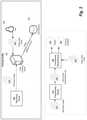
- Off-axis holographic microcopy systemcreates holograms where there is a modulating pattern over the entire field of view due to a small angle between object and reference beam.
- the reference beamis created from the object beam using two lenses and a pinhole to erase the object spatial signature and to provide a uniform plane waves for creating an interference or hologram image.
- the focal lengthwould greatly affect the quality of the acquired cell images.
- the distance between the focal plane and the objectimpacts the appearance of the phase images and their quality.
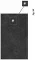
- FIG. 2illustrates example cell images with different quality. In the top row, the cells are in focus and the information content of the image can be used to discriminate among the different cell types.
- the images in the bottom roware of cells that are out of focus and distorted. The image quality is very poor and cannot be used in a diagnosis workflow.
- Embodiments of the present inventionaddress and overcome one or more of the above shortcomings and drawbacks, by providing methods, systems, and apparatuses related to identifying the quality of the cell images acquired with a microscopy device using a convolutional neural network (CNN).
- CNNconvolutional neural network
- a CNNis trained to determine whether cells are in focus or out of focus in an acquired image.
- instructionsmay be provided to the microscopy device to adjust the focal length so as to bring the acquired images into focus.
- a computer-implemented method for detecting out of focus microscopy imagesincludes acquiring microscopy images depicting cells, and extracting one or more sets of pixels from the microscopy images. Each set of pixels corresponds to an independent cell. One of a plurality of image quality labels are assigned to each set of pixels indicating the degree to which the independent cell is in focus.
- a classifieris trained to classify the set of pixels into the image quality labels. The classifier is configured according to a multi-layer architecture and the training results in determination of weights for connecting layers in the multi-layer architecture. A deployment of the classifier is created based on the multi-layer architecture, the weights, and the image quality labels.
- a computer-implemented method for performing adaptive focusing of a microscopy deviceincludes acquiring a plurality of microscopy images depicting cells using a microscopy device, and extracting one or more sets of pixels from the microscopy images. Each set of pixels corresponds to an independent cell. Then, a trained classifier is used to assign one of a plurality of image quality labels to each set of pixels indicating the degree to which the independent cell is in focus. If the image quality labels corresponding to the sets of pixels indicate that the cells are out of focus, a focal length adjustment for adjusting focus of the microscopy device is determined using a trained machine learning model. Then, executable instructions are sent to the microscopy device to perform the focal length adjustment.
- a system for performing adaptive focusing of a microscopy devicecomprises a microscopy device configured to acquire microscopy images depicting cells and one or more processors executing instructions for performing a method that includes extracting pixels from the microscopy images.
- Each set of pixelscorresponds to an independent cell.
- a trained classifieris used to assign one of a plurality of image quality labels to each set of pixels indicating the degree to which the independent cell is in focus. If the image quality labels corresponding to the sets of pixels indicate that the cells are out of focus, a focal length adjustment for adjusting focus of the microscopy device is determined using a trained machine learning model. Then, executable instructions are sent to the microscopy device to perform the focal length adjustment.
- FIG. 1shows an example DHM setup
- FIG. 2illustrates example cell images with different quality
- FIG. 3shows the system diagram illustrating the actors and operations used to assess image quality, according to some embodiments
- FIG. 4illustrates a technique for extracting the cells, according to some embodiments
- FIG. 5Aillustrates a first example extraction of cells
- FIG. 5Billustrates a second example extraction of cells
- FIG. 6Aillustrates an example of the multi-layer architecture that may be employed by the CNN, according to some embodiments.
- FIG. 6Bprovides an alternate view of the multi-layer architecture shown in FIG. 6A ;
- FIG. 7shows an assessment of classification accuracy of the techniques described herein, according to one example implementation
- FIG. 8provides an example deployment of a trained CNN, according to some embodiments.
- FIG. 9provides an example of a parallel processing memory architecture that may be utilized by image processing system, according to some embodiments of the present invention.
- the following disclosuredescribes the present invention according to several embodiments directed at methods, systems, and apparatuses related to identifying the quality of the cell images acquired with digital holographic microscopy (DHM) or another type of microscopy device using convolutional neural networks (CNNs). More specifically, techniques are described herein for differentiation between “good quality” cell images where the cells are captured in focus and the “poor quality” images that are out of focus.
- the problemis formulated as a binary image classification problem where the two classes are in-focus/out-of-focus. This problem is then solved using a CNN.
- this general frameworkcan be expanded upon with various enhancements, refinements, and other modifications in different embodiments of the present invention.
- FIG. 3shows the system diagram illustrating the actors and operations used to assess image quality, according to some embodiments.
- a Microscopy Device 305is used to acquire one or more Microscopy Images 310 .
- the Microscopy Device 305may be any system known in the art capable of acquiring microscopy images of cells.
- the Microscopy Images 310may be acquired using off-axis digital holographic microscope (DHM). The acquisition can alternatively be done using other DHM techniques such as on axis configurations.
- the Microscopy Device 305uses other cell imaging techniques known in the art which can be used to acquire the Microscopy Images 310 .
- Example alternative imaging techniquesinclude, without limitation, bright field microscopy, dark field microscopy, differential interference contrast, fluorescence microscopy, confocal microscopy, two-photon excitation microscopy, and multiphoton microscopy.
- GANDeep Convolutional General Adversarial Networks
- generative modelsmodel the distribution of individual classes.
- Generative adversarial networksgenerally represent a class of artificial intelligence algorithms that falls under the category of “unsupervised learning.”
- GANsare a combination of two neural networks: one network is learning how to generate examples (e.g., synthetic DHM images) from a training data set (e.g., images acquired using Microscopy Device 305 ), and another network attempts to distinguish between the generated examples and the training data set. The training process is successful if the generative network produces examples which converge with the actual data such that the discrimination network cannot consistently distinguish between the two.
- the Microscopy Images 310are received by an Image Processing System 345 that has processing resources for training a CNN 330 based using the Microscopy Images 310 .
- a Preprocessing Module 315extracts the independent cells from the Microscopy Images 310 for training. Each cell is extracted as a Set of Pixels 320 .
- each individual Set of Pixels 320is also sometimes referred to as a “cell image.”
- various types of image classification modelscan be used as an alternative to CNNs in other embodiments including, without limitation, linear classifiers (e.g., logistic regression, na ⁇ ve bayes classifiers, etc.), kernel estimation k-means clustering, nearest neighbor classification, support vector machines, decision trees, boosted trees, random forests, and different configurations of neural networks.
- FIG. 3shows the system diagram illustrating the actors and operations used to assess image quality, according to some embodiments.
- FIG. 4illustrates a technique 400 for extracting the cells, according to some embodiments.
- the acquired imageshave a dimension of 384 ⁇ 512 and 100 images are acquired per second.
- the average of the first 100 imagesis computed at step 405 and the average image is subtracted from each acquired image at step 410 .
- adaptive thresholdingis applied to capture all the bright components in the image.
- Various adaptive thresholding techniquesgenerally known in the art may be applied at step 415 . For example, in one embodiment, the intensity values of the local neighborhood of each pixel are used to determine a threshold for the pixel.
- the pixelis below the threshold value, it is set to some minimum value (e.g., pure black).
- one or more exclusion criteriaare applied to the images at step 420 to illuminate non-cell components. Examples of exclusion criteria that may be applied at step 420 include, without limitation, width, height, aspect ratio and circularity of the object.
- connected components analysisis applied at step 425 to identify the sets of pixels corresponding to independent cells. Each set of pixels is cropped using a predefined crop box of size 51 ⁇ 51.
- FIGS. 5A and 5Billustrate the extraction of the different cells.
- the Preprocessing Module 315can use detection techniques such as probabilistic boosting trees, deep convolutional neural networks to detect the location of the cell.
- Cell segmentationcan also be used to extract the cell. This can be performed using energy minimization techniques such as graph cuts, watershed, random walker, or Mumford-Shah. It can also be performed using model based methods that would fit a predefined shape (e.g., a circle) to the desired object.
- the segmentationcan be performed with alternative techniques such as edge matching, gradient matching or intensity matching. Additional details on how segmentation may be performed are detailed in U.S. Patent Application Publication No. 2018/0144182A1 entitled “Analyzing digital holographic microscopy data for hematology applications,” the entirety of which is incorporated herein by reference.
- the Image Processing System 345uses the Sets of Pixels 320 to train the CNN 330 to solve the image classification problem.
- the classification problemaims at assigning a label for each image.
- a User 350manually inspects each Set of Pixels 320 corresponding to a cell to generate Image Quality Labels 325 .
- the User 350may be provided with a graphical user interface (GUI) where each cell is presented and with an input field that allows specification of the Image Quality Labels 325 .
- GUIgraphical user interface
- the task of generating the Image Quality Labels 325can be distributed over a plurality of users.
- the Image Quality Labels 325are 0, for a cell image that is out of focus and 1, for a cell image that is in focus.
- a wider range of labelsare given for different focal plane images and this would capture a larger range of variation in the image.
- the labelcan be a grade for the cell from 1 to 10 where cells with grade 1 are the worst and cells with grade 10 are the best. Correlation between these grades and the focal distance can be used to automatically adjust the focal plane or provide feedback to the device operator to perform such adjustment. Depending on the subsequent workflow, cells belonging to one or more of these grade classes can be included.
- a CNN 330includes an input layer, one or more hidden layers, and an output layer.
- the objective of training the CNN 330is to learn a transfer function between the input layer (features that represent the image) and the output layer (the labels for the image).
- the Image Processing System 345performs iterative forward and backward passes that are made through the CNN 330 as the transfer function is minimized with respect to Weights 335 connecting the different layers of the CNN architecture.
- a description of the Multi-layer Architecture 340i.e., the composition of the different layers
- the Weights 335 connecting the neurons from the different layersare stored in a Data Repository 355 along with description of the labelling system employed during training.
- the information in the Data Repository 355can later be used to deploy the CNN 330 .
- the NVIDIA TensorRT®is used to deploy the CNN 330 into a production environment.
- TensorRTrequires 3 files to execute a CNN: a network architecture file, trained weights, and a label file to provide a name for each output class. These 3 files may be generated by the description of the Multi-Layer Architecture 340 , Weights 335 , and the description of the labelling system, respectively.
- FIG. 6Aillustrates an example of the Multi-Layer Architecture 340 that may be employed by the CNN 330 , according to some embodiments.
- the first layeris convolutional layer with 20 filters of kernel size 5 ⁇ 5, while the second layer max pooling layer of kernel size 2 ⁇ 2 and stride of 2.
- the third layeris a convolutional layer with 50 filters of kernel size 5 ⁇ 5 and the fourth layer is a convolutional layer of kernel size 2 ⁇ 2 and stride of 2.
- the fifth layeris a fully connected layer of size 500.
- the sixth layeris a drop out layer keeping 0.7 of the weights.
- the seventh layeris an output layer of size 2 that provides a label 0 for out of focus cells, and a label of 1 for in focus cells.
- FIG. 6Bprovides a visualization of the operations performed by the Multi-Layer Architecture 340 described in FIG. 6A .
- the network architecture shown in FIGS. 6A and 6Bis just an example of a possible architecture.
- a different number of layerscan be used, the kernel sizes of the filters can also be different and different sizes could be used for different layers.
- the dropout layercan be eliminated, or alternatively, multiple dropout layers may be used and the drop out probabilities can vary from 0 to 1.
- FIG. 8provides an example deployment, according to some embodiments.
- the output of the CNNis used to provide adaptive focusing of the microscope of the Microscopy Device 805 .
- the Microscopy Device 805is used to acquire Microscopy Images 810 which are sent to an Image Processing System 850 .
- the Microscopy Images 810are preprocessed by Preprocessing Module 815 to generate Sets of Pixels 820 corresponding to cells.
- the Preprocessing Module 815 shown in FIG. 8operates in a manner similar to the Preprocessing Module 315 described above with respect to FIG. 3 .
- the Sets of Pixels 820are used as input to the Trained CNN 830 that, in turn, output Labelled Cells 831 . That is, the output are the Sets of Pixels 820 with labels according to the labelling convention (e.g., 0 for out of focus or 1 for in focus).
- the labelling conventione.g., 0 for out of focus or 1 for in focus.
- the Labelled Cells 831are used as input to a Machine Learning Model 833 trained to output a Focal Length Adjustment 835 for the Microscopy Device 805 to adjust any focus issues.
- This Machine Learning Model 833trained by monitoring, over time, how the Microscopy Device 805 is adjusted in response to the acquired microscopy images and the output of the Trained CNN 830 . Such monitoring may be performed, for example, by recording instructions sent to the Microscopy Device 805 . Alternatively, an operator can manually enter the focal length changes into the Image Processing System 850 .
- a manifoldi.e., a basis set
- Example techniques that can be employed to learn the manifoldinclude, without limitation, principal component analysis (PCA), locally-linear embedding, and diffusion maps.
- the Machine Learning Model 833outputs a Focal Length Adjustment 835 for the Microscopy Device 805 .
- This Focal Length Adjustment 835is then used as input to an Instruction Generator 840 that translates the adjustment into Executable Instructions 845 for the Microscopy Device 805 .
- the implementation of the Instruction Generator 840is dependent on the interface of the Microscopy Device 805 . However, in general, the Instruction Generator 840 can be understood as software that provides an additional interface layer between the Image Processing System 850 and the Microscopy Device 805 .
- the Machine Learning Model 833can be trained to directly output the Executable Instructions 845 , thus obviating the need for the Instruction Generator 840 .
- FIG. 9provides an example of a parallel processing memory architecture 900 that may be utilized by an image processing system, according to some embodiments of the present invention.
- This architecture 900may be used in embodiments of the present invention where NVIDIATM CUDA (or a similar parallel computing platform) is used.
- the architectureincludes a host computing unit (“host”) 905 and a GPU device (“device”) 910 connected via a bus 915 (e.g., a PCIe bus).
- the host 905includes the central processing unit, or “CPU” (not shown in FIG. 9 ) and host memory 925 accessible to the CPU.
- the device 910includes the graphics processing unit (GPU) and its associated memory 920 , referred to herein as device memory.
- the device memory 920may include various types of memory, each optimized for different memory usages. For example, in some embodiments, the device memory includes global memory, constant memory, and texture memory.
- Parallel portions of a CNNmay be executed on the architecture 900 as “device kernels” or simply “kernels.”
- a kernelcomprises parameterized code configured to perform a particular function.
- the parallel computing platformis configured to execute these kernels in an optimal manner across the architecture 900 based on parameters, settings, and other selections provided by the user. Additionally, in some embodiments, the parallel computing platform may include additional functionality to allow for automatic processing of kernels in an optimal manner with minimal input provided by the user.
- the processing required for each kernelis performed by grid of thread blocks (described in greater detail below).
- the architecture 900 of FIG. 9may be used to parallelize training of the CNN. For example, in some embodiments, processing of individual cell images may be performed in parallel.
- the device 910includes one or more thread blocks 930 which represent the computation unit of the device 910 .
- the term thread blockrefers to a group of threads that can cooperate via shared memory and synchronize their execution to coordinate memory accesses.
- threads 940 , 945 and 950operate in thread block 930 and access shared memory 935 .
- thread blocksmay be organized in a grid structure. A computation or series of computations may then be mapped onto this grid. For example, in embodiments utilizing CUDA, computations may be mapped on one-, two-, or three-dimensional grids. Each grid contains multiple thread blocks, and each thread block contains multiple threads. For example, in FIG.
- the thread blocks 930are organized in a two dimensional grid structure with m+1 rows and n+1 columns.
- threads in different thread blocks of the same gridcannot communicate or synchronize with each other.
- thread blocks in the same gridcan run on the same multiprocessor within the GPU at the same time.
- the number of threads in each thread blockmay be limited by hardware or software constraints.
- processing of subsets of the training data or operations performed by the algorithms discussed hereinmay be partitioned over thread blocks automatically by the parallel computing platform software.
- the individual thread blockscan be selected and configured to optimize training of the CNN.
- each thread blockis assigned an individual cell image or group of related cell images.
- registers 955 , 960 , and 965represent the fast memory available to thread block 930 .
- Each registeris only accessible by a single thread.
- register 955may only be accessed by thread 940 .
- shared memoryis allocated per thread block, so all threads in the block have access to the same shared memory.
- shared memory 935is designed to be accessed, in parallel, by each thread 940 , 945 , and 950 in thread block 930 .
- Threadscan access data in shared memory 935 loaded from device memory 920 by other threads within the same thread block (e.g., thread block 930 ).
- the device memory 920is accessed by all blocks of the grid and may be implemented using, for example, Dynamic Random-Access Memory (DRAM).
- DRAMDynamic Random-Access Memory
- Each threadcan have one or more levels of memory access.
- each threadmay have three levels of memory access.
- First, each thread 940 , 945 , 950can read and write to its corresponding registers 955 , 960 , and 965 . Registers provide the fastest memory access to threads because there are no synchronization issues and the register is generally located close to a multiprocessor executing the thread.
- Second, each thread 940 , 945 , 950 in thread block 930may read and write data to the shared memory 935 corresponding to that block 930 . Generally, the time required for a thread to access shared memory exceeds that of register access due to the need to synchronize access among all the threads in the thread block.
- the shared memoryis typically located close to the multiprocessor executing the threads.
- the third level of memory accessallows all threads on the device 910 to read and/or write to the device memory.
- Device memoryrequires the longest time to access because access must be synchronized across the thread blocks operating on the device.
- the processing of each cell imageis coded such that it primarily utilizes registers and shared memory and only utilizes device memory as necessary to move data in and out of a thread block.
- the embodiments of the present disclosuremay be implemented with any combination of hardware and software.
- standard computing platformse.g., servers, desktop computer, etc.
- the embodiments of the present disclosuremay be included in an article of manufacture (e.g., one or more computer program products) having, for example, computer-readable, non-transitory media.
- the mediamay have embodied therein computer readable program code for providing and facilitating the mechanisms of the embodiments of the present disclosure.
- the article of manufacturecan be included as part of a computer system or sold separately.
- An executable applicationcomprises code or machine readable instructions for conditioning the processor to implement predetermined functions, such as those of an operating system, a context data acquisition system or other information processing system, for example, in response to user command or input.
- An executable procedureis a segment of code or machine readable instruction, sub-routine, or other distinct section of code or portion of an executable application for performing one or more particular processes. These processes may include receiving input data and/or parameters, performing operations on received input data and/or performing functions in response to received input parameters, and providing resulting output data and/or parameters.
- a graphical user interfacecomprises one or more display images, generated by a display processor and enabling user interaction with a processor or other device and associated data acquisition and processing functions.
- the GUIalso includes an executable procedure or executable application.
- the executable procedure or executable applicationconditions the display processor to generate signals representing the GUI display images. These signals are supplied to a display device which displays the image for viewing by the user.
- the processorunder control of an executable procedure or executable application, manipulates the GUI display images in response to signals received from the input devices. In this way, the user may interact with the display image using the input devices, enabling user interaction with the processor or other device.
- modulecan refer to either or both of: (i) a software component that causes an electronic device to accept various inputs and generate certain outputs; or (ii) an electronic input/output interface, such as a panel, frame, textbox, window or other portion of a GUI.
- An activityperformed automatically is performed in response to one or more executable instructions or device operation without user direct initiation of the activity.
Landscapes
- Engineering & Computer Science (AREA)
- Physics & Mathematics (AREA)
- General Physics & Mathematics (AREA)
- Theoretical Computer Science (AREA)
- Multimedia (AREA)
- Computer Vision & Pattern Recognition (AREA)
- General Health & Medical Sciences (AREA)
- Health & Medical Sciences (AREA)
- Evolutionary Computation (AREA)
- Artificial Intelligence (AREA)
- Quality & Reliability (AREA)
- Medical Informatics (AREA)
- Life Sciences & Earth Sciences (AREA)
- Data Mining & Analysis (AREA)
- Computing Systems (AREA)
- Databases & Information Systems (AREA)
- Software Systems (AREA)
- Analytical Chemistry (AREA)
- Chemical & Material Sciences (AREA)
- Optics & Photonics (AREA)
- Molecular Biology (AREA)
- Biomedical Technology (AREA)
- Evolutionary Biology (AREA)
- Bioinformatics & Cheminformatics (AREA)
- Bioinformatics & Computational Biology (AREA)
- General Engineering & Computer Science (AREA)
- Radiology & Medical Imaging (AREA)
- Nuclear Medicine, Radiotherapy & Molecular Imaging (AREA)
- Image Analysis (AREA)
- Microscoopes, Condenser (AREA)
Abstract
Description
Claims (9)
Priority Applications (1)
| Application Number | Priority Date | Filing Date | Title |
|---|---|---|---|
| US16/617,162US11227386B2 (en) | 2017-08-15 | 2018-07-06 | Identifying the quality of the cell images acquired with digital holographic microscopy using convolutional neural networks |
Applications Claiming Priority (3)
| Application Number | Priority Date | Filing Date | Title |
|---|---|---|---|
| US201762545517P | 2017-08-15 | 2017-08-15 | |
| US16/617,162US11227386B2 (en) | 2017-08-15 | 2018-07-06 | Identifying the quality of the cell images acquired with digital holographic microscopy using convolutional neural networks |
| PCT/EP2018/068345WO2019034328A1 (en) | 2017-08-15 | 2018-07-06 | Identifying the quality of the cell images acquired with digital holographic microscopy using convolutional neural networks |
Related Parent Applications (1)
| Application Number | Title | Priority Date | Filing Date |
|---|---|---|---|
| PCT/EP2018/068345A-371-Of-InternationalWO2019034328A1 (en) | 2017-08-15 | 2018-07-06 | Identifying the quality of the cell images acquired with digital holographic microscopy using convolutional neural networks |
Related Child Applications (1)
| Application Number | Title | Priority Date | Filing Date |
|---|---|---|---|
| US17/457,716DivisionUS11580640B2 (en) | 2017-08-15 | 2021-12-06 | Identifying the quality of the cell images acquired with digital holographic microscopy using convolutional neural networks |
Publications (2)
| Publication Number | Publication Date |
|---|---|
| US20200184637A1 US20200184637A1 (en) | 2020-06-11 |
| US11227386B2true US11227386B2 (en) | 2022-01-18 |
Family
ID=63077840
Family Applications (2)
| Application Number | Title | Priority Date | Filing Date |
|---|---|---|---|
| US16/617,162Active2038-07-31US11227386B2 (en) | 2017-08-15 | 2018-07-06 | Identifying the quality of the cell images acquired with digital holographic microscopy using convolutional neural networks |
| US17/457,716ActiveUS11580640B2 (en) | 2017-08-15 | 2021-12-06 | Identifying the quality of the cell images acquired with digital holographic microscopy using convolutional neural networks |
Family Applications After (1)
| Application Number | Title | Priority Date | Filing Date |
|---|---|---|---|
| US17/457,716ActiveUS11580640B2 (en) | 2017-08-15 | 2021-12-06 | Identifying the quality of the cell images acquired with digital holographic microscopy using convolutional neural networks |
Country Status (5)
| Country | Link |
|---|---|
| US (2) | US11227386B2 (en) |
| EP (1) | EP3669227B8 (en) |
| JP (1) | JP7072049B2 (en) |
| CN (1) | CN111051955B (en) |
| WO (1) | WO2019034328A1 (en) |
Cited By (2)
| Publication number | Priority date | Publication date | Assignee | Title |
|---|---|---|---|---|
| US20230160879A1 (en)* | 2021-11-19 | 2023-05-25 | Industrial Technology Research Institute | Method of training ai for label-free cell viability determination and label-free cell viability determination method by trained ai |
| US20230184683A1 (en)* | 2021-12-14 | 2023-06-15 | Instituto Potosino de Investigación Científica y Tecnológica A.C. | System and method for three-dimensional imaging of unstained samples using bright field microscopy |
Families Citing this family (26)
| Publication number | Priority date | Publication date | Assignee | Title |
|---|---|---|---|---|
| US11222415B2 (en)* | 2018-04-26 | 2022-01-11 | The Regents Of The University Of California | Systems and methods for deep learning microscopy |
| US10706328B2 (en) | 2018-05-07 | 2020-07-07 | Google Llc | Focus-weighted, machine learning disease classifier error prediction for microscope slide images |
| US11157816B2 (en)* | 2018-10-17 | 2021-10-26 | Capital One Services, Llc | Systems and methods for selecting and generating log parsers using neural networks |
| EP3644228B1 (en)* | 2018-10-23 | 2024-08-14 | The Chinese University Of Hong Kong | Method and apparatus for segmenting cellular image |
| DE102018133188A1 (en)* | 2018-12-20 | 2020-06-25 | Carl Zeiss Microscopy Gmbh | DISTANCE DETERMINATION OF A SAMPLE LEVEL IN A MICROSCOPE SYSTEM |
| US11405547B2 (en)* | 2019-02-01 | 2022-08-02 | Electronics And Telecommunications Research Institute | Method and apparatus for generating all-in-focus image using multi-focus image |
| CN113711133A (en)* | 2019-04-22 | 2021-11-26 | 加利福尼亚大学董事会 | System and method for color holographic microscope based on deep learning |
| EP3757648B1 (en)* | 2019-06-28 | 2023-08-30 | Associação Fraunhofer Portugal | Optical system attachable to a mobile device for scanning biological sample slides and operating method thereof |
| CN110516561B (en)* | 2019-08-05 | 2022-12-06 | 西安电子科技大学 | SAR image target recognition method based on DCGAN and CNN |
| CN110736747B (en)* | 2019-09-03 | 2022-08-19 | 深思考人工智能机器人科技(北京)有限公司 | Method and system for positioning under cell liquid-based smear mirror |
| CN111091539B (en)* | 2019-12-09 | 2024-03-26 | 上海联影智能医疗科技有限公司 | Network model training and medical image processing methods, devices, mediums and equipment |
| DE102020106857A1 (en)* | 2020-03-12 | 2021-09-16 | Carl Zeiss Microscopy Gmbh | MICROSCOPY SYSTEM AND METHOD FOR PROCESSING MICROSCOPE IMAGES |
| US20230085827A1 (en)* | 2020-03-20 | 2023-03-23 | The Regents Of The University Of California | Single-shot autofocusing of microscopy images using deep learning |
| GB2595873B (en)* | 2020-06-09 | 2023-01-25 | Ffei Ltd | A method for analysing scanning efficacy |
| WO2022004318A1 (en)* | 2020-07-02 | 2022-01-06 | 富士フイルム株式会社 | Information processing device, information processing method, and program |
| GB2596864A (en)* | 2020-07-10 | 2022-01-12 | Graphcore Ltd | Machine learning computer |
| JP2023537892A (en)* | 2020-08-07 | 2023-09-06 | ナノトロニクス イメージング インコーポレイテッド | A Deep Learning Model for Autofocusing Microscopy Systems |
| CN111709390A (en)* | 2020-08-11 | 2020-09-25 | 山东省食品药品检验研究院 | Intelligent identification method and system of calcium oxalate crystals based on microscopic images |
| JP7495301B2 (en)* | 2020-08-28 | 2024-06-04 | 浜松ホトニクス株式会社 | Learning model generation method, classification method, learning model generation system, classification system, learning model generation program, classification program, and recording medium |
| JP7452702B2 (en)* | 2020-11-30 | 2024-03-19 | 株式会社ニコン | Method for generating trained model, image processing method, image conversion device, program |
| KR102449858B1 (en)* | 2021-07-08 | 2022-09-30 | 가톨릭대학교 산학협력단 | Nuclear image screening device and nuclear image screening method for cancer cell determination |
| CN117597430A (en)* | 2021-07-29 | 2024-02-23 | 株式会社岛津制作所 | Cell image analysis method |
| CN118435233A (en)* | 2021-12-17 | 2024-08-02 | 贝克曼库尔特有限公司 | Quality of focus determination by multilayer processing |
| KR102436267B1 (en)* | 2021-12-24 | 2022-08-26 | (주)힉스컴퍼니 | Parallel precessing method and high-speed precessing system using the same |
| WO2024181593A1 (en)* | 2023-02-27 | 2024-09-06 | 가톨릭대학교 산학협력단 | Nuclear image selection device and nuclear image selection method for cancer cell determination |
| CN116563735A (en)* | 2023-05-15 | 2023-08-08 | 国网电力空间技术有限公司 | A focus judgment method for power transmission tower inspection images based on deep artificial intelligence |
Citations (31)
| Publication number | Priority date | Publication date | Assignee | Title |
|---|---|---|---|---|
| US4998284A (en)* | 1987-11-17 | 1991-03-05 | Cell Analysis Systems, Inc. | Dual color camera microscope and methodology for cell staining and analysis |
| US5655028A (en)* | 1991-12-30 | 1997-08-05 | University Of Iowa Research Foundation | Dynamic image analysis system |
| JPH09311102A (en) | 1996-05-24 | 1997-12-02 | Hitachi Ltd | Flow type particle image analysis method and apparatus |
| US5875258A (en)* | 1994-09-20 | 1999-02-23 | Neopath, Inc. | Biological specimen analysis system processing integrity checking apparatus |
| US20030143524A1 (en) | 2002-01-31 | 2003-07-31 | Boaz Lerner | Method and system for determining the amount, distribution and conformation of genetic material in a cell |
| US7034883B1 (en) | 1999-08-10 | 2006-04-25 | Cellavision Ab | Automatic focusing |
| US20060178833A1 (en) | 2005-02-04 | 2006-08-10 | Bauer Kenneth D | System for and method of providing diagnostic information through microscopic imaging |
| US7761250B2 (en)* | 2008-06-18 | 2010-07-20 | Tokyo Electron Limited | Optical metrology system optimized with design goals |
| US7760927B2 (en)* | 2003-09-10 | 2010-07-20 | Bioimagene, Inc. | Method and system for digital image based tissue independent simultaneous nucleus cytoplasm and membrane quantitation |
| EP1210634B1 (en) | 1999-08-10 | 2010-10-06 | Cellavision AB | Methods and devices in an optical system |
| CN102007369A (en) | 2008-02-18 | 2011-04-06 | 维森盖特有限公司 | 3d imaging of live cells with ultraviolet radiation |
| US7963906B2 (en)* | 2009-08-22 | 2011-06-21 | The Board Of Trustees Of The Leland Stanford Junior University | Imaging and evaluating embryos, oocytes, and stem cells |
| US8049811B2 (en)* | 2009-01-28 | 2011-11-01 | Board Of Regents, The University Of Texas System | Automatic focusing apparatus and method for digital images using automatic filter switching |
| CN102411715A (en) | 2010-09-21 | 2012-04-11 | 张云超 | Automatic cell image classification method and system with learning monitoring function |
| US8224058B2 (en)* | 2006-07-19 | 2012-07-17 | Hemocue Ab | Measurement apparatus, method and computer program |
| CN102625932A (en) | 2009-09-08 | 2012-08-01 | 诺达利蒂公司 | Cell Network Analysis |
| US20120258547A1 (en) | 2011-04-05 | 2012-10-11 | Von Drasek William A | Method of monitoring macrostickies in a recycling and paper or tissue making process involving recycled pulp |
| US8326029B1 (en)* | 2008-03-21 | 2012-12-04 | Hewlett-Packard Development Company, L.P. | Background color driven content retrieval |
| US8472679B2 (en)* | 2009-10-27 | 2013-06-25 | Fujitsu Limited | Biometric information processing apparatus, biometric information processing method, and biometric information processing computer program |
| US8503801B2 (en)* | 2010-09-21 | 2013-08-06 | Adobe Systems Incorporated | System and method for classifying the blur state of digital image pixels |
| US8744164B2 (en)* | 2010-04-06 | 2014-06-03 | Institute For Systems Biology | Automated analysis of images using bright field microscopy |
| US8885941B2 (en)* | 2011-09-16 | 2014-11-11 | Adobe Systems Incorporated | System and method for estimating spatially varying defocus blur in a digital image |
| US8902328B2 (en)* | 2013-03-14 | 2014-12-02 | Konica Minolta Laboratory U.S.A., Inc. | Method of selecting a subset from an image set for generating high dynamic range image |
| WO2015195609A1 (en) | 2014-06-16 | 2015-12-23 | Siemens Healthcare Diagnostics Inc. | Analyzing digital holographic microscopy data for hematology applications |
| CN105938559A (en) | 2015-03-04 | 2016-09-14 | 埃森哲环球服务有限公司 | Digital image processing using convolutional neural networks |
| WO2017050861A1 (en) | 2015-09-22 | 2017-03-30 | Siemens Healthcare Gmbh | Auto-referencing in digital holographic microscopy reconstruction |
| JP2017516992A (en) | 2014-05-23 | 2017-06-22 | ベンタナ メディカル システムズ, インコーポレイテッド | System and method for detection of biological structures and / or patterns in images |
| CN106934426A (en) | 2015-12-29 | 2017-07-07 | 三星电子株式会社 | The method and apparatus of the neutral net based on picture signal treatment |
| WO2017157555A1 (en) | 2016-03-16 | 2017-09-21 | Siemens Healthcare Gmbh | High accuracy 5-part differential with digital holographic microscopy and untouched leukocytes from peripheral blood |
| US9836839B2 (en)* | 2015-05-28 | 2017-12-05 | Tokitae Llc | Image analysis systems and related methods |
| US9927604B2 (en)* | 2014-09-12 | 2018-03-27 | Research Foundation Of The City University Of New York | Biologically inspired algorithm based method for near real-time tracking of moving objects in three dimensional environment |
Family Cites Families (5)
| Publication number | Priority date | Publication date | Assignee | Title |
|---|---|---|---|---|
| JP5476879B2 (en)* | 2008-09-29 | 2014-04-23 | ソニー株式会社 | Image processing apparatus and coefficient learning apparatus. |
| US20140192178A1 (en)* | 2011-08-12 | 2014-07-10 | Agency For Science, Technology And Research | Method and system for tracking motion of microscopic objects within a three-dimensional volume |
| US20180018757A1 (en)* | 2016-07-13 | 2018-01-18 | Kenji Suzuki | Transforming projection data in tomography by means of machine learning |
| US10573003B2 (en)* | 2017-02-13 | 2020-02-25 | Amit Sethi | Systems and methods for computational pathology using points-of-interest |
| US11416714B2 (en)* | 2017-03-24 | 2022-08-16 | Revealit Corporation | Method, system, and apparatus for identifying and revealing selected objects from video |
- 2018
- 2018-07-06WOPCT/EP2018/068345patent/WO2019034328A1/ennot_activeCeased
- 2018-07-06EPEP18748860.6Apatent/EP3669227B8/enactiveActive
- 2018-07-06USUS16/617,162patent/US11227386B2/enactiveActive
- 2018-07-06JPJP2020508555Apatent/JP7072049B2/enactiveActive
- 2018-07-06CNCN201880052840.9Apatent/CN111051955B/enactiveActive
- 2021
- 2021-12-06USUS17/457,716patent/US11580640B2/enactiveActive
Patent Citations (38)
| Publication number | Priority date | Publication date | Assignee | Title |
|---|---|---|---|---|
| US4998284A (en)* | 1987-11-17 | 1991-03-05 | Cell Analysis Systems, Inc. | Dual color camera microscope and methodology for cell staining and analysis |
| US5655028A (en)* | 1991-12-30 | 1997-08-05 | University Of Iowa Research Foundation | Dynamic image analysis system |
| US5875258A (en)* | 1994-09-20 | 1999-02-23 | Neopath, Inc. | Biological specimen analysis system processing integrity checking apparatus |
| JPH09311102A (en) | 1996-05-24 | 1997-12-02 | Hitachi Ltd | Flow type particle image analysis method and apparatus |
| US7034883B1 (en) | 1999-08-10 | 2006-04-25 | Cellavision Ab | Automatic focusing |
| EP1210634B1 (en) | 1999-08-10 | 2010-10-06 | Cellavision AB | Methods and devices in an optical system |
| US20030143524A1 (en) | 2002-01-31 | 2003-07-31 | Boaz Lerner | Method and system for determining the amount, distribution and conformation of genetic material in a cell |
| US7760927B2 (en)* | 2003-09-10 | 2010-07-20 | Bioimagene, Inc. | Method and system for digital image based tissue independent simultaneous nucleus cytoplasm and membrane quantitation |
| US20060178833A1 (en) | 2005-02-04 | 2006-08-10 | Bauer Kenneth D | System for and method of providing diagnostic information through microscopic imaging |
| US8224058B2 (en)* | 2006-07-19 | 2012-07-17 | Hemocue Ab | Measurement apparatus, method and computer program |
| US8143600B2 (en) | 2008-02-18 | 2012-03-27 | Visiongate, Inc. | 3D imaging of live cells with ultraviolet radiation |
| CN102007369A (en) | 2008-02-18 | 2011-04-06 | 维森盖特有限公司 | 3d imaging of live cells with ultraviolet radiation |
| US8326029B1 (en)* | 2008-03-21 | 2012-12-04 | Hewlett-Packard Development Company, L.P. | Background color driven content retrieval |
| US7761250B2 (en)* | 2008-06-18 | 2010-07-20 | Tokyo Electron Limited | Optical metrology system optimized with design goals |
| US8049811B2 (en)* | 2009-01-28 | 2011-11-01 | Board Of Regents, The University Of Texas System | Automatic focusing apparatus and method for digital images using automatic filter switching |
| US7963906B2 (en)* | 2009-08-22 | 2011-06-21 | The Board Of Trustees Of The Leland Stanford Junior University | Imaging and evaluating embryos, oocytes, and stem cells |
| US8323177B2 (en)* | 2009-08-22 | 2012-12-04 | The Board Of Trustees Of The Leland Stanford Junior University | Imaging and evaluating embryos, oocytes, and stem cells |
| US8721521B2 (en)* | 2009-08-22 | 2014-05-13 | The Board Of Trustees Of The Leland Stanford Junior University | Imaging and evaluating embryos, oocytes, and stem cells |
| CN102625932A (en) | 2009-09-08 | 2012-08-01 | 诺达利蒂公司 | Cell Network Analysis |
| US20140127716A1 (en) | 2009-09-08 | 2014-05-08 | Nodality, Inc | Benchmarks for normal cell identification |
| US8472679B2 (en)* | 2009-10-27 | 2013-06-25 | Fujitsu Limited | Biometric information processing apparatus, biometric information processing method, and biometric information processing computer program |
| US8744164B2 (en)* | 2010-04-06 | 2014-06-03 | Institute For Systems Biology | Automated analysis of images using bright field microscopy |
| CN102411715A (en) | 2010-09-21 | 2012-04-11 | 张云超 | Automatic cell image classification method and system with learning monitoring function |
| US8503801B2 (en)* | 2010-09-21 | 2013-08-06 | Adobe Systems Incorporated | System and method for classifying the blur state of digital image pixels |
| US20120258547A1 (en) | 2011-04-05 | 2012-10-11 | Von Drasek William A | Method of monitoring macrostickies in a recycling and paper or tissue making process involving recycled pulp |
| US8885941B2 (en)* | 2011-09-16 | 2014-11-11 | Adobe Systems Incorporated | System and method for estimating spatially varying defocus blur in a digital image |
| US8902328B2 (en)* | 2013-03-14 | 2014-12-02 | Konica Minolta Laboratory U.S.A., Inc. | Method of selecting a subset from an image set for generating high dynamic range image |
| JP2017516992A (en) | 2014-05-23 | 2017-06-22 | ベンタナ メディカル システムズ, インコーポレイテッド | System and method for detection of biological structures and / or patterns in images |
| US10109052B2 (en) | 2014-05-23 | 2018-10-23 | Ventana Medical Systems, Inc. | Systems and methods for detection of structures and/or patterns in images |
| WO2015195609A1 (en) | 2014-06-16 | 2015-12-23 | Siemens Healthcare Diagnostics Inc. | Analyzing digital holographic microscopy data for hematology applications |
| US9927604B2 (en)* | 2014-09-12 | 2018-03-27 | Research Foundation Of The City University Of New York | Biologically inspired algorithm based method for near real-time tracking of moving objects in three dimensional environment |
| CN105938559A (en) | 2015-03-04 | 2016-09-14 | 埃森哲环球服务有限公司 | Digital image processing using convolutional neural networks |
| US9524450B2 (en) | 2015-03-04 | 2016-12-20 | Accenture Global Services Limited | Digital image processing using convolutional neural networks |
| US9836839B2 (en)* | 2015-05-28 | 2017-12-05 | Tokitae Llc | Image analysis systems and related methods |
| WO2017050861A1 (en) | 2015-09-22 | 2017-03-30 | Siemens Healthcare Gmbh | Auto-referencing in digital holographic microscopy reconstruction |
| CN106934426A (en) | 2015-12-29 | 2017-07-07 | 三星电子株式会社 | The method and apparatus of the neutral net based on picture signal treatment |
| US10460231B2 (en) | 2015-12-29 | 2019-10-29 | Samsung Electronics Co., Ltd. | Method and apparatus of neural network based image signal processor |
| WO2017157555A1 (en) | 2016-03-16 | 2017-09-21 | Siemens Healthcare Gmbh | High accuracy 5-part differential with digital holographic microscopy and untouched leukocytes from peripheral blood |
Non-Patent Citations (11)
| Title |
|---|
| Anonymous: "Convolutional neural network—Wikipedia"; Aug. 17, 2016 (Aug. 17, 2016), XP055697578; Retrieved from the Internet: URL: https://en.wikipedia.org/w/index.php?title=Convolutional_neutral_network&oldid=734940910; (Retrieved on May 20, 2020). |
| Han, Liang et al: "Transferring Microscopy Image Modalities with Conditional Generative Adversarial Networks"; 2017 IEEE Conference on Computer Vision and Pattern Recognition Workshops (CVPRW), USA; IEEE; Jul. 21, 2017; pp. 851-859. |
| International Search Report dated Nov. 16, 2018 in corresponding International Patent Application No. PCT/EP2018/068345. |
| Matula, et al: "Single-cell-based image analysis of high-throughput cell array screens for quantification of viral infection"; Cytometry Part A, vol. 75A, No. 4, Apr. 1, 2009 (Apr. 1, 2009); , pp. 309-318. |
| Office Action and Search Report dated May 8, 2021 in corresponding Chinese Patent Application No. 201880052840.9. |
| Office Action dated Nov. 2, 2021 in corresponding Japanese patent application No. 2020-508555. |
| Office Action dated Sep. 15, 2021 in corresponding European patent application No. 18748860.6. |
| Pitkäaho, Tomi et al: "Preformance of Autofocus Capability of Deep Convolutional Neutral Networks in Digital Holographic Microscopy"; Digital Holography and Three-Dimensional Imaging; Jan. 1, 2016 (Jan. 1, 2016), p. W2A.5. |
| Yang, et al: "Assessing microscope image focus quality with deep learning", BMC Bioinformatics, Biomed Central Ltd, London, UK, vol. 19, No. 1, Mar. 15, 2018 (Mar. 15, 2018); pp. 1-9. |
| Zeder, et al: "Automated quality assessment of autonomously acquired microscopic images of fluorescently stained bacteria", Cytometry. Part A, John Wiley & Sons, Inc, US, vol. 77. No. 1, Jan. 1, 2010 (Jan. 1, 2010), .pp. 76-85. |
| Zeder, et al: "Multispot live-image autofocusing for high-throughput microscopy of fluorescently stained bacteria", NIH Public Access Author Manuscript, vo 1 . 7 5A, No. 9, Sep. 1, 2009 (Sep. 1, 2009), pp. 781-788. |
Cited By (4)
| Publication number | Priority date | Publication date | Assignee | Title |
|---|---|---|---|---|
| US20230160879A1 (en)* | 2021-11-19 | 2023-05-25 | Industrial Technology Research Institute | Method of training ai for label-free cell viability determination and label-free cell viability determination method by trained ai |
| US12099053B2 (en)* | 2021-11-19 | 2024-09-24 | Industrial Technology Research Institute | Method of training AI for label-free cell viability determination and label-free cell viability determination method by trained AI |
| US20230184683A1 (en)* | 2021-12-14 | 2023-06-15 | Instituto Potosino de Investigación Científica y Tecnológica A.C. | System and method for three-dimensional imaging of unstained samples using bright field microscopy |
| US11906433B2 (en)* | 2021-12-14 | 2024-02-20 | Instituto Potosino de Investigación Científica y Tecnológica A.C. | System and method for three-dimensional imaging of unstained samples using bright field microscopy |
Also Published As
| Publication number | Publication date |
|---|---|
| JP7072049B2 (en) | 2022-05-19 |
| US11580640B2 (en) | 2023-02-14 |
| JP2020531971A (en) | 2020-11-05 |
| WO2019034328A1 (en) | 2019-02-21 |
| EP3669227B8 (en) | 2024-02-28 |
| US20220092773A1 (en) | 2022-03-24 |
| US20200184637A1 (en) | 2020-06-11 |
| CN111051955A (en) | 2020-04-21 |
| EP3669227B1 (en) | 2023-12-20 |
| CN111051955B (en) | 2022-04-15 |
| EP3669227A1 (en) | 2020-06-24 |
| EP3669227C0 (en) | 2023-12-20 |
Similar Documents
| Publication | Publication Date | Title |
|---|---|---|
| US11580640B2 (en) | Identifying the quality of the cell images acquired with digital holographic microscopy using convolutional neural networks | |
| US20220222822A1 (en) | Microscopy System and Method for Evaluating Image Processing Results | |
| TW202041850A (en) | Image noise reduction using stacked denoising auto-encoder | |
| JP2017519985A (en) | Digital holographic microscopy data analysis for hematology | |
| Nguyen et al. | DRPnet: automated particle picking in cryo-electron micrographs using deep regression | |
| CN111095360A (en) | Virtual staining of cells in digital holographic microscopy images using a universal countermeasure network | |
| US12228722B2 (en) | Microscopy system and method for modifying microscope images in the feature space of a generative network | |
| Ruediger-Flore et al. | CAD-based data augmentation and transfer learning empowers part classification in manufacturing | |
| Kromp et al. | Deep Learning architectures for generalized immunofluorescence based nuclear image segmentation | |
| Pan et al. | NJUST-CCTD: an image database for milling tool wear classification with deep learning | |
| Chen et al. | Label-free live cell recognition and tracking for biological discoveries and translational applications | |
| Qamar et al. | Segmentation and characterization of macerated fibers and vessels using deep learning | |
| Chai et al. | Characterizing robustness and sensitivity of convolutional neural networks in segmentation of fluorescence microscopy images | |
| Kang et al. | Cancer Cell Classification Based on Morphological Features of 3D Phase Contrast Microscopy Using Deep Neural Network | |
| Lv et al. | Automated nanoparticle count via modified blendmask instance segmentation on sem images | |
| Yoon et al. | Automated integrated system for stained neuron detection: An end-to-end framework with a high negative predictive rate | |
| US20250037435A1 (en) | Microscopy system and method for generating registered microscope images | |
| 강미선 | Cancer Cell Classification Based on Morphological Features of 3D Phase Contrast Microscopy Using Deep Neural Network | |
| Fernandes et al. | Artificial vision inspection system for anomaly detection in metal stamped parts | |
| US20250157232A1 (en) | Method for analyzing neuronal patterns in golgi-stained images | |
| Zhu et al. | Surface Defect Detection and Classification Based on Fusing Multiple Computer Vision Techniques | |
| Li et al. | Small Object Detection Method for Bioimages Based on Improved YOLOv8n Model | |
| Hajiabadi | Assisting in the Reuse of Artificial Intelligence Approaches in Biological Image Processing | |
| Warshaneyan et al. | Automated Pollen Recognition in Optical and Holographic Microscopy Images | |
| Yang et al. | Casting defect-detection method based on multi-image feature of fusion artificial intelligence model: D. Yang et al. |
Legal Events
| Date | Code | Title | Description |
|---|---|---|---|
| AS | Assignment | Owner name:SIEMENS MEDICAL SOLUTIONS USA, INC., PENNSYLVANIA Free format text:ASSIGNMENT OF ASSIGNORS INTEREST;ASSIGNORS:EL-ZEHIRY, NOHA YOUSSRY;RAPAKA, SAIKIRAN;KAMEN, ALI;SIGNING DATES FROM 20191107 TO 20191108;REEL/FRAME:051119/0672 | |
| FEPP | Fee payment procedure | Free format text:ENTITY STATUS SET TO UNDISCOUNTED (ORIGINAL EVENT CODE: BIG.); ENTITY STATUS OF PATENT OWNER: LARGE ENTITY | |
| AS | Assignment | Owner name:SIEMENS HEALTHCARE GMBH, GERMANY Free format text:ASSIGNMENT OF ASSIGNORS INTEREST;ASSIGNOR:SIEMENS MEDICAL SOLUTIONS USA, INC.;REEL/FRAME:051273/0434 Effective date:20191202 | |
| STPP | Information on status: patent application and granting procedure in general | Free format text:APPLICATION DISPATCHED FROM PREEXAM, NOT YET DOCKETED | |
| STPP | Information on status: patent application and granting procedure in general | Free format text:DOCKETED NEW CASE - READY FOR EXAMINATION | |
| STPP | Information on status: patent application and granting procedure in general | Free format text:NON FINAL ACTION MAILED | |
| STPP | Information on status: patent application and granting procedure in general | Free format text:RESPONSE TO NON-FINAL OFFICE ACTION ENTERED AND FORWARDED TO EXAMINER | |
| STPP | Information on status: patent application and granting procedure in general | Free format text:NOTICE OF ALLOWANCE MAILED -- APPLICATION RECEIVED IN OFFICE OF PUBLICATIONS | |
| STPP | Information on status: patent application and granting procedure in general | Free format text:NOTICE OF ALLOWANCE MAILED -- APPLICATION RECEIVED IN OFFICE OF PUBLICATIONS | |
| STPP | Information on status: patent application and granting procedure in general | Free format text:PUBLICATIONS -- ISSUE FEE PAYMENT VERIFIED | |
| STCF | Information on status: patent grant | Free format text:PATENTED CASE | |
| AS | Assignment | Owner name:SIEMENS HEALTHINEERS AG, GERMANY Free format text:ASSIGNMENT OF ASSIGNORS INTEREST;ASSIGNOR:SIEMENS HEALTHCARE GMBH;REEL/FRAME:066267/0346 Effective date:20231219 | |
| MAFP | Maintenance fee payment | Free format text:PAYMENT OF MAINTENANCE FEE, 4TH YEAR, LARGE ENTITY (ORIGINAL EVENT CODE: M1551); ENTITY STATUS OF PATENT OWNER: LARGE ENTITY Year of fee payment:4 |