US11225191B2 - Smart leather with wireless power - Google Patents
Smart leather with wireless powerDownload PDFInfo
- Publication number
- US11225191B2 US11225191B2US16/696,833US201916696833AUS11225191B2US 11225191 B2US11225191 B2US 11225191B2US 201916696833 AUS201916696833 AUS 201916696833AUS 11225191 B2US11225191 B2US 11225191B2
- Authority
- US
- United States
- Prior art keywords
- functional
- vehicle component
- electronic circuit
- leather
- vehicle
- Prior art date
- Legal status (The legal status is an assumption and is not a legal conclusion. Google has not performed a legal analysis and makes no representation as to the accuracy of the status listed.)
- Active
Links
Images


Classifications
- B—PERFORMING OPERATIONS; TRANSPORTING
- B60—VEHICLES IN GENERAL
- B60Q—ARRANGEMENT OF SIGNALLING OR LIGHTING DEVICES, THE MOUNTING OR SUPPORTING THEREOF OR CIRCUITS THEREFOR, FOR VEHICLES IN GENERAL
- B60Q3/00—Arrangement of lighting devices for vehicle interiors; Lighting devices specially adapted for vehicle interiors
- B60Q3/70—Arrangement of lighting devices for vehicle interiors; Lighting devices specially adapted for vehicle interiors characterised by the purpose
- B—PERFORMING OPERATIONS; TRANSPORTING
- B60—VEHICLES IN GENERAL
- B60Q—ARRANGEMENT OF SIGNALLING OR LIGHTING DEVICES, THE MOUNTING OR SUPPORTING THEREOF OR CIRCUITS THEREFOR, FOR VEHICLES IN GENERAL
- B60Q3/00—Arrangement of lighting devices for vehicle interiors; Lighting devices specially adapted for vehicle interiors
- B60Q3/50—Mounting arrangements
- B60Q3/54—Lighting devices embedded in interior trim, e.g. in roof liners
- B—PERFORMING OPERATIONS; TRANSPORTING
- B60—VEHICLES IN GENERAL
- B60K—ARRANGEMENT OR MOUNTING OF PROPULSION UNITS OR OF TRANSMISSIONS IN VEHICLES; ARRANGEMENT OR MOUNTING OF PLURAL DIVERSE PRIME-MOVERS IN VEHICLES; AUXILIARY DRIVES FOR VEHICLES; INSTRUMENTATION OR DASHBOARDS FOR VEHICLES; ARRANGEMENTS IN CONNECTION WITH COOLING, AIR INTAKE, GAS EXHAUST OR FUEL SUPPLY OF PROPULSION UNITS IN VEHICLES
- B60K35/00—Instruments specially adapted for vehicles; Arrangement of instruments in or on vehicles
- B60K35/20—Output arrangements, i.e. from vehicle to user, associated with vehicle functions or specially adapted therefor
- B60K35/21—Output arrangements, i.e. from vehicle to user, associated with vehicle functions or specially adapted therefor using visual output, e.g. blinking lights or matrix displays
- B—PERFORMING OPERATIONS; TRANSPORTING
- B60—VEHICLES IN GENERAL
- B60K—ARRANGEMENT OR MOUNTING OF PROPULSION UNITS OR OF TRANSMISSIONS IN VEHICLES; ARRANGEMENT OR MOUNTING OF PLURAL DIVERSE PRIME-MOVERS IN VEHICLES; AUXILIARY DRIVES FOR VEHICLES; INSTRUMENTATION OR DASHBOARDS FOR VEHICLES; ARRANGEMENTS IN CONNECTION WITH COOLING, AIR INTAKE, GAS EXHAUST OR FUEL SUPPLY OF PROPULSION UNITS IN VEHICLES
- B60K35/00—Instruments specially adapted for vehicles; Arrangement of instruments in or on vehicles
- B60K35/20—Output arrangements, i.e. from vehicle to user, associated with vehicle functions or specially adapted therefor
- B60K35/28—Output arrangements, i.e. from vehicle to user, associated with vehicle functions or specially adapted therefor characterised by the type of the output information, e.g. video entertainment or vehicle dynamics information; characterised by the purpose of the output information, e.g. for attracting the attention of the driver
- B—PERFORMING OPERATIONS; TRANSPORTING
- B60—VEHICLES IN GENERAL
- B60K—ARRANGEMENT OR MOUNTING OF PROPULSION UNITS OR OF TRANSMISSIONS IN VEHICLES; ARRANGEMENT OR MOUNTING OF PLURAL DIVERSE PRIME-MOVERS IN VEHICLES; AUXILIARY DRIVES FOR VEHICLES; INSTRUMENTATION OR DASHBOARDS FOR VEHICLES; ARRANGEMENTS IN CONNECTION WITH COOLING, AIR INTAKE, GAS EXHAUST OR FUEL SUPPLY OF PROPULSION UNITS IN VEHICLES
- B60K35/00—Instruments specially adapted for vehicles; Arrangement of instruments in or on vehicles
- B60K35/50—Instruments characterised by their means of attachment to or integration in the vehicle
- B—PERFORMING OPERATIONS; TRANSPORTING
- B60—VEHICLES IN GENERAL
- B60K—ARRANGEMENT OR MOUNTING OF PROPULSION UNITS OR OF TRANSMISSIONS IN VEHICLES; ARRANGEMENT OR MOUNTING OF PLURAL DIVERSE PRIME-MOVERS IN VEHICLES; AUXILIARY DRIVES FOR VEHICLES; INSTRUMENTATION OR DASHBOARDS FOR VEHICLES; ARRANGEMENTS IN CONNECTION WITH COOLING, AIR INTAKE, GAS EXHAUST OR FUEL SUPPLY OF PROPULSION UNITS IN VEHICLES
- B60K35/00—Instruments specially adapted for vehicles; Arrangement of instruments in or on vehicles
- B60K35/60—Instruments characterised by their location or relative disposition in or on vehicles
- B60K37/02—
- B60K37/04—
- B—PERFORMING OPERATIONS; TRANSPORTING
- B60—VEHICLES IN GENERAL
- B60K—ARRANGEMENT OR MOUNTING OF PROPULSION UNITS OR OF TRANSMISSIONS IN VEHICLES; ARRANGEMENT OR MOUNTING OF PLURAL DIVERSE PRIME-MOVERS IN VEHICLES; AUXILIARY DRIVES FOR VEHICLES; INSTRUMENTATION OR DASHBOARDS FOR VEHICLES; ARRANGEMENTS IN CONNECTION WITH COOLING, AIR INTAKE, GAS EXHAUST OR FUEL SUPPLY OF PROPULSION UNITS IN VEHICLES
- B60K37/00—Dashboards
- B60K37/20—Dashboard panels
- B—PERFORMING OPERATIONS; TRANSPORTING
- B60—VEHICLES IN GENERAL
- B60N—SEATS SPECIALLY ADAPTED FOR VEHICLES; VEHICLE PASSENGER ACCOMMODATION NOT OTHERWISE PROVIDED FOR
- B60N2/00—Seats specially adapted for vehicles; Arrangement or mounting of seats in vehicles
- B60N2/58—Seat coverings
- B—PERFORMING OPERATIONS; TRANSPORTING
- B60—VEHICLES IN GENERAL
- B60Q—ARRANGEMENT OF SIGNALLING OR LIGHTING DEVICES, THE MOUNTING OR SUPPORTING THEREOF OR CIRCUITS THEREFOR, FOR VEHICLES IN GENERAL
- B60Q3/00—Arrangement of lighting devices for vehicle interiors; Lighting devices specially adapted for vehicle interiors
- B60Q3/20—Arrangement of lighting devices for vehicle interiors; Lighting devices specially adapted for vehicle interiors for lighting specific fittings of passenger or driving compartments; mounted on specific fittings of passenger or driving compartments
- B60Q3/233—Seats; Arm rests; Head rests
- B—PERFORMING OPERATIONS; TRANSPORTING
- B60—VEHICLES IN GENERAL
- B60Q—ARRANGEMENT OF SIGNALLING OR LIGHTING DEVICES, THE MOUNTING OR SUPPORTING THEREOF OR CIRCUITS THEREFOR, FOR VEHICLES IN GENERAL
- B60Q3/00—Arrangement of lighting devices for vehicle interiors; Lighting devices specially adapted for vehicle interiors
- B60Q3/20—Arrangement of lighting devices for vehicle interiors; Lighting devices specially adapted for vehicle interiors for lighting specific fittings of passenger or driving compartments; mounted on specific fittings of passenger or driving compartments
- B60Q3/283—Steering wheels; Gear levers
- B—PERFORMING OPERATIONS; TRANSPORTING
- B60—VEHICLES IN GENERAL
- B60Q—ARRANGEMENT OF SIGNALLING OR LIGHTING DEVICES, THE MOUNTING OR SUPPORTING THEREOF OR CIRCUITS THEREFOR, FOR VEHICLES IN GENERAL
- B60Q3/00—Arrangement of lighting devices for vehicle interiors; Lighting devices specially adapted for vehicle interiors
- B60Q3/80—Circuits; Control arrangements
- B—PERFORMING OPERATIONS; TRANSPORTING
- B60—VEHICLES IN GENERAL
- B60Q—ARRANGEMENT OF SIGNALLING OR LIGHTING DEVICES, THE MOUNTING OR SUPPORTING THEREOF OR CIRCUITS THEREFOR, FOR VEHICLES IN GENERAL
- B60Q9/00—Arrangement or adaptation of signal devices not provided for in one of main groups B60Q1/00 - B60Q7/00, e.g. haptic signalling
- B—PERFORMING OPERATIONS; TRANSPORTING
- B60—VEHICLES IN GENERAL
- B60R—VEHICLES, VEHICLE FITTINGS, OR VEHICLE PARTS, NOT OTHERWISE PROVIDED FOR
- B60R13/00—Elements for body-finishing, identifying, or decorating; Arrangements or adaptations for advertising purposes
- B60R13/02—Internal Trim mouldings ; Internal Ledges; Wall liners for passenger compartments; Roof liners
- B—PERFORMING OPERATIONS; TRANSPORTING
- B60—VEHICLES IN GENERAL
- B60R—VEHICLES, VEHICLE FITTINGS, OR VEHICLE PARTS, NOT OTHERWISE PROVIDED FOR
- B60R16/00—Electric or fluid circuits specially adapted for vehicles and not otherwise provided for; Arrangement of elements of electric or fluid circuits specially adapted for vehicles and not otherwise provided for
- B60R16/02—Electric or fluid circuits specially adapted for vehicles and not otherwise provided for; Arrangement of elements of electric or fluid circuits specially adapted for vehicles and not otherwise provided for electric constitutive elements
- B60R16/023—Electric or fluid circuits specially adapted for vehicles and not otherwise provided for; Arrangement of elements of electric or fluid circuits specially adapted for vehicles and not otherwise provided for electric constitutive elements for transmission of signals between vehicle parts or subsystems
- B—PERFORMING OPERATIONS; TRANSPORTING
- B60—VEHICLES IN GENERAL
- B60R—VEHICLES, VEHICLE FITTINGS, OR VEHICLE PARTS, NOT OTHERWISE PROVIDED FOR
- B60R16/00—Electric or fluid circuits specially adapted for vehicles and not otherwise provided for; Arrangement of elements of electric or fluid circuits specially adapted for vehicles and not otherwise provided for
- B60R16/02—Electric or fluid circuits specially adapted for vehicles and not otherwise provided for; Arrangement of elements of electric or fluid circuits specially adapted for vehicles and not otherwise provided for electric constitutive elements
- B60R16/03—Electric or fluid circuits specially adapted for vehicles and not otherwise provided for; Arrangement of elements of electric or fluid circuits specially adapted for vehicles and not otherwise provided for electric constitutive elements for supply of electrical power to vehicle subsystems or for
- B—PERFORMING OPERATIONS; TRANSPORTING
- B62—LAND VEHICLES FOR TRAVELLING OTHERWISE THAN ON RAILS
- B62D—MOTOR VEHICLES; TRAILERS
- B62D1/00—Steering controls, i.e. means for initiating a change of direction of the vehicle
- B62D1/02—Steering controls, i.e. means for initiating a change of direction of the vehicle vehicle-mounted
- B62D1/04—Hand wheels
- B62D1/046—Adaptations on rotatable parts of the steering wheel for accommodation of switches
- B—PERFORMING OPERATIONS; TRANSPORTING
- B62—LAND VEHICLES FOR TRAVELLING OTHERWISE THAN ON RAILS
- B62D—MOTOR VEHICLES; TRAILERS
- B62D1/00—Steering controls, i.e. means for initiating a change of direction of the vehicle
- B62D1/02—Steering controls, i.e. means for initiating a change of direction of the vehicle vehicle-mounted
- B62D1/04—Hand wheels
- B62D1/06—Rims, e.g. with heating means; Rim covers
- H—ELECTRICITY
- H05—ELECTRIC TECHNIQUES NOT OTHERWISE PROVIDED FOR
- H05K—PRINTED CIRCUITS; CASINGS OR CONSTRUCTIONAL DETAILS OF ELECTRIC APPARATUS; MANUFACTURE OF ASSEMBLAGES OF ELECTRICAL COMPONENTS
- H05K1/00—Printed circuits
- H05K1/02—Details
- H05K1/0274—Optical details, e.g. printed circuits comprising integral optical means
- H—ELECTRICITY
- H05—ELECTRIC TECHNIQUES NOT OTHERWISE PROVIDED FOR
- H05K—PRINTED CIRCUITS; CASINGS OR CONSTRUCTIONAL DETAILS OF ELECTRIC APPARATUS; MANUFACTURE OF ASSEMBLAGES OF ELECTRICAL COMPONENTS
- H05K1/00—Printed circuits
- H05K1/18—Printed circuits structurally associated with non-printed electric components
- H05K1/189—Printed circuits structurally associated with non-printed electric components characterised by the use of a flexible or folded printed circuit
- H—ELECTRICITY
- H05—ELECTRIC TECHNIQUES NOT OTHERWISE PROVIDED FOR
- H05K—PRINTED CIRCUITS; CASINGS OR CONSTRUCTIONAL DETAILS OF ELECTRIC APPARATUS; MANUFACTURE OF ASSEMBLAGES OF ELECTRICAL COMPONENTS
- H05K3/00—Apparatus or processes for manufacturing printed circuits
- H05K3/10—Apparatus or processes for manufacturing printed circuits in which conductive material is applied to the insulating support in such a manner as to form the desired conductive pattern
- H05K3/12—Apparatus or processes for manufacturing printed circuits in which conductive material is applied to the insulating support in such a manner as to form the desired conductive pattern using thick film techniques, e.g. printing techniques to apply the conductive material or similar techniques for applying conductive paste or ink patterns
- H—ELECTRICITY
- H05—ELECTRIC TECHNIQUES NOT OTHERWISE PROVIDED FOR
- H05K—PRINTED CIRCUITS; CASINGS OR CONSTRUCTIONAL DETAILS OF ELECTRIC APPARATUS; MANUFACTURE OF ASSEMBLAGES OF ELECTRICAL COMPONENTS
- H05K3/00—Apparatus or processes for manufacturing printed circuits
- H05K3/22—Secondary treatment of printed circuits
- H05K3/28—Applying non-metallic protective coatings
- H05K3/285—Permanent coating compositions
- H—ELECTRICITY
- H05—ELECTRIC TECHNIQUES NOT OTHERWISE PROVIDED FOR
- H05K—PRINTED CIRCUITS; CASINGS OR CONSTRUCTIONAL DETAILS OF ELECTRIC APPARATUS; MANUFACTURE OF ASSEMBLAGES OF ELECTRICAL COMPONENTS
- H05K3/00—Apparatus or processes for manufacturing printed circuits
- H05K3/30—Assembling printed circuits with electric components, e.g. with resistor
- H05K3/303—Surface mounted components, e.g. affixing before soldering, aligning means, spacing means
- B—PERFORMING OPERATIONS; TRANSPORTING
- B60—VEHICLES IN GENERAL
- B60K—ARRANGEMENT OR MOUNTING OF PROPULSION UNITS OR OF TRANSMISSIONS IN VEHICLES; ARRANGEMENT OR MOUNTING OF PLURAL DIVERSE PRIME-MOVERS IN VEHICLES; AUXILIARY DRIVES FOR VEHICLES; INSTRUMENTATION OR DASHBOARDS FOR VEHICLES; ARRANGEMENTS IN CONNECTION WITH COOLING, AIR INTAKE, GAS EXHAUST OR FUEL SUPPLY OF PROPULSION UNITS IN VEHICLES
- B60K2360/00—Indexing scheme associated with groups B60K35/00 or B60K37/00 relating to details of instruments or dashboards
- B60K2360/16—Type of output information
- B—PERFORMING OPERATIONS; TRANSPORTING
- B60—VEHICLES IN GENERAL
- B60K—ARRANGEMENT OR MOUNTING OF PROPULSION UNITS OR OF TRANSMISSIONS IN VEHICLES; ARRANGEMENT OR MOUNTING OF PLURAL DIVERSE PRIME-MOVERS IN VEHICLES; AUXILIARY DRIVES FOR VEHICLES; INSTRUMENTATION OR DASHBOARDS FOR VEHICLES; ARRANGEMENTS IN CONNECTION WITH COOLING, AIR INTAKE, GAS EXHAUST OR FUEL SUPPLY OF PROPULSION UNITS IN VEHICLES
- B60K2360/00—Indexing scheme associated with groups B60K35/00 or B60K37/00 relating to details of instruments or dashboards
- B60K2360/20—Optical features of instruments
- B60K2360/33—Illumination features
- B60K2360/332—Light emitting diodes
- B—PERFORMING OPERATIONS; TRANSPORTING
- B60—VEHICLES IN GENERAL
- B60K—ARRANGEMENT OR MOUNTING OF PROPULSION UNITS OR OF TRANSMISSIONS IN VEHICLES; ARRANGEMENT OR MOUNTING OF PLURAL DIVERSE PRIME-MOVERS IN VEHICLES; AUXILIARY DRIVES FOR VEHICLES; INSTRUMENTATION OR DASHBOARDS FOR VEHICLES; ARRANGEMENTS IN CONNECTION WITH COOLING, AIR INTAKE, GAS EXHAUST OR FUEL SUPPLY OF PROPULSION UNITS IN VEHICLES
- B60K2360/00—Indexing scheme associated with groups B60K35/00 or B60K37/00 relating to details of instruments or dashboards
- B60K2360/20—Optical features of instruments
- B60K2360/33—Illumination features
- B60K2360/339—Translucent dashboard skins
- B—PERFORMING OPERATIONS; TRANSPORTING
- B60—VEHICLES IN GENERAL
- B60K—ARRANGEMENT OR MOUNTING OF PROPULSION UNITS OR OF TRANSMISSIONS IN VEHICLES; ARRANGEMENT OR MOUNTING OF PLURAL DIVERSE PRIME-MOVERS IN VEHICLES; AUXILIARY DRIVES FOR VEHICLES; INSTRUMENTATION OR DASHBOARDS FOR VEHICLES; ARRANGEMENTS IN CONNECTION WITH COOLING, AIR INTAKE, GAS EXHAUST OR FUEL SUPPLY OF PROPULSION UNITS IN VEHICLES
- B60K2360/00—Indexing scheme associated with groups B60K35/00 or B60K37/00 relating to details of instruments or dashboards
- B60K2360/77—Instrument locations other than the dashboard
- B60K2360/782—Instrument locations other than the dashboard on the steering wheel
- B60K2370/16—
- B60K2370/332—
- B60K2370/339—
- B60K2370/782—
- B—PERFORMING OPERATIONS; TRANSPORTING
- B60—VEHICLES IN GENERAL
- B60K—ARRANGEMENT OR MOUNTING OF PROPULSION UNITS OR OF TRANSMISSIONS IN VEHICLES; ARRANGEMENT OR MOUNTING OF PLURAL DIVERSE PRIME-MOVERS IN VEHICLES; AUXILIARY DRIVES FOR VEHICLES; INSTRUMENTATION OR DASHBOARDS FOR VEHICLES; ARRANGEMENTS IN CONNECTION WITH COOLING, AIR INTAKE, GAS EXHAUST OR FUEL SUPPLY OF PROPULSION UNITS IN VEHICLES
- B60K35/00—Instruments specially adapted for vehicles; Arrangement of instruments in or on vehicles
- B60K35/10—Input arrangements, i.e. from user to vehicle, associated with vehicle functions or specially adapted therefor
- B—PERFORMING OPERATIONS; TRANSPORTING
- B60—VEHICLES IN GENERAL
- B60R—VEHICLES, VEHICLE FITTINGS, OR VEHICLE PARTS, NOT OTHERWISE PROVIDED FOR
- B60R16/00—Electric or fluid circuits specially adapted for vehicles and not otherwise provided for; Arrangement of elements of electric or fluid circuits specially adapted for vehicles and not otherwise provided for
- B60R16/02—Electric or fluid circuits specially adapted for vehicles and not otherwise provided for; Arrangement of elements of electric or fluid circuits specially adapted for vehicles and not otherwise provided for electric constitutive elements
- B60R16/023—Electric or fluid circuits specially adapted for vehicles and not otherwise provided for; Arrangement of elements of electric or fluid circuits specially adapted for vehicles and not otherwise provided for electric constitutive elements for transmission of signals between vehicle parts or subsystems
- B60R16/027—Electric or fluid circuits specially adapted for vehicles and not otherwise provided for; Arrangement of elements of electric or fluid circuits specially adapted for vehicles and not otherwise provided for electric constitutive elements for transmission of signals between vehicle parts or subsystems between relatively movable parts of the vehicle, e.g. between steering wheel and column
- B—PERFORMING OPERATIONS; TRANSPORTING
- B60—VEHICLES IN GENERAL
- B60R—VEHICLES, VEHICLE FITTINGS, OR VEHICLE PARTS, NOT OTHERWISE PROVIDED FOR
- B60R13/00—Elements for body-finishing, identifying, or decorating; Arrangements or adaptations for advertising purposes
- B60R13/02—Internal Trim mouldings ; Internal Ledges; Wall liners for passenger compartments; Roof liners
- B60R2013/0287—Internal Trim mouldings ; Internal Ledges; Wall liners for passenger compartments; Roof liners integrating other functions or accessories
- H—ELECTRICITY
- H05—ELECTRIC TECHNIQUES NOT OTHERWISE PROVIDED FOR
- H05K—PRINTED CIRCUITS; CASINGS OR CONSTRUCTIONAL DETAILS OF ELECTRIC APPARATUS; MANUFACTURE OF ASSEMBLAGES OF ELECTRICAL COMPONENTS
- H05K1/00—Printed circuits
- H05K1/16—Printed circuits incorporating printed electric components, e.g. printed resistor, capacitor, inductor
- H05K1/165—Printed circuits incorporating printed electric components, e.g. printed resistor, capacitor, inductor incorporating printed inductors
- H—ELECTRICITY
- H05—ELECTRIC TECHNIQUES NOT OTHERWISE PROVIDED FOR
- H05K—PRINTED CIRCUITS; CASINGS OR CONSTRUCTIONAL DETAILS OF ELECTRIC APPARATUS; MANUFACTURE OF ASSEMBLAGES OF ELECTRICAL COMPONENTS
- H05K2201/00—Indexing scheme relating to printed circuits covered by H05K1/00
- H05K2201/10—Details of components or other objects attached to or integrated in a printed circuit board
- H05K2201/10007—Types of components
- H05K2201/10053—Switch
- H—ELECTRICITY
- H05—ELECTRIC TECHNIQUES NOT OTHERWISE PROVIDED FOR
- H05K—PRINTED CIRCUITS; CASINGS OR CONSTRUCTIONAL DETAILS OF ELECTRIC APPARATUS; MANUFACTURE OF ASSEMBLAGES OF ELECTRICAL COMPONENTS
- H05K2201/00—Indexing scheme relating to printed circuits covered by H05K1/00
- H05K2201/10—Details of components or other objects attached to or integrated in a printed circuit board
- H05K2201/10007—Types of components
- H05K2201/10098—Components for radio transmission, e.g. radio frequency identification [RFID] tag, printed or non-printed antennas
- H—ELECTRICITY
- H05—ELECTRIC TECHNIQUES NOT OTHERWISE PROVIDED FOR
- H05K—PRINTED CIRCUITS; CASINGS OR CONSTRUCTIONAL DETAILS OF ELECTRIC APPARATUS; MANUFACTURE OF ASSEMBLAGES OF ELECTRICAL COMPONENTS
- H05K2201/00—Indexing scheme relating to printed circuits covered by H05K1/00
- H05K2201/10—Details of components or other objects attached to or integrated in a printed circuit board
- H05K2201/10007—Types of components
- H05K2201/10106—Light emitting diode [LED]
- H—ELECTRICITY
- H05—ELECTRIC TECHNIQUES NOT OTHERWISE PROVIDED FOR
- H05K—PRINTED CIRCUITS; CASINGS OR CONSTRUCTIONAL DETAILS OF ELECTRIC APPARATUS; MANUFACTURE OF ASSEMBLAGES OF ELECTRICAL COMPONENTS
- H05K2201/00—Indexing scheme relating to printed circuits covered by H05K1/00
- H05K2201/10—Details of components or other objects attached to or integrated in a printed circuit board
- H05K2201/10007—Types of components
- H05K2201/10151—Sensor
Definitions
- Interior vehicle componentsoften include a surface layer of premium natural leather.
- the leatheris wrapped around and secured to an underlying structure.
- the leatheris pliable, and thus conforms to the contours of the underlying structure.
- leatheris generally applied as a top layer to components that may come in direct contact with occupants of the vehicle, such as interior panels, seats, and door linings.
- the main function of the topcoat of leatheris for aesthetics and to provide a luxurious look to the interior of the vehicle.
- natural leatheroffers no functionality to the vehicle components. Accordingly, there is a need for an improved top layer for vehicle components.
- a method of producing a functional leather assemblyincludes providing a leather sheet comprising a first side and a second side opposite from the first side, and applying an electronic circuit, including a receiver coil, over the first side of the leather sheet.
- a method of producing a functional vehicle componentincludes preparing a functional leather assembly by providing a leather sheet comprising a first side and a second side opposite from the first side; and applying an electronic circuit, including a receiver coil, over the first side of the leather sheet.
- the methodincludes arranging the functional leather assembly over a vehicle component including a transmitter coil.
- the functional leather assemblyis arranged over the vehicle component such that the receiver coil is inductively coupled to the transmitter coil to thereby supply electric current to the electronic circuit.
- a method of producing a functional vehicle componentincludes preparing a functional leather assembly by providing a leather sheet comprising a first side and a second side opposite from the first side; applying an electronic circuit, including a receiver coil, over the first side of the leather sheet; and arranging a pigmented coating over the first side of the leather sheet to thereby cover the electronic circuit.
- the methodincludes arranging the functional leather assembly over a vehicle component including a transmitter coil.
- the functional leather assemblyis arranged over the vehicle component such that the receiver coil is inductively coupled to the transmitter coil to thereby supply electric current to the electronic circuit.
- a functional vehicle componentincludes a vehicle component covered by a functional leather assembly.
- the vehicle componentincludes a transmitter coil connected to a power source of an associated vehicle.
- the functional leather assemblyincludes a leather sheet covering the vehicle component; and an electronic circuit arranged on an outermost surface of the leather sheet that faces away from the vehicle component.
- the electronic circuitincludes a receiver coil inductively coupled to the transmitter coil. Delivery of power from the power source to the transmitter coil provides a supply of electric current to the electronic circuit by inductive coupling between the transmitter coil and the receiver coil.
- a functional vehicle componentincludes a vehicle component covered by a functional leather assembly.
- the vehicle componentincludes a transmitter coil connected to a power source of an associated vehicle.
- the functional leather assemblyincludes a leather sheet covering the vehicle component; an electronic circuit arranged on an outermost surface of the leather sheet that faces away from the vehicle component, and a pigmented coating arranged over the outermost surface thereby covering the electronic circuit, which includes a receiver coil inductively coupled to the transmitter coil. Delivery of power from the power source to the transmitter coil provides a supply of electric current to the electronic circuit by inductive coupling between the transmitter coil and the receiver coil.
- a method of producing a functional leather componentincludes providing a leather sheet, applying a flexible electronic circuit to an A-surface of the leather sheet, and arranging a pigmented coating over the circuit.
- a method of producing a vehicle systemincludes applying a flexible electronic circuit to an A-surface of a leather sheet, electrically connecting a light source to the circuit, the light source configured to emit light when supplied with electrical power, arranging a pigmented coating over the circuit and over the light source, fixing the leather sheet over a surface of a vehicle component such that the A-surface of the leather sheet is facing away from the vehicle component, and connecting the circuit to a vehicle electronic control unit and a vehicle power source.
- the pigmented coatinginhibits or prevents the circuit and the light source from being visible through the pigmented coating. Light emitted by the light source is visible through the pigmented coating.
- a functional vehicle componentincludes a vehicle component, a leather sheet fixed over a surface of the vehicle component, a flexible electronic circuit contacting an A-surface of the leather sheet and including a printed and cured conductive ink, and a pigmented coating arranged over the electronic circuit.
- a vehicle systemincludes a vehicle power system and an electronic control unit electrically connected to the vehicle power system.
- the vehicle systemalso includes a functional vehicle component including a vehicle component, a leather sheet fixed over a surface of the vehicle component, a flexible electronic circuit contacting an A-surface of the leather sheet and including a printed and cured conductive ink, and a pigmented coating arranged over the electronic circuit.
- the circuitis electrically connected to the electronic control unit, which is configured to control operation of the functional vehicle component.
- a wireless charger for a vehicleincludes a vehicle power source; and a wireless charging apparatus including a vehicle component, a leather sheet fixed over a surface of the vehicle component, a flexible electronic circuit contacting an A-surface of the leather sheet and including a printed and cured conductive ink, and a pigmented coating arranged over the circuit.
- the circuitis electrically connected to the power source and includes a wireless transmitter configured to generate an oscillating electromagnetic field when supplied with power from the power source.
- a smart functional vehicle componentincludes a vehicle component, a leather sheet fixed over a surface of the vehicle component, a flexible electronic circuit contacting an A-surface of the leather sheet and including a printed and cured conductive ink, a light source that emits light when electrical power is supplied to the light source, the light source being electrically connected to the circuit, and a pigmented coating arranged over the electronic circuit and over the light source.
- a vehicle systemincludes a vehicle power system; an electronic control unit electrically connected to the vehicle power system; and a smart functional vehicle component including a vehicle component, a leather sheet fixed over a surface of the vehicle component, a flexible electronic circuit contacting an A-surface of the leather sheet including a printed and cured conductive ink that is in electrical communication with the electronic control unit, a micro light emitting diode that emits light when electrical power is supplied to the micro light emitting diode from the vehicle power system, the micro light emitting diode being electrically connected to the circuit, and a pigmented coating arranged over the electronic circuit and over the micro light emitting diode.
- the electronic control unitis configured to control operation of the functional vehicle component.
- a smart functional vehicle steering wheelincludes a vehicle steering wheel, a leather sheet fixed over a surface of the steering wheel, a flexible electronic circuit contacting an A-surface of the leather sheet and including a printed and cured conductive ink, and a pigmented coating arranged over the electronic circuit.
- the circuitextends around the entire circumference of the steering wheel and includes one or more pressure sensors arranged around the entire circumference of the steering wheel.
- a method of producing a functional leather componentcomprises providing a leather sheet; and applying to a first side of the leather sheet, a flexible electronic circuit including a piezoelectric switch that can be actuated to make or break a conductive path in the circuit.
- a piezoelectric switchthat can be actuated to make or break a conductive path in the circuit.
- the piezoelectric switchprovides haptic feedback that the piezoelectric switch has been actuated.
- a method of producing a functional leather componentcomprises providing a leather sheet; applying to a first side of the leather sheet, a flexible electronic circuit including a piezoelectric switch that can be actuated to make or break a conductive path in the circuit; and arranging a pigmented coating over the circuit.
- the piezoelectric switchprovides haptic feedback that the piezoelectric switch has been actuated.
- a functional vehicle componentcomprises a vehicle component covered by a functional leather assembly.
- the functional leather assemblyincludes a leather sheet covering the vehicle component; and a flexible electronic circuit arranged on an outermost surface of the leather sheet that faces away from the vehicle component.
- the flexible electronic circuitincludes a piezoelectric switch that can be actuated to make or break a conductive path in the circuit. Upon actuation of the piezoelectric switch to make or break the conductive path in the circuit, the piezoelectric switch provides a haptic signal that indicates the actuation of the piezoelectric switch.
- a functional vehicle componentcomprises a vehicle component covered by a functional leather assembly.
- the functional leather assemblyincludes a leather sheet covering the vehicle component; a flexible electronic circuit arranged on an outermost surface of the leather sheet that faces away from the vehicle component; and a pigmented coating arranged over the circuit.
- the flexible electronic circuitincludes a piezoelectric switch that can be actuated to make or break a conductive path in the circuit. Upon actuation of the piezoelectric switch to make or break the conductive path in the circuit, the piezoelectric switch provides a haptic signal that indicates the actuation of the piezoelectric switch.
- a method of producing a functional vehicle componentcomprises applying to a first surface of a leather sheet, a flexible electronic circuit including a piezoelectric switch that is actuatable to make or break a conductive path in the circuit; arranging a pigmented coating over the first surface of the leather sheet and over the flexible electronic circuit including the piezoelectric switch; fixing the leather sheet over a surface of a vehicle component such that the first surface of the leather sheet is facing away from the vehicle component to thereby define an outermost surface of the leather sheet; and connecting the circuit to a vehicle electronic control unit and a vehicle power source.
- the piezoelectric switchUpon actuation of the piezoelectric switch to make or break the conductive path in the circuit, the piezoelectric switch provides a haptic signal that indicates the actuation of the piezoelectric switch.
- the pigmented coatinginhibits or prevents the circuit including the piezoelectric switch from being visible through the pigmented coating.
- a method of producing a functional vehicle componentcomprises applying to a first surface of a leather sheet, a flexible electronic circuit including a piezoelectric switch that is actuatable to make or break a conductive path in the circuit; fixing the leather sheet over a surface of a vehicle component such that the first surface of the leather sheet is facing away from the vehicle component to thereby define an outermost surface of the leather sheet; and connecting the circuit to a vehicle electronic control unit and a vehicle power source.
- the piezoelectric switchUpon actuation of the piezoelectric switch to make or break the conductive path in the circuit, the piezoelectric switch provides a haptic signal that indicates the actuation of the piezoelectric switch.
- a functional leather assemblyincludes a leather sheet; an electronic circuit arranged on a grain side of the leather sheet, the electronic circuit including a receiver coil, and a transmitter coil arranged on a flesh side of the leather sheet, inductively coupled to the receiver coil, and electrically connected to a power source.
- a delivery of power from the power source to the transmitter coilprovides a supply of electric current to the electronic circuit by inductive coupling between the transmitter coil and the receiver coil.
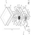
- FIG. 1is a partially exploded view of a portion of a functional vehicle component in accordance with the present subject matter.
- FIG. 2is a cross sectional view of functional vehicle component in accordance with the present subject matter.
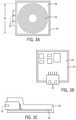
- FIG. 3Ais a bottom phantom view of a connection box in accordance with the present subject matter.
- FIG. 3Bis a top phantom view the connection box of FIG. 3A .
- FIG. 3Cis a side phantom view of the connecting box of FIGS. 3A-B .
- FIG. 4is a perspective view of part of another functional vehicle component in accordance with the present subject matter.
- FIG. 5is a perspective view of another functional vehicle component in accordance with the present subject matter.
- FIG. 6is a front view of another functional vehicle component in accordance with the present subject matter.
- FIG. 7is a front view of another functional vehicle component in accordance with the present subject matter.
- FIG. 8is a side view of another functional vehicle component in accordance with the present subject matter.
- Smart functional vehicle componentscan be used to make a driver's and passenger's driving experience more comfortable and enjoyable as compared to non-functional vehicle components.
- the present subject matterprovides a smart functional layered assembly that is flexible and therefore can be wrapped over various vehicle components to make the vehicle components smart and functional.
- the layered assemblycan be arranged on an interior or exterior of a vehicle.
- the surface of the layered assemblypresents a smooth and clean finish, and therefore has an uncluttered appearance despite having a smart functional capacity.
- the present subject matterincludes a substrate, for example a natural substrate such as leather, textiles, etc., and includes making the substrate conductive, smart, and functional without cluttering the appearance of the substrate by including visible buttons, sensors, or other functional or smart elements on an A-surface of the substrate.
- the present subject matterwill provide a dynamic interior experience for occupants of a vehicle, yet provide a functional vehicle component that has an uncluttered appearance.
- FIG. 1depicts a smart functional vehicle component 2 (also referred to herein as “functional vehicle component 2 ” including a smart functional layered assembly 4 (also referred to herein as a “layered assembly” or as a “functional leather assembly”) arranged on a vehicle component 8 .
- a smart functional vehicle component 2also referred to herein as “functional vehicle component 2 ”
- a smart functional layered assembly 4also referred to herein as a “layered assembly” or as a “functional leather assembly”
- the smart functional layered assembly 4includes a leather sheet 10 fixed over the surface 6 of the vehicle component 8 , a flexible electronic circuit layer 12 (also referred to herein as “circuit layer 12 ”) applied to an A-surface 14 of the leather sheet 10 , and a pigmented coating 16 over the circuit layer 12 .
- A-surfacerefers to the outermost surface of the leather sheet 10 that is facing away from the vehicle component 8 .
- the A-surface 14may be the most visible (i.e. facing) to the vehicle occupants after the functional vehicle component 2 including the leather sheet 10 is assembled and arranged in/on a vehicle; while other surfaces (e.g. a B-surface) of the leather sheet 10 are progressively less visible than the A-surface 14 .
- the A-surface 14may be what is referred to in the leather industry as the grain side, the skin side, the top side, or the hair side of the leather sheet 10 .
- the grain side, the skin side, the top side, or the hair sideis the side of the leather sheet 10 opposite from what is referred to in the leather industry as the flesh side or back side of the leather sheet 10 .
- the flesh sideis the side of the leather sheet 10 that is connected to the meat of the animal from which the leather sheet 10 is taken.
- the functional layered assembly 4optionally includes an anti-soiling component layer 18 .
- the functional layered assembly 4may not include a separate and distinct anti-soiling component layer 18 , and instead can include an anti-soiling component as part of the pigmented coating 16 .
- the vehicle component 8is not particularly limited by the present subject matter, and may include any interior vehicle component such as an interior panel, a door, a seat, a steering wheel, an arm rest, a dashboard, a center console, a gear shifter or any other interior component that can be wrapped with leather.
- the vehicle component 8can include an exterior vehicle component.
- the vehicle component 8is different from the smart functional vehicle component 2 , in that the vehicle component 8 does not include the smart functional layered assembly 4 applied over its surface 6 .
- the vehicle component 8may include a connecting box 20 , including a connection 22 for making an electrical connection with a power source 24 of a vehicle via a connecting cord 26 and plug 28 that mates with the connection 22 .
- the wired connection between the connecting box 20 and the power source 24is shown to be disengageable, this is not required and such electrical connection may be made through hard wiring between the connecting box 20 and the power source 24 .
- the vehicle component 8before assembling with the functional layered assembly 4 , does not include any smart or functional elements or features such as sensors, processors, circuits, switches, or the like, wherein the connecting box 20 may be arranged not on the functional vehicle component 1 , but on another component of the vehicle.
- the vehicle componentmay include smart or functional elements aside from those included on the smart functional layered assembly 4 .
- the surface 6 of the vehicle component 8may be smooth or textured, and flat or contoured. In one non-limiting example, the surface 6 of the vehicle component 8 is contoured. In any event, the functional layered assembly 4 is fixed over the surface 6 of a vehicle component 8 in order to make the vehicle component 8 smart and functional.
- the leather sheet 10may be fixed over the surface 6 of the vehicle component 8 in order to enhance the aesthetics of the vehicle component 8 .
- the leather sheet 10may be naturally flexible, pliable, and stretchable, and therefore can be wrapped around or over the vehicle component 8 and conforms to the contours of the surface 6 of the vehicle component 8 .
- the circuit layer 12may also be flexible and therefore also conforms to the contours of the surface 6 of the vehicle component 8 .
- the leather sheet 10may be in direct contact with the surface 6 of the vehicle component 8 , or may have one or more optional layers therebetween. Optionally, the leather sheet 10 may simply cover or be over the surface 6 of the vehicle component 8 .
- the leather sheet 10may be prepared in any number of ways including by regular tanning processes including soaking, sammying, shaving, fleshing/splitting, drying, staking, and milling of natural leather.
- the leather sheet 10may be replaced or supplemented with bonded leather, synthetic leather, other leather composite material, or other material or layers as desired.
- the leather sheet 10may be cut or formed to a particular size or shape to correspond to the shape and size of the vehicle component 8 to which it will be wrapped.
- the leather sheet 10may have a shape and size that is configured to wrap over a surface of an interior panel, a door, a seat, a steering wheel, a dashboard, a center console, or a gear shifter.
- the various other layers (i.e. circuit layer 12 , pigmented coating 16 , and optional anti-soiling component layer 18 ) of the functional layered assembly 4may be applied to the leather sheet 10 and the entire functional layered assembly may be embossed to produce an embossed pattern over the A-surface 14 of the leather sheet 10 and on the pigmented coating 16 an anti-soiling component layer 18 if included.
- the leather sheet 10is fixed over the surface 6 of the vehicle component 8 after the various other layers of the functional layered assembly 4 are applied to the leather sheet 10 and after embossing if performed.
- the leather sheet 10is fixed over the surface 6 of the vehicle component 8 before the various other layers of the functional layered assembly 4 are applied to the leather sheet 10 .
- the leather sheet 10may be flexible, and therefore in one non-limiting embodiment, may be fixed over the surface 6 of the vehicle component 8 by stretching and wrapping the leather sheet 10 around the vehicle component 8 .
- the leather sheet 10may be fixed, such as by adhesive or fasteners, to the surface 6 and/or other portion of the vehicle component 8 .
- the circuit layer 12 , pigmented coating 16 , and optional anti-soiling component layer 18even though they are applied over the A-surface 14 of the leather sheet 10 , still allow some characteristics (e.g. surface texture or grain, and softness) of the leather sheet 10 to be at least partially perceived by occupants of the vehicle, such as by touch or sight.
- the circuit layer 12is provided over the A-surface 14 of the leather sheet 10 in order to provide smart functional characteristics to the leather sheet 10 .
- the circuit layer 12includes one or more flexible electronic circuits 30 (also referred to herein as “electronic circuits” or “circuits”) including conductive traces 32 and electronic elements 36 electrically connected to the traces 34 , and is arranged on the A-surface 14 of the leather sheet 10 . Although the circuit layer 12 is depicted in FIG.
- circuit layer 12may or may not comprise voids between conductive traces 34 of the one or more circuits 30 , and therefore the circuit layer 12 may or may not be a continuous layer as depicted.
- the circuit layer 12contacts the A-surface 14 of the leather sheet 10 .
- the circuit layer 12is arranged on a polymer film, which is then arranged over the A-surface 14 of the leather sheet 10 .
- the one or more circuits 30 of the circuit layer 12each include one or more flexible conductive traces 34 (also referred to herein as “conductive traces”, “conductive paths” or “traces”).
- flexibleit is meant a layer, circuit, trace or other element or material that is not rigid, brittle, or stiff, and instead bends, stretches, changes shape, or otherwise yields to external forces, yet does not break or lose functionality when subject to such external forces.
- a “flexible electronic circuit”it is meant an electronic circuit 30 that does not break and retains its conductivity even when bent, stretched, twisted or otherwise deformed when arranged on a substrate.
- the flexible electronic circuitmay be at least as flexible as the substrate on which it is arranged, and may retain its conductivity even when deformed to a strain of 10% to at least 40%, 10% to at least 30%, or 10% to at least 20%.
- the circuit layer 12includes only one electronic circuit 30 .
- the circuit layer 12includes more than one electronic circuit 30 , for example, two, three or more electronic circuits 30 .
- each individual circuit 30may be configured to perform a different function than the other circuits 30 , which may mean that each circuit 30 is electrically isolated/separated from the other circuits 30 , or the circuits 30 can be independently operated, or each circuit 30 can function separately from the other circuits 30 , or the circuits 30 are electrically connected to different types of electronic elements 36 .
- the circuit 30includes a receiver coil 38 and a printed circuit board 52 , both of which may be flexible.
- the receiver coil 38may be inductively coupled to a transmitter coil 42 in the connecting box 20 , which is electrically connected to the power source 24 .
- the transmitter coil 42may be arranged on the bottom of a second printed circuit board 94 arranged in the connecting box 20 .
- the receiver coil 38is in electrical connection with the circuit 30 , and may include a non-printed wire coil, or a printed coil that is printed along with the remainder of the circuit 30 .
- the transmitter coil 42may include a non-printed wire coil arranged on the bottom of the second printed circuit board 94 in the connecting box 20 , or may include a printed coil that is printed in a similar manner as printing the circuit 30 .
- the receiver coil 38 and the transmitter coil 42may each be a non-printed wire coil or a printed coil independent of the other coil being printed or not.
- the transmitter coil 42transmits power by inductive coupling to the receiver coil 38 , which delivers electric current to the circuit 30 . That is, the transmitter coil 42 and the receiver coil 38 are configured such that a change in current through the transmitter coil 42 induces a voltage across the ends of the receiver coil 38 through electromagnetic induction.
- a changing current through the transmitter coil 42creates a changing magnetic field around it by Ampere's circuital law.
- the changing magnetic fieldinduces an electromotive force (EMF or voltage) in the receiver coil 38 by Faraday's law of induction.
- EMFelectromotive force
- the amount of inductive coupling between the transmitter coil 42 and the receiver coil 38may be measured by their mutual inductance.
- the coupling between the transmitter coil 42 and the receiver coil 38may be achieved by positioning the transmitter coil 42 and the receiver coil 38 opposite each other and on a common axis (A). Such coupling may be achieved with or without having anything arranged between the coils 38 , 42 .
- the coupling between the transmitter coil 42 and the receiver coil 39may be increased by arranging them to be separated by a gap (G) that is equal to or smaller than a diameter (D 1 ) of the transmitter coil 42 or a diameter (D 2 ) of the receiver coil 38 , and where the transmitter coil 42 and the receiver coil 38 are arranged on a common axis (A).
- the coils 38 , 42may or may not be in contact with each other.
- electric currentcan be delivered wirelessly into the functional layered assembly 4 to power the electronic elements 36 of the circuit 30 .
- This wireless delivery of power to the circuit 30may eliminate the need for a “pig tail” electrical connection to be included as part of the functional layered assembly 4 for connecting the functional layered assembly 4 to an external power source 24 .
- Such pig tail connectionscan require a flat wire cable for hard wire connection to the circuit 30 , and thus introduces potential mechanical failure points for the delivery of electrical power to the circuit 30 , and would be an added cost for producing such an assembly.
- the delivery of electric current from the power source 24 to the circuit 30 by inductive couplingdoes not require mechanical attachment to the functional layered assembly 4 , and thus allows the functional layered assembly 4 to be assembled without a pig tail connector extending therefrom, and thus presents a clean and unobstructed exterior to the functional layered assembly 4 allowing for easy movement and manipulation of the functional layered assembly 4 without having to worry about damaging a pig tail connector.
- the one or more circuits 30may be formed using an electrically conductive ink that includes a binder (e.g. polymer material such as polyimide) and conductive particles, including for example, copper, ferromagnetic material, silver, carbon, silver chloride, or other electrically conductive particles.
- the one or more circuits 30may be formed by applying, e.g. printing, a conductive ink directly on the A-surface of the leather sheet, followed by curing, drying, hardening, etc. of the conductive ink, to thereby form the conductive traces 34 , the receiver coil 38 , and electronic elements 36 of the circuits 30 .
- the conductive traces 34 , the receiver coil 38 , and electronic elements 36may be defined by or include a printed and cured conductive ink.
- Conductive inks that are suitable to create the one or more circuits 30 and electronic elements 36 and the receiver coil 38 thereofare not particularly limited, and may include for example, PE671, PE773, PE873, and PE971 Stretchable Conductors, PE410 Ink-Jet Silver Conductor, 5021, 5025, 5028, and 5064HY Ag Conductors, ME601 and ME602 Stretchable Silver Conductors, PE827 and PE828 Ultra-Low Temperature Cure Silver Composit Conductors, KaptonTM KA801 Polyimide Silver Conductor, available from E. I. du Pont de Nemours and Company; and CI-1036, CI-4040, CI-2051, and CI-1062 Stretchable Conductive Ink available from Engineered Materials Systems, Inc. (EMS).
- EMSEngineered Materials Systems, Inc.
- These conductive inkscan be applied on the surface 14 of the leather sheet 10 by any method including pad-printing, flexography, rotogravure, spraying, dipping, syringe dispensing, stenciling, screen printing, aerosol jet printing, or inkjet printing for example in order to create an electronic circuit.
- the flexible electronic circuits 30can be formed using other materials or processes including etching, in-mold forming of the electronic circuits 30 , selective photocuring, and circuit scribe, for example.
- the one or more circuits 30are formed by screen printing a conductive ink on the surface 14 of the leather sheet 10 .
- the one or more circuits 30can each include electronic elements 36 such as auxiliary power sources, capacitors, inductors, diodes, resistors, transformers, switches, sensors, electrical loads, light sources, fuses, antennas, wireless transmitters, heaters, etc., each of which may be flexible. However, it will be understood that these or other electronic elements may be included in electrical communication with the circuits 30 , but arranged elsewhere other than as part of the circuit layer 12 .
- a light source 44is included as an electronic element 36 in the functional vehicle component 2 .
- a wireless transmitter 46e.g.
- an induction coil, or a capacitive plateis included as an electronic element 36 in the functional vehicle component 2 .
- one or more sensors 48are included in an electronic circuit of the circuit layer 12 .
- a switch 50is included in an electronic circuit of the circuit layer 12 .
- the pigmented coating 16may be arranged over the circuit layer 12 to at least partially conceal or camouflage the circuit layer 12 including the electronic elements 36 .
- the pigmented coating 16is not particularly limited by the present subject matter, and may include a translucent layer, film, or coating arranged over the flexible circuit layer 12 .
- translucentit is meant a material or layer that allows light to pass therethrough, but causes sufficient diffusion to prevent perception of distinct images through the material or layer.
- the pigmented coating 16is not included, or the pigmented coating 16 is clear (i.e. optically transparent) and/or the circuit layer 12 and electronic components thereof are positioned on top of the pigmented coating 16 .
- the pigmented coating 16produces sufficient diffusion of light such that visibility through the pigmented coating 16 of the flexible electronic circuit 30 and all the electronic elements 36 of the circuit layer 12 , except for light (L) emitted by the light source 44 , is inhibited by the pigmented coating 16 .
- the flexible electronic circuit 30 and all the electronic elements 36 of the circuit layer 12may not be visible through the pigmented coating 16 .
- the light source 44is also under the pigmented coating 16 , and therefore visibility of the light source 44 through the pigmented coating may be inhibited by the pigmented coating 16 . In one embodiment, the light source 44 may not be visible through the pigmented coating 16 .
- the pigmented coating 16is sufficiently translucent (rather than being opaque) such that light (L) emitted by the light source 44 is visible through the pigmented coating 16 . Accordingly, the pigmented coating 16 at least in some measure conceals the flexible circuit layer 12 (including the light source 44 ) from view, yet allows light emitted from the light source 44 to be transmitted therethrough so that the emitted light is visible through the pigmented coating 16 and can be seen.
- Light (L) emitted from the light source 44 that is transmitted through the pigmented coating 16may be seen for example, by a vehicle occupant, and can be used for vehicle illumination or as visual indicators to convey information to a vehicle occupant.
- the pigmented coating 16may be polymer, textile, composite material, enamel, paper, glass, metal, ceramic, other material, and combinations thereof.
- the pigmented coating 16comprises a pigmented layer including for example a mixture of polymer and pigment particles.
- the polymermay be an acrylic urethane resin for example.
- the pigmented coating 16may be formed by applying the polymer/pigment mixture as a liquid over the flexible circuit layer 12 and curing the polymer to produce the pigmented coating 16 as a solid.
- the pigmented coating 16may have a pigment loading and/or thickness sufficient to inhibit or prevent the circuit 30 and the electronic elements 36 including the light source 44 from being visible through the pigmented coating 16 .
- the pigmented coating 16is sufficiently translucent, as opposed to being opaque, such that light emitted by the light source 44 can be seen through the pigmented coating 16 .
- the pigmented coating 16has a thickness from 5-50 ⁇ m, 15-40 ⁇ m, or 20-30 ⁇ m.
- the anti-soiling component layer 18 or an anti-soiling component included in the pigmented coating 16may present an exposed surface of the functional vehicle component 2 , and these are optionally included to resist any type of dirt while maintaining all physical and aesthetical properties of the underlying layers of the functional layered assembly 4 .
- the anti-soiling component layer 18is not particularly limited by the present subject matter, and may include an anti-soiling component included as a distinct layer as depicted in FIG. 1 . Alternatively, an anti-soiling component may be included as part of the pigmented coating 16 . In a non-limiting embodiment as depicted in FIG.
- the anti-soiling component layer 18when included as a distinct layer in the functional layered assembly 4 , the anti-soiling component layer 18 is essentially transparent (and may be optically transparent) such that the anti-soiling component layer 18 does not significantly interfere with the transmission of light (L) emitted by the light source 44 .
- the anti-soiling component layer 18may be slightly pigmented such that it assists the pigmented coating 16 in concealing the circuit layer 12 from view.
- the anti-soiling component layer 18has a thickness from 0.1-10 ⁇ m, 1-8 ⁇ m, or 4-6 ⁇ m.
- the anti-soiling component included in an anti-soiling component layer 18 or in the pigmented coating 16is not particularly limited and may comprise acrylic urethane resin, polyurethane resin, polyisocyanate, carbodiimide, fluorine-containing materials such as tetrafluoroethylene (TFE)-copolymers, silicone, etc.
- TFEtetrafluoroethylene
- Operation of the functional vehicle component 2 , the electronic circuits 30 , and the associated electronic elements 36may correspond to signals or data derived from one or more electronic systems of a vehicle or may be continuously activated during operation of the vehicle.
- the data or signalsmay be accessed from, sensed by, generated by, or otherwise acquired from, or produced by, one or more of the vehicle electronic systems.
- the functional layered assembly 4may include the printed circuit board (“PCB”) 52 for controlling the supply of electric current from the receiver coil 38 to the electronic elements 36 via the conductive traces 34 .
- the PCB 52may be programed or may communicate with the one or more electronic systems of the vehicle for determining when to provide electrical current to, and thus activate, the various electronic elements 36 .
- the PCB 52may also include a rectifier to convert alternating current from the receiver coil 38 to direct current delivered to the various electronic elements 36 .
- the functional vehicle component 2may provide signals or data to the one or more electronic systems of the vehicle via the PCB 52 .
- the functional vehicle component 2may include a sensor 48 and signals from the sensor 48 may be communicated to the vehicle electronic systems via the PCB 52 , and these signals may be used to operate other electronic elements 36 in the functional vehicle component 2 or to operate a different functional vehicle component.
- the vehicle electronic systems from which this data or these signals are derived, or to which this data or these signals are communicatedare not particularly limited and may include one or more vehicle electronic control units (ECU's) associated with a vehicle engine, transmission, body, chassis, passive and active safety features, vehicle performance, driver assistance, interior and exterior environment, vehicle diagnostics, vehicle control, audio/visual entertainment, navigation, electrical systems, telematics, and combinations thereof.
- ECU'svehicle electronic control units
- the vehicle electronic systemscan include a door control unit, engine control unit, electric power steering control unit, human-machine interface (HMI), powertrain control module, transmission control unit; seat control unit, speed control unit, telematics control unit, transmission control unit, brake control module (ABS or ESC), battery management system, central control module, central timing module, general electronic module, body control module, suspension control module, or combinations thereof.
- HMIhuman-machine interface
- HMIhuman-machine interface
- powertrain control modulepowertrain control module
- transmission control unitseat control unit, speed control unit, telematics control unit, transmission control unit, brake control module (ABS or ESC), battery management system
- central control modulecentral timing module
- general electronic modulegeneral electronic module
- body control modulebody control module
- suspension control moduleor combinations thereof.
- the one or more flexible electronic circuits 30are in communication with a vehicle electronic control unit (ECU), which may control, via communication with the PCB 52 , operation of the functional vehicle component 2 , the electronic circuits 30 , and the associated electronic elements 36 .
- the ECUmay be electrically connected to a vehicle power source 24 for powering the ECU.
- the functional vehicle component 2including the one or more circuits 30 of the circuit layer 12 , along with the various electronic elements 36 , may be selectively operable based on a current condition or situation relating to the vehicle or vehicle components, an occupant of the vehicle, or an environment of the vehicle including an immediate or a distant surrounding environment of the vehicle, and combinations thereof.
- conditions of the vehiclethat may be used as a basis for such selective operation include historical, current, or projected vehicle performance characteristics or diagnostic information, or the like.
- Conditions of the vehicle occupants that may be used as a basis for such selective operationcan include a physical condition of a driver, such as the driver being drowsy or inattentive while driving, or the proximity of an object (such as an occupant or an occupants hand) or a global position relative to the vehicle or to the functional vehicle component 2 .
- Conditions of the surrounding environmentthat may be used as a basis for such selective operation can include proximity of an object (such as another vehicle) to the vehicle, the current time, newsfeeds, amber alerts, nearby points of interest, or the like.
- the one or more circuits 30are in communication, via the PCB 52 , with a human machine interface (HMI), which may be used to control functioning of the functional vehicle component 2 , the electronic circuits 30 , and the associated electronic elements 36 .
- HMIhuman machine interface
- Such arrangementcould allow a user to provide input through the HMI to selectively activate the circuits 30 and associated electronic elements 36 .
- Such user inputmay be active (user initiated) or passive (sensed input from a user), and can include audible or tactile input.
- the systemmay be configured to allow a user to audibly select operation of the functional vehicle component 2 , the electronic circuits 30 , and the associated electronic elements 36 .
- a light source 44may be included as an electronic element 36 in the functional vehicle component 2 .
- the light source 44may comprise one or more separate and distinct light emitter elements.
- the light source 44emits light (L) when activated, and is electrically connected to an electronic circuit 30 of the circuit layer 12 .
- the light source 44may simply provide illumination by emitting light, which may be used to provide illumination to the interior or exterior of the vehicle, and the light source 44 may emit light in one or more colors and/or intensities.
- the light source 44may emit various colors and intensities of light to establish a particular “feel” or “mood” for occupants of the vehicle.
- the light source 44may be paired to certain functions of the vehicle or vehicle components, such that the light source 44 operates to emit light at different intensities and/or colors depending on certain circumstances such as during normal operation of the vehicle, during operation of a vehicle entertainment system, during dangerous operation of the vehicle, or other circumstances or situations as desired.
- the light source 44may be configured, such as by arrangement or operation, to emit light that provides visual indicators that convey information to a vehicle occupant.
- the light source 44may be arranged in such a way, or may emit light in such a way that the light emitted by the light source 44 provides more than mere illumination, and instead additionally conveys information to a vehicle occupant.
- the visual indicatorsare not particularly limited by the present disclosure, and may provide information such as warnings, notices (e.g. the time), alerts, instructions, information relating to a current condition or situation relating to the vehicle or vehicle components, an occupant of the vehicle, or an environment of the vehicle including an immediate surrounding environment of the vehicle, and combinations thereof.
- the visual indicatorsmay include one or more of directional indicators such as turn-by-turn directions from a navigation system, blind spot warnings, a turn signal indicator, and combinations thereof. However, such indicators are not limited to any particular type or combination.
- the light (L) emitted by the light source 44indicates a location of the one or more electronic circuits 30 or electronic elements 36 electrically connected to the electronic circuits 30 of the circuit layer 12 .
- the light source 44emits light that provides a directional indicator to a driver of the vehicle, or a current time, or a current amount of fuel reserves for the vehicle.
- the light source 44may be activated to emit light when a certain associated object is within a predetermined distance from the functional vehicle component 2 .
- the light source 44is activated to emit light when a portable electronic device is within a predetermined distance from the functional vehicle component 2 .
- the functional vehicle component 2is in communication with an HMI, via the PCB 52 , which could allow a user to provide input to activate the light source 44 by selecting a particular type of information to be displayed by the light source 44 .
- the systemmay be configured to allow a user to audibly select which fluid level (such as gas, oil, windshield wiper) to indicate in real-time, or to allow a user to audibly request how much time until a desired destination is reached.
- the visual indicatorsmay correspond to signals or data derived from the electronic systems of a vehicle or an HMI.
- electronic system of the vehicleprovide real-time signals or data that may be displayed by the light source 44 .
- Communication between the functional vehicle component 2 and the vehicle electronic system or HMImay be established through one or more intermediary systems or devices, and such communication may be performed, for example, by using a communication link or connection such as with a wired connection, Wi-Fi connection, Bluetooth connection, etc.
- Such communication connectionallows the data or signals from/to the vehicle electronic system or HMI to be communicated to activate the light source 44 to provide the visual indicators to a vehicle occupant that corresponds to such data or signals.
- the light source 44is not limited in any way and can include luminescent light sources (e.g. electroluminescent, photoluminescent, mechanoluminescent light sources), and incandescent light sources.
- Illustrative examples of the light source 44include a light emitting diode (LED), an organic light emitting diode (OLED), or a photoluminescent or electroluminescent light source configured in a film or sheet.
- the light source 44comprises LED's having a light emitting area with a size of 100 ⁇ m ⁇ 100 ⁇ m (i.e. 100 ⁇ m diameter) or less, herein referred to micro LED's.
- a micro LEDis a light source that includes an array of one or more individual light emitters, wherein an array may have a diameter of about 2 ⁇ m-20 mm and the individual light emitters have typical diameters of about 2-20 ⁇ m.
- the one or more micro LED'sare arranged as part of an electronic circuit 30 of the circuit layer 12 .
- the functional vehicle component 2may comprise a smart functional wireless charger that is separate from the receiver coil 38 , and includes a wireless transmitter 46 (e.g. an induction coil, or a capacitive plate), which is included as an electronic element 36 in the functional vehicle component 2 .
- the wireless transmitter 46may optionally be formed by printing a conductive ink in a process as described herein with respect to the flexible circuits 30 , wherein the conductive ink is applied in the form of an induction coil or capacitive plate.
- the wireless transmitter 46may be configured to generate an oscillating electromagnetic field when activated, which can be transmitted to a corresponding wireless receiver (e.g.
- the wireless transmitter 46 and the generated oscillating electromagnetic fieldmay be used to charge a portable electronic device (e.g. a cell phone) that includes the corresponding wireless receiver, which receives the oscillating electromagnetic field and converts the oscillating electromagnetic field back to DC or AC electric current that can be used by an electrical load in the portable electronic device.
- a portable electronic devicee.g. a cell phone
- the wireless transmitter 46may be able to transmit the oscillating electromagnetic field to the corresponding wireless receiver in the portable electronic device only over a short distance, e.g. less than about 10 times the transmitter 46 or receiver diameters. Therefore, in one embodiment, the wireless transmitter 46 is configured to operate to generate the oscillating electromagnetic field only when the portable electronic device or the associated wireless receiver is within a predetermined distance, e.g. less than about 10 times the transmitter or receiver diameters, from the wireless transmitter 46 . Such activation may be based on signals or data from a proximity sensor or other device included in the circuit layer 12 or elsewhere that can sense the proximity of the portable electronic device with respect to the functional vehicle component 2 . Alternatively, activation of the wireless transmitter 46 may be based on communication (e.g. blue tooth, cellular, near-field, RFID, Wi-Fi, or infrared communication) between the portable electronic device and the PCB 52 of the functional vehicle component 2 .
- communicatione.g. blue tooth, cellular, near-field, RFID, Wi-Fi, or infrare
- the functional vehicle component 2may include a light source 44 comprising a plurality of individual light emitter elements that are arranged, for example, in a ring around the wireless transmitter 46 .
- the individual light emitter elementseach emit light that collectively indicates a location of the wireless transmitter 46 on the functional vehicle component 2 .
- Such indicationis useful, since the pigmented coating 16 may optionally conceal the wireless transmitter 46 and other portions of the circuit 30 from being visible through the pigmented coating 16 , and a user therefore may not be able to locate the wireless transmitter 46 for charging the portable electronic device.
- the emitted light (L)may provide an indication of the location of the wireless transmitter 46 to allow for wireless charging of the portable electronic device.
- the color of light emitted by the light emitter elementschanges from an initial color (for example, red light) present at the onset of charging the portable electronic device, to a second color (for example, green light) when the portable electronic device is fully charged.
- the light source 44may be activated to emit light when a door of the vehicle is opened, when the vehicle is started, and/or when a portable electronic device is moved within a predetermined distance from the wireless transmitter 46 .
- the functional layered assembly 4 depicted in FIG. 4may be included on any vehicle component 8 as desired, for example on any interior surface of a vehicle such as a vehicle seat, dashboard, or center console.
- one or more sensors 48may be included in an electronic circuit 30 of the circuit layer 12 .
- the sensors 48are not particularly limited, and can include a sensor having any configuration including those that can sense pressure, temperature, proximity, location, speed, velocity, acceleration, tilt, motion, humidity, light, biometrics of a vehicle occupant, etc.
- the circuit layer 12includes one or more pressure sensors.
- the pressure sensormay include a first flexible layer of conductive material, a second flexible layer of dielectric material, and a third flexible layer of conductive material, where the second dielectric layer is arranged between and separates the first and third conductive layers.
- the first and third conductive layers of the pressure sensormay optionally be formed by applying a conductive ink as described herein, while the second dielectric layer may be formed by applying a dielectric material, for example an ink that is similar to the conductive ink as described herein, but one that has dielectric properties.
- a switch 50may be included in an electronic circuit 30 of the circuit layer 12 .
- the switch 50may be operable to make or break a conductive path in the circuit 30 .
- the switch 50may be a parallel plate capacitive switch for example, or other type of switch as desired such as a membrane switch, or a piezoelectric switch.
- a parallel plate capacitive switch or piezoelectric switchmay be arranged similar to the pressure sensor as previously described herein, wherein the capacitive switch or piezoelectric switch may include a first or bottom flexible layer of conductive material (e.g.
- the middle layermay include a flexible printed layer of dielectric material (e.g. a dielectric ink).
- the middle layermay include a piezoelectric material, which may or may not be printed and cured.
- the piezoelectric switchmay include other layers and components.
- the bottom layer of the switchis cured before applying the middle layer, and if printed, the middle layer is cured before printing the top layer. That is, the bottom, middle, and top layers of the switch 50 have overlapping areas, and the second middle layer is arranged between and thus separates the first and third conductive layers.
- the dielectric middle layer in the dielectric switchmay include one or more sub-layers (e.g. two sub-layers) of the same or different dielectric material printed and cured over the bottom layer.
- the piezoelectric middle layer in the piezoelectric switchmay include one or more sub-layers (e.g. two or more sublayers) of piezoelectric material, which also may be sequentially printed and cured over the bottom layer.
- the conductive top and bottom layersmay each include one or more sub-layers (e.g. two sub-layers) of the same or different conductive ink printed and cured below and above the middle layer.
- Thickness of the first, second, and third layersis not particularly limited, and in one non-limiting example of the dielectric switch, the thickness may range from about 100 nm to 10 ⁇ m.
- the first and third conductive layers of the switchmay optionally be formed by printing a conductive ink as described herein with respect to the flexible circuits 30 , while the second dielectric layer of the dielectric switch may be formed by printing a similar, but dielectric ink.
- the capacitive switchmay be used as a pressure sensor when electrical contact is made between the first and third conductive layers by pressing the first and third conductive layers together.
- the capacitive switchmay be used to measure biometric characteristics of a vehicle occupant in contact with the functional vehicle component 2 , wherein for example, a rate at which electrical contact is made between the first and third conductive layers may be used to determine a heart rate of the occupant.
- the piezoelectric switchis not particularly limited, and the piezoelectric material in the middle layer may include crystal piezoelectric material, ceramic piezoelectric material, polymer piezoelectric material, Group III-V and II-VI semiconductors, organic nanostructures, natural materials, bone, and combinations thereof.
- the piezoelectric materialmay include for example, lead zirconate titanate, barium titanate, quartz, berlinite, sucrose, Rochelle salt, topaz, tourmaline-group minerals, lead titanate, potassium niobate, sodium tungstate, zinc oxide (wurtzite structure), Ba 2 NaNb 5 O 5 , Pb 2 KNb 5 O 15 , sodium potassium niobate, bismuth ferrite, sodium niobate, barium titanate, bismuth titanate, sodium bismuth titanate, polyvinylidene fluoride, vinylidene fluoride-trifluoroethylene-chlorotrifluoroethylene terpolymer, P(VDF-TrFE-CTFE), vinylidene fluoride-trifluoroethylene-chlorofluoroethylene terpolymer, P(VDF-TrFE-CFE), or combinations thereof.
- lead zirconate titanatebarium titanate, quartz, berlinite, suc
- the piezoelectric layer of the piezoelectric switchincludes a piezoelectric polymer, e.g. P(VDF-TrFE-CTFE) or P(VDF-TrFE-CFE), and is printed an cured between the bottom layer and the top layer of the switch 50 .
- the piezoelectric switchis actuatable to make or break a conductive path in the conductive trace 34 of the circuit 30 .
- the piezoelectric switchmay be actuatable to make or break the conductive path by a user/occupant pressing the piezoelectric switch, thereby deforming/compressing the piezoelectric layer between the bottom and top layer of the switch 50 , and thus causing the piezoelectric material to generate a charge.
- Such chargemay be sent to a flip-flop device in the switch 50 , which is turned to steady “on” state, thus allowing current to pass therethrough and making the conductive path in the circuit 30 .
- a further deformation/compression of the piezoelectric materialwill create an additional charge, which will cause the flip-flop device in the switch 50 to turn to a steady “off” stated, thus not allowing current to pass therethrough and breaking the conductive path in the circuit 30 .
- the generated current from the piezoelectric switchmay utilize a semiconductor device such as a field effect transistor (FET), which provides a temporary “on” state, but reverts back to a steady “off” state when the charge dissipates.
- FETfield effect transistor
- the piezoelectric switchmay be connected to the receiver coil 38 , which can provide an electric charge to the piezoelectric switch when the piezoelectric switch is actuated by a user pressing the switch 50 .
- the electric charge provided to the piezoelectric switchcan cause deformations of the piezoelectric layer. Such deformations may be haptically sensed by a user when the user presses the switch 50 to actuate it. Such deformations may be felt as haptic vibrations having various frequencies and/or amplitudes. Such vibrations may be characterized as haptic signals that provide haptic feedback to the user that the piezoelectric switch has been actuated to make or break the conductive path in the circuit 30 .
- the functional layered assembly 4can include various other layers or components as desired.
- the functional layered assembly 4includes a dielectric layer over or between one or more circuits 30 or conductive traces 34 of the circuit layer 12 .
- the dielectric materialmay generally include a non-conductive resin cured to form a dielectric layer.
- a dielectric layeris arranged between the circuit layer 12 and the pigmented coating 16 in order to avoid moisture exposure during formation of the pigmented coating 16 , or to make the circuit layer 12 more durable and resistant to abrasion and therefore maintain electrical conductivity after repeated use.
- a dielectric layer or coatingmay also be used as an insulator, for example, to provide electrical insulation between a first trace or circuit and an overlying second trace or circuit.
- the dielectric layermay cover only the trace or circuit, or may also generally cover other portions of the circuit layer 12 or leather sheet 10 . That is, the dielectric layer may be generally applied over the first circuit as one continuous layer wherein the conductive traces of the first circuit and spaces therebetween are covered by the dielectric layer, or may be applied as a discontinuous layer that covers only the conductive traces of the first circuit, but not the spaces therebetween. In one non-limiting example, the dielectric layer is applied only at a location where a second trace or circuit overlaps the first trace or circuit.
- the circuit layer 12may include a plurality of separate and distinct traces 34 and/or circuits 30 that may be arranged in different planes or sub-layers of the circuit layer 12 , wherein various conductive traces 34 may overlap each other.
- various conductive traces 34may overlap each other.
- the traces 34may be in different planes within the circuit layer 12 and be configured to overlap each other.
- the circuit layer 12may include a first trace printed on the leather sheet 10 , followed by a dielectric layer applied over the first trace, and then a second trace printed on the leather sheet 10 and at least partially overlapping the first trace, yet because of the intermediary dielectric layer, the first and second trace are electrically isolated form one another.
- the present subject matteris not limited to any particular shape or orientation of the traces 34 , circuits 30 and electronic elements 36 as depicted in the various figures, and instead can have other arrangements and orientations.
- a conductive inkis first printed directly on the leather sheet 10 in order to form a wireless transmitter 46 , a dielectric layer is then arranged over the wireless transmitter 46 , then a conductive ink is printed over the dielectric layer (or overlaps a portion of it) in order to form a separate conductive trace for a different electronic element 36 (such as for a light emitter element), and then optionally another dielectric layer is printed over the light emitter trace to provide abrasion resistance for the underlying layers.
- the dielectric layer between the wireless transmitter 46 and the light emitter traceelectrically isolate the wireless transmitter 46 from the light emitter trace.
- the functional layered assembly 4includes the PCB 52 electrically connected to the circuit 30 .
- the PCB 52may be used to electrically connect the receiver coil 38 to the electronic elements 36 , and may provide communication to and from the circuits 30 and vehicle systems, or to control functions of the one or more electronic elements 36 .
- the various vehicle electronic systemssuch as an ECU or HMI, may be in communication with the functional layered assembly 4 via the PCB 52 in order to communicate with the functional layered assembly 4 .
- the one or more circuits 30 and the electronic elements 36may each be electrically connected to the receiver coil 38 for receiving electrical power from the power source 24 in order to activate the electronic elements 36 .
- the vehicle power source 24may comprise a vehicle battery, engine, or alternator, for example.
- the power source 24may provide power to the functional layered assembly 4 through the receiver coil 38 .
- a smart functional vehicle system 54includes a smart functional vehicle component 2 , along with one or more of the ECU, the HMI, and the vehicle power source 24 .
- an illustrative example of a smart functional vehicle component 2includes a smart functional vehicle seat 56 (also referred to herein as “vehicle seat” or “seat”).
- the seat 56includes a bottom 58 , a back 60 , and a headrest 62 .
- the vehicle seat 56includes a functional layered assembly 4 over the back 60 of the seat 56 . It will be appreciated that although visibility of the circuit 30 in the functional layered assembly 4 may be inhibited or prevented by pigmented coating 16 , the circuit 30 is schematically depicted in FIG. 5 in order to indicate it's arrangement on the vehicle seat 56 .
- the functional layered assembly 4 of the vehicle seat 56may include one or more electronic elements 36 .
- the functional layered assembly 4 of the seat 56includes a light source 44 , a wireless transmitter 46 , a sensor 48 , a switch 50 , and the receiver coil 38 . More or less, and different electronic elements 36 may be included as desired on the seat 56 .
- the sensors 48may be configured to sense biometrics, such as heart rate, body temperature, blood pressure, etc., of a vehicle occupant who is sitting on the seat 56 .
- the light source 44may be configured to activate when a vehicle door is open to provide illumination to the seat 56 , or during operation of the vehicle in order to provide mood lighting in a passenger compartment of the vehicle.
- the switch 50for example a piezoelectric switch, may be provided to manually turn the light source 44 on or off or to produce other functions.
- the seat 56may include an associated transmitter coil (not shown) inductively coupled to the receiver coil 38 for transmitting power to the receiver coil 38 .
- an illustrative example of a smart functional vehicle component 2includes a smart functional steering wheel 64 (also referred to herein as “steering wheel”).
- the steering wheel 64includes a central hub 66 , an outer wheel 70 , and spokes 68 extending between the hub 66 and outer wheel 70 .
- a functional layered assembly 4may be included over one or more of the hub 66 , outer wheel 70 and spokes 68 .
- the outer wheel 70includes one or more sensors 48 .
- the one or more sensors 48may be pressure sensors for sensing the presence of a user's hand on the outer wheel 70 .
- the sensors 48may also be configured to sense biometrics, such as heart rate, body temperature, blood pressure, etc., of a user.
- each of the sensors 48is circumferentially spaced by no more than two inches from an adjacent sensor 48 . In other words, there is no portion of more than two consecutive inches along the entire circumference of the outer wheel 70 that is without a sensor 48 .
- the wheel outer 70may alternately include one continuous sensor arranged on the exposed portions of the outer wheel 70 and extending around the entire circumference of the outer wheel 70 .
- the hub 66includes a light source 44 comprising an array 72 of individual light emitter elements.
- the light emitter elementswhich are not individually depicted on the hub 66 in FIG. 6 , may be arranged in the array 72 in such a way that light emitted from the array 72 conveys information to a vehicle occupant.
- the array 72is displaying a visual indicator 74 , which may be a directional indicator that is based on information or data derived from a navigation system.
- the visual indicator 74is indicating a direction (i.e. right turn) for the vehicle to follow in order to reach a predetermined destination.
- the array 72covers an area on the surface of the hub 66 and has an illuminated area 76 and a non-illuminated area 78 .
- the right turn visual indicator 74is presented by a contrast between the illuminated area 76 of the array 72 (light that is visible through the pigmented coating 16 of the functional layered assembly 4 ) and the non-illuminated area 78 of the array 72 (which is not visible through the pigmented coating 16 ).
- the visual indicator 74is determined by activation of a specific combination of individual light emitter elements in the array 72 .
- a different combination of individual light emitter elements in the array 72may be activated as desired in order to provide a different arrangement between the illuminated area 76 and the non-illuminated area 78 , such that light emitted by the illuminated area 76 may convey other visual indicators 74 and other information, such as other directional indicators, a current speed or time, etc.
- one or more of the spokes 68 of the steering wheel 64may each include a switch 50 , such as a capacitive switch or piezoelectric switch. As schematically depicted, one switch 50 is included on each of two of the spokes 68 . It will be appreciated that although visibility of the switches 50 may be inhibited or prevented by the pigmented coating 16 of the functional layered assembly 4 , the switches 50 are schematically depicted in FIG. 4 in order to indicate their arrangement on the spokes 68 .
- the switches 50may be configured to control one or more functions of the vehicle or vehicle systems, e.g. an entertainment system.
- a light source 44comprising a plurality of individual light emitter elements, are provided on the spokes 68 and are arranged around the perimeter of the two switches 50 .
- the individual light emitter elementsemit light that collectively indicates a location of the switches 50 .
- Such indicationis useful, since the pigmented coating 16 may conceal the switches 50 from being readily visible through the pigmented coating 16 , and a user may not be able to locate the switches 50 for controlling one or more functions of the vehicle or vehicle systems.
- light emitted by the light emitter elementscan be seen through the pigmented coating 16 , and therefore the emitted light provides an indication of the location of the switches 50 .
- the light emitter elementsmay be activated to continuously emit light during operation of the vehicle in order to indicate the location of the switches 50 , and may be deactivated when the vehicle is not being operated to thereby present a plain top surface for the spokes 68 of the steering wheel 64 . More or less, and different electronic elements 36 may be included as desired on the steering wheel 64 .
- an illustrative example of a smart functional vehicle component 2includes a smart functional dashboard 80 (also referred to herein as “dashboard”), which may include an instrument panel 82 and a glove box 84 .
- the dashboard 80includes a functional layered assembly 4 as discussed herein.
- the functional layered assembly 4is fixed over a surface of the dashboard 80 and presents as a plain top surface for the dashboard 80 .
- the dashboard 80includes a light source 44 comprising an array 72 of individual light emitter elements.
- the array 72 depicted in FIG. 7may be similar to the array 72 depicted in FIG. 6 on the hub 66 of the steering wheel 64 .
- the array 72is displaying a visual indicator 74 , which may be a current speed of the vehicle.
- the array 72 in FIG. 7covers an area on the surface of the dashboard 80 and has an illuminated area 76 and a non-illuminated area 78 .
- the visual indicator 74 showing the current speedis presented by a contrast between the illuminated area 76 of the array 72 and the non-illuminated area 78 of the array 72 .
- the visual indicator 74is determined by activation of a specific combination of individual light emitter elements in the array 72 .
- a different combination of individual light emitter elements in the array 72may be activated as desired in order to provide a different arrangement between the illuminated area 76 and the non-illuminated area 78 , such that light emitted by the illuminated area 76 may convey other visual indicators and other information, such as a current time, the current amount of fuel reserves for the vehicle, etc.
- Activation of the array 72 on the dashboard 80 or on the steering wheel 64may be activated by audible signals from a user. For example, a user may audibly request that the array 72 on the dashboard 80 or on the steering wheel 64 display the current speed, current amount of fuel reserves for the vehicle, distance from a selected destination, etc. More or less, and different electronic elements 36 may be included as desired on the dashboard 80 .
- an illustrative example of a smart functional vehicle component 2includes a smart functional door panel 86 (also referred to herein as “door panel”).
- the door panel 86includes a functional layered assembly 4 as discussed herein.
- the functional layered assembly 4is fixed over a surface of the door panel 86 and presents as a plain top surface for the door panel 86 .
- the door panel 86includes one or more switches 50 , such as a capacitive or piezoelectric switch, that are operable to move a window 88 , adjust a mirror 90 , or operate an interior light 92 of the vehicle.
- the smart functional door panel 86may include a light source 44 comprising a plurality of individual light emitter elements that are arranged on the circuit 30 and, for example, in a ring around the switches 50 .
- the individual light emitter elementseach emit light that collectively indicates a location of the switches 50 on the functional door panel 86 .
- Such indicationis useful, since the pigmented coating 16 may conceal the switches 50 and other portions of the circuit 30 from being visible through the pigmented coating 16 , and a user therefore may not be able to readily locate the switches 50 for operating the window 88 , mirrors 90 or light 92 .
- the emitted lightmay provide an indication of the location of the switches 50 to allow for operation of the switches 50 .
- the switches 50are piezoelectric switches, their operation may result in haptic feedback being provide to a user to indicate that the switches 50 have been operated.
- the smart functional vehicle component 2may provide various functionalities in a vehicle including a dynamic illumination experience by providing changing the color of emitted light to the interior of the vehicle according to a vehicle speed, a driving mode, a driver's mood/condition based on biofeedback data, a current music selection.
- the smart functional vehicle component 2may also be used to monitor a driver's condition to maintain safe driving using sensors 48 to monitor heart rate, peripheral capillary oxygen saturation, or a driver's health condition, and the data from such monitoring can be used to improve a driver's user experience. Illumination provided by the functional vehicle component 2 can also be utilized to keep a driver attentive by provide real time feedback.
- the use of a functional vehicle component 2can reduce the complexity of the seat because the functional vehicle component 2 can include a number or different electronic elements 36 . That is, the functional vehicle component 2 can be utilized as a pressure sensor on the seat, and measure pressure points. This can help to identify driver seat pressure and automatically adjust seat position for driver comfort. This also reduces the need for a separate component of a pressure sensor installed separately on a seat.
- the functional vehicle component 2can also be used to give opportunities to create innovative vehicle styling, such as creating navigation directional indicators ( FIG. 6 ) on a steering wheel 64 , or a vehicle speed displayed on an interior panel ( FIG. 7 ).
- the functional vehicle component 2can also be utilized as a wireless charging pad ( FIG. 4 ) for charging a portable electronic device.
- the present subject matterincludes a method of producing a functional layered assembly 4 .
- the functional layered assembly 4may be produced by passing a hide through conventional processes such as soaking, sammying, shaving, fleshing/splitting, drying, staking, and milling. Then, after application of a base coat, the hide is set aside to rest. The hide is then cut to a predetermined shape to produce a leather sheet 10 that will fit over a particular vehicle component 8 . An electronic circuit 30 is then printed, utilizing conductive ink, on the A-surface 14 of the leather sheet 10 .
- the conductive inkcan be applied through any method, and in an illustrative embodiment, is applied by one of (a) screen printing, (b) aerosol jet printing (c) inkjet printing.
- a light source 44(e.g. micro LED's), or other electronic element 36 , may be formed with or placed on the circuit 30 . Then pigmented coating 16 can be applied over the circuit 30 and light source 44 to thereby produce a functional layered assembly 4 .
- the functional layered assembly 4can be placed in interior of a vehicle as an interior panel lining, door lining, or seat cover for example.
- the present subject matterincludes a method of producing a functional vehicle component 2 .
- the functional vehicle component 2may be, for example, a smart functional wireless charger, a smart functional vehicle seat 56 , a smart functional steering wheel 64 , a smart functional dashboard 80 , or other smart functional vehicle component.
- the functional vehicle component 2may be produced by fixing a leather sheet 10 over a surface of a vehicle component 8 , such that the leather sheet 10 is conformed to contours of the vehicle component 8 .
- a flexible electronic circuit 30is applied (e.g. printed) to an A-surface 14 of the leather sheet 10 , and a pigmented coating 16 is arranged over the circuit 30 . Visibility of the circuit 30 through the pigmented coating 16 is optionally concealed by the pigmented coating, and in one embodiment the circuit 30 is not visible through the pigmented coating 16 .
- the pigmented coating 16is a pigmented layer, and a pigment loading in the pigmented coating 16 may be sufficient to inhibit or prevent the circuit 30 from being visible through the pigmented coating 16 .
- the circuit 30 and the pigmented coating 16may be applied to the leather sheet 10 before or after the leather sheet 10 is fixed over the surface 6 of the vehicle component 8 .
- the circuit 30is conformed to contours of the surface 6 of the vehicle component 8 .
- the methodmay further include applying a dielectric layer over the circuit 30 , wherein the dielectric layer is arranged between the circuit 30 and the pigmented coating 16 .
- the methodmay include electrically connecting the circuit 30 to a vehicle ECU, to a vehicle power source 24 , a vehicle HMI, or other vehicle systems, and such connections may be made directly by a wire, or through an intermediary microcontroller located at an edge of the leather sheet 10 .
- the methodmay include providing a light source 44 that emits light when activated, and electrically connecting the light source to the circuit 30 .
- the light source 44may comprise one or more individual light emitter elements, such as a micro LED, which may be connected to the circuit 30 for example by soldering of electrical contacts or other method.
- the light source 44is arranged within the flexible circuit layer 12 and directly in contact with the circuit 30 .
- the pigmented coating 16is arranged over the circuit 30 and over the light source 44 . Visibility of the light source 44 through the pigmented coating 16 may be inhibited, by the pigmented coating 16 , and in one embodiment the light source 44 is not visible through the pigmented coating 16 , but light emitted by the light source 44 is visible through the pigmented coating 16 .
- the light source 44is arranged in such a way, or is configured to emit light in such a way that light emitted by the light source provides visual indicators that convey information to a vehicle occupant.
- the methodmay include applying an acrylic urethane anti-soiling component over the A-surface of the leather sheet 10 , wherein the anti-soiling component is included a) as part of the pigmented coating 16 , or b) as a topcoat (i.e. an anti-soiling component layer 18 ) over the pigmented coating 16 .
- the vehicle component 8is a steering wheel 64
- the circuit 30includes pressure sensors 48
- the pressure sensors 48are arranged around the entire circumference of the steering wheel 64 .
- the vehicle component 8is a seat 56
- the circuit 30includes a biometric sensor 38 , which is configured to measure biometrics of a user sitting on the seat 56 .
- the methodmay include applying a second flexible electronic circuit to the A-surface 14 of the leather sheet 10 .
- the second flexible electronic circuitmay be similar to the first flexible electronic circuit, such that the pigmented coating 16 is arranged over the second circuit. As such, the pigmented coating 16 may inhibit or prevent the second circuit from being visible through the pigmented coating 16 .
- the second circuitis configured to perform a different function than the first circuit, which may mean that each circuit is electrically isolated/separated from the other circuit, or that each circuit can be independently operated, or that each circuit can function separately from the other circuits. In one embodiment, the second circuit is electrically isolated from the first circuit.
- the second circuitincludes a wireless transmitter 46 , which is configured to generate an oscillating electromagnetic field when an associated portable electronic device is within a predetermined distance from the wireless transmitter 46 .
- the light source 44may be configured to emit light that indicates a location of the wireless transmitter 46 when the portable electronic device is within a predetermined distance from the wireless transmitter 46 .
- the second circuitmay include a switch 50 , such as a capacitive or piezoelectric switch, that is operable to make or break a conductive path in the second circuit; and the light source 44 is configured to emit light that indicates a location of the switch 50 .
- a switch 50such as a capacitive or piezoelectric switch
- the present subject matteralso includes a method of producing a vehicle system 54 .
- the methodincludes applying a flexible electronic circuit 30 to an A-surface 14 of a leather sheet 10 .
- a light source 44is electrically connected to the circuit 30 .
- the light source 44is configured to emit light when supplied with electrical power.
- a pigmented coating 16is arranged over the circuit 30 and over the light source 44 .
- the methodincludes fixing the leather sheet 10 over a surface 6 of a vehicle component 8 such that the A-surface 14 of the leather sheet 10 is facing away from the vehicle component 8 .
- the circuit 30is electrically connected to a vehicle electronic control unit and a vehicle power source 24 .
- the pigmented coating 16optionally inhibits or prevent the circuit 30 and the light source 44 from being visible through the pigmented coating 16 .
- the vehicle component 8comprises an interior panel, a door, a seat, a steering wheel, a dashboard, a center console, or a gear shifter.
- a method of producing a functional leather componentmay include providing a leather sheet 10 ; applying to an A-surface 14 of the leather sheet 10 , a flexible electronic circuit 30 including a piezoelectric switch 50 that can be actuated to make or break a conductive path in the circuit 30 ; and arranging a pigmented coating 16 over the circuit 30 .
- the piezoelectric switch 50provides haptic feedback to the user that the piezoelectric switch 50 has been actuated.
- the pigmented coating 16may inhibit or prevent the circuit 30 including the piezoelectric switch 50 from being visible through the pigmented coating 16 .
- the piezoelectric switch 50may be applied to the A-surface 14 of the leather sheet 10 by printing a piezoelectric material on the A-surface 14 of the leather sheet 10 .
- the leather sheet 10 , the flexible electronic circuit 30 , and the pigmented coating 16may then be embossed to impart an embossed pattern over the A-surface 14 of the leather sheet 10 .
- Embossingmay include passing the leather sheet 10 , the flexible electronic circuit 30 , and the pigmented coating 16 through a roll-to-roll embosser.
- a light source 44may be provided that emits light when electrical power is supplied to the light source 44 .
- the light source 44may be electrically connected to the circuit 30 .
- the pigmented coating 16may be arranged over the light source 44 , and may inhibit or prevent the light source 44 from being visible through the pigmented coating 16 . However, light emitted by the light source 44 may be visible through the pigmented coating 16 .
- the light source 44may include a micro light emitting diode and may be configured to emit light that indicates a location of the piezoelectric switch 50 .
- An acrylic urethane anti-soiling componentmay be applied over the A-surface 14 of the leather sheet 10 .
- the anti-soiling componentmay be included a) as part of the pigmented coating 16 , or b) as a top coat anti-soiling component layer 18 over the pigmented coating 16 .
- the leather sheet 10may be fixed over a surface 6 of a vehicle component 8 .
- the circuit 30may conform to contours of the surface 6 of the vehicle component 8 .
- the vehicle component 8may include a steering wheel, a seat, an arm rest, a center console, a dashboard, an interior panel, a door, a gear shifter, or combinations thereof.
- a method of producing a functional vehicle component 2may include applying to the A-surface 14 of the leather sheet 10 , a flexible electronic circuit 30 including a piezoelectric switch 50 that is actuatable to make or break a conductive path in the circuit 30 ; arranging the pigmented coating 16 over the A-surface 14 of the leather sheet 10 and over the flexible electronic circuit 30 including the piezoelectric switch 50 ; fixing the leather sheet 10 over the surface 6 of the vehicle component 8 such that the A-surface 14 of the leather sheet 10 is facing away from the vehicle component 8 ; and connecting the circuit 30 to a vehicle electronic control unit and a vehicle power source 24 .
- the piezoelectric switch 50may provide a haptic signal that indicates the actuation of the piezoelectric switch 50 .
- the pigmented coating 16may inhibit or prevent the circuit 30 including the piezoelectric switch 50 from being visible through the pigmented coating 16 .
- the vehicle componentmay include a steering wheel, a seat, an arm rest, a center console, a dashboard, interior panel, a door, a gear shifter, or combinations thereof.
- a method of producing a functional vehicle component 2includes preparing a functional leather assembly 4 by providing a leather sheet 10 comprising a first side (i.e. A-surface 14 ) and a second side opposite from the first side; applying an electronic circuit 30 , including the receiver coil 38 , over the first side of the leather sheet 10 ; and arranging a pigmented coating 16 over the first side of the leather sheet 10 to thereby cover the electronic circuit 30 .
- the methodincludes arranging the functional leather assembly 4 over a vehicle component 8 including the transmitter coil 42 .
- the functional leather assembly 4is arranged over the vehicle component 8 such that the receiver coil 38 is inductively coupled to the transmitter coil 42 to thereby supply electric current to the electronic circuit 30 .
- the electronic circuit 30may further include the printed circuit board 52 including a rectifier that converts alternating current from the receiver coil 38 to direct current.
- the printed circuit board 52controls the supply of the electric current in the electronic circuit 30 .
- the receiver coil 38may be separated from the transmitter coil 42 by a gap (G) that is no larger than a diameter (D 2 ) of the receiver coil 38 .
- a functional vehicle component 2 of a vehicleincludes a vehicle component 8 covered by a functional leather assembly 4 .
- the vehicle component 8includes the transmitter coil 42 connected to a power source 24 of the vehicle.
- the functional leather assembly 4includes a leather sheet 10 covering the vehicle component 8 ; an electronic circuit 30 arranged on an outermost surface (i.e. A-surface 14 ) of the leather sheet 10 that faces away from the vehicle component 8 , and a pigmented coating 16 arranged over the outermost surface thereby covering the electronic circuit 30 , which includes the receiver coil 38 inductively coupled to the transmitter coil 42 . Delivery of power from the power source 24 to the transmitter coil 42 provides a supply of electric current to the electronic circuit 30 by inductive coupling between the transmitter coil 42 and the receiver coil 38 .
Landscapes
- Engineering & Computer Science (AREA)
- Mechanical Engineering (AREA)
- Transportation (AREA)
- Chemical & Material Sciences (AREA)
- Combustion & Propulsion (AREA)
- Microelectronics & Electronic Packaging (AREA)
- Manufacturing & Machinery (AREA)
- Human Computer Interaction (AREA)
- Aviation & Aerospace Engineering (AREA)
- Steering Controls (AREA)
Abstract
Description
Claims (19)
Priority Applications (4)
| Application Number | Priority Date | Filing Date | Title |
|---|---|---|---|
| US16/696,833US11225191B2 (en) | 2017-06-28 | 2019-11-26 | Smart leather with wireless power |
| JP2019227373AJP6840826B2 (en) | 2018-12-21 | 2019-12-17 | Wireless power smart leather |
| CN201911328276.1ACN111355306A (en) | 2018-12-21 | 2019-12-20 | Intelligent leather with wireless power |
| EP19219164.1AEP3674134A1 (en) | 2018-12-21 | 2019-12-20 | Smart leather with wireless power |
Applications Claiming Priority (10)
| Application Number | Priority Date | Filing Date | Title |
|---|---|---|---|
| US15/635,803US11665830B2 (en) | 2017-06-28 | 2017-06-28 | Method of making smart functional leather |
| US15/635,862US10272836B2 (en) | 2017-06-28 | 2017-06-28 | Smart functional leather for steering wheel and dash board |
| US15/635,838US10742061B2 (en) | 2017-06-28 | 2017-06-28 | Smart functional leather for recharging a portable electronic device |
| US201862667178P | 2018-05-04 | 2018-05-04 | |
| US16/185,633US10682952B2 (en) | 2017-06-28 | 2018-11-09 | Embossed smart functional premium natural leather |
| US16/186,870US10953793B2 (en) | 2017-06-28 | 2018-11-12 | Haptic function leather component and method of making the same |
| US201862783553P | 2018-12-21 | 2018-12-21 | |
| US201962839470P | 2019-04-26 | 2019-04-26 | |
| US16/396,397US10946797B2 (en) | 2017-06-28 | 2019-04-26 | Smart functional leather for steering wheel and dash board |
| US16/696,833US11225191B2 (en) | 2017-06-28 | 2019-11-26 | Smart leather with wireless power |
Related Parent Applications (3)
| Application Number | Title | Priority Date | Filing Date |
|---|---|---|---|
| US15/635,838Continuation-In-PartUS10742061B2 (en) | 2017-06-28 | 2017-06-28 | Smart functional leather for recharging a portable electronic device |
| US15/635,803Continuation-In-PartUS11665830B2 (en) | 2017-06-28 | 2017-06-28 | Method of making smart functional leather |
| US16/396,397Continuation-In-PartUS10946797B2 (en) | 2017-06-28 | 2019-04-26 | Smart functional leather for steering wheel and dash board |
Related Child Applications (1)
| Application Number | Title | Priority Date | Filing Date |
|---|---|---|---|
| US16/186,870Continuation-In-PartUS10953793B2 (en) | 2017-06-28 | 2018-11-12 | Haptic function leather component and method of making the same |
Publications (2)
| Publication Number | Publication Date |
|---|---|
| US20200108768A1 US20200108768A1 (en) | 2020-04-09 |
| US11225191B2true US11225191B2 (en) | 2022-01-18 |
Family
ID=70052961
Family Applications (1)
| Application Number | Title | Priority Date | Filing Date |
|---|---|---|---|
| US16/696,833ActiveUS11225191B2 (en) | 2017-06-28 | 2019-11-26 | Smart leather with wireless power |
Country Status (1)
| Country | Link |
|---|---|
| US (1) | US11225191B2 (en) |
Cited By (3)
| Publication number | Priority date | Publication date | Assignee | Title |
|---|---|---|---|---|
| US20220212541A1 (en)* | 2020-04-15 | 2022-07-07 | Shanghai Yanfeng Jinqiao Automotive Trim Systems Co. Ltd. | Component for a vehicle interior |
| US11408122B2 (en)* | 2020-04-24 | 2022-08-09 | Nan Ya Plastics Corporation | Touch display leather and leather structure |
| US12240327B2 (en) | 2022-11-30 | 2025-03-04 | Yanfeng International Automotive Technology Co., Ltd. | Component for vehicle interior |
Families Citing this family (9)
| Publication number | Priority date | Publication date | Assignee | Title |
|---|---|---|---|---|
| US11039531B1 (en)* | 2018-02-05 | 2021-06-15 | Flex Ltd. | System and method for in-molded electronic unit using stretchable substrates to create deep drawn cavities and features |
| US11224117B1 (en) | 2018-07-05 | 2022-01-11 | Flex Ltd. | Heat transfer in the printed circuit board of an SMPS by an integrated heat exchanger |
| US10964660B1 (en) | 2018-11-20 | 2021-03-30 | Flex Ltd. | Use of adhesive films for 3D pick and place assembly of electronic components |
| US10896877B1 (en) | 2018-12-14 | 2021-01-19 | Flex Ltd. | System in package with double side mounted board |
| US20230311804A1 (en)* | 2020-04-15 | 2023-10-05 | Shanghai Yanfeng Jinqiao Automotive Trim Systems Co. Ltd. | Component for vehicle interior |
| JP7725808B2 (en) | 2020-07-20 | 2025-08-20 | 株式会社オートネットワーク技術研究所 | In-vehicle device and in-vehicle system |
| FR3113630B1 (en)* | 2020-08-27 | 2023-04-14 | Faurecia Automotive Ind | Fixing device, vehicle interior fittings and associated connection method |
| US11721934B2 (en) | 2021-12-23 | 2023-08-08 | Bayerische Motoren Werke Aktiengesellschaft | Hidden power and data connectors for accessories |
| EP4532982A1 (en)* | 2022-05-25 | 2025-04-09 | Signify Holding B.V. | An electronic device comprising an elongate substrate arrangement |
Citations (209)
| Publication number | Priority date | Publication date | Assignee | Title |
|---|---|---|---|---|
| US3049077A (en) | 1959-10-05 | 1962-08-14 | Ibm | Multiple colored printing inks and pigments |
| US3075280A (en) | 1959-10-19 | 1963-01-29 | Bell Telephone Labor Inc | Method of making printed wiring assemblies |
| US3391846A (en) | 1963-08-08 | 1968-07-09 | Du Pont | Heating with antiferromagnetic particles in a high frequency magnetic field |
| US3549304A (en) | 1963-03-21 | 1970-12-22 | Basf Ag | Leather dyeing and coating with a resin dye copolymer of an n-methylolacrylamide and an alkyl acrylate |
| DE2026892A1 (en) | 1969-08-23 | 1971-12-23 | Hendrix, Hans, Dr. Dipl.-Chem., 4150 Krefeld | Electrically heated car seat - covering material manufactured in three layers |
| US4964674A (en) | 1988-03-08 | 1990-10-23 | I.G. Bauerhin Gmbh | Heated seat |
| US5002335A (en) | 1988-03-04 | 1991-03-26 | Tocksfors Verkstads Ab | Electrically heated vehicle seat and a method of manufacturing it |
| US5622652A (en) | 1995-06-07 | 1997-04-22 | Img Group Limited | Electrically-conductive liquid for directly printing an electrical circuit component onto a substrate, and a method for making such a liquid |
| US5624736A (en) | 1995-05-12 | 1997-04-29 | Milliken Research Corporation | Patterned conductive textiles |
| US5843263A (en) | 1994-09-02 | 1998-12-01 | Mitchell; Larry S. | Method for applying graphics to leather surfaces and the like |
| US5948297A (en) | 1993-06-03 | 1999-09-07 | W.E.T. Automotive Systems Ag | Method and circuit arrangement for operating an electric seat heating means of a vehicle |
| JP2000500101A (en) | 1996-08-03 | 2000-01-11 | ローベルト ボツシユ ゲゼルシヤフト ミツト ベシユレンクテル ハフツング | Handle with optoelectronic sensor |
| US6106920A (en) | 1997-08-05 | 2000-08-22 | Bertrand Faure Equipements S.A. | Automobile vehicle element including a flock coating and flocking process for such an element |
| US6311350B1 (en) | 1999-08-12 | 2001-11-06 | Ferber Technologies, L.L.C. | Interactive fabric article |
| US6345839B1 (en) | 1997-01-13 | 2002-02-12 | Furukawa Electronics Co., Ltd. | Seat fitted with seating sensor, seating detector and air bag device |
| US6371604B1 (en) | 1995-11-09 | 2002-04-16 | Canon Kabushiki Kaisha | Ink jet recording head assembly having an urging member for contacting components thereof, the urging member having an ink supply mechanism, and ink jet head cartridge and ink jet apparatus having the same |
| US6395121B1 (en) | 1999-02-04 | 2002-05-28 | Chartpak, Inc. | Method for making fabric-based, adhesively mounted printed circuit for upholstered seats and the like |
| US20020084721A1 (en) | 2001-01-03 | 2002-07-04 | Walczak Thomas J. | Piezo electric keypad assembly with tactile feedback |
| US20020104746A1 (en) | 2001-02-07 | 2002-08-08 | Lear Corporation | Vehicle interior component having a flexible cover with integrated circuitry |
| WO2002103718A2 (en) | 2001-06-19 | 2002-12-27 | E.L. Specialists, Inc. | Uv-curable inks for ptf laminates (including flexible circuitry) |
| EP1313537A1 (en) | 2000-08-29 | 2003-05-28 | Cuno Incorporated | Center post system for transporting lenticular filter cartridge assembly |
| US6579593B1 (en) | 1999-07-08 | 2003-06-17 | Kabushiki Kaisha Tokai-Rika-Denki-Seishakusho | Simulated wood tone member and method of manufacturing simulated wood tone member |
| US6607681B1 (en) | 1999-09-29 | 2003-08-19 | Toyoda Gosei, Co., Ltd. | Molded product having a coating film and process for forming coating film |
| US6652128B2 (en) | 2001-01-31 | 2003-11-25 | Textron Automotive Company, Inc. | Backlighting method for an automotive trim panel |
| US6697694B2 (en) | 1998-08-26 | 2004-02-24 | Electronic Materials, L.L.C. | Apparatus and method for creating flexible circuits |
| US6729025B2 (en) | 2000-10-16 | 2004-05-04 | Foster-Miller, Inc. | Method of manufacturing a fabric article to include electronic circuitry and an electrically active textile article |
| US6820897B2 (en)* | 1992-05-05 | 2004-11-23 | Automotive Technologies International, Inc. | Vehicle object detection system and method |
| US6868934B2 (en) | 2003-07-09 | 2005-03-22 | Honda Giken Kogyo Kabushiki Kaisha | Variable power steering assist using driver grip pressure |
| EP1580080A1 (en) | 2004-03-25 | 2005-09-28 | Denso Corporation | Seating sensor having film switch and resistor element |
| US20070052529A1 (en) | 2005-08-23 | 2007-03-08 | Perez Signifredo C | Motor vehicle dual alarm system kit for child seats |
| WO2007038950A1 (en) | 2005-09-28 | 2007-04-12 | Stichting Dutch Polymer Institute | Method for generation of metal surface structures and apparatus therefor |
| US20070149001A1 (en) | 2005-12-22 | 2007-06-28 | Uka Harshad K | Flexible circuit |
| US20070236450A1 (en) | 2006-03-24 | 2007-10-11 | Northwestern University | Haptic device with indirect haptic feedback |
| US20070265738A1 (en)* | 2005-10-06 | 2007-11-15 | Calsonic Kansei Corporation | Seat system adapted for motor vehicle |
| US7301351B2 (en) | 2006-02-10 | 2007-11-27 | Milliken & Company | Printed capacitive sensor |
| US20080157533A1 (en) | 2004-03-17 | 2008-07-03 | Jorg Flottemesch | Wind Energy Unit |
| US7395717B2 (en) | 2006-02-10 | 2008-07-08 | Milliken & Company | Flexible capacitive sensor |
| US20080202912A1 (en) | 2006-10-30 | 2008-08-28 | T-Ink, Inc. | Proximity sensor for a vehicle |
| US7432459B2 (en) | 2006-03-31 | 2008-10-07 | Volkswagen Ag | Seat control unit for adjusting a vehicle seat and vehicle seat configuration |
| US20080257706A1 (en) | 2007-04-20 | 2008-10-23 | Haag Ronald H | In-molded capacitive switch |
| JP2008254485A (en) | 2007-04-02 | 2008-10-23 | Toyota Boshoku Corp | Vehicular seat |
| US20080303800A1 (en) | 2007-05-22 | 2008-12-11 | Elwell James K | Touch-based input device providing a reconfigurable user interface |
| US20090004478A1 (en) | 2007-06-29 | 2009-01-01 | 3M Innovative Properties Company | Flexible hardcoat compositions, articles, and methods |
| JP2009018747A (en) | 2007-07-13 | 2009-01-29 | Sekisui Chem Co Ltd | Lighting device for interior of automobile and lighting system for interior of automobile using it |
| US20090061251A1 (en) | 2007-08-27 | 2009-03-05 | Mu-Gahat Enterprises, Llc | Laser circuit etching by additive deposition |
| JP2009045077A (en) | 2005-12-05 | 2009-03-05 | Pioneer Electronic Corp | Biological information detector, steering wheel member, steering wheel cover, and method of manufacturing steering wheel member |
| US7516809B2 (en) | 2004-08-31 | 2009-04-14 | Siemens Aktiengesellschaft | System and method for occupant detection and classification in motor vehicles |
| US20090108985A1 (en) | 2007-04-20 | 2009-04-30 | Ink-Logix, Llc | In-molded resistive and shielding elements |
| JP2009119230A (en) | 2007-10-23 | 2009-06-04 | T S Tec Kk | Sheet |
| JP2009527377A (en) | 2006-02-21 | 2009-07-30 | ベネツケ−カリコ・アーゲー | Plastic skin material with switch function |
| US20090251917A1 (en) | 2006-08-01 | 2009-10-08 | Wollner Mark R | Illumination device |
| US20090301852A1 (en) | 2005-11-09 | 2009-12-10 | Abatek International Ag | Integrated Switch or Integrated Button |
| JP2009292167A (en) | 2008-06-02 | 2009-12-17 | Toyota Boshoku Corp | Vehicular seat equipped with emission mechanism |
| CN201405914Y (en) | 2009-05-18 | 2010-02-17 | 王兴伟 | Automobile massage handle grip |
| JP2010061959A (en) | 2008-09-03 | 2010-03-18 | Toppan Forms Co Ltd | Organic electro-luminescence (el) component |
| US7710279B1 (en) | 2006-05-15 | 2010-05-04 | Howard Gene Fields | Safety Alarm steering wheel sensor and timer device for drivers |
| US7719007B2 (en) | 2008-04-30 | 2010-05-18 | Milliken & Company | Flexible electroluminescent capacitive sensor |
| US20100137702A1 (en) | 2008-12-03 | 2010-06-03 | Electronics And Telecommunications Research Institute | Apparatus for measuring physiological signal of vehicle driver |
| US20100206614A1 (en) | 2007-10-16 | 2010-08-19 | Sung Mee Park | Electronic fabric and preparing thereof |
| US7808488B2 (en) | 2001-11-01 | 2010-10-05 | Immersion Corporation | Method and apparatus for providing tactile sensations |
| KR20100129652A (en) | 2009-06-01 | 2010-12-09 | 하경수 | Luminous belt |
| WO2011006641A1 (en) | 2009-07-15 | 2011-01-20 | Stichting Dutch Polymer Institute | Method for generating photonically treated printed structures on surfaces, apparatus, and use thereof |
| US20110018498A1 (en) | 2007-12-21 | 2011-01-27 | Soar Roger J | Vehicle seat inductive charger and data transmitter |
| WO2011012225A1 (en) | 2009-07-15 | 2011-02-03 | Stichting Dutch Polymer Institute | Method for generation of ionic conducting surface structures and use |
| DE102010053354A1 (en) | 2010-12-03 | 2011-08-25 | Daimler AG, 70327 | Steering wheel for motor car, has textile electrode arranged in grasp region and provided for detecting vital parameters of driver of car and connected with evaluation unit through wire or wirelessly |
| US20110209976A1 (en) | 2010-03-01 | 2011-09-01 | Visteon Global Technologies, Inc. | Method for implementing capacitive sensing in the presence of conductive decorative materials |
| US20110267795A1 (en) | 2008-12-30 | 2011-11-03 | Doosung Industrial Co., Ltd. | Electronic passport case for preventing leakage of information and improving recognition rate |
| KR20120001064A (en) | 2010-06-29 | 2012-01-04 | 한국건설생활환경시험연구원 | Manufacturing method of high powder slag cement and high powder slag cement produced by this method |
| CN202138313U (en) | 2011-05-20 | 2012-02-08 | 格拉默车辆内饰(上海)有限公司 | Seat leather sheath provided with display screen |
| US8114791B2 (en) | 2002-09-16 | 2012-02-14 | Sage Automtive Interiors, Inc. | Static dissipative textile |
| US20120113667A1 (en) | 2010-11-10 | 2012-05-10 | GM Global Technology Operations LLC | Third brake light for a motor vehicle and method for operating a third brake light for a motor vehicle |
| DE202012004803U1 (en) | 2012-05-07 | 2012-06-14 | Marie-Theres Aumayr | Substrate surface with color change for indoor use |
| US20120235566A1 (en) | 2008-09-27 | 2012-09-20 | Aristeidis Karalis | Tunable wireless energy transfer for lighting applications |
| US8315061B2 (en) | 2005-09-16 | 2012-11-20 | Polyic Gmbh & Co. Kg | Electronic circuit with elongated strip layer and method for the manufacture of the same |
| US8330079B2 (en) | 2008-09-25 | 2012-12-11 | Toyoda Gosei Co., Ltd. | Steering wheel |
| CN202765080U (en) | 2012-07-25 | 2013-03-06 | 宏兴汽车皮革(福建)发展有限公司 | Vehicle steering wheel leather jacket with fluorescence effect |
| US20130126940A1 (en) | 2010-08-18 | 2013-05-23 | E I Du Pont De Nemours And Company | Light emitting diode assembly and thermal control blanket and methods relating thereto |
| US8463352B2 (en) | 2009-12-03 | 2013-06-11 | Hyundai Motor Company | Steering wheel with biometric sensor |
| US20130160183A1 (en) | 2011-12-23 | 2013-06-27 | Akseli Reho | Textile arrangement and method for manufacturing |
| DE202013005923U1 (en) | 2013-07-02 | 2013-07-16 | Iee International Electronics & Engineering S.A. | Interior trim element |
| US8497850B2 (en) | 2010-11-29 | 2013-07-30 | Printechnologics Gmbh | System and method for retrieving information from an information carrier by means of a capacitive touch screen |
| US20130192412A1 (en) | 2010-10-12 | 2013-08-01 | Yui Sekiya | Conductive leather and steering wheel |
| US8506141B2 (en) | 2010-08-02 | 2013-08-13 | International Automotive Components Group Gmbh | Trim means for a motor vehicle having integrated lighting system |
| US8507102B1 (en) | 2012-08-07 | 2013-08-13 | Fownes Brothers & Co., Inc. | Conductive leather materials and methods for making the same |
| EP2628627A1 (en) | 2012-02-14 | 2013-08-21 | Faurecia Innenraum Systeme GmbH | Micro perforated leather with a lighting element |
| US8552299B2 (en) | 2008-03-05 | 2013-10-08 | The Board Of Trustees Of The University Of Illinois | Stretchable and foldable electronic devices |
| US8587422B2 (en) | 2010-03-31 | 2013-11-19 | Tk Holdings, Inc. | Occupant sensing system |
| US20140022070A1 (en) | 2009-09-08 | 2014-01-23 | Golomb Mercantile Company Llc | Integrated Vehicle Control System and Apparatus |
| JP2014015145A (en) | 2012-07-10 | 2014-01-30 | Toyota Boshoku Corp | Planar heating element and vehicle seat using the same |
| US20140036428A1 (en) | 2011-10-18 | 2014-02-06 | Fischer Technology Pte Ltd | Method of moulding |
| CN103618389A (en) | 2013-09-06 | 2014-03-05 | 谢伦卫 | Injection molding electromagnetic resonance type wireless charging receiving device in mold and electromagnetic resonance wireless charging electrical appliance having the device |
| US20140084045A1 (en) | 2011-04-29 | 2014-03-27 | Chang-Ming Yang | Cloth electronization product and method |
| US8704758B1 (en) | 2008-11-17 | 2014-04-22 | Iron Will Innovations Canada Inc. | Resistive loop excitation and readout for touch point detection and generation of corresponding control signals |
| US20140109719A1 (en) | 2012-10-23 | 2014-04-24 | Tk Holdings, Inc. | Steering Wheel Light Bar |
| US8725230B2 (en) | 2010-04-02 | 2014-05-13 | Tk Holdings Inc. | Steering wheel with hand sensors |
| US8732866B2 (en) | 2009-11-20 | 2014-05-27 | Ryan T. Genz | Fabric constructions with sensory transducers |
| US8784342B2 (en) | 2009-04-30 | 2014-07-22 | The Invention Science Fund I Llc | Shape sensing clothes to inform the wearer of a condition |
| US20140203770A1 (en) | 2013-01-24 | 2014-07-24 | Ford Global Technologies, Llc | System and method for indicating charging status during wireless charging |
| US8804344B2 (en) | 2011-06-10 | 2014-08-12 | Scott Moncrieff | Injection molded control panel with in-molded decorated plastic film |
| US20140240132A1 (en) | 2013-02-28 | 2014-08-28 | Exmovere Wireless LLC | Method and apparatus for determining vehicle operator performance |
| US20140246415A1 (en) | 2011-10-06 | 2014-09-04 | Iee International Electronics & Engineering S.A. | Electrically conductive textiles for occupant sensing and/or heating applications |
| KR20140110321A (en) | 2013-03-07 | 2014-09-17 | 현대자동차주식회사 | Handle cover for health check system |
| US20140265555A1 (en) | 2013-03-15 | 2014-09-18 | Witricity Corporation | Series relayed wireless power transfer in a vehicle |
| US20140310610A1 (en) | 2013-04-15 | 2014-10-16 | Flextronics Ap, Llc | Vehicle occupant impairment assisted vehicle |
| US20140354568A1 (en) | 2013-05-30 | 2014-12-04 | Tk Holdings, Inc. | Multi-dimensional trackpad |
| WO2015001665A1 (en) | 2013-07-05 | 2015-01-08 | 三菱電機株式会社 | Information display device |
| US20150017421A1 (en) | 2013-07-02 | 2015-01-15 | The University Of Connecticut | Electrically conductive synthetic fiber and fibrous substrate, method of making, and use thereof |
| JP2015054564A (en) | 2013-09-11 | 2015-03-23 | 株式会社小糸製作所 | Steering handle for vehicle |
| US8985012B2 (en) | 2012-03-14 | 2015-03-24 | Codus Holdings Limited | Leather printing |
| US8999431B2 (en) | 2008-12-01 | 2015-04-07 | University Of Massachusetts Lowell | Conductive formulations for use in electrical, electronic and RF applications |
| KR20150061894A (en) | 2013-11-28 | 2015-06-05 | 코오롱글로텍주식회사 | Artificial leather laminate for Synthetic for reducing the surface temperature of car seat |
| US20150175172A1 (en) | 2013-12-20 | 2015-06-25 | Immersion Corporation | Gesture based input system in a vehicle with haptic feedback |
| WO2015103565A1 (en) | 2014-01-05 | 2015-07-09 | Vorbeck Materials | Coated leather articles and method of preparation |
| DE202015001403U1 (en) | 2014-12-23 | 2015-07-14 | Iee International Electronics & Engineering S.A. | Pressure sensitive seat occupancy sensor unit |
| US20150196209A1 (en) | 2014-01-15 | 2015-07-16 | Microsoft Corporation | Cardiovascular risk factor sensing device |
| US9112363B2 (en) | 2011-01-18 | 2015-08-18 | Mojo Mobility, Inc. | Intelligent charging of multiple electric or electronic devices with a multi-dimensional inductive charger |
| US9108402B2 (en) | 2013-09-12 | 2015-08-18 | Seiko Epson Corporation | Inkjet printer and printing method |
| US20150250420A1 (en) | 2014-03-10 | 2015-09-10 | Gianluigi LONGINOTTI-BUITONI | Physiological monitoring garments |
| US20150261264A1 (en) | 2012-10-08 | 2015-09-17 | Canatu Oy | Touch interface device and design |
| WO2015151595A1 (en) | 2014-04-04 | 2015-10-08 | オートリブ ディベロップメント エービー | Passenger information sensing device |
| US20150288048A1 (en) | 2014-04-03 | 2015-10-08 | California Institute Of Technology | Inkjet or pen based printed periodic directors for millimeter-wave links on flexible substrates |
| US9159221B1 (en) | 2012-05-25 | 2015-10-13 | George Stantchev | Steering wheel with remote control capabilities |
| US9180803B2 (en) | 2013-11-22 | 2015-11-10 | Toyota Motor Engineering & Manufacturing North America, Inc. | Rear pass through power outlet |
| US9192031B2 (en) | 2014-03-08 | 2015-11-17 | Feniex Industries Inc. | Resonating power transfer for auxiliary vehicle lights |
| US20150344060A1 (en) | 2014-06-02 | 2015-12-03 | Tk Holdings Inc. | Systems and methods for printing sensor circuits on a sensor mat for a steering wheel |
| US9210498B1 (en) | 2014-11-12 | 2015-12-08 | Alpha Audiotronics, Inc. | Wearable earbud charging band |
| US20150352953A1 (en) | 2014-06-04 | 2015-12-10 | Magna Electronics Inc. | Vehicle control system with mobile device interface |
| CN105196867A (en) | 2014-05-26 | 2015-12-30 | 南京专创知识产权服务有限公司 | Automobile control circuit based on somatosensory technology for monitoring alcohol content |
| CN204926416U (en) | 2015-08-14 | 2015-12-30 | 龙泉千成电子科技有限公司 | Prevent tired steering wheel cover |
| US20150376832A1 (en) | 2014-06-30 | 2015-12-31 | The Hong Kong Polytechnic University | Artificial leather |
| US20150378254A1 (en) | 2014-06-27 | 2015-12-31 | Boe Technology Group Co., Ltd. | Modified Epoxy Acrylate, Photoresist Composition and Method for Producing the Same, Transparent Photoresist |
| US20160004362A1 (en) | 2013-08-12 | 2016-01-07 | Yanfeng US Automotive Interior Systems I LLC | User interface for vehicle interior |
| US20160007475A1 (en) | 2013-03-07 | 2016-01-07 | D.R.E.T. Technology Sagl | Method of printing electronic systems on textile substrates |
| US20160042268A1 (en) | 2013-04-02 | 2016-02-11 | Heraeus Deutschland GmbH & Co. KG | Layered structure with conductive polymer for recognition of manipulation and process for the production thereof |
| JP2016510286A (en) | 2013-02-19 | 2016-04-07 | ウィール インヴェンションズ ピーティワイ リミテッドWeel Inventions Pty Limited | Handle-mounted instruction system |
| WO2016057487A1 (en) | 2014-10-06 | 2016-04-14 | Robert Bosch Gmbh | Wireless charging system for devices in a vehicle |
| CN105507015A (en) | 2016-01-26 | 2016-04-20 | 芜湖环瑞汽车内饰件有限公司 | Artificial leather for carbon nano tube reinforced adsorption type environment-friendly automotive upholstery and preparation method thereof |
| JP2016073196A (en) | 2014-09-26 | 2016-05-09 | 株式会社半導体エネルギー研究所 | Secondary battery module and power supply system |
| US20160144690A1 (en) | 2013-06-20 | 2016-05-26 | Iee International Electronics & Engineering S.A. | Heatable interior lining element |
| US20160167130A1 (en) | 2013-07-25 | 2016-06-16 | Ishihara Sangyo Kaisha, Ltd. | Metallic Copper Dispersion, Method For Manufacturing Same, And Usage For Same |
| US9372123B2 (en) | 2013-08-05 | 2016-06-21 | Mc10, Inc. | Flexible temperature sensor including conformable electronics |
| DE102015200264A1 (en) | 2015-01-12 | 2016-07-14 | Johnson Controls Interiors Management Gmbh | A method for selectively patterning a fibrous coating material for interior elements of a motor vehicle and interior element of such a coating material |
| DE102015200272A1 (en) | 2015-01-12 | 2016-07-14 | Johnson Controls Interiors Management Gmbh | INTERIOR ELEMENT FOR A MOTOR VEHICLE AND METHOD FOR MANUFACTURING AN INTERIOR ELEMENT |
| KR20160089299A (en) | 2016-06-20 | 2016-07-27 | 주식회사 광세로 | Leather having heat generation function and electro-conductive function |
| US20160218712A1 (en) | 2015-01-27 | 2016-07-28 | Faurecia Interieur Industrie | Control panel for vehicle and method for manufacturing such control panel |
| US9403460B2 (en) | 2014-02-06 | 2016-08-02 | Ford Global Technologies, Llc | Vehicle seating assembly having a climate controlled seat utilizing a plenum volume and flexible hoses |
| US9416495B2 (en) | 2009-12-23 | 2016-08-16 | Arjo Wiggins Fine Papers Limited | Printable sheet that is ultra-smooth and recyclable, and its method of fabrication |
| US9421884B2 (en) | 2012-05-10 | 2016-08-23 | Iee International Electronics & Engineering S.A. | Pressure-responsive seat occupancy sensor unit |
| US20160264078A1 (en) | 2015-03-13 | 2016-09-15 | Entrotech, Inc. | Concealed Embedded Circuitry, Vehicles Comprising the Same, and Related Methods |
| US9448631B2 (en) | 2013-12-31 | 2016-09-20 | Microsoft Technology Licensing, Llc | Input device haptics and pressure sensing |
| CN105951471A (en) | 2016-06-24 | 2016-09-21 | 万桦(常州)新材料科技有限公司 | Manufacturing method of environment-friendly conductive touch screen material used for gloves |
| US20160276865A1 (en) | 2013-11-22 | 2016-09-22 | Johnson Controls Technology Company | Charging integration system for a vehicle |
| US20160272112A1 (en) | 2015-03-18 | 2016-09-22 | CarEye LLC | Detection and Security System for Occupants in Vehicles |
| US20160311366A1 (en) | 2015-04-24 | 2016-10-27 | Tk Holdings Inc. | Steering wheel light bar |
| WO2016170160A1 (en) | 2015-04-24 | 2016-10-27 | Basf Se | Process for the preparation of metallic nano-particle layers and their use for decorative or security elements |
| US9481297B2 (en) | 2013-11-21 | 2016-11-01 | Ford Global Technologies, Llc | Illuminated steering assembly |
| WO2016198969A1 (en) | 2015-06-09 | 2016-12-15 | Continental - Indústria Têxtil Do Ave, S.A. | Multifuncional textile sensor |
| WO2017003531A1 (en) | 2015-06-30 | 2017-01-05 | Apple Inc. | Electronic devices with soft input-output components |
| US20170012207A1 (en) | 2015-07-08 | 2017-01-12 | Semiconductor Energy Laboratory Co., Ltd. | Light-Emitting Element, Display Device, Electronic Device, and Lighting Device |
| US20170022379A1 (en) | 2014-04-15 | 2017-01-26 | Agfa Graphics Nv | Aqueous resin based inkjet inks |
| JP2017022956A (en) | 2015-07-15 | 2017-01-26 | 凸版印刷株式会社 | Information presenting apparatus, power receiving drive unit of information presenting apparatus, and information presenting method |
| US9554732B2 (en) | 2014-06-30 | 2017-01-31 | Everyday Olympian, Inc. | Modular physical activity monitoring system |
| US9576446B2 (en) | 2014-08-07 | 2017-02-21 | Novasentis, Inc. | Ultra-thin haptic switch with lighting |
| US20170052624A1 (en) | 2015-08-17 | 2017-02-23 | Sony Mobile Communications Inc. | Touch sensitive system with haptic feedback |
| US20170061753A1 (en) | 2015-08-25 | 2017-03-02 | Immersion Corporation | Bistable haptic feedback generator |
| US20170092098A1 (en) | 2015-09-24 | 2017-03-30 | Microsoft Technology Licensing, Llc | Smart fabric that detects events and generates notifications |
| WO2017055685A1 (en) | 2015-09-28 | 2017-04-06 | Tactotek Oy | Method and arrangement for providing electrical connection to in-mold electronics |
| US20170126228A1 (en) | 2014-06-12 | 2017-05-04 | Benecke-Kaliko Ag | Sheet with integrated sensor system |
| US20170137050A1 (en) | 2015-11-16 | 2017-05-18 | I.G. Bauerhin Gmbh | Steering wheel cover |
| DE102016122074A1 (en) | 2015-11-19 | 2017-05-24 | Hyundai Motor Company | A touch input device, a vehicle having the same and a manufacturing method thereof |
| US20170147106A1 (en) | 2015-11-19 | 2017-05-25 | Hyundai Motor Company | Touch input device, vehicle including the same, and method of manufacturing the vehicle |
| US9672703B2 (en) | 2013-08-28 | 2017-06-06 | Subpac, Inc. | Multistage tactile sound device |
| US20170166237A1 (en) | 2015-12-10 | 2017-06-15 | Lg Electronics Inc. | Steering input apparatus for vehicle and vehicle |
| US20170174124A1 (en) | 2015-12-16 | 2017-06-22 | Ford Global Technologies, Llc | Illuminated vehicle panel |
| US9715687B1 (en) | 2016-05-13 | 2017-07-25 | Kazoo Technology (Hong Kong) Limited | Substrate with electrically conductive patterns that are readable |
| US9723122B2 (en) | 2009-10-01 | 2017-08-01 | Mc10, Inc. | Protective cases with integrated electronics |
| US9724869B2 (en) | 2014-12-29 | 2017-08-08 | Tacto Tek Oy | Multilayer structure for accommodating electronics and related method of manufacture |
| DE102016202013A1 (en) | 2016-02-10 | 2017-08-10 | Lisa Dräxlmaier GmbH | Vehicle interior component |
| US20170291493A1 (en) | 2016-04-12 | 2017-10-12 | International Business Machines Corporation | Vehicle steering control display device |
| US9800079B2 (en) | 2014-06-06 | 2017-10-24 | Toyota Motor Engineering & Manufacturing North America, Inc. | Vehicles and vehicle systems for wirelessly charging portable electronic devices |
| US20170308778A1 (en) | 2014-10-06 | 2017-10-26 | T-Touch International S.À.R.L. | Information carrier with improved detection accuracy by a multilayer build up of the information carrier |
| US20170310144A1 (en)* | 2016-04-25 | 2017-10-26 | Dinu Petre Madau | Wireless charging steering wheel |
| US20170311666A1 (en) | 2014-12-19 | 2017-11-02 | The North Face Apparel Corp. | Magnetic closures |
| US20170325525A1 (en) | 2016-05-12 | 2017-11-16 | Elwha Llc | Systems, devices, and methods including a lift garment |
| US20170325518A1 (en) | 2016-05-16 | 2017-11-16 | Google Inc. | Interactive Fabric |
| US20170325524A1 (en) | 2016-05-12 | 2017-11-16 | Elwha LLC, a limited liability company of the State of Delaware | Systems, devices, and methods including a lift garment |
| US20170326013A1 (en) | 2016-05-12 | 2017-11-16 | Elwha LLC, a limited liability company of the State of Delaware | Systems, devices, and methods including a wearable lift device |
| US9821680B2 (en)* | 2013-07-26 | 2017-11-21 | Johnson Controls Gmbh | Method for adjusting a vehicle seat and system for adjusting a vehicle seat |
| US20170337462A1 (en) | 2014-11-07 | 2017-11-23 | T-Touch International S.À.R.L. | Selective dielectric coating |
| US20170341573A1 (en) | 2016-05-31 | 2017-11-30 | Lisa Draexlmaier Gmbh | Illuminating device and interior part for a vehicle |
| US9873446B2 (en) | 2014-07-23 | 2018-01-23 | Tk Holdings, Inc. | Steering grip light bar systems |
| US9875866B2 (en) | 2015-06-05 | 2018-01-23 | Darfon Electronics (Suzhou) Co., Ltd. | Haptic keyswitch structure and input device |
| US9886093B2 (en) | 2013-09-27 | 2018-02-06 | Apple Inc. | Band with haptic actuators |
| WO2018032026A1 (en) | 2016-08-16 | 2018-02-22 | Wollsdorf Leder Schmidt & Co Ges.M.B.H. | Leather having an electronic layer |
| AT519037A2 (en) | 2016-08-16 | 2018-03-15 | Wollsdorf Leder Schmidt & Co Ges M B H | Leather with an electronics layer |
| US9973021B2 (en) | 2012-07-06 | 2018-05-15 | Energous Corporation | Receivers for wireless power transmission |
| KR20180060758A (en) | 2016-11-29 | 2018-06-07 | 한국전력공사 | A wireless power-supplied LED lighting device and a power tunnel provided with the LED lighting device |
| US20180208111A1 (en) | 2017-01-04 | 2018-07-26 | Tk Holdings Inc. | Vehicle illumination systems and methods |
| AT519702A2 (en) | 2017-02-21 | 2018-09-15 | Wollsdorf Leder Schmidt & Co Ges M B H | Leather with an electronics layer |
| US20180290356A1 (en) | 2017-04-07 | 2018-10-11 | Tactotek Oy | Method for manufacturing an electronic assembly and an electronic assembly |
| US20180352661A1 (en) | 2017-05-30 | 2018-12-06 | Jun Yang | 15993351 |
| US20190001879A1 (en) | 2017-06-28 | 2019-01-03 | Honda Motor Co., Ltd. | Smart functional leather for steering wheel and dash board |
| US20190008050A1 (en) | 2017-06-28 | 2019-01-03 | Honda Motor Co., Ltd. | Method of making smart functional leather |
| US20190009812A1 (en) | 2016-01-05 | 2019-01-10 | Key Safety Systems, Inc. | Steering Wheel with Distributed Sensors |
| US20190077311A1 (en) | 2017-06-28 | 2019-03-14 | Honda Motor Co., Ltd. | Haptic function leather component and method of making the same |
| US20190135199A1 (en) | 2016-07-11 | 2019-05-09 | Shanghai Yanfeng Jinqiao Automotive Trim System Co. Ltd. | Vehicle interior component |
| WO2020000001A1 (en) | 2018-06-26 | 2020-01-02 | Charge @ Home Gmbh | Method for outputting electrical energy |
| US10638618B1 (en) | 2016-07-12 | 2020-04-28 | Apple Inc. | Cosmetic integration of displays |
| US20200192423A1 (en) | 2017-05-17 | 2020-06-18 | Apple Inc. | Wearable Bands With Embedded Circuitry |
- 2019
- 2019-11-26USUS16/696,833patent/US11225191B2/enactiveActive
Patent Citations (218)
| Publication number | Priority date | Publication date | Assignee | Title |
|---|---|---|---|---|
| US3049077A (en) | 1959-10-05 | 1962-08-14 | Ibm | Multiple colored printing inks and pigments |
| US3075280A (en) | 1959-10-19 | 1963-01-29 | Bell Telephone Labor Inc | Method of making printed wiring assemblies |
| US3549304A (en) | 1963-03-21 | 1970-12-22 | Basf Ag | Leather dyeing and coating with a resin dye copolymer of an n-methylolacrylamide and an alkyl acrylate |
| US3391846A (en) | 1963-08-08 | 1968-07-09 | Du Pont | Heating with antiferromagnetic particles in a high frequency magnetic field |
| DE2026892A1 (en) | 1969-08-23 | 1971-12-23 | Hendrix, Hans, Dr. Dipl.-Chem., 4150 Krefeld | Electrically heated car seat - covering material manufactured in three layers |
| US5002335A (en) | 1988-03-04 | 1991-03-26 | Tocksfors Verkstads Ab | Electrically heated vehicle seat and a method of manufacturing it |
| US4964674A (en) | 1988-03-08 | 1990-10-23 | I.G. Bauerhin Gmbh | Heated seat |
| US6820897B2 (en)* | 1992-05-05 | 2004-11-23 | Automotive Technologies International, Inc. | Vehicle object detection system and method |
| US5948297A (en) | 1993-06-03 | 1999-09-07 | W.E.T. Automotive Systems Ag | Method and circuit arrangement for operating an electric seat heating means of a vehicle |
| US5843263A (en) | 1994-09-02 | 1998-12-01 | Mitchell; Larry S. | Method for applying graphics to leather surfaces and the like |
| US5624736A (en) | 1995-05-12 | 1997-04-29 | Milliken Research Corporation | Patterned conductive textiles |
| US5763058A (en) | 1995-06-07 | 1998-06-09 | Paramount Packaging Corporation | Electrical circuit component formed of a conductive liquid printed directly onto a substrate |
| US5622652A (en) | 1995-06-07 | 1997-04-22 | Img Group Limited | Electrically-conductive liquid for directly printing an electrical circuit component onto a substrate, and a method for making such a liquid |
| US6371604B1 (en) | 1995-11-09 | 2002-04-16 | Canon Kabushiki Kaisha | Ink jet recording head assembly having an urging member for contacting components thereof, the urging member having an ink supply mechanism, and ink jet head cartridge and ink jet apparatus having the same |
| JP2000500101A (en) | 1996-08-03 | 2000-01-11 | ローベルト ボツシユ ゲゼルシヤフト ミツト ベシユレンクテル ハフツング | Handle with optoelectronic sensor |
| US6345839B1 (en) | 1997-01-13 | 2002-02-12 | Furukawa Electronics Co., Ltd. | Seat fitted with seating sensor, seating detector and air bag device |
| US6106920A (en) | 1997-08-05 | 2000-08-22 | Bertrand Faure Equipements S.A. | Automobile vehicle element including a flock coating and flocking process for such an element |
| US6697694B2 (en) | 1998-08-26 | 2004-02-24 | Electronic Materials, L.L.C. | Apparatus and method for creating flexible circuits |
| US6395121B1 (en) | 1999-02-04 | 2002-05-28 | Chartpak, Inc. | Method for making fabric-based, adhesively mounted printed circuit for upholstered seats and the like |
| US6579593B1 (en) | 1999-07-08 | 2003-06-17 | Kabushiki Kaisha Tokai-Rika-Denki-Seishakusho | Simulated wood tone member and method of manufacturing simulated wood tone member |
| US6311350B1 (en) | 1999-08-12 | 2001-11-06 | Ferber Technologies, L.L.C. | Interactive fabric article |
| US6607681B1 (en) | 1999-09-29 | 2003-08-19 | Toyoda Gosei, Co., Ltd. | Molded product having a coating film and process for forming coating film |
| EP1313537A1 (en) | 2000-08-29 | 2003-05-28 | Cuno Incorporated | Center post system for transporting lenticular filter cartridge assembly |
| US6729025B2 (en) | 2000-10-16 | 2004-05-04 | Foster-Miller, Inc. | Method of manufacturing a fabric article to include electronic circuitry and an electrically active textile article |
| US20020084721A1 (en) | 2001-01-03 | 2002-07-04 | Walczak Thomas J. | Piezo electric keypad assembly with tactile feedback |
| US6652128B2 (en) | 2001-01-31 | 2003-11-25 | Textron Automotive Company, Inc. | Backlighting method for an automotive trim panel |
| US6545236B2 (en) | 2001-02-07 | 2003-04-08 | Lear Corporation | Vehicle interior component having a flexible cover with integrated circuitry |
| US20020104746A1 (en) | 2001-02-07 | 2002-08-08 | Lear Corporation | Vehicle interior component having a flexible cover with integrated circuitry |
| WO2002103718A2 (en) | 2001-06-19 | 2002-12-27 | E.L. Specialists, Inc. | Uv-curable inks for ptf laminates (including flexible circuitry) |
| US7808488B2 (en) | 2001-11-01 | 2010-10-05 | Immersion Corporation | Method and apparatus for providing tactile sensations |
| US8114791B2 (en) | 2002-09-16 | 2012-02-14 | Sage Automtive Interiors, Inc. | Static dissipative textile |
| US6868934B2 (en) | 2003-07-09 | 2005-03-22 | Honda Giken Kogyo Kabushiki Kaisha | Variable power steering assist using driver grip pressure |
| US20080157533A1 (en) | 2004-03-17 | 2008-07-03 | Jorg Flottemesch | Wind Energy Unit |
| EP1580080A1 (en) | 2004-03-25 | 2005-09-28 | Denso Corporation | Seating sensor having film switch and resistor element |
| US7516809B2 (en) | 2004-08-31 | 2009-04-14 | Siemens Aktiengesellschaft | System and method for occupant detection and classification in motor vehicles |
| US20070052529A1 (en) | 2005-08-23 | 2007-03-08 | Perez Signifredo C | Motor vehicle dual alarm system kit for child seats |
| US8315061B2 (en) | 2005-09-16 | 2012-11-20 | Polyic Gmbh & Co. Kg | Electronic circuit with elongated strip layer and method for the manufacture of the same |
| WO2007038950A1 (en) | 2005-09-28 | 2007-04-12 | Stichting Dutch Polymer Institute | Method for generation of metal surface structures and apparatus therefor |
| US20070265738A1 (en)* | 2005-10-06 | 2007-11-15 | Calsonic Kansei Corporation | Seat system adapted for motor vehicle |
| US20090301852A1 (en) | 2005-11-09 | 2009-12-10 | Abatek International Ag | Integrated Switch or Integrated Button |
| JP2009045077A (en) | 2005-12-05 | 2009-03-05 | Pioneer Electronic Corp | Biological information detector, steering wheel member, steering wheel cover, and method of manufacturing steering wheel member |
| US20070149001A1 (en) | 2005-12-22 | 2007-06-28 | Uka Harshad K | Flexible circuit |
| US7301351B2 (en) | 2006-02-10 | 2007-11-27 | Milliken & Company | Printed capacitive sensor |
| US7395717B2 (en) | 2006-02-10 | 2008-07-08 | Milliken & Company | Flexible capacitive sensor |
| JP2009527377A (en) | 2006-02-21 | 2009-07-30 | ベネツケ−カリコ・アーゲー | Plastic skin material with switch function |
| US20070236450A1 (en) | 2006-03-24 | 2007-10-11 | Northwestern University | Haptic device with indirect haptic feedback |
| US7432459B2 (en) | 2006-03-31 | 2008-10-07 | Volkswagen Ag | Seat control unit for adjusting a vehicle seat and vehicle seat configuration |
| US7710279B1 (en) | 2006-05-15 | 2010-05-04 | Howard Gene Fields | Safety Alarm steering wheel sensor and timer device for drivers |
| US20090251917A1 (en) | 2006-08-01 | 2009-10-08 | Wollner Mark R | Illumination device |
| US7989725B2 (en) | 2006-10-30 | 2011-08-02 | Ink-Logix, Llc | Proximity sensor for a vehicle |
| US20080202912A1 (en) | 2006-10-30 | 2008-08-28 | T-Ink, Inc. | Proximity sensor for a vehicle |
| JP2008254485A (en) | 2007-04-02 | 2008-10-23 | Toyota Boshoku Corp | Vehicular seat |
| US20090108985A1 (en) | 2007-04-20 | 2009-04-30 | Ink-Logix, Llc | In-molded resistive and shielding elements |
| US20080257706A1 (en) | 2007-04-20 | 2008-10-23 | Haag Ronald H | In-molded capacitive switch |
| US20080303800A1 (en) | 2007-05-22 | 2008-12-11 | Elwell James K | Touch-based input device providing a reconfigurable user interface |
| US20090004478A1 (en) | 2007-06-29 | 2009-01-01 | 3M Innovative Properties Company | Flexible hardcoat compositions, articles, and methods |
| JP2009018747A (en) | 2007-07-13 | 2009-01-29 | Sekisui Chem Co Ltd | Lighting device for interior of automobile and lighting system for interior of automobile using it |
| US20090061251A1 (en) | 2007-08-27 | 2009-03-05 | Mu-Gahat Enterprises, Llc | Laser circuit etching by additive deposition |
| US20100206614A1 (en) | 2007-10-16 | 2010-08-19 | Sung Mee Park | Electronic fabric and preparing thereof |
| JP2009119230A (en) | 2007-10-23 | 2009-06-04 | T S Tec Kk | Sheet |
| US20110018498A1 (en) | 2007-12-21 | 2011-01-27 | Soar Roger J | Vehicle seat inductive charger and data transmitter |
| US8552299B2 (en) | 2008-03-05 | 2013-10-08 | The Board Of Trustees Of The University Of Illinois | Stretchable and foldable electronic devices |
| US7719007B2 (en) | 2008-04-30 | 2010-05-18 | Milliken & Company | Flexible electroluminescent capacitive sensor |
| JP2009292167A (en) | 2008-06-02 | 2009-12-17 | Toyota Boshoku Corp | Vehicular seat equipped with emission mechanism |
| JP2010061959A (en) | 2008-09-03 | 2010-03-18 | Toppan Forms Co Ltd | Organic electro-luminescence (el) component |
| US8330079B2 (en) | 2008-09-25 | 2012-12-11 | Toyoda Gosei Co., Ltd. | Steering wheel |
| US20120235566A1 (en) | 2008-09-27 | 2012-09-20 | Aristeidis Karalis | Tunable wireless energy transfer for lighting applications |
| US8704758B1 (en) | 2008-11-17 | 2014-04-22 | Iron Will Innovations Canada Inc. | Resistive loop excitation and readout for touch point detection and generation of corresponding control signals |
| US8999431B2 (en) | 2008-12-01 | 2015-04-07 | University Of Massachusetts Lowell | Conductive formulations for use in electrical, electronic and RF applications |
| US20100137702A1 (en) | 2008-12-03 | 2010-06-03 | Electronics And Telecommunications Research Institute | Apparatus for measuring physiological signal of vehicle driver |
| US20110267795A1 (en) | 2008-12-30 | 2011-11-03 | Doosung Industrial Co., Ltd. | Electronic passport case for preventing leakage of information and improving recognition rate |
| US8784342B2 (en) | 2009-04-30 | 2014-07-22 | The Invention Science Fund I Llc | Shape sensing clothes to inform the wearer of a condition |
| CN201405914Y (en) | 2009-05-18 | 2010-02-17 | 王兴伟 | Automobile massage handle grip |
| KR20100129652A (en) | 2009-06-01 | 2010-12-09 | 하경수 | Luminous belt |
| WO2011006641A1 (en) | 2009-07-15 | 2011-01-20 | Stichting Dutch Polymer Institute | Method for generating photonically treated printed structures on surfaces, apparatus, and use thereof |
| WO2011012225A1 (en) | 2009-07-15 | 2011-02-03 | Stichting Dutch Polymer Institute | Method for generation of ionic conducting surface structures and use |
| US20140022070A1 (en) | 2009-09-08 | 2014-01-23 | Golomb Mercantile Company Llc | Integrated Vehicle Control System and Apparatus |
| US9723122B2 (en) | 2009-10-01 | 2017-08-01 | Mc10, Inc. | Protective cases with integrated electronics |
| US8732866B2 (en) | 2009-11-20 | 2014-05-27 | Ryan T. Genz | Fabric constructions with sensory transducers |
| US8463352B2 (en) | 2009-12-03 | 2013-06-11 | Hyundai Motor Company | Steering wheel with biometric sensor |
| US9416495B2 (en) | 2009-12-23 | 2016-08-16 | Arjo Wiggins Fine Papers Limited | Printable sheet that is ultra-smooth and recyclable, and its method of fabrication |
| US20110209976A1 (en) | 2010-03-01 | 2011-09-01 | Visteon Global Technologies, Inc. | Method for implementing capacitive sensing in the presence of conductive decorative materials |
| US8587422B2 (en) | 2010-03-31 | 2013-11-19 | Tk Holdings, Inc. | Occupant sensing system |
| US8725230B2 (en) | 2010-04-02 | 2014-05-13 | Tk Holdings Inc. | Steering wheel with hand sensors |
| KR20120001064A (en) | 2010-06-29 | 2012-01-04 | 한국건설생활환경시험연구원 | Manufacturing method of high powder slag cement and high powder slag cement produced by this method |
| US8506141B2 (en) | 2010-08-02 | 2013-08-13 | International Automotive Components Group Gmbh | Trim means for a motor vehicle having integrated lighting system |
| US20130126940A1 (en) | 2010-08-18 | 2013-05-23 | E I Du Pont De Nemours And Company | Light emitting diode assembly and thermal control blanket and methods relating thereto |
| US20130192412A1 (en) | 2010-10-12 | 2013-08-01 | Yui Sekiya | Conductive leather and steering wheel |
| US20120113667A1 (en) | 2010-11-10 | 2012-05-10 | GM Global Technology Operations LLC | Third brake light for a motor vehicle and method for operating a third brake light for a motor vehicle |
| US8497850B2 (en) | 2010-11-29 | 2013-07-30 | Printechnologics Gmbh | System and method for retrieving information from an information carrier by means of a capacitive touch screen |
| DE102010053354A1 (en) | 2010-12-03 | 2011-08-25 | Daimler AG, 70327 | Steering wheel for motor car, has textile electrode arranged in grasp region and provided for detecting vital parameters of driver of car and connected with evaluation unit through wire or wirelessly |
| US9112363B2 (en) | 2011-01-18 | 2015-08-18 | Mojo Mobility, Inc. | Intelligent charging of multiple electric or electronic devices with a multi-dimensional inductive charger |
| US20140084045A1 (en) | 2011-04-29 | 2014-03-27 | Chang-Ming Yang | Cloth electronization product and method |
| CN202138313U (en) | 2011-05-20 | 2012-02-08 | 格拉默车辆内饰(上海)有限公司 | Seat leather sheath provided with display screen |
| US8804344B2 (en) | 2011-06-10 | 2014-08-12 | Scott Moncrieff | Injection molded control panel with in-molded decorated plastic film |
| US20150077969A1 (en) | 2011-06-10 | 2015-03-19 | Scott Moncrieff | Injection molded control panel with in-molded decorated plastic film |
| US20140246415A1 (en) | 2011-10-06 | 2014-09-04 | Iee International Electronics & Engineering S.A. | Electrically conductive textiles for occupant sensing and/or heating applications |
| US20140036428A1 (en) | 2011-10-18 | 2014-02-06 | Fischer Technology Pte Ltd | Method of moulding |
| US20130160183A1 (en) | 2011-12-23 | 2013-06-27 | Akseli Reho | Textile arrangement and method for manufacturing |
| EP2628627A1 (en) | 2012-02-14 | 2013-08-21 | Faurecia Innenraum Systeme GmbH | Micro perforated leather with a lighting element |
| US8985012B2 (en) | 2012-03-14 | 2015-03-24 | Codus Holdings Limited | Leather printing |
| DE202012004803U1 (en) | 2012-05-07 | 2012-06-14 | Marie-Theres Aumayr | Substrate surface with color change for indoor use |
| US9421884B2 (en) | 2012-05-10 | 2016-08-23 | Iee International Electronics & Engineering S.A. | Pressure-responsive seat occupancy sensor unit |
| US9159221B1 (en) | 2012-05-25 | 2015-10-13 | George Stantchev | Steering wheel with remote control capabilities |
| US9973021B2 (en) | 2012-07-06 | 2018-05-15 | Energous Corporation | Receivers for wireless power transmission |
| JP2014015145A (en) | 2012-07-10 | 2014-01-30 | Toyota Boshoku Corp | Planar heating element and vehicle seat using the same |
| CN202765080U (en) | 2012-07-25 | 2013-03-06 | 宏兴汽车皮革(福建)发展有限公司 | Vehicle steering wheel leather jacket with fluorescence effect |
| US8507102B1 (en) | 2012-08-07 | 2013-08-13 | Fownes Brothers & Co., Inc. | Conductive leather materials and methods for making the same |
| US20150261264A1 (en) | 2012-10-08 | 2015-09-17 | Canatu Oy | Touch interface device and design |
| US20140109719A1 (en) | 2012-10-23 | 2014-04-24 | Tk Holdings, Inc. | Steering Wheel Light Bar |
| US20140203770A1 (en) | 2013-01-24 | 2014-07-24 | Ford Global Technologies, Llc | System and method for indicating charging status during wireless charging |
| JP2016510286A (en) | 2013-02-19 | 2016-04-07 | ウィール インヴェンションズ ピーティワイ リミテッドWeel Inventions Pty Limited | Handle-mounted instruction system |
| US20140240132A1 (en) | 2013-02-28 | 2014-08-28 | Exmovere Wireless LLC | Method and apparatus for determining vehicle operator performance |
| US20160007475A1 (en) | 2013-03-07 | 2016-01-07 | D.R.E.T. Technology Sagl | Method of printing electronic systems on textile substrates |
| KR20140110321A (en) | 2013-03-07 | 2014-09-17 | 현대자동차주식회사 | Handle cover for health check system |
| US20140265555A1 (en) | 2013-03-15 | 2014-09-18 | Witricity Corporation | Series relayed wireless power transfer in a vehicle |
| US20160042268A1 (en) | 2013-04-02 | 2016-02-11 | Heraeus Deutschland GmbH & Co. KG | Layered structure with conductive polymer for recognition of manipulation and process for the production thereof |
| US20140310610A1 (en) | 2013-04-15 | 2014-10-16 | Flextronics Ap, Llc | Vehicle occupant impairment assisted vehicle |
| US20140354568A1 (en) | 2013-05-30 | 2014-12-04 | Tk Holdings, Inc. | Multi-dimensional trackpad |
| US20160144690A1 (en) | 2013-06-20 | 2016-05-26 | Iee International Electronics & Engineering S.A. | Heatable interior lining element |
| US20150017421A1 (en) | 2013-07-02 | 2015-01-15 | The University Of Connecticut | Electrically conductive synthetic fiber and fibrous substrate, method of making, and use thereof |
| DE202013005923U1 (en) | 2013-07-02 | 2013-07-16 | Iee International Electronics & Engineering S.A. | Interior trim element |
| WO2015001665A1 (en) | 2013-07-05 | 2015-01-08 | 三菱電機株式会社 | Information display device |
| US20160167130A1 (en) | 2013-07-25 | 2016-06-16 | Ishihara Sangyo Kaisha, Ltd. | Metallic Copper Dispersion, Method For Manufacturing Same, And Usage For Same |
| US9821680B2 (en)* | 2013-07-26 | 2017-11-21 | Johnson Controls Gmbh | Method for adjusting a vehicle seat and system for adjusting a vehicle seat |
| US9372123B2 (en) | 2013-08-05 | 2016-06-21 | Mc10, Inc. | Flexible temperature sensor including conformable electronics |
| US20160004362A1 (en) | 2013-08-12 | 2016-01-07 | Yanfeng US Automotive Interior Systems I LLC | User interface for vehicle interior |
| US9672703B2 (en) | 2013-08-28 | 2017-06-06 | Subpac, Inc. | Multistage tactile sound device |
| CN103618389A (en) | 2013-09-06 | 2014-03-05 | 谢伦卫 | Injection molding electromagnetic resonance type wireless charging receiving device in mold and electromagnetic resonance wireless charging electrical appliance having the device |
| JP2015054564A (en) | 2013-09-11 | 2015-03-23 | 株式会社小糸製作所 | Steering handle for vehicle |
| US9108402B2 (en) | 2013-09-12 | 2015-08-18 | Seiko Epson Corporation | Inkjet printer and printing method |
| US9886093B2 (en) | 2013-09-27 | 2018-02-06 | Apple Inc. | Band with haptic actuators |
| US9481297B2 (en) | 2013-11-21 | 2016-11-01 | Ford Global Technologies, Llc | Illuminated steering assembly |
| US9180803B2 (en) | 2013-11-22 | 2015-11-10 | Toyota Motor Engineering & Manufacturing North America, Inc. | Rear pass through power outlet |
| US20160276865A1 (en) | 2013-11-22 | 2016-09-22 | Johnson Controls Technology Company | Charging integration system for a vehicle |
| KR20150061894A (en) | 2013-11-28 | 2015-06-05 | 코오롱글로텍주식회사 | Artificial leather laminate for Synthetic for reducing the surface temperature of car seat |
| US20150175172A1 (en) | 2013-12-20 | 2015-06-25 | Immersion Corporation | Gesture based input system in a vehicle with haptic feedback |
| US9448631B2 (en) | 2013-12-31 | 2016-09-20 | Microsoft Technology Licensing, Llc | Input device haptics and pressure sensing |
| WO2015103565A1 (en) | 2014-01-05 | 2015-07-09 | Vorbeck Materials | Coated leather articles and method of preparation |
| US20160327979A1 (en) | 2014-01-05 | 2016-11-10 | Vorbeck Materials Corp. | Wearable electronic devices |
| US20170038795A1 (en) | 2014-01-05 | 2017-02-09 | Vorbeck Materials Corp. | Coated leather articles and method of preparation |
| WO2015103563A1 (en) | 2014-01-05 | 2015-07-09 | Vorbeck Materials | Wearable electronic devices |
| US20150196209A1 (en) | 2014-01-15 | 2015-07-16 | Microsoft Corporation | Cardiovascular risk factor sensing device |
| US9403460B2 (en) | 2014-02-06 | 2016-08-02 | Ford Global Technologies, Llc | Vehicle seating assembly having a climate controlled seat utilizing a plenum volume and flexible hoses |
| US9192031B2 (en) | 2014-03-08 | 2015-11-17 | Feniex Industries Inc. | Resonating power transfer for auxiliary vehicle lights |
| US20150250420A1 (en) | 2014-03-10 | 2015-09-10 | Gianluigi LONGINOTTI-BUITONI | Physiological monitoring garments |
| US20150288048A1 (en) | 2014-04-03 | 2015-10-08 | California Institute Of Technology | Inkjet or pen based printed periodic directors for millimeter-wave links on flexible substrates |
| WO2015151595A1 (en) | 2014-04-04 | 2015-10-08 | オートリブ ディベロップメント エービー | Passenger information sensing device |
| US20170022379A1 (en) | 2014-04-15 | 2017-01-26 | Agfa Graphics Nv | Aqueous resin based inkjet inks |
| US20170101547A1 (en) | 2014-04-15 | 2017-04-13 | Agfa Graphics Nv | Uv curable inkjet inks |
| CN105196867A (en) | 2014-05-26 | 2015-12-30 | 南京专创知识产权服务有限公司 | Automobile control circuit based on somatosensory technology for monitoring alcohol content |
| US20150344060A1 (en) | 2014-06-02 | 2015-12-03 | Tk Holdings Inc. | Systems and methods for printing sensor circuits on a sensor mat for a steering wheel |
| US20150352953A1 (en) | 2014-06-04 | 2015-12-10 | Magna Electronics Inc. | Vehicle control system with mobile device interface |
| US9800079B2 (en) | 2014-06-06 | 2017-10-24 | Toyota Motor Engineering & Manufacturing North America, Inc. | Vehicles and vehicle systems for wirelessly charging portable electronic devices |
| US20170126228A1 (en) | 2014-06-12 | 2017-05-04 | Benecke-Kaliko Ag | Sheet with integrated sensor system |
| US20150378254A1 (en) | 2014-06-27 | 2015-12-31 | Boe Technology Group Co., Ltd. | Modified Epoxy Acrylate, Photoresist Composition and Method for Producing the Same, Transparent Photoresist |
| US9554732B2 (en) | 2014-06-30 | 2017-01-31 | Everyday Olympian, Inc. | Modular physical activity monitoring system |
| US20150376832A1 (en) | 2014-06-30 | 2015-12-31 | The Hong Kong Polytechnic University | Artificial leather |
| US9873446B2 (en) | 2014-07-23 | 2018-01-23 | Tk Holdings, Inc. | Steering grip light bar systems |
| US9576446B2 (en) | 2014-08-07 | 2017-02-21 | Novasentis, Inc. | Ultra-thin haptic switch with lighting |
| JP2016073196A (en) | 2014-09-26 | 2016-05-09 | 株式会社半導体エネルギー研究所 | Secondary battery module and power supply system |
| US20170308778A1 (en) | 2014-10-06 | 2017-10-26 | T-Touch International S.À.R.L. | Information carrier with improved detection accuracy by a multilayer build up of the information carrier |
| WO2016057487A1 (en) | 2014-10-06 | 2016-04-14 | Robert Bosch Gmbh | Wireless charging system for devices in a vehicle |
| US20170337462A1 (en) | 2014-11-07 | 2017-11-23 | T-Touch International S.À.R.L. | Selective dielectric coating |
| US9210498B1 (en) | 2014-11-12 | 2015-12-08 | Alpha Audiotronics, Inc. | Wearable earbud charging band |
| US20170311666A1 (en) | 2014-12-19 | 2017-11-02 | The North Face Apparel Corp. | Magnetic closures |
| DE202015001403U1 (en) | 2014-12-23 | 2015-07-14 | Iee International Electronics & Engineering S.A. | Pressure sensitive seat occupancy sensor unit |
| US9724869B2 (en) | 2014-12-29 | 2017-08-08 | Tacto Tek Oy | Multilayer structure for accommodating electronics and related method of manufacture |
| DE102015200264A1 (en) | 2015-01-12 | 2016-07-14 | Johnson Controls Interiors Management Gmbh | A method for selectively patterning a fibrous coating material for interior elements of a motor vehicle and interior element of such a coating material |
| DE102015200272A1 (en) | 2015-01-12 | 2016-07-14 | Johnson Controls Interiors Management Gmbh | INTERIOR ELEMENT FOR A MOTOR VEHICLE AND METHOD FOR MANUFACTURING AN INTERIOR ELEMENT |
| US20160218712A1 (en) | 2015-01-27 | 2016-07-28 | Faurecia Interieur Industrie | Control panel for vehicle and method for manufacturing such control panel |
| US20160264078A1 (en) | 2015-03-13 | 2016-09-15 | Entrotech, Inc. | Concealed Embedded Circuitry, Vehicles Comprising the Same, and Related Methods |
| US20160272112A1 (en) | 2015-03-18 | 2016-09-22 | CarEye LLC | Detection and Security System for Occupants in Vehicles |
| US20160311366A1 (en) | 2015-04-24 | 2016-10-27 | Tk Holdings Inc. | Steering wheel light bar |
| WO2016170160A1 (en) | 2015-04-24 | 2016-10-27 | Basf Se | Process for the preparation of metallic nano-particle layers and their use for decorative or security elements |
| US9875866B2 (en) | 2015-06-05 | 2018-01-23 | Darfon Electronics (Suzhou) Co., Ltd. | Haptic keyswitch structure and input device |
| WO2016198969A1 (en) | 2015-06-09 | 2016-12-15 | Continental - Indústria Têxtil Do Ave, S.A. | Multifuncional textile sensor |
| WO2017003531A1 (en) | 2015-06-30 | 2017-01-05 | Apple Inc. | Electronic devices with soft input-output components |
| US20170012207A1 (en) | 2015-07-08 | 2017-01-12 | Semiconductor Energy Laboratory Co., Ltd. | Light-Emitting Element, Display Device, Electronic Device, and Lighting Device |
| JP2017022956A (en) | 2015-07-15 | 2017-01-26 | 凸版印刷株式会社 | Information presenting apparatus, power receiving drive unit of information presenting apparatus, and information presenting method |
| CN204926416U (en) | 2015-08-14 | 2015-12-30 | 龙泉千成电子科技有限公司 | Prevent tired steering wheel cover |
| US20170052624A1 (en) | 2015-08-17 | 2017-02-23 | Sony Mobile Communications Inc. | Touch sensitive system with haptic feedback |
| US20170061753A1 (en) | 2015-08-25 | 2017-03-02 | Immersion Corporation | Bistable haptic feedback generator |
| US20170092098A1 (en) | 2015-09-24 | 2017-03-30 | Microsoft Technology Licensing, Llc | Smart fabric that detects events and generates notifications |
| WO2017055685A1 (en) | 2015-09-28 | 2017-04-06 | Tactotek Oy | Method and arrangement for providing electrical connection to in-mold electronics |
| US20170137050A1 (en) | 2015-11-16 | 2017-05-18 | I.G. Bauerhin Gmbh | Steering wheel cover |
| DE102016122074A1 (en) | 2015-11-19 | 2017-05-24 | Hyundai Motor Company | A touch input device, a vehicle having the same and a manufacturing method thereof |
| US20170147106A1 (en) | 2015-11-19 | 2017-05-25 | Hyundai Motor Company | Touch input device, vehicle including the same, and method of manufacturing the vehicle |
| US20170166237A1 (en) | 2015-12-10 | 2017-06-15 | Lg Electronics Inc. | Steering input apparatus for vehicle and vehicle |
| US20170174124A1 (en) | 2015-12-16 | 2017-06-22 | Ford Global Technologies, Llc | Illuminated vehicle panel |
| US20190009812A1 (en) | 2016-01-05 | 2019-01-10 | Key Safety Systems, Inc. | Steering Wheel with Distributed Sensors |
| CN105507015A (en) | 2016-01-26 | 2016-04-20 | 芜湖环瑞汽车内饰件有限公司 | Artificial leather for carbon nano tube reinforced adsorption type environment-friendly automotive upholstery and preparation method thereof |
| DE102016202013A1 (en) | 2016-02-10 | 2017-08-10 | Lisa Dräxlmaier GmbH | Vehicle interior component |
| US20170291493A1 (en) | 2016-04-12 | 2017-10-12 | International Business Machines Corporation | Vehicle steering control display device |
| US20170310144A1 (en)* | 2016-04-25 | 2017-10-26 | Dinu Petre Madau | Wireless charging steering wheel |
| US20170325524A1 (en) | 2016-05-12 | 2017-11-16 | Elwha LLC, a limited liability company of the State of Delaware | Systems, devices, and methods including a lift garment |
| US20170326013A1 (en) | 2016-05-12 | 2017-11-16 | Elwha LLC, a limited liability company of the State of Delaware | Systems, devices, and methods including a wearable lift device |
| US20170325525A1 (en) | 2016-05-12 | 2017-11-16 | Elwha Llc | Systems, devices, and methods including a lift garment |
| US9715687B1 (en) | 2016-05-13 | 2017-07-25 | Kazoo Technology (Hong Kong) Limited | Substrate with electrically conductive patterns that are readable |
| US20170325518A1 (en) | 2016-05-16 | 2017-11-16 | Google Inc. | Interactive Fabric |
| US20170341573A1 (en) | 2016-05-31 | 2017-11-30 | Lisa Draexlmaier Gmbh | Illuminating device and interior part for a vehicle |
| KR20160089299A (en) | 2016-06-20 | 2016-07-27 | 주식회사 광세로 | Leather having heat generation function and electro-conductive function |
| CN105951471A (en) | 2016-06-24 | 2016-09-21 | 万桦(常州)新材料科技有限公司 | Manufacturing method of environment-friendly conductive touch screen material used for gloves |
| US20190135199A1 (en) | 2016-07-11 | 2019-05-09 | Shanghai Yanfeng Jinqiao Automotive Trim System Co. Ltd. | Vehicle interior component |
| US10638618B1 (en) | 2016-07-12 | 2020-04-28 | Apple Inc. | Cosmetic integration of displays |
| TW201809286A (en) | 2016-08-16 | 2018-03-16 | 奧地利商沃斯多萊德史契特股份有限公司 | Leather having an electronic layer |
| WO2018032026A1 (en) | 2016-08-16 | 2018-02-22 | Wollsdorf Leder Schmidt & Co Ges.M.B.H. | Leather having an electronic layer |
| AT519037A2 (en) | 2016-08-16 | 2018-03-15 | Wollsdorf Leder Schmidt & Co Ges M B H | Leather with an electronics layer |
| KR20180060758A (en) | 2016-11-29 | 2018-06-07 | 한국전력공사 | A wireless power-supplied LED lighting device and a power tunnel provided with the LED lighting device |
| US20180208111A1 (en) | 2017-01-04 | 2018-07-26 | Tk Holdings Inc. | Vehicle illumination systems and methods |
| AT519702A2 (en) | 2017-02-21 | 2018-09-15 | Wollsdorf Leder Schmidt & Co Ges M B H | Leather with an electronics layer |
| US20180290356A1 (en) | 2017-04-07 | 2018-10-11 | Tactotek Oy | Method for manufacturing an electronic assembly and an electronic assembly |
| US20200192423A1 (en) | 2017-05-17 | 2020-06-18 | Apple Inc. | Wearable Bands With Embedded Circuitry |
| US20180352661A1 (en) | 2017-05-30 | 2018-12-06 | Jun Yang | 15993351 |
| US20190001879A1 (en) | 2017-06-28 | 2019-01-03 | Honda Motor Co., Ltd. | Smart functional leather for steering wheel and dash board |
| US20190008050A1 (en) | 2017-06-28 | 2019-01-03 | Honda Motor Co., Ltd. | Method of making smart functional leather |
| US20190077311A1 (en) | 2017-06-28 | 2019-03-14 | Honda Motor Co., Ltd. | Haptic function leather component and method of making the same |
| WO2020000001A1 (en) | 2018-06-26 | 2020-01-02 | Charge @ Home Gmbh | Method for outputting electrical energy |
Non-Patent Citations (41)
| Title |
|---|
| Afzali, A. and SH Maghsoodlou; "Nanostructured Polymer Blends and Composites in Textiles",Nanostructured Polymer Blends and Composites in Textiles (2016): 58. https://books.google.com/books?hl=en&lr=&id=upXwCgAAQBAJ&oi=fnd&pg=PA41&dq=leather+smart_material+OR+intelligent_material++vehicle+OR+automotive+OR+automobile+OR+car+OR+driver+illuminate+OR+color+-&ots=EtKF9oClou&sig=dFB_31AgXvteP7vqBtl5R6_lsql#v=onepage&q&f=false. |
| Davis, Alex; "Faurecia's Self-Driving Car Seat Knows When You Need a Massage", WIRED; Transportation, Nov. 17, 2015 https://www.wired.com/2015/11/faurecias-self-driving-car-seat-knows-when-you-need-a-massage/. |
| English translation of WO2018032026 published Feb. 22, 2018, 29 pages (WO2018032026 was already of record per IDS filed on Dec. 13, 2019 and considered as indicated in Office Action dated Aug. 4, 2020; English Yanslation was obtained within last 3 months). |
| Extended European Search Report of EP18822996.7 dated Jan. 14, 2021, 8 pages. |
| Extended European Search Report of EP18823412.4 dated Feb. 26, 2021, 10 pages. |
| Extended European Search Report of EP18825366.0 dated Mar. 2, 2021, 8 pages. |
| Extended European Search Report of EP19219164.1 dated Jun. 4, 2020, 13 pages. |
| Fukuyama et al.; "Multi-Layered Fabric Electrode for Movement Artifact Reduction in Capacitive ECG Measurement", Conf Proc IEEE Eng Med Biol Soc 2013;2013:555-8. |
| Heuer et al.; "Unobtrusive In-Vehicle Biosignal Instrumentation for Advanced Driver Assistance and Active Safety", 2010 IEEE Embs Conference on Biomedical Engineering and Sciences (IECBES) Nov. 30-Dec. 2, 2010. |
| International Search Report and Written Opinion of Serial No. PCT/US2018/031583 dated Jul. 20, 2018, 10 pages. |
| International Search Report and Written Opinion of Serial No. PCT/US2018/031803 dated Jul. 20, 2018, 11 pages. |
| International Search Report and Written Opinion of Serial No. PCT/US2018/032358 dated Jun. 21, 2018, 10 pages. |
| International Search Report and Written Opinion of Serial No. PCT/US2019/030130 dated Aug. 30, 2019, 33 pages. |
| International Search Report and Written Opinion of Serial No. PCT/US2020/023281 dated Jun. 8, 2020, 17 pages. |
| J. Hoefler, B. Hageman, E. Nungesser and R. Smith, "High-performance acrylic polymer technology", Leather International, Apr. 22, 2016. |
| J. Zaklit, Y. Wang, Y. Shen and N. Xi; "Quantitatively characterizing automotive interior surfaces using an Optical TIR-based texture sensor", 2009 IEEE International Conference on Robotics and Biomimetics (ROBIO), Guilin, 2009, pp. 1721-1726., doi: 10.1109/ROBIO.2009.5420440, IEEE Xplore. |
| Japanese Office Action of S/N 2020-519661 dated Feb. 9, 2021, 2 pages. |
| Japanese Office Action of S/N 2020-519661 dated Oct. 13, 2020, 3 pages. |
| Kindermann, "Automotive—Leather innovation from Wollsdorf—Smart Leather", Mar. 26, 2019, 2 pages. |
| M. F. Farooqui and A. Shamim; "Dual band inkjet printed bow-tie slot antenna on leather", 2013 7th European Conference on Antennas and Propagation (EuCAP), Gothenburg, 2013, pp. 3287-3290. IEEE Xplorer. |
| Notice of Allowance of U.S. Appl. No. 15/635,838 dated Apr. 10, 2020, 17 pages. |
| Notice of Allowance of U.S. Appl. No. 16/185,633 dated Feb. 20, 2020, 26 pages. |
| Notice of Allowance of U.S. Appl. No. 16/186,870 dated Nov. 18, 2020, 36 pages. |
| Notice of Allowance of U.S. Appl. No. 16/396,397 dated Aug. 21, 2020, 16 pages. |
| Notice of Allowance of U.S. Appl. No. 16/396,397 dated Nov. 17, 2020, 19 pages. |
| Notice of Allowance of U.S. Appl. No. 16/857,548 dated Feb. 9, 2021, 22 pages. |
| Office Action of U.S. Appl. No. 15/635,803 dated Dec. 12, 2019, 48 pages. |
| Office Action of U.S. Appl. No. 15/635,803 dated Dec. 24, 2020, 16 pages. |
| Office Action of U.S. Appl. No. 15/635,803 dated Jun. 24, 2020, 13 pages. |
| Office Action of U.S. Appl. No. 15/635,803 dated Jun. 24, 2021, 28 pages. |
| Office Action of U.S. Appl. No. 15/635,838 dated Dec. 26, 2019, 21 pages. |
| Office Action of U.S. Appl. No. 16/186,870 dated Aug. 4, 2020, 28 pages. |
| Office Action of U.S. Appl. No. 16/186,870 dated Feb. 13, 2020, 32 pages. |
| Office Action of U.S. Appl. No. 16/396,397 dated Apr. 20, 2020, 59 pages. |
| Office Action of U.S. Appl. No. 16/857,548 dated Oct. 22, 2020, 48 pages. |
| Rao, S.; "High-definition haptics: Feel the difference!" Texas Instruments Incorporated, Analog Applications Journal 3Q 2012, 6 pages. |
| S. Giffilhs; Daily Mail.com, Sep. 23, 2015, "The smart car seat that tackles Road Rage: Chair gives drivers a relaxing massage or a blast of air to focus their attention" https://www.dailymail.co.uk/sciencetech/article-3246341/The-smart-car-seat-tackles-ROAD-RAGE-Chair-gives-drivers-relaxing-massage-blast-air-focus-attention.html. |
| Sangeetha et al.; "Stimuli Responsive Leathers Using Smart Retanning Agents", JALCA, vol. 107, 2012. |
| TDK Group Company, Piezo Haptic Actuator—POwerHapTM, 15G Type, Preliminary data, Jun. 9, 2017, 9 pages. |
| Wang et al.; "Wireless Power Transfer System in the LED Lighting Application." 2015 12th China International Forum an Solid State Lighting (2015): 120-122. |
| Wegene Jima Demisie, Thanikaivelan Palanisamy, Krishnaraj Kaliappa, Phebe Kavati, Chandrasekaran Bangaru; "Concurrent genesis of color and electrical conductivity in leathers through in-situ polymerization of aniline for smart product applications", Feb. 28, 2015 https://onlinelibrary.wiley.com/doi/abs/10.1002/pat.3483. |
Cited By (6)
| Publication number | Priority date | Publication date | Assignee | Title |
|---|---|---|---|---|
| US20220212541A1 (en)* | 2020-04-15 | 2022-07-07 | Shanghai Yanfeng Jinqiao Automotive Trim Systems Co. Ltd. | Component for a vehicle interior |
| US11661025B2 (en)* | 2020-04-15 | 2023-05-30 | Shanghai Yanfeng Jinqiao Automotive Trim Systems Co. Ltd. | Component for a vehicle interior |
| US11766984B2 (en) | 2020-04-15 | 2023-09-26 | Shanghai Yanfeng Jinqiao Automotive Trim Systems Co. Ltd. | Component for vehicle interior |
| US11408122B2 (en)* | 2020-04-24 | 2022-08-09 | Nan Ya Plastics Corporation | Touch display leather and leather structure |
| US12240327B2 (en) | 2022-11-30 | 2025-03-04 | Yanfeng International Automotive Technology Co., Ltd. | Component for vehicle interior |
| US12296683B2 (en) | 2022-11-30 | 2025-05-13 | Yanfeng International Automotive Technology Co., Ltd. | Component for vehicle interior |
Also Published As
| Publication number | Publication date |
|---|---|
| US20200108768A1 (en) | 2020-04-09 |
Similar Documents
| Publication | Publication Date | Title |
|---|---|---|
| US10953793B2 (en) | Haptic function leather component and method of making the same | |
| US11225191B2 (en) | Smart leather with wireless power | |
| US10946797B2 (en) | Smart functional leather for steering wheel and dash board | |
| EP3645340B1 (en) | Methods of making smart functional leather | |
| EP3645341B1 (en) | Smart functional leather for recharging a portable electronic device | |
| EP3674134A1 (en) | Smart leather with wireless power | |
| JP7033670B2 (en) | Functional leather parts and their manufacturing methods | |
| US11827143B2 (en) | Embossed smart functional premium natural leather | |
| US11751337B2 (en) | Wireless power of in-mold electronics and the application within a vehicle | |
| CN110481456A (en) | Vehicle interior component with the leather covered object with conductive coating | |
| CN223085866U (en) | Occupant Recognition System |
Legal Events
| Date | Code | Title | Description |
|---|---|---|---|
| AS | Assignment | Owner name:HONDA MOTOR CO., LTD., JAPAN Free format text:ASSIGNMENT OF ASSIGNORS INTEREST;ASSIGNORS:ALI, ZAINAB I.;BAKER, ALEX W.;SCOTT, PATRICIA A.;SIGNING DATES FROM 20191119 TO 20191125;REEL/FRAME:051123/0757 | |
| FEPP | Fee payment procedure | Free format text:ENTITY STATUS SET TO UNDISCOUNTED (ORIGINAL EVENT CODE: BIG.); ENTITY STATUS OF PATENT OWNER: LARGE ENTITY | |
| STPP | Information on status: patent application and granting procedure in general | Free format text:NON FINAL ACTION MAILED | |
| STPP | Information on status: patent application and granting procedure in general | Free format text:RESPONSE TO NON-FINAL OFFICE ACTION ENTERED AND FORWARDED TO EXAMINER | |
| STPP | Information on status: patent application and granting procedure in general | Free format text:FINAL REJECTION MAILED | |
| STPP | Information on status: patent application and granting procedure in general | Free format text:RESPONSE AFTER FINAL ACTION FORWARDED TO EXAMINER | |
| STPP | Information on status: patent application and granting procedure in general | Free format text:ADVISORY ACTION MAILED | |
| STPP | Information on status: patent application and granting procedure in general | Free format text:RESPONSE AFTER FINAL ACTION FORWARDED TO EXAMINER | |
| STPP | Information on status: patent application and granting procedure in general | Free format text:NOTICE OF ALLOWANCE MAILED -- APPLICATION RECEIVED IN OFFICE OF PUBLICATIONS | |
| STPP | Information on status: patent application and granting procedure in general | Free format text:AWAITING TC RESP., ISSUE FEE NOT PAID | |
| STPP | Information on status: patent application and granting procedure in general | Free format text:AWAITING TC RESP., ISSUE FEE NOT PAID | |
| STPP | Information on status: patent application and granting procedure in general | Free format text:NOTICE OF ALLOWANCE MAILED -- APPLICATION RECEIVED IN OFFICE OF PUBLICATIONS | |
| STPP | Information on status: patent application and granting procedure in general | Free format text:PUBLICATIONS -- ISSUE FEE PAYMENT VERIFIED | |
| STCF | Information on status: patent grant | Free format text:PATENTED CASE | |
| MAFP | Maintenance fee payment | Free format text:PAYMENT OF MAINTENANCE FEE, 4TH YEAR, LARGE ENTITY (ORIGINAL EVENT CODE: M1551); ENTITY STATUS OF PATENT OWNER: LARGE ENTITY Year of fee payment:4 |