US11224477B2 - Combination electrosurgical device - Google Patents
Combination electrosurgical deviceDownload PDFInfo
- Publication number
- US11224477B2 US11224477B2US14/589,482US201514589482AUS11224477B2US 11224477 B2US11224477 B2US 11224477B2US 201514589482 AUS201514589482 AUS 201514589482AUS 11224477 B2US11224477 B2US 11224477B2
- Authority
- US
- United States
- Prior art keywords
- working arm
- electrosurgical device
- section
- working
- blade electrode
- Prior art date
- Legal status (The legal status is an assumption and is not a legal conclusion. Google has not performed a legal analysis and makes no representation as to the accuracy of the status listed.)
- Active, expires
Links
Images


Classifications
- A—HUMAN NECESSITIES
- A61—MEDICAL OR VETERINARY SCIENCE; HYGIENE
- A61B—DIAGNOSIS; SURGERY; IDENTIFICATION
- A61B18/00—Surgical instruments, devices or methods for transferring non-mechanical forms of energy to or from the body
- A61B18/04—Surgical instruments, devices or methods for transferring non-mechanical forms of energy to or from the body by heating
- A61B18/12—Surgical instruments, devices or methods for transferring non-mechanical forms of energy to or from the body by heating by passing a current through the tissue to be heated, e.g. high-frequency current
- A61B18/14—Probes or electrodes therefor
- A61B18/1442—Probes having pivoting end effectors, e.g. forceps
- A61B18/1445—Probes having pivoting end effectors, e.g. forceps at the distal end of a shaft, e.g. forceps or scissors at the end of a rigid rod
- A—HUMAN NECESSITIES
- A61—MEDICAL OR VETERINARY SCIENCE; HYGIENE
- A61B—DIAGNOSIS; SURGERY; IDENTIFICATION
- A61B18/00—Surgical instruments, devices or methods for transferring non-mechanical forms of energy to or from the body
- A61B18/04—Surgical instruments, devices or methods for transferring non-mechanical forms of energy to or from the body by heating
- A61B18/12—Surgical instruments, devices or methods for transferring non-mechanical forms of energy to or from the body by heating by passing a current through the tissue to be heated, e.g. high-frequency current
- A61B18/14—Probes or electrodes therefor
- A61B18/1442—Probes having pivoting end effectors, e.g. forceps
- A—HUMAN NECESSITIES
- A61—MEDICAL OR VETERINARY SCIENCE; HYGIENE
- A61B—DIAGNOSIS; SURGERY; IDENTIFICATION
- A61B18/00—Surgical instruments, devices or methods for transferring non-mechanical forms of energy to or from the body
- A61B18/04—Surgical instruments, devices or methods for transferring non-mechanical forms of energy to or from the body by heating
- A61B18/12—Surgical instruments, devices or methods for transferring non-mechanical forms of energy to or from the body by heating by passing a current through the tissue to be heated, e.g. high-frequency current
- A61B18/1206—Generators therefor
- A61B18/1233—Generators therefor with circuits for assuring patient safety
- A—HUMAN NECESSITIES
- A61—MEDICAL OR VETERINARY SCIENCE; HYGIENE
- A61B—DIAGNOSIS; SURGERY; IDENTIFICATION
- A61B18/00—Surgical instruments, devices or methods for transferring non-mechanical forms of energy to or from the body
- A61B2018/00571—Surgical instruments, devices or methods for transferring non-mechanical forms of energy to or from the body for achieving a particular surgical effect
- A61B2018/00589—Coagulation
- A—HUMAN NECESSITIES
- A61—MEDICAL OR VETERINARY SCIENCE; HYGIENE
- A61B—DIAGNOSIS; SURGERY; IDENTIFICATION
- A61B18/00—Surgical instruments, devices or methods for transferring non-mechanical forms of energy to or from the body
- A61B2018/00571—Surgical instruments, devices or methods for transferring non-mechanical forms of energy to or from the body for achieving a particular surgical effect
- A61B2018/00595—Cauterization
- A—HUMAN NECESSITIES
- A61—MEDICAL OR VETERINARY SCIENCE; HYGIENE
- A61B—DIAGNOSIS; SURGERY; IDENTIFICATION
- A61B18/00—Surgical instruments, devices or methods for transferring non-mechanical forms of energy to or from the body
- A61B2018/00571—Surgical instruments, devices or methods for transferring non-mechanical forms of energy to or from the body for achieving a particular surgical effect
- A61B2018/00601—Cutting
- A—HUMAN NECESSITIES
- A61—MEDICAL OR VETERINARY SCIENCE; HYGIENE
- A61B—DIAGNOSIS; SURGERY; IDENTIFICATION
- A61B18/00—Surgical instruments, devices or methods for transferring non-mechanical forms of energy to or from the body
- A61B2018/00571—Surgical instruments, devices or methods for transferring non-mechanical forms of energy to or from the body for achieving a particular surgical effect
- A61B2018/00607—Coagulation and cutting with the same instrument
- A—HUMAN NECESSITIES
- A61—MEDICAL OR VETERINARY SCIENCE; HYGIENE
- A61B—DIAGNOSIS; SURGERY; IDENTIFICATION
- A61B18/00—Surgical instruments, devices or methods for transferring non-mechanical forms of energy to or from the body
- A61B18/04—Surgical instruments, devices or methods for transferring non-mechanical forms of energy to or from the body by heating
- A61B18/12—Surgical instruments, devices or methods for transferring non-mechanical forms of energy to or from the body by heating by passing a current through the tissue to be heated, e.g. high-frequency current
- A61B18/14—Probes or electrodes therefor
- A61B2018/1405—Electrodes having a specific shape
- A61B2018/1412—Blade
- A—HUMAN NECESSITIES
- A61—MEDICAL OR VETERINARY SCIENCE; HYGIENE
- A61B—DIAGNOSIS; SURGERY; IDENTIFICATION
- A61B18/00—Surgical instruments, devices or methods for transferring non-mechanical forms of energy to or from the body
- A61B18/04—Surgical instruments, devices or methods for transferring non-mechanical forms of energy to or from the body by heating
- A61B18/12—Surgical instruments, devices or methods for transferring non-mechanical forms of energy to or from the body by heating by passing a current through the tissue to be heated, e.g. high-frequency current
- A61B18/14—Probes or electrodes therefor
- A61B18/1442—Probes having pivoting end effectors, e.g. forceps
- A61B2018/1462—Tweezers
Definitions
- the present teachingsgenerally relate to an electrosurgical device that can supply both monopolar power and bipolar power during a surgical procedure, and specifically to electrical forceps that can be mechanically reconfigured and/or electronically reconfigured to provide both monopolar power and bipolar power during open surgery.
- electrosurgical deviceshave stand-alone monopolar capabilities or bipolar capabilities.
- a surgeon before a procedure beginsmay select either a device with monopolar capabilities or a device with bipolar capabilities and the surgeon can use the device to apply either monopolar power or bipolar power.
- the surgeonmay use either the device that supplies monopolar power to perform the procedure or switch to a device with bipolar capabilities. Both of these devices may be used to perform the procedure, however, switching between devices and/or using a device that may be better suited for a different purpose may disturb the procedure flow, cause unnecessary delays in the procedure, and in some cases result in less than optimal energy sources being used.
- electrosurgical devicesare connected to a generator that produces a therapy signal and provides power to the electrosurgical device so that a therapy current is produced.
- the therapy currents that may be usedare limited by the generator and thus if the generator is only capable of producing a single therapy current then only one therapy current can be applied through the electrosurgical device.
- a generatormay be capable of producing two therapy circuits, but the electrosurgical device may only be capable of controlling and applying a single therapy current. Thus, the electrosurgical device may only apply a single therapy current.
- an electrosurgical devicewith both monopolar capabilities and bipolar capabilities where the monopolar capabilities are deactivated during use as a bipolar device and where the forceps are immobilized during use as a monopolar device.
- an electrosurgical devicethat produces more therapy currents than a generator supplies signals (i.e., generator modes) to the electrosurgical device.
- an electrosurgical devicethat is electrically reconfigurable so that the electrosurgical device has fewer activation buttons then signals that the generator supplies (i.e., generator modes) yet is capable of being electrically reconfigured to apply all of the signals from the generator.
- an electrosurgical devicecomprising: (a) forceps including: (I) a first working arm and (ii) a second working arm; (b) a blade electrode; wherein the electrosurgical device is capable of being switched between a first electrical configuration so that the electrosurgical device delivers a first therapy current through the first working arm, the second working arm, or both, and a second electrical configuration so that the electrosurgical device delivers a second therapy current through the blade electrode: and wherein the first working arm and the second working arm of the forceps are immobilized in the second electrical configuration so that both the forceps and the first therapy current are disabled.
- an electrosurgical systemcomprising: a handpiece including: (a) a first working arm, (b) a second working arm, and (c) a blade electrode; and an activation circuit having a first switch state and a second switch state, wherein a therapy current is conducted between the first working arm and the second working arm when the activation circuit is in the second switch state and the handpiece is in a first position; wherein the therapy current is conducted between the blade electrode, the first working arm, the second working arm, or a combination thereof and an adjacent handpiece component when the activation circuit is in the second switch state and the handpiece is in a second position; and wherein the therapy current is not conducted when the activation circuit is in the first switch state.
- an electrosurgical systemcomprising: a handpiece including: (a) a first power connector; (b) a second power connector; and (c) one or more moveable members having a first position and a second position; and an activation circuit having a first switch state and a second switch state, wherein the activation circuit in the first switch state does not allow either a first electrosurgical therapy signal or a second electrosurgical therapy signal to exit the handpiece: wherein when the activation circuit is in the second state and the one or more moveable members are in the first position the activation circuit allows the first electrosurgical therapy signal to exit the handpiece so that a first therapy current extends between the first power connector and the second power connector, and wherein when the activation circuit is in the second state and the one or more moveable members are in the second position the activation circuit allows the second electrosurgical therapy signal to exit the handpiece so that a second therapy current extends between the first power connector and the second power connector.
- a surgical devicecomprising: (a) a handpiece (b) forceps including: (i) a first arm and (ii) a second arm; (c) a blade; wherein the surgical device is changeable between a first configuration so that the first arm and second are configured as forceps and a second configuration so that the forceps are immobilized and the blade extends beyond the distal ends of the first arm and the second arm so the extendable blade is configured as a scalpel.
- an electrosurgical devicecomprising: (a) forceps including: (i) a first working arm and (ii) a second working arm; (b) a blade electrode that is movable between a first position and a second position; wherein the electrosurgical device is capable of being switched between a first electrical configuration so that the electrosurgical device delivers a first therapy current through the first working arm, the second working arm, or both, and a second electrical configuration so that the electrosurgical device delivers a second therapy current through the blade electrode; and wherein the blade electrode includes a slider that moves the blade electrode between the first position and the second position.
- an electrosurgical devicecomprising: a handpiece including: (i) a first working arm and (ii) a second working arm; wherein the handpiece is covered by a movable housing that secures the first working arm to the second working arm; wherein the proximal end where the two arms are secured together form a concave cross-section that creates a cavity when the arms are closed; and wherein the handpiece is configured as forceps that are movable between an open position and a closed position.
- an electrosurgical devicecomprising: a blade electrode that is movable between a first position and a second position; wherein the electrosurgical device is capable of being switched between a first configuration, and a second configuration so that the electrosurgical device delivers a therapy current through the blade electrode; and wherein the electrosurgical device include a spring pin that extends into contact with the blade electrode so that power is provided to the blade electrode through the spring pin when the blade electrode is in the second position.
- the teachings hereinprovide an electrosurgical device that may be switched between a monopolar configuration and a bipolar configuration with one hand so that a user can easily perform a desired task without the need to disrupt the flow of a procedure.
- the teachings hereinprovide an electrosurgical device that may be used in open surgery as forceps and may be used for electrical cutting and/or hemostasis.
- the teachings hereinprovide an electrosurgical device with both monopolar capabilities and bipolar capabilities where the monopolar capabilities are deactivated during use as a bipolar device and where the forceps are immobilized during use as a monopolar device.
- the teachings hereinprovide an electrosurgical device that produces more therapy currents than a generator supplies signals (i.e., generator modes) to the electrosurgical device.
- the present teachingsprovide an electrosurgical device that is electrically reconfigurable so that the electrosurgical device has fewer activation buttons then signals that the generator supplies (i.e., generator modes) yet is capable of being electrically reconfigured to apply all of the signals from the generator.
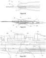
- FIG. 1illustrates an electrosurgical device in a bipolar configuration
- FIG. 2Aillustrates the electrosurgical device of FIG. 1 in a monopolar configuration
- FIG. 2Billustrates a close-up view of the blade electrode immobilized between the working arms
- FIG. 2Cillustrates a cross-sectional view of the electrosurgical device of FIG. 2A ;
- FIG. 2 D 1illustrates a close-up view of a spring pin in FIG. 2C when the blade electrode is extended:
- FIG. 2 D 2illustrates a close-up view of a spring pin when the blade electrode is retracted
- FIG. 3Aillustrates an exploded view of the electrosurgical device of FIG.
- FIG. 3Billustrates a close-up view of the spring pin of FIG. 3A ;
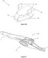
- FIG. 4illustrates a perspective view of an example of an electrosurgical device in a bipolar configuration
- FIG. 5illustrates a bottom view of the electrosurgical device of FIG. 4 in a bipolar configuration
- FIG. 6illustrates a top view of an electrosurgical device
- FIG. 7illustrates configuration bottom view of the electrosurgical device of FIG. 6 ;
- FIG. 8illustrates a bottom perspective view of a shuttle and blade electrode
- FIG. 9illustrates an example of a slider assembly of an electrosurgical device
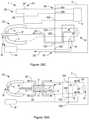
- FIG. 10illustrates another possible configuration of an electrosurgical device in a monopolar configuration
- FIG. 11illustrates an example of the electrosurgical device of FIG. 10 in a monopolar configuration
- FIG. 12illustrates an electrosurgical device with a blade electrode extending from a working arm while in the monopolar configuration
- FIG. 13illustrates the electrosurgical device of FIG. 12 in a bipolar configuration
- FIG. 14illustrates an end view of an example of working arms with a channel for the blade electrode
- FIG. 15illustrates an end view of an example of solid working arms
- FIG. 16illustrates the blade electrode rotated for side to side cutting
- FIG. 17illustrates the blade electrode rotated for up and down cutting
- FIG. 18Aillustrates a cross-sectional view of working arms gripping tissue
- FIG. 16Billustrates the electrosurgical device in the bipolar configuration with power passing between the working arms
- FIG. 19Aillustrates a plan view of power passing between a monopolar electrode and tissue
- FIG. 19Billustrates the electrosurgical device in the monopolar configuration with power passing between the monopolar electrode and the ground pad
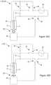
- FIG. 20 A 1illustrates a schematic of a bipolar configuration with switches and power passing between working arms
- FIG. 20 A 2illustrates a schematic of a bipolar configuration with a central processing unit and power passing between working arms
- FIG. 20 A 3illustrates a schematic of a bipolar configuration
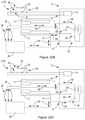
- FIG. 20Billustrates a schematic of the electrosurgical device with power passing between the blade electrode and the working arms
- FIG. 20Cillustrates a schematic of the electrosurgical device in a monopolar configuration with power extending from the working arms around the blade electrode;
- FIG. 20Dillustrates a schematic including the electrosurgical device
- FIG. 21illustrates one possible configuration of connecting the electrosurgical device of the teachings herein to a generator
- FIG. 22Aillustrates an example of a control circuit diagram with the working arms in a bipolar configuration
- FIG. 22Billustrates an example of a control circuit diagram with the working arms in a monopolar configuration
- FIG. 22Cillustrates an example of a control circuit diagram of a monopolar configurations
- FIG. 23Aillustrates a circuit diagram of one possible bipolar configuration
- FIG. 23Billustrate a circuit diagram of one possible monopolar configuration
- FIG. 23Cillustrates an example of another circuit diagram with the electrosurgical device in the monopolar configuration
- FIG. 24Aillustrates a circuit diagram of the electrosurgical device in the off position and the blade electrode including a switch
- FIG. 24Billustrates a circuit diagram of the electrosurgical device in the bipolar configuration with the blade electrode including a switch
- FIG. 24Cillustrates a circuit diagram of the electrosurgical device in the monopolar configuration with the blade electrode including a switch
- FIG. 25Aillustrates a circuit diagram of the electrosurgical device in the off position where the blade electrode is free of a switch
- FIG. 25Billustrates a circuit diagram of the electrosurgical device in the bipolar configuration with the blade electrode free of a switch
- FIG. 25Cillustrates a circuit diagram of the electrosurgical device in a monopolar configuration where the blade electrode is free of a switch
- FIG. 26Aillustrates a circuit diagram of the electrosurgical device in the off position and the electrosurgical device including a ground pad
- FIG. 26Billustrates a circuit diagram of the electrosurgical device in a bipolar configuration with the ground pad in an off state
- FIG. 26Gillustrates a circuit diagram of the electrosurgical device in a monopolar configuration with the ground pad in an on state
- FIG. 27Aillustrates an example of an electrosurgical device including an activation circuit with the activation circuit being in the off position
- FIG. 27Billustrates an example of the electrosurgical device in the bipolar configuration
- FIG. 27Cillustrates an example of the electrosurgical device in the monopolar configuration and a second activation button closed
- FIG. 27Dillustrates an example of the electrosurgical device in the monopolar configuration and a first activation button closed
- FIG. 28Aillustrates an electrosurgical device including an activation circuit including an activation button and a selector with the electrosurgical device being off;
- FIG. 28Billustrates the electrosurgical device of FIG. 28A in the bipolar configuration
- FIG. 28Cillustrates the electrosurgical device of FIG. 28A in the monopolar configuration
- FIG. 29Aillustrates an example of a shuttle including reconfigurable conductive paths and the electrosurgical device being in the bipolar configuration
- FIG. 29Billustrates an example of the shuttle being moved to a bipolar configuration and the conductive paths being reconfigured
- FIG. 29Cillustrates and example of the shuttle in the bipolar configuration and conductive paths being reconfigured within a generator
- FIG. 30Aillustrates an example of a shuttle with reconfigurable conductive paths and one possible plug arrangement
- FIG. 30Billustrates another example of a shuttle with reconfigurable conductive paths and another possible plug arrangement.
- the present teachingsrelate to an electrosurgical device.
- the present teachingsrelate to an electrosurgical device and associated componentry that form an electrosurgical system.
- the electrosurgical systemmay be any system that includes one or more of the devices taught herein.
- the electrical surgical systemincludes at least an electrosurgical device.
- the electrosurgical systemmay include one or more handpieces as taught herein, one or more ground pads, one or more generators, one or more electrosurgical devices, one or more adjacent handpiece components, or a combination thereof and the teachings herein of each device which are incorporated into the electrosurgical system.
- the electrosurgical devicemay be any device that may be used by a surgeon to perform a surgical procedure.
- the electrosurgical devicemay function to be switched between two or more configurations, two or more states, or both. For example, the electrosurgical device may be switched between a monopolar configuration, a bipolar configuration, a non-electrosurgical configuration, or a combination of the three.
- the electrosurgical devicemay be any device that may be switched between two or more configurations with one hand so that a user may switch between the configurations without the need for a second hand, without disrupting the procedure, or both.
- the electrosurgical devicemay be any device and/or configuration that may be used ambidextrously, ambidextrously switched between configurations, or both.
- the electrosurgical devicemay be used to cut, perform hemostasis, coagulate, desiccate, fulgrate, electrocautery, or a combination thereof.
- the electrosurgical devicemay be any device that includes bipolar capabilities, monopolar capabilities, non-electrosurgical capabilities, or a combination thereof.
- the electrosurgical devicemay be used in open surgery.
- the electrosurgical devicemay be used for non-electrosurgical purposes.
- the electrosurgical devicemay be used as forceps, tweezers, or both that may be used to grip an object, an organ, a vein, skin, tissue, the like, or a combination thereof.
- one or more parts of the devicemay include a sharp edge and may be used to cut, similar to that of a scalpel.
- the electrosurgical devicemay include a handpiece and a generator.
- the electrosurgical devicemay have one or more therapy signals that extend between the handpiece and the generator.
- the one or more therapy signalsmay be a signal, power, continuity, or a combination thereof.
- the one or more therapy signalsmay extend from the handpiece to the generator or vice versa.
- the one or more therapy signalsmay be formed by the handpiece, formed by the generator, or both.
- the electrosurgical therapy signalsmay be a therapy current.
- the electrosurgical therapy signalsindicate that a user has performed a step and a signal is being transmitted so that therapy current, energy, or both is generated.
- the electrosurgical therapy signalsmay provide a signal so that one or more therapy currents are produced and the therapy currents may be used for electrosurgery.
- the electrosurgical therapy signalmay be conducted when the activation circuit is in the first switch state, the second switch state, a third switch state, the handpiece is in a first position, a second position, a third position, or a combination of switch states and handpiece positions.
- a therapy signalis not generated, does not exit the handpiece, or both when the activation circuit is in the first switch state.
- the electrosurgical therapy signalmay be a monopolar therapy signal, a bipolar therapy signal, or both.
- the electrosurgical therapy signalmay be a monopolar therapy signal, a bipolar therapy signal, or both.
- the monopolar therapy signalmay be any signal that has a voltage differential between a return port and an active port in the generator.
- the monopolar therapy signalmay be any signal that when applied by the electrosurgical device extends from one pole of an electrosurgical device to another pole located at a remote location, off of the electrosurgical device, off the handpiece, or a combination thereof.
- the bipolar therapy signalmay be any signal that has a voltage differential between two leads that are connected to the electrosurgical device, that are located in the generator, or both.
- the bipolar therapy signalmay be any signal that when applied by the electrosurgical device extends from one component of a handpiece to another component of the handpiece (e.g., between two working arms, from a blade electrode to one or both working arms, or both).
- An electrosurgical therapy signalwhen the activation circuit is in the second state, may exit the handpiece so that a therapy current extends from a blade electrode, between the first working arm and the second working arm, between the blade electrode and one or both of the working arms, or a combination thereof.
- the therapy signalmay be generated and conducted from the handpiece to the generator.
- the generatormay be any device that supplies power, a therapy current, control signals, an electrosurgical therapy signal, electronically reconfigures itself in response to a signal from the user, physically reconfigures in response to adjustments by the user, or a combination thereof.
- the generatormay function to be electrically connected to a handpiece to provide and/or receive electrosurgical therapy signals, power, therapy current, or a combination thereof.
- the generatormay be capable of producing only a single therapy current.
- the generatormay be capable of producing two therapy currents.
- the generatormay include two or more power connections, three or more power connections, or four or more power connections.
- the power connectionsmay be any port in the generator so that one or more power connectors of the handpiece may be plugged into so that power, control signals, therapy currents, or a combination thereof are supplied to the electrosurgical device.
- the generatormay include one or more switches that may be switched between one or more of the power connections so that power, signals, or both may be selectively applied to the electrosurgical device based upon a desired configuration of the electrosurgical device.
- the generatormay include a central processing unit (CPU), a series of internal switching, or both.
- the internal switchingmay provide a signal from an activation circuit to the voltage source so that the voltage source is supplied to the electrosurgical device and preferably the handpiece.
- the CPUmay be interchanged with the internal switching and the switching may perform the same functions as the CPU.
- the CPUmay be any device that provides power, signals, electrical reconfiguration, a switch between two or more therapy currents, a switch between two or more configurations, a switch between two or more therapy signals, or a combination thereof to the electrosurgical device so that the electrosurgical device may be used to perform a desired function as is discussed herein.
- the CPUmay be used to switch the electrosurgical device between a first configuration, a second configuration, a third configuration, a monopolar configuration, a bipolar configuration, a non-electrosurgical configuration, or a combination thereof.
- the first configuration, second configuration, and third configurationmay be any configuration such that the electrosurgical device is mechanically reconfigured, electrically reconfigured, signally reconfigured and/or different, or a combination thereof.
- the first configuration, second configuration, and third configurationmay be any of the various configurations discussed herein.
- the first configurationmay provide a first therapy current.
- the first therapy currentmay be monopolar energy and/or monopolar current.
- the first therapy currentis bipolar energy and/or bipolar current.
- Bipolar energymay be any power source that during application extends from one pole of an electrosurgical device to another pole on the electrosurgical device. Stated another way, bipolar energy is energy that extends from one component of the handpiece to another component of the handpiece.
- the first electrical configurationmay be deactivated by electrically disconnecting the one or more first activation buttons, electrically disconnecting all or a portion of an activation circuit, covering the one or more first activation buttons, electrically disconnecting the blade electrode, electrically disconnecting one or both of the working arms, shorting the blade electrode with a return pad, or a combination thereof.
- the second configurationmay provide a second therapy current.
- the second therapy currentmay be bipolar energy (e.g., bipolar current or bipolar power).
- the second therapy currentmay be monopolar energy (e.g., monopolar current or monopolar power).
- Monopolar energymay be any power source that during application extends from one pole of an electrosurgical device to another pole located at a remote location, off of the electrosurgical device, off the handpiece, or a combination thereof.
- bipolar energyis energy that extends from one component of the handpiece to a component that is not part of the handpiece. For example, energy that extends from a blade electrode to a ground pad is monopolar energy, or energy that extends from one or both working arms to a ground pad is monopolar energy.
- the second electrical configurationmay be deactivated by electrically disconnecting the one or more second activation buttons, electrically disconnecting all or a portion of an activation circuit, covering the one or more second activation buttons, electrically disconnecting one or both working arms, electrically disconnecting the blade electrode, shorting the first working arm with the second working arm, or a combination thereof.
- the third configurationmay be an electrosurgical configuration, a non-electrosurgical configuration, or both.
- the third configurationis a non-electrosurgical configuration.
- the therapy current that extends through the handpiecemay be effected by a signal and or current from the generator; a switch state of the activation circuit (e.g., first switch state, second switch state, third switch state, etc. . . .
- the therapy currentmay be monopolar energy when the handpiece is in the second position and the activation circuit is in the second switch state.
- the therapy currentmay be bipolar energy when the handpiece is in the second position.
- the therapy currentmay be a bipolar energy when the handpiece is in the first position and the activation circuit is in the first switch state.
- the first configuration, second configuration, and third configurationmay be any configuration and/or may perform one or more of the functions as discussed herein for the monopolar configuration, bipolar configuration, non-electrosurgical configuration and each of those functions is incorporated herein.
- the first configurationis a bipolar configuration
- the second configurationis a monopolar configuration
- the third configurationis a non electrosurgical configuration.
- the non-electrosurgical configurationmay be any configuration where power is not supplied to the handpiece, the blade electrode, the two or more working arms, or a combination thereof.
- the non-electrosurgical configurationmay be used when the electrosurgical device is being used as forceps, tweezers, a scalpel, a clamp, Kelley hemostat forceps, or a combination thereof.
- the working armsIn the non-electrosurgical configuration the working arms may be mobile. In the non-electrosurgical configuration the working arms may be immobilized, may immobilize the blade electrode, a cutting arm, an extendable arm, or a combination thereof.
- the cutting arm, the extendable arm, or bothmay be the blade electrode, may be a discrete arm that includes a sharp edge and may be alternated with the monopolar arm, or both.
- the non-electrosurgical configurationmay be switched to a monopolar configuration or a bipolar configuration by pressing a button, turning a switch, advancing a cutting arm, advancing a blade electrode, advancing an extendable arm, or a combination thereof.
- the device when in a monopolar configurationmay supply power through a handpiece component (e.g., a blade electrode) and a return electrode that may be located at another location outside of the hand held portion of the electrosurgical device, through a handpiece component and an adjacent handpiece component, or both.
- the monopolar configurationmay be any configuration where the electrosurgical device may be used to apply monopolar power.
- the monopolar configurationmay be used to cut tissue, coagulate blood and/or fluids, electrical cutting, hemostasis, apply power to a large area, or a combination thereof.
- the monopolar configurationmay be used to heat a specific area, heat an object between both electrodes, in contact with both electrodes, or a combination thereof.
- a monopolar configurationmay be used so that power during use extends from a blade electrode to one or both bipolar electrodes, one or more immobilization arms, one or more working arms, one or more ground pads, or a combination thereof so that the blade electrode may be used for delicate electrosurgery, localized electrosurgery, coagulation, cutting, or a combination thereof.
- the blade electrodemay be used for less delicate procedures, less localized electrosurgery, or both when compared to bipolar electrosurgery.
- the device when in a bipolar configurationmay supply power from one portion of the device to a second portion of the device so that the return path for the power is relatively short when compared to the monopolar configuration.
- the bipolar configurationmay be any configuration where the electrosurgical device may be used to apply bipolar power.
- the device when in the bipolar configurationmay supply power between two localized handpiece components such as two working arms.
- the bipolar configurationmay be used to coagulate, for hemostasis, cutting, fulguration, or a combination thereof.
- the electrosurgical devicemay include two opposing working arms. The two opposing working arms may be configured as forceps.
- the forcepsmay function to grip, hold, squeeze, or a combination thereof one or more objects.
- the forcepsmay include one or more finger grips (i.e., configured like scissors) that may be used to move the forceps so that they may be used to grip one or more objects.
- the forcepsmay be free of finger grips and be actuated by direct pressure being applied to opposing sides of the forceps so that the forceps close and grip an object.
- the forcepsinclude at least two working arms.
- the working armsmay function to grip, hold, squeeze, or a combination thereof an object when the object is between the two or more opposing working arms.
- the working armsmay include one or more gripping features that may assist in gripping, holding, squeezing, or a combination thereof an object.
- the working armsmay be movable between two or more positions. Preferably, the working arms are movable between at least a first position and a second position.
- the working armsmay be movable between a bipolar configuration (e.g., first position) and a monopolar configuration (e.g., second position).
- the working arms in the first positionmay be off, energized, one working arm may be energized, or a combination thereof.
- the working arms in the second positionmay be off, one or both of the working arms may be electrically disconnected, one or both of the working arms may be electrically connected, one working arm may be shorted by the other working arm, or a combination thereof. More preferably, in the second position the working arms are immobilized so that the working arms cannot be used a forceps.
- the working armsmay be longitudinally static and moveable relative to each other.
- the working armsmay be longitudinally moveable and may be moveable relative to each other so that a gripping force may be created.
- the working arms when in a bipolar configurationmay both be extended and then retracted so that a blade electrode may be exposed forming a monopolar configuration.
- the working armsmay be retractable and/or extendable individually, simultaneously, or both.
- the working armsmay be selectively retractable and/or extendable so that one or more tip regions are exposed.
- the working armsmay include a tip region.
- the tip regionmay include a portion that is configured to assist in facilitating gripping, holding, squeezing, or a combination thereof. Additionally, the tip region may be configured in one or more electrosurgical configurations (e.g., a monopolar configuration, bipolar configuration, or a combination of both).
- the tip regionmay include teeth, serrations, mouse teeth, be free of teeth (i.e., smooth), or a combination thereof.
- the tip regionmay be fully and/or partially insulated. Preferably, the tip region includes insulation on the non-contact portions of the working arms so that electrosurgical energy is not transferred through incidental contact.
- the working armsmay include an active portion and an inactive portion (i.e., an insulated portion).
- the active portionmay function to apply power.
- the active portionmay be the same portion as the contact regions of the forceps. Thus, for example, when tissue is grasped between the contact portions of the forceps, power may be supplied to the tissue through this contact portion.
- the active portion of the working armspreferably is between the two opposing working arms and the active portion of the blade electrode is the portion that extends beyond the working arms, out of the channel, or both.
- the active portionsmay be substantially surrounded by inactive portions or portions that are insulated.
- the inactive portionmay be any portion that does not supply power, that is insulated, or both.
- the inactive portionmay be any portion that may transfer power through incidental contact and thus are insulated so that incidental transfer of power does not occur and/or stray current is prevented.
- an outside of the working armsmay be coated with an insulating material so that if the working arms accidentally contact tissue proximate to the tissue of interest the proximate tissue is not subjected to a transfer of power.
- the inactive portion and the active portionmay be made of different materials, coated with different materials, or both.
- the working armsmay be made of any material that may be used to grip, hold, squeeze, or a combination thereof and provide monopolar power, bipolar power, a therapy current, a gripping force, or a combination thereof to a desired location.
- the working armsmay be made of one material and the tip region of each working arm may include, be coated with, or both one or more materials that may be insulating, a higher conductivity than the base material, a lower conductivity than the base material, or a combination thereof.
- the one or more working armsmay include one or more materials along the length of the working arm.
- the working armsmay be entirely made of stainless steel.
- each working armincludes two or more materials.
- the working armsmay have a base material of stainless steel and the working arms may be coated with an insulating material such as silicone or polytetrafluoroethylene (PTFE).
- the working armsmay include any material that is safe for use in a surgical procedure, and preferably and electrosurgical procedure.
- the working armsmay include metals, plastics, a polymer, an elastomer, gold, silver, copper, titanium, aluminum, iron based metals, stainless steel, silicone, polytetrafluoroethylene (PTFE), insulating polymers, rubber, or a combination thereof.
- each working armis substantially coated with an insulating material except for a contact region between the two working arms where the working arms contact each other.
- the working armsmay be coated in regions where the user contacts the working arms.
- the working armsmay have an active portion and a passive portion, an inactive portion, or both.
- the active portionmay be the metal that extends through the working arms and is used to provide monopolar energy, bipolar energy, gripping capabilities, holding capabilities, squeezing capabilities, or a combination thereof.
- the passive portionmay be a portion that houses the active portion.
- the passive portionmay be a housing.
- the working armsmay be located within a housing.
- the housingmay be any part of the device that may include one or more working arms and be gripped by a user during use.
- the housingmay electrically connect, mechanically connect, or both the two working arms.
- the housingmay be a pivot point so that the two working arms may be moved when the housing is compressed.
- the housingmay substantially surround the working arms so that only the tip region extends out of the housing and are exposed.
- the housingmay surround an outer side of the working arms and an inner side of the working arms may be exposed so that as the blade electrode is extended between the two working arms, the blade electrode contacts one or both of the working arms.
- the housingmay include a gripping portion.
- the gripping portionupon and application of pressure, may close the working arms and upon a release of pressure the working arms may return to an open position.
- the gripping portionmay assist the user in holding the electrosurgical device like a pencil.
- the electrosurgical devicemay include an outer housing and an internal housing.
- the internal housingmay include, surround, encapsulate, encase, house, or a combination thereof, one or more internal features of the electrosurgical device.
- the internal housingmay house electrical components such as wires, terminals, plugs, printed circuit boards, spring pins, or a combination thereof.
- the internal housingmay function to provide water resistance to the electrical components.
- the internal housingmay extend through a through hole in the shuttle; provide a guide for the shuttle to move along, or a combination thereof.
- the internal housingmay be an integral part of the outer housing.
- the internal housingmay be one or more discrete parts.
- the internal housingmay be two or more pieces that are connected together.
- the internal housingmay be connected to the external housing, housing one or more of the activation buttons discussed herein, or a combination thereof.
- the housingmay be electrically connected to a power source and provide power to each of the working arms.
- the housingmay be electrically insulating.
- the housingmay include one or more hinges and/or one or more hinge portions.
- the one or more hingesmay function to connect to rigid pieces, impart flexibility into the working arms, the handpiece, the electrosurgical device, or a combination thereof.
- the one or more hingesmay function to impart movement into the housing while allowing the housing to substantially cover the components of the handpiece.
- Theremay be a hinge on only one working arm or a hinge on each working arm.
- the housingmay include a rigid stationary section, a movable section, a flexible hinge section, or a combination thereof.
- the rigid stationary sectionmay be on a proximal end of the electrosurgical device (i.e., closest to the user). The rigid portion may not move when the working arms are moved about the hinge.
- the hingemay create a pivot point for a movable section to rotate about.
- the movable sectionmay function to move so that a gripping force, a gripping movement, or both are created.
- the movable sectionmay cover all or a portion of the working arms. Only a tip of the working arm may extend beyond the movable section of the housing.
- the movable sectionmay be substantially rigid but may pivot about the hinge so that the section is movable and/or flexible.
- the movable section of the working armitself may not be flexible but the arm may be movable such that the movable section moves with the arm.
- the movable sectionmay be on the distal side of the hinge (i.e., the side of the hinge farthest from the user).
- the movable section, the rigid stationary section, or bothmay form a movable connection, a rigid connection, or both with the hinge.
- the movable sectionforms a movable connection
- the rigid stationary sectionforms a rigid connection.
- the movable connectionmay function to allow a hinging action, movement back and forth, or both.
- the movable connectionmay create a force that opposes a gripping of the forceps so that the forceps default open.
- the movable connectionmay create a pivot point that opposes a rigid connection.
- the rigid connectionmay remain static while the movable connection moves about the rigid connection.
- the rigid connectionmay form a side of the hinge that anchors the hinge so that the hinge may move, flex, pivot, allow the arms to move, or a combination thereof.
- the hingemay be any shape so that the hinge moves.
- the rigid stationary section of the housingmay have a general C-shaped cross-section to provide a shell to surround (the inner components of the forceps).
- the rigid moveable sectionmay also have a C-shaped cross-section to provide a shell to surround (the inner components of the forceps.
- the hinge sectionmay have slots in the outer portions of the C-shaped cross-section so that the cross-section of the hinge portion is substantially planar.
- the substantially planar cross-sectionmay have lower bend resistance so that the hinge section is relatively flexible compared to the rigid stationary section and the rigid movable section.
- the hinge sectionmay form a generally “T” shape.
- the housingmay include one or more activation buttons, one or more activation circuits, one or more printed circuit boards and associated controls, one or more blade electrodes, one or more shuttles, one or more channels, one or more immobilization arms, one or more immobilizing features, one or more wires, one or more conductors, or a combination thereof.
- the one or more immobilization arms, one or more immobilization features, or bothmay be any feature of the housing, the working arms, or both that may immobilize one or both working arms when the electrosurgical device is in the monopolar configuration.
- the immobilization armsmay be connected to the housing and extend between one or both of the working arms and when the blade electrode is advanced the immobilization arms are separated and the working arms are moved into contact with each other.
- the immobilization armsmay be connected to the housing and extend between one or both of the working arms and when the blade electrode is advanced the immobilization arms are compressed, pushed together, or both and the working arms are moved into contact with each other.
- the immobilization armsmay be generally parallel to the working arms, may extend: in the same direction as the working arms, may extend away from the working arms, towards an opposing working arm, towards the user, away from a user, or a combination thereof.
- the working arms and the immobilization armsform generally an “X” shape so that when one side of the “X” is moved outward the opposing side of the “X” is moved inward.
- the blade electrodemay include a wedge and the wedge may act to force the immobilizing arms apart so that the working arms are moved together.
- the working arm and the immobilization armsmay form generally two “V” shapes.
- the two generally “V” shapesmay extend generally in the same direction so that as one V is widened the other V is narrowed.
- the immobilization armsmay overlap.
- the overlap portionmay form the “V” shape.
- one immobilization armmay extend from the housing, a first working arm, or both towards the second working arm, the housing proximate the second working arm, or both
- a second immobilization armmay extend from the housing, a second working arm, or both towards the first working arm and as an immobilization feature such as a wedge is moved between the first immobilization arm and the second immobilization arm the immobilization arms may be moved closer to the opposing working arm so that the working arms are moved into contact and immobilized.
- the housing, the working arms, or bothmay be free of immobilization arms.
- the two or more working armsmay be immobilized by an immobilization feature.
- the immobilization featuremay be any feature that connects the two or more working arms together so that the arms are immobilized in the monopolar configuration, so that the forceps are disabled, or both.
- the immobilization featuresmay be part of the arms, part of the housing, all or a part of the shuttle, or a combination thereof.
- the immobilization featuresmay be a track that extends along all or a portion of each arm and as the shuttle is moved forward or backward to the monopolar configuration, each track may extend into communication with the shuttle so that each of the working arms are moved into contact with each other and vice versa from the bipolar configuration.
- the immobilization featuremay be a lock, a fastener, a piece that houses all or a portion of the working arms, or a combination thereof that locks the two working arms together.
- the immobilization featuremay be a piece that slides and compresses the working arms, a piece that twists and radially compresses the working arms, or a combination of both.
- the immobilization feature while being moved and immobilizingmay move a blade electrode, may extend a blade electrode out a channel, or a combination of both.
- the housing, the one or more working arms, or a combination of bothmay include one or more channels.
- the channelmay be located at any location within one or more of the working arms so that one or more features may be extended through the channel.
- the one or more channelsmay end at a distal end (i.e., an end used for electrosurgery, farthest from a user, or both) of the housing, a working arm, or both.
- the channelmay be an absence of material so that a device may be located within the channel and extend from the channel.
- the channelmay house any device that may be selectively used during electrosurgery.
- the channelmay be any shape to house one or more electrosurgical devices.
- the channelmay be round, square, oval, diamond, the like, or a combination thereof so that during use a device may be extended through the channel for use.
- the device extended from the channelmay be a mechanical cutting device, a suction port, a smoke evacuation pot, a blade electrode, a moveable member, or a combination thereof.
- a blade electrodeis extended out of the channel so that the blade electrode may be used.
- the blade electrodemay be any device that may be used to apply monopolar power during a procedure, that may be longitudinally movable, rotationally movable, extendable, retractable, or a combination thereof.
- the blade electrodemay be static.
- the blade electrodemay be static and the working arms moved relative to the blade electrode so that when the working arms are moved the blade electrode is exposed. More preferably, the blade electrode is a movable.
- the blade electrodemay have a first position (e.g., retracted) and a second position (e.g., extended).
- the first positionmay be where the blade electrode is located relative to the working arms so that the working arms are past the blade electrode (e.g., the blade electrode is retracted so that the working arms extend past the blade electrode or the working arms are extended so that the working arms extend past the blade electrode).
- the first positionmay be where the blade electrode is electrically disconnected, electrically shorted relative to another handpiece component, electrically insulated so that power cannot pass from the blade electrode, or a combination thereof.
- the second positionmay be where the blade electrode is located relative to the working arms so that the blade electrode is extended beyond the working arms (e.g., the blade electrode is extended so that the working arms are located proximate to the user or the working arms are retracted so that the blade electrode is beyond the working arms).
- the second positionmay be where the blade electrode is electrically connected, supplies a therapy current, is electrically continuous, or a combination thereof.
- the blade electrodemay be a separate piece that when activated may be used to supply monopolar power.
- the blade electrodemay be formed by connecting the two working arms together and supplying power through only one working arm.
- the blade electrodemay be used for electrically cutting, mechanically cutting, or both.
- the blade electrodemay be a discrete third working arm that may extend from one of the working arms, between the working arms, or both.
- the blade electrodemay be made of the same material as one or both of the working arms. Preferably, the working arms and the blade electrode are made of different materials.
- the blade electrodemay be made of one material. Preferably, the blade electrode includes two or more materials.
- the blade electrodemay be made of stainless steel, copper, silver, titanium, a metal, a surgical steel, a metal with good thermal dissipation properties, a metal with poor thermal dissipation properties, a material with high thermal conductivity, or a combination thereof.
- the blade electrodemay include a material with a first thermal conductivity and the working arms may include a material with a second thermal conductivity.
- the blade electrode, the working arms, or bothmay include both a material with a first thermal conductivity and a second thermal conductivity.
- the materials with the first conductivity and the second conductivitymay be any of the materials discussed herein.
- the material with the first thermal conductivitymay have a lower thermal conductivity than the material with the second thermal conductivity.
- the material with the first thermal conductivityhas a higher thermal conductivity than the material with the second thermal conductivity.
- the blade electrodemay include a coating.
- the coatingmay be any coating that provides insulating properties, provides improved thermal dissipation of a base material, prevents corrosion, or a combination thereof.
- the coatingmay be a polymer, an elastomeric, silicone, polytetrafluorethylene (PTFE), the like, or a combination thereof.
- the coatingmay extend over substantially all of the blade electrode except for an active region of the blade electrode.
- the blade electrodemay include one or more insulator sleeves that cover all or a portion of the blade electrode, the blade electrode may be movable into and out of an insulator housing.
- the insulator housingmay function to prevent power and/or stray power from extending to and/or from the blade electrode when the blade electrode is located within the insulator housing.
- the insulator housingmay receive all or a portion of the blade electrode.
- the insulator housingmay substantially surround all of the blade electrode when the blade electrode is in a retracted position, a bipolar configuration, or both.
- the insulator, housingmay insulate the blade electrode from stray current from the working arms, the ground pad, or both.
- the insulator housingmay be a static component and the blade electrode may move relative to the insulator housing.
- the insulator housingmay be made of insulative material so that the flow of current to and/or from the blade electrode is substantially prevented.
- the insulator housingmay be made of and/or include rubber, plastic, silicone, an elastomer, silicone, PTFE, or a combination thereof.
- the insulator housingmay be used instead of or in addition to an insulator sleeve so that the blade electrode is isolated and/or stray current is prevented.
- the insulator sleevemay prevent power from passing to and/or from the blade electrode.
- the insulator sleeveprevents power from passing to and/or from the blade electrode when the blade electrode is retracted so that the blade electrode is not powered, a circuit cannot be completed, or both.
- the insulator sleevemay be a sleeve that covers a portion of the blade electrode.
- the insulator sleevemay move with the blade electrode so that the same portions of the blade electrode are always covered and the same portions of the blade electrode are always exposed.
- the insulator sleevemay be an integral part of the blade electrode.
- the insulator sleevemay be fixedly connected to the blade electrode.
- the insulator sleevemay isolate portions of the blade electrode so that current and/or stray current are prevented from passing to and/or from the insulated portions of the blade electrode.
- the insulator sleevemay be located on the blade electrode so that when the blade electrode, the working arms, or both are in contact and/or immobilized the working arms contact the insulator sleeve.
- the insulator sleevemay located proximate to a contact portion.
- the contact portionmay contact wiring, a pin, a spring pin, or a combination thereof when the blade electrode is extended so that power passes through the blade electrode.
- the contact portionmay be free of the insulator sleeve.
- the blade electrodemay have an insulator sleeve and a contact portion that are adjacent each other and when the blade electrode is full extended a spring pin may contact the contact portion and when the blade electrode is fully retracted the spring pin may contact the insulator sleeve.
- the insulator sleevemay be made of any material that prevents power from passing into the blade electrode.
- the insulator sleevemay be any thickness so that power is prevented from entering the blade electrode thorough the insulator sleeve.
- the insulator sleevemay be connected to a monopolar insulator.
- the insulator sleevemay prevent a spring pin from providing power to the blade electrode when the blade electrode is refracted and the contact portion may allow the spring pin to power the blade electrode when the blade electrode is extended.
- the spring pinmay function to move (e.g., vertically) so that as a part of varying thickness is moved, a constant contact is created between two devices.
- the spring pinmay create contact between one or more moving parts so that power may be transferred from one part to the one or more moving parts.
- the spring pinmay include one or more springing portions that accommodate for a change in size and/or shape of a part.
- the one or more springing portionsmay create a movable connection.
- the one or more springing portionsmay allow for movement of one part relative to the other part.
- the springing portionmay extend from a body portion.
- the body portionmay assist in connecting the spring pin within a system, may provide a connection point for one or more other components, or both.
- the body portionmay include one or more connection arms that connect the spring pin to circuitry.
- the body portionincludes two connection arms that connect to a printed circuit board.
- the springing pinmay extend when the insulator sleeve is extended and the contact portion is moved proximate to the spring pin.
- the spring pinmay move out of the way when the blade electrode is retracted and the insulator sleeve is moved to a retracted position.
- the blade electrodemay include a monopolar insulator.
- the monopolar insulatormay be any device that may insulate all or a portion of the active portions of the working arms.
- the monopolar insulatormay prevent the working arms from contacting the blade electrode when the electrosurgical device is in the bipolar configuration.
- the monopolar insulatormay be moved into contact with one or both of the working arms and immobilize the working arms so that the working arms cannot be used as forceps.
- the monopolar insulatormay prevent power from being transferred from one or both of the working arms to the blade electrode.
- the monopolar insulatormay prevent stray current from being conducted from the working arms to a surrounding area, the blade electrode, the ground pad, or a combination thereof.
- the monopolar insulatormay extend between the working arms and once past the working arms a bias device may act to retract the monopolar insulator so that the tips of the working arms are pressed into a portion of the monopolar insulator and immobilized.
- the bias devicemay be any device that may act to retract and/or advance one or more components of the electrosurgical device.
- the bias devicemay act to separate the working arms of the electrosurgical device when in the bipolar configuration.
- the bias devicemay push the blade electrode and/or shuttle forward into a monopolar configuration, pull the blade electrode and/or shuttle back from a monopolar configuration, or a combination thereof.
- the bias devicemay ensure that the shuttle, blade electrode, working arms, monopolar electrode, blade, or a combination thereof are in a fully extended and/or fully retracted state. For example, if a user moves a shuttle towards a forward position and stops short, the bias device may complete the movement to a final position.
- the bias devicemay assist in moving any of the devices and/or features discussed herein so that the devices and/or features are bi-stable.
- the bias devicemay ensure that the blade electrode is always either fully extended or fully retracted and not located therebetween.
- the bias devicemay be a spring, a piece of rubber, an elastomeric piece, a bend in metal that forms a bias surface, or a combination thereof. If the bias device is bent metal the metal may be bent forming more than one plane. The first plane may contact a first surface and the second arm may contact a second surface so that two opposing electrosurgical components are moved.
- the bias devicemay be connected to the blade electrode, a shuttle, between the working arms, a device that extends through the channel, or a combination thereof.
- the shuttlemay function to cover one or more activation buttons, moves one or more activation arms, moves the blade electrode, moves one or both working arms, immobilizes and/or electrically disconnects one or more features of the electrosurgical device and/or activation circuit, immobilizes one or more activation buttons, impedes movement and/or depression of one or more activation buttons, move one or more immobilization arms, or a combination thereof.
- the shuttlemay be a shield that covers the activation buttons that are not in use so that one or more of the activation buttons are protected from contact. For example, when the electrosurgical device is configured for bipolar use the shuttle may cover the monopolar activation buttons and expose the bipolar activation buttons or vice versa.
- the shuttlemay be a solid piece.
- the shuttleincludes a through hole so that one or more components may extend through the through hole, be covered by the parts of the shuttle adjacent the through hole, guided by the through hole, or a combination thereof.
- the shuttlemay include a device that extends under, around, through, or a combination thereof one or more activation buttons so that movement of the one or more activation buttons is impeded, prevented, or both.
- a portion of the shuttlemay extend under one or more of the one or more activation buttons so that a user is unable to depress the button to provide power, electricity, a therapy current, or a combination thereof.
- the shuttlemay include one or more positions.
- the shuttleincludes at least a first position and a second position (i.e., a first electrical configuration and a second electrical configuration).
- the shuttle in the first position, the second position, or bothmay perform any of the functions discussed herein for the shuttle.
- the shuttlemay be moved by sliding on a track.
- the shuttlemay be a slider assembly that moves the blade electrode.
- the slider assemblymay function to move the shuttle in one direction and the blade electrode in an opposing direction.
- the slider assemblymay have a gear ratio so that for every unit of measurement the slider assembly is moved the blade electrode moves two units of measurement.
- the slider assemblymay include a rack and pinion system that is connected to the shuttle.
- the slider assemblymay include one or more racks.
- the shuttlemay be connected to one rack and there may be an opposing rack that is offset.
- the slider assemblymay include one or more pinions and preferably two pinions that extend between and into contact with one or more racks. Preferably, one pinion contacts one rack and the other pinion contacts the second rack and the pinions are interconnected.
- the shuttlewhen moved in a first direction may rotate the first pinion and the first pinion may rotate the second pinion and the second pinion may drive the second rack in an opposing direction as the first rack and shuttle are moving.
- the pinionsmay have a gear ratio.
- the gear ratiomay be 1:1, 1:1.1 or more, 1:1.5 or more, 1:2 or more, or even 1:5 or more (i.e., on pinion moves 5 revolutions for every 1 revolution of the other pinion).
- the shuttlemay not include a slider assembly and may be directly driven.
- the shuttlemay be connected to one or more other devices that may be retracted.
- the shuttlemay be connected to the blade electrode and the shuttle may be used to move the blade electrode into and/or between a monopolar configuration and a bipolar configuration.
- the shuttlemay be connected to the working arms so that when the shuttle is moved the working arms are extended and/or retracted.
- the shuttlemay be integrally connected to the blade electrode.
- the shuttlemay include one or more electrical connectors.
- the one or more electrical connectorsmay function to pass power from a wire to an electrosurgical component.
- a wiremay connect to an electrical connector and the electrical connector may power the blade electrode.
- the one or more electrical connectorsmay move with the shuttle so that as the shuttle is extended or retracted the electrosurgical device is electrically reconfigured through the mechanical movement.
- movement of the shuttle in the forward positionmay electrically connect the ground pad to a power source and retraction of the shuttle may electrically disconnect the ground pad from the power source.
- the shuttlemay have 2, 3, or even 4 electrical connectors.
- the shuttlemay include an electrical connector for the first working arm, the second working arm, the ground pad, and the blade electrode.
- the shuttlemay lock a device in a position, immobilize one or more working arms, or both.
- the shuttlemay lock the blade electrode in a retract position when the electrosurgical device is in a bipolar configuration.
- the shuttlemay lock the blade electrode in a forward position and immobilize both of the working arms when the electrosurgical device is configured for monopolar use.
- the shuttlemay lock by a detent, a projection that locks in a corresponding recess, a mechanical interlock, a friction fit, a mechanical lock, or a combination thereof.
- This shuttlemay be connected to one or both working arms of the electrosurgical device.
- the shuttlemay be connected to the housing and slide on a track so that when the shuttle is extended towards a monopolar position all or a portion of each working arm is contacted by the shuttle so that the arms are moved, immobilized, or both.
- the shuttlemay include a wedge, a ring, or both.
- the wedge, the ring, or bothmay be a device for moving one or both of the immobilizing arms, one or both of the working arms, or a combination thereof so that the working arms are immobilized in the monopolar configuration.
- the wedgemay be any device that assists in immobilizing the working arms, moving the immobilization arms, or both.
- the wedgemay have any shape so that the wedge when moved assists in moving one or more immobilizing arms without having a step of separating the immobilizing arms.
- the wedgemay have a tapered shape with a point on one end so that the wedge fits between the two opposing immobilizing arms and as the wedge is gradually progressed between the immobilizing arms the wedge becomes wider moving the immobilizing arms apart.
- the wedgemay be generally triangular in shape.
- the wedgemay have a shape that is a mirror image to the shape formed between the immobilization arms so that when the tip of the wedge reaches the pointed portion between the immobilization arms the wedge is prevented from moving further forward.
- the wedgemay be located at any location on the electrosurgical device, the shuttle, or both so that when the wedge is moved between the immobilization arms the wedge immobilizes the working arms.
- the shuttlemay be free of a wedge and may include a ring.
- the ringmay be any device that assists in immobilizing the working arms.
- the ringmay extend around all or a portion of the periphery, a perimeter, or both of the electrosurgical device, the working arms, the immobilization arms, or a combination thereof.
- the ringmay move along the outside of the electrosurgical device so a portion of the electrosurgical device is located within an inner portion of the ring.
- the ringmay be a complete circle, a partial circle, “U” shaped, fully surround a length of the device, partially surround a length of the device, or a combination thereof.
- the ringmay be part of the shuttle, may be the shuttle, may be discrete from the shuttle, may assist in moving the blade electrode, may cover one or more of the activation buttons, may extend under the one or more activation buttons, may extend through one or more activation buttons, deactivate all or a portion of an activation circuit, may fully and/or partially surround one or more of the immobilization arms, or a combination thereof.
- the activation circuitmay be any part of the electrical surgical system, handpiece, or both that may be activated so that one or more therapy currents are generated, applied, supplied, prevented from being supplied, or a combination thereof.
- the activation circuitmay electrically connect two or more components, electrically activate two or more components, provide a user interface, or a combination thereof.
- the activation circuitmay have one or more switch states, two or more switch states, or three or more switch states. Preferably, the activation circuit has two switch states (e.g., on or off).
- the activation circuit, the switches, or bothmay have a neutral position where the activation switches are neither on nor off.
- the first switch statemay be off, not provide a therapy signal, not provide a first therapy signal, not provide a second therapy signal, not provide a third therapy signal, or a combination thereof.
- the first switch statemay prevent a therapy signal to be produced, prevent a therapy signal (e.g., a first therapy signal, a second therapy signal, etc. . . . ) from exiting a handpiece, prevent communication between the handpiece and the generator, or a combination thereof.
- the second switch statemay be on, provide a therapy signal, provide a first therapy signal, provide a second therapy signal, provide a third therapy signal, or a combination thereof.
- the second switch statemay provide a therapy current between the blade electrode, the first working arm, the second working arm, the ground pad, or a combination thereof; produce a therapy signal; allow a therapy signal to exit the handpiece; allow communication between the handpiece and a generator; or a combination thereof.
- a therapy currentmay be conducted between the blade electrode and the first working arm, the second working arm, or both working arms.
- the activation circuitwhen the activation circuit is in the second state and the blade electrode is in the second position the blade electrode may be electrically connected to a first power connector and a ground pad may be electrically connected to a second power connector.
- the activation circuitmay include one or more switches that each include the switch states discussed herein.
- the activation circuitincludes one or more activation buttons and/or is one or more activation buttons that may be moved and/or activated into the one or more switch states discussed herein.
- the one or more buttonsmay function to control one or more functions of the electrosurgical device.
- the one or more buttonsmay control the bipolar power, the monopolar power, a bipolar cut setting, bipolar coagulation setting, a therapy current, rotation of the blade electrode, rotation of the monpolar electrode, or a combination thereof.
- a first button having a first color and/or configurationmay be for applying bipolar power
- a second button having a second color and/or configurationmay be for applying monopolar power.
- the one or more buttonsmay be exposed and/or unlocked by the shuttle as the shuttle moves, the blade electrode moves, or both to and/or from a monopolar configuration to a bipolar configuration or vice versa.
- the monopolar activation buttonmay only be exposed when the shuttle, blade electrode, or both are in the monpolar configuration.
- the monopolar activation button, the bipolar activation button, or bothmay turn on power to the respective electrode so that power is supplied to the area of interest.
- the devicemay include only one activation button and may also include a selector.
- the selectormay function to select between one or more modes and/or one or more functions.
- the selectorallows a user to select between a plurality of different modes and/or functions.
- the selectormay switch between one or more ports in the activation circuit and the one or more ports may communicate to a CPU the desired electrosurgical function to perform.
- the selectormay be automatically moved when the blade electrode is extended and retracted.
- the usermay set the selector to a desired mode and/or function.
- the selectormay power one or more functions and/or modes simultaneously.
- the electrosurgical devicemay include a button that locks the configuration of the blade electrode, allows the blade electrode to rotate, or both.
- the blade electrodemay be any part of the electrosurgical device that supplies power from one location and the power extends to a distal location.
- the blade electrodemay be a combination of two or more devices that when combined may form a blade electrode.
- the blade electrodemay be a discrete part that when electrically powered provides power.
- the blade electrodemay be static, rotatable about its axis, longitudinally movable about its axis, or a combination thereof.
- the blade electrodemay be blunt, have one or more sharpened edges, have dull edges, or a combination thereof.
- the blade electrodemay rotate to any angle so that the blade electrode may be used to cut, be ergonomically oriented so that a user is not required to reposition their grip, used for vertical cutting, used for side to side cutting, or a combination thereof.
- the blade electrodemay be rotated at an angle of about 15 degrees or more, about 30 degrees or more, about 45 degrees or more, about 60 degrees or more, or even about 90 degrees or more.
- the blade electrodemay be rotated at an angle of about 275 degrees or less, about 225 degrees or less, about 205 degrees or less, or about 180 degrees or less.
- the blade electrodemay maintain a complete circuit during rotation so that power may be applied through the blade electrode as the blade electrode is rotated.
- the blade electrode, the bipolar electrode, or bothmay complete a circuit when in contact with tissue.
- the bipolar electrodemay have two opposing working arms and the tissue may electrically connect the working arms, form an electrical bridge between the two arms, or both.
- the blade electrodemay have a single blade electrode (i.e., a monopolar working arm) and the tissue may electrically connect the blade electrode with a return electrode, act as an electrical bridge between the blade electrode and the return electrode, act as an electrical bridge between the blade electrode and one or both of the bipolar electrodes, or a combination thereof.
- the blade electrode when extendedmay activate a circuit, a switch, or both.
- the circuitmay have a switch that switches between the monopolar configuration, the bipolar configuration, or both.
- the switchmay activate one or more of the bipolar electrodes and deactivate the ground pad (i.e., return pad) or vice versa; activate one or more bipolar electrodes and deactivate the blade electrode or vice versa; deactivate one bipolar electrode and leave the bipolar electrode open (i.e., not powered); deactivate the blade electrode and leave the blade electrode open; deactivate both bipolar electrodes and activate the blade electrode and the return electrode or vice versa, deactivate the ground pad; all of the bipolar electrodes, and the blade electrodes; or a combination thereof.
- the blade electrode, one or more of the bipolar electrodes, or a combination thereofmay be connected to an alternating current power source, a direct current power source, or both.
- the blade electrodes, the bipolar electrodes, or bothare connected to an alternating current power source.
- the blade electrodemay be free of a position between the bipolar electrodes when the electrosurgical device is in the bipolar configuration.
- the blade electrodemay be positioned between the bipolar electrodes, extended beyond the bipolar electrodes, be static and the working arms retracted so that the blade electrode is extended beyond the working arms, or a combination thereof when in the monopolar configuration.
- the bipolar electrodes when in a monopolar configurationmay act to electrically insulate the blade electrode from the surrounding regions, the handpiece, or both.
- the handpiecemay be any part of the device that the user grips, that houses one or more of the control buttons, one or more switches, one or more electrical connectors, one or more diodes, one or more capacitors, or a combination thereof.
- the handpiecemay house all or a portion of the control circuitry, a central processing unit, or both.
- the handpiecemay electrically connect the electrosurgical device, the electrical system, or both to the generator.
- the handpiecemay both physically connect the functional elements of the electrosurgical device and electrically connect the elements of the electrosurgical device.
- the handpiecemay be a body portion of the electrosurgical device, a portion between the two or more working arms, a connector between the two or more working arms, that houses all or a portion of the circuitry, that includes an activation circuit, that includes one or more control buttons, or a combination thereof.
- the handpieceis the portion that a surgeon grips and presses one or more buttons to apply power to a desired location. More preferably, the handpiece is a central portion that includes both buttons and one or more electrical connectors for supplying power to the electrosurgical device, the working arms, the blade electrode, or a combination thereof.
- the handpiecemay include one or more movable members, one or more handpiece components, or both.
- the one or more movable membersmay be any part of the handpiece that may be moved between two or more positions.
- the one or more movable membersmay be moved between a first position and a second position.
- the one or more movable membersmay be moved between a monopolar configuration and bipolar configuration.
- the one or more movable membersmay be any part of the electrosurgical device and/or electrosurgical system that may be electrically reconfigured, mechanically reconfigured, or both.
- the one or more movable membersmay be a monopolar electrode, a first working arm, a second working arm, a ground pad, or a combination thereof.
- the one or more movable membersmay be electrically connected to a first power connector, a second power connector, or both.
- the moveable membermay be moved between one or more of the positions discussed herein for the monopolar electrode, the bipolar electrode, or both and the activation circuit between one or more switch states as discussed herein so that the moveable member is electrically configured, mechanically configured, or both in the same configuration as those respective components.
- the one or more movable membersmay be a handpiece component.
- the one or more handpiece componentsmay be any device that is directly electrically connected, physically connected, carried on, or a combination thereof to the handpiece.
- the one or more handpiece componentsmay be any component that may mechanically reconfigure the handpiece, be mechanically reconfigured by the handpiece, moved along the handpiece, apply a therapy current from the handpiece, or a combination thereof.
- the one or more handpiece componentsmay be electrically connected to the handpiece so that power, signals, therapy currents, or a combination thereof flow directly to and or from the handpiece from the handpiece component without travelling through an intervening device.
- the handpiece componentmay be located separate from the handpiece but electrically connected.
- the one or more handpiece components and handpiecemay be electrically reconfigurable so that the handpiece and the handpiece component are electrically connected in some configurations and electrically disconnected in some configurations.
- the one or more handpiece componentsmay be a blade electrode, the first working arm, the second working arm, the ground pad, the shuttle, a monopolar electrode, one or more bipolar electrodes, or a combination thereof.
- the ground padis placed discretely from the handpiece but the ground pad is directly electrically connected to the handpiece such that when the handpiece is in a monopolar configuration the ground pad is electrically activated.
- the handpiecemay provide power to the one or more handpiece components so that the handpiece components are not electrically connected directly to a power supply, a therapy current, a generator, or a combination thereof.
- the power connectorsmay be any device that supplies power, a therapy current, or both from a power source to the electrosurgical system, the electrosurgical device, or both so that the electrosurgical system, electrosurgical device, or both may be used for electrosurgery.
- the electrosurgical system, electrosurgical device, the handpiece, or a combination thereofmay include one or more, preferably two or more, or most preferably two power connectors supplying power to the electrosurgical system, electrosurgical device, the handpiece, or a combination thereof.
- the therapy currentmay be any current that is applied by the electrosurgical device and performs a predetermined function.
- the therapy currentmay be monopolar power, bipolar power, coagulation, cutting, hemostasis, or a combination thereof.
- the therapy currentmay be any application of power that is produced by the electrosurgical device.
- the therapy currentmay be any application of power that extends into and through the electrosurgical device from one or more power connectors.
- the therapy currentmay be supplied form a voltage source.
- the voltage sourcemay be any supply of energy that performs one or more of the function discussed herein.
- the voltage sourcemay be a direct current voltage source and preferably the voltage source is an alternating current voltage source.
- the power connectorsmay be wires, pieces of a conductor, or both.
- the electrosurgical devicemay include one or more power connectors, preferably two or more power connectors, more preferably three power connectors, or even four or more power connectors. For example, in a three power connector system the power connectors may be and/or connected to a positive pin, a negative pin, a return pin, or a combination thereof.
- the power connectorsmay be and/or connected to a bipolar positive pin, a bipolar negative pin, a monopolar active pin, a monopolar return pin, or a combination thereof.
- Each of the power connectorsmay be directly connected to a power source, a generator, or both.
- the electrosurgical devicehas three power connectors and the generator has three power connections (e.g., a power port) each power connector may be plugged separately into its own power connection
- Each power connectormay be electrically connected to a single component of the electrosurgical device.
- the electrosurgical deviceis electrically reconfigured between a first position and a second position, a first switch state and a second switch state, or a combination of both so that a therapy current and/or power from one of the power connectors may be supplied to two or more components of the electrosurgical device.
- power from the first power connectormay be supplied to the first working arm and power from the second power connector may be supplied to the second working arm, and when the handpiece is moved into the second position, the first power connector may be electrically connected to the blade electrode and the second power connector may be electrically connected to the ground pad.
- One or more of the power connectorsmay be indirectly connected to the power source. For example, if the generator includes two power connections and the electrosurgical device includes three power connectors, two of the power connectors may be electrically connected together and plugged into a power connector. Two or more power connectors may be electrically connected by a jumper.
- the jumpermay function to electrically connect two or more power connectors so that the power connectors can be electrically connected, signally connected, or both to the generator.
- the jumpermay be any device that connects two electrical connectors outside of the generator so that the two or more electrical connectors may be connected to the generator.
- the jumpermay be any device that assists in connecting two or more electrical connectors to a power, source a generator or both.
- the jumpermay electrically connect to components, wires, connectors, or a combination thereof so that a single port may be used to power the components, wires, connectors, or a combination thereof.
- Two or more of the power connectorsmay be electrically connected inside of the handpiece, the generator, or both by one or more connectors.
- the one or more connectorsmay be any device that internally connects two power connectors together.
- the one or more connectorsmay electrically connect the two or more working arms during use so that power may be applied through both working arms, so that a complete circuit is formed, or both.
- the one or more connectorsmay electrically connect both of the working arms together so that one electrical connector may be used to electrically connect both working arms and one electrical connector may extend to another component such as the ground pad, the blade electrode, or both.
- the electrosurgical device, the activation buttons, the handpiece, activation circuit, or a combination thereofmay include one or more diodes.
- the diodesmay be in any configuration so that upon pressing of an activation button, movement of a switch, or both the generator, the electrosurgical device, or both measures a frequency, a change in frequency, or both so that the generator may determine the activation mode that is being powered.
- the one or more diodesmay be different so that the two or more different frequencies, shifts in frequency, or both are created so that a generator may determine which switches in the handpiece, the electrosurgical device, the activation buttons, or a combination thereof are open, dosed, or both.
- the electrosurgical device, generator, handpiece, or a combination thereofmay include one or more transformers.
- the one or more transformersmay be of any size and shape so that depending on the current path through the one or more transformers, around the one or more transformers, or both the voltage supplied through to the handpiece, the electrodes, the working arms, or a combination thereof may be varied. For example, when in a monopolar configuration the voltage may be directly delivered to the electrode and when in a bipolar configuration the transformer may step down the voltage delivered to the working arms. Conversely, the transformer may be used to increase voltage delivered to one or more electrodes.
- various circuitsmay be created by electrically reconfiguring one or more components of the electrosurgical device, physically configuring one or more components of the electrosurgical device, or both During use one or more switches may be opened and/or closed so that one or more open circuits, one or more closed circuits, or both may be formed.
- a shuttle and blade electrodemay be extended forward so that a connection is formed between the blade electrode and a power source and the ground pad and a power source so that a circuit is completed and an open circuit may be created between the power source and the working arms so that the working arms are not powered.
- the circuitsmay be configured so that a circuit is created between two or more components and the electrosurgical device may be used for a desired type of electrosurgery.
- the electrosurgical instrumentmay be configured so that power flows from the blade electrode to one or more working anus, both working arms, to the ground pad, or a combination thereof.
- the electrosurgical devicemay be configured so that power flows from one working arm to another working arm, from one or more working arms to the blade electrode, from one or more working arms to the ground pad, or a combination thereof.
- the electrosurgical devicemay be configured with one or more power connectors, preferably two or more power connectors, and more preferably three or more power connectors. Each of the power connectors may be connected to one or more components, two or more components, or even thee or more components. Each power connector may be switched between one or more components, two or more components, or even three or more components.
- the methodmay include a step of immobilizing the blade electrode, a cutting arm, or both.
- the methodmay include a step of immobilizing one or more bipolar electrodes, one or more blade electrodes, or both simultaneously.
- a method of switching the electrosurgical device between a bipolar configuration, a monopolar configuration, a non-electrosurgical configuration, or a combination thereofmay include one or more of the steps discussed herein in virtually any order.
- the methodmay include a step of advancing a shuttle, advancing a blade electrode, retracting a shuttle, retracting a blade electrode, applying a ground pad, removing a ground pad, reconfiguring a circuit, or a combination thereof.
- the methodmay include a step of applying monopolar power and then immediately subsequently applying bipolar power.
- the methodmay include a step of cutting in a non-electrosurgical configuration and then applying either monopolar power or bipolar power to coagulate, cauterize, or both without a step of changing instruments.
- the methodmay include a step of cutting in a monopolar configuration and then coagulating, cauterizing, or both using bipolar energy without a step of changing instruments.
- FIG. 1illustrates an electrosurgical device 2 .
- the electrosurgical device 2includes a bipolar configuration 100 where the electrosurgical device is forceps 4 .
- the forceps 4include a housing 80 with a pair of working arms 6 that remain as forceps 4 in the bipolar configuration 100 when the shuttle 20 is in the bipolar position 24 .
- the housingcovers the active portions of the working arms 6 along at least a portion of their length so that power is not transferred through incidental contact. While the shuttle 20 remains in the bipolar position 24 (e.g., first position) the bipolar activation button 40 is exposed so that upon pressing the bipolar activation button 40 power travels into the forceps 4 via the power connectors 52 and the power extends between the pair of working arms 6 .
- the housing 80includes a hinge 220 that allows the working arms 6 to move relative to each other while the housing covers the electrodes of the working arms.
- the housing 80is divided by the hinge 220 which has a rigid stationary section 222 on the proximal end of the electrosurgical device 2 and a movable section 224 on the distal end of the electrosurgical device 2 so that the working arms 6 are movable relative to each other.
- the hinge 220as illustrated, is generally “T” shaped and has a rigid connection 226 on the proximal end of the electrosurgical device 2 and a movable connection 228 on the distal end of the electrosurgical device 2 .
- the hinge 220allows the arms to move relative to each other while maintaining the protection of the housing 80 over both working arms and a central portion of the electrosurgical device 2 .
- the movable section 224 of the housing 80includes a gripping portion 88 so that a user, upon applying pressure to the gripping portion closes the working arms.
- FIG. 2Aillustrates the electrosurgical device 2 of FIG. 1 transformed into a monopolar configuration 102 .
- the electrosurgical device 2is changed into a monopolar configuration 102 when the blade electrode 26 is moved forward by the shuttle 20 sliding along the housing 80 and the blade electrode 26 is immobilized between the working arms 6 .
- the shuttle 20is slid forward into a monopolar position 22 (e.g., second position) so that one or more monopolar activation buttons 42 are exposed and the bipolar activation button is covered.
- a monopolar position 22e.g., second position
- FIG. 2Billustrates a close-up view of the blade electrode 26 and working arms 6 immobilized in a monopolar position 22 .
- FIG. 2Cillustrates a cross-sectional view of the electrosurgical device 2 of FIG. 2A with the blade electrode 26 in the extended position.
- the blade electrode 26includes an insulator sleeve 54 that is extended forward with the blade electrode so that a contact portion 56 is aligned with the spring pin 250 .
- the spring pin 250is connected to a printed circuit board 260 , which is in communication with the bipolar activation button 40 and the monopolar activation button 42 .
- the spring pin 250includes a springing portion 252 that maintains contact with the blade electrode 26 so that when the spring pin 250 contacts the contact portion 56 power is supplied through the blade electrode 26 .
- FIG. 2 D 1illustrates a close-up view of a spring pin 250 in contact with a contact portion 56 of the blade electrode 26 when the blade electrode 26 is fully extended.
- the spring pin 250transfers power from the printed circuit board 260 into the blade electrode 26 so that the blade electrode 26 is energized when the bipolar activation button 40 , the monopolar activation button 42 , or both are activated by a user.
- FIG. 2 D 2illustrates a close-up view of a spring pin 250 in contact with the insulator sleeve 54 of the blade electrode 26 when the blade electrode 26 is fully retracted (as is shown in FIG. 1 ).
- the spring pin 250is prevented from transferring power from the printed circuit board 260 by the insulator sleeve 54 so that stray currents are not produced by the blade electrode 26 in the event that the bipolar activation button 40 , the monopolar activation button 42 , or both remain active and/or are activated by a user.
- FIG. 3Aillustrates an exploded view of the electrosurgical device 2 of FIGS. 2 and 3 .
- the electrosurgical device 2includes a housing 80 that when connected together retains all of the components so that the components are movable and function to produce therapy currents.
- the housing 80substantially surrounds the working arms 6 so that only a portion is exposed for creating a therapy current.
- An internal housing 86houses the power connectors 52 that supply power to the working arms 6 and the blade electrode 26 .
- the internal housing 86when assembled, extends through a through hole 32 in the shuttle 20 which is connected to the blade electrode 26 .
- the internal housing 86also contains a printed circuit board 260 with a plurality of sensors 44 that is electrically connected to the bipolar activation button 40 and the monopolar activation button 42 so that when the buttons are pressed power is supplied to a desired location via the spring pin 250 when the electrosurgical device 2 is in the monopolar configuration.
- the power connects 52terminate at a pair of power connectors 10 that plug into a wall and/or generator (not shown).
- FIG. 3Billustrates a close-up view of the spring pin 250 .
- the spring pin 250includes a springing portion 252 that connects a body portion 256 to a contact arm 258 .
- the contact arm 258is moved into contact with and supplies power to a blade electrode (not shown) when the blade electrode is fully extended.
- the body portion 256includes a pair of connection arm 254 that connect the spring pin 250 to a printed circuit board (not shown).
- FIG. 4illustrates another electrosurgical device 2 .
- the electrosurgical device 2is in the bipolar configuration 100 .
- the electrosurgical device 2 as illustratedis configured as forceps 4 having a pair of working arms 6 .
- a shuttle 20 as shownis forward in a bipolar position 24 and connected to one working arm 6 so that both of the working arms 6 are free and the working arms 6 may be biased and used in the bipolar configuration 100 .
- the shuttleis moved to a rearward position the working arms 6 are forced together and immobilized forming a monopolar electrode and/or blade electrode.
- FIG. 5is a bottom view of the electrosurgical device 2 as shown in FIG. 4 .
- the electrosurgical device 2is in the bipolar configuration 100 with the pair of working arms 6 spread apart forming forceps 4 .
- the working arms 6each include an immobilization arm 82 extending from the housing 80 and a wedge 84 that separates the immobilization arms 82 so that the working arms 6 are moved into contact and immobilized when transformed from the bipolar configuration 100 to the monopolar configuration 102 (not shown).
- FIG. 6illustrates another example of an electrosurgical device 2 of the teachings herein.
- the electrosurgical device 2includes a bipolar configuration 100 where the electrosurgical device is forceps 4 .
- the forceps 4include a housing 80 with a pair of working arms 6 that remain as forceps 4 in the bipolar configuration 100 when the shuttle 20 is in the bipolar position 24 .
- the housingcovers the active portions of the working arms 6 along at least a portion of their length so that power is not transferred through incidental contact. While the shuttle 20 remains in the bipolar position 24 (e.g., first position) the bipolar activation button 40 is exposed so that upon pressing the bipolar activation button 40 power extends between the pair of working arms 6 .
- FIG. 7illustrates a bottom view of the electrosurgical device 2 of FIG. 6 configured as forceps 4 .
- the electrosurgical device 2includes a housing 80 that covers a majority of the working arms 6 .
- the housing 80includes a pair of immobilization arms 82 that extend from the housing 80 so that when the wedge 84 advances forward the blade electrode 26 is advanced and the working arms 6 are immobilized.
- Proximate to the immobilization arms 82is a hinge 220 in the housing 80 .
- the hinge 220includes a rigid connection 226 on a proximal side of the hinge 220 and a movable connection 228 on the distal side of the hinge 220 .
- FIG. 8illustrates a bottom perspective view of a shuttle 20 including a wedge 84 .
- the shuttle 20is connected to a blade electrode 26 .
- FIG. 9illustrates an example of an electrosurgical device 2 with a slider assembly 130 .
- the electrosurgical device 2has a housing 80 connected to a working arm 6 .
- the working arm 6is connected to a slider 30 that includes a shuttle 20 .
- the shuttle 20is connected to a working arm 6 and two pinions 134 that are interfitted between a pair of racks 132 .
- Each pinion 134contacts a rack 132 and movement of the shuttle 20 in the direction 136 moves the working arm 6 along its axis in direction 138 , which is in an opposing direction as the shuttle 20 .
- the pinions 134have different sizes so that there is a gear reduction and the distance the working arms 6 travel is greater than the distance the shuttle 20 travels during movement.
- the electrosurgical device 2includes a bipolar activation button 40 and a monopolar activation button 42 .
- FIG. 10illustrates the electrosurgical device 2 in the monopolar configuration 102 .
- a blade electrode 26is moved forward to a monopolar position 22 and the working arms 6 are in contact with a monopolar insulator 30 on the blade electrode 26 so that the monopolar insulator 30 immobilizes the working arms 6 .
- the working arms 6extend into a portion of the monopolar insulator 30 and are immobilized by the monopolar insulator 30 , which also substantially prevents current from straying from the working arms 6 when the tips of the working arms 6 are covered by the monopolar insulator 30 .
- the working arms 6are also covered by an insulator 90 that insulates a length of the working arm 6 and the tips of the working arms 6 are covered by the monopolar insulator 30 so that substantially all of the stray current is insulated and prevented.
- a bias device 50is compressed when the blade electrode is moved into the monopolar position 22 so that upon release the bias device 50 assists in retracting the blade electrode 26 .
- FIG. 11illustrates the electrosurgical device 2 of FIG. 10 in the bipolar configuration 100 .
- the blade electrode 26is retracted rearward into the bipolar position 24 so that the monopolar insulator 30 is located between the two working arms 6 .
- the bias device 50is fully extended.
- the working arms 6are separate and can be used as forceps 4 and with bipolar power.
- the working arms 6further include an insulator 90 that extends the length of the working arms 6 and a tip of each working arm 6 is exposed.
- FIG. 12illustrates another possible configuration of the electrosurgical device 2 in the monopolar configuration 102 .
- the shuttle 20is moved forward into the monopolar position 22 so that the blade electrode 26 is moved forward through a blade electrode channel 46 in a working arm 6 .
- the electrosurgical device 2includes a power connectors 52 at an end so that the electrosurgical device 2 is powered during use.
- FIG. 13illustrates the electrosurgical device 2 of FIG. 12 in a bipolar configuration 100 .
- the electrosurgical device 2has the shuttle 20 moved rearward into a bipolar position 24 so that the working arms 6 are separate and can be used as forceps 4 .
- the blade electrode 26is retracted by the shuttle 20 into the blade electrode channel 46 so that the blade electrode 26 is not exposed.
- a power connector 52is at the end of the electrosurgical device 2 for powering the device.
- FIG. 14illustrates an end view of the working arms 6 of FIGS. 12 and 13 . As illustrated one of the working arms 6 includes a monpolar electrode channel 46 that extends through the working arm 6 .
- FIG. 15illustrates an end view of the working arms of FIGS. 1-7 and 10-11 where the working arms are solid and are free of a channel.
- FIGS. 16 and 17illustrate an end view of one possible monopolar configuration 102 where the orientation of the blade electrode 26 is variable between a horizontal monopolar cutting configuration 104 ( FIG. 16 ) and a vertical monopolar cutting configuration 106 ( FIG. 17 ).
- the working arms 6are made of two materials.
- the outer portion of the working arms 6is made of a material with insulating thermal conductivity 90 and the inner portion is made of a material with high thermal conductivity 92 .
- the outer portion of the blade electrode 26has insulating conductivity 90 and the center has poor thermal conductivity 94 .
- FIGS. 18A and 18Billustrate the electrosurgical device 2 during use in the bipolar configuration 100 .
- FIG. 18Aillustrates the pair of working arms 6 having a material portion having insulating thermal conductivity 90 and a material having high thermal conductivity 92 .
- the working arms 6are in contact with tissue 200 so that power flows through the tissue 200 from one working arm 6 to the other working arm 6 .
- FIG. 18Bis a circuit diagram illustrating one possible bipolar circuit configuration 100 of the electrosurgical device 2 .
- the electrosurgical device 2is connected to a voltage source 64 , and power flows through a switch 60 A from the voltage source 64 to one working arm 6 and from the voltage source 64 through a switch 60 B to the other working arm 6 .
- the switches 60 A and 60 Bare moved into the bipolar configuration 100 an open circuit 62 A and 62 B are formed so that the monopolar portion of the circuit including the ground pad 66 is free of power.
- the blade electrode 26is retracted from between the working arms 6 so that power 68 flows between the working arms 6 and any tissue 200 (not shown) located therebetween.
- FIGS. 19A and 19Billustrate the electrosurgical device 2 in a monopolar configuration 102 .
- FIG. 19Aillustrates the blade electrode 26 having power flow 68 to a ground pad 66 .
- the power 68flows through tissue 200 (not shown) from the blade electrode 26 to the ground pad 66 .
- FIG. 19Billustrates a circuit diagram showing one possible monopolar circuit configuration 102 of the electrosurgical device 2 .
- the electrosurgical device 2is connected to a voltage source 64 , and power flows through a switch 60 A from the voltage source 64 to the ground pad 66 and from the voltage source 64 through a switch 60 B to the blade electrode 26 .
- switches 60 A and 60 Bare moved into the monopolar configuration 102 open circuits 62 A and 628 are formed so that the bipolar portion of the circuit and working arms 6 are free of power.
- power 68flows from the blade electrode 26 to the ground pad 66 .
- FIGS. 20 A 1 through 20 A 3illustrate a circuit diagram of the electrosurgical device 2 as tweezers 5 in a bipolar configuration 100 .
- the electrosurgical device 2is connected to a voltage source 64 .
- FIG. 20 A 1includes a switch 60 that moves between a working arm 6 and a blade electrode 26 and a switch 60 that moves between a working arm 6 and a ground pad 66 .
- the switch 60is supplying power to both of the working arms 6 so that power flows 68 between the two working arms 6 and so that the blade electrode 26 and ground pad 66 are open.
- the two working arms 6are electrically connected via a connector 70 having a switch 60 therebetween.
- FIG. 20 A 2includes a central processing unit 74 that replaces the switching between the voltage source and the blade electrode 26 and the working arms 6 .
- the central processing unit 74controls the power supplied to the blade electrode 26 and/or the working arms 6 of the tweezers 5 so that as illustrated power 68 flows between the working arms.
- the central processing unit 74turned off the ground pad 66 and the blade electrode 26 and turned on the working arms 6 .
- a ground pad 66extends from the central processing unit 74 .
- FIG. 20 A 3illustrates an electrosurgical device 2 in a hybrid bipolar configuration 100 being configured as tweezers 5 that are gripping tissue 200 .
- the tissue 200electrically connects the two adjacent working arms 6 so that power flows from the blade electrode 26 through the tissue 200 to the working arms 6 .
- the switch 60 of the connector 70is closed so that both working arms 6 are powered and electrically connected together and the blade electrode 62 is electrically connected.
- the switch 60 between the blade electrode 26 and the power source 64is closed so that power flows between the working arms 6 and the blade electrode 26 through tissue 200 .
- FIGS. 20B through 20Dillustrate the electrosurgical device 2 in venous monopolar configurations 102 .
- the blade electrode 26being immobilized between the working arms 6 .
- FIG. 20Bis a hybrid monopolar configuration 102 for cutting.
- a switch 60is closed between the power source 64 and the blade electrode 26 so that power flows 68 from the blade electrode to the two working arms 6 .
- One working arm 6is connected directly to the power source 64 and the switch 60 proximate to the other working arm is open 62 due to the switch 60 being moved to power the blade electrode 26 .
- the two working arms 6are electrically connected via a connector 70 that includes a switch 60 so that an electrical connection between the two working arms 6 can be open and closed as the device is switched between a monopolar configuration and a bipolar configuration.
- the ground pad 66is open 62 so that power does not flow through the ground pad 66 .
- FIG. 20Cillustrates the electrosurgical device 2 in a hybrid monopolar configuration 102 /bipolar configuration 100 .
- both switches 60are closed so that power is supplied from the power source 64 to both working arms 6 and an open 62 is present between both the blade electrode 26 and the ground pad 66 so that power does not flow to the blade electrode 26 or the ground pad 66 .
- the flow of power 68is from one working arm 6 to the other working arm 6 around the blade electrode 26 .
- a connector 70 including a switch 60extends between the working arms 6 .
- FIG. 20Dillustrates the electrosurgical device 2 in a monopolar configuration 102 .
- a switch 60is located between the power source 64 and the blade electrode 26 so that power flows through the blade electrode 26 and the flow of power 68 flows to the ground pad 66 through another switch 60 so that a complete circuit is formed.
- the switch 6powers the ground pad 66 and the blade electrode 26
- the working arms 6are open 62 so that no power flows through the working arms 6 , but the working arms mechanically immobilize the blade electrode 26 .
- the two working arms 6are electrically connected by a connector 70 that includes a switch 60 .
- FIG. 21illustrates the electrosurgical device 2 connected to a generator 8 .
- the generator 8 as illustratedonly includes two power connectors 10 .
- the electrosurgical device 2is connected to the generator 8 via one power connector 10 and the ground pad 66 is connected to the generator 8 via a different power connector 10 and the two power connectors 10 are electrically connected by a jumper 12 .
- FIGS. 22A-22Cillustrate various circuit configurations between the generator 8 and the electrosurgical device 2 .
- the generator 8including central processing unit that is connected to a handpiece 120 .
- a usercan change the electrosurgical device 2 between a bipolar configuration 100 ( FIG. 22A ) and a monopolar configuration 102 ( FIGS. 22B and 22C ) and a change in configuration to the bipolar configuration 100 will change the switches 60 so that one switch is open 62 and one switch 60 is closed.
- Each branch of the circuitincludes a diode 122 so that when a switch 60 is closed power and/or a control signal pass through the diode 122 to control the electrosurgical device 2 .
- the generator 8further includes a transformer 124 electrically connected to the ground pad 66 , the working arms 6 , and the blade electrode 26 .
- a jumper 12electrically connects the ground pad 66 to one of the working arms 6 .
- the generator 8includes power connections 10 that extend from the electrical surgical device 2 and are plugged into the generator 8 .
- the generator 8includes a switch 60 that closes to electrically connect the ground pad 66 and opens 62 to disconnect the ground pad.
- FIG. 22Aillustrates the electrosurgical device 2 in bipolar configuration 100 so that power flows between the transformer 124 and each of the working arms 6 in the direction 140 and the flow of power 68 is between to working arms 6 .
- FIG. 22Billustrates electrosurgical device in the monopolar coagulation configuration.
- FIG. 22Cillustrates the electrosurgical device 2 in monopolar cut configuration so that power flows 68 from the mono polar electrode 26 to the ground pad 66 . The power then flows in the direction 140 through the closed switch 60 between the transformer 124 and the blade electrode 26 and ground pad 66 .
- FIGS. 23A and 23Billustrate the electrosurgical device 2 having three power connectors 52 extending therefrom for connecting to a generator 8 (not shown).
- FIG. 23Aillustrates the blade electrode 26 and shuttle 20 in the retracted position so that the electrosurgical device 2 is in the bipolar configuration 100 .
- the handpiece 120includes a pair of working arms 6 with a blade electrode 26 therebetween.
- the handpiece 26also includes a shuttle 20 with electrical connectors 72 that connect the working arms 6 to the power connectors 52 .
- the positive pin 52 Aconnects to a first end of an electrical connector 72 and the second end connects to a first working arm
- a negative pin 52 Bconnects to a first end of a second electrical connector 72 and the second end connects to a second working arm 6 so that the working arms are powered and power 68 extends between the working arms 6
- the negative pin 528includes two wires extending therefrom so that the negative pin 52 B is not electrically isolated.
- One wire from the negative pin 526is connected to a working arm 6 through the electrical connector 72 in the bipolar configuration as shown, and the other wire from the negative pin 526 connects to the ground pad 66 when in the monopolar configuration as is shown in FIG. 236 .
- the ground pad 66is connected to a return pin 52 R and the return pin 52 R is disconnected so that power does not flow through the ground pad 66 .
- FIG. 23Billustrates the shuttle 20 of the handpiece 120 moved forward so that the blade electrode 26 is in the monopolar configuration 102 .
- the handpiece 120includes working arms 6 and a blade electrode 26 in a monopolar configuration 102 .
- the working arms 6are disconnected so that the working arms 6 are not powered.
- Power 68extends from the blade electrode 26 to ground pad 66 .
- the ground pad 66is electrically connected to a return pin 52 R and a negative pin 526 .
- a wireextends from the return pin 52 R through an electrical connector 72 in the shuttle 20 of the handpiece 120 and connects to a negative pin 526 .
- the positive pin 52 Ais connected to a second electrical connector 72 in the handpiece 120 , but the second electrical connector 72 is free of a connection on a second side.
- FIG. 23Cillustrates an electrosurgical device 2 in a monopolar configuration 102 .
- the electrosurgical device 2includes a handpiece 120 with a pair of working arms 6 and a blade electrode 26 extending therebetween.
- Power 68extends from the blade electrode 26 to a ground pad 66 .
- the ground pad 66is electrically connected to a return pin 52 R through a shuttle 20 .
- the shuttle 20includes electrical connectors 72 that extend through the shuttle 20 and electrically connect the ground pad 66 to a return pin 52 R.
- a positive pin 52 Aconnects to a blade electrode 26 through a second electrical connector 72 that extends through the shuttle 20 in the handpiece 120 .
- the negative pin 52 B and the return pin 52 Rare electrically isolated when compared to FIGS. 23A and 23B .
- FIGS. 24A-24Cillustrate the electrosurgical device 2 having two power connectors 52 extending from the handpiece 120 for connecting the electrosurgical device to a generator 8 .
- the electrosurgical device 2also includes an activation circuit 300 for powering the handpiece 120 .
- the electrosurgical device 2 as illustratedis free of a ground pad.
- FIG. 24Aillustrates the electrosurgical device 2 in the bipolar configuration 100 where both power connectors 52 are connected to the handpiece 120 .
- the activation circuit 300includes an activation button 302 in a first switch state 310 so that the switch is open 62 and a signal does not flow from the activation circuit 300 through the ports 160 and to the generator 8 so that the voltage source 64 does not send power to the electrosurgical device through the power connectors 52 .
- the blade electrode 26includes a switch 60 that is open so that the blade electrode 26 is electrically disconnected. The switch 60 connected to the working arm 6 is closed so that the working arm is electrically connected.
- FIG. 24Billustrates the electrosurgical device 2 in the bipolar configuration 100 and power 68 extend between the working arms 6 .
- the activation button 302 on the activation circuit 300is in the second switch state 312 so that a signal is sent to the internal switch and/or central processing unit (CPU) 74 in the generator 8 , through the ports 160 .
- the internal switch and/or CPU 74triggers the voltage source 64 to power the handpiece 120 .
- Powerflows through the power connectors 52 in the direction 320 through the switch 60 and powers the working arms 6 so that power 68 flows therebetween.
- the switch 60 of the blade electrode 26is disconnected so that the blade electrode 26 is not powered.
- FIG. 24Cillustrates the electrosurgical device 2 in the bipolar configuration 102 where both power connectors 52 connect to the handpiece 120 to the generator 8 and the activation circuit 300 is connected to the generator 8 by the ports 160 .
- the activation button 302is in the second switch state 312 so that a signal is sent to the internal switch and/or CPU 74 , which triggers power to extend in the directions 320 from the voltage source 64 .
- the blade electrode 26is in the extended position and the switch 60 of the blade electrode 26 is connected to a working arm so that the blade electrode 26 is powered.
- the other switch 60extends from one working arm to the other working arm so that both working arms are electrically connected and power can travel between the blade electrode 26 and the working arms 6 .
- the direction arrowsshow the movement of the switches 60 between the bipolar configuration of FIG. 24B to the monopolar configuration of FIG. 24C
- FIGS. 25A-25Cillustrate various electrical configurations within the handpiece 120 of the electrosurgical device 2 .
- the handpiece 120includes a pair of working arms 6 and a blade electrode 26 that extends between the working arms 6 , and the handpiece 120 is connected to a generator 8 .
- the handpiece 120is controlled by an activation circuit 300 that is connected to the generator 8 .
- the electrosurgical device 2 as illustratedis free of a ground pad and a switch connected to the blade electrode.
- FIG. 25Aillustrates the electrosurgical device 2 off.
- the activation button 302 of the activation circuit 300is in a first switch state 310 and is open 62 so that a signal does not flow to the generator 8 through the ports and into communication with the internal switch and/or CPU 74 .
- the internal switch and/or CPU 74controls the flower of power from the voltage source 64 through the power connectors 52 and into the working arms 6 and/or blade electrode 26 . As illustrated, the switch 60 is closed so that when power is applied both working arms 6 will be powered.
- FIG. 25Billustrates the electrosurgical device 2 of FIG. 25A powered when the activation button 302 is moved into the second switch state 312 .
- the activation button 302is closed a signal is sent from the activation circuit 300 to the internal switching and/or CPU 74 which triggers power to be sent from the voltage source 64 through the power connectors 52 and to the working arms 6 in the direction 320 .
- the powerflows in the direction 68 between the pair of working arms 6 .
- FIG. 25Cillustrates switch 60 being moved from the second working arm 6 to the blade electrode 26 as is indicated by the arrow so that the second working arm 6 is turned off and remains open 62 and the blade electrode 26 is powered. Power flows from the generator 8 in the direction 320 so that the blade electrode is powered and power 68 flows from the blade electrode 26 to the working arm 6 .
- FIG. 26A through 26Cillustrate reconfiguration of the electrosurgical device 2 .
- the electrosurgical deviceincludes a ground pad 66 , and handpiece 120 , and an activation circuit 300 .
- FIG. 26Aillustrates the electrosurgical device 2 turned off.
- the activation button 302 on the activation circuit 300is in a first switch state 310 and is open 62 so that a signal is not sent to the generator 8 powering the handpiece 120 .
- the blade electrode 26 and the ground pad 66are open because the switches 60 are closed in the direction indicated by the arrow so that the working arms are connected by the closed switches 6 .
- FIG. 26Billustrates the electrosurgical device 2 of FIG. 26A in the bipolar configuration 100 with the activation button 302 of the activation circuit 300 moved to a second switch state 312 .
- the second switch state 312completes the circuit so that a signal passes from the activation circuit 300 through the ports 160 in the generator 8 and into communication with the internal switching and/or CPU 74 .
- the internal switching and/or CPU 74triggers power to travel from the voltage source 64 into the handpiece 120 through the power connectors 52 in the direction 320 through the closed switches 60 so that both working arms 6 are powered and power 68 flows between the working arms 6 .
- FIG. 26Cillustrates the blade electrode 26 in an extended position between the pair of working arms 6 so that a monopolar configuration 102 is formed.
- the switches 60are moved from the first working arm 6 and the second working arm 6 to the blade electrode 26 and ground pad 66 respectively so that the blade electrode 26 is powered when the activation button 302 is in the second switch state 312 as is illustrated.
- Powertravels in the direction 320 from the power connectors, through the switched 60 , and then to the blade electrode 26 and ground pad 66 respectively.
- Power 68passes between the blade electrode 26 and the ground pad 66
- FIGS. 27A through 27Dillustrate an electrosurgical device 2 with an activation circuit 300 connected to a generator by a plurality of ports 160 and a handpiece 120 connected to the generator 8 by a plurality of pins 152 .
- the activation circuit 300includes activation buttons 40 , 42 that when depressed power the handpiece 120 .
- FIG. 27Aillustrates the activation circuit 300 with both the bipolar activation button 40 and the monopolar activation button 42 in the first switch state 310 and open 62 so that the electrosurgical device 2 is off.
- the activation circuit 300has three electrical paths (i.e., wires) that connect with the generator 8 via an upper port 160 A, a middle port 160 B, and a lower port 160 C.
- the ports 160connect the activation circuit 300 with internal switching and/or a CPU 74 that when receives a signal communicates with the power source 64 powering the handpiece 120 .
- the power source 64directs power through a series of switches 60 , which as illustrated are in a neutral position 58 .
- the switches 60direct the power through the plurality of pins 160 .
- the plurality of pinsare a bipolar positive pin 152 A, a bipolar negative pin 152 B, a monopolar active pin 152 C, and a monopolar return pin 152 D that power one or more parts of the handpiece 120 when the handpiece 120 is switched between a monopolar configuration and a bipolar configuration.
- the blade electrode 26is retracted and nested within an insulator housing 96 .
- FIG. 27Billustrates the electrosurgical device 2 of FIG. 27A in the bipolar configuration 100 with the blade electrode 26 retracted and located within the insulator housing 96 so that stray currents are prevented from transferring to and/or from the blade electrode 26 , and the bipolar activation button 40 in the second switch state 312 so that a signal is generated and a circuit is completed with the upper port 160 A and the lower port 160 C so that a signal passes therethrough into the generator 8 and ultimately to the internal switching and/or CPU 74 .
- the monopolar activation button 42is in the first switch state 310 and is open 62 .
- the internal switching and/or CPU 74activates the voltage source 64 so that power extends through the upper switch 60 and through the bipolar positive pin 152 A so that the first working arm 6 is powered by current traveling in the direction 320 . Power extends through the bottom switch 60 and out the bipolar negative pin 152 B so that the second working arm receives power along the direction 320 . The power 68 then extends between the pair of working arms 6 .
- the ground pad 66 and the blade electrode 26are electrically disconnected as illustrated.
- FIG. 27Cillustrates the blade electrode 26 extended out from the insulator housing 96 and between the working arms 6 and power 68 extending from the blade electrode 26 to the ground pad 66 .
- the activation circuit 300includes the bipolar activation button 40 in the second switch state 312 so that a complete circuit is formed with the upper port 160 A and the lower port 160 C so that a signal is transmitted to the internal switching and/or CPU 74 of the generator 8 .
- the monopolar activation button 42is in the first switch state 310 and is open so that a signal is not transmitted from the monopolar activation button 42 .
- the internal switching and/or CPU 74communicates with the voltage source 64 so that power is directed along the paths 320 to the blade electrode 26 and ground pad 66 respectively.
- the switches 60are configured so that power extends from the voltage source 64 through the bipolar positive pin 152 A and the bipolar negative pin 152 B so that a the power 68 between the blade electrode 26 and the ground pad 66 is a first therapy current.
- FIG. 27Dillustrates the blade electrode 26 extended out from the insulator housing 96 and between the working arms 6 and power 68 extending from the blade electrode 26 to the ground pad 66 .
- the activation circuit 300includes the bipolar activation button 40 in a first switch state 310 and open 62 and the monopolar activation button 42 in a second switch state 312 so that a complete circuit is formed with the middle port 160 B and the lower port 160 C.
- a signalis transmitted through the middle port 160 B and the lower port 160 C to the internal switching and/or CPU 74 that communicates with the voltage source 64 so that voltage is provided through the switches 60 in the direction 320 and through the monopolar active pin 152 C to the blade electrode 62 and through the monopolar return pin 152 D to the ground pad 66 .
- FIGS. 28A through 28Cillustrate an electrosurgical device 2 with an activation circuit 300 connected to a generator by a plurality of ports 160 and a handpiece 120 connected to the generator 8 by a plurality of pins 152 .
- the activation circuit 300includes an activation buttons 302 that when depressed powers the handpiece 120 and a selector 308 that changes the signal sent from the activation circuit 300 to the generator 8 .
- FIG. 28Aillustrates the activation circuit 300 with the activation button 302 in the first switch state 310 and open 62 so that the electrosurgical device 2 is off.
- the activation circuit 300has three electrical paths (i.e., wires) that connect with the generator 8 via an upper port 160 A, a middle port 160 B, and a lower port 160 C.
- the ports 160connect the activation circuit 300 with internal switching and/or a CPU 74 that when receives a signal communicates with the power source 64 powering the handpiece 120 .
- the power source 64directs power through a series of switches 60 , which as illustrated are in a neutral position 58 .
- the switches 60direct the power through the plurality of pins 160 .
- the plurality of pinsare a bipolar positive pin 152 A, a bipolar negative pin 152 B, a monopolar active pin 152 C, and a monopolar return pin 152 D that power one or more parts of the handpiece 120 when the handpiece 120 is switched between a monopolar configuration and a bipolar configuration.
- FIG. 28Billustrates the activation button 302 in the second switch state 312 and the selector 308 in a first position so that a signal extends through the upper port 160 A and the middle port 1606 to the generator 8 and the internal switching and/or CPU 74 .
- the internal switching and/or CPU 74communicates with the voltage source 64 so that voltage extends in the direction 320 .
- the switches 60direct the voltage through the bipolar positive pin 152 A into a first working arm 6 and through the bipolar negative pin 152 B into the second working arm 6 .
- Power 68extends between the first working arm 6 and the second working arm 6 .
- FIG. 28Billustrates the activation button 302 in the second switch state 312 and the selector in a second position so that a signal extends through the upper port 160 A and a lower port 160 C to the generator 8 and the internal switching and/or CPU 74 .
- the internal switching and/or CPU 74communicates with the voltage source 64 so that voltage extends in the direction 320 .
- the switches 60direct the voltage through the monopolar active pin 152 C to the blade electrode 26 and the monopolar return pin 152 D to the ground pad 66 .
- Power 68extends between the blade electrode 68 and the ground pad 66 .
- FIGS. 29A through 29Cillustrate a close-up view of the shuttle 20 of the handpiece 120 and associated reconfiguration that occurs by movement of the shuttle 20 .
- the handpiece 120is connected to a generator 8 that provides voltage from a voltage source 64 that extends in the direction 320 through the switches. The power exits the generator 8 from the bipolar positive pin 152 A and the bipolar negative pin 152 B into the handpiece 120 .
- the shuttle 20is retracted so that power extends from the bipolar positive pin 152 A into the electrical connectors 72 of the handpiece 120 at points B and F and exits at points E and A so that the first working arm is powered.
- FIG. 29Billustrates the blade electrode 26 extended between the working arms 6 so that the ends A and C of the working arms do not align with any electrical connectors 72 and the wires of the blade electrode 26 and the ground pad 66 are aligned as is discussed herein.
- the ground pad 66is connected at points L and K and the connector exits the shuttle at points J and D and into the generator at the bipolar negative pin 152 B.
- Powerflows from the voltage source 64 to the blade electrode 26 in the direction 320 along a path through the bipolar positive pin 152 A then into the electrical connector 72 at points B and I until the power travels between the blade electrode 26 and the ground pad 66 .
- FIG. 29Cillustrates another way to power the blade electrode 26 and the ground pad 66 .
- the ground pad 66 and voltage source 64are connected through the monopolar return pin 1520 where power does not pass through the shuttle 20 and passes in the direction 320 .
- the blade electrode 26is powered through the monopolar active pin 152 C where power extends through the shuttle 20 at points B and I and then to the tip of the blade electrode 26 where power 68 flows between the blade electrode 26 and the ground pad 66 .
- FIGS. 30A and 30Billustrate two possible wiring schematics that may be used to power the handpiece 120 as is taught herein.
- FIG. 30Aillustrates an example of a four prong connector.
- the ground pad 66 as illustratedis directly connected to the plug at point W and is indirectly connected to the plug at point R through the shuttle T and electrical connector at points J and K.
- the first working arm 6is connected to the plug at point N through the electrical connector at points E and F.
- the first working arm 6is indirectly connected to the plug at point U through a connection between points M and N so that power can also pass through points E and F of the electrical connector 74 of the shuttle 20 .
- the second working armis directly connected to the plug at point R when connects through points G and H.
- FIG. 30Billustrates an example of a three prong connector.
- the ground pad 66is directly connected to the plug at point W.
- the plug at point Uis directly connected to the first working arm 6 through points E and F.
- the plug at point Ualso directly connects to the blade electrode 26 when extended at point I.
- the plug at point Nis connected to the first working arm at points E and F.
- the plug at point Ris connected to the second working arm through points G and H.
- any numerical values recited hereininclude all values from the lower value to the upper value in increments of one unit provided that there is a separation of at least 2 units between any lower value and any higher value.
- the amount of a component or a value of a process variablesuch as, for example, temperature, pressure, time and the like is, for example, from 1 to 90, preferably from 20 to 80, more preferably from 30 to 70, it is intended that values such as 15 to 85, 22 to 68, 43 to 51, 30 to 32 etc. are expressly enumerated in this specification.
- one unitis considered to be 0.0001, 0.001, 0.01 or 0.1 as appropriate.
Landscapes
- Health & Medical Sciences (AREA)
- Surgery (AREA)
- Engineering & Computer Science (AREA)
- Life Sciences & Earth Sciences (AREA)
- Biomedical Technology (AREA)
- Otolaryngology (AREA)
- Nuclear Medicine, Radiotherapy & Molecular Imaging (AREA)
- Plasma & Fusion (AREA)
- Physics & Mathematics (AREA)
- Heart & Thoracic Surgery (AREA)
- Medical Informatics (AREA)
- Molecular Biology (AREA)
- Animal Behavior & Ethology (AREA)
- General Health & Medical Sciences (AREA)
- Public Health (AREA)
- Veterinary Medicine (AREA)
- Surgical Instruments (AREA)
Abstract
Description
Claims (18)
Priority Applications (1)
| Application Number | Priority Date | Filing Date | Title |
|---|---|---|---|
| US14/589,482US11224477B2 (en) | 2013-03-15 | 2015-01-05 | Combination electrosurgical device |
Applications Claiming Priority (4)
| Application Number | Priority Date | Filing Date | Title |
|---|---|---|---|
| US201361787731P | 2013-03-15 | 2013-03-15 | |
| US201361845664P | 2013-07-12 | 2013-07-12 | |
| US14/205,598US9452011B2 (en) | 2013-03-15 | 2014-03-12 | Combination electrosurgical device |
| US14/589,482US11224477B2 (en) | 2013-03-15 | 2015-01-05 | Combination electrosurgical device |
Related Parent Applications (1)
| Application Number | Title | Priority Date | Filing Date |
|---|---|---|---|
| US14/205,598ContinuationUS9452011B2 (en) | 2013-03-15 | 2014-03-12 | Combination electrosurgical device |
Publications (2)
| Publication Number | Publication Date |
|---|---|
| US20150148798A1 US20150148798A1 (en) | 2015-05-28 |
| US11224477B2true US11224477B2 (en) | 2022-01-18 |
Family
ID=50478574
Family Applications (5)
| Application Number | Title | Priority Date | Filing Date |
|---|---|---|---|
| US14/205,919AbandonedUS20140276796A1 (en) | 2013-03-15 | 2014-03-12 | Combination electrosurgical device |
| US14/205,598Active2034-10-08US9452011B2 (en) | 2013-03-15 | 2014-03-12 | Combination electrosurgical device |
| US14/206,010AbandonedUS20140276797A1 (en) | 2013-03-15 | 2014-03-12 | Combination electrosurgical device |
| US14/589,515Active2035-03-05US10893900B2 (en) | 2013-03-15 | 2015-01-05 | Combination electrosurgical device |
| US14/589,482Active2034-11-07US11224477B2 (en) | 2013-03-15 | 2015-01-05 | Combination electrosurgical device |
Family Applications Before (4)
| Application Number | Title | Priority Date | Filing Date |
|---|---|---|---|
| US14/205,919AbandonedUS20140276796A1 (en) | 2013-03-15 | 2014-03-12 | Combination electrosurgical device |
| US14/205,598Active2034-10-08US9452011B2 (en) | 2013-03-15 | 2014-03-12 | Combination electrosurgical device |
| US14/206,010AbandonedUS20140276797A1 (en) | 2013-03-15 | 2014-03-12 | Combination electrosurgical device |
| US14/589,515Active2035-03-05US10893900B2 (en) | 2013-03-15 | 2015-01-05 | Combination electrosurgical device |
Country Status (6)
| Country | Link |
|---|---|
| US (5) | US20140276796A1 (en) |
| EP (4) | EP3427682B1 (en) |
| JP (5) | JP6141506B2 (en) |
| CN (3) | CN104994802B (en) |
| AU (3) | AU2014235755B2 (en) |
| WO (3) | WO2014150754A1 (en) |
Cited By (3)
| Publication number | Priority date | Publication date | Assignee | Title |
|---|---|---|---|---|
| US11744634B2 (en) | 2013-03-15 | 2023-09-05 | Gyrus Acmi, Inc. | Offset forceps |
| US11779384B2 (en) | 2013-03-15 | 2023-10-10 | Gyrus Acmi, Inc. | Combination electrosurgical device |
| US11957401B2 (en) | 2013-03-15 | 2024-04-16 | Gyrus Acmi, Inc. | Electrosurgical instrument |
Families Citing this family (164)
| Publication number | Priority date | Publication date | Assignee | Title |
|---|---|---|---|---|
| US11229472B2 (en) | 2001-06-12 | 2022-01-25 | Cilag Gmbh International | Modular battery powered handheld surgical instrument with multiple magnetic position sensors |
| US9089360B2 (en) | 2008-08-06 | 2015-07-28 | Ethicon Endo-Surgery, Inc. | Devices and techniques for cutting and coagulating tissue |
| US8663220B2 (en) | 2009-07-15 | 2014-03-04 | Ethicon Endo-Surgery, Inc. | Ultrasonic surgical instruments |
| US9050093B2 (en) | 2009-10-09 | 2015-06-09 | Ethicon Endo-Surgery, Inc. | Surgical generator for ultrasonic and electrosurgical devices |
| US11090104B2 (en) | 2009-10-09 | 2021-08-17 | Cilag Gmbh International | Surgical generator for ultrasonic and electrosurgical devices |
| US10441345B2 (en) | 2009-10-09 | 2019-10-15 | Ethicon Llc | Surgical generator for ultrasonic and electrosurgical devices |
| US8469981B2 (en) | 2010-02-11 | 2013-06-25 | Ethicon Endo-Surgery, Inc. | Rotatable cutting implement arrangements for ultrasonic surgical instruments |
| US8795327B2 (en) | 2010-07-22 | 2014-08-05 | Ethicon Endo-Surgery, Inc. | Electrosurgical instrument with separate closure and cutting members |
| US9192431B2 (en) | 2010-07-23 | 2015-11-24 | Ethicon Endo-Surgery, Inc. | Electrosurgical cutting and sealing instrument |
| US9259265B2 (en) | 2011-07-22 | 2016-02-16 | Ethicon Endo-Surgery, Llc | Surgical instruments for tensioning tissue |
| WO2013119545A1 (en) | 2012-02-10 | 2013-08-15 | Ethicon-Endo Surgery, Inc. | Robotically controlled surgical instrument |
| US20130267787A1 (en)* | 2012-04-05 | 2013-10-10 | Innospan Enterprises, Inc. | Illuminated apparatus for electrocautery and devices and method of use |
| US9439668B2 (en) | 2012-04-09 | 2016-09-13 | Ethicon Endo-Surgery, Llc | Switch arrangements for ultrasonic surgical instruments |
| US20140005705A1 (en) | 2012-06-29 | 2014-01-02 | Ethicon Endo-Surgery, Inc. | Surgical instruments with articulating shafts |
| US9039691B2 (en) | 2012-06-29 | 2015-05-26 | Covidien Lp | Surgical forceps |
| US9326788B2 (en) | 2012-06-29 | 2016-05-03 | Ethicon Endo-Surgery, Llc | Lockout mechanism for use with robotic electrosurgical device |
| US9226767B2 (en) | 2012-06-29 | 2016-01-05 | Ethicon Endo-Surgery, Inc. | Closed feedback control for electrosurgical device |
| US9393037B2 (en) | 2012-06-29 | 2016-07-19 | Ethicon Endo-Surgery, Llc | Surgical instruments with articulating shafts |
| US9072524B2 (en) | 2012-06-29 | 2015-07-07 | Covidien Lp | Surgical forceps |
| US9351754B2 (en) | 2012-06-29 | 2016-05-31 | Ethicon Endo-Surgery, Llc | Ultrasonic surgical instruments with distally positioned jaw assemblies |
| US9408622B2 (en) | 2012-06-29 | 2016-08-09 | Ethicon Endo-Surgery, Llc | Surgical instruments with articulating shafts |
| US20140005702A1 (en) | 2012-06-29 | 2014-01-02 | Ethicon Endo-Surgery, Inc. | Ultrasonic surgical instruments with distally positioned transducers |
| US9198714B2 (en) | 2012-06-29 | 2015-12-01 | Ethicon Endo-Surgery, Inc. | Haptic feedback devices for surgical robot |
| EP2900158B1 (en) | 2012-09-28 | 2020-04-15 | Ethicon LLC | Multi-function bi-polar forceps |
| US9095367B2 (en) | 2012-10-22 | 2015-08-04 | Ethicon Endo-Surgery, Inc. | Flexible harmonic waveguides/blades for surgical instruments |
| US20140135804A1 (en) | 2012-11-15 | 2014-05-15 | Ethicon Endo-Surgery, Inc. | Ultrasonic and electrosurgical devices |
| CN105380711B (en) | 2013-03-15 | 2018-01-02 | 捷锐士阿希迈公司(以奥林巴斯美国外科技术名义) | Combine electrosurgery device |
| JP6141506B2 (en) | 2013-03-15 | 2017-06-07 | ジャイラス エーシーエムアイ インク | Combined electrosurgical device |
| US9713492B2 (en) | 2013-09-03 | 2017-07-25 | Covidien Lp | Switch assemblies for multi-function surgical instruments and surgical instruments incorporating the same |
| US9597141B2 (en) | 2013-09-03 | 2017-03-21 | Covidien Lp | Switch assemblies for multi-function surgical instruments and surgical instruments incorporating the same |
| US9814514B2 (en) | 2013-09-13 | 2017-11-14 | Ethicon Llc | Electrosurgical (RF) medical instruments for cutting and coagulating tissue |
| US9265926B2 (en) | 2013-11-08 | 2016-02-23 | Ethicon Endo-Surgery, Llc | Electrosurgical devices |
| GB2521228A (en) | 2013-12-16 | 2015-06-17 | Ethicon Endo Surgery Inc | Medical device |
| US9795436B2 (en) | 2014-01-07 | 2017-10-24 | Ethicon Llc | Harvesting energy from a surgical generator |
| US10231776B2 (en) | 2014-01-29 | 2019-03-19 | Covidien Lp | Tissue sealing instrument with tissue-dissecting electrode |
| US9554854B2 (en) | 2014-03-18 | 2017-01-31 | Ethicon Endo-Surgery, Llc | Detecting short circuits in electrosurgical medical devices |
| US10463421B2 (en) | 2014-03-27 | 2019-11-05 | Ethicon Llc | Two stage trigger, clamp and cut bipolar vessel sealer |
| US10092310B2 (en) | 2014-03-27 | 2018-10-09 | Ethicon Llc | Electrosurgical devices |
| US9737355B2 (en) | 2014-03-31 | 2017-08-22 | Ethicon Llc | Controlling impedance rise in electrosurgical medical devices |
| JP6293922B2 (en) | 2014-04-02 | 2018-03-14 | ジャイラス エーシーエムアイ インク | Heat pipe cooling device for electrosurgical equipment |
| CN106535801B (en)* | 2014-04-02 | 2020-09-04 | 美国奥林匹斯外科技术吉鲁斯阿克米公司 | Surgical device with replaceable elements |
| US9913680B2 (en) | 2014-04-15 | 2018-03-13 | Ethicon Llc | Software algorithms for electrosurgical instruments |
| CN106456236B (en) | 2014-05-12 | 2019-10-29 | 捷锐士阿希迈公司(以奥林巴斯美国外科技术名义) | Resistance Heated Electrosurgical Instruments |
| US20150327913A1 (en)* | 2014-05-15 | 2015-11-19 | Covidien Lp | Surgical instrument with extendible monopolar element |
| USD753301S1 (en)* | 2014-06-16 | 2016-04-05 | Gyrus Acmi, Inc. | Electrosurgical device |
| US10285724B2 (en) | 2014-07-31 | 2019-05-14 | Ethicon Llc | Actuation mechanisms and load adjustment assemblies for surgical instruments |
| WO2016028835A1 (en)* | 2014-08-20 | 2016-02-25 | GYRUS ACMI, INC. (d/b/a OLYMPUS SURGICAL TECHNOLOGIES AMERICA) | Surgical forceps and latching system |
| US20160058495A1 (en)* | 2014-08-27 | 2016-03-03 | Covidien Lp | Electrosurgically removing tissue with localized return |
| US9918785B2 (en) | 2014-09-17 | 2018-03-20 | Covidien Lp | Deployment mechanisms for surgical instruments |
| US10039592B2 (en) | 2014-09-17 | 2018-08-07 | Covidien Lp | Deployment mechanisms for surgical instruments |
| US9877777B2 (en) | 2014-09-17 | 2018-01-30 | Covidien Lp | Surgical instrument having a bipolar end effector assembly and a deployable monopolar assembly |
| US9987076B2 (en) | 2014-09-17 | 2018-06-05 | Covidien Lp | Multi-function surgical instruments |
| US10080605B2 (en) | 2014-09-17 | 2018-09-25 | Covidien Lp | Deployment mechanisms for surgical instruments |
| CN104224313B (en)* | 2014-10-11 | 2016-08-03 | 黄东晓 | Intensive operation tool |
| US9867656B2 (en) | 2014-11-17 | 2018-01-16 | Covidien Lp | Multi-function surgical instruments |
| US9724153B2 (en) | 2014-11-17 | 2017-08-08 | Covidien Lp | Deployment mechanisms for surgical instruments |
| US9814517B2 (en) | 2014-11-17 | 2017-11-14 | Covidien Lp | Deployment mechanisms for multi-function surgical instruments |
| US9814516B2 (en) | 2014-11-17 | 2017-11-14 | Covidien Lp | Deployment mechanisms for multi-function surgical instruments |
| US9687294B2 (en) | 2014-11-17 | 2017-06-27 | Covidien Lp | Deployment mechanism for surgical instruments |
| US9687293B2 (en) | 2014-11-17 | 2017-06-27 | Covidien Lp | Deployment mechanism for surgical instruments |
| US10639092B2 (en) | 2014-12-08 | 2020-05-05 | Ethicon Llc | Electrode configurations for surgical instruments |
| US10478245B2 (en) | 2014-12-10 | 2019-11-19 | Covidien Lp | Energizable attachment for surgical devices |
| US9763685B2 (en)* | 2015-01-09 | 2017-09-19 | Gyrus Acmi, Inc. | Combination medical device |
| US10245095B2 (en) | 2015-02-06 | 2019-04-02 | Ethicon Llc | Electrosurgical instrument with rotation and articulation mechanisms |
| US10321950B2 (en) | 2015-03-17 | 2019-06-18 | Ethicon Llc | Managing tissue treatment |
| US10342602B2 (en) | 2015-03-17 | 2019-07-09 | Ethicon Llc | Managing tissue treatment |
| EP3581133A1 (en) | 2015-03-23 | 2019-12-18 | Gyrus ACMI, Inc. (D.B.A. Olympus Surgical Technologies America) | Medical forceps with vessel transection capability |
| US10595929B2 (en) | 2015-03-24 | 2020-03-24 | Ethicon Llc | Surgical instruments with firing system overload protection mechanisms |
| US10117702B2 (en)* | 2015-04-10 | 2018-11-06 | Ethicon Llc | Surgical generator systems and related methods |
| US12082864B2 (en)* | 2015-04-28 | 2024-09-10 | I.C. Medical, Inc. | Electrosurgery blades with argon beam capability |
| US11141213B2 (en) | 2015-06-30 | 2021-10-12 | Cilag Gmbh International | Surgical instrument with user adaptable techniques |
| US10034704B2 (en) | 2015-06-30 | 2018-07-31 | Ethicon Llc | Surgical instrument with user adaptable algorithms |
| US11129669B2 (en) | 2015-06-30 | 2021-09-28 | Cilag Gmbh International | Surgical system with user adaptable techniques based on tissue type |
| US11051873B2 (en) | 2015-06-30 | 2021-07-06 | Cilag Gmbh International | Surgical system with user adaptable techniques employing multiple energy modalities based on tissue parameters |
| US10898256B2 (en) | 2015-06-30 | 2021-01-26 | Ethicon Llc | Surgical system with user adaptable techniques based on tissue impedance |
| USD844138S1 (en) | 2015-07-17 | 2019-03-26 | Covidien Lp | Handle assembly of a multi-function surgical instrument |
| USD844139S1 (en) | 2015-07-17 | 2019-03-26 | Covidien Lp | Monopolar assembly of a multi-function surgical instrument |
| US10869716B2 (en)* | 2015-08-28 | 2020-12-22 | Covidien Lp | Powered bipolar resectoscope |
| US11076909B2 (en) | 2015-09-25 | 2021-08-03 | Gyrus Acmi, Inc. | Multifunctional medical device |
| US11020166B2 (en) | 2015-09-25 | 2021-06-01 | Gyrus Acmi, Inc. | Multifunctional medical device |
| US10194973B2 (en) | 2015-09-30 | 2019-02-05 | Ethicon Llc | Generator for digitally generating electrical signal waveforms for electrosurgical and ultrasonic surgical instruments |
| US10595930B2 (en) | 2015-10-16 | 2020-03-24 | Ethicon Llc | Electrode wiping surgical device |
| CN105167843B (en)* | 2015-10-30 | 2018-01-30 | 重庆西山科技股份有限公司 | Coagulation type power handle and planing component |
| EP3364902B1 (en) | 2015-11-25 | 2021-01-06 | Gyrus ACMI, Inc. (D.B.A. Olympus Surgical Technologies America) | Thermal control devices for electrosurgical instruments |
| US10179022B2 (en) | 2015-12-30 | 2019-01-15 | Ethicon Llc | Jaw position impedance limiter for electrosurgical instrument |
| US10575892B2 (en) | 2015-12-31 | 2020-03-03 | Ethicon Llc | Adapter for electrical surgical instruments |
| US9748057B2 (en) | 2016-01-04 | 2017-08-29 | Gyrus Acmi, Inc. | Device with movable buttons or switches |
| US10716615B2 (en) | 2016-01-15 | 2020-07-21 | Ethicon Llc | Modular battery powered handheld surgical instrument with curved end effectors having asymmetric engagement between jaw and blade |
| US11229471B2 (en) | 2016-01-15 | 2022-01-25 | Cilag Gmbh International | Modular battery powered handheld surgical instrument with selective application of energy based on tissue characterization |
| US12193698B2 (en) | 2016-01-15 | 2025-01-14 | Cilag Gmbh International | Method for self-diagnosing operation of a control switch in a surgical instrument system |
| US11051840B2 (en) | 2016-01-15 | 2021-07-06 | Ethicon Llc | Modular battery powered handheld surgical instrument with reusable asymmetric handle housing |
| US11129670B2 (en) | 2016-01-15 | 2021-09-28 | Cilag Gmbh International | Modular battery powered handheld surgical instrument with selective application of energy based on button displacement, intensity, or local tissue characterization |
| US10555769B2 (en) | 2016-02-22 | 2020-02-11 | Ethicon Llc | Flexible circuits for electrosurgical instrument |
| CN108697465A (en) | 2016-02-23 | 2018-10-23 | 柯惠Lp公司 | Common connector for monopole and bipolar instrument |
| US10537381B2 (en) | 2016-02-26 | 2020-01-21 | Covidien Lp | Surgical instrument having a bipolar end effector assembly and a deployable monopolar assembly |
| CN109069200B (en)* | 2016-03-31 | 2021-06-18 | 捷锐士阿希迈公司(以奥林巴斯美国外科技术名义) | Disengagement mechanism for electrosurgical clamps |
| US10485607B2 (en) | 2016-04-29 | 2019-11-26 | Ethicon Llc | Jaw structure with distal closure for electrosurgical instruments |
| US10646269B2 (en) | 2016-04-29 | 2020-05-12 | Ethicon Llc | Non-linear jaw gap for electrosurgical instruments |
| US10702329B2 (en) | 2016-04-29 | 2020-07-07 | Ethicon Llc | Jaw structure with distal post for electrosurgical instruments |
| US10456193B2 (en) | 2016-05-03 | 2019-10-29 | Ethicon Llc | Medical device with a bilateral jaw configuration for nerve stimulation |
| US10898258B2 (en)* | 2016-05-05 | 2021-01-26 | Russell Scott Haupt | Surgical cauterizer with smoke evacuation ports and a central vacuum |
| US20210137583A1 (en)* | 2016-05-05 | 2021-05-13 | Russell Scott Haupt | Surgical Cauterizer with Smoke Evacuation Ports and a Central Vacuum |
| US11890049B2 (en)* | 2016-06-06 | 2024-02-06 | Gyrus Acmi, Inc. | Combination electrosurgical instrument |
| US11129633B2 (en)* | 2016-06-24 | 2021-09-28 | Gyrus Acmi, Inc. | Medical device interface |
| US11510698B2 (en) | 2016-07-06 | 2022-11-29 | Gyrus Acmi, Inc. | Multiple mode electrosurgical device |
| CN115211955A (en)* | 2016-07-07 | 2022-10-21 | 直观外科手术操作公司 | Electric flux delivery and return arrangement for an electric flux delivery instrument |
| US10722299B2 (en) | 2016-07-15 | 2020-07-28 | I.C. Medical, Inc. | Ultrapolar electrosurgery blade and ultrapolar electrosurgery pencil |
| US10376305B2 (en) | 2016-08-05 | 2019-08-13 | Ethicon Llc | Methods and systems for advanced harmonic energy |
| US11826091B2 (en)* | 2016-08-16 | 2023-11-28 | Xcellanxe Medical Technologies Pvt Ltd | Bipolar electrosurgical cutting and coagulation instrument |
| US10390903B2 (en) | 2016-10-24 | 2019-08-27 | Steven Warnock | Illuminated apparatus with telescoping for electrocautery devices and method of use |
| US11000328B2 (en)* | 2016-11-09 | 2021-05-11 | Gyrus Acmi, Inc. | Resistively heated electrosurgical device |
| US11266430B2 (en) | 2016-11-29 | 2022-03-08 | Cilag Gmbh International | End effector control and calibration |
| EP3624715B1 (en)* | 2017-05-16 | 2023-08-02 | Smith & Nephew, Inc. | Electrosurgical systems |
| US11154348B2 (en) | 2017-08-29 | 2021-10-26 | Covidien Lp | Surgical instruments and methods of assembling surgical instruments |
| US10667834B2 (en) | 2017-11-02 | 2020-06-02 | Gyrus Acmi, Inc. | Bias device for biasing a gripping device with a shuttle on a central body |
| US11298801B2 (en) | 2017-11-02 | 2022-04-12 | Gyrus Acmi, Inc. | Bias device for biasing a gripping device including a central body and shuttles on the working arms |
| US11383373B2 (en) | 2017-11-02 | 2022-07-12 | Gyms Acmi, Inc. | Bias device for biasing a gripping device by biasing working arms apart |
| GB2571566B (en) | 2018-03-01 | 2022-03-16 | Cmr Surgical Ltd | Electrosurgical connection unit |
| US11896285B2 (en)* | 2018-03-14 | 2024-02-13 | Gyrus Acmi, Inc. | Device with movable buttons or switches and visual indicator |
| US11382684B2 (en)* | 2018-03-27 | 2022-07-12 | Gyrus Acmi, Inc. | Electrode blade for shavers |
| US10849641B2 (en) | 2018-03-30 | 2020-12-01 | Gyrus Acmi, Inc. | Forceps including a pre-loaded handle latch |
| US10849682B2 (en) | 2018-03-30 | 2020-12-01 | Gyrus Acmi, Inc. | Forceps including a double biased handle latch |
| US10786299B2 (en) | 2018-03-30 | 2020-09-29 | Gyrus Acmi, Inc. | Closure assembly that is laterally movable for selective locking |
| US11123132B2 (en) | 2018-04-09 | 2021-09-21 | Covidien Lp | Multi-function surgical instruments and assemblies therefor |
| US10828756B2 (en) | 2018-04-24 | 2020-11-10 | Covidien Lp | Disassembly methods facilitating reprocessing of multi-function surgical instruments |
| US10842516B2 (en) | 2018-04-30 | 2020-11-24 | Gyrus Acmi, Inc. | Forceps including a pre-loaded handle latch |
| US11896291B2 (en) | 2018-07-02 | 2024-02-13 | Covidien Lp | Electrically-insulative shafts, methods of manufacturing electrically-insulative shafts, and energy-based surgical instruments incorporating electrically-insulative shafts |
| WO2020046921A1 (en)* | 2018-08-27 | 2020-03-05 | Invuity, Inc. | Electrosurgical device, methods of making an electrosurgical device, and methods of using an electrosurgical device |
| RU187789U1 (en)* | 2018-10-02 | 2019-03-19 | Альберт Акрамович Суфианов | Electrosurgical lightweight forceps for neurosurgery |
| DE102018125181A1 (en)* | 2018-10-11 | 2020-04-16 | Aesculap Ag | Intelligent handpiece |
| US11361918B2 (en) | 2019-03-25 | 2022-06-14 | Gyrus Acmi, Inc. | Device with movable buttons or switches and tactile identifier |
| US11376063B2 (en)* | 2019-04-04 | 2022-07-05 | Cilag Gmbh International | Monopolar and bipolar functionality |
| CN109907821A (en)* | 2019-04-22 | 2019-06-21 | 上海昊从医疗科技有限公司 | A kind of two-in-one electric knife of bipolar tweezer of monopole |
| US11191586B2 (en) | 2019-07-02 | 2021-12-07 | Jamison Alexander | Removable tip for use with electrosurgical devices |
| US11172979B2 (en) | 2019-07-02 | 2021-11-16 | Jamison Alexander | Removable tip for use with electrosurgical devices |
| CN110946646B (en)* | 2019-11-11 | 2021-04-20 | 浙江天松医疗器械股份有限公司 | Multifunctional cutting pliers and installation method and operation method thereof |
| US11452525B2 (en) | 2019-12-30 | 2022-09-27 | Cilag Gmbh International | Surgical instrument comprising an adjustment system |
| US12023086B2 (en)* | 2019-12-30 | 2024-07-02 | Cilag Gmbh International | Electrosurgical instrument for delivering blended energy modalities to tissue |
| US12076006B2 (en) | 2019-12-30 | 2024-09-03 | Cilag Gmbh International | Surgical instrument comprising an orientation detection system |
| US11937866B2 (en) | 2019-12-30 | 2024-03-26 | Cilag Gmbh International | Method for an electrosurgical procedure |
| US20210196357A1 (en) | 2019-12-30 | 2021-07-01 | Ethicon Llc | Electrosurgical instrument with asynchronous energizing electrodes |
| US11779387B2 (en) | 2019-12-30 | 2023-10-10 | Cilag Gmbh International | Clamp arm jaw to minimize tissue sticking and improve tissue control |
| US12114912B2 (en) | 2019-12-30 | 2024-10-15 | Cilag Gmbh International | Non-biased deflectable electrode to minimize contact between ultrasonic blade and electrode |
| US11950797B2 (en) | 2019-12-30 | 2024-04-09 | Cilag Gmbh International | Deflectable electrode with higher distal bias relative to proximal bias |
| US12064109B2 (en) | 2019-12-30 | 2024-08-20 | Cilag Gmbh International | Surgical instrument comprising a feedback control circuit |
| US11937863B2 (en) | 2019-12-30 | 2024-03-26 | Cilag Gmbh International | Deflectable electrode with variable compression bias along the length of the deflectable electrode |
| US11944366B2 (en) | 2019-12-30 | 2024-04-02 | Cilag Gmbh International | Asymmetric segmented ultrasonic support pad for cooperative engagement with a movable RF electrode |
| US11911063B2 (en) | 2019-12-30 | 2024-02-27 | Cilag Gmbh International | Techniques for detecting ultrasonic blade to electrode contact and reducing power to ultrasonic blade |
| US11786291B2 (en) | 2019-12-30 | 2023-10-17 | Cilag Gmbh International | Deflectable support of RF energy electrode with respect to opposing ultrasonic blade |
| US12343063B2 (en) | 2019-12-30 | 2025-07-01 | Cilag Gmbh International | Multi-layer clamp arm pad for enhanced versatility and performance of a surgical device |
| US11684412B2 (en) | 2019-12-30 | 2023-06-27 | Cilag Gmbh International | Surgical instrument with rotatable and articulatable surgical end effector |
| US11986201B2 (en) | 2019-12-30 | 2024-05-21 | Cilag Gmbh International | Method for operating a surgical instrument |
| US11786294B2 (en) | 2019-12-30 | 2023-10-17 | Cilag Gmbh International | Control program for modular combination energy device |
| US12053224B2 (en) | 2019-12-30 | 2024-08-06 | Cilag Gmbh International | Variation in electrode parameters and deflectable electrode to modify energy density and tissue interaction |
| US11779329B2 (en) | 2019-12-30 | 2023-10-10 | Cilag Gmbh International | Surgical instrument comprising a flex circuit including a sensor system |
| US12336747B2 (en) | 2019-12-30 | 2025-06-24 | Cilag Gmbh International | Method of operating a combination ultrasonic / bipolar RF surgical device with a combination energy modality end-effector |
| US12262937B2 (en) | 2019-12-30 | 2025-04-01 | Cilag Gmbh International | User interface for surgical instrument with combination energy modality end-effector |
| US11696776B2 (en) | 2019-12-30 | 2023-07-11 | Cilag Gmbh International | Articulatable surgical instrument |
| US20210196362A1 (en) | 2019-12-30 | 2021-07-01 | Ethicon Llc | Electrosurgical end effectors with thermally insulative and thermally conductive portions |
| US11812957B2 (en) | 2019-12-30 | 2023-11-14 | Cilag Gmbh International | Surgical instrument comprising a signal interference resolution system |
| US12082808B2 (en) | 2019-12-30 | 2024-09-10 | Cilag Gmbh International | Surgical instrument comprising a control system responsive to software configurations |
| US11660089B2 (en) | 2019-12-30 | 2023-05-30 | Cilag Gmbh International | Surgical instrument comprising a sensing system |
| WO2022248970A1 (en)* | 2021-05-28 | 2022-12-01 | Covidien Lp | Electrosurgical forceps with smart energy delivery system |
| KR102629805B1 (en)* | 2021-12-31 | 2024-01-29 | (의) 삼성의료재단 | Multifunctional medical forceps |
Citations (324)
| Publication number | Priority date | Publication date | Assignee | Title |
|---|---|---|---|---|
| US1198958A (en) | 1915-07-12 | 1916-09-19 | Cleveland Dental Mfg Company | Tweezers. |
| US1530952A (en) | 1922-05-24 | 1925-03-24 | Charles L Lawton | Golf club |
| US2042985A (en) | 1934-08-22 | 1936-06-02 | Albert B Gardella | Tweezers |
| US2214984A (en) | 1938-04-07 | 1940-09-17 | Bachmann Henry | Tweezers |
| US2381084A (en) | 1943-07-15 | 1945-08-07 | Lillian Catherine Slad | Tweezers |
| US2575652A (en) | 1947-08-19 | 1951-11-20 | Ransom Y Bovee | Pocket tweezer article |
| US2894424A (en) | 1958-04-24 | 1959-07-14 | Jr Charles Swoope Vaughan | Tweezer type wire stripping tool having an adjustable stop and stop latching means |
| US3399583A (en) | 1966-12-09 | 1968-09-03 | Hall Gordon Lance | Locking tweezers |
| US3417752A (en) | 1965-11-12 | 1968-12-24 | Byron C. Butler | Magnetic clamp closing device for use with surgical instruments |
| US3465621A (en) | 1967-11-29 | 1969-09-09 | Ladd Res Ind | Locking tweezers |
| US3576072A (en) | 1969-09-29 | 1971-04-27 | James Bernard Turner Foster | Surgical instrument |
| US3643663A (en) | 1968-10-16 | 1972-02-22 | F L Fischer | Coagulating instrument |
| US3685518A (en) | 1970-07-29 | 1972-08-22 | Aesculap Werke Ag | Surgical instrument for high-frequency surgery |
| US3699632A (en) | 1971-07-30 | 1972-10-24 | Itt | Overriding latch mechanism |
| US3817078A (en)* | 1971-12-29 | 1974-06-18 | Ici Ltd | Removal device |
| US3818784A (en) | 1973-01-03 | 1974-06-25 | Scient Components Inc | Changeable tip tweezers and the like |
| US3913586A (en) | 1974-01-28 | 1975-10-21 | Gomco Surgical Mfg Co | Hemostat |
| US4041952A (en) | 1976-03-04 | 1977-08-16 | Valleylab, Inc. | Electrosurgical forceps |
| US4154226A (en) | 1977-04-20 | 1979-05-15 | Coloplast International A/S | Magnetically operated closure for an intestinal orifice |
| US4171700A (en) | 1976-10-13 | 1979-10-23 | Erbe Elektromedizin Gmbh & Co. Kg | High-frequency surgical apparatus |
| US4202337A (en) | 1977-06-14 | 1980-05-13 | Concept, Inc. | Bipolar electrosurgical knife |
| US4318313A (en) | 1980-03-10 | 1982-03-09 | Tartaglia John A | Tweezer forceps |
| US4375218A (en) | 1981-05-26 | 1983-03-01 | Digeronimo Ernest M | Forceps, scalpel and blood coagulating surgical instrument |
| US4407069A (en) | 1981-12-08 | 1983-10-04 | The Scott & Fetzer Company | Scissors with cushioned stop |
| US4418692A (en) | 1978-11-17 | 1983-12-06 | Guay Jean Louis | Device for treating living tissue with an electric current |
| JPS58193907U (en) | 1982-06-18 | 1983-12-23 | 持田製薬株式会社 | Ultrasonic scalpel with electric scalpel attached |
| US4443935A (en) | 1982-03-01 | 1984-04-24 | Trident Surgical Corporation | Process for making electrosurgical scalpel pencil |
| US4463759A (en) | 1982-01-13 | 1984-08-07 | Garito Jon C | Universal finger/foot switch adaptor for tube-type electrosurgical instrument |
| US4492832A (en) | 1982-12-23 | 1985-01-08 | Neomed, Incorporated | Hand-controllable switching device for electrosurgical instruments |
| US4492231A (en) | 1982-09-17 | 1985-01-08 | Auth David C | Non-sticking electrocautery system and forceps |
| US4494543A (en) | 1982-03-05 | 1985-01-22 | Hart Ernest D | Instrument for extracting splinters |
| US4504707A (en) | 1982-03-15 | 1985-03-12 | Kyushu Hitachi Maxell, Ltd. | Push-button switch locking device for use in electric appliance |
| US4524648A (en) | 1984-08-17 | 1985-06-25 | Chung Charng J | Fixation tweezers |
| US4552143A (en) | 1981-03-11 | 1985-11-12 | Lottick Edward A | Removable switch electrocautery instruments |
| US4655215A (en) | 1985-03-15 | 1987-04-07 | Harold Pike | Hand control for electrosurgical electrodes |
| US4669470A (en) | 1985-11-20 | 1987-06-02 | Brandfield Robert T | Surgical forceps/scissors |
| US4686980A (en) | 1986-04-17 | 1987-08-18 | Alcon Laboratories, Inc. | Disposable bipolar instrument |
| US4688569A (en) | 1986-06-09 | 1987-08-25 | Medi-Tech, Inc. | Finger actuated surgical electrode holder |
| US4713885A (en) | 1986-12-08 | 1987-12-22 | Ronald Keklak | Safe utility knife |
| US4757612A (en) | 1985-03-21 | 1988-07-19 | Preposreve S.A.R.L. | Fixed-blade knife with retractable blade cover |
| US4784136A (en) | 1987-01-12 | 1988-11-15 | Peter Klein | Electrical epilation |
| US4860745A (en) | 1986-07-17 | 1989-08-29 | Erbe Elektromedizin Gmbh | High frequency electrosurgical apparatus for thermal coagulation of biologic tissues |
| US4896661A (en) | 1988-02-05 | 1990-01-30 | Pfizer, Inc. | Multi purpose orthopedic ratcheting forceps |
| US4935027A (en) | 1989-08-21 | 1990-06-19 | Inbae Yoon | Surgical suture instrument with remotely controllable suture material advancement |
| EP0392548A1 (en) | 1989-04-14 | 1990-10-17 | CODMAN & SHURTLEFF INC. | Multi-position latching mechanism for forceps |
| US5021616A (en) | 1989-11-03 | 1991-06-04 | Compaq Computer Corporation | Switch cover |
| US5035695A (en) | 1987-11-30 | 1991-07-30 | Jaroy Weber, Jr. | Extendable electrocautery surgery apparatus and method |
| US5071426A (en) | 1989-04-06 | 1991-12-10 | Stuart Dolgin | Surgical scalpel with retractable blade guard |
| US5104397A (en) | 1989-04-14 | 1992-04-14 | Codman & Shurtleff, Inc. | Multi-position latching mechanism for forceps |
| US5108392A (en) | 1987-06-17 | 1992-04-28 | United States Surgical Corporation | Coagulation forceps and method of fabricating the same |
| US5147378A (en) | 1991-03-05 | 1992-09-15 | Harold Markham | Grapsing forceps |
| US5176702A (en) | 1991-04-04 | 1993-01-05 | Symbiosis Corporation | Ratchet locking mechanism for surgical instruments |
| US5190541A (en) | 1990-10-17 | 1993-03-02 | Boston Scientific Corporation | Surgical instrument and method |
| US5196009A (en) | 1991-09-11 | 1993-03-23 | Kirwan Jr Lawrence T | Non-sticking electrosurgical device having nickel tips |
| US5207696A (en) | 1992-04-30 | 1993-05-04 | Medical Sterile Products, Inc. | Surgical scalpel |
| US5207691A (en) | 1991-11-01 | 1993-05-04 | Medical Scientific, Inc. | Electrosurgical clip applicator |
| US5208983A (en) | 1991-08-19 | 1993-05-11 | Masse Joseph H | Retracting cutter |
| US5226904A (en) | 1991-02-08 | 1993-07-13 | Conmed Corporation | Electrosurgical instrument |
| US5281216A (en) | 1992-03-31 | 1994-01-25 | Valleylab, Inc. | Electrosurgical bipolar treating apparatus |
| US5290286A (en) | 1991-11-12 | 1994-03-01 | Everest Medical Corporation | Bipolar instrument utilizing one stationary electrode and one movable electrode |
| US5293878A (en) | 1991-04-04 | 1994-03-15 | Symbiosis Corporation | Endoscopic surgical instruments having stepped rotatable end effectors |
| US5318589A (en) | 1992-04-15 | 1994-06-07 | Microsurge, Inc. | Surgical instrument for endoscopic surgery |
| US5342359A (en) | 1993-02-05 | 1994-08-30 | Everest Medical Corporation | Bipolar coagulation device |
| US5370659A (en) | 1992-04-09 | 1994-12-06 | Olympus Optical Co., Ltd. | Grasping forceps for medical treatment |
| US5403312A (en) | 1993-07-22 | 1995-04-04 | Ethicon, Inc. | Electrosurgical hemostatic device |
| US5413575A (en) | 1994-04-19 | 1995-05-09 | Innovative Medical Technologies, Ltd. | Multifunction electrocautery tool |
| US5423814A (en) | 1992-05-08 | 1995-06-13 | Loma Linda University Medical Center | Endoscopic bipolar coagulation device |
| US5425743A (en) | 1992-04-06 | 1995-06-20 | United States Surgical Corporation | Surgical instrument locking mechanism |
| US5441498A (en) | 1994-02-16 | 1995-08-15 | Envision Surgical Systems, Inc. | Method of using a multimodality probe with extendable bipolar electrodes |
| US5440813A (en) | 1993-06-04 | 1995-08-15 | Roskam; Scott H. | Rideless scissors with an adjustable load transverse to the pivot axis on a pivot joint |
| US5443463A (en) | 1992-05-01 | 1995-08-22 | Vesta Medical, Inc. | Coagulating forceps |
| US5456695A (en) | 1993-10-25 | 1995-10-10 | United States Surgical Corporation | Multi-tool surgical apparatus |
| US5458598A (en) | 1993-12-02 | 1995-10-17 | Cabot Technology Corporation | Cutting and coagulating forceps |
| US5472442A (en) | 1994-03-23 | 1995-12-05 | Valleylab Inc. | Moveable switchable electrosurgical handpiece |
| US5483952A (en) | 1991-09-26 | 1996-01-16 | United States Surgical Corporation | Handle for surgical instruments |
| US5484435A (en) | 1992-01-15 | 1996-01-16 | Conmed Corporation | Bipolar electrosurgical instrument for use in minimally invasive internal surgical procedures |
| US5499998A (en) | 1993-09-14 | 1996-03-19 | Microsurge, Inc. | Endoscoptic surgical instrument with guided jaws and ratchet control |
| US5531744A (en) | 1991-11-01 | 1996-07-02 | Medical Scientific, Inc. | Alternative current pathways for bipolar surgical cutting tool |
| US5540685A (en) | 1995-01-06 | 1996-07-30 | Everest Medical Corporation | Bipolar electrical scissors with metal cutting edges and shearing surfaces |
| US5562503A (en) | 1994-12-05 | 1996-10-08 | Ellman; Alan G. | Bipolar adaptor for electrosurgical instrument |
| US5573424A (en) | 1995-02-09 | 1996-11-12 | Everest Medical Corporation | Apparatus for interfacing a bipolar electrosurgical instrument to a monopolar generator |
| JPH08322847A (en) | 1995-05-31 | 1996-12-10 | Kyocera Corp | Blood coagulation hemostatic device |
| US5626577A (en) | 1994-02-28 | 1997-05-06 | Harris; George A. | Manually extendable electrocautery surgical apparatus |
| JPH09122140A (en) | 1995-10-31 | 1997-05-13 | Olympus Optical Co Ltd | Operation device |
| CN1149519A (en) | 1995-09-01 | 1997-05-14 | 麦格达恩医疗产品股份有限公司 | Coated bipolar electrocautery |
| US5658281A (en) | 1995-12-04 | 1997-08-19 | Valleylab Inc | Bipolar electrosurgical scissors and method of manufacture |
| US5674220A (en) | 1995-09-29 | 1997-10-07 | Ethicon Endo-Surgery, Inc. | Bipolar electrosurgical clamping device |
| US5702390A (en) | 1996-03-12 | 1997-12-30 | Ethicon Endo-Surgery, Inc. | Bioplar cutting and coagulation instrument |
| US5709680A (en) | 1993-07-22 | 1998-01-20 | Ethicon Endo-Surgery, Inc. | Electrosurgical hemostatic device |
| JPH1057390A (en) | 1996-07-18 | 1998-03-03 | Valleylab Inc | Electric surgical instrument and manufacture |
| US5735849A (en) | 1996-11-07 | 1998-04-07 | Everest Medical Corporation | Endoscopic forceps with thumb-slide lock release mechanism |
| JPH10504485A (en) | 1994-08-24 | 1998-05-06 | ベスタ・メデイカル・インコーポレーテツド | Coagulation forceps |
| JPH10137259A (en) | 1996-11-08 | 1998-05-26 | Olympus Optical Co Ltd | Electric operation device |
| US5779701A (en) | 1995-04-27 | 1998-07-14 | Symbiosis Corporation | Bipolar endoscopic surgical scissor blades and instrument incorporating the same |
| US5810805A (en) | 1996-02-09 | 1998-09-22 | Conmed Corporation | Bipolar surgical devices and surgical methods |
| US5827281A (en) | 1996-01-05 | 1998-10-27 | Levin; John M. | Insulated surgical scissors |
| US5884954A (en) | 1997-06-04 | 1999-03-23 | Trozera; Thomas | Locking tweezers for tying fly-fishing hooks |
| US5891140A (en) | 1996-12-23 | 1999-04-06 | Cardiothoracic Systems, Inc. | Electrosurgical device for harvesting a vessel especially the internal mammary artery for coronary artery bypass grafting |
| US5902301A (en) | 1998-02-23 | 1999-05-11 | Everest Medical Corporation | Cutting/coagulating forceps with interleaved electrodes |
| US5922001A (en) | 1989-12-05 | 1999-07-13 | Yoon; Inbae | Surgical instrument with jaws and a movable internal blade member and method for use thereof |
| US5951545A (en) | 1996-07-15 | 1999-09-14 | Gebrueder Berchtold Gmbh & Co. | High-frequency surgical instrument and method of operating the same |
| WO1999066850A1 (en) | 1998-06-22 | 1999-12-29 | Lina Medical Aps | An electrosurgical device for coagulating and for making incisions, a method of severing blood vessels and a method of coagulating and for making incisions in or severing tissue |
| US6024741A (en) | 1993-07-22 | 2000-02-15 | Ethicon Endo-Surgery, Inc. | Surgical tissue treating device with locking mechanism |
| US6030384A (en) | 1998-05-01 | 2000-02-29 | Nezhat; Camran | Bipolar surgical instruments having focused electrical fields |
| JP2000070280A (en) | 1998-09-02 | 2000-03-07 | Olympus Optical Co Ltd | High-frequency treatment implement |
| US6039734A (en) | 1995-10-24 | 2000-03-21 | Gyrus Medical Limited | Electrosurgical hand-held battery-operated instrument |
| JP2000102545A (en) | 1997-06-18 | 2000-04-11 | Eggers & Associates Inc | Electric tweezers for surgery |
| US6050996A (en) | 1997-11-12 | 2000-04-18 | Sherwood Services Ag | Bipolar electrosurgical instrument with replaceable electrodes |
| US6053908A (en) | 1999-01-07 | 2000-04-25 | Design Standards Corporation | Ratchet assembly for surgical instrument |
| US6074386A (en) | 1995-12-29 | 2000-06-13 | Gyrus Medical Limited | Electrosurgical instrument and an electrosurgical electrode assembly |
| US6099550A (en) | 1989-12-05 | 2000-08-08 | Yoon; Inbae | Surgical instrument having jaws and an operating channel and method for use thereof |
| US6102909A (en) | 1997-08-26 | 2000-08-15 | Ethicon, Inc. | Scissorlike electrosurgical cutting instrument |
| US6110171A (en) | 1999-03-09 | 2000-08-29 | Everest Medical Corporation | Electrosurgical cutting and coagulating instrument for open surgery |
| US6113596A (en) | 1996-12-30 | 2000-09-05 | Enable Medical Corporation | Combination monopolar-bipolar electrosurgical instrument system, instrument and cable |
| US6117169A (en) | 1998-06-24 | 2000-09-12 | Sulzer Carbomedics Inc. | Living hinge attachment of leaflet to a valve body |
| US6117158A (en) | 1999-07-07 | 2000-09-12 | Ethicon Endo-Surgery, Inc. | Ratchet release mechanism for hand held instruments |
| US6152923A (en) | 1999-04-28 | 2000-11-28 | Sherwood Services Ag | Multi-contact forceps and method of sealing, coagulating, cauterizing and/or cutting vessels and tissue |
| US6174309B1 (en) | 1999-02-11 | 2001-01-16 | Medical Scientific, Inc. | Seal & cut electrosurgical instrument |
| US6190386B1 (en) | 1999-03-09 | 2001-02-20 | Everest Medical Corporation | Electrosurgical forceps with needle electrodes |
| JP2001170070A (en) | 1999-12-20 | 2001-06-26 | Olympus Optical Co Ltd | Medical treatment instrument |
| US6270497B1 (en) | 1998-08-27 | 2001-08-07 | Olympus Optical Co., Ltd. | High-frequency treatment apparatus having control mechanism for incising tissue after completion of coagulation by high-frequency treatment tool |
| US6273887B1 (en) | 1998-01-23 | 2001-08-14 | Olympus Optical Co., Ltd. | High-frequency treatment tool |
| US6325795B1 (en) | 1996-03-12 | 2001-12-04 | Sherwood Services Ag | Replaceable accessory cord and handswitch |
| US6355032B1 (en) | 1995-06-07 | 2002-03-12 | Arthrocare Corporation | Systems and methods for selective electrosurgical treatment of body structures |
| JP2002078717A (en) | 2000-07-05 | 2002-03-19 | Olympus Optical Co Ltd | Instrument for high-frequency medical treatment |
| US6358268B1 (en) | 2000-03-06 | 2002-03-19 | Robert B. Hunt | Surgical instrument |
| WO2002024089A1 (en) | 2000-09-22 | 2002-03-28 | Tissuelink Medical, Inc. | Fluid-assisted medical device |
| US6402747B1 (en) | 1997-07-21 | 2002-06-11 | Sherwood Services Ag | Handswitch cord and circuit |
| US6428538B1 (en) | 1995-10-20 | 2002-08-06 | United States Surgical Corporation | Apparatus and method for thermal treatment of body tissue |
| US20020107517A1 (en) | 2001-01-26 | 2002-08-08 | Witt David A. | Electrosurgical instrument for coagulation and cutting |
| US20020106609A1 (en) | 2001-02-06 | 2002-08-08 | Palermo Rosanne M. | Dental forceps |
| US20020115997A1 (en) | 2000-10-23 | 2002-08-22 | Csaba Truckai | Electrosurgical systems and techniques for sealing tissue |
| JP2002528166A (en) | 1998-10-23 | 2002-09-03 | シャーウッド サーヴィシス アクチェンゲゼルシャフト | Externally-opened vascular sealing forceps with disposable electrodes |
| US6458128B1 (en) | 2001-01-24 | 2002-10-01 | Ethicon, Inc. | Electrosurgical instrument with a longitudinal element for conducting RF energy and moving a cutting element |
| US6486419B2 (en) | 1998-01-09 | 2002-11-26 | Ricoh Company, Ltd. | Multifunctional image forming apparatus having a covered main power switch |
| US6494886B1 (en) | 2000-06-22 | 2002-12-17 | Granit Medical Innovation, Inc. | Off-set clamp mechanism and associated method for minimally invasive surgery |
| US20030014850A1 (en) | 2001-07-20 | 2003-01-23 | International Business Machines Corporation | Retaining clip for panel mounted input/output connector |
| US20030018329A1 (en) | 2000-04-27 | 2003-01-23 | Hooven Michael D. | Transmural ablation device with EKG sensor and pacing electrode |
| US6514252B2 (en) | 1998-05-01 | 2003-02-04 | Perfect Surgical Techniques, Inc. | Bipolar surgical instruments having focused electrical fields |
| US20030050633A1 (en) | 2001-09-13 | 2003-03-13 | Ellman Alan G. | Intelligent selection system for electrosurgical instrument |
| US6551313B1 (en) | 2001-05-02 | 2003-04-22 | John M. Levin | Electrosurgical instrument with separate cutting and coagulating members |
| US20030097126A1 (en) | 1993-05-10 | 2003-05-22 | Arthrocare Corporation | Bipolar electrosurgical clamp for removing and modifying tissue |
| US20030109876A1 (en) | 2001-12-11 | 2003-06-12 | Olympus Optical Co., Ltd. | Instrument for high-frequency treatment and method of high-frequency treatment |
| US20030106609A1 (en) | 2001-12-07 | 2003-06-12 | Nalge Nunc International Corporation | Waste funnel system |
| US6585735B1 (en) | 1998-10-23 | 2003-07-01 | Sherwood Services Ag | Endoscopic bipolar electrosurgical forceps |
| JP2003210483A (en) | 2002-01-21 | 2003-07-29 | Koichi Hosokawa | High frequency tissue incision instrument |
| US20030144605A1 (en) | 1998-04-08 | 2003-07-31 | Senorx, Inc. | Biopsy anchor device with cutter |
| US20030144652A1 (en) | 2001-11-09 | 2003-07-31 | Baker James A. | Electrosurgical instrument |
| US6619038B2 (en) | 2000-07-04 | 2003-09-16 | Kanzaki Kokyukoki Mfg. Co., Ltd. | Axle driving apparatus |
| US6623499B1 (en) | 2002-02-21 | 2003-09-23 | Michael Andreini | Retractable safety scalpel |
| US20030181904A1 (en) | 2002-01-23 | 2003-09-25 | Levine Andy H. | Electrosurgical cutting, coagulating and suction instrument |
| US6641595B1 (en) | 1999-08-20 | 2003-11-04 | Surgical Innovations Ltd. | Laparoscopic forceps handle |
| US6679882B1 (en) | 1998-06-22 | 2004-01-20 | Lina Medical Aps | Electrosurgical device for coagulating and for making incisions, a method of severing blood vessels and a method of coagulating and for making incisions in or severing tissue |
| US6689130B2 (en) | 2001-06-04 | 2004-02-10 | Olympus Corporation | Treatment apparatus for endoscope |
| US20040030330A1 (en) | 2002-04-18 | 2004-02-12 | Brassell James L. | Electrosurgery systems |
| US6726686B2 (en) | 1997-11-12 | 2004-04-27 | Sherwood Services Ag | Bipolar electrosurgical instrument for sealing vessels |
| EP1411847A2 (en) | 2001-07-09 | 2004-04-28 | ArthroCare Corporation | Articulated electrosurgical probe |
| US20040082946A1 (en) | 2002-10-24 | 2004-04-29 | Valley Forge Scientific | Electrosurgical generator apparatus |
| US20040097912A1 (en) | 2002-11-18 | 2004-05-20 | Gonnering Wayne J. | Electrosurgical generator and method with removable front panel having replaceable electrical connection sockets and illuminated receptacles |
| US20040097117A1 (en) | 2002-11-18 | 2004-05-20 | Gonnering Wayne J. | Monopolar electrosurgical multi-plug connector device and method which accepts multiple different connector plugs |
| JP2004147724A (en) | 2002-10-29 | 2004-05-27 | Aisin Kiko Co Ltd | Disposable surgical instrument and its reuse prevention method |
| US6749610B2 (en) | 2002-08-15 | 2004-06-15 | Kirwan Surgical Products, Inc. | Electro-surgical forceps having fully plated tines and process for manufacturing same |
| US6752767B2 (en) | 2002-04-16 | 2004-06-22 | Vivant Medical, Inc. | Localization element with energized tip |
| US6773434B2 (en) | 2001-09-18 | 2004-08-10 | Ethicon, Inc. | Combination bipolar forceps and scissors instrument |
| US6808525B2 (en) | 2001-08-27 | 2004-10-26 | Gyrus Medical, Inc. | Bipolar electrosurgical hook probe for cutting and coagulating tissue |
| US6827717B2 (en) | 2000-08-26 | 2004-12-07 | Olympus Winter & Ibe Gmbh | Monopolar and bipolar electrode for a urological resectoscope |
| US6860882B2 (en) | 2003-02-06 | 2005-03-01 | Codman & Shurtleff, Inc. | Electro-surgical bipolar forceps |
| US20050065510A1 (en) | 2003-08-11 | 2005-03-24 | Yuval Carmel | Electrosurgical device with floating-potential electrodes |
| EP1530952A1 (en) | 2003-11-17 | 2005-05-18 | Sherwood Services AG | Bipolar forceps having monopolar extension |
| US20050113825A1 (en) | 1996-09-20 | 2005-05-26 | Ioan Cosmescu | Multifunctional telescopic monopolar/bipolar surgical device and method therefore |
| US20050113827A1 (en)* | 2003-11-17 | 2005-05-26 | Dumbauld Patrick L. | Bipolar forceps having monopolar extension |
| US20050113824A1 (en) | 2003-11-20 | 2005-05-26 | Sartor Joe D. | Electrosurgical pencil with improved controls |
| JP2005518864A (en) | 2002-02-28 | 2005-06-30 | ミソニクス インコーポレイテッド | Ultrasonic medical treatment device for electrocautery |
| US20050159745A1 (en) | 2004-01-16 | 2005-07-21 | Surgrx, Inc. | Electrosurgical instrument with replaceable cartridge |
| JP2005521465A (en) | 2002-03-27 | 2005-07-21 | ティシューリンク メディカル インコーポレイテッド | Fluid-assisted medical device, fluid-assisted medical system, and fluid-assisted medical method |
| US20050187512A1 (en) | 2004-02-06 | 2005-08-25 | Isola Scott S. | Ultrasonic probe with detachable slidable cauterization forceps |
| US6942662B2 (en) | 2001-12-27 | 2005-09-13 | Gyrus Group Plc | Surgical Instrument |
| US20050216019A1 (en) | 2002-01-17 | 2005-09-29 | Eckman Walter W | Diskectomy instrument with disposable blade head |
| JP2005538748A (en) | 2002-01-17 | 2005-12-22 | コンセプト マトリックス エルエルシー | Apparatus and method for discectomy |
| US20060004355A1 (en)* | 2004-07-02 | 2006-01-05 | Fridolin Anders | Medical instrument for electrosurgery |
| US20060084973A1 (en)* | 2004-10-14 | 2006-04-20 | Dylan Hushka | Momentary rocker switch for use with vessel sealing instruments |
| US20060167450A1 (en) | 2005-01-14 | 2006-07-27 | Johnson Kristin D | Vessel sealer and divider with rotating sealer and cutter |
| US7083613B2 (en) | 1997-03-05 | 2006-08-01 | The Trustees Of Columbia University In The City Of New York | Ringed forceps |
| US7094231B1 (en) | 2004-01-22 | 2006-08-22 | Ellman Alan G | Dual-mode electrosurgical instrument |
| US20060190035A1 (en) | 2004-10-08 | 2006-08-24 | Sherwood Services Ag | Latching mechanism for forceps |
| US7108694B2 (en) | 2002-11-08 | 2006-09-19 | Olympus Corporation | Heat-emitting treatment device |
| US20060217701A1 (en) | 2005-03-25 | 2006-09-28 | Boston Scientific Scimed, Inc. | Ablation probe with heat sink |
| WO2006122279A2 (en) | 2005-05-11 | 2006-11-16 | Mayo Foundation For Medical Education And Research | Apparatus and methods for internal surgical procedures |
| US7147637B2 (en) | 2003-12-09 | 2006-12-12 | Gyrus Group Plc | Surgical instrument |
| US7147638B2 (en) | 2003-05-01 | 2006-12-12 | Sherwood Services Ag | Electrosurgical instrument which reduces thermal damage to adjacent tissue |
| US7150749B2 (en) | 2003-06-13 | 2006-12-19 | Sherwood Services Ag | Vessel sealer and divider having elongated knife stroke and safety cutting mechanism |
| US7156846B2 (en) | 2003-06-13 | 2007-01-02 | Sherwood Services Ag | Vessel sealer and divider for use with small trocars and cannulas |
| WO2007002545A1 (en) | 2005-06-22 | 2007-01-04 | Boston Scientific Limited | Steerable medical device control system |
| US20070007845A1 (en) | 2005-07-07 | 2007-01-11 | Suzuki Contactpoint Industry Co., Ltd. | Built-up commutator and micro-motor employing the same |
| US20070049922A1 (en) | 2005-08-23 | 2007-03-01 | Daniel Rontal | Retractable electrosurgical electrode |
| EP1769765A1 (en) | 2005-09-30 | 2007-04-04 | Sherwood Services AG | Insulating boot for electrosurgical forceps |
| US20070093857A1 (en) | 2005-10-26 | 2007-04-26 | Campbell Rogers | Devices and methods for treating mitral valve regurgitation |
| US20070106295A1 (en) | 2005-09-30 | 2007-05-10 | Garrison David M | Insulating boot for electrosurgical forceps |
| US20070123855A1 (en) | 2000-12-29 | 2007-05-31 | Intuitive Surgical Inc. | Bipolar cauterizing instrument |
| US20070129716A1 (en) | 2000-12-28 | 2007-06-07 | Derek Daw | Electrosurgical medical system and method |
| US7244257B2 (en) | 2002-11-05 | 2007-07-17 | Sherwood Services Ag | Electrosurgical pencil having a single button variable control |
| EP1810629A2 (en) | 2006-01-24 | 2007-07-25 | Sherwood Services AG | Electrosurgical generator using multiple resonant inductor/capacitor circuits |
| US20070179491A1 (en) | 2006-01-31 | 2007-08-02 | Medtronic, Inc. | Sensing needle for ablation therapy |
| US7252667B2 (en) | 2003-11-19 | 2007-08-07 | Sherwood Services Ag | Open vessel sealing instrument with cutting mechanism and distal lockout |
| WO2007093857A1 (en) | 2006-02-15 | 2007-08-23 | Jinding Group Co. Ltd. | Rotary power tool |
| JP2008018226A (en) | 2006-07-11 | 2008-01-31 | Olympus Medical Systems Corp | Treatment device |
| US20080033428A1 (en) | 2006-08-04 | 2008-02-07 | Sherwood Services Ag | System and method for disabling handswitching on an electrosurgical instrument |
| US7344536B1 (en) | 2002-02-05 | 2008-03-18 | Origin Medsystems, Inc. | Electrocautery surgical scissors |
| US20080077129A1 (en) | 2006-09-27 | 2008-03-27 | Van Wyk Robert A | Electrosurgical Device Having Floating Potential Electrode and Adapted for Use With a Resectoscope |
| JP2008119465A (en) | 2006-11-08 | 2008-05-29 | Covidien Ag | In line type unit for closing and dividing blood vessel |
| US20080147092A1 (en) | 2006-10-23 | 2008-06-19 | Michael Rogge | Hybrid energy instrument combined with clip application capability |
| US20080154300A1 (en) | 2006-12-15 | 2008-06-26 | Noel Jabbour | Surgical forceps |
| US20080236860A1 (en) | 2007-04-02 | 2008-10-02 | Prevention Products, Inc. | Electrical switch cover |
| EP1977706A1 (en) | 2007-04-03 | 2008-10-08 | Tyco Healthcare Group, LP | Controller for flexible tissue ablation procedures |
| US20080287948A1 (en) | 2007-05-04 | 2008-11-20 | Gyrus Medical Limited | Electrosurgical system |
| US7473253B2 (en) | 2001-04-06 | 2009-01-06 | Covidien Ag | Vessel sealer and divider with non-conductive stop members |
| US20090030414A1 (en)* | 2005-06-21 | 2009-01-29 | Inasurgica, Llc | Four Function Surgical Instrument |
| US20090062786A1 (en) | 2007-08-30 | 2009-03-05 | Garito Jon C | Tri-frequency electrosurgical instrument |
| US20090062792A1 (en) | 2007-08-31 | 2009-03-05 | Ethicon Endo-Surgery, Inc. | Electrical ablation surgical instruments |
| US20090062830A1 (en) | 2007-08-29 | 2009-03-05 | Olympus Medical Systems Corp. | Puncture apparatus with automatic puncture function |
| US7503917B2 (en) | 2003-11-20 | 2009-03-17 | Covidien Ag | Electrosurgical pencil with improved controls |
| US20090082768A1 (en)* | 2007-09-25 | 2009-03-26 | Uwe Bacher | Bipolar Medical Instrument |
| US20090093804A1 (en) | 2007-10-09 | 2009-04-09 | Gyrus Medical Limited, | Electrosurgical system |
| US20090138003A1 (en) | 2007-11-28 | 2009-05-28 | Derek Dee Deville | Cordless Medical Cauterization and Cutting Device |
| US20090138013A1 (en) | 2004-06-08 | 2009-05-28 | Thorne Jonathan O | Electrosurgical tool with moveable electrode that can be operated in a cutting mode or a coagulation mode |
| CN101460110A (en) | 2006-06-08 | 2009-06-17 | 塞隆医疗设备公司 | Device for cutting and coagulation of tissue |
| US20090171147A1 (en)* | 2007-12-31 | 2009-07-02 | Woojin Lee | Surgical instrument |
| US20090192509A1 (en) | 2008-01-14 | 2009-07-30 | Curtis Richard J | Electrosurgical system |
| JP2009182479A (en) | 2008-01-29 | 2009-08-13 | Duaxes Corp | Filtering device |
| US20090248002A1 (en) | 2008-04-01 | 2009-10-01 | Tomoyuki Takashino | Treatment system, and treatment method for living tissue using energy |
| US7604635B2 (en) | 2000-03-06 | 2009-10-20 | Salient Surgical Technologies, Inc. | Fluid-assisted medical devices, systems and methods |
| WO2009141624A1 (en) | 2008-05-23 | 2009-11-26 | Gyrus Medical Limited | An electrosurgical generator and system |
| US7625391B2 (en) | 2002-11-04 | 2009-12-01 | Stryker Trauma S.A. | Orthopaedic ratcheting forceps |
| JP2009297503A (en) | 2008-05-15 | 2009-12-24 | River Seiko:Kk | High frequency hemostatic forceps for endoscope |
| US20100042096A1 (en) | 2008-08-18 | 2010-02-18 | Ellman Alan G | MIS electrosurgical handpiece |
| US7674261B2 (en) | 2005-03-28 | 2010-03-09 | Elliquence, Llc | Electrosurgical instrument with enhanced capability |
| US20100069940A1 (en) | 2008-09-12 | 2010-03-18 | Miller Matthew C | Ultrasonic Device for Fingertip Control |
| US7686827B2 (en) | 2004-10-21 | 2010-03-30 | Covidien Ag | Magnetic closure mechanism for hemostat |
| US20100137854A1 (en) | 2008-05-23 | 2010-06-03 | Gyrus Medical Limited | Electrosurgical generator and system |
| US20100179545A1 (en) | 2009-01-14 | 2010-07-15 | Tyco Healthcare Group Lp | Vessel Sealer and Divider |
| US7758577B2 (en) | 2006-12-05 | 2010-07-20 | Ethicon Endo-Surgery, Inc. | Monopolar resection device and method of use |
| US7789878B2 (en) | 2005-09-30 | 2010-09-07 | Covidien Ag | In-line vessel sealer and divider |
| US20100228249A1 (en) | 2009-03-09 | 2010-09-09 | Intuitive Surgical, Inc. | User interfaces for electrosurgical tools in robotic surgical systems |
| WO2010101897A1 (en) | 2009-03-02 | 2010-09-10 | Bovie Medical Corporation | Surgical apparatus for tissue sealing and cutting |
| US20100233913A1 (en) | 2009-03-10 | 2010-09-16 | Kuehne Wolfgang | High frequency surgical device |
| US20100298865A1 (en)* | 2009-05-21 | 2010-11-25 | Jean-Luc Aufaure | Surgical tweezers |
| CN101902979A (en) | 2007-12-20 | 2010-12-01 | 爱尔博电子医疗仪器股份有限公司 | The plug system that is used for surgical device |
| US7896875B2 (en) | 2004-07-20 | 2011-03-01 | Microline Surgical, Inc. | Battery powered electrosurgical system |
| US20110054462A1 (en) | 2009-08-28 | 2011-03-03 | Ellman Alan G | Electrosurgical instrument with multi-function handpiece |
| US7909820B2 (en) | 2003-03-06 | 2011-03-22 | Salient Surgical Technologies, Inc. | Electrosurgical generator and bipolar electrosurgical device adaptors |
| US20110077648A1 (en) | 2009-09-29 | 2011-03-31 | Tyco Healthcare Group Lp | Switch Assembly for Electrosurgical Instrument |
| US7922718B2 (en) | 2003-11-19 | 2011-04-12 | Covidien Ag | Open vessel sealing instrument with cutting mechanism |
| US7931668B2 (en) | 2007-04-26 | 2011-04-26 | Sloat Glenn B | Medical tool with retractible heads |
| US7931649B2 (en) | 2002-10-04 | 2011-04-26 | Tyco Healthcare Group Lp | Vessel sealing instrument with electrical cutting mechanism |
| US20110098733A1 (en) | 2009-10-26 | 2011-04-28 | Ky Huynh | Medical device assembly having freedom of rotation |
| US7938469B2 (en) | 2008-10-16 | 2011-05-10 | Commissariat A L'energie Atomique | Tweezers with gripping elements mounted swivelling on branches |
| US20110112530A1 (en) | 2009-11-06 | 2011-05-12 | Keller Craig A | Battery Powered Electrosurgery |
| US7942872B2 (en) | 2006-02-27 | 2011-05-17 | Moshe Ein-Gal | Blended monopolar and bipolar application of RF energy |
| US7955331B2 (en) | 2004-03-12 | 2011-06-07 | Ethicon Endo-Surgery, Inc. | Electrosurgical instrument and method of use |
| US20110178515A1 (en) | 2010-01-15 | 2011-07-21 | Bloom Eliot F | Electrosurgical Devices, Electrosurgical Unit and Methods of Use Thereof |
| CN102164556A (en) | 2008-07-10 | 2011-08-24 | Hs西部投资有限公司 | Electrosurgical instruments with ablation and coagulation modes |
| US20110224669A1 (en) | 2010-03-11 | 2011-09-15 | Salient Surgical Technologies, Inc. | Bipolar Electrosurgical Cutter with Position Insensitive Return Electrode Contact |
| US20110230875A1 (en) | 2008-02-06 | 2011-09-22 | Erik Walberg | Articulable electrosurgical instrument with a stabilizable articulation actuator |
| US20110251613A1 (en) | 2010-04-12 | 2011-10-13 | Ethicon Endo-Surgery, Inc. | Electrosurgical cutting and sealing instruments with cam-actuated jaws |
| US8062292B1 (en) | 1994-12-13 | 2011-11-22 | Boston Scientific Miami Corporation | Bipolar endoscopic surgical scissor blades and instrument incorporating the same |
| US20110319892A1 (en) | 2009-06-19 | 2011-12-29 | Michael Blomeyer | Electrosurgical pencil switch,circuitry, and method of assembly |
| US8100894B2 (en) | 2002-11-26 | 2012-01-24 | Thermal Corporation | Heat pipe for cautery surgical instrument |
| US20120022530A1 (en) | 2010-07-23 | 2012-01-26 | Ethicon Endo-Surgery, Inc. | Electrosurgical cutting and sealing instrument |
| US20120078292A1 (en) | 2010-03-11 | 2012-03-29 | Olympus Medical Systems Corp. | Surgical forceps |
| US20120095460A1 (en) | 2010-10-18 | 2012-04-19 | Tyco Healthcare Group Lp | Surgical Forceps |
| US8162940B2 (en) | 2002-10-04 | 2012-04-24 | Covidien Ag | Vessel sealing instrument with electrical cutting mechanism |
| WO2012053530A1 (en) | 2010-10-20 | 2012-04-26 | テルモ カーディオバスキュラー システムズ コーポレイション | Treatment tool for surgical use |
| US20120107517A1 (en) | 2010-10-27 | 2012-05-03 | Nitto Denko Corporation | Method of manufacturing optical waveguide for touch panel |
| US20120123409A1 (en) | 2009-03-27 | 2012-05-17 | Micron Shiga, Inc | Medical treatment device |
| US20120123405A1 (en) | 2010-11-16 | 2012-05-17 | Tyco Healthcare Group Lp | Power Glove |
| US20120150165A1 (en) | 2010-12-10 | 2012-06-14 | Salient Surgical Technologies, Inc. | Bipolar Electrosurgical Device |
| CN102525639A (en) | 2010-10-04 | 2012-07-04 | Tyco医疗健康集团 | Vessel sealing instrument |
| US8216231B2 (en) | 2000-09-15 | 2012-07-10 | Boston Scientific Scimed, Inc. | Methods and systems for focused bipolar tissue ablation |
| US8226649B2 (en) | 2006-07-27 | 2012-07-24 | Applied Medical Resources Corporation | Bipolar electrosurgical scissors |
| JP2012517869A (en) | 2009-02-19 | 2012-08-09 | モリア ソシエテ アノニム | Surgical tweezers |
| US20120202388A1 (en) | 2011-02-09 | 2012-08-09 | Peter Selig | Universal connector socket |
| JP2012518490A (en) | 2009-02-23 | 2012-08-16 | サリエント・サージカル・テクノロジーズ・インコーポレーテッド | Fluid-assisted electrosurgical device and method of use thereof |
| US8246094B2 (en) | 2010-11-24 | 2012-08-21 | Premier Image Technology (China) Ltd. | Clamping tweezers |
| US8251989B1 (en) | 2006-06-13 | 2012-08-28 | Encision, Inc. | Combined bipolar and monopolar electrosurgical instrument and method |
| US8262655B2 (en) | 2007-11-21 | 2012-09-11 | Ethicon Endo-Surgery, Inc. | Bipolar forceps |
| US20120232553A1 (en) | 2011-03-11 | 2012-09-13 | Salient Surgical Technologies, Inc. | Bronchoscope-Compatible Catheter Provided with Electrosurgical Device |
| US8267935B2 (en) | 2007-04-04 | 2012-09-18 | Tyco Healthcare Group Lp | Electrosurgical instrument reducing current densities at an insulator conductor junction |
| US8287534B2 (en) | 2008-12-09 | 2012-10-16 | Carl Balog | Light emitting electrosurgical scalpel |
| US20120310229A1 (en) | 2011-05-31 | 2012-12-06 | Tyco Healthcare Group Lp | Surgical Device with DC Power Connection |
| US8328170B2 (en) | 2009-06-19 | 2012-12-11 | Toyota Motor Engineering & Manufacturing North America , Inc. | Clamping apparatus |
| CN102836006A (en) | 2011-06-23 | 2012-12-26 | 泰科保健集团有限合伙公司 | Shaped electrode bipolar ablation device, system, and method of use |
| JP2013502248A (en) | 2009-08-20 | 2013-01-24 | エルベ エレクトロメディジン ゲゼルシャフト ミット ベシュレンクテル ハフツング | Electrosurgical forceps |
| US20130066317A1 (en) | 2011-09-08 | 2013-03-14 | Arthrocare Corporation | Plasma bipolar forceps |
| US20130079762A1 (en) | 2011-09-28 | 2013-03-28 | Tyco Healthcare Group Lp | Electrosurgical Instrument |
| US20130138096A1 (en) | 2011-11-16 | 2013-05-30 | Gyrus Medical Limited | Surgical instrument and system |
| US20130178852A1 (en)* | 2012-01-06 | 2013-07-11 | Tyco Healthcare Group Lp | Monopolar Pencil With Integrated Bipolar/Ligasure Tweezers |
| US8485413B2 (en) | 2009-02-05 | 2013-07-16 | Ethicon Endo-Surgery, Inc. | Surgical stapling instrument comprising an articulation joint |
| US8491626B2 (en) | 2010-06-02 | 2013-07-23 | Covidien Lp | Apparatus for performing an electrosurgical procedure |
| US8496603B2 (en) | 2005-06-27 | 2013-07-30 | The Trustees Of Dartmough College | Wire torque apparatus, wire insertion devices, improved aneurysm clips and improved aneurysm clip applicators |
| US20130237982A1 (en) | 2010-11-08 | 2013-09-12 | Bovie Medical Corporation | Multi-mode electrosurgical apparatus |
| US8568411B2 (en) | 2008-03-31 | 2013-10-29 | Applied Medical Resources Corporation | Electrosurgical system |
| US20130296846A1 (en) | 2010-11-02 | 2013-11-07 | U.S. Patent Innovations, LLC | System and Method for Electrosurgical Conductive Gas Cutting for Improving Eschar, Sealing Vessels and Tissues |
| US8628529B2 (en) | 2010-10-26 | 2014-01-14 | Ethicon Endo-Surgery, Inc. | Surgical instrument with magnetic clamping force |
| US8632553B2 (en) | 2004-04-07 | 2014-01-21 | Olympus Corporation | Ligature and suture device for medical application, and ligaturing and suturing method for medical application |
| US8702691B2 (en) | 2005-10-19 | 2014-04-22 | Thermage, Inc. | Treatment apparatus and methods for delivering energy at multiple selectable depths in tissue |
| WO2014096815A2 (en) | 2012-12-20 | 2014-06-26 | Gerard Michael Brooke | Surgical forceps |
| US20140236202A1 (en) | 2008-11-06 | 2014-08-21 | Covidien Ag | Method for Operating a Two-Stage Switch for Surgical Device |
| WO2014143477A1 (en) | 2013-03-15 | 2014-09-18 | GYRUS ACMI, INC. (d/b/a OLYMPUS SURGICAL TECHNOLOGIES AMERICA) | Offset forceps |
| US20140276800A1 (en) | 2013-03-15 | 2014-09-18 | GYRUS ACMI, INC., d/b/a Olympus Surgical Technologies America | Combination electrosurgical device |
| WO2014143476A1 (en) | 2013-03-15 | 2014-09-18 | GYRUS ACMI, INC. (d/b/a OLYMPUS SURGICAL TECHNOLOGIES AMERICA) | Electrosurgical instrument |
| US20140276795A1 (en) | 2013-03-15 | 2014-09-18 | GYRUS ACMI, INC., d/b/a Olympus Surgical Technologies America | Combination electrosurgical device |
| US20140276798A1 (en) | 2013-03-15 | 2014-09-18 | GYRUS ACMI, INC., d/b/a Olympus Surgical Technologies America | Hand switched combined electrosurgical monopolar and bipolar device |
| US8882756B2 (en) | 2007-12-28 | 2014-11-11 | Medtronic Advanced Energy Llc | Fluid-assisted electrosurgical devices, methods and systems |
| US8939972B2 (en) | 2011-05-06 | 2015-01-27 | Covidien Lp | Surgical forceps |
| WO2015047611A1 (en) | 2013-09-24 | 2015-04-02 | Covidien Lp | Electrode for use in a bipolar electrosurgical instrument |
| US20150320485A1 (en) | 2014-05-12 | 2015-11-12 | GYRUS ACMI, INC., d/b/a Olympus Surgical Technologies America | Resistively heated electrosurgical device |
| US9204879B2 (en) | 2012-06-28 | 2015-12-08 | Ethicon Endo-Surgery, Inc. | Flexible drive member |
| US20160051275A1 (en) | 2014-08-20 | 2016-02-25 | GYRUS ACMI, INC., d/b/a Olympus Surgical Technologies America | Reconfigurable electrosurgical device |
| US9320563B2 (en) | 2010-10-01 | 2016-04-26 | Applied Medical Resources Corporation | Electrosurgical instruments and connections thereto |
| US9326810B2 (en) | 2010-11-08 | 2016-05-03 | Bovie Medical Corporation | Multi-button electrosurgical apparatus |
| US9439665B2 (en) | 2012-12-20 | 2016-09-13 | Covidien Lp | Pediatric combination surgical device |
| WO2017123189A1 (en) | 2016-01-11 | 2017-07-20 | GYRUS ACMI, INC. (d/b/a OLYMPUS SURGICAL TECHNOLOGIES AMERICA) | Advanced energy device with bipolar dissection capability |
| BR122015018777A2 (en) | 2013-03-15 | 2019-08-27 | Gyrus Acmi Inc Tambem Comercializando Como Olympus Surgical Tech America | electrosurgical apparatus |
| WO2020000001A1 (en) | 2018-06-26 | 2020-01-02 | Charge @ Home Gmbh | Method for outputting electrical energy |
Family Cites Families (7)
| Publication number | Priority date | Publication date | Assignee | Title |
|---|---|---|---|---|
| US6168638B1 (en) | 1998-04-24 | 2001-01-02 | Ball Semicondutor, Inc. | Touchless stabilizer for processing spherical shaped devices |
| EP2768412A1 (en) | 2011-10-18 | 2014-08-27 | Biomet Manufacturing Corp. | Compressive distal humerus plating system |
| FR2985271B1 (en) | 2011-12-29 | 2014-01-24 | Sofradim Production | KNITTED PICOTS |
| JP5839132B2 (en) | 2012-09-27 | 2016-01-06 | 株式会社村田製作所 | Touch panel |
| CN105208055B (en) | 2014-06-17 | 2018-10-12 | 联想(北京)有限公司 | A kind of method for downloading software and device |
| CN105248425A (en) | 2015-01-12 | 2016-01-20 | 四川利尔作物科学有限公司 | Sterilization composition and application thereof |
| JP6581875B2 (en) | 2015-10-06 | 2019-09-25 | 三菱重工業株式会社 | Composite material molding method |
- 2014
- 2014-03-12JPJP2016501393Apatent/JP6141506B2/ennot_activeExpired - Fee Related
- 2014-03-12JPJP2016501425Apatent/JP6273346B2/ennot_activeExpired - Fee Related
- 2014-03-12EPEP18186355.6Apatent/EP3427682B1/ennot_activeNot-in-force
- 2014-03-12EPEP14719559.8Apatent/EP2967735B1/ennot_activeNot-in-force
- 2014-03-12USUS14/205,919patent/US20140276796A1/ennot_activeAbandoned
- 2014-03-12WOPCT/US2014/024134patent/WO2014150754A1/enactiveApplication Filing
- 2014-03-12WOPCT/US2014/023958patent/WO2014150682A1/enactiveApplication Filing
- 2014-03-12USUS14/205,598patent/US9452011B2/enactiveActive
- 2014-03-12CNCN201480008984.6Apatent/CN104994802B/ennot_activeExpired - Fee Related
- 2014-03-12CNCN201480028116.4Apatent/CN105208956B/ennot_activeExpired - Fee Related
- 2014-03-12EPEP14716688.8Apatent/EP2967732B1/ennot_activeNot-in-force
- 2014-03-12AUAU2014235755Apatent/AU2014235755B2/ennot_activeCeased
- 2014-03-12CNCN201480007117.0Apatent/CN105246424B/ennot_activeExpired - Fee Related
- 2014-03-12JPJP2016501435Apatent/JP6440677B2/ennot_activeExpired - Fee Related
- 2014-03-12USUS14/206,010patent/US20140276797A1/ennot_activeAbandoned
- 2014-03-12EPEP14722009.9Apatent/EP2928402B1/ennot_activeNot-in-force
- 2014-03-12WOPCT/US2014/024197patent/WO2014150774A1/enactiveApplication Filing
- 2015
- 2015-01-05USUS14/589,515patent/US10893900B2/enactiveActive
- 2015-01-05USUS14/589,482patent/US11224477B2/enactiveActive
- 2015-07-24AUAU2015205939Apatent/AU2015205939B2/ennot_activeCeased
- 2015-07-28AUAU2015207838Apatent/AU2015207838B2/ennot_activeCeased
- 2015-11-06JPJP2015218856Apatent/JP2016185321A/enactivePending
- 2015-11-06JPJP2015218855Apatent/JP6109908B2/ennot_activeExpired - Fee Related
Patent Citations (498)
| Publication number | Priority date | Publication date | Assignee | Title |
|---|---|---|---|---|
| US1198958A (en) | 1915-07-12 | 1916-09-19 | Cleveland Dental Mfg Company | Tweezers. |
| US1530952A (en) | 1922-05-24 | 1925-03-24 | Charles L Lawton | Golf club |
| US2042985A (en) | 1934-08-22 | 1936-06-02 | Albert B Gardella | Tweezers |
| US2214984A (en) | 1938-04-07 | 1940-09-17 | Bachmann Henry | Tweezers |
| US2381084A (en) | 1943-07-15 | 1945-08-07 | Lillian Catherine Slad | Tweezers |
| US2575652A (en) | 1947-08-19 | 1951-11-20 | Ransom Y Bovee | Pocket tweezer article |
| US2894424A (en) | 1958-04-24 | 1959-07-14 | Jr Charles Swoope Vaughan | Tweezer type wire stripping tool having an adjustable stop and stop latching means |
| US3417752A (en) | 1965-11-12 | 1968-12-24 | Byron C. Butler | Magnetic clamp closing device for use with surgical instruments |
| US3399583A (en) | 1966-12-09 | 1968-09-03 | Hall Gordon Lance | Locking tweezers |
| US3465621A (en) | 1967-11-29 | 1969-09-09 | Ladd Res Ind | Locking tweezers |
| US3643663A (en) | 1968-10-16 | 1972-02-22 | F L Fischer | Coagulating instrument |
| US3576072A (en) | 1969-09-29 | 1971-04-27 | James Bernard Turner Foster | Surgical instrument |
| US3685518A (en) | 1970-07-29 | 1972-08-22 | Aesculap Werke Ag | Surgical instrument for high-frequency surgery |
| US3699632A (en) | 1971-07-30 | 1972-10-24 | Itt | Overriding latch mechanism |
| US3817078A (en)* | 1971-12-29 | 1974-06-18 | Ici Ltd | Removal device |
| US3818784A (en) | 1973-01-03 | 1974-06-25 | Scient Components Inc | Changeable tip tweezers and the like |
| US3913586A (en) | 1974-01-28 | 1975-10-21 | Gomco Surgical Mfg Co | Hemostat |
| US4041952A (en) | 1976-03-04 | 1977-08-16 | Valleylab, Inc. | Electrosurgical forceps |
| US4171700A (en) | 1976-10-13 | 1979-10-23 | Erbe Elektromedizin Gmbh & Co. Kg | High-frequency surgical apparatus |
| US4154226A (en) | 1977-04-20 | 1979-05-15 | Coloplast International A/S | Magnetically operated closure for an intestinal orifice |
| US4202337A (en) | 1977-06-14 | 1980-05-13 | Concept, Inc. | Bipolar electrosurgical knife |
| US4418692A (en) | 1978-11-17 | 1983-12-06 | Guay Jean Louis | Device for treating living tissue with an electric current |
| US4318313A (en) | 1980-03-10 | 1982-03-09 | Tartaglia John A | Tweezer forceps |
| US4552143A (en) | 1981-03-11 | 1985-11-12 | Lottick Edward A | Removable switch electrocautery instruments |
| US4375218A (en) | 1981-05-26 | 1983-03-01 | Digeronimo Ernest M | Forceps, scalpel and blood coagulating surgical instrument |
| US4407069A (en) | 1981-12-08 | 1983-10-04 | The Scott & Fetzer Company | Scissors with cushioned stop |
| US4463759A (en) | 1982-01-13 | 1984-08-07 | Garito Jon C | Universal finger/foot switch adaptor for tube-type electrosurgical instrument |
| US4443935A (en) | 1982-03-01 | 1984-04-24 | Trident Surgical Corporation | Process for making electrosurgical scalpel pencil |
| US4494543A (en) | 1982-03-05 | 1985-01-22 | Hart Ernest D | Instrument for extracting splinters |
| US4504707A (en) | 1982-03-15 | 1985-03-12 | Kyushu Hitachi Maxell, Ltd. | Push-button switch locking device for use in electric appliance |
| JPS58193907U (en) | 1982-06-18 | 1983-12-23 | 持田製薬株式会社 | Ultrasonic scalpel with electric scalpel attached |
| US4492231A (en) | 1982-09-17 | 1985-01-08 | Auth David C | Non-sticking electrocautery system and forceps |
| US4492832A (en) | 1982-12-23 | 1985-01-08 | Neomed, Incorporated | Hand-controllable switching device for electrosurgical instruments |
| US4524648A (en) | 1984-08-17 | 1985-06-25 | Chung Charng J | Fixation tweezers |
| US4655215A (en) | 1985-03-15 | 1987-04-07 | Harold Pike | Hand control for electrosurgical electrodes |
| US4757612A (en) | 1985-03-21 | 1988-07-19 | Preposreve S.A.R.L. | Fixed-blade knife with retractable blade cover |
| US4669470A (en) | 1985-11-20 | 1987-06-02 | Brandfield Robert T | Surgical forceps/scissors |
| US4686980A (en) | 1986-04-17 | 1987-08-18 | Alcon Laboratories, Inc. | Disposable bipolar instrument |
| US4688569A (en) | 1986-06-09 | 1987-08-25 | Medi-Tech, Inc. | Finger actuated surgical electrode holder |
| US4860745A (en) | 1986-07-17 | 1989-08-29 | Erbe Elektromedizin Gmbh | High frequency electrosurgical apparatus for thermal coagulation of biologic tissues |
| US4713885A (en) | 1986-12-08 | 1987-12-22 | Ronald Keklak | Safe utility knife |
| US4784136A (en) | 1987-01-12 | 1988-11-15 | Peter Klein | Electrical epilation |
| US5108392A (en) | 1987-06-17 | 1992-04-28 | United States Surgical Corporation | Coagulation forceps and method of fabricating the same |
| US5035695A (en) | 1987-11-30 | 1991-07-30 | Jaroy Weber, Jr. | Extendable electrocautery surgery apparatus and method |
| US4896661A (en) | 1988-02-05 | 1990-01-30 | Pfizer, Inc. | Multi purpose orthopedic ratcheting forceps |
| US5071426A (en) | 1989-04-06 | 1991-12-10 | Stuart Dolgin | Surgical scalpel with retractable blade guard |
| EP0392548A1 (en) | 1989-04-14 | 1990-10-17 | CODMAN & SHURTLEFF INC. | Multi-position latching mechanism for forceps |
| US5104397A (en) | 1989-04-14 | 1992-04-14 | Codman & Shurtleff, Inc. | Multi-position latching mechanism for forceps |
| US4935027A (en) | 1989-08-21 | 1990-06-19 | Inbae Yoon | Surgical suture instrument with remotely controllable suture material advancement |
| US5021616A (en) | 1989-11-03 | 1991-06-04 | Compaq Computer Corporation | Switch cover |
| US5922001A (en) | 1989-12-05 | 1999-07-13 | Yoon; Inbae | Surgical instrument with jaws and a movable internal blade member and method for use thereof |
| US6099550A (en) | 1989-12-05 | 2000-08-08 | Yoon; Inbae | Surgical instrument having jaws and an operating channel and method for use thereof |
| US5190541A (en) | 1990-10-17 | 1993-03-02 | Boston Scientific Corporation | Surgical instrument and method |
| US5226904A (en) | 1991-02-08 | 1993-07-13 | Conmed Corporation | Electrosurgical instrument |
| US5147378A (en) | 1991-03-05 | 1992-09-15 | Harold Markham | Grapsing forceps |
| US5176702A (en) | 1991-04-04 | 1993-01-05 | Symbiosis Corporation | Ratchet locking mechanism for surgical instruments |
| US5293878A (en) | 1991-04-04 | 1994-03-15 | Symbiosis Corporation | Endoscopic surgical instruments having stepped rotatable end effectors |
| US5208983A (en) | 1991-08-19 | 1993-05-11 | Masse Joseph H | Retracting cutter |
| US5196009A (en) | 1991-09-11 | 1993-03-23 | Kirwan Jr Lawrence T | Non-sticking electrosurgical device having nickel tips |
| US5483952A (en) | 1991-09-26 | 1996-01-16 | United States Surgical Corporation | Handle for surgical instruments |
| US5207691A (en) | 1991-11-01 | 1993-05-04 | Medical Scientific, Inc. | Electrosurgical clip applicator |
| US5531744A (en) | 1991-11-01 | 1996-07-02 | Medical Scientific, Inc. | Alternative current pathways for bipolar surgical cutting tool |
| US5290286A (en) | 1991-11-12 | 1994-03-01 | Everest Medical Corporation | Bipolar instrument utilizing one stationary electrode and one movable electrode |
| US5484435A (en) | 1992-01-15 | 1996-01-16 | Conmed Corporation | Bipolar electrosurgical instrument for use in minimally invasive internal surgical procedures |
| US5281216A (en) | 1992-03-31 | 1994-01-25 | Valleylab, Inc. | Electrosurgical bipolar treating apparatus |
| US5425743A (en) | 1992-04-06 | 1995-06-20 | United States Surgical Corporation | Surgical instrument locking mechanism |
| US5370659A (en) | 1992-04-09 | 1994-12-06 | Olympus Optical Co., Ltd. | Grasping forceps for medical treatment |
| US5318589A (en) | 1992-04-15 | 1994-06-07 | Microsurge, Inc. | Surgical instrument for endoscopic surgery |
| US5207696A (en) | 1992-04-30 | 1993-05-04 | Medical Sterile Products, Inc. | Surgical scalpel |
| US5443463A (en) | 1992-05-01 | 1995-08-22 | Vesta Medical, Inc. | Coagulating forceps |
| US5423814A (en) | 1992-05-08 | 1995-06-13 | Loma Linda University Medical Center | Endoscopic bipolar coagulation device |
| US5342359A (en) | 1993-02-05 | 1994-08-30 | Everest Medical Corporation | Bipolar coagulation device |
| US20030097126A1 (en) | 1993-05-10 | 2003-05-22 | Arthrocare Corporation | Bipolar electrosurgical clamp for removing and modifying tissue |
| US5440813A (en) | 1993-06-04 | 1995-08-15 | Roskam; Scott H. | Rideless scissors with an adjustable load transverse to the pivot axis on a pivot joint |
| US6024741A (en) | 1993-07-22 | 2000-02-15 | Ethicon Endo-Surgery, Inc. | Surgical tissue treating device with locking mechanism |
| US5709680A (en) | 1993-07-22 | 1998-01-20 | Ethicon Endo-Surgery, Inc. | Electrosurgical hemostatic device |
| US5403312A (en) | 1993-07-22 | 1995-04-04 | Ethicon, Inc. | Electrosurgical hemostatic device |
| WO1996005776A1 (en) | 1993-08-16 | 1996-02-29 | Vesta Medical, Inc. | Coagulating forceps |
| US5499998A (en) | 1993-09-14 | 1996-03-19 | Microsurge, Inc. | Endoscoptic surgical instrument with guided jaws and ratchet control |
| US5456695A (en) | 1993-10-25 | 1995-10-10 | United States Surgical Corporation | Multi-tool surgical apparatus |
| US5458598A (en) | 1993-12-02 | 1995-10-17 | Cabot Technology Corporation | Cutting and coagulating forceps |
| US5441498A (en) | 1994-02-16 | 1995-08-15 | Envision Surgical Systems, Inc. | Method of using a multimodality probe with extendable bipolar electrodes |
| US5626577A (en) | 1994-02-28 | 1997-05-06 | Harris; George A. | Manually extendable electrocautery surgical apparatus |
| US5472442A (en) | 1994-03-23 | 1995-12-05 | Valleylab Inc. | Moveable switchable electrosurgical handpiece |
| JPH09503423A (en) | 1994-03-23 | 1997-04-08 | ヴァリーラブ・インコーポレーテッド | Movable and switchable electrosurgical handpiece |
| US5413575A (en) | 1994-04-19 | 1995-05-09 | Innovative Medical Technologies, Ltd. | Multifunction electrocautery tool |
| JPH10504485A (en) | 1994-08-24 | 1998-05-06 | ベスタ・メデイカル・インコーポレーテツド | Coagulation forceps |
| US5562503A (en) | 1994-12-05 | 1996-10-08 | Ellman; Alan G. | Bipolar adaptor for electrosurgical instrument |
| US8062292B1 (en) | 1994-12-13 | 2011-11-22 | Boston Scientific Miami Corporation | Bipolar endoscopic surgical scissor blades and instrument incorporating the same |
| US5540685A (en) | 1995-01-06 | 1996-07-30 | Everest Medical Corporation | Bipolar electrical scissors with metal cutting edges and shearing surfaces |
| US5573424A (en) | 1995-02-09 | 1996-11-12 | Everest Medical Corporation | Apparatus for interfacing a bipolar electrosurgical instrument to a monopolar generator |
| US5779701A (en) | 1995-04-27 | 1998-07-14 | Symbiosis Corporation | Bipolar endoscopic surgical scissor blades and instrument incorporating the same |
| JPH08322847A (en) | 1995-05-31 | 1996-12-10 | Kyocera Corp | Blood coagulation hemostatic device |
| US6355032B1 (en) | 1995-06-07 | 2002-03-12 | Arthrocare Corporation | Systems and methods for selective electrosurgical treatment of body structures |
| CN1149519A (en) | 1995-09-01 | 1997-05-14 | 麦格达恩医疗产品股份有限公司 | Coated bipolar electrocautery |
| US5693052A (en) | 1995-09-01 | 1997-12-02 | Megadyne Medical Products, Inc. | Coated bipolar electrocautery |
| US5674220A (en) | 1995-09-29 | 1997-10-07 | Ethicon Endo-Surgery, Inc. | Bipolar electrosurgical clamping device |
| US6428538B1 (en) | 1995-10-20 | 2002-08-06 | United States Surgical Corporation | Apparatus and method for thermal treatment of body tissue |
| US6039734A (en) | 1995-10-24 | 2000-03-21 | Gyrus Medical Limited | Electrosurgical hand-held battery-operated instrument |
| JPH09122140A (en) | 1995-10-31 | 1997-05-13 | Olympus Optical Co Ltd | Operation device |
| US5658281A (en) | 1995-12-04 | 1997-08-19 | Valleylab Inc | Bipolar electrosurgical scissors and method of manufacture |
| US6074386A (en) | 1995-12-29 | 2000-06-13 | Gyrus Medical Limited | Electrosurgical instrument and an electrosurgical electrode assembly |
| US5827281A (en) | 1996-01-05 | 1998-10-27 | Levin; John M. | Insulated surgical scissors |
| US5810805A (en) | 1996-02-09 | 1998-09-22 | Conmed Corporation | Bipolar surgical devices and surgical methods |
| US6325795B1 (en) | 1996-03-12 | 2001-12-04 | Sherwood Services Ag | Replaceable accessory cord and handswitch |
| JPH10199A (en) | 1996-03-12 | 1998-01-06 | Ethicon Endo Surgery Inc | Double-pole type cutting and coagulating equipment |
| US5702390A (en) | 1996-03-12 | 1997-12-30 | Ethicon Endo-Surgery, Inc. | Bioplar cutting and coagulation instrument |
| US5951545A (en) | 1996-07-15 | 1999-09-14 | Gebrueder Berchtold Gmbh & Co. | High-frequency surgical instrument and method of operating the same |
| JPH1057390A (en) | 1996-07-18 | 1998-03-03 | Valleylab Inc | Electric surgical instrument and manufacture |
| US20050113825A1 (en) | 1996-09-20 | 2005-05-26 | Ioan Cosmescu | Multifunctional telescopic monopolar/bipolar surgical device and method therefore |
| US7112199B2 (en) | 1996-09-20 | 2006-09-26 | Ioan Cosmescu | Multifunctional telescopic monopolar/bipolar surgical device and method therefore |
| US5735849A (en) | 1996-11-07 | 1998-04-07 | Everest Medical Corporation | Endoscopic forceps with thumb-slide lock release mechanism |
| JPH10137259A (en) | 1996-11-08 | 1998-05-26 | Olympus Optical Co Ltd | Electric operation device |
| US5891140A (en) | 1996-12-23 | 1999-04-06 | Cardiothoracic Systems, Inc. | Electrosurgical device for harvesting a vessel especially the internal mammary artery for coronary artery bypass grafting |
| US6113596A (en) | 1996-12-30 | 2000-09-05 | Enable Medical Corporation | Combination monopolar-bipolar electrosurgical instrument system, instrument and cable |
| US7083613B2 (en) | 1997-03-05 | 2006-08-01 | The Trustees Of Columbia University In The City Of New York | Ringed forceps |
| US5884954A (en) | 1997-06-04 | 1999-03-23 | Trozera; Thomas | Locking tweezers for tying fly-fishing hooks |
| JP2000102545A (en) | 1997-06-18 | 2000-04-11 | Eggers & Associates Inc | Electric tweezers for surgery |
| US6402747B1 (en) | 1997-07-21 | 2002-06-11 | Sherwood Services Ag | Handswitch cord and circuit |
| US6102909A (en) | 1997-08-26 | 2000-08-15 | Ethicon, Inc. | Scissorlike electrosurgical cutting instrument |
| US6464704B2 (en) | 1997-11-12 | 2002-10-15 | Sherwood Services Ag | Bipolar electrosurgical instrument with replaceable electrodes |
| US6050996A (en) | 1997-11-12 | 2000-04-18 | Sherwood Services Ag | Bipolar electrosurgical instrument with replaceable electrodes |
| US6726686B2 (en) | 1997-11-12 | 2004-04-27 | Sherwood Services Ag | Bipolar electrosurgical instrument for sealing vessels |
| US6486419B2 (en) | 1998-01-09 | 2002-11-26 | Ricoh Company, Ltd. | Multifunctional image forming apparatus having a covered main power switch |
| US6273887B1 (en) | 1998-01-23 | 2001-08-14 | Olympus Optical Co., Ltd. | High-frequency treatment tool |
| US5902301A (en) | 1998-02-23 | 1999-05-11 | Everest Medical Corporation | Cutting/coagulating forceps with interleaved electrodes |
| US7377902B2 (en) | 1998-04-08 | 2008-05-27 | Senorx, Inc. | Biopsy anchor device with cutter |
| US20030144605A1 (en) | 1998-04-08 | 2003-07-31 | Senorx, Inc. | Biopsy anchor device with cutter |
| US6514252B2 (en) | 1998-05-01 | 2003-02-04 | Perfect Surgical Techniques, Inc. | Bipolar surgical instruments having focused electrical fields |
| US6030384A (en) | 1998-05-01 | 2000-02-29 | Nezhat; Camran | Bipolar surgical instruments having focused electrical fields |
| EP1089664A1 (en) | 1998-06-22 | 2001-04-11 | Lina Medical ApS | An electrosurgical device for coagulating and for making incisions, a method of severing blood vessels and a method of coagulating and for making incisions in or severing tissue |
| US6679882B1 (en) | 1998-06-22 | 2004-01-20 | Lina Medical Aps | Electrosurgical device for coagulating and for making incisions, a method of severing blood vessels and a method of coagulating and for making incisions in or severing tissue |
| WO1999066850A1 (en) | 1998-06-22 | 1999-12-29 | Lina Medical Aps | An electrosurgical device for coagulating and for making incisions, a method of severing blood vessels and a method of coagulating and for making incisions in or severing tissue |
| US6117169A (en) | 1998-06-24 | 2000-09-12 | Sulzer Carbomedics Inc. | Living hinge attachment of leaflet to a valve body |
| US6270497B1 (en) | 1998-08-27 | 2001-08-07 | Olympus Optical Co., Ltd. | High-frequency treatment apparatus having control mechanism for incising tissue after completion of coagulation by high-frequency treatment tool |
| JP2000070280A (en) | 1998-09-02 | 2000-03-07 | Olympus Optical Co Ltd | High-frequency treatment implement |
| JP2002528166A (en) | 1998-10-23 | 2002-09-03 | シャーウッド サーヴィシス アクチェンゲゼルシャフト | Externally-opened vascular sealing forceps with disposable electrodes |
| US6585735B1 (en) | 1998-10-23 | 2003-07-01 | Sherwood Services Ag | Endoscopic bipolar electrosurgical forceps |
| US6053908A (en) | 1999-01-07 | 2000-04-25 | Design Standards Corporation | Ratchet assembly for surgical instrument |
| US6174309B1 (en) | 1999-02-11 | 2001-01-16 | Medical Scientific, Inc. | Seal & cut electrosurgical instrument |
| US6110171A (en) | 1999-03-09 | 2000-08-29 | Everest Medical Corporation | Electrosurgical cutting and coagulating instrument for open surgery |
| US6190386B1 (en) | 1999-03-09 | 2001-02-20 | Everest Medical Corporation | Electrosurgical forceps with needle electrodes |
| US6152923A (en) | 1999-04-28 | 2000-11-28 | Sherwood Services Ag | Multi-contact forceps and method of sealing, coagulating, cauterizing and/or cutting vessels and tissue |
| US6117158A (en) | 1999-07-07 | 2000-09-12 | Ethicon Endo-Surgery, Inc. | Ratchet release mechanism for hand held instruments |
| US6641595B1 (en) | 1999-08-20 | 2003-11-04 | Surgical Innovations Ltd. | Laparoscopic forceps handle |
| JP2001170070A (en) | 1999-12-20 | 2001-06-26 | Olympus Optical Co Ltd | Medical treatment instrument |
| US7604635B2 (en) | 2000-03-06 | 2009-10-20 | Salient Surgical Technologies, Inc. | Fluid-assisted medical devices, systems and methods |
| US6358268B1 (en) | 2000-03-06 | 2002-03-19 | Robert B. Hunt | Surgical instrument |
| US20030018329A1 (en) | 2000-04-27 | 2003-01-23 | Hooven Michael D. | Transmural ablation device with EKG sensor and pacing electrode |
| US6494886B1 (en) | 2000-06-22 | 2002-12-17 | Granit Medical Innovation, Inc. | Off-set clamp mechanism and associated method for minimally invasive surgery |
| US6619038B2 (en) | 2000-07-04 | 2003-09-16 | Kanzaki Kokyukoki Mfg. Co., Ltd. | Axle driving apparatus |
| JP2002078717A (en) | 2000-07-05 | 2002-03-19 | Olympus Optical Co Ltd | Instrument for high-frequency medical treatment |
| US6827717B2 (en) | 2000-08-26 | 2004-12-07 | Olympus Winter & Ibe Gmbh | Monopolar and bipolar electrode for a urological resectoscope |
| US8216231B2 (en) | 2000-09-15 | 2012-07-10 | Boston Scientific Scimed, Inc. | Methods and systems for focused bipolar tissue ablation |
| WO2002024089A1 (en) | 2000-09-22 | 2002-03-28 | Tissuelink Medical, Inc. | Fluid-assisted medical device |
| US7651494B2 (en) | 2000-09-22 | 2010-01-26 | Salient Surgical Technologies, Inc. | Fluid-assisted medical device |
| JP2004508875A (en) | 2000-09-22 | 2004-03-25 | ティシューリンク・メディカル・インコーポレーテッド | Liquid assisted medical device |
| US20030114850A1 (en) | 2000-09-22 | 2003-06-19 | Tissuelink Medical, Inc. | Fluid-assisted medical device |
| US20020115997A1 (en) | 2000-10-23 | 2002-08-22 | Csaba Truckai | Electrosurgical systems and techniques for sealing tissue |
| US20070129716A1 (en) | 2000-12-28 | 2007-06-07 | Derek Daw | Electrosurgical medical system and method |
| US20070123855A1 (en) | 2000-12-29 | 2007-05-31 | Intuitive Surgical Inc. | Bipolar cauterizing instrument |
| US6458128B1 (en) | 2001-01-24 | 2002-10-01 | Ethicon, Inc. | Electrosurgical instrument with a longitudinal element for conducting RF energy and moving a cutting element |
| US6695840B2 (en) | 2001-01-24 | 2004-02-24 | Ethicon, Inc. | Electrosurgical instrument with a longitudinal element for conducting RF energy and moving a cutting element |
| US20020107517A1 (en) | 2001-01-26 | 2002-08-08 | Witt David A. | Electrosurgical instrument for coagulation and cutting |
| US20020106609A1 (en) | 2001-02-06 | 2002-08-08 | Palermo Rosanne M. | Dental forceps |
| US7473253B2 (en) | 2001-04-06 | 2009-01-06 | Covidien Ag | Vessel sealer and divider with non-conductive stop members |
| US6551313B1 (en) | 2001-05-02 | 2003-04-22 | John M. Levin | Electrosurgical instrument with separate cutting and coagulating members |
| US6689130B2 (en) | 2001-06-04 | 2004-02-10 | Olympus Corporation | Treatment apparatus for endoscope |
| EP1411847A2 (en) | 2001-07-09 | 2004-04-28 | ArthroCare Corporation | Articulated electrosurgical probe |
| EP1411847A4 (en) | 2001-07-09 | 2005-01-05 | Arthrocare Corp | Articulated electrosurgical probe |
| US20030014850A1 (en) | 2001-07-20 | 2003-01-23 | International Business Machines Corporation | Retaining clip for panel mounted input/output connector |
| US6808525B2 (en) | 2001-08-27 | 2004-10-26 | Gyrus Medical, Inc. | Bipolar electrosurgical hook probe for cutting and coagulating tissue |
| US20030050633A1 (en) | 2001-09-13 | 2003-03-13 | Ellman Alan G. | Intelligent selection system for electrosurgical instrument |
| US6652514B2 (en) | 2001-09-13 | 2003-11-25 | Alan G. Ellman | Intelligent selection system for electrosurgical instrument |
| US6773434B2 (en) | 2001-09-18 | 2004-08-10 | Ethicon, Inc. | Combination bipolar forceps and scissors instrument |
| US20030144652A1 (en) | 2001-11-09 | 2003-07-31 | Baker James A. | Electrosurgical instrument |
| US6926716B2 (en) | 2001-11-09 | 2005-08-09 | Surgrx Inc. | Electrosurgical instrument |
| US20030106609A1 (en) | 2001-12-07 | 2003-06-12 | Nalge Nunc International Corporation | Waste funnel system |
| US20030109876A1 (en) | 2001-12-11 | 2003-06-12 | Olympus Optical Co., Ltd. | Instrument for high-frequency treatment and method of high-frequency treatment |
| US6942662B2 (en) | 2001-12-27 | 2005-09-13 | Gyrus Group Plc | Surgical Instrument |
| JP2005538748A (en) | 2002-01-17 | 2005-12-22 | コンセプト マトリックス エルエルシー | Apparatus and method for discectomy |
| US20050216019A1 (en) | 2002-01-17 | 2005-09-29 | Eckman Walter W | Diskectomy instrument with disposable blade head |
| JP2003210483A (en) | 2002-01-21 | 2003-07-29 | Koichi Hosokawa | High frequency tissue incision instrument |
| US20030181904A1 (en) | 2002-01-23 | 2003-09-25 | Levine Andy H. | Electrosurgical cutting, coagulating and suction instrument |
| US7344536B1 (en) | 2002-02-05 | 2008-03-18 | Origin Medsystems, Inc. | Electrocautery surgical scissors |
| US7998140B2 (en) | 2002-02-12 | 2011-08-16 | Salient Surgical Technologies, Inc. | Fluid-assisted medical devices, systems and methods |
| US6623499B1 (en) | 2002-02-21 | 2003-09-23 | Michael Andreini | Retractable safety scalpel |
| JP2005518864A (en) | 2002-02-28 | 2005-06-30 | ミソニクス インコーポレイテッド | Ultrasonic medical treatment device for electrocautery |
| JP2005521465A (en) | 2002-03-27 | 2005-07-21 | ティシューリンク メディカル インコーポレイテッド | Fluid-assisted medical device, fluid-assisted medical system, and fluid-assisted medical method |
| US6752767B2 (en) | 2002-04-16 | 2004-06-22 | Vivant Medical, Inc. | Localization element with energized tip |
| US20040030330A1 (en) | 2002-04-18 | 2004-02-12 | Brassell James L. | Electrosurgery systems |
| US6749610B2 (en) | 2002-08-15 | 2004-06-15 | Kirwan Surgical Products, Inc. | Electro-surgical forceps having fully plated tines and process for manufacturing same |
| US8162940B2 (en) | 2002-10-04 | 2012-04-24 | Covidien Ag | Vessel sealing instrument with electrical cutting mechanism |
| US7931649B2 (en) | 2002-10-04 | 2011-04-26 | Tyco Healthcare Group Lp | Vessel sealing instrument with electrical cutting mechanism |
| US20040082946A1 (en) | 2002-10-24 | 2004-04-29 | Valley Forge Scientific | Electrosurgical generator apparatus |
| JP2004147724A (en) | 2002-10-29 | 2004-05-27 | Aisin Kiko Co Ltd | Disposable surgical instrument and its reuse prevention method |
| US7625391B2 (en) | 2002-11-04 | 2009-12-01 | Stryker Trauma S.A. | Orthopaedic ratcheting forceps |
| US7244257B2 (en) | 2002-11-05 | 2007-07-17 | Sherwood Services Ag | Electrosurgical pencil having a single button variable control |
| US7108694B2 (en) | 2002-11-08 | 2006-09-19 | Olympus Corporation | Heat-emitting treatment device |
| US20040097117A1 (en) | 2002-11-18 | 2004-05-20 | Gonnering Wayne J. | Monopolar electrosurgical multi-plug connector device and method which accepts multiple different connector plugs |
| US20040097912A1 (en) | 2002-11-18 | 2004-05-20 | Gonnering Wayne J. | Electrosurgical generator and method with removable front panel having replaceable electrical connection sockets and illuminated receptacles |
| US8100894B2 (en) | 2002-11-26 | 2012-01-24 | Thermal Corporation | Heat pipe for cautery surgical instrument |
| US6860882B2 (en) | 2003-02-06 | 2005-03-01 | Codman & Shurtleff, Inc. | Electro-surgical bipolar forceps |
| US7909820B2 (en) | 2003-03-06 | 2011-03-22 | Salient Surgical Technologies, Inc. | Electrosurgical generator and bipolar electrosurgical device adaptors |
| US7753909B2 (en) | 2003-05-01 | 2010-07-13 | Covidien Ag | Electrosurgical instrument which reduces thermal damage to adjacent tissue |
| US7147638B2 (en) | 2003-05-01 | 2006-12-12 | Sherwood Services Ag | Electrosurgical instrument which reduces thermal damage to adjacent tissue |
| US7150749B2 (en) | 2003-06-13 | 2006-12-19 | Sherwood Services Ag | Vessel sealer and divider having elongated knife stroke and safety cutting mechanism |
| US7156846B2 (en) | 2003-06-13 | 2007-01-02 | Sherwood Services Ag | Vessel sealer and divider for use with small trocars and cannulas |
| US20050065510A1 (en) | 2003-08-11 | 2005-03-24 | Yuval Carmel | Electrosurgical device with floating-potential electrodes |
| US7232440B2 (en) | 2003-11-17 | 2007-06-19 | Sherwood Services Ag | Bipolar forceps having monopolar extension |
| US7481810B2 (en) | 2003-11-17 | 2009-01-27 | Covidien Ag | Bipolar forceps having monopolar extension |
| US20140100569A1 (en) | 2003-11-17 | 2014-04-10 | Covidien Ag | Bipolar forceps having monopolar extension |
| US8257352B2 (en) | 2003-11-17 | 2012-09-04 | Covidien Ag | Bipolar forceps having monopolar extension |
| JP2005144192A (en) | 2003-11-17 | 2005-06-09 | Sherwood Services Ag | Bipolar forceps equipped with monopolar stretch section |
| US20050113827A1 (en)* | 2003-11-17 | 2005-05-26 | Dumbauld Patrick L. | Bipolar forceps having monopolar extension |
| US20130023874A1 (en) | 2003-11-17 | 2013-01-24 | Covidien Ag | Bipolar forceps having monopolar extension |
| EP1530952A1 (en) | 2003-11-17 | 2005-05-18 | Sherwood Services AG | Bipolar forceps having monopolar extension |
| US7367976B2 (en) | 2003-11-17 | 2008-05-06 | Sherwood Services Ag | Bipolar forceps having monopolar extension |
| JP2011212449A (en) | 2003-11-17 | 2011-10-27 | Covidien Ag | Bipolar forceps having monopolar extension |
| US7922718B2 (en) | 2003-11-19 | 2011-04-12 | Covidien Ag | Open vessel sealing instrument with cutting mechanism |
| US7252667B2 (en) | 2003-11-19 | 2007-08-07 | Sherwood Services Ag | Open vessel sealing instrument with cutting mechanism and distal lockout |
| US20050113824A1 (en) | 2003-11-20 | 2005-05-26 | Sartor Joe D. | Electrosurgical pencil with improved controls |
| US7503917B2 (en) | 2003-11-20 | 2009-03-17 | Covidien Ag | Electrosurgical pencil with improved controls |
| US7147637B2 (en) | 2003-12-09 | 2006-12-12 | Gyrus Group Plc | Surgical instrument |
| CN1889893A (en) | 2003-12-09 | 2007-01-03 | 佳乐集团公共有限公司 | Surgical instrument |
| US20050159745A1 (en) | 2004-01-16 | 2005-07-21 | Surgrx, Inc. | Electrosurgical instrument with replaceable cartridge |
| US7094231B1 (en) | 2004-01-22 | 2006-08-22 | Ellman Alan G | Dual-mode electrosurgical instrument |
| US20050187512A1 (en) | 2004-02-06 | 2005-08-25 | Isola Scott S. | Ultrasonic probe with detachable slidable cauterization forceps |
| CN1929794A (en) | 2004-03-08 | 2007-03-14 | 伊恩·考斯麦斯库 | Multifunctional retractable monopolar/bipolar surgical device and method thereof |
| US7955331B2 (en) | 2004-03-12 | 2011-06-07 | Ethicon Endo-Surgery, Inc. | Electrosurgical instrument and method of use |
| US8632553B2 (en) | 2004-04-07 | 2014-01-21 | Olympus Corporation | Ligature and suture device for medical application, and ligaturing and suturing method for medical application |
| US20090138013A1 (en) | 2004-06-08 | 2009-05-28 | Thorne Jonathan O | Electrosurgical tool with moveable electrode that can be operated in a cutting mode or a coagulation mode |
| US20060004355A1 (en)* | 2004-07-02 | 2006-01-05 | Fridolin Anders | Medical instrument for electrosurgery |
| US7896875B2 (en) | 2004-07-20 | 2011-03-01 | Microline Surgical, Inc. | Battery powered electrosurgical system |
| US20060190035A1 (en) | 2004-10-08 | 2006-08-24 | Sherwood Services Ag | Latching mechanism for forceps |
| US20060084973A1 (en)* | 2004-10-14 | 2006-04-20 | Dylan Hushka | Momentary rocker switch for use with vessel sealing instruments |
| US7686827B2 (en) | 2004-10-21 | 2010-03-30 | Covidien Ag | Magnetic closure mechanism for hemostat |
| JP2006116320A (en) | 2004-10-21 | 2006-05-11 | Sherwood Services Ag | Bipolar forceps having monopolar extension |
| US20060167450A1 (en) | 2005-01-14 | 2006-07-27 | Johnson Kristin D | Vessel sealer and divider with rotating sealer and cutter |
| US20060217701A1 (en) | 2005-03-25 | 2006-09-28 | Boston Scientific Scimed, Inc. | Ablation probe with heat sink |
| US7674261B2 (en) | 2005-03-28 | 2010-03-09 | Elliquence, Llc | Electrosurgical instrument with enhanced capability |
| WO2006122279A2 (en) | 2005-05-11 | 2006-11-16 | Mayo Foundation For Medical Education And Research | Apparatus and methods for internal surgical procedures |
| US20100241119A1 (en) | 2005-06-21 | 2010-09-23 | Ardeshir Bayat | Four function surgical instrument |
| US20090030414A1 (en)* | 2005-06-21 | 2009-01-29 | Inasurgica, Llc | Four Function Surgical Instrument |
| WO2007002545A1 (en) | 2005-06-22 | 2007-01-04 | Boston Scientific Limited | Steerable medical device control system |
| US8496603B2 (en) | 2005-06-27 | 2013-07-30 | The Trustees Of Dartmough College | Wire torque apparatus, wire insertion devices, improved aneurysm clips and improved aneurysm clip applicators |
| US20070007845A1 (en) | 2005-07-07 | 2007-01-11 | Suzuki Contactpoint Industry Co., Ltd. | Built-up commutator and micro-motor employing the same |
| US20070049922A1 (en) | 2005-08-23 | 2007-03-01 | Daniel Rontal | Retractable electrosurgical electrode |
| US8361072B2 (en) | 2005-09-30 | 2013-01-29 | Covidien Ag | Insulating boot for electrosurgical forceps |
| US7879035B2 (en) | 2005-09-30 | 2011-02-01 | Covidien Ag | Insulating boot for electrosurgical forceps |
| US20110071525A1 (en) | 2005-09-30 | 2011-03-24 | Dumbauld Patrick L | Insulating Boot for Electrosurgical Forceps |
| EP1769765A1 (en) | 2005-09-30 | 2007-04-04 | Sherwood Services AG | Insulating boot for electrosurgical forceps |
| US7722607B2 (en) | 2005-09-30 | 2010-05-25 | Covidien Ag | In-line vessel sealer and divider |
| US20070078458A1 (en)* | 2005-09-30 | 2007-04-05 | Dumbauld Patrick L | Insulating boot for electrosurgical forceps |
| JP2012152561A (en) | 2005-09-30 | 2012-08-16 | Covidien Ag | Insulating boot for electrosurgical forceps |
| US20070106295A1 (en) | 2005-09-30 | 2007-05-10 | Garrison David M | Insulating boot for electrosurgical forceps |
| US7789878B2 (en) | 2005-09-30 | 2010-09-07 | Covidien Ag | In-line vessel sealer and divider |
| US8702691B2 (en) | 2005-10-19 | 2014-04-22 | Thermage, Inc. | Treatment apparatus and methods for delivering energy at multiple selectable depths in tissue |
| US20070093857A1 (en) | 2005-10-26 | 2007-04-26 | Campbell Rogers | Devices and methods for treating mitral valve regurgitation |
| EP1810629A2 (en) | 2006-01-24 | 2007-07-25 | Sherwood Services AG | Electrosurgical generator using multiple resonant inductor/capacitor circuits |
| US20070179491A1 (en) | 2006-01-31 | 2007-08-02 | Medtronic, Inc. | Sensing needle for ablation therapy |
| WO2007093857A1 (en) | 2006-02-15 | 2007-08-23 | Jinding Group Co. Ltd. | Rotary power tool |
| US7942872B2 (en) | 2006-02-27 | 2011-05-17 | Moshe Ein-Gal | Blended monopolar and bipolar application of RF energy |
| CN101460110A (en) | 2006-06-08 | 2009-06-17 | 塞隆医疗设备公司 | Device for cutting and coagulation of tissue |
| US20100087814A1 (en) | 2006-06-08 | 2010-04-08 | Kai Desinger | Device for cutting and coagulating tissue |
| US8251989B1 (en) | 2006-06-13 | 2012-08-28 | Encision, Inc. | Combined bipolar and monopolar electrosurgical instrument and method |
| JP2008018226A (en) | 2006-07-11 | 2008-01-31 | Olympus Medical Systems Corp | Treatment device |
| US8226649B2 (en) | 2006-07-27 | 2012-07-24 | Applied Medical Resources Corporation | Bipolar electrosurgical scissors |
| US20080033428A1 (en) | 2006-08-04 | 2008-02-07 | Sherwood Services Ag | System and method for disabling handswitching on an electrosurgical instrument |
| US20080077129A1 (en) | 2006-09-27 | 2008-03-27 | Van Wyk Robert A | Electrosurgical Device Having Floating Potential Electrode and Adapted for Use With a Resectoscope |
| US20080147092A1 (en) | 2006-10-23 | 2008-06-19 | Michael Rogge | Hybrid energy instrument combined with clip application capability |
| JP2008119465A (en) | 2006-11-08 | 2008-05-29 | Covidien Ag | In line type unit for closing and dividing blood vessel |
| US7758577B2 (en) | 2006-12-05 | 2010-07-20 | Ethicon Endo-Surgery, Inc. | Monopolar resection device and method of use |
| US20080154300A1 (en) | 2006-12-15 | 2008-06-26 | Noel Jabbour | Surgical forceps |
| US20080236860A1 (en) | 2007-04-02 | 2008-10-02 | Prevention Products, Inc. | Electrical switch cover |
| EP1977706A1 (en) | 2007-04-03 | 2008-10-08 | Tyco Healthcare Group, LP | Controller for flexible tissue ablation procedures |
| US8267935B2 (en) | 2007-04-04 | 2012-09-18 | Tyco Healthcare Group Lp | Electrosurgical instrument reducing current densities at an insulator conductor junction |
| US7931668B2 (en) | 2007-04-26 | 2011-04-26 | Sloat Glenn B | Medical tool with retractible heads |
| US20080287948A1 (en) | 2007-05-04 | 2008-11-20 | Gyrus Medical Limited | Electrosurgical system |
| US20090062830A1 (en) | 2007-08-29 | 2009-03-05 | Olympus Medical Systems Corp. | Puncture apparatus with automatic puncture function |
| US20090062786A1 (en) | 2007-08-30 | 2009-03-05 | Garito Jon C | Tri-frequency electrosurgical instrument |
| US20090062792A1 (en) | 2007-08-31 | 2009-03-05 | Ethicon Endo-Surgery, Inc. | Electrical ablation surgical instruments |
| US20090082768A1 (en)* | 2007-09-25 | 2009-03-26 | Uwe Bacher | Bipolar Medical Instrument |
| US20090093804A1 (en) | 2007-10-09 | 2009-04-09 | Gyrus Medical Limited, | Electrosurgical system |
| US8262655B2 (en) | 2007-11-21 | 2012-09-11 | Ethicon Endo-Surgery, Inc. | Bipolar forceps |
| US20090138003A1 (en) | 2007-11-28 | 2009-05-28 | Derek Dee Deville | Cordless Medical Cauterization and Cutting Device |
| JP2011506008A (en) | 2007-12-20 | 2011-03-03 | エルベ エレクトロメディツィン ゲーエムベーハー | Surgical device plug system |
| US20110045680A1 (en) | 2007-12-20 | 2011-02-24 | Beller Juergenl | Plug system for surgical devices |
| CN101902979A (en) | 2007-12-20 | 2010-12-01 | 爱尔博电子医疗仪器股份有限公司 | The plug system that is used for surgical device |
| US8882756B2 (en) | 2007-12-28 | 2014-11-11 | Medtronic Advanced Energy Llc | Fluid-assisted electrosurgical devices, methods and systems |
| US20090171147A1 (en)* | 2007-12-31 | 2009-07-02 | Woojin Lee | Surgical instrument |
| US20090192509A1 (en) | 2008-01-14 | 2009-07-30 | Curtis Richard J | Electrosurgical system |
| JP2009182479A (en) | 2008-01-29 | 2009-08-13 | Duaxes Corp | Filtering device |
| US20110230875A1 (en) | 2008-02-06 | 2011-09-22 | Erik Walberg | Articulable electrosurgical instrument with a stabilizable articulation actuator |
| US8568411B2 (en) | 2008-03-31 | 2013-10-29 | Applied Medical Resources Corporation | Electrosurgical system |
| US20090248002A1 (en) | 2008-04-01 | 2009-10-01 | Tomoyuki Takashino | Treatment system, and treatment method for living tissue using energy |
| JP2009247893A (en) | 2008-04-01 | 2009-10-29 | Olympus Medical Systems Corp | Treatment system for therapy |
| US20120101501A1 (en) | 2008-05-15 | 2012-04-26 | Sumitomo Bakelite Co., Ltd. | Endoscopic high-frequency hemostatic forceps |
| JP2009297503A (en) | 2008-05-15 | 2009-12-24 | River Seiko:Kk | High frequency hemostatic forceps for endoscope |
| WO2009141624A1 (en) | 2008-05-23 | 2009-11-26 | Gyrus Medical Limited | An electrosurgical generator and system |
| US20100137854A1 (en) | 2008-05-23 | 2010-06-03 | Gyrus Medical Limited | Electrosurgical generator and system |
| CN102164556A (en) | 2008-07-10 | 2011-08-24 | Hs西部投资有限公司 | Electrosurgical instruments with ablation and coagulation modes |
| US8361065B2 (en) | 2008-07-10 | 2013-01-29 | HS West Investements, LLC | Electrosurgical instrument with an ablation mode and a coagulation mode |
| US20100042096A1 (en) | 2008-08-18 | 2010-02-18 | Ellman Alan G | MIS electrosurgical handpiece |
| US20100069940A1 (en) | 2008-09-12 | 2010-03-18 | Miller Matthew C | Ultrasonic Device for Fingertip Control |
| US7938469B2 (en) | 2008-10-16 | 2011-05-10 | Commissariat A L'energie Atomique | Tweezers with gripping elements mounted swivelling on branches |
| US20140236202A1 (en) | 2008-11-06 | 2014-08-21 | Covidien Ag | Method for Operating a Two-Stage Switch for Surgical Device |
| US8287534B2 (en) | 2008-12-09 | 2012-10-16 | Carl Balog | Light emitting electrosurgical scalpel |
| US20100179545A1 (en) | 2009-01-14 | 2010-07-15 | Tyco Healthcare Group Lp | Vessel Sealer and Divider |
| US8485413B2 (en) | 2009-02-05 | 2013-07-16 | Ethicon Endo-Surgery, Inc. | Surgical stapling instrument comprising an articulation joint |
| JP2012517869A (en) | 2009-02-19 | 2012-08-09 | モリア ソシエテ アノニム | Surgical tweezers |
| JP2012518490A (en) | 2009-02-23 | 2012-08-16 | サリエント・サージカル・テクノロジーズ・インコーポレーテッド | Fluid-assisted electrosurgical device and method of use thereof |
| EP2403422A1 (en) | 2009-03-02 | 2012-01-11 | Bovie Medical Corporation | Surgical apparatus for tissue sealing and cutting |
| WO2010101897A1 (en) | 2009-03-02 | 2010-09-10 | Bovie Medical Corporation | Surgical apparatus for tissue sealing and cutting |
| US20100228249A1 (en) | 2009-03-09 | 2010-09-09 | Intuitive Surgical, Inc. | User interfaces for electrosurgical tools in robotic surgical systems |
| US20100233913A1 (en) | 2009-03-10 | 2010-09-16 | Kuehne Wolfgang | High frequency surgical device |
| US20120123409A1 (en) | 2009-03-27 | 2012-05-17 | Micron Shiga, Inc | Medical treatment device |
| US20100298865A1 (en)* | 2009-05-21 | 2010-11-25 | Jean-Luc Aufaure | Surgical tweezers |
| US20110319892A1 (en) | 2009-06-19 | 2011-12-29 | Michael Blomeyer | Electrosurgical pencil switch,circuitry, and method of assembly |
| US8328170B2 (en) | 2009-06-19 | 2012-12-11 | Toyota Motor Engineering & Manufacturing North America , Inc. | Clamping apparatus |
| US20130079764A1 (en) | 2009-08-20 | 2013-03-28 | Erbe Elektromedizin Gmbh | Electrosurgical forceps |
| JP2013502248A (en) | 2009-08-20 | 2013-01-24 | エルベ エレクトロメディジン ゲゼルシャフト ミット ベシュレンクテル ハフツング | Electrosurgical forceps |
| CN102068307A (en) | 2009-08-28 | 2011-05-25 | 艾伦·G·爱尔曼 | Surgical unit with multifunctional handpiece |
| US20110054462A1 (en) | 2009-08-28 | 2011-03-03 | Ellman Alan G | Electrosurgical instrument with multi-function handpiece |
| US20110077648A1 (en) | 2009-09-29 | 2011-03-31 | Tyco Healthcare Group Lp | Switch Assembly for Electrosurgical Instrument |
| US20110098733A1 (en) | 2009-10-26 | 2011-04-28 | Ky Huynh | Medical device assembly having freedom of rotation |
| US20110112530A1 (en) | 2009-11-06 | 2011-05-12 | Keller Craig A | Battery Powered Electrosurgery |
| US20110178515A1 (en) | 2010-01-15 | 2011-07-21 | Bloom Eliot F | Electrosurgical Devices, Electrosurgical Unit and Methods of Use Thereof |
| US20120078292A1 (en) | 2010-03-11 | 2012-03-29 | Olympus Medical Systems Corp. | Surgical forceps |
| US20110224669A1 (en) | 2010-03-11 | 2011-09-15 | Salient Surgical Technologies, Inc. | Bipolar Electrosurgical Cutter with Position Insensitive Return Electrode Contact |
| US20110251613A1 (en) | 2010-04-12 | 2011-10-13 | Ethicon Endo-Surgery, Inc. | Electrosurgical cutting and sealing instruments with cam-actuated jaws |
| US8491626B2 (en) | 2010-06-02 | 2013-07-23 | Covidien Lp | Apparatus for performing an electrosurgical procedure |
| US20120022530A1 (en) | 2010-07-23 | 2012-01-26 | Ethicon Endo-Surgery, Inc. | Electrosurgical cutting and sealing instrument |
| US9320563B2 (en) | 2010-10-01 | 2016-04-26 | Applied Medical Resources Corporation | Electrosurgical instruments and connections thereto |
| CN102525639A (en) | 2010-10-04 | 2012-07-04 | Tyco医疗健康集团 | Vessel sealing instrument |
| US20120095460A1 (en) | 2010-10-18 | 2012-04-19 | Tyco Healthcare Group Lp | Surgical Forceps |
| WO2012053530A1 (en) | 2010-10-20 | 2012-04-26 | テルモ カーディオバスキュラー システムズ コーポレイション | Treatment tool for surgical use |
| US8702700B2 (en) | 2010-10-20 | 2014-04-22 | Terumo Cardiovascular Systems Corporation | Surgical treatment device |
| US8628529B2 (en) | 2010-10-26 | 2014-01-14 | Ethicon Endo-Surgery, Inc. | Surgical instrument with magnetic clamping force |
| US20120107517A1 (en) | 2010-10-27 | 2012-05-03 | Nitto Denko Corporation | Method of manufacturing optical waveguide for touch panel |
| US20130296846A1 (en) | 2010-11-02 | 2013-11-07 | U.S. Patent Innovations, LLC | System and Method for Electrosurgical Conductive Gas Cutting for Improving Eschar, Sealing Vessels and Tissues |
| US9326810B2 (en) | 2010-11-08 | 2016-05-03 | Bovie Medical Corporation | Multi-button electrosurgical apparatus |
| US20130237982A1 (en) | 2010-11-08 | 2013-09-12 | Bovie Medical Corporation | Multi-mode electrosurgical apparatus |
| US20120123405A1 (en) | 2010-11-16 | 2012-05-17 | Tyco Healthcare Group Lp | Power Glove |
| US8246094B2 (en) | 2010-11-24 | 2012-08-21 | Premier Image Technology (China) Ltd. | Clamping tweezers |
| US20120150165A1 (en) | 2010-12-10 | 2012-06-14 | Salient Surgical Technologies, Inc. | Bipolar Electrosurgical Device |
| US20120202388A1 (en) | 2011-02-09 | 2012-08-09 | Peter Selig | Universal connector socket |
| US20120232553A1 (en) | 2011-03-11 | 2012-09-13 | Salient Surgical Technologies, Inc. | Bronchoscope-Compatible Catheter Provided with Electrosurgical Device |
| US8939972B2 (en) | 2011-05-06 | 2015-01-27 | Covidien Lp | Surgical forceps |
| US20120310229A1 (en) | 2011-05-31 | 2012-12-06 | Tyco Healthcare Group Lp | Surgical Device with DC Power Connection |
| CN102836006A (en) | 2011-06-23 | 2012-12-26 | 泰科保健集团有限合伙公司 | Shaped electrode bipolar ablation device, system, and method of use |
| US9358065B2 (en) | 2011-06-23 | 2016-06-07 | Covidien Lp | Shaped electrode bipolar resection apparatus, system and methods of use |
| US20130066317A1 (en) | 2011-09-08 | 2013-03-14 | Arthrocare Corporation | Plasma bipolar forceps |
| US20130079762A1 (en) | 2011-09-28 | 2013-03-28 | Tyco Healthcare Group Lp | Electrosurgical Instrument |
| US20130138096A1 (en) | 2011-11-16 | 2013-05-30 | Gyrus Medical Limited | Surgical instrument and system |
| US20130178852A1 (en)* | 2012-01-06 | 2013-07-11 | Tyco Healthcare Group Lp | Monopolar Pencil With Integrated Bipolar/Ligasure Tweezers |
| US9023035B2 (en) | 2012-01-06 | 2015-05-05 | Covidien Lp | Monopolar pencil with integrated bipolar/ligasure tweezers |
| US9204879B2 (en) | 2012-06-28 | 2015-12-08 | Ethicon Endo-Surgery, Inc. | Flexible drive member |
| US9439665B2 (en) | 2012-12-20 | 2016-09-13 | Covidien Lp | Pediatric combination surgical device |
| WO2014096815A2 (en) | 2012-12-20 | 2014-06-26 | Gerard Michael Brooke | Surgical forceps |
| CN105208955A (en) | 2013-03-15 | 2015-12-30 | 捷锐士阿希迈公司(以奥林巴斯美国外科技术名义) | Combined electrosurgical device |
| US9452011B2 (en) | 2013-03-15 | 2016-09-27 | Gyrus Acmi, Inc. | Combination electrosurgical device |
| US20140276796A1 (en) | 2013-03-15 | 2014-09-18 | GYRUS ACMI, INC., d/b/a Olympus Surgical Technologies America | Combination electrosurgical device |
| US20140276786A1 (en) | 2013-03-15 | 2014-09-18 | GYRUS ACMI, INC., d/b/a Olympus Surgical Technologies America | Offset forceps |
| US20140276785A1 (en) | 2013-03-15 | 2014-09-18 | GYRUS ACMI, INC., d/b/a Olympus Surgical Technologies America | Electrosurgical instrument |
| US20140276798A1 (en) | 2013-03-15 | 2014-09-18 | GYRUS ACMI, INC., d/b/a Olympus Surgical Technologies America | Hand switched combined electrosurgical monopolar and bipolar device |
| WO2014152258A1 (en) | 2013-03-15 | 2014-09-25 | GYRUS ACMI, INC. (d/b/a OLYMPUS SURGICAL TECHNOLOGIES AMERICA) | Combination electrosurgical device |
| WO2014152433A1 (en) | 2013-03-15 | 2014-09-25 | GYRUS ACMI, INC. (d/b/a OLYMPUS SURGICAL TECHNOLOGIES AMERICA) | Combination electrosurgical device |
| WO2014150682A1 (en) | 2013-03-15 | 2014-09-25 | GYRUS ACMI, INC. (d/b/a OLYMPUS SURGICAL TECHNOLOGIES AMERICA) | Combination electrosurgical device |
| WO2014151560A1 (en) | 2013-03-15 | 2014-09-25 | Gyrus Acmi, Inc (D/B/A Olympus Surgical Technologies America) | Hand switched combined electrosurgical monopolar and bipolar device |
| WO2014149250A1 (en) | 2013-03-15 | 2014-09-25 | GYRUS ACMI, INC. (d/b/a OLYMPUS SURGICAL TECHNOLOGIES AMERICA) | Offset forceps |
| WO2014150754A1 (en) | 2013-03-15 | 2014-09-25 | GYRUS ACMI, INC. (d/b/a OLYMPUS SURGICAL TECHNOLOGIES AMERICA) | Combination electrosurgical device |
| WO2014152108A1 (en) | 2013-03-15 | 2014-09-25 | GYRUS ACMI, INC.(d/b/a OLYMPUS SURGICAL TECHNOLOGIES AMERICA) | Combination electrosurgical device |
| WO2014150774A1 (en) | 2013-03-15 | 2014-09-25 | GYRUS ACMI, INC. (d/b/a OLYMPUS SURGICAL TECHNOLOGIES AMERICA) | Combination electrosurgical device |
| US20140276804A1 (en) | 2013-03-15 | 2014-09-18 | GYRUS ACMI, INC., d/b/a Olympus Surgical Technologies America | Offset forceps |
| US20140276799A1 (en) | 2013-03-15 | 2014-09-18 | GYRUS ACMI, INC., d/b/a Olympus Surgical Technologies America | Combination electrosurgical device |
| US10893900B2 (en) | 2013-03-15 | 2021-01-19 | Gyrus Acmi, Inc. | Combination electrosurgical device |
| US20150119885A1 (en) | 2013-03-15 | 2015-04-30 | GYRUS ACMI, INC., d/b/a Olympus Surgical Technologies America | Combination electrosurgical device |
| US20140276772A1 (en) | 2013-03-15 | 2014-09-18 | GYRUS ACMI, INC., d/b/a Olympus Surgical Technologies America | Combination electrosurgical device |
| US20150148798A1 (en) | 2013-03-15 | 2015-05-28 | GYRUS ACMI, INC., d/b/a Olympus Surgical Technologies America | Combination electrosurgical device |
| AU2014235755A1 (en) | 2013-03-15 | 2015-07-23 | GYRUS ACMI, INC. (d/b/a OLYMPUS SURGICAL TECHNOLOGIES AMERICA) | Combination electrosurgical device |
| AU2015207838A1 (en) | 2013-03-15 | 2015-08-20 | GYRUS ACMI, INC. (d/b/a OLYMPUS SURGICAL TECHNOLOGIES AMERICA) | Combination electrosurgical device |
| AU2015205939A1 (en) | 2013-03-15 | 2015-08-20 | GYRUS ACMI, INC. (d/b/a OLYMPUS SURGICAL TECHNOLOGIES AMERICA) | Combination electrosurgical device |
| EP2928402A1 (en) | 2013-03-15 | 2015-10-14 | Gyrus Acmi, Inc. | Combination electrosurgical device |
| CN104994802A (en) | 2013-03-15 | 2015-10-21 | 捷锐士阿希迈公司(以奥林巴斯美国外科技术名义) | Combined electrosurgical device |
| CN105025833A (en) | 2013-03-15 | 2015-11-04 | 捷锐士阿希迈公司(以奥林巴斯美国外科技术名义) | Combined electrosurgical device |
| CN108078625B (en) | 2013-03-15 | 2020-11-17 | 捷锐士阿希迈公司(以奥林巴斯美国外科技术名义) | Offset surgical forceps |
| EP2945557A1 (en) | 2013-03-15 | 2015-11-25 | Gyrus Acmi, Inc. | Combination electrosurgical device |
| US20140276797A1 (en) | 2013-03-15 | 2014-09-18 | GYRUS ACMI, INC., d/b/a Olympus Surgical Technologies America | Combination electrosurgical device |
| CN105142556A (en) | 2013-03-15 | 2015-12-09 | 捷锐士阿希迈公司(以奥林巴斯美国外科技术名义) | Offset forceps |
| CN105142557A (en) | 2013-03-15 | 2015-12-09 | 捷锐士阿希迈公司(以奥林巴斯美国外科技术名义) | Hand switched combined electrosurgical monopolar and bipolar device |
| CN105163683A (en) | 2013-03-15 | 2015-12-16 | 捷锐士阿希迈公司(以奥林巴斯美国外科技术名义) | Electrosurgical instrument |
| CN105208956A (en) | 2013-03-15 | 2015-12-30 | 捷锐士阿希迈公司(以奥林巴斯美国外科技术名义) | Combined electrosurgical device |
| US20140276794A1 (en) | 2013-03-15 | 2014-09-18 | GYRUS ACMI, INC., d/b/a Olympus Surgical Technologies America | Electrosurgical instrument |
| CN105246424A (en) | 2013-03-15 | 2016-01-13 | 捷锐士阿希迈公司(以奥林巴斯美国外科技术名义) | Combined electrosurgical device |
| CN105246425A (en) | 2013-03-15 | 2016-01-13 | 捷锐士阿希迈公司(以奥林巴斯美国外科技术名义) | Offset Surgical Forceps |
| EP2967735A1 (en) | 2013-03-15 | 2016-01-20 | Gyrus Acmi Inc. | Combination electrosurgical device |
| EP2974682A1 (en) | 2013-03-15 | 2016-01-20 | Gyrus ACMI, Inc. | Combination electrosurgical device |
| EP2967724A1 (en) | 2013-03-15 | 2016-01-20 | Gyrus Acmi Inc. | Electrosurgical instrument |
| EP2967718A1 (en) | 2013-03-15 | 2016-01-20 | Gyrus Acmi Inc. | Offset forceps |
| EP2974684A1 (en) | 2013-03-15 | 2016-01-20 | Gyrus ACMI, Inc. | Combination electrosurgical device |
| EP2967719A1 (en) | 2013-03-15 | 2016-01-20 | Gyrus Acmi Inc. | Electrosurgical instrument |
| EP2967741A1 (en) | 2013-03-15 | 2016-01-20 | Gyrus Acmi Inc. | Combination electrosurgical device |
| EP2967732A1 (en) | 2013-03-15 | 2016-01-20 | Gyrus Acmi Inc. | Combination electrosurgical device |
| EP2967720A1 (en) | 2013-03-15 | 2016-01-20 | Gyrus Acmi Inc. | Offset forceps |
| EP2967739A1 (en) | 2013-03-15 | 2016-01-20 | Gyrus Acmi Inc. | Hand switched combined electrosurgical monopolar and bipolar device |
| CN105286992A (en) | 2013-03-15 | 2016-02-03 | 捷锐士阿希迈公司(以奥林巴斯美国外科技术名义) | Combination electrosurgical device |
| US10828087B2 (en) | 2013-03-15 | 2020-11-10 | Gyrus Acmi, Inc. | Hand switched combined electrosurgical monopolar and bipolar device |
| EP3158963B1 (en) | 2013-03-15 | 2020-05-20 | Gyrus ACMI, Inc. D.B.A. Olympus Surgical Technologies America | Combination electrosurgical device |
| EP3308731B1 (en) | 2013-03-15 | 2019-10-23 | Gyrus ACMI, Inc. (d.b.a.Olympus Surgical Technologies America) | Electrosurgical instrument |
| CN105380711A (en) | 2013-03-15 | 2016-03-09 | 捷锐士阿希迈公司(以奥林巴斯美国外科技术名义) | combination electrosurgical device |
| CN105451678A (en) | 2013-03-15 | 2016-03-30 | 捷锐士阿希迈公司(以奥林巴斯美国外科技术名义) | Electrosurgical instrument |
| JP2016047264A (en) | 2013-03-15 | 2016-04-07 | ジャイラス エーシーエムアイ インク | Combined electrosurgical device |
| JP2016510635A (en) | 2013-03-15 | 2016-04-11 | ジャイラス エーシーエムアイ インク | Electrosurgical instrument |
| JP2016510633A (en) | 2013-03-15 | 2016-04-11 | ジャイラス エーシーエムアイ インク | Electrosurgical instrument |
| JP2016510636A (en) | 2013-03-15 | 2016-04-11 | ジャイラス エーシーエムアイ インク | Offset forceps |
| JP2016510634A (en) | 2013-03-15 | 2016-04-11 | ジャイラス エーシーエムアイ インク | Offset forceps |
| JP2016512079A (en) | 2013-03-15 | 2016-04-25 | ジャイラス エーシーエムアイ インク | Combined electrosurgical device |
| JP2016512081A (en) | 2013-03-15 | 2016-04-25 | ジャイラス エーシーエムアイ インク | Combined electrosurgical device |
| US20140276795A1 (en) | 2013-03-15 | 2014-09-18 | GYRUS ACMI, INC., d/b/a Olympus Surgical Technologies America | Combination electrosurgical device |
| WO2014143476A1 (en) | 2013-03-15 | 2014-09-18 | GYRUS ACMI, INC. (d/b/a OLYMPUS SURGICAL TECHNOLOGIES AMERICA) | Electrosurgical instrument |
| JP2016512720A (en) | 2013-03-15 | 2016-05-09 | ジャイラス エーシーエムアイ インク | Combined electrosurgical device |
| JP2016513539A (en) | 2013-03-15 | 2016-05-16 | ジャイラス エーシーエムアイ インク | Electrosurgical monopolar and bipolar combination device with hand switch |
| JP2016515864A (en) | 2013-03-15 | 2016-06-02 | ジャイラス エーシーエムアイ インク | Combined electrosurgical device |
| US20140276800A1 (en) | 2013-03-15 | 2014-09-18 | GYRUS ACMI, INC., d/b/a Olympus Surgical Technologies America | Combination electrosurgical device |
| JP2016516482A (en) | 2013-03-15 | 2016-06-09 | ジャイラス エーシーエムアイ インク | Combined electrosurgical device |
| WO2014143477A1 (en) | 2013-03-15 | 2014-09-18 | GYRUS ACMI, INC. (d/b/a OLYMPUS SURGICAL TECHNOLOGIES AMERICA) | Offset forceps |
| US9445863B2 (en) | 2013-03-15 | 2016-09-20 | Gyrus Acmi, Inc. | Combination electrosurgical device |
| US9452009B2 (en) | 2013-03-15 | 2016-09-27 | Gyrus Acmi, Inc. | Combination electrosurgical device |
| WO2014143472A1 (en) | 2013-03-15 | 2014-09-18 | GYRUS ACMI, INC. (d/b/a OLYMPUS SURGICAL TECHNOLOGIES AMERICA) | Electrosurgical instrument |
| JP2016185321A (en) | 2013-03-15 | 2016-10-27 | ジャイラス エーシーエムアイ インク | Combined electrosurgical device |
| US20160346033A1 (en) | 2013-03-15 | 2016-12-01 | GYRUS ACMI, INC., d/b/a Olympus Surgical Technologies America | Combination electrosurgical device |
| EP2945557B1 (en) | 2013-03-15 | 2017-01-11 | Gyrus Acmi, Inc. | Combination electrosurgical device |
| JP2017038982A (en) | 2013-03-15 | 2017-02-23 | ジャイラス エーシーエムアイ インク | Combined electro surgery device |
| AU2015207838B2 (en) | 2013-03-15 | 2017-03-09 | GYRUS ACMI, INC. (d/b/a OLYMPUS SURGICAL TECHNOLOGIES AMERICA) | Combination electrosurgical device |
| AU2015205939B2 (en) | 2013-03-15 | 2017-03-16 | GYRUS ACMI, INC. (d/b/a OLYMPUS SURGICAL TECHNOLOGIES AMERICA) | Combination electrosurgical device |
| EP2967718B1 (en) | 2013-03-15 | 2017-04-05 | Gyrus Acmi Inc. | Offset forceps |
| JP6109908B2 (en) | 2013-03-15 | 2017-04-05 | ジャイラス エーシーエムアイ インク | Combined electrosurgical device |
| EP3158963A1 (en) | 2013-03-15 | 2017-04-26 | Gyrus ACMI, Inc. (D.B.A. Olympus Surgical Technologies America) | Combination electrosurgical device |
| EP2928402B1 (en) | 2013-03-15 | 2017-05-03 | Gyrus Acmi, Inc. | Combination electrosurgical device |
| JP6129400B2 (en) | 2013-03-15 | 2017-05-17 | ジャイラス エーシーエムアイ インク | Offset forceps |
| EP2967720B1 (en) | 2013-03-15 | 2017-05-31 | Gyrus Acmi Inc. | Offset forceps |
| US9668805B2 (en) | 2013-03-15 | 2017-06-06 | Gyrus Acmi Inc | Combination electrosurgical device |
| JP6141506B2 (en) | 2013-03-15 | 2017-06-07 | ジャイラス エーシーエムアイ インク | Combined electrosurgical device |
| JP6153654B2 (en) | 2013-03-15 | 2017-06-28 | ジャイラス エーシーエムアイ インク | Combined electrosurgical device |
| EP2967719B1 (en) | 2013-03-15 | 2017-07-12 | Gyrus Acmi Inc. | Electrosurgical instrument |
| JP6161780B2 (en) | 2013-03-15 | 2017-07-12 | ジャイラス エーシーエムアイ インク | Electrosurgical monopolar and bipolar combination device with hand switch |
| BR122015018776A2 (en) | 2013-03-15 | 2019-08-27 | Gyrus Acmi Inc Tambem Comercializando Como Olympus Surgical Tech America | electrosurgical apparatus |
| EP3210560A1 (en) | 2013-03-15 | 2017-08-30 | Gyrus ACMI, Inc. (D.B.A. Olympus Surgical Technologies America) | Offset forceps |
| EP2974684B1 (en) | 2013-03-15 | 2017-08-30 | Gyrus ACMI, Inc. | Combination electrosurgical device |
| EP2974682B1 (en) | 2013-03-15 | 2017-08-30 | Gyrus ACMI, Inc. | Combination electrosurgical device |
| JP6193469B2 (en) | 2013-03-15 | 2017-09-06 | ジャイラス エーシーエムアイ インク | Combined electrosurgical device |
| CN104994802B (en) | 2013-03-15 | 2017-09-08 | 捷锐士阿希迈公司(以奥林巴斯美国外科技术名义) | Combined electrosurgical device |
| US9763730B2 (en) | 2013-03-15 | 2017-09-19 | Gyrus Acmi, Inc. | Electrosurgical instrument |
| CN105286992B (en) | 2013-03-15 | 2017-10-17 | 捷锐士阿希迈公司(以奥林巴斯美国外科技术名义) | Combine electrosurgery device |
| JP6216031B2 (en) | 2013-03-15 | 2017-10-18 | ジャイラス エーシーエムアイ インク | Electrosurgical device |
| US20170319263A1 (en) | 2013-03-15 | 2017-11-09 | GYRUS ACMI, INC., d/b/a Olympus Surgical Technologies America | Hand switched combined electrosurgical monopolar and bipolar device |
| CN105025833B (en) | 2013-03-15 | 2017-11-21 | 捷锐士阿希迈公司(以奥林巴斯美国外科技术名义) | Combined electrosurgical device |
| CN105208956B (en) | 2013-03-15 | 2017-11-28 | 捷锐士阿希迈公司(以奥林巴斯美国外科技术名义) | Combined electrosurgical device |
| EP2967732B1 (en) | 2013-03-15 | 2017-11-29 | Gyrus Acmi Inc. | Combination electrosurgical device |
| EP2967724B1 (en) | 2013-03-15 | 2017-12-06 | Gyrus Acmi Inc. | Electrosurgical instrument |
| CN105380711B (en) | 2013-03-15 | 2018-01-02 | 捷锐士阿希迈公司(以奥林巴斯美国外科技术名义) | Combine electrosurgery device |
| JP6273346B2 (en) | 2013-03-15 | 2018-01-31 | ジャイラス エーシーエムアイ インク | Combined electrosurgical device |
| JP6275813B2 (en) | 2013-03-15 | 2018-02-07 | ジャイラス エーシーエムアイ インク | Electrosurgical instrument |
| CN105246424B (en) | 2013-03-15 | 2018-02-13 | 捷锐士阿希迈公司(以奥林巴斯美国外科技术名义) | Combined electrosurgical device |
| EP2967741B1 (en) | 2013-03-15 | 2018-02-21 | Gyrus Acmi Inc. | Combination electrosurgical device |
| US9901389B2 (en) | 2013-03-15 | 2018-02-27 | Gyrus Acmi, Inc. | Offset forceps |
| US9901388B2 (en) | 2013-03-15 | 2018-02-27 | Gyrus Acmi, Inc. | Hand switched combined electrosurgical monopolar and bipolar device |
| CN105246425B (en) | 2013-03-15 | 2018-03-09 | 捷锐士阿希迈公司(以奥林巴斯美国外科技术名义) | Offset Surgical Forceps |
| EP3308731A1 (en) | 2013-03-15 | 2018-04-18 | Gyrus ACMI, Inc. (D.B.A. Olympus Surgical Technologies America) | Electrosurgical instrument |
| EP2967739B1 (en) | 2013-03-15 | 2018-05-09 | Gyrus Acmi Inc. | Hand switched combined electrosurgical monopolar and bipolar device |
| CN108078625A (en) | 2013-03-15 | 2018-05-29 | 捷锐士阿希迈公司(以奥林巴斯美国外科技术名义) | Bias surgical clamp |
| CN105163683B (en) | 2013-03-15 | 2018-06-15 | 捷锐士阿希迈公司(以奥林巴斯美国外科技术名义) | Electrosurgical instrument |
| CN105142557B (en) | 2013-03-15 | 2018-07-03 | 捷锐士阿希迈公司(以奥林巴斯美国外科技术名义) | Manual switching combined electrical surgery monopole and bipolar devices |
| EP2967735B1 (en) | 2013-03-15 | 2018-08-29 | Gyrus ACMI, Inc. (d.b.a.Olympus Surgical Technologies America) | Combination electrosurgical device |
| JP6386010B2 (en) | 2013-03-15 | 2018-09-05 | ジャイラス エーシーエムアイ インク | Combined electrosurgical device |
| JP2018140222A (en) | 2013-03-15 | 2018-09-13 | ジャイラス エーシーエムアイ インク | Electrosurgical instrument |
| US10085793B2 (en) | 2013-03-15 | 2018-10-02 | Gyrus Acmi, Inc. | Offset forceps |
| AU2014235755B2 (en) | 2013-03-15 | 2018-11-01 | GYRUS ACMI, INC. (d/b/a OLYMPUS SURGICAL TECHNOLOGIES AMERICA) | Combination electrosurgical device |
| CN105208955B (en) | 2013-03-15 | 2018-11-06 | 捷锐士阿希迈公司(以奥林巴斯美国外科技术名义) | Combined electrosurgical device |
| US20180333196A1 (en) | 2013-03-15 | 2018-11-22 | GYRUS ACMI, INC., d/b/a/ Olympus Surgical Technologies America | Offset forceps |
| JP6440677B2 (en) | 2013-03-15 | 2018-12-19 | ジャイラス エーシーエムアイ インク | Combined electrosurgical device |
| CN105142556B (en) | 2013-03-15 | 2019-01-08 | 捷锐士阿希迈公司(以奥林巴斯美国外科技术名义) | Bias surgical clamp |
| EP3427682A1 (en) | 2013-03-15 | 2019-01-16 | Gyrus ACMI, Inc. (D.B.A. Olympus Surgical Technologies America) | Combination electrosurgical device |
| US10271895B2 (en) | 2013-03-15 | 2019-04-30 | Gyrus Acmi Inc | Combination electrosurgical device |
| US10292757B2 (en) | 2013-03-15 | 2019-05-21 | Gyrus Acmi, Inc. | Electrosurgical instrument |
| CN105451678B (en) | 2013-03-15 | 2019-07-02 | 捷锐士阿希迈公司(以奥林巴斯美国外科技术名义) | Electrosurgical instrument |
| EP3210560B1 (en) | 2013-03-15 | 2019-07-03 | Gyrus ACMI, Inc. (D.B.A. Olympus Surgical Technologies America) | Offset forceps |
| US20190239942A1 (en) | 2013-03-15 | 2019-08-08 | GYRUS ACMI, INC., d/b/a Olympus Surgical Technologies America | Electrosurgical instrument |
| US20190247110A1 (en) | 2013-03-15 | 2019-08-15 | GYRUS ACMI, INC., d/b/a Olympus Surgical Technologies America | Combination electrosurgical device |
| BR122015018777A2 (en) | 2013-03-15 | 2019-08-27 | Gyrus Acmi Inc Tambem Comercializando Como Olympus Surgical Tech America | electrosurgical apparatus |
| WO2015047611A1 (en) | 2013-09-24 | 2015-04-02 | Covidien Lp | Electrode for use in a bipolar electrosurgical instrument |
| US20150320485A1 (en) | 2014-05-12 | 2015-11-12 | GYRUS ACMI, INC., d/b/a Olympus Surgical Technologies America | Resistively heated electrosurgical device |
| US20160051314A1 (en) | 2014-08-20 | 2016-02-25 | GYRUS ACMI, INC., d/b/a Olympus Surgical Technologies America | Multi-mode combination electrosurgical device |
| US20160051273A1 (en) | 2014-08-20 | 2016-02-25 | GYRUS ACMI, INC., d/b/a Olympus Surgical Technologies America | Surgical forceps and latching system |
| US20160051275A1 (en) | 2014-08-20 | 2016-02-25 | GYRUS ACMI, INC., d/b/a Olympus Surgical Technologies America | Reconfigurable electrosurgical device |
| WO2017123189A1 (en) | 2016-01-11 | 2017-07-20 | GYRUS ACMI, INC. (d/b/a OLYMPUS SURGICAL TECHNOLOGIES AMERICA) | Advanced energy device with bipolar dissection capability |
| WO2020000001A1 (en) | 2018-06-26 | 2020-01-02 | Charge @ Home Gmbh | Method for outputting electrical energy |
Non-Patent Citations (379)
Cited By (3)
| Publication number | Priority date | Publication date | Assignee | Title |
|---|---|---|---|---|
| US11744634B2 (en) | 2013-03-15 | 2023-09-05 | Gyrus Acmi, Inc. | Offset forceps |
| US11779384B2 (en) | 2013-03-15 | 2023-10-10 | Gyrus Acmi, Inc. | Combination electrosurgical device |
| US11957401B2 (en) | 2013-03-15 | 2024-04-16 | Gyrus Acmi, Inc. | Electrosurgical instrument |
Also Published As
Similar Documents
| Publication | Publication Date | Title |
|---|---|---|
| US11224477B2 (en) | Combination electrosurgical device | |
| US11779384B2 (en) | Combination electrosurgical device | |
| EP2974684B1 (en) | Combination electrosurgical device |
Legal Events
| Date | Code | Title | Description |
|---|---|---|---|
| AS | Assignment | Owner name:GYRUS ACMI, INC., D/B/A OLYMPUS SURGICAL TECHNOLOGIES AMERICA, MASSACHUSETTS Free format text:ASSIGNMENT OF ASSIGNORS INTEREST;ASSIGNORS:WINDGASSEN, RYAN;BATCHELOR, KESTER J.;REEL/FRAME:034680/0580 Effective date:20140611 Owner name:GYRUS ACMI, INC., D/B/A OLYMPUS SURGICAL TECHNOLOG Free format text:ASSIGNMENT OF ASSIGNORS INTEREST;ASSIGNORS:WINDGASSEN, RYAN;BATCHELOR, KESTER J.;REEL/FRAME:034680/0580 Effective date:20140611 | |
| STPP | Information on status: patent application and granting procedure in general | Free format text:NON FINAL ACTION MAILED | |
| STPP | Information on status: patent application and granting procedure in general | Free format text:RESPONSE TO NON-FINAL OFFICE ACTION ENTERED AND FORWARDED TO EXAMINER | |
| STPP | Information on status: patent application and granting procedure in general | Free format text:FINAL REJECTION MAILED | |
| STPP | Information on status: patent application and granting procedure in general | Free format text:RESPONSE AFTER FINAL ACTION FORWARDED TO EXAMINER | |
| STPP | Information on status: patent application and granting procedure in general | Free format text:DOCKETED NEW CASE - READY FOR EXAMINATION | |
| STPP | Information on status: patent application and granting procedure in general | Free format text:RESPONSE TO NON-FINAL OFFICE ACTION ENTERED AND FORWARDED TO EXAMINER | |
| STPP | Information on status: patent application and granting procedure in general | Free format text:FINAL REJECTION MAILED | |
| STPP | Information on status: patent application and granting procedure in general | Free format text:DOCKETED NEW CASE - READY FOR EXAMINATION | |
| STPP | Information on status: patent application and granting procedure in general | Free format text:NON FINAL ACTION MAILED | |
| STPP | Information on status: patent application and granting procedure in general | Free format text:RESPONSE TO NON-FINAL OFFICE ACTION ENTERED AND FORWARDED TO EXAMINER | |
| STPP | Information on status: patent application and granting procedure in general | Free format text:FINAL REJECTION MAILED | |
| STPP | Information on status: patent application and granting procedure in general | Free format text:RESPONSE AFTER FINAL ACTION FORWARDED TO EXAMINER | |
| STPP | Information on status: patent application and granting procedure in general | Free format text:NOTICE OF ALLOWANCE MAILED -- APPLICATION RECEIVED IN OFFICE OF PUBLICATIONS | |
| STPP | Information on status: patent application and granting procedure in general | Free format text:PUBLICATIONS -- ISSUE FEE PAYMENT VERIFIED | |
| STCF | Information on status: patent grant | Free format text:PATENTED CASE | |
| CC | Certificate of correction | ||
| MAFP | Maintenance fee payment | Free format text:PAYMENT OF MAINTENANCE FEE, 4TH YEAR, LARGE ENTITY (ORIGINAL EVENT CODE: M1551); ENTITY STATUS OF PATENT OWNER: LARGE ENTITY Year of fee payment:4 |