US11224475B2 - Electrosurgical device and methods - Google Patents
Electrosurgical device and methodsDownload PDFInfo
- Publication number
- US11224475B2 US11224475B2US16/660,067US201916660067AUS11224475B2US 11224475 B2US11224475 B2US 11224475B2US 201916660067 AUS201916660067 AUS 201916660067AUS 11224475 B2US11224475 B2US 11224475B2
- Authority
- US
- United States
- Prior art keywords
- electrode
- distal
- proximal
- electrosurgical probe
- bone
- Prior art date
- Legal status (The legal status is an assumption and is not a legal conclusion. Google has not performed a legal analysis and makes no representation as to the accuracy of the status listed.)
- Active
Links
Images


Classifications
- A—HUMAN NECESSITIES
- A61—MEDICAL OR VETERINARY SCIENCE; HYGIENE
- A61B—DIAGNOSIS; SURGERY; IDENTIFICATION
- A61B18/00—Surgical instruments, devices or methods for transferring non-mechanical forms of energy to or from the body
- A61B18/04—Surgical instruments, devices or methods for transferring non-mechanical forms of energy to or from the body by heating
- A61B18/12—Surgical instruments, devices or methods for transferring non-mechanical forms of energy to or from the body by heating by passing a current through the tissue to be heated, e.g. high-frequency current
- A61B18/14—Probes or electrodes therefor
- A61B18/148—Probes or electrodes therefor having a short, rigid shaft for accessing the inner body transcutaneously, e.g. for neurosurgery or arthroscopy
- A—HUMAN NECESSITIES
- A61—MEDICAL OR VETERINARY SCIENCE; HYGIENE
- A61B—DIAGNOSIS; SURGERY; IDENTIFICATION
- A61B18/00—Surgical instruments, devices or methods for transferring non-mechanical forms of energy to or from the body
- A61B18/04—Surgical instruments, devices or methods for transferring non-mechanical forms of energy to or from the body by heating
- A61B18/12—Surgical instruments, devices or methods for transferring non-mechanical forms of energy to or from the body by heating by passing a current through the tissue to be heated, e.g. high-frequency current
- A61B18/14—Probes or electrodes therefor
- A61B18/1402—Probes for open surgery
- A—HUMAN NECESSITIES
- A61—MEDICAL OR VETERINARY SCIENCE; HYGIENE
- A61B—DIAGNOSIS; SURGERY; IDENTIFICATION
- A61B18/00—Surgical instruments, devices or methods for transferring non-mechanical forms of energy to or from the body
- A61B18/04—Surgical instruments, devices or methods for transferring non-mechanical forms of energy to or from the body by heating
- A61B18/12—Surgical instruments, devices or methods for transferring non-mechanical forms of energy to or from the body by heating by passing a current through the tissue to be heated, e.g. high-frequency current
- A61B18/14—Probes or electrodes therefor
- A61B18/1482—Probes or electrodes therefor having a long rigid shaft for accessing the inner body transcutaneously in minimal invasive surgery, e.g. laparoscopy
- A—HUMAN NECESSITIES
- A61—MEDICAL OR VETERINARY SCIENCE; HYGIENE
- A61B—DIAGNOSIS; SURGERY; IDENTIFICATION
- A61B18/00—Surgical instruments, devices or methods for transferring non-mechanical forms of energy to or from the body
- A61B18/04—Surgical instruments, devices or methods for transferring non-mechanical forms of energy to or from the body by heating
- A61B18/12—Surgical instruments, devices or methods for transferring non-mechanical forms of energy to or from the body by heating by passing a current through the tissue to be heated, e.g. high-frequency current
- A61B18/14—Probes or electrodes therefor
- A61B18/1485—Probes or electrodes therefor having a short rigid shaft for accessing the inner body through natural openings
- A—HUMAN NECESSITIES
- A61—MEDICAL OR VETERINARY SCIENCE; HYGIENE
- A61B—DIAGNOSIS; SURGERY; IDENTIFICATION
- A61B18/00—Surgical instruments, devices or methods for transferring non-mechanical forms of energy to or from the body
- A61B2018/00005—Cooling or heating of the probe or tissue immediately surrounding the probe
- A61B2018/00011—Cooling or heating of the probe or tissue immediately surrounding the probe with fluids
- A61B2018/00023—Cooling or heating of the probe or tissue immediately surrounding the probe with fluids closed, i.e. without wound contact by the fluid
- A—HUMAN NECESSITIES
- A61—MEDICAL OR VETERINARY SCIENCE; HYGIENE
- A61B—DIAGNOSIS; SURGERY; IDENTIFICATION
- A61B18/00—Surgical instruments, devices or methods for transferring non-mechanical forms of energy to or from the body
- A61B2018/00315—Surgical instruments, devices or methods for transferring non-mechanical forms of energy to or from the body for treatment of particular body parts
- A61B2018/00434—Neural system
- A61B2018/0044—Spinal cord
- A—HUMAN NECESSITIES
- A61—MEDICAL OR VETERINARY SCIENCE; HYGIENE
- A61B—DIAGNOSIS; SURGERY; IDENTIFICATION
- A61B18/00—Surgical instruments, devices or methods for transferring non-mechanical forms of energy to or from the body
- A61B2018/00315—Surgical instruments, devices or methods for transferring non-mechanical forms of energy to or from the body for treatment of particular body parts
- A61B2018/00565—Bone
- A—HUMAN NECESSITIES
- A61—MEDICAL OR VETERINARY SCIENCE; HYGIENE
- A61B—DIAGNOSIS; SURGERY; IDENTIFICATION
- A61B18/00—Surgical instruments, devices or methods for transferring non-mechanical forms of energy to or from the body
- A61B2018/00571—Surgical instruments, devices or methods for transferring non-mechanical forms of energy to or from the body for achieving a particular surgical effect
- A61B2018/00577—Ablation
- A—HUMAN NECESSITIES
- A61—MEDICAL OR VETERINARY SCIENCE; HYGIENE
- A61B—DIAGNOSIS; SURGERY; IDENTIFICATION
- A61B18/00—Surgical instruments, devices or methods for transferring non-mechanical forms of energy to or from the body
- A61B2018/00636—Sensing and controlling the application of energy
- A61B2018/00773—Sensed parameters
- A61B2018/00791—Temperature
- A61B2018/00797—Temperature measured by multiple temperature sensors
- A—HUMAN NECESSITIES
- A61—MEDICAL OR VETERINARY SCIENCE; HYGIENE
- A61B—DIAGNOSIS; SURGERY; IDENTIFICATION
- A61B18/00—Surgical instruments, devices or methods for transferring non-mechanical forms of energy to or from the body
- A61B18/04—Surgical instruments, devices or methods for transferring non-mechanical forms of energy to or from the body by heating
- A61B18/12—Surgical instruments, devices or methods for transferring non-mechanical forms of energy to or from the body by heating by passing a current through the tissue to be heated, e.g. high-frequency current
- A61B18/1206—Generators therefor
- A61B2018/1246—Generators therefor characterised by the output polarity
- A61B2018/126—Generators therefor characterised by the output polarity bipolar
Definitions
- the disclosurerelates to an electrosurgical device. More specifically, the disclosure relates to an electrosurgical probe and methods of use thereof.
- US application 20070016185 to Tullis et alis for an electrosurgical system. It discloses an electrode assembly for lesioning that includes an electrode surrounded by layers of insulation and tubing but does not disclose cooling of the lesioning electrode.
- Desinger et aldiscloses a probe having two distal region electrodes with the distal electrode tip having a cone shape that extends distally. Fluid in the lumen of the probe is spaced apart from the furthest point of the distal tip electrode.
- Fay et aldiscloses a flexible catheter having a plastic tip and a plastic shaft tube with electrodes attached to it.
- Some prior art bi-polar probessuch as those described in US application 2004/0167517 to Desinger et al and in US application 2009/0156981 to Fay et al, have configurations that allow cooling fluid to contact both the active electrode and the return electrode. As cooling fluid often has some conductivity, the flow of coolant between the electrodes will cause some energy to be transmitted within the probe rather than to surrounding tissue, resulting in a loss of effectiveness and possible safety concerns. The stray energy can also affect impedance measurements, causing further problems for devices that measure impedance.
- a bipolar probe used for lesioning in tissuecan be cooled by including tubular electrodes configured such that the inner surface of each electrode is cooled while keeping the electrodes electrically isolated.
- the coolantis contained in a volume that is electrically isolated from at least one of the electrodes whereby the fluid does not form a conductive link between the electrodes.
- the probecan include a means for temperature monitoring, which may be particularly useful when used in tissue that hinders the predictability of lesioning, such as electrically insulative tissue.
- embodiments of the present inventioninclude an electrosurgical probe comprising at least two electrically isolated conductors and a lumen for circulating a cooling fluid within only one of said at least two electrically isolated conductors, such that only one of the conductors is directly cooled by the cooling fluid.
- the cooling fluid circulating within the one conductornonetheless functions to reduce the temperature of the at least two electrically isolated conductors.
- embodiments of the present inventionare for an electrosurgical probe comprising the following: at least two electrically isolated electrical conductors, including an inner electrical conductor and an outer electrical conductor.
- the inner electrical conductordefines a lumen for the circulation of a cooling fluid therein.
- An inner electrical insulator disposed between the electrical conductorselectrically isolates the electrical conductors with the electrical insulator having sufficient thermal conductivity to allow for cooling of the at least two electrical conductors when the cooling fluid is circulating within the lumen of the inner electrical conductor. It is optional that the inner electrical insulator has a thickness of about 0.0254 mm (0.001′′).
- Some embodiments of the first broad aspectinclude an outer electrical insulator disposed on the outer electrical conductor, the outer and inner electrical conductors being elongated, the inner electrical conductor being disposed coaxially within the outer conductor, and the inner conductor having a closed distal end.
- the first broad aspectalso includes embodiments wherein a distal portion of the inner conductor is exposed to define a distal electrode, and a distal portion of the outer conductor is exposed to define a proximal electrode.
- Some embodimentsfurther comprise a first temperature sensor that is proximate the distal electrode or is positioned at or adjacent to the distal electrode.
- the first temperature sensorcan protrude from a surface of the distal electrode for enhancing isolation from the cooling fluid circulating within the inner conductor lumen.
- Embodimentscan include a second temperature sensor, and, in some specific embodiments, the first temperature sensor is proximate the distal electrode and the second temperature sensor is proximate the proximal electrode.
- the cooling fluidwhen in use, circulates within the inner electrical conductor lumen to contact a portion of an inner surface of the inner electrical conductor for direct cooling of the inner electrical conductor.
- the inner electrical insulatorcontacts the outer electrical conductor and the inner electrical conductor, whereby the cooling fluid circulating within the inner electrical conductor lumen indirectly cools the outer electrical conductor.
- a thickness of the outer electrical conductoris substantially constant along its length and a thickness of the inner electrical conductor is substantially constant along its length.
- the first broad aspectalso includes some embodiments wherein a surface area of the portion of the inner electrical conductor configured to directly contact the cooling fluid is larger than a surface area of an outer surface of the distal electrode and an inner surface of the outer electrical conductor that is indirectly cooled by the cooling fluid has an area larger than an outer surface of the proximal electrode.
- Some embodimentsfurther comprise a fluid inlet tube coupled to the inner electrical conductor lumen for supplying the cooling fluid, a fluid outlet tube coupled to the inner electrical conductor lumen to allow the cooling fluid to exit with the option that the fluid outlet tube extend along a majority of the length of the inner electrical conductor lumen.
- Some embodimentshave a distal end of the fluid inlet tube which is proximate the proximal electrode. The fluid outlet tube can extend along a majority of the length of the inner electrical conductor lumen.
- the inner electrical insulatoris exposed beyond the distal edge of the proximal electrode to define an exposed inner electrical insulator.
- the distal electrode, the exposed inner electrical insulator, and the proximal electrodehave a length ratio of about 1:1:1 wherein it is possible that distal electrode has a length of about 10 mm, the exposed inner electrical insulator has a length of about 10 mm, and the proximal electrode has a length of about 10 mm.
- the distal electrode, the exposed inner electrical insulator, and the proximal electrodehave a length ratio of about 2:1:2, with the possibility that the distal electrode has a length of about 4 mm, the exposed inner electrical insulator has a length of about 2 mm, and the proximal electrode has a length of about 4 mm.
- the distal electrode, the exposed inner electrical insulator, and the proximal electrodehave a length ratio of about 7:6:7, wherein the distal electrode has a length of about 7 mm, the exposed inner electrical insulator has a length of about 6 mm, and the proximal electrode has a length of about 7 mm.
- embodiments of the present inventionare for an electrosurgical probe comprising the following: a distal electrical conductor defining a distal electrode with a closed distal end and a proximal electrical conductor defining a proximal electrode, with the distal electrode longitudinally spaced apart and electrically isolated from the proximal electrode by a distal electrical insulator.
- the distal electrodehas a closed proximal end formed by a distal face of the distal electrical insulator to thereby define a closed distal inner lumen for circulating a cooling fluid.
- the proximal electrodehas a closed distal end formed by a proximal face of the distal electrical insulator and a closed proximal end formed by a distal face of a proximal electrical insulator to thereby define a closed proximal inner lumen for circulating a cooling fluid.
- the probefurther comprises a first fluid inlet tube for supplying the distal inner lumen and a first fluid outlet tube for exit of fluid therefrom, and a second fluid inlet tube for supplying the proximal inner lumen and a second fluid outlet tube for exit of fluid therefrom.
- the second broad aspectincludes some embodiments wherein the distal electrode and the proximal electrode have substantially the same diameter.
- the distal and proximal electrical conductorsare elongated.
- Some embodimentscomprise a first temperature sensor located, in some specific embodiments, proximate the distal electrode or, in alternate embodiments, positioned at or adjacent to the distal electrode.
- the first temperature sensorcan protrude from a surface of the distal electrode for enhancing isolation from the cooling fluid circulating within the distal inner lumen.
- Probes of the second aspectcan further comprise a second temperature sensor, and, in some specific embodiments, the first temperature sensor is proximate the distal electrode and the second temperature sensor is proximate the proximal electrode.
- the cooling fluid circulating within the distal inner lumencontacts a portion of an inner surface of the distal electrical conductor for direct cooling of the distal electrical conductor and the cooling fluid circulating within the proximal inner lumen contacts a portion of an inner surface of the proximal electrical conductor for direct cooling of the proximal electrical conductor.
- a thickness of the proximal electrical conductoris substantially constant along its length, and, alternatively or in addition, a thickness of the distal electrical conductor is also substantially constant along its length.
- the distal and the proximal electrical conductorsare electrically conductive along their lengths. Furthermore a surface area of the distal electrical conductor configured to directly contact the cooling fluid can be substantially similar to an area of an outer surface of the distal electrode. Also, a surface area of the proximal electrical conductor configured to directly contact the cooling fluid can be substantially similar to an area of an outer surface of the proximal electrode.
- embodiments of the present inventioninclude a system comprising the following: an electrosurgical generator, a source of cooling fluid, and at least one electrosurgical probe.
- An electrosurgical probecomprises the following: at least two electrically isolated electrical conductors, including an inner electrical conductor and an outer electrical conductor, the inner one of the electrical conductors defining a lumen for the circulation of a cooling fluid therein, and an inner electrical insulator disposed between the inner and outer electrical conductors for electrically isolating the electrical conductors.
- the inner electrical insulatorhas sufficient thermal conductivity to allow for cooling of the at least two electrical conductors when the cooling fluid is circulating within the lumen of the inner electrical conductor.
- the probeis operable to be connected to the generator for delivering energy between the inner electrical conductor and the outer electrical conductor in a bipolar manner and the lumen is operable to be connected to the source of cooling fluid for delivering fluid for cooling the inner and outer electrical conductors.
- the third aspectinclude a distal portion of the inner electrical conductor of the probe exposed to define a distal electrode.
- the electrosurgical probefurther comprises a first temperature sensor with the first temperature sensor being located proximate the distal electrode.
- Some embodimentscomprise a distal portion of the outer electrical conductor being exposed to define a proximal electrode.
- the at least one electrosurgical probefurther comprises a second temperature sensor, with the second temperature sensor being proximate the proximal electrode.
- the electrosurgical generatoris operable to deliver radiofrequency energy.
- the electrosurgical generatorcomprises a controller for monitoring the first temperature sensor and adjusting the energy delivered based on the sensed temperature.
- embodiments of the present inventioninclude a method of lesioning in bone tissue, the method comprising the following steps: providing a bipolar probe having an active tip comprising at least two electrodes for delivering energy, advancing the active tip into a bone tissue, delivering energy between the at least two electrodes in a bipolar manner whereby energy is delivered to tissue, and supplying cooling fluid to the active tip for internal cooling of the at least two electrodes.
- Some embodimentsfurther comprise selecting a temperature for the cooling fluid that is supplied to the active tip wherein the temperature selected for the cooling fluid can be from just above 0 degrees C. to about 30 degrees C. Such methods can further comprise adjusting the flow rate of the cooling fluid.
- Some embodiments of the fourth broad aspectinclude monitoring the temperature of tissue that the energy is delivered to and, in certain embodiments, controlling the delivery of energy using the temperature of the tissue that the energy is delivered to.
- the boneis a vertebral body
- the energyis delivered to a nervous tissue generating pain signals at the bone-tumor interface
- the active tipis advanced the into a trabecular bone.
- Some methods according to the fourth aspect of the inventioninclude an assembly comprising a cannula with a stylet disposed within.
- the assemblyis used to advance the probe into the vertebral body, and the stylet is withdrawn from the cannula subsequent to the introducer assembly being advanced into the vertebral body.
- the polarity of the energy delivered to the at least two electrodesis reversible.
- Some embodiments of the fourth aspect relating to the polarity of the probes being reversibleinclude methods comprising emitting a stimulation pulse comprising a continuous train of biphasic waves at a set frequency, navigating the active tip through tissue, reversing the polarity of the at least two electrodes to identify which electrode a stimulated nerve is in proximity to, and repeating the previous steps until the location of the nerve is determined.
- Some other embodiments of the fourth aspect relating to the polarity of the probes being reversibleinclude methods comprising the following: delivering energy to at least two electrodes for ablation, and reversing the polarity of the energy to the at least two electrodes.
- the methodcan include each probe being active for about 50 percent of the time.
- Some embodiments of the fourth aspect relating to monitoring tissue temperatureinclude methods comprising placing at least one external temperature sensor at the boundary of a desired lesion, monitoring the at least one external temperature sensor during energy delivery, and determining the lesion is complete when the external temperature (the temperature from the sensor at the boundary) reaches a predefined value.
- Some embodiments of the fourth broad aspectinclude methods wherein the energy is delivered to a nerve within a vertebral body, wherein it is optional that the energy is delivered to a basivertebral nerve.
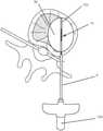
- FIG. 1is an illustration of a probe 100 in accordance with an embodiment of the present invention
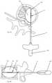
- FIG. 2 ais a side view of a probe 100 , showing various features in transparency for ease of illustration, in accordance with an embodiment of the present invention
- FIG. 2 bis a cross-sectional view of probe 100 , taken along line 2 b - 2 b of FIG. 2 a , in accordance with an embodiment of the present invention
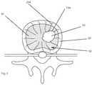
- FIG. 3is an illustration of a target location, in accordance with an embodiment of a method of the present invention.
- FIGS. 4 a and 4 bare illustrations of a method in accordance with an embodiment of the present invention.
- FIG. 5is an illustration of a probe 100 , in accordance with an alternate embodiment of the present invention.
- FIGS. 6 a , 6 b and 6 care illustrations of a portion of a probe 100 , in accordance with an embodiment of the present invention.
- Embodiments of such a probeinclude tubular electrodes configured such that the inner surface of each electrode is cooled, directly or indirectly, while keeping the electrodes electrically isolated.
- One possible configurationis an electrosurgical probe comprising two electrically isolated electrical conductors with an inner one of the conductors inside of the other and the inner electrical conductor defining a lumen for the circulation of a cooling fluid inside of it.
- the probealso has an electrical insulator layer between the electrical conductors for electrically isolating the electrical conductors.
- the electrical insulatorhas sufficient thermal conductivity to allow for cooling of the outside electrical conductor by cooling fluid circulating within the lumen of the inner electrical conductor. Thus, only one conductor is cooled directly, i.e., in contact with the cooling fluid, while the other conductor is indirectly cooled.
- FIG. 1is an illustration of a probe 100 in accordance with an embodiment of the present invention.
- the probecomprises an inner elongate conductor 30 and an outer elongate conductor 50 .
- the inner and outer conductors 30 , 50each have a hollow tubular configuration and define a lumen there-through.
- the inner and outer conductors 30 , 50are coupled to an energy supply at proximal ends thereof.
- the energy supplymay comprise a radiofrequency (RF) energy delivery source and an energy sink.
- the inner conductor 30functions as an active electrode and is coupled to an RF energy delivery source
- the outer conductor 50is coupled to an energy sink such as a ground connection, forming a return electrode.
- RFradiofrequency
- the inner conductor 30functions as a control electrode and the outer conductor 50 functions as a neutral or ground reference electrode.
- the outer conductor 50functions as an active electrode and the inner conductor 30 functions as a return electrode.
- probe 100can be operated in a bipolar manner, where energy is delivered substantially between conductors 30 , 50 .
- the inner and outer conductors 30 , 50may be connected to the RF energy delivery source and ground via an electrical connection through a probe handle 8 , shown in FIG. 2 a , which may be coupled to a proximal end of probe 100 .
- the inner conductor 30is disposed coaxially within the lumen of the outer conductor 50 .
- the inner and the outer conductors 30 , 50each comprise an electrically conductive portion at least along a length thereof and more specifically, at least along a distal segment of conductors 30 , 50 .
- Each of the electrically conductive portionsis coupled to an energy supply through an electrically conductive pathway.
- the inner conductor 30 and the outer conductor 50are electrically conductive along their length.
- the inner conductor 30has a length S 1
- the outer conductor 50has a length S 2 .
- the inner and the outer conductors 30 , 50each comprise a stainless steel hypotube.
- the inner and outer conductors 30 , 50may comprise an electrically conductive, biocompatible material such as titanium or nitinol.
- the inner conductor 30is electrically isolated from the outer conductor 50 by an inner insulator 40 disposed between the inner conductor 30 and the outer conductor 50 .
- the inner insulator 40extends longitudinally along at least the entire length of the outer conductor 50 . In some embodiments, it has a length that is greater than the length of the outer conductor 50 . In one example, as shown in FIG. 1 , the inner insulator has a length S 3 that is greater than length S 2 of the outer conductor 50 . In some embodiments, the inner insulator 40 is electrically insulative and thermally conductive. In the illustrated embodiments, the distal most portion of the inner conductor 30 is exposed at the distal tip thereof and forms a distal electrode 32 having a length L 1 .
- the inner elongate conductor 30 as shown in FIG. 1 and FIG. 2 bhas a closed distal end and defines a lumen 34 there-through for circulating a cooling fluid.
- the term “circulate”relates to fluid that mostly moves or is caused to move through a generally closed system in a controlled manner rather than fluid that enters and mostly passes through the system to the outside environment, such as passing through an open ended tube.
- a fluid inlet tube 21may be disposed within the lumen 34 to supply cooling fluid within the inner lumen 34 from a cooling supply (not shown).
- a fluid outlet tube 22may be disposed alongside the fluid inlet tube 21 within the inner lumen 34 to allow the cooling fluid to exit via a proximal end of the probe 100 .
- the fluid outlet tube 22may extend along a majority of the length of the inner conductor 30 . In some embodiments, fluid outlet tube 22 may be shorter than fluid inlet tube 21 .
- the outer conductor 50has an electrical insulator 60 disposed on an outer surface thereof, along at least a portion of the outer conductor 50 , whereas a distal portion of the outer conductor 50 remains electrically exposed, forming a proximal electrode 52 with a length L 3 .
- the outer insulator 60has a length S 4 as shown in FIG. 1 . In one embodiment the outer insulator 60 may have a length that is substantially the same as the length of the outer conductor 50 .
- the inner insulator 40is exposed between the distal edge of the proximal electrode 52 and the proximal tip of the distal electrode 32 .
- the length of the exposed insulatoris labelled as L 2 .
- the region of the probe extending from the proximal electrode 52 to the distal electrode 32forms an active tip 70 .
- a radiopaque band 72may be positioned at a proximal end of the active tip 70 as shown in FIG. 2 a .
- the radiopaque band 72may act as a navigational reference to guide and facilitate positioning the active tip 70 at a target location within a patient's body. In other embodiments, the radiopaque band may be positioned at any location along the active tip 70 or at any location along the probe 100 . In still another embodiment, more than one radiopaque band 72 or a radiopaque marker may be positioned along the probe. In one example the radiopaque band 72 may function as a navigational reference under fluoroscopic imaging.
- the proximal electrode 52is a return electrode and the cooling fluid cools the proximal electrode 52 prior to reaching and cooling the distal electrode 32 , which is the active electrode. This may provide a more uniform lesion to be produced when RF energy is supplied to the probe 100 .
- the structure of the probe 100allows cooling fluid to indirectly cool the proximal electrode 52 and to directly cool the distal electrode 32 .
- the cooling fluidflows through the inner lumen 34 of the inner conductor 30 and cooling is transmitted indirectly to the proximal electrode 52 through thermal conductivity through a wall of the inner conductor 30 and a wall of the inner insulator 40 .
- Cooling fluidis supplied from the fluid inlet tube 21 which exits into the lumen 34 near the location of the proximal electrode 52 .
- the relatively low temperature of the cooling fluidcools proximal electrode 52 indirectly, thus raising the temperature of the fluid.
- the cooling fluidallows heat to be removed from the proximal electrode 52 .
- the fluidthen flows within the lumen 34 to the distal electrode 32 at the slightly elevated temperature.
- cooling fluid at a lower temperatureis used to indirectly cool the proximal electrode 52 , whereas, cooling fluid that is at a slightly higher temperature passes through the distal electrode 32 to cool it directly.
- proximal electrode 52indirectly at a lower temperature and cooling the distal electrode 32 directly at a slightly higher temperature, cooling of electrodes 32 , 52 will be substantially equivalent.
- This arrangementmay allow cooling to be transmitted uniformly to both the proximal and distal electrodes 32 , 52 , thus allowing a relatively uniform heat distribution around the two electrodes, which may allow a more uniform lesion to be produced when the electrodes 32 , 52 are placed in target tissue.
- Providing cooler fluid to cool the proximal electrode 52may offset the difference in cooling at the proximal and distal electrodes 32 , 52 due to direct and indirect cooling respectively.
- proximal electrode 52has a larger diameter and circumference. Consequently, for distal and proximal electrodes of equal length, proximal electrode 52 will have a slightly larger inner surface, which will increase the effectiveness of the internal cooling fluid.
- the cooling fluidmay comprise water.
- the cooling fluidmay comprise saline.
- an alcoholmay be used.
- an isopropyl alcoholmay be used.
- the temperature of the cooling fluidmay range from about its freezing point to about room temperature.
- the fluid inlet and outlet tubes 21 , 22may be constructed from a metal.
- the fluid inlet and outlet tubesare made from stainless steel hypotubes and may be connected to the fluid supply at proximal ends thereof with non-conductive supply tubes 12 , 14 . These may comprise any non-conductive material such as a polymer.
- the supply tubes 12 , 14comprise polyvinylchloride (PVC) tubing that may be UV (ultraviolet) glued to the stainless steel inlet and outlet tubes 21 , 22 .
- PVCpolyvinylchloride
- any other meanscan be used to join the supply tubes to the outlet tubes.
- the fluid inlet and outlet tubes 21 , 22may be constructed from a non-conductive material such as a polymer.
- the fluid inlet and outlet tubes 21 , 22may be formed of alternate materials.
- the fluid inlet and outlet tubes 21 and 22may be positioned alongside each other within the lumen 34 of the inner conductor 30 .
- any flow pathwaymay be provided to the probe 100 to allow fluid to enter and exit the inner conductor 30 .
- the flow pathwaymay comprise a fluid inflow path that is separate from a fluid outflow path which provides directional flow.
- cooling fluidmay be directed into the inner conductor 30 directly without use of the fluid inlet tube 21 .
- the active tip 70may have a length (L 1 +L 2 +L 3 ) that ranges from about 5 mm to about 40 mm.
- the length of the distal electrode 32 (L 1 ), the exposed inner insulator 40 (L 2 ), and the proximal electrode 52 (L 3 )may vary in about a 2:1:2 ratio. In other embodiments the ratio may be in about a 1:1:1 configuration. Alternate embodiments are possible as well.
- the lengths L 1 , L 2 and L 3may have a different ratio. In another example, the L 1 :L 2 :L 3 ratio is about 7:6:7.
- the inner and outer conductors 30 , 50may only extend along a portion of the probe 100 .
- inner and outer conductors 30 , 50may be electrically conductive along their lengths and may form the proximal and the distal electrodes, 32 and 52 .
- only the exposed portions of the inner and outer conductors 30 and 50are electrically conductive, and the inner and outer conductors 30 , 50 may have substantially the same width.
- the inner and outer conductorsmay be spaced apart and electrically isolated from each other by an inner insulator 40 .
- the inner insulator 40may comprise a polymer.
- the insulator 40may comprise a substantially rigid plastic insert.
- the electrically isolated distal and proximal electrodes 32 and 52may be cooled through separate cooling sources. As shown in FIG. 5 , the distal electrode 32 is supplied with a cooling fluid through fluid inlet and outlet tubes 21 a and 22 a . Whereas, cooling to the proximal electrode 52 is supplied through cooling inlet and outlet tubes 21 b and 22 b .
- the fluid inlet and outlet tubesmay comprise a non-conductive material such as a polymer.
- Each of the proximal and distal electrodes 32 , 52are coupled to an energy supply through electrically conductive insulated wires 94 .
- the distal and proximal electrodes 32 and 52each define a closed inner lumen, 34 and 54 respectively, within which cooling fluid flows.
- the distal electrode 32has a closed distal end and a closed proximal end formed by co-operative engagement of the distal electrode proximal portion with a distal face 43 of the inner insulator 40 , defining the closed inner lumen 34 .
- the proximal electrode 52has a closed distal end formed by co-operative engagement of the proximal electrode distal end with the proximal face 45 of the inner insulator 40 , as shown in FIG. 5 .
- the proximal electrode 52further has a closed proximal end defined by co-operative engagement of the proximal electrode proximal end with a distal face 65 of the outer insulator 60 , defining the closed inner lumen 54 .
- the cooling fluidis restricted within the lumens 34 and 54 .
- the distal face 65 of the outer insulator, as well as the distal 43 and the proximal face 45 of the inner insulator,extend substantially transversally along the width of the probe.
- the distal face 65may comprise openings to allow fluid inlet tubes 21 a , 21 b and fluid outlet tubes 22 a , 22 b as well as insulated wires 94 to extend therethrough.
- distal and proximal faces 43 and 45may provide openings therethrough to allow passage of the inlet and outlet tubes 21 a and 21 b respectively and one of the insulated wires 94 .
- a sealmay be provided around the openings to ensure that cooling fluid is restricted within the lumens 34 and 54 .
- a temperature sensor 80may be positioned at a location along the probe 100 as shown in FIGS. 1, 2 and 5 .
- the temperature sensor 80may be positioned substantially adjacent the distal tip 102 of the probe 100 .
- the temperature sensor 80may protrude from the surface of the distal electrode 32 .
- temperature sensor 80may jut out or stick out from a surrounding surface of the probe 100 .
- the temperature sensor 80may be positioned at any location along the length of the probe.
- the temperature sensor 80may be positioned at or adjacent to the active tip 70 .
- the temperature sensor 80may comprise a thermocouple.
- a thermocouplemay be formed using a hypotube 84 disposed within the lumen 34 of the inner conductor 30 .
- a constantan wirecan be disposed within the thermocouple hypotube 84 to form a thermocouple junction 83 about the distal tip 102 , as shown in FIG. 2 a .
- a thermocouplemay be formed using a pair of wires to form a junction.
- a thermocoupleis positioned at a distal face of the outer electrode 52 .
- a thermocoupleis positioned between the outer electrode 52 and inner insulator 40 .
- the temperature sensor 80is coupled to and in communication with a controller for the energy supply, such as an energy supply having an RF energy delivery source.
- a controller for the energy supplysuch as an energy supply having an RF energy delivery source.
- the temperature sensor 80may be coupled to a controller at its proximal end via the handle 8 .
- a second temperature sensoris proximate to proximal electrode 52 and is in communication with a controller for the energy supply for providing additional information.
- a controllerfor the energy supply for providing additional information.
- Such an embodimentcould be used with a generator capable of monitoring two temperature sensors at one time.
- a generator capable of monitoring only one temperature at a timecould be used if an external device switched between the two (or more) temperature sensors.
- embodiments of the present inventionmay comprise a plurality of temperature sensors, which may be positioned at different locations on the probe, for example, on or adjacent to the surface of the electrodes, between the electrodes, or at or near the electrodes, proximally or distally.
- a generator used in a system with two or more temperature sensorswould include an algorithm for controlling the output of energy based on multiple temperature readings.
- the inner conductor 30has a closed distal end. As shown in FIGS. 6 a , 6 b and 6 c , in one embodiment, the distal end of the inner conductor 30 is swaged to form a concentrically tapered end 36 with an opening 38 therethrough. The size or diameter of the opening 38 is smaller than a diameter of the inner conductor 30 along its length as shown in FIG. 6 c .
- the opening 38allows the thermocouple hypotube 84 to extend or protrude from the distal end face of the inner conductor 30 .
- the thermocouple hypotube 84may be laser welded to the inner conductor 30 at a wall of the opening 38 . In other examples any other means of attachment may be used.
- the distal end of the inner conductor 30may be swaged in a similar manner as disclosed above to reduce the size of the opening at the distal end of the inner conductor hypotube 30 .
- the reduced diameter openingmay then be closed by laser welding at the distal most end.
- the closed distal end of the inner conductor 30may be formed using other means.
- the closed distal end of the hypotubemay comprise a separate end piece or end cap that may be attached to the distal end of the hypotube.
- the end piecemay be dome shaped, triangular shaped or may have a flat surface.
- the end piecemay or may not be metal.
- a closed distal end of the inner conductormay be formed by providing an end piece in the form of a metal insert which may be laser welded to the hypotube distal end.
- any other attachment meansmay be used.
- an adhesivemay be used to attach the end piece to the hypotube distal end.
- the adhesivemay be an ultraviolet (UV) glue.
- the probe sizemay range from an outer diameter of about 13 Gauge, 2.413 mm (0.095′′), to about 17 Gauge, 1.47 mm (0.058′′).
- the probe 100has a diameter of about 17 Gauge and has an outer conductor 50 with a length of about 215.9 mm (8.5′′) and an inner conductor 30 with a length of about 228.6 mm (9.0′′).
- the fluid outlet tube 22has a length of about 241.3 mm (9.5′′) and extends into the handle, whereas the fluid inlet tube 21 is about 38.1 mm (1.5′′) in length and positioned at the proximal end of the inner conductor 30 .
- the thermocouple hypotube 84is positioned within the inner lumen 34 of inner conductor 30 and has a length of about 254 mm (10′′).
- the insulators 40 and 60may comprise a polyester.
- the insulators 40 and 60may be disposed onto the conductors 30 and 50 , respectively, using a heat-shrink procedure.
- the conductors 30 and 50may be electrically conductive along their length.
- the polyesteris a Polyethylene terephthalate (PET).
- PETPolyethylene terephthalate
- FEPFluorinated ethylene propylene
- PTFEpolytetrafluoroethylene
- the insulators 40 or 60may be provided in the form of a coating or a layer. In still other embodiments PEEK may be used.
- the thickness of the inner insulator 40may vary from about 0.0127 mm (0.0005′′) to about 0.254 mm (0.010′′).
- the thickness of the inner insulator 40provides sufficient thermal conductivity to allow cooling to be conveyed to the outer conductor 50 . This feature allows heat to be removed from the outer conductor 50 , which may allow a larger lesion to be produced and minimize charring of tissue.
- PETis used in insulators 40 and 60 , each having a width of about 0.03175 mm (0.00125′′).
- the probe 100is used to treat a region within a patient's body.
- the regionmay comprise tissue with varying composition.
- the tissuemay comprise any one of or a combination of vascular tissue, soft tissue, trabecular bone tissue, cortical bone tissue, fatty tissue, tumor or nervous tissue.
- the probe 100is placed within a vertebral body.
- the probe 100may be positioned adjacent a tumor 93 within a vertebral body at a bone-tumor interface 194 .
- the probe 100may be used to destroy nervous tissue generating pain signals at the bone-tumor interface.
- the probe 100is advanced into a vertebral body 92 until the distal end 102 of the probe is positioned at the tumor-nerve interface at the edge of the tumor 93 adjacent nerves 294 , as shown in FIG. 3 .
- the probe active tip 70may be positioned within the trabecular bone 95 within the vertebral body 92 that is encased by the electrically insulative cortical bone 97 .
- the probe 100is positioned substantially adjacent the rich nerve supply within the vertebral body.
- the probe 100may be positioned within or substantially adjacent to the vertebral body in proximity to sensitive structures such as the cortical bone that may be non-conductive, or in other words, may have a low electrical conductivity.
- Nerve stimulationcan be used to position a probe.
- the stimulation effectsare not symmetric about each electrode.
- One electrodewill have a larger stimulation capacity for a given biphasic wave.
- the electrode that is closest to a stimulated nervecan be identified by reversing the polarity of the bipolar probe, also called manipulating.
- Balanced stimulation of nervescan be achieved by alternating the polarity in a balanced manner. For example, 10 pulses could be delivered with a first electrode as the control electrode to more intensely stimulate the nerves nearest to it, and then 10 pulses could be delivered with a second electrode as the control electrode.
- An embodiment of a method using such a procedure to help position a probeincludes the following steps: emitting a stimulation pulse comprising a continuous train of biphasic waves at a set frequency, navigating the active tip through tissue, and reversing the polarity of the two electrodes to identify which electrode a stimulated nerve is closest to.
- the probe 100may improve heating capability in the vicinity of a non-conductive structure.
- the probe 100provides energy in a bipolar manner and may be used in the vicinity of a cortical bone structure or other non-conductive structures to provide treatment to the non-conductive structure through indirect thermal conduction.
- probe 100may be used to treat structures that are non-conductive in monopolar RF applications, where the energy transmission to a ground may be limited as the non-conductive structure is encountered in the energy pathway to the ground.
- probe 100may be used to target nerves at other locations within the vertebral body.
- the probe 100may be positioned substantially adjacent to or in the vicinity of any other bone tissue.
- probe 100may be used to treat a highly vascular tissue such as liver.
- the probe 100may be used to provide uniform or consistent lesions in the vicinity of bone or variable tissue. In other words, the probe 100 may be used to provide lesions that are substantially homogeneous.
- an introducer needle assemblymay be inserted and advanced to a target location within a patient's body.
- the introducer needle assemblymay comprise a cannula with a stylet disposed therein.
- the target locationis a vertebral body as shown in FIGS. 4 a and 4 b .
- the introducer assembly 4may be inserted into the vertebral body using a transpedicular approach.
- the introducer needle assemblymay be inserted through the pedicle at an angle of about 15. degree. to about 25. degree. oblique to the mid-saggital plane, which provides a trajectory to access the vertebral body.
- a lateral approachmay be used.
- any approach that allows access to the vertebral bodymay be used.
- any conventional approach used in standard vertebroplasty or vertebral augmentation procedures to gain access to the vertebral bodymay be used.
- the styletmay be withdrawn from the cannula.
- the probe 100may then be inserted through the cannula and advanced to the target site.
- the probe 100can be inserted directly to the target tissue and may include a sharp trocar tip at a distal end of the probe.
- the target tissueis a soft tissue.
- a bilateral approachmay be used to treat a vertebral body.
- the probe 100may be inserted into a vertebral body at a first target location to the right of the mid-saggital plane at an angle of about 15. degree. to about 25. degree. to the mid-saggital plane.
- a first bi-polar lesionmay then be formed at a first location within the vertebral body.
- the probe 100may then be inserted at a second target location to the left of the mid-saggital plane at an angle of about 15. degree. to about 25. degree. from the mid-saggital plane.
- a second bi-polar lesionmay then be formed at a second location within the vertebral body.
- the first and second lesionsmay encompass a majority of the vertebral body.
- Bipolar lesions of different geometrycan be created by manipulating the duration and intensity of energy delivered through each electrode as the control electrode. This is related to the higher tissue temperatures being found around the control electrode. Manipulating a bipolar probe can create lesions that are peanut, mushroom or symmetric ellipsoid shaped. Keeping each electrode active for 50 percent of the time can help in creating symmetrical or more symmetrical lesions.
- RF energyis supplied by an RF generator in a bipolar manner to probe 100 .
- the power output of the RF generatormay be temperature controlled.
- direct tissue temperature monitoringis used in conjunction with internal cooling when supplying RF power to form a lesion.
- the power outputmay be adjusted based on the measured temperature response of the tissue to RF heating under cooling.
- the temperature response of the target tissuemay be monitored using the temperature sensor 80 .
- One embodimentis for a system in which the user puts the selected coolant temperature into the system from a range from just above 0. degree. C. up to about 30. degree. C.
- the cooling fluidis delivered by a pump unit, which is controlled by the same generator that delivers energy.
- the flow rate(and correspondingly the amount of cooling) can be adjusted based on tissue characteristics and the intended lesion geometry.
- the RF energyis delivered in a bipolar manner between conductors 30 and 50 and allows a lesion 90 to be formed adjacent the active tip 70 .
- Three factors in controlling lesion size and shapeare temperature, time of procedure, and active tip geometry which includes length of the active tip segments and ratios of the segment lengths.
- the active tip 70has a length of about 20 mm
- the distal electrode 32 , the exposed inner insulator 40 , and the proximal electrode 52have a length ratio L 1 :L 2 :L 3 of about 7:6:7.
- a ramp rate of about 10. degree. C./minis used in order to reach a set temperature of about 65. degree. C. to about 70. degree. C.
- the poweris supplied for about 15 minutes, resulting in a lesion having a size of about 30 mm.times.23 mm, with a lesion volume of about 8.3 cm.sup. 3.
- an active tip 70 with a length of about 30 mmis used, and the distal electrode 32 , the exposed insulator 40 , and the proximal electrode 52 have a length ratio L 1 :L 2 :L 3 of about 1:1:1.
- a ramp rate of about 20. degree. C./minmay be used. In one instance of this example, the ramp rate may be used to achieve a set temperature of about 100. degree. C.
- the poweris supplied for about 20 minutes, resulting in a lesion size of about 45 mm.times.35 mm, with a lesion volume of about 28.9 cm.sup. 3.
- a ramp rate of about 40. degree. C./minis used to achieve a set temperature of about 90. degree. C. Power is applied for about 5 minutes, resulting in a lesion size of about 15 mm.times.15 mm with a volume of about 1.8 cm.sup. 3.
- the tissue temperaturemay be maintained at between about 40. degree. C. and about 100. degree. C.
- the predictability of lesioningis improved by the use of external monitoring electrodes.
- monitoring an electrode at the periphery of a centrally-formed lesioncan help a physician decide when to stop lesioning to ensure an adequate lesion size, or the monitoring electrode could be in communication with a generator with a control program that controls energy delivery.
- the output of a generatorcould be controlled by one or more monitoring electrodes such as temperature monitoring electrodes.
- One exampleincludes placing at least one external temperature sensor at the boundary of a desired lesion, monitoring the at least one external temperature sensor during energy delivery, and determining the lesion is complete when the external temperature reaches a predefined value.
- the powermay be delivered at from about 1 Watt to about 100 Watts. In another example power may be delivered at from about 1 Watt to about 50 Watts. In other embodiments, greater than 100 Watts of power may be delivered by the RF energy delivery source. In still another embodiment, less than 1 Watt of power may be delivered. In some embodiments power may be delivered for a duration of between about 2 minutes to about 30 minutes. In other embodiments power may be applied for less than 2 minutes or greater than 30 minutes.
- the ramp ratemay range from about 2. degree ⁇ C./min to about 100. degree. C./min. In one example, the ramp rate may be about 10. degree. C./min. In another example, ramp rate may be about 20. degree. C./min. In still another example, ramp rate may be about 40. degree. C./min. In one embodiment the ramp rate may be set to optimize the tissue response to achieve the set temperature. This may prevent charring, desiccation or vaporization of tissue. In some embodiments, the power supplied to the bipolar coaxial probe 100 may be less than power supplied to a monopolar probe to achieve an equivalent lesion.
- an electrosurgical probe with internal coolingcan be particularly useful, for example, in systems and methods for lesioning in bone and other tissue.
- the probeis comprised of at least two electrically isolated electrical conductors which are operable to deliver energy in a bipolar manner.
- One embodiment of such a probeincludes an inner conductor inside an outer conductor.
- the inner electrical conductorincludes a lumen for the internal circulation of a cooling fluid.
- the probealso has an electrical insulator layer between the inner and outer electrical conductors for electrically isolating the electrical conductors.
- the electrical insulatorhas sufficient thermal conductivity to allow for cooling of the outside electrical conductor by cooling fluid circulating within the lumen of the inner electrical conductor.
- the probecould enable temperature monitoring to provide data for controlling the delivery of energy through electrodes to tissue and for controlling the flow of cooling fluids to the electrodes.
Landscapes
- Health & Medical Sciences (AREA)
- Surgery (AREA)
- Engineering & Computer Science (AREA)
- Life Sciences & Earth Sciences (AREA)
- Biomedical Technology (AREA)
- Molecular Biology (AREA)
- Nuclear Medicine, Radiotherapy & Molecular Imaging (AREA)
- Plasma & Fusion (AREA)
- Physics & Mathematics (AREA)
- Heart & Thoracic Surgery (AREA)
- Medical Informatics (AREA)
- Otolaryngology (AREA)
- Animal Behavior & Ethology (AREA)
- General Health & Medical Sciences (AREA)
- Public Health (AREA)
- Veterinary Medicine (AREA)
- Neurology (AREA)
- Neurosurgery (AREA)
- Surgical Instruments (AREA)
Abstract
Description
Claims (12)
Priority Applications (3)
| Application Number | Priority Date | Filing Date | Title |
|---|---|---|---|
| US16/660,067US11224475B2 (en) | 2010-04-26 | 2019-10-22 | Electrosurgical device and methods |
| US17/545,098US12076074B2 (en) | 2010-04-26 | 2021-12-08 | Electrosurgical device and methods |
| US18/773,475US20240398466A1 (en) | 2010-04-26 | 2024-07-15 | Electrosurgical device and methods |
Applications Claiming Priority (5)
| Application Number | Priority Date | Filing Date | Title |
|---|---|---|---|
| US32811810P | 2010-04-26 | 2010-04-26 | |
| PCT/CA2011/050203WO2011134080A1 (en) | 2010-04-26 | 2011-04-15 | Electrosurgical device & methods |
| US14/928,568US9788889B2 (en) | 2010-04-26 | 2015-10-30 | Electrosurgical devices and methods |
| US15/782,229US10448990B2 (en) | 2010-04-26 | 2017-10-12 | Electrosurgical device and methods |
| US16/660,067US11224475B2 (en) | 2010-04-26 | 2019-10-22 | Electrosurgical device and methods |
Related Parent Applications (1)
| Application Number | Title | Priority Date | Filing Date |
|---|---|---|---|
| US15/782,229ContinuationUS10448990B2 (en) | 2010-04-26 | 2017-10-12 | Electrosurgical device and methods |
Related Child Applications (1)
| Application Number | Title | Priority Date | Filing Date |
|---|---|---|---|
| US17/545,098ContinuationUS12076074B2 (en) | 2010-04-26 | 2021-12-08 | Electrosurgical device and methods |
Publications (2)
| Publication Number | Publication Date |
|---|---|
| US20200046417A1 US20200046417A1 (en) | 2020-02-13 |
| US11224475B2true US11224475B2 (en) | 2022-01-18 |
Family
ID=44860713
Family Applications (7)
| Application Number | Title | Priority Date | Filing Date |
|---|---|---|---|
| US13/643,310Active2031-10-19US9173700B2 (en) | 2010-04-26 | 2011-04-15 | Electrosurgical device and methods |
| US13/660,353Active2032-02-01US9241760B2 (en) | 2010-04-26 | 2012-10-25 | Electrosurgical device and methods |
| US14/928,568ActiveUS9788889B2 (en) | 2010-04-26 | 2015-10-30 | Electrosurgical devices and methods |
| US14/985,687ActiveUS9675408B2 (en) | 2010-04-26 | 2015-12-31 | Electrosurgical device and methods |
| US15/596,205ActiveUS10105175B2 (en) | 2010-04-26 | 2017-05-16 | Electrosurgical device and methods |
| US15/782,229Active2031-09-09US10448990B2 (en) | 2010-04-26 | 2017-10-12 | Electrosurgical device and methods |
| US16/660,067ActiveUS11224475B2 (en) | 2010-04-26 | 2019-10-22 | Electrosurgical device and methods |
Family Applications Before (6)
| Application Number | Title | Priority Date | Filing Date |
|---|---|---|---|
| US13/643,310Active2031-10-19US9173700B2 (en) | 2010-04-26 | 2011-04-15 | Electrosurgical device and methods |
| US13/660,353Active2032-02-01US9241760B2 (en) | 2010-04-26 | 2012-10-25 | Electrosurgical device and methods |
| US14/928,568ActiveUS9788889B2 (en) | 2010-04-26 | 2015-10-30 | Electrosurgical devices and methods |
| US14/985,687ActiveUS9675408B2 (en) | 2010-04-26 | 2015-12-31 | Electrosurgical device and methods |
| US15/596,205ActiveUS10105175B2 (en) | 2010-04-26 | 2017-05-16 | Electrosurgical device and methods |
| US15/782,229Active2031-09-09US10448990B2 (en) | 2010-04-26 | 2017-10-12 | Electrosurgical device and methods |
Country Status (3)
| Country | Link |
|---|---|
| US (7) | US9173700B2 (en) |
| EP (1) | EP2563256B1 (en) |
| WO (1) | WO2011134080A1 (en) |
Cited By (5)
| Publication number | Priority date | Publication date | Assignee | Title |
|---|---|---|---|---|
| US11974759B2 (en) | 2012-11-05 | 2024-05-07 | Relievant Medsystems, Inc. | Methods of navigation and treatment within a vertebral body |
| US12039731B2 (en) | 2020-12-22 | 2024-07-16 | Relievant Medsystems, Inc. | Prediction of candidates for spinal neuromodulation |
| US12059193B2 (en) | 2011-12-30 | 2024-08-13 | Relievant Medsystems, Inc. | Methods of denervating vertebral body using external energy source |
| US12082876B1 (en) | 2020-09-28 | 2024-09-10 | Relievant Medsystems, Inc. | Introducer drill |
| US12433668B1 (en) | 2021-11-08 | 2025-10-07 | Relievant Medsystems, Inc. | Impedance stoppage mitigation during radiofrequency tissue ablation procedures |
Families Citing this family (26)
| Publication number | Priority date | Publication date | Assignee | Title |
|---|---|---|---|---|
| US7258690B2 (en) | 2003-03-28 | 2007-08-21 | Relievant Medsystems, Inc. | Windowed thermal ablation probe |
| US8361067B2 (en) | 2002-09-30 | 2013-01-29 | Relievant Medsystems, Inc. | Methods of therapeutically heating a vertebral body to treat back pain |
| US6907884B2 (en) | 2002-09-30 | 2005-06-21 | Depay Acromed, Inc. | Method of straddling an intraosseous nerve |
| AU2006269738A1 (en)* | 2005-07-14 | 2007-01-18 | Kimberly-Clark Inc. | Electrosurgical device and methods |
| US10028753B2 (en) | 2008-09-26 | 2018-07-24 | Relievant Medsystems, Inc. | Spine treatment kits |
| CA2737374C (en) | 2008-09-26 | 2017-03-28 | Relievant Medsystems, Inc. | Systems and methods for navigating an instrument through bone |
| EP2563256B1 (en) | 2010-04-26 | 2019-08-28 | Medtronic Holding Company Sàrl | Electrosurgical device |
| US12076074B2 (en) | 2010-04-26 | 2024-09-03 | Medtronic Holding Company Sàrl | Electrosurgical device and methods |
| US8523875B2 (en)* | 2011-10-11 | 2013-09-03 | Smith & Nephew, Inc. | Graft caliper marking device |
| DE102011087188A1 (en)* | 2011-11-28 | 2013-05-29 | Endress + Hauser Conducta Gesellschaft für Mess- und Regeltechnik mbH + Co. KG | Method for determining process variable of medium by electrochemical sensor, involves assigning reference half cell with temperature sensor, so that process variable is determined using temperatures detected by sensors |
| US10588691B2 (en) | 2012-09-12 | 2020-03-17 | Relievant Medsystems, Inc. | Radiofrequency ablation of tissue within a vertebral body |
| US9877707B2 (en)* | 2013-03-07 | 2018-01-30 | Kyphon SÀRL | Systems and methods for track coagulation |
| CN105377128B (en) | 2013-03-15 | 2019-02-22 | 9234438加拿大股份有限公司 | Electrosurgical mapping tools and methods |
| US9724151B2 (en) | 2013-08-08 | 2017-08-08 | Relievant Medsystems, Inc. | Modulating nerves within bone using bone fasteners |
| US10441339B2 (en) | 2015-11-17 | 2019-10-15 | Medtronic Holding Company Sárl | Spinal tissue ablation apparatus, system, and method |
| EP3522807B1 (en) | 2016-10-04 | 2025-07-09 | Avent, Inc. | Cooled rf probes |
| JP6765160B2 (en)* | 2017-12-11 | 2020-10-07 | 日本ライフライン株式会社 | Acupuncture needle device and high frequency ablation treatment system for tumors |
| FR3087107A1 (en) | 2018-10-15 | 2020-04-17 | Avent Inc. | Neural ablation compositions, systems, kits and methods |
| GB2578576B (en)* | 2018-10-30 | 2022-08-24 | Creo Medical Ltd | Electrosurgical instrument |
| US11690668B2 (en)* | 2018-12-21 | 2023-07-04 | Avent, Inc. | Cooled radiofrequency ablation probe |
| US11395696B2 (en)* | 2018-12-27 | 2022-07-26 | Avent, Inc. | Radiofrequency ablation probe with directional cooling for lesion size control |
| WO2020198150A2 (en) | 2019-03-22 | 2020-10-01 | Stryker Corporation | Systems for ablating tissue |
| AU2020346827A1 (en) | 2019-09-12 | 2022-03-31 | Relievant Medsystems, Inc. | Systems and methods for tissue modulation |
| EP4580532A1 (en)* | 2022-08-31 | 2025-07-09 | Medtronic Ireland Manufacturing Unlimited Company | Neurostimulation waveform for increased tissue activation across vessel walls |
| GB202213582D0 (en)* | 2022-09-15 | 2022-11-02 | Creo Medical Ltd | A coaxial cable |
| US20240285332A1 (en)* | 2023-02-24 | 2024-08-29 | Neuwave Medical, Inc. | Temperature regulating devices and related systems and methods |
Citations (162)
| Publication number | Priority date | Publication date | Assignee | Title |
|---|---|---|---|---|
| US3224436A (en)* | 1961-04-10 | 1965-12-21 | Honeywell Regulator Co | Hypodermic apparatus for measuring hydrogen ion concentration of blood within a living body |
| US3447161A (en) | 1966-08-01 | 1969-06-03 | Avco Corp | Disinfectant dispensing percutaneous connector |
| US4532924A (en) | 1980-05-13 | 1985-08-06 | American Hospital Supply Corporation | Multipolar electrosurgical device and method |
| US4674499A (en) | 1980-12-08 | 1987-06-23 | Pao David S C | Coaxial bipolar probe |
| US4849596A (en) | 1985-12-13 | 1989-07-18 | Joyal Products, Inc. | Electrical terminals, terminating methods and assemblies |
| US4946460A (en) | 1989-04-26 | 1990-08-07 | Cryo Instruments, Inc. | Apparatus for cryosurgery |
| US5100388A (en) | 1989-09-15 | 1992-03-31 | Interventional Thermodynamics, Inc. | Method and device for thermal ablation of hollow body organs |
| US5261399A (en) | 1991-05-22 | 1993-11-16 | Klatz Ronald M | Brain cooling device and method for performing the same |
| US5300069A (en) | 1992-08-12 | 1994-04-05 | Daniel Hunsberger | Electrosurgical apparatus for laparoscopic procedures and method of use |
| US5300068A (en) | 1992-04-21 | 1994-04-05 | St. Jude Medical, Inc. | Electrosurgical apparatus |
| US5417713A (en) | 1993-02-09 | 1995-05-23 | Leonard Bloom | Transesophageal defibrillating system |
| US5462552A (en) | 1992-11-20 | 1995-10-31 | Kiester; P. Douglas | Bone cement removal and apparatus |
| US5607389A (en) | 1992-08-12 | 1997-03-04 | Vidamed, Inc. | Medical probe with biopsy stylet |
| US5766167A (en) | 1993-12-17 | 1998-06-16 | United States Surgical Corporation | Monopolar electrosurgical Instruments |
| US5797905A (en) | 1994-08-08 | 1998-08-25 | E. P. Technologies Inc. | Flexible tissue ablation elements for making long lesions |
| US5807395A (en)* | 1993-08-27 | 1998-09-15 | Medtronic, Inc. | Method and apparatus for RF ablation and hyperthermia |
| US5843086A (en) | 1997-07-29 | 1998-12-01 | Stryker Corporation | Thermal bone cement removal system with tissue protector |
| US5935123A (en) | 1993-11-08 | 1999-08-10 | Rita Medical Systems, Inc. | RF treatment apparatus |
| US5947964A (en) | 1995-03-03 | 1999-09-07 | Neothermia Corporation | Methods and apparatus for therapeutic cauterization of predetermined volumes of biological tissue |
| US6066139A (en) | 1996-05-14 | 2000-05-23 | Sherwood Services Ag | Apparatus and method for sterilization and embolization |
| US6106524A (en) | 1995-03-03 | 2000-08-22 | Neothermia Corporation | Methods and apparatus for therapeutic cauterization of predetermined volumes of biological tissue |
| US6129726A (en) | 1992-08-12 | 2000-10-10 | Vidamed, Inc. | Medical probe device and method |
| US6190378B1 (en) | 1997-12-05 | 2001-02-20 | Massachusetts Institute Of Technology | Cryosurgical instrument and related techniques |
| US6261242B1 (en) | 1995-03-31 | 2001-07-17 | Boston Scientific Corporation | Biopsy sampler |
| US20010014804A1 (en)* | 2000-02-08 | 2001-08-16 | Goble Colin C.O. | Electrosurgical instrument and an electrosurgery system including such an instrument |
| US20010023348A1 (en) | 1996-10-23 | 2001-09-20 | Ashley John E. | Catheter for delivery of energy to a surgical site |
| US6293943B1 (en) | 1995-06-07 | 2001-09-25 | Ep Technologies, Inc. | Tissue heating and ablation systems and methods which predict maximum tissue temperature |
| US20010025177A1 (en) | 1992-01-07 | 2001-09-27 | Jean Woloszko | Apparatus and methods for electrosurgical ablation and resection of target tissue |
| US6306132B1 (en) | 1999-06-17 | 2001-10-23 | Vivant Medical | Modular biopsy and microwave ablation needle delivery apparatus adapted to in situ assembly and method of use |
| US20020022835A1 (en) | 2000-08-09 | 2002-02-21 | Lee Bruce B. | Gynecological ablation procedure and system using an ablation needle |
| US6398782B1 (en) | 1992-10-13 | 2002-06-04 | Edwards Lifesciences Corporation | Bipolar vascular sealing apparatus and methods |
| US20020077627A1 (en) | 2000-07-25 | 2002-06-20 | Johnson Theodore C. | Method for detecting and treating tumors using localized impedance measurement |
| US6413255B1 (en) | 1999-03-09 | 2002-07-02 | Thermage, Inc. | Apparatus and method for treatment of tissue |
| US20020115995A1 (en) | 1997-05-09 | 2002-08-22 | The Regents Of The University Of California | Circumferential ablation device assembly |
| US6468268B1 (en) | 1999-01-25 | 2002-10-22 | Cryocath Technologies Inc. | Cryogenic catheter system |
| US6524308B1 (en) | 1997-09-04 | 2003-02-25 | Celon Ag Medical Instruments | Electrode arrangement for electrothermal treatment of human or animal bodies |
| US20030040743A1 (en)* | 1999-06-11 | 2003-02-27 | Cosman Eric R. | Ablation treatment of bone metastases |
| US20030045870A1 (en) | 2001-09-06 | 2003-03-06 | Madsen Joseph R. | Direction-oriented and spatially controlled bipolar coagulator for in-situ cauterization of adherent cranial tissue occluding a ventricular catheter previously implanted in-vivo |
| US20030083655A1 (en) | 2001-10-18 | 2003-05-01 | Van Wyk Robert A. | Electrosurgical ablator with aspiration |
| US6558379B1 (en) | 1999-11-18 | 2003-05-06 | Gyrus Medical Limited | Electrosurgical system |
| US20030088245A1 (en)* | 2001-11-02 | 2003-05-08 | Arthrocare Corporation | Methods and apparatus for electrosurgical ventriculostomy |
| US6562033B2 (en) | 2001-04-09 | 2003-05-13 | Baylis Medical Co. | Intradiscal lesioning apparatus |
| US20030093007A1 (en) | 2001-10-17 | 2003-05-15 | The Government Of The U.S.A., As Represented By The Secretary, Department Of Health And Human Serv | Biopsy apparatus with radio frequency cauterization and methods for its use |
| US20030097079A1 (en) | 2001-10-19 | 2003-05-22 | Garcia Maurice M. | Biopsy needle sheath |
| US20030109802A1 (en) | 2001-12-12 | 2003-06-12 | Laeseke Paul F. | Cauterizing biopsy system |
| US20030130711A1 (en)* | 2001-09-28 | 2003-07-10 | Pearson Robert M. | Impedance controlled tissue ablation apparatus and method |
| US6592530B1 (en) | 2000-11-20 | 2003-07-15 | Ashkan Farhadi | Automated hot biopsy needle and device |
| US20030149407A1 (en) | 2000-02-17 | 2003-08-07 | Sloan-Kettering Institute For Cancer Research | Apparatus and method for reducing interstitial fluid pressure and enhancing delivery of a therapeutic agent |
| US20030148247A1 (en) | 2001-11-21 | 2003-08-07 | Sicurelli Robert J. | Application and energy applying methods for root canal sealing material |
| US20030171744A1 (en) | 2002-03-05 | 2003-09-11 | Baylis Medical Co. Inc. | Intradiscal lesioning device |
| US20030176816A1 (en)* | 1997-07-08 | 2003-09-18 | Maguire Mark A. | Medical device with sensor cooperating with expandable member |
| US20030181963A1 (en)* | 2002-03-21 | 2003-09-25 | Pellegrino Richard C. | Novel early intervention spinal treatment methods and devices for use therein |
| US6634363B1 (en) | 1997-04-07 | 2003-10-21 | Broncus Technologies, Inc. | Methods of treating lungs having reversible obstructive pulmonary disease |
| US20030212395A1 (en)* | 2000-05-12 | 2003-11-13 | Arthrocare Corporation | Systems and methods for electrosurgery |
| US20030212394A1 (en)* | 2001-05-10 | 2003-11-13 | Rob Pearson | Tissue ablation apparatus and method |
| US20040015075A1 (en)* | 2000-08-21 | 2004-01-22 | Yoav Kimchy | Radioactive emission detector equipped with a position tracking system and utilization thereof with medical systems and in medical procedures |
| US20040030333A1 (en) | 1999-01-15 | 2004-02-12 | Gyrus Medical Ltd. | Electrosurgical system and method |
| US20040059328A1 (en)* | 2001-01-11 | 2004-03-25 | Rita Medical Systems, Inc. | Bone-treatment instrument and method |
| US20040127963A1 (en) | 1999-01-25 | 2004-07-01 | Uchida Andy H. | Intervertebral decompression |
| US6770070B1 (en) | 2000-03-17 | 2004-08-03 | Rita Medical Systems, Inc. | Lung treatment apparatus and method |
| US20040167517A1 (en)* | 2001-06-07 | 2004-08-26 | Kai Desinger | Probe arrangement |
| US20040181219A1 (en)* | 2000-02-08 | 2004-09-16 | Gyrus Medical Limited | Electrosurgical instrument and an electrosugery system including such an instrument |
| US20040193152A1 (en)* | 2003-03-28 | 2004-09-30 | Jeffrey Sutton | Windowed thermal ablation probe |
| US20050010205A1 (en)* | 1995-06-07 | 2005-01-13 | Arthrocare Corporation | Methods and apparatus for treating intervertebral discs |
| US6845264B1 (en) | 1998-10-08 | 2005-01-18 | Victor Skladnev | Apparatus for recognizing tissue types |
| US20050027235A1 (en)* | 2002-02-12 | 2005-02-03 | Knudsen Katherine A. | Radiofrequency arthrosopic ablation device |
| US20050038422A1 (en)* | 2002-08-06 | 2005-02-17 | Medically Advanced Designs, Llc | Cryo-surgical apparatus and methods |
| US6858025B2 (en) | 2002-08-06 | 2005-02-22 | Medically Advanced Designs, Llc | Cryo-surgical apparatus and method of use |
| US20050070894A1 (en)* | 2001-12-12 | 2005-03-31 | Tissuelink Medical, Inc | Fluid-assisted medical devices, systems and methods |
| US20050119650A1 (en)* | 2003-10-20 | 2005-06-02 | Arthrocare Corporation | Electrosurgical method and apparatus for removing tissue within a bone body |
| US20050126563A1 (en)* | 2003-12-15 | 2005-06-16 | Van Der Burg Erik J. | System and method for hyoidplasty |
| US20050177209A1 (en)* | 2002-03-05 | 2005-08-11 | Baylis Medical Company Inc. | Bipolar tissue treatment system |
| US20050177210A1 (en) | 2002-03-05 | 2005-08-11 | Baylis Medical Company Inc. | Electrosurgical tissue treatment method |
| US20060064101A1 (en)* | 2004-02-12 | 2006-03-23 | Arthrocare Corporation | Bone access system |
| US20060111706A1 (en) | 2001-10-22 | 2006-05-25 | Surgrx, Inc. | Electrosurgical working end for controlled energy delivery |
| US20060150986A1 (en)* | 2004-12-15 | 2006-07-13 | Aspire Medical, Inc. | System and method for hyoidplasty |
| US20060178666A1 (en)* | 2001-08-03 | 2006-08-10 | Cosman Eric R | Over-the-wire high frequency electrode |
| US20060217705A1 (en) | 2005-02-17 | 2006-09-28 | Baylis Medical Company Inc. | Electrosurgical device with discontinuous flow density |
| US20070016185A1 (en)* | 2005-04-29 | 2007-01-18 | Tullis Philip J | Medical Bipolar Electrode Assembly With A Cannula Having A Bipolar Active Tip And A Separate Supply Electrode And Medical Monopolar Electrode Assembly With A Cannula Having A Monopolar Active Tip And A Separate Temperature-Transducer Post |
| US20070027449A1 (en)* | 2002-03-05 | 2007-02-01 | Baylis Medical Company Inc. | Electrosurgical device and methods |
| US20070073282A1 (en) | 2005-09-26 | 2007-03-29 | Starion Instruments Corporation | Resistive heating device and method for turbinate ablation |
| US7216001B2 (en) | 2003-01-22 | 2007-05-08 | Medtronic Xomed, Inc. | Apparatus for intraoperative neural monitoring |
| US20070123824A1 (en) | 2005-10-17 | 2007-05-31 | Coaptus Medical Corporation | Systems and methods for directing valves that control a vacuum applied to a patient |
| US20070129715A1 (en)* | 1992-01-07 | 2007-06-07 | Arthrocare Corporation | System and method for epidermal tissue ablation |
| US20070179497A1 (en)* | 1992-01-07 | 2007-08-02 | Arthrocare Corporation | System and method for electrosurgical cutting and ablation |
| US20070198006A1 (en)* | 2002-04-16 | 2007-08-23 | Mani Prakash | Microwave antenna having a curved configuration |
| US20070203551A1 (en)* | 2005-07-01 | 2007-08-30 | Microsulis Limited | Radiation applicator and method of radiating tissue |
| WO2007113866A1 (en) | 2006-03-31 | 2007-10-11 | Breval S.R.L. | Device and method for the thermal ablation of tumors by means of high-frequency electromagnetic energy |
| US20070265617A1 (en) | 2006-05-15 | 2007-11-15 | Applied Medical Resources Corporation | Dilation catheter assembly with bipolar cutting element |
| US20080015561A1 (en) | 2006-06-28 | 2008-01-17 | Marwan Abboud | Mesh leak detection system for a medical device |
| US20080021465A1 (en) | 2006-07-20 | 2008-01-24 | Shadduck John H | Spine treatment devices and methods |
| US20080021447A1 (en)* | 1998-08-11 | 2008-01-24 | Arthrocare Corporation | Instrument for electrosurgical tissue treatment |
| US20080033418A1 (en) | 2006-08-04 | 2008-02-07 | Nields Morgan W | Methods for monitoring thermal ablation |
| CN101132743A (en) | 2005-03-02 | 2008-02-27 | 导管治疗有限公司 | Hyperthermia Catheter |
| US20080051777A1 (en)* | 2006-08-28 | 2008-02-28 | Dieter Haemmerich | Radiofrequency ablation device for reducing the incidence of skin burns |
| US20080065062A1 (en) | 2002-03-05 | 2008-03-13 | Baylis Medical Company Inc. | Electrosurgical tissue treatment method |
| US20080071270A1 (en)* | 2004-07-07 | 2008-03-20 | Kai Desinger | Bipolare Koagulationselektrode |
| US20080077128A1 (en) | 2003-02-05 | 2008-03-27 | Arthrocare Corporation | Temperature indicating electrosurgical apparatus and methods |
| US20080097424A1 (en) | 2006-10-20 | 2008-04-24 | Asthmatx, Inc. | Electrode markers and methods of use |
| US20080103504A1 (en)* | 2006-10-30 | 2008-05-01 | Schmitz Gregory P | Percutaneous spinal stenosis treatment |
| USRE40388E1 (en) | 1997-04-09 | 2008-06-17 | Covidien Ag | Electrosurgical generator with adaptive power control |
| US20080172117A1 (en) | 2007-01-12 | 2008-07-17 | Skubitz Sean P | Expandable systems for medical electrical stimulation |
| US20080195112A1 (en)* | 2006-01-23 | 2008-08-14 | Liu Y King | Vertebroplasty methods with optimized shear strength and crack propagation resistance |
| US20080249350A1 (en) | 2007-04-06 | 2008-10-09 | Marchitto Kevin S | Inductive heating of tissues using alternating magnetic fields and uses thereof |
| US7435250B2 (en) | 2000-04-27 | 2008-10-14 | Medtronic, Inc. | Method and apparatus for tissue ablation |
| US20080255571A1 (en)* | 2007-04-03 | 2008-10-16 | Csaba Truckai | Bone treatment systems and methods |
| US20090005775A1 (en) | 1997-09-11 | 2009-01-01 | Vnus Medical Technologies, Inc. | Expandable catheter having two sets of electrodes |
| US20090012525A1 (en)* | 2005-09-01 | 2009-01-08 | Eric Buehlmann | Devices and systems for delivering bone fill material |
| US20090024124A1 (en) | 2005-07-14 | 2009-01-22 | Lefler Amy | Methods for treating the thoracic region of a patient's body |
| US20090043301A1 (en) | 2007-08-09 | 2009-02-12 | Asthmatx, Inc. | Monopolar energy delivery devices and methods for controlling current density in tissue |
| US20090054962A1 (en)* | 2002-03-05 | 2009-02-26 | Baylis Medical Company Inc. | Methods for treating the thoracic region of a patient's body |
| US20090118727A1 (en) | 2007-11-05 | 2009-05-07 | Robert Pearson | Ablation devices and methods of using the same |
| US20090156981A1 (en) | 2006-10-04 | 2009-06-18 | Celon Ag Medical Instruments | Flexible Catheter for High-Frequency Therapy of Biological Tissue and Method of Using Same |
| US20090204060A1 (en) | 2005-05-13 | 2009-08-13 | Kai Desinger | Flexible Application Device for the High-Frequency Treatment of Biological Tissue |
| US20090264879A1 (en) | 2000-03-06 | 2009-10-22 | Salient Surgical Technologies, Inc. | Fluid-Assisted Medical Devices, Systems and Methods |
| US20090312806A1 (en) | 2005-06-03 | 2009-12-17 | Sherman Michael C | Formed in Place Corpectomy Device |
| US20090326527A1 (en) | 2002-01-25 | 2009-12-31 | Ocel Jon M | Cardiac Mapping Instrument with Shapeable Electrode |
| US20100010480A1 (en) | 2008-07-14 | 2010-01-14 | Primaeva Medical, Inc. | Devices and methods for percutaneous energy delivery |
| US20100016854A1 (en) | 2003-08-11 | 2010-01-21 | Electromedical Associates Llc | Bipolar electrosurgical device with floating-potential electrodes |
| US20100049190A1 (en) | 2008-08-25 | 2010-02-25 | Ethicon Endo-Surgery, Inc. | Electrical ablation devices |
| US20100125269A1 (en) | 2008-10-21 | 2010-05-20 | Microcube, Limited Liability Corporation | Microwave treatment devices and methods |
| US20100152725A1 (en) | 2008-12-12 | 2010-06-17 | Angiodynamics, Inc. | Method and system for tissue treatment utilizing irreversible electroporation and thermal track coagulation |
| US20100211058A1 (en) | 2009-02-13 | 2010-08-19 | Winterbottom John M | Heated tip implant delivery system |
| US7824398B2 (en) | 1995-06-07 | 2010-11-02 | Arthrocare Corporation | Electrosurgical systems and methods for removing and modifying tissue |
| US20100286695A1 (en)* | 2009-05-06 | 2010-11-11 | Kambiz Hannani | Methods and systems for minimally invasive lateral decompression |
| US20100298622A1 (en)* | 2006-02-17 | 2010-11-25 | Vance Waseet | Apparatuses and techniques for bioactive drug delivery in the prostate gland |
| US20100331883A1 (en)* | 2004-10-15 | 2010-12-30 | Schmitz Gregory P | Access and tissue modification systems and methods |
| US20110022041A1 (en) | 2009-07-24 | 2011-01-27 | Frank Ingle | Systems and methods for titrating rf ablation |
| US20110077451A1 (en) | 2007-04-06 | 2011-03-31 | Marchitto Kevin S | Inductive heating of tissues using alternating magnetic fields and uses thereof |
| US20110077646A1 (en) | 2009-09-25 | 2011-03-31 | Dahla Robert H | System, method and apparatus for electrosurgical instrument with movable fluid delivery sheath |
| US20110118720A1 (en) | 2009-11-17 | 2011-05-19 | Bsd Medical Corporation | Microwave coagulation applicator and system |
| US20110152855A1 (en)* | 2009-10-27 | 2011-06-23 | Mayse Martin L | Delivery devices with coolable energy emitting assemblies |
| US20110166518A1 (en) | 2010-01-04 | 2011-07-07 | Tyco Healthcare Group, L.P. | Apparatus and methods for treating hollow anatomical structures |
| US20110301450A1 (en)* | 2010-04-30 | 2011-12-08 | Yik-Kiong Hue | Magnetic resonance imaging mediated radiofrequency ablation |
| US20110319880A1 (en) | 2010-06-25 | 2011-12-29 | Vivant Medical, Inc | Microwave Ground Plane Antenna Probe |
| US20120016174A1 (en) | 2001-11-01 | 2012-01-19 | Photo Thera, Inc. | Device and method for providing a synergistic combination of phototherapy and a non-light energy modality to the brain |
| US20120029420A1 (en)* | 2005-01-11 | 2012-02-02 | Rittman Iii William J | Combination and eleectrical stimulating and infusion medical device and method |
| US8167878B2 (en) | 2007-09-11 | 2012-05-01 | Endomedical Concepts, Inc. | Bipolar electrosurgical probe for use with conductive irrigation fluids |
| US20120172858A1 (en) | 2010-12-30 | 2012-07-05 | Kimberly-Clark, Inc. | Electrosurgical Tissue Treatment Method |
| US20120209257A1 (en)* | 2009-07-28 | 2012-08-16 | Neuwave Medical, Inc. | Energy delivery systems and uses thereof |
| US20120215221A1 (en) | 2007-01-05 | 2012-08-23 | Arthrocare Corporation | Electrosurgical system with suction control apparatus, system and method |
| US20120265186A1 (en)* | 2009-05-20 | 2012-10-18 | Keith Burger | Steerable curvable ablation catheter for vertebroplasty |
| US20130012937A1 (en)* | 2010-03-19 | 2013-01-10 | Stefaan Michiel Maria Mulier | Device and method for radio frequency ablation (rfa) |
| US20130041369A1 (en)* | 2010-04-26 | 2013-02-14 | Baylis Medical Company | Electrosurgical Device and Methods |
| US20130085488A1 (en)* | 2009-05-27 | 2013-04-04 | Vivant Medical, Inc. | Narrow gauge high strength choked wet tip microwave ablation antenna |
| US8473067B2 (en) | 2010-06-11 | 2013-06-25 | Boston Scientific Scimed, Inc. | Renal denervation and stimulation employing wireless vascular energy transfer arrangement |
| US8512335B2 (en) | 2010-05-20 | 2013-08-20 | Curo Medical, Inc. | High frequency alternating current medical device with self-limiting conductive material and method |
| US20130226271A1 (en) | 2010-08-13 | 2013-08-29 | Bret A. Ferree | Method and apparatus to promote inflammation in spinal tissues |
| US20130253518A1 (en) | 2012-03-26 | 2013-09-26 | Spartek Medical, Inc. | System and method for creating a bore and implanting a bone screw in a vertebra |
| US8591507B2 (en) | 2012-03-27 | 2013-11-26 | Dfine, Inc. | Methods and systems for use in controlling tissue ablation volume by temperature monitoring |
| US20130324996A1 (en) | 2002-09-30 | 2013-12-05 | Relievant Medsystems, Inc. | Vertebral treatment |
| US8667674B2 (en) | 2008-06-09 | 2014-03-11 | Covidien Lp | Surface ablation process with electrode cooling methods |
| US20140081260A1 (en) | 2011-06-06 | 2014-03-20 | Eric R. Cosman, Jr. | Cool RF Electrode |
| US8709087B2 (en) | 2000-02-16 | 2014-04-29 | Baxano Surgical, Inc. | Methods and apparatus for performing therapeutic procedures in the spine |
| US20140257265A1 (en)* | 2013-03-07 | 2014-09-11 | Baylis Medical Company Inc. | Systems and methods for track coagulation |
| US20140303619A1 (en) | 2007-04-04 | 2014-10-09 | St. Jude Medical, Atrial Fibrillation Division, Inc. | Irrigated catheter |
| US8936594B2 (en) | 2011-06-14 | 2015-01-20 | Aerin Medical Inc. | Methods and devices to treat nasal airways |
| US20150374432A1 (en) | 2012-10-25 | 2015-12-31 | 9234438 Canada Inc. | Electrosurgical mapping tools and methods |
| US20170119461A1 (en) | 2015-10-29 | 2017-05-04 | Kyphon Sárl | Electrosurgical Apparatus with Temperature Sensing and Methods of use thereof |
| US20170135742A1 (en) | 2015-11-17 | 2017-05-18 | Kyphon Sarl | Spinal tissue ablation apparatus, system, and method |
| US20180153604A1 (en) | 2016-12-02 | 2018-06-07 | Kyphon SÀRL | Apparatus for ablation of body tissue and method of use thereof |
| US20200330152A1 (en) | 2013-03-15 | 2020-10-22 | Medtronic Holding Company Sàrl | Electrosurgical mapping tools and methods |
- 2011
- 2011-04-15EPEP11774249.4Apatent/EP2563256B1/enactiveActive
- 2011-04-15WOPCT/CA2011/050203patent/WO2011134080A1/enactiveApplication Filing
- 2011-04-15USUS13/643,310patent/US9173700B2/enactiveActive
- 2012
- 2012-10-25USUS13/660,353patent/US9241760B2/enactiveActive
- 2015
- 2015-10-30USUS14/928,568patent/US9788889B2/enactiveActive
- 2015-12-31USUS14/985,687patent/US9675408B2/enactiveActive
- 2017
- 2017-05-16USUS15/596,205patent/US10105175B2/enactiveActive
- 2017-10-12USUS15/782,229patent/US10448990B2/enactiveActive
- 2019
- 2019-10-22USUS16/660,067patent/US11224475B2/enactiveActive
Patent Citations (206)
| Publication number | Priority date | Publication date | Assignee | Title |
|---|---|---|---|---|
| US3224436A (en)* | 1961-04-10 | 1965-12-21 | Honeywell Regulator Co | Hypodermic apparatus for measuring hydrogen ion concentration of blood within a living body |
| US3447161A (en) | 1966-08-01 | 1969-06-03 | Avco Corp | Disinfectant dispensing percutaneous connector |
| US4532924A (en) | 1980-05-13 | 1985-08-06 | American Hospital Supply Corporation | Multipolar electrosurgical device and method |
| US4674499A (en) | 1980-12-08 | 1987-06-23 | Pao David S C | Coaxial bipolar probe |
| US4849596A (en) | 1985-12-13 | 1989-07-18 | Joyal Products, Inc. | Electrical terminals, terminating methods and assemblies |
| US4946460A (en) | 1989-04-26 | 1990-08-07 | Cryo Instruments, Inc. | Apparatus for cryosurgery |
| US5100388A (en) | 1989-09-15 | 1992-03-31 | Interventional Thermodynamics, Inc. | Method and device for thermal ablation of hollow body organs |
| US5261399A (en) | 1991-05-22 | 1993-11-16 | Klatz Ronald M | Brain cooling device and method for performing the same |
| US20090069807A1 (en)* | 1992-01-07 | 2009-03-12 | Arthrocare Corporation | System and method for electrosurgical cutting and ablation |
| US20070129715A1 (en)* | 1992-01-07 | 2007-06-07 | Arthrocare Corporation | System and method for epidermal tissue ablation |
| US20070179497A1 (en)* | 1992-01-07 | 2007-08-02 | Arthrocare Corporation | System and method for electrosurgical cutting and ablation |
| US20010025177A1 (en) | 1992-01-07 | 2001-09-27 | Jean Woloszko | Apparatus and methods for electrosurgical ablation and resection of target tissue |
| US5300068A (en) | 1992-04-21 | 1994-04-05 | St. Jude Medical, Inc. | Electrosurgical apparatus |
| US5607389A (en) | 1992-08-12 | 1997-03-04 | Vidamed, Inc. | Medical probe with biopsy stylet |
| US6129726A (en) | 1992-08-12 | 2000-10-10 | Vidamed, Inc. | Medical probe device and method |
| US5300069A (en) | 1992-08-12 | 1994-04-05 | Daniel Hunsberger | Electrosurgical apparatus for laparoscopic procedures and method of use |
| US6398782B1 (en) | 1992-10-13 | 2002-06-04 | Edwards Lifesciences Corporation | Bipolar vascular sealing apparatus and methods |
| US5462552A (en) | 1992-11-20 | 1995-10-31 | Kiester; P. Douglas | Bone cement removal and apparatus |
| US5417713A (en) | 1993-02-09 | 1995-05-23 | Leonard Bloom | Transesophageal defibrillating system |
| US5807395A (en)* | 1993-08-27 | 1998-09-15 | Medtronic, Inc. | Method and apparatus for RF ablation and hyperthermia |
| US5935123A (en) | 1993-11-08 | 1999-08-10 | Rita Medical Systems, Inc. | RF treatment apparatus |
| US5766167A (en) | 1993-12-17 | 1998-06-16 | United States Surgical Corporation | Monopolar electrosurgical Instruments |
| US5797905A (en) | 1994-08-08 | 1998-08-25 | E. P. Technologies Inc. | Flexible tissue ablation elements for making long lesions |
| US5947964A (en) | 1995-03-03 | 1999-09-07 | Neothermia Corporation | Methods and apparatus for therapeutic cauterization of predetermined volumes of biological tissue |
| US6106524A (en) | 1995-03-03 | 2000-08-22 | Neothermia Corporation | Methods and apparatus for therapeutic cauterization of predetermined volumes of biological tissue |
| US6261242B1 (en) | 1995-03-31 | 2001-07-17 | Boston Scientific Corporation | Biopsy sampler |
| US6293943B1 (en) | 1995-06-07 | 2001-09-25 | Ep Technologies, Inc. | Tissue heating and ablation systems and methods which predict maximum tissue temperature |
| US7824398B2 (en) | 1995-06-07 | 2010-11-02 | Arthrocare Corporation | Electrosurgical systems and methods for removing and modifying tissue |
| US20050010205A1 (en)* | 1995-06-07 | 2005-01-13 | Arthrocare Corporation | Methods and apparatus for treating intervertebral discs |
| JP3756522B2 (en) | 1995-11-13 | 2006-03-15 | ボストン サイエンティフィック リミテッド | Flexible tissue excision element for creating long lesions |
| US6066139A (en) | 1996-05-14 | 2000-05-23 | Sherwood Services Ag | Apparatus and method for sterilization and embolization |
| US20010023348A1 (en) | 1996-10-23 | 2001-09-20 | Ashley John E. | Catheter for delivery of energy to a surgical site |
| US6634363B1 (en) | 1997-04-07 | 2003-10-21 | Broncus Technologies, Inc. | Methods of treating lungs having reversible obstructive pulmonary disease |
| USRE40388E1 (en) | 1997-04-09 | 2008-06-17 | Covidien Ag | Electrosurgical generator with adaptive power control |
| US20020115995A1 (en) | 1997-05-09 | 2002-08-22 | The Regents Of The University Of California | Circumferential ablation device assembly |
| US20030176816A1 (en)* | 1997-07-08 | 2003-09-18 | Maguire Mark A. | Medical device with sensor cooperating with expandable member |
| US5843086A (en) | 1997-07-29 | 1998-12-01 | Stryker Corporation | Thermal bone cement removal system with tissue protector |
| US6524308B1 (en) | 1997-09-04 | 2003-02-25 | Celon Ag Medical Instruments | Electrode arrangement for electrothermal treatment of human or animal bodies |
| US20090005775A1 (en) | 1997-09-11 | 2009-01-01 | Vnus Medical Technologies, Inc. | Expandable catheter having two sets of electrodes |
| US6190378B1 (en) | 1997-12-05 | 2001-02-20 | Massachusetts Institute Of Technology | Cryosurgical instrument and related techniques |
| US20080021447A1 (en)* | 1998-08-11 | 2008-01-24 | Arthrocare Corporation | Instrument for electrosurgical tissue treatment |
| US6845264B1 (en) | 1998-10-08 | 2005-01-18 | Victor Skladnev | Apparatus for recognizing tissue types |
| US20040030333A1 (en) | 1999-01-15 | 2004-02-12 | Gyrus Medical Ltd. | Electrosurgical system and method |
| US6468268B1 (en) | 1999-01-25 | 2002-10-22 | Cryocath Technologies Inc. | Cryogenic catheter system |
| US20040127963A1 (en) | 1999-01-25 | 2004-07-01 | Uchida Andy H. | Intervertebral decompression |
| US6413255B1 (en) | 1999-03-09 | 2002-07-02 | Thermage, Inc. | Apparatus and method for treatment of tissue |
| US20030040743A1 (en)* | 1999-06-11 | 2003-02-27 | Cosman Eric R. | Ablation treatment of bone metastases |
| US20050192564A1 (en)* | 1999-06-11 | 2005-09-01 | Cosman Eric R. | Ablation treatment of bone metastases |
| US6881214B2 (en) | 1999-06-11 | 2005-04-19 | Sherwood Services Ag | Ablation treatment of bone metastases |
| US7160292B2 (en) | 1999-06-17 | 2007-01-09 | Vivant Medical, Inc. | Needle kit and method for microwave ablation, track coagulation, and biopsy |
| US6355033B1 (en) | 1999-06-17 | 2002-03-12 | Vivant Medical | Track ablation device and methods of use |
| US6306132B1 (en) | 1999-06-17 | 2001-10-23 | Vivant Medical | Modular biopsy and microwave ablation needle delivery apparatus adapted to in situ assembly and method of use |
| US6558379B1 (en) | 1999-11-18 | 2003-05-06 | Gyrus Medical Limited | Electrosurgical system |
| US20010014804A1 (en)* | 2000-02-08 | 2001-08-16 | Goble Colin C.O. | Electrosurgical instrument and an electrosurgery system including such an instrument |
| US20040181219A1 (en)* | 2000-02-08 | 2004-09-16 | Gyrus Medical Limited | Electrosurgical instrument and an electrosugery system including such an instrument |
| US8709087B2 (en) | 2000-02-16 | 2014-04-29 | Baxano Surgical, Inc. | Methods and apparatus for performing therapeutic procedures in the spine |
| US20030149407A1 (en) | 2000-02-17 | 2003-08-07 | Sloan-Kettering Institute For Cancer Research | Apparatus and method for reducing interstitial fluid pressure and enhancing delivery of a therapeutic agent |
| US20090264879A1 (en) | 2000-03-06 | 2009-10-22 | Salient Surgical Technologies, Inc. | Fluid-Assisted Medical Devices, Systems and Methods |
| US6770070B1 (en) | 2000-03-17 | 2004-08-03 | Rita Medical Systems, Inc. | Lung treatment apparatus and method |
| US7435250B2 (en) | 2000-04-27 | 2008-10-14 | Medtronic, Inc. | Method and apparatus for tissue ablation |
| US20030212395A1 (en)* | 2000-05-12 | 2003-11-13 | Arthrocare Corporation | Systems and methods for electrosurgery |
| US20080004615A1 (en)* | 2000-05-12 | 2008-01-03 | Arthrocare Corporation | Systems and methods for electrosurgical spine surgery |
| US20020077627A1 (en) | 2000-07-25 | 2002-06-20 | Johnson Theodore C. | Method for detecting and treating tumors using localized impedance measurement |
| US20020022835A1 (en) | 2000-08-09 | 2002-02-21 | Lee Bruce B. | Gynecological ablation procedure and system using an ablation needle |
| US20040015075A1 (en)* | 2000-08-21 | 2004-01-22 | Yoav Kimchy | Radioactive emission detector equipped with a position tracking system and utilization thereof with medical systems and in medical procedures |
| US6592530B1 (en) | 2000-11-20 | 2003-07-15 | Ashkan Farhadi | Automated hot biopsy needle and device |
| US7108696B2 (en) | 2001-01-11 | 2006-09-19 | Rita Medical Systems, Inc. | Bone-treatment instrument and method |
| US20040059328A1 (en)* | 2001-01-11 | 2004-03-25 | Rita Medical Systems, Inc. | Bone-treatment instrument and method |
| US6562033B2 (en) | 2001-04-09 | 2003-05-13 | Baylis Medical Co. | Intradiscal lesioning apparatus |
| US20030212394A1 (en)* | 2001-05-10 | 2003-11-13 | Rob Pearson | Tissue ablation apparatus and method |
| US7160296B2 (en) | 2001-05-10 | 2007-01-09 | Rita Medical Systems, Inc. | Tissue ablation apparatus and method |
| US20040167517A1 (en)* | 2001-06-07 | 2004-08-26 | Kai Desinger | Probe arrangement |
| US20060178666A1 (en)* | 2001-08-03 | 2006-08-10 | Cosman Eric R | Over-the-wire high frequency electrode |
| US20030045870A1 (en) | 2001-09-06 | 2003-03-06 | Madsen Joseph R. | Direction-oriented and spatially controlled bipolar coagulator for in-situ cauterization of adherent cranial tissue occluding a ventricular catheter previously implanted in-vivo |
| US20030130711A1 (en)* | 2001-09-28 | 2003-07-10 | Pearson Robert M. | Impedance controlled tissue ablation apparatus and method |
| US20030093007A1 (en) | 2001-10-17 | 2003-05-15 | The Government Of The U.S.A., As Represented By The Secretary, Department Of Health And Human Serv | Biopsy apparatus with radio frequency cauterization and methods for its use |
| US20030083655A1 (en) | 2001-10-18 | 2003-05-01 | Van Wyk Robert A. | Electrosurgical ablator with aspiration |
| US20030097079A1 (en) | 2001-10-19 | 2003-05-22 | Garcia Maurice M. | Biopsy needle sheath |
| US20060111706A1 (en) | 2001-10-22 | 2006-05-25 | Surgrx, Inc. | Electrosurgical working end for controlled energy delivery |
| US20120016174A1 (en) | 2001-11-01 | 2012-01-19 | Photo Thera, Inc. | Device and method for providing a synergistic combination of phototherapy and a non-light energy modality to the brain |
| US20030088245A1 (en)* | 2001-11-02 | 2003-05-08 | Arthrocare Corporation | Methods and apparatus for electrosurgical ventriculostomy |
| US20030148247A1 (en) | 2001-11-21 | 2003-08-07 | Sicurelli Robert J. | Application and energy applying methods for root canal sealing material |
| US20050070894A1 (en)* | 2001-12-12 | 2005-03-31 | Tissuelink Medical, Inc | Fluid-assisted medical devices, systems and methods |
| US20080097429A1 (en)* | 2001-12-12 | 2008-04-24 | Tissuelink Medical, Inc. | Fluid-assisted medical devices, systems and methods |
| US20030109802A1 (en) | 2001-12-12 | 2003-06-12 | Laeseke Paul F. | Cauterizing biopsy system |
| US20090326527A1 (en) | 2002-01-25 | 2009-12-31 | Ocel Jon M | Cardiac Mapping Instrument with Shapeable Electrode |
| US20050027235A1 (en)* | 2002-02-12 | 2005-02-03 | Knudsen Katherine A. | Radiofrequency arthrosopic ablation device |
| US20080065062A1 (en) | 2002-03-05 | 2008-03-13 | Baylis Medical Company Inc. | Electrosurgical tissue treatment method |
| US20130331835A1 (en) | 2002-03-05 | 2013-12-12 | Kimberly-Clark Inc. | Electrosurgical Tissue Treatment Method and Device |
| US20070027449A1 (en)* | 2002-03-05 | 2007-02-01 | Baylis Medical Company Inc. | Electrosurgical device and methods |
| US20090054962A1 (en)* | 2002-03-05 | 2009-02-26 | Baylis Medical Company Inc. | Methods for treating the thoracic region of a patient's body |
| US20050177210A1 (en) | 2002-03-05 | 2005-08-11 | Baylis Medical Company Inc. | Electrosurgical tissue treatment method |
| US20050177209A1 (en)* | 2002-03-05 | 2005-08-11 | Baylis Medical Company Inc. | Bipolar tissue treatment system |
| US20140128861A1 (en) | 2002-03-05 | 2014-05-08 | Kimberly-Clark Inc. | Electrosurgical tissue treatment device |
| US20030171744A1 (en) | 2002-03-05 | 2003-09-11 | Baylis Medical Co. Inc. | Intradiscal lesioning device |
| US20030181963A1 (en)* | 2002-03-21 | 2003-09-25 | Pellegrino Richard C. | Novel early intervention spinal treatment methods and devices for use therein |
| US20070198006A1 (en)* | 2002-04-16 | 2007-08-23 | Mani Prakash | Microwave antenna having a curved configuration |
| US7393350B2 (en) | 2002-08-06 | 2008-07-01 | Erbe Elektromedizin Gmbh | Cryo-surgical apparatus and methods |
| US6858025B2 (en) | 2002-08-06 | 2005-02-22 | Medically Advanced Designs, Llc | Cryo-surgical apparatus and method of use |
| US20050038422A1 (en)* | 2002-08-06 | 2005-02-17 | Medically Advanced Designs, Llc | Cryo-surgical apparatus and methods |
| US20130324996A1 (en) | 2002-09-30 | 2013-12-05 | Relievant Medsystems, Inc. | Vertebral treatment |
| US7216001B2 (en) | 2003-01-22 | 2007-05-08 | Medtronic Xomed, Inc. | Apparatus for intraoperative neural monitoring |
| US20080077128A1 (en) | 2003-02-05 | 2008-03-27 | Arthrocare Corporation | Temperature indicating electrosurgical apparatus and methods |
| US20040193152A1 (en)* | 2003-03-28 | 2004-09-30 | Jeffrey Sutton | Windowed thermal ablation probe |
| US20070260237A1 (en)* | 2003-03-28 | 2007-11-08 | Jeffrey Sutton | Windowed thermal ablation probe |
| US20100016854A1 (en) | 2003-08-11 | 2010-01-21 | Electromedical Associates Llc | Bipolar electrosurgical device with floating-potential electrodes |
| US20050119650A1 (en)* | 2003-10-20 | 2005-06-02 | Arthrocare Corporation | Electrosurgical method and apparatus for removing tissue within a bone body |
| US20050126563A1 (en)* | 2003-12-15 | 2005-06-16 | Van Der Burg Erik J. | System and method for hyoidplasty |
| US20060064101A1 (en)* | 2004-02-12 | 2006-03-23 | Arthrocare Corporation | Bone access system |
| US20080071270A1 (en)* | 2004-07-07 | 2008-03-20 | Kai Desinger | Bipolare Koagulationselektrode |
| US20100331883A1 (en)* | 2004-10-15 | 2010-12-30 | Schmitz Gregory P | Access and tissue modification systems and methods |
| US7824404B2 (en) | 2004-11-15 | 2010-11-02 | Kimberly-Clark, Inc. | Methods of treating the sacroiliac region of a patient's body |
| US20120296340A1 (en)* | 2004-12-15 | 2012-11-22 | Roue Chad C | System and method for hyoidplasty |
| US20060150986A1 (en)* | 2004-12-15 | 2006-07-13 | Aspire Medical, Inc. | System and method for hyoidplasty |
| US20120029420A1 (en)* | 2005-01-11 | 2012-02-02 | Rittman Iii William J | Combination and eleectrical stimulating and infusion medical device and method |
| US20060217705A1 (en) | 2005-02-17 | 2006-09-28 | Baylis Medical Company Inc. | Electrosurgical device with discontinuous flow density |
| US20080300587A1 (en) | 2005-03-02 | 2008-12-04 | Cathrx Ltd | Heat Treatment Catheter |
| CN101132743A (en) | 2005-03-02 | 2008-02-27 | 导管治疗有限公司 | Hyperthermia Catheter |
| US20070016185A1 (en)* | 2005-04-29 | 2007-01-18 | Tullis Philip J | Medical Bipolar Electrode Assembly With A Cannula Having A Bipolar Active Tip And A Separate Supply Electrode And Medical Monopolar Electrode Assembly With A Cannula Having A Monopolar Active Tip And A Separate Temperature-Transducer Post |
| US20090204060A1 (en) | 2005-05-13 | 2009-08-13 | Kai Desinger | Flexible Application Device for the High-Frequency Treatment of Biological Tissue |
| US20130012940A1 (en) | 2005-05-13 | 2013-01-10 | Kai Desinger | Flexible application device for the high-frequency treatment of biological tissue |
| US20090312806A1 (en) | 2005-06-03 | 2009-12-17 | Sherman Michael C | Formed in Place Corpectomy Device |
| US20070203551A1 (en)* | 2005-07-01 | 2007-08-30 | Microsulis Limited | Radiation applicator and method of radiating tissue |
| US20090024124A1 (en) | 2005-07-14 | 2009-01-22 | Lefler Amy | Methods for treating the thoracic region of a patient's body |
| US20090012525A1 (en)* | 2005-09-01 | 2009-01-08 | Eric Buehlmann | Devices and systems for delivering bone fill material |
| US20120239049A1 (en)* | 2005-09-01 | 2012-09-20 | Dfine, Inc. | Systems for delivering bone fill material |
| CN101325919A (en) | 2005-09-26 | 2008-12-17 | 司特让器械公司 | Resistive heating device and method for turbinate ablation |
| US20070073282A1 (en) | 2005-09-26 | 2007-03-29 | Starion Instruments Corporation | Resistive heating device and method for turbinate ablation |
| US20070123824A1 (en) | 2005-10-17 | 2007-05-31 | Coaptus Medical Corporation | Systems and methods for directing valves that control a vacuum applied to a patient |
| US20080294155A1 (en) | 2006-01-03 | 2008-11-27 | Microsulis House | Radiation Applicator and Method of Radiating Tissue |
| US20100160922A1 (en)* | 2006-01-23 | 2010-06-24 | Osseon Therapeutics, Inc. | Two-part bone cement composite containing particles in a non-uniform spatial distribution and devices for implementation |
| US20080195112A1 (en)* | 2006-01-23 | 2008-08-14 | Liu Y King | Vertebroplasty methods with optimized shear strength and crack propagation resistance |
| US20100298622A1 (en)* | 2006-02-17 | 2010-11-25 | Vance Waseet | Apparatuses and techniques for bioactive drug delivery in the prostate gland |
| WO2007113866A1 (en) | 2006-03-31 | 2007-10-11 | Breval S.R.L. | Device and method for the thermal ablation of tumors by means of high-frequency electromagnetic energy |
| US20070265617A1 (en) | 2006-05-15 | 2007-11-15 | Applied Medical Resources Corporation | Dilation catheter assembly with bipolar cutting element |
| US20100204687A1 (en) | 2006-06-28 | 2010-08-12 | Medtronic Cryocath Lp | Mesh leak detection system for a medical device |
| US20080015561A1 (en) | 2006-06-28 | 2008-01-17 | Marwan Abboud | Mesh leak detection system for a medical device |
| US20080021465A1 (en) | 2006-07-20 | 2008-01-24 | Shadduck John H | Spine treatment devices and methods |
| US20080033418A1 (en) | 2006-08-04 | 2008-02-07 | Nields Morgan W | Methods for monitoring thermal ablation |
| US20080051777A1 (en)* | 2006-08-28 | 2008-02-28 | Dieter Haemmerich | Radiofrequency ablation device for reducing the incidence of skin burns |
| US20090156981A1 (en) | 2006-10-04 | 2009-06-18 | Celon Ag Medical Instruments | Flexible Catheter for High-Frequency Therapy of Biological Tissue and Method of Using Same |
| US20080097424A1 (en) | 2006-10-20 | 2008-04-24 | Asthmatx, Inc. | Electrode markers and methods of use |
| US20080103504A1 (en)* | 2006-10-30 | 2008-05-01 | Schmitz Gregory P | Percutaneous spinal stenosis treatment |
| US20120215221A1 (en) | 2007-01-05 | 2012-08-23 | Arthrocare Corporation | Electrosurgical system with suction control apparatus, system and method |
| US20080172117A1 (en) | 2007-01-12 | 2008-07-17 | Skubitz Sean P | Expandable systems for medical electrical stimulation |
| US20080255571A1 (en)* | 2007-04-03 | 2008-10-16 | Csaba Truckai | Bone treatment systems and methods |
| US20140303619A1 (en) | 2007-04-04 | 2014-10-09 | St. Jude Medical, Atrial Fibrillation Division, Inc. | Irrigated catheter |
| US20110077451A1 (en) | 2007-04-06 | 2011-03-31 | Marchitto Kevin S | Inductive heating of tissues using alternating magnetic fields and uses thereof |
| US20080249350A1 (en) | 2007-04-06 | 2008-10-09 | Marchitto Kevin S | Inductive heating of tissues using alternating magnetic fields and uses thereof |
| US20090043301A1 (en) | 2007-08-09 | 2009-02-12 | Asthmatx, Inc. | Monopolar energy delivery devices and methods for controlling current density in tissue |
| US8167878B2 (en) | 2007-09-11 | 2012-05-01 | Endomedical Concepts, Inc. | Bipolar electrosurgical probe for use with conductive irrigation fluids |
| US20090118727A1 (en) | 2007-11-05 | 2009-05-07 | Robert Pearson | Ablation devices and methods of using the same |
| US8667674B2 (en) | 2008-06-09 | 2014-03-11 | Covidien Lp | Surface ablation process with electrode cooling methods |
| US20100010480A1 (en) | 2008-07-14 | 2010-01-14 | Primaeva Medical, Inc. | Devices and methods for percutaneous energy delivery |
| US20100049190A1 (en) | 2008-08-25 | 2010-02-25 | Ethicon Endo-Surgery, Inc. | Electrical ablation devices |
| US20100125269A1 (en) | 2008-10-21 | 2010-05-20 | Microcube, Limited Liability Corporation | Microwave treatment devices and methods |
| US20100152725A1 (en) | 2008-12-12 | 2010-06-17 | Angiodynamics, Inc. | Method and system for tissue treatment utilizing irreversible electroporation and thermal track coagulation |
| US20100211058A1 (en) | 2009-02-13 | 2010-08-19 | Winterbottom John M | Heated tip implant delivery system |
| US20100286695A1 (en)* | 2009-05-06 | 2010-11-11 | Kambiz Hannani | Methods and systems for minimally invasive lateral decompression |
| US20120265186A1 (en)* | 2009-05-20 | 2012-10-18 | Keith Burger | Steerable curvable ablation catheter for vertebroplasty |
| US20130085488A1 (en)* | 2009-05-27 | 2013-04-04 | Vivant Medical, Inc. | Narrow gauge high strength choked wet tip microwave ablation antenna |
| US20110022041A1 (en) | 2009-07-24 | 2011-01-27 | Frank Ingle | Systems and methods for titrating rf ablation |
| US20120209257A1 (en)* | 2009-07-28 | 2012-08-16 | Neuwave Medical, Inc. | Energy delivery systems and uses thereof |
| US20110077646A1 (en) | 2009-09-25 | 2011-03-31 | Dahla Robert H | System, method and apparatus for electrosurgical instrument with movable fluid delivery sheath |
| US8740895B2 (en)* | 2009-10-27 | 2014-06-03 | Holaira, Inc. | Delivery devices with coolable energy emitting assemblies |
| US20130296647A1 (en)* | 2009-10-27 | 2013-11-07 | Holaira, Inc. | Delivery devices with coolable energy emitting assemblies |
| US20110152855A1 (en)* | 2009-10-27 | 2011-06-23 | Mayse Martin L | Delivery devices with coolable energy emitting assemblies |
| US20110118720A1 (en) | 2009-11-17 | 2011-05-19 | Bsd Medical Corporation | Microwave coagulation applicator and system |
| US8936631B2 (en) | 2010-01-04 | 2015-01-20 | Covidien Lp | Apparatus and methods for treating hollow anatomical structures |
| US20110166518A1 (en) | 2010-01-04 | 2011-07-07 | Tyco Healthcare Group, L.P. | Apparatus and methods for treating hollow anatomical structures |
| US20130012937A1 (en)* | 2010-03-19 | 2013-01-10 | Stefaan Michiel Maria Mulier | Device and method for radio frequency ablation (rfa) |
| US20170245920A1 (en) | 2010-04-26 | 2017-08-31 | Kyphon Sarl | Electrosurgical device and methods |
| US20200046417A1 (en) | 2010-04-26 | 2020-02-13 | Medtronic Holding Company Sàrl | Electrosurgical device and methods |
| US20180042665A1 (en)* | 2010-04-26 | 2018-02-15 | Kyphon Sarl | Electrosurgical device and methods |
| US10448990B2 (en) | 2010-04-26 | 2019-10-22 | Medtronic Holding Company Sàrl | Electrosurgical device and methods |
| US9788889B2 (en) | 2010-04-26 | 2017-10-17 | Kyphon SÀRL | Electrosurgical devices and methods |
| US9675408B2 (en) | 2010-04-26 | 2017-06-13 | Kyphon SÀRL | Electrosurgical device and methods |
| US10105175B2 (en) | 2010-04-26 | 2018-10-23 | Medtronic Holding Company Sárl | Electrosurgical device and methods |
| US20160113704A1 (en) | 2010-04-26 | 2016-04-28 | Kyphon Sarl | Electrosurgical Device & Methods |
| US20130060244A1 (en) | 2010-04-26 | 2013-03-07 | Baylis Medical Company | Electrosurgical Device and Methods |
| US20160045256A1 (en)* | 2010-04-26 | 2016-02-18 | 9234438 Canada Inc. | Electrosurgical Devices and Methods |
| US20130041369A1 (en)* | 2010-04-26 | 2013-02-14 | Baylis Medical Company | Electrosurgical Device and Methods |
| US9241760B2 (en) | 2010-04-26 | 2016-01-26 | 9234438 Canada Inc | Electrosurgical device and methods |
| US9173700B2 (en) | 2010-04-26 | 2015-11-03 | 9234438 Canada Inc. | Electrosurgical device and methods |
| US20110301450A1 (en)* | 2010-04-30 | 2011-12-08 | Yik-Kiong Hue | Magnetic resonance imaging mediated radiofrequency ablation |
| US8512335B2 (en) | 2010-05-20 | 2013-08-20 | Curo Medical, Inc. | High frequency alternating current medical device with self-limiting conductive material and method |
| US8473067B2 (en) | 2010-06-11 | 2013-06-25 | Boston Scientific Scimed, Inc. | Renal denervation and stimulation employing wireless vascular energy transfer arrangement |
| US20110319880A1 (en) | 2010-06-25 | 2011-12-29 | Vivant Medical, Inc | Microwave Ground Plane Antenna Probe |
| US20130226271A1 (en) | 2010-08-13 | 2013-08-29 | Bret A. Ferree | Method and apparatus to promote inflammation in spinal tissues |
| US20120172858A1 (en) | 2010-12-30 | 2012-07-05 | Kimberly-Clark, Inc. | Electrosurgical Tissue Treatment Method |
| US20140081260A1 (en) | 2011-06-06 | 2014-03-20 | Eric R. Cosman, Jr. | Cool RF Electrode |
| US8936594B2 (en) | 2011-06-14 | 2015-01-20 | Aerin Medical Inc. | Methods and devices to treat nasal airways |
| US20130253518A1 (en) | 2012-03-26 | 2013-09-26 | Spartek Medical, Inc. | System and method for creating a bore and implanting a bone screw in a vertebra |
| US8591507B2 (en) | 2012-03-27 | 2013-11-26 | Dfine, Inc. | Methods and systems for use in controlling tissue ablation volume by temperature monitoring |
| US20150374432A1 (en) | 2012-10-25 | 2015-12-31 | 9234438 Canada Inc. | Electrosurgical mapping tools and methods |
| US10729490B2 (en) | 2012-10-25 | 2020-08-04 | Medtronic Holding Company Sàrl | Electrosurgical mapping tools and methods |
| US20140257265A1 (en)* | 2013-03-07 | 2014-09-11 | Baylis Medical Company Inc. | Systems and methods for track coagulation |
| US20180146957A1 (en) | 2013-03-07 | 2018-05-31 | Kyphon Sarl | Systems and methods for track coagulation |
| US9877707B2 (en) | 2013-03-07 | 2018-01-30 | Kyphon SÀRL | Systems and methods for track coagulation |
| US10918363B2 (en) | 2013-03-07 | 2021-02-16 | Medtronic Holding Company Särl | Systems and methods for track coagulation |
| US20200330152A1 (en) | 2013-03-15 | 2020-10-22 | Medtronic Holding Company Sàrl | Electrosurgical mapping tools and methods |
| US20170119461A1 (en) | 2015-10-29 | 2017-05-04 | Kyphon Sárl | Electrosurgical Apparatus with Temperature Sensing and Methods of use thereof |
| US10441339B2 (en) | 2015-11-17 | 2019-10-15 | Medtronic Holding Company Sárl | Spinal tissue ablation apparatus, system, and method |
| US20190343574A1 (en) | 2015-11-17 | 2019-11-14 | Medtronic Holding Company Sàrl | Spinal tissue ablation apparatus, system, and method |
| US20170135742A1 (en) | 2015-11-17 | 2017-05-18 | Kyphon Sarl | Spinal tissue ablation apparatus, system, and method |
| US20180153604A1 (en) | 2016-12-02 | 2018-06-07 | Kyphon SÀRL | Apparatus for ablation of body tissue and method of use thereof |
Non-Patent Citations (15)
| Title |
|---|
| AngioDynamics Incorporated Rita 1500X User's Guide and Service Manual Revision 03. |
| European Office Action EP11774249.4 dated Apr. 11, 2017. |
| European Search Report for EP11774249.4 dated Mar. 30, 2017. |
| Goh, Pyt. Radiofrequency ablation of lung tumours. Biomedical Imaging and Intervention Journal, vol. 2, No. 3: e39, 2006. |
| Groenemeyer, Dietrich H.W. et al. Image-guided Percutaneous Thermal Ablation of Bone Tumours. Academic Radiology, vol. 9, No. 4, Apr. 2002. |
| International Report on Patentability for Application: PCT/CA2011/050203 dated Oct. 30, 2012. |
| International Search Report and Written Opinion for PCT/US2016/061557 dated Feb. 16, 2017. |
| International Search Report for PCT/CA2011/050203 dated Jul. 14, 2011. |
| Non-Final Office Action and Response for U.S. Appl. No. 13/660,353. |
| Non-Final Office Action for U.S. Appl. No. 13/643,310, dated Dec. 15, 2014. |
| Non-Final Office Action for U.S. Appl. No. 13/660,353. |
| Office Action and Translation dated Apr. 30, 2020 from Chinese Application No. 201680066459.9. |
| Restriction Requirement and Response for U.S. Appl. No. 13/643,310, dated Sep. 25, 2014. |
| Restriction Requirement and Response for U.S. Appl. No. 13/660,353. |
| Supplementary European Search Report dated Jun. 18, 2019 of European Application No. 16866893.7. |
Cited By (5)
| Publication number | Priority date | Publication date | Assignee | Title |
|---|---|---|---|---|
| US12059193B2 (en) | 2011-12-30 | 2024-08-13 | Relievant Medsystems, Inc. | Methods of denervating vertebral body using external energy source |
| US11974759B2 (en) | 2012-11-05 | 2024-05-07 | Relievant Medsystems, Inc. | Methods of navigation and treatment within a vertebral body |
| US12082876B1 (en) | 2020-09-28 | 2024-09-10 | Relievant Medsystems, Inc. | Introducer drill |
| US12039731B2 (en) | 2020-12-22 | 2024-07-16 | Relievant Medsystems, Inc. | Prediction of candidates for spinal neuromodulation |
| US12433668B1 (en) | 2021-11-08 | 2025-10-07 | Relievant Medsystems, Inc. | Impedance stoppage mitigation during radiofrequency tissue ablation procedures |
Also Published As
| Publication number | Publication date |
|---|---|
| US9173700B2 (en) | 2015-11-03 |
| US20200046417A1 (en) | 2020-02-13 |
| US9788889B2 (en) | 2017-10-17 |
| US10105175B2 (en) | 2018-10-23 |
| US20180042665A1 (en) | 2018-02-15 |
| US20170245920A1 (en) | 2017-08-31 |
| US9241760B2 (en) | 2016-01-26 |
| EP2563256A1 (en) | 2013-03-06 |
| US9675408B2 (en) | 2017-06-13 |
| WO2011134080A1 (en) | 2011-11-03 |
| US20160113704A1 (en) | 2016-04-28 |
| EP2563256B1 (en) | 2019-08-28 |
| EP2563256A4 (en) | 2017-05-03 |
| US20130041369A1 (en) | 2013-02-14 |
| US10448990B2 (en) | 2019-10-22 |
| US20160045256A1 (en) | 2016-02-18 |
| US20130060244A1 (en) | 2013-03-07 |
Similar Documents
| Publication | Publication Date | Title |
|---|---|---|
| US11224475B2 (en) | Electrosurgical device and methods | |
| US12076074B2 (en) | Electrosurgical device and methods | |
| US11931016B2 (en) | Systems and methods for track coagulation | |
| US7879031B2 (en) | Cooled RF ablation needle | |
| ES2380627T3 (en) | Bipolar Electrosurgical System | |
| US9949789B2 (en) | Methods of treating the sacroiliac region of a patient's body | |
| US20070156136A1 (en) | Methods of treating the sacroiliac region of a patient's body | |
| CN107920854B (en) | Liquid delivery method for cooled RF systems | |
| AU2019277095B2 (en) | Varying the length of a temperature sensing element of a radiofrequency probe based on desired lesion size | |
| US12035963B2 (en) | System and method for generating lesions of a certain size by controlling energy delivered and pump flow rate | |
| US20210169558A1 (en) | Fiber Optic Temperature Sensor for Cooled Radiofrequency Probe | |
| US11291496B2 (en) | Methods of treating the sacroiliac region of a patient's body |
Legal Events
| Date | Code | Title | Description |
|---|---|---|---|
| AS | Assignment | Owner name:KYPHON SARL, SWITZERLAND Free format text:ASSIGNMENT OF ASSIGNORS INTEREST;ASSIGNOR:9234438 CANADA INC.;REEL/FRAME:050790/0929 Effective date:20151216 Owner name:9234438 CANADA INC., CANADA Free format text:ASSIGNMENT OF ASSIGNORS INTEREST;ASSIGNORS:GODARA, NEIL;WOO, JASON;WON, EMILY;REEL/FRAME:050793/0343 Effective date:20151002 Owner name:MEDTRONIC HOLDING COMPANY SARL, SWITZERLAND Free format text:ASSIGNMENT OF ASSIGNORS INTEREST;ASSIGNOR:KYPHON SARL;REEL/FRAME:050794/0001 Effective date:20180426 | |
| FEPP | Fee payment procedure | Free format text:ENTITY STATUS SET TO UNDISCOUNTED (ORIGINAL EVENT CODE: BIG.); ENTITY STATUS OF PATENT OWNER: LARGE ENTITY | |
| STPP | Information on status: patent application and granting procedure in general | Free format text:DOCKETED NEW CASE - READY FOR EXAMINATION | |
| STPP | Information on status: patent application and granting procedure in general | Free format text:PUBLICATIONS -- ISSUE FEE PAYMENT VERIFIED | |
| STCF | Information on status: patent grant | Free format text:PATENTED CASE | |
| STPP | Information on status: patent application and granting procedure in general | Free format text:WITHDRAW FROM ISSUE AWAITING ACTION | |
| STPP | Information on status: patent application and granting procedure in general | Free format text:DOCKETED NEW CASE - READY FOR EXAMINATION | |
| STPP | Information on status: patent application and granting procedure in general | Free format text:NON FINAL ACTION MAILED | |
| STPP | Information on status: patent application and granting procedure in general | Free format text:RESPONSE TO NON-FINAL OFFICE ACTION ENTERED AND FORWARDED TO EXAMINER | |
| STPP | Information on status: patent application and granting procedure in general | Free format text:NOTICE OF ALLOWANCE MAILED -- APPLICATION RECEIVED IN OFFICE OF PUBLICATIONS | |
| STPP | Information on status: patent application and granting procedure in general | Free format text:DOCKETED NEW CASE - READY FOR EXAMINATION | |
| STPP | Information on status: patent application and granting procedure in general | Free format text:NOTICE OF ALLOWANCE MAILED -- APPLICATION RECEIVED IN OFFICE OF PUBLICATIONS | |
| STPP | Information on status: patent application and granting procedure in general | Free format text:PUBLICATIONS -- ISSUE FEE PAYMENT VERIFIED | |
| STCF | Information on status: patent grant | Free format text:PATENTED CASE | |
| AS | Assignment | Owner name:MEDTRONIC EUROPE SARL, SWITZERLAND Free format text:MERGER;ASSIGNOR:MEDTRONIC HOLDING COMPANY SARL;REEL/FRAME:070809/0661 Effective date:20241018 | |
| MAFP | Maintenance fee payment | Free format text:PAYMENT OF MAINTENANCE FEE, 4TH YEAR, LARGE ENTITY (ORIGINAL EVENT CODE: M1551); ENTITY STATUS OF PATENT OWNER: LARGE ENTITY Year of fee payment:4 |