US11223222B2 - Contactless charging apparatus and method for contactless charging - Google Patents
Contactless charging apparatus and method for contactless chargingDownload PDFInfo
- Publication number
- US11223222B2 US11223222B2US16/986,736US202016986736AUS11223222B2US 11223222 B2US11223222 B2US 11223222B2US 202016986736 AUS202016986736 AUS 202016986736AUS 11223222 B2US11223222 B2US 11223222B2
- Authority
- US
- United States
- Prior art keywords
- primary
- electromagnetic structure
- yoke
- concentric cores
- annular spaces
- Prior art date
- Legal status (The legal status is an assumption and is not a legal conclusion. Google has not performed a legal analysis and makes no representation as to the accuracy of the status listed.)
- Active
Links
Images


Classifications
- H—ELECTRICITY
- H02—GENERATION; CONVERSION OR DISTRIBUTION OF ELECTRIC POWER
- H02J—CIRCUIT ARRANGEMENTS OR SYSTEMS FOR SUPPLYING OR DISTRIBUTING ELECTRIC POWER; SYSTEMS FOR STORING ELECTRIC ENERGY
- H02J7/00—Circuit arrangements for charging or depolarising batteries or for supplying loads from batteries
- H02J7/02—Circuit arrangements for charging or depolarising batteries or for supplying loads from batteries for charging batteries from AC mains by converters
- H—ELECTRICITY
- H01—ELECTRIC ELEMENTS
- H01F—MAGNETS; INDUCTANCES; TRANSFORMERS; SELECTION OF MATERIALS FOR THEIR MAGNETIC PROPERTIES
- H01F3/00—Cores, Yokes, or armatures
- H01F3/10—Composite arrangements of magnetic circuits
- H—ELECTRICITY
- H01—ELECTRIC ELEMENTS
- H01F—MAGNETS; INDUCTANCES; TRANSFORMERS; SELECTION OF MATERIALS FOR THEIR MAGNETIC PROPERTIES
- H01F38/00—Adaptations of transformers or inductances for specific applications or functions
- H01F38/14—Inductive couplings
- H—ELECTRICITY
- H02—GENERATION; CONVERSION OR DISTRIBUTION OF ELECTRIC POWER
- H02J—CIRCUIT ARRANGEMENTS OR SYSTEMS FOR SUPPLYING OR DISTRIBUTING ELECTRIC POWER; SYSTEMS FOR STORING ELECTRIC ENERGY
- H02J50/00—Circuit arrangements or systems for wireless supply or distribution of electric power
- H02J50/10—Circuit arrangements or systems for wireless supply or distribution of electric power using inductive coupling
- H—ELECTRICITY
- H02—GENERATION; CONVERSION OR DISTRIBUTION OF ELECTRIC POWER
- H02J—CIRCUIT ARRANGEMENTS OR SYSTEMS FOR SUPPLYING OR DISTRIBUTING ELECTRIC POWER; SYSTEMS FOR STORING ELECTRIC ENERGY
- H02J50/00—Circuit arrangements or systems for wireless supply or distribution of electric power
- H02J50/005—Mechanical details of housing or structure aiming to accommodate the power transfer means, e.g. mechanical integration of coils, antennas or transducers into emitting or receiving devices
Definitions
- This inventionrelates, in general, to electrical energy transmission, and, in particular, to a contactless charging apparatus and method for contactless charging for the transmission of electrical energy to supply power to a battery of an electronic device, for example.
- the transmission of electrical energy between two electric devicesis usually accomplished by using electrically conductive or galvanic contacts, such as a cable with plugs.
- Plug contact surfaces with different electric potentialssuch as different phases of an AC supply or positive and negative terminals of a DC supply are electrically insulated from each other and sometimes also from the surroundings. If the surrounding medium is electrically non-conductive, as with air, the operation is safe and reliable, provided that the safety measures defined in standards and other technical documents are employed.
- the most popular contactless or wireless electric energy transmission systemsuse electromagnetic induction for the energy transfer from the source to the load through air or other medium and are often referred to as “inductive transmission systems”.
- the primary coil on the source sidegenerates time varying magnetic field, which is then captured by the secondary coil. Depending on the amount of the captured magnetic field and the intensity of its variation in time, different voltage can be induced in the secondary coil. This voltage then drives the current through the load.
- Inductive transmission systemswhich are currently used, have relatively large distances between the primary and secondary and employ partially or fully air coils. This leads to a magnetic circuit with large reluctance which demands high magnetizing current and/or high frequency operation for the sufficient amount of energy to be transferred in a reasonable time. High frequency also limits the range of the materials that could be used in such device.
- a resonant electric circuitis often utilized. As a result, there is a continuing need for improved design for wireless electric energy transmission systems.
- a contactless charging apparatus and method for contactless chargingare disclosed.
- a primary electromagnetic structure and a secondary electromagnetic structureare disposed in an opposing relationship to face each other with primary concentric cores of the primary electromagnetic structure facing secondary concentric cores of the secondary electromagnetic structure with a non-magnetic gap therebetween. Coils may be positioned in the annular spaces between the primary and secondary concentric cores.
- a non-resonance circuitis formed between the primary electromagnetic structure and the secondary electromagnetic structure to provide contactless electrical energy transmission from the primary electromagnetic structure to the secondary electromagnetic structure with the use of a time-varying electromagnetic field.
- FIG. 1is a functional block diagram of one embodiment of a contactless charging apparatus, according to the teachings presented herein;
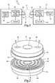
- FIG. 2is a front perspective view of one embodiment of a primary electromagnetic structure and a secondary electromagnetic structure, which form a portion of the contactless charging apparatus depicted in FIG. 1 ;
- FIG. 3is an exterior plan view of the primary electromagnetic structure depicted in FIG. 1 ;
- FIG. 4is an interior plan view of the primary electromagnetic structure depicted in FIG. 1 ;
- FIG. 5is an exterior plan view of the secondary electromagnetic structure depicted in FIG. 1 ;
- FIG. 6is an interior plan view of the secondary electromagnetic structure depicted in FIG. 1 .
- FIG. 1therein is depicted one embodiment of a contactless charging apparatus, which is schematically illustrated and designated 10 .
- a power transmitting structure 12 and a power receiving structure 14are separated by a non-magnetic gap 16 therebetween.
- the power transmitting structure 12includes an electrical power source 20 , such as battery, capacitor, or electrical plug and socket, for example, providing a power source for the transmitting power converter 22 having coils 24 within a primary electromagnetic structure 26 .
- the transmitting power converter 22is under the control of the controller 28 .
- the power receiving structure 14includes an electrical load 30 , such as a battery, providing a load for a receiving power converter 32 having coils 34 within a secondary electromagnetic structure 36 .
- the receiving power converter 32is under the control of the controller 38 . In operation, power is transferred from the electrical power source to the electrical load 30 via the primary electromagnetic structure 26 and the secondary electromagnetic structure 36 as indicated by energy transmission E.
- the primary electromagnetic structure 26has an upper end 40 and an interior end 42 .
- a primary yoke 44which may be disc-like form, is located at the upper end 40 and includes, for example, a radial flange 46 extending therefrom toward the interior end 42 .
- An opening 48is located in the primary yoke 44 .
- Wiring openings 50 , 52provide a connection with the electrical power source 20 , the transmitting power converter 22 , and controller 28 , for example.
- primary yoke 44includes primary concentric cores 58 extending therefrom into the interior end 42 of the primary electromagnetic structure 26 .
- the primary concentric cores 58include toroidal cores 60 , 62 , 64 , 66 .
- the primary concentric cores 58define annular spaces 68 , 70 , 72 , 74 and an inner space 76 .
- the primary yoke 44functions to magnetically connect all concentric cores 58 and to mechanically hold the concentric cores in a fixed position.
- the secondary electromagnetic structure 36has a lower end 80 and an interior end 82 .
- a secondary yoke 84is located at the lower end 80 and includes a radial flange 86 extending therefrom toward the interior end 82 .
- An opening 88is located in the secondary yoke 84 .
- Wiring openings 90 , 92provide a connection with the electrical load 30 , the receiving power converter 32 , and controller 38 , for example.
- the secondary yoke 84includes secondary concentric cores 98 extending therefrom into the interior end 82 of the secondary electromagnetic structure 36 .
- the secondary concentric cores 98include toroidal cores 100 , 102 , 104 , 106 .
- the secondary concentric cores 98define annular spaces 108 , 110 , 112 , 114 and an inner space 116 .
- the primary electromagnetic structure 26 and the secondary electromagnetic structure 36are symmetrical.
- each of the primary yoke 44 and the secondary yoke 84include a magnetic material, including soft-magnetic materials such as, for example, ferromagnetic materials.
- each of the primary yoke 44 and the secondary yoke 84include a soft-magnetic material, such as annealed iron, for example. Such soft-magnetic materials may stay magnetized but the magnetization may be easily annihilated after the magnetic field is removed.
- the primary electromagnetic structure and the secondary electromagnetic structuremay be geometrically inverted such that the primary yoke is located at a lower end of the primary electromagnetic structure and the secondary yoke is located at the upper end of the secondary electromagnetic structure.
- Each of the primary concentric cores 58 and the secondary concentric cores 98may be axisymmetric and composed of concentric cores with arbitrary cross-sections. Also, each of the primary concentric cores 58 may also comprise a soft-magnetic material and, in one implementation, a ferromagnetic material. Each of the primary concentric cores 58 and the secondary concentric cores 98 may include a distinct radial cross-section that may be arbitrary, such as an arbitrary polygon.
- the annular spaces 68 , 70 , 72 , 74 of the primary electromagnetic structure 26 and the annular spaces 108 , 110 , 112 , 114 of the secondary electromagnetic structure 36may also each include a distinct radial cross-section that may be arbitrary, such as an arbitrary polygon.
- N primary concentric cores 58 and N secondary concentric cores 98are present with N+1 spaces for each of the primary electromagnetic structure 26 and the secondary electromagnetic structure 36 ; namely, the annular spaces 68 , 70 , 72 , 74 and the inner space 76 of the primary electromagnetic structure 26 and the annular spaces 108 , 110 , 112 , 114 and the inner space 116 of the secondary electromagnetic structure 36 .
- Coils or winding coilsmay be inserted into the annular spaces 108 , 110 , 112 , 114 . It should be appreciated that although a particular number and configuration of primary concentric cores and secondary concentric cores are illustrated, any number or primary concentric cores and secondary concentric cores may be utilized and be within the teachings presented herein.
- the primary electromagnetic structure 26 and the secondary electromagnetic structure 36are disposed in an opposing relationship with the primary concentric cores 58 facing the secondary concentric cores 98 with the non-magnetic gap 16 therebetween.
- contactless electrical energy transmission from the primary electromagnetic structure 26 to the secondary electromagnetic structure 36may be achieved employing a closed magnetic circuit, apart from the non-magnetic gap 16 between the primary electromagnetic structure 26 and the secondary electromagnetic structure 36 , without the use of resonant electric circuit and with reasonably low supply frequency, such as a frequency below 5 kHz.
- the primary electromagnetic structure 26transmits the electrical energy from the source to the secondary electromagnetic structure 36 .
- a time-varying electromagnetic fieldis implemented by the transmitting power converter 22 and the receiving power converter 32 respectfully under the control of controllers 28 , 38 to achieve this transmission.
- electromagnetic inductionis utilized for delivery of energy from the source, such as the electrical power source 20 , to the electrical load 30 .
- the electromagnetic inductionmay include a time-varying electromagnetic field.
- contactless electrical energy transmissionincludes supplying of the primary electromagnetic structure 26 with a fixed voltage and frequency or by controlling either voltage or frequency or both, where in the case of fixed voltage and frequency, the transmitting power depends on the electrical properties of the load, and in the case of variable voltage and/or frequency, the transmitting power can be controlled from the primary electromagnetic structure 26 , for example, with a voltage-frequency (V/f) control method, assuming unchanged geometric relations, i.e. fixed width of non-magnetic gap between the primary electromagnetic structure 26 and the secondary electromagnetic structure 36 , during the energy transmission in both cases.
- V/fvoltage-frequency
- electrical energymay flow from the primary electromagnetic structure 26 to the secondary electromagnetic structure 36 .
- contactless electrical energy transmissionis achieved with arbitrary axial and circumferential position between the primary electromagnetic structure 26 and the secondary electromagnetic structure 36 , when electrical energy is transmitted therethrough.
Landscapes
- Engineering & Computer Science (AREA)
- Power Engineering (AREA)
- Computer Networks & Wireless Communication (AREA)
- Chemical & Material Sciences (AREA)
- Composite Materials (AREA)
- Charge And Discharge Circuits For Batteries Or The Like (AREA)
Abstract
Description
Claims (11)
Priority Applications (1)
| Application Number | Priority Date | Filing Date | Title |
|---|---|---|---|
| US16/986,736US11223222B2 (en) | 2019-09-13 | 2020-08-06 | Contactless charging apparatus and method for contactless charging |
Applications Claiming Priority (3)
| Application Number | Priority Date | Filing Date | Title |
|---|---|---|---|
| US201962899820P | 2019-09-13 | 2019-09-13 | |
| US202062967954P | 2020-01-30 | 2020-01-30 | |
| US16/986,736US11223222B2 (en) | 2019-09-13 | 2020-08-06 | Contactless charging apparatus and method for contactless charging |
Publications (2)
| Publication Number | Publication Date |
|---|---|
| US20210083502A1 US20210083502A1 (en) | 2021-03-18 |
| US11223222B2true US11223222B2 (en) | 2022-01-11 |
Family
ID=74868754
Family Applications (1)
| Application Number | Title | Priority Date | Filing Date |
|---|---|---|---|
| US16/986,736ActiveUS11223222B2 (en) | 2019-09-13 | 2020-08-06 | Contactless charging apparatus and method for contactless charging |
Country Status (1)
| Country | Link |
|---|---|
| US (1) | US11223222B2 (en) |
Citations (19)
| Publication number | Priority date | Publication date | Assignee | Title |
|---|---|---|---|---|
| US3801022A (en) | 1973-01-24 | 1974-04-02 | H Cassey | Swimming pool light system |
| US4675638A (en) | 1985-02-01 | 1987-06-23 | Dr. Ing. H.C.F. Porsche Aktiengesellschaft | Ferromagnetic multiple shell core for electric coils |
| US6526293B1 (en) | 1997-06-05 | 2003-02-25 | Nec Corporation | Wireless communication apparatus having rechargeable battery |
| US20060113955A1 (en) | 2004-11-29 | 2006-06-01 | Patrick Nunally | Remote power charging of electronic devices |
| US20070178945A1 (en) | 2006-01-18 | 2007-08-02 | Cook Nigel P | Method and system for powering an electronic device via a wireless link |
| US20080014897A1 (en) | 2006-01-18 | 2008-01-17 | Cook Nigel P | Method and apparatus for delivering energy to an electrical or electronic device via a wireless link |
| US7705565B2 (en) | 2003-12-31 | 2010-04-27 | Motorola, Inc. | Method and system for wireless charging |
| US20120319647A1 (en) | 2010-02-05 | 2012-12-20 | Hitachi Metals, Ltd. | Magnetic circuit, power-supplying device and power-receiving device for non-contact charging apparatus, and non-contact charging apparatus |
| US8427012B2 (en) | 2008-07-02 | 2013-04-23 | Powermat Technologies, Ltd. | Non resonant inductive power transmission system and method |
| US20140055089A1 (en)* | 2011-05-19 | 2014-02-27 | Toyota Jidosha Kabushiki Kaisha | Power reception device, power transmission device and power transfer system |
| US8796989B2 (en)* | 2009-11-13 | 2014-08-05 | Samsung Electronics Co., Ltd | Wireless charger for charging control and charging control method therefor |
| US9190849B2 (en) | 2010-03-12 | 2015-11-17 | Samsung Electronics Co., Ltd | Apparatus and method for performing wireless charging |
| US20160027576A1 (en) | 2014-07-23 | 2016-01-28 | Goodrich Corporation | System and method for increasing coupling of an axle rotary transformer |
| US9390851B2 (en)* | 2013-11-28 | 2016-07-12 | Tdk Corporation | Coil |
| US9460846B2 (en)* | 2014-06-20 | 2016-10-04 | Apple Inc. | Methods for forming shield materials onto inductive coils |
| US9466420B2 (en)* | 2012-06-11 | 2016-10-11 | Te Connectivity Nederland B.V. | Contactless connector, contactless connector system, and a manufacturing method for the contactless connector |
| US20170093213A1 (en)* | 2015-09-25 | 2017-03-30 | Aisin Seiki Kabushiki Kaisha | Contactless electric power supply device |
| US9796280B2 (en) | 2012-03-23 | 2017-10-24 | Hevo Inc. | Systems and mobile application for electric wireless charging stations |
| US20180091000A1 (en)* | 2016-09-23 | 2018-03-29 | Apple Inc. | Multi-layer transmitter coil arrangement for wireless charging mats |
- 2020
- 2020-08-06USUS16/986,736patent/US11223222B2/enactiveActive
Patent Citations (20)
| Publication number | Priority date | Publication date | Assignee | Title |
|---|---|---|---|---|
| US3801022A (en) | 1973-01-24 | 1974-04-02 | H Cassey | Swimming pool light system |
| US4675638A (en) | 1985-02-01 | 1987-06-23 | Dr. Ing. H.C.F. Porsche Aktiengesellschaft | Ferromagnetic multiple shell core for electric coils |
| US6526293B1 (en) | 1997-06-05 | 2003-02-25 | Nec Corporation | Wireless communication apparatus having rechargeable battery |
| US7705565B2 (en) | 2003-12-31 | 2010-04-27 | Motorola, Inc. | Method and system for wireless charging |
| US20060113955A1 (en) | 2004-11-29 | 2006-06-01 | Patrick Nunally | Remote power charging of electronic devices |
| US7443057B2 (en) | 2004-11-29 | 2008-10-28 | Patrick Nunally | Remote power charging of electronic devices |
| US20070178945A1 (en) | 2006-01-18 | 2007-08-02 | Cook Nigel P | Method and system for powering an electronic device via a wireless link |
| US20080014897A1 (en) | 2006-01-18 | 2008-01-17 | Cook Nigel P | Method and apparatus for delivering energy to an electrical or electronic device via a wireless link |
| US8427012B2 (en) | 2008-07-02 | 2013-04-23 | Powermat Technologies, Ltd. | Non resonant inductive power transmission system and method |
| US8796989B2 (en)* | 2009-11-13 | 2014-08-05 | Samsung Electronics Co., Ltd | Wireless charger for charging control and charging control method therefor |
| US20120319647A1 (en) | 2010-02-05 | 2012-12-20 | Hitachi Metals, Ltd. | Magnetic circuit, power-supplying device and power-receiving device for non-contact charging apparatus, and non-contact charging apparatus |
| US9190849B2 (en) | 2010-03-12 | 2015-11-17 | Samsung Electronics Co., Ltd | Apparatus and method for performing wireless charging |
| US20140055089A1 (en)* | 2011-05-19 | 2014-02-27 | Toyota Jidosha Kabushiki Kaisha | Power reception device, power transmission device and power transfer system |
| US9796280B2 (en) | 2012-03-23 | 2017-10-24 | Hevo Inc. | Systems and mobile application for electric wireless charging stations |
| US9466420B2 (en)* | 2012-06-11 | 2016-10-11 | Te Connectivity Nederland B.V. | Contactless connector, contactless connector system, and a manufacturing method for the contactless connector |
| US9390851B2 (en)* | 2013-11-28 | 2016-07-12 | Tdk Corporation | Coil |
| US9460846B2 (en)* | 2014-06-20 | 2016-10-04 | Apple Inc. | Methods for forming shield materials onto inductive coils |
| US20160027576A1 (en) | 2014-07-23 | 2016-01-28 | Goodrich Corporation | System and method for increasing coupling of an axle rotary transformer |
| US20170093213A1 (en)* | 2015-09-25 | 2017-03-30 | Aisin Seiki Kabushiki Kaisha | Contactless electric power supply device |
| US20180091000A1 (en)* | 2016-09-23 | 2018-03-29 | Apple Inc. | Multi-layer transmitter coil arrangement for wireless charging mats |
Non-Patent Citations (1)
| Title |
|---|
| International Search Report Re: PCT/US20/50362 from WIPO dated Nov. 12, 2020. |
Also Published As
| Publication number | Publication date |
|---|---|
| US20210083502A1 (en) | 2021-03-18 |
Similar Documents
| Publication | Publication Date | Title |
|---|---|---|
| EP1368815B1 (en) | Inductive coupling system with capacitive parallel compensation of the mutual self-inductance between the primary and the secondary windings | |
| US10923966B2 (en) | Coil structures for alignment and inductive wireless power transfer | |
| KR101057373B1 (en) | Solid State Power Transmitter | |
| US10593468B2 (en) | Inductive power transfer assembly | |
| US20200176990A1 (en) | Transmitting assembly for a universal wireless charging device and a method thereof | |
| CN105720695B (en) | Inductive wireless power transfer system | |
| CN111384786B (en) | Wireless charging device using a plurality of coils and wireless charging system including the same | |
| CN103972736A (en) | Electro-magnetic inductive plug and socket combination | |
| US20180062441A1 (en) | Segmented and Longitudinal Receiver Coil Arrangements for Wireless Power Transfer | |
| CN105720699B (en) | Inductive wireless power transfer system | |
| JP4900525B1 (en) | Non-contact charging module, transmitting-side non-contact charging device and receiving-side non-contact charging device provided with the same | |
| JP6609232B2 (en) | Non-contact power transmission device | |
| CN104079039B (en) | A kind of charging electric vehicle rifle structure | |
| KR102137037B1 (en) | Apparatus for wireless charging using multi-coil and repeater | |
| US11223222B2 (en) | Contactless charging apparatus and method for contactless charging | |
| US20120242445A1 (en) | Integrated reactance module | |
| US10892088B1 (en) | Stationary device for contactless electrical energy transmission | |
| KR20170142261A (en) | Transformer insulation structure is improved | |
| EP4029103A1 (en) | Contactless charging apparatus and method for contactless charging | |
| US20170179728A1 (en) | Electromagnetic induction apparatus for power transfer | |
| CN107967980A (en) | Axial magnetizing device | |
| JP2014150698A (en) | Wireless power supply system | |
| WO2017214015A1 (en) | Coil structures for alignment and inductive wireless power transfer | |
| CN204834298U (en) | Electronic transformer with thin slice coil | |
| RU2700662C1 (en) | High-frequency inductive connector |
Legal Events
| Date | Code | Title | Description |
|---|---|---|---|
| AS | Assignment | Owner name:TEXAS INSTITUTE OF SCIENCE, INC., TEXAS Free format text:ASSIGNMENT OF ASSIGNORS INTEREST;ASSIGNORS:MILJAVEC, DAMIJAN;VUKOTIC, MARIO;COROVIC, SELMA;AND OTHERS;SIGNING DATES FROM 20200304 TO 20200404;REEL/FRAME:053421/0143 | |
| FEPP | Fee payment procedure | Free format text:ENTITY STATUS SET TO UNDISCOUNTED (ORIGINAL EVENT CODE: BIG.); ENTITY STATUS OF PATENT OWNER: SMALL ENTITY | |
| FEPP | Fee payment procedure | Free format text:ENTITY STATUS SET TO SMALL (ORIGINAL EVENT CODE: SMAL); ENTITY STATUS OF PATENT OWNER: SMALL ENTITY | |
| STPP | Information on status: patent application and granting procedure in general | Free format text:RESPONSE TO NON-FINAL OFFICE ACTION ENTERED AND FORWARDED TO EXAMINER | |
| STPP | Information on status: patent application and granting procedure in general | Free format text:FINAL REJECTION MAILED | |
| STPP | Information on status: patent application and granting procedure in general | Free format text:DOCKETED NEW CASE - READY FOR EXAMINATION | |
| STPP | Information on status: patent application and granting procedure in general | Free format text:NOTICE OF ALLOWANCE MAILED -- APPLICATION RECEIVED IN OFFICE OF PUBLICATIONS | |
| STPP | Information on status: patent application and granting procedure in general | Free format text:PUBLICATIONS -- ISSUE FEE PAYMENT VERIFIED | |
| STCF | Information on status: patent grant | Free format text:PATENTED CASE | |
| FEPP | Fee payment procedure | Free format text:MAINTENANCE FEE REMINDER MAILED (ORIGINAL EVENT CODE: REM.); ENTITY STATUS OF PATENT OWNER: SMALL ENTITY |