US11221314B2 - Combined pulse echo inspection of pipeline systems - Google Patents
Combined pulse echo inspection of pipeline systemsDownload PDFInfo
- Publication number
- US11221314B2 US11221314B2US15/761,691US201615761691AUS11221314B2US 11221314 B2US11221314 B2US 11221314B2US 201615761691 AUS201615761691 AUS 201615761691AUS 11221314 B2US11221314 B2US 11221314B2
- Authority
- US
- United States
- Prior art keywords
- sensors
- pipe
- sensor
- pulse
- transmitter
- Prior art date
- Legal status (The legal status is an assumption and is not a legal conclusion. Google has not performed a legal analysis and makes no representation as to the accuracy of the status listed.)
- Active, expires
Links
Images


Classifications
- G—PHYSICS
- G01—MEASURING; TESTING
- G01N—INVESTIGATING OR ANALYSING MATERIALS BY DETERMINING THEIR CHEMICAL OR PHYSICAL PROPERTIES
- G01N29/00—Investigating or analysing materials by the use of ultrasonic, sonic or infrasonic waves; Visualisation of the interior of objects by transmitting ultrasonic or sonic waves through the object
- G01N29/22—Details, e.g. general constructional or apparatus details
- G01N29/26—Arrangements for orientation or scanning by relative movement of the head and the sensor
- G01N29/262—Arrangements for orientation or scanning by relative movement of the head and the sensor by electronic orientation or focusing, e.g. with phased arrays
- G—PHYSICS
- G01—MEASURING; TESTING
- G01N—INVESTIGATING OR ANALYSING MATERIALS BY DETERMINING THEIR CHEMICAL OR PHYSICAL PROPERTIES
- G01N29/00—Investigating or analysing materials by the use of ultrasonic, sonic or infrasonic waves; Visualisation of the interior of objects by transmitting ultrasonic or sonic waves through the object
- G01N29/04—Analysing solids
- G01N29/11—Analysing solids by measuring attenuation of acoustic waves
- G—PHYSICS
- G01—MEASURING; TESTING
- G01N—INVESTIGATING OR ANALYSING MATERIALS BY DETERMINING THEIR CHEMICAL OR PHYSICAL PROPERTIES
- G01N29/00—Investigating or analysing materials by the use of ultrasonic, sonic or infrasonic waves; Visualisation of the interior of objects by transmitting ultrasonic or sonic waves through the object
- G01N29/22—Details, e.g. general constructional or apparatus details
- G01N29/26—Arrangements for orientation or scanning by relative movement of the head and the sensor
- G01N29/265—Arrangements for orientation or scanning by relative movement of the head and the sensor by moving the sensor relative to a stationary material
- G—PHYSICS
- G01—MEASURING; TESTING
- G01N—INVESTIGATING OR ANALYSING MATERIALS BY DETERMINING THEIR CHEMICAL OR PHYSICAL PROPERTIES
- G01N29/00—Investigating or analysing materials by the use of ultrasonic, sonic or infrasonic waves; Visualisation of the interior of objects by transmitting ultrasonic or sonic waves through the object
- G01N29/44—Processing the detected response signal, e.g. electronic circuits specially adapted therefor
- G01N29/4409—Processing the detected response signal, e.g. electronic circuits specially adapted therefor by comparison
- G01N29/4427—Processing the detected response signal, e.g. electronic circuits specially adapted therefor by comparison with stored values, e.g. threshold values
- G—PHYSICS
- G01—MEASURING; TESTING
- G01N—INVESTIGATING OR ANALYSING MATERIALS BY DETERMINING THEIR CHEMICAL OR PHYSICAL PROPERTIES
- G01N2291/00—Indexing codes associated with group G01N29/00
- G01N2291/04—Wave modes and trajectories
- G01N2291/044—Internal reflections (echoes), e.g. on walls or defects
- G—PHYSICS
- G01—MEASURING; TESTING
- G01N—INVESTIGATING OR ANALYSING MATERIALS BY DETERMINING THEIR CHEMICAL OR PHYSICAL PROPERTIES
- G01N2291/00—Indexing codes associated with group G01N29/00
- G01N2291/10—Number of transducers
- G01N2291/106—Number of transducers one or more transducer arrays
- G—PHYSICS
- G01—MEASURING; TESTING
- G01N—INVESTIGATING OR ANALYSING MATERIALS BY DETERMINING THEIR CHEMICAL OR PHYSICAL PROPERTIES
- G01N2291/00—Indexing codes associated with group G01N29/00
- G01N2291/26—Scanned objects
- G01N2291/263—Surfaces
- G01N2291/2636—Surfaces cylindrical from inside
Definitions
- Certain equipment and facilitiesutilize pipeline systems having pipes or conduits to transport fluids or products, e.g. hydrocarbonic fluids, over distances.
- fluids or productse.g. hydrocarbonic fluids
- certain productsmay leak out of the pipes, leading to product loss, corrosion, pitting, and other unwanted conditions. Visual inspection of the pipe leakage may be very difficult.
- the pipemay include long “runs” having, tens, hundreds, if not thousands of miles. The need thus exists for improved systems and methods for inspecting for certain conditions and anomalies within a pipeline system.
- the subject matter disclosed hereinrelates to combined pulse echo techniques as applied to inspection of pipeline systems.
- a method for inspecting pipeincludes transmitting an ultrasound pulse through a pipe or a fluid container from inside the pipe or the fluid container.
- the methodfurther includes receiving echoes via a plurality of sensors, based on the ultrasound pulse, and combining echo data from the plurality of sensors.
- the methodadditionally includes deriving an environmental assessment based on the combining the echo data.
- a systemin accordance with a second embodiment, includes an ultrasound transmitter and receiver system comprising a plurality of sensors, and a processor.
- the processoris configured to transmit an ultrasound pulse via the ultrasound transmitter and receiver system.
- the processoris also configured to receive echo data via the plurality of sensors, based on the ultrasound pulse.
- the processoris additionally configured to combine the echo data from the plurality of sensors.
- the processoris further configured to derive an environmental assessment based on the combining the echo data.
- FIG. 1is a block diagram of an embodiment of a pipeline system having a pipeline inspection system
- FIG. 2is a cross-sectional view of an embodiment of a region of interest for observation via a single sensor
- FIG. 3is an embodiment of an amplitude versus time graph for a single signal
- FIG. 4is a cross-sectional view of an embodiment of a region of interest for observation via a combination of sensors
- FIG. 5is an embodiment of an amplitude versus time graph for a plurality of signals
- FIG. 6is a view of an embodiment of an inspection system having a plurality of sensors disposed circumferentially about an axis;
- FIG. 7is a view of an embodiment of an inspection system having a phased array system and virtual sensors
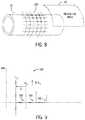
- FIG. 8is a perspective view of an embodiment of a pipe and a reference inspection area
- FIG. 9is an embodiment of a graph showing various amplitude curves
- FIG. 10is an embodiment of a near field distance graph
- FIG. 11is an embodiment of a beam divergence graph
- FIG. 12is an embodiment of side view of a region of interest and acoustic impedance
- FIG. 13is an embodiment of side view of a region of interest and certain pulse echoes
- FIG. 14is an embodiment of side view of a region of interest and certain other pulse echoes.
- FIG. 15is an embodiment of a process suitable for combining data from a plurality of sensors to derive an environmental assessment.
- the present disclosureis directed towards systems and methods for improving inspection of pipeline system by combining data processing and/or hardware systems from a plurality of pulse echo transmitters and sensors.
- the pulse echo transmitters and sensorsmay each apply one or more pulse echo techniques suitable for deriving conditions such as the coating status of pipe, and the environment surround the pipe (e.g., moisture content in the environment, type of environment, properties of the environment).
- Data received via the plurality of sensorse.g., 3, 4, 5, 6, 10, 100 or more sensors
- the techniques described hereinmay be applicable to a variety of transport systems in addition to or alternative to pipeline systems. Indeed, fluid vessels, contained transport systems, containers, and the like, may be inspected using the techniques described herein.
- an inspection systemincludes a transducer disposed inside pipeline or transport system suitable for sending a signal from inside a vessel (e.g., pipe) so that the signal traverses a vessel wall to and outside surface of the vessel.
- a vessele.g., pipe
- Reflection of the transmitted signal or energywould include some dependency based on the nature of the external environment (e.g., in form of a refraction index) and would appear in data as forms of different attenuations in amplitude over several echo pulses.
- a reference data levelmay be generated from data sets aggregated from all sensors receiving a signal echo. Conditions at a given location may then be characterized and used in comparison with other locations and may also be used as predictor of external environment conditions. Accordingly, an environmental assessment of conditions external to the pipeline system, including pipe coating status, may be derived more accurately.
- FIG. 1the figure illustrates a cross section block diagram of an embodiment of a portion of pipeline system 8 having one or more pipes 10 .
- the pipes 10may include non-ferrous and/or ferrous pipe.
- a pipeline inspection system 12disposed in the interior of the pipe 10 , useful in inspecting the pipeline system 8 .
- the pipeline inspection system 12may be inserted during inline inspection operations and subsequently propelled though the pipeline system 8 by pressure of a fluid 14 flowing through the pipeline system 8 .
- the fluid 14may include liquids and/or gases, for example, hydrocarbonic fluids used in oil and gas industries, such as petroleum, petroleum distillates, natural gas, propane, and so on.
- the fluid 14need not be limited to the aforementioned examples, and may include any fluid that traverses the pipeline system 8 with suitable pressure.
- an environmental assessmentmay be made. For example, certain undesired conditions 16 of the pipeline system 8 may be detected. For example, wet soil, dry soil, and other properties of a medium 17 (e.g., soil, gravel, water, rock, and the like) surrounding the pipe 10 may be detected. Likewise, a condition of a coating 19 disposed on outside surfaces of walls 18 of the pipe 10 , corrosion, pitting, ablative conditions, and so on, may be detected. As further described herein, the inspection system 12 may include a pulse echo system 20 . Other inline inspection (ILI) systems 22 , 24 may be used.
- IPIinline inspection
- the systems 22 , 24may include high resolution caliper systems, magnetic flux leakage (MFL) systems, acoustic resonance (AR) systems, or a combination thereof.
- the systems 20 , 22 , 24may be combined into a single package or unit, for example, for overall compactness and length reduction.
- Each of the systems 20 , 22 , 24may include a sensing package 26 , 28 , 30 , one or more processors 32 , 34 , 36 , and one or more memory 38 , 40 , 42 , respectively.
- the sensing package 26may be suitable for transmitting ultrasonic energy or signals through the pipe 10 and for detecting the conditions 16 via sensed echo pulses, as described in more detail below.
- the sensing packages 28 , 30may include mechanical sensors, electronic sensors and/or software suitable for applying ILI sensing techniques, such as the aforementioned MFL, AR, and/or high resolution caliper.
- the processor 32 , 34 , 36may be suitable for executing computer code or instructions stored in the memories 38 , 40 , 42 .
- the systems 20 , 22 , and 24may be removable and/or replaceable.
- an inspection runmay include only the pulse system 20 .
- a second inspection runmay then be performed at a later time (e.g., minutes, hours, days, weeks later) with the inspection system 12 carrying any one of the MFL, AR, high resolution caliper, or combination thereof.
- the inspection system 12may provide for better predictive characteristics of environments external to the pipe 10 , as well as the coating 19 than other techniques, as well as increased confidence and reliability of detection and characterization of particular product leakages that may be of concern for the delivery of product traversing the pipe 10 .
- the physical configuration of the combined inspection system 12may not be radically different than current conventional tools. Indeed, in some embodiments, the techniques described herein may provide for a software upgrade of certain existing hardware, e.g., via Flash upgrade, to enable the improved environmental assessment.
- FIG. 2illustrates an embodiment of set of interfaces 1, 2, 3 depicting a single ultrasonic transmitter/sensor system 50 that may be included in the sensing package 26 shown in FIG. 1 .
- a compression wave sound beammay be generated through the use of a finite ultrasonic pulse wave transmitted via the system 50 .
- wave physicsit can be shown that as the beam energy hits an interface surface (e.g., interface 1) separating different mediums (e.g., each medium having differing sonic properties), energy will be reflected (echoed) and transmitted through the interface.
- echo responsesmay be detected and recorded for each of the interfaces 1, 2, and 3 as pulse events interact with the respective interfaces.
- pulse wavesmay also cause a reflection echo and some transmission of energy.
- a reflection echo and energy transmissionmay occur at interface 3 separating medium C 19 from medium D 17 .
- Relative ratios of amplitudes of reflection and transmission energymay be based upon relative differences between the mediums at each interface 1, 2, 3, e.g., transmit “T” and reflection “R” ultrasound boundary conditions, as described in more detail below.
- the reflection pulse time for flight from interface 1 and 2maybe be used to establish the wall 18 thickness based upon a speed of sound reference for medium b (e.g., wall 18 's composition). Some energy continues to reflect within interface 1 and 2, and between interface 2 and 3, back to the probe until fully dissipated. Visualization of this amplitude reflection vs. time behavior as received at the UT probe 50 is generally referred to as an A-Scan.
- FIG. 3is a graph 60 illustrating embodiments of an amplitude versus time of certain reflections show in FIG. 2 . More specifically, the graph 60 includes a y-axis 62 representative of an amplitude or intensity of a signal 61 received via sensors included in the system 26 , and an x-axis 64 representative of time of receipt of the signal. The graph also shows three peaks 66 , 68 , and 70 . Peak 66 includes a reflection signal from interface 1's inner surface to probe system 50 and back. Peak 68 includes a reflection signal from within the medium B, between interfaces 1 and 2, 2-1, and back to the probe 50 . Peak 70 includes a residual reflection signal back from the reflection shown on peak 68 , then between interfaces 1-2, 2-1, and then back to the probe 50 . By analyzing multiple signals, an improved environmental scan may be derived.
- the identification of the 1-2, 2-3, interface events and relative amplitude/energy changesprovides insight to the interface 1, 2, 3 conditions, and thus, may be a source of insight to the sonic properties of the external environment.
- a single sensor and firing sequencemay not provide the resolution or consistency to establish the outer boundary interface conditions.
- the techniques described hereininclude the use of a plurality of sensors 50 (e.g., pulse echo sensors), which may be disposed circumferentially inside of the pipe 10 .
- Each sensor 50may record A-scans simultaneously for pulse-echo information related to the wall 18 thickness measurement, but also as relative amplitude changes due to the medium C (e.g., coating 19 ) and medium D (e.g., medium 17 ).
- a Phased Array ultrasonic probe(s)may be used in lieu of or additional to the plurality of circumferentially disposed sensors 50 , in a wall 18 measurement firing configuration.
- Data acquisition for the system 20may occur at high linear repetition as the system 20 moves through the pipe 10 (e.g., sensors 50 may be moving past the point on the pipe wall 18 , and thus, full pipe joint and full pipeline 8 information may be collected).
- those changes that infer the medium C sonic properties relative to the medium B sonic propertieswould be computed and characterized statistically for each joint and/or region of interest.
- a characteristic profile of the relative medium C/D sonic properties to medium B sonic propertiesmay be generated and then used for reference or predictive purposes.
- Certain referencesmay be useful. Relative reference—checks other areas of similar characterization profile versus an expected profile.
- Absolute referencechecks and calibrates areas of similar characterization using the independent records of the right of way/as-built information on record of for pipeline system 8 operator or other independent calibration reference (e.g. presence of external oil).
- a search for localized statistical anomalies that would represent coating disbands and/or different external conditionsmay be derived. Locations with identified or predetermined characteristic response for the medium C/D may be flagged for potential unwanted environmental state (e.g. coating dis-bond in saturated water, presence of oil surrounding pipe indicating a leak).
- Each sensor 50may have its own calibration reference for intensity, focus, and responsiveness, to known standards, hence amplitudes may be normalized to other sensors 50 as needed.
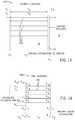
- FIGS. 4 and 5illustrate embodiments of a plurality of sensors 50 and signals 61 respectively. More specifically, FIG. 4 illustrates an embodiment of a plurality of sensors 50 each sensor 50 independently recording A-scans. In the depicted embodiment, the sensors 50 may record A-scans approximately simultaneously, thus providing for pulse-echo information related to the wall 18 thickness measurement, but also as relative amplitude changes due to the medium C (e.g., coating 19 ) and medium D (e.g., medium 17 ). As shown in FIG. 5 , the signals 61 from respective sensors 50 may be combined in single graph 80 .
- the medium Ce.g., coating 19
- medium De.g., medium 17
- An amplitude change profile 82 shown as a dashed curve following peaks of the signals 61may be derived, representative of changes that infer, for example, medium C sonic properties relative to the medium B sonic properties. Such changes would be computed and characterized statistically for each joint and/or region 16 of interest.
- FIG. 6illustrates an example system 20 having a plurality of sensors 50 .
- each sensor 50may transmit and/or observe energy (e.g., UT energy) independently, and in a preferred embodiment, simultaneously.
- Each sensormay observe the walls 18 and derive, for example, wall 18 thickness measurements 100 and/or offset measurements 102 .
- the hardware/software for the system 20may include systems available from General Electric Company, of Schenectady, N.Y., such as an Ultrascan WM tool.
- the techniques described hereinmay be “flashed” onto a processor of the WM tool, e.g., processor 32 .
- the flash upgrademay then provide software suitable for deriving certain ratios, including relative amplitude changes due to certain mediums, e.g., the medium C and medium D (e.g., medium 17 ).
- FIG. 7illustrates an example system 20 having a phased array probe 120 suitable for implementing the techniques described herein.
- the probe 120may provide the equivalent of a plurality of virtual sensors 50 , which may be configured to fire in a wall measurement time of flight mode.
- Each virtual sensor 122may fire selectively within the full array 120 , for example, to generate a 0° incident wave, thus providing for a wall measurement pulse echo.
- Full circumferential coveragemay be provided by use of multiple probes, each using virtual sensors 122 across the full width of each array 120 .
- the hardware/software for the system 20may include systems available from General Electric Company, of Schenectady, N.Y., such as an UltraScan DUO Phase Array Ultrasonic Pipeline Inspection Tool.
- FIG. 8is a perspective view of the pipe 10 and a sensing array 150 that may be provided via the sensors 50 .
- a reference area 152is also shown, depicting an area of observation.
- a plurality of sensors 50may be used. In one embodiment, 20, 30, 40, 50, or more sensors 50 may be used.
- FIG. 9is an amplitude versus time curve showing how different curves 162 , 164 , 166 mean different medium environments.
- Amplitudeis A, and looking at different amplitudes of a pulse in different environments may show changes in amplitudes based on the environment. Amplitude levels can be characterized as a profile of a given environment. Different curves 162 , 164 , 166 may thus imply different mediums and/or environments.
- FIG. 10depicts a focal capability of a sensor, and near field distance N.
- the size and nature of a fired ultrasound beamis dependent on the sensor face, frequency, and velocity of the medium used to transport the beam. More dense mediums result in higher velocities.
- Divis a divergence of the beam as the beam spreads.
- FIG. 11illustrates a beam width diagram 180 suitable to derive width W based on ultrasonic velocity V, Distance D, frequency F, and time t. Accordingly, the
- FIG. 12depicts an example diagram 200 suitable for deriving a reflection coefficient
- each mediummay include varying velocities V 1 , V 2 , V 3 .
- the reflective coefficient Rumay then be used, for example, via a lookup table, to determine conditions 16 and/or provide the environmental assessment. For example, once a value for Ru is found, the value may be used to look up what type of soil, leakage, rock properties, coating status, and so on, may be present.
- the ⁇may be derived, for example, based on certain time resulting from velocities of the mediums A, B, C.
- FIG. 13shows an embodiment of a graph 220 showing energy pulses bouncing between mediums, and gate length calculations. As pulses 222 bounce back and forth, traversing the mediums or materials 17 , 18 , 19 , each material will provide for a different ultrasonic velocity V, as shown. A delta or change in time t may be derived using the formula
- ⁇ ⁇ ⁇ t2 ⁇ d 2 V 2 + d 1 1
- V 2is the ultrasonic velocity at medium 18
- d 2is the distance over the medium 18
- d 1is the distance over medium 17 .
- a rce ′ ⁇ dA x ⁇ e - ⁇ ⁇ ( d 1 1 ) .
- Second pulse amplitudes, A 7T 1 [A 1 ], and
- a 8A 7 ⁇ e - ⁇ 1 ⁇ ( d 1 1 ) .
- a 15A 14 ⁇ e - ⁇ 1 ⁇ ( d 1 1 )
- a 22A 21 ⁇ e - ⁇ ⁇ ( d 1 1 ) .
- FIG. 15the figure is a flowchart of an embodiment of a process 300 that may be used to combine data from multiple sensors 50 to provide for improved inspections of the pipeline system 8 .
- the process 300may be implemented as computer software or instruction executable via processors and stored in memory.
- the process 300may first transmit one or more UT pulses (block 304 ).
- the pulsemay echo through various mediums.
- the process 300may then sense the various pulse echoes (block 210 ) through a plurality of sensors 50 .
- the pulsesmay bounce between various medium types, at varying velocities based on properties of the medium (e.g., densities, humidity) and sensed as they are received by the sensors ( 50 ).
- the process 300may then combine the various echo data (block 308 ).
- the combinationmay result in derivations of amplitudes and various reflection ratios (e.g., R 12 ).
- an environmental assessmentmay be derived (block 310 ). For example, lookup tables, databases, and so on, may be used to correlate the amplitudes and/or ratios with certain conditions 16, such as oil, water, dry soil, wet soil, rocks, coating status (e.g., worn coating, coating thickness).
Landscapes
- Physics & Mathematics (AREA)
- Analytical Chemistry (AREA)
- Health & Medical Sciences (AREA)
- Life Sciences & Earth Sciences (AREA)
- Chemical & Material Sciences (AREA)
- Biochemistry (AREA)
- General Health & Medical Sciences (AREA)
- General Physics & Mathematics (AREA)
- Immunology (AREA)
- Pathology (AREA)
- Signal Processing (AREA)
- Engineering & Computer Science (AREA)
- Acoustics & Sound (AREA)
- Investigating Or Analyzing Materials By The Use Of Ultrasonic Waves (AREA)
Abstract
Description
where F is frequency and V is the ultrasonic velocity.
where the amount of energy reflecting from a given interface (e.g., 12 may denote
where V2is the ultrasonic velocity at
Second pulse amplitudes, A7=T1[A1], and
Third pulse amplitudes
Claims (13)
Priority Applications (1)
| Application Number | Priority Date | Filing Date | Title |
|---|---|---|---|
| US15/761,691US11221314B2 (en) | 2015-09-20 | 2016-09-20 | Combined pulse echo inspection of pipeline systems |
Applications Claiming Priority (3)
| Application Number | Priority Date | Filing Date | Title |
|---|---|---|---|
| US201562221067P | 2015-09-20 | 2015-09-20 | |
| US15/761,691US11221314B2 (en) | 2015-09-20 | 2016-09-20 | Combined pulse echo inspection of pipeline systems |
| PCT/US2016/052705WO2017049326A1 (en) | 2015-09-20 | 2016-09-20 | Combined pulse echo inspection of pipeline systems |
Publications (2)
| Publication Number | Publication Date |
|---|---|
| US20180356370A1 US20180356370A1 (en) | 2018-12-13 |
| US11221314B2true US11221314B2 (en) | 2022-01-11 |
Family
ID=57130433
Family Applications (1)
| Application Number | Title | Priority Date | Filing Date |
|---|---|---|---|
| US15/761,691Active2038-02-25US11221314B2 (en) | 2015-09-20 | 2016-09-20 | Combined pulse echo inspection of pipeline systems |
Country Status (5)
| Country | Link |
|---|---|
| US (1) | US11221314B2 (en) |
| EP (1) | EP3350587B1 (en) |
| CA (2) | CA3009086C (en) |
| SA (1) | SA518391069B1 (en) |
| WO (1) | WO2017049326A1 (en) |
Cited By (2)
| Publication number | Priority date | Publication date | Assignee | Title |
|---|---|---|---|---|
| WO2024052847A1 (en) | 2022-09-08 | 2024-03-14 | Equanostic As | Hybrid sensor head for surface inspection and method of use |
| US12196713B2 (en) | 2021-08-24 | 2025-01-14 | Saudi Arabian Oil Company | Convex ultrasonic sensor for weld inspection |
Families Citing this family (3)
| Publication number | Priority date | Publication date | Assignee | Title |
|---|---|---|---|---|
| EP3662255B1 (en)* | 2017-08-04 | 2023-12-27 | BP Corporation North America Inc. | Ultrasonic corrosion monitoring |
| CN109946375A (en)* | 2019-03-12 | 2019-06-28 | 山东省特种设备检验研究院有限公司 | Long-distance pipeline piezoelectric ultrasonic internal detection probe assembly and detection method |
| CN114354740B (en)* | 2022-03-09 | 2022-05-31 | 成都熊谷油气科技有限公司 | Pipeline detection system |
Citations (19)
| Publication number | Priority date | Publication date | Assignee | Title |
|---|---|---|---|---|
| US2959054A (en) | 1957-01-14 | 1960-11-08 | Gulton Ind Inc | Ultrasonic flowmeter |
| US2966058A (en) | 1957-10-15 | 1960-12-27 | Bell Telephone Labor Inc | Measurement of dynamic properties of materials |
| EP0364168A2 (en) | 1988-10-11 | 1990-04-18 | Simmonds Precision Products Inc. | System and method for ultrasonic determination of density |
| US4964059A (en) | 1987-08-21 | 1990-10-16 | Nkk Corporation | Apparatus for inspecting a pipeline |
| US5460046A (en) | 1994-05-25 | 1995-10-24 | Tdw Delaware, Inc. | Method and apparatus for ultrasonic pipeline inspection |
| DE19535848C1 (en) | 1995-09-18 | 1996-07-25 | Inst Automation Und Kommunikat | Fluid acoustic impedance measuring device |
| US5681995A (en)* | 1995-03-17 | 1997-10-28 | Hitachi, Ltd. | Ultrasonic flaw detecting apparatus for inspecting multi-layer structure and method thereof |
| US5770800A (en) | 1994-09-27 | 1998-06-23 | The United States Of America As Represented By The United States Department Of Energy | Flexible ultrasonic pipe inspection apparatus |
| US6666095B2 (en) | 2001-11-30 | 2003-12-23 | The Regents Of The University Of California | Ultrasonic pipe assessment |
| US6763698B2 (en) | 2002-03-15 | 2004-07-20 | Battelle Memorial Institute | Self calibrating system and technique for ultrasonic determination of fluid properties |
| US20060219011A1 (en)* | 2005-03-31 | 2006-10-05 | Siddu Dinesh M | Method and system for inspecting objects using ultrasound scan data |
| US20090084184A1 (en)* | 2007-09-18 | 2009-04-02 | Frederik Hendrik Dijkstra | Inspection device and method for inspection |
| US20100199767A1 (en)* | 2009-02-09 | 2010-08-12 | Weatherford/Lamb | In-line inspection tool for pipeline integrity testing |
| US20110167914A1 (en)* | 2008-06-27 | 2011-07-14 | Jeffrey Earle Sutherland | Integrated multi-sensor non-destructive testing |
| US8265886B2 (en) | 2006-06-30 | 2012-09-11 | V & M France | Non-destructive testing, in particular for pipes during manufacture or in the finished state |
| WO2013059458A1 (en) | 2011-10-18 | 2013-04-25 | Cidra Corporate Services Inc. | Acoustic probing technique for the determination of interior pipe coating wear or scale build-up and liner wear |
| US20140238136A1 (en) | 2011-09-26 | 2014-08-28 | Ontario Power Generation Inc. | Ultrasound matrix inspection |
| EP2843401A1 (en) | 2013-08-30 | 2015-03-04 | Nederlandse Organisatie voor toegepast -natuurwetenschappelijk onderzoek TNO | System and method for defect monitoring |
| US20160327519A1 (en)* | 2014-01-02 | 2016-11-10 | Pipelines 2 Data (P2D) Limited | Methods and apparatus for acoustic assessment from the interior of fluid conduits |
Family Cites Families (1)
| Publication number | Priority date | Publication date | Assignee | Title |
|---|---|---|---|---|
| WO2015088351A1 (en)* | 2013-12-09 | 2015-06-18 | Bergen Technology Center As | Pulse-wave ultrasound production well logging method and tool |
- 2016
- 2016-09-20USUS15/761,691patent/US11221314B2/enactiveActive
- 2016-09-20CACA3009086Apatent/CA3009086C/enactiveActive
- 2016-09-20WOPCT/US2016/052705patent/WO2017049326A1/ennot_activeCeased
- 2016-09-20EPEP16781222.1Apatent/EP3350587B1/enactiveActive
- 2016-09-20CACA2998176Apatent/CA2998176A1/enactivePending
- 2018
- 2018-03-05SASA518391069Apatent/SA518391069B1/enunknown
Patent Citations (19)
| Publication number | Priority date | Publication date | Assignee | Title |
|---|---|---|---|---|
| US2959054A (en) | 1957-01-14 | 1960-11-08 | Gulton Ind Inc | Ultrasonic flowmeter |
| US2966058A (en) | 1957-10-15 | 1960-12-27 | Bell Telephone Labor Inc | Measurement of dynamic properties of materials |
| US4964059A (en) | 1987-08-21 | 1990-10-16 | Nkk Corporation | Apparatus for inspecting a pipeline |
| EP0364168A2 (en) | 1988-10-11 | 1990-04-18 | Simmonds Precision Products Inc. | System and method for ultrasonic determination of density |
| US5460046A (en) | 1994-05-25 | 1995-10-24 | Tdw Delaware, Inc. | Method and apparatus for ultrasonic pipeline inspection |
| US5770800A (en) | 1994-09-27 | 1998-06-23 | The United States Of America As Represented By The United States Department Of Energy | Flexible ultrasonic pipe inspection apparatus |
| US5681995A (en)* | 1995-03-17 | 1997-10-28 | Hitachi, Ltd. | Ultrasonic flaw detecting apparatus for inspecting multi-layer structure and method thereof |
| DE19535848C1 (en) | 1995-09-18 | 1996-07-25 | Inst Automation Und Kommunikat | Fluid acoustic impedance measuring device |
| US6666095B2 (en) | 2001-11-30 | 2003-12-23 | The Regents Of The University Of California | Ultrasonic pipe assessment |
| US6763698B2 (en) | 2002-03-15 | 2004-07-20 | Battelle Memorial Institute | Self calibrating system and technique for ultrasonic determination of fluid properties |
| US20060219011A1 (en)* | 2005-03-31 | 2006-10-05 | Siddu Dinesh M | Method and system for inspecting objects using ultrasound scan data |
| US8265886B2 (en) | 2006-06-30 | 2012-09-11 | V & M France | Non-destructive testing, in particular for pipes during manufacture or in the finished state |
| US20090084184A1 (en)* | 2007-09-18 | 2009-04-02 | Frederik Hendrik Dijkstra | Inspection device and method for inspection |
| US20110167914A1 (en)* | 2008-06-27 | 2011-07-14 | Jeffrey Earle Sutherland | Integrated multi-sensor non-destructive testing |
| US20100199767A1 (en)* | 2009-02-09 | 2010-08-12 | Weatherford/Lamb | In-line inspection tool for pipeline integrity testing |
| US20140238136A1 (en) | 2011-09-26 | 2014-08-28 | Ontario Power Generation Inc. | Ultrasound matrix inspection |
| WO2013059458A1 (en) | 2011-10-18 | 2013-04-25 | Cidra Corporate Services Inc. | Acoustic probing technique for the determination of interior pipe coating wear or scale build-up and liner wear |
| EP2843401A1 (en) | 2013-08-30 | 2015-03-04 | Nederlandse Organisatie voor toegepast -natuurwetenschappelijk onderzoek TNO | System and method for defect monitoring |
| US20160327519A1 (en)* | 2014-01-02 | 2016-11-10 | Pipelines 2 Data (P2D) Limited | Methods and apparatus for acoustic assessment from the interior of fluid conduits |
Non-Patent Citations (2)
| Title |
|---|
| International Preliminary Report on Patentability issued in connection with corresponding PCT Application No. PCT/US16/52705 dated Mar. 20, 2018. |
| International Search Report and Written Opinion issued in connection with corresponding PCT Application No. PCT/US16/52705 dated Dec. 15, 2016. |
Cited By (2)
| Publication number | Priority date | Publication date | Assignee | Title |
|---|---|---|---|---|
| US12196713B2 (en) | 2021-08-24 | 2025-01-14 | Saudi Arabian Oil Company | Convex ultrasonic sensor for weld inspection |
| WO2024052847A1 (en) | 2022-09-08 | 2024-03-14 | Equanostic As | Hybrid sensor head for surface inspection and method of use |
Also Published As
| Publication number | Publication date |
|---|---|
| CA2998176A1 (en) | 2017-03-23 |
| US20180356370A1 (en) | 2018-12-13 |
| WO2017049326A1 (en) | 2017-03-23 |
| EP3350587A1 (en) | 2018-07-25 |
| CA3009086C (en) | 2023-09-26 |
| CA3009086A1 (en) | 2017-03-23 |
| EP3350587B1 (en) | 2025-01-22 |
| SA518391069B1 (en) | 2022-11-22 |
Similar Documents
| Publication | Publication Date | Title |
|---|---|---|
| CN100554874C (en) | Utilize ultrasound scan data to check the method and system of object | |
| US8170809B2 (en) | Guided waves for nondestructive testing of pipes | |
| US11221314B2 (en) | Combined pulse echo inspection of pipeline systems | |
| US6925881B1 (en) | Time shift data analysis for long-range guided wave inspection | |
| Gunarathna et al. | Challenges in monitoring metallic pipeline corrosion using ultrasonic waves–a review article | |
| Belanger et al. | Lamb wave tomography to evaluate the maximum depth of corrosion patches | |
| Chen et al. | Monitoring the Cumulative Process of Corrosion Defects at the Elbow of a Welded Pipe Using Magnetostrictive-Based Torsional Guided Waves | |
| Rizwan et al. | Contextual application of pulse-compression and multi-frequency distance-gain size analysis in ultrasonic inspection of forging | |
| US10620162B2 (en) | Ultrasonic inspection methods and systems | |
| Aanes et al. | Inline-inspection crack detection for gas pipelines using a novel technology | |
| Simonetti et al. | Ultrasonic computerized tomography for continuous monitoring of corrosion and erosion damage in pipelines | |
| US11067540B2 (en) | Method and device for checking an object for flaws | |
| RU2714868C1 (en) | Method of detecting pitting corrosion | |
| Cegla et al. | Modeling the effect of roughness on ultrasonic scattering in 2D and 3D | |
| Bazulin et al. | Simultaneous measurement of the velocity of an ultrasonic shear wave and the thickness of a test object with plane-parallel boundaries using two antenna arrays | |
| Baiotto et al. | Development of methodology for the inspection of welds in lined pipes using array ultrasonic techniques | |
| RU2690975C1 (en) | Method of determining signal from pipe wall according to power lines statistics pid cd data | |
| Bertoncini et al. | 3D characterization of defects in Guided Wave monitoring of pipework using a magnetostrictive sensor | |
| Volker et al. | Annular plate inspection using guided wave tomography | |
| Kwun et al. | Magnetostrictive sensor long-range guided-wave technology for long-term monitoring of piping and vessels | |
| Cicero | Signal processing for guided wave structural health monitoring | |
| Ficquet et al. | Structural health monitoring on a girth welded pipe with residual stress measurements | |
| Stevenson et al. | Velocity compensation and practical aspects for high-temperature ultrasonic testing | |
| Instanes et al. | Corrosion-erosion monitoring systems for manageing asset integrity | |
| Bloom et al. | Opportunities for permanent corrosion monitoring of pipelines using guided wave tomography |
Legal Events
| Date | Code | Title | Description |
|---|---|---|---|
| FEPP | Fee payment procedure | Free format text:ENTITY STATUS SET TO UNDISCOUNTED (ORIGINAL EVENT CODE: BIG.); ENTITY STATUS OF PATENT OWNER: LARGE ENTITY | |
| AS | Assignment | Owner name:GENERAL ELECTRIC COMPANY, NEW YORK Free format text:ASSIGNMENT OF ASSIGNORS INTEREST;ASSIGNORS:SUTHERLAND, JEFFREY EARLE;EASTCOTT, RYAN DANNY;SIGNING DATES FROM 20180214 TO 20180504;REEL/FRAME:045737/0194 | |
| STPP | Information on status: patent application and granting procedure in general | Free format text:APPLICATION DISPATCHED FROM PREEXAM, NOT YET DOCKETED | |
| STPP | Information on status: patent application and granting procedure in general | Free format text:DOCKETED NEW CASE - READY FOR EXAMINATION | |
| AS | Assignment | Owner name:BAKER HUGHES OILFIELD OPERATIONS LLC, TEXAS Free format text:ASSIGNMENT OF ASSIGNORS INTEREST;ASSIGNOR:GENERAL ELECTRIC COMPANY;REEL/FRAME:049755/0352 Effective date:20170703 | |
| STPP | Information on status: patent application and granting procedure in general | Free format text:NON FINAL ACTION MAILED | |
| STCB | Information on status: application discontinuation | Free format text:ABANDONED -- FAILURE TO RESPOND TO AN OFFICE ACTION | |
| STCC | Information on status: application revival | Free format text:WITHDRAWN ABANDONMENT, AWAITING EXAMINER ACTION | |
| STPP | Information on status: patent application and granting procedure in general | Free format text:NON FINAL ACTION MAILED | |
| STPP | Information on status: patent application and granting procedure in general | Free format text:RESPONSE TO NON-FINAL OFFICE ACTION ENTERED AND FORWARDED TO EXAMINER | |
| STPP | Information on status: patent application and granting procedure in general | Free format text:FINAL REJECTION MAILED | |
| STPP | Information on status: patent application and granting procedure in general | Free format text:RESPONSE AFTER FINAL ACTION FORWARDED TO EXAMINER | |
| STPP | Information on status: patent application and granting procedure in general | Free format text:NOTICE OF ALLOWANCE MAILED -- APPLICATION RECEIVED IN OFFICE OF PUBLICATIONS | |
| STPP | Information on status: patent application and granting procedure in general | Free format text:PUBLICATIONS -- ISSUE FEE PAYMENT VERIFIED | |
| STCF | Information on status: patent grant | Free format text:PATENTED CASE | |
| MAFP | Maintenance fee payment | Free format text:PAYMENT OF MAINTENANCE FEE, 4TH YEAR, LARGE ENTITY (ORIGINAL EVENT CODE: M1551); ENTITY STATUS OF PATENT OWNER: LARGE ENTITY Year of fee payment:4 |