US11220368B2 - Swirl bell bottle with wavy ribs - Google Patents
Swirl bell bottle with wavy ribsDownload PDFInfo
- Publication number
- US11220368B2 US11220368B2US16/012,029US201816012029AUS11220368B2US 11220368 B2US11220368 B2US 11220368B2US 201816012029 AUS201816012029 AUS 201816012029AUS 11220368 B2US11220368 B2US 11220368B2
- Authority
- US
- United States
- Prior art keywords
- container
- base
- sidewall
- ribs
- rib
- Prior art date
- Legal status (The legal status is an assumption and is not a legal conclusion. Google has not performed a legal analysis and makes no representation as to the accuracy of the status listed.)
- Active
Links
Images


Classifications
- B—PERFORMING OPERATIONS; TRANSPORTING
- B65—CONVEYING; PACKING; STORING; HANDLING THIN OR FILAMENTARY MATERIAL
- B65D—CONTAINERS FOR STORAGE OR TRANSPORT OF ARTICLES OR MATERIALS, e.g. BAGS, BARRELS, BOTTLES, BOXES, CANS, CARTONS, CRATES, DRUMS, JARS, TANKS, HOPPERS, FORWARDING CONTAINERS; ACCESSORIES, CLOSURES, OR FITTINGS THEREFOR; PACKAGING ELEMENTS; PACKAGES
- B65D1/00—Rigid or semi-rigid containers having bodies formed in one piece, e.g. by casting metallic material, by moulding plastics, by blowing vitreous material, by throwing ceramic material, by moulding pulped fibrous material or by deep-drawing operations performed on sheet material
- B65D1/02—Bottles or similar containers with necks or like restricted apertures, designed for pouring contents
- B65D1/0223—Bottles or similar containers with necks or like restricted apertures, designed for pouring contents characterised by shape
- B65D1/0261—Bottom construction
- B65D1/0284—Bottom construction having a discontinuous contact surface, e.g. discrete feet
- B—PERFORMING OPERATIONS; TRANSPORTING
- B65—CONVEYING; PACKING; STORING; HANDLING THIN OR FILAMENTARY MATERIAL
- B65D—CONTAINERS FOR STORAGE OR TRANSPORT OF ARTICLES OR MATERIALS, e.g. BAGS, BARRELS, BOTTLES, BOXES, CANS, CARTONS, CRATES, DRUMS, JARS, TANKS, HOPPERS, FORWARDING CONTAINERS; ACCESSORIES, CLOSURES, OR FITTINGS THEREFOR; PACKAGING ELEMENTS; PACKAGES
- B65D1/00—Rigid or semi-rigid containers having bodies formed in one piece, e.g. by casting metallic material, by moulding plastics, by blowing vitreous material, by throwing ceramic material, by moulding pulped fibrous material or by deep-drawing operations performed on sheet material
- B65D1/02—Bottles or similar containers with necks or like restricted apertures, designed for pouring contents
- B65D1/0223—Bottles or similar containers with necks or like restricted apertures, designed for pouring contents characterised by shape
- B—PERFORMING OPERATIONS; TRANSPORTING
- B65—CONVEYING; PACKING; STORING; HANDLING THIN OR FILAMENTARY MATERIAL
- B65D—CONTAINERS FOR STORAGE OR TRANSPORT OF ARTICLES OR MATERIALS, e.g. BAGS, BARRELS, BOTTLES, BOXES, CANS, CARTONS, CRATES, DRUMS, JARS, TANKS, HOPPERS, FORWARDING CONTAINERS; ACCESSORIES, CLOSURES, OR FITTINGS THEREFOR; PACKAGING ELEMENTS; PACKAGES
- B65D2501/00—Containers having bodies formed in one piece
- B65D2501/0009—Bottles or similar containers with necks or like restricted apertures designed for pouring contents
- B65D2501/0018—Ribs
- B65D2501/0036—Hollow circonferential ribs
Definitions
- This inventionrelates to plastic bottles and preforms, more specifically plastic performs and bottles blown from such preforms that are suitable for containing beverages and utilize less resin such that they are lighter in weight than conventional bottles.
- PET containershave been used as a replacement for glass or metal containers in the packaging of beverages for several decades.
- the most common plastic used in making beverage containers todayis polyethylene terephthalate (PET).
- Containers made of PETare transparent, thin-walled, and have the ability to maintain their shape by withstanding the force exerted on the walls of the container by their contents.
- PET resinsare also reasonably priced and easy to process.
- PET bottlesgenerally are made by way of a process that includes blow-molding of plastic preforms which have been made by injection molding of PET resin.
- plastic packaginginclude lighter weight and decreased breakage as compared to glass, as well as lower costs overall when taking both production and transportation into account.
- plastic packagingis lighter in weight than glass, there is still great interest in creating the lightest possible plastic packaging so as to maximize the cost savings in both transportation and manufacturing by making and using containers that contain less plastic.
- a bottle designcan provide one or more of the benefits of reducing bending and point loading failures.
- the disclosed design embodimentscan alleviate the stresses during shipping and handling (including film only packaging) while maintaining ease of blow-molding.
- a bottle designuses less resin for the same or similar mechanical performance, resulting in a lightweight product.
- Embodiments of the bottle disclosed hereinmay use polyethylene terephthalate (PET), which has viscoelastic properties of creep and relaxation.
- PETpolyethylene terephthalate
- ribsare flexing or folding of ribs or other small features on the wall of the bottle.
- ribsIn response to loads at the first, larger length scale, ribs flex at the local, smaller length scale. When they are held in this position with time, the ribs will permanently deform through relaxation.
- embodiments of the bottles disclosed hereinmay undergo pressurization.
- Pressure inside a bottlecan be due to the bottle containing a carbonated beverage.
- Pressure inside a bottlecan be due to pressurization procedures or processes performed during bottling and packaging.
- a bottlecan be pressurized to help the bottle retain its shape.
- the bottlecan be pressurized with certain gases to help preserve a beverage contained in the bottle.
- Embodiments of the bottles disclosed hereinhave varying depth ribs that achieve a balance of strength and rigidity to resist the bending described above while maintaining hoop strength, such as, for example, when pressure is not used or relieved.
- a collection of flattened and/or shallow depth ribsact as recessed columns in the body of the bottle that distribute bending and top load forces along the wall to resist leaning, stretching, and crumbling.
- the collection of flattened and/or shallow depth ribscan help the bottle retain its shape during pressurization, such as, for example, help inhibit stretching of the bottle when pressurized. Inhibiting stretching of the bottle helps retain desired bottle shape to aid in packaging of the bottles as discussed herein by, for example, maintaining a substantially constant height of the bottle.
- Inhibiting stretching of the bottlecan help with applying a label to a label portion of the bottle.
- inhibiting stretching of the bottlehelps retain a constant length or height of the bottle at the label panel portion, which can help prevent tearing of the label and/or prevent the label from at least partially separating from the bottle (i.e., failure of the adhesive between the bottle and the label).
- Further details on the features and functions of varying depth ribsare disclosed in U.S. patent application Ser. No. 13/705,040, entitled “Plastic Container with Varying Depth Ribs,” filed on Dec. 4, 2012, now U.S. Pat. No.
- a balancemay be achieved between flattened and/or shallow ribs and deep ribs to attain a desired resistance to bending, leaning, and/or stretching while maintaining stiffness in a lightweight bottle.
- at least some of the aforementioned desired qualitiesmay be further achieved through a steeper bell portion of a bottle.
- a steeper bell portioncan increase top load performance in a lightweight bell.
- a lightweight bottle body and bellleaves more resin for a thicker base of the bottle, which can increase stability.
- a thicker basemay better resist bending and top load forces and benefits designs with a larger base diameter with respect to the bottle diameter for tolerance even when the base is damaged during packaging, shipping, and/or handling.
- Embodiments disclosed hereinhave a multiplicity of strap ribs that can function as straps from a base to a sidewall of the bottle to the help further achieve resistance to bending, leaning, stretching and/or flexing while maintaining stiffness.
- a strap rib on a basehelps the base resist deformation under pressure without necessitating the base being overly heavy in weight relative to the lightweight bottle (i.e., relative to wall thickness of flat foot base that does not resist pressure as well).
- the strap base ribcan be incorporated into a flat foot base.
- a flat foot basehelps retain base foot thickness.
- Retaining base foot thicknesshelps retain bottle integrity during packaging and handling using lightweight packaging, such as, for example, film only packaging that requires the base to directly resist forces, including bending and point loading, during packaging, shipping, and/or handling.
- a flat foot baseperforms well with or without internal pressure due to, for example, the ability to maintain relative foot thickness in the base in a lightweight bottle.
- the basemay have little internal pressure resistance and may rollout (pop out and create a rocker bottom).
- the strap ribshelp resist damage and deformation as discussed herein without requiring a relatively heavy footed base. Without requiring a relatively heavy footed base, less material is needed for the lightweight bottle. Further, the strapped base design may allow for a relatively easier blowing process than other known pressure bases.
- a base with strap ribs as disclosed hereinprovides for a material efficient, pressure optional bottle base.
- Incorporating strap ribs into the base with column formations in the sidewall of the bottle as discussed hereinoffers pressure resistance for internally pressurized bottles while maintaining strength and performance (i.e., resistance to bending and leaning) when without internal pressure (i.e., pressure release by a user opening a closure of a bottle).
- the strap ribscan cooperate with the column formations on the sidewall of the bottle to form straps around the bottle to communicate stresses along the height of the bottle.
- the base with strap ribshelps maintain strength and performance of the column formations for internally pressurized bottles.
- Stracket ribsresistance to bending, leaning, and/or stretching while maintaining stiffness and hoop strength is maintained without pressure while enhancing these characteristics when the bottle is pressurized.
- strap ribsallow the utilization of a flat foot base for better base strength during processing at a plant (i.e., adding beverage contents), while preventing rollout or popping out of the base during pressurization. Rollout of the base of the bottle leads to what may be called a “rocker bottom.” Preventing rollout of the base helps the bottle stay level when resting on a surface and maintains the flat feet as the contact points on the surface.
- base rolloutcan also occur without pressurization or low pressurization of the bottle, such as, for example, during shipping and handling or filling at high speed.
- Strap base ribsalso help prevent base rollout without or low internal pressurization. While the specification herein may discuss preventing or inhibiting deformation under external/internal pressures and/or forces, it is to be understood that some deformation of a bottle may occur without straying outside of the scope of this disclosure. Some deformation of the bottle under external/internal pressures and/or forces may occur while retaining excellent structural properties of the features and functions disclosed herein.
- Embodiments disclosed hereincan be utilized for bottle pressures of a wide range.
- the strap base ribcan help resist pressurization pressures in the bottle of up to 3 bars, including up to 2.5, up to 2, up to 1.5, up to 1, up to 0.5 bars, and up to 0.3 bars, including ranges bordered and including the foregoing values.
- the preform designalso plays a role in resisting pressures such that much higher pressures than already demonstrated can be resisted with greater strap thickness available from the preform.
- the strap designprovides a more efficient way of resisting the pressure in a bottle that also performs well without pressure.
- Embodiments disclosed hereincan be utilized in bottle volumes of a wide range.
- features and functions disclosed hereincan be utilized with a 3 ounce bottle up to a multiple gallon bottle.
- features and functions disclosed hereincan be utilized with an 8 ounce (0.24 liter/0.15 liter) bottle up to a 3 liter bottle, including 12 ounces (0.35 liters) to 2 liters, 16 (0.47 liters) ounces to 1 liter, 18 ounces (0.53 liters) to 0.75 liters, and 0.5 liters, including ranges bordered and including the foregoing values.
- a containercomprises a base, a bell, a sidewall between the base and the bell, a neck and a finish which define an opening to an interior of the container, and a shoulder between the sidewall and the bell.
- the containerfurther comprises a grip portion of the sidewall comprising a multiplicity of circumferentially positioned grip portion ribs; a label portion of the sidewall comprising a multiplicity of circumferentially positioned label portion ribs; a plurality of strap ribs, wherein each of the strap ribs extends substantially from a central portion of the base and terminates at a sidewall end in the grip portion, and wherein the strap ribs cooperate with a plurality of vertically aligned recessed columns of the sidewall so as to resist at least one of bending, leaning, crumbling, or stretching along the sidewall and the base; a plurality of inwardly offset portions of the sidewall configured to resist outward bowing of the sidewall due to internal pressure of contents in the interior of the container, each
- the plurality of vertically aligned recessed columnscomprises three recessed columns equally spaced around the perimeter of the sidewall, such that the sidewall comprises a circumference which is offset from a generally circular cross-sectional shape to a substantially triangular cross-sectional shape.
- each of the plurality of inwardly offset portionsis offset from 0 to 30 degrees from the circular cross-sectional shape.
- the plurality of inwardly offset portionsis configured to counteract outward-directed forces on the sidewall of the container due to internal pressure, such that the pressurized container assumes a substantially circular cross-sectional shape.
- the basecomprises a diameter which is larger than a diameter of the shoulder, such that the base creates a single point of contact with other substantially similar containers in a production line, or in packaging.
- the diameter of the baseis larger than the diameter of the shoulder by 0.5 to 4 millimeters.
- the diameter of the baseis larger than the diameter of the shoulder by 1 to 2 millimeters.
- the plurality of strap ribscomprises three strap ribs equally spaced around the circumference of the base, and wherein the plurality of load ribs comprises six load ribs, such that two load ribs are equally spaced between each pair of adjacent strap ribs.
- the basefurther comprises a gate centered on a longitudinal axis of the container, a wall extending from the gate toward the resting surface of the container, and a dome immediately surrounding the gate, wherein the dome is a portion of the wall of the base that slopes more steeply toward the resting surface of the container.
- each of the strap ribshas a base end which terminates in the dome, near the periphery of the gate.
- each of the strap ribsbegins at the base end substantially parallel to the resting surface of the container and then extends along an upward curved path, a first portion of the upward curved path comprising a first radius, a second portion of the upward curved path comprising a second radius, and a third portion of the upward curved path comprising a straight portion, wherein at a first height the first radius terminates and the second radius begins, and at a second height the straight portion connects to the sidewall end of the strap rib, and wherein the first radius and the second radius cooperate to give the strap rib and the base a spherical configuration, such that the container better accommodates internal pressure.
- each of the strap ribsfurther comprises two rib side walls that connect the strap rib to portions of the base and the feet, the rib side walls comprising smooth and gradual transitions into the base and the feet, such that the transitions comprise spherical features of the container.
- a containerconfigured to substantially reduce triangulation of the container due to internal pressure of contents within the container, comprises a base which extends upward to a sidewall of the container; a shoulder connected between the sidewall and a bell, a diameter of the bell decreasing as the bell extends upward to a neck of the container; a finish connected to the neck, the finish configured to receive a closure and defining an opening to an interior of the container; and a plurality of inwardly offset portions of the sidewall configured to resist outward bowing of the sidewall due to the internal pressure of the contents.
- the sidewallcomprises a plurality of vertically aligned recessed columns configured to resist the internal pressure of the contents.
- the plurality of vertically aligned recessed columnscomprises three recessed columns disposed uniformly around the circumference of the sidewall, and wherein one inwardly offset portion is disposed between each pair of adjacent recessed columns, such that the circumference of the sidewall is offset from a generally circular cross-sectional shape to a substantially triangular cross-sectional shape.
- each of the inwardly offset portionsis offset from 0 to 30 degrees from the circular cross-sectional shape.
- the inwardly offset portionsare configured to counteract outward-directed forces on the sidewall of the container due to internal pressure, such that the pressurized container assumes a substantially circular cross-sectional shape.
- the basecomprises a diameter which is larger than a diameter of the shoulder, such that the base creates a single point of contact with other substantially similar containers in a production line, or in packaging.
- the diameter of the baseis larger than the diameter of the shoulder by 0.5 to 4 millimeters.
- the diameter of the baseis larger than the diameter of the shoulder by 1 to 2 millimeters.
- FIG. 1illustrates a lower perspective view of an exemplary embodiment of a container in accordance with the present disclosure
- FIG. 2illustrates a front elevation view of an exemplary embodiment of a container, according to the present disclosure
- FIG. 3illustrates a rear elevation view of an exemplary embodiment of a container in accordance with the present disclosure
- FIG. 4illustrates a right side elevation view of an exemplary embodiment of a container, according to the present disclosure
- FIG. 5illustrates a left side elevation view of an exemplary embodiment of a container in accordance with the present disclosure
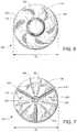
- FIG. 6illustrates a top plan view of an exemplary embodiment of a container, according to the present disclosure
- FIG. 7illustrates a bottom plan view of an exemplary embodiment of a container in accordance with the present disclosure
- FIG. 8illustrates a cross-sectional view along a longitudinal axis of an exemplary embodiment of a base of a container, according to the present disclosure
- FIG. 9illustrates an exemplary embodiment of a preform in which may be blow-molded to form a container in accordance with the present disclosure
- FIG. 10illustrates a cross-sectional view of an exemplary embodiment of a preform, according to the present disclosure
- FIG. 11illustrates a cross-sectional view of a preform in a cavity of an exemplary embodiment of a blow-molding apparatus that may be used to make a bottle or container;
- FIG. 12illustrates an exemplary embodiment of a container formed by way of stretch blow-molding in accordance with the present disclosure.
- the present disclosureprovides an apparatus for a container comprising a base, a bell, a sidewall between the base and the bell, a neck and a finish which define an opening to an interior of the container, and a shoulder between the sidewall and the bell.
- the basecomprises a diameter which is larger than a diameter of the shoulder, such that the base creates a single point of contact with other substantially similar containers in a production line, or in packaging.
- the diameter of the baseis larger than the diameter of the shoulder by 0.5 to 4 millimeters, and preferably by 1 to 2 millimeters.
- Strap ribsextend from a central portion of the base and terminate at the sidewall.
- the strap ribscooperate with vertically aligned recessed columns of the sidewall to resist bending, leaning, crumbling, or stretching along the sidewall and the base.
- An inwardly offset portion of the sidewallis disposed between each pair of adjacent recessed columns.
- three recessed columnsare equally spaced around the perimeter of the sidewall, such that the sidewall comprises a circumference which is offset from a generally circular cross-sectional shape to a substantially triangular cross-sectional shape.
- each of the inwardly offset portionsis offset from 0 to 30 degrees from the circular cross-sectional shape.
- the inwardly offset portions of the sidewallare configured to resist outward bowing of the sidewall due to internal pressure of contents within the container.
- FIG. 1illustrates a bottom perspective view of an exemplary embodiment of a container 100 in accordance with the present disclosure.
- the container 100comprises a base 104 that extends up to a grip portion 108 .
- the grip portion 108comprises a plurality of grip portion ribs 112 (i.e., sidewall ribs). As illustrated in FIG. 1 , the plurality of grip portion ribs 112 generally vary in depth, and swirl or angulate around the grip portion 108 .
- a label portion 116is connected to the grip portion 108 and comprises one or more label panel ribs 120 (i.e., sidewall ribs). The label panel portion 116 transitions into a shoulder 124 , which connects to a bell 128 .
- FIG. 1illustrates a bottom perspective view of an exemplary embodiment of a container 100 in accordance with the present disclosure.
- the container 100comprises a base 104 that extends up to a grip portion 108 .
- the grip portion 108comprises a plurality of
- the bell 128comprises a plurality of design features 132 . In other embodiments, however, the bell 128 may include various other design features, or may be smooth and generally unornamented.
- the bell 128connects to a neck 136 , which connects to a finish 140 . As shown in FIG. 1 , the bell 128 comprises a diameter that generally decreases as the bell 128 extends upward from the shoulder 124 to the neck 136 and the finish 140 .
- the finish 140is adapted to receive a closure, such as by way of non-limiting example, a container cap or bottle cap, so as to seal contents within the container 100 .
- the finish 140generally defines an opening 144 that leads to an interior of the container 100 for containing a beverage, or other contents, such as any of a variety of carbonated soft drinks.
- a substantially vertical sidewallcomprising the grip portion 108 and the label portion 116 between the base 104 and the bell 128 , extending substantially along a longitudinal axis of the container 100 , and defines at least part of the interior of the container 100 .
- the sidewallmay include the bell 128 , the shoulder 124 , and/or the base 104 .
- a perimeter (i.e., periphery) of the sidewallis substantially perpendicular to the longitudinal axis of the container 100 .
- the finish 140 , the neck 136 , the bell 128 , the shoulder 124 , the label portion 116 , the grip portion 108 , and the base 104each comprises a respective perimeter (i.e., periphery) which is substantially perpendicular to the longitudinal axis of the container 100 .
- the label portion 116comprises a label portion perimeter
- the grip portion 108comprises a grip portion perimeter, both of which perimeters being substantially perpendicular to the longitudinal axis of the container 100 .
- each grip portion rib 112comprises a deep rib portion 148 transitioning to a middle rib portion 152 and then transitioning to a shallow rib portion 156 .
- each label portion rib 120comprises a deep rib portion 160 transitioning to a middle rib portion 164 and then transitioning to a shallow rib portion 168 .
- the deep, middle, and shallow rib portionsmay also be referred to as deep, middle, and shallow ribs as a shorthand, but it is to be understood that these terms are intended to define portions of each rib in the grip portion 108 and the label portion 116 .
- the shallow rib portions 156 , 168are vertically aligned with the longitudinal axis of the container 100 .
- the shallow rib portions 156 , 168form an equivalent of recessed columns 172 at portions where the shallow rib portions 156 , 168 substantially vertically line up along the longitudinal axis of the container 100 .
- the deep rib portions 148 , 160are substantially vertically aligned along the vertical or longitudinal axis of the container 100 .
- the embodiment illustrated in FIGS. 1-5comprises three recessed columns 172 and three portions where the deep rib portion 148 , 160 are substantially vertically aligned.
- the shallow rib portions 168 of the label portion 116may be vertically misaligned with the shallow rib portions 156 of the grip portion 108 , such that the label portion 116 has a first set of recessed columns and the grip portion 108 has a second set of recessed columns.
- the container 100may have recessed columns solely in the grip portion 108 or solely in the label panel portion 116 .
- the three recessed columns 172are equally spaced apart around the perimeter of the container 100 and located on an opposite sides of the container perimeter from the deep rib portions 148 , 160 . It will be appreciated that with three equally spaced recessed columns 172 , the recessed columns 172 are spaced substantially every 120 degrees around the circumference of the container 100 . Any number of recessed columns 172 may be incorporated into a design of the container 100 by either increasing or decreasing the number of shallow rib portions 156 , 168 that are substantially vertically aligned along the longitudinal axis of the container 100 . For instance, other embodiments of the container 100 may comprise a number of the recessed columns 172 ranging between 1 and 10 recessed columns.
- the label portion 116may comprise a different number of recessed columns 172 than the grip portion 108 .
- the label portion 116may comprise six equally spaced recessed columns, wherein three are vertically aligned with the recessed columns 172 of the grip portion 108 while the remaining three recessed columns are limited to the label portion 116 .
- the recessed columnsare positioned every 60 degrees around the circumference of the container 100 . More recessed columns can help prevent triangulation of the label portion 116 .
- shallow rib portions coupled with recessed columnsbetter resists radial outward flexing, at least partially because the shallow rib portions possess a relatively smaller radial depth available for flexing.
- shallow rib portions coupled with recessed columnsprovides a greater resistance to internal pressure relative to deep rib portions.
- incorporating more frequent shallow rib portions and/or recessed columns around the circumference of the container 100helps inhibit outward triangulation of the container due to internal pressure of contents within the container.
- the vertical alignment of the shallow rib portions 156 , 168 that foil the recessed columns 172provides resistance to leaning, load crushing, and/or stretching of the container 100 .
- Leaningcan occur when, during and/or after bottle packaging, a bottle, such as the container 100 , experiences top load forces (tangential forces or otherwise) from other bottles and/or other objects stacked on top of the container.
- top load crushingcan occur due to vertical compression (or otherwise) forces from bottles and/or other objects stacked on top.
- Stretchingcan occur when the container is pressurized.
- the recessed columns 172transfer the resulting forces along the sidewall of the container 100 to the base 104 and thus increase rigidity of the container 100 .
- the deep rib portions 148 , 160 of the grip portion ribs 112 and label panel ribs 120provide a hoop strength that can be equivalent to the hoop strength imparted by ribs comprising a uniform depth.
- the number of ribs, including the grip portion ribs 112 , and/or the label panel ribs 120may vary between 1 and 30 ribs positioned, for example, every 10 centimeters along any rib-containing portion of the container 100 , such as, but not necessarily limited to the grip portion 108 and/or the label portion 116 .
- the aforementioned 10-centimeters that is used to measure the number of ribs in a portion of the containerneed not be actually 10 centimeters in length, but rather the 10-centimeters is used illustratively to provide a relationship between the number of ribs incorporated into a given length of a portion of the container.
- the three recessed columns 172operate to prevent outward triangulation of the sidewall of the container 100 , wherein the shallow rib portions 156 , 168 coupled with the recessed columns 172 better resists radial outward flexing of the sidewall of the container 100 .
- the portions of the sidewall between the recessed columns 172are bowed inward, or offset, toward the interior of the container 100 , such that the perimeter of the sidewall is offset from a generally circular cross-sectional shape to a substantially inwardly triangular cross-sectional shape.
- the offset portions of the sidewallmay be offset from 0 to 30 degrees from the circular cross-sectional shape.
- the offset portions of the sidewallare configured to resist outward bowing of the sidewall due to internal pressure when the container 100 is filled with contents, particularly carbonated contents. It is envisioned that outward-directed forces on the sidewall of the container 100 due to internal pressure are counteracted by inward-directed resistance forces produced by the offset portions, such that the pressurized container assumes a substantially circular cross-sectional shape rather than becoming outwardly triangulated, as discussed herein. Thus, incorporating inwardly offset portions between the recessed columns 172 around the perimeter of the container 100 further inhibits outward triangulation of the container.
- the base 104comprises three strap ribs 176 .
- Each of the strap ribs 176comprises a sidewall end 180 that terminates along the sidewall of the container 100 , as discussed herein.
- the base 104comprises six load ribs 184 .
- two load ribs 184are positioned between two strap ribs 176 .
- the base 104may comprise a number of load ribs 184 ranging between 1 and 5 load ribs positioned between two strap ribs 176 .
- Each of the load ribs 184has a sidewall end 188 that terminates along the base 104 at a transition from the base 104 to the sidewall of the container 100 . As illustrated in FIG.
- the sidewall end 188 of the load rib 184is vertically lower than the sidewall end 180 of the strap rib 176 along the longitudinal axis of the container 100 .
- the sidewall end 188 of the load rib 184may terminate along the sidewall of the container 100 at a height which is substantially similar to the height of the sidewall end 180 of the strap rib 176 .
- the base 104comprises feet 192 formed between the strap ribs 176 and the load ribs 184 .
- the strap rib 176is relatively larger and deeper than the load rib 184 , as discussed herein. As illustrated in FIGS. 1-5 , each of the strap ribs 176 is vertically aligned with one of the recessed columns 172 , and thus the strap ribs 176 are spaced equally around the circumference of the container 100 . It will be recognized that with three equally spaced strap ribs 176 , the strap ribs 176 are positioned every 120 degrees around the container circumference.
- the load ribs 184are vertically aligned with the grip portion ribs 112 between the recessed columns 172 . In some embodiments, the strap ribs 176 may be vertically misaligned with the recessed columns 172 .
- the strap ribs 176may be spaced unequally around the circumference of the container 100 .
- the base 104may comprise more or less strap ribs 176 than the number of recessed columns 172 .
- the strap rib 176may be vertically aligned with the deep rib portions 148 , 160 and may terminate into a first deep rib portion 148 (first from the base 104 ).
- the strap rib 176may have a sidewall end 180 that terminates past the first shallow rib portion 156 and/or the first deep rib portion 148 , such as for example at the second, third, and/or fourth grip portion ribs 112 .
- FIG. 3illustrates a rear elevation view of the container 100 .
- the sidewall end 180 of the strap rib 176vertically aligns with, or points to substantially the center of the recessed column 172 , which is coincident with the center point of the shallow rib portion 156 .
- the strap rib 176forms a recess 196 , which is relatively a small area in comparison to the contact area of the feet 192 with a resting surface. Utilizing a small recess 196 aids in distributing more resin toward the feet 192 during the blowing process, which generally increases the abrasion resistance and strength of the feet 192 .
- the strap ribs 176operate to provide internal pressure resistance while leaving enough resin for the feet 192 to achieve the benefits of a flat foot base (i.e., thicker resin feet 192 for greater abrasion, deformation, and/or stress resistance; and/or greater foot contact area for stability and load distribution).
- the strap ribs 176extend substantially from a central portion of the base 104 , coinciding with the longitudinal axis of the container 100 , as discussed herein. As will be appreciated by those skilled in the art, the strap ribs 176 operate as a straps extending between the recessed columns 172 of the sidewall to the central portion of the base 104 . As shown in FIG. 1 , the strap rib 176 provides a more direct and shorter path from the center of the base 104 to the sidewall of the container 100 without proceeding to the vertical level of the feet 192 . As discussed herein, the strap ribs 176 thus provide a relatively more pressure resistant base 104 . Each of the strap ribs 176 provides a link for forces and stresses between the sidewall, including the recessed column 172 , and the central portion of the base 104 .
- FIG. 8illustrates a cross-sectional view along the longitudinal axis of the base 104 of the container 100 .
- the strap rib 176 of the base 104begins at a base end 212 substantially parallel to a resting surface of the base 104 and then extends along a curved path, having a first radius R 1d , with an increasingly positive slope.
- the radius of the curved path of the strap rib 176changes to a second radius R 2d with an increasingly positive slope before extending into a straight portion 220 .
- the straight portion 220connects to the sidewall end 180 as discussed herein.
- the first and second radii R 1d , R 2dmay have dimensional values falling within any of the appropriate ranges of values discussed in detail in U.S. patent application Ser. No. 14/157,400, entitled “Plastic Container With Strapped Base,” filed on Jan. 16, 2014, the entirety of which is incorporated herein by reference and forms a part of the present disclosure.
- the combination of the radii R 1d and R 2dcooperate to give the strap rib 176 , and thus the base 104 , a smooth and gradual, spherical configuration.
- spherical features of the container 100better accommodate internal pressure.
- the spherical configuration of the base 104 depicted in FIG. 1-5is capable of withstanding an internal pressure at least twice the internal pressure tolerable by conventional base configurations.
- the strap rib 176 illustrated in FIG. 8does not include a transition curve between the first radius R 1d and the second radius R 2d , nor between the second radius R 2d and the straight portion 220 .
- a transition curve having a radius other than R 1d and R 2dmay be positioned between the curved portions of the strap rib 176 having radii R 1d and R 2d .
- a transition curvemay be positioned between the curved portion of the strap rib 176 having the second radius R 2d and the straight portion 220 . It is envisioned that the transition curves may have dimensional values that further produce a spherical configuration of the strap rib 176 , and thus the base 104 .
- the base 104comprises a gate 200 surrounded by a dome 204 .
- the dome 204comprises a portion of a wall of the base 104 which slopes more steeply toward a resting surface when the bottle is placed on the resting surface relative to the rest of the wall of the base 104 leading to the feet 192 .
- the strap rib 176comprises a base end 208 that terminates substantially at a periphery of the dome 204 .
- the base end 208 of each strap rib 176may be positioned outside of the dome 204 similarly to base ends 212 of the load ribs 184 .
- Each of the strap ribs 176comprises a pair of rib side walls 216 that connect the strap rib 176 to portions of the base 104 and the feet 192 .
- the rib side wall 216smoothly and gradually transitions into the base 104 and the feet 192 .
- the smooth and gradual transitionprovides internal pressure resistance at and near the rib side wall 216 since more spherical features of the container 100 better accommodate internal pressure.
- the strap rib 176is relatively deeper in the base 104 than the load rib 184 so as to provide stress transfer and pressure resistance, as discussed herein.
- each of the load ribs 184comprises a base end 212 that terminates at, or near the dome 204 .
- the base ends 212 of the load ribs 184terminate before the base ends 180 of the strap ribs 176 .
- the load ribs 184are shallow relative to the strap ribs 176 .
- the load ribs 184each comprises rib side walls that are relatively smaller than the rib side walls 216 , and thus the transition from the load ribs 184 to the base 104 and the feet 192 is more abrupt, or sharper, than in the case of the rib side walls 216 .
- the sharper transitions of the load ribs 184resist bending and/or leaning as discussed herein by, for example, maintaining the integrity and shape of the base 104 .
- the sharper transitions of the load ribs 184provide more area of the base 104 being available for relatively larger feet 192 .
- larger feet 192 of a flat-foot basesuch as the base 104 discussed herein and as illustrated in FIG. 7 , provide more resin contact area with a resting surface, and thus provide better abrasion resistance and stability of the base. As further illustrated in FIG.
- the rib side walls 216generally transition into the strap ribs 176 more abruptly, or sharply, relative to the transition from the rib side walls 216 to the feet 192 .
- the sharper transitions to the strap ribs 176provide more rigidity to the strap ribs so as to resist, or inhibit, flexing due to internal pressures.
- the base ends 208 of the strap ribs 176terminate substantially near the gate 200
- the base ends 212 of the load ribs 184terminate near the periphery of the dome 204 . It will be appreciated that terminating the base ends 208 of the strap ribs 176 and/or the base ends 212 of the load ribs 184 substantially near, or at the gate 200 provides greater internal pressure resistance to the base 104 , as discussed herein, preventing, for example, base rollout.
- terminating each of the base ends 208 substantially near, or at the gate 200provides strap ribs 176 that are substantially continuous from (or near) the gate 200 to the sidewall ends 180 . As shown in FIGS.
- the sidewall ends 180terminate at the first shallow rib portion 156 and communicate directly with the recessed columns 172 .
- the continuity from the recessed columns 172 to the gate 200provides substantially continuous pressure resistance bands, or straps, from a top of the label portion 116 to the gate 200 .
- Pressure resistance straps that are substantially continuousprovide greater resistance to internal pressure, as discussed herein.
- FIG. 6illustrates a top plan view of the container 100 , showing the shoulder 124 , the bell 128 with the design features 132 , the finish 140 , and the opening 144 to the interior of the container.
- the shoulder 124comprises a diameter D S .
- the base 104comprises a diameter D B .
- the diameter D B of the base 104preferably is larger than the diameter D S of the shoulder 124 , such that the base 104 creates a single point of contact with other substantially similar containers in a production line, or in packaging.
- the diameter D B of the base 104is larger by 0.5 to 4 millimeters than any other diameter of the container 100 , including the diameter D S of the shoulder 124 . It will be appreciated that the larger base 104 diameter D B advantageously improves conveying a multiplicity of the container 100 in a production line. Further, the larger base 104 diameter D B advantageously improves stability when there is any damage to the base 104 . In some embodiments, the diameter D S of the shoulder 124 may be equal to the diameter D B of the base 104 , thereby providing two points of contact, at the shoulder 124 and the base 104 , with other substantially similar bottles in a production line, or in packaging.
- the containersgenerally may have either a single point of contact or multiple points of contact.
- FIG. 4illustrates a right side elevation view of container 100 , which shows a plan view of the shallow rib portions 156 , 168 along the right-hand side of the container 100 and a plan view of the deep rib portions 148 , 160 along the left-hand side of the container 100 .
- FIG. 5illustrates a left side elevation view of container 100 , which shows the shallow rib portions 156 , 168 along the left-hand side of the container 100 and the deep rib portions 148 , 160 along the right-hand side of the container 100 .
- the deep rib portions 148 , 160comprise a depth which is larger than a depth of the middle rib portions 152 , 164 which is larger than a depth of the shallow rib portions 156 , 168 .
- a depth of the deep rib portions 148may range from 1 to 10 millimeters.
- a depth of the deep rib portions 160may range from 0.5 to 10 millimeters.
- a depth of the middle rib portions 152may range from 0 to 5 millimeters.
- a ratio of the depth of the deep rib portions 148 to the depth of the middle rib portions 152may vary from 1:1 to 20:1.
- a depth of the shallow rib portions 156may range from 0 to 2.5 millimeters. In some embodiments, a ratio of the depth of the deep rib portions 148 to the depth of the shallow rib portions 156 may vary from 1:1 to 100:1, including where the shallow rib portions 156 have zero depth, resulting in substantially an infinite ratio. In some embodiments, a ratio of the depth of the middle rib portions 152 to the depth of the shallow rib portions 156 may vary from 1:1 to 50:1, including where shallow rib portions 156 have zero depth, resulting in substantially an infinite ratio.
- a depth of the shallow rib portions 168may vary from 0 to 2.5 millimeters. In some embodiments, a ratio of the depth of the deep rib portions 148 to the depth of the shallow rib portions 168 may vary from 1:1 to 100:1, including where the shallow rib portions 168 have zero depth, resulting in substantially an infinite ratio. In some embodiments, a ratio of the depth of the deep rib portions 160 to the depth of the shallow rib portions 168 may range from 1:1 to 100:1, including where the shallow rib portions 168 have zero depth, resulting in substantially an infinite ratio.
- a ratio of the depth of the middle rib portions 152 , 164 to the depth of the shallow rib portions 168may vary from 1:1 to 50:1, including where the depth of the shallow rib portions 168 is zero, resulting in substantially an infinite ratio. In some embodiments, a ratio of the depth of the deep rib portions 160 to the depth of the shallow rib portions 168 may vary from 1:1 to 100:1, including a substantially infinite ratio arising when the shallow rib portions 168 have zero depth.
- Transitions between the various depths of the rib portionsare smooth, as illustrated in FIGS. 1-5 .
- the transitionsmay comprise other forms, such as by way of non-limiting example, a step-change connecting the varying depth portions.
- some embodimentsmay minimize the shallow rib portions 156 , 168 to 20-30% of the circumference of the container 100 , thereby resulting in a respective 70-80%, of the container circumference comprising the deep rib portions 148 , 160 and the middle rib portions 152 , 164 .
- any ratio of shallow rib portions to deep rib portions and middle rib portionsmay be utilized.
- FIG. 9illustrates an exemplary embodiment of a preform 230 which may be blow-molded to form the container 100 .
- the preform 230preferably is made of material approved for contact with food and beverages, such as virgin PET, and may be of any of a wide variety of shapes and sizes.
- the preform 230comprises a neck portion 232 and a body portion 234 , formed monolithically (i.e., as a single, or unitary, structure).
- the monolithic arrangement of the preform 230when blow-molded into a bottle, such as container 100 , provides greater dimensional stability and improved physical properties in comparison to a preform comprising separate neck and body portions, which are bonded together.
- the preform 230may be made by injection molding methods including those that are well known in the art.
- FIG. 10illustrates a cross-sectional view of an exemplary embodiment of the preform 230 which may be used to form the container 100 .
- the neck portion 232 of the preform 230begins at an opening 236 to an interior of the preform 230 and extends to and includes a support ring 238 .
- the neck portion 232is further characterized by the presence of a structure for engaging a closure.
- the structureincludes threads 240 , which provide a means to fasten a cap to the container 100 produced from the preform 230 .
- the illustrated preform 230comprises a shorter overall neck portion than most conventional preforms.
- the neck portion 232 of the preform 230comprises a wall thickness 252 which is generally thinner than in conventional preforms, wherein the wall thickness 252 of the neck portion 232 is measured at the very top or between the threads 240 , or between any other protruding structures.
- the body portion 234is an elongated structure extending down from the neck portion 232 and culminating in an end cap 242 .
- the body portion 234is generally cylindrical, and the end cap 242 is conical or frustoconical, and may also be hemispherical, and the very terminus of the end cap 242 may be flattened or rounded.
- the preform 230comprises a wall thickness 244 throughout most of the body portion 234 which depends upon an overall size of the preform 230 , as well as a predetermined wall thickness and overall size of the resulting container 100 . As illustrated in FIG. 10 , the wall thickness 244 tapers, between 250 and 248, to a wall thickness 246 immediately below the support ring 238 .
- the wall thickness between 244 and 250may further comprise a slight taper so as to facilitates a release of the preform 230 from a core during the injection molding process.
- Specific dimensions of the wall thickness, as well as dimensions of various other features of the preform 230are discussed in detail in U.S. patent application Ser. No. 13/295,699, entitled “Preform Extended Finish for Processing Light Weight Ecologically Beneficial Bottles,” filed on Nov. 14, 2011, the entirety of which is incorporated herein by reference and forms a part of the present disclosure.
- the preform 230may be subjected to a stretch blow-molding process. As illustrated in FIG. 11 , the preform 230 is placed in a mold 260 comprising a cavity corresponding to the desired container shape. The preform 230 is then heated and expanded by stretching such as by way of a stretch rod inserted into the center of the preform 230 to push it to the end of the mold 260 and by way of air forced into the interior of the preform 230 to fill the cavity within the mold 260 , creating a container 264 , as shown in FIG. 12 . As illustrated in FIG. 11 , the preform 230 is placed in a mold 260 comprising a cavity corresponding to the desired container shape. The preform 230 is then heated and expanded by stretching such as by way of a stretch rod inserted into the center of the preform 230 to push it to the end of the mold 260 and by way of air forced into the interior of the preform 230 to fill the cavity within the mold 260 , creating a container 264 , as shown in
- the container 264comprises a neck portion 232 and a body portion 234 corresponding to the neck and body portions of the preform 230 of FIG. 11 .
- the neck portion 232is further characterized by the presence of the threads 240 or other closure engagement means that provides a way to fasten a cap onto the container 264 .
- the blow-molding processnormally is restricted to the body portion 234 of the preform 230 with the neck portion 232 , including the threads 240 and the support ring 238 , retaining the original configuration of the preform 230 .
- the containers 100 , 264 described hereinmay be made from any suitable thermoplastic material, such as polyesters including polyethylene terephthalate (PET), polyolefins, including polypropylene and polyethylene, polycarbonate, polyamides, including nylons (e.g. Nylon 6, Nylon 66, MXD6), polystyrenes, epoxies, acrylics, copolymers, blends, grafted polymers, and/or modified polymers (monomers or portion thereof having another group as a side group, e.g. olefin-modified polyesters). These materials may be used alone or in conjunction with each other.
- PETpolyethylene terephthalate
- polyolefinsincluding polypropylene and polyethylene
- polycarbonatepolyamides, including nylons (e.g. Nylon 6, Nylon 66, MXD6), polystyrenes, epoxies, acrylics, copolymers, blends, grafted polymers, and/or modified
- More specific material examplesinclude, but are not limited to, ethylene vinyl alcohol copolymer (“EVOH”), ethylene vinyl acetate (“EVA”), ethylene acrylic acid (“EAA”), linear low density polyethylene (“LLDPE”), polyethylene 2,6- and 1,5-naphthalate (PEN), polyethylene terephthalate glycol (PETG), poly(cyclohexylenedimethylene terephthalate), polystryrene, cycloolefin, copolymer, poly-4-methylpentene-1, poly(methyl methacrylate), acrylonitrile, polyvinyl chloride, polyvinylidine chloride, styrene acrylonitrile, acrylonitrile-butadiene-styrene, polyacetal, polybutylene terephthalate, ionomer, polysulfone, polytetra-fluoroethylene, polytetramethylene 1,2-dioxybenzoate and copolymers of ethylene terephthalate and ethylene is
- polypropylenealso refers to clarified polypropylene.
- clarified polypropyleneis a broad term and is used in accordance with its ordinary meaning and may include, without limitation, a polypropylene that includes nucleation inhibitors and/or clarifying additives.
- Clarified polypropyleneis a generally transparent material as compared to the homopolymer or block copolymer of polypropylene. The inclusion of nucleation inhibitors helps prevent and/or reduce crystallinity, which contributes to the haziness of polypropylene, within the polypropylene.
- Clarified polypropylenemay be purchased from various sources such as Dow Chemical Co. Alternatively, nucleation inhibitors may be added to polypropylene.
- PETincludes, but is not limited to, modified PET as well as PET blended with other materials.
- IP A-modified PETrefers to PET in which the IPA content is preferably more than about 2% by weight, including about 2-10% IP A by weight, also including about 5-10% IP A by weight.
- CHDMcylohexane dimethanol
Landscapes
- Engineering & Computer Science (AREA)
- Ceramic Engineering (AREA)
- Mechanical Engineering (AREA)
- Containers Having Bodies Formed In One Piece (AREA)
Abstract
Description
Claims (10)
Priority Applications (4)
| Application Number | Priority Date | Filing Date | Title |
|---|---|---|---|
| US16/012,029US11220368B2 (en) | 2012-12-27 | 2018-06-19 | Swirl bell bottle with wavy ribs |
| US17/095,130US11845581B2 (en) | 2011-12-05 | 2020-11-11 | Swirl bell bottle with wavy ribs |
| US18/094,233US12195225B2 (en) | 2011-12-05 | 2023-01-06 | Swirl bell bottle with wavy ribs |
| US18/543,104US20240270435A1 (en) | 2011-12-05 | 2023-12-18 | Swirl bell bottle with wavy ribs |
Applications Claiming Priority (5)
| Application Number | Priority Date | Filing Date | Title |
|---|---|---|---|
| US201261746535P | 2012-12-27 | 2012-12-27 | |
| US14/141,224US9132933B2 (en) | 2012-12-27 | 2013-12-26 | Plastic container with strapped base |
| US14/157,400US9120589B2 (en) | 2012-12-27 | 2014-01-16 | Plastic container with strapped base |
| US14/610,940US10023346B2 (en) | 2012-12-27 | 2015-01-30 | Swirl bell bottle with wavy ribs |
| US16/012,029US11220368B2 (en) | 2012-12-27 | 2018-06-19 | Swirl bell bottle with wavy ribs |
Related Parent Applications (1)
| Application Number | Title | Priority Date | Filing Date |
|---|---|---|---|
| US14/610,940ContinuationUS10023346B2 (en) | 2011-12-05 | 2015-01-30 | Swirl bell bottle with wavy ribs |
Related Child Applications (1)
| Application Number | Title | Priority Date | Filing Date |
|---|---|---|---|
| US17/095,130Continuation-In-PartUS11845581B2 (en) | 2011-12-05 | 2020-11-11 | Swirl bell bottle with wavy ribs |
Publications (2)
| Publication Number | Publication Date |
|---|---|
| US20180297741A1 US20180297741A1 (en) | 2018-10-18 |
| US11220368B2true US11220368B2 (en) | 2022-01-11 |
Family
ID=53181726
Family Applications (2)
| Application Number | Title | Priority Date | Filing Date |
|---|---|---|---|
| US14/610,940ActiveUS10023346B2 (en) | 2011-12-05 | 2015-01-30 | Swirl bell bottle with wavy ribs |
| US16/012,029ActiveUS11220368B2 (en) | 2011-12-05 | 2018-06-19 | Swirl bell bottle with wavy ribs |
Family Applications Before (1)
| Application Number | Title | Priority Date | Filing Date |
|---|---|---|---|
| US14/610,940ActiveUS10023346B2 (en) | 2011-12-05 | 2015-01-30 | Swirl bell bottle with wavy ribs |
Country Status (1)
| Country | Link |
|---|---|
| US (2) | US10023346B2 (en) |
Cited By (6)
| Publication number | Priority date | Publication date | Assignee | Title |
|---|---|---|---|---|
| USD958659S1 (en)* | 2020-10-05 | 2022-07-26 | Niagara Bottling, Llc | Bottle |
| US11623781B2 (en)* | 2017-02-14 | 2023-04-11 | Basf Se | Container with corrugations |
| USD1046625S1 (en) | 2022-07-11 | 2024-10-15 | Krones Inc. | Container |
| US12195225B2 (en) | 2011-12-05 | 2025-01-14 | Niagara Bottling, Llc | Swirl bell bottle with wavy ribs |
| US12195227B2 (en) | 2022-07-11 | 2025-01-14 | Krones Inc. | Container having gussets |
| US12246878B2 (en) | 2011-12-05 | 2025-03-11 | Niagara Bottling, Llc | Plastic container with varying depth ribs |
Families Citing this family (33)
| Publication number | Priority date | Publication date | Assignee | Title |
|---|---|---|---|---|
| CA3037324A1 (en) | 2010-11-12 | 2012-05-18 | Niagara Bottling, Llc | Preform extended finish for processing light weight bottles |
| US10647465B2 (en) | 2010-11-12 | 2020-05-12 | Niagara Bottling, Llc | Perform extended finish for processing light weight ecologically beneficial bottles |
| US10532848B2 (en) | 2011-08-31 | 2020-01-14 | Amcor Rigid Plastics Usa, Llc | Lightweight container base |
| US10538357B2 (en) | 2011-08-31 | 2020-01-21 | Amcor Rigid Plastics Usa, Llc | Lightweight container base |
| MX353418B (en) | 2011-08-31 | 2018-01-11 | Amcor Group Gmbh | Lightweight container base. |
| US10023346B2 (en) | 2012-12-27 | 2018-07-17 | Niagara Bottling, Llc | Swirl bell bottle with wavy ribs |
| DE102012003219B4 (en) | 2012-02-20 | 2025-06-26 | Krones Ag | plastic container |
| CH707262A2 (en)* | 2012-11-30 | 2014-05-30 | Alpla Werke | Plastic container. |
| JP6321034B2 (en) | 2012-12-27 | 2018-05-09 | ナイアガラ・ボトリング・リミテツド・ライアビリテイー・カンパニー | Plastic container with strap-like base |
| USD748482S1 (en)* | 2014-02-10 | 2016-02-02 | Plastipak Packaging, Inc. | Plastic container |
| USD763092S1 (en)* | 2014-02-10 | 2016-08-09 | Plastipak Packaging, Inc. | Plastic container |
| USD749954S1 (en)* | 2014-05-21 | 2016-02-23 | Plastipak Packaging, Inc. | Plastic container |
| USD755636S1 (en)* | 2014-07-11 | 2016-05-10 | Niagara Bottling, Llc | Short swirl bell bottle with straight ribs |
| WO2016016372A1 (en)* | 2014-07-30 | 2016-02-04 | S.I.P.A. Societa' Industrializzazione Progettazione E Automazione S.P.A. | Container with pressure variation compensation |
| USD790974S1 (en)* | 2016-07-11 | 2017-07-04 | Niagara Bottling, Llc | Bottle |
| DE102016115646A1 (en)* | 2016-08-23 | 2018-03-15 | Krones Ag | Plastic bottle with crossing drawstrings |
| CA3041890A1 (en)* | 2016-11-14 | 2018-05-17 | Amcor Rigid Plastics Usa, Llc | Lightweight container base |
| US11718439B2 (en)* | 2018-05-11 | 2023-08-08 | Amcor Rigid Packaging Usa, Llc | Container pressure base |
| CN112105563B (en)* | 2018-05-31 | 2023-07-28 | 雀巢产品有限公司 | Container |
| USD872581S1 (en)* | 2018-06-04 | 2020-01-14 | Société des Produits Nestlé S.A. | Container |
| US11597556B2 (en) | 2018-07-30 | 2023-03-07 | Niagara Bottling, Llc | Container preform with tamper evidence finish portion |
| AU2019312561B2 (en) | 2018-07-30 | 2025-05-29 | Niagara Bottling, Llc | Container preform with threaded tamper evidence finish |
| US20200031020A1 (en)* | 2018-07-30 | 2020-01-30 | Niagara Bottling, Llc | Blank container preform |
| USD908502S1 (en)* | 2018-10-09 | 2021-01-26 | Société des Produits Nestlé S.A. | Bottle |
| USD871222S1 (en)* | 2019-05-16 | 2019-12-31 | Société des Produits Nestlé S.A. | Bottle |
| USD900616S1 (en)* | 2019-05-24 | 2020-11-03 | Taiwan First Biotechnology Corp. | Bottle |
| USD918043S1 (en) | 2019-06-17 | 2021-05-04 | S. C. Johnson & Son, Inc. | Bottle |
| USD924064S1 (en)* | 2019-06-17 | 2021-07-06 | S. C. Johnson & Son, Inc. | Bottle |
| GB2636920A (en)* | 2020-11-11 | 2025-07-02 | Niagara Bottling Llc | Swirl bell bottle with wavy ribs |
| USD959273S1 (en)* | 2021-01-05 | 2022-08-02 | The Coca-Cola Company | Bottle |
| CA3211856A1 (en)* | 2021-02-26 | 2022-09-01 | The Coca-Cola Company | Bottle with a ripple panel |
| CA3211715A1 (en) | 2021-03-12 | 2022-09-15 | Peter N. Bruinooge | Container preform |
| US20240010410A1 (en)* | 2022-07-05 | 2024-01-11 | Co2Pac Limited | Plastic container having a rigidified sinusoidal channel structure |
Citations (226)
| Publication number | Priority date | Publication date | Assignee | Title |
|---|---|---|---|---|
| US3029963A (en) | 1958-01-22 | 1962-04-17 | Evers Heinz | Bottle |
| US3438578A (en) | 1967-06-01 | 1969-04-15 | Union Carbide Corp | Flexible drinking tube |
| USD249121S (en) | 1976-08-30 | 1978-08-29 | Owens-Illinois, Inc. | Jar |
| US4170622A (en) | 1977-05-26 | 1979-10-09 | Owens-Illinois, Inc. | Method of making a blown hollow article having a ribbed interior surface |
| JPS5632016U (en) | 1979-08-20 | 1981-03-28 | ||
| US4316551A (en) | 1980-02-25 | 1982-02-23 | Belokin Jr Paul | Aluminum container |
| US4374878A (en) | 1979-06-11 | 1983-02-22 | Plm Aktiebolag | Blank adapted to be blown into a container and providing orientation of the material in the mouth and neck as well as the body |
| USD294462S (en) | 1985-07-30 | 1988-03-01 | Yoshino Kogyosho Co., Ltd. | Container wall |
| JPS6368095A (en) | 1986-06-12 | 1988-03-26 | イミュネックス・コ−ポレ−ション | Functional recombinant polypeptide analogue lacking in hydrophobic amino acid |
| US4756439A (en) | 1987-12-23 | 1988-07-12 | Perock Michael J | Container with integral washboard |
| US4818575A (en) | 1986-02-28 | 1989-04-04 | Toyo Seikan Kaisha, Ltd. | Biaxially drawn polyester vessel having resistance to heat distortion and gas barrier properties and process for preparation thereof |
| US4847129A (en) | 1988-09-16 | 1989-07-11 | Continental Pet Technologies, Inc. | Multilayer preform for hot fill containers |
| US4863046A (en) | 1987-12-24 | 1989-09-05 | Continental Pet Technologies, Inc. | Hot fill container |
| US4907709A (en) | 1987-11-11 | 1990-03-13 | Dainippon Ink And Chemicals, Inc. | Combination of synthetic resin bottle and closure therefor |
| US4997692A (en) | 1982-01-29 | 1991-03-05 | Yoshino Kogyosho Co., Ltd. | Synthetic resin made thin-walled bottle |
| USD315869S (en) | 1989-01-11 | 1991-04-02 | Continental Pet Technologies, Inc. | Container body for liquids or the like |
| USD321830S (en) | 1989-06-01 | 1991-11-26 | Hoover Universal, Inc. | Container bottom |
| US5067622A (en) | 1989-11-13 | 1991-11-26 | Van Dorn Company | Pet container for hot filled applications |
| US5092475A (en) | 1991-06-28 | 1992-03-03 | Continental Pet Technologies, Inc. | Reinforced and paneled hot fill container |
| US5133468A (en) | 1991-06-14 | 1992-07-28 | Constar Plastics Inc. | Footed hot-fill container |
| US5178289A (en) | 1992-02-26 | 1993-01-12 | Continental Pet Technologies, Inc. | Panel design for a hot-fillable container |
| US5199588A (en) | 1988-04-01 | 1993-04-06 | Yoshino Kogyosho Co., Ltd. | Biaxially blow-molded bottle-shaped container having pressure responsive walls |
| US5255889A (en) | 1991-11-15 | 1993-10-26 | Continental Pet Technologies, Inc. | Modular wold |
| US5281387A (en) | 1992-07-07 | 1994-01-25 | Continental Pet Technologies, Inc. | Method of forming a container having a low crystallinity |
| USD345693S (en) | 1992-03-20 | 1994-04-05 | The Coca-Cola Company | Bottle |
| US5303833A (en) | 1988-04-20 | 1994-04-19 | Yoshino Kogyosho Co., Ltd. | Blow-molded bottle-shaped container made of synthetic resin |
| US5337909A (en) | 1993-02-12 | 1994-08-16 | Hoover Universal, Inc. | Hot fill plastic container having a radial reinforcement rib |
| US5341946A (en) | 1993-03-26 | 1994-08-30 | Hoover Universal, Inc. | Hot fill plastic container having reinforced pressure absorption panels |
| USD352238S (en) | 1993-03-26 | 1994-11-08 | Hoover Universal, Inc. | Container sidewall |
| USD352245S (en) | 1993-02-18 | 1994-11-08 | Continental Pet Technologies, Inc. | Vacuum panel container |
| US5381910A (en) | 1989-07-10 | 1995-01-17 | Yoshino Kogysho Co., Ltd. | Synthetic resin bottle-shaped container |
| US5407086A (en) | 1992-08-21 | 1995-04-18 | Yoshino Kogyosho Co., Ltd. | Bottle |
| USD358766S (en) | 1993-03-26 | 1995-05-30 | Hoover Universal, Inc. | Container sidewall |
| JPH07164436A (en) | 1993-12-13 | 1995-06-27 | Denki Kagaku Kogyo Kk | Synthetic resin bottle and production thereof |
| USD364565S (en) | 1993-03-26 | 1995-11-28 | Hoover Universal, Inc. | Container sidewall |
| USD366416S (en) | 1995-03-01 | 1996-01-23 | Graham Packaging Corporation | Container sidewall and base |
| USD366417S (en) | 1995-03-01 | 1996-01-23 | Graham Packaging Corporation | Container sidewall and base |
| US5632397A (en) | 1993-09-21 | 1997-05-27 | Societe Anonyme Des Eaux Minerales D'evian | Axially-crushable bottle made of plastics material, and tooling for manufacturing it |
| JPH09240647A (en) | 1996-03-07 | 1997-09-16 | Lion Corp | Thin plastic bottles |
| US5669520A (en) | 1996-03-25 | 1997-09-23 | Simpson; Bernice | Flexible neck baby bottle |
| US5704503A (en) | 1994-10-28 | 1998-01-06 | Continental Pet Technologies, Inc. | Hot-fillable plastic container with tall and slender panel section |
| JPH1029614A (en) | 1996-07-15 | 1998-02-03 | Toyo Seikan Kaisha Ltd | Plastic bottle |
| USD391168S (en) | 1996-07-11 | 1998-02-24 | Graham Packaging Corporation | Reinforced container dome |
| USD393802S (en) | 1997-01-02 | 1998-04-28 | Continental Pet Technologies, Inc. | Container with waist ribs |
| US5762221A (en) | 1996-07-23 | 1998-06-09 | Graham Packaging Corporation | Hot-fillable, blow-molded plastic container having a reinforced dome |
| US5785197A (en) | 1996-04-01 | 1998-07-28 | Plastipak Packaging, Inc. | Reinforced central base structure for a plastic container |
| USD397614S (en) | 1996-04-19 | 1998-09-01 | Snapple Beverage Corporation | Bottle |
| USD402895S (en) | 1997-04-03 | 1998-12-22 | Yoshino Kogyosho Co., Ltd. | Container with handle |
| USD404308S (en) | 1997-04-03 | 1999-01-19 | Yoshino Kogyosho Co., Ltd. | Container with handle |
| US5888598A (en) | 1996-07-23 | 1999-03-30 | The Coca-Cola Company | Preform and bottle using pet/pen blends and copolymers |
| USD407649S (en) | 1995-12-21 | 1999-04-06 | Abbott Laboratories | Bottle for a nutritional product |
| USD407650S (en) | 1997-04-03 | 1999-04-06 | Yoshino Kogyosho Co., Ltd. | Container with handle |
| US5908128A (en) | 1995-07-17 | 1999-06-01 | Continental Pet Technologies, Inc. | Pasteurizable plastic container |
| USD411453S (en) | 1996-04-19 | 1999-06-22 | Snapple Beverage Corporation | Bottle |
| USD413519S (en) | 1998-05-01 | 1999-09-07 | Crown Cork & Seal Technologies Corporation | Container |
| US5971184A (en) | 1997-10-28 | 1999-10-26 | Continental Pet Technologies, Inc. | Hot-fillable plastic container with grippable body |
| US5988417A (en) | 1997-11-12 | 1999-11-23 | Crown Cork & Seal Technologies Corporation | Plastic container having improved rigidity |
| US6016932A (en) | 1995-05-31 | 2000-01-25 | Schmalbach-Lubeca Ag | Hot fill containers with improved top load capabilities |
| USD419882S (en) | 1996-04-19 | 2000-02-01 | Snapple Beverage Corporation | Bottle |
| USD420592S (en) | 1996-04-19 | 2000-02-15 | Snapple Beverage Corporation | Bottle |
| US6036037A (en) | 1998-06-04 | 2000-03-14 | Twinpak Inc. | Hot fill bottle with reinforced hoops |
| US6044996A (en) | 1995-10-19 | 2000-04-04 | Amcor Limited | Hot fill container |
| US6044997A (en) | 1998-06-12 | 2000-04-04 | Graham Packaging Company L. P. | Grip dome container |
| USD423365S (en) | 1998-05-01 | 2000-04-25 | Crown Cork & Seal Technologies Corporation | Container |
| US6062409A (en) | 1997-12-05 | 2000-05-16 | Crown Cork & Seal Technologies Corporation | Hot fill plastic container having spaced apart arched ribs |
| USD426460S (en) | 1997-10-21 | 2000-06-13 | Stokely-Van Camp, Inc. | Bottle |
| USD427649S (en) | 1999-06-11 | 2000-07-04 | Hop Lee Cheong Industrial Company Limited | Toy drawing table |
| USD427905S (en) | 1998-05-01 | 2000-07-11 | Crown Cork & Seal Technologies Corporation | Plastic container |
| US6092688A (en) | 1998-05-06 | 2000-07-25 | Crown Cork & Seal Technologies Corporation | Drainage ports for plastic containers |
| US6095360A (en) | 1998-10-21 | 2000-08-01 | Crown Cork & Seal Technologies Corporation | Vertical-rib reinforced bottle |
| USD430493S (en) | 1999-01-06 | 2000-09-05 | Tropicana Products, Inc. | Beverage container |
| US6112925A (en) | 1997-02-21 | 2000-09-05 | Continental Pet Technologies, Inc. | Enhanced shelf-life pressurized container with ribbed appearance |
| US6149024A (en) | 1994-04-29 | 2000-11-21 | Constar, Inc. | Plastic bottle having enhanced sculptured surface appearance |
| USD434330S (en) | 1999-04-13 | 2000-11-28 | Stokely-Van Camp, Inc. | Bottle |
| USD440158S1 (en) | 1999-03-26 | 2001-04-10 | Stokely-Van Camp, Inc. | Bottle |
| USD440157S1 (en) | 1999-03-26 | 2001-04-10 | Stokely-Van Camp, Inc. | Bottle |
| USD440877S1 (en) | 1999-03-26 | 2001-04-24 | Stokely-Van Camp, Inc. | Bottle |
| USD441294S1 (en) | 1999-03-26 | 2001-05-01 | Stokely-Van Camp, Inc. | Bottle |
| US6230912B1 (en) | 1999-08-12 | 2001-05-15 | Pechinery Emballage Flexible Europe | Plastic container with horizontal annular ribs |
| US6248413B1 (en) | 1996-03-07 | 2001-06-19 | Sipa S.P.A. | Thermoplastic-resin parisons and related manufacturing process |
| US6257433B1 (en) | 1998-06-12 | 2001-07-10 | Graham Packaging Company, L.P. | Grip dome container |
| USD445033S1 (en) | 1995-07-27 | 2001-07-17 | Stokely-Van Camp, Inc. | Bottle |
| USD446126S1 (en) | 1999-03-26 | 2001-08-07 | Stokely-Van Camp, Inc. | Bottle |
| US20010027978A1 (en) | 2000-06-30 | 2001-10-11 | Finlay Patrick J. | Container with structural ribs |
| US20010030166A1 (en) | 2000-01-25 | 2001-10-18 | Yoshino Kogyosho Co., Ltd. | Plastic bottle |
| USD452655S1 (en) | 2000-07-28 | 2002-01-01 | Berlin Packaging, Inc. | Glass bottle |
| USD454500S1 (en) | 1999-03-26 | 2002-03-19 | Stokely-Van Camp, Inc. | Bottle |
| USD465158S1 (en) | 2001-06-28 | 2002-11-05 | Ball Corporation | Plastic container |
| USD466021S1 (en) | 2001-06-08 | 2002-11-26 | Pechiney Emballage Flexible Europe | Container |
| USD466819S1 (en) | 2000-12-27 | 2002-12-10 | Plastipak Packaging, Inc. | Bottle body portion |
| US6494333B2 (en) | 1999-07-30 | 2002-12-17 | Yoshino Kogyosho Co., Ltd. | Heat-resistant hollow container |
| USD469359S1 (en) | 2001-08-07 | 2003-01-28 | Welch Foods Inc. | Beverage container |
| USD469358S1 (en) | 2001-08-07 | 2003-01-28 | Welch Foods Inc. | Beverage container |
| USD469695S1 (en) | 2001-08-07 | 2003-02-04 | Welch Foods Inc. | Beverage container |
| USD469696S1 (en) | 2001-08-07 | 2003-02-04 | Welch Foods Inc. | Beverage container |
| US6554146B1 (en) | 2002-01-17 | 2003-04-29 | Owens-Brockway Plastic Products Inc. | Single serve plastic container and package incorporating same |
| US6585125B1 (en) | 2002-07-03 | 2003-07-01 | Ball Corporation | Hot fill container with vertically asymmetric vacuum panels |
| US6616001B2 (en) | 2001-01-31 | 2003-09-09 | Yoshino Kogyosho Co., Ltd. | Bottle-type plastic container with reinforced vacuum absorption panel in grip region |
| US20040000533A1 (en) | 2002-07-01 | 2004-01-01 | Satya Kamineni | Pressurizable container |
| JP2004090425A (en) | 2002-08-30 | 2004-03-25 | Aoki Technical Laboratory Inc | Preform having thin wall thickness and injection stretch blow molding method |
| US6722514B2 (en) | 2000-08-03 | 2004-04-20 | Playtex Products, Inc. | Easy to hold container |
| FR2846946A1 (en) | 2002-11-12 | 2004-05-14 | Gervais Danone Sa | Reduced weight, threaded neck for plastic bottle used to contain still drinks such as water has threaded portion, intermediate portion and lower portion with same thickness that is 0.75-0.9 times thickness of upper portion |
| US6739467B2 (en) | 2000-11-27 | 2004-05-25 | Yoshino Kogyosho Co., Ltd. | Bottle-type plastic container |
| WO2004080828A1 (en) | 2003-03-12 | 2004-09-23 | Constar International Inc. | Container exhibiting improved top load performance |
| US6830158B2 (en) | 2002-03-07 | 2004-12-14 | Graham Packaging Company, L.P. | Plastic container having depressed grip sections |
| US6841262B1 (en) | 2000-02-03 | 2005-01-11 | Dtl Technology Limited Partnership | Hand grippable bottle and preform |
| USD504063S1 (en) | 2002-10-18 | 2005-04-19 | Stokely-Van Camp, Inc. | Bottle |
| USD506676S1 (en) | 2002-10-18 | 2005-06-28 | Stokely-Van Camp, Inc. | Bottle |
| USD506677S1 (en) | 2002-10-18 | 2005-06-28 | Stokely-Van Camp, Inc. | Bottle |
| USD507609S1 (en) | 2002-10-18 | 2005-07-19 | Stokely-Van Camp, Inc. | Bottle |
| US6932230B2 (en) | 2003-08-15 | 2005-08-23 | Plastipak Packaging, Inc. | Hollow plastic bottle including vacuum panels |
| US6974047B2 (en) | 2002-12-05 | 2005-12-13 | Graham Packaging Company, L.P. | Rectangular container with cooperating vacuum panels and ribs on adjacent sides |
| WO2006005413A1 (en) | 2004-07-08 | 2006-01-19 | Alpla-Werke Alwin Lehner Gmbh & Co.Kg | Plastic container, especially plastic bottle, having a handle part molded onto it, preform and method for producing said plastic bottle |
| JP2006016076A (en) | 2004-05-31 | 2006-01-19 | Yoshino Kogyosho Co Ltd | Synthetic resin blow molded bottle |
| WO2006027092A1 (en) | 2004-09-10 | 2006-03-16 | Alpla-Werke Alwin Lehner Gmbh & Co. Kg | Method for producing a plastic bottle, and preform and blowing mold suited therefor |
| US7017763B2 (en) | 2002-07-24 | 2006-03-28 | Graham Packaging Company, L.P. | Base having a flexible vacuum area |
| US20060070977A1 (en) | 2004-10-01 | 2006-04-06 | Graham Packaging Company, L.P. | Oval container |
| US7025219B2 (en) | 2003-10-31 | 2006-04-11 | Graham Packaging Company, L.P. | Multi-purpose grippable bell |
| US7051892B1 (en) | 2003-10-28 | 2006-05-30 | O'day Jr William R | Water bottle for a dispenser |
| US20060113274A1 (en) | 2004-12-01 | 2006-06-01 | Graham Packaging Company, L.P. | Vacuum panel base |
| US20060131257A1 (en) | 2004-12-20 | 2006-06-22 | Ball Corporation | Plastic container with champagne style base |
| WO2006067590A1 (en) | 2004-12-24 | 2006-06-29 | Acqua Minerale S. Benedetto -S.P.A. | Plastic bottle base |
| US20060157439A1 (en) | 2005-01-14 | 2006-07-20 | Graham Packaging Company, L.P. | Three panel grippable container |
| USD525530S1 (en) | 2005-07-21 | 2006-07-25 | Ball Corporation | Bottle |
| US20060186083A1 (en) | 2005-02-24 | 2006-08-24 | Joshi Rohit V | Circumferential stiffening rib for hot-fill containers |
| USD527643S1 (en) | 2004-08-04 | 2006-09-05 | Container Corporation International Inc. | Bottle |
| US7172087B1 (en) | 2003-09-17 | 2007-02-06 | Graham Packaging Company, Lp | Squeezable container and method of manufacture |
| USD538660S1 (en) | 2005-01-31 | 2007-03-20 | Ball Corporation | Container |
| WO2007033722A1 (en) | 2005-09-20 | 2007-03-29 | Alpla-Werke Alwin Lehner Gmbh & Co. Kg | Preform for pet bottles |
| US7198164B2 (en) | 2003-03-31 | 2007-04-03 | Graham Packaging Company, L.P. | Hot-fillable container with a waisted dome |
| US20070131644A1 (en) | 2004-03-04 | 2007-06-14 | Melrose David M | Headspace sealing and displacement method for removal of vacuum pressure |
| US20070145000A1 (en) | 2003-12-22 | 2007-06-28 | Musalek Oto | Plastic collapsible bottle with accordion-like arranged bellows ridges |
| USD548106S1 (en) | 2005-11-11 | 2007-08-07 | Pepsico. Inc. | Bottle |
| US7258244B2 (en) | 2004-10-04 | 2007-08-21 | Graham Packaging Company L.P. | Hot-fill plastic container and method of manufacture |
| US7267242B2 (en) | 2001-09-26 | 2007-09-11 | Yoshino Kogyosho Co., Ltd. | Bottle-shaped container including an annular projection |
| USD551081S1 (en) | 2005-02-14 | 2007-09-18 | Otsuka Pharmaceutical Co., Ltd. | Bottle |
| FR2899204A1 (en) | 2006-04-04 | 2007-10-05 | Eaux Minerales D Evian Saeme S | Plastic bottle for containing e.g. still water, has gripping portion with grip panels arranged in parallel manner with respect to central axis at distance from each other for gripping hands, where panels have specific height in median zone |
| WO2007124894A1 (en) | 2006-05-01 | 2007-11-08 | Alpla Werke Alwin Lehner Gmbh & Co. Kg | Procedure for the manufacturing of a plastic container, preform for the manufacturing of a plastic container, and plastic container |
| USD555499S1 (en) | 2006-07-03 | 2007-11-20 | Ball Corporation | Container label panel |
| US7334696B2 (en) | 2002-06-21 | 2008-02-26 | Yoshino Kogyosho Co., Ltd. | Square sectioned synthetic resin container |
| US7334695B2 (en) | 2003-09-10 | 2008-02-26 | Graham Packaging Company, L.P. | Deformation resistant panels |
| US7347339B2 (en) | 2004-04-01 | 2008-03-25 | Constar International, Inc. | Hot-fill bottle having flexible portions |
| US20080073315A1 (en)* | 2006-09-22 | 2008-03-27 | Sidel Participations | Container with an at least partially triangular prismatic body |
| US20080173614A1 (en) | 2007-01-18 | 2008-07-24 | The Coca-Cola Company | Beverage container having a modified shape |
| US20080197105A1 (en) | 2005-07-12 | 2008-08-21 | Sidel Participations | Container, in Particular a Bottle, Made of Thermoplastic Material |
| JP2008189721A (en) | 2007-02-01 | 2008-08-21 | Mitsubishi Chemicals Corp | Polyester molded product and method for producing the same |
| US7416090B2 (en) | 2004-10-08 | 2008-08-26 | Constar International Inc. | Round type hot fillable container with deformable label panel |
| US7416089B2 (en) | 2004-12-06 | 2008-08-26 | Constar International Inc. | Hot-fill type plastic container with reinforced heel |
| US20080223816A1 (en) | 2007-03-16 | 2008-09-18 | Plastipak Packaging, Inc. | Plastic container with elongated vertical formation |
| US20080257855A1 (en) | 2007-04-19 | 2008-10-23 | Graham Packaging Company, Lp | Preform Base and Method of Making a Delamination and Crack Resistant Multilayer Container Base |
| USD579339S1 (en) | 2006-01-25 | 2008-10-28 | Stokely-Van Camp, Inc. | Bottle |
| WO2008130987A1 (en) | 2007-04-16 | 2008-10-30 | Constar International, Inc. | Container having vacuum compensation elements |
| US7445826B2 (en) | 1992-07-07 | 2008-11-04 | Graham Packaging Pet Technologies Inc. | Container with high-crystallinity sidewall and low-crystallinity base |
| DE202008012290U1 (en) | 2008-09-15 | 2008-11-20 | Krones Ag | Plastic container |
| US7455189B2 (en) | 2005-08-22 | 2008-11-25 | Amcor Limited | Rectangular hot-filled container |
| USD584627S1 (en) | 2005-10-17 | 2009-01-13 | Sidel Participations | Bottle |
| US20090020497A1 (en) | 2005-08-23 | 2009-01-22 | Yoshino Kogyosho Co., Ltd. | Bottle |
| US20090057263A1 (en)* | 2007-08-31 | 2009-03-05 | Barker Steven P | Hot fill container |
| JP2009045877A (en) | 2007-08-22 | 2009-03-05 | Dainippon Printing Co Ltd | Preform for plastic bottle molding |
| US20090065468A1 (en) | 2005-05-10 | 2009-03-12 | Suntory Limited | Resin-made storage container |
| US7543713B2 (en) | 2001-04-19 | 2009-06-09 | Graham Packaging Company L.P. | Multi-functional base for a plastic, wide-mouth, blow-molded container |
| US20090159556A1 (en) | 2003-05-23 | 2009-06-25 | Amcor Limited | Container base structure responsive to vacuum related forces |
| US20090166314A1 (en) | 2007-12-28 | 2009-07-02 | The Coca-Cola Company | Plastic bottle |
| US20090184127A1 (en) | 2006-05-22 | 2009-07-23 | Mooney Michael R | Circumferential rib |
| USD598779S1 (en) | 2007-03-15 | 2009-08-25 | Sidel Participations | Bottle |
| US20090261058A1 (en) | 2008-04-17 | 2009-10-22 | Graham Packaging Company, L.P. | Volumetrically Efficient Hot-Fill Type Container |
| US20090261059A1 (en) | 2008-04-17 | 2009-10-22 | Graham Packaging Company, L.P. | Volumetrically Efficient Hot-Fill Type Container |
| US20090283495A1 (en) | 2008-05-14 | 2009-11-19 | Amcor Limited | Hot-fill container |
| US20090308835A1 (en) | 2008-06-13 | 2009-12-17 | Sidel Participations | Container, in particular a bottle, made of a thermoplastic material, provided with a reinforced base |
| US20090321383A1 (en) | 2008-06-30 | 2009-12-31 | Lane Michael T | Single serve container |
| US20100028577A1 (en) | 2006-10-24 | 2010-02-04 | Alpla Werke Alwin Lehner Gmby & Co. Kg | Preform for the production of biaxially extended plastic bottles and plastic bottle produced from a preform |
| USD610015S1 (en) | 2008-06-06 | 2010-02-16 | Graham Packaging Company, L.P. | Container |
| JP2010036942A (en) | 2008-08-01 | 2010-02-18 | Dainippon Printing Co Ltd | Plastic bottle |
| US20100072165A1 (en)* | 2008-09-15 | 2010-03-25 | Alexander Schau | Plastic container |
| US7694842B2 (en) | 1999-02-25 | 2010-04-13 | David Murray Melrose | Container having pressure responsive panels |
| US20100089856A1 (en) | 2008-10-10 | 2010-04-15 | Rebecca Dinerstein | Jar |
| US7699183B2 (en) | 2007-04-09 | 2010-04-20 | The Coca-Cola Company | Square bottle manufactured from synthetic resin |
| US20100155359A1 (en) | 2008-12-23 | 2010-06-24 | Simon John B | Hot-fill container |
| US20100163513A1 (en) | 2008-12-31 | 2010-07-01 | Plastipak Packaging, Inc. | Hot-fillable plastic container with flexible base feature |
| US7748552B2 (en) | 2005-01-14 | 2010-07-06 | Ball Corporation | Plastic container with horizontally oriented panels |
| US7748551B2 (en) | 2005-02-18 | 2010-07-06 | Ball Corporation | Hot fill container with restricted corner radius vacuum panels |
| US20100176081A1 (en) | 2007-03-16 | 2010-07-15 | Constar International Inc. | Container having meta-stable panels |
| US7757874B2 (en) | 2007-01-18 | 2010-07-20 | Ball Corporation | Flex surface for hot-fillable bottle |
| USD621271S1 (en) | 2008-09-24 | 2010-08-10 | Parle Agro Private Limited | Bottle |
| US20100206838A1 (en) | 2009-02-18 | 2010-08-19 | Mast Luke A | Hot-fill container |
| US20100206892A1 (en) | 2009-02-18 | 2010-08-19 | Mast Luke A | Hot-Fill Container |
| US20100206839A1 (en) | 2007-10-17 | 2010-08-19 | Yoshino Kogyosho Co., Ltd. | Bottle |
| US20100206837A1 (en) | 2009-02-18 | 2010-08-19 | Deemer David A | Hot-Fill Container |
| US7780025B2 (en) | 2005-11-14 | 2010-08-24 | Graham Packaging Company, L.P. | Plastic container base structure and method for hot filling a plastic container |
| USD623529S1 (en) | 2009-09-30 | 2010-09-14 | Graham Packaging Company, L.P. | Bottle |
| US7798349B2 (en) | 2007-02-08 | 2010-09-21 | Ball Corporation | Hot-fillable bottle |
| USD624427S1 (en) | 2009-09-30 | 2010-09-28 | Graham Packaging Company, L.P. | Bottle |
| US20100270259A1 (en) | 2009-04-23 | 2010-10-28 | Graham Packaging Company, L.P. | Container With Rib Elements Patterned in a Brick Pattern |
| USD626850S1 (en) | 2006-11-17 | 2010-11-09 | Acqua Minerale San Benedetto S.P.A. | Bottle |
| US20100297375A1 (en) | 2006-08-08 | 2010-11-25 | Pierrick Protais | Bottom of hollow ware obtained by the blow moulding or stretch-blow moulding of a thermoplastic hollow ware preform having such a bottom |
| US20100304169A1 (en) | 2009-05-27 | 2010-12-02 | Alpla Werke Alwin Lehner Gmbh & Co. Kg | Preform for plastics material bottles or wide-necked vessels |
| US20100304168A1 (en) | 2009-05-26 | 2010-12-02 | Alpla Werke Alwin Lehner Gmbh & Co. Kg | Preform for plastics material bottles or wide-necked vessels |
| US20100314348A1 (en) | 2007-10-23 | 2010-12-16 | S.I.P.A. Societa' Industrializzazione Progettazione E Automazione S.P.A. | Plastic material container |
| US20100320218A1 (en) | 2008-01-31 | 2010-12-23 | Yoshino Kogyosho Co., Ltd. | Synthetic resin bottle |
| US7861876B2 (en) | 2006-09-22 | 2011-01-04 | Ball Corporation | Bottle with intruding margin vacuum responsive panels |
| USD630515S1 (en) | 1998-10-29 | 2011-01-11 | Stokely-Van Camp, Inc. | Bottle |
| US7874442B2 (en) | 2006-10-06 | 2011-01-25 | Amcor Limited | Hot-fill plastic container with ribs and grip |
| US20110017700A1 (en) | 2003-05-23 | 2011-01-27 | Patcheak Terry D | Hot-fill container |
| US20110073559A1 (en) | 2009-09-25 | 2011-03-31 | Graham Packaging Company, L.P. | Hot-fill container having improved label support |
| US20110115135A1 (en) | 2008-07-24 | 2011-05-19 | Alpla Werke Alwin Lehner Gmbh & Co. Kg | Plastic formulation and method for the production of plastic bottles in a two-stage stretch blow-molding process |
| US20110132863A1 (en) | 2009-12-04 | 2011-06-09 | Plastipak Packaging, Inc. | Plastic container configured for case-less shipping |
| US8047388B2 (en) | 2008-12-08 | 2011-11-01 | Graham Packaging Company, L.P. | Plastic container having a deep-inset base |
| WO2011160748A1 (en) | 2010-06-24 | 2011-12-29 | Alpla Werke Alwin Lehner Gmbh & Co. Kg | Preform for producing plastic containers in a stretch blow moulding process and method for producing the preform |
| US8113368B2 (en) | 2005-05-31 | 2012-02-14 | Yoshino Kogyosho Co., Ltd. | Synthetic resin bottle with spirally inclined pillars |
| USD658065S1 (en) | 2010-11-15 | 2012-04-24 | Pepsico, Inc. | Bottle |
| WO2012095285A1 (en) | 2011-01-11 | 2012-07-19 | Alpla Werke Alwin Lehner Gmbh & Co. Kg | Plastic container produced in a two-stage stretch blow-molding process and preform for the production thereof |
| US20120231191A1 (en) | 2009-12-23 | 2012-09-13 | Alpla Werke Alwin Lehner Gmbh & Co. Kg | Preform for producing plastic containers in a two-stage stretch blow-moulding process |
| US8276775B2 (en) | 2008-06-16 | 2012-10-02 | Sidel Participations | Container with at least one groove of variable depth |
| US20120248003A1 (en) | 2011-04-01 | 2012-10-04 | Graham Packaging Company, L.P. | Waistless rectangular plastic container |
| WO2012156048A1 (en) | 2011-05-19 | 2012-11-22 | Alpla Werke Alwin Lehner Gmbh & Co. Kg | Plastics‑material container which is produced by stretch blow moulding and has a cut neck |
| US20130140264A1 (en) | 2011-12-05 | 2013-06-06 | Niagara Bottling, Llc | Plastic container having sidewall ribs with varying depth |
| US8486325B2 (en) | 2006-09-15 | 2013-07-16 | Alpla Werke Alwin Lehner Gmbh & Co. Kg | Parison and method for the production of plastic bottles |
| US20130213925A1 (en) | 2012-02-20 | 2013-08-22 | Krones Ag | Plastic container |
| US8544663B2 (en) | 2008-12-30 | 2013-10-01 | P.E.T. Engineering, S.R.L. | Process for drawing, injection and blowing ultra-light weight bottles (swerve neck) |
| US8561822B2 (en) | 2011-07-25 | 2013-10-22 | Devtec Labs, Inc. | Multi-gallon capacity blow molded container |
| US8567625B2 (en) | 2007-08-31 | 2013-10-29 | Toyo Seikan Kaisha, Ltd. | Synthetic resin container having a rectangular cylindrical part and a round cylindrical narrow part |
| USD696126S1 (en) | 2013-05-07 | 2013-12-24 | Niagara Bottling, Llc | Plastic container |
| USD699116S1 (en) | 2013-05-07 | 2014-02-11 | Niagara Bottling, Llc | Plastic container |
| WO2014105956A1 (en) | 2012-12-27 | 2014-07-03 | Niagara Bottling, Llc | Plastic container with strapped base |
| US9120589B2 (en) | 2012-12-27 | 2015-09-01 | Niagara Bottling, Llc | Plastic container with strapped base |
| US10023346B2 (en) | 2012-12-27 | 2018-07-17 | Niagara Bottling, Llc | Swirl bell bottle with wavy ribs |
- 2015
- 2015-01-30USUS14/610,940patent/US10023346B2/enactiveActive
- 2018
- 2018-06-19USUS16/012,029patent/US11220368B2/enactiveActive
Patent Citations (269)
| Publication number | Priority date | Publication date | Assignee | Title |
|---|---|---|---|---|
| US3029963A (en) | 1958-01-22 | 1962-04-17 | Evers Heinz | Bottle |
| US3438578A (en) | 1967-06-01 | 1969-04-15 | Union Carbide Corp | Flexible drinking tube |
| USD249121S (en) | 1976-08-30 | 1978-08-29 | Owens-Illinois, Inc. | Jar |
| US4170622A (en) | 1977-05-26 | 1979-10-09 | Owens-Illinois, Inc. | Method of making a blown hollow article having a ribbed interior surface |
| US4374878A (en) | 1979-06-11 | 1983-02-22 | Plm Aktiebolag | Blank adapted to be blown into a container and providing orientation of the material in the mouth and neck as well as the body |
| JPS5632016U (en) | 1979-08-20 | 1981-03-28 | ||
| US4316551A (en) | 1980-02-25 | 1982-02-23 | Belokin Jr Paul | Aluminum container |
| US4997692A (en) | 1982-01-29 | 1991-03-05 | Yoshino Kogyosho Co., Ltd. | Synthetic resin made thin-walled bottle |
| USD294462S (en) | 1985-07-30 | 1988-03-01 | Yoshino Kogyosho Co., Ltd. | Container wall |
| US4818575A (en) | 1986-02-28 | 1989-04-04 | Toyo Seikan Kaisha, Ltd. | Biaxially drawn polyester vessel having resistance to heat distortion and gas barrier properties and process for preparation thereof |
| JPS6368095A (en) | 1986-06-12 | 1988-03-26 | イミュネックス・コ−ポレ−ション | Functional recombinant polypeptide analogue lacking in hydrophobic amino acid |
| US4907709A (en) | 1987-11-11 | 1990-03-13 | Dainippon Ink And Chemicals, Inc. | Combination of synthetic resin bottle and closure therefor |
| US4756439A (en) | 1987-12-23 | 1988-07-12 | Perock Michael J | Container with integral washboard |
| US4863046A (en) | 1987-12-24 | 1989-09-05 | Continental Pet Technologies, Inc. | Hot fill container |
| US5199588A (en) | 1988-04-01 | 1993-04-06 | Yoshino Kogyosho Co., Ltd. | Biaxially blow-molded bottle-shaped container having pressure responsive walls |
| US5303833A (en) | 1988-04-20 | 1994-04-19 | Yoshino Kogyosho Co., Ltd. | Blow-molded bottle-shaped container made of synthetic resin |
| US4847129A (en) | 1988-09-16 | 1989-07-11 | Continental Pet Technologies, Inc. | Multilayer preform for hot fill containers |
| USD315869S (en) | 1989-01-11 | 1991-04-02 | Continental Pet Technologies, Inc. | Container body for liquids or the like |
| USD321830S (en) | 1989-06-01 | 1991-11-26 | Hoover Universal, Inc. | Container bottom |
| US5381910A (en) | 1989-07-10 | 1995-01-17 | Yoshino Kogysho Co., Ltd. | Synthetic resin bottle-shaped container |
| US5067622A (en) | 1989-11-13 | 1991-11-26 | Van Dorn Company | Pet container for hot filled applications |
| US5133468A (en) | 1991-06-14 | 1992-07-28 | Constar Plastics Inc. | Footed hot-fill container |
| US5092475A (en) | 1991-06-28 | 1992-03-03 | Continental Pet Technologies, Inc. | Reinforced and paneled hot fill container |
| US5255889A (en) | 1991-11-15 | 1993-10-26 | Continental Pet Technologies, Inc. | Modular wold |
| US5411699A (en) | 1991-11-15 | 1995-05-02 | Continental Pet Technologies, Inc. | Modular mold |
| US5178289A (en) | 1992-02-26 | 1993-01-12 | Continental Pet Technologies, Inc. | Panel design for a hot-fillable container |
| US5279433A (en) | 1992-02-26 | 1994-01-18 | Continental Pet Technologies, Inc. | Panel design for a hot-fillable container |
| US5303834A (en) | 1992-02-26 | 1994-04-19 | Continental Pet Technologies, Inc. | Squeezable container resistant to denting |
| USD345693S (en) | 1992-03-20 | 1994-04-05 | The Coca-Cola Company | Bottle |
| US7445826B2 (en) | 1992-07-07 | 2008-11-04 | Graham Packaging Pet Technologies Inc. | Container with high-crystallinity sidewall and low-crystallinity base |
| US5281387A (en) | 1992-07-07 | 1994-01-25 | Continental Pet Technologies, Inc. | Method of forming a container having a low crystallinity |
| US5407086A (en) | 1992-08-21 | 1995-04-18 | Yoshino Kogyosho Co., Ltd. | Bottle |
| US5337909A (en) | 1993-02-12 | 1994-08-16 | Hoover Universal, Inc. | Hot fill plastic container having a radial reinforcement rib |
| USD352245S (en) | 1993-02-18 | 1994-11-08 | Continental Pet Technologies, Inc. | Vacuum panel container |
| USD352238S (en) | 1993-03-26 | 1994-11-08 | Hoover Universal, Inc. | Container sidewall |
| USD358766S (en) | 1993-03-26 | 1995-05-30 | Hoover Universal, Inc. | Container sidewall |
| USD364565S (en) | 1993-03-26 | 1995-11-28 | Hoover Universal, Inc. | Container sidewall |
| US5341946A (en) | 1993-03-26 | 1994-08-30 | Hoover Universal, Inc. | Hot fill plastic container having reinforced pressure absorption panels |
| US5632397A (en) | 1993-09-21 | 1997-05-27 | Societe Anonyme Des Eaux Minerales D'evian | Axially-crushable bottle made of plastics material, and tooling for manufacturing it |
| JPH07164436A (en) | 1993-12-13 | 1995-06-27 | Denki Kagaku Kogyo Kk | Synthetic resin bottle and production thereof |
| US6149024A (en) | 1994-04-29 | 2000-11-21 | Constar, Inc. | Plastic bottle having enhanced sculptured surface appearance |
| US5704503A (en) | 1994-10-28 | 1998-01-06 | Continental Pet Technologies, Inc. | Hot-fillable plastic container with tall and slender panel section |
| USD366417S (en) | 1995-03-01 | 1996-01-23 | Graham Packaging Corporation | Container sidewall and base |
| USD366416S (en) | 1995-03-01 | 1996-01-23 | Graham Packaging Corporation | Container sidewall and base |
| US6016932A (en) | 1995-05-31 | 2000-01-25 | Schmalbach-Lubeca Ag | Hot fill containers with improved top load capabilities |
| US5908128A (en) | 1995-07-17 | 1999-06-01 | Continental Pet Technologies, Inc. | Pasteurizable plastic container |
| USD445033S1 (en) | 1995-07-27 | 2001-07-17 | Stokely-Van Camp, Inc. | Bottle |
| US6044996A (en) | 1995-10-19 | 2000-04-04 | Amcor Limited | Hot fill container |
| USD407649S (en) | 1995-12-21 | 1999-04-06 | Abbott Laboratories | Bottle for a nutritional product |
| US6248413B1 (en) | 1996-03-07 | 2001-06-19 | Sipa S.P.A. | Thermoplastic-resin parisons and related manufacturing process |
| JPH09240647A (en) | 1996-03-07 | 1997-09-16 | Lion Corp | Thin plastic bottles |
| US5669520A (en) | 1996-03-25 | 1997-09-23 | Simpson; Bernice | Flexible neck baby bottle |
| US5785197A (en) | 1996-04-01 | 1998-07-28 | Plastipak Packaging, Inc. | Reinforced central base structure for a plastic container |
| USD397614S (en) | 1996-04-19 | 1998-09-01 | Snapple Beverage Corporation | Bottle |
| USD420592S (en) | 1996-04-19 | 2000-02-15 | Snapple Beverage Corporation | Bottle |
| USD411453S (en) | 1996-04-19 | 1999-06-22 | Snapple Beverage Corporation | Bottle |
| USD419882S (en) | 1996-04-19 | 2000-02-01 | Snapple Beverage Corporation | Bottle |
| USD391168S (en) | 1996-07-11 | 1998-02-24 | Graham Packaging Corporation | Reinforced container dome |
| JPH1029614A (en) | 1996-07-15 | 1998-02-03 | Toyo Seikan Kaisha Ltd | Plastic bottle |
| US5888598A (en) | 1996-07-23 | 1999-03-30 | The Coca-Cola Company | Preform and bottle using pet/pen blends and copolymers |
| US5762221A (en) | 1996-07-23 | 1998-06-09 | Graham Packaging Corporation | Hot-fillable, blow-molded plastic container having a reinforced dome |
| USD393802S (en) | 1997-01-02 | 1998-04-28 | Continental Pet Technologies, Inc. | Container with waist ribs |
| DE69813841T2 (en) | 1997-02-21 | 2003-12-11 | Continental Pet Technologies, Inc. | RIBBED PRESSURE TANKS OF IMPROVED DURABILITY |
| US6112925A (en) | 1997-02-21 | 2000-09-05 | Continental Pet Technologies, Inc. | Enhanced shelf-life pressurized container with ribbed appearance |
| USD402895S (en) | 1997-04-03 | 1998-12-22 | Yoshino Kogyosho Co., Ltd. | Container with handle |
| USD404308S (en) | 1997-04-03 | 1999-01-19 | Yoshino Kogyosho Co., Ltd. | Container with handle |
| USD407650S (en) | 1997-04-03 | 1999-04-06 | Yoshino Kogyosho Co., Ltd. | Container with handle |
| USD426460S (en) | 1997-10-21 | 2000-06-13 | Stokely-Van Camp, Inc. | Bottle |
| US5971184A (en) | 1997-10-28 | 1999-10-26 | Continental Pet Technologies, Inc. | Hot-fillable plastic container with grippable body |
| US5988417A (en) | 1997-11-12 | 1999-11-23 | Crown Cork & Seal Technologies Corporation | Plastic container having improved rigidity |
| US6062409A (en) | 1997-12-05 | 2000-05-16 | Crown Cork & Seal Technologies Corporation | Hot fill plastic container having spaced apart arched ribs |
| US6347717B1 (en) | 1997-12-05 | 2002-02-19 | Crown Cork & Seal Technologies Corporation | Hot fill plastic container having spaced apart arched ribs |
| USD427905S (en) | 1998-05-01 | 2000-07-11 | Crown Cork & Seal Technologies Corporation | Plastic container |
| USD423365S (en) | 1998-05-01 | 2000-04-25 | Crown Cork & Seal Technologies Corporation | Container |
| USD413519S (en) | 1998-05-01 | 1999-09-07 | Crown Cork & Seal Technologies Corporation | Container |
| US6092688A (en) | 1998-05-06 | 2000-07-25 | Crown Cork & Seal Technologies Corporation | Drainage ports for plastic containers |
| US6036037A (en) | 1998-06-04 | 2000-03-14 | Twinpak Inc. | Hot fill bottle with reinforced hoops |
| US6257433B1 (en) | 1998-06-12 | 2001-07-10 | Graham Packaging Company, L.P. | Grip dome container |
| US6044997A (en) | 1998-06-12 | 2000-04-04 | Graham Packaging Company L. P. | Grip dome container |
| US6095360A (en) | 1998-10-21 | 2000-08-01 | Crown Cork & Seal Technologies Corporation | Vertical-rib reinforced bottle |
| USD630515S1 (en) | 1998-10-29 | 2011-01-11 | Stokely-Van Camp, Inc. | Bottle |
| USD430493S (en) | 1999-01-06 | 2000-09-05 | Tropicana Products, Inc. | Beverage container |
| US7694842B2 (en) | 1999-02-25 | 2010-04-13 | David Murray Melrose | Container having pressure responsive panels |
| USD440157S1 (en) | 1999-03-26 | 2001-04-10 | Stokely-Van Camp, Inc. | Bottle |
| USD454500S1 (en) | 1999-03-26 | 2002-03-19 | Stokely-Van Camp, Inc. | Bottle |
| USD446126S1 (en) | 1999-03-26 | 2001-08-07 | Stokely-Van Camp, Inc. | Bottle |
| USD447411S1 (en) | 1999-03-26 | 2001-09-04 | Stokely-Van Camp, Inc. | Bottle portion |
| USD440877S1 (en) | 1999-03-26 | 2001-04-24 | Stokely-Van Camp, Inc. | Bottle |
| USD440158S1 (en) | 1999-03-26 | 2001-04-10 | Stokely-Van Camp, Inc. | Bottle |
| USD441294S1 (en) | 1999-03-26 | 2001-05-01 | Stokely-Van Camp, Inc. | Bottle |
| USD434330S (en) | 1999-04-13 | 2000-11-28 | Stokely-Van Camp, Inc. | Bottle |
| USD427649S (en) | 1999-06-11 | 2000-07-04 | Hop Lee Cheong Industrial Company Limited | Toy drawing table |
| US6494333B2 (en) | 1999-07-30 | 2002-12-17 | Yoshino Kogyosho Co., Ltd. | Heat-resistant hollow container |
| US6230912B1 (en) | 1999-08-12 | 2001-05-15 | Pechinery Emballage Flexible Europe | Plastic container with horizontal annular ribs |
| US6296131B2 (en) | 1999-08-12 | 2001-10-02 | Pechiney Emballage Flexible Europe | Plastic container with horizontal annular ribs |
| US20010030166A1 (en) | 2000-01-25 | 2001-10-18 | Yoshino Kogyosho Co., Ltd. | Plastic bottle |
| US6841262B1 (en) | 2000-02-03 | 2005-01-11 | Dtl Technology Limited Partnership | Hand grippable bottle and preform |
| US7032770B2 (en) | 2000-06-30 | 2006-04-25 | Pepsico, Inc. | Container with structural ribs |
| US20050279728A1 (en) | 2000-06-30 | 2005-12-22 | Finlay Patrick J | Container with structural ribs |
| US20010027978A1 (en) | 2000-06-30 | 2001-10-11 | Finlay Patrick J. | Container with structural ribs |
| USD452655S1 (en) | 2000-07-28 | 2002-01-01 | Berlin Packaging, Inc. | Glass bottle |
| US6722514B2 (en) | 2000-08-03 | 2004-04-20 | Playtex Products, Inc. | Easy to hold container |
| US6739467B2 (en) | 2000-11-27 | 2004-05-25 | Yoshino Kogyosho Co., Ltd. | Bottle-type plastic container |
| USD466819S1 (en) | 2000-12-27 | 2002-12-10 | Plastipak Packaging, Inc. | Bottle body portion |
| USD470773S1 (en) | 2000-12-27 | 2003-02-25 | Plastipak Packaging, Inc. | Bottle body portion |
| US6616001B2 (en) | 2001-01-31 | 2003-09-09 | Yoshino Kogyosho Co., Ltd. | Bottle-type plastic container with reinforced vacuum absorption panel in grip region |
| US7543713B2 (en) | 2001-04-19 | 2009-06-09 | Graham Packaging Company L.P. | Multi-functional base for a plastic, wide-mouth, blow-molded container |
| US8381496B2 (en) | 2001-04-19 | 2013-02-26 | Graham Packaging Company Lp | Method of hot-filling a plastic, wide-mouth, blow-molded container having a multi-functional base |
| US7980404B2 (en) | 2001-04-19 | 2011-07-19 | Graham Packaging Company, L.P. | Multi-functional base for a plastic, wide-mouth, blow-molded container |
| USD466021S1 (en) | 2001-06-08 | 2002-11-26 | Pechiney Emballage Flexible Europe | Container |
| USD465158S1 (en) | 2001-06-28 | 2002-11-05 | Ball Corporation | Plastic container |
| USD469695S1 (en) | 2001-08-07 | 2003-02-04 | Welch Foods Inc. | Beverage container |
| USD469359S1 (en) | 2001-08-07 | 2003-01-28 | Welch Foods Inc. | Beverage container |
| USD469358S1 (en) | 2001-08-07 | 2003-01-28 | Welch Foods Inc. | Beverage container |
| USD469696S1 (en) | 2001-08-07 | 2003-02-04 | Welch Foods Inc. | Beverage container |
| US7267242B2 (en) | 2001-09-26 | 2007-09-11 | Yoshino Kogyosho Co., Ltd. | Bottle-shaped container including an annular projection |
| US6554146B1 (en) | 2002-01-17 | 2003-04-29 | Owens-Brockway Plastic Products Inc. | Single serve plastic container and package incorporating same |
| US6830158B2 (en) | 2002-03-07 | 2004-12-14 | Graham Packaging Company, L.P. | Plastic container having depressed grip sections |
| US7334696B2 (en) | 2002-06-21 | 2008-02-26 | Yoshino Kogyosho Co., Ltd. | Square sectioned synthetic resin container |
| US20040000533A1 (en) | 2002-07-01 | 2004-01-01 | Satya Kamineni | Pressurizable container |
| US6585125B1 (en) | 2002-07-03 | 2003-07-01 | Ball Corporation | Hot fill container with vertically asymmetric vacuum panels |
| US7017763B2 (en) | 2002-07-24 | 2006-03-28 | Graham Packaging Company, L.P. | Base having a flexible vacuum area |
| JP2004090425A (en) | 2002-08-30 | 2004-03-25 | Aoki Technical Laboratory Inc | Preform having thin wall thickness and injection stretch blow molding method |
| USD507749S1 (en) | 2002-10-18 | 2005-07-26 | Stokely-Van Camp, Inc. | Bottle |
| USD510526S1 (en) | 2002-10-18 | 2005-10-11 | Stokely-Van Camp, Inc. | Bottle |
| USD506677S1 (en) | 2002-10-18 | 2005-06-28 | Stokely-Van Camp, Inc. | Bottle |
| USD508857S1 (en) | 2002-10-18 | 2005-08-30 | Stokely-Van Camp, Inc. | Bottle |
| USD506676S1 (en) | 2002-10-18 | 2005-06-28 | Stokely-Van Camp, Inc. | Bottle |
| USD506675S1 (en) | 2002-10-18 | 2005-06-28 | Stokely-Van Camp, Inc. | Bottle |
| USD507491S1 (en) | 2002-10-18 | 2005-07-19 | Stokely-Van Camp, Inc. | Bottle |
| USD507609S1 (en) | 2002-10-18 | 2005-07-19 | Stokely-Van Camp, Inc. | Bottle |
| USD504063S1 (en) | 2002-10-18 | 2005-04-19 | Stokely-Van Camp, Inc. | Bottle |
| FR2846946A1 (en) | 2002-11-12 | 2004-05-14 | Gervais Danone Sa | Reduced weight, threaded neck for plastic bottle used to contain still drinks such as water has threaded portion, intermediate portion and lower portion with same thickness that is 0.75-0.9 times thickness of upper portion |
| US6974047B2 (en) | 2002-12-05 | 2005-12-13 | Graham Packaging Company, L.P. | Rectangular container with cooperating vacuum panels and ribs on adjacent sides |
| WO2004080828A1 (en) | 2003-03-12 | 2004-09-23 | Constar International Inc. | Container exhibiting improved top load performance |
| US7469796B2 (en) | 2003-03-12 | 2008-12-30 | Constar International Inc. | Container exhibiting improved top load performance |
| US7198164B2 (en) | 2003-03-31 | 2007-04-03 | Graham Packaging Company, L.P. | Hot-fillable container with a waisted dome |
| US8276774B2 (en) | 2003-05-23 | 2012-10-02 | Amcor Limited | Container base structure responsive to vacuum related forces |
| US20110017700A1 (en) | 2003-05-23 | 2011-01-27 | Patcheak Terry D | Hot-fill container |
| US20090159556A1 (en) | 2003-05-23 | 2009-06-25 | Amcor Limited | Container base structure responsive to vacuum related forces |
| US6932230B2 (en) | 2003-08-15 | 2005-08-23 | Plastipak Packaging, Inc. | Hollow plastic bottle including vacuum panels |
| US7334695B2 (en) | 2003-09-10 | 2008-02-26 | Graham Packaging Company, L.P. | Deformation resistant panels |
| US7172087B1 (en) | 2003-09-17 | 2007-02-06 | Graham Packaging Company, Lp | Squeezable container and method of manufacture |
| US7051892B1 (en) | 2003-10-28 | 2006-05-30 | O'day Jr William R | Water bottle for a dispenser |
| US7025219B2 (en) | 2003-10-31 | 2006-04-11 | Graham Packaging Company, L.P. | Multi-purpose grippable bell |
| US7802691B2 (en) | 2003-12-22 | 2010-09-28 | Mu Hacek Over S Alek Oto | Plastic collapsible bottle with accordion-like arranged bellows ridges |
| US20070145000A1 (en) | 2003-12-22 | 2007-06-28 | Musalek Oto | Plastic collapsible bottle with accordion-like arranged bellows ridges |
| DE602004008115T2 (en) | 2003-12-22 | 2008-04-30 | Kovácová, Dana | COLLAPSIBLE PLASTIC BOTTLE WITH HARMONICALLY ARRANGED BALGRAPS |
| US20070131644A1 (en) | 2004-03-04 | 2007-06-14 | Melrose David M | Headspace sealing and displacement method for removal of vacuum pressure |
| US20100213204A1 (en) | 2004-03-04 | 2010-08-26 | David Murray Melrose | Headspace sealing and displacement method for removal of vacuum pressure |
| US7347339B2 (en) | 2004-04-01 | 2008-03-25 | Constar International, Inc. | Hot-fill bottle having flexible portions |
| US20080087628A1 (en) | 2004-04-01 | 2008-04-17 | Constar International Inc. | Hot-Fill Bottle Having Flexible Portions |
| JP2006016076A (en) | 2004-05-31 | 2006-01-19 | Yoshino Kogyosho Co Ltd | Synthetic resin blow molded bottle |
| WO2006005413A1 (en) | 2004-07-08 | 2006-01-19 | Alpla-Werke Alwin Lehner Gmbh & Co.Kg | Plastic container, especially plastic bottle, having a handle part molded onto it, preform and method for producing said plastic bottle |
| USD527643S1 (en) | 2004-08-04 | 2006-09-05 | Container Corporation International Inc. | Bottle |
| WO2006027092A1 (en) | 2004-09-10 | 2006-03-16 | Alpla-Werke Alwin Lehner Gmbh & Co. Kg | Method for producing a plastic bottle, and preform and blowing mold suited therefor |
| US20060070977A1 (en) | 2004-10-01 | 2006-04-06 | Graham Packaging Company, L.P. | Oval container |
| US7258244B2 (en) | 2004-10-04 | 2007-08-21 | Graham Packaging Company L.P. | Hot-fill plastic container and method of manufacture |
| US7416090B2 (en) | 2004-10-08 | 2008-08-26 | Constar International Inc. | Round type hot fillable container with deformable label panel |
| US20060113274A1 (en) | 2004-12-01 | 2006-06-01 | Graham Packaging Company, L.P. | Vacuum panel base |
| US7416089B2 (en) | 2004-12-06 | 2008-08-26 | Constar International Inc. | Hot-fill type plastic container with reinforced heel |
| US20060131257A1 (en) | 2004-12-20 | 2006-06-22 | Ball Corporation | Plastic container with champagne style base |
| WO2006067590A1 (en) | 2004-12-24 | 2006-06-29 | Acqua Minerale S. Benedetto -S.P.A. | Plastic bottle base |
| US20060157439A1 (en) | 2005-01-14 | 2006-07-20 | Graham Packaging Company, L.P. | Three panel grippable container |
| US7748552B2 (en) | 2005-01-14 | 2010-07-06 | Ball Corporation | Plastic container with horizontally oriented panels |
| USD538660S1 (en) | 2005-01-31 | 2007-03-20 | Ball Corporation | Container |
| USD551081S1 (en) | 2005-02-14 | 2007-09-18 | Otsuka Pharmaceutical Co., Ltd. | Bottle |
| US7748551B2 (en) | 2005-02-18 | 2010-07-06 | Ball Corporation | Hot fill container with restricted corner radius vacuum panels |
| US7364046B2 (en) | 2005-02-24 | 2008-04-29 | Amcor Limited | Circumferential stiffening rib for hot-fill containers |
| US20060186083A1 (en) | 2005-02-24 | 2006-08-24 | Joshi Rohit V | Circumferential stiffening rib for hot-fill containers |
| US8162162B2 (en) | 2005-05-10 | 2012-04-24 | Suntory Holdings Limited | Resin-made storage container |
| US20090065468A1 (en) | 2005-05-10 | 2009-03-12 | Suntory Limited | Resin-made storage container |
| US8113368B2 (en) | 2005-05-31 | 2012-02-14 | Yoshino Kogyosho Co., Ltd. | Synthetic resin bottle with spirally inclined pillars |
| US20080197105A1 (en) | 2005-07-12 | 2008-08-21 | Sidel Participations | Container, in Particular a Bottle, Made of Thermoplastic Material |
| USD525530S1 (en) | 2005-07-21 | 2006-07-25 | Ball Corporation | Bottle |
| US7455189B2 (en) | 2005-08-22 | 2008-11-25 | Amcor Limited | Rectangular hot-filled container |
| US20090020497A1 (en) | 2005-08-23 | 2009-01-22 | Yoshino Kogyosho Co., Ltd. | Bottle |
| WO2007033722A1 (en) | 2005-09-20 | 2007-03-29 | Alpla-Werke Alwin Lehner Gmbh & Co. Kg | Preform for pet bottles |
| USD584627S1 (en) | 2005-10-17 | 2009-01-13 | Sidel Participations | Bottle |
| USD548106S1 (en) | 2005-11-11 | 2007-08-07 | Pepsico. Inc. | Bottle |
| US7780025B2 (en) | 2005-11-14 | 2010-08-24 | Graham Packaging Company, L.P. | Plastic container base structure and method for hot filling a plastic container |
| USD579339S1 (en) | 2006-01-25 | 2008-10-28 | Stokely-Van Camp, Inc. | Bottle |
| US20100230378A1 (en) | 2006-04-04 | 2010-09-16 | Sa Des Eaux Minerales D'evian Saeme | Plastic bottle with a gripping portion |
| US8091720B2 (en) | 2006-04-04 | 2012-01-10 | Sa Des Eaux Minerales D'evian Saeme | Plastic bottle with a gripping portion |
| FR2899204A1 (en) | 2006-04-04 | 2007-10-05 | Eaux Minerales D Evian Saeme S | Plastic bottle for containing e.g. still water, has gripping portion with grip panels arranged in parallel manner with respect to central axis at distance from each other for gripping hands, where panels have specific height in median zone |
| WO2007124894A1 (en) | 2006-05-01 | 2007-11-08 | Alpla Werke Alwin Lehner Gmbh & Co. Kg | Procedure for the manufacturing of a plastic container, preform for the manufacturing of a plastic container, and plastic container |
| US20090184127A1 (en) | 2006-05-22 | 2009-07-23 | Mooney Michael R | Circumferential rib |
| USD555499S1 (en) | 2006-07-03 | 2007-11-20 | Ball Corporation | Container label panel |
| US20100297375A1 (en) | 2006-08-08 | 2010-11-25 | Pierrick Protais | Bottom of hollow ware obtained by the blow moulding or stretch-blow moulding of a thermoplastic hollow ware preform having such a bottom |
| US8486325B2 (en) | 2006-09-15 | 2013-07-16 | Alpla Werke Alwin Lehner Gmbh & Co. Kg | Parison and method for the production of plastic bottles |
| US20080073315A1 (en)* | 2006-09-22 | 2008-03-27 | Sidel Participations | Container with an at least partially triangular prismatic body |
| US7861876B2 (en) | 2006-09-22 | 2011-01-04 | Ball Corporation | Bottle with intruding margin vacuum responsive panels |
| US7874442B2 (en) | 2006-10-06 | 2011-01-25 | Amcor Limited | Hot-fill plastic container with ribs and grip |
| US20100028577A1 (en) | 2006-10-24 | 2010-02-04 | Alpla Werke Alwin Lehner Gmby & Co. Kg | Preform for the production of biaxially extended plastic bottles and plastic bottle produced from a preform |
| USD626850S1 (en) | 2006-11-17 | 2010-11-09 | Acqua Minerale San Benedetto S.P.A. | Bottle |
| US20080173614A1 (en) | 2007-01-18 | 2008-07-24 | The Coca-Cola Company | Beverage container having a modified shape |
| US7757874B2 (en) | 2007-01-18 | 2010-07-20 | Ball Corporation | Flex surface for hot-fillable bottle |
| JP2008189721A (en) | 2007-02-01 | 2008-08-21 | Mitsubishi Chemicals Corp | Polyester molded product and method for producing the same |
| US7798349B2 (en) | 2007-02-08 | 2010-09-21 | Ball Corporation | Hot-fillable bottle |
| USD598779S1 (en) | 2007-03-15 | 2009-08-25 | Sidel Participations | Bottle |
| US20080223816A1 (en) | 2007-03-16 | 2008-09-18 | Plastipak Packaging, Inc. | Plastic container with elongated vertical formation |
| US20100176081A1 (en) | 2007-03-16 | 2010-07-15 | Constar International Inc. | Container having meta-stable panels |
| US7699183B2 (en) | 2007-04-09 | 2010-04-20 | The Coca-Cola Company | Square bottle manufactured from synthetic resin |
| WO2008130987A1 (en) | 2007-04-16 | 2008-10-30 | Constar International, Inc. | Container having vacuum compensation elements |
| US8020717B2 (en) | 2007-04-19 | 2011-09-20 | Graham Packaging Company, Lp | Preform base and method of making a delamination and crack resistant multilayer container base |
| US20080257855A1 (en) | 2007-04-19 | 2008-10-23 | Graham Packaging Company, Lp | Preform Base and Method of Making a Delamination and Crack Resistant Multilayer Container Base |
| JP2009045877A (en) | 2007-08-22 | 2009-03-05 | Dainippon Printing Co Ltd | Preform for plastic bottle molding |
| US8567625B2 (en) | 2007-08-31 | 2013-10-29 | Toyo Seikan Kaisha, Ltd. | Synthetic resin container having a rectangular cylindrical part and a round cylindrical narrow part |
| US20090057263A1 (en)* | 2007-08-31 | 2009-03-05 | Barker Steven P | Hot fill container |
| US20100206839A1 (en) | 2007-10-17 | 2010-08-19 | Yoshino Kogyosho Co., Ltd. | Bottle |
| US20100314348A1 (en) | 2007-10-23 | 2010-12-16 | S.I.P.A. Societa' Industrializzazione Progettazione E Automazione S.P.A. | Plastic material container |
| US20090166314A1 (en) | 2007-12-28 | 2009-07-02 | The Coca-Cola Company | Plastic bottle |
| US20100320218A1 (en) | 2008-01-31 | 2010-12-23 | Yoshino Kogyosho Co., Ltd. | Synthetic resin bottle |
| US8256634B2 (en) | 2008-01-31 | 2012-09-04 | Yoshino Kogyo Co., Ltd. | Synthetic resin bottle |
| US20090261059A1 (en) | 2008-04-17 | 2009-10-22 | Graham Packaging Company, L.P. | Volumetrically Efficient Hot-Fill Type Container |
| US20090261058A1 (en) | 2008-04-17 | 2009-10-22 | Graham Packaging Company, L.P. | Volumetrically Efficient Hot-Fill Type Container |
| US8286814B2 (en) | 2008-04-17 | 2012-10-16 | Graham Packaging Company, L.P. | Volumetrically efficient hot-fill type container |
| US20090283495A1 (en) | 2008-05-14 | 2009-11-19 | Amcor Limited | Hot-fill container |
| US8496130B2 (en) | 2008-05-14 | 2013-07-30 | Amcor Limited | Hot-fill container having movable ribs for accommodating vacuum forces |
| USD610015S1 (en) | 2008-06-06 | 2010-02-16 | Graham Packaging Company, L.P. | Container |
| US20090308835A1 (en) | 2008-06-13 | 2009-12-17 | Sidel Participations | Container, in particular a bottle, made of a thermoplastic material, provided with a reinforced base |
| US8276775B2 (en) | 2008-06-16 | 2012-10-02 | Sidel Participations | Container with at least one groove of variable depth |
| US20090321383A1 (en) | 2008-06-30 | 2009-12-31 | Lane Michael T | Single serve container |
| US20110115135A1 (en) | 2008-07-24 | 2011-05-19 | Alpla Werke Alwin Lehner Gmbh & Co. Kg | Plastic formulation and method for the production of plastic bottles in a two-stage stretch blow-molding process |
| JP2010036942A (en) | 2008-08-01 | 2010-02-18 | Dainippon Printing Co Ltd | Plastic bottle |
| DE202008012290U1 (en) | 2008-09-15 | 2008-11-20 | Krones Ag | Plastic container |
| US20100072165A1 (en)* | 2008-09-15 | 2010-03-25 | Alexander Schau | Plastic container |
| USD621271S1 (en) | 2008-09-24 | 2010-08-10 | Parle Agro Private Limited | Bottle |
| US20100089856A1 (en) | 2008-10-10 | 2010-04-15 | Rebecca Dinerstein | Jar |
| US8047388B2 (en) | 2008-12-08 | 2011-11-01 | Graham Packaging Company, L.P. | Plastic container having a deep-inset base |
| US20100155359A1 (en) | 2008-12-23 | 2010-06-24 | Simon John B | Hot-fill container |
| US8544663B2 (en) | 2008-12-30 | 2013-10-01 | P.E.T. Engineering, S.R.L. | Process for drawing, injection and blowing ultra-light weight bottles (swerve neck) |
| US20100163513A1 (en) | 2008-12-31 | 2010-07-01 | Plastipak Packaging, Inc. | Hot-fillable plastic container with flexible base feature |
| US8328033B2 (en) | 2009-02-18 | 2012-12-11 | Amcor Limited | Hot-fill container |
| US20100206838A1 (en) | 2009-02-18 | 2010-08-19 | Mast Luke A | Hot-fill container |
| US20100206892A1 (en) | 2009-02-18 | 2010-08-19 | Mast Luke A | Hot-Fill Container |
| US20100206837A1 (en) | 2009-02-18 | 2010-08-19 | Deemer David A | Hot-Fill Container |
| US8308007B2 (en) | 2009-02-18 | 2012-11-13 | Amcor Limited | Hot-fill container |
| US20100270259A1 (en) | 2009-04-23 | 2010-10-28 | Graham Packaging Company, L.P. | Container With Rib Elements Patterned in a Brick Pattern |
| US20100304168A1 (en) | 2009-05-26 | 2010-12-02 | Alpla Werke Alwin Lehner Gmbh & Co. Kg | Preform for plastics material bottles or wide-necked vessels |
| US20100304169A1 (en) | 2009-05-27 | 2010-12-02 | Alpla Werke Alwin Lehner Gmbh & Co. Kg | Preform for plastics material bottles or wide-necked vessels |
| US20110073559A1 (en) | 2009-09-25 | 2011-03-31 | Graham Packaging Company, L.P. | Hot-fill container having improved label support |
| USD623529S1 (en) | 2009-09-30 | 2010-09-14 | Graham Packaging Company, L.P. | Bottle |
| USD624427S1 (en) | 2009-09-30 | 2010-09-28 | Graham Packaging Company, L.P. | Bottle |
| US20110132863A1 (en) | 2009-12-04 | 2011-06-09 | Plastipak Packaging, Inc. | Plastic container configured for case-less shipping |
| US20120231191A1 (en) | 2009-12-23 | 2012-09-13 | Alpla Werke Alwin Lehner Gmbh & Co. Kg | Preform for producing plastic containers in a two-stage stretch blow-moulding process |
| WO2011160748A1 (en) | 2010-06-24 | 2011-12-29 | Alpla Werke Alwin Lehner Gmbh & Co. Kg | Preform for producing plastic containers in a stretch blow moulding process and method for producing the preform |
| USD658065S1 (en) | 2010-11-15 | 2012-04-24 | Pepsico, Inc. | Bottle |
| WO2012095285A1 (en) | 2011-01-11 | 2012-07-19 | Alpla Werke Alwin Lehner Gmbh & Co. Kg | Plastic container produced in a two-stage stretch blow-molding process and preform for the production thereof |
| US8365915B2 (en) | 2011-04-01 | 2013-02-05 | Graham Packaging Company, L.P. | Waistless rectangular plastic container |
| US20120248003A1 (en) | 2011-04-01 | 2012-10-04 | Graham Packaging Company, L.P. | Waistless rectangular plastic container |
| WO2012156048A1 (en) | 2011-05-19 | 2012-11-22 | Alpla Werke Alwin Lehner Gmbh & Co. Kg | Plastics‑material container which is produced by stretch blow moulding and has a cut neck |
| US8561822B2 (en) | 2011-07-25 | 2013-10-22 | Devtec Labs, Inc. | Multi-gallon capacity blow molded container |
| WO2013085919A1 (en) | 2011-12-05 | 2013-06-13 | Niagara Bottling, Llc | Plastic container with varying depth ribs |
| US8556098B2 (en) | 2011-12-05 | 2013-10-15 | Niagara Bottling, Llc | Plastic container having sidewall ribs with varying depth |
| US20130140264A1 (en) | 2011-12-05 | 2013-06-06 | Niagara Bottling, Llc | Plastic container having sidewall ribs with varying depth |
| US10150585B2 (en) | 2011-12-05 | 2018-12-11 | Niagara Bottling, Llc | Plastic container with varying depth ribs |
| US20130213925A1 (en) | 2012-02-20 | 2013-08-22 | Krones Ag | Plastic container |
| US10023346B2 (en) | 2012-12-27 | 2018-07-17 | Niagara Bottling, Llc | Swirl bell bottle with wavy ribs |
| WO2014105956A1 (en) | 2012-12-27 | 2014-07-03 | Niagara Bottling, Llc | Plastic container with strapped base |
| US20140183202A1 (en) | 2012-12-27 | 2014-07-03 | Niagara Bottling, Llc | Plastic container with strapped base |
| US9120589B2 (en) | 2012-12-27 | 2015-09-01 | Niagara Bottling, Llc | Plastic container with strapped base |
| US9132933B2 (en) | 2012-12-27 | 2015-09-15 | Niagara Bottling, Llc | Plastic container with strapped base |
| US10202217B2 (en) | 2012-12-27 | 2019-02-12 | Niagara Bottling, Llc | Plastic container with strapped base |
| US10358252B2 (en) | 2012-12-27 | 2019-07-23 | Niagara Bottling, Llc | Plastic container with strapped base |
| US10654609B2 (en) | 2012-12-27 | 2020-05-19 | Niagara Bottling, Llc | Plastic container with strapped base |
| US10807759B2 (en) | 2012-12-27 | 2020-10-20 | Niagara Bottling, Llc. | Plastic container with strapped base |
| USD699116S1 (en) | 2013-05-07 | 2014-02-11 | Niagara Bottling, Llc | Plastic container |
| USD696126S1 (en) | 2013-05-07 | 2013-12-24 | Niagara Bottling, Llc | Plastic container |
Non-Patent Citations (3)
| Title |
|---|
| Examination Report issued from the Australian Patent Office for related Application No. 2019250198 dated Nov. 6, 2020 (4 Pages). |
| International Search Report with Written Opinion for related Application No. PCT/US2013/077810 dated Feb. 26, 2014 (11 Pages). |
| International Search Report with Written Opinion for related Application No. PCT/US2014/011923 dated May 19, 2014 (6 Pages). |
Cited By (7)
| Publication number | Priority date | Publication date | Assignee | Title |
|---|---|---|---|---|
| US12195225B2 (en) | 2011-12-05 | 2025-01-14 | Niagara Bottling, Llc | Swirl bell bottle with wavy ribs |
| US12246878B2 (en) | 2011-12-05 | 2025-03-11 | Niagara Bottling, Llc | Plastic container with varying depth ribs |
| US11623781B2 (en)* | 2017-02-14 | 2023-04-11 | Basf Se | Container with corrugations |
| USD958659S1 (en)* | 2020-10-05 | 2022-07-26 | Niagara Bottling, Llc | Bottle |
| USD958661S1 (en)* | 2020-10-05 | 2022-07-26 | Niagara Bottling, Llc | Bottle |
| USD1046625S1 (en) | 2022-07-11 | 2024-10-15 | Krones Inc. | Container |
| US12195227B2 (en) | 2022-07-11 | 2025-01-14 | Krones Inc. | Container having gussets |
Also Published As
| Publication number | Publication date |
|---|---|
| US10023346B2 (en) | 2018-07-17 |
| US20150144587A1 (en) | 2015-05-28 |
| US20180297741A1 (en) | 2018-10-18 |
Similar Documents
| Publication | Publication Date | Title |
|---|---|---|
| US11220368B2 (en) | Swirl bell bottle with wavy ribs | |
| US12195225B2 (en) | Swirl bell bottle with wavy ribs | |
| US12246878B2 (en) | Plastic container with varying depth ribs | |
| US10654609B2 (en) | Plastic container with strapped base | |
| US11597558B2 (en) | Plastic container with strapped base | |
| AU2024266722A1 (en) | Swirl bell bottle with wavy ribs | |
| US20100006535A1 (en) | Plastic Container Possessing Improved Top Load Strength and Grippability | |
| CA3198186A1 (en) | Swirl bell bottle with wavy ribs | |
| AU2019250198B2 (en) | Plastic container with strapped base | |
| US20240059449A1 (en) | Bottle with a light weighted base |
Legal Events
| Date | Code | Title | Description |
|---|---|---|---|
| FEPP | Fee payment procedure | Free format text:ENTITY STATUS SET TO UNDISCOUNTED (ORIGINAL EVENT CODE: BIG.); ENTITY STATUS OF PATENT OWNER: LARGE ENTITY | |
| STPP | Information on status: patent application and granting procedure in general | Free format text:RESPONSE TO NON-FINAL OFFICE ACTION ENTERED AND FORWARDED TO EXAMINER | |
| STPP | Information on status: patent application and granting procedure in general | Free format text:FINAL REJECTION MAILED | |
| STPP | Information on status: patent application and granting procedure in general | Free format text:RESPONSE AFTER FINAL ACTION FORWARDED TO EXAMINER | |
| STPP | Information on status: patent application and granting procedure in general | Free format text:ADVISORY ACTION MAILED | |
| STPP | Information on status: patent application and granting procedure in general | Free format text:DOCKETED NEW CASE - READY FOR EXAMINATION | |
| STPP | Information on status: patent application and granting procedure in general | Free format text:NON FINAL ACTION COUNTED, NOT YET MAILED | |
| STPP | Information on status: patent application and granting procedure in general | Free format text:NON FINAL ACTION MAILED | |
| STPP | Information on status: patent application and granting procedure in general | Free format text:RESPONSE TO NON-FINAL OFFICE ACTION ENTERED AND FORWARDED TO EXAMINER | |
| STPP | Information on status: patent application and granting procedure in general | Free format text:FINAL REJECTION MAILED | |
| STPP | Information on status: patent application and granting procedure in general | Free format text:NON FINAL ACTION MAILED | |
| STPP | Information on status: patent application and granting procedure in general | Free format text:FINAL REJECTION MAILED | |
| AS | Assignment | Owner name:WELLS FARGO BANK, NATIONAL ASSOCIATION, AS ADMINISTRATIVE AGENT, NORTH CAROLINA Free format text:SECURITY INTEREST;ASSIGNOR:NIAGARA BOTTLING, LLC;REEL/FRAME:057205/0012 Effective date:20210330 | |
| STPP | Information on status: patent application and granting procedure in general | Free format text:RESPONSE AFTER FINAL ACTION FORWARDED TO EXAMINER | |
| STPP | Information on status: patent application and granting procedure in general | Free format text:NOTICE OF ALLOWANCE MAILED -- APPLICATION RECEIVED IN OFFICE OF PUBLICATIONS | |
| AS | Assignment | Owner name:NIAGARA BOTTLING, LLC, CALIFORNIA Free format text:ASSIGNMENT OF ASSIGNORS INTEREST;ASSIGNORS:FORSTHOVEL, JOCHEN;SCHAU, ALEXANDER;REEL/FRAME:056354/0063 Effective date:20170524 Owner name:NIAGARA BOTTLING, LLC, CALIFORNIA Free format text:ASSIGNMENT OF ASSIGNORS INTEREST;ASSIGNOR:HANAN, JAY CLARKE;REEL/FRAME:056354/0013 Effective date:20150220 | |
| STPP | Information on status: patent application and granting procedure in general | Free format text:DOCKETED NEW CASE - READY FOR EXAMINATION | |
| STPP | Information on status: patent application and granting procedure in general | Free format text:NOTICE OF ALLOWANCE MAILED -- APPLICATION RECEIVED IN OFFICE OF PUBLICATIONS | |
| STPP | Information on status: patent application and granting procedure in general | Free format text:PUBLICATIONS -- ISSUE FEE PAYMENT VERIFIED | |
| STCF | Information on status: patent grant | Free format text:PATENTED CASE | |
| MAFP | Maintenance fee payment | Free format text:PAYMENT OF MAINTENANCE FEE, 4TH YEAR, LARGE ENTITY (ORIGINAL EVENT CODE: M1551); ENTITY STATUS OF PATENT OWNER: LARGE ENTITY Year of fee payment:4 |